NEI 08-01 [Revision 2] Industry Guideline for the ITAAC Closure Process Under 10 CFR Part 52 December 2008

Welcome message from author
This document is posted to help you gain knowledge. Please leave a comment to let me know what you think about it! Share it to your friends and learn new things together.
Transcript

NEI 08-01 [Revision 2]
Industry Guideline for the ITAAC Closure Process Under 10 CFR Part 52
December 2008


Nuclear Energy Institute, 1776 I Street N. W., Suite 400, Washington D.C. (202.739.8000)
NEI 08-01 [Revision 2]
Nuclear Energy Institute
Industry Guideline for the ITAAC Closure Process Under 10 CFR Part 52
December 2008

ACKNOWLEDGEMENTS
This document, NEI 08-01, Industry Guideline for the ITAAC Closure Process Under 10 CFR Part 52, Revision 2, was developed by the NEI New Plant Construction Inspection Program Task Force with assistance from the NEI Lawyers Committee. We appreciate the time and effort of the individuals who contributed to the development of this guideline.
NOTICE
Neither NEI, nor any of its employees, members, supporting organizations, contractors, or consultants make any warranty, expressed or implied, or assume any legal responsibility for the accuracy or completeness of, or assume any liability for damages resulting from any use of, any information, methods, or process disclosed in this report, or warrant that such may not infringe privately owned rights.
NEI 08-01 (Revision 2) December 2008
i
EXECUTIVE SUMMARY
NEI 08-01, Industry Guideline for the ITAAC Closure Process Under 10 CFR Part 52, Revision 2, provides generic guidance for the inspections, tests, analyses and acceptance criteria (ITAAC) program for new nuclear plants licensed under 10 CFR Part 52. The document reflects the discussions at Nuclear Regulatory Commission (NRC) public workshops during 2007-08 concerning the development of the NRC’s construction inspection program for new plants as well as NRC review and comment on the text. A main objective of this guideline is to provide all stakeholders a common framework and understanding of the Part 52 ITAAC closure process.


NEI 08-01 (Revision 2) December 2008
iii
TABLE OF CONTENTS
EXECUTIVE SUMMARY ....................................................................................................... i
1 INTRODUCTION .......................................................................................................... 1
1.1 PURPOSE AND SCOPE ......................................................................................................1 2 DEFINITIONS .............................................................................................................. 3
3 GENERAL DESCRIPTION OF 10 CFR PART 52 AND ITAAC PROCESSES .................. 5
3.1 ROLE OF ITAAC IN PART 52 PROCESS ..........................................................................5 3.1.1 Relationship of ITAAC to Engineering Design Verification Process ........6 3.1.2 Role of the Quality Assurance Program .......................................................6 3.1.3 Sampling Based Construction Inspection Program ....................................7 3.1.4 ITAAC Performance by Licensees and Verification by NRC ....................8
3.2 ITAAC CLOSURE PROCESS ..........................................................................................10 3.2.1 Section 52.99 Process ....................................................................................10 3.2.2 ITAAC Closure Continues Until All ITAAC Are Closed .........................13 3.2.3 ITAAC May be Closed at Time of COL Issuance Under 10 CFR
52.97(a)(2) ......................................................................................................14
3.3 GENERAL DESCRIPTION OF PUBLIC HEARING OPPORTUNITY ...................................14 3.3.1 Opportunity for Late Filed Contentions .....................................................16 3.3.2 Opportunity to Request Action ...................................................................16
3.4 SUMMARY DESCRIPTION OF SECTION 52.103 PROCESS AND FUEL LOAD AUTHORIZATION PROCESS ...........................................................................................16
4 SCHEDULE CONSIDERATIONS FOR ITAAC-RELATED ACTIVITIES AND COORDINATION TO SUPPORT NRC INSPECTION PLANNING ................................. 17
4.1 PROPRIETARY CONSTRUCTION SCHEDULE INFORMATION ........................................18
4.2 LICENSEE SCHEDULE COORDINATION ........................................................................18 5 LICENSEE PROCESS FOR REVIEW AND PREPARATION OF ITAAC CLOSURE
LETTERS ................................................................................................................... 19
5.1 GUIDANCE FOR OVERSIGHT OF ITAAC CLOSURE ACTIVITIES AND MAINTENANCE OF RECORDS .......................................................................................................................19 5.1.1 ITAAC Closure Team ..................................................................................19 5.1.2 ITAAC Closure Documentation Establishment, Compilation, and
Maintenance ..................................................................................................20 5.1.3 ITAAC Closure Package Development ......................................................20
5.2 STANDARD FORMAT FOR ITAAC CLOSURE PACKAGES ..............................................21
5.3 LICENSEE PROBLEM IDENTIFICATION AND RESOLUTION PROGRAM ........................21
NEI 08-01 (Revision 2) December 2008
iv
6 GUIDANCE ON SUFFICIENT INFORMATION FOR ITAAC CLOSURE LETTERS ......... 22
7 GUIDANCE ON SUFFICIENT INFORMATION FOR 225 DAY NOTIFICATION OF UNCOMPLETED ITAAC ............................................................................................. 23
8 SPECIAL TOPICS ...................................................................................................... 24
8.1 MAINTAINING THE VALIDITY OF ITAAC CONCLUSIONS POST-ITAAC COMPLETION24
8.2 CRITERIA/PROCESS FOR WITHDRAWAL OR UPDATE OF SECTION 52.99 ITAAC COMPLETION NOTICES ..................................................................................................25
8.3 DESIGN ACCEPTANCE CRITERIA ...................................................................................25 8.3.1 DAC Closure Options ...................................................................................26 8.3.2 Actions Following DAC Closure ..................................................................26 8.3.3 Subsequent COL Projects ............................................................................27
8.4 SUBSEQUENT COL ITAAC CLOSURE .........................................................................27
8.5 NON-ITAAC SYSTEMS .................................................................................................28 9 ACRONYMS .............................................................................................................. 28
APPENDIX A – EXCERPTS FROM 10 CFR PART 52 ...................................................... A-1
10 CFR 52.99, INSPECTION DURING CONSTRUCTION (REVISION DATE AUGUST 28, 2007) ........................................................................... A-1
10 CFR 52.103, OPERATION UNDER A COMBINED LICENSE ............................................ A-2 APPENDIX B – RESERVED ............................................................................................. B-1
APPENDIX C - GENERAL DESCRIPTION OF COMMON ITAAC ACCEPTANCE CRITERIA CATEGORIES ........................................................................................................... C-1
1.1 CALCULATIONS AND ANALYSES .................................................................................. C-1
1.2 TEST PROCEDURES ....................................................................................................... C-2
1.3 SPECIAL PROCESSES .................................................................................................... C-2
1.4 INSPECTION PROGRAM ................................................................................................ C-2
1.5 ASME CODE DESIGN REPORTS .................................................................................. C-3
1.6 REPORTS THAT EXIST AND CONCLUDE THAT ACCEPTANCE CRITERIA ARE MET .... C-3
1.7 PROCUREMENT ............................................................................................................. C-3
1.8 MATERIAL CONTROL ................................................................................................... C-3
1.9 TRAINING AND QUALIFICATIONS ................................................................................ C-4 APPENDIX D – LIST OF ITAAC CLOSURE LETTER EXAMPLES ...................................... D-1
APPENDIX D-1 – EXAMPLE ITAAC CLOSURE LETTER TEMPLATE .............................. D1-1

NEI 08-01 (Revision 2) December 2008
v
APPENDIX D-2 – EXAMPLE ITAAC CLOSURE LETTER AP1000 ITAAC 3.3.6 ITEM 7D ...................................................................................................... D2-1
APPENDIX D-3 – EXAMPLE ITAAC CLOSURE LETTER ABWR ITAAC 2.15.12 ITEM 5 .................................................................................................... D3-1
APPENDIX D-4 – EXAMPLE ITAAC CLOSURE LETTER ABWR ITAAC 2.3.3 ITEM 3 ........................................................................................................ D4-1
APPENDIX D-5 – EXAMPLE ITAAC CLOSURE LETTER ABWR ITAAC 3.3 ITEM 1 ........................................................................................................... D5-1
APPENDIX D-6 – EXAMPLE ITAAC CLOSURE LETTER AP1000 ITAAC 2.1.1 ITEM 4 ........................................................................................................ D6-1
APPENDIX D-7 – EXAMPLE ITAAC CLOSURE LETTER AP1000 ITAAC 2.1.2-4 ITEM 3B ................................................................................................... D7-1
APPENDIX D-8 – EXAMPLE ITAAC CLOSURE LETTER AP1000 ITAAC 2.5.2-8 ITEM 10 ................................................................................................... D8-1
APPENDIX D-9 – EXAMPLE ITAAC CLOSURE LETTER AP1000 ITAAC 3.3-6 ITEMS 2.A.I AND II ...................................................................................... D9-1
APPENDIX D-10 – EXAMPLE ITAAC CLOSURE LETTER AP1000 ITAAC 3.7-3 ITEM 1 ...................................................................................................... D10-1
APPENDIX D-11 – EXAMPLE ITAAC CLOSURE LETTER ESBWR ITAAC 2.1.2-3 ITEM 8 ................................................................................................... D11-1
APPENDIX D-12 – EXAMPLE ITAAC CLOSURE LETTER ESBWR ITAAC 2.3-1 ITEM 5.1 ................................................................................................... D12-1
APPENDIX D-13 – EXAMPLE ITAAC CLOSURE LETTER ESBWR ITAAC 2.4.2-3 ITEM 12 ................................................................................................. D13-1
APPENDIX D-14 – EXAMPLE ITAAC CLOSURE LETTER ESBWR ITAAC 2.13.1-2 ITEM 6.C ............................................................................................. D14-1
APPENDIX D-15 – EXAMPLE ITAAC CLOSURE LETTER AP1000 ITAAC 2.2.3.4 ITEM 8A ................................................................................................ D15-1
APPENDIX D-16 – EXAMPLE ITAAC ENCLOSURE LETTER COMPLETION OF ESBWR ITAAC 2.1.1-3 ITEM #2 .................................................... D16- 1
APPENDIX D-17 – EXAMPLE ITAAC ENCLOSURE LETTER COMPLETION OF ESBWR ITAAC 2.1.2-3 ITEM #12 ................................................... D17-1

NEI 08-01 (Revision 2) December 2008
vi
APPENDIX D-18 – EXAMPLE ITAAC CLOSURE LETTER: ABWR ITAAC 2.4.4 ITEM 1 (RCIC SYSTEM BASIC CONFIGURATION) ........................... D18-1
APPENDIX D-19 – EXAMPLE ITAAC CLOSURE LETTER: COMPLETION OF AP1000 ITAAC 2.19-1 ITEM 12 ......................................................... D19-1
APPENDIX E – LIST OF 225 DAY NOTIFICATION EXAMPLES ........................................ E-1
APPENDIX E-1 – EXAMPLE 225 DAY NOTIFICATION COVER LETTER TEMPLATE ........E1-1
APPENDIX E-2 – EXAMPLE 225 DAY NOTIFICATION ......................................................E2-1
APPENDIX E-3 – DRAFT 225 DAY NOTIFICATION ITAAC 3.3-6 ITEM (7D) ...................E3-1
APPENDIX E-4 – DRAFT 225 DAY NOTIFICATION ABWR ITAAC 2.1.1D ITEM 3 ........E4-1
APPENDIX E-5 – DRAFT 225 DAY NOTIFICATION ABWR ITAAC 2.14.4A ITEM 4A .....E5-1
APPENDIX E-6 – DRAFT 225 DAY NOTIFICATION ITAAC 2.5.2-8 ITEM 10 ...................E6-1
APPENDIX E-7 – DRAFT 225 DAY NOTIFICATION AP1000 ITAAC 2.2.2-3 ITEM 7BI ....E7-1

NEI 08-01 (Revision 2) December 2008
1
ITAAC CLOSURE PROCESS
1 INTRODUCTION
This guideline documents an approach that Combined License (COL) holders may use to satisfy NRC regulatory requirements under 10 CFR 52.99 related to the completion and closure of Inspections, Tests, Analyses and Acceptance Criteria (ITAAC) for new nuclear power plants. Some activities relating to ITAAC may be conducted before the COL is granted. Therefore, portions of the guidance in this document would apply both to COL applicants performing construction-related activities and to COL holders (“licensees”) performing construction-related activities.
This guidance has been developed based on a series of public workshops at which NRC Staff and industry representatives have discussed implementation of the ITAAC inspection and closure process for plants licensed and built under 10 CFR Part 52. This industry guidance will be endorsed in an NRC Regulatory Guide with exceptions if necessary.
1.1 PURPOSE AND SCOPE
The purpose of this guidance is to provide a logical, consistent, and workable framework for ITAAC closure that will maximize the efficiency of this process while ensuring that NRC requirements are fully met. A description of the purpose of ITAAC is provided below to provide context for this guidance.
The role of ITAAC in the new-plant licensing process is established by the Atomic Energy Act of 1954, as amended (AEA). AEA Section 185.b., 42 U.S. C. § 2235, provides that:
After holding a public hearing under Section 189a.(1)(A), the Commission shall issue to the applicant a combined construction and operating license if the application contains sufficient information to support the issuance of a combined license and the Commission determines that there is reasonable assurance that the facility will be constructed and will operate in conformity with the license, the provisions of this Act, and the Commission’s rules and regulations. The Commission shall identify within the combined license the inspections, tests, and analyses, including those applicable to emergency planning, that the licensee shall perform, and the acceptance criteria that, if met, are necessary and sufficient to provide reasonable assurance that the facility has been constructed and will be operated in conformity with the license, the provisions of this Act, and the Commission’s rules and regulations. Following issuance of the combined license, the Commission shall ensure that the prescribed inspections, tests, and analyses are performed and, prior to operation of the facility, shall find that the prescribed acceptance criteria are met. Any finding made under this subsection

NEI 08-01 (Revision 2) December 2008
2
shall not require a hearing except as provided in section 189a.(1)(B). and NOTE. [footnote omitted].
NRC regulations implement the AEA’s provisions. In particular, the Commission findings that must be made in connection with the issuance of a COL are set forth in 10 CFR 52.97. The Commission will identify within the COL the inspections, tests and analyses that the licensee shall perform, and the acceptance criteria that, if met, “are necessary and sufficient to provide reasonable assurance that the facility has been constructed and will be operated in conformity with” the license, the AEA, and NRC regulations. 10 CFR 52.97(b). The licensee verifies that the plant has been built according to the COL, the Atomic Energy Act and the Commission’s regulations by performing ITAAC that are part of the COL.
The acceptance criteria of the ITAAC are carefully selected during the design certification and licensing process to ensure that their completion by the licensee will provide reasonable assurance that the plant will operate safely as designed. ITAAC, in turn, verify that specific acceptance criteria are met prior to fuel load. Additional, non-ITAAC NRC inspection activities will be performed to verify that operational programs, start-up testing, training, quality assurance, corrective action, and other important aspects of plant construction and operation are in accordance with licensee commitments, license conditions, and applicable regulations for plant construction and operation.
This document provides guidance on the major aspects of the ITAAC closure process, including:
Summary of the Part 52 ITAAC process Schedule considerations for ITAAC-related activities Licensee process for review and preparation of ITAAC closure letters Guidance for ITAAC closure letter content Guidance for the 225-day notifications regarding uncompleted ITAAC Special Topics
NEI 08-01 (Revision 2) December 2008
3
2 DEFINITIONS1
225-Day Notification Letter is the letter the licensee sends, by the date 225 days before the scheduled date for initial loading of fuel, notifying the NRC that the prescribed inspections, tests, or analyses for all uncompleted ITAAC will be performed and that the prescribed acceptance criteria will be met prior to operation.
Acceptance criteria refers to the performance, physical condition, or analysis result for a structure, system, or component (SSC) or program, which demonstrates that the design requirement/commitment is met.
Analysis means a calculation, mathematical computation, or engineering/technical evaluation.
As-built means the physical properties of a structure, system, or component following the completion of its installation or construction activities at its final location at the plant site. Determination of physical properties of the as-built structure, system, or component may be based on measurements, inspections, or tests that occur prior to installation, provided that subsequent fabrication, handling, installation, and testing do not alter the properties.
Combined License (“COL”) means a combined construction permit and operating license with conditions for a nuclear power facility, issued under 10 CFR Part 52. See 10 CFR 52.1(a).
Design Acceptance Criteria (DAC) are a set of prescribed limits, parameters, procedures, and attributes upon which the NRC relies, in a limited number of technical areas, in making a final safety determination to support a design certification. See SECY-92-053, page 3.
Determination report is a narrative provided in the ITAAC closure package describing how the licensee determined that the ITAAC acceptance criteria have been met. This report will be summarized in the ITAAC closure letter.
Inspect or inspection means visual observations, physical examinations, or review of records based on visual observation or physical examination that compare the SSC condition to one or more design commitments. Examples include walkdowns, configuration checks, measurements of dimensions, or non-destructive examinations (NDEs).
ITAAC Closure Letter (also known as ITAAC closure notification) is the letter the licensee sends to notify the NRC that an ITAAC is complete in accordance with 10 CFR 52.99(c)(1).
1 These definitions are intended to apply only within the context of this guidance document, and are not meant to replace or modify existing definitions in NRC regulations. In cases where a term’s definition in a final design certification document (DCD) does not match the definition provided in this guidance document, licensees should utilize the DCD definition applicable to their chosen design, as required.

NEI 08-01 (Revision 2) December 2008
4
ITAAC Closure Package refers to the information and records documenting the work performed to verify and close an ITAAC. Once completed, the ITAAC closure package will be available for NRC inspection at the plant site.
ITAAC Finding is a regulatory violation that is greater than minor, is associated with a specific ITAAC for which the licensee has issued the ITAAC closure letter, and is material to the ITAAC acceptance criteria. This type of finding could prevent the ITAAC from being closed and could require that previously closed ITAAC be re-opened. An ITAAC finding may be related to a single ITAAC or a family of ITAAC.
ITAAC-Related Construction Finding (IRCF) is a regulatory violation that is greater than minor, is associated with a specific ITAAC for which the licensee has not yet issued the ITAAC closure letter, and is material to the ITAAC acceptance criteria. This type of finding could prevent the ITAAC from being closed. An ITAAC-Related Construction Finding may be related to a single ITAAC or a family of ITAAC.
Test means actuation or operation, or establishment, of specified conditions to evaluate the performance or integrity of as-built SSCs, unless explicitly stated otherwise, to determine whether an ITAAC acceptance criterion is met.

NEI 08-01 (Revision 2) December 2008
5
3 GENERAL DESCRIPTION OF 10 CFR PART 52 AND ITAAC PROCESSES
This section provides an overview of NRC regulations related to ITAAC. The NRC Standard Review Plan (NUREG 0800- Standard Review Plan for the Review of Safety Analysis Reports for Nuclear Power Plants, Section 14.3 Standard Plant Designs, Initial Test Program - Final Design Approval (FDA)) describes the purpose of ITAAC as follows:
The purpose of the ITAAC is to verify that an as-built facility conforms to the approved plant design and applicable regulations. When coupled in a COL with the ITAAC for site-specific portions of the design, they constitute the verification activities for a facility that should be successfully met prior to fuel load. If the licensee demonstrates that the ITAAC are met and the NRC agrees that they are successfully met, then the licensee will be permitted to load fuel. Once completion of ITAAC and the supporting design information demonstrate that the facility has been properly constructed, it then becomes the function of existing programs such as the technical specifications, the in-service inspection and in-service testing program, the quality assurance program, and the maintenance program, to demonstrate that the facility continues to operate in accordance with the certified design and the license.
3.1 ROLE OF ITAAC IN PART 52 PROCESS
ITAAC establish a set of actions and criteria that “are necessary and sufficient to provide reasonable assurance that, if the inspections, tests, and analyses are performed and the acceptance criteria met, the facility has been constructed and will be operated in conformity with the combined license, the provisions of the Act, and the Commission's rules and regulations.” See 10 CFR 52.80(a). The licensee must complete all ITAAC, the NRC staff verifies successful ITAAC completion, and the Commission must find that all ITAAC are met before the licensee may operate the facility. See 10 CFR 52.103(g). See also NRC Inspection Manual Chapter 2503.
After the Commission makes the finding required by Section 52.103(g), “the ITAAC do not, by virtue of their inclusion in the combined license, constitute regulatory requirements either for licensees or for renewal of the license; except for the specific ITAAC for which the Commission has granted a hearing under [52.103], all ITAAC expire upon final Commission action in the proceeding.” 10 CFR 52.103(h).
Licensee programs (including but not limited to the technical specifications, the in-service inspection and in-service testing program, the quality assurance program, and the maintenance program), as well as the Commission’s continuing regulatory oversight, continue to assure that the facility is operated in accordance with the license and NRC regulations.
Formatted: Not Highlight

NEI 08-01 (Revision 2) December 2008
6
3.1.1 Relationship of ITAAC to Engineering Design Verification Process
ITAAC are used to demonstrate that as-built conditions and performance characteristics of SSCs meet established acceptance criteria. The purpose of engineering design verification (EDV), on the other hand, is to enable the NRC to verify that the NRC-approved design has been properly translated into drawings, specifications, and other design information used to procure materials and equipment and to construct the plant. EDV may be conducted before or after the design certification is granted and continued through the COL phase and into the early stages of construction. EDV is intended to gather necessary information on the licensee’s first of a kind engineering for the standard plant, site-specific design, and related design information. EDV conducted post-COL may include the NRC assessment of the licensee’s implementation of Design Acceptance Criteria (DAC). See NRC IMC-2504, “Construction Inspection Program – Non-ITAAC Inspections,” Section 8.03.a, for work completed post-COL issuance. Having verified the proper translation of the approved design via EDV, the NRC staff’s ITAAC verification process may ( , except for DAC), focus on assuring SSCs meet ITAAC acceptance criteria, and not on the underlying design of ITAAC SSCs.
The NRC performs EDV inspections under its Construction Inspection Program when the applicant (design certification or COL), licensee, or its contractor has sufficient drawings, purchase specifications, or other construction documentation to support inspections. Post-COL EDV inspections are expected to be completed early in the construction phase.
The NRC is expected to apply the design centered review approach to EDV, i.e., perform a confirmatory review only, for subsequent applicants/licensees that use the same detailed design information that was previously reviewed by the staff.
3.1.2 Role of the Quality Assurance Program
The role of the Quality Assurance Program (QAP) is the same under 10 CFR Part 52 as for existing plants licensed under 10 CFR Part 50. The QAP is the continuous licensee process of assuring that design and construction activities are performed in accordance with the license, NRC regulations and applicable codes and standards, and that SSCs will perform their intended functions.
The quality assurance requirements of Part 50 Appendix B are applicable to plants licensed under Part 52. Section 52.79(a)(25) requires information concerning the licensee’s QAP and how the QAP meets the requirements of Part 50 Appendix B to be submitted with each COL application. The COL applicant’s description of the QAP is reviewed and approved by the NRC as part of COL issuance. QAP implementation by the licensee should assure that quality-related activities associated with plant design, procurement, fabrication, construction, testing and operation are implemented properly and in accordance with licensee procedures, applicable codes and standards and NRC regulations. QA/QC deficiencies will be handled by the normal process for licensee operational programs (e.g. NRC
Formatted: Not Highlight
Formatted: Not Highlight
Formatted: Not Highlight
Formatted: Not Highlight

NEI 08-01 (Revision 2) December 2008
7
regulatory oversight, NRC inspection findings, and 10 CFR 2.206 petitions). See Section 3.2.1 below.
The role of ITAAC is different from the role of the QAP. While the QAP assures the proper implementation of quality-related construction activities, ITAAC focus on verifying that as-built SSCs satisfy the top level design and performance standards specified in the COL. Additionally, ITAAC play a special role under Part 52 in defining the scope of the post-construction hearing opportunity.
As reflected in NUREG 1789, 10 CFR Part 52 Construction Inspection Program Framework Document, the QA requirements of Appendix B to Part 50 apply to all safety-related activities being conducted by the licensee during the design, construction, and operations phase, including those safety-related activities performed to satisfy ITAAC. However, there are ITAAC activities that are not safety-related but that play a significant role in the verification of the design integrity of the as-built facility. All ITAAC, including ITAAC for SSCs that are not safety-related, will be implemented using written procedures or instructions.
QAP requirements governing licensee procurement, fabrication, construction, inspection and test activities for SSCs covered by ITAAC are specified in accordance with the safety classification and/or safety significance of the SSCs involved. ITAAC encompass SSCs of varying safety significance and safety classification, including safety-related and non-safety-related SSCs. Because ITAAC have special regulatory significance under Part 52, licensees should document ITAAC closure under their QAP.
The NRC staff has determined that a QA/QC deficiency may be considered in determining whether an ITAAC has been successfully completed. If a QA/QC deficiency is determined to be material to the ITAAC acceptance criteria, it will be documented by the NRC as an ITAAC Related Construction Finding (IRCF). Based on the resolution of the IRCF, the NRC will determine whether there is a reasonable basis for concluding that the relevant aspect of the ITAAC has been successfully completed. There may be programmatic QA/QC deficiencies that are not relevant to one or more aspects of a given ITAAC under review and, therefore, should not be relevant to or considered in the NRC's determination as to whether that ITAAC has been successfully completed. Similarly, individual QA/QC deficiencies unrelated to an aspect of the ITAAC in question would not form the basis for an NRC determination that an ITAAC has not been met. NUREG-1789, p. C-6.
3.1.3 Sampling Based Construction Inspection Program
While the scope of NRC’s Construction Inspection Program (CIP) is comprehensive, the NRC program does not inspect 100% of ITAAC related activities. Consistent with historical practice, NRC will employ a sampling based inspection program. For plants licensed under Part 52, the sampling based inspection targets to be included in the NRC’s baseline inspection program will be
NEI 08-01 (Revision 2) December 2008
8
selected based on a process that identifies those ITAAC having a higher inspection value. For subsequent construction projects, the NRC’s baseline inspection scope may be adjusted based on prior inspection experience. For more information about the NRC’s sampling based CIP for new plants. See SECY-07-0047 and Inspection Manual Chapter-2503, Construction Inspection Program: Inspections of Inspections, Tests, Analyses, and Acceptance Criteria (ITAAC).
Regardless of the set of ITAAC selected for inspection by the NRC, the licensee is responsible for ensuring that applicable quality requirements are implemented for all quality related SSCs and all ITAAC.
3.1.4 ITAAC Performance by Licensees and Verification by NRC
A licensee must complete each ITAAC before plant operation (including initial fuel load) can begin. The ITAAC may be satisfied at any time prior to fuel load, including prior to issuance of a combined license. (The NRC may find that certain ITAAC are met at the time of issuing the COL and exclude those from the 10 CFR 52.103(g) finding; See Section 3.2.3.) It is the licensee’s responsibility to ensure that the action in each ITAAC is performed and that the established acceptance criteria are met. To accomplish this, the licensee establishes a process for completing ITAAC. The licensee will also maintain auditable records that provide the basis for the licensee’s conclusion that ITAAC have been successfully completed. See Section 5.1.3 on guidance for developing ITAAC closure packages.
Many ITAAC require verification of “as-built” SSCs. However, some of these ITAAC will involve measurements and/or testing that can only be conducted at the vendor site due to the configuration of equipment or modules or the nature of the test (e.g., measurements of reactor vessel internals). For these specific items where access to the component for inspection or test is impractical after installation in the plant, the ITAAC closure documentation (e.g., test or inspection record) will be generated at the vendor site and provided to the licensee. Onsite activities for these ITAAC will likely be limited to receipt and placement of the component/module in its final location. Closure letters for such ITAAC would not be submitted to the NRC until after the component/module is installed in its final location. A closure letter relying on a record review of the inspections or tests at the vendor site should reflect consideration of issues documented during subsequent fabrication, handling, installation, and testing. A licensee intending to rely upon a vendor inspection or test to satisfy an ITAAC requirement must take care that such reliance is consistent with the applicable DCD, including the DCD definitions of relevant terms, such as “inspection,” “test,” and “as-built.” As discussed in Section 4 of this document, the licensee will provide schedule information to the NRC, including plans to perform certain ITAAC activities in vendor shops, so the staff can plan their inspection and ITAAC verification resources accordingly. The licensee is responsible for notifying the NRC when an ITAAC is complete and ready for review by the NRC. Before the licensee submits an ITAAC closure letter to NRC under Section 52.99, it will have resolved any identified ITAAC-
NEI 08-01 (Revision 2) December 2008
9
related construction findings (IRCF) that would otherwise preclude NRC Staff from determining that the ITAAC has been met.
The NRC’s determination of successful ITAAC completion is based on a combination of inspection results and a review of the information contained in or referenced by ITAAC closure letters submitted by the licensee. The ITAAC verification inspection, as described in IMC-2503, Section 07.04, may include:
Inspection related to the specific ITAAC; Inspection results from direct inspection of similar ITAAC within an ITAAC
family; and Inspection results from direct inspection of processes related to that specific
ITAAC. The NRC plans to perform closure verification of the licensee’s ITAAC closure letters and review NRC inspection records to confirm that any associated IRCFs are satisfactorily resolved. At its discretion (i.e., depending on the nature of the ITAAC and the licensee’s performance in completing similar ITAAC), however, the NRC may elect to inspect the licensee’s ITAAC closure package or perform specific inspections.
The NRC may, if necessary, delay its closure determination for a non-targeted ITAAC until at least some target ITAAC inspection has been completed in a particular ITAAC family to confirm that the licensee’s performance within that ITAAC family is satisfactory.
After determining that the prescribed inspections, tests, and analyses in the ITAAC have been performed and the acceptance criteria met, the NRC will issue notices of its determination of the successful completion of those inspections, tests, and analyses “at appropriate intervals.” See 10 CFR 52.99(e). These notices are published in the Federal Register.
The NRC will make publicly available the licensee notifications submitted under 52.99(c). See 10 CFR 52.99(e)(2).
If the NRC determines after an ITAAC closure letter has been submitted that an ITAAC was, in fact, not met, the licensee would be subject to an ITAAC Finding. In determining the severity level of an ITAAC finding, the NRC should weigh the circumstances that led to the submittal of information later found to be incorrect. After the ITAAC letter is submitted, events may occur that adversely affect an SSC that was the subject of a previously closed ITAAC. The process for tracking and correcting these issues to restore the SSC is discussed in Section 8.1 of this document.
Formatted: Not Highlight
Formatted: Not Highlight

NEI 08-01 (Revision 2) December 2008
10
3.2 ITAAC CLOSURE PROCESS
3.2.1 Section 52.99 Process
10 CFR 52.99, “Inspection During Construction,” sets forth the requirements to support the NRC’s inspections during nuclear plant construction. It establishes the regulatory process for ensuring that ITAAC are performed so that the NRC may make the necessary finding under 10 CFR 52.103(g) that the acceptance criteria in the COL are met. See 72 Fed. Reg. 49,352, 49,450 (Aug. 28, 2007). Appendix A to this document includes the text of Section 52.99.2
(a) The licensee shall submit to the NRC, no later that 1 year after issuance of the combined license or at the start of construction as defined in 10 CFR 50.10(a), whichever is later, its schedule for completing the inspections, tests, or analyses in the ITAAC. The licensee shall submit updates to the ITAAC schedules every 6 months thereafter and, within 1 year of its scheduled date for initial loading of fuel, the licensee shall submit updates to the ITAAC schedule every 30 days until the final notification is provided to the NRC under paragraph (c)(1) of this section.
The NRC added this provision to Section 52.99 so that the NRC Staff would have information on the ITAAC closure schedule that could be used in developing NRC inspections and activities necessary to support the Commission’s finding whether all of the ITAAC have been met prior to the licensee’s scheduled date for fuel load. See 72 Fed. Reg. 49,366. Even in the case where there are no changes to a licensee’s ITAAC schedule during an update cycle, the NRC expects licensees to so notify NRC. 72 Fed. Reg. 49,450. See also Section 4.2 below.
(b) With respect to activities subject to an ITAAC, an applicant for a combined license may proceed at its own risk with design and procurement activities, and a licensee may proceed at its own risk with design, procurement, construction, and pre-operational activities, even though the NRC may not have found that any one of the prescribed acceptance criteria have been met.
(c)(1) The licensee shall notify the NRC that the prescribed inspections, tests, and analyses have been performed and that the prescribed acceptance criteria have been met. The notification must contain sufficient information to demonstrate that the prescribed inspections, tests, and analyses have been performed and that the prescribed acceptance criteria have been met.
(c)(2) If the licensee has not provided, by the date 225 days before the scheduled date for initial loading of fuel, the notification required by paragraph (c)(1) of this section for all ITAAC, then the licensee shall notify the NRC that the prescribed inspections, tests, or analyses for all uncompleted ITAAC will be performed and that the prescribed acceptance criteria will be met prior to operation. The notification must be provided no later than the date 225 days
2 The major elements of the 10 CFR 52.99 process are also reflected in Section IX of each of the design certification rules. See 72 Fed. Reg. 49,352, 49,450 (Aug. 28, 2007).
NEI 08-01 (Revision 2) December 2008
11
before the scheduled date for initial loading of fuel, and must provide sufficient information to demonstrate that the prescribed inspections, tests, or analyses will be performed and the prescribed acceptance criteria for the uncompleted ITAAC will be met, including, but not limited to, a description of the specific procedures and analytical methods to be used for performing the prescribed inspections, tests, and analyses and determining that the prescribed acceptance criteria have been met.
Section 52.99(c) specifies two separate but related notification requirements for licensees concerning completion of ITAAC. The overall purpose of each notification is to ensure that the COL holder provides the NRC with sufficient publicly available information to summarize the basis for the conclusion that ITAAC are met (or will be met before initial operation) and to support the Section 52.103 ITAAC hearing opportunity. See 72 Fed. Reg. 49,450.
Section 52.99(c)(1) requires the licensee to notify the NRC when prescribed inspections, tests and analyses have been performed and the prescribed acceptance criteria have been met. In the discussion accompanying the 2007 final rule amending 10 CFR Part 52, NRC provided guidance as to what constitutes “sufficient information” under Section 52.99(c)(1) to demonstrate that the acceptance criteria have been met:
It is the licensee’s burden to demonstrate compliance with the ITAAC and the NRC expects the information submitted under paragraph (c)(1) to contain more than just a simple statement that the licensee believes the ITAAC has been completed and the acceptance criteria met. The NRC expects the notification to be sufficiently complete and detailed for a reasonable person to understand the bases for the licensee’s representation that the inspections, tests, and analyses have been successfully completed and the acceptance criteria have been met. The term ‘sufficient information’ requires, at a minimum, a summary description of the bases for the licensee’s conclusion that the inspections, tests, or analyses have been performed and that the prescribed acceptance criteria have been met. 72 Fed. Reg. 49,450; See also 72 Fed. Reg. at 49,366.
Section 52.99(c)(2) imposes an additional notification requirement on the licensee if it has not made a Section 52.99(c)(1) ITAAC completion notice for all ITAAC by 225 days before scheduled initial fuel load. Under this provision, licensees must notify the NRC and affirmatively represent that the prescribed inspections, tests, or analyses for all uncompleted ITAAC will be performed and that the prescribed acceptance criteria will be met prior to plant operation.
Note that the rule language in Section 52.99(c)(2) appears more prescriptive than the language in Section 52.99(c)(1) as to what constitutes “sufficient information” (e.g., “including but not limited to” a description of the specific procedures and analytical methods to be used). In the discussion accompanying the 2007 Part 52 final rule, NRC stated that it expects notifications under Section 52.99(c)(2) “to be sufficiently detailed such that the NRC can determine what activities it will
NEI 08-01 (Revision 2) December 2008
12
need to undertake to determine if the acceptance criteria for each of the uncompleted ITAAC have been met, once the licensee notifies the NRC that those ITAAC have been successfully completed and their acceptance criteria met.” See 72 Fed. Reg. 49,450.
In accordance with existing NRC regulations, ITAAC closure notifications to the NRC must be complete and accurate in all material respects. 10 CFR 52.6(a). Licensees should seek to provide the appropriate level of detail for “completeness,” without including extraneous information that might create confusion or expand the scope of issues inappropriately. In the case of ITAAC closure notifications, reliance on routine programs (e.g., quality assurance program, corrective action program) to provide assurance that the ITAAC are completed successfully should be expected. Information on these programs is not required in this context unless a program inadequacy calls into question the successful completion of ITAAC. Challenges to the adequacy of program implementation of routine programs may be made under a 10 CFR 2.206 petition to modify the terms and conditions of the COL.
In amending Part 52, NRC explained that: “Inasmuch as the ITAAC themselves have already been approved by the NRC and their adequacy may not be challenged except under the provisions of 10 CFR 52.103(f), a contention which alleges the deficiency of the ITAAC is not admissible under 10 CFR 52.103(b).” 72 Fed. Reg. 49,352, 49,367, note 3. NRC further stated that the agency expects that any proposed contentions regarding uncompleted ITAAC would “focus on any inadequacies of the specific procedures and analytical methods described by the licensee under [Section 52.99(c)(2)], in the context of the findings called for by 10 CFR 52.103(b)(2).” 72 Fed. Reg. at 49,367. This refers to inadequacies in the specific procedures and analytical methods (described by the COL holder’s Section 52.99(c)(2) notification) “to be used for performing the prescribed inspections, tests, and analysis and determining that the prescribed acceptance criteria have been met.” 10 CFR 52.99(c)(2). See also 10 CFR 52.103(b)(1)-(2), which sets forth requirements that requests for an ITAAC hearing must meet. The licensee will continue to submit notification letters under Section 52.99 (c)(1) after submitting the (c)(2) notification, as 52.99(c)(2) does not relieve the licensee from the requirements of 52.99(c)(1) during this late period of construction.
(d)(1) In the event that an activity is subject to an ITAAC derived from a referenced standard design certification and the licensee has not demonstrated that the ITAAC has been met, the licensee may take corrective actions to successfully complete that ITAAC or request an exemption from the standard design certification ITAAC, as applicable. A request for an exemption must also be accompanied by a request for a license amendment under § 52.98(f).
(d)(2) In the event that an activity is subject to an ITAAC not derived from a referenced standard design certification and the licensee has not demonstrated that the ITAAC has been met, the licensee may take corrective actions to successfully complete that ITAAC or request a license amendment under § 52.98(f).
NEI 08-01 (Revision 2) December 2008
13
This sub-section addresses two options for the licensee if it is determined that any ITAAC acceptance criteria have not been met. Section 52.99 (d)(1) refers to activities subject to an ITAAC derived from a referenced certified design, for which the ITAAC have not been shown to be met. In this case, because the ITAAC are the subject of a rule, the licensee may take corrective actions to successfully complete the ITAAC or request an exemption from the rule (which must be accompanied by a request for a license amendment). Paragraph (d)(2) refers to an activity subject to an ITAAC not derived from a referenced certified design (and so not the subject of a rule). In this case, the licensee may take corrective action to successfully complete the ITAAC or request a license amendment. See 72 Fed. Reg. at 49,450-51.
(e) The NRC shall ensure that the prescribed inspections, tests, and analyses in the ITAAC are performed.
(1) At appropriate intervals until the last date for submission of requests for hearing under § 52.103(a), the NRC shall publish notices in the Federal Register of the NRC Staff’s determination of the successful completion of inspections, tests, and analyses.
(2) The NRC shall make publicly available the licensee notifications under paragraph (c)(1), and, no later than the date of publication of the notice of intended operation required by § 52.103(a), make available all licensee notifications under paragraphs (c)(1) and (c)(2) of this section.
This sub-section imposes requirements on the NRC to ensure that the ITAAC are successfully completed. Section 52.99 (e)(1) requires the NRC to publish in the Federal Register the Staff’s determination of the successful completion of ITAAC, up to the last date for submission of requests for hearing under 10 CFR 52.103(a). Section 52.99(e)(2) requires that the NRC make publicly available the licensee notifications submitted under Section 52.99(c)(1). Regarding the latter provision, the Part 52 final rule Supplementary Information states: "In general, the NRC expects to make the paragraph (c)(1) notifications availability [sic] shortly after the NRC has received the notifications and concluded that they are complete and detailed." 72 Fed. Reg. 49,451. In addition, the rule requires NRC to make publicly available all of the notifications received under 52.99(c)(1) and (c)(2) no later than the date of the notice of intended operation required by 10 CFR 52.103(a).
3.2.2 ITAAC Closure Continues Until All ITAAC Are Closed
After the NRC ceases to publish the Federal Register notices as required by Section 52.99(e)(1), the licensee continues to submit the notifications required by Section 52.99(c)(1) until all ITAAC are considered completed and closed. The NRC Staff will continue to review a licensee’s notifications of completed ITAAC and, as necessary, continue to conduct audits or inspections of the facility and the licensee’s records.

NEI 08-01 (Revision 2) December 2008
14
After the final ITAAC is completed by the licensee and verified by the NRC Staff, the NRC will make the 10 CFR 52.103(g) finding. Although the rules do not require completion of all ITAAC by a certain time prior to the licensee’s scheduled fuel load date, the NRC noted in the 2007 rulemaking that licensees should “structure their construction schedules” to take into account: (1) the time needed to complete NRC review once the licensee submits its ITAAC completion notification; and (2) the time needed for the Commission to review the Staff’s conclusions regarding the ITAAC and Staff recommendations concerning the finding under Section 52.103(g). See 72 Fed. Reg. at 49,367 and 49,450. Because these final steps of the ITAAC process are likely to occur in a short period just prior to fuel load, effective communication and coordination will be necessary to assure these steps can be completed to support the scheduled fuel load date.
3.2.3 ITAAC May be Closed at Time of COL Issuance Under 10 CFR 52.97(a)(2)
The NRC may find, at the time it issues the COL, that certain acceptance criteria in one or more ITAAC in a referenced early site permit (ESP) or standard design certification have been met. See 10 CFR 52.97(a)(2). Such a finding means that those acceptance criteria will be deemed to be excluded from the COL and findings under 10 CFR 52.103(g). For these ITAAC, the licensee should include a statement in its ITAAC tracking matrix that these ITAAC were closed through the issuance of the COL.
For example, a Design Acceptance Criteria (DAC) found in the applicable design certification rules could be closed at the time of COL issuance. DAC set forth processes and criteria for completing certain design information, such as information about the digital instrumentation and control system. 10 CFR 52.97(a)(2) would allow the Commission to make a finding of successful completion of DAC when a combined license is issued, if the combined license applicant demonstrates that the DAC have been successfully completed.
3.3 GENERAL DESCRIPTION OF PUBLIC HEARING OPPORTUNITY
In addition to the public meetings that the NRC conducts throughout its review of COL applications, the public potentially impacted by an action is afforded certain specific opportunities for involvement in the Part 52 processes. For example, for a standard design certification rule, a public comment period is provided. For an ESP or COL application, there will be an opportunity for the affected public to petition to intervene in the hearing and file proposed contentions. If any contentions are admitted by the presiding officer, a contested licensing hearing on those contentions will be held and NRC Atomic Safety and Licensing Board or other presiding officer will issue a decision ruling on the contentions litigated.
The Atomic Energy Act and NRC regulations also provide for public involvement at the end of construction, when not later than 180 days before scheduled fuel load, the NRC will publish a notice of intended operation of the facility providing that any person whose interest may be affected by operation of the plant may, within 60 days of the notice,
NEI 08-01 (Revision 2) December 2008
15
request a hearing on whether the facility, as-constructed, complies, or will comply, with the acceptance criteria in the COL. 10 CFR 52.103(a).
Congress limited this pre-operation public hearing opportunity (the so-called “ITAAC hearing”) by setting a high standard for the admission of contentions. Specifically, for admission of a contention the petitioner must show, prima facie, that (1) one or more acceptance criteria of the ITAAC in the combined license have not been met or will not be met; and (2) “the specific operational consequences of nonconformance that would be contrary to providing reasonable assurance of adequate protection of public health and safety.” 10 CFR 52.103(b). These provisions are designed to accord finality to the Commission’s earlier decisions regarding design of the facility and to ensure that any proceeding is focused on ITAAC completion.
Acting as the presiding officer, the Commission itself will determine whether to grant or deny requests for an ITAAC hearing, in accordance with existing NRC requirements in 10 CFR 2.309. Those provisions require petitioners to support their proposed contentions with reasonable specificity and basis. A proposed contention asserting that an acceptance criterion is not met or will not be met must identify the specific portions of the Section 52.99(c) report that are “inaccurate, incorrect, or incomplete.” 72 Fed. Reg. 49,413. If it grants the hearing request, the Commission, acting as the presiding officer, “shall determine whether during a period of interim operation there will be reasonable assurance of adequate protection to the public health and safety. The Commission’s determination must consider the petitioner’s prima facie showing and any answers thereto. If the Commission determines there is such reasonable assurance, it shall allow operation during an interim period under the combined license.”10 CFR 52.103(c). See 72 Fed. Reg. 49, 451. The hearing opportunity described in the NRC notice of intended operation issued under 10 CFR 52.103(a) will include the ITAAC that have been completed or are still being completed. (See Appendix A for the text of 10 CFR 52.103). Thus, a petitioner has an opportunity to address in an ITAAC hearing both the Section 52.99(c)(1) notifications and the Section 52.99(c)(2) notification(s).
Section 554(a)(3) of the Administrative Procedure Act may give the Commission the option of excluding certain ITAAC from litigation in the ITAAC hearing, regardless of whether the hearing procedures are formal or informal. This APA exemption, applicable to matters in which decisions “rest solely on inspections, tests and elections,” could preclude the need to adjudicate contentions when compliance with an ITAAC can be decided solely on the basis of inspections or test results (objective, pre-established criteria). On this point, the Part 52 final rule Supplementary Information states: “(indeed, the NRC has always recognized the possibility that ITAAC could be written such that the ‘inspections and tests’ exception in Section 554(a)(3) of the APA could be invoked to preclude the need to provide an opportunity for hearing on §52.103(g) findings).” 72 Fed. Reg. 49,428. No process for identifying and excluding such ITAAC from the Section 52.103 hearing opportunity was addressed in the Part 52 final rule.

NEI 08-01 (Revision 2) December 2008
16
3.3.1 Opportunity for Late Filed Contentions
The NRC expects requests for ITAAC hearings to be filed within the allowed 60-day period provided by the notice under 10 CFR 52.103(a). The Part 52 rule does not explicitly address the applicability of the standards for admissibility of late-filed contentions submitted subsequently. On this point, Section 52.103(c) does state, inter alia, that the Commission, acting as the presiding officer, will determine whether to grant or deny the request for hearing "in accordance with the applicable requirements of 10 CFR 2.309." The 2007 final rule amending Part 52 did not revise or otherwise limit the applicability of 10 CFR 2.309(c) or (f)(2)(i)-(iii), which address the standard for admissibility of late-filed contentions.
To minimize the potential for late-filed ITAAC contentions being admitted, it is important that the Section 52.99(c) notifications provide sufficient information as discussed in Section 3.2.1.
3.3.2 Opportunity to Request Action
10 CFR 52.103(f) provides that NRC will process any petition to modify the terms and conditions of the COL (including the content of the ITAAC) as a request for action under 10 CFR 2.206. (Section 2.206 allows any person to file a request to institute a proceeding under 10 CFR 2.202, “Orders,” to “modify, suspend, or revoke a license, or for any other action as may be proper.”) Note that a Section 2.206 petition is a separate and independent request for action that is not related to the opportunity to request an ITAAC hearing under 10 CFR 52.103.
Section 52.103(f) further provides that if a Section 2.206 petition is filed, “the Commission shall determine whether any immediate action is required” before the licensed activity allegedly affected by the petition (fuel loading, low power testing, etc.) commences. If the NRC grants the Section 2.206 petition, then an appropriate order will be issued concerning the need for any immediate action. Importantly, fuel loading and operation under the combined license will not be affected by the granting of the petition unless the Commission issues an order and makes it immediately effective. See 72 Fed. Reg. 49,452.
3.4 SUMMARY DESCRIPTION OF SECTION 52.103 PROCESS AND FUEL LOAD AUTHORIZATION PROCESS
The Atomic Energy Act and NRC regulations require a timely Commission decision on issues raised in any hearing requests under 10 CFR 52.103. See 10 CFR 52.103(e). In addition to deciding whether to grant or deny a request for an ITAAC hearing, the Commission will determine the appropriate hearing procedures, whether informal or formal, to be applied in any ITAAC hearing held. While the procedures to be used for any ITAAC hearing have not yet been established, the Commission has clear authority under the Atomic Energy Act and NRC regulations to use less formal procedures. See 72 Fed. Reg. 49,451.

NEI 08-01 (Revision 2) December 2008
17
In terms of schedule, the Commission will, to the maximum possible extent, render a decision on issues raised by the hearing request within 180 days of the publication of the 10 CFR 52.103(a) notice or by the anticipated date for initial loading of fuel into the reactor, whichever is later. 10 CFR 52.103(e).
The Commission’s decision to grant or deny a hearing, and its decision regarding procedures, may not be the subject of an appeal under 10 CFR 2.311. 10 CFR 2.309(i).
If it grants a hearing request under Section 52.103, the Commission also will determine whether to allow interim operation during the hearing, on the basis that there will be reasonable assurance of adequate protection to the public health and safety notwithstanding the pending hearing. This provision authorizes interim operation during resolution of contested hearing issues and issuance of NRC findings under Section 52.103(g). See Section 52.103(c).
The NRC Staff will make a recommendation regarding the Commission’s 52.103(g) finding. For ITAAC that are the subject of an ITAAC hearing, the presiding officer will issue an initial decision under 10 CFR 52.103(g) with respect to whether acceptance criteria have been or will be met. 10 CFR 2.340(c). This initial decision is immediately effective upon issuance, unless there is good cause that it should not be immediately effective. See 10 CFR 2.340(f). For the final finding under 10 CFR 2.340(j), the Commission or its delegate will make a finding within 10 days from the date of issuance of the initial decision, if the acceptance criteria not within the scope of the initial decision have been, or will be, met and notwithstanding the pendency of a petition for reconsideration or review, or motion for stay, or filing of a petition for action to modify, suspend, or revoke a license. Provided the licensee has satisfied other applicable license conditions and technical specifications, this means that the licensee may begin operation/initial fuel loading.
4 SCHEDULE CONSIDERATIONS FOR ITAAC-RELATED ACTIVITIES AND COORDINATION TO SUPPORT NRC INSPECTION PLANNING
The NRC Construction Inspection Program (NRC/CIP) performs its regulatory functions with respect to construction inspection oversight activities through careful planning and scheduling of NRC inspection activities. To accomplish this, NRC/CIP needs access to construction scheduling information maintained by COL applicants and licensees for inspection planning and scheduling purposes. This section provides guidance for communicating schedule related information for ITAAC activities, including DAC, from the project to the NRC.
10 CFR 52.99 “Inspection during construction” requires that:
(a) The licensee shall submit to the NRC, no later than 1 year after issuance of the combined license or at the start of construction as defined in 10 CFR 50.10(a), whichever is later, its schedule for completing the inspections, tests, or analyses in the ITAAC. The licensee shall submit updates to the ITAAC schedules every 6 months thereafter and, within 1 year of its scheduled date for initial loading of
Formatted: Not Highlight

NEI 08-01 (Revision 2) December 2008
18
fuel, the licensee shall submit updates to the ITAAC schedule every 30 days until the final notification is provided to the NRC under paragraph (c)(1) of this section.
4.1 PROPRIETARY CONSTRUCTION SCHEDULE INFORMATION
In the discussion accompanying the Part 52 amendments, NRC recognized that licensees may consider construction schedule information to be proprietary and request that such information be protected from public disclosure under 10 CFR 2.390. On this point, the NRC states: “If an applicant claims that its construction schedule information submitted to the NRC is proprietary, and requests that the NRC withhold that information under the Freedom of Information Act (FOIA), the NRC will consider that request under the existing rules governing FOIA disclosure in 10 CFR 2.309(a)(4).” See 72 Fed. Reg. 49,352, 49,366. Consistent with this NRC statement, COL holders may assume that ITAAC completion schedules marked by the licensee as “Proprietary” and submitted to NRC in accordance with 10 CFR 2.390 will be handled by the NRC in accordance with the regulation. This applies to schedule information provided in accordance with Section 52.99(a) or otherwise shared to support early inspection.
As described in SECY 06-0114, “Description of the Construction Inspection Program for Plants Licensed under Part 52”, licensees may submit a single affidavit to request that schedule information be held as proprietary under 10 CFR 2.390. SECY 06-0114 states, “[B]ecause the nature of the information would not change from initial submittal to update, no additional proprietary determinations would be needed and routine schedule updates from the licensee would be considered proprietary and would be withheld from the public without further evaluation. This approach would allow for a single proprietary determination, limited to the schedule and its updates, that would apply to an entire construction project.”
4.2 LICENSEE SCHEDULE COORDINATION
There will be a licensee project scheduler that provides NRC with a Level 3 schedule for ITAAC-related activities on site and off site (in vendor shops). A Level 3 schedule is considered an intermediate project schedule that establishes a project plan that (1) integrates and relates activities performed by participants in support of project milestones and deliverables, (2) embodies a critical path, resource loaded network that defines activity interfaces and dependencies, and (3) provides the basis for activities and logic in detailed execution schedules. This Applicant/Licensee Project Scheduling Point of Contact may be a Senior Scheduling Manager, a Licensing Manager, or Project Management Representative, or other individual as best fits each project organization. Additional information will be made available as the NRC Scheduler determines a need and makes a request through the Project Scheduling Point of Contact. As schedules are updated, the licensee scheduler will assure that updated schedules are made available to the NRC.

NEI 08-01 (Revision 2) December 2008
19
Schedule information provided to NRC related to DAC should include the schedule for completing the additional design information necessary to implement design ITAAC, and subsequent DAC close-out following issuance of the NRC’s EDV inspection report.
Prior to the time Level 3 schedule information is made available to the NRC, applicants and licensees should inform their NRC Project Manager on an ad hoc basis regarding long lead procurement of SSCs and other early activities subject to ITAAC. Vendor manufacturing or fabrication of long lead components may commence well before the issuance of the COL; therefore, schedule coordination for inspection activities will likely be required significantly in advance of license receipt.
5 LICENSEE PROCESS FOR REVIEW AND PREPARATION OF ITAAC CLOSURE LETTERS
ITAAC closure letters notify the NRC that specific ITAAC have been completed. (The role of these letters in the regulatory process is discussed in Section 3, above.) The licensee’s process for demonstrating, documenting, and notifying the NRC that ITAAC have been met is described in this section. Additional information describing common ITAAC acceptance criteria categories is provided in Appendix C to this document.
5.1 GUIDANCE FOR OVERSIGHT OF ITAAC CLOSURE ACTIVITIES AND MAINTENANCE OF RECORDS
The documentation required to establish closure of an ITAAC should be maintained available on-site to enable the licensee to confirm that the inspections, tests, and analyses were properly performed and the acceptance criteria met, and to facilitate NRC ITAAC verifications. Documentation includes the references identified in ITAAC closure letters as well as key documents supporting the licensee conclusions that ITAAC are met. Some supporting vendor information may not be available on-site, such as detailed data packages that are summarized in reports for the licensee that would be used as the basis for ITAAC closure. Records will be available to NRC inspectors at the plant site upon request.
5.1.1 ITAAC Closure Team
The licensee should establish an ITAAC closure team for the site. This team ensures that sufficient resources are available for:
Establishing, compiling, and maintaining the documentation required to close each ITAAC;
Developing an ITAAC closure package for each ITAAC; Developing the ITAAC closure letter for each ITAAC; and Developing the 225 Day notification letter(s), where applicable.
The licensee may delegate the responsibility for establishing and compiling the ITAAC closure documentation.

NEI 08-01 (Revision 2) December 2008
20
5.1.2 ITAAC Closure Documentation Establishment, Compilation, and Maintenance
The licensee and its vendors (e.g., reactor vendor, constructor, balance of plant designer, etc.) should establish a method for closing each ITAAC. For each ITAAC, the closure method should define:
The activities to be conducted to perform the required inspections, tests, and analyses, and demonstrate that acceptance criteria are met; and
The documentation required to establish that the activities were performed and the acceptance criteria satisfied.
Documentation necessary to support the conclusion that ITAAC are met should be available on-site to permit the COL licensee to develop the ITAAC closure package and ITAAC closure letter, and to facilitate NRC ITAAC inspection. Documents may be stored electronically. While documentation necessary to verify closure should be available on site, supporting information (such as vendor calculations or analyses, vendor type testing documentation, or fabrication records) may be available at locations other than the site.
The licensee should establish a mechanism to permit the required documentation to be captured into the ITAAC closure package as those documents become available. This is important to avoid significant delays in schedule. If an electronic ITAAC closure package is to be developed, the vendors should strive to provide the documentation to the licensee in a format that is consistent with the latest NRC standards for electronic documents. The construction schedule may identify ITAAC-related activities to ensure that ITAAC-related information is flagged and sent to the ITAAC closure team.
5.1.3 ITAAC Closure Package Development
The ITAAC closure package provides the technical basis for the licensee’s submittals under Section 52.99(c). As such, it can be viewed as a “roadmap” documenting how the licensee has established that the activities related to the ITAAC acceptance criteria were accomplished. Documents reviewed and referenced in the ITAAC closure letter and key supporting documents should be listed in the closure package and should be readily retrievable for ease of later verification by other team members or the NRC during inspections. If certain supporting information is not available on-site, the ITAAC closure package should indicate where that information may be inspected or audited, if necessary. For example, vendor personnel training records would not be available at the licensee site.
The closure package should also provide a list of Problem Identification and Resolution (PI&R) program items that were identified as material to the specific ITAAC closure criteria, including their status (which should be complete/closed). This list would be added to the package upon closure of the ITAAC, to document that there were no outstanding items in the PI&R program that are material to the ITAAC conclusion on the date the licensee closed the ITAAC. ITAAC closure is

NEI 08-01 (Revision 2) December 2008
21
not affected by outstanding PI&R items that are not material to the ITAAC conclusion. In addition, the ITAAC closure package should contain references for the documentation associated with each NRC-identified ITAAC-related construction finding, including the final resolution of these findings.
The documents listed in the ITAAC closure package should be carefully reviewed to ensure completeness and accuracy of the technical information. The documents should also be reviewed administratively to ensure, for example, that the documentation is appropriately signed, all of the pages provided, and appropriate revisions provided.
The ITAAC closure package may be compiled in an electronic or hard-copy format. If an electronic format is utilized, the documentation would be most useful in a format that is consistent with the latest NRC standards for electronic documents.
The ITAAC closure package should not constitute the “official” copy of the documentation contained therein. Rather, the official copy of the documentation in the ITAAC closure package should be maintained by the licensee’s records organization.
A determination report should be provided in the ITAAC closure package to document how the licensee determined that the acceptance criteria have been met. The determination report provides the basis for the ITAAC closure letter.
5.2 STANDARD FORMAT FOR ITAAC CLOSURE PACKAGES
1. Cover page, including ITAAC #, title, and approval signatures. 2. If applicable, ITAAC Process Review Checklist(s). 3. Determination Report, including ITAAC Statement, ITAAC Determination Basis,
ITAAC-Related Construction Finding Review, and ITAAC Closure Statement to be included in the ITAAC closure letter.
4. List of ITAAC-Related Construction Findings, including information regarding the resolution of the findings.
5. List of Licensee PI&R items related to the ITAAC closure criteria, including an indication of the status (which should be complete/closed if the item is material to satisfaction of the ITAAC).
6. List of principal closure documents (Engineering Reports, ASME Code Reports, Completed Procedures, Completed Inspection Reports, etc.).
7. List of Supporting References as required. 8. ITAAC Closure Letter.
5.3 LICENSEE PROBLEM IDENTIFICATION AND RESOLUTION PROGRAM
The purpose of the licensee’s Problem Identification and Resolution Program is to identify, correct, and prevent recurrence of deficiencies related to the performance of

NEI 08-01 (Revision 2) December 2008
22
ITAAC and other quality related construction activities. For more information, see NEI 08-02, “Problem Identification and Resolution for New Nuclear Power Plants during Construction.”
6 GUIDANCE ON SUFFICIENT INFORMATION FOR ITAAC CLOSURE LETTERS
The information contained in the ITAAC closure letters plays an important role in the NRC ITAAC hearing process. Through a series of public workshops with the NRC Staff, the industry has developed a template for a standard ITAAC closure letter format that should be used by all applicants. The template is provided in Appendix D-1 to this document.
The Section 52.99 letters should be written for an individual with knowledge, education and/or experience concerning technical/engineering concepts underlying nuclear power, including the inspections, tests, or analyses used to demonstrate that acceptance criteria have been met. The letter should also be written with the expectation that the reader is someone who is appropriately informed about and familiar with applicable NRC regulations, licensing requirements and technical and/or engineering concepts related to ITAAC. The expectation that this informed reader understand the bases for the licensee’s representation that certain inspections, tests, and analyses have been successfully completed and the acceptance criteria have been met does not mean that the reader would have necessarily reached the same conclusion as the COL holder. Rather, it means that an informed reader understands the underlying bases for the conclusion. The template approach ensures general consistency for all ITAAC closure letters, which will benefit all stakeholders as well as the NRC Staff. To illustrate the information outlined in the template, a set of examples was developed by industry and reviewed by an NRC panel representing the Staff stakeholders in the ITAAC process. Feedback from the NRC panel on the specific ITAAC examples was provided to the industry in a series of public workshops and incorporated into the examples. These examples are set forth in Appendix D to this document.
The template provides for including the following in the ITAAC closure letters:
ITAAC statement – restates the ITAAC (including the design or COL commitment, inspection, test or analysis, and acceptance criteria)
ITAAC determination basis – explains how the ITAAC was met ITAAC-related construction findings – NRC IRCFs related to this specific ITAAC
with an indication of closure of the findings ITAAC closure statement – confirmation that the ITAAC has been closed List of references – primary references that will be available for NRC review at the
site The ITAAC closure letter provides the basis for the licensee’s conclusion that ITAAC acceptance criteria have been met as of a given date. Since plant construction will take

NEI 08-01 (Revision 2) December 2008
23
place over a period of years, it is conceivable that an ITAAC that was closed early in the process may require a corrective action or preventive maintenance at a future point in time prior to fuel load. Significantly, these activities should not invalidate the licensee’s ITAAC closure determination. (See Section 8.1, “Maintaining the Validity of ITAAC Conclusions Post-ITAAC Completion.”)
7 GUIDANCE ON SUFFICIENT INFORMATION FOR 225 DAY NOTIFICATION OF UNCOMPLETED ITAAC
As explained in Section 3.2.1 of this document, the licensee is required under 10 CFR 52.99(c)(2) to notify the NRC no later than 225 days prior to scheduled fuel load regarding the status of any uncompleted ITAAC. The notification must indicate that the inspections, tests or analyses for all uncompleted ITAAC will be performed and that the acceptance criteria will be met prior to plant operation. These notifications are similar to the ITAAC closure letter submitted under 10 CFR 52.99(c)(1) in terms of the level of technical detail required to describe the ITAAC closure process. However, because these notifications concern ITAAC that have yet to be completed, they should also provide some basis for the expectation that the ITAAC will be successfully completed before fuel load. See Fed. Reg. 49,366, 49,450. The target reader for the 225 day notification is the same as described in Section 6 of this document. The 225 day notification will describe the status for multiple ITAAC. Therefore, the licensee will provide a signed cover letter explaining the purpose of the notification that will include attachments for individual ITAAC status. To ease administrative burden for all stakeholders, a licensee may choose to provide the 225 day notification in two or more parts, each covering a portion of the uncompleted ITAAC. For example, partial 225 day notifications may be organized by system, by type of ITAAC (e.g., system hydro testing), or by the expected timing of ITAAC completion. Use of a phased approach to send a portion of the notifications to the NRC in advance of the due date could ease the burden of processing.
Similar to the approach for the ITAAC closure letters, the industry has developed templates for the cover letter and the ITAAC-specific attachments as shown in Appendices E-1 and E-2. To illustrate the use of the template, examples of 225 day notifications for specific ITAAC are provided in Appendix E. The templates and the examples were developed by industry and reviewed during public workshops by an NRC panel representing the staff stakeholders in the ITAAC process, similar to the ITAAC closure letter review discussed in Section 6.
The template for the ITAAC-specific attachments to the 225 day notification(s) provides for the following items:
ITAAC statement – restates the ITAAC, including the design or COL commitment, inspection, test or analysis; and acceptance criteria.
Actions achieved toward ITAAC closure – describes actions that are already underway or completed.
NEI 08-01 (Revision 2) December 2008
24
Actions remaining to attain ITAAC closure – describes actions remaining to complete the ITAAC.
ITAAC closure schedule – provides planned schedule to complete the ITAAC. List of references – primary references that will be available for NRC review at the
site.
8 SPECIAL TOPICS
8.1 MAINTAINING THE VALIDITY OF ITAAC CONCLUSIONS POST-ITAAC COMPLETION
The licensee will complete ITAAC over a prolonged period. ITAAC closure letters will be submitted by the licensee to establish closure in accordance with 10 CFR 52.99(c)(1), as discussed in SECY-06-0114, Description of the Construction Inspection Program for Plants Licensed Under 10 CFR Part 52, May 13, 2006. Following licensee submittal of an ITAAC closure letter, significant time may elapse before the NRC staff makes the determination regarding successful completion of the ITAAC in accordance with 10 CFR 52.99(e)(1); and the Commission makes the finding that the ITAAC acceptance criteria are met in accordance with 10 CFR 52.103(g). During this time period (ITAAC maintenance period), the licensee must maintain the validity of ITAAC determinations. The licensee should ensure that the following activities do not invalidate the ITAAC determinations:
Normal maintenance and repairs on SSCs associated with ITAAC. Incidents or findings (e.g., damage from other nearby construction work) that create
or identify potential non-compliances or non-conformances with SSCs that may be corrected under the licensee’s Problem Identification and Resolution (PI&R) Program.
Changes to SSCs or programs associated with ITAAC that may be permitted to be made by the licensee without prior NRC approval in accordance with applicable change control requirements.
The licensee should maintain the validity of ITAAC determinations through proper implementation of its QAP, including its PI&R Program, and Design/Configuration Control Program, as well as its Maintenance Program. During the ITAAC maintenance period, these programs will include provisions to maintain the validity of ITAAC determinations. For example:
The QAP should ensure that design and construction activities are performed in accordance with the license, NRC regulations and applicable codes and standards, and that safety related and risk significant SSCs will perform their intended functions. The QAP should also ensure that the ITAAC acceptance criteria continue to be met.
The Maintenance Program should ensure that the ITAAC acceptance criteria continue to be met after the maintenance or repair is complete.
The PI&R Program should be used to ensure that any identified ITAAC related deficiencies are processed and resolved under that program and ensure that the ITAAC acceptance criteria continue to be met.

NEI 08-01 (Revision 2) December 2008
25
The Design/Configuration Control Program should ensure that changes to SSCs or programs will not alter ITAAC requirements and ensure that ITAAC acceptance criteria continue to be met. Note: the license cannot alter the wording of an ITAAC without obtaining NRC review and approval in accordance with various provisions of 10 CFR Part 52.
The licensee is responsible for ensuring that these programs, and others as applicable, maintain the validity of prior ITAAC conclusions before, during and after systems and buildings are turned over to the operations staff.
8.2 CRITERIA/PROCESS FOR WITHDRAWAL OR UPDATE OF SECTION 52.99 ITAAC COMPLETION NOTICES
The hypothetical situation exists in which it may become necessary to update an NRC determination of successful completion of inspections, tests and analyses published in the Federal Register pursuant to 10 CFR 52.99(e)(1). Such a situation might arise, for example, if a material error or omission relating to a licensee’s Section 52.99(c)(1) notification is discovered after that notification is made, and that error or omission is found to affect the validity of the licensee’s notification and the NRC’s subsequent reliance on that notification in a Section 52.99(e)(1) notice.
In this situation, the licensee should initially notify the NRC of the issue and prepare and submit to the NRC an updated Section 52.99(c)(1) notification which explains the need for the update and how the underlying issue(s) or inconsistencies have been resolved. Upon receipt of this information, the NRC Staff reviews the licensee’s new submittal and, as appropriate, issues a new (updated) Federal Register notice in compliance with Section 52.99(e)(1) requirements.
8.3 DESIGN ACCEPTANCE CRITERIA
Design Acceptance Criteria (DAC) are a special type of ITAAC that may be included in design certifications. DAC set forth the processes and acceptance criteria for completing portions of a certified design, e.g. portions of the digital instrumentation and control system design. Verification of completed DAC is accomplished through as-built ITAAC.
DAC are established in areas of rapidly changing technology where it may be inappropriate to prematurely freeze the design, or in areas where the information is dependent on as-built or as-procured information. To date, DAC have been approved in design certifications in four areas: digital instrumentation and control (digital I&C), piping, human factors engineering (main control room and remote shutdown system design), and radiation shielding. Use of DAC in design certifications requires Commission approval.
NRC provides regulatory guidance regarding DAC implementation in RG 1.206, “Combined License Applications for Nuclear Power Plants (LWR Edition)”, Section
NEI 08-01 (Revision 2) December 2008
26
C.III.5. Licensees may refer to this guidance regarding NRC expectations on the level of detail and design elements for DAC closure.
8.3.1 DAC Closure Options
There are three options to close DAC, all of which involve essentially the same level of design detail. The design information necessary to close DAC should be that level which would have been provided during design certification review if DAC had not been used. Regardless of the option used to close DAC, NRC closure of DAC embodies a determination that the design has been completed in accordance with the design certification. The three options for DAC closure are:
Closure through amendment of design certification rule – Under this option, the design certification applicant would submit an amendment with design information that implements the DAC. Completed DAC would be deleted from the set of design certification ITAAC; however, the ITAAC on the as-built SSCs would remain (or be modified, as necessary) to demonstrate that the as-built facility conforms to the completed DAC. The NRC would review the amendment request, issue a safety evaluation, and conduct rulemaking to amend the design certification rule.
Closure through the COLA review process – Under this option, the COL application contains the additional design information needed to implement the DAC. The NRC reviews the design and includes the results of its review in the safety evaluation for the COL. The COL should reflect that the DAC have been completed. The as-built ITAAC would remain (or be modified as part of the NRC review of the COLA, as necessary) to demonstrate that the as-built facility conforms to the completed DAC.
Closure after COL issuance – Under this option, the COL is issued with DAC. When the necessary additional design information is available, the licensee’s DAC implementation is inspected by the NRC as part of the Engineering Design Verification (EDV) process, as described in Inspection Manual Chapter 2504. Following issuance of the NRC EDV inspection report, and resolution of any findings that would otherwise preclude DAC close-out, close-out of DAC is accomplished via the ITAAC closure process described in this document (e.g., close-out is initiated by a licensee’s ITAAC close-out letter to NRC). Sample ITAAC close-out letters for DAC are included in Appendix D.
8.3.2 Actions Following DAC Closure
Following DAC closure by the licensee and NRC, the licensee should assess the extent to which any changes to the licensing basis are necessary. For example, if actual DAC implementation is inconsistent with the FSAR, the FSAR should be updated to conform to the actual DAC implementation. Also, the FSAR will need to be updated, in accordance with 10 CFR 50.71(e), to appropriately reflect the design information generated in closing out the DAC. If the licensee determines that FSAR, technical specification or other changes are necessary or appropriate to reflect actual DAC implementation, changes should be evaluated and

NEI 08-01 (Revision 2) December 2008
27
implemented via the design certification or other applicable change process, and a license amendment requested, if required.
8.3.3 Subsequent COL Projects
DAC close-out via the design certification amendment process resolves DAC with finality for all COL applications referencing that certified design.
Closure of DAC via the COL or post-COL processes applies only to a single licensee. However, it is expected that subsequent licensees will implement DAC using the standard design information approved for the licensee who first implemented the DAC with the exception of site-specific parameters. As discussed in Section C.III.5 of RG 1.206, the staff is expected, in turn, to use the NRC’s design-centered review approach, i.e., perform a confirmatory review only, to approve DAC implementation for licensees that reference standard design DAC information approved previously by the staff. The licensee and NRC would similarly use the design-centered review approach to document close-out of the DAC.
Use of the design centered review approach supports the goal of standardization for at least a cohort of plants before technology advances to a point where a different approach may be employed. If DAC implementation is modified for subsequent licensees, e.g., to reflect evolving technology, the NRC may inspect the modified DAC implementation as it did for the first licensee to implement the DAC.
8.4 SUBSEQUENT COL ITAAC CLOSURE
The NRC has adopted a design-centered review approach for COL and DCD reviews that is described in detail in SECY 06-0019. This process allows the staff to use a “one issue-one review-one position” strategy as practical for items that are identical in the DCD and COLA or identical in the reference COLA and subsequent COLAs. This design-centered approach may also be appropriate for ITAAC verification associated with common design reports or other data that is not site-specific.
For ITAAC that are common to each licensee of a particular design, close-out letters may reference identical information, for example the same type test or reactor vendor design report. ITAAC closure by subsequent licensees based on identical information will facilitate the use of the design-centered approach by the NRC for their review and confirmation that the ITAAC is closed. Similar to what is described for the review of DAC in Section 8.3.3 of this document, this approach will enable the staff to close ITAAC via a confirmatory review. This approach would not apply to those portions of ITAAC acceptance criteria that require field activities.
NEI 08-01 (Revision 2) December 2008
28
In addition to the examples in Appendices D and E, licensees may use plant-specific ITAAC closure letters previously submitted to and accepted by the NRC for another licensee as a guide for developing their own closure letters on corresponding ITAAC.
8.5 NON-ITAAC SYSTEMS
The ITAAC for existing design certifications cover all of the structures and systems within the scope of each design certification. The level-of-detail (amount of design description) for a particular ITAAC is commensurate with the safety significance of that structure or system. Some systems with very little or no safety significance only contain the system title and the statement “no entry for this system.” These systems do not have any design commitments to be verified. Two examples of such systems are the AP1000 Potable Water System and Waste Water System. Such systems are known as non-ITAAC systems. Design certifications may employ various conventions for identifying non-ITAAC systems in Tier 1. In some cases, a system identified as a no entry ITAAC system refers to design commitments in another ITAAC. Two examples of such systems are the AP1000 Main Steam System and the Steam Generator Blowdown System. The NRC may inspect any construction-related activities it chooses as part of its Construction Inspection Program, including SSCs that are part of a non-ITAAC system. However, the notification requirements in 10 CFR 52.99 apply only to ITAAC that have, or refer to, design commitments to be verified.
9 ACRONYMS
CIP — Construction Inspection Program
COL — Combined License
COLA — Combined License Application
DAC — Design Acceptance Criteria
DCRA — Design-Centered Review Approach
EDV — Engineering Design Verification
ESP — Early Site Permit
ASME — American Society of Mechanical Engineers
FSAR — Final Safety Analysis Report
HFE — Human Factors Engineering
IRCF — ITAAC-Related Construction Finding
ITAAC — Inspections, Tests, Analyses and Acceptance Criteria

NEI 08-01 (Revision 2) December 2008
29
NDE — Non-Destructive Examinations
NRC — U.S. Nuclear Regulatory Commission
PI&R — Problem Identification and Resolution
QAP — Quality Assurance Program
QAPD — Quality Assurance Program Description
SSC — Structure, System or Component

NEI 08-01 (Revision 2) December 2008
A-1
APPENDIX A – EXCERPTS FROM 10 CFR PART 52
10 CFR 52.99, INSPECTION DURING CONSTRUCTION (REVISION DATE AUGUST 28, 2007)
(a) The licensee shall submit to the NRC, no later that 1 year after issuance of the combined license or at the start of construction as defined in 10 CFR 50.10(a), whichever is later, its schedule for completing the inspections, tests, or analyses in the ITAAC. The licensee shall submit updates to the ITAAC schedules every 6 months thereafter and, within 1 year of its scheduled date for initial loading of fuel, the licensee shall submit updates to the ITAAC schedule every 30 days until the final notification is provided to the NRC under paragraph (c)(1) of this section.
(b) With respect to activities subject to an ITAAC, an applicant for a combined license may proceed at its own risk with design and procurement activities, and a licensee may proceed at its own risk with design, procurement, construction, and pre-operational activities, even though the NRC may not have found that any one of the prescribed acceptance criteria have been met.
(c)(1) The licensee shall notify the NRC that the prescribed inspections, tests, and analyses have been performed and that the prescribed acceptance criteria have been met. The notification must contain sufficient information to demonstrate that the prescribed inspections, tests, and analyses have been performed and that the prescribed acceptance criteria have been met.
(2) If the licensee has not provided, by the date 225 days before the scheduled date for initial loading of fuel, the notification required by paragraph (c)(1) of this section for all ITAAC, then the licensee shall notify the NRC that the prescribed inspections, tests, or analyses for all uncompleted ITAAC will be performed and that the prescribed acceptance criteria will be met prior to operation. The notification must be provided no later than the date 225 days before the scheduled date for initial loading of fuel, and must provide sufficient information to demonstrate that the prescribed inspections, tests, or analyses will be performed and the prescribed acceptance criteria for the uncompleted ITAAC will be met, including, but not limited to, a description of the specific procedures and analytical methods to be used for performing the prescribed inspections, tests, and analyses and determining that the prescribed acceptance criteria have been met.
(d)(1) In the event that an activity is subject to an ITAAC derived from a referenced standard design certification and the licensee has not demonstrated that the ITAAC has been met, the licensee may take corrective actions to successfully complete that ITAAC or request an exemption from the standard design certification ITAAC, as applicable. A request for an exemption must also be accompanied by a request for a license amendment under § 52.98(f).
(2) In the event that an activity is subject to an ITAAC not derived from a referenced standard design certification and the licensee has not demonstrated that the ITAAC has
NEI 08-01 (Revision 2) December 2008
A-2
been met, the licensee may take corrective actions to successfully complete that ITAAC or request a license amendment under § 52.98(f).
(e) The NRC shall ensure that the prescribed inspections, tests, and analyses in the ITAAC are performed.
(1) At appropriate intervals until the last date for submission of requests for hearing under § 52.103(a), the NRC shall publish notices in the Federal Register of the NRC Staff’s determination of the successful completion of inspections, tests, and analyses.
(2) The NRC shall make publicly available the licensee notifications under paragraph (c)(1), and, no later than the date of publication of the notice of intended operation required by § 52.103(a), make available all licensee notifications under paragraphs (c)(1) and (c)(2) of this section.
10 CFR 52.103, OPERATION UNDER A COMBINED LICENSE
(a) The licensee shall notify the NRC of its scheduled date for initial loading of fuel no later than 270 days before the scheduled date and shall notify the NRC of updates to its schedule every 30 days thereafter. Not less than 180 days before the date scheduled for initial loading of fuel into a plant by a licensee that has been issued a combined license under this part, the Commission shall publish notice of intended operation in the Federal Register. The notice must provide that any person whose interest may be affected by operation of the plant may, within 60 days, request that the Commission hold a hearing on whether the facility as constructed complies, or on completion will comply, with the acceptance criteria in the combined license, except that a hearing shall not be granted for those ITAAC which the Commission found were met under § 52.97(a)(2).
(b) A request for hearing under paragraph (a) of this section must show, prima facie, that—
(1) One or more of the acceptance criteria of the ITAAC in the combined license have not been, or will not be, met; and
(2) The specific operational consequences of nonconformance that would be contrary to providing reasonable assurance of adequate protection of the public health and safety.
(c) The Commission, acting as the presiding officer, shall determine whether to grant or deny the request for hearing in accordance with the applicable requirements of 10 CFR 2.309. If the Commission grants the request, the Commission, acting as the presiding officer, shall determine whether during a period of interim operation there will be reasonable assurance of adequate protection to the public health and safety. The Commission's determination must consider the petitioner's prima facie showing and any answers thereto. If the Commission determines there is such reasonable assurance, it shall allow operation during an interim period under the combined license.
NEI 08-01 (Revision 2) December 2008
A-3
(d) The Commission, in its discretion, shall determine appropriate hearing procedures, whether informal or formal adjudicatory, for any hearing under paragraph (a) of this section, and shall state its reasons therefore.
(e) The Commission shall, to the maximum possible extent, render a decision on issues raised by the hearing request within 180 days of the publication of the notice provided by paragraph (a) of this section or by the anticipated date for initial loading of fuel into the reactor, whichever is later.
(f) A petition to modify the terms and conditions of the combined license will be processed as a request for action in accordance with 10 CFR 2.206. The petitioner shall file the petition with the Secretary of the Commission. Before the licensed activity allegedly affected by the petition (fuel loading, low power testing, etc.) commences, the Commission shall determine whether any immediate action is required. If the petition is granted, then an appropriate order will be issued. Fuel loading and operation under the combined license will not be affected by the granting of the petition unless the order is made immediately effective.
(g) The licensee shall not operate the facility until the Commission makes a finding that the acceptance criteria in the combined license are met, except for those acceptance criteria that the Commission found were met under § 52.97(a)(2). If the combined license is for a modular design, each reactor module may require a separate finding as construction proceeds.
(h) After the Commission has made the finding in paragraph (g) of this section, the ITAAC do not, by virtue of their inclusion in the combined license, constitute regulatory requirements either for licensees or for renewal of the license; except for the specific ITAAC for which the Commission has granted a hearing under paragraph (a) of this section, all ITAAC expire upon final Commission action in the proceeding. However, subsequent changes to the facility or procedures described in the final safety analysis report (as updated) must comply with the requirements in §§ 52.98(e) or (f), as applicable.


NEI 08-01 (Revision 2) December 2008
B-1
APPENDIX B – RESERVED
This Appendix is reserved for future use.

NEI 08-01 (Revision 2) December 2008
C-1
APPENDIX C - GENERAL DESCRIPTION OF COMMON ITAAC ACCEPTANCE CRITERIA CATEGORIES
This information is provided as a supplement to information in the ITAAC closure letters to describe common processes that are related to ITAAC. Licensees will have specific procedures and programs to conduct the activities described in this section. Each licensee will also have a Quality Assurance Program (QAP) that will govern quality-related activities. The descriptions provided below are not intended to reflect fully the licensee’s implementation of 10 CFR Part 50, Appendix B, requirements. They instead provide general information regarding the rigorous processes used by the nuclear industry for activities related to ITAAC completion. For a discussion of the application of the QAP to ITAAC close-out and underlying SSCs, refer to Section 3.1.2, Role of the Quality Assurance Program.
1.1 CALCULATIONS AND ANALYSES
Calculations and analyses to support closure of ITAAC requirements should be controlled consistent with approved procedures developed in accordance with engineering program controls and QA program requirements as applicable. Procedures should specify the requirements for the preparation, review, approval, revision and administration of design analyses and calculations involving SSCs, including those that have associated ITAAC.
A calculation is a document that records the details and results of analytical or computational processes. These processes translate inputs, assumptions, constraints, standards, and methods into outputs that may be used in specifying or authorizing design requirements or operating parameters for SSCs. The calculation may include analysis of alternate, past or future configurations in addition to the current configuration.
Each calculation should have a unique numbering system and associated revision level assigned to it. Design verification should be required for safety-related ITAAC calculations and analyses and is recommended for non-safety-related ITAAC calculations and analyses. Calculations should be prepared in accordance with a specified format as designated by each licensee for consistency. The results of the calculation should be summarized and correlated to the calculation’s purpose and objective. Review and approval of calculations, either those calculations prepared by the licensee or prepared by an approved vendor, should be defined in procedures.
Use of computers to perform calculations should be controlled by procedures.
Records sufficient to provide evidence that the calculation was properly accomplished should be maintained.

NEI 08-01 (Revision 2) December 2008
C-2
1.2 TEST PROCEDURES
Measures and governing procedures should be established to ensure that activities affecting quality are prescribed by and performed in accordance with instructions, procedures or drawings of a type appropriate to the circumstances and which, where applicable, include quantitative or qualitative acceptance criteria to implement the test procedures. Provisions should be included for reviewing, updating, and canceling such procedures.
1.3 SPECIAL PROCESSES
Measures and governing procedures should be established to assure that special processes that require interim process controls to assure quality, such as welding, heat treating, and NDE, are controlled. These provisions include assuring that special processes are accomplished by qualified personnel using qualified procedures and equipment. Personnel should be qualified and special processes should be performed in accordance with applicable codes, standards, specifications, criteria or other specially established requirements. Special processes are those where the results are highly dependent on the control of the process or the skill of the operator, or both, and for which the specified quality cannot be fully and readily determined by inspection or test of the final product.
1.4 INSPECTION PROGRAM
The inspection program establishes inspections (including surveillance of processes), as necessary to verify quality: (1) at the source of supplied items or services, (2) in-process during fabrication at a supplier’s facility or at a company facility, (3) for final acceptance of fabricated and/or installed items during construction, (4) upon receipt of items for a facility and (5) during functional testing, maintenance, and modifications.
Inspection program documents establish requirements for performing the planned inspections for and documenting required inspection information such as the person(s) performing the inspection and rejection, acceptance, and re-inspection results.
Inspection results should be documented by the inspector, reviewed by authorized personnel qualified to evaluate the technical adequacy of the inspection results, and controlled by instructions, procedures, and drawings.
Inspector Qualification
Qualification programs for personnel performing inspections should be established. The qualification program requirements should be described. These qualification programs are applied to individuals performing inspections regardless of the functional group where they are assigned.

NEI 08-01 (Revision 2) December 2008
C-3
1.5 ASME CODE DESIGN REPORTS
American Society of Mechanical Engineers (ASME) Code Section III as-built design reports should be prepared and certified by a Registered Professional Engineer consistent with ASME Code requirements. Supporting documentation for these design reports should include certified ASME Code Section III Data Report forms, construction records (including construction drawings, deviations, repairs, etc.), records of walkdowns of each piping segment to identify differences between as-designed and as-built critical functions (pipe supports, welds, component and pipe locations, weights, orientation/moments, etc.), procurement documentation, fabrication records, receipt inspection records, and other documentation as applicable.
1.6 REPORTS THAT EXIST AND CONCLUDE THAT ACCEPTANCE CRITERIA ARE MET
A number of ITAAC have acceptance criteria that will be met by preparing a report that documents the results of specified inspections, tests, and/or analyses that demonstrate that acceptance criteria are met. These reports may summarize large volumes of information contained in inspection documents such as ASME code reports, may summarize multiple analyses needed to confirm the acceptance criteria, or otherwise document conclusions derived from type tests, analyses, inspections, vendor shop tests and inspections, or other sources that support the conclusion that the acceptance criteria have been met.
1.7 PROCUREMENT
Measures and governing procedures should be established to control the procurement of items and services to assure conformance with specified requirements. Such control should provide for the following, as appropriate: source evaluation and selection, evaluation of objective evidence of quality furnished by the supplier, source inspection, audit, and examination of items or services.
Measures should be established and implemented to assess the quality of purchased items and services, whether purchased directly or through contractors, at intervals and to a depth consistent with the item’s or service’s importance to safety, complexity, quantity and the frequency of procurement. Verification actions include testing, as appropriate, during design, fabrication and construction activities. Verifications occur at the appropriate phases of the procurement process, including, as necessary, verification of activities of suppliers below the primary contractor/supplier.
Measures to assure the quality of purchased items and services should be established in the Quality Assurance Program Description (QAPD).
1.8 MATERIAL CONTROL
Measures and governing procedures should be established to identify and control items to prevent the use of incorrect or defective items. This includes controls for consumable

NEI 08-01 (Revision 2) December 2008
C-4
materials and items with limited shelf life. The identification of items is maintained throughout fabrication, erection, installation and use so that the item can be traced to its documentation, consistent with the item’s effect on safety. Identification locations and methods should be selected so as not to affect the function or quality of the item.
1.9 TRAINING AND QUALIFICATIONS
Personnel assigned to implement elements of the ITAAC should be capable of performing their assigned tasks. Formal indoctrination and training programs should be established and maintained for personnel performing, verifying, or managing activities within the scope of the ITAAC to assure that proficiency is achieved and maintained. Minimum qualification requirements should be as delineated in supporting training programs. When required by code, regulation, or standard, specific qualification and selection of personnel is conducted in accordance with those requirements. Indoctrination includes the administrative and technical objectives, requirements of the applicable codes and standards for the ITAAC elements to be employed. Records of personnel training and qualification should be maintained.

NEI 08-01 (Revision 2) December 2008
D-1
APPENDIX D – LIST OF ITAAC CLOSURE LETTER EXAMPLES
Appendix Technology Description D-1 N/A Example ITAAC Closure Letter Template D-2 AP1000 3.3-6, Item 7.d (Cable separation) D-3 ABWR 2.15.12 Item 5 (Control building) D-4 ABWR 2.3.3 Item 3 (CAMS) D-5 ABWR 3.3 Item 1 (ASME piping) D-6 AP1000* 2.1.1, Item 4 (FHM gripper) D-7 AP1000* 2.1.2-4, Item 3.b (Pressure boundary welds prove-out) D-8 AP1000* 2.5.2-8, Item 10 (Setpoints) D-9 AP1000* 3.3-6, Items 2.a.i and ii (Seismic Cat I structures) D-10 AP1000 * 3.7.3, Item 1 (D-RAP) D-11 ESBWR** 2.1.2-3 Item 8 (Nuclear boiler I&C) D-12 ESBWR** 2.3-1, Item 5.1 (Emergency facilities and equipment) D-13 ESBWR** 2.4.2-3 Item 12 (GDCS squib valves) D-14 ESBWR** 2.13.1-2, Item 6.c (On-site AC power) D-15 AP1000* 2.2.3.4, Item 8a (Passive Core Cooling System) D-16 ESBWR** 2.1.1-3 Item 2 (Reactor pressure vessel) D-17 ESBWR** 2.1.2-3 Item 12 (Nuclear boiler system) D-18 ABWR 2.4.4 Item 1 (RCIC system basic configuration) D-19 AP1000* 2.19-1 Item 12 (Secondary security power supply system)
* AP1000 examples are based on Revision 15 to the AP1000 DCD. Although the wording of the ITAAC may be subject to change in Revision 16, the examples provide useful guidance for future ITAAC closure letters.
**ESBWR examples are based on Revision 5 to the ESBWR DCD. Although the wording of the ITAAC may be subject to change, the examples provide useful guidance for future ITAAC closure letters.

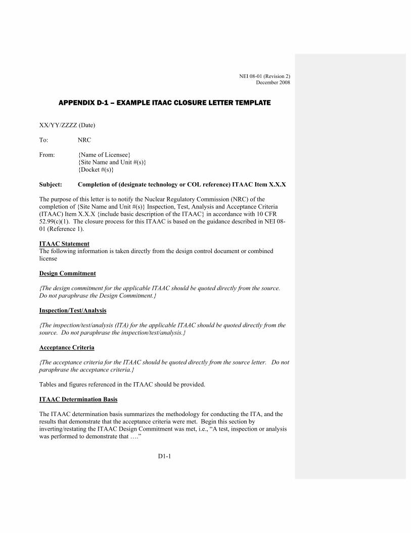
NEI 08-01 (Revision 2) December 2008
D1-1
APPENDIX D-1 – EXAMPLE ITAAC CLOSURE LETTER TEMPLATE
XX/YY/ZZZZ (Date) To: NRC From: {Name of Licensee} {Site Name and Unit #(s)} {Docket #(s)} Subject: Completion of (designate technology or COL reference) ITAAC Item X.X.X The purpose of this letter is to notify the Nuclear Regulatory Commission (NRC) of the completion of {Site Name and Unit #(s)} Inspection, Test, Analysis and Acceptance Criteria (ITAAC) Item X.X.X {include basic description of the ITAAC} in accordance with 10 CFR 52.99(c)(1). The closure process for this ITAAC is based on the guidance described in NEI 08-01 (Reference 1). ITAAC Statement The following information is taken directly from the design control document or combined license Design Commitment {The design commitment for the applicable ITAAC should be quoted directly from the source. Do not paraphrase the Design Commitment.} Inspection/Test/Analysis {The inspection/test/analysis (ITA) for the applicable ITAAC should be quoted directly from the source. Do not paraphrase the inspection/test/analysis.} Acceptance Criteria {The acceptance criteria for the ITAAC should be quoted directly from the source letter. Do not paraphrase the acceptance criteria.} Tables and figures referenced in the ITAAC should be provided. ITAAC Determination Basis The ITAAC determination basis summarizes the methodology for conducting the ITA, and the results that demonstrate that the acceptance criteria were met. Begin this section by inverting/restating the ITAAC Design Commitment was met, i.e., “A test, inspection or analysis was performed to demonstrate that ….”

NEI 08-01 (Revision 2) December 2008
D1-2
It should be written in an active voice, and consist of sufficient information to enable a person familiar with technical/engineering concepts to understand the bases underlying the conclusion established by the licensee regarding the ITAAC determination basis and successful ITAAC completion. In the event that the ITAAC offers more than one method to meet the acceptance criteria, clearly state which method was selected. In addition, the records (Tests, Reports, Completed Procedures, Completed Analyses, etc.) that form the ITAAC determination basis must be referenced and available for NRC review. A closing statement confirming the ITAAC was met should be included. ITAAC-Related Construction Finding Review {In accordance with plant procedures for ITAAC close-out, the licensee will perform a review of all ITAAC-related construction findings pertaining to the subject ITAAC to determine that associated corrective actions were completed. The ITAAC close-out letter will list all relevant ITAAC-related construction findings and state that they have been closed and all corrective actions have been completed. Alternatively, the letter will provide a justification for why the NRC may issue its Section 52.99 determination of successful ITAAC completion despite the existence of unresolved ITAAC-related construction findings or uncompleted corrective actions. ITAAC close-out reviews will be documented in ITAAC Closeout Packages and available for NRC inspection.} Example: In accordance with plant procedures for ITAAC close-out, {Licensee} performed a review of ITAAC-related construction findings and associated corrective actions. This review determined that X associated findings, listed below, have been identified.
1. {ITAAC-related construction finding #1}
2. {ITAAC-related construction finding #2}
3. {ITAAC-related construction finding #3}
The corrective actions for each finding have been completed and each finding closed. This review is documented in the close-out package for ITAAC x.x.x, (Reference 4), which is available for NRC review. NRC closure of these findings is available on the Construction Inspection Program Management System (CIPMS) portion of the NRC website for this docket and may be located by referencing the NRC finding numbers provided above.
{Alternatively, the text above can be changed to indicate that “This review determined that there are no NRC findings related to this ITAAC”.}
ITAAC Closure Statement Based on the above information, {Licensee Name} hereby notifies the NRC that ITAAC X.X.X was performed for {Site Name and Unit #(s)}, and that the prescribed acceptance criteria were met. We request NRC staff confirmation of this determination and publication of the required notice in the Federal Register per 10 CFR 52.99.

NEI 08-01 (Revision 2) December 2008
D1-3
If there are any questions, please contact {Name of Contact Person for licensee} at {Telephone Number for Contact Person}. Sincerely, {Signature of Licensee Representative} {Typed Name of Licensee Representative} {Title of Licensee Representative} References (available for NRC review) 1. NEI 08-01, Industry Guideline for the ITAAC Closure Process Under 2. 10 CFR Part 52 3. Test/inspection record(s), report, completed procedure, analysis, etc., that form the ITAAC
determination basis 4. Relevant plant inspection or test procedure 5. ITAAC Close-out Package retained on site


NEI 08-01 (Revision 2) December 2008
D2-1
APPENDIX D-2 – EXAMPLE ITAAC CLOSURE LETTER AP1000 ITAAC 3.3.6 ITEM 7D
XX/YY/ZZZZ (Date) To: NRC From: {Name of Licensee} {Site Name and Unit #(s)} {Docket #(s)} Subject: Completion of ITAAC 3.3.6 item 7d The purpose of this letter is to notify the NRC of the completion of EFG Nuclear Plant Inspection, Test, Analysis and Acceptance Criteria (ITAAC) 3.3.6 item 7d for Cable Separation in accordance with 10 CFR 52.99(c)(1). The closure process for this ITAAC is based on the guidance described in NEI 08-01(Reference 1). ITAAC Statement Design Commitment ITAAC Table 3.3.6 (7d) Physical separation is maintained between Class 1E divisions and between Class 1E divisions and non-Class 1E cables Inspection/Test/Analysis Inspections of the as-built Class 1E raceways will be performed to confirm that the separation between Class 1E raceways of different divisions and between Class 1E raceways and non-Class 1E raceways is consistent with the following:
Within the main control room and remote shutdown room, the minimum vertical separation is 3 inches and the minimum horizontal separation is 1 inch.
Within other plant areas (limited hazard areas), the minimum separation is defined by one of the following: 1. The minimum vertical separation is 5 feet and the minimum horizontal separation
is 3 feet. 2. The minimum vertical separation is 12 inches and the minimum horizontal
separation is 6 inches for raceways containing only instrumentation and control and low-voltage power cables <2/0 AWG.
3. For configurations that involve exclusively limited energy content cables (instrumentation and control), the minimum vertical separation is 3 inches and the minimum horizontal separation is 1 inch.

NEI 08-01 (Revision 2) December 2008
D2-2
4. For configurations involving an enclosed raceway and an open raceway, the minimum vertical separation is 1 inch if the enclosed raceway is below the open raceway.
5. For configuration involving enclosed raceways, the minimum separation is 1 inch in both horizontal and vertical directions.
Where minimum separation distances are not maintained, the circuits are run in enclosed raceways or barriers are provided.
Separation distances less than those specified above and not run in enclosed raceways or provided with barriers are based on analysis
Non-Class 1E wiring that is not separated from Class 1E or associated wiring by the minimum separation distance or by a barrier or analyzed is considered as associated circuits and subject to Class 1E requirements.
Acceptance Criteria Results of the inspection will confirm that the separation between Class 1E raceways of different divisions and between Class 1E raceways and non-Class 1E raceways is consistent with the followings:
Within the main control room and remote shutdown room, the vertical separation is
3 inches or more and the horizontal separation is 1 inch or more. Within other plant areas (limited hazard areas), the separation meets one of the
following: 1. The vertical separation is 5 feet or more and the horizontal separation is 3 feet or
more except. 2. The minimum vertical separation is 12 inches and the minimum horizontal
separation is 6 inches for raceways containing only instrumentation and control and low-voltage power cables <2/0 AWG.
3. For configurations that involve exclusively limited energy content cables (instrumentation and control), the minimum vertical separation is 3 inches and the minimum horizontal separation is 1 inch.
4. For configurations that involve an enclosed raceway and an open raceway, the minimum vertical separation is 1 inch if the enclosed raceway is below the raceway.
5. For configurations that involve enclosed raceways, the minimum vertical and horizontal separation is 1 inch.
Where minimum separation distances are not met, the circuits are run in enclosed raceways or barriers are provided.
A report exists and concludes that separation distances less than those specified above and not provided with enclosed raceways or barriers have been analyzed.
Non-Class 1E wiring that is not separated from Class 1E or associated wiring by the minimum separation distance or by a barrier or analyzed is treated as Class 1E wiring.
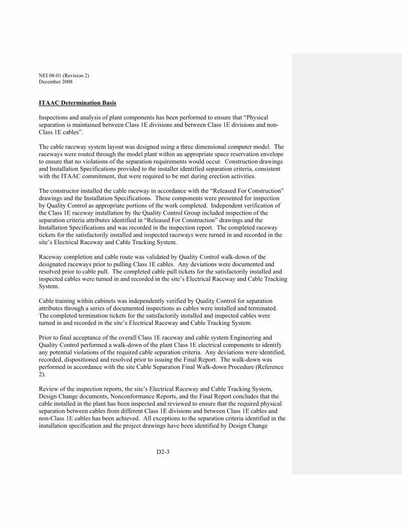
NEI 08-01 (Revision 2) December 2008
D2-3
ITAAC Determination Basis Inspections and analysis of plant components has been performed to ensure that “Physical separation is maintained between Class 1E divisions and between Class 1E divisions and non-Class 1E cables”. The cable raceway system layout was designed using a three dimensional computer model. The raceways were routed through the model plant within an appropriate space reservation envelope to ensure that no violations of the separation requirements would occur. Construction drawings and Installation Specifications provided to the installer identified separation criteria, consistent with the ITAAC commitment, that were required to be met during erection activities. The constructor installed the cable raceway in accordance with the “Released For Construction” drawings and the Installation Specifications. These components were presented for inspection by Quality Control as appropriate portions of the work completed. Independent verification of the Class 1E raceway installation by the Quality Control Group included inspection of the separation criteria attributes identified in “Released For Construction” drawings and the Installation Specifications and was recorded in the inspection report. The completed raceway tickets for the satisfactorily installed and inspected raceways were turned in and recorded in the site’s Electrical Raceway and Cable Tracking System. Raceway completion and cable route was validated by Quality Control walk-down of the designated raceways prior to pulling Class 1E cables. Any deviations were documented and resolved prior to cable pull. The completed cable pull tickets for the satisfactorily installed and inspected cables were turned in and recorded in the site’s Electrical Raceway and Cable Tracking System. Cable training within cabinets was independently verified by Quality Control for separation attributes through a series of documented inspections as cables were installed and terminated. The completed termination tickets for the satisfactorily installed and inspected cables were turned in and recorded in the site’s Electrical Raceway and Cable Tracking System. Prior to final acceptance of the overall Class 1E raceway and cable system Engineering and Quality Control performed a walk-down of the plant Class 1E electrical components to identify any potential violations of the required cable separation criteria. Any deviations were identified, recorded, dispositioned and resolved prior to issuing the Final Report. The walk-down was performed in accordance with the site Cable Separation Final Walk-down Procedure (Reference 2). Review of the inspection reports, the site’s Electrical Raceway and Cable Tracking System, Design Change documents, Nonconformance Reports, and the Final Report concludes that the cable installed in the plant has been inspected and reviewed to ensure that the required physical separation between cables from different Class 1E divisions and between Class 1E cables and non-Class 1E cables has been achieved. All exceptions to the separation criteria identified in the installation specification and the project drawings have been identified by Design Change

NEI 08-01 (Revision 2) December 2008
D2-4
documents or Nonconformance Reports. These exceptions whether identified during installation or by final walk down of the as built configuration have been evaluated and either corrected, mitigated or accepted as is. The Cable Separation Final Report concludes that separation distances are satisfactory. Those separation distances less than specified by the ITAAC criteria and not provided with enclosed raceways or barriers have been analyzed and determined to be satisfactory. The Cable Separation Final Report (Reference 3) is available for NRC review at the EFG plant site. ITAAC Related Construction Finding Review In accordance with plant procedures for ITAAC close-out, {Licensee} performed a review of ITAAC-related construction findings and associated corrective actions. This review determined that three such findings, listed below, have been identified.
1. {ITAAC-related construction finding #1}
2. {ITAAC-related construction finding #2}
3. {ITAAC-related construction finding #3}
The corrective actions for each finding have been completed and each finding closed. This review is documented in the close-out package for ITAAC 3.3.6 item 7d (Reference 4), which is available for NRC review. NRC closure of these findings is available on the Construction Inspection Program Management System (CIPMS) portion of the NRC website for this docket and may be located by referencing the NRC finding numbers provided above.
ITAAC Closure Statement Based on the above information, EFG Nuclear Plant hereby notifies the NRC that ITAAC 3.3.6 item 7d has been reviewed and the installation achieves the prescribed acceptance criteria. We request NRC staff confirmation of this determination and publication of the required notice in the Federal Register per 10 CFR 52.99. If there are any questions, please contact {Name of Contact Person for licensee} at {Telephone Number for Contact Person}. Sincerely, {Signature of Licensee Representative} {Typed Name of Licensee Representative} {Title of Licensee Representative}

NEI 08-01 (Revision 2) December 2008
D2-5
References (available for NRC review) 1. NEI 08-01, Industry Guideline for the ITAAC Closure Process Under 10 CFR Part 52 2. Cable Separation Final Walk-down Procedure 3. ITAAC 3.3.6 item 7d Cable Separation Final Report –EFG xyz, Revision 0 4. ITAAC 3.3.6 item 7d Closeout Package

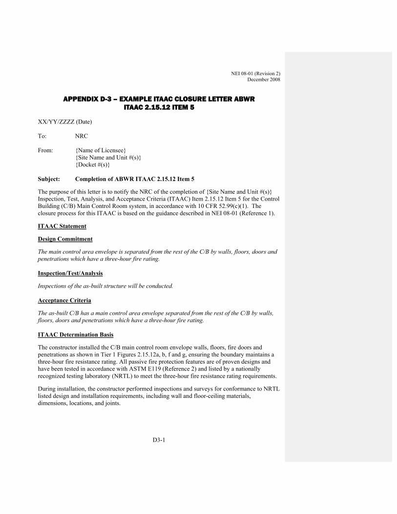
NEI 08-01 (Revision 2) December 2008
D3-1
APPENDIX D-3 – EXAMPLE ITAAC CLOSURE LETTER ABWR ITAAC 2.15.12 ITEM 5
XX/YY/ZZZZ (Date) To: NRC From: {Name of Licensee} {Site Name and Unit #(s)} {Docket #(s)} Subject: Completion of ABWR ITAAC 2.15.12 Item 5
The purpose of this letter is to notify the NRC of the completion of {Site Name and Unit #(s)} Inspection, Test, Analysis, and Acceptance Criteria (ITAAC) Item 2.15.12 Item 5 for the Control Building (C/B) Main Control Room system, in accordance with 10 CFR 52.99(c)(1). The closure process for this ITAAC is based on the guidance described in NEI 08-01 (Reference 1).
ITAAC Statement
Design Commitment
The main control area envelope is separated from the rest of the C/B by walls, floors, doors and penetrations which have a three-hour fire rating. Inspection/Test/Analysis
Inspections of the as-built structure will be conducted. Acceptance Criteria
The as-built C/B has a main control area envelope separated from the rest of the C/B by walls, floors, doors and penetrations which have a three-hour fire rating. ITAAC Determination Basis
The constructor installed the C/B main control room envelope walls, floors, fire doors and penetrations as shown in Tier 1 Figures 2.15.12a, b, f and g, ensuring the boundary maintains a three-hour fire resistance rating. All passive fire protection features are of proven designs and have been tested in accordance with ASTM E119 (Reference 2) and listed by a nationally recognized testing laboratory (NRTL) to meet the three-hour fire resistance rating requirements.
During installation, the constructor performed inspections and surveys for conformance to NRTL listed design and installation requirements, including wall and floor-ceiling materials, dimensions, locations, and joints.
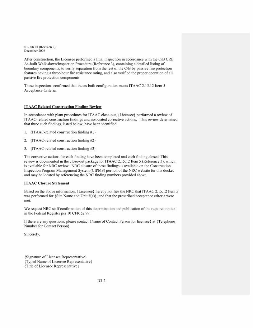
NEI 08-01 (Revision 2) December 2008
D3-2
After construction, the Licensee performed a final inspection in accordance with the C/B CRE As-built Walk-down/Inspection Procedure (Reference 3), containing a detailed listing of boundary components, to verify separation from the rest of the C/B by passive fire protection features having a three-hour fire resistance rating, and also verified the proper operation of all passive fire protection components
These inspections confirmed that the as-built configuration meets ITAAC 2.15.12 Item 5 Acceptance Criteria.
ITAAC Related Construction Finding Review
In accordance with plant procedures for ITAAC close-out, {Licensee} performed a review of ITAAC-related construction findings and associated corrective actions. This review determined that three such findings, listed below, have been identified.
1. {ITAAC-related construction finding #1}
2. {ITAAC-related construction finding #2}
3. {ITAAC-related construction finding #3}
The corrective actions for each finding have been completed and each finding closed. This review is documented in the close-out package for ITAAC 2.15.12 Item 5 (Reference 3), which is available for NRC review. NRC closure of these findings is available on the Construction Inspection Program Management System (CIPMS) portion of the NRC website for this docket and may be located by referencing the NRC finding numbers provided above.
ITAAC Closure Statement
Based on the above information, {Licensee} hereby notifies the NRC that ITAAC 2.15.12 Item 5 was performed for {Site Name and Unit #(s)}, and that the prescribed acceptance criteria were met.
We request NRC staff confirmation of this determination and publication of the required notice in the Federal Register per 10 CFR 52.99.
If there are any questions, please contact {Name of Contact Person for licensee} at {Telephone Number for Contact Person}.
Sincerely, {Signature of Licensee Representative} {Typed Name of Licensee Representative} {Title of Licensee Representative}
NEI 08-01 (Revision 2) December 2008
D3-3
References (available for NRC review)
1. NEI-08-01, Industry Guideline for the ITAAC Closure Process Under 10 CFR Part 52 2. C/B CRE as-built walk-down/inspection Procedure, C/B-CRE-WD-XXXX 3. ITAAC 2.15.12 Item 5 Closeout Package

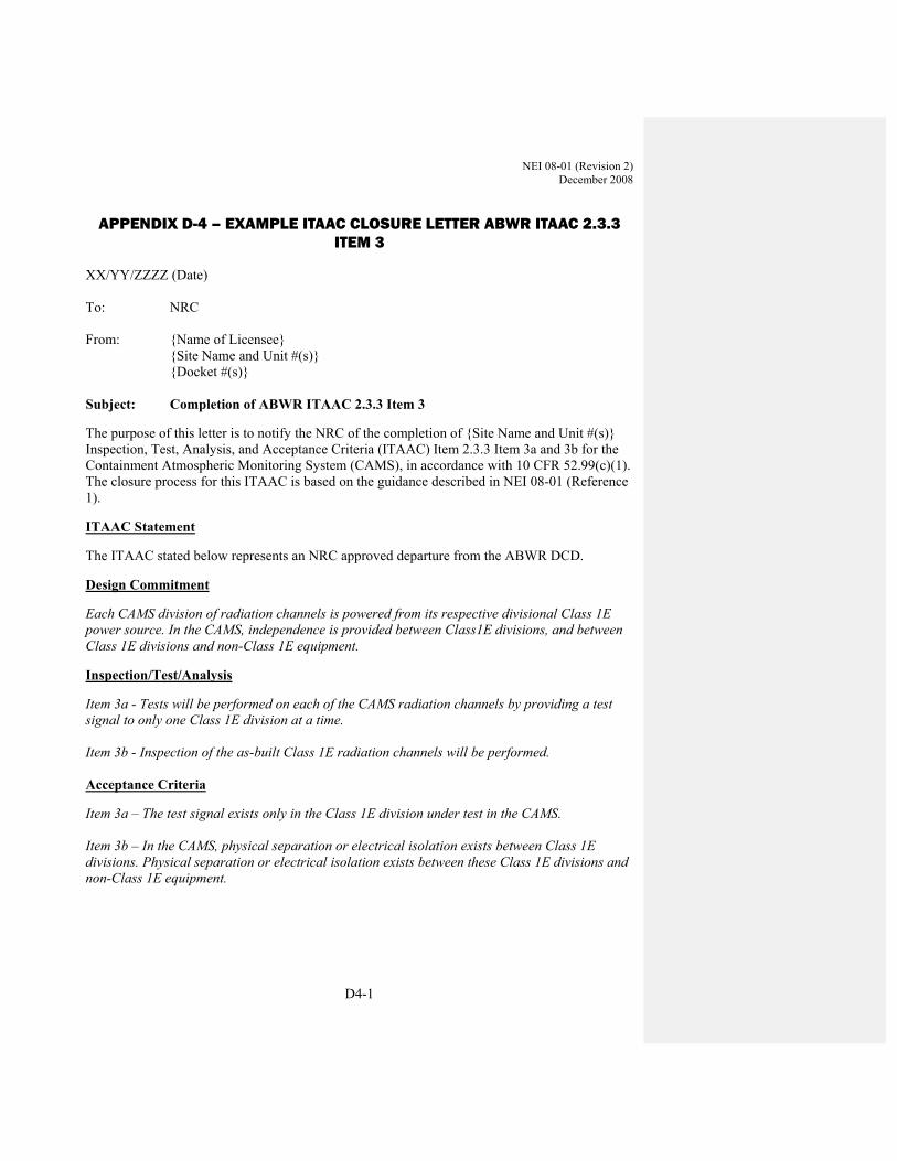
NEI 08-01 (Revision 2) December 2008
D4-1
APPENDIX D-4 – EXAMPLE ITAAC CLOSURE LETTER ABWR ITAAC 2.3.3 ITEM 3
XX/YY/ZZZZ (Date) To: NRC From: {Name of Licensee} {Site Name and Unit #(s)} {Docket #(s)} Subject: Completion of ABWR ITAAC 2.3.3 Item 3
The purpose of this letter is to notify the NRC of the completion of {Site Name and Unit #(s)} Inspection, Test, Analysis, and Acceptance Criteria (ITAAC) Item 2.3.3 Item 3a and 3b for the Containment Atmospheric Monitoring System (CAMS), in accordance with 10 CFR 52.99(c)(1). The closure process for this ITAAC is based on the guidance described in NEI 08-01 (Reference 1).
ITAAC Statement
The ITAAC stated below represents an NRC approved departure from the ABWR DCD.
Design Commitment
Each CAMS division of radiation channels is powered from its respective divisional Class 1E power source. In the CAMS, independence is provided between Class1E divisions, and between Class 1E divisions and non-Class 1E equipment.
Inspection/Test/Analysis
Item 3a - Tests will be performed on each of the CAMS radiation channels by providing a test signal to only one Class 1E division at a time. Item 3b - Inspection of the as-built Class 1E radiation channels will be performed. Acceptance Criteria
Item 3a – The test signal exists only in the Class 1E division under test in the CAMS. Item 3b – In the CAMS, physical separation or electrical isolation exists between Class 1E divisions. Physical separation or electrical isolation exists between these Class 1E divisions and non-Class 1E equipment.

NEI 08-01 (Revision 2) December 2008
D4-2
ITAAC Determination Basis
Item 3a – Testing consisted of independent test signal introduction into each radiation channel to confirm division and channel independence and separation. Testing was performed in accordance with Pre-Operational Test Procedure ABWR PTP-CAMS-0001 (Reference 3). Testing has been performed on both CAMS radiation channels to confirm test signal introduction into each division and channel does not result in a signal being detected in the other division and channels of CAMS. Test results indicate Acceptance Criteria contained in ITAAC 2.3.3 Item 3a has been satisfied.
Item 3b – Inspections have been performed during the construction and installation process to ensure that physical separation exists between Class 1E CAMS radiation channels and between Class 1E CAMS divisions and non-Class 1E equipment. The design and installation of CAMS related equipment was in accordance with Regulatory Guide 1.75 (Reference 4) as identified in section 8.3 of the ABWR DCD. A review of construction in-process installation and Quality Control records was conducted, where separation requirements were built into the process used for raceway and cable design and routing. These inspections and reviews confirmed that physical separation was maintained between Class 1E CAMS radiation channels and between Class 1E CAMS divisions and non-Class 1E equipment during installation.
Construction drawings and Installation Specifications provide the installer/contractor with identified separation criteria, consistent with the ITAAC commitment and were met during construction activities.
Raceway completion and cable route were validated by Quality Control walk-down of the designated raceways prior to pulling Class 1E cables. Cable routing within cabinets was independently verified by Quality Control for separation attributes through a series of documented inspections as cables were installed and terminated. A final walkdown was performed of the Class 1E CAMS installed equipment using Walkdown Procedure XXX to verify that there is no interference from non-Class 1equipment installed in the area. Based on a review of construction installation and independent Quality Control records, the Licensee has determined the Acceptance Criteria contained in ITAAC 2.3.3 Item 3b were met. ITAAC Related Construction Finding Review In accordance with plant procedures for ITAAC close-out, {Licensee} performed a review of ITAAC-related construction findings and associated corrective actions. This review determined that three such findings, listed below, have been identified. 1. {ITAAC-related construction finding #1}
2. {ITAAC-related construction finding #2}

NEI 08-01 (Revision 2) December 2008
D4-3
3. {ITAAC-related construction finding #3}
The corrective actions for each finding have been completed and each finding closed. This review is documented in the close-out package for ITAAC 2.3.3 Item 3a and 3b (Reference 2), which is available for NRC review. NRC closure of these findings is available on the Construction Inspection Program Management System (CIPMS) portion of the NRC website for this docket and may be located by referencing the NRC finding numbers provided above.
ITAAC Closure Statement
Based on the above information, {Licensee} hereby notifies the NRC that ITAAC 2.3.3 Item 3a and 3b were performed for {Site Name and Unit #(s)}, and that the prescribed acceptance criteria were met.
We request NRC staff confirmation of this determination and publication of the required notice in the Federal Register per 10 CFR 52.99.
If there are any questions, please contact {Name of Contact Person for licensee} at {Telephone Number for Contact Person}.
Sincerely, {Signature of Licensee Representative} {Typed Name of Licensee Representative} {Title of Licensee Representative} References (available for NRC review)
1. NEI-08-01, Industry Guideline for the ITAAC Closure Process under 10 CFR Part 52 2. ITAAC 2.3.3 Item 3a and 3b Closeout Package 3. ABWR PTP-CAMS-0001, ABWR CAMS Pre-Operational Test Procedure 4. Regulatory Guide 1.75, Criteria For Independence Of Electrical Safety Systems 5. Walkdown Procedure XXX, Walkdown of Class 1E Equipment Installation

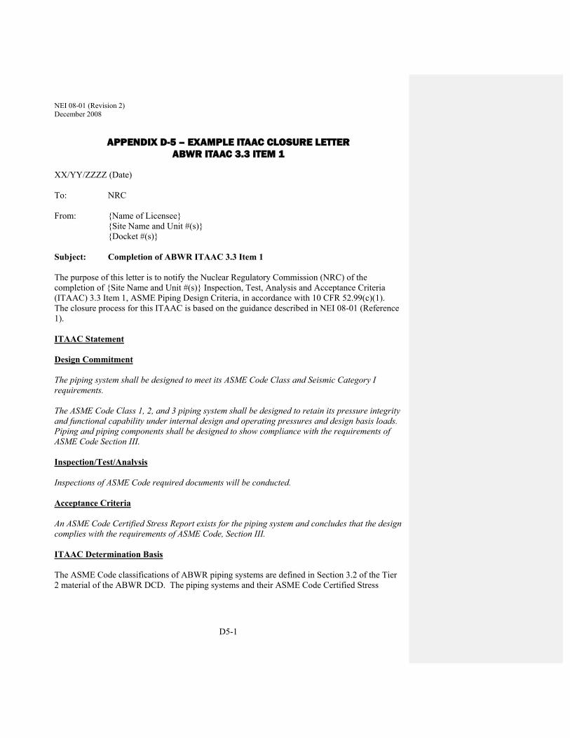
NEI 08-01 (Revision 2) December 2008
D5-1
APPENDIX D-5 – EXAMPLE ITAAC CLOSURE LETTER ABWR ITAAC 3.3 ITEM 1
XX/YY/ZZZZ (Date) To: NRC From: {Name of Licensee} {Site Name and Unit #(s)} {Docket #(s)} Subject: Completion of ABWR ITAAC 3.3 Item 1 The purpose of this letter is to notify the Nuclear Regulatory Commission (NRC) of the completion of {Site Name and Unit #(s)} Inspection, Test, Analysis and Acceptance Criteria (ITAAC) 3.3 Item 1, ASME Piping Design Criteria, in accordance with 10 CFR 52.99(c)(1). The closure process for this ITAAC is based on the guidance described in NEI 08-01 (Reference 1). ITAAC Statement Design Commitment The piping system shall be designed to meet its ASME Code Class and Seismic Category I requirements. The ASME Code Class 1, 2, and 3 piping system shall be designed to retain its pressure integrity and functional capability under internal design and operating pressures and design basis loads. Piping and piping components shall be designed to show compliance with the requirements of ASME Code Section III. Inspection/Test/Analysis Inspections of ASME Code required documents will be conducted. Acceptance Criteria An ASME Code Certified Stress Report exists for the piping system and concludes that the design complies with the requirements of ASME Code, Section III. ITAAC Determination Basis The ASME Code classifications of ABWR piping systems are defined in Section 3.2 of the Tier 2 material of the ABWR DCD. The piping systems and their ASME Code Certified Stress

NEI 08-01 (Revision 2) December 2008
D5-2
Reports are listed in Table 1 (attached). All Stress Reports are identified in the ITAAC closure package (Reference 2). Inspection Procedure XYZ (Reference 3) documents the scope of review for each of the ASME Code Certified Stress Reports. The scope of review includes the following areas:
The piping system Design Specification in accordance with ASME Code Section III, Subsection NCA-3252, including loading definitions and load combinations.
Thermal Analysis, in accordance with ASME Code Section III, Appendix C-1200, and applicable Subsection NB, NC or ND.
Structural Analysis, in accordance with ASME Code Section III, Appendix C-1300, and applicable Subsection NB, NC or ND.
Fatigue Analysis for the Class 1 piping and for the Class 3 SRV discharge piping in the wetwell and the SRV quenchers, in accordance with ASME Code Section III, Appendix C-1400, and applicable Subsection NB, NC or ND.
Inspections of the ASME Code Certified Stress Reports listed in attached Table 1 verify that the design of each piping system complies with the requirements of ASME Code, Section III, 1989 Edition, in accordance with the certified design. ITAAC-Related Construction Finding Review In accordance with plant procedures for ITAAC close-out, {Licensee} performed a review of ITAAC-related construction findings and associated corrective actions. This review determined that X associated findings, listed below, have been identified.
1. {ITAAC-related construction finding #1}
2. {ITAAC-related construction finding #2}
3. {ITAAC-related construction finding #3}
The corrective actions for each finding have been completed and each finding closed. This review is documented in the close-out package for ITAAC 3.3 Item 1, (Reference 2), which is available for NRC review. NRC closure of these findings is available on the Construction Inspection Program Management System (CIPMS) portion of the NRC website for this docket and may be located by referencing the NRC finding numbers provided above.
ITAAC Closure Statement Based on the above information, {Licensee Name} hereby notifies the NRC that ITAAC 3.3 Item 1 was performed for {Site Name and Unit #(s)}, and that the prescribed acceptance criteria were met. We request NRC staff confirmation of this determination and publication of the required notice in the Federal Register per 10 CFR 52.99.

NEI 08-01 (Revision 2) December 2008
D5-3
If there are any questions, please contact {Name of Contact Person for licensee} at {Telephone Number for Contact Person}. Sincerely, {Signature of Licensee Representative} {Typed Name of Licensee Representative} {Title of Licensee Representative} References (available for NRC review) 1. NEI 08-01, Industry Guideline for the ITAAC Closure Process under 10 CFR Part 52 2. ITAAC Close-out Package for ITAAC 3.3 Item 1 3. Inspection Procedure XYZ, “Review of ASME Code Certified Stress Reports”

NEI 08-01 (Revision 2) December 2008
D5-4
Table 1. ABWR Piping System ASME Code Design Summary
Piping System(Note 1) ASME Code
Class(es)(Note 2) ASME Code
Subsection(s)(Note 3) Certified Stress
Report(s) Nuclear Boiler
(includes MSL and FW systems, RPV head vent and main steam
drains)
1, 2 and 3 NB, NC and ND Stress Report A Stress Report B Stress Report C Stress Report D Stress Report E Stress Report F Stress Report G
Reactor Recirculation 2 NC Stress Report H Control Rod Drive
(insert line) 2 NC Stress Report I
Standby Liquid Control 1 and 2 NB and NC Stress Report J Stress Report K
Residual Heat Removal 1 and 2 NB and NC Stress Report L Stress Report M
High Pressure Core Flooder 1 and 2 NB and NC Stress Report N Stress Report O
Leak Detection and Isolation (sample lines and isolation valves)
2 NC Stress Report P
Reactor Core Isolation Cooling 1, 2 and 3 NB, NC and ND Stress Report Q Stress Report R Stress Report S
Reactor Water Cleanup 1 and 3 NB and ND Stress Report T Stress Report U
Fuel Pool Cooling and Cleanup (RHR piping for safety-related
make-up and supplemental cooling)
3 ND Stress Report V
Suppression Pool Cleanup 2 NC Stress Report W Radwaste
(portions forming part of containment boundary)
2 NC Stress Report X
Makeup Water (Purified) (portions forming part of containment boundary)
2 NC Stress Report Y
Makeup Water (Condensate) (condensate header piping)
2 NC Stress Report Z
Reactor Building Cooling Water 2 and 3 NC and ND Stress Report AA Stress Report BB
HVAC Normal Cooling Water (portions forming part of containment boundary)
2 NC Stress Report CC
HVAC Emergency Cooling Water 3 ND Stress Report DD Reactor Service Water
(safety-related portions) 3 ND Stress Report EE
Station Service Air (containment isolation)
2 NC Stress Report FF
Instrument Air Service (containment isolation)
2 NC Stress Report GG
High Pressure Nitrogen Gas Supply 2 and 3 NC and ND Stress Report HH Stress Report II

NEI 08-01 (Revision 2) December 2008
D5-5
Piping System(Note 1) ASME Code
Class(es)(Note 2) ASME Code
Subsection(s)(Note 3) Certified Stress
Report(s) Emergency Diesel Generator
(including fuel oil, cooling water and lube oil piping)
3 ND Stress Report JJ
Primary Containment (suppression chamber/drywell
vacuum breakers)
2 NC Stress Report KK
Atmospheric Control 2 and 3 NC and ND Stress Report LL Stress Report MM
Diesel Generator Fuel Oil Storage and Transfer System
3 ND Stress Report NN
Notes: 1. See Table 3.2-1 in the Tier 2 material in the DCD for Safety Class designations of specific portions of each
system. Most systems also include Class N (non-safety, non-ASME Code) portions, which are not identified in this table.
2. Per Tables 3.2-2 and 3.2-3 in the Tier 2 material in the DCD, Safety Classes 1, 2 and 3 correspond to ASME Code Classes 1, 2 and 3. All three Safety Classes are Seismic Category 1.
3. Supports for all listed piping systems are designed in accordance with Subsection NF. The Subsection NCA requirements for Design Specifications and Design Reports Subsection NCA apply to all three ASME Classes.

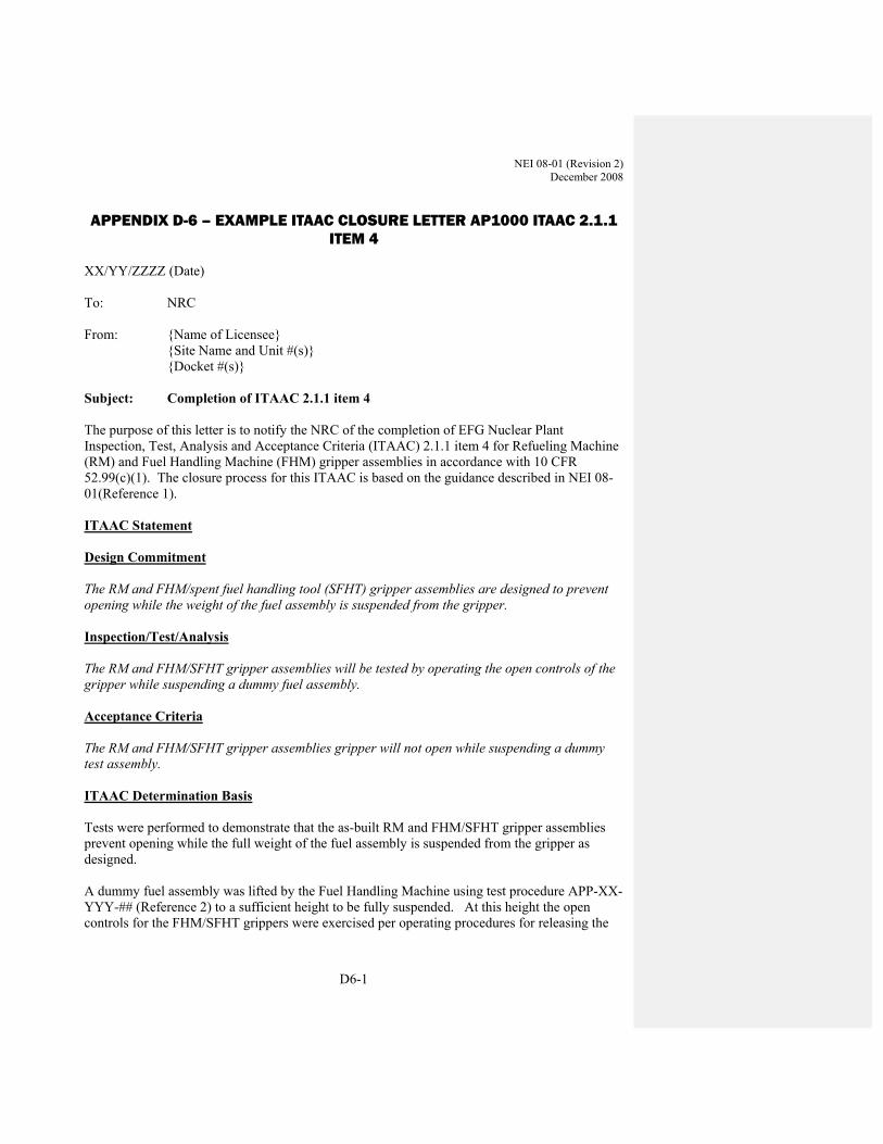
NEI 08-01 (Revision 2) December 2008
D6-1
APPENDIX D-6 – EXAMPLE ITAAC CLOSURE LETTER AP1000 ITAAC 2.1.1 ITEM 4
XX/YY/ZZZZ (Date) To: NRC From: {Name of Licensee} {Site Name and Unit #(s)} {Docket #(s)} Subject: Completion of ITAAC 2.1.1 item 4 The purpose of this letter is to notify the NRC of the completion of EFG Nuclear Plant Inspection, Test, Analysis and Acceptance Criteria (ITAAC) 2.1.1 item 4 for Refueling Machine (RM) and Fuel Handling Machine (FHM) gripper assemblies in accordance with 10 CFR 52.99(c)(1). The closure process for this ITAAC is based on the guidance described in NEI 08-01(Reference 1). ITAAC Statement Design Commitment The RM and FHM/spent fuel handling tool (SFHT) gripper assemblies are designed to prevent opening while the weight of the fuel assembly is suspended from the gripper. Inspection/Test/Analysis The RM and FHM/SFHT gripper assemblies will be tested by operating the open controls of the gripper while suspending a dummy fuel assembly. Acceptance Criteria The RM and FHM/SFHT gripper assemblies gripper will not open while suspending a dummy test assembly. ITAAC Determination Basis Tests were performed to demonstrate that the as-built RM and FHM/SFHT gripper assemblies prevent opening while the full weight of the fuel assembly is suspended from the gripper as designed. A dummy fuel assembly was lifted by the Fuel Handling Machine using test procedure APP-XX-YYY-## (Reference 2) to a sufficient height to be fully suspended. At this height the open controls for the FHM/SFHT grippers were exercised per operating procedures for releasing the

NEI 08-01 (Revision 2) December 2008
D6-2
fuel assembly. The grippers did not open. Thus, the FHM grippers met the acceptance criteria in that they did not open while suspending a fuel assembly. A dummy fuel assembly was lifted by the Refueling Machine using test procedure APP-XX-YYY-## (Reference 2) to a sufficient height to be fully suspended. At this height the open controls for the RM grippers were exercised per operating procedures for releasing the fuel assembly. The grippers did not open. Thus, the RM grippers met the acceptance criteria in that they did not open while suspending a fuel assembly. Reference 3 documents the test results and analysis and is available for NRC review. ITAAC-Related Construction Finding Review In accordance with plant procedures for ITAAC close-out, the {licensee} performed a review of all ITAAC-related construction findings pertaining to the subject ITAAC and associated corrective actions. This review found that there were no relevant ITAAC-related construction findings associated with this ITAAC. The ITAAC close-out review is documented in ITAAC Closeout Package for ITAAC 2.1.1 item 4 (Reference 4) and available for NRC review. ITAAC Closure Statement Based on the above information, EFG Nuclear Plant hereby notifies the NRC that ITAAC 2.1.1 item 4 was performed and that the prescribed acceptance criteria were met. We request NRC staff confirmation of this determination and publication of the required notice in the Federal Register per 10 CFR 52.99. If there are any questions, please contact {Name of Contact Person for licensee} at {Telephone Number for Contact Person}. Sincerely, {Signature of Licensee Representative} {Typed Name of Licensee Representative} {Title of Licensee Representative} References (available for NRC review) 1. NEI 08-01, Industry Guideline for the ITAAC Closure Process Under 10 CFR Part 52 2. APP-XX-YYY-###, ITAAC 2.1.1 item 4 Refueling Machine and Fuel Handling Machine
Grippers Test Procedure 3. ITAAC 2.1.1 item 4 Refueling Machine and Fuel Handling Machine/Spent Fuel Handling
Tool Grippers Test Record 4. ITAAC 2.1.1 item 4 Closeout Package
NEI 08-01 (Revision 2) December 2008
D7-1
APPENDIX D-7 – EXAMPLE ITAAC CLOSURE LETTER AP1000 ITAAC 2.1.2-4 ITEM 3B
XX/YY/ZZZZ (Date) To: NRC From: {Name of Licensee} {Site Name and Unit #(s)} {Docket #(s)} Subject: Completion of ITAAC 2.1.2-4 Item 3b The purpose of this letter is to notify Nuclear Regulatory Commission (NRC) of the completion of {Site Name and Unit #(s)} Inspections, Tests, Analyses, and Acceptance Criteria (ITAAC) 2.1.2- item 3b for the Reactor Coolant System (RCS), in accordance with 10 CFR 52.99(c)(1). The closure process for this ITAAC Item is based on the guidance described in Nuclear Energy Institute (NEI) Guidance Document NEI 08-01 (Reference 1).
ITAAC Statement
Design Commitment
Pressure boundary welds in piping identified in Table 2.1.2-2 as American Society of Mechanical Engineers (ASME) Code Section III meet ASME Code Section III requirements. Inspections/Tests/Analyses
Inspection of the as-built pressure boundary welds will be performed in accordance with the ASME Code Section III. Acceptance Criteria
A report exists and concludes that the ASME Code Section III requirements are met for non-destructive examination of pressure boundary welds. ITAAC Determination Basis
{Licensee} performed inspections in accordance with the ASME Code Section III {cite applicable edition and addenda} of the as-built pressure boundary welds in piping identified in Table 2.1.2-2 as ASME Code Section III. The non-destructive examinations (e.g., visual inspection, liquid penetrant, magnetic particle, radiographic, and ultrasonic testing) of pressure boundary welds are documented in traveler packages which support completion of the N-5 Code Data Report(s) certified by the Authorized Nuclear Inspector, as listed in Reference Table XX. Per ASME Code Section III, Subarticle NCA-8300, “Code Symbol Stamps,” the N-5 Code Data Report indicates the satisfactory completion of the required examination and testing of the item,

NEI 08-01 (Revision 2) December 2008
D7-2
which include the required non-destructive examination of pressure boundary welds. Satisfactory completion of the non-destructive examination of pressure boundary welds ensures that the pressure boundary welds in piping identified in Table 2.1.2-2 as ASME Code Section III meet ASME Code Section III requirements. ITAAC-Related Construction Finding Review
In accordance with plant procedures for ITAAC close-out, {Licensee} performed a review of all ITAAC-related construction findings and associated corrective actions. This review determined that the following findings, listed below, have been identified.
1. {ITAAC-related construction finding #1}
2. {ITAAC-related construction finding #2}
3. {ITAAC-related construction finding #3}
The corrective actions for each finding are complete and each finding is closed. This review is documented in the close-out package (Reference 1) for ITAAC 2.1.2-4(3b), which is available for NRC review. NRC closure of these findings is available on the Construction Inspection Program Management System (CIPMS) portion of the NRC website for this docket and may be located by referencing the NRC finding numbers provided above.
ITAAC Closure Statement
Based on the above information, {Licensee} hereby notifies the NRC that ITAAC 2.1.2-4(3b) was performed for {Site Name and Unit #(s)}, and that the prescribed acceptance criteria were met.
{Licensee} requests NRC staff confirmation of this determination and publication of the required notice in the Federal Register per 10 CFR 52.99.
If there are any questions, please contact {Name of Contact Person for licensee} at {Telephone Number for Contact Person}.
Sincerely, {Signature of Licensee Representative} {Typed Name of Licensee Representative} {Title of Licensee Representative} References (available for NRC review)
1. NEI 08-01, Industry Guideline for the ITAAC Closure Process Under 10 CFR Part 52 2. ITAAC 2.1.2-4(3b) Close Out Package 3. NEI Guidance Document NEI-08-XX 4. NDE Testing & Inspection Procedures 5. Reference Table XX

NEI 08-01 (Revision 2) December 2008
D7-3
Reference Table 2.1.2-2
Table 2.1.2-2
Line Name Line Number ASME Code Section III
Leak Before Break
Functional Capability Required
Hot Legs RCS-L001A RCS-L001B
Yes Yes Yes
Cold Legs RCS-L002A RCS-L002B RCS-L002C RCS-L002D
Yes Yes Yes
Pressurizer Surge Line RCS-L003 Yes Yes Yes
ADS Inlet Headers RCS-L004A/B RCS-L006A/B RCS-L030A/B RCS-L020A/B
Yes Yes Yes
Safety Valve Inlet Piping RCS-L005A RCS-L005B
Yes Yes Yes
Safety Valve Discharge Piping
RCS-L050A/B RCS-L051A/B
Yes No Yes
ADS First-stage Valve Inlet Piping
RCS-L010A/B RCS-L011A/B
Yes No Yes
ADS Second-stage Valve Inlet Piping
RCS-L021A/B RCS-L022A/B
Yes Yes No
Yes
ADS Third-stage Valve Inlet Piping
RCS-L131 RCS-L031A/B RCS-L032A/B
Yes Yes Yes No
Yes
ADS Outlet Piping RCS-L012A/B RCS-L023A/B RCS-L033A/B RCS-L061A/B RCS-L063A/B RCS-L064A/B
RCS-L200 RCS-L069A/B RCS-L240A/B PXS-L130A/B
Yes No Yes
ADS Fourth-stage Inlet Piping
RCS-L133A/B RCS-L135A/B RCS-L136A/B RCS-L137A/B
Yes Yes Yes

NEI 08-01 (Revision 2) December 2008
D7-4
Table 2.1.2-2
Line Name Line Number ASME Code Section III
Leak Before Break
Functional Capability Required
Hot Legs RCS-L001A RCS-L001B
Yes Yes Yes
Cold Legs RCS-L002A RCS-L002B RCS-L002C RCS-L002D
Yes Yes Yes
Pressurizer Surge Line RCS-L003 Yes Yes Yes
ADS Inlet Headers RCS-L004A/B RCS-L006A/B RCS-L030A/B RCS-L020A/B
Yes Yes Yes
Safety Valve Inlet Piping RCS-L005A RCS-L005B
Yes Yes Yes
Safety Valve Discharge Piping
RCS-L050A/B RCS-L051A/B
Yes No Yes
ADS First-stage Valve Inlet Piping
RCS-L010A/B RCS-L011A/B
Yes No Yes
ADS Second-stage Valve Inlet Piping
RCS-L021A/B RCS-L022A/B
Yes Yes No
Yes
ADS Third-stage Valve Inlet Piping
RCS-L131 RCS-L031A/B RCS-L032A/B
Yes Yes Yes No
Yes
ADS Outlet Piping RCS-L012A/B RCS-L023A/B RCS-L033A/B RCS-L061A/B RCS-L063A/B RCS-L064A/B
RCS-L200 RCS-L069A/B RCS-L240A/B PXS-L130A/B
Yes No Yes
ADS Fourth-stage Inlet Piping
RCS-L133A/B RCS-L135A/B RCS-L136A/B RCS-L137A/B
Yes Yes Yes

NEI 08-01 (Revision 2) December 2008
D7-5
Table 2.1.2-2 (cont.)
Line Name Line Number ASME Code Section III
Leak Before Break
Functional Capability Required
Pressurizer Spray Piping RCS-L106 RCS-L110A/B RCS-L212A/B
RCS-L213 RCS-L215
Yes No No
RNS Suction Piping RCS-L139 RCS-L140
Yes Yes No
CVS Purification Piping RCS-L111 RCS-L112
Yes No No

NEI 08-01 (Revision 2) December 2008
D8-1
APPENDIX D-8 – EXAMPLE ITAAC CLOSURE LETTER AP1000 ITAAC 2.5.2-8 ITEM 10
XX/YY/ZZZZ (Date) To: NRC From: {Name of Licensee} {Site Name and Unit #(s)} {Docket #(s)} Subject: Completion of ITAAC 2.5.2-8 Item10
The purpose of this letter is to notify Nuclear Regulatory Commission (NRC) of the completion of {Site Name and Unit #(s)} Inspections, Tests, Analyses, and Acceptance Criteria (ITAAC) 2.5.2-8 item 10 for the Protection and Safety Monitoring System (PMS), in accordance with 10 CFR 52.99(c)(1). The closure process for this ITAAC is based on the guidance described in NEI 08-01(Reference 1). ITAAC Statement
Design Commitment
Setpoints are determined using a methodology which accounts for loop inaccuracies, response testing, and maintenance or replacement of instrumentation.
Inspection/Test/Analysis
Inspection will be performed for a document that describes the methodology and input parameters used to determine the PMS setpoints.
Acceptance Criteria
A report exists and concludes that the PMS setpoints are determined using a methodology which accounts for loop inaccuracies, response testing, and maintenance or replacement of instrumentation.
ITAAC Determination Basis
Instrument setpoints for permanently installed instrumentation are determined using methodology specified in Procedure XXX, Instrument Uncertainty and Setpoint Calculation Guidelines (Reference 2). This methodology accounts for loop inaccuracies, response testing, and maintenance or replacement of instrumentation.
{Licensee} performed an inspection of Engineering Report YYY, Setpoint Determination for the Protection and Safety Monitoring System (Reference 3), which established the setpoints for the PMS system. The purpose of the inspection was to confirm that the PMS setpoints were

NEI 08-01 (Revision 2) December 2008
D8-2
determined using Reference 1 and that the procedure specifies a methodology that takes into account instrument loop uncertainties and inaccuracies, response testing results, and maintenance or replacement activities. This inspection is documented in Inspection Report ZZZ, Closure of ITAAC 2.5.2-8, #10 (Reference 4).
The inspection determined that References 1 and 2 were used for the PMS setpoints and that Reference 1 provides specific instructions for calculating instrument and loop uncertainty setpoints. The input parameters for the calculation include instrument and loop uncertainties and inaccuracies, response testing results, and maintenance or replacement activities.
Therefore, Inspection Report ZZZ (Reference 4) exists and concludes that the PMS setpoints are determined using a methodology which accounts for loop inaccuracies, response testing, and maintenance or replacement of instrumentation.
ITAAC-Related Construction Finding Review
In accordance with plant procedures for ITAAC close-out, {Licensee} performed a review of ITAAC-related construction findings and associated corrective actions. This review determined that three associated findings, listed below, have been identified.
1. {ITAAC-related construction finding #1}
2. {ITAAC-related construction finding #2}
3. {ITAAC-related construction finding #3}
The corrective actions for each finding have been completed and each finding closed. This review is documented in the close-out package for ITAAC 2.5.2-8, #10 (Reference 5), which is available for NRC review. NRC closure of these findings is available on the Construction Inspection Program Management System (CIPMS) portion of the NRC website for this docket and may be located by referencing the NRC finding numbers provided above.
ITAAC Closure Statement
Based on the above information, {Licensee} hereby notifies the NRC that {Licensee} has performed ITAAC 2.5.2-8 item 10 for {Site Name and Unit #(s)}, and that the prescribed acceptance criteria were met.
{Licensee} requests NRC staff confirmation of this determination and publication of the required notice in the Federal Register per 10 CFR 52.99.
If there are any questions, please contact {name of contact person for Licensee} at {telephone # for contact person}.
Sincerely, {Signature of Licensee Representative} {Typed Name of Licensee Representative} {Title of Licensee Representative}
NEI 08-01 (Revision 2) December 2008
D8-3
References (available for NRC review)
1. NEI 08-01, Industry Guideline for the ITAAC Closure Process Under 10 CFR Part 52 2. Procedure XXX, Instrument Uncertainty and Setpoint Calculation Guidelines 3. Engineering Report YYY, Setpoint Determination for the Protection and Safety Monitoring
System 4. Inspection Report ZZZ, Closure of ITAAC 2.5.2-8 item10 5. ITAAC 2.5.2-8 item 10 Close-Out Package

NEI 08-01 (Revision 2) December 2008
D9-1
APPENDIX D-9 – EXAMPLE ITAAC CLOSURE LETTER AP1000 ITAAC 3.3-6 ITEMS 2.A.I AND II
To: NRC From: {Name of Licensee} {Site Name and Unit #(s)} {Docket #(s)} Subject: Completion of AP1000 ITAAC 3.3-6 Items 2a) i.a) & ii.a) The purpose of this letter is to notify Nuclear Regulatory Commission (NRC) of the completion of {Site Name and Unit #(s)} Inspections, Tests, Analyses, and Acceptance Criteria (ITAAC) 3.3-6 Items 2a) i) & ii) for the Nuclear Island Critical Structure Sections, in accordance with 10 CFR 52.99(c)(1). The closure process for this ITAAC is based on the guidance described in NEI 08-01(Reference 1). ITAAC Statement Design Commitment 2.a) The nuclear island structures, including the critical sections listed in Table 3.3-7, are
seismic Category I and are designed and constructed to withstand design basis loads as specified in the Design Description, without loss of structural integrity and the safety-related functions.
The Inspections, Tests, and Analyses i) An inspection of the nuclear island structures will be performed. Deviations from the design
due to as-built conditions will be analyzed for the design basis loads. ii) An inspection of the as-built concrete thickness will be performed. Acceptance Criteria i.a) A report exists which reconciles deviations during construction and concludes that the as-built
nuclear island structures, including the critical sections, conform to the approved design and will withstand the design basis loads specified in the Design Description without loss of structural integrity or the safety-related functions.
ii.a) A report exists that conclude that the as-built concrete thicknesses conform with the building sections defined on Table 3.3-1.
ITAAC Determination Basis The design bases loads as defined in the AP1000 Design Control Document are those loads associated with:

NEI 08-01 (Revision 2) December 2008
D9-2
Normal plant operation (including dead loads, live loads, lateral earth pressure loads, and equipment loads, including hydrodynamic loads, temperature and equipment vibration);
External events (including rain, snow, flood, tornado, tornado generated missiles and earthquake); and
Internal events (including flood, pipe rupture, equipment failure, and equipment failure generated missiles).
AP1000 DCD Section 3.7 “Seismic Analysis”, Section 3.8 “Design of Category I Structures” and Appendix 3H “Auxiliary Building Critical Sections” describe the analyses for the design basis loads for the NI Structures. Section 3.8 specifies the applicable codes and standards governing the design, materials, fabrication, construction inspection and testing for the NI structures. Section 3.8 also describes the as-built design summary reports which document that the seismic Category I structures meet the specified acceptance criteria.
The as-built nuclear island (NI) structures including the critical sections listed in Table 3.3-7, were constructed as designed and specified in the AP1000 DCD to withstand design basis loads as specified in the Design Description, without loss of structural integrity and the safety-related functions.
i.a) NI structures were inspected during construction to verify the as-built structures conform to the specified design, codes and standards. Identified structural deviations were documented in Non-conformance reports and entered into the site corrective action program. Each NI structural deviation was evaluated by engineering individually and collectively to determine their impact to the structures’ ability to withstand design basis loads. As-built Design Summary Report XXX (Reference 4) documents the reconciliation of NI structural deviations identified during construction and concludes that the as-built NI structures will withstand the design basis loads specified in the Design Description without loss of structural integrity or safety-related functions. An ITAAC closure evaluation was performed on As-built Design Summary Report XXX to verify that the deviation reconciliation report has been completed and addresses the construction identified structural deviations.
ii.a) As-built Nuclear Island wall dimensional surveys were performed in accordance with the Construction Field Survey Procedure (Reference 2) for the critical section identified in Table 3.3-7 (Enclosure 1) to verify the wall thicknesses specified in Table 3.3-1 (Enclosure 2). These surveys were conducted on the concrete forms prior to placement and on the as-built walls subsequent to removal of the forms. As-built Design Summary Report XYZ (Reference 5) documents the evaluation performed to determine if as-built wall thickness specified meet the acceptance criteria in Table 3.3-1 or reconciles any dimensional deviations. The As-built Design Summary Report XYZ documents and concludes the as-built concrete thicknesses conform to the wall dimensions defined in Table 3.3-1 and all deviations were appropriately evaluated and dispositioned. An ITAAC closure evaluation was performed on As-built Design Summary Report to verify that the report addresses the critical sections and dimensions and appropriately resolves any deviations.
NEI 08-01 (Revision 2) December 2008
D9-3
The EFP Plant ITAAC closure evaluation, survey records, As-built Design Summary Report XXX and XYZ are retained in the EFG Plant ITAAC 3.3-6 Items 2a) ii.a) Closeout Package (Reference 3) and are available for NRC review at the EFG Plant site.
ITAAC Related Construction finding Review In accordance with plant procedures for ITAAC close-out, EFG Nuclear Plant performed a review of ITAAC-related construction findings and associated corrective actions. This review determined that three associated findings, listed below, have been identified.
1. {ITAAC-related construction finding #1}
2. {ITAAC-related construction finding #2}
3. {ITAAC-related construction finding #3}
The corrective actions for each finding have been completed and each finding closed. This review is documented in the close-out package for ITAAC 3.3-6 Items 2 a) i.a) and ii.a) (Reference 3), which is available for NRC review. NRC closure of these findings is available on the Construction Inspection Program Management System (CIPMS) portion of the NRC website for this docket may be located by referencing the NRC finding numbers provided above.
ITAAC Closure Statement Based on the above information, New Reactor Licensee hereby notifies the NRC that ITAAC 3.3-6 Items 2 a) i.a) and ii.a) were performed for EFG Nuclear Plant and Units 1 & 2, and that the prescribed acceptance criteria were met.
We request NRC staff confirmation of this determination and publication of the required notice in the Federal Register per 10 CFR 52.99.
If there are any questions, please contact {Name of Contact Person for licensee} at {Telephone Number for Contact Person}.
Sincerely, {Signature of Licensee Representative} {Typed Name of Licensee Representative} {Title of Licensee Representative} Enclosures:
1. Table 3.3-7 2. Table 3.3-1

NEI 08-01 (Revision 2) December 2008
D9-4
References (available for NRC review) 1. NEI 08-01, Industry Guideline for the ITAAC Closure Process Under 10 CFR Part 52 2. Construction Field Survey Procedure EFG-XXX-XXX 3. EFG Plant, ITAAC 3.3-6 Items 2a) i.a) and ii.a) Closeout Packages 4. As-built Design Summary Report XXX 5. As-built Design Summary Report XYZ
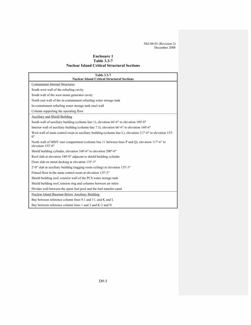
NEI 08-01 (Revision 2) December 2008
D9-5
Enclosure 1 Table 3.3-7
Nuclear Island Critical Structural Sections
Table 3.3-7 Nuclear Island Critical Structural Sections
Containment Internal Structures South west wall of the refueling cavity South wall of the west steam generator cavity North east wall of the in-containment refueling water storage tank In-containment refueling water storage tank steel wall Column supporting the operating floor
Auxiliary and Shield Building South wall of auxiliary building (column line 1), elevation 66'-6" to elevation 180'-0" Interior wall of auxiliary building (column line 7.3), elevation 66'-6" to elevation 160'-6" West wall of main control room in auxiliary building (column line L), elevation 117'-6" to elevation 153'-0" North wall of MSIV east compartment (column line 11 between lines P and Q), elevation 117'-6" to elevation 153'-0" Shield building cylinder, elevation 160'-6" to elevation 200''-0" Roof slab at elevation 180'-0" adjacent to shield building cylinder Floor slab on metal decking at elevation 135'-3" 2'-0" slab in auxiliary building (tagging room ceiling) at elevation 135'-3" Finned floor in the main control room at elevation 135'-3" Shield building roof, exterior wall of the PCS water storage tank Shield building roof, tension ring and columns between air inlets Divider wall between the spent fuel pool and the fuel transfer canal
Nuclear Island Basemat Below Auxiliary Building Bay between reference column lines 9.1 and 11, and K and L Bay between reference column lines 1 and 2 and K-2 and N

NEI
08-
01 (R
evis
ion
2)
Dec
embe
r 200
8
D
9-6
Enc
losu
re 2
Tabl
e 3.
3-1
Def
initi
on o
f Wal
l Thi
ckne
sses
for
Nuc
lear
Isla
nd B
uild
ings
and
Ann
ex B
uild
ing(1
)
Wal
l or
Sect
ion
Des
crip
tion
Col
umn
Lin
es
Floo
r E
leva
tion
or
Ele
vatio
n R
ange
C
oncr
ete
Thi
ckne
ss(2
)(3)(
4)(5
)
App
licab
le R
adia
tion
Shie
ldin
g W
all
(Yes
/No)
Con
tain
men
t Bui
ldin
g In
tern
al S
truc
ture
Sh
ield
Wal
l bet
wee
n R
eact
or V
esse
l Cav
ity a
nd R
CDT
Roo
m
E-W
wal
l par
alle
l with
col
umn
line
7 Fr
om 7
1'-6
" to
83'-0
" 3'
-0"
Yes
Wes
t Rea
ctor
Ves
sel C
avity
Wal
l N
-S w
all p
aral
lel w
ith c
olum
n lin
e N
Fr
om 8
3'-0
" to
98'-0
" 7'
-6"
Yes
Nor
th R
eact
or V
esse
l Cav
ity W
all
E-W
wal
l par
alle
l with
col
umn
line
7 Fr
om 8
3'-0
" to
98'-0
" 9'
-0"
Yes
East
Rea
ctor
Ves
sel C
avity
Wal
l N
-S w
all p
aral
lel w
ith c
olum
n lin
e N
Fr
om 8
3'-0
" to
98'-0
" 7'
-6"
Yes
Wes
t Ref
uelin
g C
avity
Wal
l N
-S w
all p
aral
lel w
ith c
olum
n lin
e N
Fr
om 9
8'-0
" to
135'
-3"
4'-0
" Y
es
Nor
th R
efue
ling
Cav
ity W
all
E-W
wal
l par
alle
l with
col
umn
line
7 Fr
om 9
8'-0
" to
135'
-3"
4'-0
" Y
es
East
Ref
uelin
g C
avity
Wal
l N
-S w
all p
aral
lel w
ith c
olum
n lin
e N
Fr
om 9
8'-0
" to
135'
-3"
4'-0
" Y
es
Sout
h R
efue
ling
Cav
ity W
all
E-W
wal
l par
alle
l with
col
umn
line
7 Fr
om 9
8'-0
" to
135'
-3"
4'-0
" Y
es
Sout
h w
all o
f wes
t ste
am g
ener
ator
com
partm
ent
Not
App
licab
le
From
103
'-0" t
o 15
3'-0
" 2'
-6"
Yes
Wes
t wal
l of w
est s
team
gen
erat
or c
ompa
rtmen
t N
ot A
pplic
able
Fr
om 1
03'-0
" to
153'
-0"
2'-6
" Y
es
Nor
th w
all o
f wes
t ste
am g
ener
ator
com
partm
ent
Not
App
licab
le
From
103
'-0" t
o 15
3'-0
" 2'
-6"
Yes
Sout
h w
all o
f pre
ssur
izer
com
partm
ent
Not
App
licab
le
From
103
'-0" t
o 15
3'-6
" 2'
-6"
Yes
Wes
t wal
l of p
ress
uriz
er c
ompa
rtmen
t N
ot A
pplic
able
Fr
om 1
07'-2
" to
160'
-0"
2'-6
" Y
es
Nor
th w
all o
f pre
ssur
izer
com
partm
ent
Not
App
licab
le
From
107
'-2" t
o 16
0'-0
" 2'
-6"
Yes
East
wal
l of p
ress
uriz
er c
ompa
rtmen
t N
ot A
pplic
able
Fr
om 1
18'-6
" to
160'
-0"
2'-6
" Y
es
Nor
th-e
ast w
all o
f in-
cont
ainm
ent r
efue
ling
wat
er st
orag
e ta
nk
Para
llel t
o co
lum
n lin
e N
Fr
om 1
03'-0
" to
135'
-3"
2'-6
" N
o
Wes
t wal
l of i
n-co
ntai
nmen
t ref
uelin
g w
ater
stor
age
tank
N
ot a
pplic
able
Fr
om 1
03'-0
" to
135'
-3"
5/8"
stee
l pla
te w
ith
stiff
ener
s N
o
Sout
h w
all o
f eas
t ste
am g
ener
ator
com
partm
ent
Not
App
licab
le
From
87'
-6" t
o 15
3'-0
" 2'
-6"
Yes

NEI
08-
01 (R
evis
ion
2)
Dec
embe
r 200
8
D9-
7
Ta
ble
3.3-
1 (c
ont.)
D
efin
ition
of W
all T
hick
ness
es fo
r N
ucle
ar Is
land
Bui
ldin
gs a
nd A
nnex
Bui
ldin
g(1)
Wal
l or
Sect
ion
Des
crip
tion
Col
umn
Lin
es
Floo
r E
leva
tion
or
Ele
vatio
n R
ange
C
oncr
ete
Thi
ckne
ss(2
)(3)
App
licab
le R
adia
tion
Shie
ldin
g W
all
(Yes
/No)
East
wal
l of e
ast s
team
gen
erat
or c
ompa
rtmen
t N
ot A
pplic
able
Fr
om 9
4'-0
" to
153'
-0"
2'-6
" Y
es
Nor
th w
all o
f eas
t ste
am g
ener
ator
com
partm
ent
Not
App
licab
le
From
87'
-6" t
o 15
3'-0
" 2'
-6"
Yes
Shie
ld B
uild
ing
Shie
ld B
uild
ing
Cyl
inde
r N
ot A
pplic
able
Fr
om 1
00'-0
" to
251'
-6"
From
256
'-9" t
o 26
6'-6
" 3'
-0"
4'-6
" Y
es
Yes
Tens
ion
Rin
g N
ot A
pplic
able
Fr
om 2
66'-6
" to
271'
3'
-0"
Yes
Con
ical
Roo
f N
ot A
pplic
able
Fr
om 2
71'-0
" to
293'
-9"
3'-0
" (in
clud
ing
1/2
inch
thic
k st
eel
plat
e lin
er o
n ea
ch fa
ce)
Yes
PCS
Tank
Ext
erna
l Cyl
indr
ical
Wal
l N
ot A
pplic
able
Fr
om 2
93'-9
" to
328'
-9"
2'-0
" Y
es
PCS
Tank
Inte
rnal
Cyl
indr
ical
Wal
l N
ot A
pplic
able
Fr
om 3
09'-4
" to
329'
-0"
1'-6
" Y
es
PCS
Tank
Roo
f N
ot A
pplic
able
32
8'-9
" (Lo
wes
t) 32
9'-0
" (H
ighe
st)
1'-3
" N
o
Nuc
lear
Isla
nd B
asem
at
Bel
ow sh
ield
bui
ldin
g Fr
om 6
0'-6
" to
cont
ainm
ent v
esse
l or
82'
-6"
6'-0
" to
22'-0
" (v
arie
s)
No
Aux
iliar
y B
uild
ing
Wal
ls/F
loor
s Rad
iolo
gica
lly C
ontr
olle
d
Col
umn
Line
1 w
all
From
I to
N
From
66'
-6" t
o 10
0'-0
" 3'
-0"
No
Col
umn
Line
1 w
all
From
I to
5'-6
" eas
t of L
-2
From
100
'-0" t
o 18
0'-0
" 2'
-3"
Yes
Col
umn
Line
1 w
all
From
5'-6
" eas
t of L
-2 to
N
From
100
'-0" t
o 12
5'-0
" 3'
-0"
Yes
Col
umn
Line
1 w
all
From
5'-6
" eas
t of L
-2 to
N
From
125
'-0" t
o 18
0'-0
" 2'
-3"
Yes
Col
umn
Line
2 w
all
From
I to
K-2
Fr
om 6
6'-6
" to
135'
-3"
2'-6
" Y
es
Col
umn
Line
2 w
all
From
K-2
to L
-2
From
66'
-6" t
o 13
5'-3
" 5'
-0"
Yes
Col
umn
Line
2 w
all
From
L-2
to N
Fr
om 9
8'-1
" to
135'
-3"
2'-6
" Y
es
Col
umn
Line
2 w
all
From
I to
J-1
From
135
'-3" t
o 15
3'-0
" 2'
-0"
Yes
Col
umn
Line
3 w
all
From
J-1
to J-
2 Fr
om 6
6'-6
" to
82'-6
" 2'
-6"
Yes
Col
umn
Line
3 w
all
From
J-1
to J-
2 Fr
om 1
00'-0
" to
135'
-3"
2'-6
" Y
es
Col
umn
Line
3 w
all
From
J-2
to K
-2
From
66'
-6" t
o 13
5'-3
" 2'
-6"
Yes

NEI
08-
01 (R
evis
ion
2)
Dec
embe
r 200
8
D
9-8
Tabl
e 3.
3-1
(con
t.)
Def
initi
on o
f Wal
l Thi
ckne
sses
for
Nuc
lear
Isla
nd B
uild
ings
and
Ann
ex B
uild
ing(1
)
Wal
l or
Sect
ion
Des
crip
tion
Col
umn
Lin
es
Floo
r E
leva
tion
or
Ele
vatio
n R
ange
C
oncr
ete
Thi
ckne
ss(2
)(3)
App
licab
le R
adia
tion
Shie
ldin
g W
all
(Yes
/No)
Col
umn
Line
3 w
all
From
K-2
to L
-2
From
66'
-6" t
o 92
'-8 1
/2"
2'-6
" Y
es
Col
umn
Line
4 w
all
From
I to
J-1
From
66'
-6" t
o 15
3'-0
" 2'
-6"
Yes
Col
umn
Line
4 w
all
From
J-1
to J-
2 Fr
om 6
6'-6
" to
92'-6
" 2'
-6"
Yes
Col
umn
Line
4 w
all
From
J-1
to J-
2 Fr
om 1
07'-2
" to
135'
-3"
2'-6
" Y
es
Col
umn
Line
4 w
all
From
J-2
to K
-2
From
66'
-6" t
o 13
5'-3
" 2'
-6"
Yes
Col
umn
Line
4 w
all
From
I to
inte
rsec
tion
with
shie
ld
build
ing
wal
l Fr
om 1
35'-3
" to
180'
-0"
2'-0
" Y
es
Col
umn
Line
5 w
all
From
I to
shie
ld b
uild
ing;
with
op
enin
g ea
st o
f J-1
(bel
ow 1
07'-2
" flo
or).
From
66'
-6" t
o 16
0'-6
" 2'
-0"
Yes
Col
umn
Line
7.1
wal
l Fr
om I
to 8
' eas
t of J
-1
From
66'
-6" t
o 82
'-6"
2'-0
" Y
es
Col
umn
Line
7.2
wal
l Fr
om I
to 5
'-6"e
ast o
f J-1
Fr
om 6
6'-6
" to
100'
-0"
2'-0
" Y
es
Col
umn
Line
I w
all
From
1 to
7.3
Fr
om 6
6'-6
" to
100'
-0"
3'-0
" N
o
Col
umn
Line
I w
all
From
1 to
4
From
100
'-0" t
o 18
0'-0
" 2'
-0"
Yes
Col
umn
Line
I w
all
From
4 to
5
From
100
'-0" t
o 16
0'-6
" 2'
-0"
No
Col
umn
Line
J-1
wal
l Fr
om 1
to 2
Fr
om 8
2'-6
" to
100'
-0"
2'-0
" Y
es
Col
umn
Line
J-1
wal
l Fr
om 2
to 4
Fr
om 6
6'-6
" to
135'
-3"
2'-6
" Y
es
Col
umn
Line
J-1
wal
l Fr
om 2
to 4
Fr
om 1
35'-3
" to
153'
-0"
2'-0
" Y
es
Col
umn
Line
J-1
wal
l Fr
om 4
to sh
ield
bui
ldin
g Fr
om 6
6'-6
" to
107'
-2"
2'-0
" Y
es
Col
umn
Line
J-2
wal
l Fr
om 2
to 4
Fr
om 6
6'-6
" to
135'
-3"
2'-6
" Y
es
Col
umn
Line
J-2
wal
l Fr
om 4
to in
ters
ectio
n w
ith sh
ield
bu
ildin
g w
all
From
66'
-6" t
o 13
5'-3
" 2'
-0"
Yes
Col
umn
Line
K-2
wal
l Fr
om 2
to 4
Fr
om 6
6'-6
" to
135'
-3"
4'-9
" Y
es
Col
umn
Line
L-2
wal
l Fr
om 2
to 4
Fr
om 6
6'-6
" to
135'
-3"
4'-0
" Y
es
Col
umn
Line
N w
all
From
1 to
2
From
66'
-6" t
o 10
0'-0
" 3'
-0"
No
Col
umn
Line
N w
all
From
1 to
12'
-9" n
orth
of 1
Fr
om 1
00'-0
" to
125'
-0"
3'-9
" N
o
Col
umn
Line
N w
all
From
1 to
12'
-9" n
orth
of 1
Fr
om 1
25'-0
" to
135'
-0"
2'-0
" N
o
Col
umn
Line
N w
all
From
12'
-9" n
orth
of 1
to 2
Fr
om 1
00'-0
" to
118'
-2 1
/2"
3'-0
" N
o
Col
umn
Line
N w
all
From
12'
-9" n
orth
of 1
to 2
Fr
om 1
18'-2
1/2
" to
135'
-3"
2'-0
" N
o

NEI
08-
01 (R
evis
ion
2)
Dec
embe
r 200
8
D9-
9
Tabl
e 3.
3-1
(con
t.)
Def
initi
on o
f Wal
l Thi
ckne
sses
for
Nuc
lear
Isla
nd B
uild
ings
and
Ann
ex B
uild
ing(1
)
Wal
l or
Sect
ion
Des
crip
tion
Col
umn
Lin
es
Floo
r E
leva
tion
or
Ele
vatio
n R
ange
C
oncr
ete
Thi
ckne
ss(2
)(3)
App
licab
le R
adia
tion
Shie
ldin
g W
all
(Yes
/No)
Col
umn
Line
N w
all
From
1 to
2
From
118
'-2 1
/2" t
o 13
5'-3
" 2'
-0"
Yes
Col
umn
Line
N w
all
From
2 to
4
From
66'
-6" t
o 98
'-1"
3'-0
" N
o
Col
umn
Line
N w
all
From
2 to
4
From
98'
-1" t
o 13
5'-3
" 5'
-6"
Yes
Col
umn
Line
N w
all
From
1 to
4
From
135
'-3" t
o 18
0'-0
" 2'
-0"
Yes
Laby
rinth
Wal
l bet
wee
n C
ol. L
ine
3 an
d 4
and
J-1
to 7
'-3"
from
J-2
Not
App
licab
le
From
82'
-6" t
o 92
'-6"
2'-6
" Y
es
N-S
Shi
eld
Wal
l (lo
w w
all)
Bet
wee
n K
-2 a
nd L
-2 e
xten
ding
fr
om c
olum
n lin
e 1
north
Fr
om 1
00'-0
" to
107'
-2"
2'-6
" Y
es
N-S
Shi
eld
Wal
l B
etw
een
K-2
and
L-2
ext
endi
ng
from
col
umn
line
1 no
rth
From
100
'-0" t
o 12
5'-0
" 2'
-3"
Yes
E-W
Shi
eld
Wal
l B
etw
een
1 an
d 2
exte
ndin
g fr
om
colu
mn
line
N e
ast
From
100
'-0" t
o 12
5'-0
" 2'
-9"
Yes
Aux
iliar
y A
rea
Base
mat
Fr
om 1
-7.3
and
I-N
, exc
ludi
ng sh
ield
bu
ildin
g Fr
om 6
0'-6
" to
66'-6
" 6'
-0"
No
Floo
r Fr
om 1
to 2
and
I to
N
82'-6
" 2'
-0"
Yes
Floo
r Fr
om 2
to 4
and
J-1
to J-
2 82
'-6"
2'-0
" Y
es
Floo
r Fr
om 4
to 5
and
J-1
to J-
2 82
'-6"
0'-9
" Y
es
Pipe
Cha
se F
loor
Fr
om 2
to 5
and
J-1
to J-
2 92
'-6"
2'-0
" Y
es
Floo
r Fr
om 2
to 3
and
J-2
to K
-2
90'-3
" 3'
-0"
Yes
Floo
r Fr
om 3
to 4
and
J-2
to K
-2
92'-6
" 2'
-0"
Yes
Floo
r Fr
om 4
to 7
.3 a
nd I
to J-
1 82
'-6"
2'-0
" Y
es
Floo
r Fr
om 1
to 2
and
I to
N
100'
-0"
3'-0
" Y
es
Floo
r Fr
om 2
to 4
and
K-2
to L
-2
92'-8
1/2
" 3'
-2 1
/2"
Yes
Floo
r Fr
om I
to J-
2 an
d 4
to in
ters
ectin
g ve
rtica
l wal
l bef
ore
colu
mn
line
5 10
7'-2
" 2'
-0"
Yes
Floo
r Fr
om I
to sh
ield
bui
ldin
g w
all a
nd
from
inte
rsec
ting
verti
cal w
all b
efor
e co
lum
n lin
e 5
to c
olum
n lin
e 5
105'
-0"
0'-9
" Y
es
Floo
r Fr
om 1
to 1
0'-0
" nor
th o
f 1 a
nd L
-2
to N
12
5'-0
" 3'
-0"
Yes
Floo
r Fr
om 1
0'-0
" nor
th o
f 1 to
2 a
nd L
-2
to N
11
8'-2
1/2
" 2'
-0"
Yes

NEI
08-
01 (R
evis
ion
2)
Dec
embe
r 200
8
D
9-10
Tabl
e 3.
3-1
(con
t.)
Def
initi
on o
f Wal
l Thi
ckne
sses
for
Nuc
lear
Isla
nd B
uild
ings
and
Ann
ex B
uild
ing(1
)
Wal
l or
Sect
ion
Des
crip
tion
Col
umn
Lin
es
Floo
r E
leva
tion
or
Ele
vatio
n R
ange
C
oncr
ete
Thi
ckne
ss(2
)(3)
App
licab
le R
adia
tion
Shie
ldin
g W
all
(Yes
/No)
Floo
r Fr
om 3
to 4
and
J-2
to K
-2
117'
-6"
2'-0
" Y
es
Floo
r Fr
om 2
to 4
and
I to
J-1
153'
-0"
0'-9
" Y
es
Roo
f Fr
om 1
to 4
and
I to
N
180'
-0"
1'-3
" Y
es
Floo
r Fr
om 4
to sh
ort o
f col
umn
line
5 an
d fr
om I
to in
ters
ectio
n w
ith sh
ield
bu
ildin
g w
all
135'
-5"
0'-9
" Y
es
Floo
r Fr
om sh
ort o
f col
umn
line
5 to
co
lum
n lin
e 5
and
from
I to
in
ters
ectio
n w
ith sh
ield
bui
ldin
g w
all
133'
-0"
0'-9
" Y
es
Aux
iliar
y B
uild
ing
Wal
ls/F
loor
s Non
-Rad
iolo
gica
lly C
ontr
olle
d
Col
umn
Line
11
wal
l Fr
om I
to Q
Fr
om 6
6'-6
" to
100'
-0"
3'-0
" N
o
Col
umn
Line
11
wal
l Fr
om I
to Q
Fr
om 1
00'-0
" to
117'
-6"
2'-0
" Y
es
Col
umn
Line
11
wal
l Fr
om I
to L
Fr
om 1
17'-6
" to
153'
-0"
2'-0
" Y
es
Col
umn
Line
11
wal
l Fr
om L
to M
Fr
om 1
17'-6
" to
135'
-3"
4'-0
" Y
es
Col
umn
Line
11
wal
l Fr
om M
to P
Fr
om 1
17'-6
" to
135'
-3"
2'-0
" Y
es
Col
umn
Line
11
wal
l Fr
om P
to Q
Fr
om 1
17'-6
" to
135'
-3"
4'-0
" Y
es
Col
umn
Line
11
wal
l Fr
om L
to Q
Fr
om 1
35'-3
" to
153'
-0"
2'-0
" Y
es
Col
umn
Line
7.3
wal
l Fr
om I
to sh
ield
bui
ldin
g Fr
om 6
6'-6
" to
100'
-0"
3'-0
" Y
es
Col
umn
Line
7.3
wal
l Fr
om I
to sh
ield
bui
ldin
g Fr
om 1
00'-0
" to
160'
-6"
2'-0
" N
o
Col
umn
Line
I w
all
From
7.3
to 1
1 Fr
om 6
6'-6
" to
100'
-0"
3'-0
" N
o
Col
umn
Line
I w
all
From
7.3
to 1
1 Fr
om 1
00'-0
" to
153'
-0"
2'-0
" N
o
Col
umn
Line
I w
all
From
5 to
7.3
Fr
om 1
00'-0
" to
160'
-6"
2'-0
" N
o
Col
umn
Line
J w
all
From
7.3
to 1
1 Fr
om 6
6'-6
" to
117'
-6"
2'-0
" N
o
Col
umn
Line
K w
all
From
7.3
to 1
1 Fr
om 6
0'-6
" to
135'
-3"
2'-0
" Y
es
Col
umn
Line
L w
all
From
shie
ld b
uild
ing
wal
l to
11
From
60'
-6" t
o 15
3'-0
" 2'
-0"
Yes
Col
umn
Line
M w
all
From
shie
ld b
uild
ing
wal
l to
11
From
66'
-6" t
o 15
3'-0
" 2'
-0"
Yes
Col
umn
Line
P w
all
From
shie
ld b
uild
ing
wal
l to
11
From
66'
-6" t
o 15
3'-0
" 2'
-0"
Yes
Col
umn
Line
Q w
all
From
shie
ld b
uild
ing
wal
l to
11
From
66'
-6" t
o 10
0'-0
" 3'
-0"
No
Col
umn
Line
Q w
all
From
shie
ld b
uild
ing
wal
l to
11
From
100
'-0" t
o 15
3'-0
" 2'
-0"
Yes

NEI
08-
01 (R
evis
ion
2)
Dec
embe
r 200
8
D9-
11
Tabl
e 3.
3-1
(con
t.)
Def
initi
on o
f Wal
l Thi
ckne
sses
for
Nuc
lear
Isla
nd B
uild
ings
and
Ann
ex B
uild
ing(1
)
Wal
l or
Sect
ion
Des
crip
tion
Col
umn
Lin
es
Floo
r E
leva
tion
or
Ele
vatio
n R
ange
C
oncr
ete
Thi
ckne
ss(2
)(3)
App
licab
le R
adia
tion
Shie
ldin
g W
all
(Yes
/No)
Col
umn
Line
9.2
wal
l Fr
om I
to J
and
K to
L
From
117
'-6" t
o 13
5'-3
" 2'
-0"
Yes
Laby
rinth
Wal
l bet
wee
n C
olum
n Li
ne 7
.3 a
nd 9
.2 a
nd J
to
K
J to
K
From
117
'-6" t
o 13
5'-3
" 2'
-0"
Yes
Aux
iliar
y A
rea
Base
mat
Fr
om 7
.3-1
1 an
d I-
Q, e
xclu
ding
sh
ield
bui
ldin
g Fr
om 6
0'-6
" to
66'-6
" 6'
-0"
No
Floo
r Fr
om 5
to 7
.3 a
nd I
to sh
ield
bu
ildin
g w
all
100'
-0"
2'-0
" Y
es
Floo
r Fr
om K
to L
and
shie
ld b
uild
ing
wal
l to
col
umn
line
10
100'
-0"
0'-9
" Y
es
Mai
n C
ontro
l Roo
m F
loor
Fr
om 9
.2 to
11
and
I to
L 11
7'-6
" 2'
-0"
Yes
Floo
r B
ound
ed b
y sh
ield
bld
g, 7
.3, J
, 9.2
an
d L
117'
-6"
2'-0
" Y
es
Floo
r Fr
om 9
.2 to
11
and
L to
Q
117'
-6"
2'-0
" Y
es
Floo
r Fr
om 5
to 7
.3 a
nd fr
om I
to
inte
rsec
tion
with
shie
ld b
uild
ing
wal
l 13
5'-3
" 0'
-9"
Yes
Ann
ex B
uild
ing
Col
umn
line
2 w
all
From
E to
H
From
107
'-2" t
o 13
5'-3
" 19
3/4
" Y
es
Col
umn
line
4 w
all
From
E to
H
From
107
'-2" t
o 16
2'-6
" & 1
66'-0
" 2'
-0"
Yes
N-S
Shi
eld
Wal
l bet
wee
n E
and
F Fr
om 2
to 4
Fr
om 1
07'-2
" to
135'
-3"
1'-0
" Y
es
Col
umn
line
4.1
wal
l Fr
om E
to H
Fr
om 1
07'-2
" to
135'
-3"
2'-0
" Y
es
E-W
Lab
yrin
th W
all b
etw
een
colu
mn
lin
e 7.
1 an
d 7.
8 an
d G
to H
N
ot A
pplic
able
Fr
om 1
00'-0
" to
112'
-0"
2'-0
"
N-S
Lab
yrin
th W
all b
etw
een
colu
mn
lin
e 7.
8 an
d 9
and
G to
H
Not
App
licab
le
From
100
'-0" t
o 11
2'-0
" 2'
-0"
E-W
Lab
yrin
th W
all b
etw
een
colu
mn
lin
e 7.
1 an
d 7.
8 an
d G
to H
N
ot A
pplic
able
Fr
om 1
00'-0
" to
112'
-0"
2'-0
" Y
es
N-S
Shi
eld
Wal
l on
Col
umn
line.
F
From
4.1
Nor
th
From
100
'-0" t
o 11
7'-6
" 1'
-0"
Yes
Col
umn
Line
9 w
all
From
E to
con
nect
ing
wal
l be
twee
n G
and
H
From
107
'-2" t
o 11
7'-6
" 2'
-0"
Yes
Col
umn
Line
E w
all
From
9 to
13
From
100
'-0" t
o 13
5'-3
" 2'
-0"
Yes
Col
umn
Line
13
wal
l Fr
om E
to I.
1 Fr
om 1
00'-0
" to
135'
-3"
2'-0
" Y
es

NEI
08-
01 (R
evis
ion
2)
Dec
embe
r 200
8
D
9-12
Tabl
e 3.
3-1
(con
t.)
Def
initi
on o
f Wal
l Thi
ckne
sses
for
Nuc
lear
Isla
nd B
uild
ings
and
Ann
ex B
uild
ing(1
)
Wal
l or
Sect
ion
Des
crip
tion
Col
umn
Lin
es
Floo
r E
leva
tion
or
Ele
vatio
n R
ange
C
oncr
ete
Thi
ckne
ss(2
)(3)
App
licab
le R
adia
tion
Shie
ldin
g W
all
(Yes
/No)
Col
umn
Line
I.1
wal
l Fr
om 1
1.09
to 1
3 Fr
om 1
00'-0
" to
135'
-3"
2'-0
" Y
es
Cor
ridor
Wal
l bet
wee
n G
and
H
From
9 to
13
From
100
'-0" t
o 13
5'-3
" 1'
-6"
Yes
Col
umn
Line
9 w
all
From
I to
H
From
117
'-6" t
o 15
8'-0
" 2'
-0"
Yes
Floo
r 2
to 4
from
shie
ld w
all b
etw
een
E an
d F
to c
olum
n lin
e H
13
5'-3
" 0'
-6"
Yes
Floo
r Fr
om 4
to 4
.1 a
nd E
to H
13
5'-3
" 1'
-0"
Yes
Floo
r Fr
om 9
to 1
3 an
d E
to I.
1 11
7'-6
" 0'
-6"
Yes
Floo
r Fr
om 9
to 1
3 an
d E
to I.
1 13
5'-3
" 0'
-8"
Yes
Con
tain
men
t Filt
ratio
n R
m A
(Nor
th W
all)
Bet
wee
n co
lum
n lin
e E
to H
Fr
om 1
35'-3
" to
158'
-0"
1'-0
" Y
es
Con
tain
men
t Filt
ratio
n R
m A
(Eas
t wal
l) B
etw
een
colu
mn
line
E to
F
From
135
'-3" t
o 15
8'-0
" 1'
-0"
Yes
Con
tain
men
t Filt
ratio
n R
m A
(Wes
t wal
l) B
etw
een
colu
mn
line
G to
H
From
135
'-3" t
o 15
8'-0
" 1'
-0"
Yes
Con
tain
men
t Filt
ratio
n R
m A
(Flo
or)
Bet
wee
n co
lum
n lin
e E
to H
13
5'-3
" 1'
-0"
Yes
Con
tain
men
t Filt
ratio
n R
m B
(Flo
or)
Bet
wee
n co
lum
n lin
e E
to H
14
6'-3
" 0'
-6"
Yes
Con
tain
men
t Filt
ratio
n R
m B
(Wes
t wal
l) B
etw
een
colu
mn
line
G to
H
From
146
'-3" t
o 15
8'-0
" 1'
-0"
Yes
Tur
bine
Bui
ldin
g
Wal
l bet
wee
n I.2
and
I.1
From
11.
05 to
11.
2 Fr
om 1
00'-0
" to
161'
-0"
2'-0
" N
o
Col
umn
Line
11.
2 W
all
From
1'-2
" off
I.1
to 2
'-4" P
ast R
Fr
om 1
00'-0
" to
161'
-0"
2'-0
" N
o
Wal
l 2'-4
" Pas
t R
From
11
to 1
1.2
From
100
'-0" t
o 16
1'-0
" 2'
-0"
No
Wal
l 11
From
11'
-0" o
ff Q
to 2
'-4" P
ast R
Fr
om 1
00'-0
" to
161'
-0"
2'-0
" N
o

NEI 08-01 (Revision 2) December 2008
D10-1
APPENDIX D-10 – EXAMPLE ITAAC CLOSURE LETTER AP1000 ITAAC 3.7-3 ITEM 1
XX/YY/ZZZZ (Date) To: NRC From: {Name of Licensee} {Site Name and Unit #(s)} {Docket #(s)} Subject: Completion of AP1000 ITAAC 3.7-3 Item 1 The purpose of this letter is to notify Nuclear Regulatory Commission (NRC) of the completion of {Site Name and Unit #(s)} Inspections, Tests, Analyses, and Acceptance Criteria (ITAAC) 3.7-3 Item 1 for the Design Reliability Assurance Program (D-RAP) in accordance with 10 CFR 52.99(c)(1). The closure process for this ITAAC is based on the guidance described in NEI 08-01(Reference 1). ITAAC Statement
Design Commitment
The D-RAP provides reasonable assurance that the design of risk-significant SSCs is consistent with their risk analysis assumptions.
Inspection/Test/Analysis
Inspection will be performed for the existence of a report which establishes the estimated reliability of as-built risk-significant SSCs.
Acceptance Criteria
A report exists and concludes that the estimated reliability of each as-built component identified in Table 3.7-1 [of the Tier 1 Material of the AP1000 Design Certification Document] is at least equal to the assumed reliability and that industry experience including operations, maintenance, and monitoring activities were assessed in estimating the reliability of these SSCs. For an as-built component with reliability less than the assumed reliability, an evaluation shall show that the net effect of as-built component reliabilities does not reduce the overall reliability. Or, an evaluation shall show that there is not a significant adverse effect on the core melt frequency or the large release frequency in the PRA applicable to the plant.

NEI 08-01 (Revision 2) December 2008
D10-2
ITAAC Determination Basis
Risk-significant SSCs identified for the AP1000 standard design are listed in Table 3.7-1 of the Tier 1 Material of the AP1000 Design Control Document (DCD). Table 3.7-1 is provided in the enclosure.
Engineering Report ZZZ, Validation of Design Reliability Assurance Program, (Reference 2) documents the estimated reliability of each as-built component identified in Table 3.7-1 and compares them to the reliability value assumed in the certified design. Engineering Report ZZZ was developed utilizing the method delineated in Procedure YYY, Validation of Design Reliability Assurance Program, (Reference 3).
Procedure YYY defines the methodology for establishing the as-built reliability for the components identified in Table 3.7-1 of Tier 1 Material of the AP1000 DCD. It considers the procurement, fabrication, construction, and preoperation test activities and programs, and industry experience including operations, maintenance, and monitoring activities. Procedure YYY also defines the methodology for comparing the as-built reliability data and the reliability data that was utilized for the AP1000 design certification.
An inspection/assessment of the Engineering Report (Reference 2) was conducted by a team of individuals who were independent of the team that developed Engineering Report ZZZ to confirm that: 1) the estimated as-built reliability for each SSC listed in Table 3.7-1 of the AP1000 DCD is at least equal to the assumed reliability utilized for the AP1000 design certification; and 2) industry experience including operations, maintenance, and monitoring activities was assessed in estimating the reliability of the SSCs, This inspection/assessment is documented as Inspection XXX, Closure of ITAAC Table 3.7-3, Item 1 (Reference 4).
The inspection/assessment concluded that for each component identified in Table 3.7-1 of the AP1000 DCD, the estimated reliability of the as-built component is at least equal to the reliability value assumed in the AP1000 design certification, and that industry experience including operations, maintenance, and monitoring activities was assessed in estimating the reliability of the components.
ITAAC Close-out Review
In accordance with plant procedures for ITAAC close-out, {Licensee} performed a review of ITAAC-related construction findings and associated corrective actions. This review determined that three associated findings, listed below, have been identified.
1. {ITAAC-related construction finding #1}
2. {ITAAC-related construction finding #2}
3. {ITAAC-related construction finding #3}
The corrective actions for each finding have been completed and each finding closed. This review is documented in the close-out package for ITAAC Table 3.7-3 Item 1 (Reference 5), which is available for NRC review at the {Site Name} site. NRC closure of these findings is available on the Construction Inspection Program Management System (CIPMS) portion of the

NEI 08-01 (Revision 2) December 2008
D10-3
NRC website for this docket may be located by referencing the NRC finding number provided above.
ITAAC Closure Statement
Based on the above information, {Licensee} hereby notifies the NRC that ITAAC Table 3.7-3 Item 1 was performed for {Site Name and Unit #(s)}, and that the prescribed acceptance criteria were met.
{Licensee} requests NRC staff confirmation of this determination and publication of the required notice in the Federal Register per 10 CFR 52.99.
If there are any questions, please contact {Name of Contact Person for licensee} at {Telephone Number for Contact Person}.
Sincerely, {Signature of Licensee Representative} {Typed Name of Licensee Representative} {Title of Licensee Representative} References (available for NRC review)
1. NEI 08-01, Industry Guideline for the ITAAC Closure Process Under 10 CFR Part 52 2. Engineering Report ZZZ, Validation of Design Reliability Assurance Program 3. Procedure YYY, Validation of Design Reliability Assurance Program 4. Inspection Report XXX, Closure of ITAAC Table 3.7-3, Item 1 5. ITAAC Table 3.7-3, Item 1 Close-Out Package

NEI 08-01 (Revision 2) December 2008
D10-4
Table 3.7-1 Risk-Significant Components
Equipment Name Tag No.
Component Cooling Water System (CCS)
Component Cooling Water Pumps CCS-MP-01A/B
Containment System (CNS)
Containment Vessel CNS-MV-01
Hydrogen Igniters VLS-EH-1 through -64
Chemical and Volume Control System (CVS)
Makeup Pumps CVS-MP-01A/B
Makeup Pump Suction and Discharge Check Valves CVS-PL-V113 CVS-PL-V160A/B
Diverse Actuation System (DAS)
DAS Processor Cabinets and Control Panel (used to provide automatic and manual actuation)
DAS-JD-001 DAS-JD-002 DAS-JD-004 OCS-JC-020
Annex Building UPS Distribution Panels (provide power to DAS)
EDS1-EA-1, EDS1-EA-14, EDS2-EA-1, EDS2-EA-14

NEI 08-01 (Revision 2) December 2008
D10-5
Table 3.7-1 (cont.)
Risk-Significant Components
Equipment Name Tag No.
Rod Drive MG Sets (Field Breakers) PLS-MG-01A/B
Containment Isolation Valves Controlled by DAS Refer to Table 2.2.1-1
Main ac Power System (ECS)
Reactor Coolant Pump Switchgear ECS-ES-31, -32, -41, -42, -51, -52, -61, -62
Ancillary Diesel Generators ECS-MS-01, -02
6900 Vac Buses ECS-ES-1, -2
Main and Startup Feedwater System (FWS)
Startup Feedwater Pumps FWS-MP-03A/B
General I&C
IRWST Level Sensors PXS-045, -046, -047, -048
RCS Hot Leg Level Sensors RCS-160A/B
Pressurizer Pressure Sensors RCS-191A/B/C/D
Pressurizer Level Sensors RCS-195A/B/C/D
Steam Generator Narrow-Range Level Sensors SGS-001, -002, -003, -004, -005, -006, -007, -008
Steam Generator Wide-Range Level Sensors SGS-011, -012, -013, -014, -015, -016, -017, -018
Main Steam Line Pressure Sensors SGS-030, -031, -032, -033, -034, -035, -036, -037
Main Feedwater Wide-Range Flow Sensors SGS-050A/C/E, -051A/C/E
Startup Feedwater Flow Sensors SGS-055A/B, -056A/B
CMT Level Sensors PXS-011A/B/C/D, -012A/B/C/D, -013A/B/C/D, -014A/B/C/D
Class 1E dc Power and Uninterruptible Power System (IDS)
125 Vdc 24-Hour Batteries IDSA-DB-1A/B, IDSB-DB-1A/B, IDSC-DB-1A/B, IDSD-DB-1A/B
250 Vdc 24-Hour Battery Chargers IDSA-DC-1, IDSB-DC-1, IDSC-DC-1, IDSD-DC-1
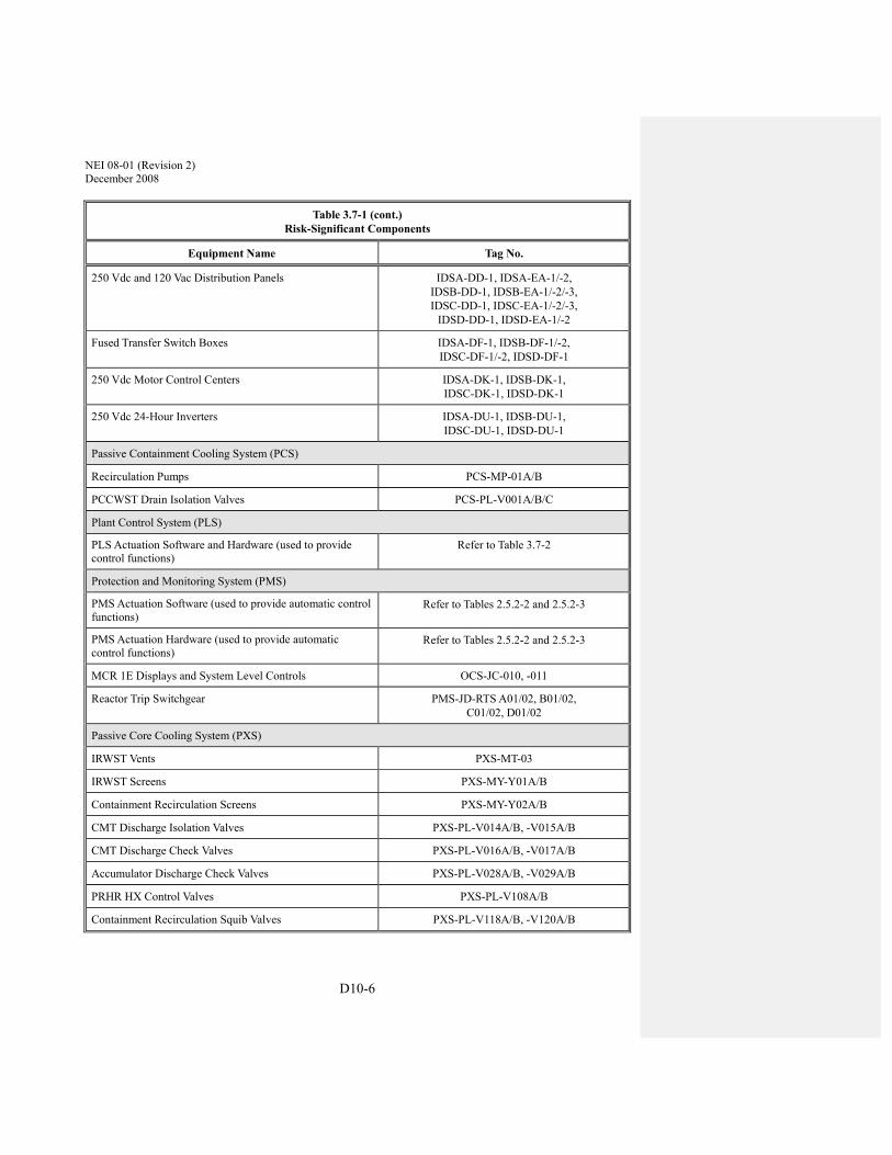
NEI 08-01 (Revision 2) December 2008
D10-6
Table 3.7-1 (cont.) Risk-Significant Components
Equipment Name Tag No.
250 Vdc and 120 Vac Distribution Panels IDSA-DD-1, IDSA-EA-1/-2, IDSB-DD-1, IDSB-EA-1/-2/-3, IDSC-DD-1, IDSC-EA-1/-2/-3,
IDSD-DD-1, IDSD-EA-1/-2
Fused Transfer Switch Boxes IDSA-DF-1, IDSB-DF-1/-2, IDSC-DF-1/-2, IDSD-DF-1
250 Vdc Motor Control Centers IDSA-DK-1, IDSB-DK-1, IDSC-DK-1, IDSD-DK-1
250 Vdc 24-Hour Inverters IDSA-DU-1, IDSB-DU-1, IDSC-DU-1, IDSD-DU-1
Passive Containment Cooling System (PCS)
Recirculation Pumps PCS-MP-01A/B
PCCWST Drain Isolation Valves PCS-PL-V001A/B/C
Plant Control System (PLS)
PLS Actuation Software and Hardware (used to provide control functions)
Refer to Table 3.7-2
Protection and Monitoring System (PMS)
PMS Actuation Software (used to provide automatic control functions)
Refer to Tables 2.5.2-2 and 2.5.2-3
PMS Actuation Hardware (used to provide automatic control functions)
Refer to Tables 2.5.2-2 and 2.5.2-3
MCR 1E Displays and System Level Controls OCS-JC-010, -011
Reactor Trip Switchgear PMS-JD-RTS A01/02, B01/02, C01/02, D01/02
Passive Core Cooling System (PXS)
IRWST Vents PXS-MT-03
IRWST Screens PXS-MY-Y01A/B
Containment Recirculation Screens PXS-MY-Y02A/B
CMT Discharge Isolation Valves PXS-PL-V014A/B, -V015A/B
CMT Discharge Check Valves PXS-PL-V016A/B, -V017A/B
Accumulator Discharge Check Valves PXS-PL-V028A/B, -V029A/B
PRHR HX Control Valves PXS-PL-V108A/B
Containment Recirculation Squib Valves PXS-PL-V118A/B, -V120A/B

NEI 08-01 (Revision 2) December 2008
D10-7
Table 3.7-1 (cont.) Risk-Significant Components
Equipment Name Tag No.
IRWST Injection Check Valves PXS-PL-V122A/B, -V124A/B
IRWST Injection Squib Valves PXS-PL-V123A/B, -V125A/B
IRWST Gutter Bypass Isolation Valves PXS-PL-V130A/B
Reactor Coolant System (RCS)
ADS Stage 1/2/3 Valves (MOVs) RCS-PL-V001A/B, -V011A/B RCS-PL-V002A/B, -V012A/B RCS-PL-V003A/B, -V013A/B
ADS Stage 4 Valves (Squibs) RCS-PL-V004A/B/C/D
Pressurizer Safety Valves RCS-PL-V005A/B
Reactor Vessel Insulation Water Inlet and Steam Vent Devices
RCS-MN-01
Reactor Cavity Doorway Damper –
Fuel Assemblies 157 assemblies with tag numbers beginning with RXS-FA
Normal Residual Heat Removal System (RNS)
Residual Heat Removal Pumps RNS-MP-01A/B
RNS Motor-Operated Valves RNS-PL-V011, -V022, -V023, -V055
RNS Stop Check Valves RNS Check Valves
RNS-PL-V015A/B RNS-PL-V017A/B
RNS Check Valves RNS-PL-V007A/B, -V013, -V056
Spent Fuel Cooling System (SFS)
Spent Fuel Cooling Pumps SFS-MP-01A/B
Steam Generator System (SGS)
Main Steam Safety Valves SGS-PL-V030A/B, -V031A/B, -V032A/B, -V033A/B, -V034A/B, -V035A/B
Main Steam Line Isolation Valves SGS-PL-V040A/B
Main Feedwater Isolation Valves SGS-PL-V057A/B
Service Water System (SWS)
Service Water Cooling Tower Fans SWS-MA-01A/B
Service Water Pumps SWS-MP-01A/B

NEI 08-01 (Revision 2) December 2008
D10-8
Table 3.7-1 (cont.) Risk-Significant Components
Equipment Name Tag No.
Nuclear Island Nonradioactive Ventilation System (VBS)
MCR Ancillary Fans VBS-MA-10A/B
I&C Room B/C Ancillary Fans VBS-MA-11, -12
Chilled Water System (VWS)
Air Cooled Chiller Pumps VWS-MP-02, -03
Air Cooled Chillers VWS-MS-02, -03
Onsite Standby Power System (ZOS)
Engine Room Exhaust Fans VZS-MY-V01A/B, -V02A/B
Onsite Diesel Generators ZOS-MS-05A/B
Note: Dash (-) indicates not applicable.

NEI 08-01 (Revision 2) December 2008
D11-1
APPENDIX D-11 – EXAMPLE ITAAC CLOSURE LETTER ESBWR ITAAC 2.1.2-3 ITEM 8
XX/YY/ZZZZ (Date) To: NRC From: {Name of Licensee} {Site Name and Unit #(s)} {Docket #(s)} Subject: Completion of ESBWR ITAAC 2.1.2-3 Item 8 The purpose of this letter is to notify Nuclear Regulatory Commission (NRC) of the completion of {Site Name and Unit #(s)} Inspections, Tests, Analyses, and Acceptance Criteria (ITAAC) 2.1.2-3 Item 8, Instrumentation and Control, for the Nuclear Boiler System in accordance with 10 CFR 52.99(c)(1). The closure process for this ITAAC is based on the guidance described in NEI 08-01(Reference 1). ITAAC Statement
Design Commitment
8. Instrumentation and Control
a) Control Room alarms, displays, and/or controls provided for the NBS System are defined in Table 2.1.2-2. (A copy of ESBWR DCD Table 2.1.2-2 is provided in the attachment to this letter.)
b) The MSIVs close upon any of the following conditions:
- Main Condenser Vacuum Low (Run mode)
- Turbine Area Ambient Temperature High
- MSL Tunnel Ambient Temperature High
- MSL Flow Rate High
- Turbine Inlet Pressure Low
- Reactor Water Level Low
Inspection/Test/Analysis
a) Inspections will be performed on the as-built Control Room alarms, displays, and/or controls for the NBS System.

NEI 08-01 (Revision 2) December 2008
D11-2
b) Valve closure tests will be performed on the as-built MSIVs using simulated signals.
Acceptance Criteria
a) Report(s) document that alarms, displays, and/or controls exist or can be retrieved in the Control Room as defined in Table 2.1.2-2.
b) Report(s) document that the MSIVs close upon generation of any of the following simulated signals:
- Main Condenser Vacuum Low (Run mode)
- Turbine Area Ambient Temperature High
- MSL Tunnel Ambient Temperature High
- MSL Flow Rate High
- Turbine Inlet Pressure Low
- Reactor Water Level Low
ITAAC Determination Basis
Preoperational Test Procedure XXX, Nuclear Boiler System Preoperational Test, (Reference 2) governs testing of the Nuclear Boiler System. This procedure includes sections that:
• Confirm alarms, displays, and/or controls exist or can be retrieved in the Control Room as defined in ESBWR Design Control Document (DCD) Table 2.1.2-2 (ITAAC Item 8a); and
• Document the Main Steam Isolation Valves (MSIVs) close upon generation of any of simulated signals specified in the ITAAC acceptance criteria (see above) (ITAAC Item 8b).
{Licensee} performed a review of Procedure XXX to confirm that it contains the appropriate steps needed to meet each ITAAC acceptance criterion and that the procedure has been successfully completed. This review is documented in Inspection Report YYY, Closure of ITAAC 2.1.2-3 #8, Instrumentation and Control (Reference 3), the results of which are summarized below.
1) ITAAC Item 8a)
Section X of Procedure XXX contains steps in which signals simulating various equipment parameters are entered at the sensor input of the instrumentation loop to confirm that alarms, displays, and/or controls exist or can be retrieved in the Control Room as defined in ESBWR DCD Table 2.1.2-2. {Licensee} successfully completed Section X, a signed copy of which is contained in ITAAC Close-Out Package for ITAAC 2.1.2-3 #8, Instrumentation and Control, (Reference 4).

NEI 08-01 (Revision 2) December 2008
D11-3
2) ITAAC Item 8b)
Section Y of Procedure XXX demonstrates MSIV closure under various plant conditions, including those identified in the ITAAC, by inputting signals simulating those conditions at the sensor input of the closure logic instrumentation. {Licensee} successfully completed Section Y, a signed copy of which is contained in ITAAC Close-Out Package for ITAAC 2.1.2-3 item 8, Instrumentation and Control, (Reference 4).
Conclusion
Therefore, as required by ITAAC Items 8a) and b), Inspection Report YYY, Closure of ITAAC 2.1.2-3 Item 8, Instrumentation and Control (Reference 3) documents that:
a) Alarms, displays, and/or controls exist or can be retrieved in the Control Room as defined in ESBWR DCD Table 2.1.2-2; and
b) The MSIVs close upon generation of any of the following simulated signals:
- Main Condenser Vacuum Low (Run mode)
- Turbine Area Ambient Temperature High
- MSL Tunnel Ambient Temperature High
- MSL Flow Rate High
- Turbine Inlet Pressure Low
- Reactor Water Level Low
ITAAC-Related Construction Finding Review
In accordance with plant procedures for ITAAC close-out, {Licensee} performed a review of ITAAC-related construction findings and associated corrective actions. This review determined that three associated findings, listed below, have been identified.
1. {ITAAC-related construction finding #1}
2. {ITAAC-related construction finding #2}
3. {ITAAC-related construction finding #3}
The corrective actions for each finding have been completed and each finding closed. This review is documented in ITAAC Close-Out Package for ITAAC 2.1.2-3 Item 8, Instrumentation and Control, which is available for NRC review. NRC closure of these findings is available on the Construction Inspection Program Management System (CIPMS) portion of the NRC website for this docket may be located by referencing the NRC finding numbers provided above.
NEI 08-01 (Revision 2) December 2008
D11-4
ITAAC Closure Statement
Based on the above information, {Licensee} hereby notifies the NRC that {Licensee} has performed ITAAC 2.1.2-3 Item 8 for {Site Name and Unit #(s)}, and that the prescribed acceptance criteria were met.
{Licensee} requests NRC staff confirmation of this determination and publication of the required notice in the Federal Register per 10 CFR 52.99.
If there are any questions, please contact {name of contact person for Licensee} at {telephone # for contact person}.
Sincerely, {Signature of Licensee Representative} {Typed Name of Licensee Representative} {Title of Licensee Representative} Attachment: ESBWR DCD Table 2.1.2-2, Nuclear Boiler System Electrical Equipment, Rev. 4
References (available for NRC review)
1. NEI 08-01, Industry Guideline for the ITAAC Closure Process Under 10 CFR Part 52 2. Preoperational Test Procedure XXX, Nuclear Boiler System Preoperational Test 3. Inspection Report YYY, Closure of ITAAC 2.1.2-3 #8, Instrumentation and Control 4. ITAAC Close-Out Package for ITAAC 2.1.2-3 #8, Instrumentation and Control

NEI 08-01 (Revision 2) December 2008
D11-5
ATTACHMENT
ESBWR DCD TABLE 2.1.2-2 NUCLEAR BOILER SYSTEM ELECTRICAL EQUIPMENT

NEI
08-
01 (R
evis
ion
2)
Dec
embe
r 200
8
D
11-6
ESB
WR
DC
D T
able
2.1
.2-2
N
ucle
ar B
oile
r Sy
stem
Ele
ctri
cal E
quip
men
t
Equ
ipm
ent N
ame
Equ
ipm
ent I
D o
n Fi
gure
2.1
.2-2
C
ontr
ol Q
-D
CIS
/DPS
3
Safe
ty-
Rel
ated
E
lect
rica
l E
quip
men
t
Safe
ty-
Rel
ated
D
ispl
ay
Act
ive
Func
tion
Seis
mic
C
ateg
ory
I R
emot
ely
Ope
rate
d
Con
tain
men
t Is
olat
ion
Val
ve
Act
uato
r
Inbo
ard
Mai
n St
eam
Is
olat
ion
Val
ves
V8
(Typ
. of 4
) Y
es
Yes
Y
es
Yes
Y
es
Yes
Y
es
Out
boar
d M
ain
Stea
m
Isol
atio
n V
alve
s V
9 (T
yp. o
f 4)
Yes
Y
es
Yes
Y
es
Yes
Y
es
Yes
Safe
ty R
elie
f Val
ves (
SRV
) V
6 (T
yp. o
f 10)
Yes
(A
DS
– Se
e Se
ctio
n 2.
2.16
)
Yes
Y
es
Yes
Y
es
Yes
Y
es
Safe
ty V
alve
s (SV
) V
7 (T
yp. o
f 8)
No
Yes
–
Posi
tion
Indi
cato
r O
nly
Yes
N
o Y
es
No
No
Dep
ress
uriz
atio
n V
alve
s V
5 (T
yp. o
f 8 to
tal)
Yes
Y
es
Yes
Y
es
Yes
Y
es
Yes
Feed
wat
er Is
olat
ion
Val
ves
V14
, V17
Y
es
Yes
Y
es
Yes
Y
es
Yes
Y
es
Feed
wat
er O
utbo
ard
Isol
atio
n C
heck
Val
ves
V13
, V16
Y
es
Yes
Y
es
Yes
Y
es
Yes
Y
es
Rea
ctor
Pre
ssur
e Tr
ansm
itter
s (1
each
in 4
di
visi
ons)
--
Y
es
Yes
Y
es
Yes
Y
es
--
--
3 S
ee S
ectio
n 2.
2.7.
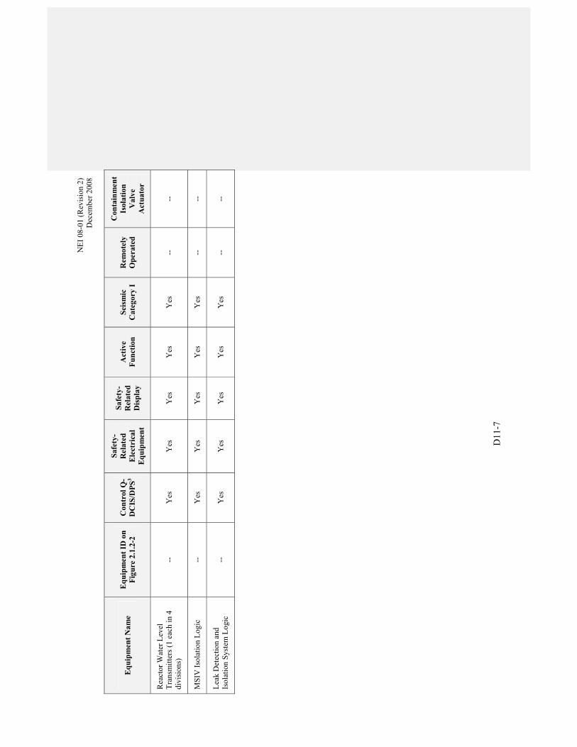
NEI
08-
01 (R
evis
ion
2)
Dec
embe
r 200
8
D11
-7
Equ
ipm
ent N
ame
Equ
ipm
ent I
D o
n Fi
gure
2.1
.2-2
C
ontr
ol Q
-D
CIS
/DPS
3
Safe
ty-
Rel
ated
E
lect
rica
l E
quip
men
t
Safe
ty-
Rel
ated
D
ispl
ay
Act
ive
Func
tion
Seis
mic
C
ateg
ory
I R
emot
ely
Ope
rate
d
Con
tain
men
t Is
olat
ion
Val
ve
Act
uato
r
Rea
ctor
Wat
er L
evel
Tr
ansm
itter
s (1
each
in 4
di
visi
ons)
--
Y
es
Yes
Y
es
Yes
Y
es
--
--
MSI
V Is
olat
ion
Logi
c --
Y
es
Yes
Y
es
Yes
Y
es
--
--
Leak
Det
ectio
n an
d Is
olat
ion
Syst
em L
ogic
--
Y
es
Yes
Y
es
Yes
Y
es
--
--


NEI 08-01 (Revision 2) December 2008
D12-1
APPENDIX D-12 – EXAMPLE ITAAC CLOSURE LETTER ESBWR ITAAC 2.3-1 ITEM 5.1
XX/YY/ZZZZ (Date) To: NRC From: {Name of Licensee} {Site Name and Unit #(s)} {Docket #(s)} Subject: Completion of ESBWR ITAAC 2.3-1 Item 5.1 The purpose of this letter is to notify Nuclear Regulatory Commission (NRC) of the completion of {Site Name and Unit #(s)} Inspections, Tests, Analyses, and Acceptance Criteria (ITAAC) 2.3-1 Item 5.1, Emergency Facilities and Equipment, in accordance with 10 CFR 52.99(c)(1). The closure process for this ITAAC is based on the guidance described in NEI 08-01(Reference 1). ITAAC Statement Planning Standard 10 CFR 50.47(b)(8) – Adequate emergency facilities and equipment to support the emergency response are provided and maintained. EP Program Elements 5.1 The licensee has established a technical support center (TSC) and onsite operations support center (OSC). [H.1] ITAAC element addressed in: COL EP II.H.1 Inspection/Test/Analysis 5.1 An inspection of the as-built TSC and OSC will be performed. Acceptance Criteria 5.1.1 A report exists that confirms the TSC has at least 174 square meters (1875 square feet) of floor space. 5.1.2 A report exists that confirms the following communications equipment has been provided in the TSC and voice transmission and reception have been accomplished:
a. NRC systems: (1) Emergency Notification System (ENS) (2) Health Physics Network (HPN)

NEI 08-01 (Revision 2) December 2008
D12-2
(3) Reactor Safety Counterpart Link (RSCL) (4) Protective Measures Counterpart Link (PMCL) (5) Management Counterpart Link (MCL)
b. Dedicated telephone to EOF c. Dedicated telephone to control room d. Dedicated telephone to OSC
5.1.3 A report exists that confirms the TSC has been located in the Electrical Building. 5.1.4 A report exists that confirms the TSC includes radiation monitors and a ventilation system with a high efficiency particulate air (HEPA) and charcoal filter. 5.1.5 A report exists that confirms back-up electrical power supply is available for the TSC. 5.1.6 A report exists that confirms the OSC is in a location separate from the control room. 5.1.7 A report exists that confirms the following communications equipment has been provided in the OSC and voice transmission and reception have been accomplished:
· Dedicated telephone to control room · Dedicated telephone to TSC · Plant page system (voice transmission only)
ITAAC Determination Basis Personnel from the Emergency Planning and Testing organizations have completed station procedure NN3-xx-123, Emergency Response Facilities Test (Reference 2). This procedure addresses the tasks necessary to determine that adequate emergency facilities and equipment to support the emergency response are provided and maintained in accordance with 10 CFR 50.47(b)(8). Results of these inspections are reported in the Emergency Facilities and Equipment Test Report (Reference 3). Results of the tests and inspections are provided below: ITAAC Item Result 2.3-1.5.1.1 The TSC has xxxx square feet of floor space, which exceeds the
required minimum 174 square meters (1875 square feet) of floor space.
2.3-1.5.1.2 Voice communications have been transmitted and received to and from the TSC and the following:
a. NRC systems: (1) Emergency Notification System (ENS) (2) Health Physics Network (HPN) (3) Reactor Safety Counterpart Link (RSCL) (4) Protective Measures Counterpart Link (PMCL) (5) Management Counterpart Link (MCL)
b. Dedicated telephone to EOF c. Dedicated telephone to control room
d. Dedicated telephone to OSC

NEI 08-01 (Revision 2) December 2008
D12-3
2.3-1.5.1.3 The TSC is located in the Electrical Building.
2.3-1.5.1.4 TSC includes radiation monitors and a ventilation system with a high
efficiency particulate air (HEPA) and charcoal filter. The radiation monitors responded appropriately to test sources, and provided alarms as designed.
2.3-1.5.1.5 Back-up electrical power supply is available for the TSC. When tested by removing the normal power source, the backup power supply automatically started and accepted the TSC electrical load. In accordance with the test procedure, the TSC was powered by the backup power supply for greater than one hour.
2.3-1.5.1.6 The OSC is in the ____________, which is a location separate from the control room.
2.3-1.5.1.7 Voice communications have been transmitted and received to and from the OSC and the following:
a. Dedicated telephone to control room c. Dedicated telephone to TSC d. Plant page system (voice transmission only)
The results presented in the test report fully satisfy ITAAC 2.3-1, Item 5.1. ITAAC-Related Construction Finding Review In accordance with plant procedures for ITAAC close-out, New ESBWR Reactor Plant Unit 3 performed a review of ITAAC-related construction findings and associated corrective actions. This review determined that X associated findings, listed below, have been identified.
1. {ITAAC-related construction finding #1}
2. {ITAAC-related construction finding #2}
3. {ITAAC-related construction finding #3}
The corrective actions for each finding have been completed and each finding closed. This review is documented in the close-out package for ITAAC 2.3-1 Item 5.1, (Reference 4) which is available for NRC review. NRC closure of these findings is available on the Construction Inspection Program Management System (CIPMS) portion of the NRC website for this docket may be located by referencing the NRC finding numbers provided above.

NEI 08-01 (Revision 2) December 2008
D12-4
ITAAC Closure Statement Based on the above information, {Licensee Name} hereby notifies the NRC that ITAAC 2.3-1 Item 5.1 was performed for {Site Name and Unit #(s)}, and that the prescribed acceptance criteria were met. We request NRC staff confirmation of this determination and publication of the required notice in the Federal Register per 10 CFR 52.99. If there are any questions, please contact {Name of Contact Person for licensee} at {Telephone Number for Contact Person}. Sincerely, {Signature of Licensee Representative} {Typed Name of Licensee Representative} {Title of Licensee Representative} References (available for NRC review) 1. NEI 08-01, Industry Guideline for ITAAC Closure Process Under 10 CFR Part 52 2. NN3-xx-123, Emergency Response Facilities Test 3. Emergency Facilities and Equipment Test Report 4. ITAAC 2.3-1, Item 5.1, Emergency Response Facilities ITAAC Close-out Package.

NEI 08-01 (Revision 2) December 2008
D13-1
APPENDIX D-13 – EXAMPLE ITAAC CLOSURE LETTER ESBWR ITAAC 2.4.2-3 ITEM 12
XX/YY/ZZZZ (Date) To: NRC From: {Name of Licensee} {Site Name and Unit #(s)} {Docket #(s)} Subject: Completion of ESBWR ITAAC Item 2.4.2-3 Item 12 The purpose of this letter is to notify the Nuclear Regulatory Commission (NRC) of the completion of {Site Name and Unit #(s)} Inspection, Test, Analysis and Acceptance Criteria (ITAAC) Item 2.4.2-3 Item 12 in accordance with 10 CFR 52.99(c)(1). The closure process for this ITAAC is based on the guidance described in NEI-08-01 (Reference 1). ITAAC Statement Design Commitment GDCS squib valves maintain RPV backflow leak tightness and maintain reactor coolant pressure boundary integrity during normal plant operation. Inspection/Test/Analysis A test will be performed to demonstrate the squib valves are leak tight during normal plant conditions. Acceptance Criteria Testing concludes GDCS squib valves have zero leakage at normal plant operation pressure ITAAC Determination Basis New ESBWR Reactor Plant Unit 3 Pre-operational test NN3-XX-123 (Reference 2), Gravity Driven Cooling System (GDCS) Pre-Operational Test, was completed with the results reviewed and accepted on 1/1/XX. Section 1.2.3.1.1 tested the leak tightness of the 3-E50-1XX, 3-E50-2XX, 3-E50-3XX, and 3-E50-4XX valves. Performance of this section of the test required the RPV to be at normal operating pressure with the GDCS system aligned such that the squib valves were closed with the drain valves (3-E50-1YYA and B) located upstream of the squib valves open. The system was maintained in this condition for X hours in accordance with the procedure.
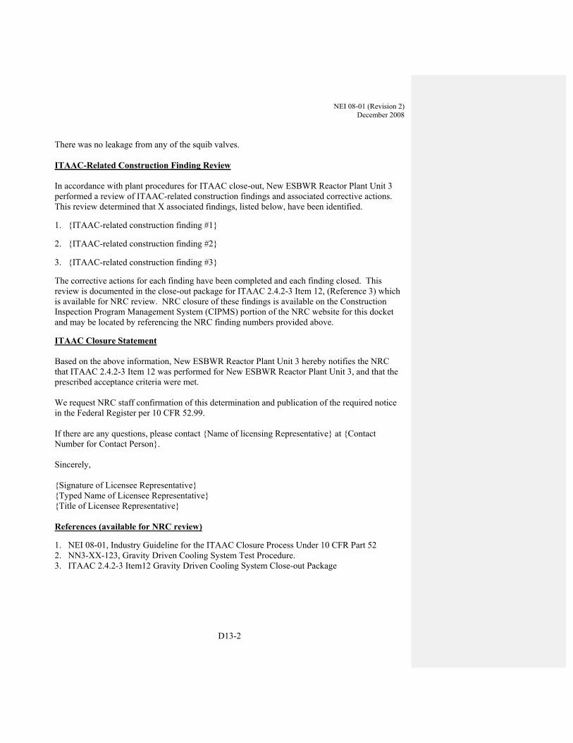
NEI 08-01 (Revision 2) December 2008
D13-2
There was no leakage from any of the squib valves. ITAAC-Related Construction Finding Review In accordance with plant procedures for ITAAC close-out, New ESBWR Reactor Plant Unit 3 performed a review of ITAAC-related construction findings and associated corrective actions. This review determined that X associated findings, listed below, have been identified.
1. {ITAAC-related construction finding #1}
2. {ITAAC-related construction finding #2}
3. {ITAAC-related construction finding #3}
The corrective actions for each finding have been completed and each finding closed. This review is documented in the close-out package for ITAAC 2.4.2-3 Item 12, (Reference 3) which is available for NRC review. NRC closure of these findings is available on the Construction Inspection Program Management System (CIPMS) portion of the NRC website for this docket and may be located by referencing the NRC finding numbers provided above.
ITAAC Closure Statement Based on the above information, New ESBWR Reactor Plant Unit 3 hereby notifies the NRC that ITAAC 2.4.2-3 Item 12 was performed for New ESBWR Reactor Plant Unit 3, and that the prescribed acceptance criteria were met. We request NRC staff confirmation of this determination and publication of the required notice in the Federal Register per 10 CFR 52.99. If there are any questions, please contact {Name of licensing Representative} at {Contact Number for Contact Person}. Sincerely, {Signature of Licensee Representative} {Typed Name of Licensee Representative} {Title of Licensee Representative} References (available for NRC review)
1. NEI 08-01, Industry Guideline for the ITAAC Closure Process Under 10 CFR Part 52 2. NN3-XX-123, Gravity Driven Cooling System Test Procedure. 3. ITAAC 2.4.2-3 Item12 Gravity Driven Cooling System Close-out Package

NEI 08-01 (Revision 2) December 2008
D14-1
APPENDIX D-14 – EXAMPLE ITAAC CLOSURE LETTER ESBWR ITAAC 2.13.1-2 ITEM 6.C
XX/YY/ZZZZ (Date) To: NRC From: {Name of Licensee} {Site Name and Unit #(s)} {Docket #(s)} Subject: Completion of ESBWR ITAAC 2.13.1-2 Item 6.c The purpose of this letter is to notify the Nuclear Regulatory Commission (NRC) of the completion of {Site Name and Unit #(s)} Inspection, Test, Analysis and Acceptance Criteria (ITAAC) 2.13.1-2 Item 6.c, On-Site AC Power, in accordance with 10 CFR 52.99(c)(1). The closure process for this ITAAC is based on the guidance described in NEI-08-01 (Reference 1). ITAAC Statement Design Commitment The standby power supply breaker closes when the standby diesel generator is ready to load. Inspection/Test/Analysis Testing will be performed using real or simulated signals. Acceptance Criteria Test report(s) demonstrate that the as-built standby power supply breaker closes after receiving a real or simulated ready to load signal from the standby AC power system. ITAAC Determination Basis New ESBWR Reactor Plant Unit 3 Pre-operational test NN3-XX-123 (Reference 2), The Onsite AC Power System was completed with the results reviewed and accepted. Section x.x.x.x tested the ability of the standby power supply breaker to close when the associated diesel generator was at rated speed and voltage. Performance of this section of the test required generation of a standby power supply breaker closure signal when the AC standby diesel generator ready logic is satisfied. The AC standby diesel generator ready logic consists of five inputs: normal supply breakers open on the
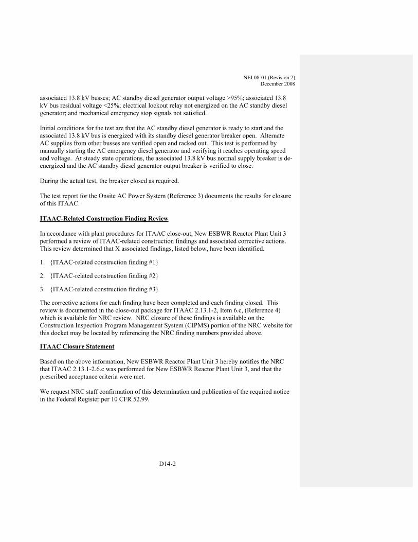
NEI 08-01 (Revision 2) December 2008
D14-2
associated 13.8 kV busses; AC standby diesel generator output voltage >95%; associated 13.8 kV bus residual voltage <25%; electrical lockout relay not energized on the AC standby diesel generator; and mechanical emergency stop signals not satisfied. Initial conditions for the test are that the AC standby diesel generator is ready to start and the associated 13.8 kV bus is energized with its standby diesel generator breaker open. Alternate AC supplies from other busses are verified open and racked out. This test is performed by manually starting the AC emergency diesel generator and verifying it reaches operating speed and voltage. At steady state operations, the associated 13.8 kV bus normal supply breaker is de-energized and the AC standby diesel generator output breaker is verified to close. During the actual test, the breaker closed as required. The test report for the Onsite AC Power System (Reference 3) documents the results for closure of this ITAAC. ITAAC-Related Construction Finding Review In accordance with plant procedures for ITAAC close-out, New ESBWR Reactor Plant Unit 3 performed a review of ITAAC-related construction findings and associated corrective actions. This review determined that X associated findings, listed below, have been identified.
1. {ITAAC-related construction finding #1}
2. {ITAAC-related construction finding #2}
3. {ITAAC-related construction finding #3}
The corrective actions for each finding have been completed and each finding closed. This review is documented in the close-out package for ITAAC 2.13.1-2, Item 6.c, (Reference 4) which is available for NRC review. NRC closure of these findings is available on the Construction Inspection Program Management System (CIPMS) portion of the NRC website for this docket may be located by referencing the NRC finding numbers provided above.
ITAAC Closure Statement Based on the above information, New ESBWR Reactor Plant Unit 3 hereby notifies the NRC that ITAAC 2.13.1-2.6.c was performed for New ESBWR Reactor Plant Unit 3, and that the prescribed acceptance criteria were met. We request NRC staff confirmation of this determination and publication of the required notice in the Federal Register per 10 CFR 52.99.

NEI 08-01 (Revision 2) December 2008
D14-3
If there are any questions, please contact {Name of licensing Representative} at {Contact Number for Contact Person}. Sincerely, {Signature of Licensee Representative} {Typed Name of Licensee Representative} {Title of Licensee Representative} References (available for NRC review) 1. NEI 08-01, Industry Guideline for ITAAC Closure Process Under 10 CFR Part 52 2. NN3-XX-123, Standby Diesel Generator System Test Procedure 3. On Site AC Power System Test Report. 4. ITAAC 2.13.1-2, Item 6.c, Standby Diesel Generator System Close-out Package.


NEI 08-01 (Revision 2) December 2008
D15-1
APPENDIX D-15 – EXAMPLE ITAAC CLOSURE LETTER AP1000 ITAAC 2.2.3.4 ITEM 8A
XX/YY/ZZZZ (Date) To: NRC From: {Name of Licensee} {Site Name and Unit #(s)} {Docket #(s)} Subject: Completion of AP1000 ITAAC Item 2.2.3-4 Item 8. a) The purpose of this letter is to notify the Nuclear Regulatory Commission (NRC) of the completion of {Site Name and Unit #(s)} Inspection, Test, Analysis and Acceptance Criteria (ITAAC) Item 2.2.3-4 Item 8. a), “Containment isolation of the Passive Core Cooling System (PXS) lines,” in accordance with 10 CFR 52.99(c)(1). The closure process for this ITAAC is based on the guidance described in NEI-08-01 (Reference 1). ITAAC Statement The following information is taken directly from the design control document. Design Commitment The PXS provides containment isolation of the PXS lines penetrating the containment. Inspection/Test/Analysis See Tier 1 Material, Table 2.2.1-3, items 1 and 7. Acceptance Criteria See Tier 1 Material, Table 2.2.1-3, items 1 and 7 ITAAC Determination Basis This ITAAC Design Commitment is shown to be met by reference to ITAAC for the Containment System in Tier 1, Table 2.2.1-3. The references are to Item 1 of Table 2.2.1-3 which demonstrates the functional arrangement of the containment system and to Item 7 of Table 2.2.1-3 which demonstrates the containment isolation function. The closure letters (References 2 and 3) for Item 1 and Item 7 of Table 2.2.1-3 summarize the methodology for conducting the ITA, and the results that demonstrate that the acceptance criteria

NEI 08-01 (Revision 2) December 2008
D15-2
were met. These closure letters have been submitted to the NRC and the supporting ITAAC closure activities are complete. The records (Tests, Reports, Completed Procedures, Completed Analyses, etc.) that form the ITAAC determination basis are referenced in the closure letters for Item 1 of Table 2.2.1-3 and Item 7 of Table 2.2.1-3. ITAAC-Related Construction Finding Review Any relevant ITAAC-related construction findings are addressed in the closure letters for Item 1 of Table 2.2.1-3 and Item 7 of Table 2.2.1-3.
The corrective actions for each finding have been completed and each finding closed. This review is documented in the close-out packages for ITAAC 2.2.1-3 Item 1 and ITAAC 2.2.1-3 Item 7, (References 4 and 5), which are available for NRC review. NRC closure of these findings is available on the Construction Inspection Program Management System (CIPMS) portion of the NRC website for this docket and may be located by referencing the NRC finding number provided below.
ITAAC Closure Statement Based on the above information, {Licensee Name} hereby notifies the NRC that ITAAC 2.2.3-4 Item 8. a) was performed for {Site Name and Unit #(s)}, and that the prescribed acceptance criteria were met. We request NRC staff confirmation of this determination and publication of the required notice in the Federal Register per 10 CFR 52.99. If there are any questions, please contact {Name of Contact Person for licensee} at {Telephone Number for Contact Person}. Sincerely, {Signature of Licensee Representative} {Typed Name of Licensee Representative} {Title of Licensee Representative} References (available for NRC review)
1. NEI 08-01, Industry Guideline for the ITAAC Closure Process Under 10 CFR Part 52 2. Closure Letter for Item 1 of Table 2.2.1-3, Dated XXXX YY, 20ZZ 3. Closure Letter for Item 7 of Table 2.2.1-3, Dated XXXX YY, 20ZZ 4. ITAAC Close-out Package for Item 1 of Table 2.2.1-3 retained on site 5. ITAAC Close-out Package for Item 7 of Table 2.2.1-3 retained on site
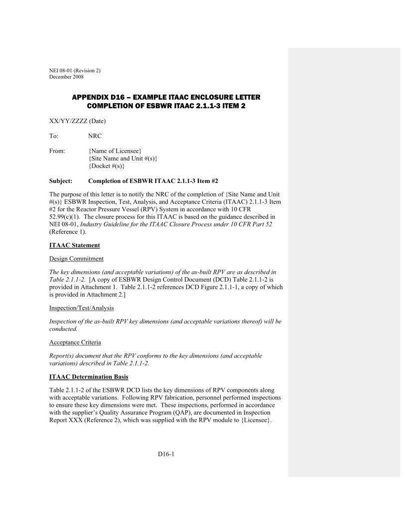
NEI 08-01 (Revision 2) December 2008
D16-1
APPENDIX D16 – EXAMPLE ITAAC ENCLOSURE LETTER COMPLETION OF ESBWR ITAAC 2.1.1-3 ITEM 2
XX/YY/ZZZZ (Date) To: NRC From: {Name of Licensee} {Site Name and Unit #(s)} {Docket #(s)} Subject: Completion of ESBWR ITAAC 2.1.1-3 Item #2
The purpose of this letter is to notify the NRC of the completion of {Site Name and Unit #(s)} ESBWR Inspection, Test, Analysis, and Acceptance Criteria (ITAAC) 2.1.1-3 Item #2 for the Reactor Pressure Vessel (RPV) System in accordance with 10 CFR 52.99(c)(1). The closure process for this ITAAC is based on the guidance described in NEI 08-01, Industry Guideline for the ITAAC Closure Process under 10 CFR Part 52 (Reference 1).
ITAAC Statement
Design Commitment
The key dimensions (and acceptable variations) of the as-built RPV are as described in Table 2.1.1-2. [A copy of ESBWR Design Control Document (DCD) Table 2.1.1-2 is provided in Attachment 1. Table 2.1.1-2 references DCD Figure 2.1.1-1, a copy of which is provided in Attachment 2.]
Inspection/Test/Analysis
Inspection of the as-built RPV key dimensions (and acceptable variations thereof) will be conducted.
Acceptance Criteria
Report(s) document that the RPV conforms to the key dimensions (and acceptable variations) described in Table 2.1.1-2.
ITAAC Determination Basis
Table 2.1.1-2 of the ESBWR DCD lists the key dimensions of RPV components along with acceptable variations. Following RPV fabrication, personnel performed inspections to ensure these key dimensions were met. These inspections, performed in accordance with the supplier’s Quality Assurance Program (QAP), are documented in Inspection Report XXX (Reference 2), which was supplied with the RPV module to {Licensee}.

NEI 08-01 (Revision 2) December 2008
D16-2
Pursuant to the {Licensee}’s QAP, delegated responsibilities may be performed under a supplier’s or principal contractor’s QAP, provided that the supplier or principle contractor has been approved as a supplier in accordance with the {Licensee}’s QAP. {Licensee} has performed periodic audits and assessments of the supplier’s QA programs to assure compliance with the supplier’s QAP and implementing procedures. {Licensee} Procedure XYZ, Material Receipt, (Reference 3), establishes and governs the process used for performing and documenting receipt and quality control (QC) inspections of quality-related components delivered to the site. The procedure requires inspection activities be performed by qualified personnel. These inspections include, but are not limited to:
• Checks for physical damage (fire, excessive exposure to weather, rough handling, etc.
• Quantity
• Technical and quality requirements
Upon arrival at {Site Name}, qualified {Licensee} personnel performed receipt and QC inspections of the RPV module in accordance with Procedure XYZ. Included in these activities was a review of the quality documentation accompanying the RPV. This activity, documented on Receiving Inspection Report #YYY (Reference 4), confirmed that Inspection Report XXX documented that the key dimensions denoted in DCD Table 2.1.1-2 are within the measurements specified in the table. Receiving Inspection Report #YYY is contained in Inspection Report ZZZ, Closure of ITAAC 2.1.1-3 #2 (Reference 5).
{Licensee} has reviewed installation records pertaining to the RPV; these are identified and contained in Inspection Report ZZZ. There is no evidence to indicate that the key dimensions identified in DCD Table 2.1.1-2 and validated by the inspections described above were adversely impacted during installation of the RPV. Specific ITAAC-related construction findings are discussed below.
Conclusion
Therefore, as required by ITAAC 2.1.1-3 #2, Inspection Report ZZZ, Closure of ITAAC 2.1.1-3 Item #2, documents that a report exists that documents that the RPV conforms to the key dimensions (and acceptable variations) described in DCD Table 2.1.1-2.
ITAAC-Related Construction Finding Review
In accordance with plant procedures for ITAAC closure, {Licensee} performed a review of ITAAC-related construction findings and associated corrective actions. This review determined that three associated findings, listed below, have been identified.
1. {ITAAC-related construction finding #1}
2. {ITAAC-related construction finding #2}

NEI 08-01 (Revision 2) December 2008
D16-3
3. {ITAAC-related construction finding #3}
The corrective actions for each finding have been completed and each finding closed. This review is documented in ITAAC Closure Package for ITAAC 2.1.1-3 Item #2 (Reference 6), which is available for NRC review. NRC closure of these findings is available on the Construction Inspection Program Management System (CIPMS) portion of the NRC website for this docket and may be located by referencing the NRC finding number provided above.
ITAAC Closure Statement
Based on the above information, {Licensee} hereby notifies the NRC that {Licensee} has performed ITAAC 2.1.1-3 Item #2 for {Site Name and Unit #(s)}, and that the prescribed acceptance criteria were met.
{Licensee} requests NRC staff confirmation of this determination and publication of the required notice in the Federal Register per 10 CFR 52.99.
If there are any questions, please contact {name of contact person for Licensee} at {telephone # for contact person}.
Sincerely,
{Signature of Licensee Representative} {Typed Name of Licensee Representative} {Title of Licensee Representative}
Attachments: 1. ESBWR DCD Table 2.1.1-2, Key Dimensions of RPV Components and Acceptable Variations, Rev. 4
2. ESBWR DCD Figure 2.1.1-1, Reactor Pressure Vessel System Key Features Layout
References (available for NRC review)
1. NEI 08-01, Industry Guideline for the ITAAC Closure Process under 10 CFR Part 52
2. Inspection Report XXX
3. Procedure XYZ, Material Receipt
4. Receiving Inspection Report #YYY
5. Inspection Report ZZZ, Closure of ITAAC 2.1.1-3 #2
6. ITAAC Closure Package for ITAAC 2.1.1-3 #2

NEI
08-
01 (R
evis
ion
2)
Dec
embe
r 200
8
D16
-4
ATT
AC
HM
ENT
1
ESB
WR
DC
D T
able
2.1
.1-2
Key
Dim
ensi
ons
of R
PV C
ompo
nent
s an
d A
ccep
tabl
e Va
riatio
ns
Des
crip
tion
Dim
ensi
on /
Elev
atio
n (F
igur
e 2.
1.1-
1)
Nom
inal
Val
ue
(mm
, in.
) A
ccep
tabl
e Va
riatio
n(s)
(mm
, in.
)
RP
V b
otto
m h
ead
insi
de in
vert
elev
atio
n A
0
Ref
eren
ce 0
Top
of c
ore
plat
e el
evat
ion
B
[417
8, 1
64.5
] [+
16,
0.6
3]
Bot
tom
of t
op g
uide
ele
vatio
n C
[7
718,
303
.9]
[+ 1
6, 0
.63]
RP
V to
p he
ad in
side
inve
rt el
ectio
n D
[2
7560
, 108
5]
[+ 1
00, 3
.94]
RP
V in
side
dia
met
er (i
nsid
e cl
addi
ng)
E
[711
2, 2
80.0
] [+
51,
2.0
1]
RP
V w
all t
hick
ness
in b
eltli
ne (i
nclu
ding
cla
ddin
g)
F [1
82, 7
.17]
[1
90.5
max
, 7.5
0 m
ax]

NEI 08-01 (Revision 2) December 2008
D16-5
ATTACHMENT 2


NEI 08-01 (Revision 2) December 2008
D17-1
APPENDIX D17 – EXAMPLE ITAAC ENCLOSURE LETTER COMPLETION OF ESBWR ITAAC 2.1.2-3 ITEM 12
XX/YY/ZZZZ (Date) To: NRC From: {Name of Licensee} {Site Name and Unit #(s)} {Docket #(s)} Subject: Completion of ESBWR ITAAC 2.1.2-3 Item #12
The purpose of this letter is to notify the NRC of the completion of {Site Name and Unit #(s)} ESBWR Inspection, Test, Analysis, and Acceptance Criteria (ITAAC) 2.1.2-3 Item #12 for the Nuclear Boiler System in accordance with 10 CFR 52.99(c)(1). The closure process for this ITAAC is based on the guidance described in NEI 08-01, Industry Guideline for the ITAAC Closure Process under 10 CFR Part 52 (Reference 1).
ITAAC Statement
Design Commitment
The throat diameter of each MSL [main steam line] flow restrictor is sized for design choke flow requirements.
Inspection/Test/Analysis
Inspection of the as-built MSL flow restrictor will be performed and measurements taken.
Acceptance Criteria
Report(s) document that the throat diameter of each MSL flow restrictor is less than or equal to 355 mm (14 in.).
ITAAC Determination Basis
As described in Sections 5.1 and 5.4 of the ESBWR design control document (DCD), each MSL flow restrictor is an integral part of the main steam nozzle on the reactor pressure vessel (RPV). The restrictor is machined into the nozzle itself during fabrication; therefore, they are supplied by General Electric – Hitachi (GEH) as part of the RPV integral module.
Following fabrication, personnel performed several inspections to ensure the RPV was fabricated in accordance with design specifications. These inspections, performed in accordance with the supplier’s Quality Assurance Program (QAP), included confirming the dimensions of the MSL flow restrictors; specifically, the throat diameter of each restrictor is less than or equal to 355

NEI 08-01 (Revision 2) December 2008
D17-2
mm (14 in.). The inspection of the flow restrictors is documented in Inspection Report XXX, Section AAA (Reference 2), which was supplied with the RPV module to {Licensee}.
Pursuant to the {Licensee}’s QAP, delegated responsibilities may be performed under a supplier’s or principal contractor’s QAP, provided that the supplier or principle contractor has been approved as a supplier in accordance with the {Licensee}’s QAP. {Licensee} has performed periodic audits and assessments of the supplier’s QA programs to assure compliance with the supplier’s QAP and implementing procedures. {Licensee} Procedure XYZ, Material Receipt, (Reference 3), establishes and governs the process used for performing and documenting receipt and quality control (QC) inspections of quality-related components delivered to the site. The procedure requires inspection activities be performed by qualified personnel. These inspections include, but are not limited to:
• Checks for physical damage (fire, excessive exposure to weather, rough handling, etc.
• Quantity
• Technical and quality requirements
Upon arrival at {Site Name}, qualified {Licensee} personnel performed receipt and QC inspections of the RPV module in accordance with Procedure XYZ. Included in these activities was a review of the quality documentation accompanying the RPV. This activity, documented on Receiving Inspection Report #YYY (Reference 4), confirmed that GEH Inspection Report XXX, Section AAA documented the throat diameter of each MSL flow restrictor to be less than or equal to 355 mm (14 in.). Receiving Inspection Report #YYY is contained in Inspection Report ZZZ, Closure of ITAAC 2.1.2-3 #12 (Reference 5).
{Licensee} has reviewed installation records pertaining to the RPV; these are identified and contained in Inspection Report ZZZ. There is no evidence to indicate that the dimensions of the MSL flow restrictors were adversely impacted during installation of the RPV. Specific ITAAC-related construction findings are discussed below.
Conclusion
Therefore, as required by ITAAC 2.1.2-3 #12, Inspection Report ZZZ, Closure of ITAAC 2.1.2-3 Item #12, documents that a report exists that documents the throat diameter of each MSL flow restrictor to be less than or equal to 355 mm (14 in.).
ITAAC-Related Construction Finding Review
In accordance with plant procedures for ITAAC closure, {Licensee} performed a review of ITAAC-related construction findings and associated corrective actions. This review determined that three associated findings, listed below, have been identified.
1. {ITAAC-related construction finding #1}
2. {ITAAC-related construction finding #2}

NEI 08-01 (Revision 2) December 2008
D17-3
3. {ITAAC-related construction finding #3}
The corrective actions for each finding have been completed and each finding closed. This review is documented in ITAAC Closure Package for ITAAC 2.1.2-3 Item #12 (Reference 6), which is available for NRC review. NRC closure of these findings is available on the Construction Inspection Program Management System (CIPMS) portion of the NRC website for this docket and may be located by referencing the NRC finding number provided above.
ITAAC Closure Statement
Based on the above information, {Licensee} hereby notifies the NRC that {Licensee} has performed ITAAC 2.1.2-3 Item #12 for {Site Name and Unit #(s)}, and that the prescribed acceptance criteria were met.
{Licensee} requests NRC staff confirmation of this determination and publication of the required notice in the Federal Register per 10 CFR 52.99.
If there are any questions, please contact {name of contact person for Licensee} at {telephone # for contact person}.
Sincerely,
{Signature of Licensee Representative} {Typed Name of Licensee Representative} {Title of Licensee Representative}
References (available for NRC review)
1. NEI 08-01, Industry Guideline for the ITAAC Closure Process under 10 CFR Part 52
2. Inspection Report XXX, Section AAA
3. Procedure XYZ, Material Receipt
4. Receiving Inspection Report #YYY
5. Inspection Report ZZZ, Closure of ITAAC 2.1.2-3 #12
6. ITAAC Closure Package for ITAAC 2.1.2-3 #12

NEI 08-01 (Revision 2) December 2008
D18-1
APPENDIX D18 – EXAMPLE ITAAC CLOSURE LETTER: ABWR ITAAC 2.4.4 ITEM 1 (RCIC SYSTEM BASIC CONFIGURATION)
XX/YY/ZZZZ (Date) To: NRC From: {Name of Licensee} {Site Name and Unit #(s)} {Docket #(s)} Subject: Completion of ABWR ITAAC 2.4.4 Item 1 The purpose of this letter is to notify the Nuclear Regulatory Commission (NRC) of the completion of {Site Name and Unit #(s)} Inspection, Test, Analysis and Acceptance Criterion (ITAAC) 2.4.4 Item 1, Reactor Core Isolation Cooling (RCIC) System Basic Configuration, in accordance with 10 CFR 52.99(c)(1). The closure process for this ITAAC is based on the guidance described in NEI 08-01 (Reference 1). ITAAC Statement Design Commitment The basic configuration of the RCIC System is as shown on Figures 2.4.4a and 2.4.4b. Inspection/Test/Analysis Inspections of the as-built system will be conducted. Acceptance Criteria The as-built RCIC System conforms with the basic configuration shown on Figures 2.4.4a and 2.4.4b. Note: Figure 2.4.4a reflects a standard departure from the RCIC Turbine/Pump design in the ABWR Design Control Document that was approved in the license for [Plant Name]. ITAAC Determination Basis In accordance with Tier 1, Sections 1.1 and 1.2 of the ABWR Design Control Document, verification of system basic configuration includes inspections, tests, and analyses in five areas, summarized as follows:
1. Functional Arrangement: Inspections confirming that the functional arrangement of structures, systems and components specified in the Design Description are consistent with the Tier 1 figures.

NEI 08-01 (Revision 2) December 2008
D18-2
2. ASME Code Welds: Inspections, including non-destructive examination (NDE), of the as-built, pressure boundary welds for ASME Code Class 1, 2, or 3 components identified in the Design Description to demonstrate that the requirements of ASME Code Section III for the quality of pressure boundary welds are met.
3. Seismic Qualification: Type tests, analyses, or a combination of type tests and analyses of the Seismic Category I mechanical and electrical equipment (including connected instrumentation and controls) identified in the Design Description to demonstrate that the as-built equipment, including associated anchorage, is qualified to withstand design basis dynamic loads without loss of its safety function.
4. Environmental Qualification: Type tests, or type tests and analyses, of the Class 1E electrical equipment identified in the Design Description (or on accompanying figures) to demonstrate that it is qualified to withstand the environmental conditions that would exist during and following a design basis accident without loss of its safety function for the time needed to be functional.
5. Motor-Operated Valves (MOVs): Tests or type tests of active safety-related motor-operated valves (MOVs) identified in the Design Description to demonstrate that the MOVs are qualified to perform their safety functions under design basis differential pressure, system pressure, fluid temperature, ambient temperature, minimum voltage, and minimum and/or maximum stroke times.
The five areas comprising basic configuration were inspected as described in the following sections. Functional Arrangement Walkdown inspections were conducted of the as-built RCIC System to confirm that the functional arrangement of the system is as shown in Figures 2.4.4a and 2.4.4b. Procedure XYZ (Reference 3) governed the preparation, performance, and documentation of the basic configuration functional arrangement inspections by trained personnel, and includes:
1. Preparing a detailed checklist covering the system components specified in the Design Description.
2. Performing visual observations that compare the system components to the verification
criteria. 3. Documenting visual observations.
The walkdown inspections confirmed that each RCIC system component identified in the Design Description was present in its proper functional or logical (for I&C) relation to the system, as shown in Figures 2.4.4a and 2.4.4b. The completed ITAAC functional arrangement checklists are included in the ITAAC Closure Package (Reference 4). ASME Code Welds The ASME Boiler and Pressure Vessel Code, Section III class boundaries for the RCIC system are shown in Figure 2.4.4a. The inspection requirements for the pressure boundary welds for the

NEI 08-01 (Revision 2) December 2008
D18-3
RCIC system Class 1 and Class 2 piping and components are specified in the ASME Code Section III, Subsections NB-5000 and NC-5000, respectively. The Code-required inspections (e.g., radiographic, ultrasonic, magnetic particle, liquid penetrant) were performed in accordance with applicable Code requirements, and the site Quality Assurance Program. For closure of this ITAAC, the quality assurance inspection records for the RCIC system ASME Class 1 and Class 2 pressure boundary welds were reviewed and confirmed to have met ASME Code requirements. The ITAAC review was documented on checklists (see Procedure XYZ (Reference 2)), which included the weld identification, weld location, type of weld (e.g., butt weld, partial penetration weld), type(s) of inspection, inspection record identification, and results from the inspection record. The completed ITAAC weld inspection checklists are included in the ITAAC Closure Package (Reference 3). Seismic Qualification The Seismic Category I RCIC system components described in the Design Description and shown in Figures 2.4.4a and 2.4.4b include the RCIC turbine, pump, valves, and operators (including connected instrumentation and controls). These components were procured in accordance with specifications that required seismic qualification in accordance with ABWR Design Control Document Sections 3.9 and 3.10, and with the site Quality Assurance Program. RCIC system piping was seismically qualified by analyses performed in accordance with the site Quality Assurance Program. Equipment anchorage or installations were inspected to ensure that they were consistent with the tested configuration, or were confirmed to meet seismic design criteria by analysis. For closure of this ITAAC, the seismic qualification records (e.g., test reports, analyses) were reviewed for each Seismic Category I component and the piping. The ITAAC review was documented on checklists (see Procedure XYZ (Reference 3)), which included the component identification, component type, seismic qualification record type (e.g., test report, analysis), seismic qualification record identification, and results from the seismic qualification record. Additionally, in accordance with Procedure XYZ, a walkdown inspection was conducted to confirm that equipment anchorages/installations met the seismic testing configuration or design criteria in applicable analyses. The seismic anchorage/installation walkdown inspection was documented on checklists, in accordance with Procedure XYZ. The completed ITAAC seismic qualification checklists are included in the ITAAC Closure Package (Reference 3). Environmental Qualification The Class 1E RCIC system electrical components are described in the Design Description and shown in Figure 2.4.4a. These components were procured in accordance with specifications that required environmental qualification in accordance with ABWR Design Control Document Section 3.11, and with the site Quality Assurance Program. For closure of this ITAAC, the environmental qualification records (e.g., test reports, operating experience analyses, or both) were reviewed for each Class 1E component. The ITAAC review was documented on a checklist (see Procedure XYZ (Reference 2)), which included the component identification, component type, environmental qualification record type, environmental qualification record identification, and results from the environmental

NEI 08-01 (Revision 2) December 2008
D18-4
qualification record. Additionally, in accordance with Procedure XYZ, a walkdown inspection was conducted to confirm the satisfactory installation of the Class 1E RCIC system components. The completed ITAAC environmental qualification checklists are included in the ITAAC Closure Package (Reference 3). Motor-Operated Valves The RCIC system includes ten (10) motor-operated valves (MOVs) shown in Figure 2.4.4a which have active safety-related functions to open, close, or both open and close, and which perform these functions under design basis differential pressure, system pressure, fluid and ambient temperature conditions, minimum voltage, and minimum and/or maximum stroke times applicable to the RCIC system. The design, qualification and testing for all safety-related MOVs is performed in accordance with the requirements of ABWR Design Control Document Section 3.9.6.2.2, and in accordance with the site Quality Assurance Program. For closure of this ITAAC, the MOV Program documentation for the ten safety-related RCIC valves was reviewed to confirm that each valve meets its functional requirements under design basis conditions, including minimum voltage conditions. The ITAAC review was documented on a checklist (see Procedure XYZ (Reference 3)), which included the valve identification, valve type/manufacturer/size, valve operator manufacturer/size, design conditions, required thrust, available thrust, and calculation/analysis identifications. Additionally, in accordance with Procedure XYZ, a walkdown inspection was conducted to confirm the satisfactory installation of the ten (10) RCIC motor-operated valves (MOVs). The completed ITAAC MOV checklists are included in the ITAAC Closure Package (Reference 3). Summary Based on these inspections of the five elements of the RCIC System basic configuration, it is concluded that the as-built RCIC System conforms with the basic configuration shown on Figures 2.4.4a and 2.4.4b.
NEI 08-01 (Revision 2) December 2008
D18-5
ITAAC-Related Construction Finding Review In accordance with plant procedures for ITAAC close-out, {Licensee} performed a review of ITAAC-related construction findings and associated corrective actions. This review determined that three such findings, listed below, have been identified.
1. {ITAAC-related construction finding #1}
2. {ITAAC-related construction finding #2}
3. {ITAAC-related construction finding #3}
The corrective actions for each finding have been completed and each finding closed. This review is documented in the close-out package for ITAAC 2.4.4 Item 1 (Reference 3), which is available for NRC review. NRC closure of these findings is available on the Construction Inspection Program Management System (CIPMS) portion of the NRC website for this docket and may be located by referencing the NRC finding numbers provided above. ITAAC Closure Statement Based on the above information, {Licensee Name} hereby notifies the NRC that ITAAC 2.4.4 Item 1, was performed for {Site Name and Unit #(s)}, and that the prescribed acceptance criteria were met. We request NRC staff confirmation of this determination and publication of the required notice in the Federal Register per 10 CFR 52.99. If there are any questions, please contact {Name of Contact Person for licensee} at {Telephone Number for Contact Person}. Sincerely, {Signature of Licensee Representative} {Typed Name of Licensee Representative} {Title of Licensee Representative} References (available for NRC review) 1. NEI 08-01, Industry Guideline for the ITAAC Closure Process under 10 CFR Part 52
2. Inspection Procedure XYZ, “Inspections of As-Built System Basic Configurations for ITAAC Closure”
3. ITAAC Close-out Package for ITAAC 2.4.4 Item 1


NEI 08-01 (Revision 2) December 2008
D19-1
APPENDIX D19 – EXAMPLE ITAAC CLOSURE LETTER: COMPLETION OF AP1000 ITAAC 2.19-1 ITEM 12
XX/YY/ZZZZ (Date) To: NRC From: {Name of Licensee} {Site Name and Unit #(s)} {Docket #(s)} Subject: Completion of AP1000 ITAAC 2.19-1 Item 12
The purpose of this letter is to notify the NRC of the completion of {Site Name and Unit #(s)} Inspection, Test, Analysis, and Acceptance Criterion (ITAAC) 2.19-1 Item 12 for Security, in accordance with 10 CFR 52.99(c)(1). The closure process for this ITAAC is based on the guidance described in NEI-08-01 (Reference 1).
ITAAC Statement
Design Commitment Secondary security power supply system for alarm annunciator equipment and non-portable communications equipment is located within a vital area. Inspection/Test/Analysis
An inspection will be performed to ensure that the location of the secondary security power supply system for alarm annunciator equipment and non-portable communications equipment is within a vital area.
Acceptance Criteria
A report exists and concludes that the secondary security power system for alarm annunciator equipment and non-portable communications equipment is located within a vital area.
ITAAC Determination Basis
The constructor installed the secondary security power supply equipment and non portable communications equipment in accordance with approved drawings and specifications released by engineering for construction.
During installation, the constructor performed inspections for conformance to the design and specifications.
NEI 08-01 (Revision 2) December 2008
D19-2
After construction, the Licensee performed a final inspection in accordance with the Security ITAAC Closure Procedure, which includes a Vital Area As-built Walk-down/Inspection (Reference 2).
Therefore, Inspection Report ZZZ (Reference 3) exists and concludes that
inspections confirmed that the secondary security power supply system for alarm annunciator equipment and non-portable communications equipment is located within a vital area.
ITAAC Related Construction Finding Review
In accordance with plant procedures for ITAAC close-out, {Licensee} performed a review of ITAAC-related construction findings and associated corrective actions. This review determined that {number of findings} such findings, listed below, have been identified.
1. {ITAAC-related construction finding #1}
2. {ITAAC-related construction finding #2}
3. {ITAAC-related construction finding #…}
The corrective actions for each finding have been completed and each finding closed. This review is documented in the close-out package for ITAAC 2.19-1 Item 12 (Reference 4), which is available for NRC review. NRC closure of these findings is available on the Construction Inspection Program Management System (CIPMS) portion of the NRC website for this docket and may be located by referencing the NRC finding numbers provided above.
ITAAC Closure Statement
Based on the above information, {Licensee} hereby notifies the NRC that ITAAC 2.19-1Item 12 was performed for {Site Name and Unit #(s)}, and that the prescribed acceptance criteria were met.
We request NRC staff confirmation of this determination and publication of the required notice in the Federal Register per 10 CFR 52.99.
If there are any questions, please contact {Name of Contact Person for licensee} at {Telephone Number for Contact Person}.
Sincerely,
{Signature of Licensee Representative} {Typed Name of Licensee Representative} {Title of Licensee Representative}

NEI 08-01 (Revision 2) December 2008
D19-3
References (available for NRC review)
1. NEI-08-01, Industry Guideline for ITAAC Closure Process Under 10 CFR Part 52
2. Security ITAAC Closure Procedure, SE-XX-XXXX
3. Inspection Report ZZZ, Closure of ITAAC 2.19-1Item 12 4. ITAAC 2.19-1 Item 12 Close-out Documentation Package


NEI 08-01 (Revision 2) December 2008
E-1
APPENDIX E – LIST OF 225 DAY NOTIFICATION EXAMPLES
Appendix Technology Description E-1 N/A Example 225 Day Notification Cover Letter E-2 N/A Example 225 Day Notification Attachment E-3 AP1000 3.3-6, Item 7.d (Cable separation) E-4 ABWR 2.1.1d, Item 3 (RPV hydro) E-5 ABWR 2.14.4a, Item 4a (SGTS) E-6 AP1000 2.5.2-8, Item 10 (Setpoints) E-7 AP1000 2.2.2-3, Item 7bi (Passive Containment System)


NEI 08-01 (Revision 2) December 2008
E1-1
APPENDIX E-1 – EXAMPLE 225 DAY NOTIFICATION COVER LETTER TEMPLATE
XX/YY/ZZZZ (Date) To: NRC From: {Name of Licensee} {Site Name and Unit #(s)} {Docket #(s)} Subject: Notification of Uncompleted ITAAC 225 Days Prior to Initial Fuel Load Pursuant to 10 CFR 52.99(c)(2), {Licensee} hereby notifies the NRC that {Site Name and Unit #(s)} Inspection, Test, Analysis, and Acceptance Criteria (ITAAC) Items listed in Enclosure 1 will not be completed 225 days prior to initial fuel load currently scheduled for {month, day, year}. Enclosures 2 through XX provide the closure plan and status for each ITAAC listed in Enclosure 1. This notification is consistent with the guidance described in NEI-08-01 (Reference 1). All ITAAC will be completed to support the Commission finding that all acceptance criteria have been met prior to plant operation, as required by 10 CFR 52.103(g).
If the NRC has any questions regarding this letter or the Attachments, please contact {name of contact person for Licensee} at {telephone # for contact person}.
Sincerely, {Signature of Licensee Representative} {Typed Name of Licensee Representative} {Title of Licensee Representative} References
1. NEI 08-01, Industry Guideline for the ITAAC Closure Process Under 10 CFR Part 52
Enclosures
1. List of Uncompleted ITAAC Items as of XX/XX/XX 2 through XX. Closure Plan and Status for Uncompleted ITAAC Items Listed in Attachment 1


NEI 08-01 (Revision 2) December 2008
E2-1
APPENDIX E-2 – EXAMPLE 225 DAY NOTIFICATION
ITAAC-Specific Attachment Template
XX/YY/ZZZZ (Date)
{Name of Licensee} {Site Name and Unit #(s)} {Docket #(s)} Subject: Notification of Status of (designate technology) ITAAC Item X.X.X ITAAC Statement The following information is taken directly from the design control document or combined license. Design Commitment {The design commitment for the applicable ITAAC should be quoted directly from the source. Do not paraphrase the Design Commitment.} Inspection/Test/Analysis {The inspection/test/analysis (ITA) for the applicable ITAAC should be quoted directly from the source. Do not paraphrase the inspection/test/analysis.} Acceptance Criteria {The acceptance criteria for the ITAAC should be quoted directly from the source letter. Do not paraphrase the acceptance criteria.} Tables and figures referenced in the ITAAC should be provided. Actions Achieved Toward ITAAC Closure This section should provide a status of activities related to ITAAC closure. Examples include providing a rough percentage of completed work on the ITAAC, an indication that certain activities listed in the ITAAC are already complete, or an indication that procedures or other supporting items that will be used to perform closure activities have been approved and are ready. There may be cases where this section has little or no information depending on the nature of the ITAAC, but this would likely be rare. For closed actions, summarize the methodology for conducting the ITA, and the results that demonstrate that the acceptance criteria were met.

NEI 08-01 (Revision 2) December 2008
E2-2
It should be written in an active voice, and consist of sufficient information to enable a person familiar with technical/engineering concepts to understand the underlying bases provided by the licensee to demonstrate the partial completion of ITAAC activities. In the event that the ITAAC offers more than one method to meet the acceptance criteria, clearly state which method was selected. Actions Remaining to Attain ITAAC Closure This section should provide a high level discussion of the remaining activities related to ITAAC closure that will be done after 225 days prior to initial fuel load. Summarize the methodology for conducting the ITA, and the results that demonstrate that the acceptance criteria were met. It should be written in an active voice, and consist of sufficient information to enable a person familiar with technical/engineering concepts to understand the bases underlying the conclusion established by the licensee regarding the activities remaining to complete ITAAC closure.
ITAAC Closure Schedule
{ITAAC x.x.x is being tracked in the ITAAC database. ITAAC x.x.x Closeout Package (and specific reports, procedures, or other references as necessary) are planned to be issued by _______. The Closure Letter for ITAAC x.x.x will follow our review and acceptance of these documents.}
Provide some forward looking statements to instill confidence that these actions will be achieved. Examples include a statement that this test or similar activity has been performed on an ITAAC that is already closed, similar activities are routinely done in the operating fleet of plants, the procedures for this activity have been written and approved, testing and analysis of this nature are routine in the nuclear industry, etc. {[brief description of forward looking statements] provide confidence that [Licensee] will be able to successfully complete this ITAAC.
References (available for NRC review) 1. Procedure, report, or other
NEI 08-01 (Revision 2) December 2008
E3-1
APPENDIX E-3 – DRAFT 225 DAY NOTIFICATION ITAAC 3.3-6 ITEM (7D)
Example ITAAC-Specific Attachment
XX/YY/ZZZZ (Date) {Name of Licensee} {Site Name and Unit #(s)} {Docket #(s)} Subject: Notification of Status of AP1000 ITAAC 3.3-6 Item (7d) ITAAC Statement Design Commitment ITAAC Table 3.3-6 (7d) Physical separation is maintained between Class 1E divisions and between Class 1E divisions and non-Class 1E cables Inspection/Test/Analysis Inspections of the as-built Class 1E raceways will be performed to confirm that the separation between Class 1E raceways of different divisions and between Class 1E raceways and non-Class 1E raceways is consistent with the following:
Within the main control room and remote shutdown room, the minimum vertical separation is 3 inches and the minimum horizontal separation is 1 inch.
Within other plant areas (limited hazard areas), the minimum separation is defined by one of the following:
1) The minimum vertical separation is 5 feet and the minimum horizontal
separation is 3 feet. 2) The minimum vertical separation is 12 inches and the minimum horizontal
separation is 6 inches for raceways containing only instrumentation and control and low-voltage power cables <2/0 AWG.
3) For configurations that involve exclusively limited energy content cables (instrumentation and control), the minimum vertical separation is 3 inches and the minimum horizontal separation is 1 inch.
4) For configurations involving an enclosed raceway and an open raceway, the minimum vertical separation is 1 inch if the enclosed raceway is below the open raceway.
5) For configuration involving enclosed raceways, the minimum separation is 1 inch in both horizontal and vertical directions.

NEI 08-01 (Revision 2) December 2008
E3-2
Where minimum separation distances are not maintained, the circuits are run in enclosed raceways or barriers are provided.
Separation distances less than those specified above and not run in enclosed raceways or provided with barriers are based on analysis
Non-Class 1E wiring that is not separated from Class 1E or associated wiring by the minimum separation distance or by a barrier or analyzed is considered as associated circuits and subject to Class 1E requirements.
Acceptance Criteria Results of the inspection will confirm that the separation between Class 1E raceways of different divisions and between Class 1E raceways and non-Class 1E raceways is consistent with the followings:
Within the main control room and remote shutdown room, the vertical separation is
3 inches or more and the horizontal separation is 1 inch or more. Within other plant areas (limited hazard areas), the separation meets one of the
following:
1) The vertical separation is 5 feet or more and the horizontal separation is 3 feet or more except.
2) The minimum vertical separation is 12 inches and the minimum horizontal separation is 6 inches for raceways containing only instrumentation and control and low-voltage power cables <2/0 AWG.
3) For configurations that involve exclusively limited energy content cables (instrumentation and control), the minimum vertical separation is 3 inches and the minimum horizontal separation is 1 inch.
4) For configurations that involve an enclosed raceway and an open raceway, the minimum vertical separation is 1 inch if the enclosed raceway is below the raceway.
5) For configurations that involve enclosed raceways, the minimum vertical and horizontal separation is 1 inch.
Where minimum separation distances are not met, the circuits are run in enclosed
raceways or barriers are provided. A report exists and concludes that separation distances less than those specified above
and not provided with enclosed raceways or barriers have been analyzed. Non-Class 1E wiring that is not separated from Class 1E or associated wiring by the
minimum separation distance or by a barrier or analyzed is treated as Class 1E wiring.
Actions Achieved toward ITAAC Closure Significant progress has been achieved as of (Month, Day, Year) toward completing this ITAAC, 99% of the installation and associated inspection activities are complete. Inspections and analysis of plant components have been performed to ensure that “Physical separation is

NEI 08-01 (Revision 2) December 2008
E3-3
maintained between Class 1E divisions and between Class 1E divisions and non-Class 1E cables”. The cable raceway system layout was designed using a three dimensional computer model. The raceways were routed through the model plant within an appropriate space reservation envelope to ensure that no violations of the separation requirements would occur. Construction drawings and Installation Specifications provided to the installer identified separation criteria, consistent with the ITAAC commitment, that were required to be met during erection activities. The constructor has installed the cable raceway in accordance with the “Released For Construction” drawings and the Installation Specifications. These components were presented for inspection by Quality Control as appropriate portions of the work were completed. The Independent verification of the Class 1E raceway installation by the Quality Control Group included inspection of the separation criteria attributes identified in “Released For Construction” drawings as well as the Installation Specifications, and was recorded in the inspection report. The completed raceway tickets for the satisfactorily installed and inspected raceways were turned in and recorded in the site’s Electrical Raceway and Cable Tracking System. Raceway completion and cable route was validated by Quality Control walk-down of the designated raceways prior to pulling Class 1E cables. Any deviations were documented and resolved prior to cable pull. The completed cable pull tickets for the satisfactorily installed and inspected cables were turned in and recorded in the site’s Electrical Raceway and Cable Tracking System. Cable training within cabinets was independently verified by Quality Control for separation attributes through a series of documented inspections as cables were installed and terminated. The completed termination tickets for the satisfactorily installed and inspected cables were turned in and recorded in the site’s Electrical Raceway and Cable Tracking System. Actions Remaining to Attain ITAAC Closure Prior to final acceptance of the overall Class 1E raceway and cable system Engineering and Quality Control will perform walk-downs of the plant Class 1E electrical components to identify any potential violations of the required cable separation criteria. Any deviations identified will be recorded, dispositioned and resolved prior to issuing the Final Report. The walk-downs will be performed in accordance with the site Cable Separation Final Walk-down Procedure (Reference 1). Review of the inspection reports, the site’s Electrical Raceway and Cable Tracking System, Design Change documents, Nonconformance Reports, and the Final Report will be performed and determined to be satisfactory before the project can conclude that the cable installed in the plant has been inspected and reviewed to ensure that the required physical separation between cables from different Class 1E divisions and between Class 1E cables and non-Class 1E cables has been achieved. All exceptions to the separation criteria identified in the installation specification and the project drawings will have been identified by Design Change documents or Nonconformance Reports. These exceptions whether identified during installation or by final

NEI 08-01 (Revision 2) December 2008
E3-4
walk down of the as built configuration will have been evaluated and either corrected, mitigated or accepted as is. These reviews will be documented in the ITAAC 3.3.6 Item (7d) Closeout Package. Before issuing the Cable Separation Final Report, Engineering must be able to conclude that separation distances are satisfactory. Those separation distances less than specified by the ITAAC criteria and not provided with enclosed raceways or barriers will have been analyzed and determined to be satisfactory. ITAAC Closure Schedule
{Licensee} is tracking ITAAC 3.3-6 Item (7d) in its ITAAC database. ITAAC 3.3.6 Item (7d) Closeout Package and ITAAC 3.3-6 Item (7d) Cable Separation Final Report –EFG xyz, Revision 0 are scheduled to be issued on ________. The Closure Letter for ITAAC 3.3-6 Item (7d) will follow our review and acceptance of these documents.
Cable Separation Programs have been successfully completed for both new nuclear power plants {Site Name and Unit #} and units being restarted after extended shutdowns {Site Name and Unit #}. These successful industry experiences, in combination with the satisfactory results through (Month, Day, Year) of the completion of the majority portions of this ITAAC at our own project provide confidence that {Licensee} will be able to successfully complete this ITAAC.
References (available for NRC review) 1. Cable Separation Final Walk-down Procedure
NEI 08-01 (Revision 2) December 2008
E4-1
APPENDIX E-4 – DRAFT 225 DAY NOTIFICATION ABWR ITAAC 2.1.1D ITEM 3
Example ITAAC-Specific Attachment
XX/YY/ZZZZ (Date) {Name of Licensee} {Site Name and Unit #(s)} {Docket #(s)} Subject: Notification of Uncompleted ABWR ITAAC 2.1.1d Item 3 ITAAC Statement Design Commitment The ASME Code components of the RPV (Reactor Pressure Vessel) System retain their pressure boundary integrity under internal pressure that will be experienced during service. Inspection/Test/Analysis A hydrostatic test will be conducted on those code components of the RPV System required to be hydrostatically tested by the ASME Code. Acceptance Criteria The results of the hydrostatic test of the ASME Code components of the RPV System conform with the requirements in the ASME Code, Section III. Actions Achieved Toward ITAAC Closure Progress as of (Month, Day, Year) toward completing this ITAAC is approximately 75% with the shop fabrication activities complete, the Hydrostatic Test Procedure per XXX.XXX.XXX (Reference 1) and the Hydrostatic Test Package (Reference 2) generated, but the final RPV System hydrostatic test, associated inspection activities, and test analysis results remain open. As described further below, the shop fabrication activities included hydrostatic testing of the RPV System under the ideal conditions provided in a shop environment, and the final RPV System hydrostatic test left to be completed is essentially an as-installed (post appurtenance) hydrostatic test in the field to confirm the pressure boundary integrity of items that were not confirmed in the fabrication shop. The ASME Code components of the RPV system were installed in a fabrication shop where compliance to Code requirements is inherent in procedures, training, inspections, and documentation. The fabrication shop was approved for ASME Code work. This resulted in the

NEI 08-01 (Revision 2) December 2008
E4-2
N – Stamping of the RPV. The fabrication of ASME components for the RPV system complied with design drawings and specifications and was verified by Quality inspections and documentation.
The ASME Code components of the RPV System were identified for both the initial shop test and final RPV System test. These components were within the hydrostatic test boundaries established by the constructor based on plant design drawings and specifications. These design documents provide design and operating temperatures and pressures which allow assembly of the Hydrostatic Test Package per Procedure XXX.XXX.XXX, Hydrostatic Testing. Hydrostatic testing personnel are trained in accordance with the Hydrostatic Testing procedure, and test results are analyzed, documented, and retained. The Hydrostatic Test Package consists of the following: 1. Hydrostatic Test Package Index Sheet 2. ASME Section III Hydrostatic Test Report 3. Drawing showing the system test boundary Initial hydrostatic testing of ASME Code components for the RPV system was completed in the approved fabrication shop. During fabrication, the EPC constructor performed inspections for material traceability, NDE requirements, welding quality, and compliance to design drawings and specifications.
The final RPV System hydrostatic test (post appurtenance hydro) in the field was not completed in the fabrication shop. It is scheduled to be complete approximately 2 months prior to fuel load in accordance with the construction schedule. Staff qualified test personnel have experience with such hydrostatic testing procedures, test packages, testing, inspections, and test analysis results. Completion of a successful final RPV System hydrostatic test confirms that ASME Code components of the RPV System retain their pressure boundary integrity under internal pressure that will be experienced during service. Actions Remaining to Attain ITAAC Closure The final RPV Hydrostatic System Test Package documentation is prepared by the Hydrostatic Test Engineer, test rig and component set up is by the Hydrostatic Test Crew, inspection for leaks is by the Quality Inspector, and verification of test analysis results is by the ANI (Authorized Nuclear Inspector). Prior to acceptance of the final hydrostatic test analysis results of the ASME Code components of the RPV System, a test package documentation review will ensure compliance to ASME Code, Section III. Any deviations identified will be resolved prior to system turnover to Start Up. The Hydrostatic Test Package documentation review by Quality Assurance will be per Quality Procedure XXX (Reference 3).
NEI 08-01 (Revision 2) December 2008
E4-3
ITAAC Closure Schedule
ITAAC 2.1.1d Item 3 is being tracked in the ITAAC database. ITAAC 2.1.1d Item 3 Closeout Package (Reference 4) is scheduled to be issued by [month, day, year]. The Closure Letter for ITAAC 2.1.1d Item 3 will follow our review and acceptance of these documents.
References (available for NRC review)
1 Procedure XXX.XXX.XXX, Hydrostatic Testing 2 RPV Hydrostatic Test Package 3 Quality Assurance Procedure XXX 4 ABWR ITAAC 2.1.1d Item 3 Closeout Package

NEI 08-01 (Revision 2) December 2008
E5-1
APPENDIX E-5 – DRAFT 225 DAY NOTIFICATION ABWR ITAAC 2.14.4A ITEM 4A
XX/YY/ZZZZ (Date) {Name of Licensee} {Site Name and Unit #(s)} {Docket #(s)} Subject: Notification of Uncompleted ABWR ITAAC 2.14.4a Item 4a ITAAC Statement Design Commitment The SGTS (Standby Gas Treatment System) maintains a negative pressure of 6.35 mm water gauge or greater in the secondary containment relative to the outdoor atmosphere within 20 minutes when the secondary containment is isolated. Inspection/Test/Analysis Tests will be conducted on each as-built SGTS division. Acceptance Criteria The SGTS maintains a negative pressure of 6.35 mm water gauge or greater in the secondary containment relative to the outdoor atmosphere within 20 minutes when the secondary containment is isolated. Actions Achieved Toward ITAAC Closure Progress as of (Month, Day, Year) toward completing this ITAAC was approximately 25% with the SGTS Negative Pressure Test Procedure XXX.XXX.XXX (Reference 1) and Negative Pressure Test Package (Reference 2) generated, but the test, associated inspection activities, and test analysis results remain open. The as-built divisions of the SGTS System identified within the secondary containment negative pressure test boundaries were established by the constructor based on plant design drawings and specifications. These design documents provide design and operating temperatures and pressures which allow assembly of the SGTS Negative Pressure Test Package per Procedure XXX.XXX.XXX, Negative Pressure Testing. Negative Pressure Testing personnel are trained in accordance with the Negative Pressure Testing Procedure, and test results are analyzed, documented, and retained. The Negative Pressure Test Package (Reference 2) consists of the following:

NEI 08-01 (Revision 2) December 2008
E5-2
1. Negative Pressure Test Package Index Sheet 2. Negative Pressure Test Report 3. Drawing showing the SGTS system test boundary 4. Equipment List Actions Remaining to Attain ITAAC Closure Prior to final acceptance of the negative pressure test results of the SGTS System, a package documentation review will ensure compliance to 6.35 mm water gauge or greater in the secondary containment relative to the outdoor atmosphere within 20 minutes when the secondary containment is isolated. Any deviations identified will be resolved prior to system turnover to Start Up. The Negative Pressure Test Package documentation review by Quality Assurance is per Quality Procedure XXX (Reference 3). Staff qualified test personnel have experience with Negative Pressure System test procedures, test packages, testing, inspections, and test analysis results. Completion of a successful test will confirm that SGTS maintains a negative pressure of 6.35 mm water gauge or greater in the secondary containment relative to the outdoor atmosphere within 20 minutes when the secondary containment is isolated. ITAAC Closure Schedule
ITAAC 2.14.4 Item 4a is being tracked in the ITAAC database. ITAAC 2.14.4 Item 4a Closeout Package (Reference 4) is scheduled to be issued by [month, day, year]. The Closure Letter for ITAAC 2.14.4 Item 4a will follow our review and acceptance of these documents.
References (available for NRC review)
1 Procedure XXX.XXX.XXX, Negative Pressure Testing 2 SGTS Negative Pressure Test Package (Initial Draft) 3 Quality Assurance Procedure XXX 4 ABWR ITAAC 2.14.4a Item 4a Closeout Package (Initial Draft)

NEI 08-01 (Revision 2) December 2008
E6-1
APPENDIX E-6 – DRAFT 225 DAY NOTIFICATION ITAAC 2.5.2-8 ITEM 10
XX/YY/ZZZZ (Date) (225 days before scheduled fuel load) {Name of Licensee} Site Name and Unit #(s)} {Docket #(s)} Subject: Notification of Status of AP1000 ITAAC 2.5.2-8 Item 10
ITAAC Statement
Design Commitment
Setpoints are determined using a methodology which accounts for loop inaccuracies, response testing, and maintenance or replacement of instrumentation.
Inspection/Test/Analysis
Inspection will be performed for a document that describes the methodology and input parameters used to determine the PMS setpoints.
Acceptance Criteria
A report exists and concludes that the PMS setpoints are determined using a methodology which accounts for loop inaccuracies, response testing, and maintenance or replacement of instrumentation.
Actions Achieved Toward ITAAC Closure
{Licensee} determines instrument setpoints for permanently installed instrumentation using methodology specified in Procedure XXX, Instrument Uncertainty and Setpoint Calculation Guidelines (Reference 1). This methodology accounts for loop inaccuracies, response testing, and maintenance or replacement of instrumentation. {Licensee} uses Procedure XXX at {Licensee’s operating units} giving additional validity and assurance to the methodology.
The setpoints for Protection and Safety Monitoring System (PMS) have been determined using Procedure XXX and documented in Engineering Report YYY, Setpoint Determination for the Protection and Safety Monitoring System (Reference 2).
Actions Remaining to Attain ITAAC Closure
In order to close ITAAC 2.5.2-8 Item #10, {Licensee} will complete an inspection of Engineering Report YYY. The purpose of the inspection is to confirm that the PMS setpoints are determined using Procedure XXX and that the procedure specifies a methodology that takes into account instrument loop uncertainties and inaccuracies, response testing results, and maintenance or replacement activities. To date, {Licensee} has completed approximately XX%

NEI 08-01 (Revision 2) December 2008
E6-2
of the inspection. This inspection will be documented in an ITAAC closure inspection report, which will be available for NRC review.
ITAAC Closure Schedule
{Licensee} is tracking ITAAC 2.5.2-8 Item #10 in its ITAAC database and is scheduled to perform the inspection of Engineering Report YYY on ______________. {Licensee} expects satisfactory results since, as mentioned above, Procedure XXX is successfully used at {Licensee’s operating units}.
References (available for NRC review)
1. Procedure XXX, Instrument Uncertainty and Setpoint Calculation Guidelines 2. Engineering Report YYY, Setpoint Determination for the Protection and Safety Monitoring
System

NEI 08-01 (Revision 2) December 2008
E7-1
APPENDIX E-7 – DRAFT 225 DAY NOTIFICATION AP1000 ITAAC 2.2.2-3 ITEM 7BI
XX/YY/ZZZZ (Date) {Name of Licensee} {Site Name and Unit #(s)} {Docket #(s)} Subject: Notification of Status of AP1000 ITAAC 2.2.2-3 Item 7.b.i Passive Containment Cooling System Water Distribution ITAAC Statement Design Commitment 7.b) The PCS wets the outside surface of the containment vessel. The inside and the outside of the containment vessel above the operating deck are coated with an inorganic zinc material. Inspection/Test/Analysis i) Testing will be performed to measure the outside wetted surface of the containment vessel with one of the three parallel flow paths delivering water to the top of the containment vessel. Acceptance Criteria i) A report exists and concludes that when the water in the PCCWST uncovers the standpipes at the following levels, the water delivered by one of the three parallel flow paths to the containment shell provides coverage measured at the spring line that is equal to or greater than the stated coverages. - 24.1 ± 0.2 ft above the tank floor; at least 90% of the perimeter is wetted. - 20.3 ± 0.2 ft above the tank floor; at least 72.9% of the perimeter is wetted. - 16.8 ± 0.2 ft above the tank floor; at least 59.6% of the perimeter is wetted. Actions Achieved Toward ITAAC Closure The containment vessel and the elements of the water distribution system on the top dome of the containment vessel are complete. The inorganic zinc coating on the outside surface of the containment is complete. The notification of the completion of ITAAC 2.2.2-3 Items 7.b.ii and 7.b.iii associated with the completion of the application of the inorganic zinc coating to the containment surface included in the design commitment is reported separately. The test procedure for the water distribution testing is prepared and approved.

NEI 08-01 (Revision 2) December 2008
E7-2
Actions Remaining to Attain ITAAC Closure During the filling of the Passive Containment Cooling Water Storage Tank (PCCWST) as each test level is reached water will be released into the distribution system. The water coverage will be determined for each tank water level at the spring line of the containment vessel. The spring line is at the connection between the ellipsoidal head and the top of the cylinder. Observation of the test, as directed by the procedure, will be by personnel directly or by use of cameras located inside the air baffle. Video or photographic means will be used to record the test. Determination of the coverage percentage will be made using measurement of photographs or estimated using markers applied to the containment shell. A report will be prepared to document the test results. This report will be available for NRC review. This observation of water coverage planned is similar to test observations originally done during the Passive Containment Cooling System Water Distribution tests performed to support the development of the passive containment cooling system. ITAAC Closure Schedule
ITAAC 2.2.2-3 Item 7.b.i is being tracked in the ITAAC database. ITAAC 2.2.2-3 Item 7.b.i Closeout Package (and specific reports, procedures, or other references as necessary) are scheduled to be issued by [month, day, year]. The Closure Letter for ITAAC 2.2.2-3 Item 7.b.i will follow our review and acceptance of these documents.
References (available for NRC review)
1 Passive Containment Cooling System Water Distribution Procedure, report, or other
Related Documents