Industrial Robot Programming Nilsson, Klas 1996 Document Version: Publisher's PDF, also known as Version of record Link to publication Citation for published version (APA): Nilsson, K. (1996). Industrial Robot Programming. Department of Automatic Control, Lund Institute of Technology (LTH). Total number of authors: 1 General rights Unless other specific re-use rights are stated the following general rights apply: Copyright and moral rights for the publications made accessible in the public portal are retained by the authors and/or other copyright owners and it is a condition of accessing publications that users recognise and abide by the legal requirements associated with these rights. • Users may download and print one copy of any publication from the public portal for the purpose of private study or research. • You may not further distribute the material or use it for any profit-making activity or commercial gain • You may freely distribute the URL identifying the publication in the public portal Read more about Creative commons licenses: https://creativecommons.org/licenses/ Take down policy If you believe that this document breaches copyright please contact us providing details, and we will remove access to the work immediately and investigate your claim.

Welcome message from author
This document is posted to help you gain knowledge. Please leave a comment to let me know what you think about it! Share it to your friends and learn new things together.
Transcript

LUND UNIVERSITY
PO Box 117221 00 Lund+46 46-222 00 00
Industrial Robot Programming
Nilsson, Klas
1996
Document Version:Publisher's PDF, also known as Version of record
Link to publication
Citation for published version (APA):Nilsson, K. (1996). Industrial Robot Programming. Department of Automatic Control, Lund Institute ofTechnology (LTH).
Total number of authors:1
General rightsUnless other specific re-use rights are stated the following general rights apply:Copyright and moral rights for the publications made accessible in the public portal are retained by the authorsand/or other copyright owners and it is a condition of accessing publications that users recognise and abide by thelegal requirements associated with these rights. • Users may download and print one copy of any publication from the public portal for the purpose of private studyor research. • You may not further distribute the material or use it for any profit-making activity or commercial gain • You may freely distribute the URL identifying the publication in the public portal
Read more about Creative commons licenses: https://creativecommons.org/licenses/Take down policyIf you believe that this document breaches copyright please contact us providing details, and we will removeaccess to the work immediately and investigate your claim.

Preface
Preface
Machines that perform hard or boring work have interested me eversince I was a boy and had to help my parents on our farm. I was moreinterested in mathematics physics, and machines. During the end -70’s,I got acquainted with computers and control. That opened a new andvery interesting world for me. When I finished my studies for a master’sdegree in mechanical engineering, I was still very interested in helpful(intelligent) machines. It was therefore an easy choice where to apply fora job: ASEA Robotics.
When I came to ASEA (later ABB) in 1982, Robotics was a new andprogressive division which was managed more like a small company. Atthat time, the demands on profitability were not severe. The primary goalwas to make good robot systems. Market share and company size thereforegrew rapidly. For me it was six years of stimulating control engineeringtogether with very good friends/colleagues.
The control engineering work ranged from tuning of joint servosto overall system design. When more than thousand, instead of a fewhundreds, of robots were manufactured, profitability and cost efficiency forpresent major applications were getting increasingly important. That wasof course a correct policy, but customers with good but unforeseen ideasabout how to use robots, too often could not accomplish the control. To startwith I was most interested in feedback control theory, but later it becameclear to me that the structure of the control system was of key importancefor the development of intelligent machines. Published research resultswere, however, not quite useful because important industrial aspects wereoverlooked. To do research in this direction, we moved back to Lund whereI got the opportunity to do a PhD at the Department of Automatic Control.
Research within automatic control almost always treats well definedproblems well suited for formal methods. It has therefore not been easyto tackle a problem that does not fit into this pattern. I hope control re-searchers do not get too disappointed when they do not find their favoriteequations in this thesis. My work has been problem oriented. The subjectand the developed solutions are closely related to computer science andproduction engineering, but the interplay between robot programming andfeedback control is of key importance.
It is now a great pleasure for me to complete this thesis, and I verymuch hope that ideas presented here will contribute to systems that bettercan perform work that is unfriendly to humans.
vii

Preface
Acknowledgments
This work was carried out in a friendly and inspiring atmosphere at theDepartment of Automatic Control in Lund, Sweden. Professor Karl JohanÅström has been a constant source of inspiration and information. It ismainly due to him that I have had the opportunity to work in a researchenvironment where one can get support and advice when needed, but alsofreedom to continue along my own ideas (even at times when nothingseems to work). I am also grateful to all other people at the department.Without mentioning all names, this includes professors, technical staff,our charming and helpful secretaries, PhD student friends, and masterthesis students that I have been guiding.
During the first stage of my work (until my licentiate thesis wascompleted), Lars Nielsen was my closest supervisor. He helped me turnmy ideas into problems definitions and solutions, and he encouraged meto pursue this direction of research. He and Ola Dahl were very helpfuland it was a pleasure to work with them.
Rolf Johansson has given me invaluable guidance during the finalpart of my work. We have also applied for funds and managed robotresearch projects together. I really appreciate his comments on this thesis,and I hope we can collaborate somehow also in the future. Thanks alsoto Björn Wittenmark and Karl-Erik Årzén for valuable comment on themanuscript. The hardware interfaces to our ABB Robots were built byRolf Braun, who also made the detailed design according to my (coarse)descriptions. I do not know the number of weeks we put into this, but Iam very grateful for all his help. Many thanks also to Anders Robertssonfor his efforts in the robot lab.
The financial support from NUTEK, which made this work and thedevelopment of the experimental platform possible, is gratefully acknowl-edged. I am also grateful for support and comments from my colleaguesat ABB Robotics. The ABB/LTH robot interface could hardly have beendeveloped without the access to information within ABB. Among others,Håkan Brantmark, Torgny Brogårdh, Peter Eriksson, Anders Holmer, ÅkeMadesäter, Mats Myhr, Einar Myklebust, Ulf-Göran Norefors, IngemarReyier, Lars Östlund, and all my friends within the Motion Control Grouphave helped me to keep in touch with the industrial reality.
It has been nice to use our properly working computer system man-aged by Leif Andersson, who is always helpful and interested in arrangingthings for the user’s best. The real-time kernel and communication soft-ware I have been using is mainly due to Anders Blomdell. He has alsobeen a great source of information concerning practical aspects of soft-ware design and hardware-related programming. He also convinced me
viii
Preface
that his implementation of dynamically linked actions (Chapter 7) usuallyis more appropriate than the function-based solution that I made. Presentand former members of the CACE project has also given valuable hintsabout software. This includes Dag Brück who often helped me to to useand misuse C+ + . Contributions from the guest researchers Albert-JanBaerveldt and Marcel Schoppers have also been helpful.
Due to the multidisciplinary topic of robot control and programming,interaction with other departments here in Lund has been of great value.At the Department of Production and Materials Engineering, GunnarBolmsjö, Krister Brink, Per Hedenborn, Hamid Nasri, Georgio Nicoleris,Magnus Olsson, and Björn Ågren have given valuable comments. Someof these persons also gave me access to the robot programming systemIGRIP.
At the Department of Computer Science, I have had the pleasure tointeract with Elizabeth Bjarnason, Görel Hedin, Roger Henriksson, andBoris Magnusson. Their comments about object-oriented software, andtheir efforts put into the Applab system, have been valuable both fordevelopment of principles and for prototyping language aspects of robotprogramming.
The always enthusiastic Gustaf Olsson, head of the Department ofIndustrial Electrical Engineering and Automation, has also been a sourceof information. At that department, an interesting development of ultra-sonic sensing for industrial robots is made by Gunnar Lindstedt, who alsoprogrammed the some of the circuits in the robot interface. Our aim toutilize his ultrasonic system for robot control appears to be promising.
The computer vision group at the Department of Mathematics, cur-rently including the researchers Anders Heyden, Gunnar Sparr, and KalleÅström, has contributed with some vision facilities within our laboratory.I look forward to connecting new vision algorithms to improve the abilitiesof our (currently blind) robots.
Finally, with some bad conscience for all evenings and weekends thathave been spent at work, I want to thank my beloved wife Rosel and ourlovely children for their love, patience and support.
About the thesis
Chapter 1 of this thesis contains a short introduction in general terms.Chapter 2 is also introductory, but it gives a broader manufacturing sys-tems perspective as well as a more specific description of the authors viewof the problems. Conclusions are given in Chapter 9, whereas Chapters 3to 8 present the contributions which also have been published accordingto next page.
ix

Preface
The software architecture proposed in Chapter 4 and two of theapplication examples presented in Chapter 8 have been presented in
K. NILSSON AND L. NIELSEN. “An architecture for application ori-ented robot programming.” In IEEE International Conference onRobotics and Automation, Nice, France, 1992.
Part of Chapter 5 treats software techniques for special purpose hardware.This was presented in
K. NILSSON. “Object oriented DSP programming.” In Proceedingsof The Fourth International Conference on Signal Processing Ap-plications & Technology, DSP Associates, Santa Clara, CA, 1993.
which was judged as one of the best papers, and therefore also publishedin a condensed form in
K. NILSSON. “DSPs moving up to object-oriented programs.” Elec-tronic Engineering Times, September, 1993.
Real-time and control aspects of such hardware are also mentioned inChapter 5 and presented in
K. NILSSON. “Software for embedded DSPs.” In Proceedings fromThe American Control Conference, 1994. Invited Paper.
The ideas about how open embedded control (Chapter 7) can be utilizedin robot programming were presented in
K. NILSSON AND L. NIELSEN. “On the programming and control ofindustrial robots.” In International Workshop on MechatronicalComputer Systems for Perception and Action, Halmstad, Sweden,1993.
whereas the thorough description of the software technique, as presentedin Chapter 7, hopefully will appear in
K. NILSSON, A. BLOMDELL, AND O. LAURIN. “Open embedded con-trol.” Submitted to: Real-Time Systems – The international jour-nal of time critical computing, 1996.
Apart from the control structure part of Chapter 6 which would benefitfrom a more thorough control analysis, remaining parts of the thesisshould be ready to be written and presented as scientific papers. Mostimportant is Chapter 3 about end-user robot programming, but also therobot reconfiguration part of Chapter 5 and the control engineering partof Chapter 6 contain novel ideas. These contributions have not yet beensubmitted for publication.
x

Contents
1. Introduction . . . . . . . . . . . . . . . . . . . . . . . . . . . . . 1
2. Preliminaries . . . . . . . . . . . . . . . . . . . . . . . . . . . . . 42.1 The importance of manufacturing systems . . . . . . . . 42.2 Industrial robots . . . . . . . . . . . . . . . . . . . . . . . . 52.3 Large-scale versus small-scale production . . . . . . . . . 62.4 Robot programs . . . . . . . . . . . . . . . . . . . . . . . . 92.5 Special applications . . . . . . . . . . . . . . . . . . . . . . 102.6 About this research . . . . . . . . . . . . . . . . . . . . . . 14
3. End-User Programming . . . . . . . . . . . . . . . . . . . . . . 193.1 Small introductory example . . . . . . . . . . . . . . . . . 203.2 Review and classification of current approaches . . . . . 213.3 An approach to integrated programming . . . . . . . . . 283.4 Local operation entails local feedback . . . . . . . . . . . 293.5 Internal states and external reality . . . . . . . . . . . . 323.6 Integrating on-line and off-line programming . . . . . . 393.7 Implementation . . . . . . . . . . . . . . . . . . . . . . . . 413.8 Summary . . . . . . . . . . . . . . . . . . . . . . . . . . . . 44
4. Architectures . . . . . . . . . . . . . . . . . . . . . . . . . . . . . 464.1 Role of Software Architectures . . . . . . . . . . . . . . . 474.2 Intelligent robots . . . . . . . . . . . . . . . . . . . . . . . 514.3 The proposed Open Robot Control architecture . . . . . 564.4 Software paradigms . . . . . . . . . . . . . . . . . . . . . . 614.5 Summary . . . . . . . . . . . . . . . . . . . . . . . . . . . . 64
5. Experimental Platform . . . . . . . . . . . . . . . . . . . . . . 655.1 Experimental control using ABB robots . . . . . . . . . . 665.2 An experimental Irb-2000 robot system . . . . . . . . . . 715.3 Low level control – Signal processing . . . . . . . . . . . 785.4 Concluding remark . . . . . . . . . . . . . . . . . . . . . . 85
xi
Contents
6. Motion Control Structure . . . . . . . . . . . . . . . . . . . . 866.1 Basic design . . . . . . . . . . . . . . . . . . . . . . . . . . 876.2 Desired properties of the software layers . . . . . . . . . 896.3 Remaining problems . . . . . . . . . . . . . . . . . . . . . 946.4 Arm control – external control interplay . . . . . . . . . 966.5 Pipelining and caching sensor-based motions . . . . . . . 986.6 Open motion control . . . . . . . . . . . . . . . . . . . . . 1026.7 Implementation . . . . . . . . . . . . . . . . . . . . . . . . 1056.8 Summary . . . . . . . . . . . . . . . . . . . . . . . . . . . . 110
7. Open Embedded Control . . . . . . . . . . . . . . . . . . . . . 1127.1 Introduction . . . . . . . . . . . . . . . . . . . . . . . . . . 1127.2 Applications . . . . . . . . . . . . . . . . . . . . . . . . . . 1147.3 Embedded dynamic binding . . . . . . . . . . . . . . . . . 1187.4 Experiments . . . . . . . . . . . . . . . . . . . . . . . . . . 1257.5 Safety and predictable real-time performance . . . . . . 1317.6 Conclusions . . . . . . . . . . . . . . . . . . . . . . . . . . . 132
8. Applications . . . . . . . . . . . . . . . . . . . . . . . . . . . . . 1348.1 Deburring of castings . . . . . . . . . . . . . . . . . . . . . 1358.2 Spot welding . . . . . . . . . . . . . . . . . . . . . . . . . . 1428.3 Materials handling . . . . . . . . . . . . . . . . . . . . . . 1458.4 Assembly . . . . . . . . . . . . . . . . . . . . . . . . . . . . 1468.5 Arc welding . . . . . . . . . . . . . . . . . . . . . . . . . . . 1508.6 The inverted pendulum benchmark problem . . . . . . . 1538.7 Industrial development . . . . . . . . . . . . . . . . . . . . 1548.8 Summary . . . . . . . . . . . . . . . . . . . . . . . . . . . . 156
9. Conclusions . . . . . . . . . . . . . . . . . . . . . . . . . . . . . . 158
References . . . . . . . . . . . . . . . . . . . . . . . . . . . . . . . . . 162
xii

1
Introduction
Making machines programmable has been very beneficial in industrialproduction systems. The programmability is normally achieved by con-trolling the equipment from a computer which also provides a user in-terface for operation, configuration, and programming. Typical examplesare NC machines, industrial robots, fixtures, transporting equipment, etc.The use of computer control to achieve flexibility implies that software is-sues for embedded control systems are central for the applicability andutilization of the equipment.
Industrial robots are distinguished from other types of machinerymainly on the basis of their programmability and adaptability to dif-ferent tasks. Robots are therefore probably the most demanding type ofequipment concerning the software and control aspects. This thesis treatssoftware issues for embedded robot control systems, with the aim to im-prove applicability of industrial robots and hopefully also for other typesof manufacturing equipment. There is also a desire to handle more com-plex situations since it is likely that future applications will demand evenmore flexible systems. Apart from flexibility there is also a strong de-mand for efficiency since performance of the robot system is often relatedto productivity.
Improved performance has been the primary goal in the still veryactive research field of robot control. Despite many advanced algorithmsthat have been developed [59, 193, 109, 45, 136], only relatively simple so-lutions have been successfully used in real industrial products and appli-cations [59, 136]. There are several reasons for this. Problems concerningthe numerical properties, the computing efficiency, and the need to tailortext-book algorithms for practical use is well known [140, 29, 71, 163].However, less attention has been paid to the interplay between the algo-rithm and the system, particularly considering real-time implementationand industrial aspects of end-user programming.
1

Chapter 1. Introduction
To simplify robot programming, a common approach is to increasethe level of abstraction. In today’s standard applications this is done to alimited extent to reduce the (expensive) programming of the robot [181].A typical research aim is fully automatic robot programming or task levelprogramming, see for instance [59] and any robot conference. However,also in this case very few research results have been applied in practice.The complexity of the problem, especially when confronted with industrialconstraints, is the main reason for this.
The development towards improved performance and ease of use willbe further pursued in this thesis, considering that superior manufacturingpractices require appropriate possibilities for man-machine interaction.Motivated by the presence of feedback in manufacturing systems, theapproach taken is influenced by principles of automatic control. As formany other types of dynamic systems, robustness and performance can beimproved by introducing new (local) feedback loops. Two types of feedbackare of special interest:
• The factory floor operator observing the actual production resultshould be able to adjust robot programs in an appropriate way. Thepurpose is improved factory floor operation.
• New (application specific) control loops should be possible to introducein the motion control system, considering typical industrial demands.The purpose is to improve applicability and/or performance.
To achieve the main goals, a number of related problems concerning designand implementation of embedded control systems have been encountered.
• Structuring and implementation principles for control algorithms.
• Real-time programming of open, layered, and embedded systems.
• Control engineering of distributed embedded systems.
These problems are also major topics, and they are likely to be useful alsofor other types of embedded control systems.
This thesis takes a problem oriented approach. It includes a discus-sion of real industrial problems. Solutions to these problems are the majortopics, but the problem formulations are in some cases (like the industrialapplication examples) contributions in themselves. There is also emphasison a software architecture, called the Open Robot Control (ORC) archi-tecture. The purpose of a software architecture is usually to organize thesoftware in such a way that the implementors of the system can cope withthe complexity and reuse of software [81, 188, 186, 13, 133, 168, 70]. Thedesign of ORC [150], on the other hand, is based on user views (relatedto use cases [96]). The primary purpose is to support different types ofprogrammers and operators by providing suitable layers of programming.
2

Outline of the thesis
Chapter 2 about manufacturing systems will give a more extensive intro-duction and put the aim of the research into a broader perspective. Robotprogramming on a standard user level is then treated in Chapter 3. Afundamental idea is to view robot programming as a control problem. Theprocess output is the production result and that is influenced by modifi-cations of the robot programs. The proposed solution includes a revisedhandling of world models [135, 81, 59] (related to the blocks world withinartificial intelligence [166]). Furthermore, the proposed representation ofrobot programs uses syntax trees in an extended way as compared to com-piler technology [12]. This exemplifies how control system technology cangain from computer science and software technology, which has been asource of inspiration for technical solutions throughout this work.
Relations to so called intelligent robots and task level programmingis treated in Chapter 4. A basic idea is that high level planning systemsshould deal with robust unit operations created by experienced robot pro-grammers. This means that low level effects such as friction and toler-ances are taken care of in these unit operations. That simplifies the highlevel planning problem.
An experimental platform has been developed to verify the proposedsolutions. Chapter 5 presents the platform. It is built around commer-cially available robots. The original control systems have been replacedby new open controllers. Implementation of embedded controllers on mul-tiprocessor hardware, with severe demands on efficiency, require specialsolutions which are presented in Chapter 6. Making use of those princi-ples, design and implementation of robot motion control are then treatedin Chapter 7. The proposed control implementation is layered and open.
Examples in Chapter 8 show some demanding applications which canbe better solved using alternative low-level motion primitives. It shouldbe possible for an advanced user to introduce such new primitives in theembedded control system. How to do this, and how the applications can besolved, are major topics in Chapter 8. Some conclusions and a summaryof the contributions are finally presented in Chapter 9.
3

2
Preliminaries
Problems within manufacturing and production systems span a widerange from servo control of individual machine tool motors and up tooverall control of large scale production facilities. Solving such problemsoften requires competence from quite different fields ranging from feed-back control theory to management and personnel policy. Depending onbackground and circumstances, engineers consider different problems andsolutions important and relevant.
This thesis treats problems related to programming and control ofvery flexible production devices, such as industrial robots. The purposeof this chapter is to give an industrial perspective, and to describe someimportant problems in control and software technology with relevance tomanufacturing systems. We try to merge two points of view; manufactur-ing systems in general, and control system aspects that are fundamentalto the thesis.
2.1 The importance of manufacturing systems
Meerkov [128] clearly described the importance of manufacturing. One ofthe conclusions is that “To live well the nation should manufacture well”.The background is that wealth could be either grown, mined, or manu-factured. Growing and mining can not alone provide sufficient wealth forindustrialized west world economies. That implies that manufacturing isimportant.
Experiences from last decades show that manufacturing has beenmuch more successful in Japan than in Europe and Northern America.This is sometimes explained by “lack of automation” outside Japan. Sev-eral facts indicates, however, that this is not the explanation. For example,the “Lowest in automation Japanese plant is 70% more efficient than themost automated plant in the world”. Still, many facts show that automa-
4
2.2 Industrial robots
tion is very important, but case studies show that it has to be done in aproper way, and to a suitable extent.
In addition to a suitable degree of automation, products should bedesigned for production in general and for automation in particular. Evenif the product design is very important for the productivity, it can be copiedmore easily than production systems involving humans with certain skillsand cultural background. Trying to explain the Japanese success, thisinstead indicates the importance of good factory practices.
The term “factory practices” means rules and habits of manufactur-ing process operation and control. A striking example is the electronicsindustry. The three most successful new products of the last 20 years arethe video cassette recorder, the fax, and the CD-player. They were all in-vented and designed in the West. Today, except for one Philips factoryin Austria, all are produced in the Far East. The explanation is superiormanufacturing practices.
Another term for factory practices is control of manufacturing pro-cesses. Control is here in the sense of process operation, which indicatesthe need for research on the large scale aspects of manufacturing, usingsystem-theoretical and other approaches. There is, however, also anotherinterpretation which is the basis for this thesis. There are a number ofdemands from the production system on the manufacturing equipment,concerning flexibility, efficiency, etc. Furthermore, in order to achieve su-perior factory practices, it is necessary that workers, operators, and engi-neers can interact with the equipment in an efficient way.
2.2 Industrial robots
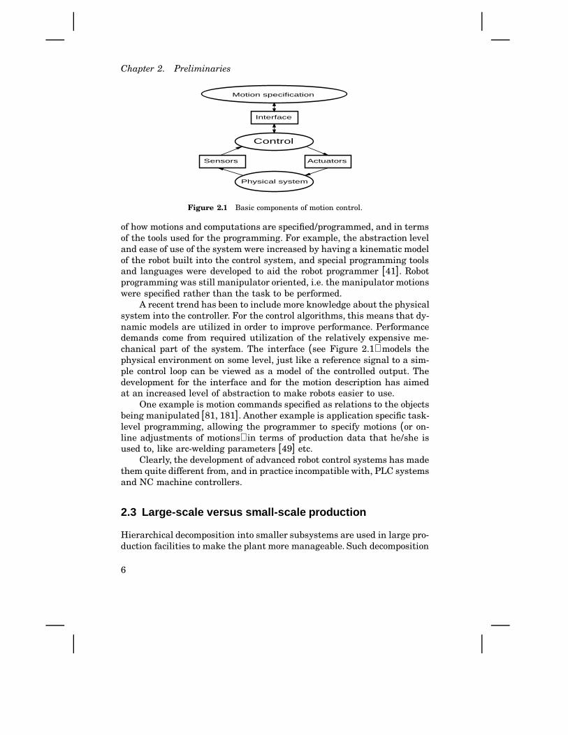
An industrial robot as such is basically not dedicated for a particular taskor application (even if some types of robots are preferably used in certainapplications). That distinguishes robots from other types of machinery.Originally, however, the individual joints of a robot were commandedand controlled as for any other multi-axes servo-controlled machine. Thismeans that motions were specified numerically by sequences of simplemotion commands. Interpretation of these commands results in calls tomove-procedures provided by an interface to the servo control algorithm,which controls the physical system via sensors and actuators, as shownin Figure 2.1. This means that rudimentary robot control is similar tostandard servo control, and is easily incorporated into any of today’sprogrammable control systems.
To make robots more useful, the development during the last 20 yearshas resulted in more sophisticated specification of motions, both in terms
5
Chapter 2. Preliminaries
Interface
Control
ActuatorsSensors
Motion specification
Physical system
Figure 2.1 Basic components of motion control.
of how motions and computations are specified/programmed, and in termsof the tools used for the programming. For example, the abstraction leveland ease of use of the system were increased by having a kinematic modelof the robot built into the control system, and special programming toolsand languages were developed to aid the robot programmer [41]. Robotprogramming was still manipulator oriented, i.e. the manipulator motionswere specified rather than the task to be performed.
A recent trend has been to include more knowledge about the physicalsystem into the controller. For the control algorithms, this means that dy-namic models are utilized in order to improve performance. Performancedemands come from required utilization of the relatively expensive me-chanical part of the system. The interface (see Figure 2.1) models thephysical environment on some level, just like a reference signal to a sim-ple control loop can be viewed as a model of the controlled output. Thedevelopment for the interface and for the motion description has aimedat an increased level of abstraction to make robots easier to use.
One example is motion commands specified as relations to the objectsbeing manipulated [81, 181]. Another example is application specific task-level programming, allowing the programmer to specify motions (or on-line adjustments of motions) in terms of production data that he/she isused to, like arc-welding parameters [49] etc.
Clearly, the development of advanced robot control systems has madethem quite different from, and in practice incompatible with, PLC systemsand NC machine controllers.
2.3 Large-scale versus small-scale pr oduction
Hierarchical decomposition into smaller subsystems are used in large pro-duction facilities to make the plant more manageable. Such decomposition
6

2.3 Large-scale versus small-scale production
should be made in such a way that the subsystems are as independentlyoperational as possible to provide robustness, but at the same time to-tal cost efficiency must be achieved. The aim for independent subsystemsleads to large-sized buffers for materials and components, and to machinesthat are not shared between different products. Aiming at cost efficiencytypically means the opposite. To make proper trade-offs between thesecontradictory demands is called “production planning and management”.This is not explicitly treated here, but we will see how the manufacturingorganization influences the desired properties of the local equipment.
Figure 2.2 shows an example of a hierarchical organization for alarger manufacturing system. Such a facility has (not shown in the figure)central engineering departments for product design, production planning,and production operation. Computer networks are widely used to connectmachines, work cells, and the central engineering facilities. Now, considerthe local robot equipment. It should be clear that a powerful host computerinterface for both programming and supervision is essential to achieveComputer Integrated Manufacturing (CIM). On the other hand, perhapsa too centralized approach is not the best solution.
Painting shop Machining shop
Milling
Assembly shop
Factory
Drilling Grinding
ConveyerInput buffer Milling machine Robot
Figure 2.2 Hierarchical levels in a large scale production facility.
If we look at a sample small mechanical workshop, there will beother demands on the (local) equipment. The production planning andoperation is probably not computerized, and a machine such as a robot istypically used as a stand-alone system which is programmed and operateddirectly on the workshop floor. Furthermore, the local operator has a goodoverview of the production, and he/she knows how to adjust the equipmentto obtain the desired production result. This means that there will be avery short turn-around time from a detected production problem until it
7
Chapter 2. Preliminaries
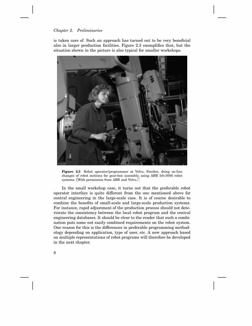
is taken care of. Such an approach has turned out to be very beneficialalso in larger production facilities. Figure 2.3 exemplifies that, but thesituation shown in the picture is also typical for smaller workshops.
Figure 2.3 Robot operator/programmer at Volvo, Sweden, doing on-linechanges of robot motions for gear-box assembly, using ABB Irb-3000 robotsystems. (With permission from ABB and Volvo.)
In the small workshop case, it turns out that the preferable robotoperator interface is quite different from the one mentioned above forcentral engineering in the large-scale case. It is of course desirable tocombine the benefits of small-scale and large-scale production systems.For instance, rapid adjustment of the production process should not dete-riorate the consistency between the local robot program and the centralengineering databases. It should be clear to the reader that such a combi-nation puts some not easily combined requirements on the robot system.One reason for this is the differences in preferable programming method-ology depending on application, type of user, etc. A new approach basedon multiple representations of robot programs will therefore be developedin the next chapter.
8
2.4 Robot programs
2.4 Robot programs
So far we have only dealt with (different types of) end-user programmingof robots, but what does robot programs look like? To clarify that for thereader not exposed to robot programming, a few comments will be givenin this section. Since a robot program contains the specifications how therobot should move, procedures for motion control will of course be used(i.e., the ‘interface’ in Figure 2.1 will be accessed). Such procedures havebeen implemented as part of the system programming, typically done bythe robot manufacturer. A high level of abstraction is often preferablein end-user programming, but a low level of abstraction is used here forclarity. Abstract actions will be converted to concrete ones anyway.
The pieces of robot program code appearing in this chapter are sup-posed to be written by an ordinary robot programmer. The code is thenexecuted in the robot controller, typically by an interpreter. The require-ments on the compiled procedure called by the interpreter is the topicin the examples. Early languages used in simple applications resembledBASIC. To deal with more complex situations, more structured (Pascal-like) languages were introduced. The first such language appears to beAL [135], in which computations are programmed in a Pascal-like syntax,but motions are requested with ‘move’ statements. Rather than having aprocedure MOVE with formal parameters, MOVE (and other types of motioninstructions) is a reserved identifier and parameters are specified withpredefined attributes belonging to the MOVE instruction. For example, agrinding motion may be expressed as (identifiers written with capitalsare reserved names):
MOVE grinder TO right_edge
WITH SPEED=0.15*mps
WITH FORCE=MyForce1
Thus, programs for simple tasks with no or little computing involved arequite readable, also for the user with limited experience from computerprogramming. The syntax of the language used is of minor importancein the thesis. A syntax similar to the most common robot programminglanguages [41, 118, 6] is therefore used.
Sensor inputs affect robot motions in four different ways [118]:1. Initiating and terminating motions.
2. Choosing among alternative actions.
3. Obtaining the identity and position of objects and features of objects.
4. Complying to external constraints.
The first three of these are simpler to handle because they map well
9
Chapter 2. Preliminaries
on conventional programming of computers and process control systems.The fourth type of sensory interaction is used when motions are contin-uously adjusted based on sensor inputs. Opposed to Items 1 to 3 whichmore have to do with event handling and reactive systems [76], Item 4requires feedback control [29, 193] Typical examples are combined posi-tion/force control using a force/torque sensor mounted on the robot wrist,or seam-tracking during arc-welding using a laser scanner. A straightfor-ward solution would of course be to specify the application-specific motioncontrol strategy directly on the end-user level. However, there are effi-ciency, complexity/simplicity, and safety reasons for not doing so. Instead,implementation of such sensor based motion control strategies used to becompletely done by the system programmer [118]. Therefore, such appli-cations put special demands on the control system.
2.5 Special applications
Contemporary systems usually allow customer specific sensors to be in-stalled, either direct via standard IO ports, or by installing a device driverfor more advanced sensors. So called open control systems [150] may evenallow replacement of specific control modules [70], but is that enough? Thefollowing example shows that the answer is no.
Industrial example – Deburring of castings
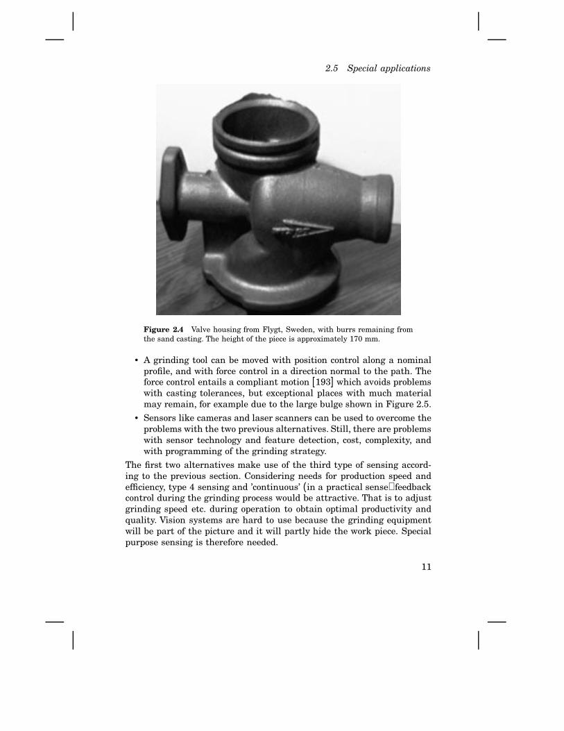
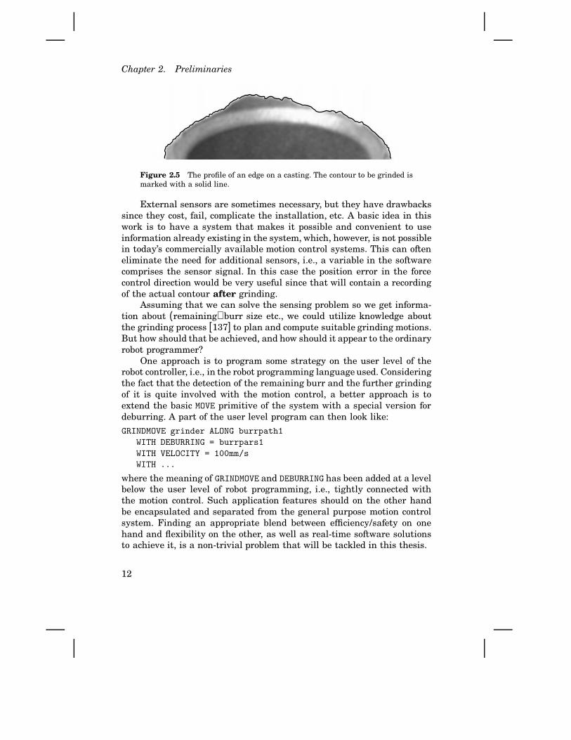
Figure 2.4 shows a typical example of a casting. Consider the uppercircular edge in the figure, i.e., it should be circular but remaining burrsfrom the sand-casting process make it look different. Those burrs haveto be removed, either by machining or manually using a grinding tool.Figure 2.5 shows the profile in more detail.
Removal of the burrs, so called deburring or cleaning of the casting,is a task that is preferably performed by flexible machines such as in-dustrial robots. That is because the task is monotonous, and there areunhealthy vibrations and air pollution. However, automatic deburring isfeasible only in simple cases today. Specific problems are to make therobot recognize where additional grinding is required and, if so, to pro-gram suitable deburring motions. More specifically, we can think of thefollowing strategies:
• The burrs can be cut off. Such a process is, however, often too slowand the position of the profile to clean must be known rather precisely.That is typically not the case due to casting tolerances.
10
2.5 Special applications
Figure 2.4 Valve housing from Flygt, Sweden, with burrs remaining fromthe sand casting. The height of the piece is approximately 170 mm.
• A grinding tool can be moved with position control along a nominalprofile, and with force control in a direction normal to the path. Theforce control entails a compliant motion [193] which avoids problemswith casting tolerances, but exceptional places with much materialmay remain, for example due to the large bulge shown in Figure 2.5.
• Sensors like cameras and laser scanners can be used to overcome theproblems with the two previous alternatives. Still, there are problemswith sensor technology and feature detection, cost, complexity, andwith programming of the grinding strategy.
The first two alternatives make use of the third type of sensing accord-ing to the previous section. Considering needs for production speed andefficiency, type 4 sensing and ’continuous’ (in a practical sense) feedbackcontrol during the grinding process would be attractive. That is to adjustgrinding speed etc. during operation to obtain optimal productivity andquality. Vision systems are hard to use because the grinding equipmentwill be part of the picture and it will partly hide the work piece. Specialpurpose sensing is therefore needed.
11
Chapter 2. Preliminaries
Figure 2.5 The profile of an edge on a casting. The contour to be grinded ismarked with a solid line.
External sensors are sometimes necessary, but they have drawbackssince they cost, fail, complicate the installation, etc. A basic idea in thiswork is to have a system that makes it possible and convenient to useinformation already existing in the system, which, however, is not possiblein today’s commercially available motion control systems. This can ofteneliminate the need for additional sensors, i.e., a variable in the softwarecomprises the sensor signal. In this case the position error in the forcecontrol direction would be very useful since that will contain a recordingof the actual contour after grinding.
Assuming that we can solve the sensing problem so we get informa-tion about (remaining) burr size etc., we could utilize knowledge aboutthe grinding process [137] to plan and compute suitable grinding motions.But how should that be achieved, and how should it appear to the ordinaryrobot programmer?
One approach is to program some strategy on the user level of therobot controller, i.e., in the robot programming language used. Consideringthe fact that the detection of the remaining burr and the further grindingof it is quite involved with the motion control, a better approach is toextend the basic MOVE primitive of the system with a special version fordeburring. A part of the user level program can then look like:
GRINDMOVE grinder ALONG burrpath1
WITH DEBURRING = burrpars1
WITH VELOCITY = 100mm/s
WITH ...
where the meaning of GRINDMOVE and DEBURRING has been added at a levelbelow the user level of robot programming, i.e., tightly connected withthe motion control. Such application features should on the other handbe encapsulated and separated from the general purpose motion controlsystem. Finding an appropriate blend between efficiency/safety on onehand and flexibility on the other, as well as real-time software solutionsto achieve it, is a non-trivial problem that will be tackled in this thesis.
12

2.5 Special applications
A benchmark/toy problem
Some characteristics have been identified in special applications like thedeburring one above.
• Some initial control strategy is required before the desired move-ment can start. For example, a grinder tool must be started and acertain initial contact force between the grinder and the work piecemust be achieved.
• A sequence of initial control actions may be needed. The robot mustfirst be properly positioned, etc.
• Normal operation entails cyclic execution of a feedback control al-gorithms, which can be derived from dynamic models and/or fromheuristics. Control of path speed depending on burr size is one exam-ple.
• There are some online supervision of control states to detect if theprocess enters a prohibited region. For instance, a too slow path speed(depending on exceptional burr size) may cause overheating of thetool or of the work-piece. Special control must then be switched in tohandle the exception.
• Control of mechanical systems is typically non-linear, but canoften be controlled locally using (piecewise) linear controllers.
• Special control may be required to gracefully finish the operation. Asmooth edge may be required also where grinding finishes.
• High sampling frequencies are sometimes required, and the real-timedemands on the control may be severe.
• The special application specific control is preferably encapsulated ina new customized statement, like the GRINDMOVE above.
It is also characteristic that a lot of equipment and installation is requiredto run a real industrial application. That makes setups in different robotlaboratories difficult and expensive. Still, it would be valuable to havea benchmark problem that can easily be setup, and that could be a testhow well a system can be used for ‘special applications’. Such a suitablebenchmark problem has been found to be control of an inverted pendulumheld by a robot hand.
Control of a pendulum [27, 192] illustrates that many different con-trol principles have to be used to accomplish a given task. Specific controlproblems include
• Initial control to a well defined initial state to prepare for specialswing-up strategies.
13
Chapter 2. Preliminaries
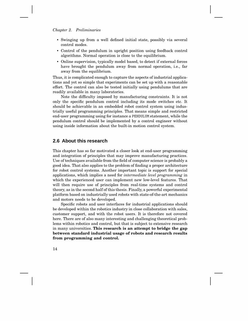
• Swinging up from a well defined initial state, possibly via severalcontrol modes.
• Control of the pendulum in upright position using feedback controlalgorithms. Normal operation is close to the equilibrium.
• Online supervision, typically model based, to detect if external forceshave brought the pendulum away from normal operation, i.e., faraway from the equilibrium.
Thus, it is complicated enough to capture the aspects of industrial applica-tions and yet so simple that experiments can be set up with a reasonableeffort. The control can also be tested initially using pendulums that arereadily available in many laboratories.
Note the difficulty imposed by manufacturing constraints. It is notonly the specific pendulum control including its mode switches etc. Itshould be achievable in an embedded robot control system using indus-trially useful programming principles. That means simple and restrictedend-user programming using for instance a PENDULUM statement, while thependulum control should be implemented by a control engineer withoutusing inside information about the built-in motion control system.
2.6 About this r esearch
This chapter has so far motivated a closer look at end-user programmingand integration of principles that may improve manufacturing practices.Use of techniques available from the field of computer science is probably agood idea. That also applies to the problem of finding a proper architecturefor robot control systems. Another important topic is support for specialapplications, which implies a need for intermediate level programming inwhich the experienced user can implement new low-level features. Thatwill then require use of principles from real-time systems and controltheory, as in the second half of this thesis. Finally, a powerful experimentalplatform based on industrially used robots with state-of-the-art mechanicsand motors needs to be developed.
Specific robots and user interfaces for industrial applications shouldbe developed within the robotics industry in close collaboration with sales,customer support, and with the robot users. It is therefore not coveredhere. There are of also many interesting and challenging theoretical prob-lems within robotics and control, but that is subject to extensive researchin many universities. This research is an attempt to bridge the gapbetween standard industrial usage of robots and research resultsfrom programming and control.
14

2.6 About this research
Misconceptions
Tackling problems that do not have an established definition can createsome confusion. Depending on the reader’s background and previous ex-periences (e.g., from some existing system), different parts of the solutionspresented can lead to some confusion concerning approach, importance,novelty, etc. Based on reactions to viewpoints presented in technical dis-cussions and earlier work [144], the following remarks are made in orderto point at some standard misconceptions.
The purpose of a software architecture Software architectures havereceived much attention within robotics research [56, 13, 127]. One reasonis that when robot controllers (e.g., for space applications) become moreand more complex, abstractions and software structures are introducedto cope with complexity. In other words, the purpose of the architectureis to make the implementation of the system feasible.
In industrial robotics the software is complex and various functionsmust be tightly coupled to achieve efficiency. However, the implementa-tion complexity is not worse than it can be handled by proper softwareengineering methods, like an object-oriented design. But the variety ofuser interactions in flexible manufacturing systems indicates that userviews of the system should be the basis for the architecture. This is acompletely different approach that should not be confused with imple-mentation architectures.
“We can do that in our system” When suggesting a new embeddedcontrol system, there will always be alternative ways to do it. Take, forinstance, some advanced process control systems. First, such a system canof course be used to control a robot, but will the desired performance, costefficiency, programmability, and flexibility be achieved? Secondly, whendoing servo control using process control systems, will use of a specificsystem and its special language etc. be appropriate for interfacing tostand-alone servos? In conclusion, almost anything feasible can be im-plemented in any system, but specific application demands as consideredin this thesis are typically not taken into consideration.
“Layered systems are not useful without a detailed specification”Layered systems are perhaps most common within computer communi-cation. Refer for example to the OSI model [90], and to the even morespecific MAP standard [156]. Within computer and telecommunicationapplications, it is crucial that the specification of the layers is completein all its details. It must be possible to interleave component and layersfrom different vendors, and the layers reflect the implementation.
15

Chapter 2. Preliminaries
In this work, the layers reflect user views of the system. Detailedinternal interfaces could of course also be developed, but that needs tobe made in collaboration with major vendors and/or standardization or-ganizations. Otherwise, the industrial impact would be too small. On theother hand, we claim that earlier and ongoing standardization of robotinterfaces on high [130], intermediate [212, 91], and low levels [169] arenot appropriate. Just like this work is not devoted to some new program-ming language, it does not depend on a detailed standard. It is usageof the principles proposed that yields the benefits. Standards come withmaturity!
“A robot controller is just another PLC block” Process control sys-tems and PLCs (Programmable Logic Controllers) often control motions,usually via dedicated servo controllers containing the drive electronicsand the low level feedback control. Process controllers are typically pro-grammed by combining and connecting PLC blocks into a block diagramdefining the control program. A servo controller can then be encapsulatedin such a block. What is then a robot controller? In simple and less de-manding cases, a robot control system is just a multi-axes programmableservo controller. For the reader with experience mainly from such appli-cations, it could be hard to understand why robot control should be sucha big issue; it is just another PLC-block. However, investigating demand-ing use of industrial robots, the needs for motion descriptions, operatorinteractions, nonlinear and variable structure control, and computing effi-ciency clearly show that robot control requires its own control techniques.It is still desirable to combine process control (for manufacturing) andadvanced robot control, but that is outside the scope of this thesis.
“We already have an open system” A system that is open allows theuser or system manager to change or add certain internal components ofthe system. In practice, systems are a mixture of open and closed parts[70]. The open parts can also be open in many ways. As an example,consider a robot control system with a replaceable trajectory generator.Such a system can be claimed to be open. However, the interfaces tothe software component (the trajectory generator in this case) could beso rigid that only the algorithm can be replaced. In other words, struc-tural changes involving, for example, new types of interaction with theservo control are often not possible. Therefore, an open system shouldbe reviewed concerning the type of changes possible, and what degree offlexibility that implies. Still, one should keep in mind that there can besafety and proprietary reasons to keep parts of the system closed.
16
2.6 About this research
“Our customers have not required that feature” Industrial devel-opment has to focus on customer requirements. Sometimes, however, newfeatures that let customers explore new possibilities simply have to beoffered. Proposal of new features for application or customer support en-gineers, sometimes results in a comment that “our customers have notrequired that feature”.
This research is inspired by real industrial problems, but specific solu-tions can very well be questioned in the light of short term requirements.The reader should in those cases, however, not forget the fundamentallong-term benefits.
“The problem is on-line teach-in programming” Different ways toprogram robots are preferable for different situations/applications. If weuse the robot system for the programming, we call it on-line programming.Combined with definition of coordinates by manually commanding/movingthe robot, we have on-line teach-in programming (OLTP). Such program-ming has turned out to be very useful in many (or even most) industrialapplications. Within robotics research and for some advanced applications,use of OLTP is often considered to be a problem because the off-line sys-tems can not fully cope with on-line changes of the programs, and becausethe robot control system does not provide sufficient support for advancedapplications. This is how it happens to be, but do not confuse the possiblebenefits of OLTP with the disadvantages of today’s systems. This topicwill be returned to in the next chapter.
“A new type of motion is just another procedure” Principles forincorporation of application features have not received the same attentionas other software aspects in robotics like high-level planning, or low-levelexplicit joint control. It has been neglected by statements of the type“just implement a procedure” or “implement another robot function”. Onthe other hand, robot manufacturers spend major efforts in designingand implementing such robot functions. Even so, it is well known thatit may be difficult or impossible to slightly modify a function, to changean application feature, or to include a new type of sensor in existingsystems. The reason is of course that the software is complex with manycoupled functions that are based on mutual primitives, include timing andso on. The seemingly harmless task to include a new robot function mayrepresent a major effort. Applications mature over time and it is naturalthat more and more special features need to be implemented. If this canbe done efficiently using the principles proposed in this thesis, then theimplications for production speed and efficiency are obvious.
17

Chapter 2. Preliminaries
Concluding remark
Throughout the thesis we take issue with the misconceptions quoted. Inconclusion, it is believed that more generally applicable robots is a keyissue in providing flexible components for manufacturing systems, evenif it is realized that control of specific machines is not the most impor-tant aspect of efficient manufacturing. The approach taken here, how-ever, is related to the manufacturing practice aspect in the sense thatthe equipment should be designed in such a way that man-machine inter-actions supporting superior manufacturing practices should be allowed.The key motivation for this research is that the problems have been de-ficiently observed/solved elsewhere. Note that there is usually no contra-diction between principles presented here and other established researchapproaches; one aim here is to ease practical use of available andfuture research results by proposing a suitable framework thatalso considers typical industrial demands, and by providing anexperimental platform for verification of these ideas.
18
3
End-User Programming
An industrial robot is a programmable industrial manipulator. A robotprogram is expressed in some kind of robot programming language (RPL),as described in Section 2.4. In this chapter we assume availability of a con-trol system providing a set of motion primitives, including those possiblyrequired in special applications according to Section 2.5. In other words,we specifically focus on possible improvements of end-user programming.
Proposals how to deal with this problem can be found in (almost)any robotics conference. A common approach is to increase the level ofabstraction aiming at so called task-level programming [112, 106, 59](an early reference appears to be [203]). Some approaches include thephysical layout in the design of robot tasks [155, 52]. In any case, anembedded control system is used for feedback control of manipulatormotions. Such robot controllers [118, 59, 46] also provide manipulator-level programming and operator interaction [164]. These features arecarefully designed to meet the requirements of standard applications, buthas until now not been fully exploited when combined with high-level(fully computerized) methods of programming. So, instead of trying tofind the ultimate solution (like special languages, databases, etc.), theaim is to better combine and integrate such methods that arepromising or successfully used for industrial applications.
A small introductory example to be used throughout this chapter willbe defined in Section 3.1, followed by some comments on different ways todo the programming today in Section 3.2. With the presented example andthe interpretation of available methods in mind, the following problemswill be tackled:
• In Section 3.3, which first describes the approach towards integratedrobot programming, the misconception concerning on-line program-ming mentioned on Page 17 is treated.
• The desire to combine the benefits of small-scale and large-scale pro-
19

Chapter 3. End-User Programming
duction as explained in the previous chapter will then in Section 3.4be interpreted as a feedback control problem.
• In Section 3.5 we look at internal states of robot programs. Needs tomaintain some world model data also in on-line programming reveala context sensitivity problem that until now have been overlooked.
• A solution to the context sensitivity problem will then be proposed inSection 3.6. This is a key issue to accomplish the desired integratedend-user programming.
• An implementation of a full prototype is described in Section 3.7.
3.1 Small introductory example
To focus interest on some important robot programming aspects, a sim-plified robot welding task will now be defined. The standard “peg-in-hole”problem [67, 59] is another such test-case for assembly applications. Thefollowing welding application does, however, better represent such appli-cations that are of primary interest in this thesis.
Consider an arc-welding task. For simplicity we study only a singleweld-joint. The task is to weld a piece of flat iron bar on a base platemounted on a fixture. See Figure 3.1. Before welding is to be started, therobot is supposed to move the weld-gun to a location clean where cleaningof the tool takes place. Welding should start on a location start pose andproceed along a straight line to location end pose, also on the base plate.After welding is completed, the robot should move to a position home whereit waits until next task starts.
zy
x
z
x
y
z
xz
x
y
y
z
x
y
zy
xy
z
xstart_pose
base_plate
end_pose
home
Welding path
fixtureworld
clean
Figure 3.1 A simplified robot welding task.
20

3.2 Review and classification of current approaches
Note that the locations clean and home are expressed relative toa fixed world coordinate system, whereas the locations start pose andend pose should be expressed relative to a frame base plate defining thelocation of the base plate on the fixture. That is to permit an alternativemounting on the fixture without changing the welding sequence.
3.2 Review and classification of current approaches
Many preferences by robot programmers for one or the other robot pro-gramming method stem from the way different methods are combined insystems today. For example, some programmers prefer off-line program-ming (explained below) because some important feature is not supportedby the teach-in interface they have access to. Others prefer on-line pro-gramming because their system provides an easy to use programming in-terface for on-line programming. Even major books in robot programminglike [41] and [59] have such preferences, but some factory floor aspects(mostly to the favor of on-line programming) deserve some comments.This section reviews current robot programming concepts in four differ-ent ways to prepare for a treatment of some basic underlying problems.
On-line or off-line programming
Let use of mechanical robot be the basis for our classification. Off-line pro-gramming means that the mechanical robot and other production equip-ment is not occupied during programming, which instead takes place ona host computer. On-line programming means that the physical robot isoccupied during the programming. These two alternatives for where theprogramming takes place are standard [41, 59] and used in different sit-uations.
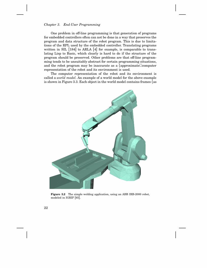
Off-line programming has the advantage that a production cell canbe designed, programmed, and its operation may be simulated before thecell is actually built. The result of the simulation can be which type ofrobot that should be used, or how the equipment in the cell should bearranged. To this purpose, advanced modeling and 3D graphics are used.As an example, Figure 3.2 shows the above application example modeledin an industrially widely used off-line system. Several advanced off-linesystems provide a general purpose RPL, and code generators for specificrobot controllers. A uniform style of programming for robots of differentbrands can thereby be achieved [59]. However, each off-line system hasits own ‘general purpose’ language. Hence, independency of robot systemsinstead results in dependency on the off-line system.
21
Chapter 3. End-User Programming
One problem in off-line programming is that generation of programsfor embedded controllers often can not be done in a way that preserves theprogram and data structure of the robot program. This is due to limita-tions of the RPL used by the embedded controller. Translating programswritten in SIL [184] to ARLA [4] for example, is comparable to trans-lating Lisp to Basic, which clearly is hard to do if the structure of theprogram should be preserved. Other problems are that off-line program-ming tends to be unsuitably abstract for certain programming situations,and the robot program may be inaccurate as a (approximate) computerrepresentation of the robot and its environment is used.
The computer representation of the robot and its environment iscalled a world model. An example of a world model for the above exampleis shown in Figure 3.3. Each object in the world model contains frames (as
Figure 3.2 The simple welding application, using an ABB IRB-2000 robot,modeled in IGRIP [65].
22

3.2 Review and classification of current approaches
home
base link-1start_pose
base_plate
end_pose
world
fixture cleanIrb-2000
flat_barAffixment by welding
Figure 3.3 World model objects for the simplified example.
coordinate systems are designated within robotics) defining the position,orientation, and geometry of the corresponding physical object. Otherattributes may describe the graphical view of the object in the case when agraphical user interface is used. Structured objects containing a numberof sub-objects may also contain kinematics and affixments. Affixmentsare used for temporary rigid connection between objects, like when asimulated robot picks up a simulated workpiece [59].
Increase incomputerprogrammingskills
Increase inshop-floor skills
lead-through
pendant teaching
textual programminglanguages
off-line programming
Figure 3.4 Computer programming versus shop-floor skills, considering hu-man factors in robot programming [164].
On-line programming does occupy the production equipment, but anadvantage is that it is tangible, i.e., abstract world modeling and computersimulation are not needed. The programmed motions will also be accuratesince locations and frames can be defined via teach-in referring to the trueframes. On the other hand, complex motions along mathematically welldefined paths (for example on airplane wings, turbine shovels, etc.) canbe very hard to program by teach-in. Such motions are better directlydescribed based on data from CAD systems.
Generally, a tradeoff between simplicity and programmability ap-pears to be necessary for a specific programming environment. On-lineprogramming systems naturally tends to focus on simplicity, whereas off-line systems tends to focus on programmability. See Figure 3.4. The con-clusion is that both on-line and off-line programming are needed in varioussituations. Thus, we want a system combining the two.
23

Chapter 3. End-User Programming
Level of “physical abstraction”
The way we describe physical operations (like robot motions), or the waywe refer to physical objects, will now be used to classify the level ofprogramming. Let us introduce the term physical abstraction for robotprogram abstraction based on (a model of) the physical properties ofoperations and objects. The reason to introduce this term is to avoid theusual confusion in the literature with the degree of abstraction for theprogramming language itself, which is called programming abstractionbelow. Concerning the physical abstraction, we have what is usually calledthe degree of abstraction according to the following levels [41, 59, 118]:Task-level programming is the highest level and it is a research field
of its own. The goal is to allow the programmer to specify what to doin a declarative manner, and the system figures out how to performthe task. This level, though not a main subject in this thesis, will becommented in Chapter 4.
Object-level programming also utilizes a model of the environment,i.e., the world model, but normally not including all obstacles etc.Motions are programmed by specifying relations between objects, butthe planning is mainly done by the human operator. Implementationof object-level programming can be done on top of a database [181].
Manipulator-level programming focuses on the definition of manipu-lator motions rather than on the objects that are manipulated. In-structions can still refer to objects in the working space, but theobjects are simply named frames and no full world model is main-tained. Motions and constraints in joint space [60] can also be dealtwith more easily.
As mentioned, the typical research approach to robot programming hasbeen to increase the level of robot programming to make robots easier touse. However, the following example (modified from [43]) indicates thatthis is not necessarily true. A task-level program for the small exampleabove may look like:
ARCWELD flat_bar ON base_plate
which implies that the system should figure out how to place the flat bar
on the base plate. This looks very simple, but the required knowledgeabout the objects, rules how to do the welding, planning of motions, etc.hinders use of such programming in two ways: Such systems and planningalgorithms have not been fully developed yet, and in most applications itis easier for the programmer to do the planning and enter an explicitprogram then it is to enter all data required by the planner. A moreexplicit, but still on an object level, program would be
24

3.2 Review and classification of current approaches
PLACE flat_bar ON base_plate SUCH THAT
flat_bar.side IS PERPENDICULAR AND
flat_bar.end CONTACTS base_plate.weld_line
ARCWELD flat_bar.end AND base_plate ALONG CONTACT
which perhaps still looks like a simpler and more elegant way of describingthe task than teach-in programming would be. It should be clear, however,that also for a quite simple task a quite extensive and accurate descriptionis required.
Object-level programming supported by graphical programming tools[188, 181] have turned out to be quite useful in circuit board assemblyapplications. In such applications, component data are available in databases and the planar geometry of the task maps well on the (also pla-nar) computer screen. On the other hand, in many other applications,manipulator-level programming is more natural for the operator with-out extensive programming knowledge; a sequence of motion commandsdirectly reflects the way a human worker would perform the task.
The conclusion is that all the different levels of physical abstractionare suitable in different programming situations. That implies that theprogramming system should be layered in such a way that higher levelsof abstraction can be added on top of the basic manipulator-level program-ming.
Level of programming abstraction
Robot programs consist of statements for motions and for informationprocessing. Either motion statements are built into the language, or theyare achieved by use of a robot software library. In the former case we havea special manipulator language, e.g., languages like ARLA [4], AL [135],or AML [204].
It has turned out that major parts of typical robot programs consistof information processing, i.e., robot programs resemble computer pro-grams. This implies that robot programming includes all the aspects andproblems of computer programming, plus some additional ones. This isalso the reason why recently introduced robot programming languageseither belongs to existing computer programming languages (with a robotlibrary), or are a new general purpose programming languages with somespecial robot programming support (types, syntax, etc.). Examples of theformer are RCCL [81], PASRO [41], and HAL [134], whereas Karel [72]and RAPID [6] are examples of the latter.
In conclusion, the similarities to computer programs indicate that thesame abstractions and paradigms (abstract data types, object orientation,etc.) should be used for robot programs. However, the difference is that
25

Chapter 3. End-User Programming
robot programming should be possible to do in a way that supports “su-perior manufacturing practices” as mentioned on Page 5. Thus, the levelof programming abstraction should be selected depending on applicationand type of production system. This is typically related to the level ofphysical abstraction, but does not need to be.
User interface
Robot programming and operation can be performed via a user interfaceincluding one or several of the following alternatives:
• Free text edit input in a usual computer programming style.
• A structured editor or programming tool supporting the RPL.
• A graphical user interface, possibly with 3D visualization.
A well designed system may use all three alternatives if appropriate.Fancy graphics is not always the best alternative. Use of the physicalworld can, for instance, be more beneficial than a graphical view of it insome cases. One such case is when on-line programming using a hand-held terminal is preferred.
Figure 3.5 Panel layout of ABB hand-held robot programming terminal(first S4 version). Joy-stick, emergency stop button, and ‘dead-mans-handle’located beside the panel are not shown.
26
3.2 Review and classification of current approaches
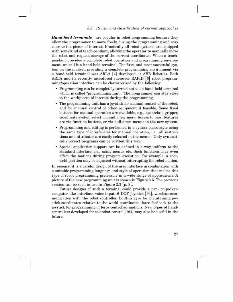
Hand-held terminals are popular in robot programming because theyallow the programmer to move freely during the programming and stayclose to the pieces of interest. Practically all robot systems are equippedwith some kind of teach-pendant, allowing the operator to manually movethe robot and request storage of the current coordinates. When a teach-pendant provides a complete robot operation and programming environ-ment, we call it a hand-held terminal. The first, and most successful sys-tem on the market, providing a complete programming environment viaa hand-held terminal was ARLA [4] developed at ABB Robotics. BothARLA and its recently introduced successor RAPID [6] robot program-ming/operation interface can be characterized by the following:
• Programming can be completely carried out via a hand-held terminalwhich is called “programming unit”. The programmer can stay closeto the workpieces of interest during the programming.
• The programming unit has a joystick for manual control of the robot,and for manual control of other equipment if feasible. Some fixedbuttons for manual operation are available, e.g., open/close gripper,coordinate system selection, and a few more. Access to most featuresare via function buttons, or via pull-down menus in the new system.
• Programming and editing is performed in a syntax-based style usingthe same type of interface as for manual operation, i.e., all instruc-tions and attributes are easily selected in the menus. Only syntacti-cally correct programs can be written this way.
• Special application support can be defined in a way uniform to thestandard interface, i.e., using menus etc. Such functions may evenaffect the motions during program execution. For example, a spot-weld position may be adjusted without interrupting the robot motion.
In essence, it is a careful design of the user interface in combination witha suitable programming language and style of operation that makes thistype of robot programming preferable in a wide range of applications. Apicture of the new programming unit is shown in Figure 3.5. The previousversion can be seen in use in Figure 2.3 (p. 8).
Future designs of such a terminal could provide a pen- or pocket-computer like interface, voice input, 6 DOF joystick [94], wireless com-munication with the robot controller, built-in gyro for maintaining joy-stick coordinates relative to the world coordinates, force feedback to thejoystick for programming of force controlled motions. New types of hand-controllers developed for telerobot control [164] may also be useful in thefuture.
27
Chapter 3. End-User Programming
Computer-based interfaces are preferably combined with off-line pro-gramming. Availability of 3D graphical models of the robot and its en-vironment then makes programming much easier [59] (pp. 418–419).Several such system are available on a commercial basis, e.g., CimSta-tion [183] and IGRIP [65]. It would of course be desirable to combinesuch systems and the more on-line oriented systems mentioned earlier.That will be returned to, but an interesting (already solved) special casewhen on-line and off-line programming can use the same kind of userinterface can be found in many circuit-board assembly applications. The“planar world” in these applications can be well mapped onto a computerscreen that can be located close to the equipment, and powerful systemslike the SMALL system [188] and the AIM system [181] have emerged.
3.3 An approach to integrated programming
Software support for demanding robot applications, requiring dextrousmotions and on-line tuning to deal with the manufacturing process andits uncertainties, are the focus in this thesis. Appropriate choices of pro-gramming principles and tools are probably most crucial in such appli-cations. A development towards off-line task-level abstract programmingonly, utilizing modern computer graphics, can be questioned in the lightof the following quote [200]:
The use of the best available interface techniques does not assurethe production of a good interface; a good menu system cannotmake up for a poor task analysis. Success in interface designcomes when an interface properly addresses the semantics of itsusers’ tasks and domains.
In other words, programming principles should be decided according tothe production situation, not the other way around. This motivates furtherwork in the following directions:
1. Dedicated program packages for specific applications should be de-veloped in close interaction with the application developers and in-dustrial users.
2. Design of robot control systems and robot programming principlessupporting application specific programming.
3. Planning and scheduling of manufacturing activities should be donein such a way that hands-on adjustments of the task are taken intoconsideration.
Whereas Item 2 merits our further attention, Item 1 is best solved in anindustrial environment in close interaction with customer support. It is
28

3.4 Local operation entails local feedback
therefore not treated here. Though planning and scheduling of manufac-turing have been subject to extensive research, the need to actually dealwith on-line changes has only more recently been considered [58].
Benefits of on-line programming
Advanced robot programmers often consider on-line programming to be aproblem. One reason is that when their favorite off-line system is used tocreate and down-load programs to the embedded controller, on-line mod-ifications then make the programs differ from the version maintained inthe central database. (Compare with the large-scale system on Page 7.)The usual research approach is not to use (or even allow) on-line modifi-cations. The approach here will be the opposite.
Another problem with on-line programming of advanced applicationshas been that the programming language/tools (available on the hand-held terminal) have been too limited. Use of a very simple teach-pendantis probably the reason for statements like the following about a sampleapplication including palletizing ([59], p. 396): “It should be clear thatthe definition of such a process through ‘teach by showing’ techniquesis probably not feasibly”. However, such an application can be very wellsolved by available built-in functions in the ARLA system [4] from ABBRobotics. The new RAPID system [6] even (potentially at least) allowsthe advanced user to introduce certain application specific functions in away that supports on-line usage [46].
A third type of problem in on-line programming is due to limitedavailability of computing and control tools in embedded systems. Althoughnot explicitly found in the literature, it is a straight forward step to extendthe networking principles used in manufacturing to also allow use ofhost computer software from the embedded system. This has also beenimplemented in our lab [191] where we used Matlab [124] as a computeserver for the embedded system.
In conclusion, we should not neglect, as typically done in university-based research, the benefits of on-line programming. Note, however, thatthis is not to say that on-line programming suits all situations. In a carproduction line, for instance, off-line programming is very useful as a wayto make the production stop as short time as possible when reprogram-ming for new car models is to be done.
3.4 Local operation entails local feedback
We are now ready to analyze the misconception “The problem is on-lineteach-in programming” from Page 17. Consider a large-scale production
29

Chapter 3. End-User Programming
facility with a central engineering department. Let us study the program-ming and operation of an industrial robot in that production system. As-sume that we allow/support interaction with the robot controller in twodifferent ways:
1. New or modified robot programs can be down-loaded from the centralengineering computer system.
2. Robot programs can be edited by the local operator on the factoryfloor.
Feedback control: The flow of information (physical signals, data, orissued operations) in the described situation is viewed in a block-diagramstyle in Figure 3.6. As shown in the figure, our two types of interactionwith the controller result in a cascade control structure; an inner loop forthe local operation and an outer loop for the overall control.
interface2) on-line
interface1) off-line
Process and product status
Robot programsMotion
Edit/Adjust Observations
Program/Teach
Report
Data
1
2
Order
Localoperator
Moni-toring
systemRobot
processManufacturing
Processtracking
ProductionengineeringDesign
Product
Figure 3.6 Local feedback by local manufacturing operation.
In control engineering, the principle of local feedback is very wellknown. It is a way of taking care of process variations locally, avoidingeffects on the total more complex system that would be harder to control.Local feedback has been of great use ever since Black [40] invented it asa way to make electronic amplifiers insensitive to component variations.That was in the beginning of this century. Successful cascaded feedbacktypically relies on the inner loop being faster. What about that in thiscase?
The local operator is typically able to adjust the robot program in amatter of minutes. Operator feedback is applied in the sense that the op-erator observes the controlled process while adjusting it. The feedback inthe outer loop, however, is considerably slower. A problem is typically firstdetected on the shop floor and reported to the central control. Adjustmentthen either uses observations from the local operator, or from some typeof supervision system. Clearly, the outer loop is anyhow slower than the
30

3.4 Local operation entails local feedback
inner one. This means that the structure necessary for successful cascadecontrol appears to be fulfilled. But what are the benefits of each loop?
The outer loop is required for management and control of the completefacility. The “production engineering” also includes off-line programmingwhen major changes are imposed from the Order and Design input, seeFigure 3.6. This is for instance the case in car production as mentionedabove. In control terms, set-point changes need to be formed in a way thatthe operation of the systems does not deteriorate.
The inner loop is required for robustness and performance duringevery-day operation. Efficiency as practically obtained in small-scale pro-duction is the key motivation for this; it is desirable to have the benefits ofsmall-scale production also in larger facilities. Specifically, the Report pathin Figure 3.6 should not need to be used for changes already expressedin the robot program. Instead, such information should be propagated tothe “Production engineering” (backwards) via the Robot programs path.In control terms, this is outer loop tracking due to inner loop saturationor manual operation.
Flexible manufacturing systems (FMS): As shown in several case-studies [24], modular locally manageable cells improve robustness andflexibility. More specifically, trying to achieve flexibility and efficiency viacomputer integration and scheduling does often not work very well inpractice as expressed1 in [24] (p. 170). This clearly motivates an approachthat supports locally operational units.
The most feasible way to implement the production feedback to thecentral manufacturing engineering, and to maintain consistency betweenthe on-line and off-line versions of the robot programs, would be auto-matic retrieval of the modifications done on the factory floor. Manufac-turing practice today is, however, less productive. Statements like ([24],p. 156) local operation “allows an operator at the machine tool to edit” theprogram, and the improved program should only be saved so it “allowsan authorized operator to create new production versions”. Furthermore,when the structure of robot programs is changed on-line, the changes can-not in general be mapped back to the engineering workstation [59, 183].This circumstance means that local feedback today actually makes overallmanufacturing control harder.
1 “FMSs promise 50% reductions in lead and manufacturing times using only a hand-ful of machines and a few operators. Yet flexible manufacturing systems are farfrom being irresistible. Many manufacturers, having long considered FMS technol-ogy, are now opting for something smaller, simpler, and cheaper. They are buyingflexible manufacturing cells and even stand-alone CNC machine tools”.
31
Chapter 3. End-User Programming
3.5 Internal states and external reality
Transfer of robot programs between on-line and off-line systems may looklike an ordinary software translation task. There are known problemswith too restrictive RPLs as explained on Page 22 (see also [59], pp. 431-433), but let us assume that the on-line language is powerful enough.
A robot program created in an off-line programming system makesuse of the world model, which is an abstraction of the ambient work cell.In on-line programming, however, the real physical world is there, whichmakes some simplifications possible. There are, on the other hand, caseswhen data have to be kept and maintained in a way that reflects theexternal reality. Such a principle of organization, known as the internalmodel principle in control theory [221], therefore appears relevant also forrobot programming. The purpose of this section is to present an (until nowoverlooked) on-line programming aspect which requires special treatmentin integration of on-line and off-line programming.
Object views in world modeling
State of the art off-line programming entails object-level programmingusing a world model as described earlier. To facilitate transfer of robotprograms later, the attributes of the object in the worlds model will nowbe classified. The term object view will be used to refer to a group ofattributes (or methods) that capture a certain aspect of the object. Thisis in conformity with views as defined in process control [199, 1], controlengineering [142], and software engineering [44]. It is of course preferableto have support for views in the programming language. The SIL [184]RPL provides this feature in connection with multiple inheritance. Inlanguages without such support, views can be maintained by managementof object attributes.
Object-level robot programming can be viewed as object-oriented[126] support concerning the physical properties of the objects within thework cell. This means that objects will have attributes reflecting their ge-ometry, but are there cases when such objects also should have attributescorresponding to logical or computational properties? Modeled in a off-lineprogramming system, we can think of the following object views:
Physical attributes represent physical properties that should be possi-ble to refer to when specifying robot motions. This of course includesthe geometry of the physical object, but also the dynamic propertieslike mass and inertia.
Graphical attributes are needed only for the graphical presentationduring off-line programming.
32

3.5 Internal states and external reality
State attributes represent the state of the physical task. This view isdefined for on-line programming purposes.
The state (called soft in the original presentation [144]) view and its usein the sequel is believed to be new. A related but different classificationof the physical and graphical attributes has been proposed by others (in-troduction to Chapter 8 in [112]), but for off-line and planning purposes.
As an example, consider a pallet being used in an assembly task (asin Chapter 12 in [59]). Considering the pallet object and the objects forthe pieces fitting into the pallet, an off-line world model today would haveattributes like:
1. Physical attributes would typically be the frame for one corner loca-tion of the pallet relative to a base frame, the frame for the diagonallyopposite corner relative to the first corner frame, the grasping posi-tion of the part relative to its pallet location, and the number of rowsand columns.
2. Graphical attributes for nice 3D animation.3. State attributes would not be present.
Instead of state attributes, the state of the application (the occupied slotsof the pallet) would be implicitly defined by spatial relations (affixmentsetc.) between objects in the world model [112] (p. 451). An off-line robotprogram can then directly access the world model and compute the stateof the application whenever needed to determine what move to perform.Alternatively, robot program variables are declared and used for book-keeping of the current state of the task (as in the palletizing examples in[59]).
Having the state of the assembly spread out in variables makes it dif-ficult to transfer and maintain object properties during on-line program-ming, which is needed for later retrieval to the off-line system. Recall thatthe overall manufacturing control (i.e., the outer loop in Figure 3.6) needsfeedback from performed on-line changes.
The most successful software technique to keep related data to-gether is object-oriented programming. Object-oriented off-line program-ming [112, 184, 188] is straight forward. Software objects can encapsulateor refer to world model objects. It is, however, not clear that object-orientedon-line programming suits a typical production engineer or robot operator.The manipulated objects are physically available and sequences of oper-ations are well expressed in an ordinary imperative language. But evenif object orientation is appropriate for off-line programming and planningsystems, and it might be useful also for on-line programming, we do notwant to resort to a certain paradigm for successful robot programming.Instead, such states of the assembly that are used to determine motions
33

Chapter 3. End-User Programming
should be stored in the proposed state attributes in the world model. It isthen up to the robot programming interface what paradigm that shouldbe supported for the end-user programming.
Specification of motions
The general problem of motion specification includes formalisms for rigidbody motions, representations suited for calibration of models accordingto measured geometries, combination of force/position specifications, andhandling of compliance. See for example [112, 176, 177, 59] and refer-ences therein. Even if ongoing research may result in other ways to de-scribe a desired motion, there are some fundamental aspects of transfer-ring motion specifications between on-line and off-line programming en-vironments. Let us approach the problem from the off-line programmingside.
For simplicity, let us assume that motions are defined by simplyspecifying the via points and the end point of the motions, i.e., specificationof velocity profiles etc. are neglected for clarity of the discussion. Framesare represented by 4 × 4 Denavit-Hartenberg transformation matrices asstandard [64, 59]. Their use by motion instructions form what is calledposition equations, for instance in RCCL [81]. A position equation for theabove example can look like
ARM * TOOL = fixture * base_plate * start_pose
where the ARM for example includes the kinematics of the IRB-2000 robotand TOOL models the weld tool used. In RCCL and in powerful off-lineprogramming systems, the system keeps track of the factors (objects) inthe equation, and the equation is solved with respect to the free variables.Typically, this means that the ARM transform is computed, and the desiredjoint angles are then computed as the solution to the inverse kinematicproblem for the manipulator used.
In an on-line programming environment, the ARM transform is knownby the robot system. The TOOL data is entered by the user according tothe tools actually used. When the programmer using teach-in program-ming defines a position, he/she defines the right-hand side of the positionequation. It may also be possible for the user to define some intermediateframe. For instance, the fixture frame may be specified using teach-in.Successive positions can then be defined relative to that frame.
World model simplifications
When we transfer a desired robot pose from the above off-line description,to an on-line system, it is in the simplest case only two frames of theequation that are required on-line, namely the frame TOOL and the frame
34

3.5 Internal states and external reality
defined by the right hand side product. These frames are called the toolframe and the goal frame. After down-loading to the robot controller, thesetwo frames will simply and concretely describe the geometry of the tooland a position to which the robot should move. Use of the introducedobject views may facilitate the extraction of the geometries in that onlyaccess to the physical view of the world model objects is required. Insteadof single frames, frame sequences modeling a path on the object can beretained for on-line use. For objects with spatial attributes which dependon time, path coordinate, or sensor signals, those dependencies must ofcourse be maintained.
home
world
start_pose end_pose clean
Figure 3.7 Simplified world model for on-line use. Intermediate frames inFigure 3.3 have been eliminated.
As an extension for advanced on-line programming, the entire physi-cal and state views of the off-line world model could be transferred to theembedded system which would only imply a minor increase of requiredmemory. The complete world model can be useful for the off-line program-mer calibrating the fixed parts of the world model on-line, and for supportof the off-line programming style on-line, but such features should only beavailable under an “advanced feature” button in the on-line user interfaceand not used by the ordinary robot programmer.
Translation to an on-line system [59, 65, 183, 41] means that the robotprogram expressed in the language of the off-line system is translated tosome other so called native language of the on-line system. Thus, eachequation will define another goal frame that will be used in the translationto the on-line system. In the on-line system, these frames will definepositions just as if programming would have been carried out by teach-in.Intermediate frames without explicit access from the robot motions canbe eliminated. Instead, the eliminated frames are represented by the realphysical environment. The resulting simplified world model for our smallexample is shown in Figure 3.7. This is supported by systems today [65].
Recall from Section 3.4, however, that we also need to translate the(changed) program back to the off-line representation to achieve the de-sired property of local feedback. That is not possible today. To preparefor a solution, let us consider the syntax tree [12] for our example task.For simplicity of the discussion, we will only consider the motions, i.e.,that the control of the welding equipment is omitted. Figure 3.8 shows
35
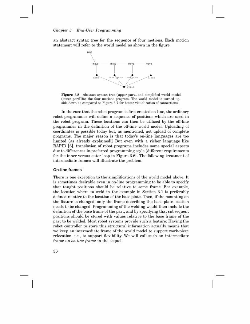
Chapter 3. End-User Programming
an abstract syntax tree for the sequence of four motions. Each motionstatement will refer to the world model as shown in the figure.
prog
move move move move
end_posestart_posehome clean
world
Figure 3.8 Abstract syntax tree (upper part) and simplified world model(lower part) for the four motions program. The world model is turned up-side-down as compared to Figure 3.7 for better visualization of connections.
In the case that the robot program is first created on-line, the ordinaryrobot programmer will define a sequence of positions which are used inthe robot program. These locations can then be utilized by the off-lineprogrammer in the definition of the off-line world model. Uploading ofcoordinates is possible today but, as mentioned, not upload of completeprograms. The major reason is that today’s on-line languages are toolimited (as already explained). But even with a richer language likeRAPID [6], translation of robot programs includes some special aspectsdue to differences in preferred programming style (different requirementsfor the inner versus outer loop in Figure 3.6). The following treatment ofintermediate frames will illustrate the problem.
On-line frames
There is one exception to the simplifications of the world model above. Itis sometimes desirable even in on-line programming to be able to specifythat taught positions should be relative to some frame. For example,the location where to weld in the example in Section 3.1 is preferablydefined relative to the location of the base plate. Then, if the mounting onthe fixture is changed, only the frame describing the base-plate locationneeds to be changed. Programming of the welding would then include thedefinition of the base frame of the part, and by specifying that subsequentpositions should be stored with values relative to the base frame of thepart to be welded. Most robot systems provide such a feature. Having therobot controller to store this structural information actually means thatwe keep an intermediate frame of the world model to support work-piecerelocation, i.e., to support flexibility. We will call such an intermediateframe an on-line frame in the sequel.
36

3.5 Internal states and external reality
When a robot program is created off-line, after defining the actualworld model, the programming system in practice imposes robot motionsto be specified relative to the manipulated physical objects. See for in-stance [65] for a further description of the methodology. Furthermore,robot motions will refer to the frames actually defining (the model of) theenvironment. Therefore, moving the base plate in the example above willautomatically update the description of the robot motions.
In the on-line programming case, however, the on-line frames do in-fluence the robot motions but an incorrect on-line frame may be hard todiscover before the motion is performed. To prevent damaging or dan-gerous motions, it is therefore crucial that the on-line frame is properlymaintained according to the states of the physical objects. Note that evenif this aspect of on-line programming is possible to simulate in a systemlike CimStation [183] (using a world model feature called proxies [185]),we are here concerned with the actual transfer of program to embeddedsystems. The following example further explains the problem.
Context sensitivity
The term context, within computer science, denotes a set of bindingsto the environment or surrounding scope [38]. A problem within robotprogramming is that robot program execution changes the state of theenvironment (for instance when two pieces are welded together), and theinfluences on the environment are sometimes hard to reflect or know inthe robot program (the success of an operation may depend on unknowndisturbances). We therefore have a context sensitivity problem to dealwith [59] (p. 409).
It is of course important, in both computer and robot programming,to provide good methods to cope with context sensitivity. Sometimes wemay need external sensors to detect if an operation has been successfulor not. That is a standard and explicit way to handle uncertainties in theenvironment. Here, we instead look at such context sensitivity problemsthat are due to operator interactions. This aspect of the problem has, asfar as known, not been treated elsewhere.
Assume that the flat bar in our small example turns out not to bequite straight. Also assume that the operator decides to adjust the weldingpath by inserting a via-point between the start pose and the end pose.We will now compare different ways to modify the program:
In the off-line programming case we modify the model of the flat bar.We then insert an intermediate position in the weld path. The in-termediate position will refer to the updated flat-bar object. If thebase plate is relocated on the fixture, the complete (simulated) weld
37

Chapter 3. End-User Programming
path is relocated by the system.
In the on-line teach-in programming case we first locate where inthe program the additional statement is to be inserted. That can bedone in two ways:
1. We can load and run the existing program, stop it when therobot approaches the welding task to be modified, and then issuestepwise execution (typically without welding) until the robothas reached position start pose. That move statement will thenbe the active one, and an additional ‘via-move’ can be insertedafter the current statement.
2. Instead of letting the robot execute the program until we are atthe right place, we may use the on-line editor to make the samestatement as item 1 to the current statement. This is quicker ifthe operator knows the program.
The difference between these two cases is that in case 1 we activatethe on-line frame by running the program, while in case 2 we man-ually have to do that activation since the activation statement wasnot executed. If the programmer forgets to do the manual ac-tivation, or in any of the cases forgets to refer to the on-line framein the move-statement inserted after the current one, there will be asevere problem. The inserted via-point will be expressed in the wrongcoordinate system, the result will be a completely wrong (andpossibly also damaging or hazardous) motion. This will showup either directly or after relocation of the base plate. Analysis ofthe problem in general, and of special cases in special systems, couldgo on for another page but is not very interesting. The conclusionis that systems more (see [144] referring to [4]) or less (as in [6])unnecessarily require that the programmer does the right thing.
From this simple example we can see that although on-line programmingis in principle a tangible and user-friendly method, we may encounterproblems when we want to utilize structural information about the en-vironment. In other words, when an otherwise superior on-line program-ming method makes assumptions about ‘object’ properties, there will beproblems if the state of the software objects have not been properly main-tained during manual operation.
In computer programming, such problems are avoided by the sequen-tial execution model, scope rules, and the absence of externally maintainedstates. The problem here is that we manually have to maintain variables(or object attributes if an object-oriented framework would be used) cor-responding to states in the real physical environment. This can be called“physical context sensitivity” due to operations on physical objects. An-
38
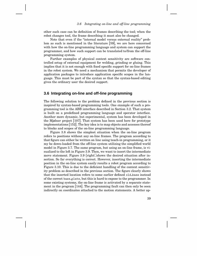
3.6 Integrating on-line and off-line programming
other such case can be definition of frames describing the tool; when therobot changes tool, the frame describing it must also be changed.
Note that even if the “internal model versus external reality” prob-lem as such is mentioned in the literature [59], we are here concernedwith how the on-line programming language and system can support theprogrammer, and how such support can be translated to/from the off-lineprogramming system.
Further examples of physical context sensitivity are software con-trolled setup of external equipment for welding, grinding or gluing. Thisimplies that it is not enough with fixed specific support for on-line framesin the robot system. We need a mechanism that permits the developer ofapplication packages to introduce application specific scopes in the lan-guage. This must be part of the syntax so that the syntax-based editinggives the ordinary user the desired support.
3.6 Integrating on-line and off-line programming
The following solution to the problem defined in the previous section isinspired by syntax-based programming tools. One example of such a pro-gramming tool is the ABB interface described in Section 3.2. That systemis built on a predefined programming language and operator interface.Another more dynamic, but experimental, system has been developed inthe Mjølner project [107]. That system has been used here for prototypeimplementations [152]. The key idea is to map objects and accesses thereofto blocks and scopes of the on-line programming language.
Figure 3.8 shows the simplest situation when the on-line programrefers to positions without any on-line frames. The program according tothat figure can either be written on line using teach-in programming, or itmy be down-loaded from the off-line system utilizing the simplified worldmodel in Figure 3.7. The same program, but using an on-line frame, is vi-sualized to the left in Figure 3.9. Then, we want to insert the intermediatemove statement. Figure 3.9 (right) shows the desired situation after in-sertion. So far everything is correct. However, inserting the intermediateposition in the on-line system easily results a robot program according toFigure 3.10. This is due to the deficient handling of the context sensitiv-ity problem as described in the previous section. The figure clearly showsthat the inserted location refers to some earlier defined old base insteadof the correct base plate, but this is hard to expose to the programmer. Insome existing systems, the on-line frame is activated by a separate state-ment in the program [144]. The programming fault can then only be seenindirectly on coordinates attached to the motion statements. A better ap-
39

Chapter 3. End-User Programming
prog
move move move move
home
world
start_pose end_pose
base_plate
clean
prog
move move move move
home
world
base_plate
move
cleanend_posemid_posestart_pose
Figure 3.9 Positions referring to an on-line frame fixture (left), and acorrectly inserted intermediate via point (right).
proach is always to display the frame list in each move statement. Thatapproach does, however, not scale very well in complexity. Hierarchicaluse of on-line frames, or longer motion sequences using the same on-lineframe, clutters the program in a way that is undesirable for hand-heldterminals.
prog
move move move move
home
base_plate
move
cleanend_posemid_posestart_pose
old_base
world
Inserted instruction
Act
ive
fram
e
Figure 3.10 Inserted move instruction referring to an incorrect on-lineframe. To the upper right, the teach pendant shown in Figure 3.5 illustratesmanual operation. The old base is the most recently used on-line frame,which may be from an other task in an other part of the working range of therobot.
The following claim is fundamental here: The location of the baseplate is in reality part of the physical scope for the motion to be performed.Expressing the welding path in a robot program should then utilize scoperules as in computer programming using standard imperative languages.The same applies to control of welding equipment etc., which entails thatthe description of the welding path should be expressed in a surroundingscope including the actual on-line frame. This implies that the concept ofon-line frames should be part of the syntax for the RPL, which providesnew possibilities to support the robot programmer by syntax-sensitiveediting.
40

3.7 Implementation
MOVELIN start_pose ARCWELD \I:=10 \U:=60
FRAME base_plate
! Welding is off here.ENDFRAME
MOVELIN home FRAME base_plateMOVELIN clean
MOVELIN mid_pose MOVELIN end_poseENDARCWELD ! => stopweld
ARCWELD \I:=10 \U:=60 ! startweld 10,60; ! implicitly done here. ! Motions performed in ! frame/welding context:
Figure 3.11 Utilization of RPL extensions in syntax-based editing. Whena block is opened the system ensures proper initialization of system settingsreflecting the physical context. Deactivation, like turning of the welding beforemoving to some other task, can in this way also be ensured by the system.
Another approach would be always to keep the geometrical descrip-tion in a separate data structure. That would correspond to maintainingan explicit world model (typically much reduced as compared to the off-line version) in the control system. Editing that world model would, how-ever, put the same demands on the system as when we give the motioncoordinates directly in the motion statement.
Considering also the control of the welding, we need to specify a cur-rent and a voltage. Start and stop of the welding have to be expressedin the program together with the welding motions. Using separate state-ments/procedures for start and stop of the welding, as indicated in Fig-ure 3.5, again resorts to proper management of the physical context (inthis case the state of the welding equipment). If we extend the syntax andsemantics of the RAPID language, our small example may look as shownin Figure 3.11 after zooming and modification.
Note that when the frame block is opened, the on-line frame as-sociated with the base plate object is automatically activated. That isachieved by semantic rules for this syntactic production. Of course theprogrammer can still explicitly use some other frame if desirable, but thedefault behavior (obtained by the non-expert robot programmer) does notresult in an unexpected/undesired motion as before.
3.7 Implementation
Having realized that the robot programming languages used in on-lineand off-line programming in many cases need to be different, it is appar-ent that automatic translation between these languages is needed. It nowremains to show how the desired bijective mapping between the represen-tations can be achieved. A full prototype is currently under evaluation.The implementation represents a considerable effort, which was possible
41

Chapter 3. End-User Programming
by initiating and guiding the work presented in [152].Two major industrial products were selected to represent the off-line
and on-line programming systems. The off-line system is the IGRIP [65]from Deneb, Inc. The off-line model for our example task was shown in Fig-ure 3.2 (p. 22). The recently released S4 control system from ABB Roboticswas selected as target (on-line) system. The RAPID language interpreterof that system was not available for experimental purposes, so we im-plemented our own RAPID to C compiler. By utilizing the architecturethat is presented in Chapter 4 together with the robot system presentedin Chapter 5, and using software techniques presented in Chapter 7, weemulated the front end of the ABB system. Thus, the program transfor-mations involved are those shown in Figure 3.14. (An on-line connectionbetween IGRIP and the experimental robot controller was also developed,but that is for other purposes as will be described in Chapter 8 aboutadvanced applications.)
The structure of the IGRIP system is shown in Figure 3.12. Theinput/output marked UNIX files in the figure is used to import and exportrobot programs. The programs were written in the internal language GSL.Programs were, however, exported as Karel [72] programs. Karel is verysimilar to GSL but the format of the Karel files were more suitable forour translation purposes.
Translation of Karel to RAPID, and RAPID to Karel, was achievedby using the Application Language Laboratory (APPLAB)[190] software.
UserCodes
UserExecutive
Nettools
CLI SimulationEngine
GSL
LLTIProcessor
MotionPipeline
LLTIUserI/O
SHLIB
User Code
Nettools
LLTI
Soket
Pipes
Ports
Async
IGRIPSocket
Interface
Hardwareinterface
UNIXFiles
MouseKeyBoard Dials Space
Ball
Deneb User Interface
TCP/IP
IGRIP
Figure 3.12 Software modules and interfaces of the IGRIP system.
42

3.7 Implementation
Figure 3.13 User interface of the Application Language Laboratory [190]used for prototyping robot programming extensions.
A very important feature in APPLAB is the interactive and incrementaldefinition of grammars and its automatic generation of syntax based ed-itors for the specified language [107, 82]. To achieve that, the tool usesa special internal data structure, but that also makes it more difficultto parse programs expressed in ordinary text form. An important exten-sion which was developed in connection with this implementation is adynamic parser [39] which was used for the parsing of robot programinto the language laboratory. Target language output is a special case of
GSL Karel Rapid C m68kApplab
Applab
ApplabIGRIP
IGRIP
gcc, etc.
Off-line language
Intermediate language
On-line language
‘High-level assembly’
Embedded system
Figure 3.14 Implemented translations of robot programs. The C and m68krepresentations emulate the ABB system (according to ABB specificationsor according to the proposed extensions depending on Applab grammars).The gcc, etc. denotes the cross compiler and our tools for dynamic binding(explained in Chapter 7).
43
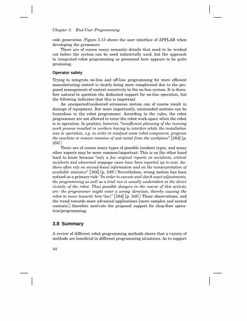
Chapter 3. End-User Programming
code generation. Figure 3.13 shows the user interface of APPLAB whendeveloping the grammars.
There are of course many semantic details that need to be workedout before the system can be used industrially used, but the approachto integrated robot programming as presented here appears to be quitepromising.
Operator safety
Trying to integrate on-line and off-line programming for more efficientmanufacturing control is clearly being more complicated due to the pro-posed management of context sensitivity in the on-line system. It is there-fore natural to question the dedicated support for on-line operation, butthe following indicates that this is important
An unexpected/undesired erroneous motion can of course result indamage of equipment. But more importantly, unintended motions can behazardous to the robot programmer. According to the rules, the robotprogrammer are not allowed to enter the robot work-space when the robotis in operation. In practice, however, “insufficient planning of the runningwork process resulted in workers having to interfere while the installationwas in operation, e.g. in order to readjust some robot component, programthe machine or remove remains of cast metal from the workpiece” [164] (p.250).
There are of course many types of possible incident types, and manyother aspects may be more common/important. This is on the other handhard to know because “only a few original reports on accidents, criticalincidents and abnormal stoppage cases have been reported up to now. Au-thors often rely on second-hand information and on the reinterpretation ofavailable statistics” [164] (p. 249). Nevertheless, wrong motion has beennoticed as a primary risk: “In order to execute and check exact adjustments,the programming as well as a trial run is usually undertaken in the directvicinity of the robot. Thus possible dangers in the course of this activityare: the programmer might enter a wrong direction, thereby causing therobot to move towards him/her;” [164] (p. 245). These observations, andthe trend towards more advanced applications (more complex and nestedcontexts), therefore motivate the proposed support for shop-floor opera-tion/programming.
3.8 Summary
A review of different robot programming methods shows that a variety ofmethods are beneficial in different programming situations. As to support
44

3.8 Summary
manufacturing practices, it should be possible to provide the end-user pro-grammer with proper programming tools, programming language, levelof abstraction, and use of the robot. The crucial point is then how thesetechniques can be integrated. After presentation of a small example anda review of techniques for robot programming, the following contributionsformed a new approach to end-user programming:
• Some benefits, like easy-to-use features for quick adjustment of themanufacturing process, of on-line programming were pointed out inSection 3.3. These benefits are fundamental to the approach taken,but they have until now been deficiently observed in academic re-search.
• An interpretation of robot programming and operation in controlterms, as done in Section 3.4, further motivated on-line operation as away to introduce local feedback. The formulation of the programmingprocess in terms of feedback control appears to be new despite itssimilarities with other interactive uses of computers. The controlinterpretation clarifies the need for back-propagation of local changesof robot programs (that is, automatic translation both ways betweenthe on-line to the off-line system is highly desirable).
• To facilitate translation of robot programs, three object views weresuggested for world-model objects (Section 3.5). A new way to illus-trate robot programs, with the syntax tree connected to the world-model tree was also introduced. A key observation, not found in theliterature, is that context sensitivity in the on-line programming caseis related to states that today have to be manually maintained by theoperator.
• A new way to manage the context sensitivity in on-line programmingwas then proposed in Section 3.6. The key idea is to make use of scoperules also for the (application specific) system states. Utilizing theblock structure of the programming language implies that tailoringthe system to a certain application may require extension of thesyntax of the on-line language. That makes it possible for the syntax-based editor to maintain important system states.
• The “Application Language Laboratory” software tool applied to im-plement the proposed ideas forms a system with unique robot pro-gramming properties; “meta grammars” and “incremental semanticanalysis” make it possible to incrementally during robot program-ming extend the syntax of the language as required in previous item.
In conclusion, a new approach to end-user programming has been pro-posed.
45

4
Architectures
The term architecture may generally denote structure or style of structurewith various—and sometimes not very precise—meaning. For the purposeof industrial robot control systems, and for this thesis, an architecture de-notes the concepts and techniques that characterize the structureof the system. Then, there is the question about what should be consid-ered to be the characteristic properties. The approach adopted here is tobase that on the usage of the system, rather than on the internal design.
The purpose of defining a system architecture normally is to supportunderstanding and implementation by coping with the complexity of thesystem. That also improves modularity and reuse of software components.Here, aiming at improved manufacturing support, application aspects willbe the main objective. This is approached in the following way:
• Taking a broader intelligent machines perspective, a review and clas-sification of architectures found in the literature will be presented inSection 4.1, where also a concept of user views will be introduced.
• Section 4.2 treats architectures and abstractions used for so calledintelligent robots. That is to draw some conclusions about the specialcase when robots are operating in more well defined environments,like in the manufacturing case.
• Finally, in this chapter we propose an architecture well suited forprogramming of industrial robots.
From an intelligent systems perspective, overall control of fully intelligentor autonomous robots is outside the scope of this thesis. Instead, theaims are to find proper abstractions for industrial robot systems, to makesuch systems fit into more complex autonomous systems, and to facilitateautonomous robot operation for well defined applications [98, 49].
46
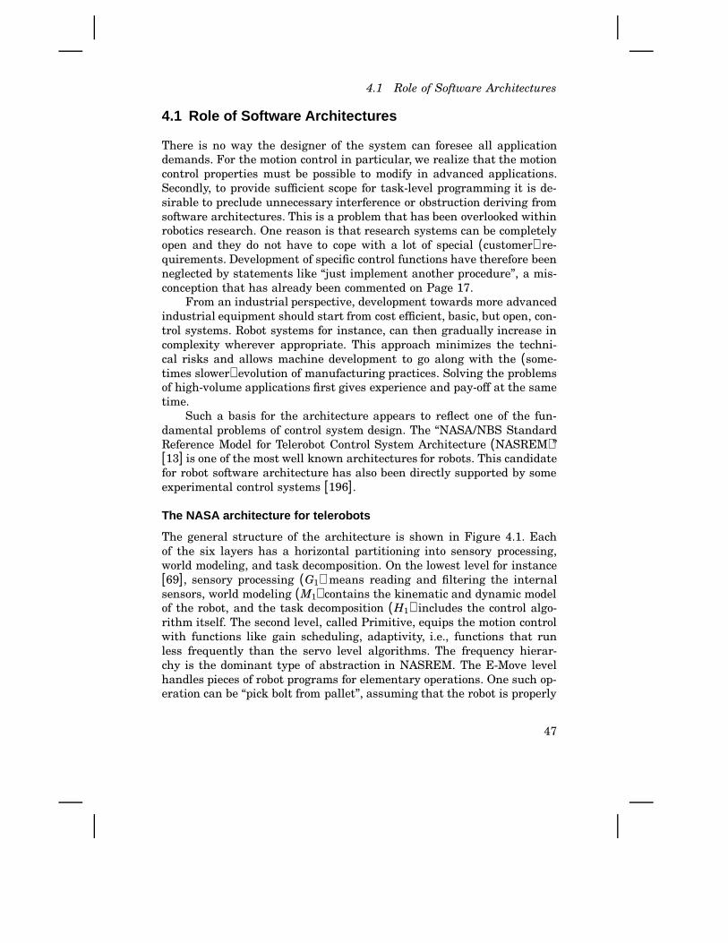
4.1 Role of Software Architectures
4.1 Role of Software Architectures
There is no way the designer of the system can foresee all applicationdemands. For the motion control in particular, we realize that the motioncontrol properties must be possible to modify in advanced applications.Secondly, to provide sufficient scope for task-level programming it is de-sirable to preclude unnecessary interference or obstruction deriving fromsoftware architectures. This is a problem that has been overlooked withinrobotics research. One reason is that research systems can be completelyopen and they do not have to cope with a lot of special (customer) re-quirements. Development of specific control functions have therefore beenneglected by statements like “just implement another procedure”, a mis-conception that has already been commented on Page 17.
From an industrial perspective, development towards more advancedindustrial equipment should start from cost efficient, basic, but open, con-trol systems. Robot systems for instance, can then gradually increase incomplexity wherever appropriate. This approach minimizes the techni-cal risks and allows machine development to go along with the (some-times slower) evolution of manufacturing practices. Solving the problemsof high-volume applications first gives experience and pay-off at the sametime.
Such a basis for the architecture appears to reflect one of the fun-damental problems of control system design. The “NASA/NBS StandardReference Model for Telerobot Control System Architecture (NASREM)”[13] is one of the most well known architectures for robots. This candidatefor robot software architecture has also been directly supported by someexperimental control systems [196].
The NASA architecture for telerobots
The general structure of the architecture is shown in Figure 4.1. Eachof the six layers has a horizontal partitioning into sensory processing,world modeling, and task decomposition. On the lowest level for instance[69], sensory processing (G1) means reading and filtering the internalsensors, world modeling (M1) contains the kinematic and dynamic modelof the robot, and the task decomposition ( H1) includes the control algo-rithm itself. The second level, called Primitive, equips the motion controlwith functions like gain scheduling, adaptivity, i.e., functions that runless frequently than the servo level algorithms. The frequency hierar-chy is the dominant type of abstraction in NASREM. The E-Move levelhandles pieces of robot programs for elementary operations. One such op-eration can be “pick bolt from pallet”, assuming that the robot is properly
47
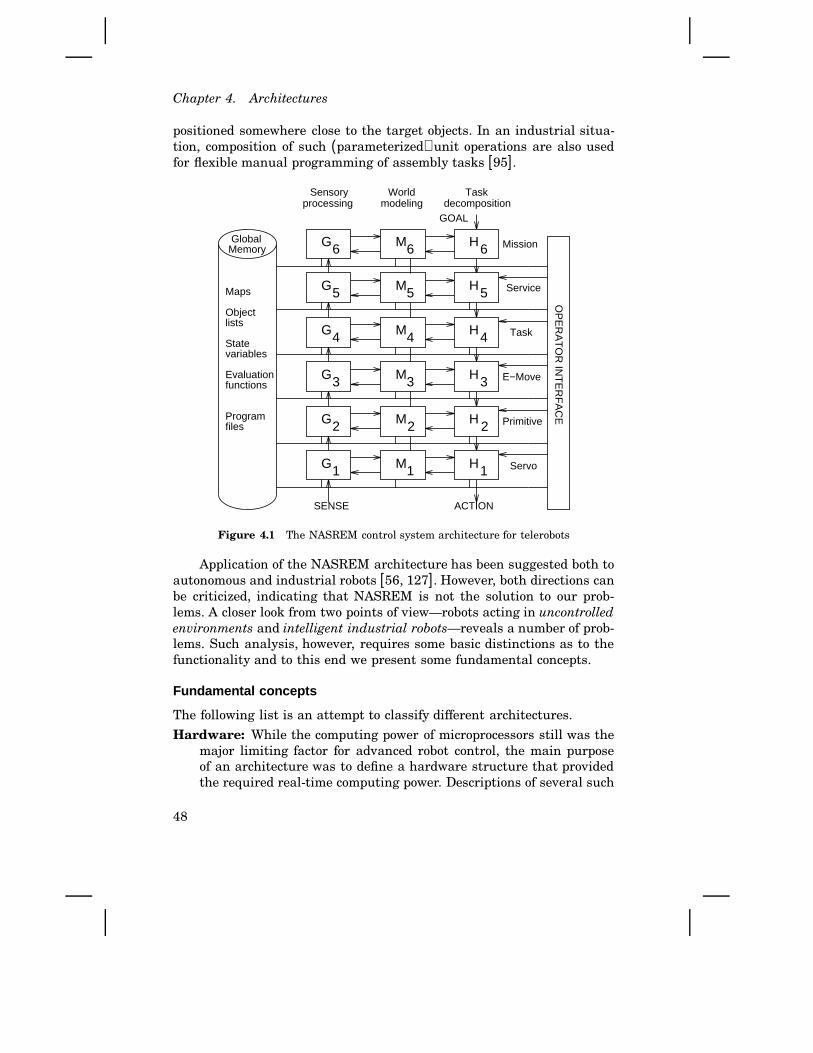
Chapter 4. Architectures
positioned somewhere close to the target objects. In an industrial situa-tion, composition of such (parameterized) unit operations are also usedfor flexible manual programming of assembly tasks [95].
OP
ER
AT
OR
INT
ER
FA
CE
GlobalMemory
Maps
Objectlists
Statevariables
Evaluationfunctions
Program files
SENSE ACTION
GOAL
Sensoryprocessing
World Taskdecomposition
Mission
Service
Task
E−Move
Primitive
ServoG
M H
G
M H
G M
H
G
M
H
G
M
H
G M H
1
2
3
4
5
6
1
2
3
4
5
6
1
2
3
4
5
6
modeling
Figure 4.1 The NASREM control system architecture for telerobots
Application of the NASREM architecture has been suggested both toautonomous and industrial robots [56, 127]. However, both directions canbe criticized, indicating that NASREM is not the solution to our prob-lems. A closer look from two points of view—robots acting in uncontrolledenvironments and intelligent industrial robots—reveals a number of prob-lems. Such analysis, however, requires some basic distinctions as to thefunctionality and to this end we present some fundamental concepts.
Fundamental concepts
The following list is an attempt to classify different architectures.
Hardware: While the computing power of microprocessors still was themajor limiting factor for advanced robot control, the main purposeof an architecture was to define a hardware structure that providedthe required real-time computing power. Descriptions of several such
48
4.1 Role of Software Architectures
architectures have been published [209, 20, 19, 206, 113]. The hard-ware structure is still important. Experimental systems should bemodular in such a way that a variety of interfaces, sensors, specialcomputers, etc. should be possible to easily add or replace. This isof course desirable also for industrial systems, but low cost (at leastfor the basic system without options) is usually even more impor-tant. Chapter 5 contains an example of an appropriate experimentalhardware configuration for the purposes of this research.
Control: The manipulator dynamic control problem as such, especiallyconsidering integrated position/force control, is a challenging problemthat has inspired to a lot of research efforts [59, 193, 109, 136, 100].A scheme that solves the control problem can be seen as an architec-ture. It typically involves several interacting control modules. Froma control theoretical point of view, other aspects of the system designare often considered to be just a matter of implementation. Moreexperiment-oriented research, on the other hand, often defines thecontrol and the physical architecture jointly [209, 15, 165]. Whileothers explicitly talk about a control architecture [110], we will useterms like control structure and block diagrams.
Task specification: Systems and methods designed for convenient de-scription of the task that the robot should perform, is another sourcefor control system architectures. This is the topic of end-user robotprogramming (sometimes related to principles used in process controlsystems for the cell and factory control levels). Solutions range fromexplicit manipulator programming [188] and up to systems where thesystem automatically generates or links robot programs. No generalpurpose system for automatic robot programming has yet been de-veloped. Systems have been designed, however, for supporting someparticular aspects of task-level programming [210, 117], or for specificapplications [181, 115, 95, 49], or using special algorithmic concepts[67, 92, 170]. An appropriate control system architecture should ofcourse be compliant with such approaches. They may turn out to beuseful in future robot programming systems. In this work, a softwarelayer for task-level programming will be specified concerning its re-lations to other parts of the system, but selection of specific methodsare subject to other ongoing and future research projects.
Abstractions: Robots operating in an unstructured and mainly unknownenvironment must make excessive use of external sensors, and theymust perform dynamic world modeling and real-time planning. Suchsystems are more complex than the control systems for robots inmanufacturing. Two questions deserve further investigation:
49

Chapter 4. Architectures
• It would be preferable to be able to use standard industrial robotsas components/modules in more complex autonomous systems.What kind of demands does this put on the industrial robotcontroller?
• Can principles from intelligent robot control systems be benefi-cial also for industrial manufacturing robots?
These questions are treated below in Section 4.2.
User views: From the perspectives of various categories of programmersthat need to configure or program industrial robot systems, severalprogramming situations may be identified. When solving a specificapplication problem, we may need to modify the system in severalways (control laws, operator interfaces, etc.) requiring different typesof competence. Assume that we have one user type for each type ofrequired competence, each user type viewing the control system in acertain way. Unless the system is carefully designed, any particularone such view will be unnecessarily complex (involving a variety ofcomputers, programming environments, special restrictions on use ofsoftware interfaces, etc.).
If we instead base the architecture on properly selected userviews, it is more likely that programming can be done more conve-niently. This approach differs from before in the way that the externalview, rather than the internal implementation, is the primary mat-ter. A view may map well onto internal modules based on some of theabove principles, but it need not to be the case. If we focus on thesoftware design for one specific view, the use-case driven approach byJacobson [96] would be the object oriented design method correspond-ing to the user views of the system. Looking at objects, rather than onthe entire system, related view-based solutions have been proposedin process control [199] and in computer aided control engineering[142].
In conclusion, control system design can be viewed in several (rele-vant and equally important) ways. Motivated by the wide variety ofusers/engineers of manufacturing systems, and by the importance of man-ufacturing practices, this thesis tries to forward the concept of user viewsas the fundamental principle for industrial robot control systems.
A specific implementation will, of course, be based on a certain hard-ware and control architecture, and means of task specification for theend-user will be provided. Chapters 3, 5, and 6 each present examples ofsuch implementations (without calling it architectures).
Defining appropriate user views for manufacturing operation will, ofcourse, not solve complexity problems encountered for so called intelligent
50

4.2 Intelligent robots
robots working in uncontrolled environments. For such robots, the authoracknowledges that architectures according to the abstractions item aboveare more appropriate. The aim is, however, that robots for manufacturingshould be useful as modules in fully autonomous systems. Furthermore,suitable abstractions are important also for task-level robot programmingand autonomous operation in some manufacturing situations. The follow-ing treatment is therefore of interest.
4.2 Intelligent r obots
We will now study how different forms of abstractions have been used todefine architectures for so called intelligent robots. We will then see howthese principles can be used for more conventional industrial robots, andhow industrial robots can fit into so called intelligent systems.
Abstraction beats complexity
The purpose of abstractions is to cope with complexity. When a complexsystem is divided into smaller manageable parts, those parts can be givena new simplified interface, and aspects of the internal behavior is omit-ted or simplified in some sense. We find this principle in organizations,industrial production (Figure 2.2 on Page 7), control theory (cascade con-trol for instance), and in software engineering (abstract data types etc.).The abstraction then allows more powerful hierarchies to be built, usingmore abstract interfaces on higher levels of the hierarchy.
An interesting question about any control system architecture is whattype of abstractions or hierarchies it is built upon. Consider a multi-layered real-time control system for fully autonomous robots. Such a sys-tem will contain both hard real-time software and artificial intelligence(AI) related features (planning). The detailed implementation of such asystem would of course make use of data abstraction and other softwareparadigms, but some kind of high level abstraction is needed to build hi-erarchies to cope with the complexity [127]. Several such hierarchies havebeen proposed by different researchers as presented by Schoppers [173]according to the following:Frequency hierarchies [13, 202] are based on the standard real-time
principle that the real-time processes in a lower layer run more fre-quently than those in the next higher layer of the system.
Data abstraction hierarchies [111] are closely related to the data ab-straction ideas—e.g., in object-oriented programming. A lower soft-ware layer provides an abstract machine for the adjacent higher layer.
51
Chapter 4. Architectures
Representational abstraction hierarchies [13, 202] is normally usedby AI people as the method of building an abstraction by suppressingor ignoring information.
Deresolution hierarchies [131, 119] is often used in motion planning.Two layers can do functionally the same computations, but with ahigher resolution on the lower level. Deresolution is related to theprevious hierarchies, but is not the same.
Subsystem hierarchies [111, 13] are based on grouping the controlof subsystems—e.g., control of individual joints—to control of thecomposed system—e.g., the arm driven by the joints. This approachis often combined with data abstraction.
Competence hierarchies [50] are built by composing simple behaviorsof lower layers into more competent behaviors on a higher level ofthe system. For example, vibrations in a robot gripper caused by asimplified control, can be utilized on a higher level for an advanced“non-stiction” assembly operation.
Temporal extent hierarchies [108, 202] are designed so that higherlevels manage behaviors of longer duration. Note that higher-levelcomputations associated to actions over a longer period of time mayrequire updating and re-computation more frequently than lower lev-els do.
An attempt to a uniform approach for the design of software architecturesis behavior abstraction [173] which is not about the software modulesthemselves. Instead, the definition’s focus is on the behavior being gener-ated, i.e., the effects the modules have on the hardware being controlled.The idea to let the architecture specify external properties instead of theinternal design is in common with the approach in this work. Topics aboutbehaviors and behavior control, however, are subject to prolonged discus-sions [56] and outside the scope of this thesis. Let us therefore continuewith aspects related to industrial robots.
Uncontrolled environments
As mentioned earlier, a major problem for robots in space, and for au-tonomous robots and vehicles in general, is to maintain a model of thedynamically changing environment and to replan the motions accordingto environmental changes. A large number of sensors is then required,as well as advanced sensory processing and world model updating. Spe-cial manipulators can also be required to position sensors in places wherethe unknown parts of the environment is best observed. An architectureshould of course aid in the development of such systems.
52
4.2 Intelligent robots
From an AI point of view, an upper layer plans and sends downdetailed actions to the next lower layer, keeping the abstract plan inthe higher layer. Unless some more sophisticated management of theinterplay between the layers is introduced, the lower layer cannot copewith changes of goal or environment and will be stuck dealing with theoriginally expected situation. Such a modification appears to be very hardto combine with hard real-time requirements. A more promising approachwould be to also supply more abstract actions and replanning functionsalong with the detailed orders, a problem which is still a research subject.Though the selection of suitable abstractions and associated architecturesis still a topic for ongoing research [222, 180, 80] and discussions [127],a promising prototype implementation of high level concepts for robots inspace is underway [175, 174].
From an embedded control point of view, when it comes to full imple-mentations of autonomous robot control, it is of course very desirable touse “off-the-shelf” manipulator control systems already widely used in in-dustrial applications. That would decrease the development effort and/orincrease reliability. To meet the special demands like special interfaces tothe planning levels, a very open manipulator controller would, however,be required. Development of intelligent industrial robots can hopefullylead to this. Another reason would be to support a bottom-up approach(build the system upon principles that have turned out to really work).
The top-down approach dominating the intelligent robot researchseems to be a major problem. It appears to the author that there aretoo many possible solutions that are subject to investigation prior to im-plementation (if that is ever done). A bottom-up approach would thereforebe more appropriate, as pointed out also by Harmon [79]. That means us-ing open and flexible industrial robots (tailored to the high-level require-ments) as modules for full implementation of specific intelligent robotcontrol tasks. Experiences from many such prototypes may likely influ-ence the definition of a suitable architecture for fully autonomous robots.
Intelligent i ndustrial robots
A standpoint declared in this thesis is that open control systems providerobot systems with flexibility and wider scope of application. Now we turnto the question whether the NASREM architecture is suitable for suchflexibility.
Figure 4.1 shows that there is a global database and an operatorinterface connected to all levels of the system. This is good in the sensethat information from lower levels can be useful on higher levels, and theoperator may need to change or monitor the low level algorithm during
53

Chapter 4. Architectures
for example new advanced robot tasks. However, our desire to have a leanand efficient system rather means the opposite—i.e., that control signals,sensor values, parameters, etc. should be kept as locally as possible in thesystem [34]. The standpoint in this work has been that data flows betweenthe different software layers, required for certain tasks, should be createdon demand. This has been hard to achieve in embedded systems withoutchanging the software on the lower level.
Another observation in NASREM is that sensor signals only enterthe system at its lowest level. This reflects the frequency hierarchy; themost frequent use of sensor signals is in the lowest layer where the highestsampling frequencies are used. However, sensor-based functions on higherlevels may very well need fast enactment, as the deburring and weldingapplications in Chapter 8 will show. Furthermore, sensors used only onhigher levels leads to unnecessarily high data flow through lower layers.
SensorCoordinator
VisionCoordinator
ArmCoordinator
Organizer
High-LevelInput Command
Lower ArmControl
Upper ArmControl
SensorsTactile, etc.
Joints1-3
Joints4-6
Gripper TVCamera
Level 2
Level 1
Level 3
Organization
Coordination
Execution
Figure 4.2 Structure of hierarchical intelligent robot control system (from[210] referring to [171]).
Looking for something more dedicated to industrial robots, an ar-chitecture that is often referred to is exemplified in Figure 4.2. As withNASREM, this is a way of organizing the control system internally. How-ever, for the industrial robot controllers, an object-oriented design andimplementation would be sufficient to cope with the internal complexity.A structure according to the figure can then very well be used, but shouldthat be specified by the architecture? As mentioned above, the proposedarchitecture will be based on user views supporting convenient factory
54

4.2 Intelligent robots
floor operation. Techniques allowing the system to be open will also be in-troduced, still maintaining the desired efficiency. Concerning the link tohigh level planning, the following approach is believed to be well suitedfor industrial operation.
Hand crafted agents
Considering the issue how an architecture can support planning and task-level programming, one of the few systems that have proved to work isconsidered. The AI laboratory at University of Edinburgh has developeda complete assembly system called SOMASS [123, 77]. The system plansand executes assemblies in a special artificial block-type world, namelythe Soma world. SOMASS has been demonstrated to work well despite anumber of possible sources of failure. The uncertainties that may causeassembly failure include part tolerance, physical characteristics such asfriction or stiction and the like. The following quote from [77] is centralfor the purposes of the thesis:
The interesting point about SOMASS, for our purposes, is that ittakes a particular, and somewhat unusual, approach to the ac-tivity orchestration problem. The conventional view in assemblyrobotics has tended to be that the planning component of the sys-tem should anticipate and deal with various possible reasons forassembly failure. This has, in practice, proved computationallyand intellectually intractable. SOMASS, on the other hand, takesthe position that the planner should concentrate on those aspectsof the problem that can tractablely be expressed in symbolic form,leaving the execution agent to cope with the specifically manip-ulative difficulties of the assembly problem. Since the agent ishand-crafted, most of the consequences of the uncertainties in theparts and their manipulation are dealt with by the human pro-grammer who has years of experience of object manipulation tocall on when diagnosing and repairing failures in the tacit skillsof the executive agent.
The fundamental standpoint in this quote is shared. However, the maininterest here is not planning or activity orchestration, but rather the ex-ecutive agent and the supporting software layers for application program-ming. The “hand-crafted executive agent” embodies the skill of the humanoperator and describes his knowledge of the physical situation and its un-certainties. The research goal here is this type of programming, to struc-ture it and thus to improve efficiency. This also illustrates how researchin structures for physical robot functions provide a link to higher-levelcontrol approaches such as planning.
55
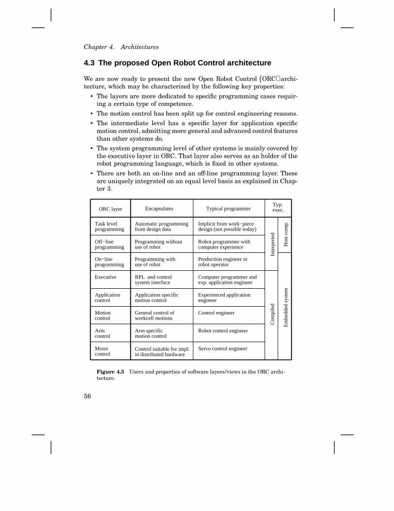
Chapter 4. Architectures
4.3 The proposed Open Robot Control architecture
We are now ready to present the new Open Robot Control (ORC) archi-tecture, which may be characterized by the following key properties:
• The layers are more dedicated to specific programming cases requir-ing a certain type of competence.
• The motion control has been split up for control engineering reasons.
• The intermediate level has a specific layer for application specificmotion control, admitting more general and advanced control featuresthan other systems do.
• The system programming level of other systems is mainly covered bythe executive layer in ORC. That layer also serves as an holder of therobot programming language, which is fixed in other systems.
• There are both an on-line and an off-line programming layer. Theseare uniquely integrated on an equal level basis as explained in Chap-ter 3.
RPL and controlsystem interface
Task levelprogramming
Executive
Motioncontrol
Armcontrol
Encapsulates
Automatic programmingfrom design data
Programming without use of robot
Programming withuse of robot
Application specificmotion control
General control ofworkcell motions
Arm specific motion control
Control suitable for impl.in distributed hardware
Typical programmer
Implicit from work−piecedesign (not possible today)
Robot programmer with computer experience
Production engineer orrobot operator
Computer programmer andexp. application engineer
Experienced applicationengineer
Control engineer
Robot control engineer
Servo control engineer
Em
bedd
ed s
yste
m
Com
pile
dIn
terp
rete
d
Hos
t com
p.
Typ. exec.ORC layer
Motor control
Applicationcontrol
Off−lineprogramming
On−lineprogramming
Figure 4.3 Users and properties of software layers/views in the ORC archi-tecture.
56
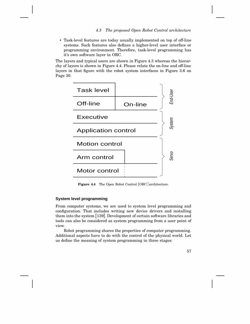
4.3 The proposed Open Robot Control architecture
• Task-level features are today usually implemented on top of off-linesystems. Such features also defines a higher-level user interface orprogramming environment. Therefore, task-level programming hasit’s own software layer in ORC.
The layers and typical users are shown in Figure 4.3 whereas the hierar-chy of layers is shown in Figure 4.4. Please relate the on-line and off-linelayers in that figure with the robot system interfaces in Figure 3.6 onPage 30.
On-line
Task level
Off-line
Executive
Application control
Motion control
Arm control
Motor controlSe
rvo
Syste
mEn
d-Us
er
Figure 4.4 The Open Robot Control (ORC) architecture.
System level programming
From computer systems, we are used to system level programming andconfiguration. That includes writing new device drivers and installingthem into the system [139]. Development of certain software libraries andtools can also be considered as system programming from a user point ofview.
Robot programming shares the properties of computer programming.Additional aspects have to do with the control of the physical world. Letus define the meaning of system programming in three stages:
57
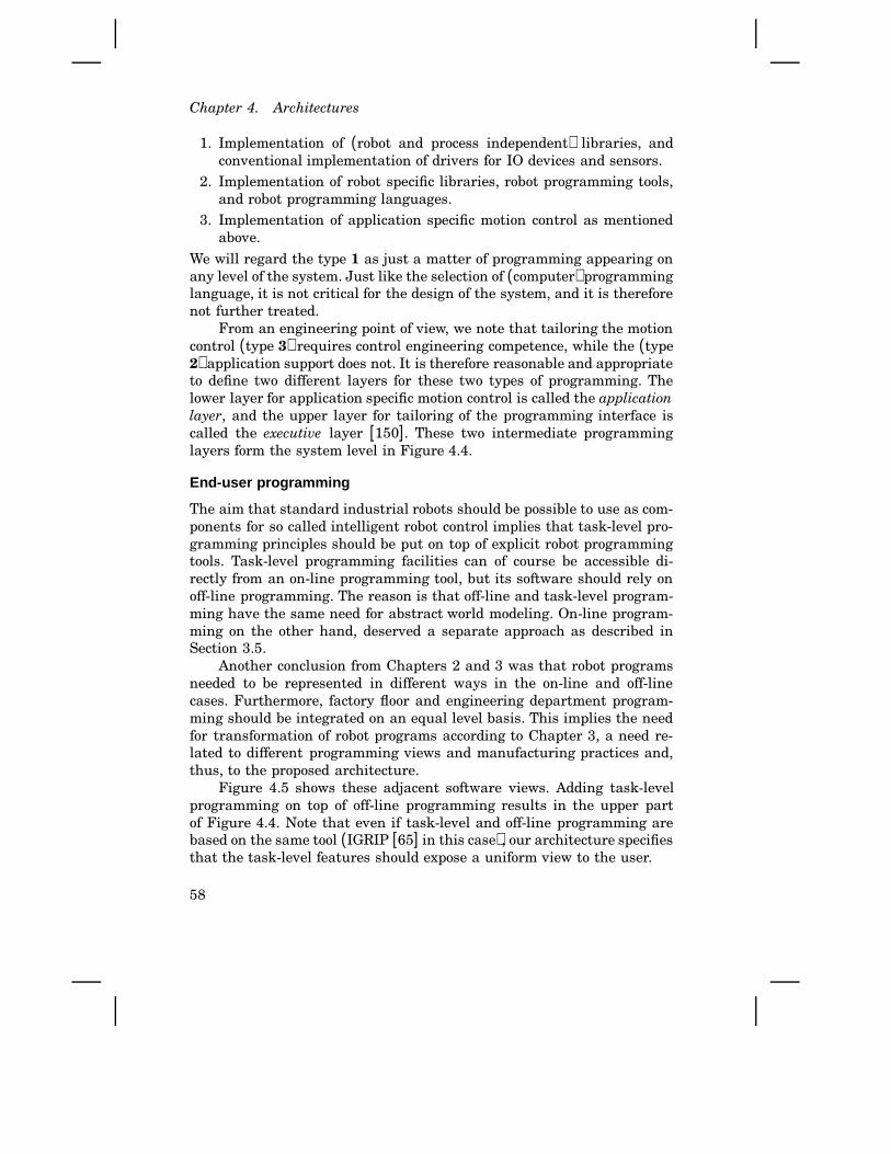
Chapter 4. Architectures
1. Implementation of (robot and process independent) libraries, andconventional implementation of drivers for IO devices and sensors.
2. Implementation of robot specific libraries, robot programming tools,and robot programming languages.
3. Implementation of application specific motion control as mentionedabove.
We will regard the type 1 as just a matter of programming appearing onany level of the system. Just like the selection of (computer) programminglanguage, it is not critical for the design of the system, and it is thereforenot further treated.
From an engineering point of view, we note that tailoring the motioncontrol (type 3) requires control engineering competence, while the (type2) application support does not. It is therefore reasonable and appropriateto define two different layers for these two types of programming. Thelower layer for application specific motion control is called the applicationlayer, and the upper layer for tailoring of the programming interface iscalled the executive layer [150]. These two intermediate programminglayers form the system level in Figure 4.4.
End-user programming
The aim that standard industrial robots should be possible to use as com-ponents for so called intelligent robot control implies that task-level pro-gramming principles should be put on top of explicit robot programmingtools. Task-level programming facilities can of course be accessible di-rectly from an on-line programming tool, but its software should rely onoff-line programming. The reason is that off-line and task-level program-ming have the same need for abstract world modeling. On-line program-ming on the other hand, deserved a separate approach as described inSection 3.5.
Another conclusion from Chapters 2 and 3 was that robot programsneeded to be represented in different ways in the on-line and off-linecases. Furthermore, factory floor and engineering department program-ming should be integrated on an equal level basis. This implies the needfor transformation of robot programs according to Chapter 3, a need re-lated to different programming views and manufacturing practices and,thus, to the proposed architecture.
Figure 4.5 shows these adjacent software views. Adding task-levelprogramming on top of off-line programming results in the upper partof Figure 4.4. Note that even if task-level and off-line programming arebased on the same tool (IGRIP [65] in this case), our architecture specifiesthat the task-level features should expose a uniform view to the user.
58
4.3 The proposed Open Robot Control architecture
f −1
f robotprogram
robotprogram
off−line server on−line server
other executive services
Exe
cutiv
eU
ser
prog
ram
min
g Off−line On−line
Figure 4.5 Integration of on-line and off-line programming required trans-formation of the robot programs according to Chapter 3. These transforma-tions are denoted f and f−1 here.
Servo level programming
On the level of servo programming, a persistent feature is that softwareand hardware modules exhibit a very close relationship. Hardware andsoftware design, at least for the motor control, are done as integrated ac-tivities to facilitate price/performance optimization. The software there-fore naturally takes on a structure that reflects the hardware structure,whereas programming is performed by the implementors of the system.This implies that the user views of the architecture maps well onto anobject-oriented design of the motion control system, which in turn reflectsthe structure of the physical objects. This is shown in Figure 4.6. Havingrealized the meaning of that figure, it is straight forward to define theservo control part of the architecture, that is, the three lower layers inFigure 4.4.
Discussion
As pointed out several times, application specific motion control is veryimportant to provide flexibility and wider scope of application of industrialrobots systems. Industrial manipulators are characterized by a strong in-terplay between user level commands, which often look robot independent,a good (but not perfect) world model, motion control services, and externalsignals from, say, a welding or grinding tool. This interplay is crucial toobtain flexibility and performance, but also to avoid the cost of otherwisenecessary external sensors.
59
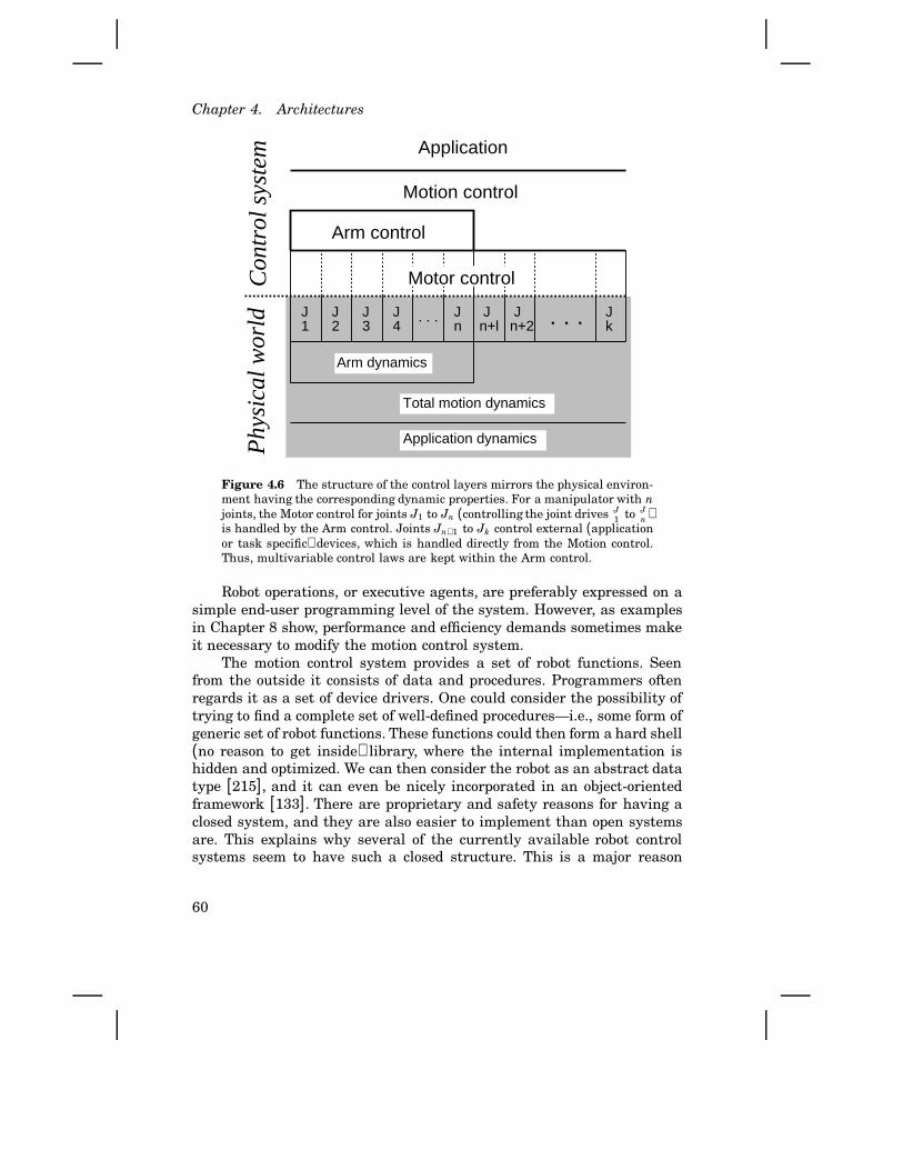
Chapter 4. Architectures
J1 . . .J
2J3
J4
. . . Jn
Jn+l
Jn+2
Jk
Arm dynamics
Total motion dynamics
Ph
ysic
al w
orld
Arm control
Motion control
Application
Application dynamics
Co
ntr
ol s
yste
mMotor control
Figure 4.6 The structure of the control layers mirrors the physical environ-ment having the corresponding dynamic properties. For a manipulator with njoints, the Motor control for joints J1 to Jn (controlling the joint drives J
1 to Jn )
is handled by the Arm control. Joints Jn+1 to Jk control external (applicationor task specific) devices, which is handled directly from the Motion control.Thus, multivariable control laws are kept within the Arm control.
Robot operations, or executive agents, are preferably expressed on asimple end-user programming level of the system. However, as examplesin Chapter 8 show, performance and efficiency demands sometimes makeit necessary to modify the motion control system.
The motion control system provides a set of robot functions. Seenfrom the outside it consists of data and procedures. Programmers oftenregards it as a set of device drivers. One could consider the possibility oftrying to find a complete set of well-defined procedures—i.e., some form ofgeneric set of robot functions. These functions could then form a hard shell(no reason to get inside) library, where the internal implementation ishidden and optimized. We can then consider the robot as an abstract datatype [215], and it can even be nicely incorporated in an object-orientedframework [133]. There are proprietary and safety reasons for having aclosed system, and they are also easier to implement than open systemsare. This explains why several of the currently available robot controlsystems seem to have such a closed structure. This is a major reason
60
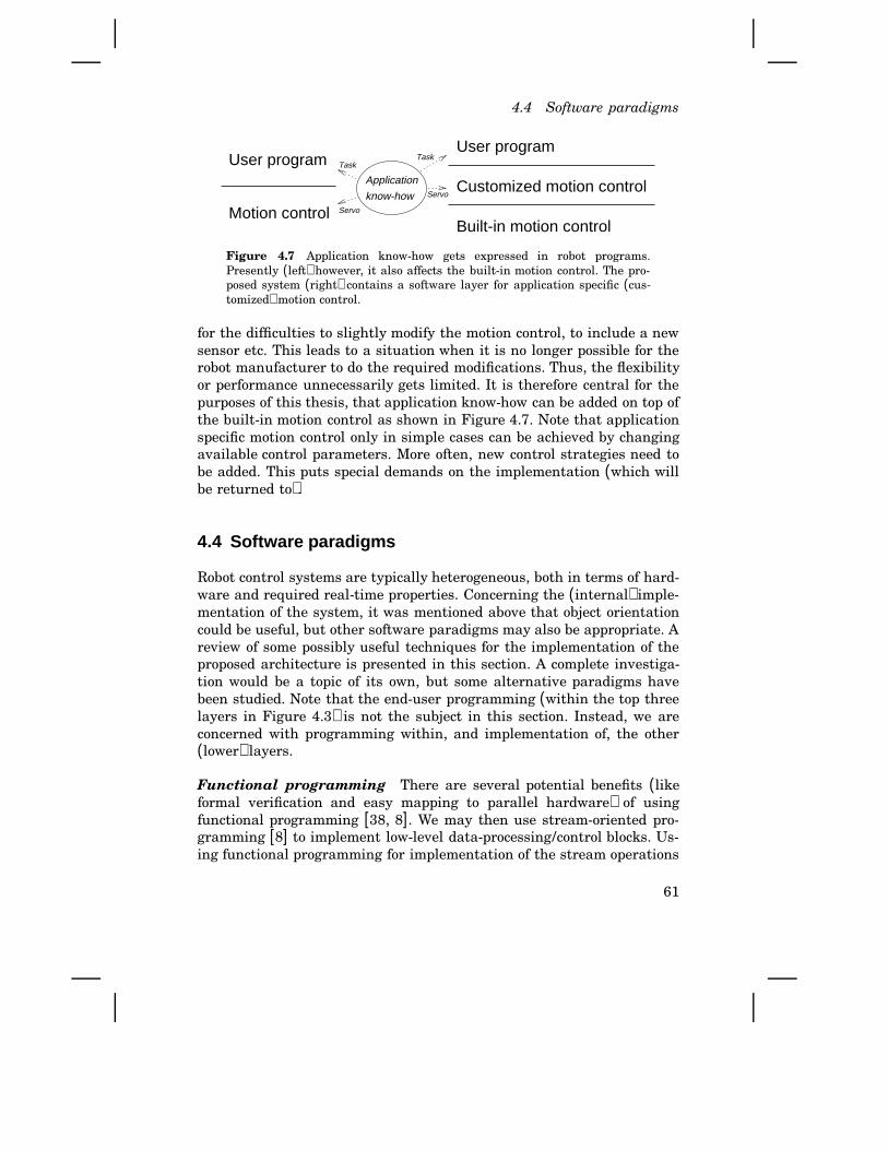
4.4 Software paradigms
Motion control
User programUser program
Built-in motion control
Customized motion controlApplication
know-howServo
TaskTask
Servo
Figure 4.7 Application know-how gets expressed in robot programs.Presently (left) however, it also affects the built-in motion control. The pro-posed system (right) contains a software layer for application specific (cus-tomized) motion control.
for the difficulties to slightly modify the motion control, to include a newsensor etc. This leads to a situation when it is no longer possible for therobot manufacturer to do the required modifications. Thus, the flexibilityor performance unnecessarily gets limited. It is therefore central for thepurposes of this thesis, that application know-how can be added on top ofthe built-in motion control as shown in Figure 4.7. Note that applicationspecific motion control only in simple cases can be achieved by changingavailable control parameters. More often, new control strategies need tobe added. This puts special demands on the implementation (which willbe returned to).
4.4 Software paradigms
Robot control systems are typically heterogeneous, both in terms of hard-ware and required real-time properties. Concerning the (internal) imple-mentation of the system, it was mentioned above that object orientationcould be useful, but other software paradigms may also be appropriate. Areview of some possibly useful techniques for the implementation of theproposed architecture is presented in this section. A complete investiga-tion would be a topic of its own, but some alternative paradigms havebeen studied. Note that the end-user programming (within the top threelayers in Figure 4.3) is not the subject in this section. Instead, we areconcerned with programming within, and implementation of, the other(lower) layers.
Functional programming There are several potential benefits (likeformal verification and easy mapping to parallel hardware) of usingfunctional programming [38, 8]. We may then use stream-oriented pro-gramming [8] to implement low-level data-processing/control blocks. Us-ing functional programming for implementation of the stream operations
61
Chapter 4. Architectures
would limit ‘side-effects’ and increase reliability, which is sometimes hardwhen traditional programming methods are used.
A particularly interesting development in this direction, includingboth the functional real-time programming language H and special pur-pose hardware, has been done by Carlstedt Research [208]. That approachwould, for instance, be well suited for implementation and programmingof the computer nodes in our system (Figure 5.4, p. 74). For instance,our data streams are time stamped, which fits the IO model in the Hlanguage. On the other hand, as far as known to the author, no func-tional approach has yet fully proven its applicability to embedded controlproblems of realistic size and complexity.
Imperative languages For almost all programming in industry, im-perative languages are used, i.e., it is explicitly stated in the program(statement by statement in order as written) the operations that shouldbe performed by the computer. Assignments to variable/memory (and forinstance in the C [104] language also pointer arithmetics and bit manip-ulations) is almost arbitrarily permitted, thereby giving the programmer(too?) much freedom. The opportunity to tune the software to hardwareand for efficiency, without resorting on advanced compilers, are major rea-sons for the success of the C language, and later also C+ + [198]. With theaim to implement industrially relevant robot control systems, such prac-tical aspects have been considered also in this work (at some expense ofprogramming style/elegance). As for any language or paradigm, we needappropriate abstractions to cope with software complexity [8].
Compared to traditional structured procedural programming, objectorientation offers a powerful way of packaging data together with relatedfunctions manipulating that data. The object-oriented paradigm [126] isbased on objects having internal attributes/states that can be manipu-lated by methods that are available via a type/class declaration. Thismeans that object orientation resorts on side effects, at least in a func-tional programming sense. So even if the data being manipulated is wellencapsulated within classes and objects, we can in a way consider objectorientation as the opposite of functional programming. One could there-fore suspect that object-oriented implementation of complex systems leadsto unpredictable behaviors and complicated faults [217], particularly if weuse active objects (i.e., objects with internal threads of execution [93]). Theproblem is, however, not the object oriented paradigm. Instead of rejectingobject orientation, we need a proper separation between the description ofdata flows in one mode of operation, and the transitions between differentsuch modes.
62
4.4 Software paradigms
Declarative and formal methods Declarative languages, such as Pro-log [57], have been designed to make the programmers task easier byadmitting programs to specify what should be done (instead of how todo it as when imperative languages are used). The problem is that adeclarative language well suited for one type of problem, like logical re-lations between objects in the Prolog case, in practice turns out to be lessappropriate for other applications. An interesting approach for embed-ded systems is the Erlang language, which also shares some propertiesof functional languages [25]. The simplicity of Erlang, in combinationwith built-in support for concurrency (among other features), makes itvery powerful for systems containing a large (and dynamically changing)number of concurrent processes, but we found it to less suitable for motioncontrol systems.
Another declarative approach is the synchronous one [36, 76], whichoffers a uniform approach and some formal verification tools concerningthe logical and temporal properties of the software. It is being appliedto robot control [186]. Synchronous languages provide a programminginterface for (correct) specification of software interconnections. However,each software component has to be implemented in a traditional way, forinstance using the C language. Thus, this is not a complete solution, butit may in the future, for instance, be useful for safe programming withinthe application layer.
A pragmatic approach There are no general agreement on the cri-terias for a “good” paradigm. We may strive for code reuse, efficiency,maintainability, ensured correctness, or for programs that are easy to un-derstand. The most appropriate language or paradigm may depend onsystem level, application, actual hardware, price/performance demands,etc. In fact, a blend of techniques is believed to be appropriate.
Use of techniques that still are in a research stage, like the syn-chronous and functional approaches, would put the implementation effortsof this project at risk. A well structured and widely accepted paradigm isobject orientation (for analysis, design, and programming). At a hardwarerelated level of the system, however, it was not thoroughly investigatedat the time when implementation of the lowest part or the ORC archi-tecture was carried out. Therefore, this was part of the research as willbe described in the final part of Section 5.3 (p. 83). For other parts ofthe system, my attitude has been to use or combine whatever paradigmthat suits the actual situation. The notion of function objects [198], for in-stance, is a way of combining functional (or data flow) programming withobject-oriented programming. The ORC architecture does not prescribeany particular software paradigm.
63

Chapter 4. Architectures
4.5 Summary
Abstractions are used to cope with complexity, a property which appliesto mathematics, to computer science, and also to robot control systems.The aim of this chapter was to find abstractions suitable for industrialrobots used in manufacturing. For such robots, complexity issues dealwith the programming/operation of the robot rather than the internal de-sign. The reason is that robots in manufacturing operates in fairly wellknown environments, so there are less demands on knowledge represen-tation, automatic world modeling, reasoning, planning, etc. Instead, themost important thing is to support manufacturing practices by havingwell defined interfaces for different programming situations. However, topermit more complex situations in the future, the control system should bestructured in such a way that ‘machine intelligence’ can be added on topof the traditional functionality. This approach and the new architectureresult from the following contributions:
• In Section 4.1, the fundamental concept of available architectureswere reviewed, and the new user-view concept was introduced.
• Abstractions used for so called intelligent robots were studied inSection 4.2. Experiences from real experiments indicated that lowlevel effects should be explicitly dealt with by the application expertprogrammer. Thus, it is a good solution to have a low-level (on-line)programming interface, and to add higher (planning) levels on top ofthat.
• Some typical programming situations were identified in Section 4.3,and the ORC architecture was proposed based on those situations.From bottom to top, the proposed architecture supports modular im-plementation of the built-in motion control (three layers), implemen-tation of application specific motion control, tailoring of embeddedsystem primitives, and end-user programming (three layers). Ourdesire to have appropriate programming interfaces without imposingany global database or hierarchical data-flow structure, which wasobserved as a problem with existing architectures, is believed to beachieved with the proposed ORC.
A major contribution of the thesis is the combination/integration of theoverall architecture (as defined in this chapter), and technical solutions(presented in other chapters) making the ORC architecture possible andefficient. Requirements on These ideas can of course also be applied toother types of machines. To have a unified approach is particularly usefulwhen designing complicated manufacturing systems.
64
5
Experimental Platform
Experimental verification is very important in applied research. It is toadvantage for robotics research that robots are feasible to have in anordinary laboratory, and many different control subjects can be put ina robotics context. Several different robot systems have therefore beenbuilt for experimental purposes within research and teaching. However,available systems were all found to belong to the following categories:
• The experimental system is built on top of an industrially availablesystem [133]. This is a way of reducing the necessary engineeringeffort, but the limitations of the original system remain.
• The control computer hardware has in several cases been replaced byexternal computers allowing complete replacement of the control soft-ware [206, 197, 37]. That is, however, done for older types of robots,typically with interfaces to DC-motor drives and angular encoders.
• Complete robot systems have been designed and built, sometimesincluding special mechanical solutions [88], but more often just withsimplified mechanics (to reduce cost and/or to make very specificexperiments possible) like direct drive robots.
In applied robot control research, it is in most cases important to use robotmanipulators that are relevant for industrial use. Simplified or specialpurpose research robots do not have realistic dynamic properties. The me-chanical design done by major robot manufacturers has been worked outconsidering many application, quality, and maintenance demands. Thus,control of such robots are industrially more relevant. As an example, directdrive (rigid) robots are (today) appropriate only in special applications.
The experimental robot control system developed is unique in thesense that it is based on modern robots commonly used in the industry,still maintaining important safety functions of the original system, butallowing the researcher full access to control and programming functions.
65

Chapter 5. Experimental Platform
A complete framework for reconfiguration of ABB industrial robotswill first be presented. The framework supports reuse of hardware mod-ules for recent (S3 and S4) versions of ABB system. Specific designs forthe two systems in our laboratory will then be described, followed bysome computing hardware considerations. Finally in this chapter, a re-mark about industrial aspects of experimental control is given.
5.1 Experimental control using ABB robots
Reconfiguration of robots has been limited to those from ABB Robotics.These robots are widely used in industry, and detailed information wasavailable to the author. The main goal of the reconfiguration is to makepossible experiments in control, where the experiments can be done onseveral levels ranging from basic servo experiments to overall program-ming of the robot functions.
Control system generations
The first ASEA/ABB robot was introduced on the market in 1974. Thecontrol system was called S1. Two types of mechanical robots were avail-able, the Irb-6 and the Irb-60. The next system, called S2, was introducedin 1982, together with the spot welding robot Irb-90 and later also the as-sembly robot Irb-1000. These types of robots are not available with controlsystems later than S2.
The control system S3 [3] was released in 1986 together with the stillquite modern Irb-2000. S3 systems from the years 1986 to 1991 havingthe measurement electronics placed on in the control cabinet are calledS3a below. Later S3 systems having the measurement electronics on therobot are called S3b. Systems S3b and later all have digital-to-analogconversions taking place in the robot and serial communication with thecontrol cabinet. That is to reduce cost and increase reliability.
During 1994, the S4 control system was introduced. S4 systems from1995 and 1996 having the same type of IO interface and drive units asin S3b are called S4a. The next generation still under development is theS4b, which will have a quite different IO and drive system interface. Thatfuture system has already been studied, and a new version of the robotinterfaces is planned. A wide range of mechanical robots are availablewith the S3 and S4 systems.
Hardware modules
In order to fill a general need for realistic but affordable (used) robots,any generation of ABB robot system should be possible to use. (S1 and
66

5.1 Experimental control using ABB robots
S2 systems are not quite relevant for servo control purposes, but maybe useful for evaluation of other control solutions also requiring accessto the low level interface.) It is therefore important to have modularhardware and software allowing reuse of modules for different systemsand research purposes. Looking at the hardware, there is the hardwarefrom the original ABB systems, and the added hardware modules whichare called LTH modules in the sequel. The ABB hardware can be dividedinto modules according to the following (abbreviations are given withinparenthesis for use in the table below):
Robot (Irb): The mechanical robot, including its motors and sensors, isregarded as one unit. Circuit boards mounted on or inside the robotmay, however, be subject to replacement if they comprise a subsystemthat is replaced. So far that applies to measurement electronics.
Measurement electronics (AME): All ABB robots are equipped withresolvers for measuring the angular motor positions (opposed to theangular encoders used on most other brands). The resolvers, and thetachometers in older systems, are not replaced whereas the electron-ics providing digital sensor values is.
Drive electronics (ADE): The power electronics for driving the motorsforms one module which is never replaced.
Control cabinet (ACC): The cabinet including main power transformer,rectifier, cabling, etc. is here called control cabinet. It also containssystems supervision hardware. The drive electronics is (so far) locatedin the cabinet, but that is a separate module.
Computing hardware (ACH): The microprocessors, mounted on one orseveral boards, of the original system form the computing hardware.The reconfiguration means that it is removed, disconnected, or con-nected differently in the control cabinet.
It is the AME and ACH modules that are subject to replacement. Theothers are still used. The following LTH modules have been designed toreplace or interface the ABB modules above:
Measurement electronics (LME): Completely new measurement elec-tronics was developed because the original one was too involved withother system functions. Our solution is slightly more expensive thanthe cost optimized ABB one. On the other hand, we get a lower noiselevel.
System adapter (LSA): Additional interface needed for S3a systems touse the LME of S3b systems. This module has not been completedyet. It is therefore unclear what noise level there will be for positionsignals of S3a systems equipped with tachometers.
67
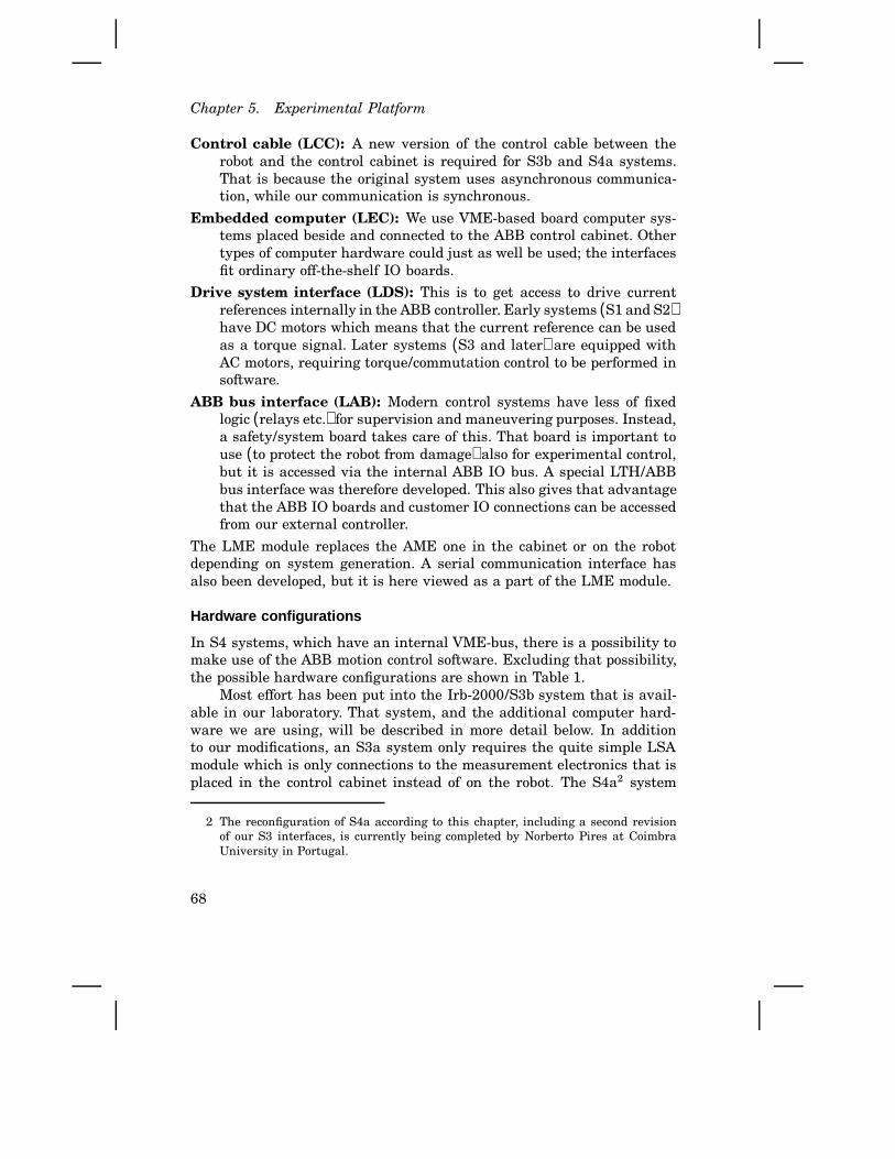
Chapter 5. Experimental Platform
Control cable (LCC): A new version of the control cable between therobot and the control cabinet is required for S3b and S4a systems.That is because the original system uses asynchronous communica-tion, while our communication is synchronous.
Embedded computer (LEC): We use VME-based board computer sys-tems placed beside and connected to the ABB control cabinet. Othertypes of computer hardware could just as well be used; the interfacesfit ordinary off-the-shelf IO boards.
Drive system interface (LDS): This is to get access to drive currentreferences internally in the ABB controller. Early systems (S1 and S2)have DC motors which means that the current reference can be usedas a torque signal. Later systems (S3 and later) are equipped withAC motors, requiring torque/commutation control to be performed insoftware.
ABB bus interface (LAB): Modern control systems have less of fixedlogic (relays etc.) for supervision and maneuvering purposes. Instead,a safety/system board takes care of this. That board is important touse (to protect the robot from damage) also for experimental control,but it is accessed via the internal ABB IO bus. A special LTH/ABBbus interface was therefore developed. This also gives that advantagethat the ABB IO boards and customer IO connections can be accessedfrom our external controller.
The LME module replaces the AME one in the cabinet or on the robotdepending on system generation. A serial communication interface hasalso been developed, but it is here viewed as a part of the LME module.
Hardware configurations
In S4 systems, which have an internal VME-bus, there is a possibility tomake use of the ABB motion control software. Excluding that possibility,the possible hardware configurations are shown in Table 1.
Most effort has been put into the Irb-2000/S3b system that is avail-able in our laboratory. That system, and the additional computer hard-ware we are using, will be described in more detail below. In additionto our modifications, an S3a system only requires the quite simple LSAmodule which is only connections to the measurement electronics that isplaced in the control cabinet instead of on the robot. The S4a2 system
2 The reconfiguration of S4a according to this chapter, including a second revisionof our S3 interfaces, is currently being completed by Norberto Pires at CoimbraUniversity in Portugal.
68
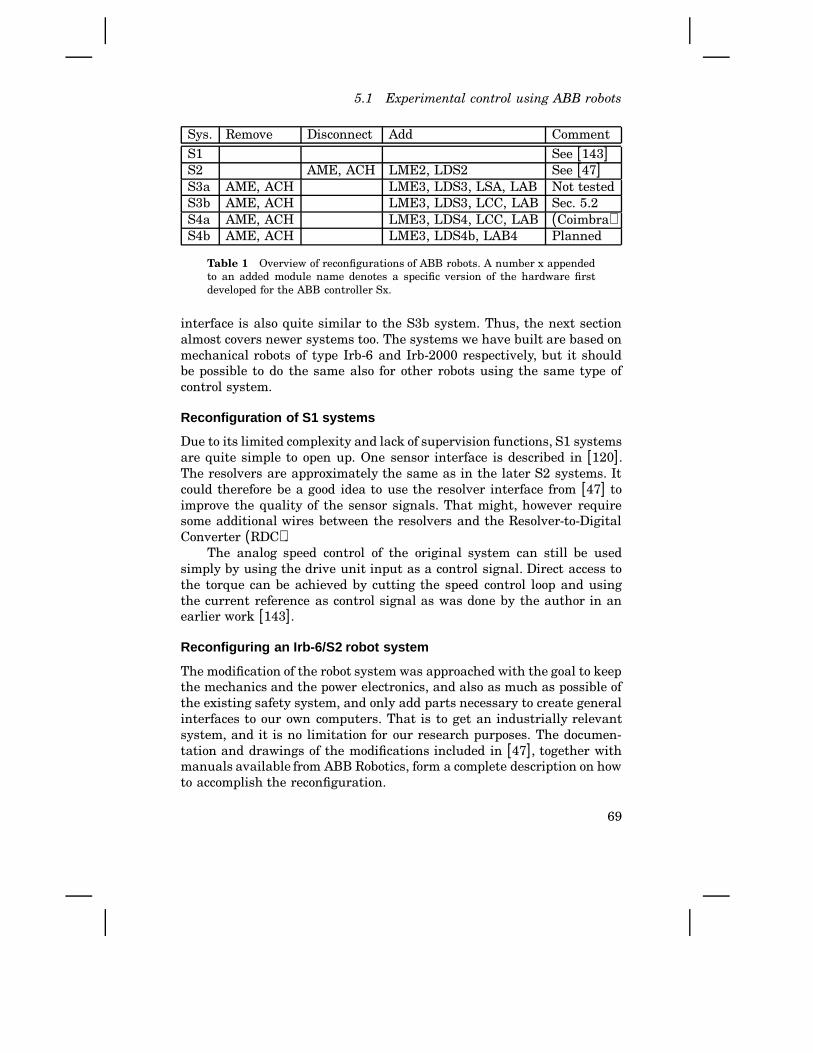
5.1 Experimental control using ABB robots
Sys. Remove Disconnect Add CommentS1 See [143]S2 AME, ACH LME2, LDS2 See [47]S3a AME, ACH LME3, LDS3, LSA, LAB Not testedS3b AME, ACH LME3, LDS3, LCC, LAB Sec. 5.2S4a AME, ACH LME3, LDS4, LCC, LAB (Coimbra)S4b AME, ACH LME3, LDS4b, LAB4 Planned
Table 1 Overview of reconfigurations of ABB robots. A number x appendedto an added module name denotes a specific version of the hardware firstdeveloped for the ABB controller Sx.
interface is also quite similar to the S3b system. Thus, the next sectionalmost covers newer systems too. The systems we have built are based onmechanical robots of type Irb-6 and Irb-2000 respectively, but it shouldbe possible to do the same also for other robots using the same type ofcontrol system.
Reconfiguration of S1 systems
Due to its limited complexity and lack of supervision functions, S1 systemsare quite simple to open up. One sensor interface is described in [120].The resolvers are approximately the same as in the later S2 systems. Itcould therefore be a good idea to use the resolver interface from [47] toimprove the quality of the sensor signals. That might, however requiresome additional wires between the resolvers and the Resolver-to-DigitalConverter (RDC).
The analog speed control of the original system can still be usedsimply by using the drive unit input as a control signal. Direct access tothe torque can be achieved by cutting the speed control loop and usingthe current reference as control signal as was done by the author in anearlier work [143].
Reconfiguring an Irb-6/S2 robot system
The modification of the robot system was approached with the goal to keepthe mechanics and the power electronics, and also as much as possible ofthe existing safety system, and only add parts necessary to create generalinterfaces to our own computers. That is to get an industrially relevantsystem, and it is no limitation for our research purposes. The documen-tation and drawings of the modifications included in [47], together withmanuals available from ABB Robotics, form a complete description on howto accomplish the reconfiguration.
69

Chapter 5. Experimental Platform
P-servo
PI
Ext.
ILIM
Current
Enable
Disable
ASEAProcessor
ASEAPower
ASEADrive power
LTH unit
On
Off
STOP
ASEA Control panel
Motor
Tacho
Resolver
Data I/O
XDisconnected
Enable
Input
Power
Power/Control
Power
Velocity
Velocity/P-servo/enable
Velocity
Position
Drive Power
LTH Regl. RB 88
POS. VEL.
IN
ENABLED
AGND.
RESOLVER-INTERFACE
LTH Regl. RB 88
Reset
Zero
OperateD/O 1
D/O 2
D/I 1
Operate
Resolver -Digital conv.
Lasermain power
LevelOperate
Alarm
Laser distancemeter.
LTH Regl. RB 91
Enable
Distance output
Laser I/O
Laser distancemeter
P-servo
PI
Ext.
ILIM
Current
Enable
Disable
Figure 5.1 Overview of S2 modifications. There is one Resolver-to-Digitalconverter (RDC) module for each joint, but only one axis is shown for clarity.The analog control signal inputs are also located at the RDC modules, whereanalog signals for joint speed and position are available, mainly for testpurposes. The joint signals are normally accessed via the Data I/O module,which comprises a 16 bit (plus address and control signals) parallel resolverdata bus. An interface for a laser distance sensor has also been included.
An overview of the resulting design can be seen in Figure 5.1. Theoriginal control computer is retained to make it easy to change the systemback to its original shape, and to keep the changes in the safety systemsmall. However, the original functions to take care of the measurement arenot used. Instead, we have built our own sensor interface (LME2), and wehave done it in a way that makes it possible to keep the sensors and cablesalready available inside the robot. The sensor system for measurementsof robot joint angles is based on resolvers. Our solution principle is todrive and read the resolvers from hardware based on existing commercialchips for resolver-to-digital (R/D) conversion [14]. The solution principlecan be seen as part of Figure 5.1, which also shows the solution principlefor driving the motors (LDS2). The user can select to use the originalanalog PI-speed-control available on the drive units by selecting the PImode shown in the expanded part of Figure 5.1.
70
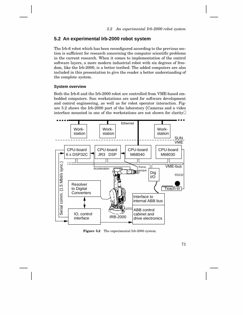
5.2 An experimental Irb-2000 robot system
5.2 An experimental Irb-2000 r obot system
The Irb-6 robot which has been reconfigured according to the previous sec-tion is sufficient for research concerning the computer scientific problemsin the current research. When it comes to implementation of the controlsoftware layers, a more modern industrial robot with six degrees of free-dom, like the Irb-2000, is a better testbed. The added computers are alsoincluded in this presentation to give the reader a better understanding ofthe complete system.
System overview
Both the Irb-6 and the Irb-2000 robot are controlled from VME-based em-bedded computers. Sun workstations are used for software developmentand control engineering, as well as for robot operator interaction. Fig-ure 5.2 shows the Irb-2000 part of the laboratory (Cameras and a videointerface mounted in one of the workstations are not shown for clarity).
Teach-in
Interface to internal ABB bus
ABB controlcabinet anddrive electronics
Resolverto DigitalConverters
IO, controlinterface
DigI/O
IRB-2000
Ser
ial c
omm
. (1.
5 M
bit/s
syn
c.)
RS232
VME-bus
6 x DSP32CCPU-board
SUNVMEV
Work-station
Ethernet
Work-station
Work-station
JR3 DSPCPU-board
M68040CPU-board
M68030CPU-board
Acceleration Force,torque
Figure 5.2 The experimental Irb-2000 system.
71

Chapter 5. Experimental Platform
Signals from the internal sensors of the robot to the VME system go viathe sensor interface to the DSP board connected to the VME bus.
The master computer in the VME computer is based on a M68040microprocessor. Supervision and safety functions are implemented on aM68030 board, well separated from the rest of the system to preventdamage of the robot. Digital Signal Processors (DSP) are used for low-level control and filtering of sensor signals. Sensors requiring very highdata bandwidths are connected directly to the DSP boards. An additionallyDSP board belongs to the force-torque sensor [101]. A six DOF joystick[94] can be connected to a serial port of the M68030 supervision computerfor data transfer to memory accessible from the VME bus.
Analog current referencesDig.
Se
ria
l/Pa
ralle
l in
terf
ace
Drive
co
ntr
ol
in
terf
ace
Drive
inte
rfa
ce jo
int 3
an
d 4
Drive
inte
rfa
ce jo
int 5
an
d 6
Drive
inte
rfa
ce jo
int 1
an
d 2
RS422 serial comm.with DSP hardware
Original drives
2x12 bits data, 5 bit addr, and 3 bit ctrl.
Local bus for new drive control boards
R/D conversionjoint 1 and 2
R/D conversionjoint 3 and 4
R/D conversionjoint 5 and 6
Ser./Par. inter−face and contr.
Lo
cal b
us
for
ne
w r
eso
lve
r in
terf
ace
24 b
its r
esol
ver
data
, etc
.
An
alo
g r
eso
lve
r si
gn
als
−o
rig
ina
l co
nn
ect
ion
s u
sed
To original drive unit connections
Ro
bo
t co
mp
ute
r d
isco
nn
ect
ed
Po
we
r su
pp
ly u
sed
Resolver interfacehardware replaced
RS422 serial comm.
R
S4
22
se
ria
l co
mm
. w
ith r
eso
lve
r b
oa
rds
Ne
w r
ob
ot in
terf
ace
pla
ced
in o
rig
ina
l IO
bo
ard
slo
ts
Test and status inter−face to master comp.
Figure 5.3 Placement of hardware added to the Irb-2000 system.
72
5.2 An experimental Irb-2000 robot system
Basic design
The Irb-2000 is equipped with AC motors, and because we want to be ableto implement all of the control layers, the interfacing to the S3 controlsystem used has to be at a lower level compared to the Irb-6 interface. Thesystem is simply cut at the drive unit interface, which means that alsothe AC motor current references must be computed in such a way thatthe desired torque is achieved. The AC motor control should be computedwith a rate of at least 1 kHz (preferably 2 kHz). Otherwise the torquecontrol will not be good enough, particularly for high speeds. This meansthat the requirements on computing power are quite severe. Our solutionis to use Digital Signal Processors (DSP) as described below.
The same type of resolver-to-digital conversion as for the Irb-6 in-terface is used, but with the accuracy of 14 bits per motor revolutionand 8 revolution counting bits in hardware. Both hardware and softwareare prepared for a resolution of 16 bits per motor turn. Thus, joint an-gles are provided as absolute 24 bit values. Using commercially availableR/D converters [14] with an internal analog velocity signal and a phase-locked loop makes it possible to get proper anti-alias filtering by tuningthat loop. This is hardly possible with optical encoders or with other typesof resolver measurement principles (a higher sampling frequency and theroll-off of the process then have to be used instead). The 24 bit positiondata for the motors can simply be differentiated to get the speed; thatsignal has been filtered in the analog phase locked loop. The samplingperiod will then, however, be quite crucial. The next generation of thesensor interface will therefore also provide the speed value from the RDCchip. The R/D conversion hardware is located on the robot which reducesthe required length of the wires for analog signals to a minimum.
The current references for each motor are output from the computerhardware as two 12 bit values for two of the phases of the motor (thethird phase is generated in the drive units). D/A conversion provides thecurrent references that can be connected to the original drive units. Thetwo 12 bit current references are transferred together as a 24 bit wordfrom the computing hardware, i.e., the same number of bits as for theresolver data.
Communication with sensors and actuators
Reduced cost for cables, reduced noise level, and increased reliability areadvantages obtained by placing sensors, actuators, and necessary elec-tronics close to the motors on the mechanical robot. That was experiencedmore than 10 years ago using optical connections [153], and this approachis also used in the S3 control system, although not optical. It is also be-
73

Chapter 5. Experimental Platform
lieved to permit more modular (and thereby more flexible and reusable)machine designs within mechatronics in general [207]. Such a modularapproach, however, has not had much industrial impact yet.
The serial communication line of the original ABB S3 system was forour purposes too dedicated and involved with the rest of the hardware. Itwas therefore realized that new communication hardware and softwareneeded to be developed. Such an interface between sensors, actuators, andcontrol modules was designed and built with two purposes in mind:
1. To connect the Irb-2000 robot and its reconfigured control system ina simple and efficient way allowing sampling rates of 4 kHz for themotion control.
2. To serve as a testbed for research within decentralized control andreal-time systems.
This has so far been successful. An early description of the design wasgiven in [144]. The system has been used in a case study on distributedreal-time control [207], and it has been referred to [220] as a platform forverification of timing problems in decentralized real-time control [219].
Sensornode n
Actuatornode
Sensornode
Computernode
Mas
ter
com
pute
rs
Motor unit n
Actuatornode n
Serial communication
Figure 5.4 The used principle for connecting the joint servos of the robot tothe control system. A sensor (input) and actuator (output) node sharing thesame address can be viewed as a motor node from the control side.
Using physically distributed, i.e., decentralized, hardware means thatthe control system (including its sensors and actuators) contains a numberof so called nodes. A node may constitute a sensor, an actuator, or aprocessor. A node can, of course, physically include several such elements,but they should conceptually be separated. Several types of so calledfield buses [156] are today used in process control. Specific designs are,however, often done for specific machines. Our type of bus, which wenamed the SA-bus (Sensor Actuator bus), is one such example. This bushas three types of nodes as shown in Figure 5.4. More specifically, someproperties/features of the modified system are:
• The robot system communicates via synchronous serial communica-tion. A bit transfer rate of 1.5 Mbit/s makes it possible to transfer 32
74

5.2 An experimental Irb-2000 robot system
q
ABBdrive
DAC
R,S,T
RDC
Rref Sref
2q 1
ABBdrive
DAC
R,S,T
RDC
Rref Sref
ABBdrive
DAC
Serial/Parallel interface and local bus control
Serial/Parallel interface and local bus control
.. ..q 3 q 5..q 4
RDC
Rref Sref
q 6
R,S,T
Serial bus to external computer
Figure 5.5 Servo hardware in the modified S3 system. Please compare withFigure 5.3 to see the physical placement.
bits of data with a sampling frequency of 8 kHz for each joint, if sixjoints are used. The communication protocol fits directly to the serialports of most DSP types.
• The serial communication signals between the computer system (i.e.,the computers that replace those of the original system) and theinterface hardware, as well as between the interface hardware andthe robot, are connected via IEEE-422 line drivers.
• Our SA-bus protocol specifies that data are transferred in 32 bitwords. A word going out to the robot system contains the currentreferences, the address of the joint, a “current references to be used”bit, a “read the resolver for the addressed joint” bit, and parity. Anaddressed resolver sends a word containing the 24 bits position databack to the computer interface on the return communication line.
• Computer nodes do not have addresses themselves. They are justprocessing elements connected in a data-flow oriented [8] style. Themotor node number is attached as an address to each data message.Time stamping is implicitly achieved by using synchronous commu-nication in combination with explicit time delay messages after tem-porary faults.
75
Chapter 5. Experimental Platform
• Additional control and status bits for the drive units are connecteddirectly to standard IO boards on the VME bus. Those signals areused by the master computer for initialization and fault detection.The planned version for S4b systems will (according to the new ABBdesign) use the serial bus instead.
Even if the nodes are conceptually separated seen from the computerside, they were actually built in clusters as already shown in Figure 5.3.That was to simplify the hardware considering the design of the originalsystem. This means that the physical LME and LDS modules mentionedon Page 69 relate to the six motor units as shown in Figure 5.5. Note,however, that the motor control conceptually agrees with the motor controllayer of the ORC architecture on Page 57.
System supervision
Development of software for the supervisory computer board (M68030 inFigure 5.2) was initially done for two reasons: 1) An overheated motorshould cause the robot to stop for sure. 2) Pushing the RUN button onthe cabinet should turn on the main power to the drives. The mechanicaldesign of the robot should normally permit end-stops to be hit with max-imum torque, at least a few times. Supervision speed and position limitsetc. was therefore postponed to some later stage of the project. Both needs,1 and 2, required access to the ABB safety board (called system board inlater systems) via an internal ABB bus. An Interface to internal ABB buswas designed and built as shown in Figure 5.2. That board, together withan available digital I/O board and flat cables, formed an VME/ABB busconnection.
An interface to the ABB supervisory control of the drive units was alsoincluded. That interface is used to reset the drives at startup and to getinformation about errors (like unacceptable current references, which forexample occurs when control gains are set too high or the excitation duringsystem identification is too persistent). This means that the interfaceboard physically replaces the ABB robot computer.
Supervision functions may not be disabled by any experimental con-trol software. For example, increasing the order of the control algorithmwhich perhaps run with maximum priority, may not cause a motor burn-up when motions are too demanding. That could be the case if the controlactivity, instead of the supervision functions, occupies the CPU. This isavoided by using a separate CPU-board for the supervision. Furthermore,the software process with the lowest priority must trigger a mono flip-flopat least each 20 ms. Otherwise, the drive power is shut off. That detectsif the supervision system is stopped.
76

5.2 An experimental Irb-2000 robot system
Supervision of control states like joint positions and velocities (asdone in the original system) is also necessary. Unfortunately, these func-tions were not implemented to start with because we were short of timeand eager to do control experiments. These supervision functions wereimplemented first after an accident during the experiments [129]. Servocontrol of a single joint was done with a sampling frequency of 24 kHz.The torque control then works for much faster commutation (motor speed)than possible in the original system. The robot was therefore able to movepast an extra mechanical stop, past the standard mechanical stop, andcontinuing outside the working range damaging cables inside the robot.The final extensions also included supervision of the cyclic execution ofthe control tasks. After that, the system works very well.
The software modules shown in Figure 5.6 form three layers. At thelowest level, the physical connections to signals in the control cabinet areencapsulated. The mid levels contain the actual supervision, which reflectinternal details of the ABB hardware. Proper error recovery further in-creased the complexity of this part. The top layers contain speed, position,torque, sampling, and jam supervision. The latter means detection of hightorque without motion. Additional functions can easily be added.
Board
Control-
ControlMaster
Shared
DigIOboard
Connection
IObus
Safety
Drive
Supervision
iSupervisionIrbHandler
Cabinet
DriveStatus
SafetyBoard
iDspRegul
iDspRegul
DspRegul
Slav
e m
ulti-
DSP
Con
trol B
oard
LTH/ABB robot interface hardware
Supe
rvis
ory
Con
trol B
oard
PowerControl
Com
plex
cou
pled
sof
twar
ere
flect
ing
ABB
hard
war
e
Figure 5.6 Supervision software modules. These contain totally 15 softwareprocesses performing the supervision and operation of the system.
77

Chapter 5. Experimental Platform
Opposed to the layers of the ORC architecture (Page 57), these lay-ers reflect the implementation (just like the OSI-layers does for a networkconnection). In other words, some functionality provided might be viewedas a system service available in a user view, but the layered implementa-tion of the supervision system is only exposed on a system programminglevel.
5.3 Low level control – Signal processing
Robot motion control can be divided into servo control of individual mo-tors and control of the complete arm. The motor control including driveelectronics and measurement system can be implemented close to the mo-tor, or distributed elsewhere in the system as described in the previoussection. The arm control is typically a multivariable controller that isimplemented on top of the motor control. Required sampling periods, i.e.,cyclic execution rates, for a typical industrial manipulator are for example(according to the author’s experience)
• 20 Hz (for trajectory generation,• 100 Hz for position control using an inner velocity control,• 500-2000 Hz for velocity control (depending on friction etc.),• 2000 Hz for torque control using inner phase-current control,
where the first two items applies to the multivariable part, and the lattertwo applies to the motor control. Considering that there are six joints tocontrol, and that a timely response on each sampling instant is importantfor the performance of the robot, we see that the real-time implementationfor the low-level motor control has to be carefully designed.
DSP hardware
A digital signal processor (DSP) is optimized for repeated operationsof the type a = b + c ∗ d, which are frequently used in convolutionsand matrix operations, which are the standard computations in signalprocessing and control algorithms. This was the most promising type ofprocessor for control implementation at the time when hardware wasselected for this project. The processor DSP32C from AT&T [31] wasselected mainly for the reasons of simple low level programming (C-likeassembly language and data directed programming [114]), compatibleperformance, and because a VME board and required software tools wasprovided by a single source (AT&T).
It would be natural to use DSPs dedicated to each motor/joint con-trol. But the connections with the robot, and the desire to efficiently use
78
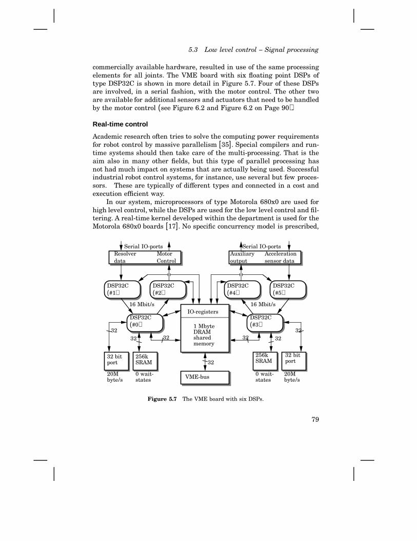
5.3 Low level control – Signal processing
commercially available hardware, resulted in use of the same processingelements for all joints. The VME board with six floating point DSPs oftype DSP32C is shown in more detail in Figure 5.7. Four of these DSPsare involved, in a serial fashion, with the motor control. The other twoare available for additional sensors and actuators that need to be handledby the motor control (see Figure 6.2 and Figure 6.2 on Page 90).
Real-time control
Academic research often tries to solve the computing power requirementsfor robot control by massive parallelism [35]. Special compilers and run-time systems should then take care of the multi-processing. That is theaim also in many other fields, but this type of parallel processing hasnot had much impact on systems that are actually being used. Successfulindustrial robot control systems, for instance, use several but few proces-sors. These are typically of different types and connected in a cost andexecution efficient way.
In our system, microprocessors of type Motorola 680x0 are used forhigh level control, while the DSPs are used for the low level control and fil-tering. A real-time kernel developed within the department is used for theMotorola 680x0 boards [17]. No specific concurrency model is prescribed,
Serial IO-portsResolverdata
MotorControl
16 Mbit/s
DSP32C(#1)
DSP32C(#2)
DSP32C(#0)
32 bitport
256kSRAM
20Mbyte/s
0 wait-states
3232 32
Serial IO-portsAuxiliaryoutput
Accelerationsensor data
16 Mbit/s
DSP32C(#4)
DSP32C(#5)
DSP32C(#3)
256kSRAM
20Mbyte/s
0 wait-states
32 bitport
323232
IO-registers
1 MbyteDRAMsharedmemory
VME-bus
32
Figure 5.7 The VME board with six DSPs.
79
Chapter 5. Experimental Platform
and real-time primitives are built on top of coroutine and interrupt routinefacilities. Sampling rates currently supported range up to 1 kHz for theM680x0 boards. Programming languages currently supported are Modula-2, C, and C+ + . Even if this part of the real-time environment is ratherstandard, it is public domain in terms of source code, etc. That has allowedimplementation of new real-time software techniques [122] in connectionwith this project [145, 121].
Looking at the special control hardware like the DSPs, it is quite clearthat more dedicated real-time solutions are needed. We know from thedescription above that we have to maintain a data flow of control signalswith a rate of 6⋅8 = 48 kHz data packets per second. For each DSP32C thisimplies that there are 260 CPU cycles available to process each sample.In fact the main DSPs (#0 and #3 in Figure 5.7) are presently only runat a 24 kHz rate, which gives us 520 CPU cycles per sample. (Whenfully utilized, each cycle consists of one floating point multiplication, onefloating point addition, two pointer modifications, and memory accesses.)It is natural to connect the control algorithm to interrupts, and to let the‘background’ process handle online parameter updates, supervision, andlogging of control signals.
Context switching The real-time demands for DSPs are contradictory,particularly for floating point DSPs because of their highly pipelinedarchitecture. DSP32C serves interrupts in a quick interrupt fashion. Thismeans that the floating point registers, the four stage pipeline, and someother states in the DSP, are automatically stored in shadow registersduring a single machine cycle (80 ns). This allows very quick interruptroutines performing for instance sensor input and buffering in less then0.2 µs, including overhead. Clock interrupt handling resulting in no taskswitch will also be very rapid. The problem is, however, how to makea context switch including the floating point registers. The only shadowregister accessible is that for the program counter, so the only possibility isto modify the code that will be executed after returning from the interrupt,in such a way that the pipeline is emptied before the context switch. Thereare two problems with such an approach; programs in ROM, and latencyeffects when branching due to the pipelining (one or more instructionsafter the branch instruction are executed before the branch occurs). Dueto these drawbacks, static scheduling into interrupt driven procedures isused.
A review of other hardware solutions for context switching has alsobeen done. On one hand, it is desirable to have a quick interrupt facilityto serve short interrupts without breaking the pipeline of the DSP. Thismeans that the floating point context (registers and pipeline status) needs
80
5.3 Low level control – Signal processing
to be saved in shadow registers. On the other hand, preemptive contextswitches are typically required in demanding control applications. Thatwould then require that shadow registers could be saved in memory.Examining the four major brands of floating point DSPs, one sees thatnone of them have an interrupt architecture very suitable for controlapplications [148].
Motorola (DSP96002) has adopted a concept of fast interrupts thatdo not perform any stack operations, and long interrupts that do. A longinterrupt can be formed from a fast interrupt. However, the fast inter-rupt is too limited to be used for operations such as a clock interruptroutine. Analog Devices (ADSP-21020) has a special status stack, but thefloating point pipeline is aborted when servicing an interrupt (as withMotorola’s long interrupt). Texas Instruments (TMS320C30) also abortsthe FP pipeline, and only uses the ordinary stack for saving the context.AT&T (DSP32C) has an interesting quick interrupt facility, in which theentire floating point context is saved in one instruction cycle. However,that context can not be accessed; it can only be restored as mentionedabove. That means that the only way (that the author has found) to doa preemptive context switch is to replace the next instruction of the in-terrupted program with a call to a context switch subroutine. That is,however, not a good solution since it would then not be allowed to inter-rupt code that has been optimized utilizing latency effects.
The DSP32C works well in our application because the backgroundprocess is only preempted by interrupt routines. In more general con-trol applications, a combination of features from the different vendorswould form the most powerful hardware. Considering the software part,it would be desirable to have means for limiting the size of the context forfrequently executed low-level control tasks. A DSP real-time kernel withsuch a feature is commercially available [213], but the fast processes mustbe coded in assembly language since there is no support from today’s highlevel programming languages.
Concurrency We now have a process interface via the SA-bus, a num-ber of processing elements, and an interrupt driven execution model. In-terrupts are caused by availability of sampled data on input ports. Thecontrol actions will then be synchronized with the sampling. Interruptseither trigger control actions, while others are needed just to handle datatransfers to/from other processors.
The real-time schedule of control actions is defined statically by tablescontaining joint numbers and execution control data. Schedules are loadedfrom the VME bus via IO-ports (Figure 5.7) and DMA into the on-chipmemory of the DSP. The schedule can be changed on line if carefully done.
81
Chapter 5. Experimental Platform
Static scheduling is a research topic of its own [194, 195, 54]. Here, it hasso far been done by hand.
To conclude the presentation of the hardware, we will now follow themotor control loop around the hardware nodes. We start in DSP #2 (seeFigure 5.7) with current references available for the next scheduled joint.
1. Upon interrupt for output buffer (current references to the SA bus)empty, DSP #2 looks up the next joint number in the static schedule.Most recent output data (phase-current references in this case) arelooked up and an output message is composed and sent.
2. The actuator node for the addressed joint catches the data, and thesensor node later replaces the data with the sensor value. Theseactions are done without delaying the message.
3. A new sensor value causes an interrupt on DSP #1. The interruptroutine unpacks the message data (extracting angle data and jointnumber), performs some error checking, and stores a valid sample ina buffer. The background process for this DSP reads the buffer andperforms digital filtering from 8 kHz to a possible lower samplingrate used in the control. The filtered value is sent to DSP #0 whenthe serial output buffer is empty.
4. The new sample interrupts DSP #0, which then gets the joint numberfrom the input message, looks up sensor and actuator (software)objects, and converts the data according to those objects. For ACmotor control this means that the data stream is split up into twopaths:
• The sensor value is passed to the actuator object which computesthe commutation angle of the rotor of the motor. An actuator out-put message is then prepared (in the actuator object) to permitrapid response when a new torque reference gets available.
• The sensor value is also converted to floating point and SI units.It is then put in a ‘shared array’ in the DRAM memory. Aninterrupt in then generated to DSP #3.
The background process for DSP #0 performs parameter updatingand data logging for master computers (M68040) on the VME bus.
5. External sensors for motor control, in our case an accelerometer isavailable, are read by DSP #4 and sent to DSP #3. The serial inputport of DSP #3 is configured to transfer data into the internal memoryby DMA. The overhead for the program is therefore only due to cyclestealing, which is less than 0.1µ s per sample.
6. The background process for DSP #3 does the same as in DSP #0,but for the motion control instead of for the actuator control. Sensor
82
5.3 Low level control – Signal processing
values are available in the DRAM for the motion regulator which istriggered by the interrupt from DSP #0. The computed control signalis put into the DRAM. In addition, a state vector is exported via theDRAM to the M68040 master control board. The master also suppliesreferences and slow control signal corrections because integral actionand windup protection are done by the master. A DSP implementationof this part would waste computing power since logics and modeswitches do not fit well into the highly pipelined architecture.
7. The control signal (torque reference) is then passed to the actuatorobject that one or a few samples earlier (according to the staticschedule) computed the commutation angle. That object limits thecontrol signal and composes a torque request message that is put inthe serial output buffer. This was done at the end of the interruptservice for the sensor data.
8. The torque request message is transferred via the serial connectionand via DMA into a buffer in the on-chip memory of DSP #2. Thebackground process then unpacks the joint number, the commutationangle, an the requested torque. A function that computes the cur-rent references is then called. (This function is written in assemblylanguage, all others are written in C+ + as described below.) The ref-erences are put in an array for the output interrupt routine. Thus,we are back to item 1, and the loop is closed.
This makes more than 10 parallel processes totally. Absence of debug-ging tools, and presence of both hardware and compiler faults, made theimplementation a very time consuming task. An industrial implementa-tion would involve hardware and software development using professionaltools. So why implement the control this way?
Even if a commercially available board is used, it provides severalhardware features that are configured and controlled from the software.That, in a way, corresponds to the custom made circuits that interface theCPUs in modern embedded controllers. With a background in assemblyprogramming of such systems, it was as part of this research to investigatehow high level software techniques could simplify programming of thistype of embedded systems.
Low-level object-oriented programming Data processing blocks (orfilters) are naturally represented by software objects. Control often alsoincludes sequences, mode changes, etc., but such control is better puton top of pure functional blocks (as most often done in process controlsystems). We can therefore reason about the control in terms of blockdiagrams.
83

Chapter 5. Experimental Platform
In an object-oriented framework, we may have methods (memberfunctions in C+ + notation) that implements the signal processing of the(control) block. Such control objects are sometimes called function ob-jects [198]. Additionally, there may be other member functions for modechanges etc. For the implementation, we want to use available compilersand a language that allows efficient manipulation of the hardware.
In practice, the only language available for (almost) all new types ofhardware, including our DSPs, is the C language. It is of course desirableto use the same programming language for DSP programming as forprogramming of the rest of the system, where C+ + [198] was available.The C+ + compiler Cfront [30] used on the Sun workstations was thereforeadapted to produce C code for the DSP, making it possible to use theobject-oriented paradigm also on the lowest levels of the system. Real-time primitives have been developed and encapsulated in C+ + , makingit possible to connect C+ + functions to hardware interrupts for example.
Critical parts of the algorithms sometimes have to be implementedin the C-like assembly language of DSP32C to fully utilize the computingpower of the DSP [53]. Therefore, the C+ + compiler was extended to per-mit easy and structured interfacing of inline assembly code. This featurehas also been useful for implementation of new real-time primitives.
The developed real-time primitives, and several features for hardwareutilization, have been encapsulated in C+ + classes providing a high-level interface. Hidden for the ordinary system programmer, the memberfunctions accessing the hardware features were implemented as assemblymacros. Call of such a member function results in inlining of the code onan assembly level, allowing the inlining to depend on actual allocation ofthe data. For example, if data is already loaded into a register due to theassembly code from the C compiler, that register can be used directly. Thisfeature in C+ + relies on extensions of the underlying AT&T C compiler[32]. Using this concept, superior efficiency was achieved in combinationwith object-oriented programming. Part of the software handling objectinteractions was, however, implemented in a procedural (C) style (butstill written in C+ +) for efficiency reasons also observed by others [211].
Another attractive property of object-oriented programming is thathardware dependencies could be nicely encapsulated in classes. Morespecifically, we have multiple CPUs that differs in type, representationof floating point numbers, address spaces, sizes of pointers, byte order-ing, and they have different real-time properties. A drawback of C+ +compared with most other languages is that more programming skill isrequired since it is a very rich language. However, many of the features– operator overloading, conversions, class dependent memory allocationetc. – were found to be very useful.
84
5.4 Concluding remark
The employment of a high level software technique for very low-levelprogramming is a contribution [147, 146] related to this thesis, but afurther description is left out here for brevity.3
5.4 Concluding remark
Robot systems are normally used as intended by the robot system de-signer. That gives reliability, and permits full support for repair and main-tenance. If customers would start to rebuild some robot systems for specialapplications according to our drawings, and then use the system for fullproduction, could that cause problems? It is quite understandable if therobot manufacturer believes that the answer is yes, being worried aboutreputation and customer support. We claim, however, that the answer isno.
Our experimental system can very well be used in real industrialapplications, but only for experimental purposes. The reasons are:
• The warranty for new robots would hardly apply.
• The original system provides a lot of special features, developed ac-cording to specific requirements from the customers. One exampleis automatic restart of robot programs (and motions) after a powerfailure. Many man-years are put into development of such features.They will not be supported for the experimental system.
• Supervision and self-test functions are much more extensive in theoriginal system. Even if the system can be changed back to its originalshape (to run the ABB self-test software) in less than an hour, thatis too long for most production systems.
• There are less support for repair and maintenance, as mentionedabove.
A system like the one described in this chapter will therefore not be usefulfor full-scale every-day production. It can, on the other hand, be usedin real applications for rapid prototyping and evaluation purposes. Thatshould be of interest also to the robot manufacturer. Thus, an R&D versionof a robot control system would fill a need not only in academic researchwithin control and programming, but also in industrial feasibility studiesfor possible new robot applications.
3 More details and examples are given in [147]. That paper was judged as one of “thebest technical presentations” (Page 2 in [146]), which resulted in publication of acondensed version[146], reaching a large engineering community.
85

6
Motion Control Structure
The primary purpose of the motion control system is to read signals frominternal sensors of the robot system, to compute control signals in such away that position and force control as requested from higher levels of thesystem are achieved, and to output the control signals to the hardware.Superior performance and robustness of the control is important for pro-ductivity and utilization of the equipment, and possibly also to allow lessexpensive mechanical design in the future. The ongoing research withincontrol theory to improve on these points is therefore very important.
A perhaps even more important problem today, given all the algo-rithms that have been proposed so far, is to facilitate use and evaluationof available control solutions on realistic robot systems. The hardwareplatform presented in Chapter 5 constitutes a system well suited for thispurpose. Implementation of the control will be treated in this chapter.Still focusing on the robot programming subject of this thesis, now on asystem/control level, the topics are software engineering and control engi-neering, and how that can be supported by a proper design of the system.More specifically, we want to find answers to the following questions:
• What is the rationale of the control part of the ORC architectureconcerning management of control complexity, hardware structure,and system development?
• Given the basic design of the architecture, what functions should thelayer interfaces contain, and what functionality is needed internallyin the software layers?
• Our approach to split up the built-in motion control in the layers, willthat make it hard to apply modern control techniques?
• Advanced planning/optimization of motions/trajectories often needsto be performed in advance (in an off-line manner). On the otherhand, motions depending on sensor values must be computed in realtime. Therefore, such motions cannot be optimized in systems today.
86

6.1 Basic design
Could the management of motion commands and sensors be designedin such a way that the distinction today between plan-time and run-time can be relaxed?
• Is a fixed definition of control interfaces (in terms of libraries or con-trol blocks as in process control systems) appropriate for our purposes(flexibility and efficiency), or do we need techniques to “get inside”control modules?
• Each layer in the proposed ORC architecture defines a view for pro-gramming/engineering. Considering the low-level motion control, howcan industrially relevant hardware (like the experimental platform inChapter 5) and engineering tools be utilized to obtain both real-timecomputing efficiency and flexible control engineering?
These issues will now be treated in one section each (in order as men-tioned). The problems are approached in two stages. The first (descriptive)stage contains a basic design (Section 6.1) in accordance with the ORC ar-chitecture, and a specification (Section 6.2) of the functionality required ineach software layer. This first part presents relevant requirements on therobot system. Section 6.3 then states two open issues associated with thespecified structure. These issues/problems are then treated in one sectioneach. Finally, an implementation of the motor control layer is presented.
6.1 Basic design
A coarse modularization of the application independent part of the motioncontrol system was made in Section 4.3. That was done as part of thedefinition of the complete architecture. The proposed ORC architecture isbased on user views. On the servo level of the system, a need to supportthree types of users was identified as shown in Figure 4.3 (p. 56). Thus, wehave three different software layers named Motion control, Arm controland Motor control, each defined for a certain type of control engineering.Some further arguments for this design now follow.
Considering a specific implementation, the motion control for alljoints of a robot can of course be viewed as a single multi-variable con-troller. The standpoint taken here is that this is not a suitable formulationof the problem, at least not for industrial development. We claim that thechoice of control structure and engineering tools is not entirely free dueto demands on modularity. The proposed software layer is an attempt toimpose such a modular structure. The reasons are the following:Control complexity: A single non-linear multi-variable controller gets
unsuitably complex when dealing with all control constraints and
87

Chapter 6. Motion Control Structure
physical effects. Examples:• There are constraints on speed, torque, and torque derivative to
protect the mechanical system.• Run-time supervision and start-up diagnostics (to detect run-
away motion, malfunctioning sensors, etc.) are easier to get reli-able when implemented together with a control structure that ina simple way reflects the hardware and the states of the physicalsystem.
• Many control difficulties due to non-linear and/or unmodeleddynamics are because of the physical properties of individualjoints. Typical examples are torque ripple, motor friction andgear-box play. Dealing with locally appearing phenomena by local(inner) control loops is a fruitful approach within control design.
One could claim that this is just a matter of judicious choice of con-trol engineering tools. But according to industrial experience of con-trol development, demands on reliable system operation/supervisionindicate the need for architectural support.
Hardware structure: The architecture should support a control struc-ture that promotes efficient hardware solutions. This motivates in-troduction of the Motor control layer.
System development: The structure of the control system should sup-port modular development in projects focusing on well defined prob-lems like multivariable arm control. In other words, user views (asdefined in Chapter 4) are appropriate also for structuring the (low-level) motion control system. The scenario expressed in Figure 4.3includes:
• Control of individual motors, perhaps using less expensive hard-ware.
• Control of the manipulator/robot arm, perhaps to achieve im-proved decoupling of joint motions.
• Incorporation of external motions, i.e., control of other work-cellmotions like servo-controlled welding fixtures.
Note that even if external motions typically were application specific,indicating that such control should be included in the application con-trol layer, support for integrated external motions affects the designof the embedded system to a larger extent. Therefore, this is part ofthe motion control layer, whereas configuration and control param-eters are selected from the application layer. Control of integratedexternal joints is today dealt with by the robot manufacturer.
The object oriented paradigm [96, 126, 44] appears to be well suited fordesign and implementation of the control systems. Classes will then en-
88
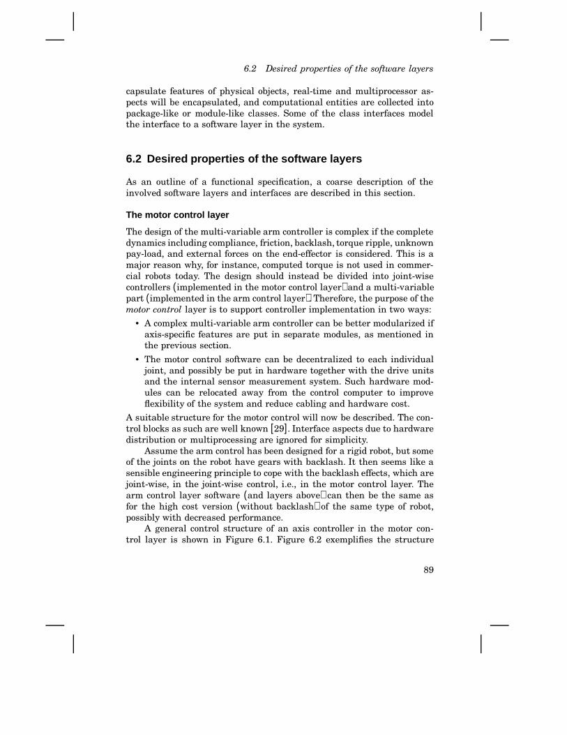
6.2 Desired properties of the software layers
capsulate features of physical objects, real-time and multiprocessor as-pects will be encapsulated, and computational entities are collected intopackage-like or module-like classes. Some of the class interfaces modelthe interface to a software layer in the system.
6.2 Desired properties of the software layers
As an outline of a functional specification, a coarse description of theinvolved software layers and interfaces are described in this section.
The motor control layer
The design of the multi-variable arm controller is complex if the completedynamics including compliance, friction, backlash, torque ripple, unknownpay-load, and external forces on the end-effector is considered. This is amajor reason why, for instance, computed torque is not used in commer-cial robots today. The design should instead be divided into joint-wisecontrollers (implemented in the motor control layer) and a multi-variablepart (implemented in the arm control layer). Therefore, the purpose of themotor control layer is to support controller implementation in two ways:
• A complex multi-variable arm controller can be better modularized ifaxis-specific features are put in separate modules, as mentioned inthe previous section.
• The motor control software can be decentralized to each individualjoint, and possibly be put in hardware together with the drive unitsand the internal sensor measurement system. Such hardware mod-ules can be relocated away from the control computer to improveflexibility of the system and reduce cabling and hardware cost.
A suitable structure for the motor control will now be described. The con-trol blocks as such are well known [29]. Interface aspects due to hardwaredistribution or multiprocessing are ignored for simplicity.
Assume the arm control has been designed for a rigid robot, but someof the joints on the robot have gears with backlash. It then seems like asensible engineering principle to cope with the backlash effects, which arejoint-wise, in the joint-wise control, i.e., in the motor control layer. Thearm control layer software (and layers above) can then be the same asfor the high cost version (without backlash) of the same type of robot,possibly with decreased performance.
A general control structure of an axis controller in the motor con-trol layer is shown in Figure 6.1. Figure 6.2 exemplifies the structure
89
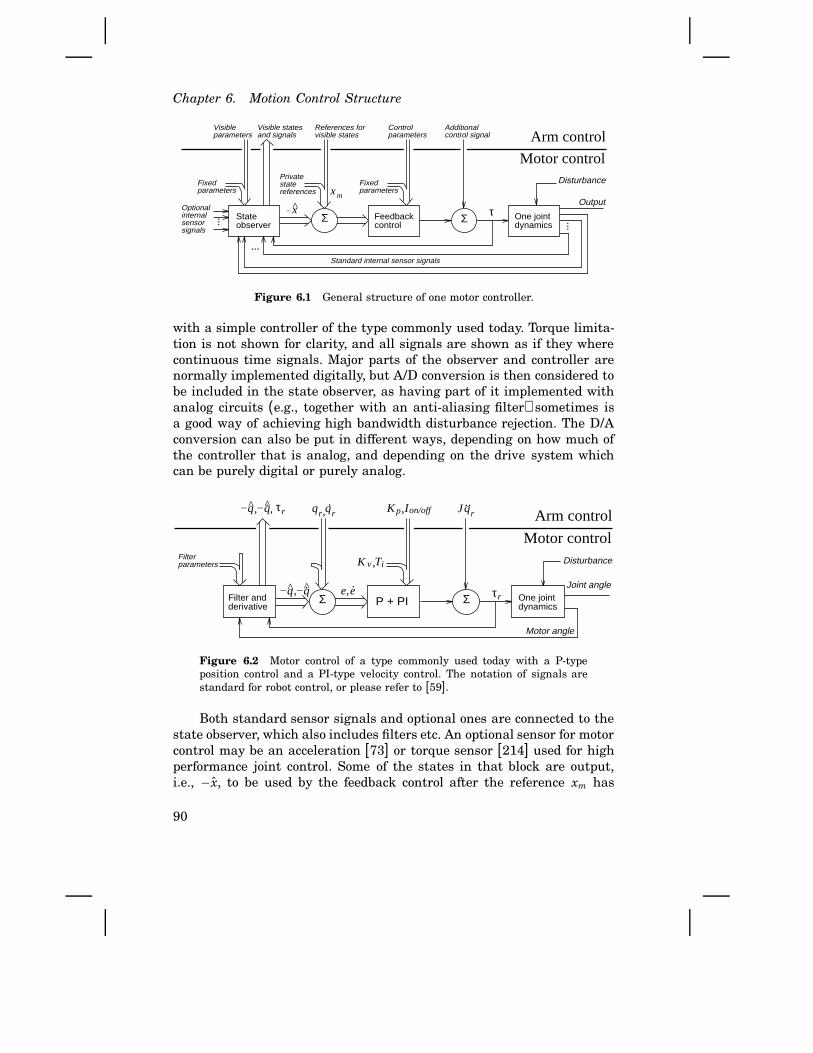
Chapter 6. Motion Control Structure
......
Standard internal sensor signals
Disturbance
τ...
Optionalinternalsensorsignals
xm
x−
Fixedparameters
Privatestatereferences
Fixedparameters
Visibleparameters
References forvisible states
Controlparameters
Visible statesand signals
Additionalcontrol signal Arm control
Output
One jointdynamics
Stateobserver
Feedbackcontrol
Σ Σ
Motor control
Figure 6.1 General structure of one motor controller.
with a simple controller of the type commonly used today. Torque limita-tion is not shown for clarity, and all signals are shown as if they wherecontinuous time signals. Major parts of the observer and controller arenormally implemented digitally, but A/D conversion is then considered tobe included in the state observer, as having part of it implemented withanalog circuits (e.g., together with an anti-aliasing filter) sometimes isa good way of achieving high bandwidth disturbance rejection. The D/Aconversion can also be put in different ways, depending on how much ofthe controller that is analog, and depending on the drive system whichcan be purely digital or purely analog.
Disturbance
τ
Arm control
Joint angle
Motor angle
K v
Kprq rq.
−q −q..ee
Filterparameters
−q −q. τ
Ti
..rqJ
One jointdynamics
Σ ΣP + PIFilter andderivative
r
r
I on/off
Motor control
, , , ,
, ,
,
Figure 6.2 Motor control of a type commonly used today with a P-typeposition control and a PI-type velocity control. The notation of signals arestandard for robot control, or please refer to [59].
Both standard sensor signals and optional ones are connected to thestate observer, which also includes filters etc. An optional sensor for motorcontrol may be an acceleration [73] or torque sensor [214] used for highperformance joint control. Some of the states in that block are output,i.e., −x, to be used by the feedback control after the reference xm has
90

6.2 Desired properties of the software layers
been added. Only the part of xm that is of importance for the arm controlcan be given reference values from that layer. The same applies to themotion control layer if the joint is an external axis. Parameters are alsodivided into one changeable and one fixed part. The additional controlsignal allows a combination of the motor control and the arm control,or an alternative control strategy can do all the control in the upperlayer, possibly based on external sensor signals not available in the motorcontrol layer.
The optional internal sensors, see Figure 6.1, are statically definedin the system. Parameters from the layer above can, however, affect how,or if, the internal optional sensors are utilized in the control. The sensorsignals can as an alternative be filtered and sent up to higher layers forfurther processing. The reason for such a solution would be to simplify thehardware by using the ports for internal sensors also for external motioncontrol sensors.
The application layer – motion control layer interface
The services available to the programs outside the general motion control,i.e., to the application layer software in this case, can be divided into twotypes:
1. Services for performing motions.2. Services for acquisition of motion properties.
Systems today are designed for type 1, while the second type of servicesis not supported, at least not by commercially available systems. Suchacquisition services can be to return information about:
• Control parameters for a certain motion.• Predefined kinematic parameters and inverse kinematic solutions.• Dynamic performance in certain locations.• Simulation of a sequence of motions.
The acquisition services can be utilized in the robot control programs onupper levels (i.e., in the application layer, executive layer, or on the userprogramming level) of the system to improve performance, functionality,and flexibility of the robot and its programming environment. The needfor such knowledge has also been noticed both from the field of off-lineprogramming, and from development of high performance motions andapplication packages.
In the off-line programming case, the reason is that robot manufactur-ers do not want to reveal their control solutions and software models forthe robot due to proprietary reasons and software maintenance reasons(improving the control system should not impose updating of software
91

Chapter 6. Motion Control Structure
tools distributed all over the world). The situation will be the same withfuture open robot control systems admitting external (to the robot manu-facturer) advanced users to implement control strategies. A key idea forthe implementation of these services is therefore that the same executablecode should be used as for the proprietary motion control of the robot. Thisis preferably handled in the following two different ways, depending on ifit is for simulation purposes or not:
1. Simulation of the robot system is proposed to be achieved by instan-tiating a motion control object that controls a dynamic model of therobot instead of the real robot. In C+ + notation, an extra argumentto an overloaded MotionLayer constructor implies that the motioncontrol object controls a virtual robot instead of a real robot with itsdrive power electronics etc.
2. Acquisition of dynamic and kinematic properties, utilizing models in-ternal to the motion controller, for motion planning and optimizationpurposes is preferably supported via special functions. In this way, thesame interface for both simulated and real robot motions is achieved.
The idea to let the robot manufacturer supply compiled code for their(secret) dynamic models and controllers is quite natural. Exactly for thispurpose, the Realistic Robot Simulation (RRS) specification [169] wasdeveloped as a joint effort between designers of robot control systems andof off-line programming systems. (The RRS interface can be considered asan interface to the “Simulation engine” in Figure 3.12, p. 42.) The claimhere is that the RRS approach can be questioned along the following lines:
• The support for application specific motion primitives and so calledsensor-based motions is too limited. It is possible to subscribe toevents that are generated when the value of time or position passesa certain threshold. This should be extended according to the ideason open control as described in Section 6.6.
• A black-box model of the robot arm and its control is difficult tocombine with simulation of equipment mounted on the robot arm.Instead, an object oriented modeling and simulation technique shouldbe used [21, 158] for the mechanical part of the system.
• Properties of control utilizing dedicated hardware, like finite word-length computations coded in assembly language, get hard or ineffi-cient to resemble in a general purpose software package.
Realistic simulation should therefore instead be achieved by having asimulation version of the robot controller connected to an object orientedsimulator of the mechanical robot. Alternatively, an available robot con-troller could be used. The interface is anyway the same as for the motion
92

6.2 Desired properties of the software layers
control as mentioned above.
Encapsulated arm control
The arm control layer was introduced to separate the optimized arm con-trol algorithms, and the fixed and efficient implementation of them, fromthe general purpose motion control and from the local control of indi-vidual joints. The arm control actually contains what is normally meantby robot control. Algorithms like “computed torque” and “hybrid force-position control” are still not much used in real industrial applications.Having a specific software layer for this type of control will hopefully easethe implementation of such algorithms.
The purpose of the application layer is to keep the basic motion con-trol clean from application specific ‘fixes’. However, for major applicationsit may still be a good idea for the robot manufacturer to develop specialbuilt-in control solutions. The reason may be that access restrictions andinappropriate data flows prevent an efficient implementation in the ap-plication layer. The only example found, so far, is short arm motions forspot-welding robots. The characteristics of this example are:
• The robot dynamics can be assumed to be constant during the motion.The load is also constant and well known.
• Performance of the motion is limited by torque, torque derivative,and resonance excitation. Speed is not a limiting factor.
• The performance of the short moves, which typically take less than0.5s, are crucial for productivity. Shorter sampling periods may beneeded to increase the time resolution of trajectory generation andfor position control.
Note that less CPU time is needed due to the first two points, whereasthe last point implies a higher CPU load. We can therefore considerthe need for special arm control as a way of improving performance bybetter hardware utilization. Let us name the special short-move functionShortMove. That function will be referred to later in Section 8.2 treatingspot welding.
The motion control – arm control interface
The following features are useful for the built-in control of the robot arm,but also as services provided for the motion control layer:
• Kinematics and inverse kinematics for the robot arm,
• Dynamic parameters for the robot arm.
• Setting of control parameters and modes.
93

Chapter 6. Motion Control Structure
• On-line trajectory time scaling for torque limited path following [61]should be provided. The nominal trajectories are then modified withrespect to the actual torque. The modified trajectories are called ac-tual trajectories.
• Nominal trajectories can be passed to the arm control, either as gener-ated trajectories passed incrementally point by point, or as completetrajectories parameterized in some predefined way to be generated inthe arm control.
• Acquiring of control data used in the arm control. For example:○ Actual generated trajectories for a motion.○ Internal sensor signals.○ Control errors for position, velocity, and force (for force control)
can be read (and preset in special modes) by the motion controllayer.
• Feed forward signals to torque and velocity references can be set. Forexample, signals that are added to the torque reference for the jointdrives can be useful when implementing force control strategies notsupported by the arm control layer itself.
This list should probably be extended if, for instance, integrated forcecontrol of multiple arms should be supported. The arm control softwarelayer can for instance be encapsulated in a class.
6.3 Remaining problems
Each specified feature so far is based on known techniques. In other words,the individual features as such are known; it is the organization of thecontrol software that is new. It is then natural to question whether theimposed structure hinders employment of control algorithms.
There are by definition no problems concerning the motor controllayer. Only control that can be performed joint-wise is included in themotor control. It is the encapsulation of the arm control that we shouldbe concerned with.
Both the desire to have the arm control encapsulated and to haveadded external joint control integrated with the arm control may be aproblem. The algorithm should to be formulated in a way that makes itmodular with respect to the individual external joints. It is not clear ifthis is generally possible. To prepare for a treatment of this problem inSection 6.4, an introduction to path velocity control is included finally inthis section.
94
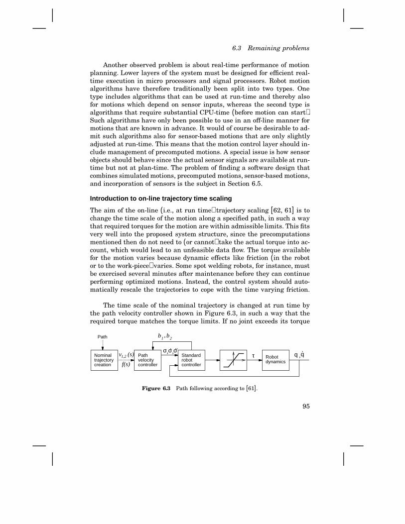
6.3 Remaining problems
Another observed problem is about real-time performance of motionplanning. Lower layers of the system must be designed for efficient real-time execution in micro processors and signal processors. Robot motionalgorithms have therefore traditionally been split into two types. Onetype includes algorithms that can be used at run-time and thereby alsofor motions which depend on sensor inputs, whereas the second type isalgorithms that require substantial CPU-time (before motion can start).Such algorithms have only been possible to use in an off-line manner formotions that are known in advance. It would of course be desirable to ad-mit such algorithms also for sensor-based motions that are only slightlyadjusted at run-time. This means that the motion control layer should in-clude management of precomputed motions. A special issue is how sensorobjects should behave since the actual sensor signals are available at run-time but not at plan-time. The problem of finding a software design thatcombines simulated motions, precomputed motions, sensor-based motions,and incorporation of sensors is the subject in Section 6.5.
Introduction to on-line trajectory time scaling
The aim of the on-line (i.e., at run time) trajectory scaling [62, 61] is tochange the time scale of the motion along a specified path, in such a waythat required torques for the motion are within admissible limits. This fitsvery well into the proposed system structure, since the precomputationsmentioned then do not need to (or cannot) take the actual torque into ac-count, which would lead to an unfeasible data flow. The torque availablefor the motion varies because dynamic effects like friction (in the robotor to the work-piece) varies. Some spot welding robots, for instance, mustbe exercised several minutes after maintenance before they can continueperforming optimized motions. Instead, the control system should auto-matically rescale the trajectories to cope with the time varying friction.
The time scale of the nominal trajectory is changed at run time bythe path velocity controller shown in Figure 6.3, in such a way that therequired torque matches the torque limits. If no joint exceeds its torque
σ σ σ. ..
b1 b2
τ q q.
Path
Nominal trajectorycreation
Standardrobotcontroller
Robotdynamics
1,2v (s)
f(s)
Pathvelocitycontroller
,
, ,,
Figure 6.3 Path following according to [61].
95
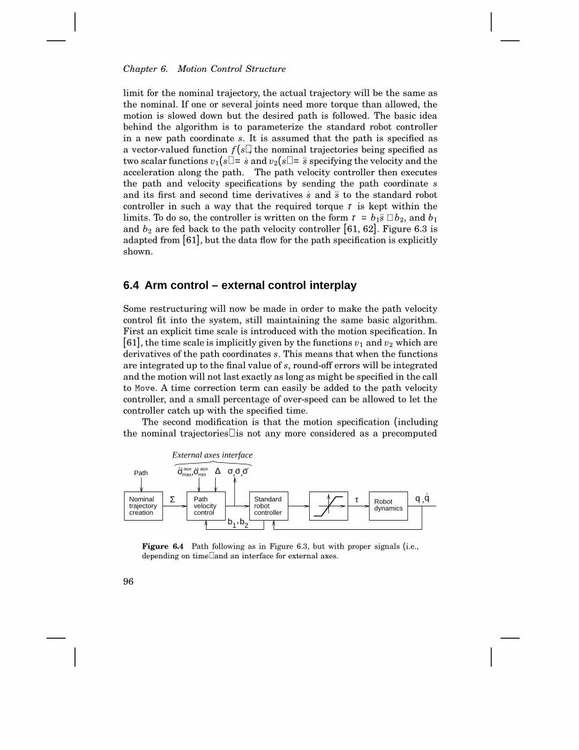
Chapter 6. Motion Control Structure
limit for the nominal trajectory, the actual trajectory will be the same asthe nominal. If one or several joints need more torque than allowed, themotion is slowed down but the desired path is followed. The basic ideabehind the algorithm is to parameterize the standard robot controllerin a new path coordinate s. It is assumed that the path is specified asa vector-valued function f (s), the nominal trajectories being specified astwo scalar functions v1(s) = s and v2(s) = s specifying the velocity and theacceleration along the path. The path velocity controller then executesthe path and velocity specifications by sending the path coordinate sand its first and second time derivatives s and s to the standard robotcontroller in such a way that the required torque τ is kept within thelimits. To do so, the controller is written on the form τ = b1s + b2, and b1
and b2 are fed back to the path velocity controller [61, 62]. Figure 6.3 isadapted from [61], but the data flow for the path specification is explicitlyshown.
6.4 Arm control – external control interplay
Some restructuring will now be made in order to make the path velocitycontrol fit into the system, still maintaining the same basic algorithm.First an explicit time scale is introduced with the motion specification. In[61], the time scale is implicitly given by the functions v1 and v2 which arederivatives of the path coordinates s. This means that when the functionsare integrated up to the final value of s, round-off errors will be integratedand the motion will not last exactly as long as might be specified in the callto Move. A time correction term can easily be added to the path velocitycontroller, and a small percentage of over-speed can be allowed to let thecontroller catch up with the specified time.
The second modification is that the motion specification (includingthe nominal trajectories) is not any more considered as a precomputed
σ σ σ. ..
b1 b2
τ q q.
Path
Σ
∆σ auxminσ aux
max
.. ..External axes interface
Robotdynamics
Standardrobotcontroller
Pathvelocitycontrol
Nominal trajectorycreation
,
,
, ,,
Figure 6.4 Path following as in Figure 6.3, but with proper signals (i.e.,depending on time) and an interface for external axes.
96

6.4 Arm control – external control interplay
matrix with columns s, v1, v2 and f , and with rows corresponding to stepsalong the path. A time column t was introduced above, and the nominaltrajectories and the path can just as well be generated at run time basedon e.g. external sensors. The columns therefore form a time signal Σ. Thereason for having a dashed line for the path information in Figure 6.3 wasthat the motion specification was considered to be preplanned nonlinearfunctions [61]. The signal Σ on the other hand is a proper signal asshown in Figure 6.4. Precomputations are still allowed according to earliersections, but the controller should work with signals giving a more or lessconstant real-time data flow permitting higher utilization of the hardware.
A third modification can now be introduced to solve the external axescontrol problem we were looking at. Additional motion reference signalsΣ i are supplied to each axis i. Σ i is a vector signal consisting of the samevalues of t and s as sent to the arm controller, but also of the scalarsv1, v2 and fi specifying the nominal motion for axis i. Exactly the samevalues of the path coordinate reference σ and its derivatives that go tothe arm controller also go to each external axis controller. Each externalaxis controller then computes the allowed range for σ according to [61],but in stages as shown in Figure 6.5. The time lag ∆ is also computed asthe maximum of the input ∆ and the time lag for the axis itself.
σ σ σ. ..
τ
qq.
∆σ aux
minσ auxmax
.. ..External axesinterface
σ σ σ. ..
τ
qq.
∆σ aux
minσ auxmax
.. ..σ σ σ. ..
τ
qq.
∆σ aux
minσ auxmax
.. .....
0
+∞,−∞
Second external axis Last external axis
...Σ ΣΣ
i i+1 m
External axis control
External axis
External axis control
External axis
External axis control
External axis
First external axis
, , ,, , , , , ,
Figure 6.5 Proposed “bit-slice” style for incorporation of external axes.
These modifications illustrate how one algorithm can be modularizedto fit into a structure suitable for industrial use with external servosconnected to the robot controller. It should even be straight forward toincorporate multiple arm synchronized with the same path coordinate s.It is believed that many other algorithms can be modularized in the sameway, but when not possible, other features in the system (like motion infunction space) will always make it possible to program and perform amotion, although a larger user or application programming effort will beneeded.
97

Chapter 6. Motion Control Structure
6.5 Pipelining and caching sensor-based motions
As mentioned above, advanced algorithms for optimization of motionssometimes take so much computing time that it may delay the motionmore than improved performance can speed it up. However, much of thecomputations can often be performed in advance, that is, when the motionspecification is known but before the motion may start. The standard ap-proach is then to do all precomputations in a robot program as an interme-diate stage after the user program is written, but before execution starts.The problem is that robot motion instructions are often interleaved withconditional expressions which depend on sensor input. Positions may alsobe taught in or modified by the robot operator after the program executionhas started. The implication is that run-time support for precomputationsis necessary for optimum time algorithms and the like.
Temporal properties
A trivial approach to pre-plan motions would be to let the motion con-trol interface contain explicit functions to obtain computed motion datawithout performing the motion (as mentioned in the description of theinterface between the arm control and motion control layers). Such a fea-ture may be useful for simulation and high level planning, but for ordinaryusage we want something simpler.
Another too limited approach would then be to request “suspendedmotion”. That is, motion data should be computed but transfer to themotion control should be suspended until it is released from the caller.This approach would, however, not permit a specific motion to be reusedlater (next cycle of the task), and computing in advance would make therobot program unnecessarily complex.
Instead, the idea here is to use software solutions resembling princi-ples used for similar problems in modern computer hardware (like pipelin-ing, paging, and cache memories). This means that we want the system(the motion layer in this case) to internally manage the performance im-proving features. Analogous to the computer hardware case [75], the sys-tem should be able to
• fetch motion instructions in advance, start processing them, and putresults in a buffer (from which set-points to the feedback controleasily can be determined),
• save key data that have required substantial computing time in tem-porary storage,
• reuse computed data if available in the temporary storage.
98
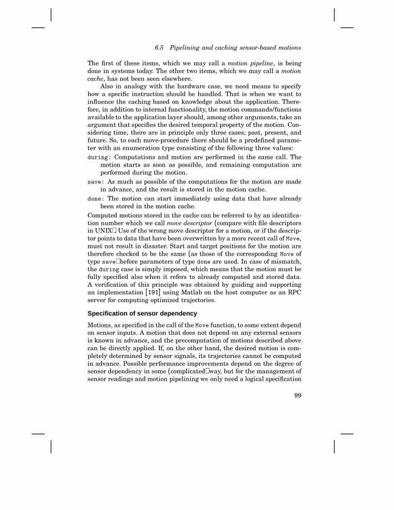
6.5 Pipelining and caching sensor-based motions
The first of these items, which we may call a motion pipeline, is beingdone in systems today. The other two items, which we may call a motioncache, has not been seen elsewhere.
Also in analogy with the hardware case, we need means to specifyhow a specific instruction should be handled. That is when we want toinfluence the caching based on knowledge about the application. There-fore, in addition to internal functionality, the motion commands/functionsavailable to the application layer should, among other arguments, take anargument that specifies the desired temporal property of the motion. Con-sidering time, there are in principle only three cases; past, present, andfuture. So, to each move-procedure there should be a predefined parame-ter with an enumeration type consisting of the following three values:during: Computations and motion are performed in the same call. The
motion starts as soon as possible, and remaining computation areperformed during the motion.
save: As much as possible of the computations for the motion are madein advance, and the result is stored in the motion cache.
done: The motion can start immediately using data that have alreadybeen stored in the motion cache.
Computed motions stored in the cache can be referred to by an identifica-tion number which we call move descriptor (compare with file descriptorsin UNIX). Use of the wrong move descriptor for a motion, or if the descrip-tor points to data that have been overwritten by a more recent call of Move,must not result in disaster. Start and target positions for the motion aretherefore checked to be the same (as those of the corresponding Move oftype save) before parameters of type done are used. In case of mismatch,the during case is simply imposed, which means that the motion must befully specified also when it refers to already computed and stored data.A verification of this principle was obtained by guiding and supportingan implementation [191] using Matlab on the host computer as an RPCserver for computing optimized trajectories.
Specification of sensor dependency
Motions, as specified in the call of the Move function, to some extent dependon sensor inputs. A motion that does not depend on any external sensorsis known in advance, and the precomputation of motions described abovecan be directly applied. If, on the other hand, the desired motion is com-pletely determined by sensor signals, its trajectories cannot be computedin advance. Possible performance improvements depend on the degree ofsensor dependency in some (complicated) way, but for the management ofsensor readings and motion pipelining we only need a logical specification
99

Chapter 6. Motion Control Structure
of how the system should handle the motion request. Each case needs tobe explicitly considered internally in the motion control layer. It is there-fore desirable to have few alternatives to simplify the implementation. Onthe other hand, having only one or two cases (depending or not dependingon external sensors) as in available systems is not enough. In the ORCarchitecture, the application layer program passes the information aboutthe degree of sensor dependency by supplying an additional enumerationparameter (in a way similar to the temporal specification above). Thisenumeration type is proposed to consist of the following four elements:completely: A completely known motion does not depend on sensors
at all. All services available from the motion control (like optimaltrajectory planning in advance) can therefore be used.
almost: An almost known motion may be subject to modifications basedon sensor information, but only to such a limited extent that motionplanning is still appropriate. One example may be gluing along al-most known paths that are followed using a path tracking sensor. Toleave control authority for the sensor-based adjustments, the nomi-nal motion may be planned with some margin according to suppliedparameters.
partly: A partly known motion basically depends on sensor information,but some nominal path exists. It is however, not useful to plan oroptimize this type of motion. For instance, a path tracking sensorcan be used to track an almost unspecified path. Specifying a nominalpath can be good for:
- Influencing the path tracking to search in preferred directionswhen the path is lost.
- Specification of a motion termination condition. A motion fromone location to the same location in a specified time will forinstance result in a specified time for the path tracking motion.
- Having both a specified and an actual motion provides data thatcan be used for supervision purposes.
A partly known motion is otherwise treated as a not known motion.not: A not known motion is entirely specified by sensor signals. One
such case is manual move of the robot arm using a joystick. None ofthe optimal trajectory planning schemes, like minimum time, can beused. Instead, trajectory planning and generation schemes useful atrun-time must be used. Note that this also applies to a situation likethe one shown in Figure 6.6.
Solutions to the run-time trajectory planning and generation problem[116] are unusual in the literature. (Do not confuse this with, for example,the solutions in [59] where the trajectory generation is done at run-time,
100
6.5 Pipelining and caching sensor-based motions
Start position
Sensor input
Goal case 1Goal case 2
Figure 6.6 Path and trajectories not known in advance. The goal positiondepends on the input from a sensor.
but not the trajectory planning.) Such trajectory generation is, however,necessary in practical applications, and at least one major robot manufac-turer therefore has considerable competence within this field. Technically,motion increment buffers for a distance at least as long as the distancerequired to stop is maintained. The buffers are then scanned through andused together with a reference model of the robot. Joint synchronizationalgorithms including extensive heuristics are applied.
Deduced properties of sensor objects
We have so far considered the fact that motions may depend on externalsensor signals, but how should sensors be managed in the control systemsoftware? Some principles and specifications for a sensor interface will begiven in this section, considering the following aspects:
• Object-oriented modeling of sensors, using an object-oriented lan-guage, is a good way to provide language support for managementof sensors.
• Application-specific or task-specific control implying that the filteringof sensor signals should be possible to change from higher levels ofthe system.
• External sensors should be possible to combine with the proposedmotion pipelining.
• The simulation support should apply also for sensor-based motions.It is quite natural to model sensors with a general base class, and thencreate derived subclasses for each special type of sensor. The idea here isthat the base class should specify the following three behaviors to supportmotion pipelining and simulation:○ Real sampling is the normal case. The data is read from a sensor
interface for external sensors. Some hardware handlers may be pre-defined, but scaling and possible transformation have to be imple-mented by the sensor engineer.
101
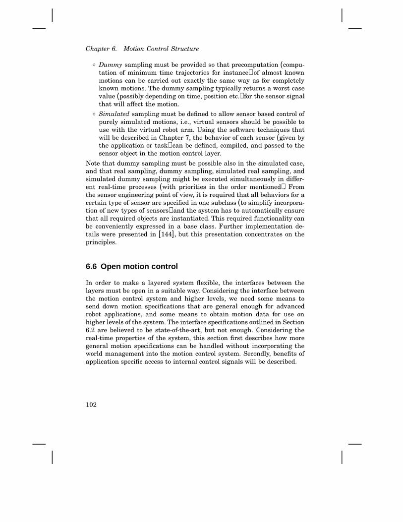
Chapter 6. Motion Control Structure
○ Dummy sampling must be provided so that precomputation (compu-tation of minimum time trajectories for instance) of almost knownmotions can be carried out exactly the same way as for completelyknown motions. The dummy sampling typically returns a worst casevalue (possibly depending on time, position etc.) for the sensor signalthat will affect the motion.
○ Simulated sampling must be defined to allow sensor based control ofpurely simulated motions, i.e., virtual sensors should be possible touse with the virtual robot arm. Using the software techniques thatwill be described in Chapter 7, the behavior of each sensor (given bythe application or task) can be defined, compiled, and passed to thesensor object in the motion control layer.
Note that dummy sampling must be possible also in the simulated case,and that real sampling, dummy sampling, simulated real sampling, andsimulated dummy sampling might be executed simultaneously in differ-ent real-time processes (with priorities in the order mentioned). Fromthe sensor engineering point of view, it is required that all behaviors for acertain type of sensor are specified in one subclass (to simplify incorpora-tion of new types of sensors) and the system has to automatically ensurethat all required objects are instantiated. This required functionality canbe conveniently expressed in a base class. Further implementation de-tails were presented in [144], but this presentation concentrates on theprinciples.
6.6 Open motion control
In order to make a layered system flexible, the interfaces between thelayers must be open in a suitable way. Considering the interface betweenthe motion control system and higher levels, we need some means tosend down motion specifications that are general enough for advancedrobot applications, and some means to obtain motion data for use onhigher levels of the system. The interface specifications outlined in Section6.2 are believed to be state-of-the-art, but not enough. Considering thereal-time properties of the system, this section first describes how moregeneral motion specifications can be handled without incorporating theworld management into the motion control system. Secondly, benefits ofapplication specific access to internal control signals will be described.
102

6.6 Open motion control
Motions determined by world model relations
The motion specification issue is by itself a research topic, particularly ifcompliance and force control should be supported [177]. Even if we limitthe discussion to ordinary position specifications, the situation may bequite complex. Consider for example object-level programming (describedin Chapter 3) for objects that are varying with time or moving around ina way not known in advance. External sensors must of course be used toobtain information about the environment at run-time. To handle caseslike this, the position equations in RCCL [81] may contain frames thatdepend on sensor signals. The frames are also part of the world model.The development towards more flexible/intelligent robots has thereforeimplied a tighter integration between the world modeling and the motioncontrol.
Opposed to such an integrated approach, the proposed layered ORCarchitecture specifies that the feedback control part of the system shouldbe separated from the world modeling and the high-level programmingsystem. That is to achieve the proposed user views. Another reason is tomake it possible to have a simpler embedded system for applications notrequiring the advanced features. A more attractive approach is thereforeto have a fixed hierarchy with a few predefined frames that can be effi-ciently handled in the embedded system as in the new system from ABB[2], and then (as a proposed extension) allow these frames to be eval-uated according to functions supplied from the application layer. Thosefunctions can then, for instance, make accesses via an additional CPUboard to obtain world model information in the most advanced cases.This was presented as motions in function space in [144] where also somemore details were given, but a further analysis and a full implementationremain to be done.
Software sensors
Industrial robots are mechanically rather precise machines driven byservo controlled motors. They are not as precise and rigid as NC machines,so desired motions are not quite precisely achieved. The same applieswhen compliant motions are used on not quite known work-pieces (likethe casting in Figure 2.5, p. 12). In many cases, the actual motion orproduction result therefore needs to be measured in order to compensatefor deviations and errors.
The problem with adding external sensors is that the hardware getsmore expensive, and it decreases the MTBF (Mean Time Between Fail-ure). However, to meet the performance requirements on the motion con-trol, the dynamics of the robot is reflected in the control system (by state
103

Chapter 6. Motion Control Structure
s1
Σ∫Ki e dtv
Σω θ
θr−τ
ep ev
Speed controlPosition control Mechanical system
KJs+DKp Σ
K v
Σ
−1
−1
τ
Figure 6.7 Simplified servo control.
observers, linearizing feedback, etc.). Therefore, states of importance forthe robot task exist within the control system. This is known in princi-ple by control engineers, but using such (internal) information to solverobot application problems has not, as far as known, been suggested un-til now. Furthermore, it is usually not clear to application engineers thatsuch useful information exists. The following simple example further illus-trates this idea of utilizing internal control information instead of externalsensors.
Consider one link of a robot, i.e., a single servo. Assume we use aquite simple control strategy with a PI type velocity controller, and a Ptype position controller. This is shown in Figure 6.7. It is basically thistype of control that is used for the joint-wise control of most commercialrobots available today. The system can be given desired compliance anddamping by only using two P regulators (i.e., Ki = 0), but the I-partis introduced to take care of unknown disturbance forces. The output ofthe inner regulator can be interpreted as an acceleration reference to thecontrolled system if we have Ki = 0 or if we have no disturbance forces.With disturbance forces and with a properly tuned Ki, the output fromthe control system is a torque (or force) reference to the servo drive unit.
The following examples illustrate how the control signals can beuseful. The first example is the most important one; that principle will beused to solve the deburring application problem.
• Recording of the signals ep and θ during motion over a surface willgive the profile of the surface along the path. The deviation of theprofile from the nominal one is simply ep as a function of θ .
○ The τ signal is an estimate of the Columb friction in the joint duringslow motion with constant speed and no contact with the environ-ment.
○ The friction coefficient of an object, or the existence of an object, can
104

6.7 Implementation
be computed from the τ signal, as for previous case and with theinternal friction already estimated according to the previous item.
○ The signal ω during acceleration and deceleration contains informa-tion about the inertia of the joint, which will give the inertia of theload if the inertia of the robot itself is known.
In a complete servo for all joints in a real robot it gets more complicatedto identify or compute signals of interest, but the information is in thesystem, the problem is to extract it. Signals depending on friction orexternal forces can of course be practically hard to estimate accurately, butcan still be feasible in some heavy applications. Note, however, that thefirst example using the position error during force control is not sensitiveto friction effects.
From the user programming point of view it makes no difference, ifa procedure called to get sensor data samples the signal from an exter-nal device, or if data acquisition is performed internally in the system.Therefore, the treatment of sensors in the previous section also applies tosoftware sensors. Implementation techniques will be developed in Chap-ter 7.
6.7 Implementation
From the user programming level, the motion control system can beseen as a driver for the manipulator device. Such a driver can then beimplemented in an ordinary operating system manner [81], it can simplybe viewed as an abstract data type [215], or it can be encapsulated bya class in an object oriented framework[133]. However, the needs foropenness in advanced manufacturing applications indicates that a moregeneral type of interface is appropriate. The operating system drivermodel can of course be kept in principle, but the generality of the services(the io-controls in a UNIX framework) would not be well expressed to theprogrammer. Instead, an object oriented framework extended with theprinciples of open embedded systems presented in Chapter 7 is suitablefor the motion control interface.
Considering robot programming within the layers for built-in motioncontrol, this is the control engineering topic. In this field, good tools foridentification, modeling, synthesis, and code generation have emergedin recent years. The aim in this work has been to connect such (hostcomputer based) tools to the embedded robot control system.
105

Chapter 6. Motion Control Structure
Motor control implementation
The motor control was mapped to the hardware in such a way thatthe DSPs were utilized for the high-frequency properties of the control,and the master M68040 CPU was used for the low frequency part. Thereason is that the DSPs execute pure filter algorithms very efficiently,but integrating action and the necessary wind-up protection contains logicthat breaks the floating point pipeline in a very undesirable way. Highsampling frequencies are also possible because the control is interruptdriven without the overhead of a full real-time kernel. The M68040 CPUon the other hand is better suited for general control tasks [53]. Currently,using our department’s real-time kernel [18], the sampling frequencycannot exceed 1 kHz, which is slow compared to the 24 kHz currentlyused for the DSPs.
Slave part of Motor control
H (z)
H (z)
Στr
Seri
al O
ut
Σ
Actuatorobject
Sensorobject
Seri
al I
n ∆
for plotting, RPC, etc.
Σ
Other shared data structures
OtherDsp
SensActPar (par)
Observed (obs)
Reference (ref)
ControlPar (par)
Mailbox Mailbox
parobs ref
DSP#3DSP#0
DRAM
y
pv H (z)
Visiblestates
Filter coefficients
yu
q
q~
.
q
r r
.
(commutation angle)Instant feedback
Sensor value(resolver angle)
Accepted output(limited torque)τ
uy
RequestedActuator control
(torque request) output
Fro
m D
SP#1
To
DSP
#2
master control and supervisionStructural information for
SharedControl(static object)
VME-bus to master CPUs
v
pars
Figure 6.8 Motor control implementation on the DSP hardware level. OnlyDSP#0 and DSP#3 are shown. Connections to the other DSPs and to thecontrolled robot are shown in Figure 5.7 (p. 79) and Figure 5.2 (p. 71)
Figure 6.8 shows the data flow for the DSP part of the control. TheDRAM memory (see also Figure 5.7, p. 79) is central for the multipro-cessor implementation. Control parameters and references are written bythe master processor to the DRAM, the two DSPs shown in the figureexchange control data via the DRAM, observed states are updated by theDSPs and it is then used both by the master part of the control and by thesupervision part (Figure 5.6, p. 77). The programs were written in C+ +for the DSPs as explained in Section 5.3. The filters Hy(z), Hv(z), andHp(z), however, were available as highly optimized assembly code fromthe application library for the DSPs.
106
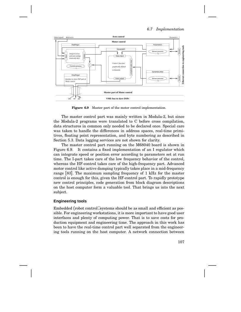
6.7 Implementation
Inpu
t
iDspRegul
Server process
Out
put
DynamicLinker
Server process
graphically defined
Control functions
in Simulink
Σ
Data input
Data output
com
pile
d co
de in
put
SimulinkIO
Parameters
Soc
ket
Soc
ket
DspRegul
Motor controlInterface to slave DSP part of
Motor control
Arm control
Control process
Integral actionand anti-windup(statically def.)
States/signals References Parameters
refobs VME-bus to slave DSPs
Master part of Motor control
par
Eth
erne
t co
nnec
tion
to
engi
neer
ing
tool
s
Figure 6.9 Master part of the motor control implementation.
The master control part was mainly written in Modula-2, but sincethe Modula-2 programs were translated to C before cross compilation,data structures in common only needed to be declared once. Special carewas taken to handle the differences in address spaces, real-time primi-tives, floating point representation, and byte numbering as described inSection 5.3. Data logging services are not shown for clarity.
The master control part running on the M68040 board is shown inFigure 6.9. It contains a fixed implementation of an I regulator whichcan integrate speed or position error according to parameters set at runtime. The I-part takes care of the low frequency behavior of the control,whereas the HF-control takes care of the high-frequency part. Advancedmotor control like active damping typically takes place in a mid-frequencyrange [83]. The maximum sampling frequency of 1 kHz for the mastercontrol is enough for this, given the HF-control part. To rapidly prototypenew control principles, code generation from block diagram descriptionson the host computer form a valuable tool. That brings us into the nextsubject.
Engineering tools
Embedded (robot control) systems should be as small and efficient as pos-sible. For engineering workstations, it is more important to have good userinterfaces and plenty of computing power. That is to save costs for pro-duction equipment and engineering time. The approach in this work hasbeen to have the real-time control part well separated from the engineer-ing tools running on the host computer. A network connection between
107
Chapter 6. Motion Control Structure
the two is of course slower than using bus-to-bus adaptors, but it corre-sponds well to the situation for manufacturing systems. A factory networkconnects embedded control systems to the central manufacturing controland to the engineering workstations, possibly located on a remote site.Without going into details, the following software tools were developed:
• Using available low-level networking primitives and UNIX sockets,processes in the embedded system were connected to Matlab runningon the host computer. Opposed to ordinary pipes and streams whichwork on a byte level, the developed connection is typed in the sensethat it works with matrices which fit well with Matlab.
• Data-logging modules were developed for the embedded system (bothfor the M68k and for the DSPs), and a Matlab-based front end waswritten.
• Development of services in the embedded system for excitation signalswas initiated and guided. That facilitates the experimental part ofsystem identification.
• An embedded system server for control parameters was specified, andthe implementation was initiated and guided. A powerful user inter-face was implemented by the author using the Matlab graphics. Theparameter interface is layered in such a way that parameters canbe accessed on five levels; the embedded level, the network level,the Matlab script level, the Matlab graphical level, and the Mat-lab script/graphical level. The script/graphical level means that thegraphical user interface is run and updated from a script.
• An operator interface for manual control and robot program executionwas implemented using Matlab graphical objects. The reason to useMatlab is to make it simple to include the ‘manual’ operation inscripts expressing control experiments.
• Using the embedded dynamic linkage according to Chapter 7, it wasmade possible to change at run-time the cross-compiled programsfrom Simulink/Real-Time-Workshop [125]. See Figure 6.9.
Thus, a tool like Matlab with the possibility to link in external (network-ing) functions is very useful. It is of course also important to make use ofother available tools whenever appropriate. Evaluation of one such tool[172] is therefore currently going on. Another system developed withinour department [66] provides high level description of control blocks, codegeneration, and reconfiguration of control blocks during run-time. Thesetools are well suited for development of the arm control and the motioncontrol, whereas the more limited Matlab-based tools are suitable for thesingle-joint control.
108

6.7 Implementation
The reason for focusing on the engineering tools, instead of on newalgorithms, is that improved control performance is more a matter ofemploying known control principles in an efficient/convenient way thanfinding some new theory. On the other hand, improved algorithms for con-trol synthesis is needed to reduce the engineering effort, for instance toadopt to changes in the mechanics. The developed system will hopefullybe used for such research. Experience from our own tools so far is that in-teractive operation of the controlled process connected to a control designenvironment greatly facilitates the control engineering work.
Experiments and discussion
The presented implementation was developed in connection with studentand master thesis projects [129, 84], in which successful experiments alsowere carried out. Experiments on individual joints have been made withsampling frequencies ranging up to 24 kHz for position and velocity con-trol, and up to 48 kHz for torque control. The present standard samplingfrequency when all six joints are used is 4 kHz. The hardware interfacesare built for 8 kHz (i.e., 48 kHz for all joints together), but we preferred touse a well structured and flexible C+ + implementation using only half therate. Controlling all joints which the rate of 4 kHz implies that the orderof the position/velocity controller should be less than ten. The Simulinkgenerated controllers, running on the master M68040 board, can usuallynot be run in more than 500 Hz.
As an example of a measurement on joint one of the Irb-2000, Figure6.10 shows the position output when the input torque was a logarith-mically swept sine-wave with constant amplitude. Estimation of transfer
0 20 40 60 80 100 120−20
−10
0
10
20
frequency [Hz]
posi
tion
[rad
]
Measurement data versus excitation frequency
Figure 6.10 Measurement performed on the fist joint [129] using the de-veloped experimental environment. To both excite resonances and capture awide frequency range in a single experiment, 35000 samples were recordedover a time period of 70 seconds (500 Hz sampling frequency in this case).
109

Chapter 6. Motion Control Structure
functions from this type of data is straight forward [99]. Doing the exper-iments interactively, or via Matlab scripts that also serves as documenta-tion, has proven to be very convenient. The main 380V drive power canalso be turned on and off from the host workstation. Note that we do notuse any intermediate storage in files; measurement data is directly sentfrom the embedded controller via the network to the Matlab workspace.
Experiences so far indicate that the layered architecture is quite con-venient to work with. We have, on the other hand, not used the layersrigidly because the interface design has been part of the work. It would ofcourse be desirable to have detailed specifications of the interfaces. Thatwould permit independent development of complete software layers ormodules. Such a standardization should, however, wait until more experi-ence of open, layered, and efficient implementations is available. For in-stance, available implementations [133] are appropriate for the situationsthey are designed for, but they are not directly applicable in an industrialmanufacturing context. The requirements on multi-layered programmingand run-time efficiency are hardly fulfilled, and defined interfaces [133]are not general enough. As pointed out on Page 15, standards most oftencome with maturity.
The question about interaction between the arm control and the con-trol of external motions, as stated earlier in this chapter, is partly leftopen. The study of the path velocity control did not reveal any major re-strictions due to the imposed control layers. Further evaluation of state-of-the-art robot control algorithms, both with respect to the software struc-ture and the control properties, is in progress.
6.8 Summary
The design of the standard, i.e., application independent, part of the mo-tion control system has been developed in this chapter. The aim was tosupport control engineering in a framework considering industrial de-mands, and to make it possible to add high-level control on top of thebuilt-in control. To achieve this, the following new principles were pro-posed:
• The motion control software should be divided into motor control,arm control, and overall motion control. That is to manage controlcomplexity, hardware structure, and system development.
• It was described what services the motion control system needs toprovide for higher levels of control. The client/server design combinesencapsulation of control solutions with support for advanced high-level control.
110
6.8 Summary
• The need to structure the control for incorporation of external jointswas pointed out, and an example how that can be done was given.
• A concept to allow use of more CPU-time consuming algorithms forembedded control was proposed. This includes a straight forward wayto save and refer to computed motions. It also contains an importantclassification of sensor dependency.
• Sensors (software) objects of course include information about phys-ical input channel, sampling, filtering, etc. Additionally, to facilitatethe two previous items, sensor objects should have methods for real,dummy, and simulated sampling. This is a key idea for advanced useof sensor based motions.
• The possibility to use control signals as sensors was pointed out. Thisis typically not realized among application engineers.
• A structure for motor control was described, and software tools formotion control engineering were developed.
The contribution of this chapter is a motion control structure with uniquesupport for: Encapsulation of control properties, appropriate programmingviews and tools for control engineers, flexible tailoring to application spe-cific demands, and management of (sensor-based) motions to achieve ef-ficiency without complicated programming. Major parts of the structurehave been implemented for control engineering purposes.
111
7
Open Embedded Control
Embedded control devices today usually allow parameter changes, andpossibly activation of different pre-implemented algorithms. Full repro-gramming using the complete source code is not allowed for safety, effi-ciency, and proprietary reasons. For these reasons, embedded regulatorsare quite rigid and closed concerning the control structure.
In several applications, like industrial robots, there is a need to tailorthe low level control to meet specific application demands. In order tomeet the efficiency and safety demands, a way of building more genericand open regulators has been developed. The key idea is to use pieces ofcompiled executable code as functional operators which in the simplestcase may appear as ordinary control parameters. In an object orientedframework, this means that new methods can be added to controllerobjects after implementation of the basic control, and even while thecontroller is running.
The implementation was carried out in industrially well acceptedlanguages such as C and C+ + . The dynamic binding at run-time differsfrom ordinary dynamic linking in that only a subset of the symbols canbe used. This subset is defined by the fixed part of the system. The safetydemands can therefore still be fulfilled. Encouraged by results from somefully implemented test cases, we believe that extensive use of this conceptwill admit more open, still efficient, embedded systems to be developed.4
7.1 Introduction
Making machines programmable has added flexibility to manufacturingequipments. Typical examples are industrial robots and NC-machines.
4 A slightly different version of this chapter has been submitted for publication[149]
112
7.1 Introduction
They can be reprogrammed for applications that were not defined at thetime the equipment was developed. Improved functionality/performanceand cost efficiency are other major driving forces for use of computercontrol, for instance in vehicles. Re-programmability is very desirablealso in this case, which means that the lifetime of the product can beprolonged without having to exchange the components when new (e.g.,environmental) demands are imposed.
In mechatronics and process control, demands on safety, efficiencyand simplicity are often contradictory to flexibility. Products providingfeatures for end-user programming, such as industrial robots, are there-fore preferably layered in such a way that the ordinary user can do theapplication programming in a simple and safe way, and the expert pro-grammer can tailor the system to fulfill unforeseen requirements fromnew applications. The same also applies to many mechatronic productsthat do not provide end-user programming. For example, the multivari-able engine control in a car should be possible to update by the car man-ufacturer. Furthermore, within mechatronics it is in general desirable touse components that can satisfy the needs of many applications and prod-ucts. That will contribute to cost reduction. This means that we have thesame situation as for the robot control; open components are needed.
A system that allows such low-level reconfiguration to meet require-ments that it was not specifically designed for, is called an open system.Most machine controllers used in industry today are closed. The reasonis that they have been specifically designed to provide an easy to use,cost efficient, and safely performing control for today’s standard applica-tions. In present and future more advanced applications, however, cus-tomization of closed systems becomes time consuming and thereby costly.Development towards more open control systems are therefore going on,see [144, 151, 70] and references therein. Still, there are proprietary, ef-ficiency, and safety reasons for not having a completely open system. Thekey issue is to find the right tradeoffs between an open and a closed de-sign of a system. The best possible solution will, of course, depend on theavailable software mechanisms. We include both (partly) open systemsand components in the term open embedded control. The term controlis used since the purpose of behaviors subject to change are typically tocontrol the system, or parts of it.
The trend towards more open systems has been going on for sometime within operating systems, computer networks, interactive software,and graphical user interfaces. This development has resulted in softwaretechniques that have inspired our approach to open embedded systems.We do, however, not want to impose the use of standard (heavy) operat-ing systems and process communication principles on an otherwise lean
113

Chapter 7. Open Embedded Control
design of a cost-sensitive mechatronic product.The desire to create software mechanisms that support simple im-
plementation of open embedded control can now be formulated as: Givenappropriate hardware, how should the software be organized to allow effi-cient extension (in terms of improved functionality, performance, etc.) bychanging open parts of the software only, while some parts of the systemmay remain closed. As the examples in the next section will show, onlyallowing parameter changes and use of pre-implemented algorithms doesnot provide enough flexibility.
One approach, used in PLC systems, is to down-load new code forinterpretation to each hardware unit. In many applications, full utilizationof the computer hardware is required, and executable code (cross-compiledto the specific hardware) is therefore preferred, and also used in a modernprocess control system like SattLine [97]. Use of compiled libraries admitsthe implementation of certain components to be hidden, but often we needclosed subsystems with open ‘slots’. Recall, however, that we want to keeppart of the software closed. The question is then how to obtain a suitableborder between the open and closed parts. This chapter presents a solutionto this problem, without requiring any special language or run-time model.We therefore believe that the proposed way of building open real-timecontrol systems is an innovative simplification compared to more generalconcepts (like [87, 154, 132, 23, 201, 178]) for open systems.
7.2 Applications
Some typical situations when an embedded system needs to be open arepresented in this section. These examples are all in the area of manu-facturing systems, but they also capture typical properties of many othertypes of embedded systems.
Feedback control
The most common type of feedback controller in industry is the PID-regulator [28]. In most process control applications, PID-controllers givesufficient performance and there are simple rules and schemes for how todo the tuning without requiring extensive knowledge about the processdynamics. Although the basic PID algorithm is very simple, industrialapplication demands have resulted in enhancements like gain-scheduling,auto-tuning, and adaptivity. Such features have been built into moreadvanced PID regulators.
Within mechatronics and machine control, ability to compensate forknown nonlinearities is often more important for performance than the
114
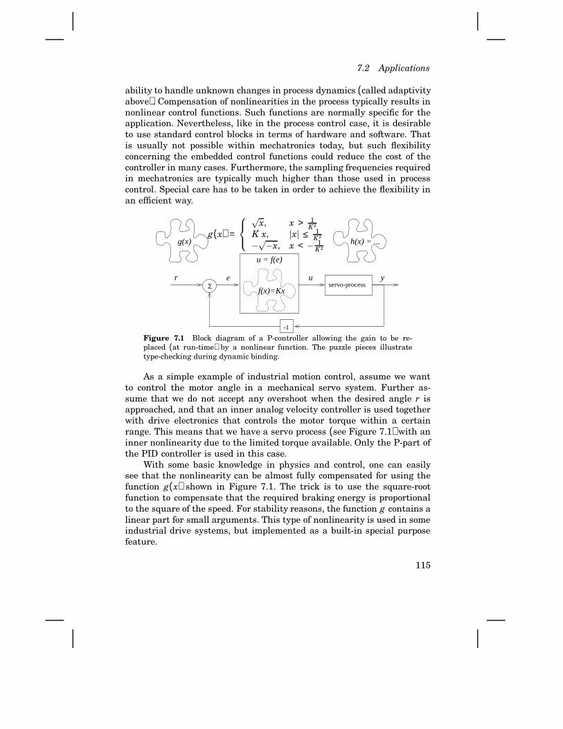
7.2 Applications
ability to handle unknown changes in process dynamics (called adaptivityabove). Compensation of nonlinearities in the process typically results innonlinear control functions. Such functions are normally specific for theapplication. Nevertheless, like in the process control case, it is desirableto use standard control blocks in terms of hardware and software. Thatis usually not possible within mechatronics today, but such flexibilityconcerning the embedded control functions could reduce the cost of thecontroller in many cases. Furthermore, the sampling frequencies requiredin mechatronics are typically much higher than those used in processcontrol. Special care has to be taken in order to achieve the flexibility inan efficient way.
servo-process
-1
eΣ
ur y
g(x)
u = f(e)
f(x)=Kx
h(x) = ...g(x) =
√
x, x > 1K2
K x, jxj ≤ 1K2
−√−x, x < − 1K2
Figure 7.1 Block diagram of a P-controller allowing the gain to be re-placed (at run-time) by a nonlinear function. The puzzle pieces illustratetype-checking during dynamic binding.
As a simple example of industrial motion control, assume we wantto control the motor angle in a mechanical servo system. Further as-sume that we do not accept any overshoot when the desired angle r isapproached, and that an inner analog velocity controller is used togetherwith drive electronics that controls the motor torque within a certainrange. This means that we have a servo process (see Figure 7.1) with aninner nonlinearity due to the limited torque available. Only the P-part ofthe PID controller is used in this case.
With some basic knowledge in physics and control, one can easilysee that the nonlinearity can be almost fully compensated for using thefunction g(x) shown in Figure 7.1. The trick is to use the square-rootfunction to compensate that the required braking energy is proportionalto the square of the speed. For stability reasons, the function g contains alinear part for small arguments. This type of nonlinearity is used in someindustrial drive systems, but implemented as a built-in special purposefeature.
115

Chapter 7. Open Embedded Control
If we instead make an embedded PID-controller in which the pro-portional gain constant can be exchanged by an external function, muchgreater flexibility is achieved. These functions need not be known whenthe controller is shipped. They can be written and inserted when the con-troller is to be used. In the next section, we will return to how this canbe achieved, but it means that we can use the same embedded controlleras a building block for controlling very different processes. Type checkingensures that only a conformant function can be inserted. The type of thefunctions is illustrated in Figure 7.1 by the shape of the pieces.
It is common within mechatronic applications to make use of a dy-namic model of the controlled system to achieve the best possible per-formance. Control techniques like state feedback, state observers, opti-mal control, linearizing control, etc., are used for this purpose. Control ofmanufacturing equipment and many military control problems are typicalapplications for such control strategies. In such systems, like industrialrobots, it is even more valuable to have software slots admitting the be-havior of the machine to be tailored to different needs.
As an example, assume we have a well functioning embedded regula-tor comprising state feedback control. For brevity, only two states x1 andx2 are used in the sequel. State feedback means that we compute the (inthis example scalar) control signal u as the negative scalar product of again vector L and the state vector x = [x1 x2]T , i.e., the control signal uis defined as u(t) = −L ⋅ x(t). The state feedback can in a simple applica-tion be used to control a servo, as in the simple control case above. Thefollowing example of exact linearization is from [105], which also containsmore advanced applications where this type of control is useful.
Consider the pendulum equation
θ = −a sinθ − bθ + cτ
where a = g/l, b = d/m, c = 1/ml2, θ is the angle subtended by the rodand the vertical axis, and τ is the torque applied to the pendulum. Herel denotes the length of the pendulum, d the viscous friction, m the mass,and g is the gravity constant. View the torque as the control input andsuppose we want to stabilize the pendulum at an angle θ = δ . This canbe achieved by the control law
τ =ac
[sin(x1 + δ ) − sinδ ] + k1x1 + k2x2
where the first term takes care of the nonlinearity, and the rest is a linearstate feedback that is used to place the closed loop poles using the gainsk1 and k2 from the measured states position and velocity respectively.
116
7.2 Applications
It would be desirable to allow an efficient implementation of thiscontrol using a standard embedded state feedback regulator. This meansthat the regulator by default should provide linear feedback, but the gainsshould be possible to replace by nonlinear functions. There should be nosignificant overhead due to such a feature. Furthermore, in more complexapplications, it should be allowed to have selected parts of an algorithmhidden. The hidden (pre-implemented) part could then conceptually be-long to the actual mechatronic device or component.
Supervisory control
A distributed control system is composed of separate local controllers andat least one supervisory controller. In such a system it is preferable to havea vendor independent interface to the local units. It is also important tominimize data flow and reduce the computational load on the supervi-sory controller. However, standard controllers for local use have differentsignals available. At construction time of a controller it is impossible toknow which signals might be desirable to use, since this depends on thespecific application. In other words, distributed control systems today aresometimes burdened with more communication and computations thannecessary.
An attractive solution would be to have a slot in the local controllersfor additional computation. This could be in the form of algorithms on asmartcard supplied by the vendor or executable code loaded over a localnetwork. With this approach standard controllers could be customized tofit different environments, and the computational load on the supervisorycontroller could be reduced.
This type of functionality partially exists in todays process controlsystems, but requires that the local controller is integrated with thesupervisory control which either sends down new code for interpretation,or restarts the local controller with new compiled code. Dynamic bindingof functions would be a more attractive solution. These functions shouldnot need to be defined in a special process control language defined by thesupervisory system. Using a standard computer programming languageinstead means that the local embedded controller more easily can beintegrated into quite different control systems.
In terms of PLC programming [89], we want to use a vendor inde-pendent method to change function blocks, or parts thereof, at run-time.Such a principle seems to be compatible with the evolving standard [89]for PLC and control system programming. (The standard does allow useof externally defined functions and we have not found any requirementon static binding of such functions.)
117
Chapter 7. Open Embedded Control
Intelligent low-l evel sensing
Intelligent sensors are equipped with electronics and data processingcapabilities so that data can be processed locally, thus requiring less datatransfer and computations for the main control. Performance can also beimproved by using intelligent sensors. Filtering algorithms in the sensorsignal processing unit may run at a higher sampling rate, and operate ondata that has not been delayed by data transfers.
High volume production of sensors like accelerometers and laser sen-sors have resulted in very low cost for the sensor. Field busses and in-terface electronics for connection of sensors are also becoming affordable.Such sensors today may provide a protocol for changing filter parametersand threshold levels. For a sensor to be considered intelligent, we also re-quire that more general nonlinear and application specific algorithms canbe performed in the sensor. There are, however, also parts of the filteringthat are specific for the sensor technology, and should not be exposed tothe user. This means that we want to have a hidden part of the filteringhardware/software, and an open part where application specific softwareshould be possible to plug in. Such algorithms sometimes need to changeover time, depending on the type of information needed by the high levelcontrol (like task planning etc.).
As a simple test case, consider an accelerometer mounted on a robotarm. Normal robot motions result in smooth changes in acceleration. Morerapid changes result if the robot hits an obstacle. We then want this eventto be detected by the sensor and reported to the main control computer. Ifmore information about the collision is requested, the sensor should alsobe able to reply with a recording of the signal during the collision. Suchinformation can be provided by a special purpose intelligent sensor, or byan off-the-shelf intelligent open sensor.
7.3 Embedded dynamic binding
We will now investigate how to bind functions at run-time to software al-ready running in the embedded system, considering demands on efficiencyand predictability for typical mechatronic applications.
Alternatives
The problem we are facing can be described in terms of a client and aserver. The server is the embedded software already implemented, andpossibly running. The basic service is first of all to perform the control,but also to service requests to change the control behavior. It is the
118
7.3 Embedded dynamic binding
latter aspect that is treated here. The client acts on a higher hierarchicallevel, which means that it contains more application specific knowledge.Depending on what is appropriate to solve the particular application, theclient requests the lower level control (i.e., the server) to use different newcontrol functions. We then need some means of expressing these functionsand to dynamically let the server evaluate them. As throughout this work,we try to apply well proven software techniques, but in the context ofmechatronics and embedded control. Some of the alternatives we haveconsidered for the implementation and dynamic binding are:
Remote Procedure Calls (RPC) are widely used and understood, butsince the input/output arguments of the procedure have to be trans-ferred to/from the computer that executes the procedure, the result-ing data flows and communication delays can be substantial. Unpre-dictable timing would also be a problem, for instance when Ethernetconnections are used.
Interpreted languages make it straightforward to pass functions tosome target software containing an interpreter. Some languages toconsider are:Lisp is a flexible and powerful alternative, but tends to be one or twoorders of magnitude slower than compiled languages unless the Lispcode is compiled. Its dependency on garbage collection also makes ithard to use for real-time tasks.Forth is powerful and relatively efficient, but hard to debug andmaintain due to its lack of structure. A solution useful for our needscould probably use Forth as an intermediate language, but with noapparent advantages.Erlang [25] is an interpreted parallel language developed for tele-communication systems. It compiles to reasonably fast intermediatecode that can be passes between processes running in different ad-dress spaces or on different CPUs, but as Lisp it relies on garbagecollection, and we therefore decided against using it in our prototypeimplementation.Java is a relatively new language with support for object-orientation,threads, and their relationship [141]. It is compiled into efficient byte-code, but the drawbacks of Erlang remains.
Compiled functions written in a widely used language like C wouldbe an attractive solution. The problem of binding the used symbolsto the external environment then has to be solved. If this can bedone, we will hopefully achieve almost the same flexibility as theother alternatives, and almost the same performance as for builtinfunctions.
119
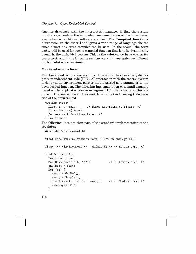
Chapter 7. Open Embedded Control
Another drawback with the interpreted languages is that the systemmust always contain the (compiled) implementation of the interpreter,even when no additional software are used. The Compiled functionsalternative, on the other hand, gives a wide range of language choicessince almost any cross compiler can be used. In the sequel, the termaction will be used for such a compiled function that is to be dynamicallybound in the embedded system. This is the solution we have chosen forour project, and in the following sections we will investigate two differentimplementations of actions.
Function-based actions
Function-based actions are a chunk of code that has been compiled asposition independent code (PIC). All interaction with the control systemis done via an environment pointer that is passed as a parameter to thedown-loaded function. The following implementation of a small examplebased on the application shown in Figure 7.1 further illustrates this ap-proach. The header file environment.h contains the following C declara-tion of the environment:
typedef struct {
float r, y, gain; /* Names according to figure. */
float (*sqrt)(float);
/* more math functions here.. */
} Environment;
The following lines are then part of the standard implementation of theregulator:
#include <environment.h>
float defaultK(Environment *env) { return env->gain; }
float (*K)(Environment *) = defaultK; /* <- Action type. */
void Pcontrol() {
Environment env;
MakeDownloadable(K, "K"); /* <- Action slot. */
env.sqrt = sqrt;
for (;;) {
env.r = GetRef();
env.y = Sample();
P = K(&env) * (env.r - env.y); /* <- Control law. */
SetOutput( P );
}
120

7.3 Embedded dynamic binding
}
where, as C-programmers know, the action declaration specifies that K
is a pointer to a function that as its argument takes a pointer to theEnvironment specified above, and returns a float.
Since automatic code generation of control algorithms nowadays isan important control engineering tool, it is of course important not toimpose special requirements on the way control laws are expressed. Thefact that we use the structure env makes the control law (only the oneline above in this simple example) different from the text-book versionP=K*(r-y) in two minor ways: First, accesses of variables that are part ofthe environment are preceded by ‘env.’. That can for example be handledby preprocessor directives in C and C+ + , or by use of WITH in Modula-2.Secondly, the number K is represented by the function taking the addressof the environment as an argument. (The “(&env)” can be avoided by usingC+ + operator overloading, but here we will be explicit and not confusethe reader by any syntactic sugar.)
Now the target system is prepared for a new function K to be down-loaded. Let us replace the defaultK with a separately compiled nonlineargain function. Since the control law is the nonlinear gain times the controlerror, we have to divide the function g in Figure 7.1 by the control error.This means that the implementation of the action will be:
#include <environment.h>
float sqrtK(Environment *env) {
float e = env->r - env->y;
float a = 1 / (env->gain * env->gain);
if (e > a) { return 1.0 / env->sqrt( e); }
else if (e < -a) { return -1.0 / env->sqrt(-e); }
else { return env->gain; }
}
Further improvements concerning the control are possible, but outside thescope of this paper. Considering the software aspects the solution seemsto be everything we need, but there are a few catches:
• The compiler must be capable to generate PIC code. On some plat-forms this can be prohibitively expensive in terms of execution speedor code size. It may also be the case that a certain compiler cannotgenerate PIC code.
• It is hard to make changes to the environment structure since allelements has to be in the same place, and no checks are done whenthe code gets down-loaded. Environment mismatches will result inruntime errors.
121

Chapter 7. Open Embedded Control
• Some language constructs need access to global data or global func-tions (e.g., operators new and delete in C+ +), which is not easilyimplemented in this scheme. This problem can be solved by a smartercompiler, but such a modification is probably not worthwhile.
In practice, this means that actions implemented this way are restrictedto be single functions. This type of actions are therefore called function-based actions. Despite the problems, successful experiments have beencarried out, as will be described in Section 7.4.
Dynamically linked actions
We will now introduce a linker to overcome the limitations with thefunction-based actions. Conceptually this seems more complicated, butin practice one can often use an existing linker and with minor effortgenerate a small file that contains the symbols that are needed to linkwith the control system. In our prototype system the linking is done withthe GNU linker [55] and a small Perl [216] script (300 lines) on the hostsystem, and a few small procedures in the control system (400 lines + 1line per symbol). The action client performs the following algorithm (byrunning the Perl script on the host computer):
1. The script requests all available interface symbols of a specific actionslot from the control system.
2. A preliminary linking with these symbols is done to check that allreferences can be resolved. If any undefined symbols remain, linkingis aborted.
3. Using the resulting code-size from step 2, the control system is in-structed to allocate a chunk of memory with the appropriate size, andits start address is sent back to the client.
4. The final linking is done and the address of the entry point of theaction is retrieved.
5. The finished code is sent to the control system along with the addressof the entry point, see the function install below.
The implementation is straightforward.To make it possible to have multiple actions in the same code seg-
ment we will also change the way actions are installed in the exampleapplication. The following is the same example as above but somewhatmodified, starting with the file environment.h:
typedef struct {
float r, y, gain;
} Environment;
122

7.3 Embedded dynamic binding
extern float sqrt(float);
/* more math functions here.. */
extern float (*K)(Environment *);
The following lines are part of the embedded control software:
#include <environment.h>
float defaultK(Environment *env) { return env->gain; }
float (*K)(Environment *) = defaultK;
void SendSymbols() {
SendSymbol("sqrt", &sqrt);
SendSymbol("K", &K);
}
void Pcontrol() {
Environment env;
MakeLoader(SendSymbols);
for (;;) {
env.r = GetRef();
env.y = Sample();
P = K(&env) * (env.r - env.y); /* <- Control law. */
SetOutput( P );
}
}
As we can see, the things that have changed are:
• The sqrt function is no longer part of the environment structure,it is instead declared as an external function. By doing it this way,it is easy to add new functions to the interface, and the removalof old functions that are used by old actions will give diagnosticmessages when down-loading is attempted. In the C+ + case we canalso detect signature changes since the parameter types are encodedin the function names (name mangling). When Modula-2 is used,module time-stamp mismatches are detected in the same way.
• The action pointer is made visible to the down-loaded action. Thereason is that the down-loaded action is now responsible for theinstallation, a fact that makes it possible to replace multiple actionssimultaneously. This also makes it straightforward to add static C+ +objects to a code segment.
123
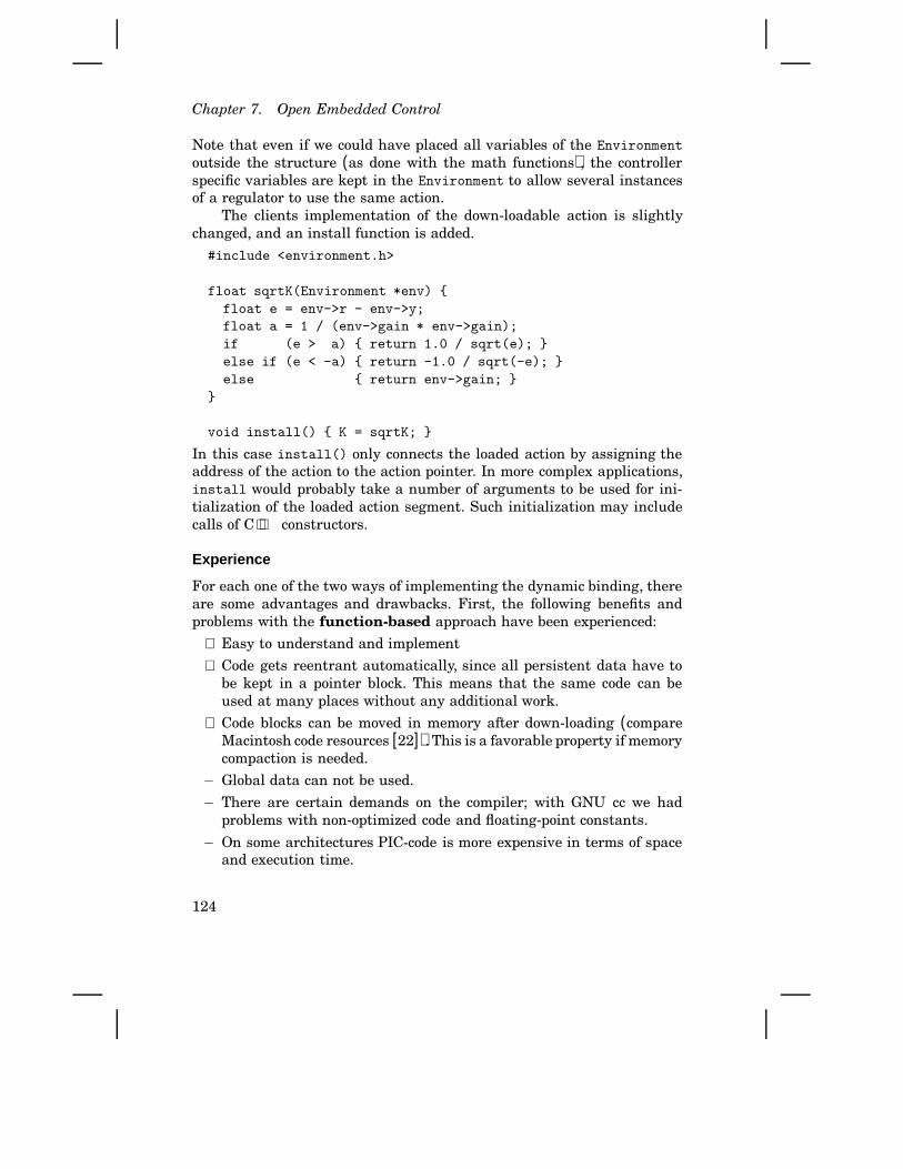
Chapter 7. Open Embedded Control
Note that even if we could have placed all variables of the Environment
outside the structure (as done with the math functions), the controllerspecific variables are kept in the Environment to allow several instancesof a regulator to use the same action.
The clients implementation of the down-loadable action is slightlychanged, and an install function is added.
#include <environment.h>
float sqrtK(Environment *env) {
float e = env->r - env->y;
float a = 1 / (env->gain * env->gain);
if (e > a) { return 1.0 / sqrt(e); }
else if (e < -a) { return -1.0 / sqrt(-e); }
else { return env->gain; }
}
void install() { K = sqrtK; }
In this case install() only connects the loaded action by assigning theaddress of the action to the action pointer. In more complex applications,install would probably take a number of arguments to be used for ini-tialization of the loaded action segment. Such initialization may includecalls of C+ + constructors.
Experience
For each one of the two ways of implementing the dynamic binding, thereare some advantages and drawbacks. First, the following benefits andproblems with the function-based approach have been experienced:
+ Easy to understand and implement
+ Code gets reentrant automatically, since all persistent data have tobe kept in a pointer block. This means that the same code can beused at many places without any additional work.
+ Code blocks can be moved in memory after down-loading (compareMacintosh code resources [22]). This is a favorable property if memorycompaction is needed.
− Global data can not be used.
− There are certain demands on the compiler; with GNU cc we hadproblems with non-optimized code and floating-point constants.
− On some architectures PIC-code is more expensive in terms of spaceand execution time.
124
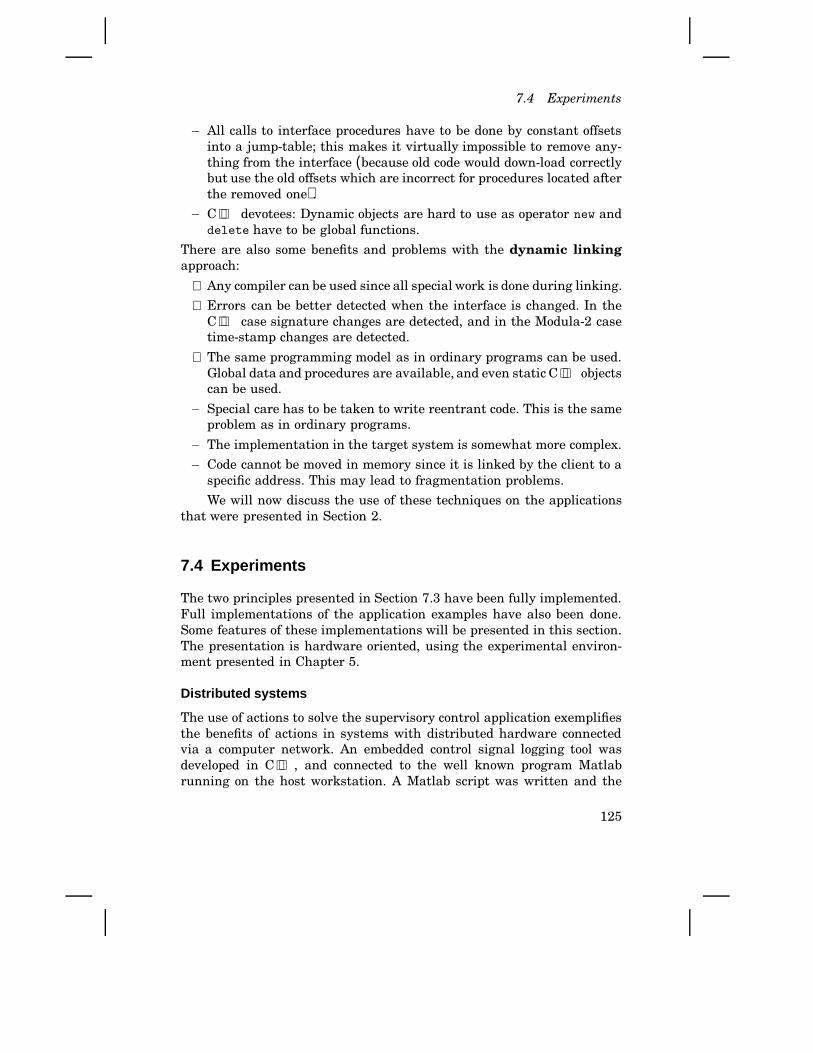
7.4 Experiments
− All calls to interface procedures have to be done by constant offsetsinto a jump-table; this makes it virtually impossible to remove any-thing from the interface (because old code would down-load correctlybut use the old offsets which are incorrect for procedures located afterthe removed one).
− C+ + devotees: Dynamic objects are hard to use as operator new anddelete have to be global functions.
There are also some benefits and problems with the dynamic linkingapproach:
+ Any compiler can be used since all special work is done during linking.
+ Errors can be better detected when the interface is changed. In theC+ + case signature changes are detected, and in the Modula-2 casetime-stamp changes are detected.
+ The same programming model as in ordinary programs can be used.Global data and procedures are available, and even static C+ + objectscan be used.
− Special care has to be taken to write reentrant code. This is the sameproblem as in ordinary programs.
− The implementation in the target system is somewhat more complex.
− Code cannot be moved in memory since it is linked by the client to aspecific address. This may lead to fragmentation problems.
We will now discuss the use of these techniques on the applicationsthat were presented in Section 2.
7.4 Experiments
The two principles presented in Section 7.3 have been fully implemented.Full implementations of the application examples have also been done.Some features of these implementations will be presented in this section.The presentation is hardware oriented, using the experimental environ-ment presented in Chapter 5.
Distributed systems
The use of actions to solve the supervisory control application exemplifiesthe benefits of actions in systems with distributed hardware connectedvia a computer network. An embedded control signal logging tool wasdeveloped in C+ + , and connected to the well known program Matlabrunning on the host workstation. A Matlab script was written and the
125
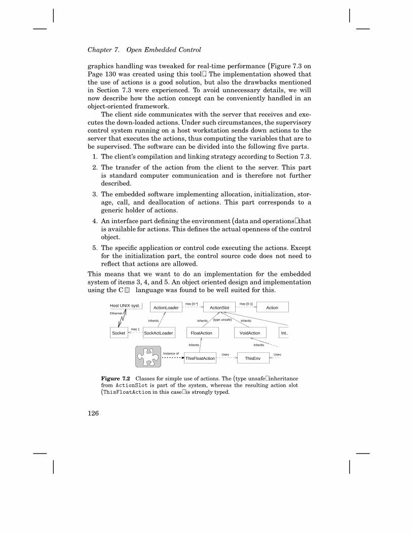
Chapter 7. Open Embedded Control
graphics handling was tweaked for real-time performance (Figure 7.3 onPage 130 was created using this tool). The implementation showed thatthe use of actions is a good solution, but also the drawbacks mentionedin Section 7.3 were experienced. To avoid unnecessary details, we willnow describe how the action concept can be conveniently handled in anobject-oriented framework.
The client side communicates with the server that receives and exe-cutes the down-loaded actions. Under such circumstances, the supervisorycontrol system running on a host workstation sends down actions to theserver that executes the actions, thus computing the variables that are tobe supervised. The software can be divided into the following five parts.
1. The client’s compilation and linking strategy according to Section 7.3.
2. The transfer of the action from the client to the server. This partis standard computer communication and is therefore not furtherdescribed.
3. The embedded software implementing allocation, initialization, stor-age, call, and deallocation of actions. This part corresponds to ageneric holder of actions.
4. An interface part defining the environment (data and operations) thatis available for actions. This defines the actual openness of the controlobject.
5. The specific application or control code executing the actions. Exceptfor the initialization part, the control source code does not need toreflect that actions are allowed.
This means that we want to do an implementation for the embeddedsystem of items 3, 4, and 5. An object oriented design and implementationusing the C+ + language was found to be well suited for this.
FloatAction
ActionSlotActionLoader Action
SockActLoader
ThisFloatAction
Socket
ThisEnv
Host UNIX syst. Has [0-*]
Instance of
(type unsafe)
Ethernet
Has 1
Inherits
Has [0-1]
VoidAction
Uses Uses
Inherits
Int..
InheritsInheritsInherits
Figure 7.2 Classes for simple use of actions. The (type unsafe) inheritancefrom ActionSlot is part of the system, whereas the resulting action slot(ThisFloatAction in this case) is strongly typed.
126
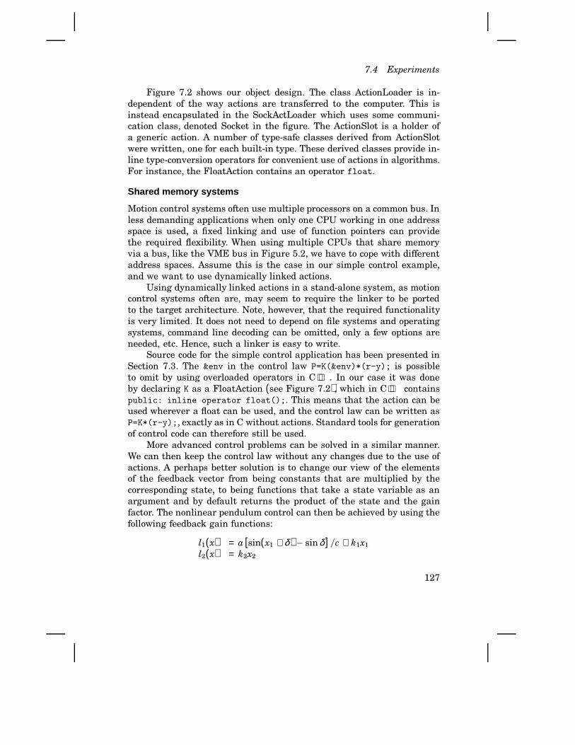
7.4 Experiments
Figure 7.2 shows our object design. The class ActionLoader is in-dependent of the way actions are transferred to the computer. This isinstead encapsulated in the SockActLoader which uses some communi-cation class, denoted Socket in the figure. The ActionSlot is a holder ofa generic action. A number of type-safe classes derived from ActionSlotwere written, one for each built-in type. These derived classes provide in-line type-conversion operators for convenient use of actions in algorithms.For instance, the FloatAction contains an operator float.
Shared memory systems
Motion control systems often use multiple processors on a common bus. Inless demanding applications when only one CPU working in one addressspace is used, a fixed linking and use of function pointers can providethe required flexibility. When using multiple CPUs that share memoryvia a bus, like the VME bus in Figure 5.2, we have to cope with differentaddress spaces. Assume this is the case in our simple control example,and we want to use dynamically linked actions.
Using dynamically linked actions in a stand-alone system, as motioncontrol systems often are, may seem to require the linker to be portedto the target architecture. Note, however, that the required functionalityis very limited. It does not need to depend on file systems and operatingsystems, command line decoding can be omitted, only a few options areneeded, etc. Hence, such a linker is easy to write.
Source code for the simple control application has been presented inSection 7.3. The &env in the control law P=K(&env)*(r-y); is possibleto omit by using overloaded operators in C+ + . In our case it was doneby declaring K as a FloatAction (see Figure 7.2), which in C+ + containspublic: inline operator float();. This means that the action can beused wherever a float can be used, and the control law can be written asP=K*(r-y);, exactly as in C without actions. Standard tools for generationof control code can therefore still be used.
More advanced control problems can be solved in a similar manner.We can then keep the control law without any changes due to the use ofactions. A perhaps better solution is to change our view of the elementsof the feedback vector from being constants that are multiplied by thecorresponding state, to being functions that take a state variable as anargument and by default returns the product of the state and the gainfactor. The nonlinear pendulum control can then be achieved by using thefollowing feedback gain functions:
l1(x) = a [sin(x1 + δ ) − sinδ ] /c + k1x1
l2(x) = k2x2
127

Chapter 7. Open Embedded Control
where k1 and k2 could get their values from a standard parameter in-terface, or whatever was used for the constant L vector values. An evenmore flexible solution would be to let a feedback vector L be a functionof the state vector and the time, i.e. L(x, t) = ... That would for instanceallow a non-stationary LQ-controller [29] to be used.
Dedicated hardware systems
The following implementation of the low-level sensing illustrates the useof actions for special purpose hardware. As shown in Figure 5.2, an ac-celerometer connected via an AD-converter to a DSP is available. Forbrevity, we will only use a simple action detecting an acceleration level.The following design tries to show how actions can be supported with aminimum of support from the embedded sensor software.
To reflect typical properties of intelligent sensors, our hardware wasused as follows: 1) There is a memory area (called action storage) re-served for loaded actions. 2) The action storage is accessed by using thebuilt-in DMA capabilities of DSP32C. This means that no support fromthe DSP program is needed; access of action storage from outside onlyimposes some cycle stealing controlled by the hardware. 3) The addressand the length of action storage must be known by the action client.In our setup, we simply get this information from the symbol table of thelinked sensor code. 4) The loaded action must obey any restrictions on theuse of resources like CPU-time and memory. We used the DSP simulator(on the host computer) to check the execution time and use of memory.
We will now use function-based actions to catch collisions and plotthe recorded signal in a host computer tool. Since they do not require anyaddresses of internal symbols (recall that the pointer to the environmentis passed as a function argument at run-time), and the management ofthe action storage is done by the master, the following C+ + code issufficient. First the header file included by both the action client (themaster) and the action server (the sensor unit):
struct Environment {
struct Signals {
float time, acc;
} *this_sample;
enum status {pending, recording, transferring, waiting};
status trig_state;
};
typedef int (*PlotAction)(Environment*);
As C-programmers know, the final typedef-line specifies that PlotAction
128

7.4 Experiments
is a pointer to a function that as its argument takes a pointer to theEnvironment specified above, and returns an integer. The basic sensorsoftware then containsint DefaultAction( register Environment *env ) {
// Default behavior implemented here.
}
long action_storage[0x400]; // Size hard-coded for brevity.
PlotAction plot_action = DefaultAction;
The return value of the action tells whether sensor data output should besupplied or not. Our built-in data-supply object of type AccPlot containsthe following member function:int AccPlot::PutSample( float signals[] ) {
// <Checking conditions that has to be fulfilled..>
// <..16 lines omitted here..>
// Space available, check trig condition.
environment.this_sample = (Environment::Signals*)signals;
if ((*plot_action)(&environment)) { // <- CALL OF ACTION.
// Put data and let HW convert to IEEE output format.
// <Some work done here.>
return 1;
} else { // <Seven final lines omitted ..>
where the line containing (*plot_action)(&environment) shows how theaction is called. As the reader with experience from the C language knows,this statement means that the function pointed to by plot_action iscalled, passing a pointer to the environment data structure as an argu-ment. The following function was written and compiled, and then positionindependence, execution time, and memory usage was checked. This wasdone on the host workstation.int AccPlotAction( register Environment *env ) {
int ilevel = 25; float level;
switch (env->trig_state) {
case Environment::pending:
level = float(ilevel);
if (env->this_sample->acc > level) {
env->trig_state = Environment::recording;
} else { return 0; };
case Environment::recording: return 1;
default: return 0;
};
};
129
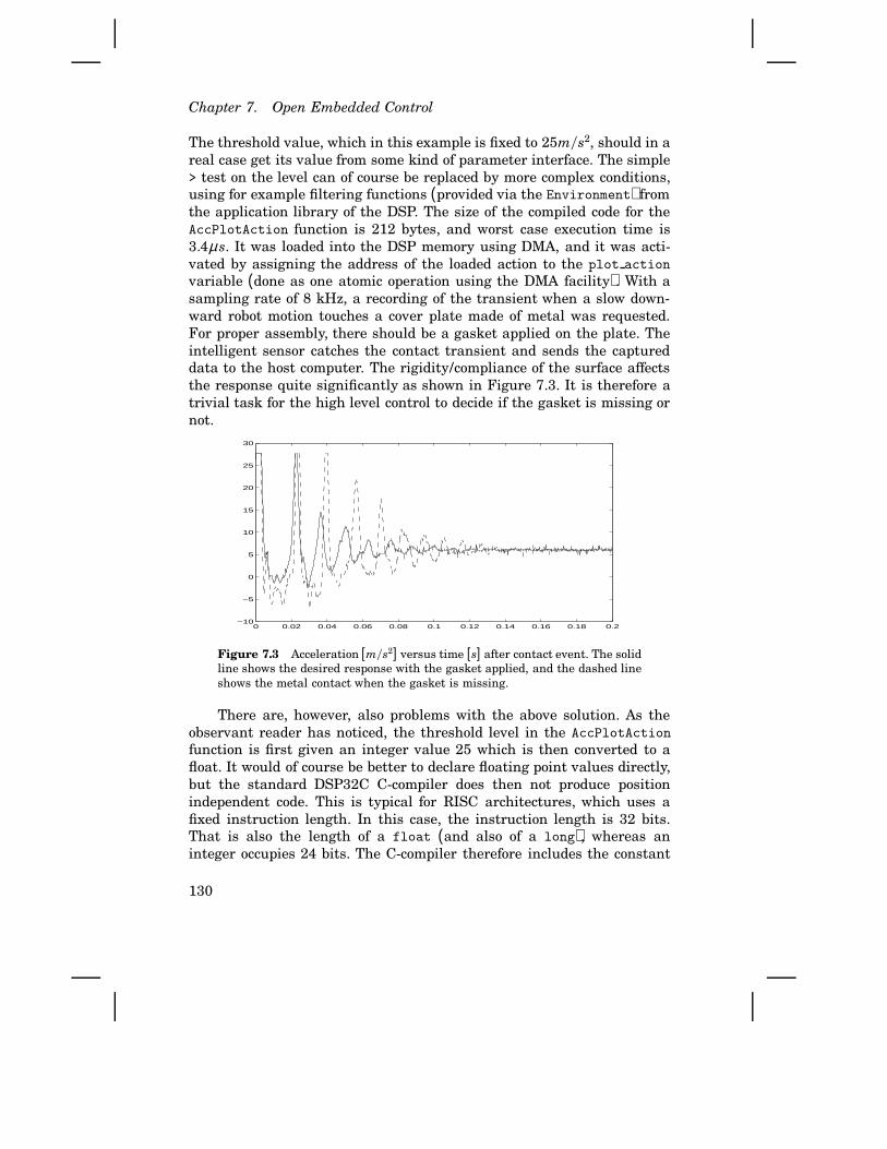
Chapter 7. Open Embedded Control
The threshold value, which in this example is fixed to 25m/s2, should in areal case get its value from some kind of parameter interface. The simple> test on the level can of course be replaced by more complex conditions,using for example filtering functions (provided via the Environment) fromthe application library of the DSP. The size of the compiled code for theAccPlotAction function is 212 bytes, and worst case execution time is3.4µ s. It was loaded into the DSP memory using DMA, and it was acti-vated by assigning the address of the loaded action to the plot action
variable (done as one atomic operation using the DMA facility). With asampling rate of 8 kHz, a recording of the transient when a slow down-ward robot motion touches a cover plate made of metal was requested.For proper assembly, there should be a gasket applied on the plate. Theintelligent sensor catches the contact transient and sends the captureddata to the host computer. The rigidity/compliance of the surface affectsthe response quite significantly as shown in Figure 7.3. It is therefore atrivial task for the high level control to decide if the gasket is missing ornot.
0 0.02 0.04 0.06 0.08 0.1 0.12 0.14 0.16 0.18 0.2−10
−5
0
5
10
15
20
25
30
Figure 7.3 Acceleration [m/s2] versus time [s] after contact event. The solidline shows the desired response with the gasket applied, and the dashed lineshows the metal contact when the gasket is missing.
There are, however, also problems with the above solution. As theobservant reader has noticed, the threshold level in the AccPlotAction
function is first given an integer value 25 which is then converted to afloat. It would of course be better to declare floating point values directly,but the standard DSP32C C-compiler does then not produce positionindependent code. This is typical for RISC architectures, which uses afixed instruction length. In this case, the instruction length is 32 bits.That is also the length of a float (and also of a long), whereas aninteger occupies 24 bits. The C-compiler therefore includes the constant
130

7.5 Safety and predictable real-time performance
integer values in the instructions in the code-section. A float, on theother hand, will be put in the data section, thus requiring linkage to theexecutable code. The same problem occurs, as mentioned in Section 7.3,when auxiliary functions are included in the action.
Even if the problem is due to the compiler, it is still relevant sincecompilers generally work in this way, and actions are preferably written ina high-level language. Special languages and/or compilers are sometimesused for safety critical systems to get deterministic execution properties.Such a special compiler could provide position independence also for theabove function. It is also easy to achieve that using assembly language.Despite the problems, we therefore think that function-based actions canbe a useful alternative in some applications. But for portability and exe-cution efficiency reasons, the dynamic linking version is probably the bestalternative in most cases.
7.5 Safety and predictable real-time performance
The proposed mechanism is a powerful way to add flexibility to embed-ded systems, but how are safety and predictability affected? The followinginvestigation is made with some typical properties of hard real-time sys-tems in mind. The reader may think of the Spring Kernel [194] and theSynchronous approach [187] as relevant examples.
Since we have the same requirements on safe programming of ac-tions as for implementation of the standard part of the system, some wayto ensure that safety has to be devised. If a language as C is used toimplement the actions, the system has to protect itself from invalid mem-ory accesses that otherwise could compromise the entire system. Properprogramming of the MMU can prevent illegal memory accesses but thatis an expensive solution, especially concerning worst case execution timefor dynamically linked actions. A more convenient (for the programmer)and efficient (for the computer) approach is to use a language (like Java[141]) where memory accesses can be checked a priori.
To ensure that deadlines in the system are met, the timing of individ-ual actions is of paramount interest. If the system is statically scheduled,the schedule has to take into account the extra time actions are allowed totake. The timing constraints is then a property of the action slot, and theconstraints have to checked when actions are installed. In dynamicallyscheduled systems, rescheduling has to be done when actions are loaded.In both cases, the execution time of the action has to be determined.
In some cases, as in our DSP system, execution times can be deter-mined by the client, and the action loader can check that timing con-
131

Chapter 7. Open Embedded Control
straints are fulfilled. Thus, no additional functionality/software for tim-ing analysis is needed on the target side. In other more general cases, forinstance when the action may be down-loaded to differently configuredhardware (but with compatible instruction sets), it is more suitable toperform timing evaluation of the action in the target system. To determinethe actual timing of the action, it either has to be statically analyzablelike in Real-Time Java [141], or the timing has to be checked at runtimeby measuring the actual time taken for some appropriately chosen testruns of the action. Assume that each action contains a function that callsthe loaded function with special parameters to get the maximum execu-tion time. It is not appropriate to just let the install function (see thecode example on Page 124) call the MaxTime function and then comparewith the bounds by calling some evaluation function defined in the ac-tion’s environment. This is because timing analysis may also require thehardware (interrupts, caches, etc.) to be setup in the same way as whenthe action has been installed. Therefore, we propose that action slots instatically scheduled systems require actions to have a MaxTime entry (andMinTime, etc.), and that the server calls it before the install function.This is a minor and straightforward extension of our present implemen-tation. Of course, the program must have a properly scheduled time slotfor the timing evaluation, but that slot can serve all actions managed bythat CPU.
When new code has been properly installed, it can be useful to mon-itor signals emanating from the the action to make sure that it fulfillspredefined control constraints. That was proposed in the Simplex Ar-chitecture [179], which has been developed to support online upgradeof hardware and software components. The action mechanism facilitatesalso such a feature; actions can of course be removed (fully implementedbut description omitted) when conditions of activation are not fulfilled.
In conclusion, we claim that the proposed mechanism is very usefulboth for improving flexibility to existing hard real-time systems, and fordevelopment of new open embedded systems.
7.6 Conclusions
A development towards more open computer systems is motivated byincreased demands on flexibility, i.e., that the system should be possibleto tailor to meet new customer demands. The need for open systemsalso within mechatronics and embedded control was illustrated by someapplication examples. To permit feedback control based on informationfrom external sensors, and for the design of reactive systems in general,
132

7.6 Conclusions
open control systems are needed. Special demands on efficiency, safety, etc.motivated use of dedicated software techniques for this type of systems.
The most basic way to allow changes is by providing parameters thatthe user can tune for his/her purposes. Such parameters have been re-stricted to data, but the demands on flexibility often require the programto be changed. Our idea is to use pieces of compiled executable code asfunctional operators. Such operators may in the simplest case be a lin-ear function, which combined with operators provided by the program-ming language may appear as an ordinary numerical control parameter.In more complex situations, even if encountered after implementation ofthe basic system, we may introduce a function with additional arguments(states, time, etc.), or even a ‘function’ with internal states. A new pa-rameterization of the control is then obtained. (Our implementation evensupports parameterization of the parameterization, that is, action param-eters supplied at plug-in-time defined the actual parameterization usedduring run-time.) In an object-oriented framework, this means that newmethods can be added to controller objects after implementation of thebasic control, and even while the controller is running. Two ways to dothe required dynamic binding of functions and objects were introducedand discussed.
A major effort was put into full implementation of the test cases.The results were encouraging; it was possible to achieve flexibility andefficiency, and to combine open and closed system designs. In other words,an embedded may indeed be open, thus justifying the title of this chapter.The application examples, the proposed principles for open embeddedcontrol, and the implementations verifying the performance are the maincontributions.
In conclusion, we propose a way to build open and efficient em-bedded systems using industrially accepted software techniques. It wasalso described how other research results, concerning for example pre-dictability and static scheduling [194, 195], can benefit from the proposedmechanism. We think that a major advantage of the concept is its sim-plicity (concerning programming and operating system requirements) andthe possibility to combine it with other solutions within mechatronics andreal-time systems. Since flexibility is likely to be even more importantin the future, for example in manufacturing systems, we hope that theproposed software technique will contribute to that.
133

8
Applications
We are now ready to further investigate special applications that are non-trivial to handle with current systems. A short introduction to such ap-plications was given in Section 2.5 (p. 10), where one industrial and onebenchmark problem were presented. This chapter contains a further treat-ment of those examples, and more industrial examples are also presented.These application examples are today, in many cases, handled by modify-ing the basic motion control of the robot. This can normally only be doneby the robot manufacturer, and requires a substantial engineering effort.
The approach taken here is as explained previously; the robot controlsystems should be open for the experienced user on a fairly low leveltightly connected to the motion control system. Actions, as defined inChapter 7, will be used to accomplish such a tight connection. The termrobot skill will be used as a short term denoting actions loaded into theapplication layer for the purpose of extending the capabilities of the robot.The experimental platform presented in Chapter 5 is instrumental toobtain the results reported.
The first application example, which is deburring of castings, illus-trates the aspects of open robot control very well. The second exampletreats high performance motion control for spot-welding. There is one ex-ample about object identification for materials handling. Two examplesin the section about assembly, describe how creative use of the applica-tion layer can improve the performance of assembly operations withoutadditional sensors or hardware. The final industrial example is about arcwelding, focusing on support for special control of the welding process,and on the use of such control from a task-level programming system.The ongoing implementation of the pendulum benchmark problem is thenpresented. Finally, we will look at some related industrial development inrecent years and put the development of application specific control intoan industrial context.
134

8.1 Deburring of castings
8.1 Deburring of castings
As already pointed out on Page 10, we want deburring to be accom-plished by moving the grinding tool with position control along a nom-inal path, and with force control in a direction normal to the path. Byappropriate tuning of speed etc., the tool will make the surface smooth.In the ideal situation when the variation in burr size is small, and whenthe grinding path is well known, successful grinding has been achieved[205, 85, 103, 160, 137]. Even in the case of more unknown burr sizes,successful experiments have been made using special tooling and externalcontrol [159]. The special tooling includes passive compliance in well de-fined directions relative to the grinding forces, and the tools is equippedwith sensors for accurate position and force measurements. Such veryspecial end-effectors [161] are needed because the robot controller cannotbe tailored to accomplish the desired grinding control.
The situation is even more difficult in the general case when the lo-cation of the work-piece is not accurately known, and when remainingbulges remain due to exceptional burr sizes. This is the case that has tobe solved before robotized grinding gets industrially useful. Major robotvendors are aware that current systems cannot handle this type of appli-cation, and many potential customers have therefore not been offered anytechnical solution [33]. Thus, robots capable of handle realistic deburringapplications are industrially very tractable.
Even if the long-term goal of this research is to develop a system forreal industrial use, such a complete implementation is beyond the scopeof this thesis. Instead, let us look at unsolved specific problems. As men-tioned above, deburring along well known paths with small variations inburr size has been accomplished in other laboratories by well designedend-effectors and well tuned feedback control. The major unsolved diffi-culty is to make the robot recognize when and where additional grindingis required and, if so, to determine additional grinding motions, like theones a human worker would have performed.
Desired behavior
Considering our example from Chapter 2 (Figure 2.5, p. 2.5), we havethe profiles according to Figure 8.1. Note that the following solution willnot require any additional sensors to measure the deviation from thenominal path. Instead, that can be computed from the position errorsduring deburring. Such (internal control) data are normally not possibleto use in robot programs. Here, it is possible due to the open controlarchitecture as described in earlier chapters.
135
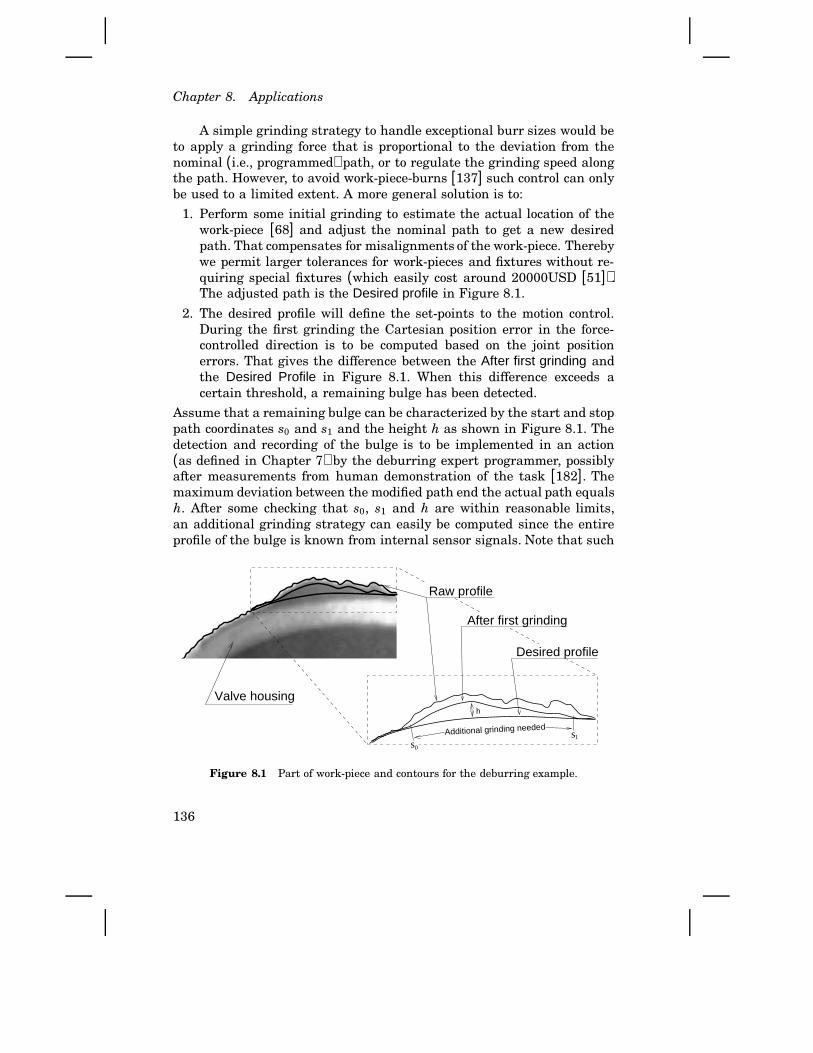
Chapter 8. Applications
A simple grinding strategy to handle exceptional burr sizes would beto apply a grinding force that is proportional to the deviation from thenominal (i.e., programmed) path, or to regulate the grinding speed alongthe path. However, to avoid work-piece-burns [137] such control can onlybe used to a limited extent. A more general solution is to:
1. Perform some initial grinding to estimate the actual location of thework-piece [68] and adjust the nominal path to get a new desiredpath. That compensates for misalignments of the work-piece. Therebywe permit larger tolerances for work-pieces and fixtures without re-quiring special fixtures (which easily cost around 20000USD [51]).The adjusted path is the Desired profile in Figure 8.1.
2. The desired profile will define the set-points to the motion control.During the first grinding the Cartesian position error in the force-controlled direction is to be computed based on the joint positionerrors. That gives the difference between the After first grinding andthe Desired Profile in Figure 8.1. When this difference exceeds acertain threshold, a remaining bulge has been detected.
Assume that a remaining bulge can be characterized by the start and stoppath coordinates s0 and s1 and the height h as shown in Figure 8.1. Thedetection and recording of the bulge is to be implemented in an action(as defined in Chapter 7) by the deburring expert programmer, possiblyafter measurements from human demonstration of the task [182]. Themaximum deviation between the modified path end the actual path equalsh. After some checking that s0, s1 and h are within reasonable limits,an additional grinding strategy can easily be computed since the entireprofile of the bulge is known from internal sensor signals. Note that such
0s1s
Valve housing
Additional grinding needed
h
Desired profile
Raw profile
After first grinding
Figure 8.1 Part of work-piece and contours for the deburring example.
136

8.1 Deburring of castings
computation in the application layer is done while the underlying motioncontrol moves the robot. At a path coordinate s2 (close to s1), the nominalmotion is interrupted, and the bulge is ground down by moving the toolback and forth over the bulge (like a human worker would have done).Grinding can then be resumed at s2.
Interruption of the normal grinding to perform the additionally re-quired grinding means that a minimum of time is wasted on moving thegrinder (or the work-piece in the case that is held by the robot) back toremaining bulges. Path planning problems (obstacle avoidance, avoidanceof singularities, and proper selection of arm configurations) are therebyavoided. Another alternative that also avoids the path planning problemis to first complete the first grinding, and then (using measurements fromthe first run) compute an additional grinding program with iterated (andpossibly increased) grinding forces at the remains. Successive runs canthen be made until the desired profile is achieved. This alternative so-lution, using a standard robot systems and an advanced grinding toolwhich also performs the sensing, has recently been implemented by Per-soons and Van Brussel in Leuven, Belgium [160]. The solution suggestedhere5, utilizing the adequate support offered by our proposed softwareorganization, should be more productive because less external hardwareis needed and the required feedback is accomplished more locally in thesystem.
Status of implementation
Our treatment of the deburring application has so far resulted in a de-scription of the problem, an analysis of possible approaches, review ofavailable research results, and a description of a desired behavior thatwe want to implement. Research efforts towards a full implementationare suggested to be done in the following stages:
1. Attainment of knowledge about the deburring process, and implemen-tation of preliminary grinding. This includes design of the deburringcontrol loop.
2. Integration of the grinding control and the robot motion control isdesirable to obtain (cost and performance) efficiency. It must be in-vestigated if application specific requirements concerning data flowsand programmability are fulfilled.
5 The proposed solution was presented internationally in 1992 [150]. That paper (and[144]) also includes some source code and further implementation details that havebeen omitted here for brevity.
137

Chapter 8. Applications
3. Incorporation of the grinding control (according to item 1) in the robotcontrol system (according to item 2). Improvements of the controland end-effector design may be necessary to obtain full experimentalgrinding.
Item 1 has, as described above, been solved in other laboratories, givingvaluable know-how about the deburring application. Here, with the limi-tations of current industrial systems in mind, we want to investigate if oursoftware architecture supports implementation of the deburring specificcontrol. This is Item 2 which will be treated below.
Item 3 requires grinders and fixtures that are currently not availablewithin our laboratory. An important subproblem that, on the other hand,is being pursued is integrated position/force control. In particular, thetransient behavior when the grinder gets in contact with the work-pieceis important. The experimental platform therefore includes a force sensorfor an ongoing implementation based on the impedance approach [100].The developed interface for experimental control of ABB robots is alsobeing used for hybrid position/force control at the University of Coimbra,Portugal [162]. To examine the applicability of the ORC architecture,without having the grinding tool and force control available, we foundthe following contour tracking experiment to be relevant.
The gripper mounted on the Irb-6 in our laboratory is equipped witha laser distance sensor [157]. The sensor emits a laser beam and sensesthe reflection. The distance is obtained (internally in the sensor) by tri-angularization. The accuracy is better than 0.1 mm. The sensor output isconnected to the control computer via an analog interface (marked LaserIO in Figure 5.1, p. 70). Instead of defining a GRINDMOVE primitive, wewill implement a TRACKMOVE primitive. This will of course be much sim-pler concerning the force control and its interaction with the grindingprocess, but the characteristics of the compensation of possible misalign-ments and the handling of exceptional bulges can be tested. Therefore,the test is relevant for evaluation of the proposed ORC architecture.
Configuration of software layers The ORC programming layers wereconfigured/utilized as follows:
• The top layers for task-level, off-line, and on-line programming wereomitted for simplicity since they are not subject to evaluation here(that was done in Chapter 3). This means that the robot was pro-grammed very much like a computer.
• The executive layer was configured for robot programming in Modula-2. This was straight forward using the action concept proposed inChapter 7.
138

8.1 Deburring of castings
• The application layer was extended with a module/package for thecontour following. This was also implemented in Modula-2 using ac-tions. It was done in such a way that the trackmove primitive could beinstalled and removed while the robot was performing (but of coursenot when the primitive was in use). For safety reasons (the laserbeam is harmful for the eyes), the orientation of the sensor was fixedand only vertical (Z) on-line adjustments were allowed.
• The motion control was done joint-wise, and no external joints weresupported. The motion control layer was therefore not used, and thearm control layer only included an arm-specific trajectory generator.Whereas the basic motion control and the application specific controlwas done in the same (M68040) CPU and in the same address space,callback procedures were used for simplicity instead of full actions topass the contour following algorithm to the arm control.
Programming To admit both robot programs (i.e., the task description)and skills (i.e., the tracking behavior) to be changed at run-time, skillsloaded into the application layer are registered in a table (internally in theapplication layer). Each slot in the table includes a pointer to the “Symbols
function” (corresponding to the SendSymbols function in the example onPage 123) of the skill. That function returns the symbols (functions anddata) that can be accessed from the executive layer. This is used whenthe robot controller is tailored to this specific application, which was donein the following steps [16]:
1. The robot skill was written and compiled referring to static informa-tion (modules or header-files describing types and functions) on thehost computer. Type checking and generation of time stamps for thecompiled code is done at this stage.
2. The contour tracking skill was installed as an action in the applicationlayer. This includes checking that only allowed symbols are referredto by the compiled code, and the time stamps are used to checkthat all interfaces (used by the action) within the embedded systemwere defined before the action was compiled. We made the socketinterface to the network available to robot skills, admitting contactwith engineering tools on the host computer to be established at run-time.
The installed skill (dynamically) exports the symbols that shouldbe possible to access from the user-program. This is done by call-ing a function in the built-in part of the application layer. Thereby,the Symbols function of the loaded skill is registered in the tablementioned above. The call performing this registration is done from
139
Chapter 8. Applications
the dynamically loaded code but in the context of the DynamicLinkerserver process (visualized in Figure 6.9 where actions defined fromSimuLink were loaded) not to disturb the execution of ongoing con-trol.
3. The robot program, including the task description (path coordinatedetc.), was compiled in the same way as in item 1. The interface to theskill is statically available, and assumed to be available also in theembedded system.
4. The robot program was loaded as an action into the robot controller,similar to item 2. The only special extension is references to symbolsthat are defined by dynamically loaded skills. Those symbols areretrieved by the executive layer (from the application layer) by callinga generic function that calls every Symbols-function that have beenregistered in the table mentioned above. The assumption from theprevious item can therefore be checked. If not fulfilled, the loadingof the robot program is aborted. If the robot program is accepted,the execution of it started as a new software process. An executioncontrol interface with a Matlab-based graphical front-end was alsoimplemented [16], but for brevity that is not described here.
Thus, both type checking and time-stamp checking (detecting referencesto old interfaces) of dynamically loaded robot skills were done. Further-more, well designed software modules and ‘makefiles’ take care of theinternal complexity; the user only needs to know a few simple commands.
Experiences and ongoing work Several practical difficulties were en-countered during the implementation and test. This had to do with anunfortunate combination of sensor and work-piece. (The problems werenot due to the hardware or software organization.)
One difficulty encountered was to program the circular motion sothat the laser always senses the top of the 1-2 mm wide burr. The laserbeam is between 0.45 mm and 0.9 mm wide depending on distance andorientation, and it is not visible which makes the programming hard. Thisdifficulty would not be present if a grinder were used. This problem wassolved by writing a program that made the robot move twice (in differentdirection) over the casting with the sensor activated. The sensor dataand end-effector coordinates were captured via the software installed inthe application layer, and the data were sent to Matlab. Then we wrotea Matlab script which read the data from the robot and computed thelocation of the work-piece. That is, the desired edge was assumed to becircular and the burrs were assumed to be perpendicular to the desirededge, and the coordinates for the circle were computed. Those coordinates
140
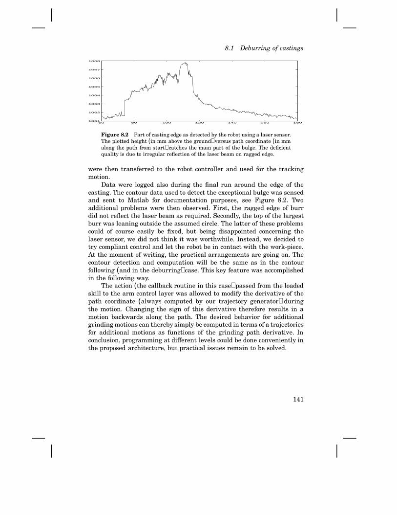
8.1 Deburring of castings
60 80 100 120 140 160 1801061
1062
1063
1064
1065
1066
1067
1068
Figure 8.2 Part of casting edge as detected by the robot using a laser sensor.The plotted height (in mm above the ground) versus path coordinate (in mmalong the path from start) catches the main part of the bulge. The deficientquality is due to irregular reflection of the laser beam on ragged edge.
were then transferred to the robot controller and used for the trackingmotion.
Data were logged also during the final run around the edge of thecasting. The contour data used to detect the exceptional bulge was sensedand sent to Matlab for documentation purposes, see Figure 8.2. Twoadditional problems were then observed. First, the ragged edge of burrdid not reflect the laser beam as required. Secondly, the top of the largestburr was leaning outside the assumed circle. The latter of these problemscould of course easily be fixed, but being disappointed concerning thelaser sensor, we did not think it was worthwhile. Instead, we decided totry compliant control and let the robot be in contact with the work-piece.At the moment of writing, the practical arrangements are going on. Thecontour detection and computation will be the same as in the contourfollowing (and in the deburring) case. This key feature was accomplishedin the following way.
The action (the callback routine in this case) passed from the loadedskill to the arm control layer was allowed to modify the derivative of thepath coordinate (always computed by our trajectory generator) duringthe motion. Changing the sign of this derivative therefore results in amotion backwards along the path. The desired behavior for additionalgrinding motions can thereby simply be computed in terms of a trajectoriesfor additional motions as functions of the grinding path derivative. Inconclusion, programming at different levels could be done conveniently inthe proposed architecture, but practical issues remain to be solved.
141

Chapter 8. Applications
8.2 Spot welding
Spot welding is a task well suited for industrial robots. As the applicationhas become mature, the performance demands have become clearer. Com-petition and benchmark tests (made by major car manufacturer) are fur-ther reasons. Customers make performance evaluations because the timeneeded to weld a spot, including the move to the spot and the closing ofthe weld-gun, is of major importance for the applicability and economicalpay-off.
The need to tightly connect the motion control system with the timingof the control of the welding equipment, as described below, became clearto the author already around 1984 at ABB Robotics. An important carmanufacturer (SAAB) required that motions between weld-spots may nottake more than 0.4 seconds, including the time needed to control the weld-gun and the time to start and stop the welding. At that time we had toextend the built-in motion control system with special features.
Such an experience naturally inspires a more structured approach, aswas proposed by the author in 1992 [144, 150]. The SpotWare package [7]developed since then within ABB Robotics very well agrees with the pro-posed principles. Technically, the new S4 system fulfills the requirementsfor this application; the added application-specific control can subscribeon time events from the built-in trajectory generator (as specified in theRRS interface [169]).
The problem
Consider welding of some part of a car. The spots to weld are typicallyequally spaced and placed in a row along the edges of the sheet-metalparts that are to be joined. A typical distance between the weld-spots isaround 50 mm, and a typical time for the motion is (today) around 0.3seconds, which still is significant compared to the welding time.
Assume that welding of one spot is almost completed. Upon comple-tion, the robot should, as quickly as possible, open the weld-gun, moveto the next spot, and start welding. Let us call this new location spotx.Hence, the statement WELDMOVE WeldGun TO spotx is to be executed. TheWELDMOVE statement on the user level will be interpreted and a compiledfunction will be called. What are the requirements on this function?
We may call the function WeldMove. It has to be built on existingmotion primitives. It needs to use information from the basic servo loops,to handle signals from the tool, and to include other types of applicationknowledge. Some of the typical characteristics will now be given, and itshould be easy to imagine that it would be a tricky task to implement the
142
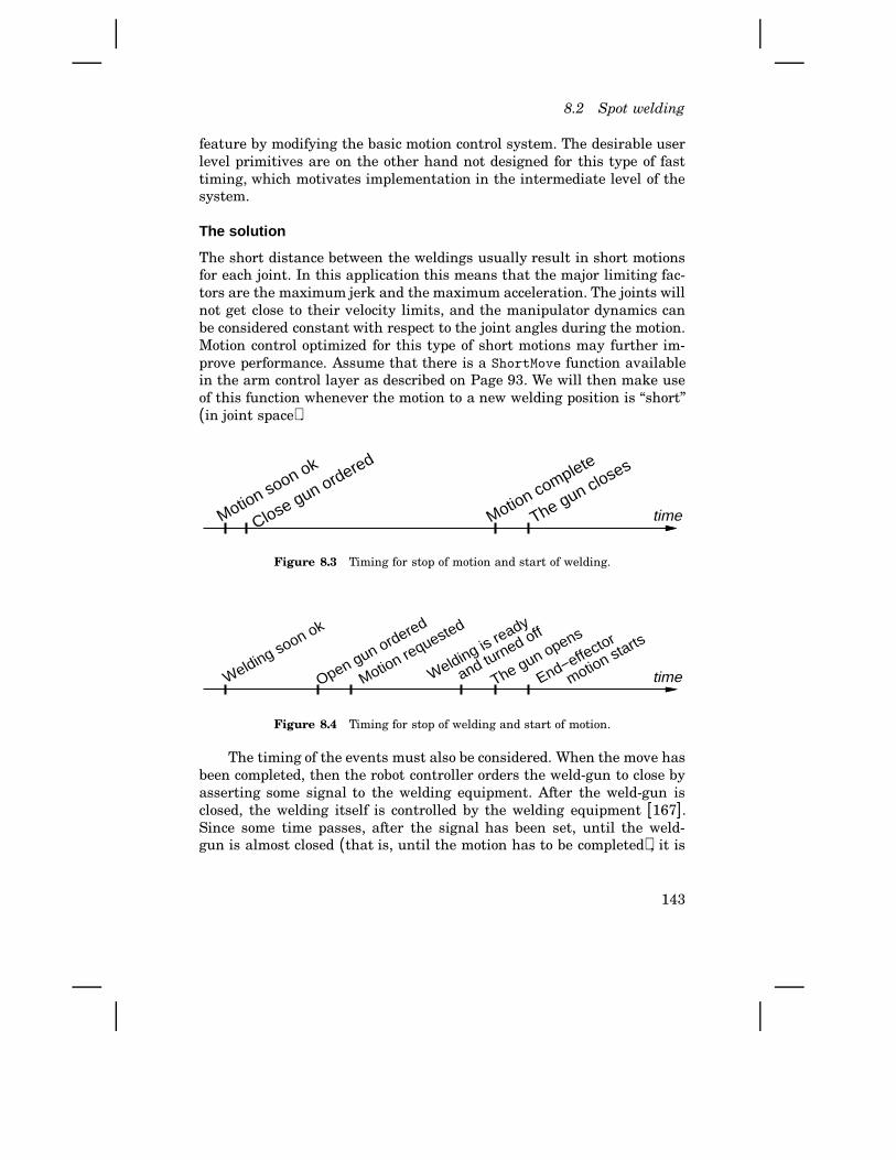
8.2 Spot welding
feature by modifying the basic motion control system. The desirable userlevel primitives are on the other hand not designed for this type of fasttiming, which motivates implementation in the intermediate level of thesystem.
The solution
The short distance between the weldings usually result in short motionsfor each joint. In this application this means that the major limiting fac-tors are the maximum jerk and the maximum acceleration. The joints willnot get close to their velocity limits, and the manipulator dynamics canbe considered constant with respect to the joint angles during the motion.Motion control optimized for this type of short motions may further im-prove performance. Assume that there is a ShortMove function availablein the arm control layer as described on Page 93. We will then make useof this function whenever the motion to a new welding position is “short”(in joint space).
timeThe gun closes
Close gun ordered
Motion complete
Motion soon ok
Figure 8.3 Timing for stop of motion and start of welding.
Open gun ordered
Motion requested
Welding is ready
and turned off
Welding soon ok
The gun opens
End−effector
motion starts
time
Figure 8.4 Timing for stop of welding and start of motion.
The timing of the events must also be considered. When the move hasbeen completed, then the robot controller orders the weld-gun to close byasserting some signal to the welding equipment. After the weld-gun isclosed, the welding itself is controlled by the welding equipment [167].Since some time passes, after the signal has been set, until the weld-gun is almost closed (that is, until the motion has to be completed), it is
143
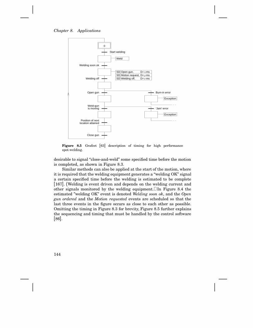
Chapter 8. Applications
D= mszWelding off,yD= msMotion request,xD= msOpen gun,
SDSDSD
Weld
Position of nextlocation attained
Exception
Exception
0
Start welding
Welding off
Welding soon ok
Burn-in error
‘Jam’ error
Close gun
Weld-gunis moving
Open gun
Figure 8.5 Grafcet [63] description of timing for high performancespot-welding.
desirable to signal “close-and-weld” some specified time before the motionis completed, as shown in Figure 8.3.
Similar methods can also be applied at the start of the motion, whereit is required that the welding equipment generates a “welding OK” signala certain specified time before the welding is estimated to be complete[167]. (Welding is event driven and depends on the welding current andother signals monitored by the welding equipment.) In Figure 8.4 theestimated ”welding OK” event is denoted Welding soon ok, and the Opengun ordered and the Motion requested events are scheduled so that thelast three events in the figure occurs as close to each other as possible.Omitting the timing in Figure 8.3 for brevity, Figure 8.5 further explainsthe sequencing and timing that must be handled by the control software[86].
144

8.3 Materials handling
8.3 Materials handling
Robots used in so called pick-and-place applications often need to identifythe presence of objects or what kind of object that is present. Also otherapplications may include sorting of pieces, thus also requiring this func-tionality. In some cases beam sensors can be used [52]. A more generalbut costly solution is to use vision systems. Another promising alternativeis ultrasonic sensors [189]. In some cases, however, there are reasons tobelieve that external sensors can be avoided by utilizing internal controlinformation.
Desired behavior
Estimation of dynamic properties using measured data is a common andimportant technique within automatic control. Several algorithms andmethods have been developed for this purpose [99]. Such system identifi-cation techniques have also been used to estimate robot arm inertias forcontrol design purposes. It is then natural to ask: Why not use systemidentification also as a way to avoid external sensors. This, of course, ap-plies to the case when the motions to grasp the objects do not depend onthe type of object. That may be the case when the objects are of similarshape, when they only differ in weight due to different materials, or whenwe want to check if an object of fixed type has been grasped or not. Theproblem today is that signals required for system/object identification, arenot possible to access from any user level of the system.
Thus, the desired behavior is that the robot after grasping an objectshould be able to identify the object, if any, only using internal (built-insensors). This feature should of course be well encapsulated and easy touse for the ordinary robot programmer, whereas the algorithms should beimplemented by the control engineer in the application layer. The end-user program may contain the following lines:
MOVE gripper TO GripPosition
WITH ...
Gripper.Close
IDENTMOVE gripper TO DropPositions[ Id ]
VIA TopPos
WITH Id = IDENT(pars, possible_parts)
CASE Id OF
NoObject : ...
where IDENTMOVE and IDENT are application specific features of the system.The parameters pars for the system identification algorithms includedata like length and magnitude of the excitation signal. Note that the
145
Chapter 8. Applications
destination in the IDENTMOVE instruction is not known when execution ofit starts. However, when the via-point is passed, the identity of the objectshould be known, and motion continues to the corresponding element ofthe position vector DropPositions[].
Prototype implementations
The proposed principle was first presented in [144]. A full implementation,proving the applicability of the concept, has more recently been carried outby others [138]. In our laboratory, system identification experiments forcontrol purposes have been carried out [129] using the developed exper-imental platform. An excitation and data logging tool (developed withinour laboratory), with a Matlab-based graphical front-end, was used forthese experiments. The tool was, however, connected directly between themotion control and the engineering workstation, and not to the user pro-gramming layers. On the other hand, successful uses of actions and ex-perience from the system identification experiments show that excitationand data logging can be conveniently controlled from outside the motioncontrol system.
Object identification controlled from the user level has been imple-mented also in our laboratory. This was done as a two weeks project byfour students (with guidance from the author) within a course in adaptivecontrol [218]. The Irb-6 robot was used, including its original analog speedcontrol (PI-mode selected, see Figure 5.1 on p. 70). The accuracy of theinertia estimation was not very good due to unmodeled dynamics (withinthe harmonic-drive gear boxes) and due to interference with the analogspeed control, but the robot was able to sort pieces depending on material(steel or aluminum). The added instructions were made compatible withthe old ABB programming language ARLA [4]. The syntax and semanticsof the instructions exposed to the end-user were therefore much simplerthan proposed above.
Another prototype experiment, illustrating that intelligent externalsensors can be used for ‘quick’ object identification, was described on Page130. With experiences from these three experiments, it is very likely thatthe proposed architecture facilitates the employment of system identi-fication as a means to avoid (unnecessary) sensor hardware for objectidentification, and also that necessary sensors can be efficiently used.
8.4 Assembly
Assembly cycle time is the key measure of the performance for an assem-bly robot. It is often too long a cycle time that is the reason for using fixed
146
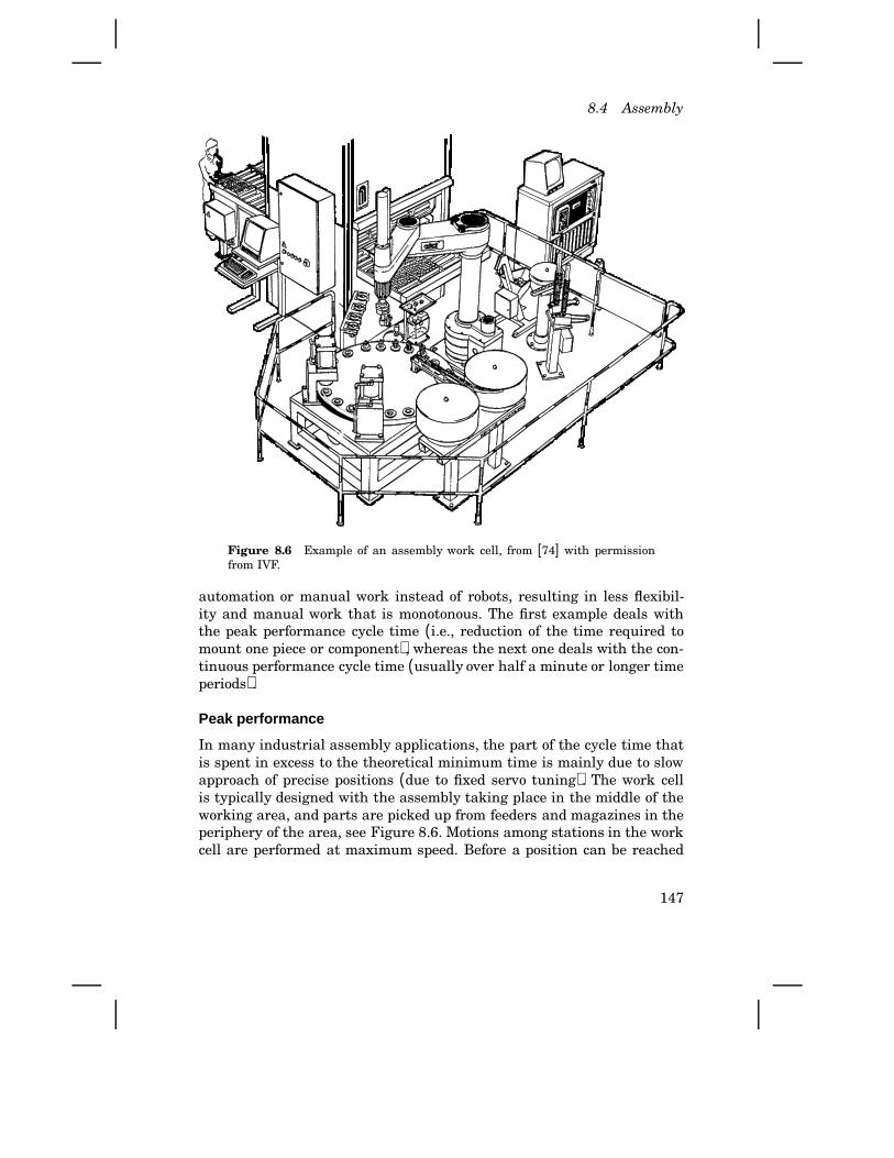
8.4 Assembly
Figure 8.6 Example of an assembly work cell, from [74] with permissionfrom IVF.
automation or manual work instead of robots, resulting in less flexibil-ity and manual work that is monotonous. The first example deals withthe peak performance cycle time (i.e., reduction of the time required tomount one piece or component), whereas the next one deals with the con-tinuous performance cycle time (usually over half a minute or longer timeperiods).
Peak performance
In many industrial assembly applications, the part of the cycle time thatis spent in excess to the theoretical minimum time is mainly due to slowapproach of precise positions (due to fixed servo tuning). The work cellis typically designed with the assembly taking place in the middle of theworking area, and parts are picked up from feeders and magazines in theperiphery of the area, see Figure 8.6. Motions among stations in the workcell are performed at maximum speed. Before a position can be reached
147

Chapter 8. Applications
accurately, the robot either has to make a smooth deceleration, or make afast deceleration and, then, a slow approaching motion. Dynamic effectsfrom the high speed motion will otherwise make the accuracy deficient.Today, it is not practically possible to have the servo so accurately tunedthat a fast motion can end directly at the desired final point. Such a tuningwould be dependent on pay-load, actuator and gear temperature (whichin turn depend on the task, time, ambient temp.), etc.
Control problems with time-varying unknown parameters are some-times approached with adaptive control [102]. This means, however, thatthe servo parameters will vary during motion, and depend on recent mo-tions. Hence, adaptive control for industrial robots requires special care,as repetitive accuracy is very crucial. Another approach is to apply autotuning [102] of the servo in one or a few critical locations of the workspace.The request for auto tuning should be issued from the user program, typi-cally when the robot is idle, waiting for new work pieces. Request for suchtuning in the end-user program may look like the following few lines:Gripper1.Close -- Holding bolt now
MOVE gripper1 TO AssemblyPos
BoltTuning = AUTOTUNE(ShakyPath)
where the AUTOTUNE primitive should be implemented in the applica-tion layer (by the control engineer). The computed control parametersBoltTuning may then be utilized in move instructions like:MOVE gripper1 TO InsertBoltPos
WITH SPEED=Vmax
WITH TUNING=BoltTuning
There will of course be several tunings for the different work pieces andfor the different locations. User access to auto tuning and use of the taskspecific control parameters should be supported by the control systemsoftware.
Overall performance
Time optimized assembly operations sometimes have a problem: The ther-mal load of the motors gets too high. The problem is that “time optimal”,i.e., torque demanding, motions sometimes need energy saving modifica-tions. The nominal torque demanding motion can be developed with for-mal methods [42], or interactively by an experienced robot programmer,as well as the modifications can. Assume that we can detect for whichjoints there is a risk for overload, and that we program modified motionsfor those cases. How should then the proper motion be selected duringexecution of the robot program? The temperatures of the actuators areneeded in the program to select the right motion. Adding thermal sensors
148
8.4 Assembly
on the actuators can be difficult and expensive. Built-in sensors used forprotection of the motors are typically of on-off type. In our experimentalIrb-2000 system we can access the output of these sensors, but that isnormally not possible. Furthermore, for safety reasons, the robot is emer-gency stopped when overheat is detected, so the outputs from the built-insensors only supplies information when it is too late.
It would on the other hand be quite easy to reconstruct the motortemperature from the torque reference, if the software architecture al-lows proper access to the signals required. Experience from the ABB S2system, which uses analog simulation built into the drives to simulatethe motor temperature, shows that this can be quite accurate if the am-bient temperature is known. The dynamic model is basically a first orderlow pass filtering of the difference between the environmental tempera-ture and the square root of the integral of the squared torque signal. Themodel can easily be calibrated by running the robot to emergency stopcaused by thermal overload. The executive layer must make it possibleto use the thermal load estimate in a convenient way on the user level,e.g., by simply supplying a predefined variable or procedure as for anysensor. If the built-in motion control does not contain motor temperatureestimation, it should be possible to add from the application layer of thesystem.
Suggested approach
Our desire to apply explicitly requested auto-tuning to improve peakperformance is a straight forward extension of the principles used in thematerials handling application. Specifically:
• The same control signals are needed. Access to those signals wasshown, in previous application, not to be any problem.
• Computation of control parameters from measured data is a pure al-gorithmic problem. Deficient availability of CPU resources and servocontrol parameters may impose some restrictions, but implementa-tion only has to deal with algorithms within the application layer.Thus, there are no restrictions imposed by the proposed architecture.
• Features admitting the end-user to obtain and use several sets oftuned parameters can be implemented in several ways. One simplealternative has been successfully implemented [218].
• The built-in motion control must support on-line change of controlparameters as specified on Page 93. This is standard, using our multi-layered parameter interface mentioned on Page 108. Such parameterchanges are even possible in the Adept system [9].
149

Chapter 8. Applications
The system requirements for the overall performance problem is a spe-cial case of the peak performance problem; only the torque signals areneeded, estimation is a simple function, and the obtained informationonly needs to be propagated to higher levels. Therefore, the proposed lay-ered architecture appears to be well suited for special application supportas desired.
8.5 Arc welding
There are several needs for intermediate level programming within arc-welding applications. The following situations have been studied:
Basic functionality: A basic application package for arc welding in-cludes control and programming features for waving motions andcontrol of the welding equipment and interfaces to common types ofwelding equipments. The ArcWare package [5] developed within ABBRobotics is an example of well designed software for this purpose.
Path tracking: Available industrial systems most often also supportweld-seam-tracking using a laser-scanner sensor. The sensor is thenintegrated with the motion control system, but this can so far onlybe done by the robot manufacturer (because available systems do notprovide an open application layer). The path tracking control prob-lem includes estimation of the weld seam based on (often very noisy)data from the laser scanner, and control of robot motion in such a waythat the seam is tracked. The stochastic nature of the problem, andthe desire to perform high-speed welding of thin-sheet metal withoutloosing track of the seam, motivates a minimum risk approach [78].The path-tracking problem was also described by the author in [144].
Welding specific functionality: Arc-welding is a quite complex elec-trical, mechanical, and chemical process which can be influenced byvoltages, currents, and weld-tool motions. For special materials, orfor welding with special demands on qualities or productivity, specialwelding principles have been developed [11]. Sensing and control (ofvoltages, currents, weld-joint geometry, etc.), and a close interactionwith the robot motion control are of key importance.
Task level programming: Even if on-line programming in this thesisis claimed to be superior concerning operator adjustments (Chapter3), it is also realized that the initial programming of, for instance,advanced arc-welding programs are often better done off-line. That isbecause CAD data for the work-pieces can be used for the definition
150

8.5 Arc welding
of welding paths and end-effector orientations. The off-line program-ming system also provides a platform for task-level programming us-ing knowledge-based techniques. So far this does not imply any needfor intermediate level control, but our desire to use “hand-craftedagents” (as described in Chapter 4) does. Special welding techniquesaccording to the previous item should be possible to load and refer tofrom the task-level system.
There are no known indications that the proposed control system designshould not suit the needed basic functionality and path tracking, but noimplementation has been done and these aspects are therefore omittedhere. Furthermore, industrially available systems can handle these items.Instead, let us focus on the desired “Welding specific functionality” andon the “Task-level programming”.
Thus, we want a system admitting incorporation of welding control atan intermediate level (here, in the application layer), and an on-line con-nection to a task-level programming system. The welding control shouldbe possible to define and install from the task-level system, and it shouldbe possible for motion commands from the task-level system to utilize theloaded welding skill.
Implementation status
Efforts to support advanced arc-welding was inspired by the welding ex-perts within the next-door laboratory at the Department of ProductionEngineering. Implementations were done in close collaboration. This ac-tivity is ongoing. At the moment of writing, the status is the following.
Techniques for control of special welding has been developed and ex-perimentally verified within the Department of Production engineering[11]. Because available systems are not open enough, such research adds
Laserscanner
WeldingprocessWelding
ArcWelding
Powercontrol
Robot
observer
system
observer
commandWelding
control
Exe
cutiv
e
HardwareMotion control
(built-in)
Application control
Welding result20 Hz
1 kHz
0.1-1 kHz
5 kHz
20 Hz
Actual welding
Figure 8.7 Block scheme interpretation of welding control according to [11].
151
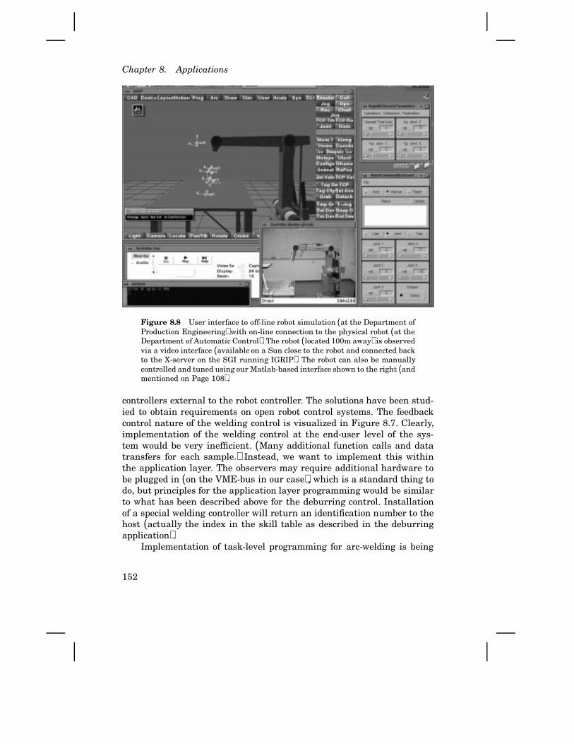
Chapter 8. Applications
Figure 8.8 User interface to off-line robot simulation (at the Department ofProduction Engineering) with on-line connection to the physical robot (at theDepartment of Automatic Control). The robot (located 100m away) is observedvia a video interface (available on a Sun close to the robot and connected backto the X-server on the SGI running IGRIP). The robot can also be manuallycontrolled and tuned using our Matlab-based interface shown to the right (andmentioned on Page 108).
controllers external to the robot controller. The solutions have been stud-ied to obtain requirements on open robot control systems. The feedbackcontrol nature of the welding control is visualized in Figure 8.7. Clearly,implementation of the welding control at the end-user level of the sys-tem would be very inefficient. (Many additional function calls and datatransfers for each sample.) Instead, we want to implement this withinthe application layer. The observers may require additional hardware tobe plugged in (on the VME-bus in our case), which is a standard thing todo, but principles for the application layer programming would be similarto what has been described above for the deburring control. Installationof a special welding controller will return an identification number to thehost (actually the index in the skill table as described in the deburringapplication).
Implementation of task-level programming for arc-welding is being
152

8.6 The inverted pendulum benchmark problem
done based on the IGRIP [65] off-line programming system. Results so farare presented in [48]. An on-line connection between the task-level systemand the robot was needed. Using the features of the ORC architecture andour experimental robot control system, this was accomplished as follows:
• The SHLIB in IGRIP was extended with functions that during robotsimulation transmitted the robot joint trajectories to the Hardwareinterface, see Figure 3.12 (p. 42). The actual hardware interface waslocated 100 meters away in our laboratory. The IGRIP part of theinterface is based on UNIX sockets connected to Internet.
• A server running on a workstation in our laboratory was developed.This server connects the off-line system to the embedded controlsystem whenever these clients are available and responding properly.
• All control engineering tools and operator interfaces running on ourSun workstations could be used directly also on the SGI workstation,as shown to the right in Figure 8.8. This is thanks to UNIX and theX-windows.
• An IGRIP server for the embedded controller was developed. Thisserver is installed at run-time into the executive layer. The server ac-cepts trajectories from IGRIP as robot commands. Call of embeddedsystem primitives from the IGRIP system is accomplished by escapecodes (negative numbers) in the time column of a supplied trajectory.One such code is used to refer to robot skills loaded into the applica-tion layer. (The identity of the skill is supplied as the second numberof the trajectory sample.)
• Video cameras, a frame grabber in the Sun workstation, and theSunVideo software were used to remotely observe the robot motions.
Though Internet-based teleoperation of the robot is possible, it is hard torely on dynamic feedback information transmitted through the networkdue to the often quite limited data rate (bandwidth). Actually, to speedup the video interface, a dedicated 10 Mbit/s connection was purchased.The simpler Irb-6 robot has been used for the initial tests, see Figure 8.8,but the Irb-2000 is to be used in the future. Experience from initial testsindicate that the ORC architecture and the experimental system form avery good platform for task-level programming.
8.6 The inverted pendulum benchmark problem
Motivated by our study of principles, robot skill has been used as aqualitative term in this chapter. It is of course desirable to also put
153
Chapter 8. Applications
some kind of measure on the skill. Such a measure will, however, verymuch depend on the specific application. Furthermore, we primarily wantto measure how well a robot control system supports incorporation ofapplication specific control. For this purpose it is interesting to consider awell defined control problem capturing important properties of industrialapplications. For this purpose, the inverted pendulum benchmark problemwas suggested on Page 13.
For some defined magnitude of disturbances, and with the require-ment that the pendulum control should be possible to add without chang-ing the built-in motion control, the minimum length of a balanced pendu-lum will be a measure of the performance that application engineers canachieve. A system not permitting external loops to be closed tightly to-gether with the built-in motion control will be less useful; sampling rates,response times, and high data flows will limit the performance (if thehardware has not been oversized).
Pendulum control has been carried out within our department [26].Implementation of the control using the experimental Irb-2000 system iscurrently going on. We decided to build a pendulum that can be graspedby the robot using an ordinary gripper. At the moment of writing, manu-facturing of both the pendulum and the gripper are about to be completed.
8.7 Industrial d evelopment
Most robot applications today are programmed on top of a fixed and closedmotion control system, possibly using sensors to determine what motion todo (as described in Section 2.4). In recent years, however, there has beensome industrial development towards open systems. This developmentwill now be shortly described, and then we will put the development ofapplication specific motion control into an industrial context.
Systems
Our approach to let the advanced user introduce application specific feed-back control may, of course, be achieved by using a completely open sys-tem. But, for reasons explained in Chapter 4, let us use an industriallycompatible approach here. Ideally, an industrially available system wouldadmit us to introduce the required control in an efficient way. Two of themost promising systems used in industry today are available from ABBRobotics and from Adept Inc. These systems are programmed in RAPID[6] and in AIM/V+ [181, 10, 9] respectively.
The Adept system is flexible in several ways. The control system canbe reconfigured for different mechanical manipulators, and parameters
154
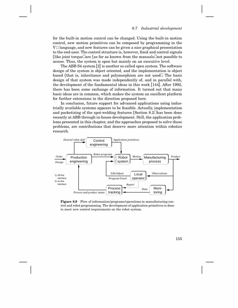
8.7 Industrial development
for the built-in motion control can be changed. Using the built-in motioncontrol, new motion primitives can be composed by programming in theV+ language, and new features can be given a nice graphical presentationto the end-user. The control structure is, however, fixed and control signals(like joint torque) are (as far as known from the manuals) not possible toaccess. Thus, the system is open but mainly on an executive level.
The ABB S4 system [2] is another so called open system. The softwaredesign of the system is object oriented, and the implementation is objectbased (that is, inheritance and polymorphism are not used). The basicdesign of that system was made independently of, and in parallel with,the development of the fundamental ideas in this work [144]. After 1992,there has been some exchange of information. It turned out that manybasic ideas are in common, which makes the system an excellent platformfor further extensions in the direction proposed here.
In conclusion, future support for advanced applications using indus-trially available systems appears to be feasible. Actually, implementationand packetizing of the spot-welding features (Section 8.2) has been donerecently at ABB through in-house development. Still, the application prob-lems presented in this chapter, and the approaches proposed to solve theseproblems, are contributions that deserve more attention within roboticsresearch.
Process and product status
interface
1) off-line
2) on-lineinterface
Production
Program/Teach
Motion
Edit/Adjust Observations
Report
engineering
Control
Product
Localoperator
Moni-toring
systemRobot
processManufacturing
Processtracking
Design
Robot programsOrder
Data
engineering
2
1
Application primitivesDesired robot skill
Figure 8.9 Flow of information/programs/operations in manufacturing con-trol and robot programming. The development of application primitives is doneto meet new control requirements on the robot system.
155
Chapter 8. Applications
Industrial development of application primitives
Development and modification of robot programs were given a controlinterpretation is Section 3.4, where robot programs only utilized standardmotion primitives in the control system. The application examples in thischapter, on the other hand, are all preferably solved by introducing controlloops (or processing of control signals) in tight connection with the built-in motion control. How does this relate to the situation shown in Figure3.6 (p. 30)?
Needs for new application specific control result from production en-gineering. Alternative solutions may be do develop special machines, orspecial end-effectors for standard robots. Development of special motioncontrol of course requires a control engineering activity. Here, that resultsin control solutions that make the robot more skilled for the particularapplication or task. The approach has been to let the advanced user accom-plish this by developing new application primitives. Figure 8.9 illustratesthe development process, which now also includes control engineering. Inthe ORC architecture, it is the application layer (Figure 4.4, p. 57) thatprovides the programming interface for such application specific control.
8.8 Summary
Some case-studies of typical industrial applications have been carried outin this chapter. This was done with the focus on possible benefits of a closeinteraction between robot programming and robot motion control. Fromthe results obtained, we can with some confidence conclude the following:
• Limitations in industrially available robot control systems today re-strict the applicability of industrial robots.
• A control system may technically provide the features required tosolve an application problem, like spot welding, but lack of well de-fined programming interfaces (user views) and supporting tools re-strict development to take place in-house (that is, still done by therobot manufacturer). By contrast, the proposed ORC architectureseems to provide appropriate features and programming views. Ofcourse, it is far from being a product.
• Further development, in directions proposed here, of the new S4system from ABB appears to be feasible.
• An open and powerful experimental system, like the one presented inChapter 5, is of key importance for prototyping of application specificcontrol.
156

8.8 Summary
Several of the application demands presented are to some extent knownby engineers in industry. Nevertheless, these aspects have most oftenbeen overlooked within robot programming research. We can thereforesummarize the contributions of this chapter as:
• The problem formulations concerning application specific motion con-trol are contributions in themselves.
• It was shown how the ORC architecture supports implementation ofsuch control.
• It was described how use of control signals in the built-in motioncontrol can be utilized to avoid external equipment and sensors, andthereby also achieving tighter external control loops.
• It was described how system identification, auto-tuning, and adaptivecontrol should be handled to obtain performance, functionality, andprogrammability of the robot.
• A connection of a task-level/off-line programming system to a robotsystem was done. The unique property is that new application prim-itives can be installed from the engineering workstation (via a sep-arate network connection) into the embedded robot controller, thusextending the capabilities of the task-level system.
• The development of application specific motion control was put intoan industrial perspective.
Thus, open multi-layered robot control systems with well defined program-ming interfaces are of key importance for the applicability of industrialrobots.
157
9
Conclusions
We can now sum up the contributions of this thesis, and propose directionsfor further research. But first, the background, motivation, and approachof the work is recalled for the reader using this chapter as a summary ofthe thesis.
Summary of topics and industrial relevance
Industrial robots play a key role in flexible manufacturing systems. Thesoftware in a robot control system contains a software level for simpleend-user (re)programming, and a software level for efficient computationof the low-level control. It turns out that application programming ofmany applications implies the need for an intermediate software levellinking these two levels. Such an intermediate level must handle aspectssuch as dynamic effects, sensor integration, timing between the robot,its equipment, and external equipment, and so on. These robot functionsare favorably hand crafted due to effects like dynamics, part tolerance,physical characteristics such as friction or stiction, and the like.
Also on the end-user programming level, there are problems that hin-der improvements of manufacturing practices. Such a problem is deficientintegration of engineering style (off-line) programming and productionstyle (on-line) robot programming. Another problem is lack of program-ming language support for special applications.
High performance low-level servo control is important for productiv-ity and high utilization of the equipment. This has inspired extensiveresearch within robot motion control. Even if more remains to be done,many research results have been presented. Industrial usage has, how-ever, been limited. First, it is hard for the robot manufacturer to in-troduce new concepts in a controller that is highly optimized for currentmain applications. Secondly, such motion controllers form closed systems,i.e., new control solutions based on feedback from external sensors (or
158
internal states) cannot be externally defined. Third, suitable experimen-tal systems based on modern and commonly used industrial manipulatorshave not been available to the academic research, and industrial demandson programmability, efficiency and a partly closed structure have not beenobserved until now.
With a background from industrial robot development, the purpose ofthis thesis project was to tackle the above problems concerning the controlprinciples, the structure of the system, and the programming methods.That would hopefully lead to more applicable robots and less repetitiveand monotonous manual work. Note, however, that the purpose is notto replace all manual task by fully automated manufacturing plants. In-stead, the desire is to have machines that allow human friendly industrialwork.
Contributions
In order as presented, the contributions of the thesis are:
• The analysis and the control interpretation of end-user robot pro-gramming. Integrated on-line and off-line programming allows anefficient cascade control type of production control.
• The proposed technique for transformation of robot programs, usingincremental tools from computer science, is novel in this context.
• The problem of physical context sensitivity and the need for supportfrom the on-line programming language were identified. An approachand a system for full implementation were developed.
• Existing control system architectures were investigated, and the newOpen Robot Control (ORC) architecture was proposed. ORC definesuser/programmer views of the system.
• A unique experimental platform based on widely used industrialrobots has been developed. This makes it easy to perform controlexperiments using a modern and industrially relevant robot dynam-ics. It has also been connected to a test-level programming system forarc welding, thus making that research possible.
• Improvements and extensive verification of the used public domainreal-time platform developed within the department, makes the ex-perimental environment even more attractive for research and teach-ing. New tools for parameter handling and control signal logging werealso developed.
• The employment of high-level principles for special purpose hard-ware, and for its interaction with other types of CPUs, was tested. A
159
Chapter 9. Conclusions
special object design and compiling strategy were fully implementedand successfully used.
• The performed multi-processor implementation of robot motion con-trol illustrates how heterogeneous real-time software and hardwarecan be combined to efficiently execute different parts of the controlalgorithms.
• To accomplish an appropriate blend between efficiency and flexibilityin embedded control systems, a concept called actions was introduced.The associated operator here means a piece of compiled code that issent as an executable control function between different parts of thecontroller, typically using different address spaces and CPU types.
• Based on the use of actions and an appropriate software design, anopen motion controller was proposed. Built-in control algorithms canstill be mainly closed. It is, however, open in the sense that the low-level servo control can be tailored to special application demands, andexternal control loops can be tightly connected to it.
• Some industrial applications that can benefit from application specificmotion control were presented. The way such applications can besolved using the proposed principles is a major contribution.
Apart from being directly applicable to robot control systems, several ofthese contributions are also useful for other type of control or embeddedsystems.
Reflections
The physical characteristics of industrial manipulators, which are ratherprecise but not perfect, influence many of the design choices. If industrialrobots were almost perfect, like NC machines, a fixed servo system witha robot independent motion description system or planning system on topof it would suffice. Such a system structure is, however, currently usedfor industrial robots, despite certain drawbacks that were discussed inthe thesis.
The other extreme case is autonomous mobile robots dealing with avery uncertain environment, e.g. in space applications. Such robots mustbe careful and therefore also slow. They rely heavily on external sensorsand maintenance of a world-model data base. The software architecturesare designed to support high level (often AI related) software concepts,and with no special coupling to the low level control.
Industrial robots, however, typically operate in a well known, but notcompletely known, environment. External sensors and internal controlsignals reflect external states that often need to be known at both high
160

and low levels of the control system. A typical situation is when a robot isused for welding or grinding. Software for industrial manipulators musttherefore provide for a strong interplay between user level commands,sensor signals, and low level control. This interplay is crucial to obtainflexibility and performance, but also to avoid the cost of otherwise neces-sary external sensors. The software architecture suggested in the thesispays careful attention to these issues.
Future work
Further research and development should preferably start by makinga more product-like experimental system. A second generation circuitboards including some improvements would promote general usage. Asoftware module containing the latest generation software from ABBRobotics, extended by some RPC servers to make it more open, wouldbe valuable. Such a system would allow full industrial evaluation of theproposed control system and programming principles.
Furthermore, formal abstraction and specification methods of thestructuring principles encountered may prove fruitful both for mathe-matical capacity analysis (in the section of discrete-event systems andfeedback control systems) and for standardization purposes.
Further development of control algorithms and control engineeringtools is, of course, very important. First, the robot and its external axesneed improved performance and simplified tuning. Secondly, combinedposition/force control, including programming and tuning, needs furtherenhancements to be generally applicable. These problems are the subjectto ongoing control research, but its incorporation into an industriallyuseful system should perhaps be more emphasised. Such control strategieswould ease full implementation of new strategies for deburring, welding,etc.
Thus, the contributions and some further development in this direc-tion will hopefully lead to more flexible and efficient industrial robots,making human-friendly industrial work possible as desired.
161

References
[1] ABB CORPORATE RESEARCH, DEPT. OF AUTOMATIC CONTROL, LUND,SWEDEN. Knowledge-Based Real-Time Control Systems. IT4 Project:Phase II, 1991.
[2] ABB FLEXIBLE AUTOMATION, S-721 68 Västerås, Sweden. ProductManual Robot Control System S4.
[3] ABB FLEXIBLE AUTOMATION, S-721 68 Västerås, Sweden. Servicemanual Irb-2000/3.
[4] ABB FLEXIBLE AUTOMATION, S-721 68 Västerås, Sweden. Program-ming Manual Robot Control System S3, 1991. Art. No. 6397 013-129.
[5] ABB FLEXIBLE AUTOMATION, S-721 68 Västerås, Sweden. ArcWareUser’s Guide, 1995. Art. No. 3HAB 0011-13.
[6] ABB FLEXIBLE AUTOMATION, S-721 68 Västerås, Sweden. RAPIDUser’s Guide, 1995. Art. No. 3HAB 0002-24.
[7] ABB FLEXIBLE AUTOMATION, S-721 68 Västerås, Sweden. SpotWareUser’s Guide, 1995. Art. No. 3HAB 0002-24.
[8] H. ABELSON, G. H. SUSSMAN, and J. SUSSMAN. Structure and In-terpretation of Computer Programs. MIT Press, Cambridge, Mas-sachusetts, 1985.
[9] ADEPT TECHNOLOGY INC., San Jose, CA, USA. AdeptMotion Servo.
[10] ADEPT TECHNOLOGY INC., San Jose, CA, USA. AIM Users Guide,1991.
[11] B. ÅGREN. Sensor Integration for Robotic Arc Welding. PhD thesisTMMV-1023, Lund Inst. of Technology, Lund, Sweden, Departmentof Production and Materials Engineering, 1995.
162

[12] A. V. AHO, R. SETHI, and J. D. ULLMAN. Compilers, Principles,Techniques, and Tools. Addison Wesley, Reading, Massachusetts,1985.
[13] S. A. ALBUS, H. G. MCCAIN, and R. LUMIA. “NASA/NBS standardreference model for telerobot control system architecture (NAS-REM).” Technical Report Technical Note 1235, U.S. Nation Bureauof Standards, 1987.
[14] ANALOG DEVICES. Variable Resolution, Monolithic Resolver-to-Digital Converter (AD2S80), 1992.
[15] R. J. ANDERSON. “Smart: A modular architecture for robotics andteleoperation.” In IEEE Conference on Robotics and Automation,Atlanta, pp. 416–421, May 1993.
[16] J. ANDERSSON. “Ett öppet system för programmering och styrningav robotar,” (An open system for robot programming and control).Master thesis ISRN LUTFD2/TFRT--5557--SE, April 1996.
[17] L. ANDERSSON and A. BLOMDELL. “A real-time programming en-vironment and a real-time kernel.” In ASPLUND, Ed., NationalSwedish Symposium on Real-Time Systems, Technical Report No 301991-06-21. Dept. of Computer Systems, Uppsala University, Upp-sala, Sweden, 1991.
[18] L. ANDERSSON and A. BLOMDELL. “A real-time programming envi-ronment and a real-time kernel.” In National Swedish Symposiumon Real-Time Systems, 1991.
[19] R. L. ANDERSSON. “Computer architectures for robot control: Acomparison and a new processor delivering 20 real Mflops.” In IEEEInternational Conference on Robotics and Automation, 1989.
[20] R. L. ANDERSSON. “System design for robot control with a scalarsupercomputer.” In IEEE International Conference on Robotics andAutomation, pp. 1210–1215, Cincinnati, OH, May 1990.
[21] P. ANELL. “Modeling of multibody systems in Omola.” Master the-sis ISRN LUTFD2/TFRT--5516--SE, Department of Automatic Con-trol, Lund Institute of Technology, Lund, Sweden, September 1994.
[22] APPLE COMPUTER INC. Inside Macintosh, volume I. Addison-Wesley,1985.
[23] APPLE COMPUTER INC. OpenDoc for Macintosh, An Overview fordevelopers, 1994.
[24] ARCHITECTURE TECHNOLOGY CORPORATION, P.O.Box 24344 Min-neapolis, Minnesota 55424, USA. Flexible Manufacturing Systems,4 edition, September 1991.
163
Chapter 9. References
[25] J. ARMSTRONG, R. VIRDING, and M. WILLIAMS. Concurrent Program-ming in Erlang. Prentice Hall, 1993.
[26] K. J. ÅSTRÖM and J. EKER. “A nonlinear observer for the invertedpendelum.” In Submitted to the IEEE Conference on Control Ap-plications, 1996.
[27] K. J. ÅSTRÖM and K. FURUTA. “Control principles with applicationsto pendelums.”. Under preparation., 1995.
[28] K. J. ÅSTRÖM and T. HÄGGLUND. PID Controllers: Theory, Design,and Tuning. Instrument Society of America, Research TrianglePark, NC, second edition, 1995.
[29] K. J. ÅSTRÖM and B. WITTENMARK. Computer Controlled Systems—Theory and Design. Prentice-Hall, Englewood Cliffs, New Jersey,second edition, 1990.
[30] AT&T. Cfront – a C++ Translator, 1990.[31] AT&T. DSP32C Digital Signal Processor - Information manual,
January 1990.[32] THE AT&T DOCUMENTATION MANAGEMENT ORGANIZATION. WE
DSP32 and DSP32C C Language Compiler User Manual, 1988.[33] ABB FLEXIBLE AUTOMATION Discussion with Åke Madesäter (re-
sponsible for Customer Focus), September 1995.[34] A. J. BARBERA. An architecture for a robot hierachical control sys-
tem. U.S. Department of Commerce, National Bureau of Standards,Special publication 500-23, Washington, D.C. 20234, USA.
[35] A. E. BEJCZY. Parallel Computation Systems for Robotics Algor-tihms and Architecture. New York: World Scientific, 1992.
[36] A. BENVENISTE and G. BERRY. “The synchronous approach to reac-tive and real-time systems.” Proceedings of the IEEE, 79:9, 1991.
[37] D. G. BIHN and T. C. S. HSIA. “Universal six-joint robot controller.”Control Systems Magazine, February, February 1988.
[38] R. BIRD and P. WADLER. Introduction to Functional Programming.Prentice Hall Int (UK), 1988.
[39] E. BJARNASON and G. HEDIN. “A grammar-interpreting parser in alanguage design laboratory.” Technical Report, Department of Com-puter Science, Lund University, Sweden, September 1995. Draftsubmitted to CC’96.
[40] H. W. BLACK. “Stabilized feedback amplifiers.” Bell Syst. Tech. J.(and US patent 2102671, 1927), 13, pp. 1–18, 1934.
[41] C. BLUME and W. JAKOB. Programming Languages for IndustrialRobots. Springer-Verlag, Heidelberg-Berlin, 1986.
164

[42] J. BOBROW, S. DUBOWSKY, and J. GIBSON. “Time-optimal control ofrobotic manipulators along specified paths.” International Journalof Robotics Research, 4:3, pp. 3–17, 1985.
[43] G. S. BOLMSJÖ. Industriell Robotteknik. Studentlitteratur, Lund,Sweden, 1989. In Swedish.
[44] G. BOOCH. Object Oriented Design with Applications. The Ben-jamin/Cummings Publishing Company, Redwood City, CA, 1991.
[45] M. BRADY, J. M. HOLLERBACH, T. L. JOHNSON, T. LOZANO-PÉREZ,and M. T. M. (EDS.). Robot Motion. MIT Press, Cambridge, Mas-sachusetts, 1982.
[46] H. BRANTMARK and I. REYIER. “Implementation of application ori-ented function packages in a robot control system.” In InternationalSymposium on Industrial Robots (ISIR), 1995.
[47] R. BRAUN, L. NIELSEN, and K. NILSSON. “Reconfiguring an ASEAIRB-6 robot system for control experiments.” Report TFRT-7465,Department of Automatic Control, Lund Institute of Technology,Lund, Sweden, October 1990.
[48] K. BRINK. Event-based Control of Industrial Robot Systems. LicTech thesis, Lund Inst. of Technology, Lund, Sweden, Departmentof Production and Materials Engineering, 1996.
[49] K. BRINK, M. OLSSON, and G. BOLMSJÖ. “Event based robot control.”In The first ECPD International conference on Advanced Roboticsand Intelligent Automation, September 1995.
[50] R. BROOKS. “A layered control system for a mobile robot.” IEEEJournal of Robotics and Automation, 2:1, pp. 14–23, 1986.
[51] H. V. BRUSSEL and W. PERSOONS. “Robotic deburring of small seriesof castings.” In Annals of the CIRP 45/1.
[52] J. F. CANNY and K. Y. GOLDBERG. “A RISC approach to sensing andmanipulation.” In Manuscript submitted for publication, Dept. ofComputer Science, UC Berkeley, USA, 1995.
[53] S. CASELLI, E. FALDELLA, and F. ZANICHELLI. “Performance evalua-tion of processor architectures for robotics.” In Compeuro, pp. 667–671. IEEE, 1991.
[54] S. CAVALIERI, A. D. STEFANO, and O. MARIBELLA. “Pre-run-timescheduling to reduce schedule length in the fieldbus environment.”IEEE Transactions on Software Engineering, No 11, November1995.
165
Chapter 9. References
[55] S. CHAMBERLAIN and R. PESCH. Using LD, the GNU linker.Free Software Foundation, Inc. and Cygnus Support, URL:http://www.cygnus.com/library/ld/ld toc.html, March 1993.
[56] R. CHATILA and S. Y. HARMON, Eds.. Workshop on architecturesfor intelligent control systems. IEEE International Conference onRobotics and Automation, 1992.
[57] W. F. CLOCKSIN and C. S. MELLISH. Programming in Prolog.Springer-Verlag, 1987.
[58] “ESPRIT 6805 COMPLAN public domain report.”. URL reference:http://www.mech.kuleuven.ac.be/pma/project/complan, July 1995.
[59] J. J. CRAIG. Introduction to robotics: mechanics and control.Addison-Wesley, second edition, 1989.
[60] O. DAHL. Path Constrained Robot Control. PhD thesis ISRNLUTFD2/TFRT--1038--SE, Department of Automatic Control, LundInstitute of Technology, Lund, Sweden, April 1992.
[61] O. DAHL. Path Constrained Robot Control. PhD thesis, Depart-ment of Automatic Control, Lund Institute of Technology, 1992.ISRN LUTFD2/TFRT––1038––SE.
[62] O. DAHL and L. NIELSEN. “Stability analysis of an on-line algorithmfor torque limited path following.” In Proceedings of the 1990 IEEEInternational Conference on Robotics and Automation, pp. 1216–1222, Cincinnati, Ohio, May 13–18 1990.
[63] R. DAVID and H. ALLA. Petri Nets and Grafcet: Tools for modellingdiscrete events systems. Prentice-Hall, 1992.
[64] J. DENAVIT and R. S. HARTENBERG. “A kinematic notation for lower-pair mechanisms based on matrices.” Journal of Applied Mechanics,pp. 215–221, 1955.
[65] DENEB ROBOTICS, Detroit, USA. IGRIP Users Manual, 1995. IGRIPis a registred trademark of Deneb Robotics Inc.
[66] J. EKER and A. BLOMDELL. “A structured interactive approach toembedded control.” In Submitted to the 4th International Sympo-sium on Intelligent Robotic Systems, Lisbon, Portugal, Dept. of Au-tomatic Control, Lund, Sweden, 1996.
[67] V. J. ENG. “Modal segments for a peg insertion task.” TechnicalReport, Harvard Robotics Laboratory, 1988.
[68] A. FEDELE, A. FIORETTI, C. MANES, and G. ULIVI. “On-line process-ing of position and force measures for contour identification androbot control.” In IEEE International Conference on Robotics andAutomation, pp. 369–374, 1993.
166
[69] J. C. FIALA, R. LUMIA, and J. S. ALBUS. “Servo level algorithms forthe NASREM telerobot control system architecture.” In SPIE SpaceStation Automation III, volume 851, 1987.
[70] W. E. FORD. “What is an open architecture controller.” In 9thInternational Symposium on Intelligent Control, 1994.
[71] C. F. L. GENE H. GOLUB. Matrix Computations. Johns HopkinsUniversity Press, Baltimore, MD, 1989.
[72] GMF INC., Troy, Mich., USA. KAREL Language Reference.[73] I. GODLER, A. AKAHANE, K. OHNISHI, and T. YAMASHITA. “A novel ro-
tary acceleration sensor.” IEEE Control Systems, February, Febru-ary 1995.
[74] GRÖNDAHL ET.AL. IVF-resultat 90609. Mekanförbundet, Stockholm,Sweden, 1990. Picture from Electrolux Industrial Systems.
[75] B. GUDMUNDSSON. Virtuellt Minne. Studentlitteratur, Lund, Swe-den, 1977.
[76] N. HALBWACHS. Synchronous programming of reactive systems.Kluwer Academic Publishers, 1993.
[77] J. HALLAM. “Autonomous robots: from dream to reality.” In Proceed-ings from ’Robotikdagar’, Linköping, Sweden, May 1991.
[78] A. HANSSON and L. NIELSEN. “Control and supervision in sensor-based robotics.” In Proceedings Robotikdagar, Linköping, Sweden,1991.
[79] S. Y. HARMON. “Architectures: Designers vs. implementors.” InWorkshop on architectures for intelligent control systems. IEEEInternational Conference on Robotics and Automation, 1992.
[80] B. HAYES-ROTH, K. PFLEGER, P. LALANDA, P. MORIGNOT, and M. BAL-ABANOVIC. “A domain-specific software architecture for adaptiveintelligent systems.” IEEE Transactions on Software Engineering,March, pp. 288–301, March 1995.
[81] V. HAYWARD and R. P. PAUL. “Robot manipulator control under unix,RCCL: A robot control “C” library.” The International Journal ofRobotics Research, 5:4, 1986.
[82] G. HEDIN. Incremental Semantic Analysis. PhD thesis, Departmentof Computer Science, Lund University, Sweden, 1992.
[83] M. HEMMINGSSON. “Digital reglering av ett resonant servo medfriktion,” (Digital control of a resonant servo with friction). Masterthesis ISRN LUTFD2/TFRT--5515--SE, Department of AutomaticControl, Lund Institute of Technology, Lund, Sweden, September1994.
167
Chapter 9. References
[84] B. H. J. HENDRIKS. “Implementation of industrial robot control.”Master thesis ISRN LUTFD2/TFRT--5555--SE, March 1996.
[85] H. HIRABAYASHI, S. OHWADA, I. YOSHIDA, and M. MIKI. “Force-controlled deburring robots.” pp. 19–1 – 19–11, Production Engi-neering Research Laboratory, Hitachi Ltd., Yokohama, Japan. un-known conference.
[86] C. A. R. HOARE. Communicating Sequential Processes. PrenticeHall Int., London, UK, 1985.
[87] IBM CORP. SOMobjects Developer Toolkit, Users Guide, 2.0 edition,June 1993. An introductory guide to the System Object Model andits accompanying frameworks.
[88] INTEGRATED MOTIONS, INC., 758 Gilman St., Berkeley, CA 94710,USA. Zebra-ZERO Force Control Robot, 1992.
[89] INTERNATIONAL ELECTROTECHNICAL COMMISSION. IEC 1131-3, Pro-grammable controllers, Part 3: Programming languages, 1992.
[90] THE INTERNATIONAL ORGANIZATION FOR STANDARDIZATION (ISO),http://www.iso.ch/cate/35100.html. Open systems interconnection(OSI), 1995.
[91] THE INTERNATIONAL ORGANIZATION FOR STANDARDIZATION (ISO),TECHNICAL COMMITTEE TC184/SC2, http://www.iso.ch/. Manipulat-ing industrial robots – Intermediate Code for Robots (ICR), ISO/TR10562:1995.
[92] J. ISH-SHALOM. “Task level specification of a robot control.” InIEEE International Symposium on Intelligent Control, Philadel-phia, 1987.
[93] Y. ISHIKAWA, H. TOKUDA, and C. W. MERCER. “An object-oriented real-time programming language.” IEEE Computer, Oc-tober, pp. 66–73, October 1992.
[94] ISRA SYSTEMTECHNIK GMBH, MorneWegstraße 45A, D-6100 Darm-stadt, Germany. Robot Command & Teach Ball, 1992.
[95] IVF-KTH. Montering, idag och bortom år 2000 (Assembly, today andbeyond year 2000), Monteringsenheten, 100 44 Stockholm, Sweden,September 1995. In Swedish.
[96] I. JACOBSON. Object-Oriented Software Engineering, A Use CaseDriven Approach. ACM Press, Addison-Wesley, 1992. ISBN 0-201-54435-0.
[97] G. JOHANNESSON. Object-Oriented Process Automation with Sat-tLine. Chartwell Bratt Ltd, 1994. ISBN 0-86238-259-5.
168
[98] R. JOHANSSON. “Lund research programme in autonomous robotics.”NUTEK project 9309758, Swedish National Board for Industrialand Technical Development, 117 86 Stockholm, Sweden, 1993.
[99] R. JOHANSSON. System Modeling and Identification. Prentice Hall,Englewood Cliffs, New Jersey, 1993.
[100] R. JOHANSSON and M. W. SPONG. “Quadratic optimization ofimpedance control.” In Proc. IEEE Int. Conf. Robotics and Automa-tion, pp. 616–621, San Diego, California, May 1994.
[101] JR3 INC., 22 Harter Avenue, Woodland, CA 95695, USA. JR3 Multi-Axis Force-Torque Sensors.
[102] K. J. ÅSTRÖM AND B. WITTENMARK. Adaptive Control. AddisonWesley, 1989.
[103] H. KAZEROONI. “Automated robotic deburring using impedance con-trol.” IEEE Control Systems Magazine, February, February 1988.
[104] B. W. KERNIGHAN and D. M. RITCHIE. The C programming language.Prentice-Hall, 1978.
[105] H. K. KHALIL. Nonlinear Systems. Macmillan, 1992.
[106] R. KLEPKO and A. MALOWANY. “A rule-based hierachical robot con-trol system.” In Proceeding of the 1987 Summer Computer Simula-tion Conference, San Diego, USA, pp. 646–652, July 1987.
[107] J. L. KNUDSEN and ET.AL. Object oriented environments: the Mjolnerapproach. Prentice Hall, 1993.
[108] W. KOHN and T. SKILLMAN. “Hierarchical control systems for au-tonomous space robots.” In Proc AIAA Conf on Guidance, Naviga-tion and Control, pp. 382–390, 1988.
[109] A. J. KOIVO. Fundamentals for Control of Robotic Manipulators.John Wiley & Sons, 1989.
[110] K. KOSUGE, K. FURUTA, and T. YOKOYAMA. “A control architecturefor intelligent mechanical system: Virtual internal model followingcontrol.” In IEEE International Symposium on Intelligent Control,Philadelphia, 1987.
[111] V. KUMAR and K. WALDRON. “Adaptive gait control for a walkingrobot.” Journal of Robotic Systems, 6:1, pp. 46–76, 1989.
[112] C. S. G. LEE, R. C. GONZALEZ, and K. S. FU (ED.). Tutorial onRobotics. Number ISBN 0-8186-0658-4. IEEE Computer SocietyPress, 1986.
[113] C. S. G. LEE, T. N. MUDGE, and J. L. TURNEY. Tutorial on Robotics,chapter Hierachical control structure using special purpose proces-
169
Chapter 9. References
sors for the control of robot arms. Number ISBN 0-8186-0658-4.IEEE Computer Society Press, 1986.
[114] E. A. LEE. “Programmable DSP architectures: Part II.” IEEE ASSPMagazine, January 1989.
[115] L. I. LIEBERMAN and M. A. WESLEY. Tutorial on Robotics, chap-ter AUTOPASS: An automatic Programming System for ComputerControlled Mechanical Assembly. Number ISBN 0-8186-0658-4.IEEE Computer Society Press, 1986.
[116] J. LLOYD and V. HAYWARD. “Real-time trajectory generation in multi-RCCL.” Technical Report, McGill Research Centre for IntelligentMachines, McGill University, Montreal, Canada, April 1992.
[117] P. LOBERG and A. TÖRNE. “A layered architecture for real-time appli-cations.” In The 7:th Euromicro Conference on Real-Time Systems,Odense, Denmark. IEEE, June 1995.
[118] T. LOZANO-PÉREZ. “Robot programming.” Proceedings of the IEEE,71:7, pp. 821–841, July 1983.
[119] R. LUHRS and A. NOWICKI. “Real-time dynamic planning for au-tonomous vehicles.” In Proc DARPA Knowledge Based PlanningWorkshop, Austin TX, 1987.
[120] LUTH M4ME-81/82. “Styrsystem för industrirobot ASEA Irb-6.”Technical report 1982:31, Luleå Technical University, Luleå, Swe-den, 1982. In Swedish.
[121] B. MAGNUSSON. “Application specific real-time systems – program-ming environments.” NUTEK project 9403737, Swedish NationalBoard for Industrial and Technical Development, 117 86 Stockholm,Sweden, 1993.
[122] B. MAGNUSSON and R. HENRIKSSON. “Garbage collection for controlsystems.” In Proceedings of IWMM’95 (International Workshop onMemory Management), Kinross, Scotland, September 1995.
[123] C. MALCOLM and T. SMITHERS. “Programming assembly robots interms of task achieving behavioural modules: First experimentalresult.” Technical Report, Department of Artificial Intelligence, Uni-versity of Edinburg, 1988. DAI Research Paper no. 410.
[124] THE MATHWORKS, INC., Natick, MA. Matlab Reference Guide, 1992.
[125] THE MATHWORKS, INC., Natick, MA. Real-time workshop Usersguide, 1994.
[126] B. MAYER. Object-oriented Software Construction. Prentice Hall,1988.
170
[127] A. MAYSTEL. “Architectures for intelligent control systems.”. Dis-cussion List: [email protected], 1992-1996.
[128] S. M. MEERKOV. “MANUFACTURING SYSTEMS: Too many prob-lems..., too few solutions...”. Plenary seminar, American ControlConference, Baltimore, July 1994.
[129] J. P. MEEUWSE. “Algorithms and tools for control of flexible servosystems.” Master thesis ISRN LUTFD2/TFRT--5531--SE, Depart-ment of Automatic Control, Lund Institute of Technology, Lund,Sweden, July 1995.
[130] G. MESSINA and G. TRICOMI. “Standard programming tools forrobots.” In Proceeding of the Third international Symposium onMeasurement and Control in Robotics, Torino, Italy, September1993. IMECO Technical Committee on Robotics (TC 17).
[131] A. MEYSTEL. “Planning in a hierarchical nested autonomous controlsystem.” In Vol 727, ‘Mobile Robots’, pp. 42–76. SPIE, 1986.
[132] MICROSOFT CORPORATION. Object Linking Embedding, 1993. Version2.0.
[133] D. J. MILLER and R. C. LENNOX. “An object oriented environmentfor robot system architectures.” In IEEE International Conferenceon Robotics and Automation, 1990.
[134] M. S. MUJTABA and W. D. FISHER. “HAL, a work station based in-telligent robot control environment.” Robots 11/ISIR 17 ConferenceProceedings, 1987.
[135] S. MUJTABA and R. GOLDMAN. “AL Users’ Manual.” Technical ReportSTAN-CS-81-889, Stanford, Dept. of Computer Science, December1981.
[136] F. N-NAGY and A. SIEGLER. Engineering Fundations of Robotics.Prentice Hall, 1987.
[137] H. NASRI. A Process Model for Robotic Grinding. Lic Tech thesisTMMV-1014, Lund Inst. of Technology, Lund, Sweden, Departmentof Production and Materials Engineering, October 1992.
[138] H. NASRI and G. BOLMSJ . “Using robot dynamics for part weightmeasuring and developing search function.” Submitted to Int. J. ofIntelligent Mechatronics, 1995.
[139] E. J. NICOLSON. “Standardizing i/o for mechatronic systems (sioms)using real time unix device drivers.” In Proc. 1994 IEEE Conf.Robotics and Automation, pp. 3489–3494, 1994.
171
Chapter 9. References
[140] L. NIELSEN. “Computer implementation of control systems.” ReportTFRT-7476, Department of Automatic Control, Lund Institute ofTechnology, Lund, Sweden, May 1991.
[141] K. NILSEN. “Real-Time Java.” Technical Report, Iowa State Univer-sity, Ames, Iowa, USA, February 1996.
[142] B. NILSSON. Object-Oriented Modeling of Chemical Processes. PhDthesis ISRN LUTFD2/TFRT--1041--SE, Department of AutomaticControl, Lund Institute of Technology, Lund, Sweden, August 1993.
[143] K. NILSSON. “Analys och syntes av en industrirobots dynamik.”.Master’s thesis, Department of Automatic Control, Lund Instituteof Technology, Lund, Sweden, 1982. In Swedish.
[144] K. NILSSON. Application Oriented Programming and Control ofIndustrial Robots. Lic Tech thesis ISRN LUTFD2/TFRT--3212--SE, Department of Automatic Control, Lund Institute of Technology,Lund, Sweden, June 1992.
[145] K. NILSSON. “Application specific real-time systems – programmingof control systsems.” NUTEK project 9302726, Swedish NationalBoard for Industrial and Technical Development, 117 86 Stockholm,Sweden, 1993.
[146] K. NILSSON. “DSPs moving up to object-oriented programs.” Elec-tronic Engineering Times, No 765, September 1993.
[147] K. NILSSON. “Object oriented DSP programming.” In Proceedings ofThe Fourth International Conference on Signal Processing Applica-tions & Technology, volume 1, pp. 561–570. DSP Associates, SantaClara, California, Sept/Oct 1993.
[148] K. NILSSON. “Software for embedded DSPs.” In Proceedings fromThe American Control Conference, 1994. Invited Paper.
[149] K. NILSSON, A. BLOMDELL, and O. LAURIN. “Open embedded control.”Submitted to: Real-Time Systems – The international journal oftime critical computing, 1996.
[150] K. NILSSON and L. NIELSEN. “An architecture for application ori-ented robot programming.” In IEEE International Conference onRobotics and Automation, Nice, France, 1992.
[151] K. NILSSON and L. NIELSEN. “On the programming and controlof industrial robots.” In International Workshop on MechatronicalComputer Systems for Perception and Action, pp. 347–357, Halm-stad, Sweden, 1993.
[152] M. NYBERG. “Integration of robot programming systems.” Masterthesis, April 1996.
172

[153] S. OBARA, T. OHMAE, M. WATANABE, and K. KUBO. “Servo systemusing serial transmission in control loop for industrial robots.” IEEETransactions on Industrial Electronics, August, 1987.
[154] OBJECT MANAGEMENT GROUP (DIGITAL, HP, HYPERDESK, NCR, OB-JECT DESIGN, SUNSOFT). The Common Object Request Broker: Ar-chitecture and Specification, document number 91.12.1 edition, De-cember 1991.
[155] D. E. OKHOTSIMSKY and V. A. KARTASHEV. “Development of a roboticassembly complex.” In IEEE International Conference on Roboticsand Automation, Nice, France, 1992.
[156] G. OLSSON and G. PIANI. Computer Systems for Automation andControl. Prentice Hall, 1992.
[157] OMRON TATEISI ELECTRONICS CO., Control components H.Q., Osaka541, Japan. Laser Displacement Sensor (Z4W-A29).
[158] M. OTTER, H. ELMQVIST, and F. E. CELLIER. “Modelling of multi-body systems with the object-oriented modeling language dymola.”In Computer Aided Analysis of Rigid and Flexible Mechanical Sys-tems, Troia, Portugal, 1993. NATO Advanced Study Institute.
[159] W. PERSOONS. “Design, manufacturing and calibration of a hydraulictool for the robotic fettling of castings.” Technical Report 94R40, De-partment of Mechanical Engineering, Katholieke Universiteit Leu-ven, Celestijnenlaan 300 B, B-3001 Leuven, Belgium, September1994.
[160] W. PERSOONS and H. V. BRUSSEL. “Off-line programming of a forcecontrolled robot for the deburring of castings.” In 13th Symposiumon Engineering Applications of Mechanical Manufacturing Scienceand Technology, McMaster, Canada, May 1996.
[161] W. PERSOONS and P. VANHERCK. “A process model for robotic cupgrinding.” In Annals of the CIRP 45/1, 1996.
[162] J. N. PIRES and J. S. DA COSTA. “A real-time system for position/forcecontrol of mechanical manipulators.” In To appear in: Procedings ofthe 7th International Machine Design Conference, Ankara, Turkey,September 1996.
[163] W. H. PRESS, B. FLANNERY, S. A. TEUKOLSKY, and W. T. VETTERLING.Numerical recepies. Cambridge University Press, 1986.
[164] M. RAHIMI and W. KARWOWSKI. Human-Robot Interaction. NumberISBN 0-85066-809-3. Taylor&Francis, 1992.
[165] U. RASPER and R. ANGERBAUER. “Heterogeneous distributed real-time achitecture for numerical and robot control.” In Proceeding of
173

Chapter 9. References
the Third international Symposium on Measurement and Controlin Robotics, pp. 493–498, 1995.
[166] E. RICH. Artificial Intelligence. McGRAW-HILL, 1983.[167] ROBERT BOSCH GMBH, INDUSTRIAL EQUIPMENT DIVISION, ELECTRONIC
CONTROLS, P.O.Box 1162, D-6120 Erbach, Germany. Bosch weldingcontrol PS-2000 – The new modular range, 1987.
[168] L. ROSSOL. “Nomad open architecture motion control software.” InProceedings of the International Robotics and Vision AutomationConference, Detroit, MI, April 1993.
[169] Realistic Robot Simulation Interface Specification. IPK Berlin, Dr.R. Bernhardt, Pascalstr. 8-9, 10 587 Berlin, Germany, 1994.
[170] E. SANDEWALL, J. HULTMAN, and E. TENGVALD. “Software architec-ture and programming paradigms for robotic applications.” Techni-cal Report LiTH-IDA-R-88-12, Department of Computer and Infor-mation Science, Linköping University, S-581 83 Linköping, Sweden,1988.
[171] G. N. SARIDIS. “Intelligent robotic control.” IEEE Trans. AutomaticControl, No AC-28, pp. 547–557.
[172] S. A. SCHNEIDER, V. W. CHEN, and G. PARDO-CASTELLOTE. “TheControlShell component-based real-time programming system.” InIEEE Conference on Robotics and Automation, 1995.
[173] M. SCHOPPERS. “Issues for real time knowledge based control sys-tems design.”. Unpublished, private correspondence, 1991.
[174] M. SCHOPPERS. “Robotic whole-body dexterity and a software archi-tecture for robotic task performance in uncontrolled environments.”Technical Report, Robotics Research Harvesting, 1993. Phase 1SBIR Final Report under NASA contract 9-18861.
[175] M. SCHOPPERS. “The use of dynamics in an intelligent controller fora space faring rescue robot.” Artificial Intelligence, No 73, pp. 175–230, 1995.
[176] J. D. SCHUTTER and H. V. BRUSSEL. “A method for specifying andcontrolling complient robot motion.” In Proceeding of 25th Confer-ence on Decision and Control, pp. 1871–1876, Athens, Greece, 1986.
[177] J. D. SCHUTTER and H. BRUYNINCKX. “Model-based specificationand execution of complient motion.” IEEE Conf. on Robotics andAutomation, May 1992.
[178] J. E. S. SEAN M. DORWARD, RAVI SETHI. “Adding new code to arunning C+ + program.” In USENIX C++ conference proceedings,pp. 279–292, April 1990.
174
[179] L. SHA, R. RAJKUMAR, and M. GAGLIARDI. “A software architecturefor dependable and evolvable industrial computing systems.” Tech-nical Report CMU/SEI-95-TR-005, Software Engineering Institute,CMU, Pittsburg, USA, July 1995.
[180] M. SHAW, R. DELINE, D. V. KLEIN, T. L. ROSS, D. M. YOUNG, andG. ZELESNIK. “Abstractions for software architecture and tools tosupport them.” IEEE Transactions on Software Engineering, March,pp. 314–335, March 1995.
[181] B. SHIMANO, C. GESCHKE, R. GOLDMAN, C. SPALDING, and D. SCAR-BOROUGH. “AIM: A task level control system for assembly.” ROBOTS11, pp. 45–62, 1987.
[182] K.-I. SHIMOKURA and S. LIU. “Programming deburring robots basedon human demonstration with direct burr size measurement.”In IEEE International Conference on Robotics and Automation,pp. 572–577, 1994.
[183] SILMA INC., 1601 Saratoga-Sunnyvale Rd., Cupertino, CA 95014,USA. The CimStation User’s manual, 1989.
[184] SILMA INC., 1601 Saratoga-Sunnyvale Rd., Cupertino, Calif. 95014.SIL Language Manual, 1991.
[185] September 1993. Information from John J. Craig during meetingat SILMA Inc.
[186] D. SIMON, B. ESPIAU, E. CASTILLO, and K. KAPELLOS. “Computer-aided design of a generic robot controller handling reactivity andreal-time control issues.” Technical Report 1801, INRIA, 2004 routedes Lucioles, B.P. 93, 06902 Sophia-Antipolis, France, November1992.
[187] D. SIMON, B. ESPIAU, E. CASTILLO, and K. KAPELLOS. “Computer-aided design of a generic robot controller handling reactivity andreal-time control issues.” IEEE Transactions on Control SystemsTechnology, December, pp. 213–229, December 1993.
[188] M. G. SMITH. “An environment for more easily programming arobot.” In IEEE International Conference on Robotics and Automa-tion, pp. 10–16, 1992.
[189] L. SOBRAL, R. JOHANSSON, G. LINDSTEDT, and G. OLSSON. “Ultra-sonic detection in robotic environments.” In Proc. 1996 IEEE Conf.Robotics and Automation, Minneapolis, MN, 1996.
[190] THE SOFTWARE DEVELOPMENT ENVIRONMENT GROUP, DEPARTMENT
OF COMPUTER SCIENCE, LUND UNIVERSITY, SWEDEN, [email protected] User’s Guide, 1995.
175
Chapter 9. References
[191] J. SONNERFELDT. “Matlab som ’compute server’ för inbyggda system– beräkning av robotrörelser,” (Matlab as a compute server forembedded systems—trajectory computation). Master thesis ISRNLUTFD2/TFRT--5527--SE, Department of Automatic Control, LundInstitute of Technology, Lund, Sweden, February 1995.
[192] M. W. SPONG. “Swing up control of the acrobot.” In IEEE Inter-national Conference on Robotics and Automation, pp. 2356–2361,1994.
[193] M. W. SPONG and M. VIDYASAGAR. Robot Dynamics and Control.John Wiley & Sons, 1989.
[194] J. A. STANKOVIC and K. RAMAMRITHAM. Hard Real-Time Systems.IEEE Computer Society Press, 1988.
[195] J. A. STANKOVIC and K. RAMAMRITHAM. Advances in Real-TimeSystems. IEEE Computer Society Press, 1993.
[196] D. B. STEWART, D. E. SCHMITZ, and P. K. KOSLA. “CHIMERA II: Areal-time multiprocessing environment for sensor-based robot con-trol.” In IEEE International Conference on Robotics and Automa-tion, 1989.
[197] D. B. STEWART, D. E. SCHMITZ, and P. K. KOSLA. “Implementing real-time robotic systems using CHIMERA II.” In IEEE InternationalConference on Robotics and Automation, 1990.
[198] B. STROUSTRUP. The C++ programming language. Addison Wesley,second edition, 1991.
[199] P. STRUSS. Expert Systems in Computer-Aided Design, chapter Mul-tiple Representation of Structure and Function, pp. 57–84. Else-vier Science Publishers B.V., SIEMENS Corp., Otto-Hahn-Ring 6,D-8000 Munich 83, Germany, 1987.
[200] J. W. SULLIVAN and S. W. T. (EDS.). Intelligent User Interfaces.Addison Wesley, 1991.
[201] SUN MICROSYSTEMS. SunOS Linker and Libraries Manual, Novem-ber 1993.
[202] W. K. T. SKILLMAN and R. GRAHAM. “Hierarchical control of a mobilerobot with a blackboard based system.” In Proc SPIE Conf on MobileRobots III, Nov 1988.
[203] R. TAYLOR. “A synthesis of manipulator control – programs fromtask-level specifications.” Technical Report AI Memo 282, StanfordUniversity, July 1976.
176

[204] R. H. TAYLOR, P. D. SUMMERS, and J. M. MAYER. Tutorial on Robotics,chapter AML: A manufacturing language. Number ISBN 0-8186-0658-4. IEEE Computer Society Press, 1986.
[205] T. THOMESSON and O. EGELAND. “Integrated force-control system forgrinding and deburring applications.”. Center for Robotic Research,The Norwegian Institute of Technology, N-7034 Trondheim, Norway.
[206] A. TOPPER and B. ENG. “A computing architecture for a multi-ple robot controller.” Technical Report TR-CIM-91-5, McGill Re-search Centre for Intelligent Machines, McGill University, Mon-treal, Canada, June 1991.
[207] M. TÖRNGREN. Modelling and Design of Distributed Real-Time Con-trol Applications. PhD thesis ISRN LUTFD2/TFRT--KTH/MMK- -95/7- -SE--SE, Royal Institute of Technology, S-100 44 Stockhom,Sweden, 1995.
[208] S. TRUVÉ. “A new H for real-time programming.”. Carlstedt Re-search & Technology AB, Stora Badhusgatan 18-20, 411 21 Göte-borg, Sweden, 1995.
[209] T. L. TURNER, J. J. CRAIG, and W. A. GRUVER. “A microprocessorarchitecture for advanced robot control.” pp. 407–416, Unidentifiedconference around 1984.
[210] S. G. TZAFESTAS. Intelligent Robotic Systems. Number ISBN 0-8247-8135-X. Marcel Dekker Inc., 1991.
[211] D. UNGAR, R. SMITH, C. CHAMBERS, and U. HÖLZLE. “Object, mes-sage, and performance: How they coexist in Self.” IEEE Computer,October, pp. 53–64, October 1992.
[212] VDI-VERLAG, DÜSSELDORF. IRDATA, VDI-Richtlinie 2863, Blatt 1.,1986.
[213] E. VERHULST. “Virtuoso: Providing sub-microsecond context switch-ing on DSPs with a dedicated nanokernel.” In Proceedings fromThe International Conference on Signal Processing Applicationsand Technology, Santa Clara, CA, USA, September 1993.
[214] D. VISCHER and O. KHATIB. “Design and development ofhigh-performance torque-controlled joints.” IEEE Transactions onRobotics and Automation, No 4, August 1995.
[215] R. A. VOLTZ and T. N. MUDGE. “Robots are (nothing more than)abstract data types.” Robotics Research: The Next Five Years andBeyond, 1984.
[216] L. WALL and R. L. SCHWARTZ. Programming Perl. UNIX Program-ming. O’Reilly & Associates, [email protected], August 1991.
177
Chapter 9. References
[217] P. WEGNER. “Dimensions of object-oriented modeling.” IEEE Com-puter, October, pp. 66–73, October 1992.
[218] B. WITTENMARK. “Projekt i Adaptiv reglering VT 93,” (Projectsin Adaptive Control). Project number 13: “Adaptiv robotstyrning”ISRN LUTFD2/TFRT--7508--SE, Department of Automatic Con-trol, Lund Institute of Technology, Lund, Sweden, June 1993.
[219] B. WITTENMARK, J. NILSSON, and M. TÖRNGREN. “Timing problemsin real-time control systems.” In Proceedings of the 1995 AmericanControl Conference, Seattle, Washington, 1995.
[220] B. WITTENMARK and M. TÖRNGREN. “Timing problems inreal-time control systems: Problem formulation.” Report ISRNLUTFD2/TFRT--7518--SE, Department of Automatic Control, LundInstitute of Technology, Lund, Sweden, May 1994.
[221] W. M. WONHAM. Linear Multivariable Control – A Geometric Ap-proach. Springer-Verlag, New York, 3rd edition, 1985.
[222] S. H. ZWEBEN, S. H. EDWARDS, B. W. WEIDE, and J. E.HOLLINGSWORTH. “The effects of layering and encapsulation on soft-ware development cost and quality.” IEEE Transactions on SoftwareEngineering, March, pp. 200–208, March 1995.
178
Related Documents