Data Acquisition & Control Signal Conditioning Data Communications Industrial Electronics Instrument Class ® 2017 Full-Line Catalog

Welcome message from author
This document is posted to help you gain knowledge. Please leave a comment to let me know what you think about it! Share it to your friends and learn new things together.
Transcript

Data Acquisition & ControlSignal Conditioning
Data Communications
Industrial Electronics
Instrument Class®
2017 Full-Line Catalog
Data Acquisition & Control, Industrial Signal Conditioning and Data Communications
High Performance Industrial Signal Conditioning, Data Acquisition & Control, and Data Communication Products Since 1984
WORLD HEADQUARTERS
Dataforth Corporation 3331 E. Hemisphere LoopTucson, AZ 85706 USA Toll Free: 800-444-7644Tel: 520-741-1404 Fax: 520-741-0762Email: [email protected] www.dataforth.com
Dataforth EuropeTel: +44 (0) 1785 472 727 Email: [email protected] www.dataforth.eu
Asia/Pacific Customer AssistanceTel: +1 800-444-7644Email: [email protected] Web: www.dataforth.com www.dataforth.com.cn
All Dataforth Products Manufactured per RoHS II Directive 2011/65/EU
www.dataforth.com
The Dataforth Quality Management System is ISO9001:2008 Registered
CAT-103M 06/17 ©1995-2017 Dataforth Corporation, All Rights Reserved ISO9001:2008-Registered QMS

Quick Product Selection Guide ............................................................................. 1SCM5B Isolated Analog Signal Conditioning Products
SCM5B Selection Guide ................................................. 3Analog Voltage Input Modules, Narrow Bandwidth: SCM5B30/31 .................................................................... 6Analog Current Input Modules: SCM5B32 ...................... 8True RMS Input Modules: SCM5B33 ............................. 10Linearized 2- or 3-Wire RTD Input Modules: SCM5B34 .. 12Linearized 4-Wire RTD Input Modules: SCM5B35 ........ 14
Potentiometer Input Modules: SCM5B36 .......................................................... 16Non-Linearized Thermocouple Input Modules: SCM5B37 ................................ 18Strain Gage Input Modules, Narrow Bandwidth: SCM5B38 .............................. 20Strain Gage Input Modules, Wide Bandwidth: SCM5B38 ................................. 22Current Output Modules: SCM5B39 .................................................................. 24Matched-Pair Servo/Motor Controller Modules: SCM5B392 ............................. 26Analog Voltage Input Modules, Wide Bandwidth: SCM5B40/41 ....................... 282-Wire Transmitter Interface Modules: SCM5B42 ............................................. 30General Purpose Input Modules: SCM5B43 ..................................................... 32Frequency Input Modules: SCM5B45 ................................................................ 34Linearized Thermocouple Input Modules: SCM5B47 ........................................ 36Accelerometer Input Module: SCM5B48 ........................................................... 38Voltage Output Modules: SCM5B49 ................................................................... 40SCM5B Module Dimensions and Pinouts ........................................................... 42SCMVAS Voltage Attenuator System ................................................................. 43Isolated Analog Voltage Input Modules: SCM5B30/40-07 .................................. 44High Voltage Attenuator Modules: SCMVAS-Mnnn ............................................ 45SCM5B Backpanels and Accessories ............................................................... 48
SCM7B Isolated Process Control Signal Conditioning Products
SCM7B Selection Guide ............................................... 66Analog Voltage Input Modules: SCM7B21/30/31 .......... 68Bipolar Voltage Output Modules: SCM7B22 .................. 70Process Current/Voltage Input Modules: SCM7B32/33 ... 72Linearized 2- or 3-Wire RTD Input Modules: SCM7B34/34N ............................................................... 74
2-Wire Transmitter Interface Modules with Loop Power: SCM7B35 .................. 76Potentiometer Input Modules: SCM7B36 ........................................................... 78Non-Linearized Thermocouple Input Modules: SCM7B37 ................................. 80Process Current Output Modules: SCM7B39 ..................................................... 82Analog Voltage Input Modules, Wide Bandwidth: SCM7B40/41 ....................... 84Linearized Thermocouple Input Modules: SCM7B47 ......................................... 86SCM7B Module Dimensions and Pinouts ........................................................... 88SCM7B Backpanels and Accessories ................................................................ 89
SensorLex® 8B Isolated Miniature Signal Conditioning Products
8B Selection Guide ..................................................... 101Voltage Input Modules, Narrow Bandwidth: 8B30/31 ....... 104Current Input Modules: 8B32 ...................................... 106True RMS Input Modules: 8B33 .................................. 108Linearized 2- or 3-Wire RTD Input Modules: 8B34 .......... 110Linearized 4-Wire RTD Input Modules: 8B35 .............. 112
Potentiometer Input Modules: 8B36 ................................................................ 114Non-Linearized Thermocouple Input Modules: 8B37 ...................................... 116Strain Gage Input Modules, Wide and Narrow Bandwidth: 8B38 ..................... 118Current Output Modules: 8B39 ........................................................................ 120Voltage Input Modules, 1kHz Bandwidth: 8B40/41 .......................................... 1222-Wire Transmitter Interface Modules: 8B42 ................................................... 124DC LVDT Input Modules: 8B43 ........................................................................ 126Frequency Input Modules: 8B45 ...................................................................... 128Linearized Thermocouple Input Modules: 8B47 .............................................. 130Voltage Output Modules: 8B49 ........................................................................ 132Voltage Input Modules, 20kHz Bandwidth: 8B50/51 ........................................ 1348B Module Dimensions and Pinouts ................................................................. 1368B Backpanels and Accessories ..................................................................... 137
SCM9B Isolated, Intelligent Signal Conditioning Products
SCM9B Selection Guide ............................................. 147
Data Acquisition Systems and Software
MAQ®20 Data Acquisition System: MAQ20 ................. 150 MAQ20 Communications Modules ............................... 154MAQ20 Voltage and Current Analog Input Modules..... 156 MAQ20 Isolated Voltage and Current Analog Input Modules ............................................................... 158MAQ20 Thermocouple Analog Input Modules .............. 160
MAQ20 RTD & Potentiometer Analog Input Modules ....................................... 162MAQ20 Strain Gage Analog Input Module ....................................................... 164MAQ20 Frequency Analog Input Module .......................................................... 166MAQ20 Voltage and Current Analog Output Modules ...................................... 168MAQ20 Discrete Input/Output Modules ............................................................ 170 MAQ20 Discrete High Density Input Modules .................................................. 172MAQ20 Discrete High Density Output Module... ............................................. 174MAQ20 Discrete Relay Output Module... ........................................................ 176MAQ20 System Backbones .............................................................................. 178ReDAQ® Shape Software for MAQ20: MAQ20-940 /-941/-945 ....................... 180IPEmotion Software for MAQ20: MAQ20-951/-952 .......................................... 182MAQ20 Accessories ......................................................................................... 1848B isoLynx® Data Acquisition System: SLX300 ............................................... 185ReDAQ Shape Software for SLX300: SLX930 ................................................. 189 SCM5B isoLynx Data Acquisition System: SLX200.......................................... 190
Table of Contents DATAFORTH WARRANTYApplying to Products Sold by Dataforth Corporation
a. General. Dataforth Corporation (“Dataforth”) warrants that its products furnished under this Agreement will, at the time of delivery, be free from defects in material and workman-ship and will conform to Dataforth’s applicable specifications or, if appropriate, to buyer’s specifications accepted in writing by Dataforth. DATAFORTH’S OBLIGATION OR LIABIL-ITY TO BUYER FOR PRODUCTS WHICH DO NOT CONFORM TO THE ABOVE STATED WARRANTY SHALL BE LIMITED TO DATAFORTH, AT DATAFORTH’S SOLE DISCRE-TION, EITHER REPAIRING, REPLACING, OR REFUNDING THE PURCHASE PRICE OF THE DEFECTIVE PRODUCT(S) PROVIDED THAT WRITTEN NOTICE OF SAID DEFECT IS RECEIVED BY DATAFORTH WITHIN THE TIME PERIODS SET FORTH BELOW:
i. for all software products including licensed programs, thirty (30) days from date of initial delivery;
ii. for all hardware products including complete systems, three (3) years from date of initial delivery;
iii. for all special products, sixty (60) days from date of initial delivery; and
further, all products warranted hereunder for which Dataforth has received timely notice of nonconformance must be returned FOB to Dataforth’s plant in Tucson, Arizona USA within thirty (30) days after the expiration of the warranty periods set forth above.
The foregoing warranties shall not apply to any products which Dataforth determines have, by buyer or otherwise, been subjected to operating and/or environmental conditions in excess of the maximum value established therefor in the applicable specifications, or any products that have been the subject of mishandling, misuse, misapplication, neglect, improper testing, repair, alteration or damage. THE PROVISIONS OF THE FOREGOING WARRANTIES EXTEND TO BUYER ONLY AND NOT TO BUYER’S CUSTOMERS OR USERS OF BUYER’S PRODUCTS. THE DATAFORTH STANDARD WARRANTY IS IN LIEU OF ALL WARRANTIES OF MERCHANTABILITY AND FITNESS FOR A PARTICULAR PURPOSE OR USE AND ALL OTHER WARRANTIES WHETHER EXPRESS, IMPLIED OR STATUTORY, EXCEPT AS TO TITLE. THE DATAFORTH STANDARD WARRANTY MAY BE CHANGED BY DATAFORTH WITHOUT NOTICE.
b. Buyer Indemnity. Buyer agrees to indemnify and hold Dataforth harmless from and against any and all claims, damages and liabilities whatsoever asserted by any person, entity, industry organization, government, or governmental agency of any country resulting directly or indirectly (i) from any acts not authorized by Dataforth in writing or any statements regarding the products inconsistent with Dataforth’s product documentation or standard warranty, or (ii) from any breach or threatened breach by buyer, or by any of its employees or agents, of any term, condition or provision of this Warranty or (iii) from any warranty, representation, covenant or obligation given by buyer to any third party and not expressly provided for in this Warranty or (iv) for any non-compliance (in any form) of the products with any necessary or mandatory applicable laws, regulations, procedures, government or industry policies or requirements related to the use, sale or importation of the products. Such indemnification shall include the payment of all reasonable attorneys’ fees and other costs incurred by Dataforth in defending such claim.
c. Limitation on Damages. (1) IN NO EVENT SHALL DATAFORTH, ITS SUPPLIERS, LICENSORS, SERVICE PROVIDERS, EMPLOYEES, AGENTS, OFFICERS, AND DIRECTORS BE LIABLE FOR INDIRECT, SPECIAL, INCIDENTAL, COVER, ECONOMIC, PUNITIVE, ACTUAL, EXEMPLARY, CONSEQUENTIAL OR OTHER DAMAGES OF ANY NATURE INCLUDING, WITHOUT LIMITATION, LOST PROFITS OR REVENUES, COSTS OF REPLACEMENT PRODUCTS, LOSS OR DAMAGE TO DATA ARISING OUT OF THE USE OR INABILITY TO USE ANY DATAFORTH PRODUCT.
(2) IN NO EVENT SHALL DATAFORTH BE LIABLE FOR DIRECT, SPECIAL, INDIRECT, INCIDENTAL OR CONSEQUENTIAL DAMAGES OF ANY NATURE RESULTING FROM BUYER’S NONCOMPLIANCE (IN ANY FORM) WITH ALL NECESSARY OR MANDATORY APPLICABLE LAWS, REGULATIONS, PROCEDURES, GOVERNMENT POLICIES OR REQUIREMENTS RELATED TO THE USE, SALE OR IMPORTATION OF PRODUCTS.
(3) IN NO EVENT WILL THE COLLECTIVE LIABILITY OF DATAFORTH AND ITS SUPPLIERS, LICENSORS, SERVICE PROVIDERS, EMPLOYEES, AGENTS, OFFI-CERS, AND DIRECTORS TO ANY PARTY (REGARDLESS OF THE FORM OF ACTION, WHETHER BASED UPON WARRANTY, CONTRACT, TORT, OR OTHERWISE) EXCEED THE GREATER OF EITHER US$1000.00 (ONE THOUSAND DOLLARS U.S.A. CURRENCY) OR THE AMOUNT PAID TO DATAFORTH FOR THE APPLICABLE PRODUCT OR SERVICE OUT OF WHICH LIABILITY AROSE.
(4) DATAFORTH’S LIABILITY ARISING OUT OF THE PRODUCTION, SALE OR SUPPLY OF PRODUCTS OR THEIR USE OR DISPOSITION, WHETHER BASED UPON WARRANTY, CONTRACT, TORT OR OTHERWISE, SHALL NOT EXCEED THE GREATER OF EITHER US$1000.00 (ONE THOUSAND DOLLARS U.S.A. CURRENCY) OR THE ACTUAL PURCHASE PRICE PAID BY BUYER FOR DATAFORTH’S PRODUCTS. DATAFORTH’S LIABILITY FOR ANY CLAIM OF ANY KIND SHALL IN NO CASE EXCEED THE OBLIGATION OR LIABILITY SPECIFIED IN THIS WARRANTY.
d. Technical Assistance. Dataforth’s Warranty as hereinabove set forth shall not be enlarged, diminished or affected by, and no obligation or liability shall arise or grow out of, Dataforth’s rendering of technical advice, facilities or service in connection with buyer’s order of the products furnished hereunder.
e. Warranty Procedures. Buyer shall notify Dataforth of any products which it believes to be defective during the applicable warranty period and which are covered by the Warranty set forth above. Buyer shall not return any products for any reason without the prior autho-rization of Dataforth and issuance of a Return Material Authorization (“RMA”) number. After issuance of a RMA number, such products shall be promptly returned by buyer (and in no event later than thirty (30) days after the Warranty expiration date), transportation and insur-ance prepaid, to Dataforth’s designated facility for examination and testing. Dataforth shall either repair or replace any such products found to be so defective and promptly return such products to buyer, transportation and insurance prepaid. Should Dataforth’s examination and testing not disclose any defect covered by the foregoing Warranty, Dataforth shall so advise buyer and dispose of or return the products in accordance with buyer’s instructions and at buyer’s sole expense, and buyer shall reimburse Dataforth for testing expenses incurred at Dataforth’s then current repair rates.
f. Repair Warranty. Dataforth warrants its repair work and/or replacement parts for a period of ninety (90) days from receipt by buyer of the repaired or replaced products or for the remainder of the warranty period for the initial delivery of such order as set forth in paragraph a above, whichever is greater.
g. Critical Applications. Certain applications using Dataforth’s products may involve potential risks of death, personal injury, or severe property or environmental damage (“Critical Applications”). DATAFORTH’S PRODUCTS ARE NOT DESIGNED, INTENDED, AUTHORIZED, OR WARRANTED TO BE SUITABLE FOR USE IN LIFE-SUPPORT DEVICES OR SYSTEMS, SAFETY EQUIPMENT, NUCLEAR FACILITY APPLICATIONS OR OTHER CRITICAL APPLICATIONS WHERE MALFUNCTION OF THE PRODUCT CAN BE EXPECTED TO RESULT IN PERSONAL INJURY, DEATH OR SEVERE PROPERTY DAMAGE. BUYER USES OR SELLS SUCH PRODUCTS FOR USE IN SUCH CRITICAL APPLICATIONS AT BUYER’S OWN RISK AND AGREES TO DEFEND, INDEMNIFY AND HOLD HARMLESS DATAFORTH FROM ANY AND ALL DAMAGES, CLAIMS, PROCEED-INGS, SUITS OR EXPENSE RESULTING FROM SUCH USE.
h. Static Sensitive. Dataforth ships all product in anti-static packages. Dataforth’s Warranty as hereinabove set forth shall not cover warranty repair, replacement, or refund on product or devices damaged by static due to buyer’s failure to properly ground.
Application SupportDataforth provides timely, high-quality product support. Call 1-800-444-7644 TOLL-FREE
Returns/Repair PolicyAll warranty and repair requests should be directed to the Dataforth Customer Service Department at (520) 741-1404. If a product return is required, request a Return Material Authorization (RMA) number. You should be ready to provide the following information: 1. Complete product model number. 2. Product serial number. 3. Name, address, and telephone number of person returning product. 4. Special repair instructions. 5. Purchase order number for out-of-warranty repairs.
The product should be carefully packaged, making sure the RMA number appears on the outside of the package, and shipped prepaid to:Dataforth Corporation6230 S. Country ClubTucson, AZ 85706 USA
The information provided herein is believed to be reliable; however, DATAFORTH assumes no responsibility for inaccuracies or omissions. DATAFORTH assumes no responsibility for the use of this information, and all use of such information shall be entirely at the user’s own risk. Application information is intended as suggestions for possible use of the products and not as explicit performance in a specific application. Prices and specifications are sub-ject to change without notice. No patent rights or licenses to any of the circuits described herein are implied or granted to any third party. DATAFORTH does not authorize or warrant any DATAFORTH product for use in life-support devices and/or systems.

SCMD Isolated Digital I/O Modules
SCMD Selection Guide ................................................ 196Miniature Digital Input Modules: SCMD-MIAC/MIDC ....................................................... 197Miniature Digital Output Modules: SCMD-MOAC/MODC .................................................... 198Miniature Digital Relay Output Modules: SCMD-MORO/MORC ................................................... 199
Digital I/O Module Backpanels ......................................................................... 200
DSCA High Performance DIN Isolated Analog Signal Conditioners
DSCA Selection Guide ................................................. 201Analog Voltage Input Signal Conditioners, Narrow Bandwidth: DSCA30/31 .................................... 204Analog Current Input Signal Conditioners: DSCA32 ......... 206Isolated True RMS Input Signal Conditioners: DSCA33 .....208Linearized 2- or 3-Wire RTD Input
Signal Conditioners: DSCA34 .......................................................................... 210Potentiometer Input Signal Conditioners: DSCA36 .......................................... 212Non-Linearized Thermocouple Input Signal Conditioners: DSCA37 ................ 214Strain Gage Input Signal Conditioners: DSCA38 ............................................. 216Current Output Signal Conditioners: DSCA39 ................................................... 218Analog Voltage Input Signal Conditioners, Wide Bandwidth: DSCA40/41 ........ 2202-Wire Transmitter Interface Signal Conditioners with Loop Power: DSCA42 ..... 222General Purpose Input Signal Conditioners: DSCA43 ...................................... 224Frequency Input Signal Conditioners: DSCA45 ................................................ 226Linearized Thermocouple Input Signal Conditioners: DSCA47 ......................... 228Voltage Output Signal Conditioners: DSCA49 ................................................... 230PWR-PS5RxW Series Power Supplies ............................................................ 232 DSCA Dimensions and Accessories ................................................................. 233
DSCL and DSCP Loop Isolators and Transmitters
DSCL and DSCP Selection Guide ................................. 235Loop Powered Isolators, Component Module: DSCL20 .. 236Loop Powered Isolator, DIN Mount: DSCL21 ................ 238Loop Powered Isolators, DIN or Panel Mount: DSCL22 .. 2404 to 20mA Isolators, DC Supply, DIN or Panel Mount: DSCL23 ......................................................................... 243
Single hannel, umper onfigurable Isolators, DIN or Panel ount DS L .. 246ulti hannel, Factory onfigurable Isolators, DIN or Panel ount DS L .... 249
Programmable ire Temperature Transmitters, DIN ount DS P .......... 252Pt100, Ni100/Loop Powered Converter: DSCP55 ............................................. 256Pt100-to-DC Current/Voltage Converter: DSCP61 ............................................ 258Thermocouple-to-DC Current/Voltage Converter with Relay Output: DSCP62......... 260DC Voltage/Current Converter: DSCP63 ........................................................... 262DC Voltage/Current Converter with Transducer Power Supply: DSCP64 ......... 264DC Low Voltage Converter: DSCP65 ................................................................ 266Power Supply Connection Module for DIN Rail Power Bus: DSCP70 .............. 268
onfigurable oltage urrent Input Signal onditioners, DIN ount DS P ... 270
DSCT DIN Rail Mount Two-Wire Transmitters
DSCT Selection Guide .................................................. 275Analog Voltage Input Transmitters: DSCT30/31 ........... 276Analog Current Input Transmitters: DSCT32 ............... 278Linearized 2- or 3-Wire RTD Input Transmitters: DSCT34 ........................................................................ 280Potentiometer Input Transmitters: DSCT36 .................. 282
Non-Linearized Thermocouple Input Transmitters: DSCT37 ............................ 284Linearized Thermocouple Input Transmitters: DSCT47 .................................... 286DSCT Wiring Diagram and Loop Drive Chart .................................................... 288DSCT Dimensions and Accessories ................................................................. 289
Data Communication Products
Data Communications Selection Guide ........................ 291Fully Isolated DIN Rail RS-232 to RS-485 Converters/Line Drivers: DCP485 ................................. 292DIN Rail Dual Port Signal-Powered RS-232 Line Drivers: DCP35 ..................................................... 294General Purpose RS-232 Line Drivers: LDM30 ............ 296
Signal Powered RS-232 Line Drivers: LDM35 .................................................. 298Fully Isolated RS-232 Line Drivers: LDM70 ...................................................... 300Fully Isolated RS-232/422 Converters: LDM422 ............................................... 302Fully Isolated RS-232/485 Converters: LDM485 ............................................... 304Signal Powered Fiber Optic RS onverters LD ................................. 306Fiber Optic RS onverters LD .............................................. 308Transformers: PT3/PT3E ................................................................................... 310

“Our passion at Dataforth Corporation is designing, manufacturing, and marketing the best possible data ac uisition and control, signal conditioning, and data communication products. Our mission is to set new standards of product quality, performance, and customer service.” Dataforth Corporation, with 30+ years of experience, is the worldwide leader in Instrument Class® Industrial Electronics – rugged, high-performance data acquisition and control, signal conditioning, and data communication products that play a vital role in maintaining the integrity of industrial automation, data acquisition, and quality assurance systems. Our products directly connect to most industrial sensors and protect valuable measurement and control signals and equipment from the dangerous and degrading effects of noise, transient power surges, internal ground loops, and other hazards.
Global Service and SupportDataforth spans the globe with more than
International Distributors and S Repre-sentative ompanies. Our customers benefit from a team of over 130 sales people highly trained in the application of precision products for industrial markets. In addition, we have a team of application engineers in our Tucson factory ready to solve any in-depth application questions, and we maintain ample inventory that allows small uantity orders to be shipped from stock.
Research and Development TeamA professional staff of engineering and marketing personnel identify and develop products to satisfy our customers’ most stringent requirements. Dataforth’s design department is composed of advanced degree engineers specializing in innovative analog and isolation circuit development, high performance mixed signal design, and software development, ensuring our customers of the highest performance products at an affordable price.
Automated Manufacturing and Test Automated manufacturing techniques and machines are employed to produce our state-of-the-art SMT designs in optimum time and at minimum cost. All products are tested multiple times in automated test fixtures, and many undergo a hour burn in at elevated temperatures.
Quality ControlDataforth operates under an ISO9001:2008 quality management system. Since our products are used in critical industrial data acquisition, control, and test and measurement applications, we strive to produce the highest uality, premier performance products available
on the market. Zero defects and complete customer satisfaction are our goals. To further strengthen our commitment to quality, Dataforth secures certifications such as L, CSA, ATEX, and CE.
www.dataforth.comtili ing the latest web development
technology, our website presents visitors with an intuitive, informative layout that quickly leads them to their areas of interest. A parametric search engine efficiently locates products by model number or functional description, while an e-commerce section provides pricing information and order entry. Fully detailed product data sheets and application notes are available for download in PDF format. Visitors also can request literature, view new product release data, read our newsletters, get answers to technical questions, and quickly locate Distributors and Sales Representatives.
The FutureWe fully understand that our ongoing success depends on satisfying our customers’ requirements. Building upon our position as marketplace leader, Dataforth continues to seek out the most cost-effective emerging technologies in design and manufacturing in order to provide the highest performance uality products at an affordable price. Our
expansion into a second building adds thousands of square feet to our manufacturing and test facilities, providing exibility and space for continued process-oriented growth. By intelligently observing and responding to changing market needs, we ensure continuation of our critical customer partnerships.
The Company
©1995-2017 Dataforth Corporation. All Rights Reserved. ISO9001:2008-Registered QMS
The information in this catalog has been chec ed carefully and is believed to be accurate however, Dataforth assumes no responsibility for possible inaccuracies or omissions. Specifications are sub ect to change without notice.
The information, tables, diagrams, and photographs contained herein are the property of Dataforth orporation. No part of this catalog may be reproduced or distributed by any means, electronic, mechanical, or otherwise, for any purpose other than the purchaser’s personal use, without the express written consent of Dataforth Corporation.
Instrument Class© is a registered trademark of Dataforth Corporation. isoLynx© is a registered trademark of Dataforth Corporation. MAQ©20 is a registered trademark of Dataforth Corporation. ReDAQ© is a registered trademark of Dataforth Corporation.SensorLex© is a registered trademark of Dataforth Corporation.
Lab I is a trademar of National Instruments orporation. icrosoft isual Studio© is a registered trademark of Microsoft Corporation, Inc. odbus© is a registered trademar of the odbus Organi ation, Inc. National Instruments easurement Studio© is a registered trademark of National Instruments Corporation.

The Company
“Our passion at Dataforth Corporation is designing, manufacturing, and mar eting the best possible signal conditioning, data ac uisition, and data communication products. Our mission is to set new standards of product quality, performance, and customer service.” Dataforth Corporation, with more than a quarter century of experience, is the worldwide leader in Instrument Class® Industrial Electronics – rugged, high-performance signal conditioning, data acquisition, and data communication products that play a vital role in maintaining the integrity of industrial automation, data acquisition, and quality assurance systems. Our products directly connect to most industrial sensors and protect valuable measurement and control signals and equipment from the dangerous and degrading effects of noise, transient power surges, internal ground loops, and other hazards present in industrial environments.
Global Service and Support
Dataforth spans the globe with more than International Distributors and S Repre-
sentative ompanies. Our customers benefit from a team of over 130 sales people highly trained in the application of precision products for industrial markets. In addition, we have a team of application engineers in our Tucson factory ready to solve any in-depth application
uestions. pon receipt of a uote or order, our Customer Service Department provides fast one-day delivery information turnaround. We maintain an ample inventory that allows small
uantity orders to be shipped from stoc .
Research and Development Team
A professional staff of engineering and marketing personnel identify and develop products to satisfy our customers’ most stringent requirements. Dataforth’s design department is composed of advanced degree engineers specializing in innovative analog and isolation circuit development, ensuring our customers of the
highest performance products at the lowest price.
Automated Manufacturing and Test
Automated manufacturing techniques and machines are employed to produce our state-of-the-art SMT designs in optimum time and at minimum cost. All products are tested multiple times in automated test fixtures, and many undergo a hour burn in at elevated temperatures.
Quality Control
Dataforth operates under an ISO9001:2008 quality management system. Since our products are used in critical industrial data acquisition, control, and test and measurement applications, we strive to produce the highest uality, premier performance products available
on the market. Zero defects and complete customer satisfaction are our goals. To further strengthen our commitment to quality, Dataforth secures certifications such as L, CSA, ATEX, and CE.
www.dataforth.com
tili ing the latest web development technology, our website presents visitors with an intuitive, informative layout that quickly leads them to their areas of interest. A parametric search engine efficiently locates products by model number or functional description, while an e-commerce section provides pricing information and order entry. Fully detailed product data sheets and application notes are available for download in PDF format. Visitors also can request literature, view new product release data, read our bi monthly newsletters, get answers to technical questions, and quickly locate Distributors and Sales Representatives.
The Future
We fully understand that our ongoing success depends on satisfying our customers’ requirements. Building upon our position as
marketplace leader, Dataforth continues to seek out the most cost-effective emerging technologies in design and manufacturing in order to provide the highest performance quality products at the lowest price. By intelligently observing and responding to constantly changing market forces, we ensure the continuation of our critical customer partnerships.
Dataforth
• 1200+ Products for Industrial Data Acquisition & Control, Signal Conditioning, and Data Communications
• 30+ Years of Experience
• Better than 6s Reliability
All Products anufactured in the SA per RoHS II Directive
• Our Quality Management System is ISO9001:2008 Registered
As Our Track Record Proves, We are
Dedicated to Your Success!

SCM5B Isolated Analog Signal Conditioning ModulesTrue ay Isolation, olt Supply oltage, Lab Performance
20 family groups & 250+ different modules: a wide selection of input and output functions
Each SCM5B module provides a single channel of isolated analog input or output. Input modules interface to all types of industrial sensors. Analog inputs include voltage and current in narrow and wide bandwidths, thermocouple, RTD, accelerometer, potentiometer, strain gage, fre uency, and wire transmitter. Output modules accept a high level analog voltage signal from a host system and provide process current or voltage output to field devices.
SCM7B Isolated Process Control Signal Conditioning Modules2-Way Isolation, 24 Volt Supply Voltage, “Industrial” Performance
14 family groups & 202 different modules: a compact, low cost solution for industrial data acquisition and process control applications
Each SCM7B module provides a single channel of isolated analog input or output. Various input modules accept analog voltage or current signals from all types of field sensors and sources they provide high level analog outputs suitable for use in a process control system. Output modules accept high level analog voltage signals from a process control system and provide current or voltage output to a field device.
• Low Output Noise• – 40° C to +85° C Operating Temperature SA S ertified (Class I, Division 2, Groups A, B, C, D)
• CE and ATEX Compliant• Manufactured per RoHS II Directive
Key 7B Features• ± 0.03% Accuracy (Typical)• ± 0.01% Linearity• 1500Vrms Transformer Isolation &
120Vrms Field-Side Protection• ANSI/IEEE C37.90.1 Transient Protection• Wide Supply Voltage, 14V to 35VDC• 5-Pole Low-Pass Filtering
The SCM5B, SCM7B, and SensorLex® B product lines include a complete selection of bac panels, DIN rail mounting options, cables, rac s, power supplies, and other accessory items.
ustom S B, S B, SensorLex B, DS A, and DS T modules are available consult factory for minimum uantity and pricing details on custom input ranges, output ranges, bandwidth, and other ey parameters.
Key 5B Features• ± 0.03% Accuracy (Typical)• ± 0.005% Linearity• 1500Vrms Transformer Isolation &
240Vrms Field-Side Protection• ANSI/IEEE C37.90.1 Transient Protection• 5V Power (30mA Typical)• 4- to 6-Pole Low-Pass Filtering
• Low Output Noise• – 40° C to +85° C Operating Temperature SA S ertified, (Class I, Division 2, Groups A, B, C, D)
• CE and ATEX Compliant• Manufactured per RoHS II Directive

Developed in response to customer requests for a smaller isolated signal conditioner, SensorLex 8B modules are housed in a miniature package that is ideal for embedded and portable applications. All B modules are fully functional and provide Instrument lass analog voltage output. They interface to a wide variety of voltage, current, temperature, position, frequency, and strain measuring devices.
SensorLex® 8B Isolated Analog Signal Conditioning Modules Miniature Size, 2-Way Isolation, 5 Volt Supply Voltage, Instrument Class® Performance20 family groups & 135 modules: an optimal solution for monitoring real-world process signals and providing high-level signals for data acquisition
SCMD miniature digital I/O modules are solid-state devices that send “On” and “Off” electrical signals to and from a computer. Input modules convert AC or DC voltages to DC logic signals and send them to the computer system. Output modules work in the opposite direction, switching either AC or DC circuits On or Off in response to logic-level voltage commands from the computer.
SCMD Isolated Digital I/O ModulesMiniature Digital I/O with 4kV IsolationA rugged, protective isolation barrier, effective to 4kV, between the field and computer system
Key 8B Features• ± 0.05% Accuracy (Typical)• ± 0.02% Linearity• 1500Vrms Transformer Isolation & up to
240Vrms Field-Side Protection• ANSI/IEEE C37.90.1 Transient Protection• 5V Power (30mA Typical)• 3- to 5-Pole Low-Pass Filtering
• Low Output Noise• – 40° C to +85° C Operating Temperature• L S Listed
(Class I, Division 2, Groups A, B, C, D)• CE Compliant• ATEX Compliance Pending • Manufactured per RoHS II Directive
Key SCMD Features• 4000Vrms Optical Isolation L Listed, SA ertified, ompliant
• Manufactured per RoHS Directive 2002/95/EC
DSCA High Performance, DIN Rail Mount Isolated Signal ConditionersTrue 3-Way Isolation, High Accuracy, Instrument Class® PerformanceEach Instrument Class DSCA module provides a single channel of isolated analog input or output for use in data acquisition, test and measurement, and control system applications.
Key DSCA Features• ± 0.03% Accuracy (Typical)• ± 0.01% Linearity• 1500Vrms Transformer Isolation &
240Vrms Field-Side Protection• ANSI/IEEE C37.90.1 Transient
Protection• Wide Supply Voltage, 15V to 30VDC• Industry Standard Output of 0 to 10V
± 10V, 0 to 20mA, or 4 to 20mA
• 4- to 6-Pole Low-Pass Filtering• Low Output Noise• – 40° C to +80° C Operating Temperature• Plug-in Terminal Blocks Simplify Wiring L S Listed (Class I, Division 2, Groups A, B, C, D)
• CE and ATEX Compliant • Manufactured per RoHS II Directive

C o n t r o l l e r N a m e& D e s c r i p t i o n U p p e r C a l i b r a t i o n L i m i t s
L o w e r C a l i b r a t i o n L i m i t s
P r o c e s s A l a r m I n d i c a t o r
A l a r m P o i n t I n d i c a t o r s
S e t P o i n t I n d i c a t o r
P r o c e s s V a r i a b l e S c a l e
E n g i n e e r i n g U n i tS e t P o i n t
P r o c e s s V a r i a b l e
C o n t r o l l e r O u t p u t C o n t r o l l e r O u t p u t S c a l e
C o n t r o l l e r M o d e
S e t t i n g s B u t t o n
F I C - 1 0 0S t e a m F l o w C o n t r o l l e r
S P ( G P M )
S PP V3 5 0
4 0 0
0 0
1 0 0
P V ( G P M )
C O ( % )
M O D E
3 5 0 . 1
5 4 . 8 1
A U T O
S e t t i n g sN o A l a r m
C O
Encompassing more than 30 years of design excellence and quality in the industrial test and measurement and control industry, the MAQ20 family consists of DIN rail mounted, programmable, multi channel, industrially rugged signal conditioning input and output modules and communication modules. ach I O module has a rms isolation barrier between field side and system side wiring, and many models offer per channel isolation. The A is supported by both ReDA ® Shape software for MAQ20 and the very advanced IPEmotion data acquisition / test and measurement software.
MAQ®20 Industrial Data Acquisition & Control System High Performance, Powerful, FlexibleThe industry’s lowest cost per channel, integral PID loop control, and ±0.035% system accuracy; ideal for test and measurement, factory, process, and machine automation, military and aerospace, power and energy, environmental monitoring, and oil and gas applications
Key MAQ20 Features• Industry’s Lowest Cost per Channel• ± 0.035% Accuracy (Typical) • 1500Vrms Channel-to-Bus Isolation p to rms ontinuous Field I O Protection
• ANSI/IEEE C37.90.1 Transient Protection• Graphical Control Software
– ReDAQ Shape for MAQ20 Software – IPEmotion Software
• Advanced Features Including Integral PID Control, Alarms, Counters, Timers, PWMs, and more
• Wide Range 7-34VDC Input Power• – 40° C to +85° C Industrial Operating
Temperature• Heavy Industrial CE Compliant L L Listing Pending (Class I, Division 2, Groups A, B, C, D)
• ATEX Compliance Pending• Manufactured per RoHS II Directive
ith ReDA Shape software, the controller runs in real time and provides up to loops of PID control faceplates within the software enable an engineer or operator to interact with the controller. ith IP motion software, the PID controller runs in indows and an unlimited number of PID control loops are possible the only limiting factor is the processing power of the P . Typical PID applications include steam, water, and chemical ow control tan level control, heat exchanger reactor temperature control, and pressure control.
This highly effective controller operates in both ReDAQ Shape for MAQ20 software and IPEmotion software
• Separate Panels for Setting Basic, Advanced, and Alarm Items
• Noninteracting and Parallel PID Control Algorithms
• Proportional and Derivative Modes can Act on rror or Process ariable
• Gap Control Built in Process ariable Filtering
• Bumpless Transfer • Change Tuning Settings Easily Process ariable Set Point Trac ing
• Limit Controller Output Range • Anti-reset Windup • Four Process Alarms
• Full-featured Faceplate for Numeric and isual Feedbac
• Integrated Auto Tuner
…with IPEmotion Software
• Control Module includes PID, State Machine, Function Generator, Math Functions
• Start, Stop, Hold Trigger for All Control Functions
• Designed for Test Sequencing and Test Bench Control Operations asily onfigured Test Se uences using VB or Python Scripts onfigure with Point and lic Functions on IP motion G I Software sable as irtual PL
PID Loop Control
Key PID Controller Features …with ReDAQ Shape Software
PID Faceplate in ReDAQ Shape Software

ReDA Shape software for A is an easy and efficient development tool as well as an effective way to configure and customi e A functions for specific application re uirements. Faceplates within the software enable an engineer or operator to interact with the PID loop controller.
Ideal for data acquisition, monitoring and control; enables users to easily interact with the Dataforth PID loop controller
Key ReDAQ Shape for MAQ20 Features• 3 Easy Steps to Create Customized
Presentation Panels No Setup or onfiguration Re uired to Acquire and Analyze Data
• Faceplates for PID Loop Control High uality Toolbox Tools
• Supports Any Graphical File Format Integrated, Across the Board Applicability ost fficient ay to onfigure and Run MAQ20 Systems: ontinuous ac uisition and burst scan modes
– Automatically scales data from counts to engineering units
– Discrete I/O offers 7 special functions: pulse/frequency counter, pulse/frequency counter with de bounce, waveform measurement, time between events, frequency generator, PWM generator, one-shot pulse generator
– Assign tag names for any input and output onfigure control loops and alarm outputs
– Three function timer (count-down, 24hr/day, day time with programmable events
ReDAQ® Shape Software for MAQ®20
Representing the next step in test and measurement, IP motion provides synchroni ed data ac uisition and is easily adaptable to all customer specific re uirements. Available in languages, IP motion provides automatic recognition of connected devices, automatic configuration of all channels, automatic start of measuring, and instant visualization of all measurement values. PID loop control is an integral part of IPEmotion, and the number of possible loops is limited only by the processing power of the P .
A very advanced, intuitive, high performance and user-friendly data acquisition / test and measurement software designed specifically for industrial and R&D applications
Key IPEmotion Features• Live Data Display, Recording, Online and
Of ine ath and Logic Functions• One-Click Acquisition – Direct hardware detection, data display
and recording Live Ad ustment
– Analyze and verify measurements during active data acquisition
G I adaptation during active measurement and storage
• PID Loop Control nlimited Loops Possible
• Data Analysis • Post Processing and Report Generation• Easy Drag and Drop HMI Creation• High Speed Recording to 1000 Samples• Plug-In Synchronization• Import and Export Recorded Data to
Standard File Formats• Scripting Option onfigurable Gauges for ide Ranging Applications
• Multilingual
IPEmotion Software for MAQ20

Building on the proven reliability and outstanding performance of the S B isoLynx® SLX200 and miniature-sized SensorLex 8B isolated signal conditioning modules, the B isoLynx SL is a compact, low cost solution for wide ranging rugged industrial applications. The system enables mix and match analog and digital I O at sustained rates of up to . S s S s burst and supports odbus® RT and T P protocols. The SL also offers advanced special functions and alarm states. The system can be panel or DIN rail mounted.
8B isoLynx® SLX300 Data Acquisition System Flexible, ompact, odular, ReliableConfigure with up to 12 isolated analog input channels, 4 isolated analog output channels, and 8 isolated digital I/O channels
Key 8B isoLynx SLX300 Features odbus RT and T P Support
• 1500Vrms Input-to-Output and Channel-to-Channel Isolation
• 240Vrms Field-Side Protection• Wide I/O Selection – Analog – 20 product families, 89 models
– Digital – 5 product families, 14 models• Mix & Match Analog & Digital I/O
• Advanced Features Including Alarms, Counters, Timers, PWMs, and more
• – 40° C to +85° C Operating Temperature Free onfiguration Software
• L S Listed (Class I, Division 2, Groups A, B, C, D)
• CE Compliant• ATEX Compliance Pending anufactured per RoHS II Directive
ReDA Shape software for SL provides the easiest and most efficient development tool to create, save, and open graphical user interface pro ects for test, process, data collection and data analysis applications. Built in functions in the software are pre configured and can be used without setup ust three easy steps are re uired to create data ac uisition and control pro ects.
ReDAQ® Shape Software for SLX300Out-of-the-box DAQ software for the 8B isoLynx SLX300 data acquisition system
Key ReDAQ Shape for SLX300 Features High uality Toolbox Tools
• 3 Easy Steps to Create Data Ac uisition and ontrol Pro ects Pre configured Built in Software Functions
• Supports Any Graphical File Format Integrated, Across the Board Applicability ost ffective ay to Set p and
onfigure B isoLynx SL Functions:
ontinuous and burst scan modes for 12 analog input and 4 analog output channels
– Automatically scales data from counts to engineering units
– 8 discrete I/O with 7 special functions: pulse/frequency counter, pulse/frequency counter with de bounce, waveform measurement, time between events, frequency generator, PWM generator, one-shot pulse generator
– Customer user tag name for any input and output
– Cold Junction Compensation and linearization for thermocouple input modules
– Control loop and alarm output – Three function timer (count-down,
hr day, day time with programmable events

SCM5B isoLynx® SLX200 Data Acquisition SystemFast, Intelligent, Modular, Fully IsolatedImplements industry standard Modbus® RTU and TCP protocols, enabling communication with existing third-party software drivers and HMI/SCADA packagesFully certified by odbus IDA and OP compatible, the S B isoLynx SL provides superior reliability, accuracy, and isolation for a wide range of rugged industrial applications. The system offers maximum flexibility of analog and digital I O selection the modular design combines a or channel I O ontroller base system and optional or channel expansion bac planes, which can be panel or DIN rail mounted. One I/O Controller unit can operate up to 60 channels of differential analog I/O and 128 channels of digital I/O, using Dataforth’s SCM5B analog and SCMD digital modules. All I/O is channel-to-channel and input-to-output isolated.
Key SCM5B isoLynx SLX200 Features odbus RT Support on RS and RS-485 odbus T P Support optional
• 1500Vrms Input-to-Output and Channel-to-Channel Isolation
• 240Vrms Field-Side Protection• Dual Ethernet for Redundancy• System Expansion to 60 Analog Channels
and 128 Discrete Channels• All I/O Mix and Match Isolated• Fast 16-Bit A/D, D/A
• Best I/O Selection with 250+ Different I/O Modules
• Drop-in Data Acquisition for Existing Installations
• Two Analog Scan Modes• – 40° C to +85° C Operating Temperature Free onfiguration Software SA S ertified (Class I, Division 2, Groups A, B, C, D)
• CE Compliant• Manufactured per RoHS II Directive
SCM5B isoLynx SLX200 Block Diagram

DSCT Loop-Powered Isolated Two-Wire TransmittersInstrument Class® Performance in a Low Cost DIN Rail Mount Package7 family groups & 48 transmitter models: economical connections between sensors and control roomsDSCT 2-wire transmitters condition and send analog signals from sensors located in the field to monitoring and control equipment, usually computers, located thousands of feet away in central control areas. The transmitters accept a wide range of inputs, including millivolt, volt, milliamp, thermocouple, RTD, potentiometer, and slide wire. They operate on power from a 2-wire signal loop and modulate the supply current to represent the input signal within a 4 to 20mA range.
Key DSCT Features • ± 0.03% Accuracy (Typical)• ± 0.01% Linearity• 1500Vrms Transformer Isolation &
240Vrms Field-Side Protection• ANSI/IEEE C37.90.1 Transient Protection• Wide Loop Supply Voltage, 10.8V to 60V• 5-Pole Low-Pass Filtering
• – 40° C to +80° C Operating Temperature• Mounts on DIN Rail EN 50022,
35x7.5 or 35x15 SA S ertified (Class I, Division 2, Groups A, B, C, D)
• CE Compliant• Manufactured per RoHS II Directive
Industrial Data Communication ProductsLine Drivers and Converters for RS-232, RS-422, and RS-485 SystemsIndustrial LANs and data communication systems stretch over long distances, inside and outside, with signals exposed to electrical transients, noise, ground loops, power surges, and lightning. Our heavy duty products “harden” and protect these systems.
Key Data Communication Features• Protects Equipment from Damage due
to Power Surges, Transients, Lightning• 1500Vrms Isolation with Optocouplers
and Power DC-to-DC Converter (3000Vp, 1 min)
• Extends RS-232 Communication Distances without xpensive Low apacitance abling
• Connects RS-232 Devices to RS-422 and RS-485 Devices Data Rates to . bps
• Distances to 12 Miles (20km)• 2- or 4-Wire Simplex/Duplex Connection• CE Compliant anufactured per RoHS II Directive
DSCL and DSCP Industrial Loop Isolators and TransmittersPassive, Active, Programmable to mA Loop ProductsLoop and universal AC/DC-powered isolators and transmitters in DIN rail, component, and head-mount packagesThis full family includes basic loop powered isolators, wide range A D powered isolators and transmitters, and fixed gain or hardware and software configurable models. They accept voltage, current, thermocouple, and RTD input signals and provide high level analog outputs for data ac uisition, test and measurement, and control system applications. The compact . mm DS P dip switch configurable signal converters are ideal when space is limited.
Key DSCL and DSCP Features • Signal-Powered Passive Loop Isolator Models• Jumper, Software, and Dip-Switch
onfigurable odels• Wide Range 24V to 60V or 85V to
230V AC/DC-Powered Models
• Isolation Protection to 4000Vrms ultiple hannels per Pac age Available
• PCB, DIN Rail, Panel, and Instrument Head Mounting Options
• CE Compliant anufactured per RoHS II Directive

Application NotesAN101: Measuring RMS Values of Voltage and Current AN102: Errors, What Are They And How Bad Can They Be AN103: Common Mode Voltage AN104: 4-20 mA Transmitters AN105: RTD, Resistance Temperature Detector AN106: Introduction To Thermocouples AN107: Practical Thermocouple Temperature Measurements AN108: When Good Grounds Go Bad AN109: Single Phase AC Measurements Revisited AN110: 3-Phase AC Calculations Revisited AN111: Current Modules Measure Power Factor AN112: Filtering in Signal Conditioning Modules, SCMs AN113: Phase Angles and Time Delays AN114: Accuracy versus Resolution AN115: Sampling Law AN hy se Isolated Signal onditioners AN117: Basic Bridge Circuits AN118: Strain Gage SCMs AN Six Sigma hat hy How AN ind Turbines Today AN121: Low Pass Filter Rise Time vs Bandwidth AN122: Introduction to PID Control AN123: Tuning Control Loops for Fast ResponseAN124: Tuning Control Loops with the IMC Tuning MethodAN125: Tuning Level Control LoopsAN126: Tuning Surge Tank Level Control Loops AN127: Op-Amp Errors, Another View AN128: RMS RevisitedAN Harmonics and tility ostsAN201: SCM9B/LDM422/485 RS-485 Connection AN LD to LD to Other RS Devices onfiguration AN501: Thermocouple Voltage-To-Temperature Conversion Method AN502: SCM5B Ground Connections and Host System Interfaces AN Interpreting Drift Specifications AN505: Hardware Linearization of Non-Linear Signals AN ANSI I . . Transient Specification AN507: Shield Grounding AN508: Protecting Signal Lines Against EMI AN509: SCM5B43 - DC LVDT Input ModuleAN701: SCM7B Thermocouple Modules and CJCAN702: SCM7B Frequency and Time ResponseAN704: Failure Rate Calculation and Prediction AN DS A alibration Procedure AN802: DSCA, SCM5B, SCM7B and 8B Failure Rate Calculation and Prediction
Signal Conditioning Tutorial www.dataforth.com/catalog/pdf/DTF-Tutorial.pdfAddresses all the ‘ classic concerns’ you should use to plan your next data acquisition or control application. Corporate Capabilities Brochure www.dataforth.com/catalog/pdf/dataforth_corp_brochure.pdf
Dataforth Literature & Application Notes www.dataforth.com/application-notes.aspx

The Dataforth System BuilderDataforth’s System Builder is an innova-tive, interactive online feature that allows you to create your own system, module by module. Based on your stated requirements and parameters, suggestions are automati-cally given on which products to choose to build the most effective system. Pricing information is continuously updated, thereby enabling you to obtain the best system for your needs at the most cost-effective price.
Visit Dataforth’s Full-Service Website: www.dataforth.comDataforth’s full service website is an easy-to-use, comprehensive source for sales, product, and applications information. The site includes:
• Fast, accurate parametric search capabilities for all Dataforth industrial signal conditioning, data acquisition, and data communication products
• Online product quote and purchase
• Online product data sheets, application notes, and user manuals
• Direct applications assistance, sales, and customer service help lines readily available
• Latest news on company operations and new products
• Comprehensive signal conditioning, data acquisition, and control tutorial
• Worldwide corporate and sales contact information
• Literature ordering center
Online Help
Online Ordering
Data Sheets
Application Notes
Product Information

Quick Product Selection Guide
©1995-2017 Dataforth Corporation, All Rights Reserved ISO9001:2008-Registered QMS
Visit our website www.dataforth.com 1
Plug-In Panel Products - SCM5B, SCM7B, 8B, SCM9BCharacteristic SCM5B SCM7B 8B SCM9BMechanical Format Modular Plug-in-Board Modular Plug-in-Board Modular Plug-in-Board Plug-in or Hockey PuckIsolation: Voltage Type
1500VrmsTransformer 3-way
1500VrmsTransformer 2-way
1500VrmsTransformer 2-way
500VrmsTransformer/Optical 2-way
CMR 160dB 110dB 100dB 100dBNMR (60Hz) Rejection 95dB (4Hz Modules) 85dB (3Hz Modules) 70dB Software onfigurableBandwidth 4Hz to 10kHz 3Hz to 10kHz 3Hz to 20kHz Software onfigurableFilter 6-Pole 5-Pole 3- to 5-Pole DigitalInput Voltage Withstand 240Vrms 120Vrms 240Vrms 120 or 250VrmsInput Signals (1) (2) (1) (3)Output Range to System 0-5VDC, 0-10VDC, ± 5VDC,
± 10VDC, 0-1mA, 0-20mA,4-20mA
1-5VDC, 0-5VDC, 0-10VDC,± 10VDC
0-5VDC, ± 5VDC RS-232 or RS-485
Output Range to Field 4-20mA, 0-20mA,± 20mA, ± 5VDC, ± 10VDC,0-5VDC, 0-10VDC
± 10VDC, 4-20mA, 0-20mA
4-20mA, 0-20mA,± 20mA, ± 5VDC, ± 10VDC,0-5VDC, 0-10VDC
4-20mA, 0-20mA, 0-1VDC, ± 1VDC, 0-5VDC,± 5VDC, 0-10VDC, ± 10VDC
Gain/Offset Adjust Fixed Fixed Fixed Auto Zero, Auto CalAccuracy 0.03% Typical 0.03% Typical 0.05% Typical 0.02% TypicalOutput Control nable Disable Always nabled Always nabled RS-232 or RS-485Supply Voltage +5VDC ± 5%
at 30-350mA14-35VDC (+24V Nom)at 12-70mA
+5VDC ± 5%at 25-225mA
12-30VDCat 0.75W Max
Dimensions (h)(w)(d)
2.28” x 2.26” x 0.6”58mm x 57mm x 15mm
2.13” x 1.7” x 0.6”54.1mm x 43.3mm x 15.4mm
1.11” x 1.65” x 0.4”28.1mm x 41.9mm x 10.2mm
3.60” x 2.45” x 1.10”91.4mm x 62.2mm x 27.9mm
Interface 14-Pin 5- or 6-Pin 5-, 6- or 7-Pin 10- or 20-Pos Term BlockCustomization Yes Yes Yes No Din Rail, Head Mount Products - DSCA, DSCT, DSCL, DSCPCharacteristic DSCA DSCT DSCL DSCPMechanical Format DIN Rail Mount DIN Rail Mount DIN Rail, Component, Panel DIN Rail, Head MountIsolation: Voltage Type
1500VrmsTransformer 3-way
1500VrmsTransformer 3-way
500Vrms to 4000VrmsTransformer/Optical
Non/1500Vrms/2300VrmsTransformer/Optical 3-way
CMR 160dB 160dB 70-110dB Consult Data SheetNMR (60Hz) Rejection 85dB (3Hz Modules) 85dB (3Hz XMTRs) 20dB/Decade S or Dip Switch onfigBandwidth 3Hz to 3kHz 3Hz 5Hz to 750Hz S or Dip Switch onfigFilter 6-Pole 6-Pole 2-Pole S or Dip Switch onfigInput Voltage Withstand 240Vrms 240Vrms N/A N/AInput Signals (1) (5) 0/4-20mA (4)Output Range to System 0-10VDC, ± 10VDC, 0-1mA
4-20mA, 0-20mA4-20mA mA, , Selectable S or Dip Switch onfig
Output Range to Field 4-20mA, 0-20mA,± 20mA, ± 10VDC,0-10VDC
N/A N/A N/A
Gain/Offset Adjust ± 5% ± 10% ± 10% on Some Models Software onfigurableAccuracy 0.03% Typical 0.03% Typical 0.05% to 0.1% Typical 0.1% TypicalOutput Control Always nabled Always nabled Always nabled Always nabledSupply Voltage 15-30VDC (+24V Nom)
at 25-80mA10.8-100VDC Loop at 4-20mA
24VDC Loop at 4-20mA
24VDC Loop,or 24 to 230VDC/VAC
Dimensions (h)(w)(d)
2.95” x 0.89” x 4.13”75mm x 22.5mm x 105mm
2.95” x 0.89” x 4.13”75mm x 22.5mm x 105mm
Consult Data Sheet Consult Data Sheet
Interface 8-Pos Term Block 6-Pos Term Block Terminal Block Terminal BlockCustomization Yes Yes No S or Dip Switch onfig
NOTES:(1) V, I, RTD, TC, Potentiometer, Strain, True RMS, 2-wire, Frequency (3) V, I, RTD, TC, Frequency, Digital I/O (5) V, I, RTD, TC, Potentiometer (2) V, I, RTD, TC, Potentiometer, 2-wire (4) V, I, RTD, TC

Isolated Analog Signal Conditioning Products
©1995-2017 Dataforth Corporation, All Rights Reserved ISO9001:2008-Registered QMS
For information call 800-444-76442
S C M 5 B
SCM5BIsolated SCM5B Analog Signal Conditioning Products
SCM5B ModulesDataforth Corporation offers cost-effective, isolated industrial signal conditioning modules. The S B analog modules are form, fit, and functional equivalents to similar products from other manufacturers. The product line includes a complete selection of bac panel options, interface cables, rac s, fuses, umpers, power supplies, and other accessory items.
Features• ± 0.03% Accuracy (Typical)• ± 0.005% Linearity• 1500Vrms Transformer Isolation & 240Vrms Field-side Protection• ANSI/IEEE C37.90.1 Transient Protection• 5V Power (30mA Typical)• 4- to 6-Pole Low-Pass Filtering• Up to 160dB CMR• 95dB NMR at 60Hz, 90dB at 50Hz Drift Output Noise as Low as rms to Operating Temperature SA S ertified
(Class I, Division 2, Groups A, B, C, D)• CE and ATEX Compliant• Manufactured per RoHS II Directive 2011/65/EU
Improved SCM5B Analog ModulesEach SCM5B module provides a single channel of isolated analog input or output. Input modules interface to all types of external sensors. The modules filter, isolate, amplify, and convert the input signal to a high level analog voltage output. The output modules accept a high-level analog voltage signal from a host system, then buffer, isolate, and amplify before providing a process current or voltage output to field devices. Over different S B modules are available encompassing a wide selection of isolated analog input and output functions. Analog inputs include voltage and current in narrow and wide bandwidths, thermocouple, RTD, accel-erometer, potentiometer, strain gage, frequency and 2-wire transmitter.
ustom I O ranges are also available. All modules are SA S certified for safe operation in Class I, Division 2, Groups A, B, C, and D hazardous environments. They are also CE and ATEX compliant.Accessories include addressable and non addressable single, dual, and
channel bac panels which include on board temperature sensors and cold junction thermocouple compensation, power supplies, mounting racks, interface cables, and evaluation boards.Dataforth SCM5B modules offer several advantages when compared with competitive parts, while maintaining equivalent price:• 50 times better noise re ection by using a o e fi ter with 95dB NMR,
versus a pole filter with dB N R• Lower output noise• True 3-way isolation• 20dB better CMR of noise spikes than competing models
Applications• Designed for Industrial Plant Environments• Protects User Equipment from Lightning and Heavy Equipment Power-Line Voltage• Reduces Electrical Noise in Measured Signals• Convenient System Expansion and Repair
ustom modules are available consult factory for minimum uantity and pricing details on custom input ranges, output ranges, bandwidth, and other key parameters.
Custom Signal Conditioning

Quick Product Selection Guide
©1995-2017 Dataforth Corporation, All Rights Reserved ISO9001:2008-Registered QMS
Visit our website www.dataforth.com 3
SCM5B Selection Guide
ANALOG VOLTAGE INPUT MODULES, NARROW BANDWIDTH (4Hz BW) Page 6MODEL INPUT RANGE OUTPUT RANGE †
SCM5B30-01 ± 10mV 1, 2SCM5B30-02 ± 50mV 1, 2SCM5B30-03 ± 100mV 1, 2SCM5B30-04 ± 10mV 3, 4SCM5B30-05 ± 50mV 3, 4SCM5B30-06 ± 100mV 3, 4SCM5B30-07 ± 1V 1, 2 High Input Z
SCM5B31-01 ± 1V 1, 2SCM5B31-02 ± 5V 1, 2SCM5B31-03 ± 10V 1, 2SCM5B31-04 ± 1V 3, 4SCM5B31-05 ± 5V 3, 4SCM5B31-06 ± 10V 3, 4SCM5B31-07 ± 20V 1, 2SCM5B31-08 ± 20V 3, 4SCM5B31-09 ± 40V 1, 2SCM5B31-10 ± 40V 3, 4ANALOG CURRENT INPUT MODULES, 4Hz AND 1kHz BANDWIDTH Pages 8 and 26MODEL INPUT RANGE OUTPUT RANGE † BWSCM5B32-01 4 to 20mA 3, 4 4HzSCM5B32-02 0 to 20mA 3, 4 4HzSCM5B392-11 4 to 20mA 0 to +5V 1kHzSCM5B392-12 4 to 20mA ± 5V 1kHzSCM5B392-13 4 to 20mA 0 to +10V 1kHzSCM5B392-14 4 to 20mA ± 10V 1kHzISOLATED TRUE RMS INPUT MODULES Page 10MODEL INPUT (rms) OUTPUT RANGE (dc)†
SCM5B33-01 0-100mV 3, 4, 5, 6, 7SCM5B33-02 0-1V 3, 4, 5, 6, 7SCM5B33-03 0-10V 3, 4, 5, 6, 7SCM5B33-04 0-150V 3, 4, 5, 6, 7SCM5B33-05 0-300V 3, 4, 5, 6, 7SCM5B33-06 0-1A 3, 4, 5, 6, 7SCM5B33-07 0-5A 3, 4, 5, 6, 7LINEARIZED 2- OR 3-WIRE RTD INPUT MODULES (0 to +5V OUTPUT†, 4Hz BW) Page 12MODEL TYPE* * INPUT RANGE OUTPUT
RANGE †
S B Pt to F to F , S B Pt to F to F , S B Pt to F to F , S B Pt to F to F , S B Pt to F to F ,
S B u at to F to F , S B u at to F to F , S B u at to F to F ,
S B N Ni to F to F ,
LINEARIZED 4-WIRE RTD INPUT MODULES (0 to +5V OUTPUT†, 4Hz BW) Page 14 OUTPUTMODEL TYPE* * INPUT RANGE RANGE† S B Pt to F to F , S B Pt to F to F , S B Pt to F to F , S B Pt to F to F , S B Pt to F t o F , S B u at to F to F , S B u at to F to F , S B u at to F to F , S B N Ni to F to F ,
POTENTIOMETER INPUT MODULES (4Hz BW) Page 16MODEL INPUT RANGE OUTPUT RANGE†
S B to , S B to , S B to , S B to , THERMOCOUPLE INPUT MODULES (0 to +5V OUTPUT†, 4Hz BW) Page 18 OUTPUTMODEL TYPE‡ INPUT RANGE RANGE† S B to F to F , S B to F to F , S B T T to F to F , S B to F to F , S B R R to F to F , S B S S to F to F , S B B B to F to F , S B to F to F , S B N N to F to F , STRAIN GAGE INPUT MODULES (±5V OUTPUT†, 4Hz or 10kHz BW)Pages 20 and 22 OUTPUTMODEL INPUT EXCITATION RANGE†
10kHz 4HzSCM5B38-01 -31 ± 10mV Full Bridge Input, (3mV/V) +3.333V 1, 2SCM5B38-02 -32 ± 30mV Full Bridge Input, (3mV/V) +10.000V 1, 2SCM5B38-03 -33 ± 10mV Half Bridge Input, (3mV/V) +3.333V 1, 2SCM5B38-04 -34 ± 30mV Half Bridge Input, (3mV/V) +10.000V 1, 2SCM5B38-05 -35 ± 20mV Full Bridge Input, (2mV/V) +10.000V 1, 2SCM5B38-06 -36 ± 33.3mV Full Bridge Input, (10mV/V) +3.333V 1, 2SCM5B38-07 -37 ± 100mV Full Bridge Input, (10mV/V) +10.000V 1, 2 ANALOG CURRENT OUTPUT MODULES, 400Hz AND 1kHz BANDWIDTHPages 24 and 26MODEL INPUT RANGE OUTPUT RANGE BWSCM5B39-01 0 to +5V 4 to 20mA 400HzSCM5B39-02 ± 5V 4 to 20mA 400HzSCM5B39-03 0 to +5V 0 to 20mA 400HzSCM5B39-04 ± 5V 0 to 20mA 400HzSCM5B39-05 0 to 20mA 0 to 20mA 400HzSCM5B39-07 ± 10V ± 20mA 275HzSCM5B392-01 0 to +5V 4 to 20mA 1kHzSCM5B392-02 ± 5V 4 to 20mA 1kHzSCM5B392-03 0 to +10V 4 to 20mA 1kHzSCM5B392-04 ± 10V 4 to 20mA 1kHz

Isolated Analog Signal Conditioning Products
©1995-2017 Dataforth Corporation, All Rights Reserved ISO9001:2008-Registered QMS
For information call 800-444-76444
S C M 5 B
SCM5B Selection Guide (Continued)
MATCHED PAIR SERVO/MOTOR CONTROLLER DRIVERS (1kHz BW)Page 26MODEL INPUT RANGE INTERFACE OUTPUT RANGESCM5B392-0111 0 to +5V 4 to 20mA 0 to +5VSCM5B392-0212 ± 5V 4 to 20mA ± 5VSCM5B392-0313 0 to +10V 4 to 20mA 0 to +10VSCM5B392-0414 ± 10V 4 to 20mA ± 10V
ANALOG VOLTAGE INPUT MODULES, WIDE BANDWIDTH (10kHz BW) Page 28MODEL INPUT RANGE OUTPUT RANGE †
SCM5B40-01 ± 10mV 1, 2SCM5B40-02 ± 50mV 1, 2SCM5B40-03 ± 100mV 1, 2SCM5B40-04 ± 10mV 3, 4SCM5B40-05 ± 50mV 3, 4SCM5B40-06 ± 100mV 3, 4SCM5B40-07 ± 1V 1, 2 High Input Z
SCM5B41-01 ± 1V 1, 2SCM5B41-02 ± 5V 1, 2SCM5B41-03 ± 10V 1, 2SCM5B41-04 ± 1V 3, 4SCM5B41-05 ± 5V 3, 4SCM5B41-06 ± 10V 3, 4SCM5B41-07 ± 20V 1, 2SCM5B41-08 ± 20V 3, 4SCM5B41-09 ± 40V 1, 2SCM5B41-10 ± 40V 3, 4
2-WIRE TRANSMITTER INTERFACE MODULES (100Hz BW) Page 30MODEL INPUT RANGE OUTPUT RANGESCM5B42-01 4 to 20mA +1 to +5VSCM5B42-02 4 to 20mA +2 to +10V
GENERAL PURPOSE INPUT MODULES, DC EXCITATION Page 32MODEL MAXIMUM INPUT OUTPUT†
SCM5B43-01 ± 1V 1, 2SCM5B43-02 ± 2V 1, 2SCM5B43-03 ± 3V 1, 2SCM5B43-04 ± 4V 1, 2SCM5B43-05 ± 5V 1, 2SCM5B43-06 ± 6V 1, 2SCM5B43-07 ± 7V 1, 2SCM5B43-08 ± 8V 1, 2SCM5B43-09 ± 9V 1, 2SCM5B43-10 ± 10V 1, 2
FREQUENCY INPUT MODULES Page 34 MODEL INPUT RANGE OUTPUT RANGE†
± 20mV HYST. ± 400mV HYST.SCM5B45-01 SCM5B45-21 0 to 500Hz 3, 4SCM5B45-02 SCM5B45-22 0 to 1kHz 3, 4SCM5B45-03 SCM5B45-23 0 to 3kHz 3, 4SCM5B45-04 SCM5B45-24 0 to 5kHz 3, 4SCM5B45-05 SCM5B45-25 0 to 10kHz 3, 4SCM5B45-06 SCM5B45-26 0 to 25kHz 3, 4SCM5B45-07 SCM5B45-27 0 to 50kHz 3, 4SCM5B45-08 SCM5B45-28 0 to 100kHz 3, 4
LINEARIZED THERMOCOUPLE INPUT MODULES (0 to +5V OUTPUT†, 4Hz BW)Page 36 OUTPUTMODEL TYPE‡ INPUT RANGE RANGE † S B to F to F , S B to F to F , S B to F to F , S B to F to F , S B to F to F , S B T T to F to F , S B T T to F to F , S B to F to F , S B R R to F to F , S B S S to F to F , S B B B to F to F , S B to F to F , S B to F to F , S B to F to , S B N N to F to F ,
ACCELEROMETER INPUT MODULES (2.5kHz to 20kHz BW) Page 38 Gain, bandwidth, and excitation are switch programmableMODEL INPUT RANGE OUTPUT RANGESCM5B48-01 ± 10V max ± 10VSCM5B48-02 ± 10V max ± 5V
VOLTAGE OUTPUT MODULES, 50mA DRIVE CAPACITY (400 Hz BW) Page 40MODEL INPUT RANGE OUTPUT RANGESCM5B49-01 0 to +5V ± 5VSCM5B49-02 ± 5V ± 5VSCM5B49-03 ± 5V 0 to +5VSCM5B49-04 0 to +10V ± 10VSCM5B49-05 ± 10V ± 10VSCM5B49-06 ± 10V 0 to +10VSCM5B49-07 ± 5V ± 10V
VOLTAGE ATTENUATOR SYSTEM Page 43The SCMVAS is a two module system - see data sheet for selection of second module.MODEL INPUT RANGE OUTPUT RANGESCMVAS-M100 ± 100V (70VAC Max) ± 1VSCMVAS-M200 ± 200V (141VAC Max) ± 1VSCMVAS-M300 ± 300V (212VAC Max) ± 1VSCMVAS-M400 ± 400V (282VAC Max) ± 1VSCMVAS-M500 ± 500V (353VAC Max) ± 1VSCMVAS-M600 ± 600V (424VAC Max) ± 1VSCMVAS-M650 ± 650V (460VAC Max) ± 1VSCMVAS-M700 ± 700V (495VAC Max) ± 1VSCMVAS-MPT 1 to 1MODEL DESCRIPTIONSCMVAS-PB8 Backpanel, 8-ChannelSCMVAS-PB8D Backpanel, 8-Channel, DIN Rail MountSCMVAS-PB16 Backpanel, 16-ChannelSCMVAS-PB16D Backpanel, 16-Channel, DIN Rail Mount

Isolated Analog Signal Conditioning Products
©1995-2017 Dataforth Corporation, All Rights Reserved ISO9001:2008-Registered QMS
Visit our website www.dataforth.com 5
S C M 5 B
SCM
5B
SCM5B Selection Guide (Continued)
ACCESSORIES Starts on Page 48MODEL DESCRIPTIONS PB Non multiplexed, channel bac panel.S PB Non multiplexed, channel bac panel, no .SCMPB01-2 SCMPB01 with DIN rail mounting option.SCMPB01-3 SCMPB01-1 with DIN rail mounting option.S PB ultiplexed, channel bac panel.S PB ultiplexed, channel bac panel, no .SCMPB02-2 SCMPB02 with DIN rail mounting option.SCMPB02-3 SCMPB02-1 with DIN rail mounting option.S PB Single channel bac panel. Mounting hardware not included.SCMPB03-2 SCMPB03 with DIN rail mounting hardware.S PB Dual channel bac panel. Mounting hardware not included.S PB Dual channel bac panel, DIN rail mount, no .SCMPB04-2 SCMPB04 with DIN rail mounting hardware.SCMPB04-3 SCMPB04-1 with DIN rail mounting hardware.SCMXBEFE Base element with snap foot.SCMXBE Base element without snap foot.SCMXSE Side element.SCMXVS Connection pins.S PB Non multiplexed, channel bac panel.S PB Non multiplexed, channel bac panel, no .SCMPB05-2 SCMPB05 with DIN rail mounting option.SCMPB05-3 SCMPB05-1 with DIN rail mounting option.S PB ultiplexed, channel bac panel.S PB ultiplexed, channel bac panel, no .SCMPB06-2 SCMPB06 with DIN rail mounting option.SCMPB06-3 SCMPB06-1 with DIN rail mounting option.S PB channel high density bac panel.SCMPB07-1 SCMPB07, no CJC.SCMPB07-2 SCMPB07, DIN rail mount.SCMPB07-3 SCMPB07, no CJC, DIN rail mount.S Single channel S B evaluation board.S A , System interface cable for both analog bac panels.S R inch metal rac for mounting analog bac panels.S IF Ribbon cable to screw terminal interface board.SCMXIF-DIN Universal Interface Board.SCMXCJC Encapsulated cold junction compensation circuit.SCM5BPT Non-isolated signal pass thru module.SCMXJP-003 Package of 10 jumpers.S R Precision resistor for S B and S B .S B PROTO Breadboard it.SCMXRAIL1-XX DIN EN50022-35x7.5 (slotted steel), length -XX in meters.SCMXRAIL2-XX DIN EN50035-G32 (slotted steel), length -XX in meters.SCMXRAIL3-XX DIN EN50022-35x15 (slotted steel), length -XX in meters.SCMXPRT-001 Power supply, 1A, 5VDC, 120VAC U.S.SCMXPRT-001D SCMXPRT-001 with DIN rail mounting option.SCMXPRE-001 Power supply, 1A, 5VDC, 220VAC European.SCMXPRE-001D SCMXPRE-001 with DIN rail mounting option.SCMXPRT-003 Power supply, 3A, 5VDC, 120VAC U.S.SCMXPRE-003 Power supply, 3A, 5VDC, 220VAC European.
‡THERMOCOUPLE ALLOY COMBINATIONS Standards: DIN IEC 584, ANSI MC96-1-82, JIS C 1602-1981TYPE MATERIALJ Iron vs. Copper-NickelK Nickel-Chromium vs. Nickel-AluminumT Copper vs. Copper-NickelE Nickel-Chromium vs. Copper-NickelR Platinum-13% Rhodium vs. PlatinumS Platinum-10% Rhodium vs. PlatinumB Platinum-30% Rhodium vs.Platinum-6%R hodiumC Tungsten-5% Rhenium vs. Tungsten-26% RheniumN Nickel-14.2% Chromium-1.4% Silicon vs. Nickel-4.4%
Silicon-0.1% Magnesium
* * RTD STANDARDSTYPE ALPHA COEFFICIENT DIN JIS IEC
Pt . DIN IS I Ni .
.
Output Range Part o u fi am e1. – 5V to +5V2. – 10V to +10V3. 0V to +5V4. 0V to +10V5. 4 to 20mA6. 0 to 20mA7. 0 to 1mA
NONED
NONEDCEB
SCM5B30-01 SCM5B30-01D SCM5B30-04 SCM5B30-04D SCM5B33-01C SCM5B33-01E SCM5B33-01B
NOTES:† OUTPUT RANGES AVAILABLE

Isolated Analog Signal Conditioning Products
©1995-2017 Dataforth Corporation, All Rights Reserved ISO9001:2008-Registered QMS
For information call 800-444-76446
S C M 5 B
SCM5B30/31Analog Voltage Input Modules, Narrow BandwidthDescriptionEach SCM5B30 and SCM5B31 voltage input module provides a single channel of analog input which is filtered, isolated, amplified, and convert-ed to a high-level analog voltage output (Figure 1). This voltage output is logic-switch controlled, allowing these modules to share a common analog bus without the re uirement of external multiplexers.The SCM5B modules are designed with a completely isolated computer side circuit which can be oated to from Power ommon, pin . This complete isolation means that no connection is re uired between I O Common and Power Common for proper operation of the output switch. If desired, the output switch can be turned on continuously by simply connecting pin , the Read nable pin, to I O ommon, pin .Signal filtering is accomplished with a six pole filter which provides dB of normal-mode rejection at 60Hz and 90dB at 50Hz. Two poles of this filter are on the field side of the isolation barrier, and the other four are on the computer side.After the initial field side filtering, the input signal is chopped by a proprietary chopper circuit. Isolation is provided by transformer coupling, again using a proprietary technique to suppress transmission of common mode spikes or surges. The module is powered from +5VDC, ± 5%.A special input circuit on the SCM5B30 and SCM5B31 modules provides protection against accidental connection of power-line voltages up to 240VAC.
Features• Accepts Millivolt and Voltage Level Signals• High-Level Voltage Outputs• 1500Vrms Transformer Isolation• ANSI/IEEE C37.90.1 Transient Protection• Input Protected to 240VAC Continuous• 160dB CMR• 95dB NMR at 60Hz, 90dB at 50Hz• ± 0.03% Accuracy• ± 0.005% Linearity Drift SA S ertified
• CE and ATEX Compliant• Mix and Match SCM5B Types on Backpanel
F i g u r e 1 : S C M 5 B 3 0 / 3 1 B l o ck D i a g r a m

Isolated Analog Signal Conditioning Products
©1995-2017 Dataforth Corporation, All Rights Reserved ISO9001:2008-Registered QMS
Visit our website www.dataforth.com 7
S C M 5 B
SCM
5B
Module SCM5B30 SCM5B31Input RangeInput Bias CurrentInput Resistance Normal
Power Off
Overload
Input Protection Continuous Transient
± 10mV to ± 1V± 0.5nA
240Vrms maxANSI/IEEE C37.90.1
± 1V to ± 40V± 0.05nA
thru thru thru
thru thru
thru
**
CMV, Input to Output Continuous TransientCMR (50Hz or 60Hz)NMR
1500Vrms maxANSI/IEEE C37.90.1
160dB95dB at 60Hz, 90dB at 50Hz
****
Accuracy(1)
LinearityStability Input Offset Output Offset GainNoise Input, 0.1 to 10Hz Output, 100kHzBandwidth, – 3dBResponse Time, 90% Span
± 0.03% Span± 0.005% Span
ppm
. rmsrms
4Hz0.2s
**
*ppm
rms***
Output RangeOutput ResistanceOutput ProtectionOutput Selection Time (to ± 1mV of VOUT)Output Current Limit
See Ordering Information
Continuous Short to Grounds at load = 0 to 2000pF
± 8mA
****
*Output nable ontrol Max Logic “0” Min Logic “1” Max Logic “1” Input Current “0,1”
+0.8V+2.4V+36V. A
****
Power Supply VoltagePower Supply CurrentPower Supply Sensitivity
+5VDC ± 5%30mA
RTI(2)
**
RTI(2)
Mechanical Dimensions (h)(w)(d)
2.28” x 2.26” x 0.60”(58mm x 57mm x 15mm)
*
Environmental Operating Temp. Range Storage Temp. Range Relative HumidityEmissions EN61000-6-4 Radiated, ConductedImmunity EN61000-6-2 RF ESD,EFT
to to
0 to 95% NoncondensingISM, Group 1
Class AISM, Group 1
Performance A ± 0.5% Span ErrorPerformance B
********
Model Input Range Output Range†
SCM5B30-01SCM5B30-02SCM5B30-03SCM5B30-04SCM5B30-05SCM5B30-06SCM5B30-07(3)
SCM5B31-01SCM5B31-02SCM5B31-03SCM5B31-04SCM5B31-05SCM5B31-06SCM5B31-07SCM5B31-08SCM5B31-09SCM5B31-10
– 10mV to +10mV– 50mV to +50mV
– 100mV to +100mV– 10mV to +10mV– 50mV to +50mV
– 100mV to +100mV– 1V to +1V
– 1V to +1V– 5V to +5V
– 10V to +10V– 1V to +1V– 5V to +5V
– 10V to +10V– 20V to +20V– 20V to +20V– 40V to +40V– 40V to +40V
1, 21, 21, 23, 43, 43, 41, 2
1, 21, 21, 23, 43, 43, 41, 23, 41, 23, 4
Output Range Part o u fi am e1. – 5V to +5V2. – 10V to +10V3. 0V to +5V4. 0V to +10V
NONED
NONED
SCM5B30-01 SCM5B30-01D SCM5B30-04 SCM5B30-04D
Ordering Information
†Output Ranges Available
Specifications Typical at TA and D power
NOTES: ontact factory or your local Dataforth sales office for maximum values.Same specification as S B .
Includes linearity, hysteresis and repeatability.(2) RTI = Referenced to input.
Same as S B with input resistance.

Isolated Analog Signal Conditioning Products
©1995-2017 Dataforth Corporation, All Rights Reserved ISO9001:2008-Registered QMS
For information call 800-444-76448
S C M 5 B
SCM5B32Analog Current Input ModulesDescriptionEach SCM5B32 current input module provides a single channel of analog input which is filtered, isolated, amplified, and converted to a high-level analog voltage output (Figure 1). This voltage output is logic switch controlled, which allows these modules to share a common analog bus without the re uirement of external multiplexers.The SCM5B modules are designed with a completely isolated computer side circuit which can be oated to from Power ommon, pin . This complete isolation means that no connection is re uired between I O Common and Power Common for proper operation of the output switch. If desired, the output switch can be turned on continuously by simply connecting pin , the Read nable pin, to I O ommon, pin .A precision current conversion resistor is supplied with the S B module. Sockets are provided on the SCMPB01/02/03/04/05/06/07 bac panels to allow installation of this resistor. xtra resistors are available under part number S R .Signal filtering is accomplished with a six pole filter which provides dB of normal-mode rejection at 60Hz and 90dB at 50Hz. Two poles of this filter are on the field side of the isolation barrier, and the other four are on the computer side.After the initial field side filtering, the input signal is chopped by a proprietary chopper circuit. Isolation is provided by transformer coupling, again using a proprietary technique to suppress transmission of common mode spikes or surges. The module is powered from +5VDC, ± 5%.A special input circuit on the SCM5B32 modules provides protection against accidental connection of power-line voltages up to 240VAC.
Features• Accepts Milliamp Level Signals• High-Level Voltage Outputs• 1500Vrms Transformer Isolation• ANSI/IEEE C37.90.1 Transient Protection• Input Protected to 240VAC Continuous• 160dB CMR• 95dB NMR at 60Hz, 90dB at 50Hz• ± 0.03% Accuracy• ± 0.005% Linearity SA S ertified
• CE and ATEX Compliant• Mix and Match SCM5B Types on Backpanel
F i g u r e 1 : S C M 5 B 3 2 B l o ck D i a g r a m

Isolated Analog Signal Conditioning Products
©1995-2017 Dataforth Corporation, All Rights Reserved ISO9001:2008-Registered QMS
Visit our website www.dataforth.com 9
S C M 5 B
SCM
5B
Model Input Range Output Range †
SCM5B32-01SCM5B32-02
4mA to 20mA0mA to 20mA
3, 43, 4
Ordering InformationSpecifications Typical at TA and D power
NOTES: ontact factory or your local Dataforth sales office for maximum values.
Includes linearity, hysteresis and repeatability. Does not include S R accuracy.(2) RTI = Referenced to input.
Module SCM5B32Input RangeInput Resistor Value Accuracy StabilityInput Protection Continuous Transient
0mA to 20mA or 4mA to 20mA
.± 0.1%
ppm
240Vrms maxANSI/IEEE C37.90.1
CMV, Input to Output Continuous TransientCMR (50Hz or 60Hz)NMR
1500Vrms maxANSI/IEEE C37.90.1
160dB95dB at 60Hz, 90dB at 50Hz
Accuracy(1)
LinearityStability Input Offset Output Offset GainNoise Input, 0.1Hz to 10Hz Output, 100kHzBandwidth, – 3dBResponse Time, 90% Span
± 0.03% Span± 0.005% Span
nA
ppm
10nArmsrms
4Hz0.2s
Output RangeOutput ResistanceOutput ProtectionOutput Selection Time (to ± 1mV of VOUT)Output Current Limit
See Ordering Information
Continuous Short to Grounds at load = 0 to 2000pF
+8mAOutput nable ontrol Max Logic “0” Min Logic “1” Max Logic “1” Input Current “0,1”
+0.8V+2.4V+36V. A
Power Supply VoltagePower Supply CurrentPower Supply Sensitivity
+5VDC ± 5%30mAA RTI(2)
Mechanical Dimensions (h)(w)(d)
2.28” x 2.26” x 0.60”(58mm x 57mm x 15mm)
Environmental Operating Temperature Range Storage Temperature Range Relative HumidityEmissions EN61000-6-4 Radiated, ConductedImmunity EN61000-6-2 RF ESD, EFT
to to
0 to 95% NoncondensingISM, Group 1
Class AISM, Group 1
Performance A ± 0.5% Span ErrorPerformance B
Output Range Part o u fi am e3. 0V to +5V4. 0V to +10V
NONED
SCM5B32-01 SCM5B32-01D
†Output Ranges Available
Refer to S B specifications, p. , for additional current input models.

Isolated Analog Signal Conditioning Products
©1995-2017 Dataforth Corporation, All Rights Reserved ISO9001:2008-Registered QMS
For information call 800-444-76441 0
S C M 5 B
SCM5B33Isolated True RMS Input ModulesDescriptionEach SCM5B33 True RMS input module provides a single channel of A input which is converted to its True R S D value, filtered, isolated, amplified, and converted to a standard process voltage or current output (Figure 1).The SCM5B modules are designed with a completely isolated computer side circuit which can be oated to from Power ommon, pin . This complete isolation means that no connection is re uired between I O Common and Power Common for proper operation of the output switch. If desired, the output switch can be turned on continuously by simply connecting pin , the Read nable pin, to I O ommon, pin .The field voltage or current input signal is processed through a pre amplifier and R S converter on the field side of the isolation barrier. The converted D signal is then chopped by a proprietary chopper circuit and transferred across the transformer isolation barrier, suppressing transmission of common mode spikes and surges. The computer side circuitry reconstructs, filters and converts the signal to industry standard outputs. Modules are powered from +5VDC, ± 5%.For current output models, in addition to the 5VDC module power, an external loop supply of 4.2V to 26V is required. The loop supply connection, with series load, is between pin and pin .Due to circuit limitations, SCM5B33-04x and -05x are not ATEX compliant.
Features• Interfaces RMS Voltage (0 – 300V) or RMS
Current (0 – 5A)• Designed for Standard Operation with Frequecies
of 45Hz to 1000Hz (Extended Range to 20kHz) ompatible with Standard urrent and Potential Transformers
• Industry Standard Output of Either 0-1mA, 0-20mA, 4-20mA, 0-5V or 0-10VDC . Factory alibrated Accuracy (Accuracy Class 0.2)
• 1500Vrms Continuous Transformer Isolation• Input Overload Protected to 480V Max
(Peak AC & DC) or 10A RMS Continuous• ANSI/IEEE C37.90.1 Transient Protection SA S ertified
• CE Compliant• ATEX Compliant (all models except
SCM5B33-04x, -05x)• Mix and Match SCM5B Types on Backpanel
F i g u r e 1 : S C M 5 B 3 3 B l o ck D i a g r a m
WARNING: The SCM5B33 interfaces to ha ardous voltages and should only be wired by ualified personnel or licensed electricians.

Isolated Analog Signal Conditioning Products
©1995-2017 Dataforth Corporation, All Rights Reserved ISO9001:2008-Registered QMS
Visit our website www.dataforth.com 1 1
S C M 5 B
SCM
5B
Model Input (rms)† Output (DC)†
SCM5B33-01SCM5B33-02 SCM5B33-03SCM5B33-04SCM5B33-05SCM5B33-06SCM5B33-07
SCM5B33-01BSCM5B33-02BSCM5B33-03BSCM5B33-04BSCM5B33-05BSCM5B33-06BSCM5B33-07B
SCM5B33-01CSCM5B33-02CSCM5B33-03CSCM5B33-04CSCM5B33-05CSCM5B33-06CSCM5B33-07C
SCM5B33-01DSCM5B33-02DSCM5B33-03DSCM5B33-04DSCM5B33-05DSCM5B33-06DSCM5B33-07D
SCM5B33-01ESCM5B33-02ESCM5B33-03ESCM5B33-04ESCM5B33-05ESCM5B33-06ESCM5B33-07E
0mV to 100mV0V to 1V
0V to 10V 0V to 150V 0V to 300V
0A to 1A0A to 5A
0mV to 100mV0V to 1V
0V to 10V 0V to 150V 0V to 300V
0A to 1A0A to 5A
0mV to 100mV0V to 1V
0V to 10V 0V to 150V 0V to 300V
0A to 1A0A to 5A
0mV to 100mV0V to 1V
0V to 10V 0V to 150V 0V to 300V
0A to 1A0A to 5A
0mV to 100mV0V to 1V
0V to 10V 0V to 150V 0V to 300V
0A to 1A0A to 5A
0V to 5V0V to 5V0V to 5V0V to 5V0V to 5V0V to 5V0V to 5V
0mA to 1mA0mA to 1mA0mA to 1mA0mA to 1mA0mA to 1mA0mA to 1mA0mA to 1mA
4mA to 20mA4mA to 20mA4mA to 20mA4mA to 20mA4mA to 20mA4mA to 20mA4mA to 20mA
0V to 10V0V to 10V0V to 10V0V to 10V0V to 10V0V to 10V0V to 10V
0mA to 20mA0mA to 20mA0mA to 20mA0mA to 20mA0mA to 20mA0mA to 20mA0mA to 20mA
Output Range Part o u fi am e 3. 0V to +5V 4. 0V to +10V 5. 4mA to 20mA 6. 0mA to 20mA 7. 0mA to 1mA
NONEDCEB
SCM5B33-01 SCM5B33-01D SCM5B33-01C SCM5B33-01E SCM5B33-01B
Ordering Information
†Output Ranges Available
Specifications Typical at TA and D power
NOTES: ontact factory or your local Dataforth sales office for maximum values.
S B and S PB , , , , , , , rating only. Bac panels obtained from other sources may have lower ratings. For to seconds the max allowable transient current rating is event time . For less than second,
ANSI I . . applies with a . load. For greater than seconds, the A rms continuous rating applies.
Module SCM5B33Input Signal Range Standard Frequency Range Extended Frequency Range Impedance
CouplingProtection(1)
Continuous (-01 thru -05) Continuous (-06 thru -07) Transient (-01 thru -05) Transient (-06 thru -07)
100mV to 300Vrms, 0 to 5Arms45Hz to 1000Hz1kHz to 20kHz
shunted by pF thru ,. , .
AC
350Vrms10Arms
ANSI/IEEE C37.90.1See note 2
Output Signal Range Current Limit
Voltage Limit Resistance Protection Ripple and Noise (100kHz)
0-5V or 0-10V or 0-1mA or 0-20mA or 4-20mA1.4mA (0-1mA models), 30mA (0/4-20mA models),
8mA (0-5, 0-10V models)± 18V (0-5, 0-10V models)
, modelsContinuous Short to Ground
0.025% Span rmsAccuracy (10-100% Span)(3)(4)
Sinusoid 50/60 Hz 45Hz to 1kHz 1kHz to 20kHz Non-Sinusoid Crest Factor = 1 to 2 Crest Factor = 2 to 3 Crest Factor = 3 to 4 Crest Factor = 4 to 5 Vs. Temperature
± 0.25% Span± 0.25% Reading Additional Error± 0.75% Reading Additional Error
± 0.05% Reading Additional Error± 0.15% Reading Additional Error± 0.30% Reading Additional Error± 0.40% Reading Additional Error
ppmIsolation (Common Mode) Input to Output, Input to Power Continuous Transient Output to Power Continuous
1500Vrms maxANSI/IEEE C37.90.1
50VDC maxRejection (50-60Hz Common Mode) 100dBResponse Time (0 to 99%) <4 00msOutput nable ontrol Selection Time Max Logic “0” Min/Max Logic “1” Current “0,1”
. S at load = 0 to 2000pF
+0.8V+2.4V/+36V
. ALoop Voltage Load Resistance (maximum)
. D min, D max, to (Loop Voltage - 4.2) / (Loop Current)
Supply Voltage Current Sensitivity
+5VDC ± 5%120mA
± 200ppm/%Mechanical Dimensions (h)(w)(d) 2.28” x 2.26” x 0.60” (58mm x 57mm x 15mm)Environmental Operating Temperature Range Storage Temperature Range Relative Humidity HazLoc ATEXEmissions EN61000-6-4 Radiated, ConductedImmunity EN61000-6-2 RF ESD, EFT
to to
0 to 95% NoncondensingAll models except SCM5B33-04x, -05x
ISM, Group 1Class A
ISM, Group 1Performance A ± 0.5% Span Error
Performance B
† odules can be ordered with other input output ranges. onsult factory for ordering details and specifications.
At standard H factory calibration. onsult factory forcalibration at other fre uencies.(4) For 0-10% Span measurements, add 0.25% accuracy error(-02 through -07) or 1.00% accuracy error (-01). Accuracy includeslinearity, hysteresis and repeatability but not source or externalshunt inaccuracy (if used).

Isolated Analog Signal Conditioning Products
©1995-2017 Dataforth Corporation, All Rights Reserved ISO9001:2008-Registered QMS
For information call 800-444-76441 2
S C M 5 B
SCM5B34Linearized 2- or 3-Wire RTD Input ModulesDescriptionEach SCM5B34 RTD input module provides a single channel of RTD input which is filtered, isolated, amplified, lineari ed, and converted to a high-level analog voltage output (Figure 1). This voltage output is logic switch controlled, which allows these modules to share a common analog bus without the re uirement of external multiplexers.The SCM5B modules are designed with a completely isolated computer side circuit which can be oated to from Power ommon, pin . This complete isolation means that no connection is re uired between I O Common and Power Common for proper operation of the output switch. If desired, the output switch can be turned on continuously by simply connecting pin , the Read nable pin, to I O ommon, pin .RTD excitation is provided from the module by two matched current sources. When using a three-wire RTD, this method allows an equal current to ow in each RTD lead, which cancels the effects of lead resistances. The excitation currents are very small . mA for Pt and
Ni, and . mA for u which minimi es self heating of the RTD.Signal filtering is accomplished with a six pole filter which provides 95dB of normal-mode rejection at 60Hz and 90dB at 50Hz. Two poles of this filter are on the field side of the isolation barrier, and the other four are on the computer side. After the initial field side filtering, the input signal is chopped by a proprietary chopper circuit. Isolation is provided by transformer coupling, again using a proprietary technique to suppress transmission of common mode spikes or surges. The module is powered from +5VDC, ± 5%.A special input circuit on the SCM5B34 modules provides protection against accidental connection of power-line voltages up to 240VAC.
Features Interfaces to Platinum, opper, or Nic el RTDs
• Linearizes RTD Signal• High-Level Voltage Outputs• 1500Vrms Transformer Isolation• ANSI/IEEE C37.90.1 Transient Protection• Input Protected to 240VAC Continuous• 160dB CMR• 95dB NMR at 60Hz, 90dB at 50Hz SA S ertified
• CE and ATEX Compliant• Mix and Match SCM5B Types on Backpanel
F i g u r e 1 : S C M 5 B 3 4 B l o ck D i a g r a m

Isolated Analog Signal Conditioning Products
©1995-2017 Dataforth Corporation, All Rights Reserved ISO9001:2008-Registered QMS
Visit our website www.dataforth.com 1 3
S C M 5 B
SCM
5B
Model Input Range Output Range† Accuracy(2)
Pt SCM5B34-01
SCM5B34-02
SCM5B34-03
SCM5B34-04
SCM5B34-05
Cu SCM5B34C-01
SCM5B34C-02
SCM5B34C-03
i SCM5B34N-01
to F to F
to F to F
to F to F
to F to F
to F to F
to at
F to F
to at
F to F
to at
F to F
to F to F
3, 4
3, 4
3, 4
3, 4
3, 4
3, 4
3, 4
3, 4
3, 4
.
.
.
.
.
.
.
.
.
Output Range Part o u fi am e 3. 0V to +5V 4. 0V to +10V
NONED
SCM5B34-01 SCM5B34-01D
Ordering Information
†Output Ranges Available
Specifications Typical at TA and D power
Module SCM5B34Input Range Limits
Input Resistance Normal Power Off OverloadInput Protection Continuous Transient
to Pt to Ni to u
240Vrms maxANSI/IEEE C37.90.1
Sensor Excitation Current Pt, Ni uLead Resistance Effect Pt, Ni uCMV, Input to Output Continuous TransientCMR (50 or 60Hz)NMR
0.25mA1.0mA
. (1)
. (1)
1500Vrms maxANSI/IEEE C37.90.1
160dB95dB at 60Hz, 90dB at 50Hz
AccuracyConformity Error(3)
Stability Input Offset Output Offset GainNoise Input, 0.1 to 10Hz Output, 100kHzBandwidth, – 3dBResponse Time, 90% Span
See Ordering Information± 0.025% Span
.
ppm of Reading
. rmsrms
4Hz0.2s
Output RangeOutput ResistanceOutput ProtectionOutput Selection Time (to ± 1mV of VOUT)Output Current Limit
See Ordering Information
Continuous Short to Grounds at load = 0 to 2000pF
+8mAOutput nable ontrol Max Logic “0” Min Logic “1” Max Logic “1” Input Current “0,1”
+0.8V+2.4V+36V. A
Open Input ResponseOpen Input Detection Time
Downscale3s
Power Supply VoltagePower Supply CurrentPower Supply Sensitivity Pt, Ni u
+5VDC ± 5%30mA
.
.Mechanical Dimensions (h)(w)(d)
2.28” x 2.26” x 0.60”(58mm x 57mm x 15mm)
Environmental Operating Temperature Range Storage Temperature Range Relative HumidityEmissions EN61000-6-4 Radiated, ConductedImmunity EN61000-6-2 RF ESD, EFT
to to
0 to 95% NoncondensingISM, Group 1
Class AISM, Group 1
Performance A ± 0.5% Span ErrorPerformance B
Type A a Coe ficient DIN JIS IEC Pt Ni u
0.003850.006720.004274
DIN 43760 JIS C 1604-1989 IEC 751
**RTD Standards
NOTES : ontact factory or your local Dataforth sales office for maximum values.
refers to the resistance in one lead. Includes conformity, hysteresis and repeatability.
(3) Conformity error is ± 0.05% Span for SCM5B34N-01.

Isolated Analog Signal Conditioning Products
©1995-2017 Dataforth Corporation, All Rights Reserved ISO9001:2008-Registered QMS
For information call 800-444-76441 4
S C M 5 B
SCM5B35Linearized 4-Wire RTD Input ModulesDescriptionIn RTD temperature measurement applications requiring a very high level of accuracy, the SCM5B35 4-Wire RTD input module offers a significant advantage over wire measurement techni ues Figure 1). The SCM5B35 measures only the voltage dropped across the RTD and almost completely ignores the resistance or length of the RTD lead wires. The SCM5B34 3-Wire RTD module provides lead resistance compensation, but re uires e ual lead resistances, while the S B does not require matched lead resistances.Each SCM5B35 RTD input module provides a single channel of RTD input which is filtered, isolated, amplified, lineari ed, and converted to a high-level analog voltage output. This voltage output is logic switch controlled, which allows these modules to share a common analog bus without the requirement of external multiplexers.The SCM5B modules are designed with a completely isolated computer side circuit which can be oated to from Power ommon, pin . This complete isolation means that no connection is re uired between I O Common and Power Common for proper operation of the output switch. If desired, the output switch can be turned on continuously by simply connecting pin , the Read nable pin, to I O ommon, pin .RTD excitation is provided from the module by a precision current source. The excitation current is available on two leads which are separate from the two input signal measuring leads. The excitation current does not ow in the input signal leads, which allows RTD measurement to be totally independent of lead resistance. The excitation current is very small . mA for Pt and Ni and . mA for u which minimizes self-heating of the RTD.Signal filtering is accomplished with a six pole filter which provides 95dB of normal-mode rejection at 60Hz and 90dB at 50Hz. Two poles
Features Interfaces to Platinum, opper, or Nic el RTDs
• True 4-Wire Input• Linearizes RTD Signal• High-Level Voltage Output• 1500Vrms Transformer Isolation• ANSI/IEEE C37.90.1 Transient Protection• Input Protected to 240VAC Continuous• 160dB CMR• 95dB NMR at 60Hz, 90dB at 50Hz SA S ertified
• CE and ATEX Compliant• Mix and Match SCM5B Types on Backpanel
F i g u r e 1 : S C M 5 B 3 5 B l o ck D i a g r a m
of this filter are on the field side of the isolation barrier, and the other four are on the computer side. After the initial field side filtering, the input signal is chopped by a proprietary chopper circuit. Isolation is provided by transformer coupling, again using a proprietary technique to suppress transmission of common mode spikes or surges. The module is powered from +5VDC, ± 5%.A special input circuit on the SCM5B35 modules provides protection against accidental connection of power-line voltages up to 240VAC.

Isolated Analog Signal Conditioning Products
©1995-2017 Dataforth Corporation, All Rights Reserved ISO9001:2008-Registered QMS
Visit our website www.dataforth.com 1 5
S C M 5 B
SCM
5B
Specifications Typical at TA and D power
Module SCM5B35Input Range Limits
Input Resistance Normal Power Off OverloadInput Protection Continuous Transient
to Pt to Ni to u
240Vrms maxANSI/IEEE C37.90.1
Sensor Excitation Current Pt, Ni uLead Resistance Effect Pt, Ni uCMV, Input to Output Continuous TransientCMR (50Hz or 60Hz)NMR
0.25mA1.0mA
. (1)
. (1)
1500Vrms maxANSI/IEEE C37.90.1
160dB95dB at 60Hz, 90dB at 50Hz
AccuracyConformity Error(3)
Stability Input Offset Output Offset GainNoise Input, 0.1 to 10Hz Output, 100kHzBandwidth, – 3dBResponse Time, 90% Span
See Ordering Information± 0.025% Span
.
ppm of Reading
. rmsrms
4Hz0.2s
Output RangeOutput ResistanceOutput ProtectionOutput Selection Time (to ± 1mV of VOUT)Output Current Limit
See Ordering Information
Continuous Short to Grounds at load = 0 to 2000pF
+8mAOutput nable ontrol Max Logic “0” Min Logic “1” Max Logic “1” Input Current “0,1”
+0.8V+2.4V+36V. A
Open Input Response Lead 1,4 Lead 2,3Open Input Detection Time
DownscaleNon-deterministic
3sPower Supply VoltagePower Supply CurrentPower Supply Sensitivity Pt, Ni u
+5VDC ± 5%30mA
.
.Mechanical Dimensions (h)(w)(d)
2.28” x 2.26” x 0.60”(58mm x 57mm x 15mm)
Environmental Operating Temperature Range Storage Temperature Range Relative HumidityEmissions EN61000-6-4 Radiated, ConductedImmunity EN61000-6-2 RF ESD, EFT
to to
0 to 95% NoncondensingISM, Group 1
Class AISM, Group 1
Performance A ± 0.5% Span ErrorPerformance B
NOTES : ontact factory or your local Dataforth sales office for maximum values.
refers to the resistance in one lead. Includes conformity, hysteresis and repeatability.
(3) Conformity error is ± 0.05% Span for SCM5B35N-01.
Model Input RangeOutput Range† Accuracy(2)
Pt SCM5B35-01
SCM5B35-02
SCM5B35-03
SCM5B35-04
SCM5B35-05
Cu SCM5B35C-01
SCM5B35C-02
SCM5B35C-03
i SCM5B35N-01
to F to F
to F to F
to F to F
to F to F
to F to F
to at
F to F
to at
F to F
to at
F to F
to F to F
3, 4
3, 4
3, 4
3, 4
3, 4
3, 4
3, 4
3, 4
3, 4
.
.
.
.
.
.
.
.
.
Output Range Part o u fi am e3. 0V to +5V4. 0V to +10V
NONED
SCM5B35-01 SCM5B35-01D
Ordering Information
TypeAlpha
Coe ficient DIN JIS IEC Pt Ni
u
0.003850.006720.004274
DIN 43760
JIS C 1604-1989 IEC 751
**RTD Standards
†Output Ranges Available

Isolated Analog Signal Conditioning Products
©1995-2017 Dataforth Corporation, All Rights Reserved ISO9001:2008-Registered QMS
For information call 800-444-76441 6
S C M 5 B
SCM5B36Potentiometer Input ModulesDescriptionEach SCM5B36 Potentiometer input module provides a single channel of potentiometer input which is filtered, isolated, amplified, and converted to a high-level analog voltage output (Figure 1). This voltage output is logic switch controlled, which allows these modules to share a common analog bus without the re uirement of external multiplexers.The SCM5B modules are designed with a completely isolated computer side circuit which can be oated to from Power ommon, pin . This complete isolation means that no connection is re uired between I O Common and Power Common for proper operation of the output switch. If desired, the output switch can be turned on continuously by simply connecting pin , the Read nable pin, to I O ommon, pin .
xcitation for the potentiometer is provided from the module by two matched current sources. When using a three-wire potentiometer, this method allows cancellation of the effects of lead resistances. The excitation currents are very small (less than 1.0mA) which minimizes self-heating of the potentiometer.Signal filtering is accomplished with a six pole filter which provides 95dB of normal-mode rejection at 60Hz and 90dB at 50Hz. Two poles of this filter are on the field side of the isolation barrier, and the other four are in the output stage. After the initial field side filtering, the input signal is chopped by a proprietary chopper circuit. Isolation is provided by transformer coupling, again using a proprietary technique to suppress transmission of common mode spikes or surges. The module is powered from +5VDC, ± 5%.A special input circuit on the SCM5B36 module provides protection against accidental connection of power-line voltages up to 240VAC.
Features Interfaces to Potentiometers up to ,
• High-Level Voltage Output• 1500Vrms Transformer Isolation• ANSI/IEEE C37.90.1 Transient Protection• Input Protected to 240VAC Continuous• 160dB CMR• 95dB NMR at 60Hz, 90dB at 50Hz• ± 0.03% Accuracy• ± 0.005% Linearity SA S ertified
• CE and ATEX Compliant• Mix and Match SCM5B Types on Backpanel
F i g u r e 1 : S C M 5 B 3 6 B l o ck D i a g r a m

Isolated Analog Signal Conditioning Products
©1995-2017 Dataforth Corporation, All Rights Reserved ISO9001:2008-Registered QMS
Visit our website www.dataforth.com 1 7
S C M 5 B
SCM
5B
Model Input Range Output Range†
SCM5B36-01SCM5B36-02SCM5B36-03SCM5B36-04
to to
to to
3, 43, 43, 43, 4
Ordering InformationSpecifications Typical at TA and D power
Module SCM5B36Input RangeInput Resistance Normal Power Off OverloadInput Protection Continuous Transient
to
240Vrms maxANSI/IEEE C37.90.1
Sensor Excitation Current
Lead Resistance Effect
. mA , , Sensor. mA Sensor
. , , Sensor. Sensor
CMV, Input to Output Continuous TransientCMR (50 or 60Hz)NMR
1500Vrms maxANSI/IEEE C37.90.1
160dB95dB at 60Hz, 90dB at 50Hz
Accuracy(1)
LinearityStability Input Offset
Output Offset GainNoise Input, 0.1 to 10Hz Output, 100kHzBandwidth, – 3dBResponse Time, 90% Span
± 0.03% Span± 0.005% Span
. , , sensor. sensor
ppm of Reading
. rmsrms
4Hz0.2s
Output RangeOutput ResistanceOutput ProtectionOutput Selection Time (to ± 1mV of VOUT)Output Current Limit
See Ordering Information
Continuous Short to Grounds at load = 0 to 2000pF
+8mAOutput nable ontrol Max Logic “0” Min Logic “1” Max Logic “1” Input Current “0,1”
+0.8V+2.4V+36V. A
Open Input ResponseOpen Input Detection Time
Downscale3s
Power Supply VoltagePower Supply CurrentPower Supply Sensitivity
+5VDC ± 5%30mA
RTI(2)
Mechanical Dimensions (h)(w)(d)
2.28” x 2.26” x 0.60” (58mm x 57mm x 15mm)
Environmental Operating Temperature Range Storage Temperature Range Relative HumidityEmissions EN61000-6-4 Radiated, ConductedImmunity EN61000-6-2 RF ESD, EFT
to to
0 to 95% NoncondensingISM, Group 1
Class AISM, Group 1
Performance A ± 0.5% Span ErrorPerformance B
NOTES: ontact factory or your local Dataforth sales office for maximum values.
Includes linearity, hysteresis and repeatability.(2) RTI = Referenced to input.
Output Range Part o u fi am e3. 0V to +5V4. 0V to +10V
NONED
SCM5B36-01 SCM5B36-01D
†Output Ranges Available

Isolated Analog Signal Conditioning Products
©1995-2017 Dataforth Corporation, All Rights Reserved ISO9001:2008-Registered QMS
For information call 800-444-76441 8
S C M 5 B
SCM5B37Non-Linearized Thermocouple Input ModulesDescriptionEach SCM5B37 non-linearized thermocouple input module provides a single channel of thermocouple input which is filtered, isolated, amplified, and converted to a high level analog voltage output Figure . This voltage output is logic-switch controlled, allowing these modules to share a common analog bus without the re uirement of external multiplexers.The SCM5B modules are designed with a completely isolated computer side circuit which can be oated to from Power ommon, pin . This complete isolation means that no connection is re uired between I O Common and Power Common for proper operation of the output switch. If desired, the output switch can be turned on continuously by simply connecting pin , the Read nable pin, to I O ommon, pin .The SCM5B37 can interface to nine industry standard thermocouple types: J, K, T, E, R, S, C, N, and B. Its corresponding output signal operates over a 0V to +5V range. Each module is cold-junction compensated to correct for parasitic thermocouples formed by the thermocouple wire and screw terminals on the mounting bac panel. pscale open thermocouple detect is provided by an internal pull up resistor. Downscale indication can be imple-mented by installing an external resistor, tolerance, between screw terminals and on the S PB bac panels.Signal filtering is accomplished with a six pole filter which provides dB of normal-mode rejection at 60Hz and 90dB at 50Hz. Two poles of this filter are on the field side of the isolation barrier, and the other four are on the computer side.After the initial field side filtering, the input signal is chopped by a propri-etary chopper circuit. Isolation is provided by transformer coupling, again using a proprietary technique to suppress transmission of common mode spikes or surges. The module is powered from +5VDC, ± 5%.
Features• Interfaces to Types J, K, T, E, R, S, C, N and B
Thermocouples• High-Level Voltage Output• 1500Vrms Transformer Isolation• ANSI/IEEE C37.90.1 Transient Protection• Input Protected to 240VAC Continuous• 160dB CMR• 95dB NMR at 60Hz, 90dB at 50Hz• ± 0.03% Accuracy• ± 0.005% Linearity Drift SA S ertified
• CE and ATEX Compliant• Mix and Match SCM5B Types on Backpanel
F i g u r e 1 : S C M 5 B 3 7 B l o ck D i a g r a m
A special input circuit on the SCM5B37 modules provides protection against accidental connection of power-line voltages up to 240VAC.

Isolated Analog Signal Conditioning Products
©1995-2017 Dataforth Corporation, All Rights Reserved ISO9001:2008-Registered QMS
Visit our website www.dataforth.com 1 9
S C M 5 B
SCM
5B
Ordering InformationSpecifications Typical at TA and D power
x
NOTES: ontact factory or your local Dataforth sales office for maximum values.
Includes linearity, hysteresis and repeatability. Does not include accuracy.This is e uivalent to as follows Type . , Types , T . ,
Type . , Types R, S . , Type N . , Type , . .(3) RTI = Referenced to input.
Output Range Part o u fi am e3. 0V to +5V4. 0V to +10V
NONED
SCM5B37J SCM5B37JD
Module SCM5B37Input RangeInput Bias CurrentInput Resistance Normal Power Off OverloadInput Protection Continuous Transient
– 0.1V to +0.5V– 25nA
240Vrms maxANSI/IEEE C37.90.1
CMV, Input to Output Continuous TransientCMR (50Hz or 60Hz)NMR
1500Vrms maxANSI/IEEE C37.90.1
160dB95dB at 60Hz, 90dB at 50Hz
AccuracyLinearityStability Input Offset Output Offset GainNoise Input, 0.1 to 10Hz Output, 100kHzBandwidth, – 3dBResponse Time, 90% Span
See Ordering Information± 0.005% Span
(2)
ppm
. rmsrms
4Hz0.2s
Output RangeOutput ResistanceOutput ProtectionOutput Selection Time (to ± 1mV of VOUT)Output Current Limit
See Ordering Information
Continuous Short to Grounds at load = 0 to 2000pF
+8mAOutput nable ontrol Max Logic “0” Min Logic “1” Max Logic “1”Input Current “0,1”Open Input ResponseOpen Input Detection TimeCold Junction Compensation Accuracy, Accuracy, to Accuracy, to
+0.8V+2.4V+36V. A
Upscale<1 0s
..
.Power Supply VoltagePower Supply CurrentPower Supply Sensitivity
+5VDC ± 5%30mA
RTI(3)
Mechanical Dimensions (h)(w)(d)
2.28” x 2.26” x 0.60”(58mm x 57mm x 15mm)
Environmental Operating Temperature Range Storage Temperature Range Relative HumidityEmissions EN61000-6-4 Radiated, ConductedImmunity EN61000-6-2 RF ESD, EFT
to to
0 to 95% NoncondensingISM, Group 1
Class AISM, Group 1
Performance A ± 0.5% Span ErrorPerformance B
ModelType‡
TC Input RangeOutputRange† Accuracy(1)
SCM5B37J
SCM5B37K
SCM5B37T
SCM5B37E
SCM5B37R
SCM5B37S
SCM5B37B
SCM5B37C
SCM5B37N
J
K
T
E
R
S
B
C
N
to F to F
to F to F
to F to F
to F to F
to F to F
to F to F
to F to F
to F to F
to F to F
3, 4
3, 4
3, 4
3, 4
3, 4
3, 4
3, 4
3, 4
3, 4
± 0.03%
± 0.03%
± 0.03%
± 0.03%
± 0.03%
± 0.03%
± 0.03%
± 0.03%
± 0.03%
.
.
.
.
.
.
.
.
.
†Output Ranges Available
‡Thermocouple Alloy Combinations
S t a n d a r d s: D I N I E C 5 8 4 , A N S I M C 9 6 - 1 - 8 2 , JI S C 1 6 0 2 - 1 9 8 1
Type MaterialJKTERSBCN
Iron vs. Copper-Nickel Nickel-Chromium vs. Nickel-Aluminum Copper vs. Copper-Nickel Nickel-Chromium vs. Copper-Nickel Platinum-13% Rhodium vs. Platinum Platinum-10% Rhodium vs. Platinum Platinum-30% Rhodium vs. Platinum-6% Rhodium Tungsten-5% Rhenium vs. Tungsten-26% Rhenium Nickel-14.2% Chromium-1.4% Silicon vs. Nickel-4.4% Silicon- 0.1% Magnesium

Isolated Analog Signal Conditioning Products
©1995-2017 Dataforth Corporation, All Rights Reserved ISO9001:2008-Registered QMS
For information call 800-444-76442 0
S C M 5 B
SCM5B38Strain Gage Input Modules, Narrow BandwidthDescriptionEach SCM5B38 Strain Gage input module provides a single channel of strain gage input which is filtered, isolated, amplified, and converted to a high-level analog voltage output (Figure 1). This voltage output is logic switch controlled, which allows these modules to share a common analog bus without the re uirement of external multiplexers.The SCM5B modules are designed with a completely isolated computer side circuit which can be oated to from Power ommon, pin . This complete isolation means that no connection is re uired between I O Common and Power Common for proper operation of the output switch. If desired, the output switch can be turned on continuously by simply connecting pin , the Read nable pin, to I O ommon, pin .The S B can interface to full bridge or half bridge transducers with a nominal resistance of to . A matched pair of bridgecompletion resistors (to ± 1mV at +10V excitation) allows use of low cost half bridge or uarter bridge transducers Figures , , .Strain gage excitation is provided from the module by a very stable or 3.333V source. The excitation supply is fully isolated, allowing the amplifier inputs to operate over the full range of the excitation voltage. This feature offers significant exibility in real world applications. Full scale sensitivities of 2mV/V, 3mV/V or 10mV/V are offered as standard. With 10V excitation, this results in ± 20mV, ± 30mV or ± 100mV full scale input range producing ± 5V full scale output.After initial field side filtering the input signal is chopped by a proprietary chopper circuit. Isolation is provided by transformer coupling, again using a proprietary technique to suppress transmission of common mode spikes or surges. The module is powered from +5VDC, ± 5%.
Features Interfaces to Thru , Full Bridge, Half-Bridge, or Quarter-Bridge Strain Gages
• High-Level Voltage Output• 1500Vrms Transformer Isolation• ANSI/IEEE C37.90.1 Transient Protection• Input Protected to 240VAC Continuous• Fully Isolated Excitation Supply• 160dB CMR• 95dB NMR at 60Hz, 90dB at 50Hz• 4Hz Signal Bandwidth• ± 0.03% Accuracy• ± 0.01% Linearity Drift SA S ertified
• CE and ATEX Compliant• Mix and Match SCM5B Types on Backpanel
F i g u r e 1 : S C M 5 B 3 8 B l o ck D i a g r a m
Special input circuits on the SCM5B38 module provide protection of the signal inputs and the isolated excitation supply up to 240VAC.

Isolated Analog Signal Conditioning Products
©1995-2017 Dataforth Corporation, All Rights Reserved ISO9001:2008-Registered QMS
Visit our website www.dataforth.com 2 1
S C M 5 B
SCM
5B
Output Range Part o u fi am e1. – 5V to +5V2. – 10V to +10V
NONED
SCM5B38-31 SCM5B38-31D
Ordering InformationSpecifications Typical at TA and D power
NOTES: ontact factory or your local Dataforth sales office for maximum values. * Same as -31, -32, -35, -36, -37 modules.
ModuleFull Bridge
SCM5B38-31,-32,-35,-36,-37Half Bridge
SCM5B38-33,-34Input RangeInput Bias CurrentInput Resistance Normal Power Off OverloadSignal Input Protection Continuous Transient
± 10mV to ± 100mV± 0.5nA
240Vrms maxANSI/IEEE C37.90.1
**
***
**
Excitation Output (-32, -34, -35, -37) Load ResistanceExcitation Output (-31, -33, -36) Load ResistanceExcitation Load Regulation
xcitation StabilityHalf Bridge Voltage Level (-34)Half Bridge Voltage Level (-33)Isolated Excitation Protection Continuous Transient
+10V ± 3mV to
+3.333V ± 2mV to
± 5ppm/mAppmNANA
240Vrms maxANSI/IEEE C37.90.1
******
+5V ± 1mV+1.667V ± 1mV
**
CMV, Input to Output Continuous TransientCMR (50 or 60Hz)NMR
1500Vrms maxANSI/IEEE C37.90.1
160dB95dB at 60Hz, 90dB at 50Hz
****
Accuracy(2)
LinearityStability Input Offset Output Offset Gain
± 0.03% Span± 0.01% Span
ppm of Reading
**
***
Noise Input, 0.1 to 10Hz Output, 100kHz
. rmsrms
rms*
Bandwidth, – 3dBResponse Time, 90% Span
4Hz0.2s
**
Output RangeOutput ResistanceOutput ProtectionOutput Selection Time (to ± 1mV of VOUT)Output Current Limit
See Ordering Information
Continuous Short to Grounds at load = 0 to 2000pF
± 8mA
****
*Output nable ontrol Max Logic “0” Min Logic “1” Max Logic “1” Input Current “0,1”
+0.8V+2.4V+36V. A
****
Power Supply VoltagePower Supply Current
Power Supply Sensitivity
+5VDC ± 5%170mA Full Exc. Load,
70mA No Exc. Load RTI(3)
**
*Mechanical Dimensions (h)(w)(d)
2.28” x 2.26” x 0.60”(58mm x 57mm x 15mm)
*
Environmental Operating Temperature Range Storage Temperature Range Relative HumidityEmissions EN61000-6-4 Radiated, ConductedImmunity EN61000-6-2 RF ESD, EFT
to to
0 to 95% NoncondensingISM, Group 1
Class AISM, Group 1
Performance A ± 0.5% Span ErrorPerformance B
********
(1) Strain element. Includes linearity, hysteresis and repeatability.
(3) RTI = Referenced to input.
Model
TypeBridgeInput Input Range citation Sens.
OutputRange†
SCM5B38-31 SCM5B38-32 SCM5B38-33 SCM5B38-34 SCM5B38-35 SCM5B38-36 SCM5B38-37
FullFullHalfHalfFullFullFull
– 10mV to +10mV– 30mV to +30mV– 10mV to +10mV– 30mV to +30mV– 20mV to +20mV
– 33.3mV to +33.3mV– 100mV to +100mV
+3.333V+10.0V+3.333V+10.0V+10.0V+3.333V+10.0V
3mV/V3mV/V3mV/V3mV/V2mV/V10mV/V10mV/V
1, 21, 21, 21, 21, 21, 21, 2
†Output Ranges Available
F i g u r e 2 : F u l l B r i d g e C o n n e ct i o n
F i g u r e 3 : H a l f B r i d g e C o n n e ct i o n
F i g u r e 4 : Q u a r t e r B r i d g e C o n n e ct i o n

Isolated Analog Signal Conditioning Products
©1995-2017 Dataforth Corporation, All Rights Reserved ISO9001:2008-Registered QMS
For information call 800-444-76442 2
S C M 5 B
SCM5B38Strain Gage Input Modules, Wide BandwidthDescriptionEach SCM5B38 Strain Gage input module provides a single channel of strain gage input which is filtered, isolated, amplified, and converted to a high-level analog voltage output (Figure 1). This voltage output is logic switch controlled, which allows these modules to share a common analog bus without the re uirement of external multiplexers.The SCM5B modules are designed with a completely isolated computer side circuit which can be oated to from Power ommon, pin . This complete isolation means that no connection is re uired between I O Common and Power Common for proper operation of the output switch. If desired, the output switch can be turned on continuously by simply connecting pin , the Read nable pin, to I O ommon, pin .The S B can interface to full bridge or half bridge transducers with a nominal resistance of to . A matched pair of bridge completion resistors to m at excitation allows use of low cost half bridge or uarter bridge transducers Figures , , . The H bandwidth allows measurement of high speed processes such as vibration analysis.Strain gage excitation is provided from the module by a very stable or 3.333V source. The excitation supply is fully isolated, allowing the amplifier inputs to operate over the full range of the excitation voltage. This feature offers significant exibility in real world applications. Full scale sensitivities of 2mV/V, 3mV/V or 10mV/V are offered as standard. With 10V excitation, this results in ± 20mV, ± 30mV or ± 100mV full scale input range producing ± 5V full scale output.The input signal is processed through a wide bandwidth pre amplifier on the field side of the isolation barrier. After amplification, the input sig-nal is chopped by a proprietary chopper circuit. Isolation is provided by transformer coupling, again using a proprietary technique to suppress
Features Interfaces to Thru , Full Bridge, Half-Bridge, or Quarter-Bridge Strain Gages
• High-Level Voltage Output• 1500Vrms Transformer Isolation• ANSI/IEEE C37.90.1 Transient Protection• Input Protected to 240VAC Continuous• Fully Isolated Excitation Supply• 100dB CMR• 10kHz Signal Bandwidth• ± 0.03% Accuracy• ± 0.01% Linearity Drift SA S ertified
• CE and ATEX Compliant• Mix and Match SCM5B Types on Backpanel
F i g u r e 1 : S C M 5 B 3 8 B l o ck D i a g r a m
transmission of common mode spikes or surges. The module is powered from +5VDC, ± 5%.Special input circuits on the SCM5B38 module provide protection of the signal inputs and the isolated excitation supply up to 240VAC.

Isolated Analog Signal Conditioning Products
©1995-2017 Dataforth Corporation, All Rights Reserved ISO9001:2008-Registered QMS
Visit our website www.dataforth.com 2 3
S C M 5 B
SCM
5B
Output Range Part o u fi am e1. – 5V to +5V2. – 10V to +10V
NONED
SCM5B38-01 SCM5B38-01D
Ordering Information
†Output Ranges Available
Specifications Typical at TA and D power
ontact factory or your local Dataforth sales office for maximum values. NOTES:* Same as – 01, – 02, – 05, – 06, – 07 modules.
Strain element. Includes linearity, hysteresis and repeatability. RTI Referenced to input.
ModuleFull Bridge
SCM5B38-01,-02,-05,-06,-07Half Bridge
SCM5B38-03,-04Input RangeInput Bias CurrentInput Resistance Normal Power Off OverloadSignal Input Protection Continuous Transient
± 10mV to ± 100mV± 0.3nA
240Vrms maxANSI/IEEE C37.90.1
**
***
**
Excitation Output (-02, -04, -05, -07) Load ResistanceExcitation Output (-01, -03, -06) Load ResistanceExcitation Load Regulation
xcitation StabilityHalf Bridge Voltage Level (-04)Half Bridge Voltage Level (-03)Isolated Excitation Protection Continuous Transient
+10V ± 3mV to
+3.333V ± 2mV to
± 5ppm/mAppmNANA
240Vrms maxANSI/IEEE C37.90.1
******
+5V ± 1mV+1.667V ± 1mV
**
CMV, Input to Output Continuous TransientCMR (50 or 60Hz)NMR (– 3dB at 10kHz)
1500Vrms maxANSI/IEEE C37.90.1
100dBdB per Decade above H
****
Accuracy(2)
LinearityStability Input Offset Output Offset Gain
± 0.03% Span± 0.01% Span
ppm of Reading
**
***
Noise Input, 0.1 to 10Hz Output, 100kHz
. rms10mVp-p
rms*
Bandwidth, – 3dBRise Time, 10 to 90% SpanSettling Time, to 0.1%
10kHzss
***
Output RangeOutput ResistanceOutput ProtectionOutput Selection Time (to ± 1mV of VOUT)Output Current Limit
See Ordering Information
Continuous Short to Grounds at load = 0 to 2000pF
± 8mA
****
*Output nable ontrol Max Logic “0” Min Logic “1” Max Logic “1” Input Current “0,1”
+0.8V+2.4V+36V. A
****
Power Supply VoltagePower Supply Current
Power Supply Sensitivity
+5VDC ± 5%170mA Full Exc. Load,
70mA No Exc. Load RTI(3)
**
*Mechanical Dimensions (h)(w)(d)
2.28” x 2.26” x 0.60”(58mm x 57mm x 15mm)
*
Environmental Operating Temperature Range Storage Temperature Range Relative HumidityEmissions EN61000-6-4 Radiated, ConductedImmunity EN61000-6-2 RF ESD, EFT
to to
0 to 95% NoncondensingISM, Group 1
Class AISM, Group 1
Performance A ± 0.5% Span ErrorPerformance B
********
Model (10kHz)
TypeBridgeInput Input Range citation Sens.
OutputRange†
SCM5B38-01 SCM5B38-02 SCM5B38-03 SCM5B38-04 SCM5B38-05 SCM5B38-06 SCM5B38-07
FullFullHalfHalfFullFullFull
– 10mV to +10mV– 30mV to +30mV– 10mV to +10mV– 30mV to +30mV– 20mV to +20mV
– 33.3mV to +33.3mV– 100mV to +100mV
+3.333V+10.0V+3.333V+10.0V+10.0V+3.333V+10.0V
3mV/V3mV/V3mV/V3mV/V2mV/V10mV/V10mV/V
1, 21, 21, 21, 21, 21, 21, 2
F i g u r e 2 : F u l l B r i d g e C o n n e ct i o n
F i g u r e 3 : H a l f B r i d g e C o n n e ct i o n
F i g u r e 4 : Q u a r t e r B r i d g e C o n n e ct i o n

Isolated Analog Signal Conditioning Products
©1995-2017 Dataforth Corporation, All Rights Reserved ISO9001:2008-Registered QMS
For information call 800-444-76442 4
S C M 5 B
SCM5B39Current Output ModulesDescriptionEach SCM5B39 current output module provides a single channel of analog output. The trac and hold circuit in the input stage can be operated in a hold mode where one DAC can supply many output modules, or a track mode where one DAC is dedicated to each module. In addition to the track-and-hold circuit, each module provides signal buffering, isolation, filtering, and conversion to a high level current output (Figure 1).Setting of the trac or hold mode is controlled by the logic state of R
N , module pin . hen pin is low, the trac mode is enabled. If pin is high, the hold mode is enabled. The module is designed with a completely isolated computer side circuit which can be oated to from Power Common, pin 16. This complete isolation means that no connection is re uired between I O ommon and Power ommon for proper operation of the track and hold circuit. For a low state, simply connect pin , the rite nable pin, to I O ommon, pin .The S PB and S PB bac panels allow host computer control of the WR EN\ control line, which allows multiplexing of one host DAC to up to 64 SCM5B39 output modules. During power-up, the output remains at 0mA for 100ms on all models except the SCM5B39-07, which allows the trac and hold circuit to be initiali ed.A special circuit in the output stage of the module provides protection against accidental connection of power-line voltages up to 240VAC on all models.
Features• Accepts High-Level Voltage or Process Current
Input• Unipolar or Bipolar Current Output• 1500Vrms Transformer Isolation• ANSI/IEEE C37.90.1 Transient Protection• Output Protected to 240VAC Continuous• 110dB CMR• 400Hz Signal Bandwidth• ± 0.03% Accuracy• ± 0.005% Linearity SA S ertified
• CE and ATEX Compliant• Mix and Match SCM5B Types on Backpanel
F i g u r e 1 : S C M 5 B 3 9 B l o ck D i a g r a m

Isolated Analog Signal Conditioning Products
©1995-2017 Dataforth Corporation, All Rights Reserved ISO9001:2008-Registered QMS
Visit our website www.dataforth.com 2 5
S C M 5 B
SCM
5B
Ordering InformationSpecifications Typical at TA and D power
NOTES: ontact factory or your local Dataforth sales office for maximum values.* Same as -01, -02, -03, -04, -05 modules.(1) See Product Description for further details.
Model Input Range Output Range Bandwidth SCM5B39-01 SCM5B39-02 SCM5B39-03 SCM5B39-04 SCM5B39-05 SCM5B39-07
0V to +5V– 5V to +5V 0V to +5V– 5V to +5V
0mA to 20mA– 10V to +10V
4mA to 20mA 4mA to 20mA 0mA to 20mA 0mA to 20mA 0mA to 20mA
– 20mA to +20mA
400Hz400Hz400Hz400Hz400Hz275Hz
ModuleUnipolar Output Current
SCM5B39-01,-02,-03,-04,-05Bipolar Output Current
SCM5B39-07Input Voltage RangeInput Current Range (-05)Input Voltage MaximumInput Current, Maximum (-05)Input ResistanceInput Resistance (-05)
± 5V or 0V to +5V0 to 20mA
± 36V (no damage)75mA (no damage)
± 10VN/A
*N/A
N/AOutput Current RangePower-Up Delay(1)
Current OutOver Range apabilityOutput Compliance Voltage (Open Circuit)Load Resistance Range
Output I Under Fault, maxOutput Protection Continuous Transient
0 to 20mA or 4 to 20mA100ms0mA10%
22VDC to
to for Power SupplyVoltage greater than 4.95VDC)
26mA
240Vrms maxANSI/IEEE C37.90.1
± 20mAN/AN/A
*
± 15VDC to
to for Power SupplyVoltage greater than 4.95VDC)
*
**
CMV, Output to Input Continuous TransientCMR (50Hz or 60Hz)NMR (– 3dB)
1500Vrms maxANSI/IEEE C37.90.1
110dB80dB per Decade
above H
***
80dB per Decadeabove H
AccuracyLinearityStability Offset GainNoise Output Ripple, 100kHzBandwidth, – 3dBRise Time, 10 to 90% Span
± 0.03% Span± 0.005% Span
. Appm
Ap p400Hz1.0ms
± 0.05% Span± 0.03% Span
*ppm
*275Hz1.2ms
Sample and Hold Output Droop Rate Acquisition Time
A ss
**
Trac and Hold nable ontrol Max Logic “0” Min Logic “1” Max Logic “1” Input Current “0”
+0.8V+2.4V+36V. A
****
Power Supply VoltagePower Supply CurrentPower Supply Sensitivity
+5VDC ± 5%170mA. A typ
*130mA
*Mechanical Dimensions (h)(w)(d)
2.28” x 2.26” x 0.6”(58mm x 57mm x 15mm)
*
Environmental Operating Temp. Range Storage Temp. Range Relative HumidityEmissions EN61000-6-4 Radiated, ConductedImmunity EN61000-6-2 RF ESD, EFT
to to
0 to 95% NoncondensingISM, Group 1
Class AISM, Group 1
Performance A ± 0.5% Span ErrorPerformance B
********
Refer to S B specifications, p. , for additional current output models.

Isolated Analog Signal Conditioning Products
©1995-2017 Dataforth Corporation, All Rights Reserved ISO9001:2008-Registered QMS
For information call 800-444-76442 6
S C M 5 B
SCM5B392Matched-Pair Servo/Motor Controller ModulesDescriptionThe SCM5B392 servo/motor controller module set is designed to solve the problem of extending a servo or motor controller signal a long distance with the possibility for noise pic up and or contacting ha ardous voltages. Each SCM5B392 module set is made up of two modules: a voltage input/current output module and a current input/voltage output module (Figure 1).The voltage input module connects to the servo or motor controller voltage output and provides an isolated 4 to 20mA output which connects to the input of the current input module. The current input module isolates and provides an output voltage identical to that of the servo or motor controller. Thus the original control signal has been isolated twice and extended via a 4 to 20mA current loop.Several mounting options are available for the S B module set. If a large number of channels are re uired, the S PB channel bac panel and S PB channel bac panel are available. Smaller channel numbers can be accommodated with the S PB single chan-nel mounting panel and SCMPB04 dual channel mounting panel. These can be mounted on a DIN rail.
Features• Extends the Distance and Isolates Servo/Motor
Controller Signals• Provides Isolated Current Loop Interface Between
Controller and Motor or Actuator• Accepts High-Level Voltage Inputs up to ± 10V• Provides High-Level Voltage Outputs up to ± 10V• 1500VrmsTransformer Isolation
(3000Vrms Total Loop)• ANSI/IEEE C37.90.1 Transient Protection• Current Loop is Protected to 240VAC Continuous• 1kHz Signal Bandwidth• 100dB CMR• ± 0.06% Total Loop Accuracy• ± 0.01% Total Loop Linearity SA S ertified
• CE and ATEX Compliant• Mix and Match SCM5B Types on Backpanel
F i g u r e 1 : S C M 5 B 3 9 2 B l o ck D i a g r a m

Isolated Analog Signal Conditioning Products
©1995-2017 Dataforth Corporation, All Rights Reserved ISO9001:2008-Registered QMS
Visit our website www.dataforth.com 2 7
S C M 5 B
SCM
5BIsolated Analog Signal Conditioning Products
©1995-2017 Dataforth Corporation, All Rights Reserved ISO9001:2008-Registered QMS
isit our website www.dataforth.com 2 7
S C M 5 B
Ordering Information (for module pairs)Specifications Typical at TA and D power
NOTES: ontact factory or your local Dataforth sales office for maximum values.* Same as -01, -02, -03, -04 modules.(1) RTI = Referenced to input.
Model Input Range InterfaceOutput Range
SCM5B392-0111 SCM5B392-0212 SCM5B392-0313 SCM5B392-0414
0V to +5V– 5V to +5V
0V to +10V– 10V to +10V
4mA to 20mA4mA to 20mA4mA to 20mA4mA to 20mA
0V to +5V– 5V to +5V
0V to +10V– 10V to +10V
ModuleSCM5B392-01,-02,-03,-04
(Input)SCM5B392-11,-12,-13,-14
(Output)Input RangeInput Resistance Accuracy StabilityInput Protection Continuous Transient
See Ordering Information , ,
N/AN/A
± 36V (no damage)N/A
4mA to 20mA
± 0.1%ppm
240Vrms maxANSI/IEEE C37.90.1
Output RangeOver Range apabilityOutput Compliance Voltage (Open Circuit)Loop Resistance Range
Output ResistanceOutput Selection Time (to ± 1mV of VOUT)Output Current LimitOutput Protection Continuous Transient
4mA to 20mA10%
22VDC to
to for Power SupplyVoltage greater than 4.95VDC)
N/AN/A
26mA
240Vrms maxANSI/IEEE C37.90.1
See Ordering InformationN/A
N/AN/A
s at load = 0 to 2000pF
+8mA
Short to GroundN/A
CMV Continuous TransientCMR (50Hz or 60Hz)NMR (– 3dB at 1KHz)
1500Vrms max, output to inputANSI/IEEE C37.90.1
100dB80dB per Decade
above H
***
120dB per Decadeabove H
AccuracyLinearityStability Offset GainNoise Output, 100kHzBandwidth, – 3dBRise Time, 10 to 90% Span
± 0.03% Span± 0.005% Span
. Appm
Ap p1kHz
s
**
ppm
rms1kHz
sSample and Hold Output Droop Rate Acquisition Time
A ss
N/AN/A
nable ontrol Max Logic “0” Min Logic “1” Max Logic “1” Input Current “0”
+0.8V+2.4V+36V. A
****
Power Supply VoltagePower Supply CurrentPower Supply Sensitivity
+5VDC ± 5%170mA. A typ
*30mAA RTI(1)
Mechanical Dimensions (h)(w)(d)
2.28” x 2.26” x 0.6”(58mm x 57mm x 15mm)
*
Environmental Operating Temp. Range Storage Temp. Range Relative HumidityEmissions EN61000-6-4 Radiated, ConductedImmunity EN61000-6-2 RF ESD, EFT
to to
0 to 95% NoncondensingISM, Group 1
Class AISM, Group 1
Performance A ± 0.5% Span ErrorPerformance B
********
Ordering Information (for single modules)
Model Input Range Output Range Bandwidth SCM5B392-01 SCM5B392-02 SCM5B392-03 SCM5B392-04
SCM5B392-11 SCM5B392-12 SCM5B392-13 SCM5B392-14
0V to +5V– 5V to +5V
0V to +10V– 10V to +10V
4mA to 20mA 4mA to 20mA 4mA to 20mA 4mA to 20mA
4mA to 20mA4mA to 20mA4mA to 20mA4mA to 20mA
0V to +5V– 5V to +5V
0V to +10V– 10V to +10V
1kHz1kHz1kHz1kHz
1kHz1kHz1kHz1kHz

Isolated Analog Signal Conditioning Products
©1995-2017 Dataforth Corporation, All Rights Reserved ISO9001:2008-Registered QMS
For information call 800-444-76442 8
S C M 5 B
SCM5B40/41Analog Voltage Input Modules, Wide BandwidthDescription
ach S B and S B wide bandwidth voltage input module provides a single channel of analog input which is amplified, isolated, and converted to a high-level analog voltage output (Figure 1). This voltage output is logic-switch controlled, allowing these modules to share a common analog bus without the re uirement of external multiplexers.The SCM5B modules are designed with a completely isolated computer side circuit which can be oated to from Power ommon, pin . This complete isolation means that no connection is re uired between I O Common and Power Common for proper operation of the output switch. If desired, the output switch can be turned on continuously by simply connecting pin , the Read nable pin, to I O ommon, pin .The input signal is processed through a wide bandwidth pre amplifier on the field side of the isolation barrier. After amplification, the input signal is chopped by a proprietary chopper circuit. Isolation is provided by transformer coupling, again using a proprietary technique to suppress transmission of common mode spikes or surges. The module is powered from +5VDC, ± 5%.A special input circuit on the SCM5B40 and SCM5B41 modules provides protection against accidental connection of power-line voltages up to 240VAC.
Features• Accepts Millivolt and Voltage Level Signals• High-Level Voltage Outputs• 1500Vrms Transformer Isolation• ANSI/IEEE C37.90.1 Transient Protection• Input Protected to 240VAC Continuous• 100dB CMR• 10kHz Signal Bandwidth• ± 0.03% Accuracy• ± 0.01% Linearity Drift SA S ertified
• CE and ATEX Compliant• Mix and Match SCM5B Types on Backpanel
F i g u r e 1 : S C M 5 B 4 0 / 4 1 B l o ck D i a g r a m

Isolated Analog Signal Conditioning Products
©1995-2017 Dataforth Corporation, All Rights Reserved ISO9001:2008-Registered QMS
Visit our website www.dataforth.com 2 9
S C M 5 B
SCM
5B
Ordering InformationSpecifications Typical at TA and D power
NOTES: ontact factory or your local Dataforth sales office for maximum values. Same specification as S B .
Includes linearity, hysteresis and repeatability.(2) RTI = Referenced to input.
Same as S B with input resistance.
Model Input Range Output Range†
SCM5B40-01 SCM5B40-02 SCM5B40-03 SCM5B40-04 SCM5B40-05 SCM5B40-06 SCM5B40-07(3)
SCM5B41-01 SCM5B41-02 SCM5B41-03 SCM5B41-04 SCM5B41-05 SCM5B41-06 SCM5B41-07 SCM5B41-08 SCM5B41-09 SCM5B41-10
– 10mV to +10mV– 50mV to +50mV
– 100mV to +100mV– 10mV to +10mV– 50mV to +50mV
– 100mV to +100mV– 1V to +1V
– 1V to +1V– 5V to +5V
– 10V to +10V– 1V to +1V– 5V to +5V
– 10V to +10V– 20V to +20V– 20V to +20V– 40V to +40V– 40V to +40V
1, 21, 21, 23, 43, 43, 41, 2
1, 21, 21, 23, 43, 43, 41, 23, 41, 23, 4
Module SCM5B40 SCM5B41Input RangeInput Bias CurrentInput Resistance Normal
Power Off
Overload
Input Protection Continuous Transient
± 10mV to ± 1V± 0.5nA
240Vrms maxANSI/IEEE C37.90.1
± 1V to ± 40V± 0.05nA
thru thru thru
thru thru
thru
**
CMV, Input to Output Continuous TransientCMR (50Hz or 60Hz)NMR (– 3dB at 10kHz)
1500Vrms maxANSI/IEEE C37.90.1
100dBdB per Decade above H
****
Accuracy(1)
LinearityStability Input Offset Output Offset GainNoise Input, 0.1 to 10Hz Output, 100kHzBandwidth, – 3dBRise Time, 10 to 90% SpanSettling Time, to 0.1%
± 0.03% Span± 0.01% Span
ppm
. rms10mVp-p
10kHzss
**
*ppm
rms****
Output RangeOutput ResistanceOutput ProtectionOutput Selection Time (to ± 1mV of VOUT )Output Current Limit
See Ordering Information
Continuous Short to Grounds at load = 0 to 2000pF
± 8mA
***
**
Output nable ontrol Max Logic “0” Min Logic “1” Max Logic “1” Input Current “0,1”
+0.8V+2.4V+36V. A
****
Power Supply VoltagePower Supply CurrentPower Supply Sensitivity
+5VDC ± 5%30mA
RTI(2)
**
RTI(2)
Mechanical Dimensions (h)(w)(d)
2.28” x 2.26” x 0.60”(58mm x 57mm x 15mm)
*
Environmental Operating Temp. Range Storage Temp. Range Relative HumidityEmissions EN61000-6-4 Radiated, ConductedImmunity EN61000-6-2 RF ESD,EFT
to to
0 to 95% NoncondensingISM, Group 1
Class AISM, Group 1
Performance A ± 0.5% Span ErrorPerformance B
********
†Output Ranges Available Output Range Part o u fi am e1. – 5V to +5V2. – 10V to +10V3. 0V to +5V4. 0V to +10V
NONED
NONED
SCM5B40-01 SCM5B40-01D SCM5B40-04 SCM5B40-04D

Isolated Analog Signal Conditioning Products
©1995-2017 Dataforth Corporation, All Rights Reserved ISO9001:2008-Registered QMS
For information call 800-444-76443 0
S C M 5 B
SCM5B422-Wire Transmitter Interface ModulesDescriptionEach SCM5B42 2-wire transmitter interface module provides a single channel which accepts a 4 to 20mA process current input and provides a standard +1 to +5V or +2 to +10V output signal (Figure 1). An isolated +20VDC regulated power supply is provided to power the current transmitter. This allows a wire loop powered transmitter to be directly connected to the SCM5B42 without requiring an external power supply. The regulated supply will provide a nominal +20VDC at a loop current of 4mA to 20mA.The S B will provide a isolation barrier for non isolated
wire field transmitters. It can also be used when additional isolation is re uired between an isolated wire transmitter and the input stage of the control room computer. The voltage output is logic switch controlled, which allows these modules to share a common analog bus without the re uirement of external mul-tiplexers.The SCM5B modules are designed with a completely isolated computer side circuit which can be oated to from Power ommon, pin . This complete isolation means that no connection is re uired between I O Common and Power Common for proper operation of the output switch. If desired, the output switch can be turned on continuously by simply con-necting pin , the Read nable pin, to I O ommon, pin .A precision current conversion resistor is supplied with the module. Soc ets are provided on the S PB bac panels to allow installation of this resistor. xtra resistors are available under part number S R . All field inputs are fully protected from accidental connection of power-line voltages up to 240VAC. The module has a 3dB bandwidth of H . Signal filtering is accomplished with a six pole filter, with two poles on the field side of the isolation barrier, and the other four on the computer side.
Features• Isolated +20VDC Current Loop Supply• Provides Isolation for Non-Isolated 2-Wire
Transmitters• High-Level Voltage Output +1V to +5V or
+2V to +10V• 1500Vrms Transformer Isolation• ANSI/IEEE C37.90.1 Transient Protection• Input Protected to 240VAC Continuous• 100dB CMR• 100Hz Signal Bandwidth• ± 0.03% Accuracy• ± 0.005% Linearity SA S ertified
• CE and ATEX Compliant• Mix and Match SCM5B Types on Backpanel
F i g u r e 1 : S C M 5 B 4 2 B l o ck D i a g r a m

Isolated Analog Signal Conditioning Products
©1995-2017 Dataforth Corporation, All Rights Reserved ISO9001:2008-Registered QMS
Visit our website www.dataforth.com 3 1
S C M 5 B
SCM
5B
Model Input Range Output Range SCM5B42-01 SCM5B42-02
4mA to 20mA4mA to 20mA
+1V to +5V+2V to +10V
Ordering InformationSpecifications Typical at TA and D power
Module SCM5B42Input RangeInput Resistor Value Accuracy StabilityLoop Supply Voltage
4mA to 20mA
.± 0.1%
ppmNominal 20V at 4mA to 20mA
Isolated Excitation Protection Continuous TransientInput Protection Continuous TransientCMV, Input to Output Continuous Transient
240Vrms maxANSI/IEEE C37.90.1
240Vrms maxANSI/IEEE C37.90.1
1500Vrms maxANSI/IEEE C37.90.1
CMR (50 or 60Hz)NMR (– 3dB at 100Hz)
100dBdB per Decade above H
Accuracy(1)
LinearityStability Input Offset Output Offset GainNoise Input, 0.1 to 10Hz Output, 100kHzBandwidth, – 3dBResponse Time, 90% Span
± 0.03% Span± 0.005% Span
ppm of Reading
10nArmsrms
100Hz4mS
Output RangeOutput ResistanceOutput ProtectionOutput Selection Time (to ± 1mV of VOUT)Output Current Limit
+1V to +5V or +2V to +10V
Continuous Short to Grounds at load = 0 to 2000pF
+8mAOutput nable ontrol Max Logic “0” Min Logic “1” Max Logic “1” Input Current “0,1”
+0.8V+2.4V+36V. A
Power Supply VoltagePower Supply Current
Power Supply Sensitivity
+5VDC ± 5%180mA at Transmitter Load of 20mA100mA at Transmitter Load of 4mA
RTI(2)
Mechanical Dimensions (h)(w)(d)
2.28” x 2.26” x 0.60”(58mm x 57mm x 15mm)
Environmental Operating Temp. Range Storage Temp. Range Relative HumidityEmissions EN61000-6-4 Radiated, ConductedImmunity EN61000-6-2 RF ESD,EFT
to to
0 to 95% NoncondensingISM, Group 1
Class AISM, Group 1
Performance A ± 0.5% Span ErrorPerformance B
NOTES: ontact factory or your local Dataforth sales office for maximum values.
Includes linearity, hysteresis and repeatability. Does not include S R accuracy.(2) RTI = Referenced to input.
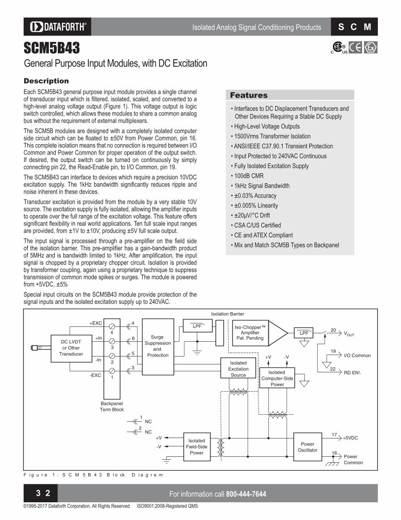
Isolated Analog Signal Conditioning Products
©1995-2017 Dataforth Corporation, All Rights Reserved ISO9001:2008-Registered QMS
For information call 800-444-76443 2
S C M 5 B
SCM5B43General Purpose Input Modules, with DC ExcitationDescriptionEach SCM5B43 general purpose input module provides a single channel of transducer input which is filtered, isolated, scaled, and converted to a high-level analog voltage output (Figure 1). This voltage output is logic switch controlled, which allows these modules to share a common analog bus without the re uirement of external multiplexers.The SCM5B modules are designed with a completely isolated computer side circuit which can be oated to from Power ommon, pin . This complete isolation means that no connection is re uired between I O Common and Power Common for proper operation of the output switch. If desired, the output switch can be turned on continuously by simply connecting pin , the Read nable pin, to I O ommon, pin .The SCM5B43 can interface to devices which require a precision 10VDC excitation supply. The H bandwidth significantly reduces ripple and noise inherent in these devices. Transducer excitation is provided from the module by a very stable source. The excitation supply is fully isolated, allowing the amplifier inputs to operate over the full range of the excitation voltage. This feature offers significant exibility in real world applications. Ten full scale input ranges are provided, from ± 1V to ± 10V, producing ± 5V full scale output.The input signal is processed through a pre amplifier on the field side of the isolation barrier. This pre amplifier has a gain bandwidth product of H and is bandwidth limited to H . After amplification, the input signal is chopped by a proprietary chopper circuit. Isolation is provided by transformer coupling, again using a proprietary techni ue to suppress transmission of common mode spikes or surges. The module is powered from +5VDC, ± 5%.Special input circuits on the SCM5B43 module provide protection of the signal inputs and the isolated excitation supply up to 240VAC.
Features• Interfaces to DC Displacement Transducers and
Other Devices Re uiring a Stable D Supply• High-Level Voltage Outputs• 1500Vrms Transformer Isolation• ANSI/IEEE C37.90.1 Transient Protection• Input Protected to 240VAC Continuous• Fully Isolated Excitation Supply• 100dB CMR• 1kHz Signal Bandwidth• ± 0.03% Accuracy• ± 0.005% Linearity Drift SA S ertified
• CE and ATEX Compliant• Mix and Match SCM5B Types on Backpanel
F i g u r e 1 : S C M 5 B 4 3 B l o ck D i a g r a m

Isolated Analog Signal Conditioning Products
©1995-2017 Dataforth Corporation, All Rights Reserved ISO9001:2008-Registered QMS
Visit our website www.dataforth.com 3 3
S C M 5 B
SCM
5B
Model a imum n ut Output Range†
SCM5B43-01 SCM5B43-02 SCM5B43-03 SCM5B43-04 SCM5B43-05 SCM5B43-06 SCM5B43-07 SCM5B43-08 SCM5B43-09 SCM5B43-10
± 1V± 2V± 3V± 4V± 5V± 6V± 7V± 8V± 9V± 10V
1, 21, 21, 21, 21, 21, 21, 21, 21, 21, 2
Ordering InformationSpecifications Typical at TA and D power
Module SCM5B43Input RangeInput Bias CurrentInput Resistance Normal Power Off OverloadInput Protection Continuous Transient
± 1V to ± 10V± 0.05nA
minimum minimum minimum
240Vrms maxANSI/IEEE C37.90.1 (formerly IEEE-472)
Excitation Voltage, VEXCExcitation CurrentExcitation Load Regulation
xcitation StabilityIsolated Excitation Protection Continuous Transient
+10.0VDC ± 2mV40mA (maximum)
± 5ppm/mAppm
240Vrms maxANSI/IEEE C37.90.1 (formerly IEEE-472)
CMV, Input to Output Continuous TransientCMR (50 or 60Hz)NMR (– 3dB at 1kHz)
1500Vrms maxANSI/IEEE C37.90.1 (formerly IEEE-472)
100dBdB per Decade above H
Accuracy(1)
Linearity± 0.03% Span
± 0.005% SpanStability Input Offset Output Offset Gain ppmNoise Input, 0.1 to 10Hz Output, 100kHz
. rms5mVp-p
Bandwidth, – 3dBResponse Time to final value
1kHzs
Output RangeOutput ResistanceOutput ProtectionOutput Selection Time (to ± 1mV of VOUT)Output Current Limit
See Ordering Information
Continuous Short to Ground. s at load = 0 to 2000pF
± 8mAOutput nable ontrol Max Logic “0” Min Logic “1” Max Logic “1”Input Current “0,1”
+0.8V+2.4V+36V. A
Power Supply VoltagePower Supply Current
Power Supply Sensitivity
+5VDC ± 5%200mA at Full Exc. Load,100mA at No Exc. Load
RTI(2)
Mechanical Dimensions (h)(w)(d)
2.28” x 2.26” x 0.60”(58mm x 57mm x 15mm)
Environmental Operating Temp. Range Storage Temp. Range Relative HumidityEmissions EN61000-6-4 Radiated, ConductedImmunity EN61000-6-2 RF ESD,EFT
to to
0 to 95% NoncondensingISM, Group 1
Class AISM, Group 1
Performance A ± 0.5% Span ErrorPerformance B
NOTES: ontact factory or your local Dataforth sales office for maximum values.
Includes excitation error, linearity, hysteresis and repeatability.(2) RTI = Referenced to input.
†Output Ranges Available Output Range Part o u fi am e1. – 5V to +5V2. – 10V to +10V
NONED
SCM5B43-01 SCM5B43-01D

Isolated Analog Signal Conditioning Products
©1995-2017 Dataforth Corporation, All Rights Reserved ISO9001:2008-Registered QMS
For information call 800-444-76443 4
S C M 5 B
SCM5B45Frequency Input ModulesDescriptionEach SCM5B45 frequency input module provides a single channel of frequency input which is isolated and converted to a high-level analog voltage output (Figure 1). This voltage output is logic switch controlled, which allows these modules to share a common analog bus without the requirement of external multiplexers.The fre uency input signal can be a TTL level signal or a ero cross-ing signal. Terminal on the field side terminal bloc is the common or ground connection for input signals. A TTL signal is connected from termi-nal 2 to terminal 3, while a zero-crossing signal is connected from terminal 4 to terminal 3. Input circuitry for each of the signal types has hysteresis built in. An input signal must cross entirely through the hysteresis region in order to trigger the threshold comparator.A . excitation is available for use with magnetic pic up or contact clo-sure type sensors. The excitation is available on pin and the excitation common is pin 3.The SCM5B modules are designed with a completely isolated computer side circuit which can be oated to from Power ommon, pin . This complete isolation means that no connection is re uired between I O Common and Power Common for proper operation of the output switch. If desired, the output switch can be turned on continuously by simply connecting pin , the Read nable pin, to I O ommon, pin .A special circuit in the input stage of the module provides protection against accidental connection of power-line voltages up to 240VAC.
Features• Accepts Frequency Inputs of 0 to 100kHz• Provides High-Level Voltage Outputs• TTL or Zero Crossing Signal Inputs• 1500 Vrms Transformer Isolation• ANSI/IEEE C37.90.1 Transient Protection• Input Protected to 240VAC Continuous• 120dB CMR• ± 0.05% Accuracy SA S ertified
• CE and ATEX Compliant• Mix and Match SCM5B Types on Backpanel
F i g u r e 1 : S C M 5 B 4 5 B l o ck D i a g r a m

Isolated Analog Signal Conditioning Products
©1995-2017 Dataforth Corporation, All Rights Reserved ISO9001:2008-Registered QMS
Visit our website www.dataforth.com 3 5
S C M 5 B
SCM
5B
Model Input Range Output Range†Zero Crossing
HysteresisSCM5B45-01SCM5B45-02SCM5B45-03SCM5B45-04SCM5B45-05SCM5B45-06SCM5B45-07SCM5B45-08
SCM5B45-21SCM5B45-22SCM5B45-23SCM5B45-24SCM5B45-25SCM5B45-26SCM5B45-27SCM5B45-28
0Hz to 500Hz0Hz to 1kHz0Hz to 3kHz0Hz to 5kHz
0Hz to 10kHz 0Hz to 25kHz 0Hz to 50kHz
0Hz to 100kHz
0Hz to 500Hz0Hz to 1kHz0Hz to 3kHz0Hz to 5kHz
0Hz to 10kHz 0Hz to 25kHz 0Hz to 50kHz
0Hz to 100kHz
3, 43, 43, 43, 43, 43, 43, 43, 4
3, 43, 43, 43, 43, 43, 43, 43, 4
± 20mV± 20mV± 20mV± 20mV± 20mV± 20mV± 20mV± 20mV
± 400mV± 400mV± 400mV± 400mV± 400mV± 400mV± 400mV± 400mV
Ordering InformationSpecifications Typical at TA and D power
Module SCM5B45Input RangeInput Threshold Minimum Input Maximum Input Minimum Pulse Width TTL Input Low TTL Input HighInput Hysteresis Zero Crossing TTLInput Resistance Normal Power Off OverloadInput Protection Continuous TransientExcitation
0Hz to 100kHzZero Crossing
60mVp-p350Vp-p
s0.8V max2.4V min
± 20mV (± 400mV on -2x models)1.5V
240Vrms maxANSI/IEEE C37.90.1+5.1V at 8mA max
CMV, Input to Output Continuous TransientCMR (50 or 60Hz)
1500Vrms max
ANSI/IEEE C37.90.1120dB
Accuracy(1)
LinearityStability Offset GainNoise Output RippleResponse Time (0 to 90%) SCM5B45-01, -02, -21, -22 SCM5B45-03, -23 SCM5B45-04, -05, -24, -25 SCM5B45-06, -07, -08, -26, -27, -28
± 0.05% Span± 0.02% Span
ppmppm
<1 0mVp-p at Input >2 % span
300ms170ms90ms20ms
Output RangeOutput ResistanceOutput ProtectionOutput Selection Time (to ± 1mV of VOUT)Output Current Limit
See Ordering Information
Continuous Short to Grounds at load = 0 to 2000pF
+8mAOutput nable ontrol Max Logic “0” Min Logic “1” Max Logic “1” Input Current “0,1”
+0.8V+2.4V+36V. A
Power Supply VoltagePower Supply CurrentPower Supply Sensitivity
+5VDC ± 5%110mA
RTO(2)
Mechanical Dimensions (h)(w)(d)
2.28” x 2.26” x 0.60”(58mm x 57mm x 15mm)
Environmental Operating Temperature Range Storage Temperature Range Relative HumidityEmissions EN61000-6-4 Radiated, ConductedImmunity EN61000-6-2 RF ESD,EFT
to to
0 to 95% NoncondensingISM, Group 1
Class AISM, Group 1
Performance A ± 0.5% Span ErrorPerformance B
NOTES: ontact factory or your local Dataforth sales office for maximum values.
Includes linearity, hysteresis and repeatability.(2) RTO = Referenced to output.
†Output Ranges AvailableOutput Range Part o u fi am e3. 0V to +5V4. 0V to +10V
NONED
SCM5B45-01 SCM5B45-01D

Isolated Analog Signal Conditioning Products
©1995-2017 Dataforth Corporation, All Rights Reserved ISO9001:2008-Registered QMS
For information call 800-444-76443 6
S C M 5 B
SCM5B47Linearized Thermocouple Input ModulesDescriptionEach SCM5B47 thermocouple input module provides a single channel of thermocouple input which is filtered, isolated, amplified, lineari ed and converted to a high-level analog voltage output (Figure 1). This voltage output is logic-switch controlled, allowing these modules to share a common analog bus without the re uirement of external multiplexers.The SCM5B modules are designed with a completely isolated computer side circuit which can be oated to from Power ommon, pin . This complete isolation means that no connection is re uired between I O Common and Power Common for proper operation of the output switch. If desired, the output switch can be turned on continuously by simply connecting pin , the Read nable pin, to I O ommon, pin .The SCM5B47 can interface to eight industry standard thermocouple types: J, K, T, E, R, S, N, and B. Its corresponding output signal operates over a 0V to +5V range. Each module is cold-junction compensated to correct for parasitic thermocouples formed by the thermocouple wire and screw terminals on the mounting bac panel. pscale open thermocouple detect is provided by an internal pull up resistor. Downscale indication can be implemented by installing an external resistor, tolerance, between screw terminals and on the S PB bac panels.Signal filtering is accomplished with a six pole filter which provides dB of normal-mode rejection at 60Hz and 90dB at 50Hz. Two poles of this filter are on the field side of the isolation barrier, and the other four are on the computer side.After the initial field side filtering, the input signal is chopped by a proprietary chopper circuit. Isolation is provided by transformer coupling, again using a proprietary technique to suppress transmission of common mode spikes or surges. The module is powered from +5VDC, ± 5%.
Features• Interfaces to Types J, K, T, E, R, S, N and B
Thermocouples• Linearizes Thermocouple Signal• High-Level Voltage Outputs• 1500Vrms Transformer Isolation• ANSI/IEEE C37.90.1 Transient Protection• Input Protected to 240VAC Continuous• 160dB CMR• 95dB NMR at 60Hz, 90dB at 50Hz Drift SA S ertified
• CE and ATEX Compliant• Mix and Match SCM5B Types on Backpanel
F i g u r e 1 : S C M 5 B 4 7 B l o ck D i a g r a m
A special input circuit on the SCM5B47 modules provides protection against accidental connection of power-line voltages up to 240VAC.

Isolated Analog Signal Conditioning Products
©1995-2017 Dataforth Corporation, All Rights Reserved ISO9001:2008-Registered QMS
Visit our website www.dataforth.com 3 7
S C M 5 B
SCM
5B
Ordering InformationSpecifications Typical at TA and D power
x
NOTES: ontact factory or your local Dataforth sales office for maximum values.
Includes conformity, hysteresis and repeatability. Does not include accuracy. This is e uivalent to as follows Type . , Types , T . ,
Type . , Types R, S . , Type N . , Type . .(3) RTI = Referenced to input.
Output Range Part o u fi am e3. 0V to +5V4. 0V to +10V
NONED
SCM5B47J-01 SCM5B47J-01D
Module SCM5B47Input RangeInput Bias CurrentInput Resistance Normal Power Off OverloadInput Protection Continuous Transient
– 0.1V to +0.5V– 25nA
240Vrms maxANSI/IEEE C37.90.1
CMV, Input to Output Continuous TransientCMR (50Hz or 60Hz)NMR
1500Vrms maxANSI/IEEE C37.90.1
160dB95dB at 60Hz, 90dB at 50Hz
AccuracyStability Input Offset Output Offset GainNoise Input, 0.1 to 10Hz Output, 100kHzBandwidth, – 3dBResponse Time, 90% Span
See Ordering Information(2)
ppm
. rmsp p, rms
4Hz0.2s
Output RangeOutput ResistanceOutput ProtectionOutput Selection Time (to ± 1mV of VOUT )Output Current Limit
See Ordering Information
Continuous Short to Grounds at load = 0 to 2000pF
+8mAOutput nable ontrol Max Logic “0” Min Logic “1” Max Logic “1”Input Current “0,1”Open Input ResponseOpen Input Detection TimeCold Junction Compensation Accuracy, Accuracy, to Accuracy, to
+0.8V+2.4V+36V. A
Upscale<1 0s
..
.Power Supply VoltagePower Supply CurrentPower Supply Sensitivity
+5VDC ± 5%30mA
RTI(3)
Mechanical Dimensions (h)(w)(d)
2.28” x 2.26” x 0.6”(58mm x 57mm x 15mm)
Environmental Operating Temperature Range Storage Temperature Range Relative HumidityEmissions EN61000-6-4 Radiated, ConductedImmunity EN61000-6-2 RF ESD, EFT
to to
0 to 95% NoncondensingISM, Group 1
Class AISM, Group 1
Performance A ± 0.5% Span ErrorPerformance B
ModelTC
Type‡ Input RangeOutputRange† Accuracy(1)
SCM5B47J-01
SCM5B47J-02
SCM5B47J-03
SCM5B47K-04
SCM5B47K-05
SCM5B47T-06
SCM5B47T-07
SCM5B47E-08
SCM5B47R-09
SCM5B47S-10
SCM5B47B-11
SCM5B47J-12
SCM5B47K-13
SCM5B47K-14
SCM5B47N-15
J
J
J
K
K
T
T
E
R
S
B
J
K
K
N
to F to F
to F to F
to F to F
to F to F
to F to F
to F to F
to F to F
to F to F
to F to F
to F to F
to F to F
to F to F
to F to F
to F to F
to F to F
3, 4
3, 4
3, 4
3, 4
3, 4
3, 4
3, 4
3, 4
3, 4
3, 4
3, 4
3, 4
3, 4
3, 4
3, 4
± 0.08%
± 0.08%
± 0.07%
± 0.08%
± 0.08%
± 0.16%
± 0.16%
± 0.10%
± 0.10%
± 0.10%
± 0.15%
± 0.08%
± 0.10%
± 0.08%
± 0.08%
.
.
.
.
.
.
.
.
.
.
.
.
.
.
.
†Output Ranges Available
‡Thermocouple Alloy Combinations S t a n d a r d s: D I N I E C 5 8 4 , A N S I M C 9 6 - 1 - 8 2 , JI S C 1 6 0 2 - 1 9 8 1
Type MaterialJKTERSBN
Iron vs. Copper-Nickel Nickel-Chromium vs. Nickel-Aluminum Copper vs. Copper-Nickel Nickel-Chromium vs. Copper-Nickel Platinum-13% Rhodium vs. Platinum Platinum-10% Rhodium vs. Platinum Platinum-30% Rhodium vs. Platinum-6% Rhodium Nickel-14.2% Chromium-1.4% Silicon vs. Nickel-4.4% Silicon- 0.1% Magnesium

©1995-2017 Dataforth Corporation, All Rights Reserved ISO9001:2008-Registered QMS
For information call 800-444-76443 8
S C M 5 B
SCM5B48Accelerometer Input ModuleDescriptionThe S B provides excitation to pie oelectric sensors with built in microelectronic amplifiers, commonly nown as I P®* or IEPE* or LIVM* sensors. The module provides a constant current excitation to the sensor, then isolates, filters, and amplifies the sensor output, yielding a high level analog voltage output (Figure 1). The excitation current, signal gain, and filter high pass and low pass cutoff fre uencies are field configurable through a set of slide switches.Six poles of signal filtering in the S B module result in greater than
dB of normal mode re ection for signal fre uencies above the cutoff fre uency. One pole of filtering is on the field side of the isolation barrier for anti aliasing purposes and the remaining five pole programmable Bessel filter is located on the system side. High pass filtering is achieved through a second order passive filter, located on the field side. If desired, the output switch can be turned on continuously by simply connecting pin , the Read nable pin, to I O ommon, pin .The SCM5B48 offers the option of setting the constant current source for sensor excitation to common values of 4mA or 9mA with a compliance volt-age of D . Programmable gains of , and are selectable and the module offers a ± 10V output. The required supply level is +5VDC, ± 5% .To ensure protection of expensive data acquisition equipment, the SCM5B48 module signal inputs and sensor excitation outputs are protected against accidental connection of voltages up to 240Vrms.* ICP is a registered trademark of PCB Group Inc. * IEPE is Integrated Electronic Piezo-Electric * LIVM is Low Impedance Voltage Mode
Features• Interfaces to ICP®* or IEPE* or LIVM* Sensors• ± 5V or ± 10V Output Range• 1500Vrms Transformer Isolation• ANSI/IEEE C37.90.1 Transient Protection• Input Protection to 240Vrms Continuous , , and Programmable Gain . , , , and H Programmable LP Filter . and H Programmable HP Filter mA or mA Programmable urrent xcitation
• 100dB CMR• ± 0.2% Accuracy• ± 0.01% Linearity Low Drift with Ambient Temperature to Operating Temperature Range SA S ertified
• CE Compliant• ATEX Compliance Pending• Mix and Match SCM5B Types on Backpanel
F i g u r e 1 : S C M 5 B 4 8 B l o ck D i a g r a m
Isolated Analog Signal Conditioning Products

Isolated Analog Signal Conditioning Products
©1995-2017 Dataforth Corporation, All Rights Reserved ISO9001:2008-Registered QMS
Visit our website www.dataforth.com 3 9
S C M 5 B
SCM
5BIsolated Analog Signal Conditioning Products
©1995-2017 Dataforth Corporation, All Rights Reserved ISO9001:2008-Registered QMS
isit our website www.dataforth.com 3 9
S C M 5 B
Model Input Range(1) Output Range Bandwidth SCM5B48-01 SCM5B48-02
– 10V to +10V– 10V to +10V
– 10V to +10V– 5V to +5V
2.5kHz to 20kHz(2)
2.5kHz to 20kHz(2)
Ordering InformationSpecifications Typical at TA and D power
Module SCM5B48Input Type Range(1)
Protection Continuous Transient
Accelerometer± 10V
240Vrms maxANSI/IEEE C37.90.1
Excitation Constant Current(2)
Compliance Voltage Protection Continuous Transient
4mA or 9mA, ± 10%24V ± 10%
240Vrms maxANSI/IEEE C37.90.1
Output Range Resistance Protection
See Ordering Information
Continuous Short to GroundGain Programmable(2) 1, 10, 100CMR (50/60Hz)Accuracy(3)
LinearityStability Offset GainOutput Noise, Gain=1 , BW= 20kHzLow Pass Filter Type Programmable(2)
High Pass Filter Programmable(2)
CMV (Input to Output) Continuous TransientNMR
100dB± 0.2% Span
± 0.01% Span
ppmppm
rms
Bessel2.5kHz, 5kHz, 10kHz, 20kHz
DC, 0.2Hz, 10Hz
1500Vrms maxANSI/IEEE C37.90.1
db per Decade above cutoff fre uencyPower Supply VoltagePower Supply Current
Power Supply Sensitivity
+5VDC ± 5%110mA typical (9mA excitation)70mA typical (4mA excitation)
± 600µ V/% RTI (4)
Mechanical Dimensions (h)(w)(d)
2.28” x 2.26” x 0.6”(58mm x 57mm x 15mm)
Environmental Operating Temperature Range Storage Temperature Range
to to
NOTES: ontact factory or your local Dataforth sales office for maximum values.(1) AC peak for AC coupling. For DC coupling input range (AC + DC): 0 to +10V.
Programmable using slide switches on the bottom of the module. Includes linearity, repeatability and hysteresis.
(4) RTI = Referenced to input.
Figure S B Side Label

Isolated Analog Signal Conditioning Products
©1995-2017 Dataforth Corporation, All Rights Reserved ISO9001:2008-Registered QMS
For information call 800-444-76444 0
S C M 5 B
SCM5B49Voltage Output ModulesDescriptionEach SCM5B49 voltage output module provides a single channel of ana-log output. The trac and hold circuit in the input stage can be operated in a hold mode where one DAC can supply many output modules, or a track mode where one DAC is dedicated to each module. In addition to the trac and hold circuit, each module provides signal buffering, isolation, filtering, and conversion to a high level voltage output Figure .Setting of the trac or hold mode is controlled by the logic state of R
N , module pin . hen pin is low, the trac mode is enabled. If pin is high, the hold mode is enabled. The module is designed with a completely isolated computer side circuit which can be oated to from Power Common, pin 16. This complete isolation means that no connection is re uired between I O ommon and Power ommon for proper operation of the track and hold circuit. For a low state, simply connect pin , the rite nable pin, to I O ommon, pin .The S PB and S PB bac panels allow host computer control of the WR EN\ control line, which allows multiplexing of one host DAC to up to 64 SCM5B49 output modules.
Features• Accepts High-Level Voltage Inputs to ± 10V• Provides High-Level Voltage Outputs to ± 10V• 1500 Vrms Transformer Isolation• ANSI/IEEE C37.90.1 Transient Protection• 5 Poles of Filtering• 110dB CMR• 400Hz Signal Bandwidth• ± 0.03% Accuracy• ± 0.015% Linearity SA S ertified
• CE and ATEX Compliant• Mix and Match SCM5B Types on Backpanel
F i g u r e 1 : S C M 5 B 4 9 B l o ck D i a g r a m

Isolated Analog Signal Conditioning Products
©1995-2017 Dataforth Corporation, All Rights Reserved ISO9001:2008-Registered QMS
Visit our website www.dataforth.com 4 1
S C M 5 B
SCM
5B
Model Input Range Output Range SCM5B49-01 SCM5B49-02 SCM5B49-03 SCM5B49-04 SCM5B49-05 SCM5B49-06 SCM5B49-07
0V to +5V– 5V to +5V– 5V to +5V
0V to +10V– 10V to +10V– 10V to +10V– 5V to +5V
– 5V to +5V– 5V to +5V 0V to +5V
– 10V to +10V– 10V to +10V 0V to +10V– 10V to +10V
Ordering InformationSpecifications Typical at TA and D power
Module SCM5B49Input Voltage RangeInput Voltage MaximumInput Resistance
± 5V, 0 to +5V, ± 10V, 0 to +10V± 36V (no damage)
Output Voltage RangeOver Range apabilityOutput DriveOutput ResistanceOutput I Under Fault, MaxOutput Protection Continuous Transient
± 5V, 0 to +5V, ± 10V, 0 to +10V5% at 10V output
50mA max.
75mA
240Vrms maxANSI/IEEE C37.90.1
CMV, Output to Input Continuous TransientCMR (50 or 60Hz)NMR (– 3dB at 400Hz)
1500Vrms maxANSI/IEEE C37.90.1
110dBdB per Decade above H
Accuracy(1)
LinearityStability Zero SpanNoise Output Ripple, H bandwidthBandwidth, – 3dBResponse Time, 90% Span
± 0.03% Span (0-5mA Load)± 0.015% Span
ppmppm
2mVp-p
400Hz1.25ms
Sample and Hold Output Droop Rate Acquisition Time
0.2% Span/ss
Trac and Hold nable ontrol Max Logic “0” Min Logic “1” Max Logic “1” Input Current “0”
+0.8V+2.4V+36V. A
Power Supply VoltagePower Supply CurrentPower Supply Sensitivity
+5VDC ± 5%350mA Full Load, 135mA no load
± 12.5ppm/%Mechanical Dimensions (h)(w)(d)
2.28” x 2.26” x 0.60”(58mm x 57mm x 15mm)
Environmental Operating Temperature Range Storage Temperature Range Relative HumidityEmissions EN61000-6-4 Radiated, ConductedImmunity EN61000-6-2 RF ESD, EFT
to to
0 to 95% NoncondensingISM, Group 1
Class AISM, Group 1
Performance A ± 0.5% Span ErrorPerformance B
NOTES: ontact factory or your local Dataforth sales office for maximum values.
Includes linearity, hysteresis and repeatability.

Isolated Analog Signal Conditioning Products
©1995-2017 Dataforth Corporation, All Rights Reserved ISO9001:2008-Registered QMS
For information call 800-444-76444 2
S C M 5 B
SCM5BModule Dimensions and PinoutsThe following mechanical drawing is useful if designing circuit boards to mount the S B modules. any soc ets are available which accept the mounting pins. As an example, AMP Inc. provides a socket with part
number . The captive nut for the mm mounting screw can be obtained from P Penn ngineering and anufacturing , part number KFS2-M3.

Isolated Analog Signal Conditioning Products
©1995-2017 Dataforth Corporation, All Rights Reserved ISO9001:2008-Registered QMS
Visit our website www.dataforth.com 4 3
S C M 5 B
SCM
5B
SCMVASVoltage Attenuator SystemDescriptionThe SCMVAS (Signal Conditioning Modular Voltage Attenuator System) is an analog signal conditioning system designed to safely monitor and accurately measure voltage potentials up to 495VAC (1400V peak-to-peak). These highlevel voltages are typically found in industrial applications such as induction heaters or electric-motor drive controllers. The system reduces the input signal to a level suitable for interface to data ac uisition systems, while at the same time providing various filter characteristics and 1500Vrms isolation (Figure 1).For each channel of analog input, an attenuator module, SCMVAS-Mnnn, pre conditions the signal which is then filtered, isolated, and converted to a high-level voltage output using an SCM5B30-07 or SCM5B40-07 module. The S B module with a H bandwidth is recom-mended for common 50/ 60Hz signals low in harmonics where the user is interested in measuring only AC voltage. The SCM5B30-07 module is used for low fre uency A signals below H . The attenuator and signal conditioning modules have excellent stability over time and do not re uire recalibration. Overall system accuracy is . .Input signal connections to the SCMVAS-Mnnn attenuator module are made using a pluggable terminal bloc for ease of system assembly and reconfiguration. For safety purposes, the terminal bloc has a cover over the screws and there are no other exposed high-voltage points on the SCMVAS-Mnnn series modules, SCM5B30-07 or SCM5B40-07 module, or the mounting bac panel.The S AS system has two specially designed bac panels for mounting the attenuator and signal conditioning modules. The S AS PB high density, channel bac panel Figures , can be panel mounted or DIN rail mounted and provides the conditioned output signal on screw terminal bloc s. umpers are provided on each channel to optionally connect or isolate each module’s I/O Common from other channel’s I/O Common and/or Power Common. The SCMVAS-PB16 Figures , has channels of analog I O simultaneously available to
high speed data ac uisition AD boards through a conductor ribbon cable. Refer to the S PB Data Sheet in this catalog and Application Note AN502 at www.dataforth.com for recommended ground connections and host system interfaces. Both the SCMVAS-PB8 and SCMVAS-PB16 bac panels can be mounted on the S R inch metal rac .
Features• Accepts High Voltage Signals up to 495VAC
(1400V Peak-to-Peak)• 5 or 10 Volt Output for A/D Systems• 1500Vrms Transformer Isolation• True 3-Way Isolation• Up to 160dB CMR• ± 0.06% Accuracy• Panel or DIN Rail Mounting Options SA ertified
• CE Compliant• ATEX Compliant (all models except
SCMVAS-M400, -M500, -M600, -M650)
F i g u r e 1 : S C M V A S S ch e m a t i c

Isolated Analog Signal Conditioning Products
©1995-2017 Dataforth Corporation, All Rights Reserved ISO9001:2008-Registered QMS
For information call 800-444-76444 4
S C M 5 B
Ordering InformationSpecifications Typical at TA and D power
NOTES: ontact factory or your local Dataforth sales office for maximum values.
Includes linearity, hysteresis and repeatability.(2) RTI = Referenced to input.
Model Description SCM5B30-07 SCM5B40-07 SCM5B30-07D SCM5B40-07D
V Isolation Module, ± 5V Output, 4Hz Bandwidth V Isolation Module, ± 5V Output, 10kHz Bandwidth V Isolation Module, ± 10V Output, 4Hz Bandwidth V Isolation Module, ± 10V Output, 10kHz Bandwidth
Module SCM5B30-07 SCM5B40-07Input RangeInput Bias CurrentInput Resistance Normal Power Off OverloadInput Protection Continuous Transient
– 1.0V to +1.0V± 0.5nA
240Vrms maxANSI/IEEE C37.90.1
**
**
**
CMV, Input to Output Continuous TransientCMR (50 or 60Hz)NMR
1500Vrms maxANSI/IEEE C37.90.1
160dB95dB at 50Hz, 90dB at 60Hz
**
100dB120dB per Decade
above HAccuracy(1)
LinearityStability Input Offset Output Offset Gain
± 0.03% Span± 0.005% Span
ppm
*± 0.01% Span
***
Noise Input, DC to 10Hz Output, 100kHz
rmsrms
*2mVp-p
Bandwidth, -3dBResponse Time to final value
4Hz0.2s
10kHz s
Output Range
Output ResistanceOutput ProtectionOutput Selection Time (to ± 1mV of VOUT)Output Current Limit
– 5V to +5V (– 10V to +10V, D model versions)
Continuous Short to Ground. S at load = 0 to 2000pF
± 8mA
*
***
*Output nable ontrol Max Logic “0” Min Logic “1” Max Logic “1” Input Current “0,1”
+0.8V+2.4V+36V. A
****
Power Supply VoltagePower Supply CurrentPower Supply Sensitivity
+5VDC ± 5%30mA RTI(2)
***
Mechanical Dimensions (h)(w)(d)
2.28”x 2.26”x 0.60”(58mm x 57mm x 15mm)
*
Environmental Operating Temp. Range Storage Temp. Range Relative HumidityEmissions EN61000-6-4 Radiated, ConductedImmunity EN61000-6-2 RF ESD,EFT
to to
0 to 95% NoncondensingISM, Group 1
Class AISM, Group 1
Performance A ± 0.5% Span ErrorPerformance B
********
SCM5B30/40-07Isolated Analog Voltage Input Modules

Isolated Analog Signal Conditioning Products
©1995-2017 Dataforth Corporation, All Rights Reserved ISO9001:2008-Registered QMS
Visit our website www.dataforth.com 4 5
S C M 5 B
SCM
5B
NOTES: ontact factory or your local Dataforth sales office for maximum values.
Includes linearity, hysteresis and repeatability.(2) RTI = Referenced to input.
Specifications Typical at TA
ontact factory or your local Dataforth sales office for maximum values.
Module SCMVAS-MnnnInput RangeInput Voltage MaximumInput Resistance
± 100Vpeak to ± 700Vpeak (70VAC to 495VAC)± 750Vpeak
AccuracyStability
± 0.03%ppm
Output RangeOutput Resistance
± 1V
Mechanical Dimensions (h)(w)(d)
1.70”x 1.98”x 0.69”(44mm x 51mm x 18mm)
Environmental Operating Temp. Range Storage Temp. Range Relative HumidityHazLoc CSA ATEX
to to
0 to 95% Noncondensing
All models except SCMVAS-M700All models except SCMVAS-M400,
-M500, -M600, -M650, -M700
SCMVAS-MnnnHigh Voltage Attenuator Modules
Accessories Model Description SCMVAS-PB8 SCMVAS-PB8D SCMVAS-PB16 SCMVAS-PB16D
Backpanel, 8-Channel Backpanel, 8-Channel, DIN Rail Mount Backpanel, 16-Channel Backpanel, 16-Channel, DIN Rail Mount
Figure 2: SCMVAS-PB8 Analog I/O Backpanel
Ordering Information
Model DescriptionInput Range with V Isolation Module
SCMVAS-M100 SCMVAS-M200 SCMVAS-M300 SCMVAS-M400 SCMVAS-M500 SCMVAS-M600 SCMVAS-M650 SCMVAS-M700 SCMVAS-MPT
Attenuator ModuleAttenuator ModuleAttenuator ModuleAttenuator ModuleAttenuator ModuleAttenuator ModuleAttenuator ModuleAttenuator Module
Attenuator Module, Pass-Thru 1-to-1
± 100V Input (70VAC)± 200V Input (141VAC)± 300V Input (212VAC)± 400V Input (282VAC)± 500V Input (353VAC)± 600V Input (424VAC)± 650V Input (460VAC)± 700V Input (495VAC)

Isolated Analog Signal Conditioning Products
©1995-2017 Dataforth Corporation, All Rights Reserved ISO9001:2008-Registered QMS
For information call 800-444-76444 6
S C M 5 B
Figure 3: SCMVAS-PB8 Schematic
Figure 4: SCMVAS-PB16 Analog I/O Backpanel

Isolated Analog Signal Conditioning Products
©1995-2017 Dataforth Corporation, All Rights Reserved ISO9001:2008-Registered QMS
Visit our website www.dataforth.com 4 7
S C M 5 B
SCM
5B
Figure 5: SCMVAS-PB16 Schematic

Isolated Analog Signal Conditioning Products
©1995-2017 Dataforth Corporation, All Rights Reserved ISO9001:2008-Registered QMS
For information call 800-444-76444 8
S C M 5 B
Accessories for SCM5B Analog Modules
Features• 1-, 2-, 8-, 16-Position Backpanels• Panel or DIN Rail Mounting Options• 19-Inch Mounting Rack For Backpanels• Multiplexed and Non-Multiplexed Backpanels
Interface ables• Module Evaluation Board able to Screw Terminal Interface Board
• Power Supplies
SCMPB0116-Position Analog I/O Backpanel,Non-MultiplexedDescriptionThe S PB channel bac panel Figure can accept any of the S B analog modules in any mixture. It can be mounted on the SCMXRK-002 19-inch metal rack. The SCMPB01 has 16 non-address-able analog I O signal channels which provides each module with its own analog bus. The module output switch is continuously on when using this bac panel and all sixteen module outputs are simultaneously accessible to high speed data ac uisition AD boards. A set of inter channel bridge umpers permits connecting an input module’s output to an output module’s input, providing two levels of isolation. A temperature sensor is mounted on each channel to provide cold junction compensation for thermocouple input modules (see Figure 2 for schematic). Field connections are terminated with four screw terminals at each module site. se system interface cable S A for connection to the host system.
Specifications Operating TemperatureRelative Humidity
to 95% Noncondensing
Interface Connector: Field System
high density screw clamp, 14 AWG max26-pin, male header connector
Isolation: Input-to-Output Channel-to-Channel
1500Vrms continuous, max1500Vrms continuous, max
Figure 1: SCMPB01 Analog I/O Backpanel

Isolated Analog Signal Conditioning Products
©1995-2017 Dataforth Corporation, All Rights Reserved ISO9001:2008-Registered QMS
Visit our website www.dataforth.com 4 9
S C M 5 B
SCM
5B
Figure 2: SCMPB01 Schematic

Isolated Analog Signal Conditioning Products
©1995-2017 Dataforth Corporation, All Rights Reserved ISO9001:2008-Registered QMS
For information call 800-444-76445 0
S C M 5 B
ElectricalP1 and P2 ConnectorConnection to the host system is made at connectors P1 and P2. These connectors are electrically equivalent. Two connectors are provided to allow both analog input and analog output from host systems having individual input and output connectors. Adjacent Channel JumpersAd acent channels may be connected together to provide an isolated output signal from an isolated input module, providing two levels of 1500V isolation. This capability is provided with the umpers labeled P through P on headers , , and . A simplified drawing of the SCMPB01 schematic for Channels 1 through 4 is shown in Figure 3.Example: Assume an SCM5B30 input module is installed in Channel 0 position and an SCM5B39 output module is installed in Channel 1 position. If JP1 is installed, the output of Channel 0 is connected to the input of Channel 1, which provides two levels of 1500V isolation.
Figure 3: SCMPB01 Adjacent Channel Jumpers
PowerThe S PB bac panel re uires external D power. The chassis mounted SCMXPRE-003 or SCMXPRT-003 power supplies have ade uate capacity to power any combination of modules.FusingThe S PB bac panel power is fuse protected through F . This is a Littelfuse type 252007, 7 amp fuse. Zener diode DZ1 provides extra protection by clamping the input power voltage to . . If the input supply voltage connection is reversed, this ener diode will be forward biased and fuse F will be blown. Grounding Figure details the optional ground umper configuration available on the S PB bac panel. umpers , , and are factory installed.Jumper J1 connects the AGND shield wires (pins 3, 6, 9, 12, 15, 18,
, and to the bac panel signal ground. This provides a ground connection between the host system and bac panel. umper is required if output modules (SCM5B39, SCM5B49) are used, or if there is no high impedance sense input (input low of a differential or pseudo-differential system) on the host measurement system.umper connects the S NS line pin to the bac panel signal
ground. If the host system has the capability, this allows measuring the SCMPB01 ground potential.
Ordering InformationPart Number DescriptionSCMPB01
SCMPB01-1
SCMPB01-2
SCMPB01-3
channel bac panel with standoffs for mounting.
channel bac panel with standoffs for mounting but without cold junction compensation circuits. Use when cost savings is desired and thermocouple input modules SCM5B37 and S B will not be used.
channel bac panel with DIN rail mounting option. Thebac panel is mounted on a plate which is captured by theSCMXBExx DIN rail mounting elements. Shipped fullyassembled.
channel bac panel without cold unction compensationcircuits and with DIN rail mounting option. Shipped fullyassembled.
For proper operation of the output switch or track-and-hold circuit when using the S PB bac panels, a current path must exist between the host control logic power common and module I/O Common (module pin . This path can be established on the S PB via umper . If this connection exists elsewhere in the system, umper should be removed since possible ground loops could exist. Other connections of power ground and signal ground usually occur at the A/D or D/A converter of the host measurement system. ore information on grounding can be found in Application Note AN502.
Figure 4: SCMPB01 Grounding Diagram
If the connection of power common and AGND shield wires exists in the host measurement system, an optional resistive connection between AGND and the bac panel signal ground can be made via R1. R1 can be as large as 10K ohms; 100 ohms is a recommended value. Jumper J2 can be used to connect the S NS line to R1 when this ground configuration is used.For full protection against large electrical disturbances on the field side of the S B modules, a ground stud is provided on the bac panel. An electrical connection between this ground stud and system ground should be provided with a large gauge wire of the shortest possible length. hen this connection is made, a possible ground loop could result through the AGND shield wires and bac panel signal ground. If the application involves only input modules and a differential input is used by the host measurement system, should be removed. Remember that is re uired if output modules are used or if the host system does not have differential inputs.

Isolated Analog Signal Conditioning Products
©1995-2017 Dataforth Corporation, All Rights Reserved ISO9001:2008-Registered QMS
Visit our website www.dataforth.com 5 1
S C M 5 B
SCM
5B
SCMPB0216-Position Analog I/O Backpanel, MultiplexedDescriptionThe S PB channel bac panel Figure can accept any of the S B analog modules in any mixture. It can be mounted on the SCMXRK-002 19-inch metal rack. The SCMPB02 has two analog buses one for analog input and one for analog output. This two bus configuration ta es advantage of the switch controlled outputs on the input modules and the track-and-hold inputs on the output modules. A temperature sensor is mounted on each channel to provide cold junction compensation for thermocouple input modules (see Figure 6 for schematic). Field connections are terminated with four screw terminals at each module site. p to four S PB bac panels may be dai-sy chained. se S A cable for daisy chaining and connecting to host computer.
F i g u r e 5 : S C M P B 0 2 A n a l o g I / O B a ckp a n e l
SpecificationsOperating TemperatureRelative Humidity
to 95% Noncondensing
Interface Connector: Field System
high density screw clamp, 14 AWG max26-pin, male header connector
Isolation: Input-to-Output Channel-to-Channel
1500Vrms continuous, max1500Vrms continuous, max
Address Input Logic Levels: Max Logic “0” Min Logic “1”
0.8V2.0V
II Input Current, “0” or “1” . A max at . A max to
RD EN\ or WR EN\ SignalDelay from Connector P1 toChannels 1-16 Standalone (address 0-15)
Expanded (address 16-63)
ns at ns at to
ns at ns at to

Isolated Analog Signal Conditioning Products
©1995-2017 Dataforth Corporation, All Rights Reserved ISO9001:2008-Registered QMS
For information call 800-444-76445 2
S C M 5 B
Figure 6: SCMPB02 Schematic

Isolated Analog Signal Conditioning Products
©1995-2017 Dataforth Corporation, All Rights Reserved ISO9001:2008-Registered QMS
Visit our website www.dataforth.com 5 3
S C M 5 B
SCM
5B
ElectricalP1 ConnectorThe pin P and P connectors provide the signal interface between the S PB bac panel and the host measurement system. Two separate analog bus connections are provided one for analog input signals and one for analog output signals. Two sets of six address lines and an enable pin allow input and output modules to be independently multiplexed onto their respective analog signal bus. R thru R and RD N are used for input modules, and W0 thru W5 and WR EN\ are used for output modules.Address SelectionThe S PB bac panel has address decoding circuitry to allow multiplexing any combination of up to input or output modules.
apability is also provided in the address decode circuitry to expand the system to channels four S PB bac panels of multiplexed input or output. Jumpers on HD10 header, E1 and E2 group, select which set of addresses are assigned to a particular bac panel. The group assigns a set of 16 addresses for input modules, and the E2 group assigns a set of addresses for output modules. The table below shows the correlation of jumper position to address range. E1 Jumper Pos E2 Jumper Pos Address Range/Mode 4 4 0-15, STAND ALONE 3 3 48-63, EXPANDED 2 2 32-47, EXPANDED 1 1 16-31, EXPANDED 0 0 0-15, EXPANDED To connect multiple S PB bac panels in this expanded configuration, use interconnect cable S A .
odules with system output of or cannot be mixed with modules with system output of ± 5V or 0-5V within a given system.
PowerThe S PB bac panel re uires external D power. The chassis mounted SCMXPRE-003 or SCMXPRT-003 power supplies have ade uate capacity to power any combination of modules.FusingThe S PB bac panel power is fuse protected through F . This is a Littelfuse type 252007, 7 amp fuse. Zener diode DZ1 provides extra protection by clamping the input power voltage to . . If the input supply voltage connection is reversed, this ener diode will be forward biased and fuse F will be blown.Grounding Figure below details the optional ground umper configuration available on the S PB bac panel. umpers , , and are factory installed.Jumper J1 connects the SIG COM shield wires (pins 2, 5, and 6) to the bac panel signal ground. This provides a ground connection between the host system and bac panel. umper is re uired if output modules (SCM5B39, SCM5B49) are used, or if there is no high impedance sense input (input low of a differential or pseudo-differential system) on the host measurement system.umper connects the SNS LO line pin to the bac panel signal
ground. If the host system has the capability, this allows measuring the SCMPB02 ground potential.
Ordering InformationPart Number DescriptionSCMPB02
SCMPB02-1
SCMPB02-2
SCMPB02-3
channel bac panel with standoffs for mounting.
channel bac panel without cold unction compensationcircuits and standoffs for mounting. Use when cost savings isdesired and thermocouple input modules SCM5B37 andS B will not be used.
channel bac panel with DIN rail mounting option. Thebac panel is mounted on a plate which is captured by theSCMXBExx DIN rail mounting elements. Shipped fullyassembled.
channel bac panel without cold unction compensationcircuits and with DIN rail mounting option. Shipped fullyassembled.
For proper operation of the output switch or track-and-hold circuit when using the S PB bac panels, a current path must exist between the host control logic power common and module I/O Common (module pin . This path can be established on the S PB via umper . If this connection exists elsewhere in the system, umper should be removed since possible ground loops could exist. Other connections of power ground and signal ground usually occur at the A/D or D/A converter of the host measurement system. ore information on grounding can be found in Application Note AN502.If the connection of power common and SIG COM shield wires exists in the host measurement system, a resistive connection between SIG O and the bac panel signal ground can be made via R1. R1 can be as large as ohms ohms is a recommended value. umper can be used to connect the SNS LO line to R1 when this ground configuration is used.For full protection against large electrical disturbances on the field side of the S B modules, a ground stud is provided on the bac panel. An electrical connection between this ground stud and system ground should be provided with a large gauge wire of the shortest possible length. hen this connection is made, a possible ground loop could result through the SIG O shield wires and bac panel signal ground. If the application involves only input modules and a differential input is used by the host measurement system, should be removed. Remember that is required if output modules are used or if the host system does not have differential inputs.
Figure 7: SCMPB02 Grounding Diagram

Isolated Analog Signal Conditioning Products
©1995-2017 Dataforth Corporation, All Rights Reserved ISO9001:2008-Registered QMS
For information call 800-444-76445 4
S C M 5 B
SCMPB03/SCMPB04One/Two Position Analog I/O BackpanelsDescriptionThe SCMPB03 and SCMPB04 are single and dual channel mounting panels for the SCM5B modules. Both are intended for DIN rail mounting.See Figures 9 and 10 for wiring diagrams, Figure 11 for schematic.The following accessories are required for mounting one SCMPB03/04 panel (Figure 8):
Qty Model Description 1 SCMXBEFE Base element with snap foot
2 SCMXSE Side element The following accessories are required for mounting two or more SCMPB03/04 panels:
Qty Model Description 2 SCMXBEFE Base element with snap foot
2 SCMXSE Side element panels S B Base element without snap foot x panels S S onnection pins
The following DIN rail styles are available. Specify length in meters SCMXRAIL1-XX DIN EN 50022-35x7.5 (slotted steel) SCMXRAIL2-XX DIN EN 50035-G32 (slotted steel) SCMXRAIL3-XX DIN EN 50022-35x15 (slotted steel)
F i g u r e 8 : D I N R a i l M o u n t i n g E l e m e n t s
SpecificationsOperating TemperatureRelative Humidity
to 95% Noncondensing
Interface Connector: Field System
high density screw clamp, 14 AWG max high density screw clamp, 14 AWG max
Isolation: Input-to-Output Channel-to-Channel
1500Vrms continuous, max1500Vrms continuous, max
Ordering InformationPart Number DescriptionSCMPB03
SCMPB03-2
SCMPB04
SCMPB04-1
SCMPB04-2
SCMPB04-3
Single channel bac panel. No mounting hardware included.
Single channel bac panel with DIN rail mounting hardware.Shipped fully assembled.
Dual channel bac panel. No mounting hardware included.
Dual channel bac panel without cold unction compensationcircuits. Use when cost savings is desired and thermocoupleinput modules S B and S PB will not be used. Nomounting hardware included.
Dual channel bac panel with DIN rail mounting hardware.Shipped fully assembled.
Dual channel bac panel without cold unction compensationcircuits and with DIN rail mounting hardware. Shipped fullyassembled.
F i g u r e 9 : S C M P B 0 3 A n a l o g I / O B a ckp a n e l
F i g u r e 1 0 : S C M P B 0 4 A n a l o g I / O B a ckp a n e l

Isolated Analog Signal Conditioning Products
©1995-2017 Dataforth Corporation, All Rights Reserved ISO9001:2008-Registered QMS
Visit our website www.dataforth.com 5 5
S C M 5 B
SCM
5B
F i g u r e 1 1 : S C M P B 0 3 / S C M P B 0 4 / S C M P B 0 7 S ch e m a t i c
N O T E S :1 . Ju m p e r s Jn a r e o n S C M P B 0 7o n l y . F a ct o r y i n st a l l e d .2 . Ju m p e r Jm i s f a ct o r y i n st a l l e dand is a 0Ω resistor.3 . S C M X C JC a r e C JCt e m p e r a t u r e se n s o r s.4 . R e si st o r s S C M X R 1 a r eo p t i o n a l I / V co n ve r si o nr e si st o r s f o r cu r r e n t i n p u t s, n o tf a ct o r y i n st a l l e d .5 . F u se i s o n S C M P B 0 7 o n l y .6 . S e e b a ckp a n e l d r a w i n g s f o rt e r m i n a l b l o ck p o si t i o n s a n dt e r m i n a l a ssi g n m e n t s.

Isolated Analog Signal Conditioning Products
©1995-2017 Dataforth Corporation, All Rights Reserved ISO9001:2008-Registered QMS
For information call 800-444-76445 6
S C M 5 B
SCMPB058-Position Analog I/O Backpanel, Non-MultiplexedDescriptionThe S PB bac panel Figure can accept up to eight S B analog input and or output modules in any combination. It can be mounted on the SCMXRK-002 19-inch metal rack. A separate analog signal path is provided for each channel and each channel’s signal is accessible at redundant pin connectors. The module output switch is continuously on when using this bac panel and all eight module outputs are simultaneously accessible to high speed data ac uistion AD boards.
On board umpers permit paralleling two S PB boards to form a S PB e uivalent. An additional set of inter channel bridge umpers permits connecting an input module’s output to an output module’s input, providing two levels of isolation (Figures 12, 13).Jumpers on the SCMPB05 permit user selection of low (i.e. channels 0-7) or high (i.e. channels 8-15) addresses.A temperature sensor mounted on each channel provides cold junction compensation for thermocouple input modules (see Fig. 13 for schematic). Field connections are terminated with four screw terminals at each module site. se system interface cable S A for connection to the host system.
F i g u r e 1 2 : S C M P B 0 5 A n a l o g I / O B a ckp a n e l
SpecificationsOperating TemperatureRelative Humidity
to 95% Noncondensing
Interface Connector: Field System
high density screw clamp, 14 AWG max 26-pin, male header connector
Isolation: Input-to-Output Channel-to-Channel
1500Vrms continuous, max1500Vrms continuous, max
Ordering InformationPart Number DescriptionSCMPB05
SCMPB05-1
SCMPB05-2
SCMPB05-3
channel bac panel with standoffs for mounting.
channel bac panel without cold unction compensationcircuits and standoffs for mounting. Use when cost savings isdesired and thermocouple input modules SCM5B37 andS B will not be used.
channel bac panel with DIN rail mounting option. Thebac panel is mounted on a plate which is captured by theSCMXBExx DIN rail mounting elements. Shipped fullyassembled.
channel bac panel without cold unction compensation circuitsand with DIN rail mounting option. Shipped fully assembled.
Electrical
Address Selection odule addresses may be selected as low channels or high
channels using the sets of pins labeled through . Place a umper over the two pins closest to the ribbon cable connectors, P and P , to select a low address factory configuration or over the two pins furthest from the ribbon cable connectors, P and P , to select a high address.Adjacent Channel JumperAd acent channels may be connected together to provide an isolated out-put signal from an isolated input module, providing two levels of 1500V isolation. This capability is provided with the seven umpers labeled JP1– JP7. See page 57 for an example.Refer to page 50 for additional notes on the P1 and P2 connectors, power requirements, fusing and grounding issues.

Isolated Analog Signal Conditioning Products
©1995-2017 Dataforth Corporation, All Rights Reserved ISO9001:2008-Registered QMS
Visit our website www.dataforth.com 5 7
S C M 5 B
SCM
5B
F i g u r e 1 3 : S C M P B 0 5 S ch e m a t i c

Isolated Analog Signal Conditioning Products
©1995-2017 Dataforth Corporation, All Rights Reserved ISO9001:2008-Registered QMS
For information call 800-444-76445 8
S C M 5 B
SCMPB068-Position Analog I/O Backpanel, MultiplexedDescriptionThe S PB bac panel Figure can accept up to eight S B modules in any combination. It can be mounted on the S R
inch metal rac . The S PB has two analog buses one for analog input and one for analog output. This two bus configuration ta es advantage of the switch controlled outputs on the input modules and the track-and-hold inputs on the output modules. A temperature sensor is mounted on each channel to provide cold junction compensation for thermocouple input modules (see Figure 15 for schematic). Field connec-tions are terminated with four screw terminals at each module site. Up to eight S PB bac panels may be daisy chained. se S A cable for daisy chaining and connecting to host computer.Jumpers on the SCMPB06 permit user selection of low (i.e. channels 0-7) or high (i.e. channels 8-15) addresses.
F i g u r e 1 4 : S C M P B 0 6 A n a l o g I / O B a ckp a n e l
SpecificationsOperating TemperatureRelative Humidity
to 95% Noncondensing
Interface Connector: Field System
high density screw clamp, 14 AWG max26-pin, male header connector
Isolation: Input-to-Output Channel-to-Channel
1500Vrms continuous, max1500Vrms continuous, max
Address Input Logic Levels: Max Logic “0” Min Logic “1”
0.8V2.0V
II Input Current, “0” or “1” . A max at . A max to
RD EN\ or WR EN\ Signal Delayfrom Connector P1 to Channels 0-7 Standalone (address 0-7) Expanded (address 8-63)
ns at , ns at to ns at , ns at to
Ordering InformationPart Number DescriptionSCMPB06
SCMPB06-1
SCMPB06-2
SCMPB06-3
channel bac panel with standoffs for mounting.
channel bac panel without cold unction compensationcircuits and standoffs for mounting. Use when cost savings isdesired and thermocouple input modules SCM5B37 andS B will not be used.
channel bac panel with DIN rail mounting option. Thebac panel is mounted on a plate which is captured by theSCMXBExx DIN rail mounting elements. Shipped fullyassembled.
channel bac panel without cold unction compensation circuitsand with DIN rail mounting option. Shipped fully assembled.Electrical
Address Selection odule read and write addresses may be selected as low channels
or high channels using the four sets of position umpers labeled through . Place a umper over the two pins furthest from the field I O
termination bloc s on all four sets to select a low address factory config-uration or over the two pins closest to the field I O termination bloc s on all four sets to select a high address.The S PB bac panel has address decoding circuitry to allow multiplex-ing any combination of up to input or output modules. apability is also provided in the address decode circuitry to expand the system to 64 chan-nels eight S PB bac panels of multiplexed input or output. umpers select which set of addresses are assigned to a particular bac panel. The Read Address group assigns a set of 16 addresses for input modules, and the Write Address group assigns a set of 16 addresses for output mod-ules. The table on the next page shows the correlation of umper position to address range. Refer to page 53 for additional notes on the P1 and P4 connectors, power requirements, fusing, and grounding issues.
odules with system output of or cannot be mixed with mod-ules with system output of ± 5V or 0-5V within a given system.

Isolated Analog Signal Conditioning Products
©1995-2017 Dataforth Corporation, All Rights Reserved ISO9001:2008-Registered QMS
Visit our website www.dataforth.com 5 9
S C M 5 B
SCM
5B
ReadAddress
Jumper (P2)
WriteAddress
Jumper (P3)
High/LowChannel Address
(J5,J6,J7,J8) Address Range1122334455
667788991010
LHLHLHLHLH
0-7 Stand Alone 8-15 Stand Alone 48-55 Expanded 56-63 Expanded 32-39 Expanded 40-47 Expanded 16-23 Expanded 24-31 Expanded 0-7 Expanded 8-15 Expanded
Address Selection Jumpers
F i g u r e 1 5 : S C M P B 0 6 S ch e m a t i c

Isolated Analog Signal Conditioning Products
©1995-2017 Dataforth Corporation, All Rights Reserved ISO9001:2008-Registered QMS
For information call 800-444-76446 0
S C M 5 B
SCMPB078-Position Backpanel, High DensityDescriptionThe S PB channel high density bac panel can accept any of the SCM5B analog modules in any mixture. Its overall width is 5.5 inches (139.7mm) versus 10 inches (254mm) for the SCMPB05 and S PB channel bac panels. Separate analog signal paths are provided for each channel. Each channel provides four high-density screw terminals for field connections and two high density screw ter-minals for host system connection. It also provides a jumper on each channel to optionally connect or isolate each module’s I/O common from other channel’s I/O common and/or power common (Figure 16).See Figure 11 on page 55 for schematic.S PB and S PB can be upgraded to DIN rail mounting. The following accessories are required for mounting one SCMPB07 or one S PB bac panel for a visual example, reference S PBSCMPB04 page 54, Figure 8): Qty Model Description 2 SCMXBEFE Base element with snap foot 2 SCMXSE Side element 2 SCMXBE Base element without snap foot 12 SCMXVS Connection pins
F i g u r e 1 6 : S C M P B 0 7 A n a l o g I / O B a ckp a n e l
SpecificationsOperating TemperatureRelative Humidity
to 95% Noncondensing
Interface Connector: Field System
high density screw clamp, 14 AWG maxhigh density screw clamp, 14 AWG max
Isolation: Input-to-Output Channel-to-Channel
1500Vrms continuous, max1500Vrms continuous, max
Ordering InformationPart Number DescriptionSCMPB07
SCMPB07-1
SCMPB07-2Shipped
SCMPB07-3
channel bac panel. No mounting hardware included.
channel bac panel without cold unction compensationcircuits. Use when cost savings is desired and thermocoupleinput modules S B and S PB will not be used.
channel bac panel with DIN rail mounting hardware.fully assembled.
channel bac panel without cold unction compensationcircuits and with DIN rail mounting hardware. Shipped fullyassembled.

Isolated Analog Signal Conditioning Products
©1995-2017 Dataforth Corporation, All Rights Reserved ISO9001:2008-Registered QMS
Visit our website www.dataforth.com 6 1
S C M 5 B
SCM
5B
SCMXEVAnalog Module Evaluation BoardDescriptionThe S is a single channel board with a test soc et for S B module evaluation (Figure 17). All signal input/output, control, and power connections are connected to terminal bloc s for ease of user access. A cold junction temperature sensor circuit is included for evaluation of thermocouple modules (see Figure 18 for schematic).The S is mechanically compatible with DIN rail mounting. The following accessories are re uired for mounting one S board for a visual example, reference SCMPB03/SCMPB04 page 54, Figure 8): Qty Model Description 2 SCMXBEFE Base element with snap foot 2 SCMXSE Side element 4 SCMXVS Connection pins Two umpers are provided for customer use. The first, , provides a current path between Power ommon module pin and I O
ommon module pin . A path must exist between the host control logic power common and module I/O Common for proper operation of the module output switch or trackand- hold circuit. If this connection exists elsewhere in the system, umper should be removed since possible ground loops could exist. Other connections of power ground and signal ground usually occur at the A/D or D/A converter of the host measurement system.Jumper J2 is used in the cold junction compensation circuit. If it is installed, the compensation circuit is enabled and will provide the proper compensation voltage to correct for the thermoelectric effect at the +In and – In screw terminals.
F i g u r e 1 7 : S C M X E V E va l u a t i o n B o a r d D i m e n si o n s a n d P i n L a yo u t
If an external simulation voltage is desired for cold junction compensation, should be removed. The external voltage is applied at the soc ets
labled and . An external voltage of . m corresponds to an ambient temperature of . The transfer function of the onboard compensation circuit is VCJC = 0.510 – 0.0025(T– 25)V.
F i g u r e 1 8 : S C M X E V E va l u a t i o n B o a r d S ch e m a t i c

Isolated Analog Signal Conditioning Products
©1995-2017 Dataforth Corporation, All Rights Reserved ISO9001:2008-Registered QMS
For information call 800-444-76446 2
S C M 5 B
SCMXCA004-01, - 02Interface ableDescriptionSCMXCA004-XX System interface cable for the S PB bac panels. This is a conductor ribbon cable with a mass terminated soc et connector installed on each end. It can be ordered in lengths of m and m xx denotes required length in meters (see Figure 19).
SCMXIF (-DIN)Universal Interface BoardDescriptionThe S IF is a universal interface board which converts a pin ribbon cable input to screw terminals for discrete wire. It can be mounted on the bac of the S R mounting rac S IF or on a DIN rail (SCMXIF-DIN). Required mounting hardware is included. Use S A cable see Figure for dimensions .
SCMXRK-00219-Inch Metal Mounting RackDescriptionThe SCMXRK-002 is a 19-inch metal rack for mounting the SCMPB01/02/05/06, SCM7BP04/08/16, SCMVAS-PB8/16 and isoLynx® SLX200-xx bac panels. It also provides capability to mount the S PRT , S PR , S PRT or S PR power supplies, and the S IF interface board see Figure for dimensions .
F i g u r e 1 9 : S C M X C A 0 0 4 - X X S yst e m I n t e r f a ce C a b l e
F i g u r e 2 1 : S C M X R K - 0 0 2 A n a l o g R a ck D i m e n si o n s
F i g u r e 2 0 : S C M X I F U n i ve r sa l I n t e r f a ce B o a r d D i m e n si o n s

Isolated Analog Signal Conditioning Products
©1995-2017 Dataforth Corporation, All Rights Reserved ISO9001:2008-Registered QMS
Visit our website www.dataforth.com 6 3
S C M 5 B
SCM
5B
Universal Interface BoardSCMXCJCEncapsulated Cold Junction CompensationDescriptionThe SCMXCJC is the identical circuit used on the SCMPB01/02/03/
bac panels except it is pac aged as a component for use in customer designed mounting boards Figure . hen interfaced to an SCM5B37 or 47 module the transfer function of the voltage across the +SEN and – SEN pins is VCJC = 0.510 – 0.0025 (T – 25)V.
SCM5BPTPass Thru ModuleDescriptionThe S BPT is a pass through module used to establish a direct con-nection between an input signal and the S B series bac plane analog bus. It has unity gain and no isolation. It accepts up to input and provides up to ± 10V output.
SCM5BPT-1367Pass Thru Module with SwitchDescriptionThe S BPT is a pass through module used to establish a direct connection between an input signal and the S B series bac plane analog bus. It has unity gain, no isolation, and a logic controlled output switch which allows sharing of a common analog bus with other S B modules. It accepts up to ± 10V input and provides up to ± 10V output. Re-settable fuses and overvoltage protection circuitry protect computer side electronics.
SCMXJP-003Jumper StrapDescriptionPackage of 10 jumpers for connecting adjacent input/output modules on the S PB bac panel. This connection is made if it is desired to direct the output of any input module to the input of an adjacent output module. The umpers can also be used for configuring I O addresses on the S PB bac panel.
SCMXR1Current Conversion ResistorDescriptionA precision , . , ppm resistor used with the S B cur-rent input module or SCM5B42 two-wire transmitter interface module (Figure 23). Sockets are provided on the SCMPB01/02/03/04/05/06/07 and S bac panels to allow installation of this resistor. One S -MXR1 is shipped with each SCM5B32 or SCM5B42 module.
SpecificationsAccuracy to to
..
.
F i g u r e 2 2 : S C M X C JC P h ysi ca l D i m e n si o n s a n d P i n L a yo u t
F i g u r e 2 3 : S C M X R 1 P h ysi ca l D i m e n si o n s

Isolated Analog Signal Conditioning Products
©1995-2017 Dataforth Corporation, All Rights Reserved ISO9001:2008-Registered QMS
For information call 800-444-76446 4
S C M 5 B
SCM5B-PROTOBreadboard itDescriptionThe S B PROTO breadboard it was designed to allow users to incorporate their own module functions using an SCM5B format. The kit
includes a pc board designed for breadboard circuits, a module case, header and mounting screw. Contact the factory for additional information.
SCMXRAIL1-XX, SCMXRAIL2-XX, SCMXRAIL3-XXDIN RailDescriptionThree styles of DIN rail are available. Specify length xx in meters when ordering, -01 for 1 meter or -02 for 2 meter.
F i g u r e 2 4 : D I N R a i l S t yl e s
SCMXPRT-001/D, SCMXPRE-001/DPower SuppliesDescriptionThe SCMXPRT-001/D and SCMXPRE-001/D encapsulated power sup-plies are available in A or A input voltage ranges and pro-vide D outputs suitable for all S B modules. They are designed to mount on the SCMXRK- 002 metal rack or DIN rail EN 50022-35x7.5 (D versions). The supplies are UL-recognized. Their compact size and low weight are ideal for high-density applications (see Figure 25).
Specifications Typical at TA
Module SCMXPRT-001/D SCMXPRE-001/DInput Voltage Range, 47Hz to 63HzOutput VoltageOutput urrent,
Operating TemperatureDielectric Withstand V (input to ground)Line RegulationLoad RegulationOutput Ripple, maxOvervoltage ProtectionWeight
105-125VAC
5VDC1A
derate . above to
2500Vrms
± 0.05%± 0.15%2mVrms
6.2V. lbs g
200-240VAC
5VDC1A
to 2500Vrms
± 0.05%± 0.15%2mVrms
6.2V. lbs g
N O T E S : Contact factory or your local Dataforth sales office for maximum values.S u p p l i e s a r e U L r e co g n i ze d , F i l e N o . E 6 5 8 9 0 .
F i g u r e 2 5 : S C M X P R T - 0 0 1 / D a n d S C M X P R E - 0 0 1 / D P h ysi ca l D i m e n si o n s

Isolated Analog Signal Conditioning Products
©1995-2017 Dataforth Corporation, All Rights Reserved ISO9001:2008-Registered QMS
Visit our website www.dataforth.com 6 5
S C M 5 B
SCM
5B
SCMXPRT-003, SCMXPRE-003Power SuppliesDescriptionThe S PRT Linear Power Supplies are available in A or
A input. They have sufficient output current capacity to supply any combination of S B modules. The S R metal rac provides mounting capability for the S PRT power supplies see Figure .
Specifications Typical at TA
Module SCMXPRT-003 SCMXPRE-003Input Voltage Range, 47Hz to 63HzOutput VoltageOutput urrent at Output urrent at Operating TempDielectric Withstand Voltage (input to ground)Line Regulation (10% line change)Load Regulation (50% load change)Output Ripple (max)Overvoltage Protection (factory set)
104-132VAC5VDC ± 1%
3A6A
to 3750VAC± 0.05%± 0.05%5mVp-p
6.2V ± 0.4V
207-265VAC5VDC ± 1%
3A6A
to 3750VAC± 0.05%± 0.05%5mVp-p
6.2V ± 0.4VN O T E S : Contact factory or your local Dataforth sales office for maximum values.Both supplies are tested and certified by TUV to VDE 0806 and IEC 380. They are UL recognized (File Number E55974) and CSA Certified (CSA File Number LR38879).
PWR-450525W Single Output Industrial DIN Rail Switching Power SupplySpecifications Typical at TA InputFrequencyInput CurrentInrush Current
fficiency
85 to 264VAC, 120 to 370VDC47 to 63Hz1.5A/115VAC, 0.75A/230VACCold start 30A/115VAC, 60A/230VAC72%
Output Voltage & Current RatingTemperature oefficientRipple Voltage
5V, 5A.
100mVp-pOverload ProtectionOver Voltage ProtectionOver Temperature Protection
105 to 150% rated output power5.75 to 6.75V
detect on heatsin of power transistor
Dielectric Strength Between input and output terminals: 3kV, 1 minuteBetween input and FG: 1.5kV, 1 minuteBetween output and FG: 0.5kV, 1 minute
Insulation Resistance Between input and output terminals/input and FG/output and FG D
Operating TemperatureStorage TemperatureRelative Humidity
to to
10 to 95%
Mechanical Dimensions (l)(w)(h)
3.66” x 3.07” x 2.24”(93mm x 78mm x 57mm)
Terminal Screw M3
N O T E S : Contact factory or your local Dataforth sales office for maximum values.
Features• Universal AC Input (85 to 264VAC) D ompatible Input to D
• Protections: Short Circuit, Overload, Over Voltage, Over Temperature• Mounts on DIN Rail TS-35/7.5 & 15• Approvals: UL, CUL, TUV, CB, CE• CE Compliant, UL 508 Listed• TUV EN60950-1 Approved• Compliant with EMC Directive EN50082-2• LED Indicator for Power On
F i g u r e 2 6 : S C M X P R T - 0 0 3 / S C M X P R E - 0 0 3P h ysi ca l D i m e n si o n s
F i g u r e 2 7 : P W R - 4 5 0 5 P h ysi ca l D i m e n si o n s

Isolated Process Control Signal Conditioning Products
©1995-2017 Dataforth Corporation, All Rights Reserved ISO9001:2008-Registered QMS
For information call 800-444-76446 6
S C M 7 B
SCM7BIsolated Process Control Signal Conditioning Products
SCM7B ModulesSCM7B Isolated Process Control Signal Conditioning modules include acomplete selection of bac panels, DIN rail mounting accessories, interface cables, and rac mounting hardware. ach S B module provides a single channel of isolated analog input or output. Various input modules accept analog voltage or current signals from all types of field sensors and sources, filter, isolate, amplify, lineari e, and convert these input signals to high level analog outputs suitable for use in a process control system. Output modules accept high level analog voltage signals from a process control system, then buffer, iso-late, filter, and amplify before providing a current or voltage output to a field device.
Features• ± 0.03% Accuracy (Typical)• ± 0.01% Linearity• 1500Vrms Transformer Isolation &
120Vrms Field-side Protection• ANSI/IEEE C37.90.1 Transient Protection• Wide Supply Voltage, 14 to 35VDC• 5-Pole Low-Pass Filtering• Low Peak and RMS Noise Low Drift Input ircuitry for Long Term Stability
• Up to 160dB CMRR• 85dB NMR at 60Hz, 80dB at 50Hz to Operating Temperature
• Backpanels Allow Use of Industry Standard Digital I/O, Solid State Relay Modules
• DIN Rail Mounting SA S ertified (Class I, Division 2, Groups A, B, C, D)
• CE and ATEX Compliant• Manufactured per RoHS II Directive 2011/65/EU
Custom Signal Conditioningustom modules are available consult factory for minimum uantity
and pricing details on custom input ranges, output ranges, bandwidth, and other key parameters.
SCM7B Selection GuideISOLATED VOLTAGE INPUT MODULES Page 68
MODEL INPUT RANGE OUTPUT RANGESCM7B21 ± 10V ± 10VSCM7B30-01 0 to +10mV †
SCM7B30-02 0 to +100mV †
SCM7B30-03 0 to +1V †
SCM7B30-05 +1 to +5V †
SCM7B30-06 ± 10mV †
SCM7B30-07 ± 100mV †
SCM7B30-08 ± 1V †
SCM7B31-01 0 to +10V †
SCM7B31-02 ± 5V †
SCM7B31-03 ± 10V †
SCM7B31-04 0 to +5V †
SCM7B31-05 0 to +20V †
SCM7B31-06 ± 20V †
SCM7B31-07 0 to +50V †
SCM7B31-08 ± 50V †
ISOLATED BIPOLAR VOLTAGE OUTPUT MODULES Page 70
MODEL INPUT RANGE OUTPUT RANGESCM7B22 ± 10V ± 10V OF SPAN
ISOLATED PROCESS CURRENT INPUT MODULES Page 72MODEL INPUT RANGE OUTPUT RANGESCM7B32-01 4 to 20mA †
SCM7B32-02 0 to 20mA †
ISOLATED PROCESS VOLTAGE INPUT MODULES Page 72MODEL INPUT RANGE OUTPUT RANGESCM7B33-01 +1 to +5V †
SCM7B33-02 0 to +5V †
A A Pt P Pa e MODEL INPUT RANGE OUTPUT RANGESCM7B34-01 to F to F †
S B to F to F †
S B to F to F †
S B to F to F †
S B to F to F †
A A i P Pa e MODEL INPUT RANGE OUTPUT RANGES B N to F to F †
S B N to F to F †

Isolated Process Control Signal Conditioning Products
©1995-2017 Dataforth Corporation, All Rights Reserved ISO9001:2008-Registered QMS
Visit our website www.dataforth.com 6 7
S C M 7 B
SCM
7B
SCM7B Selection Guide (Continued)
ISOLATED 2-WIRE XMTR INTERFACE MODULES WITH LOOP POWER Page 76MODEL INPUT RANGE OUTPUT RANGESCM7B35-01 4 to 20mA †
SCM7B35-02 4 to 20mA +2 to +10VISOLATED POTENTIOMETER INPUT MODULES Page 78MODEL INPUT RANGE OUTPUT RANGES B to †
S B to †
S B to †
S B to †
S B to †
S B to †
ISOLATED THERMOCOUPLE INPUT MODULES Page 80MODEL TYPE‡ OUTPUT RANGES B to F to F †
S B to F to F †
S B to F to F †
S B to F to F †
S B to F to F †
S B to F to F †
S B to F to F †
S B to F to F †
S B to F to F †
S B to F to F †
S B T T to F to F †
S B to F to F †
S B R R to F to F †
S B S S to F to F †
S B B B to F to F †
ISOLATED PROCESS CURRENT OUTPUT MODULES Page 82MODEL INPUT RANGE OUTPUT RANGESCM7B39-01 +1 to +5V 4 to 20mASCM7B39-02 0 to +10V 0 to 20mASCM7B39-03 0 to +10V 4 to 20mASCM7B39-04 4 to 20mA 4 to 20mAISOLATED VOLTAGE INPUT MODULES, WIDE BANDWIDTH Page 84MODEL INPUT RANGE OUTPUT RANGESCM7B40-02 0 to +100mV †
SCM7B40-03 0 to +1V †
SCM7B40-07 ± 100mV †
SCM7B40-08 ± 1V †
SCM7B41-01 0 to +10V †
SCM7B41-02 ± 5V †
SCM7B41-03 ± 10V †
SCM7B41-04 0 to +5V †
SCM7B41-05 0 to +20V †
SCM7B41-06 0 to +40V †
ISOLATED LINEARIZED THERMOCOUPLE INPUT MODULES Page 86MODEL TYPE‡ INPUT RANGE OUTPUT RANGES B to F to F †
S B to F to F †
S B to F to F †
S B to F to F †
S B T T to F to F †
S B T T to F to F †
S B to F to F †
S B R R to F to F †
S B S S to F to F †
S B B B to F to F †
S B N N to F to F †
ACCESSORIES Page 89MODEL DESCRIPTIONS B channel evaluation bac panelS BP channel bac panelS BP channel bac panelSCM7BP01-DIN SCM7BP01 with DIN rail mounting optionSCM7BP02-DIN SCM7BP02 with DIN rail mounting optionSCMXBEFE DIN Base element with snap footSCMXBE DIN Base element without snap footSCMXSE DIN Side elementsSCMXVS DIN Connection pinsSCMXRAIL1-XX DIN EN 50022-35x7.5 (slotted steel), length -XX in metersSCMXRAIL2-XX DIN EN 50035-G32 (slotted steel), length -XX in metersSCMXRAIL3-XX DIN EN 50022-35x15 (slotted steel), length -XX in metersS BP channel bac panelSCM7BP04-DIN SCM7BP04 with DIN rail mounting optionS BP channel bac panelSCM7BP08-DIN SCM7BP08 with DIN rail mounting optionS BP channel bac panelSCM7BP16-DIN SCM7BP16 with DIN rail mounting optionS R rac for mounting bac planesS B A system adapter cable DB F to S B A ’ system interface cable DB F to DB FS A xx meter system interface cable F to FS A System interface cable for bac panels
B IF DB to screw terminal interface boardS B R current conversion resistorSCM7BPT Non-isolated signal pass thru moduleS B PROTO Breadboard it
Output Range Part o u fi am e +1 to +5V 0 to +5V 0 to +10V
NONEAD
SCM7B30-01 SCM7B30-01A SCM7B30-01D
† OUTPUT RANGES AVAILABLE
POWER SUPPLIES Page 232PWR-PS5R7W Power Supply, 24V, 0.3A, 100-240VAC InputPWR-PS5R15W Power Supply, 24V, 0.65A, 100-240VAC InputPWR-PS5R30W Power Supply, 24V, 1.3A, 100-240VAC InputPWR-PS5R60W Power Supply, 24V, 2.5A, 100-240VAC InputPWR-PS5R120W Power Supply, 24V, 5.0A, 100-240VAC Input
‡THERMOCOUPLE ALLOY COMBINATIONSSTANDARDS: DIN IEC 584, ANSI MC96-1-82, JIS C 1602-1981TYPE MATERIALJ Iron vs. Copper-NickelK Nickel-Chromium vs. Nickel-AluminumT Copper vs. Copper-NickelE Nickel-Chromium vs. Copper-NickelR Platinum-13% Rhodium vs. PlatinumS Platinum-10% Rhodium vs. PlatinumB Platinum-30% Rhodium vs. Platinum-6% RhodiumN Nickel-14.2% Chromium-1.4% Silicon vs. Nickel-4.4% Silicon- 0.1% Magnesium
A ATYPE ALPHA COEFFICIENT DIN JIS IEC
PT . DIN IS I NI .
INPUT RANGE

Isolated Process Control Signal Conditioning Products
©1995-2017 Dataforth Corporation, All Rights Reserved ISO9001:2008-Registered QMS
For information call 800-444-76446 8
S C M 7 B
SCM7B21/30/31Isolated Analog Voltage Input ModulesDescriptionEach SCM7B21/30/31 voltage input module accepts one channel of analog voltage input which is filtered, isolated, amplified, and converted to a high-level analog voltage for output to the process control system (Figure 1).These modules incorporate a five pole filtering approach to maximi e both time and fre uency response by ta ing advantage of both Thomson Bessel and Butterworth characteristics. One pole of the filter is on the field
side of the isolation barrier four are on the process control system side.After the initial field side filtering, the input signal is chopped by a proprietarychopper circuit and transferred across the transformer isolation barrier, suppressing transmission of common mode spikes and surges. The signal is then reconstructed and filtered for process control system output.Modules accept a wide 14 - 35VDC power supply range (+24VDC nominal).Their compact packages (2.13”x1.705”x0.605” max) save space and are ideal for high channel density applications. They are designed for easy DIN rail mounting using any of the DIN bac panels.
Features• Accepts Millivolt and Voltage Level Signals• Provides High-Level Voltage Outputs• 1500Vrms Transformer Isolation• Accuracy, ± 0.03% of Span Typical, ± 0.1% Max• ANSI/IEEE C37.90.1 Transient Protection• Input Protected to 120Vrms Continuous Noise, p p H , rms H
• Up to 160dB CMRR• 85dB NMR at 60Hz, 80dB at 50Hz• Easy DIN Rail Mounting SA S ertified
• CE and ATEX Compliant
LPF
(1 pole)
+
–
X
NC
Surge
Suppression
and
Protection
Backpanel
Term Block
DC Supply
Field-Side
–V
+V
VIN REXT*
*REXT is a backpanel option for current to
voltage conversion using either Dataforth P/N
SCM7BXR1 (250Ω) or a user provided resistor.
VS
LPF
(4 pole)
DC Supply/
Oscillator
Process Control
System-Side
Iso-Chopper II™Amplifier
Pat. Pending
1500VrmsIsolation Barrier
VOUT
4
5
5
3
COM
COM
(14-35VDC)
0
2
1
–
+
F i g u r e 1 : S C M 7 B 2 1 / 3 0 / 3 1 B l o ck D i a g r a m

Isolated Process Control Signal Conditioning Products
©1995-2017 Dataforth Corporation, All Rights Reserved ISO9001:2008-Registered QMS
Visit our website www.dataforth.com 6 9
S C M 7 B
SCM
7B
Module SCM7B21 SCM7B30 SCM7B31Input Signal Range Bias Current Resistance Normal Power Off Overload Protection Continuous Transient
± 10V± 0.1nA
min min min
120Vrms maxANSI/IEEE C37.90.1
± 10mV to ± 1V± 0.5nA
min min
**
± 1V to ± 50V± 0.05nA
min min min
**
Output Signal Range(1)
ffective Available Power(1)
Resistance Protection Voltage/Current Limit
± 10V10mW
Continuous Short to Ground± 12V, ± 14mA
†
40mW***
†
****
CMV (Input-to-Output) Continuous TransientCMRR (50 or 60Hz)
1500VrmsANSI/IEEE C37.90.1
100dB
**
160dB
**
120dBAccuracy(2)
Linearity(3)
Stability to Gain Input Offset Zero Suppression Output OffsetNoise Peak at 5MHz B/W RMS at 10Hz to 100kHz B/W Peak at 0.1Hz to10Hz B/W
± 0.03% Span typical,± 0.1% Span max
± 0.01% Span typical,± 0.02% Span max
ppmN/A(4)
N/A. Span
1mV
RTI(6)
*
*
ppm.
± 0.005% (Vz) (5)
. Span
**
*
*
ppm
**
***
Frequency and Time Response Bandwidth, – 3dB NMR (50/60Hz) Step Response, 90% Span
300HzdB per Decade above H
1.5ms
3Hz80/85dB165ms
***
Supply Voltage Current(1)
Sensitivity
14 to 35VDC16mA
± 0.0002%/ %V S
*12mA
± 0.0001%/ %V S
***
Mechanical Dimensions (h)(w)(d)
2.13” x 1.705” x 0.605” max(54.1mm x 43.3mm x 15.4mm max)
**
**
Environmental Operating Temperature Range Storage Temperature Range Relative HumidityEmissions EN61000-6-4 Radiated, ConductedImmunity EN61000-6-2 RF ESD, EFT
to to
0 to 95% NoncondensingISM, Group 1
Class AISM, Group 1
Performance A ± 0.5% Span ErrorPerformance B
********
********
Model Input Range SCM7B21(7)
SCM7B30-01 SCM7B30-02 SCM7B30-03 SCM7B30-05 SCM7B30-06 SCM7B30-07 SCM7B30-08
SCM7B31-01 SCM7B31-02 SCM7B31-03 SCM7B31-04 SCM7B31-05 SCM7B31-06 SCM7B31-07 SCM7B31-08
± 10V 0 to +10mV 0 to +100mV 0 to +1V +1 to +5V ± 10mV ± 100mV ± 1V
0 to +10V ± 5V ± 10V 0 to +5V 0 to +20V ± 20V 0 to +50V ± 50V
Output Range Part o u fi am e+1 to +5V 0 to +5V
0 to +10V
NONEAD
SCM7B30-01 SCM7B30-01A SCM7B30-01D
Ordering Information
†Output Ranges Available
Specifications Typical at and D
NOTES: ontact factory or your local Dataforth sales office for maximum values. Specification same as preceding model.
Output Range and Supply urrent specifications are based on minimum output load resistance. inimum output loadresistance is calculated by OUT
2/PE, where PE is the Output ffective Available Power that guarantees output range, accuracy, andlinearity specifications.
Accuracy includes the effects of repeatability, hysteresis, and linearity. Linearity is calculated using the best fit straight line method. Input offset term included in output offset specification.
(5) VZ is the nominal input voltage that results in a 0V output.(6) RTI = Referenced to Input.
S B is available only as output.

Isolated Process Control Signal Conditioning Products
©1995-2017 Dataforth Corporation, All Rights Reserved ISO9001:2008-Registered QMS
For information call 800-444-76447 0
S C M 7 B
SCM7B22Isolated Bipolar Voltage Output ModulesDescriptionSCM7B22 voltage output modules accept input signals in the ± 10V range from the process control system. The signal is isolated, buffered, and filtered to provide a unity gain field voltage output Figure .These modules incorporate a five pole filtering approach to maximi e both time and fre uency response by ta ing advantage of both Thomson Bessel and Butterworth characteristics. One pole of the filter is on the process control system side of the isolation barrier four are on the field side.After the initial process control system side filtering, the input signal is chopped by a proprietary chopper circuit and transferred across the trans-former isolation barrier, suppressing transmission of common mode spi es and surges. The signal is then reconstructed and filtered for field side output.Modules accept a wide 19 - 29VDC power supply range (+24VDC nominal). Their compact packages (2.13”x1.705”x0.605” max) save space and are ideal for high channel density applications. They are designed for easy DIN rail mounting using any of the DIN bac panels.
Features• Accepts High-Level Input to ± 10V• Provides High-Level Output to ± 10V• 1500Vrms Transformer Isolation• Accuracy, ± 0.03% of Span Typical, ± 0.1% Max• ANSI/IEEE C37.90.1 Transient Protection• Output Protected to 120Vrms Continuous• Input Protected to ± 35VDC• Noise, 2mVp-p (5MHz), 1mVrms (100kHz)• 100dB CMRR• Easy DIN Rail Mounting SA S ertified
• CE and ATEX Compliant
LPF
(2 pole)
NC
Surge
Suppression
Protection. and
LPF (2 pole)
Backpanel
Term Block
–V
+V
LOAD
+
–
LPF
(1 pole)
Iso-Chopper II™Amplifier
Pat. Pending
0
2
1
–+
Input
Protection
VS
VIN
4
5
3
COM
COM
(19-29VDC)5
+
–
X
DC Supply
Field-Side
DC Supply/
Oscillator
Process Control
System-Side
1500VrmsIsolation Barrier
F i g u r e 1 : S C M 7 B 2 2 B l o ck D i a g r a m

Isolated Process Control Signal Conditioning Products
©1995-2017 Dataforth Corporation, All Rights Reserved ISO9001:2008-Registered QMS
Visit our website www.dataforth.com 7 1
S C M 7 B
SCM
7B
Model Input Range Output Range SCM7B22 ± 10V ± 10V
Ordering InformationSpecifications Typical at and D
NOTES: ontact factory or your local Dataforth sales office for maximum values.
Accuracy includes the effects of repeatability, hysteresis, and linearity. Linearity is calculated using the best fit straight line method.
(3) RTI = Referenced to Input.
Module SCM7B22Output Signal Range Drive apability Resistance Protection Continuous TransientVoltage/Current Limit
± 10V± 20mA
120VrmsANSI/IEEE C37.90.1
± 12.5V, ± 40mAInput Signal Range Bias Current Resistance Protection
± 10V± 0.5nA
min± 35VDC (no damage)
CMV (Input-to-Output) Continuous TransientCMRR (50 or 60Hz)
1500VrmsANSI/IEEE C37.90.1
100dBAccuracy(1)
Linearity(2)
Stability to Gain Output OffsetNoise Peak at 5MHz B/W RMS at 10Hz to 100kHz B/W Peak at 0.1Hz to 10Hz B/W
± 0.03% Span typical,± 0.1% Span max
± 0.01% Span typical,± 0.02% Span max
ppm. Span
2mV1mV
RTI(3)
Frequency and Time Response Bandwidth, – 3dB NMR (– 3dB at 400Hz) Step Response, 90% Span
400HzdB per Decade above H
1msSupply Voltage Current Sensitivity
19 to 29VDC16mA
± 0.0001%/ %V S
Mechanical Dimensions (h)(w)(d)
2.13” x 1.705” x 0.605” max(54.1mm x 43.3mm x 15.4mm max)
Environmental Operating Temperature Range Storage Temperature Range Relative HumidityEmissions EN61000-6-4 Radiated, ConductedImmunity EN61000-6-2 RF ESD, EFT
to to
0 to 95% NoncondensingISM, Group 1
Class AISM, Group 1
Performance A ± 0.5% Span ErrorPerformance B

Isolated Process Control Signal Conditioning Products
©1995-2017 Dataforth Corporation, All Rights Reserved ISO9001:2008-Registered QMS
For information call 800-444-76447 2
S C M 7 B
SCM7B32/33Isolated Process Current/Voltage Input ModulesDescriptionThe SCM7B32 current input modules accept input signals in the 4-20mA or
mA ranges from the field and provide a high level output to the process control system (Figure 1). Current to voltage conversion occurs internal to the module, which is factory calibrated to ensure the highest accuracy.SCM7B33 voltage input modules accept input signals in the +1V to +5V or to ranges from the field and provide a high level output to the process
control system. As an alternative, the S B can be used with an ex-ternal resistor Dataforth S B R or e uivalent , to accept input signals in the 4-20mA or 0-20mA ranges. Using the external sense resistor allows the module to be removed without disrupting the current loop. All SCM7B33s are shipped with a SCM7BXR1 resistor.These modules incorporate a five pole filtering approach to maximi e both time and fre uency response by ta ing advantage of both Thomson Bessel and Butterworth characteristics. One pole of the filter is on the field side of the isolation barrier four are on the process control system side.After the initial field side filtering conversion S B only , the input signal is chopped by a proprietary chopper circuit and transferred across the transformer isolation barrier, suppressing transmission of common mode spi es and surges. The signal is then reconstructed and filtered for process control system output.Modules accept a wide 14 - 35VDC power supply range (+24VDC nominal). Their compact packages (2.13”x1.705”x0.605” max) save space and are ideal for high channel density applications. They are designed for easy DIN rail mounting using any of the DIN bac panels.
Features• Accepts Current or Voltage Input• Provides High-Level Voltage Outputs• 1500Vrms Transformer Isolation• Accuracy, ± 0.03% of Span Typical, ± 0.1% Max• ANSI/IEEE C37.90.1 Transient Protection• Input Protected to 120Vrms Continuous Noise, p p H , rms H
• 105dB CMRR• Easy DIN Rail Mounting SA S ertified
• CE and ATEX Compliant
LPF
(1 pole)
NC
Surge
Suppression
and
Protection
Backpanel
Term Block
–V
+V
VIN/IIN REXT*
*REXT is a backpanel option for current to voltage
conversion using either Dataforth P/N SCM7BXR1
(250Ω, 0.1%) or a user provided resistor.
**RINT is installed internal to the SCM7B32 only.
LPF
(4 pole)
Iso-Chopper II™Amplifier
Pat. Pending
0
2
1
RINT**–
+
VS
VOUT
4
3
(14-35VDC)
+
–
X
DC Supply
Field-Side
DC Supply/
Oscillator
Process Control
System-Side
1500VrmsIsolation Barrier
5COM
5COM
F i g u r e 1 : S C M 7 B 3 2 / 3 3 B l o ck D i a g r a m

Isolated Process Control Signal Conditioning Products
©1995-2017 Dataforth Corporation, All Rights Reserved ISO9001:2008-Registered QMS
Visit our website www.dataforth.com 7 3
S C M 7 B
SCM
7B
Model Input Range SCM7B32-01 SCM7B32-02 SCM7B33-01 SCM7B33-02
4 to 20mA 0 to 20mA
+1 to +5V 0 to +5V
Output Range Part o u fi am e+1 to +5V 0 to +5V
0 to +10V
NONEAD
SCM7B32-01 SCM7B32-01A SCM7B32-01D
Ordering Information
†Output Ranges Available
Specifications Typical at and D
NOTES: ontact factory or your local Dataforth sales office for maximum values. Specification same as preceding model
Output Range and Supply urrent specifications are based on minimum output load resistance. inimumoutput load resistance is calculated by OUT
2/PE, where PE is the output ffective Available Power that guaranteesoutput range, accuracy, and linearity specifications.
Accuracy includes the effects of repeatability, hysteresis, and linearity.For SCM7B33, does not include SCM7BXR1 accuracy.
Linearity is calculated using the best fit straight line method. Input offset term included in output offset specification.
(5) RTI = Referenced to Input.
Module SCM7B32 SCM7B33Input Signal Range Bias Current Resistance Normal Power Off Overload Protection Continuous Transient
4-20mA, 0-20mAN/A
120Vrms maxANSI/IEEE C37.90.1
+1 to +5V, 0 to +5V± 0.1nA
**
Output Signal Range(1)
ffective Available Power(1)
Resistance Protection Voltage/Current Limit
†
40mW
Continuous Short to Ground± 12V, ± 14mA
†
****
CMV (Input-to-Output) Continuous TransientCMRR (50 or 60Hz)
1500VrmsANSI/IEEE C37.90.1
105dB
***
Accuracy(2)
Linearity(3)
Stability to Gain Input Offset Output OffsetNoise Peak at 5MHz B/W RMS at 10Hz to 100kHz B/W Peak at 0.1Hz to 10Hz B/W
± 0.03% Span typical,± 0.1% Span max
± 0.01% Span typical,± 0.02% Span max
ppmN/A(4)
. Span
RTI(5)
*
*
***
***
Frequency and Time Response Bandwidth, – 3dB NMR (– 3dB at 100Hz) Step Response, 90% Span
100HzdB per Decade above H
5ms
***
Supply Voltage Current(1)
Sensitivity
14 to 35VDC12mA
± 0.0001%/ %V S
***
Mechanical Dimensions (h)(w)(d)
2.13” x 1.705” x 0.605” max(54.1mm x 43.3mm x 15.4mm max)
**
Environmental Operating Temperature Range Storage Temperature Range Relative HumidityEmissions EN61000-6-4 Radiated, ConductedImmunity EN61000-6-2 RF ESD, EFT
to to
0 to 95% NoncondensingISM, Group 1
Class AISM, Group 1
Performance A ± 0.5% Span ErrorPerformance B
********

Isolated Process Control Signal Conditioning Products
©1995-2017 Dataforth Corporation, All Rights Reserved ISO9001:2008-Registered QMS
For information call 800-444-76447 4
S C M 7 B
SCM7B34/34NIsolated Linearized 2- or 3-Wire RTD Input ModulesDescription
ach S B N RTD input module accepts a single channel of Platinum . or Nic el . RTD input and produces an input voltage in response to a low-level current excitation. The input signal is filtered, isolated, amplified, lineari ed, and converted to a high level analog voltage for output to the process control system (Figure 1).These modules incorporate a five pole filtering approach to maximi e both time and fre uency response by ta ing advantage of both Thomson Bessel and Butterworth characteristics. One pole of the filter is on the field side of the isolation barrier four are on the process control system side. In response to the low-level current excitation signal, the RTD input signal is chopped by a proprietary chopper circuit and transferred across the transformer isolation barrier, suppressing transmission of common mode spi es and surges. The signal is then reconstructed and filtered for process control system output.Lineari ation is achieved by creating a non linear transfer function through the module itself. This non linear transfer function is configured at the factory and is designed to be e ual and opposite to the specific RTD non linearity. Lead compensation is achieved by matching two current paths thus cancelling the effects of lead resistance.Modules accept a wide 14 - 35VDC power supply range (+24VDC nominal). Their compact packages (2.13”x1.705”x0.605” max) save space and are ideal for high channel density applications. They are designed for easy DIN rail mounting using any of the DIN bac panels.
Features Interfaces to Platinum or Nickel RTDs
Provides A RTD xcitation urrent• Linearizes RTD Signal Response• Provides High-Level Voltage Outputs• 1500Vrms Transformer Isolation• Accuracy, ± 0.05% to ± 0.15% of Span Typical• Nonconformity, ± 0.025% to ± 0.07% of Span
Typical• ANSI/IEEE C37.90.1 Transient Protection• Input Protected to 120Vrms Continuous Noise, p p H , rms H
• 160dB CMRR• 85dB NMR at 60Hz, 80dB at 50Hz• Easy DIN Rail Mounting SA S ertified
• CE and ATEX Compliant
Linearization
Surge Suppression,
Protection, Lead
Compensation, LPF
(1 pole), and RTD
Current Stimulus
Backpanel
Term Block
–V
+V
RTD
Shield*
NOTE: For 2-wire operation, jumper the
(–) and (x) connections on the
backpanel term block.
* Shield ground-tie shown for ungrounded
RTD sensor configuration.
LPF
(4 pole)
Iso-Chopper II™Amplifier
Pat. Pending
0
2
1
VS
VOUT
4
3
(14-35VDC)
+
–
X
DC Supply
Field-Side
DC Supply/
Oscillator
Process Control
System-Side
1500VrmsIsolation Barrier
5
5
COM
COM
F i g u r e 1 : S C M 7 B 3 4 / 3 4 N B l o ck D i a g r a m

Isolated Process Control Signal Conditioning Products
©1995-2017 Dataforth Corporation, All Rights Reserved ISO9001:2008-Registered QMS
Visit our website www.dataforth.com 7 5
S C M 7 B
SCM
7B
Output Range Part o u fi am e+1 to +5V 0 to +5V
0 to +10V
NONEAD
SCM7B34-01 SCM7B34-01A SCM7B34-01D
Ordering Information
†Output Ranges Available
Specifications Typical at and D
NOTES: ontact factory or your local Dataforth sales office for maximum values. Specification same as preceding model.
(1) Sensor excitation current is model dependent. Output Range and Supply urrent specifications are based on minimum output load resistance.
inimum output load resistance is calculated by OUT2/PE, where PE is the output ffective Available
Power that guarantees output range, accuracy, and conformity specifications. Accuracy includes the effects of repeatability, hysteresis, and conformity. Nonconformity is calculated using the best fit straight line method.
(5) RZ is the value of the RTD resistance at the lowest measurement point. RSPAN is the change inresistance over the measurement span.(6) RTI = Referenced to Input.
Module SCM7B34 SCM7B34NInput Signal Range
Protection Continuous Transient
Pt RTDSee Ordering Information
120Vrms maxANSI/IEEE C37.90.1
Ni RTD*
**
Sensor Excitation Current(1)
Lead Resistance EffectA
. max**
Output Signal Range(2)
ffective Available Power(2)
Resistance Protection Voltage/Current Limit
†
40mW
Continuous Short to Ground± 12V, ± 14mA
†
****
CMV (Input-to-Output) Continuous TransientCMRR (50 or 60Hz)
1500VrmsANSI/IEEE C37.90.1
160dB
***
Accuracy(3)
Nonconformity(4)
Stability to Gain Input Offset Zero Suppression Output OffsetNoise Peak at 5MHz B/W RMS at 10Hz to 100kHz B/W Peak at 0.1Hz to 10Hz B/WOpen Input Response ‘ +’ Lead ‘ – ’ Lead ‘ x’ LeadOpen Input Detection Time
See Ordering InformationSee Ordering Information
ppm
± 0.002%( RZ/RSPAN)(5)
. Span
RTI(6)
UpscaleNon-deterministic
Downscale<5 s
**
****
***
****
Frequency and Time Response Bandwidth, – 3dB NMR (50/60Hz) Step Response, 90% Span
3Hz80/85dB250ms
***
Supply Voltage Current(2)
Sensitivity
14 to 35VDC12mA
± 0.0001%/ %V S
***
Mechanical Dimensions (h)(w)(d)
2.13” x 1.705” x 0.605” max(54.1mm x 43.3mm x 15.4mm max)
**
Environmental Operating Temperature Range Storage Temperature Range Relative HumidityEmissions EN61000-6-4 Radiated, ConductedImmunity EN61000-6-2 RF ESD, EFT
to to
0 to 95% NoncondensingISM, Group 1
Class AISM, Group 1
Performance A ± 0.5% Span ErrorPerformance B
********
Type A a Coe ficient DIN JIS IEC Pt Ni
0.003850.00672
DIN 43760 JIS C 1604-1989 IEC 751
**RTD Standards
Model‡ Input Range Accuracy(2) ica a
Nonconformity(3)
ica a Pt
SCM7B34-01
SCM7B34-02
SCM7B34-03
SCM7B34-04
SCM7B34-05
i SCM7B34N-01
SCM7B34N-02
to F to F
to F to F
to F to F
to F to F
to F to F
to F to F
to F to F
± 0.075%.
± 0.10%.
± 0.075%.
± 0.05%.
± 0.05%.
± 0.15%.
± 0.15%.
± 0.15%.
± 0.2%.
± 0.15%.
± 0.1%.
± 0.1%.
± 0.3%.
± 0.3%.
± 0.025%.
± 0.025%.
± 0.025%.
± 0.025%.
± 0.025%.
± 0.06%.
± 0.07%.
± 0.05%.
± 0.05%.
± 0.05%.
± 0.05%.
± 0.05%.
± 0.12%.
± 0.14%.

Isolated Process Control Signal Conditioning Products
©1995-2017 Dataforth Corporation, All Rights Reserved ISO9001:2008-Registered QMS
For information call 800-444-76447 6
S C M 7 B
SCM7B35Isolated 2-Wire Transmitter Interface Modules With Loop PowerDescriptionSCM7B35 current input modules accept input signals in the 4-20mA range from the field and provide a high level voltage output to the process control system (Figure 1). Current to voltage conversion occurs internal to the module, which is factory calibrated to ensure the highest accuracy.Loop power is provided by the module, enabling a wire transmitter to be directly connected without the need for a separate dc power supply for the 2-wire transmitter.These modules incorporate a five pole filtering approach to maximi e both time and fre uency response by ta ing advantage of both Thomson Bessel and Butterworth characteristics. One pole of the filter is on the field side of the isolation barrier four are on the process control system side.After the initial field side filtering, the input signal is chopped by a proprietary chopper circuit and transferred across the transformer isolation barrier, suppressing transmission of common mode spi es and surges. The signal is then reconstructed and filtered for process control system output.Modules accept a wide 18 - 35VDC power supply range (+24VDC nominal). Their compact packages (2.13”x1.705”x0.605” max) save space and are ideal for high channel density applications. They are designed for easy DIN rail mounting using any of the DIN bac panels.
Features• 2-Wire Transmitter Interface• Accepts 4-20mA Signals• Provides an Isolated +24VDC Supply to Power
the Loop• Provides High-Level Voltage Outputs• 1500Vrms Transformer Isolation• Accuracy, ± 0.03% of Span Typical, ± 0.1% Max• ANSI/IEEE C37.90.1 Transient Protection• 120Vrms Input Protection• 105dB CMRR• Easy DIN Rail Mounting SA S ertified
• CE and ATEX Compliant
LPF
& I-V
NC
Surge
Suppression,
Protection
Surge
Suppression,
Protection
Backpanel
Term Block
2-wire
Transmitter
–V
+V
LPF
(4 pole)
Iso-Chopper II™Amplifier
Pat. Pending
0
2
1
VS
VOUT
4
3
(18-30VDC)
+
–
X
DC Supply
+Vloop
+Vloop
Loop Supply
Field-Side
DC Supply/
Oscillator
Process Control
System-Side
1500VrmsIsolation Barrier
5COM
5COM
F i g u r e 1 : S C M 7 B 3 5 B l o ck D i a g r a m

Isolated Process Control Signal Conditioning Products
©1995-2017 Dataforth Corporation, All Rights Reserved ISO9001:2008-Registered QMS
Visit our website www.dataforth.com 7 7
S C M 7 B
SCM
7B
Model Input Range Output RangeSCM7B35-01SCM7B35-01ASCM7B35-01DSCM7B35-02
4 to 20mA4 to 20mA4 to 20mA4 to 20mA
+1 to +5V 0 to +5V
0 to +10V +2 to +10V
Ordering InformationSpecifications Typical at and D
NOTES: ontact factory or your local Dataforth sales office for maximum values.
will be supplied to the loop for an open loop condition. Approximately to will besupplied for a corresponding 4mA to 20mA input. Loop voltage is independent of supply voltage.
Output Range and Supply urrent specifications are based on minimum output load resistance.inimum output load resistance is calculated by OUT
2/PE, where PE is the Output ffective AvailablePower that guarantees output range, accuracy, and linearity specifications.
Accuracy includes the effects of repeatability, hysteresis, and linearity. Linearity is calculated using the best fit straight line method. Input offset term included in output offset specification.
(6) RTI = Referenced to Input.
Module SCM7B35Input Signal Range Protection Continuous Transient Loop Voltage(1)
4-20mA
120Vrms maxANSI/IEEE C37.90.1
+24VDCOutput Signal Range(2)
ffective Available Power(2)
Resistance Protection Voltage/Current Limit
See Ordering Information40mW
Continuous Short to Ground± 16V, ± 14mA
CMV (Input-to-Output) Continuous TransientCMRR (50 or 60Hz)
1500VrmsANSI/IEEE C37.90.1
105dBAccuracy(3)
Linearity(4)
Stability to Gain Input Offset Output OffsetNoise Peak at 5MHz B/W RMS at 10Hz to 100kHz B/W Peak at 0.1Hz to 10Hz B/W
± 0.03% Span typical,± 0.1% Span max
± 0.01% Span typical,± 0.02% Span max
ppmN/A(5)
. Span
5mV
RTI(6)
Frequency and Time Response Bandwidth, – 3dB NMR (– 3dB at 100Hz) Step Response, 90% Span
100HzdB per Decade above H
5msSupply Voltage Current(2)
Sensitivity
18 to 30VDC56mA
± 0.0002%/ %V S Mechanical Dimensions (h)(w)(d)
2.13” x 1.705” x 0.605” max(54.1mm x 43.3mm x 15.4mm max)
Environmental Operating Temperature Range Storage Temperature Range Relative HumidityEmissions EN61000-6-4 Radiated, ConductedImmunity EN61000-6-2 RF ESD, EFT
to to
0 to 95% NoncondensingISM, Group 1
Class AISM, Group 1
Performance A ± 0.5% Span ErrorPerformance B

Isolated Process Control Signal Conditioning Products
©1995-2017 Dataforth Corporation, All Rights Reserved ISO9001:2008-Registered QMS
For information call 800-444-76447 8
S C M 7 B
SCM7B36Isolated Potentiometer Input ModulesDescriptionEach SCM7B36 Potentiometer input module provides a single channel of resistance input which is filtered, isolated, amplified, and converted to a high level analog voltage output (Figure 1).The S B module interfaces to slidewires and potentiometers in both two or three wire configuration and incorporates a five pole filtering approach to maximi e both time and fre uency response by ta ing advantage of both Bessel and Butterworth characteristics. One pole of the filter is on the field side of the isolation barrier four are on the process control system side. In the ire configuration, lead resistance compensation is provided if the resistance of the “x” lead is closely equivalent to that of the “+” lead. Inter-nal to the module, measurement error due to lead resistance is canceled.In response to the low level current excitation, and after initial field side filtering, the input signal is chopped by a proprietary chopper circuit and transferred across the transformer isolation barrier, suppressing transmis-sion of common mode spikes and surges. The signal is then reconstructed and filtered for process control system output.Six standard input resistance ranges are offered, from to , with three output ranges available , , and . odules accept a wide 14- 35VDC power supply range (+24VDC nominal). Their compact packages (2.13” x 1.705” x 0.605” max.) save space and are ideal for high channel density applications. They are designed for easy DIN rail mounting using any of the DIN bac panels.
Features• Industry’s First 7B Potentiometer Input Module Interfaces to Potentiometers
• Provides High-Level Voltage Outputs• 1500Vrms Transformer Isolation• Accuracy, ± 0.03% of Span Typical, ± 0.1% Max• ANSI/IEEE C37.90.1 Transient Protection• Input Protected to 120Vrms Continuous• 120dB CMRR• 85dB NMR at 60Hz, 80dB at 50Hz• Easy DIN Rail Mounting SA S ertified
• CE and ATEX Compliant
F i g u r e 1 : S C M 7 B 3 6 B l o ck D i a g r a m

Isolated Process Control Signal Conditioning Products
©1995-2017 Dataforth Corporation, All Rights Reserved ISO9001:2008-Registered QMS
Visit our website www.dataforth.com 7 9
S C M 7 B
SCM
7B
Model Input RangeSCM7B36-01SCM7B36-02SCM7B36-03SCM7B36-04SCM7B36-05SCM7B36-06
to to to
to to
to
Ordering InformationSpecifications Typical at and D
Module SCM7B36Input Range Protection Continuous Transient
(See Ordering Information)
120Vrms maxANSI/IEEE C37.90.1
Sensor Excitation CurrentLead Resistance Effect (3-Wire)(1)
A to A
thru . . .
Output Range(2)
(See Output Range) ffective Available Power(2)
Resistance Protection Voltage/Current Limit
†
40mW
Continuous Short to Ground± 12V, ± 14mA
CMV (Input to Output) Continuous TransientCMRR (50 or 60Hz)
1500VrmsANSI/IEEE C37.90.1
120dBAccuracy(3)
Linearity(4)
Stability to Input Offset Output Offset GainNoise Peak at 5MHz B/W RMS at 10Hz to 100kHz B/W Peak at 0.1Hz to 10Hz B/WOpen Input Response ‘ +’ Lead ‘ – ’ Lead ‘ x’ LeadOpen Input Detection Time
± 0.03% Span typical,± 0.1% Span max
± 0.01% Span typical,± 0.02% Span max
.
ppm1mV
RTI(5)
UpscaleNon-deterministic
Downscale<5 s
Frequency and Time Response Bandwidth, – 3dB NMR (50/60Hz) Step Response, 0 to 90%
3Hz80/85dB250ms
Supply Voltage Current(2)
Sensitivity
14-35VDC12mA
± 0.0001%/ %V S
Mechanical Dimensions (h)(w)(d)
2.13” x 1.705” x 0.605”, max(54.1mm x 43.3mm x 15.4mm max)
Environmental Operating Temperature Range Storage Temperature Range Relative HumidityEmissions EN61000-6-4 Radiated, ConductedImmunity EN61000-6-2 RF ESD, EFT
to to
0 to 95% NoncondensingISM, Group 1
Class AISM, Group 1
Performance A ± 0.5% Span ErrorPerformance B
NOTES: ontact factory or your local Dataforth sales office for maximum values.(1) Lead resistance effect is given for the condition of not having the NTC thermistor installed in the bac panel. As a general rule, as long as the lead resistance of the lead matches the parallelcombination of the thermistor and lead resistance in the lead, the given specifications apply.
Output Range and Supply urrent specifications are based on minimum output load resistance.inimum output load resistance is calculated by OUT
2/PE, where PE is the output ffictive AvailablePower that guarantees output range and accuracy specifications.
Accuracy includes the effects of repeatability, hysteresis, and linearity, but does not include sensor accuracy. Linearity is calculated using the best fit straight line method.
(5) RTI = Referenced to Input.
Output Range Part o u fi am e+1 to +5V 0 to +5V
0 to +10V
NONEAD
SCM7B36-01 SCM7B36-01A SCM7B36-01D
†Output Ranges Available
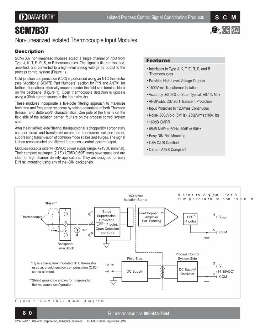
Isolated Process Control Signal Conditioning Products
©1995-2017 Dataforth Corporation, All Rights Reserved ISO9001:2008-Registered QMS
For information call 800-444-76448 0
S C M 7 B
SCM7B37Non-Linearized Isolated Thermocouple Input ModulesDescriptionSCM7B37 non-linearized modules accept a single channel of input from Type , , T, , R, S, or B thermocouples. The signal is filtered, isolated, amplified, and converted to a high level analog voltage for output to the process control system (Figure 1).Cold junction compensation (CJC) is performed using an NTC thermistor see Additional S B Part Numbers section for P N and AN for
further information externally mounted under the field side terminal bloc on the bac panel Figure . Open thermocouple detection is upscale using a 30nA current source in the input circuitry.These modules incorporate a five pole filtering approach to maximi e both time and fre uency response by ta ing advantage of both ThomsonBessel and Butterworth characteristics. One pole of the filter is on the
field side of the isolation barrier four are on the process control system side. After the initial field side filtering, the input signal is chopped by a proprietary chopper circuit and transferred across the transformer isolation barrier, suppressing transmission of common mode spikes and surges. The signal is then reconstructed and filtered for process control system output.Modules accept a wide 14 - 35VDC power supply range (+24VDC nominal). Their compact packages (2.13”x1.705”x0.605” max) save space and are ideal for high channel density applications. They are designed for easy DIN rail mounting using any of the DIN bac panels.
Features• Interfaces to Type J, K, T, E, R, S, and B
Thermocouples• Provides High-Level Voltage Outputs• 1500Vrms Transformer Isolation• Accuracy, ± 0.03% of Span Typical, ± 0.1% Max• ANSI/IEEE C37.90.1 Transient Protection• Input Protected to 120Vrms Continuous Noise, p p H , rms H
• 160dB CMRR• 85dB NMR at 60Hz, 80dB at 50Hz• Easy DIN Rail Mounting SA S ertified
• CE and ATEX Compliant
Surge
Suppression,
Protection,
LPF (1 pole),
Open Detection
and CJC
Backpanel
Term Block
–V
+V *RT is a backpanel mounted NTC thermistor
used as a cold junction compensation (CJC)
sense element.
**Shield ground-tie shown for ungrounded
thermocouple configuration.
RT*
VS
LPF
(4 pole)
Iso-Chopper II™Amplifier
Pat. Pending
VOUT
4
3
(14-35VDC)
0
2
1
Shield**
Thermocouple
+
–
X
DC Supply
Field-Side
DC Supply/
Oscillator
Process Control
System-Side
1500VrmsIsolation Barrier
5COM
5COM
F i g u r e 1 : S C M 7 B 3 7 B l o ck D i a g r a m
R e f e r t o A N 7 0 1 f o r V O U T t ot e m p e r a t u r e co n ve r si o n i n f o r m a t i o n

Isolated Process Control Signal Conditioning Products
©1995-2017 Dataforth Corporation, All Rights Reserved ISO9001:2008-Registered QMS
Visit our website www.dataforth.com 8 1
S C M 7 B
SCM
7B
Ordering InformationSpecifications Typical at and D
x
NOTES: ontact factory or your local Dataforth sales office for maximum values.(1) Thermocouple characteristics per NIST monograph 175, ITS-90.
Output Range and Supply urrent specifications are based on minimum output load resistance.inimum output load resistance is calculated by OUT
2/PE, where PE is the output ffective AvailablePower that guarantees output range, accuracy, and linearity specifications.
Accuracy includes the effects of repeatability, hysteresis, and linearity. Linearity is calculated using the best fit straight line method.
(5) VZ is the nominal input voltage that results in a 0V output.(6) RTI = Referenced to Input
The sensor accuracy should be added to the module accuracy and thermocouple accuracyto compute the overall measurement accuracy.
Output Range Part o u fi am e +1 to +5V 0 to +5V
0 to +10V
NONEAD
SCM7B37J-01 SCM7B37J-01A SCM7B37J-01D
Module SCM7B37Input Signal Range
Bias Current Resistance Normal Power Off Overload Protection Continuous Transient
Thermocouple(1)
(See Ordering Information)– 30nA
min min
120Vrms maxANSI/IEEE C37.90.1
Output Signal Range(2)
ffective Available Power(2)
Resistance Protection Voltage/Current Limit
†
40mW
Continuous Short to Ground± 12V, ± 14mA
CMV (Input-to-Output) Continuous TransientCMRR (50 or 60Hz)
1500VrmsANSI/IEEE C37.90.1
160dBAccuracy(3)
Linearity(4)
Stability to Gain Input Offset Zero Suppression Output OffsetNoise Peak at 5MHz B/W RMS at 10Hz to 100kHz B/W Peak at 0.1Hz to 10Hz B/WCJC Accuracy(7), to ambientOpen Input ResponseOpen Input Detection Time
± 0.03% Span typical,± 0.1% Span max
See Ordering Information
ppm.
± 0.005%( Vz)(5)
. Span
RTI(6)
. typ, max
Upscale<1 0s
Frequency and Time Response Bandwidth, – 3dB NMR (50/60Hz) Step Response, 90% Span
3Hz80/85dB165ms
Supply VoltageCurrent(2)
Sensitivity
14 to 35VDC12mA
± 0.0001%/ %V 8
Mechanical Dimensions (h)(w)(d)
2.13” x 1.705” x 0.605” max(54.1mm x 43.3mm x 15.4mm max)
Environmental Operating Temperature Range Storage Temperature Range Relative HumidityEmissions EN61000-6-4 Radiated, ConductedImmunity EN61000-6-2 RF ESD, EFT
to to
0 to 95% NoncondensingISM, Group 1
Class AISM, Group 1
Performance A ± 0.5% Span ErrorPerformance B
†Output Ranges Available
‡Thermocouple Alloy Combinations S t a n d a r d s : D I N I E C 5 8 4 , A N S I M C 9 6 - 1 - 8 2 , J I S C 1 6 0 2 - 1 9 8 1
Type MaterialJKTERSB
Iron vs. Copper-Nickel Nickel-Chromium vs. Nickel-Aluminum Copper vs. Copper-Nickel Nickel-Chromium vs. Copper-Nickel Platinum-13% Rhodium vs. Platinum Platinum-10% Rhodium vs. Platinum Platinum-30% Rhodium vs. Platinum-6% Rhodium
Model‡ Input Range Accuracy(3) ica a
Linearity(4)
ica aSCM7B37J-01
SCM7B37J-10
SCM7B37J-11
SCM7B37J-12
SCM7B37J-13
SCM7B37K-02
SCM7B37K-20
SCM7B37K-21
SCM7B37K-22
SCM7B37K-23
SCM7B37T-03
SCM7B37E-04
SCM7B37R-05
SCM7B37S-06
SCM7B37B-07
to F to F
to F to F
to F to F
to F to F
to F to F
to F to F
to F to F
to F to F
to F to F
to F to F
to F to F
to F to F
to F to F
to F to F
to F to F
± 0.03%.
± 0.03%.
± 0.03%.
± 0.03%.
± 0.03%.
± 0.03%.
± 0.03%.
± 0.03%.
± 0.03%.
± 0.03%.
± 0.03%.
± 0.03%.
± 0.03%.
± 0.03%.
± 0.03%.
± 0.1%.
± 0.1%.
± 0.1%.
± 0.1%.
± 0.1%.
± 0.1%.
± 0.1%.
± 0.1%.
± 0.1%.
± 0.1%.
± 0.1%.
± 0.1%.
± 0.1%.
± 0.1%.
± 0.1%.
± 0.01%.
± 0.01%.
± 0.01%.
± 0.01%.
± 0.01%.
± 0.01%.
± 0.01%.
± 0.01%.
± 0.01%.
± 0.01%.
± 0.01%.
± 0.01%.
± 0.01%.
± 0.01%.
± 0.01%.
± 0.02%.
± 0.02%.
± 0.02%.
± 0.02%.
± 0.02%.
± 0.02%.
± 0.02%.
± 0.02%.
± 0.02%.
± 0.02%.
± 0.02%.
± 0.02%.
± 0.02%.
± 0.02%.
± 0.02%.

Isolated Process Control Signal Conditioning Products
©1995-2017 Dataforth Corporation, All Rights Reserved ISO9001:2008-Registered QMS
For information call 800-444-76448 2
S C M 7 B
SCM7B39Isolated Process Current Output ModulesDescriptionSCM7B39 process current modules accept high-level signals from the process control system and provide either 0 to 20mA or 4 to 20mA current to the field Figure .These modules incorporate a five pole filtering approach to maximi e both time and fre uency response by ta ing advantage of both Thomson Bessel and Butterworth characteristics. One pole of the filter is on the process control system side of the isolation barrier, and the other four poles are on the field side.After the initial process control system side filtering, the signal is chopped by a proprietary chopper circuit and transferred across the transformer isolation barrier, suppressing transmission of common mode spi es and surges. The signal is then reconstructed, filtered, and converted to a process current for output to the field.Modules accept a wide 18 - 35VDC power supply range (+24VDC nominal). Their compact packages (2.13”x1.705”x0.605” max) save space and are ideal for high channel density applications. They are designed for easy DIN rail mounting using any of the DIN bac panels.
Features• Accepts High-Level Voltage Input• Provides 4-20mA or 0-20mA Current Output• 1500Vrms Transformer Isolation• Accuracy, ± 0.03% of Span Typical, ± 0.1% Max• ANSI/IEEE C37.90.1 Transient Protection• Output Protected to 120Vrms Continuous Noise, Ap p H , Arms H
• 110dB CMRR• Easy DIN Rail Mounting SA S ertified
• CE and ATEX Compliant
LPF
(2 pole)
NC
Surge
Suppression
Protection and
LPF (2 pole)
Backpanel
Term Block
-V
+V
LOAD
LPF
(1 pole)
Iso-Chopper II™Amplifier
Pat. Pending
0
2
1 Input
Protection/
Conversion
VS
VIN, IIN4
3
(18-35VDC)
+
-
+I
-
X
DC Supply
Field-Side
DC Supply/
Oscillator
Process Control
System-Side
1500VrmsIsolation Barrier
5COM
5COM
F i g u r e 1 : S C M 7 B 3 9 B l o ck D i a g r a m

Isolated Process Control Signal Conditioning Products
©1995-2017 Dataforth Corporation, All Rights Reserved ISO9001:2008-Registered QMS
Visit our website www.dataforth.com 8 3
S C M 7 B
SCM
7B
Model Input Range Output RangeSCM7B39-01SCM7B39-02SCM7B39-03SCM7B39-04
+1 to +5V 0 to +10V 0 to +10V 4 to 20mA
4 to 20mA0 to 20mA4 to 20mA4 to 20mA
Ordering InformationSpecifications Typical at and D
NOTES: ontact factory or your local Dataforth sales office for maximum values. Same specification as S B , , .
Output Range and Supply urrent specifications are based on maximum output load resistance. aximumoutput load resistance is calculated by PE/IOUT
2 where PE is the Output ffective Available Power that guaranteesoutput range, accuracy, and linearity specifications. Output effective available power is independent of supply voltage.
Accuracy includes the effects of repeatability, hysteresis, and linearity. Linearity is calculated using the best fit straight line method.
Module SCM7B39-01,-02,-03 SCM7B39-04Output Signal Range(1)
ffective Available Power(1)
Protection Continuous Transient Current Limit
4-20mA, 0-20mA320mW
120Vrms maxANSI/IEEE C37.90.1
32mA
4-20mA*
***
Input Signal Range Bias Current Resistance Normal Power Off Overload Protection Compliance
1 to +5V, 0 to +10V± 1nA
min min
± 35Vpeak (no damage)N/A
4-20mAN/A
N/A± 7.5Vpeak35VDC max
CMV (Input-to-Output) Continuous TransientCMRR (50 or 60Hz)
1500VrmsANSI/IEEE C37.90.1
110dB
***
Accuracy(2)
Linearity(3)
Stability to Gain Output OffsetNoise Peak at 5MHz B/W RMS at 10Hz to 100kHz B/W Peak at 0.1Hz to 10Hz B/W
± 0.03% Span typical,± 0.1% Span max
± 0.01% Span typical,± 0.02% Span max
ppm. Span
AA
42nA
*
*
ppm. Span
***
Open Output Loop Detection Response
Detection Time
N/A
N/A
Input Resistance 5ms
Frequency and Time Response Bandwidth, – 3dB NMR (– 3dB at 100Hz) Step Response, 90% Span
100HzdB per Decade above H
5ms
***
Supply Voltage Current(1)
Sensitivity
18 to 35VDC56mA
± 0.0003%/ %V S
***
Mechanical Dimensions (h)(w)(d)
2.13” x 1.705” x 0.605” max(54.1mm x 43.3mm x 15.4mm max)
**
Environmental Operating Temperature Range Storage Temperature Range Relative HumidityEmissions EN61000-6-4 Radiated, ConductedImmunity EN61000-6-2 RF ESD, EFT
to to
0 to 95% NoncondensingISM, Group 1
Class AISM, Group 1
Performance A ± 0.5% Span ErrorPerformance B
********

Isolated Process Control Signal Conditioning Products
©1995-2017 Dataforth Corporation, All Rights Reserved ISO9001:2008-Registered QMS
For information call 800-444-76448 4
S C M 7 B
SCM7B40/41Isolated Analog Voltage Input Modules, Wide BandwidthDescriptionEach SCM7B40/41 voltage input module accepts one channel of analog voltage input which is filtered, isolated, amplified, and converted to a high-level analog voltage for output to the process control system (Figure 1).These modules incorporate a five pole filtering approach to maximi e both time and fre uency response by ta ing advantage of both Thomson Bessel and Butterworth characteristics. One pole of the filter is on the field side of the isolation barrier four are on the process control system side.After the initial field side filtering, the input signal is chopped by a proprietary chopper circuit and transferred across the transformer isolation barrier, suppressing transmission of common mode spikes and surges. The signal is thenreconstructed and filtered for process control system output.Modules accept a wide 14 - 35VDC power supply range (+24VDC nominal). Their compact packages (2.13”x1.705”x0.605” max) save space and are ideal for high channel density applications. They are designed for easy DIN rail mounting using any of the DIN bac panels.
Features• Accepts Millivolt or Voltage Inputs• Provides High-Level Voltage Outputs• 10kHz Bandwidth• 1500Vrms Transformer Isolation• Accuracy, ± 0.03% of Span Typical, ± 0.1% Max• ANSI/IEEE C37.90.1 Transient Protection• Input Protected to 120Vrms Continuous• Noise, 2mVp-p (5MHz), 1mVrms (100kHz)• Up to 110dB CMRR• Easy DIN Rail Mounting SA S ertified
• CE and ATEX Compliant
LPF
(1 pole)
+
–
X
NC
Surge
Suppression
and
Protection
Backpanel
Term Block
DC Supply
Field-Side
–V
+V
VIN
VS
LPF
(4 pole)
DC Supply/
Oscillator
Process Control
System-Side
Iso-Chopper II™Amplifier
Pat. Pending
1500VrmsIsolation Barrier
VOUT
4
3
(14-35VDC)
0
2
1
–
+
5COM
5COM
F i g u r e 1 : S C M 7 B 4 0 / 4 1 B l o ck D i a g r a m

Isolated Process Control Signal Conditioning Products
©1995-2017 Dataforth Corporation, All Rights Reserved ISO9001:2008-Registered QMS
Visit our website www.dataforth.com 8 5
S C M 7 B
SCM
7B
Model Input RangeSCM7B40-02SCM7B40-03SCM7B40-07SCM7B40-08SCM7B41-01SCM7B41-02SCM7B41-03SCM7B41-04SCM7B41-05SCM7B41-06
0 to +100mV 0 to +1V ± 100mV ± 1V 0 to +10V ± 5V 10V 0 to +5V 0 to +20V 0 to +40V
Output Range Part o u fi am e+1 to +5V 0 to +5V
0 to +10V
NONEAD
SCM7B40-02 SCM7B40-02A SCM7B40-02D
Ordering Information
†Output Ranges Available
Specifications Typical at and D
NOTES: ontact factory or your local Dataforth sales office for maximum values. Specification same as preceding model.
Output Range and Supply urrent specifications are based on minimum output load resistance.inimum output load resistance is calculated by OUT
2/PE, where PE is the Output ffective AvailablePower that guarantees output range, accuracy, and linearity specifications.
Accuracy includes the effects of repeatability, hysteresis, and linearity. Linearity is calculated using the best fit straight line method.
(4) VZ is the nominal input voltage that results in a 0V output.(5) RTI = Referenced to Input.
Module SCM7B40 SCM7B41Input Signal Range Bias Current Resistance Normal Power Off Overload Protection Continuous Transient
– 1V to +1V± 1nA
min min
120Vrms maxANSI/IEEE C37.90.1
– 10V to +40V± 0.1nA
min min min
**
Output Signal Range(1)
ffective Available Power(1)
Resistance Protection Voltage/Current Limit
†
40mW
Continuous Short to Ground± 12V, ± 14mA
†
****
CMV (Input-to-Output) Continuous TransientCMRR (50 or 60Hz)
1500VrmsANSI/IEEE C37.90.1
110dB
**
110dBAccuracy(2)
Linearity(3)
Stability to Gain Input Offset Zero Suppression Output OffsetNoise Peak at 5MHz B/W RMS at 10Hz to 100kHz B/W Peak at 0.1Hz to10Hz B/W
± 0.03% Span typical,± 0.1% Span max
± 0.01% Span typical,± 0.02% Span max
ppm.
± 0.005%( Vz)(4)
. Span
2mV1mV
RTI(5)
*
*
ppm
**
***
Frequency and Time Response Bandwidth, – 3dB NMR Step Response, 90% Span
10kHzdB per Decade above H
s
***
Supply Voltage Current(1)
Sensitivity
14 to 35VDC12mA
± 0.0001%/ %V S
***
Mechanical Dimensions (h)(w)(d)
2.13” x 1.705” x 0.605” max(54.1mm x 43.3mm x 15.4mm max)
**
Environmental Operating Temperature Range Storage Temperature Range Relative HumidityEmissions EN61000-6-4 Radiated, ConductedImmunity EN61000-6-2 RF ESD, EFT
to to
0 to 95% NoncondensingISM, Group 1
Class AISM, Group 1
Performance A ± 0.5% Span ErrorPerformance B
********

Isolated Process Control Signal Conditioning Products
©1995-2017 Dataforth Corporation, All Rights Reserved ISO9001:2008-Registered QMS
For information call 800-444-76448 6
S C M 7 B
SCM7B47Isolated Linearized Thermocouple Input ModulesDescriptionSCM7B47 modules accept a single channel of input from Type J, K, T,
, R, S, B, or N thermocouples. The signal is filtered, isolated, amplified, linearized, and converted to a high-level analog voltage for output to the process control system (Figure 1).Lineari ation is achieved by creating a non linear transfer function through the module itself; refer to AN505. This non-linear transfer function is configured at the factory and is designed to be e ual and opposite to the thermocouple non-linearity.Cold junction compensation (CJC) is performed using an NTC thermistor see Additional S B Part Numbers section for P N and AN for
further information externally mounted under the field side terminal bloc on the bac panel Figure . Open thermocouple detection is upscale using a 30nA current source in the input circuitry.These modules incorporate a five pole filtering approach to maximi e both time and fre uency response by ta ing advantage of both Thomson Bes-sel and Butterworth characteristics. One pole of the filter is on the field side of the isolation barrier four are on the process control system side.After the initial field side filtering, the input signal is chopped by a proprietary chopper circuit and transferred across the transformer isolation barrier, suppressing transmission of common mode spi es and surges. The signal is then reconstructed and filtered for process control system output.Modules accept a wide 14 - 35VDC power supply range (+24VDC nominal). Their compact packages (2.13”x1.705”x0.605” max) save space and are ideal for high channel density applications. They are designed for easy DIN rail mounting using any of the DIN bac panels.
Features• Interfaces to Type J, K, T, E, R, S, B and N
Thermocouples• Linearizes Thermocouple Signals• Provides High-Level Voltage Outputs• 1500Vrms Transformer Isolation• Accuracy, ± 0.06% to ± 0.16% of Span Typical• ANSI/IEEE C37.90.1 Transient Protection• Input Protected to 120Vrms Continuous Noise, m p p H , rms H
• 160dB CMRR• 85dB NMR at 60Hz, 80dB at 50Hz• Easy DIN Rail Mounting SA S ertified
• CE and ATEX Compliant
Surge
Suppression,
Protection,
LPF (1 pole),
Open Detection
and CJC
Backpanel
Term Block
–V
+V
RT*
VS
LPF
(4 pole)
and
Linearization
Iso-Chopper II™Amplifier
Pat. Pending
VOUT
4
3
(14-35VDC)
0
2
1
Shield**
Thermocouple
+
–
X
DC Supply
Field-Side
DC Supply/
Oscillator
Process Control
System-Side
1500VrmsIsolation Barrier
*RT is a backpanel mounted NTC thermistor
used as a cold junction compensation (CJC)
sense element.
**Shield ground-tie shown for ungrounded
thermocouple configuration.
5COM
5COM
F i g u r e 1 : S C M 7 B 4 7 B l o ck D i a g r a m
R e f e r t o A N 7 0 1 f o r V O U T t ot e m p e r a t u r e co n ve r si o n i n f o r m a t i o n

Isolated Process Control Signal Conditioning Products
©1995-2017 Dataforth Corporation, All Rights Reserved ISO9001:2008-Registered QMS
Visit our website www.dataforth.com 8 7
S C M 7 B
SCM
7B
Ordering InformationSpecifications Typical at and D
NOTES: ontact factory or your local Dataforth sales office for maximum values.(1) Thermocouple characteristics per NIST monograph 175, ITS-90.
Output Range and Supply urrent specifications are based on minimum output load resistance.inimum output load resistance is calculated by OUT
2/PE, where PE is the output ffective AvailablePower that guarantees output range, accuracy, and linearity specifications.
Accuracy includes the effects of repeatability, hysteresis, and conformity.(4) VZ is the nominal input voltage that results in a 0V output.(5) RTI = Referenced to Input.
The sensor accuracy should be added to the module accuracy and thermocouple accuracyto compute overall measurement accuracy.
Output Range Part o u fi am e +1 to +5V 0 to +5V
0 to +10V
NONEAD
SCM7B47J-01 SCM7B47J-01A SCM7B47J-01D
Model‡ Input Range Accuracy(3)(5)
ica aSCM7B47J-01
SCM7B47J-02
SCM7B47K-03
SCM7B47K-04
SCM7B47T-05
SCM7B47T-06
SCM7B47E-07
SCM7B47R-08
SCM7B47S-09
SCM7B47B-10
SCM7B47N-11
to F to F
to F to F
to F to F
to F to F
to F to F
to F to F
to F to F
to F to F
to F to F
to F to F
to F to F
± 0.11% Span.
± 0.10% Span.
± 0.11% Span.
± 0.06% Span.
± 0.13% Span.
± 0.16% Span.
± 0.11% Span.
± 0.10% Span.
± 0.08% Span.
± 0.12% Span.
± 0.09% Span.
± 0.32% Span.
± 0.30% Span.
± 0.32% Span.
± 0.18% Span.
± 0.38% Span.
± 0.47% Span.
± 0.34% Span.
± 0.30% Span.
± 0.25% Span.
± 0.35% Span.
± 0.27% Span.
†Output Ranges Available
‡Thermocouple Alloy Combinations S t a n d a r d s : D I N I E C 5 8 4 , A N S I M C 9 6 - 1 - 8 2 , J I S C 1 6 0 2 - 1 9 8 1
Type MaterialJKTERSBN
Iron vs. Copper-Nickel Nickel-Chromium vs. Nickel-Aluminum Copper vs. Copper-Nickel Nickel-Chromium vs. Copper-Nickel Platinum-13% Rhodium vs. Platinum Platinum-10% Rhodium vs. Platinum Platinum-30% Rhodium vs. Platinum-6% Rhodium Nickel-14.2% Chromium-1.4% Silicon vs. Nickel-4.4% Silicon- 0.1% Magnesium
Module SCM7B47Input Signal Range
Current Resistance Normal Power Off Overload Protection Continuous Transient
Thermocouple(1)
(See Ordering Information)– 30nA
min min
120Vrms maxANSI/IEEE C37.90.1
Output Signal Range(2)
ffective Available Power(2)
Resistance Protection Voltage/Current Limit
†
40mW
Continuous Short to Ground± 12V, ± 14mA
CMV (Input-to-Output) Continuous TransientCMRR (50 or 60Hz)
1500VrmsANSI/IEEE C37.90.1
160dBAccuracy(3)
Stability to Gain Input Offset Zero Suppression Output OffsetNoise Peak at 5MHz B/W RMS at 10Hz to 100kHz B/W Peak at 0.1Hz to 10Hz B/WCJC Accuracy(6), to ambientOpen Input ResponseOpen Input Detection Time
(See Ordering Information)
ppm.
± 0.005%( Vz)(4)
. Span
1mV
RTI(5)
. Typ, max
Upscale<1 0s
Frequency and Time Response Bandwidth, – 3dB NMR (50/60Hz) Step Response, 90% Span
3Hz80/85dB165ms
Supply Voltage Current(2)
Sensitivity
14 to 35VDC16mA
± 0.0001%/ %V 8
Mechanical Dimensions (h)(w)(d)
2.13” x 1.705” x 0.605” max(54.1mm x 43.3mm x 15.4mm max)
Environmental Operating Temperature Range Storage Temperature Range Relative HumidityEmissions EN61000-6-4 Radiated, ConductedImmunity EN61000-6-2 RF ESD, EFT
to to
0 to 95% NoncondensingISM, Group 1
Class AISM, Group 1
Performance A ± 0.5% Span ErrorPerformance B

Isolated Process Control Signal Conditioning Products
©1995-2017 Dataforth Corporation, All Rights Reserved ISO9001:2008-Registered QMS
For information call 800-444-76448 8
S C M 7 BIsolated Process Control Signal Conditioning Products
©1995-2017 Dataforth Corporation, All Rights Reserved ISO9001:2008-Registered QMS
For information call 800-444-76448 8
S C M 7 B
SCM7BModule Dimensions and PinoutsThe following mechanical drawing is useful if designing circuit boards to mount the S B modules. any soc ets are available which accept the mounting pins. As an example, A P Inc. provides a soc et with part number .
F i g u r e 2 : S C M 7 B P i n o u t s
The captive nut for the mounting screw can be obtained from P Penn ngineering and anufacturing , part number SF .
F i g u r e 1 : S C M 7 B M o d u l e D i m e n si o n s

Isolated Process Control Signal Conditioning Products
©1995-2017 Dataforth Corporation, All Rights Reserved ISO9001:2008-Registered QMS
Visit our website www.dataforth.com 8 9
S C M 7 B
SCM
7BSCM7BXEVDescriptionThe S B Figures and is a single channel bac panel that can accept any of the S B analog modules. It is meant to be used primarily for module evaluation. nli e multiple channel bac panels, the single highlevel system output (or input) signal is routed to all channel pins on the system interface DB connector. The bac panel contains four standoffs to allow mounting, using a or smaller screw.System Side - Power
sing the supply input, the power supply voltage can be as little as D . If D is available, it is recommended that the supply be
connected between the A or B connections and O this will protect the module against accidental supply reversal. sing both these connections with two power supplies enables redundant operation. It is also recommended that a diode transient absorber be installed to reduce power supply transient events from degrading system performance. An accessory location, between the supply and common lines, is provided
for this purpose. The bac panel is fused at Amp for module protection.System Side - SignalThe SCM7BXEV uses either the SCM7BXCA01 (DB25 to 26-pin adapter cable and S A pin to pin interface cable , or the S B A DB to DB interface cable , depending on system requirements.
F i g u r e 1 : S C M 7 B X E V D i m e n si o n s
Field Side - SignalOn the field side, a temperature sensor is mounted underneath the field side terminal bloc to provide cold unction compensation for thermocouple modules, and a current-to-voltage conversion resistor (P/N SCM7BXR1) socketing location is provided (supplied with SCM7B33 modules). Field connections are terminated with three screw terminals.
Operating TemperatureRelative Humidity
to 95% Noncondensing
Interface Connector: Field System
high density screw clamp, 10-24 AWGDB25 (male) with 4-40 screwlocks andhigh density screw clamp, 10-24 AWG
Specifications
Accessories for SCM7B Analog Modules

Isolated Process Control Signal Conditioning Products
©1995-2017 Dataforth Corporation, All Rights Reserved ISO9001:2008-Registered QMS
For information call 800-444-76449 0
S C M 7 B
F i g u r e 2 : S C M 7 B X E V S ch e m a t i c D i a g r a m

Isolated Process Control Signal Conditioning Products
©1995-2017 Dataforth Corporation, All Rights Reserved ISO9001:2008-Registered QMS
Visit our website www.dataforth.com 9 1
S C M 7 B
SCM
7B
SCM7BP01/SCM7BP02DescriptionThe SCM7BP01 (Figure 3) and SCM7BP02 (Figure 4) are 1 and 2 chan-nel bac panels. nli e other bac panels available, both the system and field side sides have screw terminal connectors able to accept discrete wire A G . The bac panels can be ordered with standoffs to allow mounting, using a or smaller screw, or with DIN rail mounting hardware.System Side - PowerBoth bac panels accept D between and O using a screw terminal A G bloc . No reverse supply diodes are provided with this model, but both are fused at Amp or Amp for module protection.
F i g u r e 3 : S C M 7 B P 0 1 D i m e n si o n s
Field Side - SignalOn the field side, a temperature sensor is mounted underneath the field side terminal bloc to provide cold unction compensation for thermocouple modules, and a current-to-voltage conversion resistor (P/N SCM7BXR1) socket location is provided (supplied with SCM7B33 modules).
Operating TemperatureRelative Humidity
to 95% Noncondensing
Interface Connector: Field System
high density screw clamp, 10-24 AWGhigh density screw clamp, 10-24 AWG
Isolation: Input-to-Output Channel-to-Channel
1500Vrms continuous, max1500Vrms continuous, max
Specifications
Backpanel
F i g u r e 4 : S C M 7 B P 0 2 D i m e n si o n s

Isolated Process Control Signal Conditioning Products
©1995-2017 Dataforth Corporation, All Rights Reserved ISO9001:2008-Registered QMS
For information call 800-444-76449 2
S C M 7 B
SCM7BP01-DIN/SCM7BP02-DINDescriptionThe SCM7BP01 and SCM7BP02 are single and dual channel mounting panels for the SCM7B modules. Both have options for standoffs or DIN rail mounting.The following accessories are required for DIN rail mounting one SCM7BP01 or SCM7BP02 panel (Figure 5): Qty Model Description 1 SCMXBEFE Base element with snap foot 2 SCMXSE Side elementThe following accessories are required for DIN rail mounting two or more SCM7BP01-4 or SCM7BP02-4 panels: Qty Model Description 2 SCMXBEFE Base element with snap foot 2 SCMXSE Side element panels S B Base element without snap foot x panels S S onnection pinsThe following DIN rail styles are available. Specify length in meters . SCMXRAIL1-XX DIN EN 50022-35x7.5 (slotted steel) SCMXRAIL2-XX DIN EN 50035-G32 (slotted steel) SCMXRAIL3-XX DIN EN 50022-35x15 (slotted steel)
F i g u r e 5 : D I N R a i l M o u n t i n g E l e m e n t s
Part Number Description
SCM7BP01
SCM7BP01-4
SCM7BP01-DIN
SCM7BP02
SCM7BP02-4
SCM7BP02-DIN
Single channel bac panel with standoffs for mounting.
Single channel bac panel. No mounting hardware included.
Single channel bac panel with DIN rail mounting hardware.Shipped fully assembled.
Dual channel bac panel with standoffs for mounting.
Dual channel bac panel. No mounting hardware included.
Dual channel bac panel with DIN rail mounting hardware.Shipped fully assembled.
Ordering Information
Panels & DIN Rail Mounting Accessories

Isolated Process Control Signal Conditioning Products
©1995-2017 Dataforth Corporation, All Rights Reserved ISO9001:2008-Registered QMS
Visit our website www.dataforth.com 9 3
S C M 7 B
SCM
7B
F i g u r e 6 : S C M 7 B P 0 1 ( - D I N ) S ch e m a t i c D i a g r a m
F i g u r e 7 : S C M 7 B P 0 2 ( - D I N ) S ch e m a t i c D i a g r a m

Isolated Process Control Signal Conditioning Products
©1995-2017 Dataforth Corporation, All Rights Reserved ISO9001:2008-Registered QMS
For information call 800-444-76449 4
S C M 7 B
SCM7BP04(-DIN)/SCM7BP08(-DIN)/SCM7BP16(-DIN)
DescriptionThe SCM7BP04, SCM7BP08, and SCM7BP16 (see Figures 8-11) are
, , channel bac panels that can accept any of the S B analog modules. All three of these bac panels can either be rac mounted using Dataforth’s 19-inch rack P/N SCMXRK-002 (using the provided 3mm screws , or directly mounted to a surface using or smaller screws. The SCM7BP04-DIN, SCM7BP08-DIN, and SCM7BP16-DIN are identical to the S BP , S BP , and S BP , but with DIN rail mounting clips attached instead of standoffs. These brac ets allow the bac panels to be mounted on either N x . x or N G type DIN rails.System Side - Power
sing the power supply input, the power supply voltage can be as little as D . If D is available, it is recommended that the supply be connected between the A or B connections and O this will protect the modules against accidental supply reversal. sing both these connections with two power supplies enables redundant power supply operation. It is also recommended that a diode transient absorber be installed to reduce power supply transient events from degrading system performance. An accessory location, between the supply and common lines, is provided for this purpose. A system side grounding stud is also provided for use if desired. All bac panels are fused according to channel count, allowing 1/4 Amp per channel.System Side - SignalTwo system interface DB connectors are used, to enable using both input and output modules simultaneously, or to route the signal from an input module bac plane to an output module bac plane. These bac -panels use either the S B A DB to pin adapter cable and S A pin to pin interface cable , or the S B A DB to DB interface cable , depending on system re uirements.
F i g u r e 8 : S C M 7 B P 0 4 ( - D I N ) D i m e n si o n s
Field Side - SignalOn the field side a temperature sensor is mounted underneath the field side terminal bloc to provide cold unction compensation for thermocouple input modules. A current-to-voltage conversion resistor (P/N SCM7BXR1, supplied with SCM7B33 modules) socket is provided for each channel. Field connetions are terminated with three screw terminals at each module site.
Ordering Information
Backpanels
Part Number DescriptionSCM7BP04
SCM7BP04-DIN
SCM7BP08
SCM7BP08-DIN
SCM7BP16
SCM7BP16-DIN
channel bac panel with standoffs for mounting.
channel bac panel with DIN rail mounting clips.Shipped fully assembled.
channel bac panel with standoffs for mounting.
channel bac panel with DIN rail mounting clips.Shipped fully assembled.
channel bac panel with standoffs for mounting.
channel bac panel with DIN rail mounting clips.Shipped fully assembled.
Operating TemperatureRelative Humidity
to 95% Noncondensing
Interface Connector: Field System
high density screw clamp, 10-24 AWG2 DB25 (male) connectors with 4-40 screwlocks
Isolation: Input-to-Output Channel-to-Channel
1500Vrms continuous, max1500Vrms continuous, max
Specifications

Isolated Process Control Signal Conditioning Products
©1995-2017 Dataforth Corporation, All Rights Reserved ISO9001:2008-Registered QMS
Visit our website www.dataforth.com 9 5
S C M 7 B
SCM
7B
Figu
re 9
: SC
M7B
P08
(-D
IN) D
imen
sion
s
Figu
re 1
0: S
CM
7BP
16(-
DIN
) Dim
ensi
ons

Isolated Process Control Signal Conditioning Products
©1995-2017 Dataforth Corporation, All Rights Reserved ISO9001:2008-Registered QMS
For information call 800-444-76449 6
S C M 7 B
Figu
re 1
1: S
CM
7BP
04/0
8/16
(-D
IN) S
chem
atic
Dia
gram

Isolated Process Control Signal Conditioning Products
©1995-2017 Dataforth Corporation, All Rights Reserved ISO9001:2008-Registered QMS
Visit our website www.dataforth.com 9 7
S C M 7 B
SCM
7B
SCMXRK-002 19-Inch Metal Mounting RackDescriptionThe SCMXRK-002 is a 19-inch metal rack for mounting the SCM7BP04/08/16, SCMPB01/02/05/06, SCMVAS-PB8/PB16, and isoLynx® SL xx bac panels.
It also provides capability to mount a system power supply and the universal interface board, P N S IF. See Figure for dimensions.
F i g u r e 1 2 : S C M X R K - 0 0 2 A n a l o g R a ck D i m e n si o n s

Isolated Process Control Signal Conditioning Products
©1995-2017 Dataforth Corporation, All Rights Reserved ISO9001:2008-Registered QMS
For information call 800-444-76449 8
S C M 7 BIsolated Process Control Signal Conditioning Products
For information call 800-444-76449 8
S C M 7 B
SCMXCA006-01, -02, -07DescriptionSCMXCA006-XXSystem interface cable for the S BP bac panels. This is a DB
ale Female cable assembly. It can be ordered in lengths of m, m, and m (see Figure 13).
F i g u r e 1 3 : S C M X C A 0 0 6 - X X S yst e m I n t e r f a ce C a b l e
Description
Interface ables8BXIF (-DIN)Universal Interface Board
The B IF is a universal interface board which converts a DB cable input to screw terminals for discrete wire. It can be mounted on the bac of the SCMXRK-002 mounting rack (8BXIF) or on a DIN rail (8BXIF-DIN). Required mounting hardware is included. se S A cable see Figure for dimensions).
F i g u r e 1 4 : 8 B X I F U n i ve r sa l I n t e r f a ce B o a r d D i m e n si o n s
F i g u r e 1 5 : S C M 7 B X R 1 D i m e n si o n s
SCM7BXR1DescriptionThe S B R current to voltage conversion resistor , . , ppm is used with the SCM7B33 voltage input modules. Sockets are provided on all bac panels to allow installation of this resistor. Other values are available consult the factory for ordering details and specifications.
Current Conversion Resistor
M a l e D B 2 5 F e m a l e D B 2 5

Isolated Process Control Signal Conditioning Products
©1995-2017 Dataforth Corporation, All Rights Reserved ISO9001:2008-Registered QMS
Visit our website www.dataforth.com 9 9
S C M 7 B
SCM
7B
SCM7BPTDescriptionThe SCM7BPT is a non-isolated signal pass-through module which shorts together the signal inputs-to-outputs.
F i g u r e 1 6 : S C M 7 B P T
Non-Isolated Pass Thru Module
SCM7B-PROTODescriptionThe S B PROTO breadboard it was designed to allow users to incorporate their own module functions using an SCM7B format. The kit includes a pc board designed for breadboard circuits, a module case, header and mounting screw. Contact the factory for additional information.
Breadboard it
Additional Part Numbers of InterestThe following is a list of parts that are available for use with your S B system, or for fabrication of your own bac panel, along with manufacturer’s part number. Dataforth ma es no claim as to availability and or uality of parts purchased from vendors other than Dataforth.Part Description Part Number ManufacturerCJC Thermistor 100K6A1 Betatherm Corp.
DC95G104W Thermometrics Diode Transient Absorber SA series General SemiconductorSockets for SCM7B pins 50865-5 Amp Incorporated Module retaining screw KSF2-440 PEM Engineering captive nut, 4-40 thread Grounding Stud, 0.625”, KFH 10-32-10 PEM Engineering 10-32 thread Part Description Part Number Manufacturer Axial Fuse PICO II series Littelfuse position termination bloc DS , Phoenix ontact, Inc. position termination bloc DS , Phoenix ontact, Inc.
DB25 (male) PCB connector 745078-3 AMP Incorporated DB female ribbon A P Incorporated connector for custom cables 0.062” PCB Standoff 647A-5015-19 Concord 0.094” PCB Standoff 647A-5023-19 Concord
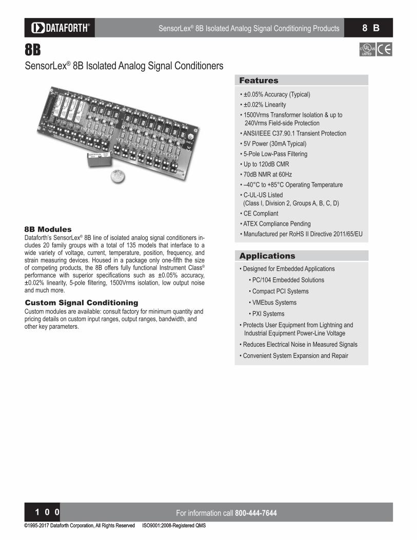
Isolated Analog Signal Conditioning Products
©1995-2017 Dataforth Corporation, All Rights Reserved ISO9001:2008-Registered QMS
For information call 800-444-76441 0 0
S C M 5 BIsolated Analog Signal Conditioning Products
©1995-2017 Dataforth Corporation, All Rights Reserved ISO9001:2008-Registered QMS
For information call 800-444-76441 0 0
S C M 5 B
For information call 800-444-76441 0 0
SensorLex® 8B Isolated Analog Signal Conditioning Products 8 B
8BSensorLex® 8B Isolated Analog Signal Conditioners
8B ModulesDataforth’s SensorLex® 8B line of isolated analog signal conditioners in-cludes 20 family groups with a total of 135 models that interface to a wide variety of voltage, current, temperature, position, frequency, and strain measuring devices. Housed in a pac age only one fifth the si e of competing products, the 8B offers fully functional Instrument Class®
performance with superior specifications such as . accuracy, . linearity, pole filtering, rms isolation, low output noise
and much more.
Features• ± 0.05% Accuracy (Typical)• ± 0.02% Linearity• 1500Vrms Transformer Isolation & up to 240Vrms Field-side Protection• ANSI/IEEE C37.90.1 Transient Protection• 5V Power (30mA Typical)• 5-Pole Low-Pass Filtering• Up to 120dB CMR• 70dB NMR at 60Hz to Operating Temperature
• C-UL-US Listed (Class I, Division 2, Groups A, B, C, D)• CE Compliant• ATEX Compliance Pending• Manufactured per RoHS II Directive 2011/65/EU
Custom Signal Conditioningustom modules are available consult factory for minimum uantity and
pricing details on custom input ranges, output ranges, bandwidth, and other key parameters.
Applications Designed for mbedded Applications
P mbedded Solutions • Compact PCI Systems bus Systems • PXI Systems• Protects User Equipment from Lightning and Industrial Equipment Power-Line Voltage• Reduces Electrical Noise in Measured Signals• Convenient System Expansion and Repair

©1995-2017 Dataforth Corporation, All Rights Reserved ISO9001:2008-Registered QMS
Visit our website www.dataforth.com 1 0 1
8 BSensorLex® 8B Isolated Analog Signal Conditioning Products
8B
8B Selection GuideVOLTAGE INPUT MODULES, 3Hz BANDWIDTH Page 104MODEL INPUT RANGE OUTPUT RANGE8B30-01 ± 10mV ± 5V8B30-02 ± 50mV ± 5V8B30-03 ± 100mV ± 5V8B30-04 ± 10mV 0 to +5V8B30-05 ± 50mV 0 to +5V8B30-06 ± 100mV 0 to +5V
8B31-01 ± 1V ± 5V8B31-02 ± 5V ± 5V8B31-03 ± 10V ± 5V8B31-04 ± 1V 0 to +5V8B31-05 ± 5V 0 to +5V8B31-06 ± 10V 0 to +5V8B31-07 ± 20V ± 5V8B31-08 ± 20V 0 to +5V8B31-09 ± 40V ± 5V8B31-10 ± 40V 0 to +5V8B31-12 ± 60V ± 5V8B31-13 ± 60V 0 to +5V
CURRENT INPUT MODULES, 3Hz BANDWIDTH Page 106MODEL INPUT RANGE OUTPUT RANGE8B32-01 4 to 20mA 0 to +5V8B32-02 0 to 20mA 0 to +5V
ISOLATED TRUE RMS INPUT MODULES Page 108MODEL INPUT RANGE OUTPUT RANGE8B33-01 0 to 100mV 0 to +5V 8B33-02 0 to 1V 0 to +5V 8B33-03 0 to 10V 0 to +5V 8B33-04 0 to 150V 0 to +5V 8B33-05 0 to 300V 0 to +5V 8B33-06 0 to 1A 0 to +5V
LINEARIZED 2- OR 3-WIRE RTD MODULES (0 to +5V OUTPUT, 3Hz BW) Page 110MODEL TYPE INPUT RANGE
B Pt to F to F B Pt to F to FB Pt to F to FB Pt to F to F
LINEARIZED 4-WIRE RTD MODULES (0 to +5V OUTPUT, 3Hz BW) Page 112MODEL TYPE INPUT RANGE
B Pt to F to FB Pt to F to FB Pt to F to FB Pt to F to F
POTENTIOMETER INPUT MODULES (0 to +5V OUTPUT, 3Hz BW) Page 114MODEL INPUT RANGE OUTPUT RANGEB to to B to to B to to B to to
THERMOCOUPLE INPUT MODULES (0 to +5V OUTPUT, 3Hz BW) Page 116MODEL TYPE INPUT RANGEB to F to FB to F to FB T T to F to FB R R to F to FB S S to F to F
STRAIN GAGE INPUT MODULES Page 118EXCITATION OUTPUT
MODEL INPUT RANGE VOLTAGE SENS RANGE BW8B38-01 ± 10mV +3.333V 3mV/V ± 5V 8kHz8B38-02 ± 30mV +10.0V 3mV/V ± 5V 8kHz8B38-05 ± 20mV +10.0V 2mV/V ± 5V 8kHz8B38-06 ± 10mV +3.333V 3mV/V 0 to +5V 8kHz8B38-07 ± 30mV +10.0V 3mV/V 0 to +5V 8kHz8B38-08 ± 20mV +10.0V 2mV/V 0 to +5V 8kHz
8B38-31 ± 10mV +3.333V 3mV/V ± 5V 3Hz8B38-32 ± 30mV +10.0V 3mV/V ± 5V 3Hz8B38-35 ± 20mV +10.0V 2mV/V ± 5V 3Hz8B38-36 ± 10mV +3.333V 3mV/V 0 to +5V 3Hz8B38-37 ± 30mV +10.0V 3mV/V 0 to +5V 3Hz8B38-38 ± 20mV +10.0V 2mV/V 0 to +5V 3Hz
CURRENT OUTPUT MODULES, 100Hz BANDWIDTH Page 120MODEL INPUT RANGE OUTPUT RANGE8B39-01 0 to +5V 4 to 20mA8B39-02 ± 5V 4 to 20mA8B39-03 0 to +5V 0 to 20mA8B39-04 ± 5V 0 to 20mA8B39-07 ± 5V -20 to 20mA
VOLTAGE INPUT MODULES, 1kHz BANDWIDTH Page 122MODEL INPUT RANGE OUTPUT RANGE8B40-01 ± 10mV ± 5V8B40-02 ± 50mV ± 5V8B40-03 ± 100mV ± 5V8B40-04 ± 10mV 0 to +5V8B40-05 ± 50mV 0 to +5V8B40-06 ± 100mV 0 to +5V
8B41-01 ± 1V ± 5V8B41-02 ± 5V ± 5V8B41-03 ± 10V ± 5V8B41-04 ± 1V 0 to +5V8B41-05 ± 5V 0 to +5V8B41-06 ± 10V 0 to +5V8B41-07 ± 20V ± 5V8B41-08 ± 20V 0 to +5V8B41-09 ± 40V ± 5V8B41-10 ± 40V 0 to +5V8B41-12 ± 60V ± 5V8B41-13 ± 60V 0 to +5V

Isolated Analog Signal Conditioning Products
©1995-2017 Dataforth Corporation, All Rights Reserved ISO9001:2008-Registered QMS
For information call 800-444-76441 0 2
S C M 5 BIsolated Analog Signal Conditioning Products
For information call 800-444-76441 0 2
S C M 5 B
For information call 800-444-76441 0 2
SensorLex® 8B Isolated Analog Signal Conditioning Products 8 BSensorLex® 8B Isolated Analog Signal Conditioning Products
For information call 800-444-76441 0 2
8 B
8B Selection Guide (Continued)2-WIRE TRANSMITTER INTERFACE MODULES Page 124MODEL INPUT RANGE OUTPUT RANGE8B42-01 4 to 20mA 0 to +5V8B42-02 4 to 20mA +1 to +5V
DC LVDT INPUT MODULES, 1kHz BANDWIDTH Page 126MODEL INPUT RANGE OUTPUT RANGE8B43-01 ± 1V ± 5V8B43-02 ± 2V ± 5V8B43-03 ± 3V ± 5V8B43-04 ± 4V ± 5V8B43-05 ± 5V ± 5V8B43-11 ± 1V 0 to +5V8B43-12 ± 2V 0 to +5V8B43-13 ± 3V 0 to +5V8B43-14 ± 4V 0 to +5V8B43-15 ± 5V 0 to +5V
FREQUENCY INPUT MODULES Page 128MODEL INPUT RANGE OUTPUT RANGE8B45-01 0 to 500Hz 0 to +5V8B45-02 0 to 1kHz 0 to +5V8B45-03 0 to 2.5kHz 0 to +5V8B45-04 0 to 5kHz 0 to +5V8B45-05 0 to 10kHz 0 to +5V8B45-06 0 to 25kHz 0 to +5V8B45-07 0 to 50kHz 0 to +5V8B45-08 0 to 100kHz 0 to +5V
LINEARIZED THERMOCOUPLE INPUT MODULES (0 to +5V OUTPUT, 3Hz BW) Page 130MODEL TYPE INPUT RANGEB to F to FB to F to FB to F to FB to F to FB to F to FB to F to F
8B47K-13 K to F to FB to F to FB T T to F to FB T T to F to F
VOLTAGE OUTPUT MODULES, 100Hz BANDWIDTH Page 132MODEL INPUT RANGE OUTPUT RANGE8B49-01 0 to +5V ± 5V8B49-02 ± 5V ± 5V8B49-03 ± 5V 0 to +5V8B49-04 0 to +10V ± 10V8B49-05 ± 10V ± 10V8B49-06 ± 10V 0 to +10V8B49-07 ± 5V ± 10V
VOLTAGE INPUT MODULES, 20kHz BANDWIDTH Page 134MODEL INPUT RANGE OUTPUT RANGE8B50-01 ± 20mV ± 5V8B50-02 ± 50mV ± 5V8B50-03 ± 100mV ± 5V8B50-04 ± 20mV 0 to +5V8B50-05 ± 50mV 0 to +5V8B50-06 ± 100mV 0 to +5V8B51-01 ± 1V ± 5V8B51-02 ± 5V ± 5V8B51-03 ± 10V ± 5V8B51-04 ± 1V 0 to +5V8B51-05 ± 5V 0 to +5V8B51-06 ± 10V 0 to +5V8B51-07 ± 20V ± 5V8B51-08 ± 20V 0 to +5V8B51-09 ± 40V ± 5V8B51-10 ± 40V 0 to +5V8B51-12 ± 60V ± 5V8B51-13 ± 60V 0 to +5V

©1995-2017 Dataforth Corporation, All Rights Reserved ISO9001:2008-Registered QMS
Visit our website www.dataforth.com 1 0 3
8 BSensorLex® 8B Isolated Analog Signal Conditioning Products
8B
isit our website www.dataforth.com 1 0 3
8 BSensorLex® 8B Isolated Analog Signal Conditioning Products
8B Selection Guide (Continued)ACCESSORIES Starts on Page 137MODEL DESCRIPTION8BP01 Single channel DIN rail mount carrierBP Standard channel bac panel
8BP02-1 8BP02 without cold junction compensation sensor8BP02-2 8BP02 with DIN rail mounting option8BP02-3 8BP02-1 with DIN rail mounting optionBP Standard channel bac panel
8BP04-1 8BP04 without cold junction compensation sensor8BP04-2 8BP04 with DIN rail mounting option8BP04-3 8BP04-1 with DIN rail mounting optionBP Standard channel bac panel
8BP08-1 8BP08 without cold junction compensation sensor8BP08-2 8BP08 with DIN rail mounting option8BP08-3 8BP08-1 with DIN rail mounting optionBP Standard channel bac panel
8BP16-1 8BP16 without cold junction compensation sensor8BP16-2 8BP16 with DIN rail mounting option8BP16-3 8BP16-1 with DIN rail mounting option8BPWR-2 Power Supply ModuleSCMXPRT-001 Power supply, 1A, 5VDC, 120VACSCMXPRE-001 Power supply, 1A, 5VDC, 220VACSCMXPRT-003 Power supply, 3A, 5VDC, 120VACSCMXPRE-003 Power supply, 3A, 5VDC, 220VACPWR-4505 Power supply, 5A, 5VDC, 85-264VACS A xx System interface cable for bac panelsB IF DB to screw terminal interface board
8BXCJC Cold Junction Compensation sensor8BPT Non-isolated signal pass thru moduleB PROTO Breadboard it
S R inch metal rac for mounting bac panelsSCMXRAIL1-XX DIN EN50022-35x7.5 (slotted steel), length -XX in metersSCMXRAIL2-XX DIN EN50035-G32 (slotted steel), length -XX in metersSCMXRAIL3-XX DIN EN50022-35x15 (slotted steel), length -XX in meters
‡THERMOCOUPLE ALLOY COMBINATIONSSTANDARDS: DIN IEC 584, ANSI MC96-1-82, JIS C 1602-1981TYPE MATERIALJ Iron vs. Copper-NickelK Nickel-Chromium vs. Nickel-AluminumT Copper vs. Copper-NickelR Platinum-13% Rhodium vs. PlatinumS Platinum-10% Rhodium vs. Platinum
A ATYPE ALPHA COEFFICIENT DIN JIS IEC
PT . DIN IS I NI .
Installation Notes:. This uipment is Suitable for se in lass I, Division , Groups A, B, , D,
or Non-Hazardous Locations Only.. ARNING xplosion Ha ard Substitution of Any omponents ay Impair
Suitability for lass I, Division .3.) WARNING - Explosion Hazard - Do Not Disconnect Equipment Unless Power Has Been Switched Off or The Area is nown to be Non Ha ardous.

Isolated Analog Signal Conditioning Products
©1995-2017 Dataforth Corporation, All Rights Reserved ISO9001:2008-Registered QMS
For information call 800-444-76441 0 4
S C M 5 BIsolated Analog Signal Conditioning Products
For information call 800-444-76441 0 4
S C M 5 B
For information call 800-444-76441 0 4
SensorLex® 8B Isolated Analog Signal Conditioning Products 8 B
8B30/31Voltage Input Modules, Narrow BandwidthDescription8B modules are an optimal solution for monitoring real-world process signals and providing high-level signals to a data acquisition system.
ach B or B module isolates, filters, and amplifies a voltage input signal and provides an analog voltage output (Figure 1).Signal filtering is accomplished with a pole filter optimi ed for time and frequency response which provides 70dB of normal-mode rejection at
H . One pole of this filter is on the field side of the isolation barrier for anti-aliasing, and the other four are on the system side.A special input circuit on the 8B30 and 8B31 modules provides protection against accidental connection of power-line voltages up to 240VAC. Clamp circuits on the I/O and power terminals protect against harmful transients.Isolation is provided by transformer coupling to suppress transmission of common mode spikes or surges. The module is powered from +5VDC, ± 5% .The modules are designed for installation in Class I, Division 2 hazardous locations and have a high level of immunity to environmental noise.
Features• Accepts Millivolt and Voltage Level Signals• High-Level Voltage Outputs• 1500Vrms Isolation• ANSI/IEEE C37.90.1 Transient Protection• Input Protection to 240VAC Continuous• 120dB CMR• 70dB NMR at 60Hz• ± 0.05% Accuracy• ± 0.02% Linearity Low Drift with Ambient Temperature
• C-UL-US Listed• CE Compliant• ATEX Compliance Pending• Mix and Match Module Types on Backpanel
Iso-Chopper™Amplifier
Pat. Pending
F i g u r e 1 : 8 B 3 0 / 3 1 B l o ck D i a g r a m

©1995-2017 Dataforth Corporation, All Rights Reserved ISO9001:2008-Registered QMS
Visit our website www.dataforth.com 1 0 5
8 BSensorLex® 8B Isolated Analog Signal Conditioning Products
8B
Module 8B30 8B31Input RangeInput Bias CurrentInput Resistance Normal Power Off OverloadInput Protection Continuous(1)
Transient
± 10mV to ± 100mV± 0.5nA
240VACANSI/IEEE C37.90.1
± 1V to ± 60V± 0.05nA
minimum minimum minimum
240VAC*
CMV, Input to OutputTransient, Input to OutputCMR (50Hz or 60Hz)NMR
1500Vrms maxANSI/IEEE C37.90.1
120dB70dB at 60Hz
****
Accuracy(2)
LinearityStability Offset GainNoise Output, 100kHzBandwidth, – 3dBResponse Time, 90% Span
± 0.05% Span± 0.02% Span
ppmppm
rms3Hz
160ms
**
*ppm
***
Output RangeOutput Protection Transient
See Ordering InformationContinuous Short to Ground
ANSI/IEEE C37.90.1
***
Power Supply VoltagePower Supply CurrentPower Supply Sensitivity
+5VDC ± 5%25mA
± 75ppm/%
***
Mechanical Dimensions (h)(w)(d)
1.11” x 1.65” x 0.40”(28.1mm x 41.9mm x 10.2mm)
*
Environmental Operating Temp. Range Storage Temp. Range Relative HumidityEmissions EN61000-6-4 Radiated, ConductedImmunity EN61000-6-2 RF ESD,EFT
to to
0 to 95% NoncondensingISM, Group 1
Class AISM, Group 1
Performance A ± 0.5% Span ErrorPerformance B
********
Model Input Range Output Range 8B30-01 8B30-02 8B30-03 8B30-04 8B30-05 8B30-06 8B31-01 8B31-02 8B31-03 8B31-04 8B31-05 8B31-06 8B31-07 8B31-08 8B31-09 8B31-10 8B31-12 8B31-13
– 10mV to +10mV– 50mV to +50mV
– 100mV to +100mV– 10mV to +10mV– 50mV to +50mV
– 100mV to +100mV– 1V to +1V– 5V to +5V
– 10V to +10V– 1V to +1V– 5V to +5V
– 10V to +10V– 20V to +20V– 20V to +20V– 40V to +40V– 40V to +40V– 60V to +60V– 60V to +60V
– 5V to +5V– 5V to +5V– 5V to +5V 0V to +5V 0V to +5V 0V to +5V– 5V to +5V– 5V to +5V– 5V to +5V 0V to +5V 0V to +5V 0V to +5V– 5V to +5V 0V to +5V– 5V to +5V 0V to +5V– 5V to +5V 0V to +5V
Ordering InformationSpecifications Typical at TA and D power
NOTES: ontact factory or your local Dataforth sales office for maximum values.* Same specification as B .
A between Input terminal and Input, , or terminals. A between Input and or terminals. A between and terminals.
Includes linearity, hysteresis and repeatability.
Installation Notes:. This uipment is Suitable for se in lass I, Division , Groups A, B, , D,
or Non-Hazardous Locations Only.. ARNING xplosion Ha ard Substitution of Any omponents ay Impair
Suitability for lass I, Division .3.) WARNING - Explosion Hazard - Do Not Disconnect Equipment Unless Power Has Been Switched Off or The Area is nown to be Non Ha ardous.

Isolated Analog Signal Conditioning Products
©1995-2017 Dataforth Corporation, All Rights Reserved ISO9001:2008-Registered QMS
For information call 800-444-76441 0 6
S C M 5 B
For information call 800-444-76441 0 6
SensorLex® 8B Isolated Analog Signal Conditioning Products 8 B
8B32Current Input ModulesDescription8B modules are an optimal solution for monitoring real-world process signals and providing high-level signals to a data acquisition system.
ach B module isolates, filters, and amplifies a process current input signal and provides an analog voltage output (Figure 1).Current to voltage conversion is accomplished internal to the module to ensure high accuracy.Signal filtering is accomplished with a pole filter optimi ed for time and frequency response which provides 70dB of normal-mode rejection at
H . One pole of this filter is on the field side of the isolation barrier for anti-aliasing, and the other two are on the system side.A special input circuit on the 8B32 module provides protection against accidental connection of power-line voltages up to 40VAC. Clamp circuits on the I/O and power terminals protect against harmful transients.Isolation is provided by transformer coupling to suppress transmission of common mode spikes or surges. The module is powered from +5VDC, ± 5% .The modules are designed for installation in Class I, Division 2 hazardous locations and have a high level of immunity to environmental noise.
Features• Accepts Milliamp Level Signals• High-Level Voltage Outputs• 1500Vrms Isolation• ANSI/IEEE C37.90.1 Transient Protection• Input Protection to 40VAC Continuous• 120dB CMR• 70dB NMR at 60Hz• ± 0.05% Accuracy• ± 0.02% Linearity Low Drift with Ambient Temperature
• C-UL-US Listed• CE Compliant• ATEX Compliance Pending• Mix and Match Module Types on Backpanel
LPF
RCONVSurge
Suppression
and
Protection
LPF
Isolation Barrier
VOUT
6
COM7
*Optional plug-in conversion resistor.
*
–EXC
2
NC
3
4
+EXC
1
I
NC
Backpanel
Terminal Block
+
–
(1) CJC Enable Jumper. Remains Installed for 8B32.
Isolated
Field-Side
Power
–V
+V
–V+V
Power
Oscillator
Computer-Side
Power
+5VDC5
7COM
´
´
Jn
CJCn
(1)
IN
Iso-Chopper™Amplifier
Pat. Pending
F i g u r e 1 : 8 B 3 2 B l o ck D i a g r a m

©1995-2017 Dataforth Corporation, All Rights Reserved ISO9001:2008-Registered QMS
Visit our website www.dataforth.com 1 0 7
8 BSensorLex® 8B Isolated Analog Signal Conditioning Products
8B
Model Input Range Output Range 8B32-01 8B32-02
4mA to 20mA0mA to 20mA
0V to +5V 0V to +5V
Ordering InformationSpecifications Typical at TA and D power
NOTES: ontact factory or your local Dataforth sales office for maximum values.
Includes linearity, hysteresis and repeatability.
Module 8B32Input RangeInput Resistance Normal Power OffInput Protection Continuous Transient
0mA to 20mA or 4mA to 20mA
40VACANSI/IEEE C37.90.1
CMV, Input to OutputTransient, Input to OutputCMR (50Hz or 60Hz)NMR
1500Vrms maxANSI/IEEE C37.90.1
120dB70dB at 60Hz
Accuracy(1)
LinearityStability Offset GainNoise Output, 100kHzBandwidth, – 3dBResponse Time, 90% Span
± 0.05% Span± 0.02% Span
ppmppm
rms3Hz
150msOutput RangeOutput Protection Transient
0V to +5VContinuous Short to Ground
ANSI/IEEE C37.90.1Power Supply VoltagePower Supply CurrentPower Supply Sensitivity
+5VDC ± 5%30mA
± 75ppm/%Mechanical Dimensions (h)(w)(d)
1.11” x 1.65” x 0.40”(28.1mm x 41.9mm x 10.2mm)
Environmental Operating Temperature Range Storage Temperature Range Relative HumidityEmissions EN61000-6-4 Radiated, ConductedImmunity EN61000-6-2 RF ESD, EFT
to to
0 to 95% NoncondensingISM, Group 1
Class AISM, Group 1
Performance A ± 0.5% Span ErrorPerformance B
Installation Notes:. This uipment is Suitable for se in lass I, Division , Groups A, B, , D,
or Non-Hazardous Locations Only.. ARNING xplosion Ha ard Substitution of Any omponents ay Impair
Suitability for lass I, Division .3.) WARNING - Explosion Hazard - Do Not Disconnect Equipment Unless Power Has Been Switched Off or The Area is nown to be Non Ha ardous.

Isolated Analog Signal Conditioning Products
©1995-2017 Dataforth Corporation, All Rights Reserved ISO9001:2008-Registered QMS
For information call 800-444-76441 0 8
S C M 5 B
For information call 800-444-76441 0 8
SensorLex® 8B Isolated Analog Signal Conditioning Products 8 B
8B33Isolated True RMS Input ModulesDescriptionEach 8B33 True RMS input module provides a single channel of AC input which is converted to its True R S D value, filtered, isolated, amplified, and converted to a standard process voltage output (Figure 1).The field voltage or current input signal is processed through a preamplifier and R S converter on the field side of the isolation barrier. The converted D signal is then chopped by a proprietary chopper circuit and transferred across the transformer isolation barrier, suppressing transmis-sion of common mode spikes and surges. The computer side circuitry reconstructs, filters, and converts the signal to an industry standard output of 0 to 5VDC.Special input circuits provide protection against accidental connection of power line voltages up to A and against transient events defined by ANSI I . . .
Features• Interfaces to RMS Voltage (0-300V) or RMS
Current (0-1A)• Designed for Standard Operation with
Frequencies of 45Hz to 1000Hz (Extended Range to 10kHz)
ompatible with Standard urrent and Potential Transformers
• Industry Standard Output of 0 to 5VDC . Factory alibrated Accuracy
• 1500Vrms Transformer Isolation• Input Overload Protected to 350Vrms Max
(Peak AC & DC) or 2Arms Continuous• 120dB CMR• ANSI/IEEE C37.90.1 Transient Protection• C-UL-US Listed• CE Compliant• ATEX Compliance Pending• Mix and Match Module Types on Backpanel
* Current Input Models Only
Pre-Amp
Conversion
I
AC Source*
Iso-Chopper™Amplifier
Pat. Pending
F i g u r e 1 : 8 B 3 3 B l o ck D i a g r a m
WARNING: The SensorLex 8B33 interfaces to ha ardous voltages and should only be wired by ualified personnel or licensed electricians.

©1995-2017 Dataforth Corporation, All Rights Reserved ISO9001:2008-Registered QMS
Visit our website www.dataforth.com 1 0 9
8 BSensorLex® 8B Isolated Analog Signal Conditioning Products
8B
Model Input Range Output Range 8B33-01 8B33-02 8B33-03 8B33-04 8B33-05 8B33-06
0mV to 100mV0V to 1V
0V to 10V 0V to 150V 0V to 300V
0A to 1A
0V to +5V 0V to +5V 0V to +5V 0V to +5V 0V to +5V 0V to +5V
Ordering InformationSpecifications Typical at TA and D power
NOTES: ontact factory or your local Dataforth sales office for maximum values.
B and BP , BP , BP , BP , BP , rating only. Bac panels obtained from other sources may have lower ratings.
For to seconds the max allowable transient current rating is event time . For lessthan second, ANSI I . . applies with a . load. For greater than seconds, the2 Arms continous rating applies.
At standard H factory calibration. onsult factory for calibration at other fre uencies.(4) For 0-5% Span measurements add 1% accuracy error (-02, -03, -04, -05) or 1.5% accuracy error
, . Accuracy error includes linearity, hysteresis and repeatability but not source or externalshunt inaccuracy (if used).
Module 8B33Input Signal Range Standard Frequency Range Extended Frequency Range Impedance
CouplingProtection (1)
Continuous (– 01 thru – 05) Continuous (– 06) Transient (– 01 thru – 05) Transient (– 06)
100mV to 300Vrms, 0 to 1Arms45Hz to 1000Hz1kHz to 10kHz
, , , .
AC
350Vrms2Arms
ANSI/IEEE C37.90.1See note 2
Output Signal Range Voltage Limit Protection Ripple and Noise
0V to 5V± 9V
Continuous Short to Ground0.0375% Span rms
Accuracy (5-100% Span)(3) (4)
Sinusoid 50/60Hz 45Hz to 1kHz 1kHz to 10kHzNon-Sinusoid Crest Factor = 1 Crest Factor = 2 Crest Factor = 3 Crest Factor = 4Vs. Temperature
± 0.25% Span± 0.625% Span
± 1.375% Span, ± 3.25% Span(-06)
± 0.25% Span± 0.325% Span± 0.475% Span
± 0.7% Span± 100ppm/º C
Isolation (Common Mode) Input to Output, Input to Power Continuous Transient
1500Vrms maxANSI/IEEE C37.90.1
CMR (50Hz to 60Hz) 120dBResponse Time, 90% Span <1 20mSSupply Voltage Current Sensitivity
+5VDC ± 5%30mA
± 200ppm/%Mechanical Dimensions (h)(w)(d)
1.11” x 1.65” x 0.40”(28.1mm x 41.9mm x 10.2mm)
Environmental Operating Temperature Range Storage Temperature Range Relative HumidityEmissions EN61000-6-4 Radiated, ConductedImmunity EN61000-6-2 RF ESD, EFT, Surge, Voltage Dips
– 40º C to +85º C– 40º C to +85º C
0 to 90% NoncondensingISM, Group 1
Class AISM, Group 1
Performance A ± 0.5% Span ErrorPerformance B
Installation Notes:. This uipment is Suitable for se in lass I, Division , Groups A, B, , D,
or Non-Hazardous Locations Only.. ARNING xplosion Ha ard Substitution of Any omponents ay Impair
Suitability for lass I, Division .3.) WARNING - Explosion Hazard - Do Not Disconnect Equipment Unless Power Has Been Switched Off or The Area is nown to be Non Ha ardous.

Isolated Analog Signal Conditioning Products
©1995-2017 Dataforth Corporation, All Rights Reserved ISO9001:2008-Registered QMS
For information call 800-444-76441 1 0
S C M 5 B
For information call 800-444-76441 1 0
SensorLex® 8B Isolated Analog Signal Conditioning Products 8 B
8B34Linearized 2- or 3-Wire RTD Input ModulesDescription8B modules are an optimal solution for monitoring real-world process signals and providing high-level signals to a data acquisition system.
ach B input module isolates, filters, amplifies, and lineari es a single channel of temperature input from an RTD and provides an analog voltage output (Figure 1).RTD excitation is provided from the module using two matched current sources. When using a 3-wire connection, this method allows equal currents to ow through the sensor leads, canceling the effects of lead resistances.The excitation currents are small (0.25mA) which minimizes self-heating of the RTD.Signal filtering is accomplished with a pole filter optimi ed for time and frequency response which provides 70dB of normal-mode rejection at
H . One pole of this filter is on the field side of the isolation barrier for anti-aliasing, and the other two are on the system side.A special input circuit on the 8B34 module provides protection against accidental connection of power-line voltages up to 240VAC. Clamp circuits on the I/O and power terminals protect against harmful transients.The modules are designed for installation in Class I, Division 2 hazardous locations and have a high level of immunity to environmental noise.
Features Interfaces to Platinum RTDs
• Linearizes RTD Signal• High-Level Voltage Outputs• 1500Vrms Isolation• ANSI/IEEE C37.90.1 Transient Protection• Input Protection to 240VAC Continuous• 120dB CMR• 70dB NMR at 60Hz Low Drift with Ambient Temperature
• C-UL-US Listed• CE Compliant• ATEX Compliance Pending• Mix and Match Module Types on Backpanel
Surge
Suppression
and
Protection
–V
LPF
7COM
2-wire3-wire
LPF
´
–EXC
2
3
4
+EXC
1
NC
Backpanel
Terminal Block
+
–
RTD
Isolated
Field-Side
Power
–V
+V
–V+V
Power
Oscillator
Computer-Side
Power
+5VDC5
7COM
´
´(1) CJC Enable Jumper. Remains Installed for 8B34.
Jn
CJCn
(1)
Isolation Barrier
Linearizer VOUT
6
–V´
RzIso-Chopper™
AmplifierPat. Pending
F i g u r e 1 : 8 B 3 4 B l o ck D i a g r a m

©1995-2017 Dataforth Corporation, All Rights Reserved ISO9001:2008-Registered QMS
Visit our website www.dataforth.com 1 1 1
8 BSensorLex® 8B Isolated Analog Signal Conditioning Products
8B
Model Input Range Output Range Accuracy(3)
Pt 8B34-01
8B34-02
8B34-03
8B34-04
to F to F
to F to F
to F to F
to F to F
0V to +5V
0V to +5V
0V to +5V
0V to +5V
.
.
.
.
Ordering InformationSpecifications Typical at TA and D power
Module 8B34Input Range LimitsInput Resistance Normal Power Off OverloadInput Protection Continuous(1)
Transient
to Pt
240VACANSI/IEEE C37.90.1
Sensor Excitation CurrentLead Resistance EffectCMV, Input to OutputTransient, Input to OutputCMR (50 or 60Hz)NMR
0.25mA. (2)
1500Vrms maxANSI/IEEE C37.90.1
120dB70dB at 60Hz
AccuracyStability Offset GainNoise Output, 100kHzBandwidth, – 3dBResponse Time, 90% Span
See Ordering Information
ppmppm
rms3Hz
150msOutput RangeOutput Protection TransientOpen Input ResponseOpen Input Detection Time
See Ordering InformationContinuous Short to Ground
ANSI/IEEE C37.90.1Downscale
1sPower Supply VoltagePower Supply CurrentPower Supply Sensitivity
+5VDC ± 5%25mA
± 75ppm/%Mechanical Dimensions (h)(w)(d)
1.11” x 1.65” x 0.40”(28.1mm x 41.9mm x 10.2mm)
Environmental Operating Temperature Range Storage Temperature Range Relative HumidityEmissions EN61000-6-4 Radiated, ConductedImmunity EN61000-6-2 RF ESD, EFT
to to
0 to 95% NoncondensingISM, Group 1
Class AISM, Group 1
Performance A ± 0.5% Span ErrorPerformance B
Type A a Coe ficient DIN JIS IEC Pt 0.00385 DIN 43760 JIS C 1604-1989 IEC 751
**RTD Standards
NOTES : ontact factory or your local Dataforth sales office for maximum values.
A between Input terminal and Input, , or terminals. A between Input and or terminals. A between and terminals.
refers to the resistance in one lead. Includes conformity, hysteresis and repeatability.
Installation Notes:. This uipment is Suitable for se in lass I, Division , Groups A, B, , D,
or Non-Hazardous Locations Only.. ARNING xplosion Ha ard Substitution of Any omponents ay Impair
Suitability for lass I, Division .3.) WARNING - Explosion Hazard - Do Not Disconnect Equipment Unless Power Has Been Switched Off or The Area is nown to be Non Ha ardous.

Isolated Analog Signal Conditioning Products
©1995-2017 Dataforth Corporation, All Rights Reserved ISO9001:2008-Registered QMS
For information call 800-444-76441 1 2
S C M 5 B
For information call 800-444-76441 1 2
SensorLex® 8B Isolated Analog Signal Conditioning Products 8 B
8B35Linearized 4-Wire RTD Input ModulesDescription8B modules are an optimal solution for monitoring real-world process signals and providing high-level signals to a data acquisition system.
ach B input module isolates, filters, amplifies, and lineari es a single channel of temperature input from an RTD and provides an analog voltage output (Figure 1).RTD excitation is provided from the module using a precision current source. xcitation current does not ow in the input signal leads, which allows RTD measurements to be made independently of lead resistance. The excitation currents are small (0.25mA) which minimizes self-heating of the RTD.Signal filtering is accomplished with a pole filter optimi ed for time and frequency response which provides 70dB of normal-mode rejection at
H . One pole of this filter is on the field side of the isolation barrier for anti-aliasing, and the other two are on the system side.A special input circuit on the 8B35 module provides protection against accidental connection of power-line voltages up to 240VAC. Clamp circuits on the I/O and power terminals protect against harmful transients.The modules are designed for installation in Class I, Division 2 hazardous locations and have a high level of immunity to environmental noise.
Features Interfaces to Platinum RTDs
• True 4-Wire Input• Linearizes RTD Signal• High-Level Voltage Outputs• 1500Vrms Isolation• ANSI/IEEE C37.90.1 Transient Protection• Input Protection to 240VAC Continuous• 120dB CMR• 70dB NMR at 60Hz Low Drift with Ambient Temperature
• C-UL-US Listed• CE Compliant• ATEX Compliance Pending• Mix and Match Module Types on Backpanel
Surge
Suppression
and
Protection
–V
LPF
7COM
LPF
´
–EXC
2
3
4
+EXC
1
Backpanel
Terminal Block
+
–
RTD
Isolated
Field-Side
Power
–V
+V
–V+V
Power
Oscillator
Computer-Side
Power
+5VDC5
7COM
´
´(1) CJC Enable Jumper. Remove for 8B35.
Jn
CJCn
(1)
Isolation Barrier
Linearizer VOUT
6Iso-Chopper™
AmplifierPat. Pending
F i g u r e 1 : 8 B 3 5 B l o ck D i a g r a m

©1995-2017 Dataforth Corporation, All Rights Reserved ISO9001:2008-Registered QMS
Visit our website www.dataforth.com 1 1 3
8 BSensorLex® 8B Isolated Analog Signal Conditioning Products
8B
Specifications Typical at TA and D power
Module 8B35Input Range LimitsInput Resistance Normal Power Off OverloadInput Protection Continuous(1)
Transient
to Pt
240VACANSI/IEEE C37.90.1
Sensor Excitation CurrentLead Resistance EffectCMV, Input to OutputTransient, Input to OutputCMR (50 or 60Hz)NMR
0.25mA. (2)
1500Vrms maxANSI/IEEE C37.90.1
120dB70dB at 60Hz
AccuracyStability Offset GainNoise Output, 100kHzBandwidth, – 3dBResponse Time, 90% Span
See Ordering Information
ppmppm
rms3Hz
150msOutput RangeOutput Protection TransientOpen Input Response +EXC, – EXC lead – IN lead +IN lead
See Ordering InformationContinuous Short to Ground
ANSI/IEEE C37.90.1
Downscale, 1sDownscale, 40s
Upscale, 40sPower Supply VoltagePower Supply CurrentPower Supply Sensitivity
+5VDC ± 5%25mA
± 75ppm/%Mechanical Dimensions (h)(w)(d)
1.11” x 1.65” x 0.40”(28.1mm x 41.9mm x 10.2mm)
Environmental Operating Temperature Range Storage Temperature Range Relative HumidityEmissions EN61000-6-4 Radiated, ConductedImmunity EN61000-6-2 RF ESD, EFT
to to
0 to 95% NoncondensingISM, Group 1
Class AISM, Group 1
Performance A ± 0.5% Span ErrorPerformance B
NOTES : ontact factory or your local Dataforth sales office for maximum values.
A between Input terminal and Input, , or terminals. A between Input and or terminals. A between and terminals.
refers to the resistance in one lead. Includes conformity, hysteresis and repeatability.
Model Input Range Output Range Accuracy(3)
Pt 8B35-01
8B35-02
8B35-03
8B35-04
to F to F
to F to F
to F to F
to F to F
0V to +5V
0V to +5V
0V to +5V
0V to +5V
.
.
.
.
Ordering Information
Type A a Coe ficient DIN JIS IEC Pt 0.00385 DIN 43760 JIS C 1604-1989 IEC 751
**RTD Standards
Installation Notes:. This uipment is Suitable for se in lass I, Division , Groups A, B, , D,
or Non-Hazardous Locations Only.. ARNING xplosion Ha ard Substitution of Any omponents ay Impair
Suitability for lass I, Division .3.) WARNING - Explosion Hazard - Do Not Disconnect Equipment Unless Power Has Been Switched Off or The Area is nown to be Non Ha ardous.

Isolated Analog Signal Conditioning Products
©1995-2017 Dataforth Corporation, All Rights Reserved ISO9001:2008-Registered QMS
For information call 800-444-76441 1 4
S C M 5 B
For information call 800-444-76441 1 4
SensorLex® 8B Isolated Analog Signal Conditioning Products 8 B
8B36Potentiometer Input ModulesDescription8B modules are an optimal solution for monitoring real-world process signals and providing high-level signals to a data acquisition system.
ach B input module isolates, filters, and amplifies a single channel of potentiometer input and provides an analog voltage output (Figure 1).
xcitation for the potentiometer is provided by using two matched current sources. When using a 3-wire connection, this method allows equal currents to ow through the sensor leads, canceling the effects of lead resistances.The excitation currents are small (equal to or less than 0.25mA) which minimizes self-heating of the potentiometer.Signal filtering is accomplished with a pole filter optimi ed for time and frequency response which provides 70dB of normal-mode rejection at
H . One pole of this filter is on the field side of the isolation barrier for anti-aliasing, and the other two are on the system side.A special input circuit on the 8B36 module provides protection against accidental connection of power-line voltages up to 240VAC. Clamp circuits on the I/O and power terminals protect against harmful transients.The modules are designed for installation in Class I, Division 2 hazardous locations and have a high level of immunity to environmental noise.
Features Interfaces to Potentiometers up to ,
• High-Level Voltage Output• 1500Vrms Isolation• ANSI/IEEE C37.90.1 Transient Protection• Input Protection to 240VAC Continuous• 120dB CMR• 70dB NMR at 60Hz• ± 0.05% Accuracy• ± 0.02% Linearity Low Drift with Ambient Temperature
• C-UL-US Listed• CE Compliant• ATEX Compliance Pending• Mix and Match Module Types on Backpanel
Surge
Suppression
and
Protection
LPF VOUT
6
7COM
2-wire
Slidewire
3-wire
Potentiometer
–EXC
2
3
4
+EXC
1
NC
Backpanel
Terminal Block
+
––
Isolated
Field-Side
Power
–V
+V
–V+V
Power
Oscillator
Computer-Side
Power
+5VDC5
7COM
´
´(1) CJC Enable Jumper. Remains Installed for 8B36.
Jn
CJCn
(1)
Isolation Barrier
+
+EXC
–V´ –V´
LPF
Iso-Chopper™Amplifier
Pat. Pending
F i g u r e 1 : 8 B 3 6 B l o ck D i a g r a m

©1995-2017 Dataforth Corporation, All Rights Reserved ISO9001:2008-Registered QMS
Visit our website www.dataforth.com 1 1 5
8 BSensorLex® 8B Isolated Analog Signal Conditioning Products
8B
Model Input Range Output Range 8B36-01 8B36-02 8B36-03 8B36-04
to to
to to
0V to +5V0V to +5V0V to +5V0V to +5V
Ordering InformationSpecifications Typical at TA and D power
Module 8B36Input RangeInput Resistance Normal Power Off OverloadInput Protection Continuous(1)
Transient
to
240VACANSI/IEEE C37.90.1
Sensor Excitation Current
Lead Resistance Effect
. mA , , Sensor. mA Sensor
. , , Sensor. Sensor
CMV, Input to OutputTransient, Input to OutputCMR (50 or 60Hz)NMR
1500Vrms maxANSI/IEEE C37.90.1
120dB70dB at 60Hz
Accuracy(2)
LinearityStability Offset GainNoise Output, 100kHzBandwidth, – 3dBResponse Time, 90% Span
± 0.05% Span± 0.02% Span
ppmppm
rms3Hz
150msOutput RangeOutput Protection TransientOpen Input ResponseOpen Input Detection Time
0V to +5VContinuous Short to Ground
ANSI/IEEE C37.90.1Downscale
1sPower Supply VoltagePower Supply CurrentPower Supply Sensitivity
+5VDC ± 5%25mA
± 75ppm/%Mechanical Dimensions (h)(w)(d)
1.11” x 1.65” x 0.40”(28.1mm x 41.9mm x 10.2mm)
Environmental Operating Temperature Range Storage Temperature Range Relative HumidityEmissions EN61000-6-4 Radiated, ConductedImmunity EN61000-6-2 RF ESD, EFT
to to
0 to 95% NoncondensingISM, Group 1
Class AISM, Group 1
Performance A ± 0.5% Span ErrorPerformance B
NOTES: ontact factory or your local Dataforth sales office for maximum values.
A between Input terminal and Input, , or terminals. A between Input and or terminals. A between and terminals.
Includes linearity, hysteresis and repeatability.
Installation Notes:. This uipment is Suitable for se in lass I, Division , Groups A, B, , D,
or Non-Hazardous Locations Only.. ARNING xplosion Ha ard Substitution of Any omponents ay Impair
Suitability for lass I, Division .3.) WARNING - Explosion Hazard - Do Not Disconnect Equipment Unless Power Has Been Switched Off or The Area is nown to be Non Ha ardous.

Isolated Analog Signal Conditioning Products
©1995-2017 Dataforth Corporation, All Rights Reserved ISO9001:2008-Registered QMS
For information call 800-444-76441 1 6
S C M 5 B
For information call 800-444-76441 1 6
SensorLex® 8B Isolated Analog Signal Conditioning Products 8 B
8B37Non-Linearized Thermocouple Input ModulesDescription8B modules are an optimal solution for monitoring real-world process signals and providing high-level signals to a data acquisition system.
ach B nonlineari ed module isolates, filters, and amplifies a sin-gle channel of temperature input from a thermocouple input signal and provides an analog voltage output (Figure 1).The 8B37 can interface to industry standard thermocouple types J, K, T, R, and S and has an output signal of 0 to +5V. Each module is coldjunc-tion compensated to correct for parasitic thermocouples formed by the thermocouple wire and screw terminals on the mounting bac panel. p-scale open thermocouple detect is provided by an internal pull up resistor.Signal filtering is accomplished with a pole filter optimi ed for time and frequency response which provides 70dB of normal-mode rejection at
H . One pole of this filter is on the field side of the isolation barrier for anti-aliasing, and the other two are on the system side.A special input circuit on the 8B37 module provides protection against accidental connection of power-line voltages up to 240VAC. Clamp circuits on the I/O and power terminals protect against harmful transients.The modules are designed for installation in Class I, Division 2 hazardous locations and have a high level of immunity to environmental noise.
Features• Interfaces to Types J, K, T, R, and S
Thermocouples• High-Level Voltage Output• 1500Vrms Isolation• ANSI/IEEE C37.90.1 Transient Protection• Input Protection to 240VAC Continuous• 120dB CMR• 70dB NMR at 60Hz• ± 0.05% Accuracy• ± 0.02% Linearity Low Drift with Ambient Temperature Accurate to
• C-UL-US Listed• CE Compliant• ATEX Compliance Pending• Mix and Match Module Types on Backpanel
LPFLPF VOUT
6
7COM
Thermocouple
100MΩ
CJCn is a thermistor mounted on the back side of the backpanel and used as a cold junction compensation sense element.
Surge
Suppression
and
Protection
Vref
–EXC
2
NC
3
4
+EXC
1
Backpanel
Terminal Block
+
–
Isolated
Field-Side
Power
–V
+V
–V+V
Power
Oscillator
Computer-Side
Power
+5VDC5
7COM
´
´
(1) CJC Enable Jumper. Remains Installed for 8B37.
Jn
CJCn
(1)
(2)
Isolation Barrier
(2)
Iso-Chopper™Amplifier
Pat. Pending
F i g u r e 1 : 8 B 3 7 B l o ck D i a g r a m

©1995-2017 Dataforth Corporation, All Rights Reserved ISO9001:2008-Registered QMS
Visit our website www.dataforth.com 1 1 7
8 BSensorLex® 8B Isolated Analog Signal Conditioning Products
8B
Ordering InformationSpecifications Typical at TA and D power
x
NOTES: ontact factory or your local Dataforth sales office for maximum values.
A between Input terminal and Input, , or terminals. A between Input and or terminals. A between and terminals.
Includes linearity, hysteresis and repeatability. Does not include accuracy.
Module 8B37Input RangeInput Bias CurrentInput Resistance Normal Power Off OverloadInput Protection Continuous(1)
Transient
See Ordering Information– 25nA
240VACANSI/IEEE C37.90.1
CMV, Input to OutputTransient, Input to OutputCMR (50Hz or 60Hz)NMR
1500Vrms maxANSI/IEEE C37.90.1
120dB70dB at 60Hz
AccuracyLinearityStability Offset GainNoise Output, 100kHzBandwidth, – 3dBResponse Time, 90% Span
See Ordering Information± 0.02% Span
ppmppm
rms3Hz
150msOutput RangeOutput Protection TransientCold Junction Compensation Accuracy, Accuracy, to , ,T Accuracy, to R,S Accuracy, to R,SOpen Input ResponseOpen Input Detection Time
0V to +5VContinuous Short to Ground
ANSI/IEEE C37.90.1
.
.
.
.Upscale
<1 0sPower Supply VoltagePower Supply CurrentPower Supply Sensitivity
+5VDC ± 5%30mA
± 75ppm/%Mechanical Dimensions (h)(w)(d)
1.11” x 1.65” x 0.40”(28.1mm x 41.9mm x 10.2mm)
Environmental Operating Temperature Range Storage Temperature Range Relative HumidityEmissions EN61000-6-4 Radiated, ConductedImmunity EN61000-6-2 RF ESD, EFT
to to
0 to 95% NoncondensingISM, Group 1
Class AISM, Group 1
Performance A ± 0.5% Span ErrorPerformance B
ModelTC
Type‡ Input RangeOutputRange Accuracy(2)
8B37J
8B37K
8B37T
8B37R
8B37S
J
K
T
R
S
to F to F
to F to F
to F to F
to F to F
to F to F
0V to +5V
0V to +5V
0V to +5V
0V to +5V
0V to +5V
± 0.05%
± 0.05%
± 0.05%
± 0.05%
± 0.05%
.
.
.
.
.
‡Thermocouple Alloy Combinations S t a n d a r d s : D I N I E C 5 8 4 , A N S I M C 9 6 - 1 - 8 2 , J I S C 1 6 0 2 - 1 9 8 1
Type Material J K T R S
Iron vs. Copper-Nickel Nickel-Chromium vs. Nickel-Aluminum Copper vs. Copper-Nickel Platinum-13% Rhodium vs. Platinum Platinum-10% Rhodium vs. Platinum
Installation Notes:. This uipment is Suitable for se in lass I, Division , Groups A, B, , D,
or Non-Hazardous Locations Only.. ARNING xplosion Ha ard Substitution of Any omponents ay Impair
Suitability for lass I, Division .3.) WARNING - Explosion Hazard - Do Not Disconnect Equipment Unless Power Has Been Switched Off or The Area is nown to be Non Ha ardous.

Isolated Analog Signal Conditioning Products
©1995-2017 Dataforth Corporation, All Rights Reserved ISO9001:2008-Registered QMS
For information call 800-444-76441 1 8
S C M 5 B
For information call 800-444-76441 1 8
SensorLex® 8B Isolated Analog Signal Conditioning Products 8 B
8B38Strain Gage Input Modules, Wide and Narrow BandwidthDescription8B modules are an optimal solution for monitoring real-world process signals and providing high-level signals to a data acquisition system.
ach B module isolates, filters, and amplifies a full bridge strain gage input signal and provides an analog voltage output (Figure 1).The B can interface to transducers with a nominal resistance of to . Bridge excitation is provided from the module with a stable . or 3.33V source. Full scale sensitivities of 2mV/V and 3mV/V are offered as standard.Signal filtering is accomplished with a pole filter optimi ed for time and frequency response which provides 100dB per decade of normal-mode re ection above the filter cutoff fre uency. One pole of this filter is on the field side of the isolation barrier for anti aliasing, and the other four are on the system side.A special input circuit on the 8B38 module provides protection against accidental connection of power-line voltages up to 240VAC. Clamp circuits on the I/O and power terminals protect against harmful transients.Isolation is provided by transformer coupling to suppress transmission of common mode spikes or surges. The module is powered from +5VDC, ± 5%.The modules are designed for installation in Class I, Division 2 hazardous locations and have a high level of immunity to environmental noise.
Features Interfaces to through Full Bridge Strain Gages
• High-Level Voltage Outputs• 1500Vrms Isolation• ANSI/IEEE C37.90.1 Transient Protection• Input Protection to 240VAC Continuous• 100dB CMR• 3Hz or 8kHz Signal Bandwidth• ± 0.05% Accuracy• ± 0.02% Linearity Low Drift with Ambient Temperature
• C-UL-US Listed• CE Compliant• ATEX Compliance Pending• Mix and Match Module Types on Backpanel
LPF
Excitation
Source
Surge
Suppression
and
Protection
Isolated
Field-Side
Power
–V
+V
–EXC
2
3
4
+EXC
1
Jn
CJCn
–V
LPF
+V
Power
Oscillator
Computer-Side
Power
Isolation Barrier
VOUT
6
COM
+5VDC5
7COM
7
Backpanel
Terminal Block
´
´
+
–
(1) CJC Enable Jumper. Remove for 8B38.
(1)
Iso-Chopper™Amplifier
Pat. Pending
F i g u r e 1 : 8 B 3 8 B l o ck D i a g r a m

©1995-2017 Dataforth Corporation, All Rights Reserved ISO9001:2008-Registered QMS
Visit our website www.dataforth.com 1 1 9
8 BSensorLex® 8B Isolated Analog Signal Conditioning Products
8B
Ordering InformationSpecifications Typical at TA and D power
NOTES: ontact factory or your local Dataforth sales office for maximum values. Same specification as B x.
A between Input terminal and Input, , or terminals. A between Input and or terminals. A between and terminals.
Includes linearity, hysteresis and repeatability.
ModuleInput RangeInput Bias CurrentInput Resistance Normal Power Off OverloadInput Protection Continuous(1)
Transient
± 10mV to ± 30mV± 0.5nA
240VACANSI/IEEE C37.90.1
**
***
**
Excitation Output (-x1) Load ResistanceExcitation Output (-x2,-x5) Load ResistanceExcitation Load Regulation
xcitation StabilityExcitation Protection
+3.333V ± 2mV to
+10V ± 5mV to
15ppm/mAppm
120VAC
*******
CMV, Input to OutputTransient, Input to OutputCMR (50Hz or 60Hz)NMR
1500Vrms maxANSI/IEEE C37.90.1
100dBdB per Decade above H
***
70dB at 60HzAccuracy(2)
LinearityStability Offset GainNoise Output, 100kHzBandwidth, – 3dBResponse Time, 90% Span
± 0.05% Span± 0.02% Span
ppmppm
rms8kHz
s
**
*ppm
rms3Hz
160msOutput RangeOutput Protection Transient
± 5VContinuous Short to Ground
ANSI/IEEE C37.90.1
***
Power Supply VoltagePower Supply Current
Power Supply Sensitivity
+5VDC ± 5%110mA No Exc. Load150mA Full Exc. Load
± 75ppm/%
****
Mechanical Dimensions (h)(w)(d)
1.11” x 1.65” x 0.40”(28.1mm x 41.9mm x 10.2mm)
*
Environmental Operating Temperature Range Storage Temperature Range Relative HumidityEmissions EN61000-6-4 Radiated, ConductedImmunity EN61000-6-2 RF ESD, EFT
to to
0 to 95% NoncondensingISM, Group 1
Class AISM, Group 1
Performance A ± 0.5% Span ErrorPerformance B
********
Model Band-width Input Range c Sens. Output
Range 8B38-01 8B38-02 8B38-05 8B38-06 8B38-07 8B38-08
8B38-31 8B38-32 8B38-35 8B38-36 8B38-37 8B38-38
8kHz8kHz8kHz8kHz8kHz8kHz
3Hz3Hz3Hz3Hz3Hz3Hz
– 10mV to +10mV– 30mV to +30mV– 20mV to +20mV– 10mV to +10mV– 30mV to +30mV– 20mV to +20mV
– 10mV to +10mV– 30mV to +30mV– 20mV to +20mV– 10mV to +10mV– 30mV to +30mV– 20mV to +20mV
+3.333V+10.0V+10.0V+3.333V+10.0V+10.0V
+3.333V+10.0V+10.0V+3.333V+10.0V+10.0V
3mV/V3mV/V2mV/V3mV/V3mV/V2mV/V
3mV/V3mV/V2mV/V3mV/V3mV/V2mV/V
– 5V to +5V– 5V to +5V– 5V to +5V 0V to +5V 0V to +5V 0V to +5V
– 5V to +5V– 5V to +5V– 5V to +5V 0V to +5V 0V to +5V 0V to +5V
Installation Notes:. This uipment is Suitable for se in lass I, Division , Groups A, B, , D,
or Non-Hazardous Locations Only.. ARNING xplosion Ha ard Substitution of Any omponents ay Impair
Suitability for lass I, Division .3.) WARNING - Explosion Hazard - Do Not Disconnect Equipment Unless Power Has Been Switched Off or The Area is nown to be Non Ha ardous.

Isolated Analog Signal Conditioning Products
©1995-2017 Dataforth Corporation, All Rights Reserved ISO9001:2008-Registered QMS
For information call 800-444-76441 2 0
S C M 5 B
For information call 800-444-76441 2 0
SensorLex® 8B Isolated Analog Signal Conditioning Products 8 B
8B39Current Output ModulesDescription8B modules are an optimal solution for monitoring real-world process signals and providing high-level signals to a data acquisition system. Each 8B39 module accepts an input signal from a non-isolated source, then isolates, filters, and converts the signal to an analog process current output (Figure 1).Signal filtering is accomplished with a pole filter optimi ed for time and frequency response which provides 60dB per decade of normal-mode re ection above H . One pole of this filter is on the system side and the other two are on the isolated field side.A special output circuit in the 8B39 module provides protection against accidental connection of power-line voltages up to 40VAC continuous. Clamp circuits on the I/O and power terminals protect against harmful transients.The modules are designed for installation in Class I, Division 2 hazardous locations and have a high level of immunity to environmental noise.
Features• Accepts High-Level Voltage or Process Current
Input• Process Current Output• 1500Vrms Isolation• ANSI/IEEE C37.90.1 Transient Protection• Output Protection to 40VAC Continuous• 110dB CMR• 100Hz Signal Bandwidth• ± 0.05% Accuracy• ± 0.02% Linearity Low Drift with Ambient Temperature
• C-UL-US Listed• CE Compliant• ATEX Compliance Pending• Mix and Match Module Types on Backpanel
Rload
–EXC
2
3
4
+EXC
1
Backpanel
Terminal Block
+
–
–V+V
Power
Oscillator
Computer-Side
Power
+5VDC
COM
COM
LPF ProtectionLPF
(1) CJC Enable Jumper. Remains Installed for 8B39.
Jn
CJCn
(1)
6
7
7
5
NC
Iso-Chopper™Amplifier
Pat. Pending
F i g u r e 1 : 8 B 3 9 B l o ck D i a g r a m

©1995-2017 Dataforth Corporation, All Rights Reserved ISO9001:2008-Registered QMS
Visit our website www.dataforth.com 1 2 1
8 BSensorLex® 8B Isolated Analog Signal Conditioning Products
8B
Ordering InformationSpecifications Typical at TA and D power
NOTES: ontact factory or your local Dataforth sales office for maximum values. Same specification as , , , models.
Includes linearity, hysteresis and repeatability.
Module 8B39-01,-02,-03,-04 8B39-07Input Voltage RangeInput Voltage MaximumInput Resistance
± 5V or 0V to +5V± 20V (no damage)
± 5V**
Output Current RangeOver Range apabilityOutput Compliance Voltage (Open Circuit)Load Resistance RangeOutput I Under Fault, maxOutput Protection Continuous Transient
0 to 20mA or 4 to 20mA10%
15VDC to 26mA
40VACANSI/IEEE C37.90.1
± 20mA*
± 12VDC to ± 26mA
**
CMV, Output to InputTransient, Output to InputCMR (50Hz or 60Hz)NMR (– 3dB at 100Hz)
1500Vrms maxANSI/IEEE C37.90.1
110dBdB per Decade above H
****
Accuracy(1)
LinearityStability Offset GainNoise Output, 100kHzBandwidth, – 3dBRise Time, 10 to 90% Span
± 0.05% Span± 0.02% Span
ppmppm
Arms100Hz5ms
**
*ppm
***
Power Supply VoltagePower Supply CurrentPower Supply Sensitivity
+5VDC ± 5%100mA
± 100ppm/%
***
Mechanical Dimensions (h)(w)(d)
1.11” x 1.65” x 0.40”(28.1mm x 41.9mm x 10.2mm)
**
Environmental Operating Temperature Range Storage Temperature Range Relative HumidityEmissions EN61000-6-4 Radiated, ConductedImmunity EN61000-6-2 RF ESD, EFT
to to
0 to 95% NoncondensingISM, Group 1
Class AISM, Group 1
Performance A ± 0.5% Span ErrorPerformance B
***
*
**
Model Input Range Output Range 8B39-01 8B39-02 8B39-03 8B39-04 8B39-07
0V to +5V– 5V to +5V 0V to +5V– 5V to +5V– 5V to +5V
4mA to 20mA 4mA to 20mA 0mA to 20mA 0mA to 20mA
– 20mA to +20mA
Installation Notes:. This uipment is Suitable for se in lass I, Division , Groups A, B, , D,
or Non-Hazardous Locations Only.. ARNING xplosion Ha ard Substitution of Any omponents ay Impair
Suitability for lass I, Division .3.) WARNING - Explosion Hazard - Do Not Disconnect Equipment Unless Power Has Been Switched Off or The Area is nown to be Non Ha ardous.

Isolated Analog Signal Conditioning Products
©1995-2017 Dataforth Corporation, All Rights Reserved ISO9001:2008-Registered QMS
For information call 800-444-76441 2 2
S C M 5 B
For information call 800-444-76441 2 2
SensorLex® 8B Isolated Analog Signal Conditioning Products 8 B
8B40/41Voltage Input Modules, 1kHz BandwidthDescription8B modules are an optimal solution for monitoring real-world process signals and providing high-level signals to a data acquisition system.
ach B or B module isolates, filters, and amplifies a voltage input signal and provides an analog voltage output (Figure 1).Signal filtering is accomplished with a pole filter optimi ed for time and frequency response which provides 100dB per decade of normal-mode re ection above H . One pole of this filter is on the field side of the isolation barrier for anti aliasing, and the other four are on the system side.A special input circuit on the 8B40 and 8B41 modules provides protection against accidental connection of power-line voltages up to 240VAC. Clamp circuits on the I/O and power terminals protect against harmful transients.Isolation is provided by transformer coupling to suppress transmission of common mode spikes or surges. The module is powered from +5VDC, ± 5% .The modules are designed for installation in Class I, Division 2 hazardous locations and have a high level of immunity to environmental noise.
Features• Accepts Millivolt and Voltage Level Signals• High-Level Voltage Outputs• 1500Vrms Isolation• ANSI/IEEE C37.90.1 Transient Protection• Input Protection to 240VAC Continuous• 100dB CMR• 1kHz Signal Bandwidth• ± 0.05% Accuracy• ± 0.02% Linearity Low Drift with Ambient Temperature
• C-UL-US Listed• CE Compliant• ATEX Compliance Pending• Mix and Match Module Types on Backpanel
F i g u r e 1 : 8 B 4 0 / 4 1 B l o ck D i a g r a m

©1995-2017 Dataforth Corporation, All Rights Reserved ISO9001:2008-Registered QMS
Visit our website www.dataforth.com 1 2 3
8 BSensorLex® 8B Isolated Analog Signal Conditioning Products
8B
Ordering InformationSpecifications Typical at TA and D power
NOTES: ontact factory or your local Dataforth sales office for maximum values. Same specification as B .
A between Input terminal and Input, , or terminals. A between Input and or terminals. A between and terminals.
Includes linearity, hysteresis and repeatability.
Model Input Range Output Range 8B40-01 8B40-02 8B40-03 8B40-04 8B40-05 8B40-06
8B41-01 8B41-02 8B41-03 8B41-04 8B41-05 8B41-06 8B41-07 8B41-08 8B41-09 8B41-10 8B41-12 8B41-13
– 10mV to +10mV– 50mV to +50mV
– 100mV to +100mV– 10mV to +10mV– 50mV to +50mV
– 100mV to +100mV
– 1V to +1V– 5V to +5V
– 10V to +10V– 1V to +1V– 5V to +5V
– 10V to +10V– 20V to +20V– 20V to +20V– 40V to +40V– 40V to +40V– 60V to +60V– 60V to +60V
– 5V to +5V– 5V to +5V– 5V to +5V 0 to +5V 0 to +5V 0 to +5V
– 5V to +5V– 5V to +5V– 5V to +5V 0V to +5V 0V to +5V 0V to +5V– 5V to +5V 0V to +5V– 5V to +5V 0V to +5V– 5V to +5V 0V to +5V
Module 8B40 8B41Input RangeInput Bias CurrentInput Resistance Normal Power Off OverloadInput Protection Continuous(1)
Transient
± 10mV to ± 100mV± 0.5nA
240VACANSI/IEEE C37.90.1
± 1V to ± 60V± 0.05nA
minimum minimum minimum
**
CMV, Input to OutputTransient, Input to OutputCMR (50Hz or 60Hz)NMR (-3dB at 1kHz)
1500Vrms maxANSI/IEEE C37.90.1
100dBdB per Decade above H
****
Accuracy(2)
LinearityStability Offset GainNoise Output, 100kHzBandwidth, – 3dBResponse Time, 90% Span
± 0.05% Span± 0.02% Span
ppmppm
rms1kHz
s
**
*ppm
***
Output RangeOutput Protection Transient
See Ordering InformationContinuous Short to Ground
ANSI/IEEE C37.90.1
***
Power Supply VoltagePower Supply CurrentPower Supply Sensitivity
+5VDC ± 5%25mA
± 75ppm/%
***
Mechanical Dimensions (h)(w)(d)
1.11” x 1.65” x 0.40”(28.1mm x 41.9mm x 10.2mm)
*
Environmental Operating Temp. Range Storage Temp. Range Relative HumidityEmissions EN61000-6-4 Radiated, ConductedImmunity EN61000-6-2 RF ESD, EFT
to to
0 to 95% NoncondensingISM, Group 1
Class AISM, Group 1
Performance A ± 0.5% Span ErrorPerformance B
********
Installation Notes:. This uipment is Suitable for se in lass I, Division , Groups A, B, , D,
or Non-Hazardous Locations Only.. ARNING xplosion Ha ard Substitution of Any omponents ay Impair
Suitability for lass I, Division .3.) WARNING - Explosion Hazard - Do Not Disconnect Equipment Unless Power Has Been Switched Off or The Area is nown to be Non Ha ardous.

Isolated Analog Signal Conditioning Products
©1995-2017 Dataforth Corporation, All Rights Reserved ISO9001:2008-Registered QMS
For information call 800-444-76441 2 4
S C M 5 B
For information call 800-444-76441 2 4
SensorLex® 8B Isolated Analog Signal Conditioning Products 8 B
8B422-Wire Transmitter Interface ModulesDescription8B modules are an optimal solution for monitoring real-world process signals and providing high-level signals to a data acquisition system. Each
B module provides power to a current transmitter, then isolates, filters, and amplifies the resulting process current input signal and provides an analog voltage output (Figure 1).Current to voltage conversion is accomplished internal to the module to ensure high accuracy.Signal filtering is accomplished with a pole filter optimi ed for time and frequency response which provides 60dB per decade of normal-mode re ection above H .A special input circuit on the 8B42 module provides protection against accidental connection of power-line voltages up to 40VAC. Clamp circuits on the I/O and power terminals protect against harmful transients.Isolation is provided by transformer coupling to suppress transmission of common mode spikes or surges. The module is powered from +5VDC, ± 5% .The modules are designed for installation in Class I, Division 2 hazardous locations and have a high level of immunity to environmental noise.
Features• +12VDC Loop Supply• Provides Isolation for Non-Isolated 2-Wire
Transmitters• High-Level Voltage Outputs• 1500Vrms Isolation• ANSI/IEEE C37.90.1 Transient Protection• Input Protection to 40VAC Continuous• 100dB CMR• 100Hz Bandwidth• ± 0.05% Accuracy• ± 0.02% Linearity Low Drift with Ambient Temperature
• C-UL-US Listed• CE Compliant• ATEX Compliance Pending• Mix and Match Module Types on Backpanel
F i g u r e 1 : 8 B 4 2 B l o ck D i a g r a m

©1995-2017 Dataforth Corporation, All Rights Reserved ISO9001:2008-Registered QMS
Visit our website www.dataforth.com 1 2 5
8 BSensorLex® 8B Isolated Analog Signal Conditioning Products
8B
Ordering InformationSpecifications Typical at TA and D power
NOTES: ontact factory or your local Dataforth sales office for maximum values.
Includes linearity, hysteresis and repeatability.
Model Input Range Output Range 8B42-01 8B42-02
4mA to 20mA4mA to 20mA
0V to +5V+1V to +5V
Module 8B42Input RangeInput Resistance Normal Power OffInput Protection Continuous TransientLoop Supply VoltageLoop Supply Protection
4mA to 20mA
40VACANSI/IEEE C37.90.1
12VDC40VAC
CMV, Input to OutputTransient, Input to OutputCMR (50Hz or 60Hz)NMR
1500Vrms maxANSI/IEEE C37.90.1
100dBdB per Decade above H
Accuracy(1)
LinearityStability Offset GainNoise Output, 100kHzBandwidth, – 3dBResponse Time, 90% Span
± 0.05% Span± 0.02% Span
ppmppm
rms100Hz5ms
Output RangeOutput Protection Transient
0V to +5VContinuous Short to Ground
ANSI/IEEE C37.90.1Power Supply VoltagePower Supply CurrentPower Supply Sensitivity
+5VDC ± 5%140mA
± 200ppm/%Mechanical Dimensions (h)(w)(d)
1.11” x 1.65” x 0.40”(28.1mm x 41.9mm x 10.2mm)
Environmental Operating Temperature Range Storage Temperature Range Relative HumidityEmissions EN61000-6-4 Radiated, ConductedImmunity EN61000-6-2 RF ESD, EFT
to to
0 to 95% NoncondensingISM, Group 1
Class AISM, Group 1
Performance A ± 0.5% Span ErrorPerformance B
Installation Notes:. This uipment is Suitable for se in lass I, Division , Groups A, B, , D,
or Non-Hazardous Locations Only.. ARNING xplosion Ha ard Substitution of Any omponents ay Impair
Suitability for lass I, Division .3.) WARNING - Explosion Hazard - Do Not Disconnect Equipment Unless Power Has Been Switched Off or The Area is nown to be Non Ha ardous.

Isolated Analog Signal Conditioning Products
©1995-2017 Dataforth Corporation, All Rights Reserved ISO9001:2008-Registered QMS
For information call 800-444-76441 2 6
S C M 5 B
For information call 800-444-76441 2 6
SensorLex® 8B Isolated Analog Signal Conditioning Products 8 B
8B43DC LVDT Input ModulesDescription8B modules are an optimal solution for monitoring real-world process signals and providing high-level signals to a data acquisition system.
ach B module isolates, filters, and amplifies a voltage input signal and provides an analog voltage output (Figure 1).The 8B43 can interface to transducers that will operate on a 10V excitation voltage and up to 30mA excitation current.Signal filtering is accomplished with a pole filter optimi ed for time and frequency response which provides 100dB per decade of normal-mode re ection above H . One pole of this filter is on the field side of the isolation barrier for anti aliasing, and the other four are on the system side.A special input circuit on the 8B43 modules provides protection against accidental connection of power-line voltages up to 240VAC. Clamp circuits on the I/O and power terminals protect against harmful transients.Isolation is provided by transformer coupling to suppress transmission of common mode spikes or surges. The module is powered from +5VDC, ± 5% .The modules are designed for installation in Class I, Division 2 hazardous locations and have a high level of immunity to environmental noise.
Features• Interfaces to DC Linear Voltage Displacement
Transducers• High-Level Voltage Outputs• 1500Vrms Isolation• ANSI/IEEE C37.90.1 Transient Protection• Input Protection to 240VAC Continuous• 100dB CMR• 1kHz Signal Bandwidth• ± 0.05% Accuracy• ± 0.02% Linearity Low Drift with Ambient Temperature
• C-UL-US Listed• CE Compliant• ATEX Compliance Pending• Mix and Match Module Types on Backpanel
F i g u r e 1 : 8 B 4 3 B l o ck D i a g r a m

©1995-2017 Dataforth Corporation, All Rights Reserved ISO9001:2008-Registered QMS
Visit our website www.dataforth.com 1 2 7
8 BSensorLex® 8B Isolated Analog Signal Conditioning Products
8B
Ordering InformationSpecifications Typical at TA and D power
NOTES: ontact factory or your local Dataforth sales office for maximum values.
A between Input terminal and Input, , or terminals. A between Input and or terminals. A between and terminals.
Includes linearity, hysteresis and repeatability.
Model Input Range Output Range 8B43-01 8B43-02 8B43-03 8B43-04 8B43-05
8B43-11 8B43-12 8B43-13 8B43-14 8B43-15
– 1V to +1V– 2V to +2V– 3V to +3V– 4V to +4V– 5V to +5V
– 1V to +1V– 2V to +2V– 3V to +3V– 4V to +4V– 5V to +5V
– 5V to +5V– 5V to +5V– 5V to +5V– 5V to +5V– 5V to +5V
0V to +5V0V to +5V0V to +5V0V to +5V0V to +5V
Module 8B43Input RangeInput Bias CurrentInput Resistance Normal Power Off OverloadInput Protection Continuous(1)
Transient
± 1V to ± 5V± 0.05nA
minimum minimum minimum
240VACANSI/IEEE C37.90.1
Excitation Voltage Current Load Regulation Stability Protection
+10V ± 5mV5mA min, 30mA max
15ppm/mAppm
120VACCMV, Input to OutputTransient, Input to OutputCMR (50Hz or 60Hz)NMR (-3dB at 1kHz)
1500Vrms maxANSI/IEEE C37.90.1
100dBdB per Decade above H
Accuracy(2)
LinearityStability Offset GainNoise Output, 100kHzBandwidth, – 3dBResponse Time, 90% Span
± 0.05% Span± 0.02% Span
ppmppm
rms1kHz
sOutput RangeOutput Protection Transient
See Ordering InformationContinuous Short to Ground
ANSI/IEEE C37.90.1Power Supply VoltagePower Supply CurrentPower Supply Sensitivity
+5VDC ± 5%160mA Full Exc. Load
± 100ppm/%Mechanical Dimensions (h)(w)(d)
1.11” x 1.65” x 0.40”(28.1mm x 41.9mm x 10.2mm)
Environmental Operating Temp. Range Storage Temp. Range Relative HumidityEmissions EN61000-6-4 Radiated, ConductedImmunity EN61000-6-2 RF ESD,EFT
to to
0 to 95% NoncondensingISM, Group 1
Class AISM, Group 1
Performance A ± 0.5% Span ErrorPerformance B
Installation Notes:. This uipment is Suitable for se in lass I, Division , Groups A, B, , D,
or Non-Hazardous Locations Only.. ARNING xplosion Ha ard Substitution of Any omponents ay Impair
Suitability for lass I, Division .3.) WARNING - Explosion Hazard - Do Not Disconnect Equipment Unless Power Has Been Switched Off or The Area is nown to be Non Ha ardous.

Isolated Analog Signal Conditioning Products
©1995-2017 Dataforth Corporation, All Rights Reserved ISO9001:2008-Registered QMS
For information call 800-444-76441 2 8
S C M 5 B
For information call 800-444-76441 2 8
SensorLex® 8B Isolated Analog Signal Conditioning Products 8 B
8B45Frequency Input ModulesDescription8B modules are an optimal solution for monitoring real-world process signals and providing high-level signals to a data acquisition system. Each 8B45 module isolates and conditions a frequency input signal and provides an analog voltage output (Figure 1).The fre uency input signal can be either a TTL level or ero crossing with as little as ± 100mV amplitude. Input circuitry for each signal type has built in hysteresis to prevent spurious noise from corrupting the module output. TTL signals are applied to the + and – terminals while zero crossing signals are applied to the +EXC and – terminals. Reference the bloc diagram below.A excitation is available for use with magnetic pic up or contact closure type sensors. The excitation is available on the terminal with return on the – terminal.A special input circuit on the 8B45 module provides protection against accidental connection of power-line voltages up to 240VAC. Clamp circuits on the I/O and power terminals protect against harmful transients.Isolation is provided by optical coupling to suppress transmission of com-mon mode spikes or surges. The module is powered from +5VDC, ± 5%.The modules are designed for installation in Class I, Division 2 hazardous locations and have a high level of immunity to environmental noise.
Features• Accepts Frequency Input Signals 0 to 100kHz• TTL or Zero-Crossing Signal Inputs• High-Level Voltage Outputs• 1500Vrms Isolation• ANSI/IEEE C37.90.1 Transient Protection• Input Protection to 240VAC Continuous• 100dB CMR• ± 0.05% Accuracy• ± 0.02% Linearity Low Drift with Ambient Temperature
• C-UL-US Listed• CE Compliant• ATEX Compliance Pending• Mix and Match Module Types on Backpanel
F i g u r e 1 : 8 B 4 5 B l o ck D i a g r a m

©1995-2017 Dataforth Corporation, All Rights Reserved ISO9001:2008-Registered QMS
Visit our website www.dataforth.com 1 2 9
8 BSensorLex® 8B Isolated Analog Signal Conditioning Products
8B
Model Input Range Output Range 8B45-01 8B45-02 8B45-03 8B45-04 8B45-05 8B45-06 8B45-07 8B45-08
0Hz to 500Hz0Hz to 1kHz
0Hz to 2.5kHz0Hz to 5kHz
0Hz to 10kHz 0Hz to 25kHz 0Hz to 50kHz
0Hz to 100kHz
0V to +5V0V to +5V0V to +5V0V to +5V0V to +5V0V to +5V0V to +5V0V to +5V
Ordering InformationSpecifications Typical at TA and D power
Module 8B45Input RangeInput Threshold Minimum Input Maximum Input Minimum Pulse Width TTL Input Low TTL Input HighInput Hysteresis Zero Crossing TTLInput Resistance Normal Power Off OverloadInput Protection Continuous(1)
TransientExcitation
0Hz to 100kHzZero Crossing
100mVp-p350Vp-p TTL, 170Vp-p Zero Crossing
s0.8V max2.4V min
± 50mV1.5V
240Vrms maxANSI/IEEE C37.90.1
+5V at 8mA maxCMV, Input to Output Continuous TransientCMR (50 or 60Hz)
1500Vrms maxANSI/IEEE C37.90.1
100dBAccuracy(2)
LinearityStability Offset GainNoise Output RippleResponse Time (0 to 90%) 8B45-01, -02, -03 8B45-04, -05, -06 8B45-07, -08
± 0.05% Span± 0.02% Span
ppmppm
<1 0mVp-p at Input >2 % span
160ms, 80ms, 35ms16ms, 8.5ms, 3.4ms
1.6ms, 0.8msOutput RangeOutput Protection Transient
0 to +5VContinuous Short to Ground
ANSI/IEEE C37.90.1Power Supply VoltagePower Supply CurrentPower Supply Sensitivity
+5VDC ± 5%45mA
± 75ppm/%Mechanical Dimensions (h)(w)(d)
1.11” x 1.65” x 0.40”(28.1mm x 41.9mm x 10.2mm)
Environmental Operating Temp. Range Storage Temp. Range Relative HumidityEmissions EN61000-6-4 Radiated, ConductedImmunity EN61000-6-2 RF ESD,EFT
to to
0 to 95% NoncondensingISM, Group 1
Class AISM, Group 1
Performance A ± 0.5% Span ErrorPerformance B
NOTES: ontact factory or your local Dataforth sales office for maximum values.
A between Input terminal and Input, , or terminals. A between Input and or terminals. A between and terminals.
Includes linearity, hysteresis and repeatability.
Installation Notes:. This uipment is Suitable for se in lass I, Division , Groups A, B, , D,
or Non-Hazardous Locations Only.. ARNING xplosion Ha ard Substitution of Any omponents ay Impair
Suitability for lass I, Division .3.) WARNING - Explosion Hazard - Do Not Disconnect Equipment Unless Power Has Been Switched Off or The Area is nown to be Non Ha ardous.

Isolated Analog Signal Conditioning Products
©1995-2017 Dataforth Corporation, All Rights Reserved ISO9001:2008-Registered QMS
For information call 800-444-76441 3 0
S C M 5 B
For information call 800-444-76441 3 0
SensorLex® 8B Isolated Analog Signal Conditioning Products 8 B
8B47Linearized Thermocouple Input ModulesDescription8B modules are an optimal solution for monitoring real-world process signals and providing high-level signals to a data acquisition system. Each
B module isolates, filters, amplifies, and lineari es a single channel of temperature input from a thermocouple and provides an analog voltage output (Figure 1).Lineari ation is accomplished using a four brea point piecewise linear approximation.The 8B47 can interface to industry standard thermocouple types J, K, and T and has an output signal of 0 to +5V. Each module is cold-unction compensated to correct for parasitic thermocouples formed by the thermocouple wire and screw terminals on the mounting bac panel.
pscale open thermocouple detect is provided by an internal pull up resistor.Signal filtering is accomplished with a pole filter optimi ed for time and frequency response which provides 70dB of normal-mode rejection at
H . One pole of this filter is on the field side of the isolation barrier for anti-aliasing, and the other two are on the system side.A special input circuit on the 8B47 module provides protection against accidental connection of power-line voltages up to 240VAC. Clamp circuits on the I/O and power terminals protect against harmful transients.The modules are designed for installation in Class I, Division 2 hazardous locations and have a high level of immunity to environmental noise.
Features• Interfaces to Types J, K, and T Thermocouples• Linearizes Thermocouple Signal• High-Level Voltage Outputs• 1500Vrms Isolation• ANSI/IEEE C37.90.1 Transient Protection• Input Protection to 240VAC Continuous• 120dB CMR• 70dB NMR at 60Hz Low Drift with Ambient Temperature Accurate to
• C-UL-US Listed• CE Compliant• ATEX Compliance Pending• Mix and Match Module Types on Backpanel
F i g u r e 1 : 8 B 4 7 B l o ck D i a g r a m

©1995-2017 Dataforth Corporation, All Rights Reserved ISO9001:2008-Registered QMS
Visit our website www.dataforth.com 1 3 1
8 BSensorLex® 8B Isolated Analog Signal Conditioning Products
8B
Ordering InformationSpecifications Typical at TA and D power
Module 8B47Input RangeInput Bias CurrentInput Resistance Normal Power Off OverloadInput Protection Continuous(1)
Transient
– 0.1V to +0.5V– 25nA
240VACANSI/IEEE C37.90.1
CMV, Input to OutputTransient, Input to OutputCMR (50Hz or 60Hz)NMR
1500Vrms maxANSI/IEEE C37.90.1
120dB70dB at 60Hz
AccuracyStability Offset GainNoise Output, 100kHzBandwidth, – 3dBResponse Time, 90% Span
See Ordering Information
ppmppm
rms3Hz
150msOutput RangeOutput Protection TransientCold Junction Compensation Accuracy, Accuracy, to Open Input ResponseOpen Input Detection Time
0V to +5VContinuous Short to Ground
ANSI/IEEE C37.90.1
.
.Upscale
<1 0sPower Supply VoltagePower Supply CurrentPower Supply Sensitivity
+5VDC ± 5%30mA
± 100ppm/%Mechanical Dimensions (h)(w)(d)
1.11” x 1.65” x 0.40”(28.1mm x 41.9mm x 10.2mm)
Environmental Operating Temperature Range Storage Temperature Range Relative HumidityEmissions EN61000-6-4 Radiated, ConductedImmunity EN61000-6-2 RF ESD, EFT
to to
0 to 95% NoncondensingISM, Group 1
Class AISM, Group 1
Performance A ± 0.5% Span ErrorPerformance B
NOTES: ontact factory or your local Dataforth sales office for maximum values.
A between Input terminal and Input, , or terminals. A between Input and or terminals. A between and terminals.
Includes conformity, hysteresis and repeatability. Does not include accuracy.
ModelTC
Type‡ Input RangeOutputRange Accuracy(2)
8B47J-01
8B47J-02
8B47J-03
8B47J-12
8B47K-04
8B47K-05
8B47K-13
8B47K-14
8B47T-06
8B47T-07
J
J
J
J
K
K
K
K
T
T
to F to F
to F to F
to F to F
to F to F
to F to F
to F to F
to F to F
to F to F
to F to F
to F to F
0V to +5V
0V to +5V
0V to +5V
0V to +5V
0V to +5V
0V to +5V
0V to +5V
0V to +5V
0V to +5V
0V to +5V
± 0.10%
± 0.20%
± 0.20%
± 0.20%
± 0.15%
± 0.15%
± 0.15%
± 0.15%
± 0.20%
± 0.20%
.
.
.
.
.
.
.
.
.
.
‡Thermocouple Alloy Combinations S t a n d a r d s : D I N I E C 5 8 4 , A N S I M C 9 6 - 1 - 8 2 , J I S C 1 6 0 2 - 1 9 8 1
Type Material J K T
Iron vs. Copper-Nickel Nickel-Chromium vs. Nickel-Aluminum Copper vs. Copper-Nickel
Installation Notes:. This uipment is Suitable for se in lass I, Division , Groups A, B, , D,
or Non-Hazardous Locations Only.. ARNING xplosion Ha ard Substitution of Any omponents ay Impair
Suitability for lass I, Division .3.) WARNING - Explosion Hazard - Do Not Disconnect Equipment Unless Power Has Been Switched Off or The Area is nown to be Non Ha ardous.

Isolated Analog Signal Conditioning Products
©1995-2017 Dataforth Corporation, All Rights Reserved ISO9001:2008-Registered QMS
For information call 800-444-76441 3 2
S C M 5 B
For information call 800-444-76441 3 2
SensorLex® 8B Isolated Analog Signal Conditioning Products 8 B
8B49Voltage Output ModulesDescription8B modules are an optimal solution for monitoring real-world process signals and providing high-level signals to a data acquisition system. Each 8B49 module accepts an input signal from a non-isolated source, then isolates, filters and converts the signal to a high level process voltage output (Figure 1).Signal filtering is accomplished with a pole filter optimi ed for time and frequency response which provides 80dB per decade of normal-mode re ection above H . One pole of this filter is on the system side and the other three are on the isolated field side.A special output circuit in the 8B49 module provides protection against accidental connection of power-line voltages up to 40VAC continuous. Clamp circuits on the I/O and power terminals protect against harmful transients.The modules are designed for installation in Class I, Division 2 hazardous locations and have a high level of immunity to environmental noise.
Features• Accepts High-Level Voltage• Isolated Process Voltage Output• 1500Vrms Isolation• ANSI/IEEE C37.90.1 Transient Protection• Output Protection to 40VAC Continuous• 110dB CMR• 100Hz Signal Bandwidth• ± 0.05% Accuracy• ± 0.02% Linearity Low Drift with Ambient Temperature
• C-UL-US Listed• CE Compliant• ATEX Compliance Pending• Mix and Match Module Types on Backpanel
Iso-Chopper™Amplifier
Pat. Pending
F i g u r e 1 : 8 B 4 9 B l o ck D i a g r a m

©1995-2017 Dataforth Corporation, All Rights Reserved ISO9001:2008-Registered QMS
Visit our website www.dataforth.com 1 3 3
8 BSensorLex® 8B Isolated Analog Signal Conditioning Products
8B
Model Input Range Output Range 8B49-01 8B49-02 8B49-03 8B49-04 8B49-05 8B49-06 8B49-07
0V to +5V -5V to +5V– 5V to +5V
0V to +10V– 10V to +10V– 10V to +10V– 5V to +5V
– 5V to +5V– 5V to +5V 0V to +5V
– 10V to +10V– 10V to +10V 0V to +10V– 10V to +10V
Ordering InformationSpecifications Typical at TA and D power
Module 8B49Input Voltage RangeInput Voltage MaximumInput Resistance
± 5V, 0 to +5V, ± 10V, 0 to +10V± 20V (no damage)
Output Voltage RangeOver Range apabilityOutput DriveOutput I Under Fault, maxOutput Protection Continuous Transient
± 5V, 0 to +5V, ± 10V, 0 to +10V5% at 10V output
± 20mA max30mA
40VAC maxANSI/IEEE C37.90.1
CMV, Output to Input Continuous TransientCMR (50 or 60Hz)NMR (– 3dB at 100Hz)
1500Vrms maxANSI/IEEE C37.90.1
110dBdB per Decade above H
Accuracy(1)
LinearityStability Offset GainNoise Output, 100kHzBandwidth, – 3dBResponse Time, 90% Span
± 0.05% Span (0 to 10mA Load)± 0.075% Span (10 to 20mA Load)
± 0.02% Span
ppmppm
rms100Hz5ms
Power Supply VoltagePower Supply CurrentPower Supply Sensitivity
+5VDC ± 5%100mA Full Load, 30mA No Load
± 100ppm/%Mechanical Dimensions (h)(w)(d)
1.11” x 1.65” x 0.40”(28.1mm x 41.9mm x 10.2mm)
Environmental Operating Temperature Range Storage Temperature Range Relative HumidityEmissions EN61000-6-4 Radiated, ConductedImmunity EN61000-6-2 RF ESD,EFT
to to
0 to 95% NoncondensingISM, Group 1
Class AISM, Group 1
Performance A ± 0.5% Span ErrorPerformance B
NOTES: ontact factory or your local Dataforth sales office for maximum values.
Includes linearity, hysteresis and repeatability.
Installation Notes:. This uipment is Suitable for se in lass I, Division , Groups A, B, , D,
or Non-Hazardous Locations Only.. ARNING xplosion Ha ard Substitution of Any omponents ay Impair
Suitability for lass I, Division .3.) WARNING - Explosion Hazard - Do Not Disconnect Equipment Unless Power Has Been Switched Off or The Area is nown to be Non Ha ardous.

Isolated Analog Signal Conditioning Products
©1995-2017 Dataforth Corporation, All Rights Reserved ISO9001:2008-Registered QMS
For information call 800-444-76441 3 4
S C M 5 B
For information call 800-444-76441 3 4
SensorLex® 8B Isolated Analog Signal Conditioning Products 8 B
8B50/51Voltage Input Modules, 20kHz BandwidthDescription8B modules are an optimal solution for monitoring real-world process signals and providing high-level signals to a data acquisition system.
ach B or B module isolates, filters, and amplifies a voltage input signal and provides an analog voltage output (Figure 1).Signal filtering is accomplished with a pole filter optimi ed for time and frequency response which provides 100dB per decade of normal-mode re ection above H . One pole of this filter is on the field side of the iso-lation barrier for anti aliasing, and the other four are on the system side.A special input circuit on the 8B50 and 8B51 modules provides protection against accidental connection of power-line voltages up to 240VAC. Clamp circuits on the I/O and power terminals protect against harmful transients.Isolation is provided by transformer coupling to suppress transmission of common mode spikes or surges. The module is powered from +5VDC, ± 5% .The modules are designed for installation in Class I, Division 2 hazardous locations and have a high level of immunity to environmental noise.
Features• Accepts Millivolt and Voltage Level Signals• High-Level Voltage Outputs• 1500Vrms Isolation• ANSI/IEEE C37.90.1 Transient Protection• Input Protection to 240VAC Continuous• 100dB CMR• 20kHz Signal Bandwidth• ± 0.05% Accuracy• ± 0.02% Linearity Low Drift with Ambient Temperature
• C-UL-US Listed• CE Compliant• ATEX Compliance Pending• Mix and Match Module Types on Backpanel
F i g u r e 1 : 8 B 5 0 / 5 1 B l o ck D i a g r a m
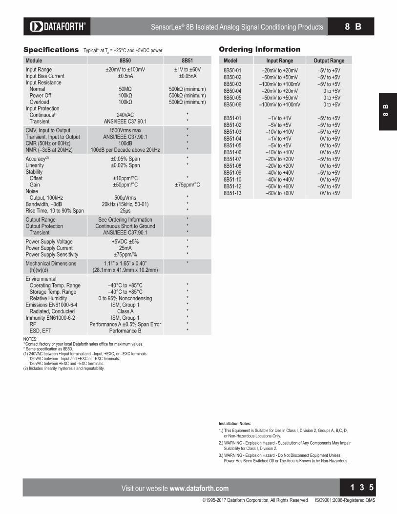
©1995-2017 Dataforth Corporation, All Rights Reserved ISO9001:2008-Registered QMS
Visit our website www.dataforth.com 1 3 5
8 BSensorLex® 8B Isolated Analog Signal Conditioning Products
8B
Ordering InformationSpecifications Typical at TA and D power
NOTES: ontact factory or your local Dataforth sales office for maximum values. Same specification as B .
A between Input terminal and Input, , or terminals. A between Input and or terminals. A between and terminals.
Includes linearity, hysteresis and repeatability.
Model Input Range Output Range 8B50-01 8B50-02 8B50-03 8B50-04 8B50-05 8B50-06
8B51-01 8B51-02 8B51-03 8B51-04 8B51-05 8B51-06 8B51-07 8B51-08 8B51-09 8B51-10 8B51-12 8B51-13
– 20mV to +20mV– 50mV to +50mV
– 100mV to +100mV– 20mV to +20mV– 50mV to +50mV
– 100mV to +100mV
– 1V to +1V– 5V to +5V
– 10V to +10V– 1V to +1V– 5V to +5V
– 10V to +10V– 20V to +20V– 20V to +20V– 40V to +40V– 40V to +40V– 60V to +60V– 60V to +60V
– 5V to +5V– 5V to +5V– 5V to +5V 0 to +5V 0 to +5V 0 to +5V
– 5V to +5V– 5V to +5V– 5V to +5V 0V to +5V 0V to +5V 0V to +5V– 5V to +5V 0V to +5V– 5V to +5V 0V to +5V– 5V to +5V 0V to +5V
Module 8B50 8B51Input RangeInput Bias CurrentInput Resistance Normal Power Off OverloadInput Protection Continuous(1)
Transient
± 20mV to ± 100mV± 0.5nA
240VACANSI/IEEE C37.90.1
± 1V to ± 60V± 0.05nA
minimum minimum minimum
**
CMV, Input to OutputTransient, Input to OutputCMR (50Hz or 60Hz)NMR (– 3dB at 20kHz)
1500Vrms maxANSI/IEEE C37.90.1
100dBdB per Decade above H
****
Accuracy(2)
LinearityStability Offset GainNoise Output, 100kHzBandwidth, – 3dBRise Time, 10 to 90% Span
± 0.05% Span± 0.02% Span
ppmppm
rms20kHz (15kHz, 50-01)
s
**
*ppm
***
Output RangeOutput Protection Transient
See Ordering InformationContinuous Short to Ground
ANSI/IEEE C37.90.1
***
Power Supply VoltagePower Supply CurrentPower Supply Sensitivity
+5VDC ± 5%25mA
± 75ppm/%
***
Mechanical Dimensions (h)(w)(d)
1.11” x 1.65” x 0.40”(28.1mm x 41.9mm x 10.2mm)
*
Environmental Operating Temp. Range Storage Temp. Range Relative HumidityEmissions EN61000-6-4 Radiated, ConductedImmunity EN61000-6-2 RF ESD, EFT
to to
0 to 95% NoncondensingISM, Group 1
Class AISM, Group 1
Performance A ± 0.5% Span ErrorPerformance B
********
Installation Notes:. This uipment is Suitable for se in lass I, Division , Groups A, B, , D,
or Non-Hazardous Locations Only.. ARNING xplosion Ha ard Substitution of Any omponents ay Impair
Suitability for lass I, Division .3.) WARNING - Explosion Hazard - Do Not Disconnect Equipment Unless Power Has Been Switched Off or The Area is nown to be Non Ha ardous.

Isolated Analog Signal Conditioning Products
©1995-2017 Dataforth Corporation, All Rights Reserved ISO9001:2008-Registered QMS
For information call 800-444-76441 3 6
S C M 5 B
For information call 800-444-76441 3 6
SensorLex® 8B Isolated Analog Signal Conditioning Products 8 BSensorLex® 8B Isolated Analog Signal Conditioning Products
©1995-2017 Dataforth Corporation, All Rights Reserved ISO9001:2008-Registered QMS
For information call 800-444-76441 3 6
8 B
8BModule Dimensions and PinoutsDescriptionThe following mechanical drawing is useful when designing circuit boards to mount the B modules. any soc ets are available which accept the mounting pins. As an example, Mill-Max provides a socket with part
number . The captive nut for the mounting screw can be obtained from P Penn ngineering and anufacturing , part number KFS2-440.

©1995-2017 Dataforth Corporation, All Rights Reserved ISO9001:2008-Registered QMS
Visit our website www.dataforth.com 1 3 7
8 BSensorLex® 8B Isolated Analog Signal Conditioning Products
8B
Part Number Description8BP01-2058BP01-3058BP01-2248BP01-324
5V Power, No CJC 5V Power, CJC 24V Power, No CJC 24V Power, CJC
Ordering InformationSpecifications Typical at TA and D power Typical at TA and D power
Features• Single Channel DIN Rail Mounting Accessory• 2-, 4-, 8-, 16-Position Backpanels• Panel or DIN Rail Mounting Options• 19-Inch Mounting Rack for Backpanels
Interface ables able to Screw Terminal Interface Board
• Power Supplies
8BP01Single Channel DIN Rail Mount CarrierDescriptionThe 8BP01 provides simple mounting and I/O connections for any of the 8B signal conditioners. 8BP01-205 and 8BP01-305 models ac-cept 5V power and provide it to the module. 8BP01-224 and 8BP01-324 models accept wide range 7-34VDC power and provide 5V power to the module through an on board power converter. The B
Module 8BP01-205, -305 8BP01-224, -324Input Voltage RangeOver-Voltage ProtectionOver-Voltage Shutdown VoltageUnder-Voltage Turn-onReverse Voltage Protection
4.85 to 5.2VDC6V TVS, 1A Fuse, OV detection
5.6V max–
1A Fuse
7 to 34VDC36V TVS, 1A Fuse, OV detection
35.5V max6.5V min1A Fuse
Output Voltage RegulationPower IndicatorOutput Voltage Temp. Coeff.Output Current
–Green LED
ppmmA max to
5VDC ± 1%Green LED
ppmmA max to
Output Current LimitLine RegulationLoad Regulation
fficiency
––––
0.8A, Auto Recovery± 0.25%± 0.5%75%
Output Ripple – < 50mVpk-pk
Mechanical Dimensions (h)(w)(d)
2.32” x 3.54” x 0.65”(59mm x 90mm x 16.5mm)
2.32” x 3.54” x 0.65”(59mm x 90mm x 16.5mm)
NOTES: ontact factory or your local Dataforth sales office for maximum values.
Figure 1: 8BP01 Single Channel DIN Rail Mount Carrier
Accessories for 8B Analog Modules
carrier can be mounted on any standard DIN rail N and EN 50035-G32). The 8BP01 measures only 2.32” x 3.54” x 0.65” (59mm x 90mm x 16.5mm), making it ideal for use in high-density installations see Figure . It has a ammability rating of L .
Installation Notes:. This uipment is Suitable for se in lass I, Division , Groups
A, B,C, D, or Non-Hazardous Locations Only.. ARNING xplosion Ha ard Substitution of Any omponents
ay Impair Suitability for lass I, Division .3.) WARNING - Explosion Hazard - Do Not Disconnect Equipment nless Power Has Been Switched Off or The Area is nown to be Non-Hazardous.

Isolated Analog Signal Conditioning Products
©1995-2017 Dataforth Corporation, All Rights Reserved ISO9001:2008-Registered QMS
For information call 800-444-76441 3 8
S C M 5 B
For information call 800-444-76441 3 8
SensorLex® 8B Isolated Analog Signal Conditioning Products 8 B
8BP02, 8BP04, 8BP08, 8BP162-, 4-, 8-, and 16-Position Analog I/O BackpanelsDescriptionThe BP , , , and bac panels can accept any of the B analog I O modules in any mixture and can be mounted on the S R 19-inch metal rack. Analog I/O signal channels provide each module with its own analog bus. All module outputs are simultaneously accessible to high speed data ac uisition AD boards. A temperature sensor is mounted on each channel to provide cold junction compensation for ther-mocouple input modules (see Figure 6 for schematic). Field connections are terminated with four screw terminals at each module site. Use system interface cable S A for connection to the host system.
F i g u r e 2 : 8 B P 0 2 A n a l o g I / O B a ckp a n e l
Operating TemperatureRelative Humidity
to 95% Noncondensing
Interface Connector: Field System
high density screw clamp, 16 AWG maxhigh density screw clamp, 16 AWG max
Isolation: Input-to-Output Channel-to-Channel
1500Vrms continuous, max1500Vrms continuous, max
Specifications
F i g u r e 3 : 8 B P 0 4 A n a l o g I / O B a ckp a n e l

©1995-2017 Dataforth Corporation, All Rights Reserved ISO9001:2008-Registered QMS
Visit our website www.dataforth.com 1 3 9
8 BSensorLex® 8B Isolated Analog Signal Conditioning Products
8B
Part Number Description8BP02
8BP02-1
8BP02-2
8BP02-3
8BP04
8BP04-1
8BP04-2
8BP04-3
8BP08
8BP08-1
8BP08-2
8BP08-3
8BP16
8BP16-1
8BP16-2
8BP16-3
Standard channel bac panel with standoffs for mounting.
8BP02 without cold junction compensation sensor. Use whencost savings are desired and thermocouple input modules B and B will not be used.
BP with DIN rail mounting option. The bac panel iscaptured by DIN rail mounting elements and is shippedfully assembled.
8BP02-1 with DIN rail mounting option.
Standard channel bac panel with standoffs for mounting.
8BP04 without cold junction compensation sensor. Use whencost savings are desired and thermocouple input modulesB and B will not be used.
BP with DIN rail mounting option. The bac panel iscaptured by DIN rail mounting elements and is shippedfully assembled.
8BP04-1 with DIN rail mounting option.
Standard channel bac panel with standoffs for mounting.
8BP08 without cold junction compensation sensor. Use whencost savings are desired and thermocouple input modulesB and B will not be used.
BP with DIN rail mounting option. The bac panel iscaptured by DIN rail mounting elements and is shippedfully assembled.
8BP08-1 with DIN rail mounting option.
Standard channel bac panel with standoffs for mounting.
8BP16 without cold junction compensation sensor. Use whencost savings are desired and thermocouple input modulesB and B will not be used.
BP with DIN rail mounting option. The bac panel iscaptured by DIN rail mounting elements and is shippedfully assembled.
8BP16-1 with DIN rail mounting option.
Ordering Information
F i g u r e 4 : 8 B P 0 8 A n a l o g I / O B a ckp a n e l
ElectricalPowerThe B bac panels have two power supply options. A D supply can be connected to the Supply’ terminal bloc , or alternatively, a wide ranging D supply can be connected to the Alternate Supply’ terminal bloc . In the latter case, the BP R module must be installed on the bac panel. The bac panel contains circuitry which automatically switches between the supplies such that only one at a time provides pow-er to the modules. hen power connections are made to both terminal bloc s simultaneously, the D supply ta es precedence over the +5VDC supply. FusingBackpanel power is fuse-protected through F1 and F2. Zener diodes D3 and D4 provide extra protection from overvoltage and supply reversal. Grounding For full protection against large electrical disturbances on the field side of the B modules, a ground stud is provided on the bac panel. An electrical connection between this ground stud and the system ground should be provided with a large gage wire of the shortest possible length.
Installation Notes:. This uipment is Suitable for se in lass I, Division , Groups A, B, , D,
or Non-Hazardous Locations Only.. ARNING xplosion Ha ard Substitution of Any omponents ay Impair
Suitability for lass I, Division .3.) WARNING - Explosion Hazard - Do Not Disconnect Equipment Unless Power Has Been Switched Off or The Area is nown to be Non Ha ardous.

Isolated Analog Signal Conditioning Products
©1995-2017 Dataforth Corporation, All Rights Reserved ISO9001:2008-Registered QMS
For information call 800-444-76441 4 0
S C M 5 B
For information call 800-444-76441 4 0
SensorLex® 8B Isolated Analog Signal Conditioning Products 8 BSensorLex® 8B Isolated Analog Signal Conditioning Products
For information call 800-444-76441 4 0
8 B
For information call 800-444-76441 4 0
F i g u r e 5 : 8 B P 1 6 A n a l o g I / O B a ckp a n e l

©1995-2017 Dataforth Corporation, All Rights Reserved ISO9001:2008-Registered QMS
Visit our website www.dataforth.com 1 4 1
8 BSensorLex® 8B Isolated Analog Signal Conditioning Products
8B
isit our website www.dataforth.com 1 4 1
8 BSensorLex® 8B Isolated Analog Signal Conditioning Products
F i g u r e 6 : 8 B P 0 1 / 8 B P 0 2 / 8 B P 0 4 / 8 B P 0 8 / 8 B P 1 6 S ch e m a t i c

Isolated Analog Signal Conditioning Products
©1995-2017 Dataforth Corporation, All Rights Reserved ISO9001:2008-Registered QMS
For information call 800-444-76441 4 2
S C M 5 B
For information call 800-444-76441 4 2
SensorLex® 8B Isolated Analog Signal Conditioning Products 8 BSensorLex® 8B Isolated Analog Signal Conditioning Products
For information call 800-444-76441 4 2
8 B
8BPWR-2Power Supply ModuleDescriptionThe 8BPWR-2 encapsulated power supply has a wide ranging 7-34VDC input voltage range and provides D output suitable for all B modules. It is designed to mount on the B bac panels. The compact si e and low weight are ideal for high-density applications (see Figure 7).
Module 8BPWR-2Input Voltage RangeOvervoltage ProtectionReverse Voltage Protection
7 to 34VDCNone provided on bac panelNone provided on bac panel
Output VoltageOutput Voltage Temp. Coeff.Output Current
Output Current LimitLine RegulationLoad Regulation
fficiency
5VDC ± 1%ppm
A to A
4A, Auto Recovery± 0.20%± 0.30%
85%Output Ripple 50mVp-p
Mechanical Dimensions (h)(w)(d)
1.11” x 1.65” x 0.40”(28.1mm x 41.9mm x 10.2mm)
Specifications Typical at TA and D power
NOTES: ontact factory or your local Dataforth sales office for maximum values.
SCMXPRT-001/D, SCMXPRE-001/DPower SuppliesDescriptionThe SCMXPRT-001/D and SCMXPRE-001/D encapsulated power sup-plies are available in A or A input voltage ranges and provide
D outputs suitable for all B modules. They are designed to mount on the SCMXRK-002 metal rack (see Figure 13) or DIN rail EN 50022-35x7.5 (D versions). The supplies are UL-recognized. Their compact size and low weight are ideal for high-density applications (see Figure 8).
Module 8BPWR-2 8BPWR-2Input Voltage Range, 47Hz to 420HzOutput VoltageOutput urrent, Operating TemperatureLine RegulationLoad RegulationOutput Ripple, maxWeight
105 to 125VAC
5VDC1A to
± 0.05%± 0.25%1mVrms
. lbs g
210 to 250VAC
5VDC1A to
± 0.05%± 0.25%1mVrms
. lbs g
Specifications Typical at TA
NOTES: ontact factory or your local Dataforth sales office for maximum values.Supplies are UL recognized, File No. E45344.
F i g u r e 7 : 8 B P W R - 2 P o w e r S u p p l y M o d u l e
F i g u r e 8 : S C M X P R T - 0 0 1 / D a n d S C M X P R E - 0 0 1 / D P h ysi ca l D i m e n si o n s

©1995-2017 Dataforth Corporation, All Rights Reserved ISO9001:2008-Registered QMS
Visit our website www.dataforth.com 1 4 3
8 BSensorLex® 8B Isolated Analog Signal Conditioning Products
8B
SCMXPRT-003, SCMXPRE-003Power SuppliesDescriptionThe S PRT linear power supplies are available in A or A input. They have sufficient output current capacity to supply any combination of B modules. The S R metal rac provides mounting capability for the S PRT power supplies (see Figure 13).
Module SCMXPRT-003 SCMXPRE-003Input Voltage Range, 47Hz to 63HzOutput VoltageOutput urrent at Output urrent at Operating TempDielectric Withstand Voltage (input to ground)Line Regulation (10% line change)Load Regulation (50% load change)Output Ripple (max)Overvoltage Protection (factory set)
104 to 132VAC5VDC ± 1%
3A6A
to 3750VAC± 0.05%± 0.05%5mVp-p
6.2V ± 0.4V
207 to 265VAC5VDC ± 1%
3A6A
to 3750VAC± 0.05%± 0.05%5mVp-p
6.2V ± 0.4V
Specifications Typical at TA
NOTES: ontact factory or your local Dataforth sales office for maximum values.Both supplies are tested and certified by T to D and I . They are L recogni ed File Number ,
SA ertified SA File Number LR , and ompliant.
F i g u r e 9 : S C M X P R T - 0 0 3 / E - 0 0 3 P h ysi ca l D i m e n si o n s

Isolated Analog Signal Conditioning Products
©1995-2017 Dataforth Corporation, All Rights Reserved ISO9001:2008-Registered QMS
For information call 800-444-76441 4 4
S C M 5 B
For information call 800-444-76441 4 4
SensorLex® 8B Isolated Analog Signal Conditioning Products 8 B
For information call 800-444-76441 4 4
8 B
PWR-450525W Single Output Industrial DIN Rail Switching Power Supply
InputFrequencyInput CurrentInrush Current
fficiency
85 to 264VAC, 120 to 370VDC47 to 63Hz1.5A/115VAC, 0.75A/230VACCold start 30A/115VAC, 60A/230VAC72%
Output Voltage & Current RatingTemperature oefficientRipple Voltage
5V, 5A.
100mVp-p
Overload ProtectionOver Voltage ProtectionOver Temperature Protection
105 to 150% rated output power5.75 to 6.75V
detect on heatsin of power transistor
Dielectric Strength Between input and output terminals: 3kV, 1 minuteBetween input and FG: 1.5kV, 1 minuteBetween output and FG: 0.5kV, 1 minute
Insulation Resistance Between input and output terminals/input and FG/output and FG D
Operating TemperatureStorage TemperatureRelative Humidity
to to
10 to 95%Mechanical Dimensions (l)(w)(h)
3.66” x 3.07” x 2.24”(93mm x 78mm x 57mm)
Terminal Screw M3
Specifications Typical at TA
NOTES: ontact factory or your local Dataforth sales office for maximum values.
Features• Universal AC Input (85 to 264VAC) D ompatible Input to D
• Protections: Short Circuit, Overload, Over Voltage, Over Temperature
• Mounts on DIN Rail TS-35/7.5 & 15• Approvals: UL, CUL, TUV, CB, CE• CE Compliant, UL 508 Listed• TUV EN60950-1 Approved• Compliant with EMC Directive EN50082-2• LED Indicator for Power On
F i g u r e 1 0 : P W R - 4 5 0 5 P h ysi ca l D i m e n si o n s

©1995-2017 Dataforth Corporation, All Rights Reserved ISO9001:2008-Registered QMS
Visit our website www.dataforth.com 1 4 5
8 BSensorLex® 8B Isolated Analog Signal Conditioning Products
8B
isit our website www.dataforth.com 1 4 5
8 BSensorLex® 8B Isolated Analog Signal Conditioning Products
SCMXCA006-01, -02, -07Interface ablesDescriptionSCMXCA006-XXSystem interface cable for the BP bac panels. This is a DB
ale Female cable assembly. It can be ordered in lengths of m, m, and 7m (see Figure 11).
8BXIF (-DIN)Universal Interface BoardDescriptionThe B IF is a universal interface board which converts a DB cable input to screw terminals for discrete wire. It can be mounted on the bac of the S R mounting rac B IF or on a DIN rail B -IF-DIN). Required mounting hardware is included. Use SCMXCA006-XX cable see Figure for dimensions .
SCMXRK-00219-Inch Metal Mounting RackDescriptionThe SCMXRK-002 is a 19-inch metal rack for mounting the 8BP04/08/16 bac panels and the B IF interface board see Figure for dimensions .
F i g u r e 1 1 : S C M X C A 0 0 6 - X X S yst e m I n t e r f a ce C a b l e
F i g u r e 1 3 : S C M X R K - 0 0 2 A n a l o g R a ck D i m e n si o n s
F i g u r e 1 2 : 8 B X I F U n i ve r sa l I n t e r f a ce B o a r d D i m e n si o n s
M a l e D B 2 5 F e m a l e D B 2 5

Isolated Analog Signal Conditioning Products
©1995-2017 Dataforth Corporation, All Rights Reserved ISO9001:2008-Registered QMS
For information call 800-444-76441 4 6
S C M 5 B
For information call 800-444-76441 4 6
SensorLex® 8B Isolated Analog Signal Conditioning Products 8 BSensorLex® 8B Isolated Analog Signal Conditioning Products
For information call 800-444-76441 4 6
8 B
For information call 800-444-76441 4 6
SCMXRAIL1-XX, SCMXRAIL2-XX, SCMXRAIL3-XXDIN RailDescriptionThree styles of DIN rail are available. Specify length xx in meters when ordering, -01 for 1 meter or -02 for 2 meter.
8B-PROTOBreadboard itDescriptionThe B PROTO breadboard it was designed to allow users to incorpo-rate their own module functions using an 8B format. The kit includes a PC board with pins designed for breadboard circuits, a module case, header and mounting screw. Contact the factory for additional information.
8BPTPass Thru ModuleDescriptionThe BPT is a pass through module used to establish a direct connection between an input signal and the B series bac plane analog bus. It has unity gain and no isolation. It accepts up to ± 10V input and provides up to ± 10V output.
8BXCJCCold Junction Compensation SensorDescriptionPac aged for use in customer designed mounting boards. This part has an initial tolerance of ± 0.25% and comes in a standard 1206 resistor format.
F i g u r e 1 4 : D I N R a i l S t yl e s Figure 15: 8BPxx-2, 8BPxx-3 Backpanel DIN Rail Mounting Option

©1995-2017 Dataforth Corporation, All Rights Reserved ISO9001:2008-Registered QMS
Visit our website www.dataforth.com 1 4 7
S C M 9 BIsolated Intelligent Signal Conditioning Products
SCM
9B
isit our website www.dataforth.com 1 4 7
S C M 9 BIsolated Intelligent Signal Conditioning Products
SCM9BIsolated, Intelligent Signal Conditioning ProductsSCM9B ModulesDataforth offers high quality SCM9B products providing cost-effective protection and conditioning for a wide range of valuable industrial control signals and systems. Our extensive line includes fixed and programmable sensor tocomputer and computer to analog output interface modules, RS-232/RS-485 converters, RS-485 repeaters, and associated bac planes, accessories, and applications software. All products are European EMC Directive Compliant.
FeaturesSCM9B Sensor-to-Computer Modules• 500Vrms Input Isolation Programmable Scaling and Lineari ation
• ASCII Command/Response Protocol bit easurement Resolution ontinuous Self alibration Analog Readbac DIN Rail ountable D Series
SCM9B Computer-to-Analog Output Modules• 0-1V, ± 1V, 0-5V, ± 5V, 0-10V, ± 10V, 0-20mA, 4-20mA Output Ranges• 500Vrms Output Isolation• 12-Bit Output Resolution Programmable . s mA s to , s
(mA/s) Output SlopesSCM9B Converters and Repeaters• Transparent to Host• Optically Isolated Bidirectional Data Flows• Automatic Internal RS-485 Bus Supervision DIN Rail ountable D odel
All SCM9B Modules• CE Compliant• Manufactured per RoHS II Directive 2011/65/EU
SCM9B-1000/2000/5000/D100Sensor-to-Computer ModulesThese isolated modules provide complete sensor/RS-232C or RS interfaces with bit measurement resolution. They accept a variety of voltage, current, thermocouple, RTD/thermistor, strain gage, timer/frequency, and multichannel digital inputs/outputs. “2000” Series modules include additional programmable features such as AS II output scaling to desired engineering units and linearization using straight-line segment approximation. “5000” Series modules provide four analog input channels. D Series modules are DIN rail mountable.
SCM9B-3000/4000Computer-to-Analog Output ModulesThese are complete, isolated interfaces designed for remote installationand communications with host computers via standard RS-232C and RS serial ports. They offer bit resolution in a range of analog output voltages and currents. “4000” series modules have fully programmable output slopes, true analog readbac , and data scaling.
SCM9B-A1000/2000/D192Converters and RepeatersThese products convert RS-232C communications signal levels to the correct RS signal re uirements, and may also be configured as repeaters to extend communications bus lengths. They are optically isolated, require no external control signals, and are completely transparent to host software.

Isolated Analog Signal Conditioning Products
©1995-2017 Dataforth Corporation, All Rights Reserved ISO9001:2008-Registered QMS
For information call 800-444-76441 4 8
S C M 5 BIsolated Intelligent Signal Conditioning Products
For information call 800-444-76441 4 8
S C M 9 B
SCM9B Selection GuideSCM9B-1000/2000 Sensor-to-Computer Products(“2000” Series products have user-programmable features)
MODEL INPUT RANGE OUTPUTVoltage InputsSCM9B-1101/2101 ± 10mV RS-232CSCM9B-1102/2102 ± 10mV RS-485SCM9B-1111/2111 ± 100mV RS-232CSCM9B-1112/2112 ± 100mV RS-485SCM9B-1121/2121 ± 1V RS-232CSCM9B-1122/2122 ± 1V RS-485SCM9B-1131/2131 ± 5V RS-232CSCM9B-1132/2132 ± 5V RS-485SCM9B-1141/2141 ± 10V RS-232CSCM9B-1142/2142 ± 10V RS-485SCM9B-1151/2151 ± 100V RS-232CSCM9B-1152/2152 ± 100V RS-485
Current InputsSCM9B-1211/2211 ± 10mA RS-232CSCM9B-1212/2212 ± 10mA RS-485SCM9B-1221/2221 ± 1mA RS-232CSCM9B-1222/2222 ± 1mA RS-485SCM9B-1231/2231 ± 100mA RS-232CSCM9B-1232/2232 ± 100mA RS-485SCM9B-1241/2241 ± 1A RS-232CSCM9B-1242/2242 ± 1A RS-485SCM9B-1251/2251 4-20mA RS-232CSCM9B-1252/2252 4-20mA RS-485
Thermocouple InputsSCM9B-1311 J Thermocouple RS-232CSCM9B-1312 J Thermocouple RS-485SCM9B-1321 K Thermocouple RS-232CSCM9B-1322 K Thermocouple RS-485SCM9B-1331 T Thermocouple RS-232CSCM9B-1332 T Thermocouple RS-485SCM9B-1341 E Thermocouple RS-232CSCM9B-1342 E Thermocouple RS-485SCM9B-1351 R Thermocouple RS-232CSCM9B-1352 R Thermocouple RS-485SCM9B-1361 S Thermocouple RS-232CSCM9B-1362 S Thermocouple RS-485SCM9B-1371 B Thermocouple RS-232CSCM9B-1372 B Thermocouple RS-485SCM9B-1381 C Thermocouple RS-232CSCM9B-1382 C Thermocouple RS-485
RTD InputsSCM9B-1411 .00385 RTD RS-232CSCM9B-1412 .00385 RTD RS-485SCM9B-1421 .00392 RTD RS-232CSCM9B-1422 .00392 RTD RS-485SCM9B-1431 .00388 RTD RS-232CSCM9B-1432 .00388 RTD RS-485S B Thermistor RSS B Thermistor RSSCM9B-1461 TD Thermistor RS-232CSCM9B-1462 TD Thermistor RS-485
MODEL INPUT RANGE OUTPUTStrain Gage InputsSCM9B-1511/2511 ± 30mV Bridge, 5V Excitation RS-232CSCM9B-1512/2512 ± 30mV Bridge, 5V Excitation RS-485SCM9B-1521/2521 ± 30mV Bridge, 10V Excitation RS-232CSCM9B-1522/2522 ± 30mV Bridge, 10V Excitation RS-485SCM9B-1531/2531 ± 100mV Bridge, 5V Excitation RS-232CSCM9B-1532/2532 ± 100mV Bridge, 5V Excitation RS-485SCM9B-1541/2541 ± 100mV Bridge, 10V Excitation RS-232CSCM9B-1542/2542 ± 100mV Bridge, 10V Excitation RS-485SCM9B-1551/2551 1-6V Bridge, 8V Excitation RS-232CSCM9B-1552/2552 1-6V Bridge, 8V Excitation RS-485SCM9B-1561/2561 1-6V Bridge, 10V Excitation RS-232CSCM9B-1562/2562 1-6V Bridge, 10V Excitation RS-485
Timer/Frequency InputsSCM9B-1601/2601 Frequency RS-232CSCM9B-1602/2602 Frequency RS-485SCM9B-1611/2611 Timer RS-232CSCM9B-1612/2612 Timer RS-485SCM9B-1621 Event Counter RS-232CSCM9B-1622 Event Counter RS-485SCM9B-1631/2631 Accumulator, Frequency RS-232CSCM9B-1632/2632 Accumulator, Frequency RS-485SCM9B-1641/2641 Accumulator, Timer RS-232CSCM9B-1642/2642 Accumulator, Timer RS-485
DIGITAL DIGITAL RSMODEL INPUT OUTPUT OUTPUTDigital Inputs/OutputsSCM9B-1701 7 8 RS-232CSCM9B-1702 7 8 RS-485SCM9B-1711 15 and/or 15 RS-232CSCM9B-1712 15 and/or 15 RS-485
SCM9B-5000 Four Channel Sensor-to-Computer Products
MODEL INPUT RANGE OUTPUTVoltage InputsSCM9B-5111 ± 100mV RS-232CSCM9B-5112 ± 100mV RS-485SCM9B-5121 ± 1V RS-232CSCM9B-5122 ± 1V RS-485SCM9B-5131 ± 5V RS-232CSCM9B-5132 ± 5V RS-485SCM9B-5141 ± 10V RS-232CSCM9B-5142 ± 10V RS-485SCM9B-5151 ± 100V RS-232CSCM9B-5152 ± 100V RS-485
Current InputsSCM9B-5251 4-20mA RS-232CSCM9B-5252 4-20mA RS-485
Thermocouple InputsSCM9B-5311 J Thermocouple RS-232CSCM9B-5312 J Thermocouple RS-485SCM9B-5321 K Thermocouple RS-232CSCM9B-5322 K Thermocouple RS-485SCM9B-5331 T Thermocouple RS-232CSCM9B-5332 T Thermocouple RS-485SCM9B-5341 E Thermocouple RS-232CSCM9B-5342 E Thermocouple RS-485
Thermistor inputsS B Thermistor RSS B Thermistor RS

©1995-2017 Dataforth Corporation, All Rights Reserved ISO9001:2008-Registered QMS
isit our website www.dataforth.com 1 4 9
S C M 9 BIsolated Intelligent Signal Conditioning Products
isit our website www.dataforth.com 1 4 9
S C M 9 BIsolated Intelligent Signal Conditioning Products
SCM9B Selection Guide (Continued)SCM9B-D100 DIN Rail Mount Sensor-to-Computer Modules
MODEL INPUT RANGE OUTPUTVoltage InputsSCM9B-D110 ± 10mV RS-485SCM9B-D111 ± 100mV RS-485SCM9B-D112 ± 1V RS-485SCM9B-D113 ± 5V RS-485SCM9B-D114 ± 10V RS-485SCM9B-D115 ± 100V RS-485
Current InputsSCM9B-D125 4-20mA RS-485
Thermocouple InputsSCM9B-D131 J Thermocouple RS-485SCM9B-D132 K Thermocouple RS-485SCM9B-D133 T Thermocouple RS-485SCM9B-D134 E Thermocouple RS-485SCM9B-D135 R Thermocouple RS-485SCM9B-D136 S Thermocouple RS-485SCM9B-D137 B Thermocouple RS-485SCM9B-D138 C Thermocouple RS-485
RTD/Thermistor InputsSCM9B-D141 .00385 RTD RS-485SCM9B-D142 .00392 RTD RS-485SCM9B-D143 .00388 RTD RS-485S B D Thermistor RSSCM9B-D146 TD Thermistor RS-485
Timer/Frequency InputsSCM9B-D161 Frequency RS-485
DIGITAL DIGITAL RSMODEL INPUTS OUTPUTS OUTPUTDigital Input/OutputsSCM9B-D171 6 0 RS-485SCM9B-D172 0 6 RS-485
SCM9B-3000/4000 Computer-to-Analog Output Products(“4000” Series products have user-programmable features)
MODEL OUTPUT RANGE INPUTVoltage OutputSCM9B-3121/4121 ± 1V RS-232CSCM9B-3122/4122 ± 1V RS-485SCM9B-3131/4131 ± 5V RS-232CSCM9B-3132/4132 ± 5V RS-485SCM9B-3141/4141 ± 10V RS-232CSCM9B-3142/4142 ± 10V RS-485SCM9B-3161/4161 0 to 1V RS-232CSCM9B-3162/4162 0 to 1V RS-485SCM9B-3171/4171 0 to 5V RS-232CSCM9B-3172/4172 0 to 5V RS-485SCM9B-3181/4181 0 to 10V RS-232CSCM9B-3182/4182 0 to 10V RS-485
MODEL OUTPUT RANGE INPUTCurrent OutputSCM9B-3251/4251 0 to 20mA RS-232CSCM9B-3252/4252 0 to 20mA RS-485SCM9B-3261/4261 4 to 20mA RS-232CSCM9B-3262/4262 4 to 20mA RS-485
SCM9B-A1000/A2000 Converters/Repeaters
MODEL DESCRIPTIONSCM9B-A1000-115 RS-232C/RS-485 Converter/Repeater, 115VACSCM9B-A1000-230 RS-232C/RS-485 Converter/Repeater, 230VACSCM9B-A2000 RS-232C/RS-485 Converter/Repeater, +10 to +30VDC
SCM9B-D192 DIN Rail Mount RS-485 Repeater
MODEL DESCRIPTIONSCM9B-D192 RS-485 Repeater
SCM9B-H1700 Digital I/O Boards
MODEL DESCRIPTIONSCM9B-H1750 24 Digital Inputs/OutputsSCM9B-H1770 64 Digital Inputs/OutputsS B H A Ribbon onnector Assembly
Accessories and Software
MODEL DESCRIPTIONSCM9B-PB08 8 Channel BackpanelSCM9B-PB14 14 Channel BackpanelSCM9B-S300 Utility Software
MA-1001 User’s Manual, SCM9B-1000MA-1002 User’s Manual, SCM9B-2000MA-1003 User’s Manual, SCM9B-3000/4000MA-1004 User’s Manual, SCM9B-1700MA-1005 User’s Manual, SCM9B-A1000/A2000MA-1011 User’s Manual, SCM9B-5000
A ser’s anual, S B odbus® ProtocolMA-1014 User’s Manual, SCM9B-D100
SCM9B Reliability Data Failure rate calculations for the SCM9B modules are derived from the MIL-HDBK-217E specification. The stress analysis method is used at naval sheltered environments, C temperature, and uality level of B . Our specified humidity level is RH noncondensing.
MODEL FAILURES/106 HRS MTBF (HRS) SCM9B-1xxx/2xxx/3xxx/4xxx/5xxx 9.52 105,000 SCM9B-17xx 8.16 123,000
or C ata s eets o to ata ort com/si na con itionin as an c ic on t e9B Analog to Serial Isolated Modules button.

Data Acquisition Systems
©1995-2017 Dataforth Corporation, All Rights Reserved ISO9001:2008-Registered QMS
For information call 800-444-76441 5 0
M A Q ®2 0
SCM
9B
MAQ®20Industrial Data Acquisition & Control System
DescriptionThe MAQ20 Industrial Data Acquisition and Control System encompasses more than 30 years of design excellence and quality in the industrial test and measurement and process control industry. This powerful, high performance, highly exible system offers the industry’s most affordable price per channel, integral PID loop control, and . system accuracy (module dependent). It is ideal for test and measurement, factory and process automation, machine automation, military and aerospace, power and energy, environmental monitoring, and oil and gas applications. The A family consists of DIN rail mounted, programmable, multichannel, industrially rugged signal conditioning input and output modules and communications modules (Figure 1). Each I/O module has a 1500Vrms isolation barrier between field side and system side wiring, and many models offer per channel isolation. All field wiring terminals are heavily protected against overload, accidental connection of incorrect signals,
Features Industry’s ost Affordable Price per hannel
• ± 0.035% Accuracy (Typical)• 1500Vrms Channel-to-Bus Isolation• Up to 240Vrms Continuous Field I/O Protection• ANSI/IEEE C37.90.1 Transient Protection• Direct Connection to Internet Option• Graphical Control Software - ReDAQ® Shape for MAQ20 Software - IPEmotion Software• Advanced Features Including Integral PID Control, Alarms, Counters, Timers, PWMs, and more - Up to 32 PID Loops with ReDAQ Shape Sofware - Formulas, Data Logger, TEDS, PID, Scripting with IPEmotion Software• Wide Range 7-34VDC Input Power to Industrial Operating Temperature System is a odbus® Server & Can Operate
Remotely Without Local PC• Heavy Industrial CE Compliant• UL/CUL Listing Pending (Class I, Division 2, Groups A, B, C, D)• ATEX Compliance Pending• Manufactured per RoHS II Directive 2011/65/EU
and ESD. Modules mount on the industry standard 35x7.5mm gull-wing DIN rail. A bac bone mounts within the rail providing power and communication interconnections between the communications modules and each I/O module.
F i g u r e 1 : M A Q 2 0 S yst e m B l o ck D i a g r a m

Data Acquisition Systems
©1995-2017 Dataforth Corporation, All Rights Reserved ISO9001:2008-Registered QMS
Visit our website www.dataforth.com 151
MAQ®20
MA
Q®20
The Modules: Compact, Flexible, and PowerfulOne MAQ20 communications module can interface to up to 24 I/O modules to construct a system with a maximum of 384 channels that fits within a standard 19” instrumentation rack. Processors within each module make this distributed system extremely powerful.
• Communications Modules: Ethernet, RS-232, RS-485, and USB with host application software interfacing to the system using Modbus® TCP or Modbus RTU protocol.
• Analog Input Modules: Interface to a wide range of standard industrial sensors and equipment and offer up to 16 channels of input, each of which can be independently configured; signal ranges are user selectable and offered in differential and per-channel isolated single-ended configurations.
- Process Voltage and Process Current Input Modules offer 8-channel differential input or 16-channel single-ended input for precise measurement of voltage and current signals; all channels are individually configurable for range, alarm limits, and averaging.
- Thermocouple Input Modules offer 8 differential input channels, all of which are individually configurable for range, alarm limits, and averaging. Separate models are offered for interfacing to Type J, Type K, Type T and Types R and S sensors.
- RTD and Potentiometer Input Modules interface to 2-wire, 3-wire, and 4-wire sensors including five RTD types and potentiometers. Modules offer five or six channels, each configurable for sensor, range, alarm limits, and averaging.
- Strain Gage Input Module connects to full, half, and quarter bridge sensors and offers four channels; each channel is configurable for range, alarm limits, averaging, bandwidth, excitation, and gain. Additional features are autozero, shunt cal, and 6-wire connection.
- Frequency Input Module accepts zero-crossing and TTL signals with frequencies from 1Hz to 1MHz plus State Change and provides a DC stimulus for contact sensors. This module has eight channels, each configurable for range and alarm limits.
- Isolated Process Voltage and Process Current Input Modules offer 8 isolated input channels with multiple ranges and high resolution conversion for precise measurement of voltage and current signals; channels are individually configurable for range, alarm limits, averaging, and high-speed burst scan.
Figure 2: Communications Module with I/O Modules
• Analog Output Modules: Process Voltage and Process Current Output Modules drive valves, perform other crucial process operations, and provide up to eight channels of output which can be independently configured.
• Discrete Input/Output Modules: Provide multiple channels of isolated AC/DC input and AC/DC output per module and offer advanced special functions as well as alarm capability. Twenty-channel input and 20-channel output models offer low per-channel cost.
- High Density Input Modules with or without Compliance Voltage offer 20 input channels. One module interfaces to 10-120VDC/VAC signals; the other model has a 24VDC compliance voltage source on each channel for interfacing to relay contacts, solid state switches, or other devices requiring excitation.
- High Density Isolated Output Module provides 20 output channels that can switch up to 60VDC signals and sink up to 3A of current. Channels can be switched individually or in blocks and have user configurable default output states.
- Discrete Relay Output Module provides 20 isolated SPST latching relay output channels with contact state readback that can switch between 2A at 30V and 0.4A at 150V. Relays can be controlled individually or in blocks and have user configurable default states.
The System Backbone resides within the DIN rail used for module mounting and provides power to and interface between the communica-tions module and the I/O modules. Modules mount on industry standard 35x7.5mm gull-wing DIN rails.
Figure 3: IPEmotion Screen Shots
Preliminary at date of printing. Contact factory for availability.

Data Acquisition Systems
©1995-2017 Dataforth Corporation, All Rights Reserved ISO9001:2008-Registered QMS
For information call 800-444-76441 5 2
M A Q ®2 0
The MAQ20 system can operate remotely without host PC intervention. It also can operate as a standalone data logger. Additional features include: p to GB of logged data can be transferred via FTP during real time acquisition
System firmware automatically registers installation and removal of I O modules
Load share power supply modules enable system expansion, standby and redundant power
Hot swappable I O modules with field side pluggable terminal bloc s on most models
- Sophisticated packaging allows high density mounting in 3U increments I O modules can be mounted remotely from the communications module
Output modules are programmable for user defined waveforms. Discrete I/O modules offer seven high level functions including pulse/fre uency counter, pulse fre uency counter with de bounce, waveform measurement, time between events, fre uency generator, P generator, and one-shot pulse generator.System power is connected to the communications module, which in turn powers the I/O modules. For systems with power supply requirements greater than those the communications module provides, the MAQ20-PWR3 load share power supply module can provide additional power. When a MAQ20 I/O module is inserted into a system, module registration occurs automatically, data acquisition starts, and data is stored locally in the module. The system is based on a odbus® compatible memory map, which ensures easy access to ac uired data, configuration settings, and alarm limits. Information is stored in consistent locations from module to module for ease of use and system design.Software OptionsThe options for intuitive graphical control software include:- ReDAQ® Shape Graphical HMI Design & Runtime Solution- IPEmotion Advanced Control & Mathematical Functions Solution
Outstanding FunctionalityThe A system comes with free configuration software programming examples and Lab I TM Is are also available.Leading-Edge PID Loop ControlThe A provides PID loop control with both software pac ages that support the system: ReDAQ Shape for MAQ20 and IPEmotion. With ReDAQ Shape, the powerful Dataforth MAQ20 communications module is capable of autonomously running up to PID control loops faceplates within the software enable an engineer or operator to configure the many features of loop control and monitor processes. With IPEmotion software, PID loop control is extensive and highly functional. Additional advanced features include formulas, data logging, TEDS, and scripting. Typical PID applications include steam, water, and chemical ow control tan level control; heat-exchanger / reactor temperature control, and pressure control.
C o n t r o l l e r N a m e& D e s c r i p t i o n U p p e r C a l i b r a t i o n L i m i t s
L o w e r C a l i b r a t i o n L i m i t s
P r o c e s s A l a r m I n d i c a t o r
A l a r m P o i n t I n d i c a t o r s
S e t P o i n t I n d i c a t o r
P r o c e s s V a r i a b l e S c a l e
E n g i n e e r i n g U n i tS e t P o i n t
P r o c e s s V a r i a b l e
C o n t r o l l e r O u t p u t C o n t r o l l e r O u t p u t S c a l e
C o n t r o l l e r M o d e
S e t t i n g sB u t t o n
F I C - 1 0 0S t e a m F l o w C o n t r o l l e r
S P ( G P M )
S PP V3 5 0
4 0 0
0 0
1 0 0
P V ( G P M )
C O ( % )
M O D E
3 5 0 . 1
5 4 . 8 1
A U T O
S e t t i n g sN o A l a r m
C O
Like all Dataforth products, the MAQ20 system provides exceptional isolation, protection, accuracy, and reliability. All A modules are designed for installation in Class I, Division 2 hazardous locations and have a high level of immunity to environmental noise commonly found in heavy industrial environments.
F i g u r e 5 : P I D F a ce p l a t e i n R e D A Q S h a p e S o f t w a r e
F i g u r e 4 : R e D A Q S h a p e f o r M A Q 2 0 S cr e e n S h o t s

Data Acquisition Systems
©1995-2017 Dataforth Corporation, All Rights Reserved ISO9001:2008-Registered QMS
Visit our website www.dataforth.com 1 5 3
M A Q ®2 0
MA
Q®20
MAQ®20 Data Acquisition System Selection Guide
COMMUNICATIONS MODULES Page 154MODEL DESCRIPTIONMAQ20-COM2 Communications Module; Ethernet, USB, RS-232MAQ20-COM4 Communications Module, Ethernet; USB, RS-485
VOLTAGE & CURRENT ANALOG INPUT MODULES Page 156MODEL DESCRIPTIONMAQ20-MVDN Analog Input Module; mV, 8-ch, DifferentialMAQ20-VSN Analog Input Module; V, 16-ch, Single EndedMAQ20-VDN Analog Input Module; V, 8-ch, DifferentialMAQ20-ISN Analog Input Module; mA, 16-ch, Single EndedMAQ20-IDN Analog Input Module; mA, 8-ch, Differential
ISOLATED VOLTAGE & CURRENT ANALOG INPUT MODULES Page 158MODEL DESCRIPTIONMAQ20-ISOMV1 Analog Input Module; mV, 8-ch, Isolated ch-chMAQ20-ISOV1 Analog Input Module; V, 8-ch, Isolated ch-chMAQ20-ISOI1 Analog Input Module; mA, 8-ch, Isolated ch-ch
THERMOCOUPLE ANALOG INPUT MODULES Page 160MODEL DESCRIPTIONMAQ20-JTC Analog Input Module; Type J Thermocouple, 8-chMAQ20-KTC Analog Input Module; Type K Thermocouple, 8-chMAQ20-TTC Analog Input Module; Type T Thermocouple, 8-chMAQ20-RSTC Analog Input Module; Type R and Type S Thermocouple, 8-ch
RTD and POTENTIOMETER ANALOG INPUT MODULES Page 162MODEL DESCRIPTIONMAQ20-RTD31 Analog Input Module; RTD/Potentiometer, 3-wire, Type Pt and Ni, 6-chMAQ20-RTD41 Analog Input Module; RTD, 4-wire, Type Pt and Ni, 5-ch
STRAIN GAGE ANALOG INPUT MODULE Page 164MODEL DESCRIPTIONMAQ20-BRDG1 Analog Input Module; Bridge/Strain Gage, 4-ch
FREQUENCY ANALOG INPUT MODULE Page 166MODEL DESCRIPTIONMAQ20-FREQ Analog Input Module; Frequency, 8-ch
VOLTAGE & CURRENT ANALOG OUTPUT MODULES Page 168MODEL DESCRIPTIONMAQ20-VO Analog Output Module; Voltage, 8-chMAQ20-IO Analog Output Module; Current mA, 8-ch
DISCRETE INPUT / OUTPUT MODULES Page 170MODEL DESCRIPTIONMAQ20-DIOL Discrete Input/Output Module; 3 to 60VDC In, 3 to 60VDC Out,
5-ch In, 5-ch OutMAQ20-DIOH Discrete Input/Output Module; 90 to 280VAC/VDC In,
24 to 280VAC Out, 4-ch In, 4-ch Out
DISCRETE HIGH DENSITY INPUT MODULES WITH OR WITHOUT COMPLIANCE VOLTAGE Page 172MODEL DESCRIPTIONMAQ20-DIV20 Discrete Input Module; 10 to 32VDC In, 20-chMAQ20-DIVC20 Discrete Input Module; 10 to 24VDC In, 24VDC Compliance, 20-ch
DISCRETE HIGH DENSITY OUTPUT MODULE Page 174MODEL DESCRIPTIONMAQ20-DODC20SK Discrete Output Module; 10 to 60VDC Out, 20-ch
DISCRETE RELAY OUTPUT MODULE Page 176MODEL DESCRIPTIONMAQ20-DORLY20 Relay Output Module; 2A at 30V, 0.4A at 150V, 20-ch SPST
SYSTEM BACKBONES Page 178MODEL DESCRIPTION
A B PL DIN Rail Bac bone Accepting O odule plus I O odulesA B PL DIN Rail Bac bone Accepting O odule plus I O odulesA B PL DIN Rail Bac bone Accepting O odule plus I O odulesA B PL DIN Rail Bac bone Accepting O odule plus I O odules
SOFTWARE Pages 180 and 182MODEL DESCRIPTIONMAQ20-940 ReDAQ® Shape Software for MAQ20 – Developer VersionMAQ20-941 ReDAQ Shape Software for MAQ20 – User Version
A A onfiguration Software ToolMAQ20-951 IPEmotion Software for MAQ20 (1 COM module and 1 to 4 I/O modules)MAQ20-952 IPEmotion Software for MAQ20 (Each additional 4 I/O modules)
POWER SUPPLIES Page 232 in 2017 Full-Line CatalogPWR-PS5R7W Power Supply, 24V, 0.3A, 100-240VAC InputPWR-PS5R15W Power Supply, 24V, 0.65A, 100-240VAC InputPWR-PS5R30W Power Supply, 24V, 1.3A, 100-240VAC InputPWR-PS5R60W Power Supply, 24V, 2.5A, 100-240VAC InputPWR-PS5R120W Power Supply, 24V, 5.0A, 100-240VAC Input
NOTE: MAQ20 and DSCA use same power supplies.
ACCESSORIES Page 184ac one ansion Ca es
MODEL DESCRIPTIONA A Bac bone xpansion able meter .A A Bac bone xpansion able meter .
Load Share Power Supply ModuleMODEL DESCRIPTIONMAQ20-PWR3 Load Share Power Supply Module
Cables to Interface 8B Backpanels to MAQ20-VSN ModuleMODEL DESCRIPTION
A B . DB to pos screw term Transition able, . m . longA B . DB to pos screw term Transition able, . m . longA B DB to pos screw term Transition able, . m . long
USB and Ethernet Cables and AdaptersMODEL DESCRIPTIONSL , , SB able, Type A to Type B m . , m . , m .SL , , thernet able, m . , m . , m .SL , , thernet rossover able, m . , m . , m .SL , Null odem Serial able, Female DB to Female DB
2m (78.7”), 7m (275.6”)SLX142, 143 RJ45 to DB9 Adapters SLX144 RJ45 RS-485 Multidrop Adapter
MAQ20 Demonstration SuitcaseMODEL DESCRIPTIONMAQ20DEMO-B MAQ20 Demonstration Suitcase with Process Simulator for Sales Channels
Preliminary at date of printing. ontact factory for availability.

Data Acquisition Systems
©1995-2017 Dataforth Corporation, All Rights Reserved ISO9001:2008-Registered QMS
For information call 800-444-76441 5 4
M A Q ®2 0
Communications ModulesProvide Connection, Power, InterfaceDescriptionThe MAQ20 communications module is offered in two models and provides the connection between a host computer and a A Data Acquisition System. MAQ20-COM4 communicates using Ethernet, USB, or RS-485; MAQ20-COM2 uses Ethernet, USB, or RS-232. Ethernet communications use the odbus® TCP protocol and USB communica-tions are based on the odbus RT protocol, which RS and RS communications also use. Serial communications over RS can be either 2-wire or 4-wire.When using the Ethernet interface, up to four simultaneous socket connections are supported. Serial communications over RS-232 or RS can be run at baud rates as fast as . bps.A very useful feature of the A system is the capability to store ac uired data locally for later analysis. This is provided by the easily accessible and removable GB micro SD memory card that is in the
A O x module and can be used to log data ac uired from all input modules.Each MAQ20-COMx module can interface to up to 24 I/O modules in any combination, allowing high channel counts and great exibility in system configuration.To power the system, a 7-34VDC power source is connected to the communications module. Regulated and protected supplies within the module then provide power both to the internal circuits and to all I O modules in the system. When many high power I/O modules are used in a system, A P R load share power supply modules can be installed in standard I/O module slots to provide the necessary additional power.
Features• Connect Host Computer and MAQ20 System• Communicate using Ethernet, USB, RS-485 or RS-232• Up to 4 Simultaneous Socket Connections with Ethernet Baud Rates to . bps with RS RS Follow odbus® TCP or RTU Protocols
• Store Acquired Data Locally• Interface to up to 24 I/O Modules• 50VDC Communications Interface-to-Bus Isolation
F i g u r e 1 : M A Q 2 0 C o m m u n i ca t i o n s M o d u l e B l o ck D i a g r a m
To ensure robustness, the communications interface to bus isolation is 50VDC and power input terminals are protected against overvoltage, transient, and reverse connections.As a minimum, a MAQ20 Data Acquisition System must have a communications module, a bac bone, and one I O module.All MAQ20 modules are designed for installation in Class I, Division 2 hazardous locations and have a high level of immunity to environmental noise commonly present in heavy industrial environments.

Data Acquisition Systems
©1995-2017 Dataforth Corporation, All Rights Reserved ISO9001:2008-Registered QMS
Visit our website www.dataforth.com 1 5 5
M A Q ®2 0
MA
Q®20
Module DescriptionMAQ20-COM4MAQ20-COM2
Ethernet, USB, RS-485Ethernet, USB, RS-232
Communications Ethernet
USB
RS-485
RS-232
Base T Base T compatibleR , odbus® TCP
USB 2.0, Type B,Proprietary odbus over SBwire or wire, up to . bps,
up to ft, R , odbus RTp to . bps, R , odbus RT
CMV Power-to-Bus Communication Port-to-Bus Transient
50VDC50VDC
ANSI/IEEE C37.90.1Power Supply Input Power Power to Bus Power onversion fficiency Quiescent Current
7-34VDC at 2A max5VDC at 3A max
76% 100mA
Dimensions (h)(w)(d)
4.51” x 1.11” x 3.26”(114.6mm x 28.2mm x 82.8mm)
Environmental Operating Temperature Storage Temperature Relative HumidityEmissions, EN61000-6-4 Radiated, ConductedImmunity EN61000-6-2 RF ESD, EFT
to to
0 to 95% NoncondensingISM Group 1
Class AISM Group 1
Performance APerformance B
ertifications Heavy Industrial CE Compliant UL/CUL Listing Pending
(Class I, Division 2, Groups A, B, C, D) ATEX Compliance Pending
Model Description MAQ20-COM4 MAQ20-COM2
Ethernet, USB, RS-485 Ethernet, USB, RS-232
Ordering InformationSpecifications Typical at TA and D system power
For full details on module operation, refer toMA1040 – MAQ20 Communications ModuleHardware User Manual, available for download at:www.dataforth.com/maq20_download.aspx
F i g u r e 2 : C o m m u n i ca t i o n s M o d u l e
Ethernet
F i g u r e 3 : C o m m u n i ca t i o n s M o d u l e I n p u t C o n n e ct i o n s
Power Input Terminal Block Position
(top to bottom) Input Connections
1 7 – 34 VDC +2 7 – 34 VDC -3 SHIELD
NOTES: ontact factory or your local Dataforth sales office for maximum values.

Data Acquisition Systems
©1995-2017 Dataforth Corporation, All Rights Reserved ISO9001:2008-Registered QMS
For information call 800-444-76441 5 6
M A Q ®2 0
Analog Input Modules: Process Voltage & Process CurrentInterface to Volt, Millivolt, and Milliamp Sensors & EquipmentDescriptionMAQ20 voltage and current analog input modules interface to a wide range of volt, millivolt, and milliamp sensors and equipment used in industrial and test and measurement applications. They offer 8-chan-nel differential input or 16-channel single-ended input for precise measurement of voltage and current signals. All channels are individually configurable for range, alarm limits, and averaging to match the most demanding applications. High, Low, High-High and Low-Low alarms provide essential monitoring and warning functions to ensure optimum process ow and fail safe operation. Hardware low pass filtering in each channel provides rejection of 50 and 60Hz line frequencies. Field I/O connections are made through a pluggable terminal bloc with four positions provided for the termination of wiring shields.Input to bus isolation is a robust rms and each individual channel is protected up to 240Vrms continuous overload in case of inadvertent wiring errors. Overloaded channels do not adversely affect other channels in the module, thereby preserving data integrity.
hannels in a module can be selectively enabled for scanning. All channels are enabled by default however, non used channels can be disabled to increase the sampling rate of enabled channels.Input ranges are selectable on a per channel basis. The A DN,
DN, and SN modules have five user selectable input ranges the MAQ20-IDN and -ISN modules have two. Over-range and under-range up to beyond the specified input values is allowed, and accuracy is guaranteed to ± f.s.
Features• Interface to Volt, Millivolt, Milliamp Sensors and Equipment• 8-Channel Differential or 16-Channel Single- Ended Input All hannels Individually onfigurable for
Range, Alarms, Averaging• 1500Vrms Input-to-Bus Isolation• Each Channel Protected up to 240Vrms Continuous Overload Selective nabling of odule hannels for
Scanning
µ C
M e m o r y
B a c k b o n eP o w e r
B a c k b o n eC o m m u n i c a t i o n s
P r o t e c t i o n
L P F
M u l t i p l e x e r P G A A D C
P o w e r
I s o l a t i o n B a r r i e r
F i e l d I n p u tM i l l i v o l t , V o l t , M i l l i a m p
8 - C h a n n e l D i f f e r e n t i a l I n p u t1 6 - C h a n n e l S i n g l e - E n d e d I n p u t
F i g u r e 1 : M A Q 2 0 V o l t a g e & C u r r e n t I n p u t M o d u l e B l o ck D i a g r a m
ables to interface B bac panels to the A SN module are available the B modules and bac panel assembly provide rms channel-to-channel isolation. All MAQ20 modules are designed for installation in Class I, Division 2 hazardous locations and have a high level of immunity to environmental noise commonly present in heavy industrial environments.

Data Acquisition Systems
©1995-2017 Dataforth Corporation, All Rights Reserved ISO9001:2008-Registered QMS
Visit our website www.dataforth.com 157
MAQ®20
MA
Q®20
Model Description MAQ20-MVDN MAQ20-VDN MAQ20-VSN MAQ20-IDN MAQ20-ISN
Analog Input Module; mV, 8-ch, Differential Analog Input Module; V, 8-ch, Differential Analog Input Module; V, 16-ch, Single Ended Analog Input Module; mA, 8-ch, Differential Analog Input Module; mA, 16-ch, Single Ended
Ordering InformationSpecifications Typical at TA =+25°C and +24VDC system power
NOTES:Contact factory or your local Dataforth sales office for maximum values.(1) Includes linearity, hysteresis and repeatability.
Module DescriptionMAQ20-MVDN
MAQ20-VDN
MAQ20-VSN
MAQ20-IDN
MAQ20-ISN
8-channel, milliVolt, Differential Input ±50mV,±100mV, ±250mV, ±1.0V (Default), ±2.0V
8-channel, Volt, Differential Input±5V (Default), ±10V, ±20V, ±40V, ±60V
16-channel, Volt, Single-Ended Input±5V (Default), ±10V, ±20V, ±40V, ±60V
8-channel, milliAmp, Differential Input0-20mA (Default), 4-20mA
16-channel, milliAmp, Single-Ended Input0-20mA (Default), 4-20mA
Per Channel Setup
Input Protection Continuous TransientCMV Channel-to-Bus Channel-to-Channel TransientCMRNMR
Individually configurable for range,alarms, averaging
240Vrms maxANSI/IEEE C37.90.1
1500Vrms, 1 min±28V peak (-VDN), ±3V peak (-MVDN, -IDN), 0V (-VSN, -ISN)
ANSI/IEEE C37.90.1100dB at 50/60Hz30dB at 50/60Hz
Accuracy(1)
Linearity / ConformityResolutionStability Zero Span
±0.035% span±0.02% span0.012% span
±15ppm/°C±35ppm/°C
Bandwidth, –3dBScan RateAlarmsPower Supply Current
3Hz200 Ch/s
High / High-High / Low / Low-Low 30mA
Dimensions (h)(w)(d) 4.51” x 0.60” x 3.26” (114.6mm x 15.3mm x 82.8mm)Environmental Operating Temperature Storage Temperature Relative HumidityEmissions, EN61000-6-4 Radiated, ConductedImmunity EN61000-6-2 RF ESD, EFT
–40°C to +85°C–40°C to +85°C
0 to 95% NoncondensingISM Group 1
Class AISM Group 1
Performance A ±0.5% Span ErrorPerformance B
Certifications Heavy Industrial CE Compliant UL/CUL Listing Pending
(Class I, Division 2, Groups A, B, C, D) ATEX Compliance Pending
Model Description MAQ20-8B25-0.3
MAQ20-8B25-0.6
MAQ20-8B25-01
DB25-to-20 pos screw term Transition Cable, 0.3m (11.8”) long DB25-to-20 pos screw term Transition Cable, 0.6m (23.6”) long DB25-to-20 pos screw term Transition Cable, 1.0m (39.4”) long
Cables to Interface 8B Backpanels to MAQ20-VSN Module
Figure 2: 8B Backpanel Interface Cable
For input connections and full details on module operation, refer to MA1041 – MAQ20 mV-V-mA Input Module Hardware User Manual, available for download at: www.dataforth.com/maq20_download.aspx
Terminal Block Position
(top to bottom)
MAQ20-MVDN, MAQ20-VDN &
MAQ20-IDNInput Connections
MAQ20-VSN &MAQ20-ISN
Input Connections
1 CH0 +IN CH0 +IN2 CH0 -IN CH1 +IN
3 SHIELD CH0, CH1, CH2, CH3 -IN, SHIELD
4 CH1 +IN CH2 +IN5 CH1 -IN CH3 +IN6 CH2 +IN CH4 +IN7 CH2 -IN CH5 +IN
8 SHIELD CH4, CH5, CH6, CH7 -IN, SHIELD
9 CH3 +IN CH6 +IN10 CH3 -IN CH7 +IN11 CH4 +IN CH8 +IN12 CH4 -IN CH9 +IN
13 SHIELD CH8, CH9, CH10, CH11 -IN, SHIELD
14 CH5 +IN CH10 +IN15 CH5 -IN CH11 +IN16 CH6 +IN CH12 +IN17 CH6 -IN CH13 +IN
18 SHIELD CH12, CH13, CH14, CH15 -IN, SHIELD
19 CH7 +IN CH14 +IN20 CH7 -IN CH15 +IN

Data Acquisition Systems
©1995-2017 Dataforth Corporation, All Rights Reserved ISO9001:2008-Registered QMS
For information call 800-444-76441 5 8
M A Q ®2 0
Analog Input Modules: Process Voltage & Process Current
DescriptionThe MAQ20-ISOMV and MAQ20-ISOV voltage input modules and MAQ20-ISOI current input module offer 8 isolated input channels with multiple signal ranges and high resolution conversion for precise measurement of a wide range of analog voltage and current signals. All channels are individually configurable for range, alarm limits, averaging, and high speed burst scan to match the most demanding applications. High, Low, High-High and Low-Low alarms provide essential monitoring and warning functions to ensure optimum process ow and fail safe applications. Signal bandwidth is
H for voltage input and . H for current input. The burst scan mode allows up to S s per channel to be captured simultaneously. Field I O connections are made through a pluggable terminal bloc with four positions provided for the termination of wiring shields.Input to bus isolation is a robust rms and each individual channel is protected up to 240Vrms continuous overload in case of inadvertent wiring errors. In addition, the MAQ20-ISOMV, -ISOV, and -ISOI modules have 300Vrms continuous channel-to-channel isolation. Overloaded channels do not adversely affect other channels in the module, thereby preserving data integrity.Signal ranges for the voltage input modules are from ± 100mV to ± 10V, and for the current input module, 0 to 20mA.All MAQ20 modules are designed for installation in Class I, Division 2 hazardous locations and have a high level of immunity to environmental noise commonly present in heavy industrial environments.
Features• 8 Isolated Input Channels with Multiple Ranges
and High Resolution Conversion• Precise Measurement of Wide Range of Analog
Voltage and Current Signals hannels Individually onfigurable for Range, Alarm Limits, Averaging, and High-speed Burst Scan Mode
• 1500Vrms Input-to-Bus Isolation• 300Vrms Channel-to-Channel Isolation • Each Channel Protected up to 240Vrms
Continuous Overload • Overloaded Channels Do Not Adversely Affect
Other Channels
F i g u r e 1 : M A Q 2 0 - I S O M V / - I S O V / - I S O I M o d u l e s B l o ck D i a g r a m
Isolated Channel-to-Channel, High Resolution Conversion, Wide Bandwidth
Preliminary at date of printing. ontact factory for availability.

Data Acquisition Systems
©1995-2017 Dataforth Corporation, All Rights Reserved ISO9001:2008-Registered QMS
Visit our website www.dataforth.com 1 5 9
M A Q ®2 0
MA
Q®20
Module DescriptionMAQ20-ISOMV1MAQ20-ISOV1MAQ20-ISOV2MAQ20-ISOI1
0 to +100mV, ± 100mV (Default)0 to +1V, ± 1V (Default)
0 to +10V, ± 10V (Default)0-20mA (Default), 4-20mA, ± 20mA
Per Channel Setup Input Protection Continuous Transient CMV Channel-to-Bus Channel-to-Channel Transient CMRNMR
Individually configurable for range, alarms, averaging, burst scan
240Vrms max
ANSI/IEEE C37.90.1
1500Vrms, 1 min300Vrms, 425V peakANSI/IEEE C37.90.1
100dB at 50/60Hz20dB/decade
Accuracy(1)
Linearity / ConformityResolution Stability Zero Span
± 0.035% span± 0.02% span0.0015% span
15ppm/º C35ppm/º C
Bandwidth Scan Rate Continuous Burst Alarms Open Input Response mV Input Detection Time Power Supply Current
5kHz Voltage Input, 1.5kHz Current Input
500 Ch/s net, 65 Ch/s at 8-Ch Simultaneous10kS/s per channel
High / High-High / Low / Low-Low
Upscale<5 s
270mADimensions (h)(w)(d) 3.27” x 4.51” x 0.60” (83.1mm x 114.6mm x 15.3mm)Environmental Operating Temperature Storage Temperature Relative Humidity Emissions, EN61000-6-4 Radiated, Conducted Immunity EN61000-6-2 RF ESD, EFT
to to
0 to 95% Noncondensing ISM Group 1
Class A ISM Group 1
Performance A ± 0.5% Span Error Performance B
ertifications Heavy Industrial CE Compliant ATEX Compliance Pending
UL/CUL Listing Pending(Class I, Division 2, Groups A, B, C, D)
Model Description MAQ20-ISOMV1 Isolated Analog Voltage Input Module; ± 100mV
MAQ20-ISOV1 Isolated Analog Voltage Input Module; ± 1V
MAQ20-ISOV2 Isolated Analog Voltage Input Module; ± 10V
MAQ20-ISOI1 Isolated Analog Current Input Module; ± 20mA
Ordering Information
For input connections and full details on module operation, refer to MA1062 – MAQ20 Ch-Ch Isolated mV-V-mA Input Module Hardware User Manual, available for download at: www.dataforth.com/maq20_download.aspx
NOTES: ontact factory or your local Dataforth sales office for maximum values.Preliminary at date of printing. ontact factory for availability.
Includes linearity conformity, hysteresis and repeatability.
Terminal Block Position (Top to Bottom) Input Connections
1 CH0 +IN2 CH0 -IN3 SHIELD4 CH1 +IN5 CH1 -IN6 CH2 +IN7 CH2 -IN8 SHIELD9 CH3 +IN10 CH3 -IN11 CH4 +IN12 CH4 -IN13 SHIELD14 CH5 +IN15 CH5 -IN16 CH6 +IN17 CH6 -IN18 SHIELD19 CH7 +IN20 CH7 -IN
Specifications Typical at TA and D system power

Data Acquisition Systems
©1995-2017 Dataforth Corporation, All Rights Reserved ISO9001:2008-Registered QMS
For information call 800-444-76441 6 0
M A Q ®2 0
Analog Input Modules: ThermocoupleInterface to Types J, K, T, R and S ThermocouplesDescriptionThe MAQ20 thermocouple analog input modules have 8 differential input channels. Separate models are offered for interfacing to Type J, Type K, Type T and Types R and S thermocouples. Cold Junction Compensa-tion uses four internal sensors resulting in industry leading measurement accuracy in any system configuration and over the entire system operating temperature range. All channels are individually configurable for range, alarm limits, and averaging to match the most demanding applications. High, Low, High-High and Low-Low alarms provide essential monitoring and warning functions to ensure optimum process ow and fail safe operation. Hardware low pass filtering in each channel
provides rejection of 50 and 60Hz line frequencies. Field I/O connections are made through spring cage terminal bloc s with four positions provided for the termination of wiring shields.Input to bus isolation is a robust rms and each individual channel is protected up to 150Vrms continuous overload in case of inadvertent wiring errors. Overloaded channels do not adversely affect other channels in the module, thereby preserving data integrity.
hannels in a module can be selectively enabled for scanning. All channels are enabled by default however, non used channels can be disabled to increase the sampling rate of enabled channels.Input ranges are selectable on a per channel basis. The A T ,
T , TT and RST modules have two to four user selectable input ranges, depending on the model. Over-range and under-range up to
beyond the specified input values is allowed. Sensor lineari ation is performed in the module, and accuracy is guaranteed to ± f.s.
Features• 8 Differential Input Channels• Interface to Types J, K, T , R and S
Thermocouples All hannels Individually onfigurable for Range, Alarms, Averaging
• 1500Vrms Input-to-Bus Isolation• Each Channel Protected up to 150Vrms Continuous
Overload Selective nabling of odule hannels for Scanning
F i g u r e 1 : M A Q 2 0 T h e r m o co u p l e I n p u t M o d u l e B l o ck D i a g r a m
All MAQ20 modules are designed for installation in Class I, Division 2 hazardous locations and have a high level of immunity to environmental noise commonly present in heavy industrial environments.

Data Acquisition Systems
©1995-2017 Dataforth Corporation, All Rights Reserved ISO9001:2008-Registered QMS
Visit our website www.dataforth.com 1 6 1
M A Q ®2 0
MA
Q®20
Model Description MAQ20-JTC
MAQ20-KTC
MAQ20-TTC
MAQ20-RSTC
Analog Input Module; Type J Thermocouple, 8-ch Analog Input Module; Type K Thermocouple, 8-ch Analog Input Module; Type T Thermocouple, 8-ch Analog Input Module; Type R and Type S Thermocouple, 8-ch
Ordering InformationSpecifications Typical at TA and D system power
NOTES: ontact factory or your local Dataforth sales office for maximum values.
Includes conformity, hysteresis and repeatability. Does not include accuracy.
Module DescriptionMAQ20-JTC
MAQ20-KTC
MAQ20-TTC
MAQ20-RSTC
ch., Type T , Differential Input to Default to , to
ch., Type T , Differential Input to Default to , to
8-channel, Type TTC, Differential Input to Default , to
8-channel, Type RTC and Type STC, Differential InputType R to Default , to
Type S to , to Per Channel SetupInput Protection Continuous TransientCMV Channel-to-Bus Channel-to-Channel TransientCMRNMR
Individually configurable for range, alarms, averaging
150Vrms maxANSI/IEEE C37.90.1
1500Vrms, 1 min± 3V peak
ANSI/IEEE C37.90.1100dB at 50/60Hz26dB at 50/60Hz
Accuracy(1)
ConformityCold Junction CompensationResolutionStability Zero Span
± 0.06% span ± 0.035% span
. at , . at to 0.020% span
ppmppm
Bandwidth, – 3dBScan RateAlarmsOpen Input ResponsePower Supply Current
3Hz200 Ch/s
High/ High-High / Low / Low-LowDownscale, <5 s, Flag Set
30mADimensions (h)(w)(d) 4.51” x 0.60” x 3.26” (114.6mm x 15.3mm x 82.8mm)Environmental Operating Temperature Storage Temperature Relative HumidityEmissions, EN61000-6-4 Radiated, ConductedImmunity EN61000-6-2 RF ESD, EFT
to to
0 to 95% NoncondensingISM Group 1
Class AISM Group 1
Performance A ± 0.5% Span ErrorPerformance B
ertifications Heavy Industrial CE Compliant UL/CUL Listing Pending
(Class I, Division 2, Groups A, B, C, D) ATEX Compliance Pending
For input connections and full details on module operation, refer to MA1047 – MAQ20 Thermocouple Input Module Hardware User Manual, available for download at:www.dataforth.com/maq20_download.aspx
Terminal Block Position (top to bottom)
A C Input Connections
1 CH0 +IN2 CH0 -IN3 SHIELD4 CH1 +IN5 CH1 -IN
6 CH2 +IN7 CH2 -IN8 SHIELD9 CH3 +IN10 CH3 -IN
11 CH4 +IN12 CH4 -IN13 SHIELD14 CH5 +IN15 CH5 -IN
16 CH6 +IN17 CH6 -IN18 SHIELD19 CH7 +IN20 CH7 -IN

Data Acquisition Systems
©1995-2017 Dataforth Corporation, All Rights Reserved ISO9001:2008-Registered QMS
For information call 800-444-76441 6 2
M A Q ®2 0
Analog Input Modules: RTD and PotentiometerInterface to 2-Wire, 3-Wire, and 4-Wire SensorsDescriptionTwo MAQ20 resistance input modules are offered. One interfaces to 2-wire and 3-wire sensors and has 6 input channels; the other interfaces to 4-wire sensors and has 5 input channels. The 2-wire/3-wire module interfaces to
types of sensors Pt and Ni RTDs, and potentiometers up to the wire module interfaces to Pt and Ni RTDs. Precision,
low magnitude current sources are used to minimize sensor self-heating and cancel lead resistance errors when using 3-wire sensors. All channels are individually configurable for sensor, range, alarm limits, and averag-ing to match the most demanding applications. High, Low, High-High and Low-Low alarms provide essential monitoring and warning functions to ensure optimum process ow and fail safe applications. Hardware low pass filtering in each channel provides re ection of and H line fre uencies. Field I O connections are made through a pluggable terminal bloc with positions designated for the termination of wiring shields.Input to bus isolation is a robust rms and each individual channel is protected up to 240Vrms continuous overload in case of inadvertent wiring errors. Overloaded channels do not adversely affect other channels in the module, which preserves data integrity.
hannels in a module can be selectively enabled for scanning. All channels are enabled by default however, non used channels can be disabled to increase the sampling rate of enabled channels.Input sensors and input ranges are selectable on a per channel basis. One to three ranges are available depending on the input sensor. Over range and under range up to beyond the specified input values is allowed. Sensor linearization is performed in the module, and accuracy is guaranteed to ± f.s.
Features• 6 Input Channels for 2-Wire or 3-Wire Sensors• 5 Input Channels for 4-Wire Sensors• Interface to Pt100, Ni120 RTDs, and
Potentiometers up to All hannels Individually onfigurable for Sensor, Range, Alarms, Averaging
• 1500Vrms Input-to-Bus Isolation• Each Channel Protected up to 240Vrms
Continuous Overload Selective nabling of odule hannels for Scanning
F i g u r e 1 : M A Q 2 0 - R T D 3 1 R T D a n d P o t e n t i o m e t e r I n p u t M o d u l e B l o ck D i a g r a m
All MAQ20 modules are designed for installation in Class I, Division 2 hazardous locations and have a high level of immunity to environmental noise commonly present in heavy industrial environments.

Data Acquisition Systems
©1995-2017 Dataforth Corporation, All Rights Reserved ISO9001:2008-Registered QMS
Visit our website www.dataforth.com 1 6 3
M A Q ®2 0
MA
Q®20
Model Description MAQ20-RTD31
MAQ20-RTD41
Analog Input Module; RTD/Potentiometer, 2-Wire or 3-Wire, Type Pt and Ni, 6-ch Analog Input Module; RTD, 4-Wire, Type Pt and Ni, 5-ch
Ordering InformationSpecifications Typical at TA and D system power
Module DescriptionMAQ20-RTD31
MAQ20-RTD41
6-channel, 2-wire or 3-wire Pt100, Ni120, Potentiometer Input Pt . to Default
Pt . to Pt . to Ni . to
Potentiometer to 5-channel, 4-wire Pt100, Ni120
Pt . to Default Pt . to
Pt . to Ni . to
Per Channel SetupInput Protection Continuous TransientCMV Channel-to-Bus Channel-to-Channel TransientCMRNMR
Individually configurable for sensor, range, alarms, averaging
240Vrms maxANSI/IEEE C37.90.1
1500Vrms, 1 min± 3V peak
ANSI/IEEE C37.90.1100dB at 50/60Hz20dB at 50/60Hz
Accuracy(1)
ConformityResolutionStability Zero Span
± 0.06% span± 0.035% span0.012% span
ppmppm
Bandwidth, – 3dBScan RateAlarmsOpen Input ResponsePower Supply Current
3Hz200 Ch/s
High / High-High / Low / Low-LowUpscale or Downscale, <5 s, Flag Set
35mADimensions (h)(w)(d) 4.51” x 0.60” x 3.26” (114.6mm x 15.3mm x 82.8mm)Environmental Operating Temperature Storage Temperature Relative HumidityEmissions, EN61000-6-4 Radiated, ConductedImmunity EN61000-6-2 RF ESD, EFT
to to
0 to 95% NoncondensingISM Group 1
Class AISM Group 1
Performance A ± 0.5% Span ErrorPerformance B
ertifications Heavy Industrial CE Compliant UL/CUL Listing Pending
(Class I, Division 2, Groups A, B, C, D) ATEX Compliance Pending
NOTES : ontact factory or your local Dataforth sales office for maximum values.
Includes conformity, hysteresis and repeatability.
For input connections and full details on module operation,refer to MA1044 – MAQ20 RTD-Potentiometer Input ModuleHardware User Manual, available for download at:www.dataforth.com/maq20_download.aspx
Terminal Block Position (top to bottom)
MAQ20-RTD31 Input Connections
1 CH0 +EXC/SHIELD2 CH0 +IN3 CH0 -IN4 CH1 +EXC/SHIELD5 CH1 +IN6 CH1 -IN7 CH2 +EXC/SHIELD8 CH2 +IN9 CH2 -IN10 NC11 NC12 CH3 +EXC/SHIELD13 CH3 +IN14 CH3 -IN15 CH4 +EXC/SHIELD16 CH4 +IN17 CH4 -IN18 CH5 +EXC/SHIELD19 CH5 +IN20 CH5 -IN

Data Acquisition Systems
©1995-2017 Dataforth Corporation, All Rights Reserved ISO9001:2008-Registered QMS
For information call 800-444-76441 6 4
M A Q ®2 0
Analog Input Module: Strain GageInterface to Full, Half, and Quarter Bridge SensorsDescriptionThe MAQ20 strain gage input module offers 4 input channels and can interface to full, half, and uarter bridge sensors using wire or wire connections. All channels are individually configurable for range, alarm limits, and averaging to match the most demanding applications. In addition, sampling rate, resolution, bandwidth, excitation voltage, and choice of shunt calibration resistors are user settable parameters. Input signals are sampled simultaneously and burst mode can be used to capture fast events. High, Low, High-High and Low-Low alarms provide essential monitoring and warning functions to ensure optimum process ow and fail safe applications. Hardware low pass filtering in each chan-
nel provides rejection of unwanted frequencies. Field I/O connections are made through spring cage terminal bloc s with positions designated for the termination of wiring shields.Input to bus isolation is a robust rms and each individual channel is protected up to 30Vrms continuous overload in case of inadvertent wiring errors. Overloaded channels do not adversely affect other channels in the module, which preserves data integrity.Input ranges are selectable on a per channel basis. Four ranges are available. Over range and under range up to beyond the specified input values is allowed, and accuracy is guaranteed to ± fs. All MAQ20 modules are designed for installation in Class I, Division 2 hazardous locations and have a high level of immunity to environmental noise commonly present in heavy industrial environments.
Features• 4 Input Channels for 4-Wire or 6-Wire Sensors• Bridge Resistance 100 to 1k• Interface to Full, Half and Quarter (with external bridge completion Sensors All hannels Individually onfigurable for
Range, Alarms, Averaging• 24-Bit Resolution Programmable Sampling Rate Resolution
• Simultaneous Sampling of Input, Bandwidth Signals• Burst Mode for Capturing Fast Events Programmable xcitation, Shunt alibration,
Remote Sense• 1500Vrms Input-to-Bus Isolation• Each Channel Protected up to 30Vrms Continuous Overload
B a c k b o n eP o w e r
B a c k b o n eC o m m u n i c a t i o n s
I s o l a t i o n B a r r i e r
P o w e r
P G A A D C
P G A A D C
P G A A D C
P G A A D C
A n t i - A l i a s E x c i t a t i o n M e m o r y
P r o t e c t i o n
F i e l d I n p u tS t r a i n G a g e
F i g u r e 1 : M A Q 2 0 S t r a i n G a g e I n p u t M o d u l e B l o ck D i a g r a m

Data Acquisition Systems
©1995-2017 Dataforth Corporation, All Rights Reserved ISO9001:2008-Registered QMS
Visit our website www.dataforth.com 1 6 5
M A Q ®2 0
MA
Q®20
Specifications Typical at TA and D system power
Module DescriptionMAQ20-BRDG1 Full, Half, Quarter Bridge
4-wire or 6-wire connectionNumber of hannelsPer Channel Setup
4Individually configurable for range, alarms, averaging
Input RangeInput Protection Continuous TransientExcitation VoltageBridge ResistanceShunt alibration
± 100mV, 0.8mV/V to 40mV/V Sensitivity
30Vrms maxANSI/IEEE C37.90.1
2.5V, 3.333V, 5.0V, 10.0V to
, , , xternalExcitation Protection Continuous TransientCMV Channel-to-Bus Channel-to-Channel TransientCMR NMR
30Vrms maxANSI/IEEE C37.90.1
1500Vrms, 1 min± 3V peak
ANSI/IEEE C37.90.1100dB at 50/60 Hz
60dB/decadeAccuracy(1)
LinearityResolutionADC ResolutionStability Zero Span
± 0.03% span± 0.01% span
0.0005% to 0.005% spanbit
50ppm/C75ppm/C
Bandwidth Scales with Sample RateSampling Rate, SimultaneousAlarmsPower Supply Current
Programmable to H
S s to S s burstHigh / High-High / Low / Low-Low
400mADimensions (h)(w)(d) 4.51” x 0.60” x 3.26” (114.6mm x 15.3mm x 82.8mm)Environmental Operating Temperature Storage Temperature Relative HumidityEmissions, EN61000-6-4 Radiated, ConductedImmunity EN61000-6-2 RF ESD, EFT
to to
0 to 95% NoncondensingISM Group 1
Class AISM Group 1
Performance A ± 0.5% Span ErrorPerformance B
ertifications Heavy Industrial CE Compliant UL/CUL Listing Pending
(Class I, Division 2, Groups A, B, C, D) ATEX Compliance Pending
NOTES : ontact factory or your local Dataforth sales office for maximum values.
Includes linearity, hysteresis and repeatability.
Model Description MAQ20-BRDG1 Analog Input Module; Bridge/Strain Gage, 4-ch
Ordering Information
For input connections and full details on module operation,refer to MA1046 – MAQ20 Strain Gage Input ModuleHardware User Manual, available for download at:www.dataforth.com/maq20_download.aspx
SensorConnection Terminal Terminal Sensor
ConnectionCH0
+EXC 1 5 +REMOTE SENSE-EXC 2 6 -REMOTE SENSE
SHIELD S S SHIELD+IN 3 7 +SHUNT CAL-IN 4 8 -SHUNT CAL
CH1+EXC 1 5 +REMOTE SENSE-EXC 2 6 -REMOTE SENSE
SHIELD S S SHIELD+IN 3 7 +SHUNT CAL-IN 4 8 -SHUNT CAL
CH2+EXC 1 5 +REMOTE SENSE-EXC 2 6 -REMOTE SENSE
SHIELD S S SHIELD+IN 3 7 +SHUNT CAL-IN 4 8 -SHUNT CAL
CH3+EXC 1 5 +REMOTE SENSE-EXC 2 6 -REMOTE SENSE
SHIELD S S SHIELD+IN 3 7 +SHUNT CAL-IN 4 8 -SHUNT CAL

Data Acquisition Systems
©1995-2017 Dataforth Corporation, All Rights Reserved ISO9001:2008-Registered QMS
For information call 800-444-76441 6 6
M A Q ®2 0
Analog Input Module: FrequencyMeasure Frequencies to 1MHzDescriptionThe MAQ20 frequency input module offers 8 input channels for measuring fre uencies up to H . All channels are individually configurable for range and alarm limits to match the most demanding applications. Four controllable outputs can be used for sensor excitation or as logic compatible outputs. High, Low, High High and Low Low alarms provide essential monitoring and warning functions to ensure optimum process ow and fail safe applications. Field I O connections are made through a
pluggable terminal bloc with positions designated for the termination of wiring shields.Input to bus isolation is a robust rms and each individual channel is protected up to 240Vrms continuous overload in case of inadvertent wiring errors.
hannels in a module can be selectively enabled for scanning. All channels are enabled by default however, non used channels can be disabled to increase the system sampling rate of enabled channels.All MAQ20 modules are designed for installation in Class I, Division 2 hazardous locations and have a high level of immunity to environmental noise commonly present in heavy industrial environments.
Features• 8 Input Channels• 50mV Sensitivity• Frequency Range: 1Hz to 1MHz plus State Change Operating Range D Signal rms All hannels Individually onfigurable for Range
and Alarms• 4 Excitation Sources to Power Sensors or Provide Logic ompatible Output• 1500Vrms Input-to-Bus Isolation• Each Channel Protected up to 240Vrms Selective nabling of odule hannels for
Scanning
B a c k b o n eP o w e r
B a c k b o n eC o m m u n i c a t i o n s
I s o l a t i o n B a r r i e r
P o w e r
T h r e s h h o l d C o m p a r a t o r s E x c i t a t i o n
M e m o r y
P r o t e c t i o n
F i e l d I n p u tF r e q u e n c y ,
M a g n e t i c P i c k u p , C o n t a c t C l o s u r e ,Z e r o C r o s s i n g , T T L
S i g n a l P r o c e s s o r s
F i g u r e 1 : M A Q 2 0 F r e q u e n cy I n p u t M o d u l e B l o ck D i a g r a m

Data Acquisition Systems
©1995-2017 Dataforth Corporation, All Rights Reserved ISO9001:2008-Registered QMS
Visit our website www.dataforth.com 1 6 7
M A Q ®2 0
MA
Q®20
Model DescriptionMAQ20-FREQ Analog Input Module; Frequency, 8-ch
Ordering InformationSpecifications Typical at TA and D system power
Module DescriptionMAQ20-FREQ
Input Signal
Excitation
8-channel, Frequency Input, 1Hz to 1MHz,plus state change detect
50mV SensitivityOperating Range: DC + signal 300Vrms
Four 5V sources at 8mA eachse for sensor excitation or logic compatible
outputPer Channel SetupInput Protection Continuous TransientCMV Channel-to-Bus Channel-to-Channel Transient
Individually configurable for range, alarms
240Vrms maxANSI/IEEE C37.90.1
1500Vrms, 1 min0V
ANSI/IEEE C37.90.1Resolution and AccuracyClock AccuracyClock Accuracy Over Temp
bits± 0.003%
. , to Scan RateAlarmsPower Supply Current
1000 Ch/sHigh / High-High / Low / Low-Low
400mADimensions (h)(w)(d) 4.51” x 0.60” x 3.26” (114.6mm x 15.3mm x 82.8mm)Environmental Operating Temperature Storage Temperature Relative HumidityEmissions, EN61000-6-4 Radiated, ConductedImmunity EN61000-6-2 RF ESD, EFT
to to
0 to 95% NoncondensingISM Group 1
Class AISM Group 1
Performance A ± 0.5% Span ErrorPerformance B
ertifications Heavy Industrial CE Compliant UL/CUL Listing Pending
(Class I, Division 2, Groups A, B, C, D) ATEX Compliance Pending
For input connections and full details on module operation,refer to MA1048 – MAQ20 Frequency Input ModuleHardware User Manual, available for download at:www.dataforth.com/maq20_download.aspx
NOTES : ontact factory or your local Dataforth sales office for maximum values.
Terminal Block Position (top to bottom)
MAQ20-FREQI/O Connections
1 CH0 +IN2 CH0 -IN3 CH1 +IN4 CH1 -IN5 EXC0 / OUT06 CH2 +IN7 CH2 -IN8 CH3 +IN9 CH3 -IN10 EXC1 / OUT111 CH4 +IN12 CH4 -IN13 CH5 +IN14 CH5 -IN15 EXC2 / OUT216 CH6 +IN17 CH6 -IN18 CH7 +IN19 CH7 -IN20 EXC3 / OUT3

Data Acquisition Systems
©1995-2017 Dataforth Corporation, All Rights Reserved ISO9001:2008-Registered QMS
For information call 800-444-76441 6 8
M A Q ®2 0
Analog Output Modules: Process Voltage & Process Current8 Isolated Voltage or Current OutputsDescriptionThe MAQ20 voltage output module and current output module offer 8 isolated voltage or current outputs. All channels are individually configurable for range and programmable output to match the most demanding applications. High-level per-channel isolation gives the module unmatched ruggedness and flexibility while default outputs provide essential functionality for fail-safe systems. User defined waveform outputs allow application-specific sophisticated, autonomous control. Field output connections are made through a pluggable terminal bloc which simplifies wiring during system setup and reconfiguration.Input to bus isolation is a robust rms and channel to channel isolation is 300Vrms. In addition, each channel is protected up to 40Vrms continuous overload in case of inadvertent wiring errors.
hannels in a module can be selectively enabled for output. All channels are enabled by default however, non used channels can be disabled to increase the refresh rate of enabled channels.All MAQ20 modules are designed for installation in Class I, Division 2 hazardous locations and have a high level of immunity to environmental noise commonly present in heavy industrial environments.
Features• 8 Isolated Output Channels• Voltage or Current Output All hannels Individually onfigurable for Range and Programmable Output
ser Defined Default Output and Output Waveform
• 1500Vrms Input-to-Bus Isolation• 300Vrms Channel-to-Channel Isolation• Each Channel Protected up to 40Vrms
Continuous Overload Selective nabling of odule hannels for Refresh
F i g u r e 1 : M A Q 2 0 V o l t a g e & C u r r e n t O u t p u t M o d u l e B l o ck D i a g r a m

Data Acquisition Systems
©1995-2017 Dataforth Corporation, All Rights Reserved ISO9001:2008-Registered QMS
Visit our website www.dataforth.com 1 6 9
M A Q ®2 0
MA
Q®20
Ordering InformationSpecifications Typical at TA and D system power
x
NOTES: ontact factory or your local Dataforth sales office for maximum values.
Includes linearity, hysteresis and repeatability.
Module DescriptionMAQ20-VO
MAQ20-IO
8 Isolated Channel Voltage Output0-2.5V, 0-5V, 0-10V, ± 2.5V, ± 5V, ± 10V (Default)
8 Isolated Channel Current Output0-20mA (Default), 4-20mA
Per Channel Setup
MAQ20-VO Output Drive (Max Load) Over-rangeMAQ20-IO Compliance Load Range Over-range Current LimitOutput Protection Continuous TransientCMV Channel-to-Bus Channel-to-Channel TransientCMR
Individually configurable for range,default output, waveform
mA at 10.5V
15VDC
21.5mA26mA
40Vrms maxANSI/IEEE C37.90.1
1500Vrms, 1 min300Vrms
ANSI/IEEE C37.90.175dB at 50/60Hz
Accuracy(1)
Linearity / ConformityResolutionStability Zero Span
± 0.040% span± 0.030% span0.024% span
ppmppm
Bandwidth, – 3dBUpdate RatePower Supply Current MAQ20-VO MAQ20-IO
100Hz1600 Ch/s
270mA at no-load, 480mA at full-load210mA at no-load, 650mA at full-load
Dimensions (h)(w)(d) 4.51” x 0.60” x 3.26” (114.6mm x 15.3mm x 82.8mm)Environmental Operating Temperature Storage Temperature Relative HumidityEmissions, EN61000-6-4 Radiated, ConductedImmunity EN61000-6-2 RF ESD, EFT
to to
0 to 95% NoncondensingISM Group 1
Class AISM Group 1
Performance A ± 0.5% Span ErrorPerformance B
ertifications Heavy Industrial CE Compliant UL/CUL Listing Pending
(Class I, Division 2, Groups A, B, C, D) ATEX Compliance Pending
Model Description MAQ20-VO MAQ20-IO
Analog Output Module; Voltage, 8-ch Analog Output Module; Current mA, 8-ch
For output connections and full details on module operation,refer to MA1042 – MAQ20 Voltage and Current Output ModuleHardware User Manual, available for download at:www.dataforth.com/maq20_download.aspx.
Terminal Block Position (top to bottom)
MAQ20-VO & MAQ20-IOOutput Connections
1 CH0 +OUT2 CH0 -OUT3 CH1 +OUT4 CH1 -OUT5 SHIELD6 CH2 +OUT7 CH2 -OUT8 CH3 +OUT9 CH3 -OUT10 SHIELD11 CH4 +OUT12 CH4 -OUT13 CH5 +OUT14 CH5 -OUT15 SHIELD16 CH6 +OUT17 CH6 -OUT18 CH7 +OUT19 CH7 -OUT20 SHIELD

Data Acquisition Systems
©1995-2017 Dataforth Corporation, All Rights Reserved ISO9001:2008-Registered QMS
For information call 800-444-76441 7 0
M A Q ®2 0
Discrete Input / Output Modules5 Input Channels and 5 Output Channels (MAQ20-DIOL)4 Input Channels and 4 Output Channels (MAQ20-DIOH)DescriptionThe MAQ20-DIOL discrete input/output module has 5 isolated discrete input channels and 5 isolated discrete output channels. Input channels accept 3-60VDC signals and output channels switch 3-60VDC signals at up to 3A load.The MAQ20-DIOH discrete input/output module has 4 isolated discrete inputs and 4 isolated discrete outputs. Input channels accept 90-280VAC/VDC signals and output channels switch 24-280VAC signals at up to 3A AC load. NOTE: DIOH output channels switch AC loads only.Discrete output channels have user configurable default output states which are set up on power up or module reset. In addition to perform-ing standard discrete I O, the channels can be configured to perform seven special functions: Pulse/Frequency Counter, Pulse/Frequency
ounter with De bounce, aveform easurement, Time Between vents, Frequency Generator, Pulse Width Modulation (PWM) Generator, and One-Shot Pulse Generator. Up to four special functions can run simultaneously. High, Low, High-High and Low-Low alarms provide essential monitoring and warning functions to ensure optimum process ow and fail safe applications. Field I O connections are made through a
pluggable terminal bloc .Input to bus isolation is a robust rms and channel to channel isolation is 300Vrms. Each individual channel has continuous overload and reverse connection protection in case of inadvertent wiring errors.
Features• Rugged Isolation and Protection for
Industrial Control ser Defined Default Output and Output Waveform
• 7 High Performance Special Functions• 1500Vrms Input-to-Bus Isolation• 300Vrms Channel-to-Channel Isolation• Continuous Overload and Reverse Protection
F i g u r e 1 : M A Q 2 0 - D I O L D i scr e t e I n p u t / O u t p u t M o d u l e B l o ck D i a g r a m
IMPORTANT: The DIOH module can only switch AC loads, not DC. The output switch is AC only with zero-crossing detection.
All MAQ20 modules are designed for installation in Class I, Division 2 hazardous locations and have a high level of immunity to environmental noise commonly present in heavy industrial environments.

Data Acquisition Systems
©1995-2017 Dataforth Corporation, All Rights Reserved ISO9001:2008-Registered QMS
Visit our website www.dataforth.com 1 7 1
M A Q ®2 0
MA
Q®20
Ordering InformationSpecifications Typical at TA and D system power
Module DescriptionMAQ20-DIOL
MAQ20-DIOH
5 Isolated Channel Discrete Input, 3-60VDC5 Isolated Channel Discrete Output, 3-60VDC
4 Isolated Channel Discrete Input, 90-280VAC/VDC4 Isolated Channel Discrete Output, 24-280VAC
Per Channel Setup
Input Protection Continuous, -DIOL Continuous, -DIOH TransientOutput Protection Continuous, -DIOL Continuous, -DIOH TransientCMV Channel-to-Bus Channel-to-Channel Transient
Individually configurable fordefault output, special function
70VDC max, Reverse Polarity Protected350VAC/VDC max
ANSI/IEEE C37.90.1
70VDC max, Reverse Polarity Protected350VAC/VDC max
ANSI/IEEE C37.90.1
1500Vrms, 1 min300Vrms, 425VDC
ANSI/IEEE C37.90.1Output Load ombinedload, all channels)(1)
MAQ20-DIOL Ta , Fre to H , Duty Cycle=5 -100% Ta , Fre to H , Duty Cycle=5 -100% MAQ20-DIOH Ta , Fre to H Ta , Fre to HSwitching Characteristics MAQ20-DIOL Input Channel Turn-On/ Turn-Off Time Output Channel Turn-On/ Turn-Off Time MAQ20-DIOH Input Channel Turn-On/ Turn-Off Time Output Channel Response TimeI/O Special Functions (MAQ20-DIOL) Pulse/Frequency Counter* * Pulse/Frequency Counter w De bounce Waveform Measurement
Time Between Events* * Frequency Generator PWM Generator One-Shot Pulse Generator
A A if ad acent module Tcase
A A if ad acent module Tcase
3Arms3Arms
s s
s s
20ms / 30ms (VAC),1ms / 1ms (VDC)
0.5 Cycle
Freq to 10kHz, Count to 10M* * , RPM to 65kFreq to 3kHz, Count to 10M
Fre to H , Periods,Pulse Width, Period, Duty Cycle
in , ax , Avg , Selectable TimebaseUp to 700Hz
s min Period, Selectable Timebases min, Programmable Pre and Post Delay
Scan/Update RateAlarms (MAQ20-DIOL)Power Supply Current
3500 Ch/sHigh / High-High / Low / Low-Low
30mADimensions (h)(w)(d)
4.51” x 0.60” x 3.26” (114.6mm x 15.3mm x 82.8mm)
Model Description
MAQ20-DIOL
MAQ20-DIOH
Discrete Input/Output Module; 3 to 60VDC In, 3 to 60VDC Out, 5-ch In, 5-ch Out Discrete Input/Output Module; 90 to 280VAC/VDC In, 24 to 280VAC Out, 4-ch In, 4-ch Out
For input and output connections and full details on moduleoperation, refer to MA1043 – MAQ20 Discrete Input-OutputModule Hardware User Manual, available for download at:www.dataforth.com/maq20_download.aspx.
Terminal Block Position (top to bottom)
MAQ20-DIOL Field Connections
MAQ20-DIOH Field Connections
1 DO CH0 +OUT DO CH0 +OUT 2 DO CH0 -OUT DO CH0 -OUT3 DO CH1 +OUT DO CH1 +OUT4 DO CH1 -OUT DO CH1 -OUT5 DO CH2 +OUT DO CH2 +OUT6 DO CH2 -OUT DO CH2 -OUT7 DO CH3 +OUT DO CH3 +OUT8 DO CH3 -OUT DO CH3 -OUT9 DO CH4 +OUT NC 10 DO CH4 -OUT NC11 DI CH0 +IN NC12 DI CH0 -IN NC13 DI CH1 +IN DI CH0 +IN14 DI CH1 -IN DI CH0 -IN15 DI CH2 +IN DI CH1 +IN16 DI CH2 -IN DI CH1 -IN17 DI CH3 +IN DI CH2 +IN18 DI CH3 -IN DI CH2 -IN19 DI CH4 +IN DI CH3 +IN20 DI CH4 -IN DI CH3 -IN
NOTES: ontact factory or your local Dataforth sales office for maximum values.
See manual for detailed calculations of load ratings based on ambient temperature, multiplechannels, and ad acent modules. Also applicable to A DIOH
Module DescriptionEnvironmental Operating Temperature Storage Temperature Relative HumidityEmissions, EN61000-6-4 Radiated, ConductedImmunity EN61000-6-2 RF ESD, EFT
to to
0 to 95% NoncondensingISM Group 1
Class AISM Group 1
Performance A ± 0.5% Span ErrorPerformance B
ertifications Heavy Industrial CE Compliant UL/CUL Listing Pending
(Class I, Division 2, Groups A, B, C, D) ATEX Compliance Pending
Specifications (continued)

Data Acquisition Systems
©1995-2017 Dataforth Corporation, All Rights Reserved ISO9001:2008-Registered QMS
For information call 800-444-7644172
MAQ®20
Discrete Input Modules: High Density Voltage
DescriptionThe MAQ20-DIV20 and MAQ20-DIVC20 are two versions of the same module, offering 20 discrete input channels. The MAQ20-DIV20 interfaces to 10-120VDC/VAC signals. The MAQ20-DIVC20 interfaces to 10-24VDC signals and has a 24VDC compliance voltage source on each channel for interfacing to relay contacts, solid state switches, or other devices that require an excitation. Discrete input states can be read individually or as a block. Logic polarity can be user defined as standard or inverted. The field inputs are designed for harsh industrial environments and have fast switching times. Pulses as narrow as 200µs can be measured. Field input connections are made through high density spring cage terminal blocks.Input-to-bus isolation is a robust 1500Vrms and each individual channel is protected up to 150Vrms continuous overload in case of inadvertent wiring errors. The high channel count within the narrow module package gives exceptional functionality while preserving valuable mounting space. The high density minimizes cost per channel resulting in economical monitoring solutions. All MAQ20 modules are designed for installation in Class I, Division 2 hazardous locations and have a high level of immunity to environmental noise commonly present in heavy industrial environments.
Features• 20 Discrete Input Channels• Interfaces to 10-120VDC/VAC Signals
(MAQ20-DIV20) • 24VDC Compliance Voltage for Interface to
Relay Contacts, Solid State Switches & Other Devices Requiring Excitation (MAQ20-DIVC20)
• 1500Vrms Input-to-Bus Isolation • Each Channel Protected up to 150Vrms
Continuous Overload • User Defined Logic Polarity• Fast Switching Times• Field Input Connections Use Spring Cage
Terminal Blocks• Most Affordable Price per Channel
Figure 1: MAQ20-DIV20/-DIVC20 Discrete Input Voltage Modules Block Diagram
20 Input Channels with or without Compliance Voltage

Data Acquisition Systems
©1995-2017 Dataforth Corporation, All Rights Reserved ISO9001:2008-Registered QMS
Visit our website www.dataforth.com 173
MAQ®20
MA
Q®20
Module DescriptionMAQ20-DIV20MAQ20-DIVC20
10 to 120VDC/VAC Input, 24VDC Nominal10 to 24VDC Input, 24VDC Compliance Voltage
per channelNumber of ChannelsInput Resistance
2077kΩ
Switching Characteristics Turn-On/Turn-Off Time Switching Threshold, Turn-On/Turn-Off
50μs / 50μs9.0V / 5.5V
Input Protection Continuous Transient CMV Channel-to-Bus Channel-to-Channel Transient
150Vrms maxANSI/IEEE C37.90.1
1500Vrms, 1 min
0V ANSI/IEEE C37.90.1
Input Functions Logic Selection Block Read
Standard / Inverted 20 Channel
Scan/Update Rate Power Supply Current
1300 Ch/s net, 65 Ch/s at 20-Ch Simultaneous50mA
Dimensions (h)(w)(d) 3.27” x 4.51” x 0.60” (83.1mm x 114.6mm x 15.3mm)
Environmental Operating Temperature Storage Temperature Relative Humidity Emissions, EN61000-6-4 Radiated, Conducted Immunity EN61000-6-2 RF ESD, EFT
-40°C to +85°C -40°C to +85°C
0 to 95% Noncondensing ISM Group 1
Class A ISM Group 1
Performance A Performance B
Certifications Heavy Industrial CE Compliant ATEX Compliance Pending
UL/CUL Listing Pending(Class I, Division 2, Groups A, B, C, D)
Model Description MAQ20-DIV20 MAQ20-DIVC20
Analog Input Module; Discrete Input Voltage, 20-ch Analog Input Module; Discrete Input 24VDC Compliance Voltage, 20-ch
Ordering Information
For input connections and full details on module operation, refer to MA1059 – MAQ20-DIV20/-DIVC20 Discrete Input Module Hardware User Manual, available for download at: www.dataforth.com/maq20_download.aspx
Specifications Typical at TA =+25°C and +24VDC system power
NOTES:Contact factory or your local Dataforth sales office for maximum values.
FieldConnection
(MAQ20-DIV20/ -DIVC20)
Terminal TerminalField
Connection (MAQ20-DIV20)
FieldConnection
(MAQ20-DIVC20)
CH0 +IN 1 2 CH0 -IN CH0 VC*CH1 +IN 3 4 CH1 -IN CH1 VC*CH2 +IN 5 6 CH2 -IN CH2 VC*CH3 +IN 7 8 CH3 -IN CH3 VC*CH4 +IN 9 10 CH4 -IN CH4 VC*CH5 +IN 11 12 CH5 -IN CH5 VC*CH6 +IN 13 14 CH6 -IN CH6 VC*CH7 +IN 15 16 CH7 -IN CH7 VC*CH8 +IN 17 18 CH8 -IN CH8 VC*CH9 +IN 19 20 CH9 -IN CH9 VC*CH10 +IN 21 22 CH10 -IN CH10 VC*CH11 +IN 23 24 CH11 -IN CH11 VC*CH12 +IN 25 26 CH12 -IN CH12 VC*CH13 +IN 27 28 CH13 -IN CH13 VC*CH14 +IN 29 30 CH14 -IN CH14 VC*CH15 +IN 31 32 CH15 -IN CH15 VC*CH16 +IN 33 34 CH16 -IN CH16 VC*CH17 +IN 35 36 CH17 -IN CH17 VC*CH18 +IN 37 38 CH18 -IN CH18 VC*CH19 +IN 39 40 CH19 -IN CH19 VC*
NOTES: *VC = Vcompliance
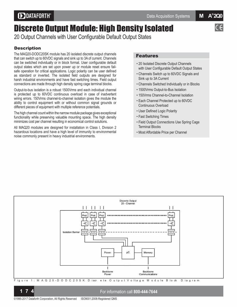
Data Acquisition Systems
©1995-2017 Dataforth Corporation, All Rights Reserved ISO9001:2008-Registered QMS
For information call 800-444-76441 7 4
M A Q ®2 0
Discrete Output Module: High Density Isolated
DescriptionThe MAQ20-DODC20SK module has 20 isolated discrete output channels that can switch up to 60VDC signals and sink up to 3A of current. Channels can be switched individually or in bloc format. ser configurable default output states which are set upon power up or module reset ensure fail-safe operation for critical applications. Logic polarity can be user defined as standard or inverted. The isolated field outputs are designed for harsh industrial environments and have fast switching times. Field output connections are made through high density spring cage terminal bloc s.Output to bus isolation is a robust rms and each individual channel is protected up to 60VDC continuous overload in case of inadvertent wiring errors. 150Vrms channel-to-channel isolation gives the module the ability to control e uipment with or without common signal grounds or different pieces of equipment with multiple reference potentials.The high channel count within the narrow module package gives exceptional functionality while preserving valuable mounting space. The high density minimizes cost per channel resulting in economical control solutions.All MAQ20 modules are designed for installation in Class I, Division 2 hazardous locations and have a high level of immunity to environmental noise commonly present in heavy industrial environments.
Features• 20 Isolated Discrete Output Channels
with ser onfigurable Default Output States• Channels Switch up to 60VDC Signals and
Sink up to 3A Current• Channels Switched Individually or in Blocks• 1500Vrms Output-to-Bus Isolation • 150Vrms Channel-to-Channel Isolation• Each Channel Protected up to 60VDC
Continuous Overload ser Defined Logic Polarity
• Fast Switching Times• Field Output Connections Use Spring Cage
Terminal Blocks ost Affordable Price per hannel
F i g u r e 1 : M A Q 2 0 - D O D C 2 0 S K D i scr e t e O u t p u t V o l t a g e M o d u l e B l o ck D i a g r a m
Output hannels with ser onfigurable Default Output States

Data Acquisition Systems
©1995-2017 Dataforth Corporation, All Rights Reserved ISO9001:2008-Registered QMS
Visit our website www.dataforth.com 1 7 5
M A Q ®2 0
MA
Q®20
Module DescriptionMAQ20-DODC20SK 10 to 60VDC Output at 3A max per channelNumber of hannelsOutput onfiguration
20Open Drain MOSFET
Switching Characteristics Turn-On/Turn-Off TimeOutput Load
ombined load, all channels Ta = 25º C Ta = 85º C
1ms / 1ms
30A10A
Output Protection Continuous Transient CMV Channel-to-Bus Channel-to-Channel Transient
60VDC max ANSI/IEEE C37.90.1
1500Vrms, 1 min
150Vrms, 212V peak ANSI/IEEE C37.90.1
Output Functions Logic Selection Block Write Default Relay State on Power Up/Reset
Standard / Inverted 20 Channel
ser onfigurable
Update Rate Power Supply Current
1300 Ch/s net, 65 Ch/s at 20-Ch Simultaneous30mA
Dimensions (h)(w)(d) 3.27” x 4.51” x 0.60” (83.1mm x 114.6mm x 15.3mm)
Environmental Operating Temperature Storage Temperature Relative Humidity Emissions, EN61000-6-4 Radiated, Conducted Immunity EN61000-6-2 RF ESD, EFT
to to
0 to 95% Noncondensing ISM Group 1
Class A ISM Group 1
Performance A Performance B
ertifications Heavy Industrial CE Compliant ATEX Compliance Pending
UL/CUL Listing Pending(Class I, Division 2, Groups A, B, C, D)
Model Description MAQ20-DODC20SK Discrete Output Module; Up to 60VDC Signals,
3A Current, 20-ch
Ordering Information
For input connections and full details on module operation, refer to MA1061 – MAQ20-DODC20SK Discrete Output Module Hardware User Manual, available for download at:www.dataforth.com/maq20_download.aspx
NOTES: ontact factory or your local Dataforth sales office for maximum values.
FieldConnection
(MAQ20-DODC20SK)Terminal Terminal
FieldConnection
(MAQ20-DODC20SK)CH0 +OUT 1 2 CH0 -OUTCH1 +OUT 3 4 CH1 -OUTCH2 +OUT 5 6 CH2 -OUTCH3 +OUT 7 8 CH3 -OUTCH4 +OUT 9 10 CH4 -OUTCH5 +OUT 11 12 CH5 -OUTCH6 +OUT 13 14 CH6 -OUTCH7 +OUT 15 16 CH7 -OUTCH8 +OUT 17 18 CH8 -OUTCH9 +OUT 19 20 CH9 -OUTCH10 +OUT 21 22 CH10 -OUTCH11 +OUT 23 24 CH11 -OUTCH12 +OUT 25 26 CH12 -OUTCH13 +OUT 27 28 CH13 -OUTCH14 +OUT 29 30 CH14 -OUTCH15 +OUT 31 32 CH15 -OUTCH16 +OUT 33 34 CH16 -OUTCH17 +OUT 35 36 CH17 -OUTCH18 +OUT 37 38 CH18 -OUTCH19 +OUT 39 40 CH19 -OUT
Specifications Typical at TA and D system power

Data Acquisition Systems
©1995-2017 Dataforth Corporation, All Rights Reserved ISO9001:2008-Registered QMS
For information call 800-444-76441 7 6
M A Q ®2 0
Discrete Output Module: Relay
DescriptionThe MAQ20-DORLY20 module has 20 isolated SPST latching relay output channels that can switch between A at and . A at . ach channel has contact state readbac to verify the physical output state. Relays can be controlled individually or in bloc s and have user configurable default output states which are set upon power up, power loss, and module reset to ensure fail-safe operation for critical applications. Relay state control can be user defined as standard or inverted logic. The isolated field outputs are designed for harsh industrial environments and have fast switching times. Advanced output functions SPDT, DPDT, 4x5 Crosspoint Matrix, 8-Channel Differential ultiplexer, ultiplexer and Null ode are configured with external field terminal bloc wiring and controlled by module commands. Field output connections are made through high density spring cage terminal bloc s. Reserve power is stored and used for predictable shutdown to user defined relay states upon loss of module power.Output to bus isolation is a robust rms and each individual channel is protected up to 150Vrms continuous overload in case of inadvertent wiring errors. rms channel to channel isolation gives the module the ability to control equipment with or without common signal grounds or different pieces of equipment with multiple reference potentials. The high channel count within the narrow module package gives exceptional functionality while preserving valuable mounting space. The high density minimizes cost per channel resulting in economical control solutions. All MAQ20 modules are designed for installation in Class I, Division 2 hazardous locations and have a high level of immunity to environmental noise commonly present in heavy industrial environments.
Features• 20 Isolated SPST Latching Relay Output
Channels• Channels Switch Between 2A at 30V and 0.4A
at 150V ontact State Readbac on ach hannel
• Relays Controlled Individually or in Blocks ser onfigurable Default States
• 1500Vrms Channel-to-Bus Isolation • 150Vrms Channel-to-Channel Isolation • Advanced Output Functions ser Defined Logic Polarity
• Fast Switching Times• Field Output Connections Use Spring Cage
Terminal Blocks
F i g u r e 1 : M A Q 2 0 - D O R L Y 2 0 M o d u l e B l o ck D i a g r a m
Isolated SPST Latching Relay Output Channels
Preliminary at date of printing. ontact factory for availability.

Data Acquisition Systems
©1995-2017 Dataforth Corporation, All Rights Reserved ISO9001:2008-Registered QMS
Visit our website www.dataforth.com 1 7 7
M A Q ®2 0
MA
Q®20
Module DescriptionMAQ20-DORLY20 60W per channel
(2A at 30V to 0.4A at 150V)Number of hannelsOutput onfiguration
20SPST Latching Relay with ontact State Readbac
Switching Characteristics Turn-On/Turn-Off TimeOutput Load Ta = 25º C Ta = 85º C
1ms / 1ms
60W per channel max (2A at 30V to 0.4A at 150V)40W per channel max (1.3A at 30V to 0.27A at 150V)
Output Protection Continuous Transient CMV Channel-to-Bus Channel-to-Channel Transient
± 150V peak max ANSI/IEEE C37.90.1
1500Vrms, 1 min
150Vrms, 212V peak ANSI/IEEE C37.90.1
Standard Output Functions Logic Selection Block Write Default Relay State on Power Up Default Relay State on Power Loss Default Relay State on Reset Advanced Output Functions onfigure with xternal iring
Standard / Inverted 20 Channel
ser onfigurable
ser onfigurable
ser onfigurable
SPDT, DPDT, 4x5 Crosspoint Matrix, 8-Channel Differential Multiplexer, 20:1 Multiplexer, Null Mode
Update Rate Power Supply Current
1300 Ch/s net, 65 Ch/s at 20-Ch Simultaneous30mA
Dimensions (h)(w)(d) 3.27” x 4.51” x 0.60” (83.1mm x 114.6mm x 15.3mm)
Environmental Operating Temperature Storage Temperature Relative Humidity Emissions, EN61000-6-4 Radiated, Conducted Immunity EN61000-6-2 RF ESD, EFT
to to
0 to 95% Noncondensing ISM Group 1
Class A ISM Group 1
Performance A ± 0.5% Span Error Performance B
ertifications Heavy Industrial CE Compliant ATEX Compliance Pending
UL/CUL Listing Pending(Class I, Division 2, Groups A, B, C, D)
Model Description MAQ20-DORLY20 Discrete Output Module; Isolated SPST Latching
Relay Channels
Ordering Information
For input connections and full details on module operation, refer to MA1063 – MAQ20-DORLY20 Discrete Relay Output Module Hardware User Manual, available for download at: www.dataforth.com/maq20_download.aspx
NOTES: ontact factory or your local Dataforth sales office for maximum values. Preliminary at date of printing. ontact factory for availability.
FieldConnection Terminal Terminal Field
Connection
CH0 POLE 1 2 CH0 THROWCH1 POLE 3 4 CH1 THROWCH2 POLE 5 6 CH2 THROWCH3 POLE 7 8 CH3 THROWCH4 POLE 9 10 CH4 THROWCH5 POLE 11 12 CH5 THROWCH6 POLE 13 14 CH6 THROWCH7 POLE 15 16 CH7 THROWCH8 POLE 17 18 CH8 THROWCH9 POLE 19 20 CH9 THROWCH10 POLE 21 22 CH10 THROWCH11 POLE 23 24 CH11 THROWCH12 POLE 25 26 CH12 THROWCH13 POLE 27 28 CH13 THROWCH14 POLE 29 30 CH14 THROWCH15 POLE 31 32 CH15 THROWCH16 POLE 33 34 CH16 THROWCH17 POLE 35 36 CH17 THROWCH18 POLE 37 38 CH18 THROWCH19 POLE 39 40 CH19 THROW
Specifications Typical at TA and D system power

Data Acquisition Systems
©1995-2017 Dataforth Corporation, All Rights Reserved ISO9001:2008-Registered QMS
For information call 800-444-76441 7 8
M A Q ®2 0
System BackbonesDistribute Power and ommunicationsDescriptionThe A system bac bone resides within the DIN rail used for module mounting and provides power to and interface between the communications module and the I O modules. Standard bac bones provide for one communication module and 4, 8, 16, or 24 I/O modules. The longest bac bone, which accommodates I O modules, fits in an industry standard rac . ach bac bone utili es a pluggable connector system on each end such that varying system channel counts can be configured using the standard bac bones. As a result of this pluggable system, the main part of a system, including the communications module, can be installed in one location while other sets of I O modules installed in remote locations connect to the main system through a wire harness.Modules mount on industry standard 35x7.5mm gull-wing DIN rails.Once a system is established with a system bac bone and a communications module, system configuration is accomplished by applying power and installing the I/O modules. These are hot swappable and true plug and run’. hen an I O module is plugged into any bac bone position, the communications module automatically recogni es that it has been added to the system, registers it in the system configuration record, and ma es it immediately available in the host software for use in data acquisition and control, and test and measurement applications. Similarly, when a module is removed from any bac bone position, the communications module recogni es that it has been unplugged, removes it from the system configuration, and disables it in the software.
Features• Compact Mounting in DIN Rail Channel Distribute Power and ommunications
• 4, 8, 16, and 24 Position Models• Simplify System Wiring xpandable for Local or Distributed Installation
• Prevent Reverse Installation Long Life, Durable, ibration Resistant ontacts odules are Hot Swappable and True “Plug and Run”
F i g u r e 1 : M A Q 2 0 B a ckb o n e B l o ck D i a g r a m

Data Acquisition Systems
©1995-2017 Dataforth Corporation, All Rights Reserved ISO9001:2008-Registered QMS
Visit our website www.dataforth.com 1 7 9
M A Q ®2 0
MA
Q®20
Ordering InformationSpecifications Module DescriptionMAQ20-BKPL4
MAQ20-BKPL8
MAQ20-BKPL16
MAQ20-BKPL24
DIN Rail Bac bone, Accepting 1 COM Module plus 4 I/O Modules
DIN Rail Bac bone, Accepting 1 COM Module plus 8 I/O Modules
DIN Rail Bac bone, Accepting 1 COM Module plus 16 I/O Modules
DIN Rail Bac bone, Accepting 1 COM Module plus 24 I/O Modules
xpansion DistributedInstallation Mechanical
Expansion DistanceMounting Physical
Reverse Protection
Electrical Circuitry Inter-Module Communications
ale Female pluggable terminal bloc s ateach end of the bac bone allow directinterconnection or remote installationusing the accessory expansion cable.
100ft (30m) max
Spring clips hold the bac bonein the DIN rail. When modules are installed,
the bac bone is secured to the DIN rail.Mechanical interface prevents
reverse module installation.
PassiveRS-485
Dimensions (h)(w)(d) MAQ20-BKPL4 MAQ20-BKPL8 MAQ20-BKPL16 MAQ20-BKPL24
5.05” x 0.94” (127.1mm x 3.9mm)7.53” x 0.94” (191.1mm x 3.9mm)
12.63” x 0.94” (320.9mm x 3.9mm)17.41” x 0.94” (442.1mm x 3.9mm)
Environmental Operating Temperature Storage Temperature Relative Humidity
to to
0 to 95% Noncondensingertifications Heavy Industrial CE Compliant
UL/CUL Listing Pending (Class I, Division 2, Groups A, B, C, D)
ATEX Compliance Pending
Model Description MAQ20-BKPL4
MAQ20-BKPL8
MAQ20-BKPL16
MAQ20-BKPL24
DIN Rail Bac bone Accepting O odule plus 4 I/O Modules DIN Rail Bac bone Accepting O odule plus 8 I/O Modules DIN Rail Bac bone Accepting O odule plus 16 I/O Modules DIN Rail Bac bone Accepting O odule plus 24 I/O Modules
Figure 3: Flexible Backbone System Allows Configuration with CommunicationsM o d u l e a n d 4 , 8 , 1 6 , o r 2 4 I / O M o d u l e s i n 1 9 ” R a ck S p a ce
F i g u r e 2 : M A Q 2 0 B a ckb o n e s f o r 4 , 8 , 1 6 , a n d 2 4 I / O M o d u l e s
For connections and full details on system operation,refer to MA1040 – MAQ20 Communications ModuleHardware User Manual, available for download at:www.dataforth.com/maq20_download.aspx.

Data Acquisition Systems
©1995-2017 Dataforth Corporation, All Rights Reserved ISO9001:2008-Registered QMS
For information call 800-444-76441 8 0
M A Q ®2 0
MAQ20-940/-941/-945ReDAQ® Shape and onfiguration Software for ADescriptionDataforth offers ReDAQ Shape software for MAQ20 as an easy and efficient development tool for use with the A Industrial Data Ac uisition and ontrol System. This software enables users to create, save, and open graphical user interface projects for test, process, data collection and data analysis applications. Built-in functions in the Acquire and Analy e panels are pre configured and can be used as is. ust three easy steps are required to create data acquisition and control projects in the Presentation panel using 65 high quality tools and powerful MAQ20 functions.ReDAQ Shape for MAQ20 is ideal for data acquisition, monitoring and control applications. It enables users to easily interact with the Dataforth PID loop controller, which an engineer or operator accesses through faceplates within the software.The ReDA Shape software also provides an effective way to configure and customi e A functions for specific application re uirements. The toolbox tools are easily moved, re si ed, cut, copied, pasted, and deleted. The main screen of ReDAQ Shape shows a representation of the system inclusive of the communications module and any installed I/O modules. This graphic is updated as I/O modules are added to or removed from the system. odules can be given uni ue identifiers, and I O module channels can be assigned tag names to represent process variables they control.Based on programming tools incorporated from Microsoft Visual Studio® and National Instruments Measurement Studio®, ReDAQ Shape software for MAQ20 has a very short user-learning curve and offers integrated, across the board applicability for data ac uisition and control applications. It requires only a one-time low-cost license fee.Link to ReDAQ software at www.dataforth.com/maq20_ download.aspx
Features• 3 Easy Steps to Create Customized
Applications No Setup or onfiguration Re uired to Acquire and Analyze Data
• Faceplates for PID Loop Control Toolbox Tools Simplify Pro ect reation
• Supports Any Graphical File Format Integrated, Across the Board Applicability ost fficient ay to onfigure and Run MAQ20 Systems
ontinuous ac uisition and burst scan modes - Automatically scales data from counts to
engineering units - Discrete I/O offers 7 special functions: Pulse/
Frequency Counter, Pulse/Frequency Counter with De bounce, aveform easurement, Time Between Events, Frequency Generator, PWM Generator, One-Shot Pulse Generator
- Assign tag names for any input and output onfigure control loops and alarm outputs - Three function timer (count-down, 24hr/day,
day time with programmable events
F i g u r e 1 : R e D A Q S h a p e S o f t w a r e S cr e e n S h o t s
Configure
Disp lay

Data Acquisition Systems
©1995-2017 Dataforth Corporation, All Rights Reserved ISO9001:2008-Registered QMS
Visit our website www.dataforth.com 1 8 1
M A Q ®2 0
MA
Q®20
Ordering Information Model Description MAQ20-940
MAQ20-941
MAQ20-945
ReDAQ Shape Software for MAQ20 Developer Version ReDAQ Shape Software for MAQ20 User Version A onfiguration Software Tool
PID Control Using MAQ20-COMx Modulesand ReDAQ® Shape for MAQ20 SoftwareDescriptionThe powerful Dataforth A communications module is capable of autonomously running up to 32 PID control loops; faceplates within ReDA Shape software enable an engineer or operator to configure the many features of loop control and monitor processes.With proportional and derivative modes that can act on error or a process variable, the controller can eliminate process bumps from set point changes. Gap control provides improved loop stability near the set point while retaining high response speed. The ability to change tuning settings without disturbing the process when the controller is in automatic mode and the option to trac the set points of process variables during manual operation are both ey features that enable smooth operation in both manual and automatic modes.To ensure sensitive equipment is well protected, the controller’s output range can be limited. The anti reset windup feature both minimi es overshoot and improves stability after output saturation conditions.The integrated Auto Tuner simplifies the complex tas of control loop tuning with separate methods for integrating and self-regulating loops.
Typical PID Control Applications Steam, water, and chemical ow control
• Tank level control• Heat-exchanger / reactor temperature control• Pressure control
any types of processes in a wide variety of applications can be managed using the Dataforth PID controller in the MAQ20 system. Its high level of performance and broad range of features are paralleled only by much larger state of the art distributed control systems.
Features• Separate Panels for Setting Basic, Advanced,
and Alarm Items• Noninteracting and Parallel PID Control
Algorithms• Up to 32 Loops of PID Control• Controller Runs in Real Time• Controller Accessed through Faceplates• Proportional and Derivative Modes can Act on
rror or Process ariable• Gap Control Built in Process ariable Filtering
• Bumpless Manual to Automatic Control Mode Transfer
• Change Tuning Settings Easily in Automatic Mode
Optional Process ariable Set Point Trac ing in Manual Mode
• Limit Controller Output Range• Anti-Reset Windup• Four Process Alarms• Full-Featured Faceplate for Numeric and Visual
Feedbac• Integrated Auto-Tuner
C o n t r o l l e r N a m e& D e s c r i p t i o n U p p e r C a l i b r a t i o n L i m i t s
L o w e r C a l i b r a t i o n L i m i t s
P r o c e s s A l a r m I n d i c a t o r
A l a r m P o i n t I n d i c a t o r s
S e t P o i n t I n d i c a t o r
P r o c e s s V a r i a b l e S c a l e
E n g i n e e r i n g U n i tS e t P o i n t
P r o c e s s V a r i a b l e
C o n t r o l l e r O u t p u t C o n t r o l l e r O u t p u t S c a l e
C o n t r o l l e r M o d e
S e t t i n g sB u t t o n
F I C - 1 0 0S t e a m F l o w C o n t r o l l e r
S P ( G P M )
S PP V3 5 0
4 0 0
0 0
1 0 0
P V ( G P M )
C O ( % )
M O D E
3 5 0 . 1
5 4 . 8 1
A U T O
S e t t i n g sN o A l a r m
C O
F i g u r e 2 : P I D F a ce p l a t e i n R e D A Q S h a p e S o f t w a r e

Data Acquisition Systems
©1995-2017 Dataforth Corporation, All Rights Reserved ISO9001:2008-Registered QMS
For information call 800-444-76441 8 2
M A Q ®2 0
MAQ20-951/-952IPEmotion Software for MAQ20DescriptionRepresenting the next step in test and measurement, IPEmotion is a very advanced, intuitive, versatile, and high performance data acquisition / test and measurement software designed specifically for industrial and R D applications. Now available with an interface to the A , this powerful new generation software provides synchronized data acquisition and is easily adaptable to all customer specific re uirements.These re uirements can include device configuration, data ac uisition measurement, visualization, and analysis; to meet them, IPEmotion provides automatic recognition of connected devices, automatic configuration of all channels, automatic start of measuring, and instant visualization of all measurement values.MAQ20 and IPEmotion measurements include temperature, current and voltage, strain, pressure, frequencies and rotational speeds, and logging and diagnostic data.To enhance ease of use and increase productivity, the versatile IP motion software is available in seven languages nglish, German, French, Italian, hinese traditional and simplified , orean, and Japanese. PID loop control is an integral part of IPEmotion. It runs in Windows and an unlimited number of loops are possible the only limiting factor is the processing power of the PC.IPEmotion communicates with the MAQ20 via a Plug-In driver. The software enables many functions to be integrated by lin ing external .dll and isual Basic Script . BS files to the application. Scripting is a powerful tool which enables users to automate the measurement process and to change menus, settings, analyzing procedures, and other aspects of the software.Well designed for long-term measurements, IPEmotion allows measure-ment analysis and verification during data ac uisition. Storage can be on a local hard drive or a remote drive, including a mapped Internet or network drive.
Features Live Data Display, Recording, Online and Of ine Math and Logic Functions
• One-Click Acquisition - Direct hardware detection, data display and
recording• Live Adjustment - Analyze and verify measurements during
active data acquisition - GUI adaptation during active measurement
and storage• Data Analysis• PID Loop Control• Post Processing and Report Generation• Easy Drag and Drop HMI Creation• High Speed Recording to 1000 Samples/s• Plug-In Synchronization• Import and Export Recorded Data Using
Standard File Formats• Scripting Option with VB or Python Software onfigurable Gauges for ide Ranging Applications
• Multilingual
F i g u r e 1 : I P E m o t i o n S o f t w a r e S cr e e n S h o t s
Control Recording

Data Acquisition Systems
©1995-2017 Dataforth Corporation, All Rights Reserved ISO9001:2008-Registered QMS
Visit our website www.dataforth.com 1 8 3
M A Q ®2 0
MA
Q®20
Ordering Information Model Description MAQ20-951
MAQ20-952
IPEmotion Software for MAQ20 (1 COM module and 1 to 4 I/O modules) IPEmotion Software for MAQ20 (Each additional 4 I/O modules)
PID Control Using IPEmotion Softwarewith MAQ20 Plug-InDescriptionPID loop control is extensive and highly functional in the IPEmotion software. An unlimited number of loops can be run the only limiting factor is the processing power of the PC.A maximum calculation cycle time update rate of 1kHz allows the software to control processes with fast reacting elements.
Typical PID Applications Steam, water, and chemical ow control
• Tank level control• Heat-exchanger / reactor temperature control• Pressure control
Features• Control Module Includes PID, State Machine,
Function Generator, Math Functions nlimited PID ontrol Loops Possible
• PID Controller Runs in Windows• Start, Stop, Hold Trigger for All Control
Functions• Designed for Test Sequencing and Test Bench
Control Operations• 1kHz Maximum Calculation Cycle Time Update
Rate asily onfigured Test Se uences using B or Python Scripts
onfigure with Point and lic Functions on IPEmotion GUI
Software sable as irtual PL

Data Acquisition Systems
©1995-2017 Dataforth Corporation, All Rights Reserved ISO9001:2008-Registered QMS
For information call 800-444-76441 8 4
M A Q ®2 0
Accessoriesxpansion ables and Load Share Power Supply odule
DescriptionAccessories for the MAQ20 Industrial Data Acquisition and Control System include bac bone expansion cables and a load share power supply module for systems that have power supply requirements greater than those the communications module provides.Also available are cables to interface B bac panels to the A SN module, and SB and thernet cables and adapters.A MAQ20 Demonstration Suitcase with process simulator is offered to sales channels. The five P R PS Rx power supplies used by the A are the same as those used by DS A signal conditioners.
Ordering Informationac one ansion Ca es
Model Description MAQ20-XCA-01 MAQ20-XCA-02
Bac bone xpansion able meter . Bac bone xpansion able meter .
Load Share Power Supply Module Model Description MAQ20-PWR3 Load Share Power Supply Module
Cables to Interface 8B Backpanels to MAQ20-VSN Module
P P Po er u ies
USB and Ethernet Cables and Adapters
Model Description MAQ20-8B25-0.3
MAQ20-8B25-0.6
MAQ20-8B25-01
DB to pos screw term Transition able, 0.3m (11.8”) long DB to pos screw term Transition able, 0.6m (23.6”) long DB to pos screw term Transition able, 1.0m (39.4”) long
Model Description SLX147-01, -02, -05
SLX141-01, -02, -07 SLX141-X01, -X02, -X07 SLX146-02, -07
SLX142, 143 SLX144
SB able, Type A to Type B m . , 2m (78.7”), 5m (196.9”) thernet able, m . , m . , 7m (275.6”) thernet rossover able, m . , m . , 7m (275.6”) Null odem Serial able, Female DB to Female DB-9; 2m (78.7”), 7m (275.6”) RJ45 to DB9 Adapters RJ45 RS-485 Multidrop Adapter
MAQ20 Demonstration Suitcase Model Description MAQ20DEMO-B MAQ20 Demonstration Suitcase with Process
Simulator for Sales Channels
F i g u r e 1 : C a b l e I n t e r f a ci n g 8 B B a ckp a n e l t o M A Q 2 0 - V S N M o d u l e
Model PWR-PS5R7W PWR-PS5R15W PWR-PS5R30W PWR-PS5R60W PWR-PS5R120WInput to A nominal to A , to D compatible
Output Voltage & Current Ratings 24V, 0.3A 24V, 0.65A 24V, 1.3A 24V, 2.5A 24V, 5.0A
Power 7.5W 15W 30W 60W 120W
Dimensions(h)(w)(d)
2.95” x1.77” x 2.76”)(75mm x 45mm x 70mm)
3.54” x 0.89” x 3.74”(90mm x 22.5mm x 95mm)
3.54” x 0.89” x 3.74”(90mm x 22.5mm x 95mm)
3.74” x 1.42” x 4.25” (95mm x 36mm x 108mm)
4.53” x 1.81” x 4.76” (115mm x 46mm x 121mm)
NOTE:For complete P R PS Rx Power Supplies specifications, see page in Full Line atalog.

©1995-2017 Dataforth Corporation, All Rights Reserved ISO9001:2008-Registered QMS
Visit our website www.dataforth.com 1 8 5
i s o L y n x ® Data Acquisition Systems
isoL
ynx®
8BSLX300 Data Acquisition System
DescriptionDataforth’s 8B isoLynx® SL data ac uisition system builds on the proven reliability and outstanding performance of the S B isoLynx®
SLX200 DAQ system and miniature-sized SensorLex® 8B isolated signal conditioning modules to provide a compact, low cost solution for wide ranging, rugged industrial applications. Like the SLX200, the SLX300 ensures superior reliability, accuracy, and isolation. Through the use of pluggable modules, the SL offers maximum exibility of analog and digital channel configuration for factory automation, process control, test and measurement, machine control, and data acquisition applications. The isoLynx SL uses industry standard odbus® RTU and TCP protocols, thus enabling communication with a wide range of existing third-party software tools and HMI/SCADA packages. Fast I/O Channel-to-Channel Isolated
Features odbus® RTU and TCP Support
• 1500Vrms Input-to-Output & Channel-to- Channel Isolation• 240Vrms Field-side Protection• Wide I/O Selection: Analog - 20 Families, 89 Models Digital - 5 Families, 14 Models• Mix and Match Analog & Digital I/O• Advanced Features Including Alarms, Counters, Timers, PWMs, and More to Operating Temperature Free onfiguration Software
• C-UL-US Listed (Class I, Division 2, Groups A, B, C, D)• CE Compliant• ATEX Compliance Pending• Manufactured per RoHS II Directive 2011/65/EU
Using Dataforth’s SensorLex 8B analog modules and SCMD digital modules, the exible, modular SL design can be configured with up to twelve channels of isolated analog input, four channels of isolated analog output, and eight channels of isolated digital I/O (Figure 3). The isolation rating is 1500Vrms from input to output and from channel to channel. The system can be powered by D or a wide range to
D using the BP R module, and it can be either panel or DIN rail mounted. Multiple powerful, highspeed microcontrollers and high performance data converters at the heart of the system enable mix and match analog and digital I/O at sustained rates of up to 3.0kS/s. In addition, a burst mode of operation is provided for analog input that allows sampling up to 100kS/s on analog input channels. Industry’s Widest I/O SelectionThe isoLynx SL can be configured for any application by selecting from over 89 analog I/O modules and 14 digital I/O modules. These module selections enable monitoring of common industrial signals including millivolt, volt, milliamp, amp, linearized and non-linearized thermocouple, 3- and 4-wire RTD, potentiometer, slidewire, strain gage, AC-to-True RMS output, frequency, 2-wire transmitter, and DC LVDT. Analog output modules provide isolated high-level voltage and current options. Industry standard digital I/O solid-state relay modules provide AC/DC input and output monitoring and control. Both analog and digital output channels can be configured as alarm outputs. The ability to mix
and match module types on a per channel basis ensures maximum system exibility. Operation and storage temperature for the isoLynx SLX300, as well as for all analog and digital I/O modules used in the most extreme environments, is – 40º C to +85º C; the relative humidity range is 0 to 95% noncondensing. The SLX300 system is C-UL-US Listed, CE Compliant, and designed for operation in Class I, Division 2 Hazardous Locations. Powerful FunctionalityThe SLX300 has many features and special purpose functions specifically for data ac uisition and control. urrent sampled data from analog input channels is stored to a sample buffer. Data is available as minimum, maximum, and average readings with selectable averaging weight. A burst mode of operation allows up to S s sampling rate on analog input channels and also provides a waveform generator function using the analog output channels. Continuous scan mode scans up to
input channels, and burst sampling mode can be set up with a entry scan list to specify scan sequence, scan rate, and scan count. In addition to performing standard digital I/O, the eight digital I/O channels can be configured to perform seven different special functions pulsefre uency counter, pulse fre uency counter with de bounce, waveform measurement, time between events, fre uency generator, pulse width modulation (PWM) generator, and one-shot generator. The SLX300 also allows four alarm states high, high high, low, and low low to be set on the analog input and digital I/O special function channels with alarm output mapped to a user selectable analog or digital output channel.
onfigurable analog and digital default output values ensure output sig-nals are set to safe values upon system startup or when unexpected pow-er outages or brownouts occur. System status and mode L Ds constantly display communication activity, mode of operation, and alarm status.

Data Acquisition Systems
©1995-2017 Dataforth Corporation, All Rights Reserved ISO9001:2008-Registered QMS
For information call 800-444-76441 8 6
i s o L y n x ®
Flexible Communications and ConfigurationThe isoLynx SLX300 interfaces to a host system through a choice of communication links. RS-232 or RS-485 serial links operate from
. bps to . bps, use true fail safe transceivers, and have software controlled termination networks, eliminating the need for dip switches. A USB Virtual Communications Port provides a common connection to modern computers and a 10/100 Base-T Ethernet connection is also available. p to systems can be multi dropped on the RS serial link and up to 4 sockets are supported on Ethernet.The odbus® RTU protocol used on serial and USB interfaces and the
odbus T P protocol used on the thernet interface are open, industry
Figure 2: Configuration Tool - Channel Monitoring and Data Display
standard protocols that define how devices on a networ communi-cate with each other. This ensures that the system can be integrated seamlessly onto existing odbus networ s using common odbus function codes. Free configuration software is provided for uic and easy system setup (see Figure 1 and Figure 2). Channel I/O setup, communication, default output, and other parameters are stored in non-volatile memory. A Lab I TM I library enables fast application development using indus-try standard tools. The SL system can be either panel or DIN rail mounted. It is also available in a rac mounted or bench top enclosure.
Figure 1: Configuration Tool - System Setup

©1995-2017 Dataforth Corporation, All Rights Reserved ISO9001:2008-Registered QMS
Visit our website www.dataforth.com 1 8 7
i s o L y n x ® Data Acquisition Systems
isoL
ynx®
iso n ® SLX300Analog Input Channel Count Module Type
Accuracy(1)
Resolution Cold Junction Compensation Accuracy, +25º C Accuracy, – 40º C to +85º C Input Protection Isolation (Input-to-Output & Ch-to-Ch) Throughput(2)
Sampling Buffer Scan List Averaging Alarm
Alarm Response
12ix and match input types on a per channel basis
8B30/31/32/33/34/35/36/37/ 38/40/41/42/43/45/47/50/51/PT
All models with 0-5V output± 0.07%
± 0.024%
± 0.5º C± 1.5º C
240VAC continuous, ESD per EN61000-6-21500Vrms max
3.0kS/s max continuous,S s max burst(3), programmable
sample, bytesUp to 48 entries in any order
Selectable weightProgram High/High-High/Low/Low-Low
per channelProgrammable analog out, digital out
Analog Output Channel Count Module Type
Accuracy(1)
Resolution Output Protection Isolation (Ouput-to-Input & Ch-to-Ch) Throughput(2)
Programmable aveform
4Mix and match output types on a
per channel basis8B39/49
All models with 0-5V input± 0.07%
± 0.024%40VAC max, ESD per EN61000-6-2
1500Vrms max
1.0kS/s max continuous. S s max burst, programmable
16k samples per channelDigital I/O Channel Count Module Type
Isolation (Input-to-Output & Ch-to-Ch) Throughput(2)
8ix and match I O types on a per channel basis
SCMD-MIAC5x, SCMD-MIDC5xSCMD-MOAC5x, SCMD-MODC5x
SCMD-MORx5, SCMD-PT1500Vrms max
2.0kS/s max continuous
Specifications Typical at TA and D power
NOTES: ontact factory or your local Dataforth sales office for maximum values.(1) System accuracy does not include module accuracy or SLX300 CJC accuracy. SLX300 CJC accuracy replaces CJC accuracy in 8B37/47 module datasheets. Reference module datasheets for further details.
Throughput varies with system configuration.(3) Burst Mode Scan rate is reduced when CJC, linearization, averaging, and/or alarm functions areenabled.(4) Does not include module power consumption. Reference module datasheets for further details.
iso n ® SLX300 (continued)Digital I/O Special Functions Pulse/Frequency Counter Pulse/Frequency Counter with De bounce Waveform Measurement Time Between Events Frequency Generator PWM Generator One-Shot Generator
AlarmAlarm Response
Frequency to 80kHz, count to 10M, RPM to 65kFrequency to 50Hz, count to 10M
Fre uency to H , periods, pulse width, period, duty cycle
in, max, avg, selectable timebaseUp to 100kHz
Selectable timebases min pulse, programmable
pre- and post-delayProgram High/High-High/Low/Low-Low per function
Programmable digital outCommunications RS-232 RS-485 USB Ethernet
. bps to . bps, DB connector. bps to . bps, pluggable
screw terminal connectorSB to serial bridge
(Virtual Communications Port), type B10/100 Base-T, static IP, RJ-45 connector
Protocol RS-232, RS-485, USB Ethernet
odbus® RTUodbus T P
Software Tools Free configuration software toolPower +5VDC 7-34VDC (8BPWR-2 required)
270mA(4)
320mA(4)
Physical Dimensions (l)(w)(h) Panel Mount DIN Rail Mount Bench Top 1U EnclosureMounting
16.24” x 3.47” x 1.92” (413mm x 88mm x 49mm)16.24” x 3.47” x 2.00” (413mm x 88mm x 51mm)16.73” x 6.0” x 1.72” (424.9mm x 152.4mm x 43.7mm)
Panel or DIN railRac mounted or bench top enclosure
Environmental Operating Temp. Range Storage Temp. Range Relative Humidity
– 40º C to +85º C– 40º C to +85º C
0 to 95% NoncondensingEmissions, EN61000-6-4 Radiated, Conducted
ISM, Group 1Class A
Immunity, EN61000-6-2 RF ESD, EFT
ISM, Group 1Performance A ± 0.5% span error
Performance B

Data Acquisition Systems
©1995-2017 Dataforth Corporation, All Rights Reserved ISO9001:2008-Registered QMS
For information call 800-444-76441 8 8
i s o L y n x ®
Model Description SLX300-10(S)* SLX300-20(S)* SLX300-30(S)* SLX300-40(S)*
SLX300-10D(S)* SLX300-20D(S)* SLX300-30D(S)* SLX300-40D(S)*
SLX300-10U(S)* SLX300-20U(S)* SLX300-50U(S)*
SLX146-02, -07 SLX147-01, -02, -05 SLX370(1)
SLX380(1)
SLX141-01, -02, -07 SLX141-X01, -X02, -X07
SCMXRK-002 SCMXRAIL1-XX SCMXRAIL3-XX
8B30-04, -05, -06 8B31-04, -05, -06, -08, -10, -13 8B32-01, -02 8B34-01, -02, -03, -04 8B35-01, -02, -03, -04 8B36-01, -02, -03, -04 8B37J, K, T, R, S
12-Ch AI, 4-Ch AO, 8-Ch DIO, RS-232, Panel Mount 12-Ch AI, 4-Ch AO, 8-Ch DIO, RS-485, Panel Mount 12-Ch AI, 4-Ch AO, 8-Ch DIO, USB (VCP), Panel Mount 12-Ch AI, 4-Ch AO, 8-Ch DIO, Ethernet, Panel Mount
12-Ch AI, 4-Ch AO, 8-Ch DIO, RS-232, DIN Rail Mount 12-Ch AI, 4-Ch AO, 8-Ch DIO, RS-485, DIN Rail Mount 12-Ch AI, 4-Ch AO, 8-Ch DIO, USB (VCP), DIN Rail Mount 12-Ch AI, 4-Ch AO, 8-Ch DIO, Ethernet, DIN Rail Mount
12-Ch AI, 4-Ch AO, 8-Ch DIO, RS-232, SD Card, 1U Box 12-Ch AI, 4-Ch AO, 8-Ch DIO, RS-485, SD Card, 1U Box 12-Ch AI, 4-Ch AO, 8-Ch DIO, USB (VCP) & Ethernet, SD Card, 1U Box
Null odem Serial able, Female DB to Female DB m, m SB able, Type A to Type B m, m, m Software Tools, onfig Sample, Lab I TM VI Quick Start Guide, Hardware Manual, Software Manual
thernet able, m, m, mthernet rossover able, m, m, m
19” Metal Rack for Mounting Backpanels DIN EN50022-35x7.5 (slotted steel), length -XX in meters DIN EN50022-35x15 (slotted steel), length -XX in meters
milliVolt Input Modules, 3Hz BWVoltage Input Modules, 3Hz BWCurrent Input Modules, 3Hz BW2- and 3-Wire RTD Input Modules, 3Hz BW4-Wire RTD Input Modules, 3Hz BWPotentiometer Input Modules, 3Hz BWThermocouple Input Modules, Non-linearized, 3Hz BW
Ordering Information Model Description
8B38-06, -07, -088B38-36, -37, -388B39-01, -038B40-04, -05, -068B41-04, -05, -06, -08, -10, -138B42-01, -028B43-11 through -158B45-01 through -088B47J-xx, K-xx, T-xx8B49-01, -028B50-04, -05, -068B51-04, -05, -06, -08, -10, -138BPT8BPWR-2
SCMD-MIAC5x SCMD-MIDC5x SCMD-MOAC5x SCMD-MODC5x SCMD-MORx5 SCMD-PT
SCMXPRT-001 SCMXPRE-001 SCMXPRT-003 SCMXPRE-003 PWR-4505
PWR-PS5R15W PWR-PS5R30W PWR-PS5R60W PWR-PS5R120W
Strain Gage Input Modules, 3kHz BW Strain Gage Input Modules, 3Hz BW Current Output Modules, 100Hz BW milliVolt Input Modules, 1kHz BW Voltage Input Modules, 1kHz BW 2-Wire Transmitter Input Modules, 100Hz BW DC LVDT Input Modules, 1kHz BW Frequency Input Modules Thermocouple Input Modules, Linearized, 3Hz BW Voltage Output Modules, 100Hz BW milliVolt Input Modules, 20kHz BW Voltage Input Modules, 20kHz BW Non-Isolated Signal Pass Thru Module Power Supply Module, 7-34VDC Input
Miniature Digital AC Input Modules Miniature Digital DC Input Modules Miniature Digital AC Output Modules Miniature Digital DC Output Modules Miniature Relay Output Modules Miniature Pass Thru Module
Power Supply, 5VDC, 1A, 120VAC Input Power Supply, 5VDC, 1A, 220VAC Input Power Supply, 5VDC, 3A, 120VAC Input Power Supply, 5VDC, 3A, 220VAC Input Power Supply, 5VDC, 5A, 85-264VAC Input
Power Supply, 24VDC, 0.65A, 100-240VAC Input Power Supply, 24VDC, 1.3A, 100-240VAC Input Power Supply, 24VDC, 2.5A, 100-240VAC Input Power Supply, 24VDC, 5.0A, 100-240VAC Input
NOTES: *Add an ‘S’ suffix to any SLX300 system part number to order the system bundled with ReDAQ® S h a p e so f t w a r e . ( 1 ) D o w n l o a d a b l e f r o m w e b si t e .
Figure 3: 8B isoLynx SLX300 Block Diagram

©1995-2017 Dataforth Corporation, All Rights Reserved ISO9001:2008-Registered QMS
Visit our website www.dataforth.com 1 8 9
i s o L y n x ® Data Acquisition Systems
isoL
ynx®
SLX930ReDAQ® Shape Software for8B isoLynx® SLX300DescriptionReDA Shape, Dataforth’s out of the box DA software for the SL , provides the easiest and most efficient development tool to create, save, and open graphical user interface projects for test, process, data collec-tion and data analysis applications. Built-in functions in the Acquire and Analy e panels are pre configured and can be used without setup. ust three easy steps are required to create data acquisition and control projects using 18 high quality tools and powerful isoLynx® SLX300 functions. These projects are developed and executed in the software’s Presentation panel.
The ReDAQ Shape tools include:
Features• 3 Easy Steps to Create Customized
Presentation Panels No Setup or onfiguration Re uired in Ac uire and Analyze Panels
High uality Toolbox Tools• Supports Any Graphical File Format Integrated, Across the Board Applicability ost ffective ay to Set p onfigure B isoLynx SLX300 Functions: ontinuous and burst scan modes for analog input and 4 analog output channels
– Automatically scales data from counts to engineering units
– 8 discrete I/O with 7 special functions: pulse/frequency counter, pulse/frequency counter with de bounce, waveform measurement, time between events, fre uency generator, P generator, one-shot pulse generator
– Customer user tag name for any input and output
– Cold Junction Compensation and linearization for thermocouple input modules
– Control loop and alarm output– Three function timer (count-down, 24hr/day,
day time with programmable events
F i g u r e 1 : R e D A Q S h a p e f o r S L X 3 0 0 S cr e e n S h o t s
– Slide– Tank– Gage– Meter nob
– Chart Recorder– Oscilloscope– XY Plot– Discrete Waveform Graph
– Button– Picture Box– Text Box– Group Box Label
– LED– Switch– Numeric Edit– Thermometer
ReDA Shape also provides the most effective way to configure and customi e SL functions for specific application re uirements. The toolbox tools are easily moved, re si ed, cut, copied, pasted, and deleted. They also support any graphical file format so presentations made with other software can be loaded into ReDA Shape.In contrast to other graphical software environments, ReDAQ Shape software for SL has a very short user learning curve. It is based on programming tools incorporated from Microsoft Visual Studio® and National Instruments Measurement Studio®, ensuring its ease of use and integrated, across theboard applicability for data ac uisition and control applications. Model Description
SLX930 ReDAQ Shape Software for SLX300
Ordering Information
A c q u i r e
P r e s e n t
A n a l y ze

Data Acquisition Systems
©1995-2017 Dataforth Corporation, All Rights Reserved ISO9001:2008-Registered QMS
For information call 800-444-76441 9 0
i s o L y n x ®
SCM5BSLX200 Data Acquisition System
DescriptionFaulty thousand dollar data ac uisition systems can shut down billion dollar operations. The SCM5B isoLynx® SLX200 is a fast, intelligent, fully isolated data ac uisition system providing superior reliability, accuracy, and isolation for a wide range of rugged industrial applications. It offers maximum exibility of analog and digital I O selection at competitive prices for a broad range of factory automation, process control, test and measurement, machine control, and data acquisition applications. The isoLynx SL implements the industry standard odbus® RTU and T P protocols, thereby enabling communication with a wide variety of existing third-party software drivers and HMI/SCADA packages. It is fully certified by odbus IDA and compatible with OP . All I/O Channel-to-Channel Isolated
Features odbus® RTU Support on RS-232 and RS-485 odbus T P Support optional
• 1500Vrms Input-to-Output & Channel-to- Channel Isolation• 240Vrms Field-side Protection• 16-Bit A/D, D/A• Up to 6-Pole Analog Input Filtering• ± 0.012% Base System Accuracy, No Modules• ± 0.005% Base System Linearity, No Modules• ± 0.03% Module Accuracy• ± 0.005% Module Linearity• Best I/O Selection: 250+ Different I/O Modules to Operating Temperature Free onfiguration Software All Analog I O odules ertified to SA S,
CE, and ATEX Requirements• SLX200 & SLX101 CE Compliant SL SA S ertified
(Class I, Division 2, Groups A, B, C, D)• Manufactured per RoHS II Directive 2011/65/EU
The exible, modular design combines a or channel I O ontroller base system and optional or channel expansion bac planes, which can be either panel or DIN rail mounted see Figure .One I/O Controller unit can operate up to 60 channels of differential analog I/O and 128 channels of digital I/O, using Dataforth’s SCM5B an-alog and SCMD digital modules. The Controller contains a powerful high-speed microcontroller, A D and D A subsystem, communication interface, data storage memory, and status L Ds. The A D system is built around a
bit, successive approximation converter and can convert a maximum channel configuration in msec. The D A converter is also a bit
device and can write a maximum channel configuration in msec. Industry’s Widest I/O SelectionBy selecting from over 250 standard and custom single-channel SCM5B analog I O modules, the isoLynx SL can interface to a broad spectrum of analog signals, including millivolt, volt, milliamp, amp, linearized and non-linearized thermocouple, RTD, potentiometer, slidewire, strain gage, AC to True RMS output, frequency, 2-wire transmitter, and transducers requiring DC excitation. Analog output modules are available which provide a wide selection of current or voltage output ranges. Industry standard miniature digital I/O modules are used for digital AC/DC input and output requirements. Users can mix and match most I O module types on a per channel basis, thus reducing wasted I/O channels and saving costs.Interface to digital signals is provided by the dedicated SL digital I O bac panel. This intelligent bac panel is designed to interface to the SL but can also be used stand alone for digital I O only systems.
The operation and storage temperature range for the SCM5B isoLynx SL is to the relative humidity is to noncondensing. Power re uirement is D , . base system with no modules installed. The SLX200 and SLX101 are CE Compliant. SLX200 is SA S ertified for lass I, Division Ha ardous Locations.
e i e Communications an Confi urationThe SCM5B isoLynx SLX200 communicates on RS-232/RS-485 serial lin s up to . bps or b s thernet. p to systems can be multidropped on the RS-485 serial link and up to 4 sockets are supported on thernet. Optional thernet communication boards are available these can be factory installed or field upgradeable.The communication protocol is odbus RT for RS RS or
odbus T P for thernet. odbus is an open, industry standard protocol that defines how devices on a networ or bus communicate with each other. Full certification of the S B isoLynx SL by odbus IDA ensures the device can be integrated onto existing odbus networ s, and most common odbus function codes are supported. The system is also OP compatible. As device configuration is performed using standard odbus function codes, any third party software application that supports the odbus RT and or odbus T P protocol can be used to configure the device.
onfiguration parameters are stored in non volatile memory, so configu-ration only has to happen once. Free configuration software is provided to ensure configuration is easy and intuitive see Figure and Figure .

©1995-2017 Dataforth Corporation, All Rights Reserved ISO9001:2008-Registered QMS
Visit our website www.dataforth.com 1 9 1
i s o L y n x ® Data Acquisition Systems
isoL
ynx®
Powerful Firmware FeaturesThe S B isoLynx SL hosts many powerful firmware fea-tures. Two analog scan modes are supported: one for general purpose signal monitoring with running average, maximum, and minimum values available for each analog input the other with user configurable scan parameters such as scan list, scan rate, and scan count, used to obtain data with highly accurate time correlation between samples. onfigurable
default output values ensure output signals get set at safe values when unexpected power outages or brownouts occur. Power on selftest results can be obtained visually by glancing at a status L D or programatically by reading the appropriate register on the device. A section of memory is set aside for general purpose user data, some of which is stored in non-volatile memory.
Figure 1: SCM5B isoLynx SLX200 Block Diagram
Figure 2: Configuration Utility - Communications Setup Figure 3: Configuration Utility - Analog Channel Setup

Data Acquisition Systems
©1995-2017 Dataforth Corporation, All Rights Reserved ISO9001:2008-Registered QMS
For information call 800-444-76441 9 2
i s o L y n x ®
iso n ® SLX200 Analog I/O Base UnitGeneral System Protocol I O apability
Software Tools
odbus® RT or T P, OP Server ompatibleOne ch or ch bac panel minimum xpandable to60-ch Analog I/O, 128-ch Digital I/OFree onfiguration tility, in DLL, Lab I TM I library
Digital System Microcontroller Status LEDs Failsafe Features
High Performance RISC+5V, System Status, TD/RD (Serial), LNK/ACK (Ethernet)Watchdog Timer & Brownout Detection - Reset to userdefined configuration
Communication Interface Serial I/O
Port for SLX101 Digital I/O Panel RS-485
Ethernet
Separate RJ-45 modular phone jacks for RS-232 and RS . bps maxRJ-45 modular phone jack, 2-wire RS-485
2-wire or 4-wire, 4000 feet max distance, 32 maxmultidrops, non-isolatedTo isolate, extend, or convert RS-232 or RS-485, useDataforth LDM and DCP Data Communication productsRJ-45 modular phone jack, 10Base-TDefault IP Address 192.168.0.215, Keep-alive timeout 7200s
Analog I/O Channels
alibration System Accuracy Field Connector System Connector Ground Network Jumpers
A/D Converter
D/A Converter Isolation Input Protection Throughput, Analog Input
Throughput, Analog Output
Expansion Panels
ix and match I O types on a per channel basis(1)
Maximum 60-ch differential I/O of SCM5B modulesInput modules must have system output of ± 5V or
to or to cannot be usedNIST traceable test and calibration sheets ship with modulesAnalog Input ± 0.024% (2), Analog Output ± 0.006% (2)
High density screw clamp, 14 AWG max, 0.5N-M torque26-pin, male header connectorFactory Default R , , and installedJ3 not installed. See Hardware User Manual forrecommended grounding practices.
bit, input, bit min accuracyResolution vs. input range bit at ,
bit at , bit at to bit, output
rms ch to ch or ch to internal bus240VAC continuous, ESDms for ch ch sec at . bps odbus RTms for ch ch sec at . bps odbus RTms for ch ch sec at . bps odbus RTms for ch ch sec at . bps odbus RT
SCMPB02 (16-ch, can use up to 3),SCMPB06 (8-ch, can use up to 6)
Power Supply Requirements SLX200-1xx SLX200-2xx SLX200-3xx
+5VDC ± 5% at 500mA, no modules installed+5VDC ± 5% at 700mA, no modules installed+5VDC ± 5% at 900mA, no modules installed
Dimensions (l)(w)(h) SLX200-xx, 12-ch SLX200-xxAx, 6-ch
17.4” x 3.47” x 3.30” (442.0mm x 88.1mm x 83.8mm)11.8” x 3.47” x 3.30” (300.7mm x 88.1mm x 83.8mm)
Mounting Options Panel Mount or DIN Rail MountEnvironmental Operating Temp. Range Storage Temp. Range Relative HumidityEmissions EN61000-6-4 Radiated, ConductedImmunity EN61000-6-2 RF ESD, EFT
to to for SL xx, xx to
0 to 95% NoncondensingISM, Group 1Class AISM, Group 1Performance A ± 0.5% Span ErrorPerformance B
ertifications CE Compliant CSA, FM odbus
Class I, Division 2, Groups A, B, C, D Hazardous LocationsIDA Conformance Tested
Specifications Typical at TA and D power
iso n ® SLX101 Digital I/O BackpanelGeneral System Protocol
I O apability
odbus RT or T P, OP Server ompatiblethrough SLX200. Proprietary as stand-alone.One ch bac panel minimum. xpandable to128-ch Digital I/O.
Digital System Microcontroller Status LEDs Failsafe Features
High Performance RISC+5V, System Status, Channel StateWatchdog Timer & Brownout Detection - Reset touser defined configuration
Communication Interface Serial I/O
RS-485 2W
Two RJ-45 modular phone jacks for daisy-chainconnection
. bps max4000 feet max distance, 32 max multidrops, non-isolated
Digital I/O Channels Field Connector Isolation Throughput
ix and match I O types on a per channel basis
High density screw clamp, 14 AWG max, 0.5N-M torque rms ch to ch or ch to internal bus
ms for ch ch sec at . bps odbus RTms for ch ch sec at . bps odbus
RTUPower Supply Requirements +5VDC ± 5% at 40mA, no modules installedDimensions (l)(w)(h) 10.0” x 3.47” x 1.95” (254.0mm x 88.1mm x 49.5mm)Mounting Options Panel Mount or DIN Rail MountEnvironmental Operating Temp. Range Storage Temp. Range Relative HumidityEmissions EN61000-6-4 Radiated, ConductedImmunity EN61000-6-2 RF ESD, EFT
to to
0 to 95% NoncondensingISM, Group 1Class AISM, Group 1Performance A ± 0.5% Span ErrorPerformance B
ertifications CE Compliant CSA, FM
Not covered under the SL certifications.ust ualify separately based on source of I O modules.
NOTES: ontact factory or your local Dataforth sales office for maximum values.
odules with system output of or cannot be used in the SL systems. This includes SCM5Bxx-xxD, SCM5B392-13, -14, SCM5B42-02, and SCM5B48-01.(2) 10V span for analog input, 20V span for analog output. Does not include SCM5B module accuracy.

©1995-2017 Dataforth Corporation, All Rights Reserved ISO9001:2008-Registered QMS
Visit our website www.dataforth.com 1 9 3
i s o L y n x ® Data Acquisition Systems
isoL
ynx®
iso n ® SLX101 Digital I/O BackpanelGeneral System Protocol
I O apability
odbus RT or T P, OP Server ompatiblethrough SLX200. Proprietary as stand-alone.One ch bac panel minimum. xpandable to128-ch Digital I/O.
Digital System Microcontroller Status LEDs Failsafe Features
High Performance RISC+5V, System Status, Channel StateWatchdog Timer & Brownout Detection - Reset touser defined configuration
Communication Interface Serial I/O
RS-485 2W
Two RJ-45 modular phone jacks for daisy-chainconnection
. bps max4000 feet max distance, 32 max multidrops, non-isolated
Digital I/O Channels Field Connector Isolation Throughput
ix and match I O types on a per channel basis
High density screw clamp, 14 AWG max, 0.5N-M torque rms ch to ch or ch to internal bus
ms for ch ch sec at . bps odbus RTms for ch ch sec at . bps odbus
RTUPower Supply Requirements +5VDC ± 5% at 40mA, no modules installedDimensions (l)(w)(h) 10.0” x 3.47” x 1.95” (254.0mm x 88.1mm x 49.5mm)Mounting Options Panel Mount or DIN Rail MountEnvironmental Operating Temp. Range Storage Temp. Range Relative HumidityEmissions EN61000-6-4 Radiated, ConductedImmunity EN61000-6-2 RF ESD, EFT
to to
0 to 95% NoncondensingISM, Group 1Class AISM, Group 1Performance A ± 0.5% Span ErrorPerformance B
ertifications CE Compliant CSA, FM
Not covered under the SL certifications.ust ualify separately based on source of I O modules.
NOTES: SL suffix changes to xxA or xxAD for ch base unit.
(2) Cold Junction Compensation. Required for SCM5B37 and SCM5B47. Downloadable from website. odules with system output of or cannot be used in the SL systems.
This includes SCM5Bxx-xxD, SCM5B392-13, -14, SCM5B42-02, and SCM5B48-01.
Model DescriptionSLX200-10(1)
SLX200-20(1)
SLX200-30(1)
SLX200-11(1)
SLX200-21(1)
SLX200-31(1)
SLX200-10D(1)
SLX200-20D(1)
SLX200-30D(1)
SLX200-11D(1)
SLX200-21D(1)
SLX200-31D(1)
SLX101SLX101-D
SLX141-01,-02,-07SLX141-X01,-X02,-X07SLX142,143SLX144SLX145SLX270(3)
SLX280(3)
SCMPB02SCMPB02-1SCMPB02-2SCMPB02-3
SCMPB06SCMPB06-1SCMPB06-2SCMPB06-3
SCMXRK-002
SCM5B30/31(4)
SCM5B32(4)
SCM5B33(4)
SCM5B34(4)
SCM5B35(4)
SCM5B36(4)
SCM5B37(4)
SCM5B38(4)
SCM5B39SCM5B392(4)
SCM5B40/41(4)
SCM5B42(4)
SCM5B43(4)
SCM5B45(4)
SCM5B47(4)
SCM5B49
SCMD-MIAC5xSCMD-MIDC5xSCMD-MOAC5xSCMD-MODC5xSCMD-MORx5
SCMXCA004-xxSCMXPRT-001SCMXPRE-001SCMXPRT-003SCMXPRE-003
12-Ch, RS-232/485, Panel Mount12-Ch, Ethernet, Panel Mount12-Ch, Dual-Ethernet, Panel Mount12-Ch, RS-232/485, No CJC(2), Panel Mount12-Ch, Ethernet, No CJC(2), Panel Mount12-Ch, Dual-Ethernet, No CJC(2), Panel Mount12-Ch, RS-232/485, DIN Rail Mount12-Ch, Ethernet, DIN Rail Mount12-Ch, Dual-Ethernet, DIN Rail Mount12-Ch, RS-232/485, No CJC(2), DIN Rail Mount12-Ch, Ethernet, No CJC(2), DIN Rail Mount12-Ch, Dual-Ethernet, No CJC(2), DIN Rail Mount( For 6-Ch. Base Unit, See Note(1))
Backpanel Digital: 16-ChBackpanel Digital: 16-Ch, DIN Rail Mount
thernet and Serial able Optionsthernet rossover able Options
RJ45 to DB9 AdaptersRJ45 RS-485 Multidrop AdapterFuse 4A, package of 5Software Tools and User ManualsSoftware and Hardware User Manuals
Backpanel Analog: 16-ChBackpanel Analog: 16-Ch, No CJC(3)
Backpanel Analog: 16-Ch, DIN Rail MountBackpanel Analog: 16 Ch, No CJC(3), DIN Rail Mount
Backpanel Analog: 8-ChBackpanel Analog: 8-Ch, No CJC(3)
Backpanel Analog: 8-Ch, DIN Rail MountBackpanel Analog: 8-Ch, No CJC(3), DIN Rail Mount
Accessory: 19-Inch Rack Analog Backpanels
Analog Voltage Input ModulesAnalog Current Input ModulesIsolated True RMS Input ModulesLinearized 2- or 3-Wire RTD Input ModulesLinearized 4-Wire RTD Input ModulesPotentiometer Input ModulesThermocouple Input ModulesStrain Gage Input ModulesCurrent Output ModulesMatched-Pair Servo/Motor Controller ModulesAnalog Voltage Input Modules, Wide Bandwidth2-Wire Transmitter Interface ModulesGeneral Purpose Input Modules, with DC Exc.Frequency Input ModulesLinearized Thermocouple Input ModulesVoltage Output Modules
Miniature Digital AC Input ModulesMiniature Digital DC Input ModulesMiniature Digital AC Output ModulesMiniature Digital DC Output ModulesMiniature Relay Output Modules
System interface cable for both analog bac panelsPower supply, 1A, 5VDC, 120VAC U.S.Power supply, 1A, 5VDC, 220VAC EuropeanPower supply, 3A, 5VDC, 120VAC U.S.Power supply, 3A, 5VDC, 220VAC European
Ordering Information

Data Acquisition Systems
©1995-2017 Dataforth Corporation, All Rights Reserved ISO9001:2008-Registered QMS
For information call 800-444-76441 9 4
i s o L y n x ®
Figure 4: SLX200-xx 12-Channel Base System

©1995-2017 Dataforth Corporation, All Rights Reserved ISO9001:2008-Registered QMS
Visit our website www.dataforth.com 1 9 5
i s o L y n x ® Data Acquisition Systems
isoL
ynx®
F i g u r e 5 : S L X 1 0 1 D i g i t a l I / O B a ckp a n e l

©1995-2017 Dataforth Corporation, All Rights Reserved ISO9001:2008-Registered QMS
For information call 800-444-76441 9 6
S C M D Isolated Digital I/O Products
SCMDIsolated SCMD Digital I/O ModulesDataforth offers a broad line of digital input and output modules and accessories providing safe, reliable interfacing to industrial measurement and control applications. hen installed near individual field loads, our S D series I O modules create a rugged protective isolation barrier, effective to
, between the field and computer system. se of these modules can also reduce field wiring costs while establishing an economical, manageable ap-proach for system expansion and repair. The SCMD SeriesSCMD miniature digital I/O modules are solid-state devices which send “ON” and “OFF” electrical signals to and from a computer. The input modules, depending on the type selected, convert AC or DC voltages to DC logic signals and send them to the computer system. Output modules work in the opposite direction, switching either AC or DC circuits on or off in response to logic-level voltage commands from the computer. SCMD modules are available in miniature versions of four basic types A input, D input, A output, and DC output.• SCMD–MIAC and –MIDC miniature input modules are used for sensing
“ON” and “OFF” AC or DC voltage levels in the ranges 10-60, 90-140, and 180- 280VAC and 3.3-32 and 10-60VDC. Models with low noise, fast switching, and other special features are also available.
• SCMD–MOAC and –MODC are miniature output modules accepting 5VDC or 24VDC inputs and providing several different output ranges, including 12/24 to 140/280VAC and 0/3/5 to 50/60/200VDC. Fast switching, and other special options are also available.
• SCMD–MORO and –MORC are miniature relay output modules used for switching AC and DC loads up to 125Vrms or 100VDC at maximum 30WDC or 62.5VA.
Features• 4000Vrms Optical Isolation• Industry Standard Packaging• Input Modules Incorporate Input Filtering for
Transient-Free Switching• Complete Selection of Backpanels and
Accessories• Optional Low Noise, Fast Switching Models L Listed, SA ertified, ompliant
• Manufactured per RoHS Directive 2002/95/EC
ApplicationsInput Modules Interface To:• Proximity Switches• Limit Switches• Photoelectric Switches• TTL Devices Pushbuttons
Output Modules For Switching AC and DC Loads:• Relays • Solenoids• Motor Starters • Indicator Lamps
SCMD Selection GuideDIGITAL INPUT MODULES, MINIATURE Page 197
MODEL INPUT RANGE SUPPLY VOLTAGESCMD-MIAC5 90 to 140VAC/DC 5VSCMD-MIAC5A 180 to 280VAC/DC 5VSCMD-MIAC5E 10 to 60VAC/DC 5VSCMD-MIAC24 90 to 140VAC/DC 24VSCMD-MIAC24A 180 to 280VAC/DC 24VSCMD-MIDC5 3.3 to 32VDC 5VSCMD-MIDC5F 3.3 to 32VDC 5VSCMD-MIDC5N 10 to 60VDC 5VSCMD-MIDC24 3.3 to 32VDC 24V
DIGITAL OUTPUT & RELAY OUTPUT MODULES, MINIATURE Pages 198 and 199
MODEL OUTPUT RANGE SUPPLY VOLTAGESCMD-MOAC5 12 to 140VAC 5VSCMD-MOAC5A 24 to 280VAC 5VSCMD-MOAC5B 24 to 280VAC 5VSCMD-MOAC24 12 to 140VAC 24VSCMD-MOAC24A 24 to 280VAC 24VSCMD-MODC5 3.0 to 60VDC 5VSCMD-MODC5A 5.0 to 200VDC 5VSCMD-MODC5ML 1.0 to 50VDC 5VSCMD-MODC24 3.0 to 60VDC 24VSCMD-MORO5 100/125 VDC/Vrms 5VSCMD-MORC5 100/125 VDC/Vrms 5VSCMD-MORO24 100/125 VDC/Vrms 24VSCMD-MORC24 100/125 VDC/Vrms 24V
DIGITAL I/O MODULE ACCESSORIES Page 200
SCMD-PB4/D 4-Ch Backpanel, Full Size & Miniature / DIN MountSCMD-PB4R/D 4-Ch Backpanel, Full Size & Miniature, Output Only / DIN MountSCMD-PB8SM/D 8-Ch Backpanel, Miniature / DIN MountSCMD-PB16SM/D 16-Ch Backpanel, Miniature / DIN MountSCMD-PB16TSM/D 16-Ch Backpanel, Miniature, Screw Term I/O / DIN MountSCMD-PB24SM/D 24-Ch Backpanel, Miniature / DIN MountSCMD-JM8 Board Jumper, Miniature
i ita n ut o u es o e o u fi es enti in tiona eatures u fi A E F N
Feature High voltage versions (280VAC for AC modules). Low voltage 10VAC input for AC modules. Fast-switching version of DC modules. Enhanced noise immunity version of DC modules.
i ita ut ut o u es o e o u fi es enti in tiona eatures u fi A B
ML
Feature High voltage versions (280VAC for AC modules, 200VDC for DC modules). High voltage version (280VAC for AC modules) with low leakage output current. FET output version of DC module, 5.0A, 50VDC.

©1995-2017 Dataforth Corporation, All Rights Reserved ISO9001:2008-Registered QMS
Visit our website www.dataforth.com 1 9 7
S C M D Isolated Digital I/O Products
SCM
D
Model Input Range Supply Voltage SCMD-MIAC5 SCMD-MIAC5A SCMD-MIAC5E SCMD-MIAC24 SCMD-MIAC24A SCMD-MIDC5 SCMD-MIDC5F SCMD-MIDC5N SCMD-MIDC24
90 to 140VAC/DC 180 to 280VAC/DC 10 to 60VAC/DC
90 to 140VAC/DC 180 to 280VAC/DC
3.3 to 32VDC3.3 to 32VDC 10 to 60VDC3.3 to 32VDC
5V5V5V24V24V5V5V5V24V
Ordering Information
F i g u r e 1 : S C M D - M I A C / M I D C P h ysi ca l D i m e n si o n s F i g u r e 2 : S C M D - M I A C / M I D C C i r cu i t D i a g r a m s
i ita n ut o u es o e o u fi es enti in tiona eatures u fi A E F N
Feature High voltage versions (280VAC for AC modules). Low voltage 10VAC input for AC modules. Fast-switching version of DC modules. Enhanced noise immunity version of DC modules.
SCMD-MIAC/MIDCMiniature Digital Input Modules
S D digital input modules provide highly reliable and safe interfaces to harsh industrial measurement and control applications. With SCMD modules installed near individual field signals, a reliable isolation barrier is provided between the field wiring computer system. Other benefits include reduction of field wiring costs and establishment of a cost effective and manageable method for system expansion and repair.The SCMD-MIAC digital input modules are used for sensing ON/OFF AC or DC voltage levels in the ranges of 18-36, 90-140 and 180-280VAC or VDC respectively. They are protected from damage due to high-voltage transients on the input signal.The SCMD-MIDC digital input modules provide DC voltage sensing at the lower ranges of 3.3 to 32VDC and 10 to 60VDC. High voltage, low voltage, fast switching, and low noise options are available, designated by suffixes A , , F , and N respectively.Five bac panels are available for mounting S D digital input modules. See “Accessories” section.
Description Features• Plug into Backpanels for Miniature or Full-Sized
Modules• AC Inputs for 24V, 120V, 240V• DC Inputs for 3.3 to 32V, 10 to 60V• 4000Vrms Optical Isolation• Open-Collector Output• Industry-Standard Pinout and Footprint Operating Temperature to L Listed, SA ertified, ompliant

©1995-2017 Dataforth Corporation, All Rights Reserved ISO9001:2008-Registered QMS
For information call 800-444-76441 9 8
S C M D Isolated Digital I/O Products
SCMD-MOAC/MODCMiniature Digital Output ModulesDescriptionThe SCMD digital output modules are used for switching AC and DC loads such as relays, solenoids, motor starters, or indicator lamps. All models provide up to rms of optical isolation between the field device and the control logic. The AC output modules incorporate zero voltage switching and an R snubber circuit which allows switching heavy inductive loads. Functionality is denoted by case color A modules are blac , and D modules are red.Six bac panels are available for mounting S D digital output modules. See “Accessories” section.
Features• AC Modules have High Current Thyristor with Amp Surge apability ero or Random Turn On Available in A
Modules• Plug into Backpanels for Miniature or Full-Sized Modules rms Optical Isolation except L suffix rms Optical Isolation with L suffix
• Industry Standard Pinout and Footprint• 3.5 Amp AC Modules Provide Extra Switching apability . Amp D odules Available Operating Temperature to L Listed, SA ertified, ompliant
F i g u r e 2 : S C M D - M O A C / M O D C C i r cu i t D i a g r a m s
F i g u r e 1 : S C M D - M O A C / M O D C P h ysi ca l D i m e n si o n s
i ita ut ut o u es o e o u fi es enti in tiona eatures u fi A B
ML
Feature High voltage versions (280VAC for AC modules, 200VDC for DC modules). High voltage version (280VAC for AC modules) with low leakage output current. FET output version of DC module, 5.0A, 50VDC.
Model Output Range Supply Voltage SCMD-MOAC5 SCMD-MOAC5A SCMD-MOAC5B SCMD-MOAC24 SCMD-MOAC24A SCMD-MODC5 SCMD-MODC5A SCMD-MODC5ML SCMD-MODC24
12 to 140VAC 24 to 280VAC 24 to 280VAC 12 to 140VAC 24 to 280VAC3.0 to 60VDC
5.0 to 200VDC 0 to 50VDC3.0 to 60VDC
5V5V5V24V24V5V5V5V24V
Ordering Information

©1995-2017 Dataforth Corporation, All Rights Reserved ISO9001:2008-Registered QMS
Visit our website www.dataforth.com 1 9 9
S C M D Isolated Digital I/O Products
SCM
D
SCMD-MORO/MORCMiniature Digital Relay Output ModulesDescriptionThe SCMD digital relay output modules are used for switching AC and DC loads such as resistors in and out of circuit, transistors, SCRs for switching inductive loads, indicator lamps, and low level heaters. All models provide up to rms of optical isolation between the field device and the control logic. Functionality is denoted by case color relay modules are brown.The -MOROxx models have a normally open contact and the -MORCxx models have a normally closed contact.Six bac panels are available for mounting S D relay output modules. See “Accessories” section.
Features• Resistive Load Only• Max On-state Current 1A, 30WDC, 62.5VA• Max Turn-on Time 2ms• Max Turn-off Time 1ms• 1000Vrms Isolation• Plug into Backpanels for Miniature or Full-Sized Modules• Industry Standard Pinout and Footprint Operating Temperature to L Listed, SA ertified, ompliant
F i g u r e 1 : S C M D - M O R O / M O R C P h ysi ca l D i m e n si o n s
Model Output Range Supply Voltage Contact SCMD-MORO5 SCMD-MORC5 SCMD-MORO24 SCMD-MORC24
100/125 VDC/Vrms100/125 VDC/Vrms100/125 VDC/Vrms100/125 VDC/Vrms
5V5V24V24V
Normally open Normally closed Normally open Normally closed
Ordering Information
F i g u r e 2 : S C M D - M O R O / M O R C C i r cu i t D i a g r a m s

©1995-2017 Dataforth Corporation, All Rights Reserved ISO9001:2008-Registered QMS
For information call 800-444-76442 0 0
S C M D Isolated Digital I/O Products
SCMD Accessories*Digital I/O Module Backpanels
Features Plug ompatible Logic onnections on ,
16- and 24-Position Backpanels, Screw Terminal Barrier Block for Logic Connections on 4- Position Backpanels• Screw Terminal Barrier Block for Load Connections• Resident Pull-Up Resistors Amp Field Replaceable Fuses
Littelfuse or uivalent• LEDs Indicate Logic Status All ven Numbered Logic onnections are
Logic Ground• Input and Output Modules Accepted Interchangeably• Operate with 5 or 24 Volt Logic Supplies• Plastic Captive-Screw Retaining System for All Modules• PB4, PB4R, PB8SM, PB16SM, PB16TSM, and PB S , L Listed, SA ertified and Compliant
Model Description SCMD-PB4 SCMD-PB4R SCMD-PB8SM SCMD-PB16SM SCMD-PB16TSM SCMD-PB24SM
SCMD-PB4D SCMD-PB4RD
SCMD-PB8SMD
SCMD-PB16SMD
SCMD-PB16TSMD
SCMD-PB24SMD
4-Ch Backpanel, Full Size & Miniature 4-Ch Backpanel, Full Size & Miniature, Output Only 8-Ch Backpanel, 50-trace I/O male card edge 16-Ch Backpanel, 50-trace I/O male card edge 16-Ch Backpanel, screw terminal input and output 24-Ch Backpanel, 50-trace I/O male card edge
4-Ch Backpanel, Full Size & Miniature, DIN Rail Mount 4-Ch Backpanel, Full Size & Miniature, Output Only, DIN Rail Mount 8-Ch Backpanel, 50-trace I/O male card edge, DIN Rail Mount 16-Ch Backpanel, 50-trace I/O male card edge, DIN Rail Mount 16-Ch Backpanel, screw terminal input and output, DIN Rail Mount 24-Ch Backpanel, 50-trace I/O male card edge, DIN Rail Mount
Ordering Information
Model Description SCMD-JM8 Miniature, 8-position
Jumpers onnect common terminals on bac panels
Part Number Manufacturer 66317-150 3415-0001
FCI-Berg 3M
ConnectorsMating connector for 50-trace I/O male card edge
*For technical details and drawings, go to www.dataforth.com/scmd.aspx

High Performance Signal Conditioners
©1995-2017 Dataforth Corporation, All Rights Reserved ISO9001:2008-Registered QMS
Visit our website www.dataforth.com 2 0 1
DSC
A
D S C A
DSCAHigh Performance DIN Isolated Analog Signal Conditioners
Features• ± 0.03% Accuracy (Typical)• ± 0.01% Linearity• 1500Vrms Transformer Isolation & 240Vrms Field-side Protection• ANSI/IEEE C37.90.1 Transient Protection• True 3-Way Isolation• Wide Supply Voltage, 15 to 30VDC• Industry Standard Output of 0 to +10V, ± 10V, 0 to 20mA, or 4 to 20mA• 4- to 6-Pole Low-Pass Filtering• Up to 160dB CMR• 85dB NMR at 60Hz, 80dB at 50Hz to Operating Temperature
• Screw Terminals and Plug-in Terminal Blocks Simplify Wiring and Maintenance• C-UL-US Listed (Class I, Division 2, Groups A, B, C, D)• CE and ATEX Compliant• Manufactured per RoHS II Directive 2011/65/EU
DescriptionEach Instrument-Class® DSCA module provides a single channel of isolated analog input or output. Input modules accept analog voltage or current signals from all types of field sensors and sources and filter, isolate, amplify, linearize, and convert these input signals to high-level analog outputs suitable for use in data ac uisition, test and measurement, and control system applications. Output modules accept high-level analog voltage signals from a system, then buffer, isolate, filter, and amplify them before providing a current or voltage output to a field device.
DSCA Selection GuideANALOG VOLTAGE INPUT MODULES, 3Hz BW Page 204MODEL INPUT RANGE OUTPUT RANGE†
DSCA30-01 – 10mV to +10mV 1DSCA30-02 – 50mV to +50mV 1DSCA30-03 – 100mV to +100mV 1DSCA30-04 – 10mV to +10mV 2, 3, 4DSCA30-05 – 50mV to +50mV 2, 3, 4DSCA30-06 – 100mV to +100mV 2, 3, 4DSCA30-07 0 to +10mV 2, 3, 4DSCA30-08 0 to +50mV 2, 3, 4DSCA30-09 0 to +100mV 2, 3, 4
DSCA31-01 – 1V to +1V 1DSCA31-02 – 5V to +5V 1DSCA31-03 – 10V to +10V 1DSCA31-04 – 1V to +1V 2, 3, 4DSCA31-05 – 5V to +5V 2, 3, 4DSCA31-06 – 10V to +10V 2, 3, 4DSCA31-07 – 20V to +20V 1DSCA31-08 – 20V to +20V 2, 3, 4DSCA31-09 – 40V to +40V 1DSCA31-10 – 40V to +40V 2, 3, 4DSCA31-11 0 to +1V 2, 3, 4DSCA31-12 0 to +5V 2, 3, 4DSCA31-13 0 to +10V 2, 3, 4DSCA31-14 0 to +20V 2, 3, 4DSCA31-15 0 to +40V 2, 3, 4
ANALOG CURRENT INPUT MODULES Page 206MODEL INPUT RANGE OUTPUT RANGE†
DSCA32-01 4mA to 20mA 2, 3, 4DSCA32-02 0mA to 20mA 2, 3, 4DSCA32-03 – 20mA to 20mA 1
ISOLATED TRUE RMS INPUT MODULES Page 208MODEL INPUT RANGE (rms) OUTPUT RANGE (dc)†
DSCA33-01 0 to 100mV 2, 3, 4, 5, 6DSCA33-02 0 to 1V 2, 3, 4, 5, 6DSCA33-03 0 to 10V 2, 3, 4, 5, 6DSCA33-04 0 to 150V 2, 3, 4, 5, 6DSCA33-05 0 to 300V 2, 3, 4, 5, 6DSCA33-06 0 to 1A 2, 3, 4, 5, 6DSCA33-07 0 to 5A 2, 3, 4, 5, 6
LINEARIZED 2- or 3-WIRE RTD INPUT MODULES Page 210MODEL INPUT RANGE OUTPUT RANGE†
Pt * *DS A to F to F , , DS A to F to F , , DS A to F to F , , DS A to F to F , , DS A to F to F , ,
Ni * *DS A N to F to F , ,

Isolated Analog Signal Conditioning Products
©1995-2017 Dataforth Corporation, All Rights Reserved ISO9001:2008-Registered QMS
For information call 800-444-76442 0 2
S C M 5 B High Performance Signal Conditioners
©1995-2017 Dataforth Corporation, All Rights Reserved ISO9001:2008-Registered QMS
For information call 800-444-76442 0 2
DSCA Selection Guide (Continued)
POTENTIOMETER INPUT MODULES Page 212MODEL INPUT RANGE OUTPUT RANGE†
DS A , , DS A , , DS A , , DS A , ,
THERMOCOUPLE INPUT MODULES Page 214MODEL TYPE‡ INPUT RANGE OUTPUT RANGE†
DS A to F to F , , DS A to F to F , , DS A T T to F to F , , DS A to F to F , , DS A R R to F to F , , DS A S S to F to F , , DS A B B to F to F , , DS A N N to F to F , ,
STRAIN GAGE INPUT MODULES Page 216OUTPUT
MODEL INPUT EXCITATION RANGE†
DSCA38-01 ± 10mV Full Bridge Input, (3mV/V) +3.333V 1DSCA38-02 ± 30mV Full Bridge Input, (3mV/V) +10.0V 1DSCA38-03 ± 10mV Half Bridge Input, (3mV/V) +3.333V 1DSCA38-04 ± 30mV Half Bridge Input, (3mV/V) +10.0V 1DSCA38-05 ± 20mV Full Bridge Input, (2mV/V) +10.0V 1DSCA38-06 ± 33.3mV Full Bridge Input, (10mV/V) +3.333V 1DSCA38-07 ± 100mV Full Bridge Input, (10mV/V) +10.0V 1DSCA38-08 ± 10mV Full Bridge Input, (3mV/V) +3.333V 2, 3, 4DSCA38-09 ± 30mV Full Bridge Input, (3mV/V) +10.0V 2, 3, 4DSCA38-10 ± 10mV Half Bridge Input, (3mV/V) +3.333V 2, 3, 4DSCA38-11 ± 30mV Half Bridge Input, (3mV/V) +10.0V 2, 3, 4DSCA38-12 ± 20mV Full Bridge Input, (2mV/V) +10.0V 2, 3, 4DSCA38-13 ± 33.3mV Full Bridge Input, (10mV/V) +3.333V 2, 3, 4DSCA38-14 ± 100mV Full Bridge Input, (10mV/V) +10.0V 2, 3, 4DSCA38-15 0 to +10mV Full Bridge Input, (3mV/V) +3.333V 2, 3, 4DSCA38-16 0 to +30mV Full Bridge Input, (3mV/V) +10.0V 2, 3, 4DSCA38-17 0 to +10mV Half Bridge Input, (3mV/V) +3.333V 2, 3, 4DSCA38-18 0 to +30mV Half Bridge Input, (3mV/V) +10.0V 2, 3, 4DSCA38-19 0 to +20mV Full Bridge Input, (2mV/V) +10.0V 2, 3, 4DSCA38-20 0 to +33.3mV Full Bridge Input, (10mV/V) +3.333V 2, 3, 4DSCA38-21 0 to +100mV Full Bridge Input, (10mV/V) +10.0V 2, 3, 4
CURRENT OUTPUT MODULES Page 218MODEL INPUT RANGE OUTPUT RANGEDSCA39-01 0V to +10V 4mA to 20mADSCA39-02 – 10V to +10V 4mA to 20mADSCA39-03 0V to +10V 0mA to 20mADSCA39-04 – 10V to +10V 0mA to 20mADSCA39-05 0mA to 20mA 0mA to 20mADSCA39-07 – 10V to +10V -20mA to +20mA
ANALOG VOLTAGE INPUT MODULES, 3kHz BW Page 220MODEL INPUT RANGE OUTPUT RANGE†
DSCA40-01 – 10mV to +10mV 1DSCA40-02 – 50mV to +50mV 1DSCA40-03 – 100mV to +100mV 1DSCA40-04 – 10mV to +10mV 2, 3, 4DSCA40-05 – 50mV to +50mV 2, 3, 4DSCA40-06 – 100mV to +100mV 2, 3, 4DSCA40-07 0 to +10mV 2, 3, 4DSCA40-08 0 to + 50mV 2, 3, 4DSCA40-09 0 to +100mV 2, 3, 4
DSCA41-01 – 1V to +1V 1DSCA41-02 – 5V to +5V 1DSCA41-03 – 10V to +10V 1DSCA41-04 – 1V to +1V 2, 3, 4DSCA41-05 – 5V to +5V 2, 3, 4DSCA41-06 – 10V to +10V 2, 3, 4DSCA41-07 – 20V to +20V 1DSCA41-08 – 20V to +20V 2, 3, 4DSCA41-09 – 40V to +40V 1DSCA41-10 – 40V to +40V 2, 3, 4DSCA41-11 0 to +1V 2, 3, 4DSCA41-12 0 to +5 V 2, 3, 4DSCA41-13 0 to +10V 2, 3, 4DSCA41-14 0 to +20V 2, 3, 4DSCA41-15 0 to +40V 2, 3, 4
2-WIRE TRANSMITTER INTERFACE MODULES Page 222MODEL INPUT RANGE OUTPUT RANGE†
DSCA42-01 4mA to 20mA 0V to +10V & 3, 4DSCA42-02 4mA to 20mA 2 V to +10V
GENERAL PURPOSE INPUT MODULES, DC EXCITATION Page 224MODEL INPUT RANGE OUTPUT RANGE†
DSCA43-01 – 1V to +1V 1DSCA43-02 – 2V to +2V 1DSCA43-03 – 3V to +3V 1DSCA43-04 – 4V to +4V 1DSCA43-05 – 5V to +5V 1DSCA43-06 – 6V to +6V 1DSCA43-07 – 7V to +7V 1DSCA43-08 – 8V to +8V 1DSCA43-09 – 9V to +9V 1DSCA43-10 – 10V to +10V 1DSCA43-11 – 1V to +1V 2, 3, 4DSCA43-12 – 2V to +2V 2, 3, 4DSCA43-13 – 3V to +3V 2, 3, 4DSCA43-14 – 4V to +4V 2, 3, 4DSCA43-15 – 5V to +5V 2, 3, 4DSCA43-16 – 6V to +6V 2, 3, 4DSCA43-17 – 7V to +7V 2, 3, 4DSCA43-18 – 8V to +8V 2, 3, 4DSCA43-19 – 9V to +9V 2, 3, 4DSCA43-20 – 10V to +10V 2, 3, 4
D S C A

High Performance Signal Conditioners
©1995-2017 Dataforth Corporation, All Rights Reserved ISO9001:2008-Registered QMS
Visit our website www.dataforth.com 2 0 3
DSC
A
D S C A
DSCA Selection Guide (Continued)
FREQUENCY INPUT MODULES Page 226MODEL INPUT RANGE OUTPUT RANGE†
DSCA45-01 0 to 500Hz 2, 3, 4DSCA45-02 0 to 1kHz 2, 3, 4DSCA45-03 0 to 2.5kHz 2, 3, 4DSCA45-04 0 to 5kHz 2, 3, 4DSCA45-05 0 to 10kHz 2, 3, 4DSCA45-06 0 to 25kHz 2, 3, 4DSCA45-07 0 to 50kHz 2, 3, 4DSCA45-08 0 to 100kHz 2, 3, 4
LINEARIZED THERMOCOUPLE INPUT MODULES Page 228MODEL TYPE‡ INPUT RANGE OUTPUT RANGE†
DS A to F to F , , DS A to F to F , , DS A to F to F , , DS A to F to F , , DS A to F to F , , DS A to F to F , , DS A to F to F , , DS A T T to F to F , , DS A T T to F to F , , DS A to F to F , , DS A R R to F to F , , DS A S S to F to F , , DS A B B to F to F , , DS A N N to F to F , ,
VOLTAGE OUTPUT MODULES Page 230MODEL INPUT RANGE OUTPUT RANGEDSCA49-04 0V to +10V – 10V to +10VDSCA49-05 – 10V to +10V – 10V to +10VDSCA49-06 – 10V to +10V 0V to +10V
Output Range Part o u fi am e 1. – 10V to +10V 2. 0V to +10V 3. 4 to 20mA 4. 0 to 20mA 5. 0 to +5V 6. 0 to 1mA
NoneNone
CEAB
DSCA30-01 DSCA30-04 DSCA30-01C DSCA30-04E DSCA33-01A DSCA33-01B
‡THERMOCOUPLE ALLOY COMBINATIONSStandards: DIN IEC 584, ANSI MC96-1-82, JIS C 1602-1981
TYPE MATERIAL J Iron vs. Copper-Nickel K Nickel-Chromium vs. Nickel-Aluminum T Copper vs. Copper-Nickel E Nickel-Chromium vs. Copper-Nickel R Platinum-13% Rhodium vs. Platinum S Platinum-10% Rhodium vs. Platinum B Platinum-30% Rhodium vs. Platinum-6% Rhodium N Nickel-14.2% Chromium-1.4% Silicon vs. Nickel-4.4% Silicon- 0.1% Magnesium
A ATYPE ALPHA COEFFICIENT DIN JIS IEC
Pt . DIN IS I Ni .
† OUTPUT RANGES AVAILABLE
POWER SUPPLIES Page 232PWR-PS5R7W Power Supply, 24V, 0.3A, 100-240VAC InputPWR-PS5R15W Power Supply, 24V, 0.65A, 100-240VAC InputPWR-PS5R30W Power Supply, 24V, 1.3A, 100-240VAC InputPWR-PS5R60W Power Supply, 24V, 2.5A, 100-240VAC InputPWR-PS5R120W Power Supply, 24V, 5.0A, 100-240VAC Input
ACCESSORIES Page 233SCMXRAIL1-XX DIN EN 50022-35 x 7.5 (slotted steel), length -xx, in metersSCMXRAIL3-XX DIN EN 50022-35 x 15 (slotted steel), length -xx, in meters
Installation Notes:. This uipment is Suitable for se in lass I, Division , Groups A, B, , D,
or Non-Hazardous Locations Only.. ARNING xplosion Ha ard Substitution of omponents ay Impair
Suitability for lass I, Division .3.) WARNING - Explosion Hazard - Do Not Disconnect Equipment Unless Power Has Been Switched Off or The Area is nown to be Non Ha ardous.4.) The Power to These Devices Shall Be Limited By an Over-Current Protection Device, L ertified Fuse D D Rated A ax.

High Performance Signal Conditioners
©1995-2017 Dataforth Corporation, All Rights Reserved ISO9001:2008-Registered QMS
For information call 800-444-76442 0 4
D S C A
DSCA30/31Analog Voltage Input Signal Conditioners, Narrow BandwidthDescriptionEach DSCA30/31 voltage input module provides a single channel of analog input which is filtered, isolated, amplified, and converted to a high level voltage output Figure . Signal filtering is accomplished with a five pole filter which provides dB of normal mode re ection at H and dB at H . An anti aliasing pole is located on the field side of the isolation barrier, and the other four poles are on the system side. After the initial field side filtering, the input signal is chopped by a proprietary chopper circuit. Isolation is provided by transformer coupling, again using a proprietary technique to suppress transmission of common mode spikes or surges.Module output is either voltage or current. For current output models a dedicated loop supply is provided at terminal 3 (+OUT) with loop return located at terminal O T . The system side load may be either oating or grounded.Special input circuits provide protection against accidental connection of power line voltages up to A and against transient events as defined by ANSI I . . . Protection circuits are also present on the signal output and power input terminals to guard against transient events and power reversal. Signal and power lines are secured to the module using screw terminals which are in pluggable terminal bloc s for ease of system assembly and reconfiguration.The modules have excellent stability over time and do not re uire recalibration, however, ero and span settings are ad ustable up to to accommodate situations where fine tuning is desired. The ad ustments are made using potentiometers located under the front panel label and are non-interactive for ease of use.
Features• Accepts Millivolt and Voltage Level Signals• Industry Standard Output of 0 to +10V, ± 10V, 0 to 20mA, or 4 to 20mA• 1500Vrms Transformer Isolation• ANSI/IEEE C37.90.1 Transient Protection• Input Protected to 240VAC Continuous• True 3-Way Isolation• Wide Range of Supply Voltage• 160dB CMR• 85dB NMR at 60Hz, 80dB at 50Hz• ± 0.03% Accuracy• ± 0.01% Linearity• Easily Mounts on Standard DIN Rail• C-UL-US Listed• CE and ATEX Compliant
F i g u r e 1 : D S C A 3 0 / 3 1 B l o ck D i a g r a m

High Performance Signal Conditioners
©1995-2017 Dataforth Corporation, All Rights Reserved ISO9001:2008-Registered QMS
Visit our website www.dataforth.com 2 0 5
DSC
A
D S C A
Module DSCA30 DSCA31Input RangeInput Bias CurrentInput Resistance Normal Power Off OverloadInput Protection Continuous Transient
± 10mV to ± 100mV± 0.5nA
240Vrms maxANSI/IEEE C37.90.1
± 1V to ± 40V± 0.05nA
min min min
**
Output RangeLoad Resistance (IOUT)Current LimitOutput Protection Short to Ground TransientCMV, Input to Output, Input to Power Continuous TransientCMV, Output to Power ContinuousCMR (50Hz or 60Hz)
See Ordering Information max
8mA (VOUT), 30mA (IOUT)
ContinuousANSI/IEEE C37.90.1
1500Vrms maxANSI/IEEE C37.90.1
50VDC max160dB
**
**
**
**
Accuracy(1)
LinearityAd ustabilityStability Input Offset Output Offset Zero Suppression GainOutput Noise, 100kHz BW
± 0.03% Span± 0.01% Span
± 5% Zero and Span
.ppm OUT , ppm IOUT)
± 50ppm(Vz)(2)
ppmrms OUT , Arms IOUT)
***
**
ppm*
Bandwidth, – 3dBNMRResponse Time, 90% Span
3Hz 85dB at 60Hz, 80dB at 50Hz
165ms
***
Power Supply Voltage Current Sensitivity Protection Reverse Polarity Transient
15 to 30VDC25mA (VOUT), 55mA (IOUT)
± 0.0001%/ %
ContinuousANSI/IEEE C37.90.1
***
**
Mechanical Dimensions (h)(w)(d)
2.95” x 0.89” x 4.13”(75mm x 22.5mm x 105mm)
*
Mounting DIN EN 50022 -35x7.5 or -35x15 rail *Environmental Operating Temp. Range Storage Temp. Range Relative HumidityEmissions EN61000-6-4 Radiated, ConductedImmunity EN61000-6-2 RF ESD,EFT
to to
0 to 95% NoncondensingISM, Group 1
Class AISM, Group 1
Performance A ± 0.5% Span ErrorPerformance B
********
Model Input Range Output Range †
DSCA30-01DSCA30-02DSCA30-03DSCA30-04DSCA30-05DSCA30-06DSCA30-07DSCA30-08DSCA30-09
DSCA31-01DSCA31-02DSCA31-03DSCA31-04DSCA31-05DSCA31-06DSCA31-07DSCA31-08DSCA31-09DSCA31-10DSCA31-11DSCA31-12DSCA31-13DSCA31-14DSCA31-15
– 10mV to +10mV– 50mV to +50mV
– 100mV to +100mV– 10mV to +10mV– 50mV to +50mV
– 100mV to +100mV 0 to +10mV 0 to +50mV
0 to +100mV
– 1V to +1V– 5V to +5V
– 10V to +10V– 1V to +1V– 5V to +5V
– 10V to +10V– 20V to +20V– 20V to +20V– 40V to +40V– 40V to +40V 0 to +1V 0 to +5V
0 to +10V 0 to +20V 0 to +40V
111
2, 3, 42, 3, 42, 3, 42, 3, 42, 3, 42, 3, 4
111
2, 3, 42, 3, 42, 3, 4
12, 3, 4
12, 3, 42, 3, 42, 3, 42, 3, 42, 3, 42, 3, 4
Ordering InformationSpecifications Typical at TA and D supply voltage
NOTES: ontact factory or your local Dataforth sales office for maximum values. Same specification as DS A .
Includes linearity, hysteresis and repeatability.(2) Vz is the nominal input voltage that results in 0V or 0mA output.
Output Range Part o u fi am e1. – 10V to +10V2. 0V to +10V3. 4 to 20mA4. 0 to 20mA
NONENONE
CE
DSCA30-01 DSCA30-04 DSCA30-04C DSCA30-04E
†Output Ranges Available
Installation Notes:. This uipment is Suitable for se in lass I, Division , Groups A, B, , D,
or Non-Hazardous Locations Only.. ARNING xplosion Ha ard Substitution of omponents ay Impair
Suitability for lass I, Division .3.) WARNING - Explosion Hazard - Do Not Disconnect Equipment Unless Power Has Been Switched Off or The Area is nown to be Non Ha ardous.4.) The Power to These Devices Shall Be Limited By an Over-Current Protection Device, L ertified Fuse D D Rated A ax.

High Performance Signal Conditioners
©1995-2017 Dataforth Corporation, All Rights Reserved ISO9001:2008-Registered QMS
For information call 800-444-76442 0 6
D S C A
DSCA32Analog Current Input Signal ConditionersDescriptionEach DSCA32 current input module provides a single channel of analog input which is filtered, isolated, amplified, and converted to a high level voltage output Figure . Signal filtering is accomplished with a five pole filter which is optimi ed for step response. An anti aliasing pole is located on the field side of the isolation barrier, and the other four poles are on the system side. After the initial field side filtering, the input signal is chopped by a proprietary chopper circuit. Isolation is provided by transformer coupling, again using a proprietary technique to suppress transmission of common mode spikes or surges.Module output is either voltage or current. For current output models a dedicated loop supply is provided at terminal 3 (+OUT) with loop return located at terminal O T . The system side load may be either oating or grounded.Special input circuits provide protection against accidental connection of power line voltages up to A and against transient events as defined by ANSI I . . . Protection circuits are also present on the signal output and power input terminals to guard against transient events and power reversal. Signal and power lines are secured to the module using screw terminals which are in pluggable terminal bloc s for ease of system assembly and reconfiguration.The modules have excellent stability over time and do not re uire recalibration, however, ero and span settings are ad ustable up to to accommodate situations where fine tuning is desired. The ad ustments are made using potentiometers located under the front panel label and are non-interactive for ease of use.
Features• Accepts Milliamp Level Signals• Industry Standard Output of 0 to +10V, 0 to 20mA, or 4 to 20mA• 1500Vrms Transformer Isolation• ANSI/IEEE C37.90.1 Transient Protection• Input Protected to 240VAC Continuous• True 3-Way Isolation• Wide Range of Supply Voltage• 105dB CMR• 5 Poles of Filtering• ± 0.03% Accuracy• ± 0.01% Linearity• Easily Mounts on Standard DIN Rail• C-UL-US Listed• CE and ATEX Compliant
F i g u r e 1 : D S C A 3 2 B l o ck D i a g r a m

High Performance Signal Conditioners
©1995-2017 Dataforth Corporation, All Rights Reserved ISO9001:2008-Registered QMS
Visit our website www.dataforth.com 2 0 7
DSC
A
D S C A
Model Input Range Output Range †
DSCA32-01 DSCA32-02 DSCA32-03
4mA to 20mA0mA to 20mA
± 20mA
2, 3, 42, 3, 4
1
Ordering InformationSpecifications Typical at TA and D supply voltage
NOTES: ontact factory or your local Dataforth sales office for maximum values.
Includes linearity, hysteresis and repeatability.
Module DSCA32Input RangeInput Resistance Normal Power Off OverloadInput Protection Continuous Transient
0-20mA or 4-20mA
240Vrms maxANSI/IEEE C37.90.1
Output RangeLoad Resistance (IOUT)Current LimitOutput Protection Short to Ground TransientCMV, Input to Output, Input to Power Continuous TransientCMV, Output to Power ContinuousCMR (50Hz or 60Hz)
See Ordering Information max
8mA (VOUT), 30mA (IOUT)
ContinuousANSI/IEEE C37.90.1
1500Vrms maxANSI/IEEE C37.90.1
50VDC max105dB
Accuracy(1)
LinearityAd ustabilityStability Offset GainOutput Noise, 100kHz Bandwidth
± 0.03% Span± 0.01% Span
± 5% Zero and Span
ppm OUT , ppm IOUT)ppm
rms OUT , Arms IOUT)Bandwidth, – 3dBNMR (– 3dB at 100Hz)Response Time, 90% Span
100Hz dB per Decade above H
5msPower Supply Voltage Current Sensitivity Protection Reverse Polarity Transient
15 to 30VDC25mA (VOUT), 55mA (IOUT)
± 0.0001%/ %
ContinuousANSI/IEEE C37.90.1
Mechanical Dimensions (h)(w)(d)
2.95” x 0.89” x 4.13”(75mm x 22.5mm x 105mm)
Mounting DIN EN 50022 -35x7.5 or -35x15 railEnvironmental Operating Temperature Range Storage Temperature Range Relative HumidityEmissions EN61000-6-4 Radiated, ConductedImmunity EN61000-6-2 RF ESD, EFT
to to
0 to 95% NoncondensingISM, Group 1
Class AISM, Group 1
Performance A ± 0.5% Span ErrorPerformance B
Output Range Part o u fi am e1. – 10V to +10V2. 0V to +10V3. 4 to 20mA4. 0 to 20mA
NONENONE
CE
DSCA32-03 DSCA32-01 DSCA32-01C DSCA32-01E
†Output Ranges Available
Installation Notes:. This uipment is Suitable for se in lass I, Division , Groups A, B, , D,
or Non-Hazardous Locations Only.. ARNING xplosion Ha ard Substitution of omponents ay Impair
Suitability for lass I, Division .3.) WARNING - Explosion Hazard - Do Not Disconnect Equipment Unless Power Has Been Switched Off or The Area is nown to be Non Ha ardous.4.) The Power to These Devices Shall Be Limited By an Over-Current Protection Device, L ertified Fuse D D Rated A ax.

High Performance Signal Conditioners
©1995-2017 Dataforth Corporation, All Rights Reserved ISO9001:2008-Registered QMS
For information call 800-444-76442 0 8
D S C A
DSCA33Isolated True RMS Input Signal ConditionersDescriptionEach DSCA33 True RMS input module provides a single channel of AC input which is converted to its True R S D value, filtered, isolated, amplified, and converted to standard process voltage or current output (Figure 1).The field voltage or current input signal is processed through an A coupled pre amplifier and R S converter on the field side of the isolation barrier. The converted dc signal is then filtered and chopped by a proprietary chopper circuit and transferred across the transformer isolation barrier, suppressing transmission of common mode spi es and surges. The computer side circuitry reconstructs, filters and converts the signal to industry standard outputs.Module output is either voltage or current. For current output models a dedicated loop supply is provided at terminal 3 (+OUT) with loop return located at terminal O T . The system side load may be either oating or grounded.Special input circuits provide protection against accidental connection of power line voltages up to A and against transient events as defined by ANSI I . . . Protection circuits are also present on the signal output and power input terminals to guard against transient events and power reversal. Signal and power lines are secured to the module using screw terminals which are pluggable terminal bloc s for ease of system assembly and reconfiguration.DS A modules have excellent stability over time and do not re uire recalibration, however, both ero and span settings are ad ustable to accommodate situations where fine tuning is desired. The ad ustments are made using potentiometers located under the front panel label and are non-interactive for ease of use.Due to circuit limitations, DSCA33-04x and -05x are not ATEX compliant.
Features• Interfaces RMS Voltage (0 – 300V) or
RMS Current (0 – 5A)• Designed for Standard Operation with
Frequencies of 45Hz to 1000Hz (Extended Range Operation to 20kHz)
ompatible with Standard urrent and Potential Transformers
• Industry Standard Output of 0 to 1mA, 0 to 20mA, 4 to 20mA, 0 to +5V, or 0 to +10V
. Factory alibrated Accuracy (Accuracy Class 0.2)
Ad ustable ero and Span• 1500Vrms Transformer Isolation• Input Overload Protected to 480V
(Peak AC & DC) or 10Arms Continuous• 100dB CMR• ANSI/IEEE C37.90.1 Transient Protection• Easily Mounts on Standard DIN Rail• C-UL-US Listed and CE Compliant• ATEX Compliant (all models except
DSCA33-04x, -05x)
F i g u r e 1 : D S C A 3 3 B l o ck D i a g r a m
* C u r r e n t I n p u t M o d e l s o n l y* * A d d j u m p e r s f o r C u r r e n t I n p u t M o d u l e s ( p r o vi d e d w i t h D S C A 3 3 - 0 6 , - 0 7 )
WARNING: The DSCA33 interfaces to hazardous voltages and should only be wired by ualified personnel or licensed electricians.

High Performance Signal Conditioners
©1995-2017 Dataforth Corporation, All Rights Reserved ISO9001:2008-Registered QMS
Visit our website www.dataforth.com 2 0 9
DSC
A
D S C A
Model Input (rms)† Output (dc)†
DSCA33-01DSCA33-02DSCA33-03DSCA33-04DSCA33-05DSCA33-06DSCA33-07
0mV to 100mV0V to 1V
0V to 10V 0V to 150V 0V to 300V
0A to 1A0A to 5A
2, 3, 4, 5, 62, 3, 4, 5, 62, 3, 4, 5, 62, 3, 4, 5, 62, 3, 4, 5, 62, 3, 4, 5, 62, 3, 4, 5, 6
Specifications Typical at TA and D supply voltage
NOTES: ontact factory or your local Dataforth sales office for maximum values.
For to seconds the max allowable transient current rating is event time . For less than second,ANSI I . . applies with a . load. For greater than seconds, the A max continuous rating applies.(2) For 0-10% Span measurements, add 0.25% accuracy error (-02 thru -07) or 1.00% accuracy error (-01). Accuracy includes linearity, hysteresis and repeatability but not source or external shunt inaccuracy if used .
At standard H factory calibration H for , . onsult factory for calibration at other fre uencies.
Module DSCA33Input Signal Range Standard Frequency Range Extended Frequency Range Impedance CouplingProtection Continuous (-01 thru -05) Continuous (-06 thru -07) Transient (-01 thru -05) Transient (-06 thru -07)
100mV to 300Vrms, 0 to 5Arms45Hz to 1000Hz1kHz to 20kHz
pF thru , . , . AC
350Vrms5Arms (-06), 10Arms (-07) max
ANSI/IEEE C37.90.1See note 1
Output Signal Range Ad ustabilityLoad ResistanceCurrent Limit
Protection Short to Ground TransientRipple and Noise
See Ordering Information± 5% Zero & Span
max. mA models , max. mA models1.4mA (0-1mA models), 30mA (0/4-20mA models),
8mA (0-5/10V models)
ContinuousANSI/IEEE C37.90.1<0 .025% Span rms
Accuracy (10-100% Span)(2) (3)
Sinusoid 50/60Hz 45Hz-1kHz 1kHz-20kHzNon-Sinusoid Crest Factor = 1 to 2 Crest Factor = 2 to 3 Crest Factor = 3 to 4 Crest Factor = 4 to 5Vs. Temperature
± 0.25% Span± 0.25% Reading Additional Error± 0.75% Reading Additional Error
± 0.05% Reading Additional Error± 0.15% Reading Additional Error± 0.30% Reading Additional Error± 0.40% Reading Additional Error
ppmIsolation (Common Mode)Input to Output, Input to Power Continuous TransientOutput to Power Continuous
1500Vrms maxANSI/IEEE C37.90.1
50VDC maxResponse Time (0 to 99%) <4 00msCMR (50 or 60Hz) 100dBPower Supply Voltage Current Sensitivity Protection Reverse Polarity Transient
19 to 29VDC45mA (VOUT), 65mA (IOUT)
± 0.0002%/ %
ContinuousANSI/IEEE C37.90.1
Mechanical Dimensions (h)(w)(d)
2.95” x 0.89” x 4.13” (75mm x 22.5mm x 105mm)
Mounting DIN EN50022 -35x7.5 or -35x15 railEnvironmental Operating Temperature Range Storage Temperature Range Relative Humidity HazLoc ATEXEmissions EN61000-6-4 Radiated, ConductedImmunity EN61000-6-2 RF ESD, EFT
to to
0 to 95% NoncondensingAll models except DSCA33-04x, -05x
ISM, Group 1Class A
ISM, Group 1Performance A ± 0.83% Span Error
Performance B
Ordering Information
Output Range Part o u fi am e2. 0V to +10V3. 4 to 20mA4. 0 to 20mA5. 0V to +5V6. 0 to 1mA
NONECEAB
DSCA33-01 DSCA33-01C DSCA33-01E DSCA33-01A DSCA33-01B
†Output Ranges Available
† odules can be ordered with other input output ranges. onsult factory for ordering details and specifications
Installation Notes:. This uipment is Suitable for se in lass I, Division , Groups A, B, , D,
or Non-Hazardous Locations Only.. ARNING xplosion Ha ard Substitution of omponents ay Impair
Suitability for lass I, Division .3.) WARNING - Explosion Hazard - Do Not Disconnect Equipment Unless Power Has Been Switched Off or The Area is nown to be Non Ha ardous.4.) The Power to These Devices Shall Be Limited By an Over-Current Protection Device, L ertified Fuse D D Rated A ax.

High Performance Signal Conditioners
©1995-2017 Dataforth Corporation, All Rights Reserved ISO9001:2008-Registered QMS
For information call 800-444-76442 1 0
D S C A
DSCA34Linearized 2- or 3-Wire RTD Input Signal ConditionersDescriptionEach DSCA34 RTD input module provides a single channel of RTD input which is filtered, isolated, amplified, lineari ed, and converted to a high level voltage output Figure . Signal filtering is accomplished with a five pole filter which provides dB of normal mode re ection at H and dB at H . An antialiasing pole is located on the field side of the isolation barrier, and the other four poles are on the system side. After the initial field side filtering, the input signal is chopped by a proprietary chopper circuit. Isolation is provided by transformer coupling, again using a proprietary technique to suppress transmission of common mode spikes or surges.RTD excitation is provided from the module using a precision current source. Lead compensation is achieved by matching two current paths which cancels the effects of lead resistance. The excitation current is small ( approx. 0.25mA) which minimizes self-heating of the RTD.Module output is either voltage or current. For current output models a dedicated loop supply is provided at terminal 3 (+OUT) with loop return located at terminal O T . The system side load may be either oating or grounded.Special input circuits provide protection against accidental connection of powerline voltages up to A and against transient events as defined by ANSI I . . . Protection circuits are also present on the signal output and power input terminals to guard against transient events and power reversal. Signal and power lines are secured to the module using screw terminals which are in pluggable terminal bloc s for ease of system assembly and reconfiguration.The modules have excellent stability over time and do not re uire recalibration, however, ero and span settings are ad ustable up to to accommodate situations where fine tuning is desired. The ad ustments are made using potentiometers located under the front panel label and are non-interactive for ease of use.
Features Interfaces to Platinum or Nic el RTDs
• Linearizes RTD Signal• Industry Standard Output of 0 to +10V,
0 to 20mA, or 4 to 20mA• 1500Vrms Transformer Isolation• ANSI/IEEE C37.90.1 Transient Protection• Input Protected to 240VAC Continuous• True 3-Way Isolation• Wide Range of Supply Voltage• 160dB CMR• 85dB NMR at 60Hz, 80dB at 50Hz• ± 0.08% Accuracy• ± 0.025% Conformity• Easily Mounts on Standard DIN Rail• C-UL-US Listed• CE and ATEX Compliant
F i g u r e 1 : D S C A 3 4 B l o ck D i a g r a m

High Performance Signal Conditioners
©1995-2017 Dataforth Corporation, All Rights Reserved ISO9001:2008-Registered QMS
Visit our website www.dataforth.com 2 1 1
DSC
A
D S C A
Model Input Range Output Range† Accuracy(1)
Pt DSCA34-01
DSCA34-02
DSCA34-03
DSCA34-04
DSCA34-05
i DSCA34N-01
to F to F
to F to F
to F to F
to F to F
to F to F
to F to F
2, 3, 4
2, 3, 4
2, 3, 4
2, 3, 4
2, 3, 4
2, 3, 4
± 0.08%
± 0.10%
± 0.08%
± 0.05%
± 0.05%
± 0.15%
.
.
.
.
.
.
Ordering InformationSpecifications Typical at TA and D supply voltage
Module DSCA34Input Range Limits
Input Protection Continuous TransientSensor Excitation CurrentLead Resistance Effect
to Pt to Ni
240Vrms maxANSI/IEEE C37.90.1
A.
Output RangeLoad Resistance (IOUT)Current LimitOutput Protection Short to Ground TransientCMV, Input to Output, Input to Power Continuous TransientCMV, Output to Power ContinuousCMR (50Hz or 60Hz)
See Ordering Information max
8mA (VOUT), 30mA (IOUT)
ContinuousANSI/IEEE C37.90.1
1500Vrms maxANSI/IEEE C37.90.1
50VDC max160dB
AccuracyConformity
Ad ustabilityStability Input Offset Output Offset GainOutput Noise, 100kHz Bandwidth
See Ordering Information. Pt. Ni
± 3% Zero and Span
ppm OUT , ppm IOUT)ppm
rms OUT , Arms IOUT)
Bandwidth, – 3dBNMRResponse Time, 90% SpanOpen Input Response +IN -IN +EXC
3Hz85dB at 60Hz, 80dB at 50Hz
165ms
UpscaleNon-deterministic
DownscalePower Supply Voltage Current Sensitivity Protection Reverse Polarity Transient
15 to 30VDC25mA (VOUT), 55mA (IOUT)
± 0.0001%/ %
ContinuousANSI/IEEE C37.90.1
Mechanical Dimensions (h)(w)(d)
2.95” x 0.89” x 4.13”(75mm x 22.5mm x 105mm)
Mounting DIN EN 50022 -35x7.5 or -35x15 railEnvironmental Operating Temperature Range Storage Temperature Range Relative HumidityEmissions EN61000-6-4 Radiated, ConductedImmunity EN61000-6-2 RF ESD, EFT
to to
0 to 95% NoncondensingISM, Group 1
Class AISM, Group 1
Performance A ± 0.5% Span ErrorPerformance B
Type A a Coe ficient DIN JIS IEC Pt Ni
0.003850.00672
DIN 43760 JIS C 1604-1989 IEC 751
**RTD Standards
NOTES : ontact factory or your local Dataforth sales office for maximum values.
Includes conformity, hysteresis and repeatability.
Output Range Part o u fi am e1. – 10V to +10V2. 0V to +10V3. 4 to 20mA4. 0 to 20mA
NONENONE
CE
NA DSCA34-01 DSCA34-01C DSCA34-01E
†Output Ranges Available
Installation Notes:. This uipment is Suitable for se in lass I, Division , Groups A, B, , D,
or Non-Hazardous Locations Only.. ARNING xplosion Ha ard Substitution of omponents ay Impair
Suitability for lass I, Division .3.) WARNING - Explosion Hazard - Do Not Disconnect Equipment Unless Power Has Been Switched Off or The Area is nown to be Non Ha ardous.4.) The Power to These Devices Shall Be Limited By an Over-Current Protection Device, L ertified Fuse D D Rated A ax.

High Performance Signal Conditioners
©1995-2017 Dataforth Corporation, All Rights Reserved ISO9001:2008-Registered QMS
For information call 800-444-76442 1 2
D S C A
DSCA36Potentiometer Input Signal ConditionersDescriptionEach DSCA36 potentiometer input module provides a single channel of potentiometer input which is filtered, isolated, amplified, and converted to a high level voltage output Figure . Signal filtering is accomplished with a fivepole filter which provides dB of normal mode re ection at H and dB at H . An anti aliasing pole is located on the field side of the isolation barrier, and the other four poles are on the system side. After the initial field side filtering, the input signal is chopped by a proprietary chopper circuit. Isolation is provided by transformer coupling, again using a proprietary technique to suppress transmission of common mode spikes or surges. Potentiometer excitation is provided from the module using a precision current source. Lead compensation is achieved by matching two current paths which cancels the effects of lead resistance. The excitation current is small (approx. 0.25mA) which minimizes self-heating of the sensor.Module output is either voltage or current. For current output models a dedicated loop supply is provided at terminal 3 (+OUT) with loop return located at terminal O T . The system side load may be either oating or grounded.Special input circuits provide protection against accidental connection of powerline voltages up to A and against transient events as defined by ANSI I . . . Protection circuits are also present on the signal output and power input terminals to guard against transient events and power reversal. Signal and power lines are secured to the module using screw terminals which are in pluggable terminal bloc s for ease of system assembly and reconfiguration.The modules have excellent stability over time and do not re uire recalibration, however, ero and span settings are ad ustable up to to accommodate situations where fine tuning is desired. The ad ustments are made using potentiometers located under the front panel label and are non-interactive for ease of use.
Features Interfaces to Potentiometers up to
• Industry Standard Output of 0 to +10V, 0 to 20mA, or 4 to 20mA• 1500Vrms Transformer Isolation• ANSI/IEEE C37.90.1 Transient Protection• Input Protected to 240VAC Continuous• True 3-Way Isolation• Wide Range of Supply Voltage• 160dB CMR• 85dB NMR at 60Hz, 80dB at 50Hz• ± 0.03% Accuracy• ± 0.01% Linearity• Easily Mounts on Standard DIN Rail• C-UL-US Listed• CE and ATEX Compliant
F i g u r e 1 : D S C A 3 6 B l o ck D i a g r a m

High Performance Signal Conditioners
©1995-2017 Dataforth Corporation, All Rights Reserved ISO9001:2008-Registered QMS
Visit our website www.dataforth.com 2 1 3
DSC
A
D S C A
Specifications Typical at TA and D supply voltage
Module DSCA36Input Range LimitsInput Protection Continuous TransientSensor Excitation Current
Lead Resistance Effect
to
240Vrms maxANSI/IEEE C37.90.1
A , , SensorA Sensor
. , , Sensor. Sensor
Output RangeLoad Resistance (IOUT)Current LimitOutput Protection Short to Ground TransientCMV, Input to Output, Input to Power Continuous TransientCMV, Output to Power ContinuousCMR (50Hz or 60Hz)
See Ordering Information max
8mA (VOUT), 30mA(IOUT)
ContinuousANSI/IEEE C37.90.1
1500Vrms maxANSI/IEEE C37.90.1
50VDC max160dB
Accuracy(1)
ConformityAd ustabilityStability Input Offset
Output OffsetGainOutput Noise, 100kHz Bandwidth
± 0.03%± 0.01%
± 5% Zero and Span
. , , Sensor. Sensor
ppm OUT , ppm IOUT)ppm
rms OUT , Arms IOUT)Bandwidth, – 3dBNMRResponse Time, 90% SpanOpen Input Response +IN -IN +EXC
3Hz85dB at 60Hz, 80dB at 50Hz
165ms
UpscaleNon-deterministic
DownscalePower Supply Voltage Current Sensitivity Protection Reverse Polarity Transient
15 to 30VDC
25mA (VOUT), 55mA (IOUT)± 0.0001%/ %
Continuous
ANSI/IEEE C37.90.1Mechanical Dimensions (h)(w)(d)
2.95” x 0.89” x 4.13”(75mm x 22.5mm x 105mm)
Mounting DIN EN 50022 -35x7.5 or -35x15 railEnvironmental Operating Temperature Range Storage Temperature Range Relative HumidityEmissions EN61000-6-4 Radiated, ConductedImmunity EN61000-6-2 RF ESD, EFT
to to
0 to 95% NoncondensingISM, Group 1
Class AISM, Group 1
Performance A ± 0.5% Span ErrorPerformance B
Model Input Range Output Range†
DSCA36-01 DSCA36-02 DSCA36-03 DSCA36-04
to to
to to
2, 3, 42, 3, 42, 3, 42, 3, 4
Ordering Information
Output Range Part o u fi am e1. – 10V to +10V2. 0V to +10V3. 4 to 20mA4. 0 to 20mA
NONENONE
CE
NA DSCA36-01 DSCA36-01C DSCA36-01E
†Output Ranges Available
NOTES : ontact factory or your local Dataforth sales office for maximum values.
Includes conformity, hysteresis and repeatability.
Installation Notes:. This uipment is Suitable for se in lass I, Division , Groups A, B, , D,
or Non-Hazardous Locations Only.. ARNING xplosion Ha ard Substitution of omponents ay Impair
Suitability for lass I, Division .3.) WARNING - Explosion Hazard - Do Not Disconnect Equipment Unless Power Has Been Switched Off or The Area is nown to be Non Ha ardous.4.) The Power to These Devices Shall Be Limited By an Over-Current Protection Device, L ertified Fuse D D Rated A ax.

High Performance Signal Conditioners
©1995-2017 Dataforth Corporation, All Rights Reserved ISO9001:2008-Registered QMS
For information call 800-444-76442 1 4
D S C A
DSCA37Non-Linearized Thermocouple Input Signal ConditionersDescriptionEach DSCA37 non-linearized thermocouple input module provides a single channel of thermocouple input which is filtered, isolated, amplified, and converted to a high level voltage output Figure . Signal filtering is accomplished with a five pole filter which provides dB of normal mode rejection at 60Hz and 80dB at 50Hz. An anti-aliasing pole is located on the field side of the isolation barrier, and the other four poles are on the system side. After the initial field side filtering, the input signal is chopped by a proprietary chopper circuit. Isolation is provided by transformer coupling, again using a proprietary technique to suppress transmission of common mode spikes or surges.The DSCA37 can interface to eight industry standard thermocouple types: J, K, T, E, R, S, B and N. Each module has cold junction compensation to correct for parasitic thermocouples formed by the thermocouple wire and input screw terminals on the module. Upscale open thermocouple detection is provide by internal circuitry. Downscale indication can be implemented by installing a , resistor between screw terminals and on the input terminal bloc .Module output is either voltage or current. For current output models a dedicated loop supply is provided at terminal 3 (+OUT) with loop return located at terminal O T . The system side load may be either oating or grounded.Special input circuits provide protection against accidental connection of power line voltages up to A and against transient events as defined by ANSI/IEEE C37.90.1. Protection circuits are also present on the signal output and power input terminals to guard against transient events and power rever-sal. Power lines are secured to the module using screw terminals which are in pluggable terminal bloc s for ease of system assembly and reconfiguration.The modules have excellent stability over time and do not re uire recalibration, however, ero and span settings are ad ustable up to to accommodate situations where fine tuning is desired. The ad ustments are made using potentiometers located under the front panel label and are non-interactive for ease of use.
Features• Interfaces to Types J, K, T, E, R, S, B, and N Thermocouples• Industry Standard Output of 0 to +10V, 0 to 20mA, or 4 to 20mA• 1500Vrms Transformer Isolation• ANSI/IEEE C37.90.1 Transient Protection• Input Protected to 240VAC Continuous• True 3-Way Isolation• Wide Range of Supply Voltage• 160dB CMR• 85dB NMR at 60Hz, 80dB at 50Hz• ± 0.05% Accuracy• ± 0.01% Linearity• Easily Mounts on Standard DIN Rail• C-UL-US Listed• CE and ATEX Compliant
F i g u r e 1 : D S C A 3 7 B l o ck D i a g r a m

High Performance Signal Conditioners
©1995-2017 Dataforth Corporation, All Rights Reserved ISO9001:2008-Registered QMS
Visit our website www.dataforth.com 2 1 5
DSC
A
D S C A
ModelTC
Type‡ Input RangeOutputRange† Accuracy1
DSCA37J-01
DSCA37K-02
DSCA37T-03
DSCA37E-04
DSCA37R-05
DSCA37S-06
DSCA37B-07
DSCA37N-08
J
K
T
E
R
S
B
N
to F to F
to F to F
to F to F
to F to F
to F to F
to F to F
to F to F
to F to F
2, 3, 4
2, 3, 4
2, 3, 4
2, 3, 4
2, 3, 4
2, 3, 4
2, 3, 4
2, 3, 4
± 0.05%
± 0.05%
± 0.05%
± 0.05%
± 0.05%
± 0.05%
± 0.05%
± 0.05%
.
.
.
.
.
.
.
.
Ordering InformationSpecifications Typical at TA and D supply voltage
Module DSCA37Input Range
Input Bias CurrentInput Resistance Normal Power Off OverloadInput Protection Continuous TransientCold Junction Compensation Accuracy, to Accuracy, to
Standard ThermocoupleTemperature Limits as per
NIST Monograph 175, ITS-90– 30nA
240Vrms maxANSI/IEEE C37.90.1
..
Output RangeLoad Resistance (IOUT)Current LimitOutput Protection Short to Ground TransientCMV, Input to Output, Input to Power Continuous TransientCMV, Output to Power ContinuousCMR (50Hz or 60Hz)
See Ordering Information max
8mA (VOUT), 30mA (IOUT)
ContinuousANSI/IEEE C37.90.1
1500Vrms maxANSI/IEEE C37.90.1
50VDC max160dB
AccuracyLinearityAd ustabilityStability Input Offset Output Offset GainOutput Noise, 100kHz Bandwidth
See Ordering Information± 0.01% Span
± 5% Zero and Span
.ppm OUT , ppm IOUT)
ppmrms OUT , Arms IOUT)
Bandwidth, – 3dBNMRResponse Time, 90% SpanOpen Input ResponseOpen Input Detection Time
3Hz 85dB at 60Hz, 80dB at 50Hz
165msUpscale
<5 sPower Supply Voltage Current Sensitivity Protection Reverse Polarity Transient
15 to 30VDC25mA (VOUT), 55mA (IOUT)
± 0.0001%/ %
ContinuousANSI/IEEE C37.90.1
Mechanical Dimensions (h)(w)(d)
2.95” x 0.89” x 4.13”(75mm x 22.5mm x 105mm)
Mounting DIN EN 50022 -35x7.5 or -35x15 railEnvironmental Operating Temperature Range Storage Temperature Range Relative HumidityEmissions EN61000-6-4 Radiated, ConductedImmunity EN61000-6-2 RF ESD, EFT
to to
0 to 95% NoncondensingISM, Group 1
Class AISM, Group 1
Performance A ± 0.5% Span ErrorPerformance B
NOTES: ontact factory or your local Dataforth sales office for maximum values.
Includes conformity, hysteresis, repeatability, and error.
Output Range Part o u fi am e1. – 10V to +10V2. 0V to +10V3. 4 to 20mA4. 0 to 20mA
NONENONE
CE
NA DSCA37J-01 DSCA37J-01C DSCA37J-01E
†Output Ranges Available
‡Thermocouple Alloy Combinations S t a n d a r d s : D I N I E C 5 8 4 , A N S I M C 9 6 - 1 - 8 2 , J I S C 1 6 0 2 - 1 9 8 1
Type MaterialJKTERSBN
Iron vs. Copper-Nickel Nickel-Chromium vs. Nickel-Aluminum Copper vs. Copper-Nickel Nickel-Chromium vs. Copper-Nickel Platinum-13% Rhodium vs. Platinum Platinum-10% Rhodium vs. Platinum Platinum-30% Rhodium vs. Platinum-6% Rhodium Nickel-14.2% Chromium-1.4% Silicon vs. Nickel-4.4% Silicon- 0.1% Magnesium
Installation Notes:. This uipment is Suitable for se in lass I, Division , Groups A, B, , D,
or Non-Hazardous Locations Only.. ARNING xplosion Ha ard Substitution of omponents ay Impair
Suitability for lass I, Division .3.) WARNING - Explosion Hazard - Do Not Disconnect Equipment Unless Power Has Been Switched Off or The Area is nown to be Non Ha ardous.4.) The Power to These Devices Shall Be Limited By an Over-Current Protection Device, L ertified Fuse D D Rated A ax.

High Performance Signal Conditioners
©1995-2017 Dataforth Corporation, All Rights Reserved ISO9001:2008-Registered QMS
For information call 800-444-76442 1 6
D S C A
DSCA38Strain Gage Input Signal ConditionersDescriptionEach DSCA38 strain gage input module provides a single channel of strain gage input which is filtered, isolated, amplified, and converted to a high level voltage output Figure . Signal filtering is accomplished with a five pole filter which is optimi ed for step response. An anti aliasing pole is located on the field side of the isolation barrier, and the other four poles are on the system side. After the initial field side filtering, the input signal is chopped by a proprietary chopper circuit. Isolation is provided by transformer coupling, again using a proprietary techni ue to suppress transmission of common mode spikes or surges.The DSCA38 can interface to transducers with a nominal resistance of
to . Strain gage excitation is provided from the module by a stable or . source. This source is fully isolated, allowing the amplifier inputs to operate over the full range of the excitation voltage.This feature enables the module to be interfaced to other sensors re uiring exctitation.Module output is either voltage or current. For current output models a dedicated loop supply is provided at terminal 3 (+OUT) with loop return located at terminal O T . The system side load may be either oating or grounded.Special input circuits provide signal input and excitation protection against accidental connection of power-line voltages up to 240VAC and against transient events as defined by ANSI I . . . Protection circuits are also present on the signal output and power input terminals to guard against transient events and power reversal. Signal and power lines are secured to the module using screw terminals which are in pluggable terminal bloc s for ease of system assembly and reconfiguration.The modules have excellent stability over time and do not re uire recalibration, however, ero and span settings are ad ustable up to
to accommodate situations where fine tuning is desired. The ero
Features Interfaces to through Strain Gages
• Industry Standard Output of ± 10V, 0 to 20mA, or 4 to 20mA
• 1500Vrms Transformer Isolation• ANSI/IEEE C37.90.1 Transient Protection• Input Protected to 240VAC Continuous• True 3-Way Isolation• Wide Range of Supply Voltage• 100dB CMR• Fully Isolated Excitation Supply• ± 0.03% Accuracy• ± 0.01% Linearity• Easily Mounts on Standard DIN Rail• C-UL-US Listed• CE and ATEX Compliant
F i g u r e 1 : D S C A 3 8 B l o ck D i a g r a m
ad ustment can be used to offset bridge imbalances. The ad ustments are made using potentiometers located under the front panel label and are non-interactive for ease of use.

High Performance Signal Conditioners
©1995-2017 Dataforth Corporation, All Rights Reserved ISO9001:2008-Registered QMS
Visit our website www.dataforth.com 2 1 7
DSC
A
D S C A
Ordering InformationSpecifications Typical at TA and D supply voltage
x
NOTES: ontact factory or your local Dataforth sales office for maximum values.
Includes linearity, hysteresis and repeatability. Strain lement.
Module DSCA38Input RangeInput Bias CurrentInput Resistance Normal Power Off OverloadSignal Input Protection Continuous
Transient
± 10mV to ± 100mV± 0.5nA
240Vrms max (Full Bridge)120Vrms max (Half Bridge)
ANSI/IEEE C37.90.1
Excitation Output Half Bridge Output Level Load Resistance (10V) Load Resistance (3.33V) Load Regulation Stability Protection Continuous Transient
10V ± 0.03% or 3.33V ± 0.03%Excitation Output/2 ± 0.03%
to to
± 5ppm/mAppm
240Vrms maxANSI/IEEE C37.90.1
Output RangeLoad Resistance (IOUT)Current LimitOutput Protection Short to Ground TransientCMV, Input to Output, Input to Power Continuous TransientCMV, Output to Power ContinuousCMR (50Hz or 60Hz)
See Ordering Information max
8mA (VOUT), 30mA (IOUT)
ContinuousANSI/IEEE C37.90.1
1500Vrms maxANSI/IEEE C37.90.1
50VDC max100dB
Accuracy(1)
LinearityAd ustabilityStability Input Offset Output Offset GainOutput Noise, 100kHz Bandwidth
± 0.03% Span± 0.01% Span
± 5% Zero and Span
ppm OUT , ppm IOUT)ppm
rms OUT , Arms IOUT)Bandwidth, – 3dBNMRResponse Time, 90% Span
3kHzdB per Decade above H
sPower Supply Voltage Current Sensitivity Protection Reverse Polarity Transient
19 to 29VDC60mA (VOUT), 80mA (IOUT)
± 0.0002%/ %
ContinuousANSI/IEEE C37.90.1
Mechanical Dimensions (h)(w)(d)
2.95” x 0.89” x 4.13”(75mm x 22.5mm x 105mm)
Mounting DIN EN 50022 -35x7.5 or -35x15 railEnvironmental Operating Temperature Range Storage Temperature Range Relative HumidityEmissions EN61000-6-4 Radiated, ConductedImmunity EN61000-6-2 RF ESD, EFT
to to
0 to 95% NoncondensingISM, Group 1
Class AISM, Group 1
Performance A ± 0.5% Span ErrorPerformance B
Model
TypeBridgeInput Input Range citation Sens.
OutputRange†
DSCA38-01DSCA38-02DSCA38-03DSCA38-04DSCA38-05DSCA38-06DSCA38-07DSCA38-08DSCA38-09DSCA38-10DSCA38-11DSCA38-12DSCA38-13DSCA38-14DSCA38-15DSCA38-16DSCA38-17DSCA38-18DSCA38-19DSCA38-20DSCA38-21
FullFullHalfHalfFullFullFullFullFullHalfHalfFullFullFullFullFullHalfHalfFullFullFull
– 10mV to +10mV– 30mV to +30mV– 10mV to +10mV– 30mV to +30mV– 20mV to +20mV
– 33.3mV to +33.3mV– 100mV to +100mV– 10mV to +10mV– 30mV to +30mV– 10mV to +10mV– 30mV to +30mV– 20mV to +20mV
– 33.3mV to +33.3mV– 100mV to +100mV 0 to +10mV 0 to +30mV 0 to +10mV 0 to +30mV 0 to +20mV
0 to +33.3mV 0 to +100mV
+3.333V+10.0V+3.333V+10.0V+10.0V+3.333V+10.0V+3.333V+10.0V+3.333V+10.0V+10.0V+3.333V+10.0V+3.333V+10.0V+3.333V+10.0V+10.0V+3.333V+10.0V
3mV/V3mV/V3mV/V3mV/V2mV/V10mV/V10mV/V3mV/V3mV/V3mV/V3mV/V2mV/V10mV/V10mV/V3mV/V3mV/V3mV/V3mV/V2mV/V10mV/V10mV/V
1111111
2, 3, 42, 3, 42, 3, 42, 3, 42, 3, 42, 3, 42, 3, 42, 3, 42, 3, 42, 3, 42, 3, 42, 3, 42, 3, 42, 3, 4
Output Range Part o u fi am e1. – 10V to +10V2. 0V to +10V3. 4 to 20mA4. 0 to 20mA
NONENONE
CE
DSCA38-01 DSCA38-08 DSCA38-08C DSCA38-08E
†Output Ranges Available
Installation Notes:. This uipment is Suitable for se in lass I, Division , Groups A, B, , D, or Non Ha ardous Locations Only.. ARNING xplosion Ha ard Substitution of omponents ay Impair Suitability for lass I, Division .
3.) WARNING - Explosion Hazard - Do Not Disconnect Equipment Unless Power Has Been Switched Off or The Area is nown to be Non Ha ardous.. The Power to These Devices Shall Be Limited By an Over urrent Protection Device, L ertified Fuse
(JDYX/JDYX2) Rated 6A Max.
Figure 2: Half Bridge Connection
Figure 3: Quarter Bridge Connection

High Performance Signal Conditioners
©1995-2017 Dataforth Corporation, All Rights Reserved ISO9001:2008-Registered QMS
For information call 800-444-76442 1 8
D S C A
DSCA39Current Output Signal ConditionersDescriptionEach DSCA39 current output module provides a single channel of analog output. The input signal is buffered, isolated, filtered and converted to a unipolar or bipolar current output Figure . Signal filtering is accomplished with a fivepole filter which provides dB per decade of attenuation above H . An anti aliasing pole is located on the system side of the isolation barrier, and the other four poles are on the field side. After the initial system side filtering, the input signal is chopped by a proprietary chopper circuit. Isolation is provided by transformer coupling, again using a proprietary technique to suppress transmission of common mode spikes or surges.Special output circuits provide protection against accidental connection of power line voltages up to A and against transient events as defined by ANSI I . . . Protection circuits are also present on the signal input and power input terminals to guard against transient events and power reversal. Signal and power lines are secured to the module using screw terminals which are in pluggable terminal bloc s for ease of system assembly and reconfiguration.The modules have excellent stability over time and do not re uire recalibration, however, ero and span settings are ad ustable up to to accommodate situations where fine tuning is desired. The ad ustments are made using potentiometers located under the front panel label and are non-interactive for ease of use.
Features• Accepts High-Level Voltage Input• Provides 4 to 20mA, 0 to 20mA, or – 20 to
+20mA Output• ANSI/IEEE C37.90.1 Transient Protection• 1500Vrms Transformer Isolation• ± 0.03% Accuracy• ± 0.01% Linearity• Output Protected to 240VAC Continuous• True 3-Way Isolation• Wide Range of Supply Voltage• 100dB CMR• Easily Mounts on Standard DIN Rail• C-UL-US Listed• CE and ATEX Compliant
F i g u r e 1 : D S C A 3 9 B l o ck D i a g r a m

High Performance Signal Conditioners
©1995-2017 Dataforth Corporation, All Rights Reserved ISO9001:2008-Registered QMS
Visit our website www.dataforth.com 2 1 9
DSC
A
D S C A
Ordering InformationSpecifications Typical at TA and D supply voltage
NOTES: ontact factory or your local Dataforth sales office for maximum values. Same specification as DS A , , ,
Includes linearity, hysteresis and repeatability.
Installation Notes:. This uipment is Suitable for se in lass I, Division , Groups A, B, , D, or Non Ha ardous Locations Only.. ARNING xplosion Ha ard Substitution of omponents ay Impair Suitability for lass I, Division .
3.) WARNING - Explosion Hazard - Do Not Disconnect Equipment Unless Power Has Been Switched Off or The Area is nown to be Non Ha ardous.
. The Power to These Devices Shall Be Limited By an Over urrent Protection Device, L ertified Fuse (JDYX/JDYX2) Rated 6A Max.
Module DSCA39-01, -02, -03, -04 DSCA39-05 DSCA39-07Output RangeOver Range apabilityOutput Compliance Voltage (Open Circuit)Load Resistance RangeOutput Protection Continuous Transient
4 to 20mA or 0 to 20mA10%
22VDC to
240Vrms maxANSI/IEEE C37.90.1
0 to 20mA*
**
**
– 20mA to +20mA5%
± 15VDC to
**
Input RangeInput Resistance Normal Power Off OverloadInput Protection Continuous Transient
± 10V or 0V to +10V
± 35V maxANSI/IEEE C37.90.1
0 to 20mA
75mA*
± 10V
***
**
CMV, Output to Input, Output to Power Continuous TransientCMV, Input to Power ContinuousCMR (50Hz or 60Hz)
Accuracy(1)
LinearityAd ustabilityStability Offset GainOutput Noise, 100kHz Bandwidth
1500Vrms maxANSI/IEEE C37.90.1
50VDC max110dB
± 0.03% Span± 0.01% Span
± 5% Zero and Span
ppmppmArms
**
**
**
*
*ppm
*
**
**
± 0.05%**
***
Bandwidth, – 3dBNMRResponse Time, 90% Span
1kHz dB per Decade above H
s
***
***
Power Supply Voltage Current Sensitivity Protection Reverse Polarity Transient
15 to 30VDC65mA
± 0.0003%/ %
ContinuousANSI/IEEE C37.90.1
***
**
19 to 29VDC**
**
Mechanical Dimensions (h)(w)(d)
2.95” x 0.89” x 4.13”(75mm x 22.5mm x 105mm)
* *
Mounting DIN EN 50022 -35x7.5 or -35x15 rail * *Environmental Operating Temperature Range Storage Temperature Range Relative HumidityEmissions EN61000-6-4 Radiated, ConductedImmunity EN61000-6-2 RF ESD, EFT
to to
0 to 95% NoncondensingISM, Group 1
Class AISM, Group 1
Performance A ± 0.5% Span ErrorPerformance B
********
********
Model Input Range Output RangeDSCA39-01DSCA39-02DSCA39-03DSCA39-04DSCA39-05DSCA39-07
0V to +10V– 10V to +10V 0V to +10V– 10V to +10V 0mA to 20mA– 10V to +10V
4mA to 20mA 4mA to 20mA 0mA to 20mA 0mA to 20mA 0mA to 20mA
– 20mA to +20mA

High Performance Signal Conditioners
©1995-2017 Dataforth Corporation, All Rights Reserved ISO9001:2008-Registered QMS
For information call 800-444-76442 2 0
D S C A
DSCA40/41Analog Voltage Input Signal Conditioners, Wide BandwidthDescriptionEach DSCA40/41 voltage input module provides a single channel of analog input which is filtered, isolated, amplified, and converted to a high level voltage output Figure . Signal filtering is accomplished with a five pole filter. An antialiasing pole is located on the field side of the isolation barrier, and the other four poles are on the system side. After the initial field side filtering, the input signal is chopped by a proprietary chopper circuit. Isolation is provided by transformer coupling, again using a proprietary technique to suppress transmission of common mode spikes or surges.Module output is either voltage or current. For current output models a dedicated loop supply is provided at terminal 3 (+OUT) with loop return located at terminal O T . The system side load may be either oating or grounded.Special input circuits provide protection against accidental connection of powerline voltages up to A and against transient events as defined by ANSI I . . . Protection circuits are also present on the signal output and power input terminals to guard against transient events and power reversal. Signal and power lines are secured to the module using screw terminals which are in pluggable terminal bloc s for ease of system assembly and reconfiguration. The modules have excellent stability over time and do not re uire recalibration, however, ero and span settings are ad ustable up to to accommodate situations where fine tuning is desired. The ad ustments are made using potentiometers located under the front panel label and are non-interactive for ease of use.
Features• Accepts Millivolt and Voltage Level Signals• Industry Standard Output of 0 to +10V, ± 10V,
0 to 20mA, or 4 to 20mA• 1500Vrms Transformer Isolation• ANSI/IEEE C37.90.1 Transient Protection• Input Protected to 240VAC Continuous• True 3-Way Isolation• Wide Range of Supply Voltage• 100dB CMR• 3 kHz Signal Bandwidth• ± 0.03% Accuracy• ± 0.01% Linearity• Easily Mounts on Standard DIN Rail• C-UL-US Listed• CE and ATEX Compliant
F i g u r e 1 : D S C A 4 0 / 4 1 B l o ck D i a g r a m

High Performance Signal Conditioners
©1995-2017 Dataforth Corporation, All Rights Reserved ISO9001:2008-Registered QMS
Visit our website www.dataforth.com 2 2 1
DSC
A
D S C A
Ordering InformationSpecifications Typical at TA and D supply voltage
NOTES: ontact factory or your local Dataforth sales office for maximum values. Same specification as DS A .
Includes linearity, hysteresis and repeatability.(2) Vz is the nominal input voltage that results in 0V or 0mA output.
Module DSCA40 DSCA41Input RangeInput Bias CurrentInput Resistance Normal Power Off OverloadInput Protection Continuous Transient
+10mV to +100mV± 0.5nA
240Vrms maxANSI/IEEE C37.90.1
± 1V to ± 40V± 0.05nA
min min min
**
Output RangeLoad Resistance (IOUT)Current LimitOutput Protection Short to Ground TransientCMV, Input to Output, Input to Power Continuous TransientCMV, Output to Power ContinuousCMR (50Hz or 60Hz)
See Ordering Information max
8mA (VOUT), 30mA (IOUT)
ContinuousANSI/IEEE C37.90.1
1500Vrms maxANSI/IEEE C37.90.1
50VDC max100dB
*
**
**
**
Accuracy(1)
LinearityAd ustabilityStability Input Offset Output Offset Zero Suppression GainOutput Noise, 100kHz Bandwidth
± 0.03% Span± 0.01% Span
± 5% Zero and Span
.ppm OUT , ppm IOUT)
± 50ppm(Vz)(2)
ppmrms OUT , Arms IOUT)
***
**
ppm*
Bandwidth, – 3dBNMRResponse Time, 90% Span
3kHzdB per Decade above H
s
***
Power Supply Voltage Current Sensitivity Protection Reverse Polarity Transient
15 to 30VDC25mA (VOUT), 55mA (IOUT)
± 0.0001%/ %
ContinuousANSI/IEEE C37.90.1
***
**
Mechanical Dimensions (h)(w)(d)
2.95” x 0.89” x 4.13”(75mm x 22.5mm x 105mm)
*
Mounting DIN EN 50022 -35x7.5 or -35x15 rail *Environmental Operating Temperature Range Storage Temperature Range Relative HumidityEmissions EN61000-6-4 Radiated, ConductedImmunity EN61000-6-2 RF ESD, EFT
to to
0to 95% NoncondensingISM, Group 1
Class AISM, Group 1
Performance A ± 0.5% Span ErrorPerformance B
********
Model Input Range Output Range †
DSCA40-01DSCA40-02DSCA40-03DSCA40-04DSCA40-05DSCA40-06DSCA40-07DSCA40-08DSCA40-09
DSCA41-01DSCA41-02DSCA41-03DSCA41-04DSCA41-05DSCA41-06DSCA41-07DSCA41-08DSCA41-09DSCA41-10DSCA41-11DSCA41-12DSCA41-13DSCA41-14DSCA41-15
– 10mV to +10mV– 50mV to +50mV
– 100mV to +100mV– 10mV to +10mV– 50mV to +50mV
– 100mV to +100mV 0 to +10mV 0 to +50mV
0 to +100mV
– 1V to +1V– 5V to +5V
– 10V to +10V– 1V to +1V– 5V to +5V
– 10V to +10V– 20V to +20V– 20V to +20V– 40V to +40V– 40V to +40V 0 to +1V 0 to +5V
0 to +10V 0 to +20V 0 to +40V
111
2, 3, 42, 3, 42, 3, 42, 3, 42, 3, 42, 3, 4
111
2, 3, 42, 3, 42, 3, 4
12, 3, 4
12, 3, 42, 3, 42, 3, 42, 3, 42, 3, 42, 3, 4
Output Range Part o u fi am e1. – 10V to +10V2. 0V to +10V3. 4 to 20mA4. 0 to 20mA
NONENONE
CE
DSCA40-01 DSCA40-04 DSCA40-04C DSCA40-04E
†Output Ranges Available
Installation Notes:. This uipment is Suitable for se in lass I, Division , Groups A, B, , D,
or Non-Hazardous Locations Only.. ARNING xplosion Ha ard Substitution of omponents ay Impair
Suitability for lass I, Division .3.) WARNING - Explosion Hazard - Do Not Disconnect Equipment Unless Power Has Been Switched Off or The Area is nown to be Non Ha ardous.4.) The Power to These Devices Shall Be Limited By an Over-Current Protection Device, L ertified Fuse D D Rated A ax.

High Performance Signal Conditioners
©1995-2017 Dataforth Corporation, All Rights Reserved ISO9001:2008-Registered QMS
For information call 800-444-76442 2 2
D S C A
DSCA422-Wire Transmitter Interface Signal Conditioners with Loop PowerDescriptionEach DSCA42 2-wire transmitter interface module provides a single chan-nel of to mA process current input which is filtered, isolated, amplified, and converted to a high-level voltage output (Figure 1). An isolated 24V power supply is provided to power the wire transmitter. Signal filtering is accomplished with a five pole filter which is optimi ed for step response. An anti aliasing pole is located on the field side of the isolation barrier, and the other four poles are on the system side. After the initial field side filter-ing, the input signal is chopped by a proprietary chopper circuit. Isolation is provided by transformer coupling, again using a proprietary techni ue to suppress transmission of common mode spikes or surges.Module output is either voltage or current. For current output models a dedicated loop supply is provided at terminal 3 (+OUT) with loop return located at terminal O T . The system side load may be either oating or grounded.Special input circuits provide protection against accidental connection of powerline voltages up to A and against transient events as defined by ANSI I . . . Protection circuits are also present on the signal output and power input terminals to guard against transient events and power reversal. Signal and power lines are secured to the module using screw terminals which are in pluggable terminal bloc s for ease of system assembly and reconfiguration.The modules have excellent stability over time and do not re uire reca-libration, however, ero and span settings are ad ustable up to to accommodate situations where fine tuning is desired. The ad ustments are made using potentiometers located under the front panel label and are non-interactive for ease of use.
Features• Accepts Process Loop Signals• Industry Standard Output of 0 to +10V,
2 to +10V, 0 to 20mA, or 4 to 20mA• Provides Isolated Loop Excitation• 1500Vrms Transformer Isolation• ANSI/IEEE C37.90.1 Transient Protection• Input Protection to 240VAC Continuous• True 3-Way Isolation• Wide Range of Supply Voltage• 105dB CMR• 5 Poles of Filtering• ± 0.03% Accuracy• ± 0.01% Linearity• Easily Mounts on Standard DIN Rail• C-UL-US Listed• CE and ATEX Compliant
F i g u r e 1 : D S C A 4 2 B l o ck D i a g r a m

High Performance Signal Conditioners
©1995-2017 Dataforth Corporation, All Rights Reserved ISO9001:2008-Registered QMS
Visit our website www.dataforth.com 2 2 3
DSC
A
D S C A
Ordering InformationSpecifications Typical at TA and D supply voltage
NOTES: ontact factory or your local Dataforth sales office for maximum values.
Includes linearity, hysteresis and repeatability.
Model Input Range Output Range DSCA42-01 DSCA42-02 DSCA42-01C DSCA42-01E
4mA to 20mA4mA to 20mA4mA to 20mA4mA to 20mA
0V to +10V2V to +10V
4 to 20mA 0 to 20mA
Module DSCA42Input RangeInput Resistance Normal Power Off OverloadInput Protection Continuous Transient
4-20mA
240Vrms maxANSI/IEEE C37.90.1
Loop Supply VoltageIsolated Excitation Protection Continuous Transient
+20VDC
240Vrms maxANSI/IEEE C37.90.1
Output RangeLoad Resistance (IOUT)Current LimitOutput Protection Short to Ground TransientCMV, Input to Output, Input to Power Continuous TransientCMV, Output to Power ContinuousCMR (50Hz or 60Hz)
See Ordering Information max
8mA (VOUT), 30mA (IOUT)
ContinuousANSI/IEEE C37.90.1
1500Vrms maxANSI/IEEE C37.90.1
50VDC max105dB
Accuracy(1)
LinearityAd ustabilityStability Offset GainOutput Noise, 100kHz Bandwidth
± 0.03% Span± 0.01% Span
± 5% Zero and Span
ppm OUT , ppm IOUT)ppm
rms OUT , . Arms IOUT)Bandwidth, – 3dBNMR (-3dB at 100Hz)Response Time, 90% Span
100HzdB per Decade above H
5msPower Supply Voltage Current Sensitivity Protection Reverse Polarity Transient
19 to 29VDC60mA (VOUT), 80mA (IOUT)
± 0.0002%/ %
ContinuousANSI/IEEE C37.90.1
Mechanical Dimensions (h)(w)(d)
2.95” x 0.89” x 4.13”(75mm x 22.5mm x 105mm)
Mounting DIN EN 50022 -35x7.5 or -35x15 railEnvironmental Operating Temperature Range Storage Temperature Range Relative HumidityEmissions EN61000-6-4 Radiated, ConductedImmunity EN61000-6-2 RF ESD, EFT
to to
0 to 95% NoncondensingISM, Group 1
Class AISM, Group 1
Performance A ± 0.5% Span ErrorPerformance B
Installation Notes:. This uipment is Suitable for se in lass I, Division , Groups A, B, , D,
or Non-Hazardous Locations Only.. ARNING xplosion Ha ard Substitution of omponents ay Impair
Suitability for lass I, Division .3.) WARNING - Explosion Hazard - Do Not Disconnect Equipment Unless Power Has Been Switched Off or The Area is nown to be Non Ha ardous.4.) The Power to These Devices Shall Be Limited By an Over-Current Protection Device, L ertified Fuse D D Rated A ax.

High Performance Signal Conditioners
©1995-2017 Dataforth Corporation, All Rights Reserved ISO9001:2008-Registered QMS
For information call 800-444-76442 2 4
D S C A
DSCA43General Purpose Input Signal Conditioners, with DC ExcitationDescriptionEach DSCA43 general purpose input module provides a single channel of transducer input which is filtered, isolated, amplified, and converted to a high level voltage output Figure . Signal filtering is accomplished with a fivepole filter which is optimi ed for step response. An anti aliasing pole is located on the field side of the isolation barrier, and the other four poles are on the system side. After the initial field side filtering, the input signal is chopped by a proprietary chopper circuit. Isolation is provided by transformer coupling, again using a proprietary techni ue to suppress transmission of common mode spikes or surges.Transducer excitation is provided from the module by a stable source. This source is fully isolated, allowing the amplifier inputs to operate over the full range of the excitation voltage. This feature enables the module to be interfaced to a wide variety of sensors re uiring exctitation.Module output is either voltage or current. For current output models a dedicated loop supply is provided at terminal 3 (+OUT) with loop return located at terminal O T . The system side load may be either oating or grounded.Special input circuits provide signal input and excitation protection against accidental connection of power-line voltages up to 240VAC and against transient events as defined by ANSI I . . . Protection circuits are also present on the signal output and power input terminals to guard against transient events and power reversal. Signal and power lines are secured to the module using screw terminals which are in pluggable terminal bloc s for ease of system assembly and reconfiguration.The modules have excellent stability over time and do not re uire recalibration, however, ero and span settings are ad ustable up to to accommodate situations where fine tuning is desired. The ad ustments
Features• Interfaces to Transducers and Other Devices
Re uiring a Stable, Isolated D Supply• Industry Standard Output of 0 to +10V, ± 10V,
0 to 20mA, or 4 to 20mA• 1500Vrms Transformer Isolation• ANSI/IEEE C37.90.1 Transient Protection• Input Protected to 240VAC Continuous• True 3-Way Isolation• Wide Range of Supply Voltage• 100dB CMR• Fully Isolated Excitation Supply• ± 0.03% Accuracy• ± 0.01% Linearity• Easily Mounts on Standard DIN Rail• C-UL-US Listed• CE and ATEX Compliant
F i g u r e 1 : D S C A 4 3 B l o ck D i a g r a m
are made using potentiometers located under the front panel label and are non-interactive for ease of use.

High Performance Signal Conditioners
©1995-2017 Dataforth Corporation, All Rights Reserved ISO9001:2008-Registered QMS
Visit our website www.dataforth.com 2 2 5
DSC
A
D S C A
Ordering InformationSpecifications Typical at TA and D supply voltage
NOTES: ontact factory or your local Dataforth sales office for maximum values.
Includes linearity, hysteresis and repeatability.
Model Input Range Output Range †
DSCA43-01DSCA43-02DSCA43-03DSCA43-04DSCA43-05DSCA43-06DSCA43-07DSCA43-08DSCA43-09DSCA43-10DSCA43-11DSCA43-12DSCA43-13DSCA43-14DSCA43-15DSCA43-16DSCA43-17DSCA43-18DSCA43-19DSCA43-20
– 1V to +1V– 2V to +2V– 3V to +3V– 4V to +4V– 5V to +5V– 6V to +6V– 7V to +7V– 8V to +8V– 9V to +9V
– 10V to +10V– 1V to +1V– 2V to +2V– 3V to +3V– 4V to +4V– 5V to +5V– 6V to +6V– 7V to +7V– 8V to +8V– 9V to +9V
– 10V to +10V
1111111111
2, 3, 42, 3, 42, 3, 42, 3, 42, 3, 42, 3, 42, 3, 42, 3, 42, 3, 42, 3, 4
Module DSCA43Input RangeInput Bias CurrentInput Resistance Normal Power Off OverloadSignal Input Protection Continuous Transient
± 1V to ± 10V± 0.05nA
240Vrms maxANSI/IEEE C37.90.1
Excitation Output Voltage (– EXC to +EXC) Output Current Load Regulation Stability Protection Continuous Transient
10V ± 0.03%40mA maximum
± 5ppm/mAppm
240Vrms maxANSI/IEEE C37.90.1
Output RangeLoad Resistance (IOUT)Current LimitOutput Protection Short to Ground TransientCMV, Input to Output, Input to Power Continuous TransientCMV, Output to Power ContinuousCMR (50Hz or 60Hz)
See Ordering Information max
8mA (VOUT), 30mA (IOUT)
ContinuousANSI/IEEE C37.90.1
1500Vrms maxANSI/IEEE C37.90.1
50VDC max100dB
Accuracy(1)
LinearityAd ustabilityStability Input Offset Output Offset GainOutput Noise, 100kHz Bandwidth
± 0.03% Span± 0.01% Span
± 5% Zero and Span
ppm OUT , ppm IOUT)ppm
rms OUT , Arms IOUT )Bandwidth, – 3dBNMRResponse Time, 90% Span
3kHzdB per Decade above H
sPower Supply Voltage Current Sensitivity Protection Reverse Polarity Transient
19 to 29VDC60mA (VOUT), 80mA (IOUT)
+0.0002%/ %
ContinuousANSI/IEEE C37.90.1
Mechanical Dimensions (h)(w)(d)
2.95” x 0.89” x 4.13”(75mm x 22.5mm x 105mm)
Mounting DIN EN 50022 -35x7.5 or -35x15 railEnvironmental Operating Temperature Range Storage Temperature Range Relative HumidityEmissions EN61000-6-4 Radiated, ConductedImmunity EN61000-6-2 RF ESD, EFT
to to
0 to 95% NoncondensingISM, Group 1
Class AISM, Group 1
Performance A ± 0.5% Span ErrorPerformance B
Output Range Part o u fi am e1. – 10V to +10V2. 0V to +10V3. 4 to 20mA4. 0 to 20mA
NONENONE
CE
DSCA43-01 DSCA43-11 DSCA43-11C DSCA43-11E
†Output Ranges Available
Installation Notes:. This uipment is Suitable for se in lass I, Division , Groups A, B, , D,
or Non-Hazardous Locations Only.. ARNING xplosion Ha ard Substitution of omponents ay Impair
Suitability for lass I, Division .3.) WARNING - Explosion Hazard - Do Not Disconnect Equipment Unless Power Has Been Switched Off or The Area is nown to be Non Ha ardous.4.) The Power to These Devices Shall Be Limited By an Over-Current Protection Device, L ertified Fuse D D Rated A ax.

High Performance Signal Conditioners
©1995-2017 Dataforth Corporation, All Rights Reserved ISO9001:2008-Registered QMS
For information call 800-444-76442 2 6
D S C A
DSCA45Frequency Input Signal ConditionersDescriptionEach DSCA45 frequency input module provides a single channel of frequency input which is isolated and converted to a standard analog voltage or current output (Figure 1).The fre uency input signal can be a TTL level or ero crossing signal. Terminal IN on the field side terminal bloc is the common or ground connection for input signals. A TTL signal is connected from terminal 6 (+IN) to terminal 7 (-IN), while a zero-crossing signal is connected from terminal 5 (+EXC) to terminal 7 (-IN). Input circuitry for each of the signal types has hysteresis built in. An input signal must cross entirely through the hysteresis region in order to trigger the threshold comparator.A . excitation is available for use with magnetic pic up or contact closure type sensors. The excitation is available on terminal (-EXC) with return at terminal 7 (-IN).Module output is either voltage or current. For current output models a dedicated loop supply is provided at terminal 3 (+OUT) with loop return located at terminal O T . The system side load may be either oating or grounded.Special input circuits provide protection against accidental connection of powerline voltages up to A and against transient events as defined by ANSI I . . . Protection circuits are also present on the signal output and power input terminals to guard against transient events and power reversal. Signal and power lines are secured to the module using screw terminals which are pluggable terminal bloc s for ease of system assembly and reconfiguration.DS A modules have excellent stability over time and do not re uire recalibration, however, both ero and span settings are ad ustable to accommodate situations where fine tuning is desired. The ad ustments
Features• Accepts Frequency Inputs of 0 to 100kHz• Industry Standard Output of 0 to +10V,
0 to 20mA, or 4 to 20mA . Factory alibrated Accuracy Ad ustable ero and Span
• 1500Vrms Transformer Isolation• Input Overload Protected to 240VAC Continuous• 120dB CMR• ANSI/IEEE C37.90.1 Transient Protection• Mounts on Standard DIN Rail• C-UL-US Listed• CE and ATEX Compliant
F i g u r e 1 : D S C A 4 5 B l o ck D i a g r a m
are made using potentiometers located under the front panel label and are non-interactive for ease of use.

High Performance Signal Conditioners
©1995-2017 Dataforth Corporation, All Rights Reserved ISO9001:2008-Registered QMS
Visit our website www.dataforth.com 2 2 7
DSC
A
D S C A
Ordering InformationSpecifications Typical at TA and D supply voltage
NOTES: ontact factory or your local Dataforth sales office for maximum values.
Includes linearity, hysteresis and repeatability.
Model Input Range Output Range†
DSCA45-01DSCA45-02DSCA45-03DSCA45-04DSCA45-05DSCA45-06DSCA45-07DSCA45-08
0Hz to 500Hz0kHz to 1kHz
0kHz to 2.5kHz0kHz to 5kHz
0kHz to 10kHz 0kHz to 25kHz 0kHz to 50kHz
0kHz to 100kHz
2, 3, 42, 3, 42, 3, 42, 3, 42, 3, 42, 3, 42, 3, 42, 3, 4
Module DSCA45Input Range Threshold Minimum Input Maximum Input Minimum Pulse Width TTL Input Low TTL Input HighHysteresis Zero Crossing TTLResistanceProtection Continuous Transient
0 to 100kHz maxZero Crossing
60mVp-p350Vp-p
s0.8V max2.4V min
40mV1.5V
240Vrms maxANSI/IEEE C37.90.1
Output RangeAd ustabilityLoad Resistance (IOUT)Current Limit
See Ordering Information± 5% Zero & Span
max.8mA (VOUT), 30mA (IOUT)
Output Protection Short to Ground Transient Ripple
ContinuousANSI/IEEE C37.90.1
<0 .20% Span at input >2 % SpanAccuracy(1)
vs. TemperatureLinearity
± 0.05% Spanppm ero Span
± 0.02% SpanIsolation (Common Mode) Input to Output, Input to Power Continuous Transient Output to Power ContinuousRejection (50-60Hz Common Mode)
1500Vrms maxANSI/IEEE C37.90.1
50VDC max120dB
Response Time (0 to 90%) DSCA45-01, -02, -03 DSCA45-04, -05, -06 DSCA45-07, -08
310ms, 175ms, 50ms30ms, 30ms, 15ms
15ms, 1.5msField ExcitationPower Supply Voltage Current Sensitivity Protection Reverse Polarity Transient
+5.1V ± 5% at 8mA max
19 to 29VDC60mA (VOUT), 80mA (IOUT)
± 0.0002%/ %
ContinuousANSI/IEEE C37.90.1
Mechanical Dimensions (h)(w)(d)
2.95” x 0.89” x 4.13”(75mm x 22.5mm x 105mm)
Mounting DIN EN50022 -35x7.5 or -35x15 railEnvironmental Operating Temp. Range Storage Temp. Range Relative HumidityEmissions EN61000-6-4 Radiated, ConductedImmunity EN61000-6-2 RF ESD,EFT
to to
0 to 95% NoncondensingISM, Group 1
Class AISM, Group 1
Performance A ± 0.5% Span ErrorPerformance B
Output Range Part o u fi am e1. – 10V to +10V2. 0V to +10V3. 4 to 20mA4. 0 to 20mA
NONENONE
CE
N/A DSCA45-01 DSCA45-01C DSCA45-01E
†Output Ranges Available
Installation Notes:. This uipment is Suitable for se in lass I, Division , Groups A, B, , D,
or Non-Hazardous Locations Only.. ARNING xplosion Ha ard Substitution of omponents ay Impair
Suitability for lass I, Division .3.) WARNING - Explosion Hazard - Do Not Disconnect Equipment Unless Power Has Been Switched Off or The Area is nown to be Non Ha ardous.4.) The Power to These Devices Shall Be Limited By an Over-Current Protection Device, L ertified Fuse D D Rated A ax.

High Performance Signal Conditioners
©1995-2017 Dataforth Corporation, All Rights Reserved ISO9001:2008-Registered QMS
For information call 800-444-76442 2 8
D S C A
DSCA47Linearized Thermocouple Input Signal ConditionersDescriptionEach DSCA47 thermocouple input module provides a single channel of thermocouple input which is filtered, isolated, amplified, lineari ed, and converted to a high level voltage output Figure . Signal filtering is accomplished with a fivepole filter which provides dB of normal mode rejection at 60Hz and 80dB at 50Hz. An anti-aliasing pole is located on the field side of the isolation barrier, and the other four poles are on the system side. After the initial field side filtering, the input signal is chopped by a proprietary chopper circuit. Isolation is provided by transformer coupling, again using a proprietary technique to suppress transmission of common mode spikes or surges.The DSCA47 can interface to eight industry standard thermocouple types: J, K, T, E, R, S, B and N. Each module has cold junction compensation to correct for parasitic thermocouples formed by the thermocouple wire and input screw terminals on the module. Upscale open thermocouple detection is provided by internal circuitry. Downscale indication can be implemented by installing a , resistor between screw terminals and on the input terminal bloc .Module output is either voltage or current. For current output models a dedicated loop supply is provided at terminal 3 (+OUT) with loop return located at terminal O T . The system side load may be either oating or grounded.Special input circuits provide protection against accidental connection of powerline voltages up to 240VAC and against transient events as defined by ANSI I . . . Protection circuits are also present on the signal output and power input terminals to guard against transient events and power reversal. Power lines are secured to the module using screw terminals which are in pluggable terminal bloc s for ease of system assembly and reconfiguration.The modules have excellent stability over time and do not re uire recalibration, however, ero and span settings are ad ustable up to to accommodate situations where fine tuning is desired. The ad ustments
Features• Interfaces to Types J, K, T, E, R, S, B, and N
Thermocouples• Linearizes Thermocouple Signal• Industry Standard Output of 0 to +10V,
0 to 20mA, or 4 to 20mA• 1500Vrms Transformer Isolation• ANSI/IEEE C37.90.1 Transient Protection• Input Protected to 240VAC Continuous• True 3-Way Isolation• Wide Range of Supply Voltage• 160dB CMR• 85dB NMR at 60Hz, 80dB at 50Hz• ± 0.08% Accuracy• Easily Mounts on Standard DIN Rail• C-UL-US Listed• CE and ATEX Compliant
F i g u r e 1 : D S C A 4 7 B l o ck D i a g r a m
are made using potentiometers located under the front panel label and are non-interactive for ease of use.

High Performance Signal Conditioners
©1995-2017 Dataforth Corporation, All Rights Reserved ISO9001:2008-Registered QMS
Visit our website www.dataforth.com 2 2 9
DSC
A
D S C A
Specifications Typical at TA and D supply voltage
Module DSCA47Input Range
Input Bias CurrentInput Resistance Normal Power Off OverloadInput Protection Continuous TransientCold Junction Compensation Accuracy, to Accuracy, to
Standard thermocouple temperaturelimits as per NIST monograph
175, ITS-90– 30nA
240Vrms maxANSI/IEEE C37.90.1
..
Output RangeLoad Resistance (IOUT)Current LimitOutput Protection Short to Ground TransientCMV, Input to Output, Input to Power Continuous TransientCMV, Output to Power ContinuousCMR (50Hz or 60Hz)
See Ordering Information
8mA (VOUT), 30mA (IOUT)
ContinuousANSI/IEEE C37.90.1
1500Vrms maxANSI/IEEE C37.90.1
50VDC max160dB
AccuracyAd ustabilityStability Input Offset Output Offset GainOutput Noise, 100kHz Bandwidth
See Ordering Information Below± 3% Zero and Span
.ppm OUT , ppm IOUT)
ppmrms OUT , Arms IOUT)
Bandwidth, – 3dBNMRResponse Time, 90% SpanOpen Input ResponseOpen Input Detection Time
3Hz95dB at 60Hz, 85dB at 50Hz
165msUpscale
<5 sPower Supply Voltage Current Sensitivity Protection Reverse Polarity Transient
15 to 30VDC25mA (VOUT), 55mA (IOUT)
± 0.0001%/ %Continuous
ANSI/IEEE C37.90.1Mechanical Dimensions (h)(w)(d)
2.95” x 0.89” x 4.13”(75mm x 22.5mm x 105mm)
Mounting DIN EN 50022 -35x7.5 or -35x15 railEnvironmental Operating Temperature Range Storage Temperature Range Relative HumidityEmissions EN61000-6-4 Radiated, ConductedImmunity EN61000-6-2 RF ESD, EFT
to to
0 to 95% NoncondensingISM, Group 1
Class AISM, Group 1
Performance A ± 0.5% Span ErrorPerformance B
NOTES: ontact factory or your local Dataforth sales office for maximum values.
Includes conformity, hysteresis, repeatability, and error.Installation Notes:. This uipment is Suitable for se in lass I, Division , Groups A, B, , D, or Non Ha ardous Locations Only.. ARNING xplosion Ha ard Substitution of omponents ay Impair Suitability for lass I, Division .
3.) WARNING - Explosion Hazard - Do Not Disconnect Equipment Unless Power Has Been Switched Off or The Area is nown to be Non Ha ardous.. The Power to These Devices Shall Be Limited By an Over urrent Protection Device, L ertified Fuse
(JDYX/JDYX2) Rated 6A Max.
Ordering Information
ModelTC
Type‡ Input RangeOutputRange Accuracy(1)
DSCA47J-01
DSCA47J-02
DSCA47J-03
DSCA47K-04
DSCA47K-05
DSCA47K-13
DSCA47K-14
DSCA47T-06
DSCA47T-07
DSCA47E-08
DSCA47R-09
DSCA47S-10
DSCA47B-11
DSCA47N-15
J
J
J
K
K
K
K
T
T
E
R
S
B
N
to F to F
to F to F
to F to F
to F to F
to F to F
to F to F
to F to F
to F to F
to F to F
to F to F
to F to F
to F to F
to F to F
to F to F
2, 3, 4
2, 3, 4
2, 3, 4
2, 3, 4
2, 3, 4
2, 3, 4
2, 3, 4
2, 3, 4
2, 3, 4
2, 3, 4
2, 3, 4
2, 3, 4
2, 3, 4
2, 3, 4
± 0.08%
± 0.08%
± 0.07%
± 0.08%
± 0.08%
± 0.08%
± 0.08%
± 0.16%
± 0.13%
± 0.10%
± 0.10%
± 0.10%
± 0.15%
± 0.08%
.
.
.
.
.
.
.
.
.
.
.
.
.
.
Output Range Part o u fi am e1. – 10V to +10V2. 0V to +10V3. 4 to 20mA4. 0 to 20mA
NONENONE
CE
N/A DSCA47J-01 DSCA47J-01C DSCA47J-01E
†Output Ranges Available
‡Thermocouple Alloy Combinations S t a n d a r d s : D I N I E C 5 8 4 , A N S I M C 9 6 - 1 - 8 2 , J I S C 1 6 0 2 - 1 9 8 1
Type MaterialJKTERSBN
Iron vs. Copper-Nickel Nickel-Chromium vs. Nickel-Aluminum Copper vs. Copper-Nickel Nickel-Chromium vs. Copper-Nickel Platinum-13% Rhodium vs. Platinum Platinum-10% Rhodium vs. Platinum Platinum-30% Rhodium vs. Platinum-6% Rhodium Nickel-14.2% Chromium-1.4% Silicon vs. Nickel-4.4% Silicon- 0.1% Magnesium

High Performance Signal Conditioners
©1995-2017 Dataforth Corporation, All Rights Reserved ISO9001:2008-Registered QMS
For information call 800-444-76442 3 0
D S C A
DSCA49Voltage Output Signal ConditionersDescriptionEach DSCA49 voltage output module provides a single channel of analog output. The input signal is buffered, isolated, filtered and converted to a voltage output Figure . Signal filtering is accomplished with a five pole filter which provides dB per decade of attenuation above H . An anti aliasing pole is located on the system side of the isolation barrier, and the other four poles are on the field side. After the initial system side filtering, the input signal is chopped by a proprietary chopper circuit. Isolation is provided by transformer coupling, again using a proprietary technique to suppress transmission of common mode spikes or surges.Special output circuits provide protection against accidental connection of power line voltages up to A and against transient events as defined by ANSI I . . . Protection circuits are also present on the signal input and power input terminals to guard against transient events and power reversal. Signal and power lines are secured to the module using screw terminals which are in pluggable terminal bloc s for ease of system assembly and reconfiguration.The modules have excellent stability over time and do not re uire recalibration, however, ero and span settings are ad ustable up to to accommodate situations where fine tuning is desired. The ad ustments are made using potentiometers located under the front panel label and are non-interactive for ease of use.
Features• Accepts High-Level Voltage Input• Provides High-Level Voltage Outputs to ± 10V
at 50mA• ANSI/IEEE C37.90.1• 1500Vrms Transformer Isolation• ± 0.05% Accuracy• ± 0.02% Linearity• Output Protected to 240VAC Continuous• True 3-Way Isolation• Wide Range of Supply Voltage• 110dB CMR• Easily Mounts on Standard DIN Rail• C-UL-US Listed• CE and ATEX Compliant
+P
WR
-PW
R+O
UT
+IN
-IN
-OU
T
NC
PowerOscillator
+V
-V
+Vf
-Vf
s
s
R Load
Surge Suppressionand Protection LPF
IsolatedField-Side
Power
IsolatedSystem-Side
Power
NC
LPFProtection
Iso-Chopper IIAmplifier
Pat. Pending
TM
1 2 3 4
5 6 7 8
+-
(19-29VDC)
Isolation Barrier
F i g u r e 1 : D S C A 4 9 B l o ck D i a g r a m

High Performance Signal Conditioners
©1995-2017 Dataforth Corporation, All Rights Reserved ISO9001:2008-Registered QMS
Visit our website www.dataforth.com 2 3 1
DSC
A
D S C A
Ordering InformationSpecifications Typical at TA and D supply voltage
Module DSCA49-04, -05, -06Output RangeOver Range apabilityOutput DriveOutput ResistanceOutput Current LimitOutput Protection Continuous Transient
0 to +10V or – 10 to +10V5%
± 50mA max..
75mA
240Vrms maxANSI/IEEE C37.90.1
Input RangeInput Resistance Normal Power Off OverloadInput Protection Continuous TransientCMV, Output to Input, Output to Power ContinuousTransientCMV, Input to Power ContinuousCMR (50Hz or 60Hz)
0V to +10V or – 10V to +10V
± 35V maxANSI/IEEE C37.90.1
1500Vrms maxANSI/IEEE C37.90.1
50VDC max110dB
Accuracy(1)
LinearityAd ustabilityStability Zero SpanOutput Noise, 100kHz Bandwidth
± 0.05% Span± 0.02% Span
± 5% Zero and Span
ppmppm
2mVrmsBandwidth, – 3dBNMRResponse Time, 90% Span
1kHzdB per Decade above H
sPower Supply Voltage Current Sensitivity Protection Reverse Polarity Transient
19 to 29VDC80mA
± 0.0003%/ %
ContinuousANSI/IEEE C37.90.1
Mechanical Dimensions (h)(w)(d)
2.95” x 0.89” x 4.13”(75mm x 22.5mm x 105mm)
Mounting DIN EN 50022 -35x7.5 railEnvironmental Operating Temperature Range ATEX Group II, Category 3 Storage Temperature Range Relative HumidityEmissions EN61000-6-4 Radiated, ConductedImmunity EN61000-6-2 RF ESD, EFT
to to to
0 to 95% NoncondensingISM, Group 1
Class AISM, Group 1
Performance A ± 0.5% Span ErrorPerformance B
NOTES: ontact factory or your local Dataforth sales office for maximum values.
Includes linearity, hysteresis and repeatability.
Model Input Range Output RangeDSCA49-04DSCA49-05DSCA49-06
0V to +10V– 10V to +10V– 10V to +10V
– 10V to +10V– 10V to +10V 0V to +10V
Installation Notes:. This uipment is Suitable for se in lass I, Division , Groups A, B, , D,
or Non-Hazardous Locations Only.. ARNING xplosion Ha ard Substitution of omponents ay Impair
Suitability for lass I, Division .3.) WARNING - Explosion Hazard - Do Not Disconnect Equipment Unless Power Has Been Switched Off or The Area is nown to be Non Ha ardous.4.) The Power to These Devices Shall Be Limited By an Over-Current Protection Device, L ertified Fuse D D Rated A ax.

Isolated Analog Signal Conditioning Products
©1995-2017 Dataforth Corporation, All Rights Reserved ISO9001:2008-Registered QMS
For information call 800-444-76442 3 2
S C M 5 B High Performance Signal Conditioners
For information call 800-444-76442 3 2
D S C A
For information call 800-444-76442 3 2
PWR-PS5RxW SeriesSwitching Power SuppliesDescriptionDataforth’s PWR-PS5RxW series sets new standards for switching power supply technology. ombining rugged, compact enclosures, incorporating all international standards and approvals, and offering customers a broad selection of inputs and outputs, the P R PS Rx series makes your power supply choice a simple one. The PWR-PS5RxW series is UL, C-UL and TUV Approved, CE Compliant, and UL 508 Listed. odels are available with output ratings from . to with 24VDC output voltages. Customers may choose from a wide range of input voltages to A , and to D compatible , ma ing the P R PS Rx series an unbeatable pac age of versatility.
Features• Universal AC Input (85 to 264VAC) D ompatible Input to D
• Unique Spring-Up Terminals• DIN Rail or Panel Mount• Five Different Output Capacities: 7.5W to 120W• UL, C-UL, and TUV Approvals• CE Compliant, UL 508 Listed ertified to N
• IP20 Protection (EN60529)• Compliant with EMC Directive EN61204-3
Specifications PWR-PS5RxW Series Typical at TA
Model PWR-PS5R7W PWR-PS5R15W PWR-PS5R30W PWR-PS5R60W PWR-PS5R120W Input to A nominal to A , to D compatible
Frequency 50/60Hz
Input Current 0.18A at 100V0.10A at 200V
0.35A at 100V0.19A at 200V
0.70A at 100V0.30A at 200V
1.30A at 100V0.80A at 200V
1.40A at 100V0.70A at 200V
Output Voltage & Current Ratings 24V, 0.3A 24V, 0.65A 24V, 1.3A 24V, 2.5A 24V, 5.0A Temperature Change 0.05% Ripple Voltage 1% p-p maximum (including noise) Overcurrent Protection 105% minimum
Dielectric StrengthBetween input and output terminals: 3,000VAC, 1 minute
Between input terminals and housing: 2,000VAC, 1 minuteBetween output terminal and housing: 500VAC, 1 minute
Insulation Resistance Between input and output terminals input terminal and housing minimum D megger Operating Temperature to to to StorageTemperature to Operating Humidity 20 to 90% RH (avoid condensation) Dimensions (h)(w)(d)
2.95” x 1.77” x 2.76”(75mm x 45mm x 70mm)
3.54” x 0.89” x 3.74”(90mm x 22.5mm x 95mm)
3.74” x 1.42” x 4.25”(95mm x 36mm x 108mm)
4.53” x 1.81” x 4.76”(115mm x 46mm x 121mm)
Terminal Screw M3.5 Phillips screws in spring-up terminals
Ordering Information Model Power Output
PWR-PS5R7WPWR-PS5R15WPWR-PS5R30WPWR-PS5R60WPWR-PS5R120W
7.5W15W30W60W120W
24VDC/0.3A 24VDC/0.65A 24VDC/1.3A 24VDC/2.5A 24VDC/5.0A
3 . 8
9 5
4.4
35.3
27.3
61.6
12.2
8.2
90
9 . 52 2 . 5
S c r e w T e r m i n a l
L i n e I n p u t
D C O u t p u t
5 - M 3 . 5
D S C A
F i g u r e 1 : P W R - P S 5 R 1 5 W , P W R - P S 5 R 3 0 W P h ysi ca l D i m e n si o n s ( C o n su l t f a ct o r y f o r o t h e r m o d e l d r a w i n g s)

High Performance Signal Conditioners
©1995-2017 Dataforth Corporation, All Rights Reserved ISO9001:2008-Registered QMS
Visit our website www.dataforth.com 2 3 3
DSC
A
D S C A
DSCAModule Dimensions
Accessories for DSCA Analog Modules
SCMXRAIL1-XX/SCMXRAIL3-XXDin RailDescriptionTwo styles of DIN rail are available. Specify length xx in meters when ordering, -01 for 1 meter or -02 for 2 meter.

©1995-2017 Dataforth Corporation, All Rights Reserved ISO9001:2008-Registered QMS
For information call 800-444-76442 3 4
Industrial Loop Isolators and Transmitters D S C L a n d D S C P
DSCL and DSCPIndustrial Loop Isolators and TransmittersDataforth’s DSCL and DSCP series of products is a complete family of loop and universal AC/DC powered isolators and transmitters in component, DIN and head mount pac ages. They include basic looppowered isolators, wide-range AC/DC powered isolators and transmitters, and fixed gain or hardware and software configurable models. Depending on the model, they accept a wide range of voltage, current, thermocouple, or RTD input signals then filter, isolate, amplify, lineari e, and convert these signals to high level analog outputs suitable for use in data acquisition, test and measurement, and control system applications. They protect valuable measurement and control signals as well as connected equipment from the dangerous and degrading effects of noise, transient power surges, internal ground loops, and other hazards present in industrial environments.
Features• Full Family of Loop Isolators and Transmitters• Signal-Powered Passive Loop Isolator Models• Wide Range 24 to 60V or 85 to 230V AC/DC Powered Models umper and Software onfigurable odels . mm Dip switch onfigurable odels
• 4000Vrms Isolation ultiple hannels per Pac age Available
• PCB, DIN Rail, Panel, and Instrument Head Mounting Options No Recalibration or aintenance Re uired Fault Detection of Input Signal Available
• CE Compliant• Manufactured per RoHS II Directive 2011/65/EU

©1995-2017 Dataforth Corporation, All Rights Reserved ISO9001:2008-Registered QMS
Visit our website www.dataforth.com 2 3 5
DSC
L
Industrial Loop Isolators and Transmitters D S C L a n d D S C P
©1995-2017 Dataforth Corporation, All Rights Reserved ISO9001:2008-Registered QMS
isit our website www.dataforth.com 2 3 5

©1995-2017 Dataforth Corporation, All Rights Reserved ISO9001:2008-Registered QMS
For information call 800-444-76442 3 6
D S C LIndustrial Loop Isolators and Transmitters
DSCL20Loop Powered Isolators - “Component Module”DescriptionEach DSCL20 loop powered isolator provides a single channel of analog sig-nal protection by electrically isolating its input from output for any D process signal in the range of 0-20mA (or 4-20mA). The DSCL20 operates passively, obtaining its power from the transmitted signal see Figure .The input signal is chopped by a proprietary D chopper circuit, isolation is provided by transformer coupling, a proprietary techni ue is used to suppress transmission of common mode spikes or surges, and the output signal from the secondary of the transformer is reconstructed to the original input signal.
Features• No Power Supply Required, Signal Powered
from 0-20mA (or 4-20mA) Input Simplified iring, asy to Install Plug In Accessories
• Small OEM Modular Package Ideal for PCB Mounting
• I/O Packaging for Vertical or Horizontal Mounting
• 500Vrms Transformer Isolation Prevents Ground Loop Problems
• Prevents the Transfer of Interference Voltages and Currents
• High Accuracy Over Full Span• CE Compliant
F i g u r e 1 : D S C L 2 0 B l o ck D i a g r a m
T h e c o m p l i a n c e v o l t a g e o r l o o p v o l t a g e m u s t n o t e x c e e d 1 7 V , a s t h i s m a y d a m a g e t h e m o d u l e .

©1995-2017 Dataforth Corporation, All Rights Reserved ISO9001:2008-Registered QMS
Visit our website www.dataforth.com 2 3 7
D S C LIndustrial Loop Isolators and Transmitters
DSC
L
Specifications Typical at TA
Module DSCL20Input Range Input Current CMV Input to Output Accuracy at Load (1)
Linearity Stability Overshoot Compliance Voltage(2) (Vin) Voltage drop
0/4-20mA50mA max at 18V max
500Vrms, 1 Minute± 0.05% Span Typical
± 0.1% Span MaxIncluded in Accuracy
ppmA Typical A17V max
for LoadOutput Range Limit Upper Range Bandwidth, -3dB CMR (50Hz or 60Hz) NMR Response Time Load Resistance Range Output Noise
0/4-20mA30mA750Hz90dB
dB per Decade above H1ms, to 90% Span
<2 0mV Peak-to-Peak (Typical <5 mV)Environmental Housing Material Shock Test Operating Temp. Range Storage Temp. Range Relative HumidityEmissionsImmunity
Weight Approximately 1.5gLexan 940 (UL 94 V-O)50g (10 Shocks, 3 Axis)
to to
0 to 75% NoncondensingEN50081-2 (Radiated, Conducted)
EN50082-2 (ESD, RF, EFT)NOTES: ontact factory or your local Dataforth sales office for maximum values.
Additional error . at load(2) Vin=I ORL + <2 V
Model Input Range Output Range Package DSCL20-01 DSCL20-02
0-20mA (4-20mA)0-20mA (4-20mA)
0-20mA (4-20mA)0-20mA (4-20mA)
Bent Pins Straight Pins
Ordering Information
Model Description DSCX-01 Socket for DSCL20-02
Accessory
F i g u r e 2 : D S C L 2 0 - 0 1 ( B e n t P i n s)
F i g u r e 3 : D S C L 2 0 - 0 2 ( S t r a i g h t P i n s)
F i g u r e 4 : D S C X - 0 1 S o cke t a n d H o l d - d o w n A cce sso r y f o r D S C L 2 0 - 0 2 ( S t r a i g h t P i n M o d u l e s)

©1995-2017 Dataforth Corporation, All Rights Reserved ISO9001:2008-Registered QMS
For information call 800-444-76442 3 8
D S C LIndustrial Loop Isolators and Transmitters
DSCL21Loop Powered Isolator - DIN MountDescriptionEach DSCL21 loop powered isolator provides a single channel of analog signal protection by electrically isolating its input from output for any DC process signal in the range of 0-20mA (or 4-20mA). The DSCL21 operates passively, obtaining its power from the transmitted signal (see Figure 1).The input signal is chopped by a proprietary D chopper circuit, isolation is provided by transformer coupling, a proprietary techni ue is used to suppress transmission of common mode spikes or surges, the output signal from the secondary of the transformer is reconstructed to the original input signal.
Features• No Power Supply Required, Signal Powered from 0-20mA (or 4-20mA) Input Simplified iring for Fast Installation
• Narrow 12.5mm DIN Package for High-Density Mounting No Recalibration or aintenance Re uired
• 500Vrms Transformer Isolation Prevents Ground Loop Problems
• Prevents the Transfer of Interference Voltages and Currents• High Accuracy Over Full Span• CE Compliant
+
3
4
F i g u r e 1 : D S C L 2 1 B l o ck D i a g r a m
T h e c o m p l i a n c e v o l t a g e o r l o o p v o l t a g e m u s t n o t e x c e e d 1 7 V , a s t h i s m a y d a m a g e t h e m o d u l e .

©1995-2017 Dataforth Corporation, All Rights Reserved ISO9001:2008-Registered QMS
Visit our website www.dataforth.com 2 3 9
D S C LIndustrial Loop Isolators and Transmitters
DSC
L
Specifications Typical at TA Load R Iout , out)
Module DSCL21-01Input Range Input Current CMV Input to Output Accuracy at Load (1)
Linearity Stability Overshoot Compliance Voltage(2) (Vin) Voltage drop
0/4-20mA50mA max at 18V max
500Vrms, 1 Minute± 0.1% Span Typical
± 0.2% Span MaxIncluded in Accuracy
ppmA Typical A17V max
for LoadOutput Range Limit Upper Range Bandwidth, -3dB CMR (50Hz or 60Hz) NMR Response Time Load Resistance Range Output Noise
0-20mA (4-20mA)30mA750Hz90dB
dB per Decade above H1ms, to 90% Span
<2 0mV (Typical <5 mV)Environmental Housing Material Shock Test Operating Temp. Range Storage Temp. Range Relative HumidityEmissionsImmunity
Weight Approximately 35gLexan 940 (UL 94 V-O)50g (10 Shocks, 3 Axis)
to to
0 to 75% NoncondensingEN50081-2 (Radiated, Conducted)
EN50082-2 (ESD, RF, EFT)NOTES: ontact factory or your local Dataforth sales office for maximum values.
Additional error . at load IOUT)(2) Vin=I ORL + <2 V
Model Input Range Output Range DSCL21-01 0-20mA (4-20mA) 0-20mA (4-20mA)
Ordering Information
Dimensional and Wiring InformationThe DSCL21 DIN mount package accepts EN50022 (35 x 7.5) and EN50035 (G32) type rails; Dataforth SCMXRAIL1-xx or SCMXRAIL2-xx.
ultiple DS L modules may be mounted next to each other without affecting input or output signals.Screw terminals with wire protection clamps sized for 0.2 to 4mm2 solid or 0.2 to 2.5mm2 stranded wires. The DS L may be mounted in any position. The DSCL21 requires no maintenance.
F i g u r e 2 : D S C L 2 1 D i m e n si o n s

©1995-2017 Dataforth Corporation, All Rights Reserved ISO9001:2008-Registered QMS
For information call 800-444-76442 4 0
D S C LIndustrial Loop Isolators and Transmitters
DSCL22Loop Powered Isolators - DIN or Panel MountDescriptionEach DSCL22 loop powered isolator provides 1, 2, or 3 channels of analog signal protection by electrically isolating its input from output for any D process signal in the range of 0-20mA (or 4-20mA). The DSCL22 operates passively, obtaining its power from the transmitted signal see Figure .The input signal is chopped by a proprietary D chopper circuit, isolation is provided by transformer coupling, a proprietary techni ue is used to suppress transmission of common mode spikes or surges, and the output signal from the secondary of the transformer is reconstructed to the original input signal.If one input to two isolated outputs is desired, multiple channel units may be configured as a splitter see Figure .
Features• No Power Supply Required, Signal Powered from 0-20mA (or 4-20mA) Input Simplified iring for Fast Installation DIN Rail or Panel ountable
• Narrow DIN Package, Mounts up to 27 Devices into a 19” Rack Space No Recalibration or aintenance Re uired
• Up to 4000Vrms Transformer Isolation Prevents Ground Loop Problems
• Prevents the Transfer of Interference Voltages and Currents• High Accuracy Over Full Span• CE Compliant
F i g u r e 1 : D S C L 2 2 B l o ck D i a g r a m , S i n g l e C h a n n e l M o d e l
T h e c o m p l i a n c e v o l t a g e o r l o o p v o l t a g e m u s t n o t e x c e e d 1 7 V , a s t h i s m a y d a m a g e t h e m o d u l e .

©1995-2017 Dataforth Corporation, All Rights Reserved ISO9001:2008-Registered QMS
Visit our website www.dataforth.com 2 4 1
D S C LIndustrial Loop Isolators and Transmitters
DSC
L
Model Channels Input Range Output Range Figure DSCL22-01 DSCL22-11 DSCL22-21
123
0-20mA (4-20mA)0-20mA (4-20mA)0-20mA (4-20mA)
0-20mA (4-20mA)0-20mA (4-20mA)0-20mA (4-20mA)
344
Ordering InformationSpecifications Typical at TA Load R current out
NOTES: ontact factory or your local Dataforth sales office for maximum values.
Additional error . per above (2) Vin=I ORL + <2 .6V
Module DSCL22-01,-11,-21Input Range Input Current CMV Input to Output
Accuracy at Load (1)
Linearity Stability Input Overshoot Compliance Voltage(2) (Vin) Voltage Drop
0/4-20mA50mA max at 27V max
4000Vrms (1ch) or2300Vrms (2 & 3ch), 1 Minute
± 0.05% Span Typical± 0.1% Span Max
Included in Accuracyppm
A Typical A25.65V max
. for LoadOutput Range Limit Upper Range Bandwidth, – 3dB CMR (50Hz or 60Hz) NMR Response Time Load Resistance Range Output Noise
0/4-20mA40mA500Hz112dB
dB per Decade above H1ms, to 90% Span
<2 0mV (Typical <5 mV)Environmental Housing Material Shock Test Operating Temp. Range Storage Temp. Range Relative HumidityEmissionsImmunity
Weight Approximately 100gLexan 940 (UL 94 V-O)50g (10 Shocks, 3 Axis)
to to
0 to 75% NoncondensingEN50081-2 (Radiated, Conducted)
EN50082-2 (ESD, RF, EFT)
Dimensional and Wiring InformationThe DSCL22 DIN mount package accepts EN50022 (35 x 7.5) type rails Dataforth PN S RAIL xx. ultiple DS L modules may be mounted next to each other without affecting input or output signals. The DS L may be mounted in any position.Screw terminals with wire protection clamps sized for 2 x 0.75mm2 or 1 x 2.5mm2 wires. The DSCL22 requires no maintenance.
F i g u r e 2 : M u l t i - C h a n n e l V e r si o n s m a y b e u se d a s a S p l i t t e r

©1995-2017 Dataforth Corporation, All Rights Reserved ISO9001:2008-Registered QMS
For information call 800-444-76442 4 2
D S C LIndustrial Loop Isolators and Transmitters
F i g u r e 3 : D S C L 2 2 - 0 1 W i r i n g a n d D i m e n si o n s
F i g u r e 4 : D S C L 2 2 - 1 1 , - 2 1 W i r i n g a n d D i m e n si o n s

©1995-2017 Dataforth Corporation, All Rights Reserved ISO9001:2008-Registered QMS
Visit our website www.dataforth.com 2 4 3
D S C LIndustrial Loop Isolators and Transmitters
DSC
L
DSCL234 to 20mA Isolators with DC Supply - DIN or Panel MountDescriptionEach DSCL23 loop powered isolator provides 1 or 2 channels of analog signal protection by electrically isolating its input from output for any D process signal in the range 4-20mA. The DSCL23 feeds isolated DC power to the field transmitter and returns a fully isolated mA analog signal (see Figure 1).The input signal is chopped by a proprietary D chopper circuit, isolation is provided by transformer coupling, a proprietary techni ue is used to suppress transmission of common mode spikes or surges, and the output signal from the secondary of the transformer is reconstructed to the original input signal.
Features• Feeds DC Power to 4 to 20mA Transmitter,
Isolates Loop Simplified iring for uic Install and Signal Protection
DIN Rail or Panel ountable• Narrow DIN Package, Mounts up to 27 Devices
into a 19” Rack Space No Recalibration or aintenance Re uired
• 2300Vrms Transformer Isolation Prevents Ground Loop Problems
• Prevents the Transfer of Interference Voltages and Currents
• High Accuracy Over Full Span• CE Compliant
F i g u r e 1 : D S C L 2 3 - 0 1 B l o ck D i a g r a m , S i n g l e C h a n n e l M o d e l
DSCL23

©1995-2017 Dataforth Corporation, All Rights Reserved ISO9001:2008-Registered QMS
For information call 800-444-76442 4 4
D S C LIndustrial Loop Isolators and Transmitters
Model Channels Input Range Output Range Figure DSCL23-01 DSCL23-02
12
4-20mA4-20mA
4-20mA4-20mA
23
Ordering InformationSpecifications Typical at TA and D power
NOTES: ontact factory or your local Dataforth sales office for maximum values. Same specification as DS L
At connection between isolator and ire Transmitter. At connection between isolator and Power Supply
Dimensional and Wiring InformationThe DSCL23 DIN mount package accepts EN50022 (35 x 7.5) type rails; Dataforth PN S RAIL xx. Both DS L models may be adapted for screw mounting to wall or panel.
ultiple DS L modules may be mounted next to each other without affecting input or output signals. The compact and narrow 17.5mm housing allows for up to 27 devices in a 19” rack space. The DSCL23 may be mounted in any position.Screw terminals with wire protection clamps sized for 2 x 0.75mm2 or 1 x 2.5mm2 wires. The DSCL23 requires no maintenance.
Module DSCL23-01 DSCL23-02Input Range(1) from Xmtr CMV Input to Output Accuracy
Linearity Stability Overshoot
4-20mA2300Vrms, 1 Minute± 0.1% Span Typical
± 0.2% Span MaxIncluded in Accuracy
ppmA Typical A
*******
Output Range(2) to System Bandwidth, – 3dB CMR (50Hz or 60Hz) NMR Response Time Output Noise
4-20mA (50mA max)200Hz80dB
dB per Decade above H2ms, to 90% Span
<2 0mV p-p (Typical <5 mV p-p)(120 kHz)
******
DC Power Source, Vi(2) 12-30VDC (24V nom) *Xmtr. Power Supplied, Vo(1) >1 9.3VDC at 20mA
and 24V Power Vi*
Environmental Housing Material Operating Temp. Range Storage Temp. Range Shock Test Relative HumidityEmissionsImmunity
Weight Approx. 100gLexan 940 (UL 94 V-O)
to to
50g (10 Shocks, 3 Axis)0 to 75% Noncondensing
EN50081-2 (Radiated, Conducted)EN50082-2 (ESD, RF, EFT)
Weight Approx. 200g*******

©1995-2017 Dataforth Corporation, All Rights Reserved ISO9001:2008-Registered QMS
Visit our website www.dataforth.com 2 4 5
D S C LIndustrial Loop Isolators and Transmitters
DSC
L
F i g u r e 2 : D S C L 2 3 - 0 1 W i r i n g a n d D i m e n si o n s
F i g u r e 3 : D S C L 2 3 - 0 2 W i r i n g a n d D i m e n si o n s

©1995-2017 Dataforth Corporation, All Rights Reserved ISO9001:2008-Registered QMS
For information call 800-444-76442 4 6
D S C LIndustrial Loop Isolators and Transmitters
DSCL24 (Single Channel)umper onfigurable Isolators DIN or Panel ount
DescriptionEach single channel DSCL24 module provides up to 36 different configurations of process current or voltage inputs and outputs. A uni ue snap in tool allows uic extraction of the module’s circuit board to permit the user to reposition four umpers and reconfigure each module’s I/O. The factory default setting provides 4-20mA input and output current.Each module provides full 3-way isolation with 2300Vrms CMV input to output and 3700Vrms CMV power supply to I/O protection (Figure 1). Two module versions are offered that accept universal power supply of either 24 to 60VDC or AC and 85 to 230VDC or AC with the alternating current usage accepting 45 to 400Hz power.
Features• Uses Universal Power Supply of 24 to 60V or 85 to 230V AC/DC onfiguration umpers Allow up to I O
Settings• Three-Way Isolation for 2300Vrms Protection Prevents Ground Loop Problems
• Prevents the Transfer of Interference Voltages and Currents• High Accuracy Over Full Span No Recalibration or aintenance Re uired
• Narrow DIN Package, Mounts up to 27 Devices into a 19” Rack Space DIN Rail or Panel ountable
• CE Compliant
F i g u r e 1 : D S C L 2 4 B l o ck D i a g r a m

©1995-2017 Dataforth Corporation, All Rights Reserved ISO9001:2008-Registered QMS
Visit our website www.dataforth.com 2 4 7
D S C LIndustrial Loop Isolators and Transmitters
DSC
L
Model Input (default(1)) Output (default(1)) Power Supply DSCL24-01 DSCL24-02
4-20mA4-20mA
4-20mA4-20mA
24-60VDC/AC85-230VDC/AC
Ordering InformationSpecifications Typical at TA and D or A supply voltage
NOTES: ontact factory or your local Dataforth sales office for maximum values.
Thirty six uni ue I O ranges are umper configurable. See Tables for configuration options.
Module DSCL24-01,-02Input Range(1)
Input Limit (IIN) Input Limit (VIN) CMV Input to Output CMV Power Supply to I/O Accuracy at Load
Input Resistance Linearity Stability Input Overshoot
0/4-20mA, ± 20mA, 2-10V, 0-10V, ± 10V50mA, ± 50mA
40V, ± 40V2300Vrms, 1 min.3700Vrms, 1 min.
± 0.1% Span Typical± 0.2% Span Max
urrent ode, oltage odeIncluded in Accuracy
ppmA Typical A
Output Range(1)
Output Limit (IOUT) Output Limit (VOUT) Limit Upper Range Bandwidth, – 3dB CMR (50Hz or 60Hz) NMR Response Time Load Resistance Range Output Noise
0/4-20mA, ± 20mA, 2-10V, 0-10V, ± 10V20mA, ± 20mA
10V, ± 10V40mA15Hz110dB
16dB at 50/60Hz30ms, to 90% Span
urrent ode, oltage ode<0 .5% p-p
Power Supply Voltage Tolerance Power consumption
(24 to 60) or (85 to 230)VDC/AC at 45-400HzDC – 15% to +33%, AC ± 15%
D . , A AEnvironmental Housing Material Shock Test Operating Temp. Range Storage Temp. Range Relative HumidityEmissionsImmunity
Weight Approximately 180gLexan 940 (UL 94 V-O)50g (3 Shocks, 6 Axis)
to to
0 to 75% NoncondensingEN50081-2 (Radiated, Conducted)
EN50082-2 (ESD, RF, EFT)
Configuration GuideThe default setting of factory stoc modules is to mA for both module input and output, that is, jumpers are inserted in positions B1 and B4 designating 4-20mA input and jumpers ST4 and ST3 are in position for current output.However, the output can be user reconfigured for an alternative voltage or current signal by inserting the plug in umpers ST and ST in the appro-priate positions shown in Table .
Table 1: Select Output Voltage or Current
Table 2: Select Voltage or Current Ranges
NOT B through B umpers mar ed on P board

©1995-2017 Dataforth Corporation, All Rights Reserved ISO9001:2008-Registered QMS
For information call 800-444-76442 4 8
D S C LIndustrial Loop Isolators and Transmitters
Dimensions
umpers B to B Table are used for selecting the standard configurable rang-es. Providing that the ‘ Span’ and ‘ Zero’ potentiometers are not adjusted, changing the range has no effect on the modules’ accuracy. The ‘ Span’ and ‘ Zero’ allow ± 10% adjustments.
Connection Guide

©1995-2017 Dataforth Corporation, All Rights Reserved ISO9001:2008-Registered QMS
Visit our website www.dataforth.com 2 4 9
D S C LIndustrial Loop Isolators and Transmitters
DSC
L
DSCL24 (Multi-Channel)Loop Isolators - DIN or Panel MountDescriptionEach multi-channel DSCL24 module provides 4-20mA process current inputs and outputs. Each module provides full 3-way isolation with 2300Vrms CMV input to output and 3700Vrms CMV power supply to I/O protection (Figure 1). Two module versions are offered that accept universal power supply of either 24 to 60VDC or AC and 85 to 230VDC or AC with the alternating current usage accepting 45 to 400Hz power.
Features• Uses Universal Power Supply of 24 to 60V or 85 to 230V AC/DC• Three-Way Isolation for 2300Vrms Protection Prevents Ground Loop Problems
• Prevents the Transfer of Interference Voltages and Currents• High Accuracy Over Full Span No Recalibration or aintenance Re uired
• Narrow DIN Package, Mounts up to 27 Devices into a 19” Rack Space DIN Rail or Panel ountable
• CE Compliant
F i g u r e 1 : D S C L 2 4 B l o ck D i a g r a m

©1995-2017 Dataforth Corporation, All Rights Reserved ISO9001:2008-Registered QMS
For information call 800-444-76442 5 0
D S C LIndustrial Loop Isolators and Transmitters
Specifications Typical at TA and D or A supply voltage
NOTES: ontact factory or your local Dataforth sales office for maximum values.
Module DSCL24-11,-12Input Range Input Limit CMV Input to Output CMV Power Supply to I/O Accuracy at Load Input Resistance Linearity Stability Input Overshoot
4-20mA40mA, ± 40mA
2300Vrms, 1 min.3700Vrms, 1 min.
± 0.1% Span Typical, ± 0.2% Span Max urrent ode
Included in Accuracyppm
A Typical AOutput Range Limit Upper Range Bandwidth, – 3dB CMR (50Hz or 60Hz) NMR Response Time Load Resistance Range Output Noise
4-20mA40mA15Hz110dB
16dB at 50/60Hz30ms, to 90% Span
urrent ode<0 .5% p-p
Power Supply Voltage Tolerance Power Consumption
(24 to 60) or (85 to 230)VDC/AC at 45-400HzDC – 15% to +33%, AC ± 15%
D . , A . AEnvironmental Housing Material Shock Test Operating Temp. Range Storage Temp. Range Relative HumidityEmissionsImmunity
Weight Approximately 180gLexan 940 (UL 94 V-O)50g (3 Shocks, 6 Axis)
to to
0 to 75% NoncondensingEN50081-2 (Radiated, Conducted)
EN50082-2 (ESD, RF, EFT)

©1995-2017 Dataforth Corporation, All Rights Reserved ISO9001:2008-Registered QMS
Visit our website www.dataforth.com 2 5 1
D S C LIndustrial Loop Isolators and Transmitters
DSC
L
Connection Guide Model n ut e au t ut ut e au t Power Supply DSCL24-11 DSCL24-12
(2) 4-20mA, 4-20mA(2) 4-20mA, 4-20mA
(2) 4-20mA, 4-20mA(2) 4-20mA, 4-20mA
24-60VDC/AC85-230VDC/AC
Ordering Information
Dimensions and Mounting
D i m e n si o n s: I n ch e s ( m i l l i m e t e r s)

onfigurable Transmitters
Dataforth orporation, All Rights Reserved ISO Registered S
For information call 800-444-76442 5 2
D S C P
DSCP20Programmable ire Temperature Transmitters, DIN ountDescriptionEach DSCP20 2-wire transmitter is designed for measuring temperature using thermocouples or RTDs (Figure 1). The input type, measurement range, and other features are software configurable. A P , the DS
and DS interface cables, and the DS configuration software are re uired to configure the transmitter. ommunication is serial RS-232C.The DSCP20 can interface to 12 industry standard thermocouple types: J, K, T, E, R, S, B, N, L, U, C, and D. Cold junction compensation is selectable as either internal or external. Three RTD types, Pt , Ni , and u can be interfaced in a , or wire connection. All inputs are linearized using up to 23 points of interpolation, and total errors are less than ± 0.2%.Other configurable features include ero point and input range ad ustment, output response for open or short circuit sensor or cable failure, normal or inverted output, ripple suppression for 50Hz or 60Hz, and output time response. The DS configuration software allows
uery, print out and saving of configuration settings, display of input measurement value, and display of interpolation table points. * Call factory for Cu RTD information.
Features• Low-Cost Non-Isolated 4-20mA Transmitter• No Power Supply Required, Powered from Output Loop Current• Interfaces to All Standard Thermocouples and RTDs Software onfigurable Input Type and Range
• Open and Short-Circuit Input Detection onfigurable with or without Output Loop Power
Connected• Mounts on Standard DIN Rail to Operating Temperature
• CE Compliant
(see Electrical Connections on page 249 for conection details)
F i g u r e 1 : D S C P 2 0 B l o ck D i a g r a m
The following grounding condition must be observed when programming the instrument.If one of the power supply or input wires is grounded to earth, a PC without an earth connection must be used when programming (e.g. a laptop running on batteries).Under no circumstances should a PC be used running from a power supply with an earth connection, as this will damage the module.
Type MaterialBEJKLNRSTUCD
Pt30Rh-Pt6Rh NiCr-CuNi Fe-CuNi NiCr-Ni Fe-CuNi NiCrSi-NiSi Pt13Rh-Pt Pt10Rh-Pt Cu-CuNi Cu-CuNi W5 Re/W26 Re W3 Re/W25 Re
Thermocouple Type and Material

©1995-2017 Dataforth Corporation, All Rights Reserved ISO9001:2008-Registered QMS
Visit our website www.dataforth.com 2 5 3
D S C P onfigurable Transmitters
DSC
P
Module DSCP20Input Range, Thermocouple Thermocouple Types: B,E,J,K,N,R,S,T,L,U,C,D Cold Junction Compensation Internal External Input Resistance
Reference Table
Incorporated Pt 100 to , onfigurable
Input Range, RTD RTD Types: Pt 100, Ni 100 RTD Excitation Current Input Resistance Lead Resistance
Reference Table
. mA
per LeadOutput Range Output Noise Loop Supply Voltage Reverse Supply Protection Load Resistance Output Response for Input Failure
Output Time Response
4 to 20mA or Inverse 20 to 4mA<1 % p-p
12 to 30 VDCContinuousSee Note 1
onfigurable to hold value of outputimmediately prior to input failure, or
value between and . mAonfigurable, see Table
Accuracy(2) ± 0.1% Span Typ., ± 0.2% Span max.†
Linearity ± 0.03% Span Typ., ± 0.1% Span max.Stability . .Mechanical Dimensions (h)(w)(d)
2.44” x 0.67” x 2.56”(62mm x 17mm x 65mm)
Mounting DIN EN 50022-35x7.5 or EN 50035-G32Housing Material Polyamide, Flammability lass
According to UL 94Environmental Operating Temp. Range Storage Temp. Range Relative HumidityEmissionsImmunity
to to
0 to 75% NoncondensingEN50081-2 (Radiated, Conducted)
EN50082-2 (ESD, RF, EFT)
Model Input Range/Description Output Range DSCP20 Basic onfiguration (3)
onfigurable RTD or Thermocouple,User Programmed
4 to 20mA, or Inverted
Ordering InformationSpecifications
NOTES: ontact factory or your local Dataforth sales office for maximum values.(1) Load Resistance: RL(max) = Loop Supply (V) – 12V
IOUTPUT(max)
Typical at TA , D loop supply voltage, RL PT , wire,
Includes hysteresis, conformity and repeatability at reference conditions. Does not includeCJC error.
Shipped as PT for wire connection, to range, to mA output, open circuitdetect = 21.6mA output.
Downloadable from website. any different ranges may be programmed as long as the min max limits are observed. For
minimum range examples, a type thermocouple could be programmed for to . , or to , or to , and so on.
Model Description DSCX-887 DSCX-416 DSCX-895(4)
P Interface able odule Interface able onfiguration Software
Accessories
Measured VariablesMeasuring Ranges
Limits in an a anRTD: 2, 3, or 4-wire Pt 100, Standard IEC 60 751 Ni 100, Standard DIN 43 760
to to
Thermocouple Type B, E, J, K, N, R, S, T; Standard IEC 60 584-1
Type L and U; Standard DIN 43 710
Type C: W5 Re/W26 Re, Type D: W3 Re/W25 Re; Standard ASTM E 988-90
According to type 2mV(5) 80mV(5)
Table 1
MeasuringMode
OpenSensorCircuit
Short-Circuit Possible Response Times [s]
TC int. comp.TC int. comp.TC ext. comp.TC ext. comp.RTD 2LRTD 3L, 4LRTD 2L, 3L, 4L
activeoff
activeoff
activeactive
off
–––––
activeoff
1.5 2.5 3.5 6.5 11 20.5 401.5 2.5 3.5 6.5 13.5 24.5 49.51.5 2.5 3.5 6.5 11 20.5 401.5 2.5 4 6.5 13.5 24.5 48.5 2 2.5 3 5 9.5 17.5 33.5 2 2.5 4 6.5 11.5 21 40.51.5 2.5 3.5 7.5 14 26.5 50.5
Table 2: Output Response Times
Low Measuring Range Resistance Thermometer Span Thermocouples Span
± 0.015% Span Typ., ± 0.05% Span max± 0.015% Span Typ., ± 0.05% Span max
High Initial Value Factor: Error:
± 0.0002 Typ., ± 0.0005 max(Factor)* (Initial Value/Span)* 100 [ % ]
In uence of Lead Resistance . per
Internal Cold Junction Compensation . Span
†Additional Errors

onfigurable Transmitters
Dataforth orporation, All Rights Reserved ISO Registered S
For information call 800-444-76442 5 4
D S C P
Measuringran e e am es[°C]
Resistancethermometers (1) Thermocouples (2)
Pt100 Ni100 B E J K L N R S T U C(3) D(4)
0...40 X X X X
0...50 X X X X X X X X0...60 X X X X X X X X
0...80 X X X X X X X X X
0...100 X X X X X X X X X
0...120 X X X X X X X X X
0...150 X X X X X X X X X X
0...200 X X X X X X X X X X X
0...250 X X X X X X X X X X X
0...300 X X X X X X X X X X X X
0...400 X X X X X X X X X X X X
0...500 X X X X X X X X X X X0...600 X X X X X X X X X X X0...800 X X X X X X X X X X X0...900 X X X X X X X X X X
0...1000 X X X X X X X X X0...1200 X X X X X X X X0...1500 X X X X X0...1600 X X X X X0... 1800 X X X0... 2000 X X50...150 X X X X X X X X X
100...300 X X X X X X X X X X200...500 X X X X X X X X X X X300...600 X X X X X X X X X X X600...900 X X X X X X X X X X
600...1000 X X X X X X X X X900...1200 X X X X X X X X600...1600 X X X X X600...1800 X X X
-10...40 X X X X X X X-30...60 X X X X X X X X X
Measuringrangelimits
– 200to
850
– 60to
250
0to
1820
– 270to
1000
– 210to
1200
– 270to
1372
– 200to
900
– 270to
1300
– 50to
1769
– 50to
1769
– 270to
400
– 200to
600
0to
2315
0to
2315NOTES:
inimum span is when the end value(3) is less than or e ual to . inimum span is when the end value(3) is greater than and not exceeding . The ratio of the min value to the span must be less than or e ual to . For two wire connections, the end value is made up of the measured end value plus the total resistance of the leads.
Range of span is m minimum to m maximum. The ratio of the min value to the span must be less than or e ual to .(3) W5 Re W26 Re (ASTM E 988-90)(4) W3 Re W25 Re (ASTM E 988-90)
Table 3: Temperature Measuring Ranges

©1995-2017 Dataforth Corporation, All Rights Reserved ISO9001:2008-Registered QMS
Visit our website www.dataforth.com 2 5 5
D S C P onfigurable Transmitters
DSC
P
Measuringran e e am es[°C]
Resistancethermometers (1) Thermocouples (2)
Pt100 Ni100 B E J K L N R S T U C(3) D(4)
0...40 X X X X
0...50 X X X X X X X X0...60 X X X X X X X X
0...80 X X X X X X X X X
0...100 X X X X X X X X X
0...120 X X X X X X X X X
0...150 X X X X X X X X X X
0...200 X X X X X X X X X X X
0...250 X X X X X X X X X X X
0...300 X X X X X X X X X X X X
0...400 X X X X X X X X X X X X
0...500 X X X X X X X X X X X0...600 X X X X X X X X X X X0...800 X X X X X X X X X X X0...900 X X X X X X X X X X
0...1000 X X X X X X X X X0...1200 X X X X X X X X0...1500 X X X X X0...1600 X X X X X0... 1800 X X X0... 2000 X X50...150 X X X X X X X X X
100...300 X X X X X X X X X X200...500 X X X X X X X X X X X300...600 X X X X X X X X X X X600...900 X X X X X X X X X X
600...1000 X X X X X X X X X900...1200 X X X X X X X X600...1600 X X X X X600...1800 X X X
-10...40 X X X X X X X-30...60 X X X X X X X X X
Measuringrangelimits
– 200to
850
– 60to
250
0to
1820
– 270to
1000
– 210to
1200
– 270to
1372
– 200to
900
– 270to
1300
– 50to
1769
– 50to
1769
– 270to
400
– 200to
600
0to
2315
0to
2315NOTES:
inimum span is when the end value(3) is less than or e ual to . inimum span is when the end value(3) is greater than and not exceeding . The ratio of the min value to the span must be less than or e ual to . For two wire connections, the end value is made up of the measured end value plus the total resistance of the leads.
Range of span is m minimum to m maximum. The ratio of the min value to the span must be less than or e ual to .(3) W5 Re W26 Re (ASTM E 988-90)(4) W3 Re W25 Re (ASTM E 988-90)
Electrical Connections
Table 4: Accessories and Spare Parts
Example of the set-up for programming a DSCP20 without the power supply. For this case the switch on the interface must be set to ON’. The DS configuration software is downloadable from the website.
Dimensions
DSCP20 Clipped onto a Top-Hat Rail EN 50-022-35 x 7.5 DSCP20 Clipped onto a Rail “G” EN 50-035-G32
Dimensions: inches (millimeters)

onfigurable Transmitters
Dataforth orporation, All Rights Reserved ISO Registered S
For information call 800-444-76442 5 6
D S C P
DSCP55Pt100, Ni100/Loop-Powered ConverterDescriptionEach DSCP55 RTD Loop-Powered Converter provides a single channel of RTD input which is amplified, lineari ed and converted to a high level to mA or to mA output. Inputs may be connected by , , or wires and measurement range may be configured by dip switch.
Features Input Pt to
Ni to • Output Current: 4 to 20 or 20 to 4mA• Spring Cage Clamp Connection• 16-Bit Resolution• Better than ± 0.1% Accuracy onfiguration by Dip Switch
• Compact 6.2mm DIN Housing• CE Compliant

©1995-2017 Dataforth Corporation, All Rights Reserved ISO9001:2008-Registered QMS
Visit our website www.dataforth.com 2 5 7
D S C P onfigurable Transmitters
DSC
P
Module DSCP55Input selectable Pt Probe EN 60751
Ni Probe
Accepts 2-, 3-, or 4-wire RTDsSensor current A
able resistance max per wireeasurement range to
settableSpan min
Accepts 2-, 3-, or 4-wire RTDsSensor current A
able resistance max per wireeasurement range to settable
Span minAccuracyThermal DriftA/D ConversionResponse Time, 90% Spanselectable
IsolationDip Switch onfiguration
Status Indicators (LED)
± 0.1% (max)ppm
bit
ms without filter , ms with filterNo
Sets input and output ranges, sensor type,filter and faults
Internal fault, configuration error,connection fault
Output selectable Current
Current Output Maximum Fault Output
Hot Swapping Loop Supply Voltage
4 to 20 or 20 to 4mALoad resistance max
30mA102.5% or 105% of full-scale value in
case of over-rangeYes
5 to 30VDCMechanical Dimensions (w x h x d)
0.24” x 3.67” x 4.04”(6.2mm x 93.1mm x 102.5mm)
Housing Terminal housing for mounting on35mm DIN 46277
Connections Spring cage clampWeight 1.6 ounces (45g)Environmental Operating Temp. Range Storage Temp. Range Relative Humidity IP ProtectionEmissionsImmunity
to to
0 to 90%, NoncondensingIP20
EN61000-6-4EN61000-6-2
Model Description DSCP55 Pt100, Ni100 Loop-Powered Converter
Ordering InformationSpecifications Typical at TA and D loop power
NOTES: ontact factory or your local Dataforth sales office for maximum values.
Dimensional Drawing

onfigurable Transmitters
Dataforth orporation, All Rights Reserved ISO Registered S
For information call 800-444-76442 5 8
D S C P
DSCP61Pt100-to-DC Current/Voltage ConverterDescriptionEach DSCP61 RTD Pt100 Converter provides a single channel of RTD input which is amplified, lineari ed and converted to a high level current or voltage output. Inputs may be connected by , , or wires and measurement range may be configured by dip switch to cover a range of to . Power can be applied directly to the converter’s terminals or through a DIN rail mounted bus connector accessory, eliminating the need to wire power to each individual converter.
Features Input Pt , , wires, to
• Output Current: 0 to 20, 4 to 20, 20 to 0, 20 to 4mA• Output Voltage: 0 to 5, 1 to 5, 0 to 10, 10 to 0VDC• 1500Vrms Galvanic Isolation, 3-Way• 19.2 to 30VDC Power• Spring Cage Clamp Connection• 14-Bit Resolution• Better than ± 0.1% Accuracy onfiguration by Dip Switch
• Compact 6.2mm DIN Housing• CE Compliant

©1995-2017 Dataforth Corporation, All Rights Reserved ISO9001:2008-Registered QMS
Visit our website www.dataforth.com 2 5 9
D S C P onfigurable Transmitters
DSC
P
Installation
NOTES: ontact factory or your local Dataforth sales office for maximum values.
Module DSCP61Input selectable Pt Probe EN 60751 Accepts 2-, 3-, or 4-wire RTDs
Sensor current Aable resistance per wire max
easurement range to settable
Span minInput voltage: 32VDC (max)
AccuracyThermal DriftA/D ConversionProcessingResponse Time, 90% Spanselectable
IsolationDip Switch onfiguration
Status Indicators (LED)
± 0.1% (max)ppm
bitFloating point bit
ms without filter , ms with filter1500Vrms (1 minute), 3-Way
Sets input and output ranges, sensor type,filter and faults
Internal fault, configuration error,connection fault
Output selectable Current
Current Output Maximum Fault Output
Voltage
0 to 20, 4 to 20, 20 to 0 or 20 to 4mALoad resistance max
25mA102.5% or 105% of full-scale value in case of
over-range0 to 5, 1 to 5, 0 to 10 or 10 to 0VDC
Load resistance minPower SupplyPower ConsumptionHot Swapping
19.2 to 30VDC500mW (21mA at 24VDC)
YesMechanical Dimensions (w x h x d)
0.24” x 3.67” x 4.04”(6.2mm x 93.1mm x 102.5mm)
Housing Terminal housing for mounting on35mm DIN 46277
Connections Spring cage clampWeight 1.8 ounces (50g)Environmental Operating Temp. Range Storage Temp. Range Relative Humidity IP ProtectionEmissionsImmunity
to to
0 to 90%, NoncondensingIP20
EN61000-6-4EN61000-6-2
Model Description DSCP61 Pt100-to-DC Current/Voltage Converter
Ordering Information
Model Description DSCX-02 DIN Rail xpandable Power Bus onnector
DSCP70 Power Supply Connection Module
Accessories
Dimensional Drawing
Specifications Typical at TA and D loop power

onfigurable Transmitters
Dataforth orporation, All Rights Reserved ISO Registered S
For information call 800-444-76442 6 0
D S C P
DSCP62Thermocouple-to-DC Current/Voltage Converter with Relay OutputDescriptionEach DSCP62 Thermocouple Converter provides a single channel of thermocouple input which is amplified, lineari ed and converted to a high-level current or voltage output. Thermocouple type, measure-ment range, filter, output type and range, and fault indication may be configured by dip switch. An auxiliary relay output is provided to generate an alarm or act as a ther mostat. Power can be applied directly to the converter’s terminals or through a DIN rail mounted bus connector accessory, eliminating the need to wire power to each individual converter.
Features• Input: Thermocouple types J, K, E, N, S, R, B, T• Output Current: 0 to 20, 4 to 20, 20 to 0, 20 to 4mA• Output Voltage: 0 to 5, 1 to 5, 0 to 10, 10 to 0VDC• Auxiliary Relay for Alarm or Control• 1500Vrms Galvanic Isolation, 3-Way• 19.2 to 30VDC Power• Spring Cage Clamp Connection• 14-Bit Resolution• Better than ± 0.1% Accuracy onfiguration by Dip Switch
• Compact 6.2mm DIN Housing• CE Compliant

©1995-2017 Dataforth Corporation, All Rights Reserved ISO9001:2008-Registered QMS
Visit our website www.dataforth.com 2 6 1
D S C P onfigurable Transmitters
DSC
P
NOTES: ontact factory or your local Dataforth sales office for maximum values.
Module DSCP62Input selectable Thermocouple Type EN 60584-1
Input Impedance
J, K, E, N, S, R, B, TMeasurement range: Depends on thermo-
couple type and dip-switch settingSpan min
AccuracyCold Junction ErrorThermal DriftA/D ConversionProcessingResponse Time, 90% Span selectable
CMRRIsolationDip Switch onfiguration
Status Indicators (LED)
± 0.1% (max). max
ppmbit
Floating point bit
ms without filter , ms with filter>1 35dB, referred to power supply side
1500Vrms (1 minute), 3-WaySets input and output ranges, sensor type,
filter and faultsInternal fault, configuration error,
connection faultOutput selectable Current
Current Output Protection Fault Output
Voltage
Auxiliary Relay Output
0 to 20, 4 to 20, 20 to 0 or 20 to 4mALoad resistance max
25mA (max)102.5% or 105% of full-scale value in
case of over-range0 to 5, 1 to 5, 0 to 10 or 10 to 0VDC
Load resistance minRated 60mA (max) at 24VAC
Power SupplyPower ConsumptionHot Swapping
19.2 to 30VDC<6 00mW (24mA at 24VDC)
YesMechanical Dimensions (w x h x d)
0.24” x 3.67” x 4.04”(6.2mm x 93.1mm x 102.5mm)
Housing Terminal housing for mounting on35mm DIN 46277
Connections Spring cage clampWeight 1.6 ounces (46g)Environmental Operating Temp. Range Storage Temp. Range Relative Humidity IP ProtectionEmissionsImmunity
to to
0 to 90%, NoncondensingIP20
EN61000-6-4EN61000-6-2
Model Description DSCP62 Thermocouple Converter
Ordering Information
Model DescriptionDSCX-02 DIN Rail xpandable Power Bus onnector
DSCP70 Power Supply Connection Module
Accessories
Installation
Dimensional Drawing
Specifications Typical at TA and D loop power

onfigurable Transmitters
Dataforth orporation, All Rights Reserved ISO Registered S
For information call 800-444-76442 6 2
D S C P
DSCP63DC Voltage/Current ConverterDescriptionEach DSCP63 Voltage/Current Converter provides a single channel of voltage or current input which is converted to a voltage or current output. It is designed for industrial standard voltage or current signals. Input/output range, filter, fault indication, s uare root function and other functions may be configured by dip switch. Power can be applied directly to the convert-er’s terminals or through a DIN rail mounted bus connector accessory, eliminating the need to wire power to each individual converter.
Features• Input Voltage: 0 to 5, 0 to 10, 0 to 15, 0 to 30,
1 to 5, 2 to 10VDC• Input Current: 0 to 20, 4 to 20mA• Output Voltage: 0 to 5, 0 to 10, 1 to 5, 2 to 10VDC• Output Current: 0 to 20, 4 to 20, 20 to 0, 20 to 4mA• 1500Vrms Galvanic Isolation, 3-Way• 19.2 to 30VDC Power• Spring Cage Clamp Connection• 14-Bit Resolution• Better than ± 0.1% Accuracy onfiguration by Dip Switch
• Compact 6.2mm DIN Housing• CE Compliant

©1995-2017 Dataforth Corporation, All Rights Reserved ISO9001:2008-Registered QMS
Visit our website www.dataforth.com 2 6 3
D S C P onfigurable Transmitters
DSC
P
Module DSCP63Input selectable Voltage (maximum 50VDC) Voltage (maximum 30VDC)
Current (maximum 24mA)
to , to D input R 0 to 5, 1 to 5, 0 to 10, 2 to 10VDC
input R to , to mA input R
AccuracyThermal DriftA/D ConversionProcessingResponse Time, 90% Span,selectable
IsolationDip Switch onfiguration
Status Indicators (LED)
± 0.1% (max)ppm
bitFloating point bit
ms without filter , ms with filter1500Vrms (1 minute), 3-Way
Sets input and output ranges, filter and faults
Internal fault, configuration error,connection fault
Output selectable Current
Current Output Maximum Fault Output Voltage
0 to 20, 4 to 20, 20 to 0 or 20 to 4mA
Load resistance max25mA
102.5% or 105% of full-scale value incase of over-range
0 to 5, 1 to 5, 0 to 10 or 2 to 10VDCLoad resistance min
Power SupplyPower ConsumptionHot Swapping
19.2 to 30VDC<6 00mW (22mA at 24VDC)
YesMechanical Dimensions (w x h x d)
0.24” x 3.67” x 4.04”(6.2mm x 93.1mm x 102.5mm)
Housing Terminal housing for mounting on35mm DIN 46277
Connections Spring cage clampWeight 1.8 ounces (50g)Environmental Operating Temp. Range Storage Temp. Range Relative Humidity IP ProtectionEmissionsImmunity
to to
0 to 90%, NoncondensingIP20
EN61000-6-4EN61000-6-2
NOTES: ontact factory or your local Dataforth sales office for maximum values.
Model Description DSCP63 DC Voltage/Current Converter
Ordering Information
Model DescriptionDSCX-02 DIN Rail xpandable Power Bus onnector
DSCP70 Power Supply Connection Module
Accessories
Installation
Dimensional Drawing
Specifications Typical at TA and D loop power

onfigurable Transmitters
Dataforth orporation, All Rights Reserved ISO Registered S
For information call 800-444-76442 6 4
D S C P
DSCP64DC Voltage/Current Converter with Transducer Power SupplyDescriptionEach DSCP64 Voltage/Current Converter provides a single channel of voltage or current input which is converted to a current or voltage output. An auxiliary power supply is provided for powering the input transducer/sensor. It is designed for industrial standard voltage or current signals. Input output range, filter, fault indication, s uare root function and other functions may be configured by dip switch. Power can be applied directly to the converter’s terminals or through a DIN rail mounted bus connector accessory, eliminating the need to wire power to each individual converter.
Features• Input Voltage: 0 to 5, 0 to 10, 1 to 5, 2 to 10VDC• Input Current: 0 to 20, 4 to 20mA• Output Voltage: 0 to 5, 0 to 10, 1 to 5, 2 to 10VDC• Output Current: 0 to 20, 4 to 20, 20 to 0, 20 to 4mA• 1500Vrms Galvanic Isolation, 4-Way• 19.2 to 30VDC Power• Spring Cage Clamp Connection• 14-Bit Resolution• Better than ± 0.1% Accuracy onfiguration by Dip Switch
• Compact 6.2mm DIN Housing• CE Compliant

©1995-2017 Dataforth Corporation, All Rights Reserved ISO9001:2008-Registered QMS
Visit our website www.dataforth.com 2 6 5
D S C P onfigurable Transmitters
DSC
P
Module DSCP64Input selectable Voltage
Current
0 to 5, 1 to 5, 0 to 10, 2 to 10VDCinput R
to , to mA input R
AccuracyThermal DriftA/D ConversionProcessingResponse Time, 90% Span,selectable
IsolationDip Switch onfigurationStatus Indicators (LED)
± 0.1% (max)ppm
bitFloating point bit
ms without filter , ms with filter1500Vrms (1 minute), 3-Way
Sets input and output ranges, filter and faultsInternal fault, configuration error,
connection faultOutput selectable Current
Current Output Maximum Fault Output
Voltage
Auxiliary Power Supply
0 to 20, 4 to 20, 20 to 0 or 20 to 4mALoad resistance max
25mA102.5% or 105% of full-scale value in
case of over-range0 to 5, 1 to 5, 0 to 10 or 2 to 10VDC
Load resistance min17 to 21VDC, 0 to 25mA
Power SupplyPower Consumption
Hot Swapping
19.2 to 30VDC23mA (max) at 24VDC with output at 20mA
and auxiliary supply not used45mA (max) at 24VDC with output at 21mA
and auxilliary supply at 21mAYes
Mechanical Dimensions (w x h x d)
0.24” x 3.67” x 4.04”(6.2mm x 93.1mm x 102.5mm)
Housing Terminal housing for mounting on35mm DIN 46277
Connections Spring cage clampWeight 1.6 ounces (46g)Environmental Operating Temp. Range Storage Temp. Range Relative Humidity IP ProtectionEmissionsImmunity
to to
0 to 90%, NoncondensingIP20
EN61000-6-4EN61000-6-2
NOTES: ontact factory or your local Dataforth sales office for maximum values.
Model Description DSCP64 DC Voltage/Current Converter
Ordering Information
Model DescriptionDSCX-02 DIN Rail xpandable Power Bus onnector
DSCP70 Power Supply Connection Module
Accessories
Installation
Dimensional Drawing
Specifications Typical at TA and D loop power

onfigurable Transmitters
Dataforth orporation, All Rights Reserved ISO Registered S
For information call 800-444-76442 6 6
D S C P
DSCP65DC Low Voltage ConverterDescriptionEach DSCP65 Low Voltage Converter provides a single channel of low voltage input which is converted to a current or voltage output. It is designed for industrial standard voltage or current signals. Input/output range, filter, fault indication, and other functions may be configured by dip switch. Power can be applied directly to the converter’s terminals or through a DIN rail mounted bus connector accessory, eliminating the need to wire power to each individual converter.
Features Input oltage m to D in Settable Steps
• Output Voltage: 0 to 5, 1 to 5, 0 to 10, 2 to 10VDC• Output Current: 0 to 20, 4 to 20, 20 to 0, 20 to 4mA• 1500Vrms Galvanic Isolation, 3-Way• 19.2 to 30VDC Power• Spring Cage Clamp Connection• 14-Bit Resolution• Better than ± 0.1% Accuracy onfiguration by Dip Switch
• Compact 6.2mm DIN Housing• CE Compliant

©1995-2017 Dataforth Corporation, All Rights Reserved ISO9001:2008-Registered QMS
Visit our website www.dataforth.com 2 6 7
D S C P onfigurable Transmitters
DSC
P
Module DSCP65Input selectable Voltage (Terminals 3 and 4) Voltage (Terminals 2 and 4)
Voltage (Terminals 1 and 4) Maximum Input Voltage
, , , , , or m input R 120, 150, 200, 250, 300, 400, or 500mV
input R or m input R
± 50VDCAccuracyThermal DriftA/D ConversionProcessingResponse Time, 90% Spanselectable
CMRRIsolationDip Switch onfigurationStatus Indicators (LED)
± 0.1% (max)ppm
bitFloating point bit
ms without filter , ms with filter
>1 60dB1500Vrms (1 minute), 3-Way
Sets input and output ranges, filter and faultsInternal fault, configuration error,
connection faultOutput selectable Current
Current Output Maximum Fault Output
Voltage
Voltage Output Maximum
0 to 20, 4 to 20, 20 to 0 or 20 to 4mA
Load resistance max25mA
102.5% or 105% of full-scale value incase of over-range
0 to 5, 1 to 5, 0 to 10 or 2 to 10VDCLoad resistance min
12.5VDCPower SupplyPower ConsumptionHot Swapping
19.2 to 30VDC<6 00mW (22mA at 24VDC)
YesMechanical Dimensions (w x h x d)
0.24” x 3.67” x 4.04”(6.2mm x 93.1mm x 102.5mm)
Housing Terminal housing for mounting on35mm DIN 46277
Connections Spring cage clampWeight 1.6 ounces (46g)Environmental Operating Temp. Range Storage Temp. Range Relative Humidity IP ProtectionEmissionsImmunity
to to
0 to 90%, NoncondensingIP20
EN61000-6-4EN61000-6-2
Specifications Typical at TA and D loop power
NOTES: ontact factory or your local Dataforth sales office for maximum values.
Model Description DSCP65 DC Low Voltage Converter
Ordering Information
Model Description DSCX-02 DIN Rail xpandable Power Bus onnector
DSCP70 Power Supply Connection Module
Accessories
Installation
Dimensional Drawing

onfigurable Transmitters
Dataforth orporation, All Rights Reserved ISO Registered S
For information call 800-444-76442 6 8
D S C P
DSCP70Power Supply Connection Module for DIN Rail Power BusDescriptionEach DSCP70 Power Supply Connection Module permits the delivery of power to DS P x modules through DIN rail mounted power bus connec-tors. An external power supply, or supplies for redundant operation, are connected to the terminals of the DSCP70. The DSCP70 then routes the power to the DIN rail power bus, provides protection against power supply reversal, provides LED status indication of correct power, inverted power connection and presence of AC, and provides over-voltage protection.
Features• Delivers Power to DSCP6x Modules via DIN Rail• Two Independent Inputs Allow Redundant Power• LED Indication of Power Supply Presence• LED Indication of Reversed Power Connection• 19.2 to 30VDC Power• Spring Cage Clamp Connection• Compact 6.2mm DIN Housing• CE Compliant

©1995-2017 Dataforth Corporation, All Rights Reserved ISO9001:2008-Registered QMS
Visit our website www.dataforth.com 2 6 9
D S C P onfigurable Transmitters
DSC
P
Specifications Typical at TA and D loop power
Module DSCP70Input Voltage Current Capacity Protection
19.2 to 30VDC
4A maximum per terminalEach positive input must have an external
fuseOutput Internal Voltage Drop Current Capacity
Filter
Power Consumption
300mVOne input = 1.6A
parallel inputs 1 and 2 = 2ADifferential mode: 4.7mH and two 470nF
per input5mA per input maximum
Mechanical Dimensions (w x h x d)
0.24” x 3.67” x 4.04”(6.2mm x 93.1mm x 102.5mm)
Housing Terminal housing for mounting on35mm DIN 46277
Connections Spring cage clampWeight 1.6 ounces (46g)Environmental Operating Temp. Range Storage Temp. Range Relative Humidity IP ProtectionEmissionsImmunity
to to
0 to 90%, NoncondensingIP20
EN61000-6-4EN61000-6-2
NOTES: ontact factory or your local Dataforth sales office for maximum values.
Model Description DSCP70 Power Supply Connection Module
DSCX-02 DIN Rail xpandable Power Bus onnector
Ordering Information
Installation
Dimensional Drawing

onfigurable Transmitters
Dataforth orporation, All Rights Reserved ISO Registered S
For information call 800-444-76442 7 0
D S C P
DSCP81onfigurable oltage urrent Input Signal onditioners, DIN ount
DescriptionEach isolated DSCP81 signal conditioner is designed for measuring voltages up to ± 1000VDC and currents up to ± 100mA. The input type, measurement range, and other features are software configurable. A P with RS serial port, the DS and DS interface cables, and the DS configuration software are re uired to program the DSCP81.The DSCP81 can interface to either a current or voltage input and provide a current or voltage output Figure . The input filter characteritics, input and output ranges, input signal linearization, signal inversion, and optional alarm relay output are all software configurable by the user. The input signal may be lineari ed using up to points of interpolation. Optionally, the user may specify all configurable parameters.Two models are available offering wide range power supply connection
to D A , and to D A . The DS configuration software allows uery, print out and saving of configuration settings, dis-play of input measurement value, and display of interpolation table points.
Features• Interfaces to Voltages up to ± 1000VDC and
Currents up to ± 100mA Software onfigurable Input Type and Range Software onfigurable Filter
• 3700Vrms Transformer Isolation• Supply Voltage of 24 to 60VDC/AC or 85 to
230VDC/AC• Alarm Relay Output• Mounts on Standard DIN Rail• – 25C to +55C Operating Temperature• CE Compliant
F i g u r e 1 : D S C P 8 1 B l o ck D i a g r a m
T h e r e i s i m p e n d i n g d a n g e r o f h i g h v o l t a g e o n a n y D S C P 8 1c o n n e c t i o n s f r o m h i g h i n p u t v o l t a g e o r h i g h p o w e r s u p p l y v o l t a g e .

©1995-2017 Dataforth Corporation, All Rights Reserved ISO9001:2008-Registered QMS
Visit our website www.dataforth.com 2 7 1
D S C P onfigurable Transmitters
DSC
P
Ordering InformationSpecifications Typical at TA and D or A supply voltage
NOTES: ontact factory or your local Dataforth sales office for maximum values.
Includes linearity and repeatability errors at reference conditions. Shipped as to mA input, to mA output, lineari ation linear, input filter ms,
ripple suppression = 60Hz, alarm function = inactive. Downloadable from website. onfiguration software allows selection of the values.
Module DSCP81Input Range, Voltage Input Resistance
Input Range, Current Input Resistance
D to D max, onfigurable IN . ,
IN . to ,. IN> ± 100V to ± 1000V)mA to mA max, onfigurable
IIN = – 1.5mA to +1.5mA),. IIN = – 100mA to +100mA)
Output Range, Voltage V Limit Under Overload Short Circuit Current External Resistance
Output Range, Current Output Load Voltage Current Limit Under Overload Open-Circuit Voltage External Resistance
Output Ripple (Voltage or Current)
to max, onfigurableApprox. ± 11V
mARextmin ev/10mA
Note: Vev = Output Voltage End ValuemA to mA max, onfigurable
12VApprox. ± 22mA
<1 6VRextmax Iev
Note: Iev = Output Current End Value<0 .5% p-p
CMV, Input to Output & RelayCMV, Power Supply to Input & OutputCMV, Power Supply to RelayCMV, Output to RelayMains Ripple SuppressionInput Filter
3700Vrms, 1 min.3700Vrms, 1 min.
2300Vrms, 1 min.2300Vrms, 1 min.
onfigurable to or Honfigurable, see Table
Accuracy(1)
Output Stability± 0.1% Span Typ., ± 0.2% Span max.
ppmLinearization onfigurable Linear, ustom, x1/2, x3/2, x5/2
Alarm Relay Material Contact Rating
Mode of Action
Trip Point Type Trip Point Setting
Trip Point Hysteresis Energize/De-energize Delay isible Alarm
SPST Isolated ContactGold Flashed Silver AlloyA A at A ,
D A at onfigurable Alarm and Power Loss
see Table Feature onfigurable Inactive, Low, High
see Table Feature onfigurable, to Input Span
see Table Feature onfigurable, to Input Span
see Table Feature onfigurable, . to s
see Table Feature Front Panel Green L D ashes ON
Power Supply Voltage
Tolerance Power Consumption
24 to 60VDC/AC, or 85 to 230VDC/AC;45 to 400Hz AC
DC – 15% to +33%, AC ± 15%D . , A . A
Mechanical Dimensions (h)(w)(d)
2.72” x 0.69” x 4.49”(69.2mm x 17.5mm x 114mm)
Housing Material Lexan , Flammability lass According to UL 94
Mounting DIN EN 50022 -35x7.5 or -35x15Environmental Operating Temperature Range Storage Temperature Range Relative HumidityEmissionsImmunity
to to
0 to 75% NoncondensingEN50081-2 (Radiated, Conducted)
EN50082-2 (ESD, RF, EFT)
Model Input Range/Description Output RangeDSCP81-01Standard onfiguration(2))
DSCP81-02Standard onfiguration(2))
ser onfigurableV or I Input,
24 to 60VDC/AC Power
ser onfigurableV or I Input,
85 to 230VDC/AC Power
Useronfigurable
V or I Output
Useronfigurable
V or I Output
Table 1: Configurable Input Filter SettingsResponse Time (63%) [s] 50Hz 60Hz
Response Time(4) (99%) [s] 50Hz 60Hz
0.040.060.100.180.340.661.32.65.110.320.54182160330
0.030.050.080.150.280.551.12.24.38.6173468140270
0.080.170.360.721.53.06.0122448941903807501500
0.070.140.300.601.22.55.0102040801603156301260
Accessories Model Description DSCX-787 DSCX-587 DSCX-557(3)
P Interface able odule Interface able onfiguration Software

onfigurable Transmitters
Dataforth orporation, All Rights Reserved ISO Registered S
For information call 800-444-76442 7 2
D S C P
Figure 2: Switching Function by Trip Point TypeAlarm Relay Features(1)
Trip point type: onfigurable as low or high or inactive
Trip point adjustment: onfigurable between and (2)
Hysteresis: onfigurable between and (2)
Energize/De-energize delays: onfigurable between and sRelay contact position: onfigurableFront panel display: Green L D ON ashes when the limit
value is exceeded.NOTES:
Refer to Table for connections(2) In relation to the analog input span
Table 2: Input Range and Associated Connection Diagram
Figure 3: Configuring the DSCP81 A P , DS P interface cable, DS module interface cable, and DS configuration software are re uired to program the DS P .Power must be connected to the DS P for configuration. The DSconfiguration software is downloadable from the website.
IMPORTANT!
1. DO NOT connect the DS module interface cable to the DS Pprogramming connector when >2 53V is applied to the DSCP81 input.
2. The DS module interface cable must first be connected to theDS cable before it is connected to the DS P .
3. The programming connector on the DSCP81 is DC connected to theDSCP81 input circuit. DO NOT touch any metal parts of the plug or socketif an input voltage >2 4V is connected to the DSCP81.

©1995-2017 Dataforth Corporation, All Rights Reserved ISO9001:2008-Registered QMS
Visit our website www.dataforth.com 2 7 3
D S C P onfigurable Transmitters
DSC
P
Figure 4: Product Dimensions
DSCP81 Clipped onto a Top-Hat Rail (35 x 15mm or 35 x 17mm, acc. to EN 50022).

DIN Rail Mount Two-WireTransmitters
©1995-2017 Dataforth Corporation, All Rights Reserved ISO9001:2008-Registered QMS
For information call 800-444-76442 7 4
D S C T
DSCTIsolated DIN Rail Mount 2-Wire Transmitters
Instrument Class® PerformanceBest of Breed accuracy, linearity, stability and noise specifications.
Outstanding protection and isolation performance for input, output and power connections. apable of operating on the widest of loop supply power and over the broadest operating temperature range
Features• ± 0.03% Accuracy (Typical)• ± 0.01% Linearity• 1500Vrms Transformer Isolation & 240Vrms Field-side Protection• ANSI/IEEE C37.90.1 Transient Protection• Wide Loop Supply Voltage, 10.8V to 60V• 5-Pole Low-Pass Filtering• Up to 160dB CMR• 85dB NMR at 60Hz, 80dB at 50Hz• Protected Against Reverse Connection of Loop Voltage to Operating Temperature
• Mounts on DIN Rail EN 50022, 35x7.5 or 35x15 SA S ertified
(Class I, Division 2, Groups A, B, C, D)• CE Compliant• Manufactured per RoHS II Directive 2011/65/EU
DescriptionDataforth’s DSCT series of loop powered 2-wire transmitters consists of seven family groups with a total of 48 transmitter models that interface to a wide variety of voltage, current, temperature and position measuring devices. As one of Dataforth’s Instrument Class® products, the DS T family provides superior specifications such as . accuracy, five poles of filtering, rms continuous isolation, low output noise, and much more.The DSCT 2-wire transmitter conditions and sends analog signals from sensors located in the field to monitoring and control e uipment, usually omputers, located thousands of feet away in central control areas. The DSCT accepts a wide range of inputs, including millivolt, volt, milliamp, thermocouple, RTD, potentiometer, and slide wire. It operates on power from a 2-wire signal loop and modulates the supply current to represent the input signal within a 4 to 20mA range.Two-wire transmission loops are a very economical method for connecting sensors to distant control rooms. Since the DSCT operates from the signal loop current, no additional, expensive power and wiring are required. Only low cost, twisted pair wiring is needed.

DIN Rail Mount Two-WireTransmitters
©1995-2017 Dataforth Corporation, All Rights Reserved ISO9001:2008-Registered QMS
Visit our website www.dataforth.com 2 7 5
D S C T
DSC
T
DSCT Selection GuideANALOG VOLTAGE INPUT TRANSMITTERS Page 276MODEL INPUT RANGE MODEL INPUT RANGE DSCT30-01 ± 10mV DSCT31-01 ± 1VDSCT30-02 ± 50mV DSCT31-02 ± 5VDSCT30-03 ± 100mV DSCT31-03 ± 10VDSCT30-04 0 - 10mV DSCT31-04 0 - 1VDSCT30-05 0 - 50mV DSCT31-05 0 - 5VDSCT30-06 0 - 100mV DSCT31-06 0 - 10V
DSCT31-07 ± 20VDSCT31-08 0 - 20V
ANALOG CURRENT INPUT TRANSMITTERS Page 278MODEL INPUT RANGE DSCT32-01 4 to 20mADSCT32-02 0 to 20mA
LINEARIZED 2- OR 3-WIRE RTD INPUT TRANSMITTERS Page 280MODEL TYPE* * INPUT RANGEDS T Pt to F to FDS T Pt to F to FDS T Pt to F to FDS T Pt to F to FDS T Pt to F to FDS T N Ni to F to F
POTENTIOMETER INPUT TRANSMITTERS Page 282MODEL INPUT RANGE DS T to DS T to DS T to DS T to
THERMOCOUPLE INPUT TRANSMITTERS Page 284MODEL TYPE‡ INPUT RANGEDS T to F to FDS T to F to FDS T T T to F to FDS T to F to FDS T R R to F to FDS T S S to F to FDS T B B to F to FDS T N N to F to F
LINEARIZED THERMOCOUPLE INPUT TRANSMITTERS Page 286MODEL TYPE‡ INPUT RANGEDS T to F to FDS T to F to FDS T to F to FDS T to F to FDS T to F to FDS T to F to FDS T to F to FDS T T T to F to FDS T T T to F to FDS T to F to FDS T R R to F to FDS T S S to F to FDS T B B to F to FDS T N N to F to F
ACCESSORIES Page 289MODEL DESCRIPTIONSCMXRAIL1-XX DIN EN50022-35x7.5 (slotted steel),length -XX metersSCMXRAIL3-XX DIN EN50022-35x15 (slotted steel),length -XX meters
POWER SUPPLIES Page 232PWR-PS5R7W Power Supply, 24V, 0.3A, 100-240VAC InputPWR-PS5R15W Power Supply, 24V, 0.65A, 100-240VAC Input
‡THERMOCOUPLE ALLOY COMBINATIONSStandards: DIN IEC 584, ANSI MC96-1-82, JIS C 1602-1981TYPE MATERIAL J Iron vs. Copper-Nickel K Nickel-Chromium vs. Nickel-Aluminum T Copper vs. Copper-Nickel E Nickel-Chromium vs. Copper-Nickel R Platinum-13% Rhodium vs. Platinum S Platinum-10% Rhodium vs. Platinum B Platinum-30% Rhodium vs.Platinum-6%R hodium N Nickel-14.2% Chromium-1.4% Silicon vs. Nickel-4.4% Silicon-0.1% Magnesium
A ATYPE ALPHA COEFFICIENT DIN JIS
Pt . DIN IS Ni .

DIN Rail Mount Two-WireTransmitters
©1995-2017 Dataforth Corporation, All Rights Reserved ISO9001:2008-Registered QMS
For information call 800-444-76442 7 6
D S C T
DSCT30/31Analog Voltage Input TransmittersDescriptionEach DSCT30 and DSCT31 voltage input transmitter provides a single channel of analog input which is filtered, isolated, amplified, and converted to a process current output Figure . Signal filtering is accomplished with a five pole filter, which provides dB of normal mode rejection at 60Hz and 80dB at 50Hz. An anti-aliasing pole is located on the field side of the isolation barrier, and the other four are on the process loop side. After the initial field side filtering, the input signal is chopped by a proprietary chopper circuit. Isolation is provided by transformer coupling, again using a proprietary technique to suppress transmission of common mode spikes or surges.Special input and output circuits on the DSCT30 and DSCT31 transmitters provide protection against accidental connection of power line voltages up to A and against transient events as defined by ANSI I . . . Signal and loop power lines are secured to the module using screw terminals, which are in pluggable terminal bloc s for ease of system assembly and reconfiguration.The modules have excellent stability over time and do not re uire recalibration, however, ero and span settings are ad ustable up to to accommodate situations where fine tuning is desired. The ad ustments are made using potentiometers located under the front panel label and are non-interactive for ease of use.
Features• Accepts Millivolt and Voltage Level Signals• Process Current Output• 1500Vrms Transformer Isolation• ANSI/IEEE C37.90.1 Transient Protection• Input and Output Protected to 240VAC Continuous• Up to 60V Loop Voltage• 160dB CMR• 85dB NMR at 60Hz, 80dB at 50Hz• ± 0.03% Accuracy• ± 0.01% Linearity• Easily Mounts on Standard DIN Rail SA S ertified
• CE Compliant
F i g u r e 1 : D S C T 3 0 / 3 1 B l o ck D i a g r a m

DIN Rail Mount Two-WireTransmitters
©1995-2017 Dataforth Corporation, All Rights Reserved ISO9001:2008-Registered QMS
Visit our website www.dataforth.com 2 7 7
D S C T
DSC
T
Module DSCT30 DSCT31Input RangeInput Bias CurrentInput Resistance Normal Power Off OverloadInput Protection Continuous TransientCMV, Input to Output Continuous TransientCMR (50Hz or 60Hz)NMR
± 10mV to ± 100mV± 0.5nA
240Vrms maxANSI/IEEE C37.90.1
1500Vrms maxANSI/IEEE C37.90.1
160dB85dB at 60Hz, 80dB at 50Hz
± 1V to ± 20V± 0.05nA
**
****
Ad ustabilityAccuracy(1)
ConformityStability Offset GainNoise Output, 100kHzBandwidth, – 3dBResponse Time, 90% Span
± 10% Zero and Span± 0.03%± 0.01%
ppmppm
Arms3Hz
165ms
***
**
***
Output RangeOutput Limits Under-range Over-rangeOutput Protection Reverse Polarity Over-voltage TransientLoop Supply VoltageLoop Supply SensitivityTurn-On Delay
4mA to 20mA
2.8mA29mA
Continuous240Vrms continuousANSI/IEEE C37.90.1
10.8V to 60V± 0.0005%/ V
400ms
*
**
******
Mechanical Dimensions (h)(w)(d)
2.95” x 0.89” x 4.13”(75mm x 22.5mm x 105mm)
**
Mounting DIN EN 50022 -35x7.5 or -35x15 rail *Environmental Operating Temperature Storage Temperature Relative HumidityEmissions, EN61000-6-4 Radiated, ConductedImmunity EN61000-6-2 RF ESD, EFT
to to
0 to 95% NoncondensingISM, Group 1
Class AISM, Group 1
Performance A ± 0.5% Span ErrorPerformance B
***
Model Input Range DSCT30-01 DSCT30-02 DSCT30-03 DSCT30-04 DSCT30-05 DSCT30-06
DSCT31-01 DSCT31-02 DSCT31-03 DSCT31-04 DSCT31-05 DSCT31-06 DSCT31-07 DSCT31-08
– 10mV to +10mV – 50mV to +50mV– 100mV to +100mV 0mV to +10mV 0mV to +50mV 0mV to +100mV
– 1V to +1V – 5V to +5V – 10V to +10V 0V to +1V 0V to +5V 0V to +10V – 20V to +20V 0V to +20V
Ordering InformationSpecifications Typical at TA and D loop voltage
NOTES: ontact factory or your local Dataforth sales office for maximum values. Same specification as DS T .
Includes linearity, hysteresis and repeatability.

DIN Rail Mount Two-WireTransmitters
©1995-2017 Dataforth Corporation, All Rights Reserved ISO9001:2008-Registered QMS
For information call 800-444-76442 7 8
D S C T
DSCT32Analog Current Input TransmittersDescriptionEach DSCT32 current input transmitter provides a single channel of analog input which is filtered, isolated, amplified, and converted to a process current output Figure . Signal filtering is accomplished with a five pole filter, which provides dB per decade of normal mode re ection above H . An anti aliasing pole is located on the field side of the isolation barrier, and the other four are on the process loop side. After the initial field side filtering, the input signal is chopped by a proprietary chopper circuit. Isolation is provided by transformer coupling, again using a proprietary technique to suppress transmission of common mode spikes or surges.Special input and output circuits on the DSCT32 transmitters provide protection against accidental connection of power-line voltages up to
A and against transient events as defined by ANSI I . . . Signal and loop power lines are secured to the module using screw terminals, which are in pluggable terminal bloc s for ease of system assembly and reconfiguration.The modules have excellent stability over time and do not re uire recalibration, however, ero and span settings are ad ustable up to
to accommodate situations where fine tuning is desired. The adjustments are made using potentiometers located under the front panel label and are non interactive for ease of use.
Features• Accepts Milliamp Level Signals• Process Current Output• 1500Vrms Transformer Isolation• ANSI/IEEE C37.90.1 Transient Protection• Input and Output Protected to 240VAC Continuous• Up to 60V Loop Voltage• 105dB CMR• ± 0.03% Accuracy• ± 0.01% Linearity• Easily Mounts on Standard DIN Rail SA S ertified
• CE Compliant
F i g u r e 1 : D S C T 3 2 B l o ck D i a g r a m

DIN Rail Mount Two-WireTransmitters
©1995-2017 Dataforth Corporation, All Rights Reserved ISO9001:2008-Registered QMS
Visit our website www.dataforth.com 2 7 9
D S C T
DSC
T
Module DSCT32Input RangeCurrent Conversion ResistorInput Protection Continuous TransientCMV, Input to Output Continuous TransientCMR (50Hz or 60Hz)NMR (– 3dB at 100Hz)
0-20mA or 4-20mA.
240Vrms maxANSI/IEEE C37.90.1
1500Vrms maxANSI/IEEE C37.90.1
105dBdB decade Above H
Ad ustabilityAccuracy(1)
ConformityStability Offset GainNoise Output, 100kHzBandwidth, – 3dBResponse Time, 90% Span
± 10% Zero and Span± 0.03%± 0.01%
ppmppm
Arms100Hz5ms
Output RangeOutput Limits Under-range Over-rangeOutput Protection Reverse Polarity Over-voltage TransientLoop Supply VoltageLoop Supply SensitivityTurn-On Delay
4mA to 20mA
2.8mA29mA
Continuous240Vrms ContinuousANSI/IEEE C37.90.1
10.8V to 60V± 0.0005%/ V
400msMechanical Dimensions (h)(w)(d)
2.95” x 0.89” x 4.13”(75mm x 22.5mm x 105mm)
Mounting DIN EN 50022 -35x7.5 or -35x15 railEnvironmental Operating Temperature Storage Temperature Relative HumidityEmissions, EN61000-6-4 Radiated, ConductedImmunity EN61000-6-2 RF ESD, EFT
to to
0 to 95% NoncondensingISM, Group 1
Class AISM, Group 1
Performance A ± 0.5% Span ErrorPerformance B
Model Input Range DSCT32-01 DSCT32-02
4-20mA 0-20mA
Ordering InformationSpecifications Typical at TA and D loop voltage
NOTES: ontact factory or your local Dataforth sales office for maximum values.
Includes linearity, hysteresis and repeatability.

DIN Rail Mount Two-WireTransmitters
©1995-2017 Dataforth Corporation, All Rights Reserved ISO9001:2008-Registered QMS
For information call 800-444-76442 8 0
D S C T
DSCT34Linearized 2- or 3-Wire RTD Input TransmittersDescriptionEach DSCT34 RTD input transmitter provides a single channel of RTD input which is filtered, isolated, amplified, lineari ed, and converted to a process current output Figure . Signal filtering is accomplished with a five pole filter, which provides dB of normal mode re ection at H and dB at H . An anti aliasing pole is located on the field side of the isolation barrier, and the other four are on the process loop side. After the initial field side filtering, the input signal is chopped by a proprietary chopper circuit. Isolation is provided by transformer coupling, again using a proprietary technique to suppress transmission of common mode spikes or surges.RTD excitation is provided from the transmitter using a precision current source. The excitation currents are very small . mA max for Pt and Ni which minimi es self heating of the RTD. Lineari ation is achieved by creating a non linear transfer function through the module itself. This non linear transfer function is configured at the factory and is designed to be e ual and opposite to the specific RTD non linearity. Lead compensation is achieved by matching two current paths thus canceling the effects of lead resistance.The specifications listed are for a wire connection. A wire connection of the RTD to the module is also possible and is achieved by adding a umper between pin and pin IN on the terminal bloc and connecting the RTD leads between pin IN and pin IN . The
wire connection nullifies the lead resistance compensation feature of the module.Special input and output circuits on the DSCT34 transmitters provide protection against accidental connection of power-line voltages up to
A and against transient events as defined by ANSI I . . . Signal and loop power lines are secured to the module using screw terminals, which are in pluggable terminal bloc s for ease of system assembly and reconfiguration.
Features Interfaces to Platinum or Nic el
RTDs• Linearizes RTD Signal• Process Current Output• 1500Vrms Transformer Isolation• ANSI/IEEE C37.90.1 Transient Protection• Input and Output Protected to 240VAC Continuous• Up to 60V Loop Voltage• 160dB CMR• 85dB NMR at 60Hz, 80dB at 50Hz• ± 0.1% Accuracy• ± 0.025% Conformity• Easily Mounts on Standard DIN Rail SA S ertified
• CE Compliant
F i g u r e 1 : D S C T 3 4 B l o ck D i a g r a m
The modules have excellent stability over time and do not re uire recalibration, however, ero and span settings are ad ustable up to to accommodate situations where fine tuning is desired. The ad ustments are made using potentiometers located under the front panel label and are non-interactive for ease of use.

DIN Rail Mount Two-WireTransmitters
©1995-2017 Dataforth Corporation, All Rights Reserved ISO9001:2008-Registered QMS
Visit our website www.dataforth.com 2 8 1
D S C T
DSC
T
Model Input Range Accuracy(1)
Pt DSCT34-01
DSCT34-02
DSCT34-03
DSCT34-04
DSCT34-05
i DSCT34N-01
to F to F
to F to F
to F to F
to
F to F
to F to F
to F to F
± 0.1%
± 0.1%
± 0.1%
± 0.1%
± 0.1%
± 0.1%
.
.
.
.
.
.
Ordering InformationSpecifications Typical at TA and D loop voltage
NOTES: ontact factory or your local Dataforth sales office for maximum values.
Includes linearity conformity, hysteresis and repeatability.
Module DSCT34Input Range
Input Resistance Normal Power Off OverloadInput Protection Continuous TransientCMV, Input to Output Continuous TransientCMR (50Hz or 60Hz)NMR
to Pt to Ni
240Vrms maxANSI/IEEE C37.90.1
1500Vrms maxANSI/IEEE C37.90.1
160dB85dB at 60Hz, 80dB at 50Hz
Ad ustabilityAccuracyConformityStability Offset GainSensor Excitation CurrentLead Resistance EffectNoise Output, 100kHzBandwidth, – 3dBResponse Time, 90% Span
± 3% Zero and SpanSee Ordering Information
± 0.025%
ppmppm
0.260mA.
Arms3Hz
165msOutput RangeOutput Limits Under-range Over-rangeOutput Protection Reverse Polarity Over-voltage TransientLoop Supply VoltageLoop Supply SensitivityTurn-On Delay
4mA to 20mA
3mA29mA
Continuous240Vrms ContinuousANSI/IEEE C37.90.1
10.8V to 60V± 0.0005%/ V
400msMechanical Dimensions (h)(w)(d)
2.95” x 0.89” x 4.13”(75mm x 22.5mm x 105mm)
Mounting DIN EN 50022 -35x7.5 or -35x15 railEnvironmental Operating Temperature Storage Temperature Relative HumidityEmissions, EN61000-6-4 Radiated, ConductedImmunity EN61000-6-2 RF ESD, EFT
to to
0 to 95% NoncondensingISM, Group 1
Class AISM, Group 1
Performance A ± 0.5% Span ErrorPerformance B
Type A a Coe ficient DIN JIS IEC Pt Ni
0.003850.00672
DIN 43760 JIS C 1604-1989 IEC 751
**RTD Standards
NOTES: ontact factory or your local Dataforth sales office for maximum values.
Includes conformity, hysteresis and repeatability.

DIN Rail Mount Two-WireTransmitters
©1995-2017 Dataforth Corporation, All Rights Reserved ISO9001:2008-Registered QMS
For information call 800-444-76442 8 2
D S C T
DSCT36Potentiometer Input TransmittersDescriptionEach DSCT36 potentiometer input transmitter provides a single channel of potentiometer input which is filtered, isolated, amplified, and converted to a process current output Figure . Signal filtering is accomplished with a five pole filter, which provides dB of normal mode re ection at H and dB at H . An anti aliasing pole is located on the field side of the isolation barrier, and the other four are on the process loop side. After the initial field side filtering, the input signal is chopped by a proprietary chopper circuit. Isolation is provided by transformer coupling, again using a proprietary technique to suppress transmission of common mode spikes or surges.Potentiometer excitation is provided from the transmitter using a precision current source. The excitation current is small (less than 0.26mA) which minimizes self-heating of the potentiometer. Lead compensation is achieved by matching two current paths which cancels the effects of lead resistance.Special input and output circuits on the DSCT36 transmitters provide protection against accidental connection of power-line voltages up to
A and against transient events as defined by ANSI I . . . Signal and loop power lines are secured to the module using screw terminals, which are in pluggable terminal bloc s for ease of system assembly and reconfiguration.The modules have excellent stability over time and do not re uire recalibration, however, ero and span settings are ad ustable up to to accommodate situations where fine tuning is desired. The ad ustments are made using potentiometers located under the front panel label and are non-interactive for ease of use.
Features Interfaces to Potentiometers up to
• Process Current Output• 1500Vrms Transformer Isolation• ANSI/IEEE C37.90.1 Transient Protection• Input and Output Protected to 240VAC Continuous• Up to 60V Loop Voltage• 160dB CMR• 85dB NMR at 60Hz, 80dB at 50Hz• ± 0.03% Accuracy• ± 0.01% Linearity• Easily Mounts on Standard DIN Rail SA S ertified
• CE Compliant
F i g u r e 1 : D S C T 3 6 B l o ck D i a g r a m

DIN Rail Mount Two-WireTransmitters
©1995-2017 Dataforth Corporation, All Rights Reserved ISO9001:2008-Registered QMS
Visit our website www.dataforth.com 2 8 3
D S C T
DSC
T
Model Input Range DSCT36-01 DSCT36-02 DSCT36-03 DSCT36-04
to to to to
Ordering InformationSpecifications Typical at TA and D loop voltage
NOTES: ontact factory or your local Dataforth sales office for maximum values.
Includes linearity, hysteresis and repeatability.
Module DSCT36Input RangeInput Resistance Normal Power Off OverloadInput Protection Continuous TransientCMV, Input to Output Continuous TransientCMR (50Hz or 60Hz)NMR
to
240Vrms maxANSI/IEEE C37.90.1
1500Vrms maxANSI/IEEE C37.90.1
160dB85dB at 60Hz, 80dB at 50Hz
Ad ustabilityAccuracy(1)
ConformityStability Offset GainSensor Excitation Current
Lead Resistance Effect
Noise Output, 100kHzBandwidth, – 3dBResponse Time, 90% Span
± 10% Zero and Span± 0.03%± 0.01%
ppmppm
. mA , Sensor. mA Sensor
. mA Sensor . , , Sensor
. Sensor
Arms3Hz
165msOutput RangeOutput Limits Under-range Over-rangeOutput Protection Reverse Polarity Over-voltage TransientLoop Supply VoltageLoop Supply SensitivityTurn-On Delay
4mA to 20mA
3mA29mA
Continuous240Vrms ContinuousANSI/IEEE C37.90.1
10.8V to 60V± 0.0005%/ V
400msMechanical Dimensions (h)(w)(d)
2.95” x 0.89” x 4.13”(75mm x 22.5mm x 105mm)
Mounting DIN EN 50022 -35x7.5 or -35x15 railEnvironmental Operating Temperature Storage Temperature Relative HumidityEmissions, EN61000-6-4 Radiated, ConductedImmunity EN61000-6-2 RF ESD, EFT
to to
0 to 95% NoncondensingISM, Group 1
Class AISM, Group 1
Performance A ± 0.5% Span ErrorPerformance B

DIN Rail Mount Two-WireTransmitters
©1995-2017 Dataforth Corporation, All Rights Reserved ISO9001:2008-Registered QMS
For information call 800-444-76442 8 4
D S C T
DSCT37Non-Linearized Thermocouple Input TransmittersDescriptionEach DSCT37 non-linearized thermocouple input transmitter provides a single channel of thermocouple input which is filtered, isolated, amplified, and converted to a process current output Figure . Signal filtering is accomplished with a five pole filter, which provides dB of normal mode rejection at 60Hz and 80dB at 50Hz. An anti-aliasing pole is located on the field side of the isolation barrier, and the other four are on the process loop side. After the initial field side filtering, the input signal is chopped by a proprietary chopper circuit. Isolation is provided by transformer coupling, again using a proprietary technique to suppress transmission of common mode spikes or surges.The DSCT37 can interface to eight industry standard thermocouple types: J, K, T, E, R, S, B and N. Each transmitter is cold-junction compensated to correct for parasitic thermocouples formed by the thermocouple wire and screw terminals on the transmitter. Upscale open thermocouple detection is provided by circuitry. Downscale indication can be implemented by installing a , resistor between screw terminals IN and
on the input terminal bloc .Special input and output circuits on the DSCT37 transmitters provide protection against accidental connection of power-line voltages up to
A and against transient events as defined by ANSI I . . . Loop power lines are secured to the module using screw terminals, which are in pluggable terminal bloc s for ease of system assembly and reconfiguration. Transmitter ero and span settings are ad ustable up to ± 10%. The adjustments are made using potentiometers located under the front panel label and are non interactive for ease of use.
Features• Interfaces to Types J, K, T, E, R, S, B, and N
Thermocouples• Process Current Output• 1500Vrms Transformer Isolation• ANSI/IEEE C37.90.1 Transient Protection• Input and Output Protected to 240VAC
Continuous• Up to 60V Loop Voltage• 160dB CMR• 85dB NMR at 60Hz, 80dB at 50Hz• ± 0.05% Accuracy• ± 0.01% Linearity• Easily Mounts on Standard DIN Rail SA S ertified
• CE Compliant
F i g u r e 1 : D S C T 3 7 B l o ck D i a g r a m

DIN Rail Mount Two-WireTransmitters
©1995-2017 Dataforth Corporation, All Rights Reserved ISO9001:2008-Registered QMS
Visit our website www.dataforth.com 2 8 5
D S C T
DSC
T
ModelTC
Type‡ Input Range Accuracy(1)
DSCT37J-01
DSCT37K-02
DSCT37T-03
DSCT37E-04
DSCT37R-05
DSCT37S-06
DSCT37B-07
DSCT37N-08
J
K
T
E
R
S
B
N
to F to F
to F to F
to F to F
to F to F
to F to F
to F to F
to F to F
to F to F
± 0.05%
± 0.05%
± 0.05%
± 0.05%
± 0.05%
± 0.05%
± 0.05%
± 0.05%
.
.
.
.
.
.
.
.
Ordering InformationSpecifications Typical at TA and D loop voltage
Module DSCT37Input Range
Input Bias CurrentInput Resistance Normal Power Off OverloadInput Protection Continuous TransientCMV, Input to Output Continuous TransientCMR (50Hz or 60Hz)NMR
Standard thermocouple temperature limitsas per NIST monograph 175, ITS-90
– 25nA
240Vrms maxANSI/IEEE C37.90.1
1500Vrms maxANSI/IEEE C37.90.1
160dB85dB at 60Hz, 80dB at 50Hz
Ad ustabilityAccuracyStability Offset GainCold Junction Compensation Accuracy, Accuracy, to Accuracy, to Open Input ResponseOpen Input Detection TimeNoise Output, 100kHzBandwidth, – 3dBResponse Time, 90% Span
± 10% Zero and SpanSee Ordering Information
ppmppm
.
.
.Upscale
<5 s
Arms3Hz
165msOutput RangeOutput Limits Under-range Over-rangeOutput Protection Reverse Polarity Over-voltage TransientLoop Supply VoltageLoop Supply SensitivityTurn-On Delay
4mA to 20mA
2.8mA29mA
Continuous240Vrms ContinuousANSI/IEEE C37.90.1
10.8V to 60V± 0.0005%/ V
400msMechanical Dimensions (h)(w)(d)
2.95” x 0.89” x 4.13”(75mm x 22.5mm x 105mm)
Mounting DIN EN 50022 -35x7.5 or -35x15 railEnvironmental Operating Temperature Storage Temperature Relative HumidityEmissions, EN61000-6-4 Radiated, ConductedImmunity EN61000-6-2 RF ESD, EFT
to to
0 to 95% NoncondensingISM, Group 1
Class AISM, Group 1
Performance A ± 0.5% Span ErrorPerformance B
NOTES : ontact factory or your local Dataforth sales office for maximum values.
Includes conformity, hysteresis, repeatability and error.
‡Thermocouple Alloy Combinations S t a n d a r d s : D I N I E C 5 8 4 , A N S I M C 9 6 - 1 - 8 2 , J I S C 1 6 0 2 - 1 9 8 1
Type MaterialJKTERSBN
Iron vs. Copper-Nickel Nickel-Chromium vs. Nickel-Aluminum Copper vs. Copper-Nickel Nickel-Chromium vs. Copper-Nickel Platinum-13% Rhodium vs. Platinum Platinum-10% Rhodium vs. Platinum Platinum-30% Rhodium vs. Platinum-6% Rhodium Nickel-14.2% Chromium-1.4% Silicon vs. Nickel-4.4% Silicon- 0.1% Magnesium

DIN Rail Mount Two-WireTransmitters
©1995-2017 Dataforth Corporation, All Rights Reserved ISO9001:2008-Registered QMS
For information call 800-444-76442 8 6
D S C T
DSCT47Linearized Thermocouple Input TransmittersDescriptionEach DSCT47 thermocouple input transmitter provides a single channel of thermocouple input which is filtered, isolated, amplified, lineari ed, and converted to a process current output Figure . Signal filtering is accomplished with a five pole filter, which provides dB of normal mode rejection at 60Hz and 80dB at 50Hz. An anti-aliasing pole is located on the field side of the isolation barrier, and the other four are on the process loop side. After the initial field side filtering, the input signal is chopped by a proprietary chopper circuit. Isolation is provided by transformer coupling, again using a proprietary technique to suppress transmission of common mode spikes or surges.Lineari ation is achieved by creating a non linear transfer function through the module itself. This non linear transfer function is configured at the factory and is designed to be e ual and opposite to the thermocouple non-linearity.The DSCT47 can interface to eight industry standard thermocouple types: J, K, T, E, R, S, B and N. Each transmitter is cold-junction compensated to correct for parasitic thermocouples formed by the thermocouple wire and screw terminals on the transmitter. Upscale open thermocouple detection is provided by circuitry. Downscale indication can be implemented by installing a , resistor between screw terminals IN and
on the input terminal bloc .Special input and output circuits on the DSCT47 transmitters provide protection against accidental connection of power-line voltages up to
A and against transient events as defined by ANSI I . . . Loop power lines are secured to the module using screw terminals, which are in pluggable terminal bloc s for ease of system assembly and recon-figuration. Transmitter ero and span settings are ad ustable up to .
Features• Interfaces to Types J, K, T, E, R, S, B, and N Thermocouples• Linearizes Thermocouple Signal• Process Current Output• 1500Vrms Transformer Isolation• ANSI/IEEE C37.90.1 Transient Protection• Input and Output Protected to 240VAC Continuous• Up to 60V Loop Voltage• 160dB CMR• 85dB NMR at 60Hz, 80dB at 50Hz• ± 0.10% Accuracy• Easily Mounts on Standard DIN Rail SA S ertified
• CE Compliant
F i g u r e 1 : D S C T 4 7 B l o ck D i a g r a m
The adjustments are made using potentiometers located under the front panel label and are non interactive for ease of use.

DIN Rail Mount Two-WireTransmitters
©1995-2017 Dataforth Corporation, All Rights Reserved ISO9001:2008-Registered QMS
Visit our website www.dataforth.com 2 8 7
D S C T
DSC
T
Specifications Typical at TA and D loop voltage
Module DSCT47Input Range
Input Bias CurrentInput Resistance Normal Power Off OverloadInput Protection Continuous TransientCMV, Input to Output Continuous TransientCMR (50Hz or 60Hz)NMR
Standard thermocouple temperature limitsas per NIST monograph 175, ITS-90
– 25nA
240Vrms maxANSI/IEEE C37.90.1
1500Vrms maxANSI/IEEE C37.90.1
160dB85dB at 60Hz, 80dB at 50Hz
Ad ustabilityAccuracyStability Offset GainCold Junction Compensation Accuracy, Accuracy, to Accuracy, to Open Input ResponseOpen Input Detection TimeNoise Output, 100kHzBandwidth, – 3dBResponse Time, 90% Span
± 3% Zero and SpanSee Ordering Information
ppmppm
.
.
.Upscale
< 5s
Arms3Hz
165msOutput RangeOutput Limits Under-range Over-rangeOutput Protection Reverse Polarity Over-voltage TransientLoop Supply VoltageLoop Supply SensitivityTurn-On Delay
4mA to 20mA
2.8mA29mA
Continuous240Vrms ContinuousANSI/IEEE C37.90.1
10.8V to 60V± 0.0005%/ V
400msMechanical Dimensions (h)(w)(d)
2.95” x 0.89” x 4.13”(75mm x 22.5mm x 105mm)
Mounting DIN EN 50022 – 35x7.5 or – 35x15 railEnvironmental Operating Temperature Storage Temperature Relative HumidityEmissions, EN61000-6-4 Radiated, ConductedImmunity EN61000-6-2 RF ESD, EFT
to to
0 to 95% NoncondensingISM, Group 1
Class AISM, Group 1
Performance A ± 0.5% Span ErrorPerformance B
NOTES : ontact factory or your local Dataforth sales office for maximum values.
Includes conformity, hysteresis, repeatability and error.
ModelTC
Type‡ Input Range Accuracy(1)
DSCT47J-01
DSCT47J-02
DSCT47J-03
DSCT47K-04
DSCT47K-05
DSCT47K-13
DSCT47K-14
DSCT47T-06
DSCT47T-07
DSCT47E-08
DSCT47R-09
DSCT47S-10
DSCT47B-11
DSCT47N-15
J
J
J
K
K
K
K
T
T
E
R
S
B
N
to F to F
to F to F
to F to F
to F to F
to F to F
to F to F
to F to F
to F to F
to F to F
to F to F
to F to F
to F to F
to F to F
to F to F
± 0.1% span
± 0.1% span
± 0.1% span
± 0.1% span
± 0.1% span
± 0.1% span
± 0.1% span
± 0.1% span
± 0.1% span
± 0.1% span
± 0.1% span
± 0.1% span
± 0.1% span
± 0.1% span
.
.
.
.
.
.
.
.
.
.
.
.
.
.
Ordering InformationModule DSCT47Input Range
Input Bias CurrentInput Resistance Normal Power Off OverloadInput Protection Continuous TransientCMV, Input to Output Continuous TransientCMR (50Hz or 60Hz)NMR
Standard thermocouple temperature limitsas per NIST monograph 175, ITS-90
– 25nA
240Vrms maxANSI/IEEE C37.90.1
1500Vrms maxANSI/IEEE C37.90.1
160dB85dB at 60Hz, 80dB at 50Hz
Ad ustabilityAccuracyStability Offset GainCold Junction Compensation Accuracy, Accuracy, to Accuracy, to Open Input ResponseOpen Input Detection TimeNoise Output, 100kHzBandwidth, – 3dBResponse Time, 90% Span
± 3% Zero and SpanSee Ordering Information
ppmppm
.
.
.Upscale
<5 s
Arms3Hz
165msOutput RangeOutput Limits Under-range Over-rangeOutput Protection Reverse Polarity Over-voltage TransientLoop Supply VoltageLoop Supply SensitivityTurn-On Delay
4mA to 20mA
2.8mA29mA
Continuous240Vrms ContinuousANSI/IEEE C37.90.1
10.8V to 60V± 0.0005%/ V
400msMechanical Dimensions (h)(w)(d)
2.95” x 0.89” x 4.13”(75mm x 22.5mm x 105mm)
Mounting DIN EN 50022 -35x7.5 or -35x15 railEnvironmental Operating Temperature Storage Temperature Relative HumidityEmissions, EN61000-6-4 Radiated, ConductedImmunity EN61000-6-2 RF ESD, EFT
to to
0 to 95% NoncondensingISM, Group 1
Class AISM, Group 1
Performance A ± 0.5% Span ErrorPerformance B
‡Thermocouple Alloy Combinations S t a n d a r d s : D I N I E C 5 8 4 , A N S I M C 9 6 - 1 - 8 2 , J I S C 1 6 0 2 - 1 9 8 1
Type MaterialJKTERSBN
Iron vs. Copper-Nickel Nickel-Chromium vs. Nickel-Aluminum Copper vs. Copper-Nickel Nickel-Chromium vs. Copper-Nickel Platinum-13% Rhodium vs. Platinum Platinum-10% Rhodium vs. Platinum Platinum-30% Rhodium vs. Platinum-6% Rhodium Nickel-14.2% Chromium-1.4% Silicon vs. Nickel-4.4% Silicon- 0.1% Magnesium

DIN Rail Mount Two-WireTransmitters
©1995-2017 Dataforth Corporation, All Rights Reserved ISO9001:2008-Registered QMS
For information call 800-444-76442 8 8
D S C T DIN Rail Mount Two-WireTransmitters
©1995-2017 Dataforth Corporation, All Rights Reserved ISO9001:2008-Registered QMS
For information call 800-444-76442 8 8
D S C T
DSCT Wiring Diagram
DSCT Loop Drive Capability
The DSCT Transmitter’s wide range of Loop Supply Voltage (10.8V to ma es it a versatile device which can be used in most any cur-
rent loop. The maximum loop resistance is determined by subtracting the transmitter’s minimum loop supply voltage from the total loop supply voltage and dividing the result by the maximum loop current see graph .The low Loop Supply oltage of . allows the DS T to be used in applications with low output power supplies and the high Loop Supply Voltage of 60V allows use in applications with long distance current loops.

DIN Rail Mount Two-WireTransmitters
©1995-2017 Dataforth Corporation, All Rights Reserved ISO9001:2008-Registered QMS
Visit our website www.dataforth.com 2 8 9
D S C T
DSC
T
DSCT Module Dimensions
Accessories for DSCT Analog Modules

Industrial Data Communication Products
©1995-2017 Dataforth Corporation, All Rights Reserved ISO9001:2008-Registered QMS
For information call 800-444-76442 9 0
D a t a C o m m .
Data Communication ProductsProtecting aluable Industrial LANS and Data ommunication SystemsIndustrial LANs and data communication systems stretch over long distances, inside and outside, with signals exposed to electrical transients, noise, ground loops, power surges, and lightning. Commercial communications equipment often is not designed for use in these environments, which can lead to unreliable signal uality, damage to expensive peripherals, computers, and other online equipment, and production downtime. Our heavy duty products “harden” and protect these systems, and can extend communications for many miles without expensive low capacitance cabling.Our LDM Series line drivers and converters protect host computers and equipment and extend the distances over which computers, terminals, and other devices can communicate within hazardous industrial and institutional environments – up to 12 miles using wire pairs and current loop protocols, or two miles with fiber optic data lin s for total electrical isolation.Our DCP485 DIN Rail RS-232 to RS-485 converter/line driver provides
rms continuous isolation and data transfer up to . bps with automatic RS-485 line control while powered from +10 to +30VDC.
Features• 1500Vrms Isolation with Optocouplers and Power DC-to-DC Converter (3000Vp, 1 min)• Industrial Temperature Range• DTE/DC Selection Switches, Diagnostic LEDs• Rugged, Compact Industrial Packaging, Choice of Host Connectors Data Rates to . bps
• Distances to 12 Miles (20km)• Multidrop, Handshake Functions• 2- or 4-Wire, Simplex/Duplex Connection• Full Line of Power and Connector Accessories• CE Compliant• Manufactured per RoHS II Directive 2011/65/EU
Applications• Protects Equipment from Damage due to Power Surges, Transients, Lightning; Breaks Ground Loops• Extends RS-232 Communication Distances without xpensive Low apacitance abling• Connects RS-232 Devices to RS-422 and RS-485 Devices• Ideal Choice for Industrial and Institutional LANs
DCP485 DCP35
LDM30
LDM70
LDM80
LDM35
LDM422
LDM85
LDM485
PT3 PT3E

Industrial Data Communication Products
©1995-2017 Dataforth Corporation, All Rights Reserved ISO9001:2008-Registered QMS
Visit our website www.dataforth.com 2 9 1
D a t a C o m m .
Data
Com
m
Data Communications Selection Guide
ModelMax Bit Ratevs Distance
Max Distancevs Bit Rate
FieldIsolation
HostPower NotesSignal Mode #Wires Connectors Interface Connector
DCP35 19.2k (0.5mi) (0.8km)
12.0 mi (300)11.3 km
ElectricalCurrentLoop
Simplex,Full-Duplex
24
ScrewTerminals
Comm(2) RS-232 Male/FemaleDB-9
Port-Signals
Port-Signal Powered
DCP485 115.2k (.8mi) (1.3 km)
7 mi (2.4k)11.3 km
ElectricalRS-485DifferentialVoltage
SimplexHalf/Full-Duplex
22
4
ScrewTerminals
Comm(2)/Power(3)
RS-232 Fe/MaleDB-9/ScrewTerms
Ext.(6) DIN Rail mountingAuto RS-485Line control
LDM30 57.6k (.5 mi)(.8 km)
12 mi (1.2k)19.3 km
ElectricalCurrentLoop
SimplexFull-Duplex
2
4
Screw TermsMod PhoneJack
Comm(2) RS-232 Male/FemaleDB-25
Ext.(1) Low Cost
LDM35 19.2k (.5 mi)(.8 km)
12 mi (0.3k)19.3 km
ElectricalCurrentLoop
SimplexFull-Duplex
2
4
Screw TermsMod PhoneJack
Comm(2) RS-232 Male/FemaleDB-25
PortSignals
Port-SignalPowered
LDM70 57.6k (.5 mi)(.8 km)
12 mi (1.2k)19.3 km
ElectricalCurrentLoop
SimplexFull-Duplex
2
4
Screw TermsMod PhoneJack
Comm(2)/Power(3)
RS-232 Male/FemaleDB-25
Ext.(1) Full isolation,DTR/RLSD handshake
LDM422 19.2k (1 mi)(1.6 km)
7 mi (1.2k)11.3 km
ElectricalRS-422DifferentialVoltage
SimplexHalf/Full-Duplex
2
24
ScrewTerminals
Comm(2)/Power(3)
RS-232 Male/FemaleDB-25
Ext.(1) Multidrop capableRTS/CTS handshakeor 2nd data channel
LDM485 57.6k (.5 mi)(.8 km)
8 mi (2.4k)12.9 km
ElectricalRS-485DifferentialVoltage
SimplexHalf/Full-Duplex
2
24
ScrewTerminals
Comm(2)/Power(3)
RS-232 Male/FemaleDB-25
Ext.(1) Multidrop capableRTS/CTS handshakeor 2nd data channel
LDM80 19.2k (2.2mi) (3.5 km)
2.2 mi (19.2k)3.5 km
Optical SimplexFull-Duplex
SMA (905)ST
Total(4) RS-232 Male/FemaleDB-25
PortSignals
Total electrical isolation,
intrinsic safetyLDM85 5M(5) (1.2 mi)
(2 km)1.2 mi (5M)2 km
Optical SimplexFull-Duplex
SMA (905)ST
Total(4) RS-232RS-422/RS-423TTL
Male/FemaleDB-25
Ext.(1) Multipoint optical loop,total electrical isolation
Line Drivers and Converters
Model Description Power Supply PWR-PS5R7W PWR-PS5R15W PWR-PS5R30W PWR-PS5R60W PWR-PS5RE120W
DIN Rail Mount, 85-264VAC, 47-63Hz In 24VDC, 0.3A Out 24VDC, 0.65A Out 24VDC, 1.3A Out 24VDC, 2.5A Out 24VDC, 5.0A Out
Accessories
NOTES:(1) Externally powered LDMs may be powered with wall transformer (supplied)or through pins 9 and 10 on host interface.(2) Comm isolation provides an optical barrier on receive circuits and/ortransmit circuits plus ANSI/IEEE C37.90.1 surge protection.
(4) Fiber optic units provide total electrical isolation.(5) Max data rate for LDM85 is 2.5M bps NRZ TTL and 100K bps RS-232/422.(6) Externally powered +10V to +30VDC.

Industrial Data Communication Products
©1995-2017 Dataforth Corporation, All Rights Reserved ISO9001:2008-Registered QMS
For information call 800-444-76442 9 2
D a t a C o m m .
DCP485Fully Isolated DIN Rail RS-232 to RS-485 Converters/Line DriversDescriptionThe DCP485 is a compact RS-232 to RS-485 converter which features a complete electrical isolation barrier and heavy duty electrical surge protectors. These devices feature a DIN rail mountable enclosure for application to a unction box, a panel, a relay rac , the sides of computer e uipment, or anywhere a DIN rail can be mounted. Isolation is provided by optical couplers and a transformer isolated D to D converter. The RS connection is through male or female IA pin D sub connectors, or a wire RS connection can be made through convenient pluggable screw terminals. The RS connections are made through convenient pluggable solderless screw terminals.The DCP485 series is designed for full duplex operation over two wire pairs. Outputs are tri-state, allowing multidropping of up to 32 units over one pair. Data rates are D to . bits per second. Four diagnostic LED indicators are provided for installation guidance and system troubleshooting. The RS interface includes Re uest To Send RTS and Data Terminal Ready DTR either of which can be used via DIP switches to enable the RS transmitter. Alternately, the D P offers automatic line switching in which the RS transmitter is enabled automatically by each character sent on the RS Transmit Data TD line. Additionally, the RS transmitter and receiver may be inde-pendently enabled continuously or under RS control. A convenient null modem switch is provided for the data lines. Also, line termination switches independently connect line termination and line bias resistors to the RS-485 lines. The units are powered from wide-range voltages of +10 to D through pluggable solderless screw terminals.
Features• Complete Isolation with Optical Couplers and Transformer-Coupled DC-to-DC Converter• Industrial Surge Protection Devices and 15kV ESD Protected RS-232 Inherent• Four LED Diagnostic Indicators . bps at ile . m ,
. bps at . ile . m• RTS, DTR, or Auto RS-485 Transmitter Control• Tri-state Outputs for Multidrop Applications, up to 32 Devices• Selection of Connectors• Wide Operating Temperature Range Pluggable Solderless Screw Terminal Field
Connections• CE Compliant
F i g u r e 1 : D C P 4 8 5 B l o ck D i a g r a m

Industrial Data Communication Products
©1995-2017 Dataforth Corporation, All Rights Reserved ISO9001:2008-Registered QMS
Visit our website www.dataforth.com 2 9 3
D a t a C o m m .
Data
Com
m
Model DCP485Bit Rate bpsbps vs Distance Distance(miles) Distance(km)
. bps 115.2k 57.6k 38.4k 19.2k 9.6k 4.8k 2.4k-0 0.8 0.9 1.0 2.0 3.0 4.0 7.0 1.3 1.5 1.6 3.2 4.8 6.4 11.3
Wire CapacitanceMax Multidrop Units
Equal to 25pf per foot and up to 32 multidrop units32
Common Mode Isolation
Differential Mode Surge Protection(9 devices)
Surge: 3000Vp, 1 min.Continuous: 1500Vrms(DC input and RS-232 inputs and outputs)ANSI/IEEE C37.90.1(all RS-485 inputs and outputs)
Modes Asynchronous 4-wire full-duplex, 2-wirehalf-duplex, 2-wire simplex
Channel Lines(1)
Control Lines(1)TD, RDRTS, DTR
Null Modem Switch 1 (Reverses RS-232 pins 2 and 3)RS-485 Output DriveRS-485 Input Impedance
28mA max/output min input
Power +10 to +30 VDC at 150mA maxEnvironmental: Operating Temperature Range Storage Temperature Range Relative Humidity Altitude
to to
0 to 95% Noncondensingto 15000 ft (4574 m)
Dimensions 4.3” x 3.3” x 0.89”(109mm x 84mm x 22.5mm)
Weight 4.6 oz (130g)MTTF(2) > 100,000 hrs
Model Description DCP485-P DCP485-S Power Supply PWR-PS5R7W
Male RS-232 connector Female RS-232 connector DIN Rail Mount 85-264VAC, 47-63Hz In 24VDC, 0.3A Out
Ordering InformationSpecifications Typical at TA
F i g u r e 2 : D C P 4 8 5 D i m e n si o n sNOTES: ontact factory or your local Dataforth sales office for maximum values.(1) TD = Transmit Data, RD = Receive Data, RTS = Request To Send, DTR = Data Terminal Ready.
Ground benign environmental conditions no salt atmosphere, ambient temperature .
RS-232 P1 Pin Descriptions RS-232/POWER P2 Pin Descriptions RS-485 P3 Pin Descriptions Pin 1 RLSD Receive Line Signal Detect (DCD) (Data Carrier Detect) Pin 2 RD Receive Data Pin 3 TD Transmit Data Pin 4 DTR Data Terminal Ready Pin 5 SG Signal Ground Pin 6 DSR Data Set Ready Pin 7 RTS Request To Send Pin 8 CTS Clear To Send Pin 9 NC Not Connected
Pin 4 TD Transmit Data Pin 3 RD Read Data Pin 2 GND Ground (also Signal Ground) Pin 1 +V +10 to +30VDC
Pin 5 TD A Transmit Data A Pin 4 TD B Transmit Data B Pin 3 RD A’ Receive Data A’ Pin 2 RD B’ Receive Data B’ Pin 1 RTN Return, Isolated

Industrial Data Communication Products
©1995-2017 Dataforth Corporation, All Rights Reserved ISO9001:2008-Registered QMS
For information call 800-444-76442 9 4
D a t a C o m m .
DCP35DIN Rail Signal-Powered RS-232 Line DriversDescriptionThe D P series of products is designed to allow RS devices to be inter connected over distances sufficient to cover any industrial or insti-tutional complex of buildings. These line drivers feature a DIN rail mount-able enclosure for application to a unction box, a panel, a relay rac , the sides of computer e uipment, or anywhere a DIN rail can be mounted.The DCP35 series does not require a power supply for operation. The use of low power circuits and a sensitive optically isolated receiver allows the devices to derive all necessary power from the RS-232 data and control signals. They are designed for full-duplex, asynchronous operation over two, DC-continuous, non-loaded, twisted-wire pairs. Two-wire simplex operation may be accomplished over one twisted wire pair. The line driver circuits and, conse uently, the host device are protected from electrical transients due to lightning strikes or operation of heavy industrial equipment.Each device features a convenient DCE (Data Communication Equipment) to DTE (Data Terminal Equipment) switch which reverses pins 2 and 3 of the RS connector. For installation and system troubleshooting each unit has diagnostic Light Emitting Diodes (LEDs) on the transmit and receive lines.The RS connector may be ordered as a male or female pin connector. Field connection is made through pluggable solderless screw terminals.
Features• Signal-powered: No Power Source Required• Optical Isolation: Breaks Ground Loops• Heavy Duty Surge Protectors: Prevents Lightning Damage L D Diagnostic Indicators Simplifies Installation
and System Troubleshooting . bps to . ile . m ,
. bps to . iles . m , . bps to . iles . m• Four-Wire Full Duplex, Two-Wire Simplex Pluggable Solderless Screw Terminal Field
Connections• Null Modem Switch• CE Compliant
F i g u r e 1 : D C P 3 5 B l o ck D i a g r a m

Industrial Data Communication Products
©1995-2017 Dataforth Corporation, All Rights Reserved ISO9001:2008-Registered QMS
Visit our website www.dataforth.com 2 9 5
D a t a C o m m .
Data
Com
m
Model DCP35Bit Rate bpsbps vs Distance Distance (miles) Distance (km)
. bps19.2k 9.6k 4.8k 2.4k 1.2k-0 0.5 2.0 3.0 5.0 7.0 0.8 3.2 4.8 8.1 11.3
Common Mode Isolation
Differential Mode Surge Protection(3 devices)
Surge: 500Vp, 1 min.Continuous: 300VrmsANSI/IEEE C37.90.1
Modes Asynchronous 4-wire full-duplex, 2-wire simplexChannel Lines(1)
Control Lines(1)TD, RDRTS, CTS, DTR, DSR, RLSD(DCD)
Null Modem Switch 1 (Reverses RS-232 pins 2 and 3)Power RS-232 Data RS-232 Control Signals
RS-232 data and control signals± 5V to ± 15V, 3.0mA to 10.0mA± 6V to ± 15V, 3.0mA to 10.0mA
Environmental: Operating Temperature Range Storage Temperature Range Relative Humidity
to to
0 to 95% NoncondensingDimensions 4.2” x 3.3” x 0.89”
(107mm x 84mm x 22.5mm)Weight 4.2 oz (119g)MTTF(2) >1 50,000 hrs
Model 9-Pin Connector Termination DCP35-P DCP35-S
1 ch Male 1 ch Female
Screw terminals Screw terminals
Ordering InformationSpecifications Typical at TA
F i g u r e 2 : D C P 3 5 D i m e n si o n s
NOTES: ontact factory or your local Dataforth sales office for maximum values.(1) TD = Transmit Data, RD = Receive Data, RTS = Request To Send, CTS = Clear To Send, DTR = DataTerminal Ready, DSR = Data Set Ready, RLSD = Received Line Signal Detect (DCD = Data Carrier Detect).
Ground benign environmental conditions no salt atmosphere, ambient temperature .
RS-232 Pin Descriptions Field Pin Descriptions
Pin 1 RLSD [ 8] Receive Line Signal DetectPin 2 RD [ 3] Receive DataPin 3 TD [ 2] Transmit DataPin 4 DTR [ 20] Data Terminal ReadyPin 5 SG [ 7] Signal GroundPin 6 DSR [ 6] Data Set ReadyPin 7 RTS [ 4] Request To SendPin 8 CTS [ 5] Clear To Send
Screw TermsPin 1 RD+ Receive Data +Pin 2 RD- Receive Data -Pin 3 TD+ Transmit Data +Pin 4 TD- Transmit Data -
Pin numbers given are for the pin connector with the pin e uivalent in .

Industrial Data Communication Products
©1995-2017 Dataforth Corporation, All Rights Reserved ISO9001:2008-Registered QMS
For information call 800-444-76442 9 6
D a t a C o m m .
LDM30General Purpose RS-232 Line DriversDescriptionThe LDM30 series of products is designed to allow video display terminals
DTs and other RS devices to be connected over distances suffi-cient to cover any industrial or institutional complex of buildings. These line drivers feature a rugged aluminum enclosure small enough to mount on the bac panel of DT units, saving valuable des and oor space.The LDM30 series is designed for full-duplex, asynchronous opera-tion over two, DC-continuity, non-loaded, twisted-wire pairs. Through special high-speed optically-coupled circuits they may communicate at data rates up to , bps. A self powered model and a host powered model are available. The self powered unit uses A from a wallmounted transformer while the host-powered unit takes ± DC power from pins and of the RS connector. The line driver circuits and, conse uently, the host device are protected from electrical transients due to lightning strikes or operation of heavy industrial equipment.Each device features a convenient Data-Communication Equipment (DCE) to Data-Terminal Equipment (DTE) switch which reverses pins
and of the RS connector. For installation and troubleshooting, each unit has diagnostic Light-Emitting Diodes (LEDs) on the transmit and receive lines.The RS connector may be ordered as a male or female pin connector. Field connection is made through a modern, solderless, screw termination assembly.
Features D to , bps
• Optical Isolation• Surge Protectors• LED Diagnostic Indicators Operation to iles m at bps,
ile . m at , bps, . iles . m at , bps• Four-Wire Full Duplex, Two-Wire Simplex• Self-Powered or Host-Powered• Selection of Connectors ide Operating Temperature Range, to
• CE Compliant
F i g u r e 1 : L D M 3 0 B l o ck D i a g r a m

Industrial Data Communication Products
©1995-2017 Dataforth Corporation, All Rights Reserved ISO9001:2008-Registered QMS
Visit our website www.dataforth.com 2 9 7
D a t a C o m m .
Data
Com
m
Model Type Power Termination LDM30-P LDM30-S LDM30-PT LDM30-ST LDM30-PE LDM30-SE
Male Female Male Female Male Female
Host-powered Host-powered U.S. transformer U.S. transformer European transformer European transformer
Screw termination Screw termination Screw termination Screw termination Screw termination Screw termination
Ordering InformationSpecifications Typical at TA
NOTES: ontact factory or your local Dataforth sales office for maximum values.(1) TD = Transmit Data, RD = Receive Data, RTS = Request To Send, CTS = Clear To Send, DTR = DataTerminal Ready, DSR = Data Set Ready, RLSD = Received Line Signal Detect.
A and A power transformers are available. Ground benign environmental conditions no salt atmosphere, ambient temperature .
Model LDM30Bit Rate bpsbps vs Distance Distance(miles) Distance(km)
0-57.6k57.6k 38.4k 19.2k 9.6k 4.8k 2.4k 1.2k-0 0.5 0.75 1.0 3.0 5.0 7.0 12.0 0.8 1.21 1.6 4.8 8.1 11.3 19.3
Common Mode Isolation
Differential Mode Surge Protection(3 devices)
Surge: 500Vp, 1 min.Continuous: 300VrmsANSI/IEEE C37.90.1
Modes Asynchronous 4-wire full-duplex, 2-wire simplexChannel Lines(1)
Control Lines(1)TD, RDRTS, CTS, DTR, DSR, RLSD
Power AC operation(2)
DC operation12VAC at 92mA± 9VDC to ± 15VDC, 35mA
Environmental: Operating Temperature Range Storage Temperature Range Relative Humidity
to to
0 to 95% NoncondensingDimensions 3.6” x 2.1” x 1”
(91.4mm x 53.3mm x 25.4mm)Weight PT3 and PT3E
3.5 oz (100g) max11.0 oz (312g) max
MTTF(3) >1 50,000 hrs
Model Description PT3 PT3E
U.S. style wall mount transformer, 120VAC Euro style wall mount transformer, 220VAC
F i g u r e 2 : L D M 3 0 D i m e n si o n s
RS-232 P1 Pin Descriptions Field P2 Pin Description
Pin 1 CASE GroundPin 2 TD [ 3] Transmit DataPin 3 RD [ 2] Receive DataPin 4 RTS [ 7] Req. To SendPin 5 CTS [ 8] Clear To SendPin 6 DSR [ 6] Data Set Ready Pin 7 GND [ 5] Signal GroundPin 8 RLSD [ 1] Receive Line Signal DetectPin 9 +DC Positive DC Supply InputPin 10 -DC Negative DC Supply InputPin 20 DTR [ 4] Data Terminal Ready
Screw TermsPin 1 12VACPin 2 AC GNDPin 3 RD+Pin 4 RD-Pin 5 TD+Pin 6 TD-
RD+ = Receive Data +RD- = Receive Data -TD+ = Transmit Data +TD- = Transmit Data -
Pin numbers given are for the pin connector with the pin e uivalent in .

Industrial Data Communication Products
©1995-2017 Dataforth Corporation, All Rights Reserved ISO9001:2008-Registered QMS
For information call 800-444-76442 9 8
D a t a C o m m .
LDM35Signal Powered RS-232 Line DriversDescriptionThe LDM35 series of products is designed to allow video display terminals DTs and other RS devices to be connected over distances sufficient to cover any industrial or institutional complex of buildings. These line drivers feature a rugged enclosure small enough to mount on the bac panel of DT units, saving valuable des and oor space.The LDM35 series does not require a power supply for operation. The use of low power circuits and a sensitive optical receiver allows the devices to derive all necessary power from the RS-232 data and control signal. They are designed for full-duplex, asynchronous operation over two, DC-continuity, non-loaded, twisted-wire pairs. Two-wire simplex operation may be accomplished over two wires. The line driver circuits and, conse uently, the host device are protected from electrical transients due to lightning strikes or operation of heavy industrial equipment.Each device features a convenient Data-Communication Equipment (DCE) to Data-Terminal Equipment (DTE) switch which reverses pins
and of the RS connector. For installation and troubleshooting, each unit has diagnostic Light-Emitting Diodes (LEDs) on the transmit and receive lines.The RS connector may be ordered as a male or female pin connector. Field connection is made through a modern, solderless, screw termination assembly.
Features• Signal-powered: No Power Source Required• Optical Isolation: Breaks Ground Loops• Heavy Duty Surge Protectors: Prevents
Lightning Damage L D Diagnostic Indicators Simplifies Installation and System Troubleshooting
Operation to iles . m at bps, . iles . m at , bps, iles . m at bps
• Four-Wire Full Duplex, Two-Wire Simplex• Selection of Connectors• Wide Operating Temperature Range,
to • Null Modem Switch• CE Compliant
F i g u r e 1 : L D M 3 5 B l o ck D i a g r a m

Industrial Data Communication Products
©1995-2017 Dataforth Corporation, All Rights Reserved ISO9001:2008-Registered QMS
Visit our website www.dataforth.com 2 9 9
D a t a C o m m .
Data
Com
m
Model 25-Pin Connector Termination LDM35-P LDM35-S
Male Female
Screw terminals Screw terminals
Ordering InformationSpecifications Typical at TA
NOTES: ontact factory or your local Dataforth sales office for maximum values.(1) TD = Transmit Data, RD = Receive Data, RTS = Request To Send, CTS = Clear To Send, DTR = DataTerminal Ready, DSR = Data Set Ready, RLSD = Received Line Signal Detect.
Ground benign environmental conditions no salt atmosphere, ambient temperature .
Model LDM35Bit Rate bpsbps vs Distance Distance(miles) Distance(km)
0-19.2k19.2k 9.6k 4.8k 2.4k 1.2k-0 0.5 2.0 3.0 5.0 7.0 0.8 3.2 4.8 8.1 11.3
Common Mode Isolation
Differential Mode Surge Protection(3 devices)
Surge: 500Vp, 1min.Continuous: 300VrmsANSI/IEEE C37.90.1
Modes Asynchronous 4-wire full-duplex, 2-wire simplexChannel Lines(1)
Control Lines(1)TD, RDRTS, CTS, DTR, DSR, RLSD
Power RS-232 Data RS-232 Control Signals
RS-232 data and control signals± 5V to ± 15V, 3.0mA to 10.0mA± 6V to ± 15V, 3.0mA to 10.0mA
Environmental: Operating Temperature Range Storage Temperature Range Relative Humidity
to to
0 to 95% NoncondensingDimensions 3.6” x 2.1” x 1”
(91.4mm x 53.3mm x 25.4mm)Weight 3.2 oz (91g) maxMTTF(2) >1 50,000 hrs
RS-232 P1 Pin Descriptions Field P2 Pin Description
Pin 1 CASE GroundPin 2 TD [ 3] Transmit Data Pin 3 RD [ 2] Receive DataPin 4 RTS [ 7] Req. To Send Pin 5 CTS [ 8] Clear To SendPin 6 DSR [ 6] Data Set ReadyPin 7 GND [ 5] Signal GroundPin 8 RLSD [ 1] Receive Line Signal DetectPin 20 DTR [ 4] Data Terminal Ready
Screw TermsPin 1 RD+Pin 2 RD-Pin 3 TD+Pin 4 TD-
RD+ = Receive Data +RD- = Receive Data -TD+ = Transmit Data +TD- = Transmit Data -
Pin numbers given are for the pin connector with the pin e uivalent in .
F i g u r e 2 : L D M 3 5 D i m e n si o n s

Industrial Data Communication Products
©1995-2017 Dataforth Corporation, All Rights Reserved ISO9001:2008-Registered QMS
For information call 800-444-76443 0 0
D a t a C o m m .
LDM70Fully Isolated RS-232 Line DriversDescriptionThe LDM70 series of products is designed to allow video display terminals
DTs and other RS devices to be connected over distances suffi-cient to cover any industrial or institutional complex of buildings. These line drivers feature a rugged aluminum enclosure small enough to mount on the bac panel of DT units, saving valuable des and oor space.The LDM70 series is designed for full duplex, asynchronous operation over two DC-continuity, non-loaded, twisted-wire pairs. Through special high-speed optically coupled circuits, they may communicate at data rates up to , bits per second. A handsha e operation is implemented over the same two-wire pairs. A self-powered model and a host-powered model are available. The self powered unit uses A from a wallmounted transformer, while the host-powered unit takes ± DC power from pins and of the RS connector. The line driver circuits and, conse uently, the host device are protected from electrical transients due to lightning strikes or operation of heavy industrial equipment.Each device features a convenient Data-Communication Equipment (DCE) to Data-Terminal Equipment (DTE) switch which reverses pins
and of the RS connector. For installation and troubleshooting, each unit has diagnostic Light-Emitting Diodes (LEDs) on the transmit and receive lines. In addition, LEDs indicate valid carrier detect and data terminal ready.The RS connector may be ordered as a male or female pin connector. Field connection is made through a modern, solderless, screw termination assembly.
Features D to , bps
• Complete Isolation with Optical Couplers and Power DC-to-DC Converter
• Data Terminal Ready, Carrier Detect Handshake without Extra Wires
• Surge Protectors• Four LED Diagnostic Indicators Operation to iles m at bps,
ile . m at , bps, . iles . m at , bps
• Four-Wire Full Duplex, Two-Wire Simplex• Self-Powered or Host-Powered• Selection of Connectors ide Operating Temperature Range, to
• CE Compliant
F i g u r e 1 : L D M 7 0 B l o ck D i a g r a m

Industrial Data Communication Products
©1995-2017 Dataforth Corporation, All Rights Reserved ISO9001:2008-Registered QMS
Visit our website www.dataforth.com 3 0 1
D a t a C o m m .
Data
Com
m
Ordering InformationSpecifications Typical at TA
Model LDM70Bit Rate bpsbps vs Distance Distance(miles) Distance(km)
0-57.6k57.6k 38.4k 19.2k 9.6k 4.8k 2.4k 1.2k-0 0.5 0.75 1.0 3.0 5.0 7.0 12.0 0.8 1.21 1.6 4.8 8.1 12.9 19.3
Common Mode Isolation
Differential Mode Surge Protection(3 devices)
Surge: 1500Vp, 1 min.Continuous: 1000VrmsANSI/IEEE C37.90.1
Modes Asynchronous 4-wire duplex, 2-wire simplexChannel Lines(1)
Control Lines(1)TD, RDDTR, RLSD
Power AC operation(2)
DC operation12VAC at 120mA± 9VDC to ± 15VDC, 45mA
Environmental: Operating Temperature Range Storage Temperature Range Relative Humidity
to to
0 to 95% NoncondensingDimensions 5.7” x 2.1” x 1”
(144.8mm x 53.3mm x 25.4mm)Weight PT3 and PT3E
5.5 oz (156g) max11.0 oz (312g) max
MTTF(3) >1 00,000 hrsNOTES : ontact factory or your local Dataforth sales office for maximum values.(1) TD = Transmit Data, RD = Receive Data, DTR = Data Terminal Ready, RLSD = Received Line Signal Detect.
A and A power transformers are available. Ground benign environmental conditions no salt atmosphere, ambient temperature .
Model Type Power Termination LDM70-P LDM70-S LDM70-PT LDM70-ST LDM70-PE LDM70-SE
Male Female Male Female Male Female
Host-powered Host-powered U.S. transformer U.S. transformer European transformer European transformer
Screw termination Screw termination Screw termination Screw termination Screw termination Screw termination
Model Description PT3 PT3E
U.S. style wall mount transformer, 120VAC Euro style wall mount transformer, 220VAC
RS-232 P1 Pin Descriptions Field P2 Pin Description
Pin 1 CASE GroundPin 2 TD [ 3] Transmit DataPin 3 RD [ 2] Receive DataPin 4 RTS [ 7] Req. To Send Pin 5 CTS [ 8] Clear To SendPin 6 DSR [ 6] Data Set Ready Pin 7 GND [ 5] Signal GroundPin 8 RLSD [ 1] Receive Line Signal DetectPin 9 +DC Positive DC Supply InputPin 10 -DC Negative DC Supply InputPin 20 DTR [ 4] Data Terminal Ready
Screw TermsPin 1 12VACPin 2 AC GNDPin 3 RD+Pin 4 RD-Pin 5 TD+Pin 6 TD-
RD+ = Receive Data +RD- = Receive Data -TD+ = Transmit Data +TD- = Transmit Data -
Pin numbers given are for the pin connector with the pin e uivalent in .
F i g u r e 2 : L D M 7 0 D i m e n si o n s

Industrial Data Communication Products
©1995-2017 Dataforth Corporation, All Rights Reserved ISO9001:2008-Registered QMS
For information call 800-444-76443 0 2
D a t a C o m m .
LDM422Fully Isolated RS-232/422 ConvertersDescriptionThe LDM422 is a compact RS-232 to RS-422 converter which features a complete electrical isolation barrier and heavy duty electrical surge protectors. These devices feature a rugged aluminum enclosure small enough to mount on the bac panel of typical computer e uipment, saving valuable des and oor space. Isolation is provided by optical couplers and a DC-to-DC converter. The RS-232 connection is through male or female EIA 25-pin connectors. The RS422 connections are made through convenient solderless screw terminals.The LDM422 series is designed for full duplex operation over two-wire pairs. Outputs are tri-state, allowing multidropping of up to 32 units. Hardware handsha e is available over two separate wire pairs. Data rates are to , bits per second. Six diagnostic L D indicators are pro-vided see Figure for installation guidance and system troubleshooting. The RS-232 interface supports Request To Send, Clear To Send, Data Set Ready, Received Line Signal Detect, and Data Terminal Ready. A convenient null modem switch is provided for the data lines. The RS-422 interface supports Request To Send and Clear To Send on separate wire pairs. The LD may be used to convert two sets of send and receive channels by using RTS and TS circuits as the second data channels. Data rates are the same. The units use 12VAC from a wall-mounted transformer or ± 12VDC to pins 9 (+) and 10 (– ) of the RS-232 connector.
Features• Complete Isolation with Optical Couplers and Power DC-to-DC Converter• Industrial Surge Protection Devices• Six LED Diagnostic Indicators D to , bps at Feet m ,
bps at iles m• Request-To-Send, Clear-To-Send Handshake• Tri-state Outputs for Multidrop Applications• Selection of Connectors• Wide Operating Temperature Range• Solderless Screw Terminal Field Connections• CE Compliant
F i g u r e 1 : L D M 4 2 2 B l o ck D i a g r a m

Industrial Data Communication Products
©1995-2017 Dataforth Corporation, All Rights Reserved ISO9001:2008-Registered QMS
Visit our website www.dataforth.com 3 0 3
D a t a C o m m .
Data
Com
m
Specifications Typical at TA
Model LDM422Bit Rate bpsbps vs Distance Distance(miles) Distance(km)
0-19.2k19.2k 9.6k 4.8k 2.4k 1.2k-0 1.14 3.0 4.0 5.0 7.0 1.8 4.8 6.4 8.1 11.3
Maximum Multidrop Units . Reduced distances may be re uired when asmany as 32 units are multidropped. No restric-tions apply for distances of 1 mile (1.7 km) or less.
Common Mode Isolation
Differential Mode Surge Protection(9 devices)
Surge: 1500Vp, 1 min.Continuous: 1000Vrms(AC input)ANSI/IEEE C37.90.1(all RS-422 inputs and outputs)
Modes Asynchronous 4-wire duplex, 2-wire half-duplex,2-wire simplex
Channel Lines(1)
Control Lines(1)TD, RD, RTS, CTSRTS, CTS, DTR, DSR, RLSD
Null Modem Switch 1 (Reverses RS-232 pins 2 and 3)RS-422 Output DriveRS-422 Input Impedance
20mA min/output min input
Power AC operation(2)
DC operation12VAC, ± 10%, 10W screw terms 1 & 2+11.5VDC to +17.0VDC at 400mA on pin 9– 11.5VDC to – 17.0VDC at 400mA on pin 10
Environmental: Operating Temperature Range Storage Temperature Range Relative Humidity
to to
0 to 95% NoncondensingDimensions 6.6” x 2.1” x 1.28”
(167.6mm x 53.3mm x 32.5mm)Weight PT3 and PT3E
7 oz (198g) max11.0 oz (312g) max
MTTF(3) >1 00,000 hrsNOTES : ontact factory or your local Dataforth sales office for maximum values.(1) TD = Transmit Data, RD = Receive Data, RTS = Request To Send, CTS = Clear To Send,DTR = Data Terminal Ready, DSR = Data Set Ready, RLSD = Received Line Signal Detect.
A and A power transformers are available. Ground benign environmental conditions no salt atmosphere, ambient temperature .
Model Description LDM422-P LDM422-S LDM422-PT LDM422-ST LDM422-PE LDM422-SE PT3 PT3E
Male RS-232 connector Female RS-232 connector Male RS-232 connector and U.S. power transformer Female RS-232 connector and U.S. power transformer Male RS-232 connector, Euro power transformer Female RS-232 connector, Euro power transformer Wall mount U.S. power transformer, 120VAC Wall mount Euro power transformer, 220VAC
Ordering Information
RS-232 P1 Pin Descriptions RS-422 P2 Pin Desc.Pin 1 CASE GroundPin 2 TD [ 3] Transmit DataPin 3 RD [ 2] Receive DataPin 4 RTS [ 7] Request To SendPin 5 CTS [ 8] Clear To SendPin 6 DSR [ 6] Data Set Ready (connected to Data Terminal Ready)Pin 7 GND [ 5] Signal GroundPin 8 RLSD [ 1] Receive Line Signal DetectPin 9 +12VDC Positive DC Supply InputPin 10 – 12VDC Negative DC Supply InputPin 16 Echo Sup Echo Suppression tie to pin to enablePin 17 Echo Sup Echo Suppression tie to pin to enablePin 20 DTR [ 4] Data Terminal Ready (connected to Data Set Ready)
Pin 1 12VACPin 2 PWR RTNPin 3 RTS APin 4 RTS BPin 5 CTS A’Pin 6 CTS B’Pin 7 TD APin 8 TD BPin 9 SIG RTNPin 10 RD A’Pin 11 RD B’Pin 12 SIG RTN
Pin numbers given are for the pin connector with the pin e uivalent in .
F i g u r e 2 : L D M 4 2 2 D i m e n si o n s

Industrial Data Communication Products
©1995-2017 Dataforth Corporation, All Rights Reserved ISO9001:2008-Registered QMS
For information call 800-444-76443 0 4
D a t a C o m m .
LDM485Fully Isolated RS-232/485 ConvertersDescriptionThe LDM485 is a compact RS-232 to RS-485 converter which features a complete electrical isolation barrier and heavy duty electrical surge protectors. These devices feature a rugged aluminum enclosure small enough to mount on the bac panel of typical computer e uipment, saving valuable des and oor space. Isolation is provided by optical couplers and a DC-to-DC converter. The RS-232 connection is through male or female EIA 25-pin connectors. The RS-485 connections are made through convenient solderless screw terminals.The LDM485 series is designed for full duplex operation over two-wire pairs. Outputs are tri-state, allowing multidropping of up to 64 units. Hardware handsha e is available over two separate wire pairs. Data rates are D to . bits per second. Six diagnostic L D indicators are provided (see Figure 1) for installation guidance and system troubleshooting. The RS interface supports Re uest To Send, lear To Send, Data Set Ready, Received Line Signal Detect, and Data Terminal Ready. A convenient null modem switch is provided for the data lines. Also, a line termination switch connects a line termination resistor and line bias resistors to the RS-485 receive lines. The RS-485 interface supports Request To Send and Clear To Send on separate wire pairs. The LDM485 may be used to convert two sets of send and receive channels by using RTS and CTS circuits as the second data channels. Data rates are the same. The units use 12VAC from a wall-mounted transformer to screw terminals 1 and 2 on the RS-485 connector. Alternately, they can use ± 12VDC to pins 9 (+) and 10 (– ) of the RS-232 connector.
Features• Complete Isolation with Optical Couplers and Power DC-to-DC Converter• Industrial Surge Protection Devices• Six LED Diagnostic Indicators . bps at iles m ,
. bps at . iles . m• Request-To-Send, Clear-To-Send Handshake• Tri-state Outputs for Multidrop Applications, Up to 64 Devices• Selection of Connectors• Wide Operating Temperature Range• Solderless Screw Terminal Field Connections• CE Compliant
F i g u r e 1 : L D M 4 8 5 B l o ck D i a g r a m

Industrial Data Communication Products
©1995-2017 Dataforth Corporation, All Rights Reserved ISO9001:2008-Registered QMS
Visit our website www.dataforth.com 3 0 5
D a t a C o m m .
Data
Com
m
Model Description LDM485-P LDM485-S LDM485-PT LDM485-ST LDM485-PE LDM485-SE PT3 PT3E
Male RS-232 connector Female RS-232 connector Male RS-232 connector and U.S. power transformer Female RS-232 connector and U.S. power transformer Male RS-232 connector, European power transformer Female RS-232 connector, European power transformer Wall mount U.S. power transformer, 120VAC Wall mount Euro power transformer, 220VAC
Ordering InformationSpecifications Typical at TA
NOTES: ontact factory or your local Dataforth sales office for maximum values.
Distances reduced if multidropping more than units by for units for .(2) TD = Transmit Data, RD = Receive Data, RTS = Request To Send, CTS = Clear To Send,DTR = Data Terminal Ready, DSR = Data Set Ready, RLSD = Received Line Signal Detect.
A and A power transformers are available. Ground benign environmental conditions no salt atmosphere, ambient temperature .
Model LDM485Bit Rate bpsbps vs Distance Distance(miles)(1)
Distance(km)
0-57.6k57.6k 38.4k 19.2k 9.6k 4.8k 1.2k-0 0.5 1.0 3.0 4.0 5.0 8.0 0.8 1.6 4.8 6.4 8.1 12.9
Wire CapacitanceMaximum Multidrop Units
Equal to 25pf per foot and up to 32 multidrop units64
Common Mode Isolation
Differential Mode Surge Protection(9 devices)
Surge: 1500Vp, 1 min.Continuous: 1000Vrms(AC input)ANSI/IEEE C37.90.1(all RS-485 inputs and outputs)
Modes Asynchronous 4-wire duplex, 2-wire half-duplex,2-wire simplex
Channel Lines(2)
Control Lines(2)TD, RD, RTS, CTSRTS, CTS, DTR, DSR, RLSD
Null Modem Switch 1 (Reverses RS-232 pins 2 and 3)RS-485 Output DriveRS-485 Input Impedance
60mA max/output min input
Power AC operation(3)
DC operation12VAC, ± 10%, 10W screw terms 1 & 2+11.5VDC to +17.0VDC at 500mA on pin 9– 11.5VDC to – 17.0VDC at 100mA on pin 10
Environmental: Operating Temperature Range Storage Temperature Range Relative Humidity
to to
0 to 95% NoncondensingDimensions 6.6” x 2.1” x 1.28”
(167.6mm x 53.3mm x 32.5mm)Weight PT3 and PT3E
7 oz (198g) max11.0 oz (312g) max
MTTF(4) >1 00,000 hrs
F i g u r e 2 : L D M 4 8 5 D i m e n si o n s
RS-232 Pin Descriptions RS-485 P2 Pin Desc.Pin 1 CASE GroundPin 2 TD [ 3] Transmit DataPin 3 RD [ 2] Receive DataPin 4 RTS [ 7] Request To SendPin 5 CTS [ 8] Clear To SendPin 6 DSR [ 6] Data Set Ready (connected to Data Terminal Ready)Pin 7 GND [ 5] Signal GroundPin 8 RLSD [ 1] Receive Line Signal DetectPin 9 +12VDC Positive DC Supply InputPin 10 – 12VDC Negative DC Supply InputPin 16 Echo Sup Echo Suppression tie to pin to enablePin 17 Echo Sup Echo Suppression tie to pin to enablePin 20 DTR [ 4] Data Terminal Ready (connected to Data Set Ready)
Pin 1 12VACPin 2 PWR RTNPin 3 RTS APin 4 RTS BPin 5 CTS A’Pin 6 CTS B’Pin 7 TD APin 8 TD BPin 9 SIG RTNPin 10 RD A’Pin 11 RD B’Pin 12 SIG RTN
Pin numbers given are for the pin connector with the pin e uivalent in .

Industrial Data Communication Products
©1995-2017 Dataforth Corporation, All Rights Reserved ISO9001:2008-Registered QMS
For information call 800-444-76443 0 6
D a t a C o m m .
LDM80Signal Powered Fiber Optic onvertersDescriptionThe LD is a small, inexpensive fiber optic transmitter receiver completely powered by the host RS port. The enclosure for the LDM80 is a conductive shell which greatly reduces RF radiation and susceptibility. The rugged metal enclosure is small enough to mount on the bac panel of typical computer e uipment saving valuable des and oor space. A pair of these units allows most RS cable lin s to be replaced and extended with a duplex fiber optic cable. The normal
foot m RS limit may be extended to . miles . m . Fiber optic data communications provide complete EMI/RFI rejection, isolation, elimination of ground loops, and reduced error rates. Data security is enhanced by almost nonexistent electromagnetic emissions. The RS connection is through male or female IA pin connectors. The fiber optic connection is through ST connectors.The LDM80 is equivalent to a 3-wire, full duplex, RS-232 circuit. Hand-shake signals are locally connected as in Figure 1. Indicating LEDs come on during a “SPACE” on transmit or receive data. A TD/RD reversing DIP switch is provided for connection to DTE (Data Terminal Equipment) or DCE (Data Communication Equipment) ports.
Features Data Rates to . bps at . iles . m
• 17dB Optical Link Power Budget Powered by RS Host Port Signals
• Full Duplex Asynchronous Operation• Indicating LEDs• DCE/DTE Switch• Designed for FCC Class A Requirements• Complies with FCC Class A Requirements• Pinned or Socketed RS-232 Connectors• CE Compliant
F i g u r e 1 : L D M 8 0 B l o ck D i a g r a m

Industrial Data Communication Products
©1995-2017 Dataforth Corporation, All Rights Reserved ISO9001:2008-Registered QMS
Visit our website www.dataforth.com 3 0 7
D a t a C o m m .
Data
Com
m
Ordering InformationSpecifications Typical at TA
NOTES: ontact factory or your local Dataforth sales office for maximum values.(1) TD = Transmit Data, RD = Receive Data, RTS = Request To Send, CTS = Clear ToSend, DTR = Data Terminal Ready, DSR = Data Set Ready, RLSD = Received Line Signal Detect.
Ground benign environmental conditions no salt atmosphere, ambient temperature .
W ARN IN G ! Modern PC ports may not have enough power to power theLDM80 sufficiently for reliable data communications. The user may haveto bring in external power through RTS (pin 4), CTS (pin 5), DSR (pin 6), RLSD (pin 8), or DTR (pin 20) and GND (pin 7). The power needs to be at least +5VDC at 5mA for the receive circuits. Also, the Transmit Data port line (pin 2) should be able to provide at least ±5VDC at 5mA minimum.
Model Description LDM80-P-025
LDM80-S-025
Pinned RS connector, ST fiber optic connector Soc eted RS connector, ST fiber optic connector
Model LDM80Bit Rate bpsDistance Over Bit Rate Range Fiber ore Diameter m 100.0 (glass) 50.0 (glass) 62.5 (glass) 85.0 (glass) 200.0 (glass) 1000.0 (plastic)
0-19.2k
ax able Length Loss Budget dB2.2 mi (3.5) (km) 171.6 (2.6) 91.2 (1.9) 112.2 (3.5) 162.2 (3.5) 2398 feet 30 (meters) 32
Modes Asynchronous fiber full duplex, fiber simplexChannel Lines(1)
Control Lines(1)TD, RDRTS, CTS, DTR, DSR, RLSD
Optical TransmitterOutput from m cableOptical Receiver Power Input for s Pulse DistortionOptical Connectors
850 nm wavelength– 26dB typ, – 27dB min, – 18dB max
– 44dB minST ompatible
RS-232 Output Voltage with Load +5V logic 0, – 5V logic 1DCE/DTE Switch 1Diagnostic LEDs 2Power Port Power and/or DC operation
+5.0 to +8.5VDC, no current limit, 5mA>+8 .5 VDC, 10mA current limit
Environmental: Operating Temperature Range Storage Temperature Range Relative Humidity
to to
0 to 95% NoncondensingDimensions 3.57” x 2.1” x 0.74”
(90.7mm x 53.3mm x 18.8mm)Weight 4.2 oz (119g) maxMTTF(2) >1 00,000 hrs
Pin Descriptions Fiber OpticPin 1 CASE GroundPin 2 TD [ 3] Transmit DataPin 3 RD [ 2] Receive DataPin 4 RTS [ 7] Request To SendPin 5 CTS [ 8] Clear To SendPin 6 DSR [ 6] Data Set ReadyPin 7 SIG GND [ 5] Signal GroundPin 8 RLSD [ 1] Receive Line Signal DetectPin 20 DTR [ 4] Data Terminal Ready
Pin numbers given are for the pin connector with the pin e uivalent in .
F i g u r e 2 : L D M 8 0 D i m e n si o n s
T
R

Industrial Data Communication Products
©1995-2017 Dataforth Corporation, All Rights Reserved ISO9001:2008-Registered QMS
For information call 800-444-76443 0 8
D a t a C o m m .
LDM85Fiber Optic onvertersDescriptionThe LD is a small, inexpensive fiber optic transmitter receiver. It features a complete RS-232/422/423 port as well as high speed TTL data transmit and receive. It is capable of data rates from D to bps. A pair of these units allows most RS cable lin s to be replaced and extended with a duplex fiber optic cable. The normal foot RS limit may be extended to . miles m . Fiber optic data communications provide complete EMI/RFI rejection, isolation, elimination of ground loops, and reduced error rates. Data security is enhanced by almost nonexistent electromagnetic emissions. A uni ue multipoint capability allows local area networ s to be formed with the isolation and data security of a fiber optic data highway.The LDM85 is packaged in a rugged aluminum enclosure small enough to mount on the bac panel of typical computer e uipment, saving valuable des and oor space. The RS connection is through male or female
IA pin connectors. The fiber optic connection is either through S A (905) or ST connectors. Additional features include a TD/RD reversing switch for connection to DTE (Data Terminal Equipment) or DCE (Data Communication Equipment) ports, three diagnostic LED indicators, and locally connected handsha e lines. The TTL port combined with the RS port may be interfaced to RS ports in wire pointto-point mode only.
Features Data Rates to bps
• RS-232, RS-422, TTL System Interfaces ultipoint apability
• LED Indicators• DCE/DTE Switch• Small Size• Low Cost S A or ST ompatible Optic onnectors
• 120/220VAC, +5VDC or 8 to 20VAC/DC Power• CE Compliant
F i g u r e 1 : L D M 8 5 B l o ck D i a g r a m

Industrial Data Communication Products
©1995-2017 Dataforth Corporation, All Rights Reserved ISO9001:2008-Registered QMS
Visit our website www.dataforth.com 3 0 9
D a t a C o m m .
Data
Com
m
Ordering InformationSpecifications Typical at TA
NOTES: ontact factory or your local Dataforth sales office for maximum values.(1) TD = Transmit Data, RD = Receive Data, TTL TD and TTL RD are DCE referenced TTL signals, RTS = Request To Send, CTS = Clear To Send, DTR = Data Terminal Ready, DSR = Data Set Ready, RLSD = Received Line Signal Detect.
A and A power transformers are available. Ground benign environmental conditions no salt atmosphere, ambient temperature . For ST fiber optic connector, add to the part number.
Model Description LDM85-P(4)
LDM85-S(4)
LDM85-PT(4)
LDM85-ST(4)
LDM85-PE(4)
LDM85-SE(4)
PT3 PT3E
Pinned RS-232 connector Socketed RS-232 connector Pinned RS-232 connector, U.S. wall transformer, 120VAC Socketed RS-232 connector, U.S. wall transformer, 120VAC Pinned RS-232 connector, European wall transformer, 220VAC Socketed RS-232 connector, European wall transformer, 220VAC U.S. wall transformer, 120VAC European wall transformer, 220VAC
Model LDM85Bit Rate Range TTLBit Rate Range RS-232/422/423Distance (miles)Distance (km)
0 – 5M, 0 – 2.5M NRZ0 – 100k
p to . depending on cablep to . depending on cable
Modes Asynchronous fiber full duplex, fiber simplexChannel Lines(1)
Control Lines(1)TD, RD, TTL TD, TTL RDRTS, CTS, DTR, DSR, RLSD
Optical Transmitter
Numerical Aperture Optical Port DiameterOptical Receiver
Equivalent Numerical Aperature Optical Port DiameterOptical Connectors
820nm wavelength – 11.5dBm typical output from m cable, dBm minimum output
to 0.49290mm– 25dBm to – 12dBm dynamic range for logic 1,– 24dBm minimum input logic 1
to ,– 40dBm maximum input logic 00.50
mST, SMA (905)
Power Budget dB to , dB to DCE/DTE Switch 1Diagnostic LEDs 3Power AC operation(2)
DC operation
120VAC or 220VAC (3W wall transformer) or10VAC to 20VAC (3W transformer rating)+8VDC to +24VDC at 130mA or+5VDC ± 0.25VDC at 130mA
Environmental: Operating Temperature Range Storage Temperature Range Relative Humidity
to to
0 to 95% NoncondensingDimensions 3.75” x 2.1” x 1”
(95.3mm x 53.3mm x 25.4mm)Weight PT3, PT3E
3.7 oz (105g) max11.0 oz (312g)
MTTF(3) >1 20,000 hrs
P1 Pin Descriptions P2 Pin DescriptionsPin 1 CASE GroundPin 2 TD [ 3] Transmit DataPin 3 RD [ 2] Receive DataPin 4 RTS [ 7] Request To SendPin 5 CTS [ 8] Clear To SendPin 6 DSR [ 6] Data Set ReadyPin 7 GND [ 5] Signal GroundPin 8 RLSD [ 1] Receive Line Signal DetectPin 9 +VDC +8 to +24 VDC Power InPin 11 TTL TD TTL TD Inverse of TDPin 16 Echo Sup 1 Echo Suppress Control OutPin 17 Echo Sup 2 Echo Suppress Control InPin 18 +5VDC +5VDC Power In, Pull Up Power OutPin 20 DTR [ 4] Data Terminal ReadyPin 25 TTL RD TTL RD Inverse of RD
Pin 1 12VACPin 2 AC RTN (GND)
Fiber Optic
Pin numbers given are for the pin connector with the pin e uivalent in .
DCE
2.085 (53.0)
1.968 (50.0)
1.868 (47.4)
0.216 (5.5)
0.116 (3.0)
01.00 (25.4)
0.497 (12.6)
0.252 (6.4)0
LDM85
DTE
RD R
T
ACT
TD
1.491(37.9)
3.38(85.9)
0.80(20.3)
0.573(14.6)
0.315(8.0)
0
0.566(14.4)
0.45(11.4)
Dimensions: Inches (Millimeters)F i g u r e 2 : L D M 8 5 D i m e n si o n s
T
R

Industrial Data Communication Products
©1995-2017 Dataforth Corporation, All Rights Reserved ISO9001:2008-Registered QMS
For information call 800-444-76443 1 0
D a t a C o m m .
PT3US Style Wall-Mount Transformer
PT3EEuropean Style Transformer
F i g u r e 1 : P T 3 P o w e r S u p p l y F i g u r e 2 : P T 3 E P o w e r S u p p l y
Specifications Typical at TA
Model PT3lectrical Specifications
Input Output
120VAC, 60Hz, 18W12VAC, 1000mA, 12.0VA
Output able Length 6.0 ft (1.83m) minimumDimensions 2.21” x 2.14” x 1.65”
(56.1mm x 54.4mm x 41.9mm)Weight 11.0 oz (312g)
NOTES: ontact factory or your local Dataforth sales office for maximum values.
Specifications Typical at TA
Model PT3Electrical Specifications
Input Output
230VAC, 50Hz, 10W12VAC, 500mA, 6VA
Input able LengthOutput able Length
3.5 ft (1.1m) minimum6.0 ft (1.83m) minimum
Dimensions 2.70” x 1.95” x 1.60”(68.6mm x 49.5mm x 40.6mm)
Weight 11.0 oz (312g)NOTES: ontact factory or your local Dataforth sales office for maximum values.

Quick Product Selection Guide ............................................................................. 1SCM5B Isolated Analog Signal Conditioning Products
SCM5B Selection Guide ................................................. 3Analog Voltage Input Modules, Narrow Bandwidth: SCM5B30/31 .................................................................... 6Analog Current Input Modules: SCM5B32 ...................... 8True RMS Input Modules: SCM5B33 ............................. 10Linearized 2- or 3-Wire RTD Input Modules: SCM5B34 .. 12Linearized 4-Wire RTD Input Modules: SCM5B35 ........ 14
Potentiometer Input Modules: SCM5B36 .......................................................... 16Non-Linearized Thermocouple Input Modules: SCM5B37 ................................ 18Strain Gage Input Modules, Narrow Bandwidth: SCM5B38 .............................. 20Strain Gage Input Modules, Wide Bandwidth: SCM5B38 ................................. 22Current Output Modules: SCM5B39 .................................................................. 24Matched-Pair Servo/Motor Controller Modules: SCM5B392 ............................. 26Analog Voltage Input Modules, Wide Bandwidth: SCM5B40/41 ....................... 282-Wire Transmitter Interface Modules: SCM5B42 ............................................. 30General Purpose Input Modules: SCM5B43 ..................................................... 32Frequency Input Modules: SCM5B45 ................................................................ 34Linearized Thermocouple Input Modules: SCM5B47 ........................................ 36Accelerometer Input Module: SCM5B48 ........................................................... 38Voltage Output Modules: SCM5B49 ................................................................... 40SCM5B Module Dimensions and Pinouts ........................................................... 42SCMVAS Voltage Attenuator System ................................................................. 43Isolated Analog Voltage Input Modules: SCM5B30/40-07 .................................. 44High Voltage Attenuator Modules: SCMVAS-Mnnn ............................................ 45SCM5B Backpanels and Accessories ............................................................... 48
SCM7B Isolated Process Control Signal Conditioning Products
SCM7B Selection Guide ............................................... 66Analog Voltage Input Modules: SCM7B21/30/31 .......... 68Bipolar Voltage Output Modules: SCM7B22 .................. 70Process Current/Voltage Input Modules: SCM7B32/33 ... 72Linearized 2- or 3-Wire RTD Input Modules: SCM7B34/34N ............................................................... 74
2-Wire Transmitter Interface Modules with Loop Power: SCM7B35 .................. 76Potentiometer Input Modules: SCM7B36 ........................................................... 78Non-Linearized Thermocouple Input Modules: SCM7B37 ................................. 80Process Current Output Modules: SCM7B39 ..................................................... 82Analog Voltage Input Modules, Wide Bandwidth: SCM7B40/41 ....................... 84Linearized Thermocouple Input Modules: SCM7B47 ......................................... 86SCM7B Module Dimensions and Pinouts ........................................................... 88SCM7B Backpanels and Accessories ................................................................ 89
SensorLex® 8B Isolated Miniature Signal Conditioning Products
8B Selection Guide ..................................................... 101Voltage Input Modules, Narrow Bandwidth: 8B30/31 ....... 104Current Input Modules: 8B32 ...................................... 106True RMS Input Modules: 8B33 .................................. 108Linearized 2- or 3-Wire RTD Input Modules: 8B34 .......... 110Linearized 4-Wire RTD Input Modules: 8B35 .............. 112
Potentiometer Input Modules: 8B36 ................................................................ 114Non-Linearized Thermocouple Input Modules: 8B37 ...................................... 116Strain Gage Input Modules, Wide and Narrow Bandwidth: 8B38 ..................... 118Current Output Modules: 8B39 ........................................................................ 120Voltage Input Modules, 1kHz Bandwidth: 8B40/41 .......................................... 1222-Wire Transmitter Interface Modules: 8B42 ................................................... 124DC LVDT Input Modules: 8B43 ........................................................................ 126Frequency Input Modules: 8B45 ...................................................................... 128Linearized Thermocouple Input Modules: 8B47 .............................................. 130Voltage Output Modules: 8B49 ........................................................................ 132Voltage Input Modules, 20kHz Bandwidth: 8B50/51 ........................................ 1348B Module Dimensions and Pinouts ................................................................. 1368B Backpanels and Accessories ..................................................................... 137
SCM9B Isolated, Intelligent Signal Conditioning Products
SCM9B Selection Guide ............................................. 147
Data Acquisition Systems and Software
MAQ®20 Data Acquisition System: MAQ20 ................. 150 MAQ20 Communications Modules ............................... 154MAQ20 Voltage and Current Analog Input Modules..... 156 MAQ20 Isolated Voltage and Current Analog Input Modules ............................................................... 158MAQ20 Thermocouple Analog Input Modules .............. 160
MAQ20 RTD & Potentiometer Analog Input Modules ....................................... 162MAQ20 Strain Gage Analog Input Module ....................................................... 164MAQ20 Frequency Analog Input Module .......................................................... 166MAQ20 Voltage and Current Analog Output Modules ...................................... 168MAQ20 Discrete Input/Output Modules ............................................................ 170 MAQ20 Discrete High Density Input Modules .................................................. 172MAQ20 Discrete High Density Output Module... ............................................. 174MAQ20 Discrete Relay Output Module... ........................................................ 176MAQ20 System Backbones .............................................................................. 178ReDAQ® Shape Software for MAQ20: MAQ20-940 /-941/-945 ....................... 180IPEmotion Software for MAQ20: MAQ20-951/-952 .......................................... 182MAQ20 Accessories ......................................................................................... 1848B isoLynx® Data Acquisition System: SLX300 ............................................... 185ReDAQ Shape Software for SLX300: SLX930 ................................................. 189 SCM5B isoLynx Data Acquisition System: SLX200.......................................... 190
Table of Contents DATAFORTH WARRANTYApplying to Products Sold by Dataforth Corporation
a. General. Dataforth Corporation (“Dataforth”) warrants that its products furnished under this Agreement will, at the time of delivery, be free from defects in material and workman-ship and will conform to Dataforth’s applicable specifications or, if appropriate, to buyer’s specifications accepted in writing by Dataforth. DATAFORTH’S OBLIGATION OR LIABIL-ITY TO BUYER FOR PRODUCTS WHICH DO NOT CONFORM TO THE ABOVE STATED WARRANTY SHALL BE LIMITED TO DATAFORTH, AT DATAFORTH’S SOLE DISCRE-TION, EITHER REPAIRING, REPLACING, OR REFUNDING THE PURCHASE PRICE OF THE DEFECTIVE PRODUCT(S) PROVIDED THAT WRITTEN NOTICE OF SAID DEFECT IS RECEIVED BY DATAFORTH WITHIN THE TIME PERIODS SET FORTH BELOW:
i. for all software products including licensed programs, thirty (30) days from date of initial delivery;
ii. for all hardware products including complete systems, three (3) years from date of initial delivery;
iii. for all special products, sixty (60) days from date of initial delivery; and
further, all products warranted hereunder for which Dataforth has received timely notice of nonconformance must be returned FOB to Dataforth’s plant in Tucson, Arizona USA within thirty (30) days after the expiration of the warranty periods set forth above.
The foregoing warranties shall not apply to any products which Dataforth determines have, by buyer or otherwise, been subjected to operating and/or environmental conditions in excess of the maximum value established therefor in the applicable specifications, or any products that have been the subject of mishandling, misuse, misapplication, neglect, improper testing, repair, alteration or damage. THE PROVISIONS OF THE FOREGOING WARRANTIES EXTEND TO BUYER ONLY AND NOT TO BUYER’S CUSTOMERS OR USERS OF BUYER’S PRODUCTS. THE DATAFORTH STANDARD WARRANTY IS IN LIEU OF ALL WARRANTIES OF MERCHANTABILITY AND FITNESS FOR A PARTICULAR PURPOSE OR USE AND ALL OTHER WARRANTIES WHETHER EXPRESS, IMPLIED OR STATUTORY, EXCEPT AS TO TITLE. THE DATAFORTH STANDARD WARRANTY MAY BE CHANGED BY DATAFORTH WITHOUT NOTICE.
b. Buyer Indemnity. Buyer agrees to indemnify and hold Dataforth harmless from and against any and all claims, damages and liabilities whatsoever asserted by any person, entity, industry organization, government, or governmental agency of any country resulting directly or indirectly (i) from any acts not authorized by Dataforth in writing or any statements regarding the products inconsistent with Dataforth’s product documentation or standard warranty, or (ii) from any breach or threatened breach by buyer, or by any of its employees or agents, of any term, condition or provision of this Warranty or (iii) from any warranty, representation, covenant or obligation given by buyer to any third party and not expressly provided for in this Warranty or (iv) for any non-compliance (in any form) of the products with any necessary or mandatory applicable laws, regulations, procedures, government or industry policies or requirements related to the use, sale or importation of the products. Such indemnification shall include the payment of all reasonable attorneys’ fees and other costs incurred by Dataforth in defending such claim.
c. Limitation on Damages. (1) IN NO EVENT SHALL DATAFORTH, ITS SUPPLIERS, LICENSORS, SERVICE PROVIDERS, EMPLOYEES, AGENTS, OFFICERS, AND DIRECTORS BE LIABLE FOR INDIRECT, SPECIAL, INCIDENTAL, COVER, ECONOMIC, PUNITIVE, ACTUAL, EXEMPLARY, CONSEQUENTIAL OR OTHER DAMAGES OF ANY NATURE INCLUDING, WITHOUT LIMITATION, LOST PROFITS OR REVENUES, COSTS OF REPLACEMENT PRODUCTS, LOSS OR DAMAGE TO DATA ARISING OUT OF THE USE OR INABILITY TO USE ANY DATAFORTH PRODUCT.
(2) IN NO EVENT SHALL DATAFORTH BE LIABLE FOR DIRECT, SPECIAL, INDIRECT, INCIDENTAL OR CONSEQUENTIAL DAMAGES OF ANY NATURE RESULTING FROM BUYER’S NONCOMPLIANCE (IN ANY FORM) WITH ALL NECESSARY OR MANDATORY APPLICABLE LAWS, REGULATIONS, PROCEDURES, GOVERNMENT POLICIES OR REQUIREMENTS RELATED TO THE USE, SALE OR IMPORTATION OF PRODUCTS.
(3) IN NO EVENT WILL THE COLLECTIVE LIABILITY OF DATAFORTH AND ITS SUPPLIERS, LICENSORS, SERVICE PROVIDERS, EMPLOYEES, AGENTS, OFFI-CERS, AND DIRECTORS TO ANY PARTY (REGARDLESS OF THE FORM OF ACTION, WHETHER BASED UPON WARRANTY, CONTRACT, TORT, OR OTHERWISE) EXCEED THE GREATER OF EITHER US$1000.00 (ONE THOUSAND DOLLARS U.S.A. CURRENCY) OR THE AMOUNT PAID TO DATAFORTH FOR THE APPLICABLE PRODUCT OR SERVICE OUT OF WHICH LIABILITY AROSE.
(4) DATAFORTH’S LIABILITY ARISING OUT OF THE PRODUCTION, SALE OR SUPPLY OF PRODUCTS OR THEIR USE OR DISPOSITION, WHETHER BASED UPON WARRANTY, CONTRACT, TORT OR OTHERWISE, SHALL NOT EXCEED THE GREATER OF EITHER US$1000.00 (ONE THOUSAND DOLLARS U.S.A. CURRENCY) OR THE ACTUAL PURCHASE PRICE PAID BY BUYER FOR DATAFORTH’S PRODUCTS. DATAFORTH’S LIABILITY FOR ANY CLAIM OF ANY KIND SHALL IN NO CASE EXCEED THE OBLIGATION OR LIABILITY SPECIFIED IN THIS WARRANTY.
d. Technical Assistance. Dataforth’s Warranty as hereinabove set forth shall not be enlarged, diminished or affected by, and no obligation or liability shall arise or grow out of, Dataforth’s rendering of technical advice, facilities or service in connection with buyer’s order of the products furnished hereunder.
e. Warranty Procedures. Buyer shall notify Dataforth of any products which it believes to be defective during the applicable warranty period and which are covered by the Warranty set forth above. Buyer shall not return any products for any reason without the prior autho-rization of Dataforth and issuance of a Return Material Authorization (“RMA”) number. After issuance of a RMA number, such products shall be promptly returned by buyer (and in no event later than thirty (30) days after the Warranty expiration date), transportation and insur-ance prepaid, to Dataforth’s designated facility for examination and testing. Dataforth shall either repair or replace any such products found to be so defective and promptly return such products to buyer, transportation and insurance prepaid. Should Dataforth’s examination and testing not disclose any defect covered by the foregoing Warranty, Dataforth shall so advise buyer and dispose of or return the products in accordance with buyer’s instructions and at buyer’s sole expense, and buyer shall reimburse Dataforth for testing expenses incurred at Dataforth’s then current repair rates.
f. Repair Warranty. Dataforth warrants its repair work and/or replacement parts for a period of ninety (90) days from receipt by buyer of the repaired or replaced products or for the remainder of the warranty period for the initial delivery of such order as set forth in paragraph a above, whichever is greater.
g. Critical Applications. Certain applications using Dataforth’s products may involve potential risks of death, personal injury, or severe property or environmental damage (“Critical Applications”). DATAFORTH’S PRODUCTS ARE NOT DESIGNED, INTENDED, AUTHORIZED, OR WARRANTED TO BE SUITABLE FOR USE IN LIFE-SUPPORT DEVICES OR SYSTEMS, SAFETY EQUIPMENT, NUCLEAR FACILITY APPLICATIONS OR OTHER CRITICAL APPLICATIONS WHERE MALFUNCTION OF THE PRODUCT CAN BE EXPECTED TO RESULT IN PERSONAL INJURY, DEATH OR SEVERE PROPERTY DAMAGE. BUYER USES OR SELLS SUCH PRODUCTS FOR USE IN SUCH CRITICAL APPLICATIONS AT BUYER’S OWN RISK AND AGREES TO DEFEND, INDEMNIFY AND HOLD HARMLESS DATAFORTH FROM ANY AND ALL DAMAGES, CLAIMS, PROCEED-INGS, SUITS OR EXPENSE RESULTING FROM SUCH USE.
h. Static Sensitive. Dataforth ships all product in anti-static packages. Dataforth’s Warranty as hereinabove set forth shall not cover warranty repair, replacement, or refund on product or devices damaged by static due to buyer’s failure to properly ground.
Application SupportDataforth provides timely, high-quality product support. Call 1-800-444-7644 TOLL-FREE
Returns/Repair PolicyAll warranty and repair requests should be directed to the Dataforth Customer Service Department at (520) 741-1404. If a product return is required, request a Return Material Authorization (RMA) number. You should be ready to provide the following information: 1. Complete product model number. 2. Product serial number. 3. Name, address, and telephone number of person returning product. 4. Special repair instructions. 5. Purchase order number for out-of-warranty repairs.
The product should be carefully packaged, making sure the RMA number appears on the outside of the package, and shipped prepaid to:Dataforth Corporation6230 S. Country ClubTucson, AZ 85706 USA
The information provided herein is believed to be reliable; however, DATAFORTH assumes no responsibility for inaccuracies or omissions. DATAFORTH assumes no responsibility for the use of this information, and all use of such information shall be entirely at the user’s own risk. Application information is intended as suggestions for possible use of the products and not as explicit performance in a specific application. Prices and specifications are sub-ject to change without notice. No patent rights or licenses to any of the circuits described herein are implied or granted to any third party. DATAFORTH does not authorize or warrant any DATAFORTH product for use in life-support devices and/or systems.

Data Acquisition & ControlSignal Conditioning
Data Communications
Industrial Electronics
Instrument Class®
2017 Full-Line Catalog
Data Acquisition & Control, Industrial Signal Conditioning and Data Communications
High Performance Industrial Signal Conditioning, Data Acquisition & Control, and Data Communication Products Since 1984
WORLD HEADQUARTERS
Dataforth Corporation 3331 E. Hemisphere LoopTucson, AZ 85706 USA Toll Free: 800-444-7644Tel: 520-741-1404 Fax: 520-741-0762Email: [email protected] www.dataforth.com
Dataforth EuropeTel: +44 (0) 1785 472 727 Email: [email protected] www.dataforth.eu
Asia/Pacific Customer AssistanceTel: +1 800-444-7644Email: [email protected] Web: www.dataforth.com www.dataforth.com.cn
All Dataforth Products Manufactured per RoHS II Directive 2011/65/EU
www.dataforth.com
The Dataforth Quality Management System is ISO9001:2008 Registered
CAT-103M 06/17 ©1995-2017 Dataforth Corporation, All Rights Reserved ISO9001:2008-Registered QMS
Related Documents