Occupational Analyses Series Industrial Electrician 2011 Trades and Apprenticeship Division Workplace Partnerships Directorate National Occupational Classification: Disponible en français sous le titre : Division des métiers et de l’apprentissage Direction des partenariats en milieu de travail 7242 Électricien industriel/électricienne industrielle

Welcome message from author
This document is posted to help you gain knowledge. Please leave a comment to let me know what you think about it! Share it to your friends and learn new things together.
Transcript
7/14/2019 Industrial Electrician 2011 En
http://slidepdf.com/reader/full/industrial-electrician-2011-en 1/132
Occupational
Analyses Series
Industrial Electrician
2011
Trades and Apprenticeship Division
Workplace Partnerships Directorate
National Occupational Classification:
Disponible en français sous le titre :
Division des métiers et de l’apprentissage
Direction des partenariats en milieu de
travail
7242
Électricien industriel/électricienne
industrielle

7/14/2019 Industrial Electrician 2011 En
http://slidepdf.com/reader/full/industrial-electrician-2011-en 2/132
You can order this publication by contacting:
Publications Services Human Resources and Skills Development Canada
140 Promenade du Portage
Phase IV, 5th Floor
Gatineau, Quebec K1A 0J9
Online: www.red‐seal.ca
This document is available on demand in alternative formats (Large Print, Braille, Audio
Cassette, Audio CD, e‐Text Diskette, e‐Text CD, or DAISY), by contacting 1 800 O‐Canada
(1 800 622‐6232). If you have a hearing or speech impairment and use a teletypewriter (TTY), call 1 800 926‐9105.
© Her Majesty the Queen in Right of Canada, 2011
Paper Cat. No.: HS42‐1/20‐2011E
ISBN: 978‐1‐100‐17970‐4
Cat. No.: HS42‐1/20‐2011E‐PDF
ISBN: 978‐1‐100‐17971‐1

7/14/2019 Industrial Electrician 2011 En
http://slidepdf.com/reader/full/industrial-electrician-2011-en 3/132
‐ I ‐
FOREWORD
The Canadian Council of Directors of Apprenticeship (CCDA) recognizes this National Occupational Analysis as the national standard for the occupation of Industrial Electrician.
Background
The first National Conference on Apprenticeship in Trades and Industries, held in Ottawa in
1952, recommended that the federal government be requested to cooperate with provincial and
territorial apprenticeship committees and officials in preparing analyses of a number of skilled
occupations. To this end, Human Resources and Skills Development Canada (HRSDC) sponsors
a program, under the guidance of the CCDA, to develop a series of National Occupational Analyses (NOAs).
The NOAs have the following objectives:
to describe and group the tasks performed by skilled workers;
to identify which tasks are performed in every province and territory;
to develop instruments for use in the preparation of Interprovincial Red Seal Examinations and curricula for training leading to the certification of skilled workers;
to facilitate the mobility of apprentices and skilled workers in Canada; and,
to supply employers, employees, associations, industries, training institutions and
governments with analyses of occupations.

7/14/2019 Industrial Electrician 2011 En
http://slidepdf.com/reader/full/industrial-electrician-2011-en 4/132
‐ II ‐
The CCDA and HRSDC wish to express sincere appreciation for the contribution of the many
tradespersons, industrial establishments, professional associations, labour organizations, provincial and territorial government departments and agencies, and all others who contributed
to this publication.
Special acknowledgement is extended by HRSDC and the CCDA to the following
representatives from the trade.
Don Bemko Ontario
Mathew Collins Prince Edward Island
Leo Doran International Brotherhood of Electrical Workers (IBEW)
Sal Gagliano International Brotherhood of
Electrical Workers (IBEW) Peter King Newfoundland and Labrador Paul‐André Lebrun Quebec
Greg McFarlane Manitoba
Michelle McInnis Nova Scotia
Steven Roy New Brunswick
Alan C. Stewart British Columbia
This analysis was prepared by the Workplace Partnerships Directorate of HRSDC. The
coordinating,
facilitating
and
processing
of
this
analysis
were
undertaken
by
employees
of
the
NOA development team of the Trades and Apprenticeship Division. Loreen Barbour for the
host jurisdiction of Ontario also participated in the development of this NOA.
ACKNOWLEDGEMENTS

7/14/2019 Industrial Electrician 2011 En
http://slidepdf.com/reader/full/industrial-electrician-2011-en 5/132
‐ III ‐
FOREWORD I
ACKNOWLEDGEMENTS II
TABLE OF CONTENTS III
LIST OF PUBLISHED NATIONAL OCCUPATIONAL ANALYSES VI
STRUCTURE OF ANALYSIS VIII
DEVELOPMENT AND VALIDATION OF ANALYSIS X
ANALYSIS
SAFETY 3
SCOPE OF THE INDUSTRIAL ELECTRICIAN TRADE 4
OCCUPATIONAL OBSERVATIONS 6
ESSENTIAL SKILLS SUMMARY 7
BLOCK A COMMON OCCUPATIONAL SKILLS
Task 1 Performs safety‐related functions. 10 Task 2 Uses and maintains tools and equipment. 13
Task 3 Organizes work. 16
Task 4 Performs routine trade activities. 20
BLOCK B POWER DISTRIBUTION AND GENERATING SYSTEMS
Task 5 Maintains high voltage power distribution
systems. 23
Task 6 Maintains low voltage power distribution
systems. 27
Task 7 Maintains alternating current (AC) systems. 30
Task 8 Maintains direct current (DC) systems. 33
TABLE OF CONTENTS

7/14/2019 Industrial Electrician 2011 En
http://slidepdf.com/reader/full/industrial-electrician-2011-en 6/132
‐ IV ‐
Task 9 Maintains grounding and bonding systems. 36
Task 10 Maintains power generating systems. 38
BLOCK C ELECTRICAL EQUIPMENT
Task 11 Maintains equipment, wiring, cabling and
terminations. 43
Task 12 Maintains lighting systems. 46
Task 13 Maintains protection devices. 49
Task 14 Maintains rotating equipment and associated
controls. 51
Task 15 Maintains drives and associated controls. 54
Task 16 Maintains non‐rotating equipment and associated
controls. 57
BLOCK D EMERGENCY AND STANDBY SYSTEMS
Task 17 Maintains uninterruptible power supply (UPS) systems.
60
Task 18 Maintains standby power generating systems. 64
BLOCK E
COMMUNICATION
SYSTEMS
Task 19 Maintains alarm systems. 69
Task 20 Maintains paging systems. 72
Task 21 Maintains multimedia systems. (NOT
COMMON CORE) 75
Task 22 Maintains network systems. 77
BLOCK F PROCESS CONTROL SYSTEMS
Task 23 Maintains input/output (I/O) field devices. 80
Task 24 Maintains control systems. 85

7/14/2019 Industrial Electrician 2011 En
http://slidepdf.com/reader/full/industrial-electrician-2011-en 7/132
‐ V ‐
BLOCK G BUILDING AND ENVIRONMENTAL CONTROL SYSTEMS
Task 25 Maintains electrical components of heating and
cooling systems. 90
Task 26 Maintains building automation systems. 94
Task 27 Maintains environmental control systems. 97
APPENDICES
APPENDIX A TOOLS AND EQUIPMENT 103
APPENDIX B GLOSSARY 106
APPENDIX C ACRONYMS 107
APPENDIX D BLOCK AND TASK WEIGHTING 109
APPENDIX E PIE CHART 114
APPENDIX F TASK PROFILE CHART 115

7/14/2019 Industrial Electrician 2011 En
http://slidepdf.com/reader/full/industrial-electrician-2011-en 8/132
‐ VI ‐
LIST OF PUBLISHED
NATIONAL OCCUPATIONAL ANALYSES
(Red Seal Trades)
TITLE
NOC Code
Agricultural Equipment Technician (2007) 7312 Appliance Service Technician (2011) 7332
Automotive Painter (2009) 7322 Automotive Service Technician (2009) 7321 Baker (2006) 6252 Boilermaker (2008) 7262 Bricklayer (2007) 7281 Cabinetmaker (2007) 7272 Carpenter (2010) 7271 Concrete Finisher (2006) 7282 Construction Craft Worker (2009) 7611
Construction Electrician (2008) 7241 Cook (2008) 6242 Electrical Rewind Mechanic (1999) 7333 Electronics Technician – Consumer Products (1997) 2242 Floorcovering Installer (2005) 7295 Glazier (2008) 7292 Hairstylist (2009) 6271 Heavy Duty Equipment Technician (2009) 7312 Industrial Electrician (2011) 7242 Industrial Mechanic (Millwright) (2009) 7311 Instrumentation and Control Technician (2010) 2243 Insulator (Heat and Frost) (2007) 7293 Ironworker (Generalist) (2010) 7264 Ironworker (Reinforcing) (2010) 7264 Ironworker (Structural/Ornamental) (2010) 7264 Landscape Horticulturist (2010) 2225
National Occupational Classification

7/14/2019 Industrial Electrician 2011 En
http://slidepdf.com/reader/full/industrial-electrician-2011-en 9/132
‐ VII ‐
TITLE NOC Code
Lather (Interior Systems Mechanic) (2007) 7284 Machinist (2010) 7231 Metal Fabricator (Fitter) (2008) 7263 Mobile
Crane
Operator
(2009)
7371
Motorcycle Mechanic (2006) 7334 Motor Vehicle Body Repairer (Metal and Paint) (2010) 7322 Oil Heat Systems Technician (2006) 7331 Painter and Decorator (2007) 7294 Partsperson (2010) 1472 Plumber (2010) 7251 Powerline Technician (2009) 7244 Recreation Vehicle Service Technician (2006) 7383 Refrigeration and Air Conditioning Mechanic (2009) 7313 Rig Technician (2008) 8232
Roofer (2006) 7291 Sheet Metal Worker (2010) 7261 Sprinkler System Installer (2009) 7252 Steamfitter/Pipefitter (2010) 7252 Tilesetter (2010) 7283 Tool and Die Maker (2010) 7232 Transport Trailer Technician (2008) 7321 Truck and Transport Mechanic (2010) 7321 Welder (2009) 7265
Requests for printed copies of National Occupational Analyses may be forwarded to:
Trades and Apprenticeship Division
Workplace Partnership Directorate
Human Resources and Skills Development Canada
140 Promenade du Portage, Phase IV, 5th Floor
Gatineau, Quebec K1A 0J9
These publications can be ordered or downloaded online at: www.red‐seal.ca. Links to
Essential Skills Profiles for some of these trades are also available on this website.

7/14/2019 Industrial Electrician 2011 En
http://slidepdf.com/reader/full/industrial-electrician-2011-en 10/132
‐ VIII ‐
STRUCTURE OF ANALYSIS
To facilitate understanding of the occupation, the work performed by tradespersons is divided
into the following categories:
Blocks largest division within the analysis that is comprised of a distinct set of trade activities
Tasks distinct actions that describe the activities within a block
Sub‐Tasks distinct actions that describe the activities within a task
Key Competencies activities that a person should be able to do in order to be called
“competent” in the trade
The analysis also provides the following information:
Trends changes identified that impact or will impact the trade including
work practices, technological advances, and new materials and
equipment
Related Components list of products, items, materials and other elements relevant to
the block
Tools and
Equipment
categories of tools and equipment used to perform all tasks in the
block; these tools and equipment are listed in Appendix A
Context information to clarify the intent and meaning of tasks
Required Knowledge elements of knowledge that an individual must acquire to
adequately perform a task

7/14/2019 Industrial Electrician 2011 En
http://slidepdf.com/reader/full/industrial-electrician-2011-en 11/132
‐ IX ‐
The appendices located at the end of the analysis are described as follows:
Appendix A —
Tools and Equipment
non‐exhaustive list of tools and equipment used in this trade
Appendix B
—
Glossary definitions or explanations of selected technical terms used in the
analysis
Appendix C —
Acronyms
list of acronyms used in the analysis with their full name
Appendix D —
Block and Task
Weighting
block and task percentages submitted by each jurisdiction, and
the national averages of these percentages; these national averages determine the number of questions for each block and
task in the Interprovincial exam
Appendix E
—
Pie Chart graph which depicts the national percentages of exam questions
assigned to blocks
Appendix F —
Task Profile Chart
chart which outlines graphically the blocks, tasks and sub‐tasks
of this analysis
7/14/2019 Industrial Electrician 2011 En
http://slidepdf.com/reader/full/industrial-electrician-2011-en 12/132
‐ X ‐
DEVELOPMENT AND VALIDATION OF
ANALYSIS
Development of Analysis
A draft analysis is developed by a committee of industry experts in the field led by a team of facilitators from HRSDC. This draft analysis breaks down all the tasks performed in the
occupation and describes the knowledge and abilities required for a tradesperson to
demonstrate competence in the trade.
Draft Review
The NOA development team then forwards a copy of the analysis and its translation to
provincial and territorial authorities for a review of its content and structure. Their
recommendations
are
assessed
and
incorporated
into
the
analysis.
Validation and Weighting
The analysis is sent to all provinces and territories for validation and weighting. Participating
jurisdictions consult with industry to validate and weight the document, examining the blocks, tasks and sub‐tasks of the analysis as follows:
BLOCKS Each jurisdiction assigns a percentage of questions to each block for an
examination that would cover the entire trade.
TASKS Each jurisdiction assigns a percentage of exam questions to each task within a
block.
SUB‐TASKS Each jurisdiction indicates, with a YES or a NO, whether or not each sub‐task
is performed by skilled workers within the occupation in its jurisdiction.
The results of this exercise are submitted to the NOA development team who then analyzes the
data and incorporates it into the document. The NOA provides the individual jurisdictional validation results as well as the national averages of all responses. The national averages for
block and task weighting guide the Interprovincial Red Seal Examination plan for the trade.
This method for the validation of the NOA also identifies common core sub‐tasks across Canada for the occupation. If at least 70% of the responding jurisdictions perform a sub‐task, it shall be considered common core. Interprovincial Red Seal Examinations are based on the
common core sub‐tasks identified through this validation process.

7/14/2019 Industrial Electrician 2011 En
http://slidepdf.com/reader/full/industrial-electrician-2011-en 13/132
‐ XI ‐
Definitions for Validation and Weighting
YES sub‐task performed by qualified workers in the occupation in a specific jurisdiction
NO sub‐task not performed by qualified workers in the occupation in a
specific
jurisdiction
NV analysis Not Validated by a province/territory
ND trade Not Designated in a province/territory
NOT
COMMON
CORE (NCC)
sub‐task, task or block performed by less than 70% of responding
jurisdictions; these will not be tested by the Interprovincial Red Seal Examination for the trade
NATIONAL
AVERAGE %
average percentage of questions assigned to each block and task in
Interprovincial Red Seal Examination for the trade
Provincial/Territorial Abbreviations
NL Newfoundland and Labrador NS Nova Scotia
PE Prince Edward Island
NB New Brunswick
QC Quebec ON Ontario
MB Manitoba
SK Saskatchewan
AB Alberta
BC British Columbia
NT Northwest Territories YT Yukon Territory
NU Nunavut

7/14/2019 Industrial Electrician 2011 En
http://slidepdf.com/reader/full/industrial-electrician-2011-en 14/132

7/14/2019 Industrial Electrician 2011 En
http://slidepdf.com/reader/full/industrial-electrician-2011-en 15/132
ANALYSIS

7/14/2019 Industrial Electrician 2011 En
http://slidepdf.com/reader/full/industrial-electrician-2011-en 16/132

7/14/2019 Industrial Electrician 2011 En
http://slidepdf.com/reader/full/industrial-electrician-2011-en 17/132
‐ 3 ‐
SAFETY
Safe working procedures and conditions, accident prevention, and the preservation of health
are of primary importance to industry in Canada. These responsibilities are shared and require
the joint efforts of government, employers and employees. It is imperative that all parties are
aware of circumstances and conditions that may lead to injury or harm. Safe learning
experiences and work environments can be created by controlling the variables and behaviours that may contribute to accidents or injury.
It is generally recognized that safety‐conscious attitudes and work practices contribute to a
healthy, safe and accident‐free work environment.
It is imperative to apply and be familiar with the Occupational Health and Safety (OH&S) Acts and Workplace Hazardous Materials Information System (WHMIS) regulations. As well, it is essential to determine workplace hazards and take measures to protect oneself, co‐workers, the
public and the environment.
Safety education is an integral part of training in all jurisdictions. As safety is an imperative part of all trades, it is assumed and therefore it is not included as a qualifier of any activities. However, the technical safety tasks and sub‐tasks specific to the trade are included in
this analysis.

7/14/2019 Industrial Electrician 2011 En
http://slidepdf.com/reader/full/industrial-electrician-2011-en 18/132
‐ 4 ‐
“Industrial Electrician” is this trade’s official Red Seal occupational title approved by the
CCDA. This analysis covers tasks performed by industrial electricians whose occupational title
has been identified by some provinces and territories of Canada under the following names:
NL NS PE NB QC ON MB SK AB BC NT YT NU
Electrician (Non‐
Construction)
Industrial Electrician
Industrial electricians install, maintain, test, troubleshoot, service and repair industrial electrical
equipment
and
associated
electrical
controls.
These
include
equipment
or
components
directly
or indirectly exposed to electrical power such as motors, generators, pumps and lighting
systems. Industrial electricians are employed by electrical contractors and maintenance
departments of factories, plants, mines, fabrication facilities and government, and other industrial establishments.
Industrial electricians must read and interpret prints, drawings and code specifications for layout and installation of electrical equipment. They install, service and maintain electrical components such as lighting fixtures, switches, conduit and electrical controls. They test electrical systems and continuity of circuits using test equipment to ensure system safety and
compatibility. They conduct preventative and predictive maintenance programs and keep
maintenance records. Some industrial electricians specialize in maintenance functions in areas such as high voltage and process controls.
Industrial electricians must possess manual dexterity, and good planning, organizational and
communication skills. They also require strong analytical, mathematical and problem‐solving
skills in order to read and interpret schematics, drawings and specifications. They should have
good mechanical aptitude to install, troubleshoot and repair equipment. They must also have
good vision and hearing, the ability to distinguish colours and a willingness to keep up with
new developments in the trade.
The work environment of industrial electricians can expose them to hazards. Their work is performed indoors or outdoors in extreme climate conditions, and may be at variable heights or in confined spaces. Other occupational risks include electrical shocks, arc flashes, falls, and
injury from lifting and kneeling.
SCOPE OF THE INDUSTRIAL
ELECTRICIAN TRADE

7/14/2019 Industrial Electrician 2011 En
http://slidepdf.com/reader/full/industrial-electrician-2011-en 19/132
‐ 5 ‐
This analysis recognizes similarities or overlaps with the work of construction electricians, powerline technicians, instrumentation and control technicians, electric motor systems
technicians, heating, ventilation and air conditioning (HVAC) technicians, telecommunications technicians and industrial mechanics (millwrights). Industrial electricians also work with
process operators, engineers and inspectors.
With experience, industrial electricians may act as mentors and trainers to apprentices in the
trade. They may also advance to managerial, inspection or teaching positions.

7/14/2019 Industrial Electrician 2011 En
http://slidepdf.com/reader/full/industrial-electrician-2011-en 20/132
‐ 6 ‐
OCCUPATIONAL OBSERVATIONS
Technological advancements have altered the way industrial electricians perform their work on
a daily basis. Computers are increasingly being used for research, communication, programming, ordering, record keeping and diagnostics. Testing equipment is becoming more
precise and user‐friendly allowing for troubleshooting to be less time consuming.
In the maintenance of industrial electrical equipment and systems, inspection is evolving into a
more critical area of focus. In fact, inspection is gaining more importance in assuring the health
and safety of employees and the continued smooth and safe operation of machinery
and components.
The combination of various factors in the presence of a fault may cause an arc flash, an extreme
explosion, which could result in serious injury or death. Injuries caused by arc flash have led to
heightened safety measures. New practices, procedures, safety equipment and jurisdictional
regulations have been created and implemented in order to address the issue.
Predictive and preventative maintenance programs, using computerized maintenance
management systems (CMMSs), are becoming more prevalent in the workplace. These systems
have enhanced efficiency and organization of the tasks required for maintenance of electrical systems. They also centralize other functions such as trends, component ordering, project control, history, costing, work hours and tool cribs.
Programmable logic controllers (PLCs) and distributed control systems (DCSs) facilitate the
monitoring and control of industrial processes and building controls. This equipment has
become
more
user‐
friendly
and
affordable.
Smaller
units
are
readily
available
for
a
variety
of applications.
Digital technology has facilitated the use of new components, making the tracking of energy
usage more reliable and efficient. It is simpler to replace many of the old parts and devices now
that they are smaller and available in digital format.
In many sectors of industry, robotic technology is being utilized. Therefore, some industrial electricians are now required to develop specialized skills to keep abreast of this new technology.
The workload for industrial electricians has increased in process control, environmental control and building control systems. There is now an increased emphasis on accountability for safety
in the workplace.

7/14/2019 Industrial Electrician 2011 En
http://slidepdf.com/reader/full/industrial-electrician-2011-en 21/132
‐ 7 ‐
ESSENTIAL SKILLS SUMMARY
Essential skills are needed for work, learning and life. They provide the foundation for learning
all other skills and enable people to evolve with their jobs and adapt to workplace change.
Through extensive research, the Government of Canada and other national and international agencies have identified and validated nine essential skills. These skills are used in nearly every
occupation and throughout daily life in different ways.
A series of CCDA‐endorsed tools have been developed to support apprentices in their training
and to be better prepared for a career in the trades. The tools can be used independently or with
the assistance of a tradesperson, trainer, employer, teacher or mentor to:
‐ understand how essential skills are used in the trades; ‐ learn about individual essential skills strengths and areas for improvement; and
‐ improve essential skills and increase success in an apprenticeship program.
The tools are available online or for order at: www.hrsdc.gc.ca/essentialskills.
The essential skills profile for the industrial electrician trade indicates that the most important essential skills are document use , thinking skills such as problem solving and computer use. Industrial electricians attending the NOA workshop also identified numeracy as being very
important for this trade.
The application of these skills may be described throughout this document within the
competency
statements
which
support
each
subtask
of
the
trade.
The
following
are
summaries
of the requirements in each of the essential skills, taken from the essential skills profile. A link to
the complete essential skills profile can be found at www.red‐seal.ca.
Reading In their daily work, industrial electricians read and comprehend several types of text. These
include safety and workplace documents and work orders as well as more complex technical electrical codes, regulations and equipment manuals.
Document Use
Industrial electricians must use workplace documents such as electrical diagrams and schematic
drawings, Material Safety Data Sheets (MSDS) and shift schedules. They must be familiar with
electrical codes. It is necessary for industrial electricians to seek service and repair information
online.

7/14/2019 Industrial Electrician 2011 En
http://slidepdf.com/reader/full/industrial-electrician-2011-en 22/132
‐ 8 ‐
Writing Industrial electricians use writing skills to record comments or notes in logbooks or work
records. They write messages to colleagues or management to give work details or reply to
requests for technical information. They also write longer service reports to describe problems and their solutions.
Oral Communication Industrial electricians use oral communication skills to coordinate work with production crews and equipment operators. Clear communication of technical and complex information is very
important to avoid injuries and promote efficiency. Industrial electricians also use
communication skills working with co‐workers and supervisors, and mentoring apprentices in
the trade. Good listening skills are also required of industrial electricians for comprehension
and understanding such as the ability to repeat back clearly what has been stated or learned.
Numeracy Industrial electricians use a range of complex math skills in their day‐to‐day work. These
include scheduling, measurement, conversions and calculations. They use electrical theory by applying formulas from electrical codes to determine equipment and wiring specifications and
to analyze measurements.
Thinking Skills Industrial electricians require strong analytical skills to troubleshoot and diagnose malfunctions in equipment. They use logic and memory to determine the faults. They must use
decision‐making skills to perform work planning and prioritizing. Decisions about when to
perform shut‐downs have important implications on safety in their workplace.
Industrial electricians organize the most effective use of their time within the framework of assigned tasks. Routine tasks are generally assigned by supervisors or dictated by a procedure
established by the employer. Much of their other work is in response to broken or malfunctioning equipment. They often have to re‐prioritize tasks several times a day. Industrial electricians coordinate their work with other trades and production staff, all of whom have
different needs and priorities.
Working with Others Industrial electricians work as part of a team that includes other tradespeople and professionals to install, repair and maintain industrial electrical systems and equipment. They most often
work independently, co‐ordinating their work with the work of others, but for large jobs they
work with a partner or crew.
Computer Use Computer skills are increasingly important for industrial electricians. They use general applications such as e‐mails, Internet, word processing, databases and original equipment manufacturer (OEM) software to communicate, perform research and organize their work. More trade‐specific applications include computer assisted design (CAD) and computer‐aided
manufacturing (CAM) software and logic controllers.

7/14/2019 Industrial Electrician 2011 En
http://slidepdf.com/reader/full/industrial-electrician-2011-en 23/132
‐ 9 ‐
Continuous Learning Industrial electricians often receive in‐house safety training to update their certifications such as WHMIS, transportation of dangerous goods (TDG), First Aid and cardiopulmonary
resuscitation (CPR). They also receive training so that they can safely operate equipment such as forklifts, scissor lifts and scaffolding. They learn about new equipment on the job by reading
manuals, taking courses and through hands‐on experience. They obtain computer training by
taking courses off‐site and through e‐learning.

7/14/2019 Industrial Electrician 2011 En
http://slidepdf.com/reader/full/industrial-electrician-2011-en 24/132
‐ 10 ‐
Trends Although arc flash has always been recognized as a hazard, nowadays, more training is required for industrial electricians. The use of additional personal protective equipment (PPE) such as gloves, hoods
and poles is also required to match the rating of the arc flash potential. Less work is performed on energized equipment, due to the arc flash
regulations.
Related
Components
All components apply.
Tools and
Equipment
See Appendix A.
Task 1 Performs safety‐related functions.
Context Safety is extremely important in the work of industrial electricians. While all tasks in this analysis must be performed safely, this task describes activities that are performed specifically to promote a safe workplace.
Required Knowledge
K 1 OH&S regulations
K 2 WHMIS symbols and MSDS
K 3 workers’ rights and responsibilities
K 4 company and site safety policies and procedures
K 5 site‐specific fire safety and work permit procedures
K 6 emergency procedures such as for evacuation, fire and hazardous chemical alarms
K 7 location of on‐site first aid stations and equipment
K 8 types of PPE such as hard hats, safety glasses, safety footwear, insulating
gloves, arc flash equipment, and fall arrest and respiratory protection
equipment
K 9 Canadian Standards Association (CSA) approved equipment
K 10 types of safety equipment such as first aid kits, fire extinguishers and eye
wash stations
K 11 certification and training requirements for PPE and safety equipment
BLOCK A COMMON OCCUPATIONAL SKILLS

7/14/2019 Industrial Electrician 2011 En
http://slidepdf.com/reader/full/industrial-electrician-2011-en 25/132
‐ 11 ‐
K 12 jurisdictional certification and training requirements
K 13 types and operation of fire extinguishing equipment
K 14 location of PPE and safety equipment
K 15 shelf life of PPE and safety equipment
K 16 confined space procedures
K 17 TDG regulations
K 18 lock‐out and tagging procedures
K 19 Atomic Energy Control Board (AECB) regulations
K 20 Codes such as building codes, the Canadian Electrical Code (CEC) and
jurisdictional codes
Sub‐task
A‐1.01
Maintains
safe
work
environment.
NL NS PE NB QC ON MB SK AB BC NT YT NU
yes yes yes yes yes yes yes ND ND yes ND NV ND
Key Competencies
A‐1.01.01 perform housekeeping practices
A‐1.01.02 identify, report and correct potential and existing hazards such as arc flash
A‐
1.01.03
test
radiation
sources
using
measurement
instruments
such
as
Geiger counters
A‐1.01.04 test for gasses such as hydrogen sulfide (H2S) and sulfur dioxide (SO2) according to site policy and local regulations
A‐1.01.05 calibrate gas monitors according to safety regulations
A‐1.01.06 inform surrounding co‐workers concerning safety and well‐ being
A‐1.01.07 safely store materials and equipment
A‐1.01.08 identify and respect physical limitations of self and others
A‐1.01.09 set up or identify location of safety zone containing components such as first
aid kits, fire extinguishers, MSDS and eye wash stations
A‐1.01.10 document items such as inspections, potential hazards, safety meetings, injuries and training according to jurisdictional regulations
A‐1.01.11 attend tool box meetings
7/14/2019 Industrial Electrician 2011 En
http://slidepdf.com/reader/full/industrial-electrician-2011-en 26/132
‐ 12 ‐
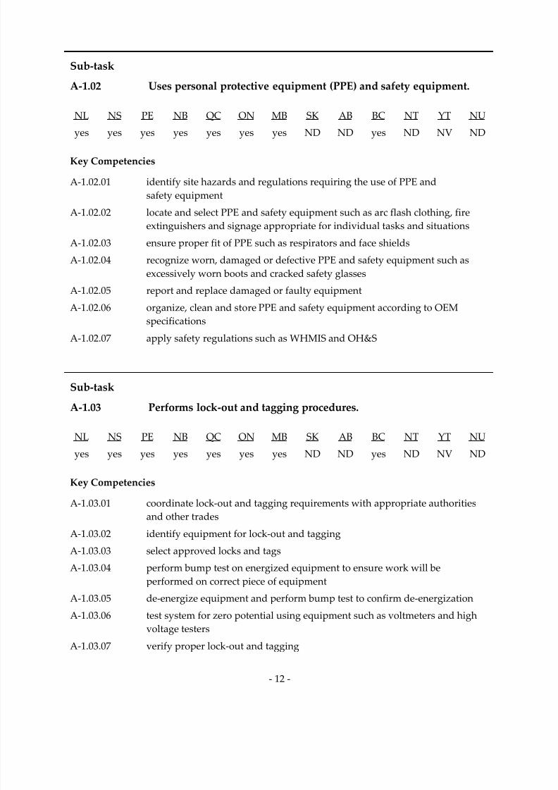
Sub‐task
A‐1.02 Uses personal protective equipment (PPE) and safety equipment.
NL NS PE NB QC ON MB SK AB BC NT YT NU
yes
yes
yes
yes
yes
yes
yes
ND
ND
yes
ND
NV
ND
Key Competencies
A‐1.02.01 identify site hazards and regulations requiring the use of PPE and
safety equipment
A‐1.02.02 locate and select PPE and safety equipment such as arc flash clothing, fire
extinguishers and signage appropriate for individual tasks and situations
A‐1.02.03 ensure proper fit of PPE such as respirators and face shields
A‐1.02.04 recognize worn, damaged or defective PPE and safety equipment such as
excessively
worn
boots
and
cracked
safety
glasses
A‐1.02.05 report and replace damaged or faulty equipment
A‐1.02.06 organize, clean and store PPE and safety equipment according to OEM
specifications
A‐1.02.07 apply safety regulations such as WHMIS and OH&S
Sub‐task
A‐1.03 Performs lock‐out and tagging procedures.
NL NS PE NB QC ON MB SK AB BC NT YT NU
yes yes yes yes yes yes yes ND ND yes ND NV ND
Key Competencies
A‐1.03.01 coordinate lock‐out and tagging requirements with appropriate authorities and other trades
A‐1.03.02 identify equipment for lock‐out and tagging
A‐1.03.03 select approved locks and tags A‐1.03.04 perform bump test on energized equipment to ensure work will be
performed on correct piece of equipment
A‐1.03.05 de‐energize equipment and perform bump test to confirm de‐energization
A‐1.03.06 test system for zero potential using equipment such as voltmeters and high
voltage testers
A‐1.03.07 verify proper lock‐out and tagging

7/14/2019 Industrial Electrician 2011 En
http://slidepdf.com/reader/full/industrial-electrician-2011-en 27/132
‐ 13 ‐
Task 2 Uses and maintains tools and equipment.
Context Industrial electricians must have the ability to select, use and maintain the
appropriate tools and equipment for specific tasks.
Required Knowledge
K 1 types and limitations of hand tools such as screwdrivers, pliers, wrenches and measuring tapes
K 2 types, functions, capabilities, limitations and operating procedures of portable pneumatic, electric and hydraulic power tools
K 3 types, functions, capabilities, limitations and operating procedures of stationary power tools such as drill presses, bench grinders and belt sanders
K 4 types, functions, capabilities, limitations and operating procedures of powder‐actuated tools
K 5 fastener specifications for powder‐actuated tools
K 6 training and certification requirements to operate powder‐actuated tools
K 7 powder‐actuated tool components
K 8 types and operating procedures of mechanical measuring equipment such as
micrometers, torque wrenches and feeler gauges
K 9 types, functions, capabilities, limitations and operating procedures of equipment used for measuring high voltage and/or frequency
K 10 types, functions, applications, limitations and ratings of electrical testing and
diagnostic
tools
such
as
multimeters,
voltage
testers,
non‐
contact
voltage
testers, megohmmeters and clamp ammeters
K 11 electrical testing and diagnostic tool accessories such as leads, fuses and batteries
K 12 maintenance schedules
K 13 environmental factors that affect readings
K 14 OEM specifications for operating and maintenance instructions, and for calibration schedules
K 15 types of access equipment such as scissor lifts, platform lifts and articulated
boom lifts K 16 types of scaffolding such as tubular and frame
K 17 capabilities and limitations of scaffolding and access equipment
K 18 load bearing capacity of access equipment
K 19 certification requirements and regulations for scaffolding and
access equipment
K 20 fall protection requirements when working on access equipment

7/14/2019 Industrial Electrician 2011 En
http://slidepdf.com/reader/full/industrial-electrician-2011-en 28/132
‐ 14 ‐
K 21 safe angles of ladders
K 22 three‐point contact rule
K 23 work site surroundings such as trenching, pits and overhead hazards
K 24 types, functions, operating procedures, techniques, and limitations of rigging, tugging, hoisting and lifting equipment
K 25 certification requirements regarding rigging, tugging, hoisting and
lifting equipment
K 26 anchor points
K 27 load ratings
Sub‐task
A‐2.01 Maintains tools and equipment.
NL NS PE NB QC ON MB SK AB BC NT YT NU
yes yes yes yes yes yes yes ND ND yes ND NV ND
Key Competencies
A‐2.01.01 organize and store tools and components according to OEM specifications
A‐2.01.02 clean, sharpen, lubricate and adjust tools to OEM specifications
A‐2.01.03 ensure calibration of measuring equipment to OEM specifications
A‐2.01.04 identify worn, damaged or defective tools
A‐2.01.05 change tool components such as chucks, bits and blades
A‐2.01.06 replace tool components such as cords, attachment plugs and air lines
A‐2.01.07 repair tools according to OEM specifications
A‐2.01.08 identify hazards associated with tools
7/14/2019 Industrial Electrician 2011 En
http://slidepdf.com/reader/full/industrial-electrician-2011-en 29/132
‐ 15 ‐
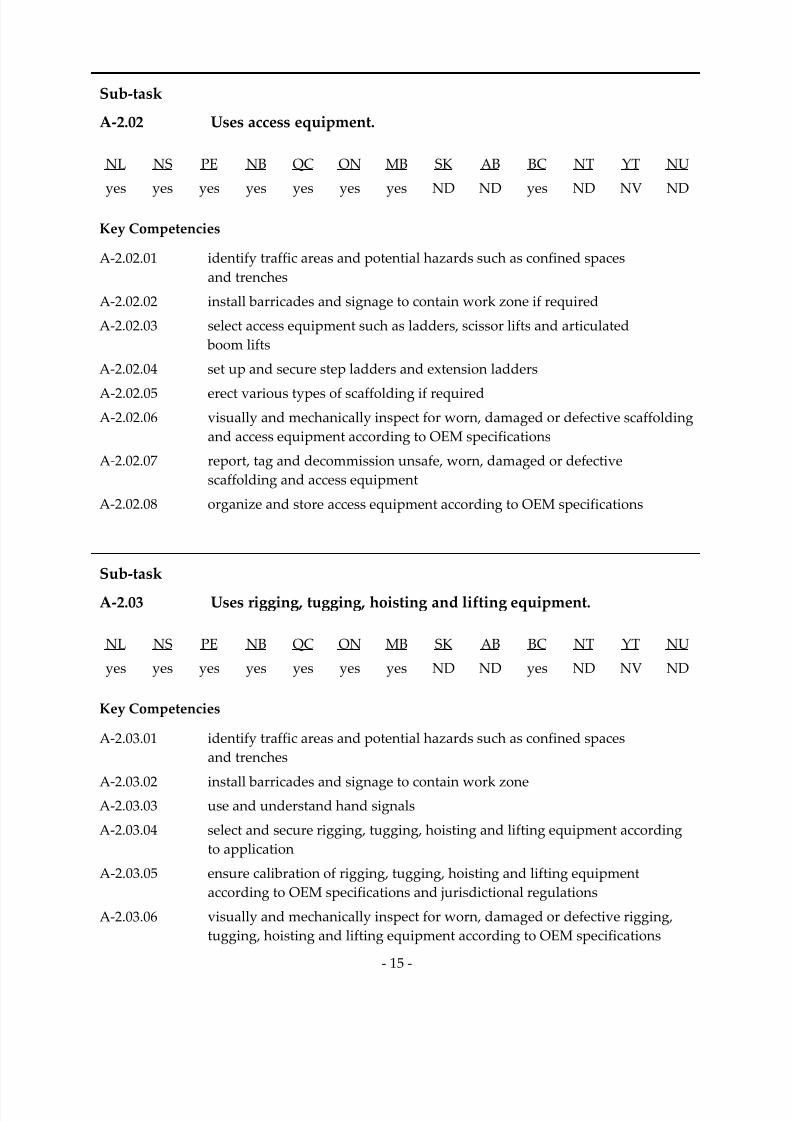
Sub‐task
A‐2.02 Uses access equipment.
NL NS PE NB QC ON MB SK AB BC NT YT NU
yes
yes
yes
yes
yes
yes
yes
ND
ND
yes
ND
NV
ND
Key Competencies
A‐2.02.01 identify traffic areas and potential hazards such as confined spaces and trenches
A‐2.02.02 install barricades and signage to contain work zone if required
A‐2.02.03 select access equipment such as ladders, scissor lifts and articulated
boom lifts
A‐2.02.04 set up and secure step ladders and extension ladders
A‐2.02.05 erect various types of scaffolding if required
A‐2.02.06 visually and mechanically inspect for worn, damaged or defective scaffolding
and access equipment according to OEM specifications
A‐2.02.07 report, tag and decommission unsafe, worn, damaged or defective
scaffolding and access equipment
A‐2.02.08 organize and store access equipment according to OEM specifications
Sub‐task
A‐2.03 Uses rigging, tugging, hoisting and lifting equipment.
NL NS PE NB QC ON MB SK AB BC NT YT NU
yes yes yes yes yes yes yes ND ND yes ND NV ND
Key Competencies
A‐2.03.01 identify traffic areas and potential hazards such as confined spaces and trenches
A‐2.03.02 install barricades and signage to contain work zone
A‐2.03.03 use and understand hand signals
A‐2.03.04 select and secure rigging, tugging, hoisting and lifting equipment according
to application
A‐2.03.05 ensure calibration of rigging, tugging, hoisting and lifting equipment according to OEM specifications and jurisdictional regulations
A‐2.03.06 visually and mechanically inspect for worn, damaged or defective rigging, tugging, hoisting and lifting equipment according to OEM specifications

7/14/2019 Industrial Electrician 2011 En
http://slidepdf.com/reader/full/industrial-electrician-2011-en 30/132
‐ 16 ‐
A‐2.03.07 report, tag and decommission unsafe, worn, damaged or defective rigging, tugging, hoisting and lifting equipment
A‐2.03.08 secure load for application according to jurisdictional regulations and
company policy
A‐2.03.09 clean, lubricate and store rigging, tugging, hoisting and lifting equipment
A‐2.03.10 perform minor field repairs and replenish fluid levels
Task 3 Organizes work.
Context Organizing work allows industrial electricians to interpret, locate and modify
documentation, as well as organize necessary materials, plan project tasks
and prepare the work site in order to do their jobs safely and effectively.
Required Knowledge
K 1 codes such as building codes, the CEC and jurisdictional codes
K 2 OH&S regulations
K 3 standards such as CSA and Underwriters’ Laboratories of Canada (ULC)
K 4 code and regulation updates
K 5 features of plans, schematics, drawings and specifications such as scale, legend, details, abbreviations and symbols
K
6
standard
symbol
and
drawing
conventions
K 7 CAD systems
K 8 documentation requirements for modifying drawings
K 9 types of documentation such as manuals, work orders, preventative
maintenance sheets, regulations, technical bulletins, shop drawings and catalogues
K 10 company policies and procedures
K 11 types of equipment
K 12 WHMIS symbols and MSDS
K 13 OEM specifications K 14 trade terminology
K 15 project or task to be completed
K 16 work site location, conditions and restrictions
K 17 delivery dates, inventory control and availability of materials
K 18 sequence of operations
K 19 building structures such as walls, ceilings and floors

7/14/2019 Industrial Electrician 2011 En
http://slidepdf.com/reader/full/industrial-electrician-2011-en 31/132
‐ 17 ‐
K 20 equipment such as panel boards, switchgear and motor control centres (MCCs)
K 21 work site hazards such as existing utilities, dust, temperature, chemicals and
weather
K 22 CMMSs
Sub‐task
A‐3.01 Interprets codes and regulations.
NL NS PE NB QC ON MB SK AB BC NT YT NU
yes yes yes yes yes yes yes ND ND yes ND NV ND
Key Competencies
A‐3.01.01 access codes and regulations such as CEC, TP127, municipal and local codes
A‐3.01.02 refer to codes and regulations to locate information
A‐3.01.03 apply codes and regulations according to application
A‐3.01.04 remain up‐to‐date with modifications and changes to codes and regulations
Sub‐task
A‐3.02 Uses plans, schematics, drawings and specifications.
NL NS PE NB QC ON MB SK AB BC NT YT NU
yes yes yes yes yes yes yes ND ND yes ND NV ND
Key Competencies
A‐3.02.01 cross reference plans, drawings and specifications
A‐3.02.02 locate information on plans, drawings and specifications
A‐3.02.03 scale dimensions
A‐3.02.04 interpret three‐dimensional structures and circuits A‐3.02.05 perform mathematical calculations such as conduit fill, and single‐ and
three‐phase circuit calculations
A‐3.02.06 apply schematics and wiring diagrams to perform tasks such as troubleshooting, maintaining and installing systems
A‐3.02.07 determine whether plans, schematics and drawings are up‐to‐date according
to as‐ built

7/14/2019 Industrial Electrician 2011 En
http://slidepdf.com/reader/full/industrial-electrician-2011-en 32/132
‐ 18 ‐
A‐3.02.08 modify and produce as‐ built plans, schematics and drawings to reflect change brought to application
A‐3.02.09 document changes made to equipment and wiring
Sub‐task
A‐3.03 Selects materials and supplies.
NL NS PE NB QC ON MB SK AB BC NT YT NU
yes yes yes yes yes yes yes ND ND yes ND NV ND
Key Competencies
A‐3.03.01 identify required materials and supplies according to application, plans, specifications, codes and environment
A‐3.03.02 perform mathematical calculations such as scaling, ratios and determining
segment lengths of cabling and wiring
A‐3.03.03 interpret site measurements and instructions
A‐3.03.04 quantify materials according to plans
A‐3.03.05 perform inventory control
A‐3.03.06 order materials and supplies
Sub‐task
A‐3.04 Plans project tasks and procedures.
NL NS PE NB QC ON MB SK AB BC NT YT NU
yes yes yes yes yes yes yes ND ND yes ND NV ND
Key Competencies
A‐3.04.01 visually inspect work environment to determine scope of work
A‐3.04.02 determine labour and equipment requirements according to specifications such as wire sizes, load requirements and locations
A‐3.04.03 establish and maintain assigned schedules
A‐3.04.04 coordinate work with other trades such as shutdown requirements and
installation sequencing
A‐3.04.05 draw and sketch layouts
A‐3.04.06 follow installation and operational sequences

7/14/2019 Industrial Electrician 2011 En
http://slidepdf.com/reader/full/industrial-electrician-2011-en 33/132
‐ 19 ‐
Sub‐task
A‐3.05 Prepares work site.
NL NS PE NB QC ON MB SK AB BC NT YT NU
yes yes yes yes yes yes yes ND ND yes ND NV ND
Key Competencies
A‐3.05.01 visually inspect to identify traffic areas and potential hazards such as confined spaces and trenches
A‐3.05.02 install barricades and signage to contain work zone
A‐3.05.03 create openings and penetrations in structures and equipment
A‐3.05.04 ensure sufficient lighting and ventilation of work area
A‐3.05.05 ensure all required materials and equipment are on‐site
Sub‐task
A‐3.06 Documents maintenance work.
NL NS PE NB QC ON MB SK AB BC NT YT NU
yes yes yes yes yes yes yes ND ND yes ND NV ND
Key Competencies
A‐3.06.01 retrieve, record and interpret test data for future reference
A‐3.06.02 record faults and failed components to aid in diagnosis
A‐3.06.03 record service performed and required repairs to keep a log on that piece
of equipment
A‐3.06.04 record corrective actions to speed up repairs and to monitor equipment trends
A‐3.06.05 record date and parts used to replace or repair defective or recalled devices,
to keep a log on that piece of equipment and for budgeting purposes A‐3.06.06 record identified potential and existing hazards for safety purposes and to
help prioritize the work
A‐3.06.07 record modifications for inspection purposes from local authorities, to repeat successful modification on other common pieces of equipment and for troubleshooting purposes
A‐3.06.08 identify and record work needed to be performed to prioritize the tasks

7/14/2019 Industrial Electrician 2011 En
http://slidepdf.com/reader/full/industrial-electrician-2011-en 34/132
‐ 20 ‐
A‐3.06.09 record industry alerts to replace or repair defective or recalled devices
A‐3.06.10 record calibration data as found and as left for auditing purposes
Task 4
Performs routine
trade
activities.
Context These are activities that are performed throughout the trade. Industrial electricians perform these tasks in a safe and efficient manner. These
tasks identify specific skills and functions that are typically performed
by industrial electricians in the normal course of their work.
Required Knowledge
K 1 electrical classification of work site location
K 2 building structures such as walls, ceilings and floors
K 3 equipment such as panel boards, switchgear and MCCs
K 4 work site hazards such as existing utilities, explosive atmosphere, dust, temperature, chemicals and weather
K 5 impact of performing task during process operations
K 6 start‐up and commissioning procedures such as rotational testing, voltage
readings and current readings
K 7 required documentation
K
8
OEM
specifications
K 9 sequence of operation of equipment
K 10 types, styles, purposes and sizes of fasteners, fittings and connectors such as expansion joints, explosion proof and water proof
K 11 installation and replacement procedures, and capabilities and limitations of fasteners, fittings and connectors
K 12 fire stopping techniques

7/14/2019 Industrial Electrician 2011 En
http://slidepdf.com/reader/full/industrial-electrician-2011-en 35/132
‐ 21 ‐
Sub‐task
A‐4.01 Installs fasteners, fittings and connectors.
NL NS PE NB QC ON MB SK AB BC NT YT NU
yes
yes
yes
yes
yes
yes
yes
ND
ND
yes
ND
NV
ND
Key Competencies
A‐4.01.01 select and use tools and equipment such as hand tools, threaders, pipe
wrenches, knock‐out sets, step drills, hole saws and welding equipment
A‐4.01.02 determine thread size according to size of raceway
A‐4.01.03 cut and thread fittings according to measurements of installation
A‐4.01.04 select fasteners, fittings, ground bushings and connectors to match the
installation requirements, and verify compatibility according to engineered
drawings,
electrical
classification
of
work
site
and
environment
such
as
underground and wet location
A‐4.01.05 locate and mount fasteners, fittings, ground bushings and connectors, and
ensure accessibility of fittings according to installation requirements
A‐4.01.06 torque and tighten fasteners and connectors to engineered specifications
A‐4.01.07 apply lubricant, sealant, anti‐seize and anti‐oxidant compounds according to
engineering specifications and industry practices
Sub‐task
A‐4.02 Conducts operational tests.
NL NS PE NB QC ON MB SK AB BC NT YT NU
yes yes yes yes yes yes yes ND ND yes ND NV ND
Key Competencies
A‐4.02.01 select and use tools and equipment such as multimeters, hand tools, scope
meters and calibrators
A‐4.02.02 perform sensory inspection to check for ambient temperature, abnormal heat, equipment damage, and presence of corrosion, smoke or unusual odours
A‐4.02.03 take measurements such as voltages, current, frequency, temperature, speed
and pressure to verify system operation and parameters
A‐4.02.04 retrieve, read and interpret historical data, OEM specifications, and
engineered drawings and data to assist in the testing

7/14/2019 Industrial Electrician 2011 En
http://slidepdf.com/reader/full/industrial-electrician-2011-en 36/132
‐ 22 ‐
A‐4.02.05 disconnect/reconnect components to allow access to circuitry according to
industry practices
A‐4.02.06 put the process in Manual mode to prevent upset and to aid in testing
procedure, and put back to Automatic upon completion
A‐4.02.07 calibrate devices and sensors according to plant requirements
A‐4.02.08 compare historical and as found data to interpret tendencies and trends and
change maintenance frequency accordingly
A‐4.02.09 make calculations and conversions such as power factor and power usage to
verify that equipment is working correctly and to aid in the selection of components according to engineering specifications
A‐4.02.10 test equipment to specifications such as motor overload protection and
adjustable trip mechanism circuit breakers
A‐4.02.11 ensure sequencing and safety circuit operation after testing

7/14/2019 Industrial Electrician 2011 En
http://slidepdf.com/reader/full/industrial-electrician-2011-en 37/132
‐ 23 ‐
BLOCK B POWER DISTRIBUTION AND
GENERATING SYSTEMS
Trends Tidal generation systems are starting to appear. They offer dependable,
renewable energy through the oceanic tidal cycle. Increasingly, industrial establishments are using their own
micro‐generation systems. These systems are cost‐efficient, using the
by‐products of their operation to produce their own electricity.
Related
Components
(including, but not
limited to)
Disconnects, MCCs, distribution panels, breakers, relays, fuses, overloads, protective relays, capacitors, transformers, contactors, motors, alternators, generators, cables, raceways, cable trays, bus systems, insulators, synchronisers, arrestors, ground rods, grids, solar cell mats, ground fault systems, wind turbines.
Tools and
Equipment
See Appendix A.
Task 5 Maintains high voltage power distribution systems.
Context
High
voltage
power
distribution
systems
are
used
in
power
lines,
plants
and
substations for long distance transmission at lower currents. Industrial electricians must be able to install, service and repair these systems in order to ensure their efficient operation and reduce unscheduled disruptions. Maintaining high voltage power systems is among the most hazardous tasks for industrial electricians and extreme caution must be used in these
environments.
Required Knowledge
K 1 regulations regarding the installation of high voltage power systems
K 2 types of high voltage power systems
K 3 components such as switchgear, transformers and cabling
K 4 hazards associated with high voltage power systems
K 5 methods and procedures for installing high voltage power systems such as terminations, splicing and testing
K 6 safety procedures to access high voltage environments and equipment

7/14/2019 Industrial Electrician 2011 En
http://slidepdf.com/reader/full/industrial-electrician-2011-en 38/132
‐ 24 ‐
K 7 inspection, maintenance, troubleshooting, repair, replacement and
adjustment procedures and OEM specifications
K 8 safety procedures and equipment required to maintain high voltage
power systems
K 9 system and component operation
K 10 potential causes of power loss such as phase‐to‐phase shorts, overcurrent and
under frequency
K 11 events that lead to system failure
K 12 performance history of equipment
K 13 preventative and predictive maintenance schedules
K 14 calibration according to OEM specifications for components such as breakers, relays and switchgear
Sub‐task
B‐5.01 Installs high voltage power distribution systems.
(NOT COMMON CORE)
NL NS PE NB QC ON MB SK AB BC NT YT NU
yes no yes no yes yes no ND ND yes ND NV ND
Key Competencies
B‐5.01.01 select and use tools and equipment such as wrenches, knives and pliers B‐5.01.02 ensure proper egress around distribution system according to
code requirements
B‐5.01.03 assemble and torque components in appropriate locations according to
OEM specifications
B‐5.01.04 shim and level the cabinets
B‐5.01.05 splice and terminate cable according to OEM specifications
B‐5.01.06 follow installation procedures and specifications
B‐5.01.07 verify system operation

7/14/2019 Industrial Electrician 2011 En
http://slidepdf.com/reader/full/industrial-electrician-2011-en 39/132
‐ 25 ‐
Sub‐task
B‐5.02 Services high voltage power distribution systems.
NL NS PE NB QC ON MB SK AB BC NT YT NU
yes
no
yes
no
yes
yes
yes
ND
ND
yes
ND
NV
ND
Key Competencies
B‐5.02.01 identify hazards of stored energy in capacitors, cabling and transformers
B‐5.02.02 de‐energize system from all power sources
B‐5.02.03 test system for zero potential using high voltage tester
B‐5.02.04 apply ground sets to phase conductors to drain capacitance charge
B‐5.02.05 select and use tools and equipment such as vacuum cleaners and
torque wrenches
B‐5.02.06 visually inspect high voltage components for deterioration such as corrosion, corona, loose torque and discolouration
B‐5.02.07 select and use diagnostic tools and equipment such as hi‐pot testing tools and
ultra‐sonic detectors
B‐5.02.08 identify worn, damaged, defective or hazardous components using methods such as oil samplings
B‐5.02.09 identify components that require repair or replacement
B‐5.02.10 clean and lubricate components
B‐5.02.11 verify system operation
Sub‐task
B‐5.03 Troubleshoots high voltage power distribution systems.
NL NS PE NB QC ON MB SK AB BC NT YT NU
yes no yes no yes yes yes ND ND yes ND NV ND
Key Competencies
B‐5.03.01 identify hazards of stored energy in capacitors, cabling and transformers
B‐5.03.02 perform sensory inspection of component deterioration such as corrosion, corona, loose torque and discolouration
B‐5.03.03 select and use diagnostic tools and equipment such as hi‐pot testing tools, thermal graphic cameras and ultra‐sonic detectors
B‐5.03.04 isolate faults by de‐energizing source of energy
7/14/2019 Industrial Electrician 2011 En
http://slidepdf.com/reader/full/industrial-electrician-2011-en 40/132
‐ 26 ‐
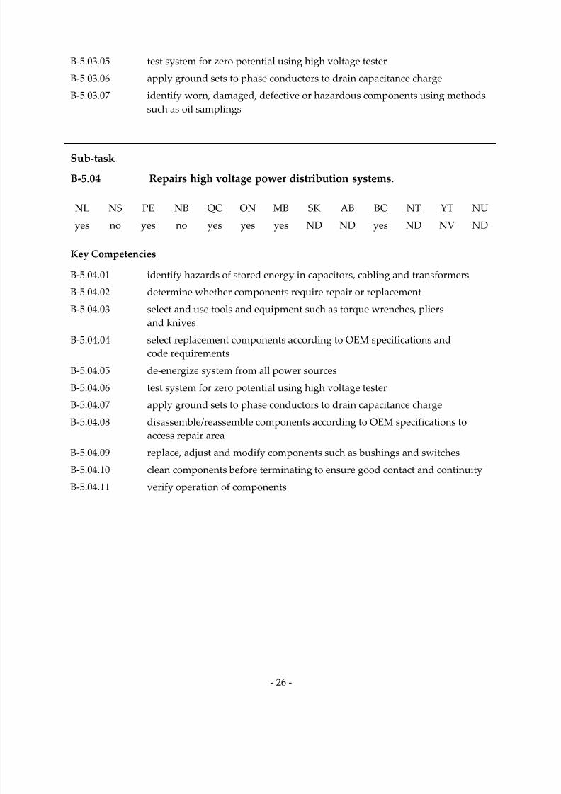
B‐5.03.05 test system for zero potential using high voltage tester
B‐5.03.06 apply ground sets to phase conductors to drain capacitance charge
B‐5.03.07 identify worn, damaged, defective or hazardous components using methods such as oil samplings
Sub‐task
B‐5.04 Repairs high voltage power distribution systems.
NL NS PE NB QC ON MB SK AB BC NT YT NU
yes no yes no yes yes yes ND ND yes ND NV ND
Key Competencies
B‐
5.04.01
identify
hazards
of
stored
energy
in
capacitors,
cabling
and
transformers
B‐5.04.02 determine whether components require repair or replacement
B‐5.04.03 select and use tools and equipment such as torque wrenches, pliers and knives
B‐5.04.04 select replacement components according to OEM specifications and
code requirements
B‐5.04.05 de‐energize system from all power sources
B‐5.04.06 test system for zero potential using high voltage tester
B‐5.04.07 apply ground sets to phase conductors to drain capacitance charge
B‐5.04.08 disassemble/reassemble components according to OEM specifications to
access repair area
B‐5.04.09 replace, adjust and modify components such as bushings and switches
B‐5.04.10 clean components before terminating to ensure good contact and continuity
B‐5.04.11 verify operation of components

7/14/2019 Industrial Electrician 2011 En
http://slidepdf.com/reader/full/industrial-electrician-2011-en 41/132
‐ 27 ‐
Task 6 Maintains low voltage power distribution systems.
Context Low voltage power distribution systems provide power to the plant. Industrial electricians must be able to install, service and repair these systems in order to ensure their efficient operation and reduce unscheduled
disruptions.
Required Knowledge
K 1 codes and regulations regarding the installation of low voltage
power systems
K 2 types of low voltage power systems, single‐ and three‐phase
K 3 types of components such as disconnects, MCCs, power transformers and cabling
K 4 installation, inspection, maintenance, testing, troubleshooting and repair procedures and specifications
K 5 rating, sizing and compatibility of components such as bus bars, breakers, fuses and distribution panels
K 6 hazards associated with low voltage power systems
K 7 system and component operation
K 8 events that lead to system failure
K 9 performance history of equipment
K 10 safety procedures required for service and repair
Sub‐task
B‐6.01 Installs low voltage power distribution systems.
NL NS PE NB QC ON MB SK AB BC NT YT NU
yes yes yes yes yes yes no ND ND yes ND NV ND
Key Competencies
B‐6.01.01 select and use tools and equipment such as phase meters, compression tools, wire strippers and benders
B‐6.01.02 ensure proper egress around distribution system according to code
requirements
B‐6.01.03 perform phasing to achieve required rotation of three‐phase rotating
equipment

7/14/2019 Industrial Electrician 2011 En
http://slidepdf.com/reader/full/industrial-electrician-2011-en 42/132
‐ 28 ‐
B‐6.01.04 assemble and torque components in appropriate locations according to
OEM specifications
B‐6.01.05 shim and level the cabinets
B‐6.01.06 terminate cable according to code requirements
B‐6.01.07 follow installation procedures according to OEM specifications
B‐6.01.08 verify system operation
Sub‐task
B‐6.02 Services low voltage power distribution systems.
NL NS PE NB QC ON MB SK AB BC NT YT NU
yes yes yes yes yes yes yes ND ND yes ND NV ND
Key Competencies
B‐6.02.01 select and use diagnostic tools and equipment such as megohmmeters and
multimeters
B‐6.02.02 identify hazards of stored energy in capacitors
B‐6.02.03 de‐energize system from all power sources
B‐6.02.04 test system for zero potential using multimeter
B‐6.02.05 select and use tools and equipment such as vacuum cleaners and
torque wrenches
B‐6.02.06 visually inspect components for deterioration such as corrosion, loose torque
and discolouration using methods such as thermography for hot spots
B‐6.02.07 identify components that require repair or replacement
B‐6.02.08 clean and lubricate components
B‐6.02.09 perform adjustments such as trip settings and tap changes
B‐6.02.10 verify system operation

7/14/2019 Industrial Electrician 2011 En
http://slidepdf.com/reader/full/industrial-electrician-2011-en 43/132
‐ 29 ‐
Sub‐task
B‐6.03 Troubleshoots low voltage power distribution systems.
NL NS PE NB QC ON MB SK AB BC NT YT NU
yes
yes
yes
yes
yes
yes
yes
ND
ND
yes
ND
NV
ND
Key Competencies
B‐6.03.01 select and use diagnostic tools and equipment such as multimeters, clamp‐on
ammeters and megohmmeters
B‐6.03.02 identify hazards of stored energy in capacitors according to indicators such
as hazard stickers or drawings
B‐6.03.03 visually inspect components for deterioration such as corrosion, loose torque
and discolouration
B‐
6.03.04
isolate
faults
by
de‐
energizing
source
of
energy
B‐6.03.05 de‐energize system from all power sources
B‐6.03.06 test system for zero potential using multimeter
B‐6.03.07 identify components that require repair or replacement
Sub‐task
B‐6.04 Repairs low voltage power distribution systems.
NL NS PE NB QC ON MB SK AB BC NT YT NU
yes yes yes yes yes yes yes ND ND yes ND NV ND
Key Competencies
B‐6.04.01 select and use tools and equipment such as screwdrivers, wrenches and pliers
B‐6.04.02 determine whether components require repair or replacement
B‐6.04.03 select replacement components such as relays, contactors and fuses according
to OEM specifications and code requirements
B‐6.04.04 de‐energize system from all power sources
B‐6.04.05 disassemble/reassemble components according to OEM specifications
B‐6.04.06 replace, adjust and modify components such as relays, contactors and fuses
B‐6.04.07 test system for zero potential using multimeter
B‐6.04.08 identify hazards of stored energy in capacitors, cabling and transformers
B‐6.04.09 clean components before terminating to ensure good contact and continuity
B‐6.04.10 verify operation of components

7/14/2019 Industrial Electrician 2011 En
http://slidepdf.com/reader/full/industrial-electrician-2011-en 44/132
‐ 30 ‐
Task 7 Maintains alternating current (AC) systems.
Context AC systems are used to supply load power to branch circuit equipment. Therefore, it is important to maintain these systems by installing upgrades, performing preventative maintenance and making necessary repairs in an
expedient manner.
Required Knowledge
K 1 codes and regulations regarding the installation of AC systems
K 2 types of AC systems such as single‐ and three‐phase
K 3 AC system components, controls, capabilities and specifications
K 4 component operation
K 5 OEM installation, maintenance, inspection, troubleshooting and
repair
specifications
K 6 load balancing
K 7 power factor correction
K 8 line and low voltage controls
K 9 events that lead to system failure
K 10 performance history of equipment
K 11 preventative maintenance techniques, tests and procedures
Sub‐task
B‐7.01 Installs alternating current (AC) systems.
NL NS PE NB QC ON MB SK AB BC NT YT NU
yes yes yes yes yes yes yes ND ND yes ND NV ND
Key Competencies
B‐7.01.01 select and use tools and equipment such as wrenches, wire strippers
and pliers B‐7.01.02 ensure proper egress around distribution system according to code
requirements
B‐7.01.03 determine circuit loading capacity
B‐7.01.04 assemble and torque components in appropriate locations according to
OEM specifications
B‐7.01.05 shim and level the cabinets

7/14/2019 Industrial Electrician 2011 En
http://slidepdf.com/reader/full/industrial-electrician-2011-en 45/132
‐ 31 ‐
B‐7.01.06 terminate cable according to code and OEM specifications
B‐7.01.07 follow installation procedures according to code and OEM specifications
B‐7.01.08 verify system operation
Sub‐task
B‐7.02 Services alternating current (AC) systems.
NL NS PE NB QC ON MB SK AB BC NT YT NU
yes yes yes yes yes yes yes ND ND yes ND NV ND
Key Competencies
B‐7.02.01 select and use diagnostic tools and equipment such as megohmmeters
and
multimeters
B‐7.02.02 de‐energize system from all power sources
B‐7.02.03 test system for zero potential using multimeter
B‐7.02.04 select and use tools and equipment such as vacuum cleaners and
torque wrenches
B‐7.02.05 visually inspect components for deterioration such as corrosion, loose torque
and discolouration using methods such as thermography for hot spots
B‐7.02.06 identify components that require repair or replacement
B‐7.02.07 disassemble/reassemble components according to OEM specifications
B‐7.02.08 clean and lubricate components
B‐7.02.09 perform adjustments such as trip settings and overloads
B‐7.02.10 verify system operation

7/14/2019 Industrial Electrician 2011 En
http://slidepdf.com/reader/full/industrial-electrician-2011-en 46/132
‐ 32 ‐
Sub‐task
B‐7.03 Troubleshoots alternating current (AC) systems.
NL NS PE NB QC ON MB SK AB BC NT YT NU
yes
yes
yes
yes
yes
yes
yes
ND
ND
yes
ND
NV
ND
Key Competencies
B‐7.03.01 select and use diagnostic tools and equipment such as multimeters, clamp‐on
ammeters and megohmmeters
B‐7.03.02 perform sensory inspection of components for deterioration such as
corrosion, loose torque and discolouration
B‐7.03.03 isolate faults by de‐energizing source of energy
B‐7.03.04 de‐energize system from all power sources
B‐7.03.05 test system for zero potential using multimeter B‐7.03.06 disassemble/reassemble components according to OEM specifications
B‐7.03.07 identify components such as fuses, breakers and contactors that require
repair or replacement
Sub‐task
B‐7.04 Repairs alternating current (AC) systems.
NL NS PE NB QC ON MB SK AB BC NT YT NU
yes yes yes yes yes yes yes ND ND yes ND NV ND
Key Competencies
B‐7.04.01 select and use tools and equipment such as screwdrivers, wrenches and pliers
B‐7.04.02 determine whether components require repair or replacement
B‐7.04.03 select replacement components such as relays, contactors and fuses according
to OEM specifications and code requirements
B‐7.04.04 de‐energize system from all power sources
B‐7.04.05 test system for zero potential using multimeter
B‐7.04.06 disassemble/reassemble components according to OEM specifications
B‐7.04.07 replace, adjust and modify components such as relays, contactors and fuses
B‐7.04.08 clean components before terminating to ensure good contact and continuity
B‐7.04.09 verify operation of components
7/14/2019 Industrial Electrician 2011 En
http://slidepdf.com/reader/full/industrial-electrician-2011-en 47/132
‐ 33 ‐
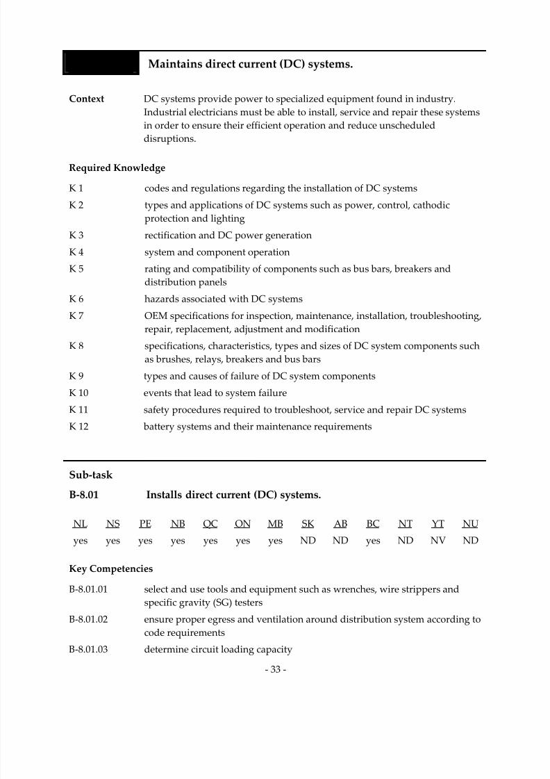
Task 8 Maintains direct current (DC) systems.
Context DC systems provide power to specialized equipment found in industry. Industrial electricians must be able to install, service and repair these systems
in order to ensure their efficient operation and reduce unscheduled
disruptions.
Required Knowledge
K 1 codes and regulations regarding the installation of DC systems
K 2 types and applications of DC systems such as power, control, cathodic
protection and lighting
K 3 rectification and DC power generation
K 4 system and component operation
K
5
rating
and
compatibility
of
components
such
as
bus
bars,
breakers
and
distribution panels
K 6 hazards associated with DC systems
K 7 OEM specifications for inspection, maintenance, installation, troubleshooting, repair, replacement, adjustment and modification
K 8 specifications, characteristics, types and sizes of DC system components such
as brushes, relays, breakers and bus bars
K 9 types and causes of failure of DC system components
K 10 events that lead to system failure
K 11 safety procedures required to troubleshoot, service and repair DC systems
K 12 battery systems and their maintenance requirements
Sub‐task
B‐8.01 Installs direct current (DC) systems.
NL NS PE NB QC ON MB SK AB BC NT YT NU
yes
yes
yes
yes
yes
yes
yes
ND
ND
yes
ND
NV
ND
Key Competencies
B‐8.01.01 select and use tools and equipment such as wrenches, wire strippers and
specific gravity (SG) testers
B‐8.01.02 ensure proper egress and ventilation around distribution system according to
code requirements
B‐8.01.03 determine circuit loading capacity

7/14/2019 Industrial Electrician 2011 En
http://slidepdf.com/reader/full/industrial-electrician-2011-en 48/132
‐ 34 ‐
B‐8.01.04 ensure cables are connected according to polarity and grounded as required
B‐8.01.05 assemble and torque components in appropriate locations according to
OEM specifications
B‐8.01.06 shim and level the cabinets
B‐8.01.07 terminate cable according to code requirements
B‐8.01.08 follow installation procedures according to code and OEM specifications B‐8.01.09 verify system operation
Sub‐task
B‐8.02 Services direct current (DC) systems.
NL NS PE NB QC ON MB SK AB BC NT YT NU
yes yes yes yes yes yes yes ND ND yes ND NV ND
Key Competencies
B‐8.02.01 select and use diagnostic tools and equipment such as megohmmeters and multimeters
B‐8.02.02 de‐energize system from all power sources
B‐8.02.03 test system for zero potential using multimeter
B‐8.02.04 select and use tools and equipment such as vacuum cleaners and
torque wrenches
B‐8.02.05 perform sensory inspection on components such as generators, commutators and batteries for deterioration such as corrosion, loose torque and
discolouration using methods such as thermography for hot spots
B‐8.02.06 identify presence of power anomalies such as ripple, noise and spikes
B‐8.02.07 identify components that require repair or replacement
B‐8.02.08 disassemble/reassemble components according to OEM specifications
B‐8.02.09 clean and lubricate components
B‐8.02.10 perform adjustments such as adding distilled water to battery
B‐
8.02.11
verify
system
operation

7/14/2019 Industrial Electrician 2011 En
http://slidepdf.com/reader/full/industrial-electrician-2011-en 49/132
‐ 35 ‐
Sub‐task
B‐8.03 Troubleshoots direct current (DC) systems.
NL NS PE NB QC ON MB SK AB BC NT YT NU
yes
yes
yes
yes
yes
yes
yes
ND
ND
yes
ND
NV
ND
Key Competencies
B‐8.03.01 select and use diagnostic tools and equipment such as multimeters, scope
meters, clamp‐on ammeters and megohmmeters
B‐8.03.02 perform sensory inspection on components for deterioration such as corrosion, loose torque and discolouration
B‐8.03.03 isolate faults by de‐energizing source of energy
B‐8.03.04 de‐energize system from all power sources
B‐8.03.05 test system for zero potential using multimeter B‐8.03.06 identify presence of power anomalies such as ripple, noise and spikes
B‐8.03.07 identify components that require repair or replacement
B‐8.03.08 disassemble/reassemble components according to OEM specifications
Sub‐task
B‐8.04 Repairs direct current (DC) systems.
NL NS PE NB QC ON MB SK AB BC NT YT NU
yes yes yes yes yes yes yes ND ND yes ND NV ND
Key Competencies
B‐8.04.01 select and use tools and equipment such as screwdrivers, wrenches and pliers
B‐8.04.02 determine whether components require repair or replacement
B‐8.04.03 select replacement components such as relays, brushes, batteries and fuses according to OEM specifications and code requirements
B‐8.04.04 de‐energize system from all power sources
B‐8.04.05 disassemble/reassemble components according to OEM specifications
B‐8.04.06 replace, adjust and modify components such as relays, brushes, batteries and fuses
B‐8.04.07 test system for zero potential using multimeter
B‐8.04.08 clean components before terminating to ensure good contact and continuity
B‐8.04.09 verify operation of components
7/14/2019 Industrial Electrician 2011 En
http://slidepdf.com/reader/full/industrial-electrician-2011-en 50/132
‐ 36 ‐
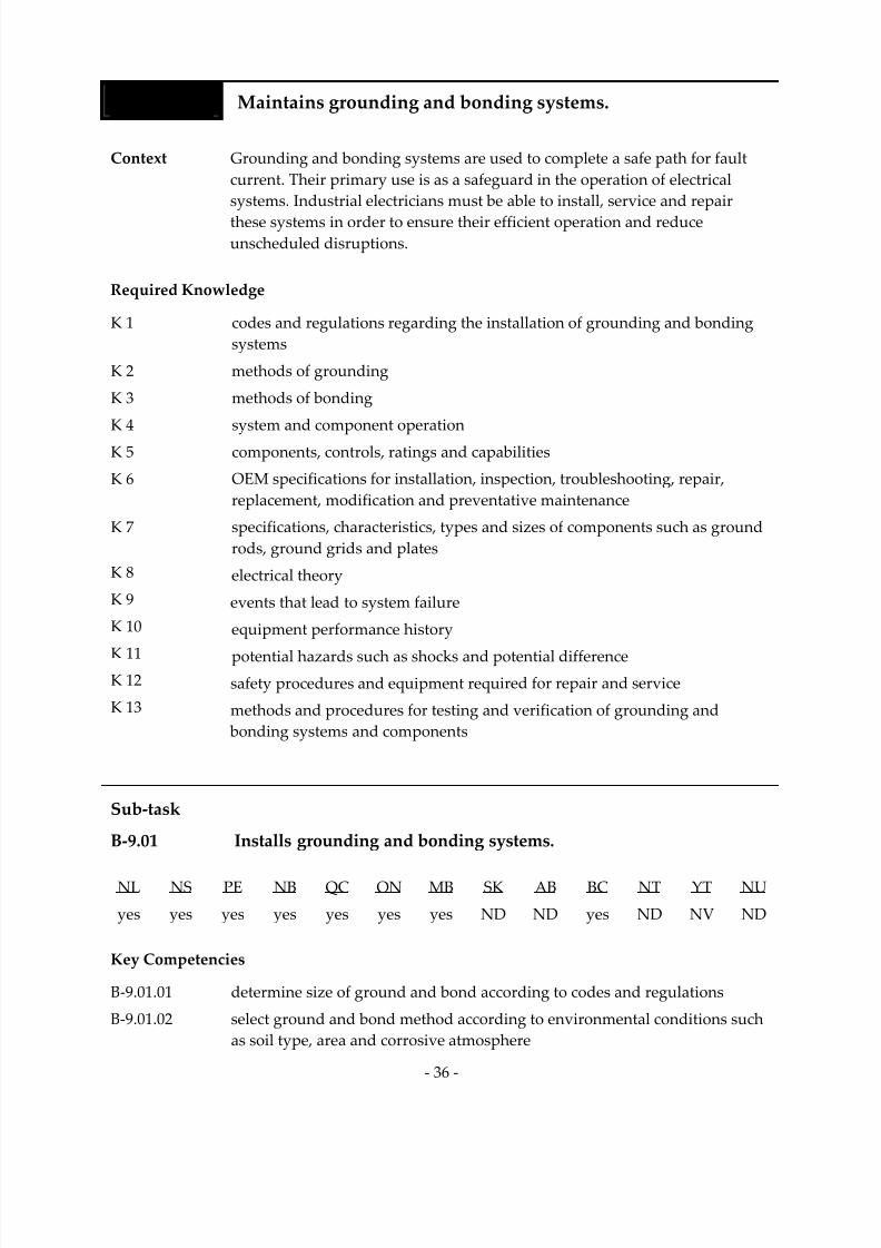
Task 9 Maintains grounding and bonding systems.
Context Grounding and bonding systems are used to complete a safe path for fault current. Their primary use is as a safeguard in the operation of electrical systems. Industrial electricians must be able to install, service and repair
these systems in order to ensure their efficient operation and reduce
unscheduled disruptions.
Required Knowledge
K 1 codes and regulations regarding the installation of grounding and bonding
systems
K 2 methods of grounding
K 3 methods of bonding
K 4 system and component operation
K 5 components, controls, ratings and capabilities
K 6 OEM specifications for installation, inspection, troubleshooting, repair, replacement, modification and preventative maintenance
K 7 specifications, characteristics, types and sizes of components such as ground
rods, ground grids and plates
K 8 electrical theory
K 9 events that lead to system failure
K 10 equipment performance history
K 11 potential hazards such as shocks and potential difference
K 12 safety procedures and equipment required for repair and service
K 13 methods and procedures for testing and verification of grounding and
bonding systems and components
Sub‐task
B‐9.01 Installs grounding and bonding systems.
NL NS PE NB QC ON MB SK AB BC NT YT NU
yes yes yes yes yes yes yes ND ND yes ND NV ND
Key Competencies
B‐9.01.01 determine size of ground and bond according to codes and regulations
B‐9.01.02 select ground and bond method according to environmental conditions such
as soil type, area and corrosive atmosphere
7/14/2019 Industrial Electrician 2011 En
http://slidepdf.com/reader/full/industrial-electrician-2011-en 51/132
‐ 37 ‐
B‐9.01.03 select and use tools and equipment such as wrenches, compression tools and
exothermic welders
B‐9.01.04 select and install ground components such as rods and plates according to
code requirements
B‐9.01.05 locate and secure ground and bond conductor using methods such as
torquing, exothermic welding and anti‐oxidation compounds according to code requirements
Sub‐task
B‐9.02 Services grounding and bonding systems.
NL NS PE NB QC ON MB SK AB BC NT YT NU
yes yes yes yes yes yes yes ND ND yes ND NV ND
Key Competencies
B‐9.02.01 assess torque, cleanliness and corrosion of bonding terminations
B‐9.02.02 ensure grounding and bonding terminations are secure
B‐9.02.03 select and use tools and equipment such as torque wrenches, hammers and
wire brushes
B‐9.02.04 visually inspect components for wear, oxidation and loose connections
B‐9.02.05 identify corroded, damaged or defective bonding components by
discolouration and nicking
B‐9.02.06 clean components to ensure good contact and lowest resistance
Sub‐task
B‐9.03 Troubleshoots grounding and bonding systems.
NL NS PE NB QC ON MB SK AB BC NT YT NU
yes yes yes yes yes yes yes ND ND yes ND NV ND
Key Competencies
B‐9.03.01 select and use tools and equipment such as megohmmeters, multimeters, clamp‐on ammeters and ohmmeters
B‐9.03.02 perform continuity checks to determine if there is a break in grounding
or bonding

7/14/2019 Industrial Electrician 2011 En
http://slidepdf.com/reader/full/industrial-electrician-2011-en 52/132
‐ 38 ‐
B‐9.03.03 perform sensory inspection for nicks, breaks, discolouration and
loose connections
B‐9.03.04 take voltage measurements to determine problems with ground and bond
B‐9.03.05 check for current on the ground
Sub‐task
B‐9.04 Repairs grounding and bonding systems.
NL NS PE NB QC ON MB SK AB BC NT YT NU
yes yes yes yes yes yes yes ND ND yes ND NV ND
Key Competencies
B‐
9.04.01
select
replacement
components
according
to
code
requirements
such
as
type,
size, capacity and environment
B‐9.04.02 select and use tools and equipment such as compression tools, exothermal welding equipment and torque wrenches
B‐9.04.03 replace damaged conductors
B‐9.04.04 clean conductors and metal surfaces before terminating to ensure good
contact and continuity
B‐9.04.05 locate and secure grounding and bonding components in appropriate
locations to prevent further damage
B‐9.04.06 verify fault has been corrected
Task 10 Maintains power generating systems.
Context Power generating systems such as solar cell, wind turbine and co‐generation
produce electricity to a variety of applications. Industrial electricians must be
able to install, service and repair these systems in industrial plants in order to
ensure
their
efficient
operation
and
reduce
unscheduled
disruptions.
Required Knowledge
K 1 codes and regulations regarding the installation of power generating systems
K 2 types of power generating systems such as solar cell, photovoltaic, wind
turbine and co‐generation
K 3 components such as switchgear and transformers

7/14/2019 Industrial Electrician 2011 En
http://slidepdf.com/reader/full/industrial-electrician-2011-en 53/132
‐ 39 ‐
K 4 hazards associated with power generating systems
K 5 methods and procedures for installing power generating systems
K 6 preventative and predictive maintenance schedules
K 7 inspection, maintenance, troubleshooting, repair, replacement and
adjustment procedures and specifications
K 8 safety procedures and equipment required to access, inspect and service
power generating systems
K 9 system and component operation
K 10 potential causes of power loss such as phase‐to‐phase shorts, overcurrent and
under frequency
K 11 events that lead to system failure
K 12 history of equipment performance
Sub‐task
B‐10.01 Installs power generating systems. (NOT COMMON CORE)
NL NS PE NB QC ON MB SK AB BC NT YT NU
yes no yes no yes yes no ND ND yes ND NV ND
Key Competencies
B‐10.01.01 select and use tools and equipment such as wrenches, knives and pliers
B‐10.01.02 ensure proper egress around distribution system according to
code requirements
B‐10.01.03 ensure proper location and direction of component such as solar cell and
wind turbine
B‐10.01.04 perform phasing to achieve required rotation of three‐phase rotating
equipment
B‐10.01.05 ensure cables are connected according to polarity and grounded as required
B‐10.01.06 assemble and torque components in appropriate locations according to
OEM specifications
B‐10.01.07 terminate cable according to code and OEM specifications
B‐10.01.08 follow installation procedures according to code and OEM specifications
B‐10.01.09 verify system operation

7/14/2019 Industrial Electrician 2011 En
http://slidepdf.com/reader/full/industrial-electrician-2011-en 54/132
‐ 40 ‐
Sub‐task
B‐10.02 Services power generating systems.
NL NS PE NB QC ON MB SK AB BC NT YT NU
yes
no
yes
no
yes
yes
yes
ND
ND
yes
ND
NV
ND
Key Competencies
B‐10.02.01 identify hazards of power generating system
B‐10.02.02 isolate system from dynamic and kinetic energy
B‐10.02.03 test system for zero potential using tools such as multimeters and high
voltage testers
B‐10.02.04 apply ground sets to phase conductors to drain capacitance charge
B‐10.02.05 select tools and equipment such as pliers and torque wrenches
B‐10.02.06 perform sensory inspection of components for deterioration such as
corrosion, loose torque and discolouration
B‐10.02.07 select and use diagnostic tools and equipment such as megohmmeters and
thermal graphic cameras
B‐10.02.08 identify worn, damaged, defective or hazardous components
B‐10.02.09 identify components that require repair or replacement
B‐10.02.10 clean and lubricate components
B‐10.02.11 verify system operation
Sub‐task
B‐10.03 Troubleshoots power generating systems.
NL NS PE NB QC ON MB SK AB BC NT YT NU
yes no yes no yes yes yes ND ND yes ND NV ND
Key Competencies
B‐10.03.01 identify hazards of stored energy in capacitors, cabling and transformers B‐10.03.02 perform sensory inspection of components deterioration such as corrosion,
corona, loose torque and discolouration
B‐10.03.03 select and use diagnostic tools and equipment such as hi‐pot testing tools, thermal graphic cameras and ultra‐sonic detectors
B‐10.03.04 isolate faults by de‐energizing source of energy
B‐10.03.05 test system for zero potential using high voltage tester and multimeter

7/14/2019 Industrial Electrician 2011 En
http://slidepdf.com/reader/full/industrial-electrician-2011-en 55/132
‐ 41 ‐
B‐10.03.06 apply ground sets to phase conductors to drain capacitance charge
B‐10.03.07 identify worn, damaged, defective or hazardous components using methods such as oil samplings
Sub‐task
B‐10.04 Repairs power generating systems.
NL NS PE NB QC ON MB SK AB BC NT YT NU
yes no yes no yes yes yes ND ND yes ND NV ND
Key Competencies
B‐10.04.01 identify hazards of stored energy in capacitors, cabling and transformers
B‐
10.04.02
determine
whether
components
require
repair
or
replacement
B‐10.04.03 select and use tools and equipment such as torque wrenches, pliers and knives
B‐10.04.04 select replacement components according to OEM specifications and
code requirements
B‐10.04.05 de‐energize system from all power sources
B‐10.04.06 test system for zero potential using high voltage tester and multimeter
B‐10.04.07 apply ground sets to phase conductors to drain capacitance charge
B‐10.04.08 disassemble/reassemble components according to OEM specifications
B‐10.04.09 replace, adjust and modify components such as bushings and switches B‐10.04.10 clean components before terminating to ensure good contact and continuity
B‐10.04.11 verify operation of components

7/14/2019 Industrial Electrician 2011 En
http://slidepdf.com/reader/full/industrial-electrician-2011-en 56/132
‐ 42 ‐
BLOCK C ELECTRICAL EQUIPMENT
Trends Lighting system load‐shedding devices such as occupancy‐detectors, task‐lighting, automatic dimmers and building automation systems are
increasingly being used to conserve electricity. Safety has driven advances in the design of electrical equipment such as tamper‐proof receptacles and arc fault interrupters.
Installation of electrical equipment and wiring must now include
consideration of fire‐stopping ratings in building design.
Related
Components
(including, but not
limited to)
Electrical wiring, cabling and terminations.
Lighting systems: light emitting diode (LED), high intensity
discharge (HID), fluorescent lighting, compact fluorescent lamp (CFL), plasma, breakers, photocells, timers, conduits, cables, fasteners, cable
trays and supports, contactors, transformers, switches. Protection devices: fuses, breakers, overloads, arc fault protection, ground‐fault circuit interrupters (GFCIs), overcurrent devices, disconnects, switches, voltage regulators, synchronizers.
Rotating equipment: AC and DC motors, generators, alternators, eddy
current brakes/clutches, friction brakes/clutches, centrifugal switches, governors.
Drives and associated controls: variable‐frequency drives (VFDs), DC
drives, soft‐start, silicon‐controlled rectifiers (SCRs).
Non‐rotating
equipment:
transformers, encoders, scales, start/stop stations, starters.
Tools and
Equipment
See Appendix A.

7/14/2019 Industrial Electrician 2011 En
http://slidepdf.com/reader/full/industrial-electrician-2011-en 57/132
‐ 43 ‐
Task 11 Maintains equipment, wiring, cabling and terminations.
Context Equipment, wiring, cabling and terminations are the electrical components
linking the source to the load. This task also includes maintenance of seismic
restraint systems, as required in certain geographic locations. Maintaining
these components includes installation and repair.
Required Knowledge
K 1 regulations and code requirements regarding the installation of electrical wiring, cabling and terminations
K 2 types and functions of electrical wiring, cabling and terminations
K 3 capabilities and limitations of electrical wiring, cabling and terminations
K 4 installation procedures and techniques for electrical wiring, cabling
and terminations
K 5 sizes of electrical wires and cables
K 6 termination procedures and considerations for dissimilar metals
K 7 types, functions, capabilities and limitations of raceways, cable trays, busways and associated components
K 8 bending and connecting techniques for conduit applications including rigid, electrical metallic tubing (EMT) and polyvinyl chloride (PVC)
K 9 installation procedures and techniques, and supporting and securing
methods for raceways, ca ble trays, busways and associated components
K
10
jurisdictional
regulations
regarding
seismic
restraint
systems
K 11 types of seismic restraint systems
K 12 risks of seismic events
K 13 equipment that contains seismic restraint systems such as battery banks, trays
and control panels

7/14/2019 Industrial Electrician 2011 En
http://slidepdf.com/reader/full/industrial-electrician-2011-en 58/132
‐ 44 ‐
Sub‐task
C‐11.01 Installs electrical wiring, cabling and terminations.
NL NS PE NB QC ON MB SK AB BC NT YT NU
yes
yes
yes
yes
yes
yes
no
ND
ND
yes
ND
NV
ND
Key Competencies
C‐11.01.01 install cable and conductors through raceways according to CEC and OEM
specifications in order to prevent damage to cable and conductors and
to separate power from control wiring to eliminate noise and induction
C‐11.01.02 select and use lubricant as required by application
C‐11.01.03 select and use tools and equipment such as rollers, wheels, tuggers, pulleys and sheaves
C‐11.01.04 determine termination method to be used according to material and OEM specifications
C‐11.01.05 prepare termination of conductors using methods such as cutting, crimping
and torquing
C‐11.01.06 terminate cables and conductors using methods such as nut and bolt, and
compression connections
C‐11.01.07 check for continuity and insulation of electrical wires and cables
C‐11.01.08 label, verify and record installation of electrical wiring and cabling
Sub‐task
C‐11.02 Installs raceways, cable trays, busways and associated components.
NL NS PE NB QC ON MB SK AB BC NT YT NU
yes yes yes yes yes yes no ND ND yes ND NV ND
Key Competencies
C‐
11.02.01
select
and
size
raceways,
cable
trays,
busways
and
associated
components
according to code, standards, environments and OEM specifications
C‐11.02.02 lay out route of raceways, cable trays, busways and associated components
according to code requirements such as number of bends allowed, and
location and size of pull‐ box and fittings
C‐11.02.03 perform mathematical calculations such as scaling, ratios and installation
trigonometry

7/14/2019 Industrial Electrician 2011 En
http://slidepdf.com/reader/full/industrial-electrician-2011-en 59/132
‐ 45 ‐
C‐11.02.04 select and use hand and power tools such as torque wrenches, hammers, nut drivers and hack saws
C‐11.02.05 select cable fittings such as rain‐tight, dust‐tight and explosion‐proof fittings
according to the installation environment
C‐11.02.06 bend conduit and secure raceways according to code requirements
Sub‐task
C‐11.03 Repairs electrical wiring, cabling and terminations.
NL NS PE NB QC ON MB SK AB BC NT YT NU
yes yes yes yes yes yes yes ND ND yes ND NV ND
Key Competencies
C‐11.03.01 replace faulty electrical wiring and cabling
C‐11.03.02 select and use tools and equipment such as thermal graphic cameras, megohmmeters and reflectometers to locate faults and verify repair
C‐11.03.03 perform visual inspections to repair or replace worn or cracked coverings
C‐11.03.04 repair conductor coverings and conductor using manufacturer‐specific
repair kit
C‐11.03.05 replace, tighten and clean terminations to avoid overheating and to
lower resistance
C‐11.03.06 secure support systems, enclosures and adjacent equipment to avoid vibration of wires and terminations
Sub‐task
C‐11.04 Maintains seismic restraint systems. (NOT COMMON CORE)
NL NS PE NB QC ON MB SK AB BC NT YT NU
yes no no no yes no yes ND ND yes ND NV ND
Key Competencies
C‐11.04.01 select and use tools and equipment such as hand tools, torque wrenches and
hydraulic wrenches
C‐11.04.02 torque bolting according to periodic maintenance and after seismic events
C‐11.04.03 inspect flexible joints, bolting and bracketing for any kind of damage, cracks or stresses according to periodic maintenance and after seismic events

7/14/2019 Industrial Electrician 2011 En
http://slidepdf.com/reader/full/industrial-electrician-2011-en 60/132
‐ 46 ‐
C‐11.04.04 coordinate non‐destructive tests such as magnaflux and x‐ray to check for cracks according to periodic maintenance
C‐11.04.05 select mounting hardware according to seismic risk and engineering data
C‐11.04.06 install mounting hardware according to local regulations and engineering
data such as torque settings and size of bolting
C‐11.04.07 repair and replace seismic hardware according to diagnostic from periodic maintenance and after seismic events
Task 12 Maintains lighting systems.
Context Various devices and fixtures are maintained by industrial electricians to meet the power and lighting requirements of the end users. Lighting systems are
used to properly illuminate specified areas according to users’ needs. DC
powered lighting is used in limited applications such as emergency lighting. Maintaining lighting systems includes the installation of new components, upgrading of existing systems, servicing, troubleshooting and repairing.
Required Knowledge
K 1 codes and regulations regarding the installation of lighting systems
K 2 types of lighting systems such as LED, HID, CFL, fluorescent and
incandescent
K 3 lighting system components and controls K 4 component operation
K 5 installation, inspection, troubleshooting, repair and preventative
maintenance procedures and techniques
K 6 lighting specifications
K 7 events that lead to system failure
K 8 history of equipment performance
K 9 DC lighting system for emergency lights
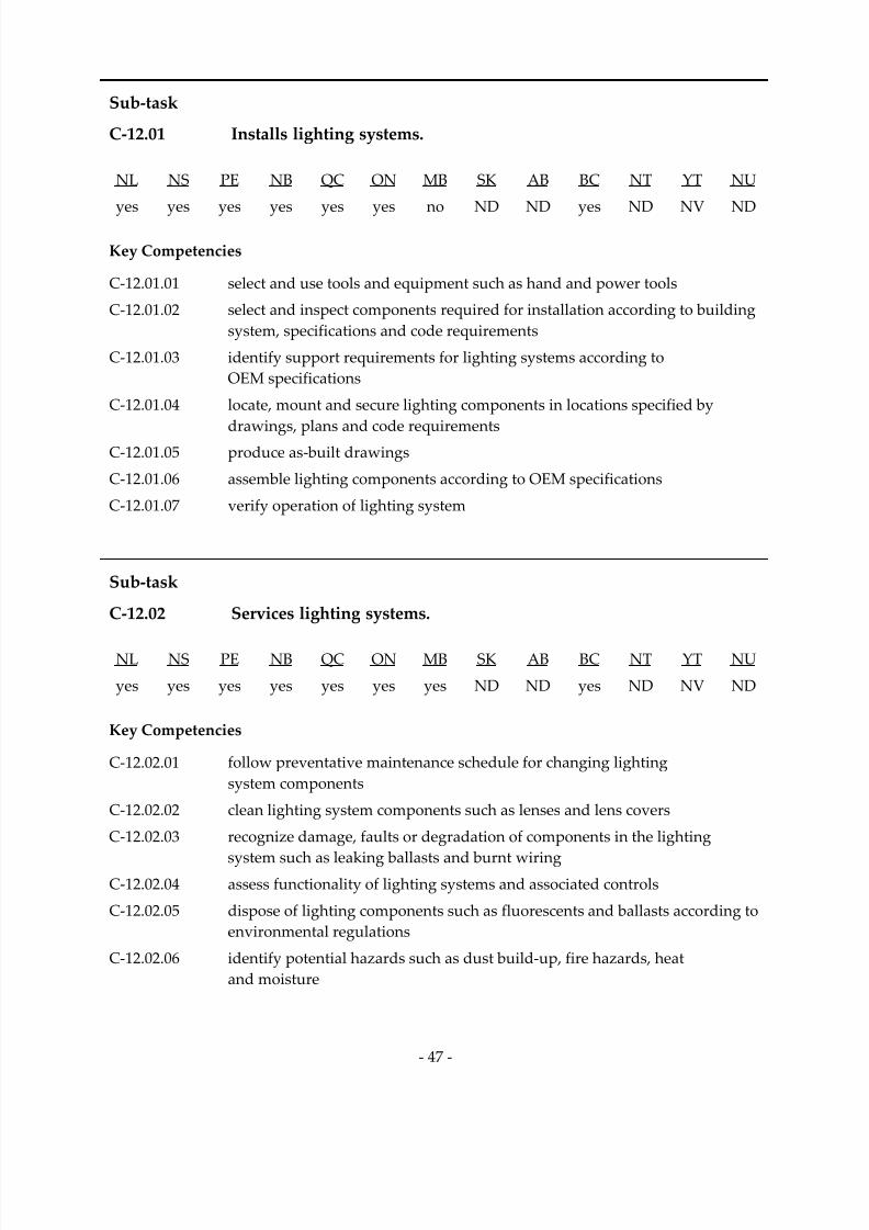
7/14/2019 Industrial Electrician 2011 En
http://slidepdf.com/reader/full/industrial-electrician-2011-en 61/132
‐ 47 ‐
Sub‐task
C‐12.01 Installs lighting systems.
NL NS PE NB QC ON MB SK AB BC NT YT NU
yes
yes
yes
yes
yes
yes
no
ND
ND
yes
ND
NV
ND
Key Competencies
C‐12.01.01 select and use tools and equipment such as hand and power tools
C‐12.01.02 select and inspect components required for installation according to building
system, specifications and code requirements
C‐12.01.03 identify support requirements for lighting systems according to
OEM specifications
C‐12.01.04 locate, mount and secure lighting components in locations specified by
drawings,
plans
and
code
requirements
C‐12.01.05 produce as‐ built drawings
C‐12.01.06 assemble lighting components according to OEM specifications
C‐12.01.07 verify operation of lighting system
Sub‐task
C‐12.02 Services lighting systems.
NL NS PE NB QC ON MB SK AB BC NT YT NU
yes yes yes yes yes yes yes ND ND yes ND NV ND
Key Competencies
C‐12.02.01 follow preventative maintenance schedule for changing lighting
system components
C‐12.02.02 clean lighting system components such as lenses and lens covers
C‐12.02.03 recognize damage, faults or degradation of components in the lighting
system such as leaking ballasts and burnt wiring
C‐12.02.04 assess functionality of lighting systems and associated controls
C‐12.02.05 dispose of lighting components such as fluorescents and ballasts according to
environmental regulations
C‐12.02.06 identify potential hazards such as dust build‐up, fire hazards, heat and moisture

7/14/2019 Industrial Electrician 2011 En
http://slidepdf.com/reader/full/industrial-electrician-2011-en 62/132
‐ 48 ‐
Sub‐task
C‐12.03 Troubleshoots lighting systems.
NL NS PE NB QC ON MB SK AB BC NT YT NU
yes
yes
yes
yes
yes
yes
yes
ND
ND
yes
ND
NV
ND
Key Competencies
C‐12.03.01 select and use tools and equipment such as multimeters and hand tools
C‐12.03.02 recognize worn, faulty and degraded components such as bulb flickers, tar leaks in ballast, bulb colour, and burnt or discoloured contacts and bulbs
C‐12.03.03 determine viability of replacement or repair of components
Sub‐task
C‐12.04 Repairs lighting systems.
NL NS PE NB QC ON MB SK AB BC NT YT NU
yes yes yes yes yes yes yes ND ND yes ND NV ND
Key Competencies
C‐12.04.01 select and use tools and equipment such as telescopic bulb
removers/extractors, hand tools and multimeters
C‐12.04.02 verify operating voltage according to fixture specifications
C‐12.04.03 interpret wiring scheme to upgrade wiring of lighting system
C‐12.04.04 select replacement components according to factors such as type, desired
light colour, compatibility, size and capacity
C‐12.04.05 replace components according to socket style and specifications
C‐12.04.06 verify system operation

7/14/2019 Industrial Electrician 2011 En
http://slidepdf.com/reader/full/industrial-electrician-2011-en 63/132
‐ 49 ‐
Task 13 Maintains protection devices.
Context Protection devices include fuses, relays, overloads and over‐current devices. They protect the equipment from fault damage and provide injury protection. Industrial electricians must be able to install, service, troubleshoot and repair
these devices at various voltages.
Required Knowledge
K 1 codes and regulations regarding the installation of protection devices
K 2 types of protection devices such as fuses, relays, phase loss, solid state
controls, surge protection, overloads and overcurrent devices
K 3 component characteristics such as ratings, controls and sizes
K 4 compatibility of components
K
5
installation,
inspection,
troubleshooting,
maintenance
and
repair
procedures
and techniques
K 6 devices and component operation
K 7 potential hazards related to protection devices
K 8 probable causes of fault and appropriate corrective methods
K 9 events that lead to system failure
K 10 history of equipment performance
K 11 safety procedures required to repair protection devices
Sub‐task
C‐13.01 Installs protection devices.
NL NS PE NB QC ON MB SK AB BC NT YT NU
yes yes yes yes yes yes no ND ND yes ND NV ND
Key Competencies
C‐13.01.01 determine type and model of protection device required according to service
requirements such as voltage, current and torque
C‐13.01.02 select and use tools and equipment such as hand and power tools
C‐13.01.03 locate, mount and secure protection devices according to drawings, plans and
code requirements
C‐13.01.04 produce as‐ built drawings
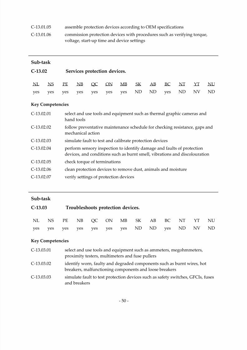
7/14/2019 Industrial Electrician 2011 En
http://slidepdf.com/reader/full/industrial-electrician-2011-en 64/132
‐ 50 ‐
C‐13.01.05 assemble protection devices according to OEM specifications
C‐13.01.06 commission protection devices with procedures such as verifying torque, voltage, start‐up time and device settings
Sub‐task
C‐13.02 Services protection devices.
NL NS PE NB QC ON MB SK AB BC NT YT NU
yes yes yes yes yes yes yes ND ND yes ND NV ND
Key Competencies
C‐13.02.01 select and use tools and equipment such as thermal graphic cameras and
hand tools
C‐13.02.02 follow preventative maintenance schedule for checking resistance, gaps and
mechanical action
C‐13.02.03 simulate fault to test and calibrate protection devices
C‐13.02.04 perform sensory inspection to identify damage and faults of protection
devices, and conditions such as burnt smell, vibrations and discolouration
C‐13.02.05 check torque of terminations
C‐13.02.06 clean protection devices to remove dust, animals and moisture
C‐13.02.07 verify settings of protection devices
Sub‐task
C‐13.03 Troubleshoots protection devices.
NL NS PE NB QC ON MB SK AB BC NT YT NU
yes yes yes yes yes yes yes ND ND yes ND NV ND
Key Competencies
C‐13.03.01 select and use tools and equipment such as ammeters, megohmmeters, proximity testers, multimeters and fuse pullers
C‐13.03.02 identify worn, faulty and degraded components such as burnt wires, hot breakers, malfunctioning components and loose breakers
C‐13.03.03 simulate fault to test protection devices such as safety switches, GFCIs, fuses and breakers
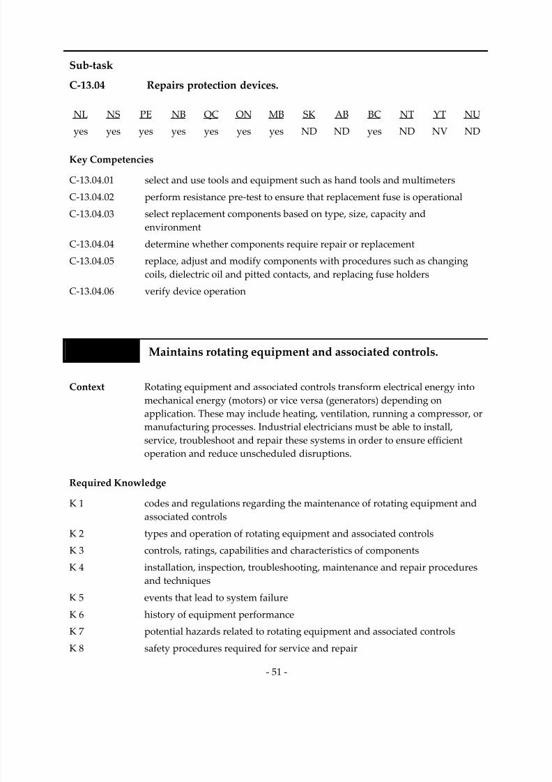
7/14/2019 Industrial Electrician 2011 En
http://slidepdf.com/reader/full/industrial-electrician-2011-en 65/132
‐ 51 ‐
Sub‐task
C‐13.04 Repairs protection devices.
NL NS PE NB QC ON MB SK AB BC NT YT NU
yes
yes
yes
yes
yes
yes
yes
ND
ND
yes
ND
NV
ND
Key Competencies
C‐13.04.01 select and use tools and equipment such as hand tools and multimeters
C‐13.04.02 perform resistance pre‐test to ensure that replacement fuse is operational
C‐13.04.03 select replacement components based on type, size, capacity and
environment
C‐13.04.04 determine whether components require repair or replacement
C‐13.04.05 replace, adjust and modify components with procedures such as changing
coils, dielectric oil and pitted contacts, and replacing fuse holders C‐13.04.06 verify device operation
Task 14 Maintains rotating equipment and associated controls.
Context Rotating equipment and associated controls transform electrical energy into
mechanical energy (motors) or vice versa (generators) depending on
application. These may include heating, ventilation, running a compressor, or manufacturing processes. Industrial electricians must be able to install, service, troubleshoot and repair these systems in order to ensure efficient operation and reduce unscheduled disruptions.
Required Knowledge
K 1 codes and regulations regarding the maintenance of rotating equipment and
associated controls
K 2 types and operation of rotating equipment and associated controls
K 3 controls, ratings, capabilities and characteristics of components
K 4 installation, inspection, troubleshooting, maintenance and repair procedures and techniques
K 5 events that lead to system failure
K 6 history of equipment performance
K 7 potential hazards related to rotating equipment and associated controls
K 8 safety procedures required for service and repair

7/14/2019 Industrial Electrician 2011 En
http://slidepdf.com/reader/full/industrial-electrician-2011-en 66/132
‐ 52 ‐
Sub‐task
C‐14.01 Installs rotating equipment and associated controls.
NL NS PE NB QC ON MB SK AB BC NT YT NU
yes
yes
yes
yes
yes
yes
yes
ND
ND
yes
ND
NV
ND
Key Competencies
C‐14.01.01 select and use tools and equipment such as hand and power tools
C‐14.01.02 determine type and model of rotating equipment and controls required
according to application
C‐14.01.03 assemble and connect components such as resistance temperature detectors
(RTDs), vibration probes and over temperature contacts according to
OEM specifications
C‐
14.01.04
recognize
hazards
related
to
rotating
equipment
and
associated
controls
C‐14.01.05 locate, mount and secure rotating equipment and associated controls
according to OEM specifications and code requirements
C‐14.01.06 commission rotating equipment and associated controls by checking
connections, rotation direction, torque, voltage, and start‐up and
full‐load current
C‐14.01.07 ensure that safety features of equipment such as guards, controls and limits are operational
C‐14.01.08 verify sequence of operations for equipment
C‐14.01.09 produce as‐ built drawings
Sub‐task
C‐14.02 Services rotating equipment and associated controls.
NL NS PE NB QC ON MB SK AB BC NT YT NU
yes yes yes yes yes yes yes ND ND yes ND NV ND
Key Competencies
C‐14.02.01 select and use tools and equipment such as data monitors, thermal graphic
cameras, air blowers and temperature guns
C‐14.02.02 follow preventative maintenance schedule for checking brush length, seating
and spring tension of brush holders
C‐14.02.03 perform vibration analysis on rotating equipment in order to assess problems such as misalignment and worn bearings

7/14/2019 Industrial Electrician 2011 En
http://slidepdf.com/reader/full/industrial-electrician-2011-en 67/132
‐ 53 ‐
C‐14.02.04 identify damage and faults of rotating equipment and associated controls by
observing conditions such as abnormal heat, discolouration, grooving and
wear points
C‐14.02.05 clean dust and carbon from rotating equipment and associated controls using
air blower or non‐conductive solution to prevent overheating and to ensure
good contact
C‐14.02.06 check wiring and cable connections, and torque of terminations
C‐14.02.07 verify operation of components according to specifications
Sub‐task
C‐14.03 Troubleshoots rotating equipment and associated controls.
NL NS PE NB QC ON MB SK AB BC NT YT NU
yes yes yes yes yes yes yes ND ND yes ND NV ND
Key Competencies
C‐14.03.01 select and use tools and equipment such as hi‐pot testers, vibration analyzers, ammeters, megohmmeters and multimeters
C‐14.03.02 perform sensory inspection to identify abnormal heat, sounds, odours, vibrations and arcing/sparking sources
C‐14.03.03 perform resistance checks on winding for phase loss
C‐14.03.04 perform megohmmeter test to determine ground
C‐14.03.05 identify worn, damaged or defective components such as bearings, slip rings
and commutators
C‐14.03.06 check seating, brush length and spring tension of brush holders

7/14/2019 Industrial Electrician 2011 En
http://slidepdf.com/reader/full/industrial-electrician-2011-en 68/132
‐ 54 ‐
Sub‐task
C‐14.04 Repairs rotating equipment and associated controls.
NL NS PE NB QC ON MB SK AB BC NT YT NU
yes
yes
yes
yes
yes
yes
yes
ND
ND
yes
ND
NV
ND
Key Competencies
C‐14.04.01 select and use tools and equipment such as bearing pullers, bearing heaters, spring tension gauges, commutator stones and feeler gauges
C‐14.04.02 select replacement components based on type, size, capacity and
environment
C‐14.04.03 determine whether components require repair or replacement
C‐14.04.04 replace components such as brush holders, springs, capacitors and bearings
C‐14.04.05 perform equipment repairs such as recoating, and resurfacing brush ends
and motor brake
C‐14.04.06 run DC current through motor to remove moisture from windings and
improve the ohmic value of the windings
C‐14.04.07 verify system operation by performing load, hi‐pot, neutral plane and
dynamic rotation tests
Task 15
Maintains
drives
and
associated
controls.
Context Drives and associated controls provide speed, frequency, torque, current, time and braking control to motors. Industrial electricians must be able to
install, service, troubleshoot and repair these systems in order to ensure
efficient operation and reduce unscheduled disruptions.
Required Knowledge
K 1 codes and regulations regarding the maintenance of drives and associated
controls according to OEM specifications K 2 AC and DC theory
K 3 methods to prevent damage to drives from static electricity such as using
static discharge wristbands and anti‐static mats
K 4 processes related to drives and associated controls
K 5 types and operation of drives and associated controls
K 6 controls, ratings, capabilities and characteristics of components

7/14/2019 Industrial Electrician 2011 En
http://slidepdf.com/reader/full/industrial-electrician-2011-en 69/132
‐ 55 ‐
K 7 installation, inspection, troubleshooting, maintenance and repair procedures and techniques
K 8 programming techniques and operating parameters of drives and
associated controls
K 9 events that lead to system failure
K 10 history of equipment performance
K 11 potential hazards related to drives and associated controls
K 12 safety procedures required for service and repair
Sub‐task
C‐15.01 Installs drives and associated controls.
NL
NS
PE
NB
QC
ON
MB
SK
AB
BC
NT
YT
NU
yes yes yes yes yes yes yes ND ND yes ND NV ND
Key Competencies
C‐15.01.01 select and use tools and equipment such as hand and power tools
C‐15.01.02 determine type and model of drives and associated controls required
according to application and motor
C‐15.01.03 identify hazards related to drives and associated controls
C‐15.01.04 locate, mount and secure drives and associated controls according to
OEM specifications C‐15.01.05 program and configure drives and associated controls according to
OEM specifications
C‐15.01.06 verify device operation to confirm performance within parameters such as deceleration, loading and acceleration
C‐15.01.07 produce as‐ built drawings

7/14/2019 Industrial Electrician 2011 En
http://slidepdf.com/reader/full/industrial-electrician-2011-en 70/132
‐ 56 ‐
Sub‐task
C‐15.02 Services drives and associated controls.
NL NS PE NB QC ON MB SK AB BC NT YT NU
yes
yes
yes
yes
yes
yes
yes
ND
ND
yes
ND
NV
ND
Key Competencies
C‐15.02.01 select and use tools and equipment such as hand tools, data monitors, thermal graphic cameras, air blowers and temperature guns
C‐15.02.02 follow preventative maintenance schedule for replacing filters, torquing lugs, backing up programs and checking fans
C‐15.02.03 clean dust from drives and associated controls using air blower to
prevent overheating
C‐
15.02.04
check
wiring
and
cable
connections,
and
torque
of
terminations
Sub‐task
C‐15.03 Troubleshoots drives and associated controls.
NL NS PE NB QC ON MB SK AB BC NT YT NU
yes yes yes yes yes yes yes ND ND yes ND NV ND
Key Competencies
C‐15.03.01 read and interpret error codes by checking human machine interface (HMI) and referring to troubleshooting manual
C‐15.03.02 verify for faults such as loose cables, low voltage and discolouration
C‐15.03.03 identify problems with sequence of operation that affect the performance of the drive and motor
C‐15.03.04 verify for required ground according to OEM specifications
C‐15.03.05 identify communications problems
C‐15.03.06 determine issues relating to the length of the conductors such as distance of motor from drive and the equal length of conductors for multiple motors
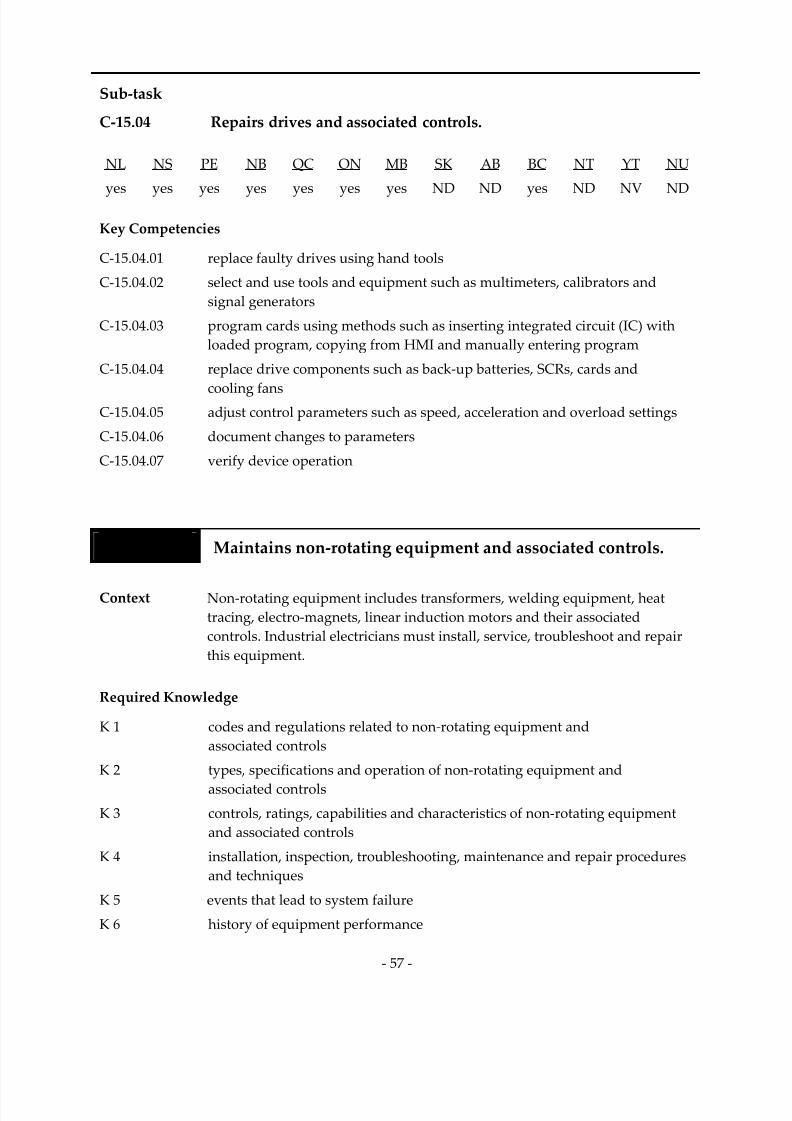
7/14/2019 Industrial Electrician 2011 En
http://slidepdf.com/reader/full/industrial-electrician-2011-en 71/132
‐ 57 ‐
Sub‐task
C‐15.04 Repairs drives and associated controls.
NL NS PE NB QC ON MB SK AB BC NT YT NU
yes
yes
yes
yes
yes
yes
yes
ND
ND
yes
ND
NV
ND
Key Competencies
C‐15.04.01 replace faulty drives using hand tools
C‐15.04.02 select and use tools and equipment such as multimeters, calibrators and
signal generators
C‐15.04.03 program cards using methods such as inserting integrated circuit (IC) with
loaded program, copying from HMI and manually entering program
C‐15.04.04 replace drive components such as back‐up batteries, SCRs, cards and
cooling
fans
C‐15.04.05 adjust control parameters such as speed, acceleration and overload settings
C‐15.04.06 document changes to parameters
C‐15.04.07 verify device operation
Task 16 Maintains non‐rotating equipment and associated controls.
Context Non‐rotating equipment includes transformers, welding equipment, heat tracing, electro‐magnets, linear induction motors and their associated
controls. Industrial electricians must install, service, troubleshoot and repair this equipment.
Required Knowledge
K 1 codes and regulations related to non‐rotating equipment and
associated controls
K 2 types, specifications and operation of non‐rotating equipment and
associated controls
K 3 controls, ratings, capabilities and characteristics of non‐rotating equipment and associated controls
K 4 installation, inspection, troubleshooting, maintenance and repair procedures and techniques
K 5 events that lead to system failure
K 6 history of equipment performance

7/14/2019 Industrial Electrician 2011 En
http://slidepdf.com/reader/full/industrial-electrician-2011-en 72/132
‐ 58 ‐
K 7 potential hazards related to non‐rotating equipment and associated controls
K 8 safety procedures required for service and repair
Sub‐task
C‐16.01 Installs non‐rotating equipment and associated controls.
NL NS PE NB QC ON MB SK AB BC NT YT NU
yes yes yes yes yes yes yes ND ND yes ND NV ND
Key Competencies
C‐16.01.01 select and use tools and equipment such as hand and power tools
C‐16.01.02 determine type and model of non‐rotating equipment and controls required
according
to
application
C‐16.01.03 assemble components according to OEM specifications
C‐16.01.04 identify hazards related to non‐rotating equipment and associated controls
and discharge when required
C‐16.01.05 locate, mount and secure non‐rotating equipment and associated controls according to OEM specifications
C‐16.01.06 commission non‐rotating equipment and associated controls by checking
connections, voltage, current and sequence of operations
C‐16.01.07 produce as‐ built drawings
Sub‐task
C‐16.02 Services non‐rotating equipment and associated controls.
NL NS PE NB QC ON MB SK AB BC NT YT NU
yes yes yes yes yes yes yes ND ND yes ND NV ND
Key Competencies
C‐16.02.01 select and use tools and equipment such as data monitors, thermal graphic
cameras, air blowers and temperature guns
C‐16.02.02 complete scheduled preventative maintenance tasks such as tightening loose
connections and checking for excessive heat, discolouration and odours
C‐16.02.03 identify damage and faults of non‐rotating equipment and associated
controls by observing conditions such as abnormal heat and discolouration

7/14/2019 Industrial Electrician 2011 En
http://slidepdf.com/reader/full/industrial-electrician-2011-en 73/132
‐ 59 ‐
C‐16.02.04 clean dust from non‐rotating equipment and associated controls using air blower to prevent overheating
C‐16.02.05 check wiring and cable connections, and torque of terminations
C‐16.02.06 verify operation of components according to specifications
Sub‐task
C‐16.03 Troubleshoots non‐rotating equipment and associated controls.
NL NS PE NB QC ON MB SK AB BC NT YT NU
yes yes yes yes yes yes yes ND ND yes ND NV ND
Key Competencies
C‐
16.03.01
select
and
use
tools
and
equipment
such
as
hi‐
pot
testers,
ammeters,
megohmmeters and multimeters
C‐16.03.02 perform sensory inspection to identify abnormal heat, sounds and odours
C‐16.03.03 monitor status of non‐rotating equipment using phase status indicators
C‐16.03.04 check voltage and current levels for each phase
C‐16.03.05 perform megohmmeter test to check insulation integrity
Sub‐task
C‐16.04 Repairs non‐rotating equipment and associated controls.
NL NS PE NB QC ON MB SK AB BC NT YT NU
yes yes yes yes yes yes yes ND ND yes ND NV ND
Key Competencies
C‐16.04.01 select and use tools and equipment such as multimeters and hand tools
C‐16.04.02 select replacement components based on type, size, capacity and
environment C‐16.04.03 determine whether components require repair or replacement
C‐16.04.04 replace, adjust and modify equipment with procedures such as tightening
loose connections and changing dielectric oil
C‐16.04.05 verify system operation

7/14/2019 Industrial Electrician 2011 En
http://slidepdf.com/reader/full/industrial-electrician-2011-en 74/132
‐ 60 ‐
BLOCK D EMERGENCY AND STANDBY SYSTEMS
Trends Solar and wind systems are increasingly used to support emergency
and standby systems. Therefore, industrial electricians require a high
level of training on these systems. There is an increase in the use of PLCs and DCSs to simplify
maintenance, operation and reliability of emergency and standby
systems. This technological advance is going to continue to increase and
will also require industrial electricians to develop the skills required to
maintain these systems.
Related
Components
(including, but not
limited to)
Batteries, inverters, solid state devices, heat sinks, circuit boards, cabling, capacitors, rectifiers, relays, transfer switches, prime movers, meters, bearings, brushes, slip rings.
Tools and
Equipment
See Appendix A.
Task 17 Maintains uninterruptible power supply (UPS) systems.
Context UPS systems are used in industrial and institutional buildings to provide
constant voltage for essential devices and to maintain power to critical equipment during power outages. They ensure seamless and bumpless transfer of power. Industrial electricians must be able to install, service, troubleshoot and repair UPS systems.
Required Knowledge
K 1 codes and regulations regarding the maintenance of UPS systems
K 2 types, sizes, ratings, capabilities and operation of UPS systems
K 3 installation, inspection, troubleshooting, repair and preventative
maintenance procedures and techniques
K 4 components such as batteries, inverters, transfer switches, solid state devices, heat sinks and circuit boards
K 5 causes of component overheating such as dust, contamination, overloading
and loose connections

7/14/2019 Industrial Electrician 2011 En
http://slidepdf.com/reader/full/industrial-electrician-2011-en 75/132
‐ 61 ‐
K 6 inverter system fault indicators such as no output, alarms, odour, noise and
breaker failure
K 7 battery faults such as low battery voltage, bulging cells, low electrolyte level, incorrect charging rate and failed solid‐state devices
K 8 events that lead to system failure such as ambient high temperature and dirty
ventilation filters K 9 safety procedures for UPS systems
K 10 history of equipment performance
K 11 optimum performance of system and equipment
K 12 effects of static electricity on ICs
K 13 potential hazards of installation and repair such as battery acid, hydrogen
discharge and stored electrical energy
K 14 compatibility of solvents with UPS components
Sub‐task
D‐17.01 Installs uninterruptible power supply (UPS) systems.
NL NS PE NB QC ON MB SK AB BC NT YT NU
yes yes yes yes yes yes yes ND ND yes ND NV ND
Key Competencies
D‐17.01.01 select and use tools and equipment such as compression tools, torque
wrenches, hand tools, isolated tools, power tools, knock‐out cutters, hole
saws, thermal graphic cameras and multimeters
D‐17.01.02 determine location and installation procedure of components by reading and
interpreting prints, OEM manuals and code requirements
D‐17.01.03 select interconnection electrical fittings according to engineered drawings and building codes
D‐17.01.04 visually inspect equipment to be installed to check for damage and to ensure
name plate data matches engineered drawings
D‐17.01.05 assemble system components according to OEM specifications and engineered drawings
D‐17.01.06 connect system components such as cables, batteries, inverters, alarms and
solar panels according to code requirements
D‐17.01.07 terminate and torque all connections according to OEM specifications and
code requirements
D‐17.01.08 check and fill non maintenance‐free batteries with electrolyte

7/14/2019 Industrial Electrician 2011 En
http://slidepdf.com/reader/full/industrial-electrician-2011-en 76/132
‐ 62 ‐
D‐17.01.09 commission UPS system to ensure correct voltages, frequency and operation
of charging system, transfer switch, alarms, isolating breakers, and
HVAC system
D‐17.01.10 produce as‐ built drawings
Sub‐task
D‐17.02 Services uninterruptible power supply (UPS) systems.
NL NS PE NB QC ON MB SK AB BC NT YT NU
yes yes yes yes yes yes yes ND ND yes ND NV ND
Key Competencies
D‐17.02.01 select and use tools and equipment such as frequency meters, multimeters, thermal graphic cameras, hydrometers and torque wrenches
D‐17.02.02 check and correct electrolyte levels according to OEM specifications
D‐17.02.03 check all battery connection torques according to OEM specifications
D‐17.02.04 check and set system voltages such as float voltage and inverter output voltage according to OEM specifications
D‐17.02.05 record individual cell voltages, SG and temperatures, and compare to
OEM specifications
D‐17.02.06 check and set charging current limit according to OEM specifications
D‐17.02.07 change HVAC and inverter filters according to OEM specifications D‐17.02.08 check and set inverter output frequency according to local conditions and
OEM specifications
D‐17.02.09 test alarms according to engineered drawings
D‐17.02.10 check ambient temperature according to engineered drawings and
OEM specifications
D‐17.02.11 test transfer switch to ensure seamless and bumpless transfer according to
OEM specifications
D‐17.02.12 perform battery load test to check discharge time according to
OEM specifications D‐17.02.13 identify calendar life of batteries to replace according to OEM specifications
D‐17.02.14 verify system operation
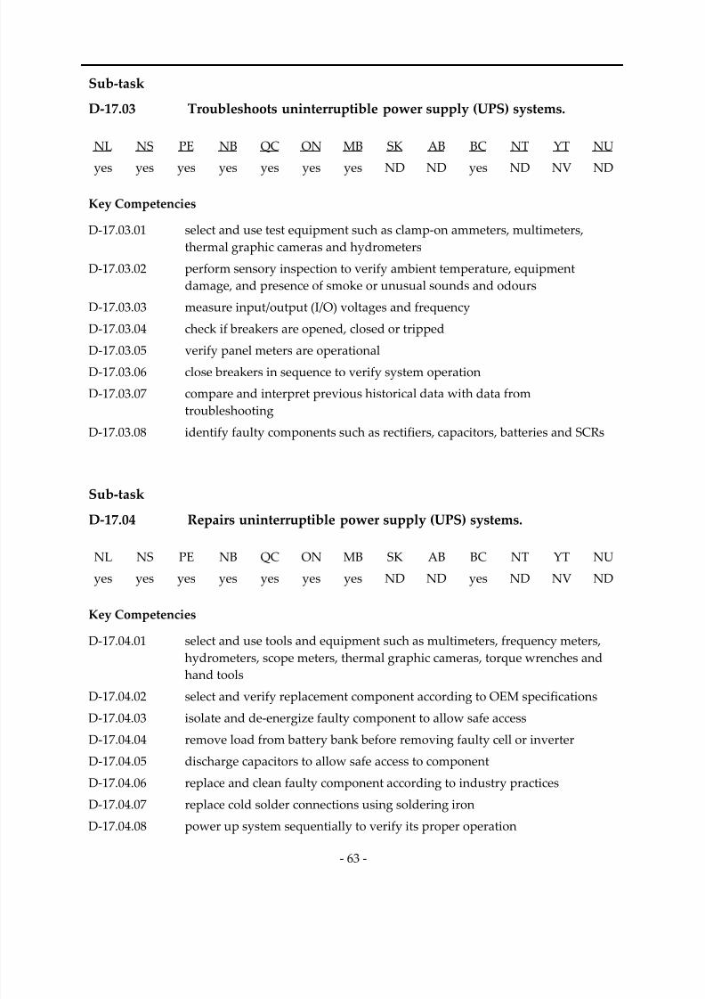
7/14/2019 Industrial Electrician 2011 En
http://slidepdf.com/reader/full/industrial-electrician-2011-en 77/132
‐ 63 ‐
Sub‐task
D‐17.03 Troubleshoots uninterruptible power supply (UPS) systems.
NL NS PE NB QC ON MB SK AB BC NT YT NU
yes
yes
yes
yes
yes
yes
yes
ND
ND
yes
ND
NV
ND
Key Competencies
D‐17.03.01 select and use test equipment such as clamp‐on ammeters, multimeters, thermal graphic cameras and hydrometers
D‐17.03.02 perform sensory inspection to verify ambient temperature, equipment damage, and presence of smoke or unusual sounds and odours
D‐17.03.03 measure input/output (I/O) voltages and frequency
D‐17.03.04 check if breakers are opened, closed or tripped
D‐17.03.05 verify panel meters are operational D‐17.03.06 close breakers in sequence to verify system operation
D‐17.03.07 compare and interpret previous historical data with data from
troubleshooting
D‐17.03.08 identify faulty components such as rectifiers, capacitors, batteries and SCRs
Sub‐task
D‐
17.04
Repairs
uninterruptible
power
supply
(UPS)
systems.
NL NS PE NB QC ON MB SK AB BC NT YT NU
yes yes yes yes yes yes yes ND ND yes ND NV ND
Key Competencies
D‐17.04.01 select and use tools and equipment such as multimeters, frequency meters, hydrometers, scope meters, thermal graphic cameras, torque wrenches and
hand tools
D‐17.04.02 select and verify replacement component according to OEM specifications D‐17.04.03 isolate and de‐energize faulty component to allow safe access
D‐17.04.04 remove load from battery bank before removing faulty cell or inverter
D‐17.04.05 discharge capacitors to allow safe access to component
D‐17.04.06 replace and clean faulty component according to industry practices
D‐17.04.07 replace cold solder connections using soldering iron
D‐17.04.08 power up system sequentially to verify its proper operation
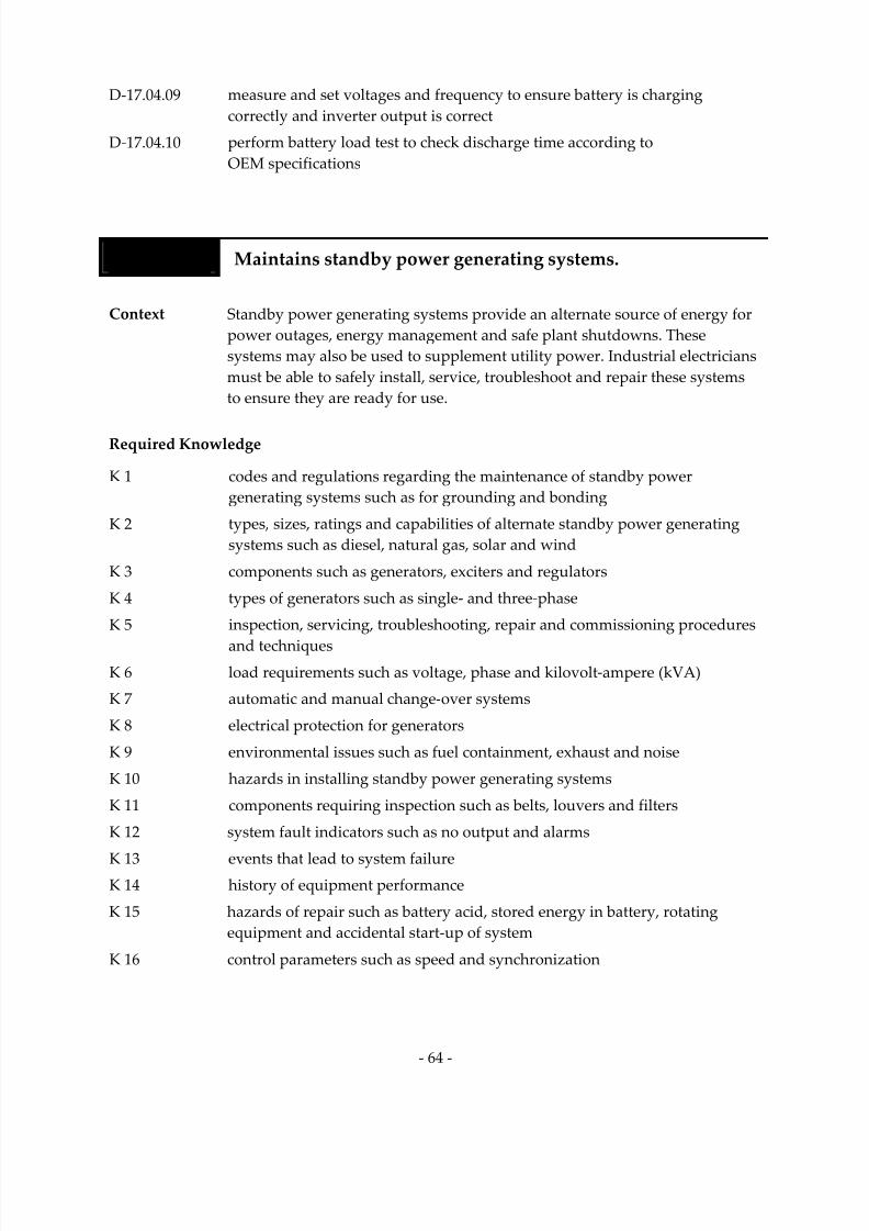
7/14/2019 Industrial Electrician 2011 En
http://slidepdf.com/reader/full/industrial-electrician-2011-en 78/132
‐ 64 ‐
D‐17.04.09 measure and set voltages and frequency to ensure battery is charging
correctly and inverter output is correct
D‐17.04.10 perform battery load test to check discharge time according to
OEM specifications
Task 18 Maintains standby power generating systems.
Context Standby power generating systems provide an alternate source of energy for power outages, energy management and safe plant shutdowns. These
systems may also be used to supplement utility power. Industrial electricians must be able to safely install, service, troubleshoot and repair these systems
to ensure they are ready for use.
Required Knowledge
K 1 codes and regulations regarding the maintenance of standby power generating systems such as for grounding and bonding
K 2 types, sizes, ratings and capabilities of alternate standby power generating
systems such as diesel, natural gas, solar and wind
K 3 components such as generators, exciters and regulators
K 4 types of generators such as single‐ and three‐phase
K 5 inspection, servicing, troubleshooting, repair and commissioning procedures
and techniques
K 6 load requirements such as voltage, phase and kilovolt‐ampere (kVA)
K 7 automatic and manual change‐over systems
K 8 electrical protection for generators
K 9 environmental issues such as fuel containment, exhaust and noise
K 10 hazards in installing standby power generating systems
K 11 components requiring inspection such as belts, louvers and filters
K 12 system fault indicators such as no output and alarms
K 13 events that lead to system failure
K 14 history of equipment performance
K 15 hazards of repair such as battery acid, stored energy in battery, rotating
equipment and accidental start‐up of system
K 16 control parameters such as speed and synchronization

7/14/2019 Industrial Electrician 2011 En
http://slidepdf.com/reader/full/industrial-electrician-2011-en 79/132
‐ 65 ‐
Sub‐task
D‐18.01 Installs standby power generating systems.
NL NS PE NB QC ON MB SK AB BC NT YT NU
yes
yes
yes
yes
yes
yes
yes
ND
ND
yes
ND
NV
ND
Key Competencies
D‐18.01.01 select and use tools and equipment such as compression tools, torque
wrenches, hand tools, insulated tools, phase meters, power tools, knock‐out cutters, hole saws, hoisting and rigging equipment, thermal graphic cameras and multimeters
D‐18.01.02 determine location and installation procedure of components by reading and
interpreting prints, OEM manuals and code requirements
D‐18.01.03 select interconnection electrical fittings according to engineered drawings and building codes
D‐18.01.04 visually inspect equipment to be installed to check for damage and to ensure
name plate data matches engineered drawings
D‐18.01.05 assemble system components according to OEM specifications and
engineered drawings
D‐18.01.06 connect system components such as cables, batteries and alarms according to
code requirements
D‐18.01.07 terminate and torque all connections according to OEM specifications and
code requirements
D‐18.01.08 check electrolyte level and SG of non maintenance‐free batteries
D‐18.01.09 verify phasing matches utility power
D‐18.01.10 commission standby power generating system to ensure correct voltages, frequency and operation of transfer switch, alarms, isolating breakers and
ventilation system
D‐18.01.11 produce as‐ built drawings

7/14/2019 Industrial Electrician 2011 En
http://slidepdf.com/reader/full/industrial-electrician-2011-en 80/132
‐ 66 ‐
Sub‐task
D‐18.02 Services standby power generating systems.
NL NS PE NB QC ON MB SK AB BC NT YT NU
yes
yes
yes
yes
yes
yes
yes
ND
ND
yes
ND
NV
ND
Key Competencies
D‐18.02.01 select and use tools and equipment such as frequency meters, multimeters, scope meters, thermal graphic cameras, hydrometers, pressure gauges, pneumatic tools, hand tools, and torque and impact wrenches
D‐18.02.02 check and correct electrolyte levels and SG on starting system according to
OEM specifications
D‐18.02.03 inspect battery charging system on starting system to ensure proper current rate
D‐18.02.04 check fuel levels, fluid levels and SG of coolant, and change according to
maintenance schedule
D‐18.02.05 clean and lubricate components
D‐18.02.06 change filters such as air, fuel and oil according to OEM specifications
D‐18.02.07 perform sensory inspection to recognize abnormal heat, sounds, odours, vibrations and arcing sources, and worn, damaged or defective components
such as bearings, brushes and slip rings
D‐18.02.08 ensure guards are in place
D‐18.02.09 check wiring and cable connections
D‐18.02.10 check and set genset output voltage and frequency according to
OEM specifications
D‐18.02.11 test alarms according to engineered drawings
D‐18.02.12 check ambient temperature according to engineered drawings and
OEM specifications
D‐18.02.13 test transfer switch to ensure transfer according to OEM specifications
D‐18.02.14 verify system operation
D‐18.02.15 perform generator run test according to OEM specifications

7/14/2019 Industrial Electrician 2011 En
http://slidepdf.com/reader/full/industrial-electrician-2011-en 81/132
‐ 67 ‐
Sub‐task
D‐18.03 Troubleshoots standby power generating systems.
NL NS PE NB QC ON MB SK AB BC NT YT NU
yes
yes
yes
yes
yes
yes
yes
ND
ND
yes
ND
NV
ND
Key Competencies
D‐18.03.01 select and use test equipment such as frequency meters, multimeters, thermal graphic cameras and hydrometers
D‐18.03.02 perform sensory inspection to verify ambient temperature, equipment damage, and presence of smoke or unusual sounds and odours
D‐18.03.03 review and analyze sequence of events that led to the problem such as alarm
and fault history, and trends
D‐
18.03.04
measure
output
voltage
and
frequency
to
ensure
correct
operation
D‐18.03.05 check if breakers are opened, closed or tripped
D‐18.03.06 verify panel meters are operational
D‐18.03.07 compare and interpret previous historical data with data from
troubleshooting
D‐18.03.08 identify faulty components such as batteries, voltage regulators, exciters, brushes, ignition systems, governors and switchgear
D‐18.03.09 identify faults such as short circuit, excessive loads and loose connections
D‐18.03.10 perform transfer function and load tests according to OEM and
site specifications D‐18.03.11 test starting system according to OEM and site specifications
Sub‐task
D‐18.04 Repairs standby power generating systems.
NL NS PE NB QC ON MB SK AB BC NT YT NU
yes
yes
yes
yes
yes
yes
yes
ND
ND
yes
ND
NV
ND
Key Competencies
D‐18.04.01 select and use tools and equipment such as multimeters, frequency meters, hydrometers, scope meters, phase meters, thermal graphic cameras, torque
wrenches and hand tools
D‐18.04.02 select and verify replacement component according to OEM specifications

7/14/2019 Industrial Electrician 2011 En
http://slidepdf.com/reader/full/industrial-electrician-2011-en 82/132
‐ 68 ‐
D‐18.04.03 isolate and lock‐out standby system to allow access and replacement of component
D‐18.04.04 replace and clean faulty component according to industry practices
D‐18.04.05 replace cold solder connections using soldering iron
D‐18.04.06 measure and set voltages and frequency according to OEM and
site specifications D‐18.04.07 verify phasing matches utility power before standby system goes online
D‐18.04.08 verify starting system after battery replacement according to OEM and
site specifications
D‐18.04.09 perform battery load test to check discharge time according to
OEM specifications
D‐18.04.10 power up system sequentially to verify its proper operation

7/14/2019 Industrial Electrician 2011 En
http://slidepdf.com/reader/full/industrial-electrician-2011-en 83/132
‐ 69 ‐
BLOCK E COMMUNICATION SYSTEMS
Trends There is a greater use of Internet‐ based interfaces for communication
systems.
There is a trend towards more wireless alarm, network communication
and video communication.
Related
Components
(including, but not
limited to)
Alarm systems: Fire alarms, gas detectors, pull station, smoke detectors, floats, pressure sensors, limit switches, fasteners, cameras, speakers, heat detectors, infrared sensors, motion sensors, bells, whistles, annunciators, tamper switches, end of line (EOL) resistors, duct detectors
Paging systems: amplifiers, speakers, microphones, music system,
Multimedia systems: cameras, monitors, microphones, screens, projectors, power supplies.
Network systems: computers, monitors, switches, routers, printers, hard drives, foil, balluns, antennae, jacks, cabinets, patch panels, modules, conduits, boxes.
Tools and
Equipment
See Appendix A.
Task 19 Maintains alarm systems.
Context Alarm systems are installed to provide timely warnings to aid in the safety of personnel, environment and facilities. They also notify authorities and control equipment in emergency situations. They need to be maintained to the
highest standards to ensure functionality.
Required Knowledge
K 1 codes and regulations regarding the installation, inspection, troubleshooting, repair and servicing of alarm systems
K 2 broad‐ based and manufacturer‐specific training requirements for alarm systems
K 3 types of alarm systems such as fire, heat, security and gas
K 4 alarm system components, controls, parameters capabilities and
characteristics

7/14/2019 Industrial Electrician 2011 En
http://slidepdf.com/reader/full/industrial-electrician-2011-en 84/132
‐ 70 ‐
K 5 specifications for installation, maintenance, inspection, repair and
troubleshooting
K 6 events that lead to system failure
K 7 history of equipment performance
K 8 authorities having jurisdiction for various alarm systems such as fire and gas
Sub‐task
E‐19.01 Installs alarm systems.
NL NS PE NB QC ON MB SK AB BC NT YT NU
yes yes yes yes yes yes no ND ND yes ND NV ND
Key Competencies
E‐19.01.01 select and use tools and equipment such as hand tools, multimeters and
battery testers
E‐19.01.02 assemble alarm system components such as detectors, indicating devices and
annunciators according to OEM specifications
E‐19.01.03 locate and mount components in appropriate locations according to drawings and specifications
E‐19.01.04 configure circuitry and panel for alarm systems such as addressable
and conventional
E‐19.01.05 connect alarm systems to communication systems for notification of authorities such as security companies and fire departments
E‐19.01.06 test and verify alarm system in order to comply with code requirements
E‐19.01.07 record and sign off panel and wiring documentation
E‐19.01.08 ensure record of floor plan matches the information in the panel

7/14/2019 Industrial Electrician 2011 En
http://slidepdf.com/reader/full/industrial-electrician-2011-en 85/132
‐ 71 ‐
Sub‐task
E‐19.02 Services alarm systems.
NL NS PE NB QC ON MB SK AB BC NT YT NU
yes
yes
yes
yes
yes
yes
no
ND
ND
yes
ND
NV
ND
Key Competencies
E‐19.02.01 select and use tools and equipment such as hand tools, smoke cans, pull stations and portable heating elements
E‐19.02.02 clean alarm system components of dust to ensure accurate operation
E‐19.02.03 check that parameters such as timing, EOL resistor and calibration are
operating according to OEM specifications
E‐19.02.04 select replacement components based on type, compatibility, size,
environment
and
capacity
E‐19.02.05 replace components according to manufacturer‐specified life cycle and
legislated requirements
E‐19.02.06 recognize worn, damaged or defective components
E‐19.02.07 check wiring and cable connections to ensure good continuity
E‐19.02.08 verify system’s operational requirements such as audibility, visual alarms and connections with sprinkler system
E‐19.02.09 document faults and test data
Sub‐task
E‐19.03 Troubleshoots alarm systems.
NL NS PE NB QC ON MB SK AB BC NT YT NU
yes yes yes yes yes yes no ND ND yes ND NV ND
Key Competencies
E‐19.03.01 select and use tools and equipment such as hand tools, multimeters and smoke cans
E‐19.03.02 isolate faults in alarm systems by referring to panels
E‐19.03.03 determine zone, type and status of alarm such as “trouble” and “alarm”
E‐19.03.04 perform sensory inspection to identify presence of conditions such as smoke, corrosion and water damage
E‐19.03.05 perform and interpret diagnostic tests such as internal diagnostics, battery
tests, power supply tests and resistance tests

7/14/2019 Industrial Electrician 2011 En
http://slidepdf.com/reader/full/industrial-electrician-2011-en 86/132
‐ 72 ‐
Sub‐task
E‐19.04 Repairs alarm systems.
NL NS PE NB QC ON MB SK AB BC NT YT NU
yes
yes
yes
yes
yes
yes
no
ND
ND
yes
ND
NV
ND
Key Competencies
E‐19.04.01 select and use tools and equipment such as hand tools, magnets and multimeters
E‐19.04.02 select replacement components based on characteristics such as type, size, environment and capacity
E‐19.04.03 replace faulty components such as batteries, power supplies, sensors, remote
displays and pull stations
E‐
19.04.04
re‐
mount
components
in
previous
locations
E‐19.04.05 adjust locations for alarm systems according to code regulations and
operational requirements
E‐19.04.06 re‐verify fire alarm system operation
E‐19.04.07 verify alarm system operation
E‐19.04.08 document repairs performed
Task 20
Maintains
paging
systems.
Context Paging systems allow for communication between various locations
throughout the facility. Industrial electricians install, service, inspect, troubleshoot and repair these systems in order to ensure security, safety and
production.
Required Knowledge
K 1 codes and regulations regarding the installation, inspection, troubleshooting,
servicing and repair of paging systems
K 2 types of paging systems such as public address systems, duress (panic) alarms and intercom systems
K 3 specifications for installation, maintenance, inspection, troubleshooting
and repair
K 4 installation, maintenance, inspection, troubleshooting and repair procedures
K 5 paging system components, controls, parameters, operation and capabilities

7/14/2019 Industrial Electrician 2011 En
http://slidepdf.com/reader/full/industrial-electrician-2011-en 87/132
‐ 73 ‐
K 6 events that lead to system failure
K 7 history of equipment performance
Sub‐task
E‐20.01 Installs paging systems.
NL NS PE NB QC ON MB SK AB BC NT YT NU
yes yes yes no yes yes no ND ND yes ND NV ND
Key Competencies
E‐20.01.01 select and use tools and equipment such as hand tools and multimeters
E‐20.01.02 determine wiring types and methods according to specifications and code
E‐20.01.03 assemble paging system components such as amplifiers and annunciation
equipment according to OEM specifications
E‐20.01.04 locate and mount components in appropriate locations according to drawings and specifications
E‐20.01.05 configure circuitry and panel for paging systems
E‐20.01.06 balance impedance for speakers
E‐20.01.07 connect paging system to UPS
E‐20.01.08 test and verify paging system in order to comply with code requirements
Sub‐task
E‐20.02 Services paging systems.
NL NS PE NB QC ON MB SK AB BC NT YT NU
yes yes yes no yes yes yes ND ND yes ND NV ND
Key Competencies
E‐20.02.01 select and use tools and equipment such as decibel (dB) meters, multimeters and hand tools
E‐20.02.02 ensure that paging system is heard in all required areas
E‐20.02.03 select replacement components based on type, compatibility, size, environment and capacity
E‐20.02.04 replace components according to OEM specifications

7/14/2019 Industrial Electrician 2011 En
http://slidepdf.com/reader/full/industrial-electrician-2011-en 88/132
‐ 74 ‐
E‐20.02.05 check wiring connections to ensure good continuity
E‐20.02.06 document faults and test data
Sub‐task
E‐20.03 Troubleshoots paging systems.
NL NS PE NB QC ON MB SK AB BC NT YT NU
yes yes yes no yes yes yes ND ND yes ND NV ND
Key Competencies
E‐20.03.01 isolate faults in paging systems by testing system performance and
functionality
E‐
20.03.02
check
voltage,
wattage,
power
supply
and
wiring
connections
to
ensure
good continuity
Sub‐task
E‐20.04 Repairs paging systems.
NL NS PE NB QC ON MB SK AB BC NT YT NU
yes yes yes no yes yes yes ND ND yes ND NV ND
Key Competencies
E‐20.04.01 select and use tools and equipment such as hand tools and multimeters
E‐20.04.02 select replacement components based on characteristics such as type, size, environment and capacity
E‐20.04.03 replace faulty components such as speakers, microphones and amplifiers
E‐20.04.04 adjust locations for paging systems according to code requirements
E‐20.04.05 verify system operation
E‐20.04.06 document repairs performed

7/14/2019 Industrial Electrician 2011 En
http://slidepdf.com/reader/full/industrial-electrician-2011-en 89/132
‐ 75 ‐
Task 21 Maintains multimedia systems. (NOT COMMON CORE)
Context Multimedia systems are used to transmit audio and video information. These
systems can be used mainly for administrative purposes (orientation, meetings and safety). They need to be maintained on a regular basis by
industrial electricians to ensure their function and reliability.
Required Knowledge
K 1 codes and regulations regarding the installation, servicing and repair of multimedia systems
K 2 types of multimedia systems such as analog and digital
K 3 components such as speakers, receivers, screens, projectors, monitors, computers and cameras
K 4 component operation
K 5 installation, maintenance, inspection, troubleshooting and repair procedures and techniques
K 6 types of cables such as fibre optic, coaxial, category 5 (CAT‐5), and shielded
and unshielded cables
K 7 multimedia system controls and parameters
K 8 events that lead to system failure
K 9 history of equipment performance
Sub‐task
E‐21.01 Installs multimedia systems. (NOT COMMON CORE)
NL NS PE NB QC ON MB SK AB BC NT YT NU
yes no no no yes yes no ND ND yes ND NV ND
Key Competencies
E‐21.01.01 select and use tools and equipment such as hand tools, signal injectors, colour bar generators and multimeters
E‐21.01.02 determine wiring types and methods according to specifications and codes
E‐21.01.03 locate and mount components such as speakers, receivers, monitors and
screens in appropriate locations according to drawings and specifications
E‐21.01.04 configure circuitry for multimedia systems
E‐21.01.05 test and verify multimedia system

7/14/2019 Industrial Electrician 2011 En
http://slidepdf.com/reader/full/industrial-electrician-2011-en 90/132
‐ 76 ‐
Sub‐task
E‐21.02 Services multimedia systems. (NOT COMMON CORE)
NL NS PE NB QC ON MB SK AB BC NT YT NU
yes
no
no
no
yes
yes
yes
ND
ND
yes
ND
NV
ND
Key Competencies
E‐21.02.01 select and use tools and equipment such as multimeters, analyzers and
hand tools
E‐21.02.02 ensure that multimedia system is heard and seen in all required areas
E‐21.02.03 select replacement components based on type, compatibility, size, environment and capacity
E‐21.02.04 replace components according to OEM specifications
E‐21.02.05 check wiring connections to ensure good continuity
E‐21.02.06 document faults and test data
Sub‐task
E‐21.03 Troubleshoots multimedia systems. (NOT COMMON CORE)
NL NS PE NB QC ON MB SK AB BC NT YT NU
yes
no
no
no
yes
yes
yes
ND
ND
yes
ND
NV
ND
Key Competencies
E‐21.03.01 select and use tools and equipment such as colour bar generators, signal injectors and oscilloscopes
E‐21.03.02 isolate faults in multimedia systems using procedures such as disconnecting
power, replacing cables and interchanging components
E‐21.03.03 test system performance and functionality
E‐21.03.04 check power supply and wiring connections to ensure good continuity

7/14/2019 Industrial Electrician 2011 En
http://slidepdf.com/reader/full/industrial-electrician-2011-en 91/132
‐ 77 ‐
Sub‐task
E‐21.04 Repairs multimedia systems. (NOT COMMON CORE)
NL NS PE NB QC ON MB SK AB BC NT YT NU
yes
no
no
no
yes
yes
yes
ND
ND
yes
ND
NV
ND
Key Competencies
E‐21.04.01 select and use tools and equipment such as hand tools and multimeters
E‐21.04.02 select replacement components based on characteristics such as type, size, environment and capacity
E‐21.04.03 replace faulty components such as lamps and cables
E‐21.04.04 adjust locations for multimedia systems
E‐21.04.05 verify system operation
E‐21.04.06 document repairs performed
Task 22 Maintains network systems.
Context Network systems are designed to manage voice, video and data through
optical and copper cabling as well as wireless data transfer. Applications of network systems include process control and telecommunications. To
minimize down time, these systems need to be maintained by industrial electricians.
Required Knowledge
K 1 codes and regulations regarding the maintenance of network systems
K 2 types of network systems such as Ethernet, peer to peer and wireless
K 3 types of network cabling such as fibre optic and copper
K 4 telecommunication industry standards for fibre optic cables
K
5
installation
considerations
for
fibre
optic
networks
such
as
terminations,
location, pulling forces, lubricants and turning radius
K 6 components such as modems, routers and switches, and their operation
K 7 installation, maintenance, inspection, troubleshooting and repair procedures and techniques according to engineered drawings and industry
standard practices
K 8 network system controls, parameters and capabilities

7/14/2019 Industrial Electrician 2011 En
http://slidepdf.com/reader/full/industrial-electrician-2011-en 92/132
‐ 78 ‐
K 9 events that lead to system failure
K 10 history of equipment performance
Sub‐task
E‐22.01 Installs network systems.
NL NS PE NB QC ON MB SK AB BC NT YT NU
yes yes yes no yes yes no ND ND yes ND NV ND
Key Competencies
E‐22.01.01 select and use tools and equipment such as tension gauges, pulling eyes, multimeters, optical meters and punch‐down tools
E‐
22.01.02
select
and
use
lubricants
according
to
OEM
specifications
E‐22.01.03 determine wiring types and methods according to specifications and codes
E‐22.01.04 locate, mount and fasten network system components such as racks, cabinets and termination devices in appropriate locations according to drawings and specifications
E‐22.01.05 test and verify network system
Sub‐task
E‐22.02
Services
network
systems.
NL NS PE NB QC ON MB SK AB BC NT YT NU
yes yes yes no yes yes no ND ND yes ND NV ND
Key Competencies
E‐22.02.01 select and use tools and equipment such as multimeters, analyzers, punch‐down tools and hand tools
E‐22.02.02 select replacement components based on type, compatibility, size, environment and capacity
E‐22.02.03 replace components according to OEM specifications
E‐22.02.04 check wiring and fibre optic terminations using analyzers
E‐22.02.05 clean dust from network system components to ensure accurate operation
E‐22.02.06 perform visual check of components for faults such as supports too tight and
kinks in cable
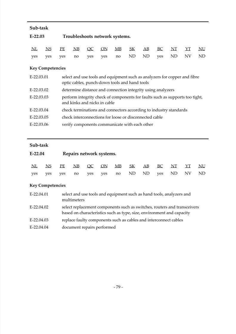
7/14/2019 Industrial Electrician 2011 En
http://slidepdf.com/reader/full/industrial-electrician-2011-en 93/132
‐ 79 ‐
Sub‐task
E‐22.03 Troubleshoots network systems.
NL NS PE NB QC ON MB SK AB BC NT YT NU
yes
yes
yes
no
yes
yes
no
ND
ND
yes
ND
NV
ND
Key Competencies
E‐22.03.01 select and use tools and equipment such as analyzers for copper and fibre
optic cables, punch‐down tools and hand tools
E‐22.03.02 determine distance and connection integrity using analyzers
E‐22.03.03 perform integrity check of components for faults such as supports too tight, and kinks and nicks in cable
E‐22.03.04 check terminations and connectors according to industry standards
E‐22.03.05 check interconnections for loose or disconnected cable
E‐22.03.06 verify components communicate with each other
Sub‐task
E‐22.04 Repairs network systems.
NL NS PE NB QC ON MB SK AB BC NT YT NU
yes
yes
yes
no
yes
yes
no
ND
ND
yes
ND
NV
ND
Key Competencies
E‐22.04.01 select and use tools and equipment such as hand tools, analyzers and
multimeters
E‐22.04.02 select replacement components such as switches, routers and transceivers based on characteristics such as type, size, environment and capacity
E‐22.04.03 replace faulty components such as cables and interconnect cables
E‐22.04.04 document repairs performed
7/14/2019 Industrial Electrician 2011 En
http://slidepdf.com/reader/full/industrial-electrician-2011-en 94/132
‐ 80 ‐
BLOCK F PROCESS CONTROL SYSTEMS
Trends There is an increased use of wireless systems, internetworking protocol (IP) and addressable components for field devices that are used as
nodes which communicate to the central processing unit (CPU). The effect is reduced cost, and installation and repair time. Industrial electricians are now required to do more configuration and
programming.
Another trend in this trade is an increased responsibility for managing
process control systems.
Related
Components
(including, but not
limited to)
I/O devices: transducers, transmitters, indicator lights, timers, converters, photocells, valves, potentiometers, controllers, actuators, solenoids, push buttons, horns, buzzers, meters, switches (proximity,
selector, limit). Control systems: DCSs, PLCs, screens, racks, cards, modules (communication, history and process management), cabling, computers, keyboards, monitors, mouse, HMI.
Tools and
Equipment
See Appendix A.
Task 23 Maintains input/output (I/O) field devices.
Context I/O field devices are used in control systems. There may be analog or digital (discrete) field devices. Industrial electricians must be able to install, service, troubleshoot and repair these devices.
Required Knowledge
K 1 codes and regulations regarding the installation of I/O field devices
K 2 types, size, rating and functions of input field devices such as transducers, limit switches and stop switches
K 3 types, size, rating and functions of output field devices such as indicator lights, solenoids and control valves
K 4 compatibility of devices with PLCs or DCSs
K 5 installation environment
K 6 operation of I/O field devices

7/14/2019 Industrial Electrician 2011 En
http://slidepdf.com/reader/full/industrial-electrician-2011-en 95/132
‐ 81 ‐
K 7 installation, inspection, troubleshooting, servicing and repair procedures and techniques
K 8 events that lead to system failure
K 9 history of equipment performance
K 10 compatibility of replacement components
K 11 types of connectors, cabling and shielding
K 12 types of lubricants and anti‐corrosion compounds
K 13 communication protocols
K 14 ladder and logic diagrams
K 15 networking
K 16 types of converters such as current to pressure (I/P) and temperature to
pressure (T/P)
Sub‐task
F‐23.01 Installs input/output (I/O) field devices.
NL NS PE NB QC ON MB SK AB BC NT YT NU
yes yes yes yes yes yes yes ND ND yes ND NV ND
Key Competencies
F‐23.01.01 select and use tools and equipment such as multimeters, calibrators, hand
tools, personal computers and communication/configuration devices F‐23.01.02 visually inspect equipment to be installed to check for damage and to ensure
name plate data matches engineered drawings
F‐23.01.03 locate analog and digital I/O devices by reading and interpreting prints, OEM
manuals and codes
F‐23.01.04 connect grounding, shielding, piping and wiring according to OEM and site
specifications, and codes
F‐23.01.05 align sensors, transmitters and receivers according to OEM specifications
F‐23.01.06 ensure polarity of wiring to field devices
F‐23.01.07 program and configure device by setting protocol and mapping PLCs according to OEM specifications and engineered drawings
F‐23.01.08 ensure calibration data for external devices matches those pre‐programmed
in the PLCs
F‐23.01.09 calibrate analog field device according to engineered drawings

7/14/2019 Industrial Electrician 2011 En
http://slidepdf.com/reader/full/industrial-electrician-2011-en 96/132
‐ 82 ‐
F‐23.01.10 commission analog and digital devices, and modify the settings according to
engineered drawings and site specifications
F‐23.01.11 produce as‐ built drawings
Sub‐task
F‐23.02 Services input/output (I/O) field devices.
NL NS PE NB QC ON MB SK AB BC NT YT NU
yes yes yes yes yes yes yes ND ND yes ND NV ND
Key Competencies
F‐23.02.01 select and use tools and equipment such as multimeters, protocol communicators, calibrators and network analyzers
F‐23.02.02 detect I/O field device defects such as corrosion, loose wiring and cabling, mechanical damage and wear
F‐23.02.03 perform sensory inspection of components such as limit switches, photocells and transmitters for damage, wear or misalignment
F‐23.02.04 review and analyze trends from input device signal for a specified time
period to verify integrity of signal
F‐23.02.05 check network protocols to verify proper network communication
F‐23.02.06 check and set power supply voltages
F‐23.02.07 change wireless output device battery according to OEM specifications F‐23.02.08 calibrate analog input devices (temperature, speed, flow and pressure)
according to engineered drawings, and OEM and site specifications, and
record as found and as left
F‐23.02.09 calibrate analog output devices (current, millivolts, volts and resistance) according to engineered drawings, and OEM and site specifications, and
record as found and as left
F‐23.02.10 perform I/O (on/off) test on discrete device
F‐23.02.11 verify operation of I/O field devices following service
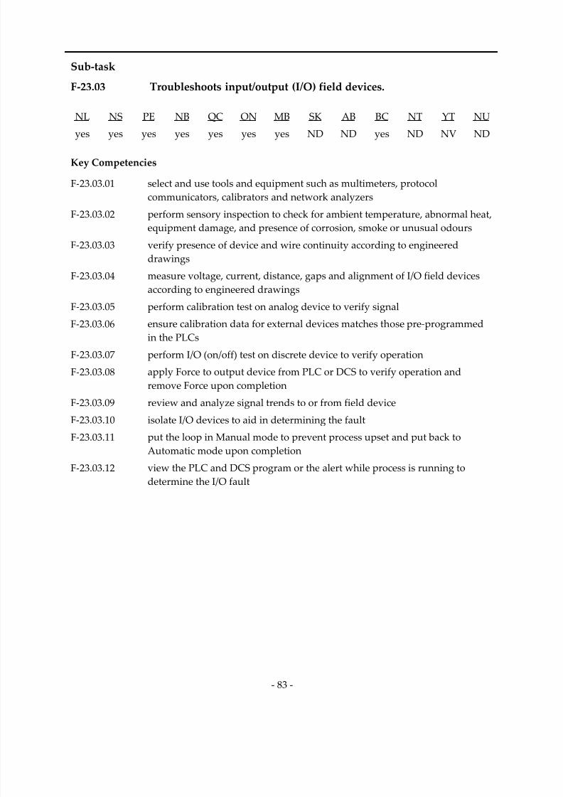
7/14/2019 Industrial Electrician 2011 En
http://slidepdf.com/reader/full/industrial-electrician-2011-en 97/132
‐ 83 ‐
Sub‐task
F‐23.03 Troubleshoots input/output (I/O) field devices.
NL NS PE NB QC ON MB SK AB BC NT YT NU
yes
yes
yes
yes
yes
yes
yes
ND
ND
yes
ND
NV
ND
Key Competencies
F‐23.03.01 select and use tools and equipment such as multimeters, protocol communicators, calibrators and network analyzers
F‐23.03.02 perform sensory inspection to check for ambient temperature, abnormal heat, equipment damage, and presence of corrosion, smoke or unusual odours
F‐23.03.03 verify presence of device and wire continuity according to engineered
drawings
F‐
23.03.04
measure
voltage,
current,
distance,
gaps
and
alignment
of
I/O
field
devices
according to engineered drawings
F‐23.03.05 perform calibration test on analog device to verify signal
F‐23.03.06 ensure calibration data for external devices matches those pre‐programmed
in the PLCs
F‐23.03.07 perform I/O (on/off) test on discrete device to verify operation
F‐23.03.08 apply Force to output device from PLC or DCS to verify operation and
remove Force upon completion
F‐23.03.09 review and analyze signal trends to or from field device
F‐23.03.10 isolate I/O devices to aid in determining the fault F‐23.03.11 put the loop in Manual mode to prevent process upset and put back to
Automatic mode upon completion
F‐23.03.12 view the PLC and DCS program or the alert while process is running to
determine the I/O fault

7/14/2019 Industrial Electrician 2011 En
http://slidepdf.com/reader/full/industrial-electrician-2011-en 98/132
‐ 84 ‐
Sub‐task
F‐23.04 Repairs input/output (I/O) field devices.
NL NS PE NB QC ON MB SK AB BC NT YT NU
yes
yes
yes
yes
yes
yes
yes
ND
ND
yes
ND
NV
ND
Key Competencies
F‐23.04.01 select and use tools and equipment such as multimeters, protocol communicators, calibrators and network analyzers
F‐23.04.02 select and verify replacement component according to OEM specifications and engineered drawings
F‐23.04.03 replace faulty wiring and check for continuity according to local regulations and site specifications
F‐
23.04.04
apply
Force
to
output
device
from
PLC
or
DCS
to
bypass
alarms
and
shutdowns while doing the replacement, and take Force out upon completion
F‐23.04.05 put the loop in Manual mode to prevent process upset, and bypass alarms and shutdowns while doing the replacement and put back to Automatic
mode upon completion
F‐23.04.06 isolate power and process to the device prior to replacement
F‐23.04.07 clean and realign sensor to ensure proper operation of field devices
F‐23.04.08 replace field device according to OEM specifications and engineered
drawings
F‐23.04.09 program and configure device by setting protocol according to OEM specifications and engineered drawings
F‐23.04.10 calibrate analog input devices (temperature, speed, flow and pressure) according to engineered drawings, and OEM and site specifications, and
record as found and as left
F‐23.04.11 calibrate analog output devices (current, millivolts, volts and resistance) according to engineered drawings, and OEM and site specifications, and
record as found and as left
F‐23.04.12 perform I/O (on/off) test on discrete device after repair or replacement
F‐
23.04.13
verify
operation
of
replaced,
aligned,
adjusted
and
calibrated
devices
7/14/2019 Industrial Electrician 2011 En
http://slidepdf.com/reader/full/industrial-electrician-2011-en 99/132
‐ 85 ‐
Task 24 Maintains control systems.
Context Control systems are used to efficiently operate processes and assembly
operations. These systems are controlled by computer and may be made up
of DCSs and PLCs. They allow flexibility in the reconfiguration of process
variables. The maintenance of control systems implies installation, servicing, troubleshooting, repair and optimization of PLCs and DCSs.
Required Knowledge
K 1 codes and regulations regarding the maintenance of control systems
K 2 types and functions of control systems and components such as monitors, CPUs and I/O racks
K 3 power supply criteria such as type, size and rating
K 4 maintenance, installation, inspection, troubleshooting and repair procedures and techniques
K 5 interference such as harmonics and electromagnetic interference (EMI), and
effects of static electricity on system components
K 6 grounding and bonding according to OEM specifications and local regulations
K 7 types of output relays such as solid‐state and mechanical
K 8 types of hardware used for constructing control systems such as rail devices and wire channels
K 9 industrial process operation and requirements
K 10 causes of faults such as overloaded power supply, faulty communication
card and board failure
K 11 events that lead to system failure
K 12 history of equipment performance
K 13 software program, and upgrade and back‐up procedures
K 14 OEM system capabilities such as replacement of components when system
is energized
K 15 types of PLCs
K 16 PLC capabilities such as on‐line and off‐line programming
K 17 capabilities, limitations and performance parameters of systems and
components
K 18 types of cards such as analog I/O, and digital I/O
K 19 software and hardware modification procedures
K 20 HMI usage, editing, interpretation and modifications

7/14/2019 Industrial Electrician 2011 En
http://slidepdf.com/reader/full/industrial-electrician-2011-en 100/132
‐ 86 ‐
Sub‐task
F‐24.01 Installs control systems.
NL NS PE NB QC ON MB SK AB BC NT YT NU
yes
yes
yes
yes
yes
yes
yes
ND
ND
yes
ND
NV
ND
Key Competencies
F‐24.01.01 select and use tools and equipment such as multimeters, hand tools, and
torque and specialty wrenches
F‐24.01.02 visually inspect equipment to be installed to check for damage and to ensure
name plate data matches engineered drawings
F‐24.01.03 locate and mount components such as power supplies, racks and CPUs by
reading and interpreting prints, OEM manuals and code requirements
F‐
24.01.04
connect
grounding,
shielding
and
wiring
according
to
OEM
and
site
specifications, and code requirements
F‐24.01.05 ensure polarity of wiring to control system components
F‐24.01.06 power up the system sequentially to ensure proper functionality of all system blocks
F‐24.01.07 configure CPU by setting protocol according to OEM specifications and
engineered drawings
F‐24.01.08 ensure control systems/HMI access is enabled via remote Web access
F‐24.01.09 ensure correct communication to all the system blocks such as HMI,
IP devices, analog blocks and I/O blocks F‐24.01.10 upload and execute system program according to OEM and engineering
specifications, and system application
F‐24.01.11 test field devices to ensure they report properly to CPU and have correct range values
F‐24.01.12 commission control system, and modify the settings if required, according to
process requirements, engineered drawings and site specifications
F‐24.01.13 produce as‐ built drawings and back‐up program according to
site specifications
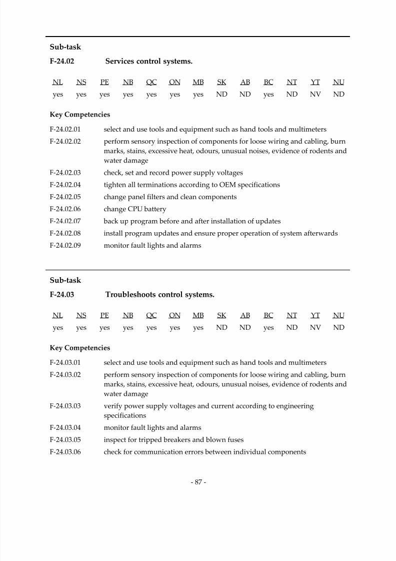
7/14/2019 Industrial Electrician 2011 En
http://slidepdf.com/reader/full/industrial-electrician-2011-en 101/132
‐ 87 ‐
Sub‐task
F‐24.02 Services control systems.
NL NS PE NB QC ON MB SK AB BC NT YT NU
yes
yes
yes
yes
yes
yes
yes
ND
ND
yes
ND
NV
ND
Key Competencies
F‐24.02.01 select and use tools and equipment such as hand tools and multimeters
F‐24.02.02 perform sensory inspection of components for loose wiring and cabling, burn
marks, stains, excessive heat, odours, unusual noises, evidence of rodents and
water damage
F‐24.02.03 check, set and record power supply voltages
F‐24.02.04 tighten all terminations according to OEM specifications
F‐24.02.05 change panel filters and clean components
F‐24.02.06 change CPU battery
F‐24.02.07 back up program before and after installation of updates
F‐24.02.08 install program updates and ensure proper operation of system afterwards
F‐24.02.09 monitor fault lights and alarms
Sub‐task
F‐24.03
Troubleshoots
control
systems.
NL NS PE NB QC ON MB SK AB BC NT YT NU
yes yes yes yes yes yes yes ND ND yes ND NV ND
Key Competencies
F‐24.03.01 select and use tools and equipment such as hand tools and multimeters
F‐24.03.02 perform sensory inspection of components for loose wiring and cabling, burn
marks, stains, excessive heat, odours, unusual noises, evidence of rodents and
water damage
F‐24.03.03 verify power supply voltages and current according to engineering
specifications
F‐24.03.04 monitor fault lights and alarms
F‐24.03.05 inspect for tripped breakers and blown fuses
F‐24.03.06 check for communication errors between individual components
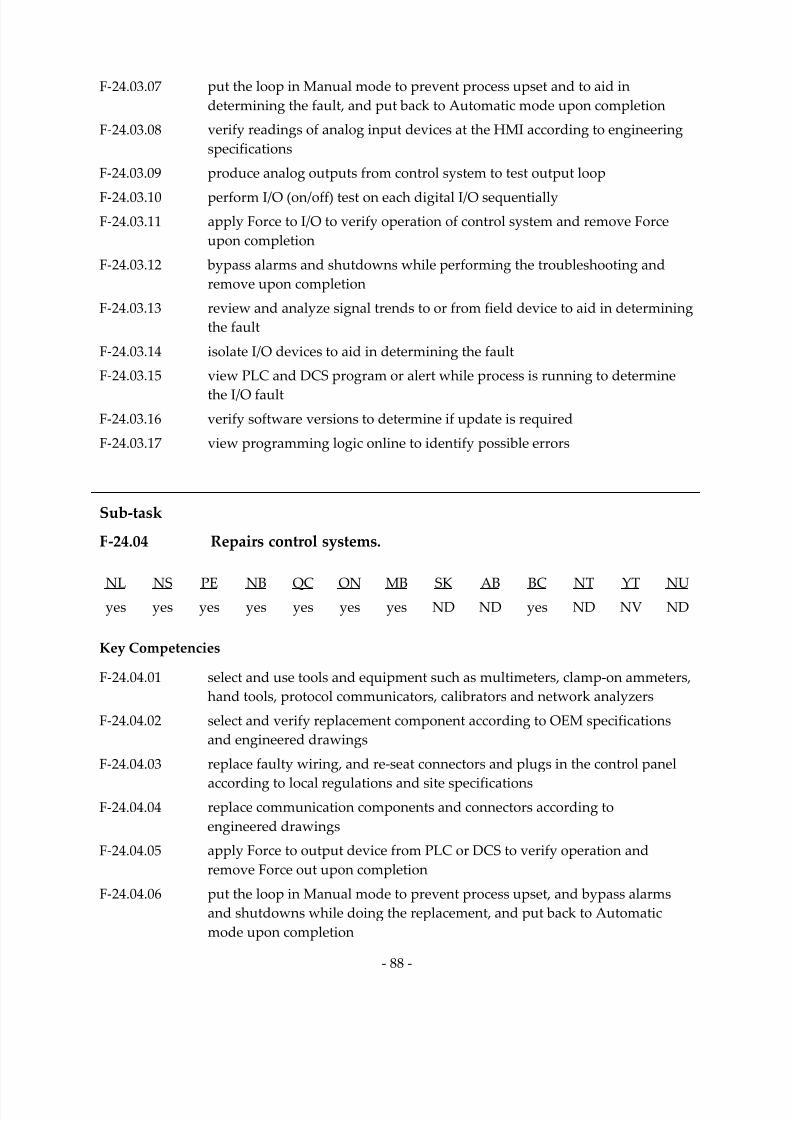
7/14/2019 Industrial Electrician 2011 En
http://slidepdf.com/reader/full/industrial-electrician-2011-en 102/132
‐ 88 ‐
F‐24.03.07 put the loop in Manual mode to prevent process upset and to aid in
determining the fault, and put back to Automatic mode upon completion
F‐24.03.08 verify readings of analog input devices at the HMI according to engineering
specifications
F‐24.03.09 produce analog outputs from control system to test output loop
F‐24.03.10 perform I/O (on/off) test on each digital I/O sequentially
F‐24.03.11 apply Force to I/O to verify operation of control system and remove Force
upon completion
F‐24.03.12 bypass alarms and shutdowns while performing the troubleshooting and
remove upon completion
F‐24.03.13 review and analyze signal trends to or from field device to aid in determining
the fault
F‐24.03.14 isolate I/O devices to aid in determining the fault
F‐24.03.15 view PLC and DCS program or alert while process is running to determine
the I/O fault F‐24.03.16 verify software versions to determine if update is required
F‐24.03.17 view programming logic online to identify possible errors
Sub‐task
F‐24.04 Repairs control systems.
NL
NS
PE
NB
QC
ON
MB
SK
AB
BC
NT
YT
NU
yes yes yes yes yes yes yes ND ND yes ND NV ND
Key Competencies
F‐24.04.01 select and use tools and equipment such as multimeters, clamp‐on ammeters, hand tools, protocol communicators, calibrators and network analyzers
F‐24.04.02 select and verify replacement component according to OEM specifications and engineered drawings
F‐24.04.03 replace faulty wiring, and re‐seat connectors and plugs in the control panel
according to local regulations and site specifications F‐24.04.04 replace communication components and connectors according to
engineered drawings
F‐24.04.05 apply Force to output device from PLC or DCS to verify operation and
remove Force out upon completion
F‐24.04.06 put the loop in Manual mode to prevent process upset, and bypass alarms and shutdowns while doing the replacement, and put back to Automatic
mode upon completion

7/14/2019 Industrial Electrician 2011 En
http://slidepdf.com/reader/full/industrial-electrician-2011-en 103/132
‐ 89 ‐
F‐24.04.07 isolate power and process prior to replacement
F‐24.04.08 replace faulty component according to OEM specifications and
engineered drawings
F‐24.04.09 program and configure replaced component by setting protocol according to
OEM specifications and engineered drawings
F‐24.04.10 perform I/O (on/off) test after repair or replacement F‐24.04.11 perform analog I/O test after repair or replacement
F‐24.04.12 upload and execute programs
Sub‐task
F‐24.05 Optimizes programmable logic controller (PLC).
NL
NS
PE
NB
QC
ON
MB
SK
AB
BC
NT
YT
NU
yes yes yes yes yes yes yes ND ND yes ND NV ND
Key Competencies
F‐24.05.01 ensure the version of the OEM manual matches the version of the
OEM software
F‐24.05.02 review and modify existing program and system parameters to match the
changes of the process, and to ensure efficiency of program
F‐24.05.03 ensure sequential programming logic to minimize scan time and add
comments to record the changes
F‐24.05.04 run program in test mode, and upload and execute programs required to
update the system
F‐24.05.05 tune control loops to optimize process
F‐24.05.06 create back‐up for every change made
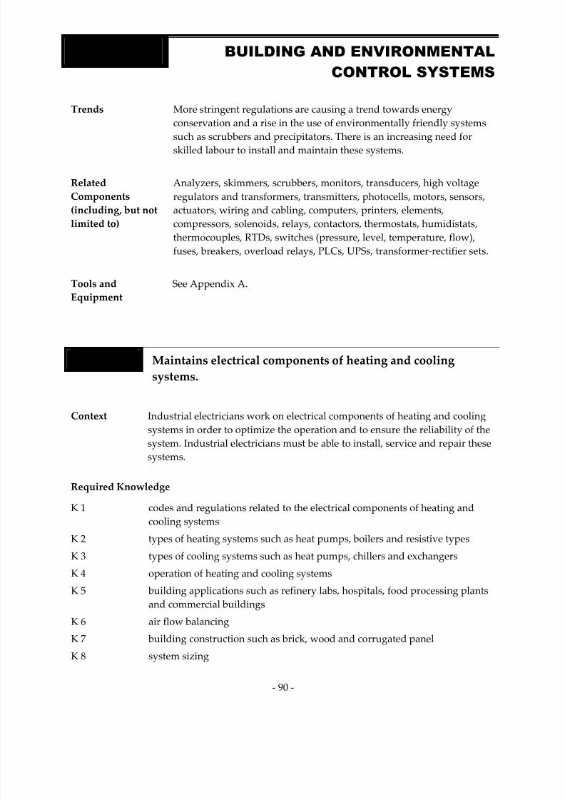
7/14/2019 Industrial Electrician 2011 En
http://slidepdf.com/reader/full/industrial-electrician-2011-en 104/132
‐ 90 ‐
Trends More stringent regulations are causing a trend towards energy
conservation and a rise in the use of environmentally friendly systems
such
as
scrubbers
and
precipitators.
There
is
an
increasing
need
for
skilled labour to install and maintain these systems.
Related
Components
(including, but not
limited to)
Analyzers, skimmers, scrubbers, monitors, transducers, high voltage
regulators and transformers, transmitters, photocells, motors, sensors, actuators, wiring and cabling, computers, printers, elements, compressors, solenoids, relays, contactors, thermostats, humidistats, thermocouples, RTDs, switches (pressure, level, temperature, flow), fuses, breakers, overload relays, PLCs, UPSs, transformer‐rectifier sets.
Tools and
Equipment See Appendix A.
Task 25 Maintains electrical components of heating and cooling
systems.
Context
Industrial
electricians
work
on
electrical
components
of
heating
and
cooling
systems in order to optimize the operation and to ensure the reliability of the
system. Industrial electricians must be able to install, service and repair these
systems.
Required Knowledge
K 1 codes and regulations related to the electrical components of heating and
cooling systems
K 2 types of heating systems such as heat pumps, boilers and resistive types
K
3
types
of
cooling
systems
such
as
heat
pumps,
chillers
and
exchangers
K 4 operation of heating and cooling systems
K 5 building applications such as refinery labs, hospitals, food processing plants and commercial buildings
K 6 air flow balancing
K 7 building construction such as brick, wood and corrugated panel
K 8 system sizing
BLOCK G BUILDING AND ENVIRONMENTAL
CONTROL SYSTEMS

7/14/2019 Industrial Electrician 2011 En
http://slidepdf.com/reader/full/industrial-electrician-2011-en 105/132
‐ 91 ‐
K 9 confined space entry and egress regulations
K 10 types, ratings and operation of electrical components
K 11 faults such as failed zone actuators and damaged elements
K 12 events that lead to system failure
K 13 physical properties and hazards of refrigerants
K 14 history of equipment performance
K 15 repair, replacement, inspection, calibration, adjustment and maintenance
procedures and techniques
K 16 compatibility of replacement components
K 17 types of lubricants
Sub‐task
G‐25.01
Installs
electrical
components
of
heating
and
cooling
systems.
NL NS PE NB QC ON MB SK AB BC NT YT NU
yes yes yes no yes yes yes ND ND yes ND NV ND
Key Competencies
G‐25.01.01 select and use tools and equipment such as compression tools, wire strippers and pliers
G‐25.01.02 ensure proper egress around heating and cooling system according to
code requirements G‐25.01.03 assemble components to building management controllers according to
OEM specifications
G‐25.01.04 shim and level the cabinets
G‐25.01.05 terminate cable according to code requirements
G‐25.01.06 follow installation procedures according to OEM specifications and
code requirements
G‐25.01.07 perform adjustments such as setting high and low limits, fan speeds and temperature
G‐25.01.08 verify system operation

7/14/2019 Industrial Electrician 2011 En
http://slidepdf.com/reader/full/industrial-electrician-2011-en 106/132
‐ 92 ‐
Sub‐task
G‐25.02 Services electrical components of heating and cooling systems.
NL NS PE NB QC ON MB SK AB BC NT YT NU
yes
yes
yes
no
yes
yes
yes
ND
ND
yes
ND
NV
ND
Key Competencies
G‐25.02.01 select and use diagnostic tools and equipment such as hand tools, pressure
simulators and multimeters
G‐25.02.02 identify hazards when conducting inspections such as live voltages, dangerous gases, and restricted access and egress
G‐25.02.03 de‐energize system from power source
G‐25.02.04 test system for zero potential using multimeter
G‐25.02.05 perform and interpret diagnostic tests for conditions such as air quality and
humidity levels
G‐25.02.06 select tools and equipment such as pliers, screwdrivers and torque wrenches
G‐25.02.07 disassemble/reassemble components according to OEM specifications
G‐25.02.08 visually inspect components for deterioration such as corrosion, loose torque
and discolouration using methods such as thermography for hot spots
G‐25.02.09 identify abnormal heat, sounds and odours
G‐25.02.10 identify components that require repair or replacement
G‐25.02.11 clean and lubricate components
G‐25.02.12 perform adjustments such as setting high and low limits, fan speeds and temperature
G‐25.02.13 verify system operation
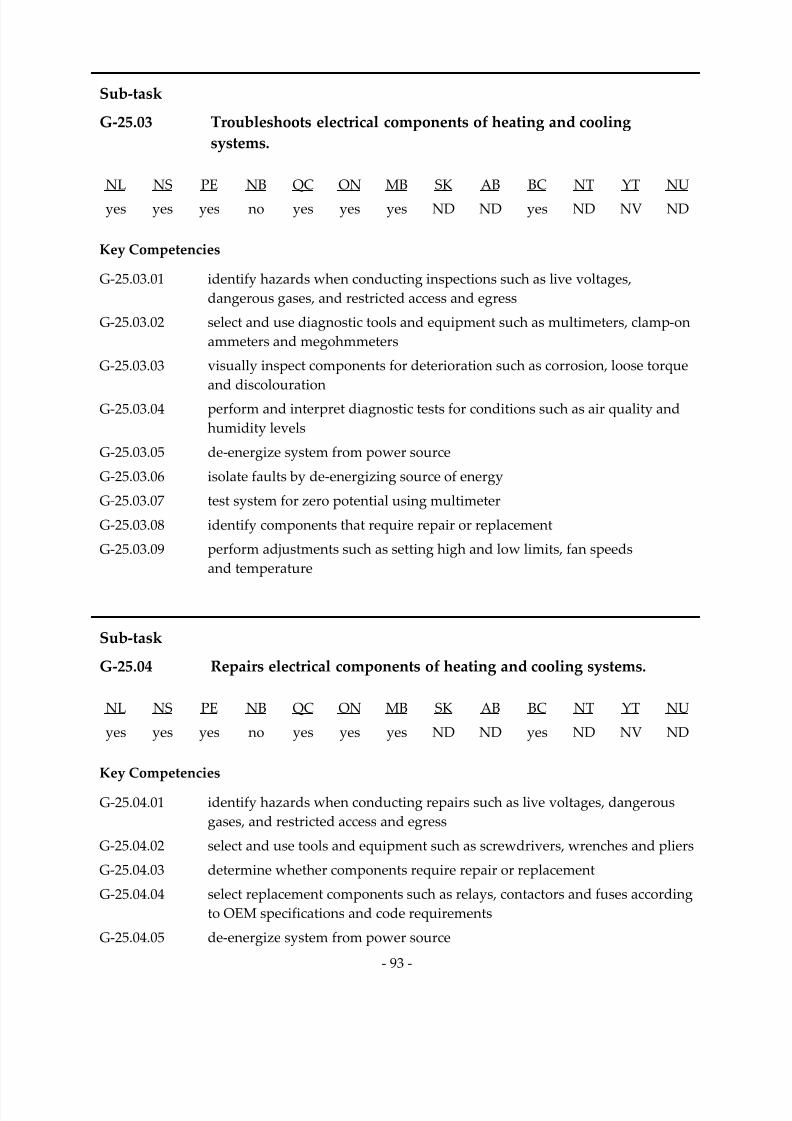
7/14/2019 Industrial Electrician 2011 En
http://slidepdf.com/reader/full/industrial-electrician-2011-en 107/132
‐ 93 ‐
Sub‐task
G‐25.03 Troubleshoots electrical components of heating and cooling
systems.
NL NS PE NB QC ON MB SK AB BC NT YT NU
yes yes yes no yes yes yes ND ND yes ND NV ND
Key Competencies
G‐25.03.01 identify hazards when conducting inspections such as live voltages, dangerous gases, and restricted access and egress
G‐25.03.02 select and use diagnostic tools and equipment such as multimeters, clamp‐on
ammeters and megohmmeters
G‐25.03.03 visually inspect components for deterioration such as corrosion, loose torque
and
discolouration
G‐25.03.04 perform and interpret diagnostic tests for conditions such as air quality and
humidity levels
G‐25.03.05 de‐energize system from power source
G‐25.03.06 isolate faults by de‐energizing source of energy
G‐25.03.07 test system for zero potential using multimeter
G‐25.03.08 identify components that require repair or replacement
G‐25.03.09 perform adjustments such as setting high and low limits, fan speeds and temperature
Sub‐task
G‐25.04 Repairs electrical components of heating and cooling systems.
NL NS PE NB QC ON MB SK AB BC NT YT NU
yes yes yes no yes yes yes ND ND yes ND NV ND
Key Competencies
G‐25.04.01 identify hazards when conducting repairs such as live voltages, dangerous gases, and restricted access and egress
G‐25.04.02 select and use tools and equipment such as screwdrivers, wrenches and pliers
G‐25.04.03 determine whether components require repair or replacement
G‐25.04.04 select replacement components such as relays, contactors and fuses according
to OEM specifications and code requirements
G‐25.04.05 de‐energize system from power source

7/14/2019 Industrial Electrician 2011 En
http://slidepdf.com/reader/full/industrial-electrician-2011-en 108/132
‐ 94 ‐
G‐25.04.06 test system for zero potential using multimeter
G‐25.04.07 disassemble/reassemble components according to OEM specifications
G‐25.04.08 replace, adjust and modify components such as relays, contactors and fuses
G‐25.04.09 clean components before terminating to ensure good contact and continuity
G‐25.04.10 verify operation of components
Task 26 Maintains building automation systems.
Context Building automation systems include energy, HVAC and security systems. Industrial electricians program, perform software updates and back up
programs. They must be able to install, service and repair these systems in
order to ensure their efficient operation and reduce unscheduled disruptions.
Required Knowledge
K 1 codes and regulations related to building automation systems
K 2 components, operation and types of building automation systems such as energy and security
K 3 procedures and techniques for servicing building automation systems
K 4 types, ratings and operation of electrical components such as temperature
sensors and actuators
K
5
calibration
devices
such
as
air
supply
and
current
source
potentiometers
K 6 history of equipment performance
K 7 calibration, repair, replacement, programming, adjustment and inspection
procedures and techniques
K 8 building automation systems and software
K 9 faults such as temperature imbalance and unresponsive system
K 10 effects of faults on the system
K 11 events that lead to system failure
K 12 types of buildings using automated systems such as office buildings,
manufacturing plants and hospitals K 13 cabling and shielding
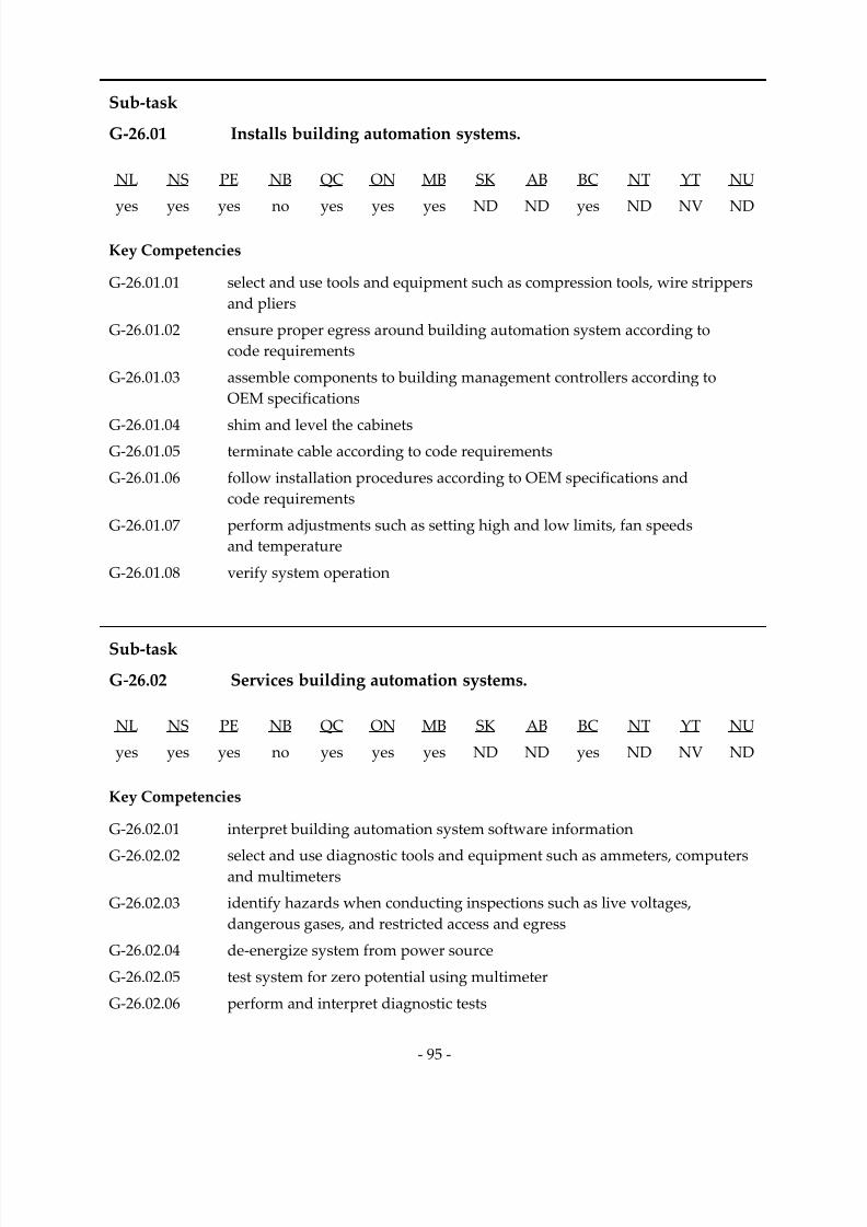
7/14/2019 Industrial Electrician 2011 En
http://slidepdf.com/reader/full/industrial-electrician-2011-en 109/132
‐ 95 ‐
Sub‐task
G‐26.01 Installs building automation systems.
NL NS PE NB QC ON MB SK AB BC NT YT NU
yes
yes
yes
no
yes
yes
yes
ND
ND
yes
ND
NV
ND
Key Competencies
G‐26.01.01 select and use tools and equipment such as compression tools, wire strippers and pliers
G‐26.01.02 ensure proper egress around building automation system according to
code requirements
G‐26.01.03 assemble components to building management controllers according to
OEM specifications
G‐
26.01.04
shim
and
level
the
cabinets
G‐26.01.05 terminate cable according to code requirements
G‐26.01.06 follow installation procedures according to OEM specifications and
code requirements
G‐26.01.07 perform adjustments such as setting high and low limits, fan speeds and temperature
G‐26.01.08 verify system operation
Sub‐task
G‐26.02 Services building automation systems.
NL NS PE NB QC ON MB SK AB BC NT YT NU
yes yes yes no yes yes yes ND ND yes ND NV ND
Key Competencies
G‐26.02.01 interpret building automation system software information
G‐26.02.02 select and use diagnostic tools and equipment such as ammeters, computers and multimeters
G‐26.02.03 identify hazards when conducting inspections such as live voltages, dangerous gases, and restricted access and egress
G‐26.02.04 de‐energize system from power source
G‐26.02.05 test system for zero potential using multimeter
G‐26.02.06 perform and interpret diagnostic tests
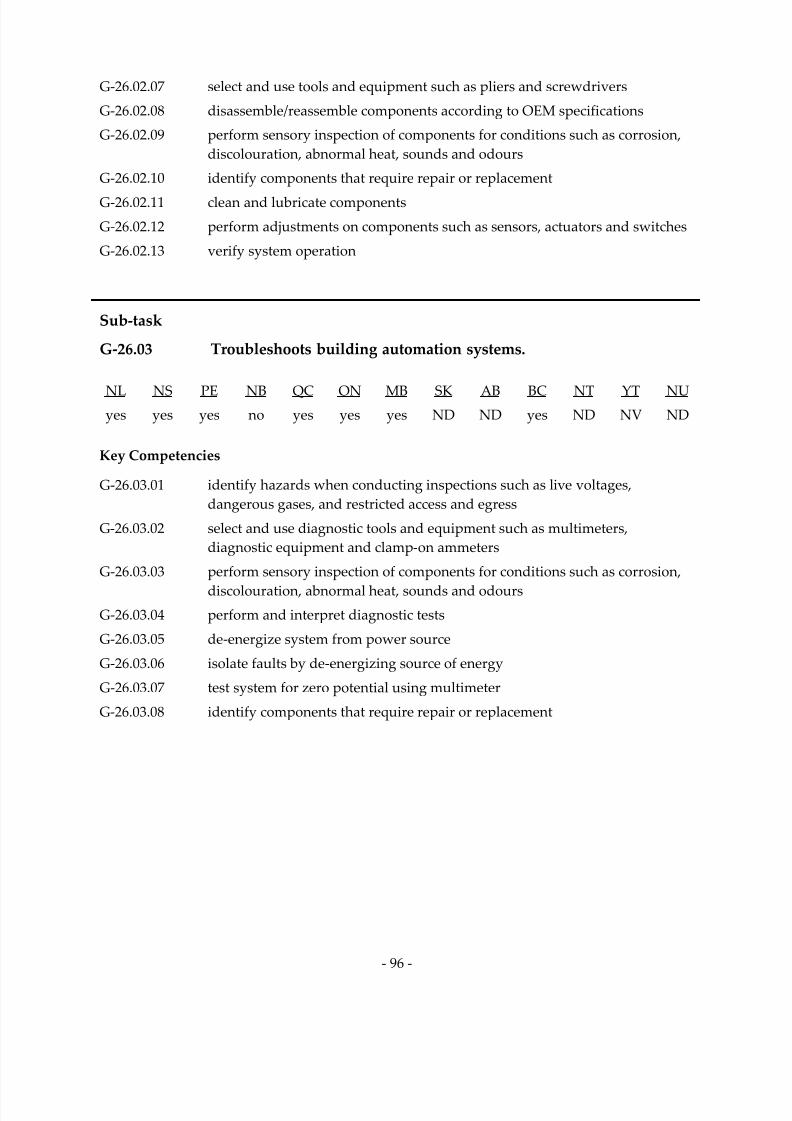
7/14/2019 Industrial Electrician 2011 En
http://slidepdf.com/reader/full/industrial-electrician-2011-en 110/132
‐ 96 ‐
G‐26.02.07 select and use tools and equipment such as pliers and screwdrivers
G‐26.02.08 disassemble/reassemble components according to OEM specifications
G‐26.02.09 perform sensory inspection of components for conditions such as corrosion, discolouration, abnormal heat, sounds and odours
G‐26.02.10 identify components that require repair or replacement
G‐26.02.11 clean and lubricate components
G‐26.02.12 perform adjustments on components such as sensors, actuators and switches
G‐26.02.13 verify system operation
Sub‐task
G‐26.03 Troubleshoots building automation systems.
NL NS PE NB QC ON MB SK AB BC NT YT NU
yes yes yes no yes yes yes ND ND yes ND NV ND
Key Competencies
G‐26.03.01 identify hazards when conducting inspections such as live voltages, dangerous gases, and restricted access and egress
G‐26.03.02 select and use diagnostic tools and equipment such as multimeters, diagnostic equipment and clamp‐on ammeters
G‐26.03.03 perform sensory inspection of components for conditions such as corrosion,
discolouration, abnormal heat, sounds and odours G‐26.03.04 perform and interpret diagnostic tests
G‐26.03.05 de‐energize system from power source
G‐26.03.06 isolate faults by de‐energizing source of energy
G‐26.03.07 test system for zero potential using multimeter
G‐26.03.08 identify components that require repair or replacement

7/14/2019 Industrial Electrician 2011 En
http://slidepdf.com/reader/full/industrial-electrician-2011-en 111/132
‐ 97 ‐
Sub‐task
G‐26.04 Repairs building automation systems.
NL NS PE NB QC ON MB SK AB BC NT YT NU
yes
yes
yes
no
yes
yes
yes
ND
ND
yes
ND
NV
ND
Key Competencies
G‐26.04.01 identify hazards when conducting repairs such as live voltages, dangerous gases, and restricted access and egress
G‐26.04.02 select and use tools and equipment such as screwdrivers, wrenches and pliers
G‐26.04.03 determine whether components require repair or replacement
G‐26.04.04 select replacement components such as relays, sensors and fuses according to
OEM specifications and code requirements
G‐26.04.05 de‐energize system from power source
G‐26.04.06 test system for zero potential using multimeter
G‐26.04.07 disassemble/reassemble components according to OEM specifications
G‐26.04.08 replace, adjust and modify components such as relays, sensors and fuses
G‐26.04.09 clean components before terminating to ensure good contact and continuity
G‐26.04.10 verify operation of components
Task 27 Maintains environmental control systems.
Context Environmental control systems regulate and monitor emissions. These
emissions are typically from industrial processes but may also come from
residential, institutional and commercial buildings. Industrial electricians must be able to install, service and repair these systems in order to ensure
their efficient operation and reduce unscheduled disruptions.
Required Knowledge
K 1 codes and regulations regarding environmental control systems
K 2 types and operation of environmental control systems such as waste
management, noise reduction, precipitator, water treatment, dust suppression, scrubber and stack emissions
K 3 characteristics and specifications of components such as samplers, particulate
analyzers and skimmers

7/14/2019 Industrial Electrician 2011 En
http://slidepdf.com/reader/full/industrial-electrician-2011-en 112/132
‐ 98 ‐
K 4 inspection, installation, operation, calibration and preventative maintenance
procedures and schedules of environmental control systems
K 5 hazards such as chemicals, gases, ultraviolet light and high voltage
K 6 impact of environmental control system shutdown
K 7 causes of faults
K 8 events that lead to system failure
K 9 diagnostic equipment such as leak detectors, meters and stack monitors
K 10 history of equipment performance
K 11 response and containment of environmental discharge
K 12 environmental regulations
Sub‐task
G‐27.01
Installs
environmental
control
systems.
NL NS PE NB QC ON MB SK AB BC NT YT NU
yes yes no yes yes yes yes ND ND yes ND NV ND
Key Competencies
G‐27.01.01 select and use tools and equipment such as compression tools, wire strippers and pliers
G‐27.01.02 ensure proper egress around environmental control system according to
code requirements G‐27.01.03 assemble components of environmental control systems according to
OEM specifications
G‐27.01.04 shim and level the cabinets
G‐27.01.05 terminate cable according to code requirements
G‐27.01.06 follow installation procedures according to OEM specifications and
code requirements
G‐27.01.07 store, contain, handle and dispose of hazardous materials according
to regulations
G‐27.01.08 verify system operation

7/14/2019 Industrial Electrician 2011 En
http://slidepdf.com/reader/full/industrial-electrician-2011-en 113/132
‐ 99 ‐
Sub‐task
G‐27.02 Services environmental control systems.
NL NS PE NB QC ON MB SK AB BC NT YT NU
yes
yes
no
yes
yes
yes
yes
ND
ND
yes
ND
NV
ND
Key Competencies
G‐27.02.01 select and use diagnostic tools and equipment such as leak detectors, megohmmeters and multimeters
G‐27.02.02 identify hazards when conducting inspections such as chemicals, ultraviolet light, residue and high voltage
G‐27.02.03 de‐energize system from power source
G‐27.02.04 test system for zero potential using multimeter
G‐27.02.05 perform and interpret diagnostic tests such as leak and fault tests
G‐27.02.06 select tools and equipment such as pliers, screwdrivers and torque wrenches
G‐27.02.07 disassemble/reassemble components according to OEM specifications
G‐27.02.08 perform sensory inspection of components for conditions such as corrosion, loose torque, discolouration, and abnormal heat, sounds and odours
G‐27.02.09 identify components that require repair or replacement
G‐27.02.10 clean and lubricate components
G‐27.02.11 perform adjustments such as calibration, and high and low limits
G‐
27.02.12
store,
contain,
handle
and
dispose
of
hazardous
materials
according
to regulations
G‐27.02.13 verify system operation
Sub‐task
G‐27.03 Troubleshoots environmental control systems.
NL NS PE NB QC ON MB SK AB BC NT YT NU
yes yes no yes yes yes yes ND ND yes ND NV ND
Key Competencies
G‐27.03.01 identify hazards when conducting inspections such chemicals, ultraviolet light, residue and high voltage
G‐27.03.02 select and use diagnostic tools and equipment such as leak detectors, megohmmeters and multimeters

7/14/2019 Industrial Electrician 2011 En
http://slidepdf.com/reader/full/industrial-electrician-2011-en 114/132
‐ 100 ‐
G‐27.03.03 disassemble/reassemble components according to OEM specifications
G‐27.03.04 perform sensory inspection of components for conditions such as corrosion, loose torque, discolouration, and abnormal heat, sounds and odours
G‐27.03.05 perform and interpret diagnostic tests for conditions such as air quality and
humidity levels
G‐27.03.06 de‐energize system from power source
G‐27.03.07 isolate faults by de‐energizing source of energy
G‐27.03.08 test system for zero potential using multimeter
G‐27.03.09 identify components that require repair or replacement
G‐27.03.10 store, contain, handle and dispose of hazardous materials according
to regulations
Sub‐task
G‐27.04 Repairs environmental control systems.
NL NS PE NB QC ON MB SK AB BC NT YT NU
yes yes no yes yes yes yes ND ND yes ND NV ND
Key Competencies
G‐27.04.01 identify hazards when conducting repairs such as chemicals, ultraviolet light, residue and high voltage
G‐27.04.02 select and use tools and equipment such as screwdrivers, wrenches and pliers G‐27.04.03 disassemble/reassemble components according to OEM specifications
G‐27.04.04 determine whether components require repair or replacement
G‐27.04.05 select replacement components such as relays, contactors and fuses according
to OEM specifications and code requirements
G‐27.04.06 de‐energize system from power source
G‐27.04.07 test system for zero potential using multimeter
G‐27.04.08 replace, adjust and modify components such as pressure switches, samplers and particulate analyzers
G‐27.04.09 clean components before terminating to ensure good contact and continuity
G‐27.04.10 store, contain, handle and dispose of hazardous materials according
to regulations
G‐27.04.11 verify operation of components

7/14/2019 Industrial Electrician 2011 En
http://slidepdf.com/reader/full/industrial-electrician-2011-en 115/132
APPENDICES

7/14/2019 Industrial Electrician 2011 En
http://slidepdf.com/reader/full/industrial-electrician-2011-en 116/132
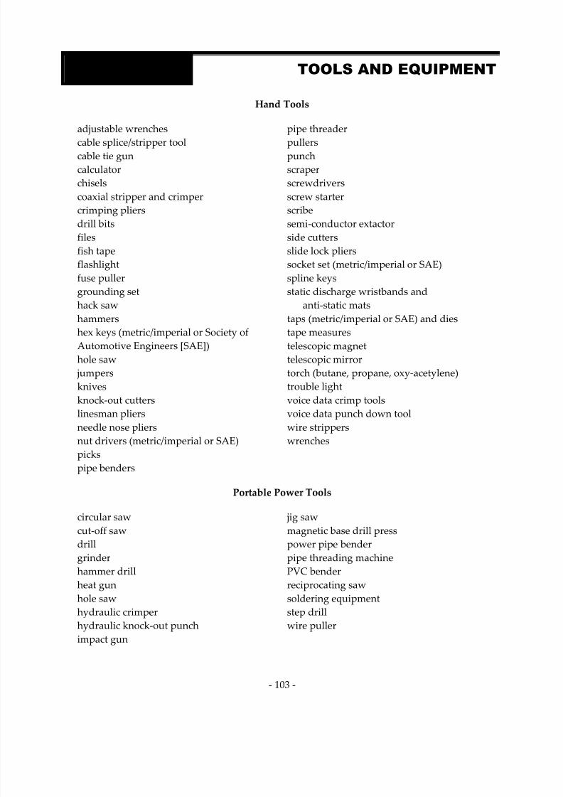
7/14/2019 Industrial Electrician 2011 En
http://slidepdf.com/reader/full/industrial-electrician-2011-en 117/132
‐ 103 ‐
APPENDIX A TOOLS AND EQUIPMENT
Hand Tools
adjustable wrenches
cable splice/stripper tool cable tie gun
calculator chisels coaxial stripper and crimper crimping pliers drill bits files fish tape
flashlight
fuse puller grounding set hack saw
hammers hex keys (metric/imperial or Society of Automotive Engineers [SAE]) hole saw
jumpers knives knock‐out cutters
linesman
pliers
needle nose pliers nut drivers (metric/imperial or SAE) picks pipe benders
pipe threader
pullers punch
scraper screwdrivers screw starter scribe
semi‐conductor extactor side cutters
slide lock pliers socket set (metric/imperial or SAE)
spline keys static discharge wristbands and
anti‐static mats taps (metric/imperial or SAE) and dies tape measures telescopic magnet telescopic mirror torch (butane, propane, oxy‐acetylene) trouble light voice data crimp tools
voice
data
punch
down
tool
wire strippers wrenches
Portable Power Tools
circular saw
cut‐off saw
drill
grinder hammer drill heat gun
hole saw
hydraulic crimper hydraulic knock‐out punch
impact gun
jig saw
magnetic base drill press
power pipe bender
pipe threading machine PVC bender reciprocating saw
soldering equipment step drill wire puller
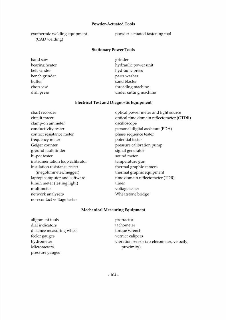
7/14/2019 Industrial Electrician 2011 En
http://slidepdf.com/reader/full/industrial-electrician-2011-en 118/132
‐ 104 ‐
Powder‐Actuated Tools
exothermic welding equipment (CAD welding)
powder‐actuated fastening tool
Stationary Power Tools
band saw
bearing heater belt sander bench grinder buffer chop saw
drill press
grinder hydraulic power unit hydraulic press
parts washer sand blaster threading machine
under cutting machine
Electrical Test and Diagnostic Equipment
chart recorder circuit tracer clamp‐on ammeter conductivity tester contact resistance meter frequency meter Geiger counter ground fault finder hi‐pot tester instrumentation loop calibrator
insulation
resistance
tester
(megohmmeter/megger) laptop computer and software
lumin meter (testing light) multimeter network analysers non‐contact voltage tester
optical power meter and light source
optical time domain reflectometer (OTDR) oscilloscope
personal digital assistant (PDA) phase sequence tester potential tester pressure calibration pump
signal generator sound meter temperature gun
thermal
graphic
camera
thermal graphic equipment time domain reflectometer (TDR) timer voltage tester Wheatstone bridge
Mechanical Measuring Equipment
alignment tools
dial indicators distance measuring wheel feeler gauges hydrometer Micrometers pressure gauges
protractor
tachometer torque wrench
vernier calipers vibration sensor (accelerometer, velocity,
proximity)

7/14/2019 Industrial Electrician 2011 En
http://slidepdf.com/reader/full/industrial-electrician-2011-en 119/132
‐ 105 ‐
Rigging, Tugging, Hoisting, Lifting Material
articulated boom lift beam clamps block and tackle
cable puller (hand or electric powered)
cable pulling grips (wire mesh grips) chain fall/come‐along
hoists
lifting eyes
platform lift pulley
ropes scissor lift
shackles slings strain relief tow motor/fork lift
Scaffolding and Access Equipment
aerial man lift extension ladder man baskets
portable stairs scaffolds step ladder
Personal Protective
Equipment
and
Safety
Equipment
arc flash PPE
ear protectors
face shield
fall arrest equipment fall restraint equipment fire retardant clothing
gas detectors
grounding stick
hard
hat
harness
high visibility vests
high voltage gloves
high voltage test equipment hot gloves hot pad
hot stick
knee pads protective apron
protective gloves/gauntlets
respirator
safety
footwear
safety glasses/goggles Self Contained Breathing Apparatus (SCBA)

7/14/2019 Industrial Electrician 2011 En
http://slidepdf.com/reader/full/industrial-electrician-2011-en 120/132
‐ 106 ‐
APPENDIX B GLOSSARY
arc flash electrical explosion that occurs on live equipment resulting from a low
impedance connection to ground or another voltage phase in an electrical system. The intensity of the blast is dependent on the energy source and the
size of the conductors
bonding low impedance path obtained by permanently joining all non‐current‐carrying metal parts to assure electrical continuity and having the capacity
to conduct safely any current likely to be imposed on it
bump test a functional test used on rotating equipment that initiates a start to
determine a) if the correct equipment will turn, b) the direction of rotation or c) if the correct equipment is de‐energized
cable
insulated
or
sheathed,
wire
or
fibre,
carrying
current
or
light,
it
can
be
comprised of one or more conductors
cathodic
protection
protection technique to control the corrosion of a metal surface by making
that surface the cathode of an electrochemical cell
commissionning initial startup of new equipment systematically to OEM specifications
Force manual virtual bypass that is placed in control system program logic, that can be On or Off, it can be used for troubleshooting, temporary repairs, servicing and diagnostics. A Force will flag up in the system as long as it is
in
effect
grounding permanent and continuous conductive path to the earth with
sufficient ampacity to carry any fault current liable to be imposed on it, and
of a sufficiently low impedance to limit the voltage rise above ground and
to facilitate the operation of the protective devices in the circuit
high voltage any voltage exceeding 750 volts, as per CEC
low voltage any voltage from 31 to 750 volts, as per CEC
multimedia
system an
electronically
delivered
combination
of
media
including
video,
still
images, audio, text in such a way that can be accessed interactively
raceway any channel designed for holding wires, cables, or busbars, and, unless otherwise qualified by rules of the CEC, the term includes conduit (rigid, flexible, metal, non‐metallic) electrical, metallic and nonmetallic
tubing, underfloor raceways, cellular floors, surface raceways, wireways, cable trays, busways, and auxiliary gutters

7/14/2019 Industrial Electrician 2011 En
http://slidepdf.com/reader/full/industrial-electrician-2011-en 121/132
‐ 107 ‐
APPENDIX C ACRONYMS
AC alternating current
AECB Atomic Energy Control Board
CAD computer assisted design
CAM computer‐aided manufacturing
CAT‐5 category 5 cable
CEC Canadian Electrical Code
CFL compact fluorescent lamp
CMMS computerized maintenance management system
CPR cardiopulmonary resuscitation
CPU central processing unit
CSA Canadian Standards Association
dB decibel
DC direct current
DCS distributed control system
EMI electromagnetic interference
EMT electrical metallic tubing
EOL end of line
GFCI ground‐fault circuit interrupter
H2S hydrogen sulfide
HID high intensity discharge
HMI human machine interface
HVAC heating, ventilation, and air conditioning
I/O input/output
7/14/2019 Industrial Electrician 2011 En
http://slidepdf.com/reader/full/industrial-electrician-2011-en 122/132
‐ 108 ‐
I/P current to pressure
IC integrated circuit
IP internetworking protocol
kVA kilovolt‐ampere
LED light emitting diode
MCC motor control centre
MSDS material safety data sheets
OEM original equipment manufacturer
OH&S Occupational Health and Safety
PPE personal protective equipment
PLC programmable logic controller
PVC polyvinyl chloride
RTD resistance temperature detector
SCR silicon‐controlled rectifier
SG specific gravity
SO2 sulfur dioxide
T/P temperature to pressure
TDG transportation of dangerous goods
ULC Underwriters’ Laboratories of Canada
UPS uninterruptible power supply
VFD variable‐frequency drive
WHMIS Workplace Hazardous Materials Information System

7/14/2019 Industrial Electrician 2011 En
http://slidepdf.com/reader/full/industrial-electrician-2011-en 123/132
‐ 109 ‐
BLOCK A COMMON OCCUPATIONAL SKILLS
NL NS PE NB QC ON MB SK AB BC NT YT NU
% 10 14 10 10 15 20 14 ND ND 10 ND NV ND
National
Average
13%
Task 1 Performs safety‐related functions.
NL NS PE NB QC ON MB SK AB BC NT YT NU
% 50 25 20 25 20 50 25 ND ND 30 ND NV ND
31%
Task 2 Uses and maintains tools and equipment.
NL NS PE NB QC ON MB SK AB BC NT YT NU
% 15 25 30 25 20 15 25 ND ND 15 ND NV ND
21%
Task 3 Organizes work.
NL NS PE NB QC ON MB SK AB BC NT YT NU
% 35 25 20 25 30 10 25 ND ND 40 ND NV ND
26%
Task 4 Performs routine trade activities.
NL NS PE NB QC ON MB SK AB BC NT YT NU % 0 25 30 25 30 25 25 ND ND 15 ND NV ND
22%
BLOCK B POWER DISTRIBUTION AND GENERATING SYSTEMS
NL NS PE NB QC ON MB SK AB BC NT YT NU
% 25 21 20 20 20 14 14 ND ND 22 ND NV ND
National Average
19%
Task 5 Maintains high voltage power distribution systems.
NL NS PE NB QC ON MB SK AB BC NT YT NU
% 8 0 10 0 10 5 20 ND ND 16 ND NV ND
9%
APPENDIX D BLOCK AND TASK WEIGHTING

7/14/2019 Industrial Electrician 2011 En
http://slidepdf.com/reader/full/industrial-electrician-2011-en 124/132
‐ 110 ‐
Task 6 Maintains low voltage power distribution systems.
NL NS PE NB QC ON MB SK AB BC NT YT NU
% 30 30 20 20 25 25 16 ND ND 25 ND NV ND
24%
Task 7 Maintains alternating current (AC) systems.
NL NS PE NB QC ON MB SK AB BC NT YT NU
% 30 30 30 30 25 30 16 ND ND 25 ND NV ND
27%
Task 8 Maintains direct current (DC) systems.
NL NS PE NB QC ON MB SK AB BC NT YT NU
% 6 20 10 30 15 15 16 ND ND 14 ND NV ND
16%
Task 9 Maintains grounding and bonding systems.
NL NS PE NB QC ON MB SK AB BC NT YT NU
% 20 20 15 20 15 15 16 ND ND 12 ND NV ND
16%
Task 10 Maintains power generating systems.
NL NS PE NB QC ON MB SK AB BC NT YT NU
% 6 0 15 0 10 10 16 ND ND 8 ND NV ND
8%
BLOCK C ELECTRICAL EQUIPMENT
NL NS PE NB QC ON MB SK AB BC NT YT NU
% 25 23 30 20 20 25 14 ND ND 22 ND NV ND
National Average
22%
Task 11 Maintains equipment, wiring, cabling and terminations.
NL NS PE NB QC ON MB SK AB BC NT YT NU
% 20 10 10 10 20 15 20 ND ND 25 ND NV ND
16%
Task 12 Maintains lighting systems.
NL NS PE NB QC ON MB SK AB BC NT YT NU
% 8 10 15 10 20 10 16 ND ND 10 ND NV ND
12%
Task 13 Maintains protection devices.
NL NS PE NB QC ON MB SK AB BC NT YT NU
% 20 20 10 20 10 15 16 ND ND 15 ND NV ND
16%
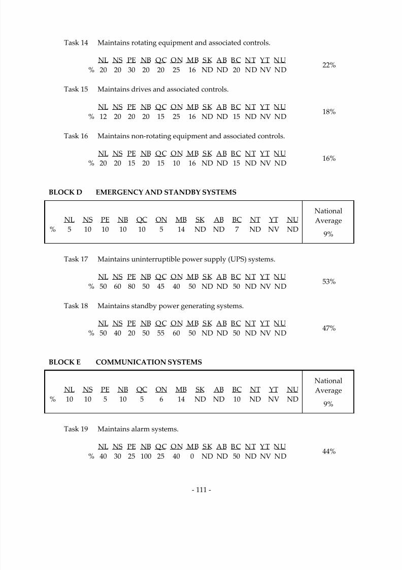
7/14/2019 Industrial Electrician 2011 En
http://slidepdf.com/reader/full/industrial-electrician-2011-en 125/132
‐ 111 ‐
Task 14 Maintains rotating equipment and associated controls.
NL NS PE NB QC ON MB SK AB BC NT YT NU
% 20 20 30 20 20 25 16 ND ND 20 ND NV ND
22%
Task 15 Maintains drives and associated controls.
NL NS PE NB QC ON MB SK AB BC NT YT NU
% 12 20 20 20 15 25 16 ND ND 15 ND NV ND
18%
Task 16 Maintains non‐rotating equipment and associated controls.
NL NS PE NB QC ON MB SK AB BC NT YT NU
% 20 20 15 20 15 10 16 ND ND 15 ND NV ND
16%
BLOCK D EMERGENCY AND STANDBY SYSTEMS
NL NS PE NB QC ON MB SK AB BC NT YT NU
% 5 10 10 10 10 5 14 ND ND 7 ND NV ND
National Average
9%
Task 17 Maintains uninterruptible power supply (UPS) systems.
NL NS PE NB QC ON MB SK AB BC NT YT NU
% 50 60 80 50 45 40 50 ND ND 50 ND NV ND
53%
Task 18 Maintains standby power generating systems.
NL NS PE NB QC ON MB SK AB BC NT YT NU
% 50 40 20 50 55 60 50 ND ND 50 ND NV ND
47%
BLOCK E COMMUNICATION SYSTEMS
NL NS PE NB QC ON MB SK AB BC NT YT NU
% 10 10 5 10 5 6 14 ND ND 10 ND NV ND
National Average
9%
Task 19 Maintains alarm systems.
NL NS PE NB QC ON MB SK AB BC NT YT NU
% 40 30 25 100 25 40 0 ND ND 50 ND NV ND
44%

7/14/2019 Industrial Electrician 2011 En
http://slidepdf.com/reader/full/industrial-electrician-2011-en 126/132
‐ 112 ‐
Task 20 Maintains paging systems.
NL NS PE NB QC ON MB SK AB BC NT YT NU
% 10 25 25 0 25 25 50 ND ND 10 ND NV ND
24%
Task 21 Maintains multimedia systems. (NOT COMMON CORE)
NL NS PE NB QC ON MB SK AB BC NT YT NU
% 10 0 0 0 25 5 50 ND ND 10 ND NV NV
NCC*
Task 22 Maintains network systems.
NL NS PE NB QC ON MB SK AB BC NT YT NU
% 40 45 50 0 25 30 0 ND ND 30 ND NV ND
32%
BLOCK F PROCESS CONTROL SYSTEMS
NL NS PE NB QC ON MB SK AB BC NT YT NU
% 20 13 20 20 15 24 14 ND ND 22 ND NV ND
National Average
19%
Task 23 Maintains input/output (I/O) field devices.
NL NS PE NB QC ON MB SK AB BC NT YT NU
% 50 55 60 70 50 50 50 ND ND 40 ND NV ND
53%
Task 24 Maintains control systems.
NL NS PE NB QC ON MB SK AB BC NT YT NU
% 50 45 40 30 50 50 50 ND ND 60 ND NV ND
47%
BLOCK G BUILDING AND ENVIRONMENTAL CONTROL SYSTEMS
NL NS PE NB QC ON MB SK AB BC NT YT NU
% 5 9 5 10 15 6 16 ND ND 7 ND NV ND
National Average
9%
Task 25 Maintains electrical components of heating and cooling
systems.
NL NS PE NB QC ON MB SK AB BC NT YT NU
% 40 40 70 0 30 45 33 ND ND 40 ND NV ND
37%

7/14/2019 Industrial Electrician 2011 En
http://slidepdf.com/reader/full/industrial-electrician-2011-en 127/132
‐ 113 ‐
Task 26 Maintains building automation systems.
NL NS PE NB QC ON MB SK AB BC NT YT NU
% 20 30 30 0 30 25 34 ND ND 30 ND NV ND
25%
Task 27 Maintains environmental control systems.
NL NS PE NB QC ON MB SK AB BC NT YT NU
% 40 30 0 100 40 30 33 ND ND 30 ND NV ND
38%
*NCC = Not common core
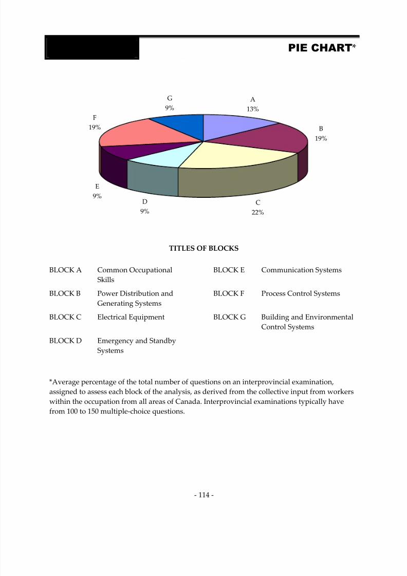
7/14/2019 Industrial Electrician 2011 En
http://slidepdf.com/reader/full/industrial-electrician-2011-en 128/132
‐ 114 ‐
G9%F
19%
D9%
C22%
B19%
A13%
E9%
TITLES OF BLOCKS
BLOCK A Common Occupational Skills
BLOCK E Communication Systems
BLOCK B Power Distribution and
Generating Systems
BLOCK F Process Control Systems
BLOCK C Electrical Equipment BLOCK G Building and Environmental Control Systems
BLOCK D Emergency and Standby
Systems
*Average percentage of the total number of questions on an interprovincial examination, assigned to assess each block of the analysis, as derived from the collective input from workers
within the occupation from all areas of Canada. Interprovincial examinations typically have from 100 to 150 multiple‐choice questions.
APPENDIX E PIE CHART*

7/14/2019 Industrial Electrician 2011 En
http://slidepdf.com/reader/full/industrial-electrician-2011-en 129/132
‐ 115 ‐
APPENDIX F TASK PROFILE CHART —
Industrial Electricia
BLOCKS
TASKS
SUB‐TASKS
A ‐ COMMON
OCCUPATIONAL
SKILLS
1. Performs safety‐related
functions.
1.01 Maintains safe work
environment.
1.02 Uses personal protective
equipment (PPE) and safety
equipment.
1.03 Performs lock‐
out and tagging
procedures.
2. Uses and
maintains tools and equipment.
2.01 Maintains tools and
equipment.
2.02 Uses access equipment.
2.03 Uses rigging, tugging, hoisting
and lifting
equipment.
3. Organizes work.
3.01 Interprets codes and
regulations.
3.02 Uses plans, schematics, drawings and
specifications.
3.03 Selects materials and
supplies.
3.04 Plans project tasks and
procedures.
3.05 Prepares work site.
3.06 Documents maintenance
work.
4. Performs routine trade
activities.
4.01 Installs fasteners, fittings and connectors.
4.02 Conducts operational tests.
B ‐ POWER
DISTRIBUTION
AND
GENERATING
SYSTEMS
5. Maintains high
voltage power distribution
systems.
5.01 Installs high
voltage power distribution
systems. (NOT
COMMON
CORE)
5.02 Services high
voltage power distribution
systems.
5.03 Troubleshoots high voltage power distribution
systems.
5.04 Repairs high
voltage power distribution
systems.
6. Maintains low
voltage power distribution
systems.
6.01 Installs low
voltage power distribution
systems.
6.02 Services low
voltage power distribution
systems.
6.03 Troubleshoots low voltage power distribution
systems.
6.04 Repairs low
voltage power distribution
systems.

7/14/2019 Industrial Electrician 2011 En
http://slidepdf.com/reader/full/industrial-electrician-2011-en 130/132
‐ 116 ‐
BLOCKS TASKS SUB‐TASKS
7. Maintains alternating
current (AC) systems.
7.01 Installs alternating
current (AC) systems.
7.02 Services alternating
current (AC) systems.
7.03 Troubleshoots alternating current (AC) systems.
7.04 Repairs alternating
current (AC) systems.
8. Maintains direct current (DC) systems.
8.01 Installs direct current (DC) systems.
8.02 Services direct current (DC) systems.
8.03 Troubleshoots direct current (DC) systems.
8.04 Repairs direct current (DC) systems.
9. Maintains grounding and
bonding systems.
9.01 Installs grounding and
bonding systems.
9.02 Services grounding and
bonding systems.
9.03 Troubleshoots grounding and
bonding systems.
9.04 Repairs grounding and
bonding
systems.
10. Maintains power generating
systems.
10.01 Installs power generating
systems. (NOT
COMMON
CORE)
10.02 Services power generating
systems.
10.03 Troubleshoots power generating
systems.
10.04 Repairs power generating
systems.
C ‐ ELECTRICAL
EQUIPMENT
11. Maintains equipment, wiring, cabling
and terminations.
11.01 Installs electrical wiring, cabling and
terminations.
11.02 Installs raceways, cable
trays, busways and associated
components.
11.03 Repairs electrical wiring, cabling and
terminations.
11.04 Maintains seismic restraint systems. (NOT
COMMON
CORE)
12. Maintains lighting systems.
12.01 Installs lighting systems.
12.02 Services lighting systems.
12.03 Troubleshoots lighting systems.
12.04 Repairs lighting systems.
13. Maintains protection
devices.
13.01 Installs protection
devices.
13.02 Services protection
devices.
13.03 Troubleshoots protection devices.
13.04 Repairs protection
devices.
14. Maintains rotating
equipment and
associated
controls.
14.01 Installs rotating
equipment and
associated
controls.
14.02 Services rotating
equipment and
associated
controls.
14.03 Troubleshoots rotating equipment and associated
controls.
14.04 Repairs rotating
equipment and
associated
controls.

7/14/2019 Industrial Electrician 2011 En
http://slidepdf.com/reader/full/industrial-electrician-2011-en 131/132
‐ 117 ‐
BLOCKS TASKS SUB‐TASKS
15. Maintains drives and
associated
controls.
15.01 Installs drives and
associated
controls.
15.02 Services drives and
associated
controls.
15.03 Troubleshoots drives and
associated controls.
15.04 Repairs drives and
associated
controls.
16. Maintains non‐rotating
equipment and
associated
controls.
16.01 Installs non‐
rotating
equipment and
associated
controls.
16.02 Services non‐rotating
equipment and
associated
controls.
16.03 Troubleshoots non‐rotating
equipment and
associated controls.
16.04 Repairs non‐rotating
equipment and
associated
controls.
D ‐ EMERGENCY
AND STANDBY
SYSTEMS
17. Maintains uninterruptible power supply
(UPS) systems.
17.01 Installs uninterruptible power supply
(UPS) systems.
17.02 Services uninterruptible power supply
(UPS) systems.
17.03 Troubleshoots uninterruptible power supply
(UPS) systems.
17.04 Repairs uninterruptible power supply
(UPS) systems.
18. Maintains standby power generating
systems.
18.01 Installs standby power generating
systems.
18.02 Services standby power generating
systems.
18.03 Troubleshoots standby power generating systems.
18.04 Repairs standby power generating
systems.
E ‐ COMMUNICA‐
TION SYSTEMS
19. Maintains alarm systems.
19.01 Installs alarm systems.
19.02 Services alarm systems.
19.03 Troubleshoots alarm systems.
19.04 Repairs alarm systems.
20. Maintains paging systems.
20.01 Installs paging systems.
20.02 Services paging systems.
20.03 Troubleshoots paging systems.
20.04 Repairs paging systems.
21. Maintains multimedia
systems. (NOT
COMMON
CORE)
21.01 Installs multimedia
systems. (NOT
COMMON
CORE)
21.02 Services multimedia
systems. (NOT
COMMON
CORE)
21.03 Troubleshoots multimedia
systems. (NOT
COMMON CORE)
21.04 Repairs multimedia
systems. (NOT
COMMON
CORE)
22. Maintains network systems.
22.01 Installs network systems.
22.02 Services network systems.
22.03 Troubleshoots network systems.
22.04 Repairs network
systems.

7/14/2019 Industrial Electrician 2011 En
http://slidepdf.com/reader/full/industrial-electrician-2011-en 132/132
BLOCKS TASKS SUB‐TASKS
F ‐ PROCESS
CONTROL
SYSTEMS
23. Maintains input/output (I/O) field devices.
23.01 Installs input/output (I/O) field devices.
23.02 Services input/output (I/O) field devices.
23.03 Troubleshoots input/output (I/O) field devices.
23.04 Repairs input/output (I/O) field
devices.
24. Maintains control systems.
24.01 Installs control systems.
24.02 Services control systems.
24.03 Troubleshoots control systems.
24.04 Repairs control systems.
24.05 Optimizeprogrammablelogic controller(PLC).
G ‐ BUILDING
AND
ENVIRONMEN‐
TAL CONTROL
SYSTEMS
25. Maintains electrical components of heating and
cooling
systems.
25.01 Installs electrical components of heating and
cooling
systems.
25.02 Services electrical components of heating and
cooling
systems.
25.03 Troubleshoots electrical components of heating and cooling
systems.
25.04 Repairs electrical components of heating and
cooling
systems.
26. Maintains building
automation
systems.
26.01 Installs building
automation
systems.
26.02 Services building
automation
systems.
26.03 Troubleshoots building
automation
systems.
26.04 Repairs building
automation
systems.
27. Maintains environmental control systems.
27.01 Installs environmental control systems.
27.02 Services environmental control systems.
27.03 Troubleshoots environmental control systems.
27.04 Repairs environmental control systems.
Related Documents