GE Fanuc Automation Industrial Computer Products Marathon Series Industrial Computers and Monitors User's Manual GFK-1791A April 2001

Welcome message from author
This document is posted to help you gain knowledge. Please leave a comment to let me know what you think about it! Share it to your friends and learn new things together.
Transcript

GE Fanuc Automation
Industrial Computer Products
Marathon SeriesIndustrial Computers and Monitors
User's Manual
GFK-1791A April 2001
GFL-002
Warnings, Cautions, and Notesas Used in this Publication
Warning
Warning notices are used in this publication to emphasize that hazardous voltages,currents, temperatures, or other conditions that could cause personal injury exist in thisequipment or may be associated with its use.
In situations where inattention could cause either personal injury or damage toequipment, a Warning notice is used.
Caution
Caution notices are used where equipment might be damaged if care is not taken.
Note: Notes merely call attention to information that is especially significant to understanding andoperating the equipment.
This document is based on information available at the time of its publication. While effortshave been made to be accurate, the information contained herein does not purport to cover alldetails or variations in hardware or software, nor to provide for every possible contingency inconnection with installation, operation, or maintenance. Features may be described hereinwhich are not present in all hardware and software systems. GE Fanuc Automation assumes noobligation of notice to holders of this document with respect to changes subsequently made.
GE Fanuc Automation makes no representation or warranty, expressed, implied, or statutorywith respect to, and assumes no responsibility for the accuracy, completeness, sufficiency, orusefulness of the information contained herein. No warranties of merchantability or fitness forpurpose shall apply.
The following are trademarks of GE Fanuc Automation North America, Inc.
Alarm Master Genius PROMACRO Series SixCIMPLICITY Helpmate PowerMotion Series ThreeCIMPLICITY 90–ADS Logicmaster PowerTRAC VersaMaxCIMSTAR Modelmaster Series 90 VersaProField Control Motion Mate Series Five VuMasterGEnet ProLoop Series One Workmaster
©Copyright 2000—2001 GE Fanuc Automation North America, Inc.All Rights Reserved.
Contents
GFK-1791A iii
Chapter 1 Product Features ............................................................................................. 1-1
Innovative Modular Design .................................................................................... 1-1Factory Ready ........................................................................................................ 1-2Connectivity........................................................................................................... 1-2
Marathon Display Modules........................................................................................... 1-3Features.................................................................................................................. 1-3Modular Simplicity................................................................................................. 1-3Rugged Touchscreens............................................................................................. 1-4Keypad Option ....................................................................................................... 1-4
Marathon Series CPU Module, Standard....................................................................... 1-5Marathon Series CPU Module, Expanded ..................................................................... 1-6Single Board Computers ............................................................................................... 1-7
SBC-Max-2 Features .............................................................................................. 1-7SBC-PII Features.................................................................................................... 1-7SBC-PII Single Board Computer Overview ............................................................ 1-8SBC-PII Detailed Feature Description .................................................................... 1-8
Marathon Series Monitor Video Electronics Module................................................... 1-10
Chapter 2 Marathon Monitors — Quick Install.............................................................. 2-1
Installing Marathon Display Modules ........................................................................... 2-1Installing the Marathon Monitor Video Electronics Module .......................................... 2-2
Connecting the Marathon Video Electronics Module .............................................. 2-2Setting Video Resolution ........................................................................................ 2-3Switch Box Installation........................................................................................... 2-4
Installing the Dynapro SC3 Driver ................................................................................ 2-5Calibrating the Dynapro SC3 Driver ............................................................................. 2-5Monitor Adjustments .................................................................................................... 2-6
Display Control Menus........................................................................................... 2-6Remove On Screen Display .................................................................................... 2-7Video Position Adjustment ..................................................................................... 2-7Width ..................................................................................................................... 2-7Brightness .............................................................................................................. 2-7Contrast.................................................................................................................. 2-8Phase...................................................................................................................... 2-8Zoom Enable.......................................................................................................... 2-8Restore Factory Settings ......................................................................................... 2-8Video Source.......................................................................................................... 2-8Menu Position Adjustment ..................................................................................... 2-9Menu Timeout........................................................................................................ 2-9Status ..................................................................................................................... 2-9
Contents
iv Marathon Series Industrial Computers and Monitors User's Manual–April 2001 GFK-1791A
Chapter 3 Marathon Computers — Quick Install .......................................................... 3-1
Installing Marathon Display Modules ........................................................................... 3-1Installing Marathon Computer (CPU) Modules ............................................................. 3-2Power Connections ....................................................................................................... 3-3Powering Up the Marathon Unit ................................................................................... 3-3Setting Up Windows 98 Systems .................................................................................. 3-4Setting Up Windows NT Systems ................................................................................. 3-4Setting Screen Resolution ............................................................................................. 3-5Calibrating the Touchscreen.......................................................................................... 3-6Configuring the Marathon Computer to Run on a Microsoft Network............................ 3-6Login Recommendation................................................................................................ 3-6
Chapter 4 Keypad and Connector Information .............................................................. 4-1
Keypads ....................................................................................................................... 4-1Marathon 12" Display Keypad Assignments ........................................................... 4-2Marathon 15" Display Keypad Assignments ........................................................... 4-3
Connectors ................................................................................................................... 4-5Front Access Panel ................................................................................................. 4-5Communication Ports ............................................................................................. 4-5
ISA and PCI Expansion on the Marathon MSCPX CPUs .............................................. 4-6
Chapter 5 BIOS Setup Guide........................................................................................... 5-1
Starting the BIOS Setup Utility..................................................................................... 5-2Navigating the Setup Menus ......................................................................................... 5-2
Legend Bar............................................................................................................. 5-3Field Help Window ................................................................................................ 5-3General Help Window............................................................................................ 5-4
Main Menu................................................................................................................... 5-5Advanced Hard Disk Features....................................................................................... 5-6Advanced Menu............................................................................................................ 5-7
Integrated Peripherals ............................................................................................. 5-8Security Control ................................................................................................... 5-11
Power Menu ............................................................................................................... 5-12Boot Menu.................................................................................................................. 5-14Exit Menu................................................................................................................... 5-15
Exit Saving Changes............................................................................................. 5-15Exit Discarding Changes ...................................................................................... 5-15Load Setup Defaults ............................................................................................. 5-16Discard Changes................................................................................................... 5-16Save Changes ....................................................................................................... 5-16
Contents
GFK-1791A Contents v
Chapter 6 Technical Specifications .................................................................................. 6-1
CPU ............................................................................................................................. 6-1Displays ....................................................................................................................... 6-1Touchscreens................................................................................................................ 6-2System DRAM ............................................................................................................. 6-2System DRAM Installation (U3)................................................................................... 6-2Connectors ................................................................................................................... 6-3
SBC-Max-2 Single Board Computer Connectors .................................................... 6-3PS/2 Mouse........................................................................................................... 6-3Keyboard Connector ............................................................................................. 6-3USB Ports............................................................................................................. 6-4Serial Port Connector ............................................................................................ 6-4Printer Port (LPT1) ............................................................................................... 6-4VGA Video Connector.......................................................................................... 6-5Ethernet Port (E-NET) .......................................................................................... 6-5
SBC-PII Single Board Computer Connectors.......................................................... 6-6External Battery (J14) ........................................................................................... 6-6PS/2 Mouse Connector (J17)................................................................................. 6-6Keyboard Interface (J27)....................................................................................... 6-6USB Ports (J21) .................................................................................................... 6-8Serial Port Interface (J18, J19, J24 and J25)........................................................... 6-9Serial Port Information........................................................................................ 6-10SF12 Definition .................................................................................................. 6-10Parallel Port (J20) ............................................................................................... 6-11VGA Video Connector........................................................................................ 6-11Ethernet (J10) ..................................................................................................... 6-12Ethernet LEDs (J9) ............................................................................................. 6-12
Interrupt Assignments................................................................................................. 6-13
Chapter 7 Dimensions....................................................................................................... 7-1
12" Display, No Keypads, Standard Back CPU or Monitor Video Electronics Module7-212" Display, Keypads, Standard Back CPU or Monitor Video Electronics Module.. 7-312" Display, No Keypads, Expanded Back CPU ..................................................... 7-412" Display, Keypads, Expanded Back CPU........................................................... 7-515" Display, No Keypads, Standard Back CPU or Monitor Video Electronics Module7-615" Display, Keypads, Standard Back CPU or Monitor Video Electronics Module.. 7-715" Display, No Keypads, Expanded Back CPU ..................................................... 7-815" Display, Keypads, Expanded Back CPU........................................................... 7-918" Display, No Keypads, Standard Back CPU or Monitor Video Electronics Module7-1018" Display, No Keypads, Expanded Back CPU ................................................... 7-11
GFK-1791A 1-1
Product Features
A Marathon computer, with a PentiumTM, AMDTM, CeleronTM, or PIIITM processor, combined withone of the many Marathon display options, can run virtually any application efficiently, crunchingthrough even the most complex algorithms at amazing speeds.
State-of-the-art panel mounting and connecting systems make it perfect for the shop floor orcontrol area. Built for harsh environments, a Marathon flat-panel computer will give you manyyears of trouble-free service. Flexible and robust, Marathon computers make it easy for operators tomonitor and interact with machines and industrial processes. They give you the features you needand connectivity that’s second to none. Because they’re open-system machines, they’ll easilyexpand with your business.
Available in a full range of sizes, Marathon Flat Panel Displays offer an array of features andoptions to complement their superior resolution and wide-angle visibility. Durable and sensitiveanalog resistive touchscreens, and optional integrated membrane keypads increase the adaptabilityof Marathon industrial monitors to your needs.
Innovative Modular Design
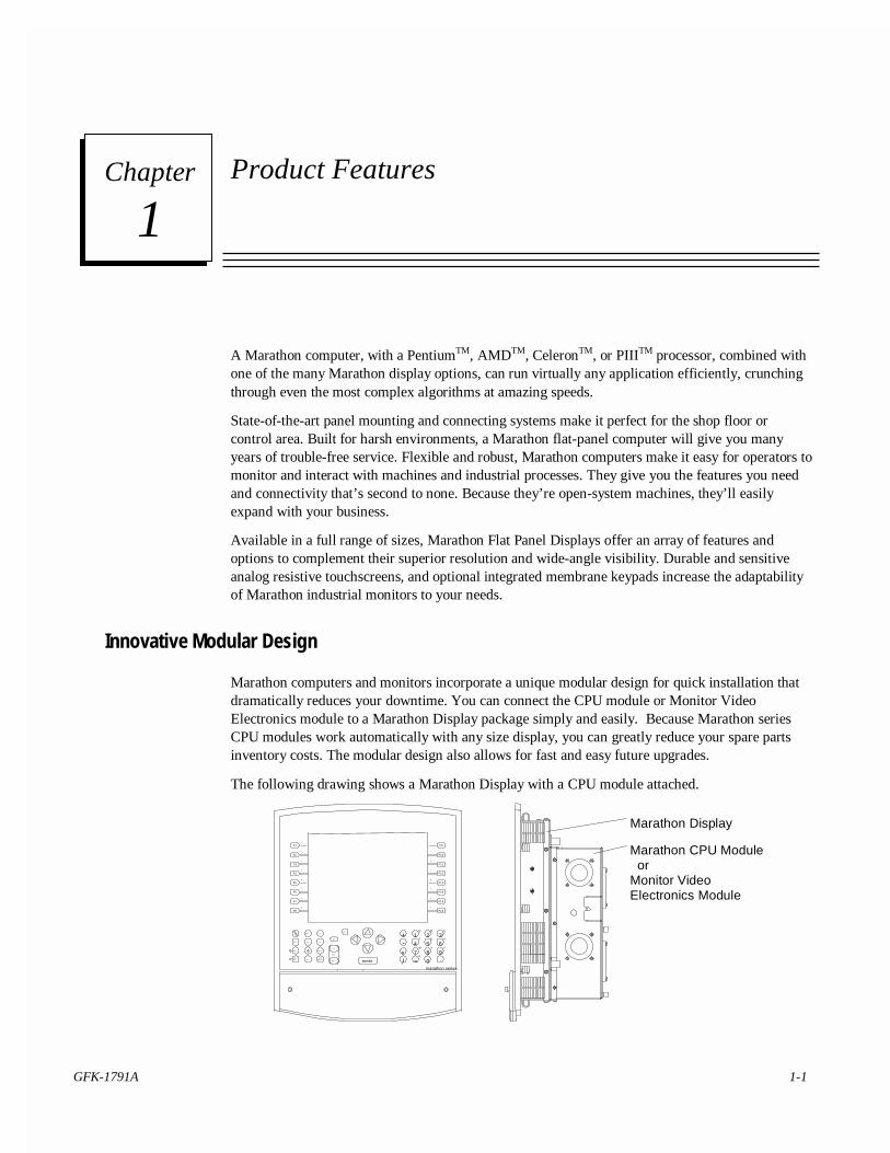
Marathon computers and monitors incorporate a unique modular design for quick installation thatdramatically reduces your downtime. You can connect the CPU module or Monitor VideoElectronics module to a Marathon Display package simply and easily. Because Marathon seriesCPU modules work automatically with any size display, you can greatly reduce your spare partsinventory costs. The modular design also allows for fast and easy future upgrades.
The following drawing shows a Marathon Display with a CPU module attached.
hom e ctr l
en dpr int
shift
shiftlock esc
bac kspa ce
spa ce
pa ge
dow n
up
ta b
alt
+ 1 2 3
7
5 64
8 9
0
-
*/ = .
Z
W X Y
T U V
Q R S
marathon series
del
enter
I
F9
F10J
K
L
M
N
O
P
F11
F12
F13
F14
F15
F16
A
F1
F2B
C
F3
D
F4
E
F5
F
F6
G
F7
H
F8
Marathon Display
Marathon CPU Module orMonitor VideoElectronics Module
1Chapter
1-2 Marathon Series Industrial Computers and Monitors User's Manual – April 2001 GFK-1791A
1
Factory Ready
Designed and built to withstand harsh, demanding environments, Marathon monitors are the perfecttools for delivering information on the factory floor.
• Substantially smaller in size, they fit easier in any location
• Modular design allows for speedy installation and removal
• Increased reliability reduces downtime in your factory
• Lower power consumption rate means reduced operating costs and lower temperature
• Immunity to electromagnetic emissions, resistance to vibration, and a wider operationaltemperature range enhance flexibility of placement
Connectivity
A Marathon series industrial computer is the ideal choice for plant floor communications. The CPUmodule contains on-board Ethernet (10/100 Mbps), dual USB (Universal Serial Bus) ports, dualRS-232 COM ports (one used by touchscreen) and an IrDA port so that you can connect withoutthe need for additional hardware.
GFK-1791A Chapter 1 Product Features 1-3
1
Marathon Display Modules
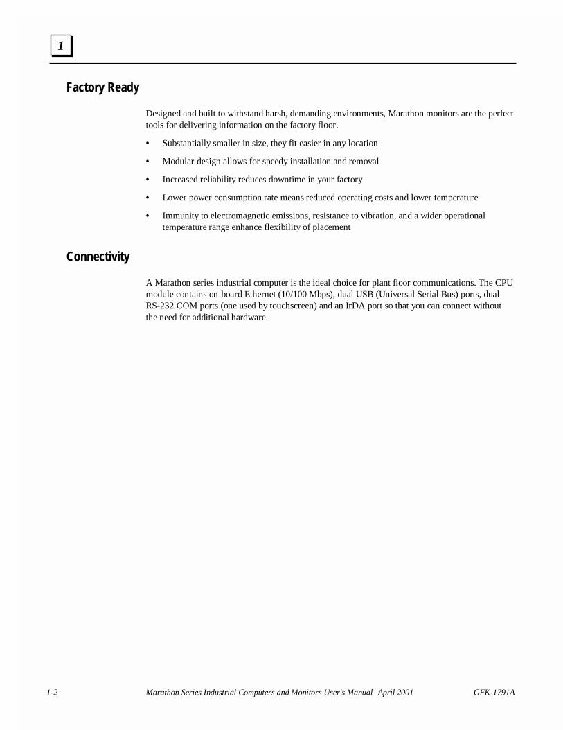
Combine a 12.1", 15", or 18.1" Marathon Display module with a CPU module to create anindustrial computer package. Combine a 12.1" or 15" Marathon Display module with a MonitorVideo Electronics module for a stand-alone industrial monitor. The Marathon Display module isinstalled in the panel cutout with clips. The CPU module and the Monitor Video Electronicsmodule are installed on the Marathon Display module using clamps.
The following drawing shows a Marathon Display Module with a Monitor Video Electronicsmodule. The Video Electronics module has the same dimensions as the MSCPU computer module.
Panel
home ctrl
endprint
shift
shiftlock esc back
space
space
page
down
up
tabalt
+ 1 2 3
7
5 64
8 9
0
-
*/ = .
Z
W X Y
T U V
Q R S
marathon series
del
A
F1
F2B
C
F3
D
F4
E
F5
F
F6
G
F7
H
F8
I
F9
F10J
K
L
M
N
O
P
F11
F12
F13
F14
F15
F16
enter
Marathon Display
Marathon MonitorVideo ElectronicsModule
Features
Displays 12.1" SVGA 800 x 600 pixels15.0" XGA 1024 x 768 pixels18.1" SXGA 1280 x 1024 pixels
High Performance Direct CRT replacementCompatible with VESA compliant video signalsAnalog Resistive touchscreen with serial outputAuto-sizingStandard 15 pin VGA inputOptional function keypadFront or side-accessible keyboard port
High Visibility TFT Active Matrix Color
Modular Simplicity
Unlike systems that require a specific PC bus video card, Marathon series flat-panel monitors withstate-of-the-art technology connect directly to your video sources using standard DB15 connectors.This makes connecting our flat-panel monitors to such non-PC compatible platforms as VMEbus or
1-4 Marathon Series Industrial Computers and Monitors User's Manual – April 2001 GFK-1791A
1
Macintosh easy. For even greater convenience, you don't need a drill or screws to mount aMarathon monitor in a panel—it simply clips in place.
Rugged Touchscreens
All Marathon displays come with a resistive touchscreen. Offering excellent durability andresolution, resistive technology can be used in a wide variety of applications and environments. Alltouchscreen Marathon series monitors come with high performance device drivers that enable thetouchscreen to emulate a mouse. They can operate with any application designed to run underWindows™ 95/98, Windows NT™, or Windows 2000™. Resistive touchscreens allow operationwith gloved hands.
Keypad Option
The 12" and 15" Marathon Displays are available with integrated membrane keypads, making themeven more adaptable to your demanding applications. The membrane keypad option is notavailable with the 18" Marathon display.
GFK-1791A Chapter 1 Product Features 1-5
1
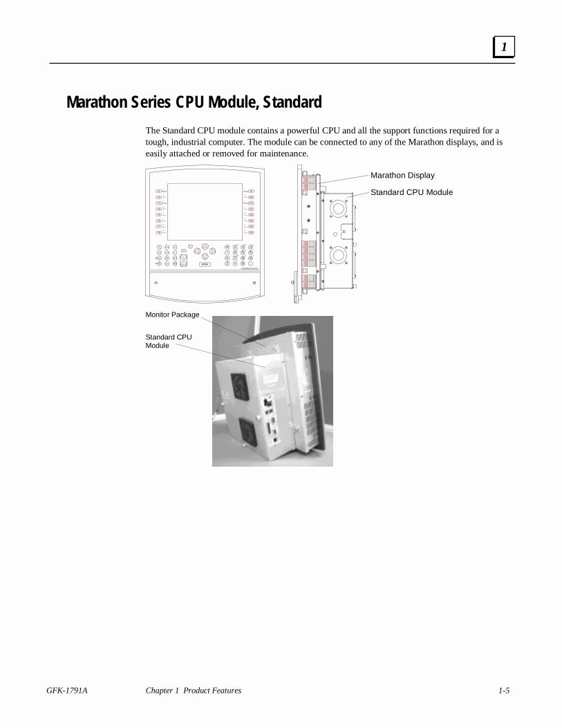
Marathon Series CPU Module, Standard
The Standard CPU module contains a powerful CPU and all the support functions required for atough, industrial computer. The module can be connected to any of the Marathon displays, and iseasily attached or removed for maintenance.
home ctr l
endprint
shift
shiftlock esc
backspace
space
page
down
up
tab
alt
+ 1 2 3
7
5 64
8 9
0
-
*/ = .
Z
W X Y
T U V
Q R S
marathon series
del
enter
I
F9
F10J
K
L
M
N
O
P
F11
F12
F13
F14
F15
F16
A
F1
F2B
C
F3
D
F4
E
F5
F
F6
G
F7
H
F8
Marathon Display
Standard CPU Module
Monitor Package
Standard CPU Module
1-6 Marathon Series Industrial Computers and Monitors User's Manual – April 2001 GFK-1791A
1
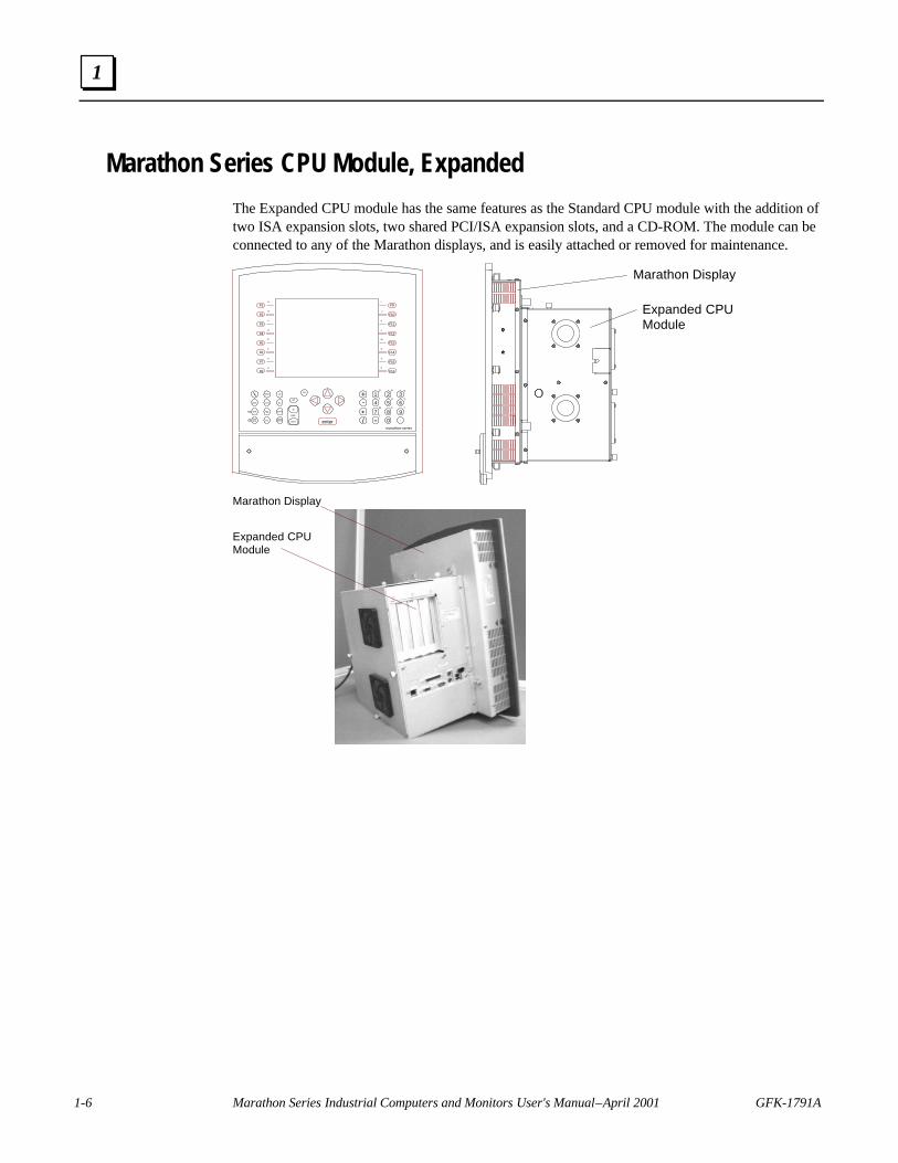
Marathon Series CPU Module, Expanded
The Expanded CPU module has the same features as the Standard CPU module with the addition oftwo ISA expansion slots, two shared PCI/ISA expansion slots, and a CD-ROM. The module can beconnected to any of the Marathon displays, and is easily attached or removed for maintenance.
home ctrl
endprint
shift
shiftlock esc
backspace
space
page
down
up
tab
alt
+ 1 2 3
7
5 64
8 9
0
-
*/ = .
Z
W X Y
T U V
Q R S
marathon series
del
A
F1
F2B
C
F3
D
F4
E
F5
F
F6
G
F7
H
F8
I
F9
F10J
K
L
M
N
O
P
F11
F12
F13
F14
F15
F16
enter
Marathon Display
Expanded CPUModule
Marathon Display
Expanded CPU Module
GFK-1791A Chapter 1 Product Features 1-7
1
Single Board Computers
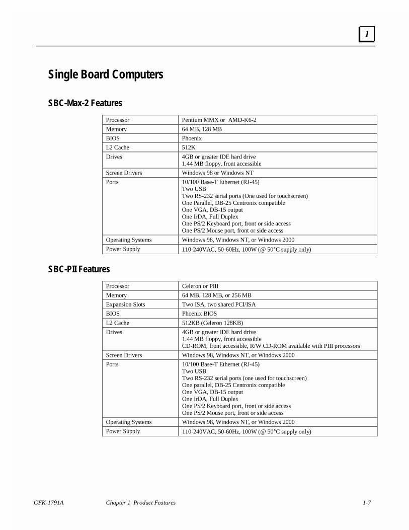
SBC-Max-2 Features
Processor Pentium MMX or AMD-K6-2
Memory 64 MB, 128 MB
BIOS Phoenix
L2 Cache 512K
Drives 4GB or greater IDE hard drive1.44 MB floppy, front accessible
Screen Drivers Windows 98 or Windows NT
Ports 10/100 Base-T Ethernet (RJ-45)Two USBTwo RS-232 serial ports (One used for touchscreen)One Parallel, DB-25 Centronix compatibleOne VGA, DB-15 outputOne IrDA, Full DuplexOne PS/2 Keyboard port, front or side accessOne PS/2 Mouse port, front or side access
Operating Systems Windows 98, Windows NT, or Windows 2000
Power Supply 110-240VAC, 50-60Hz, 100W (@ 50°C supply only)
SBC-PII Features
Processor Celeron or PIII
Memory 64 MB, 128 MB, or 256 MB
Expansion Slots Two ISA, two shared PCI/ISA
BIOS Phoenix BIOS
L2 Cache 512KB (Celeron 128KB)
Drives 4GB or greater IDE hard drive1.44 MB floppy, front accessibleCD-ROM, front accessible, R/W CD-ROM available with PIII processors
Screen Drivers Windows 98, Windows NT, or Windows 2000
Ports 10/100 Base-T Ethernet (RJ-45)Two USBTwo RS-232 serial ports (one used for touchscreen)One parallel, DB-25 Centronix compatibleOne VGA, DB-15 outputOne IrDA, Full DuplexOne PS/2 Keyboard port, front or side accessOne PS/2 Mouse port, front or side access
Operating Systems Windows 98, Windows NT, or Windows 2000
Power Supply 110-240VAC, 50-60Hz, 100W (@ 50°C supply only)
1-8 Marathon Series Industrial Computers and Monitors User's Manual – April 2001 GFK-1791A
1
SBC-PII Single Board Computer Overview
The SBC-PII is an industrial-design single board computer with all the functionality of today’s bestdesktop Intel Celeron and PIII machines. Its standard features include a Celeron or PIII CPU,Accelerated Graphics Port (AGP) video controller, 10/100BaseT Ethernet, and USB ports.
The SBC-PII provides leading edge flat panel support, including GUI Accelerator and MultimediaEngine especially for the newer color TFT LCDs. This 64-bit AGP chip includes up to 4MbytesSDRAM video memory for maximum color depth in all resolutions and operating systems. TheCT69000 also supports YUV and NTSC input with RGB conversion for CRT and provides displaycentering and stretching features for optimal presentation of VGA graphics and text on 800x600and 1024x768 panels.
The SBC-PII memory and storage options start with 8Mbytes DRAM and up to 256 Mbytes withone double sided non-registered DIMM. The IDE hard disk interface supports up to four IDE(ATA/ATAPI) drives. The floppy disk controller supports two 1.44Mbyte or 2.88Mbyte floppydrives.
Other I/O features include two USB ports for extra peripheral interfaces, up to four serial ports (onewith IrDA interface), slot or header option, a printer port, plus standard keyboard header, PS/2mouse and PC speaker. Advanced power management with timed power down, wake-up on LAN,PS/2 mouse or Keyboard triggers. Completing the list of features is PCI/ISA bus expansion using aPISA option card.
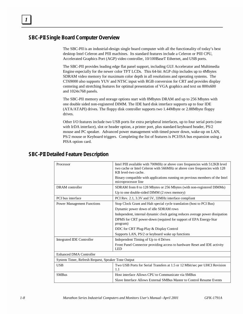
SBC-PII Detailed Feature Description
Processor Intel PIII available with 700MHz or above core frequencies with 512KB leveltwo cache or Intel Celeron with 566MHz or above core frequencies with 128KB level-two cache.
Binary compatible with applications running on previous members of the Intelmicroprocessor line
DRAM controller SDRAM from 8 to 128 Mbytes or 256 Mbytes (with non-registered DIMMs)
Up to one double-sided DIMM (2 rows memory)
PCI bus interface PCI Rev. 2.1, 3.3V and 5V, 33MHz interface compliant
Power Management Functions Stop Clock Grant and Halt special cycle translation (host to PCI Bus)
Dynamic power down of idle SDRAM rows
Independent, internal dynamic clock gating reduces average power dissipation
DPMS for CRT power-down (required for support of EPA Energy-Starprogram)
DDC for CRT Plug-Play & Display Control
Supports LAN, PS/2 or keyboard wake up functions
Integrated IDE Controller Independent Timing of Up to 4 Drives
Front Panel Connector providing access to hardware Reset and IDE activityLED
Enhanced DMA Controller
System Timer, Refresh Request, Speaker Tone Output
USB Two USB Ports for Serial Transfers at 1.5 or 12 Mbit/sec per UHCI Revision1.1
SMBus Host interface Allows CPU to Communicate via SMBus
Slave Interface Allows External SMBus Master to Control Resume Events
GFK-1791A Chapter 1 Product Features 1-9
1
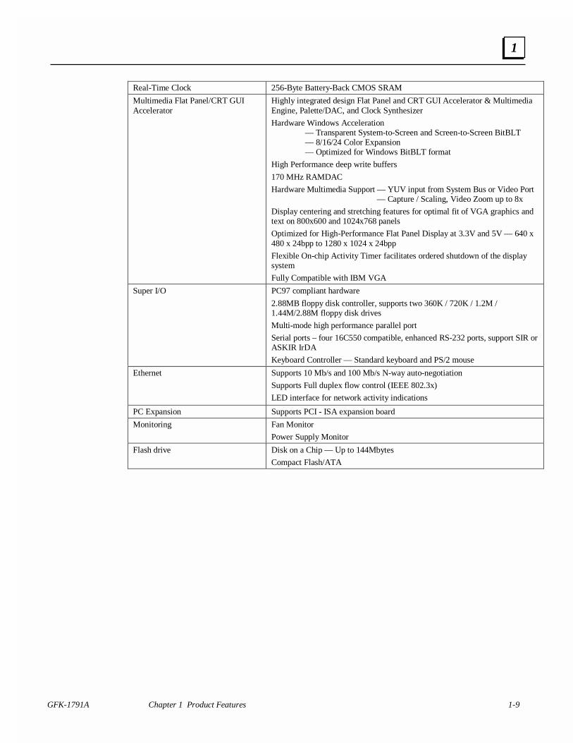
Real-Time Clock 256-Byte Battery-Back CMOS SRAM
Multimedia Flat Panel/CRT GUIAccelerator
Highly integrated design Flat Panel and CRT GUI Accelerator & MultimediaEngine, Palette/DAC, and Clock Synthesizer
Hardware Windows Acceleration— Transparent System-to-Screen and Screen-to-Screen BitBLT— 8/16/24 Color Expansion— Optimized for Windows BitBLT format
High Performance deep write buffers
170 MHz RAMDAC
Hardware Multimedia Support — YUV input from System Bus or Video Port — Capture / Scaling, Video Zoom up to 8x
Display centering and stretching features for optimal fit of VGA graphics andtext on 800x600 and 1024x768 panels
Optimized for High-Performance Flat Panel Display at 3.3V and 5V — 640 x480 x 24bpp to 1280 x 1024 x 24bpp
Flexible On-chip Activity Timer facilitates ordered shutdown of the displaysystem
Fully Compatible with IBM VGA
Super I/O PC97 compliant hardware
2.88MB floppy disk controller, supports two 360K / 720K / 1.2M /1.44M/2.88M floppy disk drives
Multi-mode high performance parallel port
Serial ports – four 16C550 compatible, enhanced RS-232 ports, support SIR orASKIR IrDA
Keyboard Controller — Standard keyboard and PS/2 mouse
Ethernet Supports 10 Mb/s and 100 Mb/s N-way auto-negotiation
Supports Full duplex flow control (IEEE 802.3x)
LED interface for network activity indications
PC Expansion Supports PCI - ISA expansion board
Monitoring Fan Monitor
Power Supply Monitor
Flash drive Disk on a Chip — Up to 144Mbytes
Compact Flash/ATA
1-10 Marathon Series Industrial Computers and Monitors User's Manual – April 2001 GFK-1791A
1
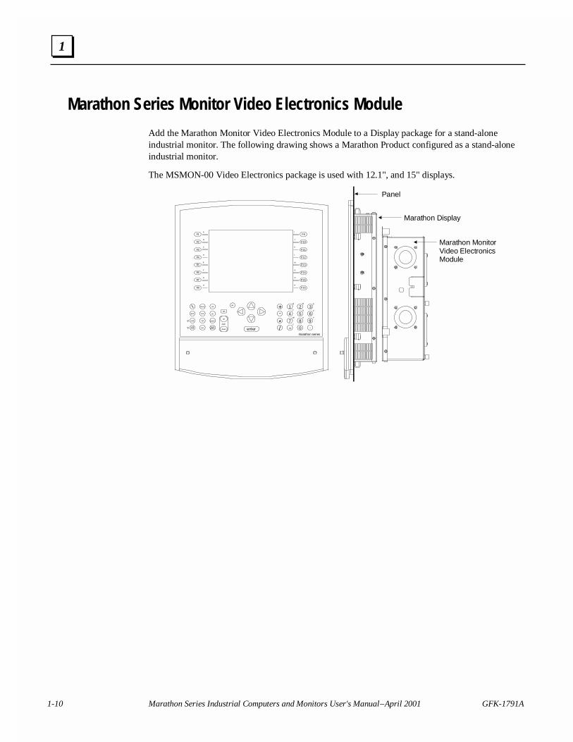
Marathon Series Monitor Video Electronics Module
Add the Marathon Monitor Video Electronics Module to a Display package for a stand-aloneindustrial monitor. The following drawing shows a Marathon Product configured as a stand-aloneindustrial monitor.
The MSMON-00 Video Electronics package is used with 12.1", and 15" displays.
Panel
home ctrl
endprint
shift
shiftlock esc back
space
space
page
down
up
tabalt
+ 1 2 3
7
5 64
8 9
0
-
*/ = .
Z
W X Y
T U V
Q R S
marathon series
del
A
F1
F2B
C
F3
D
F4
E
F5
F
F6
G
F7
H
F8
I
F9
F10J
K
L
M
N
O
P
F11
F12
F13
F14
F15
F16
enter
Marathon Display
Marathon MonitorVideo ElectronicsModule
GFK-1791A 2-1
Marathon Monitors — Quick Install
A Marathon Industrial Monitor consists of two components: a Marathon display, and a MarathonMonitor Video Electronics module. The installation process is simple. Make a cutout in the panel,clip the Display module in place, then attach the Marathon Monitor Video Electronics module tothe display package using the built-in quarter-turn clamps. If you have questions during theinstallation process you can contact our technical support group at 1-800-433-2682.
All Marathon Industrial Monitor products are fully compatible with VESA compliant Videosignals.
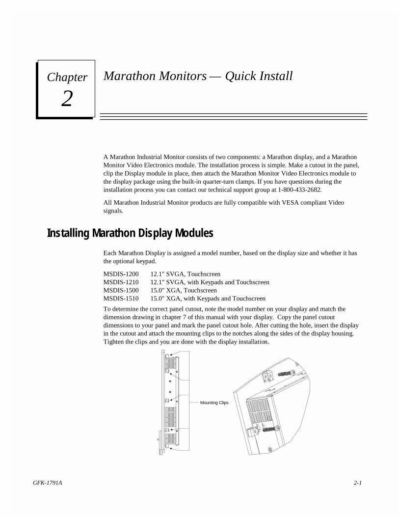
Installing Marathon Display Modules
Each Marathon Display is assigned a model number, based on the display size and whether it hasthe optional keypad.
MSDIS-1200 12.1" SVGA, TouchscreenMSDIS-1210 12.1" SVGA, with Keypads and TouchscreenMSDIS-1500 15.0" XGA, TouchscreenMSDIS-1510 15.0" XGA, with Keypads and Touchscreen
To determine the correct panel cutout, note the model number on your display and match thedimension drawing in chapter 7 of this manual with your display. Copy the panel cutoutdimensions to your panel and mark the panel cutout hole. After cutting the hole, insert the displayin the cutout and attach the mounting clips to the notches along the sides of the display housing.Tighten the clips and you are done with the display installation.
Mounting Clips
2Chapter
2-2 Marathon Series Industrial Computers and Monitors User's Manual – April 2001 GFK-1791A
2
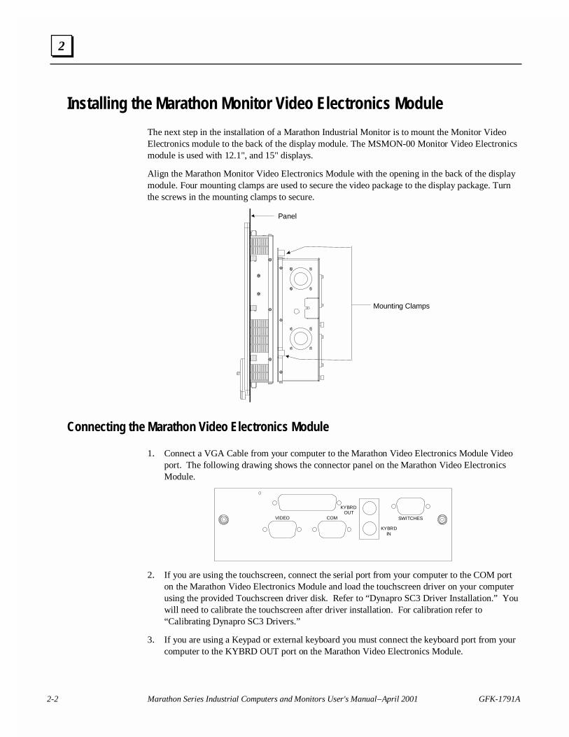
Installing the Marathon Monitor Video Electronics Module
The next step in the installation of a Marathon Industrial Monitor is to mount the Monitor VideoElectronics module to the back of the display module. The MSMON-00 Monitor Video Electronicsmodule is used with 12.1", and 15" displays.
Align the Marathon Monitor Video Electronics Module with the opening in the back of the displaymodule. Four mounting clamps are used to secure the video package to the display package. Turnthe screws in the mounting clamps to secure.
Mounting Clamps
Panel
Connecting the Marathon Video Electronics Module
1. Connect a VGA Cable from your computer to the Marathon Video Electronics Module Videoport. The following drawing shows the connector panel on the Marathon Video ElectronicsModule.
VIDEO COM
KYBRDOUT
KYBRDIN
SWITCHES
2. If you are using the touchscreen, connect the serial port from your computer to the COM porton the Marathon Video Electronics Module and load the touchscreen driver on your computerusing the provided Touchscreen driver disk. Refer to “Dynapro SC3 Driver Installation.” Youwill need to calibrate the touchscreen after driver installation. For calibration refer to“Calibrating Dynapro SC3 Drivers.”
3. If you are using a Keypad or external keyboard you must connect the keyboard port from yourcomputer to the KYBRD OUT port on the Marathon Video Electronics Module.
GFK-1791A Chapter 2 Marathon Monitors — Quick Install 2-3
2
4. Connect your keyboard (if used) to either the front-access PS/2 port on the front of yourmarathon display or to the KYBRD IN port on the Marathon Video Electronics module. Boththe front access port and the side access keyboard ports may not be used simultaneously.
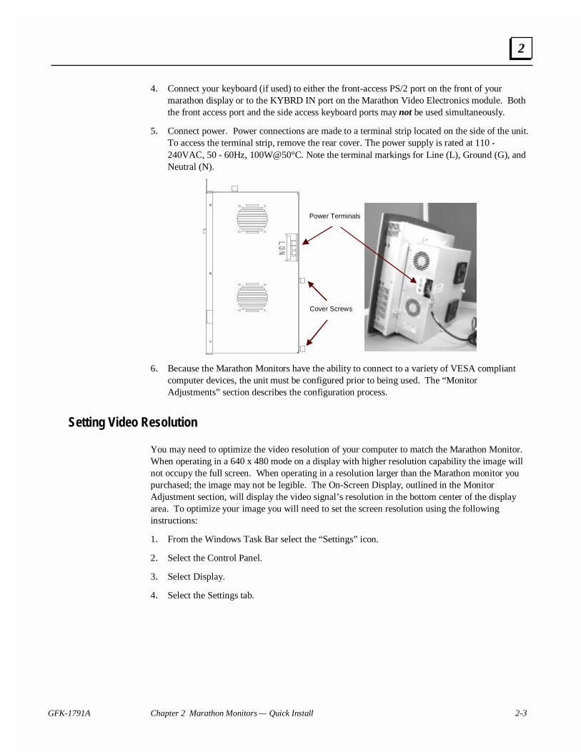
5. Connect power. Power connections are made to a terminal strip located on the side of the unit.To access the terminal strip, remove the rear cover. The power supply is rated at 110 -240VAC, 50 - 60Hz, 100W@50°C. Note the terminal markings for Line (L), Ground (G), andNeutral (N).
Cover Screws
Power Terminals
6. Because the Marathon Monitors have the ability to connect to a variety of VESA compliantcomputer devices, the unit must be configured prior to being used. The “MonitorAdjustments” section describes the configuration process.
Setting Video Resolution
You may need to optimize the video resolution of your computer to match the Marathon Monitor.When operating in a 640 x 480 mode on a display with higher resolution capability the image willnot occupy the full screen. When operating in a resolution larger than the Marathon monitor youpurchased; the image may not be legible. The On-Screen Display, outlined in the MonitorAdjustment section, will display the video signal’s resolution in the bottom center of the displayarea. To optimize your image you will need to set the screen resolution using the followinginstructions:
1. From the Windows Task Bar select the “Settings” icon.
2. Select the Control Panel.
3. Select Display.
4. Select the Settings tab.

2-4 Marathon Series Industrial Computers and Monitors User's Manual – April 2001 GFK-1791A
2
5. In the box labeled Desktop Area select the proper resolution for your Marathon Display usingthe table below:
Model # Screen Resolution
MSDIS-1200/1210 800 x 600
MSDIS-1500/1510 1024 x 768
6. Click the Test button to verify that the changes you have selected are working properly.
7. After the 5 second test mode has completed, click OK, followed by the Apply button. Yourdisplay should now be set up properly.
Switch Box Installation
1. Locate the SWITCHES connector on the Marathon Monitor Video Electronics Module andconnect the cable from the switch box to the port.
2. Press the FCTN key to display the On-Screen-Display (OSD) menu.
The switch box contains firmware that monitors switch activity and responds accordingly. TheOSD menus provide visual confirmation of selections and adjustments by highlighting selectionsand modifying on-screen bar-graph levels.
The Video Electronics module is initialized during power-on to the last known saved conditions.All parameters are saved when you exit the menus, or by a sixty second time out.

GFK-1791A Chapter 2 Marathon Monitors — Quick Install 2-5
2
Installing the Dynapro SC3 Driver
1. Insert Dynapro SC3 Driver disk into your computer's floppy drive.
2. Run A:\INSTALL.EXE.
Driver and Path verification screen: These settings are not modifiable. They are forverifying the driver and version that is being installed. Click Next.
Configuration Screen: For MSDIS, MSMON combination - change COM Port to that whichthe DB9 cable is attached to on the PC. Verify IRQ and I/O address are those that are definedin CMOS. Click Next.
Install Parameter Summary Screen: Verify settings are correct.
3. Click Install.
4. After installation is complete, restart Windows for the changes to take effect by clicking “Yes”when prompted.
5. Remove floppy disk while system is rebooting.
6. Cursor may not respond correctly to touches after system has finished booting for the firsttime.
7. Run Driver Configuration as described in “Calibrating the Dynapro SC3 Driver.”
Calibrating the Dynapro SC3 Driver
Note: The cursor may not respond to the touchscreen correctly aftersystem has finished booting for the first time.
1. Run Start – Programs – Touch Screen Utilities – Configuration.
2. Click “Interface…”
3. Click “Advanced…”
4. Change “Screen Wires:” from 4 to 8 using the pulldown menu.
5. Click “OK” to exit Advanced Controller Option.
6. Click “OK” to exit Interface Configuration Options.
7. Choose “Calibration…” on Configuration Utilities Screen.
8. Choose “Calibrate”
9. Touch the three targets as they appear on the screen, the first in the upper left corner, thesecond in the lower right, and the third in the middle right.
10. Click “OK” to exit calibration screen.
11. Click “Exit” to close Configuration Utility.
2-6 Marathon Series Industrial Computers and Monitors User's Manual – April 2001 GFK-1791A
2
Monitor Adjustments
An on-board micro-controller in the Marathon Video Electronics module provides main systemcontrol, system initialization, input mode auto-detection, and a user interface for monitoradjustments. An external switch box is connected to the user interface port (SWITCHES) andallows the user to make all monitor display adjustments.
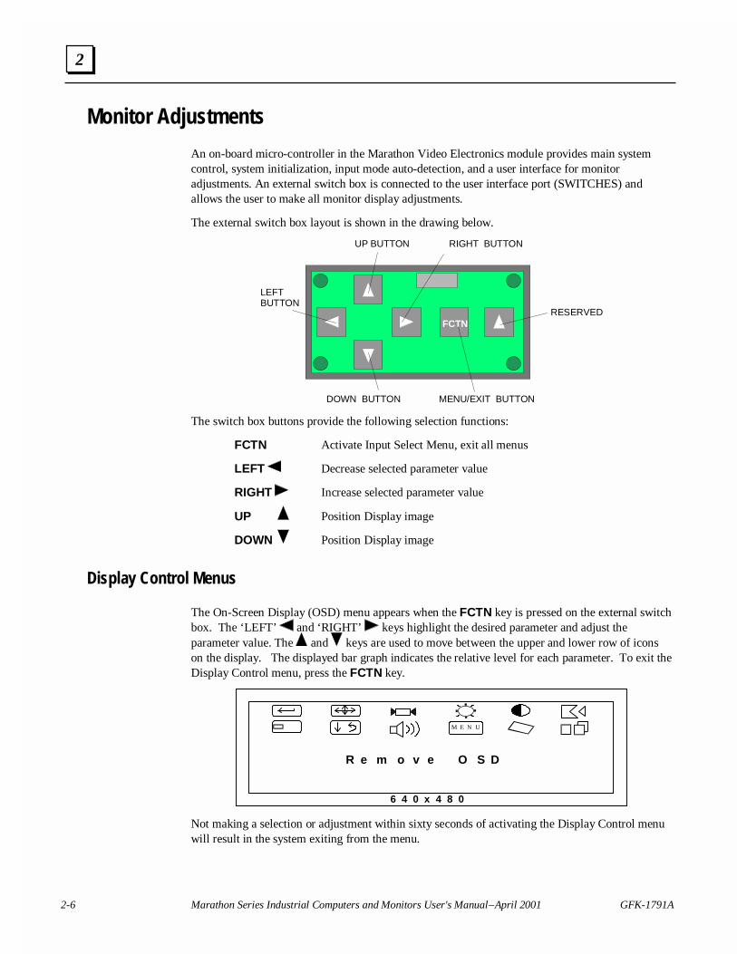
The external switch box layout is shown in the drawing below.
FCTN
UP BUTTON
DOWN BUTTON
LEFTBUTTON
RIGHT BUTTON
MENU/EXIT BUTTON
RESERVED
The switch box buttons provide the following selection functions:
FCTN Activate Input Select Menu, exit all menus
LEFT Decrease selected parameter value
RIGHT Increase selected parameter value
UP Position Display image
DOWN Position Display image
Display Control Menus
The On-Screen Display (OSD) menu appears when the FCTN key is pressed on the external switchbox. The ‘LEFT’ and ‘RIGHT’ keys highlight the desired parameter and adjust theparameter value. The and keys are used to move between the upper and lower row of iconson the display. The displayed bar graph indicates the relative level for each parameter. To exit theDisplay Control menu, press the FCTN key.
R e m o v e O S D
M E N U
6 4 0 x 4 8 0
Not making a selection or adjustment within sixty seconds of activating the Display Control menuwill result in the system exiting from the menu.
GFK-1791A Chapter 2 Marathon Monitors — Quick Install 2-7
2
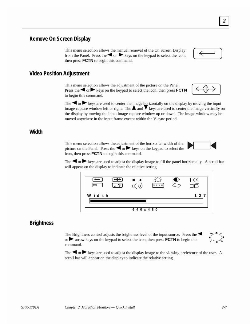
Remove On Screen Display
This menu selection allows the manual removal of the On Screen Displayfrom the Panel. Press the or keys on the keypad to select the icon,then press FCTN to begin this command.
Video Position Adjustment
This menu selection allows the adjustment of the picture on the Panel.Press the or keys on the keypad to select the icon, then press FCTNto begin this command.
The or keys are used to center the image horizontally on the display by moving the inputimage capture window left or right. The and keys are used to center the image vertically onthe display by moving the input image capture window up or down. The image window may bemoved anywhere in the input frame except within the V-sync period.
Width
This menu selection allows the adjustment of the horizontal width of thepicture on the Panel. Press the or keys on the keypad to select theicon, then press FCTN to begin this command.
The or keys are used to adjust the display image to fill the panel horizontally. A scroll barwill appear on the display to indicate the relative setting.
M E N U
W i d t h
6 4 0 x 4 8 0
1 2 7
Brightness
The Brightness control adjusts the brightness level of the input source. Press the or arrow keys on the keypad to select the icon, then press FCTN to begin thiscommand.
The or keys are used to adjust the display image to the viewing preference of the user. Ascroll bar will appear on the display to indicate the relative setting.
2-8 Marathon Series Industrial Computers and Monitors User's Manual – April 2001 GFK-1791A
2
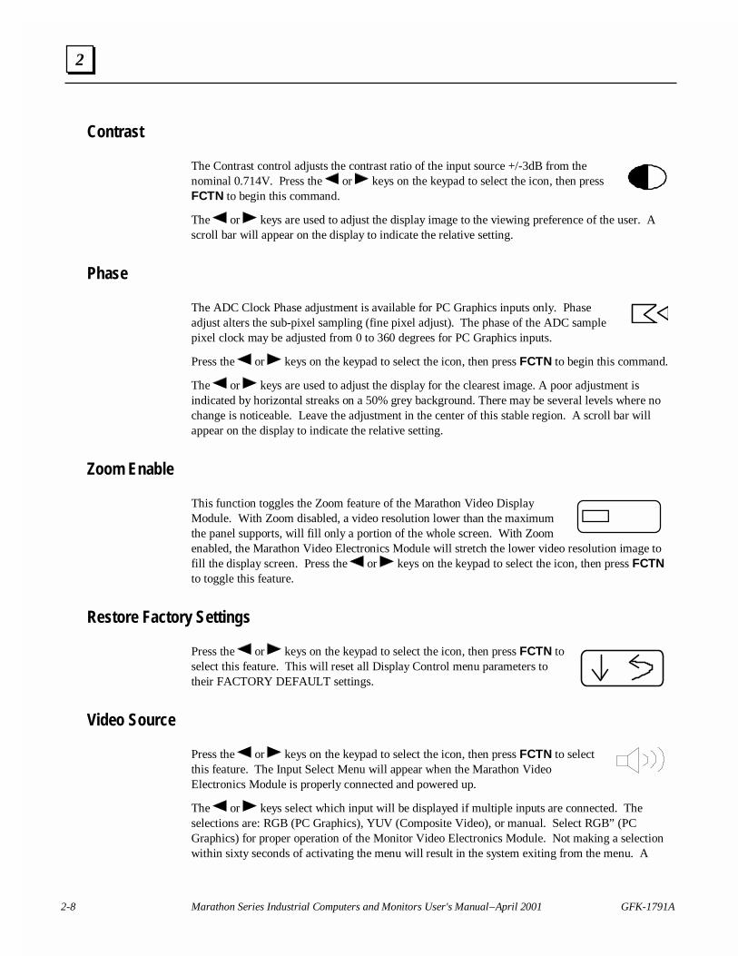
Contrast
The Contrast control adjusts the contrast ratio of the input source +/-3dB from thenominal 0.714V. Press the or keys on the keypad to select the icon, then pressFCTN to begin this command.
The or keys are used to adjust the display image to the viewing preference of the user. Ascroll bar will appear on the display to indicate the relative setting.
Phase
The ADC Clock Phase adjustment is available for PC Graphics inputs only. Phaseadjust alters the sub-pixel sampling (fine pixel adjust). The phase of the ADC samplepixel clock may be adjusted from 0 to 360 degrees for PC Graphics inputs.
Press the or keys on the keypad to select the icon, then press FCTN to begin this command.
The or keys are used to adjust the display for the clearest image. A poor adjustment isindicated by horizontal streaks on a 50% grey background. There may be several levels where nochange is noticeable. Leave the adjustment in the center of this stable region. A scroll bar willappear on the display to indicate the relative setting.
Zoom Enable
This function toggles the Zoom feature of the Marathon Video DisplayModule. With Zoom disabled, a video resolution lower than the maximumthe panel supports, will fill only a portion of the whole screen. With Zoomenabled, the Marathon Video Electronics Module will stretch the lower video resolution image tofill the display screen. Press the or keys on the keypad to select the icon, then press FCTNto toggle this feature.
Restore Factory Settings
Press the or keys on the keypad to select the icon, then press FCTN toselect this feature. This will reset all Display Control menu parameters totheir FACTORY DEFAULT settings.
Video Source
Press the or keys on the keypad to select the icon, then press FCTN to selectthis feature. The Input Select Menu will appear when the Marathon VideoElectronics Module is properly connected and powered up.
The or keys select which input will be displayed if multiple inputs are connected. Theselections are: RGB (PC Graphics), YUV (Composite Video), or manual. Select RGB” (PCGraphics) for proper operation of the Monitor Video Electronics Module. Not making a selectionwithin sixty seconds of activating the menu will result in the system exiting from the menu. A
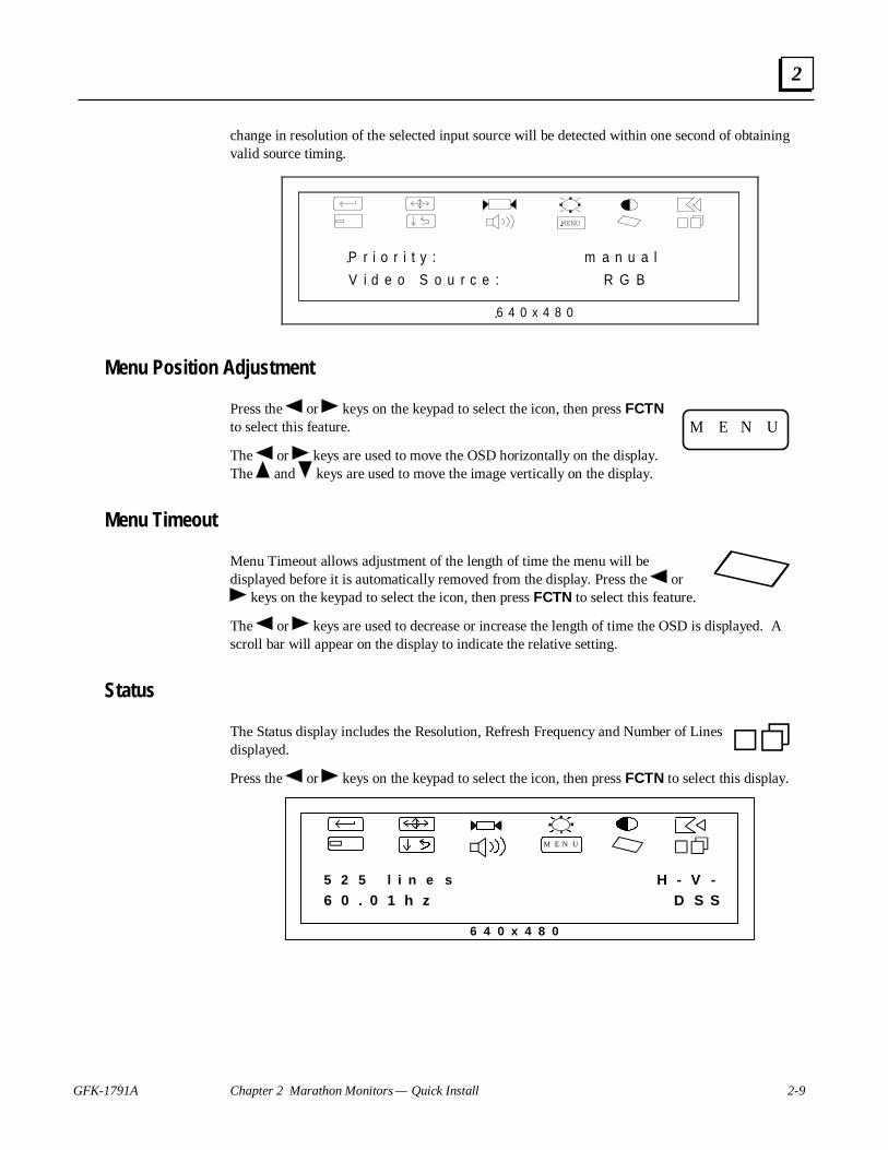
GFK-1791A Chapter 2 Marathon Monitors — Quick Install 2-9
2
change in resolution of the selected input source will be detected within one second of obtainingvalid source timing.
MENU
V i d e o S o u r c e : R G B
6 4 0 x 4 8 0
P r i o r i t y : m a n u a l
Menu Position Adjustment
Press the or keys on the keypad to select the icon, then press FCTNto select this feature.
The or keys are used to move the OSD horizontally on the display.The and keys are used to move the image vertically on the display.
Menu Timeout
Menu Timeout allows adjustment of the length of time the menu will bedisplayed before it is automatically removed from the display. Press the or
keys on the keypad to select the icon, then press FCTN to select this feature.
The or keys are used to decrease or increase the length of time the OSD is displayed. Ascroll bar will appear on the display to indicate the relative setting.
Status
The Status display includes the Resolution, Refresh Frequency and Number of Linesdisplayed.
Press the or keys on the keypad to select the icon, then press FCTN to select this display.
H - V -
M E N U
6 4 0 x 4 8 0
D S S5 2 5 l i n e s6 0 . 0 1 h z
M E N U
GFK-1791A 3-1
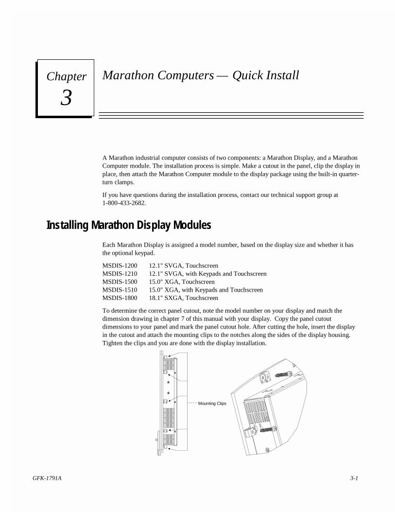
Marathon Computers — Quick Install
A Marathon industrial computer consists of two components: a Marathon Display, and a MarathonComputer module. The installation process is simple. Make a cutout in the panel, clip the display inplace, then attach the Marathon Computer module to the display package using the built-in quarter-turn clamps.
If you have questions during the installation process, contact our technical support group at1-800-433-2682.
Installing Marathon Display Modules
Each Marathon Display is assigned a model number, based on the display size and whether it hasthe optional keypad.
MSDIS-1200 12.1" SVGA, TouchscreenMSDIS-1210 12.1" SVGA, with Keypads and TouchscreenMSDIS-1500 15.0" XGA, TouchscreenMSDIS-1510 15.0" XGA, with Keypads and TouchscreenMSDIS-1800 18.1" SXGA, Touchscreen
To determine the correct panel cutout, note the model number on your display and match thedimension drawing in chapter 7 of this manual with your display. Copy the panel cutoutdimensions to your panel and mark the panel cutout hole. After cutting the hole, insert the displayin the cutout and attach the mounting clips to the notches along the sides of the display housing.Tighten the clips and you are done with the display installation.
Mounting Clips
3Chapter
3-2 Marathon Series Industrial Computers and Monitors User's Manual – April 2001 GFK-1791A
3
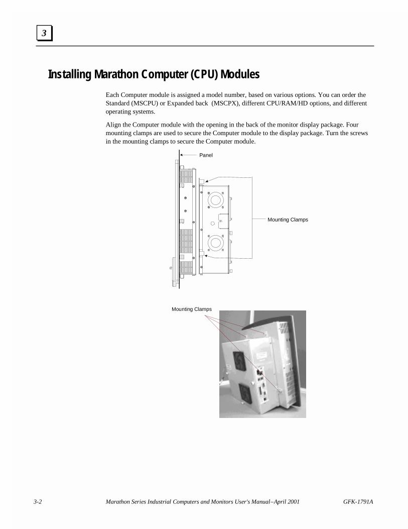
Installing Marathon Computer (CPU) Modules
Each Computer module is assigned a model number, based on various options. You can order theStandard (MSCPU) or Expanded back (MSCPX), different CPU/RAM/HD options, and differentoperating systems.
Align the Computer module with the opening in the back of the monitor display package. Fourmounting clamps are used to secure the Computer module to the display package. Turn the screwsin the mounting clamps to secure the Computer module.
Mounting Clamps
Panel
Mounting Clamps
GFK-1791A Chapter 3 Marathon Computers — Quick Install 3-3
3
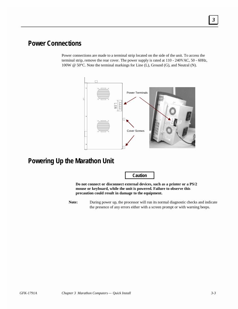
Power Connections
Power connections are made to a terminal strip located on the side of the unit. To access theterminal strip, remove the rear cover. The power supply is rated at 110 - 240VAC, 50 - 60Hz,100W @ 50°C. Note the terminal markings for Line (L), Ground (G), and Neutral (N).
Cover Screws
Power Terminals
Powering Up the Marathon Unit
Caution
Do not connect or disconnect external devices, such as a printer or a PS/2mouse or keyboard, while the unit is powered. Failure to observe thisprecaution could result in damage to the equipment.
Note: During power up, the processor will run its normal diagnostic checks and indicatethe presence of any errors either with a screen prompt or with warning beeps.
3-4 Marathon Series Industrial Computers and Monitors User's Manual – April 2001 GFK-1791A
3
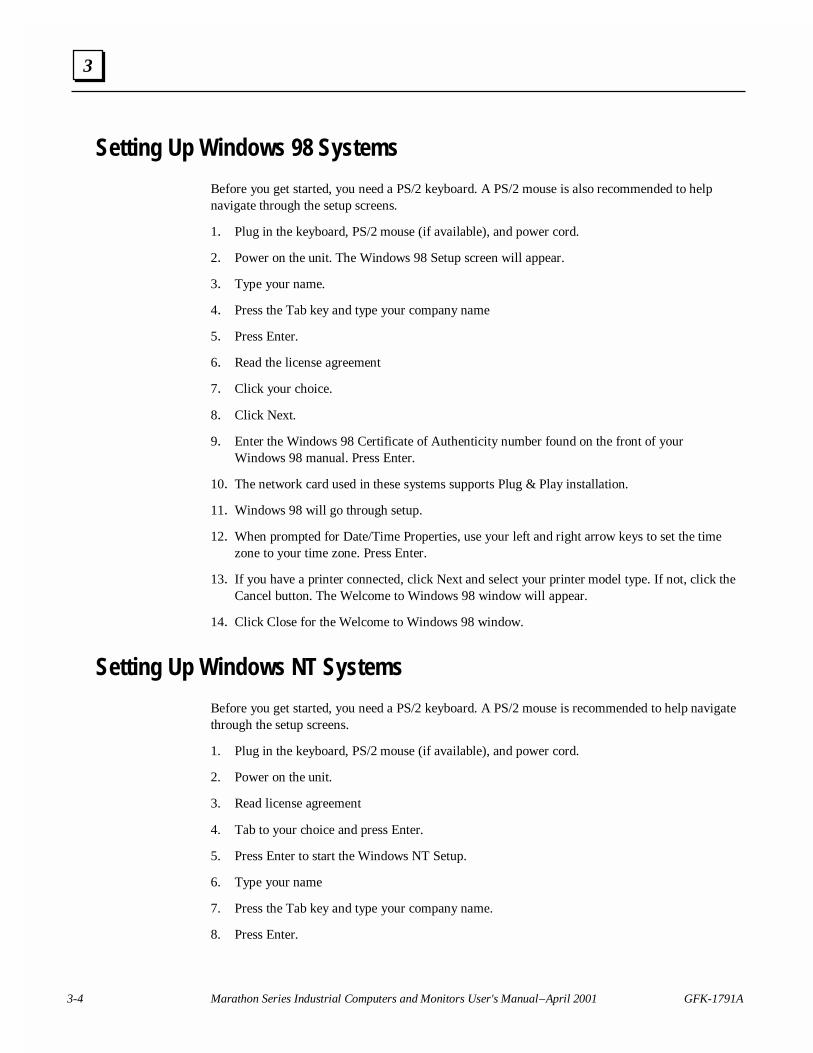
Setting Up Windows 98 Systems
Before you get started, you need a PS/2 keyboard. A PS/2 mouse is also recommended to helpnavigate through the setup screens.
1. Plug in the keyboard, PS/2 mouse (if available), and power cord.
2. Power on the unit. The Windows 98 Setup screen will appear.
3. Type your name.
4. Press the Tab key and type your company name
5. Press Enter.
6. Read the license agreement
7. Click your choice.
8. Click Next.
9. Enter the Windows 98 Certificate of Authenticity number found on the front of yourWindows 98 manual. Press Enter.
10. The network card used in these systems supports Plug & Play installation.
11. Windows 98 will go through setup.
12. When prompted for Date/Time Properties, use your left and right arrow keys to set the timezone to your time zone. Press Enter.
13. If you have a printer connected, click Next and select your printer model type. If not, click theCancel button. The Welcome to Windows 98 window will appear.
14. Click Close for the Welcome to Windows 98 window.
Setting Up Windows NT Systems
Before you get started, you need a PS/2 keyboard. A PS/2 mouse is recommended to help navigatethrough the setup screens.
1. Plug in the keyboard, PS/2 mouse (if available), and power cord.
2. Power on the unit.
3. Read license agreement
4. Tab to your choice and press Enter.
5. Press Enter to start the Windows NT Setup.
6. Type your name
7. Press the Tab key and type your company name.
8. Press Enter.
GFK-1791A Chapter 3 Marathon Computers — Quick Install 3-5
3
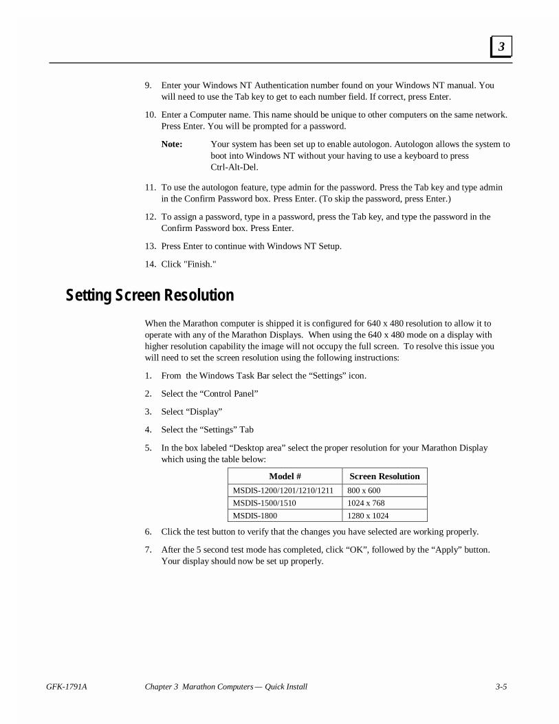
9. Enter your Windows NT Authentication number found on your Windows NT manual. Youwill need to use the Tab key to get to each number field. If correct, press Enter.
10. Enter a Computer name. This name should be unique to other computers on the same network.Press Enter. You will be prompted for a password.
Note: Your system has been set up to enable autologon. Autologon allows the system toboot into Windows NT without your having to use a keyboard to pressCtrl-Alt-Del.
11. To use the autologon feature, type admin for the password. Press the Tab key and type adminin the Confirm Password box. Press Enter. (To skip the password, press Enter.)
12. To assign a password, type in a password, press the Tab key, and type the password in theConfirm Password box. Press Enter.
13. Press Enter to continue with Windows NT Setup.
14. Click "Finish."
Setting Screen Resolution
When the Marathon computer is shipped it is configured for 640 x 480 resolution to allow it tooperate with any of the Marathon Displays. When using the 640 x 480 mode on a display withhigher resolution capability the image will not occupy the full screen. To resolve this issue youwill need to set the screen resolution using the following instructions:
1. From the Windows Task Bar select the “Settings” icon.
2. Select the “Control Panel”
3. Select “Display”
4. Select the “Settings” Tab
5. In the box labeled “Desktop area” select the proper resolution for your Marathon Displaywhich using the table below:
Model # Screen Resolution
MSDIS-1200/1201/1210/1211 800 x 600
MSDIS-1500/1510 1024 x 768
MSDIS-1800 1280 x 1024
6. Click the test button to verify that the changes you have selected are working properly.
7. After the 5 second test mode has completed, click “OK”, followed by the “Apply” button.Your display should now be set up properly.

3-6 Marathon Series Industrial Computers and Monitors User's Manual – April 2001 GFK-1791A
3
Calibrating the Touchscreen
The first time you Power on the Marathon Computer you will need to calibrate the touchscreenusing the steps listed below:
1. From the Windows taskbar select Programs.
2. Select Touch Screen Utilities.
3. Select Calibrate and follow the directions on your screen.
Configuring the Marathon Computer to Run on a Microsoft Network
Before setting up your new Marathon Computer for the network, you should consult with yournetwork administrator. Duplicate TCP/IP addresses and duplicate computer names on the samenetwork can cause network problems.
1. Click the Start icon, then click Settings and Control Panel.
2. In the Control Panel window, double click the Network icon. The Network dialog box willappear.
3. In the Network dialog box, click the Identification tab. You will need to type in your Computername, Workgroup name, and Computer Description.
4. To allow sharing,
A. Go to the Configuration tab and click the File and Print Sharing button. The File and PrintSharing dialog box will appear.
B. Check the File and Print Sharing options that you want and click OK.
5. To add the TCP/IP protocol,
A. Go to the Configuration tab and click the Add button. The Select Network Componentdialog box will appear.
B. Click the Protocol icon and click Add. The Select Network Protocol dialog box willappear.
C. In the Manufacturer list, select Microsoft. In the Protocol list, select TCP/IP. Click OK.
D. Change the Address from 10.0.0.1 to a unique address. Change the default subnet mask255.0.0.0 to your subnet mask.
E. Click OK twice.
6. When you have finished setting up the Network, click OK in the Network dialog box. ClickYes to reboot your system now.
Login Recommendation
If you type admin as your Administrator password, you will automatically log on as Administrator.
GFK-1791A 4-1
Keypad and Connector Information
Keypads
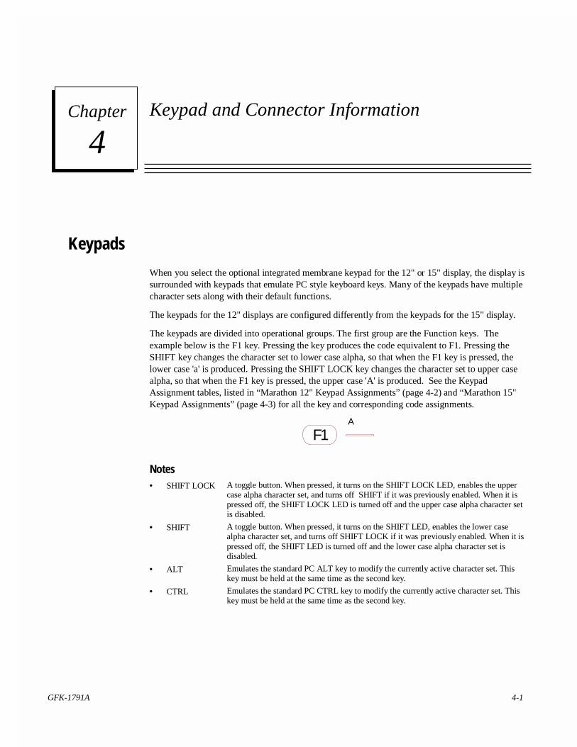
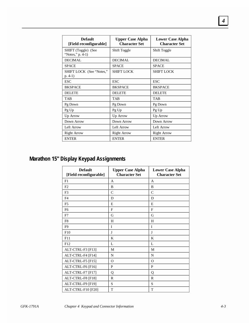
When you select the optional integrated membrane keypad for the 12" or 15" display, the display issurrounded with keypads that emulate PC style keyboard keys. Many of the keypads have multiplecharacter sets along with their default functions.
The keypads for the 12" displays are configured differently from the keypads for the 15" display.
The keypads are divided into operational groups. The first group are the Function keys. Theexample below is the F1 key. Pressing the key produces the code equivalent to F1. Pressing theSHIFT key changes the character set to lower case alpha, so that when the F1 key is pressed, thelower case 'a' is produced. Pressing the SHIFT LOCK key changes the character set to upper casealpha, so that when the F1 key is pressed, the upper case 'A' is produced. See the KeypadAssignment tables, listed in “Marathon 12" Keypad Assignments” (page 4-2) and “Marathon 15"Keypad Assignments” (page 4-3) for all the key and corresponding code assignments.
A
F1
Notes• SHIFT LOCK A toggle button. When pressed, it turns on the SHIFT LOCK LED, enables the upper
case alpha character set, and turns off SHIFT if it was previously enabled. When it ispressed off, the SHIFT LOCK LED is turned off and the upper case alpha character setis disabled.
• SHIFT A toggle button. When pressed, it turns on the SHIFT LED, enables the lower casealpha character set, and turns off SHIFT LOCK if it was previously enabled. When it ispressed off, the SHIFT LED is turned off and the lower case alpha character set isdisabled.
• ALT Emulates the standard PC ALT key to modify the currently active character set. Thiskey must be held at the same time as the second key.
• CTRL Emulates the standard PC CTRL key to modify the currently active character set. Thiskey must be held at the same time as the second key.
4Chapter
4-2 Marathon Series Industrial Computers and Monitors User's Manual – April 2001 GFK-1791A
4
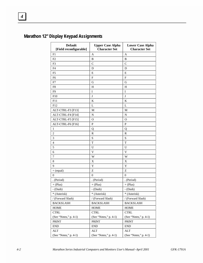
Marathon 12" Display Keypad Assignments
Default[Field reconfigurable]
Upper Case AlphaCharacter Set
Lower Case AlphaCharacter Set
F1 A A
F2 B B
F3 C C
F4 D D
F5 E E
F6 F F
F7 G G
F8 H H
F9 I I
F10 J J
F11 K K
F12 L L
ALT-CTRL-F3 [F13] M M
ALT-CTRL-F4 [F14] N N
ALT-CTRL-F5 [F15] O O
ALT-CTRL-F6 [F16] P P
1 Q Q
2 R R
3 S S
4 T T
5 U U
6 V V
7 W W
8 X X
9 Y Y
= (equal) Z Z
0 0 0
. (Period) . (Period) . (Period)
+ (Plus) + (Plus) + (Plus)
- (Dash) - (Dash) - (Dash)
* (Asterisk) * (Asterisk) * (Asterisk)
/ (Forward Slash) / (Forward Slash) / (Forward Slash)
BACKSLASH BACKSLASH BACKSLASH
HOME HOME HOME
CTRL
(See “Notes,” p. 4-1)
CTRL
(See “Notes,” p. 4-1)
CTRL
(See “Notes,” p. 4-1)
PRINT PRINT PRINT
END END END
ALT
(See “Notes,” p. 4-1)
ALT
(See “Notes,” p. 4-1)
ALT
(See “Notes,” p. 4-1)
GFK-1791A Chapter 4 Keypad and Connector Information 4-3
4
Default[Field reconfigurable]
Upper Case AlphaCharacter Set
Lower Case AlphaCharacter Set
SHIFT (Toggle) (See“Notes,” p. 4-1)
Shift Toggle Shift Toggle
DECIMAL DECIMAL DECIMAL
SPACE SPACE SPACE
SHIFT LOCK (See “Notes,”p. 4-1)
SHIFT LOCK SHIFT LOCK
ESC ESC ESC
BKSPACE BKSPACE BKSPACE
DELETE DELETE DELETE
TAB TAB TAB
Pg Down Pg Down Pg Down
Pg Up Pg Up Pg Up
Up Arrow Up Arrow Up Arrow
Down Arrow Down Arrow Down Arrow
Left Arrow Left Arrow Left Arrow
Right Arrow Right Arrow Right Arrow
ENTER ENTER ENTER
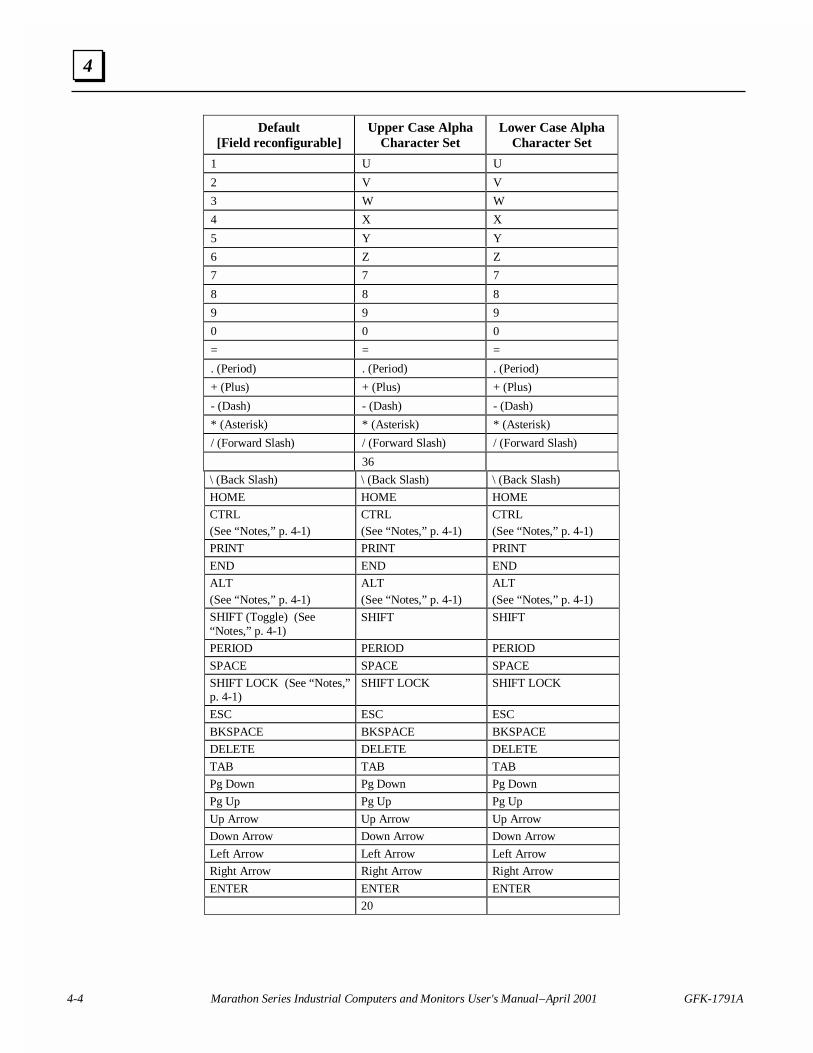
Marathon 15" Display Keypad Assignments
Default[Field reconfigurable]
Upper Case AlphaCharacter Set
Lower Case AlphaCharacter Set
F1 A A
F2 B B
F3 C C
F4 D D
F5 E E
F6 F F
F7 G G
F8 H H
F9 I I
F10 J J
F11 K K
F12 L L
ALT-CTRL-F3 [F13] M M
ALT-CTRL-F4 [F14] N N
ALT-CTRL-F5 [F15] O O
ALT-CTRL-F6 [F16] P P
ALT-CTRL-F7 [F17] Q Q
ALT-CTRL-F8 [F18] R R
ALT-CTRL-F9 [F19] S S
ALT-CTRL-F10 [F20] T T
4-4 Marathon Series Industrial Computers and Monitors User's Manual – April 2001 GFK-1791A
4
Default[Field reconfigurable]
Upper Case AlphaCharacter Set
Lower Case AlphaCharacter Set
1 U U
2 V V
3 W W
4 X X
5 Y Y
6 Z Z
7 7 7
8 8 8
9 9 9
0 0 0
= = =
. (Period) . (Period) . (Period)
+ (Plus) + (Plus) + (Plus)
- (Dash) - (Dash) - (Dash)
* (Asterisk) * (Asterisk) * (Asterisk)
/ (Forward Slash) / (Forward Slash) / (Forward Slash)
36
\ (Back Slash) \ (Back Slash) \ (Back Slash)
HOME HOME HOME
CTRL(See “Notes,” p. 4-1)
CTRL(See “Notes,” p. 4-1)
CTRL(See “Notes,” p. 4-1)
PRINT PRINT PRINT
END END END
ALT(See “Notes,” p. 4-1)
ALT(See “Notes,” p. 4-1)
ALT(See “Notes,” p. 4-1)
SHIFT (Toggle) (See“Notes,” p. 4-1)
SHIFT SHIFT
PERIOD PERIOD PERIOD
SPACE SPACE SPACE
SHIFT LOCK (See “Notes,”p. 4-1)
SHIFT LOCK SHIFT LOCK
ESC ESC ESC
BKSPACE BKSPACE BKSPACE
DELETE DELETE DELETE
TAB TAB TAB
Pg Down Pg Down Pg Down
Pg Up Pg Up Pg Up
Up Arrow Up Arrow Up Arrow
Down Arrow Down Arrow Down Arrow
Left Arrow Left Arrow Left Arrow
Right Arrow Right Arrow Right Arrow
ENTER ENTER ENTER
20
GFK-1791A Chapter 4 Keypad and Connector Information 4-5
4
Connectors
Caution
External devices (printer, external disk drive etc.) should not be connectedor disconnected from the industrial computer when the unit is powered up.
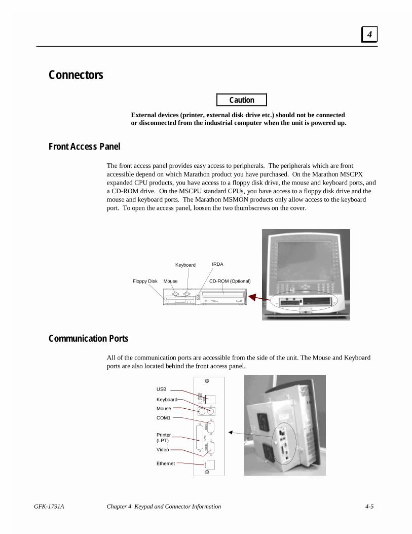
Front Access Panel
The front access panel provides easy access to peripherals. The peripherals which are frontaccessible depend on which Marathon product you have purchased. On the Marathon MSCPXexpanded CPU products, you have access to a floppy disk drive, the mouse and keyboard ports, anda CD-ROM drive. On the MSCPU standard CPUs, you have access to a floppy disk drive and themouse and keyboard ports. The Marathon MSMON products only allow access to the keyboardport. To open the access panel, loosen the two thumbscrews on the cover.
Floppy Disk Mouse
Keyboard
CD-ROM (Optional)
IRDA
Communication Ports
All of the communication ports are accessible from the side of the unit. The Mouse and Keyboardports are also located behind the front access panel.
Ethernet
Video
Printer (LPT)
COM1
Mouse
Keyboard
USB
E-N
ET
VID
EO
LPT1
CO
M 1
1 -
MO
US
E2
- K
YB
RD
US
B1 2

4-6 Marathon Series Industrial Computers and Monitors User's Manual – April 2001 GFK-1791A
4
Connector Description
VGA Video Connector VGA, DB-15 output. A VGA monitor can beconnected to the Marathon Computer products if anexternal monitor is required during the developmentprocess. This option is not available on the MarathonMonitor products.
Serial Port Connector The Marathon MSCPU and MSCPX products haveone RS-232 serial port (COM 1) available on the sideof the computer module. The second serial port isused for the touchscreen and is not available for theuser.
Printer Port (LPT1) Parallel, DB-25 Centronix compatible.
USB Ports Two industry standard USB ports.
Keyboard Connector Industry standard PS/2 keyboard connector.
PS/2 Mouse Industry standard PS/2 mouse connector.
IrDA (Infrared Data Association) Port The IrDA port interfaces with an optical module forwireless communication with other IrDA devices.The IrDA LEDs are accessible from the front accessdoor on the MSDIS Marathon displays. The IrDAport is only available when the Marathon displaymodule is connected to an MSCPU or MSCPXMarathon CPU. This option is not available whenusing an MSMON Monitor Video ElectronicsModule.
Ethernet Port (E-NET) Industry standard RJ-45 port for 10/100baseTEthernet.
Note: For pinouts, refer to "Connectors" in Chapter 6.
ISA and PCI Expansion on the Marathon MSCPX CPUs
Before applying power to your Marathon computer you will need to install any PCI or ISA cardsrequired for your application. The Marathon MSCPX Expanded CPU backplane has two slotsdedicated to ISA expansion cards and two slots that can be used for either ISA or PCI cards.
To install cards, remove the back cover from the MSCPX CPU module by removing the five thumbscrews. Once you have removed the cover, remove the blank orbs for the slots in which you willinstall cards. After you have completed the installation of your boards simply reinstall the backcover.
Note: There are actually three PCI slots on the Marathon MSCPX CPU backplane.Only two PCI slots can be used unless the on-board Ethernet controller isdisabled.
Note: The ISA and PCI cards installed in the Marathon MSCPX chassis can have amaximum card length of 9 inches.
GFK-1791A 5-1
BIOS Setup Guide
The Marathon CPU modules are shipped with the BIOS already configured for proper operation.This chapter summarizes the complete BIOS functionality for customers who require a customBIOS configuration.
Use the Phoenix BIOS Setup program for:
• Setting system time and date
• Installing new drives for hard disks and floppy disks
• Enhancing system performance by controlling advanced features such as shadow memory andcache memory
• Configuring system resources
• Setting security passwords
Caution
Incorrect settings can cause your system to malfunction.
5Chapter
5-2 Marathon Series Industrial Computers and Monitors User's Manual – April 2001 GFK-1791A
5
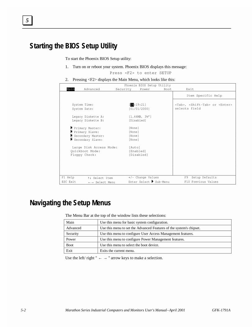
Starting the BIOS Setup Utility
To start the Phoenix BIOS Setup utility:
1. Turn on or reboot your system. Phoenix BIOS displays this message:
Press <F2> to enter SETUP
2. Pressing <F2> displays the Main Menu, which looks like this:Phoenix BIOS Setup Utility
Main Advanced Security Power Boot Exit
Item Specific Help
System Time: [16:19:21]System Date: [01/01/2000]
<Tab>, <Shift-Tab> or <Enter>selects field
Legacy Diskette A: [1.44MB, 3½”]Legacy Diskette B: [Disabled]
Primary Master: [None] Primary Slave: [None] Secondary Master: [None] Secondary Slave: [None]
Large Disk Access Mode: [Auto]Quickboot Mode: [Enabled]Floppy Check: [Disabled]
F1 Help ↑↓ Select Item +/- Change Values F9 Setup Defaults
ESC Exit ←→ Select Menu Enter Select Sub-Menu F10 Previous Values
Navigating the Setup Menus
The Menu Bar at the top of the window lists these selections:
Main Use this menu for basic system configuration.
Advanced Use this menu to set the Advanced Features of the system's chipset.
Security Use this menu to configure User Access Management features.
Power Use this menu to configure Power Management features.
Boot Use this menu to select the boot device.
Exit Exits the current menu.
Use the left/ right " ← → " arrow keys to make a selection.
GFK-1791A Chapter 5 BIOS Setup Guide 5-3
5
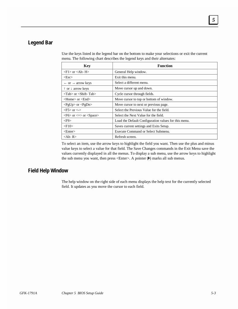
Legend Bar
Use the keys listed in the legend bar on the bottom to make your selections or exit the currentmenu. The following chart describes the legend keys and their alternates:
Key Function
<F1> or <Alt- H> General Help window.
<Esc> Exit this menu.
← or → arrow keys Select a different menu.
↑ or ↓ arrow keys Move cursor up and down.
<Tab> or <Shift- Tab> Cycle cursor through fields.
<Home> or <End> Move cursor to top or bottom of window.
<PgUp> or <PgDn> Move cursor to next or previous page.
<F5> or <-> Select the Previous Value for the field.
<F6> or <+> or <Space> Select the Next Value for the field.
<F9> Load the Default Configuration values for this menu.
<F10> Saves current settings and Exits Setup.
<Enter> Execute Command or Select Submenu.
<Alt- R> Refresh screen.
To select an item, use the arrow keys to highlight the field you want. Then use the plus and minusvalue keys to select a value for that field. The Save Changes commands in the Exit Menu save thevalues currently displayed in all the menus. To display a sub menu, use the arrow keys to highlightthe sub menu you want, then press <Enter>. A pointer ( ) marks all sub menus.
Field Help Window
The help window on the right side of each menu displays the help text for the currently selectedfield. It updates as you move the cursor to each field.
5-4 Marathon Series Industrial Computers and Monitors User's Manual – April 2001 GFK-1791A
5
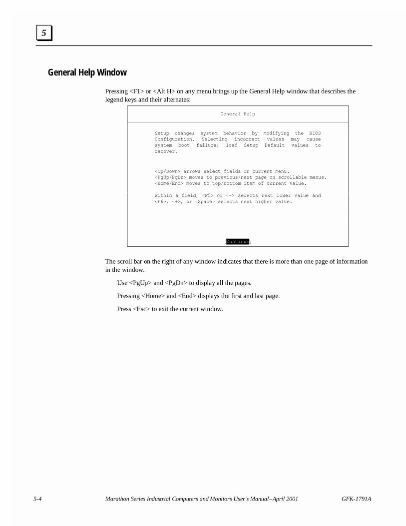
General Help Window
Pressing <F1> or <Alt H> on any menu brings up the General Help window that describes thelegend keys and their alternates:
General Help
Setup changes system behavior by modifying the BIOSConfiguration. Selecting incorrect values may causesystem boot failure; load Setup Default values torecover.
<Up/Down> arrows select fields in current menu.<PgUp/PgDn> moves to previous/next page on scrollable menus.<Home/End> moves to top/bottom item of current value.
Within a field, <F5> or <-> selects next lower value and<F6>, <+>, or <Space> selects next higher value.
[Continue]
The scroll bar on the right of any window indicates that there is more than one page of informationin the window.
Use <PgUp> and <PgDn> to display all the pages.
Pressing <Home> and <End> displays the first and last page.
Press <Esc> to exit the current window.
GFK-1791A Chapter 5 BIOS Setup Guide 5-5
5
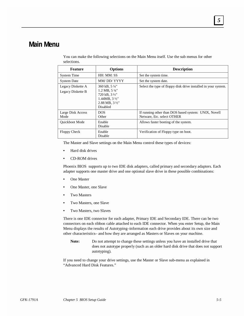
Main Menu
You can make the following selections on the Main Menu itself. Use the sub menus for otherselections.
Feature Options Description
System Time HH: MM: SS Set the system time.
System Date MM/ DD/ YYYY Set the system date.
Legacy Diskette A
Legacy Diskette B
360 kB, 5 ¼"1.2 MB, 5 ¼"720 kB, 3 ½"1.44MB, 3 ½"2.88 MB, 3 ½"Disabled
Select the type of floppy disk drive installed in your system.
Large Disk AccessMode
DOSOther
If running other than DOS based system: UNIX, NovellNetware, Etc. select OTHER
Quickboot Mode EnableDisable
Allows faster booting of the system.
Floppy Check EnableDisable
Verification of Floppy type on boot.
The Master and Slave settings on the Main Menu control these types of devices:
• Hard disk drives
• CD-ROM drives
Phoenix BIOS supports up to two IDE disk adapters, called primary and secondary adapters. Eachadapter supports one master drive and one optional slave drive in these possible combinations:
• One Master
• One Master, one Slave
• Two Masters
• Two Masters, one Slave
• Two Masters, two Slaves
There is one IDE connector for each adapter, Primary IDE and Secondary IDE. There can be twoconnectors on each ribbon cable attached to each IDE connector. When you enter Setup, the MainMenu displays the results of Autotyping–information each drive provides about its own size andother characteristics– and how they are arranged as Masters or Slaves on your machine.
Note: Do not attempt to change these settings unless you have an installed drive thatdoes not autotype properly (such as an older hard disk drive that does not supportautotyping).
If you need to change your drive settings, use the Master or Slave sub-menu as explained in“Advanced Hard Disk Features.”
5-6 Marathon Series Industrial Computers and Monitors User's Manual – April 2001 GFK-1791A
5
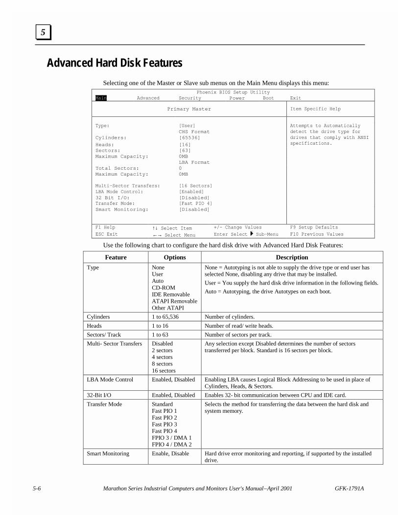
Advanced Hard Disk Features
Selecting one of the Master or Slave sub menus on the Main Menu displays this menu:Phoenix BIOS Setup Utility
Main Advanced Security Power Boot Exit
Primary Master Item Specific Help
Type: [User]CHS Format
Cylinders: [65536]
Heads: [16]Sectors: [63]Maximum Capacity: 0MB
LBA FormatTotal Sectors: 0
Attempts to Automaticallydetect the drive type fordrives that comply with ANSIspecifications.
Maximum Capacity: 0MB
Multi-Sector Transfers: [16 Sectors]LBA Mode Control: [Enabled]32 Bit I/O: [Disabled]Transfer Mode: [Fast PIO 4]Smart Monitoring: [Disabled]
F1 Help ↑↓ Select Item +/- Change Values F9 Setup Defaults
ESC Exit ←→ Select Menu Enter Select Sub-Menu F10 Previous Values
Use the following chart to configure the hard disk drive with Advanced Hard Disk Features:
Feature Options Description
Type NoneUserAutoCD-ROMIDE RemovableATAPI RemovableOther ATAPI
None = Autotyping is not able to supply the drive type or end user hasselected None, disabling any drive that may be installed.
User = You supply the hard disk drive information in the following fields.
Auto = Autotyping, the drive Autotypes on each boot.
Cylinders 1 to 65,536 Number of cylinders.
Heads 1 to 16 Number of read/ write heads.
Sectors/ Track 1 to 63 Number of sectors per track.
Multi- Sector Transfers Disabled2 sectors4 sectors8 sectors16 sectors
Any selection except Disabled determines the number of sectorstransferred per block. Standard is 16 sectors per block.
LBA Mode Control Enabled, Disabled Enabling LBA causes Logical Block Addressing to be used in place ofCylinders, Heads, & Sectors.
32-Bit I/O Enabled, Disabled Enables 32- bit communication between CPU and IDE card.
Transfer Mode StandardFast PIO 1Fast PIO 2Fast PIO 3Fast PIO 4FPIO 3 / DMA 1FPIO 4 / DMA 2
Selects the method for transferring the data between the hard disk andsystem memory.
Smart Monitoring Enable, Disable Hard drive error monitoring and reporting, if supported by the installeddrive.
GFK-1791A Chapter 5 BIOS Setup Guide 5-7
5
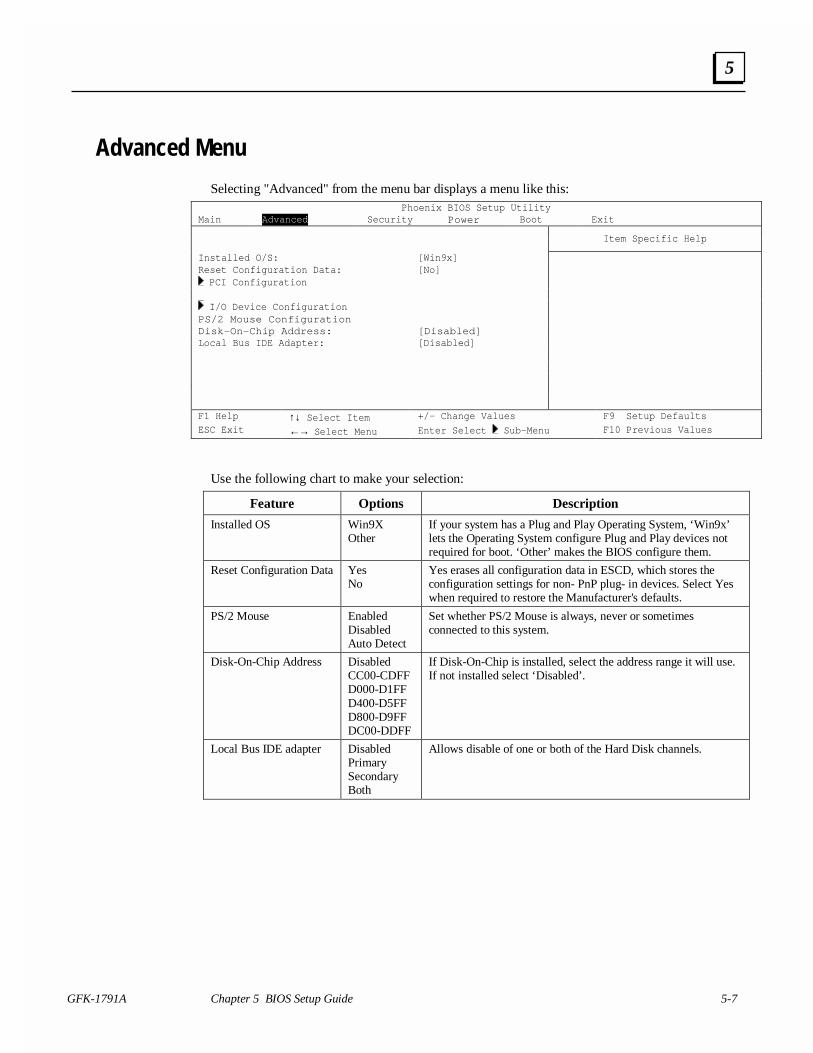
Advanced Menu
Selecting "Advanced" from the menu bar displays a menu like this:Phoenix BIOS Setup Utility
Main Advanced Security Power Boot Exit
Item Specific Help
Installed O/S: [Win9x]Reset Configuration Data: [No] PCI Configuration
I/O Device ConfigurationPS/2 Mouse ConfigurationDisk-On-Chip Address: [Disabled]Local Bus IDE Adapter: [Disabled]
F1 Help ↑↓ Select Item +/- Change Values F9 Setup DefaultsESC Exit ←→ Select Menu Enter Select Sub-Menu F10 Previous Values
Use the following chart to make your selection:
Feature Options Description
Installed OS Win9XOther
If your system has a Plug and Play Operating System, ‘Win9x’lets the Operating System configure Plug and Play devices notrequired for boot. ‘Other’ makes the BIOS configure them.
Reset Configuration Data YesNo
Yes erases all configuration data in ESCD, which stores theconfiguration settings for non- PnP plug- in devices. Select Yeswhen required to restore the Manufacturer's defaults.
PS/2 Mouse EnabledDisabledAuto Detect
Set whether PS/2 Mouse is always, never or sometimesconnected to this system.
Disk-On-Chip Address DisabledCC00-CDFFD000-D1FFD400-D5FFD800-D9FFDC00-DDFF
If Disk-On-Chip is installed, select the address range it will use.If not installed select ‘Disabled’.
Local Bus IDE adapter DisabledPrimarySecondaryBoth
Allows disable of one or both of the Hard Disk channels.
5-8 Marathon Series Industrial Computers and Monitors User's Manual – April 2001 GFK-1791A
5
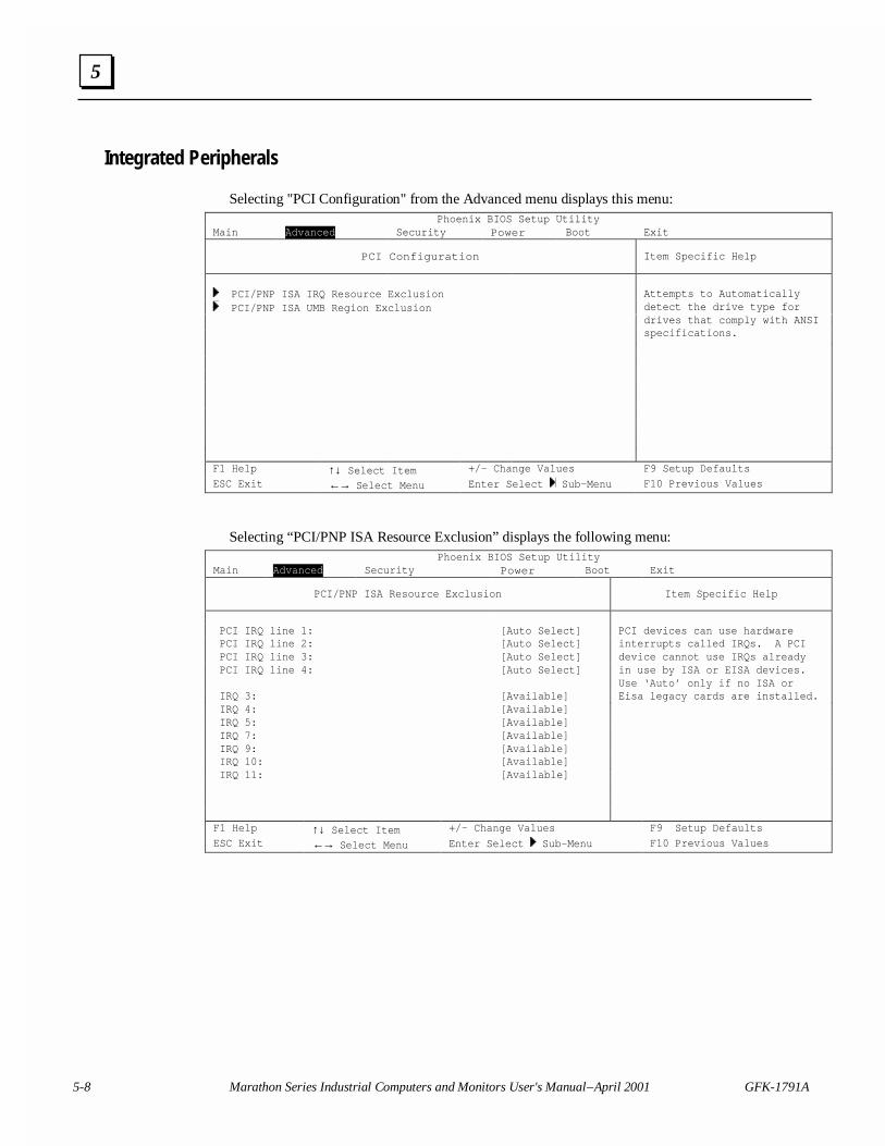
Integrated Peripherals
Selecting "PCI Configuration" from the Advanced menu displays this menu:Phoenix BIOS Setup Utility
Main Advanced Security Power Boot Exit
PCI Configuration Item Specific Help
PCI/PNP ISA IRQ Resource Exclusion PCI/PNP ISA UMB Region Exclusion
Attempts to Automaticallydetect the drive type fordrives that comply with ANSIspecifications.
F1 Help ↑↓ Select Item +/- Change Values F9 Setup Defaults
ESC Exit ←→ Select Menu Enter Select Sub-Menu F10 Previous Values
Selecting “PCI/PNP ISA Resource Exclusion” displays the following menu:Phoenix BIOS Setup Utility
Main Advanced Security Power Boot Exit
PCI/PNP ISA Resource Exclusion Item Specific Help
PCI IRQ line 1: [Auto Select] PCI IRQ line 2: [Auto Select] PCI IRQ line 3: [Auto Select] PCI IRQ line 4: [Auto Select]
IRQ 3: [Available] IRQ 4: [Available] IRQ 5: [Available] IRQ 7: [Available]
PCI devices can use hardwareinterrupts called IRQs. A PCIdevice cannot use IRQs alreadyin use by ISA or EISA devices.Use ‘Auto’ only if no ISA orEisa legacy cards are installed.
IRQ 9: [Available] IRQ 10: [Available] IRQ 11: [Available]
F1 Help ↑↓ Select Item +/- Change Values F9 Setup Defaults
ESC Exit ←→ Select Menu Enter Select Sub-Menu F10 Previous Values
GFK-1791A Chapter 5 BIOS Setup Guide 5-9
5
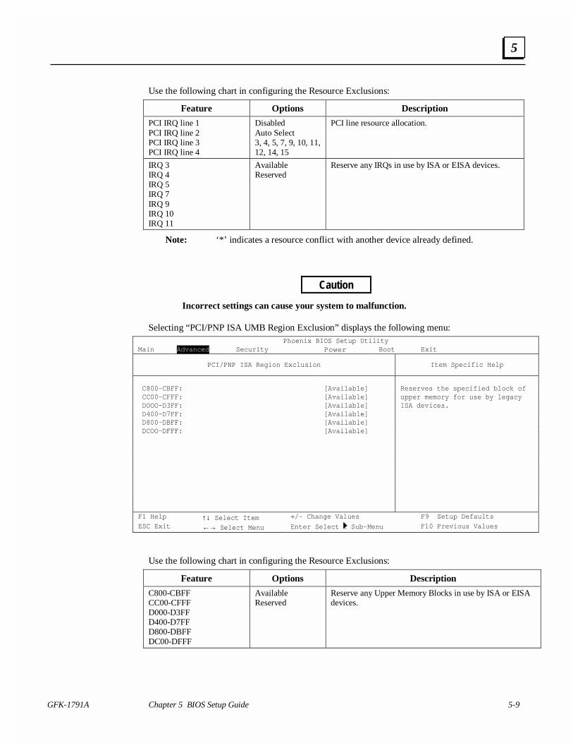
Use the following chart in configuring the Resource Exclusions:
Feature Options Description
PCI IRQ line 1PCI IRQ line 2PCI IRQ line 3PCI IRQ line 4
DisabledAuto Select3, 4, 5, 7, 9, 10, 11,12, 14, 15
PCI line resource allocation.
IRQ 3IRQ 4IRQ 5IRQ 7IRQ 9IRQ 10IRQ 11
AvailableReserved
Reserve any IRQs in use by ISA or EISA devices.
Note: ‘*’ indicates a resource conflict with another device already defined.
Caution
Incorrect settings can cause your system to malfunction.
Selecting “PCI/PNP ISA UMB Region Exclusion” displays the following menu:Phoenix BIOS Setup Utility
Main Advanced Security Power Boot Exit
PCI/PNP ISA Region Exclusion Item Specific Help
C800-CBFF: [Available] CC00-CFFF: [Available] DOOO-D3FF: [Available] D400-D7FF: [Available] D800-DBFF: [Available] DCOO-DFFF: [Available]
Reserves the specified block ofupper memory for use by legacyISA devices.
F1 Help ↑↓ Select Item +/- Change Values F9 Setup DefaultsESC Exit ←→ Select Menu Enter Select Sub-Menu F10 Previous Values
Use the following chart in configuring the Resource Exclusions:
Feature Options Description
C800-CBFFCC00-CFFFD000-D3FFD400-D7FFD800-DBFFDC00-DFFF
AvailableReserved
Reserve any Upper Memory Blocks in use by ISA or EISAdevices.
5-10 Marathon Series Industrial Computers and Monitors User's Manual – April 2001 GFK-1791A
5
Caution
Incorrect settings can cause your system to malfunction.
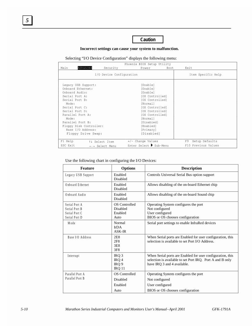
Selecting “I/O Device Configuration” displays the following menu:Phoenix BIOS Setup Utility
Main Advanced Security Power Boot Exit
I/O Device Configuration Item Specific Help
Legacy USB Support: [Enable] Onboard Ethernet: [Enable] Onboard Audio: [Enable] Serial Port A: [OS Controlled] Serial Port B: [OS Controlled] Mode: [Normal] Serial Port C: [OS Controlled] Serial Port D: [OS Controlled] Parallel Port A: [OS Controlled] Mode: [Normal] Parallel Port B: [Disabled] Floppy Disk Controller: [Enabled] Base I/O Address: [Primary] Floppy Drive Swap: [Disabled]
F1 Help ↑↓ Select Item +/- Change Values F9 Setup DefaultsESC Exit ←→ Select Menu Enter Select Sub-Menu F10 Previous Values
Use the following chart in configuring the I/O Devices:
Feature Options Description
L e g a c y U S B S u p p o r t EnabledDisabled
Controls Universal Serial Bus option support
O n b o a r d E th e r n e t EnabledDisabled
Allows disabling of the on-board Ethernet chip
O n b o a r d A u d io EnabledDisabled
Allows disabling of the on-board Sound chip
S er i a l P o r t AS er i a l P o r t BS er i a l P o r t CS er i a l P o r t D
OS ControlledDisabledEnabledAuto
Operating System configures the portNot configuredUser configuredBIOS or OS chooses configuration
M o d e NormalIrDAASK-IR
Serial port settings to enable InfraRed devices
B a s e I /O A d d r e s s 2E82F83E83F8
When Serial ports are Enabled for user configuration, thisselection is available to set Port I/O Address.
I n t e r r u p t IRQ 3IRQ 4IRQ 9IRQ 11
When Serial ports are Enabled for user configuration, thisselection is available to set Port IRQ. Port A and B onlyhave IRQ 3 and 4 available.
P ar a l l e l P o r t AP ar a l l e l P o r t B
OS Controlled
Disabled
Enabled
Auto
Operating System configures the port
Not configured
User configured
BIOS or OS chooses configuration
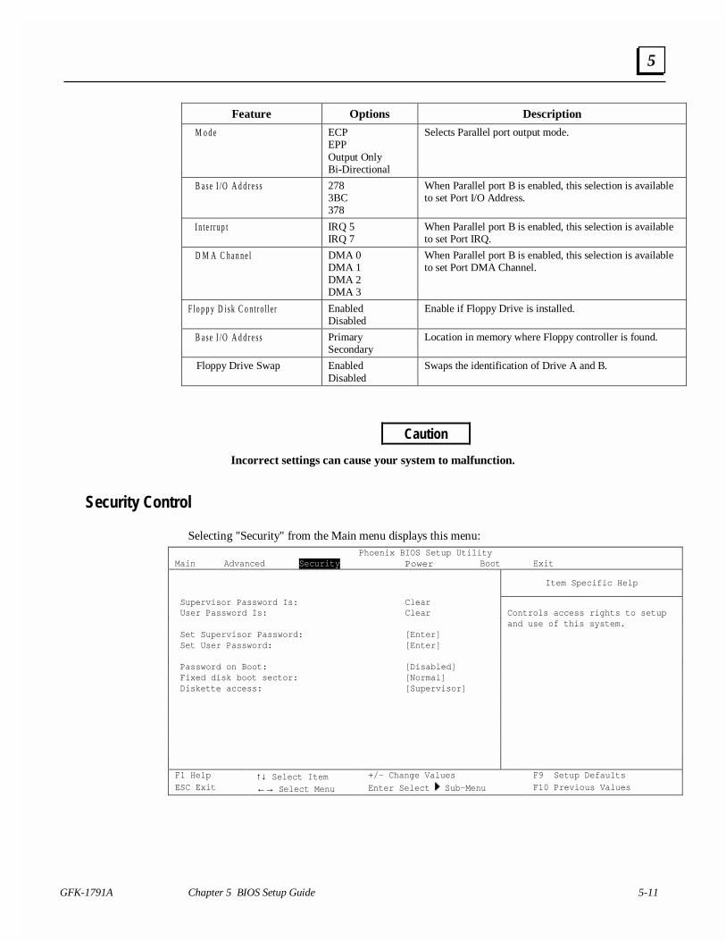
GFK-1791A Chapter 5 BIOS Setup Guide 5-11
5
Feature Options Description
M o d e ECPEPPOutput OnlyBi-Directional
Selects Parallel port output mode.
B a s e I /O A d d r e s s 2783BC378
When Parallel port B is enabled, this selection is availableto set Port I/O Address.
I n t e r r u p t IRQ 5IRQ 7
When Parallel port B is enabled, this selection is availableto set Port IRQ.
D M A C h a n n e l DMA 0DMA 1DMA 2DMA 3
When Parallel port B is enabled, this selection is availableto set Port DMA Channel.
F lo p p y D i s k C o n t r o ll e r EnabledDisabled
Enable if Floppy Drive is installed.
B a s e I /O A d d r e s s PrimarySecondary
Location in memory where Floppy controller is found.
Floppy Drive Swap EnabledDisabled
Swaps the identification of Drive A and B.
Caution
Incorrect settings can cause your system to malfunction.
Security Control
Selecting "Security" from the Main menu displays this menu:Phoenix BIOS Setup Utility
Main Advanced Security Power Boot Exit
Item Specific Help
Supervisor Password Is: Clear User Password Is: Clear
Set Supervisor Password: [Enter] Set User Password: [Enter]
Password on Boot: [Disabled] Fixed disk boot sector: [Normal] Diskette access: [Supervisor]
Controls access rights to setupand use of this system.
F1 Help ↑↓ Select Item +/- Change Values F9 Setup DefaultsESC Exit ←→ Select Menu Enter Select Sub-Menu F10 Previous Values
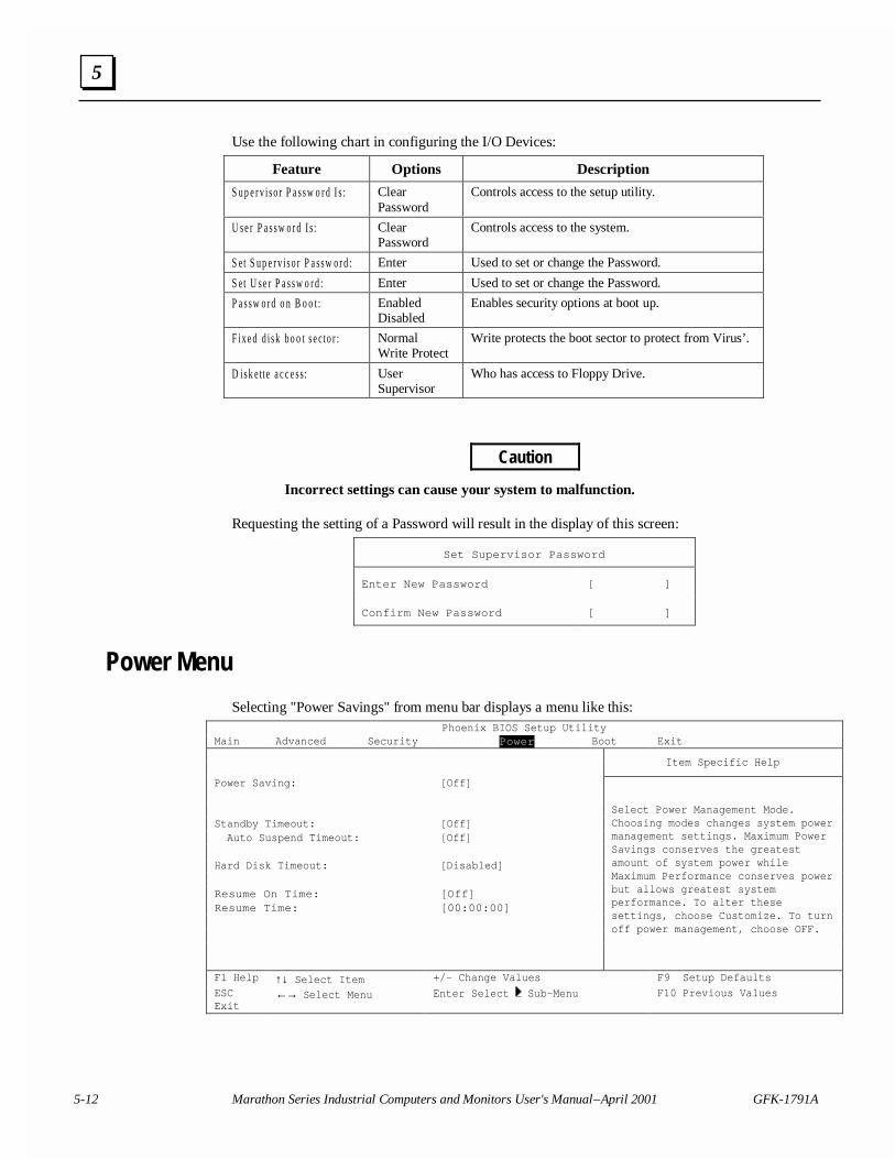
5-12 Marathon Series Industrial Computers and Monitors User's Manual – April 2001 GFK-1791A
5
Use the following chart in configuring the I/O Devices:
Feature Options Description
S u p e r v i s o r P a s s w o r d I s : ClearPassword
Controls access to the setup utility.
U s e r P a s s w o r d I s: ClearPassword
Controls access to the system.
S et S u p e r v i s o r P a s s w o r d : Enter Used to set or change the Password.
S et U s e r P a s s w o r d : Enter Used to set or change the Password.
P a s s w o r d o n B o o t : EnabledDisabled
Enables security options at boot up.
F ix e d d i s k b o o t s e c to r : NormalWrite Protect
Write protects the boot sector to protect from Virus’.
D is k e tt e a c c e s s: UserSupervisor
Who has access to Floppy Drive.
Caution
Incorrect settings can cause your system to malfunction.
Requesting the setting of a Password will result in the display of this screen:
Set Supervisor Password
Enter New Password [ ]
Confirm New Password [ ]
Power Menu
Selecting "Power Savings" from menu bar displays a menu like this:Phoenix BIOS Setup Utility
Main Advanced Security Power Boot Exit
Item Specific Help
Power Saving: [Off]
Standby Timeout: [Off] Auto Suspend Timeout: [Off]
Hard Disk Timeout: [Disabled]
Resume On Time: [Off]Resume Time: [00:00:00]
Select Power Management Mode.Choosing modes changes system powermanagement settings. Maximum PowerSavings conserves the greatestamount of system power whileMaximum Performance conserves powerbut allows greatest systemperformance. To alter thesesettings, choose Customize. To turnoff power management, choose OFF.
F1 Help ↑↓ Select Item +/- Change Values F9 Setup Defaults
ESCExit
←→ Select Menu Enter Select Sub-Menu F10 Previous Values
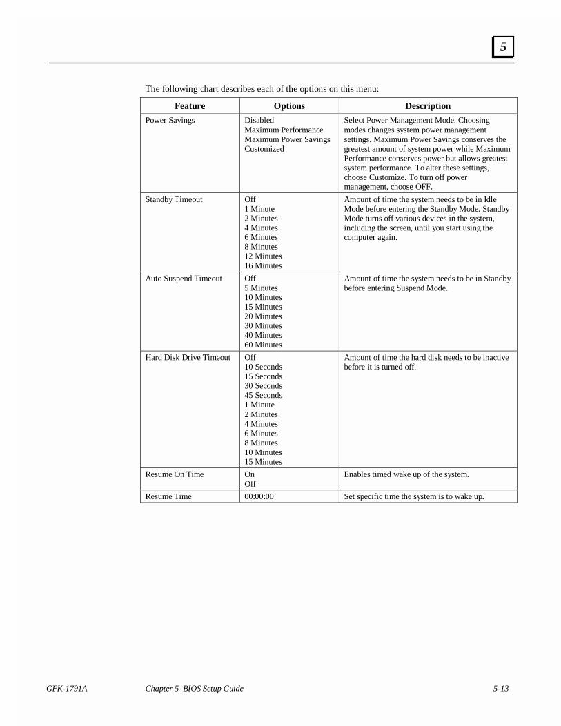
GFK-1791A Chapter 5 BIOS Setup Guide 5-13
5
The following chart describes each of the options on this menu:
Feature Options Description
Power Savings DisabledMaximum PerformanceMaximum Power SavingsCustomized
Select Power Management Mode. Choosingmodes changes system power managementsettings. Maximum Power Savings conserves thegreatest amount of system power while MaximumPerformance conserves power but allows greatestsystem performance. To alter these settings,choose Customize. To turn off powermanagement, choose OFF.
Standby Timeout Off1 Minute2 Minutes4 Minutes6 Minutes8 Minutes12 Minutes16 Minutes
Amount of time the system needs to be in IdleMode before entering the Standby Mode. StandbyMode turns off various devices in the system,including the screen, until you start using thecomputer again.
Auto Suspend Timeout Off5 Minutes10 Minutes15 Minutes20 Minutes30 Minutes40 Minutes60 Minutes
Amount of time the system needs to be in Standbybefore entering Suspend Mode.
Hard Disk Drive Timeout Off10 Seconds15 Seconds30 Seconds45 Seconds1 Minute2 Minutes4 Minutes6 Minutes8 Minutes10 Minutes15 Minutes
Amount of time the hard disk needs to be inactivebefore it is turned off.
Resume On Time OnOff
Enables timed wake up of the system.
Resume Time 00:00:00 Set specific time the system is to wake up.
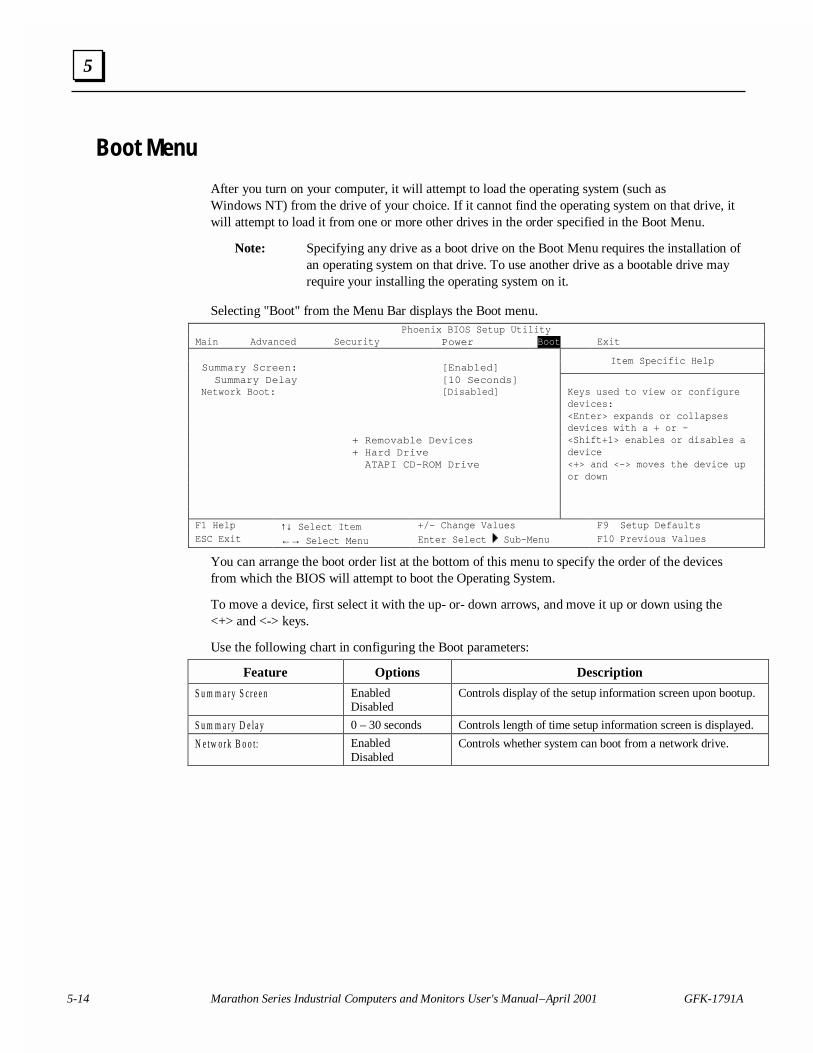
5-14 Marathon Series Industrial Computers and Monitors User's Manual – April 2001 GFK-1791A
5
Boot Menu
After you turn on your computer, it will attempt to load the operating system (such asWindows NT) from the drive of your choice. If it cannot find the operating system on that drive, itwill attempt to load it from one or more other drives in the order specified in the Boot Menu.
Note: Specifying any drive as a boot drive on the Boot Menu requires the installation ofan operating system on that drive. To use another drive as a bootable drive mayrequire your installing the operating system on it.
Selecting "Boot" from the Menu Bar displays the Boot menu.Phoenix BIOS Setup Utility
Main Advanced Security Power Boot Exit
Summary Screen: [Enabled]Item Specific Help
Summary Delay [10 Seconds] Network Boot: [Disabled]
+ Removable Devices+ Hard Drive ATAPI CD-ROM Drive
Keys used to view or configuredevices:<Enter> expands or collapsesdevices with a + or –<Shift+1> enables or disables adevice<+> and <-> moves the device upor down
F1 Help ↑↓ Select Item +/- Change Values F9 Setup DefaultsESC Exit ←→ Select Menu Enter Select Sub-Menu F10 Previous Values
You can arrange the boot order list at the bottom of this menu to specify the order of the devicesfrom which the BIOS will attempt to boot the Operating System.
To move a device, first select it with the up- or- down arrows, and move it up or down using the<+> and <-> keys.
Use the following chart in configuring the Boot parameters:
Feature Options Description
S u m m a r y S cr e e n EnabledDisabled
Controls display of the setup information screen upon bootup.
S u m m a r y D e la y 0 – 30 seconds Controls length of time setup information screen is displayed.
N e tw o r k B o o t: EnabledDisabled
Controls whether system can boot from a network drive.
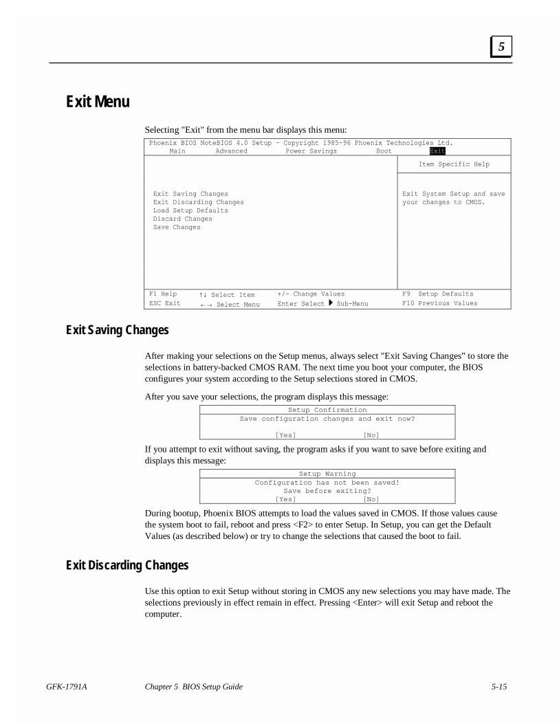
GFK-1791A Chapter 5 BIOS Setup Guide 5-15
5
Exit Menu
Selecting "Exit" from the menu bar displays this menu:Phoenix BIOS NoteBIOS 4.0 Setup – Copyright 1985-96 Phoenix Technologies Ltd.
Main Advanced Power Savings Boot Exit
Item Specific Help
Exit Saving Changes Exit Discarding Changes Load Setup Defaults
Exit System Setup and saveyour changes to CMOS.
Discard Changes Save Changes
F1 Help ↑↓ Select Item +/- Change Values F9 Setup DefaultsESC Exit ←→ Select Menu Enter Select Sub-Menu F10 Previous Values
Exit Saving Changes
After making your selections on the Setup menus, always select "Exit Saving Changes” to store theselections in battery-backed CMOS RAM. The next time you boot your computer, the BIOSconfigures your system according to the Setup selections stored in CMOS.
After you save your selections, the program displays this message:Setup Confirmation
Save configuration changes and exit now?
[Yes] [No]
If you attempt to exit without saving, the program asks if you want to save before exiting anddisplays this message:
Setup WarningConfiguration has not been saved!
Save before exiting?[Yes] [No]
During bootup, Phoenix BIOS attempts to load the values saved in CMOS. If those values causethe system boot to fail, reboot and press <F2> to enter Setup. In Setup, you can get the DefaultValues (as described below) or try to change the selections that caused the boot to fail.
Exit Discarding Changes
Use this option to exit Setup without storing in CMOS any new selections you may have made. Theselections previously in effect remain in effect. Pressing <Enter> will exit Setup and reboot thecomputer.
5-16 Marathon Series Industrial Computers and Monitors User's Manual – April 2001 GFK-1791A
5
The program asks if you want to save before exiting and displays this message:Setup Warning
Configuration has not been saved!Save before exiting?
[Yes] [No]
Load Setup Defaults
To display the default values for all the Setup menus, select "Load Setup Defaults" from the ExitMenu. The program displays this message:
Setup ConfirmationLoad default configuration now?
[Yes] [No]
If, during bootup, the BIOS program detects a problem in the integrity of values stored in CMOS,the program displays this message:
System CMOS checksum bad - run SETUPPress <F1> to resume, <F2> to Setup
The CMOS values have been corrupted or modified incorrectly, perhaps by an application programthat changes data stored in CMOS. Press <F1> to resume the boot or <F2> to run Setup with theROM default values already loaded into the menus. You can make other changes before saving thevalues to CMOS.
Discard Changes
To display the previous values for all the Setup menus, select "Discard Changes" from the ExitMenu. The program displays this message:
Setup ConfirmationLoad previous configuration now?
[Yes] [No]
Save Changes
Selecting “Save Changes” saves all the selections without exiting Setup. You can return to theother menus if you want to review and change your selections.
The program displays this message:Setup Confirmation
Save configuration changes now?
[Yes] [No]
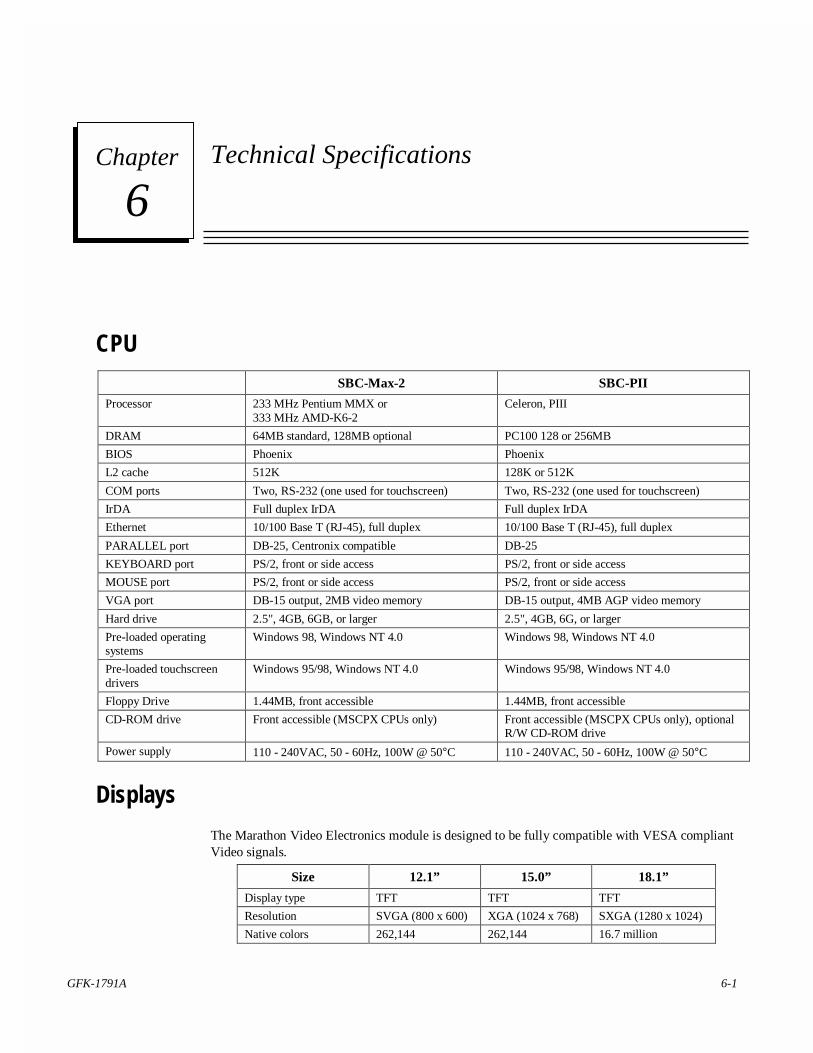
GFK-1791A 6-1
Technical Specifications
CPU
SBC-Max-2 SBC-PII
Processor 233 MHz Pentium MMX or333 MHz AMD-K6-2
Celeron, PIII
DRAM 64MB standard, 128MB optional PC100 128 or 256MB
BIOS Phoenix Phoenix
L2 cache 512K 128K or 512K
COM ports Two, RS-232 (one used for touchscreen) Two, RS-232 (one used for touchscreen)
IrDA Full duplex IrDA Full duplex IrDA
Ethernet 10/100 Base T (RJ-45), full duplex 10/100 Base T (RJ-45), full duplex
PARALLEL port DB-25, Centronix compatible DB-25
KEYBOARD port PS/2, front or side access PS/2, front or side access
MOUSE port PS/2, front or side access PS/2, front or side access
VGA port DB-15 output, 2MB video memory DB-15 output, 4MB AGP video memory
Hard drive 2.5", 4GB, 6GB, or larger 2.5", 4GB, 6G, or larger
Pre-loaded operatingsystems
Windows 98, Windows NT 4.0 Windows 98, Windows NT 4.0
Pre-loaded touchscreendrivers
Windows 95/98, Windows NT 4.0 Windows 95/98, Windows NT 4.0
Floppy Drive 1.44MB, front accessible 1.44MB, front accessible
CD-ROM drive Front accessible (MSCPX CPUs only) Front accessible (MSCPX CPUs only), optionalR/W CD-ROM drive
Power supply 110 - 240VAC, 50 - 60Hz, 100W @ 50°C 110 - 240VAC, 50 - 60Hz, 100W @ 50°C
Displays
The Marathon Video Electronics module is designed to be fully compatible with VESA compliantVideo signals.
Size 12.1” 15.0” 18.1”
Display type TFT TFT TFT
Resolution SVGA (800 x 600) XGA (1024 x 768) SXGA (1280 x 1024)
Native colors 262,144 262,144 16.7 million
6Chapter
6-2 Marathon Series Industrial Computers and Monitors User's Manual – April 2001 GFK-1791A
6
Touchscreens
Displays All sizes
Type Analog Resistive
Resolution 4096 X 4096, >100,000 touch-points/sq. inch
Transmissivity 75%
MTBF 35 million touches/spot
Response time 100ms
Stylus All types
O/S driver availability Windows 95/98, Windows NT
System DRAM
The Marathon Computer Modules support one 168-pin EDO DIMM DRAM module for amaximum of 128 Mbytes of system memory. The 168-pin EDO DIMM DRAM module must be3.3V and unbuffered 100MHz bus. PIII systems support PC100 compatible memory. For moreinformation on compatible memory modules, contact your Support Representative.
Total System Memory DIMM module
64MB 8M x 64 or 8M x 72
128MB 16M x 64 or 16M x 72
256MB (SBC-PII systems) 32M x 64 pr 32M x 72
System DRAM Installation (U3)
The SBC-PII supports double sided 168-pin DIMM SDRAM modules providing 8 to 256 Mbytes(with non-registered DIMMs) of system memory. SBC-PII supports 64 bit (Non-ECC) or 72 bit(ECC) SDRAMs. Enhanced SDRAM Open Page Architecture Support for 16- and 64-MbitDRAM devices with 2k, 4k and 8k page sizes.
Memory Sizing
Incremental Memory DIMM module
8MB 1M x 64 or 1M x 72
16MB 2M x 64 or 2M x 72
32MB 4M x 64 or 4M x 72
64MB 8M x 64 or 8M x 72
128MB 16M x 64 or 16M x 72
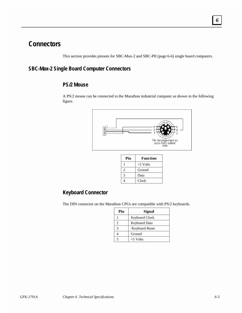
GFK-1791A Chapter 6 Technical Specifications 6-3
6
Connectors
This section provides pinouts for SBC-Max-2 and SBC-PII (page 6-6) single board computers.
SBC-Max-2 Single Board Computer Connectors
PS/2 Mouse
A PS/2 mouse can be connected to the Marathon industrial computer as shown in the followingfigure.
Pin Function
1 +5 Volts
2 Ground
3 Data
4 Clock
Keyboard Connector
The DIN connector on the Marathon CPUs are compatible with PS/2 keyboards.
Pin Signal
1 Keyboard Clock
2 Keyboard Data
3 /Keyboard Reset
4 Ground
5 +5 Volts
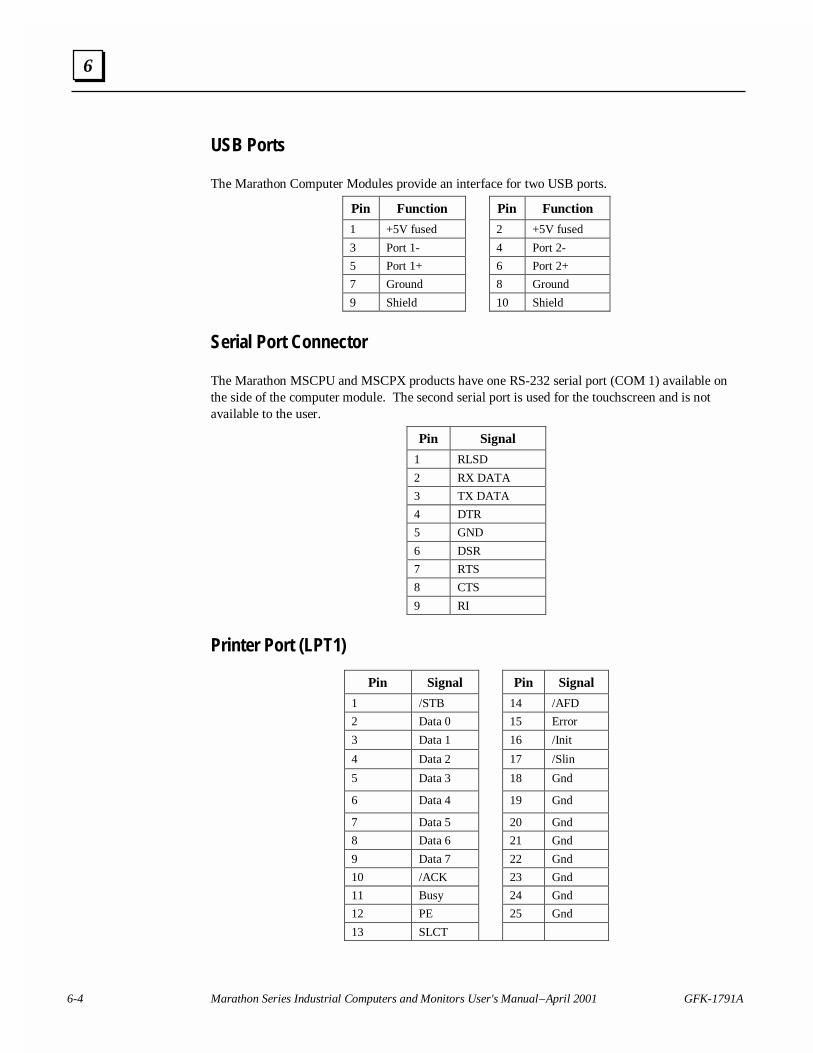
6-4 Marathon Series Industrial Computers and Monitors User's Manual – April 2001 GFK-1791A
6
USB Ports
The Marathon Computer Modules provide an interface for two USB ports.
Pin Function Pin Function
1 +5V fused 2 +5V fused
3 Port 1- 4 Port 2-
5 Port 1+ 6 Port 2+
7 Ground 8 Ground
9 Shield 10 Shield
Serial Port Connector
The Marathon MSCPU and MSCPX products have one RS-232 serial port (COM 1) available onthe side of the computer module. The second serial port is used for the touchscreen and is notavailable to the user.
Pin Signal
1 RLSD
2 RX DATA
3 TX DATA
4 DTR
5 GND
6 DSR
7 RTS
8 CTS
9 RI
Printer Port (LPT1)
Pin Signal Pin Signal
1 /STB 14 /AFD
2 Data 0 15 Error
3 Data 1 16 /Init
4 Data 2 17 /Slin
5 Data 3 18 Gnd
6 Data 4 19 Gnd
7 Data 5 20 Gnd
8 Data 6 21 Gnd
9 Data 7 22 Gnd
10 /ACK 23 Gnd
11 Busy 24 Gnd
12 PE 25 Gnd
13 SLCT
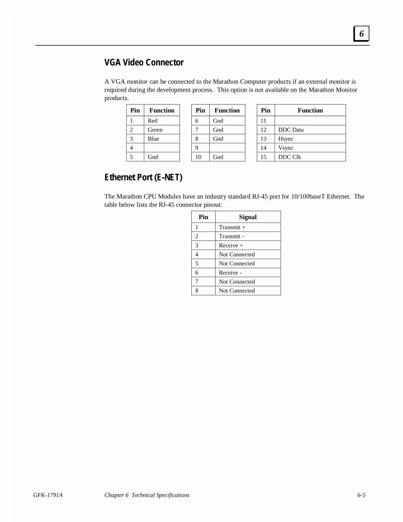
GFK-1791A Chapter 6 Technical Specifications 6-5
6
VGA Video Connector
A VGA monitor can be connected to the Marathon Computer products if an external monitor isrequired during the development process. This option is not available on the Marathon Monitorproducts.
Pin Function Pin Function Pin Function
1 Red 6 Gnd 11
2 Green 7 Gnd 12 DDC Data
3 Blue 8 Gnd 13 Hsync
4 9 14 Vsync
5 Gnd 10 Gnd 15 DDC Clk
Ethernet Port (E-NET)
The Marathon CPU Modules have an industry standard RJ-45 port for 10/100baseT Ethernet. Thetable below lists the RJ-45 connector pinout:
Pin Signal
1 Transmit +
2 Transmit -
3 Receive +
4 Not Connected
5 Not Connected
6 Receive -
7 Not Connected
8 Not Connected

6-6 Marathon Series Industrial Computers and Monitors User's Manual – April 2001 GFK-1791A
6
SBC-PII Single Board Computer Connectors
External Battery (J14)
If the internal battery is not installed, the SBC-PII board has the external battery option connector.An internal or external 3 Volt battery will need to be installed to maintain the CMOS settingswhenever the power is off. The connector is a 3 x 1 straight locking 0.1" center header.
Pin Signal
1 +3 Volts
2 Gnd
3 N/C
PS/2 Mouse Connector (J17)
The PS/2 mouse connector, J17 on the SBC-PII, is a 4 x 1 straight locking 0.1” center header. Theuse of an adapter cable available from Computer Dynamics, provides a direct interface to PS/2mice. The Mouse circuit is compatible with industry standard PS/2 mice.
Pin Signal Pin
1 +5 Volts 4
2 Gnd 3
3 Data 1
4 Clock 5
N/C 2,6
Keyboard Interface (J27)
The keyboard connector, J27 on the SBC-PII, is a 5 x 2 straight 0.1” center header. The connectorprovides an interface to PC/AT-compatible keyboards. It is 8042 compatible with 2KBprogrammable ROM and 256-byte data RAM.
A transistor is provided to drive a speaker or annunciator. Attach an 8-Ω speaker (2" to 2.5" aretypically used) to the keyboard cable as shown. Annunciators may be connected in place of thespeaker. It will need to be connected to either the 5V supply or the 12V supply depending on therequirements of the particular device.
An IDE activity indicator LED may be connected to this cable as well.
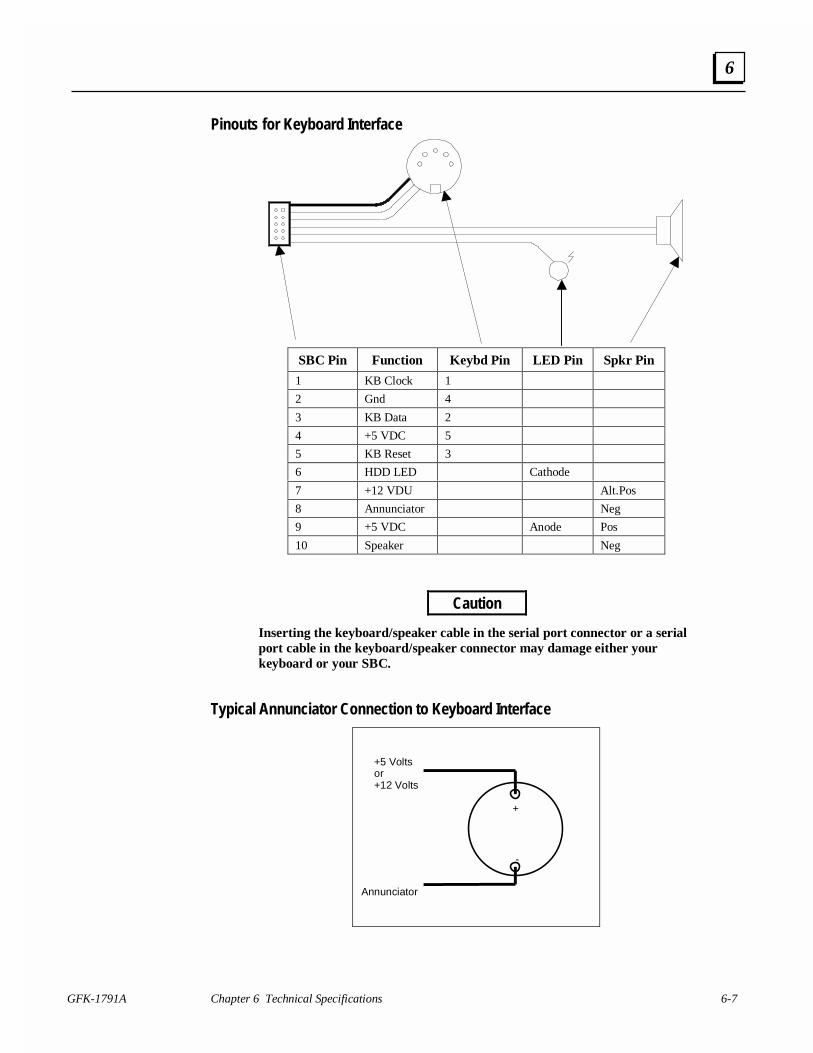
GFK-1791A Chapter 6 Technical Specifications 6-7
6
Pinouts for Keyboard Interface
SBC Pin Function Keybd Pin LED Pin Spkr Pin
1 KB Clock 1
2 Gnd 4
3 KB Data 2
4 +5 VDC 5
5 KB Reset 3
6 HDD LED Cathode
7 +12 VDU Alt.Pos
8 Annunciator Neg
9 +5 VDC Anode Pos
10 Speaker Neg
Caution
Inserting the keyboard/speaker cable in the serial port connector or a serialport cable in the keyboard/speaker connector may damage either yourkeyboard or your SBC.
Typical Annunciator Connection to Keyboard Interface
+
-
+5 Voltsor+12 Volts
Annunciator
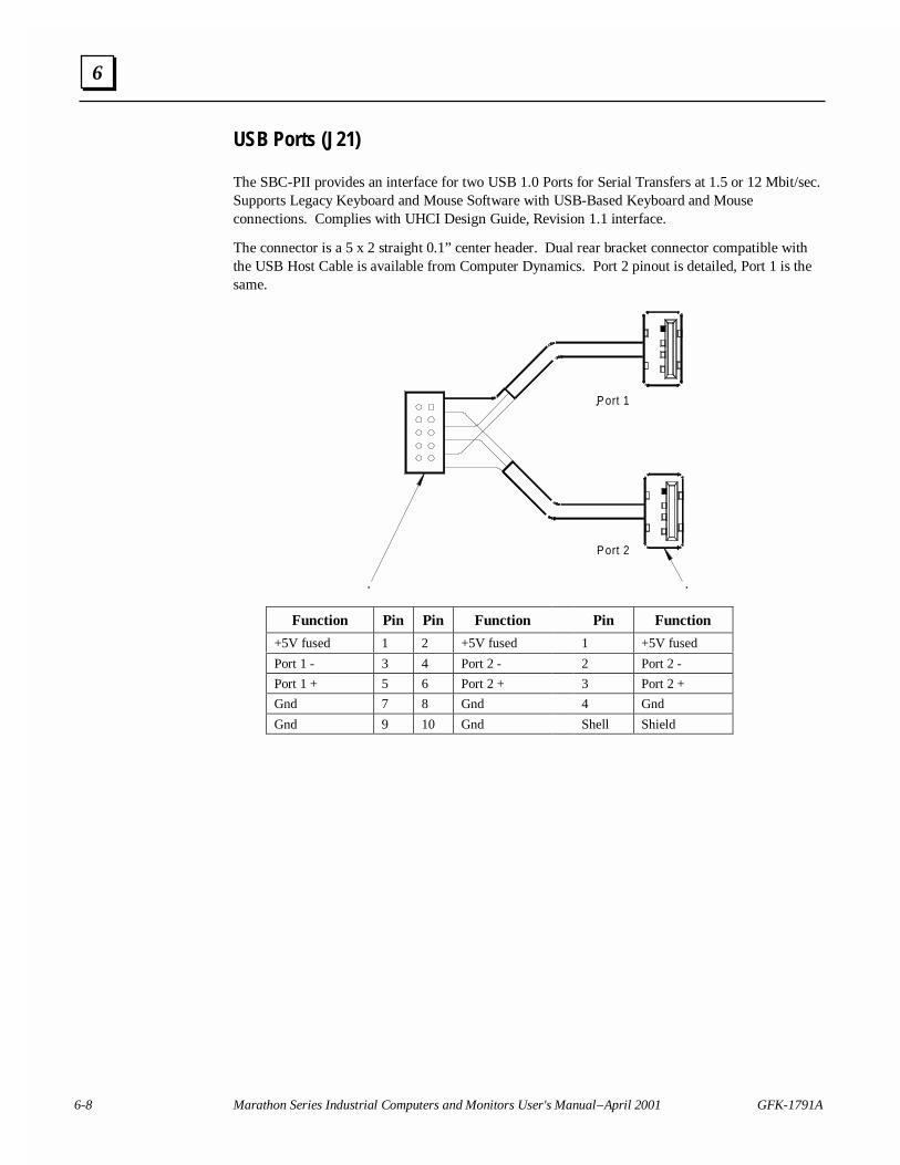
6-8 Marathon Series Industrial Computers and Monitors User's Manual – April 2001 GFK-1791A
6
USB Ports (J21)
The SBC-PII provides an interface for two USB 1.0 Ports for Serial Transfers at 1.5 or 12 Mbit/sec.Supports Legacy Keyboard and Mouse Software with USB-Based Keyboard and Mouseconnections. Complies with UHCI Design Guide, Revision 1.1 interface.
The connector is a 5 x 2 straight 0.1” center header. Dual rear bracket connector compatible withthe USB Host Cable is available from Computer Dynamics. Port 2 pinout is detailed, Port 1 is thesame.
Port 1
Port 2
Function Pin Pin Function Pin Function
+5V fused 1 2 +5V fused 1 +5V fused
Port 1 - 3 4 Port 2 - 2 Port 2 -
Port 1 + 5 6 Port 2 + 3 Port 2 +
Gnd 7 8 Gnd 4 Gnd
Gnd 9 10 Gnd Shell Shield
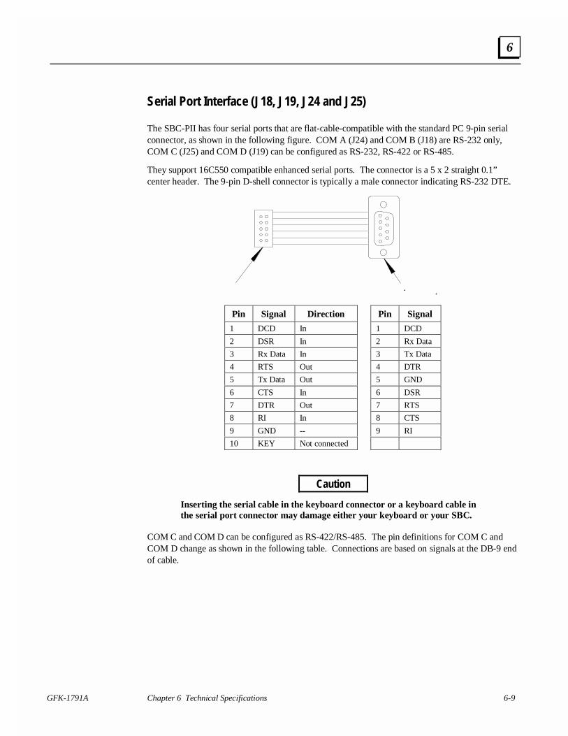
GFK-1791A Chapter 6 Technical Specifications 6-9
6
Serial Port Interface (J18, J19, J24 and J25)
The SBC-PII has four serial ports that are flat-cable-compatible with the standard PC 9-pin serialconnector, as shown in the following figure. COM A (J24) and COM B (J18) are RS-232 only,COM C (J25) and COM D (J19) can be configured as RS-232, RS-422 or RS-485.
They support 16C550 compatible enhanced serial ports. The connector is a 5 x 2 straight 0.1”center header. The 9-pin D-shell connector is typically a male connector indicating RS-232 DTE.
Pin Signal Direction Pin Signal
1 DCD In 1 DCD
2 DSR In 2 Rx Data
3 Rx Data In 3 Tx Data
4 RTS Out 4 DTR
5 Tx Data Out 5 GND
6 CTS In 6 DSR
7 DTR Out 7 RTS
8 RI In 8 CTS
9 GND -- 9 RI
10 KEY Not connected
Caution
Inserting the serial cable in the keyboard connector or a keyboard cable inthe serial port connector may damage either your keyboard or your SBC.
COM C and COM D can be configured as RS-422/RS-485. The pin definitions for COM C andCOM D change as shown in the following table. Connections are based on signals at the DB-9 endof cable.
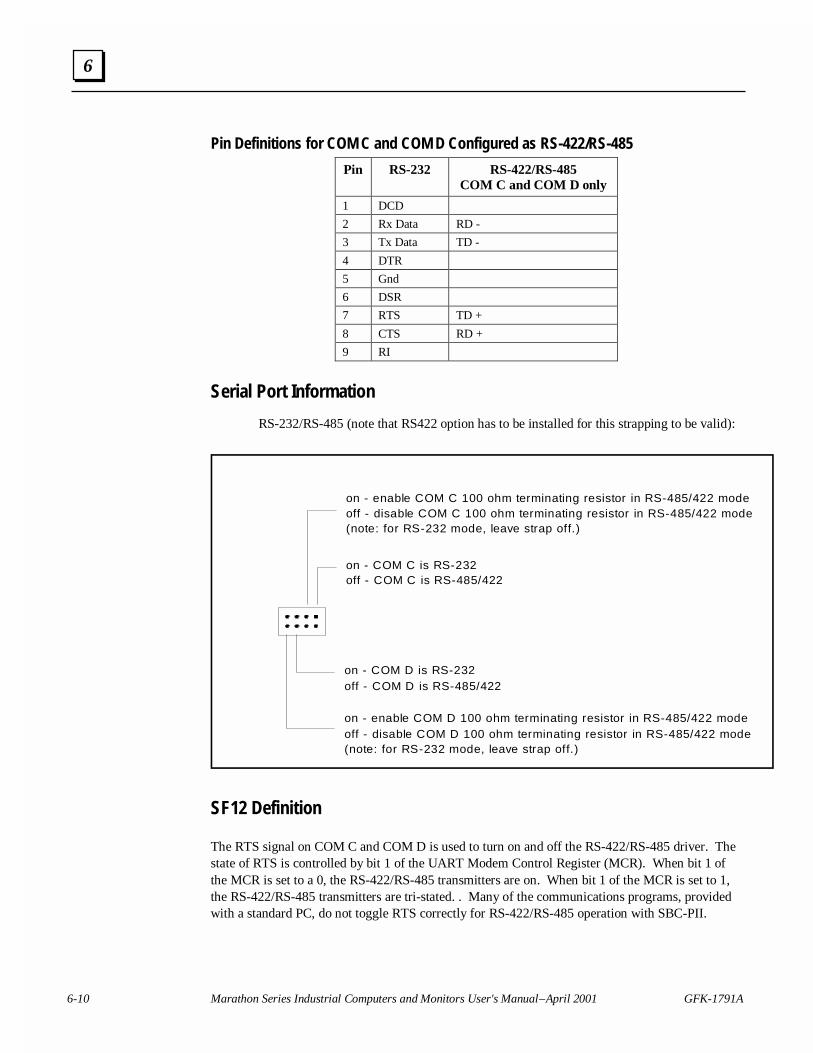
6-10 Marathon Series Industrial Computers and Monitors User's Manual – April 2001 GFK-1791A
6
Pin Definitions for COM C and COM D Configured as RS-422/RS-485
Pin RS-232 RS-422/RS-485COM C and COM D only
1 DCD
2 Rx Data RD -
3 Tx Data TD -
4 DTR
5 Gnd
6 DSR
7 RTS TD +
8 CTS RD +
9 RI
Serial Port Information
RS-232/RS-485 (note that RS422 option has to be installed for this strapping to be valid):
on - enable COM C 100 ohm terminating resistor in RS-485/422 modeoff - disable COM C 100 ohm terminating resistor in RS-485/422 mode(note: for RS-232 mode, leave strap off.)
on - COM C is RS-232off - COM C is RS-485/422
on - COM D is RS-232off - COM D is RS-485/422
on - enable COM D 100 ohm terminating resistor in RS-485/422 modeoff - disable COM D 100 ohm terminating resistor in RS-485/422 mode(note: for RS-232 mode, leave strap off.)
SF12 Definition
The RTS signal on COM C and COM D is used to turn on and off the RS-422/RS-485 driver. Thestate of RTS is controlled by bit 1 of the UART Modem Control Register (MCR). When bit 1 ofthe MCR is set to a 0, the RS-422/RS-485 transmitters are on. When bit 1 of the MCR is set to 1,the RS-422/RS-485 transmitters are tri-stated. . Many of the communications programs, providedwith a standard PC, do not toggle RTS correctly for RS-422/RS-485 operation with SBC-PII.
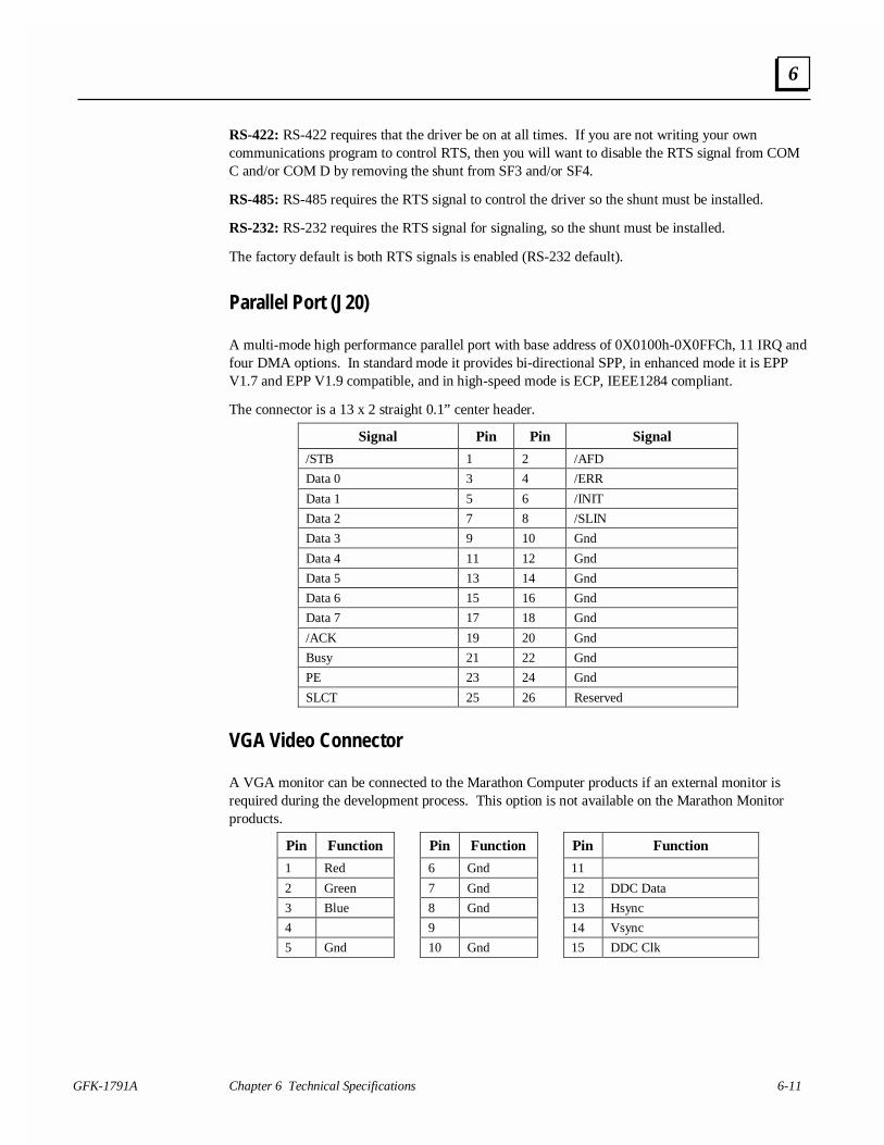
GFK-1791A Chapter 6 Technical Specifications 6-11
6
RS-422: RS-422 requires that the driver be on at all times. If you are not writing your owncommunications program to control RTS, then you will want to disable the RTS signal from COMC and/or COM D by removing the shunt from SF3 and/or SF4.
RS-485: RS-485 requires the RTS signal to control the driver so the shunt must be installed.
RS-232: RS-232 requires the RTS signal for signaling, so the shunt must be installed.
The factory default is both RTS signals is enabled (RS-232 default).
Parallel Port (J20)
A multi-mode high performance parallel port with base address of 0X0100h-0X0FFCh, 11 IRQ andfour DMA options. In standard mode it provides bi-directional SPP, in enhanced mode it is EPPV1.7 and EPP V1.9 compatible, and in high-speed mode is ECP, IEEE1284 compliant.
The connector is a 13 x 2 straight 0.1” center header.
Signal Pin Pin Signal
/STB 1 2 /AFD
Data 0 3 4 /ERR
Data 1 5 6 /INIT
Data 2 7 8 /SLIN
Data 3 9 10 Gnd
Data 4 11 12 Gnd
Data 5 13 14 Gnd
Data 6 15 16 Gnd
Data 7 17 18 Gnd
/ACK 19 20 Gnd
Busy 21 22 Gnd
PE 23 24 Gnd
SLCT 25 26 Reserved
VGA Video Connector
A VGA monitor can be connected to the Marathon Computer products if an external monitor isrequired during the development process. This option is not available on the Marathon Monitorproducts.
Pin Function Pin Function Pin Function
1 Red 6 Gnd 11
2 Green 7 Gnd 12 DDC Data
3 Blue 8 Gnd 13 Hsync
4 9 14 Vsync
5 Gnd 10 Gnd 15 DDC Clk
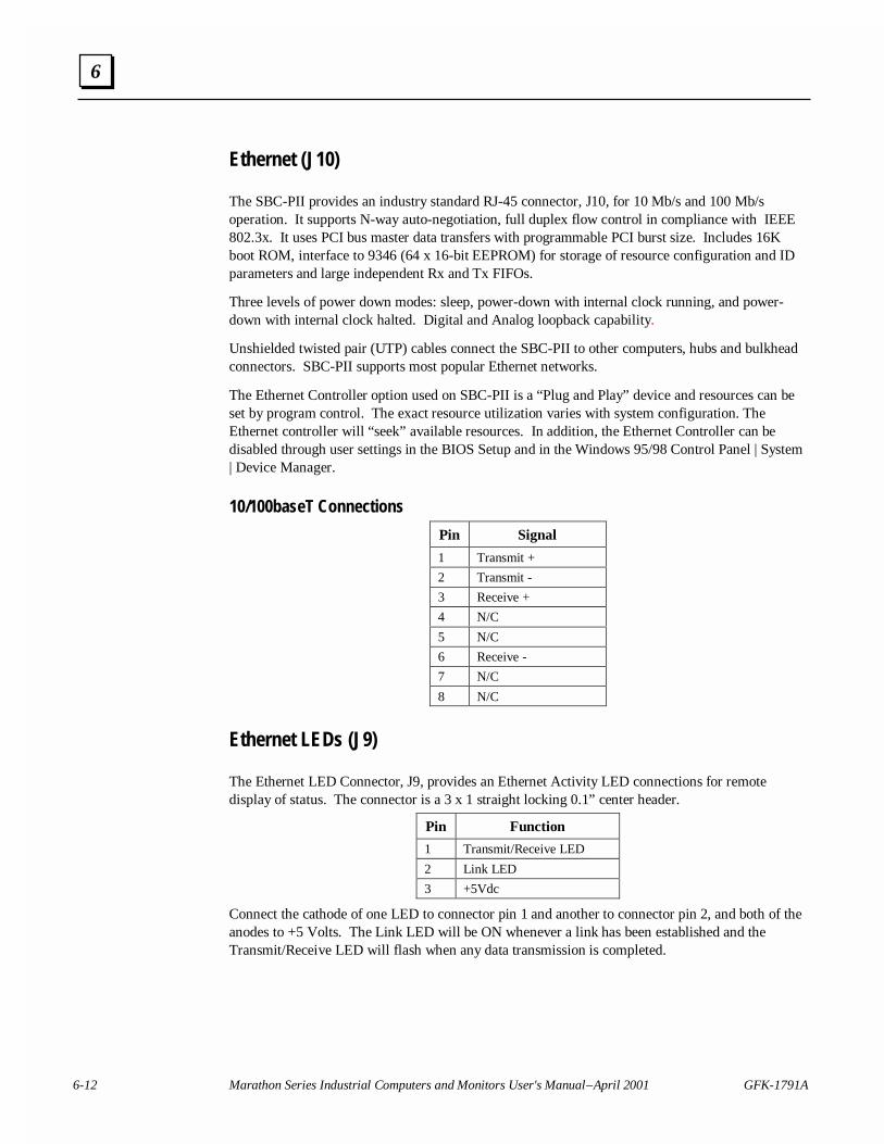
6-12 Marathon Series Industrial Computers and Monitors User's Manual – April 2001 GFK-1791A
6
Ethernet (J10)
The SBC-PII provides an industry standard RJ-45 connector, J10, for 10 Mb/s and 100 Mb/soperation. It supports N-way auto-negotiation, full duplex flow control in compliance with IEEE802.3x. It uses PCI bus master data transfers with programmable PCI burst size. Includes 16Kboot ROM, interface to 9346 (64 x 16-bit EEPROM) for storage of resource configuration and IDparameters and large independent Rx and Tx FIFOs.
Three levels of power down modes: sleep, power-down with internal clock running, and power-down with internal clock halted. Digital and Analog loopback capability.
Unshielded twisted pair (UTP) cables connect the SBC-PII to other computers, hubs and bulkheadconnectors. SBC-PII supports most popular Ethernet networks.
The Ethernet Controller option used on SBC-PII is a “Plug and Play” device and resources can beset by program control. The exact resource utilization varies with system configuration. TheEthernet controller will “seek” available resources. In addition, the Ethernet Controller can bedisabled through user settings in the BIOS Setup and in the Windows 95/98 Control Panel | System| Device Manager.
10/100baseT Connections
Pin Signal
1 Transmit +
2 Transmit -
3 Receive +
4 N/C
5 N/C
6 Receive -
7 N/C
8 N/C
Ethernet LEDs (J9)
The Ethernet LED Connector, J9, provides an Ethernet Activity LED connections for remotedisplay of status. The connector is a 3 x 1 straight locking 0.1” center header.
Pin Function
1 Transmit/Receive LED
2 Link LED
3 +5Vdc
Connect the cathode of one LED to connector pin 1 and another to connector pin 2, and both of theanodes to +5 Volts. The Link LED will be ON whenever a link has been established and theTransmit/Receive LED will flash when any data transmission is completed.
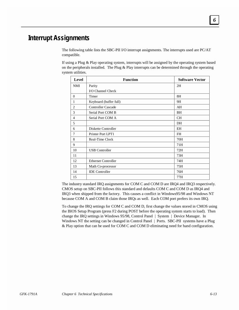
GFK-1791A Chapter 6 Technical Specifications 6-13
6
Interrupt Assignments
The following table lists the SBC-PII I/O interrupt assignments. The interrupts used are PC/ATcompatible.
If using a Plug & Play operating system, interrupts will be assigned by the operating system basedon the peripherals installed. The Plug & Play interrupts can be determined through the operatingsystem utilities.
Level Function Software Vector
NMI Parity
I/O Channel Check
2H
0 Timer 8H
1 Keyboard (buffer full) 9H
2 Controller Cascade AH
3 Serial Port COM B BH
4 Serial Port COM A CH
5 DH
6 Diskette Controller EH
7 Printer Port LPT1 FH
8 Real-Time Clock 70H
9 71H
10 USB Controller 72H
11 73H
12 Ethernet Controller 74H
13 Math Co-processor 75H
14 IDE Controller 76H
15 77H
The industry standard IRQ assignments for COM C and COM D are IRQ4 and IRQ3 respectively.CMOS setup on SBC-PII follows this standard and defaults COM C and COM D as IRQ4 andIRQ3 when shipped from the factory. This causes a conflict in Windows95/98 and Windows NTbecause COM A and COM B claim those IRQs as well. Each COM port prefers its own IRQ.
To change the IRQ settings for COM C and COM D, first change the values stored in CMOS usingthe BIOS Setup Program (press F2 during POST before the operating system starts to load). Thenchange the IRQ settings in Windows 95/98, Control Panel | System | Device Manager. InWindows NT the setting can be changed in Control Panel | Ports. SBC-PII systems have a Plug& Play option that can be used for COM C and COM D eliminating need for hand configuration.
GFK-1791A 7-1
Dimensions
The following drawings contain the dimensions for all display packages, CPU modules and VideoElectronics modules. Make sure you select the correct panel cutout for your model display.
Each Marathon Display is assigned a model number, based on the display size and whether it hasthe optional keypad.
MSDIS-1200 12.1" SVGA, TouchscreenMSDIS-1210 12.1" SVGA, with Keypads and TouchscreenMSDIS-1500 15.0" XGA, TouchscreenMSDIS-1510 15.0" XGA, with Keypads and TouchscreenMSDIS-1800 18.1" SXGA, Touchscreen
7Chapter
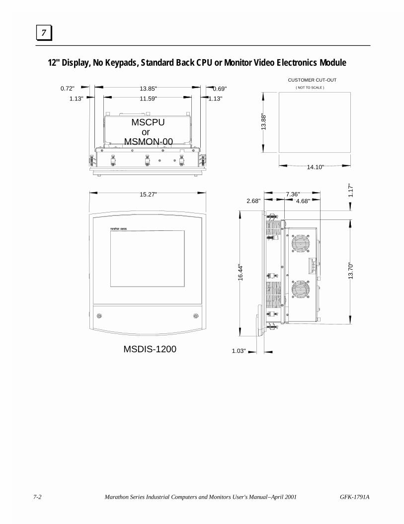
7-2 Marathon Series Industrial Computers and Monitors User's Manual – April 2001 GFK-1791A
7
12" Display, No Keypads, Standard Back CPU or Monitor Video Electronics Module
15.27"
16.4
4"
1.03"
7.36"4.68"2.68"
13.8
8"
14.10"
0.72" 0.69"
1.13"1.13"
13.85"
11.59"
1.17
"13
.70"
CUSTOMER CUT-OUT
( NOT TO SCALE )
MSCPU orMSMON-00
MSDIS-1200
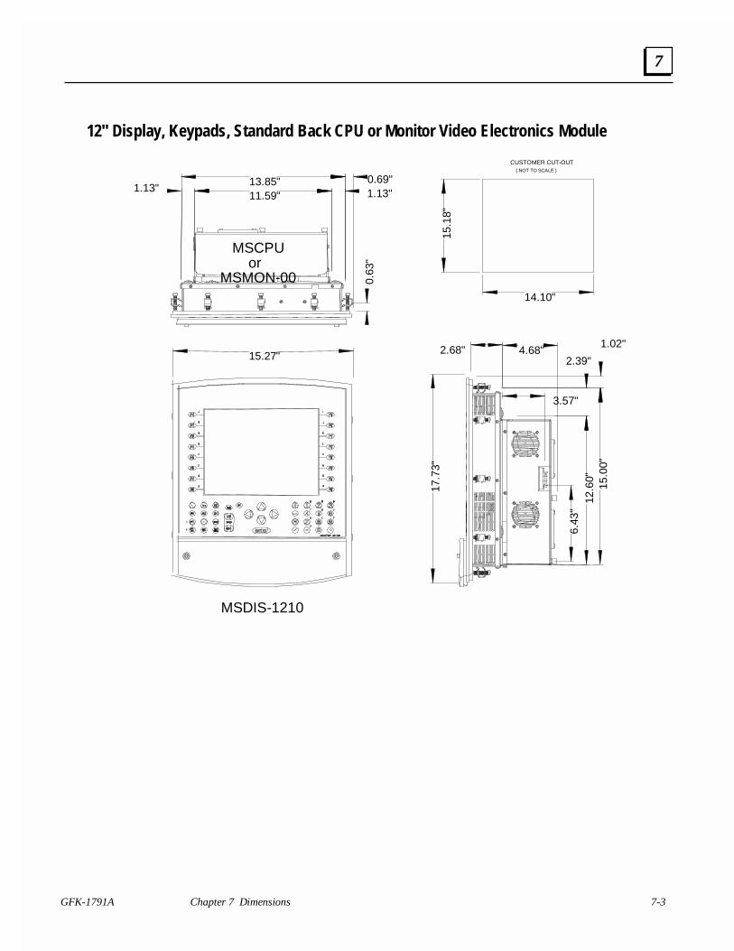
GFK-1791A Chapter 7 Dimensions 7-3
7
12" Display, Keypads, Standard Back CPU or Monitor Video Electronics Module
15.27"
17.7
3"
13.85" 0.69"
4.68"1.02"
15.0
0"
2.39"
12.6
0"
15.1
8"
14.10"
6.43
"
3.57"
2.68"
1.13"1.13"11.59"
0.63
"
CUSTOMER CUT-OUT ( NOT TO SCALE )
MSCPU orMSMON-00
MSDIS-1210
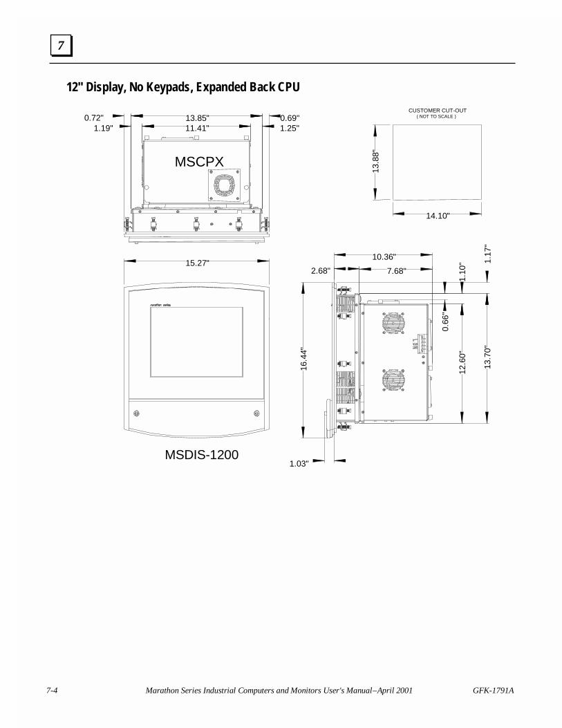
7-4 Marathon Series Industrial Computers and Monitors User's Manual – April 2001 GFK-1791A
7
12" Display, No Keypads, Expanded Back CPU
15.27"
16.4
4"
1.03"
2.68"
13.8
8"
14.10"
13.85"0.72" 0.69"11.41"1.19" 1.25"
7.68"
10.36"
0.66
"
1.10
" 1.17
"13
.70"
12.6
0"
CUSTOMER CUT-OUT ( NOT TO SCALE )
MSCPX
MSDIS-1200
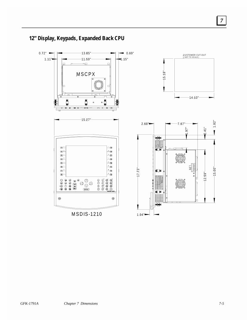
GFK-1791A Chapter 7 Dimensions 7-5
7
12" Display, Keypads, Expanded Back CPU
15.27"
17.7
3"
13 .85"
7 .67"
1.02
"15
.00"
2.41
"
1.97
"
12.5
9"
15.1
8"
14 .10"
0 .72" 0 .69"
1 .11" 11 .59" 1 .15"
2 .68"
1 .04"
CU STO M ER CUT-O UT ( N O T TO SC ALE )
M S C P X
M S D IS -1210M S D IS -1211
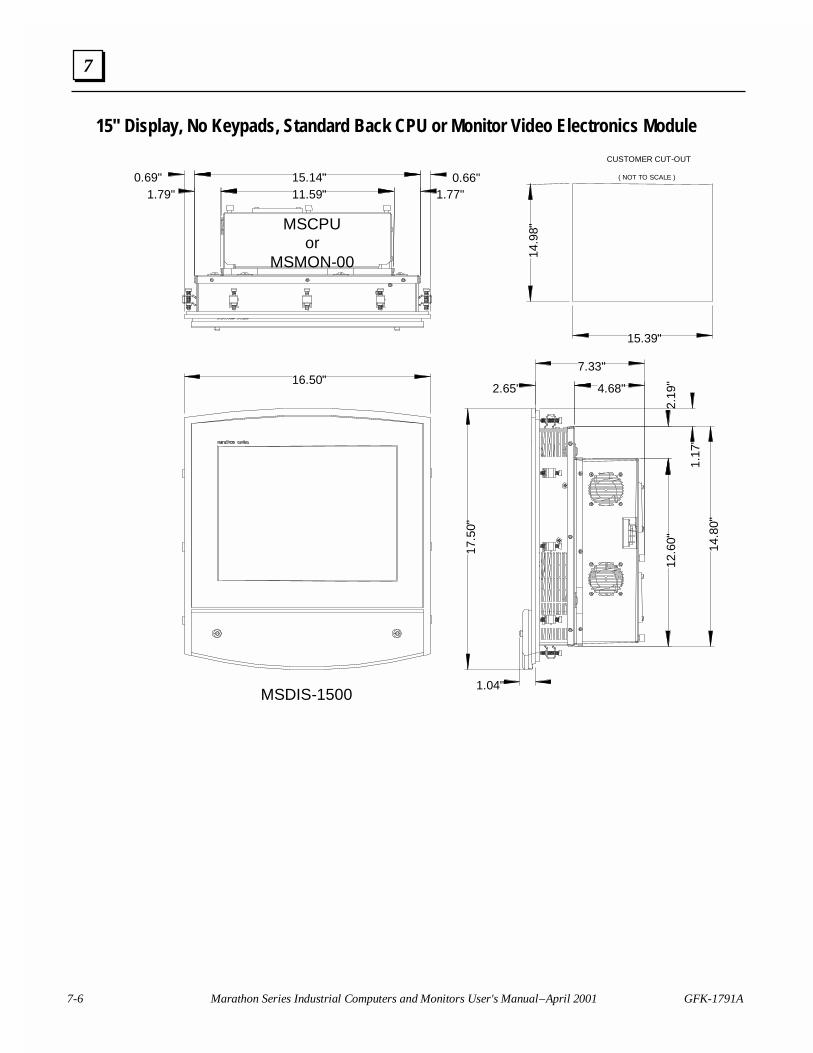
7-6 Marathon Series Industrial Computers and Monitors User's Manual – April 2001 GFK-1791A
7
15" Display, No Keypads, Standard Back CPU or Monitor Video Electronics Module
16.50"
17.5
0"
7.33"
4.68"
15.14"
1.17
"
14.8
0"
1.79"
2.65"
2.19
"12
.60"
15.39"
14.9
8"
11.59" 1.77"0.66"0.69"
1.04"
CUSTOMER CUT-OUT
( NOT TO SCALE )
MSDIS-1500
MSCPUor
MSMON-00
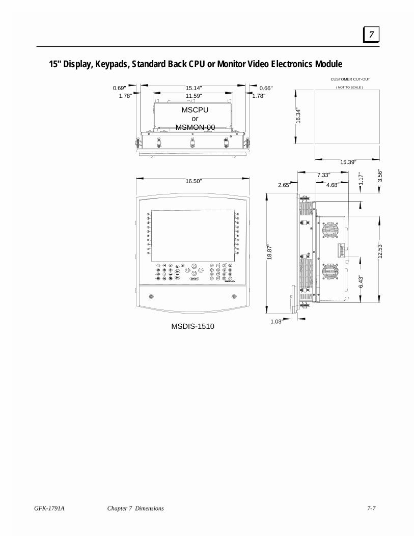
GFK-1791A Chapter 7 Dimensions 7-7
7
15" Display, Keypads, Standard Back CPU or Monitor Video Electronics Module
16.50"
18.8
7"
7.33"
4.68"
15.14"
1.17
"
1.78"
2.65"
3.56
"
15.39"
16.3
4"
11.59" 1.78"0.66"0.69"
1.03"
CUSTOMER CUT-OUT
( NOT TO SCALE )
MSDIS-1510
MSCPUor
MSMON-00
12.5
3"
6.43
"
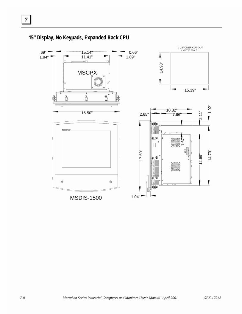
7-8 Marathon Series Industrial Computers and Monitors User's Manual – April 2001 GFK-1791A
7
15" Display, No Keypads, Expanded Back CPU
16.50"
17.5
0"
10.32"7.66" 1.
02"
15.14"
2.65"
2.11
"12
.69"
14.9
8"
15.39"
1.67
"
11.41"1.84" 1.89"0.66".69"
1.04"
CUSTOMER CUT-OUT ( NOT TO SCALE )
MSCPX
MSDIS-1500
14.7
9"
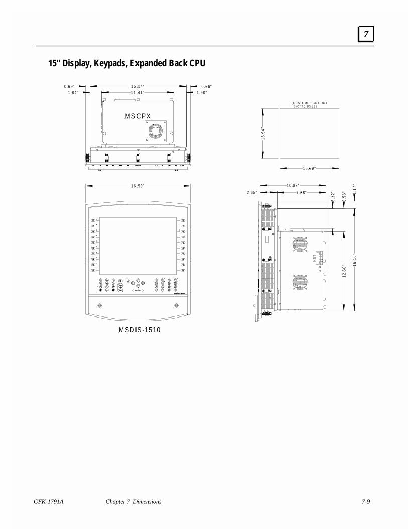
GFK-1791A Chapter 7 Dimensions 7-9
7
15" Display, Keypads, Expanded Back CPU
16.3
4"
1 5 .39 "
1 6 .50 "
0 .6 9" 0 .6 6"1 5 .1 4"
2 .6 5"
16.1
6"
1 1 .41 " 1 .9 0"1 .8 4"
12.6
0"3.
56"
3.12
"7 .6 8"
1 0 .33 "
1.17
"
C U ST O M E R C U T-O U T ( N O T T O S C A L E )
M S C P X
M S D IS -15 10
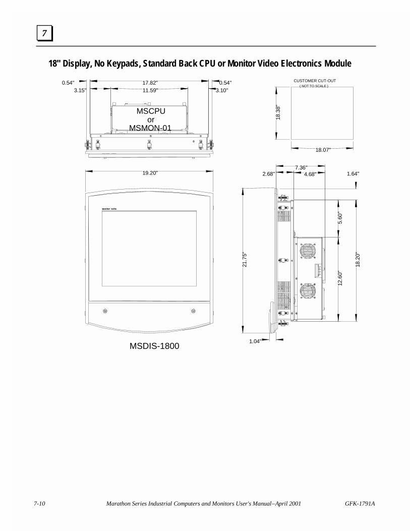
7-10 Marathon Series Industrial Computers and Monitors User's Manual – April 2001 GFK-1791A
7
18" Display, No Keypads, Standard Back CPU or Monitor Video Electronics Module
19.20"
21.7
5"
0.54" 17.82" 0.54"
7.36"4.68" 1.64"
18.2
0"
3.15"
2.68"
5.60
"12
.60"
18.3
8"
18.07"
11.59" 3.10"
1.04"
CUSTOMER CUT-OUT ( NOT TO SCALE )
MSCPUor
MSMON-01
MSDIS-1800
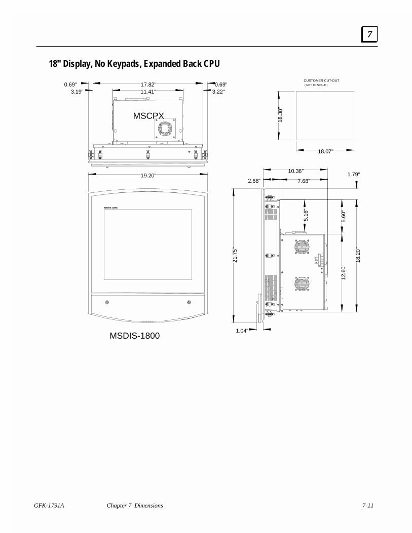
GFK-1791A Chapter 7 Dimensions 7-11
7
18" Display, No Keypads, Expanded Back CPU
18.3
8"
18.07"
17.82"0.69" 0.69"11.41"3.19" 3.22"
2.68" 7.68"
10.36"1.79"
18.2
0"
12.6
0"5.
60"
5.16
"
21.7
5"
19.20"
1.04"
CUSTOMER CUT-OUT ( NOT TO SCALE )
MSCPX
MSDIS-1800
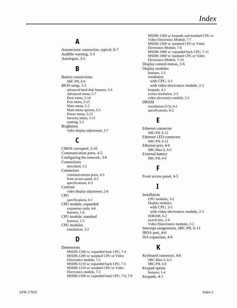
Index
GFK-1791A Index-1
AAnnunciator connection, typical, 6-7Audible warning, 3-3Autologon, 3-5
BBattery connections
SBC-PII, 6-6BIOS setup, 5-1
advanced hard disk features, 5-6Advanced menu, 5-7Boot menu, 5-14Exit menu, 5-15Main menu, 5-2Main menu options, 5-5Power menu, 5-12Security menu, 5-11starting, 5-2
Brightnessvideo display adjustment, 2-7
CCMOS corrupted, 5-16Communication ports, 4-5Configuring the network, 3-6Connections
described, 1-2Connectors
communications ports, 4-5front access panel, 4-5specifications, 6-3
Contrastvideo display adjustment, 2-8
CPUspecifications, 6-1
CPU module, expandedexpansion cards, 4-6features, 1-6
CPU module, standardfeatures, 1-5
CPU modulesinstallation, 3-2
DDimensions
MSDIS-1200 w/ expanded back CPU, 7-4MSDIS-1200 w/ standard CPU or VideoElectronics module, 7-2MSDIS-1210 w/ expanded back CPU, 7-5MSDIS-1210 w/ standard CPU or VideoElectronics module, 7-3MSDIS-1500 w/ expanded back CPU, 7-8, 7-9
MSDIS-1500 w/ keypads and standard CPU orVideo Electronics Module, 7-7MSDIS-1500 w/ standard CPU or VideoElectronics Module, 7-6MSDIS-1800 w/ expanded back CPU, 7-11MSDIS-1800 w/ standard CPU or VideoElectronics Module, 7-10
Display control menus, 2-6Display modules
features, 1-3installation
with CPU, 3-1with video electronics module, 2-1
keypads, 4-1screen resolution, 3-5video electronics module, 2-2
DRAMinstallation (U3), 6-2specifications, 6-2
EEthernet connector
SBC-PII, 6-12Ethernet LED connector
SBC-PII, 6-12Ethernet port, 4-6
SBC-Max-2, 6-5External battery
SBC-PII, 6-6
FFront access panel, 4-5
IInstallation
CPU modules, 3-2Display modules
with CPU, 3-1with video electronics module, 2-1
SDRAM, 6-2switch box, 2-4Video Eleoctronics modules, 2-2
Interrupt assignments, SBC-PII, 6-13IRDA port, 4-6ISA expansion, 4-6
KKeyboard connector, 4-6
SBC-Max-2, 6-3SBC-PII, 6-6
Keypad optionfeatures, 1-4
Keypads, 4-1
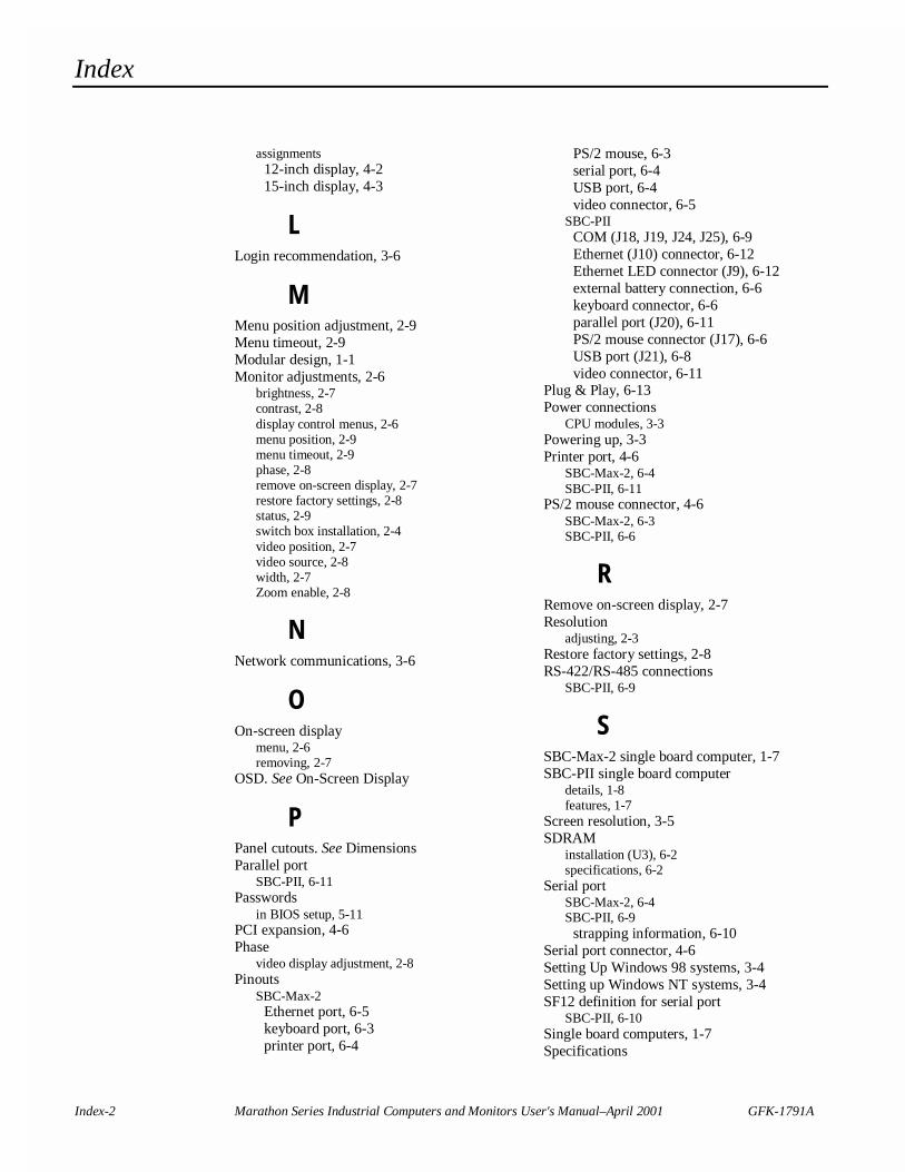
Index
Index-2 Marathon Series Industrial Computers and Monitors User's Manual–April 2001 GFK-1791A
assignments12-inch display, 4-215-inch display, 4-3
LLogin recommendation, 3-6
MMenu position adjustment, 2-9Menu timeout, 2-9Modular design, 1-1Monitor adjustments, 2-6
brightness, 2-7contrast, 2-8display control menus, 2-6menu position, 2-9menu timeout, 2-9phase, 2-8remove on-screen display, 2-7restore factory settings, 2-8status, 2-9switch box installation, 2-4video position, 2-7video source, 2-8width, 2-7Zoom enable, 2-8
NNetwork communications, 3-6
OOn-screen display
menu, 2-6removing, 2-7
OSD. See On-Screen Display
PPanel cutouts. See DimensionsParallel port
SBC-PII, 6-11Passwords
in BIOS setup, 5-11PCI expansion, 4-6Phase
video display adjustment, 2-8Pinouts
SBC-Max-2Ethernet port, 6-5keyboard port, 6-3printer port, 6-4
PS/2 mouse, 6-3serial port, 6-4USB port, 6-4video connector, 6-5
SBC-PIICOM (J18, J19, J24, J25), 6-9Ethernet (J10) connector, 6-12Ethernet LED connector (J9), 6-12external battery connection, 6-6keyboard connector, 6-6parallel port (J20), 6-11PS/2 mouse connector (J17), 6-6USB port (J21), 6-8video connector, 6-11
Plug & Play, 6-13Power connections
CPU modules, 3-3Powering up, 3-3Printer port, 4-6
SBC-Max-2, 6-4SBC-PII, 6-11
PS/2 mouse connector, 4-6SBC-Max-2, 6-3SBC-PII, 6-6
RRemove on-screen display, 2-7Resolution
adjusting, 2-3Restore factory settings, 2-8RS-422/RS-485 connections
SBC-PII, 6-9
SSBC-Max-2 single board computer, 1-7SBC-PII single board computer
details, 1-8features, 1-7
Screen resolution, 3-5SDRAM
installation (U3), 6-2specifications, 6-2
Serial portSBC-Max-2, 6-4SBC-PII, 6-9
strapping information, 6-10Serial port connector, 4-6Setting Up Windows 98 systems, 3-4Setting up Windows NT systems, 3-4SF12 definition for serial port
SBC-PII, 6-10Single board computers, 1-7Specifications
Index
GFK-1791A Index Index-3
Connectors, 6-3CPU, 6-1display, 6-1DRAM, 6-2interrupt assignments, 6-13touchscreen, 6-2
Status, video display, 2-9Switch box installation, 2-4
TTechnical Support, 2-1Touchscreens
calibration, 3-6features, 1-4specifications, 6-2
UUSB ports, 4-6
SBC-Max-2, 6-4SBC-PII, 6-8
VVGA Video connector, 4-6
SBC-Max-2, 6-5SBC-PII, 6-11
Video connector, 4-6SBC-Max-2, 6-5SBC-PII, 6-11
Video drivercalibration, 2-5installation, 2-5
Video Electronics modulefeatures, 1-10mounting, 2-2specifications, 6-1
Video position adjustment, 2-7Video resolution
adjusting, 2-3Video source, 2-8
WWarning, audible, 3-3Width
video display adjustment, 2-7Windows 98 systems, 3-4Windows NT systems, 3-4
ZZoom enable, 2-8
Related Documents