www.ijird.com April, 2013 Vol 2 Issue 4 INTERNATIONAL JOURNAL OF INNOVATIVE RESEARCH & DEVELOPMENT Page 928 Industrial Application Of DTMF Communication In Robotics T.L.V.V.Hemanth IV/IV B.Tech, Dept. of ECE, K L University, Vaddeswaram, A.P, India P.Sasi kiran IV/IV B.Tech, Dept. of ECE, K L University, Vaddeswaram, A.P, India A.Suresh Assoc. Professor, Dept. of ECE, K L University, Vaddeswaram, A.P, India Abstract: We here by present controlling of cranes, electrical appliances using Dual Tone Multi Frequency (DTMF) technology. The crane is controlled by a mobile phone that makes a call to another mobile phone attached to the crane's control panel. During the call, if any button is pressed, tone corresponding to that button is heard at the other end of the call. This tone is received through headset which is subsequently used to relay the commands to a Programmable Logic Controller (PLC) that would perform switching action of motors, connected to the moving parts of the crane or electrical devices. Similarly in the place of motor driver if we replace it with relay driver we can control different electrical appliances also. With advantages of simplicity, audibility, cost effectiveness & unlimited range the hypothesis is that DTMF could replace Radio Frequency (RF) in simple communications. This paper proposes other application areas, such as Industrial environments, where DTMF is feasible and would be advantageous over RF. In this fashion, direction of motion of the crane can be remotely controlled by a mobile phone by DTMF technology via Global System for Mobile communication (GSM). The major advantage of DTMF over RF is the wide range of network provided by DTMF where ever the network of mobile is available we can implement this technology where as in RF the drawback is it low coverage area. ISSN: 2278 – 0211 (Online)

Welcome message from author
This document is posted to help you gain knowledge. Please leave a comment to let me know what you think about it! Share it to your friends and learn new things together.
Transcript
www.ijird.com April, 2013 Vol 2 Issue 4
INTERNATIONAL JOURNAL OF INNOVATIVE RESEARCH & DEVELOPMENT Page 928
Industrial Application Of DTMF Communication In Robotics
T.L.V.V.Hemanth IV/IV B.Tech, Dept. of ECE, K L University, Vaddeswaram, A.P, India
P.Sasi kiran IV/IV B.Tech, Dept. of ECE, K L University, Vaddeswaram, A.P, India
A.Suresh Assoc. Professor, Dept. of ECE, K L University, Vaddeswaram, A.P, India
Abstract:
We here by present controlling of cranes, electrical appliances using Dual Tone Multi
Frequency (DTMF) technology. The crane is controlled by a mobile phone that makes
a call to another mobile phone attached to the crane's control panel. During the call,
if any button is pressed, tone corresponding to that button is heard at the other end of
the call. This tone is received through headset which is subsequently used to relay the
commands to a Programmable Logic Controller (PLC) that would perform switching
action of motors, connected to the moving parts of the crane or electrical devices.
Similarly in the place of motor driver if we replace it with relay driver we can control
different electrical appliances also. With advantages of simplicity, audibility, cost
effectiveness & unlimited range the hypothesis is that DTMF could replace Radio
Frequency (RF) in simple communications. This paper proposes other application
areas, such as Industrial environments, where DTMF is feasible and would be
advantageous over RF. In this fashion, direction of motion of the crane can be
remotely controlled by a mobile phone by DTMF technology via Global System for
Mobile communication (GSM). The major advantage of DTMF over RF is the wide
range of network provided by DTMF where ever the network of mobile is available we
can implement this technology where as in RF the drawback is it low coverage area.
ISSN: 2278 – 0211 (Online)
www.ijird.com April, 2013 Vol 2 Issue 4
INTERNATIONAL JOURNAL OF INNOVATIVE RESEARCH & DEVELOPMENT Page 929
1.Introduction The aim of the proposed system is to develop a cost effective solution that will provide
controlling of industrial equipment’s remotely and enable Industrial security against
intrusion in the absence of industrial owner. The system not only does the same work in
twenty times less capital but also provides an unlimited range of control unlike
contemporary remotes based on radio frequency (RF) control. These remotes (RF) have a
range of around 200 meters. However devices connected also consume electrical power.
As a result, it is crucial to control these devices by turning on/off whenever required.
Since now it is a necessity to control devices more effectively and efficiently at anytime
from anywhere. In this system,
To operate electric appliances we are going to develop a cellular phone based
industrial equipment controller via PLC. To activate the cellular phone unit
on the system a call is to be made and as the call is answered, the caller press
the specific key or number in the keypad of cell phone turning ON or OFF the
specific device allotted to that number. The device Switching is achieved by
Relays. Security is preserved because these dedicated passwords owned and
known by selected persons only. For instance, our system contains an alarm
unit giving the user a remote on/off mechanism, which is capable of
informing up to five different numbers over telephony network about the
nature of the event.
Similarly, While operating the cranes also a specific direction is allotted to
specific keys in the key pad in such a way we can perform 12 operations on
crane like key 2 for move front, key 4 for move left, key 6 for move right, key
8 for move back, key 5 to stop the crane…etc.,
3.DTMF Generation & Decoding Dual-tone multi-frequency (DTMF) signaling is used for telephone signaling over the
line in the voice-frequency band to the call switching center. The version of DTMF used
for telephone tone dialing is known by the trademarked term Touch-Tone, and is
standardised by ITU-T Recommendation Q.23. Other multi-frequency systems are used
for signaling internal to the telephone network
DTMF-Dual Tone Multi Frequency i.e., in the mobile each number is accustomed with a
certain range of frequency if a number is pressed corresponding frequency can be
www.ijird.com April, 2013 Vol 2 Issue 4
INTERNATIONAL JOURNAL OF INNOVATIVE RESEARCH & DEVELOPMENT Page 930
decoded and particular operation is assigned to that frequency. It is what the principle
used in the customer care centre eg: type 1 for Hindi, type 2 for English etc.,
Dual-Tone Multi-Frequency is the signal that you generate when you press an ordinary
telephone's touch keys. Over the years, DTMF has replaced Pulse dialing, the early type
of telephone dialing in which short pulses were used to relay the dialed number. With
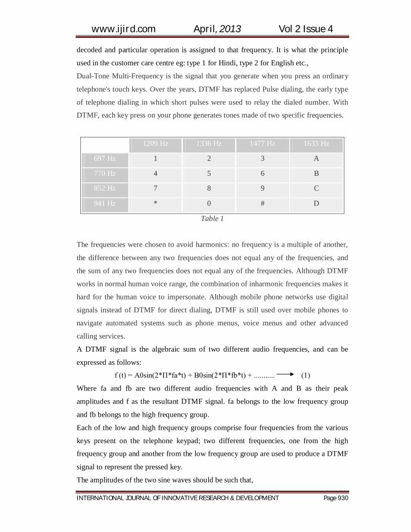
DTMF, each key press on your phone generates tones made of two specific frequencies.
1209 Hz 1336 Hz 1477 Hz 1633 Hz
697 Hz 1 2 3 A
770 Hz 4 5 6 B
852 Hz 7 8 9 C
941 Hz * 0 # D
Table 1
The frequencies were chosen to avoid harmonics: no frequency is a multiple of another,
the difference between any two frequencies does not equal any of the frequencies, and
the sum of any two frequencies does not equal any of the frequencies. Although DTMF
works in normal human voice range, the combination of inharmonic frequencies makes it
hard for the human voice to impersonate. Although mobile phone networks use digital
signals instead of DTMF for direct dialing, DTMF is still used over mobile phones to
navigate automated systems such as phone menus, voice menus and other advanced
calling services.
A DTMF signal is the algebraic sum of two different audio frequencies, and can be
expressed as follows:
f (t) = A0sin(2*П*fa*t) + B0sin(2*П*fb*t) + ........... (1)
Where fa and fb are two different audio frequencies with A and B as their peak
amplitudes and f as the resultant DTMF signal. fa belongs to the low frequency group
and fb belongs to the high frequency group.
Each of the low and high frequency groups comprise four frequencies from the various
keys present on the telephone keypad; two different frequencies, one from the high
frequency group and another from the low frequency group are used to produce a DTMF
signal to represent the pressed key.
The amplitudes of the two sine waves should be such that,

www.ijird.com April, 2013 Vol 2 Issue 4
INTERNATIONAL JOURNAL OF INNOVATIVE RESEARCH & DEVELOPMENT Page 931
(0.7 < (A/B) < 0.9)V (2)
The frequencies are chosen such that they are not the harmonics of each other. The
frequencies associated with various keys on the keypad are shown in figure:
When you press the digit 1 in the keypad it generates a resultant tone signal which is
made up of frequencies 697Hz and 1209Hz. Pressing digit 7 will produce the tone taken
from tones 852Hz and 1336Hz. In both the cases, the column frequency 1209 Hz is the
same.
Figure 1
These signals are digital signals which are symmetrical with the sinusoidal wave.
Figure 2:Dual Tone Multi Frequency (DTMF) spectrum
As the above frequency spectrum demonstrates, each & every tone must fall within the
proper band pass before a valid decoding takes place. If one tone falls outside the band
www.ijird.com April, 2013 Vol 2 Issue 4
INTERNATIONAL JOURNAL OF INNOVATIVE RESEARCH & DEVELOPMENT Page 932
pass spectrum, the decoder will not operate at all. The purpose of DTMF decoding is to
detect sinusoidal signals in the presence of noise. The DTMF decoder IC interfaces with
a controller. In addition, the signal processing associated with the decoding is usually
beyond the scope of the microcontroller's capabilities. So the designer is forced to use the
devoted IC or advance controller to perhaps a more costly digital signal processor. The
theory is quite similar to the "classical" signal processing technique. To detect DTMF
signals it is digitized w.r.t. the incoming signal and 8 DFT's (discrete Fourier transforms)
are computed centered on the 8 DTMF composite frequencies. DFT's are preferred over
FFT's because the frequencies are not equally spaced (in fact, they are logarithmically
spaced). In its simplest form, the DFT can be written as:
DFT(x) = Σ x (k) W (k) (1)
Where x (k) are the time samples and W (k) is the famous kernel function:
W (k) = e (j2πfk/N) = cos (2πfk/N) + j sin (2πfk/N) (2)
It means that multiplying the samples by sine waves and cosine waves and adding them
together the W(k) can be found. This will give up eight complex numbers. The
magnitudes of these numbers give an idea about how much energy is present for each
frequency of the input signal. In other words, we have computed the frequency spectrum
at the 8 DTMF composite frequencies. The reason why this works so well is because of
the "orthogonality" of the sine waves. In other words, this happens if the DFT is
performed on two sine waves as shown in the following equation:
DFT = Σ [sin (f1t) sin (f2t)] (3)
From equation (3), it is clear that we will get the result as a "large" number if the two
frequencies are the same and a "small" number or zero if they're different. "DFT" With
Square waves
3.1.DTMF Decoder
The MT8870 is a full DTMF Receiver that integrates both band split filter and decoder
functions into a single 18-pin DIP or SOIC package. Manufactured using CMOS process
technology, the MT8870 offers low power consumption (35 mw max) and precise data
handling. Its filter section uses switched capacitor technology for both the high and low
group filters and for dial tone rejection. Its decoder uses digital counting techniques
to detect and decode all 16 DTMF tone pairs into a 4-bit code. External component count
is minimized by provision of an on-chip differential input amplifier, clock generator, and
latched tri-state interface bus. Minimal external components required include a low-cost

www.ijird.com April, 2013 Vol 2 Issue 4
INTERNATIONAL JOURNAL OF INNOVATIVE RESEARCH & DEVELOPMENT Page 933
3.579545 MHz color burst crystal, a timing resistor, and a timing capacitor. The MT8870
provides a “power-down” option which, when enabled, drops consumption to less than
0.5 mw. The MT8870 can also inhibit the decoding of fourth column digits.
Figure 3: MT8870 IC circuit diagram
The input of the DTMF decoder is the DTMF audio tone; it is provided using an
earphone jack cut and separated the tip and ring. DTMF decoder identifies the key
pressed by the caller using the band width as discussed in the DTMF generation and is
decoded. The decoded output is a binary output drawn at Q1, Q2, Q3, and Q4 as shown
in the above circuit diagram. The corresponding outputs of different touch tones of
keypad are listed below.
Table 2
www.ijird.com April, 2013 Vol 2 Issue 4
INTERNATIONAL JOURNAL OF INNOVATIVE RESEARCH & DEVELOPMENT Page 934
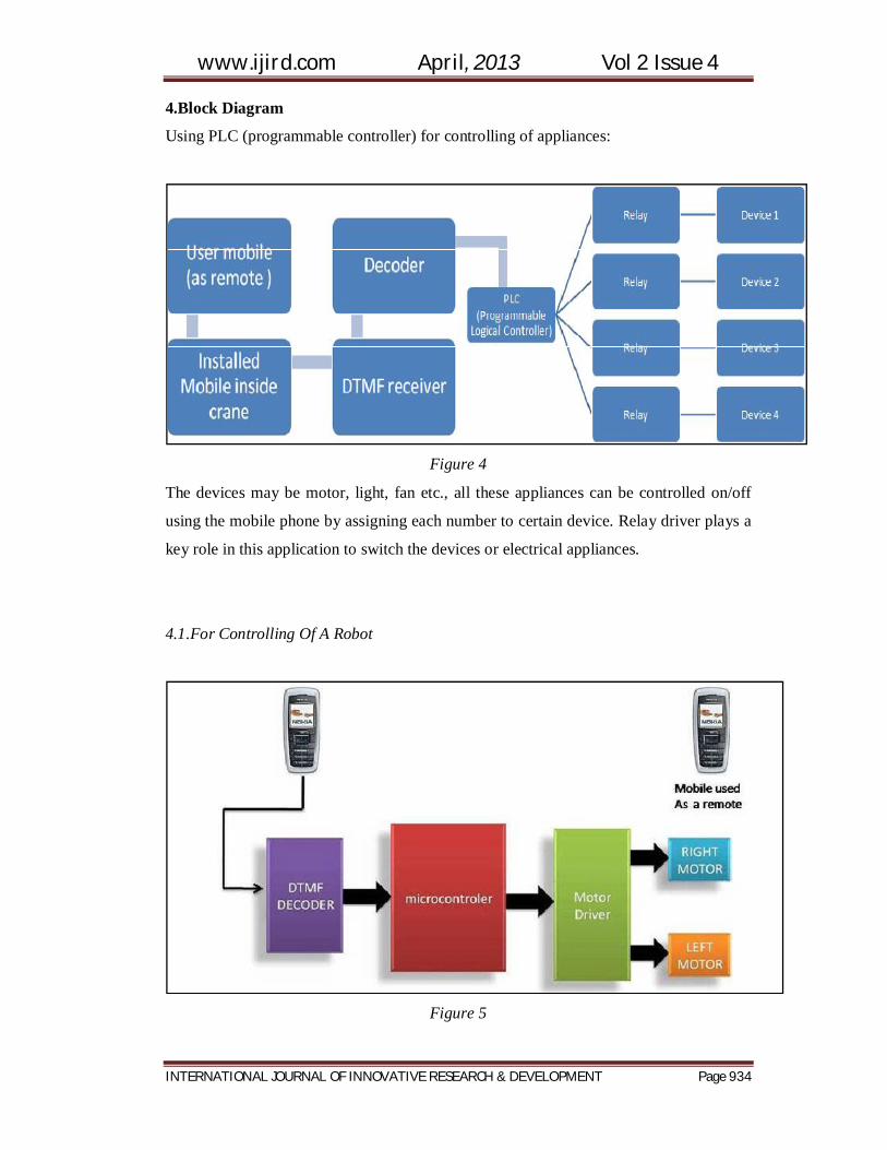
4.Block Diagram
Using PLC (programmable controller) for controlling of appliances:
Figure 4
The devices may be motor, light, fan etc., all these appliances can be controlled on/off
using the mobile phone by assigning each number to certain device. Relay driver plays a
key role in this application to switch the devices or electrical appliances.
4.1.For Controlling Of A Robot
Figure 5
www.ijird.com April, 2013 Vol 2 Issue 4
INTERNATIONAL JOURNAL OF INNOVATIVE RESEARCH & DEVELOPMENT Page 935
In general DTMF decoder is MT8870, micro controller is atmega16, motor driver is
L293D
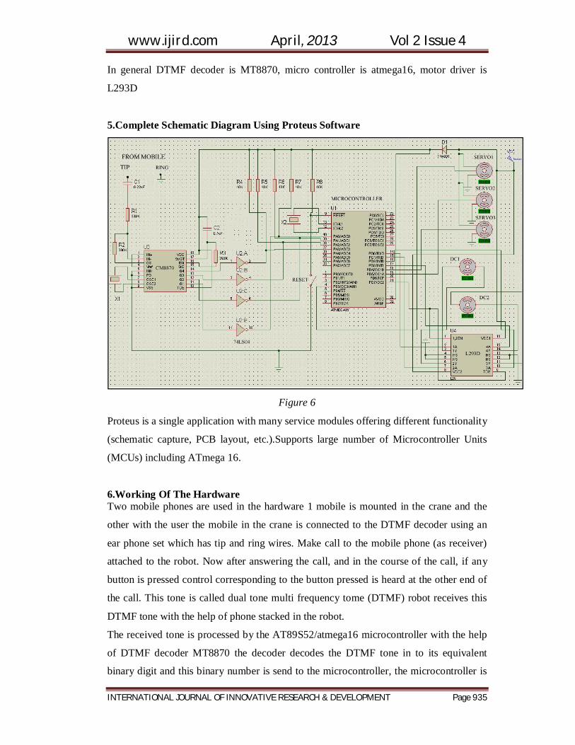
5.Complete Schematic Diagram Using Proteus Software
Figure 6
Proteus is a single application with many service modules offering different functionality
(schematic capture, PCB layout, etc.).Supports large number of Microcontroller Units
(MCUs) including ATmega 16.
6.Working Of The Hardware Two mobile phones are used in the hardware 1 mobile is mounted in the crane and the
other with the user the mobile in the crane is connected to the DTMF decoder using an
ear phone set which has tip and ring wires. Make call to the mobile phone (as receiver)
attached to the robot. Now after answering the call, and in the course of the call, if any
button is pressed control corresponding to the button pressed is heard at the other end of
the call. This tone is called dual tone multi frequency tome (DTMF) robot receives this
DTMF tone with the help of phone stacked in the robot.
The received tone is processed by the AT89S52/atmega16 microcontroller with the help
of DTMF decoder MT8870 the decoder decodes the DTMF tone in to its equivalent
binary digit and this binary number is send to the microcontroller, the microcontroller is

www.ijird.com April, 2013 Vol 2 Issue 4
INTERNATIONAL JOURNAL OF INNOVATIVE RESEARCH & DEVELOPMENT Page 936
preprogrammed to take a decision for any give input and outputs its decision to motor
drivers in order to drive the motors for forward or backward motion or a turn.
The mobile that makes a call to the mobile phone stacked in the robot acts as a remote.
So this simple robotic project does not require the construction of receiver and
transmitter units. DTMF signaling is used for telephone signaling over the line in the
voice frequency band to the call switching center. The version of DTMF used for
telephone dialing is known as touch tone. DTMF assigns a specific frequency (consisting
of two separate tones) to each key that it can easily be identified by the electronic circuit.
The signal generated by the DTMF encoder is the direct algebraic submission, in real
time of the amplitudes of two sine (cosine) waves of different frequencies, i.e pressing 5
will send a tone made by adding 1336 Hz and 770Hz to the other end of the mobile.
7.Output For Controlling A Crane
Table 3
Various operations we can perform on crane is shown above in such a way we can
perform 12 operation on crane and can control nearly 12 elecrical appliances using a
relay driver.
8.Software Used The software is written in ‘C’ language and compiled using Code Vision AVR ‘C’
compiler. The source program is converted into hex code by the compiler. Burn this hex
code into ATmega16 AVR microcontroller.
The source program is well commented and easy to understand. First include the register
www.ijird.com April, 2013 Vol 2 Issue 4
INTERNATIONAL JOURNAL OF INNOVATIVE RESEARCH & DEVELOPMENT Page 937
name defined specifically for ATmega16 and also declare the variable. Set port A as the
input and port D as the output. The program will run forever by using ‘while’ loop.
Under ‘while’ loop, read port A and test the received input using ‘switch’ statement. The
corresponding data will output at port D after testing of the received data.
9.Further Improvements & Future Scope
9.1.IR Sensors
IR sensors can be used to automatically detect &avoid obstacles if the robot goes beyond
line of sight. This avoids damage to the vehicle if we are maneuvering it from a distant
place.
9.2.Password Protection
Project can be modified in order to password protect the robot so that it can be operated
only if correct password is entered. Either cell phone should be password protected or
necessary modification should be made in the assembly language code. This introduces
conditioned access &increases security to a great extent.
9.3.Alarm Phone Dialer
By replacing DTMF Decoder IC CM8870 by a 'DTMF Transceiver IC’ CM8880, DTMF
tones can be generated from the robot. So, a project called 'Alarm Phone Dialer' can be
built which will generate necessary alarms for something that is desired to be
monitored (usually by triggering a relay). For example, a high water alarm, low
temperature alarm, opening of back window, garage door, etc. When the system is
activated it will call a number of programmed numbers to let the user know the alarm has
been activated. This would be great to get alerts of alarm conditions from home when
user is at work.
9.4.Adding A Camera
If the current project is interfaced with a camera (e.g. a Webcam) robot can be driven
beyond line-of-sight &range becomes practically unlimited as GSM networks have a
very large range.
www.ijird.com April, 2013 Vol 2 Issue 4
INTERNATIONAL JOURNAL OF INNOVATIVE RESEARCH & DEVELOPMENT Page 938
10.Reference
1. MJ. Jung, F. Arai, Y. Hasegawa, and T. Fukuda, "Mood and task coordination of
home robots" IEEE International Conference ICRA 2003, vol. 1, pp. 250-255,
September 2003.
2. M. Callahan Jr., "Integrated DTMF Receiver", IEEE Transactions on
communications, vol. 27, pp. 343-348, February 1979.
3. http://en.wikipedia.org/wiki/DTMF
4. http://www.polar-electric.com/DTMF/
5. http://topcoder.ahlamontada.com/t41-proteus-isis-simulation-software
6. www.zenave.com/DTMF
Related Documents