Inductive power transfer in e-textile applications: Reducing the effects of coil misalignment Zhu, D. , Grabham, N. J. , Clare, L. , Stark, B. H. and Beeby, S. P. Author post-print (accepted) deposited in CURVE January 2016 Original citation & hyperlink: Zhu, D. , Grabham, N. J. , Clare, L. , Stark, B. H. and Beeby, S. P. (2015) 'Inductive power transfer in e-textile applications: Reducing the effects of coil misalignment' In: Wireless Power Transfer Conference (WPTC), 2015 IEEE, 'Wireless Power Transfer Conference (WPTC)'. Held 13-15 May 2015 at Boulder, CO, USA. IEEE, 1-4. http://dx.doi.org/10.1109/WPT.2015.7140116 ISSN 2327-4697 DOI 10.1109/WPT.2015.7140116 (c) 2015 IEEE. Personal use of this material is permitted. Permission from IEEE must be obtained for all other users, including reprinting/ republishing this material for advertising or promotional purposes, creating new collective works for resale or redistribution to servers or lists, or reuse of any copyrighted components of this work in other works. Copyright © and Moral Rights are retained by the author(s) and/ or other copyright owners. A copy can be downloaded for personal non-commercial research or study, without prior permission or charge. This item cannot be reproduced or quoted extensively from without first obtaining permission in writing from the copyright holder(s). The content must not be changed in any way or sold commercially in any format or medium without the formal permission of the copyright holders. This document is the author’s post-print version, incorporating any revisions agreed during the peer-review process. Some differences between the published version and this version may remain and you are advised to consult the published version if you wish to cite from it. CURVE is the Institutional Repository for Coventry University http://curve.coventry.ac.uk/open

Welcome message from author
This document is posted to help you gain knowledge. Please leave a comment to let me know what you think about it! Share it to your friends and learn new things together.
Transcript

Inductive power transfer in e-textile applications: Reducing the effects of coil misalignment Zhu, D. , Grabham, N. J. , Clare, L. , Stark, B. H. and Beeby, S. P. Author post-print (accepted) deposited in CURVE January 2016 Original citation & hyperlink: Zhu, D. , Grabham, N. J. , Clare, L. , Stark, B. H. and Beeby, S. P. (2015) 'Inductive power transfer in e-textile applications: Reducing the effects of coil misalignment' In: Wireless Power Transfer Conference (WPTC), 2015 IEEE, 'Wireless Power Transfer Conference (WPTC)'. Held 13-15 May 2015 at Boulder, CO, USA. IEEE, 1-4. http://dx.doi.org/10.1109/WPT.2015.7140116 ISSN 2327-4697 DOI 10.1109/WPT.2015.7140116 (c) 2015 IEEE. Personal use of this material is permitted. Permission from IEEE must be obtained for all other users, including reprinting/ republishing this material for advertising or promotional purposes, creating new collective works for resale or redistribution to servers or lists, or reuse of any copyrighted components of this work in other works. Copyright © and Moral Rights are retained by the author(s) and/ or other copyright owners. A copy can be downloaded for personal non-commercial research or study, without prior permission or charge. This item cannot be reproduced or quoted extensively from without first obtaining permission in writing from the copyright holder(s). The content must not be changed in any way or sold commercially in any format or medium without the formal permission of the copyright holders. This document is the author’s post-print version, incorporating any revisions agreed during the peer-review process. Some differences between the published version and this version may remain and you are advised to consult the published version if you wish to cite from it.
CURVE is the Institutional Repository for Coventry University http://curve.coventry.ac.uk/open
Inductive Power Transfer in E-Textile Applications: Reducing the Effects of Coil Misalignment
Dibin Zhu1, Neil J. Grabham1, Lindsay Clare2, Bernard H. Stark2 and Steve P. Beeby1 1Electronics and Computer Science, University of Southampton, Southampton, SO17 1BJ, UK
2Faculty of Engineering, University of Bristol, Bristol, BS8 1UB, UK
Abstract — Wireless power transfer (WPT) is an attractive
approach for recharging wearable technologies and therefore textile implementations are of interest. Such textile WPT systems are inherently flexible and prone to misalignments of the inductively coupled coils which affects performance. This paper investigates two methods to reduce the effect of coil misalignment in inductive WPT in e-textile applications: a single large transmitter coil and a switched transmitter coil array. Transmission efficiency and maximum received power are determined for both methods, and compared against the baseline system that uses a single small transmitter coil. All coils used in this study were fabricated using automated stitching of PTFE insulated flexible wire onto a polyester/cotton textile. This fabrication method allows coils to be sewn directly to existing garments.
Index Terms — Misalignment, wireless power transfer, flexible coil, e-textiles.
I. INTRODUCTION
Recent developments in printing electronics and e-textiles have seen increasing demand of embedding digital components and electronics into fabrics. Such applications require reliable power sources that can be seamlessly integrated into garments. Potential power sources for this application include energy harvesting from human movement, temperature difference and ambient light. However, these energy harvesting techniques are highly dependent on the ambient environment and the amount of energy generated is unpredictable. By contrast, active power transfer techniques are more reliable and suitable for powering e-textile systems.
One of the most promising active power transfer techniques is inductive power transfer (IPT), a technology that has attracted increasing attention over the years as a reliable power source for wireless systems [1]. The concept can be applied to body-worn textiles by, for example, integrating a flexible transmitter coil into upholstery, and a flexible receiver coil into garments. However significant challenges arise: The performance of the inductive wireless power transfer system is a strong function of the alignment and separation of the inductively coupled coils [2][3]. The performance is also highly dependent on the materials and geometry of the coils. In body worn e-textile applications, accurate alignment of transmitter and receiver coils is difficult to achieve. As the coils need to be flexible, their performance is also compromised due to the limitations of flexible materials.
This paper demonstrates coils that have been fabricated using automated stitching onto textiles, and investigates the use of these resistive, planar, flexible coils, in e-textiles applications. Two methods are applied to address coil misalignment: a single large transmitter coil and an actively-switched multiple transmitter coil arrangement. Transmission efficiency and maximum received power are measured using a variable frequency coil driver, and compared against a baseline system. Fabrication and characterization of the flexible coils are presented first, followed by tests using different transmitter coil arrangements.
II. FLEXIBLE COILS
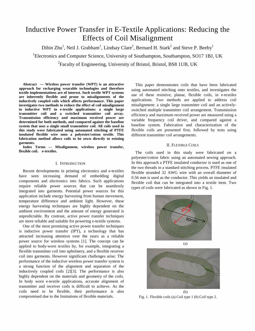
The coils used in this study were fabricated on a polyester/cotton fabric using an automated sewing approach. In this approach a PTFE insulated conductor is used as one of the two threads in a standard stitching process. PTFE insulated flexible stranded 32 AWG wire with an overall diameter of 0.56 mm is used as the conductor. This yields an insulated and flexible coil that can be integrated into a textile item. Two types of coils were fabricated as shown in Fig. 1.
(a)
(b)
Fig. 1. Flexible coils (a) Coil type 1 (b) Coil type 2.

Fig. 2. Schematic of the switched three-coil array.
50mm 50 mm
Fig. 3. Schematic of a single large transmitter coil.
195 mm
150 mm
90 m
m
45m
m
Both coils have ten turns and a pitch of 2.5 mm. Coil type 1 has outer and inner diameters of 90 mm and 45 mm respectively. Coil type 2 has outer and inner lengths of 195 mm and 150 mm respectively. Its outer width is 90 mm and its inner width is 45 mm. Properties of the two coils were measured at 300 kHz using a Wayne Kerr 6500B precision impedance analyzer and the results are listed in Table I.
III. TRANSMITTER COIL ARRANGEMENT
In order to investigate methods to reduce the effect of coil misalignment in IPT, the following two transmitter coil arrangements have been characterized and compared against a baseline system that uses a single small transmitter coil (coil type 1).
A. Multiple Transmitter Coils
In a first arrangement, the three transmitter coil array shown in Fig. 2 was used. Each of these coils has the same specifications as coil type 1. The centers of the three coils were aligned in plan with a 50 mm distance between adjacent coil centers. During power transmission, whichever coil provides the maximum transfer efficiency is used to transmit energy to the receiver coil, with the other two coils remaining inactive. The coil selection function can be achieved automatically using a wireless power transmitter controller, such as Texas Instruments bq500410A [4]. For simplicity in this study, the choice of the transmitter coil was done manually.
B. Single Large Coil
In this arrangement, a single type 2 coil as shown in Fig. 1(b) was used. Its schematic is shown in Fig. 3. It covers the same overall area as the three-coil array as shown in Fig. 2.
IV. EXPERIMENTS
A. Test Circuit
Fig. 4 shows the test circuit. The transmitting coil is driven by a resonant multivibrator circuit.
Chokes L1 and L2 store energy which is alternately fed into
the resonant circuit comprising the transmitter coil L3 and the tuning capacitor C3; this resonant circuit determines the operating frequency which is 300 kHz in this case. The inductance of L1 and L2 is sufficient to allow the current in the inductors to be continuous, with energy being replenished each time the MOSFET associated with each inductor switches. Capacitors C1 and C2 provide feedback to maintain oscillation. The driver is powered by a 9 V DC source. The input current Iin is measured, and input DC power Pin can be calculated as Pin = 9Iin.
At the receiver end, the receiver coil L4 is connected in parallel with the tuning capacitor C4. The AC input is then rectified using a bridge rectifier. A variable load resistor RL is connected to the output of the bridge rectifier so that the optimal load can be determined. The voltage VL across the optimal load resistor is measured, and maximum output DC
TABLE I PROPERTIES OF THE TWO COILS AT 300 KHZ
Property Coil 1 Coil 2 Inductance 9.6 µH 20.94 µH Equivalent Series Resistance 1.2 Ω 2.27 Ω Parasitic Capacitance 18 pF 30 pF
90 m
m
195 mm
45m
m
V
A
9V
L1 L2
C1 C2C3 C4
L3 L4
RLQ1 Q2
Transmitter Receiver
C5
Iin
VL
Fig. 4. Test circuit.

power PL can then be calculated as PL = VL2/ RL.
The DC to DC efficiency ηDC can be calculated as
𝜂𝜂𝐷𝐷𝐷𝐷 = 𝑃𝑃𝐿𝐿𝑃𝑃𝑖𝑖𝑖𝑖
=𝑉𝑉𝐿𝐿2𝑅𝑅𝐿𝐿
9𝐼𝐼𝑖𝑖𝑖𝑖 (1)
B. Results and Discussions
The receiver coil in all tests is a type 1 coil and there is no gap between the transmitter and receiver coils during the tests.
Various values of tuning capacitor, C4, were first tested in order to find its optimum value for maximum power transfer efficiency. In the case of using the small transmitter coils, the receiver coil was placed to completely overlap the transmitter coil. In the case of using a large transmitter coil, the receiver coil was placed to overlap the edge of the transmitter coil as shown in Fig. 5.
Fig. 6 shows experimental results of maximum power
transferred and power transfer efficiency with variance of C4. It was found that in the case of small transmitter coil, the optimum value for C4 is 10 nF while the optimum C4 in the case of large transmitter coil is 30 nF. These values were used in all follow-on tests.
Figs. 7 and 8 show the maximum power transferred and power transfer efficiency respectively, as a function of the x-y location of the center of the receiver coil, for the three cases described above. It was found that the switched three-coil array offers the highest power transfer efficiency and can transfer more power compared to a single large transmitter coil, as the electromagnetic field is more concentrated and the transmitter and receiver coils are better coupled. The effective area where transmitter power is over 1 W of the switched three-coil array is 56 % and 30 % higher than those of a single large coil and a single small coil, respectively. The effective area where transmitter efficiency is over 30 % of the switched three-coil array is 45 % higher than those of the other two transmitter coil arrangements. This approach, however, comes with the complication of needing to selectively energize the correct transmitter coils.
V. CONCLUSION
This paper presented fabrication of flexible coils on textiles and two methods to address coil misalignment in inductive power transfer using such flexible coils including a single large transmitter coil and a switched multiple transmitter coil
array. It was found that the switched coil array can provide higher power transfer efficiency over a larger area compared to the single small transmitter coil. However, a single large transmitter cannot increase the effective power transmission area. It is worth mentioning that although using a transmitter coil array is more efficient compared to the other two transmitter coil arrangements, it requires extra energy and a more complicated system to enable coil selection function. Future work will be focused on developing an efficient coil selection system and demonstrating its application in e-textile systems.
ACKNOWLEDGEMENT
This work was performed under the SPHERE IRC funded by the UK Engineering and Physical Sciences Research Council (EPSRC), Grant EP/K031910/1. Beeby also acknowledges EPSRC fellowship funding Grant EP/I005323/1.
(a)
(b)
Fig. 6. Maximum power transferred and power transfer efficiency with variance of C4 (a) small transmitter coil (b) large transmitter coil.
Transmitter coil
Receiver coil
Fig. 5. Coils arrangement for finding optimum value of C4 in the case of a large transmitter coil.

REFERENCES
[1] K. Y. Kim, Wireless Power Transfer - Principles and Engineering Explorations, Open access, InTech, 2012.
[2] K. Fotopoulou and B. Flynn, “Wireless Power Transfer in Loosely Coupled Links: Coil Misalignment Model,” IEEE Trans. Magnetics, vol. 47, no. 2, pp. 416-430, February 2011.
[3] S. Aldhaher, P. C. K. Luk, and J. F. Whidborne, “Electronic Tuning of Misaligned Coils In Wireless Power Transfer Systems,” IEEE Transactions on Power Electronics, vol. 29, Issue 11, 2014, pp. 5975 - 5982.
[4] Datasheet of TI BQ500410A, available at http://www.ti.com/product/bq500410A (31 March 2015)
(a) Single small coil
(a) Three coil array
(b) Single large coil
Fig. 7. Comparison of maximum power transferred (W).
(a) Single small coil
(a) Three coil array
(b) Single large coil
Fig. 8. Comparison of DC to DC power transfer efficiency (%).
Related Documents


![Design and Development of a Wearable Inductive Textile ...summit.sfu.ca/system/files/iritems1/21035/etd21150.pdfExample of a capacitive textile sensor [27]. This image is licensed](https://static.cupdf.com/doc/110x72/612d41d71ecc5158694213b9/design-and-development-of-a-wearable-inductive-textile-example-of-a-capacitive.jpg)