energies Article Induction Motors Condition Monitoring System with Fault Diagnosis Using a Hybrid Approach Hong-Chan Chang *, Yu-Ming Jheng, Cheng-Chien Kuo and Yu-Min Hsueh Department of Electrical Engineering, National Taiwan University of Science and Technology No.43, Keelung Rd., Sec.4, Da’an Dist, Taipei 10607, Taiwan; [email protected] (Y.-M.J.); [email protected] (C.-C.K.); [email protected] (Y.-M.H.) * Correspondence: [email protected]; Tel.: +886-2737-6677 Received: 17 March 2019; Accepted: 9 April 2019; Published: 18 April 2019 Abstract: This study develops a condition monitoring system, which includes operating condition monitoring (OCM) and fault diagnosis analysis (FDA). The OCM uses a vibration detection approach based on the ISO 10816-1 and NEMA MG-1 international standards, and the FDA uses a vibration-electrical hybrid approach based on various indices. The system can acquire real-time vibration and electrical signals. Once an abnormal vibration has been detected by using OCM, the FDA is applied to classify the type of faults. Laboratory results indicate that the OCM can successfully diagnose induction motors healthy condition, and FDA can classify the various damages stator fault, rotor fault, bearing fault and eccentric fault. The FDA with the hybrid approach is more reliable than the traditional approach using electrical detection alone. The proposed condition monitoring system can provide simple and clear maintenance information to improve the reliability of motor operations. Keywords: operating condition monitoring; fault diagnosis analysis; hybrid approach 1. Introduction Taking a large power plant in Taiwan as an example, each of its large thermal generator sets relies on an auxiliary system with numerous high-voltage motors for operation. The elements of the auxiliary system for the generator sets—which includes fans, coal pulverizers, gearboxes, fluid couplings, and conveyor belts—are all driven by high-voltage motors, and these motors often require operation under specialized conditions. Any breakdown in the auxiliary system not only affects the power quality and reliability of the entire power system, but it can also result in enormous economic losses. Thus, the importance of condition monitoring and fault diagnosis of induction motors in auxiliary systems cannot be underestimated. Various damage types were found, such as interturn short-circuit [1], broken rotor bar [2], bearing inner ring failure, bearing outer ring failure, ball failure, cage failure [3], and eccentricity [4]. As for fault diagnosis of an induction motor, the literature has also indicated that approximately 30% of motor breakdowns are related to stators, 10% to rotors, 40% to bearings, and 20% to other components [5]. A great deal of research proposes how to classify the damage types, such as stator breakdowns, and have employed various approaches [6–12], including magnetic pendulous oscillation, motor current signature analysis, instantaneous active and reactive power signature analyses, and total harmonic voltage. Studies on rotor breakdowns [13–16] have used mathematical morphology and wavelet analysis. Bearing breakdowns have been investigated using the root-multiple signal classification method and neural networks [17,18]. As for breakdowns in other components, recent studies focused on the relatively more common eccentricity problems, which were examined in References [19–22]. Energies 2019, 12, 1471; doi:10.3390/en12081471 www.mdpi.com/journal/energies

Welcome message from author
This document is posted to help you gain knowledge. Please leave a comment to let me know what you think about it! Share it to your friends and learn new things together.
Transcript

energies
Article
Induction Motors Condition Monitoring System withFault Diagnosis Using a Hybrid Approach
Hong-Chan Chang *, Yu-Ming Jheng, Cheng-Chien Kuo and Yu-Min Hsueh
Department of Electrical Engineering, National Taiwan University of Science and Technology No.43,Keelung Rd., Sec.4, Da’an Dist, Taipei 10607, Taiwan; [email protected] (Y.-M.J.);[email protected] (C.-C.K.); [email protected] (Y.-M.H.)* Correspondence: [email protected]; Tel.: +886-2737-6677
Received: 17 March 2019; Accepted: 9 April 2019; Published: 18 April 2019�����������������
Abstract: This study develops a condition monitoring system, which includes operating conditionmonitoring (OCM) and fault diagnosis analysis (FDA). The OCM uses a vibration detectionapproach based on the ISO 10816-1 and NEMA MG-1 international standards, and the FDA usesa vibration-electrical hybrid approach based on various indices. The system can acquire real-timevibration and electrical signals. Once an abnormal vibration has been detected by using OCM, the FDAis applied to classify the type of faults. Laboratory results indicate that the OCM can successfullydiagnose induction motors healthy condition, and FDA can classify the various damages stator fault,rotor fault, bearing fault and eccentric fault. The FDA with the hybrid approach is more reliable thanthe traditional approach using electrical detection alone. The proposed condition monitoring systemcan provide simple and clear maintenance information to improve the reliability of motor operations.
Keywords: operating condition monitoring; fault diagnosis analysis; hybrid approach
1. Introduction
Taking a large power plant in Taiwan as an example, each of its large thermal generator sets relieson an auxiliary system with numerous high-voltage motors for operation. The elements of the auxiliarysystem for the generator sets—which includes fans, coal pulverizers, gearboxes, fluid couplings,and conveyor belts—are all driven by high-voltage motors, and these motors often require operationunder specialized conditions. Any breakdown in the auxiliary system not only affects the powerquality and reliability of the entire power system, but it can also result in enormous economic losses.Thus, the importance of condition monitoring and fault diagnosis of induction motors in auxiliarysystems cannot be underestimated.
Various damage types were found, such as interturn short-circuit [1], broken rotor bar [2],bearing inner ring failure, bearing outer ring failure, ball failure, cage failure [3], and eccentricity [4].As for fault diagnosis of an induction motor, the literature has also indicated that approximately30% of motor breakdowns are related to stators, 10% to rotors, 40% to bearings, and 20% to othercomponents [5].
A great deal of research proposes how to classify the damage types, such as stator breakdowns,and have employed various approaches [6–12], including magnetic pendulous oscillation, motor currentsignature analysis, instantaneous active and reactive power signature analyses, and total harmonicvoltage. Studies on rotor breakdowns [13–16] have used mathematical morphology and waveletanalysis. Bearing breakdowns have been investigated using the root-multiple signal classificationmethod and neural networks [17,18]. As for breakdowns in other components, recent studies focusedon the relatively more common eccentricity problems, which were examined in References [19–22].
Energies 2019, 12, 1471; doi:10.3390/en12081471 www.mdpi.com/journal/energies
Energies 2019, 12, 1471 2 of 12
Recently, a motor diagnosis manner was generally used in industries, which is called time-basedmaintenance (TBM) [23]. The TBM is maintenance performed on equipment based on calendarschedules. This means that the schedules will be important for routine maintenance. However,the TBM may result in over maintenance to prevent considerable waste of manpower and resources.
In industry 4.0, thriving developments in the sensor, communication, and information processingindustries have gradually made the real-time online monitoring of motors a real possibility. The latesttrend in motor maintenance is thus condition-based maintenance (CBM), which is effective in accidentprevention. CBM also allows motors to remain reliable throughout their service time [23]. Thus,it is critically important to develop a condition monitoring system with fault diagnosis using avibration–electrical hybrid approach system for induction motors based on CBM.
2. Hardware Architecture
2.1. Overall Structure
Most condition monitoring systems (CMS) worldwide that are currently used for monitoringimportant motors have a hierarchical structure. Figure 1 depicts such a system, the front end of whichconsists of small, inexpensive, reliable, fast, and simply constructed data acquisition/transmissiondevices, embedded in crucial equipment on site, and the back end of which is a monitoring system.Relay stations may be installed between the front and back ends due to distance or data transmissionconsiderations. Relay stations must have high expandability and flexibility to allow effective andtimely presentation of motor conditions to on-site operators at the front end and long-term recordingof operating data at the back end. Additionally, the system should be able to perform trend analysesbased on longitudinal data stored in its database. The study develops condition monitoring with faultdiagnosis embedded system in the front end.
Energies 2019, 12, x FOR PEER REVIEW 2 of 12
studies focused on the relatively more common eccentricity problems, which were examined in
References [19–22].
Recently, a motor diagnosis manner was generally used in industries, which is called
time‐based maintenance (TBM) [23]. The TBM is maintenance performed on equipment based on
calendar schedules. This means that the schedules will be important for routine maintenance.
However, the TBM may result in over maintenance to prevent considerable waste of manpower and
resources.
In industry 4.0, thriving developments in the sensor, communication, and information
processing industries have gradually made the real‐time online monitoring of motors a real
possibility. The latest trend in motor maintenance is thus condition‐based maintenance (CBM),
which is effective in accident prevention. CBM also allows motors to remain reliable throughout
their service time [23]. Thus, it is critically important to develop a condition monitoring system with
fault diagnosis using a vibration–electrical hybrid approach system for induction motors based on
CBM.
2. Hardware Architecture
2.1. Overall Structure
Most condition monitoring systems (CMS) worldwide that are currently used for monitoring
important motors have a hierarchical structure. Figure 1 depicts such a system, the front end of
which consists of small, inexpensive, reliable, fast, and simply constructed data
acquisition/transmission devices, embedded in crucial equipment on site, and the back end of which
is a monitoring system. Relay stations may be installed between the front and back ends due to
distance or data transmission considerations. Relay stations must have high expandability and
flexibility to allow effective and timely presentation of motor conditions to on‐site operators at the
front end and long‐term recording of operating data at the back end. Additionally, the system
should be able to perform trend analyses based on longitudinal data stored in its database. The
study develops condition monitoring with fault diagnosis embedded system in the front end.
Figure 1. Overall system diagram.

Energies 2019, 12, 1471 3 of 12
In Figure 2, a simple embedded system is proposed for condition monitoring and fault diagnosisof induction motors. The front end embedded system prototype size is 240 × 170 × 30 mm. The systemassesses the current condition of a motor through vibration detection. When an abnormality is detected,electrical detection is used in conjunction with vibration detection to determine the possible type of fault.This system adopts a triaxial accelerometer to measure the vibration of the motor, non-contact captureof voltage, and current signals using Hall sensors. The acquired analog signals are passed through asignal processing circuit and transmitted to an analog-to-digital converter, which converts them intodigital signals and passes them on to a microprocessor for processing. Subsequently, fast-screeningfault diagnosis and fast-screening condition monitoring are employed, and the results are displayedon the touchscreen in simple and intuitive graphics. If intranet is available on site, the original signaldata can be transmitted to the server-side system, which will make the system operations even morecomprehensive by conducting rigorous analyses. If intranet is not available, the original data canbe transported using a secure digital (SD) card to a computer for further analysis. As a means ofdata transportation, the SD card and intranet are not mutually exclusive; the choice between the twodepends solely on the availability of on-site intranet.
Energies 2019, 12, x FOR PEER REVIEW 3 of 12
Figure 1. Overall system diagram.
In Figure 2, a simple embedded system is proposed for condition monitoring and fault
diagnosis of induction motors. The front end embedded system prototype size is 240 × 170 × 30 mm.
The system assesses the current condition of a motor through vibration detection. When an
abnormality is detected, electrical detection is used in conjunction with vibration detection to
determine the possible type of fault. This system adopts a triaxial accelerometer to measure the
vibration of the motor, non‐contact capture of voltage, and current signals using Hall sensors. The
acquired analog signals are passed through a signal processing circuit and transmitted to an
analog‐to‐digital converter, which converts them into digital signals and passes them on to a
microprocessor for processing. Subsequently, fast‐screening fault diagnosis and fast‐screening
condition monitoring are employed, and the results are displayed on the touchscreen in simple and
intuitive graphics. If intranet is available on site, the original signal data can be transmitted to the
server‐side system, which will make the system operations even more comprehensive by conducting
rigorous analyses. If intranet is not available, the original data can be transported using a secure
digital (SD) card to a computer for further analysis. As a means of data transportation, the SD card
and intranet are not mutually exclusive; the choice between the two depends solely on the
availability of on‐site intranet.
Voltage Sensor
Current Sensor
3-Axis Accelerometer
ADS85563 Data Line
3 Data Line
3 Data Line
ARMLPC4088
16 Data Line
16 Data Line
Internet
USB
LCD
SD Card
ADS8556
Figure 2. Front‐end embedded system block diagram.
2.2. Sensor Modules
The voltage and current sensors are used in this study were all Hall devices because of their
high safety and convenience. A triaxial accelerometer is used to measure accelerations along the
three axes, and its sensor is an integrated electronics piezoelectric (IEPE) circuit. Such sensors have
sensitive built‐in charge or voltage amplifiers because the current generated by the accelerometer is
extremely weak, and that signal interference can easily occur in the sensors without such amplifiers.
The IEPE transducer integrates these sensitive circuits and brings them close to the sensors to ensure
greater noise immunity and easier packaging. The detailed sensor specifications are as listed in Table
1.
Table 1. Specifications of sensors.
Sensors Model Type Measuring Range Frequency Bandwidth
Voltage Sensor CHV 50P/600 0~±800 V 0~20 kHz
Current Sensor HTR 50‐SB 0~±100 A 0~10 kHz
3‐Axis Accelerometer AD100T ±50 g 0.3~12 kHz
ADC ADS8556 16 Bits 630 kSPS (Parallel)
3. Software Process
3.1. Overall Structure
Figure 2. Front-end embedded system block diagram.
2.2. Sensor Modules
The voltage and current sensors are used in this study were all Hall devices because of their highsafety and convenience. A triaxial accelerometer is used to measure accelerations along the three axes,and its sensor is an integrated electronics piezoelectric (IEPE) circuit. Such sensors have sensitivebuilt-in charge or voltage amplifiers because the current generated by the accelerometer is extremelyweak, and that signal interference can easily occur in the sensors without such amplifiers. The IEPEtransducer integrates these sensitive circuits and brings them close to the sensors to ensure greaternoise immunity and easier packaging. The detailed sensor specifications are as listed in Table 1.
Table 1. Specifications of sensors.
Sensors Model Type Measuring Range Frequency Bandwidth
Voltage Sensor CHV 50P/600 0~±800 V 0~20 kHzCurrent Sensor HTR 50-SB 0~±100 A 0~10 kHz
3-Axis Accelerometer AD100T ±50 g 0.3~12 kHzADC ADS8556 16 Bits 630 kSPS (Parallel)
3. Software Process
3.1. Overall Structure
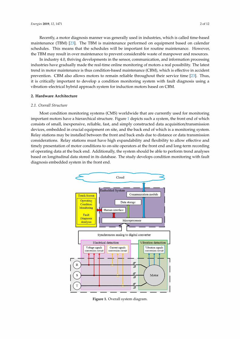
Figure 3 illustrates the process of the proposed hybrid approach. The CMS operations are dividedinto two major parts: Operating condition monitoring (OCM) and fault diagnosis analysis (FDA).When electrical and vibration signals have been acquired by the embedded system, the OCM module
Energies 2019, 12, 1471 4 of 12
determines the current condition of the motor using vibration indices and international standards.When an abnormality is detected in the motor’s operations, the system can classify the type of detectedfault through vibration and electrical indices and simultaneously informs maintenance personnel ofthe components requiring attention. The system can reduce maintenance costs or advise maintenancepersonnel of the possible type of fault, thereby shortening the time needed for troubleshooting.
Energies 2019, 12, x FOR PEER REVIEW 4 of 12
Figure 3 illustrates the process of the proposed hybrid approach. The CMS operations are
divided into two major parts: Operating condition monitoring (OCM) and fault diagnosis analysis
(FDA). When electrical and vibration signals have been acquired by the embedded system, the OCM
module determines the current condition of the motor using vibration indices and international
standards. When an abnormality is detected in the motor’s operations, the system can classify the
type of detected fault through vibration and electrical indices and simultaneously informs
maintenance personnel of the components requiring attention. The system can reduce maintenance
costs or advise maintenance personnel of the possible type of fault, thereby shortening the time
needed for troubleshooting.
Operating Condition Monitoring module
(OCM module)
Measuring voltage, current and vibration
Index >ISO threshold-(1)?
Fault diagnosis analysis module(FDA module)Display the
operating status
Yes
Displays the fault type
Calculate the electrical and vibration indicators
Index >ISO threshold-(3)?No
Start
No
Yes
Send message Maintenance work
Figure 3. Overall hybrid approach flow chart.
3.2. OCM Module
OCM relies on existing international standards as the basis for its judgments. The international
standards used are primarily the ISO 10816‐1 [24], which regards velocity control (Table 2), and the
NEMA MG‐1 [25], which regards displacement control (Table 3).
Table 2. Thresholds by Std. ISO 10816‐1.
Velocity (mm/s) Threshold Class I ≤ 15 kW
<1.12 Good
1.12 ISO threshold‐(1)
1.12~2.8 Satisfactory
2.8 ISO threshold‐(2)
2.8~7.1 Unsatisfactory
7.1 ISO threshold‐(3)
>7.1 Unacceptable
Table 3. Thresholds by Std. NEMA MG‐1.
Figure 3. Overall hybrid approach flow chart.
3.2. OCM Module
OCM relies on existing international standards as the basis for its judgments. The internationalstandards used are primarily the ISO 10816-1 [24], which regards velocity control (Table 2), and theNEMA MG-1 [25], which regards displacement control (Table 3).
Table 2. Thresholds by Std. ISO 10816-1.
Velocity (mm/s) Threshold Class I ≤ 15 kW
<1.12 Good1.12 ISO threshold-(1)
1.12~2.8 Satisfactory2.8 ISO threshold-(2)
2.8~7.1 Unsatisfactory7.1 ISO threshold-(3)
>7.1 Unacceptable
Table 3. Thresholds by Std. NEMA MG-1.
Synchronous Speed (rpm) Thresholds(Maximum Relative Shaft Displacement, Peak-peak)
1801–3600 0.0028 in (70 µm)≤1800 0.0035 in (90 µm)

Energies 2019, 12, 1471 5 of 12
Concerning the electrical detection method, although established international standards areavailable for the indices, comparable standards for the operations of motors are currently lacking.Hence, if the information currently at hand is to be used for the assessment of motor operatingconditions, algorithms must be employed to perform the necessary calculations. However, this is anextremely time-consuming undertaking for microprocessors. For this reason, a fast-screening conditionmonitoring method is introduced instead. The method uses international standards on vibrations toassess the condition of motors. According to the motor’s accelerations along the three axes, first-orderintegration is performed to obtain the velocity values to be compared with ISO 10816-1; subsequently,second-order integration is performed to obtain the displacement values to be compared with NEMAMG-1. Figure 4 describes the fast-screening process in more detail. Because ISO 10816-1 dividesmotor operations into four steps whereas NEMA MG-1 only has two steps, the method makes a logicjudgment on the velocity and displacement comparison results and chooses the more serious onesfor display in the system. The displayed results can be categorized into four levels: normal, caution,warning, and danger.
Energies 2019, 12, x FOR PEER REVIEW 5 of 12
Synchronous Speed (rpm) Thresholds
(Maximum Relative Shaft Displacement, Peak‐peak)
1801–3600 0.0028 in (70 μm)
≤1800 0.0035 in (90 μm)
Concerning the electrical detection method, although established international standards are
available for the indices, comparable standards for the operations of motors are currently lacking.
Hence, if the information currently at hand is to be used for the assessment of motor operating
conditions, algorithms must be employed to perform the necessary calculations. However, this is an
extremely time‐consuming undertaking for microprocessors. For this reason, a fast‐screening
condition monitoring method is introduced instead. The method uses international standards on
vibrations to assess the condition of motors. According to the motor’s accelerations along the three
axes, first‐order integration is performed to obtain the velocity values to be compared with ISO
10816‐1; subsequently, second‐order integration is performed to obtain the displacement values to
be compared with NEMA MG‐1. Figure 4 describes the fast‐screening process in more detail.
Because ISO 10816‐1 divides motor operations into four steps whereas NEMA MG‐1 only has two
steps, the method makes a logic judgment on the velocity and displacement comparison results and
chooses the more serious ones for display in the system. The displayed results can be categorized
into four levels: normal, caution, warning, and danger.
Measurement of vibration acceleration signal
Integral operation to obtain speed, displacement
Compared to NEMA MG-1 international specification
Over ISO threshold-(1)?
Normal Caution Warning Danger
The results are in accordance with ISO 10816-1 international
standard
The results are in accordance with NEMA MG-1
international standard
No
Compared to ISO 10816-1 international
standard
Over NEMA MG-1
threshold?
Yes
Over ISO threshold-(2)?
Over ISO threshold-(3)?
Danger
Yes
No No No
Yes Yes
Figure 4. OCM module flow chart.
3.3. FDA Module
A two‐stage hybrid approach for fault diagnosis analysis of induction motors is shown in
Figure 5. The first stage of FDA uses vibration detection for preliminary classification of the faults.
Numerous studies have been consulted to establish the indices for signal analysis, from which a
small number of key signal indices for vibration acceleration are chosen for use [26].
The second stage of FDA involves using electrical detection to develop a more rigorous
classification system of fault types on the basis of the electrical indices. The suitability of an
electrical index to the detection of a fault type can be determined by observing the effect of each
electrical index on the corresponding fault model.
Figure 4. OCM module flow chart.
3.3. FDA Module
A two-stage hybrid approach for fault diagnosis analysis of induction motors is shown inFigure 5. The first stage of FDA uses vibration detection for preliminary classification of the faults.Numerous studies have been consulted to establish the indices for signal analysis, from which a smallnumber of key signal indices for vibration acceleration are chosen for use [26].
The second stage of FDA involves using electrical detection to develop a more rigorous classificationsystem of fault types on the basis of the electrical indices. The suitability of an electrical index tothe detection of a fault type can be determined by observing the effect of each electrical index on thecorresponding fault model.
1. Current unbalance rate (CUR): IEC 60034-1 [27] and IEEE Std. 141 [28] are used as a referencefor the definition of CUR, which is similar to voltage imbalance rate; that is, it is the ratio of thethree-phase current’s maximum deviation value to its mean value. When the motor is operating

Energies 2019, 12, 1471 6 of 12
at its rated output, it should avoid exceeding 10% of the recommended value, as indicated in thefollowing equations: ∣∣∣Iavg
∣∣∣ = |Ia|+ |Ib|+ |Ic|
3(1)
CUR(%) =max
(∣∣∣∣∣∣|Ia| −∣∣∣Iavg
∣∣∣∣∣∣, ∣∣∣|Ib| −∣∣∣Iavg
∣∣∣∣∣∣, ∣∣∣|Ic| −∣∣∣Iavg
∣∣∣∣∣∣∣∣∣)∣∣∣Iavg∣∣∣ × 100%, (2)
2. Current unbalance factor (CUF): IEC 60034-1 is used as a reference for CUF. Continuous operationof over 5% should be avoided:
I0
I1
I2
= 13
1 1 11 a a2
1 a2 a
Ia
IbIc
, a = 1∠120◦, (3)
CUF(%) =
∣∣∣I2∣∣∣∣∣∣I1∣∣∣ × 100%. (4)
3. Voltage total harmonic distortion (VTHD): IEEE Std. 519 [29] was used as a reference for VTHD,which is expressed as a percentage and defined as the square root of the sum of harmonic voltagesdivided by the fundamental frequency voltage, as shown in Equation (4). It is one of the means ofassessing the total harmonic voltage’s effect on the system.
THDV =
√∑∞
h=2 V2h
V1× 100%. (5)
4. Each voltage harmonic distortion (EVHD): IEEE Std. 519 is used as a reference for EVHD, which isdefined as the percentage of the fundamental frequency voltage that is individual harmonicvoltage, as shown in Equation (6). It is one of the means of assessing an individual harmonicvoltage’s effect on the system.
VHD(%) =VhV1× 100%. (6)
5. Current total harmonic distortion (CTHD): IEEE Std. 519 is used as a reference for CTHD, which isexpressed as a percentage and defined as the square root of the sum of harmonic currents dividedby the fundamental frequency voltage, as shown in Equation (7). CTHD is used to assess the totalharmonic current’s effect on the system.
THDI(%) =
√∑∞
h=2 I2h
I1× 100%. (7)
6. Each current harmonic distortion (ECHD): IEEE Std. 519 is used as a reference for ECHD.Defined in the same vein as EVHD, ECHD refers to the rate of an individual harmonic current’svoltage to the fundamental frequency voltage. Expressed in percentage, this index serves as ameans of assessing an individual harmonic current’s effect on the system.
IHD(%) =IhI1× 100%. (8)
The suitability coefficient for an electrical index can be obtained by taking the mean of 50 datapoints of an index in the fault model, and calculating its difference from that of a healthy motor,

Energies 2019, 12, 1471 7 of 12
followed by dividing the difference by the product of the difference (∆) between the maximum andminimum values in the 50 data points of the same index in the fault model and that of a healthy motor.
Fault diagnosis in induction motors can be divided into two stages. The first is a preliminaryclassification of fault type through vibration detection, and the second is a further classification of faulttype through electrical detection. The following is a description of the fast-screening fault diagnosis ofthe two stages.
In the first stage, the motor’s acceleration signals along the three axes are acquired to calculatethe statistical indices and peak values and to determine the corresponding thresholds. As the valuesfor motors with stator and rotor faults are statistically closer to those for healthy motors, they areconsidered as belonging to the same fault group (Group 1). Bearing and misalignment faults areconsidered to belong to the same fault group (Group 2) because the index values for such motors aresignificantly higher than those for healthy motors. In summary, peak values can be used to roughlydivide fault types into two groups.
The second stage is to acquire the motor’s signals for the three-phase voltages and currentsfor determination of the electrical indices. According to the aforementioned suitability assessment,current unbalance rate (CUR), current unbalance factor (CUF), voltage total harmonic distortion(VTHD), each voltage harmonic distortion (EVHD), current total harmonic distortion (CTHD), and eachcurrent harmonic distortion (ECHD) are classified as either current imbalance electrical indices orharmonic distortion electrical indices for fast-screening fault diagnosis. If the result of the first stage isGroup 1, then the screening rules for the second stage are as follows: If the electrical indices in bothcurrent imbalance and harmonic distortion are all lower than the international standard threshold,the motor is identified as healthy; if any electrical index in current imbalance exceeds the internationalstandard threshold, it is identified as a stator fault; and if any electrical index in harmonic distortionexceeds the international standard threshold, it is identified as a rotor fault. As the fast-screeningfault diagnosis is only based on a logic judgment of whether a value exceeds the threshold or not,it is unable to distinguish whether a fault occurs in the stator or rotor when electrical indices in bothcurrent imbalance and harmonic distortion exceed the threshold.
Energies 2019, 12, x FOR PEER REVIEW 7 of 12
minimum values in the 50 data points of the same index in the fault model and that of a healthy
motor.
Fault diagnosis in induction motors can be divided into two stages. The first is a preliminary
classification of fault type through vibration detection, and the second is a further classification of
fault type through electrical detection. The following is a description of the fast‐screening fault
diagnosis of the two stages.
In the first stage, the motor’s acceleration signals along the three axes are acquired to calculate
the statistical indices and peak values and to determine the corresponding thresholds. As the values
for motors with stator and rotor faults are statistically closer to those for healthy motors, they are
considered as belonging to the same fault group (Group 1). Bearing and misalignment faults are
considered to belong to the same fault group (Group 2) because the index values for such motors
are significantly higher than those for healthy motors. In summary, peak values can be used to
roughly divide fault types into two groups.
The second stage is to acquire the motor’s signals for the three‐phase voltages and currents for
determination of the electrical indices. According to the aforementioned suitability assessment,
current unbalance rate (CUR), current unbalance factor (CUF), voltage total harmonic distortion
(VTHD), each voltage harmonic distortion (EVHD), current total harmonic distortion (CTHD), and
each current harmonic distortion (ECHD) are classified as either current imbalance electrical indices
or harmonic distortion electrical indices for fast‐screening fault diagnosis. If the result of the first
stage is Group 1, then the screening rules for the second stage are as follows: If the electrical indices
in both current imbalance and harmonic distortion are all lower than the international standard
threshold, the motor is identified as healthy; if any electrical index in current imbalance exceeds the
international standard threshold, it is identified as a stator fault; and if any electrical index in
harmonic distortion exceeds the international standard threshold, it is identified as a rotor fault. As
the fast‐screening fault diagnosis is only based on a logic judgment of whether a value exceeds the
threshold or not, it is unable to distinguish whether a fault occurs in the stator or rotor when
electrical indices in both current imbalance and harmonic distortion exceed the threshold.
(Group 2)Bearing
Eccentric
Yes
(Group 1)HealthStatorRotor
No
Three - axis vibration acceleration signal
Select the acceleration fitness index (Peak)
Set the accelerometer threshold
Over the threshold?
CIR:10 %CIF:2.5 %
VTHD:5 %EVHD:3 %CTHD:5 %ECHD:4 %
Electrical indicators threshold
Two types of indicators are above threshold
Can not distinguish stator or rotor
Stator FaultWhat kind of indicators
over the threshold?
Yes
HealthNo
Current imbalance
Rotor Fault
Harmonic distortion
Two types of indicators are above threshold
Can not distinguish stator or rotor
Misalignment FaultWhat kind of indicators
over the threshold?
Yes
No
Current imbalance
Bearing Fault
Harmonic distortion
One of them is greater than the
threshold
Can not distinguish stator or rotor
Figure 5. FDA module two-stage hybrid approach flow chart.

Energies 2019, 12, 1471 8 of 12
4. Experimental Results and Analysis
4.1. OCM Results and Analysis
The rules are established based on two sets of international standards: ISO 10816-1 and NEMAMG-1. When the displacement is judged to be “Normal” according to NEMA MG-1, the velocitywould be used to assess the level of operating condition as per IOS 10816-1; conversely, when thedisplacement is judged to be “Danger” as per NEMA MG-1, the operating condition would be rated as“Danger”. The comprehensive results are shown in (Table 4).
Table 4. Operating condition monitoring rules.
NEMA MG-1ISO 10816-1
Good Acceptable Unsatisfactory Unacceptable
Normal Normal Caution Warning DangerDanger Danger Danger Danger Danger
The feasibility assessment of the motor condition monitoring system requires longitudinal data.However, such data are lacking because the proposed system had not yet begun on-site testing. Hence,the feasibility of the proposed system is assessed using a vibration exciter in the laboratory to generatevarying vibrations, the velocities, and displacements of which, after integral operations, is fast-screenedto determine the operating conditions.
4.2. FDA Results and Analysis
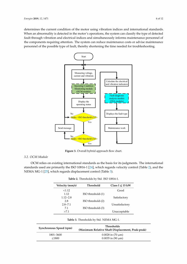
To obtain standard sample data for the proposed fault diagnosis, this study used induction motorswith identical specifications (220 V, 7 A, 60 Hz, 2 HP, and four poles) to create four common faultmodels, and then used a healthy model for contrast. The experimental scale-down fault models aredescribed as follows:
1. Stator fault: This fault occurs when the insulation layer of the stator coils is damaged by friction,aging, overheating, humidity, or corona. In the present study, a mild inter-coil short circuit issimulated by two coils short circuit after part of their insulation layer had been lightly scraped off
(Figure 6a).2. Rotor fault: If a motor is overloaded or restarted often, stress or heat buildup can cause the
breakage of a rotor bar. This study consulted the literature and drilled a hole 7 mm in diameterand 30 mm in depth into the rotor bar (Figure 6b).
3. Bearing fault: The bearing outer ring is prone to damage when the motor is overloaded, overheated,or intruded by foreign objects. In this study, electric heating is applied to melt a hole in thebearing outer ring under the premise that the bearing and other components were not to beaffected. The hole was 1 mm in diameter and depth (Figure 6c).
4. Misalignment fault: When the motor is with load, the coupling can cause misalignment at bothends due to human, environmental, or operational reasons, which in turn induces problems suchas noise and heating. Because of safety considerations, the present study uses a healthy motorbut displaced the coupling and load 0.5 mm upward (Figure 6d).
Energies 2019, 12, 1471 9 of 12Energies 2019, 12, x FOR PEER REVIEW 9 of 12
Figure 6. Four experimental models: (a) Stator fault, (b) rotor fault, (c) bearing fault, (d)
misalignment fault.
To verify the effectiveness of the proposed system, the aforementioned stator interturn short
circuit, rotor bar breaking, bearing outer ring damage, and misalignment fault models and a healthy
motor were employed for measurement. The sampling rate was 10 kHz, and 50 data entries were
taken for each motor, amounting to 250 data points in total. The data were used to compare the
diagnostic results when electrical detection alone was employed and the proposed hybrid approach
of combining vibration detection and electrical detection was used. From the results of Table 5, it is
shown that the five experimental models can be effectively distinguished using the hybrid approach.
Table 5. FDA results classification accuracy (%).
Fault Type H S R B M
Diagnosis
H 100 0 0 0 0
S 0 100 0 0 4 *1
0 *2
R 0 0 100 0 0
B 0 0 0 100 0
M 0 0 0 0 96 *1
100 *2
H: Health, S: Stator, R: Rotor, B: Bearing, M: Misalignment; *1: Electrical approach; *2: Hybrid approach.
Table 6 presents the testing results of the samples, suggesting that electrical detection alone and
the proposed hybrid approach are both able to accurately identify the healthy motor and the stator,
rotor, and bearing faults; however, for misalignment faults, electrical detection identified 20.76% as
misalignment faults and misidentified 37.85% as stator faults. By contrast, the proposed hybrid
approach was able to accurately identify misalignment faults. For each individual model, the hybrid
approach was superior to electrical detection in fault diagnosis. For example, the hybrid approach
was able to identify 56.21% of stator faults whereas electrical detection was only able to identify
37.85%.
Figure 6. Four experimental models: (a) Stator fault, (b) rotor fault, (c) bearing fault,(d) misalignment fault.
To verify the effectiveness of the proposed system, the aforementioned stator interturn shortcircuit, rotor bar breaking, bearing outer ring damage, and misalignment fault models and a healthymotor were employed for measurement. The sampling rate was 10 kHz, and 50 data entries were takenfor each motor, amounting to 250 data points in total. The data were used to compare the diagnosticresults when electrical detection alone was employed and the proposed hybrid approach of combiningvibration detection and electrical detection was used. From the results of Table 5, it is shown that thefive experimental models can be effectively distinguished using the hybrid approach.
Table 5. FDA results classification accuracy (%).
Fault TypeDiagnosis
H S R B M
H 100 0 0 0 0
S 0 100 0 0 4 *1
0 *2
R 0 0 100 0 0B 0 0 0 100 0
M 0 0 0 0 96 *1
100 *2
H: Health, S: Stator, R: Rotor, B: Bearing, M: Misalignment; *1: Electrical approach; *2: Hybrid approach.
Table 6 presents the testing results of the samples, suggesting that electrical detection alone andthe proposed hybrid approach are both able to accurately identify the healthy motor and the stator,rotor, and bearing faults; however, for misalignment faults, electrical detection identified 20.76%as misalignment faults and misidentified 37.85% as stator faults. By contrast, the proposed hybridapproach was able to accurately identify misalignment faults. For each individual model, the hybridapproach was superior to electrical detection in fault diagnosis. For example, the hybrid approach wasable to identify 56.21% of stator faults whereas electrical detection was only able to identify 37.85%.

Energies 2019, 12, 1471 10 of 12
Table 6. FDA results classification accuracy (%).
Fault TypeDiagnosis
H S R B M
H99.99 *1 0.01 *1 0.61 *1 0.01 *1 0.01 *1
99.91 *2 0.01 *2 0.01 *2 0 *2 0 *2
S0 *1 37.85 *1 16.05 *1 19.61 *1 37.85 *1
0.01 *2 56.21 *2 38.99 *2 0.01 *2 0.01 *2
R0 *1 19.83 *1 51.4 *1 27.13 *1 20.45 *1
0.01 *2 43.77 *2 60.99 *2 0.01 *2 0 *2
B0 *1 21.54 *1 24.02 *1 41.3 *1 20.93 *1
0.04 *2 0 *2 0 *2 99.97 *2 0.01 *2
M0 *1 20.76 *1 7.92 *1 11.94 *1 20.76 *1
0 *2 0 *2 0 *2 0.01 *2 99.98 *2
H: Health, S: Stator, R: Rotor, B: Bearing, M: Misalignment; *1: Electrical approach; *2: Hybrid approach.
5. Conclusions
The present study successfully develops a condition-based system which can monitor varioustypes of motor faults by using the proposed vibration-electrical hybrid approach. The system usesvibration detection for operating condition monitoring in accordance with rules drawn from the ISO10816-1 and NEMA MG-1 standards. Laboratory test results indicate that the system can correctlymonitor the operating conditions of a motor as per the rules. For fault diagnosis analysis, the systemuses vibration detection and electrical detection for fault classification. The results of laboratorytests show that the classification accuracy of the proposed hybrid system is superior to that of theelectrical approach to fault type identification. Additionally, the system is able to issue simple andclear instructions, which is a substantial improvement on existing systems and highly convenient foron-site personnel.
Author Contributions: Conceptualization, H.-C.C. and C.-C.K.; methodology, H.-C.C. and C.-C.K.; software,Y.-M.J. and Y.-M.H.; validation, Y.-M.J. and Y.-M.H.; data curation, H.-C.C.; writing—original draft preparation,Y.-M.J.
Funding: MOST-105-2221-E-011-081-MY3.
Acknowledgments: This paper supports the research funding of the Ministry of Science and Technology,Taiwan under Grant MOST-105-2221-E-011-081-MY3 is gratefully acknowledged.
Conflicts of Interest: The authors declare no conflict of interest.
References
1. Maitre, J.; Bouchard, B.; Bouzouane, A.; Gaboury, S. Classification Algorithms Comparison for InterturnShort-Circuit Recognition in Induction Machines Using Best-Fit 3-D-Ellipse Method. Can. J. Electr. Comput.Eng. 2017, 40, 255–265.
2. Hou, Z.; Huang, J.; Liu, H.; Ye, M.; Liu, Z.; Yang, J. Diagnosis of broken rotor bar fault in open- and closed-loopcontrolled wye-connected induction motors using zero-sequence voltage. IET Electr. Power Appl. 2017, 11,1214–1223. [CrossRef]
3. Boudinar, A.H.; Benouzza, N.; Bendiabdellah, A. Induction Motor Bearing Fault Analysis Using a Root-MUSICMethod. IEEE Trans. Ind. Appl. 2016, 52, 3851–3860. [CrossRef]
4. Antonino-Daviu, J.A.; Arkkio, A.; Georgoulas, G.; Climente-Alarcon, V.; Tsoumas, I.P.; Stylios, C.D.;Nikolakopoulos, G. The Use of a Multilabel Classification Framework for the Detection of Broken Bars andMixed Eccentricity Faults Based on the Start-Up Transient. IEEE Trans. Ind. Inform. 2017, 13, 625–634.
5. Zhang, P.; Du, Y.; Habetler, T.G.; Lu, B. A Survey of Condition Monitoring and Protection Methods forMedium-Voltage Induction Motors. IEEE Trans. Ind. Appl. 2011, 47, 34–46. [CrossRef]
6. Mahmoud, H.; Abdallh, A.A.; Bianchi, N.; El-Hakim, S.M.; Shaltout, A.; Dupré, L. An Inverse Approach forInter-Turn Fault Detection in Asynchronous Machines Using Magnetic Pendulous Oscillation Technique.IEEE Trans. Ind. Appl. 2016, 52, 226–233. [CrossRef]

Energies 2019, 12, 1471 11 of 12
7. Ghanbari, T. Autocorrelation function-based technique for stator turn-fault detection of induction motor.IET Sci. Meas. Technol. 2016, 10, 100–110. [CrossRef]
8. Drif, M.; Cardoso, A.J.M. Stator Fault Diagnostics in Squirrel Cage Three-Phase Induction Motor DrivesUsing the Instantaneous Active and Reactive Power Signature Analyses. IEEE Trans. Ind. Inform. 2014, 10,1348–1360. [CrossRef]
9. Duan, F.; Živanovic, R. Condition Monitoring of an Induction Motor Stator Windings Via Global OptimizationBased on the Hyperbolic Cross Points. IEEE Trans. Ind. Electron. 2015, 62, 1826–1834. [CrossRef]
10. Urresty, J.-C.; Ruiz, J.-R.R.; Romeral, L. Influence of the Stator Windings Configuration in the Currents andZero-Sequence Voltage Harmonics in Permanent Magnet Synchronous Motors With Demagnetization Faults.IEEE Trans. Magn. 2013, 49, 4885–4893. [CrossRef]
11. Faiz, J.; Nejadi-Koti, H.; Valipour, Z. Comprehensive review on inter-turn fault indexes in permanent magnetmotors. IET Electr. Appl. 2017, 11, 142–156. [CrossRef]
12. Abdallah, H.; Benatman, K. Stator winding inter-turn short-circuit detection in induction motors by parameteridentification. IET Electr. Appl. 2017, 11, 272–288. [CrossRef]
13. Rangel-Magdaleno, J.D.J.; Peregrina-Barreto, H.; Ramirez-Cortes, J.M.; Gomez-Gil, P.; Morales-Caporal, R.FPGA-Based Broken Bars Detection on Induction Motors Under Different Load Using Motor CurrentSignature Analysis and Mathematical Morphology. IEEE Trans. Instrum. Meas. 2014, 63, 1032–1040.[CrossRef]
14. Gritli, Y.; Bin Lee, S.; Filippetti, F.; Zarri, L. Advanced Diagnosis of Outer Cage Damage inDouble-Squirrel-Cage Induction Motors Under Time-Varying Conditions Based on Wavelet Analysis.IEEE Trans. Ind. Appl. 2014, 50, 1791–1800. [CrossRef]
15. Kang, T.-J.; Kim, J.; Bin Lee, S.; Yung, C. Experimental Evaluation of Low-Voltage Offline Testing for InductionMotor Rotor Fault Diagnostics. IEEE Trans. Ind. Appl. 2015, 51, 1375–1384. [CrossRef]
16. Godoy, W.F.; Da Silva, I.N.; Lopes, T.D.; Goedtel, A.; Palácios, R.H.C. Application of intelligent tools to detectand classify broken rotor bars in three-phase induction motors fed by an inverter. IET Electr. Appl. 2016, 10,430–439. [CrossRef]
17. Frosini, L.; Harlisca, C.; Szabó, L. Induction Machine Bearing Fault Detection by Means of StatisticalProcessing of the Stray Flux Measurement. IEEE Trans. Ind. Electron. 2015, 62, 1846–1854. [CrossRef]
18. Prieto, M.D.; Cirrincione, G.; Espinosa, A.G.; Ortega, J.A.; Henao, H. Bearing Fault Detection by a NovelCondition-Monitoring Scheme Based on Statistical-Time Features and Neural Networks. IEEE Trans. Ind.Electron. 2013, 60, 3398–3407. [CrossRef]
19. Sousa, K.M.; Dreyer, U.J.; Martelli, C.; Da Silva, J.C.C. Dynamic Eccentricity Induced in Induction MotorDetected by Optical Fiber Bragg Grating Strain Sensors. IEEE Sens. J. 2016, 16, 4786–4792. [CrossRef]
20. Ebrahimi, B.M.; Roshtkhari, M.J.; Faiz, J.; Khatami, S.V. Advanced Eccentricity Fault Recognition in PermanentMagnet Synchronous Motors Using Stator Current Signature Analysis. IEEE Trans. Ind. Electron. 2014, 61,2041–2052. [CrossRef]
21. Yahia, K.; Sahraoui, M.; Ghoggal, A.; Cardoso, A.J. The Use of a Modified Prony’s Method to Detect theAirgap-Eccentricity Occurrence in Induction Motors. IEEE Trans. Ind. Appl. 2016, 52, 3869–3877. [CrossRef]
22. Ojaghi, M.; Aghmasheh, R.; Sabouri, M. Model-based exact technique to identify type and degree ofeccentricity faults in induction motors. IET Electr. Appl. 2016, 10, 706–713. [CrossRef]
23. Fischer, K.; Coronado, D.A. Condition Monitoring of Wind Turbines: State of the Art, User Experience andRecommendation; Fraunhofer Institute for Wind Energy and Energy System Technology IWES: Bremerhaven,Germany, January 2015; pp. 51–56.
24. ISO 10816-1. Mechanical Vibration—Evaluation of Machine Vibration by Measurements on Non-RotatingParts—Part 1: General Guidelines; ISO: Geneva, Switzerland, 1995.
25. NEMA MG-1. Motors and Generators; NEMA: Rosslyn, VI, USA, 2009.26. Lin, S.C.; Chang, H.C.; Kuo, C.C.; Hsu, T.C.; Shen, W.C. Assessment of Motor Conditions Using Electrical
and Vibrational Detection Methods. In Proceedings of the International Conference on Engineering andNatural Science, Tokyo, Japan, 22–24 July 2015; pp. 41–58.
27. IEC 60034-1. Rotating Electrical Machines—Part 1: Rating and Performance; IEC: Geneva, Switzerland, 2010.28. ANSI/IEEE Std. IEEE Recommended Practice for Electric Power Distribution for Industrial Plants; ANSI/IEEE Std.:
New York, NY, USA, 1993.

Energies 2019, 12, 1471 12 of 12
29. IEEE Std. 519. IEEE Recommended Practices and Requirements for Harmonic Control in Electrical Power Systems;IEEE Std.: New York, NY, USA, 1992.
© 2019 by the authors. Licensee MDPI, Basel, Switzerland. This article is an open accessarticle distributed under the terms and conditions of the Creative Commons Attribution(CC BY) license (http://creativecommons.org/licenses/by/4.0/).
Related Documents
![Fault Diagnosis System of Induction Motors Based on Neural ...downloads.hindawi.com/journals/ijrm/2006/061690.pdf · Table 1: Fault occurrence possibility on induction motor [2].](https://static.cupdf.com/doc/110x72/5ebcc7cd12e2c058e72a65f3/fault-diagnosis-system-of-induction-motors-based-on-neural-table-1-fault-occurrence.jpg)