INDRAPRASTHA COLLEGE FOR WOMEN: DELHI 31, SHAM NATH MARG, DELHI – 110054 TENDER NAME OF WORK: - Upgradation of Property Counter and Seminar Room in the Library Building at Indraprastha College for Women, Delhi.

Welcome message from author
This document is posted to help you gain knowledge. Please leave a comment to let me know what you think about it! Share it to your friends and learn new things together.
Transcript

INDRAPRASTHA COLLEGE FOR WOMEN: DELHI
31, SHAM NATH MARG, DELHI – 110054
TENDER
NAME OF WORK: - Upgradation of Property Counter and SeminarRoom in the Library Building at Indraprastha College for Women,
Delhi.

NOTICE INVITING TENDER
1.1 GENERAL
Indraprastha College invites sealed Tender in prescribed Performa on Limited Tender basis from theshortlisted agencies out of Pre Qualification process, for the following work.
1.2 POINTS TO BE NOTED
1.2.1 Works envisaged under this contract are required to be completed in all respects within the periodof completion mentioned above.
1.2.2 The mere fact that the tenderer has been short-listed for the work shall not imply that his tendershall automatically be accepted. The same should contain all technical details as required for theconsideration of tender.
1.2.3 Tender document consists of following sections:
i) Notice Inviting tenderii) Form of Tenderiii) Article of Agreementiv) Instructions to Tendererv) General Conditions of Contractvi) Special Conditions for Cement and Steelvii) Testing of Material & Brief Specificationviii) Tenderer’s Financial Offerix) Tender drawings
Tender document may be purchased from the office of the Principal office on all working daysfrom 20 March 2016 to 30 March 2016 between 10.30 Hrs. to 17.30 Hrs by paying Rs 500/- incash or DD drawn in favor of “Indraprastha College” payable at New Delhi from any scheduledbank.
1.2.4 Sealed Tender documents duly filled in are to be submitted to the Principal’s office, IndraprasthaCollege for Women, 31, Sham Nath Marg, Alipur Road, Delhi, before and up to 16:30 hrs on 30March 2016. No consideration will be given to the tender received late or submitted /dispatchedto any other offices than Principal Office.
1.2.5 The contract shall be governed by the documents listed in Para 1.2.3 above.
Description of work EarnestMoneyDeposit(EMD)
Period ofcompletion
Estimated Cost Last date forsubmission of
Tender
Upgradation of Property Counterand Seminar Room in the LibraryBuilding at Indraprastha College
for Women, Delhi.
Rs. 98978.00 3 Months Rs.49,48,886.93 30 March 2016
1.2.6 Conditional offer or offer with deviations from the Conditions of Contract or other requirementsstipulated in this tender document is likely to be rejected as non-responsive.
1.2.7 The I.P. College reserves the right to accept or reject the tender offer without assigning anyreasons. Tenderer shall not have any cause of action or claim against the I.P. College for rejectionof his proposal.
1.2.8 Earnest Money Deposit (EMD) to be furnished by the Tenderer for the amount as mentioned inNIT in favor of Indraprastha College in the form of demand draft drawn on any Scheduled bankpayable at New Delhi.
PrincipalIndraprastha College for Women
SECTION – II
FORM OF TENDER
To,…………………………..,…………………………..,…………………………..,…………………………..,
Dear Sir,
Subject: C/o Indraprastha college
I/We have read and examined the notice inviting tender, Form of Tender, Article of Agreement,Instructions to Tenderer, General Conditions of Contract, Special Conditions for Cement and Steel andTenderer Financial Offer, Testing of Materials & Brief specifications, Drawings and other documents andRules referred to in the conditions of contract and all other contents in the tender document for the work.
I/We hereby tender for the execution of the work specified as above within the time specified viz.schedule of quantities and in accordance in all respects with the specifications, designs, drawings andinstructions in writing referred in the General Rules, Directions and in Clauses of the Conditions ofContract.
I/We have deposited as Earnest Money Rs.98978/- (Rs. Ninety Eight Thousand Nine Hundred SeventyEight) only by a Demand Draft drawn in favor of “Indraprastha college” payable at New Delhi from anyscheduled bank. I/We do hereby agree that this amount shall not bear any interest and shall be forfeited byyou in the event of your tender is accepted and if I/We fail to execute the contract agreement or tocommence the works at site when called upon to do so.
Dated..................................... Signature of Contractor....................................Name of ----------------------------Witness: -................................ Postal Address: -...............................................
Address: -...............................
Occupation: -..........................Telephone No.
Fax:-
E-Mail:-ii)
Dated.....................................Name ----------------------------Address: - ............................... * *Occupation: -..........................
** To be filled in by the Contractor.
**
**

S. NO. ITEM OF CIVIL WORK AMOUNT
1.0 Earth Work Rs.
2.0 Concrete Work Rs.
3.0 R.C.C. Work Rs.
4.0 Brick Work Rs.
5.0 MARBLE & GRANITE WORK Rs.
6.0 Steel Work Rs.
7.0 Flooring Work Rs.
8.0 Roofing Work Rs.
9.0 Finishing Work Rs.
10.0 Wood Work Rs.
11.0 Steel Work Rs.
12.0 Aluminium Work Rs.
13.0 Sanitary Installation Rs.
14.0 Water Supply Rs.
15.0 Drainage Rs.
16.0 Wiring Rs.
17.0 MCCB, MCB & DB'S Rs.
18.0 EARTHING Rs.
19.0 Non-Sheduled Items Rs.
20.0 HT Cable Laying Rs.Total Rs.
ABSTRACT OF COSTName of work : Upgradation of Property Counter and Seminar Room in the Library
Building at Indraprastha College for Women, Delhi

Item No. Description of Item Quantity Unit Rate Amount
1.00 EARTH WORK
1.01 Earth work in excavation by mechanical means (Hydraulicexcavator) / manual means in foundation trenches ordrains (not exceeding 1.5 m in width or 10 sqm on plan),including dressing of sides and ramming of bottoms, liftupto 1.5 m, including getting out the excavated soil anddisposal of surplus excavated soil as directed, within alead of 50 m.
1.01.1 a) All kinds of soil 115.00 Cum
1.02 Filling available excavated earth (excluding rock) intrenches, plinth, sides of foundations etc. in layers notexceeding 20cm in depth, consolidating each depositedlayer by ramming and watering, lead up to 50 m and liftupto 1.5 m.
59.00 Cum
1.03 Supplying and filling in plinth with Jamuna sand underfloors, including watering, ramming, consolidating anddressing complete.
20.00 Cum
Total Earth Work :
2.00 CONCRETE WORK
2.01 Providing and laying in position cement concrete ofspecified grade excluding the cost of centering andshuttering - All work up to plinth level :
2.01.1 a) 1:4:8 (1 Cement : 4 coarse sand : 8 graded stone aggregate 40 mm nominal size)
15.00 Cum
2.01.2 b) 1:5:10 (1 cement : 5 coarse sand : 10 graded stone aggregate 40 mm nominal size)
2.02 Providing and laying damp-proof course 40 mm thick withcement concrete 1:2:4 (1 Cement : 2 coarse sand : 4graded stone aggregate 12.5mm nominal size).
11.50 Sqm
SCHEDULE OF QUANTITIES
Name of work : Upgradation of Property Counter and Seminar Room in the Library Building at Indraprastha College for Women, Delhi.
2.03 Applying a coat of residual petroleum bitumen ofpenetration 80/100 of approved quality using 1.7 kg persquare metre on damp proof course after cleaning thesurface with brushes and finally with a piece of cloth lightlysoaked in kerosene oil.
11.50 Sqm
2.04 Making plinth protection 50mm thick of cement concrete1:3:6 (1 cement : 3 coarse sand : 6 graded stoneaggregate 20mm nominal size) over 75mm bed of dry brickballast 40mm nominal size well rammed and consolidatedand grouted with fine sand including finishing the topsmooth.
23.00 Sqm
Total Cement Concrete work :
3.00 R.C.C. WORK
3.01 Providing and laying in position machine batched andmachine mixed design mix M-25 grade cement concretefor reinforced cement concrete work, using cement contentas per approved design mix, including pumping of concreteto site of laying but excluding the cost of centering,shuttering, finishing and reinforcement, includingadmixtures in recommended proportions as per IS: 9103 toaccelerate, retard setting of concrete, improve workabilitywithout impairing strength and durability as per direction ofEngineer-in-charge.
(Note :- Cement content considered in this item is @ 330kg/cum. Excess/less cement used as per design mix ispayable/recoverable separately).
3.01.1 a) All works upto plinth level 28.00 Cum
3.01.2 b) All works above plinth level upto floor V level 102.00 Cum
3.02 Centering and shuttering including strutting, propping etc. and removal of form for :
3.02.1 Foundations, footings, bases of columns, etc. for massconcrete
130.11 Sqm
3.02.2 Lintels, beams, plinth beams, girders, bressumers and cantilevers with water proof ply 12 mm thick
112.52 Sqm
3.02.3 Suspended floors, roofs, landings, balconies and access platform
334.57 Sqm
3.02.4 Columns, Pillars, Piers, Abutments, Posts and Struts 119.00 sqm
3.03 Steel reinforcement for R.C.C. work includingstraightening, cutting, bending, placing in position andbinding all complete upto plinth level.
3.03.1 a) Thermo-Mechanically Treated bars 4,100.00 Kg

3.04 Reinforcement for RCC work including straightening,cutting, bending, placing in position and binding allcomplete. Above plinth level.
3.04.1 a) Thermo-Mechanically Treated bars 9,250.00 Kg
Total R.C.C. Work :
4.00 BRICK WORK
4.01 Brick work with common burnt clay F.P.S. (non modular)bricks of class designation 7.5 in foundation and plinth in:
4.01.1 a) Cement mortar 1:4 (1 cement : 4 coarse sand) 22.00 Cum
4.02 Brick work with common burnt clay F.P.S. (non modular)bricks of class designation 7.5 in superstructure aboveplinth level up to floor V level in all shapes and sizes in :
4.02.1 a) Cement mortar 1:4 (1 cement : 4 coarse sand) 113.15 Cum
4.03 Tile brick work cladding with F.P.S. (non modular) tilebricks of class designation 10 in cement mortar 1:3 (1cement: 6 coarse sand) in exterior surface of wall
40.00 sqm
4.04 Half brick masonry with common burnt clay F.P.S. (nonmodular) bricks of class designation 7.5 in superstructureabove plinth level up to floor V level.
4.04.1 Cement mortar 1:4 (1 cement :4 coarse sand) 18.00 Sqm
4.05 Extra for providing and placing in position 2 nos. 6mm diaMS bars at every third course of half brick masonry (withFPS bricks).
18.00 Sqm
4.06 Brick edging 7cm wide 11.4 cm deep to plinth protectionwith common burnt clay F.P.S. (non modular) bricks ofclass designation 7.5 including grouting with cementmortar 1:4 (1 cement : 4 fine sand).
31.00 Metre
Total Brick Work :
5.00 MARBLE & GRANITE WORK
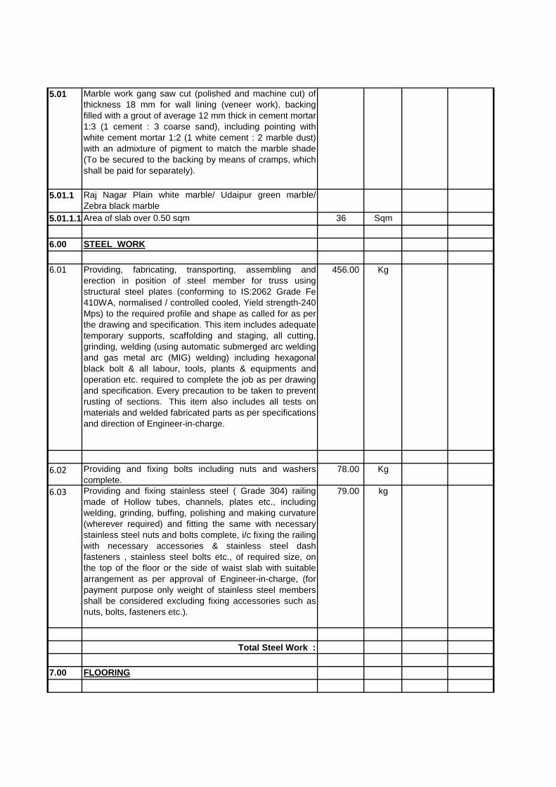
5.01 Marble work gang saw cut (polished and machine cut) ofthickness 18 mm for wall lining (veneer work), backingfilled with a grout of average 12 mm thick in cement mortar1:3 (1 cement : 3 coarse sand), including pointing withwhite cement mortar 1:2 (1 white cement : 2 marble dust)with an admixture of pigment to match the marble shade(To be secured to the backing by means of cramps, whichshall be paid for separately).
5.01.1 Raj Nagar Plain white marble/ Udaipur green marble/Zebra black marble
5.01.1.1 Area of slab over 0.50 sqm 36 Sqm
6.00 STEEL WORK
6.01 Providing, fabricating, transporting, assembling anderection in position of steel member for truss usingstructural steel plates (conforming to IS:2062 Grade Fe410WA, normalised / controlled cooled, Yield strength-240Mps) to the required profile and shape as called for as perthe drawing and specification. This item includes adequatetemporary supports, scaffolding and staging, all cutting,grinding, welding (using automatic submerged arc weldingand gas metal arc (MIG) welding) including hexagonalblack bolt & all labour, tools, plants & equipments andoperation etc. required to complete the job as per drawingand specification. Every precaution to be taken to preventrusting of sections. This item also includes all tests onmaterials and welded fabricated parts as per specificationsand direction of Engineer-in-charge.
456.00 Kg
6.02 Providing and fixing bolts including nuts and washerscomplete.
78.00 Kg
6.03 Providing and fixing stainless steel ( Grade 304) railingmade of Hollow tubes, channels, plates etc., includingwelding, grinding, buffing, polishing and making curvature(wherever required) and fitting the same with necessarystainless steel nuts and bolts complete, i/c fixing the railingwith necessary accessories & stainless steel dashfasteners , stainless steel bolts etc., of required size, onthe top of the floor or the side of waist slab with suitablearrangement as per approval of Engineer-in-charge, (forpayment purpose only weight of stainless steel membersshall be considered excluding fixing accessories such asnuts, bolts, fasteners etc.).
79.00 kg
Total Steel Work :
7.00 FLOORING
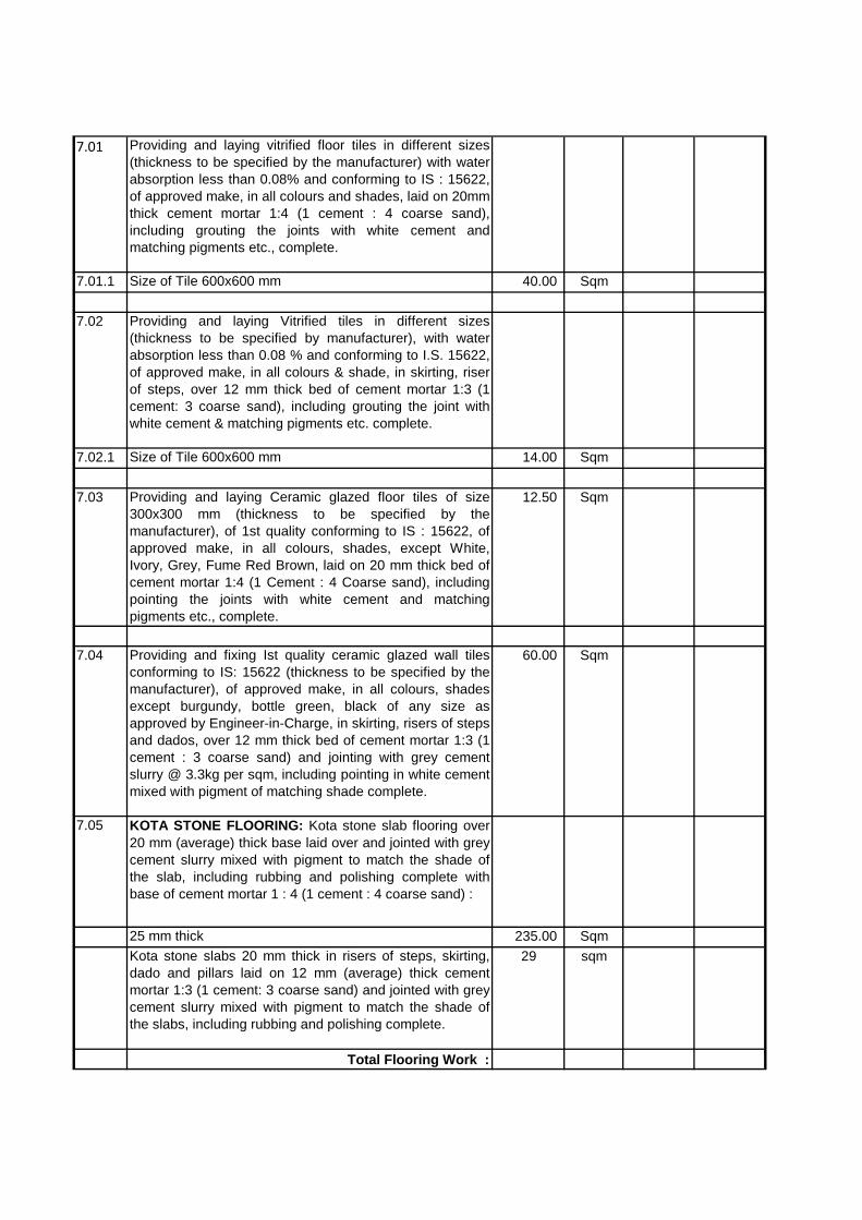
7.01 Providing and laying vitrified floor tiles in different sizes(thickness to be specified by the manufacturer) with waterabsorption less than 0.08% and conforming to IS : 15622,of approved make, in all colours and shades, laid on 20mmthick cement mortar 1:4 (1 cement : 4 coarse sand),including grouting the joints with white cement andmatching pigments etc., complete.
7.01.1 Size of Tile 600x600 mm 40.00 Sqm
7.02 Providing and laying Vitrified tiles in different sizes(thickness to be specified by manufacturer), with waterabsorption less than 0.08 % and conforming to I.S. 15622,of approved make, in all colours & shade, in skirting, riserof steps, over 12 mm thick bed of cement mortar 1:3 (1cement: 3 coarse sand), including grouting the joint withwhite cement & matching pigments etc. complete.
7.02.1 Size of Tile 600x600 mm 14.00 Sqm
7.03 Providing and laying Ceramic glazed floor tiles of size300x300 mm (thickness to be specified by themanufacturer), of 1st quality conforming to IS : 15622, ofapproved make, in all colours, shades, except White,Ivory, Grey, Fume Red Brown, laid on 20 mm thick bed ofcement mortar 1:4 (1 Cement : 4 Coarse sand), includingpointing the joints with white cement and matchingpigments etc., complete.
12.50 Sqm
7.04 Providing and fixing Ist quality ceramic glazed wall tilesconforming to IS: 15622 (thickness to be specified by themanufacturer), of approved make, in all colours, shadesexcept burgundy, bottle green, black of any size asapproved by Engineer-in-Charge, in skirting, risers of stepsand dados, over 12 mm thick bed of cement mortar 1:3 (1cement : 3 coarse sand) and jointing with grey cementslurry @ 3.3kg per sqm, including pointing in white cementmixed with pigment of matching shade complete.
60.00 Sqm
7.05 KOTA STONE FLOORING: Kota stone slab flooring over20 mm (average) thick base laid over and jointed with greycement slurry mixed with pigment to match the shade ofthe slab, including rubbing and polishing complete withbase of cement mortar 1 : 4 (1 cement : 4 coarse sand) :
25 mm thick 235.00 SqmKota stone slabs 20 mm thick in risers of steps, skirting,dado and pillars laid on 12 mm (average) thick cementmortar 1:3 (1 cement: 3 coarse sand) and jointed with greycement slurry mixed with pigment to match the shade ofthe slabs, including rubbing and polishing complete.
29 sqm
Total Flooring Work :
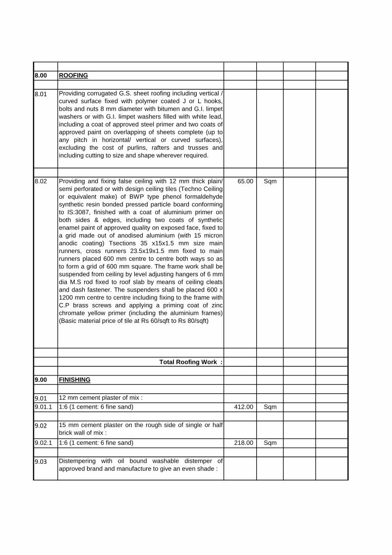
8.00 ROOFING
8.01 Providing corrugated G.S. sheet roofing including vertical /curved surface fixed with polymer coated J or L hooks,bolts and nuts 8 mm diameter with bitumen and G.I. limpetwashers or with G.I. limpet washers filled with white lead,including a coat of approved steel primer and two coats ofapproved paint on overlapping of sheets complete (up toany pitch in horizontal/ vertical or curved surfaces),excluding the cost of purlins, rafters and trusses andincluding cutting to size and shape wherever required.
8.02 Providing and fixing false ceiling with 12 mm thick plain/semi perforated or with design ceiling tiles (Techno Ceilingor equivalent make) of BWP type phenol formaldehydesynthetic resin bonded pressed particle board conformingto IS:3087, finished with a coat of aluminium primer onboth sides & edges, including two coats of syntheticenamel paint of approved quality on exposed face, fixed toa grid made out of anodised aluminium (with 15 micronanodic coating) Tsections 35 x15x1.5 mm size mainrunners, cross runners 23.5x19x1.5 mm fixed to mainrunners placed 600 mm centre to centre both ways so asto form a grid of 600 mm square. The frame work shall besuspended from ceiling by level adjusting hangers of 6 mmdia M.S rod fixed to roof slab by means of ceiling cleatsand dash fastener. The suspenders shall be placed 600 x1200 mm centre to centre including fixing to the frame withC.P brass screws and applying a priming coat of zincchromate yellow primer (including the aluminium frames)(Basic material price of tile at Rs 60/sqft to Rs 80/sqft)
65.00 Sqm
Total Roofing Work :
9.00 FINISHING
9.01 12 mm cement plaster of mix :9.01.1 1:6 (1 cement: 6 fine sand) 412.00 Sqm
9.02 15 mm cement plaster on the rough side of single or halfbrick wall of mix :
9.02.1 1:6 (1 cement: 6 fine sand) 218.00 Sqm
9.03 Distempering with oil bound washable distemper ofapproved brand and manufacture to give an even shade :

9.03.1 New work (two or more coats) over and including watertinnable priming coat with cement primer
425.00 Sqm
9.04 Finishing walls with Acrylic Smooth exterior paint ofrequired shade :
9.04.1 New work (Two or more coat applied @ 1.67 ltr/10 sqmover and including priming coat of exterior primer applied@ 2.20 kg/ 10 sqm)
190.00 Sqm
9.05 Providing and applying plaster of paris putty of 2 mmthickness over plastered surface to prepare the surfaceeven and smooth complete.
223.00 Sqm
Total Finishing Work :
10.00 WOOD WORK
10.01 Providing and fixing ISI marked flush door shuttersconforming to IS : 2202 (Part I) decorative type, core ofblock board construction with frame of 1st class hard woodand well matched teak 3 ply veneering with vertical grainsor cross bands and face veneers on both faces of shutters.
10.01.1 35 mm thick including ISI marked Stainless Steel butthinges with necessary screws
3.50 Sqm
10.02 Providing and fixing fly proof galvanized M.S. wire gaugeto windows and clerestory windows using wire gauge withaverage width of aperture 1.4 mm in both directions withwire of dia 0.63 mm all complete.
10.02.1 With 12 mm mild steel U beading 4.00 Sqm
10.03 Providing and fixing aluminium sliding door bolts, ISImarked anodised anodic coating not less than grade AC10 as per IS 1868), transparent or dyed to required colouror shade, with nuts and screws etc. complete :
10.03.1 250x16 mm 8.00 Each
10.04 Providing and fixing aluminium tower bolts, ISI marked,anodised (anodic coating not less than grade AC 10 as perIS : 1868 ) transparent or dyed to required colour or shade,with necessary screws etc. complete
10.04.1 250x10 mm 26.00 Each
10.05 Providing and fixing aluminium hanging floor door stopper,ISI marked, anodised (anodic coating not less than gradeAC 10 as per IS : 1868) transparent or dyed to requiredcolour and shade, with necessary screws etc. complete.
10.05.1 Twin rubber stopper 3.00 Each
Total Wood Work :
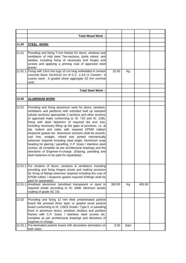
11.00 STEEL WORK
11.01 Providing and fixing T-iron frames for doors, windows andventilators of mild steel Tee-sections, joints mitred andwelded, including fixing of necessary butt hinges andscrews and applying a priming coat of approved steelprimer.
11.01.1 Fixing with 15x3 mm lugs 10 cm long embedded in cementconcrete block 15x10x10 cm of C.C. 1:3:6 (1 Cement : 3coarse sand : 6 graded stone aggregate 20 mm nominalsize)
32.00 Kg
Total Steel Work :
12.00 ALUMINIUM WORK
12.01 Providing and fixing aluminium work for doors, windows,ventilators and partitions with extruded built up standardtubular sections/ appropriate Z sections and other sectionsof approved make conforming to IS: 733 and IS: 1285,fixing with dash fasteners of required dia and size,including necessary filling up the gaps at junctions, i.e. attop, bottom and sides with required EPDM rubber/neoprene gasket etc. Aluminium sections shall be smooth,rust free, straight, mitred and jointed mechanicallywherever required including cleat angle, Aluminium snapbeading for glazing / panelling, C.P. brass / stainless steelscrews, all complete as per architectural drawings and thedirections of Engineer-in-charge. (Glazing, panelling anddash fasteners to be paid for separately) :
12.01.1 For shutters of doors, windows & ventilators includingproviding and fixing hinges/ pivots and making provisionfor fixing of fittings wherever required including the cost ofEPDM rubber / neoprene gasket required (Fittings shall bepaid for separately)
12.01.1.1Anodised aluminium (anodised transparent or dyed torequired shade according to IS: 1868, Minimum anodiccoating of grade AC 15)
350.00 Kg 405.90
12.02 Providing and fixing 12 mm thick prelaminated particleboard flat pressed three layer or graded wood particleboard conforming to IS: 12823 Grade l Type ll, in panellingfixed in aluminum doors, windows shutters and partitionframes with C.P. brass / stainless steel screws etc.complete as per architectural drawings and directions ofengineer-in-charge.
12.02.1 Pre-laminated particle board with decorative lamination onboth sides
5.50 Sqm
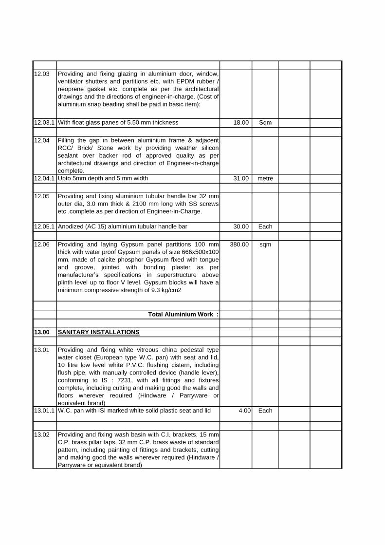
12.03 Providing and fixing glazing in aluminium door, window,ventilator shutters and partitions etc. with EPDM rubber /neoprene gasket etc. complete as per the architecturaldrawings and the directions of engineer-in-charge. (Cost ofaluminium snap beading shall be paid in basic item):
12.03.1 With float glass panes of 5.50 mm thickness 18.00 Sqm
12.04 Filling the gap in between aluminium frame & adjacentRCC/ Brick/ Stone work by providing weather siliconsealant over backer rod of approved quality as perarchitectural drawings and direction of Engineer-in-chargecomplete.
12.04.1 Upto 5mm depth and 5 mm width 31.00 metre
12.05 Providing and fixing aluminium tubular handle bar 32 mmouter dia, 3.0 mm thick & 2100 mm long with SS screwsetc .complete as per direction of Engineer-in-Charge.
12.05.1 Anodized (AC 15) aluminium tubular handle bar 30.00 Each
12.06 Providing and laying Gypsum panel partitions 100 mmthick with water proof Gypsum panels of size 666x500x100mm, made of calcite phosphor Gypsum fixed with tongueand groove, jointed with bonding plaster as permanufacturer’s specifications in superstructure aboveplinth level up to floor V level. Gypsum blocks will have aminimum compressive strength of 9.3 kg/cm2
380.00 sqm
Total Aluminium Work :
13.00 SANITARY INSTALLATIONS
13.01 Providing and fixing white vitreous china pedestal typewater closet (European type W.C. pan) with seat and lid,10 litre low level white P.V.C. flushing cistern, includingflush pipe, with manually controlled device (handle lever),conforming to IS : 7231, with all fittings and fixturescomplete, including cutting and making good the walls andfloors wherever required (Hindware / Parryware orequivalent brand)
13.01.1 W.C. pan with ISI marked white solid plastic seat and lid 4.00 Each
13.02 Providing and fixing wash basin with C.I. brackets, 15 mmC.P. brass pillar taps, 32 mm C.P. brass waste of standardpattern, including painting of fittings and brackets, cuttingand making good the walls wherever required (Hindware /Parryware or equivalent brand)
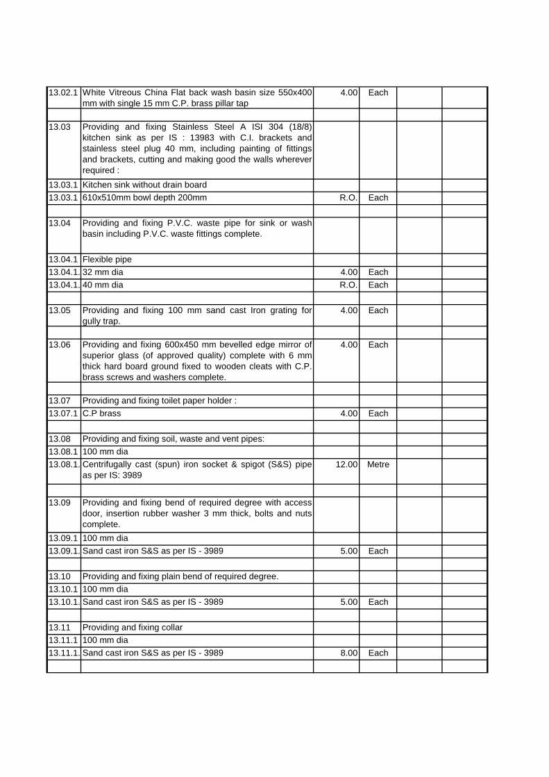
13.02.1 White Vitreous China Flat back wash basin size 550x400mm with single 15 mm C.P. brass pillar tap
4.00 Each
13.03 Providing and fixing Stainless Steel A ISI 304 (18/8)kitchen sink as per IS : 13983 with C.I. brackets andstainless steel plug 40 mm, including painting of fittingsand brackets, cutting and making good the walls whereverrequired :
13.03.1 Kitchen sink without drain board13.03.1 610x510mm bowl depth 200mm R.O. Each
13.04 Providing and fixing P.V.C. waste pipe for sink or washbasin including P.V.C. waste fittings complete.
13.04.1 Flexible pipe13.04.1.132 mm dia 4.00 Each13.04.1.240 mm dia R.O. Each
13.05 Providing and fixing 100 mm sand cast Iron grating forgully trap.
4.00 Each
13.06 Providing and fixing 600x450 mm bevelled edge mirror ofsuperior glass (of approved quality) complete with 6 mmthick hard board ground fixed to wooden cleats with C.P.brass screws and washers complete.
4.00 Each
13.07 Providing and fixing toilet paper holder :13.07.1 C.P brass 4.00 Each
13.08 Providing and fixing soil, waste and vent pipes:13.08.1 100 mm dia13.08.1.1Centrifugally cast (spun) iron socket & spigot (S&S) pipe
as per IS: 398912.00 Metre
13.09 Providing and fixing bend of required degree with accessdoor, insertion rubber washer 3 mm thick, bolts and nutscomplete.
13.09.1 100 mm dia13.09.1.1Sand cast iron S&S as per IS - 3989 5.00 Each
13.10 Providing and fixing plain bend of required degree.13.10.1 100 mm dia13.10.1.1Sand cast iron S&S as per IS - 3989 5.00 Each
13.11 Providing and fixing collar13.11.1 100 mm dia13.11.1.1Sand cast iron S&S as per IS - 3989 8.00 Each

13.12 Providing lead caulked joints to sand cast iron/centrifugallycast (spun) iron pipes and fittings of diameter :
13.12.1 100 mm 8.00 Each
13.13 Providing and fixing trap of self cleansing design withscrewed down or hinged grating with or without vent armcomplete, including cost of cutting and making good thewalls and floors :
13.13.1 100 mm inlet and 75 mm outlet13.13.1.1Sand cast iron S&S as per IS: 3989 8.00 Each
13.14 Providing and fixing 150mm dia.. C.P. brass towel ring withC.P. brass brackets fixed to raw plugs fixed with C.P.brass screws complete including cutting and making goodthe walls wherever required. (Make: Paryyware Cat No.T6002A1 or Equivalent of TOTO)
2.00 Each
Total Sanitary Installation :
14.00 WATER SUPPLY
14.01 Providing and fixing Chlorinated Polyvinyl Chloride (CPVC)pipes, having thermal stability for hot & cold water supply,including all CPVC plain & brass threaded fittings,including fixing the pipe with clamps at 1.00 m spacing.This includes jointing of pipes & fittings with one stepCPVC solvent cement and testing of joints complete as perdirection of Engineer in Charge.
Internal work - Exposed on wall14.01.1 20 mm nominal outer dia Pipes 35.00 Metre
14.02 Providing and fixing Chlorinated Polyvinyl Chloride (CPVC)pipes, having thermal stability for hot & cold water supply,including all CPVC plain & brass threaded fittings, i/c fixingthe pipe with clamps at 1.00 m spacing. This includesjointing of pipes & fittings with one step CPVC solventcement and the cost of cutting chases and making goodthe same including testing of joints complete as perdirection of Engineer in Charge. Concealed work, includingcutting chases and making good the walls etc.
14.02.1 15 mm nominal outer dia Pipes 20.00 Metre
14.03 Providing and fixing Chlorinated Polyvinyl Chloride (CPVC)pipes, having thermal stability for hot & cold water supplyincluding all CPVC plain & brass threaded fittings Thisincludes jointing of pipes & fittings with one step CPVCsolvent cement ,trenching ,refilling & testing of jointscomplete as per direction of Engineer in Charge.
External work14.03.1 15 mm nominal outer dia Pipes 3.00 Metre
14.03.2 20 mm nominal outer dia Pipes 5.00 Metre
14.03.3 25 mm nominal outer dia Pipes 5.00 Metre
14.04 Making connection of G.I. distribution branch with G.I.main of following sizes by providing and fixing tee,including cutting and threading the pipe etc. complete :
14.04.1 25 to 40 mm nominal bore 1.00 Each
14.05 Providing and fixing gun metal gate valve with C.I. wheel ofapproved quality (screwed end) :
14.05.1 25 mm nominal bore 2.00 Each
14.06 Providing and fixing ball valve (brass) of approved quality,High or low pressure, with plastic floats complete :
14.06.1 15 mm nominal bore 1.00 Each
14.07 Providing and fixing uplasticised PVC connection pipe withbrass unions :
14.07.1 45 cm length14.07.1.115 mm nominal bore 4.00 Each
14.8 Providing and filling sand of grading zone V or coarsergrade all-round the G.I. pipes in external work.
14.8.1 15 mm diameter pipe 3.00 Metre
14.8.2 20 mm diameter pipe 5.00 Metre
14.8.3 25 mm diameter pipe 5.00 Metre
14.9 Providing and fixing G.I. Union in G.I. pipes includingcutting and threading the pipe and making long screws etc.complete. (New work)
14.9.1 15 mm dia. nominal bore 10.00 Each
14.9.2 20 mm dia. nominal bore 6.00 Each
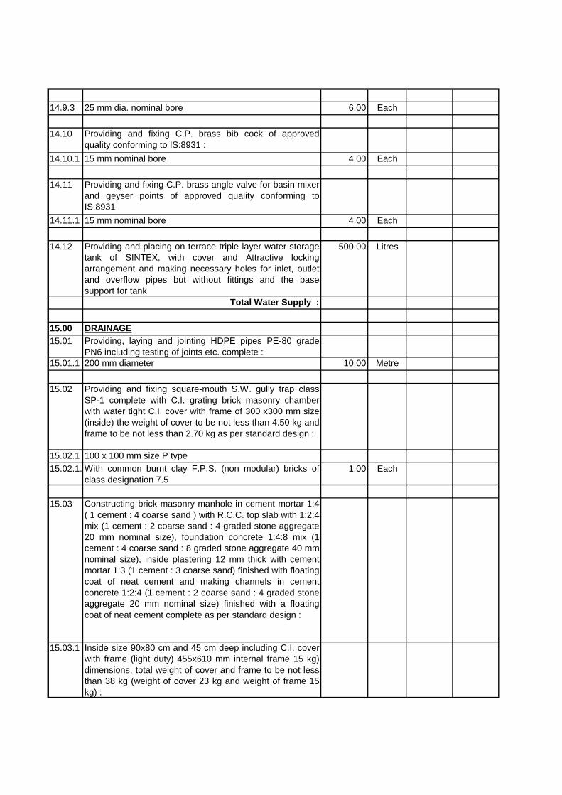
14.9.3 25 mm dia. nominal bore 6.00 Each
14.10 Providing and fixing C.P. brass bib cock of approvedquality conforming to IS:8931 :
14.10.1 15 mm nominal bore 4.00 Each
14.11 Providing and fixing C.P. brass angle valve for basin mixerand geyser points of approved quality conforming toIS:8931
14.11.1 15 mm nominal bore 4.00 Each
14.12 Providing and placing on terrace triple layer water storagetank of SINTEX, with cover and Attractive lockingarrangement and making necessary holes for inlet, outletand overflow pipes but without fittings and the basesupport for tank
500.00 Litres
Total Water Supply :
15.00 DRAINAGE15.01 Providing, laying and jointing HDPE pipes PE-80 grade
PN6 including testing of joints etc. complete :15.01.1 200 mm diameter 10.00 Metre
15.02 Providing and fixing square-mouth S.W. gully trap classSP-1 complete with C.I. grating brick masonry chamberwith water tight C.I. cover with frame of 300 x300 mm size(inside) the weight of cover to be not less than 4.50 kg andframe to be not less than 2.70 kg as per standard design :
15.02.1 100 x 100 mm size P type15.02.1.1With common burnt clay F.P.S. (non modular) bricks of
class designation 7.51.00 Each
15.03 Constructing brick masonry manhole in cement mortar 1:4( 1 cement : 4 coarse sand ) with R.C.C. top slab with 1:2:4mix (1 cement : 2 coarse sand : 4 graded stone aggregate20 mm nominal size), foundation concrete 1:4:8 mix (1cement : 4 coarse sand : 8 graded stone aggregate 40 mmnominal size), inside plastering 12 mm thick with cementmortar 1:3 (1 cement : 3 coarse sand) finished with floatingcoat of neat cement and making channels in cementconcrete 1:2:4 (1 cement : 2 coarse sand : 4 graded stoneaggregate 20 mm nominal size) finished with a floatingcoat of neat cement complete as per standard design :
15.03.1 Inside size 90x80 cm and 45 cm deep including C.I. coverwith frame (light duty) 455x610 mm internal frame 15 kg)dimensions, total weight of cover and frame to be not lessthan 38 kg (weight of cover 23 kg and weight of frame 15kg) :

15.03.1.1With common burnt clay F.P.S. (non modular) bricks ofclass designation 7.5
2.00 Each
15.04 Extra for depth for manholes :15.04.1 Size 90 x 80 cm15.04.1.1With common burnt clay F.P.S. (non modular) bricks of
class designation 7.50.50 Metre
15.05 Making connection of drain or sewer line with existingmanhole including breaking into and making good thewalls, floors with cement concrete 1:2:4 mix (1 cement : 2coarse sand : 4 graded stone aggregate 20 mm nominalsize) cement plastered on both sides with cement mortar1:3 (1 cement : 3 coarse sand), finished with a floatingcoat of neat cement and making necessary channels forthe drain etc. complete :
15.05.1 For pipes 250 to 300 mm diameter 1.00 Each
Total Drainage :Electrical Work
16.00 Wiring16.01 Wiring for light point/ fan point/ exhaust fan point/ call bell
point with 1.5 sq.mm FRLS PVC insulated copperconductor single core cable in surface / recessed mediumclass PVC conduit, with modular switch, modular plate,suitable GI box and earthing the point with 1.5 sq.mm.FRLS PVC insulated copper conductor single core cableetc. as required.
16.01.1 Group c 55.00 Point16.02 Wiring for twin control light point with 1.5 sq.mm FRLS
PVC insulated copper conductor single core cable insurface / recessed medium class PVC conduit, 2 waymodular switch, modular plate, suitable GI box andearthing the point with 1.5 sq.mm. FRLS PVC insulatedcopper conductor single core cable etc. as required.
4.00 Point
16.03 Wiring for light/ power plug with 2X4 sq. mm FRLS PVCinsulated copper conductor single core cable in surface/recessed medium class PVC conduit alongwith 1 No 4 sq.mm FRLS PVC insulated copper conductor single corecable for loop earthing as required.
100.00 Meter
16.04 Wiring for circuit/ submain wiring alongwith earth wire withthe following sizes of FRLS PVC insulated copperconductor, single core cable in surface/ recessed mediumclass PVC conduit as required
16.04.1 2 X 2.5 sq.mm + 1 X 2.5 sq. mm earth wire 70.00 meter16.04.2 2 X 4 sq. mm + 1 X 4 sq. mm earth wire 50.00 meter16.04.3 2 X 6 sq.mm + 1 X 6 sq. mm earth wire 60.00 meter16.04.5 2 X 10 sq.mm + 1 X 10 sq. mm earth wire 50.00 meter

16.05 Supplying and fixing following modular switch/ socket onthe existing modular plate & switch box includingconnections but excluding modular plate etc. as required.
16.05.1 5/6 amps switch 48.00 each16.05.2 3 pin 5/6 amp socket outlet 5.00 each16.05.3 2 way 5/6 amps switch 4.00 each16.05.4 15/16 amp switch 10.00 each16.05.5 6 pin 15/16 amp socket outlet 20.00 each16.06 Supplying and fixing stepped type electronic fan regulator
on the existing modular plate switch box includingconnections but excluding modular plate etc. as required.
20.00 each
16.07 Supplying and fixing modular blanking plate on the existingmodular plate & switch box excluding modular plate asrequired.
38.00 each
16.08 Supplying and fixing following size/ modules, GI boxalongwith modular base & cover plate for modular switchesin recess etc as required.
16.08.1 3 Module (100mm X 75mm) 38.00 each
17.00 MCCB, MCB & DB'S17.01 Supplying and fixing following way prewired vertical type
TP&N MCB distribution board of steel sheet for 415 voltson surface/recess complete with loose wire box of sheetsteel, dust protected,duly powder painted, inclusive of 200amps tinned copper bus bar,common neutral link, earthbar, din bar for mounting MCB's, terminal connectors for allincoming and outgoing circuits, duly prewired withadequate size of FRLS PVC insulated copper conductorupto the terminal connector/ neutral link, earthing etc asrequired (But without MCB/ RCCB/ Isolator). (Note :Prewired vertical type MCB TPDB is normally used where3 phase outlets are required.)
17.01.1 4 way Double door 12.00 each17.02 Supplying and fixing 5 amps to 32 amps rating, 240/415
volts, "C" curve, miniature circuit breaker suitable forinductive load of following poles in the existing MCB DBcomplete with connections, testing and commissioning etc.as required.
17.02.1 Single pole 6.00 each17.02.2 Single pole and neutral 6.00 each17.02.3 Double Pole 5.00 each17.02.4 Triple Pole 5.00 each17.02.5 Triple Pole & Neutral 3.00 each
18.00 EARTHING

18.01 Earthing with copper earth plate 600 mm X 600 mm X 3mm thick including accessories, and providing masonryenclosure with cover plate having locking arrangement andwatering pipe of 2.7 metre long etc. with charcoal/ cokeand salt as required.
2.00 Set
19.00 Non-Sheduled Items19.01 Providing & fixing of ceiling fans (48 inches) 20.00 each19.02 providing & fixing of Tube lights (40 Watt) 28.00 each
20.00 HT Cable Laying20.01 Laying of one number XLPE power cable of 33KV of
following size direct in ground including excavation, sandcushioning, protective covering and refilling the trench etc.as required.
20.01.1 Above 120sq.mm and upto 400 sq. mm 1,500.00 Meter
SECTION III
ARTICLES OF AGREEMENT
Articles of agreement made this ….……………………………………………...…. day
of……………………………….. between …………………………… having its Registered office at
…………………………………….................................................... (Here in after referred to as the
Employer/Owner which expression shall include its successor or successors and assigns) of the one part.
AND
M/s.…………………………………….. having its registered office at ……………………
………………………………………………………….………………................… and head
office…………………………………………………………. (Here in after referred to as the Contractor
of the other part).
Whereas the Employer/Owner is desirous of Executing Civil works, water supply and public health works
including internal electrification work, for the C/o Indraprastha college Delhi as stated herein Tender
Document (here in after called the work.)
And whereas the Employer/Owner in order to effectively carry out the said work has appointed M/S
Swati Structure Solutions Pvt. Ltd, here in after referred to as (the Architect/Consultant) to prepare plans,
drawings and specifications describing the same to be executed.
And whereas the Employer/Owner has made the Plans, Drawings as per lists attached, specifications
priced schedule of quantities for the work as per instructions to tenderers, General conditions of contract
and special conditions of contract prepared with assistance of the said Architect / consultant subject to
which the offer of the contractor shall be accepted.
And whereas the said Architect/Consultant has issued drawings etc. therefore to the contractor. The
drawings attached with tender documents are informative and additional working drawings shall be
separately issued and the contractor has to execute the work as per working drawings without any extra
payment or claim.
And Whereas the relevant drawings inclusive of the specifications, priced schedule of quantities,
instruction of tenderer, general condition of contract and special conditions and letter exchanged by and
between the parties from submission of Pre-Qualification document, tender up to acceptance including
letter of order (herein after collectively referred to as the said conditions) have been signed by the parties
here to and the contractor has agreed to execute the work upon and subject to the said conditions.
Now it is hereby agreed as follows:
1. In consideration of the payments to be made to the contractor as hereinafter provided the
contractor shall upon and subject to the said conditions execute and complete the works as
described in the said specifications and the said priced schedule of quantities.
2. The employer will pay to the contractor the sum of Rs.--------------------(Rupees----------------------
-------------------------------------------------------------------------------)
(Here in after called the contract sum) or such other sum as shall become payable here under at
the times and in the manner specified in the said conditions.
3. The terms Architect/ Consultant in the said conditions shall mean the same and in the event of the
said Architect/ Consultant ceasing to be the Architect / Consultant for the purpose by the
Employer, provided always that no person subsequently appointed to be the Architect /Consultant
under this contract shall be entitled to disregard or over rule any decision or approval expressed in
writing by the outgoing Architect/ Consultant for the time being if the same had been done under
instructions from the employer.
4. The agreement and documents mentioned above shall form the basis of this contract and all
disputes to be decided in the manner prescribed in the condition attached here to.
5. The said contract comprises civil works, water supply and public health works including internal
electrification works as mentioned above and in the tender documents and all subsidiary work
connected there within the same site as may be ordered to be done from time to time by the said
employer through the Architect/ Consultant or other Architect/ Consultant the case may be even
though the said work may not be shown on the drawing or described in the said specification or
the priced schedule of quantities.
6. Notwithstanding what is stated herein before or hereinafter or in the instruction to the tenderer,
general conditions of contract, special conditions, the employer through the Architect/ Consultant
reserves to himself the right to alter the nature of the work and of adding to or, omitting any items
of works from the contract or of having portions of the same carried out Entirely or otherwise and
such alterations or variations shall be carried out without prejudice to this contract.
7. The contractor will raise the bill (to be submitted in triplicate) for the work executed at site and
payment will be made by the owner within 15 (Fifteen) days from the date of submission of bill
and approval of bill.
8. The above conditions shall be read and be treated as forming part of this agreements and the
parties hereto will respectively be bound hereby and to abide by themselves to the conditions and
stipulation and perform the same on their parts to be respectively observed and preferred.
AS WITNESS our hand this Day of
SIGNED by the said
in presence of : Employer
SIGNED by the said in the
presence of : Contractor
Witness
(1) Name of ----------------------------
Address: - ...............................
Occupation: -...........................
(2) Name of ----------------------------
Address: - ...............................
Occupation: -..........................

SECTION – IV
INSTRUCTION TO TENDERERS
1. The EMPLOYER through the ARCHITECTS does not bind itself to accept the lowest or any
tender and reserves to itself the right to accept or reject any or all the tenders, in whole or in part
without assigning any reasons for doing so.
2. All erasures and alterations made while filling the tender must be attested by initials of the
Tenderer. Overwriting of figures is not permitted; failure to comply with either of these
conditions will render the tender void. No advice of any change in rate or condition after the
opening of the tender will be entertained.
3. The CONTRACTOR must not sublet any portion of the contract except with the written consent
of the EMPLOYER failing which the ARCHITECT/EMPLOYER may serve a notice in writing
rescinding the contract whereupon the security deposit shall stand forfeited and at absolute
disposal of the EMPLOYER.
4. Time shall be considered as the essence of the Contract. The Entire constructions must be
completed in 3 (Three) Months including internal electrical installations, installation of cable
T.V./Telephone Cabling installation of internal sanitary and internal water supply arrangements
and all external development works etc. It is intended that all general works should be so
completed so as to leave the last two months for installations and finishing cleaning and handing
over items. The attentions of the tenderer are drawn to clause (13) of the general conditions of the
contract referring to damages for non completion. The tenderer shall before commencing work
prepare a detailed work programme to achieve timely completion of the work which shall be
approved by the ARCHITECT and EMPLOYER and shall be adhered to The CONTRACTOR is
bound to carry out any items of work necessary for the completion of job even though such items
are not included In strictly the schedule of area/quantities and rates. Instruction in respect of such
additional items and their quantities will be issued in writing by the EMPLOYER through
ARCHITECT.
5. LAND FOR CONTRACTORS ESTABLISHMENT
For the purpose of construction of contractor’s store yard, godowns, site office, etc. the
Contractor may utilize with the permission of the architect/ consultant, portion of the land
belonging to the employer if available at such location as would not interface with the execution
of the work. The contractor shall for this purpose submit to the Architect/consultant for his
approval a plan or plans of the proposed layouts for the site facilities. The Architect/ consultant
reserve the Right to modify the contractor’s proposal as he may deem fit.
6. WATER.
The rates quoted by the contractor shall include all expenditure for providing all the water for the
full contract period required for the work, including for the people at work and all staff on the
site. He shall make his own arrangement for the supply of good quality water suitable for use in
the work and the work people. He shall obtain Municipal connection and all charges for the
connection and consumption shall be born by him. If Municipal water is not available or
inadequate, he shall make other arrangements like sinking tube wells or making bore wells or
transport from outside by tanker or any other suitable means entirely at his cost and no separate
payment shall be made for the same.
7. POWER
The contractor shall at his own cost arrange for necessary power for construction and lighting for
the entire period of contract. If however separate power is available in the premises, the
contractor shall make his own arrangement to obtain necessary connections, maintain and
efficient service of Electric lights and power and shall pay for all the requisite charges for the
same.
The Employer, as well as the Architect / Consultant shall give all the recommendations necessary
to obtain power and water connections from the concerned authorities, but the responsibility for
obtaining the same shall rest with the contractor. If any other Contractor, appointed by the
employer, is required to use water and power, he shall be allowed to use the same and make
temporary connections from the supply arranged by the main Contractor at rates and terms that
may be mutually agreed upon by both, failing which, at rate, terms and conditions that may be
decided by the Architect/ consultant.
8. FIRST – AID FACILITIES & LIABILITIES
The Contractor shall at his own expense arrange to ensure availability of medical attendant
promptly when necessary. He shall provide properly equipped first –aid station in-charge or
qualified persons at suitable location nearest to the Hospital. The Contractor shall be responsible
for any liability which may be excluded from the insurance policies and also for all other
damages to any person, animal or property arising out of incidental to the negligence or defective
carrying out of this contract. He shall also indemnify the employer in respect of any cost, charges
or expenses arising out of any claims or proceedings and also in respect of any award of
compensations and damages arising there from.
The employer shall with the concurrence of the Architect be entitled to deduct the amount of any
damage ,compensation , cost charges and expenses arising from or occurring from ,or in respect
of ,any such claims or damages from any or all sums due or become due to the contractor without
prejudice to the employers other rights in respect thereof.
Accidental Policy for the labours working at site shall be on account of Contractor. He shall
produce the same before start of work.
The liability arising out any accident, incident at the site is the responsibility of contractor and
shall bear all the expenses, compensations, legal implications are to be settled by the contractor.
All labour regulations related to welfare, health, Safety & Security of labour are to be strictly
adhered by the contractor. Till the completion of building and handing over the completed work
to the owner, the contractor shall be solely responsible for any mishaps or injury to the worker &
damages to the structure of owner or neighbours which may arise from the operator’s neglect or
himself or his employee. Whether such injury or damage may arise from carelessness, accident or
mishaps due to any reasons what so ever, contractor shall suitably and adequately compensate for
damages to the effected party or persons as per applicable Government rules. The owner under no
circumstances shall own any responsibility for any such accident/ mishaps and no financial
responsibility shall devolve on the owner.
9. FIRE FIGTHING ARRANGMENTS
The contractor shall at his all expenses provide at suitable, prominent and easily accessible places
requisite number of fire extinguishers of appropriate type and buckets some filled with sand and
others with water.

10. REPORTS AND RETURNS
The contractor shall maintain at site daily records of progress with regard to the work carried out,
labour engaged and construction equipment deployed .These daily record shall be made available
/accessible to the employer / Engineers / Architect / Consultant as and when required by him.
Enlarged progress photographs are also to be submitted regularly by the contractor at no extra
cost to the employer/owner.
11. SITE ORDER BOOK
For the purpose of quick communication, the contractor shall maintain and preserve at site, a
book with machine numbered pages in triplicate. Any instruction / advice given and recorded in
the site order book by the consultant / employer shall be considered as a notice served on the
contractor.
12. The following documents will be required to be submitted by the tenderer along with tender:
i) Tender Documents duly signed and stamped on each page.
ii) List of equipments proposed to be deployed on work.
iii) List of staff proposed to be deployed on work.
iv) if you need to associate with another company in executing the works then this
should be clearly mentioned in your offer.
v) The details of laboratory where the samples to be tested shall also to be indicated.
if any tenderer gives wrong information or suppresses any material facts, the employer/engineer
shall be free to reject such a tender at any stage and even cancel the contract (after the
acceptance of the tender) at the risk and cost of the tenderer.
13. CONTENTS OF TENDER DOCUMENTS.
The tenderer is expected to examine carefully all the contents of the tender documents including
instructions, conditions, terms, specifications and drawings and take them fully into account
before submitting his offer. Failure to comply with the requirements as detailed in these
documents shall be at the tenderer’s own risk. Tenders which are not responsive to the
requirements of the tender documents will be rejected.
14. GENERAL INSTRUCTION TO TENDERER
14.1 Except for the items, for which particular specifications are given or where it is specifically
mentioned otherwise in the description of the items in the schedule of quantities, the work shall
generally be carried out in accordance with the “CPWD Specifications 2000 Vol. I & II with upto
date corrections slips (Here in after to be referred to as CPWD Specifications) and instructions of
Client/ Architect. Wherever CPWD Specifications are silent, the latest IS Codes / Specifications
shall be followed.
14.2 The proposed building is a prestigious project and quality of work is of paramount importance.
Contractor shall have to engage well experienced skilled labour and deploy modern T&P and
other equipment to execute the work.
14.3 Samples including brand / quality of materials and fittings to be used in the work shall be got
approved from the Client / Architect, well in advance of actual execution and shall be preserved
till the completion of the work.
14.4 Unless otherwise specified in the schedule of quantities, the rates tendered by the contractor shall
be all inclusive and shall apply to all lifts & all heights, floors including terrace, leads and depths
and nothing extra shall be payable on this account.
14.5 The rates for all items of work shall, unless clearly specified otherwise, include cost of all labour,
material, tools and plants, incidentals and other inputs involved in the execution of the item.
14.6 The contractor(s) shall quote all inclusive rates against the items in the schedule of quantities and
nothing extra shall be payable for any of the conditions and specifications mentioned in the tender
documents unless specifically specified otherwise.
14.7 Unless otherwise specified in the schedule of quantities the rates for all items shall be considered
as inclusive of pumping / bailing out water, if necessary for which no extra payment shall be
made. However, regarding level of water table Soil Investigation Report may be seen in the office
of the architect and the same shall also be checked at site before quoting the rates.
14.8 The rate for all items, in which the use of cement is involved, is inclusive of charges for curing.
14.9 The foundation trenches shall be kept free from water while works below ground level are in
progress.
14.10 The work shall be executed and measured as per metric dimensions (SI Units) given in the
schedule of quantities, drawings etc. (FPS units wherever indicated are for guidelines only)
14.11 Any legal or financial implications resulting out of disposal of earth shall be the sole
responsibility of the contractor. Nothing extra shall be paid on this account.
15. SPECIAL INSTRUCTION TO TENDERER FOR CIVIL WORKS
15.1 (a) The Contractor(s) shall inspect the site of work before tendering and acquaint himself with
the site conditions and no claim on this account shall be entertained by the Employer.
(b) The contractor(s) shall get himself acquainted with nature and extent of the work and satisfy
himself about the availability of materials from kiln or approved quarries for collection and
conveyance of materials required for construction.
15.2 The tenderer shall see the approaches to the site. In case any approach from main road is required
at site or existing approach is to be improved and maintained for cartage of materials by the
contractor, the same shall be provided, improved and maintained by the contractor at his own
cost. No payment shall be made on this account.
15.3 Contractor shall take all precautionary measures to avoid any damage to adjoining property. All
necessary arrangement shall be made at his own cost.
15.4 The contractor shall take all precautions to avoid accidents by exhibiting necessary caution
boards day and night, speed limit boards, red flags, red lights and providing barriers. He shall be
responsible for all damages and accidents caused to existing / new work due to negligence on his
part. No hindrances shall be caused during the execution of the work.
15.5 Royalty at the prevailing rates wherever payable shall have to be paid by the contractor on the
boulders, metal, shingle, sand and bajri etc. or any other material collected by him for the work
direct to revenue authorities and nothing extra shall be paid by the Employer for the same.
15.6 The contractor shall provide at his own cost suitable weighing, surveying & leveling and
measuring arrangements as may be necessary at site for checking. All such equipment shall be got
calibrated in advance from laboratory, approved by the Client / Architect. Nothing extra shall be
payable on this account. The equipment shall be calibrated at regular intervals during the period
of contract.
15.7 The contractor shall take instructions from the Client / Architect regarding collection and stacking
of materials at any place. No excavated earth or building rubbish shall be stacked on areas where
other buildings, roads, services and compound walls are to be constructed.
15.8 Contractor shall provide permanent bench marks, flag tops and other reference points for the
proper execution of work and these shall be preserved till the end of work. All such reference
points shall be in relation to the levels and locations, given in the Architectural drawings.
15.9 Any cement slurry added over base surface (or) for continuation of concerning for better bond is
deemed to have been included in the items and nothing extra shall be payable (or) extra cement
considered in consumption on this account. For RCC work, only factory made round type cover
block shall be used. For Brick work unless otherwise specified FPS bricks shall be used in all
items of work. The classification of bricks brought by the contractor shall conform to the CPWD
Specifications.
15.10 The contractor shall bear all incidental charges for cartage storage and safe custody of materials
brought to site.
15.11 The work shall be carried out in accordance with the Architectural drawings and structural
drawings, to be issued from time to time, by the Client / Architect. Before commencement of any
item of work, the contractor shall correlate all the relevant architectural and structural drawings
issued for the work and satisfy himself that the information available there from is complete and
unambiguous. The discrepancy, if any, shall be brought to the notice of the Client/ Architect
before execution of the work. The contractor alone shall be responsible for any loss or damage
occurring by the commencement of work on the basis of any erroneous and or incomplete
information.
15.12 (i) Quality of all materials brought to the site shall be got checked as per relevant BIS codes
from the approved / reputed laboratories and inform the Client/ Architect or his any
authorized supervisory staff on receipt of the same along with test certificates at site before
use. The cost of testing shall be on account of contractor, nothing extra is payable.
(ii) All material shall only be brought at site as per program finalized with the Client /
Architect. Any redelivery of the material not required for immediate consumption shall not
be accepted and thus not paid for.
(iii) The contractor shall ensure quality construction in a planned and time bound manner. Any
sub-standard material / work beyond set-out tolerance limit shall be summarily rejected by
the Client / Architect & contractor shall be bound to replace / remove such sub-standard /
defective work immediately at his own cost / at no extra cost.
15.13 The contractor shall ensure quality construction in a planned and time bound manner. Any sub-
standard material / work beyond set-out tolerance limit shall be summarily rejected by the Client /
Architect & contractor shall be bound to replace / remove such sub-standard / defective work
immediately at his own cost / at no extra cost. The contractor shall conduct his work, so as not to
interfere with or hinder the progress or completion of the work being performed by other
contractor(s) or by the Client/ Architect and shall as far as possible arrange his work and shall
place and dispose off the materials being used or removed so as not to interfere with the
operations of other contractor or he shall arrange his work with that of the others in an acceptable
and in a proper co-ordination manner and shall perform it in proper sequence to the complete
satisfaction of others.
15.14 The Architectural drawings given in the tender other than those indicated in nomenclature of
items are only indicative of the nature of the work and materials/fixings involved unless and
otherwise specifically mentioned. However, the work shall be executed in accordance with the
drawings duly approved by the Client / Architect.
15.15 PROGRAMME CHART:-
i) The Contractor shall prepare an integrated program chart for the execution of work,
showing clearly all activities from the start of work to completion, with details of
manpower, equipment and machinery required for the fulfillment of the program within
the stipulated period and submit the same for approval of the Client/ Architect within two
weeks of the award of the contract. The contractor shall draw the program keeping in
view the activities to be taken. It is obligatory on the part of contractor to adhere to the
program approved by the client/ architect
ii) The program chart should include the following:-
a) Descriptive note explaining sequence of various activities.
b) PERT / CPM / BAR-CHART prepared on M.S. Project which will indicate
resources in financial terms, manpower and specialized equipment for every
important stage.
iii) If at any time, it appears to the Client / Architect that the actual progress of work does not
conform to the approved program referred above, the contractor shall produce a revised
program showing the modifications to the approved program by additional inputs to
ensure completion of the work within the stipulated time. However, for every month the
employer will review the progress vis-a-vis Programme submitted
iv) The submission for approval by the Client/ Architect of such program or the furnishing of
such particulars shall not relieve the contractor of any of his duties or responsibilities
under the contract. This is without prejudice to the right of Client/ Architect to take action
against the contractor as per terms and conditions of the agreement.
15.16 Normally contractors shall not be allowed to work at night. Work at night shall, however, be
allowed if the site conditions / circumstances so demand. However, if the work is carried out in
more than one shift or at night, no claim on this account shall be entertained. In such situations
the contractor shall make available to the Employer proper means of communications such as
vehicle at his own cost.
15.17 Existing drains, pipes, cables, over-head wires, sewer lines, water lines and similar services
encountered in the course of the execution of work shall be protected against the damage by the
contractor's own expense. The contractor shall not store materials or otherwise occupy any part of
the site in a manner likely to hinder the operation of such services
15.18 The contractor shall be responsible for the watch and ward / guard of the buildings, safety of all
fittings and fixtures including sanitary and water supply fittings and fixtures provided by him

against pilferage and breakage during the period of installations and thereafter till the building is
physically handed over to the Employer. No extra payment shall be made on this account.
15.19 The day to day receipt and issue accounts of cement shall be maintained separately in the
standard Performa given by the Client / Architect and which shall be duly signed by the
contractor or his authorized representative.
15.20 The contractor shall be fully responsible for the safe custody of materials brought by him or
issued to him even though the materials are under double lock key system.
15.21 The contractor shall procure the required materials in advance so that there is sufficient time for
testing of the materials and clearance of the same before use in the work. Any redelivery of the
materials not required for immediate consumption shall not be resorted to. The contractor shall
provide at his own cost suitable weighing and measuring arrangements at site for checking the
weight / dimensions as may be necessary for execution of work.
15.22 For construction works which are likely to generate malba / rubbish to the tune of more than a
tempo / truck load, contractor shall dispose of malba, rubbish & other unserviceable materials and
wastes at his own cost to the notified specified dumping ground and under no circumstances these
shall be stacked / dumped even temporarily, outside the construction premises.
15.23 The contractor shall arrange at site centering and shuttering required before start of the work. In
case the completion schedule requires more quantity of centering and shuttering, the contractor
shall do so at no extra cost to the Employer.
16. SUPPLY OF MATERIALS
16.1 Cement, Steel (TMT Bars) and Structural steel will be procured by the contractor.
16.2 The account of the cement and steel shall be kept in proper register.
16.3 The contractor shall be fully responsible and accountable for safe custody and proper care to
prevent damage or deterioration of theft of the cement and steel brought at site.
17. SCHEDULE OF APPROVED BRAND NAMES OF MATERIALS:
All materials specified in these specifications and condition of contract must confirm to the following
brand name, and should be of first quality. BIS marked wherever available. Fabricated items shall be
manufactured in accordance with the CPWD / ISI specifications and should be of first quality. Samples of
all materials to be used must be submitted and got approved before procurement.
NO. Item Brand specified
(or as approved by Architect/Employer)
1. Flush doors Jyoti/Donear/Green or ISI Marked
2. Plywood/blockboard
Soft board. Jyoti/Donear/Green or ISI Marked
3. Aluminium hardwares Oxford, Classic, Arches, or equivalent
4. Locks (Mortice) Godrej, Golden
5. Glazed titles Somani, Kazaria, Orient
6. Ceramic floor titles Somani/Kazaria/Regency
7. Coarse sand Baderpur sand of fineness modulus
8. Stone aggregate Clean Blue Delhi quartzite stone
(Free of any foreign material)
9. Laminate (1.0mm thick) Formica, Sanctuary, Greenlam
10. Teak vencer (Natural) Archid, Duro, Donear
11. Sealant/ Additive Assian Paints, Fosroc
12. Glass Modiguard, Saint Gobain
13. Polymers sealant CICO
Concrete additive.
14. Water proofing CICO No. 1 (Liquid) / Pidilite
Treatment
15. Anti-termite treatment Pest control Co., Pest Control Incorp
Pest (I) Co., Member of IPCA
16. Paints ICI, Asian, Berger, Shalimar all
Ist Quality Snowcem (only for exterior)
17. Adhesive Fevicol, Mowicol
18. Water stops Fixopan, L1oyd 150mm double shoes.
SANITARY:
1. Vitreous china sanitary ware Parry wares (IS-2556)
Nycer/CERA, Hindware.
1A. Cistern (China ware) Hindware Parry ware (water saver-do- flushing
Sleek (Hindware) Cistern (P.V.C.) operation liver from top of the cistern.)
For L.W.C.
2. Plastic W.C. Seats Cover Commander (IS-2548) equivalent
(Good quality)
3. CP fittings & toiletries Dripless/Parko.
4. C.P. Waste, spreaders
flush pipes - CAMRY Marc or equivalent make.
5. Soil, Waste & rainwater pipe & fittings:
a. PVC Pipes Fineless polypick
b. PVC fittings (6Kg/cm2) Setia
c. CI pipes RIF/HINDUSTAN
6. Gunmetal Values (Fullway check and globe values)Leader/Sant or ISI make.
7. Gully traps Perfect or Burn (IS-651)

8. CI Main hole covers & frames B.C.I/SKF/SIF
9. G.I. Pipe Jindal Hissar B-class
10. Ball valve Audco/Zoloto/Rapid Conroll
11. Brass foot valves Leader/Sant
12. R.C.C. Pipe Indian hume pipe or ISI.
13. GI fittings Unik
14. Horizontal/Vertical check valves Zoloto/leader
15. Pressure reducing valves ITT/Zoloto/Audco
16. Globe Valve Audco/Bankim-sarkar/zoloto
17. SFRC manhole & drain cover Heavy duty conferming to ISI-2592
18. Kitchen sink Jayana/ Neelkanth
19. Mirror Modi-guard
18. LIST OF APPROVED MANUFACTURERS FOR DIFFERENT MATERIALS TO BE
USED FOR ELECTRICAL WORK
(All materials shall be ISI mark)
S.NO. Detail of Materials Manufacturers Name/Brand Name
1. PVC Conduit BEC / ATUL / AKG
2. PVC Insulated copper FINOLEX / R R CABLE / NATIONAL /
conductor FR cable BONTON
3. Modular Plate Switch LEGRAND (MOSAIC) / CLIPSAL
(OPALE)
4. MCBDB LEGRAND / SEIMENS / ADHUNIK
5. MCB LEGRAND / GE / SCHNEIDER (MG)
19. AMENDMENT TO TENDER DOCUMENTS.
At any time prior to the deadline for the submission of tenders, the Engineer may, for any reason,
whether at his own initiative or in response to a clarification or query raised by a prospective
tenderer, modify the tender documents by an amendment.
The said amendment in the form of an addendum will be sent to all prospective tenderers who
have received the tender documents, to reach them 2 days prior to the deadline for the submission
of tenders. This communication will be in writing or by telefax and the same shall be binding
upon them. Prospective tenderers should promptly acknowledge receipt thereof by telefax to the
Engineer.
In order to afford prospective tenderers reasonable time for preparing their tenders after taking
into account such amendments, the Engineer or the Employer may, at his discretion, extend the
deadline for the submission of tenders.
20. LANGUAGE OF TENDER.

The tender prepared by the tenderer and all correspondence and documents relating to the tender
exchanged between the tenderer and the Employer/Engineer shall be in the English language.
21. TENDER PRICES
The tenderer is required to quote for all the items as per tender documents.
The rate for each item shall be reasonable and not unbalanced. If the Engineer comes across any
unbalanced rates, he may require the
tenderer to furnish detailed analysis to justify the same. Should the tenderer fail to comply with
this, his tender shall be liable to be rejected by the employer, who may award the contract to any
other tenderer.
In case of any discrepancy in rate quoted for individual item and its amount , the rate quoted is
final for the purpose of all calculations and payments.
The tenderer shall keep the contents of his tender and rates quoted by him confidential.
22. CURRENCIES OF THE TENDER
Tender prices shall be quoted in Indian Rupees only.
23. TENDER VALIDITY
The tender shall remain valid and open for acceptance for a period of 60 days after submission of
offer.
24. EARNEST MONEY DEPOSIT (EMD)
The tenderer shall furnish, as Earnest Money Deposit (EMD) as specified in para -1.1 of NIT.The
Earnest Money Deposit (EMD) shall be in the form of a bank draft on any Scheduled bank
payable at New Delhi.
Any Tender not accompanied by an acceptable EMD will be summarily rejected by the Employer
as non-responsive.
The Earnest Money Deposit (EMD) of the unsuccessful tenderer shall be returned upon executing
the contract agreement by successful tenderer. The Earnest Money Deposit (EMD) shall be
adjusted against security deposit against each running bill.
Earnest Money Deposit (EMD) will be forfeited in the following cases
a. If the Tenderer withdraws / modifies his tender during the period of tender validity
b. If the tenderer after award of work, does not start the work within the stipulated time
period as per letter of award
No interest will be payable by the Employer on the Earnest Money Deposit (EMD) amount cited
above
25. SIGNING OF THE TENDER
Entries to be filled in by the Tenderer shall be typed or written in indelible ink. Each page of the
documents should be signed in full at the bottom by the person submitting the Tender along with
the date of signing. The person signing/initiating the documents shall be one who is duly
authorised in writing by or for and on behalf of the Tenderer and/or by a Satute Attorney of the
Tenderer. Such authority in writing in favour of the person signing the tender and/or notarially
certified copy of the Power of Attorney as the case may be, shall be enclosed along with the
tender.
The complete tender shall be without alterations, overwriting, interlineations or erasures except
those to accord with instructions issued by the Employer, or as necessary to correct errors made
by the tenderer. All amendments/corrections shall be initialed by the person or persons signing
the tender.
26. CLARIFICATION OF TENDERS
To assist in the examination, evaluation and comparison of Tenders, the Engineer / Employer
may ask tenderers individually for clarification of their tenders, including Breakdowns of prices.
The request for clarification and the response shall be in writing or by telefax but no change in the
price or substance of the tender shall be sought, Offered or permitted except as required to
confirm correction of arithmetical errors Discovered by the Engineer during the evaluation of
tenders.
Prior to the detailed evaluation of tenders, the Engineer will determine whether each tender is
responsive to the requirements of the tender documents.
The Employer/Engineer will award, the contract to the tenderer, whose tender has been
determined to be substantially responsive, complete and in accordance with the tender documents
and whose evaluated Price has been determined to be the lowest. Negotiations, if any, shall be
carried out with lowest responsive tenderer.
27. EMPLOYER’S RIGHT TO ACCEPT ANY TENDER AND TO REJECT ANY OR ALL
TENDERS
The Employer reserves the right to accept or reject any tender, and to annul the tender process
and reject all tenders, at any time prior to award of contract, or to divide the contract between /
amongst tenderers without thereby incurring any liability to the affected tenderer or tender's or
any obligations to inform the affected tenderer or tender's of the grounds for the Employer’s
action.
28. SIGNING OF AGREEMENT
The Engineer/Employer shall prepare the Agreement in the Proforma included in this Document,
duly incorporating all the terms of agreement between the two parties.However, the successful
tenderer shall arrange the necessary Non-judicial stamp Papers of requisite value and attend the
Owmer office to execute the agreement Within two weeks of the date of receipt of the “Letter of
acceptance” duly Acknowledged and signed by the successful tenderer. Up on executing the
agreement the original agreement will be retained by the employer and one copy of the
Agreement duly signed by the Employer and the Contractor through their authorized Signatories
will be supplied by the Employer to the contractor.
29. RISKS AND COST
In case contractor fails to complete work as per schedule, Owner has discretion to get the work
done completed by any other agency at risk and cost of the agency to which the work has initially
been awarded by giving seven days notice.
30. SAFETY PRECAUTIONS DURING PROGRESS OF WORKS
The contractor shall take all precautions to ensure safety of the staff, existing utility services,
adjoining structures etc., during progress of work. The contractor shall also make necessary
arrangement for the safety of his workers, if any accident occurs, the entire responsibility fall on
the part of the contractor.
31. FORCE MAJEURE
War, invasion, revolution, riot, sabotage, lockouts, strikes, work shut down imposed by
Government, acts of legislative or other authorities, stoppage in supply of raw materials, fuel or
electricity, break down of machinery by mob or mass, act of God, epidemic, fires, earthquakes,
floods, explosives, accidents and navigation blockages, or any other acts or events whatsoever,
which are beyond reasonable controls of contractor and which shall directly or indirectly prevent
completion of project within the time specified in the agreement, will be considered Force
Majeure. Owner shall grant necessary extension of completion date to cover the delays caused by
Force Majeure without any financial repercussions
32. SETTLEMENT OF DISPUTES.
Matters will be finally determined by Owner. All disputes and differences of any kind whatsoever
arising out of or in connection with the contractor, whether during the progress of the works or
after their completion and whether before or after the determination of the contract shall be
referred by the contractor to and Owner shall within a reasonable time after their presentation
made and notify decisions thereon in writing. The decisions, directions, classification,
measurements drawings and certificates with respect to any matter the decision of which is
specially provided for by these or other special conditions, given and made by the Owner or a by
the Engineer on behalf of the Owner, are matters which are referred to hereinafter as accepted
matters and shall be final and binding upon the contractor and shall not be set aside on account of
any infirmity, omission, delay or error in proceedings, In or about the same or any other ground
or for any other reasons and shall be without appeal. In the event of any dispute or differences
between the parties hereto as to the construction or operation of this contract or the respective
rights and liabilities of the parties on any matter in question, dispute or differences on any
account, or as to the withholding by Owner of any certificate to which the contractor may claim
to be entitled to or if the Owner fails to make a decision within a reasonable time, then and in any
such case, the contractor after 30 days of presenting his final claim on disputed matter may
demand in writing that the dispute or differences be referred to arbitration. Such demand for
arbitration shall specify the matters which are in question dispute or differences and only such
disputes or differences of which the demand has been made and no other, shall be referred to
arbitration, obligations during tendency of arbitration work under the contract, shall unless
otherwise directed by the Engineer, continue during the arbitration proceedings and no payment
due or payable by Owner. shall unless withheld on account of such proceeding, provided
however, it shall be open for the arbitrator or arbitrators to consider and decide whether or not
such work should continue during arbitration proceedings.

33. ARBITRATION
Matters in question, dispute or differences to be arbitrated upon shall be referred to for decision to
a sole arbitrator who shall be a nominated person appointed by Management of Owner, whose
decision shall be final and binding to the contractor.
The work shall be continued as per programme during pendency of arbitration.
34. ON ACCOUNT PAYMENT
The Contractor shall be entitled to take from time to time by way of on account Payments only
for such works as in the opinion of Owner he has executed in terms of the Contract. A certificate
of measurement shall be subject to any deduction which may be deemed necessary by Owner for
non-execution of any work or any part of the work.
35. RUNNING PAYMENTS NOT PREJUDICIAL TO FINAL SETTLEMENT
Running payment made to the contractor shall be without prejudice to the final payment of
accounts (except where measurements are specifically noted in the measurements book as final
measurements and as such have been signed by the contractor) and shall in no respect be
considered or used as evidence of any facts stated or in or to be inferred from such accounts not
of any particular quantity of works having been executed nor of the manner of its execution being
satisfactory.
36. PAYMENT TO CONTRACTOR.
The payment to the contractor shall be made as per the actual work done at site after submission
of bills in triplicate duly verified by PMC/ Architect/ Engineer at a frequency of 45 Days or when
the value of work exceeds Rupees 40Lakhs
37. SECURITY DEPOSIT
Security Deposit @ 5% of value of the work done subject to Rupees 25 Lakhs which shall be
withheld on every running account bill and the same will be released on completion of defect
liability period to the entire satisfaction of owner/ Architect/ PMC. Any defects/ flaws found in
work during this period shall have to be rectified by contractor. In case of non compliance such
the security Deposit will be forfeited.
38. Certificate of completion of work
As soon as in the opinion of the Owner, Architect & Consultant, the work shall have been
substantially completed the Owner shall issue a certificate of completion in respect of work.
39. Other Conditions
In case of premature termination, no extra compensation shall be payable. Payment of
remuneration in that case will be made to the extent the services rendered till that time can be
made use of by Owner limited to the period for which the agency had actually rendered the
service and subject to the intermediate targets being adhered to as per the work schedule mutually
agreed to. No notice of termination or remuneration There of will be necessary and continuance
shall be solely at the discretion of owner.

All the documents and drawings created out of the assigned work will become the sole property
of the Owner and Owner will be free to use the same in any manner deemed fit.
The agency will exercise all responsible skill, care and diligence in the performance of the service
under this work and shall carry out all the responsibilities with recognized latest professional
standards.
All the work area shall be properly barricaded as per directives if Engineer. Necessary watch and
ward luminous indicators etc. as required shall be provided at the cost of the contractor.
Reflective paint/tape shall be provided on barricades to ensure safety at night. Adequate measures
shall be taken to ensure that no water or soil spillover the road. The specifications for the works
are attached. All work shall be carried out in accordance with relevant IS codes or any other
internationally accepted standards e.g. British Standards or ASTM.
Quality of the work undertaken is of paramount importance. The thrust of the investigation is to
obtain good quality and reliable technical data, which will form the basis of subsequent design.
Constant site supervision will be necessary to ensure that the desired end result is obtained. if you
need to associate with another company in executing the works then this should be clearly
mentioned in your offer. The details of laboratory where the samples to be tested shall also to be
indicated.
SECTION –V
GENERAL CONDITIONS OF CONTRACT
Except where provided for in the description of the individual items in the schedule of quantities and in
the specification and conditions laid down here in after and in the drawings, the works shall be carried out
as per standard specifications and under the direction of the employer / architect
1. DEFINITIONS & INTERPRETATIONS:
In construing these conditions, the specifications, bill of quantities and contract agreement etc., the
following words shall have the meaning herein assigned to them except where the subject or context
otherwise required.
Ia. “Employer” means I.P. College at 31, Sham Nath Marg, Alipur Road Delhi, it includes the
EMPLOYER, successors and assigns.
Ib. “Architect” means M/s. Swati Structure Solutions Private Limited, 503, Sachdeva Corporate
Tower, Plot # 08, Sector-8, Rohini, Delhi- 110085- Tele No. 09953416367, and their
authorized nominees and representative or such other
Ic. “ENGINEER” means clerk of works (paid by the society) and shall be nominated by the
EMPLOYER in writing or the technical representative of the EMPLOYER at site for all
matters pertaining to execution, supervision, quality control etc.
II. “Contractor” is the successful tenderer in whose favor the contract has been awarded by the
EMPLOYER to perform the works covered by the contract and shall be deemed to include
the Contractors ‘successors, heirs, executors, administrators, representative or permitted
assigns approved by the EMPLOYER and will be referred to as if on masculine gender and
singular \ number throughout in these documents.
2. ASSIGNMENT AND SUB-CONTRACTING:
The CONTRACTOR shall be deemed to have based his sufficiency of the tender on the data made
available by the EMPLOYER and of Tender on his own inspection & examination, all as mentioned.
The contractor shall be deemed to have satisfied himself as to and prices stated in the Schedule of
rates, all of which shall except or otherwise provided in the contract, cover all his obligations under
the contract (including those in respect of supply of goods, material, plants or services and
contingencies) and matter the things necessary for the proper execution completion of the work
including rectification of defects.
The CONTRACTOR shall not with out prior approval /consent of the EMPLOYER/ARCHITECT
assign the contract or any part there of, provided that the CONTRACTOR shall not be required to
obtain such consent for:
a. The provision of labour.
b. The purchase of material.
c. The sub-contracting of any part of the work for which the sub-contractor’s name is
mentioned in the tender.
2.1 If any dispute / ambiguity / discrepancy arises between the CONTRACTOR and the
ARCHITECT/ENGINEER pertaining to the interpretation of the contractor Agreement, the same
shall be the referred to the EMPLOYER whose decision shall be final and binding on both the
parties.
2.2 Adverse physical obstruction’s or conditions: If however arise, during the execution of the work
the contractor faces physical obstruction or physical conditions, other than climate conditions on
the site than he shall forthwith give notice to the ARCHITECT in writing, with a copy to the
EMPLOYER, on receipt of such notice, the ARCHITECT shall, in his opinion such obstruction
or condition which the CONTRACTOR, determined, any extension of time to the contractor,
after obtaining approval from the Employer.
3. LETTER OF ACCEPTANCE:
Before signing of the contract, the EMPLOYER shall issue by hand or by registered post or otherwise
dispatch at the registered office of the contractor, letter of acceptance for execution of the work in
accordance with contract until a formal contract agreement is prepared and executed, the tender
documents agreement letter, area schedule, payment schedule general conditions of contract, scope of
work and specifications and documents submitted by tenderer to gather correspondence exchanged
from the receipt of the tender to acceptance and together with the Employer’s letter of acceptance
along with the documents mentioned at 1.2.3 of NIT shall constitute a binding contract between the
parties.
4. CONTRACTOR’S SUPERINTENDENCE:
The CONTRACTOR and his authorized agent/ staff (approved by the EMPLOYER/ ARCHITECT)
shall provide all necessary superintendence during the execution of the works and as long as the
ENGINEER may consider necessary for the proper fulfilling of the CONTRACTOR’s obligations
under the contract.
Proper team of Engineers, Planners, Architect, Support Staff, Technical Assistants, Clerical Staff,
Skilled & Unskilled labour shall be deployed at site for completion of the work.
a) Site in charge- A graduate Civil ENGINEER having minimum 15 years experience and adequate
exposure to various works of similar nature or
magnitude. The non-deployment of this Site Engineer shall cause EMPLOYER to recover Rs. 25,
000/- P.M. from the contractor.
b) Additional ENGINEER staff/ Technical assistants- who are qualified including qualified electrical,
sanitary and plumbing ENGINEERS experienced in their respective fields and leading hands who
are competent to give proper supervision ensuring quality and output of the work, are required to
supervise the work including all services. The non-deployment of these Technical assistants shall
cause EMPLOYER to recover Rs. 15, 000/- P.M. from the contractor.
c) Such skilled, Semi-skilled, unskilled labours as are necessary for the proper timely execution,
completion of the works.
5. QUANTITY VARIATIONS:

The detail of area, unless otherwise stated shall be deemed to have been prepared in accordance with
the approved drawings, measurement of the area are to be considered as estimated and not accurate
because if any changes are required at the time of construction due to some practical problems, any
change due to change of some bye-laws etc. but subject to a maximum variation of the total area/
contract value by (+/-) 25%. The contractor shall execute the same at the original contract rates only.
6. EXTENSION OF TIME FOR COMPLETION:
If in the opinion of EMPLOYER/ ARCHITECT the works be delayed for reasons beyond the control
of the CONTRACTOR, the Society may give a fair and reasonable extension of time for completion
of the construction works.
If the CONTRACTOR needs an extension of item for the completion of the work or if the completion
of work is likely to be delayed for any reasons beyond the due date of completion stipulated in the
contract, the CONTRACTOR shall apply to the EMPLOYER for extension of time in writing at least
30 days before the expiry of the Scheduled time and while applying for extension of time
CONTRACTOR shall furnish the response in detail and his justification, if any for the delays. While
granting extension, the EMPLOYER shall notify the CONTRACTOR the period of time which will
not qualify for imposition of liquidated damages.
7. TENDERER SHALL VISIT THE SITE
Intending tenderer shall visit the site and make himself thoroughly acquainted with the local site
condition. Nature and requirement of the work, facilities of transport condition. Effective labour and
materials, access and storage for material and removal of rubbish. The tenderer shall provide in their
for cost of carriage, freight and other charges as also for any special difficulties and including police
restrictions for transport etc. for proper execution of work as indicated in the drawings. The
successful tender will not be entitled to any claim of compensation for difficulties faced or loses
incurred on account of any site condition of the Employer/Architect might be deemed to have
reasonably been inferred to be existing before commencement of work.
8. GOVERNMENT AND LOCAL RULES
The contractor shall confirm to the provision of all local bylaws and Acts relating to the work and to
the Regulations etc. of the Government and local Authorities and of any company with whose system
the structure is proposed to be connected. The contractor shall give all notices required by the said
Acts, Rules, and Regulations Bylaws etc. and pay all fees payable to such Authority / Authorities for
execution of the work involved. The cost, if any shall be deemed to have been included in his quoted
rates, taking into account all liabilities for licenses, fees for footpath encroachment and restorations
etc. and shall indemnify the employer against such liabilities and shall defend action arising from
such claims or liabilities.
9. TAXES AND DUTIES
The tenderer must include in their tender prices quoted for all duties, royalties, access, excise, sales
tax, work contract sales tax and Service Tax. Nothing extra shall be payable over and above quoted
price.
10. QUANTITY OF WORK TO BE EXECUTED
The quantities shown in the Schedule of quantities are intended to cover the entire new structure
indicated in the drawings but the Employer reserves the right to execute only a part or the whole or
any excess there of without assigning any reason therefore.
11. CONTRACTOR TO PROVIDE EVERYTHING NECESSARY
The contractor shall provide everything necessary for the proper execution of the work according to
the intent and meaning of the drawings, schedule of quantities and specifications taken together
whether the same may or may not be particularly shown or described therein provided that the same
can reasonably be inferred there from and if the Contractor finds any discrepancies therein he shall
immediately and in writing refer the same to the Employer /Architect whose decision shall be final
and binding. The Contractor shall provide himself for ground and fresh water for carrying out the
work at his own cost. The Employer shall on no account be responsible for the expenses incurred by
the Contractor for hired ground or fresh water obtained from elsewhere.
The rates quoted against individual items will be inclusive or everything necessary to complete the
said items of work within the contemplation of the contract, and beyond the unit price no extra
payment will be allowed for incidental or contingent work, labour and/or materials inclusive of all
taxes and duties whatsoever except for specific items, if any stipulated in the tender document. The
Contractor shall supply, fix and maintain at his own cost, for the execution of any work, all tools,
tackles, machineries and equipments and all the necessary centering, scaffolding staging, planking,
timbering, strutting, shoring, pumping, fencing, boarding, watching and lighting of night as well as by
day required not only for the proper execution and protection of the said work but also for the
protection of the public and safety of any adjacent roads, streets, walls, homes, buildings, all other
erections, matters and things and the Contractor shall take down and remove any all such centering,
scaffolding, planking, timbering, strutting, shoring, etc, as occasion shall be required or when
ordered so to do, and shall fully reinstate and make good all matters and things disturbed during the
execution of work to the satisfaction of the Employer / Architect.
The Contractor shall provide such temporary road on site as may be necessary for the proper
performance of the contract and for his own convenience but not otherwise. Upon completion, such
road shall be broken up and leveled where so required by the drawings unless the Employer shall
otherwise direct.
The Contractor shall at the times give access to workers employed by the Employer or any men
employed on the buildings and to provide such parties with proper sufficient and if required, special
scaffolding, hoists and ladders and provide them with water and lighting and leave or make any holes,
grooves etc. in any work, where directed by the employer as may be required to enable such workmen
to lay or fix pipes, electrical wiring, special fittings, etc. The quoted rates of the tenders shall
accordingly include all these above mentioned contingent work.
12. TIME OF COMPLETION, EXTENSION OF TIME AND PROGRESS CHART
a) Time of Completion: The entire work is to be completed in all respects
within the stipulated period. The work shall be deemed to be
commenced within 10 (Ten) days from the date of issue of formal work
order or the date on which the Contractor is instructed to take
possession of the site whichever is earlier. Time is the essence of the
contract and shall be strictly observed by the Contractor.
b) Extension of Time : If in the opinion of the Employer / Architect the work
be delayed (a) by reason of any exceptionally inclement weather, or (b) by reason of instruction
form the Employer / Architect in consequence of proceedings taken or threatened by or disputes,
with adjoining or neighboring owners or (c) by the work, or delay, of other contractors or
tradesmen engaged or nominated by the Employer / Architect and not referred to in the
specification or (d) by reason of authorized extra and additions or (e) by reason of any
combination of workmen or strike or lock-out affecting any of the building trades or (f) from
other causes which the Employer / Architect before the completion of the time allowed for the
contract shall make fair and reasonable extension of time for completion in respect therefore. In
the event of the Employer failing to give possession of the site upon the day specified above the
time of completion shall be extended suitably. In case of such strikes or lock-outs, as are referred
to above, the Contractor shall, Immediately give the Employer / Architect, written notice thereof.
Nevertheless, the contractor shall use his best endeavors to prevent delay, and shall do all that
may be reasonably required, to the satisfaction of the Employer / Architect to proceed with the
work and on his doing so that it will be ground of consideration by the Employer / Architect for
an extension of time as above provided. The decision of the Employer as to the period to be
allowed for an extension of time for completion hereunder (which decision shall be final and
binding on the Contractor) shall be promulgated at the conclusion of such strike or lock-out and
the Employer shall then, in the event of extension being granted, determine and declare the final
completion date. Hindrance Register shall be maintain and proper record of hindrances arisen and
solved with the dates to be recorded in the register by the Owner’s Site Engineer, Architect’s Site
Engineer and Contractor’s authorized representative so that extension of time limit to granted can
be derived from the register, and recommended by the Architect and approved by the Bank’s
competent authority.
c) Progress of work / Work program : During the period of construction the
contractor shall maintain proportionate progress on the basis of a
Program Chart submitted by the contractor immediately before commencement of work and
agreed to by the Employer / Architect. Contractor should also include planning for procurement
for scarce material well in advance and reflect the same in the Program Chart so that there is no
delay in completion of the project.
i) Separate registers for receipt or consumption of all materials (building wise or as
directed by the Architect) including steel cement, tiles, wood, lead, bitumen paints,
electrical fittings and sanitary ware.
ii) Work force including supervisory staff, skilled and unskilled labours and their
payment registers.
iii) Site Order book, Hindrance Register in triplicate with printed page numbers.
13. LIQUIDATED DAMAGES
Should the work be not completed to the satisfaction of the Employer / Architect within the stipulated
period, the Contractor shall be bound to pay to the Employer a sum calculated @ 0.2% of the
accepted contract sum per week of delay subject to a maximum of 2% of the accepted contract value
by way of liquidated damages and not as penalty during which the work remains uncommented or
unfinished after the expiry of the completion date.
14. TOOLS, STORAGE OF MATERIALS, PROTECTIVE WORK AND SITE OFFICE
REQUIRENTS
The Contractor shall provide, fix up and maintain in approved position proper office accommodation
for the Contractor’s representative and staff, which offices shall be open at all reasonable hours to
receive instruction notices or communications and clear away on completion of the work and make
good all work disturbed.
All drawings maintained on the site are to be carefully mounted on boards of appropriate size and
covered with a coat of approved varnish. They are to be protected form ravages of termites, ants, and
other insects.
The Contractor shall provide at his own cost all artificial light required for the work and to enable
other within contractors and sub contractors to complete the work the specified time.
The Contractor shall provide a suitable temporary hut for the use of workers and field staff and keep
the same in a clean and sanitary condition to the satisfaction of the Public Health Authorities and
shall cause such latrines and soil to be cleared away whenever necessary and shall make good all the
work disturbed by these conveniences.
Every precaution shall be taken by the contractor to prevent the breeding of mosquitoes on the work
during the construction and all receptacles. Cisterns, water tanks etc. used for indemnify the
Employer against any breach of rules in respect of anti-malarial measures. The Contractor shall not
fix or place any placards or advertisement of any description of permit the same to be fixed or placed
in or upon any boarding gantry, building structure other than those approval by the Employer.
Protective Measures
The contractor from the time of being placed in possession of the site must make suitable
arrangements for watching, lighting and protecting the work, the site and surrounding property by
day, by night, on Sundays and other holidays.
The Contractor shall indemnify the Employer against any possible damage to the building roads, or
member of the public in course of execution of the work.
The contractor shall provide necessary temporary enclosures, gates, entrances etc. for the protection
of the work and materials and for altering and adopting the same as may be required and removing on
completion of the work and making good all work disturbed.
The Contractor will have to provide watch and ward during the construction of the building and till:
i) Virtual completion
ii) Handing over of the buildings
iii) The work of all trades completed
iv) Defect liability period
Whichever is later or till it is occupied. No extra payment will be made for the above.
Storage of Materials
The Contractor shall provide and maintain proper sheds for the proper storage and adequate
protection of the materials etc. and other work that may be executed on the site including the tools
and materials of subcontractors and remove same on completion. Sheds for storage of cement are to
have pucca floor raised above the ground. Cement godown shall be constructed for storing about six
weeks requirements of cement and stored as per norms with a stack of 10 bags each one. Two ft.
opening all around with two ft. passage of each stack. Structure shall be waterproof from all the sides
and top. Cement should be stored one ft. above the ground level and have pucca raised floor.

So also reinforcement bars are to be stored above the ground level to prevent the same from getting
rusted.
Tools
All tools, equipments and instruments as instructed by the Employer / Architect and considered
necessary for the work shall be provided by the Contractor for the due performance of this contract.
All measuring, tapes shall be of steel and suitable scaffolding and ladders that way be required for
safely taking measurement shall be supplied by the Contractor.
The ministries and the supervisors on the work shall carry with them always a one meter or two meter
steel tapes and a measuring tape of 30 meters, a spirit level, a plumb bob and a square and shall check
the work to see that the work is being done according to the drawing and specifications. The Site
Engineer will use any or all measuring instruments or tools belonging to the contractors as he chooses
for checking the work executed or being executed on the contract. The contractor should cover in his
rates for making provision for all reasonable facilities for the use of his scaffolding, tools and plant
etc. by sub-contractors for their work.
15. CLEARING SITE AND SETTING OUT WORK
The site shown on the plan shall be cleared of all obstructions, loose stone, and materials rubbish of
all kinds. All holes or hollows whether originally existing or produced by removal or loose stone or
materials shall be carefully filled up with earth well rammed and leveled off as directed at his own
cost.
The contractor shall set out the work and shall be responsible for the true and perfect setting out of the
work and for the correctness of the positions, levels, dimensions and alignment of all parts thereof. If
at any time, any error shall appear during the progress of any part of the work the Contractor shall at
his own expenses rectify such error, if called upon to the satisfaction of the Employer / Architect. The
Contractor shall further set out the work to the alternative positions at the site until one is finally
approved and the rates quoted in his tender should include for this and no extra on this account will be
entertained.
16. CONTRACTOR IMMEDIATELY TO REMOVE ALL OFFENSIVE MATTERS
All soil, filth or other matters of an offensive nature taken out of any trench, sewer, drain, pool or
other place shall not be deposited on the surface but shall be at once carted away by the contractor
to a safe place as per rules of the appropriate authorities, i.e. The contractor shall keep the
foundations and work free from water and shall provide and maintain at his own expenses
electrical or other power driven pumps and other plant to the satisfaction of the Employer for the
purpose, until the building is handed over to the Employer.
The Contractor shall arrange for the disposal of the water so accumulated to the satisfaction of the
Employer and the local authority and no claims will be entertained afterwards if it does not
include in his rates for the purpose.
17. ACCESS
Any authorized representative of the Employer / Architect shall at all reasonable times have free
access to the work and/or to the workshops, factories or other places where materials are being
prepared or constructed for the work and also to any place where the materials ore lying or from

where they are being obtained, and the Contractor shall give every facility to the Owner or their
representatives necessary for inspection and examination and test of the materials and
workmanship. Except the representatives of the Employer and Architect no person shall be
allowed at any time without the written permission of the Employer.
18. REMOVAL OF IMPROPER WORK
The Employer / Architect shall during the progress of the work have power to order in writing
from time to time the removal from the work within such reasonable time or times as may be
specified in the order of any materials which in the opinion of the Employer / Architect are not in
accordance with specifications or instruction, the substitutions or proper re-execution of any work
executed with materials or workmanships not in accordance with the drawing and specifications
or instruction. In case the Contractor refuses to comply with the order the Employer / Architect
shall have the power to employ and pay other agencies to carry out the work and all expenses
consequent thereon or incidental thereto as certified by the Employer / Architect shall be borne by
the Contractor or may be deducted from any money due to or that may become due to the
contractor. No certificate which may be given by the Architect shall relieve the contractor from
his liability in respect of sound work or bad materials.
19. SITE ENGINEER/ PROJECT MANAGEMENT CONSULTANT (PMC)
The term site Engineer / Project Management Consultant (PMC) shall mean the person appointed
and paid by the Employer to supervise the work. The contractor shall afford the Site Engineer /
PMC every facility and assistance for examining of the work and materials and for checking and
measuring work and materials. The Site Engineer / PMC shall have no power to revoke, alter,
enlarge or relax any requirements of the contract or to sanction any day work, additions,
alternations, deviations of omission or any extra work whatever, except in so far as such authority
may be specially conferred by a written order of the Employer.
The Site Engineer / PMC shall have power to give notice to the Contractor or to his foreman of
non approval of any work or materials and such work shall be suspended or the use of such
materials shall be discontinued until the decision of the Employer / Architect is obtained. The
work will from time to time be examined by the Architect, Engineer from the Premises
Department of the Employer and the Site Engineer / PMC. But such examination shall not in any
way exonerate the Contractor from the obligation to remove any defects which may be found to
exist at any stage of the work or after the same is complete. Subject to the limitations of this
clause the Contractor shall take instruction only from the Employer / Architect.
20. OFFICE ACCOMMODATION FOR THE SITE ENGINEER/PMC
The Contractor shall provide, erect and maintain at his cost a separate simple water tight office
accommodation for the Site Engineer / PMC in case it is not already available at site. This
accommodation shall be well lighted and ventilated and provided with windows, door with a
look. The Site Engineers/PMC’s office shall be a minimum of 14 Sqm. (150 St.) and the
Contractor shall provide a desk, chairs, drawers for keeping drawings, a cupboard having proper
lock and a teak board for displaying drawings and lights and fans. The accommodation shall be
demolished when directed.
21. DISMISSAL OF WORKMEN

The Contractor shall on the request of the Architect / Employer immediately dismiss from work
any person employed thereon by him, who may in the opinion of the Architect / Employer be
unsuitable or incompetent or who may misconduct himself. Such discharge shall not be the basis
of any claim for compensation or damages against the Architect / Employer or any of their officer
or employee.
22. ASSIGNMENT
The whole of the work included in the contract shall be executed by the Contractor and the
Contractor shall not directly or indirectly transfer, assign or underlet the contract or any part,
share or interest therein nor, shall take a new partner, without written consent of the Employer
and no subletting shall relieve the Contractor from the full and entire
Responsibility of the contract or from active superintendence of the work during their progress.
23. MEASUREMENTS
Before taking any measurements of any work, the Site Engineer / PMC or a subordinate deputed
by him shall give reasonable notice to the Contractor. If the Contractor fails to attend at the
measurements after such notice/ or fails to countersign or to recorded the difference within a
week from the date of measurement in the manner required by the Site Engineer/ PMC then in
any, such event the measurement taken by the Site Engineer/ PMC or by the Subordinate deputed
by him as the case may be is final any binding on the Contractor and the Contractor shall have no
right to dispute the same.
24. VARIATION/ DEVIATION
The Contractor may when authorized and shall, when directed in writing by the Architect /
Employer add and or omit, or very the work shown in the drawings or described in the
specifications or included in the period schedule of quantities. The Contractor on his own accord
shall make no addition, omission or variation without such authorization or direction by the
Architect/ Employer shall when confirmed correctly by the Contractor in writing within 3 days
shall be deemed to have been given in writing.
The price of all such addition/ non-tendered items will be worked out on the basis of rates quoted
for similar items in the contract wherever existing or on engineering rate analysis based on
prevalent fair price of labour, materials at site of work including wastage plus 10% towards Taxes
and Contractor’s profit, supervision, overhead etc. The tender rates shall hold good for variation
in qty to any extend.
25. PREPARATION OF BUILDING WORK FOR OCCUPATION AND USE ON
COMPLETION.
The whole of the work will be thoroughly inspected by the Contractor and deficiencies and
defects put right completion of such inspection, he shall inform the Architect that he has
completed the work and it is ready for inspection.
On completion, the Contractor shall clean all windows doors including cleaning and oiling, if
necessary, of all hardware, inside & outside, all floors, staircases and every part of the building.
He will leave the entire building neat and clean but ready for immediate occupation and to the
satisfaction of the Employer/ Architect.
26. CLEARING SITE ON COMPLETION
On completion of the work the Contractor shall clear away and remove from the site/ complex all
constructional plant surplus materials, rubbish and temporary work of every kind and leave the
whole of the site and the work clean and in a workmanlike condition to the satisfaction of the
Employer/ Architect.
27. DEFECTS AFTER COMPLETION
Contractor shall make good at his cost and to the satisfaction of the Employer/ Architect all
defects, shrinkage, settlement or other faults which may appear within 6 (six) months after
completion of the work and considered as the defect liability period. In default the Employer may
employ and pay other person to amend and make good such damages, losses and expenses
consequent thereon or incidental thereto shall be made good and borne by the Contractor and
such damage loss and expenses shall be amending and making good by the Contractor, deduct
from any money due to the Contractor a sum equivalent to the cost of amending such work and in
the event of the amount retained being insufficient recover that balance from the Contractor from
the amount retained under Clause No. 37 of ITT together with any expenses the Employer may
have incurred in connection therewith.
28. CONCEALED WORK
The Contractor shall give due notice to the Employer/ Architect whenever any work is to be
buried in the earth, concrete or in the bodies of walls or otherwise becoming inaccessible burial,
in default whereof he shall, at the opinion of the Employer/ Architect be either opened up for
measurement at the Contractor’s expenses or no payment may be made for such materials should
any dispute or defense arise after the execution of any work as to measurements etc or other
matters which cannot be conveniently lasted or checked, the notes of the Employer/ Architect
shall be accepted as correct and binding on the Contractor.
29. ESCALATION
The rates quoted shall be firm throughout the tenure of the contract (including extension of time,
if any, (granted) and will not be subject to any fluctuation due to increase in cost of materials,
labour, Taxes etc. unless specifically provided in these documents.
30. IDLE LABOUR
Whatever the reasons may be no claim for idle labour, additional establishment cost of hire and
labour charges of tools and plants would be entertained under any circumstances.
31. SHOP DRAWINGS
The contractor shall prepare and get it approved by Consultant/ Architect before execution of the
work.
32. ON COMPLETION SERVICES DRAWINGS
The drawings of services like plumbing, Sewerage, Telephone, Electrical, Fire Fighting etc. on
completion of the work shall be prepared and submitted by the contractor in Triplicate. The final
payment will be released subject to submission of the same

SECTION- VI
1.0 SPECIAL CONDITIONS FOR CEMENT AND STEEL
1.0.1. Cement, Steel (TMT Bars) and Structural steel will be procured by contractor.
1.0.2. The contractor shall also employ necessary watch and ward establishment for the safe custody of
materials at his own cost.
1.1 STEEL
1.1.1 The standard sectional weights to be considered for conversion of length of various sizes of Mild
Steel / CTD bars / TMT bars into weight are as under.
Dia in mm Weight in Kg / Meter
6 0.222
8 0.395
10 0.617
12 0.888
16 1.580
18 2.000
20 2.470
22 2.980
25 3.850
28 4.830
1.1.2 The following procedure shall be adopted for payment of steel.
a. The standard sectional weights as indicated in para 1.1.1 shall be applicable for payment of steel
bars above 6 mm dia for the works executed. The length measured at site shall be multiplied with
the standard weights shown in 1.1.1 above to arrive at total weight of steel and the payment shall
be made accordingly.
b. The payment for the work done will be on the basis of actual length, recorded in M.B multiplied by
the standard weights given in para 1.1.1
1.1.3 The actual issue and consumption of steel on work shall be regulated and proper accounts
maintained as provided in the contract. The theoretical consumption of steel shall be worked out
as per procedure prescribed in the contract document elsewhere of the contract and shall be
governed by conditions laid therein.
1.1.4 The steel reinforcement shall be stored by the contractor at site of work about 30cm. to 45 cm.
above ground. A coat of cement wash shall be given to steel bars when stored at site for long
duration so as to prevent corrosion. Nothing extra shall be paid on this account. Bars of different
sizes and lengths shall be stored separately to facilitate easy counting and checking.
1.1.5 The Actual issue and consumption of steel on work shall be regulated and proper account
maintained as provided in the contract. The theoretical consumption of steel shall be worked out
as per procedure prescribed in the contract and shall be governed by conditions laid therein.
The actual issue of steel shall be actual weight of total quantity of Steel
received at the site less actual weight of balance quantity of steel lying
unutilized at the work site.
1.1.7 i) Reinforcement including authorized spacer bars and lap pages shall be measured in
length of different diameters as actually (not more than as specified in the drawings) used
in the work nearest to a centimeter. Wastage and unauthorized overlaps shall not be
measured.
ii) The standard sectional weights referred in CPWD Specifications for works will be
considered for conversion of length of various sizes of M.S. Bars, Tor Steel Bars and
T.M.T. bars into Standard Weight.
1.2 CONDITIONS FOR CEMENT
1.2.1 The day to day actual issue / receipt and consumption of cement on work shall be regulated and
proper accounts maintained as provided in the contract. The theoretical consumption of cement
shall be worked out as per the procedure prescribed in the CPWD Delhi Schedule of Rates
2007 and shall be governed by conditions laid therein. If the quantity of cement actually used in
the work is found to be more than the theoretical quantity of cement including authorized
variation, nothing extra shall be payable to the contractor on this account. In the event of it
being discovered that after completion of the work, the quantity of cement used is less than the
quantity ascertained as herein before provided (allowing variation on minus side as stipulated in
the contract), the cost of quantity of cement not so used shall be recovered from the contractor
@ Rs. 5000/-(Rupees five thousand) only per metric tonne. Decision of Employer/Architect in
regard to theoretical quantity of cement which should have been actually used as per the
schedule and recovered at the rate specified, shall be final and binding on the contractor. For
non-schedule items, the decision of the Employer/Architect regarding theoretical quantity of
cement which should have been actually used, shall be final and binding on the contractor.
1.2.1.1 Cement brought to site and remaining unused after completion of work shall not be removed
from site without written permission of the Employer/Architect
1.2.1.3 The contractor shall take all precautions to avoid accidents by exhibiting caution boards day
and night. The contractor shall be responsible for all damages and accident due to negligence
on his part.
1.2.1.4 No foreign exchange shall be made available by the Owner for the purchase of equipments,
plants, machinery, material of any kind or other items required to be carried out in execution of
work.

1.2.1.4 The contractor shall be bound to follow the instructions and restrictions imposed by the
Administration / Police authorities on the working and / or movement of labour, materials etc.
and nothing extra shall be payable on this account or due to less / restricted working hours or
any detours in movement of vehicles.
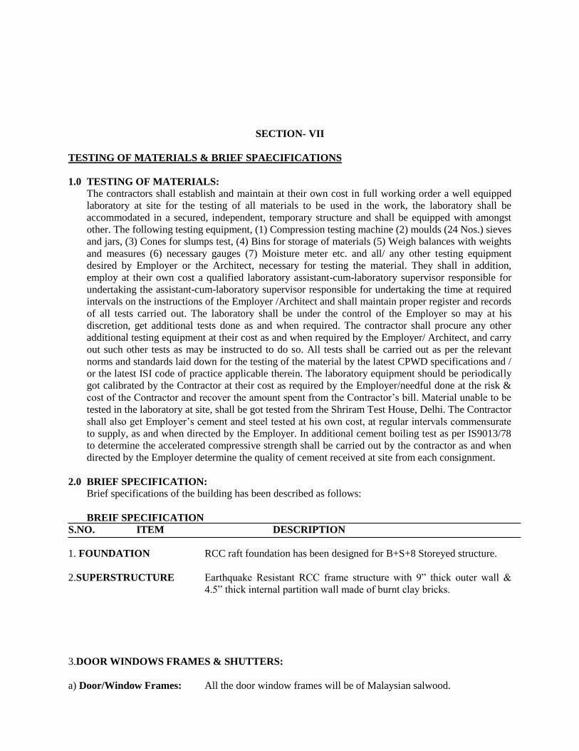
SECTION- VII
TESTING OF MATERIALS & BRIEF SPAECIFICATIONS
1.0 TESTING OF MATERIALS:
The contractors shall establish and maintain at their own cost in full working order a well equipped
laboratory at site for the testing of all materials to be used in the work, the laboratory shall be
accommodated in a secured, independent, temporary structure and shall be equipped with amongst
other. The following testing equipment, (1) Compression testing machine (2) moulds (24 Nos.) sieves
and jars, (3) Cones for slumps test, (4) Bins for storage of materials (5) Weigh balances with weights
and measures (6) necessary gauges (7) Moisture meter etc. and all/ any other testing equipment
desired by Employer or the Architect, necessary for testing the material. They shall in addition,
employ at their own cost a qualified laboratory assistant-cum-laboratory supervisor responsible for
undertaking the assistant-cum-laboratory supervisor responsible for undertaking the time at required
intervals on the instructions of the Employer /Architect and shall maintain proper register and records
of all tests carried out. The laboratory shall be under the control of the Employer so may at his
discretion, get additional tests done as and when required. The contractor shall procure any other
additional testing equipment at their cost as and when required by the Employer/ Architect, and carry
out such other tests as may be instructed to do so. All tests shall be carried out as per the relevant
norms and standards laid down for the testing of the material by the latest CPWD specifications and /
or the latest ISI code of practice applicable therein. The laboratory equipment should be periodically
got calibrated by the Contractor at their cost as required by the Employer/needful done at the risk &
cost of the Contractor and recover the amount spent from the Contractor’s bill. Material unable to be
tested in the laboratory at site, shall be got tested from the Shriram Test House, Delhi. The Contractor
shall also get Employer’s cement and steel tested at his own cost, at regular intervals commensurate
to supply, as and when directed by the Employer. In additional cement boiling test as per IS9013/78
to determine the accelerated compressive strength shall be carried out by the contractor as and when
directed by the Employer determine the quality of cement received at site from each consignment.
2.0 BRIEF SPECIFICATION:
Brief specifications of the building has been described as follows:
BREIF SPECIFICATION
S.NO. ITEM DESCRIPTION
1. FOUNDATION RCC raft foundation has been designed for B+S+8 Storeyed structure.
2.SUPERSTRUCTURE Earthquake Resistant RCC frame structure with 9” thick outer wall &
4.5” thick internal partition wall made of burnt clay bricks.
3.DOOR WINDOWS FRAMES & SHUTTERS:
a) Door/Window Frames: All the door window frames will be of Malaysian salwood.
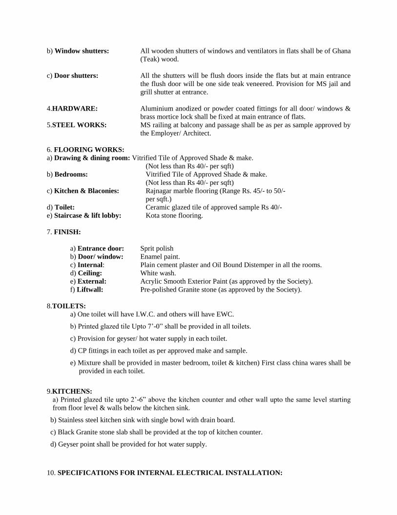
b) Window shutters: All wooden shutters of windows and ventilators in flats shall be of Ghana
(Teak) wood.
c) Door shutters: All the shutters will be flush doors inside the flats but at main entrance
the flush door will be one side teak veneered. Provision for MS jail and
grill shutter at entrance.
4.HARDWARE: Aluminium anodized or powder coated fittings for all door/ windows &
brass mortice lock shall be fixed at main entrance of flats.
5.STEEL WORKS: MS railing at balcony and passage shall be as per as sample approved by
the Employer/ Architect.
6. FLOORING WORKS:
a) Drawing & dining room: Vitrified Tile of Approved Shade & make.
(Not less than Rs 40/- per sqft)
b) Bedrooms: Vitrified Tile of Approved Shade & make.
(Not less than Rs 40/- per sqft)
c) Kitchen & Blaconies: Rajnagar marble flooring (Range Rs. 45/- to 50/-
per sqft.)
d) Toilet: Ceramic glazed tile of approved sample Rs 40/-
e) Staircase & lift lobby: Kota stone flooring.
7. FINISH:
a) Entrance door: Sprit polish
b) Door/ window: Enamel paint.
c) Internal: Plain cement plaster and Oil Bound Distemper in all the rooms.
d) Ceiling: White wash.
e) External: Acrylic Smooth Exterior Paint (as approved by the Society).
f) Liftwall: Pre-polished Granite stone (as approved by the Society).
8.TOILETS:
a) One toilet will have I.W.C. and others will have EWC.
b) Printed glazed tile Upto 7’-0” shall be provided in all toilets.
c) Provision for geyser/ hot water supply in each toilet.
d) CP fittings in each toilet as per approved make and sample.
e) Mixture shall be provided in master bedroom, toilet & kitchen) First class china wares shall be
provided in each toilet.
9.KITCHENS:
a) Printed glazed tile upto 2’-6” above the kitchen counter and other wall upto the same level starting
from floor level & walls below the kitchen sink.
b) Stainless steel kitchen sink with single bowl with drain board.
c) Black Granite stone slab shall be provided at the top of kitchen counter.
d) Geyser point shall be provided for hot water supply.
10. SPECIFICATIONS FOR INTERNAL ELECTRICAL INSTALLATION:
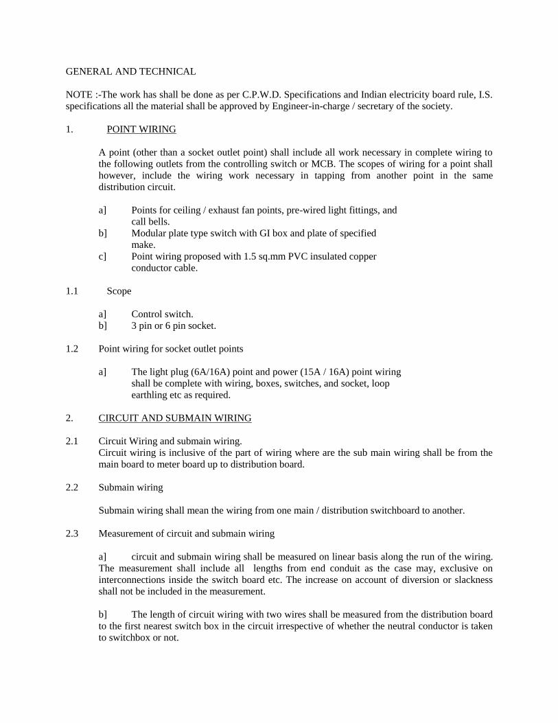
GENERAL AND TECHNICAL
NOTE :-The work has shall be done as per C.P.W.D. Specifications and Indian electricity board rule, I.S.
specifications all the material shall be approved by Engineer-in-charge / secretary of the society.
1. POINT WIRING
A point (other than a socket outlet point) shall include all work necessary in complete wiring to
the following outlets from the controlling switch or MCB. The scopes of wiring for a point shall
however, include the wiring work necessary in tapping from another point in the same
distribution circuit.
a] Points for ceiling / exhaust fan points, pre-wired light fittings, and
call bells.
b] Modular plate type switch with GI box and plate of specified
make.
c] Point wiring proposed with 1.5 sq.mm PVC insulated copper
conductor cable.
1.1 Scope
a] Control switch.
b] 3 pin or 6 pin socket.
1.2 Point wiring for socket outlet points
a] The light plug (6A/16A) point and power (15A / 16A) point wiring
shall be complete with wiring, boxes, switches, and socket, loop
earthling etc as required.
2. CIRCUIT AND SUBMAIN WIRING
2.1 Circuit Wiring and submain wiring.
Circuit wiring is inclusive of the part of wiring where are the sub main wiring shall be from the
main board to meter board up to distribution board.
2.2 Submain wiring
Submain wiring shall mean the wiring from one main / distribution switchboard to another.
2.3 Measurement of circuit and submain wiring
a] circuit and submain wiring shall be measured on linear basis along the run of the wiring.
The measurement shall include all lengths from end conduit as the case may, exclusive on
interconnections inside the switch board etc. The increase on account of diversion or slackness
shall not be included in the measurement.
b] The length of circuit wiring with two wires shall be measured from the distribution board
to the first nearest switch box in the circuit irrespective of whether the neutral conductor is taken
to switchbox or not.
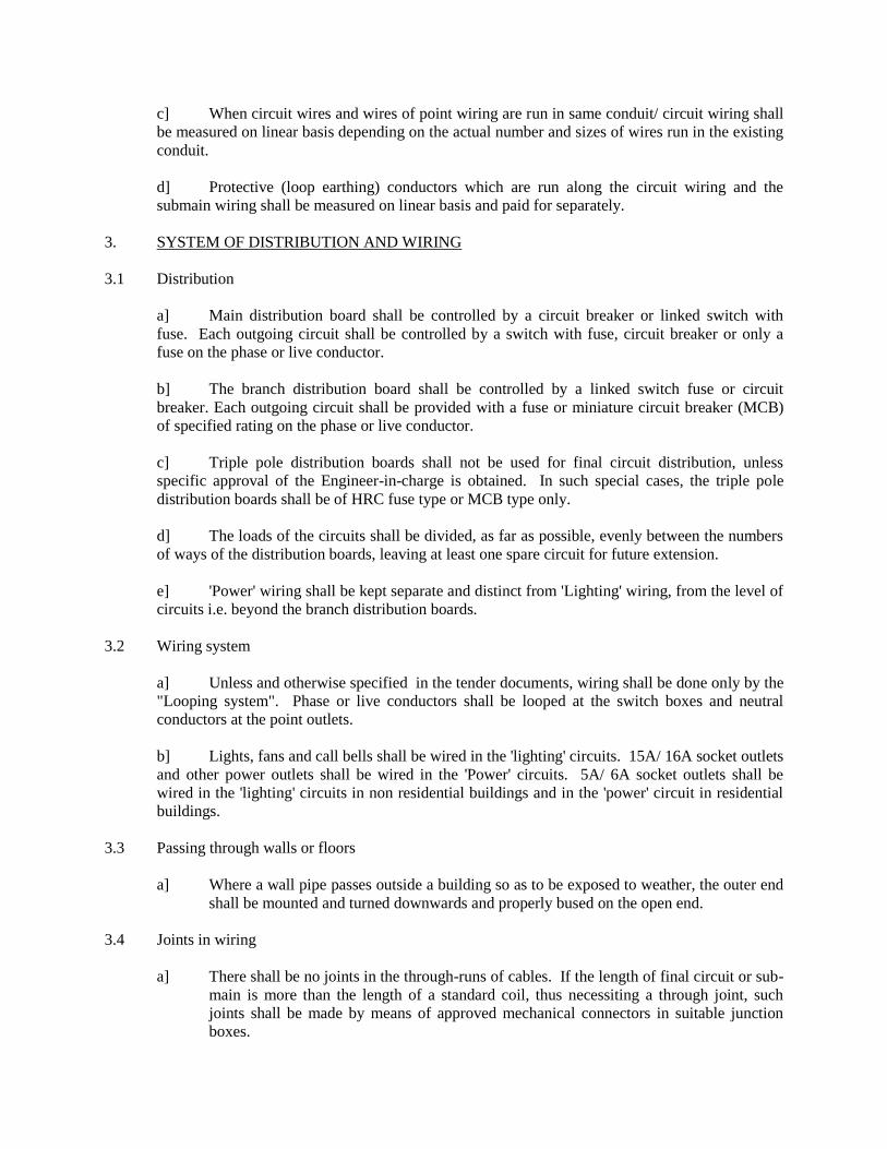
c] When circuit wires and wires of point wiring are run in same conduit/ circuit wiring shall
be measured on linear basis depending on the actual number and sizes of wires run in the existing
conduit.
d] Protective (loop earthing) conductors which are run along the circuit wiring and the
submain wiring shall be measured on linear basis and paid for separately.
3. SYSTEM OF DISTRIBUTION AND WIRING
3.1 Distribution
a] Main distribution board shall be controlled by a circuit breaker or linked switch with
fuse. Each outgoing circuit shall be controlled by a switch with fuse, circuit breaker or only a
fuse on the phase or live conductor.
b] The branch distribution board shall be controlled by a linked switch fuse or circuit
breaker. Each outgoing circuit shall be provided with a fuse or miniature circuit breaker (MCB)
of specified rating on the phase or live conductor.
c] Triple pole distribution boards shall not be used for final circuit distribution, unless
specific approval of the Engineer-in-charge is obtained. In such special cases, the triple pole
distribution boards shall be of HRC fuse type or MCB type only.
d] The loads of the circuits shall be divided, as far as possible, evenly between the numbers
of ways of the distribution boards, leaving at least one spare circuit for future extension.
e] 'Power' wiring shall be kept separate and distinct from 'Lighting' wiring, from the level of
circuits i.e. beyond the branch distribution boards.
3.2 Wiring system
a] Unless and otherwise specified in the tender documents, wiring shall be done only by the
"Looping system". Phase or live conductors shall be looped at the switch boxes and neutral
conductors at the point outlets.
b] Lights, fans and call bells shall be wired in the 'lighting' circuits. 15A/ 16A socket outlets
and other power outlets shall be wired in the 'Power' circuits. 5A/ 6A socket outlets shall be
wired in the 'lighting' circuits in non residential buildings and in the 'power' circuit in residential
buildings.
3.3 Passing through walls or floors
a] Where a wall pipe passes outside a building so as to be exposed to weather, the outer end
shall be mounted and turned downwards and properly bused on the open end.
3.4 Joints in wiring
a] There shall be no joints in the through-runs of cables. If the length of final circuit or sub-
main is more than the length of a standard coil, thus necessiting a through joint, such
joints shall be made by means of approved mechanical connectors in suitable junction
boxes.
b] Termination of multi-stranded conductors shall be done using suitable crimping type
thimbles.
4. RATING OF OUTLETS (TO BE ADOPTED FOR DESIGN)
a] Ceiling fans shall be rated at 60 W. Exhaust fan, fluorescent tubes, compact fluorescent
tubes, HPMV lamps, HPSV lamps etc. shall be rated according to their capacity. Control gear
losses shall be also considered as applicable.
b] 5A / 6A and 15A / 16A socket outlet points shall be related at 100W and 1000W
respectively, unless the actual values of loads are specified.
5. CAPACITY OF CIRCUITS:
a] "Lighting" circuit shall not have more than a total of 10 points of light, fan and socket
outlets, or a total connected load of 800W, whichever is less.
b] "Power" circuit shall be designed with only one outlet per circuit in nonresidential
buildings. The circuit shall be designed based on the load. Where not specified, the load shall be
taken as 1 KW per outlet.
c] "Power" circuit in residential buildings shall be designed for not more than two outlets
(15A/ 16A and / or 5A/ 6A) per circuit. The ratings for load calculation purposed shall however
be taken as per the type of outlets.
d] Load more than 1 KW shall be controlled by an isolator or miniature circuit breaker.
6. WIRING ACCESSORIES
6.1 Control switches for points
a] Control switches of 15A/ 16A rating may preferably be only of modular type. If,
however, modular type switch is used for controlling a socket outlet, combined switch
cum socket shall not be permitted.
b] Power (15A/ 16A) outlets shall be controlled by single pole modular type switches or by
MCB's, where specified. Only MCB's shall be used for controlling industrial type socket
outlets, and power outlets above 1 KW.
6.2 Socket outlets
a] Socket outlets shall be of the same type, namely modular type, as their control switches.
These shall be rated either for 5A/ 6A, or 15A/16A. Combined 5A/ 15A, or 6A/ 16A six
pin socket outlet may be provided in 'power circuits only where specified.
b] Outlet boxes for socket outlets (both 15A/ 16A ands 5A/ 6A) points in residential
buildings shall be of size 175mm x 100mm.
c] 5A/ 6A and 15A/ 16A socket outlets shall be installed at the following positions, unless
otherwise specified.
i) Non-residential buildings - 23 cm above floor level.
ii) Kitchen - 23 cm above working platform and away from the
likely positions of stove and sink.
iii) Bathroom - No socket outlet is permitted for connecting a
portable appliance thereto. MCB / IC switch may be
provided above 2.1m for fixed appliances, and at least 1 m
away from shower.
7. MCB TYPE DISTRIBUTION BOARD (MCBDB)
a] MCB DB's may be of single phase, 3 phase (horizontal type) suitable for feeding single
phase loads, or 3 phase (vertical type) suitable for feeding single phase as well as 3 phase
loads, as specified. These shall be complete with accessories, but without MCB's which
shall be specified as a separate item in the tender documents.
b] The current ratings and the number of ways shall be as specified. Blanking plates shall
be provided to close unused ways. These shall be indicated as separate item in the
Schedule of work.
8. PRE-WIRED MCB DISTRIBUTION BOARDS
a] The board shall also be provided with a loose wire box as a compartment for the
complete width and, depth of the board, and of minimum height of 125mm in case of
TPN DB's, and 100mm in case of SPN DB's.
b] The board shall be provided with a hinged cover of 1.6mm thick sheet steel in the front.
Only the knobs of the MCB's shall protrude out of the front covers through openings
neatly machine made for the purpose.
c] The board shall be complete with the following accessories:-
i) 200 A copper busbar (s).
ii) Neutral link.
iii) Common earth bar.
iv) DIN bar for mounting MCB's.
v) Elmex type terminal connectors suitable for incoming and
outgoing cables.
vi) A set of indication lamps with HRC cartridge fuses for each phase of the incoming
supply.
vii) Earthing stud.(s)
Note: - MCB's and blanking plates shall be specified as separate items, as required.
9. SWITCH BOARD INSTALLATION
a] Unless and otherwise specified in the tender documents, a switchboard shall not be
installed so that its bottom is within 1.25 m above the floor.
b] There shall be a clear distance of 1 m in front of the switch boards. The space behind the
switchboards shall be either less than 20 cm or more than 75 cm. If there are any
attachments or bare connections at the back of the switch board. Rule 51 (c) of the Indian
Electricity Rules shall apply.

c] Where it is required to terminate a number of conduits on a board. it may be convenient
to provide a suitable MS adopter box for the purpose. Such boxes shall be provided with
the prior approval of the Engineer-in-charge and this will be paid for separately.
d] No apparatus shall project beyond any edge of the panel. No fuse body shall be mounted
within 2.5cm of any edge of the panel.
e] Busbars and interconnecting strips in fabricated boards shall be PVC tapped or sleeved in
Red, Yellow and Blue for phases, and Black for neutral. The interconnecting cables shall
also follow this colour coding.
10. ATTACHMENT OF FITTINGS AND ACCESSORIES
10.1 Conduit wiring system
a] All accessories like switches, socket outlets, call bell pushes and regulators shall be fixed
in flush pattern inside the switch/ regulator boxes.
b] Aluminum alloy or cadmium plated iron screws shall be used to fix the accessories to
their bases.
c] The switch box / regulator box shall normally be mounted with their bottom 1.25cm from
floor level, unless otherwise directed by the Engineer-in-charge.
11. FIXING TO WALLS AND CEILING
a] Wooden plugs for ordinary walls or ceiling shall not be used in view of the ban on use of
timber in Govt. works. However, where so specified, these shall be of well seasoned teak
or other approved hard wood not less than 5 cm long by 2.5cm square on the inner end,
and 2cm square on the outer end. They shall be cemented into walls within 6.5mm of the
surface, the remainder being finished according to the nature of the surface with plasters
or lime punning.
b] PVC sleeves/ dash fasteners should normally be used for fixing to walls or ceiling.
PVC CONDUIT WIRING SYSTEM
APPLICATION
a] Recessed conduit is suitable generally for all applications. Surface conduit work may be
adopted in places like wiring above false ceiling / below false flooring, and at locations
where recessed work may not be possible to be done. The type of work, viz. surface or
recessed, shall be as specified in the respective works.
b] Flexible conduits may only be permitted for interconnections between switchgear, DB's
and conduit terminations in wall
MATERIALS
Conduits
a] All rigid conduit pipes shall be of PVC and ISI marked. The wall thickness shall not be
less than 1.6mm (16 SWG) for conduits up-to 32mm dia. and not less than 2mm ( 14
SWG ) for conduits above 32mm dia.

b] No PVC conduit less than 20mm in diameter shall be used.
Conduit accessories
a] All conduit accessories shall be of solid type.
b] Saddles for surface conduit work on wall shall not be less than 0.55mm (24 gauge) for
conduits upto 25mm dia. and not less than 0.9mm (20 gauge) for larger diameter. The
corresponding widths shall be 19mm & 25mm.
Outlets
a] The switch box or regulator box shall be made of metal on all sides, except on the front.
In the case of cast boxes, the wall thickness shall be at least 3mm and in case of welded
mild steel sheet boxes, the wall thickness shall not be less than 1.2mm (18 gauge) for
boxes upto a size of 20cm x 30cm, and above this size 1.6mm (16 gauge) thick MS boxes
shall be used. The metallic boxes shall be duly painted with anticorrosive paint before
erection as per chapter 10 of these specifications.
b] Outlet boxes shall be of one of the size, covered in the Schedule of Rates (Elect.), Part I-
Internal- 1993.
c] Where a large number of control switches and/ or fan regulators are required to be
installed at one place, these shall be installed in more than one outlet box adjacent to each
other for ease of maintenance.
d] An earth terminal with stud and 2 metal washers shall be provided in each MS box for
termination of protective conductors and for connection to socket outlet/ metallic body of
fan regulator etc.
e] Clear depth of the box shall not be less than 50mm, and this shall be increased suitably to
accordance mounting of fan regulators in flush pattern.
INSTALLATION
Common aspects for recessed and surface conduit works.
a] Bends in conduit
i) All necessary bends in the system, including diversion, shall be done either by neatly
bending the pipes without cracking with a bending radius, or alternatively, by
inserting suitable solid type normal bends or similar fittings, whichever is most
suitable.
ii) No length of conduit shall have more than the equivalent of four quarter bends from
outlet to outlet.
Additional requirements for surface conduit work.
a] Fixing conduit on surface
i) Conduit pipes shall be fixed by saddles, secured to suitable approved plugs with screws
in an approved manner at an interval of not more than one metre, but on either side of
the couplers or bends or similar fittings, saddles shall be fixed at a distance of 30 cm
from the centre of such fittings.
b] Fixing outlet boxes
i) Only a portion of the switch box shall be sunk in the wall, the other portion being
projected out for suitable entry of conduit pipes into the box.
Additional requirements for recessed conduit work
a] Fixing conduits in chase
i) The conduit pipe shall be fixed by means of J-hooks, or by means of saddles, not more
than 60 cm apart, or by any other approved means of fixing.
ii) All joints of conduit pipes shall be treated with some approved preservative compound
to secure protection against rust.
b] Fixing conduits in RCC work
i) The conduit pipes shall be laid in position and fixed to the steel reinforcement bars by
steel binding wires before the concreting is done. The conduit pipes shall be fixed
firmly to the steel reinforcement bars to avoid their dislocation during pouring of
cement concrete and subsequent tamping of the same.
ii) Fixing of standard bends or elbows shall be avoided as far as practicable, and all
curves shall be maintained by bending the conduit pipe itself with a long radius which
will permit easy drawing in of conductors.
c] Fixing inspection boxes
i) Suitable inspection boxes to the minimum requirement shall be provided to
permit inspection, and to facilitate replacement of wires, if necessary.
ii) These shall be mounted flush with the wall or ceiling concrete. Minimum 65mm
depth junction boxes shall be used on roofslabs and the depth of the boxes in
other places shall be as per IS: 2667 - 1977.
d] Fixing switch boxes and accessories
i) Switch boxes shall be mounted flush with the wall. All outlets such as switches,
socket outlets etc. shall be flush mounting type, unless otherwise specified in the
Additional Specifications.
e] Fish wire
i) To facilitate subsequent drawing of wires in the conduit, GI fish wire of 1.6mm /
1.2mm ( 16/ 18 SWG ) shall be provided along with the laying of the recessed
conduit.
TABLE - I
Maximum number of PVC insulated 650/ 1100 V grade aluminium / copper conductor cable conforming
to IS: 694/ 1990.
Clause 2.2 a]
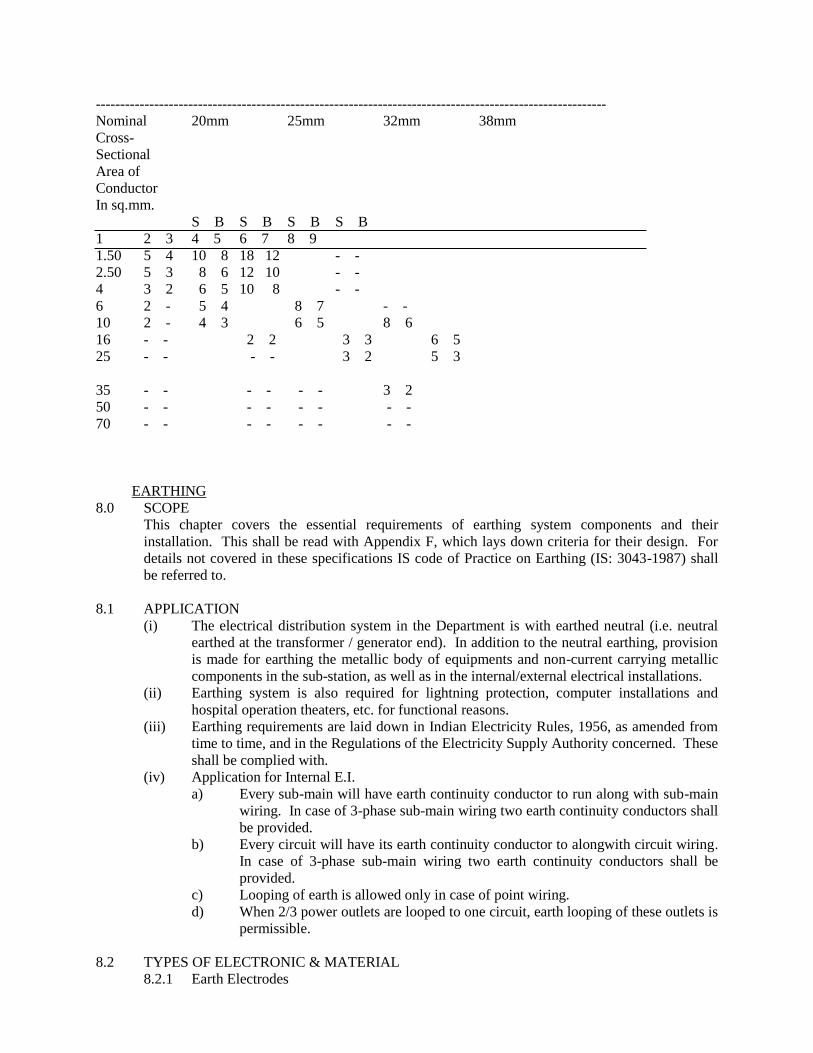
---------------------------------------------------------------------------------------------------------
Nominal 20mm 25mm 32mm 38mm
Cross-
Sectional
Area of
Conductor
In sq.mm.
S B S B S B S B
1 2 3 4 5 6 7 8 9
1.50 5 4 10 8 18 12 - -
2.50 5 3 8 6 12 10 - -
4 3 2 6 5 10 8 - -
6 2 - 5 4 8 7 - -
10 2 - 4 3 6 5 8 6
16 - - 2 2 3 3 6 5
25 - - - - 3 2 5 3
35 - - - - - - 3 2
50 - - - - - - - -
70 - - - - - - - -
EARTHING
8.0 SCOPE
This chapter covers the essential requirements of earthing system components and their
installation. This shall be read with Appendix F, which lays down criteria for their design. For
details not covered in these specifications IS code of Practice on Earthing (IS: 3043-1987) shall
be referred to.
8.1 APPLICATION
(i) The electrical distribution system in the Department is with earthed neutral (i.e. neutral
earthed at the transformer / generator end). In addition to the neutral earthing, provision
is made for earthing the metallic body of equipments and non-current carrying metallic
components in the sub-station, as well as in the internal/external electrical installations.
(ii) Earthing system is also required for lightning protection, computer installations and
hospital operation theaters, etc. for functional reasons.
(iii) Earthing requirements are laid down in Indian Electricity Rules, 1956, as amended from
time to time, and in the Regulations of the Electricity Supply Authority concerned. These
shall be complied with.
(iv) Application for Internal E.I.
a) Every sub-main will have earth continuity conductor to run along with sub-main
wiring. In case of 3-phase sub-main wiring two earth continuity conductors shall
be provided.
b) Every circuit will have its earth continuity conductor to alongwith circuit wiring.
In case of 3-phase sub-main wiring two earth continuity conductors shall be
provided.
c) Looping of earth is allowed only in case of point wiring.
d) When 2/3 power outlets are looped to one circuit, earth looping of these outlets is
permissible.
8.2 TYPES OF ELECTRONIC & MATERIAL
8.2.1 Earth Electrodes

8.2.1.1 Types
The type of earth electrode shall be any of the following, as specified. (For selection
criteria in designs, Appendix F may be referred to).
(a) Pipe earth electrode.
(b) Plate earth electrode.
(c) Strip or conductor earth electrode.
8.2.1.2 Electrode materials and dimensions.
(i) The materials and minimum sizes of earth electrodes shall be as per Table IX.
(ii) GI pipe electrodes shall be cut tapered at the bottom, and provided with holes of 12mm
dia, drilled not less than 7.5 cm from each other upto 2 m of length from the bottom.
(iii) The length of the buried strip or conductor earth electrode shall be not less than 15 m.
This length shall suitably be increased if necessary, on the basis of the information
available about soil resistance, so that the required earth resistance is obtained. Prior
approval of the Engineer-in-charge shall be taken for any such increase in length.
(iv) All hardware items used for connecting the earthing conductor with the electrode shall
be of GI in the case of GI pipe and GI plate earth electrodes, and forged tinned brass in
case of copper plate electrodes.
8.2.2 Earthing Conductor & sizes
(i) The earthing conductor (protective conductor from earth electrode up to the main
earthing terminal/earth bus, as the case may be) shall be of the same material as the
electrode, viz. GI or copper, and in the form of wire or strip as specified.
(ii) The size of earthing conductor shall be specified, but this shall not be less than the
following (For calculating the size of the earthing conductor in design, Appendix F para
3.5.1).
(a) 4mm dia. (8 SWG) copper wire.
(b) 25mm x 4mm in the case of GI strip, or,
(c) 20 mm x 3mm in the case of copper strip.
(iii) Earthing conductor larger than the following sectional areas need not be used, unless
otherwise specified.
(a) 150 sq.mm. in case of GI, or,
(b) 100 sq.mm. in case of copper.
8.2.3 Earth continuity / loop earthing conductor & sizes
(i) The material and size of protective conductors shall be as specified Below (for criteria in
design of these appendix F may be
referred to):
-------------------------------------------------------------------------------------
Size Size of protective conductor
Phase of the same material as
Conductor phase conductor
-------------------------------------------------------------------------------------
Upto 4 sq.mm 4 sq.mm.
Above 4 sq.mm up to 16 sq.mm. Same size as phase conductor
Above 16 sq.mm up to 35 sq.mm. 16 sq.mm.
Above 35 sq.mm. Half of the phase conductor
8.3 LOCATION FOR EARTH ELECTRODES
(i) Normally an earth electrode shall not be located closer than 1.5 m from any building.
Care shall be taken to see that the excavation
for earth electrode does not affect the foundation of the building; in such cases, electrodes
may be located further away from the building, with the prior approval of the Engineer-
in-Charge.
(ii) The location of the earth electrode will be such that the soil has a reasonable chance of
remaining moist as far as possible. Entrances, pavements and roadways, should be
avoided for locating earth electrodes.
8.4 INSTALLATION
8.4.1 Electrodes
8.4.1.1 Various types of electrodes
(i) (a) Pipe electrode shall be buried in the ground vertically with its top at not less than
20 cm below the ground level. The installation shall be carried out as shown in
Fig. 11.
(b) In locations where the full length of pipe electrode is not possible to be installed
due to meeting a water table, hard soil or rock, the electrode may be to reduced
length, provided the required earth resistance result is achieved with or without
additional electrodes, or any alternative method of earthing may be adopted, with
the prior approval of the Engineer-in-charge. Pipe electrodes may also be
installed in horizontal formation in such exceptional cases.
(ii) Plate electrode shall be buried in ground with its faces vertical, and its top not less than
1.5 m below the ground level. The installation shall be carried
(iii) When more than one electrode (plate/pipe) is to be installed, a separation of not less than
2 m shall be maintained between two adjacent electrodes.
(iv) (a) The strip or conductor electrode shall be buried in trench not less than 0.5 m
deep.
(b) If conditions necessitate the use of more than one strip or conductor electrode,
they shall be laid as widely distributed as possible, in a single straight trench
where feasible, or preferably in a number of trenches radiating from one point.
(c) If the electrode cannot be laid in a straight length, it may be laid in a zigzag
manner with a deviation upto 45 degrees from the axis of the strip. IT can also
be laid in the form of an arc with curvature more than 1 m or a polygon.
8.4.1.2. Artificial treatment of soil
When artificial treatment of soil is to be resorted to, the same shall be specified in the
schedule of work. The electrode shall be surrounded by charcoal / coke and salt as
indicated in Fig. 11 and 12. In such cases, excavation for earth electrode shall be
increased as per the dimensions indicated in these figures.
8.4.1.3 Watering arrangement
(i) In the case of plate earth electrodes, a watering pipe 20 mm dia.
Medium class pipe shall be provided and attached to the
electrodes as shown in Fig. 9 and 10. A funnel with mesh shall be provided on the top of
this pipe for watering the earth.
(ii) In the case of pipe electrodes, a 40 mm x 20 mm reducer shall be used for fixing the
funnel with mesh.
(iii) The watering funnel attachment shall be housed in a masonry enclosure of size not less
than 30 cm to 30 cm x 30 cm.
(v) A cast iron / MS frame with MS cover, 6mm thick, and having locking arrangement shall
be suitably embedded in the masonry enclosure.
8.4.2 Earthing conductor (Main earthing lead)
(i) In the case of plate earth electrode, the earthing conductor shall be secured as indicated in
fig. 11 using a through bolt, nuts and washers and terminating socket.
(ii) In the case of pipe earth electrode, the earthing conductor shall be securely terminated on
to the plate with two bolts, nuts and washers and terminating socket.
(iii) A double C-clamp arrangement shall be provided for terminating tape type earthing
conductor with GI watering pipe coupled to the pipe earth electrode. Galvanized “C”
shaped strips, bolts, washers, nuts and check nuts of adequate size shall be used for the
purpose.
(iv) The earthing conductor from the electrode up to the building shall be protected from
mechanical injury by a medium class, 15mm dia. GI pipe in the case of wire, and by
40mm dia, medium class GI pipe in the case of strip. The protection pipe in ground shall
be buried at least 30 cm deep (to be increased to 60 cm in case of road crossing and
pavements). The portion within the building shall be recessed in walls and floors to
adequate depth in due co-ordination with the building work.
(v) The earthing conductor shall be securely connected at the other end to the earth stud/earth
bar provided on the switch board by:
(a) Soldered or preferably crimped lug, bolt, nut and washer in the case of wire, and
(b) Bolt, nut and washer in case of strip conductor.
In the case of substations or alternators, the termination shall be made on the earthing terminal of
the neutral point on the equipment and/or the earth bus, as the case may be.
8.4.3 Loop Earthing/Earth continuity Conductor
(i) Earth terminal of every switchboard in the distribution system shall be bonded to the
earth bar/terminal of the upstream switch board by protective conductor(s).
(ii) Two protective conductors shall be provided for a switchboard carrying a 3-phase
switchgear thereon.
(iii) Loop earthing of individual units will not be however necessary in the case of cubicle
type switchboards.
(iv) The earth connector in every distribution board (DB) shall be securely connected to the
earth stud/earth bar of the corresponding switch board by a protective conductor.
(vi) The earth pin of socket outlets as well as metallic body of fan regulators shall be
connected to the earth stud in switch boxes by protective conductor. Where the switch
boxes are of non-metallic type, these shall be looped at the socket earth terminals, or at
an independent screwed connector inside the switch box. Twisted earth connections
shall not be accepted in any case.
8.5 EARTH RESISTANCE
(i) The earth resistance at each electrode shall be measured. No earth electrode shall have a
greater ohmic resistance than 5 ohms as measured by an approved earth testing apparatus.
In rocky soil the resistance may be up to 8 ohms.
(ii) Where the above stated earth resistance is not achieved, necessary improvement shall be
made by additional provisions, such as additional electrode (s), different type of
electrode, or artificial chemical treatment of soil etc., as may be directed by the Engineer-
in-Charge.
8.6 MARKING
(i) Earth bars/terminals at all switch boards shall be marked permanently, either as “E” or as
(ii) Main earthing terminal shall be marked “SAFETY EARTH – DO NOT DISCONNECT”.
8.7 USE OF RESIDUAL CURRENT DEVICES (RDCs)
An extract on selection and application of RCDs (also known as RCCBs) from IS: 12640-1988 is
given at Appendix G. Provision of RCD shall be specified in individual cases keeping in view the
type, use, importance, system of earthing and nature of electrical installations to be protected by
the RCCBs, requirements of the local electric supply company, etc. The sensitivity shall be
30mA, 100mA, 300mA, or 500mA, as specified.
TABLE IX
Materials and sizes of earth electrodes
[Clause 8.2.1.2 (i)]
Type of Electrode Material Size Pipe GI medium class 40mm dia
3.45m long (Without any joint)
Plate (i) GI (ii) Copper
60 cm x 60 cm x 6 mm thick 60 cm x 60 cm x 3 mm thick
Strip (i) GI (ii) Copper
100 sq.mm section 40 sq.mm section
Conductor (i) Copper 4mm dia (8 SWG)
Note: Galvanization of GI items shall conform to Class IV of IS: 4736-1986.
PROTECTION OF BUILDING AGAINST LIGHTNING
9.0 SCOPE
This chapter covers the detailed requirements of installation of lightning conductor system for
protection of buildings against lighting. The principles of this type of protection are outlined in
Appendix I to these Specifications. For details not covered in these specifications, reference may
be made to IS: 2309-1989.
9.1 APPLICATION
This system shall be provided where specified. The decision whether or not to provide this
system should be taken by the competent authority considering all relevant factors as per
Appendix I.
9.2 PRINCIPAL COMPONENTS
The principal components of a lightning protective system are :-
a) Air terminations,
b) Down conductors,
c) Joint and bonds,
d) Testing joints,
e) Earth terminations, and
f) Earth electrodes.
9.3 MATERIALS
9.3.1 The materials of air terminations, down conductors, earth termination etc. of the
protective system shall be reliably resistant to corrosion, or be adequately protected
against corrosion. The material shall be one of the following, as specified.
(a) Copper: Solid or flat copper strip of at least 98% conductivity conforming to relevant I.S.
Specifications shall be used.
(b) Copper Clad Steel: Copper clad steel with copper covering permanently and effectively
welded to the steel core shall be used. The proportion of copper and steel shall be such that
the conductance of the material is not less than 30% of conductance of the solid copper of the
same total cross-sectional area.
(c) Galvanized Steel: Steel thoroughly protected against corrosion by a zinc coating shall be
used.
(d) Aluminium: Aluminium, 99% pure, and with sufficient mechanical strength, and protected
against corrosion shall be used.
9.3.2 Aluminium should not be used underground, or in direct contact with walls.
9.3.3 All air terminations shall be of GI and all down conductors shall be of GI or aluminium,
except where the atmospheric conditions necessitate the use of copper or copper clad
steel for air terminations and down conductors.
9.3.4 The recommended shape and minimum sizes of conductors for use above and below
ground are given in Tables X and XI respectively.
9.4 LAYOUT
9.4.1. The system design and layout shall be done in accordance with IS: 2309-1989 and
specified in the tender documents. The work shall be carried out accordingly satisfying
at the same time, the requirements of clauses 8.4.2 to 8.4.3.
9.4.2. Air terminations:
(i) Air termination networks may consist of vertical or horizontal conductors, or
combinations of both. For the purpose of lightning protection, the vertical and horizontal
conductors are considered equivalent and the use of pointed air terminations, or vertical
finial is, therefore, not regarded as essential.
(ii) A vertical air termination, where provided, need not have more than one point, and shall
project at least 30 cm, above the object, salient point or network on which it is fixed.
(iii) For a flat roof, horizontal air termination along the outer perimeter of the roof shall
project at least 30 cm, above the object, salient point or network on which it is fixed.
(iv) Horizontal air terminations should be carried along the contours such as ridges, parapets
and edges of flat roofs, and, where necessary, over flat surfaces, in such a way as to join
each air termination to the rest, and should themselves form a closed network.
(v) All metallic projections including reinforcement, on or above the main surface of the roof
which are connected to the general mass of the earth, should be bonded to the down
conductors of the taller portions, in addition to their own down conductors.
(vi) If portions of a structure vary considerably in height, any necessary air terminations or air
termination network for the lower portions should be bonded to the down conductors of
the taller portions.
9.4.3 Down Conductors
(i) The number and spacing of down conductors shall be as specified, or as directed by the
Engineer-in-charge.
(ii) Routing
(a) A down conductor should follow the most direct path possible between the air
terminal network and the earth termination network. Where more than one down
conductor is used, the conductors should be arranged as evenly as practicable around
the outside walls of the structures.
(b) The walls of light wells may be used for fixing down conductors, but lift shafts
should not be used for this purpose.
(c) Metal pipes leading rainwater from the roof to the ground may be connected to the
down conductors, but cannot replace them, such connections should have
disconnecting joints.
(d) In deciding on the routing of the down conductor, its accessibility for inspection,
testing and maintenance should be taken into consideration.
(iii) Provision when external route is not available.
(a) Where the provision of external routes foe down conductors is impracticable, for
example, in buildings of cantilever construction from the first floor upwards,
down conductors should not follow the outside contours of the building. To do
so would create a hazard to persons standing under the over hang. In such cases,
the down conductors may be housed in an air space provided by a nonmetallic
and non-combustible internal duct and taken straight down to the ground.
(b) Any suitable covered recess, not smaller than 76 mm x 13 mm, or any suitable
vertical service duct running the full height of the building may be used for this
purpose, provided it does not contain an unarmored or a non-metal sheathed
cable.
(c) In cases where an unrestricted duct is used, seals at each floor level may be
required for fire protection. As far as possible, access to the interior of the duct
should be available.
9.4.4 The lightning protective system should be so installed that it does not spoil the
architectural or aesthetic beauty of the buildings.
9.5 INSTALLATION
9.5.1 General
(i) The entire lightning protective system should be mechanically strong to withstand the
mechanical forces produced in the event of a lightning strike.
(ii) Conductors shall be securely attached to the building, or other object to be protected by
fasteners, which shall be substantial in construction, not subject to breakage, and shall be
of galvanized steel or other suitable materials, with suitable precautions to avoid
corrosion.
(iii) The lightning conductors shall be secured not more than 1.2 m apart for horizontal run,
and 1 m for vertical run.
9.5.2 Air Terminations
All air terminals shall be effectively secured against overturning either by attachment to
the object to be protected, or by means of substantial bracings and fixings which shall be
permanently and rigidly attached to the building. The method and nature of the fixings
should be simple, solid and permanent, due attention being given to the climatic
conditions and possible corrosion.
9.5.3 Down Conductors
(i) The down conductor system must, where practicable, be directly routed from the air
termination to the earth termination network, and as far as possible, be symmetrically
placed around the outside walls of the structure starting from the corners. In all cases
consideration to side flashing must always be given.
(ii) (a) Practical reasons may not sometimes allow the most direct route be followed.
While sharp bends, such as arise at the end of roof are in escapable (and hence
permissible), re-entrant loops in a conductor can produce high inductive voltage
drops so that the lightning discharge may jump across the open side of a loop.
As a rough guide, this risk may arise when the length of the conductor forming
the loop exceeds 8 times the width of the open side of the loop.
(b) When large re-entrant loops as defined above cannot be avoided, such as in the
case of some cornices or parapets, the conductors should be arranged in such a
way that the distance across the open side of a loop complies with the
requirement indicated above. Alternatively, such cornices or parapets should be
provided with holes through which the conductor can pass freely.
(iii) Bonding to prevent side flashing
Any metal in, or forming a part of the structure, or any building services having metallic
parts which are in contact with the general mass of the earth, should be either isolated
from, or bonded to the down conductor. This also applies to all exposed large metal
items having any dimension greater than 2 m whether connected to the earth or not.
9.5.4. Joints and bonds
9.5.4.1 Joints
(i) A lightning protective system should have as few joints as possible.
(ii) Joints should be mechanically and electrically effective, for example, clamped, screwed,
bolted, crimped, riveted or welded.
(iii) With overlapping joints, the length of the overlap should not be less than 20 mm for all
types of conductors.
(iv) Contact surfaces should first be cleaned, and then inhibited from oxidation with a suitable
non-corrosive compound.
(v) Joints of dissimilar metals should be protected against corrosion or erosion from the
elements, or the environment and should present an adequate contact area.
9.5.4.2 Bonds
(i) Bonds have to join a variety of metallic parts of different shapes and composition, and
cannot therefore be of a standard form.
(ii) There is the constant problem of corrosion and careful attention must be given to the
metals involved, i.e. the metal form which the bond is made, and those of the items being
bonded.

(iii) The bond must be mechanically and electrically effective, and protected from corrosion
in, and erosion by the operating environment.
(iv) External metal on, or forming part of a structure, may have to discharge the full lightning
current, and its bond to the lightning protective system should have a cross sectional area
not less than that employed for the main conductors.
(v) Structures supporting overhead electric supply, telephone and other lines must not be
bonded to a lightning protective system without the permission of the appropriate
authority.
(vi) Gas pipe in no case shall be bonded to the lightning protective earth termination system.
9.5.5. Test joints
Each down conductor should be provided with a test joint in such a position that, while
not inviting unauthorized interference, it is convenient for use when testing.
9.5.6 Earth termination network
(i) An earth station comprising one or more earth electrodes as required, should be
connected to each down conductor. This shall be specified.
(ii) Each of the earth stations should have a resistance not exceeding the product given by 10
ohms multiplied by the number of earth electrodes to be provided therein. The whole of
the lightning protective system, including any ring earth, should have a combined
resistance to earth not exceeding 10 ohms, a reductioncan be achieved by extending or
adding to the electrodes, or by
interconnecting the individual earth terminations of the down conductors by a conductor
installed below ground, sometimes referred to as a ring conductor. Buried ring
conductors laid in this manner are considered to be an integral part of the earth
termination network, and should be taken into account when assessing the overall value
of resistance to earth of the installation.
(iii) If the value obtained for the whole of the lightning protection system exceeds 10 ohms, a
reduction can be achieved by extending or adding to the electrodes, or by interconnecting
the individual earth terminations of the down conductors by a conductor installed below
ground, sometimes referred to as a ring conductor. Buried ring conductors laid in this
manner are considered to be an integral part of the earth termination network, and should
be taken into account when assessing the overall value of resistance to earth of the
installation.
(iv) A reduction of the resistance to the earth to a value below 10 ohms has the advantage of
further reducing the potential gradient around the earth electrodes when discharging
lightning current. IT also further reduces the risk of side flashing to metal in, or of
structure.
(v) Earth electrodes should be capable of being isolated and a reference earth point should be
provided for testing purposes.
TESTING OF INSTALLATION SCOPE

This chapter describes the details of tests to be conducted in the completed internal electrical
installations, before commissioning.
GENERAL Tests
On completion of installation, the following tests shall be carried out : -
1) Insulation resistance test.
2) Polarity test of switch.
3) Earth continuity test.
4) Earth electrode resistance test.
Witnessing of tests
Testing shall be carried out for the completed installations, in the presence of and to the
satisfaction of the Engineer-in-charge by the contractor. All test results shall be recorded
and submitted to the Department.
Test instruments
All necessary test instruments for the test shall be arranged by the contractor if so required
by the Engineer-in-charge.
INSULATION RESISTANCE
The insulation resistance shall be measured by applying between earth and the whole system of conductors,
or any section thereof with all fuses in place, and all switches closed, and except in earthed concentric
wiring, all lamps in position, or both poles of the installation otherwise electrically connected together, a
direct current pressure of not less than twice the working pressure, provided it need not exceed 500 volts for
medium voltage circuits. Where the supply is derived from a three wire D.C., or a polyphase A.C. system,
the neutral pole of which is connected to earth either directly or through added resistance, the working
pressure shall be deemed to be that which is maintained between the phase conductor and the neutral.
The insulation resistance shall also be measured between all the conductors connected to one pole, or phase
conductor of the supply, and all the conductors connected to the neutral, or to the other pole, or phase
conductors of the supply with all the lamps in position and switches in “off” position, and its value shall be
not less than that specified in sub-clause. The insulation resistance in mega ohms measured as above shall
not be less than 12.5 mega ohms for the wiring with PVC insulated cables, subject to a minimum of 1 mega
ohms. Where a whole installation is being tested, a lower value than that given by the formula, subject to a
minimum of 1 mega ohm, is acceptable. A preliminary and similar test may be made before the lamps etc.
are installed, and in this event the insulation resistance to earth should not be less than 25 megs ohms for
the wiring with PVC insulated cables, subject to a minimum of 2 mega ohms. The term “outlet” includes
every point along with every switch, except that a switch combined with a socket outlet, appliance or
lighting fitting is regarded as one outlet. Control rheostats, heating and power appliances and electric signs
may, if required, be disconnected from the circuit during the test, but in that event the insulation resistance
between the case or frame work, and all live parts of each rheostat, appliance and sign, shall be not less than
that specified in the relevant Indian Standard Specifications, or where there is no such Specification, shall
be not less than one mega ohm.
POLARITY TEST OF SWITCH
In a two wire installation, a test shall be made to verify that all the switches in every circuit have been fitted
in the same conductor throughout, and such conductor shall be labeled or marked for connection to the
phase conductor, or to the non-earthed conductors of the supply. In a three wire or a four wire installation, a
test shall be made to verify that every non-linked single pole switch in a conductor which is labeled, or
marked for connection to one of the phase conductors of the supply. The installation shall be connected to
the supply for testing. The terminals of all switches shall be tested by a test lamp, one lead of which is
connected to the earth. Glowing of test lamp to its full brilliance, when the switch is in “on” position
irrespective of appliance in position or not, shall indicate that the switch is connected to the right polarity.
TESTING OF EARTH CONTINUITY PATH
The earth continuity conductor, including metal conduits and metallic envelopes of cables in all cases, shall
be tested for electric continuity. The electrical resistance of the same alongwith the earthing lead, but
excluding any added resistance, or earth leakage circuit breaker, measured from the connection with the
earth electrode to any point in the earth continuity conductor in the completed installation shall not exceed
one ohm.
MEASURMENT OF EARTH ELECTRODE RESISTANCE
Two auxiliary earth electrode, besides the test electrode, are placed at suitable distance from the test
electrode (see figure 14). A measure current is passed between the electrode ‘A’ to be tested and an
auxiliary current electrode ‘C’, and the potential difference between the electrode ‘A’ and auxiliary
potential ‘B’ is measured. The resistance of the test electrode ‘A’ is then given by:
R = V
I
Where,
R - Resistance of the test electrode in ohms,
V - Reading of the voltmeter in volts.
I - Reading of the ammeter in amps.
(i) Stray currents flowing in the soil may produce serious errors in the measurement of
earth resistance. To eliminate this, hand driven generator is used.
(ii) If the frequency of the supply of hand driven generator coincides with the
frequency of stray current, there will be wandering of instrument pointer. An
increase or decrease of generator speed will cause this to disappear.
At the time of test, the test electrode shall be separated from the earthing system.
The auxiliary electrodes shall be of 13 mm diameter mild steel rod driven upto 1 mm into the ground. All
the three electrodes shall be so placed that they are independent of the resistance area of each other. IF the
test electrode is in the form of a rod, pipe or plate, the auxiliary current electrode ‘C’ shall be placed at least
30 m away from it, and the auxiliary potential electrode ‘B’ shall be placed mid-way between them. Unless
three consecutive readings of test electrode resistance agree, the test shall be repeated by increasing the
distance between electrodes A and C upto 50 m, and each time placing the electrode B midway between
them. On these principles, “Megger Earth Tester”, containing a direct reading ohm-meter, a hand driven
generator and auxiliary electrodes are manufactured for direct reading of earth resistance of electrode.
TESTING CERTIFICATE
On completion of an electrical installation (or an extension to an installation), a certificate shall be
furnished by the contractor, countersigned by the certified supervisor under whose direct supervision the
installation was carried out. This certificate shall be in the prescribed form as given in Appendix ‘E’ in
addition to the test certificate required by the local Electric Supply Authorities.
11. WATER SUPPLY AND DRAINAGE:
a) An underground water storage tank shall be provided for all the blocks. Each block shall have an PVC
overhead tank @1000 Lt per flat & a RCC Tank of 20000 Lts. For fire fighting purpose which shall be
connected to the underground water tank through the booster pumps to have regular water supply.
b) CI/ PVC pipe to be used for soil/waste and rain water pipes.
12. WATER PROOFING:
a) Sunken Areas: Plain neat cement plaster with water proofing liquid compound.
b) Under Ground Water Tanks: Red stone water proofing / pressure grouting shall be done as per
specifications and details.
13. BOUNDARY WALL/ GRILLS & GATES:
All railings/grills/gates shall be with kharad (Cast Iron) Bhallas.

GENERAL CONDITIONS OF CONTRACT
1. The work will be executed according to the drawings to be released as GOOD FOR
CONSTRUCTION from time to time by the Principal, I.P. College and according to any
additions/modifications/deletions made from time to time, as required by any other drawings that
would be issued to the contractor progressively during executive of work.
2. The quantities of various items as entered in the BILL OF QUANTITIES are indicative only and
may vary depending upon the actual requirement. The contractor shall be bound to carry out and
complete the stipulated work irrespective of the variation in individual items specified in the bill
of quantities.
3. The security deposit or the retention money shall be deducted from each running bill of the
contractor at 5% of the gross value of the Running Account bill. The security deposit or retention
money shall be refunded to the contractor after successful completion of work.
4. It shall be entirely the contractor’s responsibility to provide, operate and maintain all necessary
construction equipments, scaffoldings and safety, gadget, lifting tackles, tools and appliances to
perform the work in a workman like and efficient manner and complete all jobs as per the
specifications and within the scheduled time of completion of work.
5. It is mandatory for the contractor to provide safety equipments and gadgets to its all workers,
supervisory and Technical staff engaged in the execution of the work while working. The
minimum requirement shall be gum boots, safety helmets, rubber hand gloves, face masks, safety
nets, belts, goggles etc. as per work requirements. The cost of the above equipments,/gadgets are
deemed to be included in the rates quoted by the contractor for the items & works as per Bill of
Quantities and contractor shall not be entitled for any extra cost in these regards. The above norm
is to be strictly complied with at site. In case the contractor is found to be deficient in providing
safety Equipments/gadgets in the opinion of the Principal, I.P. College, at his option can procure
the same at the risk & cost of contractor an provide the same for the use of worksite and shall
make the recoveries from the bills of the contractor for the same. The decision of the Principal, I.
P. College shall be final and binding on contractor in this regard.
6. One copy of contract documents including drawings furnished to the contractor shall be kept at
the site and the same shall at all reasonable times be available for inspection.
7. Income tax deductions shall be made from all payments made to the contractor including advance
against work done, as per the rules and regulations in force in accordance with the Income tax act
prevailing from time to time.
8. The rates are inclusive of Turnover Tax/sales Tax on Works Contract payable of State Govt.
along with other taxes, duties, levies etc. in conjunction with other terms and conditions. In case,
the Turnover Tax/sales Tax on Works Contract on execution of works is waived off by the State
Govt. at later stage for this project, the equivalents amount from the date of waiver of such tax
shall be deducted from the amount payable to the contractor from subsequent RA bills.
9. The rates quoted by the tender shall firm and fixed for the entire period of completion and till
handing over of the work. No revision to rates or any escalation shall be allowed on account of
any increase in prices of materials, labour. POL and Overheads etc or nay the statutory increase
during the entire contract period or extended contract period.
10. The contractor shall be deemed to have inspected the site, its surrounding and acquitted itself with
the nature of the ground accessibility of the site and full extent and nature of all operations
necessary for the full and proper execution of the contract, space for the storage of materials,
constructional plant, temporary works, restrictions on the plying of heavy vehicles in area, supply
and use of labour, materials, plant, equipment and laws, rules and regulations, if any imposed by
the local authorities.
11. The rates and prices to be tendered in the bill of quantities are for completed and finished items of
works and complete in all respects. It will be deemed to include all constructional plant, labour,
supervision, materials, transport, all temporary works erection, maintenance, contractor’s profit
and establishment/overheads, together with preparation of designs k& drawings pertaining to
casting yard, shop drawing, staging form work, stacking yard etc. all general risk, taxes, royalty,
duties, cess, octroi and other levies, insurance liabilities and obligations set out or implied in the
tender documents and contract.
12. No Claim on account of any price variation/Escalation on whatsoever ground shall be entertained
at any stage of works. All rates as per bill of quantities(BOQ) quoted by Contractor shall be firm
and fixed for entire contract period as well as extended period for completion of the works. No
escalation/price variation clause shall be applicable on this contract.
13. The Contractor shall obtain a valid license under the contract labour act 1970 and the contract
labour Act Central Rules 1971 and amended from time to time and continue to have a valid
license until the completion of the works including defect liability period. The Contractor shall
also abide by the provision of the child labour Act 1986 and amended from time to time. Any
failure to fulfill this requirement shall attract the penal provisions of this contract arising out the
resultant for non execution of the work before the commencement of work.
14. No labour below the age of 18 years shall be employed on the work. If there is any violation then
the contract will be terminated. No labour will stay in the college premises after performing his
daily work.
15. The Contractor shall at his own cost take all precautions to ensure safety of life and property by
providing necessary barriers, lights, watchman etc. during the progress of work as directed by the
Principal, College.
16. In case of all labour directly or indirectly employee din work for the performance on the
contractor’s part of this contract, the contractor shall comply with all rules framed by Govt. from
time to time for the protection of health and sanitary arrangements for workers.
17. Interest free secured advance up to a maximum of 75% of rate of item or market cost of material
whichever is less, required for incorporation in the permanent work and brought to site and shall
be paid to Contractor for all non-perishable items. The advance shall be recovered in full from
next running account bill and fresh advance paid for the balance quantities of materials. The
Contractor shall construct suitable god own at site of work for safe storing the materials against
any possible damages due to sun, rain, dampness, fire, theft etc. at his own cost. He shall also
employ necessary watch & ward establishment for the purpose at his costs and risks. Such
secured advance shall be payable on the other items of perishable nature, fragile, land
combustible with approval of the Principal, I. P. College provided the contractor provides a
comprehensive insurance cover for the full cost of such materials . The decision of the Principal,
I.P. College shall be final and binding on the contractor in this matter. No secured advance shall
however be paid on high risk materials such as ordinary glass, sand , petrol, diesel etc.
18. Unless otherwise mentioned in the bill of quantities the measurements of works shall be done as
per MOST/CPWD specifications and if the same is not given in the MOST/CPWD specifications,
the same shall be measured as per latest relevant BIS codes in force.
19. PAYMENTS
1) 75% payment of value of material shall be released on receipt of material at site.
2) Contractor has to submit R.A. Bill any 15 days against work done payment up to 95% shall be
released to contractor within seven days . I t might work is to be done for any reason. All
arrangements for lighting shall be done by the contractor. Only male labour shall be employed
for sight work if any.
3) Final bill shall be submitted by Contractor on completion of work and after checking by I.P.
College payment up to 95% shall be released within seven days.
4) 5% of the cost of these terms would be returned as guarantee to the reference of the work done.
20. PERIOD FOR COMPLETION
The entire work is to be completed within forty five days after receipt of work order
21 COMPENSTION FOR DELAY AND REMEDIES
If the Contractor fails to complete the work and clear the site on or before the contract or
extended date of completion, he shall, without prejudice to any other right or remedy available
under the law on account of such breach, pay as agreed compensation the amount calculated at the
rates stipulated below or such smaller amount as the Principal, I.P. College may decide on the
amount of contract value of the work for every completed day/week that the work remains
incomplete.
Completion period (as originally stipulated) @ 1% per week
Provided always that the total amount of compensation for delay to the paid under this condition
shall not exceed 10% of the contract value of work.
22. It is specifically and distinctly understood and agreed between the I.P. COLLEGE and the contractor
that the contractor shall have no right, title or interest in the site made available by the I. P. COLLEGE for
execution of the works or in the building, structures or works executed on the said site by the contractor
or in the goods, articles, materials etc. brought on the said site (unless the same specifically belongs to the
contractor) and the contractor shall not have or deemed to have any lien whatsoever charge for unpaid
bills will not be entitled to assume or retain possession or control of the site or structures and the I.P.
COLLEGE shall have an absolute and unfettered right to take full possession of site and to remove the
contractor, their servants, agents and materials belonging to the contractor and lying on the site
23. No part of the contract shall be sublet without written permission of I.P. COLLEGE. Nor shall
transfer to made authorizing others to receive payment on contractors behalf .
24. The contract shall be responsible for payment of minimum wages, EPF, ESI, Bonus , workman
compensation etc. as per relevant acts and rules. Necessary records hall be kept in compliance of the
same and for verification by enfacing agencies and I. P. COLLEGE. Final clearance of contractors bill
will be made after full satisfaction of I.P. College that all statutory dues and all dues to labor have been
cleared.
25. The contractor shall clean the site thoroughly of all scaffolding, materials and rubbish etc. left of his
wok and clean the site around his place of work to the satisfaction of I. P. COLLEGE before the work is
considered complete.
26. All expenditure incurred towards use of electricity provided by I.P. COLLEGE shall be reimbursed by
the contractor a deducted from his bill
27 The specifications and mode of measurements for Civil works shall be in accordance with C.P.W.D.specifications 1996 Volumes I to VI. Unless otherwise specified in the nomenclature of individual item or in the specifications, the entire work shall be carried out as per the C.P.W.D. specifications with upto date correction slips upto the date of opening of tender.
28 For the item not covered under CPWD Specifications mentioned above, the work shall be executed as per latest relevant standards/codes published by B.I.S. (formerly lSI) inclusive of all amendments issued thereto or revision thereof, if any, upto the date of opening of tenders. 29. In case of B.I.S. (formerly I.S.I) codes/specifications are not available, the decision of the Principal based on acceptable sound engineering practice and local usage shall be final and binding on the contractor.
1.04 However, in the event of any discrepancy in the description of any item as given in the schedule
of quantities or specifications appended with the tender and the specifications relating to the relevant item as per CPWD specifications mentioned above, or in drawings the former shall prevail.
1.06 The work shall be carried out in accordance with the architectural, structural and electrical
drawings etc. The drawings shall have to be properly co-related before executing the work. In
case of any difference noticed between the drawings, final decision, in writing of the Principal
shall be obtained by the contractor. For items where so required, samples shall be
prepared before starting the particular items of work for prior approval of the Engineer and
nothing extra shall be payable on this account.
1.07 All materials to be used on works shall bear I.S. certification mark unless specifically permitted
otherwise in writing. In case I.S. marked materials are not available (not produced), the materials used shall conform to I.S. code or CPWD specifications as applicable in this contract.
In such cases the Principal satisfy himself about the quality of such materials and give his approval in writing. Only articles classified as "First Quality" by the manufacturers shall be used unless otherwise specified. All materials shall be tested as per provisions on the Mandatory Tests in CPWD specifications and the relevant IS specifications. The Principal may relax the condition regarding testing if the quantity of materials required for the work is small. Proper proof of procurement of materials from authentic manufacturers shall be provided by the contractor to the satisfaction of Engineer. Grade of cement used shall be 43 unless otherwise specified explicitly. The contractor shall get the Design Mix for RCC done by the labs approved by HSCC only. Reinforcement Steel used shall be of FE-415 unless otherwise specified.
1.08 In respect of the work of the sub-agencies deployed for doing work of
electrification, external services, other building work, horticulture work, etc. for this project and any other agencies simultaneously executing other works, the contractor shall afford necessary coordination and facilities for the same. The contractor shall leave such necessary holes, openings, etc. for laying / burrying in the work pipes, and nothing extra over the agreement rates shall be paid.
1.09 Unless otherwise specified in the bill of quantities, the rates for all items of work shall be considered as inclusive of pumping out or bailing out water if required for which no extra payment will be made. This will include water encountered from any source such as rains, floods, subsoil water table being high or due to any other cause whatsoever.
1.10 Any cement slurry added over base surface (or) for continuation of concreting for bond is added
its cost is deemed to have in built in the item unless otherwise/explicitly stated and nothing extra shall be payable or extra cement considered with consumption on this account.
1.11 The rate for all items in which the use of cement is involved is inclusive of charges for curing.
1.12 The contractor shall clear the site thoroughly of all scaffolding materials and
rubbish etc. left out of his work and dress the site around the building to the satisfaction of the Engineer before the work is considered as complete.
1.13 Rates for plastering work (excluding washed grit finish on external wall surfaces) shall include for
making grooves, bands etc. wherever required and nothing extra shall be paid for the same. 1.14 The rates quoted for all brick/concrete work shall be deemed to include making openings and
making good these with the same specifications as shown in drawings and/or as directed. No extra payment shall be made to the contractor on this account.
1.15 Rates for all concrete/plaster work shall include for making drip course moulding, grooves etc.
wherever required and nothing extra shall be paid for the same. 1.16 The drawing(s) attached with the tender documents are for the purpose of tender only, giving the
tenderer a general idea of the nature and the extent of works to be executed. The rates quoted by the tenderer shall be deemed to be for the execution of works taking into account the "Design Aspect" of the items and in accordance with the "Construction Drawings" to be supplied to the Contractor during execution of the works.
1.17 The quoted rate shall be for finished items and shall be complete in all respects including the cost
of all materials, labour, tools & plants, machinery etc., all taxes, duties, levies, octroi, royalty charges, statutory levies etc. applicable from time to time and any other item required but not mentioned here involved in the operations described above. The quoted rate shall also include the cost of providing of vehicle (Ambassador or equivalent) in excellent working condition for official use of site staff of I.P. College during project duration including the period of extension granted, if any ,limited to 500Km per month, in addition to this the contractor shall also provide suitable office accommodation including storage and furniture including maintenance. The Employer shall not be supplying any material, labour, plant etc. unless explicitly mentioned so.
1.18 The entire works shall be liable to be inspected by Chief Technical Examiner i.e. CTFJ CVC and
ISO auditors. The contractor shall provide all necessary help required for in this connection. The contractor shall have to comply with the procedures/ observations/ suggestions of the CTE / ISO in respect of quality, specifications and workmanship in his scope of work, if any. No extra payment shall be made on this account. However any recovery arising out of the CTE's observation shall be borne by the contractor.
1.19 All the expenditure incurred towards payment to the local body for getting electrical/ power load,
sewer line and water supply connection for Employer shall be reimbursed on production of proof of payment. The contractor shall be promptly extended all assistance in this connection.
1.20 Field testing arrangements along with two skilled and two unskilled manpower and equipment are
to be made available and maintained at site by the contractor to carry out mandatory field tests as per CPWD specifications. The field tests shall be as listed in CPWD specifications and the equipments to be kept at site are Compressive strength testing machine, set of 6 Nos. of cube moulds of size 150 mm with temping rod, sieve sets for Coarse and Fine sand, cylindrical flask for testing silt content (2 Nos.), weighing balance with weights, equipment for testing initial and final setting time of cement and other apparatus required to fulfill the requirements of mandatory field tests as per CPWD norms.
A. Quantities mentioned in the tender document is preliminary based on site inspection, the actual
quantity may vary during execution. The contractor is bound to execute the additional quantity at the
same rate as mentioned agaist the quoted items. In case of quantities are lower than the tender document,
the contractor shall be paid as per the actual quantity executed and he shall have no claim or disputes on
the balance quantity.
B. For item not covered under the tender document, i.e for extra items, the contractor is bound to execute
the cost as per the owner / Architect / consultants specifications and drawings at the market rate derived
by the consultant. Nothing extra shall be paid for this amount.

EARTHING
1.0 SCOPE
This chapter covers the essential requirements of earthing system components and their
installation. This shall be read with Appendix F, which lays down criteria for their design. For
details not covered in these specifications IS code of Practice on Earthing (IS: 3043-1987) shall
be referred to.
1.1 APPLICATION
(i) The electrical distribution system in the Department is with earthed neutral (i.e. neutral
earthed at the transformer / generator end). In addition to the neutral earthing, provision
is made for earthing the metallic body of equipments and non-current carrying metallic
components in the sub-station, as well as in the internal/external electrical installations.
(ii) Earthing system is also required for lightning protection, computer installations and
hospital operation theaters, etc. for functional reasons.
(iii) Earthing requirements are laid down in Indian Electricity Rules, 1956, as amended from
time to time, and in the Regulations of the Electricity Supply Authority concerned. These
shall be complied with.
(iv) Application for Internal E.I.
a) Every sub-main will have earth continuity conductor to run along with sub-main
wiring. In case of 3-phase sub-main wiring two earth continuity conductors shall
be provided.
b) Every circuit will have its earth continuity conductor to alongwith circuit wiring.
In case of 3-phase sub-main wiring two earth continuity conductors shall be
provided.
c) Looping of earth is allowed only in case of point wiring.
d) When 2/3 power outlets are looped to one circuit, earth looping of these outlets is
permissible.
1.2 TYPES OF ELECTRONIC & MATERIAL
8.2.1 Earth Electrodes
8.2.1.1 Types
The type of earth electrode shall be any of the following, as specified. (For selection
criteria in designs, Appendix F may be referred to).
(d) Pipe earth electrode.
(e) Plate earth electrode.
(f) Strip or conductor earth electrode.
1.2.1.2 Electrode materials and dimensions.
(i) The materials and minimum sizes of earth electrodes shall be as per Table IX.
(ii) GI pipe electrodes shall be cut tapered at the bottom, and provided with holes of 12mm
dia, drilled not less than 7.5 cm from each other upto 2 m of length from the bottom.
(iii) The length of the buried strip or conductor earth electrode shall be not less than 15 m.
This length shall suitably be increased if necessary, on the basis of the information
available about soil resistance, so that the required earth resistance is obtained. Prior
approval of the Engineer-in-charge shall be taken for any such increase in length.
(iv) All hardware items used for connecting the earthing conductor with the electrode shall be
of GI in the case of GI pipe and GI plate earth electrodes, and forged tinned brass in case
of copper plate electrodes.
1.2.2 Earthing Conductor & sizes
(i) The earthing conductor (protective conductor from earth electrode up to the main
earthing terminal/earth bus, as the case may be) shall be of the same material as the
electrode, viz. GI or copper, and in the form of wire or strip as specified.
(ii) The size of earthing conductor shall be specified, but this shall not be less than the
following (For calculating the size of the earthing conductor in design, Appendix F para
3.5.1).
(d) 4mm dia. (8 SWG) copper wire.
(e) 25mm x 4mm in the case of GI strip, or,
(f) 20 mm x 3mm in the case of copper strip.
(iii) Earthing conductor larger than the following sectional areas need not be used, unless
otherwise specified.
(c) 150 sq.mm. in case of GI, or,
(d) 100 sq.mm. in case of copper.
1.2.3 Earth continuity / loop earthing conductor & sizes
(i) The material and size of protective conductors shall be as specified
Below (for criteria in design of these appendix F may be referred to):
-------------------------------------------------------------------------------------
Size Size of protective conductor
Phase of the same material as
Conductor phase conductor
-------------------------------------------------------------------------------------
Upto 4 sq.mm 4 sq.mm.
Above 4 sq.mm up to 16 sq.mm. Same size as phase conductor
Above 16 sq.mm up to 35 sq.mm. 16 sq.mm.
Above 35 sq.mm. Half of the phase conductor
1.3 LOCATION FOR EARTH ELECTRODES
(i) Normally an earth electrode shall not be located closer than 1.5 m from any building.
Care shall be taken to see that the excavation for earth electrode does not affect the

foundation of the building; in such cases, electrodes may be located further away from
the building, with the prior approval of the Engineer-in-Charge.
(ii) The location of the earth electrode will be such that the soil has a reasonable chance of
remaining moist as far as possible. Entrances, pavements and roadways, should be
avoided for locating earth electrodes.
1.4 INSTALLATION
1.4.1 Electrodes
1.4.1.1 Various types of electrodes
(i) (a) Pipe electrode shall be buried in the ground vertically with its top at not less than
20 cm below the ground level. The installation shall be carried out as shown in
Fig. 11.
(b) In locations where the full length of pipe electrode is not possible to be installed
due to meeting a water table, hard soil or rock, the electrode may be to reduced
length, provided the required earth resistance result is achieved with or without
additional electrodes, or any alternative method of earthing may be adopted, with
the prior approval of the Engineer-in-charge. Pipe electrodes may also be
installed in horizontal formation in such exceptional cases.
(ii) Plate electrode shall be buried in ground with its faces vertical, and its top not less than
1.5 m below the ground level. The installation shall be carried
(iii) When more than one electrode (plate/pipe) is to be installed, a separation of not less than
2 m shall be maintained between two adjacent electrodes.
(iv) (a) The strip or conductor electrode shall be buried in trench not less than 0.5
m deep.
(b) If conditions necessitate the use of more than one strip or conductor electrode,
they shall be laid as widely distributed as possible, in a single straight trench
where feasible, or preferably in a number of trenches radiating from one point.
(c) If the electrode cannot be laid in a straight length, it may be laid in a zigzag
manner with a deviation upto 45 degrees from the axis of the strip. IT can also
be laid in the form of an arc with curvature more than 1 m or a polygon.
1.4.1.2. Artificial treatment of soil
When artificial treatment of soil is to be resorted to, the same shall be specified in the
schedule of work. The electrode shall be surrounded by charcoal / coke and salt as
indicated in Fig. 11 and 12. In such cases, excavation for earth electrode shall be
increased as per the dimensions indicated in these figures.
1.4.1.3 Watering arrangement
(i) In the case of plate earth electrodes, a watering pipe 20 mm dia. Medium class pipe shall
be provided and attached to the electrodes as shown in Fig. 9 and 10. A funnel with mesh
shall be provided on the top of this pipe for watering the earth.

(ii) In the case of pipe electrodes, a 40 mm x 20 mm reducer shall be used for fixing the
funnel with mesh.
(iii) The watering funnel attachment shall be housed in a masonry enclosure of size not less
than 30 cm to 30 cm x 30 cm.
(iv) A cast iron / MS frame with MS cover, 6mm thick, and having locking arrangement shall
be suitably embedded in the masonry enclosure.
1.4.2 Earthing conductor (Main earthing lead)
(i) In the case of plate earth electrode, the earthing conductor shall be secured as indicated in
fig. 11 using a through bolt, nuts and washers and terminating socket.
(ii) In the case of pipe earth electrode, the earthing conductor shall be securely terminated on
to the plate with two bolts, nuts and washers and terminating socket.
(iii) A double C-clamp arrangement shall be provided for terminating tape type earthing
conductor with GI watering pipe coupled to the pipe earth electrode. Galvanized “C”
shaped strips, bolts, washers, nuts and check nuts of adequate size shall be used for the
purpose.
(iv) The earthing conductor from the electrode up to the building shall be protected from
mechanical injury by a medium class, 15mm dia. GI pipe in the case of wire, and by
40mm dia, medium class GI pipe in the case of strip. The protection pipe in ground shall
be buried at least 30 cm deep (to be increased to 60 cm in case of road crossing and
pavements). The portion within the building shall be recessed in walls and floors to
adequate depth in due co-ordination with the building work.
(v) The earthing conductor shall be securely connected at the other end to the earth stud/earth
bar provided on the switch board by:
(c) Soldered or preferably crimped lug, bolt, nut and washer in the case of wire, and
(d) Bolt, nut and washer in case of strip conductor.
In the case of substations or alternators, the termination shall be made on the earthing terminal of
the neutral point on the equipment and/or the earth bus, as the case may be.
1.4.3 Loop Earthing/Earth continuity Conductor
(i) Earth terminal of every switchboard in the distribution system shall be bonded to the
earth bar/terminal of the upstream switch board by protective conductor(s).
(ii) Two protective conductors shall be provided for a switchboard carrying a 3-phase
switchgear thereon.
(iii) Loop earthing of individual units will not be however necessary in the case of cubicle
type switchboards.
(iv) The earth connector in every distribution board (DB) shall be securely connected to the
earth stud/earth bar of the corresponding switch board by a protective conductor.

(v) The earth pin of socket outlets as well as metallic body of fan regulators shall be
connected to the earth stud in switch boxes by protective conductor. Where the switch
boxes are of non-metallic type, these shall be looped at the socket earth terminals, or at an
independent screwed connector inside the switch box. Twisted earth connections shall
not be accepted in any case.
1.5 EARTH RESISTANCE
(i) The earth resistance at each electrode shall be measured. No earth electrode shall have a
greater ohmic resistance than 5 ohms as measured by an approved earth testing apparatus.
In rocky soil the resistance may be up to 8 ohms.
(ii) Where the above stated earth resistance is not achieved, necessary improvement shall be
made by additional provisions, such as additional electrode (s), different type of
electrode, or artificial chemical treatment of soil etc., as may be directed by the Engineer-
in-Charge.
1.6 MARKING
(i) Earth bars/terminals at all switch boards shall be marked permanently, either as “E” or as
(ii) Main earthing terminal shall be marked “SAFETY EARTH – DO NOT DISCONNECT”.
1.7 USE OF RESIDUAL CURRENT DEVICES (RDCs)
An extract on selection and application of RCDs (also known as RCCBs) from IS: 12640-1988 is
given at Appendix G. Provision of RCD shall be specified in individual cases keeping in view the
type, use, importance, system of earthing and nature of electrical installations to be protected by
the RCCBs, requirements of the local electric supply company, etc. The sensitivity shall be
30mA, 100mA, 300mA, or 500mA, as specified.
TABLE IX
Materials and sizes of earth electrodes
[Clause 8.2.1.2 (i)]
Type of Electrode Material Size Pipe GI medium class 40mm dia
3.45m long (Without any joint)
Plate (i) GI (ii) Copper
60 cm x 60 cm x 6 mm thick 60 cm x 60 cm x 3 mm thick
Strip (i) GI (ii) Copper
100 sq.mm section 40 sq.mm section
Conductor (i) Copper 4mm dia (8 SWG)
Note: Galvanization of GI items shall conform to Class IV of IS: 4736-1986.
MOULDED CASE CIRCUIT BREAKERS:
Moulded case circuit breakers shall be of adjustable current setting type with trip free manual closing
mechanisms. MCCB s shall confirm to IS: 1397-1, 2(1993). They shall of single break type but preferably
double break. They shall be trip free from all positions and temperature compensated for thermal type
only. Suitable discrimination shall be provided between upstream and downstream breakers in the range
of 8 milliseconds upwards. All molded case circuit breakers will have front operated extended rotary
handle offering IP54 protection. They shall have minimum watt loss per pole. The closed and open
positions must be as per clause in IS part – I of the IS standard. MCCB cover and case shall be made of
high strength heat resistant and flame resistant thermosetting insulating material, operating handle shall be
quick make, quick break type. Front operating handle shall have a common operating handle for
simultaneous operations and tripping of all three phases. All MCCB s shall have indication light for ON.
MCCB shall be extra current limiting type. All capacities taken are service breaking capacity. The MCCB
shall be suitable for aluminium terminations. All the MCCBs shall have variable trip setting facility
which could be adjusted easily at site. It shall have clear TRIP position marked in front. MCCB shall have
provision of adding in future accessories like under voltage trip, shunt trip, alarm switches, earth fault and
earth leakage for fitting if required. Whenever interlocking is required, suitable selection shall be made.
The MCCB shall have extended links with phase barrers and temp. Of links shall not reach beyond the
limits specified in IS.
MINIATURE CIRCUIT BREAKERS:
It shall comply IEC 898-1995. The MCB be suitable for DC and 400 Hz application. The MCB shall be
made of self extinguishing troicalised (95% humidity 55% material). The MCB shall have a trip free
toggle mechanism. The contact closing shall be independent of operator speed.
The terminal shall be protected against any finger contact to IP 20 degree of protection with no restriction
for line and load. The breaking capacity shall be 10 KA in accordance with IS 898-1995, watt loss per
pole shall be as per IS 898-1995. The rated impulse voltage (Vimp) of MCB shall be 6KV. The MCB
shall be capable of being used as incomer and isolator application and shall have provision of accessories
like auxiliary switch, alarm switch, shunt trip and under voltage trip. The manufacturer shall define the
tripping characteristics of their MCBs and furnish the respective tripping curves.
AIR CIRCUIT BREAKERS:
Circuit breaker shall be air break type with draw out design confirming to the relevant Indian standards.
All the circuit breakers of the panel will be mounted in separate cubicles and will be of same make to
maintain the uniformity.
The breakers will be draw out type and will be mounted on a rigid steel frame moving on horizontal ball,
telescopic slides offering minimum of friction. The system will have horizontal, self-aligning, isolation
pairs of moving and stationary power and control contacts. The unit will have three horizontal positions
corresponding to.
a) Plugged in position:
Here both the power and control contacts are in made position and the breaker gets mechanically
locked in this position. The breaker can go in ON position only after being locked in this position.
b) Test position:
Here the power contacts get isolated where the control contacts can be kept in made status. The
breaker can be mechanically locked in this position and made ON and OFF for testing purposes.
c) Withdrawn position :
In this position the power and control connections are in isolated status and the moving portion of
the breaker can be dismantled from the panel. An isolating shutter or set of shutters are to be
provided for the automatic coverage of live power and control fixed isolating contacts in the
withdrawn position.
All the breakers with remote closing arrangement will have a spring charging motor of single
phase 230V and a closing coil. In case of power failure the spring charging can be done manually
with the help of button or lever. The circuit breaker should switch on only when the spring is
charged fully which should be able to store energy for one closing and one tripping operation.

The spring will also get fully charged when the breaker is in closed position. In this case the
spring should store energy to make first tripping, one reclosing and the second tripping.
The breaker will have quick making trip free closing mechanism. The operation of the
mechanism will be independent of the speed of the closing lever or the duration of the closing
signal.
All breakers will have switching ON and OFF time less than 4 cycles and will have the following
interlocks for the safe operation of the equipment:
- Breaker to ON only when mechanically locked in any of the three horizontal position.
- When the breaker is in “plugged in” in position it will ON only when the front door is closed.
The breakers will be provided with 6 Nos. each of type NO and NC auxiliary contacts rated for
10Amps AC at 415 V and 6 Amps DC at 48 V. These contacts are in addition to the ones already
in use for the operation of the breaker and will be required for subsequent interlocks incorporated
in near future.
Whenever requested mechanical positive interlocks will be provided between the operation of
different breakers with the help of individually unique and suitable castle key locks.
MOTOR PROTECTION CIRCUIT BREAKERS:
The MPCB shall be offered for protection to motors against overload, short circuit and phase
failure. It shall have quick make, quick break mechanism and shall be capable of operating in
ambient temperature ranging from -20 to +60 degree centigrade (without any deration). This shall
be temperature compensated. The MPCB shall comply with IS/IEC 947 standards IS 13947 – 1,
2&4(general standards). The MPCB shall be suitable as defined by IS 13947- I suitability for
isolation. The MPCB shall have minimum breaking capacity of 15 KA at 415V, AC, 50Hz. The
MPCB shall have a electrical life of more than 50000 operations.
The MPCB shall have a provision with adjustable overload and sealing facility from protection
against tampering. It shall have test push to trip facility in the front with facility of padlocking.
TESTS TO BE CONDUCTED PRIOR TO DISPATCH
- Visual check for damage
- Check equipments specifications.
- Checks generally all contacts, hardware.
- Continuity and earthing.
- Polarity of current transformers.
- Breaker mechanism and alignment.
- Simultaneous closing of all poles in breaker.
- Meggaring of all equipments for phase to phase and phase to earth.
- High voltage test.
- All functional tests.

TECHNICAL SPECIFICATION OF VCB PANEL
GENERAL
The technical specifications covers the equipment to be supplied, delivered, erected and commissioned
for 11 KV Panels suitable for 11 KV 3 Phase earth system, 50 Hz, AC supply with a fault level of 350
MVA at 11 KV.
STANDARDS AND CODES
The following Indian Standards specifications and codes of Practice will apply to the equipment and the
work covered by the Codes of Practice will apply to the equipment and the work covered by the Scope of
this Contract. In addition, the relevant clauses of the Indian Electricity Act 1910 and Indian Electricity
Rules 1926 as amended upto date shall also apply. Where ever appropriate standards are not available,
relevant British and/or IEC Standards shall be applicable.
ISO 9001 – 2000 certified equipment shall be used as a part of the Contract in line with Government
Regulations. Necessary test certificates in support of the specification shall be submitted prior too supply
of the equipment.
It is to be noted that updated and current Standards shall be applicable irrespective of those listed below.
- 11000 Volt Circuit Breaker IS 13118
- Metal Enclosed Switchgear and Controlgear
For voltages above 1000 volts IS 3427: 1969
- Electrical Relays for Power System Protection IS 3231: 1986
- Voltage Transformers IS 3126 Parts I to IV 1978
- Current Transformers IS 2702: 1981
Part I to IV
- Specifications for Dry Type Power
Transformers IS 11171: 1982
- Code of Practice for Installation
And Maintenance of Transformers IS 10028: 1981
- Rubber Mats for Electrical Works IS 2424: 1983
- PVC Sleeving for Electrical purposes IS 1921: 1961
- Danger Notice Plate IS 2221: 1982
11000 VOLT CIRCUIT BREAKERS
TECHNICAL PARAMETERS
The 11000 volt circuit breakers shall be triple pole Vacuum Circuit breaker as specified suitable for
indoor mounting with the requirements of the relevant Indian Standards. The Circuit Breakers shall be
suitable for operation at 11000 volts 3 phase 50 Hz supply system and shall have a certified symmetrical
breaking capacity of 350 MVA at 11000 Volts or as specified.
CIRCUIT BREAKER CONSTRUCTIONAL FEATURES
The 11000 Volt circuit breaker shall be suitable for flush front, metal clad, truck mounted, vertical
isolation, horizontal draw out type and fully interlocked. The truck that carries the Circuit Breaker shall
be of rigid fabricated construction Each Circuit breaker shall be housed in a separate compartment
enclosed on all sides. Each withdrawal truck shall have its own Circuit Breaker.

All electrical connections on the truck shall be brought to secondary plugs, which engage similar sockets
in the housing. The draw out mechanism shall be so designed and constructed as to permit smooth
withdrawal and insertion. The movement shall be free of jerks, easy to operate and positive.
Sheet steel barriers shall be provided between
-Instrument Panel and Potential Transformer
-Instrument panel and Current Transformers
-Busbar chamber and Circuit Breaker compartments
Vacuum circuit breaker shall have an assembly of three Vacuum interrupters of proven design. The
Vacuum interrupters offered shall be of similar make as that of the circuit breaker.
CIRCUIT BREAKER OPERATING MECHANISM
The Circuit Breaker shall be trip free and equipped with a 230 V AC motor charged closing mechanism
shall be such that the Circuit Breaker is at all times free to open immediately the trip coil is energized.
Mechanical ON/OFF position indication shall be provided on the front of the circuit breaker. The
operating mechanism shall be mounted on the front panel of the truck.
The operating handle and the mechanical trip push button shall be at the front of and integral with the
Circuit Breaker.
The operating mechanism shall provide distinct and separate positions of the Circuit Breaker on the
cradle.
-Service
-Test
-Isolated
-Maintenance
CIRCUIT BREAKER INTERLOCKING
Breaker shall be provided with the following mechanical safety Interlocks to ensure protection of the
equipment and the operator.
The Circuit breaker cannot be unless it is in the ‘PLUGGED IN’ position.
Breaker cannot be withdrawn from or pushed into the housing unless the main contacts are open.
Circuit Breaker cannot be put into service without making the secondary connections between the truck
and housing.
The cover of the draw out voltage transformer cannot be opened unless the transformer is isolated.
CIRCUIT BREAKER AXILLARY CONTACTS
Each Circuit Breaker shall be provided minimum of 6 N.O. and 6 N.C. auxiliary contacts. These contacts
shall close before the main contacts when the circuit Breaker is plugged in and vice versa when the
Circuit Breaker is lowered.
PROTECTION RELAYS

The Circuit Breaker shall have over current, earth fault protection and auxiliary relay devices as specified
in the schedule of Quantities. The relays shall be mounted flush on a separate compartment with the
access from the rear for wiring and maintenance. The trip circuit supervision relay and master trip relay in
each panel shall be required besides over current and earth fault protection.
POTENTIAL AND INSTRUMENT TRANSORMERS
A draw out type cast resin voltage transformer shall be mounted in the panel and connected to the Line.
This shall be arranged for Horizontal isolation.
The Circuit Breaker shall have the required current transformers as specified in the Schedule of Quantities
for metering and protection mounted outside the Circuit Breaker compartment but within the free standing
cubicle. The transformers shall comply to the relevant Indian Standards. All Transformers for metering
shall be Accuracy Class 1 and of capacity 15 VA and ratio as required. Dual core current transformers
shall be provided for metering and protection.
INSTRUMENTATION
Instruments and indicating lamps as required in the Schedule of Quantities shall not be mounted on the
Circuit Breaker compartment door. A separate adequate compartment shall be provided. The instruments
and relays shall be accessible for testing and maintenance without danger of accidents contact with the
parts in the Switch gear Panel.
Square pattern flush mounting meters and selector switches of the three way and OFF pattern complying
with the requirements of the relevant Indian Standards shall be used.
The current transformers for metering and protection shall be mounted on the solid copper bus bar with
proper supports.
Neon type indicating lamps shall be provided for phase and other operational indications.
EARTHING
One main earth bus bar of G.I. copper shall be provided throughout the length of the Switchgear Panels to
provide an integral earthing to the entire switchboard.
DESIGNATION LABELS
Suitably engraved white on black nameplates and identification labels of metal for all Panels and circuits
shall be provided. These shall indicate the feeder number and the designation.
SHEET STEEL TREATMENT AND PAINTING
Sheet steel treatment used in the construction of the Switchgear panels should have powder coating finish
and should have undergone seven tank painting process.
All sheet steel work shall after metal treatment be powder coated with two coats of shade 631 to IS 5.
Each coat of paint shall be properly stored and the paint thickness shall be not less than 20 microns.
INSTALLATION
The foundations prepared as per the manufacturers drawings shall be leveled, checked for accuracy and
thereafter the Switchgear Panels installed. All bus bar connections shall be checked with a feeler gauge
after installation. The cable end boxes shall be scaled to prevent the entry of moisture. The main earth
bars shall be connected to the sub-station earths.
A 12mm thick rubber matting of approved make shall be provided in front of the Switchgear Panels and
along its entire length. The width of the rubber matting shall be 1000mm. The rubber mat shall withstand
12 KV for 1 minute and leakage current shall not exceed 160-mA/sq.m. After installation of the
Switchgear Panels, these shall be tested prior to commissioning.
TESTING AND COMMISSIONING
Prior to commissioning the following tests shall be carried out
Mechanical operation of the Circuit Breakers.
Insulation resistance test shall be carried out between phases and phases and earth.
Accuracy and operation of all control and protection relays and tripping sequences shall be checked.
TECHNICAL SPECIFICATIONS (M.V. CUBICLE BOARD)
1. GENERAL
The Panel shall be indoor type having incoming, sectionalisation and outgoing switchgear as specified.
The design shall be cubicle type. The degree of Enclosure protection shall be IP 42.
2. CONSTRUCTION FEATURES:
The panel shall be floor mounted freestanding type, dust and vermin proof and shall include all provisions
for safety of operating and maintenance personnel. The general construction shall conform to relevant IS
for factory assembled panel.
The panel shall be fabricated out of sheet steel not less than 2.0mm thick. Wherever necessary, such sheet
steel members shall be stiffened by angle iron framework.
General construction shall employ the principle of compartmentalization and segregation for each circuit.
The Compartment door shall be so interlocked that it shall not be possible to open the door with the
switch in ON position. An arrangement for defeating this door interlock shall be provided for testing
purposes.
Overall height of the board shall not exceed 2.0 metres. Operating levers, handle etc. of highest unit shall
not be at a height more than 1.7metres for convenience of operation and cable termination. There shall be
gap of at least 13.50mm between the floor level and the bottom most units.
Multi-tier mounting of feeders is permissible. The general arrangement for multi-tier construction shall
be such that the horizontal tiers formed present a pleasing and aesthetic look.
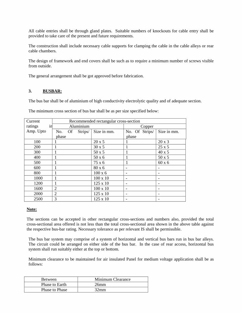
All cable entries shall be through gland plates. Suitable numbers of knockouts for cable entry shall be
provided to take care of the present and future requirements.
The construction shall include necessary cable supports for clamping the cable in the cable alleys or rear
cable chambers.
The design of framework and end covers shall be such as to require a minimum number of screws visible
from outside.
The general arrangement shall be got approved before fabrication.
3. BUSBAR:
The bus bar shall be of aluminium of high conductivity electrolytic quality and of adequate section.
The minimum cross section of bus bar shall be as per size specified below:
Current
ratings in
Amp. Upto
Recommended rectangular cross-section Aluminium Copper
No. Of Strips/
phase Size in mm. No. Of Strips/
phase Size in mm.
100 1 20 x 5 1 20 x 3 200 1 30 x 5 1 25 x 5 300 1 50 x 5 1 40 x 5 400 1 50 x 6 1 50 x 5 500 1 75 x 6 1 60 x 6 600 1 80 x 6 - - 800 1 100 x 6 - - 1000 1 100 x 10 - - 1200 1 125 x 10 - - 1600 2 100 x 10 - - 2000 2 125 x 10 - - 2500 3 125 x 10 - -
Note:
The sections can be accepted in other rectangular cross-sections and numbers also, provided the total
cross-sectional area offered is not less than the total cross-sectional area shown in the above table against
the respective bus-bar rating. Necessary tolerance as per relevant IS shall be permissible.
The bus bar system may comprise of a system of horizontal and vertical bus bars run in bus bar alleys.
The circuit could be arranged on either side of the bus bar. In the case of rear access, horizontal bus
system shall run suitably either at the top or bottom.
Minimum clearance to be maintained for air insulated Panel for medium voltage application shall be as
follows:
Between Minimum Clearance Phase to Earth 26mm Phase to Phase 32mm

Bus bar support insulation shall be made of non hygroscopic, non combustible, tack resistant high
strength SMC / DMC material and shall be of suitable size and spacing to withstand the dynamic stress
due to short circuit currents.
All connections to individual circuits from the bus bar shall be with solid connections and the same
shall be extended upto connector / insulated stud capable of taking cable / Bus-bar trunking of size
suitable for that circuit. The connector / insulated stud shall be located near the respective cable entry
points in the cable alley.
All bus bars and connections shall be suitably sleeved with PVC Heat Shrinkable sleeves or suitably
insulated in an approved manner.
4. PAINTING:
All sheet work shall undergo a process of degreasing, pickling in acid, cold rinsing phosphating,
passivating and than be sprayed with high corrosion resistant primer. The primer shall be baked in an
oven. The finishing treatment shall be by applying a minimum of two or more coats and powder coated
of approved shade.
5. INDICATION LAMPS:
5.1 Each INCOMER shall have:
1. A set of three indicators (RED, YELLOW & BLUE) for indicating the healthiness of the
incoming phases.
2. A set of two indicators, RED for OFF status and GREEN for ON status of the incoming
switches.
5.2 Each outgoing shall have a set of two indicators, RED for OFF status and GREEN for ON status
of the outgoing switch.
5.3 Each indicator shall be of multiple LED type.
Supply to the indicators shall be protected through MCB of suitable rating.
6. CONTROL WIRING:
All control and indication wiring etc. shall be with suitable copper conductor PVC insulated cables
conforming to relevant specifications.
Runs of wires shall be neatly bunched and suitably supported and clamped.
Identification ferrules shall be used at both ends of the wires.
All control wirings meant for external connection are to be brought out on a terminal board to be
located near the cable entry meant for such external cables.
7. INSTALLATION:
The installation work shall cover assembly of various sections of the panels lining up, grouting the units
etc.
In the case of multiple panel switchboards after connecting up the bus bars etc. all joints shall be insulated
with necessary insulation tape or approved insulation material.
A common earth bar shall be run at a suitable location in the panel. It will be ensured that all metal parts
of the panel are connected to this earth bar system. The recommended size of earth bus bar shall be in
accordance with general specification for electrical works (Part I internal as amended upto date).
However minimum size of earth lead shall be 20 mm x 4mm copper or 25mm x 5mm GI Strip.
8. TESTING AND COMMISSIONING:
Commissioning checks and tests shall include the following:
(a) Operational checks.
(b) Interlock function checks.
(c) Continuity checks of wiring, fuses etc. as required.
(d) Insulation test: When measured with 3.500 V Megger the insulation resistance shall not be less
than 100 mega ohms.
(e) Trip tests and protection gear test.
SPECIAL CONDITIONS OF CONTRACT
1) The electrical contractor shall be in possession of valid contractor’s license and shall posse’s
senior electrical engineer with minimum 2 years experience for degree holder and minimum 8
years experience for diploma holder.
2) The successful contractor himself shall execute the work. Sub-letting of work will not be allowed.
3) The work shall be carried out carried out as per Specification and as per manufacturers design and
recommendations. If the specifications for any item are not available in the specifications cited
above, relevant IS specifications shall be followed. In case ISI specifications are also not
available, the decision of the Electrical consultant given in writing based on acceptable sound
Engineering Practice and local usage shall be final and binding on the contractor.
4) All the material to be used on the work shall be of superior quality and shall have to be got
approved from the Engineer-In-Charge/Electrical consultant before use at site.
5) The contractor shall make his own arrangement for the safe custody / storage of his material.
Theft, pilferage, breakage, damage if any during the storage / execution of the work, shall be
replaced / rectified by the contractor at his own cost.
6) The contractor is bound to sign the entry/ entries made by the Engineer-In-Charge or his
representative in the site order book time to time.
7) Good workmanship is an essential requirement for compliance with the rules & specifications.
8) The entire installation shall be at the risk and responsibility of the contractor until these are tested
and handed over to the department.
9) Notwithstanding the bill of quantity, all items of inter-related work considered necessary to make
installation complete and operative should be deemed to be included by the contractor at no extra
cost.
10) The equipments and the installation shall conform to various Indian Standards amended up to
date wherever applicable.
11) The department’s authorized representative shall have full powers to inspect the drawings of any
portion of the work or examine the materials and workmanship of the equipment at the Firm’s
works or at any other place from where the material or equipment is obtained, if the department
so desires. Acceptance of any material or equipment shall in no way relieve the firm of their
responsibility for meeting the requirements of the specifications. In case, any equipment is found
defective or of inferior quality the firm shall have to replace the same free of cost.
12) The firm shall comply with all bye-laws and regulations of local and statutory authorities having
jurisdiction over the works and shall be responsible for payment of all fees and other charges and
giving / receiving all necessary notices and keep the Engineer-in-Charge informed.
13) Fees, damages, cost and charges of all and every sort that may be legally incurred in respect
thereof shall be borne by the firm/contractor.
14) It shall be Firm’s liability to follow all safety procedures in accordance with relevant I.S.
specifications / fire-by-laws or any other statutory rules / regulations amended up to date during
execution of work at site.
15) If the completed installation / equipment or any portion thereof, after it is taken over, is found to
be defective or fails to fulfill the intent of the specifications, the Firm shall on receipt of a written
notice from the Engineer-in-Charge, forthwith make good the defective installation / equipment.
Should the firm fail to rectify the defects / make good the defective installation / replace the
equipment at no extra cost, within a stipulated time mentioned in the written notice, institute may
get the work done at the risk and expenses of the Firm.
16) The institute reserves the right to make changes in the specifications of the work if in its opinion
the same is found necessary. However such alterations shall be made after mutual discussion and
agreement between the institute and the firm. Any price implication in this regard shall be
mutually discussed and agreed upon in terms of relevant clause of the contract.
17) The works shall be executed in close co-ordination with the progress of Building works. This
being essences of the contract, no claim for idle labor will be entertained.
18) It will be the responsibility of the contractor to obtain electrical no objection certificate from
Chief electrical inspector of the electrical department Govt. of Delhi before commissioning of
transformer and shall comply instructions contained in Indian Electricity rules. All the tests shall
be carried out as per Indian Electricity rules before commissioning of transformer. Dehydration of
transformer oil be got tested and test certificates are to be submitted. 11KV cable used on work be
got done before procurement of cable and manufacturers certificate is to be attached before
commissioning of cables.
19) All the cable certificates are to be submitted along with running bills.
20) Meggar test and earth test to be done in presence of Engineer- In- Charge.

Related Documents