IndraDrive Cs Drive Systems with HCS01 Project Planning Manual R911322210 Edition 08

Welcome message from author
This document is posted to help you gain knowledge. Please leave a comment to let me know what you think about it! Share it to your friends and learn new things together.
Transcript
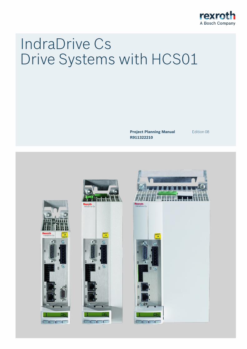
IndraDrive CsDrive Systems with HCS01
Project Planning ManualR911322210
Edition 08
IndraDrive CsDrive Systems with HCS01
Project Planning Manual
DOK-INDRV*-HCS01******-PR08-EN-P
RS-898e3e765ff4d61d0a6846a000329fdd-10-en-US-4
● Overview of the Rexroth IndraDrive Cs system● Description of the allowed combinations of Rexroth IndraDrive Cs
system components● Selection of the system components of the Rexroth IndraDrive Cs
system● Specification applying to all components (ambient and operating
conditions)● Application description of system characteristics
Record of Revisions See chapter "Editions" on page 15Copyright © Bosch Rexroth AG 2020
All rights reserved, also regarding any disposal, exploitation, reproduction,editing, distribution, as well as in the event of applications for industrialproperty rights.
Liability The specified data is intended for product description purposes only and shallnot be deemed to be a guaranteed characteristic unless expressly stipulatedin the contract. All rights are reserved with respect to the content of thisdocumentation and the availability of the product.
Editorial Department Engineering Drives [HaSc (UdSt; BaBo)]
Title
Type of Documentation
Document Typecode
Internal File Reference
Purpose of Documentation
IndraDrive Cs Drive Systems with HCS01
Table of ContentsPage
1 System presentation...................................................................................................... 11.1 Rexroth IndraDrive Cs range.................................................................................................................. 11.1.1 Overview – Rexroth IndraDrive Cs...................................................................................................... 11.1.2 Target applications.............................................................................................................................. 21.1.3 Features.............................................................................................................................................. 3
Functional features........................................................................................................................... 3Performance features....................................................................................................................... 5Combination of HCS01 and MSM/MSK............................................................................................ 6Interfaces.......................................................................................................................................... 6Supported encoder systems............................................................................................................. 6
1.2 System configuration.............................................................................................................................. 81.2.1 System structure.................................................................................................................................. 81.2.2 System components............................................................................................................................ 9
HCS01 drive controllers.................................................................................................................... 9Type code...................................................................................................................................... 9
HAP01 control panel....................................................................................................................... 12Firmware......................................................................................................................................... 13
1.2.3 About this documentation.................................................................................................................. 14Purpose.......................................................................................................................................... 14Editions........................................................................................................................................... 15Documentations.............................................................................................................................. 18
Drive systems, system components............................................................................................ 18Motors.......................................................................................................................................... 18Cables......................................................................................................................................... 19Firmware...................................................................................................................................... 19
Your comments.............................................................................................................................. 21
2 Important directions for use......................................................................................... 232.1 Intended use......................................................................................................................................... 232.1.1 Introduction........................................................................................................................................ 232.1.2 Areas of use and application............................................................................................................. 232.2 Unintended use..................................................................................................................................... 24
3 Safety instructions for electric drives and controls....................................................... 253.1 Definitions of terms............................................................................................................................... 253.2 General information.............................................................................................................................. 263.2.1 Using the Safety instructions and passing them on to others............................................................ 263.2.2 Requirements for safe use................................................................................................................ 263.2.3 Hazards by improper use.................................................................................................................. 283.3 Instructions with regard to specific dangers.......................................................................................... 283.3.1 Protection against contact with electrical parts and housings........................................................... 283.3.2 Protective extra-low voltage as protection against electric shock .................................................... 303.3.3 Protection against dangerous movements........................................................................................ 30
IndraDrive Cs Drive Systems with HCS01 I
Table of Contents
R911322210_Edition 08 Bosch Rexroth AG
Page
3.3.4 Protection against electromagnetic and magnetic fields during operation and mounting.................. 313.3.5 Protection against contact with hot parts........................................................................................... 323.3.6 Protection during handling and mounting.......................................................................................... 323.3.7 Battery safety..................................................................................................................................... 323.3.8 Protection against pressurized systems............................................................................................ 333.4 Explanation of signal words and the Safety alert symbol..................................................................... 34
4 Combining the individual components......................................................................... 354.1 Documentations.................................................................................................................................... 354.2 Brief description of the individual components..................................................................................... 354.2.1 HCS01 - brief description and design................................................................................................ 354.3 Configuring the drive system................................................................................................................ 354.3.1 Converter........................................................................................................................................... 354.3.2 Functional equipment........................................................................................................................ 374.3.3 Firmware............................................................................................................................................ 38
Firmware and device types............................................................................................................. 38Firmware types............................................................................................................................... 38Firmware variants........................................................................................................................... 40
MPx-xxVRS................................................................................................................................. 404.3.4 Motors................................................................................................................................................ 41
IndraDyn......................................................................................................................................... 41Third-Party Motors.......................................................................................................................... 42
General Information on Third-Party Motors................................................................................. 42Requirements on Third-Party Motors.......................................................................................... 43Requirements on the Encoder of the Third-Party Motor.............................................................. 46Notes on Selection and Commissioning...................................................................................... 46
4.3.5 Cables............................................................................................................................................... 48Motor power cables........................................................................................................................ 48
Selection...................................................................................................................................... 48Allowed cable lengths.................................................................................................................. 48
Encoder cables............................................................................................................................... 49MSM motors................................................................................................................................ 49MS2N motors............................................................................................................................... 49MSK motors................................................................................................................................. 49
4.4 Installation conditions........................................................................................................................... 494.4.1 Ambient and operating conditions..................................................................................................... 494.4.2 Control cabinet design and cooling................................................................................................... 514.4.3 UL ratings.......................................................................................................................................... 534.4.4 Compatibility with foreign matters...................................................................................................... 544.5 Mechanical project planning................................................................................................................. 544.5.1 Drive controller.................................................................................................................................. 54
Dimensional Drawings.................................................................................................................... 54Dimensions, mass, insulation, sound pressure level...................................................................... 58Temperatures, cooling, power dissipation, distances..................................................................... 59Mounting Positions of Components................................................................................................ 62
4.6 Electrical project planning..................................................................................................................... 63
II
Table of Contents
IndraDrive Cs Drive Systems with HCS01
Bosch Rexroth AG R911322210_Edition 08
Page
4.6.1 Overall connection diagram............................................................................................................... 634.6.2 Project planning of control voltage.................................................................................................... 64
Control voltage for drive systems................................................................................................... 64Sizing the control voltage supply.................................................................................................... 64
Determining the power requirements.......................................................................................... 64Requirements on the 24V power supply unit............................................................................... 68Installing the 24V supply.............................................................................................................. 68
4.6.3 Mains connection............................................................................................................................... 70Residual-current-operated circuit breakers (RCD, RCCB) as additional fusing............................. 70
General information..................................................................................................................... 70Cause of leakage currents........................................................................................................... 71Possibilities of use....................................................................................................................... 71Using residual-current-operated circuit breakers at HCS drive controllers.................................. 72
Mains types.................................................................................................................................... 73TN-S mains type.......................................................................................................................... 73TN-C mains type.......................................................................................................................... 74IT mains type............................................................................................................................... 74TT system.................................................................................................................................... 75Mains with grounded outer conductor (Corner-grounded delta mains)....................................... 76
Mains connection type.................................................................................................................... 76Mains connected load and mains current ...................................................................................... 80
Technical data of the components............................................................................................... 80Calculating the mains-side phase current .................................................................................. 80
Sizing the line cross sections and fuses......................................................................................... 81Sizing and selecting the mains transformer.................................................................................... 81Sizing the mains filter..................................................................................................................... 82Selecting the mains filter................................................................................................................ 84Determining the Mains Choke........................................................................................................ 88Sizing the mains contactor............................................................................................................. 88Combining transformer, mains filter and mains choke................................................................... 89Control Circuit for the Mains Connection........................................................................................ 90
4.6.4 DC bus coupling................................................................................................................................ 91Requirements for DC bus coupling................................................................................................. 91Central supply and DC bus coupling.............................................................................................. 91Group supply and DC bus coupling................................................................................................ 92Implementing the DC bus coupling................................................................................................. 94DC Bus Capacitor Unit................................................................................................................... 97Module bus and parameterization.................................................................................................. 98Bb relay contact.............................................................................................................................. 98
4.7 Acceptance tests and approvals......................................................................................................... 100
5 Condition as supplied, identification, transport and storage...................................... 1035.1 Condition as supplied......................................................................................................................... 1035.1.1 Factory testing................................................................................................................................. 103
Voltage testing and insulation resistance testing.......................................................................... 1035.1.2 Customer testing............................................................................................................................. 103
IndraDrive Cs Drive Systems with HCS01 III
Table of Contents
R911322210_Edition 08 Bosch Rexroth AG

Page
5.2 Identification........................................................................................................................................ 1045.2.1 Type Plates...................................................................................................................................... 104
Arrangement................................................................................................................................. 104Design.......................................................................................................................................... 104
5.2.2 Scope of supply............................................................................................................................... 1055.3 Transporting the components............................................................................................................. 1065.4 Storing the components...................................................................................................................... 106
6 Mounting and installation........................................................................................... 1076.1 Mounting HCS01 Devices in the Control Cabinet............................................................................... 1076.2 Electrical connection........................................................................................................................... 1096.2.1 Overall connection diagram............................................................................................................. 1096.2.2 Connection points............................................................................................................................ 110
Arrangement of the HCS01 connection points............................................................................. 1106.2.3 On-board connection points............................................................................................................ 113
Connection of Equipment Grounding Conductor.......................................................................... 113X3, mains connection................................................................................................................... 115
Important notes.......................................................................................................................... 115X3, mains connection HCS01.1E-W0003...W0013-x-02, -W0005-x-03, -W0008-x-03............. 116X3, mains connection HCS01.1E-W0018-x-02, -W0018-x-03, -W0028-x-03............................ 116X3, mains connection HCS01.1E-W0054-x-03......................................................................... 117
X4, motor encoder connection...................................................................................................... 118X5, Motor Connection................................................................................................................... 120
Important Notes......................................................................................................................... 120X5, Motor Connection HCS01.1E-W0003…W0013-x-02, -W0005-x-03, -W0008-x-03............ 121X5, Motor Connection HCS01.1E-W0018-x-02, -W0018-x-03, -W0028-x-03........................... 122X5, Motor Connection HCS01.1E-W0054-x-03......................................................................... 123
X6, motor temperature monitoring and motor holding brake ....................................................... 124X9, integrated/external braking resistor........................................................................................ 127X13, 24V Supply (Control Voltage)............................................................................................... 129X24 P2, X25 P1, communication.................................................................................................. 130X26, Engineering interface........................................................................................................... 132X31, digital inputs, digital output................................................................................................... 133X32, analog input.......................................................................................................................... 134X47, Bb relay contact, module bus............................................................................................... 135X77, L+ L-, DC bus connection.................................................................................................... 137Shield connection......................................................................................................................... 141
Shield connection plates............................................................................................................ 141Analog inputs/outputs: Shield connection.................................................................................. 143
Ground connection....................................................................................................................... 1446.2.4 Optional connection points.............................................................................................................. 145
X8, optional encoder (EC option)................................................................................................. 145X8, encoder emulation (EM option).............................................................................................. 145X22 P2, X23 P1, Multi-Ethernet (ET option)................................................................................. 147X26, Engineering interface........................................................................................................... 147X30, PROFIBUS PB..................................................................................................................... 148
IV
Table of Contents
IndraDrive Cs Drive Systems with HCS01
Bosch Rexroth AG R911322210_Edition 08

Page
X37, digital inputs/outputs (DA option)......................................................................................... 151X38, analog inputs/outputs (DA option)........................................................................................ 152X41, Safe Motion safety technology (S4, S5 options).................................................................. 153X42, X43, Safe Motion safety technology (communication; S4, S5 options)................................ 154X49, optional safety technology L3 or L4..................................................................................... 155X61, CANopen (CN Option)......................................................................................................... 156
6.2.5 EMC measures for design and installation...................................................................................... 157Rules for design of installations with drive controllers in compliance with EMC........................... 157Optimum EMC installation in facility and control cabinet.............................................................. 158
General information................................................................................................................... 158Division into areas (zones)........................................................................................................ 158Control cabinet design according to interference areas - exemplary arrangements................. 159Design and installation in area A - control cabinet area free from interference......................... 161Design and installation in area B - control cabinet area prone to interference.......................... 163Design and installation in area C - control cabinet area highly prone to interference............... 163
Ground connections..................................................................................................................... 164Installing signal lines and signal cables........................................................................................ 165General interference suppression measures for relays, contactors, switches, chokes and in‐ductive loads................................................................................................................................. 166Information on interference suppression measures..................................................................... 166
7 Technical data of the components............................................................................. 1697.1 Control section.................................................................................................................................... 1697.1.1 EC - standard encoder evaluation................................................................................................... 169
Supported encoder systems......................................................................................................... 169Encoder type................................................................................................................................ 170
IndraDyn S MSM motors (5V supply voltage)........................................................................... 170IndraDyn S MSK/QSK motors S1/M1, S2/M2, S3/M3, S5/M5 (12 V supply voltage)................ 171IndraDyn S MS2N motors AS/AM, BS/BM, CS/CM, HS/HM, DS/DM (12 V supply voltage)..... 172HIPERFACE® (12 V supply voltage)........................................................................................ 174EnDat 2.1 according to Heidenhain standard (5 V supply voltage)........................................... 175EnDat 2.2 according to Heidenhain standard (5 V supply voltage)........................................... 1761Vpp according to Heidenhain standard (5 V supply voltage).................................................... 1771Vpp (12 V supply voltage)......................................................................................................... 178TTL (5 V supply voltage)........................................................................................................... 179TTL (12 V supply voltage)......................................................................................................... 180SSI (5 V supply voltage)............................................................................................................ 181SSI (12 V supply voltage).......................................................................................................... 182Combined encoder for SSI (5 V supply voltage)....................................................................... 183Resolvers without encoder data memory.................................................................................. 184Hall sensor box SHL02.1 (12 V supply voltage)........................................................................ 185BiSS C....................................................................................................................................... 186
Power supply................................................................................................................................ 1875 V power supply....................................................................................................................... 18712 V power supply..................................................................................................................... 187Resolver power supply.............................................................................................................. 188
IndraDrive Cs Drive Systems with HCS01 V
Table of Contents
R911322210_Edition 08 Bosch Rexroth AG

Page
Encoder cable length.................................................................................................................... 189Technical data of EC encoder evaluation..................................................................................... 191Signal assignment to the actual position value............................................................................. 193
7.1.2 EM - encoder emulation.................................................................................................................. 195Cables.......................................................................................................................................... 195Incremental encoder emulation.................................................................................................... 195
Connection................................................................................................................................ 195Electrical data............................................................................................................................ 196
Absolute encoder emulation (SSI format)..................................................................................... 197Connection................................................................................................................................ 197Electrical data............................................................................................................................ 197Pulse diagram............................................................................................................................ 198
7.1.3 ET - Multi-Ethernet.......................................................................................................................... 199Display elements.......................................................................................................................... 199Port LED....................................................................................................................................... 200
EtherNet/IP................................................................................................................................ 200EtherCAT................................................................................................................................... 200sercos III.................................................................................................................................... 200PROFINET IO............................................................................................................................ 201
Diagnostic LED............................................................................................................................. 202EtherNet/IP................................................................................................................................ 202EtherCAT................................................................................................................................... 203sercos III.................................................................................................................................... 204PROFINET IO............................................................................................................................ 206
7.1.4 PB - PROFIBUS.............................................................................................................................. 2077.1.5 CN - CANopen................................................................................................................................. 2087.1.6 Sx - Safe Motion, Safe Motion Bus.................................................................................................. 209
Display elements.......................................................................................................................... 2097.1.7 Digital inputs/outputs....................................................................................................................... 211
General Information...................................................................................................................... 211Digital inputs................................................................................................................................. 211
Digital inputs type A (standard)................................................................................................. 211Digital inputs type B (probe)...................................................................................................... 212Digital inputs (safety technology L options)............................................................................... 213Digital inputs (safety technology S options)............................................................................... 214
Digital outputs............................................................................................................................... 215Digital outputs (standard).......................................................................................................... 215Digital outputs (safety technology L options)............................................................................. 216Digital outputs (safety technology S options)............................................................................ 217
7.1.8 Analog voltage input........................................................................................................................ 2197.1.9 Analog current input........................................................................................................................ 2207.1.10 Analog output.................................................................................................................................. 2217.1.11 Relay contacts................................................................................................................................. 222
Relay contact type 2..................................................................................................................... 2227.2 Control panel...................................................................................................................................... 2237.2.1 Design............................................................................................................................................. 223
VI
Table of Contents
IndraDrive Cs Drive Systems with HCS01
Bosch Rexroth AG R911322210_Edition 08
Page
Standard control panel HAP01.1N............................................................................................... 223ADVANCED Control Panel HAP01.1A......................................................................................... 224
7.3 Power section..................................................................................................................................... 2257.3.1 Control voltage................................................................................................................................ 2257.3.2 Mains voltage.................................................................................................................................. 2267.3.3 DC bus............................................................................................................................................. 2337.3.4 Integrated braking resistor............................................................................................................... 2357.3.5 Inverter............................................................................................................................................ 237
8 Cables, accessories, additional components............................................................. 2418.1 Overview............................................................................................................................................. 2418.1.1 Cables............................................................................................................................................. 2418.1.2 Accessories..................................................................................................................................... 2428.1.3 Additional Components................................................................................................................... 2428.2 Accessories........................................................................................................................................ 2438.2.1 Mounting and connection accessories (HAS09).............................................................................. 243
Use............................................................................................................................................... 243Assignment................................................................................................................................... 243Product insert............................................................................................................................... 244Module bus cable shield connection............................................................................................. 248
8.2.2 DC Bus Connector (RLS0778/K06)................................................................................................. 2508.2.3 SUP-E02-MSM-BATTERYBOX battery box.................................................................................... 2518.2.4 Battery (SUP-E02-MSM-BATTERY)............................................................................................... 2538.2.5 Encoder cable for MSM motors with absolute value encoder M5 (RKG0065)................................ 2558.2.6 D-Sub connector for encoder cable and battery connection (RGS0001/K01)................................. 2568.2.7 RKB0021, Multi-Ethernet cable....................................................................................................... 2598.2.8 RKB0013, Multi-Ethernet cable....................................................................................................... 2608.2.9 Hall Sensor Adapter Box (SHL03.1-NNN-S-NNN).......................................................................... 2618.2.10 Snap-on ferrite (HAS05.1-015)........................................................................................................ 2678.3 Additional components....................................................................................................................... 2708.3.1 Transformers................................................................................................................................... 270
General information...................................................................................................................... 270Autotransformers for drive controllers.......................................................................................... 271
Types......................................................................................................................................... 271Selected transformers............................................................................................................... 272
8.3.2 Mains Filters NFD / NFE.................................................................................................................. 273Type Code NFE / NFD................................................................................................................. 273
NFE02.1 - Mains Filter, Single-Phase....................................................................................... 273NFD03.1 - Mains Filter, Three-Phase........................................................................................ 273
Mechanical Data NFE / NFD........................................................................................................ 274NFE02.1.................................................................................................................................... 274NFD03.1.................................................................................................................................... 275
Electrical Data NFE / NFD............................................................................................................ 2768.3.3 Mains chokes................................................................................................................................... 278
Type code..................................................................................................................................... 278Type plate..................................................................................................................................... 279
IndraDrive Cs Drive Systems with HCS01 VII
Table of Contents
R911322210_Edition 08 Bosch Rexroth AG
Page
HNL01.1E - mains chokes, feeding ............................................................................................. 280Technical data........................................................................................................................... 280
8.3.4 External braking resistors HLR........................................................................................................ 282Types............................................................................................................................................ 282Data.............................................................................................................................................. 282HLR01.2N-01K0-N28R0, ...-N68R0 dimensions.......................................................................... 284HLR01.2N-0K06-N100R, ...-N180R dimensions.......................................................................... 286Assignment HLR01.2 to HCS01................................................................................................... 287Installation.................................................................................................................................... 287
8.3.5 DC bus capacitor units HLC............................................................................................................ 290Type code..................................................................................................................................... 290Technical data.............................................................................................................................. 290Connection................................................................................................................................... 291Operation...................................................................................................................................... 292
9 Environmental protection and disposal ..................................................................... 2939.1 Environmental protection.................................................................................................................... 2939.2 Disposal.............................................................................................................................................. 293
10 Service and support................................................................................................... 295
11 Appendix.................................................................................................................... 29711.1 Sizing the line cross sections and fuses ............................................................................................ 29711.1.1 Introduction...................................................................................................................................... 29711.1.2 International except for USA/Canada; installation type B1.............................................................. 29711.1.3 International except for USA/Canada; installation type B2.............................................................. 29911.1.4 International except for USA/Canada; installation type E................................................................ 30111.1.5 USA/Canada; installation type E..................................................................................................... 30311.1.6 Sizing variables of the table values................................................................................................. 30611.2 Determining the Leakage Capacitance............................................................................................... 30811.3 Leakage capacitances........................................................................................................................ 30811.3.1 Leakage capacitance of motors....................................................................................................... 30811.3.2 Leakage capacitance of power cables ........................................................................................... 311
Index.......................................................................................................................... 313
VIII/323
Table of Contents
IndraDrive Cs Drive Systems with HCS01
Bosch Rexroth AG R911322210_Edition 08
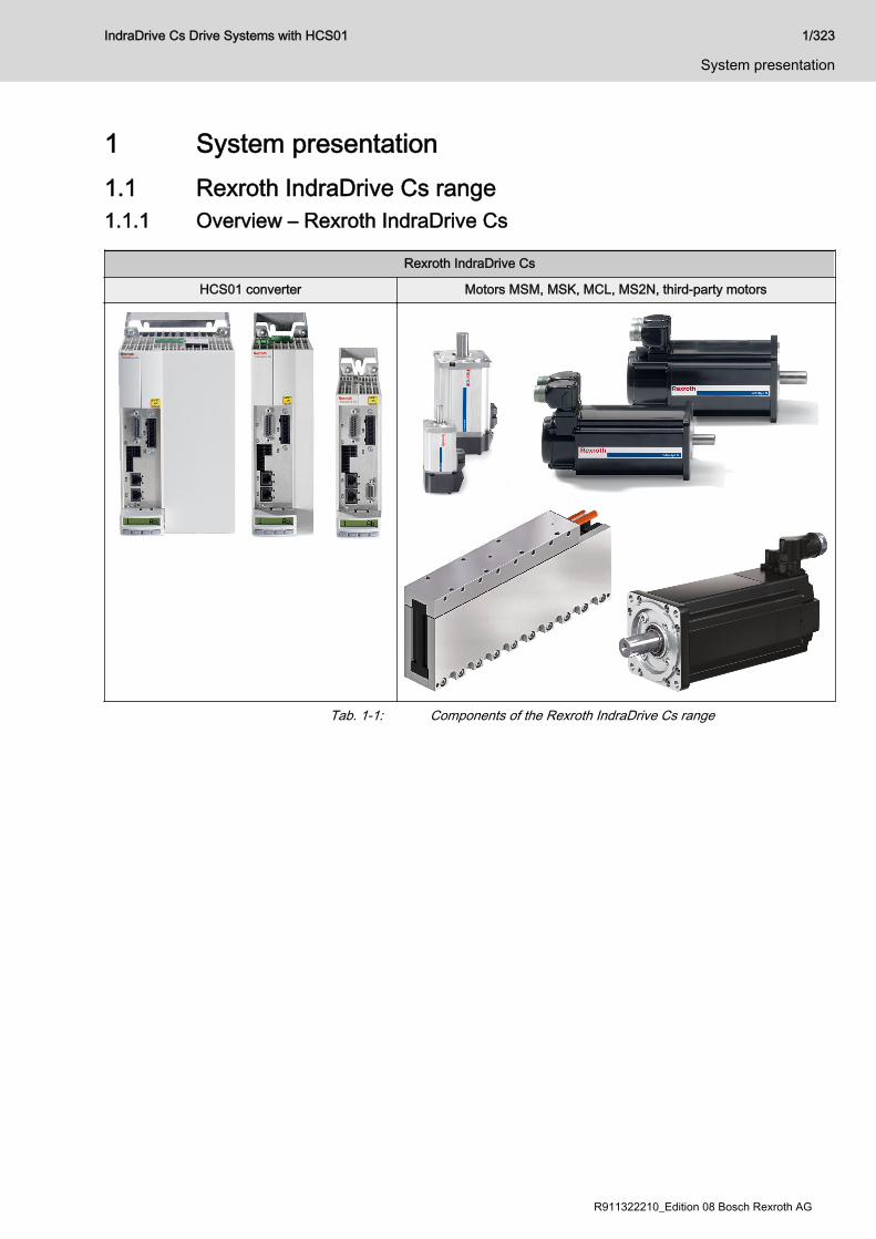
1 System presentation1.1 Rexroth IndraDrive Cs range1.1.1 Overview – Rexroth IndraDrive Cs
Rexroth IndraDrive Cs
HCS01 converter Motors MSM, MSK, MCL, MS2N, third-party motors
Tab. 1-1: Components of the Rexroth IndraDrive Cs range
IndraDrive Cs Drive Systems with HCS01 1/323
System presentation
R911322210_Edition 08 Bosch Rexroth AG
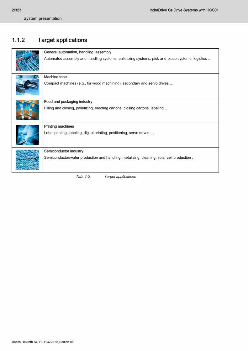
1.1.2 Target applications
General automation, handling, assemblyAutomated assembly and handling systems, palletizing systems, pick-and-place systems, logistics …
Machine toolsCompact machines (e.g., for wood machining), secondary and servo drives …
Food and packaging industryFilling and closing, palletizing, erecting cartons, closing cartons, labeling …
Printing machinesLabel printing, labeling, digital printing, positioning, servo drives …
Semiconductor industrySemiconductor/wafer production and handling, metalizing, cleaning, solar cell production …
Tab. 1-2: Target applications
2/323
System presentation
IndraDrive Cs Drive Systems with HCS01
Bosch Rexroth AG R911322210_Edition 08

1.1.3 FeaturesFunctional features
● Compact type of construction● Degree of protection IP20● Control panel with programming module function● Scalable signal processing and firmware● Multi-encoder interface for all standard encoders (HIPERFACE®,
EnDat2.1, EnDat2.2, SSI, BiSS C, TTL, sin/cos, resolver, MSM encoder,MS2N encoder)
● DC bus connection (at HCS01.1E-W00xx-x-03 devices)● Analog input (14 bit, ±10 V)● 8 digital inputs
– 2 probe inputs– 1 combined I/O which can be configured as digital input or as
digital output● Performance-dependent fan control● Integrated brake current measurement and monitoring● Winding short circuit at motor output for shutdown as reaction to fatal
errors● Compact MSM motors● 2 options for buffering the data of MSM encoders
– Battery box (SUP-E0x-MSM-BATTERYBOX; can be mounted nearthe motor; one battery box is required for each drive controller)
– Encoder cable (RKG0065) with D-Sub connector (RGS0001/K01)to connect a battery or an uninterruptible power supply
● Hall sensor adapter box SHL03.1 to operate MCL linear motors withdigital Hall sensors
IndraDrive Cs Drive Systems with HCS01 3/323
System presentation
R911322210_Edition 08 Bosch Rexroth AG
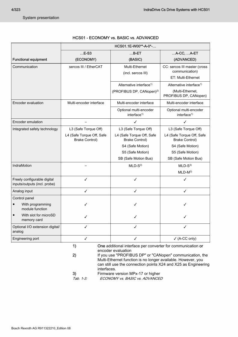
HCS01 - ECONOMY vs. BASIC vs. ADVANCED
Functional equipment
HCS01.1E-W00**-A-0*-…
…E-S3(ECONOMY)
…B-ET(BASIC)
…A-CC, …A-ET(ADVANCED)
Communication sercos III / EtherCAT Multi-Ethernet(incl. sercos III)
CC: sercos III master (crosscommunication)
ET: Multi-Ethernet
Alternative interface1)
(PROFIBUS DP, CANopen)2)
Alternative interface1)
(Multi-Ethernet,PROFIBUS DP, CANopen)
Encoder evaluation Multi-encoder interface Multi-encoder interface Multi-encoder interface
Optional multi-encoderinterface1)
Optional multi-encoderinterface1)
Encoder emulation – ✓ ✓
Integrated safety technology L3 (Safe Torque Off)L4 (Safe Torque Off, Safe
Brake Control)
L3 (Safe Torque Off)L4 (Safe Torque Off, Safe
Brake Control)S4 (Safe Motion)S5 (Safe Motion)
SB (Safe Motion Bus)
L3 (Safe Torque Off)L4 (Safe Torque Off, Safe
Brake Control)S4 (Safe Motion)S5 (Safe Motion)
SB (Safe Motion Bus)
IndraMotion – MLD-S3) MLD-S3)
MLD-M3)
Freely configurable digitalinputs/outputs (incl. probe)
✓ ✓ ✓
Analog input ✓ ✓ ✓
Control panel● With programming
module function● With slot for microSD
memory card
✓ ✓
✓ ✓
✓ ✓
Optional I/O extension digital/analog
✓ ✓ ✓
Engineering port ✓ ✓ ✓ (A-CC only)
1) One additional interface per converter for communication orencoder evaluation
2) If you use "PROFIBUS DP" or "CANopen" communication, theMulti-Ethernet function is no longer available. However, youcan still use the connection points X24 and X25 as Engineeringinterfaces.
3) Firmware version MPx-17 or higherTab. 1-3: ECONOMY vs. BASIC vs. ADVANCED
4/323
System presentation
IndraDrive Cs Drive Systems with HCS01
Bosch Rexroth AG R911322210_Edition 08
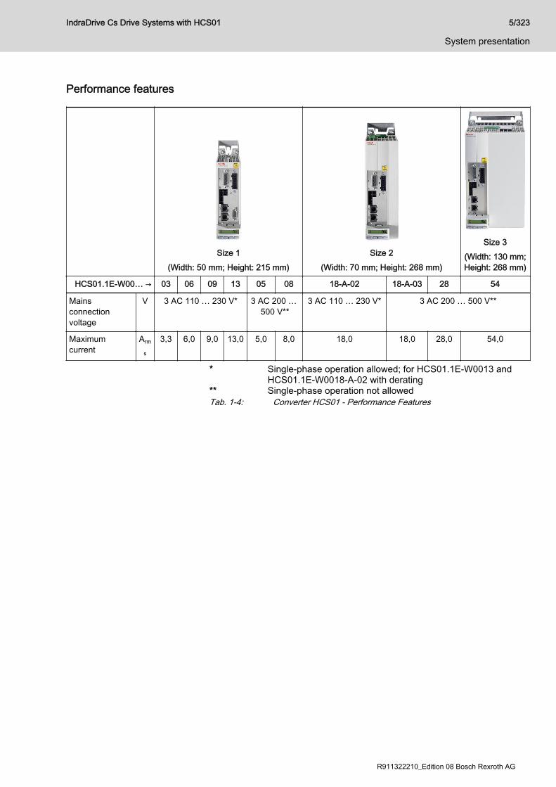
Performance features
Size 1(Width: 50 mm; Height: 215 mm)
Size 2(Width: 70 mm; Height: 268 mm)
Size 3(Width: 130 mm;Height: 268 mm)
HCS01.1E-W00… → 03 06 09 13 05 08 18-A-02 18-A-03 28 54
Mainsconnectionvoltage
V 3 AC 110 … 230 V* 3 AC 200 … 500 V**
3 AC 110 … 230 V* 3 AC 200 … 500 V**
Maximumcurrent
Arm
s
3,3 6,0 9,0 13,0 5,0 8,0 18,0 18,0 28,0 54,0
* Single-phase operation allowed; for HCS01.1E-W0013 andHCS01.1E-W0018-A-02 with derating
** Single-phase operation not allowedTab. 1-4: Converter HCS01 - Performance Features
IndraDrive Cs Drive Systems with HCS01 5/323
System presentation
R911322210_Edition 08 Bosch Rexroth AG
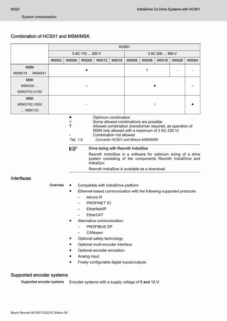
Combination of HCS01 and MSM/MSK
HCS01
3 AC 110 … 230 V 3 AC 200 … 500 V
W0003 W0006 W0009 W0013 W0018 W0005 W0008 W0018 W0028 W0054
MSMMSM019 … MSM041
■ T - -
MSKMSK030 …
MSK070C-0150□ ■ □
MSKMSK070C-0300
… MSK103- □ ■
■ Optimum combination□ Some allowed combinations are possibleT Allowed combination (transformer required, as operation of
MSM only allowed with a maximum of 3 AC 230 V)- Combination not allowedTab. 1-5: Converter HCS01 and Motors MSM/MSK
Drive sizing with Rexroth IndraSizeRexroth IndraSize is a software for optimum sizing of a drivesystem consisting of the components Rexroth IndraDrive andIndraDyn.Rexroth IndraSize is available as a download.
InterfacesOverview ● Compatible with IndraDrive platform
● Ethernet-based communication with the following supported protocols:– sercos III– PROFINET IO– EtherNet/IP– EtherCAT
● Alternative communication:– PROFIBUS DP– CANopen
● Optional safety technology● Optional multi-encoder interface● Optional encoder emulation● Analog input● Freely configurable digital inputs/outputs
Supported encoder systemsSupported encoder systems Encoder systems with a supply voltage of 5 and 12 V:
6/323
System presentation
IndraDrive Cs Drive Systems with HCS01
Bosch Rexroth AG R911322210_Edition 08

● MSM motor encoder● MSK motor encoder● MS2N motor encoder● 1Vpp sin-cos encoder; HIPERFACE®● 1Vpp sin-cos encoder; EnDat 2.1● 1Vpp sin-cos encoder; with reference track● 5V-TTL square-wave encoder; with reference track● SSI● Combined encoder for SSI (combination of SSI and 1Vpp sin-cos
encoder)● BiSS C● EnDat 2.2● Resolver (resolvers are not supported if an optional S4 safety
technology is available at the same time.)● SHL02.1 Hall sensor box● Digital Hall sensor in conjunction with SHL03.1 Hall sensor adapter box
IndraDrive Cs Drive Systems with HCS01 7/323
System presentation
R911322210_Edition 08 Bosch Rexroth AG
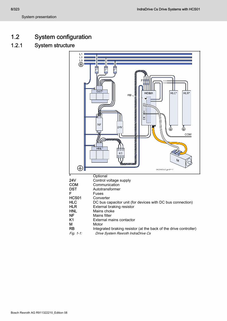
1.2 System configuration1.2.1 System structure
* Optional24V Control voltage supplyCOM CommunicationDST AutotransformerF FusesHCS01 ConverterHLC DC bus capacitor unit (for devices with DC bus connection)HLR External braking resistorHNL Mains chokeNF Mains filterK1 External mains contactorM MotorRB Integrated braking resistor (at the back of the drive controller)Fig. 1-1: Drive System Rexroth IndraDrive Cs
8/323
System presentation
IndraDrive Cs Drive Systems with HCS01
Bosch Rexroth AG R911322210_Edition 08
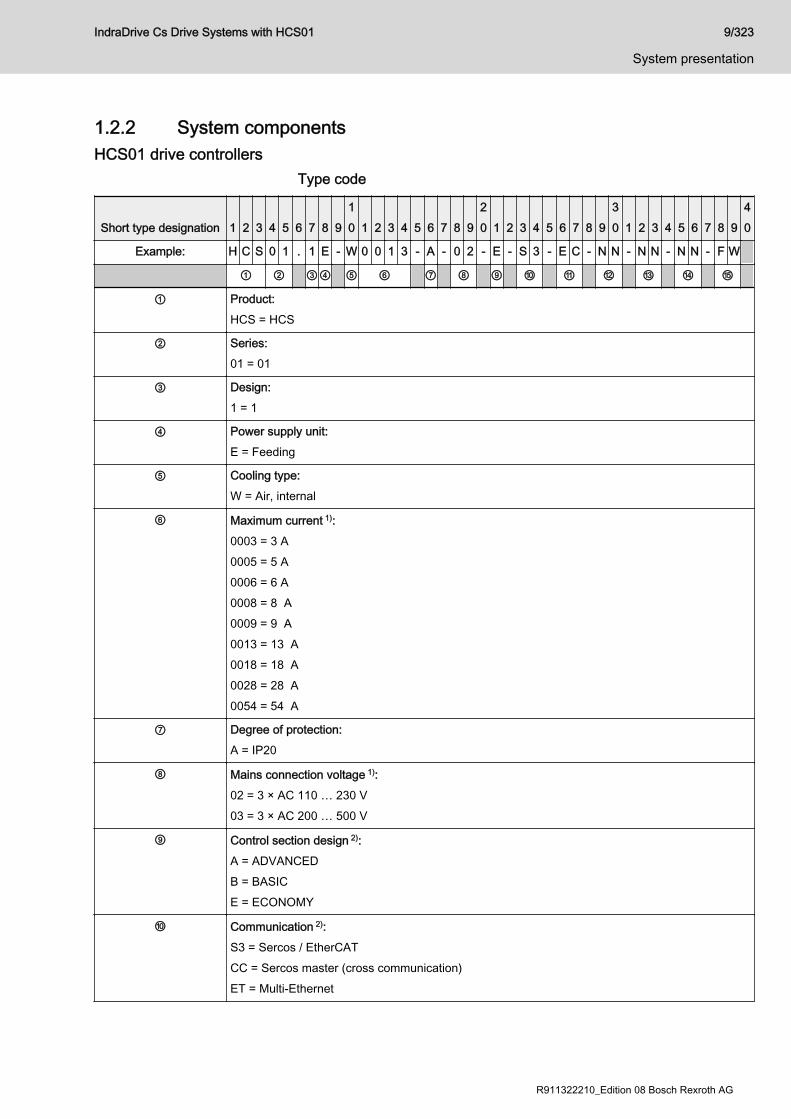
1.2.2 System componentsHCS01 drive controllers
Type code
Short type designation 1 2 3 4 5 6 7 8 910 1 2 3 4 5 6 7 8 9
20 1 2 3 4 5 6 7 8 9
30 1 2 3 4 5 6 7 8 9
40
Example: H C S 0 1 . 1 E - W 0 0 1 3 - A - 0 2 - E - S 3 - E C - N N - N N - N N - F W
① ② ③④ ⑤ ⑥ ⑦ ⑧ ⑨ ⑩ ⑪ ⑫ ⑬ ⑭ ⑮
① Product:HCS = HCS
② Series:01 = 01
③ Design:1 = 1
④ Power supply unit:E = Feeding
⑤ Cooling type:W = Air, internal
⑥ Maximum current 1):0003 = 3 A0005 = 5 A0006 = 6 A0008 = 8 A0009 = 9 A0013 = 13 A0018 = 18 A0028 = 28 A0054 = 54 A
⑦ Degree of protection:A = IP20
⑧ Mains connection voltage 1):02 = 3 × AC 110 … 230 V03 = 3 × AC 200 … 500 V
⑨ Control section design 2):A = ADVANCEDB = BASICE = ECONOMY
⑩ Communication 2):S3 = Sercos / EtherCATCC = Sercos master (cross communication)ET = Multi-Ethernet
IndraDrive Cs Drive Systems with HCS01 9/323
System presentation
R911322210_Edition 08 Bosch Rexroth AG
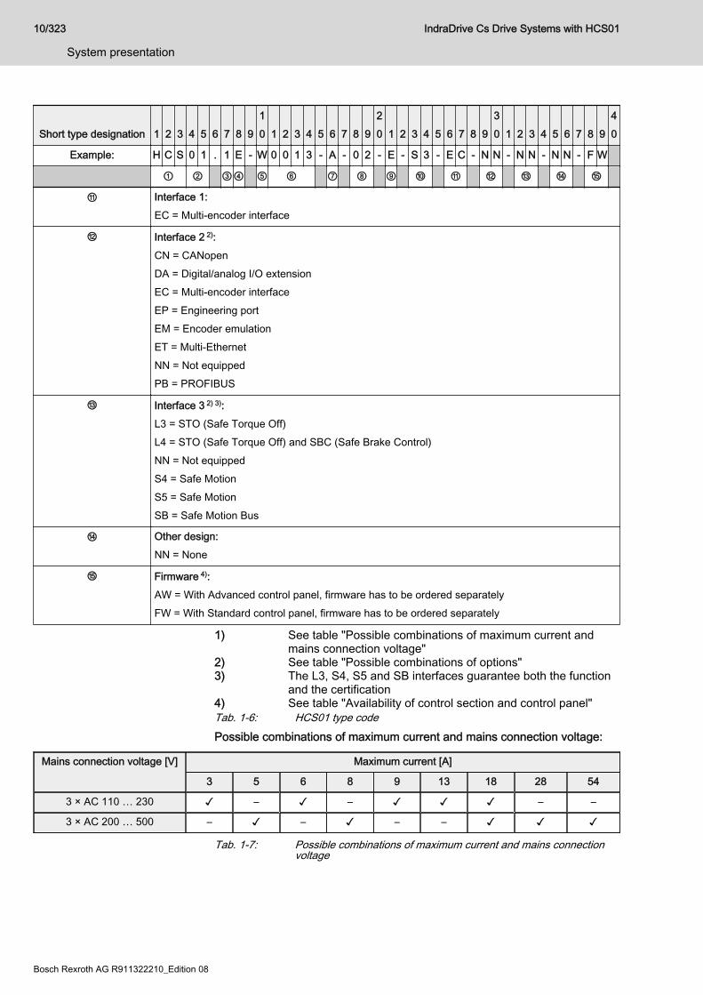
Short type designation 1 2 3 4 5 6 7 8 910 1 2 3 4 5 6 7 8 9
20 1 2 3 4 5 6 7 8 9
30 1 2 3 4 5 6 7 8 9
40
Example: H C S 0 1 . 1 E - W 0 0 1 3 - A - 0 2 - E - S 3 - E C - N N - N N - N N - F W
① ② ③④ ⑤ ⑥ ⑦ ⑧ ⑨ ⑩ ⑪ ⑫ ⑬ ⑭ ⑮
⑪ Interface 1:EC = Multi-encoder interface
⑫ Interface 2 2):CN = CANopenDA = Digital/analog I/O extensionEC = Multi-encoder interfaceEP = Engineering portEM = Encoder emulationET = Multi-EthernetNN = Not equippedPB = PROFIBUS
⑬ Interface 3 2) 3):L3 = STO (Safe Torque Off)L4 = STO (Safe Torque Off) and SBC (Safe Brake Control)NN = Not equippedS4 = Safe MotionS5 = Safe MotionSB = Safe Motion Bus
⑭ Other design:NN = None
⑮ Firmware 4):AW = With Advanced control panel, firmware has to be ordered separatelyFW = With Standard control panel, firmware has to be ordered separately
1) See table "Possible combinations of maximum current andmains connection voltage"
2) See table "Possible combinations of options"3) The L3, S4, S5 and SB interfaces guarantee both the function
and the certification4) See table "Availability of control section and control panel"Tab. 1-6: HCS01 type codePossible combinations of maximum current and mains connection voltage:
Mains connection voltage [V] Maximum current [A]
3 5 6 8 9 13 18 28 54
3 × AC 110 … 230 ✓ – ✓ – ✓ ✓ ✓ – –
3 × AC 200 … 500 – ✓ – ✓ – – ✓ ✓ ✓
Tab. 1-7: Possible combinations of maximum current and mains connectionvoltage
10/323
System presentation
IndraDrive Cs Drive Systems with HCS01
Bosch Rexroth AG R911322210_Edition 08

Possible combinations of options:
Maximumcurrent
Control sectionCommunication
Interface 2 Interface 3
CN DA EC EM EP ET NN PB L3 L4 NN S4 S5 SB
All A-CC ✓ – ✓ ✓ – ✓ ✓ ✓ ✓ ✓ ✓ ✓ ✓ ✓
– ✓ – – – – – – – – ✓ – – –
A-ET – – ✓ ✓ – – ✓ – ✓ ✓ ✓ ✓ ✓ ✓
– ✓ – – – – – – – – ✓ – – –
B-ET ✓ – ✓ ✓ ✓ – ✓ ✓ ✓ ✓ ✓ ✓ ✓ ✓
– ✓ – – – – – – – – ✓ – – –
E-S3 – – – – ✓ – ✓ – ✓ ✓ ✓ – – –
Tab. 1-8: Possible combinations of options Availability of control section and control panel:
Control section Firmware Control panel Information
A FW HAP01.1A-018-NN-FW always equipped
B FW HAP01.1N-018-NN-FW preferred option
B AW HAP01.1A-018-NN-FW alternative option
E FW HAP01.1N-018-NN-FW preferred option
E AW HAP01.1A-018-NN-FW alternative option
B PW HAP01.1N-018-NN-FW always equipped
Tab. 1-9: Availability of control section and control panel
The figure illustrates the basic structure of the type code. Oursales representative in charge will help you with the currentlyavailable designs.
IndraDrive Cs Drive Systems with HCS01 11/323
System presentation
R911322210_Edition 08 Bosch Rexroth AG

HAP01 control panelView
Fig. 1-2: HAP01 control panel
Type code
Short type designation 1 2 3 4 5 6 7 8 910 1 2 3 4 5 6 7 8 9
20 1 2 3 4 5 6 7 8 9
30 1 2 3 4 5 6 7 8 9
40
Example: H A P 0 1 . 1 N - 0 1 8 - N N - F W
① ② ③④ ⑤ ⑥ ⑦
① Product:HAP = Control panel
② Series:01 = 01
③ Design:1 = 1
④ Additional option:A = ADVANCED control panel with memory card slotN = Standard control panel without memory card slot
⑤ Memory size:018 = 18 MB (example)
⑥ Other design:NN = None
⑦ Firmware:FW = Firmware must be ordered as a separate subposition
Tab. 1-10: HAP01 type code
The figure illustrates the basic structure of the type code. Oursales representative in charge will help you with the currentlyavailable designs.
12/323
System presentation
IndraDrive Cs Drive Systems with HCS01
Bosch Rexroth AG R911322210_Edition 08

HAP01 ↔ HCS01 assignmentControl panel Drive controller
HAP01.1A HCS01.1E-W****-*-**-A-CC (ADVANCED)HCS01.1E-W****-*-**-A-ET (ADVANCED)
HCS01.1E-W****-*-**-B-ET (BASIC) 1)
HCS01.1E-W****-*-**-E-S3 (ECONOMY) 1)
HAP01.1N HCS01.1E-W****-*-**-B-ET (BASIC)HCS01.1E-W****-*-**-E-S3 (ECONOMY)
1) Requires firmware MPx-20 or higherTab. 1-11: HAP01 ↔ HCS01 assignment ● chapter "Standard control panel HAP01.1N" on page 223● chapter "ADVANCED Control Panel HAP01.1A" on page 224
FirmwareFirmware types ECONOMY
● FWA-INDRV*-MPE-16VRS-D5-x-NNN-NN or higherBASIC● FWA-INDRV*-MPB-16VRS-D5-x-xxx-xx or higherADVANCED● FWA-INDRV*-MPC-17VRS-D5-x-xxx-xx or higherSee also chapter "Firmware types" on page 38
For detailed information, see the Functional Description of the firmwareused (index entry "Overview of functions/functional packages").
IndraDrive Cs Drive Systems with HCS01 13/323
System presentation
R911322210_Edition 08 Bosch Rexroth AG
1.2.3 About this documentationPurpose
Personal injury and property damage causedby incorrect project planning for installations,machines and applications!
WARNING
Observe the contents of the documentations relevant to your drive system(see chapter "Documentations" on page 18).
This documentation contains● Overview of the IndraDrive Cs system● Description of the allowed combinations of IndraDrive Cs system
components● Selection of the system components of the IndraDrive Cs system● Specification applying to all components (ambient and operating
conditions)● Application description of system characteristics
14/323
System presentation
IndraDrive Cs Drive Systems with HCS01
Bosch Rexroth AG R911322210_Edition 08
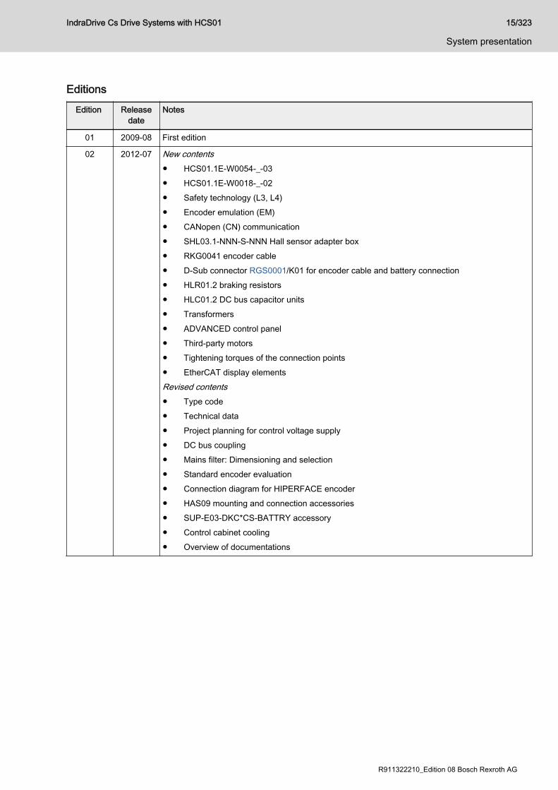
EditionsEdition Release
dateNotes
01 2009-08 First edition
02 2012-07 New contents● HCS01.1E-W0054-_-03● HCS01.1E-W0018-_-02● Safety technology (L3, L4)● Encoder emulation (EM)● CANopen (CN) communication● SHL03.1-NNN-S-NNN Hall sensor adapter box● RKG0041 encoder cable● D-Sub connector RGS0001/K01 for encoder cable and battery connection● HLR01.2 braking resistors● HLC01.2 DC bus capacitor units● Transformers● ADVANCED control panel● Third-party motors● Tightening torques of the connection points● EtherCAT display elementsRevised contents● Type code● Technical data● Project planning for control voltage supply● DC bus coupling● Mains filter: Dimensioning and selection● Standard encoder evaluation● Connection diagram for HIPERFACE encoder● HAS09 mounting and connection accessories● SUP-E03-DKC*CS-BATTRY accessory● Control cabinet cooling● Overview of documentations
IndraDrive Cs Drive Systems with HCS01 15/323
System presentation
R911322210_Edition 08 Bosch Rexroth AG
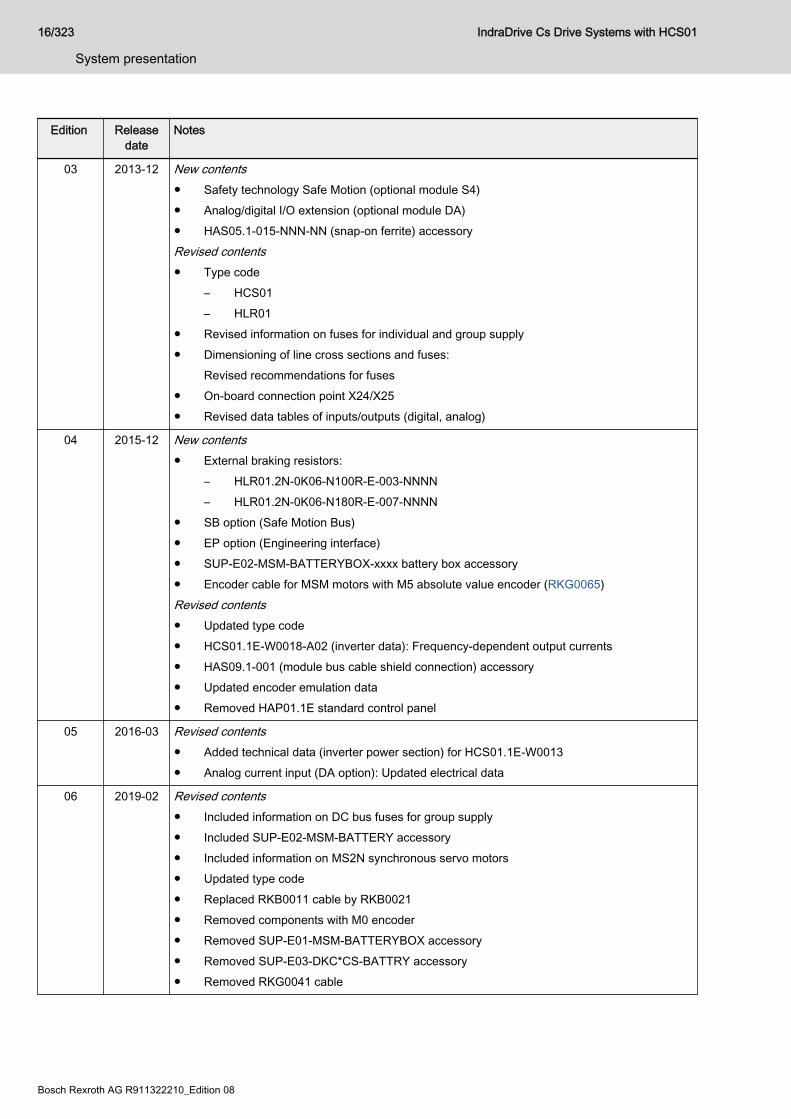
Edition Releasedate
Notes
03 2013-12 New contents● Safety technology Safe Motion (optional module S4)● Analog/digital I/O extension (optional module DA)● HAS05.1-015-NNN-NN (snap-on ferrite) accessoryRevised contents● Type code
– HCS01– HLR01
● Revised information on fuses for individual and group supply● Dimensioning of line cross sections and fuses:
Revised recommendations for fuses● On-board connection point X24/X25● Revised data tables of inputs/outputs (digital, analog)
04 2015-12 New contents● External braking resistors:
– HLR01.2N-0K06-N100R-E-003-NNNN– HLR01.2N-0K06-N180R-E-007-NNNN
● SB option (Safe Motion Bus)● EP option (Engineering interface)● SUP-E02-MSM-BATTERYBOX-xxxx battery box accessory● Encoder cable for MSM motors with M5 absolute value encoder (RKG0065)Revised contents● Updated type code● HCS01.1E-W0018-A02 (inverter data): Frequency-dependent output currents● HAS09.1-001 (module bus cable shield connection) accessory● Updated encoder emulation data● Removed HAP01.1E standard control panel
05 2016-03 Revised contents● Added technical data (inverter power section) for HCS01.1E-W0013● Analog current input (DA option): Updated electrical data
06 2019-02 Revised contents● Included information on DC bus fuses for group supply● Included SUP-E02-MSM-BATTERY accessory● Included information on MS2N synchronous servo motors● Updated type code● Replaced RKB0011 cable by RKB0021● Removed components with M0 encoder● Removed SUP-E01-MSM-BATTERYBOX accessory● Removed SUP-E03-DKC*CS-BATTRY accessory● Removed RKG0041 cable
16/323
System presentation
IndraDrive Cs Drive Systems with HCS01
Bosch Rexroth AG R911322210_Edition 08

Edition Releasedate
Notes
07 2019-03 Revised contents● Group supply/parallel operation:
removed balancing factor 0.5 since parallel operation without balancing chokes is notallowed
● Updated encoder emulation (EM option)● Updated HAS09 accessory
08 2020-04 Revised contents● Group supply: The DC bus fuses implemented in edition 06 were removed● EC encoder evaluation: Included BiSS C● X6, motor temperature evaluation: Included resistance values● Updated type code● Included information on Safe Motion Bus
Tab. 1-12: Editions
IndraDrive Cs Drive Systems with HCS01 17/323
System presentation
R911322210_Edition 08 Bosch Rexroth AG
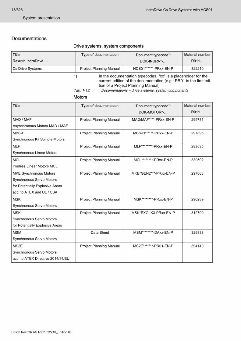
DocumentationsDrive systems, system components
TitleRexroth IndraDrive …
Type of documentation Document typecode1)
DOK-INDRV*-…
Material numberR911…
Cs Drive Systems Project Planning Manual HCS01******-PRxx-EN-P 322210
1) In the documentation typecodes, "xx" is a placeholder for thecurrent edition of the documentation (e.g.: PR01 is the first edi‐tion of a Project Planning Manual)
Tab. 1-13: Documentations – drive systems, system components
Motors
Title Type of documentation Document typecode1)
DOK-MOTOR*-…
Material numberR911…
MAD / MAFAsynchronous Motors MAD / MAF
Project Planning Manual MAD/MAF****-PRxx-EN-P 295781
MBS-HSynchronous Kit Spindle Motors
Project Planning Manual MBS-H******-PRxx-EN-P 297895
MLFSynchronous Linear Motors
Project Planning Manual MLF********-PRxx-EN-P 293635
MCLIronless Linear Motors MCL
Project Planning Manual MCL********-PRxx-EN-P 330592
MKE Synchronous MotorsSynchronous Servo Motorsfor Potentially Explosive Areasacc. to ATEX and UL / CSA
Project Planning Manual MKE*GEN2***-PRxx-EN-P 297663
MSKSynchronous Servo Motors
Project Planning Manual MSK********-PRxx-EN-P 296289
MSKSynchronous Servo Motorsfor Potentially Explosive Areas
Project Planning Manual MSK*EXGIIK3-PRxx-EN-P 312709
MSMSynchronous Servo Motors
Data Sheet MSM********-DAxx-EN-P 329338
MS2ESynchronous Servo Motorsacc. to ATEX Directive 2014/34/EU
Project Planning Manual MS2E*******-PR01-EN-P 394140
18/323
System presentation
IndraDrive Cs Drive Systems with HCS01
Bosch Rexroth AG R911322210_Edition 08
Title Type of documentation Document typecode1)
DOK-MOTOR*-…
Material numberR911…
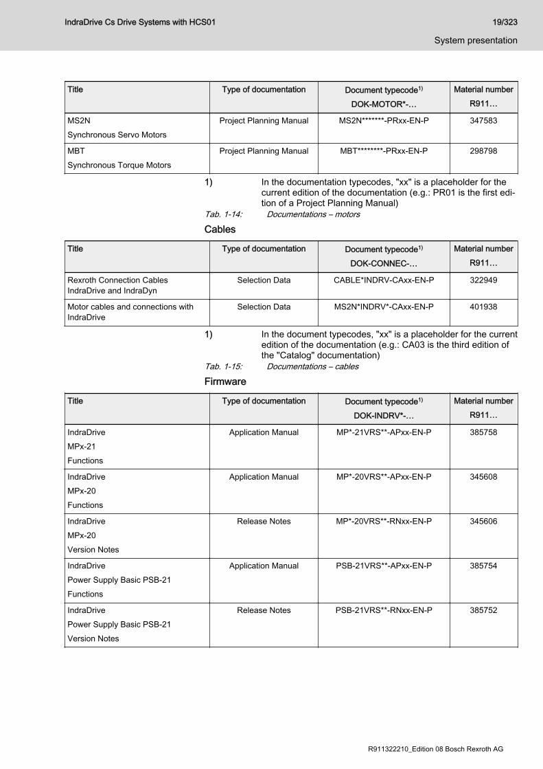
MS2NSynchronous Servo Motors
Project Planning Manual MS2N*******-PRxx-EN-P 347583
MBTSynchronous Torque Motors
Project Planning Manual MBT********-PRxx-EN-P 298798
1) In the documentation typecodes, "xx" is a placeholder for thecurrent edition of the documentation (e.g.: PR01 is the first edi‐tion of a Project Planning Manual)
Tab. 1-14: Documentations – motors
Cables
Title Type of documentation Document typecode1)
DOK-CONNEC-…
Material numberR911…
Rexroth Connection CablesIndraDrive and IndraDyn
Selection Data CABLE*INDRV-CAxx-EN-P 322949
Motor cables and connections withIndraDrive
Selection Data MS2N*INDRV*-CAxx-EN-P 401938
1) In the document typecodes, "xx" is a placeholder for the currentedition of the documentation (e.g.: CA03 is the third edition ofthe "Catalog" documentation)
Tab. 1-15: Documentations – cables
Firmware
Title Type of documentation Document typecode1)
DOK-INDRV*-…
Material numberR911…
IndraDriveMPx-21Functions
Application Manual MP*-21VRS**-APxx-EN-P 385758
IndraDriveMPx-20Functions
Application Manual MP*-20VRS**-APxx-EN-P 345608
IndraDriveMPx-20Version Notes
Release Notes MP*-20VRS**-RNxx-EN-P 345606
IndraDrivePower Supply Basic PSB-21Functions
Application Manual PSB-21VRS**-APxx-EN-P 385754
IndraDrivePower Supply Basic PSB-21Version Notes
Release Notes PSB-21VRS**-RNxx-EN-P 385752
IndraDrive Cs Drive Systems with HCS01 19/323
System presentation
R911322210_Edition 08 Bosch Rexroth AG

Title Type of documentation Document typecode1)
DOK-INDRV*-…
Material numberR911…
IndraDrivePower Supply Basic PSB-20Functions
Application Manual PSB-20VRS**-APxx-EN-P 345610
Rexroth IndraDrivePower Supply Basic PSB-19Functions
Application Manual PSB-19VRS**-APxx-EN-P 345602
Rexroth IndraDriveMPx-18Functions
Application Manual MP*-18VRS**-APxx-EN-P 338673
Rexroth IndraDriveMPx-18Version Notes
Release Notes MP*-18VRS**-RNxx-EN-P 338658
Rexroth IndraDriveMPx-17Functions
Application Manual MP*-17VRS**-APxx-EN-P 331236
Rexroth IndraDriveMPx-17Version Notes
Release Notes MP*-17VRS**-RNxx-EN-P 331588
Rexroth IndraDriveMPx-16Functions
Application Manual MP*-16VRS**-APxx-EN-P 326767
Rexroth IndraDriveMPx-16Version Notes
Release Notes MP*-16VRS**-RNxx-EN-P 329272
IndraDriveMPx-16 to MPx-21 and PSBParameters
Reference Book GEN1-PARA**-RExx-EN-P 328651
IndraDriveMPx-16 to MPx-21 and PSBDiagnostics
Reference Book GEN1-DIAG**-RExx-EN-P 326738
Rexroth IndraDriveIntegrated Safety Technology"Safe Torque Off" (as of MPx-16)
Application Manual SI3-**VRS**-APxx-EN-P 332634
IndraDriveIntegrated Safety Technology"Safe Motion" (as of MPx-18)
Application Manual SI3*SMO-VRS-APxx-EN-P 338920
20/323
System presentation
IndraDrive Cs Drive Systems with HCS01
Bosch Rexroth AG R911322210_Edition 08
Title Type of documentation Document typecode1)
DOK-INDRV*-…
Material numberR911…
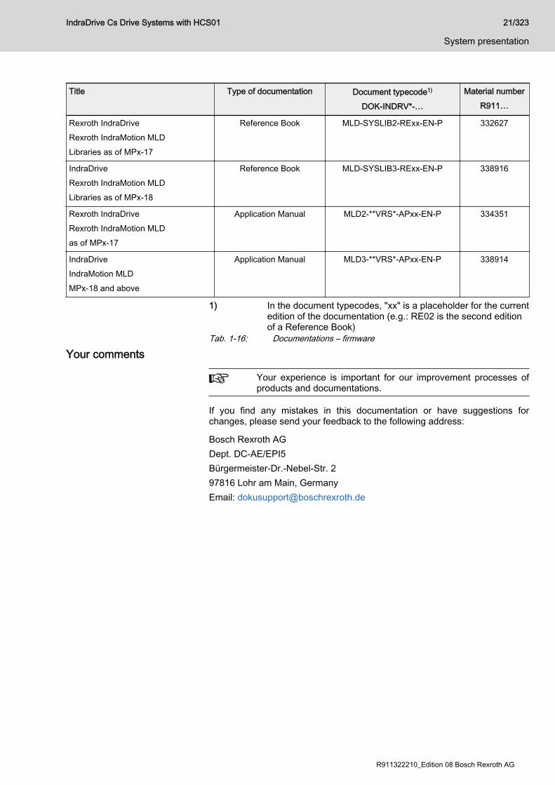
Rexroth IndraDriveRexroth IndraMotion MLDLibraries as of MPx-17
Reference Book MLD-SYSLIB2-RExx-EN-P 332627
IndraDriveRexroth IndraMotion MLDLibraries as of MPx-18
Reference Book MLD-SYSLIB3-RExx-EN-P 338916
Rexroth IndraDriveRexroth IndraMotion MLDas of MPx-17
Application Manual MLD2-**VRS*-APxx-EN-P 334351
IndraDriveIndraMotion MLDMPx-18 and above
Application Manual MLD3-**VRS*-APxx-EN-P 338914
1) In the document typecodes, "xx" is a placeholder for the currentedition of the documentation (e.g.: RE02 is the second editionof a Reference Book)
Tab. 1-16: Documentations – firmware
Your comments
Your experience is important for our improvement processes ofproducts and documentations.
If you find any mistakes in this documentation or have suggestions forchanges, please send your feedback to the following address:
Bosch Rexroth AGDept. DC-AE/EPI5Bürgermeister-Dr.-Nebel-Str. 297816 Lohr am Main, GermanyEmail: [email protected]
IndraDrive Cs Drive Systems with HCS01 21/323
System presentation
R911322210_Edition 08 Bosch Rexroth AG

22/323 IndraDrive Cs Drive Systems with HCS01
Bosch Rexroth AG R911322210_Edition 08
2 Important directions for use2.1 Intended use2.1.1 Introduction
Rexroth products are developed and manufactured to the state-of-the-art.The products are tested prior to delivery to ensure operational safety andreliability.
Personal injury and property damage byusing products incorrectly!
WARNING
The products have been designed for use in an industrial environment andmay only be used as intended. Failure to use them in the intended way maycause situations resulting in property damage and personal injury.
Rexroth as the manufacturer shall not honor any warranty, liabilityor compensatory claims for damages resulting from unintendeduse of the products. The user alone shall bear the risks ofunintended use of the products.
Before using Rexroth products, make sure that all the prerequisites for anintended use of the products are satisfied:● Personnel that in any way, shape or form uses our products must first
read and understand the relevant safety instructions and be familiar withtheir intended use.
● Leave hardware products in their original state, i.e., do not make anystructural modifications. It is not permitted to decompile softwareproducts or alter their source codes.
● Do not install damaged or faulty products or put them into operation.● Make sure that the products have been installed as described in the
relevant documentation.
2.1.2 Areas of use and applicationDrive controllers by Rexroth are designed to control electric motors andmonitor their operation.Controlling and monitoring the Drive controllers may require additionalsensors and actuators.
The drive controllers may only be used with the accessories andattachments specified in this documentation. Components thatare not expressly mentioned may neither be attached norconnected. The same applies to cables and lines.Operation is only allowed in the specified configurations andcombinations of the components using the software and firmwareas specified in the relevant functional descriptions.
Drive controllers have to be programmed before commissioning to ensurethat the motor executes the functions specific to the application.Drive controllers of the IndraDrive Cs series have been developed for use insingle- and multi-axis drive and control tasks.
IndraDrive Cs Drive Systems with HCS01 23/323
Important directions for use
R911322210_Edition 08 Bosch Rexroth AG
Device types with different drive power and interfaces are available for usingthe Drive controllers in specific applications.Typical applications include, for example:● Handling and mounting systems● Packaging and food machines● Printing and paper converting machines● Machine toolsDrive controllers may only be operated under the assembly and installationconditions specified in this documentation, in the specified position of normaluse and under the specified ambient conditions (temperature, degree ofprotection, humidity, EMC, etc.).
Note regarding the RoHS Directive 2011/65/EU:The CSB01, CSH01 and CDB01 control sections do not meet therequirements of the RoHS Directive 2011/65/EU.However, the CSB01, CSH01 and CDB01 control sections maystill be placed on the market within the EU if they are exclusivelyused in applications that are so-called "large-scale stationaryindustrial tools" or so-called "large-scale fixed installations".This is stated by the derogation contemplated by Article 2,paragraph 4 of the RoHS Directive 2011/65/EU. Article 3 of thisDirective specifies the definitions.
2.2 Unintended use"Unintended use" refers to using the Drive controllers outside of the operatingconditions, technical data and specifications described in this documentation.Drive controllers must not be used, if …● they are exposed to operating conditions that do not meet the specified
ambient conditions. This includes, for example, operation under water,under extreme temperature fluctuations or extreme maximumtemperatures.
● Furthermore, Drive controllers may not be used in applications that havenot been expressly authorized by Rexroth. Therefore, please carefullyfollow the specifications outlined in the general safety instructions!
Components of the IndraDrive Cs system are products ofCategory C3 (with restricted distribution) in accordance withIEC 61800-3. This Category comprises EMC limit values for line-based and radiated noise emission. Compliance with thisCategory (limit values) requires the appropriate measures ofinterference suppression to be used in the drive system (e.g.,mains filters, shielding measures).These components are not provided for use in a public low-voltage mains supplying residential areas. If these componentsare used in such a mains, high-frequency interference is to beexpected. This can require additional measures of interferencesuppression.
24/323
Important directions for use
IndraDrive Cs Drive Systems with HCS01
Bosch Rexroth AG R911322210_Edition 08

3 Safety instructions for electric drives and controls3.1 Definitions of terms
Application documentation Application documentation comprises the entire documentation used toinform the user of the product about the use and safety-relevant features forconfiguring, integrating, installing, mounting, commissioning, operating,maintaining, repairing and decommissioning the product. The following termsare also used for this kind of documentation: Operating Instructions,Commissioning Manual, Instruction Manual, Project Planning Manual,Application Description, etc.
Component A component is a combination of elements with a specified function, whichare part of a piece of equipment, device or system. Components of theelectric drive and control system are, for example, supply units, drivecontrollers, mains choke, mains filter, motors, cables, etc.
Control system A control system comprises several interconnected control componentsplaced on the market as a single functional unit.
Device A device is a finished product with a defined function, intended for users andplaced on the market as an individual piece of merchandise.
Electrical equipment Electrical equipment encompasses all devices used to generate, convert,transmit, distribute or apply electrical energy, such as electric motors,transformers, switching devices, cables, lines, power-consuming devices,circuit board assemblies, plug-in units, control cabinets, etc.
Electric drive system An electric drive system comprises all components from mains supply tomotor shaft; this includes, for example, electric motor(s), motor encoder(s),supply units and drive controllers, as well as auxiliary and additionalcomponents, such as mains filter, mains choke and the corresponding linesand cables.
Installation An installation consists of several devices or systems interconnected for adefined purpose and on a defined site which, however, are not intended to beplaced on the market as a single functional unit.
Machine A machine is the entirety of interconnected parts or units at least one ofwhich is movable. Thus, a machine consists of the appropriate machine driveelements, as well as control and power circuits, which have been assembledfor a specific application. A machine is, for example, intended for processing,treatment, movement or packaging of a material. The term "machine" alsocovers a combination of machines which are arranged and controlled in sucha way that they function as a unified whole.
Manufacturer The manufacturer is an individual or legal entity bearing responsibility for thedesign and manufacture of a product which is placed on the market in theindividual's or legal entity's name. The manufacturer can use finishedproducts, finished parts or finished elements, or contract out work tosubcontractors. However, the manufacturer must always have overall controland possess the required authority to take responsibility for the product.
Product Examples of a product: Device, component, part, system, software, firmware,among other things.
Project Planning Manual A Project Planning Manual is part of the application documentation used tosupport the sizing and planning of systems, machines or installations.
Qualified persons In terms of this application documentation, qualified persons are thosepersons who are familiar with the installation, mounting, commissioning andoperation of the components of the electric drive and control system, as wellas with the hazards this implies, and who possess the qualifications their
IndraDrive Cs Drive Systems with HCS01 25/323
Safety instructions for electric drives and controls
R911322210_Edition 08 Bosch Rexroth AG

work requires. To comply with these qualifications, it is necessary, amongother things,● to be trained, instructed or authorized to switch electric circuits and
devices safely on and off, to ground them and to mark them.● to be trained or instructed to maintain and use adequate safety
equipment.● to attend a course of instruction in first aid.
Qualified personnel for handlingfunctionally safe products
Individuals configuring, commissioning and operating functionally safeproducts must have the knowledge specified under "Qualified persons".Additionally, these individuals must be familiar with technical safety conceptsas well as prevailing standards and regulations in the field of functionalsafety.
User A user is a person installing, commissioning or using a product which hasbeen placed on the market.
3.2 General information3.2.1 Using the Safety instructions and passing them on to others
Do not attempt to install and operate the components of the electric drive andcontrol system without first reading all documentation provided with theproduct. Read and understand these safety instructions and all userdocumentation prior to working with these components. If you do not havethe user documentation for the components, contact your responsibleRexroth sales partner. Ask for these documents to be sent immediately to theperson or persons responsible for the safe operation of the components.If the component is resold, rented and/or passed on to others in any otherform, these safety instructions must be delivered with the component in theofficial language of the user's country.Improper use of these components, failure to follow the safety instructions inthis document or tampering with the product, including disabling of safetydevices, could result in property damage, injury, electric shock or even death.
3.2.2 Requirements for safe useRead the following instructions before initial commissioning of thecomponents of the electric drive and control system in order to eliminate therisk of injury and/or property damage. You must follow these safetyinstructions.● Rexroth is not liable for damages resulting from failure to observe the
safety instructions.● Read the operating, maintenance and safety instructions in your
language before commissioning. If you find that you cannot completelyunderstand the application documentation in the available language,please ask your supplier to clarify.
● Proper and correct transport, storage, mounting and installation, as wellas care in operation and maintenance, are prerequisites for optimal andsafe operation of the component.
● Only qualified persons may work with components of the electric driveand control system or within its proximity.
● Only use accessories and spare parts approved by Rexroth.
26/323
Safety instructions for electric drives and controls
IndraDrive Cs Drive Systems with HCS01
Bosch Rexroth AG R911322210_Edition 08
● Follow the safety regulations and requirements of the country in whichthe components of the electric drive and control system are operated.
● Only use the components of the electric drive and control system in themanner that is defined as appropriate. See chapter "Appropriate Use".
● The ambient and operating conditions given in the available applicationdocumentation must be observed.
● Applications for functional safety are only allowed if clearly and explicitlyspecified in the application documentation "Integrated SafetyTechnology". If this is not the case, they are excluded. Functional safetyis a safety concept in which measures of risk reduction for personalsafety depend on electrical, electronic or programmable controlsystems.
● The information given in the application documentation with regard tothe use of the delivered components contains only examples ofapplications and suggestions.The machine and installation manufacturers must– make sure that the delivered components are suited for their
individual application and check the information given in thisapplication documentation with regard to the use of thecomponents,
– make sure that their individual application complies with theapplicable safety regulations and standards and carry out therequired measures, modifications and complements.
● Commissioning of the delivered components is only allowed once it issure that the machine or installation in which the components areinstalled complies with the national regulations, safety specifications andstandards of the application.
● Operation is only allowed if the national EMC regulations for theapplication are met.
● The instructions for installation in accordance with EMC requirementscan be found in the section on EMC in the respective applicationdocumentation.The machine or installation manufacturer is responsible for compliancewith the limit values as prescribed in the national regulations.
● The technical data, connection and installation conditions of thecomponents are specified in the respective application documentationsand must be followed at all times.
National regulations which the user has to comply with● European countries: In accordance with European EN standards● United States of America (USA):
– National Electrical Code (NEC)– National Electrical Manufacturers Association (NEMA), as well as
local engineering regulations– Regulations of the National Fire Protection Association (NFPA)
● Canada: Canadian Standards Association (CSA)● Other countries:
– International Organization for Standardization (ISO)– International Electrotechnical Commission (IEC)
IndraDrive Cs Drive Systems with HCS01 27/323
Safety instructions for electric drives and controls
R911322210_Edition 08 Bosch Rexroth AG

3.2.3 Hazards by improper use● High electrical voltage and high working current! Danger to life or
serious injury by electric shock!● High electrical voltage by incorrect connection! Danger to life or injury by
electric shock!● Dangerous movements! Danger to life, serious injury or property
damage by unintended motor movements!● Health hazard for persons with heart pacemakers, metal implants and
hearing aids in proximity to electric drive systems!● Risk of burns by hot housing surfaces!● Risk of injury by improper handling! Injury by crushing, shearing, cutting,
hitting!● Risk of injury by improper handling of batteries!● Risk of injury by improper handling of pressurized lines!
3.3 Instructions with regard to specific dangers3.3.1 Protection against contact with electrical parts and housings
This section concerns components of the electric drive andcontrol system with voltages of more than 50 volts.
Contact with parts conducting voltages above 50 volts can cause personaldanger and electric shock. When operating components of the electric driveand control system, it is unavoidable that some parts of these componentsconduct dangerous voltage. High electrical voltage! Danger to life, risk of injury by electric shock orserious injury!● Only qualified persons are allowed to operate, maintain and/or repair the
components of the electric drive and control system.● Follow the general installation and safety regulations when working on
power installations.● Before switching on, the equipment grounding conductor must have
been permanently connected to all electric components in accordancewith the connection diagram.
● Even for brief measurements or tests, operation is only allowed if theequipment grounding conductor has been permanently connected to thepoints of the components provided for this purpose.
● Before accessing electrical parts with voltage potentials higher than50 V, you must disconnect electric components from the mains or fromthe power supply unit. Secure the electric component fromreconnection.
● With electric components, observe the following aspects:Always wait 30 minutes after switching off power to allow live capacitorsto discharge before accessing an electric component. Measure theelectrical voltage of live parts before beginning to work to make surethat the equipment is safe to touch.
28/323
Safety instructions for electric drives and controls
IndraDrive Cs Drive Systems with HCS01
Bosch Rexroth AG R911322210_Edition 08
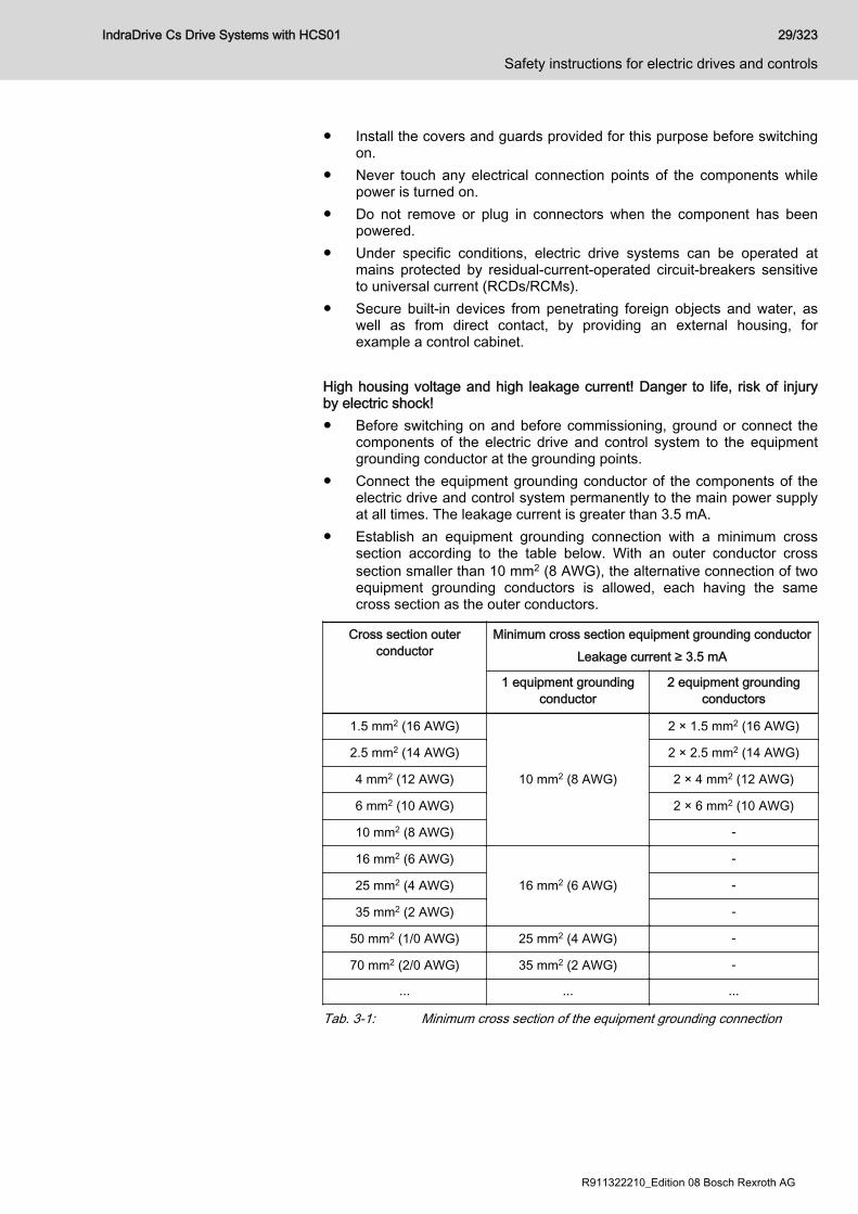
● Install the covers and guards provided for this purpose before switchingon.
● Never touch any electrical connection points of the components whilepower is turned on.
● Do not remove or plug in connectors when the component has beenpowered.
● Under specific conditions, electric drive systems can be operated atmains protected by residual-current-operated circuit-breakers sensitiveto universal current (RCDs/RCMs).
● Secure built-in devices from penetrating foreign objects and water, aswell as from direct contact, by providing an external housing, forexample a control cabinet.
High housing voltage and high leakage current! Danger to life, risk of injuryby electric shock!● Before switching on and before commissioning, ground or connect the
components of the electric drive and control system to the equipmentgrounding conductor at the grounding points.
● Connect the equipment grounding conductor of the components of theelectric drive and control system permanently to the main power supplyat all times. The leakage current is greater than 3.5 mA.
● Establish an equipment grounding connection with a minimum crosssection according to the table below. With an outer conductor crosssection smaller than 10 mm2 (8 AWG), the alternative connection of twoequipment grounding conductors is allowed, each having the samecross section as the outer conductors.
Cross section outerconductor
Minimum cross section equipment grounding conductorLeakage current ≥ 3.5 mA
1 equipment groundingconductor
2 equipment groundingconductors
1.5 mm2 (16 AWG)
10 mm2 (8 AWG)
2 × 1.5 mm2 (16 AWG)
2.5 mm2 (14 AWG) 2 × 2.5 mm2 (14 AWG)
4 mm2 (12 AWG) 2 × 4 mm2 (12 AWG)
6 mm2 (10 AWG) 2 × 6 mm2 (10 AWG)
10 mm2 (8 AWG) -
16 mm2 (6 AWG)
16 mm2 (6 AWG)
-
25 mm2 (4 AWG) -
35 mm2 (2 AWG) -
50 mm2 (1/0 AWG) 25 mm2 (4 AWG) -
70 mm2 (2/0 AWG) 35 mm2 (2 AWG) -
... ... ...
Tab. 3-1: Minimum cross section of the equipment grounding connection
IndraDrive Cs Drive Systems with HCS01 29/323
Safety instructions for electric drives and controls
R911322210_Edition 08 Bosch Rexroth AG

3.3.2 Protective extra-low voltage as protection against electric shock Protective extra-low voltage is used to allow connecting devices with basicinsulation to extra-low voltage circuits.On components of an electric drive and control system provided by Rexroth,all connections and terminals with voltages up to 50 volts are PELV("Protective Extra-Low Voltage") systems. It is allowed to connect devicesequipped with basic insulation (such as programming devices, PCs,notebooks, display units) to these connections. Danger to life, risk of injury by electric shock! High electrical voltage byincorrect connection!If extra-low voltage circuits of devices containing voltages and circuits ofmore than 50 volts (e.g., the mains connection) are connected to Rexrothproducts, the connected extra-low voltage circuits must comply with therequirements for PELV ("Protective Extra-Low Voltage").
3.3.3 Protection against dangerous movementsDangerous movements can be caused by faulty control of connected motors.Some common examples are:● Improper or wrong wiring or cable connection● Operator errors● Wrong input of parameters before commissioning● Malfunction of sensors and encoders● Defective components● Software or firmware errorsThese errors can occur immediately after equipment is switched on or evenafter an unspecified time of trouble-free operation.The monitoring functions in the components of the electric drive and controlsystem will normally be sufficient to avoid malfunction in the connecteddrives. Regarding personal safety, especially the danger of injury and/orproperty damage, this alone cannot be relied upon to ensure complete safety.Until the integrated monitoring functions become effective, it must beassumed in any case that faulty drive movements will occur. The extent offaulty drive movements depends upon the type of control and the state ofoperation. Dangerous movements! Danger to life, risk of injury, serious injury or propertydamage!A risk assessment must be prepared for the installation or machine, with itsspecific conditions, in which the components of the electric drive and controlsystem are installed.As a result of the risk assessment, the user must provide for monitoringfunctions and higher-level measures on the installation side for personalsafety. The safety regulations applicable to the installation or machine mustbe taken into consideration. Unintended machine movements or othermalfunctions are possible if safety devices are disabled, bypassed or notactivated.To avoid accidents, injury and/or property damage:
30/323
Safety instructions for electric drives and controls
IndraDrive Cs Drive Systems with HCS01
Bosch Rexroth AG R911322210_Edition 08

● Keep free and clear of the machine’s range of motion and movingmachine parts. Prevent personnel from accidentally entering themachine’s range of motion by using, for example:– Safety fences– Safety guards– Protective coverings– Light barriers
● Make sure the safety fences and protective coverings are strong enoughto resist maximum possible kinetic energy.
● Mount emergency stopping switches in the immediate reach of theoperator. Before commissioning, verify that the emergency stoppingequipment works. Do not operate the machine if the emergencystopping switch is not working.
● Prevent unintended start-up. Isolate the drive power connection bymeans of OFF switches/OFF buttons or use a safe starting lockout.
● Make sure that the drives are brought to safe standstill before accessingor entering the danger zone.
● Additionally secure vertical axes against falling or dropping afterswitching off the motor power by, for example,– mechanically securing the vertical axes,– adding an external braking/arrester/clamping mechanism or– ensuring sufficient counterbalancing of the vertical axes.
● The standard equipment motor holding brake or an external holdingbrake controlled by the drive controller is not sufficient to guaranteepersonal safety!
● Disconnect electrical power to the components of the electric drive andcontrol system using the master switch and secure them fromreconnection ("lock out") for:– Maintenance and repair work– Cleaning of equipment– Long periods of discontinued equipment use
● Prevent the operation of high-frequency, remote control and radioequipment near components of the electric drive and control system andtheir supply leads. If the use of these devices cannot be avoided, checkthe machine or installation, at initial commissioning of the electric driveand control system, for possible malfunctions when operating such high-frequency, remote control and radio equipment in its possible positionsof normal use. It might possibly be necessary to perform a specialelectromagnetic compatibility (EMC) test.
3.3.4 Protection against electromagnetic and magnetic fields during opera‐tion and mounting
Electromagnetic and magnetic fields!Health hazard for persons with active implantable medical devices (AIMD)such as pacemakers or passive metallic implants.● Hazards for the above-mentioned groups of persons by electromagnetic
and magnetic fields in the immediate vicinity of drive controllers and theassociated current-carrying conductors.
IndraDrive Cs Drive Systems with HCS01 31/323
Safety instructions for electric drives and controls
R911322210_Edition 08 Bosch Rexroth AG

● Entering these areas can pose an increased risk to the above-mentioned groups of persons. They should seek advice from theirphysician.
● If overcome by possible effects on above-mentioned persons duringoperation of drive controllers and accessories, remove the exposedpersons from the vicinity of conductors and devices.
3.3.5 Protection against contact with hot partsHot surfaces of components of the electric drive and control system. Risk ofburns!● Do not touch hot surfaces of, for example, braking resistors, heat sinks,
supply units and drive controllers, motors, windings and laminatedcores!
● According to the operating conditions, temperatures of the surfaces canbe higher than 60 °C (140 °F) during or after operation.
● Before touching motors after having switched them off, let them cooldown for a sufficient period of time. Cooling down can require up to 140minutes! The time required for cooling down is approximately five timesthe thermal time constant specified in the technical data.
● After switching chokes, supply units and drive controllers off, wait 15minutes to allow them to cool down before touching them.
● Wear safety gloves or do not work at hot surfaces.● For certain applications, and in accordance with the respective safety
regulations, the manufacturer of the machine or installation must takemeasures to avoid injuries caused by burns in the final application.These measures can be, for example: Warnings at the machine orinstallation, guards (shieldings or barriers) or safety instructions in theapplication documentation.
3.3.6 Protection during handling and mountingRisk of injury by improper handling! Injury by crushing, shearing, cutting,hitting!● Observe the relevant statutory regulations of accident prevention.● Use suitable equipment for mounting and transport.● Avoid jamming and crushing by appropriate measures.● Always use suitable tools. Use special tools if specified.● Use lifting equipment and tools in the correct manner.● Use suitable protective equipment (hard hat, safety goggles, safety
shoes, safety gloves, for example).● Do not stand under hanging loads.● Immediately clean up any spilled liquids from the floor due to the risk of
falling!
3.3.7 Battery safetyBatteries consist of active chemicals in a solid housing. Therefore, improperhandling can cause injury or property damage.Risk of injury by improper handling!
32/323
Safety instructions for electric drives and controls
IndraDrive Cs Drive Systems with HCS01
Bosch Rexroth AG R911322210_Edition 08

● Do not attempt to reactivate low batteries by heating or other methods(risk of explosion and cauterization).
● Do not attempt to recharge the batteries as this may cause leakage orexplosion.
● Do not throw batteries into open flames.● Do not dismantle batteries.● When replacing the battery/batteries, do not damage the electrical parts
installed in the devices.● Only use the battery types specified for the product.
Environmental protection and disposal! The batteries contained inthe product are considered dangerous goods during land, air, andsea transport (risk of explosion) in the sense of the legalregulations. Dispose of used batteries separately from otherwaste. Observe the national regulations of your country.
3.3.8 Protection against pressurized systemsAccording to the information given in the Project Planning Manuals, motorsand components cooled with liquids and compressed air can be partiallysupplied with externally fed, pressurized media, such as compressed air,hydraulics oil, cooling liquids and cooling lubricants. Improper handling of theconnected supply systems, supply lines or connections can cause injuries orproperty damage.Risk of injury by improper handling of pressurized lines!● Do not attempt to disconnect, open or cut pressurized lines (risk of
explosion).● Observe the respective manufacturer's operating instructions.● Before dismounting lines, relieve pressure and empty medium.● Use suitable protective equipment (safety goggles, safety shoes, safety
gloves, for example).● Immediately clean up any spilled liquids from the floor due to the risk of
falling!
Environmental protection and disposal! The agents (e.g., fluids)used to operate the product might not be environmentally friendly.Dispose of agents harmful to the environment separately fromother waste. Observe the national regulations of your country.
IndraDrive Cs Drive Systems with HCS01 33/323
Safety instructions for electric drives and controls
R911322210_Edition 08 Bosch Rexroth AG

3.4 Explanation of signal words and the Safety alert symbolThe Safety Instructions in the available application documentation containspecific signal words (DANGER, WARNING, CAUTION or NOTICE) and,where required, a safety alert symbol (in accordance with ANSIZ535.6-2011).The signal word is meant to draw the reader's attention to the safetyinstruction and identifies the hazard severity.The safety alert symbol (a triangle with an exclamation point), whichprecedes the signal words DANGER, WARNING and CAUTION, is used toalert the reader to personal injury hazards.
DANGER
In case of non-compliance with this safety instruction, death or serious injurywill occur.
WARNING
In case of non-compliance with this safety instruction, death or serious injurycould occur.
CAUTION
In case of non-compliance with this safety instruction, minor or moderateinjury could occur.
NOTICE
In case of non-compliance with this safety instruction, property damage couldoccur.
34/323
Safety instructions for electric drives and controls
IndraDrive Cs Drive Systems with HCS01
Bosch Rexroth AG R911322210_Edition 08

4 Combining the individual components4.1 Documentations
See chapter "Documentations" on page 18
4.2 Brief description of the individual components4.2.1 HCS01 - brief description and design
Brief description The compact converters HCS01 are part of the IndraDrive Cs product rangeand are used to operate Rexroth IndraDyn motors or third-party motors.HCS01 types:● 02: Mains connection voltage 3 AC 110 … 230 V● 03: Mains connection voltage 3 AC 200 … 500 V
Design, block diagram
1) Mains input with rectifier2) Braking resistor circuit; charging current limitation3) DC bus capacitances4) Inverter stage with output to motor5) DC bus connectionFig. 4-1: HCS01 block diagram
4.3 Configuring the drive system4.3.1 Converter
The selection of the appropriate converter depends on● Mains type● Mains Voltage● Mains supply (1-phase or 3-phase)
IndraDrive Cs Drive Systems with HCS01 35/323
Combining the individual components
R911322210_Edition 08 Bosch Rexroth AG
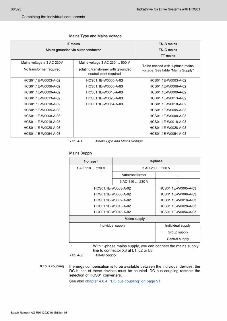
Mains Type and Mains Voltage
IT mainsMains grounded via outer conductor
TN-S mainsTN-C mains
TT mains
Mains voltage ≤ 3 AC 230V Mains voltage 3 AC 230 … 500 VTo be noticed with 1-phase mainsvoltage: See table "Mains Supply"No transformer required Isolating transformer with grounded
neutral point required
HCS01.1E-W0003-A-02HCS01.1E-W0006-A-02HCS01.1E-W0009-A-02HCS01.1E-W0013-A-02HCS01.1E-W0018-A-02HCS01.1E-W0005-A-03HCS01.1E-W0008-A-03HCS01.1E-W0018-A-03HCS01.1E-W0028-A-03HCS01.1E-W0054-A-03
HCS01.1E-W0005-A-03HCS01.1E-W0008-A-03HCS01.1E-W0018-A-03HCS01.1E-W0028-A-03HCS01.1E-W0054-A-03
HCS01.1E-W0003-A-02HCS01.1E-W0006-A-02HCS01.1E-W0009-A-02HCS01.1E-W0013-A-02HCS01.1E-W0018-A-02HCS01.1E-W0005-A-03HCS01.1E-W0008-A-03HCS01.1E-W0018-A-03HCS01.1E-W0028-A-03HCS01.1E-W0054-A-03
Tab. 4-1: Mains Type and Mains Voltage Mains Supply
1-phase1) 3-phase
1 AC 110 … 230 V 3 AC 200 ... 500 V
Autotransformer -
3 AC 110 … 230 V -
HCS01.1E-W0003-A-02HCS01.1E-W0006-A-02HCS01.1E-W0009-A-02HCS01.1E-W0013-A-02HCS01.1E-W0018-A-02
HCS01.1E-W0005-A-03HCS01.1E-W0008-A-03HCS01.1E-W0018-A-03HCS01.1E-W0028-A-03HCS01.1E-W0054-A-03
Mains supply
Individual supply Individual supply
Group supply
Central supply
1) With 1-phase mains supply, you can connect the mains supplyline to connector X3 at L1, L2 or L3
Tab. 4-2: Mains Supply
DC bus coupling If energy compensation is to be available between the individual devices, theDC buses of these devices must be coupled. DC bus coupling restricts theselection of HCS01 converters.See also chapter 4.6.4 "DC bus coupling" on page 91.
36/323
Combining the individual components
IndraDrive Cs Drive Systems with HCS01
Bosch Rexroth AG R911322210_Edition 08
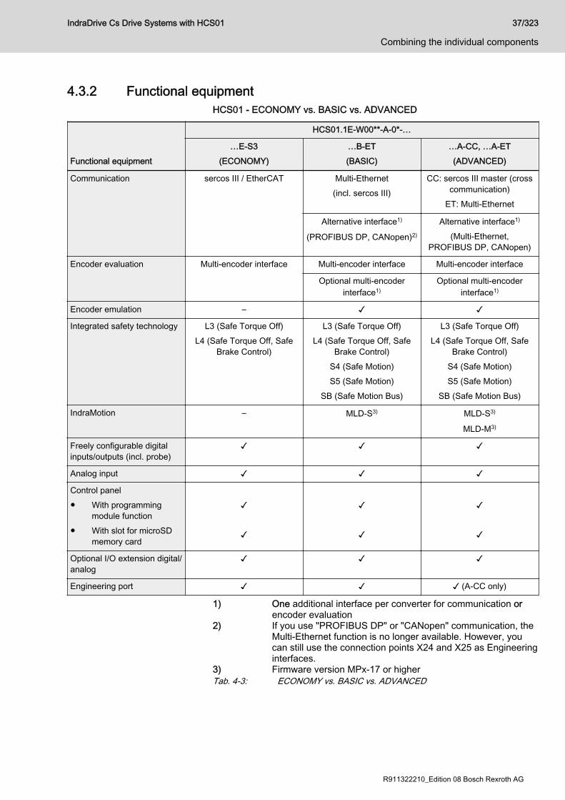
4.3.2 Functional equipmentHCS01 - ECONOMY vs. BASIC vs. ADVANCED
Functional equipment
HCS01.1E-W00**-A-0*-…
…E-S3(ECONOMY)
…B-ET(BASIC)
…A-CC, …A-ET(ADVANCED)
Communication sercos III / EtherCAT Multi-Ethernet(incl. sercos III)
CC: sercos III master (crosscommunication)
ET: Multi-Ethernet
Alternative interface1)
(PROFIBUS DP, CANopen)2)
Alternative interface1)
(Multi-Ethernet,PROFIBUS DP, CANopen)
Encoder evaluation Multi-encoder interface Multi-encoder interface Multi-encoder interface
Optional multi-encoderinterface1)
Optional multi-encoderinterface1)
Encoder emulation – ✓ ✓
Integrated safety technology L3 (Safe Torque Off)L4 (Safe Torque Off, Safe
Brake Control)
L3 (Safe Torque Off)L4 (Safe Torque Off, Safe
Brake Control)S4 (Safe Motion)S5 (Safe Motion)
SB (Safe Motion Bus)
L3 (Safe Torque Off)L4 (Safe Torque Off, Safe
Brake Control)S4 (Safe Motion)S5 (Safe Motion)
SB (Safe Motion Bus)
IndraMotion – MLD-S3) MLD-S3)
MLD-M3)
Freely configurable digitalinputs/outputs (incl. probe)
✓ ✓ ✓
Analog input ✓ ✓ ✓
Control panel● With programming
module function● With slot for microSD
memory card
✓ ✓
✓ ✓
✓ ✓
Optional I/O extension digital/analog
✓ ✓ ✓
Engineering port ✓ ✓ ✓ (A-CC only)
1) One additional interface per converter for communication orencoder evaluation
2) If you use "PROFIBUS DP" or "CANopen" communication, theMulti-Ethernet function is no longer available. However, youcan still use the connection points X24 and X25 as Engineeringinterfaces.
3) Firmware version MPx-17 or higherTab. 4-3: ECONOMY vs. BASIC vs. ADVANCED
IndraDrive Cs Drive Systems with HCS01 37/323
Combining the individual components
R911322210_Edition 08 Bosch Rexroth AG
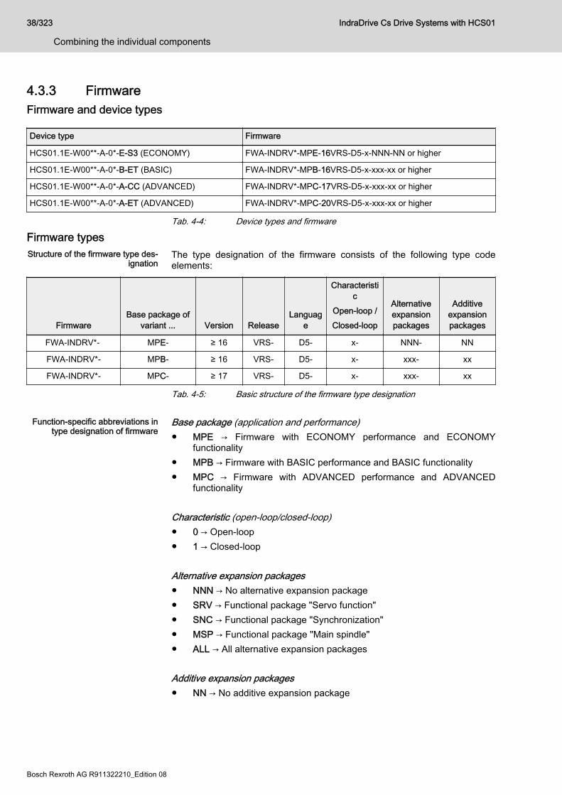
4.3.3 FirmwareFirmware and device types
Device type Firmware
HCS01.1E-W00**-A-0*-E-S3 (ECONOMY) FWA-INDRV*-MPE-16VRS-D5-x-NNN-NN or higher
HCS01.1E-W00**-A-0*-B-ET (BASIC) FWA-INDRV*-MPB-16VRS-D5-x-xxx-xx or higher
HCS01.1E-W00**-A-0*-A-CC (ADVANCED) FWA-INDRV*-MPC-17VRS-D5-x-xxx-xx or higher
HCS01.1E-W00**-A-0*-A-ET (ADVANCED) FWA-INDRV*-MPC-20VRS-D5-x-xxx-xx or higher
Tab. 4-4: Device types and firmware
Firmware typesStructure of the firmware type des‐
ignationThe type designation of the firmware consists of the following type codeelements:
FirmwareBase package of
variant ... Version ReleaseLanguag
e
Characteristic
Open-loop /Closed-loop
Alternativeexpansionpackages
Additiveexpansionpackages
FWA-INDRV*- MPE- ≥ 16 VRS- D5- x- NNN- NN
FWA-INDRV*- MPB- ≥ 16 VRS- D5- x- xxx- xx
FWA-INDRV*- MPC- ≥ 17 VRS- D5- x- xxx- xx
Tab. 4-5: Basic structure of the firmware type designation
Function-specific abbreviations intype designation of firmware
Base package (application and performance)● MPE → Firmware with ECONOMY performance and ECONOMY
functionality● MPB → Firmware with BASIC performance and BASIC functionality● MPC → Firmware with ADVANCED performance and ADVANCED
functionality Characteristic (open-loop/closed-loop)● 0 → Open-loop● 1 → Closed-loop Alternative expansion packages● NNN → No alternative expansion package● SRV → Functional package "Servo function"● SNC → Functional package "Synchronization"● MSP → Functional package "Main spindle"● ALL → All alternative expansion packages Additive expansion packages● NN → No additive expansion package
38/323
Combining the individual components
IndraDrive Cs Drive Systems with HCS01
Bosch Rexroth AG R911322210_Edition 08

● MA → IndraMotion MLD Advanced (for MPB, MPC firmware only)● ML → IndraMotion MLD for free programming; incl. use of technology
functions (for MPB, MPC firmware)
The Rexroth sales representative in charge will help you with thecurrently available firmware types.
For detailed information, see the Functional Description of the firmwareused (index entry "Overview of functions/functional packages").
IndraDrive Cs Drive Systems with HCS01 39/323
Combining the individual components
R911322210_Edition 08 Bosch Rexroth AG

Firmware variantsMPx-xxVRS
Firmware variant → MPE1) MPB MPC
Firmware characteristic → OL CL OL CL OL CL
Base package Basic functions ■ ■ ■ ■ ■ ■
Base package "open-loop" ■ ■ ■ ■ ■ ■
Base package "closed-loop" - ■ - ■ - ■
Alternative functionalpackages
Servo function - - - ■ - ■
Synchronization - - ■ ■ ■ ■
Main spindle - 2) ■ ■ ■ ■
Additive functional package IndraMotion MLD - - ■ ■ ■ ■
MPE Single-axis firmware with Economy performanceMPB Single-axis firmware with Basic performanceMPC Single-axis firmware with Advanced performanceOL Open-loop characteristicCL Closed-loop characteristic1) For Economy firmware MPE, there is only one expanded base
package available2) The expanded base package contains the "parameter set
switching" function.Tab. 4-6: Dependence of functional packages on hardware and firmware var‐
iant
40/323
Combining the individual components
IndraDrive Cs Drive Systems with HCS01
Bosch Rexroth AG R911322210_Edition 08
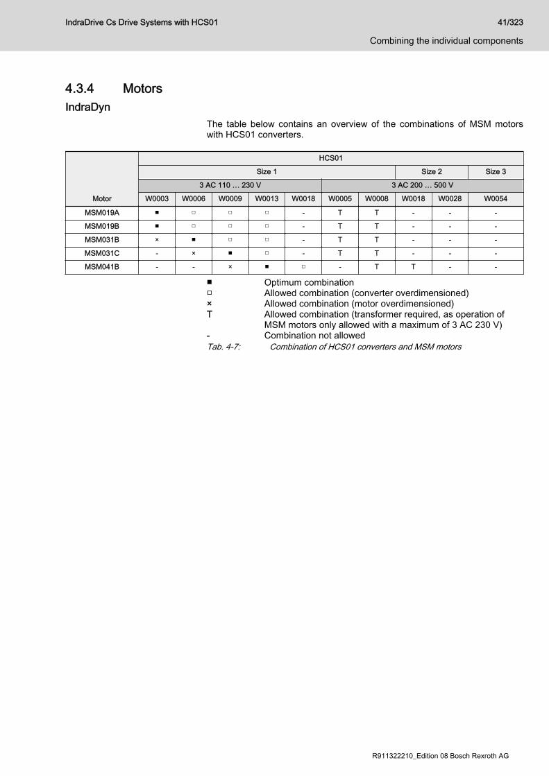
4.3.4 MotorsIndraDyn
The table below contains an overview of the combinations of MSM motorswith HCS01 converters.
Motor
HCS01
Size 1 Size 2 Size 3
3 AC 110 … 230 V 3 AC 200 … 500 V
W0003 W0006 W0009 W0013 W0018 W0005 W0008 W0018 W0028 W0054
MSM019A ■ □ □ □ - T T - - -
MSM019B ■ □ □ □ - T T - - -
MSM031B × ■ □ □ - T T - - -
MSM031C - × ■ □ - T T - - -
MSM041B - - × ■ □ - T T - -
■ Optimum combination□ Allowed combination (converter overdimensioned)× Allowed combination (motor overdimensioned)T Allowed combination (transformer required, as operation of
MSM motors only allowed with a maximum of 3 AC 230 V)- Combination not allowedTab. 4-7: Combination of HCS01 converters and MSM motors
IndraDrive Cs Drive Systems with HCS01 41/323
Combining the individual components
R911322210_Edition 08 Bosch Rexroth AG
Third-Party MotorsGeneral Information on Third-Party MotorsWhy Use Third-Party Motors at IndraDrive Cs Controllers?Today, machine axes are mainly moved with electric drives. Motors ofstandard design are used in most cases, as this is the most cost-efficientsolution.
Special Requirements Due to special requirements at machine axes, constructional or safety-relatedaspects, it may be necessary for the machine manufacturer to use a motorconstruction diverging from the standard.
Motor Design not Included inProduct Range
For these cases, there is the demand on drive suppliers to realize drives withmotors that are not included in their own product ranges due to the specialdesign.
Check Before Using Third-PartyMotors
At drive controllers of the IndraDrive Cs range, it is possible to use third-partymotors. For this purpose, check whether the third-party motor complies withthe requirements of use.The Functional Description of the firmware contains forms for motor data.Procure the completed forms for the performance test of a third-party motor.
Which are the Important Directives?In accordance with the legal regulations (EU Directive EMC 89/336/EEC andthe German EMC laws), installations and machines must be designed andbuilt in accordance with the present state-of-the-art of standardization.In order to comply with the machine directives regarding "electromagneticcompatibility (EMC)", a conformity test of the drive system (motor withcontroller and connection design) must be carried out. The machinemanufacturer must guarantee the test of the drive system and compliancewith the directives.
Third-Party Motors to be ControlledMotor Types The following motor types can be controlled:
● Asynchronous motors, rotary● Asynchronous motors, linear● Synchronous motors, rotary● Synchronous motors, linearThese motors can be operated within the scope of the technical data of theselected IndraDrive Cs controller. If motors have been provided with aholding brake, it should be controlled via the drive controller. Make sure thatthe relevant technical data of the motor holding brake are complying withthose of the holding brake output!
For third-party motors Rexroth, as a matter of principle, does notassume the guarantee for the power data at the motor shaft!
Synchronous Motors For synchronous motors with motor encoder, the commutation offset must beset during commissioning. The drive firmware provides several methods fordetermining this offset so that it is possible to determine the value for differentmotor characteristics.
42/323
Combining the individual components
IndraDrive Cs Drive Systems with HCS01
Bosch Rexroth AG R911322210_Edition 08
Observe the restrictions in conjunction with the commutationoffset determination when using synchronous motors! Seefirmware documentation, chapter "Drive Control", "CommutationSetting".Possibly available reluctance property cannot be used forsynchronous third-party motors! For third-party motors, it isimpossible to determine fail-safe motor parameter values forusing the reluctance property. The respective bit of "P-0-4014,Type of construction of motor" therefore mustn't be set!
Requirements on Third-Party MotorsGeneral InformationFor successful and fail-safe use of a third-party motor, check● whether the third-party motor to be controlled satisfies the voltage loads● which drive controller is suitable due to the motor torques to be
delivered● whether the third-party motor has the required minimum inductance● whether the motor can be protected against inadmissible temperature
rise in the case of overload (temperature evaluation)● whether the mounted position measuring system can be evaluated by
the drive controller or which position measuring system can be selectedfor kit motors
Voltage Load of the Third-Party MotorThe voltage load of the insulation system of a motor occurring in practicalapplication is mainly influenced by the following characteristics:● The output variables of the drive controller which is used (feed the
transmission distance)● Cable parameters depending on cable design and length (determine the
properties of the transmission distance, such as the attenuation)● The motor design regarding capacitive and inductive properties (form
the end of the transmission distance)As a result of the variables, the insulation system of the third-party motor, asregards voltage, is loaded by the following values:● Periodic peak voltage Upp and● Voltage change dv/dtThe occurring periodic peak voltages at the motor terminals are caused byreflections at the motor cable end. The insulation of the motor is therebyloaded with a higher peak voltage than the one occurring at the output of thepower section.
Determine the occurring voltage load at the terminals of the third-party motor in the application with all involved components.
Using the HMF Motor Filter Use voltage-reducing components (e.g. motor filter HMF), if one of thefollowing criteria applies:● Allowed voltage change (dv/dt) of third-party motor: < 5 kV/μs● With mains voltage 3 AC 230 V … 500 V:
Allowed periodic peak voltage (crest value) of third-party motor betweenphase-phase and phase-housing: < 1,500 V
IndraDrive Cs Drive Systems with HCS01 43/323
Combining the individual components
R911322210_Edition 08 Bosch Rexroth AG
● With mains voltage up to 3 AC 230 V:Allowed periodic peak voltage (crest value) of third-party motor betweenphase-phase and phase-housing: < 850 V(To operate motors which do not require any voltage-reducingcomponents at this mains voltage, the switch-on threshold of the brakingresistor must be reduced to DC 430 V for devices with the mainsconnection voltage identifier "03"!)
● The voltage change (dv/dt) and periodic peak voltage (Upp) at the motorterminals are influenced by the length and the electrical properties of themotor cable:– The longer the motor cable, the higher the degree of voltage
overshoot (periodic peak voltage) at the motor-side cable end. Witha cable length of approx. 25 m and more, the maximum periodicpeak voltage occurs. Further voltage increase is not to be expectedeven with longer cables.
– With cable lengths of less than 15 m, the periodic peak voltage isreduced, depending on the length and as compared to thespecified maximum value, down to the DC bus voltage value.
Apart from the nominal current IN, especially take the maximumallowed switching frequency of the power output stage (fs) intoaccount with which the motor filter HMF may be operated.Verify the success of the voltage-reducing measures bymeasuring the voltage at the motor terminals. Use an isolatedmeasuring device!
Minimum Inductance of Third-Party MotorDepending on the drive controller used, the motor has to have a minimumvalue for inductance. The actually available inductance of a motor can bemeasured directly between two motor terminals by means of an inductancemeasuring bridge. The measurement has to be made for a complete motorwired for normal operation but not yet connected. During the measurement,one motor terminal remains open! For asynchronous motors, the measuredvalue can only be used if the rotor doesn't have closed slots!
Drive controller Minimum required motor inductance
HCS01 with 3 × AC 230 V LU-V = 60 × 4 / (√2 × ITyp × fs) (in mH)
HCS01 with 3 × AC 400 V LU-V = 80 × 4 / (√2 × ITyp × fs) (in mH)
HCS01 with 3 × AC 480 V LU-V = 116 × 4 / (√2 × ITyp × fs) (in mH)
ITyp Maximum current of drive controller according to type code(rms value)
fs Desired switching frequency in kHzTab. 4-8: Minimum Inductances Depending on Drive Controller Data, Supply
Units and Supply VoltageInstall a three-phase choke in the motor feed wire, if the inductance of thethird-party motor is smaller than indicated in the table above. This choke hasto increase the inductance that can be measured between two motorterminals to the minimum value.
44/323
Combining the individual components
IndraDrive Cs Drive Systems with HCS01
Bosch Rexroth AG R911322210_Edition 08
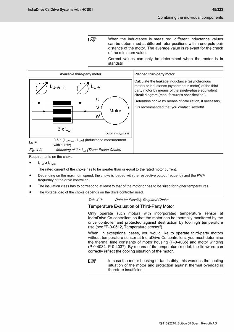
When the inductance is measured, different inductance valuescan be determined at different rotor positions within one pole pairdistance of the motor. The average value is relevant for the checkof the minimum value.Correct values can only be determined when the motor is instandstill!
Available third-party motor Planned third-party motor
LDr =0.5 × (LU-Vmin - LU-V) (inductance measurementwith 1 kHz)
Fig. 4-2: Mounting of 3 × LDr (Three-Phase Choke)
Calculate the leakage inductance (asynchronousmotor) or inductance (synchronous motor) of the third-party motor by means of the single-phase equivalentcircuit diagram (manufacturer's specification!).Determine choke by means of calculation, if necessary.It is recommended that you contact Rexroth!
Requirements on the choke:● In_Dr ≥ In_Mot
The rated current of the choke has to be greater than or equal to the rated motor current.● Depending on the maximum speed, the choke is loaded with the respective output frequency and the PWM
frequency of the drive controller.● The insulation class has to correspond at least to that of the motor or has to be sized for higher temperatures.● The voltage load of the choke depends on the drive controller used.
Tab. 4-9: Data for Possibly Required Choke
Temperature Evaluation of Third-Party MotorOnly operate such motors with incorporated temperature sensor atIndraDrive Cs controllers so that the motor can be thermally monitored by thedrive controller and protected against destruction by too high temperaturerise (see "P-0-0512, Temperature sensor").When, in exceptional cases, you would like to operate third-party motorswithout temperature sensor at IndraDrive Cs controllers, you must determinethe thermal time constants of motor housing (P-0-4035) and motor winding(P-0-4034, P-0-4037). By means of its temperature model, the firmware cancorrectly reflect the cooling situation of the motor.
In case the motor housing or fan is dirty, this worsens the coolingsituation of the motor and protection against thermal overload istherefore insufficient!
IndraDrive Cs Drive Systems with HCS01 45/323
Combining the individual components
R911322210_Edition 08 Bosch Rexroth AG
Requirements on the Encoder of the Third-Party MotorMotor Encoder of Asynchronous Third-Party MotorAsynchronous motors can also be controlled by IndraDrive Cs controllers in"open-loop" operation (without motor encoder). In "closed-loop" operation(with motor encoder), a relative measuring system is sufficient forasynchronous motors.
Motor Encoder of Synchronous Third-Party MotorFor fail-safe drives with synchronous third-party motors at IndraDrive Cscontrollers, the following possible combinations or restrictions have to betaken into account when selecting the measuring system:
Drive range Motor measuring system Synchronous third-partymotor
IndraDrive CsAbsolute ■
Relative □
■ Advantageous combination□ Combination is possible (restrictions specific to application),
commissioning may be more complicated!Tab. 4-10: Possible Combinations of Synchronous Third-Party Motor and Motor
Measuring System
The drive controller can evaluate measuring systems as motorencoder when they are contained in "P-0-0074, Encoder type 1(motor encoder)".For information on absolute and relative measuring systems, seesection "Measuring Systems" of firmware documentation!
Motor Encoder Resolver - Notes on SelectionResolvers must first be checked as to whether they are suited as motorencoders. To check whether they can be evaluated by the drive controllers,the following resolver data are required:● Data of resolver system to be compared must be available at 8 kHz● Ratio● Current consumption● DC resistance of stator● Number of poles● Phase shiftBy means of the resolver data, check whether the supply voltage of theencoder interface and the signal levels of the encoder tracks are sufficient.
Notes on Selection and CommissioningSelecting the Controller as Regards Continuous CurrentThe drive controller required for the respective motor is determined bycomparing the motor data to the device data.
The continuous current of the drive controller should be greaterthan the continuous current of the motor.The continuous power of the drive controller must be greater thanthe required average power!
46/323
Combining the individual components
IndraDrive Cs Drive Systems with HCS01
Bosch Rexroth AG R911322210_Edition 08

Selecting the Connection TechniqueFor the available power cables and encoder cables, see documentation"Rexroth Connection Cables IndraDrive and IndraDyn".
Notes on Commissioning
For further information, notes on commissioning and supportingdocuments (e.g., forms for entering the required data) seefirmware documentation.
IndraDrive Cs Drive Systems with HCS01 47/323
Combining the individual components
R911322210_Edition 08 Bosch Rexroth AG
4.3.5 CablesMotor power cables
SelectionHow to select a suitable motor power cable:See documentation "Rexroth Connection Cables IndraDrive and IndraDyn"(R911322949).
Allowed cable lengthsAllowed cable lengths at ambient temperature Ta_work ≤ 40 °C according toEN 60 204:
HCS01.1E-…-A-02
PWM frequency [kHz]
4 8 12 16
W0003 40 m 20 m 15 m 5 m
W0006
W0009
W0013
W0018
HCS01.1E-…-A-03
W0005
W0008
W0018
W0028
W0054 75 m 38 m 25 m -
Tab. 4-11: Allowed motor cable lengths
48/323
Combining the individual components
IndraDrive Cs Drive Systems with HCS01
Bosch Rexroth AG R911322210_Edition 08

Encoder cablesMSM motors
HCS01
Size 1 Size 2 Size 3
3 AC 110 … 230 V 3 AC 200 … 500 V
Motor W0003 W0006 W0009 W0013 W0018 W0005 W0008 W0018 W0028 W0054
MSM019A-…-M
RKG0062; RKG0065; RKG0063 (extension, optional)
- - -
MSM019B-…-M - - -
MSM031B-…-M - - -
MSM031C-…-M - - -
MSM041B-…-M RKG0062; RKG0065; RKG0063 (extension, optional) - -
- Combination not allowedTab. 4-12: Encoder cables for HCS01 converters and MSM motors
Encoder cable length See chapter "Encoder cable length" on page 189
MS2N motors
MS2N encoders Encoder cables
AS/AM, BS/BM RG2-002AB; RG2-500AB (extension, optional)
CS/CM, HS/HM, DS/DM RG2-002AA; RG2-510AA (extension, optional)
Tab. 4-13: Encoder cables for HCS01 converters and MS2N motorsEncoder cable length See chapter "Encoder cable length" on page 189
MSK motorsSee documentation "Rexroth Connection Cables IndraDrive and IndraDyn" →Selection for Encoder Cables.
4.4 Installation conditions4.4.1 Ambient and operating conditions
Lethal electric shock by live parts with morethan 50 V!
WARNING
Only operate the device● with the connectors plugged on (even if no lines have been connected
to the connectors) and● with the equipment grounding conductor connected!
Control cabinet The devices in the IndraDrive Cs product range, as well as their additionalcomponents (except for some braking resistors), have to be mounted incontrol cabinets.Check that the ambient and operating conditions, in particular the controlcabinet temperature, are observed by calculating the heat levels in thecontrol cabinet. Afterwards, make the corresponding measurements toconfirm that ambient and operating conditions have actually been observed.
IndraDrive Cs Drive Systems with HCS01 49/323
Combining the individual components
R911322210_Edition 08 Bosch Rexroth AG
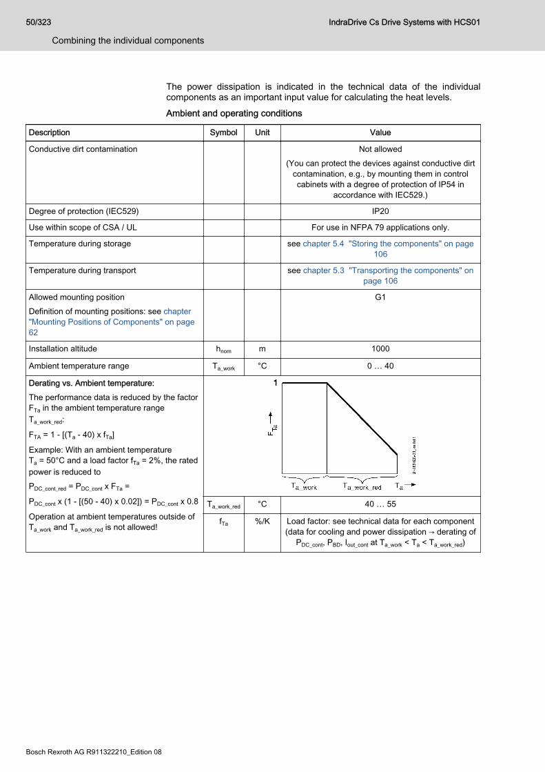
The power dissipation is indicated in the technical data of the individualcomponents as an important input value for calculating the heat levels.Ambient and operating conditions
Description Symbol Unit Value
Conductive dirt contamination Not allowed(You can protect the devices against conductive dirt
contamination, e.g., by mounting them in controlcabinets with a degree of protection of IP54 in
accordance with IEC529.)
Degree of protection (IEC529) IP20
Use within scope of CSA / UL For use in NFPA 79 applications only.
Temperature during storage see chapter 5.4 "Storing the components" on page106
Temperature during transport see chapter 5.3 "Transporting the components" onpage 106
Allowed mounting positionDefinition of mounting positions: see chapter"Mounting Positions of Components" on page62
G1
Installation altitude hnom m 1000
Ambient temperature range Ta_work °C 0 … 40
Derating vs. Ambient temperature:The performance data is reduced by the factorFTa in the ambient temperature rangeTa_work_red:
FTA = 1 - [(Ta - 40) x fTa]
Example: With an ambient temperatureTa = 50°C and a load factor fTa = 2%, the ratedpower is reduced toPDC_cont_red = PDC_cont x FTa =
PDC_cont x (1 - [(50 - 40) x 0.02]) = PDC_cont x 0.8
Operation at ambient temperatures outside ofTa_work and Ta_work_red is not allowed!
Ta_work_red °C 40 … 55
fTa %/K Load factor: see technical data for each component(data for cooling and power dissipation → derating of
PDC_cont, PBD, Iout_cont at Ta_work < Ta < Ta_work_red)
50/323
Combining the individual components
IndraDrive Cs Drive Systems with HCS01
Bosch Rexroth AG R911322210_Edition 08
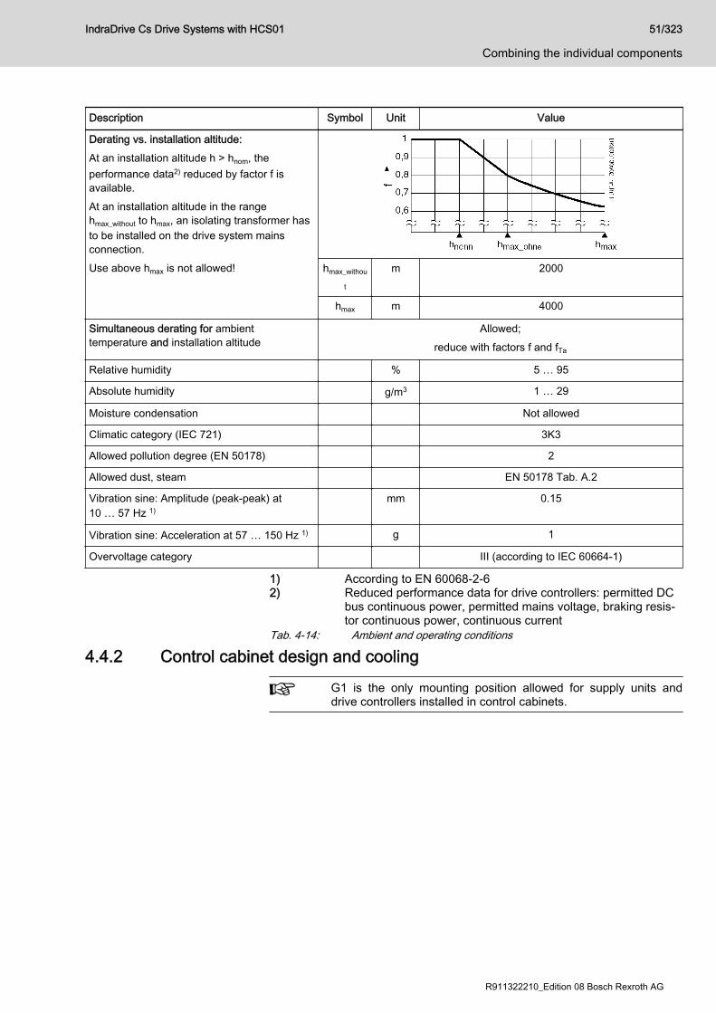
Description Symbol Unit Value
Derating vs. installation altitude:At an installation altitude h > hnom, theperformance data2) reduced by factor f isavailable.At an installation altitude in the rangehmax_without to hmax, an isolating transformer hasto be installed on the drive system mainsconnection.Use above hmax is not allowed! hmax_withou
t
m 2000
hmax m 4000
Simultaneous derating for ambienttemperature and installation altitude
Allowed;reduce with factors f and fTa
Relative humidity % 5 … 95
Absolute humidity g/m3 1 … 29
Moisture condensation Not allowed
Climatic category (IEC 721) 3K3
Allowed pollution degree (EN 50178) 2
Allowed dust, steam EN 50178 Tab. A.2
Vibration sine: Amplitude (peak-peak) at10 … 57 Hz 1)
mm 0.15
Vibration sine: Acceleration at 57 … 150 Hz 1) g 1
Overvoltage category III (according to IEC 60664-1)
1) According to EN 60068-2-62) Reduced performance data for drive controllers: permitted DC
bus continuous power, permitted mains voltage, braking resis‐tor continuous power, continuous current
Tab. 4-14: Ambient and operating conditions
4.4.2 Control cabinet design and cooling
G1 is the only mounting position allowed for supply units anddrive controllers installed in control cabinets.
IndraDrive Cs Drive Systems with HCS01 51/323
Combining the individual components
R911322210_Edition 08 Bosch Rexroth AG
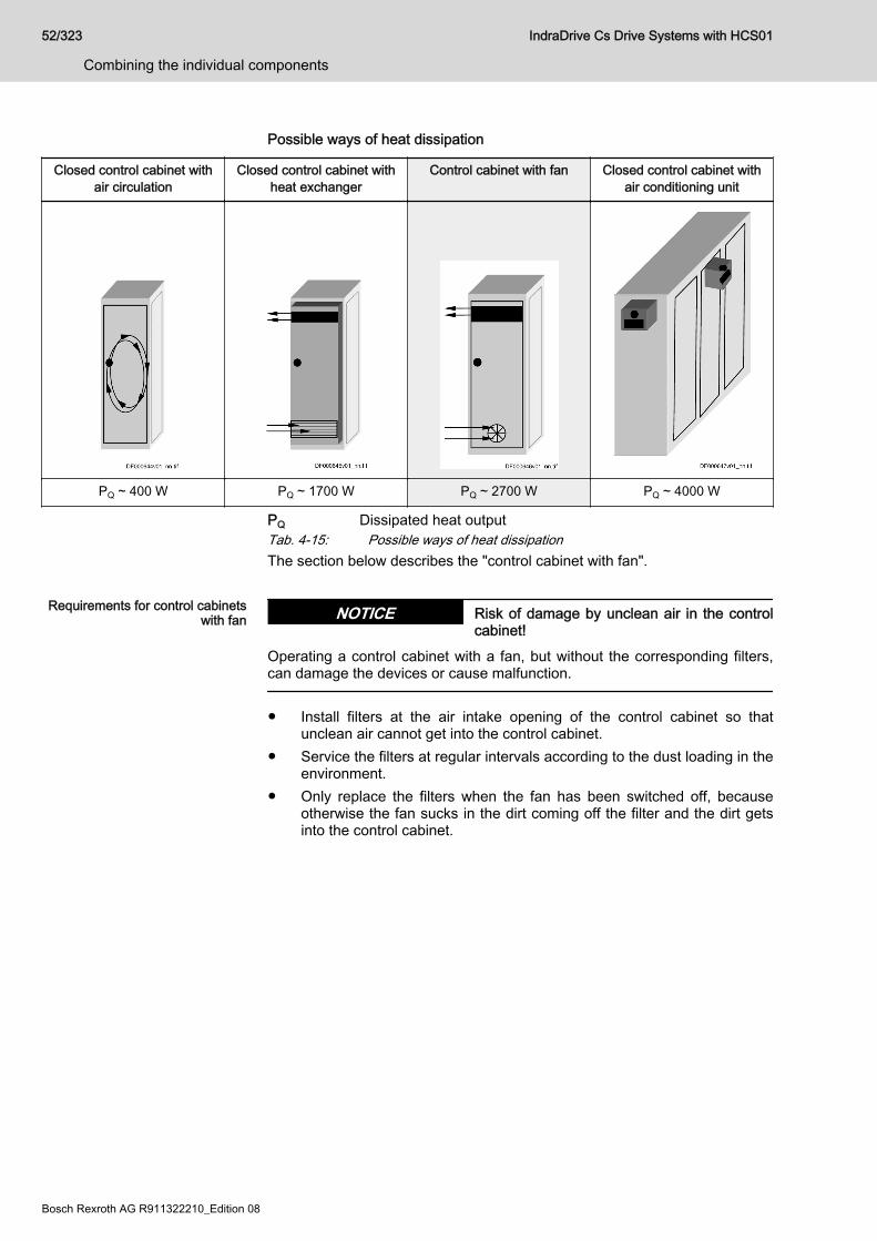
Possible ways of heat dissipation
Closed control cabinet withair circulation
Closed control cabinet withheat exchanger
Control cabinet with fan Closed control cabinet withair conditioning unit
PQ ~ 400 W PQ ~ 1700 W PQ ~ 2700 W PQ ~ 4000 W
PQ Dissipated heat outputTab. 4-15: Possible ways of heat dissipationThe section below describes the "control cabinet with fan".
Requirements for control cabinetswith fan Risk of damage by unclean air in the control
cabinet!NOTICE
Operating a control cabinet with a fan, but without the corresponding filters,can damage the devices or cause malfunction.
● Install filters at the air intake opening of the control cabinet so thatunclean air cannot get into the control cabinet.
● Service the filters at regular intervals according to the dust loading in theenvironment.
● Only replace the filters when the fan has been switched off, becauseotherwise the fan sucks in the dirt coming off the filter and the dirt getsinto the control cabinet.
52/323
Combining the individual components
IndraDrive Cs Drive Systems with HCS01
Bosch Rexroth AG R911322210_Edition 08
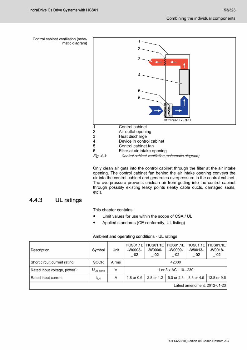
Control cabinet ventilation (sche‐matic diagram)
1 Control cabinet2 Air outlet opening3 Heat discharge4 Device in control cabinet5 Control cabinet fan6 Filter at air intake openingFig. 4-3: Control cabinet ventilation (schematic diagram) Only clean air gets into the control cabinet through the filter at the air intakeopening. The control cabinet fan behind the air intake opening conveys theair into the control cabinet and generates overpressure in the control cabinet.The overpressure prevents unclean air from getting into the control cabinetthrough possibly existing leaky points (leaky cable ducts, damaged seals,etc.).
4.4.3 UL ratingsThis chapter contains:● Limit values for use within the scope of CSA / UL● Applied standards (CE conformity, UL listing) Ambient and operating conditions - UL ratings
Description Symbol UnitHCS01.1E-W0003-
_-02
HCS01.1E-W0006-
_-02
HCS01.1E-W0009-
_-02
HCS01.1E-W0013-
_-02
HCS01.1E-W0018-
_-02
Short circuit current rating SCCR A rms 42000
Rated input voltage, power1) ULN_nenn V 1 or 3 x AC 110...230
Rated input current ILN A 1.8 or 0.6 2.8 or 1.2 5.0 or 2.3 8.3 or 4.5 12.8 or 9.6
Latest amendment: 2012-01-23
IndraDrive Cs Drive Systems with HCS01 53/323
Combining the individual components
R911322210_Edition 08 Bosch Rexroth AG
Description Symbol UnitHCS01.1E-W0003-
_-02
HCS01.1E-W0006-
_-02
HCS01.1E-W0009-
_-02
HCS01.1E-W0013-
_-02
HCS01.1E-W0018-
_-02
Output voltage Uout V 3 x AC 0...230
Output current Iout A 1.1 2.0 3.0 4.5 7.6
Latest amendment: 2012-01-23
1) Mains input L1, L2, L3 (for HMV and HCS only); For use on asolidly grounded wye source only.
Tab. 4-16: HCS - Ambient and operating conditions - UL ratingsAmbient and operating conditions - UL ratings
Description Symbol UnitHCS01.1E-W0005-
_-03
HCS01.1E-W0008-
_-03
HCS01.1E-W0018-
_-03
HCS01.1E-W0028-
_-03
HCS01.1E-W0054-
_-03
Short circuit current rating SCCR A rms 42000
Rated input voltage, power1) ULN_nenn V 3 x AC 200...500
Rated input current ILN A 1.5 2.5 5.0 10.0 28.0
Output voltage Uout V 3 x AC 0...500
Output current Iout A 1.7 2.7 7.6 11.5 21.0
Latest amendment: 2013-01-10
1) Mains input L1, L2, L3 (for HMV and HCS only); For use on asolidly grounded wye source only.
Tab. 4-17: HCS - Ambient and operating conditions - UL ratings
4.4.4 Compatibility with foreign mattersAll Rexroth controls and drives are developed and tested according to thestate-of-the-art technology.As it is impossible to follow the continuing development of all materials (e.g.lubricants in machine tools) which may interact with the controls and drives, itcannot be completely ruled out that any reactions with the materials we usemight occur.For this reason, before using the respective material a compatibility test hasto be carried out for new lubricants, cleaning agents etc. and our housings/materials.
4.5 Mechanical project planning4.5.1 Drive controllerDimensional Drawings
Options for Mounting ● Standard mounting:The back of the device is directly mounted to the mounting surface inthe control cabinet
● Left-hand or right-hand mounting:The left or right side of the device is directly mounted to the mountingsurface in the control cabinet
54/323
Combining the individual components
IndraDrive Cs Drive Systems with HCS01
Bosch Rexroth AG R911322210_Edition 08
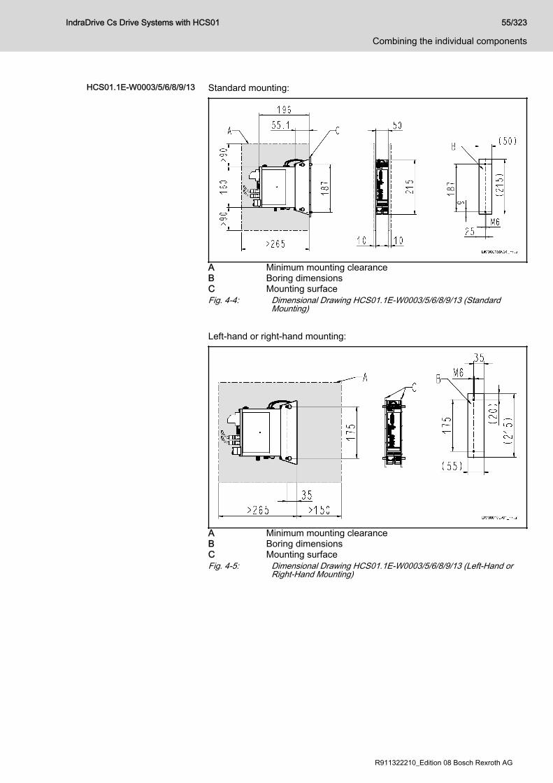
HCS01.1E-W0003/5/6/8/9/13 Standard mounting:
A Minimum mounting clearanceB Boring dimensionsC Mounting surfaceFig. 4-4: Dimensional Drawing HCS01.1E-W0003/5/6/8/9/13 (Standard
Mounting) Left-hand or right-hand mounting:
A Minimum mounting clearanceB Boring dimensionsC Mounting surfaceFig. 4-5: Dimensional Drawing HCS01.1E-W0003/5/6/8/9/13 (Left-Hand or
Right-Hand Mounting)
IndraDrive Cs Drive Systems with HCS01 55/323
Combining the individual components
R911322210_Edition 08 Bosch Rexroth AG
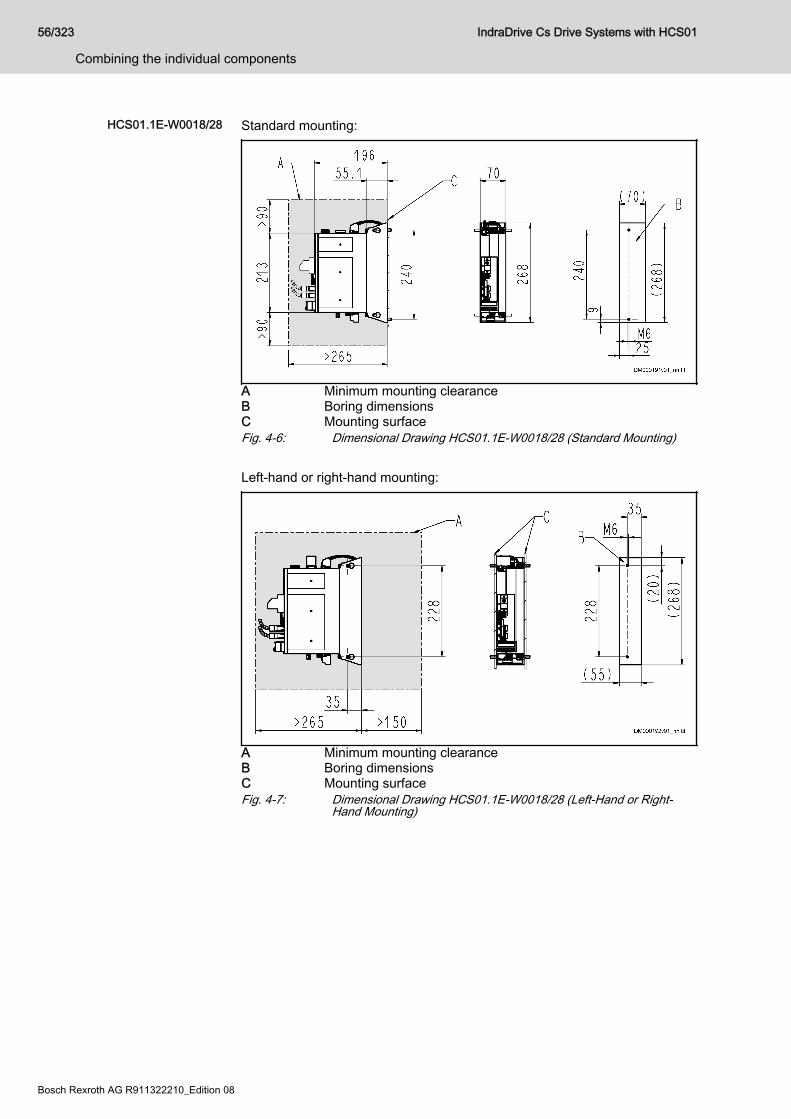
HCS01.1E-W0018/28 Standard mounting:
A Minimum mounting clearanceB Boring dimensionsC Mounting surfaceFig. 4-6: Dimensional Drawing HCS01.1E-W0018/28 (Standard Mounting) Left-hand or right-hand mounting:
A Minimum mounting clearanceB Boring dimensionsC Mounting surfaceFig. 4-7: Dimensional Drawing HCS01.1E-W0018/28 (Left-Hand or Right-
Hand Mounting)
56/323
Combining the individual components
IndraDrive Cs Drive Systems with HCS01
Bosch Rexroth AG R911322210_Edition 08

HCS01.1E-W0054 Standard mounting:
A Minimum mounting clearanceB Boring dimensionsC Mounting surfaceFig. 4-8: Dimensional Drawing HCS01.1E-W0054 (Standard Mounting) Left-hand or right-hand mounting:
A Minimum mounting clearanceB Boring dimensionsC Mounting surfaceFig. 4-9: Dimensional Drawing HCS01.1E-W0054 (Left-Hand or Right-Hand
Mounting)
IndraDrive Cs Drive Systems with HCS01 57/323
Combining the individual components
R911322210_Edition 08 Bosch Rexroth AG

Dimensions, mass, insulation, sound pressure levelData for mass, dimensions, sound pressure level, insulation
Description Symbol UnitHCS01.1E-W0003-
_-02
HCS01.1E-W0006-
_-02
HCS01.1E-W0009-
_-02
HCS01.1E-W0013-
_-02
HCS01.1E-W0018-
_-02
Mass m kg 1.30 2.10
Device height1) H mm 215 268
Device depth2) T mm 196
Device width3) B mm 50 70
Insulation resistance at 500 V DC Ris Mohm 10.00
Capacitance against housing CY nF 2 x 68 2 x 100
Latest amendment: 2018-05-29
1) 2) 3) Housing dimension; see also related dimensional drawingTab. 4-18: HCS - Data for mass, dimensions, sound pressure level, insulationData for mass, dimensions, sound pressure level, insulation
Description Symbol UnitHCS01.1E-W0005-
_-03
HCS01.1E-W0008-
_-03
HCS01.1E-W0018-
_-03
HCS01.1E-W0028-
_-03
HCS01.1E-W0054-
_-03
Mass m kg 1.30 2.10 4.60
Device height1) H mm 215 268
Device depth2) T mm 196
Device width3) B mm 50 70 130
Insulation resistance at 500 V DC Ris Mohm 10.00
Capacitance against housing CY nF 2 x 68 2 x 100
Latest amendment: 2018-05-29
1) 2) 3) Housing dimension; see also related dimensional drawingTab. 4-19: HCS - Data for mass, dimensions, sound pressure level, insulation
58/323
Combining the individual components
IndraDrive Cs Drive Systems with HCS01
Bosch Rexroth AG R911322210_Edition 08
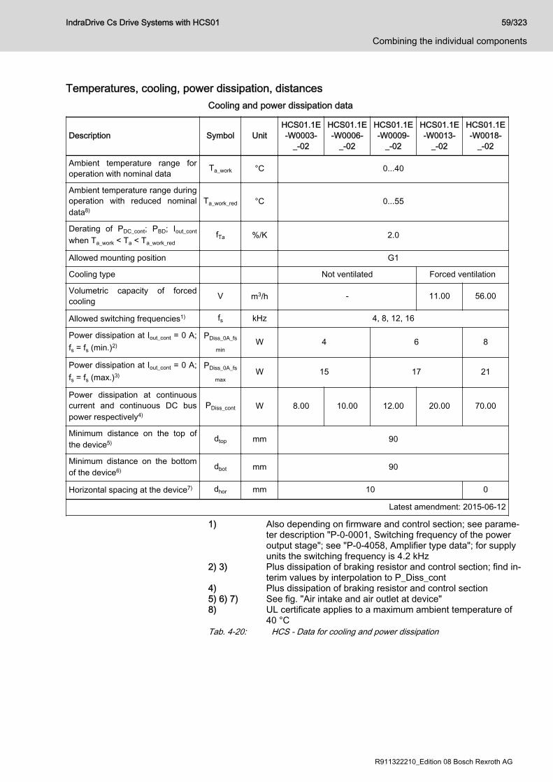
Temperatures, cooling, power dissipation, distancesCooling and power dissipation data
Description Symbol UnitHCS01.1E-W0003-
_-02
HCS01.1E-W0006-
_-02
HCS01.1E-W0009-
_-02
HCS01.1E-W0013-
_-02
HCS01.1E-W0018-
_-02
Ambient temperature range foroperation with nominal data Ta_work °C 0...40
Ambient temperature range duringoperation with reduced nominaldata8)
Ta_work_red °C 0...55
Derating of PDC_cont; PBD; Iout_cont
when Ta_work < Ta < Ta_work_redfTa %/K 2.0
Allowed mounting position G1
Cooling type Not ventilated Forced ventilation
Volumetric capacity of forcedcooling V m3/h - 11.00 56.00
Allowed switching frequencies1) fs kHz 4, 8, 12, 16
Power dissipation at Iout_cont = 0 A;fs = fs (min.)2)
PDiss_0A_fs
minW 4 6 8
Power dissipation at Iout_cont = 0 A;fs = fs (max.)3)
PDiss_0A_fs
maxW 15 17 21
Power dissipation at continuouscurrent and continuous DC buspower respectively4)
PDiss_cont W 8.00 10.00 12.00 20.00 70.00
Minimum distance on the top ofthe device5) dtop mm 90
Minimum distance on the bottomof the device6) dbot mm 90
Horizontal spacing at the device7) dhor mm 10 0
Latest amendment: 2015-06-12
1) Also depending on firmware and control section; see parame‐ter description "P-0-0001, Switching frequency of the poweroutput stage"; see "P-0-4058, Amplifier type data"; for supplyunits the switching frequency is 4.2 kHz
2) 3) Plus dissipation of braking resistor and control section; find in‐terim values by interpolation to P_Diss_cont
4) Plus dissipation of braking resistor and control section5) 6) 7) See fig. "Air intake and air outlet at device"8) UL certificate applies to a maximum ambient temperature of
40 °CTab. 4-20: HCS - Data for cooling and power dissipation
IndraDrive Cs Drive Systems with HCS01 59/323
Combining the individual components
R911322210_Edition 08 Bosch Rexroth AG

Cooling and power dissipation data
Description Symbol UnitHCS01.1E-W0005-
_-03
HCS01.1E-W0008-
_-03
HCS01.1E-W0018-
_-03
HCS01.1E-W0028-
_-03
HCS01.1E-W0054-
_-03
Ambient temperature range foroperation with nominal data Ta_work °C 0...40
Ambient temperature range duringoperation with reduced nominaldata8)
Ta_work_red °C 0...55
Derating of PDC_cont; PBD; Iout_cont
when Ta_work < Ta < Ta_work_redfTa %/K 2.0
Allowed mounting position G1
Cooling type Forced ventilation
Volumetric capacity of forcedcooling V m3/h 11.00 56.00 113.00
Allowed switching frequencies1) fs kHz 4, 8, 12, 16 4, 8, 12
Power dissipation at Iout_cont = 0 A;fs = fs (min.)2)
PDiss_0A_fs
minW 23 30 36 55
Power dissipation at Iout_cont = 0 A;fs = fs (max.)3)
PDiss_0A_fs
maxW 65 85 91 135
Power dissipation at continuouscurrent and continuous DC buspower respectively4)
PDiss_cont W 37.00 46.00 80.00 120.00 400.00
Minimum distance on the top ofthe device5) dtop mm 90
Minimum distance on the bottomof the device6) dbot mm 90
Horizontal spacing at the device7) dhor mm 10 0
Latest amendment: 2014-09-23*
1) Also depending on firmware and control section; see parame‐ter description "P-0-0001, Switching frequency of power outputstage"; see "P-0-4058, Amplifier type data"
2) 3) Plus dissipation of braking resistor and control section; find in‐terim values by interpolation to P_Diss_cont
4) Plus dissipation of braking resistor and control section5) 6) 7) See fig. "Air intake and air outlet at device"8) UL certificate applies to a maximum ambient temperature of
40 °CTab. 4-21: HCS - Data for cooling and power dissipation
60/323
Combining the individual components
IndraDrive Cs Drive Systems with HCS01
Bosch Rexroth AG R911322210_Edition 08
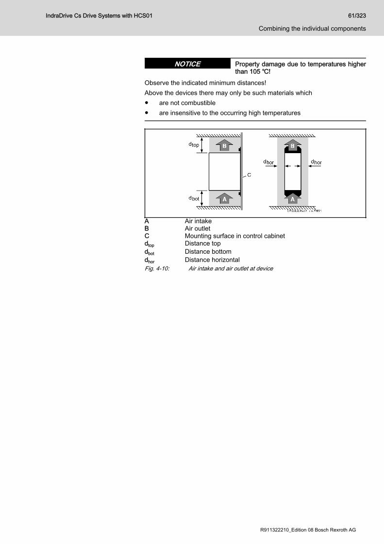
Property damage due to temperatures higherthan 105 ℃!
NOTICE
Observe the indicated minimum distances!Above the devices there may only be such materials which● are not combustible● are insensitive to the occurring high temperatures
A Air intakeB Air outletC Mounting surface in control cabinetdtop Distance topdbot Distance bottomdhor Distance horizontalFig. 4-10: Air intake and air outlet at device
IndraDrive Cs Drive Systems with HCS01 61/323
Combining the individual components
R911322210_Edition 08 Bosch Rexroth AG
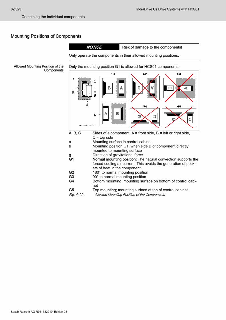
Mounting Positions of Components
Risk of damage to the components!NOTICE
Only operate the components in their allowed mounting positions.
Allowed Mounting Position of theComponents
Only the mounting position G1 is allowed for HCS01 components.
A, B, C Sides of a component: A = front side, B = left or right side,C = top side
a Mounting surface in control cabinetb Mounting position G1, when side B of component directly
mounted to mounting surfaceg Direction of gravitational forceG1 Normal mounting position: The natural convection supports the
forced cooling air current. This avoids the generation of pock‐ets of heat in the component.
G2 180° to normal mounting positionG3 90° to normal mounting positionG4 Bottom mounting; mounting surface on bottom of control cabi‐
netG5 Top mounting; mounting surface at top of control cabinetFig. 4-11: Allowed Mounting Position of the Components
62/323
Combining the individual components
IndraDrive Cs Drive Systems with HCS01
Bosch Rexroth AG R911322210_Edition 08
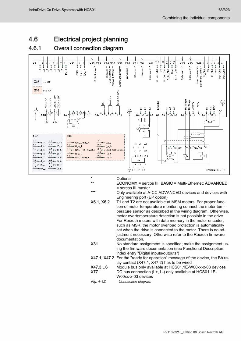
4.6 Electrical project planning4.6.1 Overall connection diagram
* Optional** ECONOMY = sercos III; BASIC = Multi-Ethernet; ADVANCED
= sercos III master*** Only available at A-CC ADVANCED devices and devices with
Engineering port (EP option)X6.1, X6.2 T1 and T2 are not available at MSM motors. For proper func‐
tion of motor temperature monitoring connect the motor tem‐perature sensor as described in the wiring diagram. Otherwise,motor overtemperature detection is not possible in the drive.For Rexroth motors with data memory in the motor encoder,such as MSK, the motor overload protection is automaticallyset when the drive is connected to the motor. There is no ad‐justment necessary. Otherwise refer to the Rexroth firmwaredocumentation.
X31 No standard assignment is specified; make the assignment us‐ing the firmware documentation (see Functional Description,index entry "Digital inputs/outputs")
X47.1, X47.2 For the "ready for operation" message of the device, the Bb re‐lay contact (X47.1, X47.2) has to be wired
X47.3…6 Module bus only available at HCS01.1E-W00xx-x-03 devicesX77 DC bus connection (L+, L-) only available at HCS01.1E-
W00xx-x-03 devicesFig. 4-12: Connection diagram
IndraDrive Cs Drive Systems with HCS01 63/323
Combining the individual components
R911322210_Edition 08 Bosch Rexroth AG
4.6.2 Project planning of control voltageControl voltage for drive systems
Some components of a drive system have to be supplied with control voltage.When doing the project planning for control voltage supply, take therequirements of the drive system components into account:● Allowed tolerances of the supply voltage depending on the length of the
motor cable and the use of motor holding brakes● Power consumption of the drive controllers● Power consumption of other loads (e.g., motor holding brakes, digital
outputs)● Current carrying capacity of the connection point for control voltage
supply at the component for the purpose of looping through the controlvoltage to other components
PELV1) for 24V power supply unitFor the 24V supply of the devices of the IndraDrive Cs range, usea power supply unit or a control-power transformer with protectionby PELV according to IEC 60204-1 (section 6.4).In the scope of CSA/UL, the data of the control-power transformerare limited to:● Max. output voltage: 42.4 Vpeak or 30 Vac
● Max. output power: 10000 VA
Sizing the control voltage supplyDetermining the power requirements
Power requirement of the drivecontroller
The total power requirement of the control voltage supply of a drive controllerresults from the sum of the following power values:● Basic device (drive controller without connected encoders)● Optional connection interfaces (e.g. communication, additional encoder
evaluation)● Connected encoder systems● External loads For the configuration of your drive controller, see the type plate and the typecode.
1) Protective Extra Low Voltage
64/323
Combining the individual components
IndraDrive Cs Drive Systems with HCS01
Bosch Rexroth AG R911322210_Edition 08

Type code example:
A Basic device (maximum current [W0028 = 28 A], series [03],on-board connection point [EC])
B Control section design (E = Economy; S3 = sercos III)C Optional connection points (PB = ProfiBus; L4 = safety technol‐
ogy [STO, SBC])Fig. 4-13: HCS01 type code The tables below contain the individual power values required by the drivecontroller. The power requirement of the supplying 24V power supply unitresults from the sum of these individual power values.
Power requirement of the basicdevice
The power requirement of the basic device results from● Maximum current of drive controller● Control section designTable 1: Power requirement of the basic device
Maximum current, series 1)
HCS01.1E-…
Control section design
E-S3(ECONOMY)
B-ET(BASIC)
A-CC(ADVANCED)
W0003-A-02-x-xx-EC 8.1 W 12.7 W 13.4 W
W0006-A-02-x-xx-EC
W0009-A-02-x-xx-EC
W0013-A-02-x-xx-EC 9.4 W 14.3 W 15 W
W0018-A-02-x-xx-EC 12.7 W 17.3 W 18 W
W0005-A-03-x-xx-EC 9.4 W 14.3 W 15 W
W0008-A-03-x-xx-EC
W0018-A-03-x-xx-EC 12.7 W 17.3 W 18 W
W0028-A-03-x-xx-EC
W0054-A-03-x-xx-EC 25.7 W 30.3 W 31 W
1) The placeholder x-xx in this column represents the control sec‐tion design. Example: The basic device HCS01.1E-W0028-A-03-E-S3-EC has a power requirement of 12.7 W.
Tab. 4-22: Power requirement of the basic device
Power requirements of the option‐al connection points
If the drive controller has optional connection points, the power requirementof the basic device is increased.
IndraDrive Cs Drive Systems with HCS01 65/323
Combining the individual components
R911322210_Edition 08 Bosch Rexroth AG
Table 2: Power requirement of the optional connection point
Optionalconnection point(Identifier in type
code)
Powerrequirement
[W]
Explanation
EC 1) 1.1 Encoder systems● MSM motor encoder● MS2N motor encoder● MSK motor encoder● Sin-cos encoder 1 Vpp; HIPERFACE®
● Sin-cos encoder 1 Vpp; EnDat 2.1
● Sin-cos encoder 1 Vpp; with reference track
● 5V-TTL square-wave encoder; withreference track
● SSI encoder● BiSS C● EnDat 2.2
L3 1.0 STO (Safe Torque Off)
L4 1.0 STO (Safe Torque Off)SBC (Safe Brake Control)
S4, S5, SB 2.5 Safe Motion
PB 1.1 ProfiBus (communication)
ET 2) 2.7 Multi-Ethernet interface (communication)
CN 1.5 CANopen
EM 1.2 Encoder emulation
EP < 0.3 Engineering Port
DA 0.6 I/O extension digital/analog
1) The power requirement of the on-board connection point EC(HCS01-1E-W00xx-A-0x-x-xx-EC) is already taken into ac‐count with the power requirement of the basic device (see ta‐ble 1, column "Maximum current, series")
2) The power requirement of the on-board connection point ET(HCS01-1E-W00xx-A-0x-x-ET) is already taken into accountwith the power requirement of the basic device (see table 1,column "Maximum current, series")
Tab. 4-23: Power requirements of the optional connection points
Power requirements of the exter‐nal loads
External loads include, for example,● Encoder system of the motor● Motor holding brake● Load at a digital output The drive controller has to supply the external loads with power.
66/323
Combining the individual components
IndraDrive Cs Drive Systems with HCS01
Bosch Rexroth AG R911322210_Edition 08
Table 3: Power requirements of the external loads
External load Power requirement
5 V encoder system P = IEncoder × 5 V × 1.75 1), 5)
12 V encoder system P = IEncoder x 12 V x 1.25 1), 5)
Load at digital output P = ILoad x UN3 2), 4)
Motor holding brake P = IBrake x UN3 3), 4)
1) IEncoder : Current consumption of encoder system2) ILoad : Current consumption of external load3) IBrake : Current consumption of motor holding brake4) UN3 : Control voltage supply of drive controller5) The sum of the power consumptions of all connected encoder
systems incl. encoder emulation cannot exceed 6 W.Tab. 4-24: Power requirements of the external loads
Calculation formula The total power consumption (PN3) from the 24V control voltage of a drivecontroller is calculated with:PN3 = Pbasic device + ΣPoptional connection points + ΣPexternal loads
Example of calculation
ComponentHCS01.1E-W0028-A-03-B-ET-EC-PB-L4-NN-FW
Power requirement
Basic device HCS01.1E-W0028-A-03-B-ET-EC 17.3 W
Optional connection point PROFIBUS "PB" 1.1 W
Optional connection point STO/SBC "L4" 1.0 W
12 V encoder system of motor 12 V / 200 mA P = IEncoder × 12 V × 1.25 = 0.2 A × 15 V = 3.0 W
Motor holding brake 300 mA P = IBrake × UN3 = 0.3 A × 24 V = 7.2 W
Load at digital output 250 mA P = ILoad × UN3 = 0.25 A × 24 V = 6.0 W
Total power consumption PN3= Pbasic device + ΣPoptional connection points + ΣPexternal loads
PN3= 17.3 W + 1.1 W + 1.0 W + 3.0 W + 7.2 W + 6.0 W = 35.6 W
Tab. 4-25: Example of calculation
IndraDrive Cs Drive Systems with HCS01 67/323
Combining the individual components
R911322210_Edition 08 Bosch Rexroth AG
Requirements on the 24V power supply unit
PELV2) for 24V power supply unitFor the 24V supply of the devices of the IndraDrive Cs range, usea power supply unit or a control-power transformer with protectionby PELV according to IEC 60204-1 (section 6.4).In the scope of CSA/UL, the data of the control-power transformerare limited to:● Max. output voltage: 42.4 Vpeak or 30 Vac
● Max. output power: 10000 VA
The following parameters contain the essential electrical requirements on the24V power supply unit:● Output voltage or output voltage range● Continuous power which the 24 V power supply unit has to supply
during operation● Peak current which the 24 V power supply unit has to supply when
switching onRequired continuous power The continuous power of the 24 V power supply unit has to be greater than
the sum of the power consumptions PN3 of the components to be supplied.To select the 24V power supply unit, determine the continuous current IN3 ofall components:IN3 = PN3 / UN3
(PN3 : power consumption of all components) The calculated current IN3 corresponds to the continuous current of the 24Vpower supply unit.The power consumption is indicated as maximum value of the respectivecomponent and can occur at individual components.In drive systems with multiple components, the occurring power consumptionunder statistical assumptions will be lower than the calculated one.
Required peak current When the 24V control voltage unit is switched on, the 24V power supply unitis loaded with the charging current of the capacitors of the connectedcomponents. This charging current is electronically limited in thecomponents.The required peak current of the power supply unit is calculated with:IPeakCurrent_PowerSupplyUnit = 1.2 × PN3 / UN3
(PN3 : power consumption of all components)The power supply unit has to provide the calculated peak currentIPeakCurrent_PowerSupplyUnit for at least one second.
Installing the 24V supplyNotes on installation ● The 24 V supply of the IndraDrive Cs drive system components should
be installed in a star layout. This means it is necessary to run separatesupply lines for each group of drive controllers or third-party
2) Protective Extra Low Voltage
68/323
Combining the individual components
IndraDrive Cs Drive Systems with HCS01
Bosch Rexroth AG R911322210_Edition 08
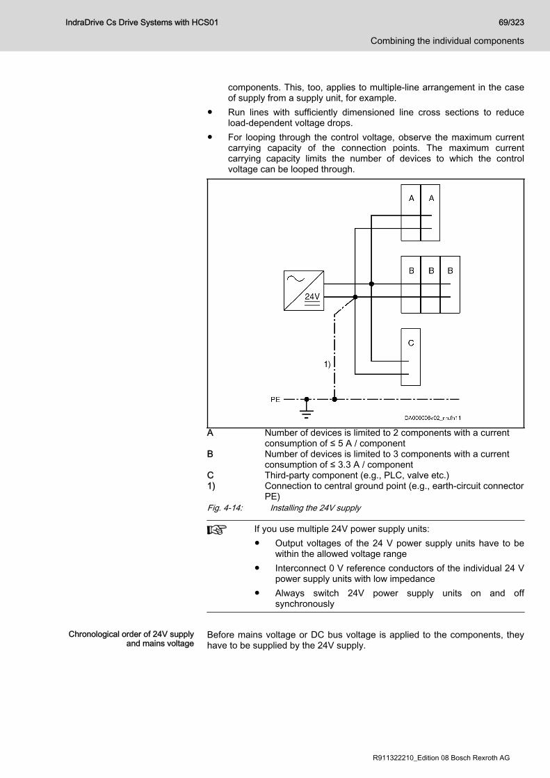
components. This, too, applies to multiple-line arrangement in the caseof supply from a supply unit, for example.
● Run lines with sufficiently dimensioned line cross sections to reduceload-dependent voltage drops.
● For looping through the control voltage, observe the maximum currentcarrying capacity of the connection points. The maximum currentcarrying capacity limits the number of devices to which the controlvoltage can be looped through.
A Number of devices is limited to 2 components with a currentconsumption of ≤ 5 A / component
B Number of devices is limited to 3 components with a currentconsumption of ≤ 3.3 A / component
C Third-party component (e.g., PLC, valve etc.)1) Connection to central ground point (e.g., earth-circuit connector
PE)Fig. 4-14: Installing the 24V supply
If you use multiple 24V power supply units:● Output voltages of the 24 V power supply units have to be
within the allowed voltage range● Interconnect 0 V reference conductors of the individual 24 V
power supply units with low impedance● Always switch 24V power supply units on and off
synchronously
Chronological order of 24V supply
and mains voltageBefore mains voltage or DC bus voltage is applied to the components, theyhave to be supplied by the 24V supply.
IndraDrive Cs Drive Systems with HCS01 69/323
Combining the individual components
R911322210_Edition 08 Bosch Rexroth AG
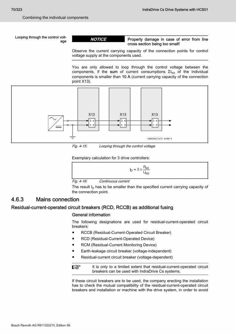
Looping through the control volt‐age Property damage in case of error from line
cross section being too small!NOTICE
Observe the current carrying capacity of the connection points for controlvoltage supply at the components used.
You are only allowed to loop through the control voltage between thecomponents, if the sum of current consumptions ΣIN3 of the individualcomponents is smaller than 10 A (current carrying capacity of the connectionpoint X13).
Fig. 4-15: Looping through the control voltage Exemplary calculation for 3 drive controllers:
Fig. 4-16: Continuous currentThe result ID has to be smaller than the specified current carrying capacity ofthe connection point.
4.6.3 Mains connectionResidual-current-operated circuit breakers (RCD, RCCB) as additional fusing
General informationThe following designations are used for residual-current-operated circuitbreakers:● RCCB (Residual-Current-Operated Circuit Breaker)● RCD (Residual-Current-Operated Device)● RCM (Residual-Current Monitoring Device)● Earth-leakage circuit breaker (voltage-independent)● Residual-current circuit breaker (voltage-dependent)
It is only to a limited extent that residual-current-operated circuitbreakers can be used with IndraDrive Cs systems.
If these circuit breakers are to be used, the company erecting the installationhas to check the mutual compatibility of the residual-current-operated circuitbreakers and installation or machine with the drive system, in order to avoid
70/323
Combining the individual components
IndraDrive Cs Drive Systems with HCS01
Bosch Rexroth AG R911322210_Edition 08

accidental triggering of the residual-current-operated circuit breaker. This hasto be taken into account● for switch-on processes, due to high asymmetric inrush currents and● during operation of the installation, due to leakage currents produced in
normal operation.
Cause of leakage currentsFor the purpose of stepless speed variation with a high degree of positioningaccuracy and dynamic response, certain modulation procedures arenecessary for drive systems. For physical reasons, these modulationprocedures give rise to inevitable leakage current produced during normaloperation. Especially with unbalanced loads of the mains phases or a largenumber of drives it can easily reach some amperes (rms value).The leakage current is not sinusoidal but pulse-shaped. For this reason,measuring instruments normally sized for alternating currents in the range of50 Hz are not suited. Use measuring instruments with rms value measuringranges.The degree of leakage current depends on the following features of theinstallation:● Type of inrush current limitation● Number, type and size of drives used● Length and cross section of connected motor power cables● Grounding conditions of the mains at the site of installation● Unbalance of the three-phase network● Types of filters and chokes connected in the incoming circuit● EMC measures that are takenIf measures are taken to improve the electromagnetic compatibility (EMC) ofthe installation (mains filters, shielded lines), the leakage current in theground wire is inevitably increased, especially when switching on or in thecase of mains unbalance. Given these operating conditions, residual-current-operated circuit breakers can trigger without an error having occurred.The EMC measures are mainly based on capacitive short-circuiting of theinterference currents within the drive system. Inductive filter measures canreduce the leakage currents, but affect the dynamic response of the drive andbring about● higher construction volume● higher weight● expensive core material
Possibilities of useMotor cable lengths Keep the motor cables as short as possible. Only short motor cables make
low leakage currents possible and thereby enable residual-current-operatedcircuit breakers to work.
Types of residual-current-operatedcircuit breakers
There are two types of residual-current-operated circuit breakers:1. Residual-current-operated circuit breakers sensitive to power pulse
current (type A acc. to IEC 60755)These are normally used. However, it is only pulsating direct faultcurrents of a maximum of 5 mA and sinusoidal alternating fault currentsthat they switch off safely. This is why they are not allowed for devicesthat can generate smoothed direct fault currents. In the case of
IndraDrive Cs Drive Systems with HCS01 71/323
Combining the individual components
R911322210_Edition 08 Bosch Rexroth AG
smoothed direct fault currents that can be produced in power supplyunits, mains rectifiers and drive controllers with power converters in B6circuit, the residual-current-operated circuit breaker is not triggered. Thisblocks the triggering of a residual-current-operated circuit breakersensitive to power pulse current in the case of ground contact, i.e. in thecase of error.Residual-current-operated circuit breakers sensitive to power pulsecurrent do not provide any protection against inadmissible contactvoltage.
2. Residual-current-operated circuit breakers sensitive to universal current(type B acc. to IEC 60755)These circuit breakers are suited for smoothed direct fault currents, too,and safely switch off devices with B6 input rectifiers.If a current with 30 mA triggers the residual-current-operated circuitbreaker, it is possible to use a residual-current-operated circuit breakerwith a higher tripping current for machine protection.If this residual-current-operated circuit breaker triggers accidentally, too,check in how far the above conditions and dependencies can beimproved (for example, by connecting current-compensated mainschokes in the incoming circuit, increasing the inrush current limitation).
Using isolating transformer to re‐duce leakage current in mains
If no improvement is achieved and the residual-current-operated circuitbreaker, due to specific mains conditions on site, has to be usednevertheless on the mains input side, connect an isolating transformerbetween mains connection and power connection of the drive system. Thisreduces the leakage current in the ground wire of the mains that is producedduring normal operation which allows the residual-current-operated circuitbreaker to be used. Connect the neutral point of the secondary winding of theisolating transformer to the equipment grounding conductor of the drivesystem.Adjust the ground-fault loop impedance to the overcurrent protective deviceso that the unit can be switched off in the case of failure.Before operating enable, check the correct function of the overcurrentprotection device including activation in the case of failure.Exclusive fusing by residual-current-operated circuit breakerFor drive systems with electronic drive controllers, exclusive protection bymeans of a residual-current-operated circuit breaker normally is not possibleand not allowed.Electronic equipment that has a nominal power higher than 4 kVA or isdestined for permanent connection normally does not need residual-current-operated circuit breakers. Observe the country-specific standards.According to IEC 60204-1 and IEC 61800-5-1, the mains-side protectionagainst indirect contact, i.e. in the case of insulation failure, has to beprovided in a different way, for example by means of an overcurrentprotection device, protective grounding, protective-conductor system,protective separation or total insulation.
Using residual-current-operated circuit breakers at HCS drive control‐lers
HCS drive controllers at residual-current-operated circuit breaker
Residual-current-operated circuit breakers can be used under the followingconditions:● Residual-current-operated circuit breaker is of type B (IEC60755)● Trip limit of the residual-current circuit breaker is ≥ 300 mA
72/323
Combining the individual components
IndraDrive Cs Drive Systems with HCS01
Bosch Rexroth AG R911322210_Edition 08

● Supplying TN-S mains● Maximum length of motor cable 20 m in shielded design● Use of an NFD03 mains filter● Each residual-current-operated circuit breaker only supplies one drive
controller● Only Rexroth components and accessories including cables and filters
are used
Mains typesTN-S mains typeThe TN-S mains type is the usual mains type in Europe.
T = Direct grounding of a point (station ground)N = Exposed conductive parts directly connected to station groundS = Separate neutral conductor and equipment grounding conduc‐
tor in entire mainsFig. 4-17: TN-S mains type
IndraDrive Cs Drive Systems with HCS01 73/323
Combining the individual components
R911322210_Edition 08 Bosch Rexroth AG
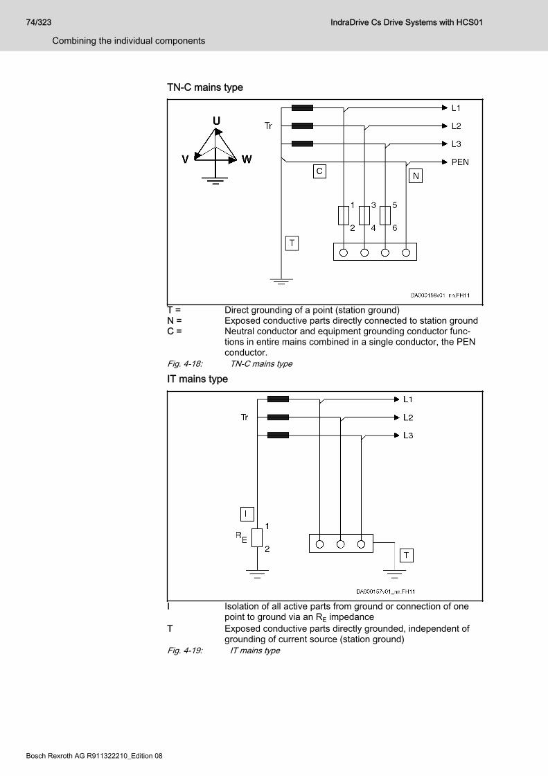
TN-C mains type
T = Direct grounding of a point (station ground)N = Exposed conductive parts directly connected to station groundC = Neutral conductor and equipment grounding conductor func‐
tions in entire mains combined in a single conductor, the PENconductor.
Fig. 4-18: TN-C mains type
IT mains type
I Isolation of all active parts from ground or connection of onepoint to ground via an RE impedance
T Exposed conductive parts directly grounded, independent ofgrounding of current source (station ground)
Fig. 4-19: IT mains type
74/323
Combining the individual components
IndraDrive Cs Drive Systems with HCS01
Bosch Rexroth AG R911322210_Edition 08
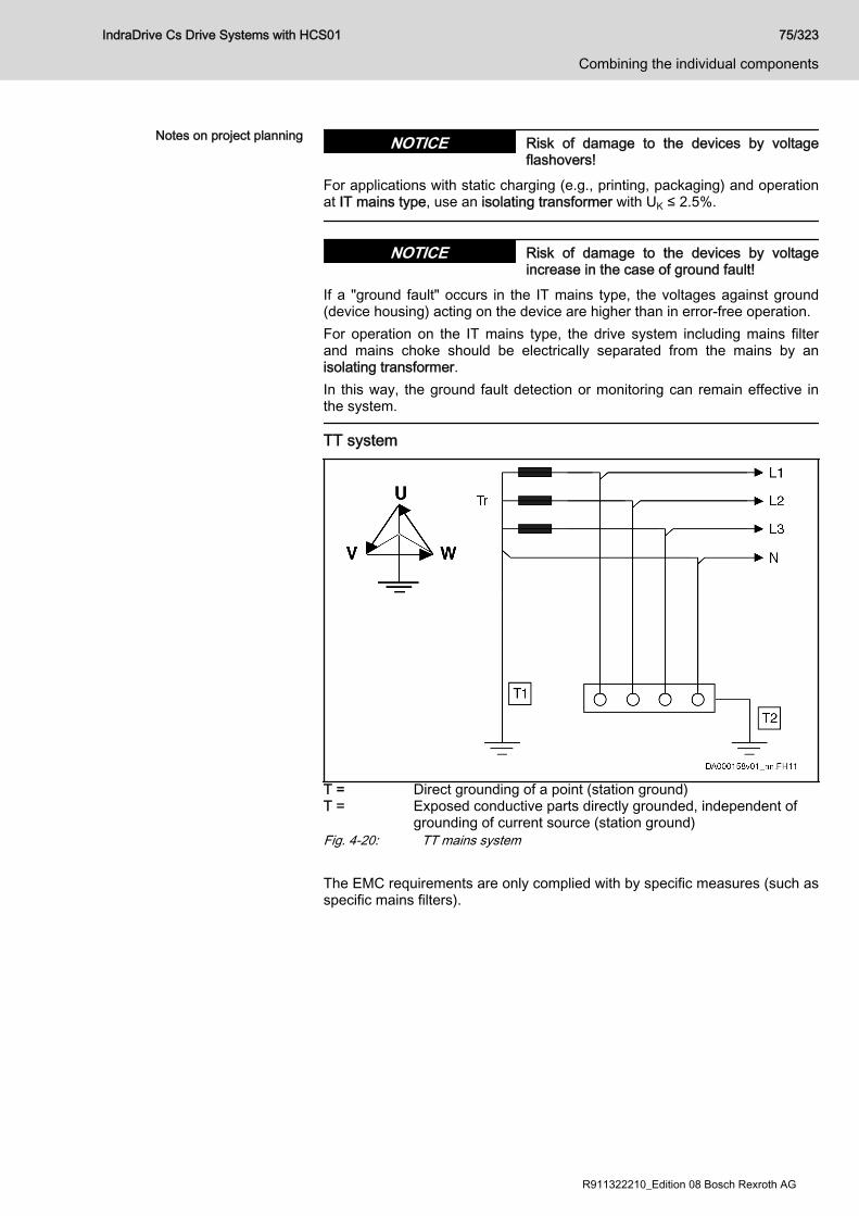
Notes on project planning Risk of damage to the devices by voltageflashovers!
NOTICE
For applications with static charging (e.g., printing, packaging) and operationat IT mains type, use an isolating transformer with UK ≤ 2.5%.
Risk of damage to the devices by voltageincrease in the case of ground fault!
NOTICE
If a "ground fault" occurs in the IT mains type, the voltages against ground(device housing) acting on the device are higher than in error-free operation.For operation on the IT mains type, the drive system including mains filterand mains choke should be electrically separated from the mains by anisolating transformer.In this way, the ground fault detection or monitoring can remain effective inthe system.
TT system
T = Direct grounding of a point (station ground)T = Exposed conductive parts directly grounded, independent of
grounding of current source (station ground)Fig. 4-20: TT mains system The EMC requirements are only complied with by specific measures (such asspecific mains filters).
IndraDrive Cs Drive Systems with HCS01 75/323
Combining the individual components
R911322210_Edition 08 Bosch Rexroth AG
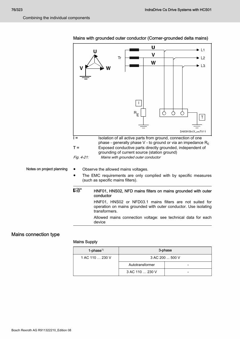
Mains with grounded outer conductor (Corner-grounded delta mains)
I = Isolation of all active parts from ground, connection of onephase - generally phase V - to ground or via an impedance RE
T = Exposed conductive parts directly grounded, independent ofgrounding of current source (station ground)
Fig. 4-21: Mains with grounded outer conductor
Notes on project planning ● Observe the allowed mains voltages.● The EMC requirements are only complied with by specific measures
(such as specific mains filters).
HNF01, HNS02, NFD mains filters on mains grounded with outerconductorHNF01, HNS02 or NFD03.1 mains filters are not suited foroperation on mains grounded with outer conductor. Use isolatingtransformers.Allowed mains connection voltage: see technical data for eachdevice
Mains connection typeMains Supply
1-phase1) 3-phase
1 AC 110 … 230 V 3 AC 200 ... 500 V
Autotransformer -
3 AC 110 … 230 V -
76/323
Combining the individual components
IndraDrive Cs Drive Systems with HCS01
Bosch Rexroth AG R911322210_Edition 08
HCS01.1E-W0003-A-02HCS01.1E-W0006-A-02HCS01.1E-W0009-A-02HCS01.1E-W0013-A-02HCS01.1E-W0018-A-02
HCS01.1E-W0005-A-03HCS01.1E-W0008-A-03HCS01.1E-W0018-A-03HCS01.1E-W0028-A-03HCS01.1E-W0054-A-03
Mains supply
Individual supply Individual supply
Group supply
Central supply
1) With 1-phase mains supply, you can connect the mains supplyline to connector X3 at L1, L2 or L3
Tab. 4-26: Mains SupplyWire the Bb relay contacts of the drive controllers supplied with mains voltagein the control circuit of the mains contactor.
Individual supply Each component is individually connected to the power grid. There is no DCbus connection between the devices.
Grayed out components: optional, depending on the applica‐tion
A HCS01 componentBb Bb relay contact wiringFig. 4-22: Individual supply
Risk of fire caused by missing fuses!NOTICE
Install a fuse before each drive controller. In case a short circuit occurs in thedrive controller, a fuse provides optimum safety against overheating or fire(see also IEC 61800-5-1 and UL 508C).For distribution in North America, single fuses are required for this type ofmains connection (see UL 508A).In the scope of international and European standards (IEC/EN, not NorthAmerica), it is allowed to use a group fuse instead of the single fuses. Whenselecting the nominal current of the group fuse, observe the loop impedance,the line length and the line cross section of the mains supply feeder (see IEC60204-1, chapter Appendix A).Observe the data for dimensioning line cross sections and fuses (see alsoIEC 60204-1, UL 508A and NFPA 79).
IndraDrive Cs Drive Systems with HCS01 77/323
Combining the individual components
R911322210_Edition 08 Bosch Rexroth AG
Central supply ● Only HCS01.1E-W0028 and -W0054 components are suitedfor central supply.
● Central supply via HCS02.1, HCS03.1, HMV01.1 orHMV02.1 components is not allowed.
● Use the corresponding mains chokes to increase the DC buscontinuous power.
● If the total DC bus capacitance (sum of DC buscapacitances of all components at the DC bus) is ≥ 1.5 mF,install a mains choke in the supply feeder of the supplyingcomponent.
● Wire the Bb relay contacts.
One powerful component supplies other components via the common DCbus connection.
Grayed out components: optional, depending on the applica‐tion
A HCS01 component (more powerful than component B); con‐nected to other components via DC bus
B HCS01 component (less powerful than component A); connec‐ted to other components via DC bus
Bb Bb relay contact wiringM Module busFig. 4-23: Central supply
Group supply ● Option 1:Multiple powerful HCS01 components (of the same size!) are connectedto the mains. This requires balancing chokes between power grid andcomponents.
78/323
Combining the individual components
IndraDrive Cs Drive Systems with HCS01
Bosch Rexroth AG R911322210_Edition 08

Grayed out components: optional, depending on the appli‐cation; the choke is used to reduce current harmonics
A HCS01 component (more powerful than component B; allcomponents A identical); connected to power grid via bal‐ancing chokes; connected to other components via DCbus
B HCS01 component (less powerful than component A);connected to other components via DC bus
Bb Bb relay contact wiringM Module busFig. 4-24: Group supply; multiple HCS01 components connected to the
power grid● Option 2:
All powerful HCS01 components (of the same size!) are connected tothe mains. This requires balancing chokes between power grid andcomponents.
Grayed out components: optional, depending on the appli‐cation; the choke is used to reduce current harmonics
A HCS01 component (all components A identical); connec‐ted to power grid via balancing chokes; interconnected viaDC bus
Bb Bb relay contact wiringM Module bus (not obligatory)Fig. 4-25: Group supply; all HCS01 components connected to the power
grid
IndraDrive Cs Drive Systems with HCS01 79/323
Combining the individual components
R911322210_Edition 08 Bosch Rexroth AG

Risk of fire caused by missing fuses!NOTICE
– Install a fuse before each drive controller. In case a short circuitoccurs in the drive controller, a fuse provides optimum safetyagainst overheating or fire (see also IEC 61800-5-1 and UL 508C).For distribution in North America, single fuses are required for thistype of mains connection (see UL 508A).In the scope of international and European standards (IEC/EN, notNorth America), it is allowed to use a group fuse instead of thesingle fuses. When selecting the nominal current of the group fuse,observe the loop impedance, the line length and the line crosssection of the supply feeder (see IEC 60204-1, chapter AppendixA).Observe the data for sizing line cross sections and fuses (see alsoIEC 60204-1, UL 508A and NFPA 79).
Mains connected load and mains current Technical data of the components● See chapter 7.3.2 "Mains voltage" on page 226● See chapter 7.3.3 "DC bus" on page 233
Calculating the mains-side phase current The mains-side phase current is required for the following cases:● Selecting the mains contactor● Determining the fuses in the mains connection● Determining the line cross section● Selecting other components in the mains connection (mains filter, mains
choke)Operation under rated conditions For data on mains contactor, fuses and cross section in operation under
rated conditions, see technical data of the respective component.Operation at partial load Operation at partial load may involve smaller mains contactors, fuses and line
cross sections.If defined data for operation at partial load are available, the mains-sidephase current can be determined as follows:1. Determine the motor power
Take power of drive controller-motor combination from RexrothIndraSize or calculate it.
PmHa Mechanical nominal power for main drives (shaftoutput) [kW]
Mn Nominal motor torque [Nm]nn Nominal motor speed [min-1]
2. Determine the DC bus power from motor power and efficiency
80/323
Combining the individual components
IndraDrive Cs Drive Systems with HCS01
Bosch Rexroth AG R911322210_Edition 08
PDC Required DC bus continuous power [W]Mm Average torque in Nmnm Average speed in min-1
k Factor for motor and controller efficiency = 1.253. Add the powers of all axes at the common DC bus and put them into
relation to the rated power of the supply unit⇒ Partial load of PDC_cont is known
4. Determine the power factor TPF for partial load (TPF = Total PowerFactor)For the value TPF at rated power and TPF10 (at 10% of rated power),see technical data (mains voltage) of the component.
5. Calculate the mains connected load
SLN Mains connected load [VA]PDC DC bus continuous power [W]TPF Total Power Factor λ
6. Calculate the mains-side phase current
3-phase:
1-phase: ILN Mains-side phase current in [A]SLN Mains connected load [VA]ULN Voltage between phases of mains [V]
7. Select the mains contactor8. Determine the mains circuit breaker and line cross section
See chapter 11.1 "Sizing the line cross sections and fuses " on page297
Sizing the line cross sections and fuseschapter 11.1 "Sizing the line cross sections and fuses " on page 297.
Sizing and selecting the mains transformerMains transformers are always needed when the mains voltage is outside ofthe allowed nominal voltage of the component.
Grounded mains As a matter of principle, the mains voltage for grounded mains is adjustedwith autotransformers.
Ungrounded mains As a matter of principle, the mains voltage for ungrounded mains is adjustedwith isolating transformers to avoid prevent overvoltages between outerconductor and ground. Short-circuit voltage of the isolating transformer: ≤ 4%
IndraDrive Cs Drive Systems with HCS01 81/323
Combining the individual components
R911322210_Edition 08 Bosch Rexroth AG
Applications for autotransformers With HCS01 components, there are two applications that require
autotransformers:1. HCS01.1E-W00xx-A-02 components are used:
With a mains voltage of 3 AC 400 V, the voltage has to be adjusted viaan autotransformer to use HCS01.1E-W00xx-A-02 components with aninput voltage range of 3 AC 110…230 V.
2. An MSM motor is used in conjunction with an HCS01.1E-W00xx-A-03component:MSM motors are sized for a voltage of 230 V. To operate MSM motorsat a mains voltage of 3 AC 400 V at an HCS01.1E-W00xx-A-03component, the mains voltage has to be adjusted to 3 AC 230 V via anautotransformer.
Sizing the mains filterCriteria for Selecting the Mains Fil‐
terTake the following criteria into account for selecting the appropriate mainsfilter:● EMC limit value class on site● Ambient conditions on site● Harmonics on mains voltage on site● Loading by mains voltage and mains frequency on site● Loading by harmonics on site● Loading by mains-side phase current● Total length of connected power cables● Sum of leakage capacitances● Clock frequency of drive controller
How to proceed for selecting themains filter
The selection of the mains filter is significantly determined by the operatingconditions.How to proceed for selecting the mains filter:1. Determine the required EMC limit value class for the application.2. Determine the maximum applied mains voltage. Observe that not all
IndraDrive Cs mains filters are suited for a mains voltage of 3 AC 500 V.Check whether the mains voltage of the mains filter is loaded withharmonics and still allowed for the mains filter.If necessary, reduce the harmonics on site.
3. Determine the mains connection type, such as central supply, groupsupply, etc. (To do this, it is useful to outline the involved componentsand their interaction.)
4. Calculate the mains-side phase current of the mains filter. You can findthe procedure for calculating the mains-side phase current in a separatechapter (see chapter "Calculating the mains-side phase current " onpage 80). For selecting the components, calculate the effective rmsvalue.Check or determine the maximum occurring ambient temperature.Select a mains filter with a higher nominal current, if the ambienttemperature is above 45 °C.
5. The nominal current of the selected mains fuse should not exceed thenominal current of the mains filter.
82/323
Combining the individual components
IndraDrive Cs Drive Systems with HCS01
Bosch Rexroth AG R911322210_Edition 08
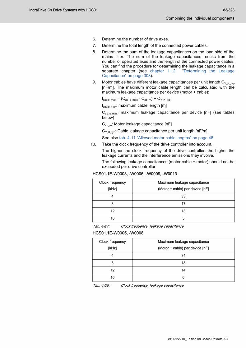
6. Determine the number of drive axes.7. Determine the total length of the connected power cables.8. Determine the sum of the leakage capacitances on the load side of the
mains filter. The sum of the leakage capacitances results from thenumber of operated axes and the length of the connected power cables.You can find the procedure for determining the leakage capacitance in aseparate chapter (see chapter 11.2 "Determining the LeakageCapacitance" on page 308).
9. Motor cables have different leakage capacitances per unit length CY_K_typ[nF/m]. The maximum motor cable length can be calculated with themaximum leakage capacitance per device (motor + cable):lcable_max = (Cab_c_max - Cab_m) ÷ CY_K_typ
lcable_max: maximum cable length [m]Cab_c_max: maximum leakage capacitance per device [nF] (see tablesbelow)Cab_m: Motor leakage capacitance [nF]CY_K_typ: Cable leakage capacitance per unit length [nF/m]See also tab. 4-11 "Allowed motor cable lengths" on page 48.
10. Take the clock frequency of the drive controller into account.The higher the clock frequency of the drive controller, the higher theleakage currents and the interference emissions they involve.The following leakage capacitances (motor cable + motor) should not beexceeded per drive controller.
HCS01.1E-W0003, -W0006, -W0009, -W0013
Clock frequency[kHz]
Maximum leakage capacitance(Motor + cable) per device [nF]
4 33
8 17
12 13
16 5
Tab. 4-27: Clock frequency, leakage capacitanceHCS01.1E-W0005, -W0008
Clock frequency[kHz]
Maximum leakage capacitance(Motor + cable) per device [nF]
4 34
8 18
12 14
16 6
Tab. 4-28: Clock frequency, leakage capacitance
IndraDrive Cs Drive Systems with HCS01 83/323
Combining the individual components
R911322210_Edition 08 Bosch Rexroth AG
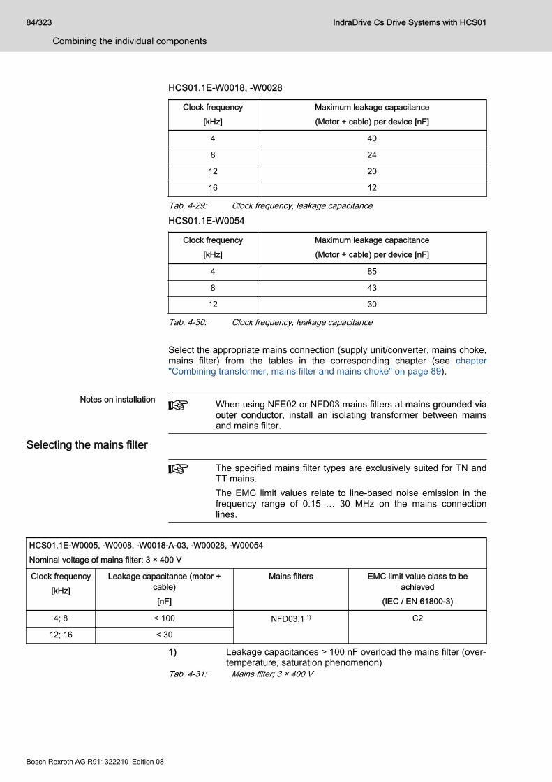
HCS01.1E-W0018, -W0028
Clock frequency[kHz]
Maximum leakage capacitance(Motor + cable) per device [nF]
4 40
8 24
12 20
16 12
Tab. 4-29: Clock frequency, leakage capacitanceHCS01.1E-W0054
Clock frequency[kHz]
Maximum leakage capacitance(Motor + cable) per device [nF]
4 85
8 43
12 30
Tab. 4-30: Clock frequency, leakage capacitance Select the appropriate mains connection (supply unit/converter, mains choke,mains filter) from the tables in the corresponding chapter (see chapter"Combining transformer, mains filter and mains choke" on page 89).
Notes on installation When using NFE02 or NFD03 mains filters at mains grounded viaouter conductor, install an isolating transformer between mainsand mains filter.
Selecting the mains filter
The specified mains filter types are exclusively suited for TN andTT mains.The EMC limit values relate to line-based noise emission in thefrequency range of 0.15 … 30 MHz on the mains connectionlines.
HCS01.1E-W0005, -W0008, -W0018-A-03, -W00028, -W00054Nominal voltage of mains filter: 3 × 400 V
Clock frequency[kHz]
Leakage capacitance (motor +cable)[nF]
Mains filters EMC limit value class to beachieved
(IEC / EN 61800-3)
4; 8 < 100 NFD03.1 1) C2
12; 16 < 30
1) Leakage capacitances > 100 nF overload the mains filter (over‐temperature, saturation phenomenon)
Tab. 4-31: Mains filter; 3 × 400 V
84/323
Combining the individual components
IndraDrive Cs Drive Systems with HCS01
Bosch Rexroth AG R911322210_Edition 08
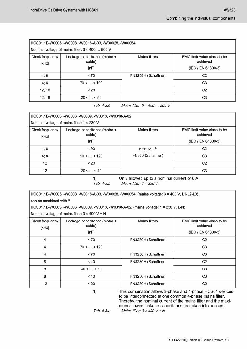
HCS01.1E-W0005, -W0008, -W0018-A-03, -W00028, -W00054Nominal voltage of mains filter: 3 × 400 … 500 V
Clock frequency[kHz]
Leakage capacitance (motor +cable)[nF]
Mains filters EMC limit value class to beachieved
(IEC / EN 61800-3)
4; 8 < 70 FN3258H (Schaffner) C2
4; 8 70 < … < 100 C3
12; 16 < 20 C2
12; 16 20 < … < 50 C3
Tab. 4-32: Mains filter; 3 × 400 … 500 V
HCS01.1E-W0003, -W0006, -W0009, -W0013, -W0018-A-02Nominal voltage of mains filter: 1 × 230 V
Clock frequency[kHz]
Leakage capacitance (motor +cable)[nF]
Mains filters EMC limit value class to beachieved
(IEC / EN 61800-3)
4; 8 < 90 NFE02.1 1)
FN350 (Schaffner)
C2
4; 8 90 < … < 120 C3
12 < 20 C2
12 20 < … < 40 C3
1) Only allowed up to a nominal current of 8 ATab. 4-33: Mains filter; 1 × 230 V
HCS01.1E-W0005, -W0008, -W0018-A-03, -W00028, -W00054, (mains voltage: 3 × 400 V, L1-L2-L3)
can be combined with 1)
HCS01.1E-W0003, -W0006, -W0009, -W0013, -W0018-A-02, (mains voltage: 1 × 230 V, L-N)Nominal voltage of mains filter: 3 × 400 V + N
Clock frequency[kHz]
Leakage capacitance (motor +cable)[nF]
Mains filters EMC limit value class to beachieved
(IEC / EN 61800-3)
4 < 70 FN3280H (Schaffner) C2
4 70 < … < 120 C3
4 < 70 FN3256H (Schaffner) C3
8 < 40 FN3280H (Schaffner) C2
8 40 < … < 70 C3
8 < 40 FN3256H (Schaffner) C3
12 < 20 FN3280H (Schaffner) C2
1) This combination allows 3-phase and 1-phase HCS01 devicesto be interconnected at one common 4-phase mains filter.Thereby, the nominal current of the mains filter and the maxi‐mum allowed leakage capacitance are taken into account.
Tab. 4-34: Mains filter; 3 × 400 V + N
IndraDrive Cs Drive Systems with HCS01 85/323
Combining the individual components
R911322210_Edition 08 Bosch Rexroth AG
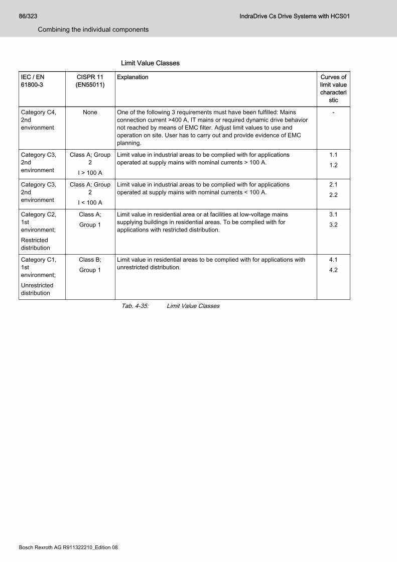
Limit Value Classes
IEC / EN61800-3
CISPR 11(EN55011)
Explanation Curves oflimit valuecharacteri
stic
Category C4,2ndenvironment
None One of the following 3 requirements must have been fulfilled: Mainsconnection current >400 A, IT mains or required dynamic drive behaviornot reached by means of EMC filter. Adjust limit values to use andoperation on site. User has to carry out and provide evidence of EMCplanning.
-
Category C3,2ndenvironment
Class A; Group2
I > 100 A
Limit value in industrial areas to be complied with for applicationsoperated at supply mains with nominal currents > 100 A.
1.11.2
Category C3,2ndenvironment
Class A; Group2
I < 100 A
Limit value in industrial areas to be complied with for applicationsoperated at supply mains with nominal currents < 100 A.
2.12.2
Category C2,1stenvironment;Restricteddistribution
Class A;Group 1
Limit value in residential area or at facilities at low-voltage mainssupplying buildings in residential areas. To be complied with forapplications with restricted distribution.
3.13.2
Category C1,1stenvironment;Unrestricteddistribution
Class B;Group 1
Limit value in residential areas to be complied with for applications withunrestricted distribution.
4.14.2
Tab. 4-35: Limit Value Classes
86/323
Combining the individual components
IndraDrive Cs Drive Systems with HCS01
Bosch Rexroth AG R911322210_Edition 08
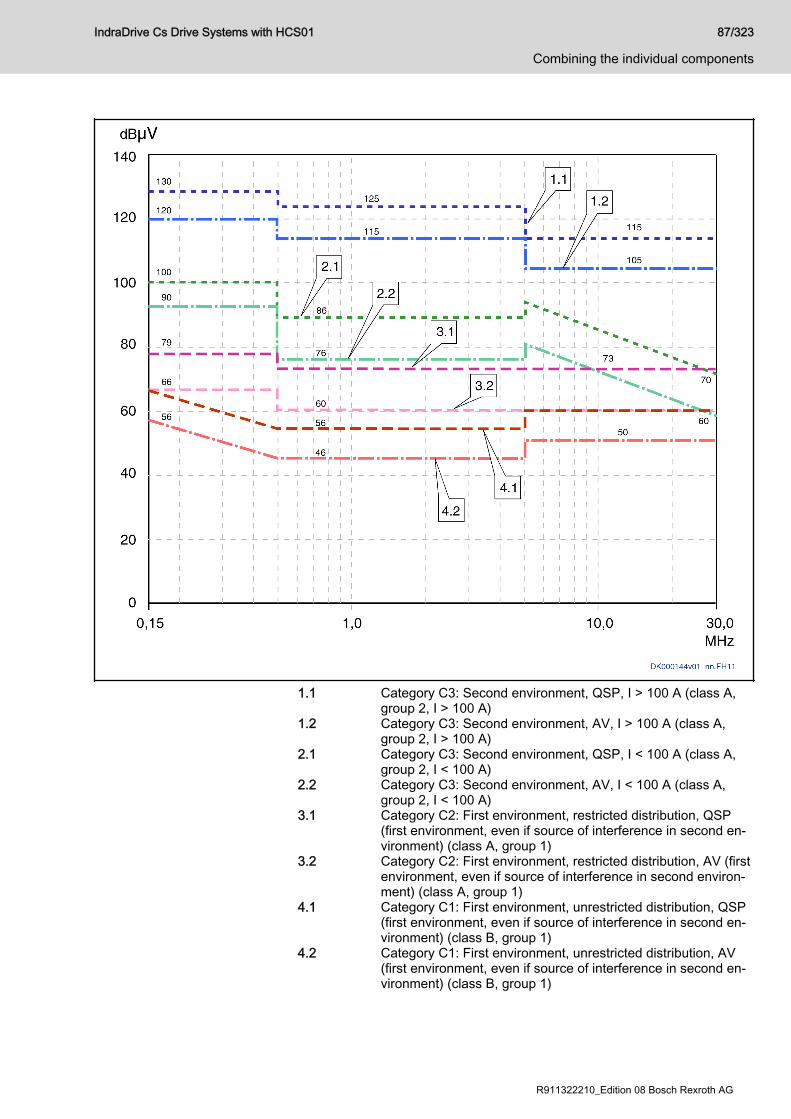
1.1 Category C3: Second environment, QSP, I > 100 A (class A,group 2, I > 100 A)
1.2 Category C3: Second environment, AV, I > 100 A (class A,group 2, I > 100 A)
2.1 Category C3: Second environment, QSP, I < 100 A (class A,group 2, I < 100 A)
2.2 Category C3: Second environment, AV, I < 100 A (class A,group 2, I < 100 A)
3.1 Category C2: First environment, restricted distribution, QSP(first environment, even if source of interference in second en‐vironment) (class A, group 1)
3.2 Category C2: First environment, restricted distribution, AV (firstenvironment, even if source of interference in second environ‐ment) (class A, group 1)
4.1 Category C1: First environment, unrestricted distribution, QSP(first environment, even if source of interference in second en‐vironment) (class B, group 1)
4.2 Category C1: First environment, unrestricted distribution, AV(first environment, even if source of interference in second en‐vironment) (class B, group 1)
IndraDrive Cs Drive Systems with HCS01 87/323
Combining the individual components
R911322210_Edition 08 Bosch Rexroth AG
Notes (1) Limit value for first environment is also relevant, if source ofinterference of second environment affects first environment(2) Designations "class" and "group" according to IEC CISPR11QSP: Measuring method quasi peak measurement; AV: Meas‐uring method arithmetic averaging
Fig. 4-26: Limit Values for Line-Based Disturbances (IEC 61800-3); Limit ValueCharacteristic through Frequency Range
Determining the Mains ChokeWhen using mains chokes, take their effect on the connected drivecontrollers into account. Due to their inductance, mains chokes have asmoothing effect on the current and thereby reduce harmonics.Take the nominal current of the mains choke into account to have theinductance of the mains choke available.Some mains chokes are assigned to certain drive controllers (see technicaldata of the drive controller "Data for mains voltage supply → Assigned type ofmains choke").
Sizing the mains contactorRequired data:● Nominal current ILN of the drive controller (see chapter 7.3.2 "Mains
voltage" on page 226)● Number of drive controllers connected to the mains contactor When using mains contactors of the utilization category AC-1, observe theconventional thermal continuous current Ith (see data sheet of mainscontactor) when dimensioning the mains contactor.The minimum required conventional thermal continuous current Ith resultsfrom the sum of nominal currents Σ ILN of all connected drive controllers.
88/323
Combining the individual components
IndraDrive Cs Drive Systems with HCS01
Bosch Rexroth AG R911322210_Edition 08
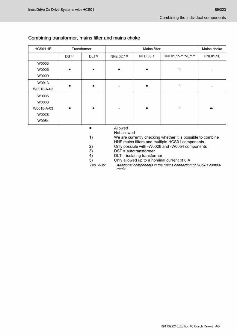
Combining transformer, mains filter and mains choke
HCS01.1E Transformer Mains filter Mains choke
DST3) DLT4) NFE 02.15) NFD 03.1 HNF01.1*-****-E**** HNL01.1E
W0003W0006W0009
■ ■ ■ ■ 1) -
W0013W0018-A-02
■ ■ - ■ 1) -
W0005W0008
W0018-A-03W0028W0054
■ ■ - ■ 1) ■2)
■ Allowed- Not allowed1) We are currently checking whether it is possible to combine
HNF mains filters and multiple HCS01 components.2) Only possible with -W0028 and -W0054 components3) DST = autotransformer4) DLT = isolating transformer5) Only allowed up to a nominal current of 8 ATab. 4-36: Additional components in the mains connection of HCS01 compo‐
nents
IndraDrive Cs Drive Systems with HCS01 89/323
Combining the individual components
R911322210_Edition 08 Bosch Rexroth AG
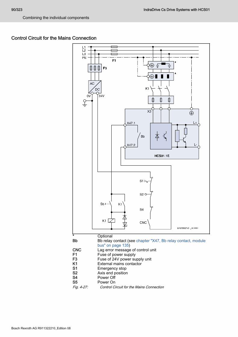
Control Circuit for the Mains Connection
* OptionalBb Bb relay contact (see chapter "X47, Bb relay contact, module
bus" on page 135)CNC Lag error message of control unitF1 Fuse of power supplyF3 Fuse of 24V power supply unitK1 External mains contactorS1 Emergency stopS2 Axis end positionS4 Power OffS5 Power OnFig. 4-27: Control Circuit for the Mains Connection
90/323
Combining the individual components
IndraDrive Cs Drive Systems with HCS01
Bosch Rexroth AG R911322210_Edition 08

4.6.4 DC bus couplingRequirements for DC bus coupling
Device types Only devices of the "HCS01.1E-W00**-*-03" type are suited for DC buscoupling. DC bus coupling takes place via the optionally available DC busconnector RLS0778/K06 at the connection point X77.
Parameterization: For all devices only supplied via the DC bus,"DC bus → inverter mode" has to be set as the source of powersupply in the parameter "P-0-0860, Converter configuration" (seealso parameter description of the firmware used).
Mains connection DC bus coupling is possible for the following types of mains connection:● Central supply● Group supplyDC bus coupling requires:● That the Bb contacts of all devices connected to the mains be wired● That the module bus be wired via all devices at the common DC bus
Central supply and DC bus couplingUse this type of DC bus coupling if the DC bus continuous power of theinfeeding device makes available sufficient power reserves to supply otherHCS01 devices. The devices in the group can be of different types.
Risk of damage if power withdrawal is toohigh!
NOTICE
For the project planning of the application, observe that the supplying devicescan only make available the DC bus power for other devices which they donot consume themselves.
With central supply, one HCS01 device charges the DC bus and the otherdevices are supplied using DC bus coupling.Features● The supplying device has to be of the HCS01.1E-W0028 or -W0054
type● Energy compensation between the devices is possible (the DC bus
capacitors of the devices are connected in parallel)● Balancing of the integrated braking resistors exists (equal load of all
braking resistors integrated in the devices)● No balancing measures required in the supply feeder● To increase the DC bus power, an optional mains choke can be used● It is possible to connect DC bus capacitor units; DC bus capacitor units
should always be placed directly next to the most powerful deviceA DC bus capacitor unit HLC requires a mains choke to be installed
● Small wiring effort for the mains connection● DC bus short circuit functionality has to be realized externally, if required
IndraDrive Cs Drive Systems with HCS01 91/323
Combining the individual components
R911322210_Edition 08 Bosch Rexroth AG
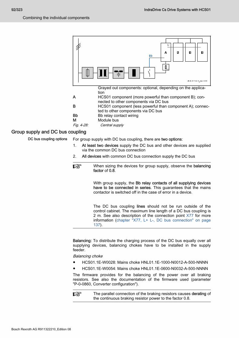
Grayed out components: optional, depending on the applica‐tion
A HCS01 component (more powerful than component B); con‐nected to other components via DC bus
B HCS01 component (less powerful than component A); connec‐ted to other components via DC bus
Bb Bb relay contact wiringM Module busFig. 4-28: Central supply
Group supply and DC bus couplingDC bus coupling options For group supply with DC bus coupling, there are two options:
1. At least two devices supply the DC bus and other devices are suppliedvia the common DC bus connection
2. All devices with common DC bus connection supply the DC bus
When sizing the devices for group supply, observe the balancingfactor of 0.8. With group supply, the Bb relay contacts of all supplying deviceshave to be connected in series. This guarantees that the mainscontactor is switched off in the case of error in a device.
The DC bus coupling lines should not be run outside of thecontrol cabinet. The maximum line length of a DC bus coupling is2 m. See also description of the connection point X77 for moreinformation (chapter "X77, L+ L-, DC bus connection" on page137).
Balancing: To distribute the charging process of the DC bus equally over allsupplying devices, balancing chokes have to be installed in the supplyfeeder.Balancing choke● HCS01.1E-W0028: Mains choke HNL01.1E-1000-N0012-A-500-NNNN● HCS01.1E-W0054: Mains choke HNL01.1E-0600-N0032-A-500-NNNNThe firmware provides for the balancing of the power over all brakingresistors. See also the documentation of the firmware used (parameter"P-0-0860, Converter configuration").
The parallel connection of the braking resistors causes derating ofthe continuous braking resistor power to the factor 0.8.
92/323
Combining the individual components
IndraDrive Cs Drive Systems with HCS01
Bosch Rexroth AG R911322210_Edition 08
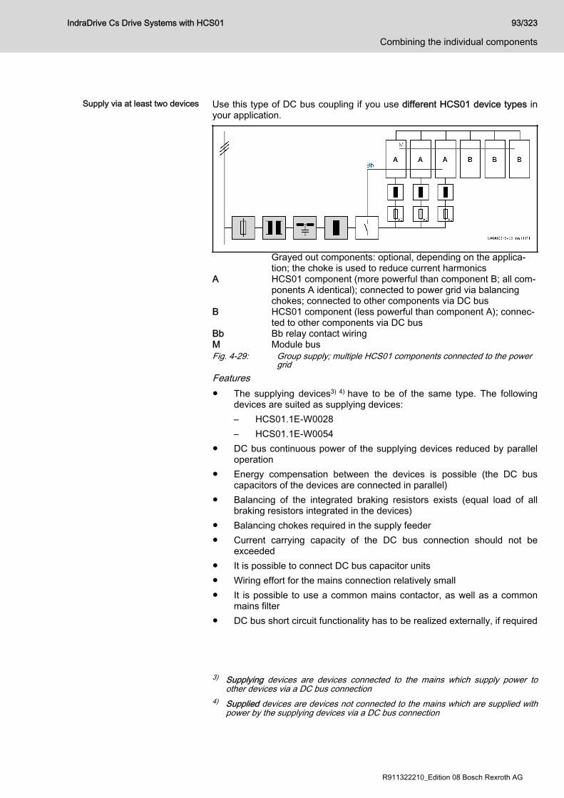
Supply via at least two devices Use this type of DC bus coupling if you use different HCS01 device types in
your application.
Grayed out components: optional, depending on the applica‐tion; the choke is used to reduce current harmonics
A HCS01 component (more powerful than component B; all com‐ponents A identical); connected to power grid via balancingchokes; connected to other components via DC bus
B HCS01 component (less powerful than component A); connec‐ted to other components via DC bus
Bb Bb relay contact wiringM Module busFig. 4-29: Group supply; multiple HCS01 components connected to the power
gridFeatures● The supplying devices3) 4) have to be of the same type. The following
devices are suited as supplying devices:– HCS01.1E-W0028– HCS01.1E-W0054
● DC bus continuous power of the supplying devices reduced by paralleloperation
● Energy compensation between the devices is possible (the DC buscapacitors of the devices are connected in parallel)
● Balancing of the integrated braking resistors exists (equal load of allbraking resistors integrated in the devices)
● Balancing chokes required in the supply feeder● Current carrying capacity of the DC bus connection should not be
exceeded● It is possible to connect DC bus capacitor units● Wiring effort for the mains connection relatively small● It is possible to use a common mains contactor, as well as a common
mains filter● DC bus short circuit functionality has to be realized externally, if required
3) Supplying devices are devices connected to the mains which supply power toother devices via a DC bus connection
4) Supplied devices are devices not connected to the mains which are supplied withpower by the supplying devices via a DC bus connection
IndraDrive Cs Drive Systems with HCS01 93/323
Combining the individual components
R911322210_Edition 08 Bosch Rexroth AG

Supply via all devices Use this type of DC bus coupling if you exclusively use one HCS01 devicetype in your application.
Grayed out components: optional, depending on the applica‐tion; the choke is used to reduce current harmonics
A HCS01 component (all components A identical); connected topower grid via balancing chokes; interconnected via DC bus
Bb Bb relay contact wiringM Module bus (not obligatory)Fig. 4-30: Group supply; all HCS01 components connected to the power gridFeatures● All devices have to be of the same type● DC bus continuous power of the supplying devices reduced by parallel
operation● Energy compensation between the devices is possible (the DC bus
capacitors of the devices are connected in parallel)● Balancing of the integrated braking resistors exists (equal load of all
braking resistors integrated in the devices)● Balancing chokes required in the supply feeder● It is possible to connect DC bus capacitor units● Wiring effort for the mains connection of all devices relatively big● DC bus short circuit functionality has to be realized externally, if required
Implementing the DC bus couplingMaximum number of devices The maximum number of devices which can be interconnected via DC bus
coupling depends on● the power reserves of the supplying devices
(The power reserve (Preserve) results from the difference between thepossible DC bus continuous power of the device and the powerconsumed by the motor connected to the device.)
● the sum of DC bus continuous powers of all supplied devices● the mains voltage value● the maximum continuous power which can be looped through via the
DC bus connector X77(The continuous power results from the current carrying capacity of theDC bus connector X77 and the mains voltage value.)
94/323
Combining the individual components
IndraDrive Cs Drive Systems with HCS01
Bosch Rexroth AG R911322210_Edition 08
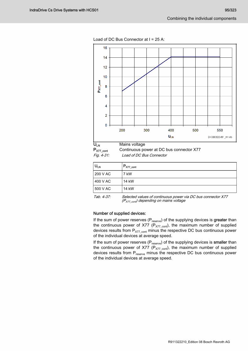
Load of DC Bus Connector at I = 25 A:
ULN Mains voltagePX77_cont Continuous power at DC bus connector X77Fig. 4-31: Load of DC Bus Connector
ULN PX77_cont
200 V AC 7 kW
400 V AC 14 kW
500 V AC 14 kW
Tab. 4-37: Selected values of continuous power via DC bus connector X77(PX77_cont) depending on mains voltage
Number of supplied devices:If the sum of power reserves (Preserve) of the supplying devices is greater thanthe continuous power of X77 (PX77_cont), the maximum number of supplieddevices results from PX77_cont minus the respective DC bus continuous powerof the individual devices at average speed.If the sum of power reserves (Preserve) of the supplying devices is smaller thanthe continuous power of X77 (PX77_cont), the maximum number of supplieddevices results from Preserve minus the respective DC bus continuous powerof the individual devices at average speed.
IndraDrive Cs Drive Systems with HCS01 95/323
Combining the individual components
R911322210_Edition 08 Bosch Rexroth AG
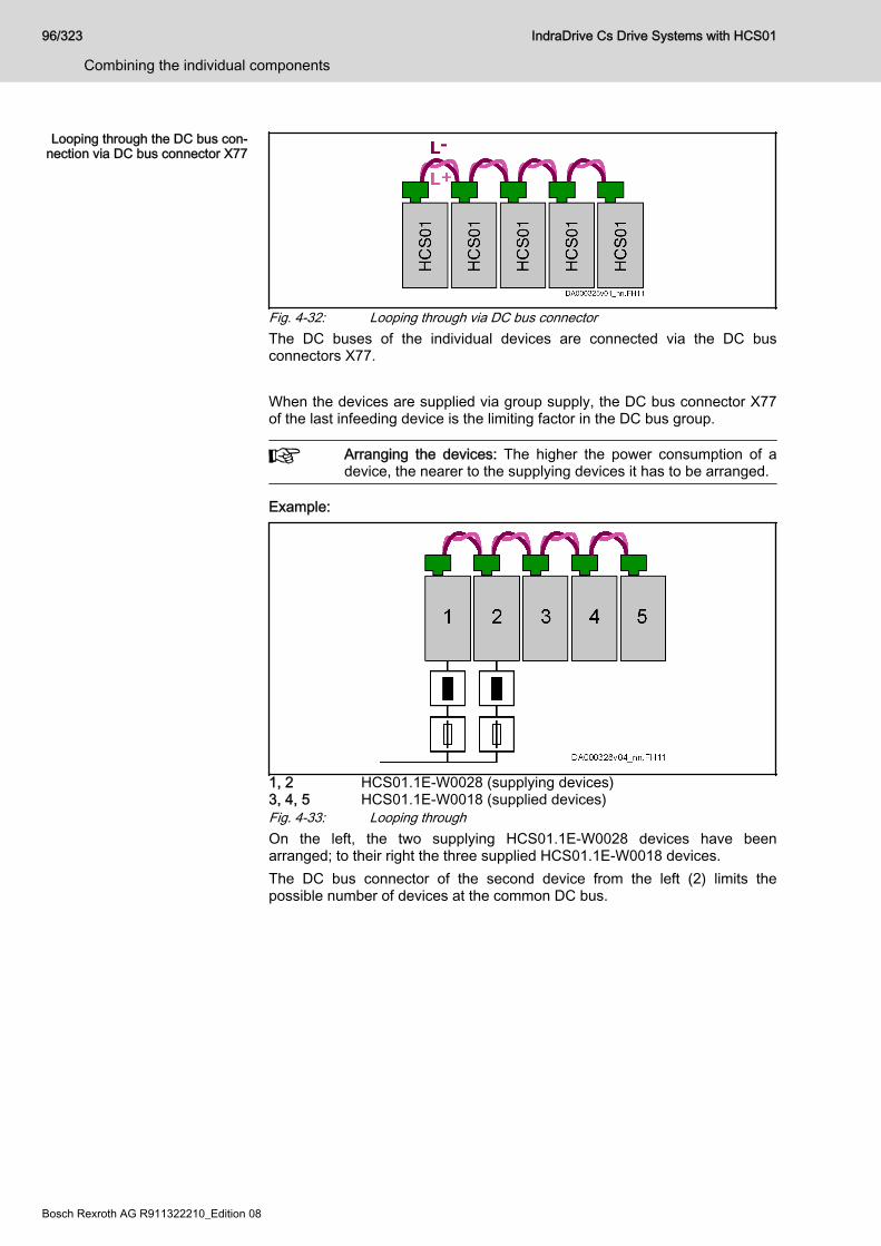
Looping through the DC bus con‐nection via DC bus connector X77
Fig. 4-32: Looping through via DC bus connectorThe DC buses of the individual devices are connected via the DC busconnectors X77. When the devices are supplied via group supply, the DC bus connector X77of the last infeeding device is the limiting factor in the DC bus group.
Arranging the devices: The higher the power consumption of adevice, the nearer to the supplying devices it has to be arranged.
Example:
1, 2 HCS01.1E-W0028 (supplying devices)3, 4, 5 HCS01.1E-W0018 (supplied devices)Fig. 4-33: Looping throughOn the left, the two supplying HCS01.1E-W0028 devices have beenarranged; to their right the three supplied HCS01.1E-W0018 devices.The DC bus connector of the second device from the left (2) limits thepossible number of devices at the common DC bus.
96/323
Combining the individual components
IndraDrive Cs Drive Systems with HCS01
Bosch Rexroth AG R911322210_Edition 08
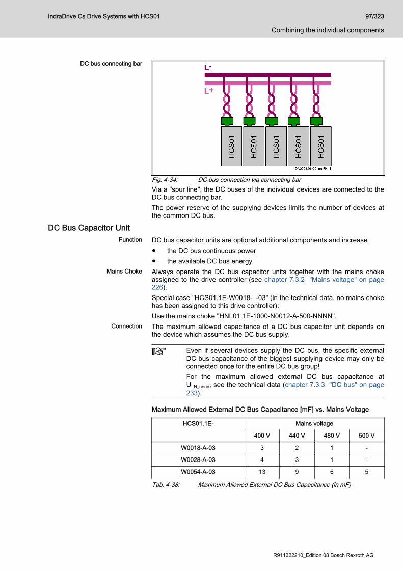
DC bus connecting bar
Fig. 4-34: DC bus connection via connecting barVia a "spur line", the DC buses of the individual devices are connected to theDC bus connecting bar.The power reserve of the supplying devices limits the number of devices atthe common DC bus.
DC Bus Capacitor UnitFunction DC bus capacitor units are optional additional components and increase
● the DC bus continuous power● the available DC bus energy
Mains Choke Always operate the DC bus capacitor units together with the mains chokeassigned to the drive controller (see chapter 7.3.2 "Mains voltage" on page226).Special case "HCS01.1E-W0018-_-03" (in the technical data, no mains chokehas been assigned to this drive controller):Use the mains choke "HNL01.1E-1000-N0012-A-500-NNNN".
Connection The maximum allowed capacitance of a DC bus capacitor unit depends onthe device which assumes the DC bus supply.
Even if several devices supply the DC bus, the specific externalDC bus capacitance of the biggest supplying device may only beconnected once for the entire DC bus group!For the maximum allowed external DC bus capacitance atULN_nenn, see the technical data (chapter 7.3.3 "DC bus" on page233).
Maximum Allowed External DC Bus Capacitance [mF] vs. Mains Voltage
HCS01.1E- Mains voltage
400 V 440 V 480 V 500 V
W0018-A-03 3 2 1 -
W0028-A-03 4 3 1 -
W0054-A-03 13 9 6 5
Tab. 4-38: Maximum Allowed External DC Bus Capacitance (in mF)
IndraDrive Cs Drive Systems with HCS01 97/323
Combining the individual components
R911322210_Edition 08 Bosch Rexroth AG
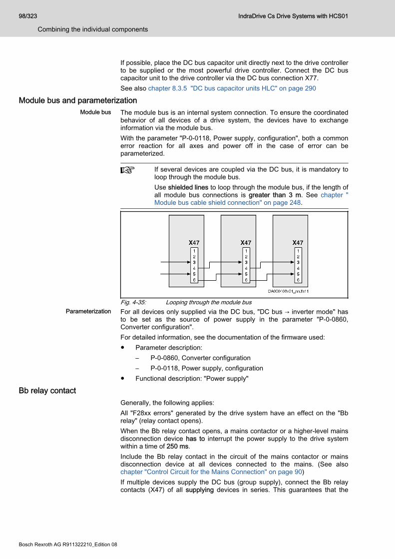
If possible, place the DC bus capacitor unit directly next to the drive controllerto be supplied or the most powerful drive controller. Connect the DC buscapacitor unit to the drive controller via the DC bus connection X77.See also chapter 8.3.5 "DC bus capacitor units HLC" on page 290
Module bus and parameterizationModule bus The module bus is an internal system connection. To ensure the coordinated
behavior of all devices of a drive system, the devices have to exchangeinformation via the module bus.With the parameter "P-0-0118, Power supply, configuration", both a commonerror reaction for all axes and power off in the case of error can beparameterized.
If several devices are coupled via the DC bus, it is mandatory toloop through the module bus.Use shielded lines to loop through the module bus, if the length ofall module bus connections is greater than 3 m. See chapter "Module bus cable shield connection" on page 248.
Fig. 4-35: Looping through the module busParameterization For all devices only supplied via the DC bus, "DC bus → inverter mode" has
to be set as the source of power supply in the parameter "P-0-0860,Converter configuration".For detailed information, see the documentation of the firmware used:● Parameter description:
– P-0-0860, Converter configuration– P-0-0118, Power supply, configuration
● Functional description: "Power supply"
Bb relay contactGenerally, the following applies:All "F28xx errors" generated by the drive system have an effect on the "Bbrelay" (relay contact opens).When the Bb relay contact opens, a mains contactor or a higher-level mainsdisconnection device has to interrupt the power supply to the drive systemwithin a time of 250 ms.Include the Bb relay contact in the circuit of the mains contactor or mainsdisconnection device at all devices connected to the mains. (See alsochapter "Control Circuit for the Mains Connection" on page 90)If multiple devices supply the DC bus (group supply), connect the Bb relaycontacts (X47) of all supplying devices in series. This guarantees that the
98/323
Combining the individual components
IndraDrive Cs Drive Systems with HCS01
Bosch Rexroth AG R911322210_Edition 08

power supply to the drive system is interrupted in the case of error in adevice.For devices which are only supplied via the DC bus, it is sufficient that youestablish the module bus connection. You do not need to connect the Bbrelay contacts of these devices in series.
Risk of fire caused by incorrect control of themains contactor or mains disconnectiondevice!
NOTICE
Include the Bb relay contact in the switch-off chain of the mains contactor ormains disconnection device so that the power supply is interrupted in thecase of error.
IndraDrive Cs Drive Systems with HCS01 99/323
Combining the individual components
R911322210_Edition 08 Bosch Rexroth AG
4.7 Acceptance tests and approvalsDeclaration of conformity Declarations of conformity confirm that the components comply with the valid
EN standards and EC directives. If required, our sales representative canprovide you with the declarations of conformity for components.
Drive controllers,Supply units Motors
CE conformity regardingLow-Voltage Directive
EN 61800-5-1:2007 EN 60034-1:2010+Cor.:2010EN 60034-5:2001+A1:2007
CE conformity regardingEMC product standard EN 61800-3:2004 + A1:2012
Tab. 4-39: CE - applied standards
C-UL-US listing The components are listed by UL (Underwriters Laboratories Inc.®).Proof of certification can be found online. Enter the terms "UL" and"databases" in a search engine to get to the relevant UL web page. With thefile number you will find the proof of certification.
● UL standard: UL 508C● CSA standard: C22.2 No. 274-13
Company NameBOSCH REXROTH ELECTRIC DRIVES &CONTROLS GMBHCategory Name:Power Conversion Equipment
File numbersIndraDrive Cs components:● E134201● E227957
Tab. 4-40: C-UL listing
UL ratingsWhen using the component in the scope of CSA / UL, observe theUL ratings for each component.Make sure that the specified short-circuit current rating SCCR isnot exceeded, e.g. by providing appropriate fuses in the mainsconnection of the supply unit.
UL wiring materialIn the scope of CSA / UL, use copper 60/75 °C only; class 1 orequivalent only.
100/323
Combining the individual components
IndraDrive Cs Drive Systems with HCS01
Bosch Rexroth AG R911322210_Edition 08
Allowed pollution degreeComply with the allowed pollution degree of the components (see"Ambient and operating conditions").
C-UR-US listing The components are listed by UL (Underwriters Laboratories Inc.®).Proof of certification can be found online. Enter the terms "UL" and"databases" in a search engine to get to the relevant UL web page. With thefile number you will find the proof of certification.
● UL standard: UL 1004-1● CSA standard: Canadian National
Standard C22.2 No. 100
Company NameBOSCH REXROTH ELECTRIC DRIVES &CONTROLS GMBHCategory Name:Servo and Stepper Motors - Component
File numbersMSK, MSM motors: E335445
Tab. 4-41: C-UR listing
UL wiring material (ready-made Rexroth cables)In the scope of CSA / UL, use copper only; class 6 or equivalentonly with minimum allowed wire temperature of 75°C.
Allowed pollution degreeComply with the allowed pollution degree of the components (see"Ambient and operating conditions").
CCC (China Compulsory Certifica‐
tion)The CCC mark is a compulsory certification of safety and quality for certainproducts mentioned in the product catalog "First Catalogue of ProductsSubject to Compulsory Certification" and in the CNCA document "ApplicationScope for Compulsory Certification of Products acc. first Catalogue" and putin circulation in China. This compulsory certification has existed since 2003.CNCA is the Chinese authority responsible for certification guidelines. Whena product is imported in China, the certification will be checked at customsusing the entries in a database. Three criteria are typically critical forcertification being required:1. Customs tariff number (HS code) according to CNCA document
"Application Scope for Compulsory Certification of Products acc. firstCatalogue".
2. Area of application according to CNCA document "Application Scope forCompulsory Certification of Products acc. first Catalogue".
3. For the IEC product standard used, a corresponding Chinese GB-standard must exist.
For the drive components by Rexroth described in this documentation,certification is currently not required, so they are not CCC certified. Negativecertifications will not be issued.
IndraDrive Cs Drive Systems with HCS01 101/323
Combining the individual components
R911322210_Edition 08 Bosch Rexroth AG

102/323 IndraDrive Cs Drive Systems with HCS01
Bosch Rexroth AG R911322210_Edition 08
5 Condition as supplied, identification, transport andstorage
5.1 Condition as supplied5.1.1 Factory testingVoltage testing and insulation resistance testing
According to standard, the components of the IndraDrive Cs range are testedwith voltage.
Testing Test rate
Voltage testing 100% (EN 61800-5-1)
Insulation resistance testing 100% (EN 60204-1)
Tab. 5-1: Applied standards
5.1.2 Customer testing
Risk of damage to the installed Rexrothcomponents by customer-side testing of themachine or installation!
NOTICE
Before conducting voltage testing or insulation resistance testing for aninstallation or machine in which these components are used:Disconnect all connections to the Rexroth components or disconnect theplug-in connections to protect the electronic components.
IndraDrive Cs Drive Systems with HCS01 103/323
Condition as supplied, identification, transport and storage
R911322210_Edition 08 Bosch Rexroth AG
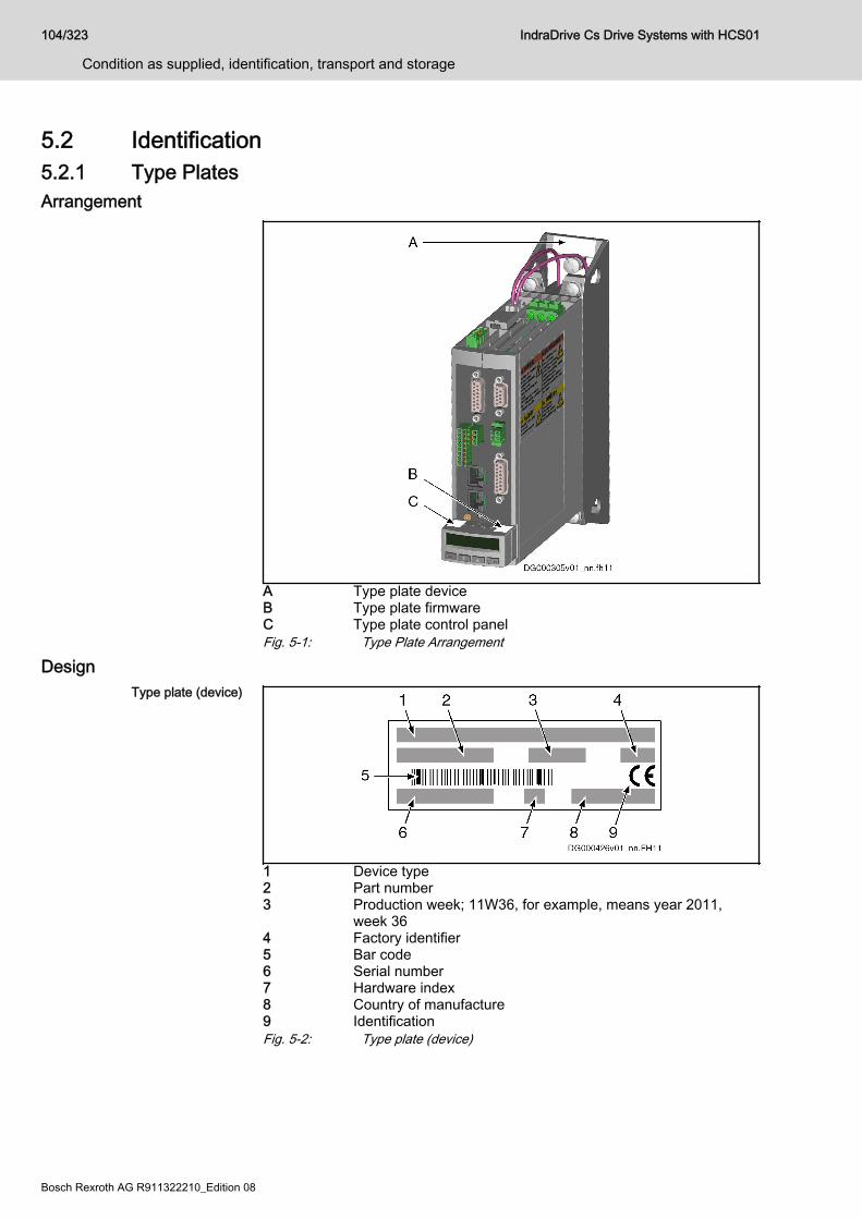
5.2 Identification5.2.1 Type PlatesArrangement
A Type plate deviceB Type plate firmwareC Type plate control panelFig. 5-1: Type Plate Arrangement
DesignType plate (device)
1 Device type2 Part number3 Production week; 11W36, for example, means year 2011,
week 364 Factory identifier5 Bar code6 Serial number7 Hardware index8 Country of manufacture9 IdentificationFig. 5-2: Type plate (device)
104/323
Condition as supplied, identification, transport and storage
IndraDrive Cs Drive Systems with HCS01
Bosch Rexroth AG R911322210_Edition 08
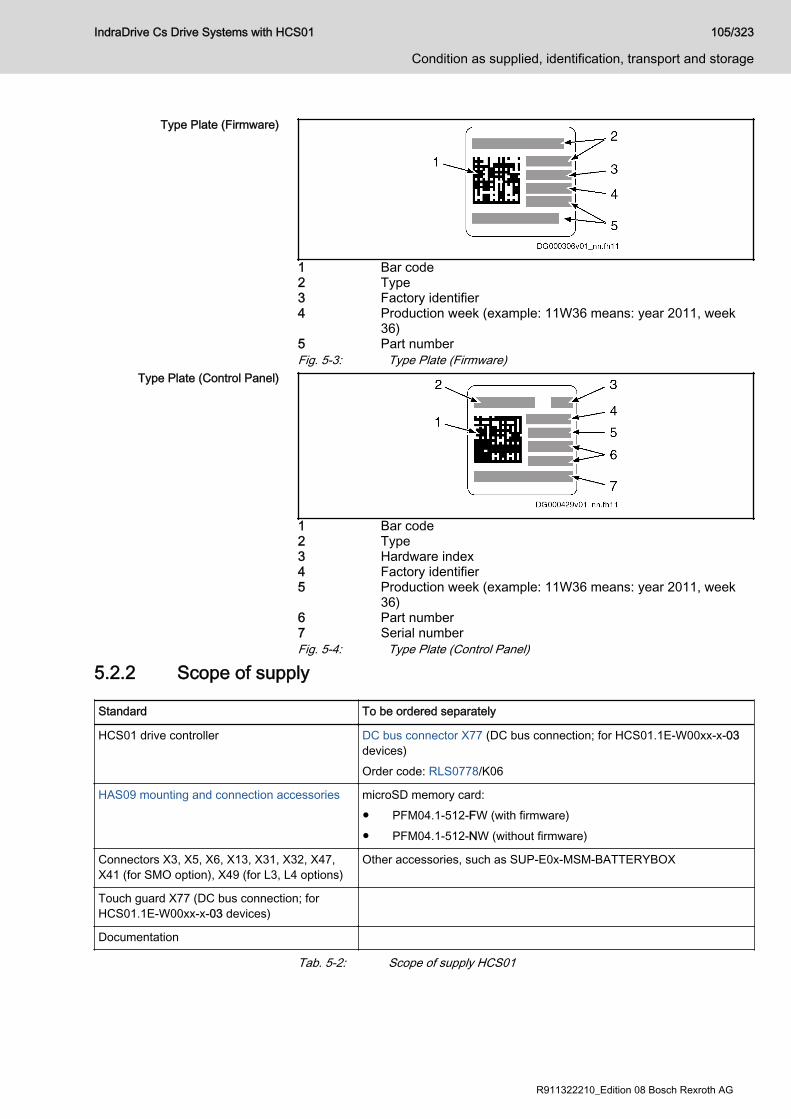
Type Plate (Firmware)
1 Bar code2 Type3 Factory identifier4 Production week (example: 11W36 means: year 2011, week
36)5 Part numberFig. 5-3: Type Plate (Firmware)
Type Plate (Control Panel)
1 Bar code2 Type3 Hardware index4 Factory identifier5 Production week (example: 11W36 means: year 2011, week
36)6 Part number7 Serial numberFig. 5-4: Type Plate (Control Panel)
5.2.2 Scope of supply
Standard To be ordered separately
HCS01 drive controller DC bus connector X77 (DC bus connection; for HCS01.1E-W00xx-x-03devices)Order code: RLS0778/K06
HAS09 mounting and connection accessories microSD memory card:● PFM04.1-512-FW (with firmware)● PFM04.1-512-NW (without firmware)
Connectors X3, X5, X6, X13, X31, X32, X47,X41 (for SMO option), X49 (for L3, L4 options)
Other accessories, such as SUP-E0x-MSM-BATTERYBOX
Touch guard X77 (DC bus connection; forHCS01.1E-W00xx-x-03 devices)
Documentation
Tab. 5-2: Scope of supply HCS01
IndraDrive Cs Drive Systems with HCS01 105/323
Condition as supplied, identification, transport and storage
R911322210_Edition 08 Bosch Rexroth AG

5.3 Transporting the componentsAmbient and operating conditions for transport
Description Symbol Unit Value
Temperature range Ta_tran °C -20 … +70
Relative humidity % 5 … 95
Absolute humidity g/m3 1 … 60
Climatic category (IEC 721) 2K3
Moisture condensation Not allowed
Icing Not allowed
Tab. 5-3: Ambient and operating conditions for transport
5.4 Storing the components
Risk of damage to components from long-term storage!
NOTICE
Some components contain electrolytic capacitors which may deteriorateduring storage.When storing the following components for a longer period of time, run themonce a year for at least 1 hour:● Converters and supply units: Operated with mains voltage ULN
● Inverters and DC bus capacitor units: Operated with DC bus voltageUDC
Ambient and operating conditions - storage
Description Symbol Unit Value
Temperature range Ta_store °C -20 … +55
Relative humidity % 5 … 95
Absolute humidity g/m3 1 … 29
Climatic category (IEC721) 1K3
Moisture condensation Not allowed
Icing Not allowed
Tab. 5-4: Ambient and operating conditions - storage
106/323
Condition as supplied, identification, transport and storage
IndraDrive Cs Drive Systems with HCS01
Bosch Rexroth AG R911322210_Edition 08
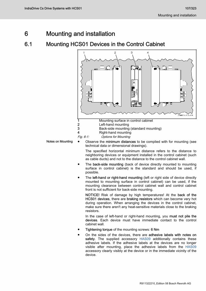
6 Mounting and installation6.1 Mounting HCS01 Devices in the Control Cabinet
1 Mounting surface in control cabinet2 Left-hand mounting3 Back-side mounting (standard mounting)4 Right-hand mountingFig. 6-1: Options for Mounting
Notes on Mounting ● Observe the minimum distances to be complied with for mounting (seetechnical data or dimensional drawings).The specified horizontal minimum distance refers to the distance toneighboring devices or equipment installed in the control cabinet (suchas cable ducts) and not to the distance to the control cabinet wall.
● The back-side mounting (back of device directly mounted to mountingsurface in control cabinet) is the standard and should be used, ifpossible.
● The left-hand or right-hand mounting (left or right side of device directlymounted to mounting surface in control cabinet) can be used, if themounting clearance between control cabinet wall and control cabinetfront is not sufficient for back-side mounting.NOTICE! Risk of damage by high temperatures! At the back of theHCS01 devices, there are braking resistors which can become very hotduring operation. When arranging the devices in the control cabinet,make sure there aren't any heat-sensitive materials close to the brakingresistors.In the case of left-hand or right-hand mounting, you must not pile thedevices. Each device must have immediate contact to the controlcabinet wall.
● Tightening torque of the mounting screws: 6 Nm● On the sides of the devices, there are adhesive labels with notes on
safety. The supplied accessory HAS09 additionally contains theseadhesive labels. If the adhesive labels at the devices are no longervisible after mounting, place the adhesive labels from the HAS09accessory clearly visibly at the device or in the immediate vicinity of thedevice.
IndraDrive Cs Drive Systems with HCS01 107/323
Mounting and installation
R911322210_Edition 08 Bosch Rexroth AG

Required Steps to Follow HCS01 drive controllers were designed for control cabinet mounting. Theyare mounted with two screws (M6×20; contained in the suppliedaccessory HAS09).
Mounting the drive controller1. Fix screws to the back panel of the control cabinet.2. Attach the drive controller to the screws.3. Fix the screws with 6 Nm.
108/323
Mounting and installation
IndraDrive Cs Drive Systems with HCS01
Bosch Rexroth AG R911322210_Edition 08

6.2 Electrical connection6.2.1 Overall connection diagram
* Optional** ECONOMY = sercos III; BASIC = Multi-Ethernet; ADVANCED
= sercos III master*** Only available at A-CC ADVANCED devices and devices with
Engineering port (EP option)X6.1, X6.2 T1 and T2 are not available at MSM motors. For proper func‐
tion of motor temperature monitoring connect the motor tem‐perature sensor as described in the wiring diagram. Otherwise,motor overtemperature detection is not possible in the drive.For Rexroth motors with data memory in the motor encoder,such as MSK, the motor overload protection is automaticallyset when the drive is connected to the motor. There is no ad‐justment necessary. Otherwise refer to the Rexroth firmwaredocumentation.
X31 No standard assignment is specified; make the assignment us‐ing the firmware documentation (see Functional Description,index entry "Digital inputs/outputs")
X47.1, X47.2 For the "ready for operation" message of the device, the Bb re‐lay contact (X47.1, X47.2) has to be wired
X47.3…6 Module bus only available at HCS01.1E-W00xx-x-03 devicesX77 DC bus connection (L+, L-) only available at HCS01.1E-
W00xx-x-03 devicesFig. 6-2: Connection diagram
IndraDrive Cs Drive Systems with HCS01 109/323
Mounting and installation
R911322210_Edition 08 Bosch Rexroth AG
6.2.2 Connection pointsArrangement of the HCS01 connection points
HCS01 connection points (ECONOMY, BASIC)
* Optional connection pointA Connection point of equipment grounding conductor, mainsB Connection point of equipment grounding conductor, motorC Control line shield connectionD Motor cable shield connectionE Control panelX3 Mains connectionX4 Motor encoderX5 Motor connectionX6 Motor temperature monitoring, motor holding brakeX8 Encoder evaluation (EC option); encoder emulation (EM op‐
tion)X9 Integrated/external braking resistorX13 24V supply (control voltage)
110/323
Mounting and installation
IndraDrive Cs Drive Systems with HCS01
Bosch Rexroth AG R911322210_Edition 08
X24 / X25 ECONOMY: sercos III communication; BASIC: Multi-Ethernetcommunication
X26 Engineering interfaceX30 PROFIBUS communication (PB option)X31 Digital inputs, digital outputX32 Analog inputX37 Digital inputs/outputs (DA option)X38 Analog inputs/outputs (DA option)X41, X42, X43 Safety technology (S4, S5 option: Safe Motion)X47 Bb relay contact, module bus (module bus at HCS01.1E-
W00xx-x-03 devices only)X49 Safety technology (L3 option: Safe Torque Off; L4 option:
Safe Torque Off, Safe Brake Control)X61 CANopen communication (CN option)X77 DC bus connection (at HCS01.1E-W00xx-x-03 devices only);
DC bus connector optionally available (if the DC bus connec‐tor is not used, the DC bus connection must be covered withthe supplied touch guard)
Fig. 6-3: HCS01 connection points
IndraDrive Cs Drive Systems with HCS01 111/323
Mounting and installation
R911322210_Edition 08 Bosch Rexroth AG
HCS01 connection points (ADVANCED)
* Optional connection pointA Connection point of equipment grounding conductor, mainsB Connection point of equipment grounding conductor, motorC Control line shield connectionD Motor cable shield connectionE Control panelX3 Mains connectionX4 Motor encoderX5 Motor connectionX6 Motor temperature monitoring, motor holding brakeX8 Encoder evaluation (EC option); encoder emulation (EM op‐
tion)X9 Integrated/external braking resistorX13 24V supply (control voltage)X22 / X23 Multi-Ethernet communication (ET option)X24 / X25 sercos III masterX26 Engineering interface (only available at A-CC ADVANCED
devices)
112/323
Mounting and installation
IndraDrive Cs Drive Systems with HCS01
Bosch Rexroth AG R911322210_Edition 08
X30 PROFIBUS communication (PB option)X31 Digital inputs, digital outputX32 Analog inputX37 Digital inputs/outputs (DA option)X38 Analog inputs/outputs (DA option)X41, X42, X43 Safety technology (S4, S5 option: Safe Motion)X47 Bb relay contact, module bus (module bus at HCS01.1E-
W00xx-x-03 devices only)X49 Safety technology (L3 option: Safe Torque Off; L4 option:
Safe Torque Off, Safe Brake Control)X61 CANopen communication (CN option)X77 DC bus connection (at HCS01.1E-W00xx-x-03 devices only);
DC bus connector optionally available (if the DC bus connec‐tor is not used, the DC bus connection must be covered withthe supplied touch guard)
Fig. 6-4: HCS01 connection points
6.2.3 On-board connection pointsConnection of Equipment Grounding Conductor
High housing voltage and high leakagecurrent! Danger to life, risk of injury byelectric shock!
WARNING
● Before switching on and before commissioning, ground or connect thecomponents of the electric drive and control system to the equipmentgrounding conductor at the grounding points.
● Connect the equipment grounding conductor of the components of theelectric drive and control system permanently to the main power supplyat all times. The leakage current is greater than 3.5 mA.
● Establish an equipment grounding connection with a copper wire of across section of at least 10 mm2 (8 AWG) or additionally run a secondequipment grounding conductor of the same cross section as theoriginal equipment grounding conductor.
Lethal electric shock by live parts with morethan 50 V!
WARNING
Only operate the device● with the connectors plugged on (even if no lines have been connected
to the connectors) and● with the equipment grounding conductor connected!
IndraDrive Cs Drive Systems with HCS01 113/323
Mounting and installation
R911322210_Edition 08 Bosch Rexroth AG
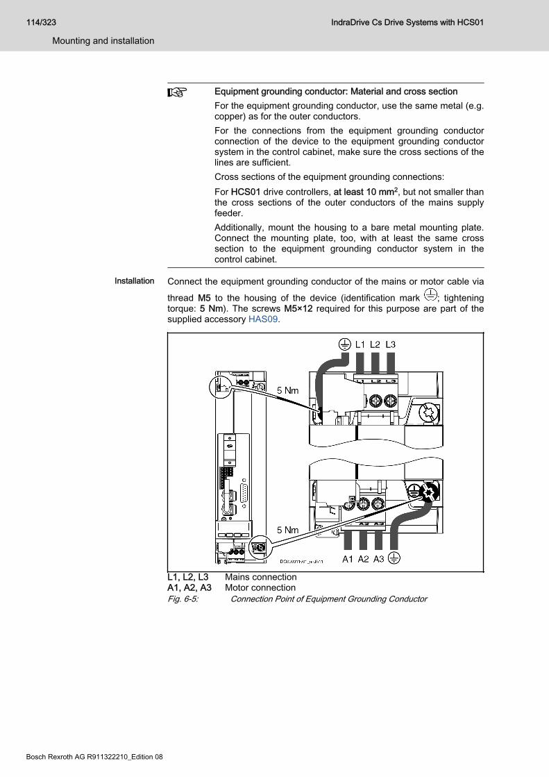
Equipment grounding conductor: Material and cross sectionFor the equipment grounding conductor, use the same metal (e.g.copper) as for the outer conductors.For the connections from the equipment grounding conductorconnection of the device to the equipment grounding conductorsystem in the control cabinet, make sure the cross sections of thelines are sufficient.Cross sections of the equipment grounding connections:For HCS01 drive controllers, at least 10 mm2, but not smaller thanthe cross sections of the outer conductors of the mains supplyfeeder.Additionally, mount the housing to a bare metal mounting plate.Connect the mounting plate, too, with at least the same crosssection to the equipment grounding conductor system in thecontrol cabinet.
Installation Connect the equipment grounding conductor of the mains or motor cable via
thread M5 to the housing of the device (identification mark ; tighteningtorque: 5 Nm). The screws M5×12 required for this purpose are part of thesupplied accessory HAS09.
L1, L2, L3 Mains connectionA1, A2, A3 Motor connectionFig. 6-5: Connection Point of Equipment Grounding Conductor
114/323
Mounting and installation
IndraDrive Cs Drive Systems with HCS01
Bosch Rexroth AG R911322210_Edition 08

X3, mains connectionImportant notes
Lethal electric shock by live parts with morethan 50 V!
WARNING
Only operate the device● with the connectors plugged on (even if no lines have been connected
to the connectors) and● with the equipment grounding conductor connected!
Notes on installation ● The equipment grounding conductor is connected directly to the deviceand not via the connection point X3 (see chapter "Connection ofEquipment Grounding Conductor" on page 113).
● Measure the necessary cross section of the connection cablesaccording to the determined phase current ILN and the mains fuse.
● Single-phase mains connection (outer conductor and neutral conductor):Connection to X3 can be made via L1, L2 or L3.
Risk of damage to the device!NOTICE
Provide strain relief for the terminal connectors of the device in the controlcabinet.
IndraDrive Cs Drive Systems with HCS01 115/323
Mounting and installation
R911322210_Edition 08 Bosch Rexroth AG
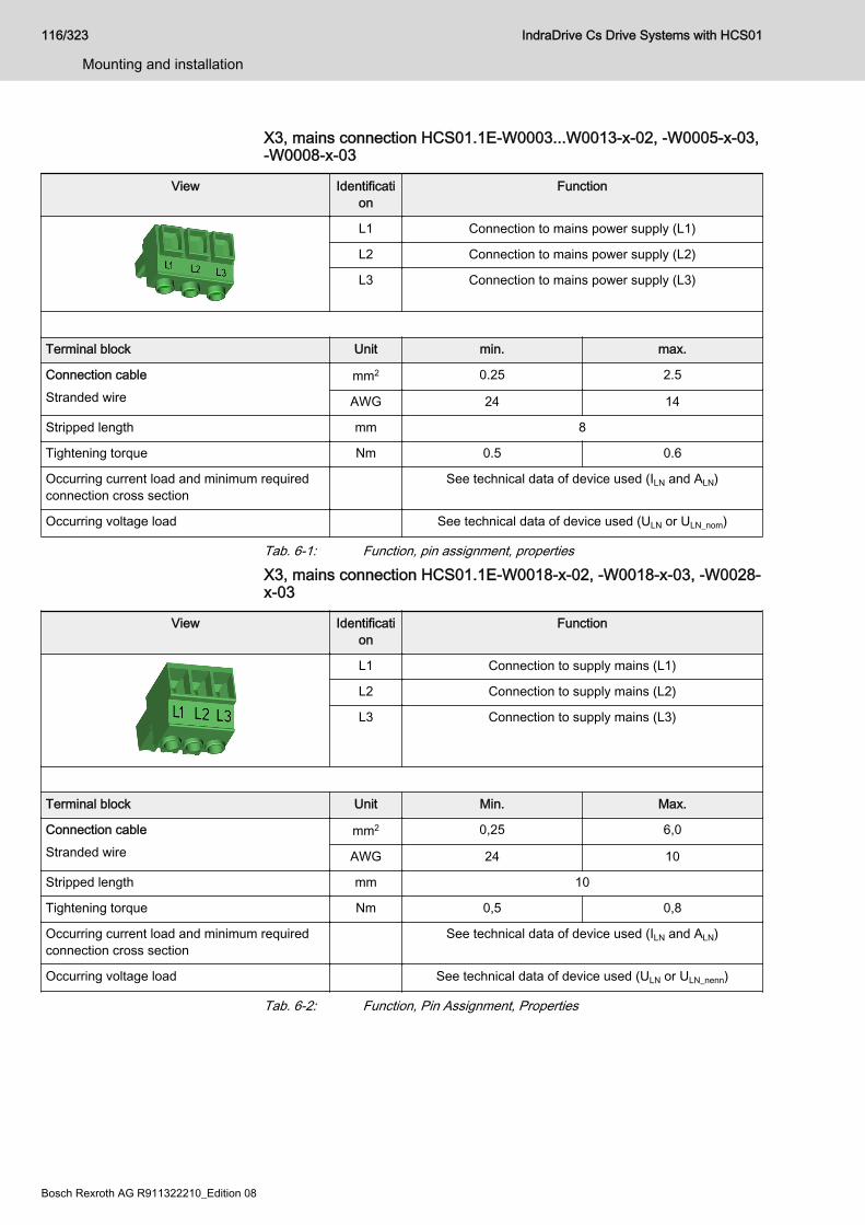
X3, mains connection HCS01.1E-W0003...W0013-x-02, -W0005-x-03,-W0008-x-03
View Identification
Function
L1 Connection to mains power supply (L1)
L2 Connection to mains power supply (L2)
L3 Connection to mains power supply (L3)
Terminal block Unit min. max.
Connection cableStranded wire
mm2 0.25 2.5
AWG 24 14
Stripped length mm 8
Tightening torque Nm 0.5 0.6
Occurring current load and minimum requiredconnection cross section
See technical data of device used (ILN and ALN)
Occurring voltage load See technical data of device used (ULN or ULN_nom)
Tab. 6-1: Function, pin assignment, properties
X3, mains connection HCS01.1E-W0018-x-02, -W0018-x-03, -W0028-x-03
View Identification
Function
L1 Connection to supply mains (L1)
L2 Connection to supply mains (L2)
L3 Connection to supply mains (L3)
Terminal block Unit Min. Max.
Connection cableStranded wire
mm2 0,25 6,0
AWG 24 10
Stripped length mm 10
Tightening torque Nm 0,5 0,8
Occurring current load and minimum requiredconnection cross section
See technical data of device used (ILN and ALN)
Occurring voltage load See technical data of device used (ULN or ULN_nenn)
Tab. 6-2: Function, Pin Assignment, Properties
116/323
Mounting and installation
IndraDrive Cs Drive Systems with HCS01
Bosch Rexroth AG R911322210_Edition 08
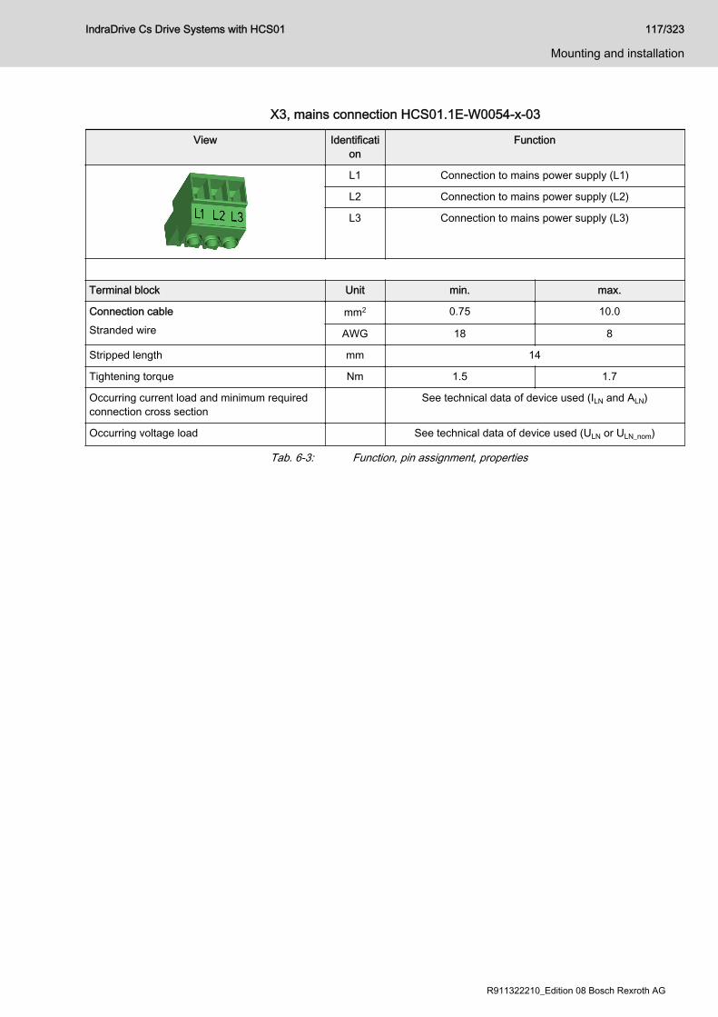
X3, mains connection HCS01.1E-W0054-x-03
View Identification
Function
L1 Connection to mains power supply (L1)
L2 Connection to mains power supply (L2)
L3 Connection to mains power supply (L3)
Terminal block Unit min. max.
Connection cableStranded wire
mm2 0.75 10.0
AWG 18 8
Stripped length mm 14
Tightening torque Nm 1.5 1.7
Occurring current load and minimum requiredconnection cross section
See technical data of device used (ILN and ALN)
Occurring voltage load See technical data of device used (ULN or ULN_nom)
Tab. 6-3: Function, pin assignment, properties
IndraDrive Cs Drive Systems with HCS01 117/323
Mounting and installation
R911322210_Edition 08 Bosch Rexroth AG
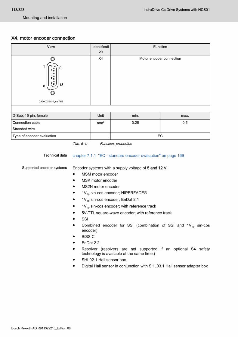
X4, motor encoder connectionView Identificati
onFunction
X4 Motor encoder connection
D-Sub, 15-pin, female Unit min. max.
Connection cableStranded wire
mm2 0.25 0.5
Type of encoder evaluation EC
Tab. 6-4: Function, properties
Technical data chapter 7.1.1 "EC - standard encoder evaluation" on page 169
Supported encoder systems Encoder systems with a supply voltage of 5 and 12 V:● MSM motor encoder● MSK motor encoder● MS2N motor encoder● 1Vpp sin-cos encoder; HIPERFACE®● 1Vpp sin-cos encoder; EnDat 2.1● 1Vpp sin-cos encoder; with reference track● 5V-TTL square-wave encoder; with reference track● SSI● Combined encoder for SSI (combination of SSI and 1Vpp sin-cos
encoder)● BiSS C● EnDat 2.2● Resolver (resolvers are not supported if an optional S4 safety
technology is available at the same time.)● SHL02.1 Hall sensor box● Digital Hall sensor in conjunction with SHL03.1 Hall sensor adapter box
118/323
Mounting and installation
IndraDrive Cs Drive Systems with HCS01
Bosch Rexroth AG R911322210_Edition 08

Pin assignment Connection Signal Function
1 GND_shld Connection signal shields (internal shields)
2 A+ Track A analog positive
3 A- Track A analog negative
4 GND_Encoder Reference potential power supplies
5 B+ Track B analog positive
6 B- Track B analog negative
7 EncData+ Data transmission positive
A+TTL Track A TTL positive
8 EncData- Data transmission negative
A-TTL Track A TTL negative
9 R+ Reference track positive
10 R- Reference track negative
11 +12V Encoder supply 12V
12 +5V Encoder supply 5V
13 EncCLK+ Clock positive
B+TTL Track B TTL positive
14 EncCLK- Clock negative
B-TTL Track B TTL negative
15 Sense- Return of reference potential (Sense line)
VCC_Resolver Resolver supply
Connectorhousing Overall shield
Tab. 6-5: Pin assignment
IndraDrive Cs Drive Systems with HCS01 119/323
Mounting and installation
R911322210_Edition 08 Bosch Rexroth AG
X5, Motor ConnectionImportant Notes
Lethal electric shock by live parts with morethan 50 V!
WARNING
Only operate the device● with the connectors plugged on (even if no lines have been connected
to the connectors) and● with the equipment grounding conductor connected!
Risk of damage to the device!NOTICE
Provide strain relief for the terminal connectors of the device in the controlcabinet.
Notes on Installation The equipment grounding conductor is connected directly to the device and
not via the connection point X5.The indicated connection cross sections are the cross sections which can beconnected. Dimension the required cross section of the connection linesaccording to the occurring current load.
● For optimum shield contact of the motor power cable, usethe supplied accessory HAS09.
● For the connection between drive controller and motor, useour ready-made motor power cables, where possible.
● When using NFD03.1 mains filters, the maximum allowedconductor cross section is limited to 4 mm2.
120/323
Mounting and installation
IndraDrive Cs Drive Systems with HCS01
Bosch Rexroth AG R911322210_Edition 08
X5, Motor Connection HCS01.1E-W0003…W0013-x-02, -W0005-x-03, -W0008-x-03
View Identification
Function
A1 For power connection U1 at motor
A2 For power connection V1 at motor
A3 For power connection W1 at motor
Screw connection at connector Unit Min. Max.
Connection cableStranded wire
mm2 0,25 2,5
AWG 24 12
Stripped length mm 8
Tightening torque Nm 0,5 0,6
Occurring current load and minimum requiredconnection cross section
A See technical data of device used (Iout)
Occurring voltage load V See technical data of device used (Uout)
Short circuit protection A1, A2, A3 against each other and each of them againstground
Connection of equipment grounding conductor Via connection point of equipment grounding conductor
at device (see index entry "Connection → Equipmentgrounding conductor")
Tab. 6-6: Function, Pin Assignment, Properties
IndraDrive Cs Drive Systems with HCS01 121/323
Mounting and installation
R911322210_Edition 08 Bosch Rexroth AG
X5, Motor Connection HCS01.1E-W0018-x-02, -W0018-x-03, -W0028-x-03
View Identification
Function
A1 For power connection U1 at motor
A2 For power connection V1 at motor
A3 For power connection W1 at motor
Screw connection at connector Unit Min. Max.
Connection cableStranded wire
mm2 0,25 6,0
AWG 24 10
Stripped length mm 10
Tightening torque Nm 0,5 0,8
Occurring current load and minimum requiredconnection cross section
A See technical data of device used (Iout)
Occurring voltage load V See technical data of device used (Uout)
Short circuit protection A1, A2, A3 against each other and each of them againstground
Connection of equipment grounding conductor Via connection point of equipment grounding conductor
at device
Tab. 6-7: Function, Pin Assignment, Properties
122/323
Mounting and installation
IndraDrive Cs Drive Systems with HCS01
Bosch Rexroth AG R911322210_Edition 08
X5, Motor Connection HCS01.1E-W0054-x-03
View Identification
Function
A1 For power connection U1 at motor
A2 For power connection V1 at motor
A3 For power connection W1 at motor
Screw connection at connector Unit Min. Max.
Connection cableStranded wire
mm2 0,75 10,0
AWG 18 8
Stripped length mm 14
Tightening torque Nm 1,5 1,7
Occurring current load and minimum requiredconnection cross section
A See technical data of device used (Iout)
Occurring voltage load V See technical data of device used (Uout)
Short circuit protection A1, A2, A3 against each other and each of them againstground
Connection of equipment grounding conductor Via connection point of equipment grounding conductor
at device
Tab. 6-8: Function, Pin Assignment, Properties
IndraDrive Cs Drive Systems with HCS01 123/323
Mounting and installation
R911322210_Edition 08 Bosch Rexroth AG
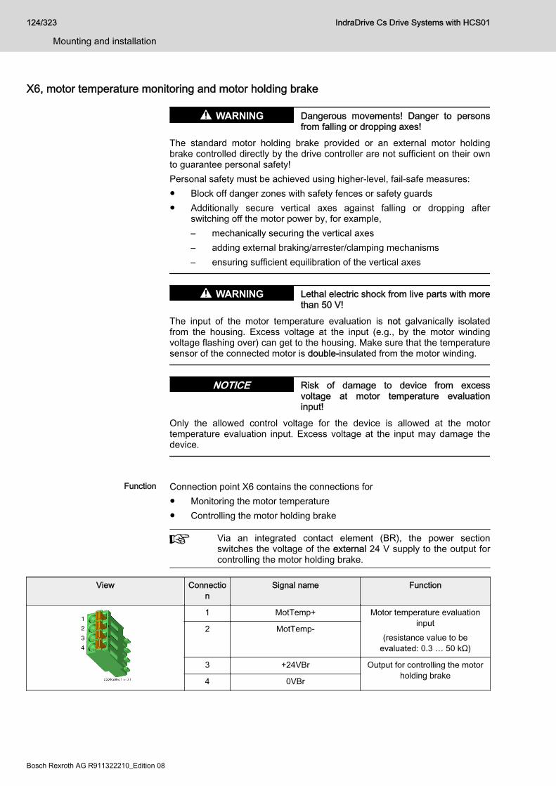
X6, motor temperature monitoring and motor holding brake
Dangerous movements! Danger to personsfrom falling or dropping axes!
WARNING
The standard motor holding brake provided or an external motor holdingbrake controlled directly by the drive controller are not sufficient on their ownto guarantee personal safety!Personal safety must be achieved using higher-level, fail-safe measures:● Block off danger zones with safety fences or safety guards● Additionally secure vertical axes against falling or dropping after
switching off the motor power by, for example,– mechanically securing the vertical axes– adding external braking/arrester/clamping mechanisms– ensuring sufficient equilibration of the vertical axes
Lethal electric shock from live parts with morethan 50 V!
WARNING
The input of the motor temperature evaluation is not galvanically isolatedfrom the housing. Excess voltage at the input (e.g., by the motor windingvoltage flashing over) can get to the housing. Make sure that the temperaturesensor of the connected motor is double-insulated from the motor winding.
Risk of damage to device from excessvoltage at motor temperature evaluationinput!
NOTICE
Only the allowed control voltage for the device is allowed at the motortemperature evaluation input. Excess voltage at the input may damage thedevice.
Function Connection point X6 contains the connections for
● Monitoring the motor temperature● Controlling the motor holding brake
Via an integrated contact element (BR), the power sectionswitches the voltage of the external 24 V supply to the output forcontrolling the motor holding brake.
View Connection
Signal name Function
1 MotTemp+ Motor temperature evaluationinput
(resistance value to beevaluated: 0.3 … 50 kΩ)
2 MotTemp-
3 +24VBr Output for controlling the motorholding brake4 0VBr
124/323
Mounting and installation
IndraDrive Cs Drive Systems with HCS01
Bosch Rexroth AG R911322210_Edition 08
Spring terminal (connector) Unit min. max.
Connection cableStranded wire
mm2 0.25 1.5
AWG 24 16
Stripped length mm 10
Current carrying capacity of outputs X6 A - 1.25
Time constant of load ms - 50
Number of switching actions atmaximum time constant of load
Wear-free electronic contact
Switching frequency Hz - 0.5
Short circuit protection X6.3 against X6.4 (output for controlling the motor holding brake)
Overload protection X6.3 against X6.4 (output for controlling the motor holding brake)
Tab. 6-9: Function, pin assignment
Motor holding brake: Selection Maximum current carrying capacity of X6 outputs: 1.25 A⇒ Rbr (min) = Ubr (max) / 1.25 ARbr (min): minimum allowed resistance of motor holding brakeUbr (max): maximum supply voltage of motor holding brakeIf Ubr (max) = 24 V +5% = 25.2 V, then:Rbr (min) = 20.16 Ω (applies to all operating and ambient conditions)
Motor holding brake: Notes on in‐stallation
Make sure the power supply is sufficient for the motor holding brake at themotor. Observe that voltage drops on the supply line. Use connection lineswith the largest possible cross section of single strands.Use an external contact element in accordance with the required safetycategory if you wish to supply motor holding brakes with higher currents thanthe current load allowed at X6. Make sure to comply with the requiredminimum current consumption of 100 mA when using an external contactelement. Otherwise the brake current monitor will signal an error.
IndraDrive Cs Drive Systems with HCS01 125/323
Mounting and installation
R911322210_Edition 08 Bosch Rexroth AG
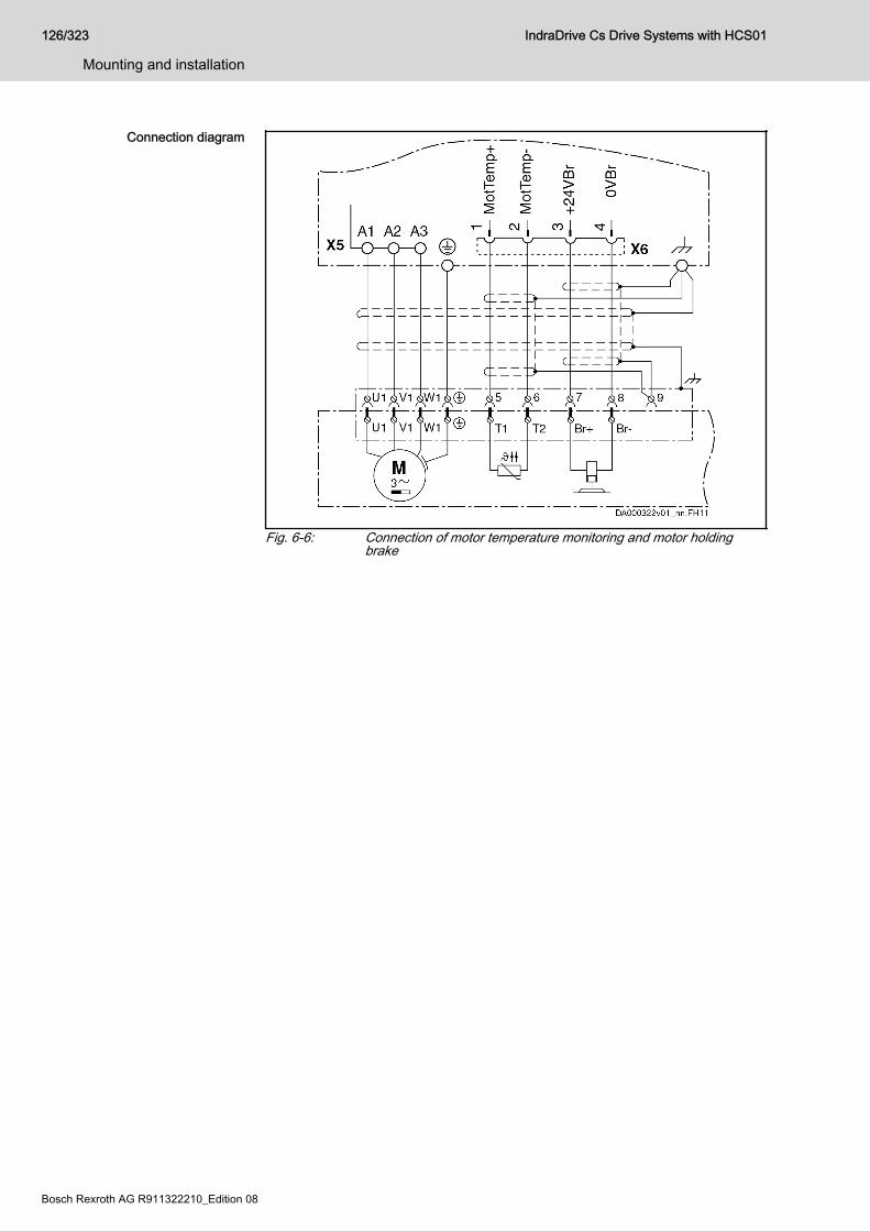
Connection diagram
Fig. 6-6: Connection of motor temperature monitoring and motor holdingbrake
126/323
Mounting and installation
IndraDrive Cs Drive Systems with HCS01
Bosch Rexroth AG R911322210_Edition 08
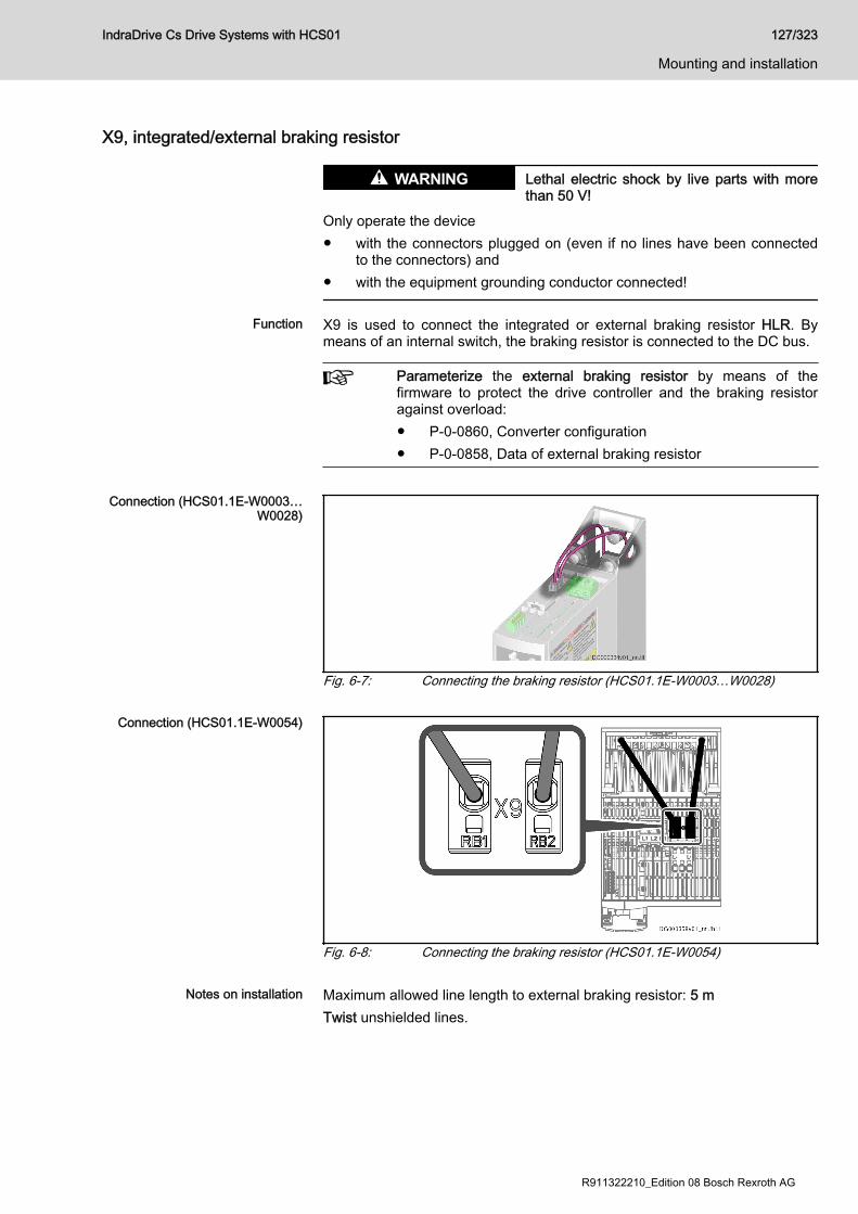
X9, integrated/external braking resistor
Lethal electric shock by live parts with morethan 50 V!
WARNING
Only operate the device● with the connectors plugged on (even if no lines have been connected
to the connectors) and● with the equipment grounding conductor connected!
Function X9 is used to connect the integrated or external braking resistor HLR. Bymeans of an internal switch, the braking resistor is connected to the DC bus.
Parameterize the external braking resistor by means of thefirmware to protect the drive controller and the braking resistoragainst overload:● P-0-0860, Converter configuration● P-0-0858, Data of external braking resistor
Connection (HCS01.1E-W0003…
W0028)
Fig. 6-7: Connecting the braking resistor (HCS01.1E-W0003…W0028)
Connection (HCS01.1E-W0054)
Fig. 6-8: Connecting the braking resistor (HCS01.1E-W0054)
Notes on installation Maximum allowed line length to external braking resistor: 5 mTwist unshielded lines.
IndraDrive Cs Drive Systems with HCS01 127/323
Mounting and installation
R911322210_Edition 08 Bosch Rexroth AG

The accessory HAS05.1-015-NNN-NN (snap-on ferrite) ensures thatClass C3 of the EMC Directive EN 61800-3 is complied with for brakingresistors installed outside of the control cabinet.The snap-on ferrite is designed for the following components:■ HCS01.1E-W0018 + HLR01.2N-01K0-N68R0-E-007■ HCS01.1E-W0028 + HLR01.2N-01K0-N68R0-E-007■ HCS01.1E-W0054 + HLR01.2N-01K0-N28R0-E-007
Lethal electric shock from live parts with morethan 50 V!Risk of burns by hot housing surfaces! Riskof fire!
WARNING
The temperature of the housing surface of an external HLR braking resistorcan rise up to 150 °C. Run the connection lines with a sufficient distance(> 200 mm) to the housing of the HLR braking resistor to avoid damaging theinsulation of the connection lines. Outside of the control cabinet, run theconnection lines of an HLR braking resistor in a metal pipe with a wallthickness of at least 1 mm.Do not touch hot housing surfaces! Mount the HLR braking resistor on atemperature-resistant mounting surface. Provide a sufficient distancebetween the HLR braking resistor and heat-sensitive materials. Make surethe cooling air supply is unrestricted. Take care that the environment candischarge the dissipation heat.
Danger by insufficient installation!NOTICE
Protect the lines with the appropriate fusing elements in the supply feeder.For the connection lines at X9, use at least the cross section of the lines formains connection at X3. If this is impossible, select the cross section of theconnection line at X9 in accordance with the continuous power of the brakingresistor.
128/323
Mounting and installation
IndraDrive Cs Drive Systems with HCS01
Bosch Rexroth AG R911322210_Edition 08

X13, 24V Supply (Control Voltage)Function, Pin Assignment The external 24V supply is applied via connection point X13 for
● the control section and power section of the drive controller● brake control via X6● the digital inputs and the digital output to X31 / X32
View Connection
Signal name Function
1 0V Reference potential forpower supply2 0V
3 +24V Power supply
4 +24V
Spring terminal (connector) Unit Min. Max.
Connection cableStranded wire
mm2 1,0 2,5
AWG 16 12
Stripped length mm 10
Power consumption W PN3 (see data for control voltage)
Voltage load capacity V UN3 (see data for control voltage)
Current carrying capacity "looping through" from0V to 0V, 24V to 24V
A 10
Polarity reversal protection Within the allowed voltage range by internal protective diode
Insulation monitoring Possible
Tab. 6-10: Function, Pin Assignment, PropertiesNotes on Installation Requirements on the connection to the 24V supply:
● Minimum cross section: 1 mm2
● Maximum allowed inductance: 100 µH (2 twisted single strands, 75 mlong)
● Parallel line routing where possibleDepending on the power consumption of the devices and the current carryingcapacity of the connector X13, check via how many devices one line for 24Vsupply can be looped through. You might possibly have to connect anotherdevice directly to the 24V supply and then loop through the control voltagefrom this device to other devices.
IndraDrive Cs Drive Systems with HCS01 129/323
Mounting and installation
R911322210_Edition 08 Bosch Rexroth AG
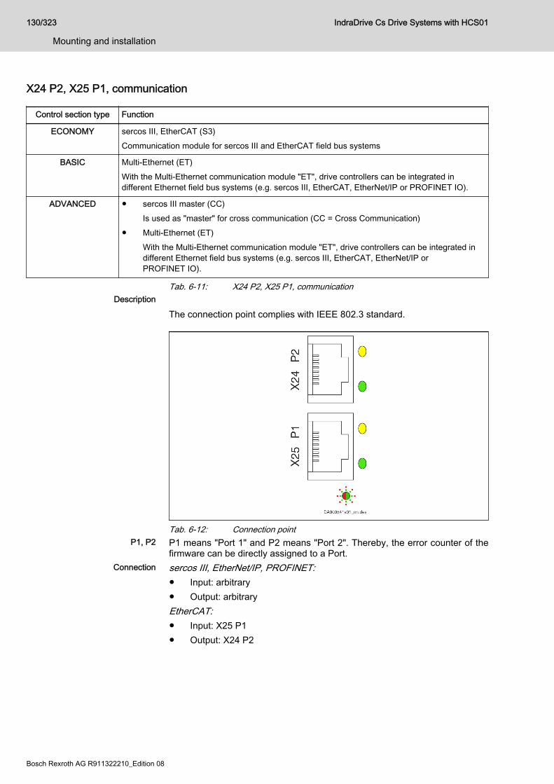
X24 P2, X25 P1, communication
Control section type Function
ECONOMY sercos III, EtherCAT (S3)Communication module for sercos III and EtherCAT field bus systems
BASIC Multi-Ethernet (ET)With the Multi-Ethernet communication module "ET", drive controllers can be integrated indifferent Ethernet field bus systems (e.g. sercos III, EtherCAT, EtherNet/IP or PROFINET IO).
ADVANCED ● sercos III master (CC)Is used as "master" for cross communication (CC = Cross Communication)
● Multi-Ethernet (ET)With the Multi-Ethernet communication module "ET", drive controllers can be integrated indifferent Ethernet field bus systems (e.g. sercos III, EtherCAT, EtherNet/IP orPROFINET IO).
Tab. 6-11: X24 P2, X25 P1, communicationDescription
The connection point complies with IEEE 802.3 standard.
Tab. 6-12: Connection pointP1, P2 P1 means "Port 1" and P2 means "Port 2". Thereby, the error counter of the
firmware can be directly assigned to a Port.Connection sercos III, EtherNet/IP, PROFINET:
● Input: arbitrary● Output: arbitraryEtherCAT:● Input: X25 P1● Output: X24 P2
130/323
Mounting and installation
IndraDrive Cs Drive Systems with HCS01
Bosch Rexroth AG R911322210_Edition 08
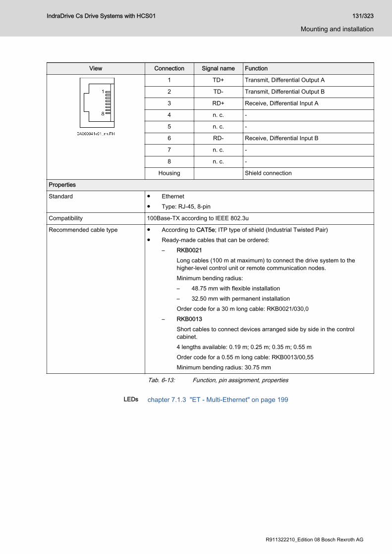
View Connection Signal name Function
1 TD+ Transmit, Differential Output A
2 TD- Transmit, Differential Output B
3 RD+ Receive, Differential Input A
4 n. c. -
5 n. c. -
6 RD- Receive, Differential Input B
7 n. c. -
8 n. c. -
Housing Shield connection
Properties
Standard ● Ethernet● Type: RJ-45, 8-pin
Compatibility 100Base-TX according to IEEE 802.3u
Recommended cable type ● According to CAT5e; ITP type of shield (Industrial Twisted Pair)● Ready-made cables that can be ordered:
– RKB0021Long cables (100 m at maximum) to connect the drive system to thehigher-level control unit or remote communication nodes.Minimum bending radius:– 48.75 mm with flexible installation– 32.50 mm with permanent installationOrder code for a 30 m long cable: RKB0021/030,0
– RKB0013Short cables to connect devices arranged side by side in the controlcabinet.4 lengths available: 0.19 m; 0.25 m; 0.35 m; 0.55 mOrder code for a 0.55 m long cable: RKB0013/00,55Minimum bending radius: 30.75 mm
Tab. 6-13: Function, pin assignment, properties
LEDs chapter 7.1.3 "ET - Multi-Ethernet" on page 199
IndraDrive Cs Drive Systems with HCS01 131/323
Mounting and installation
R911322210_Edition 08 Bosch Rexroth AG
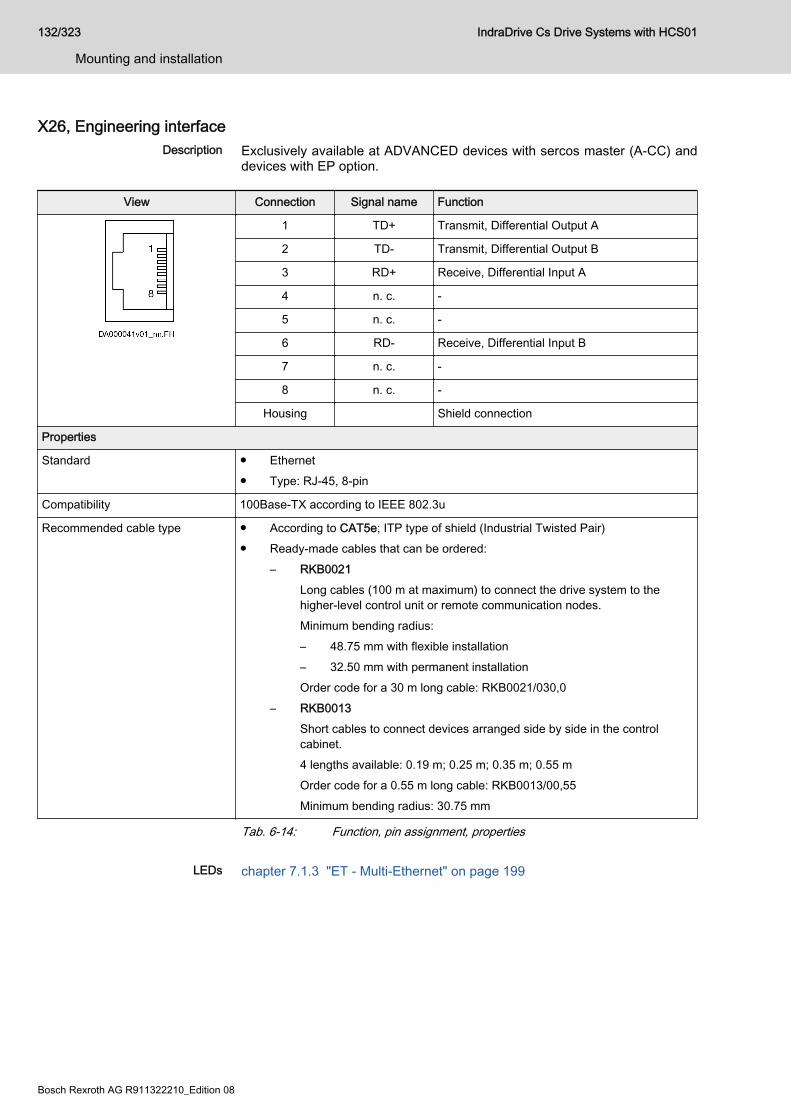
X26, Engineering interfaceDescription Exclusively available at ADVANCED devices with sercos master (A-CC) and
devices with EP option.
View Connection Signal name Function
1 TD+ Transmit, Differential Output A
2 TD- Transmit, Differential Output B
3 RD+ Receive, Differential Input A
4 n. c. -
5 n. c. -
6 RD- Receive, Differential Input B
7 n. c. -
8 n. c. -
Housing Shield connection
Properties
Standard ● Ethernet● Type: RJ-45, 8-pin
Compatibility 100Base-TX according to IEEE 802.3u
Recommended cable type ● According to CAT5e; ITP type of shield (Industrial Twisted Pair)● Ready-made cables that can be ordered:
– RKB0021Long cables (100 m at maximum) to connect the drive system to thehigher-level control unit or remote communication nodes.Minimum bending radius:– 48.75 mm with flexible installation– 32.50 mm with permanent installationOrder code for a 30 m long cable: RKB0021/030,0
– RKB0013Short cables to connect devices arranged side by side in the controlcabinet.4 lengths available: 0.19 m; 0.25 m; 0.35 m; 0.55 mOrder code for a 0.55 m long cable: RKB0013/00,55Minimum bending radius: 30.75 mm
Tab. 6-14: Function, pin assignment, properties
LEDs chapter 7.1.3 "ET - Multi-Ethernet" on page 199
132/323
Mounting and installation
IndraDrive Cs Drive Systems with HCS01
Bosch Rexroth AG R911322210_Edition 08

X31, digital inputs, digital outputView Connectio
nSignalname
Function Default assignment
1 I_1 Digital input Probe 1 1)
2 I_2 Probe 2 1)
3 I_3 E-Stop input 2)
4 I_4 Travel range limit switchinput 2)
5 I_5 Travel range limit switchinput 2)
6 I_6 Not assigned 2)
7 I_7 Not assigned 2)
8 I/O_8 Digital input/output Not assigned
Spring terminal (connector) Unit min. max.
Connection cableStranded wire
mm2 0.2 1.5
AWG 24 16
Stripped length mm - 10
Input current A - 0.01
Input voltage V - 24
Output current I/O_8 A - 0.5
1) Digital inputs type B (probe)2) Digital inputs type A (standard)Tab. 6-15: Function, pin assignment, properties
The reference potential for the digital inputs and the digital input/output is applied to X13.1 and X13.2.The power supply for the digital inputs and the digital input/outputis applied to X13.3 and X13.4.
Technical data ● chapter "Digital inputs type A (standard)" on page 211
● chapter "Digital inputs type B (probe)" on page 212● chapter "Digital outputs (standard)" on page 215
IndraDrive Cs Drive Systems with HCS01 133/323
Mounting and installation
R911322210_Edition 08 Bosch Rexroth AG
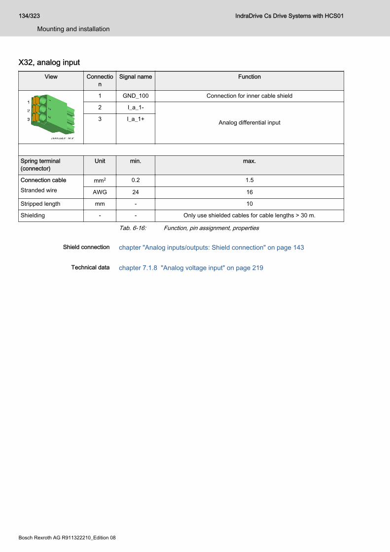
X32, analog inputView Connectio
nSignal name Function
1 GND_100 Connection for inner cable shield
2 I_a_1-
Analog differential input3 I_a_1+
Spring terminal(connector)
Unit min. max.
Connection cableStranded wire
mm2 0.2 1.5
AWG 24 16
Stripped length mm - 10
Shielding - - Only use shielded cables for cable lengths > 30 m.
Tab. 6-16: Function, pin assignment, properties
Shield connection chapter "Analog inputs/outputs: Shield connection" on page 143
Technical data chapter 7.1.8 "Analog voltage input" on page 219
134/323
Mounting and installation
IndraDrive Cs Drive Systems with HCS01
Bosch Rexroth AG R911322210_Edition 08
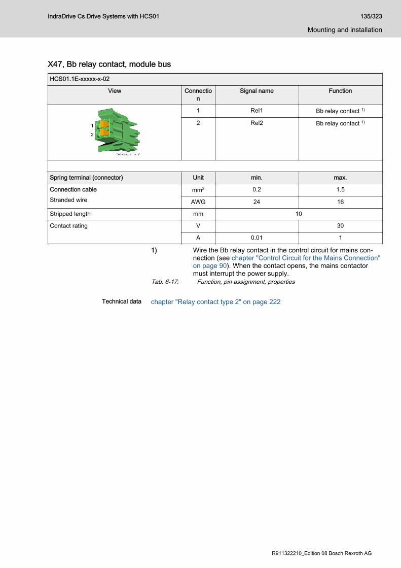
X47, Bb relay contact, module busHCS01.1E-xxxxx-x-02
View Connection
Signal name Function
1 Rel1 Bb relay contact 1)
2 Rel2 Bb relay contact 1)
Spring terminal (connector) Unit min. max.
Connection cableStranded wire
mm2 0.2 1.5
AWG 24 16
Stripped length mm 10
Contact rating V 30
A 0.01 1
1) Wire the Bb relay contact in the control circuit for mains con‐nection (see chapter "Control Circuit for the Mains Connection"on page 90). When the contact opens, the mains contactormust interrupt the power supply.
Tab. 6-17: Function, pin assignment, properties
Technical data chapter "Relay contact type 2" on page 222
IndraDrive Cs Drive Systems with HCS01 135/323
Mounting and installation
R911322210_Edition 08 Bosch Rexroth AG
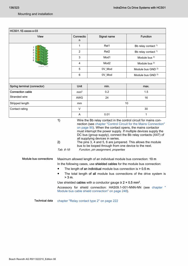
HCS01.1E-xxxxx-x-03
View Connection
Signal name Function
1 Rel1 Bb relay contact 1)
2 Rel2 Bb relay contact 1)
3 Mod1 Module bus 2)
4 Mod2 Module bus 2)
5 0V_Mod Module bus GND 2)
6 0V_Mod Module bus GND 2)
Spring terminal (connector) Unit min. max.
Connection cableStranded wire
mm2 0.2 1.5
AWG 24 16
Stripped length mm 10
Contact rating V 30
A 0.01 1
1) Wire the Bb relay contact in the control circuit for mains con‐nection (see chapter "Control Circuit for the Mains Connection"on page 90). When the contact opens, the mains contactormust interrupt the power supply. If multiple devices supply theDC bus (group supply), connect the Bb relay contacts (X47) ofall supplying devices in series.
2) The pins 3, 4 and 5, 6 are jumpered. This allows the modulebus to be looped through from one device to the next.
Tab. 6-18: Function, pin assignment, properties
Module bus connections Maximum allowed length of an individual module bus connection: 10 mIn the following cases, use shielded cables for the module bus connection:● The length of an individual module bus connection is > 0.5 m.● The total length of all module bus connections of the drive system is
> 3 m.Use shielded cables with a conductor gauge ≥ 2 × 0.5 mm2.Accessory for shield connection: HAS09.1-001-NNN-NN (see chapter "Module bus cable shield connection" on page 248).
Technical data chapter "Relay contact type 2" on page 222
136/323
Mounting and installation
IndraDrive Cs Drive Systems with HCS01
Bosch Rexroth AG R911322210_Edition 08

X77, L+ L-, DC bus connection
Lethal electric shock from live parts with morethan 50 V!
WARNING
Before working on live parts: De-energize installation and secure powerswitch against unintentional or unauthorized reconnection.Before accessing the device, wait at least 30 minutes after switching off thesupply voltages to allow discharging.Make sure voltage has fallen below 50 V before touching live parts!Never operate the drive controller without touch guard or without DC busconnector. Only remove the touch guard, if you wish to use the DC busconnector at the drive controller. If you do not use the DC bus connector anylonger, you have to cover the DC bus connection with the supplied touchguard.
Observe the information on DC bus coupling (see chapter 4.6.4 "DC bus coupling" on page 91).
Function, pin assignment The DC bus connection connects
● multiple HCS01.1E-W00xx-x-03 drive controllers to each other● one drive controller to a DC bus capacitor unit (to backup the DC bus
voltage)
Touch guard The DC bus connection has been provided with a touch guard at the factory.To plug the DC bus connector, you have to remove the touch guard.
IndraDrive Cs Drive Systems with HCS01 137/323
Mounting and installation
R911322210_Edition 08 Bosch Rexroth AG
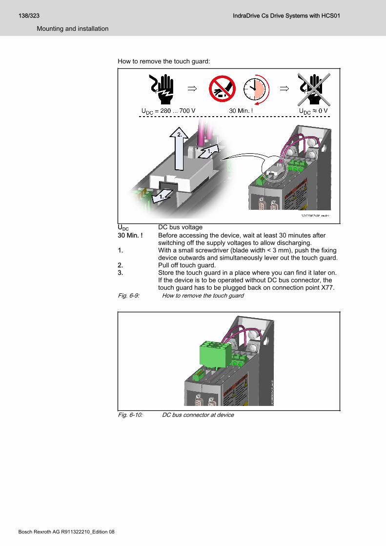
How to remove the touch guard:
UDC DC bus voltage30 Min. ! Before accessing the device, wait at least 30 minutes after
switching off the supply voltages to allow discharging.1. With a small screwdriver (blade width < 3 mm), push the fixing
device outwards and simultaneously lever out the touch guard.2. Pull off touch guard.3. Store the touch guard in a place where you can find it later on.
If the device is to be operated without DC bus connector, thetouch guard has to be plugged back on connection point X77.
Fig. 6-9: How to remove the touch guard
Fig. 6-10: DC bus connector at device
138/323
Mounting and installation
IndraDrive Cs Drive Systems with HCS01
Bosch Rexroth AG R911322210_Edition 08
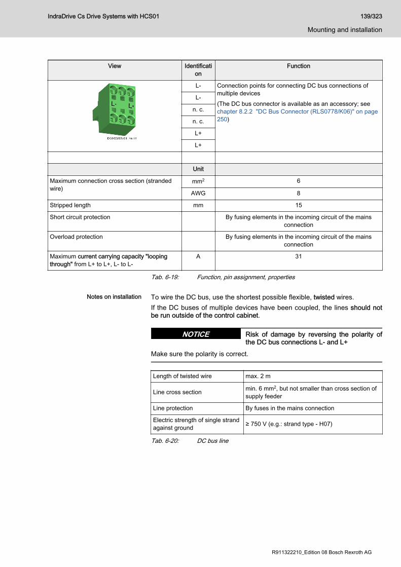
View Identification
Function
L- Connection points for connecting DC bus connections ofmultiple devices(The DC bus connector is available as an accessory; seechapter 8.2.2 "DC Bus Connector (RLS0778/K06)" on page250)
L-
n. c.
n. c.
L+
L+
Unit
Maximum connection cross section (strandedwire)
mm2 6
AWG 8
Stripped length mm 15
Short circuit protection By fusing elements in the incoming circuit of the mainsconnection
Overload protection By fusing elements in the incoming circuit of the mainsconnection
Maximum current carrying capacity "loopingthrough" from L+ to L+, L- to L-
A 31
Tab. 6-19: Function, pin assignment, properties
Notes on installation To wire the DC bus, use the shortest possible flexible, twisted wires.If the DC buses of multiple devices have been coupled, the lines should notbe run outside of the control cabinet.
Risk of damage by reversing the polarity ofthe DC bus connections L- and L+
NOTICE
Make sure the polarity is correct.
Length of twisted wire max. 2 m
Line cross section min. 6 mm2, but not smaller than cross section ofsupply feeder
Line protection By fuses in the mains connection
Electric strength of single strandagainst ground ≥ 750 V (e.g.: strand type - H07)
Tab. 6-20: DC bus line
IndraDrive Cs Drive Systems with HCS01 139/323
Mounting and installation
R911322210_Edition 08 Bosch Rexroth AG
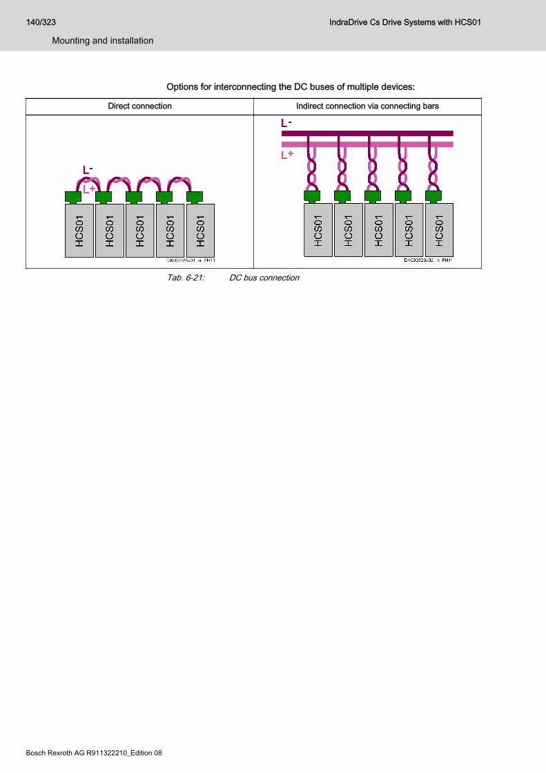
Options for interconnecting the DC buses of multiple devices:
Direct connection Indirect connection via connecting bars
Tab. 6-21: DC bus connection
140/323
Mounting and installation
IndraDrive Cs Drive Systems with HCS01
Bosch Rexroth AG R911322210_Edition 08
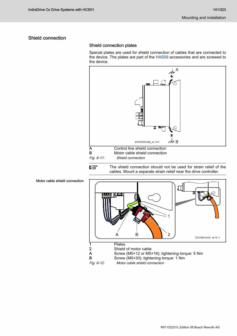
Shield connectionShield connection platesSpecial plates are used for shield connection of cables that are connected tothe device. The plates are part of the HAS09 accessories and are screwed tothe device.
A Control line shield connectionB Motor cable shield connectionFig. 6-11: Shield connection
The shield connection should not be used for strain relief of thecables. Mount a separate strain relief near the drive controller.
Motor cable shield connection
1 Plates2 Shield of motor cableA Screw (M5×12 or M5×16); tightening torque: 5 NmB Screw (M5×30); tightening torque: 1 NmFig. 6-12: Motor cable shield connection
IndraDrive Cs Drive Systems with HCS01 141/323
Mounting and installation
R911322210_Edition 08 Bosch Rexroth AG
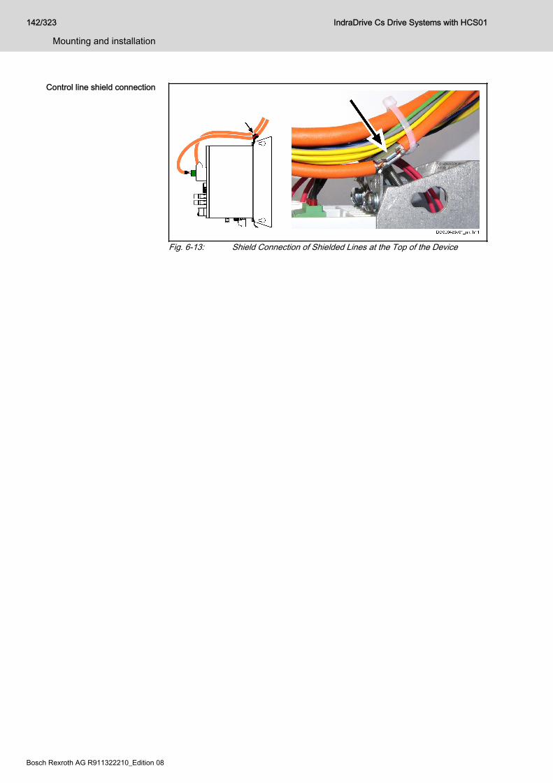
Control line shield connection
Fig. 6-13: Shield Connection of Shielded Lines at the Top of the Device
142/323
Mounting and installation
IndraDrive Cs Drive Systems with HCS01
Bosch Rexroth AG R911322210_Edition 08
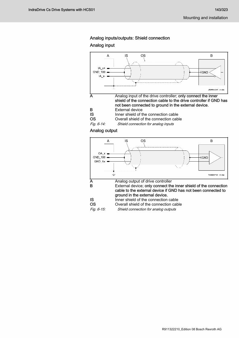
Analog inputs/outputs: Shield connectionAnalog input
A Analog input of the drive controller; only connect the innershield of the connection cable to the drive controller if GND hasnot been connected to ground in the external device.
B External deviceIS Inner shield of the connection cableOS Overall shield of the connection cableFig. 6-14: Shield connection for analog inputs
Analog output
A Analog output of drive controllerB External device; only connect the inner shield of the connection
cable to the external device if GND has not been connected toground in the external device.
IS Inner shield of the connection cableOS Overall shield of the connection cableFig. 6-15: Shield connection for analog outputs
IndraDrive Cs Drive Systems with HCS01 143/323
Mounting and installation
R911322210_Edition 08 Bosch Rexroth AG
Ground connectionThe ground connection of the housing is used to provide functional safety ofthe drive controllers and protection against contact in conjunction with theequipment grounding conductor.Ground the housings of the drive controllers:
1. Connect the bare metal back panel of the drive controller in conductiveform to the mounting surface in the control cabinet.
2. Connect the bare metal mounting surface of the control cabinet inconductive form to the equipment grounding system.See also Project Planning Manual "Control Cabinet: Air Conditioning,EMC, Design, IP Code, Electrics; IndraDrive, Rexroth EFC/Fv, Sytronix"(R911344988).
3. For the ground connection, observe the maximum allowed groundresistance.
4. Use a ground connection with a cross section ≥ 10 mm2 to the drivecontroller.
144/323
Mounting and installation
IndraDrive Cs Drive Systems with HCS01
Bosch Rexroth AG R911322210_Edition 08

6.2.4 Optional connection pointsX8, optional encoder (EC option)
You can connect an optional encoder to connection point X8.Technical data: See description of connection point X4.
X8, encoder emulation (EM option)Description Emulation of absolute value and incremental encoder signals for further
evaluation by a control unit. The signals are galvanically isolated from thecircuit board.
View Identification
Function
X8 Encoder emulation
D-Sub 15-pin, male Unit min. max.
Connection cableStranded wire
mm2 0.25 0.5
Tab. 6-22: Function, pin assignment, properties
Emulated encoder systems ● Incremental encoder (RS422)● Incremental encoder (single-ended)● Absolute encoder (SSI encoder)
IndraDrive Cs Drive Systems with HCS01 145/323
Mounting and installation
R911322210_Edition 08 Bosch Rexroth AG
Pin assignment
Connection
Signal Level Input/Output
Function Incremental encoder(RS422)
SSIencoder
Incremental encoder
(single-ended)
1 n. c. - - Not assigned
2 UL Uext In Power supply for output driver ✓
3 SSI_CLK+ RS422 In SSI clock positive ✓
4 SSI_CLK- RS422 In SSI clock negative ✓
5 n. c. - - Not assigned
6 ULA0 Uout Out Reference track with UL level ✓
7 ULA1 Uout Out Track A1 with UL level ✓
8 ULA2 Uout Out Track A2 with UL level ✓
9 UA0+ RS422 Out Reference track positive ✓
SSI_Data+ RS422 Out SSI data positive ✓
10 0 V 0 V - Reference potential / inner shield ✓ ✓ ✓
11 UA0- RS422 Out Reference track negative ✓
SSI_Data- RS422 Out SSI data negative ✓
12 UA1+ RS422 Out Track A1 positive ✓
13 UA1- RS422 Out Track A1 negative ✓
14 UA2+ RS422 Out Track A2 positive ✓
15 UA2- RS422 Out Track A2 negative ✓
Connectorhousing
- - - Overall shield
Tab. 6-23: Pin assignment
Technical data chapter 7.1.2 "EM - encoder emulation" on page 195
146/323
Mounting and installation
IndraDrive Cs Drive Systems with HCS01
Bosch Rexroth AG R911322210_Edition 08
X22 P2, X23 P1, Multi-Ethernet (ET option)
Tab. 6-24: Connection point
Technical data chapter "X24 P2, X25 P1, communication" on page 130
X26, Engineering interfaceSee chapter "X26, Engineering interface" on page 132.
IndraDrive Cs Drive Systems with HCS01 147/323
Mounting and installation
R911322210_Edition 08 Bosch Rexroth AG

X30, PROFIBUS PBDescription
Fig. 6-16: PROFIBUS Interface
View Identification Function
X30 PROFIBUS PB
D-Sub, 9-pin, female Unit Min. Max.
Connection cableStranded wire
mm2 0.08 0.5
Tab. 6-25: Function, pin assignment, propertiesPin assignment Pin DIR Signal Function
1 - n. c.
2 - n. c.
3 I/O RS485+ Receive/transmit data-positive
4 O CNTR-P Repeater control signal
5 0 V 0 V
6 O +5 V Repeater supply
7 - n. c.
8 I/O RS485- Receive/transmit data-negative
9 0V 0 V
Tab. 6-26: Signal assignmentShield Connection Via D-sub mounting screws and metallized connector housing.
Compatibility of the Interface According to DIN EN 50 170Recommended Cable Type According to DIN EN 50 170 - 2, cable type A
Bus Connectors The PROFIBUS connectors each have a connectable terminating resistor.The terminating resistor must always be active at both the first and last busnode. Carry out the connection as shown in the figures below.
148/323
Mounting and installation
IndraDrive Cs Drive Systems with HCS01
Bosch Rexroth AG R911322210_Edition 08
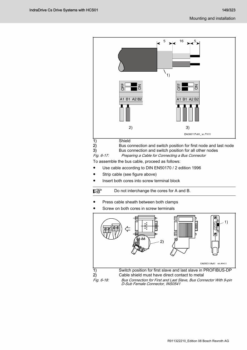
1) Shield2) Bus connection and switch position for first node and last node3) Bus connection and switch position for all other nodesFig. 6-17: Preparing a Cable for Connecting a Bus ConnectorTo assemble the bus cable, proceed as follows:● Use cable according to DIN EN50170 / 2 edition 1996● Strip cable (see figure above)● Insert both cores into screw terminal block
Do not interchange the cores for A and B.
● Press cable sheath between both clamps● Screw on both cores in screw terminals
1) Switch position for first slave and last slave in PROFIBUS-DP2) Cable shield must have direct contact to metalFig. 6-18: Bus Connection for First and Last Slave, Bus Connector With 9-pin
D-Sub Female Connector, INS0541
IndraDrive Cs Drive Systems with HCS01 149/323
Mounting and installation
R911322210_Edition 08 Bosch Rexroth AG
1) Terminating resistor is off2) Cable shield must have direct contact to metalFig. 6-19: Bus Connection for all Other Slaves, Bus Connector With 9-pin D-
Sub Female Connector, INS0541
1) Switch position for first slave and last slave in PROFIBUS-DP2) Cable shield must have direct contact to metalFig. 6-20: Bus Connection for First and Last Slave, Without 9-pin D-Sub Fe‐
male Connector, INS0540
1) Terminating resistor is off2) Cable shield must have direct contact to metalFig. 6-21: Bus Connection for all Other Slaves, Without 9-pin D-Sub Female
Connector, INS0540Connect the drive controller to a control unit using a shielded two-wire line inaccordance with DIN 19245/Part 1.
Signal Specification chapter 7.1.4 "PB - PROFIBUS" on page 207
150/323
Mounting and installation
IndraDrive Cs Drive Systems with HCS01
Bosch Rexroth AG R911322210_Edition 08
X37, digital inputs/outputs (DA option)View Connectio
nSignal name Function Connectio
nSignal name Function
1.1 I_3 Digital input 2.1 IO_1 Digital input/output
1.2 I_4 2.2 IO_2
1.3 I_5 2.3 O_3 Digital output
1.4 I_6 2.4 O_4
1.5 I_7 2.5 O_5
1.6 I_8 2.6 O_6
1.7 24V_Ext Power supply (Uext) 2.7 O_7
1.8 0V_Ext 2.8 O_8
Spring terminal(connector)
Unit Min. Max.
Connection cableStranded wire
mm2 0,2 1,5
AWG 24 16
Stripped length mm - 10
Tab. 6-27: Function, pin assignment, properties
Technical data ● chapter "Digital inputs type A (standard)" on page 211● chapter "Digital outputs (standard)" on page 215
IndraDrive Cs Drive Systems with HCS01 151/323
Mounting and installation
R911322210_Edition 08 Bosch Rexroth AG
X38, analog inputs/outputs (DA option)View Connectio
nSignal name Function Connectio
nSignal name Function
1.1 GND_AnaEA GND reference 2.1 IA_2+ Analog differentialinput1.2 OA_1 Analog output 2.2 IA_2-
1.3 GND_100_AnaOut
Connection forinner cable shield
2.3 GND_100_AnaIn
Connection forinner cable shield
1.4 OA_2 Analog output 2.4 IA_1+ Analog differentialinput1.5 GND_AnaEA GND reference 2.5 IA_1-
Spring terminal(connector)
Unit min. max.
Connection cableStranded wire
mm2 0.2 1.5
AWG 24 16
Stripped length mm - 10
Tab. 6-28: Function, pin assignment, properties
Shield connection chapter "Analog inputs/outputs: Shield connection" on page 143
Technical data ● chapter 7.1.8 "Analog voltage input" on page 219● chapter 7.1.9 "Analog current input" on page 220● chapter 7.1.10 "Analog output" on page 221
152/323
Mounting and installation
IndraDrive Cs Drive Systems with HCS01
Bosch Rexroth AG R911322210_Edition 08
X41, Safe Motion safety technology (S4, S5 options)View Connectio
nSignal name Function
1.1 SI_Out_Ch2 Safe output channel 2
1.2 0V Power supply of inputs/outputs (Uext)
1.3 SI_Out_Ch1 Safe output channel 1
2.1 SI_In_Ch2 Input 2
2.2 24V Power supply of inputs/outputs (Uext)
2.3 SI_In_Ch1 Input 1
Spring terminal (connector) Unit min. max.
Connection cableStranded wire
mm2 0.25 1.5
AWG 24 16
Stripped length mm - 10
Polarity reversal protectionfor power supply
- Present
Overvoltage protection - Present
Tab. 6-29: X41, Safe Motion safety technology
Technical data chapter "Digital inputs (safety technology S options)" on page 214chapter "Digital outputs (safety technology S options)" on page 217
IndraDrive Cs Drive Systems with HCS01 153/323
Mounting and installation
R911322210_Edition 08 Bosch Rexroth AG
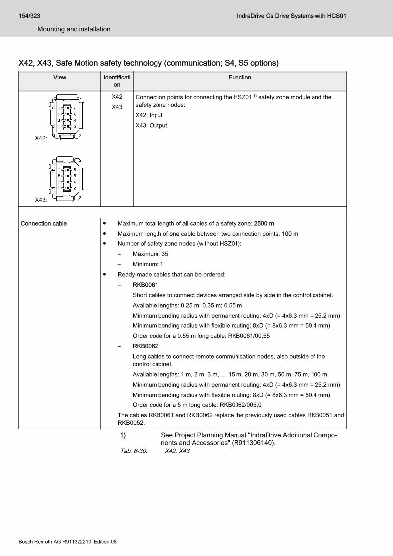
X42, X43, Safe Motion safety technology (communication; S4, S5 options)View Identificati
onFunction
X42:
X43:
X42X43
Connection points for connecting the HSZ01 1) safety zone module and thesafety zone nodes:X42: InputX43: Output
Connection cable ● Maximum total length of all cables of a safety zone: 2500 m● Maximum length of one cable between two connection points: 100 m● Number of safety zone nodes (without HSZ01):
– Maximum: 35– Minimum: 1
● Ready-made cables that can be ordered:– RKB0061
Short cables to connect devices arranged side by side in the control cabinet.Available lengths: 0.25 m; 0.35 m; 0.55 mMinimum bending radius with permanent routing: 4xD (= 4x6.3 mm = 25.2 mm)Minimum bending radius with flexible routing: 8xD (= 8x6.3 mm = 50.4 mm)Order code for a 0.55 m long cable: RKB0061/00,55
– RKB0062Long cables to connect remote communication nodes, also outside of thecontrol cabinet.Available lengths: 1 m, 2 m, 3 m, … 15 m, 20 m, 30 m, 50 m, 75 m, 100 mMinimum bending radius with permanent routing: 4xD (= 4x6.3 mm = 25.2 mm)Minimum bending radius with flexible routing: 8xD (= 8x6.3 mm = 50.4 mm)Order code for a 5 m long cable: RKB0062/005,0
The cables RKB0061 and RKB0062 replace the previously used cables RKB0051 andRKB0052.
1) See Project Planning Manual "IndraDrive Additional Compo‐nents and Accessories" (R911306140).
Tab. 6-30: X42, X43
154/323
Mounting and installation
IndraDrive Cs Drive Systems with HCS01
Bosch Rexroth AG R911322210_Edition 08
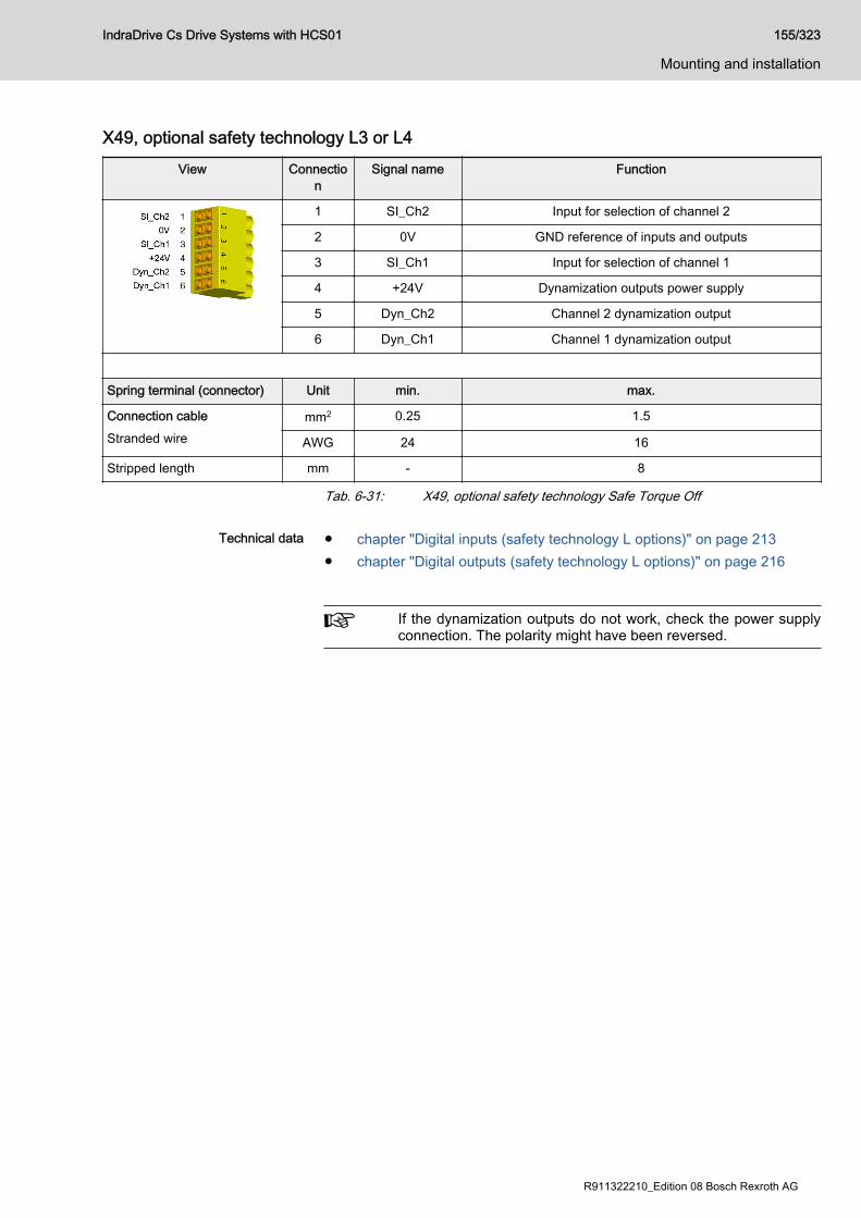
X49, optional safety technology L3 or L4View Connectio
nSignal name Function
1 SI_Ch2 Input for selection of channel 2
2 0V GND reference of inputs and outputs
3 SI_Ch1 Input for selection of channel 1
4 +24V Dynamization outputs power supply
5 Dyn_Ch2 Channel 2 dynamization output
6 Dyn_Ch1 Channel 1 dynamization output
Spring terminal (connector) Unit min. max.
Connection cableStranded wire
mm2 0.25 1.5
AWG 24 16
Stripped length mm - 8
Tab. 6-31: X49, optional safety technology Safe Torque Off
Technical data ● chapter "Digital inputs (safety technology L options)" on page 213● chapter "Digital outputs (safety technology L options)" on page 216
If the dynamization outputs do not work, check the power supplyconnection. The polarity might have been reversed.
IndraDrive Cs Drive Systems with HCS01 155/323
Mounting and installation
R911322210_Edition 08 Bosch Rexroth AG
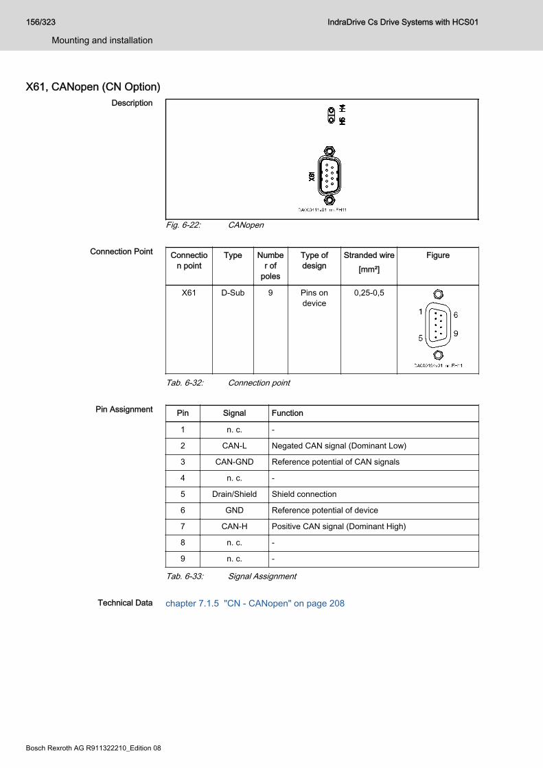
X61, CANopen (CN Option)Description
Fig. 6-22: CANopen
Connection Point Connection point
Type Number of
poles
Type ofdesign
Stranded wire[mm²]
Figure
X61 D-Sub 9 Pins ondevice
0,25-0,5
Tab. 6-32: Connection point
Pin Assignment Pin Signal Function
1 n. c. -
2 CAN-L Negated CAN signal (Dominant Low)
3 CAN-GND Reference potential of CAN signals
4 n. c. -
5 Drain/Shield Shield connection
6 GND Reference potential of device
7 CAN-H Positive CAN signal (Dominant High)
8 n. c. -
9 n. c. -
Tab. 6-33: Signal Assignment
Technical Data chapter 7.1.5 "CN - CANopen" on page 208
156/323
Mounting and installation
IndraDrive Cs Drive Systems with HCS01
Bosch Rexroth AG R911322210_Edition 08
6.2.5 EMC measures for design and installationRules for design of installations with drive controllers in compliance with EMC
The following rules are the basics for designing and installing drives incompliance with EMC.
Mains filter Use an appropriate mains filter recommended by Rexroth for radiointerference suppression in the supply feeder of the drive system.
Control cabinet grounding Connect all metal parts of the cabinet with one another over the largestpossible surface area to establish a good electrical connection. This, too,applies when mounting the mains filter. If required, use serrated washerswhich cut through the paint surface. Connect the cabinet door to the controlcabinet using the shortest possible grounding straps.
Line routing Avoid coupling routes between lines with a high potential of noise and noise-free lines. Therefore, signal, mains and motor lines and power cables have tobe routed separately from another. Minimum distance: 10 cm. Provideseparating sheets between power and signal lines. Ground separating sheetsseveral times.Lines with a high potential of noise include:● Lines at the mains connection (incl. synchronization connection)● Lines at the motor connection● Lines at the DC bus connectionGenerally, interference injections are reduced by routing cables close togrounded sheet steel plates. For this reason, cables and wires should not berouted freely in the cabinet, but close to the cabinet housing or mountingplates. Separate the incoming and outgoing cables of the radio interferencesuppression filter.
Interference suppression elements Provide the following components in the control cabinet with interferencesuppression combinations:● Contactors● Relays● Solenoid valves● Electromechanical operating hours countersConnect these combinations directly at each coil.
Twisted wires Twist unshielded wires belonging to the same circuit (supply and return lines)or keep the surface between supply and return lines as small as possible.Wires that are not used have to be grounded at both ends.
Lines of measuring systems Lines for measuring systems have to be shielded. Connect the shield toground at both ends and over the largest possible surface area. The shieldshould not be interrupted, e.g., using intermediate terminals.
Digital signal lines Ground the shields of digital signal lines at both ends (transmitter andreceiver) over the largest possible surface area and with low impedance. Inthe case of bad ground connection between transmitter and receiver,additionally route a bonding conductor (min. 10 mm2). Braided shields arebetter than foil shields.
Analog signal lines Ground the shields of analog signal lines at one end (transmitter or receiver)over the largest possible surface area and with low impedance. This avoidslow-frequency interference current (in the mains frequency range) on theshield.
Connecting the mains choke Keep connection lines of the mains choke at the drive controller as short aspossible and twist them.
IndraDrive Cs Drive Systems with HCS01 157/323
Mounting and installation
R911322210_Edition 08 Bosch Rexroth AG

With regenerative supply units, use shielded lines with the shield grounded atboth ends for the connection between supply unit and mains choke.
Installing the motor power cable ● Use shielded motor power cables or run motor power cables in ashielded duct
● Use the shortest possible motor power cables● Ground shield of motor power cable at both ends over the largest
possible surface area to establish a good electrical connection● Run motor lines in shielded form inside the control cabinet● Do not use any steel-shielded lines● The shield of the motor power cable should not be interrupted by
mounted components, such as output chokes, sine filters or motorfilters.
Optimum EMC installation in facility and control cabinetGeneral informationFor optimum EMC installation, a spatial separation of the interference-freearea (mains connection) and the interference-susceptible area (drivecomponents) is recommended, as shown in the figures below.
Recommendation: For optimum EMC installation in the controlcabinet, use a separate control cabinet panel for the drivecomponents.
Division into areas (zones)Exemplary arrangements in the control cabinet: See section Control cabinetdesign according to interference areas - exemplary arrangements, page 159.We distinguish three areas:
1. Interference-free area of control cabinet (area A):This includes:● Supply feeder, input terminals, fuse, main switch, mains side of
mains filter for drives and corresponding connecting lines● Control voltage or auxiliary voltage connection with power supply
unit, fuse and other parts unless connection is run via the mainsfilter of the AC drives
● All components that are not electrically connected with the drivesystem
2. Interference-susceptible area (area B):● Mains connections between drive system and mains filter for
drives, mains contactor● Interface lines of drive controller
3. Strongly interference-susceptible area (area C):● Motor power cables including single cores
Never run lines of one of these areas in parallel with lines of another area sothat there is no unwanted interference injection from one area to the otherand that the filter is jumpered with regard to high frequency. Use the shortestpossible connecting lines.Recommendation for complex systems: Install drive components in onecabinet and the control units in a second, separate cabinet.
158/323
Mounting and installation
IndraDrive Cs Drive Systems with HCS01
Bosch Rexroth AG R911322210_Edition 08

Badly grounded control cabinet doors act as antennas. For this reason,connect the control cabinet doors to the cabinet on top, in the middle and onthe bottom with short equipment grounding conductors with a cross section ofat least 6 mm2 or, even better, with grounding straps of the same crosssection. Make sure connection points have good contact.
Control cabinet design according to interference areas - exemplary ar‐rangements
Do not operate any additional loads at the mains filter!Do not run any other loads at the connection from the mains filteroutput to the mains connection of the supply unit.For motor fans and power supply units, for example, use separatemains filters.
IndraDrive Cs Drive Systems with HCS01 159/323
Mounting and installation
R911322210_Edition 08 Bosch Rexroth AG

DR1 Mains chokeE1…E5 Equipment grounding conductor of the components
160/323
Mounting and installation
IndraDrive Cs Drive Systems with HCS01
Bosch Rexroth AG R911322210_Edition 08
K1 External mains contactor for supply units without integratedmains contactor
ML Motor fanNT Power supply unitQ1, Q2, Q3 FusingT TransformerZ1, Z2 Shield connection points for cablesFig. 6-23: EMC areas in the control cabinet
Design and installation in area A - control cabinet area free from inter‐ference
Arranging the components in thecontrol cabinet
Comply with recommended distance of at least 200 mm (distance d1 in thefigure):● Between components and electrical elements (switches, pushbuttons,
fuses, terminal connectors) in interference-free area A and thecomponents in the two other areas B and C
Comply with recommended distance of at least 400 mm (distance d4 in thefigure):● Between magnetic components (such as transformers, mains chokes
and DC bus chokes that are directly connected to the powerconnections of the drive system) and the interference-free componentsand lines between mains and filter including the mains filter in area A
If these distances are not complied with, the magnetic leakage fields areinjected to the interference-free components and lines connected to themains, and the limit values at the mains connection are exceeded in spite ofthe installed filter.
Cable routing for interference-freelines to the mains connection
Comply with recommended distance of at least 200 mm (distances d1 and d3in the figure):● Between supply feeder or lines between filter and exit point from the
control cabinet in area A and the lines in areas B and CIf this is impossible, there are two alternatives:1. Install lines in shielded form and connect the shield at several points (at
least at the beginning and at the end of the line) to the mounting plate orthe control cabinet housing over a large surface area.
2. Separate lines from the other interference-susceptible lines in areas Band C by means of a grounded distance plate vertically attached to themounting plate.
Install the shortest possible lines within the control cabinet and install themdirectly on the grounded metal surface of the mounting plate or of the controlcabinet housing.Mains supply lines from areas B and C should not be connected to the mainswithout a filter.
In case you do not observe the information on cable routing givenin this section, the effect of the mains filter is totally or partlyneutralized. This will cause the noise level of the interferenceemission to be higher within the range of 150 kHz to 40 MHz andthe limit values at the connection points of the machine orinstallation will thereby be exceeded. Consider the specifieddistances to be recommended data, provided that the dimensionsof the control cabinet allow installing the lines accordingly.
IndraDrive Cs Drive Systems with HCS01 161/323
Mounting and installation
R911322210_Edition 08 Bosch Rexroth AG
Routing and connecting a neutralconductor (N)
If a neutral conductor is used together with a three-phase connection, itshould not be installed unfiltered in zones B and C, in order to keepinterference off the mains.
Motor fan at mains filter Single-phase or three-phase supply lines of motor fans, that are usuallyrouted in parallel with motor power cables or interference-susceptible lines,have to be filtered:● In drive systems with regenerative supply units via a separate single-
phase (NFE type) or three-phase filter (NFD type) near the mainsconnection of the control cabinet
● In drive systems with only feeding supply units via the available three-phase filter of the drive systemOn the load side of the mains filter, voltage against ground with a highrise of voltage dv/dt can be present and interfere with the additionalloads connected there.
When switching power off, make sure the fan is not switched off.Loads at drive system mains filter Only operate allowed loads at the mains filter of the drive system!
At the three-phase filter for the power connection of regenerativesupply units, it is only allowed to operate the following loads:● HMV supply unit with mains choke and, if necessary, mains
contactorDo not operate any motor fans, power supply units etc. at themains filter of the drive system.
Shielding mains supply lines in thecontrol cabinet
If there is a high degree of interference injection to the mains supply linewithin the control cabinet, although you have observed the above instructions(to be found out by EMC measurement according to standard), proceed asfollows:● Only use shielded lines in area A● Connect shields to the mounting plate at the beginning and the end of
the line by means of clipsThe same procedure may be required for long cables of more than 2 mbetween the point of power supply connection of the control cabinet and thefilter within the control cabinet.
Mains filters for AC drives Ideally mount the mains filter on the parting line between the areas A and B.Make sure the ground connection between filter housing and housing of thedrive controllers has good electrically conductive properties.If single-phase loads are connected on the load side of the filter, their currentmay be a maximum of 10% of the three-phase operating current. A highlyunbalanced load of the filter would deteriorate its interference suppressioncapacity.If the mains voltage is more than 480 V, connect the filter to the output side ofthe transformer and not to the supply side of the transformer.
Grounding In the case of bad ground connections in the system, the distance betweenthe lines to grounding points E1 and E2 in area A and the other groundingpoints of the drive system should be at least d4 = 400 mm in order tominimize interference injection from ground and ground cables to the mainssupply lines.See also Division into areas (zones), page 158.
Equipment grounding conductorconnection point at machine, sys‐
tem, control cabinet
The equipment grounding conductor of the power cable for the machine,system or control cabinet has to be permanently connected at point PE andhave a cross section of at least 10 mm2, or be complemented by a second
162/323
Mounting and installation
IndraDrive Cs Drive Systems with HCS01
Bosch Rexroth AG R911322210_Edition 08
equipment grounding conductor using separate terminals (according to EN61800-5-1:2007+A1:2017, section 4.3.5.5.2). If the cross section of the outerconductor is bigger, the cross section of the equipment grounding conductorhas to be accordingly bigger.
Design and installation in area B - control cabinet area prone to inter‐ference
Arranging components and lines Modules, components and lines in area B have to be placed at a distance ofat least d1 = 200 mm from modules and lines in area A.Alternative: Shield modules, components and lines in area B using distanceplates mounted vertically on the mounting plate from modules and lines inarea A or use shielded lines.Only connect power supply units for auxiliary or control voltage connectionsin the drive system to the mains via a mains filter. See Division into areas(zones), page 158.Install the shortest possible lines between drive controller and filter.
Control voltage or auxiliary voltageconnection
Only in exceptional cases should you connect power supply unit and fusingfor the control voltage connection to phase and neutral conductor. In thiscase, mount and install these components in area A far away from theareas B and C of the drive system. For details see section Design andinstallation in area A - control cabinet area free from interference, page 161.Run the connection between the control voltage connection of the drivesystem and the power supply unit used through area B over the shortestdistance.
Line routing Run the lines along grounded metal surfaces, in order to minimize radiationof interference fields to area A (transmitting antenna effect).
Design and installation in area C - control cabinet area highly prone tointerferenceArea C mainly concerns the motor power cables, especially at the connectionpoint at the drive controller.
Influence of the motor power cable The longer the motor power cable, the greater its leakage capacitance. Tocomply with a certain EMC limit value, the allowed leakage capacitance ofthe mains filter is limited. For the calculation of the leakage capacitance, seethe documentation on the drive system of the drive controller used.
● Run the shortest possible motor power cables.● Only use shielded motor power cables by Rexroth.
Routing the motor power cablesand motor encoder cables
Route the motor power cables and motor encoder cables along groundedmetal surfaces, both inside the control cabinet and outside of it, in order tominimize radiation of interference fields. If possible, route the motor powercables and motor encoder cables in metal-grounded cable ducts.Route the motor power cables and motor encoder cables● with a distance of at least d5 = 100 mm to interference-free lines, as
well as to signal cables and signal lines(alternatively separated by a grounded distance plate)
● in separate cable ducts, if possibleRouting the motor power cables
and mains connection linesFor converters (drive controllers with individual mains connection), routemotor power cables and (unfiltered) mains connection lines parallel to oneanother for a maximum distance of 300 mm. After that distance, route motor
IndraDrive Cs Drive Systems with HCS01 163/323
Mounting and installation
R911322210_Edition 08 Bosch Rexroth AG

power cables and power supply cables in opposite directions and preferablyin separate cable ducts.Ideally, the motor power cables should exit the control cabinet at a distanceof at least d3 = 200 mm from the (filtered) power supply cable.Converter - routing motor power cables
With cable duct Without cable duct
B Area BC Area C1 Cable duct for mains connection lines2 Shield connection of motor power cable with
clips at least at one point; alternatively, atthe device or control cabinet mounting plate
3 Cable duct for motor power cables4 Parallel routing of mains connection lines
and motor power cables over a maximum of300 mm
5 Distance of at least 100 mm or separated bya grounded distance plate
Fig. 6-24: Routing motor power cables with cableduct
B Area BC Area C1 Cable duct for mains connection lines2 Shield connection of motor power cable with
clips at least at one point; alternatively, atthe device or control cabinet mounting plate
3 Control cabinet outlet of motor power cables4 Parallel routing of mains connection lines
and motor power cables over a maximum of300 mm
5 Distance of at least 100 mm or separated bya grounded distance plate
Fig. 6-25: Routing motor power cables without cableduct
Tab. 6-34: Routing cables for converter
Ground connectionsHousing and mounting plate With the appropriate ground connections, it is possible to avoid the emission
of interference, because interference is discharged to ground on the shortestpossible way.Ground connections of the metal housings of EMC-critical components (suchas filters, devices of the drive system, connection points of the cable shields,devices with microprocessor and switching power supply units) have to bewell contacted over a large surface area. This also applies to all screwconnections between mounting plate and control cabinet wall and tomounting a ground bar to the mounting plate.The best solution is to use a zinc-coated mounting plate. Compared to avarnished plate, the connections in this case have a good long-time stability.
Connecting elements For varnished mounting plates, always use screw connections with tooth lockwashers and zinc-coated, tinned screws as connecting elements. At theconnection points, remove the varnish so that there is safe electrical contact
164/323
Mounting and installation
IndraDrive Cs Drive Systems with HCS01
Bosch Rexroth AG R911322210_Edition 08
over a large surface area. You achieve contact over a large surface area withbare connection surfaces or multiple connection screws. For screwconnections, you can establish the contact to varnished surfaces by usingtooth lock washers.
Metal surfaces Always use connecting elements (screws, nuts, washers) with goodelectroconductive surface.Bare zinc-coated or tinned metal surfaces have good electroconductiveproperties.Anodized, yellow chromatized, black gunmetal finish or lacquered metalsurfaces have bad electroconductive properties.
Ground wires and shield connec‐tions
When connecting ground wires and shield connections, what is important isnot the cross section of the wire, but the area of the contact surface, sincehigh-frequency interference currents mainly flow on the surface of theconductor.Always connect cable shields, especially shields of the motor power cables,to ground potential over a large surface area.
Installing signal lines and signal cablesLine routing For measures to prevent interference, see the Project Planning Manuals for
each device. In addition, we recommend the following measures:● Route signal and control lines separately from the power cables with a
minimum distance of d5 = 100 mm (see Division into areas (zones),page 158) or with a grounded separating sheet. The optimum way is toroute them in separate cable ducts. If possible, lead signal lines into thecontrol cabinet at one point only.
● If signal lines are crossing power cables, route them in an angle of 90°in order to avoid interference injection.
● Ground spare cables, that are not used and have been connected, atleast at both ends so that they do not have any antenna effect.
● Avoid unnecessary line lengths.● Run cables as close as possible to grounded metal surfaces (reference
potential). The ideal solution are closed, grounded cable ducts or metalpipes which, however, is only obligatory for high requirements (sensitivemeasuring lines).
● Avoid suspended lines or lines routed along synthetic carriers, becausethey are functioning like reception antennas (noise immunity) and liketransmitting antennas (emission of interference). Exceptional cases areflexible cable tracks over short distances of a maximum of 5 m.
Shielding Connect the cable shield immediately at the devices in the shortest and mostdirect way possible and over the largest possible surface area.Connect the shield of analog signal lines at one end over a large surfacearea, normally in the control cabinet at the analog device. Make sure theconnection to ground/housing is short and over a large surface area.Connect the shield of digital signal lines at both ends over a large surfacearea and in short form. In the case of potential differences between beginningand end of the line, run an additional bonding conductor in parallel. Thisprevents compensating current from flowing via the shield. Therecommended cross section is 10 mm2.Separable connections always have to be equipped with male and femaleconnectors with grounded metal housings.
IndraDrive Cs Drive Systems with HCS01 165/323
Mounting and installation
R911322210_Edition 08 Bosch Rexroth AG

In the case of non-shielded lines belonging to the same circuit, twist thesupply and return lines.
General interference suppression measures for relays, contactors, switches, chokes and in‐ductive loads
If inductive loads, such as chokes, contactors or relays are switched bycontacts or semiconductors in conjunction with electronic devices andcomponents, suitable interference suppression has to be provided for them:● By arranging free-wheeling diodes in the case of d.c. operation● In the case of a.c. operation, by arranging usual RC interference
suppression elements depending on the contactor type, immediately atthe inductance
Only the interference suppression element placed immediately at theinductance serves the purpose. Otherwise, the radiated noise level is toohigh and may affect the function of electronics and drive.
Information on interference suppression measuresIf high-frequency interference injection occurs in spite of the recommendedinterference suppression measures, the source of interference should beidentified and removed in the control cabinet or in the field.
Possible sources of interference in the control cabinet:● Frequency converters● Contactors featuring a control coil without interference suppression● 24 V DC brush motors● 24 V solenoid valves● Incorrect line routing Possible sources of interference in the field:● Improper ground connections of installation parts or machine parts● Installation parts or machine parts that are charged electrostatically
during the operating process and cannot discharge If it is impossible to find the source of interference, connect the heat sink ofthe drive controller directly to the bare metal mounting surface using agrounding strip (as short as possible; cross section ≥ 10 mm2).
166/323
Mounting and installation
IndraDrive Cs Drive Systems with HCS01
Bosch Rexroth AG R911322210_Edition 08

Fig. 6-26: Grounding strip between heat sink and mounting surface (example)
IndraDrive Cs Drive Systems with HCS01 167/323
Mounting and installation
R911322210_Edition 08 Bosch Rexroth AG

168/323 IndraDrive Cs Drive Systems with HCS01
Bosch Rexroth AG R911322210_Edition 08

7 Technical data of the components7.1 Control section7.1.1 EC - standard encoder evaluationSupported encoder systems
Supported encoder systems Encoder systems with a supply voltage of 5 and 12 V:● MSM motor encoder● MSK motor encoder● MS2N motor encoder● 1Vpp sin-cos encoder; HIPERFACE®● 1Vpp sin-cos encoder; EnDat 2.1● 1Vpp sin-cos encoder; with reference track● 5V-TTL square-wave encoder; with reference track● SSI● Combined encoder for SSI (combination of SSI and 1Vpp sin-cos
encoder)● BiSS C● EnDat 2.2● Resolver (resolvers are not supported if an optional S4 safety
technology is available at the same time.)● SHL02.1 Hall sensor box● Digital Hall sensor in conjunction with SHL03.1 Hall sensor adapter box
IndraDrive Cs Drive Systems with HCS01 169/323
Technical data of the components
R911322210_Edition 08 Bosch Rexroth AG
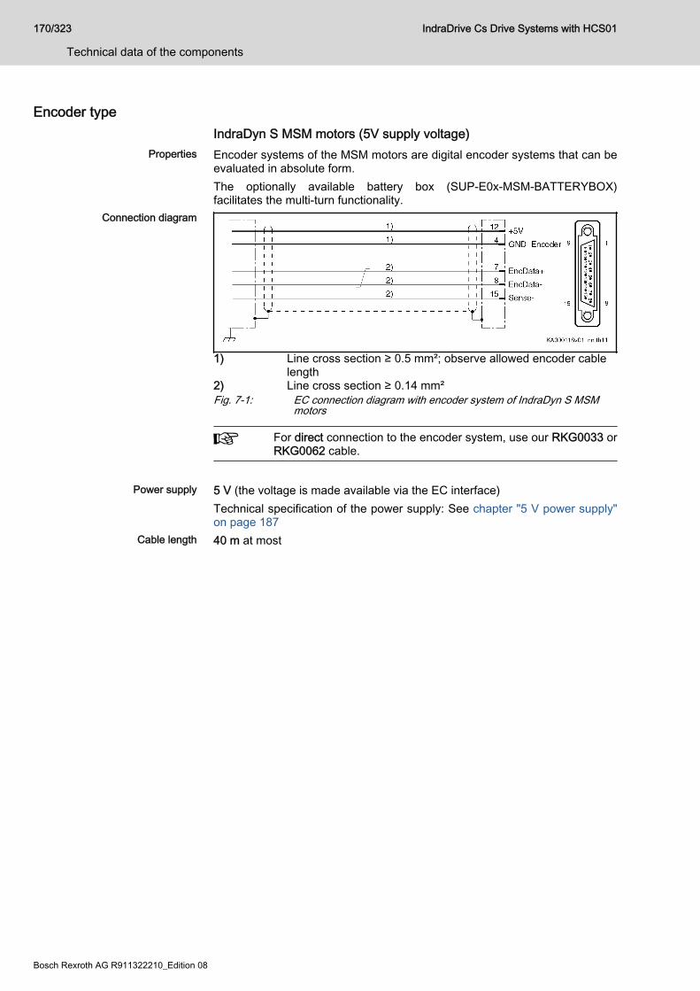
Encoder typeIndraDyn S MSM motors (5V supply voltage)
Properties Encoder systems of the MSM motors are digital encoder systems that can beevaluated in absolute form.The optionally available battery box (SUP-E0x-MSM-BATTERYBOX)facilitates the multi-turn functionality.
Connection diagram
1) Line cross section ≥ 0.5 mm²; observe allowed encoder cablelength
2) Line cross section ≥ 0.14 mm²Fig. 7-1: EC connection diagram with encoder system of IndraDyn S MSM
motors
For direct connection to the encoder system, use our RKG0033 orRKG0062 cable.
Power supply 5 V (the voltage is made available via the EC interface)
Technical specification of the power supply: See chapter "5 V power supply"on page 187
Cable length 40 m at most
170/323
Technical data of the components
IndraDrive Cs Drive Systems with HCS01
Bosch Rexroth AG R911322210_Edition 08
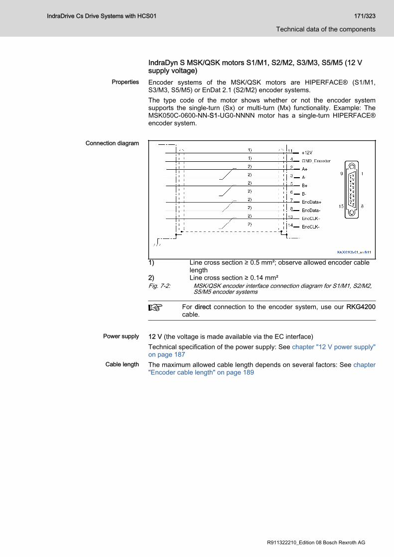
IndraDyn S MSK/QSK motors S1/M1, S2/M2, S3/M3, S5/M5 (12 Vsupply voltage)
Properties Encoder systems of the MSK/QSK motors are HIPERFACE® (S1/M1,S3/M3, S5/M5) or EnDat 2.1 (S2/M2) encoder systems.The type code of the motor shows whether or not the encoder systemsupports the single-turn (Sx) or multi-turn (Mx) functionality. Example: TheMSK050C-0600-NN-S1-UG0-NNNN motor has a single-turn HIPERFACE®encoder system.
Connection diagram
1) Line cross section ≥ 0.5 mm²; observe allowed encoder cablelength
2) Line cross section ≥ 0.14 mm²Fig. 7-2: MSK/QSK encoder interface connection diagram for S1/M1, S2/M2,
S5/M5 encoder systems
For direct connection to the encoder system, use our RKG4200cable.
Power supply 12 V (the voltage is made available via the EC interface)
Technical specification of the power supply: See chapter "12 V power supply"on page 187
Cable length The maximum allowed cable length depends on several factors: See chapter"Encoder cable length" on page 189
IndraDrive Cs Drive Systems with HCS01 171/323
Technical data of the components
R911322210_Edition 08 Bosch Rexroth AG
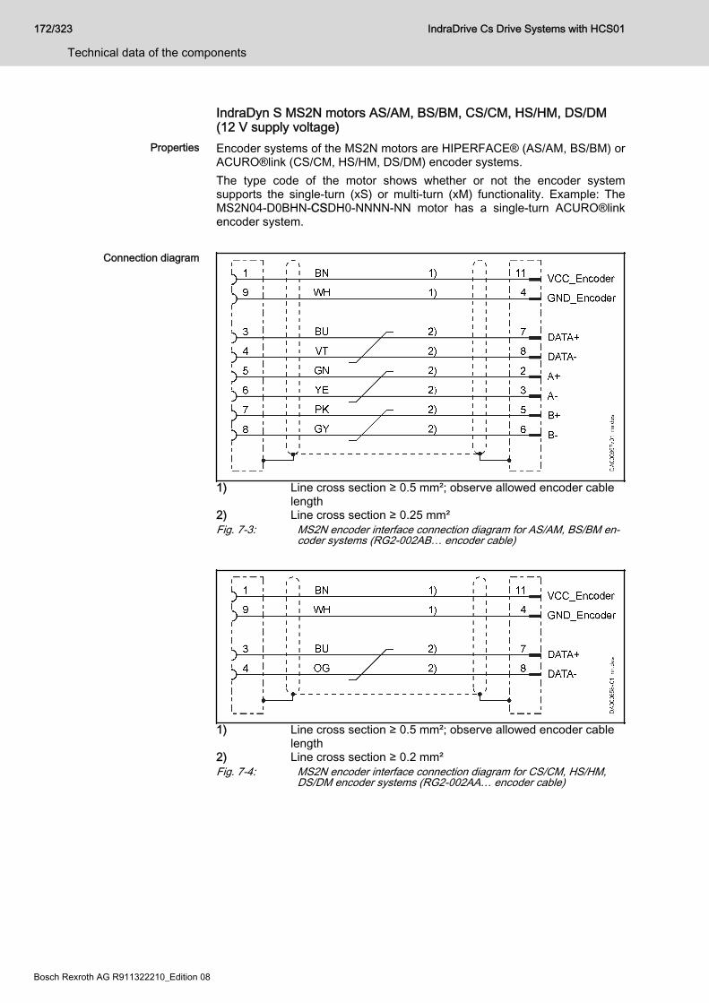
IndraDyn S MS2N motors AS/AM, BS/BM, CS/CM, HS/HM, DS/DM(12 V supply voltage)
Properties Encoder systems of the MS2N motors are HIPERFACE® (AS/AM, BS/BM) orACURO®link (CS/CM, HS/HM, DS/DM) encoder systems.The type code of the motor shows whether or not the encoder systemsupports the single-turn (xS) or multi-turn (xM) functionality. Example: TheMS2N04-D0BHN-CSDH0-NNNN-NN motor has a single-turn ACURO®linkencoder system.
Connection diagram
1) Line cross section ≥ 0.5 mm²; observe allowed encoder cablelength
2) Line cross section ≥ 0.25 mm²Fig. 7-3: MS2N encoder interface connection diagram for AS/AM, BS/BM en‐
coder systems (RG2-002AB… encoder cable)
1) Line cross section ≥ 0.5 mm²; observe allowed encoder cablelength
2) Line cross section ≥ 0.2 mm²Fig. 7-4: MS2N encoder interface connection diagram for CS/CM, HS/HM,
DS/DM encoder systems (RG2-002AA… encoder cable)
172/323
Technical data of the components
IndraDrive Cs Drive Systems with HCS01
Bosch Rexroth AG R911322210_Edition 08
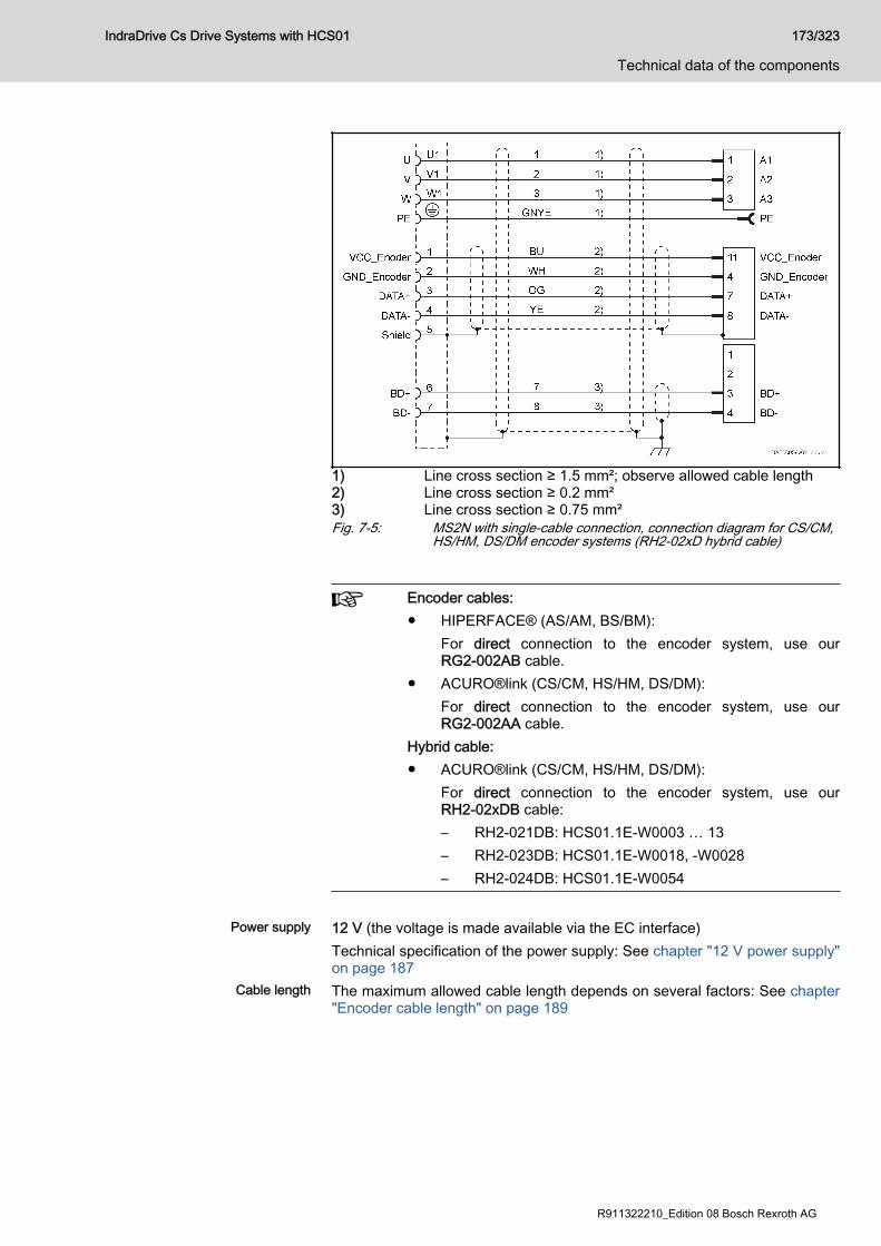
1) Line cross section ≥ 1.5 mm²; observe allowed cable length2) Line cross section ≥ 0.2 mm²3) Line cross section ≥ 0.75 mm²Fig. 7-5: MS2N with single-cable connection, connection diagram for CS/CM,
HS/HM, DS/DM encoder systems (RH2‑02xD hybrid cable)
Encoder cables:● HIPERFACE® (AS/AM, BS/BM):
For direct connection to the encoder system, use ourRG2-002AB cable.
● ACURO®link (CS/CM, HS/HM, DS/DM):For direct connection to the encoder system, use ourRG2-002AA cable.
Hybrid cable:● ACURO®link (CS/CM, HS/HM, DS/DM):
For direct connection to the encoder system, use ourRH2-02xDB cable:– RH2-021DB: HCS01.1E-W0003 … 13– RH2-023DB: HCS01.1E-W0018, -W0028– RH2-024DB: HCS01.1E-W0054
Power supply 12 V (the voltage is made available via the EC interface)
Technical specification of the power supply: See chapter "12 V power supply"on page 187
Cable length The maximum allowed cable length depends on several factors: See chapter"Encoder cable length" on page 189
IndraDrive Cs Drive Systems with HCS01 173/323
Technical data of the components
R911322210_Edition 08 Bosch Rexroth AG
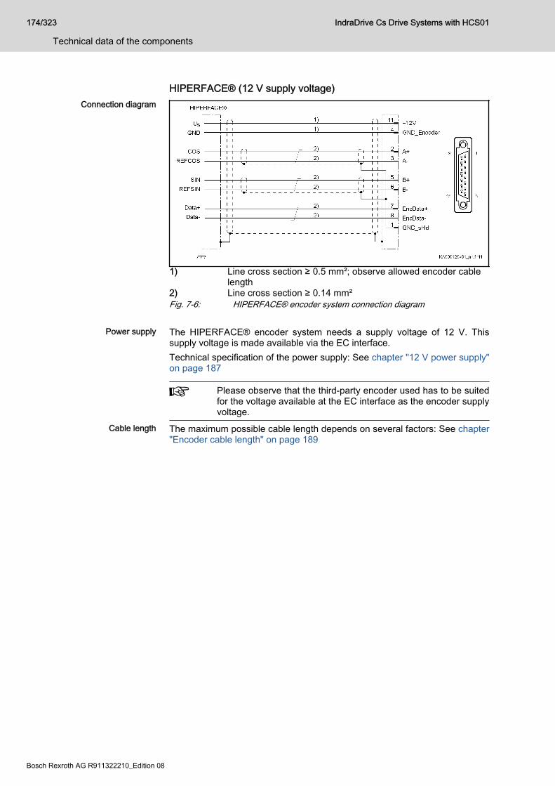
HIPERFACE® (12 V supply voltage)Connection diagram
1) Line cross section ≥ 0.5 mm²; observe allowed encoder cablelength
2) Line cross section ≥ 0.14 mm²Fig. 7-6: HIPERFACE® encoder system connection diagram
Power supply The HIPERFACE® encoder system needs a supply voltage of 12 V. Thissupply voltage is made available via the EC interface.Technical specification of the power supply: See chapter "12 V power supply"on page 187
Please observe that the third-party encoder used has to be suitedfor the voltage available at the EC interface as the encoder supplyvoltage.
Cable length The maximum possible cable length depends on several factors: See chapter"Encoder cable length" on page 189
174/323
Technical data of the components
IndraDrive Cs Drive Systems with HCS01
Bosch Rexroth AG R911322210_Edition 08
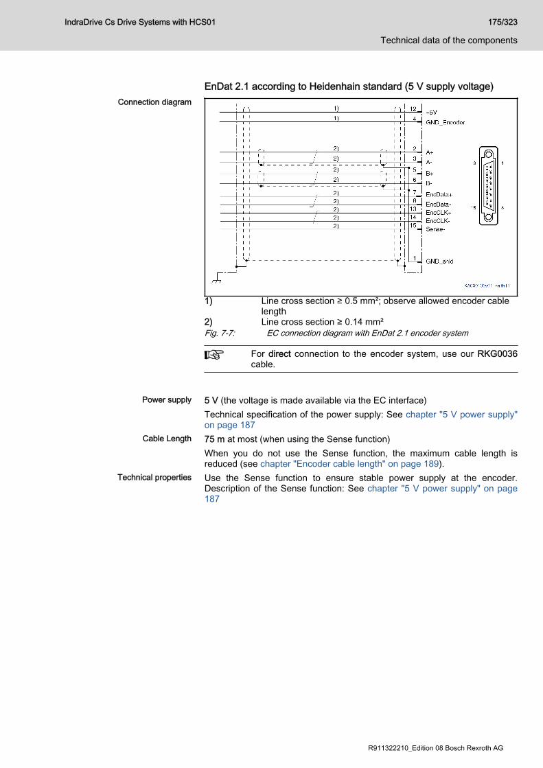
EnDat 2.1 according to Heidenhain standard (5 V supply voltage)Connection diagram
1) Line cross section ≥ 0.5 mm²; observe allowed encoder cablelength
2) Line cross section ≥ 0.14 mm²Fig. 7-7: EC connection diagram with EnDat 2.1 encoder system
For direct connection to the encoder system, use our RKG0036cable.
Power supply 5 V (the voltage is made available via the EC interface)
Technical specification of the power supply: See chapter "5 V power supply"on page 187
Cable Length 75 m at most (when using the Sense function)When you do not use the Sense function, the maximum cable length isreduced (see chapter "Encoder cable length" on page 189).
Technical properties Use the Sense function to ensure stable power supply at the encoder.Description of the Sense function: See chapter "5 V power supply" on page187
IndraDrive Cs Drive Systems with HCS01 175/323
Technical data of the components
R911322210_Edition 08 Bosch Rexroth AG
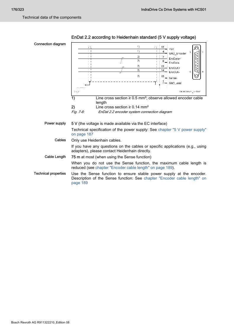
EnDat 2.2 according to Heidenhain standard (5 V supply voltage)Connection diagram
1) Line cross section ≥ 0.5 mm²; observe allowed encoder cablelength
2) Line cross section ≥ 0.14 mm²Fig. 7-8: EnDat 2.2 encoder system connection diagram
Power supply 5 V (the voltage is made available via the EC interface)Technical specification of the power supply: See chapter "5 V power supply"on page 187
Cables Only use Heidenhain cables.If you have any questions on the cables or specific applications (e.g., usingadapters), please contact Heidenhain directly.
Cable Length 75 m at most (when using the Sense function)When you do not use the Sense function, the maximum cable length isreduced (see chapter "Encoder cable length" on page 189).
Technical properties Use the Sense function to ensure stable power supply at the encoder.Description of the Sense function: See chapter "Encoder cable length" onpage 189
176/323
Technical data of the components
IndraDrive Cs Drive Systems with HCS01
Bosch Rexroth AG R911322210_Edition 08
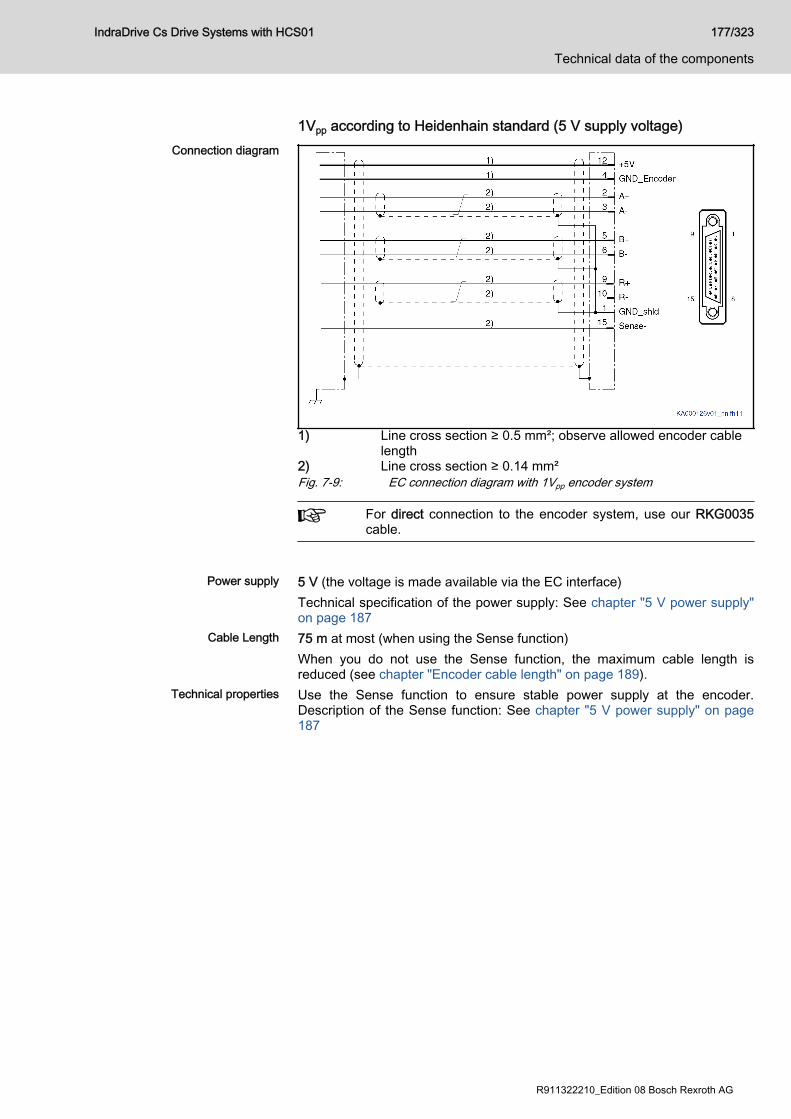
1Vpp according to Heidenhain standard (5 V supply voltage)Connection diagram
1) Line cross section ≥ 0.5 mm²; observe allowed encoder cablelength
2) Line cross section ≥ 0.14 mm²Fig. 7-9: EC connection diagram with 1Vpp encoder system
For direct connection to the encoder system, use our RKG0035cable.
Power supply 5 V (the voltage is made available via the EC interface)
Technical specification of the power supply: See chapter "5 V power supply"on page 187
Cable Length 75 m at most (when using the Sense function)When you do not use the Sense function, the maximum cable length isreduced (see chapter "Encoder cable length" on page 189).
Technical properties Use the Sense function to ensure stable power supply at the encoder.Description of the Sense function: See chapter "5 V power supply" on page187
IndraDrive Cs Drive Systems with HCS01 177/323
Technical data of the components
R911322210_Edition 08 Bosch Rexroth AG
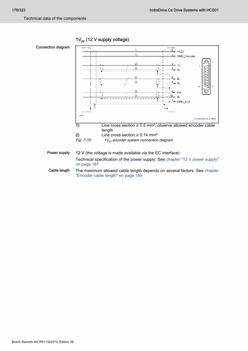
1Vpp (12 V supply voltage)Connection diagram
1) Line cross section ≥ 0.5 mm²; observe allowed encoder cablelength
2) Line cross section ≥ 0.14 mm²Fig. 7-10: 1Vpp encoder system connection diagram
Power supply 12 V (the voltage is made available via the EC interface)Technical specification of the power supply: See chapter "12 V power supply"on page 187
Cable length The maximum allowed cable length depends on several factors: See chapter"Encoder cable length" on page 189
178/323
Technical data of the components
IndraDrive Cs Drive Systems with HCS01
Bosch Rexroth AG R911322210_Edition 08
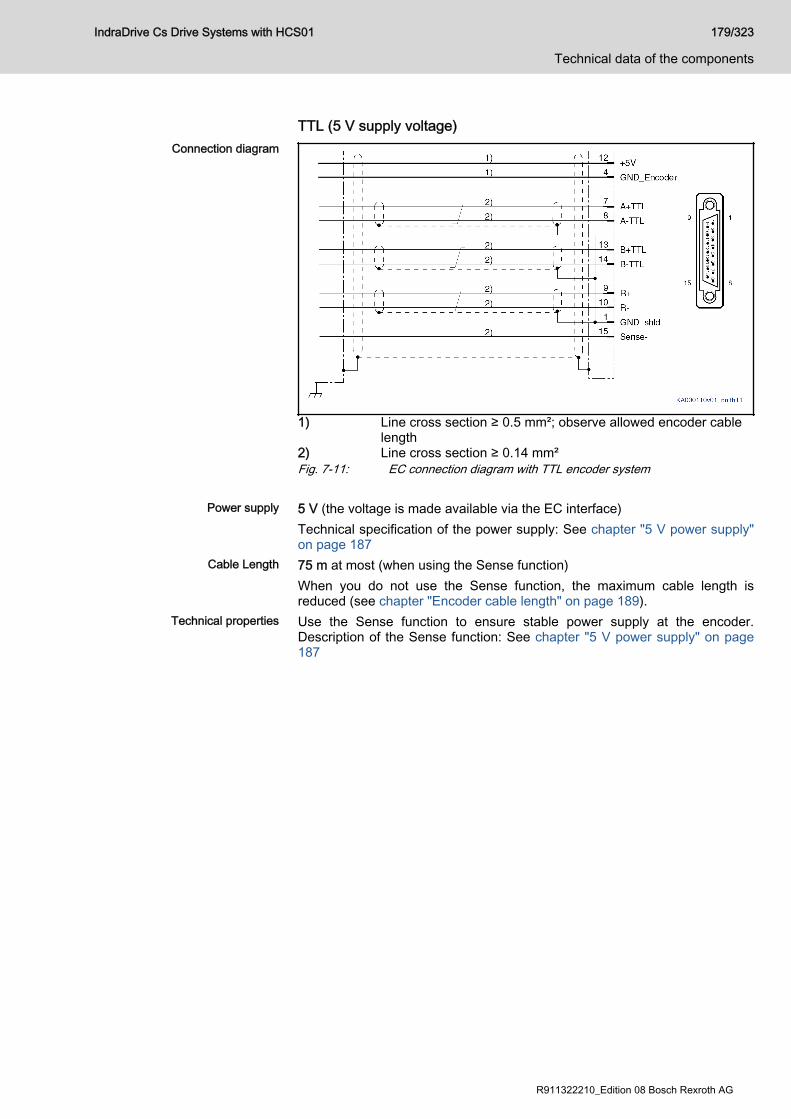
TTL (5 V supply voltage)Connection diagram
1) Line cross section ≥ 0.5 mm²; observe allowed encoder cablelength
2) Line cross section ≥ 0.14 mm²Fig. 7-11: EC connection diagram with TTL encoder system
Power supply 5 V (the voltage is made available via the EC interface)Technical specification of the power supply: See chapter "5 V power supply"on page 187
Cable Length 75 m at most (when using the Sense function)When you do not use the Sense function, the maximum cable length isreduced (see chapter "Encoder cable length" on page 189).
Technical properties Use the Sense function to ensure stable power supply at the encoder.Description of the Sense function: See chapter "5 V power supply" on page187
IndraDrive Cs Drive Systems with HCS01 179/323
Technical data of the components
R911322210_Edition 08 Bosch Rexroth AG
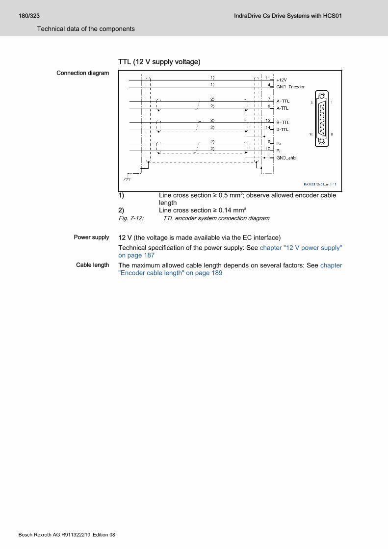
TTL (12 V supply voltage)Connection diagram
1) Line cross section ≥ 0.5 mm²; observe allowed encoder cablelength
2) Line cross section ≥ 0.14 mm²Fig. 7-12: TTL encoder system connection diagram
Power supply 12 V (the voltage is made available via the EC interface)Technical specification of the power supply: See chapter "12 V power supply"on page 187
Cable length The maximum allowed cable length depends on several factors: See chapter"Encoder cable length" on page 189
180/323
Technical data of the components
IndraDrive Cs Drive Systems with HCS01
Bosch Rexroth AG R911322210_Edition 08
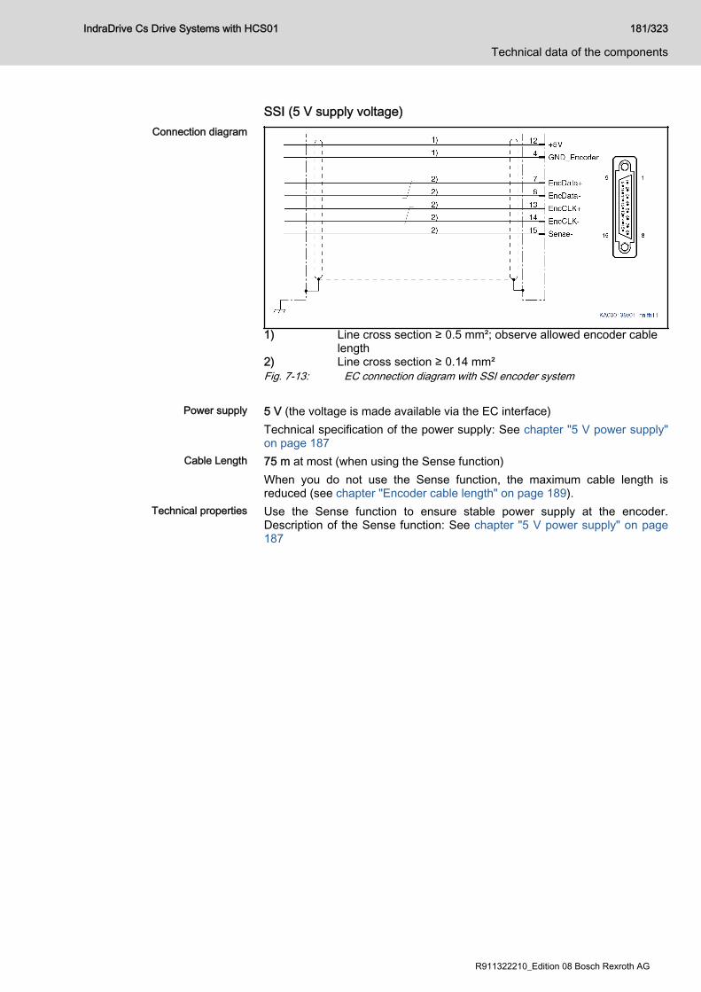
SSI (5 V supply voltage)Connection diagram
1) Line cross section ≥ 0.5 mm²; observe allowed encoder cablelength
2) Line cross section ≥ 0.14 mm²Fig. 7-13: EC connection diagram with SSI encoder system
Power supply 5 V (the voltage is made available via the EC interface)Technical specification of the power supply: See chapter "5 V power supply"on page 187
Cable Length 75 m at most (when using the Sense function)When you do not use the Sense function, the maximum cable length isreduced (see chapter "Encoder cable length" on page 189).
Technical properties Use the Sense function to ensure stable power supply at the encoder.Description of the Sense function: See chapter "5 V power supply" on page187
IndraDrive Cs Drive Systems with HCS01 181/323
Technical data of the components
R911322210_Edition 08 Bosch Rexroth AG
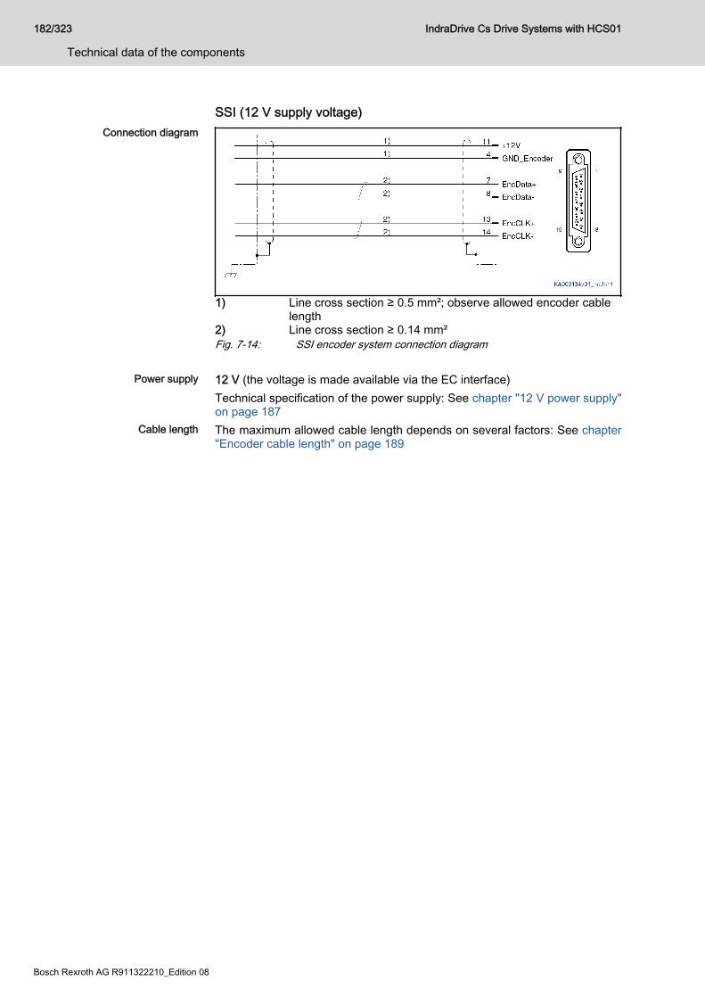
SSI (12 V supply voltage)Connection diagram
1) Line cross section ≥ 0.5 mm²; observe allowed encoder cablelength
2) Line cross section ≥ 0.14 mm²Fig. 7-14: SSI encoder system connection diagram
Power supply 12 V (the voltage is made available via the EC interface)Technical specification of the power supply: See chapter "12 V power supply"on page 187
Cable length The maximum allowed cable length depends on several factors: See chapter"Encoder cable length" on page 189
182/323
Technical data of the components
IndraDrive Cs Drive Systems with HCS01
Bosch Rexroth AG R911322210_Edition 08
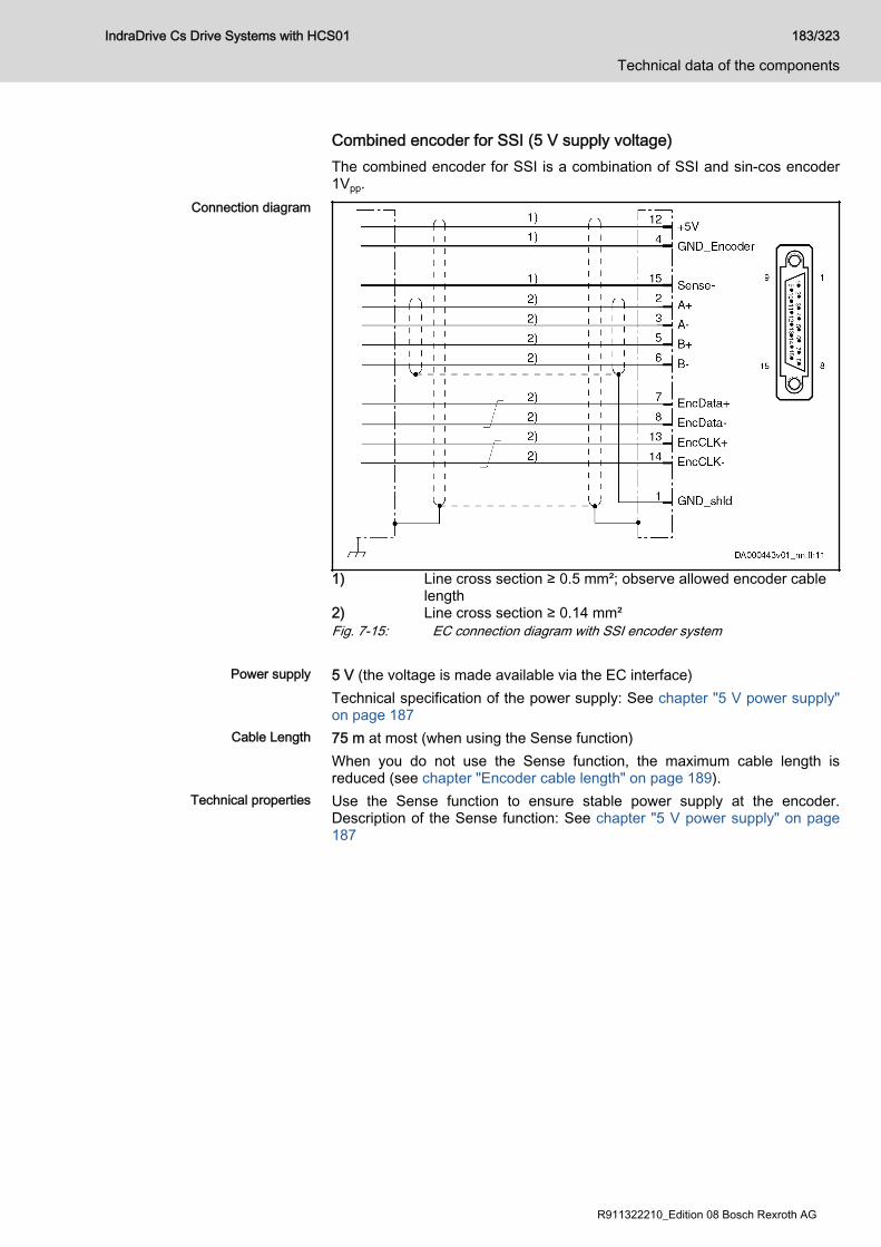
Combined encoder for SSI (5 V supply voltage)The combined encoder for SSI is a combination of SSI and sin-cos encoder1Vpp.
Connection diagram
1) Line cross section ≥ 0.5 mm²; observe allowed encoder cablelength
2) Line cross section ≥ 0.14 mm²Fig. 7-15: EC connection diagram with SSI encoder system
Power supply 5 V (the voltage is made available via the EC interface)Technical specification of the power supply: See chapter "5 V power supply"on page 187
Cable Length 75 m at most (when using the Sense function)When you do not use the Sense function, the maximum cable length isreduced (see chapter "Encoder cable length" on page 189).
Technical properties Use the Sense function to ensure stable power supply at the encoder.Description of the Sense function: See chapter "5 V power supply" on page187
IndraDrive Cs Drive Systems with HCS01 183/323
Technical data of the components
R911322210_Edition 08 Bosch Rexroth AG
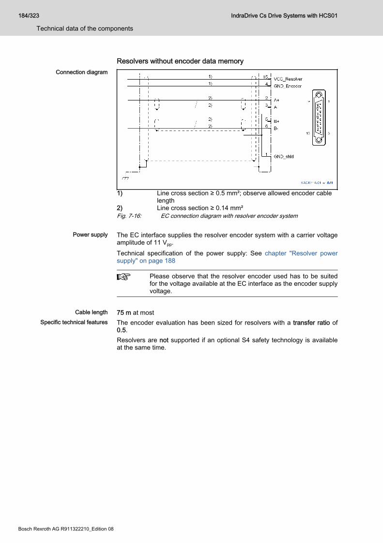
Resolvers without encoder data memoryConnection diagram
1) Line cross section ≥ 0.5 mm²; observe allowed encoder cablelength
2) Line cross section ≥ 0.14 mm²Fig. 7-16: EC connection diagram with resolver encoder system
Power supply The EC interface supplies the resolver encoder system with a carrier voltageamplitude of 11 Vpp.Technical specification of the power supply: See chapter "Resolver powersupply" on page 188
Please observe that the resolver encoder used has to be suitedfor the voltage available at the EC interface as the encoder supplyvoltage.
Cable length 75 m at most
Specific technical features The encoder evaluation has been sized for resolvers with a transfer ratio of0.5.Resolvers are not supported if an optional S4 safety technology is availableat the same time.
184/323
Technical data of the components
IndraDrive Cs Drive Systems with HCS01
Bosch Rexroth AG R911322210_Edition 08
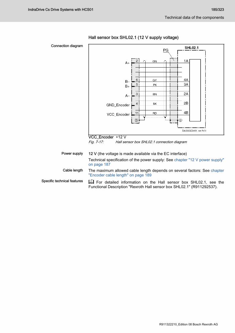
Hall sensor box SHL02.1 (12 V supply voltage)
Connection diagram
VCC_Encoder +12 VFig. 7-17: Hall sensor box SHL02.1 connection diagram
Power supply 12 V (the voltage is made available via the EC interface)Technical specification of the power supply: See chapter "12 V power supply"on page 187
Cable length The maximum allowed cable length depends on several factors: See chapter"Encoder cable length" on page 189
Specific technical features For detailed information on the Hall sensor box SHL02.1, see theFunctional Description "Rexroth Hall sensor box SHL02.1" (R911292537).
IndraDrive Cs Drive Systems with HCS01 185/323
Technical data of the components
R911322210_Edition 08 Bosch Rexroth AG

BiSS CBiSS C is hardware-compatible with the SSI standard.Connection diagram:chapter "SSI (5 V supply voltage)" on page 181chapter "SSI (12 V supply voltage)" on page 182.
186/323
Technical data of the components
IndraDrive Cs Drive Systems with HCS01
Bosch Rexroth AG R911322210_Edition 08
Power supply5 V power supply
5 V power supply Data Unit min. typ. max.
DC output voltage +5V V 5.0 5.25
Output current mA 500 1)
1) The sum of the power consumptions of all connected encodersystems (5 V / 12 V) should not exceed 6 W (applies toHCS01) or 12 W (applies to Cxx02 control sections).
Tab. 7-1: 5 V power supply
Switching off power supply viafirmware
The "parking axis" firmware command (C1600) causes the encoder powersupply to be switched off.
Sense function The EC encoder evaluation allows the 5 V supply voltage at the encoder tobe corrected. It is thereby possible, within certain limits, to compensate forvoltage drops on the encoder cable.Functional principle: The current consumption of the connected encodersystem generates a voltage drop due to the ohmic resistance of the encodercable (line cross section and line length). This reduces the signal at theencoder input. The actual value of the 0 V encoder potential at the encoder ismeasured via a separate "Sense" line (Sense-) and is fed back to the drivecontroller. Thus, the drive controller can influence the voltage of the encodersupply.
For correct "Sense" evaluation, the encoder supply lines "+5V"and "GND_Encoder" have to have the same line cross section.If the encoder has a "Sense-" connection, connect the "Sense-"line at this connection. A "Sense+" connection that might exist isnot used.If the encoder has no "Sense" connection, apply the 0 V encoderpotential to the "Sense-" line on the encoder side.
12 V power supply12 V power supply Data Unit min. typ. max.
Voltage for encoder supply V 10.7 12 12.3
Output current mA 500 1)
1) The sum of the power consumptions of all connected encodersystems (5 V / 12 V) should not exceed 6 W (applies toHCS01) or 12 W (applies to Cxx02 control sections).
Tab. 7-2: 12 V power supply
Switching off power supply viafirmware
The "parking axis" firmware command (C1600) causes the encoder powersupply to be switched off.
IndraDrive Cs Drive Systems with HCS01 187/323
Technical data of the components
R911322210_Edition 08 Bosch Rexroth AG
Resolver power supplyResolver encoder system Data Unit min. typ. max.
AC output voltage VCC_Resolver(peak-peak value)
V 8.3 10 12
Output frequency sine kHz 8
Output current (peak value) mA 60 1)
Output current (rms value) mA 40 1)
1) The sum of the power consumptions of all connected encodersystems should not exceed 6 W (applies to HCS01) or 12 W(applies to Cxx02 control sections).
Tab. 7-3: Resolver encoder supply
Switching off power supply viafirmware
The "parking axis" firmware command (C1600) causes the encoder powersupply to be switched off.
188/323
Technical data of the components
IndraDrive Cs Drive Systems with HCS01
Bosch Rexroth AG R911322210_Edition 08

Encoder cable length
Use lines with the same line cross section for encoder supply.
Allowed encoder cable length for5 V encoder systems without
Sense function
If the encoder system used does not support the Sense function, themaximum possible cable length results from the diagram below.
I [mA] Encoder current consumptionl [m] Cable length0.5 mm2; 1.0 mm2 Line cross sectionsFig. 7-18: Maximum allowed encoder cable lengths for 5 V encoder systems
without Sense connection depending on line cross section
Allowed encoder cable length for5 V encoder systems with Sense
function
75 m at most; (exception: 40 m at most for IndraDyn S MSM motors)(Besides, the maximum allowed cable lengths depend on the motor size. Seedocumentation of motor used.)The cross section of the supply voltage lines has to be at least 0.5 mm2.
Allowed encoder cable length for12 V encoder systems
Requirements:● The cross section of the supply voltage lines is at least 0.5 mm2
● The minimum allowed supply voltage at the encoder is 10 V
IndraDrive Cs Drive Systems with HCS01 189/323
Technical data of the components
R911322210_Edition 08 Bosch Rexroth AG
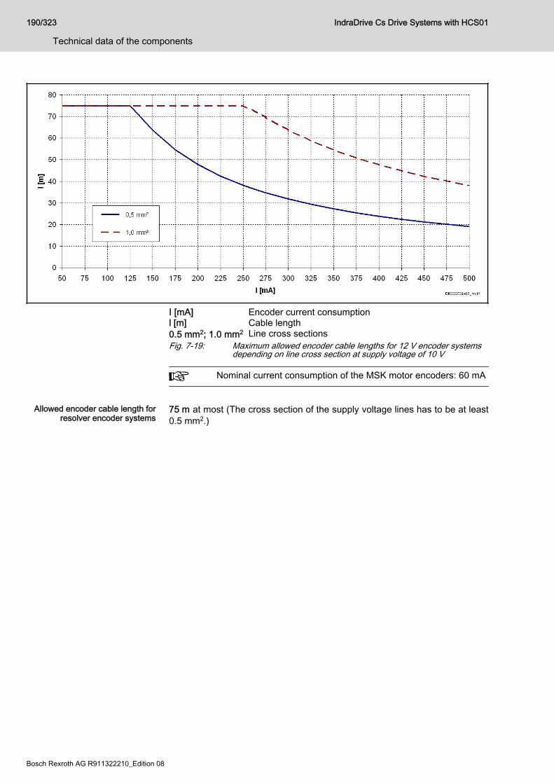
I [mA] Encoder current consumptionl [m] Cable length0.5 mm2; 1.0 mm2 Line cross sectionsFig. 7-19: Maximum allowed encoder cable lengths for 12 V encoder systems
depending on line cross section at supply voltage of 10 V
Nominal current consumption of the MSK motor encoders: 60 mA
Allowed encoder cable length for
resolver encoder systems75 m at most (The cross section of the supply voltage lines has to be at least0.5 mm2.)
190/323
Technical data of the components
IndraDrive Cs Drive Systems with HCS01
Bosch Rexroth AG R911322210_Edition 08
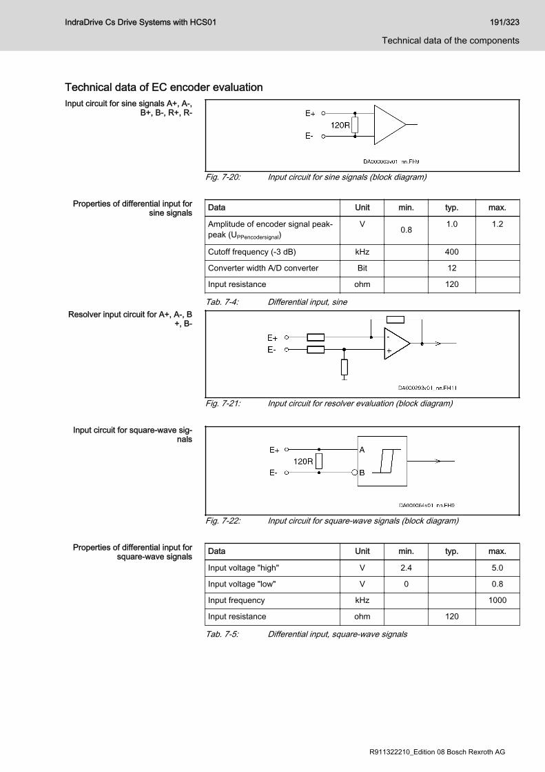
Technical data of EC encoder evaluationInput circuit for sine signals A+, A-,
B+, B-, R+, R-
Fig. 7-20: Input circuit for sine signals (block diagram)
Properties of differential input forsine signals Data Unit min. typ. max.
Amplitude of encoder signal peak-peak (UPPencodersignal)
V 0.8 1.0 1.2
Cutoff frequency (-3 dB) kHz 400
Converter width A/D converter Bit 12
Input resistance ohm 120
Tab. 7-4: Differential input, sineResolver input circuit for A+, A-, B
+, B-
Fig. 7-21: Input circuit for resolver evaluation (block diagram)
Input circuit for square-wave sig‐nals
Fig. 7-22: Input circuit for square-wave signals (block diagram)
Properties of differential input forsquare-wave signals Data Unit min. typ. max.
Input voltage "high" V 2.4 5.0
Input voltage "low" V 0 0.8
Input frequency kHz 1000
Input resistance ohm 120
Tab. 7-5: Differential input, square-wave signals
IndraDrive Cs Drive Systems with HCS01 191/323
Technical data of the components
R911322210_Edition 08 Bosch Rexroth AG

Differential input for resolver oper‐ation Data Unit min. typ. max.
Amplitude encoder signal sine(Upp)
V 5 6
Input resistance kohm 12
Converter width A/D converter Bit 12
Tab. 7-6: Resolver operation input data
192/323
Technical data of the components
IndraDrive Cs Drive Systems with HCS01
Bosch Rexroth AG R911322210_Edition 08
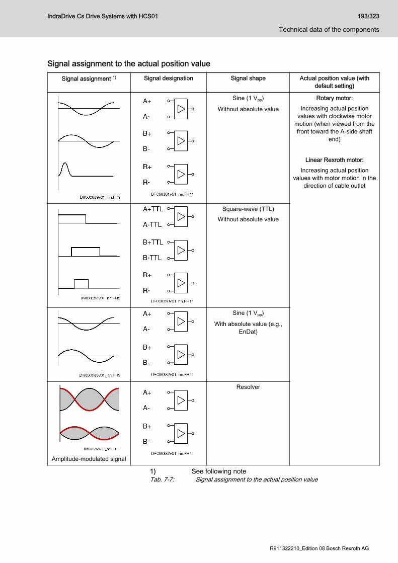
Signal assignment to the actual position value
Signal assignment 1) Signal designation Signal shape Actual position value (withdefault setting)
Sine (1 Vpp)
Without absolute value
Rotary motor:Increasing actual position
values with clockwise motormotion (when viewed from thefront toward the A-side shaft
end)
Linear Rexroth motor:Increasing actual position
values with motor motion in thedirection of cable outlet
Square-wave (TTL)Without absolute value
Sine (1 Vpp)
With absolute value (e.g.,EnDat)
Amplitude-modulated signal
Resolver
1) See following noteTab. 7-7: Signal assignment to the actual position value
IndraDrive Cs Drive Systems with HCS01 193/323
Technical data of the components
R911322210_Edition 08 Bosch Rexroth AG

The encoder signal assignment to the inputs is based onclockwise rotation (front view toward motor shaft).● Track A (A+, A-, "cos") advances track B (B+, B-, "sin") 90°
electrically.● The actual position value increases (prerequisite: negation
of the encoder signals was not parameterized).● If available, the reference track R (R+, R-) provides the
reference mark pulse at positive signals of track A andtrack B (in the so-called "0-th" quadrant).
Standard setting: See Functional Description of firmware.
194/323
Technical data of the components
IndraDrive Cs Drive Systems with HCS01
Bosch Rexroth AG R911322210_Edition 08
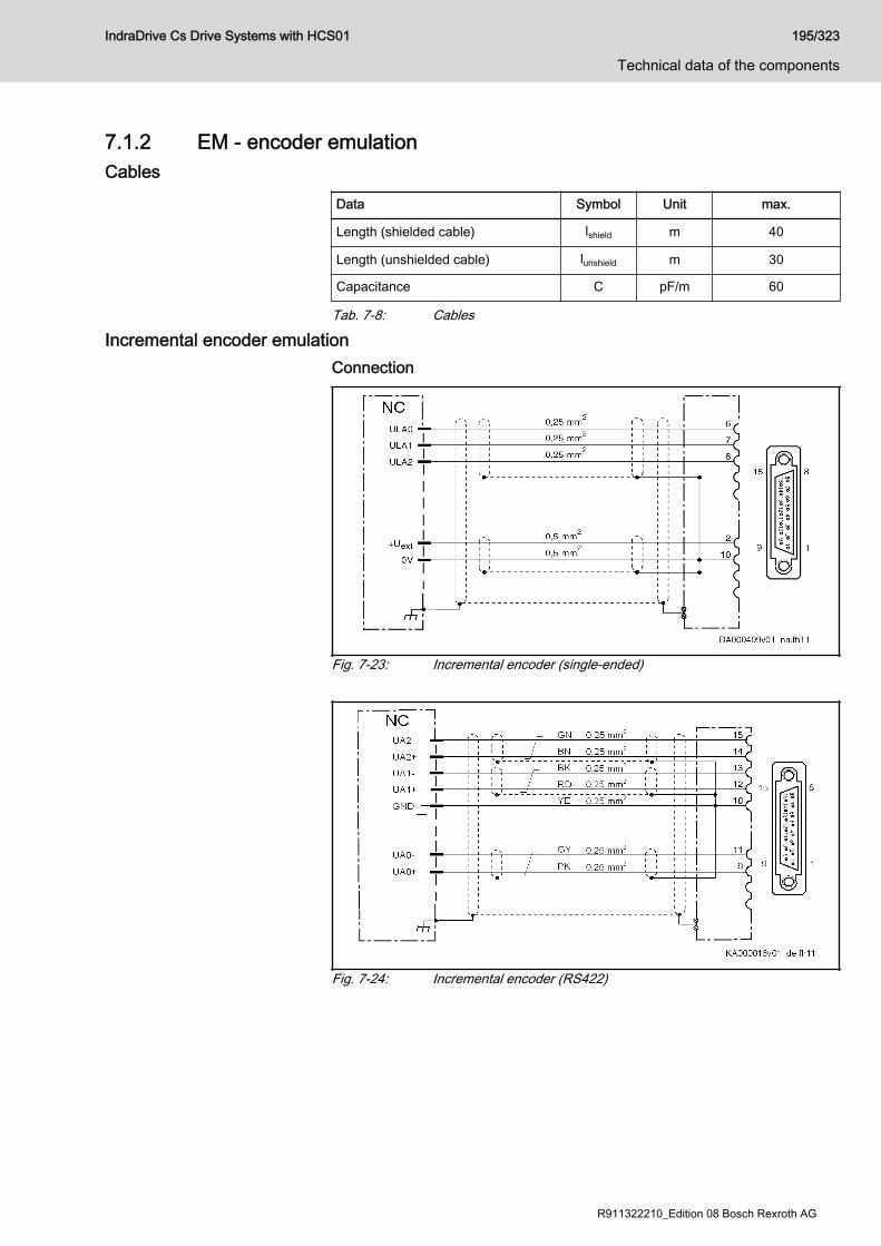
7.1.2 EM - encoder emulationCables
Data Symbol Unit max.
Length (shielded cable) lshield m 40
Length (unshielded cable) lunshield m 30
Capacitance C pF/m 60
Tab. 7-8: Cables
Incremental encoder emulationConnection
Fig. 7-23: Incremental encoder (single-ended)
Fig. 7-24: Incremental encoder (RS422)
IndraDrive Cs Drive Systems with HCS01 195/323
Technical data of the components
R911322210_Edition 08 Bosch Rexroth AG
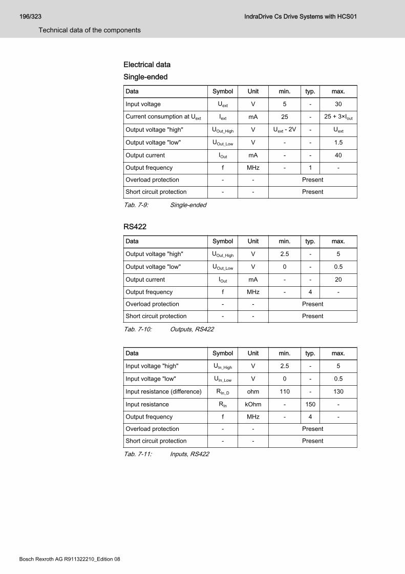
Electrical dataSingle-ended
Data Symbol Unit min. typ. max.
Input voltage Uext V 5 - 30
Current consumption at Uext Iext mA 25 - 25 + 3×Iout
Output voltage "high" UOut_High V Uext - 2V - Uext
Output voltage "low" UOut_Low V - - 1.5
Output current IOut mA - - 40
Output frequency f MHz - 1 -
Overload protection - - Present
Short circuit protection - - Present
Tab. 7-9: Single-ended
RS422
Data Symbol Unit min. typ. max.
Output voltage "high" UOut_High V 2.5 - 5
Output voltage "low" UOut_Low V 0 - 0.5
Output current IOut mA - - 20
Output frequency f MHz - 4 -
Overload protection - - Present
Short circuit protection - - Present
Tab. 7-10: Outputs, RS422
Data Symbol Unit min. typ. max.
Input voltage "high" UIn_High V 2.5 - 5
Input voltage "low" UIn_Low V 0 - 0.5
Input resistance (difference) RIn_D ohm 110 - 130
Input resistance RIn kOhm - 150 -
Output frequency f MHz - 4 -
Overload protection - - Present
Short circuit protection - - Present
Tab. 7-11: Inputs, RS422
196/323
Technical data of the components
IndraDrive Cs Drive Systems with HCS01
Bosch Rexroth AG R911322210_Edition 08
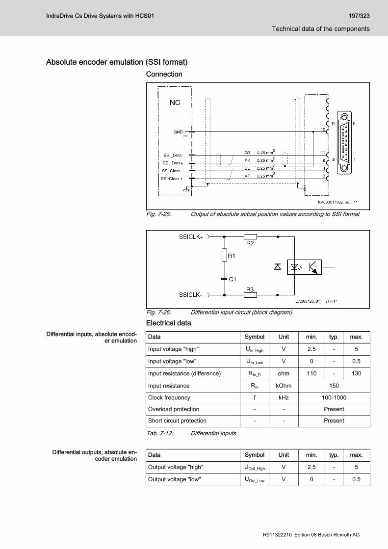
Absolute encoder emulation (SSI format)Connection
Fig. 7-25: Output of absolute actual position values according to SSI format
Fig. 7-26: Differential input circuit (block diagram)
Electrical dataDifferential inputs, absolute encod‐
er emulation Data Symbol Unit min. typ. max.
Input voltage "high" UIn_High V 2.5 - 5
Input voltage "low" UIn_Low V 0 - 0.5
Input resistance (difference) RIn_D ohm 110 - 130
Input resistance RIn kOhm 150
Clock frequency f kHz 100-1000
Overload protection - - Present
Short circuit protection - - Present
Tab. 7-12: Differential inputs
Differential outputs, absolute en‐coder emulation Data Symbol Unit min. typ. max.
Output voltage "high" UOut_High V 2.5 - 5
Output voltage "low" UOut_Low V 0 - 0.5
IndraDrive Cs Drive Systems with HCS01 197/323
Technical data of the components
R911322210_Edition 08 Bosch Rexroth AG

Data Symbol Unit min. typ. max.
Output current IOut mA - - 20
Output frequency f MHz - - 1
Load capacitance between outputand 0 V nF - - 10
Terminating resistor at load RTerm ohm 150-180
Overload protection - - Present
Short circuit protection - - Present
Tab. 7-13: Differential outputs
The differential output corresponds to the RS422 specifications.On the control side, a line terminating resistor has to be availablefor the SSI data signal. If this resistor is not available, connect anexternal line terminating resistor (150-180 ohm).
Pulse diagram
1) Resolution for 4096 revolutions2) Resolution for 1 revolutionG0 Least significant bit in Gray codeG23 Most significant bit in Gray codem Stored parallel informationT Clock timeTp Clock break ≥ 20 μstv Max. delay 200 nsPFB Power failure bit (not used and always logically LOW)Fig. 7-27: Pulse diagram with absolute actual position value output (SSI for‐
mat)
198/323
Technical data of the components
IndraDrive Cs Drive Systems with HCS01
Bosch Rexroth AG R911322210_Edition 08
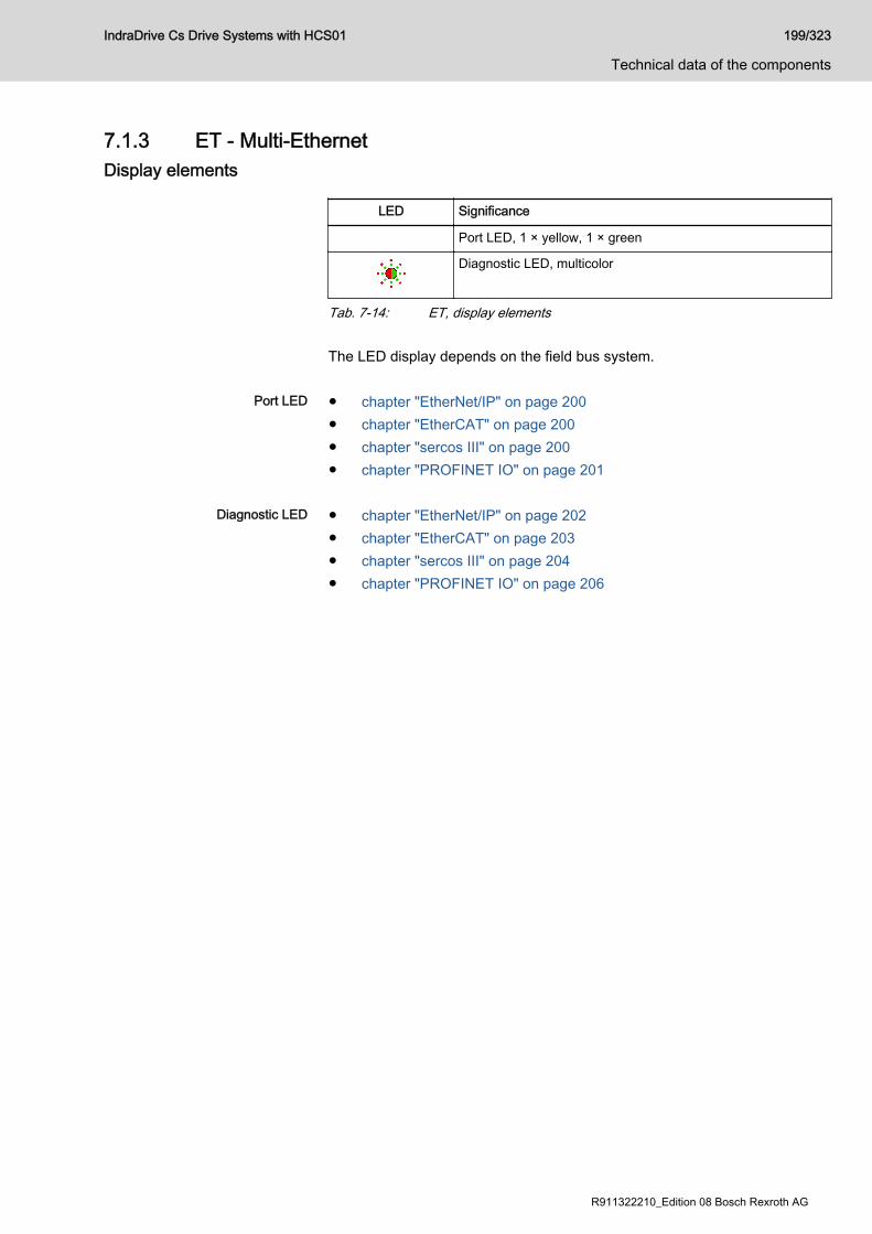
7.1.3 ET - Multi-EthernetDisplay elements
LED Significance
Port LED, 1 × yellow, 1 × green
Diagnostic LED, multicolor
Tab. 7-14: ET, display elements The LED display depends on the field bus system.
Port LED ● chapter "EtherNet/IP" on page 200● chapter "EtherCAT" on page 200● chapter "sercos III" on page 200● chapter "PROFINET IO" on page 201
Diagnostic LED ● chapter "EtherNet/IP" on page 202● chapter "EtherCAT" on page 203● chapter "sercos III" on page 204● chapter "PROFINET IO" on page 206
IndraDrive Cs Drive Systems with HCS01 199/323
Technical data of the components
R911322210_Edition 08 Bosch Rexroth AG

Port LEDEtherNet/IP
LED: Color / flashingpattern
Significance
Off
No connectionNo data transmission
Permanently lit yellow
Data transmission running
Permanently lit green
Connection to network available
Tab. 7-15: Port LED
EtherCATEtherCAT has only one active LED per port.
LED: Color / flashingpattern
Significance
Off
No connection
Permanently lit green
Connection to network available, but no telegram exchange (EtherCAT bus inactive)
Flashing green
Connection to network available with telegram exchange (EtherCAT bus active)
Tab. 7-16: Port LED
sercos III
LED: Color / flashingpattern
Significance
Off
No connectionNo data transmission
Permanently lit yellow
Data transmission running
Permanently lit green
Connection to network available
Tab. 7-17: Port LED
200/323
Technical data of the components
IndraDrive Cs Drive Systems with HCS01
Bosch Rexroth AG R911322210_Edition 08
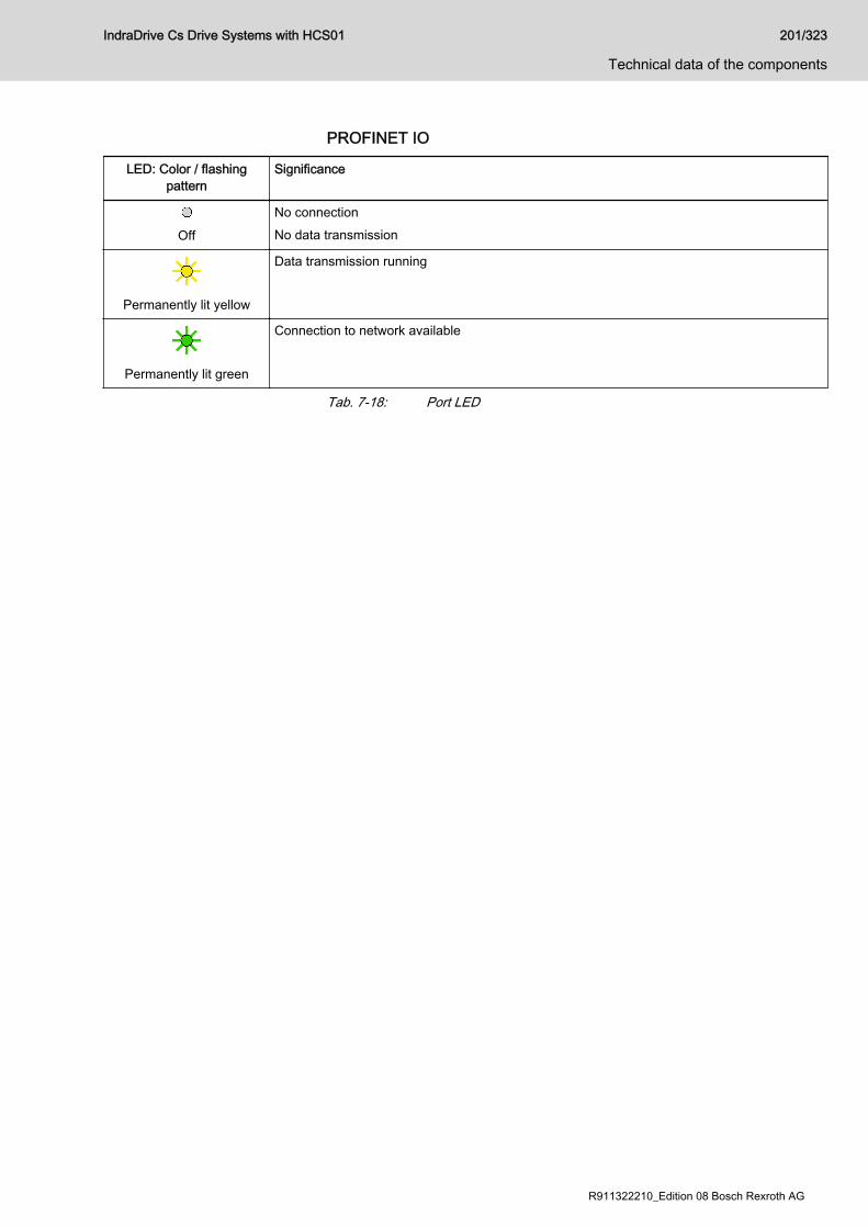
PROFINET IO
LED: Color / flashingpattern
Significance
Off
No connectionNo data transmission
Permanently lit yellow
Data transmission running
Permanently lit green
Connection to network available
Tab. 7-18: Port LED
IndraDrive Cs Drive Systems with HCS01 201/323
Technical data of the components
R911322210_Edition 08 Bosch Rexroth AG
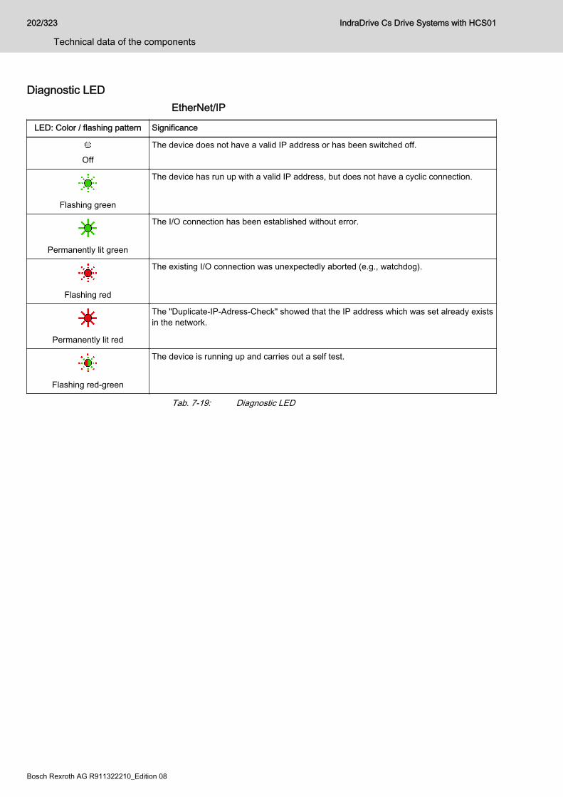
Diagnostic LEDEtherNet/IP
LED: Color / flashing pattern Significance
Off
The device does not have a valid IP address or has been switched off.
Flashing green
The device has run up with a valid IP address, but does not have a cyclic connection.
Permanently lit green
The I/O connection has been established without error.
Flashing red
The existing I/O connection was unexpectedly aborted (e.g., watchdog).
Permanently lit red
The "Duplicate-IP-Adress-Check" showed that the IP address which was set already existsin the network.
Flashing red-green
The device is running up and carries out a self test.
Tab. 7-19: Diagnostic LED
202/323
Technical data of the components
IndraDrive Cs Drive Systems with HCS01
Bosch Rexroth AG R911322210_Edition 08
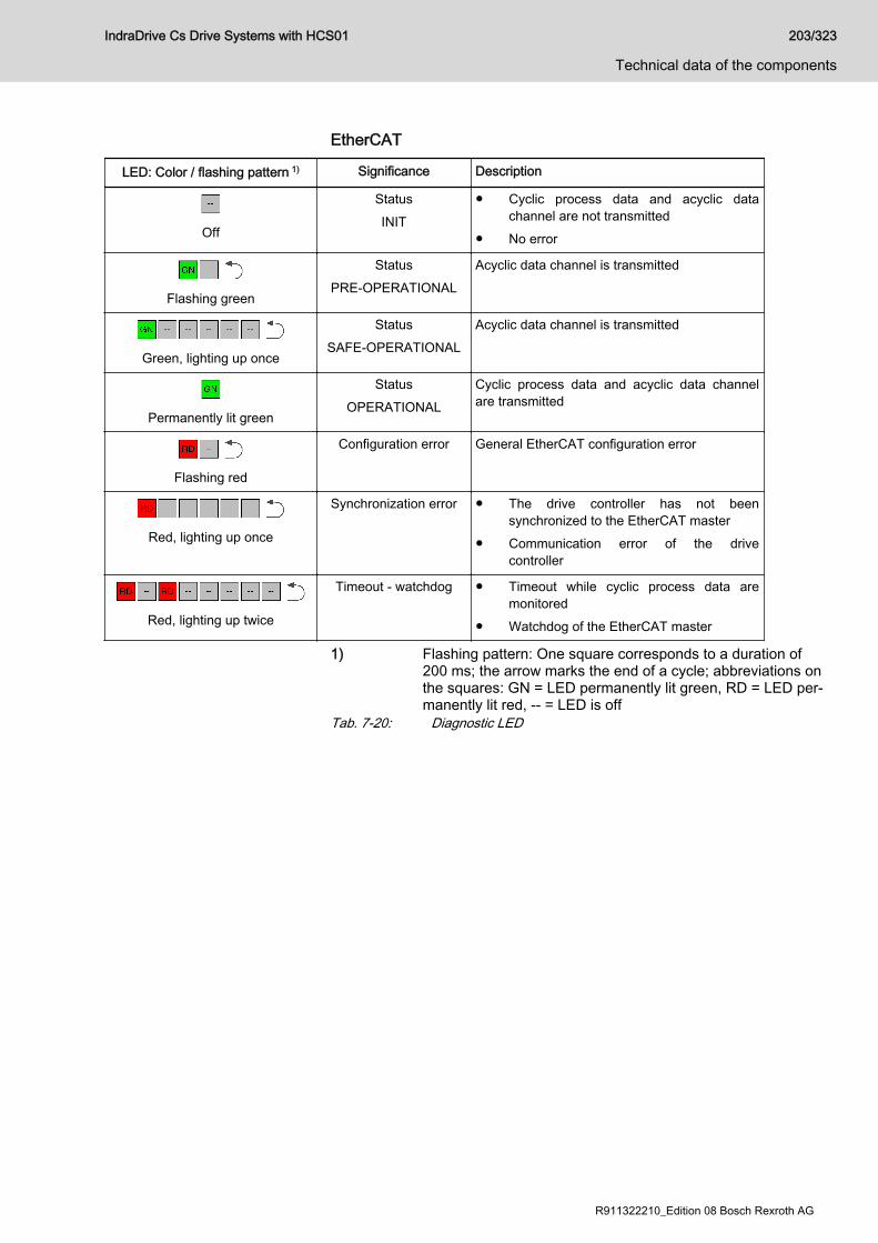
EtherCAT
LED: Color / flashing pattern 1) Significance Description
Off
StatusINIT
● Cyclic process data and acyclic datachannel are not transmitted
● No error
Flashing green
StatusPRE-OPERATIONAL
Acyclic data channel is transmitted
Green, lighting up once
StatusSAFE-OPERATIONAL
Acyclic data channel is transmitted
Permanently lit green
StatusOPERATIONAL
Cyclic process data and acyclic data channelare transmitted
Flashing red
Configuration error General EtherCAT configuration error
Red, lighting up once
Synchronization error ● The drive controller has not beensynchronized to the EtherCAT master
● Communication error of the drivecontroller
Red, lighting up twice
Timeout - watchdog ● Timeout while cyclic process data aremonitored
● Watchdog of the EtherCAT master
1) Flashing pattern: One square corresponds to a duration of200 ms; the arrow marks the end of a cycle; abbreviations onthe squares: GN = LED permanently lit green, RD = LED per‐manently lit red, -- = LED is off
Tab. 7-20: Diagnostic LED
IndraDrive Cs Drive Systems with HCS01 203/323
Technical data of the components
R911322210_Edition 08 Bosch Rexroth AG
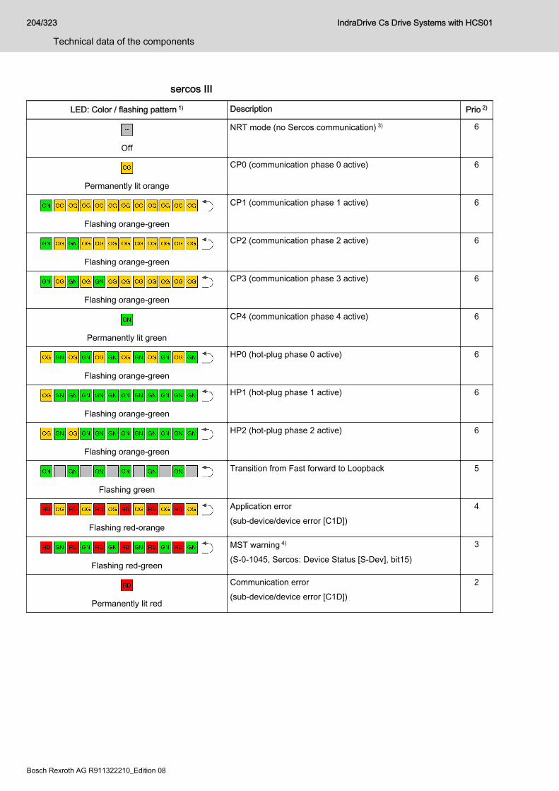
sercos III
LED: Color / flashing pattern 1) Description Prio 2)
Off
NRT mode (no Sercos communication) 3) 6
Permanently lit orange
CP0 (communication phase 0 active) 6
Flashing orange-green
CP1 (communication phase 1 active) 6
Flashing orange-green
CP2 (communication phase 2 active) 6
Flashing orange-green
CP3 (communication phase 3 active) 6
Permanently lit green
CP4 (communication phase 4 active) 6
Flashing orange-green
HP0 (hot-plug phase 0 active) 6
Flashing orange-green
HP1 (hot-plug phase 1 active) 6
Flashing orange-green
HP2 (hot-plug phase 2 active) 6
Flashing green
Transition from Fast forward to Loopback 5
Flashing red-orange
Application error(sub-device/device error [C1D])
4
Flashing red-green
MST warning 4)
(S-0-1045, Sercos: Device Status [S-Dev], bit15)
3
Permanently lit red
Communication error(sub-device/device error [C1D])
2
204/323
Technical data of the components
IndraDrive Cs Drive Systems with HCS01
Bosch Rexroth AG R911322210_Edition 08
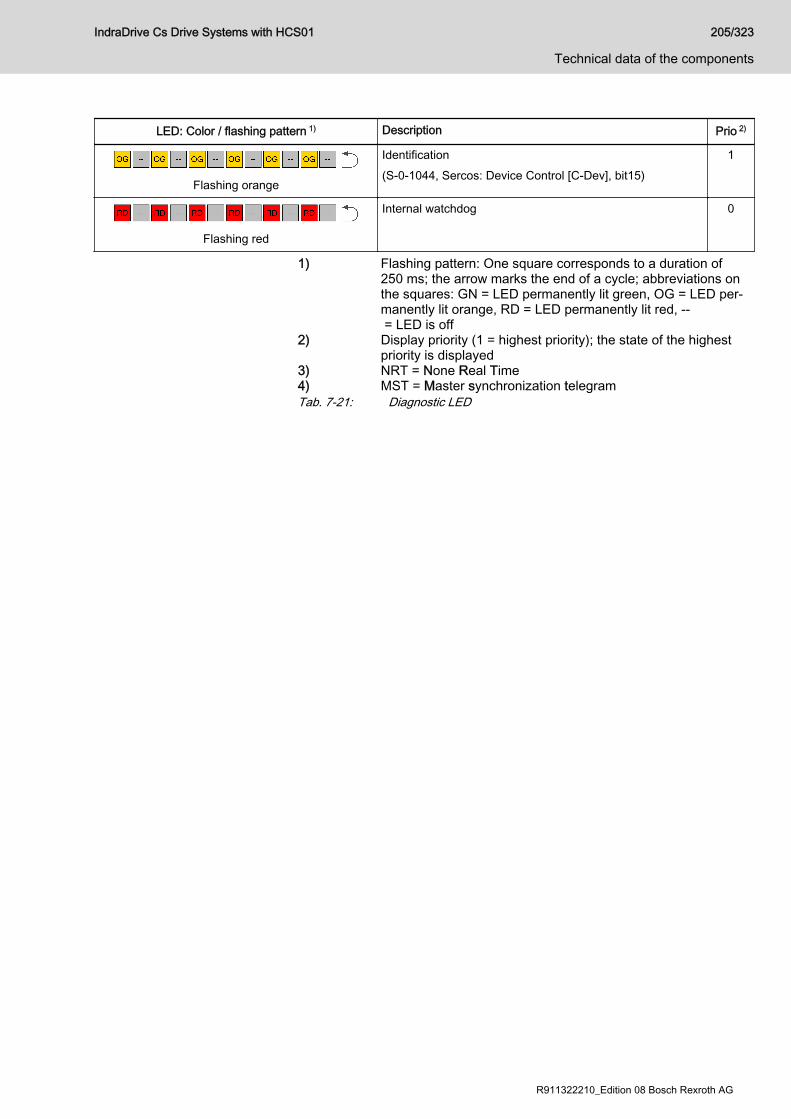
LED: Color / flashing pattern 1) Description Prio 2)
Flashing orange
Identification(S-0-1044, Sercos: Device Control [C-Dev], bit15)
1
Flashing red
Internal watchdog 0
1) Flashing pattern: One square corresponds to a duration of250 ms; the arrow marks the end of a cycle; abbreviations onthe squares: GN = LED permanently lit green, OG = LED per‐manently lit orange, RD = LED permanently lit red, -- = LED is off
2) Display priority (1 = highest priority); the state of the highestpriority is displayed
3) NRT = None Real Time4) MST = Master synchronization telegramTab. 7-21: Diagnostic LED
IndraDrive Cs Drive Systems with HCS01 205/323
Technical data of the components
R911322210_Edition 08 Bosch Rexroth AG
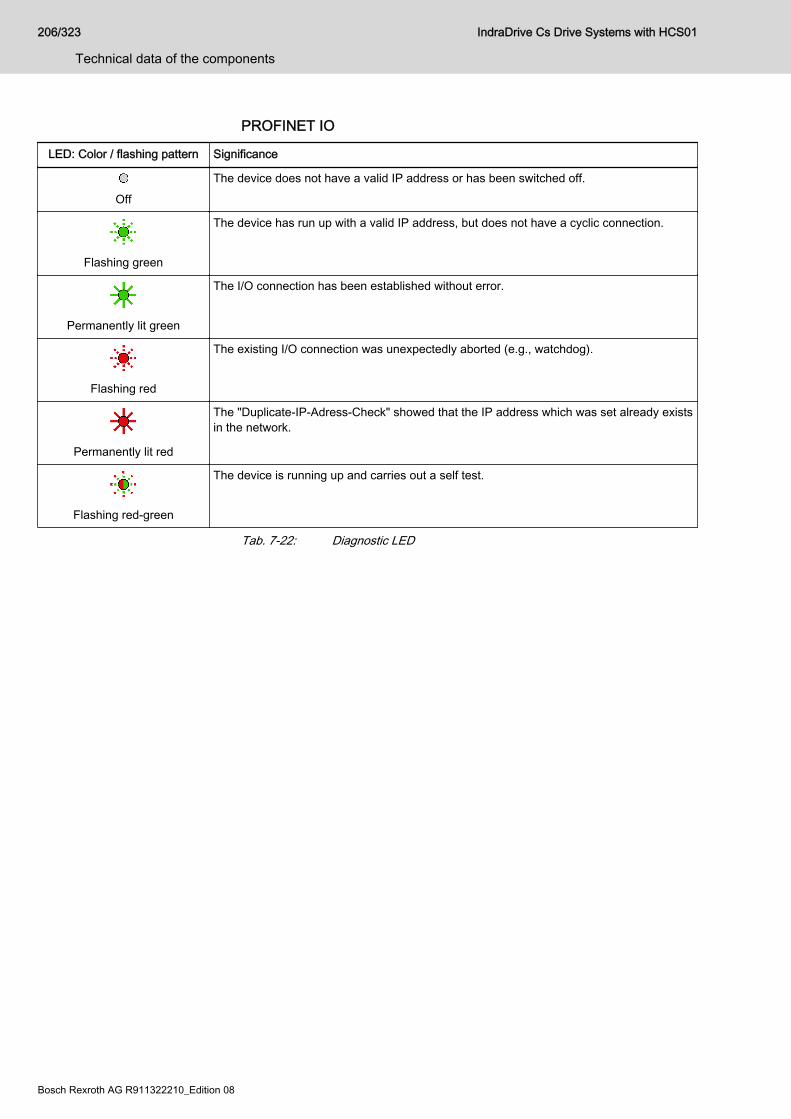
PROFINET IO
LED: Color / flashing pattern Significance
Off
The device does not have a valid IP address or has been switched off.
Flashing green
The device has run up with a valid IP address, but does not have a cyclic connection.
Permanently lit green
The I/O connection has been established without error.
Flashing red
The existing I/O connection was unexpectedly aborted (e.g., watchdog).
Permanently lit red
The "Duplicate-IP-Adress-Check" showed that the IP address which was set already existsin the network.
Flashing red-green
The device is running up and carries out a self test.
Tab. 7-22: Diagnostic LED
206/323
Technical data of the components
IndraDrive Cs Drive Systems with HCS01
Bosch Rexroth AG R911322210_Edition 08
7.1.4 PB - PROFIBUSSignal specification Signal Specification
+5VRepeater supply
+5 V (±10%)Max. 75 mA
Repeater control signal TTL-compatible:● 1: Transmit● 0: ReceiveOutput resistance: 350RVOL ≤ 0.8 V at IOL ≤ 2 mA
VOH ≥ 3.5 V at IOH ≤ 1 mA
Receive/transmit data EIA-RS485 standard
Tab. 7-23: Signal specification
Danger of destroying output "+5V repeater supply" by overload!
NOTICE
Do not short-circuit the output.Do not exceed the maximum current.
Diagnostic displays For the significance of the diagnostic displays, see firmware documentation.
IndraDrive Cs Drive Systems with HCS01 207/323
Technical data of the components
R911322210_Edition 08 Bosch Rexroth AG
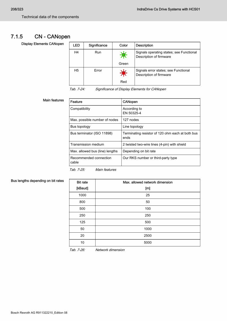
7.1.5 CN - CANopenDisplay Elements CANopen LED Significance Color Description
H4 Run
Green
Signals operating states; see FunctionalDescription of firmware
H5 Error
Red
Signals error states; see FunctionalDescription of firmware
Tab. 7-24: Significance of Display Elements for CANopen
Main features Feature CANopen
Compatibility According to EN 50325-4
Max. possible number of nodes 127 nodes
Bus topology Line topology
Bus terminator (ISO 11898) Terminating resistor of 120 ohm each at both busends
Transmission medium 2 twisted two-wire lines (4-pin) with shield
Max. allowed bus (line) lengths Depending on bit rate
Recommended connectioncable
Our RKS number or third-party type
Tab. 7-25: Main features
Bus lengths depending on bit rates Bit rate[kBaud]
Max. allowed network dimension[m]
1000 25
800 50
500 100
250 250
125 500
50 1000
20 2500
10 5000
Tab. 7-26: Network dimension
208/323
Technical data of the components
IndraDrive Cs Drive Systems with HCS01
Bosch Rexroth AG R911322210_Edition 08
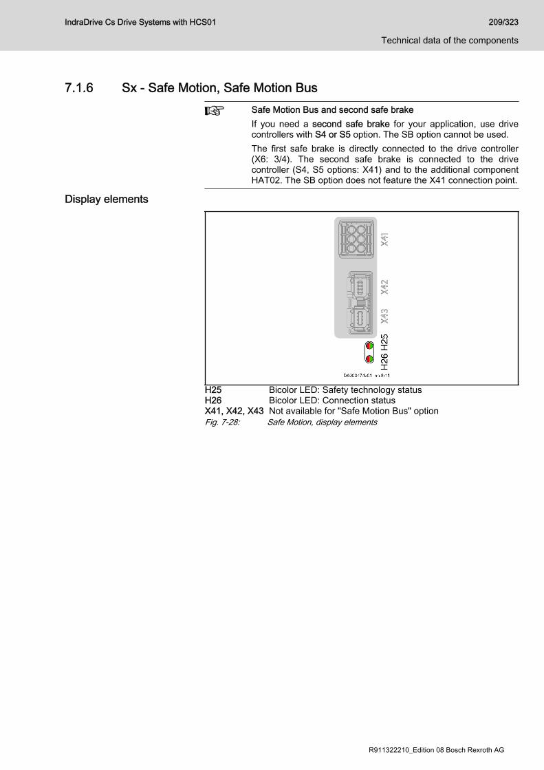
7.1.6 Sx - Safe Motion, Safe Motion BusSafe Motion Bus and second safe brakeIf you need a second safe brake for your application, use drivecontrollers with S4 or S5 option. The SB option cannot be used.The first safe brake is directly connected to the drive controller(X6: 3/4). The second safe brake is connected to the drivecontroller (S4, S5 options: X41) and to the additional componentHAT02. The SB option does not feature the X41 connection point.
Display elements
H25 Bicolor LED: Safety technology statusH26 Bicolor LED: Connection statusX41, X42, X43 Not available for "Safe Motion Bus" optionFig. 7-28: Safe Motion, display elements
IndraDrive Cs Drive Systems with HCS01 209/323
Technical data of the components
R911322210_Edition 08 Bosch Rexroth AG

Color / flashing pattern 1) Safety technology status 3)
(Safety Supervisor State / Event)Connection status 3)
Off
● Not active● Safety bus communication not
configured
● Not ready● Safety bus communication not
configured
Flashing green
Active, no connection (safety default) Ready and no active connection
Permanently lit green
Active, at least one safe connection Ready and at least one active connection
Flashing red-green
● Waiting for TUNID 2)
● Self test and initialization● Identifying the axis identifier
● Waiting for TUNID 2)
● Self test and initialization● Identifying the axis identifier
Flashing red-green
Indentifying the safety technology -
Flashing red-green
TUNID 2) not yet set -
Flashing red
Abortion of connections Faulty abortion of at least one activeconnection
Permanently lit red
Critical error Critical connection error
1) Flashing pattern: One square corresponds to a duration of250 ms; the arrow marks the end of a cycle; abbreviations onthe squares: GN = LED permanently lit green, RD = LED per‐manently lit red, -- = LED is off
2) TUNID = Target Unique Network Identifier3) The LED display is only active with safety bus communication
via the master communicationTab. 7-27: LED display
210/323
Technical data of the components
IndraDrive Cs Drive Systems with HCS01
Bosch Rexroth AG R911322210_Edition 08
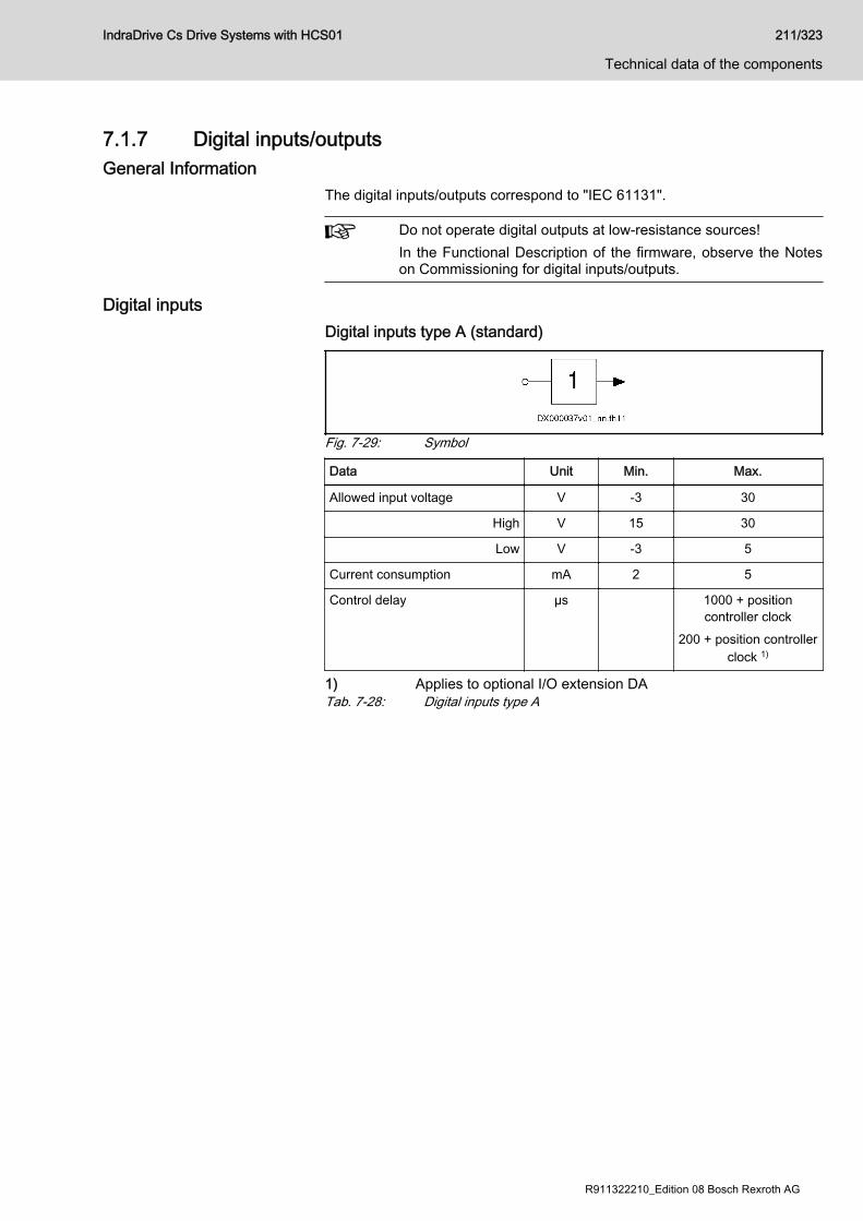
7.1.7 Digital inputs/outputsGeneral Information
The digital inputs/outputs correspond to "IEC 61131".
Do not operate digital outputs at low-resistance sources!In the Functional Description of the firmware, observe the Noteson Commissioning for digital inputs/outputs.
Digital inputsDigital inputs type A (standard)
Fig. 7-29: Symbol
Data Unit Min. Max.
Allowed input voltage V -3 30
High V 15 30
Low V -3 5
Current consumption mA 2 5
Control delay µs 1000 + positioncontroller clock
200 + position controllerclock 1)
1) Applies to optional I/O extension DATab. 7-28: Digital inputs type A
IndraDrive Cs Drive Systems with HCS01 211/323
Technical data of the components
R911322210_Edition 08 Bosch Rexroth AG
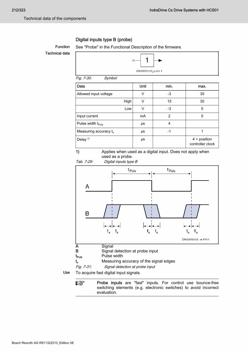
Digital inputs type B (probe)Function See "Probe" in the Functional Description of the firmware.
Technical data
Fig. 7-30: Symbol
Data Unit min. max.
Allowed input voltage V -3 30
High V 15 30
Low V -3 5
Input current mA 2 5
Pulse width tPuls μs 4
Measuring accuracy tx μs -1 1
Delay 1) μs 4 + positioncontroller clock
1) Applies when used as a digital input. Does not apply whenused as a probe.
Tab. 7-29: Digital inputs type B
A SignalB Signal detection at probe inputtPuls Pulse widthtx Measuring accuracy of the signal edgesFig. 7-31: Signal detection at probe input
Use To acquire fast digital input signals.
Probe inputs are "fast" inputs. For control use bounce-freeswitching elements (e.g. electronic switches) to avoid incorrectevaluation.
212/323
Technical data of the components
IndraDrive Cs Drive Systems with HCS01
Bosch Rexroth AG R911322210_Edition 08
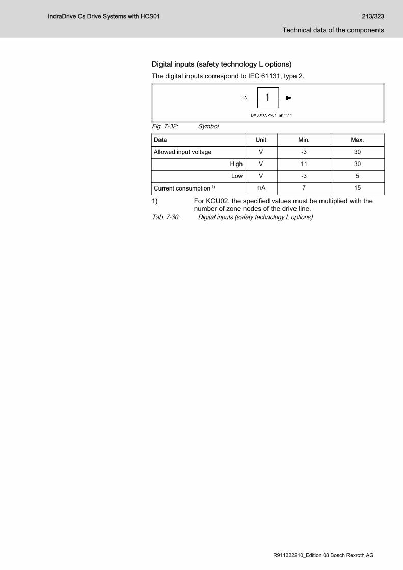
Digital inputs (safety technology L options)The digital inputs correspond to IEC 61131, type 2.
Fig. 7-32: Symbol
Data Unit Min. Max.
Allowed input voltage V -3 30
High V 11 30
Low V -3 5
Current consumption 1) mA 7 15
1) For KCU02, the specified values must be multiplied with thenumber of zone nodes of the drive line.
Tab. 7-30: Digital inputs (safety technology L options)
IndraDrive Cs Drive Systems with HCS01 213/323
Technical data of the components
R911322210_Edition 08 Bosch Rexroth AG
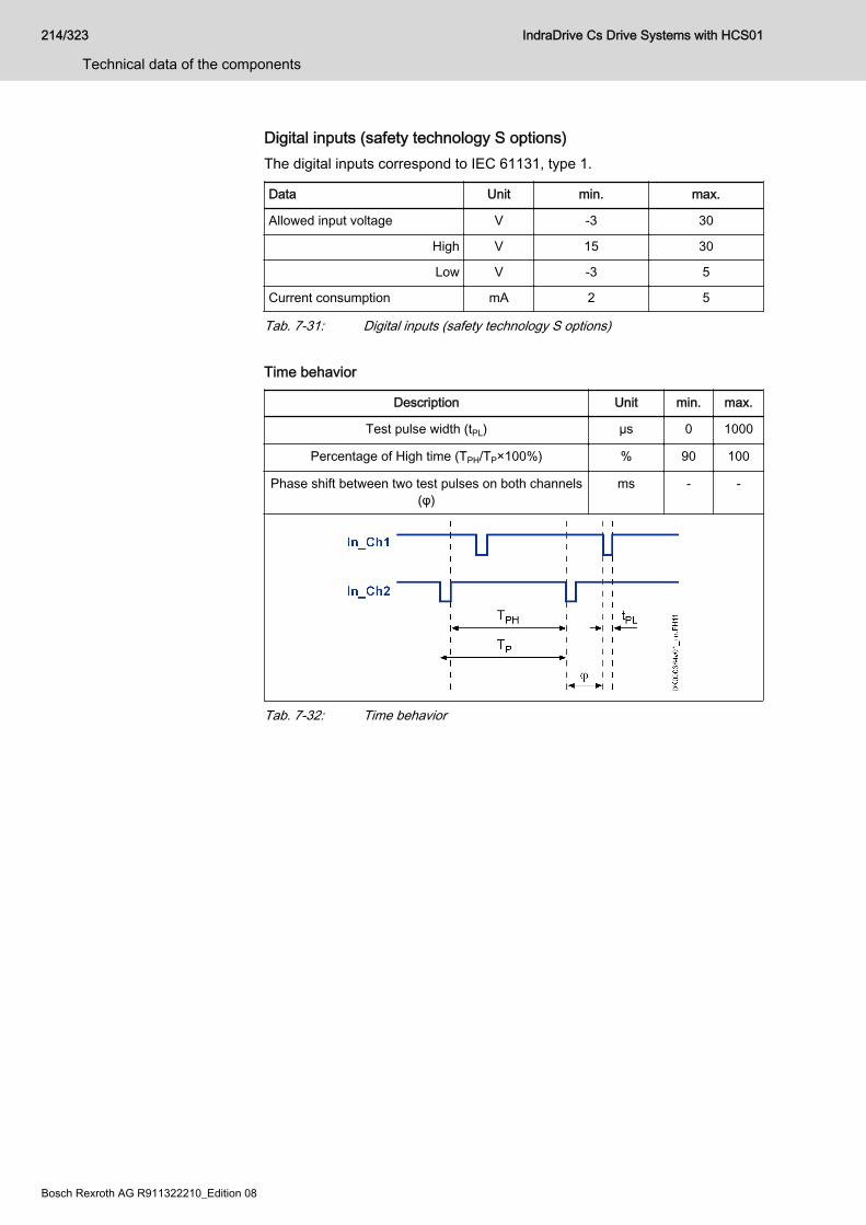
Digital inputs (safety technology S options)The digital inputs correspond to IEC 61131, type 1.
Data Unit min. max.
Allowed input voltage V -3 30
High V 15 30
Low V -3 5
Current consumption mA 2 5
Tab. 7-31: Digital inputs (safety technology S options) Time behavior
Description Unit min. max.
Test pulse width (tPL) µs 0 1000
Percentage of High time (TPH/TP×100%) % 90 100
Phase shift between two test pulses on both channels(φ)
ms - -
Tab. 7-32: Time behavior
214/323
Technical data of the components
IndraDrive Cs Drive Systems with HCS01
Bosch Rexroth AG R911322210_Edition 08
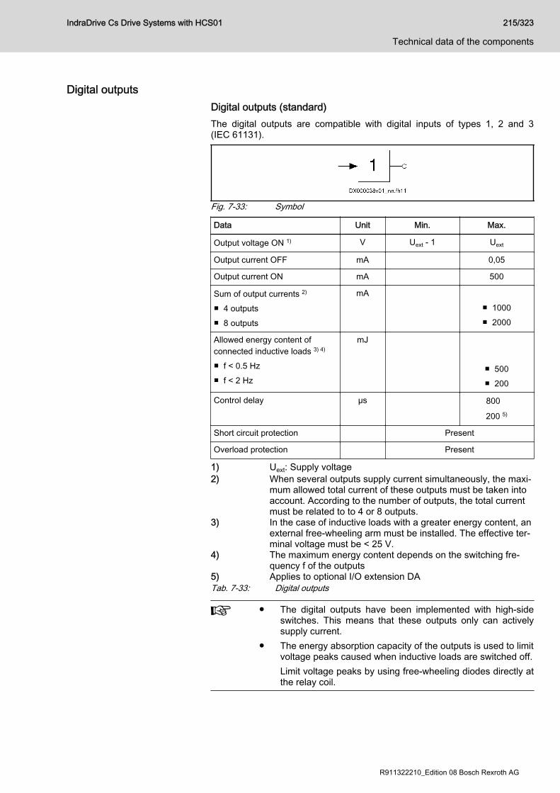
Digital outputsDigital outputs (standard)The digital outputs are compatible with digital inputs of types 1, 2 and 3(IEC 61131).
Fig. 7-33: Symbol
Data Unit Min. Max.
Output voltage ON 1) V Uext - 1 Uext
Output current OFF mA 0,05
Output current ON mA 500
Sum of output currents 2)
■ 4 outputs■ 8 outputs
mA ■ 1000■ 2000
Allowed energy content ofconnected inductive loads 3) 4)
■ f < 0.5 Hz■ f < 2 Hz
mJ
■ 500■ 200
Control delay µs 800
200 5)
Short circuit protection Present
Overload protection Present
1) Uext: Supply voltage2) When several outputs supply current simultaneously, the maxi‐
mum allowed total current of these outputs must be taken intoaccount. According to the number of outputs, the total currentmust be related to to 4 or 8 outputs.
3) In the case of inductive loads with a greater energy content, anexternal free-wheeling arm must be installed. The effective ter‐minal voltage must be < 25 V.
4) The maximum energy content depends on the switching fre‐quency f of the outputs
5) Applies to optional I/O extension DATab. 7-33: Digital outputs
● The digital outputs have been implemented with high-sideswitches. This means that these outputs only can activelysupply current.
● The energy absorption capacity of the outputs is used to limitvoltage peaks caused when inductive loads are switched off.Limit voltage peaks by using free-wheeling diodes directly atthe relay coil.
IndraDrive Cs Drive Systems with HCS01 215/323
Technical data of the components
R911322210_Edition 08 Bosch Rexroth AG

Digital outputs (safety technology L options)The digital outputs are compatible with digital inputs of types 1, 2 and 3(IEC 61131).
Fig. 7-34: Symbol
Data Unit Min. Max.
Supply voltage (Uext) V 19,2 30
Current consumption (Iext) mA 700
Output voltage ON V 18,2 30
Output voltage OFF V 5
Output current ON mA 350
Allowed energy content ofconnected inductive loads, e.g.relay coils; only allowed assingle pulse
mJ 400
Short circuit protection Available
Overload protection Available
Tab. 7-34: Digital outputs (safety technology L options)
216/323
Technical data of the components
IndraDrive Cs Drive Systems with HCS01
Bosch Rexroth AG R911322210_Edition 08
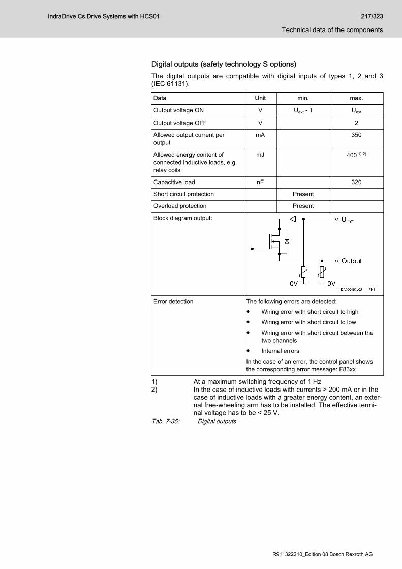
Digital outputs (safety technology S options)The digital outputs are compatible with digital inputs of types 1, 2 and 3(IEC 61131).
Data Unit min. max.
Output voltage ON V Uext - 1 Uext
Output voltage OFF V 2
Allowed output current peroutput
mA 350
Allowed energy content ofconnected inductive loads, e.g.relay coils
mJ 400 1) 2)
Capacitive load nF 320
Short circuit protection Present
Overload protection Present
Block diagram output:
Error detection The following errors are detected:● Wiring error with short circuit to high● Wiring error with short circuit to low● Wiring error with short circuit between the
two channels● Internal errorsIn the case of an error, the control panel showsthe corresponding error message: F83xx
1) At a maximum switching frequency of 1 Hz2) In the case of inductive loads with currents > 200 mA or in the
case of inductive loads with a greater energy content, an exter‐nal free-wheeling arm has to be installed. The effective termi‐nal voltage has to be < 25 V.
Tab. 7-35: Digital outputs
IndraDrive Cs Drive Systems with HCS01 217/323
Technical data of the components
R911322210_Edition 08 Bosch Rexroth AG
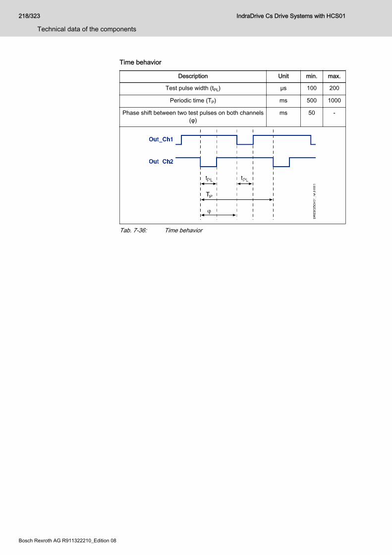
Time behavior
Description Unit min. max.
Test pulse width (tPL) μs 100 200
Periodic time (TP) ms 500 1000
Phase shift between two test pulses on both channels(φ)
ms 50 -
Tab. 7-36: Time behavior
218/323
Technical data of the components
IndraDrive Cs Drive Systems with HCS01
Bosch Rexroth AG R911322210_Edition 08
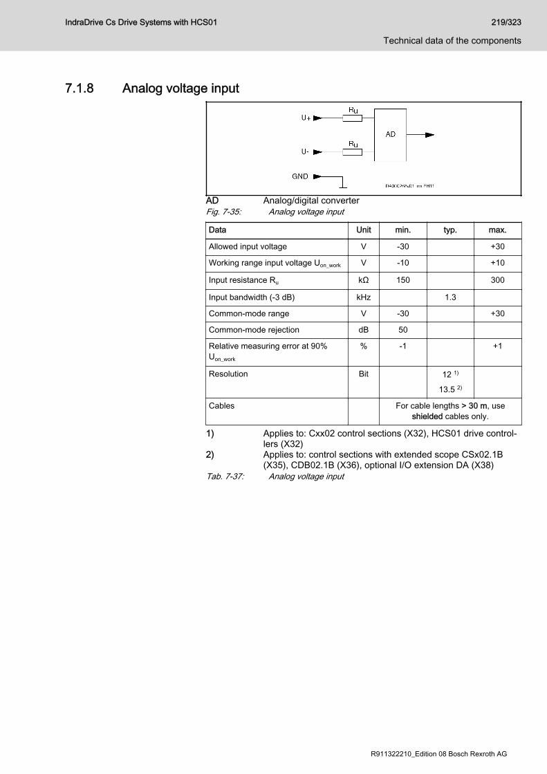
7.1.8 Analog voltage input
AD Analog/digital converterFig. 7-35: Analog voltage input
Data Unit min. typ. max.
Allowed input voltage V -30 +30
Working range input voltage Uon_work V -10 +10
Input resistance Ru kΩ 150 300
Input bandwidth (-3 dB) kHz 1.3
Common-mode range V -30 +30
Common-mode rejection dB 50
Relative measuring error at 90%Uon_work
% -1 +1
Resolution Bit 12 1)
13.5 2)
Cables For cable lengths > 30 m, useshielded cables only.
1) Applies to: Cxx02 control sections (X32), HCS01 drive control‐lers (X32)
2) Applies to: control sections with extended scope CSx02.1B(X35), CDB02.1B (X36), optional I/O extension DA (X38)
Tab. 7-37: Analog voltage input
IndraDrive Cs Drive Systems with HCS01 219/323
Technical data of the components
R911322210_Edition 08 Bosch Rexroth AG

7.1.9 Analog current input
AD Analog/digital converterFig. 7-36: Analog current input Electrical data (current inputs [-20/4 … 20 mA])
Spring terminal (connector) Unit min. max.
Input current measuring range1) mA -20 / 4 20
Input current minimum value monitoring2) mA 2 3
Input current maximum value monitoring3) mA 21 22
Input resistance Ω 280
Input bandwidth (-3db) kHz 1.3
Relative measuring error at 18 mA % -1 +1
Resolution - 13bit (12bit + 4-fold oversampling)5)
12bit (11bit + 4-fold oversampling)6)
Overload protection4) - Present
Wiring - Only use shielded cables for cable lengths > 30 m.
1) Measuring range (-20 … 20 or 4 … 20) can be set using a pa‐rameter. With a measuring range 4 … 20, the minimum valuemonitoring (wire break) is automatically active.
2) Only possible with a measuring range 4 … 203) Monitoring switched off at approx. ±35 mA4) In the case of input currents greater than the maximum value,
an error is signaled and the input is switched at high resistance5) Applies to: Optional I/O extension DA (X38)6) Applies to: Control sections with extended scope CSx02.1B
(X35), CDB02.1B (X36)Tab. 7-38: Electrical data
220/323
Technical data of the components
IndraDrive Cs Drive Systems with HCS01
Bosch Rexroth AG R911322210_Edition 08
7.1.10 Analog outputData Unit min Typ. max
Output voltage V -10 +10
Output load, ohmic kΩ 2
Output load, capacitive nF 100
Resolution mV/incr 6 2)
Conversion time (incl. responsetime)
µs 750
250 1)
Output clock Position controller clock
Precision (in relation to themeasuring range)
±0.5% with load ≥ 10 kΩ±1% with load ≥ 2 kΩ
Short circuit protection Present
Overload protection Present
1) Applies to optional I/O extension DA2) Valid with index AH1 and above of the ICI04 circuit board
and/or with production week 15W39 and above of the controlsection (see control section type plate). Previously, the resolu‐tion was 24 mV/incr.
Tab. 7-39: Analog outputs
IndraDrive Cs Drive Systems with HCS01 221/323
Technical data of the components
R911322210_Edition 08 Bosch Rexroth AG
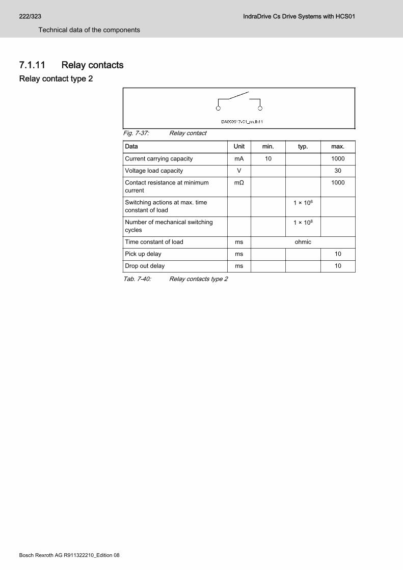
7.1.11 Relay contactsRelay contact type 2
Fig. 7-37: Relay contact
Data Unit min. typ. max.
Current carrying capacity mA 10 1000
Voltage load capacity V 30
Contact resistance at minimumcurrent
mΩ 1000
Switching actions at max. timeconstant of load
1 × 10⁶
Number of mechanical switchingcycles
1 × 10⁸
Time constant of load ms ohmic
Pick up delay ms 10
Drop out delay ms 10
Tab. 7-40: Relay contacts type 2
222/323
Technical data of the components
IndraDrive Cs Drive Systems with HCS01
Bosch Rexroth AG R911322210_Edition 08

7.2 Control panel7.2.1 DesignStandard control panel HAP01.1N
For a detailed description of the control panel, see thedocumentation "Application Manual, Functions" of the firmwareused.
Fig. 7-38: Standard control panel HAP01.1NDescription The standard control panel
● has a single-line display● must have been plugged in when the drive controller is switched on so
that it can be recognized (not suited for hot plug)● can be used as programming module● The display shows operating states, command and error diagnoses and
pending warnings.● Using the four keys, the commissioning engineer or service technician
can have extended diagnoses displayed and trigger simple commands.● Memory
– 650 kbytes for MLD boot program– 492 bytes for MLD retain variables
IndraDrive Cs Drive Systems with HCS01 223/323
Technical data of the components
R911322210_Edition 08 Bosch Rexroth AG
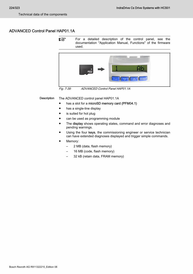
ADVANCED Control Panel HAP01.1A
For a detailed description of the control panel, see thedocumentation "Application Manual, Functions" of the firmwareused.
Fig. 7-39: ADVANCED Control Panel HAP01.1A
Description The ADVANCED control panel HAP01.1A● has a slot for a microSD memory card (PFM04.1)● has a single-line display● is suited for hot plug● can be used as programming module● The display shows operating states, command and error diagnoses and
pending warnings.● Using the four keys, the commissioning engineer or service technician
can have extended diagnoses displayed and trigger simple commands.● Memory:
– 2 MB (data, flash memory)– 16 MB (code, flash memory)– 32 kB (retain data, FRAM memory)
224/323
Technical data of the components
IndraDrive Cs Drive Systems with HCS01
Bosch Rexroth AG R911322210_Edition 08
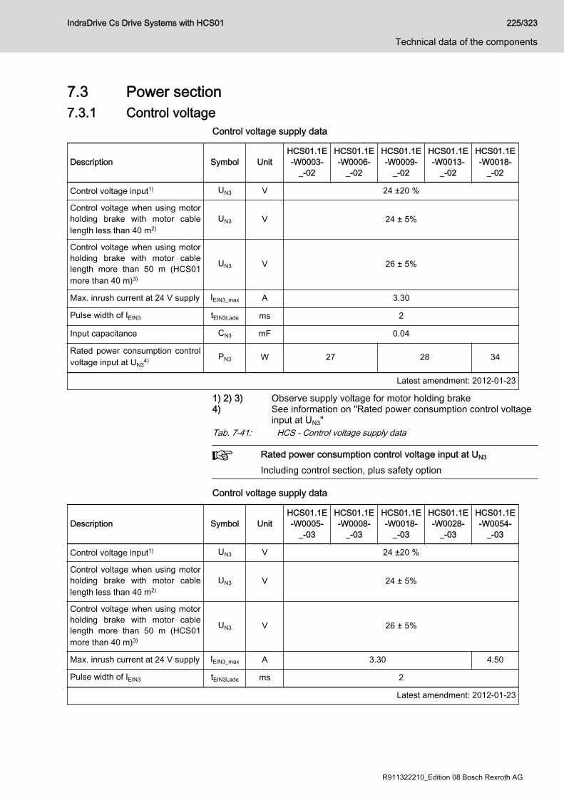
7.3 Power section7.3.1 Control voltage
Control voltage supply data
Description Symbol UnitHCS01.1E-W0003-
_-02
HCS01.1E-W0006-
_-02
HCS01.1E-W0009-
_-02
HCS01.1E-W0013-
_-02
HCS01.1E-W0018-
_-02
Control voltage input1) UN3 V 24 ±20 %
Control voltage when using motorholding brake with motor cablelength less than 40 m2)
UN3 V 24 ± 5%
Control voltage when using motorholding brake with motor cablelength more than 50 m (HCS01more than 40 m)3)
UN3 V 26 ± 5%
Max. inrush current at 24 V supply IEIN3_max A 3.30
Pulse width of IEIN3 tEIN3Lade ms 2
Input capacitance CN3 mF 0.04
Rated power consumption controlvoltage input at UN3
4) PN3 W 27 28 34
Latest amendment: 2012-01-23
1) 2) 3) Observe supply voltage for motor holding brake4) See information on "Rated power consumption control voltage
input at UN3"Tab. 7-41: HCS - Control voltage supply data
Rated power consumption control voltage input at UN3
Including control section, plus safety option
Control voltage supply data
Description Symbol UnitHCS01.1E-W0005-
_-03
HCS01.1E-W0008-
_-03
HCS01.1E-W0018-
_-03
HCS01.1E-W0028-
_-03
HCS01.1E-W0054-
_-03
Control voltage input1) UN3 V 24 ±20 %
Control voltage when using motorholding brake with motor cablelength less than 40 m2)
UN3 V 24 ± 5%
Control voltage when using motorholding brake with motor cablelength more than 50 m (HCS01more than 40 m)3)
UN3 V 26 ± 5%
Max. inrush current at 24 V supply IEIN3_max A 3.30 4.50
Pulse width of IEIN3 tEIN3Lade ms 2
Latest amendment: 2012-01-23
IndraDrive Cs Drive Systems with HCS01 225/323
Technical data of the components
R911322210_Edition 08 Bosch Rexroth AG

Description Symbol UnitHCS01.1E-W0005-
_-03
HCS01.1E-W0008-
_-03
HCS01.1E-W0018-
_-03
HCS01.1E-W0028-
_-03
HCS01.1E-W0054-
_-03
Input capacitance CN3 mF 0.04 0.06
Rated power consumption controlvoltage input at UN3
4) PN3 W 27 28 34 45
Latest amendment: 2012-01-23
1) 2) 3) Observe supply voltage for motor holding brake4) See information on "Rated power consumption control voltage
input at UN3"Tab. 7-42: HCS - Control voltage supply data
Rated power consumption control voltage input at UN3
Including control section, plus safety option
OvervoltageOvervoltage greater than 33 V has to be discharged by theappropriate electrical equipment of the machine or installation.This includes:● 24V power supply units that reduce incoming overvoltage to
the allowed value.● Overvoltage limiters at the control cabinet input that limit
existing overvoltage to the allowed value. This also appliesto long 24V lines that have been run in parallel to powercables and mains cables and can absorb overvoltage byinductive or capacitive coupling.
7.3.2 Mains voltageMains voltage supply data
Description Symbol UnitHCS01.1E-W0003-
_-02
HCS01.1E-W0006-
_-02
HCS01.1E-W0009-
_-02
HCS01.1E-W0013-
_-02
HCS01.1E-W0018-
_-02
Mains frequency fLN Hz 50...60
Tolerance input frequency Hz ± 2
Maximum allowed mainsfrequency change ΔfLN/Δt Hz/s 2
Rotary field condition None
Short circuit current rating SCCR A rms 42000
Nominal mains voltage ULN_nom V 3 AC 230
Mains voltage, single-phase ULN V 110...230
Three-phase mains voltage at TN-S, TN-C, TT mains ULN V 110...230
Latest amendment: 2012-06-28
226/323
Technical data of the components
IndraDrive Cs Drive Systems with HCS01
Bosch Rexroth AG R911322210_Edition 08

Description Symbol UnitHCS01.1E-W0003-
_-02
HCS01.1E-W0006-
_-02
HCS01.1E-W0009-
_-02
HCS01.1E-W0013-
_-02
HCS01.1E-W0018-
_-02
Mains voltage, three-phase at ITmains1) ULN V 110...230
Mains voltage, three-phase atCorner-grounded-Delta mains2) ULN V 110...230
Tolerance rated input voltage ULN % ± 10
Minimum short circuit power of themains for failure-free operation Sk_min MVA 0.02 0.03 0.05 0.1 0.2
Minimum inductance of mainssupply (mains phase inductance)3) Lmin µH 40
Assigned type of mains choke -
Inrush currentIL_trans_max
_onA See figure
Maximum allowed ON-OFF cyclesper minute4) 1
Mains input continuous current atULN_nenn and PDC_cont (single-phase, without mains choke)5)
ILN A 1.80 2.80 5.00 8.30 12.80
Mains input continuous current atULN_nenn and PDC_cont (three-phase,without mains choke)6)
ILN A 0.60 1.20 2.30 4.50 9.60
Mains input continuous current atULN_nenn and PDC_cont (single-phase, with mains choke)7)
ILN A -
Mains input continuous current atULN_nenn and PDC_cont (three-phase,with mains choke)8)
ILN A -
Nominal current AC1 for mainscontactor at nom. data ILN
Mains fuse according toEN 60204-1 (single-phase,without mains choke)
A 4;gG 6;gG 10;gG 16;gG
Mains fuse according toEN 60204-1 (three-phase, withoutmains choke)
A 2;gG 4;gG 6;gG 16;gG
Mains fuse according toEN 60204-1 (single-phase, withmains choke)
A -
Mains fuse according toEN 60204-1 (three-phase, withmains choke)
A -
Latest amendment: 2012-06-28
IndraDrive Cs Drive Systems with HCS01 227/323
Technical data of the components
R911322210_Edition 08 Bosch Rexroth AG

Description Symbol UnitHCS01.1E-W0003-
_-02
HCS01.1E-W0006-
_-02
HCS01.1E-W0009-
_-02
HCS01.1E-W0013-
_-02
HCS01.1E-W0018-
_-02
Required wire size in accordancewith NFPA 79 and UL 508 A(internal wiring);9)
ALN AWG 14 AWG
Mains connected load at ULN_nenn
and PDC_cont (three-phase, withoutmains choke)
SLN kVA 0.30 0.53 0.92 1.55 3.52
Mains connected load at ULN_nenn
and PDC_cont (three-phase, withmains choke)
SLN kVA -
Mains connection power atULN_nenn and PDC_cont (single-phase, without mains choke)
SLN kVA -
Mains connection power atULN_nenn and PDC_cont (single-phase, with mains choke)
SLN kVA -
Power factor TPF (λL) at ULN_nenn
and PDC_cont (single-phase, withoutmains choke)10)
TPF 0.29 0.32 0.35 0.37 0.49
Power factor TPF (λL) at ULN_nenn
and PDC_cont (three-phase, withoutmains choke)11)
TPF 0.47 0.52 0.56 0.52
Power factor TPF (λL) at ULN_nenn
and PDC_cont (single-phase, withmains choke)12)
TPF -
Power factor TPF (λL) at ULN_nenn
and PDC_cont (three-phase, withmains choke)13)
TPF -
Power factor TPF (λL) at ULN_nenn
and 10% PDC_cont (single-phase,without mains choke)
TPF10% -
Power factor TPF (λL) at ULN_nenn
and 10% PDC_cont (three-phase,without mains choke)
TPF10% 0.28 0.33 0.38 0.40 0.37
Power factor TPF (λL) at ULN_nenn
and 10% PDC_cont (single-phase,with mains choke)
TPF10% -
Power factor TPF (λL) at ULN_nenn
and 10% PDC_cont (three-phase,with mains choke)
TPF10% -
Latest amendment: 2012-06-28
228/323
Technical data of the components
IndraDrive Cs Drive Systems with HCS01
Bosch Rexroth AG R911322210_Edition 08
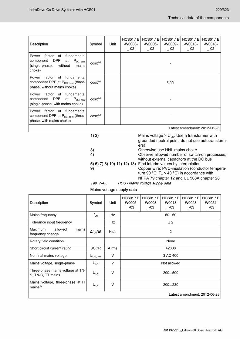
Description Symbol UnitHCS01.1E-W0003-
_-02
HCS01.1E-W0006-
_-02
HCS01.1E-W0009-
_-02
HCS01.1E-W0013-
_-02
HCS01.1E-W0018-
_-02
Power factor of fundamentalcomponent DPF at PDC_cont
(single-phase, without mainschoke)
cosφh1 -
Power factor of fundamentalcomponent DPF at PDC_cont (three-phase, without mains choke)
cosφh1 0.99
Power factor of fundamentalcomponent DPF at PDC_cont
(single-phase, with mains choke)cosφh1 -
Power factor of fundamentalcomponent DPF at PDC_cont (three-phase, with mains choke)
cosφh1 -
Latest amendment: 2012-06-28
1) 2) Mains voltage > ULN: Use a transformer withgrounded neutral point, do not use autotransform‐ers!
3) Otherwise use HNL mains choke4) Observe allowed number of switch-on processes;
without external capacitors at the DC bus5) 6) 7) 8) 10) 11) 12) 13) Find interim values by interpolation9) Copper wire; PVC-insulation (conductor tempera‐
ture 90 °C; Ta ≤ 40 °C) in accordance withNFPA 79 chapter 12 and UL 508A chapter 28
Tab. 7-43: HCS - Mains voltage supply dataMains voltage supply data
Description Symbol UnitHCS01.1E-W0005-
_-03
HCS01.1E-W0008-
_-03
HCS01.1E-W0018-
_-03
HCS01.1E-W0028-
_-03
HCS01.1E-W0054-
_-03
Mains frequency fLN Hz 50...60
Tolerance input frequency Hz ± 2
Maximum allowed mainsfrequency change ΔfLN/Δt Hz/s 2
Rotary field condition None
Short circuit current rating SCCR A rms 42000
Nominal mains voltage ULN_nom V 3 AC 400
Mains voltage, single-phase ULN V Not allowed
Three-phase mains voltage at TN-S, TN-C, TT mains ULN V 200...500
Mains voltage, three-phase at ITmains1) ULN V 200...230
Latest amendment: 2012-06-28
IndraDrive Cs Drive Systems with HCS01 229/323
Technical data of the components
R911322210_Edition 08 Bosch Rexroth AG
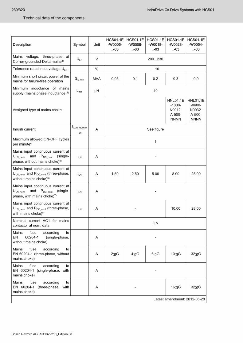
Description Symbol UnitHCS01.1E-W0005-
_-03
HCS01.1E-W0008-
_-03
HCS01.1E-W0018-
_-03
HCS01.1E-W0028-
_-03
HCS01.1E-W0054-
_-03
Mains voltage, three-phase atCorner-grounded-Delta mains2) ULN V 200...230
Tolerance rated input voltage ULN % ± 10
Minimum short circuit power of themains for failure-free operation Sk_min MVA 0.05 0.1 0.2 0.3 0.9
Minimum inductance of mainssupply (mains phase inductance)3) Lmin µH 40
Assigned type of mains choke -
HNL01.1E-1000-N0012-A-500-NNNN
HNL01.1E-0600-N0032-A-500-NNNN
Inrush currentIL_trans_max
_onA See figure
Maximum allowed ON-OFF cyclesper minute4) 1
Mains input continuous current atULN_nenn and PDC_cont (single-phase, without mains choke)5)
ILN A -
Mains input continuous current atULN_nenn and PDC_cont (three-phase,without mains choke)6)
ILN A 1.50 2.50 5.00 8.00 25.00
Mains input continuous current atULN_nenn and PDC_cont (single-phase, with mains choke)7)
ILN A -
Mains input continuous current atULN_nenn and PDC_cont (three-phase,with mains choke)8)
ILN A - 10.00 28.00
Nominal current AC1 for mainscontactor at nom. data ILN
Mains fuse according toEN 60204-1 (single-phase,without mains choke)
A -
Mains fuse according toEN 60204-1 (three-phase, withoutmains choke)
A 2;gG 4;gG 6;gG 10;gG 32;gG
Mains fuse according toEN 60204-1 (single-phase, withmains choke)
A -
Mains fuse according toEN 60204-1 (three-phase, withmains choke)
A - 16;gG 32;gG
Latest amendment: 2012-06-28
230/323
Technical data of the components
IndraDrive Cs Drive Systems with HCS01
Bosch Rexroth AG R911322210_Edition 08
Description Symbol UnitHCS01.1E-W0005-
_-03
HCS01.1E-W0008-
_-03
HCS01.1E-W0018-
_-03
HCS01.1E-W0028-
_-03
HCS01.1E-W0054-
_-03
Required wire size in accordancewith NFPA 79 and UL 508 A(internal wiring);9)
ALN AWG 14 AWG 10 AWG
Mains connected load at ULN_nenn
and PDC_cont (three-phase, withoutmains choke)
SLN kVA 1.00 1.54 3.50 4.90 16.00
Mains connected load at ULN_nenn
and PDC_cont (three-phase, withmains choke)
SLN kVA - 5.50 18.00
Mains connection power atULN_nenn and PDC_cont (single-phase, without mains choke)
SLN kVA -
Mains connection power atULN_nenn and PDC_cont (single-phase, with mains choke)
SLN kVA -
Power factor TPF (λL) at ULN_nenn
and PDC_cont (single-phase, withoutmains choke)10)
TPF -
Power factor TPF (λL) at ULN_nenn
and PDC_cont (three-phase, withoutmains choke)11)
TPF 0.49 0.56 0.52 0.53 0.56
Power factor TPF (λL) at ULN_nenn
and PDC_cont (single-phase, withmains choke)12)
TPF -
Power factor TPF (λL) at ULN_nenn
and PDC_cont (three-phase, withmains choke)13)
TPF - 0.72 0.78
Power factor TPF (λL) at ULN_nenn
and 10% PDC_cont (single-phase,without mains choke)
TPF10% -
Power factor TPF (λL) at ULN_nenn
and 10% PDC_cont (three-phase,without mains choke)
TPF10% 0.30 0.35 0.38 0.40 0.45
Power factor TPF (λL) at ULN_nenn
and 10% PDC_cont (single-phase,with mains choke)
TPF10% -
Power factor TPF (λL) at ULN_nenn
and 10% PDC_cont (three-phase,with mains choke)
TPF10% -
Latest amendment: 2012-06-28
IndraDrive Cs Drive Systems with HCS01 231/323
Technical data of the components
R911322210_Edition 08 Bosch Rexroth AG

Description Symbol UnitHCS01.1E-W0005-
_-03
HCS01.1E-W0008-
_-03
HCS01.1E-W0018-
_-03
HCS01.1E-W0028-
_-03
HCS01.1E-W0054-
_-03
Power factor of fundamentalcomponent DPF at PDC_cont
(single-phase, without mainschoke)
cosφh1 -
Power factor of fundamentalcomponent DPF at PDC_cont (three-phase, without mains choke)
cosφh1 0.99 0.98 0.99 0.98 0.97
Power factor of fundamentalcomponent DPF at PDC_cont
(single-phase, with mains choke)cosφh1 -
Power factor of fundamentalcomponent DPF at PDC_cont (three-phase, with mains choke)
cosφh1 - 0.99 0.95
Latest amendment: 2012-06-28
1) 2) Mains voltage > ULN: Use a transformer withgrounded neutral point, do not use autotransform‐ers!
3) Otherwise use HNL mains choke4) Observe allowed number of switch-on processes;
without external capacitors at the DC bus5) 6) 7) 8) 10) 11) 12) 13) Find interim values by interpolation9) Copper wire; PVC-insulation (conductor tempera‐
ture 90 °C; Ta ≤ 40 °C) in accordance withNFPA 79 chapter 12 and UL 508A chapter 28
Tab. 7-44: HCS - Mains voltage supply data
232/323
Technical data of the components
IndraDrive Cs Drive Systems with HCS01
Bosch Rexroth AG R911322210_Edition 08
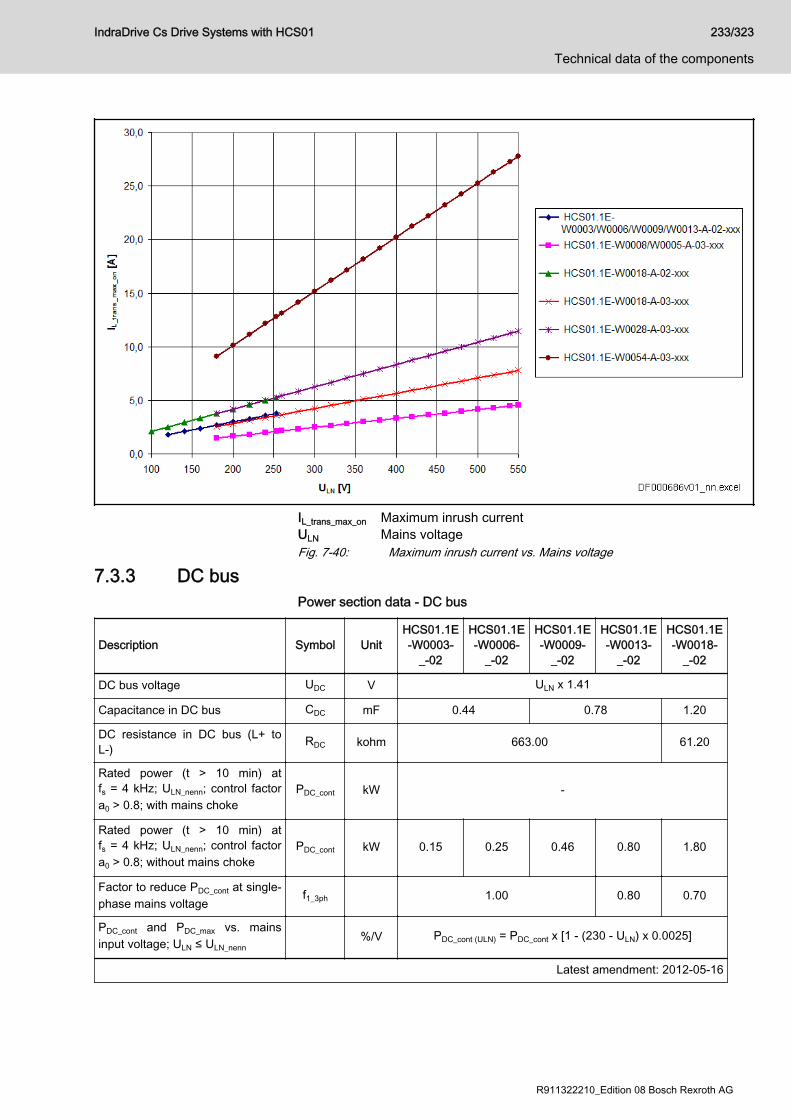
IL_trans_max_on Maximum inrush currentULN Mains voltageFig. 7-40: Maximum inrush current vs. Mains voltage
7.3.3 DC busPower section data - DC bus
Description Symbol UnitHCS01.1E-W0003-
_-02
HCS01.1E-W0006-
_-02
HCS01.1E-W0009-
_-02
HCS01.1E-W0013-
_-02
HCS01.1E-W0018-
_-02
DC bus voltage UDC V ULN x 1.41
Capacitance in DC bus CDC mF 0.44 0.78 1.20
DC resistance in DC bus (L+ toL-) RDC kohm 663.00 61.20
Rated power (t > 10 min) atfs = 4 kHz; ULN_nenn; control factora0 > 0.8; with mains choke
PDC_cont kW -
Rated power (t > 10 min) atfs = 4 kHz; ULN_nenn; control factora0 > 0.8; without mains choke
PDC_cont kW 0.15 0.25 0.46 0.80 1.80
Factor to reduce PDC_cont at single-phase mains voltage
f1_3ph 1.00 0.80 0.70
PDC_cont and PDC_max vs. mainsinput voltage; ULN ≤ ULN_nenn
%/V PDC_cont (ULN) = PDC_cont x [1 - (230 - ULN) x 0.0025]
Latest amendment: 2012-05-16
IndraDrive Cs Drive Systems with HCS01 233/323
Technical data of the components
R911322210_Edition 08 Bosch Rexroth AG
Description Symbol UnitHCS01.1E-W0003-
_-02
HCS01.1E-W0006-
_-02
HCS01.1E-W0009-
_-02
HCS01.1E-W0013-
_-02
HCS01.1E-W0018-
_-02
PDC_cont and PDC_max vs. mainsinput voltage; ULN > ULN_nenn
%/V No power increase
Maximum allowed DC bus powerat ULN_nenn; with mains choke PDC_max kW -
Maximum allowed DC bus powerat ULN_nenn; without mains choke PDC_max kW 0.45 0.75 1.38 2.40 4.80
Balancing factor for PDC_cont (forparallel operation at common DCbus) with mains choke
-
Balancing factor for PDC_cont (forparallel operation at common DCbus) without mains choke
-
Monitoring value maximum DCbus voltage, switch-off threshold
UDC_limit_m
axV 420
Monitoring value minimum DC busvoltage, undervoltage threshold
UDC_limit_mi
nV
0.75 x ULN or "P-0-0114, Undervoltage threshold", ifP-0-0114 > 0.75 x ULN
Charging resistor continuouspower PDC_Start kW 0.03 0.15
Allowed external DC buscapacitance (nom.) at ULN_nenn
1) CDCext mF -
Charging time for maximumexternal DC bus capacitanceCDCext at ULN_nenn
tlade_DC_Ce
xts 2.50
Latest amendment: 2012-05-16
1) Use assigned mains chokeTab. 7-45: HCS - Power section data - DC busPower section data - DC bus
Description Symbol UnitHCS01.1E-W0005-
_-03
HCS01.1E-W0008-
_-03
HCS01.1E-W0018-
_-03
HCS01.1E-W0028-
_-03
HCS01.1E-W0054-
_-03
DC bus voltage UDC V ULN x 1.41
Capacitance in DC bus CDC mF 0.11 0.39 0.78
DC resistance in DC bus (L+ toL-) RDC kohm 320.00 230.00 136.00
Rated power (t > 10 min) atfs = 4 kHz; ULN_nenn; control factora0 > 0.8; with mains choke
PDC_cont kW - 4.00 14.00
Rated power (t > 10 min) atfs = 4 kHz; ULN_nenn; control factora0 > 0.8; without mains choke
PDC_cont kW 0.46 0.86 1.70 2.60 9.00
Latest amendment: 2014-12-19
234/323
Technical data of the components
IndraDrive Cs Drive Systems with HCS01
Bosch Rexroth AG R911322210_Edition 08
Description Symbol UnitHCS01.1E-W0005-
_-03
HCS01.1E-W0008-
_-03
HCS01.1E-W0018-
_-03
HCS01.1E-W0028-
_-03
HCS01.1E-W0054-
_-03
Factor to reduce PDC_cont at single-phase mains voltage
f1_3ph 1-phase operation not allowed
PDC_cont and PDC_max vs. mainsinput voltage; ULN ≤ ULN_nenn
%/V PDC_cont (ULN) = PDC_cont x [1 - (400 - ULN) x 0.0025]
PDC_cont and PDC_max vs. mainsinput voltage; ULN > ULN_nenn
%/V No power increase
Maximum allowed DC bus powerat ULN_nenn; with mains choke PDC_max kW - 9.70 19.00
Maximum allowed DC bus powerat ULN_nenn; without mains choke PDC_max kW 1.38 2.58 5.10 6.20 14.00
Balancing factor for PDC_cont (forparallel operation at common DCbus) with mains choke
- 0.80
Monitoring value maximum DCbus voltage, switch-off threshold
UDC_limit_m
axV 900
Monitoring value minimum DC busvoltage, undervoltage threshold
UDC_limit_mi
nV
0.75 x ULN or "P-0-0114, Undervoltage threshold", ifP-0-0114 > 0.75 x ULN
Charging resistor continuouspower PDC_Start kW 0.03 0.05 0.15 0.50
Allowed external DC buscapacitance (nom.) at ULN_nenn
1) CDCext mF - 3.00 4.00 13.00
Charging time for maximumexternal DC bus capacitanceCDCext at ULN_nenn
tlade_DC_Ce
xts 2.50
Latest amendment: 2014-12-19
1) Use assigned mains chokeTab. 7-46: HCS - Power section data - DC bus
7.3.4 Integrated braking resistor
Information on the external braking resistor: See chapter 8.3.4 "External braking resistors HLR" on page 282.
Integrated braking resistor data
Description Symbol UnitHCS01.1E-W0003-
_-02
HCS01.1E-W0006-
_-02
HCS01.1E-W0009-
_-02
HCS01.1E-W0013-
_-02
HCS01.1E-W0018-
_-02
Braking resistor continuous power PBD kW 0.02 0.03 0.15
Braking resistor peak power PBS kW 1.68 2.24
Nominal braking resistance RDC_Bleeder ohm 100 68
Latest amendment: 2012-05-16
IndraDrive Cs Drive Systems with HCS01 235/323
Technical data of the components
R911322210_Edition 08 Bosch Rexroth AG
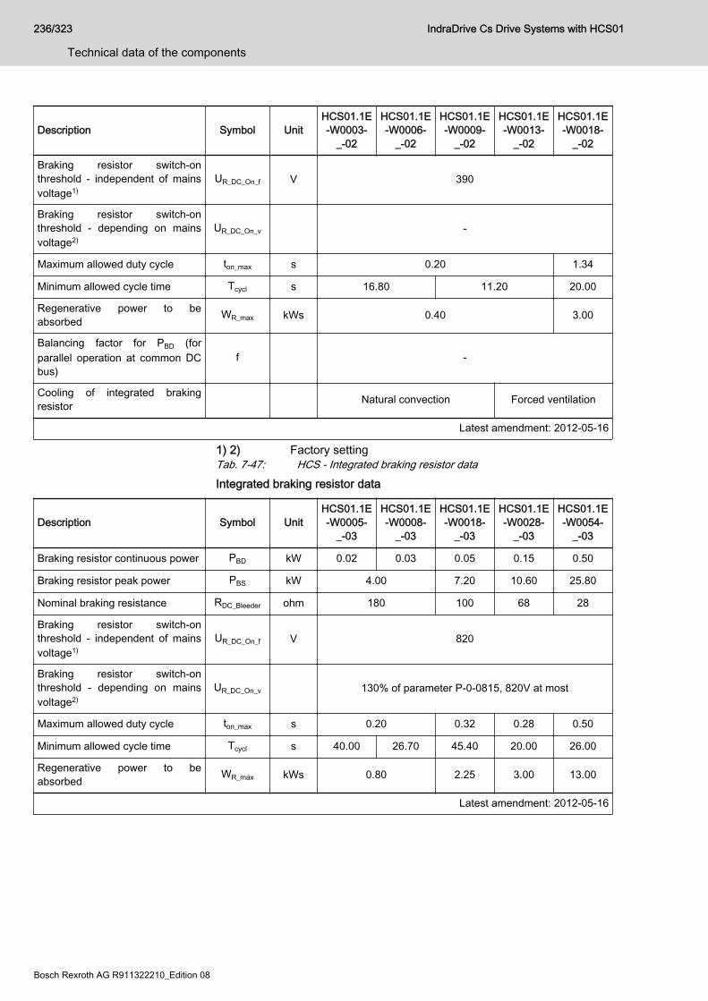
Description Symbol UnitHCS01.1E-W0003-
_-02
HCS01.1E-W0006-
_-02
HCS01.1E-W0009-
_-02
HCS01.1E-W0013-
_-02
HCS01.1E-W0018-
_-02
Braking resistor switch-onthreshold - independent of mainsvoltage1)
UR_DC_On_f V 390
Braking resistor switch-onthreshold - depending on mainsvoltage2)
UR_DC_On_v -
Maximum allowed duty cycle ton_max s 0.20 1.34
Minimum allowed cycle time Tcycl s 16.80 11.20 20.00
Regenerative power to beabsorbed WR_max kWs 0.40 3.00
Balancing factor for PBD (forparallel operation at common DCbus)
f -
Cooling of integrated brakingresistor Natural convection Forced ventilation
Latest amendment: 2012-05-16
1) 2) Factory settingTab. 7-47: HCS - Integrated braking resistor dataIntegrated braking resistor data
Description Symbol UnitHCS01.1E-W0005-
_-03
HCS01.1E-W0008-
_-03
HCS01.1E-W0018-
_-03
HCS01.1E-W0028-
_-03
HCS01.1E-W0054-
_-03
Braking resistor continuous power PBD kW 0.02 0.03 0.05 0.15 0.50
Braking resistor peak power PBS kW 4.00 7.20 10.60 25.80
Nominal braking resistance RDC_Bleeder ohm 180 100 68 28
Braking resistor switch-onthreshold - independent of mainsvoltage1)
UR_DC_On_f V 820
Braking resistor switch-onthreshold - depending on mainsvoltage2)
UR_DC_On_v 130% of parameter P-0-0815, 820V at most
Maximum allowed duty cycle ton_max s 0.20 0.32 0.28 0.50
Minimum allowed cycle time Tcycl s 40.00 26.70 45.40 20.00 26.00
Regenerative power to beabsorbed WR_max kWs 0.80 2.25 3.00 13.00
Latest amendment: 2012-05-16
236/323
Technical data of the components
IndraDrive Cs Drive Systems with HCS01
Bosch Rexroth AG R911322210_Edition 08
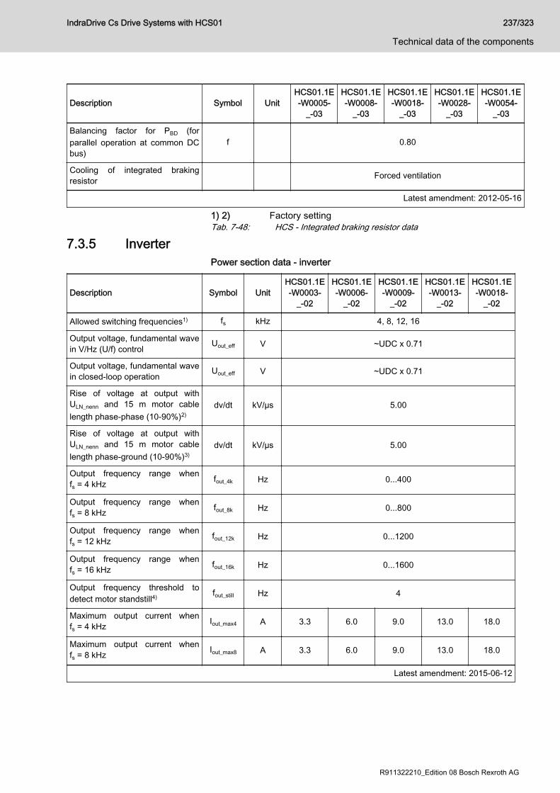
Description Symbol UnitHCS01.1E-W0005-
_-03
HCS01.1E-W0008-
_-03
HCS01.1E-W0018-
_-03
HCS01.1E-W0028-
_-03
HCS01.1E-W0054-
_-03
Balancing factor for PBD (forparallel operation at common DCbus)
f 0.80
Cooling of integrated brakingresistor Forced ventilation
Latest amendment: 2012-05-16
1) 2) Factory settingTab. 7-48: HCS - Integrated braking resistor data
7.3.5 InverterPower section data - inverter
Description Symbol UnitHCS01.1E-W0003-
_-02
HCS01.1E-W0006-
_-02
HCS01.1E-W0009-
_-02
HCS01.1E-W0013-
_-02
HCS01.1E-W0018-
_-02
Allowed switching frequencies1) fs kHz 4, 8, 12, 16
Output voltage, fundamental wavein V/Hz (U/f) control Uout_eff V ~UDC x 0.71
Output voltage, fundamental wavein closed-loop operation Uout_eff V ~UDC x 0.71
Rise of voltage at output withULN_nenn and 15 m motor cablelength phase-phase (10-90%)2)
dv/dt kV/µs 5.00
Rise of voltage at output withULN_nenn and 15 m motor cablelength phase-ground (10-90%)3)
dv/dt kV/µs 5.00
Output frequency range whenfs = 4 kHz fout_4k Hz 0...400
Output frequency range whenfs = 8 kHz fout_8k Hz 0...800
Output frequency range whenfs = 12 kHz fout_12k Hz 0...1200
Output frequency range whenfs = 16 kHz fout_16k Hz 0...1600
Output frequency threshold todetect motor standstill4) fout_still Hz 4
Maximum output current whenfs = 4 kHz Iout_max4 A 3.3 6.0 9.0 13.0 18.0
Maximum output current whenfs = 8 kHz Iout_max8 A 3.3 6.0 9.0 13.0 18.0
Latest amendment: 2015-06-12
IndraDrive Cs Drive Systems with HCS01 237/323
Technical data of the components
R911322210_Edition 08 Bosch Rexroth AG
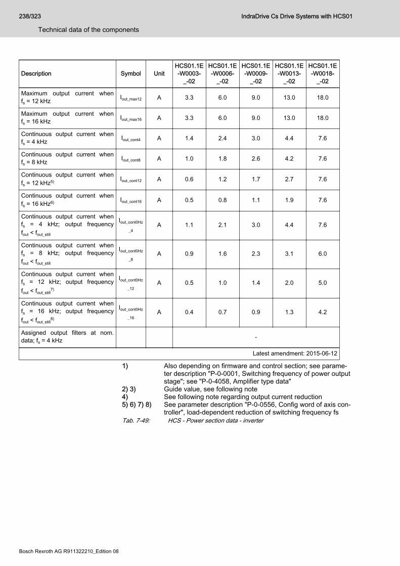
Description Symbol UnitHCS01.1E-W0003-
_-02
HCS01.1E-W0006-
_-02
HCS01.1E-W0009-
_-02
HCS01.1E-W0013-
_-02
HCS01.1E-W0018-
_-02
Maximum output current whenfs = 12 kHz Iout_max12 A 3.3 6.0 9.0 13.0 18.0
Maximum output current whenfs = 16 kHz Iout_max16 A 3.3 6.0 9.0 13.0 18.0
Continuous output current whenfs = 4 kHz Iout_cont4 A 1.4 2.4 3.0 4.4 7.6
Continuous output current whenfs = 8 kHz Iout_cont8 A 1.0 1.8 2.6 4.2 7.6
Continuous output current whenfs = 12 kHz5) Iout_cont12 A 0.6 1.2 1.7 2.7 7.6
Continuous output current whenfs = 16 kHz6) Iout_cont16 A 0.5 0.8 1.1 1.9 7.6
Continuous output current whenfs = 4 kHz; output frequencyfout < fout_still
Iout_cont0Hz
_4A 1.1 2.1 3.0 4.4 7.6
Continuous output current whenfs = 8 kHz; output frequencyfout < fout_still
Iout_cont0Hz
_8A 0.9 1.6 2.3 3.1 6.0
Continuous output current whenfs = 12 kHz; output frequencyfout < fout_still
7)
Iout_cont0Hz
_12A 0.5 1.0 1.4 2.0 5.0
Continuous output current whenfs = 16 kHz; output frequencyfout < fout_still
8)
Iout_cont0Hz
_16A 0.4 0.7 0.9 1.3 4.2
Assigned output filters at nom.data; fs = 4 kHz -
Latest amendment: 2015-06-12
1) Also depending on firmware and control section; see parame‐ter description "P-0-0001, Switching frequency of power outputstage"; see "P-0-4058, Amplifier type data"
2) 3) Guide value, see following note4) See following note regarding output current reduction5) 6) 7) 8) See parameter description "P-0-0556, Config word of axis con‐
troller", load-dependent reduction of switching frequency fsTab. 7-49: HCS - Power section data - inverter
238/323
Technical data of the components
IndraDrive Cs Drive Systems with HCS01
Bosch Rexroth AG R911322210_Edition 08
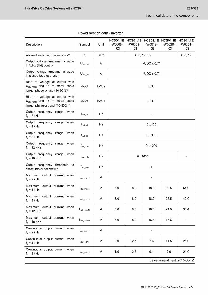
Power section data - inverter
Description Symbol UnitHCS01.1E-W0005-
_-03
HCS01.1E-W0008-
_-03
HCS01.1E-W0018-
_-03
HCS01.1E-W0028-
_-03
HCS01.1E-W0054-
_-03
Allowed switching frequencies1) fs kHz 4, 8, 12, 16 4, 8, 12
Output voltage, fundamental wavein V/Hz (U/f) control Uout_eff V ~UDC x 0.71
Output voltage, fundamental wavein closed-loop operation Uout_eff V ~UDC x 0.71
Rise of voltage at output withULN_nenn and 15 m motor cablelength phase-phase (10-90%)2)
dv/dt kV/µs 5.00
Rise of voltage at output withULN_nenn and 15 m motor cablelength phase-ground (10-90%)3)
dv/dt kV/µs 5.00
Output frequency range whenfs = 2 kHz fout_2k Hz -
Output frequency range whenfs = 4 kHz fout_4k Hz 0...400
Output frequency range whenfs = 8 kHz fout_8k Hz 0...800
Output frequency range whenfs = 12 kHz fout_12k Hz 0...1200
Output frequency range whenfs = 16 kHz fout_16k Hz 0...1600 -
Output frequency threshold todetect motor standstill4) fout_still Hz 4
Maximum output current whenfs = 2 kHz Iout_max2 A -
Maximum output current whenfs = 4 kHz Iout_max4 A 5.0 8.0 18.0 28.5 54.0
Maximum output current whenfs = 8 kHz Iout_max8 A 5.0 8.0 18.0 28.5 40.0
Maximum output current whenfs = 12 kHz Iout_max12 A 5.0 8.0 18.0 21.9 30.4
Maximum output current whenfs = 16 kHz Iout_max16 A 5.0 8.0 16.5 17.6 -
Continuous output current whenfs = 2 kHz Iout_cont2 A -
Continuous output current whenfs = 4 kHz Iout_cont4 A 2.0 2.7 7.6 11.5 21.0
Continuous output current whenfs = 8 kHz Iout_cont8 A 1.6 2.3 6.1 7.9 21.0
Latest amendment: 2015-06-12
IndraDrive Cs Drive Systems with HCS01 239/323
Technical data of the components
R911322210_Edition 08 Bosch Rexroth AG
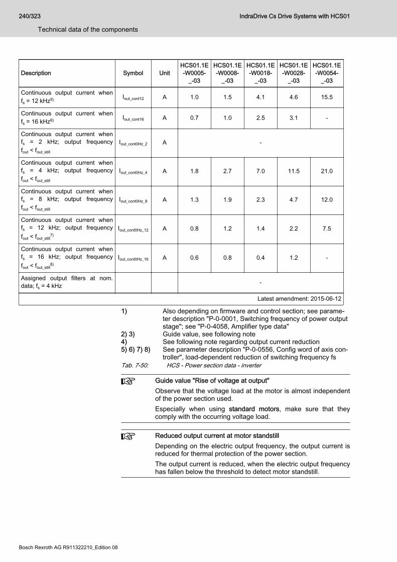
Description Symbol UnitHCS01.1E-W0005-
_-03
HCS01.1E-W0008-
_-03
HCS01.1E-W0018-
_-03
HCS01.1E-W0028-
_-03
HCS01.1E-W0054-
_-03
Continuous output current whenfs = 12 kHz5) Iout_cont12 A 1.0 1.5 4.1 4.6 15.5
Continuous output current whenfs = 16 kHz6) Iout_cont16 A 0.7 1.0 2.5 3.1 -
Continuous output current whenfs = 2 kHz; output frequencyfout < fout_still
Iout_cont0Hz_2 A -
Continuous output current whenfs = 4 kHz; output frequencyfout < fout_still
Iout_cont0Hz_4 A 1.8 2.7 7.0 11.5 21.0
Continuous output current whenfs = 8 kHz; output frequencyfout < fout_still
Iout_cont0Hz_8 A 1.3 1.9 2.3 4.7 12.0
Continuous output current whenfs = 12 kHz; output frequencyfout < fout_still
7)Iout_cont0Hz_12 A 0.8 1.2 1.4 2.2 7.5
Continuous output current whenfs = 16 kHz; output frequencyfout < fout_still
8)Iout_cont0Hz_16 A 0.6 0.8 0.4 1.2 -
Assigned output filters at nom.data; fs = 4 kHz -
Latest amendment: 2015-06-12
1) Also depending on firmware and control section; see parame‐ter description "P-0-0001, Switching frequency of power outputstage"; see "P-0-4058, Amplifier type data"
2) 3) Guide value, see following note4) See following note regarding output current reduction5) 6) 7) 8) See parameter description "P-0-0556, Config word of axis con‐
troller", load-dependent reduction of switching frequency fsTab. 7-50: HCS - Power section data - inverter
Guide value "Rise of voltage at output"Observe that the voltage load at the motor is almost independentof the power section used.Especially when using standard motors, make sure that theycomply with the occurring voltage load.
Reduced output current at motor standstillDepending on the electric output frequency, the output current isreduced for thermal protection of the power section.The output current is reduced, when the electric output frequencyhas fallen below the threshold to detect motor standstill.
240/323
Technical data of the components
IndraDrive Cs Drive Systems with HCS01
Bosch Rexroth AG R911322210_Edition 08
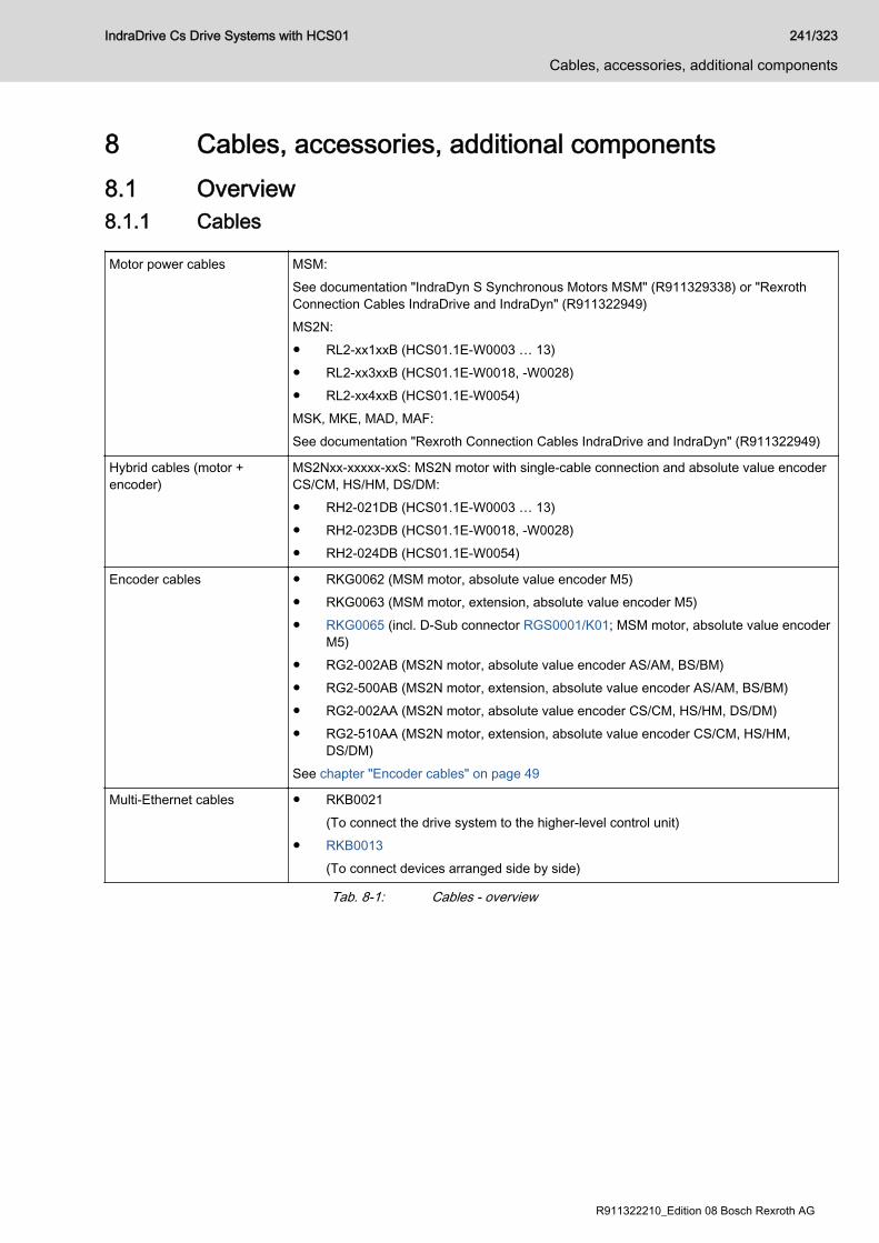
8 Cables, accessories, additional components8.1 Overview8.1.1 Cables
Motor power cables MSM:See documentation "IndraDyn S Synchronous Motors MSM" (R911329338) or "RexrothConnection Cables IndraDrive and IndraDyn" (R911322949)MS2N:● RL2-xx1xxB (HCS01.1E-W0003 … 13)● RL2-xx3xxB (HCS01.1E-W0018, -W0028)● RL2-xx4xxB (HCS01.1E-W0054)MSK, MKE, MAD, MAF:See documentation "Rexroth Connection Cables IndraDrive and IndraDyn" (R911322949)
Hybrid cables (motor +encoder)
MS2Nxx-xxxxx-xxS: MS2N motor with single-cable connection and absolute value encoderCS/CM, HS/HM, DS/DM:● RH2-021DB (HCS01.1E-W0003 … 13)● RH2-023DB (HCS01.1E-W0018, -W0028)● RH2-024DB (HCS01.1E-W0054)
Encoder cables ● RKG0062 (MSM motor, absolute value encoder M5)● RKG0063 (MSM motor, extension, absolute value encoder M5)● RKG0065 (incl. D-Sub connector RGS0001/K01; MSM motor, absolute value encoder
M5)● RG2-002AB (MS2N motor, absolute value encoder AS/AM, BS/BM)● RG2-500AB (MS2N motor, extension, absolute value encoder AS/AM, BS/BM)● RG2-002AA (MS2N motor, absolute value encoder CS/CM, HS/HM, DS/DM)● RG2-510AA (MS2N motor, extension, absolute value encoder CS/CM, HS/HM,
DS/DM)See chapter "Encoder cables" on page 49
Multi-Ethernet cables ● RKB0021(To connect the drive system to the higher-level control unit)
● RKB0013(To connect devices arranged side by side)
Tab. 8-1: Cables - overview
IndraDrive Cs Drive Systems with HCS01 241/323
Cables, accessories, additional components
R911322210_Edition 08 Bosch Rexroth AG
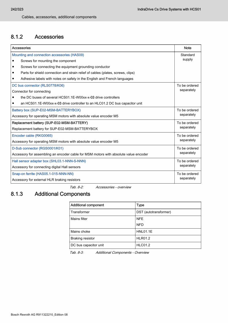
8.1.2 Accessories
Accessories Note
Mounting and connection accessories (HAS09)● Screws for mounting the component● Screws for connecting the equipment grounding conductor● Parts for shield connection and strain relief of cables (plates, screws, clips)● Adhesive labels with notes on safety in the English and French languages
Standardsupply
DC bus connector (RLS0778/K06)Connector for connecting● the DC buses of several HCS01.1E-W00xx-x-03 drive controllers● an HCS01.1E-W00xx-x-03 drive controller to an HLC01.2 DC bus capacitor unit
To be orderedseparately
Battery box (SUP-E02-MSM-BATTERYBOX)Accessory for operating MSM motors with absolute value encoder M5
To be orderedseparately
Replacement battery (SUP-E02-MSM-BATTERY)Replacement battery for SUP-E02-MSM-BATTERYBOX
To be orderedseparately
Encoder cable (RKG0065)Accessory for operating MSM motors with absolute value encoder M5
To be orderedseparately
D-Sub connector (RGS0001/K01)Accessory for assembling an encoder cable for MSM motors with absolute value encoder
To be orderedseparately
Hall sensor adapter box (SHL03.1-NNN-S-NNN)Accessory for connecting digital Hall sensors
To be orderedseparately
Snap-on ferrite (HAS05.1-015-NNN-NN)Accessory for external HLR braking resistors
To be orderedseparately
Tab. 8-2: Accessories - overview
8.1.3 Additional Components
Additional component Type
Transformer DST (autotransformer)
Mains filter NFENFD
Mains choke HNL01.1E
Braking resistor HLR01.2
DC bus capacitor unit HLC01.2
Tab. 8-3: Additional Components - Overview
242/323
Cables, accessories, additional components
IndraDrive Cs Drive Systems with HCS01
Bosch Rexroth AG R911322210_Edition 08
8.2 Accessories8.2.1 Mounting and connection accessories (HAS09)Use
The accessories contain:● Screws for mounting the component● Screws for connecting the equipment grounding conductor● Parts for shield connection of cables (plates, screws)● Parts for shield connection of module bus cables (heat shrink tubing,
copper tape) The accessories are part of the standard scope of supply.
Assignment
Accessories Component
HAS09.1-001-NNN-NN HCS01.1E-W0003 … W0028
HAS09.1-003-NNN-NN HCS01.1E-W0054
HAS09.1-004-NNN-NN HLC01.2; HLR01.2N
Tab. 8-4: HAS09 and HCS01
IndraDrive Cs Drive Systems with HCS01 243/323
Cables, accessories, additional components
R911322210_Edition 08 Bosch Rexroth AG
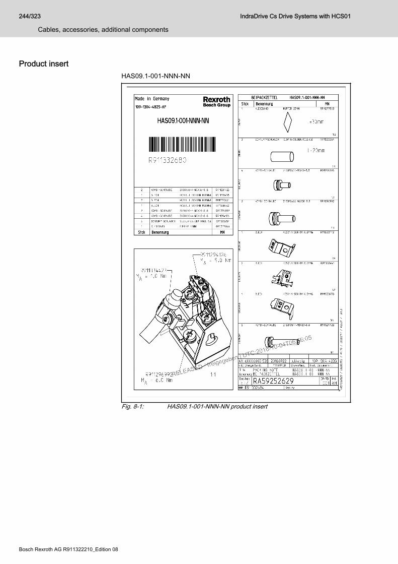
Product insertHAS09.1-001-NNN-NN
Fig. 8-1: HAS09.1-001-NNN-NN product insert
244/323
Cables, accessories, additional components
IndraDrive Cs Drive Systems with HCS01
Bosch Rexroth AG R911322210_Edition 08
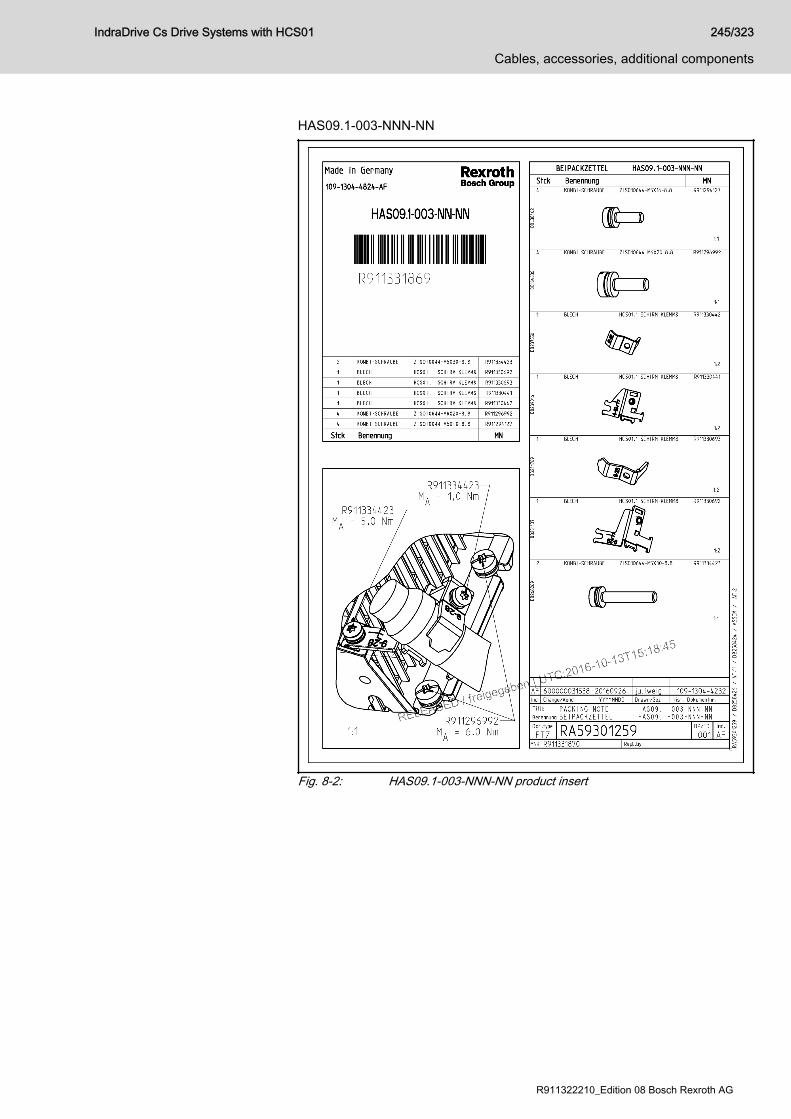
HAS09.1-003-NNN-NN
Fig. 8-2: HAS09.1-003-NNN-NN product insert
IndraDrive Cs Drive Systems with HCS01 245/323
Cables, accessories, additional components
R911322210_Edition 08 Bosch Rexroth AG
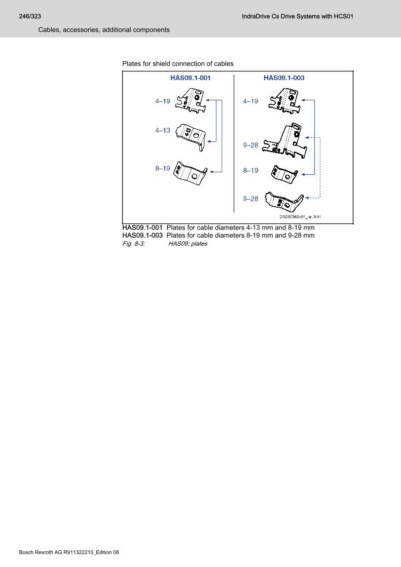
Plates for shield connection of cables
HAS09.1-001 Plates for cable diameters 4-13 mm and 8-19 mmHAS09.1-003 Plates for cable diameters 8-19 mm and 9-28 mmFig. 8-3: HAS09; plates
246/323
Cables, accessories, additional components
IndraDrive Cs Drive Systems with HCS01
Bosch Rexroth AG R911322210_Edition 08
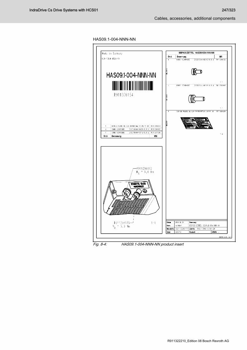
HAS09.1-004-NNN-NN
Fig. 8-4: HAS09.1-004-NNN-NN product insert
IndraDrive Cs Drive Systems with HCS01 247/323
Cables, accessories, additional components
R911322210_Edition 08 Bosch Rexroth AG

Module bus cable shield connectionUse shielded cables for the module bus in the following cases:● An individual module bus connection is > 0.5 m long.● All drive system module bus connections together are > 3 m long. The HAS09.1-001 accessories contain parts for assembling shielded modulebus cables:● Heat shrink tubing (3 × 20 mm)● Self-adhesive copper tape (1 × 30 mm) Use shielded cables of a conductor size ≥ 2 × 0.5 mm2.Observe the data of connection point X47.
Assembling cables:1. Strip cable: A = 24 mm, B = 180 mm, C = 35 mm
Fig. 8-5: Stripping the cable2. Remove protective foil, then wrap self-adhesive copper tape around
shield braid.
Fig. 8-6: Copper tape3. Put 2 heat shrink tubings on cable and shrink them.
Fig. 8-7: Heat shrink tubing4. Fold back shield braid over cable jacket and strip wire ends.
Fig. 8-8: Shield braid, wire ends
248/323
Cables, accessories, additional components
IndraDrive Cs Drive Systems with HCS01
Bosch Rexroth AG R911322210_Edition 08
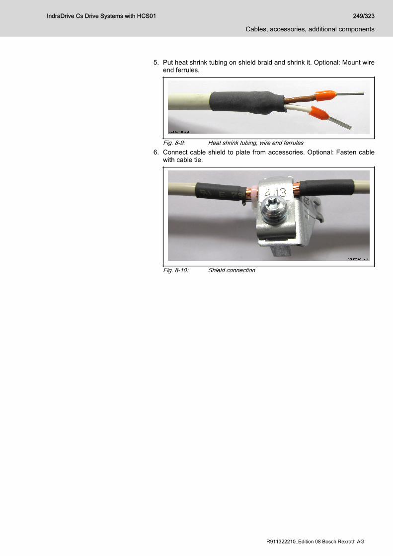
5. Put heat shrink tubing on shield braid and shrink it. Optional: Mount wireend ferrules.
Fig. 8-9: Heat shrink tubing, wire end ferrules6. Connect cable shield to plate from accessories. Optional: Fasten cable
with cable tie.
Fig. 8-10: Shield connection
IndraDrive Cs Drive Systems with HCS01 249/323
Cables, accessories, additional components
R911322210_Edition 08 Bosch Rexroth AG
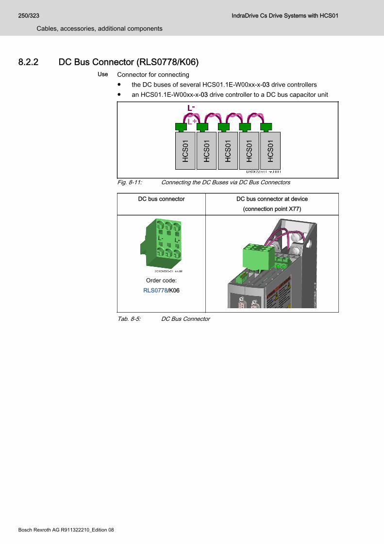
8.2.2 DC Bus Connector (RLS0778/K06)Use Connector for connecting
● the DC buses of several HCS01.1E-W00xx-x-03 drive controllers● an HCS01.1E-W00xx-x-03 drive controller to a DC bus capacitor unit
Fig. 8-11: Connecting the DC Buses via DC Bus Connectors
DC bus connector DC bus connector at device(connection point X77)
Order code:RLS0778/K06
Tab. 8-5: DC Bus Connector
250/323
Cables, accessories, additional components
IndraDrive Cs Drive Systems with HCS01
Bosch Rexroth AG R911322210_Edition 08
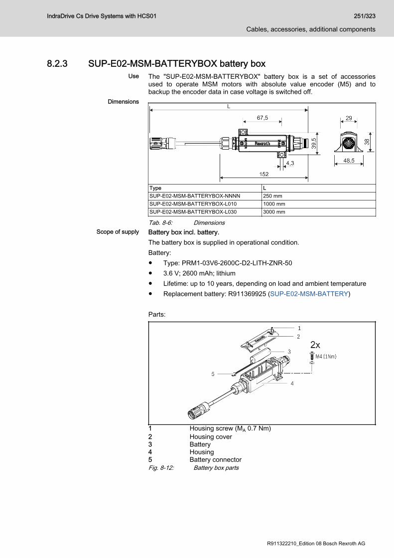
8.2.3 SUP-E02-MSM-BATTERYBOX battery boxUse The "SUP-E02-MSM-BATTERYBOX" battery box is a set of accessories
used to operate MSM motors with absolute value encoder (M5) and tobackup the encoder data in case voltage is switched off.
Dimensions
Type LSUP-E02-MSM-BATTERYBOX-NNNN 250 mmSUP-E02-MSM-BATTERYBOX-L010 1000 mmSUP-E02-MSM-BATTERYBOX-L030 3000 mm
Tab. 8-6: DimensionsScope of supply Battery box incl. battery.
The battery box is supplied in operational condition.Battery:● Type: PRM1-03V6-2600C-D2-LITH-ZNR-50● 3.6 V; 2600 mAh; lithium● Lifetime: up to 10 years, depending on load and ambient temperature● Replacement battery: R911369925 (SUP-E02-MSM-BATTERY) Parts:
1 Housing screw (MA 0.7 Nm)2 Housing cover3 Battery4 Housing5 Battery connectorFig. 8-12: Battery box parts
IndraDrive Cs Drive Systems with HCS01 251/323
Cables, accessories, additional components
R911322210_Edition 08 Bosch Rexroth AG
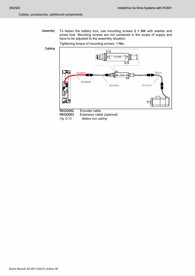
Assembly To fasten the battery box, use mounting screws 2 × M4 with washer andscrew lock. Mounting screws are not contained in the scope of supply andhave to be adjusted to the assembly situation.Tightening torque of mounting screws: 1 Nm.
Cabling
RKG0062 Encoder cableRKG0063 Extension cable (optional)Fig. 8-13: Battery box cabling
252/323
Cables, accessories, additional components
IndraDrive Cs Drive Systems with HCS01
Bosch Rexroth AG R911322210_Edition 08
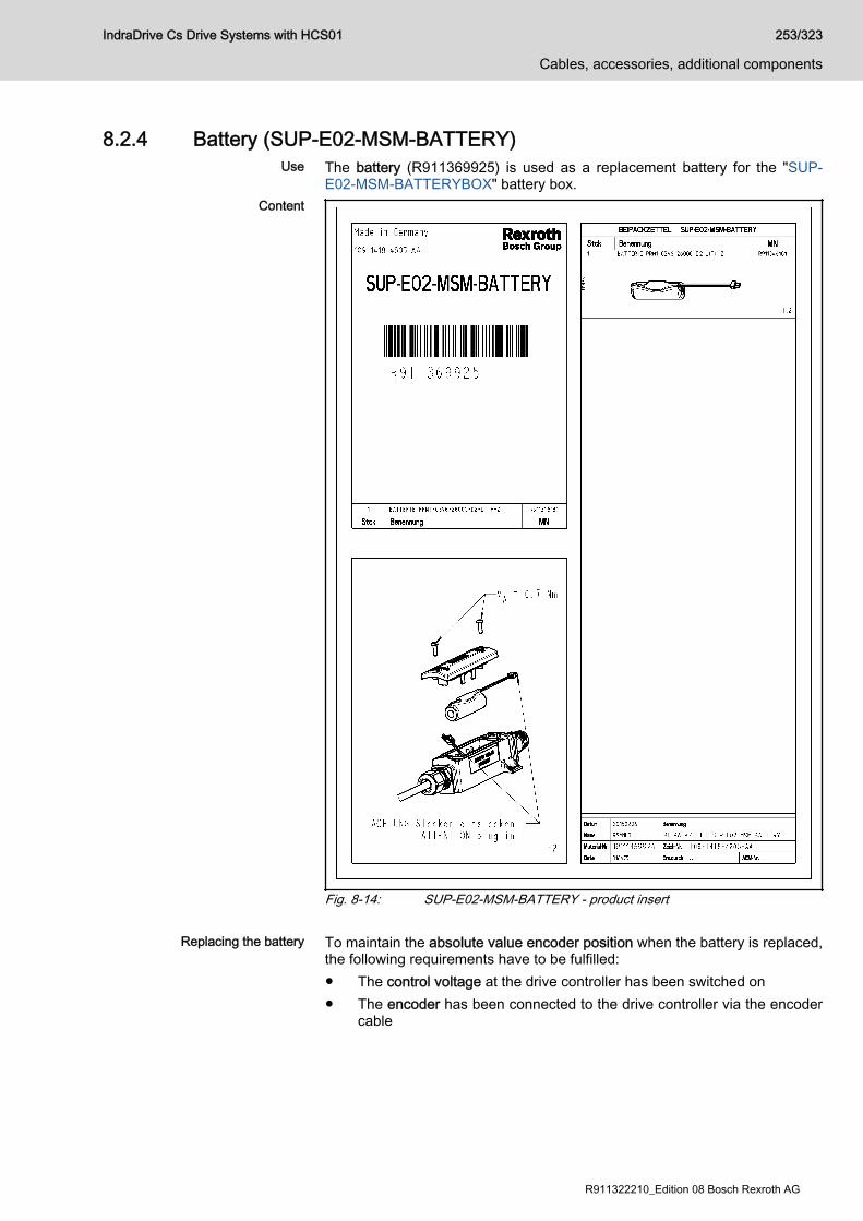
8.2.4 Battery (SUP-E02-MSM-BATTERY)Use The battery (R911369925) is used as a replacement battery for the "SUP-
E02-MSM-BATTERYBOX" battery box.Content
Fig. 8-14: SUP-E02-MSM-BATTERY - product insert
Replacing the battery To maintain the absolute value encoder position when the battery is replaced,the following requirements have to be fulfilled:● The control voltage at the drive controller has been switched on● The encoder has been connected to the drive controller via the encoder
cable
IndraDrive Cs Drive Systems with HCS01 253/323
Cables, accessories, additional components
R911322210_Edition 08 Bosch Rexroth AG
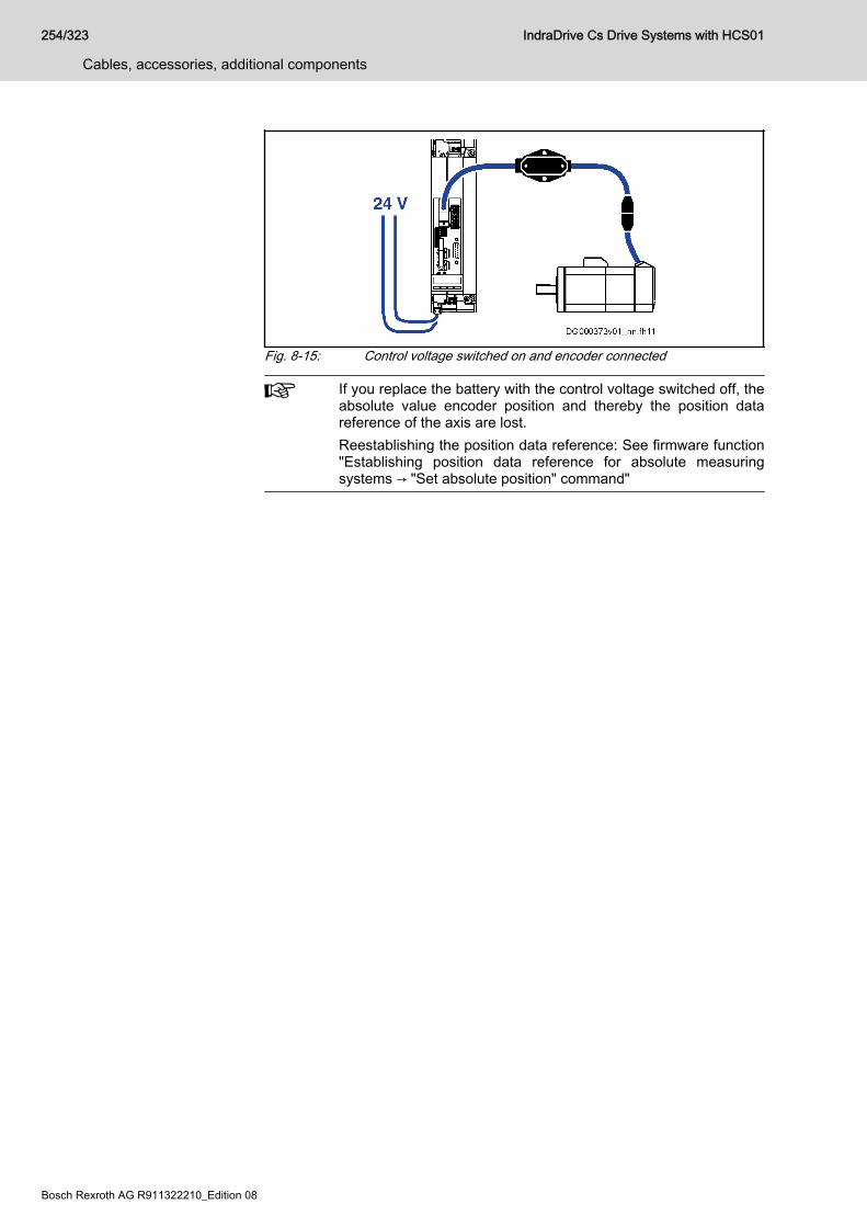
Fig. 8-15: Control voltage switched on and encoder connected
If you replace the battery with the control voltage switched off, theabsolute value encoder position and thereby the position datareference of the axis are lost.Reestablishing the position data reference: See firmware function"Establishing position data reference for absolute measuringsystems → "Set absolute position" command"
254/323
Cables, accessories, additional components
IndraDrive Cs Drive Systems with HCS01
Bosch Rexroth AG R911322210_Edition 08
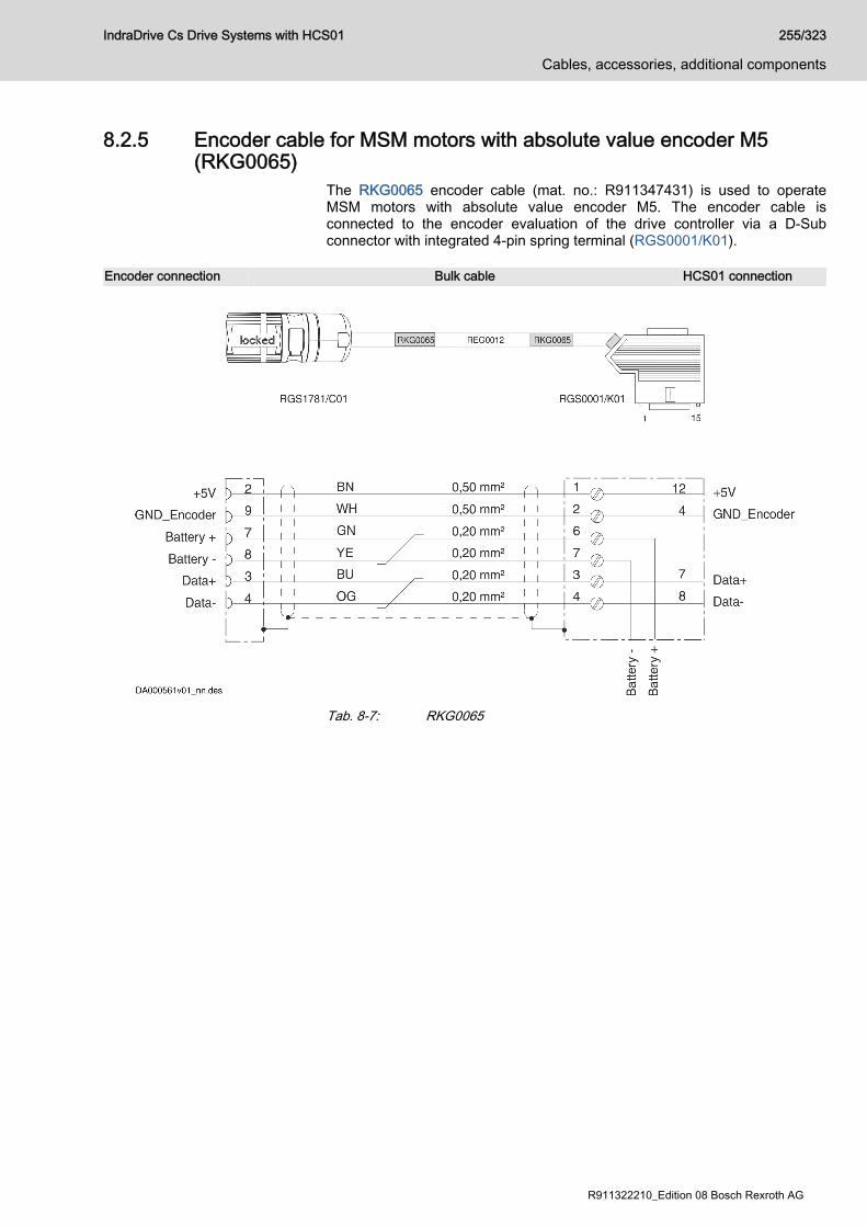
8.2.5 Encoder cable for MSM motors with absolute value encoder M5(RKG0065)
The RKG0065 encoder cable (mat. no.: R911347431) is used to operateMSM motors with absolute value encoder M5. The encoder cable isconnected to the encoder evaluation of the drive controller via a D-Subconnector with integrated 4-pin spring terminal (RGS0001/K01).
Encoder connection Bulk cable HCS01 connection
Tab. 8-7: RKG0065
IndraDrive Cs Drive Systems with HCS01 255/323
Cables, accessories, additional components
R911322210_Edition 08 Bosch Rexroth AG
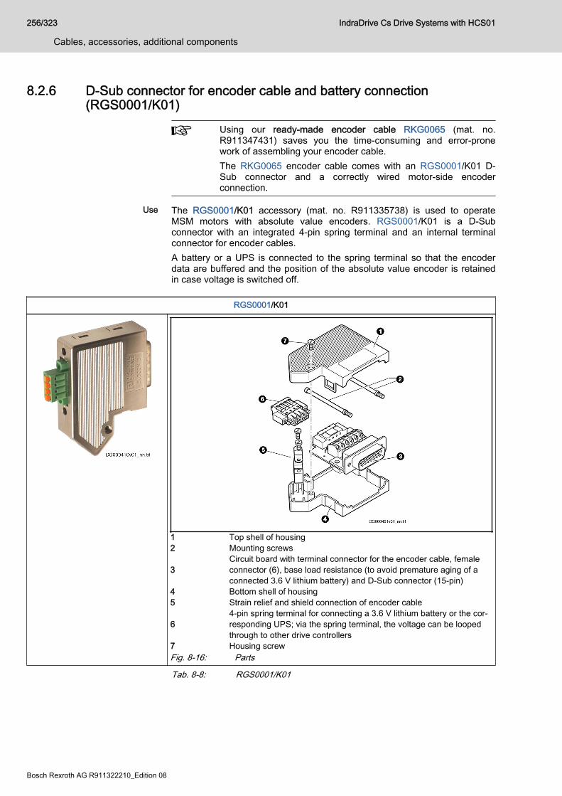
8.2.6 D-Sub connector for encoder cable and battery connection(RGS0001/K01)
Using our ready-made encoder cable RKG0065 (mat. no.R911347431) saves you the time-consuming and error-pronework of assembling your encoder cable.The RKG0065 encoder cable comes with an RGS0001/K01 D-Sub connector and a correctly wired motor-side encoderconnection.
Use The RGS0001/K01 accessory (mat. no. R911335738) is used to operateMSM motors with absolute value encoders. RGS0001/K01 is a D-Subconnector with an integrated 4-pin spring terminal and an internal terminalconnector for encoder cables.A battery or a UPS is connected to the spring terminal so that the encoderdata are buffered and the position of the absolute value encoder is retainedin case voltage is switched off.
RGS0001/K01
1 Top shell of housing2 Mounting screws
3Circuit board with terminal connector for the encoder cable, femaleconnector (6), base load resistance (to avoid premature aging of aconnected 3.6 V lithium battery) and D-Sub connector (15-pin)
4 Bottom shell of housing5 Strain relief and shield connection of encoder cable
64-pin spring terminal for connecting a 3.6 V lithium battery or the cor‐responding UPS; via the spring terminal, the voltage can be loopedthrough to other drive controllers
7 Housing screwFig. 8-16: Parts
Tab. 8-8: RGS0001/K01
256/323
Cables, accessories, additional components
IndraDrive Cs Drive Systems with HCS01
Bosch Rexroth AG R911322210_Edition 08
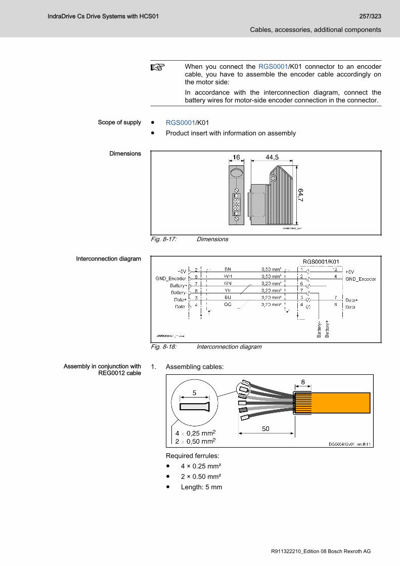
When you connect the RGS0001/K01 connector to an encodercable, you have to assemble the encoder cable accordingly onthe motor side:In accordance with the interconnection diagram, connect thebattery wires for motor-side encoder connection in the connector.
Scope of supply ● RGS0001/K01
● Product insert with information on assembly
Dimensions
Fig. 8-17: Dimensions
Interconnection diagram
Fig. 8-18: Interconnection diagram
Assembly in conjunction withREG0012 cable
1. Assembling cables:
Required ferrules:● 4 × 0.25 mm²● 2 × 0.50 mm²● Length: 5 mm
IndraDrive Cs Drive Systems with HCS01 257/323
Cables, accessories, additional components
R911322210_Edition 08 Bosch Rexroth AG

● Without plastic collarLength of inner wires incl. ferrules starting at cable jacket: 50 mmFold back shield braid over outer cable jacket, comb it out and cut it to8 mm.
2. Open housing:
● Unscrew housing screw ①.● Unlock top shell of housing with screwdriver and open housing ②.
3. Connect cable according to interconnection diagram.4. Insert circuit board into housing in accordance with desired outgoing
direction of encoder cable.
● Put shield braid under clip (A) of strain relief and screw on clip (A).● Insert mounting screws (B) and tuck wires away.
5. Close housing:Put top shell of housing onto bottom shell of housing, engage it inbottom shell and screw housing screw down.
258/323
Cables, accessories, additional components
IndraDrive Cs Drive Systems with HCS01
Bosch Rexroth AG R911322210_Edition 08
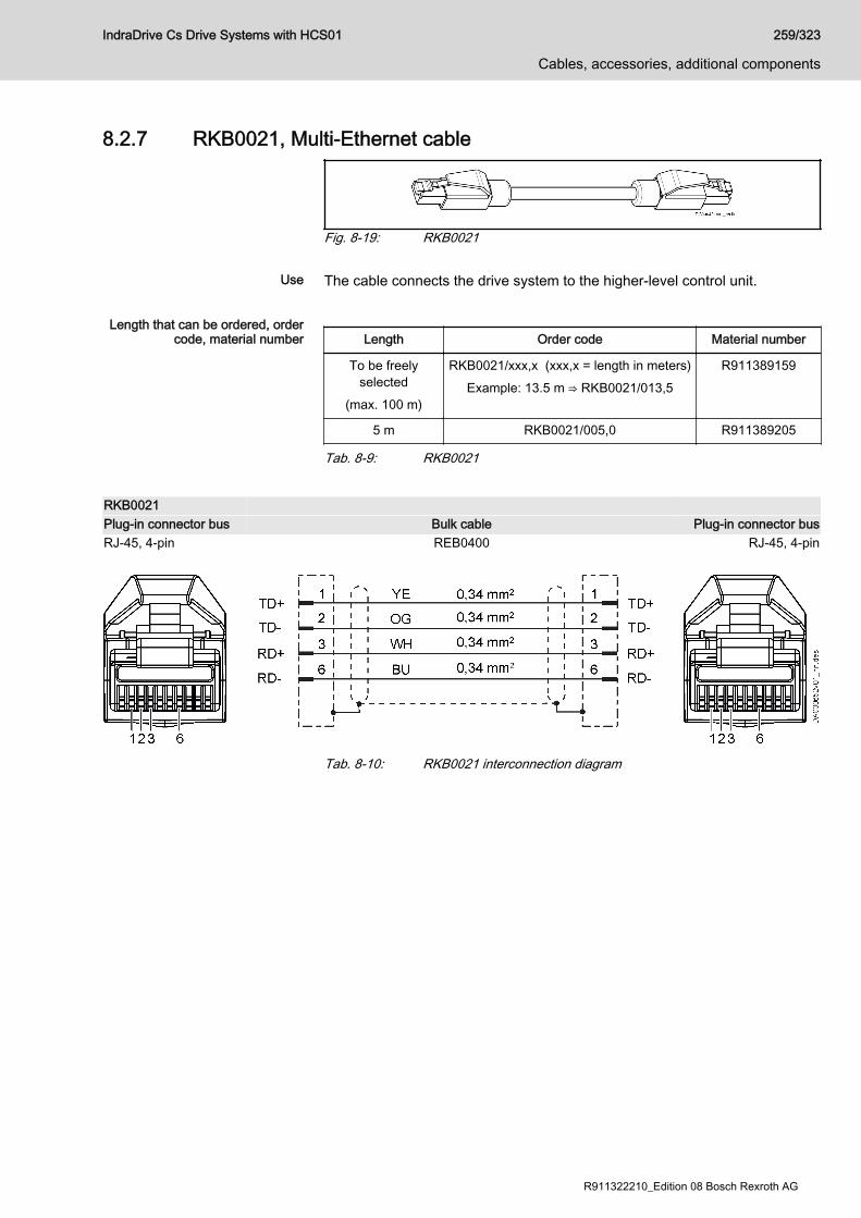
8.2.7 RKB0021, Multi-Ethernet cable
Fig. 8-19: RKB0021
Use The cable connects the drive system to the higher-level control unit.
Length that can be ordered, ordercode, material number Length Order code Material number
To be freelyselected
(max. 100 m)
RKB0021/xxx,x (xxx,x = length in meters)Example: 13.5 m ⇒ RKB0021/013,5
R911389159
5 m RKB0021/005,0 R911389205
Tab. 8-9: RKB0021
RKB0021 Plug-in connector bus Bulk cable Plug-in connector busRJ-45, 4-pin REB0400 RJ-45, 4-pin
Tab. 8-10: RKB0021 interconnection diagram
IndraDrive Cs Drive Systems with HCS01 259/323
Cables, accessories, additional components
R911322210_Edition 08 Bosch Rexroth AG
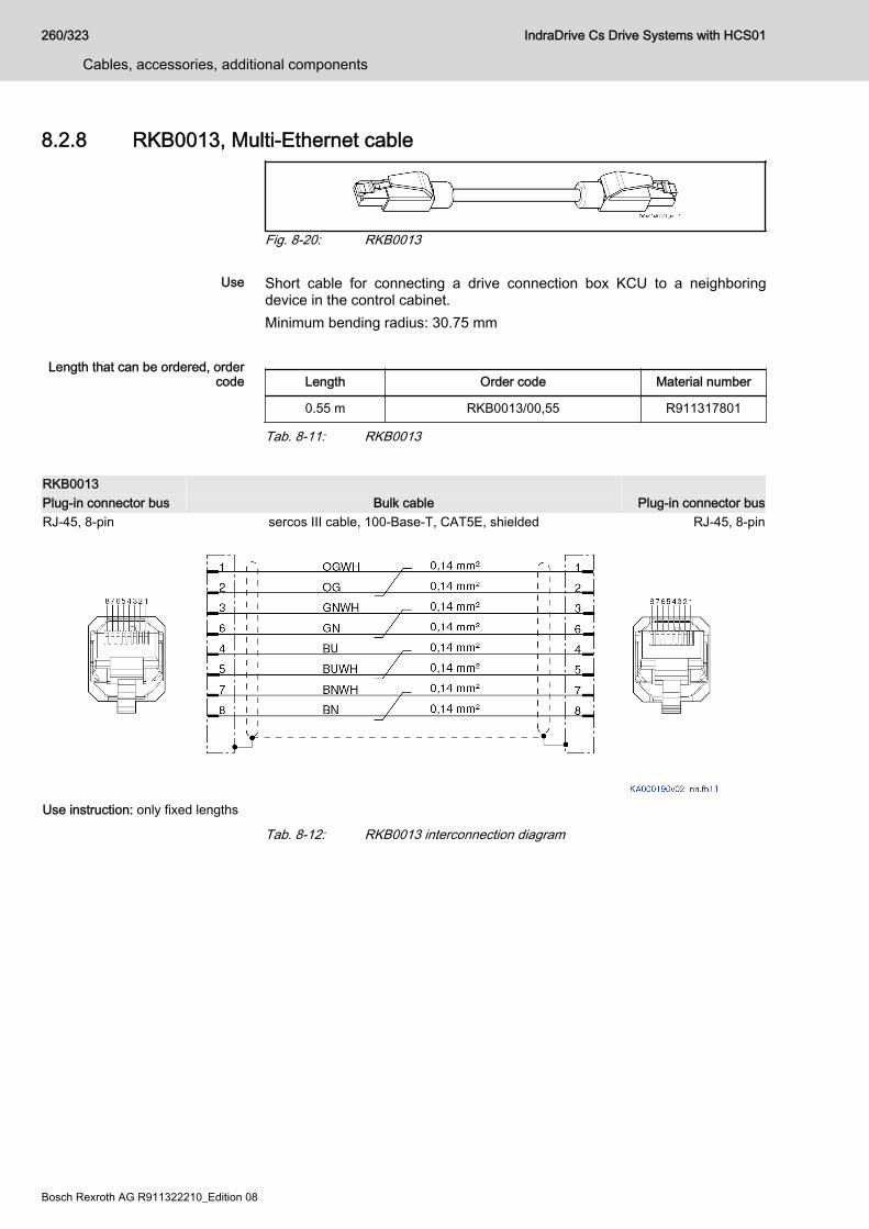
8.2.8 RKB0013, Multi-Ethernet cable
Fig. 8-20: RKB0013
Use Short cable for connecting a drive connection box KCU to a neighboringdevice in the control cabinet.Minimum bending radius: 30.75 mm
Length that can be ordered, ordercode Length Order code Material number
0.55 m RKB0013/00,55 R911317801
Tab. 8-11: RKB0013
RKB0013 Plug-in connector bus Bulk cable Plug-in connector busRJ-45, 8-pin sercos III cable, 100-Base-T, CAT5E, shielded RJ-45, 8-pin
Use instruction: only fixed lengths
Tab. 8-12: RKB0013 interconnection diagram
260/323
Cables, accessories, additional components
IndraDrive Cs Drive Systems with HCS01
Bosch Rexroth AG R911322210_Edition 08
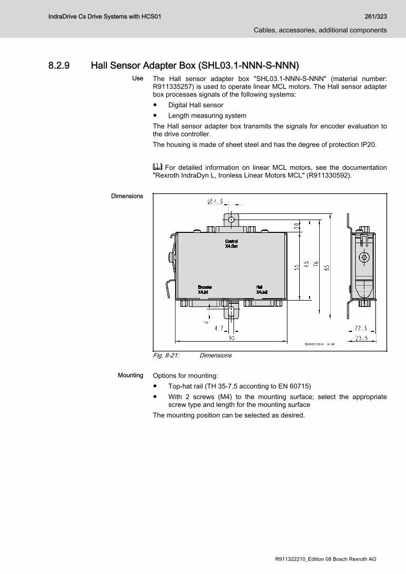
8.2.9 Hall Sensor Adapter Box (SHL03.1-NNN-S-NNN)Use The Hall sensor adapter box "SHL03.1-NNN-S-NNN" (material number:
R911335257) is used to operate linear MCL motors. The Hall sensor adapterbox processes signals of the following systems:● Digital Hall sensor● Length measuring systemThe Hall sensor adapter box transmits the signals for encoder evaluation tothe drive controller.The housing is made of sheet steel and has the degree of protection IP20.
For detailed information on linear MCL motors, see the documentation"Rexroth IndraDyn L, Ironless Linear Motors MCL" (R911330592).
Dimensions
Fig. 8-21: Dimensions
Mounting Options for mounting:● Top-hat rail (TH 35-7.5 according to EN 60715)● With 2 screws (M4) to the mounting surface; select the appropriate
screw type and length for the mounting surfaceThe mounting position can be selected as desired.
IndraDrive Cs Drive Systems with HCS01 261/323
Cables, accessories, additional components
R911322210_Edition 08 Bosch Rexroth AG

Connection Points
Fig. 8-22: Connection PointsEncoder X4.In1
View Identification Function
EncoderX4.In1
Encoder connection
D-Sub, 15-pin, female Unit Min. Max.
Connection cableStranded wire
mm2 0,25 0,5
Tab. 8-13: Function, Pin Assignment, Properties
Connection Signal Function
1 GND_shld Connection signal shields (inner shields)
2 A+ Track A positive
3 A- Track A negative
4 GND_Encoder Reference potential for power supplies
5 B+ Track B positive
6 B- Track B negative
7 n. c.
8 n. c.
9 R+ Reference track positive
10 R- Reference track negative
11 +12V Encoder supply 12 V
262/323
Cables, accessories, additional components
IndraDrive Cs Drive Systems with HCS01
Bosch Rexroth AG R911322210_Edition 08
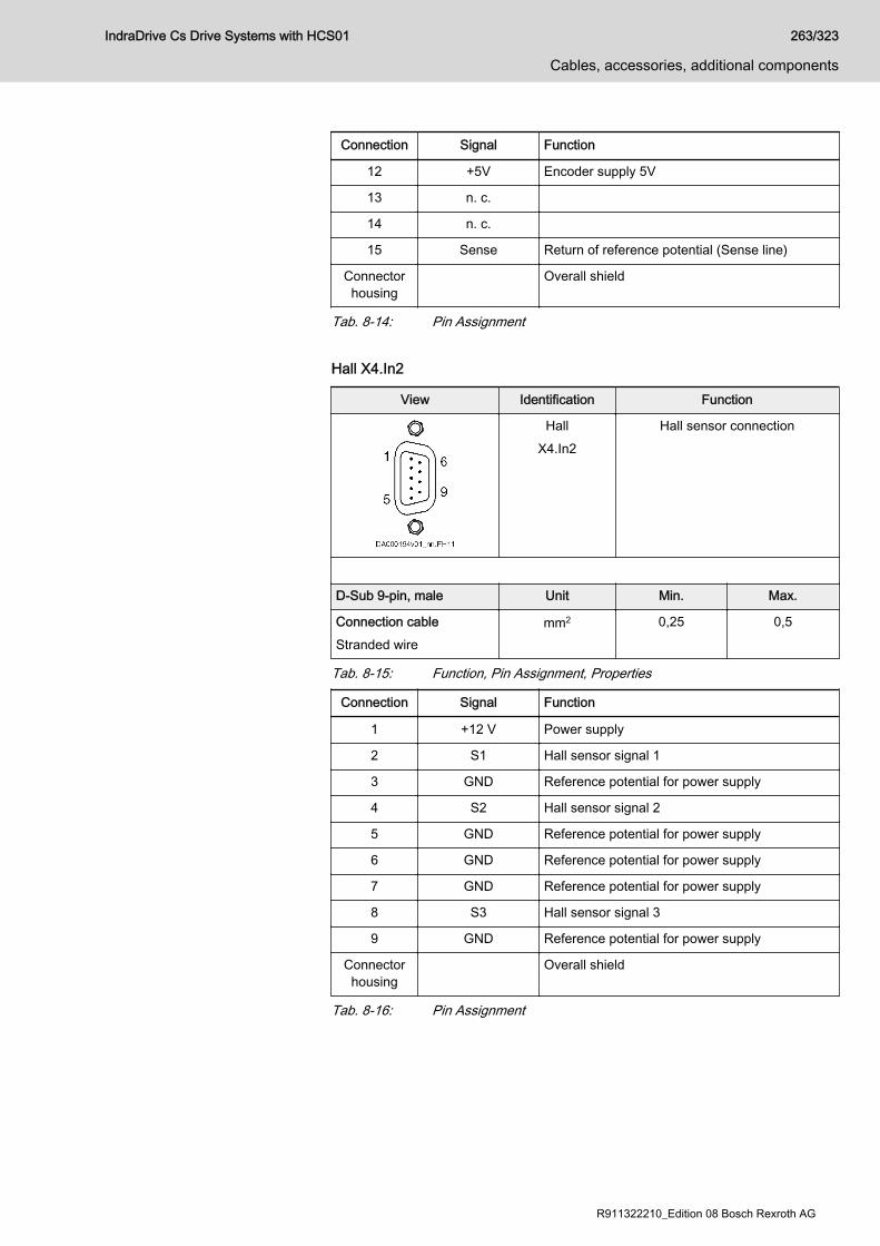
Connection Signal Function
12 +5V Encoder supply 5V
13 n. c.
14 n. c.
15 Sense Return of reference potential (Sense line)
Connectorhousing
Overall shield
Tab. 8-14: Pin Assignment Hall X4.In2
View Identification Function
HallX4.In2
Hall sensor connection
D-Sub 9-pin, male Unit Min. Max.
Connection cableStranded wire
mm2 0,25 0,5
Tab. 8-15: Function, Pin Assignment, Properties
Connection Signal Function
1 +12 V Power supply
2 S1 Hall sensor signal 1
3 GND Reference potential for power supply
4 S2 Hall sensor signal 2
5 GND Reference potential for power supply
6 GND Reference potential for power supply
7 GND Reference potential for power supply
8 S3 Hall sensor signal 3
9 GND Reference potential for power supply
Connectorhousing
Overall shield
Tab. 8-16: Pin Assignment
IndraDrive Cs Drive Systems with HCS01 263/323
Cables, accessories, additional components
R911322210_Edition 08 Bosch Rexroth AG
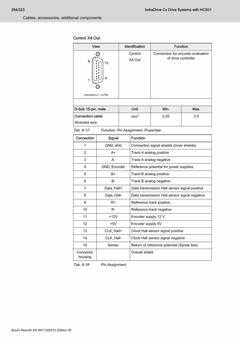
Control X4.Out
View Identification Function
ControlX4.Out
Connection for encoder evaluationof drive controller
D-Sub 15-pin, male Unit Min. Max.
Connection cableStranded wire
mm2 0,25 0,5
Tab. 8-17: Function, Pin Assignment, Properties
Connection Signal Function
1 GND_shld Connection signal shields (inner shields)
2 A+ Track A analog positive
3 A- Track A analog negative
4 GND_Encoder Reference potential for power supplies
5 B+ Track B analog positive
6 B- Track B analog negative
7 Data_Hall+ Data transmission Hall sensor signal positive
8 Data_Hall- Data transmission Hall sensor signal negative
9 R+ Reference track positive
10 R- Reference track negative
11 +12V Encoder supply 12 V
12 +5V Encoder supply 5V
13 CLK_Hall+ Clock Hall sensor signal positive
14 CLK_Hall- Clock Hall sensor signal negative
15 Sense- Return of reference potential (Sense line)
Connectorhousing
Overall shield
Tab. 8-18: Pin Assignment
264/323
Cables, accessories, additional components
IndraDrive Cs Drive Systems with HCS01
Bosch Rexroth AG R911322210_Edition 08
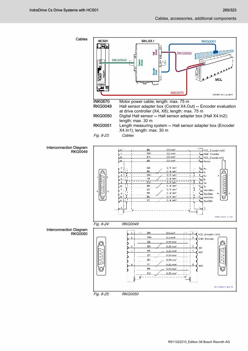
Cables
INK0670 Motor power cable; length: max. 75 mRKG0049 Hall sensor adapter box (Control X4.Out) ↔ Encoder evaluation
at drive controller (X4, X8); length: max. 75 mRKG0050 Digital Hall sensor ↔ Hall sensor adapter box (Hall X4.In2);
length: max. 30 mRKG0051 Length measuring system ↔ Hall sensor adapter box (Encoder
X4.In1); length: max. 30 mFig. 8-23: Cables
Interconnection DiagramRKG0049
Fig. 8-24: RKG0049Interconnection Diagram
RKG0050
Fig. 8-25: RKG0050
IndraDrive Cs Drive Systems with HCS01 265/323
Cables, accessories, additional components
R911322210_Edition 08 Bosch Rexroth AG
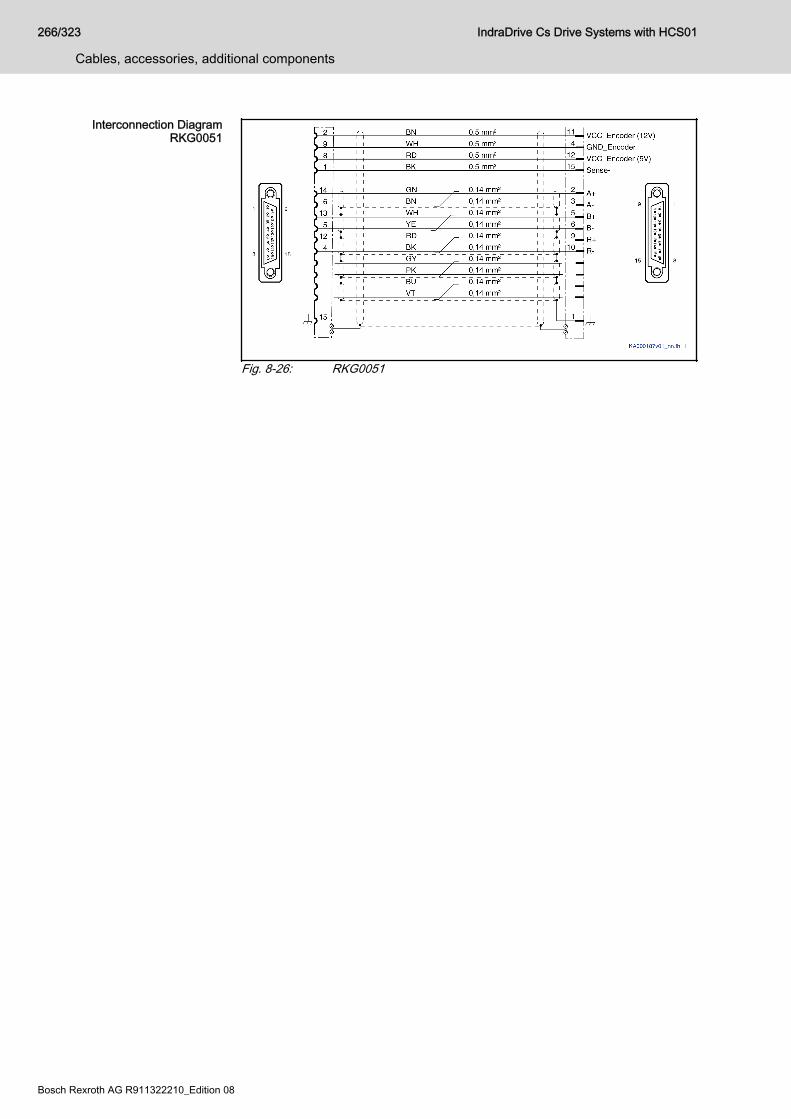
Interconnection DiagramRKG0051
Fig. 8-26: RKG0051
266/323
Cables, accessories, additional components
IndraDrive Cs Drive Systems with HCS01
Bosch Rexroth AG R911322210_Edition 08
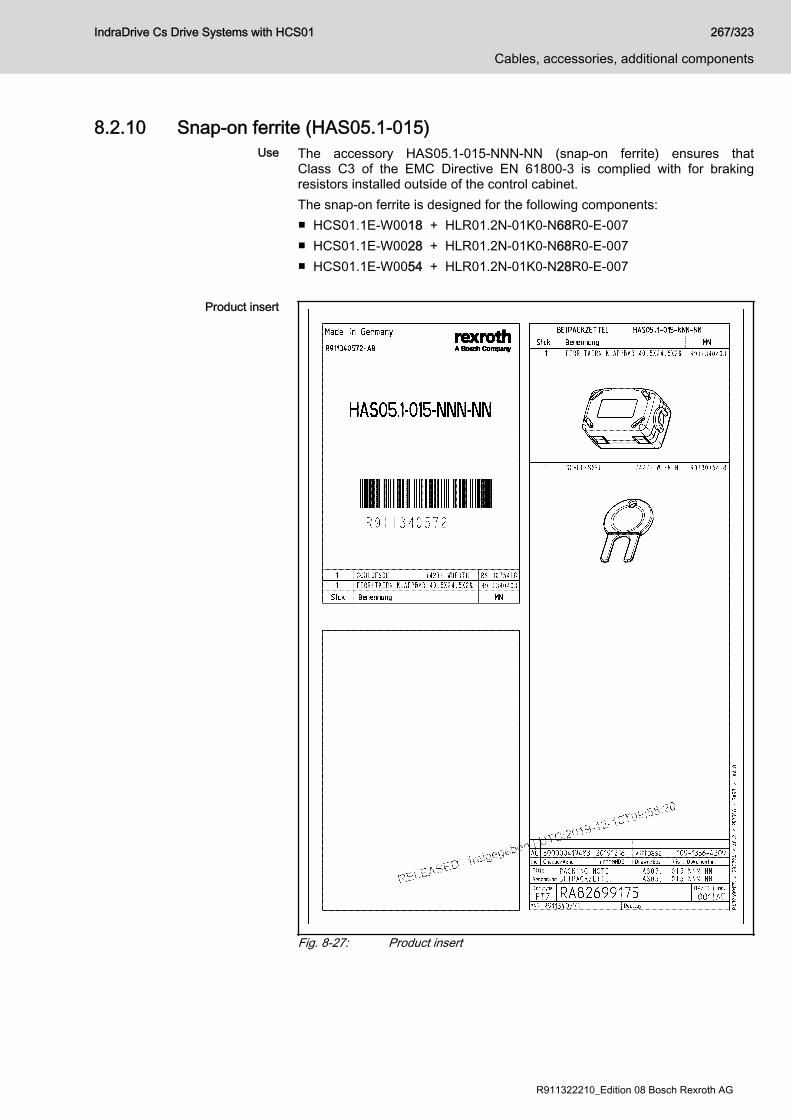
8.2.10 Snap-on ferrite (HAS05.1-015)Use The accessory HAS05.1-015-NNN-NN (snap-on ferrite) ensures that
Class C3 of the EMC Directive EN 61800-3 is complied with for brakingresistors installed outside of the control cabinet.The snap-on ferrite is designed for the following components:■ HCS01.1E-W0018 + HLR01.2N-01K0-N68R0-E-007■ HCS01.1E-W0028 + HLR01.2N-01K0-N68R0-E-007■ HCS01.1E-W0054 + HLR01.2N-01K0-N28R0-E-007
Product insert
Fig. 8-27: Product insert
IndraDrive Cs Drive Systems with HCS01 267/323
Cables, accessories, additional components
R911322210_Edition 08 Bosch Rexroth AG
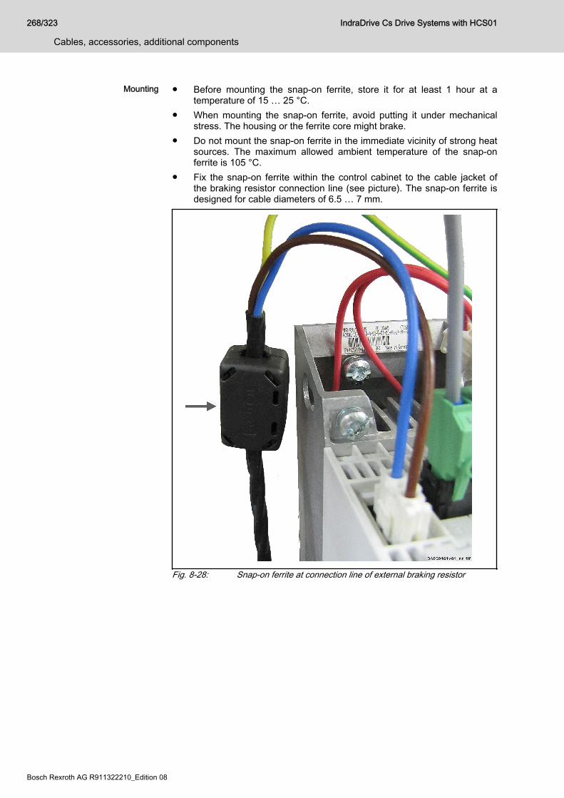
Mounting ● Before mounting the snap-on ferrite, store it for at least 1 hour at atemperature of 15 … 25 °C.
● When mounting the snap-on ferrite, avoid putting it under mechanicalstress. The housing or the ferrite core might brake.
● Do not mount the snap-on ferrite in the immediate vicinity of strong heatsources. The maximum allowed ambient temperature of the snap-onferrite is 105 °C.
● Fix the snap-on ferrite within the control cabinet to the cable jacket ofthe braking resistor connection line (see picture). The snap-on ferrite isdesigned for cable diameters of 6.5 … 7 mm.
Fig. 8-28: Snap-on ferrite at connection line of external braking resistor
268/323
Cables, accessories, additional components
IndraDrive Cs Drive Systems with HCS01
Bosch Rexroth AG R911322210_Edition 08

To open the snap-on ferrite, use the proper tool:
Fig. 8-29: Opening the snap-on ferrite
IndraDrive Cs Drive Systems with HCS01 269/323
Cables, accessories, additional components
R911322210_Edition 08 Bosch Rexroth AG

8.3 Additional components8.3.1 TransformersGeneral information
Transformers are only needed when the mains voltage is outside of theallowed nominal voltage of the drive controller.
Grounded mains For grounded mains, the mains voltage is adjusted to the nominal voltage ofthe device using autotransformers that have been sized for a specific outputvoltage range.
Ungrounded mains For voltage adjustment of ungrounded mains, always connect isolatingtransformers to prevent overvoltages between outer conductor and ground.
270/323
Cables, accessories, additional components
IndraDrive Cs Drive Systems with HCS01
Bosch Rexroth AG R911322210_Edition 08

Autotransformers for drive controllersTypesDST
Short type designation 1 2 3 4 5 6 7 8 910 1 2 3 4 5 6 7 8 9
20 1 2 3 4 5 6 7 8 9
30 1 2 3 4 5 6 7 8 9
40
Example: D S T - 4 , 0 0 / L / 3 8 0 , 4 1 5 , 4 4 0 - 2 3 0 - 1 0 M M
① ② ③ ④ ⑤ ⑥
① Product:DST = AC autotransformer
② Nominal power:2,00 = 2.0 kVA2,50 = 2.5 kVA4,00 = 4.0 kVA5,00 = 5.0 kVA7,50 = 7.5 kVA8,00 = 8.0 kVA10,0 = 10.0 kVA12,5 = 12.5 kVA13,0 = 13.0 kVA15,0 = 15.0 kVA16,0 = 16.0 kVA18,0 = 18.0 kVA20,0 = 20.0 kVA25,0 = 25.0 kVA35,0 = 35.0 kVA50,0 = 50.0 kVA
③ Type of construction (design):G = suited for mounting in an IP55 housingL = horizontal mountingS = upright mounting
④ Nominal input voltage (phase-phase):380,415,440 = e.g., AC380V, AC415V, AC440V
⑤ Nominal output voltage (phase-phase):230 = e.g., AC 230 V
⑥ Special design (optional):This field is not required for standard transformers
10MM = max. conductor connection cross section: e.g., 10 mm2
IP23 = degree of protection: e.g., IP23, in ST0 protective housingNEMA = Nema designUL-N = UL standard
Tab. 8-19: DST, type code
IndraDrive Cs Drive Systems with HCS01 271/323
Cables, accessories, additional components
R911322210_Edition 08 Bosch Rexroth AG
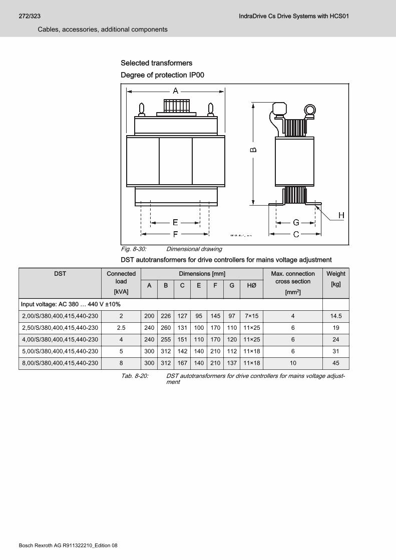
Selected transformersDegree of protection IP00
Fig. 8-30: Dimensional drawingDST autotransformers for drive controllers for mains voltage adjustment
DST Connectedload[kVA]
Dimensions [mm] Max. connectioncross section
[mm2]
Weight[kg]A B C E F G HØ
Input voltage: AC 380 … 440 V ±10%
2,00/S/380,400,415,440-230 2 200 226 127 95 145 97 7×15 4 14.5
2,50/S/380,400,415,440-230 2.5 240 260 131 100 170 110 11×25 6 19
4,00/S/380,400,415,440-230 4 240 255 151 110 170 120 11×25 6 24
5,00/S/380,400,415,440-230 5 300 312 142 140 210 112 11×18 6 31
8,00/S/380,400,415,440-230 8 300 312 167 140 210 137 11×18 10 45
Tab. 8-20: DST autotransformers for drive controllers for mains voltage adjust‐ment
272/323
Cables, accessories, additional components
IndraDrive Cs Drive Systems with HCS01
Bosch Rexroth AG R911322210_Edition 08
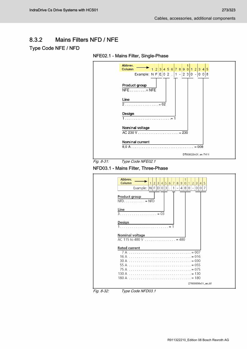
8.3.2 Mains Filters NFD / NFEType Code NFE / NFD
NFE02.1 - Mains Filter, Single-Phase
Fig. 8-31: Type Code NFE02.1
NFD03.1 - Mains Filter, Three-Phase
Fig. 8-32: Type Code NFD03.1
IndraDrive Cs Drive Systems with HCS01 273/323
Cables, accessories, additional components
R911322210_Edition 08 Bosch Rexroth AG
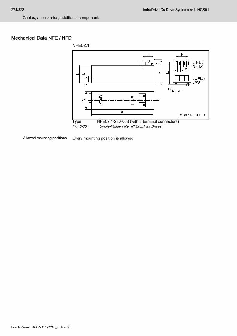
Mechanical Data NFE / NFDNFE02.1
Type NFE02.1-230-008 (with 3 terminal connectors)Fig. 8-33: Single-Phase Filter NFE02.1 for Drives
Allowed mounting positions Every mounting position is allowed.
274/323
Cables, accessories, additional components
IndraDrive Cs Drive Systems with HCS01
Bosch Rexroth AG R911322210_Edition 08
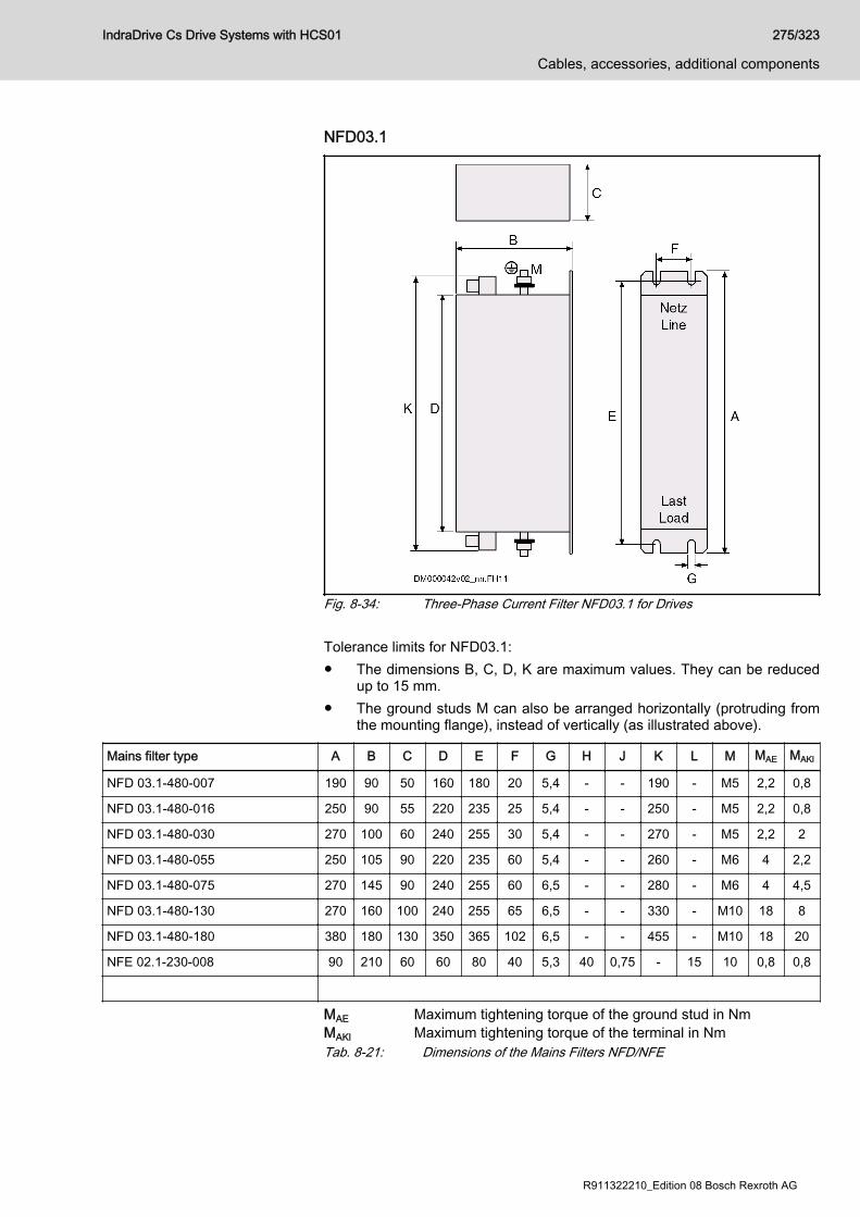
NFD03.1
Fig. 8-34: Three-Phase Current Filter NFD03.1 for Drives Tolerance limits for NFD03.1:● The dimensions B, C, D, K are maximum values. They can be reduced
up to 15 mm.● The ground studs M can also be arranged horizontally (protruding from
the mounting flange), instead of vertically (as illustrated above).
Mains filter type A B C D E F G H J K L M MAE MAKl
NFD 03.1-480-007 190 90 50 160 180 20 5,4 - - 190 - M5 2,2 0,8
NFD 03.1-480-016 250 90 55 220 235 25 5,4 - - 250 - M5 2,2 0,8
NFD 03.1-480-030 270 100 60 240 255 30 5,4 - - 270 - M5 2,2 2
NFD 03.1-480-055 250 105 90 220 235 60 5,4 - - 260 - M6 4 2,2
NFD 03.1-480-075 270 145 90 240 255 60 6,5 - - 280 - M6 4 4,5
NFD 03.1-480-130 270 160 100 240 255 65 6,5 - - 330 - M10 18 8
NFD 03.1-480-180 380 180 130 350 365 102 6,5 - - 455 - M10 18 20
NFE 02.1-230-008 90 210 60 60 80 40 5,3 40 0,75 - 15 10 0,8 0,8
MAE Maximum tightening torque of the ground stud in NmMAKl Maximum tightening torque of the terminal in NmTab. 8-21: Dimensions of the Mains Filters NFD/NFE
IndraDrive Cs Drive Systems with HCS01 275/323
Cables, accessories, additional components
R911322210_Edition 08 Bosch Rexroth AG
Allowed Mounting PositionsMountingposition
Note
G1 Allowed without restrictions
G2 Allowed without restrictions
G3 Mains filter may only be loaded with 80% of the maximum allowedcontinuous current
G4 Allowed without restrictions
G5 Mains filter may only be loaded with 80% of the maximum allowedcontinuous current
Tab. 8-22: Allowed Mounting Positions
Electrical Data NFE / NFD
Using mains filters in mains grounded via outer conductorWhen using mains filters NFD03 in mains grounded via outerconductor, use an isolating transformer between mains and mainsfilter.
Maximum mainsconnection voltage ofmains 50…60 HzUN
NominalmainscurrentInenn (1)
Numberof
phases
Mains filter type Terminal connectors (3) Powerdissipation approx.
Weight
Type ofconstructi
on
In V In A Flexible
[mm2]
Rigid
[mm2]
AWG W kg
AC 480V +10% 7 3 NFD03.1-480-007
4 (3) 6 (3) AWG 12 3,9 0,7 Vertical
AC 480V +10% 16 3 NFD03.1-480-016
4 (3) 6 (3) AWG 12 6,4 1,0 Vertical
AC 480V +10% 30 3 NFD03.1-480-030
10 16 AWG 6 11,9 1,4 Vertical
AC 480V +10% 55 3 NFD03.1-480-055
16 25 AWG 4 25,9 2,0 Vertical
AC 480V +10% 75 3 NFD03.1-480-075
25 35 AWG 3 30,4 3,5 Vertical
AC 480V +10% 130 3 NFD03.1-480-130
50 50 AWG 1/0 38 4,7 Vertical
AC 480V +10% 180 3 NFD03.1-480-180
95 95 AWG 4/0 61 10 Vertical
276/323
Cables, accessories, additional components
IndraDrive Cs Drive Systems with HCS01
Bosch Rexroth AG R911322210_Edition 08
Maximum mainsconnection voltage ofmains 50…60 HzUN
NominalmainscurrentInenn (1)
Numberof
phases
Mains filter type Terminal connectors (3) Powerdissipation approx.
Weight
Type ofconstructi
on
AC 230V +10% 7,5 1 NFE02.1-230-008
4 (3) 6 (3) AWG 10 7,2 1,1 Vertical
NFD Three-phase filterNFE Single-phase filter(1) Mains-side maximum continuous current at 45 °C ambient tem‐
perature(2) Only use for interference suppression of the power supply unit
NTM(3) For the equipment grounding conductor, connect a conductor
cross section of 10 mm2 by means of terminal pin or ring cablelug
Tab. 8-23: Technical data
Operating frequency From 0-60 Hz at 45 °C
Power dissipation Measured 2 or 3 × RI2 Nenn DC
Temperature range -25 … +85 ℃
Overload 1.5 × INenn for 1 minute per hour or
4 × INenn for 10 seconds per hour
Effective attenuation Frequency range 0.15-30 MHz
Saturation behavior Reduction of filter attenuation by 6 dB at 2.5-fold to 3-foldnominal current
Test voltage L/N → PE or L → PE: 2000 V, 50 Hz, 2 s at 25 °CL/ N → L: DC 1,100 V, 2 s at 25 °C
Current reduction inthe case ofovertemperature
See formula for reduction in chapter "Calculations"
Leakage current at50 Hz
Symmetrical three-phase operation: Typ. 30 mASingle-phase operation or in the case of tripped fuses of aphase: Typ. 175 … 190 mA
Degree of protection IP 20
Tab. 8-24: Technical Data
IndraDrive Cs Drive Systems with HCS01 277/323
Cables, accessories, additional components
R911322210_Edition 08 Bosch Rexroth AG
8.3.3 Mains chokesType code
Fig. 8-35: Type code
278/323
Cables, accessories, additional components
IndraDrive Cs Drive Systems with HCS01
Bosch Rexroth AG R911322210_Edition 08
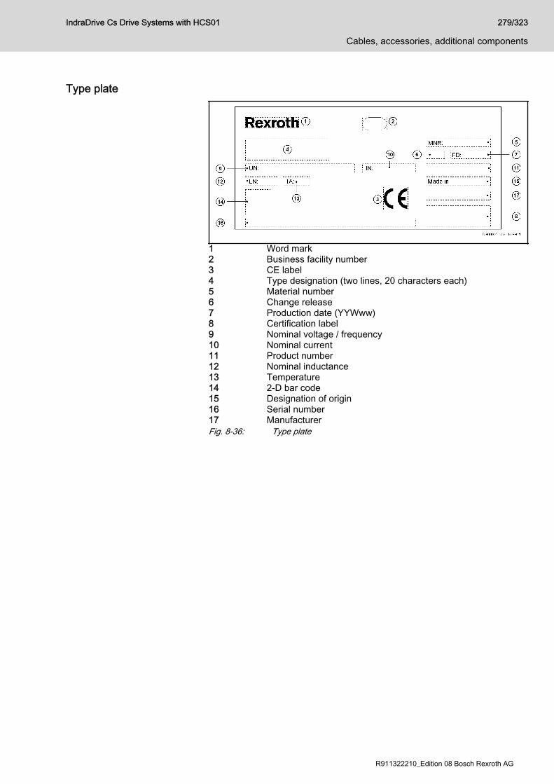
Type plate
1 Word mark2 Business facility number3 CE label4 Type designation (two lines, 20 characters each)5 Material number6 Change release7 Production date (YYWww)8 Certification label9 Nominal voltage / frequency10 Nominal current11 Product number12 Nominal inductance13 Temperature14 2-D bar code15 Designation of origin16 Serial number17 ManufacturerFig. 8-36: Type plate
IndraDrive Cs Drive Systems with HCS01 279/323
Cables, accessories, additional components
R911322210_Edition 08 Bosch Rexroth AG
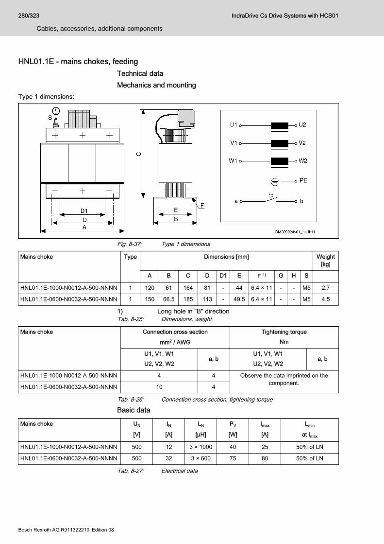
HNL01.1E - mains chokes, feeding Technical dataMechanics and mounting
Type 1 dimensions:
Fig. 8-37: Type 1 dimensions
Mains choke Type Dimensions [mm] Weight[kg]
A B C D D1 E F 1) G H S
HNL01.1E-1000-N0012-A-500-NNNN 1 120 61 164 81 - 44 6.4 × 11 - - M5 2.7
HNL01.1E-0600-N0032-A-500-NNNN 1 150 66.5 185 113 - 49.5 6.4 × 11 - - M5 4.5
1) Long hole in "B" directionTab. 8-25: Dimensions, weight
Mains choke Connection cross section
mm2 / AWG
Tightening torqueNm
U1, V1, W1U2, V2, W2
a, bU1, V1, W1U2, V2, W2
a, b
HNL01.1E-1000-N0012-A-500-NNNN 4 4 Observe the data imprinted on thecomponent.HNL01.1E-0600-N0032-A-500-NNNN 10 4
Tab. 8-26: Connection cross section, tightening torque
Basic data
Mains choke UN
[V]
IN[A]
LN
[µH]
PV
[W]
Imax
[A]
Lmin
at Imax
HNL01.1E-1000-N0012-A-500-NNNN 500 12 3 × 1000 40 25 50% of LN
HNL01.1E-0600-N0032-A-500-NNNN 500 32 3 × 600 75 80 50% of LN
Tab. 8-27: Electrical data
280/323
Cables, accessories, additional components
IndraDrive Cs Drive Systems with HCS01
Bosch Rexroth AG R911322210_Edition 08

Temperature contacts a, bSwitching capacity Switching temperature
1 A / AC 250 VDC 24 V
125 °CHNL01.1E mains chokes of type 1 are equipped with atemperature contact (a, b), types 2, 3 and 4 are not.
Tab. 8-28: Temperature contact
IndraDrive Cs Drive Systems with HCS01 281/323
Cables, accessories, additional components
R911322210_Edition 08 Bosch Rexroth AG
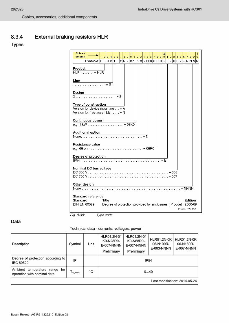
8.3.4 External braking resistors HLRTypes
Fig. 8-38: Type code
DataTechnical data - currents, voltages, power
Description Symbol Unit
HLR01.2N-01K0-N28R0-
E-007-NNNNPreliminary
HLR01.2N-01K0-N68R0-
E-007-NNNNPreliminary
HLR01.2N-0K06-N100R-
E-003-NNNN
HLR01.2N-0K06-N180R-
E-007-NNNN
Degree of protection according toIEC 60529 IP IP54
Ambient temperature range foroperation with nominal data Ta_work °C 0...40
Last modification: 2014-05-26
282/323
Cables, accessories, additional components
IndraDrive Cs Drive Systems with HCS01
Bosch Rexroth AG R911322210_Edition 08
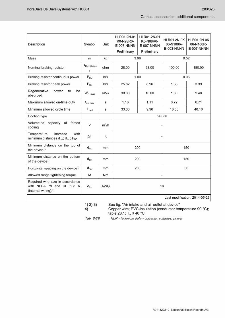
Description Symbol Unit
HLR01.2N-01K0-N28R0-
E-007-NNNNPreliminary
HLR01.2N-01K0-N68R0-
E-007-NNNNPreliminary
HLR01.2N-0K06-N100R-
E-003-NNNN
HLR01.2N-0K06-N180R-
E-007-NNNN
Mass m kg 3.96 0.52
Nominal braking resistorRDC_Bleede
rohm 28.00 68.00 100.00 180.00
Braking resistor continuous power PBD kW 1.00 0.06
Braking resistor peak power PBS kW 25.82 8.96 1.38 3.39
Regenerative power to beabsorbed WR_max kWs 30.00 10.00 1.00 2.40
Maximum allowed on-time duty ton_max s 1.16 1.11 0.72 0.71
Minimum allowed cycle time Tcycl s 33.30 9.90 16.50 40.10
Cooling type natural
Volumetric capacity of forcedcooling V m3/h -
Temperature increase withminimum distances dbot; dtop; PBD
ΔT K -
Minimum distance on the top ofthe device1) dtop mm 200 150
Minimum distance on the bottomof the device2) dbot mm 200 150
Horizontal spacing on the device3) dhor mm 200 50
Allowed range tightening torque M Nm -
Required wire size in accordancewith NFPA 79 and UL 508 A(internal wiring);4)
ALN AWG 16
Last modification: 2014-05-26
1) 2) 3) See fig. "Air intake and air outlet at device"4) Copper wire; PVC-insulation (conductor temperature 90 °C);
table 28.1; Ta ≤ 40 °CTab. 8-29: HLR - technical data - currents, voltages, power
IndraDrive Cs Drive Systems with HCS01 283/323
Cables, accessories, additional components
R911322210_Edition 08 Bosch Rexroth AG
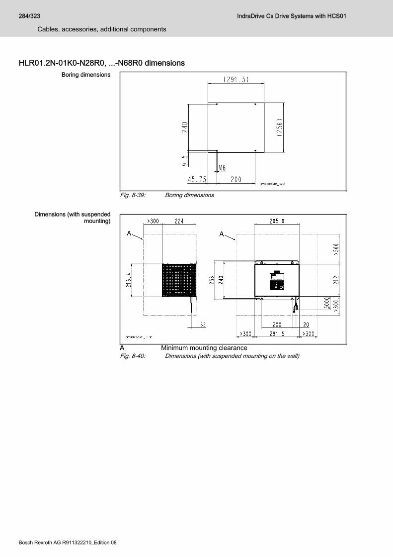
HLR01.2N-01K0-N28R0, ...-N68R0 dimensionsBoring dimensions
Fig. 8-39: Boring dimensions
Dimensions (with suspendedmounting)
A Minimum mounting clearanceFig. 8-40: Dimensions (with suspended mounting on the wall)
284/323
Cables, accessories, additional components
IndraDrive Cs Drive Systems with HCS01
Bosch Rexroth AG R911322210_Edition 08
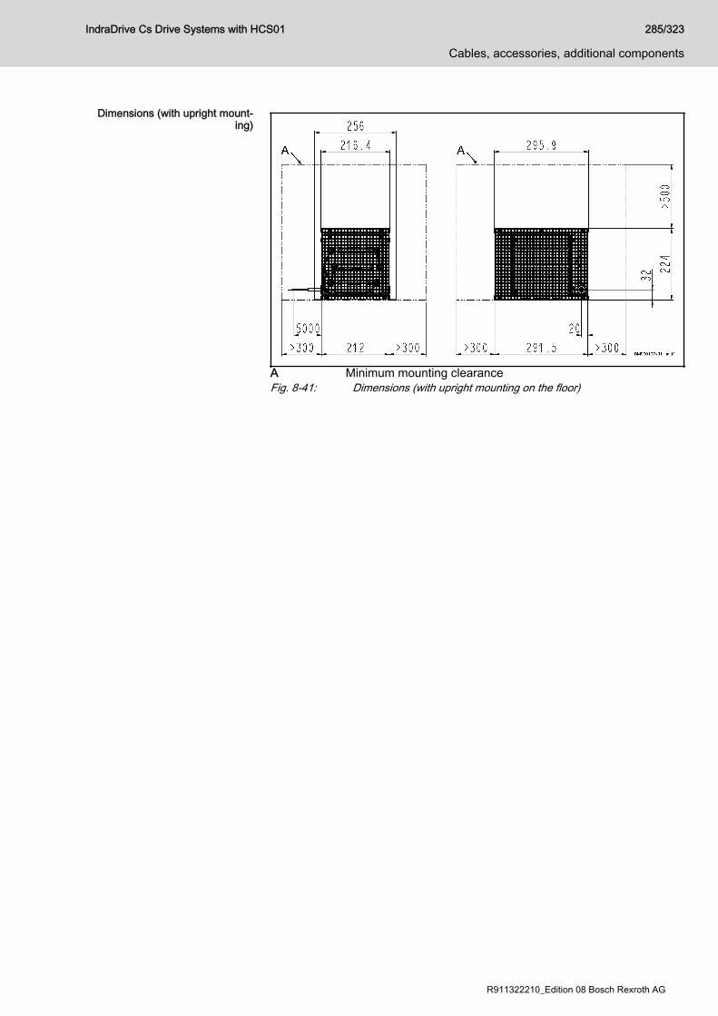
Dimensions (with upright mount‐ing)
A Minimum mounting clearanceFig. 8-41: Dimensions (with upright mounting on the floor)
IndraDrive Cs Drive Systems with HCS01 285/323
Cables, accessories, additional components
R911322210_Edition 08 Bosch Rexroth AG

HLR01.2N-0K06-N100R, ...-N180R dimensions
Fig. 8-42: Dimensions
Connector Data
Manufacturer: TE connectivity Ltd.
Type: Mini-Universal MATE-N-LOK 2
Number: 794186-1
Contacts (female):● Number: 794223-1
● Connection cross section: 0.5 … 1.4 mm2 (16 … 20 AWG)
Tab. 8-30: Connector
286/323
Cables, accessories, additional components
IndraDrive Cs Drive Systems with HCS01
Bosch Rexroth AG R911322210_Edition 08
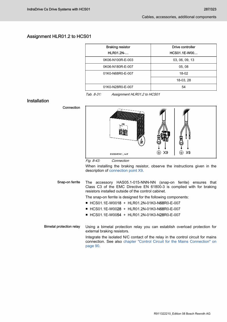
Assignment HLR01.2 to HCS01
Braking resistorHLR01.2N-…
Drive controllerHCS01.1E-W00…
0K06-N100R-E-003 03, 06, 09, 13
0K06-N180R-E-007 05, 08
01K0-N68R0-E-007 18-02
18-03, 28
01K0-N28R0-E-007 54
Tab. 8-31: Assignment HLR01.2 to HCS01
InstallationConnection
Fig. 8-43: ConnectionWhen installing the braking resistor, observe the instructions given in thedescription of connection point X9.
Snap-on ferrite The accessory HAS05.1-015-NNN-NN (snap-on ferrite) ensures thatClass C3 of the EMC Directive EN 61800-3 is complied with for brakingresistors installed outside of the control cabinet.The snap-on ferrite is designed for the following components:■ HCS01.1E-W0018 + HLR01.2N-01K0-N68R0-E-007■ HCS01.1E-W0028 + HLR01.2N-01K0-N68R0-E-007■ HCS01.1E-W0054 + HLR01.2N-01K0-N28R0-E-007
Bimetal protection relay Using a bimetal protection relay you can establish overload protection forexternal braking resistors.Integrate the isolated N/C contact of the relay in the control circuit for mainsconnection. See also chapter "Control Circuit for the Mains Connection" onpage 90.
IndraDrive Cs Drive Systems with HCS01 287/323
Cables, accessories, additional components
R911322210_Edition 08 Bosch Rexroth AG
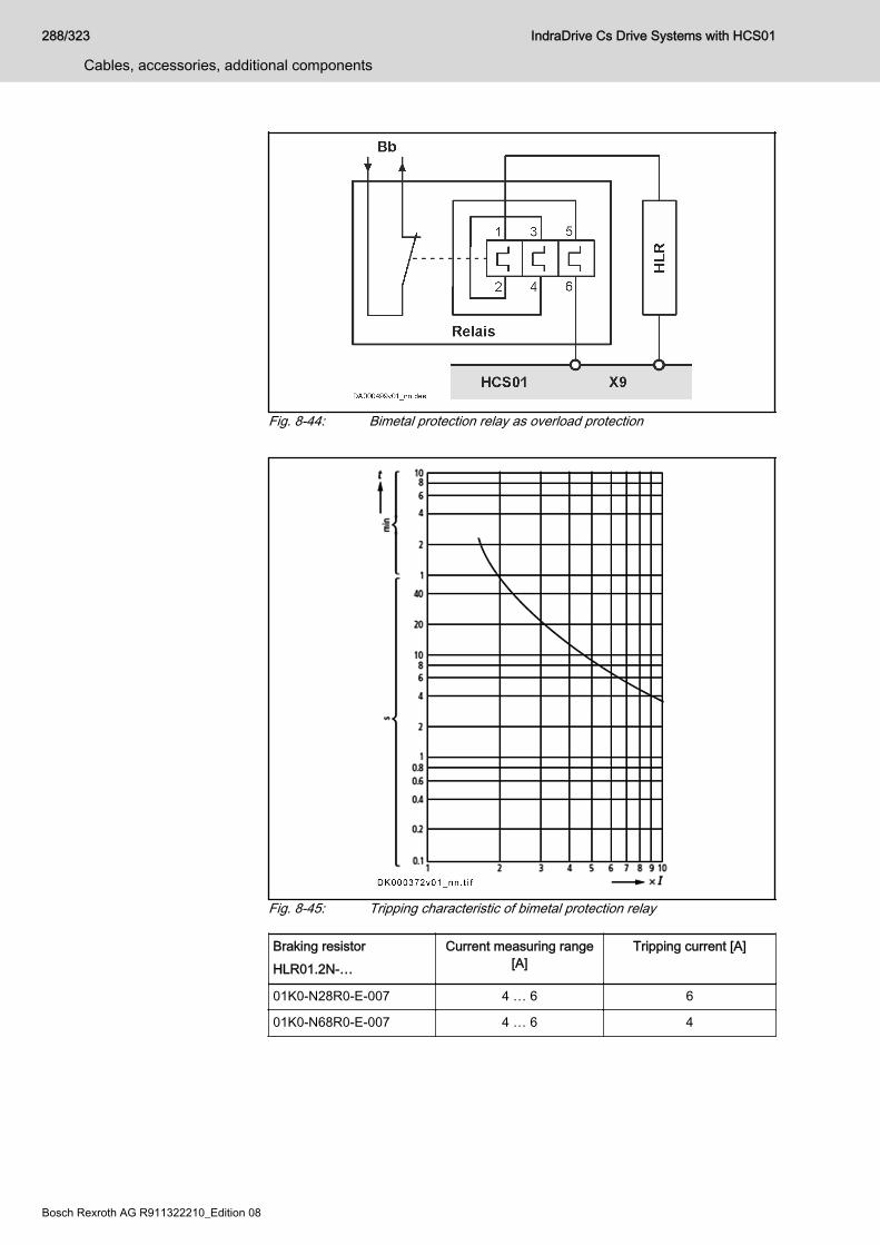
Fig. 8-44: Bimetal protection relay as overload protection
Fig. 8-45: Tripping characteristic of bimetal protection relay
Braking resistorHLR01.2N-…
Current measuring range[A]
Tripping current [A]
01K0-N28R0-E-007 4 … 6 6
01K0-N68R0-E-007 4 … 6 4
288/323
Cables, accessories, additional components
IndraDrive Cs Drive Systems with HCS01
Bosch Rexroth AG R911322210_Edition 08

Braking resistorHLR01.2N-…
Current measuring range[A]
Tripping current [A]
0K06-N100R-E-003 0.6 … 1 0.8
0K06-N180R-E-007 0.6 … 1 0.6
Tab. 8-32: HLR and bimetal protection relay: Current measuring range and trip‐ping current
IndraDrive Cs Drive Systems with HCS01 289/323
Cables, accessories, additional components
R911322210_Edition 08 Bosch Rexroth AG
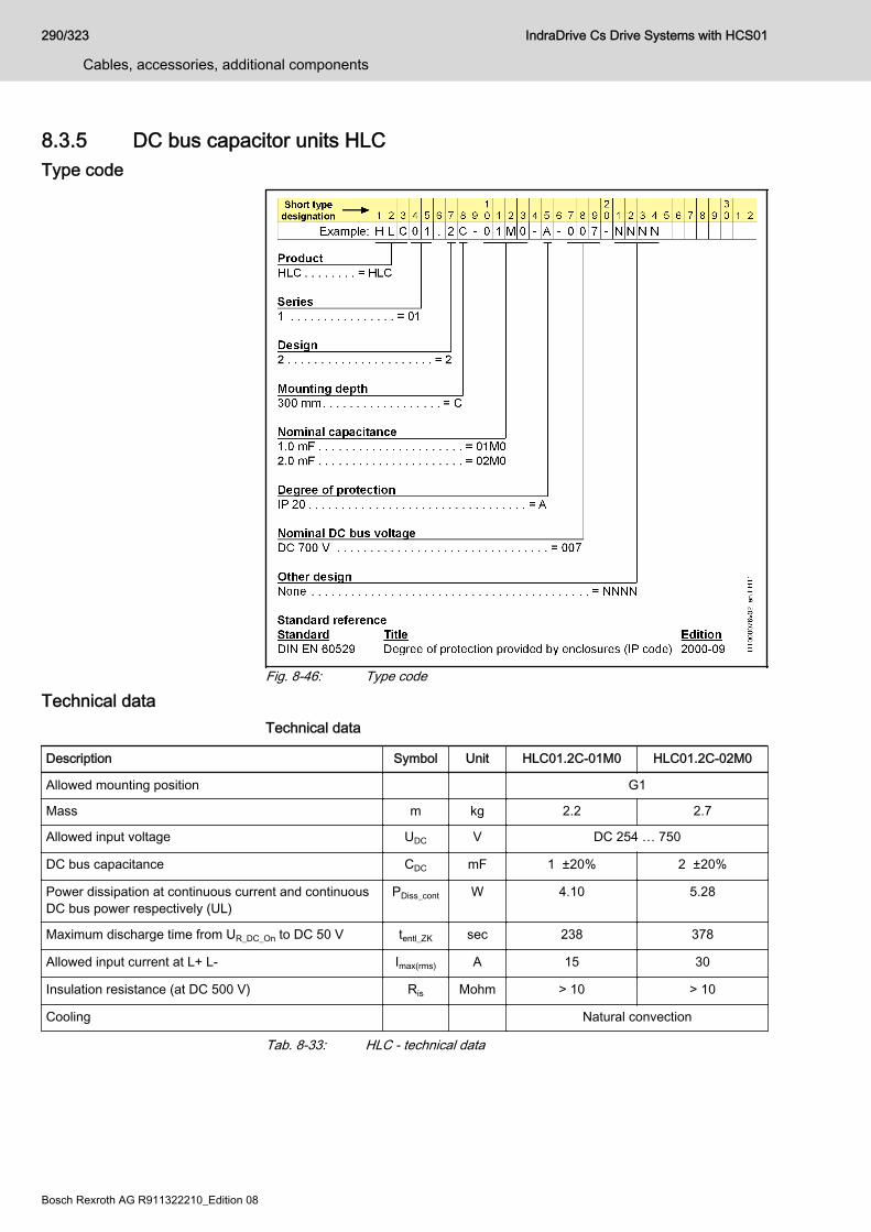
8.3.5 DC bus capacitor units HLCType code
Fig. 8-46: Type code
Technical dataTechnical data
Description Symbol Unit HLC01.2C-01M0 HLC01.2C-02M0
Allowed mounting position G1
Mass m kg 2.2 2.7
Allowed input voltage UDC V DC 254 … 750
DC bus capacitance CDC mF 1 ±20% 2 ±20%
Power dissipation at continuous current and continuousDC bus power respectively (UL)
PDiss_cont W 4.10 5.28
Maximum discharge time from UR_DC_On to DC 50 V tentl_ZK sec 238 378
Allowed input current at L+ L- Imax(rms) A 15 30
Insulation resistance (at DC 500 V) Ris Mohm > 10 > 10
Cooling Natural convection
Tab. 8-33: HLC - technical data
290/323
Cables, accessories, additional components
IndraDrive Cs Drive Systems with HCS01
Bosch Rexroth AG R911322210_Edition 08
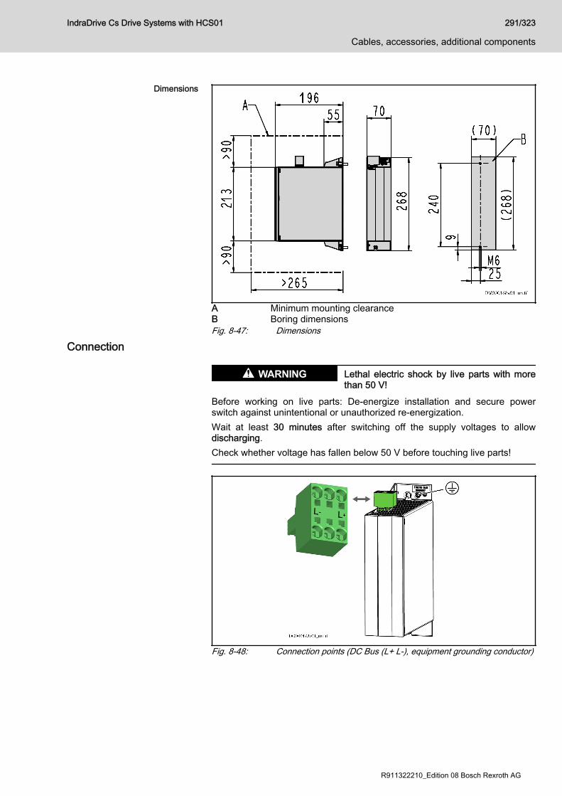
Dimensions
A Minimum mounting clearanceB Boring dimensionsFig. 8-47: Dimensions
Connection
Lethal electric shock by live parts with morethan 50 V!
WARNING
Before working on live parts: De-energize installation and secure powerswitch against unintentional or unauthorized re-energization.Wait at least 30 minutes after switching off the supply voltages to allowdischarging.Check whether voltage has fallen below 50 V before touching live parts!
Fig. 8-48: Connection points (DC Bus (L+ L-), equipment grounding conductor)
IndraDrive Cs Drive Systems with HCS01 291/323
Cables, accessories, additional components
R911322210_Edition 08 Bosch Rexroth AG

Equipment grounding conductor Connect the equipment grounding conductor via thread M5 to the housing of
the device (identification mark ; tightening torque: 5 Nm). The M5×12screw required for this purpose is part of the supplied accessories HAS09.
DC bus Connect HLC01 to HCS01 with twisted lines: L+ to L+; L- to L-Technical data of the connection point: See description of connection pointX77.
Arrangement Place the HLC next to the most powerful drive controller of a drive system.
OperationMains Choke Always operate the DC bus capacitor units together with the mains choke
assigned to the drive controller (see chapter 7.3.2 "Mains voltage" on page226).Special case "HCS01.1E-W0018-_-03" (in the technical data, no mains chokehas been assigned to this drive controller):Use the mains choke "HNL01.1E-1000-N0012-A-500-NNNN".
DC bus coupling Information on DC bus coupling: See chapter "DC Bus Capacitor Unit" onpage 97
292/323
Cables, accessories, additional components
IndraDrive Cs Drive Systems with HCS01
Bosch Rexroth AG R911322210_Edition 08

9 Environmental protection and disposal9.1 Environmental protection
Production processes The products are manufactured in energy- and resource-optimizedproduction processes which allow re-using and recycling the resulting waste.We regularly try to replace pollutant-loaded raw materials and supplies bymore environment-friendly alternatives.
No release of hazardous substan‐ces
Our products do not contain any hazardous substances which may bereleased in case of appropriate use. Normally, our products will not have anynegative influences on the environment.
Significant components Significant components of our products are:Electronic devices Motors∙ Steel ∙ Steel / Stainless steel∙ Aluminum ∙ Aluminum∙ Copper ∙ Copper∙ Plastics ∙ Brass∙ Electronic components ∙ Magnetic materials ∙ Elektronic components
9.2 DisposalReturn of products Our products can be returned to us for disposal free of charge. However, this
requires that the products be free from oil, grease or other dirt.Furthermore, the products returned for disposal may not contain any undueforeign material or foreign components.Deliver the products "free domicile" to the following address: Bosch Rexroth AG Electric Drives and Controls Buergermeister-Dr.-Nebel-Straße 2 97816 Lohr am Main, Germany
Packaging Packaging materials consist of cardboard, wood and polystyrene They canbe recycled anywhere without any problem.For ecological reasons, please refrain from returning the empty packages tous.
Batteries and accumulators Batteries and accumulators can be labeled with this symbol.
The symbol indicating "separate collection" for all batteries andaccumulators is the crossed-out wheeled bin.End users in the EU are legally bound to return used batteries andaccumulators. Outside the validity of the EU Directive 2006/66/EC, theparticularly applicable regulations must be followed.Batteries and accumulators can contain hazardous substances which canharm the environment or people's health when improperly stored or disposedof.After use, the batteries or accumulators contained in Rexroth products mustbe properly disposed of according to the country-specific collection systems.
IndraDrive Cs Drive Systems with HCS01 293/323
Environmental protection and disposal
R911322210_Edition 08 Bosch Rexroth AG

Recycling Most of the products can be recycled due to their high content of metal. Inorder to recycle the metal in the best possible way, the products must bedisassembled into individual assemblies.Metals contained in electric and electronic assemblies can also be recycledby means of special separation processes.Plastic parts of the products may contain flame retardants. These plasticparts are labeled according to EN ISO 1043. They have to be recycledseparately or disposed of according to the applicable legal provisions.
294/323
Environmental protection and disposal
IndraDrive Cs Drive Systems with HCS01
Bosch Rexroth AG R911322210_Edition 08

10 Service and supportOur worldwide service network provides an optimized and efficient support.Our experts offer you advice and assistance should you have any queries.You can contact us 24/7.
Service Germany Our technology-oriented Competence Center in Lohr, Germany, isresponsible for all your service-related queries for electric drive and controls.Contact the Service Hotline and Service Helpdesk under:
Phone: +49 9352 40 5060Fax: +49 9352 18 4941E-mail: [email protected]: http://www.boschrexroth.com
Additional information on service, repair (e.g. delivery addresses) and trainingcan be found on our internet sites.
Service worldwide Outside Germany, please contact your local service office first. For hotlinenumbers, refer to the sales office addresses on the internet.
Preparing information To be able to help you more quickly and efficiently, please have the followinginformation ready:● Detailed description of malfunction and circumstances● Type plate specifications of the affected products, in particular type
codes and serial numbers● Your contact data (phone and fax number as well as your e-mail
address)
IndraDrive Cs Drive Systems with HCS01 295/323
Service and support
R911322210_Edition 08 Bosch Rexroth AG

296/323 IndraDrive Cs Drive Systems with HCS01
Bosch Rexroth AG R911322210_Edition 08

11 Appendix11.1 Sizing the line cross sections and fuses 11.1.1 Introduction
The sizing of the line cross sections described here refers to theshort circuit protection of the devices and not to the lineprotection.
Sizing the line cross sections and fuses in the supply feeder andbranches to the drive system:
1. Determine the current in the supply feeder of the drive system andcorrect it with the correction factors for ambient temperature andbundling.
2. Determine the country of use ("international except for USA/Canada" or"USA/Canada")
3. Determine the installation type (e.g., B1 or B2)4. In the "Current carrying capacity" table row, select the value that is
immediately above the value determined in the first step5. In the "Fuse" table row, read the corresponding fuse6. In the "Cross section A …" table row, read the corresponding required
cross section
11.1.2 International except for USA/Canada; installation type B1
Country of use: international except for USA/Canada
Fuse IN [A] Current carryingcapacity (× 0.87)
IZ(40) [A]
Cross section A [mm2]Installation type B11 × 2 × 3 ×
2 1.6 1.5
4 3.3 1.5
6 5.0 1.5
10 8.6 1.5
16 10.3 1.5
16 13.5 1.5
20 18.27 2.5
35 24.36 4
35 31.32 6
50 43.50 10
80 59.16 16
100 77.43 25
125 95.70 35
160 116.58 50
200 148.77 70
IndraDrive Cs Drive Systems with HCS01 297/323
Appendix
R911322210_Edition 08 Bosch Rexroth AG
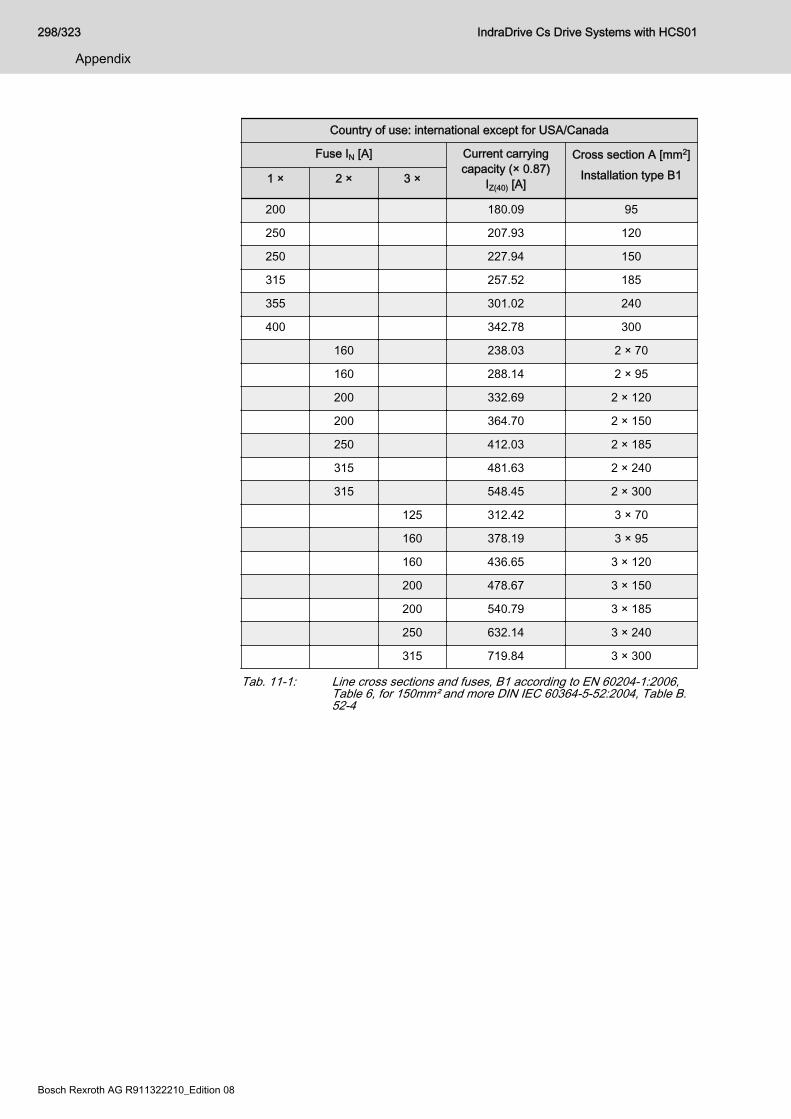
Country of use: international except for USA/Canada
Fuse IN [A] Current carryingcapacity (× 0.87)
IZ(40) [A]
Cross section A [mm2]Installation type B11 × 2 × 3 ×
200 180.09 95
250 207.93 120
250 227.94 150
315 257.52 185
355 301.02 240
400 342.78 300
160 238.03 2 × 70
160 288.14 2 × 95
200 332.69 2 × 120
200 364.70 2 × 150
250 412.03 2 × 185
315 481.63 2 × 240
315 548.45 2 × 300
125 312.42 3 × 70
160 378.19 3 × 95
160 436.65 3 × 120
200 478.67 3 × 150
200 540.79 3 × 185
250 632.14 3 × 240
315 719.84 3 × 300
Tab. 11-1: Line cross sections and fuses, B1 according to EN 60204-1:2006,Table 6, for 150mm² and more DIN IEC 60364-5-52:2004, Table B.52-4
298/323
Appendix
IndraDrive Cs Drive Systems with HCS01
Bosch Rexroth AG R911322210_Edition 08

11.1.3 International except for USA/Canada; installation type B2
Country of use: international except for USA/Canada
Fuse IN [A] Current carryingcapacity (× 0.87)
IZ(40) [A]
Cross section A [mm2]Installation type B21 × 2 × 3 ×
2 1.6 0.75
4 3.3 0.75
6 5.0 0.75
10 8.5 0.75
16 10.1 1.0
16 13.05 1.5
20 17.40 2.5
25 23.49 4
35 29.58 6
50 40.02 10
63 53.94 16
80 69.60 25
100 86.13 35
125 102.66 50
160 129.63 70
200 155.73 95
200 179.22 120
224 195.75 150
250 221.85 185
315 258.39 240
355 294.93 300
125 207.41 2 × 70
160 249.17 2 × 95
160 286.75 2 × 120
200 313.20 2 × 150
200 354.96 2 × 185
250 413.42 2 × 240
315 471.89 2 × 300
100 272.22 3 × 70
125 327.03 3 × 95
160 376.36 3 × 120
160 411.08 3 × 150
IndraDrive Cs Drive Systems with HCS01 299/323
Appendix
R911322210_Edition 08 Bosch Rexroth AG

Country of use: international except for USA/Canada
Fuse IN [A] Current carryingcapacity (× 0.87)
IZ(40) [A]
Cross section A [mm2]Installation type B21 × 2 × 3 ×
200 465.89 3 × 185
200 542.62 3 × 240
250 619.35 3 × 300
Tab. 11-2: Line cross sections and fuses, B2 according to EN 60204-1:2006,Table 6, for 150mm² and more DIN IEC 60364-5-52:2004, Table B.52-4
300/323
Appendix
IndraDrive Cs Drive Systems with HCS01
Bosch Rexroth AG R911322210_Edition 08

11.1.4 International except for USA/Canada; installation type E
Country of use: international except for USA/Canada
Fuse IN [A] Current carryingcapacity (× 0.87)
IZ(40) [A]
Cross section A [mm2]Installation type E1 × 2 × 3 ×
2 1.6 0.75
4 3.3 0.75
6 5.0 0.75
10 8.3 0.75
16 10.4 0.75
16 12.4 1
20 16.10 1.5
25 21.75 2.5
35 29.58 4
50 37.41 6
63 52.20 10
80 69.60 16
100 87.87 25
125 109.62 35
160 133.11 50
200 170.52 70
250 207.06 95
315 240.12 120
355 277.53 150
400 316.68 185
425 374.10 240
500 432.39 300
160 272.83 2 × 70
200 331.30 2 × 95
250 384.19 2 × 120
250 444.05 2 × 150
315 506.69 2 × 185
400 598.56 2 × 240
400 691.82 2 × 300
160 358.09 3 × 70
200 434.83 3 × 95
200 504.25 3 × 120
IndraDrive Cs Drive Systems with HCS01 301/323
Appendix
R911322210_Edition 08 Bosch Rexroth AG
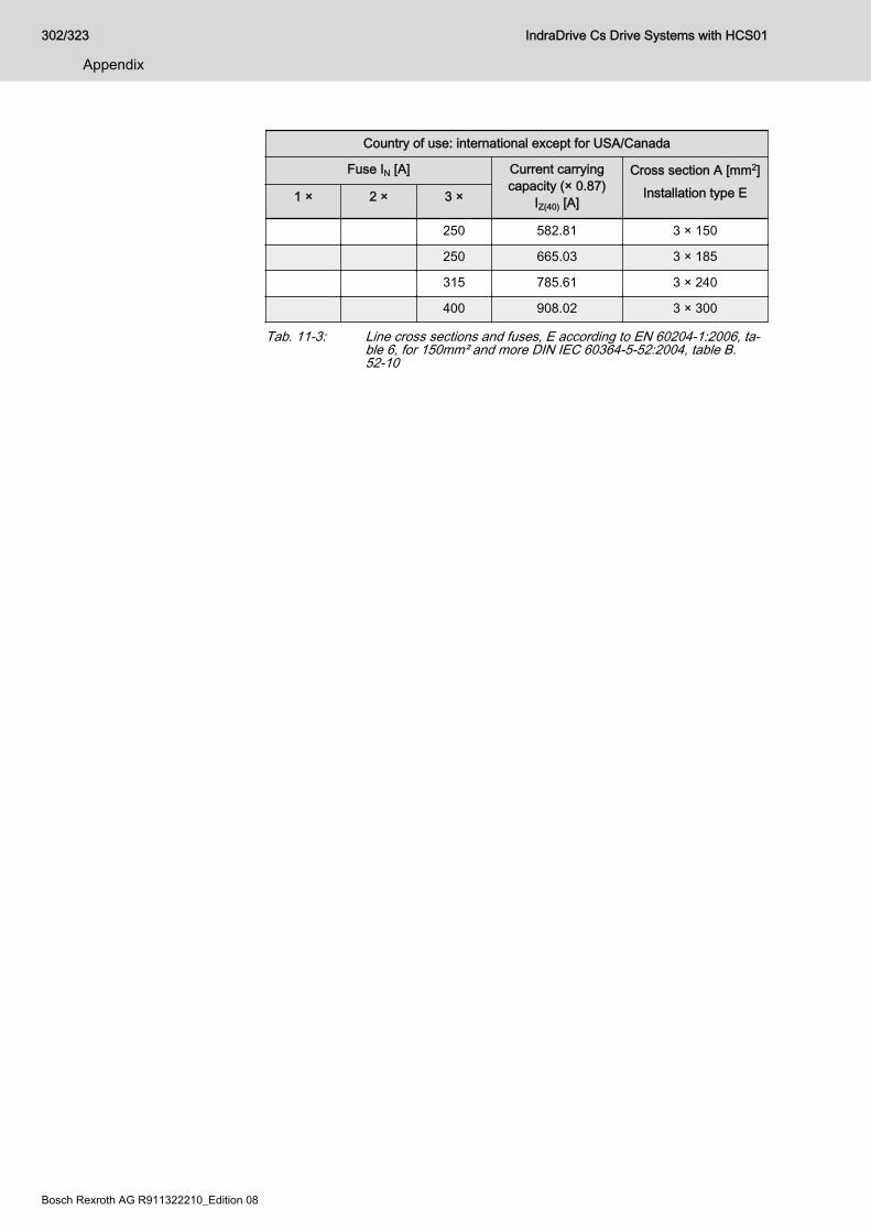
Country of use: international except for USA/Canada
Fuse IN [A] Current carryingcapacity (× 0.87)
IZ(40) [A]
Cross section A [mm2]Installation type E1 × 2 × 3 ×
250 582.81 3 × 150
250 665.03 3 × 185
315 785.61 3 × 240
400 908.02 3 × 300
Tab. 11-3: Line cross sections and fuses, E according to EN 60204-1:2006, ta‐ble 6, for 150mm² and more DIN IEC 60364-5-52:2004, table B.52-10
302/323
Appendix
IndraDrive Cs Drive Systems with HCS01
Bosch Rexroth AG R911322210_Edition 08
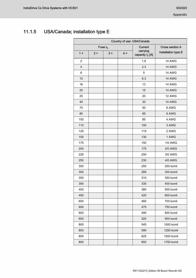
11.1.5 USA/Canada; installation type E
Country of use: USA/Canada
Fuse IN Currentcarrying
capacity IZ [A]
Cross section AInstallation type E1 × 2 × 3 × 4 ×
2 1.6 14 AWG
4 3.3 14 AWG
6 5 14 AWG
10 8.3 14 AWG
16 13 14 AWG
20 15 14 AWG
25 20 12 AWG
40 30 10 AWG
70 50 8 AWG
80 65 6 AWG
100 85 4 AWG
110 100 3 AWG
125 115 2 AWG
150 130 1 AWG
175 150 1/0 AWG
200 175 2/0 AWG
225 200 3/0 AWG
250 230 4/0 AWG
300 255 250 kcmil
300 285 300 kcmil
350 310 350 kcmil
350 335 400 kcmil
400 380 500 kcmil
450 420 600 kcmil
600 460 700 kcmil
600 475 750 kcmil
600 490 800 kcmil
600 520 900 kcmil
800 545 1000 kcmil
800 590 1250 kcmil
800 625 1500 kcmil
800 650 1750 kcmil
IndraDrive Cs Drive Systems with HCS01 303/323
Appendix
R911322210_Edition 08 Bosch Rexroth AG

Country of use: USA/Canada
Fuse IN Currentcarrying
capacity IZ [A]
Cross section AInstallation type E1 × 2 × 3 × 4 ×
800 665 2000 kcmil
200 300 2 × 1/0 AWG
225 350 2 × 2/0 AWG
250 400 2 × 3/0 AWG
300 460 2 × 4/0 AWG
300 510 2 × 250 kcmil
350 570 2 × 300 kcmil
350 620 2 × 350 kcmil
400 670 2 × 400 kcmil
450 760 2 × 500 kcmil
600 840 2 × 600 kcmil
600 920 2 × 700 kcmil
600 950 2 × 750 kcmil
600 980 2 × 800 kcmil
800 1040 2 × 900 kcmil
800 1090 2 × 1000 kcmil
200 450 3 × 1/0 AWG
225 525 3 × 2/0 AWG
250 600 3 × 3/0 AWG
300 690 3 × 4/0 AWG
300 765 3 × 250 kcmil
350 855 3 × 300 kcmil
350 930 3 × 350 kcmil
400 1005 3 × 400 kcmil
450 1140 3 × 500 kcmil
200 600 4 × 1/0 AWG
225 700 4 × 2/0 AWG
250 800 4 × 3/0 AWG
300 920 4 × 4/0 AWG
300 1020 4 × 250 kcmil
350 1140 4 × 300 kcmil
350 1240 4 × 350 kcmil
304/323
Appendix
IndraDrive Cs Drive Systems with HCS01
Bosch Rexroth AG R911322210_Edition 08

Country of use: USA/Canada
Fuse IN Currentcarrying
capacity IZ [A]
Cross section AInstallation type E1 × 2 × 3 × 4 ×
400 1340 4 × 400 kcmil
450 1520 4 × 500 kcmil
Tab. 11-4: Line cross sections and fuses according to UL508A:2007, Table 28.1
IndraDrive Cs Drive Systems with HCS01 305/323
Appendix
R911322210_Edition 08 Bosch Rexroth AG
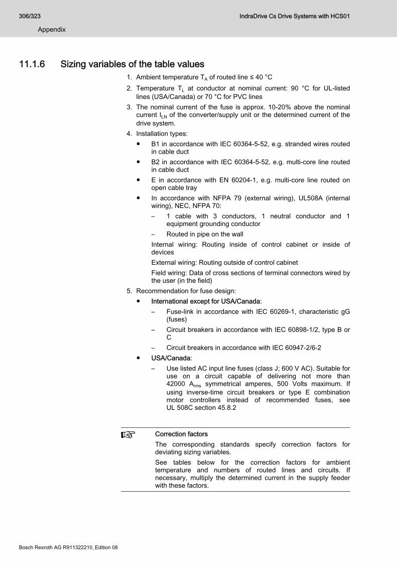
11.1.6 Sizing variables of the table values1. Ambient temperature TA of routed line ≤ 40 °C2. Temperature TL at conductor at nominal current: 90 °C for UL-listed
lines (USA/Canada) or 70 °C for PVC lines3. The nominal current of the fuse is approx. 10-20% above the nominal
current ILN of the converter/supply unit or the determined current of thedrive system.
4. Installation types:● B1 in accordance with IEC 60364-5-52, e.g. stranded wires routed
in cable duct● B2 in accordance with IEC 60364-5-52, e.g. multi-core line routed
in cable duct● E in accordance with EN 60204-1, e.g. multi-core line routed on
open cable tray● In accordance with NFPA 79 (external wiring), UL508A (internal
wiring), NEC, NFPA 70:– 1 cable with 3 conductors, 1 neutral conductor and 1
equipment grounding conductor– Routed in pipe on the wallInternal wiring: Routing inside of control cabinet or inside ofdevicesExternal wiring: Routing outside of control cabinetField wiring: Data of cross sections of terminal connectors wired bythe user (in the field)
5. Recommendation for fuse design: ● International except for USA/Canada:
– Fuse-link in accordance with IEC 60269-1, characteristic gG(fuses)
– Circuit breakers in accordance with IEC 60898-1/2, type B orC
– Circuit breakers in accordance with IEC 60947-2/6-2● USA/Canada:
– Use listed AC input line fuses (class J; 600 V AC). Suitable foruse on a circuit capable of delivering not more than42000 Arms symmetrical amperes, 500 Volts maximum. Ifusing inverse-time circuit breakers or type E combinationmotor controllers instead of recommended fuses, seeUL 508C section 45.8.2
Correction factorsThe corresponding standards specify correction factors fordeviating sizing variables.See tables below for the correction factors for ambienttemperature and numbers of routed lines and circuits. Ifnecessary, multiply the determined current in the supply feederwith these factors.
306/323
Appendix
IndraDrive Cs Drive Systems with HCS01
Bosch Rexroth AG R911322210_Edition 08
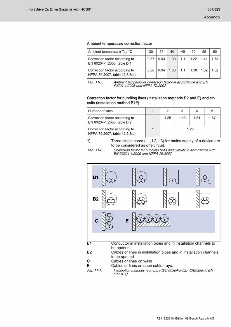
Ambient temperature correction factor
Ambient temperature TA / °C 30 35 40 45 50 55 60
Correction factor according toEN 60204-1:2006, table D.1
0.87 0.93 1.00 1.1 1.22 1.41 1.73
Correction factor according toNFPA 79:2007, table 12.5.5(a)
0.88 0.94 1.00 1.1 1.18 1.32 1.52
Tab. 11-5: Ambient temperature correction factor in accordance with EN60204-1:2006 and NFPA 79:2007
Correction factor for bundling lines (installation methods B2 and E) and cir‐cuits (installation method B11))
Number of lines 1 2 3 4 5
Correction factor according toEN 60204-1:2006, table D.2
1 1.25 1.43 1.54 1.67
Correction factor according toNFPA 79:2007, table 12.5.5(b)
1 1.25
1) Three single cores (L1, L2, L3) for mains supply of a device areto be considered as one circuit.
Tab. 11-6: Correction factor for bundling lines and circuits in accordance withEN 60204-1:2006 and NFPA 79:2007
B1 Conductor in installation pipes and in installation channels tobe opened
B2 Cables or lines in installation pipes and in installation channelsto be opened
C Cables or lines on wallsE Cables or lines on open cable trays.Fig. 11-1: Installation methods (compare IEC 60364-5-52; VDE0298-7; EN
60204-1)
IndraDrive Cs Drive Systems with HCS01 307/323
Appendix
R911322210_Edition 08 Bosch Rexroth AG
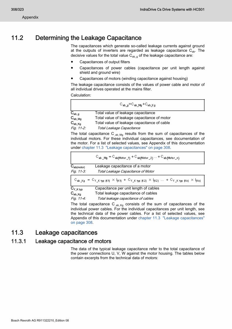
11.2 Determining the Leakage CapacitanceThe capacitances which generate so-called leakage currents against groundat the outputs of inverters are regarded as leakage capacitance Cab. Thedecisive values for the total value Cab_g of the leakage capacitance are:● Capacitances of output filters● Capacitances of power cables (capacitance per unit length against
shield and ground wire)● Capacitances of motors (winding capacitance against housing)The leakage capacitance consists of the values of power cable and motor ofall individual drives operated at the mains filter.Calculation:
Cab_g Total value of leakage capacitanceCab_Mg Total value of leakage capacitance of motorCab_Kg Total value of leakage capacitance of cableFig. 11-2: Total Leakage CapacitanceThe total capacitance C_ab_Mg results from the sum of capacitances of theindividual motors. For these individual capacitances, see documentation ofthe motor. For a list of selected values, see Appendix of this documentationunder chapter 11.3 "Leakage capacitances" on page 308.
Cab(motor) Leakage capacitance of a motorFig. 11-3: Total Leakage Capacitance of Motor
CY_K typ Capacitance per unit length of cablesCab_Kg Total leakage capacitance of cablesFig. 11-4: Total leakage capacitance of cablesThe total capacitance C_ab_Kg consists of the sum of capacitances of theindividual power cables. For the individual capacitances per unit length, seethe technical data of the power cables. For a list of selected values, seeAppendix of this documentation under chapter 11.3 "Leakage capacitances"on page 308.
11.3 Leakage capacitances11.3.1 Leakage capacitance of motors
The data of the typical leakage capacitance refer to the total capacitance ofthe power connections U, V, W against the motor housing. The tables belowcontain excerpts from the technical data of motors:
308/323
Appendix
IndraDrive Cs Drive Systems with HCS01
Bosch Rexroth AG R911322210_Edition 08
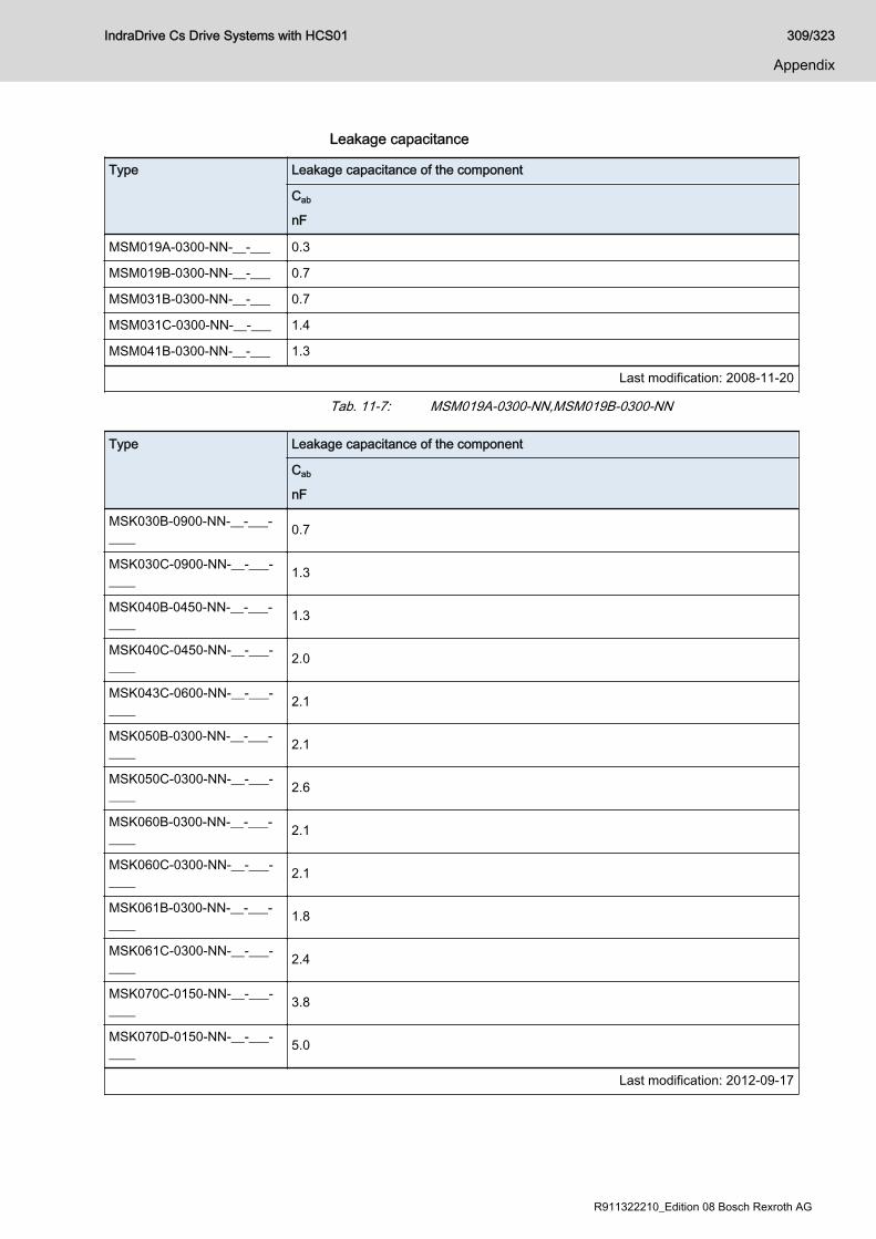
Leakage capacitance
Type Leakage capacitance of the component
Cab
nF
MSM019A-0300-NN-__-___ 0.3
MSM019B-0300-NN-__-___ 0.7
MSM031B-0300-NN-__-___ 0.7
MSM031C-0300-NN-__-___ 1.4
MSM041B-0300-NN-__-___ 1.3
Last modification: 2008-11-20
Tab. 11-7: MSM019A-0300-NN,MSM019B-0300-NN
Type Leakage capacitance of the component
Cab
nF
MSK030B-0900-NN-__-___-____ 0.7
MSK030C-0900-NN-__-___-____ 1.3
MSK040B-0450-NN-__-___-____ 1.3
MSK040C-0450-NN-__-___-____ 2.0
MSK043C-0600-NN-__-___-____ 2.1
MSK050B-0300-NN-__-___-____ 2.1
MSK050C-0300-NN-__-___-____ 2.6
MSK060B-0300-NN-__-___-____ 2.1
MSK060C-0300-NN-__-___-____ 2.1
MSK061B-0300-NN-__-___-____ 1.8
MSK061C-0300-NN-__-___-____ 2.4
MSK070C-0150-NN-__-___-____ 3.8
MSK070D-0150-NN-__-___-____ 5.0
Last modification: 2012-09-17
IndraDrive Cs Drive Systems with HCS01 309/323
Appendix
R911322210_Edition 08 Bosch Rexroth AG
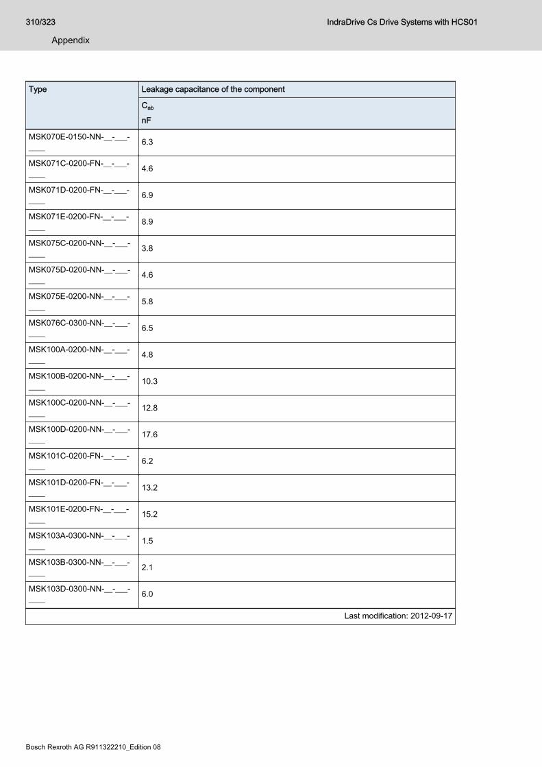
Type Leakage capacitance of the component
Cab
nF
MSK070E-0150-NN-__-___-____ 6.3
MSK071C-0200-FN-__-___-____ 4.6
MSK071D-0200-FN-__-___-____ 6.9
MSK071E-0200-FN-__-___-____ 8.9
MSK075C-0200-NN-__-___-____ 3.8
MSK075D-0200-NN-__-___-____ 4.6
MSK075E-0200-NN-__-___-____ 5.8
MSK076C-0300-NN-__-___-____ 6.5
MSK100A-0200-NN-__-___-____ 4.8
MSK100B-0200-NN-__-___-____ 10.3
MSK100C-0200-NN-__-___-____ 12.8
MSK100D-0200-NN-__-___-____ 17.6
MSK101C-0200-FN-__-___-____ 6.2
MSK101D-0200-FN-__-___-____ 13.2
MSK101E-0200-FN-__-___-____ 15.2
MSK103A-0300-NN-__-___-____ 1.5
MSK103B-0300-NN-__-___-____ 2.1
MSK103D-0300-NN-__-___-____ 6.0
Last modification: 2012-09-17
310/323
Appendix
IndraDrive Cs Drive Systems with HCS01
Bosch Rexroth AG R911322210_Edition 08

Type Leakage capacitance of the component
Cab
nF
MSK131B-0200-NN-__-___-____ 14.3
MSK131D-0200-NN-__-___-____ 27.7
Last modification: 2012-09-17
Tab. 11-8: MSK - leakage capacitance (excerpt)See also Rexroth IndraDyn - Technical data.
11.3.2 Leakage capacitance of power cables The power cables (bulk cables) of the "RKL" series by Rexroth have thecapacitances per unit length listed below. The values refer to the sum of theindividual capacitances of power cores 1, 2 and 3 against the overall shield.See also Rexroth Connection Cables - Data sheet Bulk cable.Excerpt of data sheet - bulk cables
Type Power core cross section Leakage capacitance
mm2CY_K_typ
nF/m
INK0653 1.0 0.6
INK0650 1.5 0.8
INK0602 2.5 0.7
INK0603 4.0 0.8
INK0604 6.0 0.8
INK0605 10.0 1.0
INK0606 16.0 1.2
INK0607 25.0 1.1
INK0667 35.0 1.2
INK0668 50.0 1.3
Last modification: 2007-11-08
Tab. 11-9: INK - technical data (excerpt)
IndraDrive Cs Drive Systems with HCS01 311/323
Appendix
R911322210_Edition 08 Bosch Rexroth AG
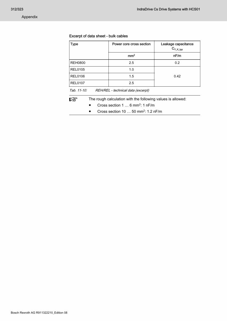
Excerpt of data sheet - bulk cables
Type Power core cross section Leakage capacitanceCY_K_typ
mm2 nF/m
REH0800 2.5 0.2
REL0105 1.0
0.42REL0106 1.5
REL0107 2.5
Tab. 11-10: REH/REL - technical data (excerpt)
The rough calculation with the following values is allowed:● Cross section 1 … 6 mm2: 1 nF/m● Cross section 10 … 50 mm2: 1.2 nF/m
312/323
Appendix
IndraDrive Cs Drive Systems with HCS01
Bosch Rexroth AG R911322210_Edition 08
Index0 … 91Vpp
Encoder, 5 V supply voltage........................ 177Encoder, 12 V supply voltage...................... 178
24V supplyConnection point.......................................... 129Continuous power.......................................... 68Installation...................................................... 68Peak current................................................... 68Project planning............................................. 64
AAcceptance tests............................................... 100Accessories
Battery.......................................................... 253Battery box, SUP-E02-MSM-BATTERY‐BOX............................................................. 251Cables, RKB0013........................................ 260Cables, RKB0021........................................ 259DC bus connector........................................ 250HAS09.......................................................... 243Mounting and connection accessories(HAS09)....................................................... 243Overview...................................................... 242Replacement battery.................................... 253Snap-on ferrite, HAS05.1-015-NNN-NN...... 267SUP-E02-MSM-BATTERY........................... 253X77, DC bus connector................................ 250
Accumulators.................................................... 293ACURO®link (MS2N encoder interface)........... 172Additional components...................................... 270
Overview...................................................... 242Additional documentations.................................. 18ADVANCED
Control panel................................................ 224HCS01....................................................... 4, 37
Ambient conditions.............................................. 49Analog input
Connection point X38................................... 152Current, technical data................................. 220Shield connection......................................... 143Voltage, technical data................................. 219
Analog inputsConnection point X32................................... 134
Analog outputConnection point X38................................... 152Shield connection......................................... 143Technical data.............................................. 221
Approvals.......................................................... 100Autotransformers.............................................. 271Axis coupling....................................................... 91
BBASIC
HCS01....................................................... 4, 37
Batteries............................................................ 293Battery
Battery box................................................... 251Replace........................................................ 253Replacement battery.................................... 253SUP-E02-MSM-BATTERY........................... 253
Bb relay contactConnection point X47................................... 135Control circuit for the mains connection......... 90DC bus coupling............................................. 98Technical data.............................................. 222
BiSS CEncoder........................................................ 186
Braking resistorExternal, connection.................................... 127External, data............................................... 282HLR, data..................................................... 282Integrated, connection................................. 127Integrated, data............................................ 235Parameterization.......................................... 127
Brief descriptionHCS01........................................................... 35
CC-UL-US listing................................................. 100C-UR-US listing................................................. 101Cables
Capacitance................................................. 311Documentation............................................... 19Encoder cable for MSM motors with ab‐solute value encoder M5 (RKG0065)........... 255Encoder cables, selection table..................... 49Leakage capacitance................................... 311Motor power cables, allowed cable lengths... 48Motor power cables, selection....................... 48Overview...................................................... 241RG2-002AA.................................................. 172RG2-002AB.................................................. 172RH2-02xDB.................................................. 173RKB0013...................................... 131, 132, 260RKB0021...................................... 131, 132, 259RKB0061...................................................... 154RKB0062...................................................... 154RKG0033..................................................... 170RKG0035..................................................... 177RKG0036..................................................... 175RKG0062..................................................... 170RKG0065..................................................... 255RKG4200..................................................... 171Shield connection......................................... 141
CalculationsLeakage capacitance................................... 308Mains choke HNL........................................... 88Mains-side phase current............................... 80Phase current................................................. 80
IndraDrive Cs Drive Systems with HCS01 313/323
Index
CANopenBus length.................................................... 208Connection point X61................................... 156Display elements.......................................... 208Main features............................................... 208Network dimension...................................... 208
CapacitanceAdditional capacitance (DC bus capacitorunit).............................................................. 290Motors.......................................................... 308Power cables............................................... 311
CCsercos III master.......................................... 130
CCC, China Compulsory Certification............... 101CE label............................................................ 100Central supply..................................................... 78Certifications..................................................... 100Characteristic
Fuses........................................................... 306China Compulsory Certification (CCC)............. 101CN
CANopen..................................................... 156Combined encoder for SSI
Encoder, 5 V supply voltage........................ 183Communication module
CANopen - CN............................................. 156Multi-Ethernet - ET............................... 130, 147PROFIBUS PB, interface............................. 148PROFIBUS PB, signal specification............. 207sercos III master.......................................... 130sercos III slave............................................. 130
CompatibilityWith foreign matters....................................... 54
ComponentsCombining...................................................... 35Mounting positions......................................... 62Supplied......................................................... 93Supplying....................................................... 93
Condition as supplied........................................ 103Conditions
Ambient and operating conditions.................. 49Configuration
Drive system.................................................. 35Connection
24V supply (X13)......................................... 129Analog input (X32)....................................... 134Analog inputs/outputs (X38)......................... 152Bb relay contact (X47)................................. 135Braking resistor (X9).................................... 127Connection diagram..................................... 109Connection points, overview........................ 110Control voltage (X13)................................... 129DC bus (X77)............................................... 137Digital inputs, digital output (X31)................ 133Digital inputs/outputs (X37).......................... 151Electrical...................................................... 109Encoder emulation (X8)............................... 145Equipment grounding conductor.................. 113
Ground......................................................... 144Mains............................................................. 70Mains (X3).................................................... 115Module bus (X47)......................................... 135Motor (X5).................................................... 120Motor encoder (X4)...................................... 118Motor holding brake (X6)............................. 124Motor temperature monitoring (X6).............. 124Optional encoder (X8).................................. 145Probe........................................................... 133PROFIBUS (X30)......................................... 148Shield........................................................... 141Shield connection, analog input................... 143Shield connection, analog output................. 143
Connection diagram.......................................... 109Connection points
HCS01, overview......................................... 110On-board...................................................... 113Optional........................................................ 145
Contained substancessee "Significant components"...................... 293
Control cabinetArea A, free from interference...................... 161Area B, prone to interference....................... 163Area C, prone to interference....................... 163Cooling........................................................... 51Design............................................................ 51Interference areas........................................ 159
Control circuitFor the mains connection............................... 90HCS01........................................................... 90
Control linesCable, shield connection.............................. 142
Control panelADVANCED control panel........................... 224HAP01............................................................ 12HAP01.1A.................................................... 224HAP01.1N.................................................... 223Standard control panel................................. 223Type code...................................................... 12Type plate.................................................... 105
Control sectionRoHS............................................................. 24
Control voltageConnection point X13................................... 129Continuous power.......................................... 68Data............................................................. 225Determining the power requirements............. 64For drive systems........................................... 64HCS01......................................................... 225Installation...................................................... 68Loop-through contacts (X13)....................... 129Looping through............................................. 70Peak current................................................... 68Project planning............................................. 64Requirements on the power supply unit......... 68Supply with control voltage 24 V.................... 64
Cooling
314/323
Index
IndraDrive Cs Drive Systems with HCS01

HCS01........................................................... 59Corner-grounded delta mains............................. 76Coupling
Axis coupling.................................................. 91DC bus coupling............................................. 91
DDA
Optional module, analog/digital I/O exten‐sion...................................................... 151, 152
DataAmbient conditions......................................... 49HCS01, braking resistor (external)............... 282HCS01, braking resistor (integrated)........... 235HCS01, control voltage................................ 225HCS01, cooling.............................................. 59HCS01, DC bus........................................... 233HCS01, dimensional drawings....................... 54HCS01, dimensions....................................... 54HCS01, distances.......................................... 59HCS01, housing dimensions.......................... 58HCS01, insulation.......................................... 58HCS01, inverter........................................... 237HCS01, mains voltage................................. 226HCS01, mass................................................. 58HCS01, power dissipation.............................. 59HCS01, temperatures.................................... 59HCS01, UL ratings......................................... 53Operating conditions...................................... 49
DC busConnection point X77................................... 137Connector, accessories............................... 250Coupling......................................................... 91Coupling, DC bus capacitor unit.................... 97Data, HCS01................................................ 233DC bus capacitor unit, HLC......................... 290Group............................................................. 91
Declaration of conformity.................................. 100Design
HCS01........................................................... 35Devices
Mounting positions......................................... 62Supplied......................................................... 93Supplying....................................................... 93
Digital inputsConnection point X31................................... 133Connection point X37................................... 151Probe........................................................... 133Technical data, safety technology L op‐tions............................................................. 213Technical data, safety technology S op‐tions............................................................. 214Technical data, type A (standard input)....... 211Technical data, type B (probe)..................... 212
Digital outputsConnection point X31................................... 133Connection point X37................................... 151
Technical data, safety technology L op‐tions............................................................. 216Technical data, safety technology S op‐tions............................................................. 217Technical data, standard output................... 215
Dimensional drawingHCS01.1E-W0003/5/6/8/9/13........................ 55HCS01.1E-W0018/28.................................... 56HCS01.1E-W0054......................................... 57
Dimensional drawingsHCS01........................................................... 54
DimensionsHCS01.1E-W0003/5/6/8/9/13........................ 55HCS01.1E-W0018/28.................................... 56HCS01.1E-W0054......................................... 57
Display elementsMulti-Ethernet, LEDs.................................... 199
Disposal............................................................ 293Distances
HCS01........................................................... 59Documentation
Additional documentations............................. 18Cables............................................................ 19Changes......................................................... 15Drive systems................................................ 18Editions.......................................................... 15Firmware........................................................ 19Motors............................................................ 18Overview........................................................ 18Purpose.......................................................... 14Reference documentations............................ 18System components...................................... 18
Drive rangeRexroth IndraDrive Cs..................................... 1
Drive system....................................................... 25Configuring..................................................... 35System structure.............................................. 8
DSTAutotransformers......................................... 271
EEC
Standard encoder evaluation....................... 169ECONOMY
HCS01....................................................... 4, 37Editions
Documentation............................................... 15Electric drive system........................................... 25Electrical connection......................................... 109Electrical project planning................................... 63EM
Encoder emulation....................................... 145Encoder emulation, data.............................. 195
EMCLimit value classes......................................... 86Measures for design and installation........... 157
Emulated encoder systems............................... 145
IndraDrive Cs Drive Systems with HCS01 315/323
Index
Encoder1Vpp, 5 V supply voltage............................. 1771Vpp, 12 V supply voltage........................... 1785 V power supply......................................... 18712 V power supply....................................... 187ACURO®link................................................ 172BiSS C......................................................... 186Cable length................................................. 189Combined encoder for SSI, 5 V supplyvoltage......................................................... 183Connection, X4............................................ 118Connection, X8, encoder emulation............. 145EC, standard encoder evaluation................. 169Emulated encoder systems.......................... 145EnDat 2.1, 5 V supply voltage...................... 175EnDat 2.2, 5 V supply voltage...................... 176HIPERFACE® (MS2N encoder interface).... 172HIPERFACE®, 12 V supply voltage............ 174Input circuit, resolver.................................... 191Input circuit, sine signals.............................. 191Input circuit, square-wave signals................ 191MS2N encoder interface.............................. 172MSK/QSK encoder interface........................ 171MSM, 5V supply voltage.............................. 170Optional, X8................................................. 145Power supply............................................... 187Resolver encoder system without encod‐er data memory............................................ 184Resolver power supply................................. 188RGS0001/K01, D-Sub connector for en‐coder cable and battery connection............. 256Signal assignment to actual position val‐ue................................................................. 193SSI, 5 V supply voltage................................ 181SSI, 12 V supply voltage.............................. 182Standard encoder evaluation EC................. 169Supported encoder systems............ 6, 118, 169TTL, 5 V supply voltage............................... 179TTL, 12 V supply voltage............................. 180
Encoder cable length........................................ 189Encoder emulation
EM................................................................ 145EM, data....................................................... 195
EnDat 2.1Encoder, 5 V supply voltage........................ 175
EnDat 2.2Encoder, 5 V supply voltage........................ 176
Engineering interfaceX26............................................................... 132
Environmental protection.................................. 293Equipment grounding conductor
Connection................................................... 113ET
Multi-Ethernet, connection point.................. 130Multi-Ethernet, LEDs.................................... 199
EtherCATMulti-Ethernet, interface............................... 130
External braking resistor
Data............................................................. 282External wiring.................................................. 306
FField wiring........................................................ 306File numbers
UL................................................................ 100Firmware
Assigned HCS01 device types....................... 38Documentation............................................... 19MPB-16VRS................................................... 38MPB-17VRS................................................... 38MPB-18VRS................................................... 38MPC-17VRS.................................................. 38MPC-18VRS.................................................. 38MPE-16VRS................................................... 38MPE-17VRS................................................... 38MPE-18VRS................................................... 38Type plate.................................................... 105Types............................................................. 38Variants.......................................................... 40
Foreign mattersCompatibility.................................................. 54
Functional equipmentHCS01....................................................... 4, 37
Functional featuresHCS01............................................................. 3
FusesCharacteristic............................................... 306Circuit breaker.............................................. 306Design.......................................................... 306Sizing........................................................... 297
GG1, G2, G3, G4, G5
Mounting positions......................................... 62Ground
Connection................................................... 144Ground connection............................................ 144Ground connections.......................................... 164Group supply....................................................... 78
HH4, H5
LED (CANopen)........................................... 208H25, H26
LED (Safe Motion)....................................... 209Hall sensor adapter box
SHL03.1-NNN-S-NNN................................. 261Hall sensor box
SHL02.1....................................................... 185HAP01
Control panel.................................................. 12HAP01.1A
Control panel................................................ 224HAP01.1N
Control panel................................................ 223
316/323
Index
IndraDrive Cs Drive Systems with HCS01
HAS05.1-015, snap-on ferrite...................................... 267
HAS09Accessories (for mounting and installa‐tion).............................................................. 243
Hazardous substances..................................... 293HCS01
ADVANCED............................................... 4, 37BASIC........................................................ 4, 37Block diagram................................................ 35Braking resistor (external), data................... 282Braking resistor (integrated), data................ 235Brief description............................................. 35Combination with MSM.................................. 41Connection points, overview........................ 110Control voltage, data.................................... 225DC bus, data................................................ 233Design (block diagram).................................. 35Dimensional drawings.................................... 54Dimensions.................................................... 54Distances....................................................... 59ECONOMY................................................ 4, 37Firmware........................................................ 38Functional equipment................................. 4, 37Functional features.......................................... 3Housing dimensions....................................... 58Insulation........................................................ 58Inverter, data................................................ 237Mains voltage, data...................................... 226Mass.............................................................. 58Mounting in the control cabinet.................... 107MSM, selection table...................................... 41On-board connection points......................... 113Optional connection points........................... 145Performance features...................................... 5Power dissipation........................................... 59Scope of supply........................................... 105Select appropriate converter.......................... 35Sound pressure level..................................... 58Temperatures................................................. 59Type code........................................................ 9UL ratings....................................................... 53
HCS01 converter.................................................. 1Helpdesk........................................................... 295HIPERFACE®................................................... 174HIPERFACE® (MS2N encoder interface)......... 172HLC
DC bus capacitor unit................................... 290Type code.................................................... 290
HLRBraking resistor (external)............................ 282Snap-on ferrite, HAS05.1-015-NNN-NN...... 267Type code.................................................... 282
HNLType code.................................................... 278Type plate.................................................... 279
HNL01.1E......................................................... 280Technical data.............................................. 280
Hotline............................................................... 295Housing dimensions
HCS01........................................................... 58Hybrid cable
RH2-02xDB.................................................. 173
IIdentification
Of the components....................................... 104Individual components
Combining...................................................... 35Individual supply................................................. 77IndraDrive Cs
Overview.......................................................... 1Target applications........................................... 2
InputAnalog, X32................................................. 134Digital, X31................................................... 133Probe........................................................... 133
Installation24V supply..................................................... 68Connection points........................................ 109Control voltage supply................................... 68Electrical connection.................................... 109EMC measures............................................ 157Ground connections..................................... 164Signal lines................................................... 165
Installation conditions.......................................... 49Installation methods.......................................... 307Installation type
B1......................................................... 297, 306B2......................................................... 299, 306E................................................... 301, 303, 306E (international except for USA/Canada)..... 301E (USA/Canada).......................................... 303NFPA........................................................... 306UL508A........................................................ 306
InsulationHCS01........................................................... 58
Insulation resistance testing.............................. 103Integrated braking resistor
Data............................................................. 235Intended use....................................................... 23
Applications.................................................... 23Interference suppression measures
For relays, contactors, switches, chokes,inductive loads............................................. 166
Internal wiring.................................................... 306Inverter, data
HCS01......................................................... 237IT mains type...................................................... 74
LL+, L-
DC bus......................................................... 137L3
Safe Torque Off........................................... 155
IndraDrive Cs Drive Systems with HCS01 317/323
Index
L4Safe Torque Off, Safe Brake Control........... 155
Leakage capacitanceCalculations................................................. 308Determining.................................................. 308Motors.......................................................... 308Power cables............................................... 311
Leakage currentsCause............................................................. 71
LEDCommunication............................................ 199Diagnostic LED, EtherCAT.......................... 203Diagnostic LED, EtherNet/IP........................ 202Diagnostic LED, PROFINET IO................... 206Diagnostic LED, sercos III............................ 204H4, H5 (CANopen)....................................... 208H25, H26 (Safe Motion)............................... 209Multi-Ethernet............................................... 199Port LED, EtherCAT..................................... 200Port LED, EtherNet/IP.................................. 200Port LED, PROFINET IO............................. 201Port LED, sercos III...................................... 200
Limit value classesEMC (table).................................................... 86
LineCorrection factor.......................................... 306Cross sections, sizing.................................. 297Fuses, sizing................................................ 297
ListingC-UL-US...................................................... 100C-UR-US...................................................... 101
MMains
With grounded outer conductor...................... 76Mains choke
Combining with mains filter............................ 89Determining.................................................... 88Feeding........................................................ 280HNL01.1E.................................................... 280Selection........................................................ 88Types........................................................... 278
Mains connectionCentral supply................................................ 78Circuit............................................................. 90Control circuit................................................. 90Group supply.................................................. 78Individual supply............................................ 77Mains current................................................. 80Power............................................................. 80Project planning............................................. 70Transformer, mains filter, mains choke.......... 89Types............................................................. 76X3................................................................. 115
Mains contactorSizing............................................................. 88
Mains current...................................................... 80
Mains filterCombining with mains choke......................... 89Motor fan...................................................... 162NFD, NFE.................................................... 273Other loads.................................................. 162Sizing............................................................. 82
Mains transformerSelecting........................................................ 81Sizing............................................................. 81
Mains types......................................................... 73Mains voltage
HCS01......................................................... 226Mains-side phase current
Calculating..................................................... 80Mass
HCS01........................................................... 58Mechanical project planning............................... 54microSD memory card
ADVANCED control panel........................... 224PFM04.1...................................................... 105
Module busConnection point X47................................... 135Parameterization............................................ 98
MotorCable lengths................................................. 48Cable, shield connection.............................. 141Capacitance................................................. 308Connection (X5)........................................... 120Connection, motor encoder (X4).................. 118Documentation............................................... 18Leakage capacitance................................... 308Motor holding brake..................................... 124Motor holding brake connection (X6)........... 124Motor output (X5)......................................... 120Motor temperature monitoring...................... 124Motor temperature monitoring connection(X6).............................................................. 124MSM, supported MSM motors....................... 41Supported motors.......................................... 41Third-party motors.......................................... 42
Motor fanMains filter.................................................... 162
MountingHCS01 in the control cabinet....................... 107
Mounting positionsDefinitions...................................................... 62
MPB-16VRS........................................................ 38MPB-17VRS........................................................ 38MPB-18VRS........................................................ 38MPC-17VRS....................................................... 38MPC-18VRS....................................................... 38MPE-16VRS........................................................ 38MPE-17VRS........................................................ 38MPE-18VRS........................................................ 38MS2N encoder interface
for AS/AM, BS/BM, CS/CM, HS/HM,DS/DM encoder systems............................. 172
MSK/QSK encoder interface
318/323
Index
IndraDrive Cs Drive Systems with HCS01
For S1/M1, S2/M2, S3/M3, S5/M5 encod‐er systems.................................................... 171
MSMCombination with HCS01............................... 41Encoder, 5V supply voltage......................... 170
Multi-EthernetDisplay elements (LEDs)............................. 199ET................................................................ 130Optional........................................................ 147X24 P2, X25 P1........................................... 130
NNFD
Data, electrical............................................. 276Data, mechanical......................................... 274Mains filter.................................................... 273
NFEData, electrical............................................. 276Data, mechanical......................................... 274Mains filter.................................................... 273
OOn-board connection points
HCS01......................................................... 113Operating conditions........................................... 49Operation at partial load...................................... 80Optional connection points................................ 145Optional encoder
X8................................................................. 145Optional module
CN, CANopen.............................................. 156DA, analog/digital I/O extension........... 151, 152EC, standard encoder evaluation................. 169EM, encoder emulation................................ 145ET, Multi-Ethernet........................................ 147L3, Safe Torque Off..................................... 155L4, Safe Torque Off, Safe Brake Control..... 155PB, PROFIBUS, interface............................ 148PB, PROFIBUS, signal specification............ 207S, standard control panel............................. 223S4, Safe Motion........................................... 153S5, Safe Motion........................................... 153
Output, digitalX31............................................................... 133
Overall connection diagram.............................. 109Overview
Accessories.................................................. 242Additional components................................. 242Cables.......................................................... 241
PP1, P2
Communication............................................ 130Packaging......................................................... 293Parallel operation
see Group supply........................................... 78PB
Optional module, interface........................... 148Optional module, signal specification........... 207
PELV................................................................... 30Performance features
HCS01............................................................. 5PFM04.1
microSD memory card................................. 105Phase current
Calculating..................................................... 80Port LED
Displays....................................................... 200Probe
Technical data.............................................. 212Probe input (X31).............................................. 133Production processes....................................... 293PROFIBUS
Interface....................................................... 148Signal specification...................................... 207
PROFINETMulti-Ethernet, interface............................... 130
Project planningElectrical project planning.............................. 63Mechanical project planning.......................... 54
Protective extra-low voltage................................ 30
RRCCB.................................................................. 70RCD.................................................................... 70Recycling.......................................................... 294Reference documentations................................. 18Relay contact
Connection point X47................................... 135Control circuit for the mains connection......... 90Technical data.............................................. 222Type 2.......................................................... 222
Residual-current-operated circuit breakers......... 70Resolver
Encoder, input circuit................................... 191Resolvers
Encoder system without encoder datamemory........................................................ 184
Return of products............................................ 293Rexroth IndraDrive Cs
Drive range...................................................... 1Overview.......................................................... 1System presentation........................................ 1Target applications........................................... 2
RG2-002AA....................................................... 172RG2-002AB…................................................... 172RGS0001/K01
D-Sub connector for encoder cable andbattery connection........................................ 256
RH2-02xDB....................................................... 173RKB0013................................................... 131, 132
Cables.......................................................... 260RKB0021................................................... 131, 132
Cables.......................................................... 259
IndraDrive Cs Drive Systems with HCS01 319/323
Index
RKB0061........................................................... 154RKB0062........................................................... 154RKG0033.......................................................... 170RKG0035.......................................................... 177RKG0036.......................................................... 175RKG0062.................................................. 170, 252RKG0063.......................................................... 252RKG0065
Encoder cable for MSM motors with ab‐solute value encoder M5.............................. 255
RKG4200.......................................................... 171RLS0778/K06
DC bus connector........................................ 250RoHS
CSB01, CSH01, CDB01................................ 24
SS
Optional module, standard control panel..... 223S4
Safe Motion.................................................. 153S5
Safe Motion.................................................. 153Safe Brake Control
X49............................................................... 155Safe Motion
LEDs (H25, H26).......................................... 209S4................................................................. 153S5................................................................. 153X41............................................................... 153
Safe Motion BusApplication................................................... 209LEDs (H25, H26).......................................... 209
Safe Torque OffL3................................................................. 155X49............................................................... 155
Safe Torque Off, Safe Brake ControlL4................................................................. 155
Safety instructions for electric drives andcontrols............................................................... 25Safety technology
L3 (Safe Torque Off).................................... 155L4 (Safe Torque Off, Safe Brake Control).... 155S4 (Safe Motion).......................................... 153S5 (Safe Motion).......................................... 153
Scope of supplyHCS01......................................................... 105
sercos IIIOptional........................................................ 147
sercos III masterCC................................................................ 130
sercos III slaveS3................................................................. 130
Service hotline.................................................. 295Shield
Connection................................................... 141Control lines................................................. 142
Motor cable.................................................. 141Shield connection
Analog input................................................. 143Analog output............................................... 143
SHL02.1Hall sensor box............................................ 185
SHL03.1-NNN-S-NNNHall sensor adapter box............................... 261
Signal linesInstallation.................................................... 165
Significant components..................................... 293Sine signals
Encoder, input circuit................................... 191Sizing
Line cross sections and fuses...................... 297Snap-on ferrite
HAS05.1-015-NNN-NN................................ 267Sound pressure level
HCS01........................................................... 58Square-wave signals
Encoder, input circuit................................... 191SSI
Encoder, 5 V supply voltage........................ 181Encoder, 12 V supply voltage...................... 182
Standard control panel...................................... 223Standard encoder evaluation EC...................... 169Standard motors
Voltage load................................................. 240State-of-the-art.................................................... 23Storing
Components................................................. 106SUP-E02-MSM-BATTERY................................ 253SUP-E02-MSM-BATTERYBOX
Battery box................................................... 251Supplied components......................................... 93Supplied devices................................................. 93Supply
With control voltage 24 V............................... 64With mains voltage......................................... 70
Supplying components........................................ 93Supplying devices............................................... 93Support............................................................. 295System structure................................................... 8
TTarget applications
IndraDrive Cs................................................... 2Technical data
Analog input, current.................................... 220Analog input, voltage................................... 219Analog output............................................... 221Digital inputs, safety technology L op‐tions............................................................. 213Digital inputs, safety technology S op‐tions............................................................. 214Digital inputs, type A (standard input).......... 211Digital inputs, type B (probe)........................ 212
320/323
Index
IndraDrive Cs Drive Systems with HCS01
Digital outputs, safety technology L op‐tions............................................................. 216Digital outputs, safety technology S op‐tions............................................................. 217Digital outputs, standard output................... 215HCS01, power section................................. 225Relay contact............................................... 222See also index entry Data............................ 169
TestingCustomer-side.............................................. 103Factory-side................................................. 103Insulation resistance.................................... 103Voltage testing............................................. 103
Third-party motorsAt drive controllers......................................... 42
TN-C mains type................................................. 74TN-S mains type................................................. 73Transformers..................................................... 270Transporting
Components................................................. 106TT system........................................................... 75TTL
Encoder, 5 V supply voltage........................ 179Encoder, 12 V supply voltage...................... 180
Type codeHAP01............................................................ 12HCS01............................................................. 9HLC.............................................................. 290HLR.............................................................. 282HNL.............................................................. 278
Type plateArrangement at the device........................... 104Control panel................................................ 105Device.......................................................... 104Firmware...................................................... 105HNL.............................................................. 279
UUL
File numbers................................................ 100Listing................................................... 100, 101Ratings, HCS01............................................. 53
Ungrounded mains.............................................. 74Unintended use................................................... 24
Consequences, disclaimer............................. 23Use
Intended use.................................................. 23Unintended use.............................................. 24
VVoltage testing.................................................. 103
XX3
Mains connection......................................... 115X4
Motor encoder.............................................. 118
X5Motor output................................................. 120
X6Motor temperature monitoring and motorholding brake............................................... 124
X8Encoder emulation....................................... 145Optional encoder.......................................... 145
X9Braking resistor............................................ 127
X13Control voltage (24 V).................................. 129
X22 P2, X23 P1Multi-Ethernet............................................... 147
X24 P2, X25 P1Communication............................................ 130
X26Engineering interface................................... 132
X30PROFIBUS PB............................................. 148
X31Digital inputs, digital output.......................... 133
X32Analog input................................................. 134
X37Digital inputs/outputs.................................... 151
X38Analog inputs/outputs.................................. 152
X41Optional safety technology Safe Motion...... 153
X42, X43Optional safety technology Safe Motion(communication).......................................... 154
X47Bb relay contact, module bus....................... 135
X49Safe Torque Off, Safe Brake Control........... 155
X61CANopen..................................................... 156
X77DC bus connection....................................... 137DC bus connector........................................ 250
IndraDrive Cs Drive Systems with HCS01 321/323
Index

Notes
322/323 IndraDrive Cs Drive Systems with HCS01

Notes
IndraDrive Cs Drive Systems with HCS01 323/323

Bosch Rexroth AGElectric Drives and ControlsP.O. Box 13 5797803 Lohr, GermanyBgm.-Dr.-Nebel-Str. 297816 Lohr, GermanyPhone +49 9352 18 0Fax +49 9352 18 8400www.boschrexroth.com/electrics
*R911322210*R911322210
DOK-INDRV*-HCS01******-PR08-EN-P
Related Documents