151 IJOG/JGI (Jurnal Geologi Indonesia) - Acredited by LIPI No. 547/AU2/P2MI-LIPI/06/2013, valid 21 June 2013 - 21 June 2016 Indonesian Journal on Geoscience Vol. 1 No. 3 December 2014: 151-163 INDONESIAN JOURNAL ON GEOSCIENCE Geological Agency Ministry of Energy and Mineral Resources Journal homepage: h�p://ijog.bgl.esdm.go.id ISSN 2355-9314 (Print), e-ISSN 2355-9306 (Online) Fault-Plane Markings as Displacement Sense Indicators H.D. Tjia Universiti Kebangsaan Malaysia 436000 UKM Bangi, Selangor, Malaysia Corresponding Author: [email protected] Manuscript received: September 17, 2014, revised: December 29, 2014, approved: December 29, 2014, available online: December 31, 2014 Abstract - In order to determine the sense of fault motion, older textbooks advise to stroke the fault surface parallel to its striations, or slickensides. The smoother touch is felt when one’s palm moved in the direction of the adjacent fault surface. Laboratory triaxial tests and abundant field evidence proved this ‘smoothness criterion’ of producing ambiguous results. The first published field evidence contradicting the criterion probably originated from the Lokulo area in Central Jawa over half a century ago. Similar findings from elsewhere around the world have also been printed. A practical nomenclature has since developed. The types of reliable fault-plane markings in various rock types are now known. Recognition of fault-movement sense is essential when outcrop size is limited such as in underground exploration and in trenches. In addition, the present article also shows examples how the sense of faulting is applied to arrive at determining structural evolution of a rock body. The method is readily applied to solve structural problems of more extensive geological terranes. Keywords: fault-plane markings, application in structural analysis Introduction In laboratory stress experiments, Paterson (1956) discovered that fault slip sense occurred transverse to step-like asperities that face in the direction whence the opposite fault surface origi- nated (Figure 1). This observation is contrary to conventional wisdom and practice that advocate the “smoothness criterion” in determining fault- slip sense. Even some years after the discovery some textbooks maintained that the sense of fault slip can be determined by stroking a fault surface parallel to its striations, also known as slickensides. For instance, Davis (1984, p. 223 and following pages) and Davis et al. (2011) remained silent on the subject and preferred to draw attention to apparent displacement by a fault as result of differential erosion. According to the “smoother criterion” smoother feel determines the fault sense, that is, the direction of one’s fingers that registers the smoother touch is that of the Figure 1. A sheared test core of Wombeyan marble was found by Paterson (1958) to have developed step-like asperi- ties across the fault direction with risers facing into the point of origin of the adjoining fault surface as to hamper slippage. The figure is after Paterson’s triaxial test experiment. Step-like asperities facing into direction whence the opposite fault surface originated IJOG

Welcome message from author
This document is posted to help you gain knowledge. Please leave a comment to let me know what you think about it! Share it to your friends and learn new things together.
Transcript
151IJOG/JGI (Jurnal Geologi Indonesia) - Acredited by LIPI No. 547/AU2/P2MI-LIPI/06/2013, valid 21 June 2013 - 21 June 2016
Indonesian Journal on Geoscience Vol. 1 No. 3 December 2014: 151-163
INDONESIAN JOURNAL ON GEOSCIENCEGeological Agency
Ministry of Energy and Mineral Resources
Journal homepage: h�p://ijog.bgl.esdm.go.idISSN 2355-9314 (Print), e-ISSN 2355-9306 (Online)
Fault-Plane Markings as Displacement Sense Indicators
H.D. Tjia
Universiti Kebangsaan Malaysia 436000 UKM Bangi, Selangor, Malaysia
Corresponding Author: [email protected] Manuscript received: September 17, 2014, revised: December 29, 2014, approved: December 29, 2014,
available online: December 31, 2014
Abstract - In order to determine the sense of fault motion, older textbooks advise to stroke the fault surface parallel to its striations, or slickensides. The smoother touch is felt when one’s palm moved in the direction of the adjacent fault surface. Laboratory triaxial tests and abundant field evidence proved this ‘smoothness criterion’ of producing ambiguous results. The first published field evidence contradicting the criterion probably originated from the Lokulo area in Central Jawa over half a century ago. Similar findings from elsewhere around the world have also been printed. A practical nomenclature has since developed. The types of reliable fault-plane markings in various rock types are now known. Recognition of fault-movement sense is essential when outcrop size is limited such as in underground exploration and in trenches. In addition, the present article also shows examples how the sense of faulting is applied to arrive at determining structural evolution of a rock body. The method is readily applied to solve structural problems of more extensive geological terranes.
Keywords: fault-plane markings, application in structural analysis
Introduction
In laboratory stress experiments, Paterson (1956) discovered that fault slip sense occurred transverse to step-like asperities that face in the direction whence the opposite fault surface origi-nated (Figure 1). This observation is contrary to conventional wisdom and practice that advocate the “smoothness criterion” in determining fault-slip sense. Even some years after the discovery some textbooks maintained that the sense of fault slip can be determined by stroking a fault surface parallel to its striations, also known as slickensides. For instance, Davis (1984, p. 223 and following pages) and Davis et al. (2011) remained silent on the subject and preferred to draw attention to apparent displacement by a fault as result of differential erosion. According to the “smoother criterion” smoother feel determines the fault sense, that is, the direction of one’s fingers that registers the smoother touch is that of the
Figure 1. A sheared test core of Wombeyan marble was found by Paterson (1958) to have developed step-like asperi-ties across the fault direction with risers facing into the point of origin of the adjoining fault surface as to hamper slippage. The figure is after Paterson’s triaxial test experiment.
Step-like asperities facing into direction whence the opposite fault surface originatedIJOG

Indonesian Journal on Geoscience, Vol. 1 No. 3 December 2014: 151-163
152
movement of the adjoining fault surface. Field evidence in the Lokulo, or Karangsambung area of Central Jawa, confirms Paterson’s findings for the first time (Tjia, 1964, 1966). A number of pa-pers by other researchers followed to elaborate on the topic. Among the articles are those published by Dzulynski and Kotlarczyk (1965), Riecker (1965), Norris and Barron (1968), Gay (1970), Ui (1973), Petit (1976, 1987), Uemura (1977), Petit et al. (1983), and Doblas et al. (1997).
Methodology
Identification of Fault-plane MarkingsField studies determine slip sense on fault
planes by identifying an array of markings that over the years have been classified in Tjia (1967, 1968, 1972, 1997, and 1998). Correct identifica-tion of these markings leads to unambiguous solution of the fault-generating stress system. In certain cases, the “smoothness criterion” provides the right sense of fault slip; but in most other cases it does not.
While fault-plane markings have now been widely described, its structural analysis in terms of causative stress has rarely been applied. Over half a century of field observations of fault-mark-ings on various rock types are presented in this article. Examples of their causative stress analysis are also given. It will be noted that the nomen-clature of fault-plane markings are sometimes similar to geomorphological terms already in use to describe features produced by moving ice.
Paterson (1958) found in triaxial tests using Wombeyan marble that shear failure of the rock produced step-like asperities arranged normal to the sense of failure (Figure 1). Moreover, the steps of the asperities face into the direction from where the opposite shear surface originated and thus resist further shearing. The arrangement of these asperities is such as to hamper further slippage. The present article highlights and il-lustrates field examples of fault-plane markings encountered during many years of study by the author in Indonesia and Malaysia. Application of the technique in the past twenty years had also been to oil and gas projects of proprietary nature and are therefore not listed in the references.
In the national geological field school area of Karangsambung, Central Jawa, several outcrops of pre-Tertiary meta sedimentary rocks up to Neogene sedimentary rocks exhibit fault sur-faces that contradict the ‘smoothness criterion’. One of outcrops at Kali (river) Gebang, located four kilometers due West of the Karangsambung field school, the footwall of a steeply inclined reverse fault shows a very rough surface com-posed of steps of recrystallised gouge facing into the direction whence the adjoining fault surface originated. The sense of reverse fault motion is definitively demonstrated by the disposition of crag-and-tail features (CT; Figure 2). The sen-sation of roughness is in the direction of fault movement. Coarse fault shavings, or gouge, tend to accumulate as ridges parallel to fault movement. The inset serves to better illustrate the crag-and-tail features.
SS CT CT
CT
SSS
SSS
SS
Figure 2. The foot wall of a reverse fault zone at Kali (River) Gebang, four kilometers due West of the Karangsambung geological field school in Central Jawa, probably provided the first field evidence in support of Paterson’s laboratory finding contradicting the “smoothness criterion” as an am-biguous procedure in determining sense of faulting. The 15-cm long pencil points in the direction of movement of the adjoining fault surface. Slip sense is indicated by crag-and-tail-and furrow (CT) features that are more distinct in the inset as result of controlled lighting.
Figure 3 is a collection of commonly occurring fault-plane markings in many rock types. Field experience has taught that touch-of-smoothness may sometimes be indicative of the sense of fault slip. However, the opposite is often also true. As a practical guide in determining fault sense it is advisable to rely on more than a single type of fault marking. I have also encountered fault sur-faces where its markings were not determinative
IJOG

Fault-Plane Markings as Displacement Sense Indicators (H.D. Tjia)
153
as to movement sense. In other cases, however, a combination of bruised steps and pluck steps on the same fault surface yield the solution. Many of the transverse-to-slip fault-plane markings seem to be associated with second-order fractures, especially those of the riedel-types. A discussion on second-order structures has appeared in print (Tjia, 1972).
Nomenclature of Fault-plane MarkingsThe fault-plane markings illustrated in Figure
3 and the following figures and sketches use a consistent nomenclature, some are similar to those applied to glacio-morphology, and some are used for the first time. Striations only indicate direction, while mineral streaks or mineral smears may be difficult to use as sense indicator on fault surfaces that have endured weathering. The term accretion steps were already used by Norris and Barron (1968).
The arrows on all illustrations represent sense of movement of the adjoining fault surface:
1. Bruised step (BS), an elongate step riser across fault striations and facing the sense of fault motion. The ‘bruise’, or fault gouge, may consist of fine to coarse grained shavings derived from
the host rock . The shavings may be recrystallised by the faulting. Bruised fault asperities have been seen in limestone and rocks containing quartz components. Bruised steps may rise as high as a decimeter above the fault surface, such as in parts of the outcrop represented by Figure 2. Obviously bruised steps provide the rougher sensation when the containing fault plane is stroked with the fault sense. Under controlled lighting the inset shows off the crag-tail-furrow evidence (CT) for determining the correct slip sense. A row of asperities (SSS) suggests development through a stick-slip-spalling process.
2. Stoss spall (SS) and 3.accretion spall (AS). Figure 3 shows that flaking or better named as spalling of fault surfaces may occur at intersections with second order fractures, or riedel fractures (Figure 3d). Stoss spalls may be accompanied by bruised steps, while 4. pluck steps (PS), that are ris-ers transverse to fault striations, may be associated with riedel shear type 2 in Figure 3d. Discussion on second-order structures and riedel fractures are discussed in Tjia (1972), Wilson (1982) and refer-ences there in. Fault gouge may accumulate on the protected side of steps created by shear type 2 and form 5. accretion steps (Figure 3c). In cases, the
Figure 3. Nomenclature of fault-plane markings. (a) Lunate fractures; (b) crescentic gouge and accumulated recrystallised gouge forming “bruising”; (c) pluck, bruised and accretion steps are in certain occasions probably associated with (d) riedel shears and second-order fractures; (e) crag-and-tail fault-plane markings are unambiguous sense indicators. Arrows indicate direction of movement of adjoining fault surface. Sources: Tjia (1967 and 1968).
extension
bruised steps
recrystallized fault shavings
Crescentic gouge
accretion steps
a
shear 1
shear 2accretion spall
stoss spall
Crag-and-tail
groove + nai pointprod groove + tool
groove
toolprod ridgeprod groove
dislodged spall
Riedel Fracturesremoved r
lunate fractures
pluck steps c
b
d
e
IJOG

Indonesian Journal on Geoscience, Vol. 1 No. 3 December 2014: 151-163
154
fault gouge manifests as elongate crystals, while those forming bruised steps generally do not ex-hibit systematic parallel patterns.
6. Crescentic gouge features if accompanied by bruising are good fault-sense indicators. The concave side of the crescent faces into the direc-tion whence the adjoining fault surface originated.
In plan 7. lunate fractures can be associated with riedel shear type 1 (Figures 3a and 3d). I have observed that lunate fractures may occur in belts and the pattern thus suggests as if having been produced by a hard object hitting the fault surface in “skipping” fashion.
8. Crag-and-tail (CT; Figure 3e) provides de-pendable fault-sense indicators. The feature may be complete with a furrow marking the trail of the crag (Figure 4a). The fault-plane in the Kodiang marble is replete with crag-tail-furrow features that leave no doubt about its slip sense.
9 . Fault roche moutonnee (RM) is an elongate positive feature consisting of the host rock. Alike the glaciated feature, the fault roche moutonnee is a slip sense indicator if it possesses an asymmetri-cal longitudinal profile comprising a less bulky and tapering stoss end (Figure 4b). The presence of a crescentic bruised step (BSc) confirms the slip sense interpretation in the figure.
Slip sense is indicated consistent with the 10. ‘smoothness criterion’ for the Lembang fault surface shown in Figure 4c. The North-facing fault surface reaches a throw of 250 meters and is usually considered a normal fault. The outcrop clearly shows a left-lateral oblique slip com-ponent. The fault cuts into late Quaternary and Holocene volcanic products and is considered an active structure.
Figure 5a is a close up of quartz gouge form-ing a well-defined bruised step (BS) and that also developed an accretion spall (AS) of the same material. The stereo-viewing allows appreciation of the different morphologies (Figure 5b). The 11. gouge smear (GS) tapers off in the direction of slip (arrow). Pluck steps (PS) face into the same direction.
Figure 6 shows a fault surface in meta-arenite where a 12. fault drumlin (D) and bruised step (BS) indicate slip sense. Accretion spalls are especially well developed on this surface.
Figure 7 is a fault surface in mica-schist where the different light and dark colour tones of the dif-
Figure 4. (a) Crag-and-tail markings (CT) on a fault plane in the Triassic Kodiang Limestone, Peninsular Malaysia. The hard rock indentors are quartz grains, (b) is a fault surface in meta-arenite. Arrow indicates slip sense of the adjoining fault surface; fault movement is indicated by the large crescentic bruised step (BSc), bruised step (BS), fault roche moutonnee (RM); striae (S) consisting of elongated ridges and rilles, and stoss spall (SS). Arrow indicates direc-tion of movement of adjoining fault surface, (c) Footwall of subvertically dipping Lembang Fault at Cisarua, West Jawa. The smoothness criterion applies here: pluck step (PS), fault roche moutonnee (RM); rock is Quaternary tuff. Photo: Tjia 1962.
CT
CT
a
S
S
BS
BS
SS
SS
RM
BSc
b
PS
RM
c
IJOG
Fault-Plane Markings as Displacement Sense Indicators (H.D. Tjia)
155
Figure 5(a) The ‘smoothness criterion’ does not apply. Fault plane markings: bruised step (BR) of quartz gouge; accretion spall (AS); striae (S) of thin but long ridges and rilles scraped off the quartz-schist surface by faulting. Arrow of 6-cm in-dicates direction of movement of adjoining fault surface. (b) Stereogram of fault surface with markings of siliceous gouge: bruised step (BS), accretion spall (AS), gouge “smearing out” (GS) in the direction of movement, pluck step (PS). Arrow indicates direction of movement of adjoining fault surface.
ferent mineral components accentuate the mark-ings. The combination of thin ridges alternating with thin grooves together form 13. striae (S). In outcrops and hand specimens the striae only indicate direction. At higher magnification, such as under a binocular microscope one may well distinguish fault drumlins and tiny bruised steps and so determine the correct slip sense.
Left-lateral slip on this fault (Figure 8) in the Cirata dam site, West Jawa is indicated by the hard-rock tools (t) and the associated 14. fault grooves (G). The relatively soft volcaniclastic lapilli tuff also hosts other markings: bruised steps (BS), stoss spalls (SS), and a prominent fault drumlin (D). The fault groove and disposi-tion of its scouring tools provide unmistakable
AS
AS
AS
AS
D
BS
Kuala Sawah
Figure 6. Accretion spalls (AS), fault drumlin (D), bruised step. Meta-arenite, Kuala Sawah, Negeri Sembilan. Arrow indicates direction of movement of adjoining fault surface.
BSBS
BS
BS
S
Figure 7. Silica gouge forming bruised steps (BS) and elongated fault drumlins manifesting as long narrow ridges alternating with grooves are collectively referred to as striae (S). Mica schist, Peninsular Malaysia.
fault sense indicators. Scale is the 13-cm long mechanical pencil.
A fault surface in dense and massive-bedded Crocker sandstone in an outcrop at Sungai (river) Nukukatan, Sabah exhibits stoss spalls garnished with bruising (SSbs) that allow determina-tion of slip sense (Figure 9). In contrast, a less consolidated volcaniclastic sediment possesses
S BR
AS
BS AS
GS
PS
a
b
IJOG
Indonesian Journal on Geoscience, Vol. 1 No. 3 December 2014: 151-163
156
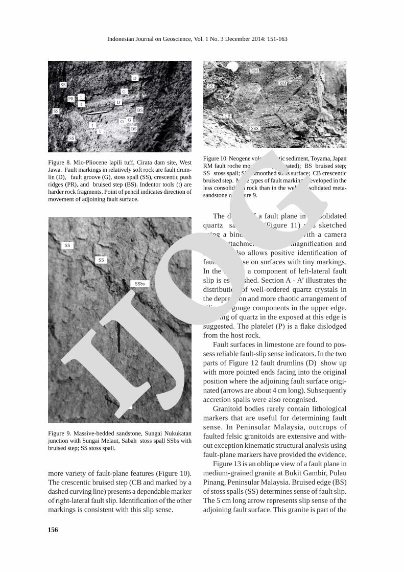
Figure 8. Mio-Pliocene lapili tuff, Cirata dam site, West Jawa. Fault markings in relatively soft rock are fault drum-lin (D), fault groove (G), stoss spall (SS), crescentic push ridges (PR), and bruised step (BS). Indentor tools (t) are harder rock fragments. Point of pencil indicates direction of movement of adjoining fault surface.
SS
SS
D
D
G
G G
PR
t
t
t
t
BS
BS
SS
Figure 10. Neogene volcaniclastic sediment, Toyama, JapanRM fault roche moutonnee (elongated); BS bruised step; SS stoss spall; SSS smoothed stoss surface; CB crescentic bruised step. More types of fault markings developed in the less consolidated rock than in the well-consolidated meta-sandstone of Figure 9.
RM
RM
SS
CB
SSS
Figure 9. Massive-bedded sandstone, Sungai Nukukatan junction with Sungai Melaut, Sabah stoss spall SSbs with bruised step; SS stoss spall.
more variety of fault-plane features (Figure 10). The crescentic bruised step (CB and marked by a dashed curving line) presents a dependable marker of right-lateral fault slip. Identification of the other markings is consistent with this slip sense.
SS
SS
SSbs
SS
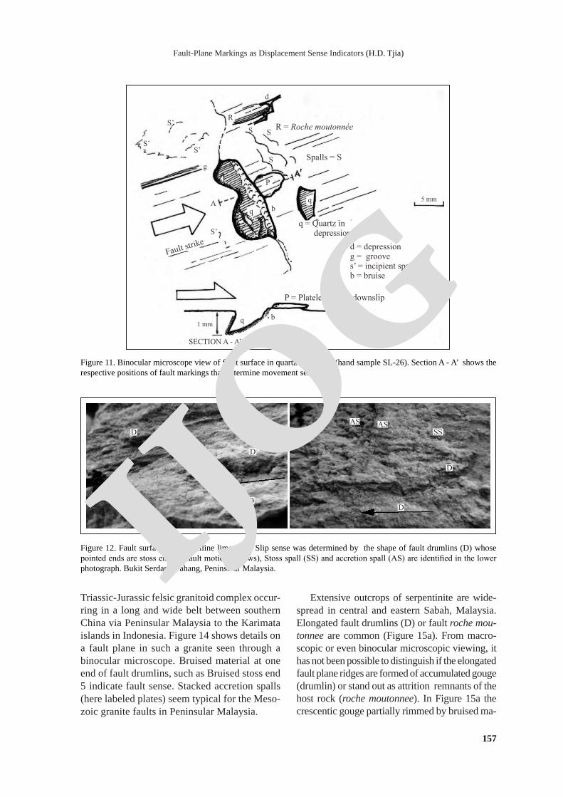
The details of a fault plane in consolidated quartz sandstone (Figure 11) was sketched using a binocular microscope with a camera lucida attachment. Its high magnification and 3D view also allows positive identification of fault-slip sense on surfaces with tiny markings. In the sketch, a component of left-lateral fault slip is established. Section A - A’ illustrates the distribution of well-ordered quartz crystals in the depression and more chaotic arrangement of siliceous gouge components in the upper edge. Bruising of quartz in the exposed at this edge is suggested. The platelet (P) is a flake dislodged from the host rock.
Fault surfaces in limestone are found to pos-sess reliable fault-slip sense indicators. In the two parts of Figure 12 fault drumlins (D) show up with more pointed ends facing into the original position where the adjoining fault surface origi-nated (arrows are about 4 cm long). Subsequently accretion spalls were also recognised.
Granitoid bodies rarely contain lithological markers that are useful for determining fault sense. In Peninsular Malaysia, outcrops of faulted felsic granitoids are extensive and with-out exception kinematic structural analysis using fault-plane markers have provided the evidence.
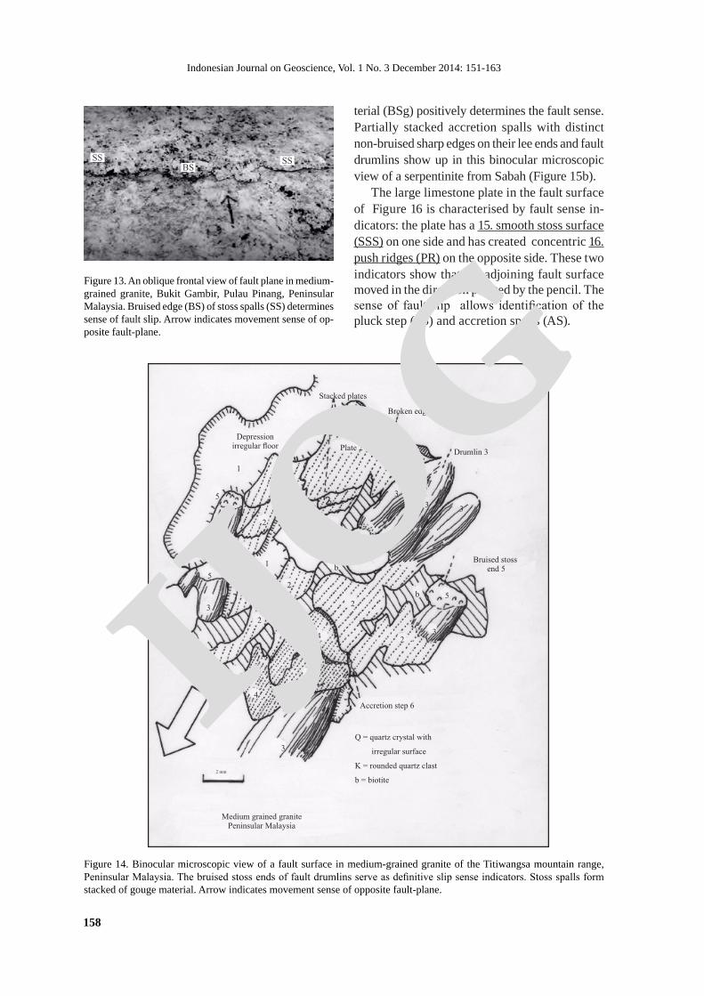
Figure 13 is an oblique view of a fault plane in medium-grained granite at Bukit Gambir, Pulau Pinang, Peninsular Malaysia. Bruised edge (BS) of stoss spalls (SS) determines sense of fault slip. The 5 cm long arrow represents slip sense of the adjoining fault surface. This granite is part of the
IJOG
Fault-Plane Markings as Displacement Sense Indicators (H.D. Tjia)
157
R = Roche moutonnée
Spalls = S
S S
S
S’
S’
S’
S’
A
d
R
g
q
q
q b
b
P
P = Platelet shifted downslip
1 mm
5 mm
SECTION A - A’
Fault strike
q = Quartz in depression
d = depressiong = grooves’ = incipient spallb = bruise
Figure 11. Binocular microscope view of fault surface in quartz sandstone (hand sample SL-26). Section A - A’ shows the respective positions of fault markings that determine movement sense.
D
D
SS
AS ASD
D
D
Figure 12. Fault surfaces in crystalline limestone. Slip sense was determined by the shape of fault drumlins (D) whose pointed ends are stoss ends to fault motion (arrows), Stoss spall (SS) and accretion spall (AS) are identified in the lower photograph. Bukit Serdam, Pahang, Peninsular Malaysia.
Triassic-Jurassic felsic granitoid complex occur-ring in a long and wide belt between southern China via Peninsular Malaysia to the Karimata islands in Indonesia. Figure 14 shows details on a fault plane in such a granite seen through a binocular microscope. Bruised material at one end of fault drumlins, such as Bruised stoss end 5 indicate fault sense. Stacked accretion spalls (here labeled plates) seem typical for the Meso-zoic granite faults in Peninsular Malaysia.
Extensive outcrops of serpentinite are wide-spread in central and eastern Sabah, Malaysia. Elongated fault drumlins (D) or fault roche mou-tonnee are common (Figure 15a). From macro-scopic or even binocular microscopic viewing, it has not been possible to distinguish if the elongated fault plane ridges are formed of accumulated gouge (drumlin) or stand out as attrition remnants of the host rock (roche moutonnee). In Figure 15a the crescentic gouge partially rimmed by bruised ma-
IJOG
Indonesian Journal on Geoscience, Vol. 1 No. 3 December 2014: 151-163
158
Bruised stoss end 5
Q
K
b
Spall 4
2 mm
Medium grained granitePeninsular Malaysia
Q = quartz crystal with
irregular surface
K = rounded quartz clast
b = biotite
1
1
2
2
2
2
2
2
2
2
2
2
3
3
3
3 3
3
3
5b
4
4
5
5
6
Accretion step 6
Stacked plates
Broken edge of plate
Drumlin 3Plate 2
Depression irregular floor
Figure 14. Binocular microscopic view of a fault surface in medium-grained granite of the Titiwangsa mountain range, Peninsular Malaysia. The bruised stoss ends of fault drumlins serve as definitive slip sense indicators. Stoss spalls form stacked of gouge material. Arrow indicates movement sense of opposite fault-plane.
SS BS
SS
Figure 13. An oblique frontal view of fault plane in medium-grained granite, Bukit Gambir, Pulau Pinang, Peninsular Malaysia. Bruised edge (BS) of stoss spalls (SS) determines sense of fault slip. Arrow indicates movement sense of op-posite fault-plane.
terial (BSg) positively determines the fault sense. Partially stacked accretion spalls with distinct non-bruised sharp edges on their lee ends and fault drumlins show up in this binocular microscopic view of a serpentinite from Sabah (Figure 15b).
The large limestone plate in the fault surface of Figure 16 is characterised by fault sense in-dicators: the plate has a 15. smooth stoss surface (SSS) on one side and has created concentric 16. push ridges (PR) on the opposite side. These two indicators show that the adjoining fault surface moved in the direction pointed by the pencil. The sense of fault slip allows identification of the pluck step (PS) and accretion spalls (AS).
IJOG

Fault-Plane Markings as Displacement Sense Indicators (H.D. Tjia)
159
Figure 15. Fault-plane markings in serpentinite of Lahad Data area, Sabah. The elongated fault drumlins (D) (a and b) only indicate slip direction; the bruised steps (BSg) (a) and crescentic gouge mark are the indicators for sense of slip sense (arrow). Arrow indicates movement sense of opposite fault-plane.
glomerate of Jurassic-Cretaceous age. The fault slip sense (arrow) is determined from the disposition of the crescentic depression and the crag-and-tail feature complete with the groove track that marks the crag’s progress. The 17. scoop depressions (Sc) do not appear indicative of slip sense and are only elongated in the direction of fault movement. Some of the fault drumlins have 18. sheath-like features (labeled as ‘peel-offs’ in the sketch) on their lee-sides. The vein quartz of Figure 17b is part of a very large dyke of the same material. The more than 17-km long dyke invaded a strand of the Kuala Lumpur fault zone . In turn the quartz dyke became faulted. One of the fault surfaces displays rugged microtopography of fault roche moutonnee (labeled 7) and/or fault drumlins (2 in the sketch) with pointed ends and bruising on the stoss ends. Subsequent to this positive slip sense identification, pluck and accretion steps could also be recognised.
Sometimes heat generated by faulting is sufficient to also remelt minerals other than quartz or those of the carbonate group. Spray (1989) reported on slickenside formation associated with heating. Figure 18 is a fault surface in the Bukit Gambir granite and asymmetric disposition of darker coloured minerals form 19. mineral streaks (MS). The dark minerals (probably biotite) streak out into pointed ends toward the lee-side of fault
PS
SSS
PR
AS
P
AS
Figure 16. A large plate of limestone embedded in the fault plane has slip sense indicators: a smooth stoss surface (SSS) and push ridges (PR) on the opposite side. Both are consistent with motion in the direction pointed by the 10-cm long arrow . Pluck step (PS) and accretion spalls (AS) can then be identified. Wariu Formation, Sabah. Arrow indicates movement sense of opposite fault-plane.
Two uncommon fault surfaces are shown in Figures 17a and 17b. The left microscopic view is a fault surface in a consolidated con-
D
PS
PS
BSg
D
D
D
D
a
Sense of motion
5 mmSL-22 Serpentinite
Gouge film
Gouge film
Drumlin
Drumlin
Spall
Spall
RidgeRidge
Depression
Accretion spall
Depression
b
IJOG

Indonesian Journal on Geoscience, Vol. 1 No. 3 December 2014: 151-163
160
Results and Discussion
Preservation of Multiple Fault-slip EventsConventional wisdom leads us to assume that
markings on fault only represent a record of the latest faulting event as those of earlier events were obliterated. This is not always the case. Figure 19 is a case in point. On a subvertical inclined fault surface in gneissic granite at Bukit Tinggi, Pahang, Peninsular Malaysia, markings belonging to two fault-slip directions have been preserved. The down-dip faulting event most probably represent the earlier faulting episode as its markings are less prominent. Its markings are represented by bruised steps (BR1) extending subhorizontally across the fault plane. Markings by the second event point to fault slip diverging about 40 degrees from that of the earlier event. The later fault slip produced a well-developed crescentic gouge (CG2), fault roche moutonnee (RM), and fine striations. The smaller Figure 19 is a plan view of part of the fault zone that strikes Northwest. The respective orientation of
motion. The MS patch of reddish hue may only represent rust staining but its lee edge also ap-pears smeared out.
Figure 17. (a). Fault surface with markings in a consolidated Jurassic-Cretaceous conglomerate. Slip sense is determined by the crag-tail-furrow combination, crescentic gouge/depression and unusual shape of fault drumlins. The lee end of the fault drumlins is adorned with a sheath-like gouge feature. This is a binocular stereoscopic image drawn using a camera lucida attachment. (b). Vein quartz forms the very large Genting Kelang dyke bordering the north edge of the Kuala Lumpur metropolis of Peninsular Malaysia. This binocular microscopic view of a fault surface show fault-slip sense indicators in the form of fault roche moutonnee, the disposition of its bruised step, accretion step/spall, and pluck step. Arrow indicates movement sense of opposite fault-plane.
Figure 18. A fault surface in a granite massif at Bukit Gambir, Pinang Island, Malaysia. Mineral streaks (MS) of probably biotite have pointed ends in the direction of movement of the adjoining fault plane. The rusty brown MS patch owes its co-lour to weathering of Fe-ion components of the rock. The stoss end of this patch is sharper delineated than its opposite edge. Arrow indicates movement sense of opposite fault-plane.
BSMS
MS
MS
TrailTool (quartz grain)
Groove G
Crescenticdepression
Scoop depression
Sc
P
P
D
D
D
D
D
D
DDSense of motion
Peel offP
Drumlin
Conglomerate, Parit SulungHD-136
0 1 2 3 4 5 6
mm
aDepression 1
Knife-back roche mouonee 2Groove
Bruise step
Pluck step
Accretion step
Sen
se o
f m
otio
n
Roche mouonee
4 mm
Vein quartz, Genting Kelang
7
6
7
2
6
5
2
4
3
2
2
2
7 7
4 4 4
33
7
1
1
1
1
1 2
1
2
1
2
6 1
7
4
b
IJOG

Fault-Plane Markings as Displacement Sense Indicators (H.D. Tjia)
161
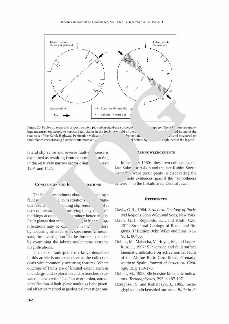
provide data for structural analysis. The Karak Highway cuts across the Titiwangsa Range and its Triassic-Jurassic granitoid core. Slip sense on fault planes were determined and pitch of the fault striations were plotted on a lower hemisphere equal-area projection. The majority of fault striation pitches are very low, including that of one reverse slip. Quartz veins plotted as poles to their respective surfaces dip vertical. The pattern of lateral slips and reverse slip are consistent with a maximum principal stress, or SHmax, acting along 50o - 230o direction.
The intensely fractured serpentinite body at Luhan near Ranau in central Sabah, was analysed using fault-plane markings. The equal-area plot shows a variety of slip-sense pitches ranging from horizontal to very steep inclination. Among the latter are two dip slip pitches. The pattern of
en echelon fractures within the zone indicates left-lateral slip, confirming interpretation based on conventional field mapping by Shu (1989). A score of weak earthquake epicenters (2007 - 2008) are located in the fault zone.
Using Fault-plane Markings in Structural Analysis
In tropical terrains faults are usually difficult to trace due to burial by debris, soil and heavy vegetative cover. Fresh-rock outcrops are mostly found in rivers and in fresh road cuts which are also of limited extent. The same limitations ap-ply to subsurface geological work in mining and engineering tunnels. For instance, the correct identification of slip sense will allow effective pursuit of a fault-displaced ore vein. Figure 20 are two examples in which fault-plane markings
Figure 19. The Bukit Tinggi Fault Zone is exemplified by one of its fault surfaces and its plan view (smaller photograph). Fault markings representing slip sense in directions diverging about 40 degrees from each other were identified as bruise step of an earlier generation bruised step (BS1) of downdip sense and better preserved second faulting event of oblique normal slip that produced bruise step 2 (BS2) and a prominent crescentic gouge (CG2). The plan view shows a meter-wide strand of the fault zone striking Northwest. Within the fault strand are en echelon fractures formed by left-lateral slip on the main fault (white line).
R M 2EE
BS1
B S 2
CG 2
BS1
BS2 Trend Bukit Tinggi FZ
IJOG
Indonesian Journal on Geoscience, Vol. 1 No. 3 December 2014: 151-163
162
lateral slip sense and reverse fault-slip sense is explained as resulting from compression acting in the relatively narrow sector oriented between 120o and 142o.
Conclusion and Recommendations
The feel of smoothness obtained by stroking a fault surface parallel to its striations yield ambigu-ous results for determining slip sense. Instead it is recommended that identifying the type of fault markings at outcrops will produce better results. Fault planes that require viewing at higher mag-nifications may be examined in the laboratory by acquiring oriented hand specimens. If neces-sary, the investigation can be further expanded by examining the fabrics under more extreme magnifications.
The list of fault-plane markings described in this article is not exhaustive as the collection deals with commonly occurring features. Where outcrops of faults are of limited extent, such as in underground exploration and in trenches exca-vated in areas with “float” as overburden, correct identification of fault -plane markings is the practi-cal effective method in geological investigations.
Acknowledgements
In the early 1960s, these two colleagues, the late Sukendar Asikin and the late Rubini Soeria Atmadja, were participants in discovering the initial field evidences against the “smoothness criterion” in the Lokulo area, Central Jawa.
References
Davis, G.H., 1984. Structural Geology of Rocks and Regions. John Wiley and Sons, New York.
Davis, G.H., Reynolds, S.J., and Kluth, C.F., 2011. Structural Geology of Rocks and Re-gions. 3rd Edition, John Wiley and Sons, New York, 864pp.
Doblas, M., Mahecha, V., Hoyos, M., and Lopez-Ruiz, J., 1997. Slickenside and fault surface kinematic indicators on active normal faults of the Alpine Betic Cordilleras, Grenada, southern Spain. Journal of Structural Geol-ogy, 19, p.159-170.
Doblas, M., 1998. Slickenside kinematic indica-tors. Tectonophysics, 295, p.187-197.
Dzulynski, S. and Kotlarczyk, J., 1965. Tecto-glyphs on slickensided surfaces. Bulletin de
Figure 20. Fault-slip sense and respective pitch plotted on equal-area projection, lower hemisphere. The left figure are mark-ings measured on steeply to vertical fault planes in the felsic granitoid of the Titiwangsa Range and exposed in one of the road cuts of the Karak Highway, Peninsular Malaysia. The right-hand plot contains markings determined and measured on fault planes crisscrossing a serpentinite mass at Luhan near Ranau in central Sabah. Symbols are explained in the legend.
Karak HighwayTitiwangsa granitoid
Luhan, SabahSerpentinite
SHmax
o142
o122
NN
o50
SHmax
Quatrz vein
o230
Right slip Reverse slip
Left slip Normal slip
IJOG

Fault-Plane Markings as Displacement Sense Indicators (H.D. Tjia)
163
l’Academie Polonaises des Sciences, Serie Geologie et Geographie, 17 (2), p.149-154.
Norris, D.K. and Barron, K., 1968. Structural analysis of features on natural and artificial faults. In: Baer, A.J. and Norris, D.K. (eds.), Proceedings Conference on Research in Tec-tonics, Geological Society of Canada, Paper, 68 (52), p.136-167.
Gay, N.C., 1970. The formation of step structures on slickensided shear surfaces. Journal of Geology, 78, p.523-532.
Paterson, M.S., 1958. Experimental deformation of Wombeyan marble. Bulletin Geological Society of America, 69, p.465-476.
Petit, J-P., 1976. La zone de decrochements du Tizi n’ Test (Maroc) et son fonctionnement depuis le Carbonifere. These, Universite des Sciences et Techniques du Languedoc, 99pp.
Petit, J-P., 1987. Criteria for the sense of move-ment on fault surfaces in brittle rocks. Journal of Structural Geology, 9, p.597-608.
Petit, J-P., Proust, F. and Tapponnier, P., 1983. Critere du sens du mouvement sur les mirroirs de failles en roches noncalcaires. Bulletin de la Societe geologique de France, 7, p.589-608.
Riecker, R.F., 1965. Fault-plane features, and alternative explanation. Journal Sedimentary Petrology, 35 (3), p.746-748.
Sander, B., 1970. An Introduction To The Study Of Fabrics Of Geological Bodies. Pergamon, Oxford, 631pp.
Shu, Y. K., 1989. The Geology and Mineral Re-sources of the Kuala Kelawang Area, Jelebu, Negeri Sembilan. Geological Survey of Ma-laysia, District Memoir, 20, 208pp.
Spray, J.G., 1989. Slickenside formation by sur-face melting during the mechanical excavation of rock. Journal of Structural Geology, 11 (7), p.895-905.
Tjia, H.D., 1964. Slickensides and fault move-ments. Bulletin Geological Society of Ameri-ca, 75, p.683-686.
Tjia, H.D., 1966. Structural analysis of the Pre-Tertiary of the Lokulo area, Central Java. Institut Teknologi Bandung, Contributions from the Department of Geology, 63, 110pp.
Tjia, H.D., 1967. Sense of fault displacements. Geologie en Mijnbouw, 48, p.392-396.
Tjia, H.D., 1968. Fault-plane markings. XXIII International Geological Congress, Prague, Czechoslovakia, 13, p.279-284.
Tjia, H.D., 1972. Fault movement, reoriented stress field and subsidiary structures. Pacific Geology, 5, p.49-70.
Tjia, H.D., 1994. Kinematic analysis of striated features in Titiwangsa granitoid, Karak High-way - Selangor sides. Geological Society of Malaysia Bulletin, 35, p.25-35.
Tjia, H.D., 1997. The Kuala Lumpur fault zone revisited. Warta Geologi, 23 (4), p.225-230.
Tjia, H.D., 1998. Fault-sense indicators - A field guide. Workshop of GEOSEA ’98, Ninth Regional Congress on Geology, Mineral and Energy Resources of Southeast Asia, Kuala Lumpur, Malaysia, 19pp.
Uemura, T., 1977. Fault-plane features and pro-cess of faulting. Journal Geological Society of Japan, 83 (2), p.811-820.
Ui, H., 1973. Mechanical properties and fault-plane features of Shidara sandstone in uniaxial compression tests. Journal of Earth Science, Nagoya University, 21, p.59-71.
Wilson, G., 1982. Introduction to Small-scale Geological Structures. George Allen and Unwin, London: Chapter 5.IJOG
Related Documents