4/6/2014 1 EPMN 302: ELEMENTS OF POWER SYSTEMS Dr. Mostafa Elshahed 1 OBJECTIVES Learn a brief history of the electrical power systems construction List and describe different components of electrical power systems Learn the per-unit system calculations Draw the single line and impedance diagram Define the transformers and synchronous machines representations Calculate the transmission lines parameters Formulate the various transmission lines models Establish the transmission lines performance Calculate the symmetrical faults variables Learn the principles of symmetrical components transformations Calculate the unsymmetrical faults variables 2

Welcome message from author
This document is posted to help you gain knowledge. Please leave a comment to let me know what you think about it! Share it to your friends and learn new things together.
Transcript
4/6/2014
1
EPMN 302: ELEMENTS OF
POWER SYSTEMS
Dr. Mostafa Elshahed1
OBJECTIVES
Learn a brief history of the electrical power systems construction
List and describe different components of electrical power systems
Learn the per-unit system calculations
Draw the single line and impedance diagram
Define the transformers and synchronous machines representations
Calculate the transmission lines parameters
Formulate the various transmission lines models
Establish the transmission lines performance
Calculate the symmetrical faults variables
Learn the principles of symmetrical components transformations
Calculate the unsymmetrical faults variables
2
4/6/2014
2
TRANSMISSION LINES
PARARMATERS3
To develop models of transmission lines, we first need to determine the TL parameters.
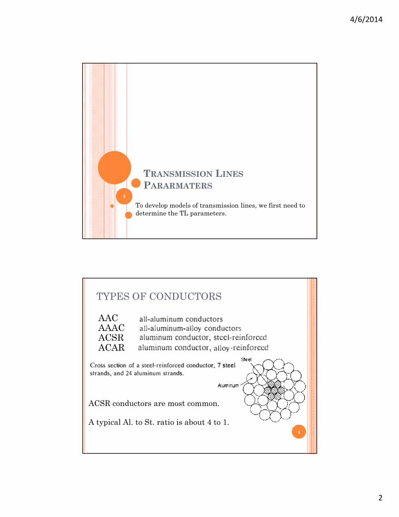
TYPES OF CONDUCTORS
4
ACSRAAACAAC
ACAR
ACSR conductors are most common.
A typical Al. to St. ratio is about 4 to 1.
4/6/2014
3
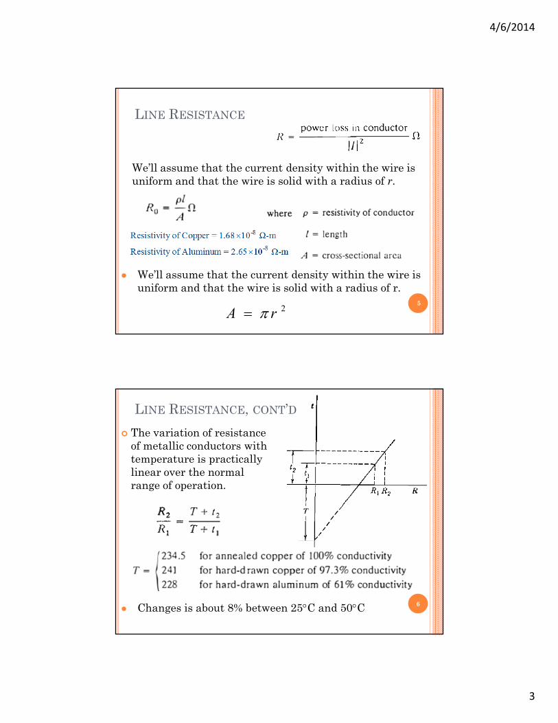
LINE RESISTANCE
5
We’ll assume that the current density within the wire is uniform and that the wire is solid with a radius of r.
We’ll assume that the current density within the wire is uniform and that the wire is solid with a radius of r.
2rA
The variation of resistance of metallic conductors with temperature is practically linear over the normal range of operation.
6
LINE RESISTANCE, CONT’D
Changes is about 8% between 25C and 50C

4/6/2014
4
LINE RESISTANCE, CONT’D
Uniform distribution of current throughout the cross
section of a conductor exists only for DC.
Because ac current tends to flow towards the surface of
a conductor, the resistance of a line at 50 Hz is slightly
higher than at dc.
An increase in frequency causes non uniform current
density.
This phenomenon is called skin effect.
7
INDUCTANCE OF A SINGLE WIRE
The lines of magnetic flux form closed loops linking the
circuit, and the lines of electric flux originate on the
positive charges on one conductor and terminate on the
negative charges the other conductor.
8
4/6/2014
5
INDUCTANCE OF A SINGLE WIRE
9
Variations of the current in the conductors causes a
change in the number of lines of magnetic flux linking
the circuit.
Any change in the flux linking a circuit induces a
voltage in the circuit which is proportional to the rate of
change of flux.
The inductance of the circuit relates the voltage induced
by changing flux to the rate of change of current.
INDUCTANCE OF A SINGLE WIRE
To do this we need to determine the wire’s total flux
linkage, including:
Flux linkages within the wire (Internal)
Flux linkages outside of the wire (External)
We’ll assume that the current density within the wire is
uniform and that the wire is solid with a radius of r.
10

4/6/2014
6
INDUCTANCE OF A CONDUCTOR DUE TO FLUX
11
Internal
External
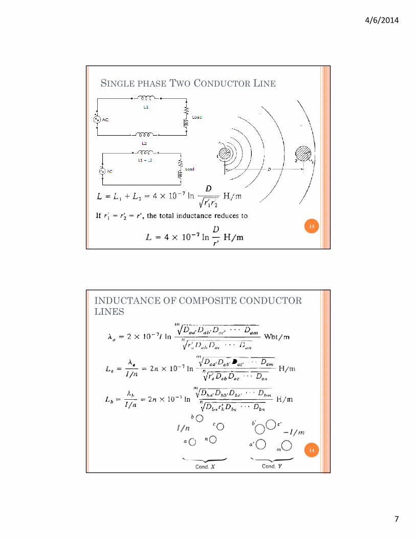
SINGLE PHASE TWO CONDUCTOR LINE
12
r‘ = Geometric mean radius
4/6/2014
7
SINGLE PHASE TWO CONDUCTOR LINE
13
INDUCTANCE OF COMPOSITE CONDUCTOR LINES
14

4/6/2014
8
INDUCTANCE OF COMPOSITE CONDUCTOR LINES
15
Numerator ≡ Geometric Mean Distance (GMD) ≡ Dm
Denominator ≡ Geometric Mean Radius (GMR) ≡ Ds
INDUCTANCE OF COMPOSITE CONDUCTOR LINES
16
4/6/2014
9
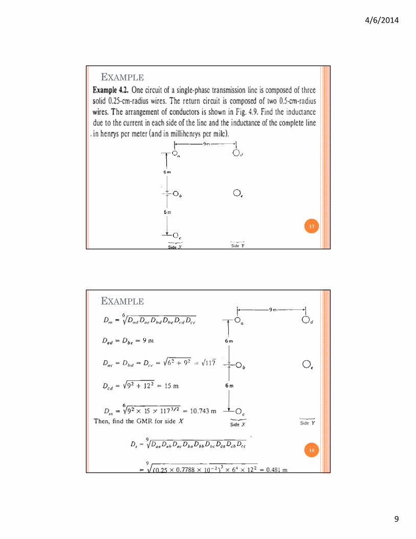
EXAMPLE
17
EXAMPLE
18
4/6/2014
10
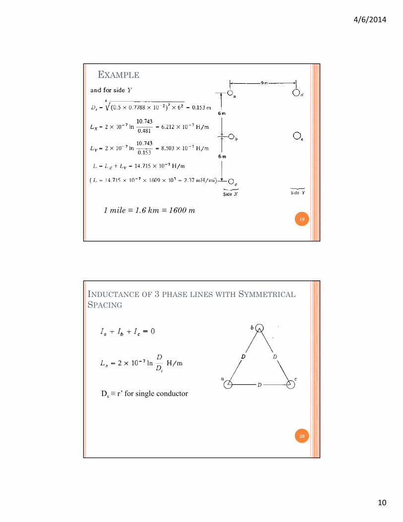
EXAMPLE
19
1 mile = 1.6 km = 1600 m
INDUCTANCE OF 3 PHASE LINES WITH SYMMETRICAL
SPACING
20
Ds ≡ r’ for single conductor
4/6/2014
11
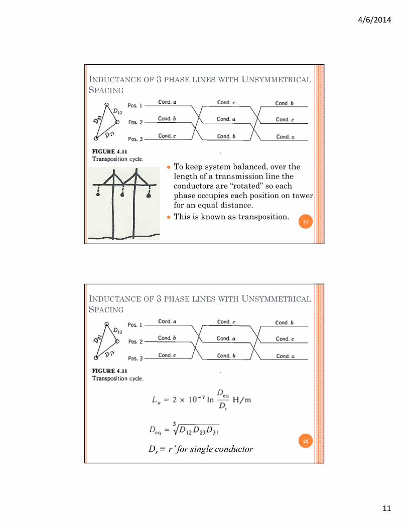
INDUCTANCE OF 3 PHASE LINES WITH UNSYMMETRICAL
SPACING
21
To keep system balanced, over the length of a transmission line the conductors are “rotated” so each phase occupies each position on tower for an equal distance.
This is known as transposition.
INDUCTANCE OF 3 PHASE LINES WITH UNSYMMETRICAL
SPACING
22
Ds ≡ r’ for single conductor
4/6/2014
12
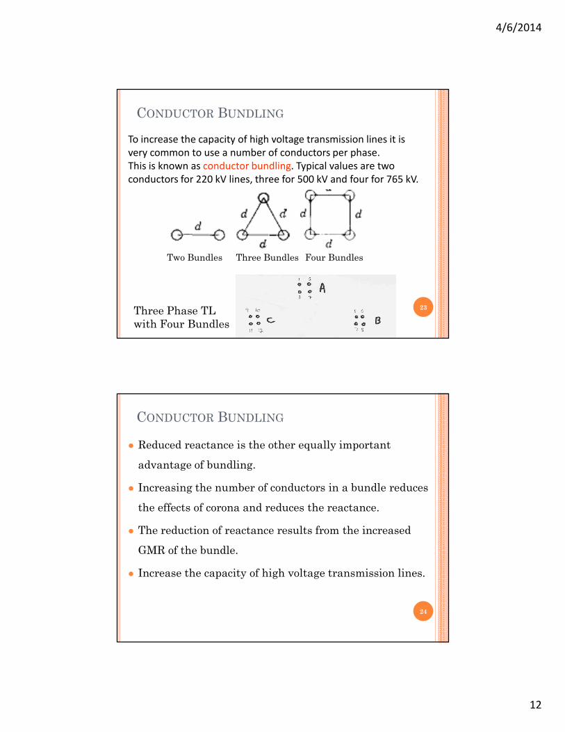
CONDUCTOR BUNDLING
23
To increase the capacity of high voltage transmission lines it is very common to use a number of conductors per phase. This is known as conductor bundling. Typical values are two conductors for 220 kV lines, three for 500 kV and four for 765 kV.
Two Bundles Three Bundles Four Bundles
Three Phase TL with Four Bundles
CONDUCTOR BUNDLING
24
Reduced reactance is the other equally important
advantage of bundling.
Increasing the number of conductors in a bundle reduces
the effects of corona and reduces the reactance.
The reduction of reactance results from the increased
GMR of the bundle.
Increase the capacity of high voltage transmission lines.
4/6/2014
13
CONDUCTOR BUNDLING
25Dsb ≡ GMR of a Bundled Conductor (Bundles)
Ds ≡ GMR of a Single Conductor (a Bundle) ≡ r’
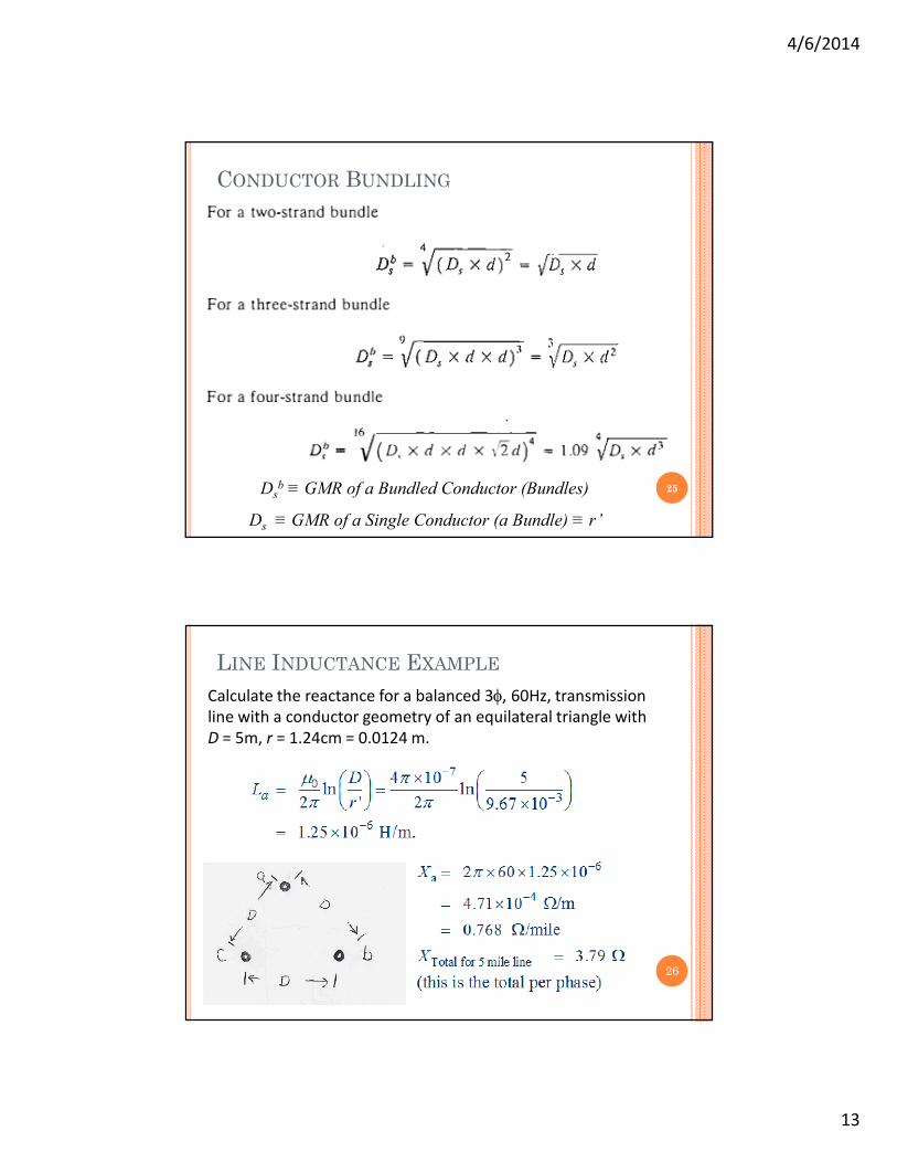
LINE INDUCTANCE EXAMPLE
Calculate the reactance for a balanced 3, 60Hz, transmission line with a conductor geometry of an equilateral triangle withD = 5m, r = 1.24cm = 0.0124 m.
26
4/6/2014
14
0.25 M0.25 M
0.25 M
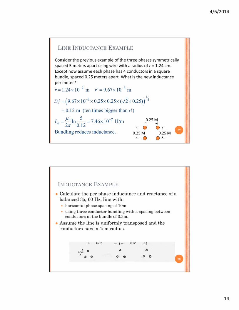
Consider the previous example of the three phases symmetrically spaced 5 meters apart using wire with a radius of r = 1.24 cm. Except now assume each phase has 4 conductors in a square bundle, spaced 0.25 meters apart. What is the new inductance per meter?
2 3
13 4
70
1.24 10 m ' 9.67 10 m
9.67 10 0.25 0.25 ( 2 0.25)
0.12 m (ten times bigger than !)
5ln 7.46 10 H/m
2 0.12
Bundling reduces inductance.
b
a
r r
R
r
L
27
LINE INDUCTANCE EXAMPLE
Dsb
INDUCTANCE EXAMPLE
Calculate the per phase inductance and reactance of a balanced 3, 60 Hz, line with:
horizontal phase spacing of 10m
using three conductor bundling with a spacing between conductors in the bundle of 0.3m.
Assume the line is uniformly transposed and the conductors have a 1cm radius.
28

4/6/2014
15
INDUCTANCE EXAMPLE
29
Dsb
Dsb
Deq
ACSR TABLES Because ACSR conductors are stranded, actual resistance,
inductance, and capacitance needs to be determined from tables.
30
Inductance and Capacitance assume a geometric mean distance Deq of 1 ft.
GMR is equivalent toeffective radius r’