INSTALLATION INSTRUCTIONS INDIGO ELECTRONICS AT-4CE FRESH WATER COOLING – ELECTRIC PUMP ATOMIC 4 CAUTION The electric pump(s) contained in this kit must be full of fluid before applying power and attempting to be operated. The bearing system for the rotor is lubricated by the fluid and will be damaged if operated without being flooded with the fluid. See the Start-Up paragraph (16) later in the instructions. Engine Preparation Performance and reliability of the Atomic 4 can be enhanced during the fresh water cooling conversion by addressing three areas: Cooling water passages Existing water pump Existing water hoses Cooling water passages suffer from corrosion and salt build up when sea water is used to cool the engine directly. If no serious cooling problems have occurred, a minor cleaning of the passages should be sufficient. This would include removing both the plate on the starboard side of the block where cooling water is introduced to the block and the thermostat housing. With these removed, the exposed areas can be mechanically cleaned of loose rust and scale. Back flushing with pressurized fresh water through the thermostat opening is also recommended to promote flushing rust and scale and also to verify that the cooling passages between block and head are open. Back flush the exhaust manifold as well by introducing pressurized fresh water (Do not exceed about 7 psi as higher pressures may cause a failure of the block, head or manifold ) into the discharge fitting on the aft end of the manifold. If the above recommendations do not yield unobstructed water flow, it may be necessary to conduct more extensive cleaning such as a Muriatic Acid Flush. To begin this process, remove the thermostat and pinch off the bypass hose (the one that runs from the clean out plate on the alternator side of the block to the thermostat housing) with vise grip pliers or similar. Then, mix a solution of 1/3 gallon of Muriatic Acid to 5 gallons of water and then filling the block, head and manifold with the mixture by running a hose from the original water pump suction to the bucket of diluted acid and running the engine. Once the engine cooling passages are full of the mixture, stop the engine and allow the mixture to work on the engine for 30 minutes. Then flush with fresh water and repeat one or more times until the mixture has little reaction within the engine. Restore thermostat unless installing an Indigo Thermostat Kit. New Antifreeze Pump With any Fresh Water Cooling System, there must be a pump for the seawater and a pump for the antifreeze. With this system, the existing pump remains the seawater pump and a new electric pump is installed to circulate the antifreeze. The pump chosen for this system is a Johnson Model CM30P7- 1 and was designed specifically for circulating hot antifreeze. It is a centrifugal pump of a low pressure, high flow design and is not self priming . For this reason, the pump should be mounted low relative to the heat exchanger and engine. An excellent location is on top of the transmission cover. By mounting the pump low, any small loss of antifreeze will create an air pocket in the top of the antifreeze loop and will not cause the pump to lose suction and stop circulating antifreeze For this system on the Atomic 4, it is recommended that several hose and fitting changes be made to allow for the highest flow of antifreeze. (NOTE: If the seawater in your area stays below 70F at all times and you DO NOT elect to install an Indigo Thermostat Kit, the existing hoses and fittings will be satisfactory). These recommended changes are: a. On Late Model Engines, replace the hose and fittings between the thermostat housing and the exhaust manifold. Currently the hose is ½” ID. It should be replaced with a 5/8” ID hose. This will require replacement of the hose barb fitting at the thermostat housing and the hose barb fitting at the exhaust manifold. Fittings and hose clamps are

Welcome message from author
This document is posted to help you gain knowledge. Please leave a comment to let me know what you think about it! Share it to your friends and learn new things together.
Transcript

INSTALLATION INSTRUCTIONS
INDIGO ELECTRONICS AT-4CE FRESH WATER COOLING – ELECTRIC PUMP ATOMIC 4
CAUTION The electric pump(s) contained in this kit must be full of fluid before applying power and attempting to be operated. The bearing system for the rotor is lubricated by the fluid and will be damaged if operated without being flooded with the fluid. See the Start-Up paragraph (16) later in the instructions. Engine Preparation Performance and reliability of the Atomic 4 can be enhanced during the fresh water cooling conversion by addressing three areas:
Cooling water passages Existing water pump Existing water hoses
Cooling water passages suffer from corrosion and salt build up when sea water is used to cool the engine directly. If no serious cooling problems have occurred, a minor cleaning of the passages should be sufficient. This would include removing both the plate on the starboard side of the block where cooling water is introduced to the block and the thermostat housing. With these removed, the exposed areas can be mechanically cleaned of loose rust and scale. Back flushing with pressurized fresh water through the thermostat opening is also recommended to promote flushing rust and scale and also to verify that the cooling passages between block and head are open. Back flush the exhaust manifold as well by introducing pressurized fresh water (Do not exceed about 7 psi as higher pressures may cause a failure of the block, head or manifold) into the discharge fitting on the aft end of the manifold. If the above recommendations do not yield unobstructed water flow, it may be necessary to conduct more extensive cleaning such as a Muriatic Acid Flush. To begin this process, remove the thermostat and pinch off the bypass hose (the one that runs from the clean out plate on the alternator side of the block to the thermostat housing) with vise grip pliers or similar. Then, mix a solution of 1/3 gallon of Muriatic Acid to 5 gallons of water and then filling the block, head
and manifold with the mixture by running a hose from the original water pump suction to the bucket of diluted acid and running the engine. Once the engine cooling passages are full of the mixture, stop the engine and allow the mixture to work on the engine for 30 minutes. Then flush with fresh water and repeat one or more times until the mixture has little reaction within the engine. Restore thermostat unless installing an Indigo Thermostat Kit. New Antifreeze Pump With any Fresh Water Cooling System, there must be a pump for the seawater and a pump for the antifreeze. With this system, the existing pump remains the seawater pump and a new electric pump is installed to circulate the antifreeze. The pump chosen for this system is a Johnson Model CM30P7-1 and was designed specifically for circulating hot antifreeze. It is a centrifugal pump of a low pressure, high flow design and is not self priming. For this reason, the pump should be mounted low relative to the heat exchanger and engine. An excellent location is on top of the transmission cover. By mounting the pump low, any small loss of antifreeze will create an air pocket in the top of the antifreeze loop and will not cause the pump to lose suction and stop circulating antifreeze For this system on the Atomic 4, it is recommended that several hose and fitting changes be made to allow for the highest flow of antifreeze. (NOTE: If the seawater in your area stays below 70F at all times and you DO NOT elect to install an Indigo Thermostat Kit, the existing hoses and fittings will be satisfactory). These recommended changes are:
a. On Late Model Engines, replace the hose and fittings between the thermostat housing and the exhaust manifold. Currently the hose is ½” ID. It should be replaced with a 5/8” ID hose. This will require replacement of the hose barb fitting at the thermostat housing and the hose barb fitting at the exhaust manifold. Fittings and hose clamps are

2
provided in the kit. Early Model Engines cannot be readily modified. b. Replace the discharge hose and fitting on the exhaust manifold with 5/8” ID hose if necessary. It may already be 5/8” ID.
Domestic Hot Water Heating
Installation of a Domestic Hot Water Heater in the antifreeze loop is possible with the Johnson Model CM30P7-1 pump provided ¾” ID hoses are run to and from the connections on the HW tank to minimize flow losses in that part of the antifreeze loop. Additionally, the elevation of the HW tank relative to the new Heat Exchanger must be taken into consideration. If the HW tank is higher than the new Heat Exchanger (normal highest point in the antifreeze loop), then a provision MUST be made to continuously vent the antifreeze loop to the HW tank to prevent if from becoming Air Locked. The most effective means for maintaining such a continuous vent is the incorporation of a Head Tank . A Head Tank is nothing more than a small tank that is placed at the highest point in the system and has a pressure/vacuum relief cap on it like on an automotive radiator.. Any air trapped in the pressurized system will thus find its way to the Head Tank and be expelled during subsequent heating coolant cycles. As in an automotive setup, there will need to be a coolant recovery bottle attached to the Head Tank. Head Tanks are commercially available.
The existing water pump will remain the seawater pump with the discharge hose re-routed to the Heat Exchanger. The pump should be opened and the impeller inspected. If any vanes are torn or show signs of distress, the impeller should be replaced. It is best to replace the cover gasket to prevent a future leak.
NOTE: The original style pumps (both Oberdorfer and Sherwood) do not have bearings. The shaft is positioned by the pump housing itself and as such, will cause the lip seal to leak seawater as the pump housing wears. Moyer Marine Inc.
(www.moyermarine.com) now offers a replacement pump which does have bearings and is a far superior replacement pump.
Any existing water hoses that do not get replaced as a part of this installation should be replaced if more than a year or two old.
Heat Exchanger
1. Determine an appropriate location for the heat exchanger. Vertical mounting is preferred but it can be mounted at up to 45 degrees off vertical with the fill cap being at the highest point. When choosing a location, consider the following:
The Heat Exchanger should be as close to the engine as possible to keep hose runs to a minimum. Elevation of the Heat Exchanger relative to the engine should preferably be such that the fill cap is at the highest point. The coolant level will require checking periodically so access to the pressure cap should be considered. An automotive type coolant recovery kit is provided to aid in this periodic check. A consumable anode is installed in the heat exchanger which must be accessible for annual replacement. Orient heat exchanger for access. Four hose connections will be made (two seawater, two antifreeze). Consider these when orienting Heat Exchanger.
2. Mount Heat Exchanger with brackets provided. Mount angle iron bracket to vertical or angled surface selected for Heat Exchanger location. Fasteners will be required (not supplied in kit) to attach bracket to vessel as so many possibilities exist that a standard package is impractical. Stainless steel 1/4" through bolts with lock washer and nut are recommended. The two large circular clamps fit around the 3.2" diameter part of the Heat Exchanger about 6" apart. Be sure to orient the Heat Exchanger for optimum location of hose connections. It may be necessary to

3
obtain and install brass ½” nipples and 90° elbows to obtain desired orientation. Using 1/2" open or box end wrenches, attach each circular bracket to angle iron bracket using 5/16 x 1 1/2" bolts, lock washers, and nuts (provided in kit). The larger diameter holes in the bracket are used with each 5/16 x 1 1/2" bolt passing through both "ears" on the circular bracket and then through the hole in the angle iron bracket before receiving the lock washer and nut. Tighten 5/16" bolts to lock Heat Exchanger in position. New Antifreeze Pump Installation Shown below are two possible configurations of pump installation. The most basic is the single pump configuration. For convenience a ¾ x ½ hose barb connector is supplied to facilitate installation.
Single Pump Configuration For redundancy and complete piece of mind with regard to the electric pump, a dual pump series configuration is shown. In this case, both pumps are permanently installed but only one is fused and running at a time. If the first pump should fail, the second can be fused and operation restored.
Dual Pump - Series Configuration 3. The new antifreeze pump can easily be mounted “in line” between the lower antifreeze fitting on the Heat Exchanger and the coolant inlet to the block on the side clean-out plate. The suction and discharge connections on the new pump are both sized to accommodate ¾” ID hose. Location of the pump should be such that the hose runs are as short as possible and the wiring on the motor can readily reach the ignition coil. About 3 foot long leads are supplied. 4. If hose routing permits, install a ½ NPT x ¾ hose fitting (provided in kit) into the lower heat exchanger connection using pipe dope on threads. If routing is a problem, provide and install appropriate fittings to facilitate routing. Be sure to hold back on the hex portion of the female connection on the Heat Exchanger with a wrench when tightening fittings. 5. Once a location has been identified for the pump, a piece of ¾” ID heater hose should be run from the Heat Exchanger fitting previously installed to the suction connection on the end of the new pump (opposite the end where the wiring enters the motor). Then a piece of ¾” ID heater hose will be run from the pump discharge (connection on pump that is 90° from the other connection) over to the ½” ID hose that currently runs from the seawater pump to the

4
block inlet tee. A special ¾” x ½” reducing hose barb fitting is provided to connect the two hoses. Secure hoses. (Hose clamps provided in kit). If a second pump is installed in series, a ¾ x ¾ 90 degree ell hose barb fitting is supplied to facilitate installation. 6. The new pump(s) itself does not need to be attached to anything other than the hoses. A mounting bracket is provided, however.
CAUTION The hose runs to and from the new pump(s) must be “fair” in that there can be no kinks or sharp bends that will cause a restriction in the hose.
The pump(s) can be oriented either horizontally or vertically. If horizontal orientation is chosen, the discharge can be oriented any way that is convenient. If vertical orientation is chosen, the motor(s) must be up. 7. Once the pump(s) has been located and connected, the wiring must be connected (If 2 pumps are installed, one pump should not be fused at this time). The Red Lead on the pump(s) should be attached to the “+” stud on the ignition coil. (This red lead has a fuse in it as well as a "ballast resistor" to adjust the voltage that the motor receives). This is the preferred location such that power is supplied to the pump only when the ignition switch is in the “ON” position. The pump draws about 1.7 amps. NOTE: If you already have a Ballast Resistor landed on the "+" terminal of the coil to limit the voltage to the coil, land the pump lead(s) on the end of this Ballast Resistor not attached to the coil. The Black Lead is the “-“ or ground and should be landed under one of the ignition coil bracket bolts. Be sure the bolt chosen is clean and the area on the bracket and under the bracket is also clean so a good ground will be established. A stainless steel bolt and lock washer is provided in the kit. The Red and Black leads have terminals attached to suit the preferred landing locations. These leads can be extended if needed. Only the primary pump, in a 2 pump set-up, has a "ballast resistor". Should the primary pump fail, the "ballast resistor" should be moved to the backup pump as soon as a good opportunity presents itself. It is not critical that it be moved immediately.
Recommended Ballast Resistors
System Resistor Pump Voltage Voltage
(Est) 13.2 .50 Ohms 12.4
13.4 .50 Ohms 12.6 13.6 .50 Ohms 12.8 13.8 .50 Ohms 13.0 14.0 .75 Ohms 12.8 14.2 .75 Ohms 13.0 14.4 1.0 Ohms 12.8 14.6 1.0 Ohms 13.0 14.8 1.5 Ohms 12.6 15.0 1.5 Ohms 12.8
Thermostat
8. Proper functioning of the thermostat is critical to maintaining proper operating temperatures with your new fresh water cooling system. When the thermostat housing is removed for cleaning of the head, examine the thermostat carefully and check it for proper operation by immersing in a container of heated water. It should cycle at about 140F. Additionally, carefully examine the housing itself for excessive corrosion of the control surfaces. The housing is designed with a “boss” at the top on the inside which connects to the bypass hose coming from the tee on the water inlet plate on the side of the block. The lower-most machined surface on this “boss” is designed to be about 3/8” above the top surface of the thermostat when installed. In this manner, the housing “boss” plays a major role in temperature regulation in that opening of the thermostat closes off some of the bypass coolant flow thus forcing more flow through the block. Historically, the “boss” quickly gets corroded away in salt water, leaving a gaping hole above the thermostat thus allowing bypass coolant to flow unchecked. Such a condition will cause the engine to run too hot as there will be insufficient coolant flow through the block.
Good News An entirely new thermostat is now available from Indigo Electronics. It is very similar in concept to the original Atomic 4 “Dole” thermostat but features a new Silicon Bronze thermostat housing and two different double action thermostats (160°F and 180°F) readily

5
available through NAPA Auto Parts stores. This new kit eliminates the current thermostat and bypass hose going from the side plate on the block to the thermostat housing and controls the temperature of the antifreeze coming from the engine. All coolant flows through the engine all of the time with a portion being re-circulated to yield much more uniform temperatures within the engine, faster warm up, and more precise temperature control. A three-way valve can be incorporated to bypass the thermostat and thus cool the engine to about 120°F for those times when you may want to cool the engine down before shutdown on a hot summer day. Sketches of the valve and system arrangement are enclosed. Also, a photo is included to show one possible mounting configurations of the thermostat housing on the exhaust manifold. Indigo Thermostat Performance Engine RPM at Load 2000 Engine Temperature Normal Gauge 186F Coolant entering Thermostat 175F Coolant entering Engine 133F
Hose Installation
9. Install a 3/8 NPT x 5/8 Hose fitting (included in kit) in the existing pump discharge (inboard hose fitting) connection. Install a 5/8” ID piece of hose between this pump fitting and the sea water hose bib connection on the Heat Exchanger that is closest to the fill cap. The seawater connections are the hose bib connections made into the Heat Exchanger near the top clean out. Secure hose at each end. (Hose clamps provided in kit). It is best to “tie down” this hose to something stationary and not on the engine itself as vibration from the engine may weaken the hose bib connection on the Heat Exchanger over time. 10. Install a 5/8" ID hose between the heat exchanger sea water discharge and the existing fitting to which the sea water discharge from the exhaust manifold connects. It may be necessary to provide a new fitting to accommodate the 5/8" ID hose. Secure hose at each end (Hose clamp provided in kit for heat exchanger end).
11. If the existing hose barb fitting in the 90° fitting in the coolant discharge connection on the aft end of the exhaust manifold (currently the seawater discharge connection) is not for 5/8” ID hose, install a ½ NPT x 5/8 hose barb fitting in the 90° fitting using pipe dope on threads. 12. Install a piece of 5/8” ID heater hose between the hose barb fitting on the exhaust manifold and the upper ½” NPT (antifreeze) connection on the end of the “leg” of the Heat Exchanger. If hose routing permits, screw a ½” NPT x 5/8” hose fitting (provided in kit) into the Heat Exchanger connection using pipe dope on threads. If routing is a problem, provide and install appropriate fittings to facilitate routing. Be sure to hold back on the hex portion of the female connection on the Heat Exchanger with a wrench when tightening fittings. Secure hose at each end (hose clamps provided in kit). 13. Check all hose routing to insure that hoses are clear of all sources of damage such as the propeller shaft, coupling, and the exhaust piping. Secure out of harms way as necessary. Initial Engine Operation 14. For about the first 10-20 hours of engine operation following conversion to Fresh Water Cooling, it is recommended that the system initially be filled with plain fresh water instead of an antifreeze solution. Furthermore, it is strongly recommended that a simple temporary “filter” be installed at the hot coolant inlet to the Heat Exchanger. There will be a significant amount of rust scale and debris that will be flushed out the of the block, head, and manifold into the Heat Exchanger where is can block the small openings (about .040”) between the cooling tubes. Several filter configurations are available. The most inexpensive is simply a 1½” PVC tee with a 1½” x ½” female NPT PVC reducing bushing glued into each end, and a 1½” PVC plug simply pushed into the side leg (no glue) and held in position with a tie-wrap. A medium bronze wool or medium stainless steel wool pad is then pushed into the tee via the side leg (with the PVC plug removed) to filter the coolant coming in and exiting through the other two legs of the tee. Hose barb fittings, sized to suit the hose bringing antifreeze to the heat exchanger, are installed in the two legs of the tee which have the ½”

6
female NPT connections. A “Filter Assembly” is Shown disassembled below: 15. For a more permanent “filter assembly”, galvanized fittings can be substituted for the PVC. While more expensive, such a “filter” will be less prone to any leakage. It has been found that the PVC material will allow some coolant leakage at the plug and screwed in hose barb fittings when hot. NOTE: SEE DETAILED INSTRUCTIONS FOR “FILTER” CONSTRUCTION AT THE END OF THESE INSTRUCTIONS. PVC and galvanized fittings are available at Lowes or Home Depot and bronze wool is available at West Marine. Although PVC is generally not rated for 180°F use, it has been found to hold up satisfactorily in this application for the short duration of use and the low pressure (less than 7 psi). START-UP PROCEDURE 16. Fill the Heat Exchanger with plain water. Also, remove the thermostat housing upper half and fill the block and head with plain water as well. It will be necessary to add more water as the coolant fills all of the internal passages. Fill the Heat Exchanger completely full. Turn on the ignition switch momentarily to initiate rotation of the new electric pump. If there is any air remaining in the pump impeller housing, an ugly squealing sound may be heard. Turn the ignition switch on and off several times in order to purge the air. The noise should stop after one or two cycles indicating that the air is purged and the pump is ready for operation. If the noise continues, secure the pump and investigate why it is not full of water. Correct the problem and attempt Start-up again. 17. Start the engine (don't forget to open the sea water hull valve) and ascertain sea water is coming out of the exhaust. Add additional clean water as
necessary to the heat exchanger. Install pressure cap on the heat exchanger and operate engine to bring it to operating temperature. When hot, check for and correct any leaks. 18. Run the engine at various speeds and power levels and periodically check the condition of the “filter pad” by cutting the tie wrap and removing the PVC plug. Be sure to relieve any pressure on the system by loosening the heat exchange cap prior to cutting the tie wrap. When it has accumulated a reasonable amount of debris, remove the “filter pad” and replace with a new one. After about 10 hours (or until the filter remains clean), the plain water can be removed from the engine. 19. Fill the Heat Exchanger with a 50/50 mixture of antifreeze (never exceed 50% full strength antifreeze in the solution). It will be necessary to add more 50/50 mixture as the coolant fills all of the internal passages. Fill the Heat Exchanger completely full. 20. Start the engine (don't forget to open the sea water hull valve) and ascertain sea water is coming out of the exhaust. Add additional antifreeze coolant as necessary to fill the system. 21. Check the “filter” after about 10 additional hours of operation. If clean, less than about 15 pieces of debris present, remove the “filter assembly”. If there are more than 15 pieces present, change the “filter pad” and leave it in place for another 10 hours of operation and check again. Repeat this process until a “filter” is obtained with less than 15 pieces of debris. 22. A coolant recovery bottle is provided to recover antifreeze when the system heats up. It can be mounted at whatever elevation is convenient relative to the engine. It may be necessary to purchase an additional piece of hose if the clear plastic one provided is not sufficiently long. Connect the coolant bottle hose to the small piece of tubing just beneath the fill cap on the heat exchanger. 23. Start the engine (don't forget to open the sea water hull valve) and ascertain seawater is coming out of the exhaust. Operate engine to bring it to operating temperature. When hot, check for and correct any leaks.

7
24. Conduct a sea trial and determine operating temperature at cruising speed. Optimum engine performance is obtained at about 180 F at cruise speed.
Troubleshooting
High Temperature
Note: Even small antifreeze leaks can lead to serious overheating as the quantity of antifreeze within the system is rather small and can be quickly depleted by even a 10 drop per minute leak. Insure that seawater hull valve is open. Verify sufficient antifreeze in Heat
Exchanger.
Verify proper seawater flow in exhaust. If not sufficient, check for:
Obstruction in seawater hose. Obstruction in seawater strainer. Obstruction in seawater hull valve. Obstruction in seawater side of Heat
Exchanger or fitting in Heat Exchanger.
Failed seawater pump impeller.
Verify proper antifreeze flow. Check for:
Failed antifreeze pump. (Connect wiring or install fuse for second pump if so configured)
Loss of power to antifreeze pump. Loose or bad wiring connection in
antifreeze pump wiring.
Seawater leak at sea water pump
Check for failed pump seal. Seawater will be leaking from drain hole at bottom of pump.
Check for loose hose clamps at pump connections
Maintenance
Sacrificial Anode- In order to control galvanic activity on the sea water side of the heat exchanger, a zinc anode is provided in the heat exchanger. It is located on the top of the long leg (looks like a hex head pipe plug from the outside) and should be replaced on an annual basis to provide ongoing protection. The anode is a “pencil” type with a 3/8 pipe plug on the end. The anode itself is 1/2” in diameter and extends 1 1/4” beyond the end of the plug.
NOTE: It has been found that pencil zincs tend to be consumed prematurely in the area of the threads on the brass pipe plug. When this happens, a “blob” of zinc will fall off. Once it breaks free from the brass plug, all galvanic protection stops. After several seasons of this zinc failure, the sea water flow path can become sufficiently obstructed to cause overheating of the system.
Winter Lay-up – If freezing temperatures will be encountered during periods of inactivity, precautions MUST be taken to prevent raw water in the raw water loop from freezing and damaging the raw water pump, the heat exchanger, and hoses or fittings. The preferred method for accomplishing this is to suck antifreeze (preferably the “pink” kind sold for RVs as it is non-toxic) into the system via the raw water suction line. (On my own boat, I close the thru hull for the raw water supply, open the raw water strainer at the strainer basket access, and then run the engine at a very slow idle while pouring antifreeze into the strainer.) A gallon is more than sufficient. If you want to drain the heat exchanger, you have to loosen the center bolt on the bottom clean out plate on the long leg of the heat exchanger. There is no need to fully remove the plate. Once sufficiently loosened, sea water will begin to leak out of the heat exchanger until it is empty.
8
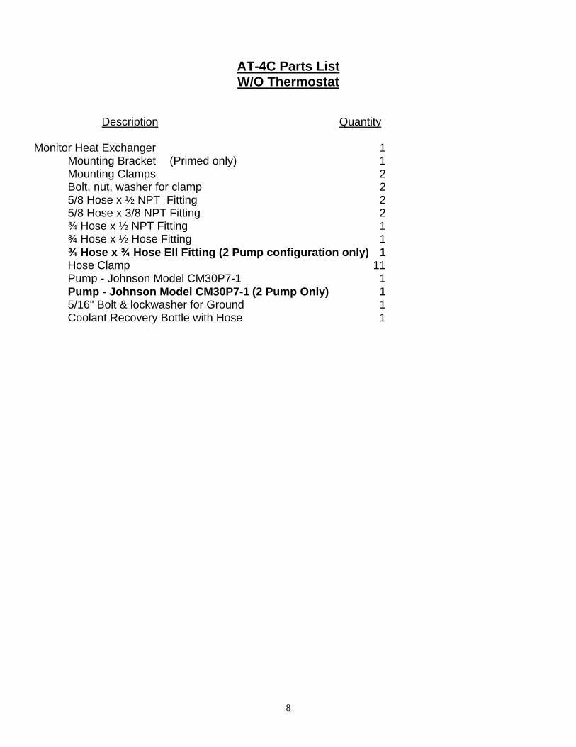
AT-4C Parts List W/O Thermostat
Description Quantity Monitor Heat Exchanger 1 Mounting Bracket (Primed only) 1 Mounting Clamps 2 Bolt, nut, washer for clamp 2 5/8 Hose x ½ NPT Fitting 2 5/8 Hose x 3/8 NPT Fitting 2 ¾ Hose x ½ NPT Fitting 1 ¾ Hose x ½ Hose Fitting 1
¾ Hose x ¾ Hose Ell Fitting (2 Pump configuration only) 1 Hose Clamp 11 Pump - Johnson Model CM30P7-1 1 Pump - Johnson Model CM30P7-1 (2 Pump Only) 1 5/16" Bolt & lockwasher for Ground 1 Coolant Recovery Bottle with Hose 1

9

10

11

12
New Indigo Thermostat and Housing Mounted on Flywheel end of Manifold

13
Temporary Filter For Antifreeze Loop With the installation of an Indigo FWC system on an Atomic 4, the potential exists for rust and scale particles circulating with the antifreeze to accumulate and restrict the flow of antifreeze in the heat exchanger. It is strongly recommended that a temporary antifreeze filter be installed for the first twenty (20) hours of operation. A very simple filter can be constructed from the following components: One 1 ½” PVC tee, Schedule 40 Two 1 ½” x ½ Female NPT PVC reducing bushings One 1 ½” PVC plug Two ½ NPT x ½” hose barb fittings (5/8” hose barb depending on your hose) One pack of bronze or stainless steel wool pads, medium texture.
Construction: 1. Glue a 1 ½” x ½” reducing bushing into each of the long legs on the tee. 2. Screw a hose barb fitting in each reducing coupling. Use Teflon tape on threads. 3. Push a pad into the side opening on the tee such that it is fully up against one of the reducing
bushings so as to catch any debris passing through. 4. Install the plug securely without glue. Cut a notch in each side of the top of the plug such that
when you put a nylon tie wrap around the tee and plug, the tie wrap will not slip off of the plug. Install the tie wrap.
5. Install filter assembly in the hose that runs from the exhaust manifold antifreeze discharge to the heat exchanger. Orient the filter assembly such that plug leg of the tee is horizontal to facilitate draining and changing the pad.
6. Fill the system with plain water and run the engine.
The pad may initially become plugged fairly soon after starting the engine. Leave the cap off of the heat exchanger initially and observe the water flow. If it starts to be reduced, check the pad. Otherwise, run the engine for about one (1) hour and then replace the pad. Monitor the water flow in the heat exchanger and monitor the engine temperature for about the next 18 hours of operation. Change the pad as necessary.
NOTE: PVC is not really intended to be used in pressurized systems at 180F. However, for this application, the pressure is very low and the material will withstand the temperature. The assembly may leak some at the plug. Additionally, the threaded hose barb fittings will become loose when hot but nothing will fail. For a more permanent solution, use galvanized pipe fittings such as a 4” x 1 ½” nipple and two 1 ½” x ½” reducing couplings. Once the initial period of operation is past and the system is filled with an antifreeze solution, it is recommended that this filter be removed to avoid leaking antifreeze into the bilge.

14
Related Documents