Welcome message from author
This document is posted to help you gain knowledge. Please leave a comment to let me know what you think about it! Share it to your friends and learn new things together.
Transcript
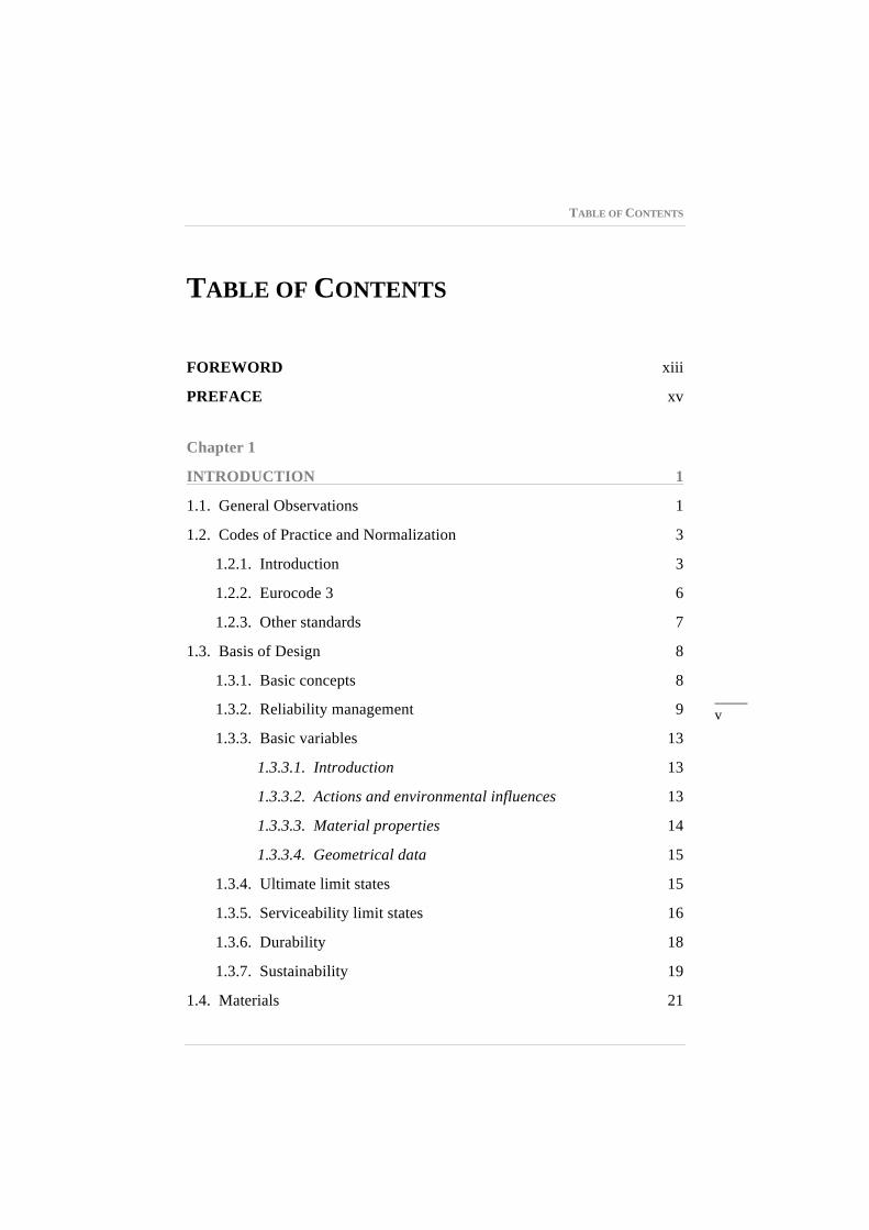
TABLE OF CONTENTS
_____ v
TABLE OF CONTENTS
FOREWORD xiii
PREFACE xv
Chapter 1
INTRODUCTION 1
1.1. General Observations 1
1.2. Codes of Practice and Normalization 3
1.2.1. Introduction 3
1.2.2. Eurocode 3 6
1.2.3. Other standards 7
1.3. Basis of Design 8
1.3.1. Basic concepts 8
1.3.2. Reliability management 9
1.3.3. Basic variables 13
1.3.3.1. Introduction 13
1.3.3.2. Actions and environmental influences 13
1.3.3.3. Material properties 14
1.3.3.4. Geometrical data 15
1.3.4. Ultimate limit states 15
1.3.5. Serviceability limit states 16
1.3.6. Durability 18
1.3.7. Sustainability 19
1.4. Materials 21
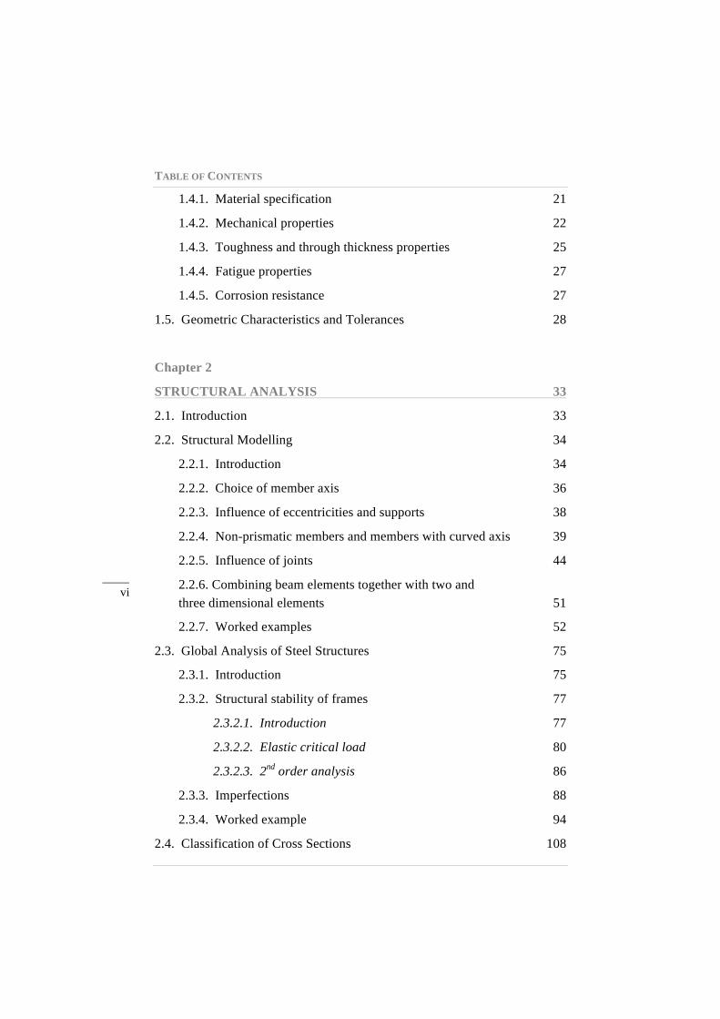
TABLE OF CONTENTS
_____ vi
1.4.1. Material specification 21
1.4.2. Mechanical properties 22
1.4.3. Toughness and through thickness properties 25
1.4.4. Fatigue properties 27
1.4.5. Corrosion resistance 27
1.5. Geometric Characteristics and Tolerances 28
Chapter 2
STRUCTURAL ANALYSIS 33
2.1. Introduction 33
2.2. Structural Modelling 34
2.2.1. Introduction 34
2.2.2. Choice of member axis 36
2.2.3. Influence of eccentricities and supports 38
2.2.4. Non-prismatic members and members with curved axis 39
2.2.5. Influence of joints 44
2.2.6. Combining beam elements together with two and three dimensional elements 51
2.2.7. Worked examples 52
2.3. Global Analysis of Steel Structures 75
2.3.1. Introduction 75
2.3.2. Structural stability of frames 77
2.3.2.1. Introduction 77
2.3.2.2. Elastic critical load 80
2.3.2.3. 2nd order analysis 86
2.3.3. Imperfections 88
2.3.4. Worked example 94
2.4. Classification of Cross Sections 108
TABLE OF CONTENTS
_____ vii
Chapter 3
DESIGN OF MEMBERS 119
3.1. Introduction 119
3.1.1. General 119
3.1.2. Resistance of cross sections 120
3.1.2.1. General criteria 120
3.1.2.2. Section properties 121
3.1.3. Buckling resistance of members 125
3.2. Tension 125
3.2.1. Behaviour in tension 125
3.2.2. Design for tensile force 128
3.2.3. Worked examples 131
3.3. Laterally Restrained Beams 138
3.3.1. Introduction 138
3.3.2. Design for bending 139
3.3.2.1. Elastic and plastic bending moment resistance 139
3.3.2.2. Uniaxial bending 141
3.3.2.3. Bi-axial bending 142
3.3.2.4. Net area in bending 142
3.3.3. Design for shear 143
3.3.4. Design for combined shear and bending 144
3.3.5. Worked examples 146
3.4. Torsion 157
3.4.1. Theoretical background 157
3.4.1.1. Introduction 157
3.4.1.2. Uniform torsion 159
3.4.1.3. Non-uniform torsion 161
TABLE OF CONTENTS
_____ viii
3.4.1.4. Cross section resistance in torsion 166
3.4.2. Design for torsion 173
3.4.3. Worked examples 176
3.5. Compression 186
3.5.1. Theoretical background 186
3.5.1.1. Introduction 186
3.5.1.2. Elastic critical load 186
3.5.1.3. Effect of imperfections and plasticity 192
3.5.2. Design for compression 198
3.5.3. Worked examples 204
3.6. Laterally Unrestrained Beams 212
3.6.1. Introduction 212
3.6.2. Lateral-torsional buckling 212
3.6.2.1. Introduction 212
3.6.2.2. Elastic critical moment 213
3.6.2.3. Effect of imperfections and plasticity 223
3.6.3. Lateral-torsional buckling resistance 225
3.6.4. Worked examples 229
3.7. Beam-Columns 242
3.7.1. Introduction 242
3.7.2. Classification of cross sections under bending and axial force 243
3.7.3. Cross section resistance 247
3.7.3.1. Theoretical background 247
3.7.3.2. Design resistance 249
3.7.4. Buckling resistance 253
3.7.4.1. Theoretical background 253
3.7.4.2. Design resistance 256
3.7.5. Worked examples 265
TABLE OF CONTENTS
_____ ix
Chapter 4
ELASTIC DESIGN OF STEEL STRUCTURES 293
4.1. Introduction 293
4.2. Simplified Methods of Analysis 295
4.2.1. Introduction 295
4.2.2. Amplified sway-moment method 297
4.2.3. Sway-mode buckling length method 299
4.2.4. Worked example 300
4.3. Member Stability of Non-prismatic Members and Components 310
4.3.1. Introduction 310
4.3.2. Non-prismatic members 310
4.3.3. Members with intermediate restraints 316
4.3.4. General method 322
4.3.5. Worked example 325
4.4. Design Example 1: Elastic Design of Braced Steel-Framed Building 340
4.4.1. Introduction 340
4.4.2. Description of the structure 342
4.4.3. General safety criteria, actions and combinations of actions 344
4.4.3.1. General safety criteria 344
4.4.3.2. Permanent actions 345
4.4.3.3. Imposed loads 345
4.4.3.4. Wind actions 346
4.4.3.5. Summary of basic actions 353
4.4.3.6. Frame imperfections 353
4.4.3.7. Load combinations 356
4.4.3.8. Load arrangement 358
4.4.4. Structural analysis 359
TABLE OF CONTENTS
_____ x
4.4.4.1. Structural model 359
4.4.4.2. Linear elastic analysis 360
4.4.4.3. Susceptibility to 2nd order effects: elastic critical loads 361
4.4.4.4. 2nd order elastic analysis 362
4.4.5. Design checks 363
4.4.5.1. General considerations 363
4.4.5.2. Cross section resistance 365
4.4.5.3. Buckling resistance of beams 366
4.4.5.4. Buckling resistance of columns and beam-columns 366
Chapter 5
PLASTIC DESIGN OF STEEL STRUCTURES 367
5.1. General Principles for Plastic Design 367
5.1.1. Introduction 367
5.1.2. Plastic limit analysis: method of mechanisms 368
5.1.3. Code requirements for plastic analysis 372
5.2. Methods of Analysis 376
5.2.1. Introduction 376
5.2.2. Approximate methods for pre-design 376
5.2.3. Computational analysis 388
5.2.4. 2nd order effects 393
5.2.4.1. Introduction 393
5.2.4.2. Elastic critical load 394
5.2.4.3. 2nd order computational analysis 397
5.2.4.4. Simplified methods for analysis 397
5.2.5. Worked example 400
5.3. Member Stability and Buckling Resistance 410
TABLE OF CONTENTS
_____ xi
5.3.1. Introduction 410
5.3.2. General criteria for the verification of the stability of members with plastic hinges 410
5.3.3. Bracings 411
5.3.4. Verification of the stability of members with plastic hinges 414
5.3.4.1. Introduction 414
5.3.4.2. Prismatic members constituted by hot-rolled or equivalent welded I sections 415
5.3.4.3. Haunched or tapered members made of rolled or equivalent welded I sections 417
5.3.4.4. Modification factors for moment gradients in members laterally restrained along the tension flange 420
5.3.5. Worked examples 423
5.4. Design Example 2: Plastic Design of Industrial Building 432
5.4.1. Introduction 432
5.4.2. General description 433
5.4.3. Quantification of actions, load combinations and general safety criteria 434
5.4.3.1. General criteria 434
5.4.3.2. Permanent actions 434
5.4.3.3. Imposed loads 434
5.4.3.4. Snow loads 435
5.4.3.5. Wind loads 435
5.4.3.6. Summary of basic actions 440
5.4.3.7. Imperfections 440
5.4.3.8. Load combinations 441
5.4.4. Pre-design 443
5.4.5. Structural analysis 446
TABLE OF CONTENTS
_____ xii
5.4.5.1. Linear elastic analysis 446
5.4.5.2. 2nd order effects 448
5.4.5.3. Elastic-plastic analysis 449
5.4.6. Code checks 451
5.4.6.1. General considerations 451
5.4.6.2. Cross section resistance 451
5.4.6.3. Buckling resistance of the rafters 451
5.4.6.4. Buckling resistance of the columns 454
5.4.7. Synthesis 454
REFERENCES 455
Annex A
FORMULAS FOR COMMON TORSIONAL CASES 465
A.1. Cross Sectional Properties for Torsion 465
A.2. Solution of Differential Equation for Torsion 467
A.2.1 Concentrated torsional moment 467
A.2.2 Distributed torsional moment 474
Annex B
ELASTIC CRITICAL MOMENT 483
B.1. Abacus to Calculate the Coefficients C1, C2 and C3 483
B.1.1 Elastic critical moment in beams submitted to end moments simultaneously with transverse loads 483
B.1.2 Elastic critical moment of unbraced cantilevers 487
B.2. Alternative Equations for the Determination of the Elastic Critical Moment 490
FOREWORD
_____ xiii
FOREWORD The development program for the design manuals of the European Convention for Constructional Steelwork (ECCS) represents a major effort for the steel construction industry and the engineering profession in Europe. Conceived by the ECCS Technical Activities Board under the leadership of its chairman, Professor Luis Simões da Silva, the manuals are being prepared in close agreement with the final stages of Eurocode 3 and its national Annexes. The scope of the development effort is vast, and reflects a unique undertaking in the world.
The publication of the first of the manuals, Design of Steel Structures, is a signal achievement which heralds the successful completion of the Eurocode 3 work and brings it directly to the designers who will implement the actual use of the code. As such, the book is more than a manual – it is a major textbook that details the fundamental concepts of the code and their practical application. It is a unique publication for a major construction market.
Following a discussion of the Eurocode 3 basis of design, including the principles of reliability management and the limit state approach, the steel material standards and their use under Eurocode 3 are detailed. Structural analysis and modeling are presented in a chapter that will assist the design engineer in the first stages of a design project. This is followed by a major chapter that provides the design criteria and approaches for the various types of structural members. The theories of behavior and strength are closely tied to the Eurocode requirements, making for a unique presentation of theory into practice. The following chapters expand on the principles and applications of elastic and plastic design of steel structures.
The many design examples that are presented throughout the book represent a significant part of the manual. These will be especially well received by the design profession. Without a doubt, the examples will facilitate the acceptance of the code and provide for a smooth transition from earlier national codes to the Eurocode.
Reidar Bjorhovde Member, ECCS Editorial Board
PREFACE
_____ xv
PREFACE 2nd EDITION The first edition of Design of Steel Structures was published by ECCS as a paperback in 2010. Since 2012, this publication is also available in electronic format as an e-book. The first edition was sold in over 100 countries and the interest for this publication was so high that a second edition would have to be printed.
The authors took the opportunity of this second edition to revise their manuscript. The standard that constitutes the object of this book, namely EN 1993-1-1, is still in application in the same versions as those that prevailed at the time of writing the first edition except for a minor amendment published in 2013. However, many comments were received by readers that resulted in the correction of some small mistakes and the rephrasing of some sentences or sections and the addition of some new material.
The new material comprises:
− A revised section dealing with the design for torsion of steel members, including a new worked example illustrating an open cross section beam subject to bending and torsional moments;
− A revised section on the elastic critical moment of beams; − An improved explanation on the classification of cross sections
subject to bending and axial force; − An additional worked example of a beam-column with transversal
loads and end moments; − A new Annex containing formulas for common torsional cases; − A revised and expanded Annex with formulas for elastic critical
moment calculation.
The authors are indebted to Profs. E. Mirambell and K. Rasmussen for their thorough revision of the section on torsion.
Luís Simões da Silva Rui Simões Helena Gervásio Coimbra, 2016
PREFACE
_____ xvii
PREFACE 1st EDITION
The General rules and rules for buildings of part 1-1 of Eurocode 3 constitute the core of the code procedures for the design of steel structures. They contain the basic guidance for structural modeling and analysis of steel frameworks and the rules for the evaluation of the resistance of structural members and components subject to different loading conditions.
According to the objectives of the ECCS Eurocode Design Manuals, it is the objective of this book to provide mix of “light” theoretical background, explanation of the code prescriptions and detailed design examples. Consequently, this book is more than a manual: it provides an all-in-one source for an explanation of the theoretical concepts behind the code and detailed design examples that try to reproduce real design situations instead of the usually simplified examples that are found in most textbooks.
This book evolved from the experience of teaching Steel Structures according to ENV 1993-1-1 since 1993. It further benefited from the participation in Technical Committees TC8 and TC10 of ECCS where the background and the applicability of the various clauses of EN 1993-1-1 was continuously questioned. This book covers exclusively part 1-1 of Eurocode 3 because of the required level of detail. Forthcoming volumes discuss and apply most of the additional parts of Eurocode 3 using a consistent format.
Chapter 1 introduces general aspects such as the basis of design, material properties and geometric characteristics and tolerances, corresponding to chapters 1 to 4 and chapter 7 of EN 1993-1-1. It highlights the important topics that are required in the design of steel structures. Structural analysis is discussed in chapter 2, including structural modelling, global analysis and classification of cross sections, covering chapter 5 of EN 1993-1-1. The design of steel members subjected to various types of internal force (tension, bending and shear, compression and torsion) and their combinations is described in chapter 3, corresponding to chapter 6 of EN 1993-1-1. Chapter 4 presents the design of steel structures using 3D elastic analysis based on the case study of a
PREFACE
_____ xviii
real building. Finally, chapter 5 discusses plastic design, using a pitched-roof industrial building to exemplify all relevant aspects.
Furthermore, the design examples provided in this book are chosen from real design cases. Two complete design examples are presented: i) a braced steel-framed building; and ii) a pitched-roof industrial building. The chosen design approach tries to reproduce, as much as possible, real design practice instead of more academic approaches that often only deal with parts of the design process. This means that the design examples start by quantifying the actions. They then progress in a detailed step-by-step manner to global analysis and individual member verifications. The design tools currently available and adopted in most design offices are based on software for 3D analysis. Consequently, the design example for multi-storey buildings is analysed as a 3D structure, all subsequent checks being consistent with this approach. This is by no means a straightforward implementation, since most global stability verifications were developed and validated for 2D structures.
The authors are indebted to Prof. Reidar Bjorhovde who carried out a detailed technical review of the manuscript and provided many valuable comments and suggestions. Warm thanks to Prof. David Anderson who carried out an additional detailed revision of the book and also made sure that the English language was properly used. Further thanks to Liliana Marques and José Alexandre Henriques, PhD students at the University of Coimbra, for the help with the design examples of chapter 4. Additional thanks to Prof. Tiago Abecasis who spotted innumerous “bugs” in the text. Finally, thanks to Filipe Dias and the staff of cmm and ECCS for all the editorial and typesetting work, making it possible to bring to an end two years of work in this project.
Luís Simões da Silva Rui Simões Helena Gervásio Coimbra, 2010
_____ 119
Chapter 3
DESIGN OF MEMBERS
3.1. INTRODUCTION
3.1.1. General
According to the general framework established in EN 1990 for the safety of structures, the safety of steel members at ultimate limit state is ensured by applying partial safety factors γM to the various characteristic values of resistance. The safety factors are defined in accordance with the potential failure modes. For steel members, the following three failure modes are considered (clause 6.1(1)): i) resistance of cross sections, whatever the class; ii) resistance of members to instability assessed by member checks and iii) resistance of cross sections in tension to fracture. Specific partial safety factors γM0, γM1 and γM2, deemed to guarantee the reliability targets of EN 1990, correspond to each failure mode, respectively. The following values of the partial safety factors γMi are recommended for buildings1:γM0 = 1.00; γM1 = 1.00 and γM2 = 1.25 and will be used throughout this book. It is noted that for other types of structures, recommended values are given in Parts 2 to 6 of EN 1993. For structures not covered by Parts 2 to 6 of EN 1993, the National Annexes may define the partial factors γMi; it is recommended in this case to take the partial factors γMi from EN 1993-2 (CEN, 2006d).
This chapter describes the basic theoretical concepts, as well as the normative design rules (according to EC3-1-1) concerning the verification of the resistance of steel members. In particular, the evaluation of the resistance
1 These values were adopted by the majority of the National Annexes.
3. DESIGN OF MEMBERS
_____ 120
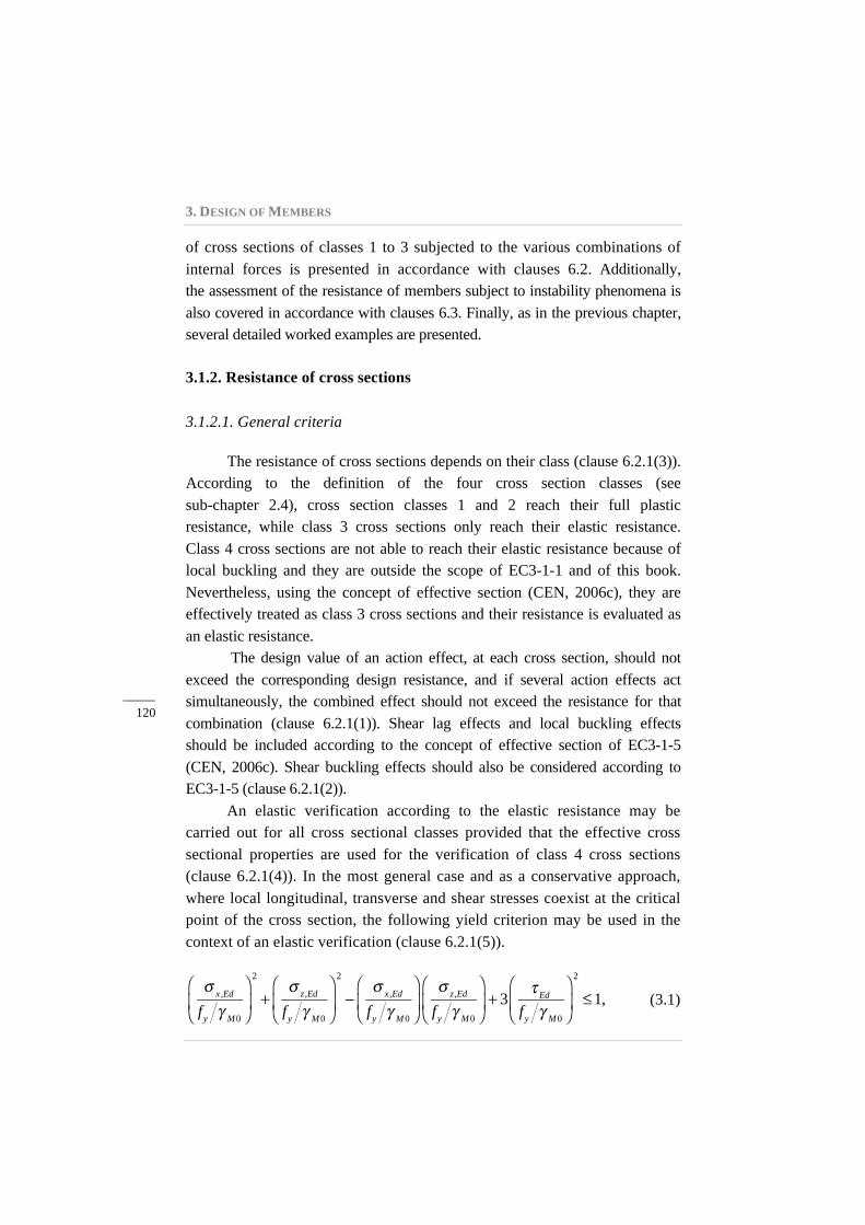
of cross sections of classes 1 to 3 subjected to the various combinations of internal forces is presented in accordance with clauses 6.2. Additionally,the assessment of the resistance of members subject to instability phenomena is also covered in accordance with clauses 6.3. Finally, as in the previous chapter, several detailed worked examples are presented.
3.1.2. Resistance of cross sections
3.1.2.1. General criteria
The resistance of cross sections depends on their class (clause 6.2.1(3)). According to the definition of the four cross section classes (see sub-chapter 2.4), cross section classes 1 and 2 reach their full plastic resistance, while class 3 cross sections only reach their elastic resistance. Class 4 cross sections are not able to reach their elastic resistance because of local buckling and they are outside the scope of EC3-1-1 and of this book. Nevertheless, using the concept of effective section (CEN, 2006c), they are effectively treated as class 3 cross sections and their resistance is evaluated as an elastic resistance.
The design value of an action effect, at each cross section, should not exceed the corresponding design resistance, and if several action effects act simultaneously, the combined effect should not exceed the resistance for that combination (clause 6.2.1(1)). Shear lag effects and local buckling effects should be included according to the concept of effective section of EC3-1-5 (CEN, 2006c). Shear buckling effects should also be considered according to EC3-1-5 (clause 6.2.1(2)).
An elastic verification according to the elastic resistance may be carried out for all cross sectional classes provided that the effective cross sectional properties are used for the verification of class 4 cross sections (clause 6.2.1(4)). In the most general case and as a conservative approach, where local longitudinal, transverse and shear stresses coexist at the critical point of the cross section, the following yield criterion may be used in the context of an elastic verification (clause 6.2.1(5)).
σ x ,Ed
fy γ M0
⎛
⎝⎜
⎞
⎠⎟
2
+σ z ,Ed
fy γ M0
⎛
⎝⎜
⎞
⎠⎟
2
−σ x ,Ed
fy γ M0
⎛
⎝⎜
⎞
⎠⎟
σ z ,Ed
fy γ M0
⎛
⎝⎜
⎞
⎠⎟ + 3
τ Ed
fy γ M0
⎛
⎝⎜
⎞
⎠⎟
2
≤1, (3.1)
3.1. INTRODUCTION
_____ 121
where σx,Ed is the design value of the local longitudinal stress, σz,Ed is the design value of the local transverse stress and τ Ed is the design value of the local shear stress, all values at the point of consideration.
For classes 1 or 2, the resistance of cross sections may be evaluated on the basis of their plastic resistance by finding a stress distribution which is in equilibrium with the internal forces and moments without exceeding the yield strength. This stress distribution should be compatible with the associated plastic deformations (clause 6.2.1(6)).
For class 3 cross sections, where all the compression parts of a cross section are class 3, its resistance should be based on an elastic distribution of strains across the cross section. Compressive stresses should be limited to the yield strength at the extreme fibres (clause 6.2.1(9)). These extreme fibres may be assumed at the midplane of the flanges for ULS checks. However, whenever yielding first occurs on the tension side of the cross section, the plastic reserves of the tension zone may be utilized by accounting for partial plastification when determining the resistance of a class 3 cross section (clause 6.2.1(10)).
For both plastic and elastic verifications of safety, interaction formulae on the basis of resistances (NRd, MRd, VRd) are favoured since they may lead to less conservative results. As a conservative approximation for all cross section classes, a linear summation of the utilization ratios for each stress resultant may be used. For class 1, class 2 or class 3 cross sections subjected to a combination of NEd, My,Ed, Mz,Ed this method may be applied by using the following criterion (clause 6.2.1(7)):
NEd
NRd
+My ,Ed
My ,Rd
+Mz ,Ed
Mz ,Rd
≤1 . (3.2)
Class 3 cross sections exhibit a gradual transition from plastic to elastic resistance because of residual stress effects and local yielding. This is not currently recognized by Eurocode 3 whose provisions result in a sudden transition from plastic resistance to elastic resistance. Extensive research was recently carried out to provide a safe smooth transition between classes 2 and 3 (Greiner et al, 2011).
3.1.2.2. Section properties
The properties of the gross cross section should be determined using the nominal dimensions. Holes for fasteners need not be deducted, but
3. DESIGN OF MEMBERS
_____ 122
allowance should be made for larger openings. Splice materials should not be included (clause 6.2.2.1(1)).
Because of the existence of holes and other openings, it is necessary to define the net area of a cross section. Generally, it is defined as its gross area less appropriate deductions for all holes and other openings (clause 6.2.2.2(1)). For calculating net section properties, the deduction for a single fastener hole should be the gross cross sectional area of the hole in the plane of its axis. For countersunk holes, appropriate allowance should be made for the countersunk portion (clause 6.2.2.2(2)).
In the case of multiple fastener holes, provided that the fastener holes are not staggered, the total area to be deducted for fastener holes should be the maximum sum of the sectional areas of the holes in any cross section perpendicular to the member axis (clause 6.2.2.2(3)). Where the fastener holes are staggered (Figure 3.1), the net area Anet should be the minimum of (clause 6.2.2.2(4)):
A − np t d0 (fracture section 1) ; (3.3)
A − n t d0 + t
s2
4p⎛⎝⎜
⎞⎠⎟∑ (fracture section 2) , (3.4)
where: A is the gross area of the section; np is the number of non-staggered holes in any cross section
perpendicular to the member axis; n is the number of holes extending in any diagonal or zig-zag line
progressively across the member or part of the member, see Figure 3.1;
t is the thickness; d0 is the hole diameter; s is the staggered pitch, the spacing of the centres of two
consecutive holes in the chain measured parallel to the member axis;
p is the spacing of the centres of the same two holes measured perpendicular to the member axis.
3.1. INTRODUCTION
_____ 123
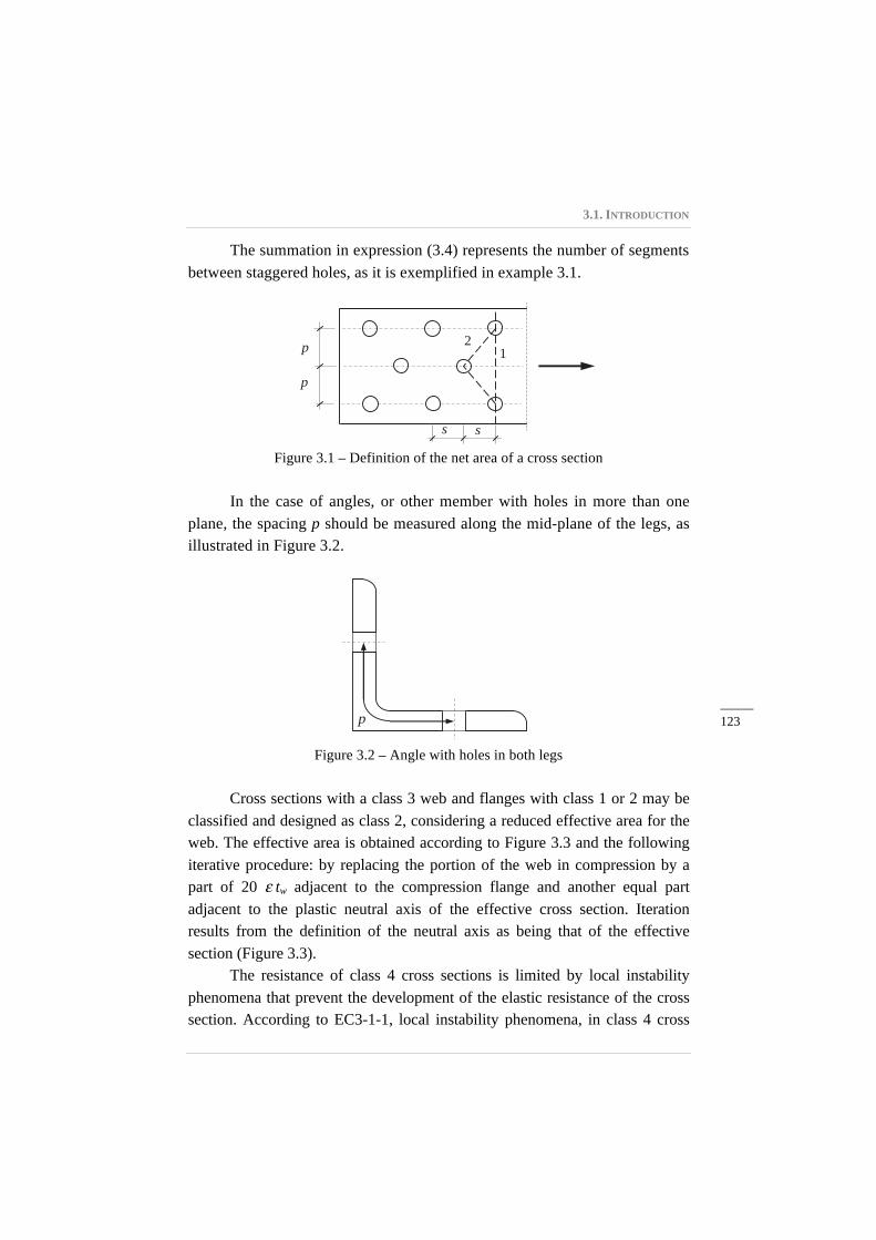
The summation in expression (3.4) represents the number of segments between staggered holes, as it is exemplified in example 3.1.
Figure 3.1 – Definition of the net area of a cross section
In the case of angles, or other member with holes in more than one plane, the spacing p should be measured along the mid-plane of the legs, as illustrated in Figure 3.2.
Figure 3.2 – Angle with holes in both legs
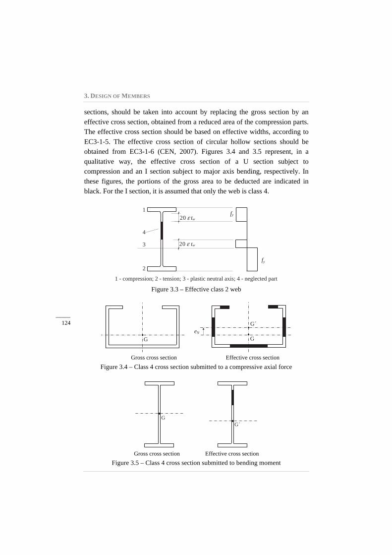
Cross sections with a class 3 web and flanges with class 1 or 2 may be classified and designed as class 2, considering a reduced effective area for the web. The effective area is obtained according to Figure 3.3 and the following iterative procedure: by replacing the portion of the web in compression by a part of 20 ε tw adjacent to the compression flange and another equal part adjacent to the plastic neutral axis of the effective cross section. Iteration results from the definition of the neutral axis as being that of the effective section (Figure 3.3).
The resistance of class 4 cross sections is limited by local instability phenomena that prevent the development of the elastic resistance of the cross section. According to EC3-1-1, local instability phenomena, in class 4 cross
ss
p
p
1 2
p
3. DESIGN OF MEMBERS
_____ 124
sections, should be taken into account by replacing the gross section by an effective cross section, obtained from a reduced area of the compression parts. The effective cross section should be based on effective widths, according to EC3-1-5. The effective cross section of circular hollow sections should be obtained from EC3-1-6 (CEN, 2007). Figures 3.4 and 3.5 represent, in a qualitative way, the effective cross section of a U section subject to compression and an I section subject to major axis bending, respectively. In these figures, the portions of the gross area to be deducted are indicated in black. For the I section, it is assumed that only the web is class 4.
Figure 3.3 – Effective class 2 web
Gross cross section Effective cross section
Figure 3.4 – Class 4 cross section submitted to a compressive axial force
Gross cross section Effective cross section
Figure 3.5 – Class 4 cross section submitted to bending moment
20 tw fy
20 tw
1
2
4
3
fy
1 - compression; 2 - tension; 3 - plastic neutral axis; 4 - neglected part
G G eN
G´
G´ G
3.2. TENSION
_____ 125
An axial compression force in a cross section in class 4 due to the possible shift, eN, of the centroid of the effective area, Aeff, relative to the centre of gravity of the gross cross section, results in an additional bending moment ΔMEd = NEdeN .
The analysis of cross sections with class 4 is not included in the scope of this book. The analysis may be performed according to EC3-1-3, for cold formed sections; according to EC3-1-5, for hot rolled sections and welded sections; and according to EC3-1-6, for circular hollow sections.
3.1.3. Buckling resistance of members
In addition to verification of the cross section resistance, the buckling resistance of members must also be checked, according to clauses 6.3 and 6.4. The buckling phenomenon depends on the presence of compressive stresses and therefore it must be checked for all members subjected to axial compression, bending moment or a combination of both. Shear buckling effects should also be considered according to EC3-1-5.
For a member under pure compression the buckling modes to take into account are: i) flexural buckling; ii) torsional buckling and iii) torsional-flexural buckling. A member under bending moment must be checked against lateral-torsional buckling. A member under a combination of compression force and bending moment must be checked against all the buckling modes mentioned above. The theoretical background, the design rules and several applications relating to the buckling resistance of steel members are presented in the sub-chapters 3.5, 3.6 and 3.7.
3.2. TENSION
3.2.1. Behaviour in tension
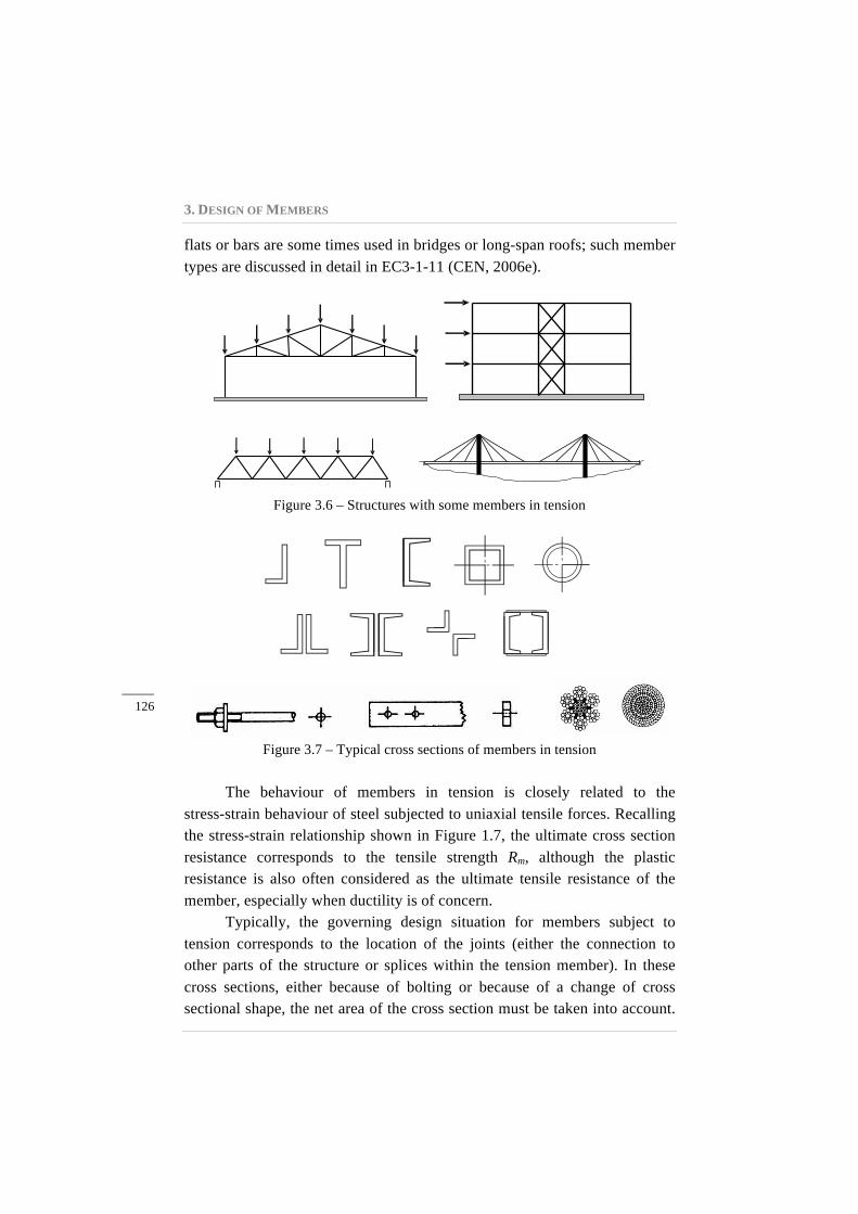
Figure 3.6 illustrates various examples of structures with some members that are commonly assumed to be loaded only in tension. Figure 3.7 shows typical cross sections of tension members. Simple or built-up rolled sections are commonly used in trusses, lattice girders and as bracing members. Cables, flats or bars are used in bracing systems. Cables,
3. DESIGN OF MEMBERS
_____ 126
flats or bars are some times used in bridges or long-span roofs; such member types are discussed in detail in EC3-1-11 (CEN, 2006e).
Figure 3.6 – Structures with some members in tension
Figure 3.7 – Typical cross sections of members in tension
The behaviour of members in tension is closely related to the stress-strain behaviour of steel subjected to uniaxial tensile forces. Recalling the stress-strain relationship shown in Figure 1.7, the ultimate cross section resistance corresponds to the tensile strength Rm, although the plastic resistance is also often considered as the ultimate tensile resistance of the member, especially when ductility is of concern.
Typically, the governing design situation for members subject to tension corresponds to the location of the joints (either the connection to other parts of the structure or splices within the tension member). In these cross sections, either because of bolting or because of a change of cross sectional shape, the net area of the cross section must be taken into account.
3.2. TENSION
_____ 127
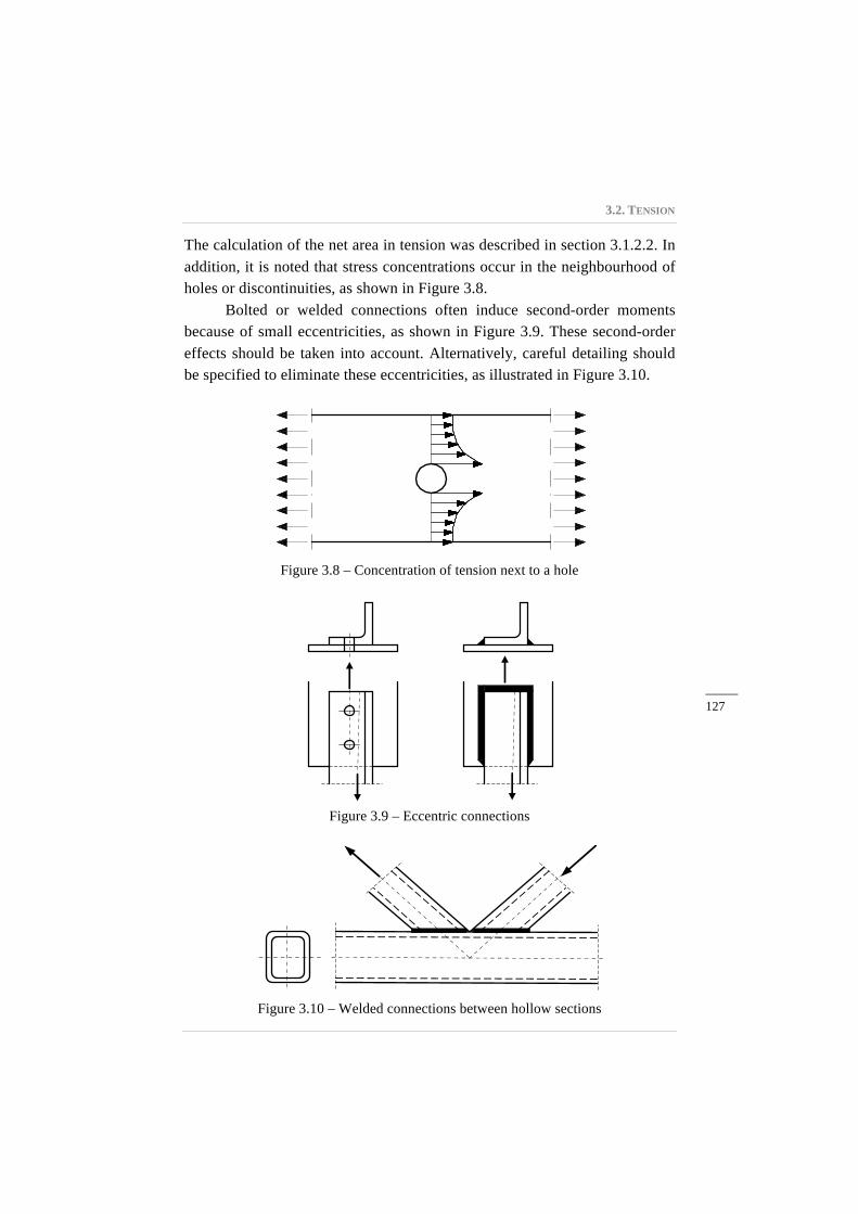
The calculation of the net area in tension was described in section 3.1.2.2. In addition, it is noted that stress concentrations occur in the neighbourhood of holes or discontinuities, as shown in Figure 3.8.
Bolted or welded connections often induce second-order moments because of small eccentricities, as shown in Figure 3.9. These second-order effects should be taken into account. Alternatively, careful detailing should be specified to eliminate these eccentricities, as illustrated in Figure 3.10.
Figure 3.8 – Concentration of tension next to a hole
Figure 3.9 – Eccentric connections
Figure 3.10 – Welded connections between hollow sections
3. DESIGN OF MEMBERS
_____ 128
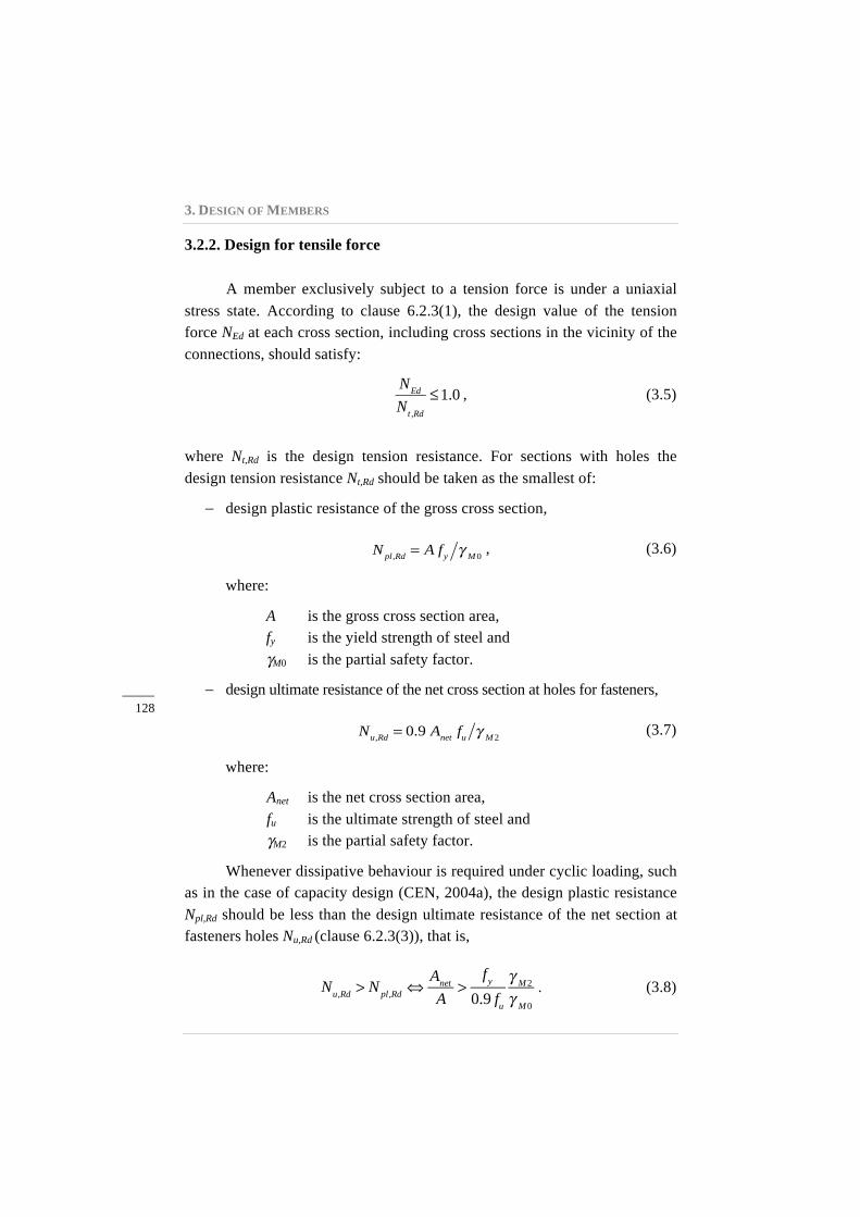
3.2.2. Design for tensile force
A member exclusively subject to a tension force is under a uniaxial stress state. According to clause 6.2.3(1), the design value of the tension force NEd at each cross section, including cross sections in the vicinity of the connections, should satisfy:
NEd
Nt ,Rd
≤1.0 , (3.5)
where Nt,Rd is the design tension resistance. For sections with holes the design tension resistance Nt,Rd should be taken as the smallest of:
− design plastic resistance of the gross cross section,
Npl,Rd = A fy γ M0
, (3.6)
where:
A is the gross cross section area, fy is the yield strength of steel and γM0 is the partial safety factor.
− design ultimate resistance of the net cross section at holes for fasteners,
Nu,Rd = 0.9 Anet fu γ M2
(3.7)
where:
Anet is the net cross section area, fu is the ultimate strength of steel and γM2 is the partial safety factor.
Whenever dissipative behaviour is required under cyclic loading, such as in the case of capacity design (CEN, 2004a), the design plastic resistance Npl,Rd should be less than the design ultimate resistance of the net section at fasteners holes Nu,Rd (clause 6.2.3(3)), that is,
Nu,Rd > Npl,Rd ⇔
Anet
A>
fy0.9 fu
γ M2
γ M0
. (3.8)
3.2. TENSION
_____ 129
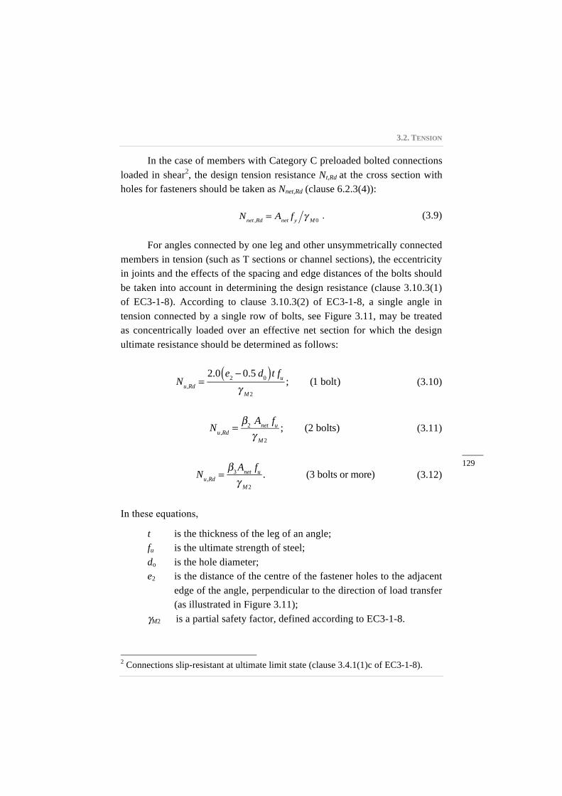
In the case of members with Category C preloaded bolted connections loaded in shear2, the design tension resistance Nt,Rd at the cross section with holes for fasteners should be taken as Nnet,Rd (clause 6.2.3(4)):
Nnet ,Rd = Anet fy γ M0
. (3.9)
For angles connected by one leg and other unsymmetrically connected members in tension (such as T sections or channel sections), the eccentricity in joints and the effects of the spacing and edge distances of the bolts should be taken into account in determining the design resistance (clause 3.10.3(1) of EC3-1-8). According to clause 3.10.3(2) of EC3-1-8, a single angle in tension connected by a single row of bolts, see Figure 3.11, may be treated as concentrically loaded over an effective net section for which the design ultimate resistance should be determined as follows:
Nu,Rd =
2.0 e2 − 0.5 d0( )t fuγ M2
; (1 bolt) (3.10)
Nu,Rd =
β2 Anet fuγ M2
; (2 bolts) (3.11)
Nu,Rd =
β3Anet fuγ M2
. (3 bolts or more) (3.12)
In these equations,
t is the thickness of the leg of an angle; fu is the ultimate strength of steel; do is the hole diameter; e2 is the distance of the centre of the fastener holes to the adjacent
edge of the angle, perpendicular to the direction of load transfer (as illustrated in Figure 3.11);
γM2 is a partial safety factor, defined according to EC3-1-8.
2 Connections slip-resistant at ultimate limit state (clause 3.4.1(1)c of EC3-1-8).
3. DESIGN OF MEMBERS
_____ 130
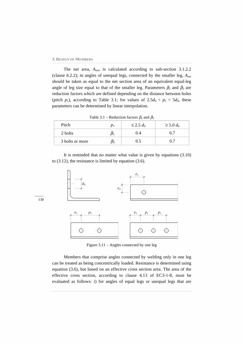
The net area, Anet, is calculated according to sub-section 3.1.2.2 (clause 6.2.2); in angles of unequal legs, connected by the smaller leg, Anet
should be taken as equal to the net section area of an equivalent equal-leg angle of leg size equal to that of the smaller leg. Parameters β2 and β3 are reduction factors which are defined depending on the distance between holes (pitch p1), according to Table 3.1; for values of 2.5d0 < p1 < 5d0, these parameters can be determined by linear interpolation.
Table 3.1 – Reduction factors β2 and β3
Pitch p1 ≤ 2.5 d0 ≥ 5.0 d0
2 bolts β2 0.4 0.7
3 bolts or more β3 0.5 0.7
It is reminded that no matter what value is given by equations (3.10) to (3.12), the resistance is limited by equation (3.6).
Figure 3.11 – Angles connected by one leg
Members that comprise angles connected by welding only in one leg can be treated as being concentrically loaded. Resistance is determined using equation (3.6), but based on an effective cross section area. The area of the effective cross section, according to clause 4.13 of EC3-1-8, must be evaluated as follows: i) for angles of equal legs or unequal legs that are
d0 e2
e1
e1 e1 p1 p1 p1
3.2. TENSION
_____ 131
connected by the larger leg, the area of the effective section may be considered as equal to the gross area; ii) for angles of unequal legs, connected by the smaller leg, the area of the effective section should be taken as equal to the gross area of an equivalent angle, with legs that are equal to the smaller of the legs.
3.2.3. Worked examples
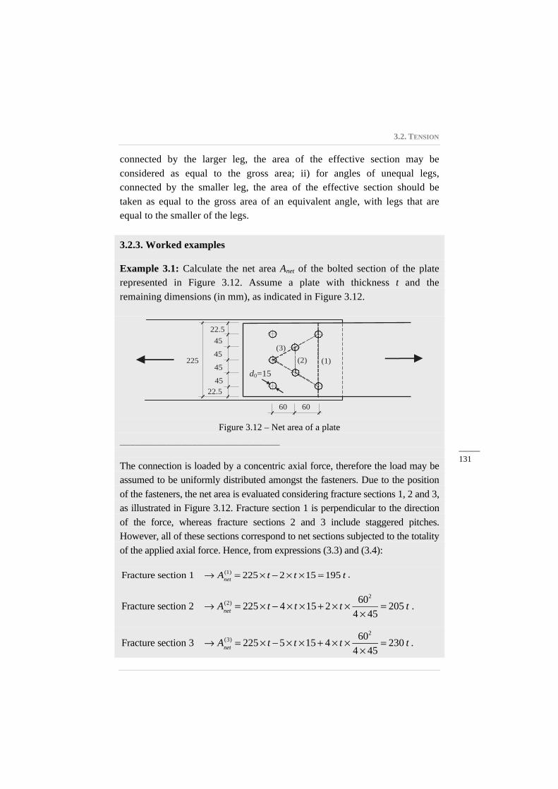
Example 3.1: Calculate the net area Anet of the bolted section of the plate represented in Figure 3.12. Assume a plate with thickness t and the remaining dimensions (in mm), as indicated in Figure 3.12.
Figure 3.12 – Net area of a plate
_______________________________
The connection is loaded by a concentric axial force, therefore the load may be assumed to be uniformly distributed amongst the fasteners. Due to the position of the fasteners, the net area is evaluated considering fracture sections 1, 2 and 3, as illustrated in Figure 3.12. Fracture section 1 is perpendicular to the direction of the force, whereas fracture sections 2 and 3 include staggered pitches. However, all of these sections correspond to net sections subjected to the totality of the applied axial force. Hence, from expressions (3.3) and (3.4):
Fracture section 1 → Anet(1) = 225× t − 2× t ×15 = 195 t .
Fracture section 2 → Anet
(2) = 225× t − 4 × t ×15+ 2× t × 602
4 × 45= 205 t .
Fracture section 3 → Anet
(3) = 225× t −5× t ×15+ 4 × t × 602
4 × 45= 230 t .
22.5
22.5
45 45
45 45
(1) (2) (3)
225
60 60
d0=15
3. DESIGN OF MEMBERS
_____ 132
The net area of the plate is given by the minimum value, Anet = 195 t. _____________________________________________________________
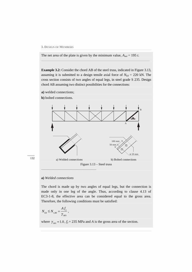
Example 3.2: Consider the chord AB of the steel truss, indicated in Figure 3.13, assuming it is submitted to a design tensile axial force of NEd = 220 kN. The cross section consists of two angles of equal legs, in steel grade S 235. Design chord AB assuming two distinct possibilities for the connections:
a) welded connections;
b) bolted connections.
a) Welded connections b) Bolted connections
Figure 3.13 – Steel truss _______________________________
a) Welded connections
The chord is made up by two angles of equal legs, but the connection is made only in one leg of the angle. Thus, according to clause 4.13 of EC3-1-8, the effective area can be considered equal to the gross area. Therefore, the following conditions must be satisfied:
NEd ≤ Nt ,Rd =
A fyγ M0
,
where γ M0 = 1.0 , fy = 235 MPa and A is the gross area of the section.
A
B
50 mm 100 mm
18 mm
3.2. TENSION
_____ 133
Considering the design axial force, NEd = 220 kN, then:
220 kN ≤ A × 235×103
1.0⇒ A ≥ 9.36 ×10⁻⁴m2 = 9.36 cm2 .
From a table of commercial profiles, a solution with two angles 50 ×50×5mm, with a total area of 2× 4.8 = 9.6 cm2 , satisfies the above safety requirement.
b) Bolted connections
In this case, the chord, made up by angles of equal legs, is connected by 2 bolts only in one leg. According to clause 3.10.3 of EC3-1-8, the following design conditions must be ensured:
NEd ≤ Nt ,Rd , with Nt ,Rd = min Npl,Rd =
A fyγ M0
; Nu,Rd =β2 Anet fuγ M2
⎡
⎣⎢⎢
⎤
⎦⎥⎥,
where, γM0 = 1.0, γM2 = 1.25, fy = 235 MPa, fu = 360 MPa, A is the gross area of the cross section, Anet is the net area of the bolted section, and β2 is a factor obtained from Table 3.1 (or Table 3.8 of EC3-1-8). A first check based on the plastic design of the gross cross section leads to:
220 kN ≤ A × 235×103
1.0⇒ A ≥ 9.36 ×10⁻⁴ m2 = 9.36 cm2.
Hence, the section obtained in the previous design, two angles 50 ×50×5 mm (A = 9.6 cm2), also satisfies this safety requirement.
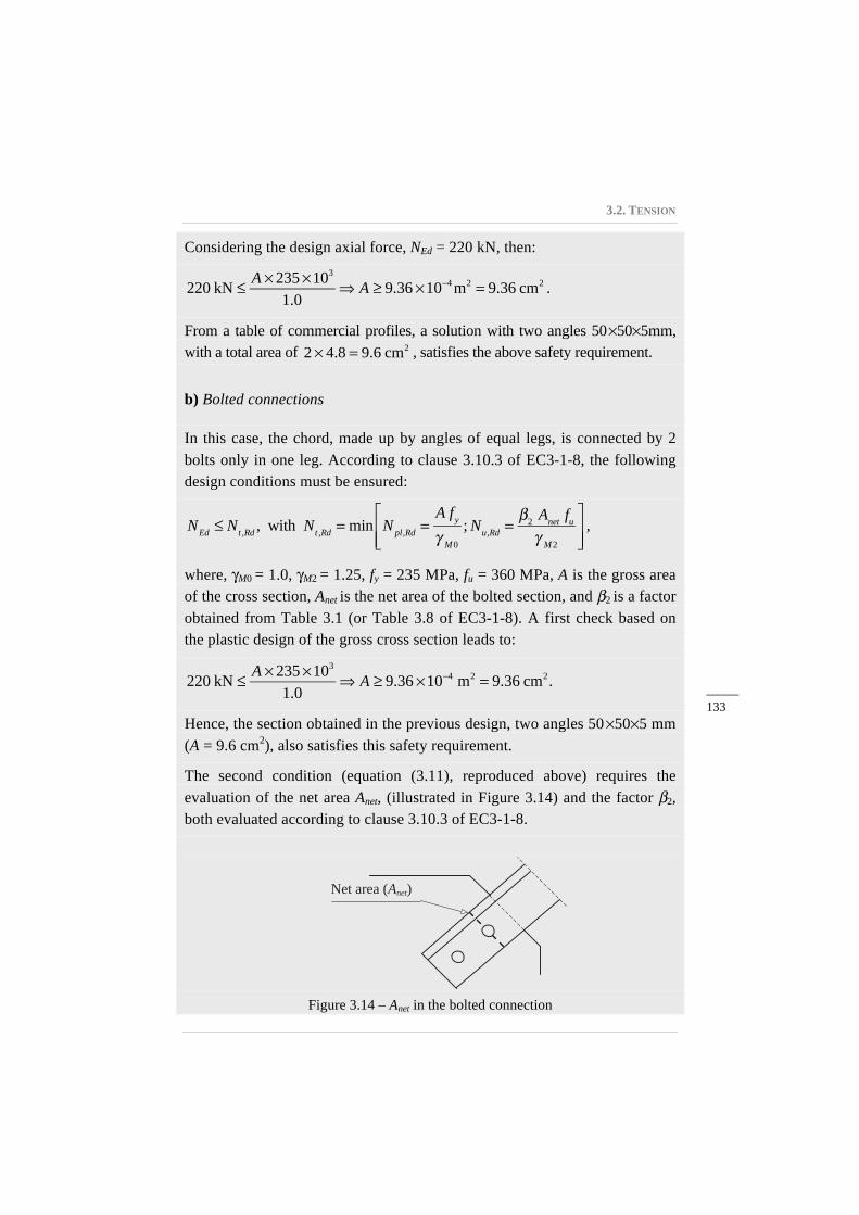
The second condition (equation (3.11), reproduced above) requires the evaluation of the net area Anet, (illustrated in Figure 3.14) and the factor β2, both evaluated according to clause 3.10.3 of EC3-1-8.
Figure 3.14 – Anet in the bolted connection
Net area (Anet)
3. DESIGN OF MEMBERS
_____ 134
For d0 = 18 mm, 2.5d0 = 45 mm and 5d0 = 90 mm.
As p1 = 100 mm > 90 mm, then β2 = 0.70.
The net area of the bolted section made up of two angles is given by:
Anet = A − 2 t d0 = 9.6 − 2× 0.5×1.8 = 7.8 cm2.
Thus, the design ultimate resistance is given by:
Nu,Rd =
0.7 ×7.8×10−4 × 360×103
1.25= 157.2 kN.
However, NEd = 220 kN > Nu,Rd = 157.2 kN; therefore, the chosen cross section is not appropriate. By adopting a cross section with enhanced resistance, for example, two angles 60×60×6 mm (A = 13.82 cm2 and Anet =11.66 cm2), then:
Npl,Rd = 13.82×10−4 × 235×103 1.0 = 324.8 kN > NEd = 220 kN ;
Nu,Rd =
0.7 ×11.66 ×10−4 × 360×103
1.25= 235.1 kN > NEd = 220 kN .
As Npl,Rd = 324.8 kN > Nu,Rd = 235.1 kN, failure is non-ductile; however, since this is not a design condition, the section defined by two angles 60×60×6 mm can be accepted. _____________________________________________________________
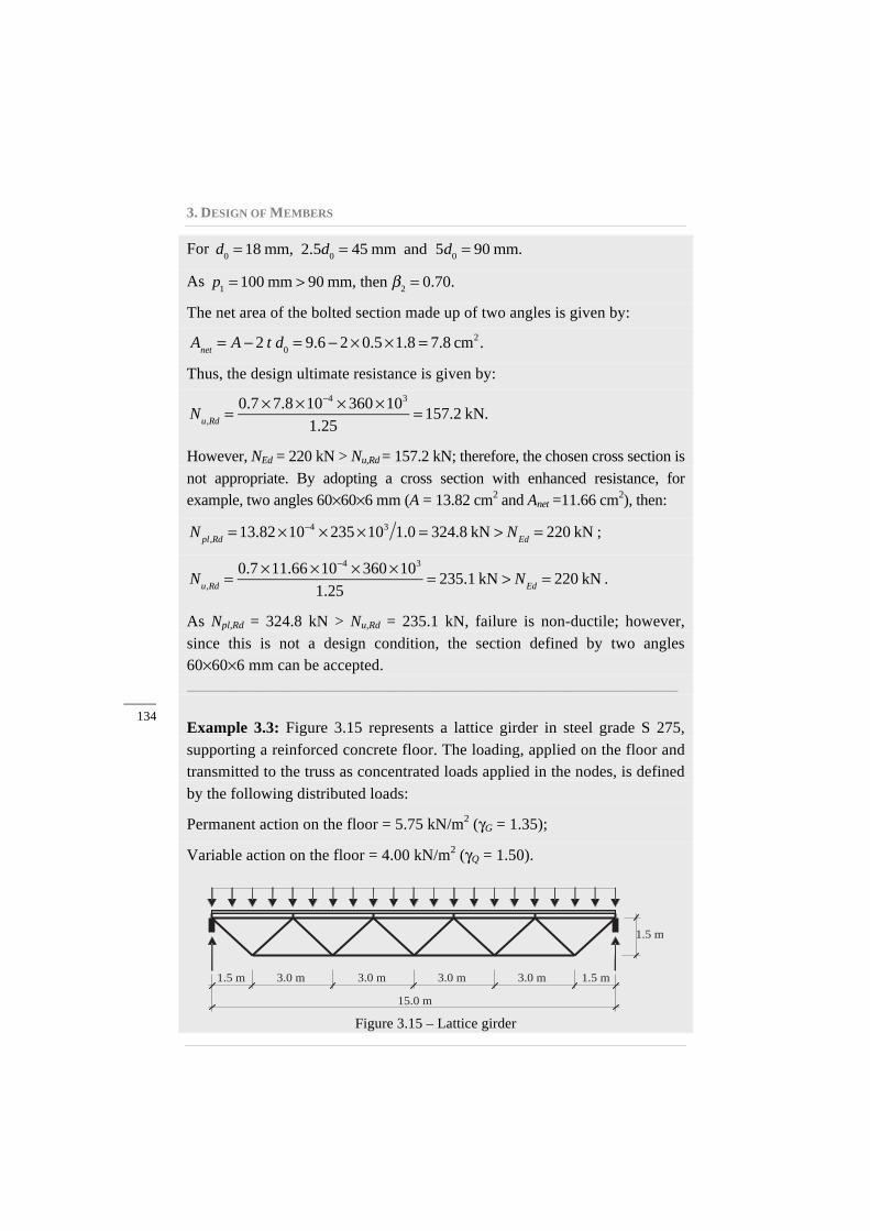
Example 3.3: Figure 3.15 represents a lattice girder in steel grade S 275, supporting a reinforced concrete floor. The loading, applied on the floor and transmitted to the truss as concentrated loads applied in the nodes, is defined by the following distributed loads:
Permanent action on the floor = 5.75 kN/m2 (γG = 1.35);
Variable action on the floor = 4.00 kN/m2 (γQ = 1.50).
Figure 3.15 – Lattice girder
3.0 m 1.5 m
15.0 m
1.5 m
3.0 m 3.0 m 3.0 m 1.5 m
3.2. TENSION
_____ 135
The distance between lattice girders is 3.00 m; the nodes of the truss are braced in the perpendicular direction to the plane of the structure; the loading already includes the selfweight of the steel truss. Design the tension members of the truss, assuming the following alternatives:
a) Square hollow sections (SHS), and welded connections for the members of the structure.
b) HEA profiles in the upper and lower chords (horizontal members) and 2 UPN channel profiles for the diagonal members. The diagonal members are bolted to gusset plates, which are welded to the HEA profiles in the upper and lower chords.
_______________________________
For design at the ultimate limit state, the following combination of actions is considered (according to EN 1990):
pEd = 1.35×5.75+1.5× 4.00 = 13.76 kN m2 ,
where pEd is the design load, uniformly distributed on the floor.
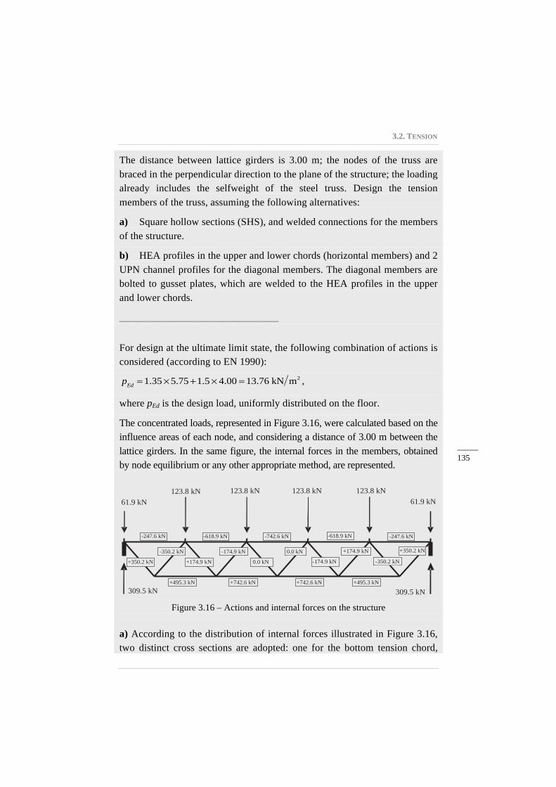
The concentrated loads, represented in Figure 3.16, were calculated based on the influence areas of each node, and considering a distance of 3.00 m between the lattice girders. In the same figure, the internal forces in the members, obtained by node equilibrium or any other appropriate method, are represented.
Figure 3.16 – Actions and internal forces on the structure
a) According to the distribution of internal forces illustrated in Figure 3.16, two distinct cross sections are adopted: one for the bottom tension chord,
61.9 kN 61.9 kN 123.8 kN 123.8 kN 123.8 kN 123.8 kN
309.5 kN 309.5 kN
-247.6 kN
+495.3 kN
-618.9 kN -742.6 kN
+742.6 kN
+350.2 kN -350.2 kN
+174.9 kN -174.9 kN
0.0 kN 0.0 kN
-247.6 kN -618.9 kN
+495.3 kN +742.6 kN
-174.9 kN +174.9 kN
-350.2 kN +350.2 kN
3. DESIGN OF MEMBERS
_____ 136
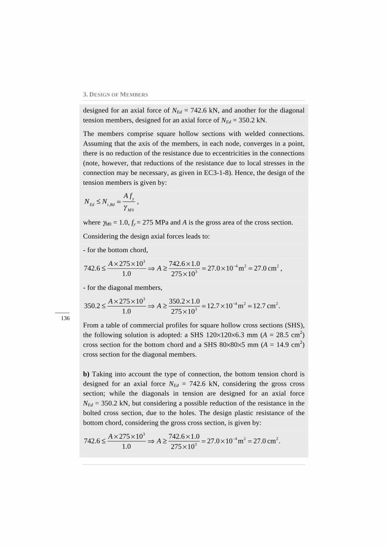
designed for an axial force of NEd = 742.6 kN, and another for the diagonal tension members, designed for an axial force of NEd = 350.2 kN.
The members comprise square hollow sections with welded connections. Assuming that the axis of the members, in each node, converges in a point, there is no reduction of the resistance due to eccentricities in the connections (note, however, that reductions of the resistance due to local stresses in the connection may be necessary, as given in EC3-1-8). Hence, the design of the tension members is given by:
NEd ≤ Nt ,Rd =
A fyγ M0
,
where γM0 = 1.0, fy = 275 MPa and A is the gross area of the cross section.
Considering the design axial forces leads to:
- for the bottom chord,
742.6 ≤ A × 275×103
1.0⇒ A ≥ 742.6 ×1.0
275×103 = 27.0×10⁻⁴m2 = 27.0 cm2 ,
- for the diagonal members,
350.2 ≤ A × 275×103
1.0⇒ A ≥ 350.2×1.0
275×103 = 12.7 ×10⁻⁴m2 = 12.7 cm2.
From a table of commercial profiles for square hollow cross sections (SHS), the following solution is adopted: a SHS 120×120×6.3 mm (A = 28.5 cm2) cross section for the bottom chord and a SHS 80×80×5 mm (A = 14.9 cm2) cross section for the diagonal members.
b) Taking into account the type of connection, the bottom tension chord is designed for an axial force NEd = 742.6 kN, considering the gross cross section; while the diagonals in tension are designed for an axial force NEd = 350.2 kN, but considering a possible reduction of the resistance in the bolted cross section, due to the holes. The design plastic resistance of the bottom chord, considering the gross cross section, is given by:
742.6 ≤ A × 275×103
1.0⇒ A ≥ 742.6 ×1.0
275×103 = 27.0×10⁻⁴m2 = 27.0 cm2.
3.2. TENSION
_____ 137
Similarly, for the diagonal members:
350.2 ≤ A × 275×103
1.0⇒ A ≥ 350.2×1.0
275×103 = 12.7 ×10⁻⁴m2 = 12.7 cm2.
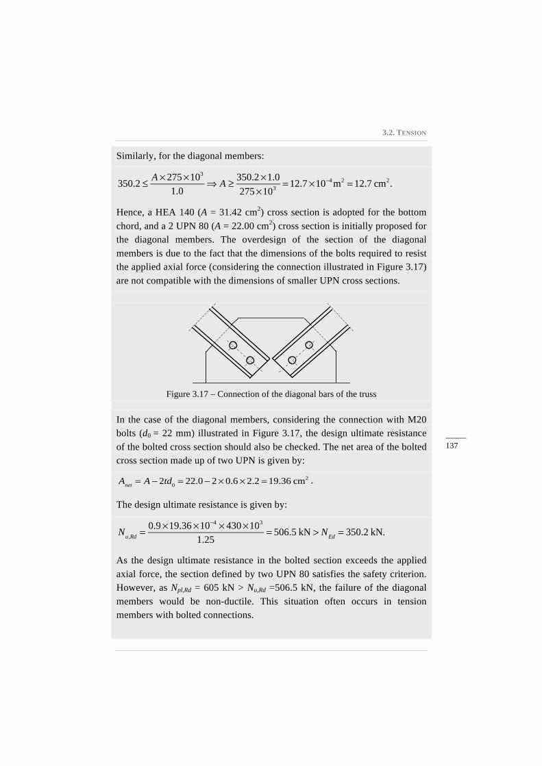
Hence, a HEA 140 (A = 31.42 cm2) cross section is adopted for the bottom chord, and a 2 UPN 80 (A = 22.00 cm2) cross section is initially proposed for the diagonal members. The overdesign of the section of the diagonal members is due to the fact that the dimensions of the bolts required to resist the applied axial force (considering the connection illustrated in Figure 3.17) are not compatible with the dimensions of smaller UPN cross sections.
Figure 3.17 – Connection of the diagonal bars of the truss
In the case of the diagonal members, considering the connection with M20 bolts (d0 = 22 mm) illustrated in Figure 3.17, the design ultimate resistance of the bolted cross section should also be checked. The net area of the bolted cross section made up of two UPN is given by:
Anet = A − 2td0 = 22.0− 2× 0.6 × 2.2 = 19.36 cm2 .
The design ultimate resistance is given by:
Nu,Rd =
0.9×19.36 ×10−4 × 430×103
1.25= 506.5 kN > NEd = 350.2 kN.
As the design ultimate resistance in the bolted section exceeds the applied axial force, the section defined by two UPN 80 satisfies the safety criterion. However, as Npl,Rd = 605 kN > Nu,Rd =506.5 kN, the failure of the diagonal members would be non-ductile. This situation often occurs in tension members with bolted connections.

Order Form
Delivery- and Invoice address: �private �business
We guarantee you the right to revoke this order within two weeks. Please mail to Verlag Ernst & Sohn, Wiley-VCH, Boschstr. 12, D-69469 Weinheim.
Date Signature *In EU countries the local VAT is effective for books and journals. Postage will be charged. Whilst every effort is made to ensure that the contents of this leaflet are accurate, all information is subject to change without notice. Our standard terms and delivery conditions apply. Prices are subject to change without notice. Date of information: Sep 2016 (homepage sample chapter)
Quantity Order-No.: Title Price* €
978-3-433-03163-6 Design of Steel Structures 70,00-
909538 Publishing Index Ernst & Sohn 2016/2017 for free
2489 Free sample issue of the journal Steel Construction for free
please tick Monthly email-Newsletter for free
Company
Contact Person Telephone
VAT-ID No. Fax
Street//No. Email
Country ZIP-Code Location
Wilhelm Ernst & Sohn Verlag für Architektur und technische Wissenschaften GmbH & Co. KG Rotherstraße 21, 10245 Berlin Germany www.ernst-und-sohn.de
Related Documents