CT18IGBD1 A1 INDICE INDEX INHALTSVERZEICHNIS MOTORI ELETTRICI TRIFASE E MONOFASE THREE-PHASE AND SINGLE-PHASE ELECTRIC MOTORS DREHSTROM- UND EINPHASENMOTOREN A3 MOTORI ELETTRICI TRIFASE SERIE VL VELA ELECTRIC MOTORS VELA ELEKTROMOTOREN INVERTER (STM DRIVE) INVERTER (STM DRIVE) FREQUENZUMRICHTER (STM DRIVE) B1 C1 A B C D Z ESV ESV ESV Pag. Page Seite D1 WEB SITE MAP Z1 Gestione Revisione Cataloghi STM Managing STM Catalog Revisions Management Wiederholt Kataloge STM Z2

Welcome message from author
This document is posted to help you gain knowledge. Please leave a comment to let me know what you think about it! Share it to your friends and learn new things together.
Transcript

CT18IGBD1 A1
INDICEINDEXINHALTSVERZEICHNIS
MOTORI ELETTRICI TRIFASE E MONOFASETHREE-PHASE AND SINGLE-PHASE ELECTRIC MOTORSDREHSTROM- UND EINPHASENMOTOREN
A3
MOTORI ELETTRICI TRIFASE SERIE VLVELA ELECTRIC MOTORSVELA ELEKTROMOTOREN
INVERTER (STM DRIVE)INVERTER (STM DRIVE)FREQUENZUMRICHTER (STM DRIVE)
B1
C1
A
B
C
D
Z
ESVESVESV
Pag.PageSeite
D1
WEB SITE MAP Z1
Gestione Revisione Cataloghi STMManaging STM Catalog RevisionsManagement Wiederholt Kataloge STM
Z2
CT18IGBD1A2
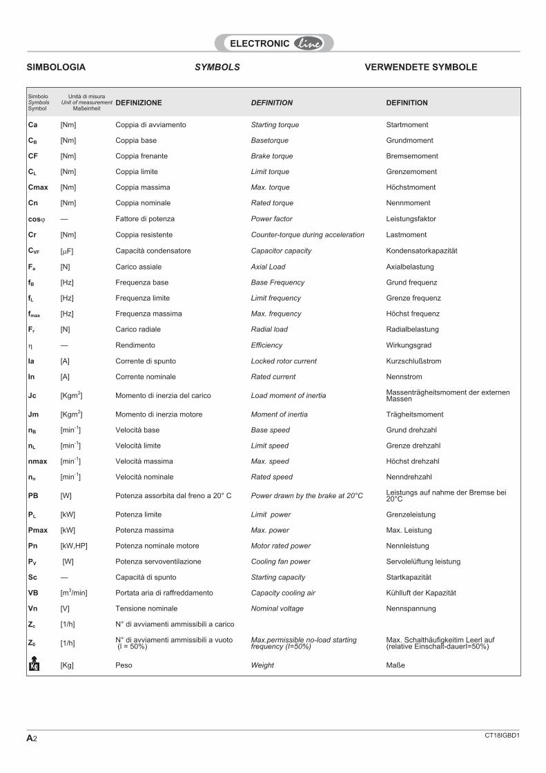
SIMBOLOGIA
SimboloSymbolsSymbol
Unità di misuraUnit of measurement
MaßeinheitDEFINIZIONE DEFINITION DEFINITION
Ca [Nm] Coppia di avviamento Starting torque Startmoment
CB [Nm] Coppia base Basetorque Grundmoment
CF [Nm] Coppia frenante Brake torque Bremsemoment
CL [Nm] Coppia limite Limit torque Grenzemoment
Cmax [Nm] Coppia massima Max. torque Höchstmoment
Cn [Nm] Coppia nominale Rated torque Nennmoment
cos� — Fattore di potenza Power factor Leistungsfaktor
Cr [Nm] Coppia resistente Counter-torque during acceleration Lastmoment
CVF [�F] Capacità condensatore Capacitor capacity Kondensatorkapazität
Fa [N] Carico assiale Axial Load Axialbelastung
fB [Hz] Frequenza base Base Frequency Grund frequenz
fL [Hz] Frequenza limite Limit frequency Grenze frequenz
fmax [Hz] Frequenza massima Max. frequency Höchst frequenz
Fr [N] Carico radiale Radial load Radialbelastung
� — Rendimento Efficiency Wirkungsgrad
Ia [A] Corrente di spunto Locked rotor current Kurzschlußstrom
In [A] Corrente nominale Rated current Nennstrom
Jc [Kgm2] Momento di inerzia del carico Load moment of inertia Massenträgheitsmoment der externenMassen
Jm [Kgm2] Momento di inerzia motore Moment of inertia Trägheitsmoment
nB [min-1] Velocità base Base speed Grund drehzahl
nL [min-1] Velocità limite Limit speed Grenze drehzahl
nmax [min-1] Velocità massima Max. speed Höchst drehzahl
nn [min-1] Velocità nominale Rated speed Nenndrehzahl
PB [W] Potenza assorbita dal freno a 20° C Power drawn by the brake at 20°C Leistungs auf nahme der Bremse bei20°C
PL [kW] Potenza limite Limit power Grenzeleistung
Pmax [kW] Potenza massima Max. power Max. Leistung
Pn [kW,HP] Potenza nominale motore Motor rated power Nennleistung
PV [W] Potenza servoventilazione Cooling fan power Servolelüftung leistung
Sc — Capacità di spunto Starting capacity Startkapazität
VB [m3/min] Portata aria di raffreddamento Capacity cooling air Kühlluft der Kapazität
Vn [V] Tensione nominale Nominal voltage Nennspannung
Zc [1/h] N° di avviamenti ammissibili a carico
Z0 [1/h] N° di avviamenti ammissibili a vuoto(l = 50%)
Max.permissible no-load startingfrequency (I=50%)
Max. Schalthäufigkeitim Leerl auf(relative Einschalt-dauerI=50%)
[Kg] Peso Weight Maße
SYMBOLS VERWENDETE SYMBOLE

CT18IGBD1 A3
1.0 MOTORI TRIFASE E MONOFASETHREE-PHASE AND SINGLE-PHASE ELECTRIC MOTORS
DREHSTROM- UND EINPHASENMOTOREN
T-TA,D-DA,H-HA,I-IA.R-RA,S-SA,M-MA,MD-MDA,
MF-MFA,MC
1.1 Generalità General information Allgemeines A4
1.2 Designazione Designation Bezeichnungen A12
1.3 Caratteristiche meccaniche Mechanical characteristics Mechanische Ausführung A16
1.4 Caratteristiche elettriche Electrical specifications Elektrische eigenschaften A26
1.5 Opzioni Options Optionen A31
1.6 Motori asincroni autofrenanti Self-braking SelbstbremsendeAsynchronmotoren
A37
1.7 Dati tecnici Technical specifications Technische Daten A50
1.8 Dimensioni Dimensions Abmessungen A72
Pag.PageSeite

CT18IGBD1A4
NormeStandards
IEC(World)
CENELEC(Europe)
CEI(Italy)
UNEL(Italy)
DIN(Germany)
VDE(Germany)
BS(U.K.)
NFC(France)
UL*(USA)
NEMA*(USA)
CAN-CSA*
(Canada)
Caratteristiche elettricheElectrical specificationsElektrische Merkmale
IEC34-1
HD53.1.S2
CEIEN
60034-1
VDE0530T1
BS26135000
NFC51-10051-120
UL1004
NEMAMG1
CSA22.2
N0 100
Grado di protezioneProtection classSchutzart
IEC34-5
EN60034-5
CEIEN
60034-5
UNEL05515
DIN40050
VDE0530
BS4999-20
NFC51-115
UL1004
NEMAMG1
CSA22.2
No.100
Metodo ventilazione motoriMotor ventilation systemMethode derMotorenbelaüftung
IEC34-6
EN60034-6
DINIEC 34-6
BS4999-21
NEMAMG1
Forme costruttiveConfigurationsBauformen
IEC34-7
HD53.7
CEIEN
60034-7
UNEL05513
DIN42950
NFC51117
NEMAMG1
Limiti di rumorositàNoise limitsGeräuschlimits
IEC34-9
CEIEN
60034-9
Voltaggi unificatiStandardized voltagesGenormte Spannungen
IEC38
CEI8-6
NFC6
UL1004
NEMAMG1
CSA22.2
No.100
Caratteristiche dimensionaliSizes and dimensionsAbmessungen
IEC72-1 CEI
IEC 74-1
UNEL131131311713118
DIN426734267742946
BS3979
NFC51-10551-120
NEMAMG1
Sicurezza del macchinarioequipaggiamento elettricodelle macchineMachinery safety electricequipment of the machinesSicherheit der Anlage undder elektrichen Ausrüstungder Maschinen
CEIEN
60204-1
* a richiesta / * upon request / * auf Anfrage
Norme di riferimento
Marcatura CE
I motori industriali del presente catalogosono costruiti in conformità alla normativaIEC 60034 la quale include la Direttiva Bas-sa Tensione CEE 73/23 (1973), modificatacon CEE 93/68 (1993) e la direttiva EMCCEE 89/336.I nostri motori sono conformi inoltre alla Di-rettiva Macchine 98/37/CEE rilevando cheil componente motore non potrà esseremesso in servizio prima che la macchi-na, in cui esso sarà incorporato, sia sta-ta dichiarata conforme alle disposizionidella direttiva.Ai fini della sicurezza è applicata la normaEN 60204-1 (Equipaggiamento elettricodelle macchine) e delle avvertenze genera-li sulla sicurezza riportate nel manualed'uso del costruttore.
Omologazione(USA - Canada)Su richiesta sono possibili, previo accordosulle quantità con la STM SpA, forniture dimotori marcati secondo Norma UL 1004Standard for Safety e Norma CAN/CSAC22.2No. 100 Motors and Generators.
Approval(USA - Canada)Upon agreement as to the quantities sup-plied by STM SpA, motors marked for ap-proval by UL 1004 Standard for Safety andCAN/CSA-C22.2 standard No. 100, Motorsand Generators, are available for supply.
Zulassung(USA - Canada)Die STM SpA liefert auf Wunsch bei vere-inbarten Mengen Motoren nach UL 1004(Standard for Safety) und nachCAN/CSA-C22.2 No. 100 (Motors and Ge-nerators).
Reference standards Bezugsnormen
1.1 GENERAL INFORMATION
CE mark
The industrial motors in this catalogue are
manufactured conforming to IEC 60034standard which includes the Low VoltageDirective CEE 73/23 (1973), revised byCEE 93/68 (1993) and the EMC CEE89/336 directive.Our motors also comply with Machine Di-
rective 98/37/CEE which states that the
motor component may not be put into
service until the machine into which it is
incorporated has been declared to com-
ply with the rules of the directive.In the interests of safety, standard EN60204-1 (Machine electrical equipment) isapplied as well as general safety warningsgiven in the manufacturer’s User manual.
EG-Kennzeichnung
Die in diesem Katalog aufgeführten Moto-ren für den industriellen Einsatz sind ge-mäß der Norm IEC 60034 gebaut, die dieRichtlinie 73/23/EWG (1973) für Nieder-spannung, geändert durch die Richtlinie93/68/EWG (1993), und die Richtlinie EMC89/336/EWG umfasst.Unsere Motoren stimmen ferner mit derRichtlinie 98/37/EWG für Maschinen über-ein. Hierbei wird herausgestellt, dass dasBauteil Motor erst in Betrieb genommenwerden kann, nachdem die Maschine,in die er eingebaut ist, in Übereinstim-mung mit den Bestimmungen der Richt-linie erklärt wurde.Für die Sicherheit kommen die Norm EN60204-1 (Elektrische Ausrüstung von Ma-schinen) und die allgemeinen Sicherheits-hinweise aus der Betriebsanleitung desHerstellers zur Anwendung.
1.1 ALLGEMEINES1.1 GENERALITÀ

CT18IGBD1 A5
MOTORI TRIFASE / THREE-PHASE MOTORS / DREHSTROMMOTOREN
I motori asincroni sono con rotore a gabbiadi scoiattolo pressofusa, statore avvolto,chiusi, ventilati esternamente secondo IEC34-6.
The induction motors we produce havedie-cast squirrel cage motor and woundstator, are enclosed and have external coo-ling to IEC 34-6.
Alle unsere Asynchronmotoren haben ei-nen druckgegossenen Käfigläufer, gewic-kelten Stator und sind geschlossen undaußenbelüftet nach IEC 34-6.
Serie / Series/ Serie Designazione Designation Typenschlüssel A12
T - TAD - DA
Caratteristiche meccaniche Mechanical characteristics Mechanische Ausführung A16Caratteristiche elettriche Electrical characteristics Elektrische Ausführung A26Collegamenti morsettiera Terminal board connections Klemmenanschlüsse A29Opzioni Options Optionen A31
Grand. / Size / Größe Freno Brake Bremse A3750...160 Dati tecnici Technical specifications Technische Daten A52
Dimensioni Dimensions Abmessungen A72
Design with high level of technology, withnew characteristics of construction,multipourpouse applications for save en-ergy. Efficiency, is increased on range of (5- 10)%, in function of motor type.In generall high efficiency save energy withhigh power applications, with a lot of motorsor with high power motors.
Progetto di elevato contenuto tecnologico edi caratteristiche innovative per quanto ri-guarda la tecnologia utilizzata, studiato perapplicazioni generali. L’efficienza rispettoun motore standard è incrementata nel ran-ge del (5-10)%, funzione del tipo che si con-sidera.In generale l’alta efficienza comporta unrisparmio energetico notevole con grossiconsumi, quindi con molti motori o di eleva-ta potenza.
Für allgemeine Anwendungen entwickeltesProjekt auf hohem technologischem Ni-veau mit innovativen Merkmalen hinsicht-lich der eingesetzten Technologie. Je nachMotortyp wurde der Wirkungsgrad gegen-über einem Standardmotor um 5-10% ge-steigert.Im Allgemeinen garantiert der hohe Wir-kungsgrad eine bemerkenswerte Reduzie-rung des Energieverbrauchs insbesonderebei Großverbrauchern, d.h. beim Einsatzvieler Motoren oder von Motoren hoher Lei-stung.
Serie / Series/ Serie Designazione Designation Typenschlüssel A12
HHA
Caratteristiche meccaniche Mechanical characteristics Mechanische Ausführung A16Caratteristiche elettriche Electrical characteristics Elektrische Ausführung A26Collegamenti morsettiera Terminal board connections Klemmenanschlüsse A29Opzioni Options Optionen A31
Grand. / Size / Größe Freno Brake Bremse A3756...160 Dati tecnici Technical specifications Technische Daten A52
Dimensioni Dimensions Abmessungen A72
High efficiency motor (EFF1)
Drehstrom-asynchronmotoren
High efficiency motor (EFF1)Motori ad alta efficienza (EFF1)
Three-phase induction motorsMotori asincroni trifase

CT18IGBD1A6
MOTORI TRIFASE / THREE-PHASE MOTORS / DREHSTROMMOTOREN
From a mechanical standpoint, given thegrade G6.3 rotary balance per ISO1940-UNI 4218, at discretion of technicaloffice, in the defluxing area it is possible toachieve approximately 3 times the ratedmotor speed without rotorstator contacts.A steel insert is provided in the bearing slotthat prevents radial movement by the outerring with a fair degree of security (at discre-tion of technical office).In this type of motor, the bearing ispre-charged with an appropriate elastic ringthat eliminates residual mechanical clea-rance within the bearing itself.As our row radial ball bearings are still ableto turn without problems for the sizes weuse at rotation speeds around 10000 rpm,this is additional insurance of long motor lifeand low noise levels.From an electrical standpoint, we also wishto point out that many motors are built withspecial duallayer and shortened-pitch win-dings for the pur pose of eliminating undesi-red torque harmonics and satisfy the needfor variable-speed controls. Low-leak ma-gnetic sheet metals Cp = 10W/Kg at 50Hz/1T are always used with a favorable ra-tio (stator slots/rotor slots). Special, reinfor-ced insulation systems are used.Generally speaking, it is possible to defluxapproximately 2 times with this type of mo-tor while keeping the rated power constant(2p - 6000 rpm).This holds for 2- and 4-pole motors powe-red at the maximum rated star voltage Y.This type of motor may also be used con-nected to � (and powered by the inverter toachieve a constant rated torque at the ratedstar voltage Y – see figure below), with ther-mal duty control.
Example: a 230V/400V/50 Hz motor is con-nected to � and taken to 400V/87 Hz at con-stant torque. The available powers aremore or less those listed in the catalogue. Ifthe motor operates below 50 Hz, or withspecifications other than the rated listings,power cooling is required.
Aufgrund der Auswuchtung der rotierendenTeile vom Grade G 6.3 nach ISO 1940-UNI4218 kann von der Mechanik her im Bere-ich der verminderten Stromentnahme circadie dreifache Nenndrehzahl des Motorsohne Kontakt zwischen Läufer und Statorerreicht werden. Um Radialbewegungendes äußeren Rings weitgehend au-szuschließen, wurde der Sitz des Lagersmit einem Einsatz aus Stahl versehen(nach Ermessen der technischen Abtei-lung). Das Lager wird bei dieser Art von Mo-toren durch einen geeigneten elastischenRing vorgespannt, der das in den Lagernverbliebene mechanische Spiel beseitigt.Unsere Lager mit einem Kugelkranz sindgroßdimensionier t und sind problemlos fürDrehzahlen bis zu 10000 min-1 einsetzbar.Außerdem gewährleisten sie eine lange Le-bensdauer und einen ruhigen Lauf des Mo-tors.Durch den Einsatz von Spezialwicklungenmit doppelter Lackschicht und ver minder-tem Wicklungsschritt werden, um denAnforderungen der Überwachung wechsel-nder Drehzahlen zu genügen, Oberschwin-gungen vermieden. Auch in diesem Fallwerden Magnetbleche mit einem niedrigenVerlustfaktor von Cp=10W/kg bei 50 Hz miteinem günstigen Verhältnis zwischen Sta-tor-und Läuferschlitzen sowie besondersverstärkte Isoliersysteme eingesetzt. Mitdieser Ar t von Motor kann die Stromen-tnahme bei gleichbleibender Leistung umetwa die Hälfte verminder t werden (2p -6000 min-1 ), d.h. bei 2- und 4-poligen Moto-ren auf die max. Sternspannung Y desTypenschilds. Dieser Motor kann außer-dem in � -Schaltung (invertergespeist) ver-wendet werden, so daß bei max.Sternspannung Y ein konstantes Nennmo-ment erreicht wird (siehe Abbildung unten)mit Überwachung des thermischen Verhal-tens.Beispiel: Ein Motor von 230V/400V/50Hz istin � -Schaltung angeschlossen (und wirddann auf das konstante Drehmoment bis400V/87Hz gebracht). Die verfügbaren Lei-stungen sind im Katalog angegeben. Wennder Motor unter 50Hz oder mit von denTypenschild-Nennwerten abweichendenWerten betrieben wird, muß eine Servo-belüftung vorgesehen werden.
Dal punto di vista meccanico, data l’equili-bratura dei rotanti di grado G6.3 secondoISO 1940-UNI 4218, a discrezione ufficiotecnico, si possono raggiungere in zona dideflussaggio circa 3 volte la velocità nomi-nale del motore, senza contatti rotore stato-re. È presente un inserto in acciaio nellasede del cuscinetto che permette con unacerta sicurezza di evitare movimenti radialidell’anello esterno (a discrezione ufficiotecnico). In questo tipo di motori il cuscinet-to è precaricato da un anello elastico appro-priato, che elimina i giochi meccaniciresidui all’interno dei cuscinetti stessi.Essendo ancora i nostri cuscinetti a una co-rona di sfere in grado di girare senza pro-blemi, per le grandezze da noi utilizzate, avelocità di rotazione dell’ordine di 10000rpm (giri/minuto) ciò è ulteriore garanzia didurata e silenziosità del motore. Dal puntodi vista elettrico si vuole ancora fare pre-sente che molti motori sono realizzati conavvolgimenti speciali a doppio strato e pas-so raccorciato, con lo scopo di eliminare ar-moniche indesiderate di coppia, persoddisfare le esigenze di controlli a velocitàvariabile.Sono sempre utizzate lamiere magnetichea bassa perdita Cp=10W/Kg a 50Hz/1T,con rapporto favorevole (cave statore/caverotore). Sono utilizzati sistemi di isolamentospeciali, rinforzati. Indicativamente, conquesto tipo di motore si può deflussare cir-ca 2 volte, mantenendo costante la potenzadi targa (2p - 6000 min-1). Ciò per motori 2 e4 poli, alimentati alla tensione massima ditarga stellata Y. Si può ancora utilizzarequesto tipo di motore collegato a � (e ali-mentato dall’inverter in modo da arrivare acoppia costante nominale, alla V nominalestellata Y (vedi figura sotto), con verifica delservizio termico.Esempio: un motore 230V/400V/50 Hz sicollega a � (e lo si porta a coppia costantefino a 400V/87Hz. Le potenze disponibili in-dicativamente sono quelle da catalogo.Se si scende a funzionare al di sotto dei50Hz, o a caratteristiche diverse dalle no-minali di targa, è imposto l’uso della servo-ventilazione.
Serie / Series/ Serie Designazione Designation Typenschlüssel A12
I - IA
Caratteristiche meccaniche Mechanical characteristics Mechanische Ausführung A16Caratteristiche elettriche Electrical characteristics Elektrische Ausführung A26Collegamenti morsettiera Terminal board connections Klemmenanschlüsse A29Opzioni Options Optionen A31
Grand. / Size / Größe Freno Brake Bremse A3750...160 Dati tecnici Technical specifications Technische Daten A52
Dimensioni Dimensions Abmessungen A72
Inverter motors InvertermotorenMotori per inverter

CT18IGBD1 A7
P
Pmax
[W]
Pn
50Hz 87Hz f [Hz]
A B C D
B
C
D
Frequenza di base / / GrundfrequenzBase frequency
Frequenza massima / / HöchstfrequenzMaximum frequency
Frequenza limite / / GrenzfrequenzLimit frequency
MOTORI TRIFASE / THREE-PHASE MOTORS / DREHSTROMMOTOREN
Special high-technology motors for applica-tions requiring a high starting torque whilemaintaining the synchronous speed. Themotor starts as a high- performanceasynchronous motor; then, if load condi-tions permit, it synchronizes to achieve andmaintain synchronous speed in synchrono-us mode. Example: a 4-pole motor poweredat 50 Hz reaches exactly 1500 rpmat nominal load. Standard power outputsare generally achieved, in relation to a cata-logue motor, at around 40% in S1 duty atthe rated input.
Es handelt sich dabei um hochtechnologi-sche Spezialmotoren für Anwendungsbere-iche, in denen ein hohes Anzugsmomentund zugleich die Erhaltung der Synchron-geschwindigke i terforderlich ist. Der Motorstartet wie ein hochleistungsfähigerAsynchron- motor, synchronisiert sich, so-bald es die Last gestattet, und läuft dannmit Synchrongeschwindigkeit im Synchron-betrieb weiter.Beispiel: Ein 4poliger Motor mit 50 Hz erre-icht bei Nennlast genau 1500 Umdrehun-gen. Verglichen mit Standardmotorenwerden Betriebsleistungen von 40% imS1-Betrieb bei gleichen Eingangsnennwer-ten erzielt.
Motori speciali ad elevata tecnologia perapplicazioni in cui è richiesta un’alta coppiadi spunto e contemporaneamente il mante-nimento della velocità di sincronismo. Il mo-tore si avvia come un asincrono di elevatecaratteristiche poi, se le condizioni di caricolo permettono, si sincronizza raggiungendoe mantenendo la velocità sincrona in fun-zionamento sincrono.Esempio: un motore 4 Poli alimentato a 50Hz., raggiunge esattamente i 1500 rpm acarico nominale. Indicativamente si otten-gono potenze rese di regime, rispetto unmotore da catalogo, nell’ordine del 40% inservizio S1 alle caratteristiche nominali diingresso.
Serie / Series/ Serie Designazione Designation Typenschlüssel A12
RRA
Caratteristiche meccaniche Mechanical characteristics Mechanische Ausführung A16Caratteristiche elettriche Electrical characteristics Elektrische Ausführung A26Collegamenti morsettiera Terminal board connections Klemmenanschlüsse A29Opzioni Options Optionen A31
Grand. / Size / Größe Freno Brake Bremse A3763...160 Dati tecnici Technical specifications Technische Daten A66
Dimensioni Dimensions Abmessungen A72
Motore collegato a APn= potenza nominale motore (230V)Pmax= potenza massima (400V)
Motor connected to APn= rated motor power (230V)Pmax= maximum power (400V)
Motor in A-SchaltungPn= Nennleistung des Motors (230V)Pmax= max. Leistung (400V)
Zone di funzionamento(per collegamento standard):AB= zona a coppia costanteBC= zona a potenza costanteCD= zona a potenza calante
Operating areas(for standard connection):AB= constant torqueBC= constant power areaCD= falling power area
Betriebsbereiche(für Standardanschlüsse):AB= Bereich mit konstantem DrehmomentBC= Bereich mit konstanter LeistungCD= Bereich mit abnehmender Leistung
Synchronous asynchronousthreephase motors (reluctance)(per CEI EN 60034-1 / IEC 34-1)
Drehstrom-Asynchronmotoren undSynchronmotoren (Reluktanz).(nach CEI EN 60034-1 / IEC 34-1)
Motori asincroni trifasesincronizzati (riluttanza).(secondo CEI EN 60034-1 / IEC

CT18IGBD1A8
These are special motors that make use ofup-to-date design and manufacturing tec-hnologies. The stator is wound whereas therotor is monobloc and features highshort-circuit resistance. The main characte-ristic of this motor is the possibility of wor-king at constant power when the number ofrpm changes. Under particular conditionsthe motor's rotor can stay locked withoutexceeding the rated temperature class forwhich it is designed. For special applica-tions the motor can be equipped with axialservoassisted ventilation with high loc-ked-rotor torque increments as comparedto the standard motor.
Use range.The usual range of application is for thewinding of stitching wire, yarn, adhesivetape, steel band, etc., situations in whichwhen the speed changes the material is tobe pulled constantly and steadily to preventit from breaking. Another possibility is thatof using it as a BRAKE IN THE OPPOSINGFIELD, up to about half the synchronismspeed. As far as special applications areconcerned, please contact our technical de-partment.
Special and single-phase cumulativelycompound motorsSingle-phase and special cumulativelycompound motors can be manufactured, invarious shapes and polarities, with suppliedtorque features on request.
Torque adjustmentVoltage converters are used for adjustingthe value of the supplied torque, dependingon the type of material to be processed,withchange of torque in quadratic functionof the voltage applied to the terminals. Vol-tage is adjusted by means of electronic ormechanical devices that detect the tensionof the wire and therefore regulate the torquesupplied by the motor accordingly, creatinga closed-ring feedback system.
MOTORI TRIFASE / THREE-PHASE MOTORS / DREHSTROMMOTOREN
Hierbei handelt es sich um Spezialmotorenmit moderner Entwicklungstechnologie undKonstruktionstechnik. Der Stator ist gewic-kelt, während der Läufer aus einem Blockmit hohem Kurzschlußwiderstand besteht.Das wichtigste Merkmal eines solchen Mo-tors liegt in der Möglichkeit des Betriebs beikonstanter Leistung und variablen Dreh-zahlen. Unter besonderen Bedingungenüberschreitet der Motor auch bei blockier-tem Läufer die Temperatur der Isolie-rungsklasse, für die er entwickelt wurde,nicht. Für Sonderanwendungen kann derMotor mit einem axialen Servolüfter mit ge-genüber dem Standardmotor erhöhtemAntriebsdrehmoment bei blockiertem Läu-fer geliefert werden.Einsatzbereich.Der normale Anwendungsbereich umfaßtdie Wicklung von Metalldrähten, Zwirn, Kle-bebändern, Bandeisen, d.h. diese Motorenkommen in den Anwendungen zum Ein-satz, in denen bei Änderungen der Dreh-zahl eine konstante Spannung desMaterials erforderlich ist, um ein Reißendesselben zu vermeiden. Eine weitere Mö-glichkeit liegt im Einsatz als BREMSE IMGEGENFELD bis ca. zur Hälfte derSynchrongeschwindigkeit. HinsichtlichSonderanwendungen sollten Sie sich anunsere technische Abteilung wenden.Spezial- und Einphasen-Schlupfmotoren
Auf Anfrage sind wir in der Lage, Spezial-und Einphasen-Schlupfmotoren in ver-schiedenen Bauformen und Polanzahlenmit kundenspezifischem Anlaufdrehmomentherzustellen.
Einstellung des AnlaufdrehmomentsUm den Wert des verfügbaren Anlaufdreh-moments je nach Typ oder zu verarbeiten-dem Material einzustellen, werdenSpannungsregler eingesetzt, die das Anla-ufdrehmoment als quadratische Funktionder an den Klemmen angelegten Span-nung regulieren. Die Einstellung der Span-nung kann über elektronische oder mecha-nische Vorrichtungen erfolgen, die dieSpannung auf dem Leiter erfassen und dasvom Motor erzeugte Anlaufdrehmomententsprechend regulieren. Dabei wird einSystem mit Rückkopplung im geschlosse-nen Kreislauf gebildet.
Sono motori speciali, con impiego di tecno-logie di progetto e costruzione moderne. Lostatore è avvolto, mentre il rotore è mono-blocco ad alta resistenza in cortocircuito. Lacaratteristica principale di tale motore è lapossibilità di funzionare a potenza costanteal variare del numero di giri. In particolaricondizioni il motore può rimanere a rotorebloccato senza che superi la temperaturaalla classe di isolamento per cui è progetta-to. Per applicazioni speciali si può dotare ilmotore di servo ventilazione assistita assia-le, con incrementi di coppia motrice a rotorebloccato elevati, rispetto il motore standard.
Campo di utilizzazione.Il campo di applicazione usuale è quellodove si bobinano fili metallici, filati, nastriadesivi, reggetta, quindi nelle situazioni incui al variare della velocità si desidera tirocostante del materiale per evitare di spez-zarlo. Altra possibilità è di utilizzarlo comeFRENO IN CONTROCAMPO, fino a circala metà della velocità di sincronismo. Perapplicazioni speciali contattare il nostro uffi-cio tecnico.
Motori a scorrimento speciali e monofasi
Si possono realizzare, motori a scorrimentomonofasi e speciali, nelle varie forme e po-larità, con caratteristiche di coppia motriceerogata su richiesta.
Regolazione della coppia motricePer regolare il valore della coppia motriceerogata, in funzione del tipo o materiale datrattare, si utilizzano dei variatori di tensio-ne, con variazione della coppia motrice fun-zione quadratica della tensione applicata aimorsetti. La regolazione di tensione può es-sere fatta con dispositivi elettronici o mec-canici che rilevano la tensione del filo eregolano la coppia motrice erogata dal mo-tore di conseguenza, realizzando un siste-ma in retroazione ad anello chiuso.
Serie / Series/ Serie Designazione Designation Typenschlüssel A12
S - SA
Caratteristiche meccaniche Mechanical characteristics Mechanische Ausführung A16Caratteristiche elettriche Electrical characteristics Elektrische Ausführung A26Collegamenti morsettiera Terminal board connections Klemmenanschlüsse A29Opzioni Options Optionen A31
Grand. / Size / Größe Freno Brake Bremse A3771...132 Dati tecnici Technical specifications Technische Daten A62
Dimensioni Dimensions Abmessungen A72
Slip motors Drehstrom-SchlupfmotorenMotori a scorrimento

CT18IGBD1 A9
MD - MDA
High-technology motors resulting from ourown exclusive experience and technology.High power outputs, 30% lower than stan-dard catalogue motors, all other conditionsbeing equal. In some cases a single capaci-tor is used for both speeds, providing sim-pler circuitry.Quiet, reliable, high performance, theyrepresent an evolutionary step for the sin-gle-phase motor. They have % starting cur-rents and starting drive torque % si milar tostandard motors.
MOTORI MONOFASE / SINGLE-PHASE MOTORS / EINPHASENMOTOREN
MD - MDA
Es handelt sich dabei um hochtechnologi-sche Spezialmotoren, die aus unserer ex-klusiven Erfahrung und Technologieentstanden sind, die ausschließlich dankunserer Erfahrung und unserer technologi-schen Kenntnisse entworfen und gebautwerden konnten.Mit diesen Motoren können hohe Betrieb-sleistungen erzielt werden, die bei Gleic-hheit aller übrigen Bedingungen um ca.30% niedriger sind als bei unseren Stan-dardmotoren. Es besteht die Möglichkeit,um den Schaltkreis zu vereinfachen, nur ei-nem Kondensator für zwei Geschwindigkei-ten einzusetzen. Es handelt sich umgeräuscharme und zuverlässige Motorenmit hoher Leistung, die als Weiterentwic-klung des herkömmlichen Einphasen-mo-tors mit ähnlichen Anlaufströmen undAnlaufmomenten, angesehen werden kön-nen.
MD - MDA
Motori ad alto contenuto tecnologico deri-vati dalla nostra esclusiva esperienza e tec-nologia.Si ottengono elevate potenze rese, ridotte diun 30% rispetto i motori standard da catalo-go, a parità di tutte le altre condizioni.In alcuni casi, utilizzando un solo conden-satore per le due velocità, con conseguentesemplificazione circuitale. Silenziosi, affida-bili, di elevate prestazioni, sono una ulterio-re evoluzione del motore monofase, hannocorrenti di spunto in % e coppie motrici diavviamento %, simili ai motori standard.
Serie / Series/ Serie Designazione Designation Typenschlüssel A12
M - MAMD - MDA
Caratteristiche meccaniche Mechanical characteristics Mechanische Ausführung A16Caratteristiche elettriche Electrical characteristics Elektrische Ausführung A26Collegamenti morsettiera Terminal board connections Klemmenanschlüsse A29Opzioni Options Optionen A31
Grand. / Size / Größe Freno Brake Bremse A3750...100 Dati tecnici Technical specifications Technische Daten A68
Dimensioni Dimensions Abmessungen A76
Serie / Series/ Serie Designazione Designation Typenschlüssel A12
MFMFA
Caratteristiche meccaniche Mechanical characteristics Mechanische Ausführung A16Caratteristiche elettriche Electrical characteristics Elektrische Ausführung A26Collegamenti morsettiera Terminal board connections Klemmenanschlüsse A29Opzioni Options Optionen A31
Grand. / Size / Größe Freno Brake Bremse A3750...100 Dati tecnici Technical specifications Technische Daten A70
Dimensioni Dimensions Abmessungen A76
They are motors produced with a specialwinding, they work with a single capacitorfor double voltage and frequency (example115V/230V -50 Hz/60 Hz). You can reversethe rotation of the motor with simple con-nections in the terminal box. Refering to thepower given to the shaft (W) and the gene-ral performance of the motors, they can becompared to M series.
Es handelt sich hier um Motoren mit einerSpezialwicklung. Mit nur einem Betriebs-kondensator kann der Motor mit zwei Span-nungen und zwei Frequenzen betriebenwerden (Beisp.: 115V/230V-50Hz/60Hz).Durch einfache Verbindungen am Klem-menbrett ist die Umschaltung der Drehrich-tung möglich. Die an die Welle abgegebeneLeistung [W] und die Leistungen im allge-meinen sind bei gleicher Baugröße mit denMotoren der Serie M.
Sono motori realizzati con un avvolgimentospeciale. Si ottiene un funzionamento conun solo condensatore per le due tensioni ele due frequenze. (esempio 115V/230V-50Hz/60Hz). É possibile l'inversione delsenso di rotazione del motore con semplicicollegamenti in morsettiera. Le potenzerese all'albero [W], e le prestazioni in gene-rale sono paragonabili, ai motori SERIE M apari grandezza di macchina.
I motori asincroni sono con rotore a gabbiadi scoiattolo pressofusa, statore avvolto,chiusi, ventilati esternamente secondo IEC34-6.
The induction motors we produce havedie-cast squirrel cage motor and woundstator, are enclosed and have external coo-ling to IEC 34-6.
Alle unsere Asynchronmotoren haben ei-nen druckgegossenen Käfigläufer, gewic-kelten Stator und sind geschlossen undaußenbelüftet nach IEC 34-6.
Single-phase motors Einphasenmotoren
Single-phase, dual voltage and dualfrequency motors
Motori monofase
Einphasenmotoren Spannungs-undFrequenzumschaltbar
Monofase doppia tensione e doppiafrequenza

CT18IGBD1A10
MOTORI MONOFASE / SINGLE-PHASE MOTORS / EINPHASENMOTOREN
This is a highly stable device, as it detectsthe rpm of the motor. It consists of a rotarypart keyed to the motor shaft, a duly insu-lated electrical part keyed to the rear motorshield, and an aluminum cap for mechani-cal protection, with sealing gaskets that en-sure an IP 55 rating for the unit.Only STM can offer complete motorprotection with centrifugal circuit breaker atIP 55 through an aluminum cap (on re-quest). Without protection cap. (standard)- Centrifugal switch IP20- Motor IP55.
Upon request internal centrifugal circuit
breaker.This device has a normally closedspring-loaded contact. When the motor be-gins to turn, the centrifugal force acts ontwo masses rotating on the shaft and exertsa force that overcomes the opposition of thespring once the rated rpm is reached.This opens the contact and disconnects thestarting capacitor used to achieve the highstarting drive torque.It may be approved by UL and CSA stan-dards.dards (on request).
Es handelt sich um eine Vorrichtung dieununterbrochen eingeschaltet ist, da sie dieMotordrehzahl erfaßt. Der Fliehkraftschal-ter besteht aus einem Drehteil, das an derMotorwelle befestigt ist, aus einem e n t s prechendisolierten elektrischen Teil, das amhinteren Lagerschild angebracht ist, undaus einer Schutzhaube aus Aluminium mitDichtungen in der Schutzart IP55. Der kom-plette Schutz des Motors durch einen Flieh-kraftschalter mit Aluhaube in der SchutzartIP55 ist ein Exklusivprodukt der STM (aufAnfrage). Ohne Schutzkalotte (standard):- Abschalter IP20- Motor IP55.
Auf Anfrage eingebauter Fliehkraftab-schalter am Motor.Diese Vorrichtung hat einen normalerweisevon einer Feder geschlossenen Kontakt.Wenn sich der Motor in Betrieb setzt, über-windet die Fliehkraft - mit Hilfe von zweiDrehgewichten an der Welle - beim Errei-chen der Nenndrehzahl die Kraft der Federund öffnet den Kontakt, wobei der zumErreichen des hohen Anzugsmoments die-nende Anlaufkondensator ausgeschaltetwird. Der Fliehkraftschalter kann nach ULoder CSA zugelassen werden (auf Anfrage).
È un dispositivo molto stabile in quanto rile-va i giri al minuto del motore. È compostoda una parte rotante calettata sull’alberomotore, da una parte elettrica debitamenteisolata, calettata sullo scudo posteriore almotore e da una calotta in alluminio di pro-tezione meccanica, con guarnizioni di tenu-ta, che assicurano una protezione IP 55all’insieme. La protezione completa del mo-tore con disgiuntore centrifugo in IP 55 tra-mite calotta in alluminio (fornibile a richies-ta).Senza calotta di protezione (standard):- disgiuntore IP20- motore IP55.
A richiesta disgiuntore interno al motore.
Questo dispositivo ha un contatto normal-mente chiuso tramite molla; quando il moto-re inizia a girare, la forza centrifuga, agendosu due masse rotanti sull’albero, esercitauna forza che raggiunto il numero di giri no-minali vince l’opposizione della mollaaprendo il contatto e sconnettendo il con-densatore di spunto servito per ottenerel’alta coppia motrice di avviamento.È omologabile secondo norme UL o CSA (arichiesta).
Motori monofase ad alta coppia dispunto
Sono motori provvisti di dispositivi che han-no lo scopo di connettere, in parallelo alcondensatore di marcia, un condensatoredi spunto che, una volta avviato il motore,viene disinserito automaticamente rilevan-do diverse grandezze in funzione deldispositivo utilizzato.Le coppie motrici ottenibili allo spunto [Nm],sono paragonabili a quelle di un motoretrifase equivalente.
Wechselstrommotoren mit hohemAnlaufmoment
Es handelt sich um Motoren, die über Vor-richtungen für die Parallelschaltung desAnlaufkondensators mit dem Betriebskon-densator verfügen. Sobald der Motor läuftwird der Anlaufkondensator automatischausgeschaltet und unterliegt der Steuerungder eingesetzten Vorrichtung. Das erreic-hbare Anlaufmoment [Nm] entspricht demvergleichbarer Drehstrommotoren.
Single-phase motors with highstarting torque
These are motors with devices for thepurpose of connecting a starting capacitorin parallel with the run capacitor, which isshut off automatically once the motor isstarted and measures various parametersbased on the device in question.The drive torque that may be achievedduring starting [Nm] is comparable to that ofan equivalent three-phase motor.
Serie / Series/ Serie Designazione Designation Typenschlüssel A12
MC
Caratteristiche meccaniche Mechanical characteristics Mechanische Ausführung A16Caratteristiche elettriche Electrical characteristics Elektrische Ausführung A26Collegamenti morsettiera Terminal board connections Klemmenanschlüsse A29Opzioni Options Optionen A31
Grand. / Size / Größe Freno Brake Bremse A3750...100 Dati tecnici Technical specifications Technische Daten A68
Dimensioni Dimensions Abmessungen A76
Centrifugal circuit breaker FliehkraftschalterMotori monofase con disgiuntorecentrifugo

CT18IGBD1 A11
MOTORI MONOFASE / SINGLE-PHASE MOTORS / EINPHASENMOTOREN
This is an ampere relay which overcomesthe force of an antagonist spring when thestarting torque is high, working through acoil and mobile armature with electricalcontact, to connect the starting capacitorparallel to the run capacitor.When the motor has started the absorbedcurrent drops and the antagonist spring isthen able to overcome the electromagneticforce of the coil, thereby disconnecting thestarting capacitor.This device is available in various amperecapacities and is approved per UL and CSAstandards.
È un relay amperometrico, il quale quandola corrente allo spunto è elevata, agendotramite una bobina e un’ancora mobile concontatto elettrico, vince la forza di una mollaantagonista, connettendo in parallelo alcondensatore di marcia quello di avviamen-to.Nel momento in cui il motore si è avviato, lacorrente assorbita cala e la molla antagoni-sta questa volta è in grado di vincere la for-za elettromagnetica della bobina per cuidisconette il condensatore di spunto.Tale dispositivo è disponibile in varie porta-te amperometriche, ed è omologato secon-do norme UL e CSA.
Es handelt sich dabei um ein amperometri-sches Relais. Wenn der Anlaufstrom hochist, überwindet dieses Relais durch eineSpule und einen beweglichen Anker mitSchaltkontakt die Kraft einer Gegenfederund schaltet den Anlaufkondensator undden Betriebskondensator parallel.Sobald der Motor läuft, verminder t sich dieStromaufnahme, und die Gegenfeder über-windet die elektromagnetische Kraft derSpule und schaltet den Anlaufkondensatoraus.Diese Vorrichtung, die über eine UL- bzw.CSA-Zulassung verfügt, ist für unterschie-dliche Amperwerte lieferbar.
Serie / Series/ Serie Designazione Designation Typenschlüssel A12
MRMRA
Caratteristiche meccaniche Mechanical characteristics Mechanische Ausführung A16Caratteristiche elettriche Electrical characteristics Elektrische Ausführung A26Collegamenti morsettiera Terminal board connections Klemmenanschlüsse A29Opzioni Options Optionen A31
Grand. / Size / Größe Freno Brake Bremse A3750...100 Dati tecnici Technical specifications Technische Daten A68
Dimensioni Dimensions Abmessungen A76
Single/phase induction motors withelectronic capacitor
Asynchronmotoren mitelektronischem Kondensator und
Motori monofase con condensatoreelettronico
Single-phase motor with Ampererelay (Klixon)
Einphasenmotoren mit Stromrelais(Klixon)
Motori monofase con Relèamperometrico (Klixon)
Single/phase induction motors withelectronic capacitor
This is a timed electronic device built intothe housing of an impregnated-paper ca-pacitor.This device starts a timer when the motor ispowered, when the starting capacitor is par-allel to the run capacitor; after a certain pe-riod of tie, the timer disconnects the startingcapacitor to achieve a high starting torque,allowing start-stop cycles every 3 seconds.
Motori asincroni monofase concondensatore elettronico
È un dispositivo elettronico temporizzato in-tegrato nell’involucro di un condensatore acarta impregnata.Questo dispositivo, al momento dell’ali-mentazione del motore, quando il conden-satore di spunto è in parallelo a quello dimarcia, fa partire un timer che dopo un cer-to periodo di tempo disconnette il con-densatore di spunto stesso, ottenendo cosìl’alta coppia di spunto, consente cicli start-stop ogni 3 secondi.
Asynchronmotoren mitelektronischem Kondensator undhohem Anlaufmoment
Es handelt sich um eine zeitgesteuer te,elektronische Vorrichtung, die sich in derHülle eines Kondensators aus imprägnier-tem Papier befindet.Sobald der Motor mit Strom versorgt wirdund wenn der Anlaufkondensator parallelzum Betriebskondensator geschaltet ist,schaltet diese Vorrichtung einen Timer ein,der nach Ablauf einer bestimmten Zeit denAnlauf-kondensator ausschaltet. Auf dieseWeise wird ein hohes Anlaufmoment er-reicht. Der Ein -und Ausschaltvorgang kannin Abständen von 3 Sekunden erfolgen.
Serie / Series/ Serie Designazione Designation Typenschlüssel A12
MEMEA
Caratteristiche meccaniche Mechanical characteristics Mechanische Ausführung A16Caratteristiche elettriche Electrical characteristics Elektrische Ausführung A26Collegamenti morsettiera Terminal board connections Klemmenanschlüsse A29Opzioni Options Optionen A31
Grand. / Size / Größe Freno Brake Bremse A3750...100 Dati tecnici Technical specifications Technische Daten A68
Dimensioni Dimensions Abmessungen A76

CT18IGBD1A12
DescrizioneDescription
Beschreibung
T 63 A 4 B5 — 55 F FA M LS1TipoTypeTyp
GrandezzaSize
Größe
LunghezzaLenghtLänge
n° poliPole n.Polzahl
[*1] [*2] [*3] [*4] [*5] [*6] [*7]
MOTORI TRIFASE / THREE-PHASE MOTORS / DREHSTROMMOTORENTrifaseThree-phaseDrehstrom
T50...160
A...
ML
2468
12
B5B14*B3
*B35 (B3/B5)*B34 (B3/B14)
B3L4B3L2
—AB
(Vedi tabelle)(See tables)
(Siehe Tabellen)
545556
FH FA M
Trifase autofrenanteSelf braking three-phaseDrehstrom, Bremsmotor
TA
Alta EfficienzaHigh efficiencyMit hohem Wirkungsgrad
H56...160 2-4
Alta Efficienza autofrenanteSelf braking high efficiencyMit hohem Wirkungsgrad, Bremsmotor
HA
Per InverterFor inverterFür Inverter
I50...160 2-4-6
Per Inverter autofrenanteFor self braking inverterFür Inverter, Bremsmotor
IA
Trifase doppia polaritàDual polarity three-phaseDrehstrom, polumschaltbar
D
56...160
2/44/84/66/82/62/8
2/12
Trifase doppia polarità autofrenanteSelf braking dual polarity three-phaseDrehstrom, polumschaltbar,Bremsmotor
DA
a ScorrimentoSlipSchlupf
S71...132 4-6-8
a Scorrimento autofrenanteSelf braking slipSchlupf, Bremsmotor
SA
a RiluttanzaReluctanceReluktanz
R63...160 2-4-6
a Riluttanza autofrenanteSelf braking reluctanceReluktanz, Bremsmotor
RA
MOTORI MONOFASE / SINGLE-PHASE MOTORS / EINPHASENMOTORENMonofaseSingle-phaseEinphasen
M
50...100A...
ML2-4-6
5B14*B3
*B35 (B3/B5)*B34 (B3/B14)
B3L4B3L2
—
(Vedi tabelle)(See tables)
(Siehe Tabellen)
545556
FH FA M
Monofase autofrenanteSelf braking single-phaseEinphasen, Bremsmotor
MA
Monofase doppia polaritàDual polarity single-phaseEinphasen, polumschaltbar
MD
Monofase doppia polaritàautofrenanteSelf braking dual polarity single-phaseEinphasen, polumschaltbar,Bremsmotor
MDA
Doppia tensione doppia frequenzaDual frequency dual voltageSpannungs- und frequenzumschaltbar
MF
Doppia tensione doppia frequenzaautofrenanteSelf braking dual frequency dual voltageSpannungs- und frequenzumschaltbar,Bremsmotor
MFA
Con disgiuntore centrifugoWith centrifugal circuit breakerMit Fliehkraftschalter
MC
Con relè amperometricoWith ampere relayMit Stromrelais
MR
Con relè amperometrico autofrenanteWith self braking ampere relayMit Stromrelais, Bremsmotor
MRA
Con condensatore elettronicoWith electronic capacitorMit elektronischem Kondensator
ME
Con condensatore elettronicoautofrenanteWith self braking electronic capacitorMit elektronischem Kondensator,Bremsmotor
MEA
1.2 DESIGNATION 1.2 BEZEICHNUNGEN1.2 DESIGNAZIONE

CT18IGBD1 A13
ELECTRONIC line
B3 B3L4 B3L2standard
[*2] Voltage and frequency (page A27)Specify STD voltage or upon request
[*3] Protection level
[*4] Insulation class (page A26)
[*5] Type of brake
[*6] Increased brake (page A43-A45)
M – Only available on FA and FD bra-kes
[*7] OptionsState the symbol for the option requi-red.Option details on page A14.
A richiestaOn requestAuf anfrage
CL FStandard CL H
Indicazione designazioneDesignation indication
BezeichnungF H
Freni disponibili Brakes available Lieferbare Bremsen Pag./ Page / SeiteFreno in C.A. AC brake Wechselstrombremse FA 42
Freno in C.C. DC brake Gleichstrombremse FD 44
Freno di stazionamento Parking brake Haltebremse FS 46
Freno ad azione positiva Positive action brake Arbeitsstrombremse FP 48
[*1] Design version (page A16)Specify adapted connectionsIf IEC adapted connections: e.g. 71 B5.
If just shaft or flange specify dimensions.e.g.: 160/11.
On design versions with feet, the terminalbox can be set in three positions.
[*1] Bauform (S. A16)Verkleinerte Befestigungen angebenWenn verkleinerte BefestigungenIEC:ES.71 B5.
Wenn nur Welle oder Flansch Maße ange-ben z.B.: 160/11.Bei den Bauformen mit Fuß kann der Klem-menkasten in drei Positionen ausgerichtetwerden.
[*1] Forma (pag. A16)Specificare attacchi ridotti.Se attacchi ridotti IEC: ES. 71 B5.
Se solo albero o flangia specificare dimen-sioni : Es. 160/11.
Nelle forme costruttive con piede, la scatolamorsettiera può essere orientata in tre posi-zioni.
[*2] Spannung und Frequenz (S. A27)Spannung STD oder auf Wunsch an-geben
[*3] Schutzart
[*2] Tensione e frequenza (pag. A27)Specificare tensione STD o a richiesta
[*3] Grado di protezione
[*4] Isolierstoffklasse (S. A26)[*4] Classe di isolamento (pag. A26)
[*5] Bremsentyp[*5] Tipo di freno
[*6] Vergrößerte Bremse (S. A43-A45)M – Nur für die Bremsen FA und FDerhältlich
[*7] OptionenDas Symbol der gewünschten Optionangeben.Optionen siehe S. A14
[*6] Freno maggiorato (pag. A43-A45)M – Disponibile solo sui freni FA e FD
[*7] OpzioniIndicare il simbolo della opzione chesi desidera.Dettaglio opzioni a pag. A14.
FrenoBrake
BremseIP54 IP55 IP56 IP65
TA-DA-HA-IA-RA-SA-MA-MDA-MFA
FA StandardFD StandardFS StandardFP Standard
Indicazione designazioneDesignation indication
Bezeichnung54 55 56 65
IP54 IP55 IP56 IP65T-D-H-I-R-S-M-MD-MF Standard
Indicazione designazioneDesignation indication
Bezeichnung54 55 56 65

CT18IGBD1A14
Tipo opzione / Option type / Option
Applicabilità / Applicability / Anwendbarkeit
Descrizione / Description / Beschreibung Note Pag.trifase / three-phase
Drehstrommotoren50..160
monofase / single-phaseEinphasenmotoren
50..160
Alimentazione separataSeparate voltage supplySeparate Stromversorgung
..SAFreno ad alimentazione separata A.C.Brake with separate AC voltage supplyBremse mit separater Wechselstromversorgung
1)
39
..SDFreno ad alimentazione separata D.C.Brake with separate DC voltage supplyBremse mit separater Gleichstromversorgung
39
Leva di sbloccoRelease leverEntsperrhebel
LS..Posizione leva di sbloccoRelease lever positionPosition des Entsperrhebels
2) 38
Avviamento e frenata progressiviProgressive starting and brakingAnlauf- und bremsverzögert
PR 3) 39
ServoventilazionePower coolingServobelüftung
VFServoventilato monofaseSingle-phase power cooledServobelüftet Einphasen
4) 32
VTServoventilato trifaseThree-phase power cooledServobelüftet Drehstrom
5) 32
Albero bisporgenteDouble ended shaftZweiseitige Welle
BI 6) 35
Protezioni termicheThermal overload cut-out switchesÜberhitzungsschutz
TOProtezione termica PTOPTO thermal overload cut-out switchPTO-Überhitzungsschutz
35
TCProtezione termica PTCPTC thermal overload cut-out switchPTC-Überhitzungsschutz
35
3TO3 Protezioni termiche PTO (standard)3 PTO thermal overload cut-out switches (standard)PTO-Überhitzungsschutz 3 Stück (Standard)
—
3TC3 Protezioni termiche PTC3 PTC thermal overload cut-out switchesPTC-Überhitzungsschutz 3 Stück
—
Protezione umiditàDamp protectionFeuchtigkeitsschutz
TRTropicalizzatoTropicalizedTropenfest
31
InterruttoreSwitchSchalter
ITInterruttore semirotativoSemi-rotary switchPTC-Überhitzungsschutz 3 Stück
7)
—
IVInvertitore semirotativoSemi-rotary inverterUmkehrschalter 180º-Drehbereich
—
Normative estereForeign standardsAusländische Normen
URcRSus (Normative americane)cRSus (American standards)cRSus (Amerikanische Normen)
—
VentoleFansLüfterräder
VMVentola in metalloMetal fansLüfterrad aus Metall
32
SVSenza ventolaNo fanOhne Lüfterrad
32
Tettuccio parapioggiaRain shieldRegenschutzdach
PP 8) 36
Scarico condensaCondensation drainageKondenswasserablauf
FCForo scarico condensaCondensation drainage holeKondenswasserablaufloch
31
Scaldiglie anticondensaAnti-condensation heatersWicklungsheizung
SC 31
Doppia morsettieraDouble terminal boardDoppelte Klemmenleisten
DM 8b) —
Encoder EN 34
Motore per alte temperatureMotor for high temperaturesMotor für hohe Temperaturbereiche
TCon anelli tenuta Viton e parti metallicheWith Viton retention rings and metal partsMit Viton-Dichtungsringen und Metallteilen
—
Doppio avvolgimentoDouble windingDoppellagige Wicklung
DA 9) —
Condensatore MFMF CapacitorKondensator MF
C.. —
Avvolgimento equilibratoBalanced windingAusgewuchtete Wicklung
AE 36
Tipo di servizioType of dutyBetriebsart
S 21

CT18IGBD1 A15
Note:
1) If nothing is indicated the voltage shownin the catalogue applies.Otherwise indicate the voltage supply (e.g.:24SD for 24 V in DC)
2) Option not available of brake types: FS, FP
3) Cast iron fan (or flywheel, on self brakingmotors)
4) Option not available: BI
5) Option not available: BI. Standard sepa-rate power supply. Not available IEC: 50,56, 63, 71.
6) Option not available: PP, VF, VT
7) Only on standard single-phase andthree-phase
8) Option not available: BI
8b) See terminal board table on page A30
9) Option not available. Dual polarity mo-tors with dual polarity (e.g.: 2/4, 4/8, etc.)
Esempio / Example / Beispiel **
LS1 VF 3TO** Motore con leva di sblocco in posizione 1,servoventilazione e 3 protezioni PTO
** Motor with release lever in position 1, powercooling and 3 PTO overload switches
** Motor mit Entsperrhebel in Position 1,Servobelüftung und 3 Stück PTO-Über hitzun-gsschutz
Anmerkungen:
1) Sofern nicht anderweitig angegeben, giltder Spannungswert aus dem Katalog. An-dernfalls den Wert der Versorgungsspan-nung angeben (Beispiel: 24SD für 24 VGleichstrom)
2) Option nicht erhältlich für Bremsen vomTyp: FS, FP
3) Lüfterrad aus Gusseisen (oder Schwun-grad bei Bremsmotoren)
4) Option nicht erhältlich: BI
5) Option nicht erhältlich: BI. SeparateStandardversorgung. Nicht erhältlich IEC:50, 56, 63, 71
6) Option nicht erhältlich: PP, VF, VT
7) Nur für Drehstrom und Einphasen inStandardausführung
8) Option nicht erhältlich: BI
8b) Siehe Klemmenanschlusstabelle S. A 30
9) Option nicht erhältlich. PolumschaltbareMotoren mit zwei Polungen (Beispiel: 2/4,4/8, etc.)
Note:
1) Se non viene indicato niente si intende ilvalore di tensione riportato a catalogo.Altrimenti riportare il valore della tensione dialimentazione( esempio: 24SD per 24 V in D.C.).
2) Opzione non disponibile sui freni tipo :FS; FP
3) Ventola in ghisa (o volano, nei motori au-tofrenanti)
4) Opzione non disponibile: BI
5) Opzione non disponibile: BIAlimentazione separata StandardNon disponibile IEC: 50, 56, 63, 71
6) Opzioni non disponibili: PP, VF, VT
7) Solo su trifase e monofase standard
8) Opzione non disponibile: BI
8b) Vedi tabella morsettiere a pag. A30
9) Opzione non disponibile: Motori doppiapolarità con polarità doppia (esempio: 2/4;4/8 ecc.)

CT18IGBD1A16
1.3 CHARACTERISTICS
Forme costruttive
Nella tabella seguente sono riportate le for-me costruttive dei motori e le posizioni dimontaggio secondo IEC 34-7.Versioni B3, B5, B14.
Forma costruttiva baseBasic design version
Gundbauform
Forma costruttiva derivataDerived design version
Andere Einbaulagen
IM B3 IM B6 IM B7 IM B8 IM V5 IM V6
IM B5 IM V1 IM V3
IM B14 IM V18 IM V19
IM 1051 (IM B6)
IM 1061 (IM B7)
IM 1071 (IM B8)
IM 2001 (IM B35)
B3/B5
IM 1001 (IM B3)
IM 1011 (IM V5)
IM 1031 (IM V6)
IM 2101 (IM B34)
B3/B14
IM 3001 (IM B5)
IM 3031 (IM V1)
IM 3031 (IM V3)
IM 2011 (IM V15)
V3/V5
IM 3601 (IM B14)
IM 3631 (IM V18)
IM 3631 (IM V19)
IM 2031 (IM V36)
V3/V6
Motori con piedi B3Motors with feet B3Motoren mit Füßen B3
Motori con Flangia B5Flange-mounted motors B5Motoren mit Flansch B5
Motori con Flangia B14Flange-mounted motors B14Motoren mit Flansch B14
Carcassa (secondo CEI-IEC 72-1)È in alluminio pressofuso, ad elevata capaci-tà meccanica, con buona conducibilità termi-ca, ed elevata leggerezza. È disponibile inversione con tiranti standard e a richiestacon borchie.
Available configurations
Available configurations Table shows theavailable motor configurations and installa-tion positions per I EC 34-7.Versions B3,B5, B14.
Bauformen
Bauformen In der Tabelle sind die Baufor-men der Motoren und die Einbaupositionennach IEC 34-7 aufgeführt.Ausführungen: B3, B5, B14.
1.3 DREHMOMENTMERKMALE1.3 CARATTERISTICHEMECCANICHE
The plates on the motors show (unless ot-herwise indicated) the basic design versionbut can be installed in the derived designversions as indicated in the following table:
Frame (per CEI-IEC 72-1)Die-cast aluminum with high mechanicalcapacity, good thermal conductivity, andvery lightweight. Frames are available in aversion with standard tie-rods, with studsupon request.
Gehäuse (nach CEI-IEC 72-1)Das Motorgehäuse ist Aluminium-Druckgußmit hoher Widerstandsfähigkeit, guterWärmeleitfähigkeit und geringem Gewicht.Das Gehäuse ist als Ausführung mit Stan-dard-Zugstangen oder auf Wunsch mit Nie-ten lieferbar.
Tab. 1.1
Tab. 1.2
Die Motoren weisen auf dem Typenschild(sofern nicht anderweitig angegeben) dieGrundbauform auf, sie können jedoch inden abgeleiteten Formen gemäß der nach-stehenden Tabelle installiert werden:
I motori riportano in targa (salvo diversa in-dicazione) la forma costruttiva base mapossono essere installati nelle forme deri-vate come indicato nella tabella seguente:

CT18IGBD1 A17
Gli alberi motore e le linguette di seriesono conformi, per quanto riguarda dimen-sioni e tolleranze, alle CEI IEC 72-1.Gli alberi di serie sono costruiti con acciaioC43.
As standard, the drive shafts and tangshave dimensions and tolerances to CEI IEC72-1.Standard shafts are constructed in C43 ste-el.
Die serienmäßigen Antriebswellen undFederkeile entsprechen in den Abmessun-gen und der Toleranz der Nor m CEI IEC72-1. Die serienmäßigen Wellen sind ausC43-Stahl hergestellt, Motorengehäuse.
Cuscinetti
Sono del tipo ZZ anteriormente e posterior-mente (2RS stagni a richiesta), con dueschermi metallici, e prelubrificati con grassoal litio con range di temperature da -10 °C a+110 °C.Possono essere applicati cuscinetti stagnianteriori, cuscinetti a gioco maggiorato C3o con grasso speciale per alte temperature(-30 °C a +140 °C) - grassi sintetici.Sono tutti precaricati, tramite anelli ondulatiin acciaio temprato, per eliminare i giochiresidui del cuscinetto.
Grandezza / Size / Baugröße 50 56 63 71 80 90 100 112 132 160
Lato comando / Front / Vorne 6000-ZZ 6201-ZZ 6202-ZZ 6203-ZZ 6204-ZZ 6205-ZZ 6206-ZZ 6206-ZZ 6308-ZZ 6309-ZZ
* Lato opposto comando / Back / Hhinten 6000-ZZ 6201-ZZ 6202-ZZ 6203-ZZ 6204-ZZ 6205-ZZ 6206-ZZ 6206-ZZ 6308-ZZ 6309-ZZ
* 2RS a richiesta / * 2RS upon request / * 2RS auf Anfrage
Bearings are type ZZ front and back ( 2RSupon request), with two metal screens,pre-lubrificated with lithium grease with atemperature range from -10° C till +110° C.Waterproof front bearings, C3 bearings withincreased clearance, or bearings with spe-cial grease for high temperatures (-30 ° C to+140 ° C)/synthetic grease may be applied.All are pre-loaded with corrugated tempe-red steel rings to eliminate residual clearan-ce from the bearing.
Vorn und hinten vom Typ ZZ (abgedichtete2RS-Lager auf Anfrage), ausgestattet mitzwei metallenen Schutzkappen, vor-geschmiert mit Lithiumfett und geeignet fürden Temperaturbereich von -10° C bis+110° C.Auf Wunsch sind geschlossene Vorderla-ger, Lager mit größerem Spiel (C3) oder mitSpezialfett für extreme Temperaturberei-che von -30° C bis +140° C (synthetischeFette) lieferbar. Alle Lager sind durch Au-sgleichsringe aus gehärtetem Stahl axialvorgespannt, um eventuell noch vorhande-nes Spiel zu beseitigen.
Bearings Lager
I cuscinetti da noi utilizzati sono ad una co-rona di sfere radiali, precaricati, di marcheprimarie.I motori sono costruiti per un servizio S1standard, altre esecuzioni a richiesta.
We use preloaded radial ball bearing ringsof the best makes, which our company con-siders reliable.Motors are manufactured for standard S1service, other executions on request..
Die von uns eingesetzten Lager sind vorge-spannte einreihige Radialkugellager eineserstrangigen Lieferanten, die wir für zu-verlässig halten. Die Motoren sind für dieBetriebsart S1 Standard ausgelegt.Andere Ausführungen auf Anfrage.
Geometric tolerances
DescrizioneDescriptionBeschreibung
DimensioniDimensions
Abmessungen
TolleranzaToleranceToleranz
Diametro alberoShaft diameterWellendurchmesser
D� 9 � 28� 32 � 48� 55 � 110
j6k6m6
Linguetta CEI IEC 72-1CEI IEC 72-1 Standardized keysNach CEI IEC 72-1 genormte Paßfedern
F h9
GA 2 � 67 � 16
h9h11
Flange unificate CEI IEC 72-1CEI IEC 72-1 Standardized flangesNach CEI IEC 72-1 genormte Flansche
N � � 450 j6
Alltezza d’asse secondo CEI IEC 72-1Axis height per CEI IEC 72-1Achsenhöhe nach CEI IEC 72-1
H +0 � -0.5
Battuta alberoShaft stopWellenansatz
E - EA +0 � -0.2
The table below shows the mechanical tole-rances of the control side.
Tab.1.4
Tab.1.3
Geometrische Toleranzen
In der nachstehenden Tabelle sind die me-chanischen Toleranzen auf der Frontseiteangegeben.
Tolleranze geometriche
Nella tabella seguente sono riportate le tol-leranze meccaniche dal lato comando.

CT18IGBD1A18
Flange e scudi (secondo CEI IEC 72-1)Sono in lega di alluminio pressofuso, di di-mensioni unificate secondo CEI IEC 72-1,su disegno del cliente, ridotte o maggiorate.Nella grandezza 160 le flange B5 e B14sono in ghisa.
Flanges and shields (per CEI-IEC 72-1)These are made of die-cast aluminu malloy,with standard dimensions per CEI-IEC 72-1or based on customer drawings, reduced orenlarged.On 160 sizes the B5 and B14 flanges are incast iron.
Flansche und Lagerschilder (nachCEI-IEC 72-1)Die Flansche und Lagerschilder sind ausAluminium-Druckguß und sind mit genor-mten Abmessungen nach CEI-IEC 72-1oder nach Kundenzeichnung in größereroder kleinerer Ausführung lieferbar. In derGröße 160 sind die Flansche B5 und B14aus Guß.
Dimensions of design versionswith flange
T
C B DD
U
U
T
C
B5 B14
B
Grandezza motoreMotor sizeBaugröße
IEC 71_1
� alberoShaft diam.
� Welle
� flangia B5B5 Flange diam.
� Flansch B5
� flangia B14B14 Flange diam.
� Flansch B14
D C T B C T B
50 IEC 56 Standard 9 — — — 80 65 50
56IEC 56 Standard 9 120 100 80 80 65 50
IEC 63 11 — — — 90 75 60
63
IEC 56 9 120 100 80 90 65 50IEC 63 Standard 11 140 115 95 90 75 60
IEC 71 14 — — — 105 85 70IEC 80 14 — — — 120 100 80
71
IEC 56 9 120 100 80 — — —IEC 63 11 140 115 95 105 75 60
IEC 71 Standard 14 160 130 110 105 85 70IEC 80 19 — — — 120 100 80IEC 90 19 — — — 140 115 95
80
IEC 63 11 140 115 95 — — —IEC 71 14 160 130 110 120 85 70
IEC 80 Standard 19 200 165 130 120 100 80IEC 90 24 — — — 140 115 95
IEC 100/112 24 — — — 160 130 110
90
IEC 71 14 160 130 110 — — —IEC 80 19 200 165 130 140 100 80
IEC 90 Standard 24 200 165 130 140 115 95IEC 100/112 28 — — — 160 130 110
100
IEC 71 14 160 130 110 — — —IEC 80 19 200 165 130 120 100 80IEC 90 24 200 165 130 160 115 95
IEC 100/112 Standard 28 250 215 180 160 130 110IEC 132 28 — — — 200 165 130
112IEC 90 24 200 165 130 140 115 95
IEC 100/112 Standard 28 250 215 180 160 130 110IEC 132 — — — — 200 165 130
132IEC 100/112 28 250 215 180 — — —
IEC 132 Standard 28 300 265 230 200 165 130
160 IEC 160 Standard 42 350 300 250 250 215 180
Tab.1.5
Abmessungen der Bauformen mitFlansch
Dimensioni delle forme costruttivecon flangia

CT18IGBD1 A19
Gradi di protezione (IP)
Il grado di protezione standard dei motori èIP55. Sono possibili esecuzioni speciali perambienti aggressivi con protezione mag-giorata o specifica, salvo diverse indicazio-ni in targa motore.
Il grado di protezione meccanica è stabilitoin accordo alla IEC 60034-5 ed è indicatodalla dicitura IP seguita da due cifre caratteristiche.
IP Definizione / Definition / Erklärung IP Definizione / Definition / Erklärung
0Nessuna protezione specialeNo special protection
Kein besonderer Schutz0
Nessuna protezione specialeNo special protection
Kein besonderer Schutz
1
Protezione contro i corpi solidi superiori a 50 mm(esempio: contatti involontari della mano)Protection from solid bodies larger than 50 mm(e.g.: accidental hand contact)
Schutz gegen feste Fremdkörper > 50 mm(Beispiel: zufälliges Berühren mit der Hand)
1
Protezione contro la caduta verticale di gocce d'acqua (condensa)Protection from drops of water falling vertically (condensation)
Schutz gegen senkrecht fallendes Tropfwasser (Kondenswasser)
2
Protezione contro i corpi solidi superiori a 12 mm(esempio: contatti involontari delle dita della mano)Protection from solid bodies larger than 12 mm(e.g.: accidental contact with fingers)
Schutz gegen feste Fremdkörper > 12 mm(Beispiel: zufälliges Berühren mit den Fingern)
2
Protezione contro la caduta verticale di gocce d'acqua con un'inclinazionefino a 15°Protection from drops of water falling vertically at angles up to 15°Schutz gegen senkrecht fallendes Tropfwasser mit einem Schrägwinkel bis15°
3
Protezione contro i corpi solidi superiori a 2.5 mm(esempio: fili utensili)Protection from solid bodies larger than 2.5 mm(e.g.: tool cables)
Schutz gegen feste Fremdkörper > 2,5 mm(Beispiel: Drähte, Werkzeuge)
3
Protezione contri gli spruzzi d' acqua con inclinazione fino a 60°Protection from sprayed water at angles of up to 60°.
Schutz gegen Sprühwasser mit einem Schrägwinkel bis 60°
4
Protezione contro i corpi solidi superiori a 1 mmProtection from solid bodies larger than 1 mm
Schutz gegen feste Fremdkörper > 1 mm4
Protezione contri gli getti d'acqua provenienti da tutte le direzioniProtection from water spray coming from all direction
Schutz gegen Spritzwasser, das aus allen Richtungen gegen die Maschinespritzt
5
Protezione contro la polvere(non deve penetrare in quantità dannosa)Protection from dust(must not penetrate in dangerous quantities)
Schutz gegen Staubablagerungen(darf nicht in schädlichen Mengen eindringen)
5
Protezione contro l'acqua proiettata con un ugello sul motore da tutte ledirezioniProtection from water sprayed with a nozzle on the motor from all directions
Schutz gegen Strahlwasser, das mit einer Düse aus allen Richtungen aufden Motor gerichtet wird.
6
Protezione completa contro la polvereComplete protection from dust
Vollständiger Schutz gegen Staubablagerung 6
Protezione contri gli getti d'acqua potenti da tutte le direzioni(non deve penetrare in quantità dannosa)Protection from water spray coming from all directions(must not penetrate in dangerous quantities)
Schutz gegen starkes Strahlwasser, das aus allen Richtungen gegen dieMaschine gerichtet ist (darf nicht in schädlichen Mengen eindringen)
7Protezione contro gli effetti dell'immersione tra 0.15 1 mProtection from the effects of immersion between 0.15 and 1 m
Schutz beim Eintauchen zwischen 0,15 und 1 m
8
Protezione contro gli effetti prolungati dell'mmersione in acqua allecondizioni concordate tra il produttore e l'utilizzatoreProtection from the effects of prolonged immersion in water at conditionsagreed between the manufacturer and user
Schutz bei verlängertem Untertauchen zu zwischen Hersteller undAnwender vereinbarten Bedingungen
IP55 standard protection rating of the mo-tors. Special executions are possible forharsh environments with greater or specificprotection except for other indications onmotor rating plate.
The mechanical protection level is set in ac-cordance with IEC 60034-5 and is indicatedby the letters IP followed by two characteri-stic numbers
Die Motoren verfügen über die Stan-dard-Schutzart IP55. Sonderausführungenfür aggressive Umgebungen mit verstärk-tem oder spezifischem Schutz sind, sofernauf dem Typenschild des Motors nicht an-ders angegeben, lieferbar.Die mechanische Schutzart in gemäß IEC60034-5 festgelegt und durch die Kennzeic-hnung IP gefolgt von zwei Ziffern angege-ben.
Housing protection level (IP) Schutzarten (IP)
Tab.1.6

CT18IGBD1A20
Nominal and operatingspecifications(per CEI EN 60034-1/IEC 34-1)
Pn - Rated power [KW]:This is the mechanical power supplied tothe shaft, expressed in kW per internationalstandards. You will also find it expressed inHP in the tables.
Vn - Rated voltage [Volt]:This is the incoming voltage to be applied tothe motor terminals in standard configura-tions 230 V/400V/ 50 Hz/S1. In asynchron-ous three-phase motors, a voltage variation
of up to � 10% of rated values is tolerable(Tab. 10 - pag. A28).
Ca - Starting torque [Nm]:Minimum torque provided by the motor withthe rotor blocked, powered at the rated volt-age and frequency.
Cmax - Maximum torque [Nm]:this is the maximum torque that the motorcan develop during operation when pow-ered at the rated voltage and frequency,without brusquely stopping or slowingdown.
Cn - Rated torque [Nm]:This is the torque resulting from the ratedpower at the rated rpm. The rated torquevalue is determined by the formula:
Pn = rated power expressed in kW
n = rated rotation speed expressed in rpm
ns -Synchronous speed:The synchronous speed (see graph) is de-termined by the formula:
f frequenza di alimentazione espressa in Hz supply frequency expressed in Hz Speisefrequenz in HzP numero di poli number of poles Anzahl der PoleCR coppia resistente resistance torque WiderstandsmomentCa coppia di avviamento starting torque AnlaufmomentCmax coppia massima maximum torque HöchstmomentCn coppia nominale rated torque Nennmomentrpm giri/min. rounds per minutes Umdrehungen/MinuteCM coppia motrice drive torque Antriebsmoment
CM
CR
Ca
0
N•m
Cn
Cm
ax
ns rpm
Cn 9740Pn
n[Nm]� �
nf 120
p[rpm]s �
�
Nennwerte undBetriebseigenschaften(nach CEI EN 60034-1/IEC 34-1)
Caratteristiche nominali e difunzionamento(secondo CEI EN 60034-1/IEC 34-1)
Pn - Nennleistung [KW]:Ist die an die Welle abgegebene mechani-sche Leistung, die nach den internationalenNormen in kW ausgedrückt wird. In einigenTabellen wird sie auch in HP angegeben.
Vn - Nennspannung [Volt]:Ist die Spannung, die an den Klemmen vonMotoren in der Standardausführung230V/400V/ 50Hz/S1 angelegt sein muß.Bei Drehstrom-Asynchronmotoren ist eineAbweichung von � 10% von den Nennwer-ten akzeptabel (Tab. 10 - Seite A28).
Ca - Anlaufmoment [Nm]:Kleinstes Moment, das der Motor mit Nenn-spannung und -frequenz bei blockiertemLäufer liefert.
Cmax - Höchstmoment [Nm]:Höchstes Moment, das der Motor währendseines Betrieb mit Nennspannung und -fre-quenz ohne anzuhalten und ohne abruptesAbbremsen entwickeln kann.
Cn - Nennmoment [Nm]:Ist das Moment, das sich aus der Nennlei-stung bei Nenndrehzahl ergibt. Der Wertdes Nennmoments wird mit der folgendenFormel berechnet:
Pn = Nennleistung in kWn = Motordrehzahl in min-1
ns - Synchrongeschwindigkeit:Die Synchrongeschwindigkeit (sieheSchaubild) wird mit der folgenden Formelberechnet:
Pn - Potenza nominale [KW]:è la potenza meccanica resa all'albero,espressa secondo le norme internazionaliin kW, la troverete nelle tabelle ancheespresse in HP.
Vn - Tensione nomunale [Volt]:la tensione da applicare in entrata, ai mor-setti dei motori nelle configurazioni stan-dard 230V / 400V / 50Hz/S1.Nei motori assicromi trifasi e tollerabile unavariazione di tensione fino a � 10% dei valo-ri nominali (Tab. 10 - pag A28)
Ca - Coppia di avviamento [Nm]:coppia minima che fornisce il motore a roto-re bloccato, alimentato con tensione e fre-quenza nominali.
Cmax - Coppia massima [Nm]:è la coppia massima che il motore può svi-luppare durante durante il suo funzio- na-mento alimentato con tensione e frequenzanominali, senza arrestarsi o ralentarebruscamente.
Cn - Coppia nominale [Nm]:è la coppia risultante della potenza nomina-le ai giri nominali. Il valore della coppia no-minale è dato dalla formula:
Pn = potenza nominale espressa in kWn = velocità di rotazione nominale espressa
in giri/minutons - Velocità di sincronismo:la velocità di sincronismo (vedi grafico) èdata dalla formula:

CT18IGBD1 A21
I motori, salvo diverso accordo con il co-struttore, sono progettati per il funzio-namento alle seguenti caratteristiche nomi-nali:1) altitudine inferiore a 1000 m s.l.m..2) massima temperatura ambiente di fun-zionamento inferiore a 40 °C3) minima temperatura ambiente dell'aria-15 °C (+ 5 °C per motori di potenza nomi-nale inferiore a 600 W).4) U.R. � 60%Per condizioni ambientali diverse da quellenominali, le potenze variano come indicatonel seguente diagramma:
Preale = coeff. x Pn
1
0.9
0.8
0.7
0.6
0.5
0 1000 2000 3000 4000Altitudine / (m)Altitude / Höhe
40°C
50°C
60°C
45°C
55°C
Pn
=P
ote
nza
No
min
ale
/R
ate
dp
ow
er
/N
en
nle
istu
ng
COEFFICIENTE TEMPERATURA / TEMPERATURKOEFFIZIENTTEMPERATURE COEFFICIENT /
Type of duty
The power of the motors shown in the cata-logue refers to S1 duty.For different applicational conditions thetype of duty must be identified by referringto CEI EN 60034-1 standards.As an example the following are the opera-ting conditions for S1 and S2 types.
Altitudine e temperatura Altitude and temperature Höhe und Temperatur
Unless otherwise agreed with the manufac-turer, the machines are designed to run un-der the following nominal conditions:1) Altitude below 1000 m a.s.l.2) Maximum ambient running temperaturebelow 40 °C3) Minimum ambient air temperature -15 °C(+5 °C for machines with a rated power be-low 600W).4) R.H. = 60%For ambient conditions other than thosestated above, the powers vary as indicatedin the following diagram:
Die Motoren werden, falls nicht anders mitdem Hersteller vereinbart, für die folgendenEinsatzbedingungen ausgelegt:1) Höhe unter 1000 m ü.d.M.2) max. Umgebungstemperatur unter 40°C.3) min. Umgebungslufttemperatur -15°C(+5°C bei Maschinen mit einer Nennlei-stung unter 600W).4) relative Luftfeuchtigkeit = 60% Bei vonden Nennwerten abweichenden Umge-bungsbedingungen ändern sich die Lei-stungen gemäß folgendem Diagramm:
AttenzionePer quanto riguarda i motori monofase, siraccomanda di specificare correttamente ilservizio termico di funzionamento. Esem-pio: S3 30%, in quanto in questo particolaremotore assume grande importanza la mar-cia a vuoto ai fini del riscaldamento, e que-sto perché la macchina è elettricamentesquilibrata.
AttentionFor single-phase motors, the thermal oper-ating duty must be correctly specified. Ex-ample: S3 30%, as for this motor no-loadoperation is quite important for heating pur-poses, since the machine is electrically un-balanced.
AchtungBei Wechselstrommotoren ist eine genaueAngabe des thermischen Verhaltens sehrwichtig (z.B. S3 30%), da diese Art von Mo-tor elektrisch nicht abgeglichen ist und derLeerlauf deshalb eine wichtige Rolle bei derErwärmung des Motors spielt.
S1 - Continuous duty:motor operating at a constant load for an in-definite period of time, in any case enoughto reach thermal balance.
S2 - Limited duty:motor operating at a constant load for limi-ted period of time not long enough to reachthermal balance, followed by a rest periodsufficient to bring the motor back to ambienttemperature.
BetriebsartenTipi di servizio
Für die im Katalog aufgeführten Motorenbezieht sich die Leistungsangabe auf dieBetriebsart S1.Für abweichende Einsatzbedingungen istdie Betriebsart nach CEI EN 60034-1 anzu-geben.Als Beispiel führen wir die Betriebsbedin-gungen für die Betriebsarten S1 und S2 an.
I motori riportati a catalogo hanno la poten-za riferita ad un servizio S1.Per condizioni applicative diverse è neces-sario identificare il tipo di servizio facendoriferimento alle Norme CEI EN 60034-1.A titolo esemplificativo riportiamo le condi-zioni di funzionamento relative ai tipi S1 eS2.
S1 - Dauerbetrieb:Betrieb des Motors mit konstanter Last übereinen unbestimmten Zeitraum, der für dieErreichung des Temperaturgleichgewichtsausreichend ist.
S2 - Betrieb von begrenzter Dauer:Betrieb des Motors mit konstanter Last übereinen begrenzten Zeitraum, der für dieErreichung des Temperaturgleichgewichtsnicht ausreichend ist, gefolgt von einemRuhezeitraum, der für die Abkühlung desMotors auf Umgebungstemperatur ausrei-chend ist.
S1 - Servizio continuo:funzionamento del motore a carico cos-tante per un periodo di tempo indefinito, co-munque sufficiente a raggiungere l'equili-brio termico.
S2 - Servizio di durata limitata:funzionamento del motore a carico cos-tante per un periodo di tempo limitato insuf-ficiente a raggiungere l'equilibrio termico,seguito da un periodo di riposo sufficiente ariportare il motore a temperatura ambiente.
S1 - S9: pag. D10 S1 - S9: page D10 S1 - S9: Seite D10

A22
Controllo dei motori serie T coninverter (V/F) costante
Controlling standard STM motors Tseries with constant inverter (V/F)
Überwachung derSTM-StandardmotorenSerie T für Inverter mit konstanten V/f
I motori asincroni trifase riportati a catalogo,possono essere controllati con ottimi risul-tati tramite inverter a V/F costante.Tali motori sono stati specificatamente pro-gettati pensando ad un eventuale loroimpiego a velocità, coppia e potenza varia-bili.Quindi, grazie all'impiego di materiali di ele-vata qualità, è stato possibile ottenereprestazioni elevate in termini di temperatu-re modeste, alti rendimenti anche controllatida inverter.Prove pratiche sui motori hanno consentitodi evidenziare nel grafico sottostante le pre-stazioni ottenute (i valori indicati sono pura-mente indicativi e non impegnativi perSTM).
The three-phase induction motors shown inthe catalogue can be controlled with excel-lent results by means of a constant V/F in-verter.These motors have been specificallydesigned to be used at variable speed, tor-que and power.Therefore, through the use of high qualitymaterials, it has been possible to obtainhigh performance in terms of reasonabletemperatures, high output also controlledby inverter.Practical tests carried out on the motorshave resulted in the performances shownon the graph below (the values shown arepurely approximate and not binding uponSTM).
Die im Katalog aufgeführten Drehstrom-Asynchronmotoren können mit ausge-zeichneten Resultaten über Inverter mitkonstanten V/f überwacht werden.Diese Motoren sind eigens für einen etwai-gen Einsatz mit verstellbarer Drehzahl,Drehmoment und Leistung konzipiert. Auf-grund der Verwendung von hochwertigenMaterialien konnten hohe Leistungsmerk-male in punkto mäßige Temperaturberei-che und hohe Wirkungsgrade erzieltwerden, die auch inverterüberwacht sind.Praktische Tests an den Motoren haben dieLeistungswerte ergeben, die im nachste-henden Diagramm aufgeführt sind (die an-gegebenen Werte sind ausschließlichRichtwerte und für STM nicht verbindlich).
1
2
3
2
(Anzahl in %)(volte%) / (times%) /
1.5
0.5
0 10 20 30 40 50 60 70 80 90 100 f [Hz]
1
Sovracoppia transitoria(variabile a seconda deltipo di inverter)Transient overspedd(variable according to thetype of inverter)VorübergehendeDrehmomentüberschreitung(ändert sich je nach Inverter-Typ)
Zona motori servoventilatiPower cooled motor areaBereich der servobelüftetenMotoren
Motori standardautoventilatiStandard self-cooled motorsEigenbelüfteteStandardmotoren
1
2
3
Cn [Nm]
Caratteristiche di coppiaIn questo grafico le curve definiscono lacoppia permanente e la zona 1 di sovracop-pia transitoria (di durata limitata) resa da unmotore standard autoventilato e su di unmotore servoventilato.Nel caso del motore autoventilato (zona 3) lacoppia al di sotto dei 50 Hz nominali dev'es-sere opportunamente limitata a causa dellaridotta autoventilazione affinchè la tempera-tura degli avvolgimenti non raggiunga livellipericolosi per la loro integrità.Naturalmente questa limitazione può essereevitata adottando una servoventilazione delmotore indipendente o, nel caso il funziona-mento a bassi giri, si verifichi solo per breviperiodi di tempo con intervalli di riposo suffi-cienti al raffreddamento del motore (zona 2).La servoventilazione và scelta di portata[m3 / min] adeguata al servizio termico delmotore.Per un maggiore controllo delle tempera-ture, se si prevede di utilizzare il motore, conelevate coppie, maggiori della nominale, o abassa velocità di rotazione, l'utilizzo di unatermica bimetallica è sconsigliata.
Torque characteristicsIn this graph, the curves define the perma-nent torque and the transient overspeedarea (limited duration) on a standard,self-cooled motor and a power cooled mo-tor.In the case of the self-cooled motor (area3), the torque below a rated 50 Hz must beappropriately limited due to the reducedself-cooling so that the winding temperaturedoes not reach levels hazardous to their in-tegrity.This limitation may obviously be avoided byadopting independent power cooling of themotor or, for low rpm operation, if it occursonly briefly with rest intervals sufficient tocool the motor (area 2).Power cooling should be selected with athroughput [m
3/min] suited to the thermal
duty of the motor.For greater temperature control, if the mo-tor is to be used with a torque above therated level or at a low rotation speed, werecommend using a bimetallic thermalcut-out switch.
DrehmomentmerkmaleIn dieser grafischen Darstellung wird dasNennmoment und die vorübergehendeDrehmomentüberschreitung (Bereich 1,nur für eine beschränkte Zeit) für servobe-lüftete und eigenbelüftete Standardmoto-ren durch Kurven dargestellt.Beim eigenbelüfteten Motor (Bereich 3)muß das Drehmoment unter 50 Hz auf-grund der verminderten Eigenbelüftungentsprechend beschränkt werden, um dieWicklung vor Überhitzung zu schützen. DieBeschränkung kann durch eine eigenstän-dige Servobelüftung des Motors oder durchfür die Abkühlung des Motors ausreichendlange Stillstandzeiten (Bereich 2) beim Be-trieb im niedrigen Drehzahlbereich umgan-gen werden.Die Leistung der Servobelüftung [m3] /min]muß entsprechend dem thermischen Ver-halten des Motors gewählt werden. Wenndas Nenndrehmoment des Motors häufigüberschritten oder wenn mit niedrigenDrehzahlen gearbeitet wird, kann die Tem-peraturberwachung durch den Einsatz vonBimetall-Temperaturfühlern merklich ver-bessert werden.
AttenzioneNel caso di controllo motori serie T con inverter,non si dà garanzia di durata in quanto l'isolamentoè sottoposto a picchi elevati di tensione.
AttentionIn case you control standard serie T with inverter,we are not abel to guarantee the duration,because the insulation is subject to high peaks ofvoltage.
AchtungBei Überwachnung der Motoren Serie T mitInverter kann keine Gewähr für die Lebensdauerdes Motors übernommen werden, da die Isolierunghohen Spannun- gsspitzen ausgesetzt ist.
Tab.1.7
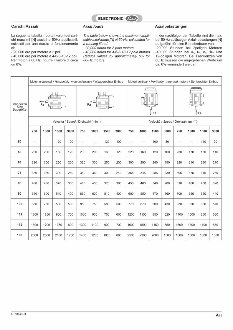
CT18IGBD1 A23
Carichi Assiali
La seguente tabella riporta i valori dei cari-chi massimi [N] assiali a 50Hz applicabili,calcolati per una durata di funzionamentodi:- 20.000 ore per motore a 2 poli- 40.000 ore per motore a 4-6-8-10-12 poliPer motori a 60 Hz. ridurre il valore di circaun 6%.
GrandezzaSize
Baugröße
Motori orizzontali / Horizontaly- mounted motors / Waagerechter Einbau Motori verticali / Vertically- mounted motors / Senkrechter Einbau
Velocità / Speed / Drehzahl (min-1) Velocità / Speed / Drehzahl (min-1)
750 1000 1500 3000 750 1000 1500 3000 750 1000 1500 3000 750 1000 1500 3000
50 — — 120 100 — — 120 100 — — 100 80 — — 110 90
56 230 200 160 120 230 200 160 120 220 160 120 100 230 170 130 110
63 320 300 250 200 320 300 250 200 300 290 240 190 320 310 260 210
71 380 360 300 240 380 360 300 240 365 345 285 230 395 375 315 250
80 480 430 370 300 480 430 370 300 450 400 340 280 510 460 400 320
90 650 600 510 400 650 600 510 400 600 550 470 360 700 650 550 440
100 850 750 580 500 850 750 580 500 770 670 500 430 930 830 660 570
112 1300 1250 950 700 1000 900 750 600 1200 1150 850 620 1100 1000 850 680
132 1800 1700 1350 800 1300 1100 900 700 1600 1500 1150 650 1500 1300 1100 850
160 2800 2500 2100 1700 1400 1200 1000 800 2500 2300 2000 1500 1600 1500 1300 1000
Fa
The table below shows the maximum appli-cable axial loads [N] at 50 Hz, calculated fora running life of:- 20,000 hours for 2-pole motors- 40,000 hours for 4-6-8-10-12 pole motorsReduce values by approximately 6% for60-Hz motors.
In der nachfolgenden Tabelle sind die max.bei 50 Hz zulässigen Axial- belastungen [N]aufgeführt für eine Betriebsdauer von:-20.000 Stunden bei 2poligen Motoren-40.000 Stunden bei 4-, 6-, 8-, 10- und12-poligen Motoren. Bei Frequenzen von60Hz müssen die angegebenen Werte umca. 6% vermindert werden.
Axial loads Axialbelastungen
Fa Fa
Fa

CT18IGBD1A24
Carichi Radiali
Da questi diagrammi è possibile ricavare ivalori dei carichi massimi Fr [N] applicabili(senza l'applicazione di un carico assialesupplementare, in funzione del punto diapplicazione del carico X.
Numero di poli / Number of poles / Polzahl2 4 6-8-10-12
Radial loads
These diagrams make it possibleto deter-mine the maximum applicable loads [N](without the application of a supplementaryaxial load, depending on the point of appli-cation of the X load).
Radialbelastungen
Aus den nachfolgenden Diagrammen kön-nen die max. zulässigen Radialbelastungen[N] (ohne zusätzliche Axiallast, in Abhän-gigkeit vom Belastungspunkt X).
Carichi radiali nel caso di utilizzo dipulegge e cinghie
Qualora l'accoppiamento del motore av-venga mediante cinghie, occorre verificareche il carico radiale gravante sull'albero nonsuperi i valori massimi consentiti.Tale verifica può essere effettuata utilizzan-do la seguente formula:
Fr = Carico radiale sull'albero in NPn = Potenza in kWnn = Velocità dell'albero in min-1
D = Diametro puleggia in mK = Coefficiente di tensione della cinghia i
cui valori indicativi sono:
2 pulegge piane con rullo tendicinghia2.25 pulegge a gola trapezoidale2.5 - 3 per servizi gravosi e altre pulegge
F19100 P K
n Dr
n
n
�� �
�
If the motor is coupled by belts, make surethe radial load on the shaft does not exceedthe maximum allowed values. This may bechecked using the following formula:
Bei Verwendung von Riemen muß geprüftwerden, ob die Radialbelastung der Welleinnerhalb der max. zulässigen Werte liegt.Diese Prüfung kann mit Hilfe der folgendenFormel durchgeführt werden:
Radial load when using pulleys andbelts
Radialbelastung beim Einsatz vonRiemenscheiben und Riemen
Fr = Radial load in N
Pn = Power in kW
nn = Shaft speed in min-1
D = Pulley diameter in meters
K = Coefficient of belt for whichthe indicative values are:
2 flat pulleys with belt stretcher roller
2.25 for trapezoid groove pulleys
2.5 - 3 for heavy duty and other pulleys
Fr = Radialbelastung in NPn = Leistung in kWnn = Drehzahl des Welle in min-1
D = Ø der Riemenscheibe in MeternK = BeanspruchungKoeffizient des
Riemen. Weisend wert sind:
2 für Flachriemen mit Spannrolle2.25 für Keilriemen2.5 - 3 Belastungen und andere Riemenscheiben
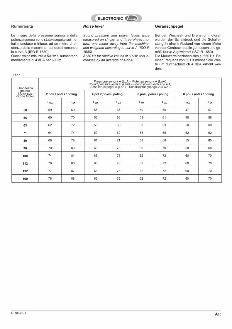
CT18IGBD1 A25
Noise level
Sound pressure and power levels weremeasured on single- and three-phase mo-tors, one meter away from the machine,and weighted according to curve A (ISO R1680).At 50 Hz for relative values at 60 Hz, this in-creases by an average of 4 dbA.
Grandezzamotore
Motor sizeGröße Motor
Pressione sonora A (LpA) - Potenza sonora A (LwA)Sound pressure level at (LpA) – Sound power level at (LwA)
Schalldruckpegel A (LpA) – Schallleistungspegel A (LwA)
2 poli / poles / poling 4 pol i/ poles / poling 6 poli / poles / poling 8 poli / poles / poling
LWA LpA LWA LpA LWA LpA LWA LpA
50 59 69 55 65 50 60 47 57
56 60 70 56 66 51 61 48 58
63 62 72 58 68 53 63 50 60
71 64 74 59 69 55 65 52 62
80 68 78 61 71 58 68 55 65
90 70 80 63 73 60 70 58 68
100 74 84 65 75 62 72 60 70
112 76 86 66 76 62 72 60 70
132 77 87 66 76 62 72 60 70
160 78 88 66 76 62 72 60 70
GeräuschpegelRumorosità
Bei den Wechsel- und Drehstrommotorenwurden der Schalldruck und die Schallei-stung in einem Abstand von einem Metervon der Geräuschquelle gemessen und ge-mäß Kurve A gewichtet (ISO R 1680).Die Meßwerte beziehen sich auf 50 Hz. Beieiner Frequenz von 60 Hz müssen die Wer-te um durchschnittlich 4 dBA erhöht wer-den.
Le misure della pressione sonora e dellapotenza sonora sono state eseguite sui mo-tori monofase e trifase, ad un metro di di-stanza dalla macchina, ponderati secondola curva A (ISO R 1680).Questi valori misurati a 50 Hz si aumentanomediamente di 4 dBA per 60 Hz.
Tab.1.8

CT18IGBD1A26
1.4 ELECTRICALSPECIFICATIONS
Isolamento / / IsolationInsulationC°
220°
180°
155°
130°
120°
Standard
15°
100°
40°
F H
15°
125°
40°
Margine di sicurezza
SicherheitsgrenzeSafety margin
Sovratemperatura ammissibile
Zulässige ÜbertemperaturAdmissible peak temperature
Temperatura ambiente convenzionale 40 °C
Bezugstemperatur von 40°CConventional ambient temperature 40 °C
1.4 ELEKTRISCHEEIGENSCHAFTEN
1.4 CARATTERISTICHEELETTRICHE
Statori avvoltiPer la maggior parte della produzione sonoutilizzate lamiere magnetiche con elevataqualità CP= 10 W /Kg (50Hz/1T), tali da as-sicurare comunque una costanza di pre-stazioni ed elevati rendimenti.Il rame utilizzato è impregnato con un doppiostrato di smalto isolante per assicurareun'elevata tenuta alle sollecitazioni elettriche,termiche e meccaniche.Gli strati di materiale isolante sono inNOMEX /D.M./D.M.D./N.M./N.M.N./M. conclasse di isolamento H.La temperatura ambiente considerata è di40 °C. Sono disponibili processi di tropica-lizzazione con impregnazione tramite ver-nici di elevate qualità igroscopiche, perl'uso in ambienti di elevata umidità >60%U.R.
Wound StatorsHigh-quality magnetic sheet metals areused for most of the production, CP = 10W/kg (50Hz/1T) to ensure constant highperformance.The copper used is impregnated with adouble layer of insulating enamel to ensurehigh resistance to electrical, thermal andmechanical stress.The layers of insulating material are madeof NOMEX /D.M./D.M.D./N.M./N.M.N./M.with insulation class H.The ambient temperature considered is 40° C. Tropicalization processes are availablethrough impregnation with paints havinghigh hygroscopic qualities, for use in areaswith high ambient humidity >60% R.H.
StatorwicklungIn unserer Hauptproduktion wird hochqua-litatives Magnetblech des Typs CP= 10W/kg (50Hz/1T) eingesetzt, das gle-ichmäßig hohe Leistungen gewährleistet.Der verwendete Kupferdraht ist durch einedoppelte Lackschicht isoliert, die für äu-ßerst hohe Widerstandsfähigkeit gegenelektrische, thermische und mechanischeBelastungen sorgt. Die Isolierschicht istaus NOMEX/D.M./D.M.D./N.M./N.M.N. /M.und entspricht der Iso-Klasse H.Es wird eine Umgebungstemperatur von40° C angenommen. Die Tropena-usführung sieht die Impregnierung mit hoc-hqualitativen, hygroskopischen Lacken fürden Einsatz in Umgebungen mit einer rela-tive Luftfeuchtigkeit von über 60% vor.
RotoriSono a gabbia di scoiattolo in pressofusio-ne di alluminio o lega di (Al- Si) Silumin.
RotorsThese are die-cast aluminum or Silumin al-loy (Al-Si) squirrel-cage rotors.
LäuferEs handelt sich dabei um Käfigläufer ausAluminium-Druckguß oder Silumin-Legie-rung (Al-Si).
Insulation class
Windings are made of copper wire with dou-ble thickness enamelling and are subjectedto vacuum impregnation.
They are also class F insulated granting amaximum thermal margin of 155 °C accor-ding to the main specifications.For particular applications it is possible tosupply (upon request)class H insulated mo-tors.Specially treated motors suitable to operatein humid and corrosive ambients are alsoavailable upon request.
Isolationsklasse
Die Wicklungen sind mit einer doppeltenLackschieht versehen und vakuumimpräg-niert. Sie sind nach Klasse F isoliert undgarantieren somit einen den einschlägigenNormen entsprechenden maximalen Tem-peraturgrenzwert von 155°C.Für besondere Anforderungen können dieMotoren auf Anfrage mit einer Isolierungnach Klasse H und speziellen Schutz- be-handlungen für feuchte und korrosive Arbe-itsumgebungen geliefert werden.
Classe di isolamento
Gli avvolgimenti, realizzati con filo a doppiosmalto al massimo della tolleranza e sotto-posti ad impregnazione sotto vuoto, sonoisolati in classe F garantendo in tal modoun margine termico massimo di 155 °C,conforme alle prescrizioni delle principalinormative.Per particolari applicazioni è possibile forni-re (a richiesta) l’isolamento in classe H emotori sottoposti a trattamenti speciali perrenderli atti a funzionare in ambienti umidi ecorrosivi.

CT18IGBD1 A27
Tensioni e frequenze(secondo CEI EN 60034-1)
CEI EN 60034-11.10
1.05
1.03
1.03
1 1.02
0.95 0.98 FREQUENZAFREQUENCYFREQUENZ p.u.
ZONAZONEBEREICH
A
ZONAZONEBEREICH
B
0.97
0.95
0.93
0.90
TENSIONE / VOLTAGE / SPANNUNG p.u.
ZONA / ZONE / BEREICH A :
ZONA / ZONE / BEREICH B :
PUNTO1 / POINT / PUNKT1 :
Servizio pesante limitatoHeavy limited dutyBeschränkter Schwerlastbetrieb
Servizio normale continuoNormal continous dutyNormaler Dauerbetrieb
Funzione principaleMain functionHauptfunktion
Voltages and frequencies(according to CEI EN 60034-1)
Spannungen und Frequenzen(gemäß CEI EN 60034-1)
Tensione / frequenza nominali range di tensioniRated voltage/frequency Rated voltage/frequency range
Nennspannung/-frequenz Bereich der Nennspannungen/-frequenzen
GrandezzaSize
Größe
Tensioni nominali [V]Rated voltage [V]
Nennspannungen [V]
� 10% (IEC 60038)
Range di tensioni nominali [V]Rated voltage range [V]
Nennspannungsbereich [V]
� 5%
IndicazioneDesignazione
IndicationDesignationAngabe der
Bezeichnung(50 Hz) (60 Hz)
(50 Hz)Zona / Zone / Bereich A
(CEI EN 60034-1)
(60 Hz)Zona / Zone / Bereich A
(CEI EN 60034-1)
Trifase / Three-phase / Drehstrom T - H - I - S - R
56 - 112 230/400��
265/460��
220-240 / 380-415 255-277 / 440-480 —
160 400/690��
460�
380-415 / 660-717 440-480 —
132230/400
��265/460
��220-240 / 380-415 255-277 / 440-480 A
400/690��
460�
380-415 / 660-717 440-480 BTrifase / Three-phase / Drehstrom D - DA
Tutti /All / Alles 400 50 Hz — 380- 415 —
Monofase / Single-phase / Einphasen M - MD - MC - MR - ME
Tutti /All / Alles 230 50 Hz — 220 - 240 —
Monofase / Single-phase / Einphasen MF
Tutti /All / Alles 115/230 50/60 Hz 110-120/220-240 50/60 Hz —
Tab.1.9
la normativa EN 60034-1 precisa la tensio-ne nominale consentita, indicando un valo-re di ± 5%.In conformità alla normativa IEC 60038 letensioni principali devono avere un valore ditolleranza di ± 10%.I motori sono quindi progettati per funziona-re in un "range" di tensione nominali (vede-re tabella 1.9).Nella gamma dei motori con le presenti ten-sioni nominali, non viene superata la tem-peratura ammissibile (Zona A).Se i motori funzionano al limite della tolle-ranza di tensione, la sovratemperatura am-missibile dell'avvolgimento dello statorepuò superare il valore massimo di 10 K(Zona B).
Die Norm EN 60034-1 legt die zulässigeNennspannung mit einer Toleranz von ± 5% fest.Gemäß der Norm IEC 60038 müssen dieHauptspannungen einen Toleranzwert von± 10 % haben.Die Motoren sind daher für den Betrieb ineinem „Bereich“ von Nennspannungenkonzipiert (siehe Tabelle 1.9).In der Motorenpalette mit den vorliegendenNennspannungen wird die zulässige Tem-peratur nicht überschritten (Bereich A).Wenn die Motoren im Grenzbereich derSpannungstoleranz arbeiten, kann die zu-lässige Übertemperatur der Statorwicklungden Höchstwert von 10 K überschreiten(Bereich B).
The EN 60034-1 standard states the per-mitted rated voltage, indicating a value of ±5%.In accordance with IEC 60038 standard themain voltages must have a tolerance valueof ± 10%.The motors are therefore designed to ope-rate within a rated voltage “range” (see ta-ble 1.9).In the series of motors with the present ra-ted voltages, the permitted temperature isnot exceeded (Zone A).If the motors operate at the voltage toleran-ce limit, the permitted excess temperaturefor the stator winding may exceed the maxi-mum value by 10 K (Zone B).

CT18IGBD1A28
Frequencies at 60 Hz
Volt di targa a 50 HzRated voltage at 50 HzVolt bei 50 Hz gemäß
Typenschild
Volt a 60 HzVolt at 60 Hz
Volt bei 60 Hz
Potenza nominale WRated power WNennleistung W
rpm In Ia / In Ca / Cn C max / Cn
220 220 1.00 1.2 1.20 0.80 0.80 0.80220 230 1.05 1.2 1.15 0.85 0.85 0.85220 240 1.06 1.2 1.10 0.87 0.87 0.87*230 230 1.00 1.2 1.20 0.80 0.80 0.80230 240 1.10 1.2 1.15 0.90 0.90 0.90230 260 1.20 1.2 1.00 1.00 1.00 1.00*400 400 1.00 1.2 1.20 0.80 0.80 0.80400 440 1.06 1.2 1.10 0.87 0.87 0.87400 460 1.20 1.2 1.00 1.00 1.00 1.00400 480 1.25 1.2 1.00 1.10 1.10 1.10440 440 1.00 1.2 1.20 0.80 0.80 0.80500 500 1.00 1.2 1.20 0.80 0.80 0.80500 550 1.06 1.2 1.10 0.87 0.87 0.87
All electrical data in this catalogue refer tothree-phase wound motors at 50 Hz. Thesemay be connected to 60 Hz, taking into ac-count the multiplier coefficients in the table13 below:
Ia/In =Corrente di spunto
Corrente nominaleStarting current
Rated current
Anlaufstrom
Nennstrom
Ca/Cn =Cooppia di spunto
Coppia nominale
Starting torque
Rated toeque
Anlaufmoment
Nennmoment
Cmax/Cn =Coppia massima
Coppia nominale
Maximum torque
Rated torque
Maximales Drehmoment
Nennmoment
In = Corrente nominale Rated current Nennstrom
Dove, dalle righe (*) si ricava che un motoreavvolto a 50 Hz può funzionare a 60 Hz allemedesime tensioni nominali, alla medesi-ma potenza resa [W], con un incremento a1.2 volte dei giri [rpm e della corrente nomi-nale In, e un calo a 0.8 volte della correntedi spunto Ia/In della coppia di spunto Ca/Cne della coppia massima Cmax/Cn.
Where you can notice (*) that a motorwinded at 50 Hz can work at 60 Hz with thesame rated voltage, power [W], with a 1.2increase of rpm and rated current in, also a0.8 reduction of starting current Ia/In, of thestarting torque Ca/Cn and of the maximumtorque Cmax/Cn.
Den mit einem Sternchen (*) markierten Zei-len kann entnommen werden, daß ein für 50Hz ausgelegter Motor bei 60 Hz betriebenwerden kann mit gleichen Nennspannun-gen, gleicher Leistung [W], einer Steigerungder Drehzahl [rpm] und des Nennstroms [In]um den Faktor 1.2 undein er Verminderungum den Faktor 0.8 des Anlaufstroms [Ia/In],des Anzugmoments [Ca/Cn] und desHöchstmoments [Cmax/Cn].
Frequenz von 60 HzFrequenza 60 Hz
In questo catalogo tutti i dati elettrici sono ri-feriti a motori trifasi avvolti a 50 Hz.Questi possono essere collegati a 60 Hz te-nendo conto dei coefficienti moltiplicatividella tabella seguente:
Alle in diesem Katalog aufgeführten elektri-schen Daten beziehen sich auf Drehstrom-motoren mit einer Frequenz von 50 Hz. Siekönnen an 60 Hz angeschlossen werden,wobei die in der Tabelle 13 aufgeführtenMultiplikationsfaktoren berücksichtigt wer-den müssen.
Tab.1.10

CT18IGBD1 A29
Single-phase motor wiringdiagrams
Sensi di rotazione lato presa di forzaRotation sense understood from driveendDrehsinn auf der Abtriebsseite
HIGH SPEED LOW SPEED
R S T
U1 V1 W1
W2 U2 V2
R S T
U1 V1 W1
W2 U2 V2
R S T
U1 V1 W1
W2 U2 V2
R S T
U1 V1 W1
W2 U2 V2
HIGH SPEED LOW SPEED
R S T
U1 V1 W1
W2 U2 V2
R S T
U1 V1 W1
W2 U2 V2
U1 V1 W1
W2 U2 V2
U1 V1 W1
W2 U2 V2
U1 V1 W1
W2 U2 V2
LL LL
U1 V1 W1
W2 U2 V2
LL LL L
U1 V1 W1
W2 U2 V2
U1 V1 W1
W2 U2 V2
L LL
L L
U1
W2 U2
V1 W1
V2
L L
U1
W2 U2
V1 W1
V2
L L
U1
W2 U2
V1 W1
V2
L L
U1
W2 U2
V1 W1
V2
115 V 230 V
T-H-HA-I-IA-R-RA-S-SA D-DA 2/4 - 4/8 D-DA 4/6-2/6-2/8-2/12
Unico avvolgimentoSingle winding
Einlagige Wicklung
Doppio avvolgimentoDouble winding
Doppellagige Wicklung
M-MC-ME AE MR
MF
Coprimorsettiera
Il coprimorsettiera è in alluminio pressofusoin esecuzione standard nella versione mo-noblocco IP55, a richiesta versione a duecomponenti in IP65, versione a due compo-nenti da motori autofrenanti in IP65 di di-mensione maggiorata..
Terminal box Klemmenkasten
In der Monoblock- Standardausführung ge-mäß Schutzart IP55 ist er aus Alumini-um-Preßguß. Auf Wunsch ist er auchzweiteilig gemäß IP65 und für Bremsmoto-ren vergrößert, ebenfalls gemäß IP65, lie-ferbar. Für aggressive Milieus steht einePlastikausführung gemäß IP55 zur Verfü-gung.
Made of die-cast aluminum in the standardversion, as a single unit at IP55. Availableupon request in the two-component versionfor selfbraking motors at IP65 in enlargedsize.
Size A B H A B H A B H50 56 53 30
56-71 66 76 34 93 85 47 137 84 4080-112 78 91 40 110 102 58 153 100 46
132 92 105 46 123 102 63160 185 172 73
Three-phase motor wiring diagrams Anschlusspläne fürDrehstrommotoren
Schemi di collegamento di motoritrifase
Anschlusspläne fürEinphasenmotoren
Schemi di collegamento di motorimonofase

CT18IGBD1A30
Motor terminal board
IP55
IP55
IP55 IP55
IP55
IP65CIP65C
IP65C
IP65CIP65C
IP55 IP55IP55
IP55
IP55
IP65C IP55IP65C
IP55
IP55IP55
IP55
IP55
IP55
IP55
IP65L
IP65L
IP65L
IP65L
IP65L
IP65LIP65L
IP65LIP65L
IP65L IP65L
IP65L
IP55
IP55
IP65L
FP
FD
FA
VF
VF
VF
VF
VF
VF
VT
VT
VT
VT
VT
VT
..SD
..SA
FP + ..SD + VF
FD + ..SD + VF
FD + VF
FA + ..SA + VF
FA + VF
FP + ..SD + VT
FD + ..SD + VT
FD + VT
FA + ..SA + VT
FA + VT
FP
FD
FA
..SD
..SD
..SA
VF
VF
VF
VF
VT
VT
VT
VT
FP + ..SD + VF
FD + ..SD + VF
FA + ..SA + VF
FP + ..SD + VT
FD + ..SD + VT
FA + ..SA + VT
TRIFASE / THREE-PHASE / DREHSTROMMONOFASE / SINGLE PHASE / EINPHASEN
T - H - I - R -SM - MC - MR - ME
TRIFASE DOPPIA POLARITA' / THREE-PHASE DUAL POLARITY / DREHSTROM POLUMSCHALTBARMONOFASE / SINGLE PHASE / EINPHASEN
D - DAM - MDA
Klemmenbrett des MotorsMorsettiera motore

CT18IGBD1 A31
Tropicalization (in accordance with CEIEN 60034-1/IEC 34-1)If the motors are installed outdoors or inrooms with a high percentage of humidity >60% (R.H.), upon request a tropicalizationtreatment can be carried out on the wind-ings by cold painting with a product havinghigh hygroscopic qualities which protectsthe motor from condensation penetratingthe insulating material, thereby compromis-ing effective insulation.
Drain holes for condensationOn request, drain holes for condensationclosed with plugs can be supplied whichcan be removed once the motors havebeen put into service.
1.5 OPTIONS
Anti-condensation heater per CEI EN
60034-1/IEC 34-1)In applications where the ambient tempera-ture is extremely low (0 ° C) or where thehumidity is high (> 60% R.H.), it is possibleto install a special pre-heating element onthe winding heads for the machine whennot running.This prevents mechanical parts such asbearings or isolations from being damagedby low temperatures.The heating power of the heater dependson the motor size; AC supply voltages uponrequest.The terminals are free or fixed to the termi-nal board upon request.
Wicklungsheizung (nach CEI EN60034-1/IEC 34-1)Bei Motoren, die in Umgebungen mit be-sonders niedrigen Temperaturen (0° C)oder extrem hoher relativer Luftfeuchtigkeit(> 60%) betrieben werden, kann aufWunsch an den Wicklungsköpfen ein be-sonderes Heizelement eingebaut werden.Dieses Heizelement sorgt dafür, daß derMotor während des Stillstands vorgewärmtwird. Damit soll eine Beschädigung der me-chanischen Teile wie Lager und Isolierma-terial durch zu niedr ige Temperaturenvermieden werden. Die Leistung der Wic-klungsheizung wird auf die Größe des Mo-tors ausgelegt.Die Wechselspannungen können gewähltwerden.Die Kabelenden sind frei oder werden aufWunsch am Klemmbrett befestigt.
Scaldiglia anticondensa (secondo CEIEN 60034-1/IEC 34-1)Su richiesta è possibile, in quelle applica-zioni nelle quali la temperatura ambiente èestremamente bassa (0 °C), o dove il tassodi umidità è elevato > 60% (U.R.), installaresulle testate degli avvolgimenti una resi-stenza speciale di preriscaldamento dellamacchina quando questa non è funzionan-te.In questo modo si evita che le parti mecca-niche quali i cuscinetti o gli isolamentivengano danneggiati dalle basse tempe-rature.Le potenze riscaldanti della scaldiglia sonoin funzione della grandezza di motore, letensioni a.c. di alimentazione sono a richie-sta.I terminali sono liberi o, su richiesta, fissatiin morsettiera.
Grandezza motoreMotor sizeBaugrößeMEC-IEC
Potenza riscaldanteHeating powerHeizleistung
Alimentazione AC [V]AC [V] feed
Gleichstromversorgung
50 � 71 8 220*
80 �� 22 220*
100 � 112 22 220*
132 40 220*
160 40 220*
* altre tensioni a richiesta / * other tensions upon request / * andere Spannungen auf Anfrage
Tab.1.11
1.5 OPTIONEN1.5 OPZIONI
Tropenfestigkeit (gemäß CEI EN60034-1/IEC 34-1)Wenn die Motoren im Freien oder in Umge-bungen mit hohem Feuchtigkeitsgehalt >60 % (rel. F.) installiert werden, können aufAnfrage die Wicklungen durch eine speziel-le Kaltlackierung mit einem stark hygrosko-pischen Produkt tropenfest ausgelegtwerden, das den Motor vor dem Eindringenvon Kondenswasser in die Isolierstoffeschützt und die Beeinträchtigung der Iso-lierdichtigkeit verhindert.
KondenswasserabflusslöcherAuf Anfrage werden Kondenswasserabflu-sslöcher ausgeführt. Diese werden vonStopfen verschlossen, die nach Installationder Motoren entfernt werden.
Tropicalizzazione (secondo CEI EN60034-1/IEC 34-1)Se i motori vanno installati all'aperto o inambienti con alto tasso di umidità > 60%(U.R.), si esegue su richiesta un processodi tropicalizzazione degli avvolgimenti tra-mite verniciatura a freddo con prodotto dielevate qualità igroscopiche che protegge ilmotore dalla penetrazione della condensanei materiali isolanti, evitando di pregiu-dicare la buona tenuta isolante.
Fori per scarico condensaSu richiesta si eseguono fori di scarico con-densa chiusi da tappi che verranno tolti unavolta posti in servizio i motori
TROpzioneOptionOption
SCOpzioneOptionOption
FCOpzioneOptionOption

CT18IGBD1A32
Cooling (in accordance with IEC34-6 andCEI EN 60034-6)This is obtained using a revolving valve withtwo-way radial blades coupled to the IC 41motor shaft. Made in Latamid 6, it has ahigh operating temperature at 100°C.For applications with electronic controlssuch as inverters, power cooling is availa-ble by means of an IC416 cooling type auxi-liary motor, also available in kit form.
Upon request the SV option is availablewhereby the motor is supplied without a fan.
If the VM option is selected, the standardfan will be replaced with a metal one.
Power cooling
Supply voltages
VT: 230V / 400V ( 50Hz / 60Hz)VF: 230V (50Hz / 60Hz)
Insulation class
IP 23 standardIP 55 upon request
For applications with a rated torque belowmotor speed at 50 Hz, the appropriatepower cooling must be mounted as thereare too many variables involved to deter-mine the various possible thermal duties,and thus the temperatures reached by themotors.
ServobelüftungVersorgungsspannungenVT: 230V / 400V ( 50Hz / 60Hz)VF: 230V (50Hz / 60Hz)IsolierungsklasseIP 23 standardIP 55 auf WunschBei Einsatz des Motors mit einem Nennmo-ment, das unter der Drehzal für 50 Hz liegt,muß eine adäquate Servobelüftung vorge-sehen werden, da die Anzahl der Variablenfür die Bestimmung des thermischen Ver-haltens und somit der vom Motor erreichtenTemperaturen zu groß ist.
ServoventilazioneTensioni di alimentazione:VT: 230V / 400V ( 50Hz / 60Hz)VF: 230V (50Hz / 60Hz)Classe di isolamento:IP 23 standardIP 55 a richiestaPer applicazioni con coppia nominale al disotto della velocità a 50Hz del motore, si im-pone il montaggio della servoventilazioneadeguata, in quanto troppe le variabili in gio-co per la determinazione dei vari servizi ter-mici possibili e quindi delle temperatureraggiunte dai motori.
GrandezzaSize
BaugrößeR CS PS SV LM PB
[W]VB
[m3/min]
50A 104 — — 103 116 — — —50B 104 — — 116 133 — — —56 110 90 229 142 158 V 220 15 0.763 123 102 261 161 178 V 220 17 2.671 140 95 274 182 202 V 220 17 2.680 159 100 305 199 222 V 220 42 5.4
90S 176 95 320 210 238 V 220 42 5.490L 176 95 343 235 262 V 220 42 5.4100 195 125 402 263 289 V 220 42 5.4112 219 175 402 276 310 V 220 42 5.4
132S 258 220 565 315 350 V 220 42 5.4132M 258 220 606 350 385 V 220 42 5.4160M 315 260 735 423 458 V 220 115 26.8160L 315 260 770 467 502 V 220 115 26.8
Ventilazione forzataForced cooling
Zwangsbelüftung
Tab.1.12
Belüftung (gemäß IEC 34-6 und CEI EN60034-6)Die Belüftung wird mittels eines richtungs-umkehrbaren Lüfterrades mit Radialschau-feln ausgeführt, das auf die Motorwelle IC41 aufgezogen wird. Das Lüfterrad bestehtaus Latamid 6 und hat eine hohe Betriebs-temperatur von 100°C.Für Anwendungen mit elektronischen Über-wachungen wie Inverter ist die Servobelüf-tung mit Hilfsmotor möglich, die dem TypIC416 – auch als Kit erhältlich - entspricht.
Auf Anfrage ist die Option SV für die Liefe-rung des Motors ohne Lüfterrad erhältlich.
Unter Angabe der Variante VM wird dasLüfterrad in der Standardausführung gegenein Lüfterrad aus Metall ausgewechselt.
Ventilazione (secondo IEC 34-6 e CEI EN60034-6)Si ottiene tramite una ventola girante a paleradiali bidirezionale calettata sull'alberomotore IC 41. Realizzata in Latamid 6 hauna elevata temperatura di funzionamentodi 100 °C.Per applicazioni con controlli elettroniciquali inverter, è disponibile la servoventila-zione assistita tramite motore ausiliario,tipo ventilazione IC416 anche in kit.
A richiesta è disponibile l'opzione SV cheprevede la fornitura del motore privo di ven-tola.
Indicando la variante VM, verrà sostituita laventola standard con una in metallo.
SVOpzioneOptionOption
VM OpzioneOptionOption
VFOpzioneOptionOption VT
OpzioneOptionOption

CT18IGBD1 A33
Ventilazione forzata e encoderForced cooling and encoder
Zwangsbelüftung und Encoder
Freno e ventilazione forzataBrake and forced cooling
Bremse und Zwangsbelüftung
GrandezzaSize
BaugrößeR PS CS SV PB
[W]VB
[m3/min]
50A 104 — — 103 — — —50B 104 — — 116 — — —56 110 232 — 142 V 220 15 0.763 123 299 146 157 V 220 17 2.671 138 350 175 166 V 220 17 2.680 156 377 175 191 V 220 42 5.4
90S 176 366 140 219 V 220 42 5.490L 176 462 140 234 V 220 42 5.4100 195 420 155 263 V 220 42 5.4112 220 470 — 280 V 220 42 5.4
132S 258 562 220 315 V 220 42 5.4132M 258 604 220 352 V 220 42 5.4160M 315 735 — 423 — 115 26.8160L 315 770 — 467 — 115 26.8
GrandezzaSize
BaugrößeR PS CS SV PB
[W]VB
[m3/min]
50A 104 — — 103 — — —50B 104 — — 116 — — —56 110 232 — 142 V 220 15 0.763 123 300 146 157 V 220 17 2.671 138 341 162 163 V 220 17 2.680 156 377 175 196 V 220 42 5.4
90S 176 401 183 275 V 220 42 5.490L 176 462 220 234 V 220 42 5.4100 195 442 155 261 V 220 42 5.4112 220 470 — 280 V 220 42 5.4
132S 258 610 265 316 V 220 42 5.4132M 258 603 350 V 220 42 5.4160M 315 735 — 423 — 115 26.8160L 315 770 — 467 — 115 26.8
Ventilazione forzata con encoder e frenoForced cooling with encoder and brake
Zwangsbelüftung mit Encoder und Bremse
GrandezzaSize
BaugrößeR CS PS SV PB
[W]VB
[m3/min]
50A 104 — — 103 — — —50B 104 — — 116 — — —56 110 — — 142 V 220 15 0.763 123 — — 159 V 220 17 2.671 138 176 351 166 V 220 17 2.680 156 290 410 195 V 220 42 5.4
90S 176 220 436 219 V 220 42 5.490L 176 244 486 234 V 220 42 5.4100 195 — — 263 V 220 42 5.4112 220 220 516 276 V 220 42 5.4
132S 258 — 315 V 220 42 5.4132M 258 — 350 V 220 42 5.4160M 315 — — 423 — 115 26.8160L 315 — — 467 — 115 26.8
Tab.1.15
Tab.1.13
Tab.1.14

CT18IGBD1A34
Encoder
Special shaft configurations are availableupon request, prepared or based on draw-ings to receive the speed or position mea-suring device, or for keying onto the motorshield. In this case, assisted power coolingis also available, supported by brackets onthe fan cover.
EH
Tensione di alimentazione / Supply voltage / Versorgungsspannung 5 /8...24 V
Assorbimento a vuoto / Absorption when empty / Stromaufnahme bei Nulllast max 100 mA
Max. frequenza di utilizzo / Max. operating frequency / Max. Arbeitsfrequenz 100 kHz
Risoluzione (con tacca di zero) / Resolution (with zero notch) / Auflösung (mitNullmarke)
200-250-400-500-512-1000-1024-2000-2048 (imp/giro) / (imp/rev.) / (Imp/U)
Risoluzione (senza tacca di zero) / Resolution (without zero notch) / Auflösung (ohneNullmarke)
2-4-7-10-12-25-30-60-100-360-600 (imp/giro) / (imp/rev.) / (Imp/U)
Grado di protezione / Protection level / Schutzart IP54
Temperatura di funzionamento / Operating temperature / Betriebstemperatur -10...+85 °C
Temperatura di immagazzinamento / Storage temperature / Lagertemperatur -25...+85 °C
Peso / Weight / Gewicht 250 g
ENOpzioneOptionOption
GrandezzaSize
BaugrößeR CS PS SV
50A 104 — — 10350B 104 — — 11656 110 90 229 14263 123 102 261 15971 140 95 274 18280 159 100 305 198
90S 176 95 320 20790L 176 95 343 237100 195 125 402 263112 219 175 402 280
132S 258 220 565 315132M 258 220 606 350160M 315 260 735 423160L 315 260 770 467
Encoder
Auf Wunsch sind Sonderwellen, auch nachKundenzeichnung, lieferbar, die auf denEinbau von Drehzahl- oder Positionsmeß-vorrichtungen und die Anbringung dieserVorrichtungen am Lagerschild des Motorsvorbereitet sind. In diesem Fall ist auch einzusätzlicher Servolüfter lieferbar, der mitKlammern an der Lüfterhaube befestigtwird.
Encoder
Sono possibili esecuzioni speciali di alberi arichiesta predisposti, o su disegno per rice-vere il dispositivo di misura della velocità oposizione, e per il calettaggio dello stessosullo scudo motore.In questo caso, si può anche avere la ser-voventilazione assistita, sostenuta con staf-fe sul copriventola.
Tab.1.16

CT18IGBD1 A35
Thermal overload cut-outswitches-Standard TP111(per IEC 34 - 11)
The electrical protections on the motorpower line may not be sufficient to protectagainst overloads. If the cooling conditionsworsen, the motor overheats but the electri-cal conditions do not change, which inhibitsline protections.Installing built-in protections on the wind-ings solves this problem:
Bimetallic device PTO
this is a normally-closed electromechanicaldevice that opens electrically when thethreshold temperature is reached; it auto-matically resets when the temperature fallsbelow the threshold level. Bimetallic de-vices are available with various interventiontemperatures and without automatic reset,per EN 60204-1.
PTC thermistor device
this device promptly, positively adjusts itsresistance once the threshold temperatureis reached.
Albero bisporgente
BI
Il motore può essere fornito a richiesta condoppia estremità d'albero; le dimensionisono disponibili nelle tabelle dimensionali.Non può essere fornito dove siano presentile opzioni VF, VT, PP.
BIOpzioneOptionOption
StandardüberhitzungsschutzTP111 (nach IEC 34 - 11)
Die in der Zuleitung des Motors vorhande-nen Sicherungen gewährleisten nicht in al-len Fällen einen ausreichenden Schutz vorÜberlastungen. Wenn sich die Belüftungverschlechtert, wird der Motor zu heiß. Dajedoch keine Änderung der elektrischenBedingungen erfolgt, werden die Sicherun-gen in der Zuleitung nicht angesprochen.Dieser Nachteil kann durch den Einbau vonSchutzeinrichtungen an der Wicklung ver-mieden werden.
Bimetall-Schalter PTOEs handelt sich um einen in Ruhestellunggeschlossenen elektromechanischenSchalter, der sich bei Erreichen der An-sprechtemperatur automatisch öffnet. BeiAbsenkung der Temperatur kehrt derSchaltkontakt selbständig in die Ruhestel-lung zurück. Die Bimetall- Schalter sind fürverschiedene Ansprechtemperaturen undauf Wunsch auch ohne automatische Rüc-kstellung, nach EN 60204- lieferbar.
PTC ThermistorenDiese Vorrichtungen mit positivem Tempe-raturkoeffizenten sind in der Lage, ihren Wi-derstandswert beim Erreichen derAnsprechtemperatur plötzlich zu ändern.
Protezioni termiche Standard TP111(secondo IEC 34 - 11)
Le protezioni elettriche presenti sulla lineadi alimentazione del motore possono esse-re insufficienti ad assicurare la protezionedai sovraccarichi. Infatti, se peggiorano lecondizioni di ventilazione, il motore si surri-scalda ma le condizioni elettriche non simodificano e ciò inibisce le protezioni sullelinea.Si ovvia a questo inconveniente installandoprotezioni sugli avvolgimenti.
Dispositivo bimetallico PTOè un dispositivo elettromeccanico che, nor-malmente chiuso, una volta raggiunta latemperatura di scatto si apre elettronica-mente; si ripristina automaticamente quan-do la temperatura scende sotto il limite discatto.Sono disponibili bimetallici con diverse tem-perature di intervento e senza ripristinoautomatico, secondo EN-60204-1.
Dispositivo termistore PTCquesto dispositivo varia la sua resistenza inmodo repentino e positivo una volta rag-giunta la temperarura di intervento.
TOOpzioneOptionOption
TC OpzioneOptionOption
Double ended shaft
Upon request the motor can be suppliedwith a double ended shaft; the dimensionsare shown in the size tables.It cannot be supplied where options VF, VTand PP are present.
Zweiseitige WelleDer Motor kann auf Anfrage mit zweiseitigaustretender Welle geliefert werden. DieAbmessungen sind in den Maßtabellenangegeben.Nicht lieferbar in Verbindung mit den Optio-nen VF, VT und PP.

CT18IGBD1A36
Symmetrical winding
Two-phase winding distributed symmetri-cally around the machine circumference,run in single-phase mode with the capacitoralways working.This is used where it is necessary to re-verse the motor rotation direction with sim-ple circuits. It generally offers morenoiseless operation than a traditionalsinglephase winding, though at the cost ofreducing the starting torque (-20%).
Rain shield
For outdoor applications with V5 V3 - V19 -V15 - V18 - V1 - V36 - V6 installation (seeTable 6), we recommend installing a rainshield. This configuration may also be usedin the textiles processing industry.
GrandezzaSize
BaugrößePP R LP
56 209 110 22
63 238 123 22
71 267 140 22
80 297 159 22
90S 320 176 22
90L 348 176 22
100 390 195 22
112 410 219 26
132S 490 258 30
132L 517 258 30
160S 636 315 36
160L 690 315 36
LP
R
PP
PPOpzioneOptionOption
Regenschutzdach
Für Einsätze im Freien in den Einbauposi-tionen V5 - V3 - V19 - V15 - V18 - V1 - V36 -V6 (siehe Tab. 6) sollte ein Regenschut-zdach verwendet werden. Das Regen-schutzdach ist auch für Einsätze in derTextilverarbeitungsindustrie geeignet.
Tettuccio parapioggia
Per applicazioni esterne con montaggio informa V5 - V3 - V19 - V15 - V18 - V1 - V36 -V6, è consigliabile montare un tettuccio pa-rapioggia.
Es handelt sich dabei um eine am Motor-umfang symmetrisch verteilte Zweiphasen-wicklung, die im Einphasenberieb mitständig angeschlossenem Kondensatorver-wendet wird.Sie wird eingesetzt, wenn eine Umkehrungder Drehrichtung des Motors, ohne denSchaltkreis zu komplizieren, notwendig ist.Diese Wicklung ist geräuschärmer als dieherkömmliche Einphasenwicklung, hat je-doch ein geringeres Anlaufmoment (-20%).
Avvolgimento bifase distribuito simmetrica-mente sulla circonferenza di macchina, fat-to funzionare in regime monofase con con-densatore sempre inserito.E' usato dove è necessario invertire il sensodi rotazione del motore in modo circuital-mente semplice.In genere ha il funzionamento più silenzio-so rispetto un avvolgimento monofasetradizionale, a scapito di una minore coppiadi spunto % (-20%).
Symmetrische WicklungAvvolgimento simmetrico
AEOpzioneOptionOption
Tab.1.17

CT18IGBD1 A37
1.6 SELF-BRAKING
GeneralitàPrevedono l’impiego di freni a pressione dimolle, calettati saldamente su uno scudo inghisa nella parte posteriore del motore. Neimotori con freno FS lo scudo può esserein alluminio.L’azione frenante si manifesta in assenza dialimentazione alla bobina freno, siamo inpresenza quindi di freni di sicurezza trannefreno positivo.La classe di isolamento di questi freni è la“Classe F”.
Per quanto riguarda i motori, di tipo mono-fase, trifase e a doppia polarità, questi se-guono fedelmente le caratteristiche giàillustrate in questo catalogo dal punto di vi-sta meccanico ed elettrico, ad esclusionedell’ingombro assiale, che aumenta per lapresenza del freno.La guarnizione di attrito (ferodo) dei nostrifreni è priva di amianto, secondo le più re-centi Direttive Comunitarie in materia diIgiene e Sicurezza del Lavoro.Tutti i corpi freno sono protetti contro le ag-gressioni atmosferiche tramite vernicia-ture e/o zincatura a caldo. Le parti più sog-gette ad usura sono trattate in atmosferespeciali che conferiscono proprietà notevolidi resistenza all’usura delle parti.
Tensione di alimentazionePer quanto riguarda le tensioni di alimenta-zione standard dei freni, queste sono230/400 V ± 10%/50 Hz per freni tritase,mentre per freni in corrente continua sonodi 230V± 10% 50/6OHz dal lato A.C. dell’a-limentatore freno. Infatti i freni in correntecontinua necessitano di un alimentatore perfunzionare su rete A.C.
Ambiente di installazioneII grado di protezione elettrica del freno èIP54 standard. Il grado di protezione mec-canica del freno montato sul motore è IP54.Particolare attenzione deve essere postanella scelta della protezione del freno, infunzione dell’ambiente di utilizzazione; in-fatti, in ambienti con acqua nebulizzata omolto umidi, o dove sono presenti polveri inatmosfera, o dove sono presenti atmosfereoleose, è obbligatorio il montaggio di prote-zioni meccaniche aggiuntive come succes-sivamente specificato (anello antipolvere).
1.6 SELBSTBREMSENDEASYNCHRONMOTOREN
General notes
These use spring-pressure brakes, firmlyspliced onto a cast iron shield at the back of
the motor. In the S line, the shield may be
aluminum.
The braking action appears in the absenceof power supply to the brake coil; these aretherefore safety brakes except positivebrake.The insulation class of these brakes is“Class F”.
For single-phase, three-phase and dual-po-larity motors, these faithfully follow thespecifications already illustrated in this cat-alogue from a mechanical and electricalstandpoint, with the exception of axial di-mensions which increase due to the pres-ence of the brake.The lining of our brakes is asbestos-free,per the most recent EEC Directives in termsof Workplace Hygiene and Safety.All brake assemblies are protected againstatmospheric aggression by painting and/orheat galvanizing.The parts most subject to wear are treatedin special atmospheres that provide consid-erable wear resistance to the parts.
Supply voltage
The standard supply voltages for thebrakes are 230/400V V ± 10%/50 Hz forthree-phase brakes, and 230V ± 10% 50/60Hz for direct current brakes on the AC sideof the brake power pack. Direct currentbrakes require a power pack in order to op-erate on an AC mains.
Installation site
The standard electrical protection rating forthe brake is IP54, while the mechanical pro-tection for the brake installed on the motoris IP54. Choosing the brake protection re-quires special attention based on the userenvironment: in places with misted water orhigh humidity, where dust is present in theair, or where oily atmospheres are present,additional mechanical protections must beinstalled as specified below (dust protectionring).
Allgemeine AngabenBei den Bremsmotoren werden Federdr uc-kbremsen eingesetzt, die fest an einem Gu-ßschild hinten am Motor verankert sind. Beider Serie S ist der Schild auch in Alu lie-ferbar.Die Bremsung wird ausgelöst, wenn dieBremsspule nicht mehr mit Strom versorgtwird. Es handelt sich also außer bei der Ar-beitsstrom- bremse um eine Sicherheits-bremse. Die Isolationsklasse der Bremsenist “F”.
Die mechanischen und elektrischen Datender Wechsel-, Drehstrom- und polum-schaltbaren Bremsmotoren entsprechendenen der im Katalog aufgeführten Stan-dard-motoren, jedoch nicht die Außenab-messungen, die durch die Bremsevergrößert sind. Die Reibbeläge unsererBremsen entsprechen den neusten euro-päischen Gesundheits-und Arbeitsschutz-vorschriften asbestfrei. Die Bremskörpersind durch Lack und/oder Warmverzinkungvor schädlichen Umwelteinflüssen ge-schützt. Die Verschleißteile werden beson-deren Behandlungen unterzogen, um ihreBeständigkeit zu erhöhen.
SpeisespannungBei Drehstrombremsen ist die Standard-speisespannung der Bremsen 230/400 V ±10%/50 bei 60 Hz. Die Gleichstrombrem-sen benötigen ein Netzgerät für den An-schluß an das Wechselstromnetz. DieSpeisespannung beträgt 230 V V ± 10%bei 50/60 Hz an der Wechselstromseite desNetzgerätes der Bremse.
Umfeld der InstallationDie Standardschutzart für die Elektrik undMechanik der Bremse ist IP54. Die Schutz-vorrichtungen der Bremse müssen mit be-sonderer Sorgfalt gewählt werden.In Umgebungen mit Sprühwasser,besonders hoher Feuchtigkeit, viel Stauboder ölhaltiger Luft müssen, wie nachfol-gend aufgeführt, zusätzliche mechanischeSchutzvorrichtungen (Staubschutzring) an-gebracht werden.
Freni disponibili Brakes available Erhältliche Bremsen Pag./SeiteFreno in C.A. AC Brake Wechselstrombrems FA (FAM*) A42
Freno in C.C. DC Brake Gleichstrombremse FD (FDM*) A44
Freno di stazionamento Parking brake Haltebremse FS A46
Freno ad azione positiva Positive action brake Arbeitsstrombremse FP A48* Coppia di frenatura maggiorata / Increased braking torque / Erhöhtes Bremsmoment
1.6 MOTORI ASINCRONIAUTOFRENANTI
Tab.1.18

CT18IGBD1A38
LS1
LS4 LS2
LS3
OPZIONI FRENI / BRAKE OPTIONS / BREMSENOPTIONEN
LSOpzioneOptionOption
Tempi di intervento dei freni D.C.
Gli alimentatori possono essere scelti infunzione dei tempi di frenata desiderati.Infatti, a causa della rotazione inerziale delmotore, i morsetti del freno ricevono ener-gia anche dopo l’interruzione dell’alimenta-zione dalla rete (se collegati in morsettiera).Questo comporta un tempo di ritardo dellafrenata che può risultare indesiderato.Per eliminare questo ritardo si ricorre all’in-terruzione del circuito di alimentazione fre-no direttamente sulla bobina dello stesso,impedendo così all’energia inerziale delmotore di mantenere il freno in tensione.Si può quindi, dalle tabelle successive, ef-fettuare la scelta dei tempi di frenatadesiderati.
RumorositàI freni utilizzati per le grandezze di motoreda noi prodotti rimangono ampiamente al disotto dei limiti imposti dalle Direttive Comu-nitarie in materia di Protezione dei lavorato-ri contro i rischi di esposizione al rumoredurante il lavoro.Tale limite si può sommariamente identifi-care in 140dB per pressione acustica istan-tanea non ponderata.
Coppie frenanti maggiorate:è possibile, a richiesta, avere freni con cop-pie frenanti maggiorate, nelle tabelle deidati tecnici dei freni sono riportate le coppiedelle versioni maggiorate FAM e FDM.
Leva di sblocco manuale:consente, mediante lo spostamento dellaleva, in direzione lato copriventola del mo-tore, lo sblocco del freno e la possibilità dimanovra tramite chiave a brugola esagona-le. Infatti, dal lato copriventola, è presenteun foro passante che permette di raggiun-gere la testa dell’albero motore in cui è rica-vato il foro esagonale di manovra.Essa può essere montata in 4 diverseposizioni come indicato nella seguente illu-strazione.
DC brake intervention times
The power packs may be chosen based onthe desired braking times. Due to the iner-tial rotation of the motor, the brake termi-nals receive energy even after the mainspower supply is shut off (if connected viaterminal board). This causes a braking de-lay that may be undesirable.To eliminate this delay, the brake powersupply circuit may be interrupted directly onits coil, thereby preventing the inertial en-ergy of the motor from keeping the brakepowered. The table below offers the param-eters for choosing the desired brakingtimes.
Noise levels
The brakes used for motor sizes we pro-duce remain well within the limits set by theEEC Directives in terms of Worker Protec-tion against the risk of exposure to noise atthe workplace.This limit may be briefly identified as 140 dBfor non-weighted instantaneous acousticpressure.
Increased braking torque:
upon request brakes with increased brakingtorque can be supplied, the brake technicalspecification tables show the torques of theuprated versions FAM and FDM.
Hand release lever:
moving the level towards the fan cover ofthe motor releases the brake, making it pos-sible to use the hexagonal Allen wrench tomove the unit. A through hole is availableon the fan cover side to access the head ofthe motor shaft, containing the hexagonalmovement hole.It can be fitted in 4 different positions asshown in the following illustration.
Betätigunszeiten derGleichstrombremsenBei der Wahl des Netzgerätes müssen diegewünschten Betätigunszeiten berücksic-htigt werden. Durch das Nachlaufen desMotors werden die Klemmen der Bremse(falls sie im Klemmenkasten angeschlos-sen sind) auch nach Unterbrechung derStromversorgung noch mit Strom versorgt.Dadurch wir die Bremsung verzögert. Umdiese Verzöger ung zu verhindern, wird dieStromversorgung der Bremse direkt an derBremsspule unterbrochen, so daß dieBremse nicht mehr durch den Nachlauf-strom des Motors unter Spannung gesetztwird. Aus den nachfolgenden Tabellen kön-nen die gewünschten Ansprechzeiten derBremse gewählt werden.
GeräuschpegelDer Geräuschpegel der für unsere Motorenverwendeten Bremsen liegt bei allen Bau-größen unter den von den EG-Richtlinienfür den Lärmschutz vorgeschriebenenGrenzwerten.Die Grenzwerte sehen einen nicht gewic-hteten. Schalldruckpegel von ca. 140 dBvor.
Höheres Bremsmoment:Auf Anfrage sind Bremsen mit erhöhtemBremsmoment erhältlich. In den Tabellenmit den technischen Daten der Bremsensind die Bremsmomente der momentgeste-igerten Versionen FAM und FDM angege-ben.
EntsperrhebelWenn man diesen Hebel in Richtung Lüfter-haube schiebt, wird die Bremse entriegeltund kann mit einem Inbusschlüssel betätigtwerden. An der Seite der Lüfterhaube befin-det sich eine durchgehende Bohrung, überdie man an das Ende der Motorwelle ge-langt, in der sich die Sechskantbohrung fürdie Betätigung der Bremse befindet.Die Bremse kann in vier verschiedenenEinbaulagen gemäß der nachstehendenAbbildung montiert werden.

CT18IGBD1 A39
Alimentazione separata del freno:
si ottiene tramite una morsettiera ausiliaria,con fissati i morsetti delle bobine freno, po-sizionata all’interno del coprimorsettieramotore. Sono disponibili a richiesta copri-morsettiera maggiorati da autofrenantiIP65.Nei motori doppia polarità autofrenanti, l’ali-mentazione separata è standard.
Separate brake power supply:
achieved by means of an auxiliary terminalboard, with fixed brake coil terminals, loca-ted inside the motor terminal box. Increa-sed terminal boxes for IP65 self-brakingmotors are available upon request.Separate power supply is standard fordual-polarity self-braking motors.
Separate Stromversorgung der Bremse:Die Bremse wird über ein zusätzlichesKlemmbrett, an dem die Klemmen derBremsenspule angeschlossen sind, mitStrom versorgt. Dieses Klemmbrett befindetsich im Klemmenkasten des Motors. AufWunsch sind größere Klemmenkästen(Ausführung wie für die Bremsmotoren) in IP65 lieferbar.Bei polumschaltbaren Bremsmotoren wirddie separate Stromversorgung der Bremseserienmäßig eingebaut.
SAOpzioneOptionOption SD Opzione
OptionOption
Tensioni di alimentazione speciali / Special supply voltages are available upon requestSonderspannungen
Tensioni A.C.AC voltages
Wechselstromspannungen
Tensioni D.C.DC voltages
Gleichstromspannungen
..SA 24-690 V 50/60 Hz —
..SD — 24-205 V 50/60 Hz
Volani per motori / Fly-wheels for motors / Schwungräder für motoren
Tipo / Type / Type Peso volano / Fly-wheel weight / Gewicht Schwungrad(Kg)
Inerzia volano / Fly-wheel inertiaTrägheitsmoment Schwungrad
(Kgm2)
71 0.525 0.00088
80 0.780 0.0019
90 0.840 0.0025
100 - 112 1 0.0034
Avviamento progressivo
Sono motori nei quali viene installata unaventola speciale in ghisa, che funge da vo-lano energetico, ritardando al momento ilraggiungimento della velocità di regime.Questo perchè essendo l'energia cineticadel corpo ventola Ec = (1/2) J �
2 [J], al mo-mento dell'avviamento il motore deve spen-dere lavoro per avviare il volanosupplementare e ciò implica l'impiego deltempo di avviamento a parità di tutte le altrecondizioni.
Progressive starting
These are motors in which a specialcast-iron fan is installed, which acts as anenergy catalyst, delaying the standardspeed at start-up time. Since the kinetic en-
ergy of the fan assembly Ec = (1/2) J �2 [J],
during start-up the motor must work to startthe supplementary flywheel; this involvesusing the starting time with all other condi-tions being equal.
Anlaufverzögerte Motoren
Es handelt sich um Motoren, die über einspezielles Lüfterrad aus Gußeisen verfü-gen. Das Lüfterrad übernimmt die Funktioneines Schwungrads und zögert beim Anlau-fen des Motors das Erreichen der Betriebs-drehzahl hinaus. Da die kinetische Energiedes Lüfterradkörpers Ec = (1/2) J �
2 [J] ist,muß der Motor beim Starten zusätzlicheEnergie aufbringen, um das Schwungrad inBewegung zu setzen. Dadurch wird die An-laufzeit verlänger t, alle anderen Bedingun-gen bleiben jedoch gleich.
PR OpzioneOptionOption
Gradi di protezione superiori:Sono disponibili a richiesta due ulteriori gra-di di protezione IP:- il primo prevede l’utilizzo di un anello anti-polvere, di un disco in acciaio INOX, di unanello di tenuta, che porta il grado di prote-zione a IP 65, consigliato in ambienti polve-rosi e leggermente umidi UR < 60%.- il secondo prevede l’utilizzo di una calottain Alluminio con anello di tenuta che porta ilgrado di protezione a IP 56, consigliato inquegli ambienti dove è presente una forteumidità UR � 60%, o sono presenti oli nebu-lizzati o getti d’acqua (tipici esempi sonomacchine automatiche o macchine alimen-tari per il cui lavaggio si ricorre al getto inpressione d’acqua).
Increased protection levels:
We can supply other two protection levels,available upon request.- The first one needs a seal that protects to-tally against dust, an Inox disc, an oil seal,that all together bring the protection level toIP 65, which should be used in very dusty
and slightly humid areas, RH<60%.- The second needs an Aluminium calottewith an oil seal which bring the protection toIP 56, adviced for areas where the humidity
is very high R.H. � 60%, or where there arewater jets and nebuloused oil. (typicalexamples are automatic machines or foodmachines cleaned by using water sprayed
under pressure).
Höhere Schutzart:
Auf Wunsch sind zwei weitere Schutzartenverfügbar.- Die erste Schutzart sieht den Einsatz einesStaubschutzringes, einer Edelstahscheibeund eines Dichtungsringes vor, womit die instaubiger und schwach feuchter Umgebung(relative Luftfeuchtigkeit < 60%) empfohleneSchutzart IP65 erreicht wird.- Die zweite Schutzart sieht eine Aluminium-kappe mit Dichtungsring vor, womit die insehr feuchten Umgebungen (relative Luftfe-uchtigkeit � 60%) oder in Umgebungen mitölhaltiger Luft oder Spritzwasser empfohle-ne Schutzart IP56 erreicht wird. (wie z.B. beiautomatischen Maschinen oder Lebensmit-telmaschinen, die mit Wasser abgespritztwerden).
Tab.1.20
Tab.1.19

CT18IGBD1A40
Choosing the brake
Calculating possible loadthresholds:
the number no-load starts possible is consi-dered to be Zo, listed in the motor specifica-tion tables to remain within the peaktemperature limits posed by the “IC. F” insu-lation class of the brake, and the maximumpeak temperature admissible for maintai-ning the rated braking torque of the lining.This makes it possible to determine thenumber of starts per hour under load thro-
ugh the following experimental formula:
dove � e � si ricavano dai grafici sperimen-tali seguenti in funzione rispettivamente,dalle coppie [Nm] e dalle masse [kg] in que-stione.Infatti il coefficiente adimensionale � è fun-zione del rapporto fra i momenti di inerziadel carico applicato Jc [kg m2] e delle mas-se rotanti del motore primo Jm [kg m2] � = f(Jc/Jm), mentre il coefficiente adimensio-nale � è funzione del rapporto fra la coppiaresistente Cr [Nm] e la coppia di avviamen-to del motore primo Ca [Nm], � = f (Cr/Ca).
Dove:Jc = momento di inerzia del carico [kg m2]Jm = momento di inerzia del motore primo
[kg m2]Cr = coppia resistente del carico [Nm]Ca = coppia di avviamento del motore [Nm]� = f (Jc/Jm)� = f (Cr/Ca)
1
1
1.2
1.0
0.8
0.8
0.8
0.6
0.6
0.6
0.40.4
0.4
0.2 0.2
0.2
0 0
0 1 20Cr/Ca
3 4 5 6 7 8Jc/J
Wahl der BremseScelta del freno
Berechnung der zulässigenBremsfrequenz unter Last:Damit die max zulässige Übertemperaturder Isolationsklasse “IC.F” der Bremse unddie max. zulässige Übertemperatur der Be-läge für die Erhaltung des Nennbremsmo-ments nicht überschritten wird muß manvon der zulässigen Einschaltfrequenz ùodes Motors ohne Last, die in den Tabellender Motordaten angegeben ist, ausgehen.Die Einschaltfrequenz des Motors pro Stun-de unter Last kann mit der folgenden For-mel ermittelt werden:
Calcolo interventi a caricopossibili:si considerano il numero di avviamenti pos-sibili a vuoto Zo, riportati nelle tabelle riguar-danti le caratteristiche dei motori, perrimanere nei limiti di sovratemperatura, im-posta dalla classe di isolamento del freno“1C. F”, e sovratemperatura massima am-missibile per il mantenimento della coppiafrenante nominale dalla guarnizione di attri-to (ferodo), si ricavano il numero di avvia-menti orari a carico dalla seguente formulasperimentale:
where � and � are determined from the fol-lowing experimental graphs, based respec-tively on the torque [Nm] and mass [kg] inquestion.
The � -dimensional coefficient is a functionof the ratio between the inertia moments ofthe applied load Jc [kg m
2] and the rotating
masses of the first motor Jm [kg m2
] � = f(Jc/Jm), while the a-dimensional coefficient
� is a function of the ratio between the re-sistance torque Cr [Nm] and the starting
torque of the first motor Ca [Nm] � = f
(Cr/Ca).
Where:Jc = load inertia moment [kg m
2]
Jm = first motor inertia moment [kg m2]
Cr = resistance torque of the load [Nm]Ca = starting torque of the motor [Nm]
� = f (Jc/Jm)
�= f (Cr/Ca)
wobei � und � als Funktion der Drehmomen-te [Nm] bzw. der Massen [kg] aus den nach-folgenden graphischen Darstellungenentnommen werden können.Der dimensionslose Koeffizient � ist nämlicheine Funktion des Verhältnisses des Träg-heitsmoments der Last Jc [kg m2] zu demder rotierenden Massen des Motors Jm [kgm2]: � = f(Jc/Jm), während der dimensionslo-se Koeffizient � eine Funktion des Verhält-nisses des Widerstandsmoments Cr [Nm]zum Anlaufmoment des Motors Ca [Nm] ist:� = f(Cr/Ca).
Dabei ist:Jc = Trägheitsmoment der Last [kg m2]Jm = Trägheitsmoment des Motors [kg m2]Cr = Widerstandsmoment der Last [Nm]Ca = Anlaufmoment des Motors [Nm]� = f (Jc/Jm)�= f (Cr/Ca)
Zc = Zo • � • �

CT18IGBD1 A41
Für Massen mit zylindrischer Symmetriewird das Trägheitsmoment mit der folgen-den Formel berechnet:
where M [kg] is the mass of the rotating as-sembly, while R [m] is the radius of thecylindrical symmetry volume.A classical example is that of the rotor andshaft of an asynchronous electric motor. Ifwe consider the inertia moments of theshaft J1 and the rotor J2, these are added al-gebrically to determine the total inertia mo-ment J =J1+J2 [kg m
2] as they rotate around
the same rotation axis. If the rotation axis isnot the same (a typical example is that oftransmission belts and pulleys), it is neces-sary to consider a transport end
Calculating the braking time tf [s]To arrive at an approximate braking time,the following formula may be used:
where:Jtot = Overall inertia moment at the motorshaft [kg m
2]
n = Motor rotation speed [min-1
]CF= Braking moment [Nm]Cr = Resistance moment of the applied load[Nm] with a + sign if the sign agrees with thebraking moment, or – if nottB = Electrical brake response time [s]- 7 ms AC brake- 20 ms DC brake (rapid)- 80 ms for DC brake (normal)
Then select the brake based on the two va-
riables Zc and tf.
Lining break-inThe nominal brake operation is achievedafter a few cycles, to allow the lining to set-tle.
For masses with cylindrical symmetry, theinertia moment J is calculated according tothe formula:
Per masse con simmetria cilindrica il mo-mento di inerzia J si calcola tramite laformula:
wobei M [kg] die Masse des Drehkörpersund R [m] der Radius des Volumens mitzylindrischer Symmetrie ist.Ein klassisches Beispiel dafür ist der Läuferund der Welle eines Asynchronmotors.Wenn man das Trägheitsmoment der WelleJ1 und des Läufers J2 berücksichtigt und al-gebraisch addiert, erhält man das Ge-samtträgheitsmoment J =J1+J2 [kg m2 ], dasie sich um die gleiche Drehachse drehen.Wenn die Drehachse nicht dieselbe ist, wiezum Beispiel bei Riemenscheiben und Trei-briemen, muß ein Transportterm berücksic-htigt werden.Berechnung der Bremszeit tf [s]Die ungefähre Bremszeit kann mit der fol-genden Formel berechnet werden:
dove M [kg] è la massa della massa rotante,mentre R [m] è il raggio del volume a sim-metria cilindrica.Un classico esempio è quello del rotore edell’albero di un motore elettrico asincrono.Se consideriamo i momenti di inerzia del-l’albero J1 e del rotore J2, questi si somma-no algebricamente a ricavare il momento diinerzia totale J =J1+J2 [kg m2], in quanto ru-otanti attorno il medesimo asse di rotazio-ne. Se l’asse di rotazione non è ilmedesimo, esempio tipico delle pulegge ecinghie di trasmissione, è necessario consi-derare un termine di trasporto.Calcolo del tempo di frenatura tf [s]Per una determinazione indicativa del tem-po di frenatura, si può fare uso della se-guente formula:
Dabei ist:Jtot = Gesamtträgheitsmoment an derMotorwelle [kg m2]n = Drehgeschwindigkeit des Motors [min-1]CF= Bremsmoment [Nm] Cr = Wider-standsmoment der Last [Nm], positiv beiÜbereinstimmung des Vorzeichens mitdem des Bremsmoment, negativ im gegen-teiligen Fall- tB = elektrische Ansprechzeit der Bremse [s]- 7 ms Wechselstrombremse- 20 ms Gleichstrombremse (Schnellbremsung)- 80 ms Gleichstrombremse(Normalbremsung)
Die Bremse muß also unter Berücksichti-gung der beiden Variablen Zc und tfgewählt.
Quindi si sceglierà il freno in funzione delledue variabili Zc e tf.
Rodaggio ferodoII funzionamento nominale del freno si rag-giunge dopo alcuni cicli di intervento, tali dapermettere alla guarnizione di attrito diassestarsi.
Einfahrzeit der BelägeDie Bremse erreicht ihre Nennleistung erstnach einigen Bremszyklen, da sich dieBremsbeläge erst einfahren müssen.
dove:Jtot = Monento d’inerzia complessivo all’al-bero motore [kg m2]n = Velocità di rotazione motore [min-1]CF = Momento frenante [Nm]Cr = Momento resistente del carico applica-to [Nm] con segno -i- se di segno concordeal momento frenante, - nel caso oppostotB = Tempo di risposta elettrica del freno [s]- 7 ms freno in A.C.- 20 ms freno in D.C. (Rapida)- 80 ms per freno D.C. (Normale)
tJ n
9.55 (CF Cr)tf
totB�
�
��

CT18IGBD1 A1

CT18IGBD1A42
FRENO FA - FAM / FA – FAM BRAKE / BREMSE FA - FAM
Electromagnetic brake in acalternating current
Description and operationElectromagnetic brake with negative opera-tion (positive upon request).The brake coil is powered through a con-nection to the motor terminal board in thestandard version.The standard supply voltage for the brakingunit is 230/400V ± 10% 50 Hz.The braking action is exercised in the ab-sence of power supply. When the powersupply is interrupted, the excitation coil (1)is no longer powered and therefore doesnot exert the magnetic force necessary torestrain the mobile armature (2) which,pushed by the pressure spring (14), com-presses the brake disk (3) against the motorflange on one side and the armature itselfon the other, thereby creating a braking ac-tion. .
AdjustmentTwo different types of adjustment are possi-
ble.
Air gap adjustmentFor proper operation, the air gap. S be-tween the electromagnet (1 and the mobilearmature (2) mus) be between the limits in-dicated in the table (Snom-Smax);adjustusing the holding screws (10) andnuts (11), using a thickness gauge to makesure that the desired air gap Snom isreached.
Braking torque adjustmentThis is done using the headless screw (12)
according to the instructions in the table (Cn
= rated torque; �C = torque variation perone-quarter turn of the screw). If the handrelease lever (5) is present, once the brak-ing torque is adjusted it is also necessary toadjust the free stroke of the lever before re-lease begins, using the holding data of thelever itself.
ElektromagnetischeWechselstrombremse
Beschreibung und BetriebDie elektromagnetische Wechselstrom-bremse ist eine Ruhestrombremse (aufWunsch als Arbeitsstrombremse lieferbar).In der serienmäßigen Ausführung wird dieZuleitung der Bremsspule am Klemmbrettdes Motors angeschlossen. Die Standard-spannung der Bremsgruppe ist 230/400 V ±10% bei 50 Hz. Die Bremsung erfolgt beifehlender Spannung.Bei Unterbrechung der Stromversorgungübt die Erregerspule (1) , da sie nicht mehrgespeist wird, keine Kraft mehr auf den mo-bilen Anker (2) aus. Dieser klemmt dieBremsscheibe (3) mit Hilfe der Druckfeder(14) zwischen dem Motorflansch (6) undsich selbst ein. Dadurch wird der Bremsef-fekt erzielt.
EinstellungEs können zwei verschiedene Einstellun-gen vorgenommen werden.
LuftspalteinstellungDer Abstand des Luftspalts S zwischendem Elektromagneten (1) und dem mobilenAnker (2) muß innerhalb der in der Tabelleangegebenen Werte (Snom-Smax) liegen.Die Einstellung wird an den Befestigungs-schrauben (10) und Blockiermuttern (11)vorgenommen. Mit einer Lehre muß danngeprüft werden, ob der gewünschte Snom-Wert für den Luftspalt erreicht wurde.
Einstellung des BremsmomentsDie Einstellung des Bremsmoments wird anden Bolzen (12) unter Beachtung der in derTabelle enthaltenen Angaben (Cn = Nenn-moment - �C = Änderung pro Vierteldre-hung des Bolzens) vorgenommen. Wennder Entsperrhebel (5) eingebaut ist, muß,sobald das Bremsmoment eingestellt wur-de, der freie Hebelweg vor der Entriege-lungr an den Hebelbefestigungsmutterneingestellt werden.
Freno elettromagnetico in correntealternata.
Descrizione e funzionamentoFreno elettromagnetico con funzionamentonegativo (positivo a richiesta).L’alimentazione della bobina freno è previ-sta nell’esecuzione standard con collega-mento in morsettiera motore.La tensione standard di alimentazione delgruppo freno è 230/400V ±10% 50Hz.L’azione frenante si esercita in assenza dialimentazione; quando si interrompe l’ali-mentazione la bobina di eccitazione (1),non essendo più alimentata, non esercita laforza elettromagnetica necessaria a tratte-nere l’ancora mobile (2), la quale spinta dal-le molle di pressione (14) comprime il disco(3) da una parte sulla flangia del motore,dall’altra sull’ancora stessa, esercitandocosì l’azione frenante.
RegolazioneSi possono effettuare due tipi diversi di re-golazione:
Regolazione del traferroPer un corretto funzionamento, il traferro Sfra elettromagnete (1) e ancora mobile (2)deve essere compreso nei limiti di valori in-dicati in tabella (Snom-Smax); la regolazio-ne si effettua agendo sulle viti di fissaggio(10) e sui dadi di bloccaggio (11), control-lando mediante spessimetro che sia rag-giunto il valore di traferro desiderato Snom.
Regolazione della coppia frenanteSi ottiene agendo sulle viti senza testa (12),secondo le indicazioni della tabella (Cn =coppia nominale - �C = variazione coppiaper un quarto di di giro di vite).In presenza di leva di sblocco manuale (5),una volta regolata la coppia frenante, oc-corre regolare la corsa libera della leva pri-ma dell’inizio sblocco, agendo sui dadi difissaggio della leva stessa.
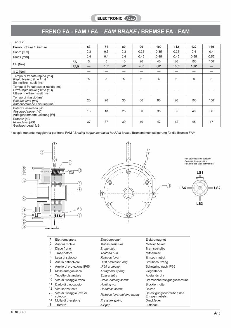
CT18IGBD1 A43
FRENO FA - FAM / FA – FAM BRAKE / BREMSE FA - FAM
Freno / Brake / Bremse 63 71 80 90 100 112 132 160
Snom [mm] 0.3 0.3 0.3 0.35 0.35 0.35 0.4 0.4
Smax [mm] 0.4 0.4 0.4 0.45 0.45 0.45 0.55 0.55
CF [Nm]FA 5 5 10 20 40 80 100 150
FAM — 10* 20* 40* 80* 100* 150* —
� C [Nm] — — — — — — — —
Tempo di frenata rapida [ms]Rapid braking time [ms]Schnellbremszeit [ms]
5 5 5 6 6 6 8 8
Tempo di frenata super rapida [ms]Extra-rapid braking time [ms]Ultraschnellbremszeit [ms]
— — — — — — — —
Tempo di rilascio [ms]Release time [ms]Aufgenommene Leistung [ms]
20 20 35 60 90 90 100 150
Potenza assorbita [W]Absorbed power [W]Aufogenommene Leistung [W]
18 18 25 30 35 35 40 60
Rumore [dB]Noise level [dB]Geräuschpegel [dB]
37 37 39 40 42 42 45 47
1 Elettromagnete Electromagnet Elektromagnet2 Ancora mobile Mobile armature Mobiler Anker3 Disco freno Brake disc Bremsscheibe4 Trascinatore Toothed hub Mitnehmer5 Leva di sblocco Release lever Entsperrhebel6 Anello antipolvere Dust protection ring Staubschutzring7 Anello di protezione IP65 IP55 protection Schutzring nach IP658 Molla antagonistica Antagonist spring Gegenfeder9 Tubetto distanziale Spacer tube Abstandsrohr
10 Vite di fissaggio freno Brake holding screw Bremsenbefestigungsschraube11 Dado di bloccaggio Holding nut Blockiermutter12 Vite senza testa Headless screw Bolzen
13 Vite di fissaggio leva disblocco Release lever holding screw
Befestigungsschrauben desEntsperrhebels
14 Molla di pressione Pressure spring DruckfederS Traferro Air gap Luftspalt
1
8
2
11
10
3
4
6
2
5
14
12
10
S9
7
113
LS1
LS4 LS2
LS3
Posizione leva di sbloccoRelease lever positionPosition des Entsperrhebels
* coppia frenante maggiorata per freno FAM / Braking torque increased for FAM brake / Bremsmomentsteigerung für die Bremse FAM
Tab.1.20
CT18IGBD1A44
FRENO FD - FDM / FD – FDM BRAKE / BREMSE FD – FDM
Electromagnetic brake in dc directcurrent
Description and operationElectromagnetic brake with negative opera-tion, whose braking action is exercised inthe absence of power supply. When thepower supply (7) is interrupted, the excita-tion coil is no longer powered and thereforedoes not exert the magnetic force neces-sary to restrain the mobile armature (1)which, pushed by the pressure spring (2),compresses the brake disk (3) against themotor flange (6) on one side and the arma-ture itself on the other, thereby creating abraking action. The allowed rated supplyvoltage variation for the brake is ± 10%.
AdjustmentTwo different types of adjustment are possi-ble.
Air gap adjustmentFor proper operation, the air gap S betweenthe electromagnet (7) and the mobile arma-ture (1) must be between the limits indi-cated in the table (Snom- Smax); adjustusing the threaded bushes (12), using athickness gauge to make sure that the de-sired air gap Snom is reached.
Braking torque adjustmentThis is done using the adjuster ring (9) ac-cording to the instructions in the table (Cn =
rated torque; � C = torque variation pertooth). If the hand release lever (8) is pres-ent, once the braking torque is adjusted it isalso necessary to adjust the free stroke ofthe lever before release begins, using theholding data of the lever itself.
Brake intervention timeFor the DC brake, it is possible to improvethe braking time by directly interrupting thebrake power supply via the switch.
Freno elettromagnetico in correntecontinua
Descrizione e funzionamentoFreno elettromagnetico con funzionamentonegativo, la cui azione frenante si esercitain assenza di alimentazione; quando si in-terrompe l’alimentazione, la bobina di ecci-tazione (7), non essendo più alimentata,non esercita la forza magnetica necessariaa trattenere l’ancora mobile (1), la quale,spinta dalle molle di pressione (2), compri-me il disco del freno (3) da una parte sullaflangia del motore (6), dall’altra sull’ancorastessa, esercitando così l’azione frenante.Variazione tensione d'alimentazione nomi-nale freno consentita ±10%.
RegolazioneSi possono effettuare due tipi diversi di re-golazione.
Regolazione del traferroPer un corretto funzionamento, il traferro Sfra elettromagnete (7) e ancora mobile (1),dev’essere compreso nei limiti di valori indi-cati in tabella (Snom- Smax); la regolazionesi effettua agendo sulle bussole filettate(12) controllando mediante spessimetroche si sia raggiunto il valore di traferro desi-derato Snom.
Regolazione della coppia frenanteSi ottiene agendo sulla ghiera di regolazio-ne (9), secondo le indicazioni della tabella(Cn = coppia nominale - �C = variazione dicoppia per dentatura). In presenza di leva disblocco manuale (8), una volta regolata lacoppia frenante, occorre regolare la corsalibera della leva prima dell’inizio sblocco,agendo sui dati di fissaggio della leva stes-sa.
Tempo d'intervento frenoIn caso di freno in D.C. è possibile migliora-re il tempo di frenata, interrompendo diret-tamente l’alimentazione del freno tramiteinterruttore.
ElektromagnetischeGleichstrombremse
Beschreibung und BetriebDie elektromagnetische Gleichstrombrem-se ist eine Ruhestrombremse, d.h siebremst bei fehlender Spannung. Bei Unter-brechung der Stromversorgung (7) übt dieErregerspule, da sie nicht mehr gespeistwird, keine Kraft mehr auf den mobilen An-ker (1) aus. Dieser klemmt die Bremsschei-be (3) mit Hilfe der Druckfeder (2) zwischendem Motorflansch (6) und sich selbst ein.Dadurch wird der Bremseffekterzielt. Die zulässige Abweichung von derNennspannung beträgt ± 10%.
EinstellungEs können zwei verschiedene Einstellun-gen vorgenommen werden.
LuftspalteinstellungDer Abstand des Luftspalts S zwischendem Elektromagneten (7) und dem mobilenAnker (1) muß innerhalb der in der Tabelleangegebenen Werte (Snom- Smax) liegen.Die Einstellung wird an den Gewindebuch-sen (12) vorgenommen. Mit einer Lehremuß dann geprüft werden, ob der ge-wünschte Snom-Wert für den Luftspalt er-reicht wurde.
Einstellung des BremsmomentsDie Einstellung des Bremsmoments wird ander Einstellring (9) unter Beachtung der inder Tabelle enthaltenen Angaben (Cn =Nennmoment - �C = Änderung pro Verzah-nung) vorgenommen. Wenn der Entsperr-hebel (8) eingebaut ist, muß, sobald dasBremsmoment eingestellt wurde, der freieHebelweg vor der Entriegelung an den He-belbefestigungsmuttern eingestellt werden.
Ansprechzeit der BremseBei Gleichstrombremsen kann die An-sprechzeit durch direkte UnterbrechungderStromversorgung mittels Schalter verbes-sert werden.

CT18IGBD1 A45
FRENO FD - FDM / FD – FDM BRAKE / BREMSE FD – FDM
Freno / Brake / Bremse 56 63 71 80 90 100 112 132 160
Snom [mm] 0015 0.2 0.2 0.2 0.2 0.3 0.3 0.3 0.4
Smax [mm] — 0.5 0.5 0.5 0.5 0.7 0.8 1 1
CF [Nm]FD 1 5 5 10 16 32 60 80 150
FDM — — 10* 16* 32* 60* 80* 150* —
� C [Nm] — 0.1 0.1 0.36 0.6 1.2 1.5 2.1 2.1
Tempo di frenata rapida [ms]Rapid braking time [ms]Schnellbremszeit [ms]
30 45 50 70 90 120 180 210 230
Tempo di rilascio rapida [ms]Rapid release time [ms]Schnellbremslösezeit [ms]
12 15 30 35 50 65 75 90 110
Tempo di frenata extra rapida [ms]Extra-rapid braking time [ms]Ultraschnellbremseit [ms]
20 25 30 40 45 60 110 140 180
Tempo di rilascio extra rapida [ms]Extra-rapid release time [ms]Ultraschnellbremslösezeit [ms]
8 12 20 25 35 45 60 70 90
Potenza assorbita [W]Absorbed power [W]Aufogenommene Leistung [W]
12 20 20 25 30 40 50 55 85
Rumore [dB]Noise level [dB]Geräuschpegel [dB]
39 36 36 37 37 38 38 39 42
1 Ancora mobile Mobile armature Mobiler Anker2 Molle Springs Federn3 Disco freno Brake disc Bremsscheibe4 Trascinatore Toothed hub Mitnehmer5 Albero motore Motor shaft Motorwelle6 Flanfia motore Motor flange Motorflansch7 Elettromagnete Eletromagnet Elektromagnet8 Leva di sblocco Release lever Entsperrhebel9 Ghiera di regolazione Adjuster ring Einstellring
10 Seeger Seeger Seeger-Ring11 Anello antipolvere Dust protection ring Staubschutzring12 Bussola filettata Threaded bush Gewindebuchse13 Anello di protezione IP65 IP55 protection Schutzring nach IP65S Traferro Air gap Luftspalt
6
54
7
9
8
2
3
1
12
S
11
10 13
LS1
LS4 LS2
LS3
Posizione leva di sbloccoRelease lever positionPosition des Entsperrhebels
* coppia frenante maggiorata per freno FDM / Braking torque increased for FDM brake / Bremsmomentsteigerung für die Bremse FDM
Tab.1.22

CT18IGBD1A46
FRENO FS / BRAKE FS / BREMSE FS
Freno elettromagnetico di stazio-namento in C.C.
Descrizione e funzionamentoFreno elettromagnetico con funzionamentonegativo la cui azione frenante si esercita inassenza di alimentazione: se l’alimentazio-ne dell’elettromagnete (1) è presente es-sendo l’ancora mobile(2) richiamata dallaforza magnetica, permette la rotazione libe-ra dell’albero; quando si interrompe l’ali-mentazione, la bobina di eccitazione, nonessendo più alimentata, non esercita la for-za magnetica necessaria a trattenere l’an-cora mobile (2), la quale spinta dalle molledi coppia (3) comprime la guarnizione di at-trito, solidale con l’ancora mobile contro laventola in ghisa (4), solidale con l’alberomotore tramite la chiavetta (5), esercitandocosì l’azione frenante.La tensione standard per questo tipo di fre-no è 230V/ 50Hz/60Hz con variazioni possi-bili del ±10% del valore nominale ditensione.
Regolazione traferroPer un corretto funzionamento, il traferro S[mm] fra elettromagnete (1) e ancora mobi-le (2) dev’essere compreso nei limiti dei va-lori indicati in tabella (Snom-Smax); laregolazione si effettua, una volta fissatosaldamente il corpo freno al motore, agen-do sulla vite (6), registrandola e controllan-do mediante spessimetro che si siaraggiunto il valore di traferro desiderato.Questa operazione va eseguita con freno atemperatura ambiente.
Tempo di intervento frenoIn caso di freno in corrente continua, ali-mentato tramite un ponte di diodi in alterna-ta, è possibile ottenere degli interventisuperapidi in frenata, tramite alimentatorispeciali.
DC electromagnetic parking brake
Description and operationElectromagnetic brake with negative opera-tion, whose braking action is exercised inthe absence of power supply. If the electro-magnet (1) is powered, the mobile armature(2) is drawn by the magnetic force and al-lows the shaft to rotate freely. When thepower supply is interrupted, the excitationcoil is no longer powered and thereforedoes not exert the magnetic force neces-sary to restrain the mobile armature (2).The latter, pushed by the pressure spring(3), compresses the lining attached to themobile armature against the cast-iron fan(4), in turn attached to the motor shaft bythe key (5), thereby creating a braking ac-tion. The standard voltage for this type ofbrake is 230V/50Hz/ 60Hz with possiblevariations of ± 10% in the rated voltage.
Air gap adjustmentFor proper operation, the air gap S [mm] be-tween the electromagnet (1) and the mobilearmature (2) must be between the limits in-dicated in the table (Snom-Smax). Oncethe brake assembly is firmly attached to themotor, adjust using the screw (6), settingand checking with a thickness gauge tomake sure that the desired air gap isreached. This should be done with thebrake at ambient temperature.
Braking intervention timesFor the direct current brake, powered by analternatingcurrent diode jumper, it is possi-ble to achieve extra-rapid braking interven-tion using special power packs.
ElektromagnetischeGleichstromfeststellbremse
Beschreibung und BetriebDie elektromagnetische Gleichstromfest-stellbremse ist eine Ruhestrombremse, d.hsie bremst bei fehlender Spannung. Wennder Elektromagnet (1) mit Strom versorgtwird, kann sich die Welle ohne Behinderungdrehen, da die Kraft des Magneten den mo-bilen Anker (2) zurückhält. Bei Unterbre-chung der Stromversorgung übt dieErregerspule, da sie nicht mehr gespeistwird, keine Kraft mehr auf den mobilen An-ker (2) aus. Dieser drückt den an ihm befes-tigten Belag mit Hilfe der Drehmomentfeder(3) gegen das mit der Motorwelle verkeilte(5) Lüfterrad aus Guß (4). Dadurch wird derBremseffekt erzielt. Die Standardspannungfür diese Art von Bremse beträgt230V/50Hz/60Hz mit einer Toleranz von ±10% der Nennspannung.
LuftspalteinstellungDer Abstand des Luftspalts S [ mm] zwi-schen dem Elektromagneten (1) und demmobilen Anker (2) muß innerhalb der in derTabelle angegebenen Werte (Snom-Smax) liegen. Die Einstellung wird, sobaldder Bremsenkörper am Motor befestigt wur-de, an der Schraube (6) vorgenommen. Miteiner Lehre muß dann geprüft werden, obder gewünschte Wert für den Luftspalt er-reicht wurde. Bei dieser Einstellung mußdie Bremse Umgebungstemperatur haben.
Ansprechzeit der BremseBei Gleichstrombremsen, die über eineDiodenbrücke mit Wechselstrom gespeistwerden, kann die Ansprechzeit durch denEinsatz von besonderen Netzteilen merk-lich verbessert werden (Ultraschnellbrem-sung).
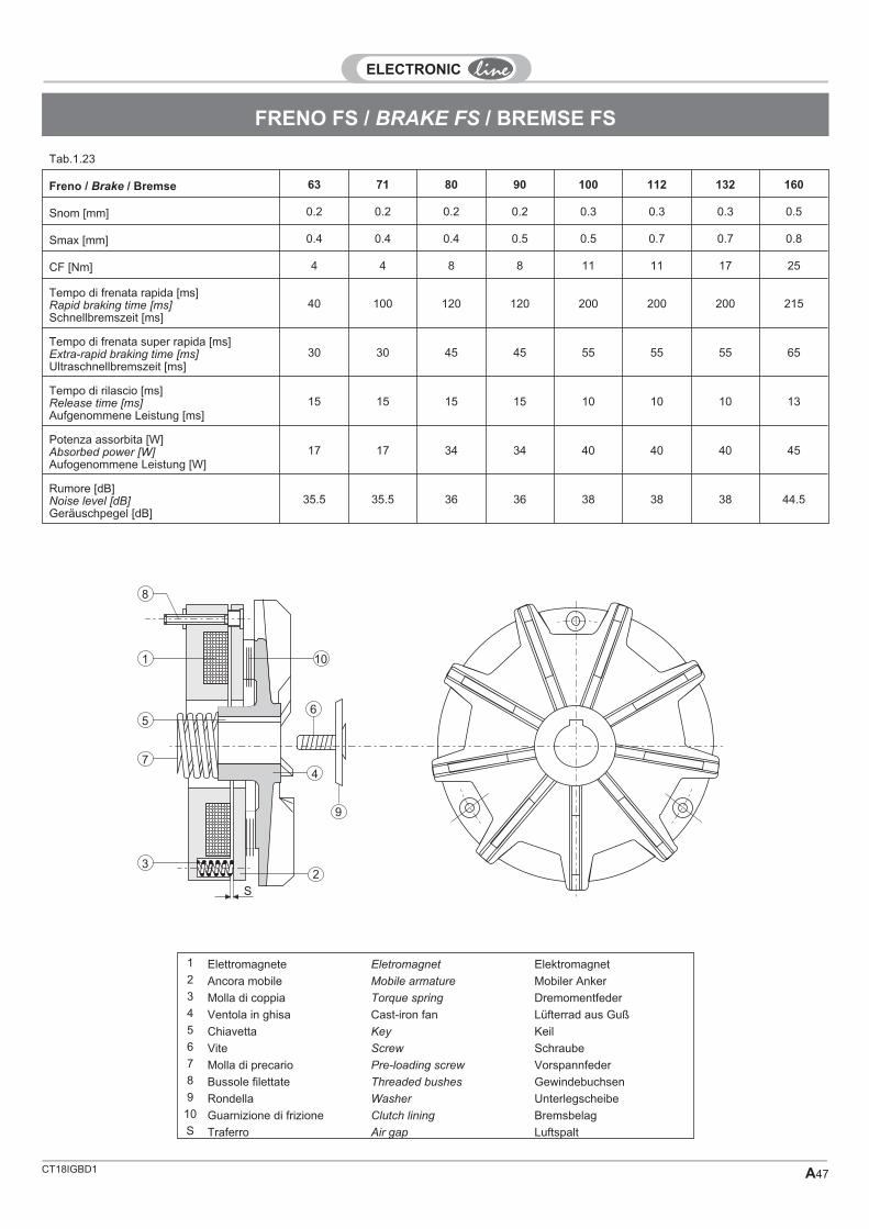
CT18IGBD1 A47
FRENO FS / BRAKE FS / BREMSE FS
Freno / Brake / Bremse 63 71 80 90 100 112 132 160
Snom [mm] 0.2 0.2 0.2 0.2 0.3 0.3 0.3 0.5
Smax [mm] 0.4 0.4 0.4 0.5 0.5 0.7 0.7 0.8
CF [Nm] 4 4 8 8 11 11 17 25
Tempo di frenata rapida [ms]Rapid braking time [ms]Schnellbremszeit [ms]
40 100 120 120 200 200 200 215
Tempo di frenata super rapida [ms]Extra-rapid braking time [ms]Ultraschnellbremszeit [ms]
30 30 45 45 55 55 55 65
Tempo di rilascio [ms]Release time [ms]Aufgenommene Leistung [ms]
15 15 15 15 10 10 10 13
Potenza assorbita [W]Absorbed power [W]Aufogenommene Leistung [W]
17 17 34 34 40 40 40 45
Rumore [dB]Noise level [dB]Geräuschpegel [dB]
35.5 35.5 36 36 38 38 38 44.5
1 Elettromagnete Eletromagnet Elektromagnet2 Ancora mobile Mobile armature Mobiler Anker3 Molla di coppia Torque spring Dremomentfeder4 Ventola in ghisa Cast-iron fan Lüfterrad aus Guß5 Chiavetta Key Keil6 Vite Screw Schraube7 Molla di precario Pre-loading screw Vorspannfeder8 Bussole filettate Threaded bushes Gewindebuchsen9 Rondella Washer Unterlegscheibe
10 Guarnizione di frizione Clutch lining BremsbelagS Traferro Air gap Luftspalt
9
6
4
S
3
7
5
1
8
10
2
Tab.1.23

CT18IGBD1A48
FRENO FP / BRAKE FP / BREMSE FP
Freno elettromagnetico ad azionepositiva in C.C.
Descrizione e funzionamentoFreno elettromagnetico con funzionamentopositivo la cui azione frenante si esercita inpresenza di alimentazione: infatti, se l’ali-mentazione dell’elettromagnete (6) è as-sente, essendo l’ancora mobile (1)trattenuta dalla forza esercitata dalla mollaanulare (4), permette la rotazione liberadell’albero (5).Quando si alimenta la bobina di eccitazione(6), questa esercita la forza magnetica ne-cessaria ad attrarre l’ancora mobile (1), laquale, vincendo la forza della molla anulare(4), impegna la guarnizione di attrito (3) so-lidale con lo statore; ancora essendo la (1)solidale con l’albero motore (5) tramite lachiavetta (8), esercita così l’azione frenan-te.La tensione standard per questo tipo di fre-no è 24 V.D.C. con variazioni possibili(±10% del valore nominale di tensione).Questo tipo di freno è isolato in classe “B”.
Regolazione traferroPer un corretto funzionamento, il traferro S[mm] fra statore elettromagnete [(3)+(6)] eancora mobile (1), dev’essere compresonei limiti di valori indicati in tabella (Snom-Smax); la regolazione si effettua, una voltafissato saldamente il corpo freno al motore,agendo sul dado autobloccante (7) registra-zione traferro, e controllando mediantespessimetro che si sia raggiunto il valore ditraferro desiderato.Questa operazione va eseguita con freno atemperatura ambiente.
Tempo di intervento frenoIn caso di freno in corrente continua, ali-mentato tramite un ponte di diodi in alterna-ta, è possibile ottenere degli interventisuper rapidi in frenata, tramite alimentatorispeciali come indicato in tabella 24.
ElektromagnetischeArbeitsstrombremse fürGleichstrom
Beschreibung und BetriebDieelektromagnetische Gleichstrombrem-se ist eine Arbeitsstrombremse, d.h siebremst bei angelegter Spannung. Wennder Elektromagnet (6) nicht mit Strom ver-sorgt wird, kann sich die Welle (5) frei dre-hen, da die Kraft der Ringfeder (4) denmobilen Anker (1) zurückhält. Wenn die Er-regerspule (6) mit Strom versorgt wird,zieht sie den mobilen Anker (1) durch ihremagnetische Kraft an. Dadurch überwindetder mobile Anker die Kraft der Ringfeder (4)und wirkt auf den am Stator befestigtenBremsbelag (3) ein. Da der mobile Anker(1) mit der Motorwelle (5) verkeilt (8) ist,wird der Bremseffekt erzielt. Die Standard-spannung für diese Art von Bremse beträgt24V mit Toleranzen von ± 10% derNennspannung. Die Isolationsklasse dieserBremse ist "B".
LuftspalteinstellungDer Abstand des Luftspalts S [mm] zwi-schen dem Stator / Elektromagneten[(3)+(6)] und dem mobilen Anker (1) mußinnerhalb der in der Tabelle angegebenenWerte (Snom-Smax) liegen. Die Einstel-lung wird, sobald der Körper der Bremseam Motor befestigt wurde, an der selbstblo-ckierenden Luftspalteinstellmutter (7) vor-genommen. Mit einer Lehre muß danngeprüft werden, ob der gewünschte Wertfür den Luftspalt erreicht wurde. Bei dieserEinstellung muß die Bremse Umgebungs-temperatur haben.
Ansprechzeit der BremseBei Gleichstrombremsen, die über eineDiodenbrücke mit Wechselstrom gespeistwerden, kann die Ansprechzeit durch denEinsatz von besonderen Netzteilen (Tab.24) merklich verbessert werden (Ultra-schnellbremsung).
DC electromagnetic positive-action brake
Description and operationElectromagnetic brake with positive opera-tion, whose braking action is exercised inthe presence of power supply. If the electro-magnet (6) power supply is absent, the mo-bile armature (1) is drawn by the forceexerted by the anular spring (4) and allowsthe shaft (5) to rotate freely.When the excitation coil (6) is poweredpower, it exerts the magnetic force neededto attract the mobile armature (1). The latterovercomes the force of the anular spring (4)and engages the lining (3) attached to thestator, in turn (1) attached to the motor shaft(5) by the key (8), thereby creating a brak-ing action.The standard voltage for this type of brakeis 24 VDC with possible variations of ± 10%in the rated voltage. This type of brake is in-sulated for class "B".
Air gap adjustmentFor proper operation, the air gap S [mm] be-tween the electromagnet stator [(3)+(6)]and the mobile armature (1) must be be-tween the limits indicated in the table(Snom- Smax). Once the brake assembly isfirmly attached to the motor, adjust usingthe self-locking air gap setting nut (7),checking with a thickness gauge to makesure that the desired air gap is reached.This should be done with the brake at ambi-ent temperature.
Braking intervention timesFor the direct current brake, powered by analternating-current diode jumper, it is possi-ble to achieve extra-rapid braking interven-tion using special power packs as indicatedin the table 24.

CT18IGBD1 A49
FRENO FP / BRAKE FP / BREMSE FP
Freno / Brake / Bremse 63 71 80 90 100 112 132 160
Snom [mm] 0.2 0.2 0.2 0.2 0.3 0.3 0.3 0.5
Smax [mm] 0.4 0.4 0.4 0.4 0.6 0.6 0.6 1
CF [Nm] 7.5 7.5 15 15 30 30 60 120
Tempo di frenata rapida [ms]Rapid braking time [ms]Schnellbremszeit [ms]
40 100 120 140 200 230 280 340
Tempo di frenata super rapida [ms]Extra-rapid braking time [ms]Ultraschnellbremszeit [ms]
30 45 60 70 85 100 115 140
Tempo di rilascio [ms]Release time [ms]Aufgenommene Leistung [ms]
20 20 16 16 13 13 12 10
Potenza assorbita [W]Absorbed power [W]Aufogenommene Leistung [W]
11.5 11.5 16 16 21 21 28 38
Rumore [dB]Noise level [dB]Geräuschpegel [dB]
35.5 35.5 36 36 38 38 38 44.5
1 Ancora mobile Mobile armature Mobiler Anker2 Flangia di mozzo Hub flange Nabenflansch3 Guarnizione di frizione Clutch lining Bremsbelag4 Molla anullare Anular spring Ringfeder5 Albero Shaft Welle6 Bobina Coil Spule7 Dado regolazione traferro Air gap setting nut Luftspalteinstellmutter8 Chiavetta Key KeilS Traferro Air gap Luftspalt
S
1
2
7
4
36
5
8
Tab.1.24

CT18IGBD1A50
T
T50A* 0.06 0.08 2700 0.25 48 0.64 2.4 2.4 2.6 0.21 0.00008 2.2 — —T50B* 0.09 0.12 2700 0.36 52 0.68 2.8 2.5 2.7 0.23 0.00010 2.4 — —T56A 0.09 0.12 2740 0.40 58 0.70 3.2 2.7 2.8 0.26 0.00012 2.6 15 0.7T56B 0.14 0.18 2750 0.50 60 0.72 3.5 2.8 2.9 0.40 0.00015 3.2 15 0.7T63A 0.18 0.25 2760 0.60 65 0.79 3.7 2.6 2.7 0.60 0.00025 3.7 17 2.6T63B 0.25 0.35 2790 0.80 69 0.80 3.9 2.9 3.0 0.78 0.00030 4.3 17 2.6T63C* 0.37 0.50 2790 1.0 72 0.78 4.3 3.0 3.1 1.2 0.00035 5.6 17 2.6T71A 0.37 0.50 2790 1.1 71 0.81 4.5 2.6 2.7 1.2 0.00038 5.8 17 2.6T71B 0.55 0.75 2800 1.6 73 0.82 4.5 2.9 3.0 1.8 0.00046 6.2 17 2.6T71C* 0.75 1.0 2800 1.9 72 0.83 4.6 3.0 3.1 2.1 0.00057 7.4 17 2.6T80A 0.75 1.0 2820 2.0 76 0.84 4.8 2.3 2.6 2.4 0.00080 8.5 38 5.4T80B 1.1 1.5 2830 2.6 78 0.86 5.2 2.6 2.7 3.6 0.00097 9.8 38 5.4T80C* 1.5 2.0 2830 3.0 77 0.86 5.6 2.8 3.0 4.7 0.00120 10.5 38 5.4T80D* 1.8 2.5 2770 4.2 75 0.85 5.6 2.7 3.0 6.3 0.00130 11.5 38 5.4T90S 1.5 2.0 2830 3.6 78 0.84 5.5 2.3 2.8 4.9 0.00150 12.0 38 5.4T90L 2.2 3.0 2840 5.2 79 0.83 6.0 2.8 3.1 7.2 0.00230 13.5 38 5.4T90LB* 3.0 4.0 2840 6.5 80 0.88 6.1 3.0 3.2 9.3 0.00280 15.5 38 5.4T100A 3.0 4.0 2860 7.0 81 0.88 6.4 2.4 2.9 9.7 0.00530 18.5 38 5.4T100B* 4.0 5.5 2860 8.9 84 0.86 6.5 2.1 2.8 13.9 0.00850 21 38 5.4T112A 4.0 5.5 2860 8.7 84 0.86 6.5 2.1 2.6 13.9 0.00900 27 38 5.4T112B* 5.5 7.5 2880 11.8 85 0.85 6.8 2.2 2.7 18.0 0.01200 32 38 5.4T112BL* 7.5 10.0 2860 16.0 86 0.85 6.5 2.9 2.8 25 0.01300 34 38 5.4T132S 5.5 7.5 2870 13.0 85 0.88 6.0 2.2 2.3 18.0 0.01300 45 38 5.4T132SL 7.5 10.0 2890 16.5 85 0.88 6.4 2.8 3.2 24 0.02000 48 38 5.4T132M* 11.0 15.0 2940 21 88 0.87 7.3 2.5 3.5 36 0.02800 54 38 5.4T132ML* 15.0 20 2900 30 86 0.90 6.8 2.7 3.7 50 0.03000 58 38 5.4T160MA 11.0 15.0 2900 24 86 0.84 6.4 2.2 2.7 36 0.03200 75 115 27T160MB 15.0 20 2930 32 88 0.85 7.4 2.2 2.8 49 0.03600 88 115 27T160L 18.5 25 2910 39 89 0.84 7.6 2.3 2.8 61 0.04000 99 115 27
T50A* 0.03 0.05 1350 0.23 50 0.60 2.4 2.0 2.1 0.3 0.00008 2.2 — —T50B* 0.06 0.08 1350 0.35 52 0.63 2.6 2.1 2.3 0.4 0.00010 2.4 — —T56A 0.06 0.08 1360 0.38 54 0.63 2.5 2.3 2.5 0.4 0.00015 2.5 15.0 0.7T56B 0.09 0.12 1360 0.45 56 0.65 2.8 2.3 2.5 0.6 0.00015 2.6 15.0 0.7T56C 0.11 0.15 1360 0.50 58 0.66 2.8 2.4 2.7 0.7 0.00020 3.2 15.0 0.7T63A 0.13 0.18 1360 0.70 60 0.66 3.0 2.4 2.8 0.8 0.00028 3.7 17.0 2.6T63B 0.18 0.25 1370 0.75 60 0.68 3.0 2.5 2.8 1.2 0.00040 4.3 17.0 2.6T63C* 0.22 0.30 1400 0.78 60 0.66 3.2 2.6 2.9 1.5 0.00040 4.3 17.0 2.6T71A 0.25 0.35 1370 0.86 65 0.70 3.6 2.5 2.7 1.6 0.00050 5.8 17.0 2.6T71B 0.37 0.50 1380 1.2 67 0.74 3.5 2.5 2.8 2.6 0.00080 6.2 17.0 2.6T71C* 0.55 0.75 1380 1.5 66 0.72 3.8 2.6 2.8 3.5 0.00090 7.4 17.0 2.6T80A 0.55 0.75 1390 1.7 68 0.75 4.0 2.5 2.6 3.5 0.00140 8.5 38 5.4T80B 0.75 1.0 1390 2.0 70 0.76 4.2 2.6 2.8 5.4 0.00170 9.8 38 5.4T80C* 0.88 1.2 1350 2.6 70 0.75 4.3 2.5 2.7 6.2 0.00200 10.5 38 5.4T80D* 1.1 1.5 1390 3.1 71 0.75 4.3 2.7 2.8 7.6 0.00230 11.0 38 5.4T90S 1.1 1.5 1400 3.3 75 0.78 4.2 2.5 2.6 7.6 0.00330 12.0 38 5.4T90L 1.5 2.0 1400 4.1 78 0.78 4.6 2.6 2.7 9.8 0.00400 13.5 38 5.4T90LB* 1.8 2.5 1400 5.0 77 0.75 4.7 2.6 2.8 12.2 0.00500 15.5 38 5.4T100A 2.2 3.0 1410 5.9 78 0.80 4.9 2.5 2.6 14.8 0.00750 19.0 38 5.4T100B 3.0 4.0 1420 7.3 78 0.82 5.0 2.5 2.7 19.5 0.00850 21 38 5.4T100BL* 4.0 5.5 1410 9.2 78 0.79 5.0 2.5 2.7 26 0.01100 23 38 5.4T112A 4.0 5.5 1425 9.0 80 0.81 5.3 2.6 2.9 26 0.01300 29 38 5.4T112BL* 5.5 7.5 1400 11.7 80 0.82 5.5 2.7 3.0 38 0.01600 35 38 5.4T132S 5.5 7.5 1440 12.0 81 0.81 5.8 2.5 2.8 37 0.02400 43 38 5.4T132M 7.5 10.0 1440 16.0 82 0.83 6.2 2.6 3.0 49 0.03300 52 38 5.4T132ML* 9.2 12.5 1450 20 87 0.83 5.5 2.5 3.2 61 0.03400 54 38 5.4T160M 11.0 15.0 1455 24 86 0.81 5.3 2.3 2.2 72 0.06200 68 115 27T160L 15.0 20 1455 32 87 0.82 5.6 2.2 2.3 99 0.07400 78 115 27
4 P 1500 min-1
ServoventilazloneBlower
Servobelüftung230V/50HZ
TipoTypeTyp
Pn nn In(400 V)
� cos � Ia
In
Ca
Cn
Cmax
CnCn Jm PV VB
[kW] [HP] [min-1] [A] � [Nm] [Kgm2] [W] [m3/min]
2 P 3000 min-1
ServoventilazloneBlower
Servobelüftung230V/50HZ
TipoTypeTyp
Pn nn In(400 V)
� cos � Ia
In
Ca
Cn
Cmax
CnCn Jm PV VB
[kW] [HP] [min-1] [A] � [Nm] [Kgm2] [W] [m3/min]
1.7 TECHNICAL SPECIFICATIONS1.7 DATI TECNICI 1.7 TECHNISCHE DATEN
TRIFASETHREE-PHASEDREHSTROM

CT18IGBD1 A51
TA
— — — — — — — — — — — — — — — — —— — — — — — — — — — — — — — — — —
TA56A 1.0 9700 12.0 4.0 — — — — — — — — — — — —TA56B 1.0 8900 12.0 5.0 — — — — — — — — — — — —TA63A 5.0 8100 20 5.0 5.0 8100 18.0 5.0 4.0 8100 17.0 5.0 7.5 8100 11.5 4.1TA63B 5.0 6750 20 6.0 5.0 6750 18.0 6.0 4.0 6750 17.0 6.0 7.5 6750 11.5 4.7TA63C 5.0 5400 20 7.0 5.0 5400 18.0 7.0 4.0 5400 17.0 7.0 7.5 5400 11.5 6.0TA71A 5.0 5400 20 8.0 5.0 5400 18.0 8.0 4.0 5400 17.0 7.0 7.5 5400 11.5 6.2TA71B 5.0 5400 20 8.0 5.0 5400 18.0 8.0 4.0 5400 17.0 8.0 7.5 5400 11.5 6.6TA71C 5.0 5500 20 9.0 5.0 5500 18.0 9.0 4.0 5500 17.0 9.0 7.5 5500 11.5 7.8TA80A 10.0 5400 25 11.0 10.0 5400 25 11.0 8.0 5400 34 11.0 15.0 5400 16.0 9.1TA80B 10.0 5400 25 12.0 10.0 5400 25 12.0 8.0 5400 34 12.0 15.0 5400 16.0 10.4TA80C 10.0 5100 25 13.0 10.0 5100 25 13.0 8.0 5100 34 13.0 15.0 5100 16.0 11.1TA80D 10.0 4900 25 14.0 10.0 4900 25 14.0 8.0 4900 34 14.0 15.0 4900 16.0 12.0TA90S 16.0 4000 30 17.0 20 4000 30 17.0 8.0 4000 34 14.0 15.0 4000 16.0 12.6TA90L 16.0 4000 30 18.0 20 4000 30 18.0 8.0 4000 34 15.0 15.0 4000 16.0 14.1TA90LB 16.0 3800 30 20 20 3800 30 20 8.0 3800 34 18.0 15.0 3800 16.0 16.1TA100A 32 2500 40 25 40 2500 35 27 11.0 2500 40 22 30 2500 21 19.4TA100B 32 2400 40 28 40 2400 35 30 11.0 2400 40 25 30 2400 21 22TA112A 60 1500 50 36 80 1500 35 36 11.0 1500 40 31 30 1500 21 28TA112B 60 1400 50 41 80 1400 35 41 11.0 1400 40 36 30 1400 21 33TA112BL 60 1300 50 43 80 1300 35 43 11.0 1300 40 38 30 1300 21 35TA132S 80 430 55 58 100 430 45 59 17.0 430 40 50 60 430 28 46TA132SL 80 430 55 61 100 430 45 62 17.0 430 40 58 60 430 28 49TA132M 80 400 55 67 100 400 45 68 17.0 400 40 59 60 400 28 55TA132ML 80 400 55 71 100 400 45 72 17.0 400 40 63 60 400 28 59TA160MA 150 300 85 95 150 300 47 93 25.0 300 45 82 120 300 38 77TA160MB 150 300 85 108 150 300 47 106 25.0 300 45 95 120 300 38 90TA160L 150 300 85 119 150 300 47 117 25.0 300 45 106 120 300 38 101
TA50A 1.0 12500 12.0 3.7 — — — — — — — — — — — —TA50B 1.0 12500 12.0 3.9 — — — — — — — — — — — —TA56A 1.0 12500 12.0 4.0 — — — — — — — — — — — —TA56B 1.0 12500 12.0 5.0 — — — — — — — — — — — —TA56C 1.0 12500 12.0 5.0 — — — — — — — — — — — —TA63A 5.0 10500 20 5.0 5.0 10500 18.0 5.0 4.0 10500 17.0 5.0 7.5 10500 11.5 4.1TA63B 5.0 10500 20 7.0 5.0 10500 18.0 7.0 4.0 10500 17.0 6.0 7.5 10500 11.5 4.7TA63C 5.0 10500 20 7.0 5.0 10500 18.0 7.0 4.0 10500 17.0 6.0 7.5 10500 11.5 4.7TA71A 5.0 18000 20 8.0 5.0 18000 18.0 8.0 4.0 18000 17.0 7.0 7.5 18000 11.5 6.2TA71B 5.0 17000 20 8.0 5.0 17000 18.0 8.0 4.0 17000 17.0 8.0 7.5 17000 11.5 6.6TA71C 5.0 16000 20 9.0 5.0 16000 18.0 9.0 4.0 16000 17.0 9.0 7.5 16000 11.5 7.8TA80A 10.0 9000 25 11.0 10.0 9000 25 11.0 8.0 9000 34 11.0 15.0 9000 16.0 9.1TA80B 10.0 9000 25 13.0 10.0 9000 25 13.0 8.0 9000 34 12.0 15.0 9000 16.0 10.4TA80C 10.0 9000 25 13.5 10.0 9000 25 13.5 8.0 9000 34 13.5 15.0 9000 16.0 11.1TA80D- 10.0 9000 25 14.0 10.0 9000 25 14.0 8.0 9000 34 14.0 15.0 9000 16.0 11.6TA90S 16.0 13500 30 17.0 20 13500 30 17.0 8.0 13500 34 15.0 15.0 13500 16.0 12.6TA90L 16.0 11000 30 18.0 20 11000 30 18.0 8.0 11000 34 16.0 15.0 11000 16.0 14.1TA90LB 16.0 8000 30 20 20 8000 30 20 8.0 8000 34 18.0 15.0 8000 16.0 16.1TA100A 32 7200 40 26 40 7200 35 28 11.0 7200 40 23 30 7200 21 19.9TA100B 32 6300 40 28 40 6300 35 30 11.0 6300 40 25 30 6300 21 22TA100BL 32 6000 40 30 40 6000 35 32 11.0 6000 40 27 30 6000 21 24TA112A 60 3600 50 38 80 3600 35 38 11.0 3600 40 33 30 3600 21 30TA112BL 60 3400 50 44 80 3400 35 44 11.0 3400 40 39 30 3400 21 36TA132S 80 1100 55 56 100 1100 45 57 17.0 1100 40 48 60 1100 28 44TA132M 80 850 55 66 100 850 45 67 17.0 850 40 57 60 850 28 53TA132ML 80 800 55 68 100 800 45 69 17.0 800 40 59 60 800 28 55TA160M 150 750 85 87 150 750 47 85 25 750 45 75 120 750 38 70TA160L 150 750 85 97 150 750 47 95 25 750 45 83 120 750 38 80
FSFD FA FPTipoTypeTyp
Autofrenante in D.C.Brake motor In D.C.Gleichstrom-Bremsmotor
Autofrenante in A.C.Brake motor In A.C.Wechselstrom-Bremsmotor
Autofrenante in D.C.Brake motor in D.C.Gleichstrom-Bremsmotor
Autofrenante in D.C.Brake motor in D.C.Gleichstrom-Bremsmotor
CF Z0 PB CF Z0 PB CF Z0 PB CF Z0 PB
[Nm] [1/h] [W] [Nm] [1/h] [W] [Nm] [1/h] [W] [Nm] [1/h] [W]
TipoTypeTyp
Autofrenante in D.C.Brake motor In D.C.Gleichstrom-Bremsmotor
Autofrenante in A.C.Brake motor In A.C.Wechselstrom-Bremsmotor
Autofrenante in D.C.Brake motor in D.C.Gleichstrom-Bremsmotor
Autofrenante in D.C.Brake motor in D.C.Gleichstrom-Bremsmotor
CF Z0 PB CF Z0 PB CF Z0 PB CF Z0 PB
[Nm] [1/h] [W] [Nm] [1/h] [W] [Nm] [1/h] [W] [Nm] [1/h] [W]
FSFD FA FP
TRIFASETHREE-PHASEDREHSTROM

CT18IGBD1A52
T
T56B 0.03 0.05 820 0.36 42 0.56 2.4 1.5 1.6 0.6 0.00015 2.6 15.0 0..7T56C 0.06 0.08 820 0.40 46 0.58 2.4 1.9 2.0 0.7 0.00020 3.0 15.0 0.7T63B 0.09 0.12 860 0.60 48 0.62 3.0 2.0 2.1 0.9 0.00025 3.8 17.0 2.6T63C 0.13 0.18 860 0.75 50 0.65 3.2 2.3 2.2 1.2 0.00040 4.2 17.0 2.6T71A 0.18 0.25 870 1.0 56 0.66 3.0 2.3 2.4 1.9 0.00060 5.7 17.0 2.6T71B 0.25 0.35 870 1.1 58 0.68 3.1 2.4 2.4 2.6 0.00080 6.4 17.0 2.6T71C* 0.37 0.50 880 1.2 60 0.68 3.1 2.4 2.5 3.7 0.00100 6.5 17.0 2.6T80A 0.37 0.50 910 1.6 65 0.70 3.2 2.3 2.5 3.8 0.00200 8.7 38 5.4T80B 0.55 0.75 910 1.9 68 0.72 3.8 2.3 2.4 5.7 0.00250 10.5 38 5.4T80C* 0.75 1.0 910 2.3 69 0.72 3.9 2.4 2.4 7.9 0.00260 11.0 38 5.4T90S 0.75 1.0 920 2.4 72 0.73 3.9 2.4 2.5 7.9 0.00350 12.0 38 5.4T90L 1.1 1.5 920 3.4 74 0.75 4.2 2.5 2.6 11.5 0.00450 14.0 38 5.4T90LB* 1.5 2.0 925 4.1 73 0.75 4.4 2.3 2.7 15.5 0.00500 16.0 38 5.4T100A 1.5 2.0 940 4.2 75 0.76 4.5 2.6 2.8 15.2 0.00900 19.5 38 5.4T100B 1.9 2.5 940 5.2 77 0.76 4.7 2.6 2.7 19.0 0.01000 21 38 5.4T100BL 2.2 3.0 940 5.6 78 0.76 4.9 2.4 2.5 22 0.01100 23 38 5.4T112A 2.2 3.0 950 5.6 80 0.77 4.9 2.4 2.6 22 0.01500 30 38 5.4T112B 3.0 4.0 940 7.4 80 0.77 5.4 2.0 2.4 31 0.01800 37 38 5.4T132S 3.0 4.0 950 7.2 81 0.78 5.4 2.1 2.5 30 0.03000 43 38 5.4T132M 4.0 5.5 950 9.8 83 0.78 5.6 2.2 2.5 40 0.04000 52 38 5.4T132ML 5.5 7.5 950 13.0 83 0.80 5.7 2.3 2.6 55 0.04200 55 38 5.4T160M 7.5 10.0 960 15.0 85 0.81 5.2 2.1 2.2 75 0.08800 70 115 27T160L 11.0 15.0 965 24 85 0.81 5.4 2.2 2.6 109 0.10600 90 115 27
T56B 0.03 0.05 640 0.40 40 0.50 1.9 1.9 1.9 0.43 0.00010 3.2 15.0 0.7T63B 0.05 0.07 660 0.56 42 0.52 1.9 2.0 2.0 0.75 0.00030 3.9 17.0 2.6T63C 0.07 0.10 660 0.63 42 0.52 2.0 2.0 2.1 0.9 0.00060 4.3 17.0 2.6T71B 0.09 0.12 660 0.65 45 0.56 2.0 2.1 2.2 1.2 0.00080 5.7 17.0 2.6T71C 0.12 0.17 660 0.80 46 0.58 2.1 2.2 2.2 1.5 0.00100 6.4 17.0 2.6T80A 0.18 0.25 670 0.90 55 0.60 2.4 2.2 2.4 3.0 0.00200 8.8 38 5.4T80B 0.25 0.35 670 1.2 57 0.61 2.6 2.3 2.5 3.4 0.00250 10.5 38 5.4T80C 0.37 0.50 670 1.6 60 0.60 3.0 2.0 2.6 5.2 0.00280 11.0 38 5.4T90S 0.37 0.50 680 1.5 61 0.62 3.3 2.1 2.4 4.9 0.00350 12.0 38 5.4T90L 0.55 0.75 680 2.2 63 0.63 3.4 2.0 2.1 7.5 0.00450 14.0 38 5.4T90LB 0.75 1.0 680 2.8 65 0.62 3.6 2.1 2.0 10.0 0.00550 16.0 38 5.4T100A 0.75 1.0 690 2.7 69 0.67 3.8 1.9 2.1 9.9 0.00900 19.8 38 5.4T100B 1.1 1.5 690 4.0 71 0.68 4.0 2.1 2.3 15.0 0.01000 22 38 5.4T100BL 1.3 1.8 680 4.6 71 0.68 4.2 2.0 2.3 21 0.01200 24 38 5.4T112A 1.5 2.0 700 4.7 73 0.70 4.0 2.1 2.4 20 0.01500 32 38 5.4T132S 2.2 3.0 700 7.5 73 0.72 4.6 2.0 2.4 30 0.03000 44 38 5.4T132M 3.0 4.0 700 8.5 76 0.74 4.6 1.9 2.2 40 0.04000 53 38 5.4T132ML 4.0 5.5 680 11.0 74 0.76 4.9 1.8 2.1 56 0.05000 58 38 5.4T160MA 4.0 5.5 720 11.5 80 0.76 4.6 1.9 2.3 53 0.08000 64 115 27T160MB 5.5 7.5 725 13.5 81 0.77 4.7 2.0 2.2 72 0.09200 72 115 27T160L 7.5 10.0 725 18.5 82 0.78 4.6 2.0 2.1 99 0.11200 86 115 27
T71C 0.09 0.12 410 0.60 36 0.60 1.7 1.4 1.6 2.1 0.00120 6.5 17.0 2.6T80C 0.18 0.25 415 1.1 42 0.61 1.8 1.5 1.7 4.0 0.00300 11.0 38 5.4T90L 0.25 0.35 420 1.7 43 0.60 1.9 1.6 1.8 5.6 0.00500 15.0 38 5.4T100A 0.37 0.50 425 2.1 46 0.60 1.7 1.8 1.9 8.3 0.01000 21 38 5.4T100B 0.55 0.75 450 2.8 54 0.62 2.0 2.4 2.0 11.5 0.01300 23 38 5.4T112B 0.75 1.0 450 3.0 60 0.63 2.1 2.6 2.1 16.0 0.01600 28 38 5.4T132S 1.1 1.5 455 6.1 61 0.63 3.3 2.0 1.8 23 0.03000 55 38 5.4T132M 1.5 2.0 460 6.5 62 0.60 3.4 1.8 1.7 31 0.03800 66 38 5.4T160M 3.0 4.0 460 11.0 70 0.64 3.8 1.9 1.8 63 0.09000 80 115 27T160L 4.0 5.5 450 14.0 72 0.66 4.0 2.2 2.0 83 0.13000 90 115 27
6 P 1000 min-1
ServoventilazloneBlower
Servobelüftung230V/50HZ
TipoTypeTyp
Pn nn In(400 V)
� cos � Ia
In
Ca
Cn
Cmax
CnCn Jm PV VB
[kW] [HP] [min-1] [A] � [Nm] [Kgm2] [W] [m3/min]
8 P 750 min-1
ServoventilazloneBlower
Servobelüftung230V/50HZ
TipoTypeTyp
Pn nn In(400 V)
� cos � Ia
In
Ca
Cn
Cmax
CnCn Jm PV VB
[kW] [HP] [min-1] [A] � [Nm] [Kgm2] [W] [m3/min]
12 P 500 min-1
ServoventilazloneBlower
Servobelüftung230V/50HZ
TipoTypeTyp
Pn nn In(400 V)
� cos � Ia
In
Ca
Cn
Cmax
CnCn Jm PV VB
[kW] [HP] [min-1] [A] � [Nm] [Kgm2] [W] [m3/min]
TRIFASETHREE-PHASEDREHSTROM

CT18IGBD1 A53
TA
TA56B 1.0 21500 12.0 4.0 — — — — — — — — — — — —TA56C 1.0 21500 12.0 5.0 — — — — — — — — — — — —TA63B 5.0 18000 20 5.0 5.0 18000 18.0 5.0 4.0 18000 17.0 5.0 7.5 18000 11.5 4.2TA63C 5.0 18000 20 6.0 5.0 18000 18.0 6.0 4.0 18000 17.0 6.0 7.5 18000 11.5 4.6TA71A 5.0 25000 20 7.0 5.0 25000 18.0 7.0 4.0 25000 17.0 7.0 7.5 25000 11.5 6.1TA71B 5.0 25000 20 8.0 5.0 25000 18.0 8.0 4.0 25000 17.0 8.0 7.5 25000 11.5 6.8TA71C 5.0 24000 20 8.0 5.0 24000 18.0 8.0 4.0 24000 17.0 8.0 7.5 24000 11.5 6.9TA80A 10.0 16000 25 11.0 10.0 16000 25 11.0 8.0 16000 34 11.0 15.0 16000 16.0 9.3TA80B 10.0 16000 25 13.0 10.0 16000 25 13.0 8.0 16000 34 13.0 15.0 16000 16.0 11.1TA80C 10.0 15000 25 14.0 10.0 15000 25 14.0 8.0 15000 34 14.0 15.0 15000 16.0 11.6TA90S 16.0 15000 30 17.0 20 15000 30 17.0 8.0 15000 34 15.0 15.0 15000 16.0 12.6TA90L 16.0 13500 30 18.0 20 13500 30 18.0 8.0 13500 34 17.0 15.0 13500 16.0 14.6TA90LB 16.0 13000 30 19.5 20 13000 30 19.5 8.0 13000 34 18.5 15.0 13000 16.0 16.6TA100A 32 10000 40 26 40 10000 35 28 11.0 10000 40 23 30 10000 21 20TA100B 32 7500 40 28 40 7500 35 30 11.0 7500 40 25 30 7500 21 22TA100BL 32 7000 40 30 40 7000 35 32 11.0 7000 40 27 30 7000 21 24TA112A 60 6000 50 39 80 6000 35 39 11.0 6000 40 34 30 6000 21 31TA112B 60 5500 50 46 80 5500 35 46 11.0 5500 40 41 30 5500 21 38TA132S 80 1600 55 56 100 1600 45 57 17.0 1600 40 48 60 1600 28 44TA132M 80 1350 55 65 100 1350 45 66 17.0 1350 40 57 60 1350 28 53TA132ML 80 1100 55 68 100 1100 45 69 17.0 1100 40 60 60 1100 28 56TA160M 150 1000 85 89 150 1000 47 87 25 1000 45 75 120 1000 38 72TA160L 150 850 85 109 150 850 47 107 25 850 45 95 120 850 38 92
TA56B 1.0 27000 12.0 5.0 — — — — — — — — — — — —TA63B 5.0 22500 20 6.0 5.0 22500 18.0 6.0 4.0 22500 17.0 5.0 7.5 22500 11.5 4.3TA63C 5.0 22500 20 6.0 5.0 22500 18.0 6.0 4.0 22500 17.0 6.0 7.5 22500 11.5 4.7TA71B 5.0 27000 20 7.0 5.0 27000 18.0 7.0 4.0 27000 17.0 7.0 7.5 27000 11.5 6.1TA71C 5.0 27000 20 8.0 5.0 27000 18.0 8.0 4.0 27000 17.0 8.0 7.5 27000 11.5 6.8TA80A 10.0 27000 25 11.0 10.0 27000 25 11.0 8.0 27000 34 10.0 15.0 27000 16.0 9.4TA80B 10.0 27000 25 13.0 10.0 27000 25 13.0 8.0 27000 34 13.0 15.0 27000 16.0 11.1TA80C 10.0 25500 25 14.0 10.0 25500 25 14.0 8.0 25500 34 14.0 15.0 25500 16.0 11.6TA90S 16.0 18000 30 17.0 20 18000 30 17.0 8.0 18000 34 15.0 15.0 18000 16.0 12.6TA90L 16.0 15000 30 18.0 20 15000 30 18.0 8.0 15000 34 17.0 15.0 15000 16.0 14.6TA90LB 16.0 14500 30 20 20 14500 30 20 8.0 14500 34 19.0 15.0 14500 16.0 16.6TA100A 32 12500 40 26 40 12500 35 28 11.0 12500 40 24 30 12500 21 21TA100B 32 8500 40 29 40 8500 35 31 11.0 8500 40 26 30 8500 21 23TA100BL 32 8000 40 31 40 8000 35 33 11.0 8000 40 28 30 8000 21 25TA112A 60 6500 50 41 80 6500 35 41 11.0 6500 40 36 30 6500 21 33TA132S 80 1900 55 57 100 1900 45 58 17.0 1900 40 49 60 1900 28 45TA132M 80 1900 55 66 100 1900 45 67 17.0 1900 40 58 60 1900 28 54TA132ML 80 1900 55 71 100 1900 45 72 17.0 1900 40 63 60 1900 28 59TA160MA 150 1600 85 83 150 1600 47 81 25 1600 45 69 120 1600 38 66TA160MB 150 1600 85 91 150 1600 47 89 25 1600 45 77 120 1600 38 74TA160L 150 1600 85 105 150 1600 47 103 25 1600 45 91 120 1600 38 88
TA71C 5.0 21500 20 8.0 5.0 21500 18.0 8.0 4.0 21500 17.0 8.0 7.5 21500 11.5 6.9TA80B 10.0 21500 25 14.0 10.0 21500 25 14.0 8.0 21500 34 14.0 15.0 21500 16.0 11.6TA90L 16.0 27000 30 19.0 20 27000 30 19.0 8.0 27000 34 18.0 15.0 27000 16.0 15.6TA100A 32 13500 40 25 40 13500 35 29 11.0 13500 40 25 30 13500 21 22TA100B 32 11500 40 27 40 11500 35 32 11.0 11500 40 27 30 11500 21 24TA112B 60 11000 50 35 80 11000 35 37 11.0 11000 40 33 30 11000 21 29TA132S 80 2000 55 66 100 2000 45 69 17.0 2000 40 64 60 2000 28 56TA132M 80 2000 55 79 100 2000 45 83 25 2000 45 75 60 2000 28 67TA160M 150 1650 85 99 150 1650 47 97 25 1650 45 94 120 1650 38 82TA160L 150 1650 85 109 150 1650 47 107 25 1650 45 99 120 1650 38 92
TipoTypeTyp
Autofrenante in D.C.Brake motor In D.C.Gleichstrom-Bremsmotor
Autofrenante in A.C.Brake motor In A.C.Wechselstrom-Bremsmotor
Autofrenante in D.C.Brake motor in D.C.Gleichstrom-Bremsmotor
Autofrenante in D.C.Brake motor in D.C.Gleichstrom-Bremsmotor
CF Z0 PB CF Z0 PB CF Z0 PB CF Z0 PB
[Nm] [1/h] [W] [Nm] [1/h] [W] [Nm] [1/h] [W] [Nm] [1/h] [W]
FSFD FA FP
FSFD FA FP
FSFD FA FP
TipoTypeTyp
Autofrenante in D.C.Brake motor In D.C.Gleichstrom-Bremsmotor
Autofrenante in A.C.Brake motor In A.C.Wechselstrom-Bremsmotor
Autofrenante in D.C.Brake motor in D.C.Gleichstrom-Bremsmotor
Autofrenante in D.C.Brake motor in D.C.Gleichstrom-Bremsmotor
CF Z0 PB CF Z0 PB CF Z0 PB CF Z0 PB
[Nm] [1/h] [W] [Nm] [1/h] [W] [Nm] [1/h] [W] [Nm] [1/h] [W]
TRIFASETHREE-PHASEDREHSTROM

CT18IGBD1A54
H56A 0.06 0.06 1360 1632 0.38 0.35 57 58 0.65 0.43 2.5 2.8 2.3 2.6 2.5 2.8 0.42 0.35 0.00020 3.2
H56B 0.09 0.09 1360 1632 0.45 0.41 59 61 0.69 0.52 2.8 3.1 2.3 2.6 2.5 2.8 0.63 0.53 0.00020 3.2
H63A 0.12 0.12 1360 1632 0.70 0.64 63 65 0.64 0.42 3.0 3.3 2.4 2.8 2.6 2.9 0.84 0.70 0.00040 4.3
H63B 0.18 0.18 1370 1644 0.75 0.68 63 65 0.62 0.59 3.0 3.3 2.5 2.9 2.8 3.0 1.3 1.1 0.00040 4.3
H71A 0.25 0.25 1370 1644 0.9 0.78 68 70 0.72 0.66 3.6 4.0 2.5 2.9 2.8 3.0 1.7 1.5 0.00090 7.4
H71B 0.37 0.37 1380 1656 1.2 1.1 70 72 0.65 0.68 3.5 3.9 2.5 2.9 2.8 3.0 2.6 2.1 0.00090 7.4
H80A 0.55 0.55 1390 1668 1.7 1.6 71 74 0.71 0.70 4.0 4.4 2.5 2.9 2.8 3.0 3.8 3.2 0.00230 11.0
H80B 0.75 0.75 1390 1668 2.0 1.8 81 83 0.75 0.71 4.2 4.6 2.6 3.0 2.9 3.1 5.2 4.3 0.00230 11.0
H90S 1.1 1.1 1400 1680 3.3 3.0 84 84 0.76 0.63 4.2 4.6 2.5 2.9 2.8 3.0 7.5 6.3 0.00400 13.5
H90L 1.5 1.5 1400 1680 4.1 3.7 85 84 0.73 0.69 4.6 5.1 2.6 3.0 2.9 3.1 10.2 8.5 0.00500 15.5
H100A 2.2 2.2 1410 1692 5.9 5.4 86 88 0.73 0.68 4.9 5.4 2.5 2.9 2.8 3.0 14.9 12.4 0.01100 23
H100B 3.0 3.0 1420 1704 7.8 7.1 87 84 0.77 0.72 5.0 5.5 2.5 2.9 2.8 3.0 20 16.8 0.01100 23
H112A 4.0 4.0 1425 1710 9.2 8.4 88 88 0.69 0.79 5.3 5.8 2.6 3.0 2.9 3.1 27 22 0.01600 35
H132S 5.5 5.5 1440 1728 12.0 10.9 89 90 0.74 0.81 5.8 6.4 2.5 2.9 2.8 3.0 36 30 0.02400 52
H132M 7.5 7.5 1440 1728 16.0 14.6 90 90 0.73 0.83 6.2 6.8 2.6 3.0 2.9 3.1 50 41 0.03400 54
H160M 11.0 11.0 1455 1746 24 22 91 93 0.75 0.78 5.3 5.8 2.3 2.6 2.5 2.8 72 60 0.06200 68
H160L 15.0 15.0 1455 1746 32 29 92 94 0.75 0.79 5.6 6.2 2.2 2.5 2.4 2.7 99 82 0.07400 78
H56A 0.09 0.09 2740 3288 0.33 0.30 61 63 0.65 0.69 3.2 3.5 2.7 3.1 3.0 3.3 0.31 0.26 0.00012 2.6
H56B 0.12 0.12 2750 3300 0.40 0.36 63 65 0.69 0.73 3.5 3.9 2.8 3.2 3.1 3.4 0.42 0.35 0.00015 3.2
H63B 0.18 0.18 2790 3348 0.60 0.55 68 70 0.64 0.68 3.7 4.1 2.6 3.0 2.9 3.1 0.62 0.51 0.00030 4.3
H63C 0.25 0.25 2790 3348 0.80 0.73 72 75 0.62 0.67 3.9 4.3 2.9 3.3 3.2 3.5 0.86 0.71 0.00035 5.6
H71B 0.37 0.37 2800 3360 1.0 0.91 75 77 0.72 0.77 4.5 5.0 2.6 3.0 2.9 3.1 1.3 1.1 0.00046 6.2
H71C 0.55 0.55 2800 3360 1.6 1.5 77 79 0.65 0.69 4.5 5.0 2.9 3.3 3.2 3.5 1.9 1.6 0.00057 7.4
H80B 0.75 0.75 2830 3396 1.9 1.7 80 82 0.71 0.76 4.8 5.3 3.0 3.5 3.3 3.6 2.5 2.1 0.00097 9.8
H80C 1.1 1.1 2830 3396 2.6 2.4 83 83 0.75 0.81 5.2 5.7 2.6 3.0 2.9 3.1 3.7 3.1 0.00120 10.5
H90S 1.5 1.5 2830 3396 3.5 3.2 84 84 0.76 0.81 5.6 6.2 2.8 3.2 3.1 3.4 5.1 4.2 0.00230 13.5
H90LB 2.2 2.2 2840 3408 5.2 4.7 86 86 0.73 0.78 6.0 6.6 2.8 3.2 3.1 3.4 7.4 6.2 0.00280 15.5
H100B 3.0 3.0 2860 3432 7.0 6.4 87 88 0.73 0.78 6.4 7.0 2.4 2.8 2.6 2.9 10.0 8.4 0.00850 21
H112B 4.0 4.0 2880 3456 8.7 7.9 88 89 0.77 0.83 6.5 7.2 2.1 2.4 2.3 2.5 13.3 11.1 0.01200 32
H132SL 5.5 5.5 2890 3468 13.0 11.8 89 92 0.69 0.73 6.0 6.6 2.2 2.5 2.4 2.7 18.2 15.2 0.02000 48
H132M 7.5 7.5 2940 3528 16.5 15.0 90 92 0.74 0.79 6.4 7.0 2.8 3.2 3.1 3.4 24 20 0.02800 54
H160MA 11.0 11.0 2900 3480 24 22 91 93 0.73 0.78 6.4 7.0 2.2 2.5 2.4 2.7 36 30 0.03200 75
H160MB 15.0 15.0 2930 3516 32 29 92 93 0.75 0.80 7.4 8.1 2.2 2.5 2.4 2.7 49 41 0.03600 88
H160L 18.5 18.5 2910 3492 39 35 92 94 0.75 0.80 7.6 8.4 2.3 2.6 2.5 2.8 61 51 0.04000 99
H
4 P 1500 min-1
TipoTypeTyp
Pn[kW] (400V)
nn
[min-1]In
[A] (400V)�%
cos � Ia
In
Ca
Cn
Cmax
CnCn
[Nm]Jm
[Kgm2]
50Hz 60Hz 50Hz 60Hz 50Hz 60Hz 50Hz 60Hz 50Hz 60Hz 50Hz 60Hz 50Hz 60Hz 50Hz 60Hz 50Hz 60Hz
2 P 3000 min-1
TipoTypeTyp
Pn[kW] (400V)
nn
[min-1]In
[A] (400V)� % cos � Ia
In
Ca
Cn
Cmax
CnCn
[Nm]Jm
[Kgm2]
50Hz 60Hz 50Hz 60Hz 50Hz 60Hz 50Hz 60Hz 50Hz 60Hz 50Hz 60Hz 50Hz 60Hz 50Hz 60Hz 50Hz 60Hz
Classe di efficienzaEfficiency classWirkungsgradklasse
EFF1TRIFASETHREE-PHASEDREHSTROM

CT18IGBD1 A55
HA
HA56A 1.0 12500 12.0 5.0 — — — — — — — — — — — —
HA56B 1.0 12500 12.0 5.0 — — — — — — — — — — — —
HA63A 5.0 10500 20 7.0 5.0 10500 18.0 7.0 4.0 10500 17.0 6.0 7.5 10500 11.5 4.7
HA63B 5.0 10500 20 7.0 5.0 10500 18.0 7.0 4.0 10500 17.0 6.0 7.5 10500 11.5 4.7
HA71A 5.0 16000 20 9.0 5.0 16000 18.0 9.0 4.0 16000 17.0 9.0 7.5 16000 11.5 7.8
HA71B 5.0 16000 20 9.0 5.0 16000 18.0 9.0 4.0 16000 17.0 9.0 7.5 16000 11.5 7.8
HA80A 10.0 9000 25 14.0 10.0 9000 25 14.0 8.0 9000 34 14.0 15.0 9000 16.0 11.6
HA80B 10.0 9000 25 14.0 10.0 9000 25 14.0 8.0 9000 34 14.0 15.0 9000 16.0 11.6
HA90S 16.0 11000 30 18.0 20 11000 30 18.0 8.0 11000 34 16.0 15.0 11000 16.0 14.1
HA90L 16.0 8000 30 20 20 8000 30 20 8.0 8000 34 18.0 15.0 8000 16.0 16.1
HA100A 32 6000 40 30 40 6000 35 32 11.0 6000 40 27 30 6000 21 24
HA100B 32 6000 40 30 40 6000 35 32 11.0 6000 40 27 30 6000 21 24
HA112A 60 3400 50 44 80 3400 35 44 11.0 3400 40 39 30 3400 21 36
HA132S 80 1100 55 56 100 1100 45 57 17.0 1100 40 48 60 1100 28 44
HA132M 80 800 55 68 100 800 45 69 17.0 800 40 59 60 800 28 55
HA160M 150 750 85 87 150 750 47 85 25.0 750 45 75 120 750 38 70
HA160L 150 750 85 97 150 750 47 95 25.0 750 45 83 120 750 38 80
HA56A 1.0 9700 12.0 4.0 — — — — — — — — — — — —
HA56B 1.0 8900 12.0 5.0 — — — — — — — — — — — —
HA63B 5.0 6750 20 6.0 5.0 6750 18.0 6.0 4.0 6750 17.0 6.0 7.5 6750 11.5 4.7
HA63C 5.0 5400 20 7.0 5.0 5400 18.0 7.0 4.0 5400 17.0 7.0 7.5 5400 11.5 6.0
HA71B 5.0 5400 20 8.0 5.0 5400 18.0 8.0 4.0 5400 17.0 8.0 7.5 5400 11.5 6.6
HA71C 5.0 5500 20 9.0 5.0 5500 18.0 9.0 4.0 5500 17.0 9.0 7.5 5500 11.5 7.8
HA80B 10.0 5400 25 12.0 10.0 5400 25 12.0 8.0 5400 34 12.0 15.0 5400 16.0 10.4
HA80C 10.0 5100 25 13.0 10.0 5100 25 13.0 8.0 5100 34 13.0 15.0 5100 16.0 11.1
HA90S 16.0 4000 30 18.0 20 4000 30 18.0 8.0 4000 34 15.0 15.0 4000 16.0 14.1
HA90LB 16.0 3800 30 20 20 3800 30 20 8.0 3800 34 18.0 15.0 3800 16.0 16.1
HA100B 32 2400 40 28 40 2400 35 30 11.0 2400 40 25 30 2400 21 22
HA112B 60 1400 50 41 80 1400 35 41 11.0 1400 40 36 30 1400 21 33
HA132SL 80 430 55 61 100 430 45 62 17.0 430 40 58 60 430 28 49
HA132M 80 400 55 67 100 400 45 68 17.0 400 40 59 60 400 28 55
HA160MA 150 300 85 95 150 300 47 93 25.0 300 45 82 120 300 38 77
HA160MB 150 300 85 108 150 300 47 106 25.0 300 45 95 120 300 38 90
HA160L 150 300 85 119 150 300 47 117 25.0 300 45 106 120 300 38 101
TipoTypeTyp
Autofrenante in D.C.Brake motor In D.C.Gleichstrom-Bremsmotor
Autofrenante in A.C.Brake motor In A.C.Wechselstrom-Bremsmotor
Autofrenante in D.C.Brake motor in D.C.Gleichstrom-Bremsmotor
Autofrenante in D.C.Brake motor in D.C.Gleichstrom-Bremsmotor
CF Z0 PB CF Z0 PB CF Z0 PB CF Z0 PB
[Nm] [1/h] [W] [Nm] [1/h] [W] [Nm] [1/h] [W] [Nm] [1/h] [W]
FSFD FA FP
TipoTypeTyp
Autofrenante in D.C.Brake motor In D.C.Gleichstrom-Bremsmotor
Autofrenante in A.C.Brake motor In A.C.Wechselstrom-Bremsmotor
Autofrenante in D.C.Brake motor in D.C.Gleichstrom-Bremsmotor
Autofrenante in D.C.Brake motor in D.C.Gleichstrom-Bremsmotor
CF Z0 PB CF Z0 PB CF Z0 PB CF Z0 PB
[Nm] [1/h] [W] [Nm] [1/h] [W] [Nm] [1/h] [W] [Nm] [1/h] [W]
FSFD FA FP
Classe di efficienzaEfficiency classWirkungsgradklasse
EFF1TRIFASETHREE-PHASEDREHSTROM

CT18IGBD1A56
I
I50A 3000 4800 6000 0.06 0.08 0.06 0.08 0.03 0.04 0.19 0.12 0.05 0.30 50 80 100 0.00010 2.4I56A 3000 4800 6000 0.09 0.12 0.09 0.12 0.05 0.07 0.29 0.18 0.07 0.40 50 80 100 0.00015 3.2I63A 3000 4800 6000 0.18 0.24 0.18 0.24 0.09 0.12 0.57 0.36 0.14 0.60 50 80 100 0.00025 3.7I63B 3000 4800 6000 0.25 0.34 0.25 0.34 0.13 0.18 0.80 0.50 0.20 0.80 50 80 100 0.00030 4.3I63C 3000 4800 6000 0.37 0.50 0.37 0.50 0.19 0.26 1.2 0.74 0.29 1.0 50 80 100 0.00035 5.6I71B 3000 6000 7200 0.55 0.75 0.55 0.75 0.28 0.38 1.8 0.88 0.36 1.6 50 100 120 0.00046 6.2I71C 3000 6000 7200 0.75 1.0 0.75 1.0 0.38 0.52 2.4 1.2 0.50 1.9 50 100 120 0.00057 7.4I80B 3000 6000 7200 1.1 1.5 1.1 1.5 0.55 0.75 3.5 1.8 0.73 2.6 50 100 120 0.00097 9.8I80C 3000 6000 7200 1.5 2.0 1.5 2.0 0.75 1.0 4.8 2.4 1.0 3.0 50 100 120 0.00120 10.5I80D 3000 6000 7200 1.9 2.5 1.9 2.5 0.93 1.3 5.9 3.0 1.2 4.2 50 100 120 0.00130 11.5I90L 3000 6000 7200 2.2 3.0 2.2 3.0 1.1 1.5 7.0 3.5 1.5 5.2 50 100 120 0.00230 13.5I100A 3000 6000 7200 3.0 4.1 3.0 4.1 1.5 2.0 9.6 4.8 2.0 7.0 50 100 120 0.00530 18.5I100B 3000 6000 7200 4.0 5.4 4.0 5.4 2.0 2.7 12.7 6.4 2.7 8.5 50 100 120 0.00850 21I112B 3000 6000 7200 5.5 7.5 5.5 7.5 2.8 3.7 17.5 8.8 3.7 11.8 50 100 120 0.01200 32I112BL 3000 6000 7200 7.5 10 7.5 10.2 3.8 5.1 24 11.9 5.0 15.0 50 100 120 0.01300 34I132M 3000 6000 7200 11.0 15 11.0 15.0 5.5 7.5 35 17.5 7.3 21 50 100 120 0.02800 54I132ML 3000 6000 7200 15.0 20 15.0 20 7.5 10.2 48 24 10.0 30 50 100 120 0.03000 58I160L 3000 6000 7200 18.5 25 18.5 25 9.3 12.6 59 29 12.3 39 50 100 120 0.04000 99
I50A 1500 2400 3000 0.03 0.04 0.03 0.04 0.02 0.03 0.19 0.12 0.05 0.20 50 80 100 0.00010 2.4I56A 1500 2400 3000 0.06 0.08 0.06 0.08 0.03 0.04 0.38 0.24 0.10 0.40 50 80 100 0.00015 2.5I56C 1500 2400 3000 0.11 0.15 0.11 0.15 0.05 0.07 0.70 0.44 0.16 0.50 50 80 100 0.00020 3.2I63A 1500 2400 3000 0.13 0.18 0.13 0.18 0.06 0.08 0.83 0.52 0.19 0.70 50 80 100 0.00028 3.7I63B 1500 2400 3000 0.18 0.24 0.18 0.24 0.06 0.08 1.2 0.72 0.19 0.80 50 80 100 0.00040 4.3I71A 1500 2700 3300 0.25 0.34 0.25 0.34 0.12 0.16 1.6 0.88 0.35 0.90 50 90 110 0.00050 5.8I71B 1500 2700 3300 0.37 0.50 0.37 0.50 0.18 0.24 2.4 1.3 0.52 1.2 50 90 110 0.00090 7.4I80A 1500 2700 3300 0.55 0.75 0.55 0.75 0.27 0.37 3.5 2.0 0.78 1.6 50 90 110 0.00140 8.5I80B 1500 2700 3300 0.75 1.0 0.75 1.0 0.38 0.52 4.8 2.7 1.1 2.0 50 90 110 0.00170 9.8I80C 1500 2700 3300 0.90 1.2 0.90 1.2 0.44 0.60 5.6 3.1 1.3 2.6 50 90 110 0.00230 11.0I90S 1500 2700 3300 1.1 1.5 1.1 1.5 0.55 0.75 7.0 3.9 1.6 3.3 50 90 110 0.00330 12.0I90L 1500 2700 3300 1.5 2.0 1.5 2.0 0.75 1.0 9.6 5.3 2.2 4.1 50 90 110 0.00400 13.5I90LB 1500 2700 3300 1.8 2.5 1.8 2.5 0.9 1.2 11.5 6.4 2.6 5.0 50 90 110 0.00500 15.5I100A 1500 2700 3300 2.2 3.0 2.2 3.0 1.1 1.5 14.0 7.8 3.2 5.9 50 90 110 0.00750 19.0I100B 1500 2700 3300 3.0 4.1 3.0 4.1 1.5 2.0 19.1 10.6 4.3 7.8 50 90 110 0.01100 23I112A 1500 2700 3300 4.0 5.4 4.0 5.4 2.0 2.7 25 14.2 5.8 9.2 50 90 110 0.01300 29I132S 1500 2700 3300 5.5 7.5 5.5 7.5 2.3 3.1 35 19.5 6.7 12.0 50 90 110 0.02400 43I132M 1500 2700 3300 7.5 10.2 7.5 10.2 3.8 5.2 48 27 11.0 16.0 50 90 110 0.03300 52I132ML 1500 2700 3300 9.2 12.5 9.2 12.5 4.6 6.3 59 33 13.3 20 50 90 110 0.03400 54I160M 1500 2700 3300 11.0 15.0 11.0 15.0 5.5 7.5 70 39 15.9 24 50 90 110 0.06200 68I160L 1500 2700 3300 15.0 20 15.0 20 7.5 10.2 96 53 22 32 50 90 110 0.07400 78
I56A 1000 1400 1800 0.03 0.04 0.03 0.04 0.02 0.03 0.29 0.20 0.08 0.4 50 70 90 0.00020 3.0I63B 1000 1400 1800 0.09 0.12 0.09 0.12 0.05 0.07 0.86 0.61 0.24 0.6 50 70 90 0.00040 4.2I71A 1000 1600 2000 0.18 0.24 0.18 0.24 0.09 0.12 1.7 1.1 0.43 0.9 50 80 100 0.00080 6.4I71B 1000 1600 2000 0.25 0.34 0.25 0.34 0.13 0.18 2.4 1.5 0.60 1.1 50 80 100 0.00100 6.5I80A 1000 1600 2000 0.37 0.50 0.37 0.50 0.19 0.26 3.5 2.2 0.88 1.3 50 80 100 0.00250 10.5I80B 1000 1600 2000 0.55 0.75 0.55 0.75 0.28 0.38 5.3 3.3 1.3 1.9 50 80 100 0.00260 11.0I90S 1000 1600 2000 0.75 1.0 0.75 1.0 0.38 0.52 7.2 4.5 1.8 2.4 50 80 100 0.00450 14.0I90L 1000 1600 2000 1.1 1.5 1.1 1.5 0.55 0.75 10.5 6.6 2.6 3.4 50 80 100 0.00500 16.0I100A 1000 1600 2000 1.5 2.0 1.5 2.0 0.75 1.02 14.3 9.0 3.6 4.2 50 80 100 0.01000 21I100B 1000 1600 2000 1.9 2.5 1.9 2.5 0.93 1.26 17.7 11.1 4.4 5.2 50 80 100 0.01100 23I112A 1000 1600 2000 2.2 3.0 2.2 3.0 1.1 1.5 21 13.1 5.3 5.6 50 80 100 0.01800 37I132S 1000 1600 2000 3.0 4.1 3.0 4.1 1.5 2.0 29 17.9 7.2 7.2 50 80 100 0.03000 43I132M 1000 1600 2000 4.0 5.4 4.0 5.4 2.0 2.7 38 24 9.6 9.8 50 80 100 0.04000 52I132ML 1000 1600 2000 5.5 7.5 5.5 7.5 2.8 3.7 53 33 13.1 13 50 80 100 0.04200 55I160M 1000 1600 2000 7.5 10.2 7.5 10.2 3.8 5.1 72 45 17.9 15.0 50 80 100 0.08800 70I160L 1000 1600 2000 11.0 15.0 11.0 15.0 5.5 7.5 105 66 26 23.5 50 80 100 0.10600 90
6 P 1000 min-1
TipoTypeTyp
nB nmax nL Pn Pmax PL CB Cmax CL In(400 V)(50Hz)
[A]
fB fmax fL Jm
[min-1] [min-1] [min-1] [kW] [HP] [kW] [HP] [kW] [HP] [Nm] [Nm] [Nm] [Hz] [Hz] [Hz] [Kgm2]
4 P 3000 min-1
TipoTypeTyp
nB nmax nL Pn Pmax PL CB Cmax CL In(400 V)(50Hz)
[A]
fB fmax fL Jm
[min-1] [min-1] [min-1] [kW] [HP] [kW] [HP] [kW] [HP] [Nm] [Nm] [Nm] [Hz] [Hz] [Hz] [Kgm2]
2 P 3000 min-1
TipoTypeTyp
nB nmax nL Pn Pmax PL CB Cmax CL In(400 V)(50Hz)
[A]
fB fmax fL Jm
[min-1] [min-1] [min-1] [kW] [HP] [kW] [HP] [kW] [HP] [Nm] [Nm] [Nm] [Hz] [Hz] [Hz] [Kgm2]
TRIFASETHREE-PHASEDREHSTROM

CT18IGBD1 A57
IA
IA50A — — — — — — — — — — — — — — — —IA56A 1.0 12500 12.0 5.0 — — — — — — — — — — — —IA56C 1.0 12500 12.0 5.0 — — — — — — — — — — — —IA63A 5.0 10500 20 5.0 5.0 10500 18.0 5.0 4.0 10500 17.0 5.0 7.5 10500 11.5 4.1IA63B 5.0 10500 20 7.0 5.0 10500 18.0 7.0 4.0 10500 17.0 6.0 7.5 10500 11.5 4.7IA71A 5.0 18000 20 8.0 5.0 18000 18.0 8.0 4.0 18000 17.0 7.0 7.5 18000 11.5 6.2IA71B 5.0 16000 20 9.0 5.0 16000 18.0 9.0 4.0 16000 17.0 9.0 7.5 16000 11.5 7.8IA80A 10.0 9000 25 11.0 10.0 9000 25 11.0 8.0 9000 34 11.0 15.0 9000 16.0 9.1IA80B 10.0 9000 25 13.0 10.0 9000 25 13.0 8.0 9000 34 12.0 15.0 9000 16.0 10.4IA80C 10.0 9000 25 14.0 10.0 9000 25 14.0 8.0 9000 34 14.0 15.0 9000 16.0 11.6IA90S 16.0 13500 30 17.0 20 13500 30 17.0 8.0 13500 34 15.0 15.0 13500 16.0 12.6IA90L 16.0 11000 30 18.0 20 11000 30 18.0 8.0 11000 34 16.0 15.0 11000 16.0 14.1IA90LB 16.0 8000 30 20 20 8000 30 20 8.0 8000 34 18.0 15.0 8000 16.0 16.1IA100A 32 7200 40 26 40 7200 35 28 11.0 7200 40 23 30 7200 21 20IA100B 32 6000 40 30 40 6000 35 32 11.0 6000 40 27 30 6000 21 24IA112A 60 3600 50 38 80 3600 35 38 11.0 3600 40 33 30 3600 21 30IA132S 80 1100 55 56 100 1100 45 57 17.0 1100 40 48 60 1100 28 44IA132M 80 850 55 66 100 850 45 67 17.0 850 40 57 60 850 28 53IA132ML 80 800 55 68 100 800 45 69 17.0 800 40 59 60 800 28 55IA160M 150 750 85 87 150 750 47 85 25 750 45 75 120 750 38 70IA160L 150 750 85 97 150 750 47 95 25 750 45 83 120 750 38 80
IA56A 1.0 8900 12.0 5.0 — — — — — — — — — — — —IA63A 5.0 8100 20 5.0 5.0 8100 18.0 5.0 4.0 8100 17.0 5.0 7.5 8100 11.5 4.1IA63B 5.0 6750 20 6.0 5.0 6750 18.0 6.0 4.0 6750 17.0 6.0 7.5 6750 11.5 4.7IA63C 5.0 5400 20 7.0 5.0 5400 18.0 7.0 4.0 5400 17.0 7.0 7.5 5400 11.5 6.0IA71B 5.0 5400 20 8.0 5.0 5400 18.0 8.0 4.0 5400 17.0 8.0 7.5 5400 11.5 6.6IA71C 5.0 5500 20 9.0 5.0 5500 18.0 9.0 4.0 5500 17.0 9.0 7.5 5500 11.5 7.8IA80B 10.0 5400 25 12.0 10.0 5400 25 12.0 8.0 5400 34 12.0 15.0 5400 16.0 10.4IA80C 10.0 5100 25 13.0 10.0 5100 25 13.0 8.0 5100 34 13.0 15.0 5100 16.0 11.1IA80D 10.0 4900 25 14.0 10.0 4900 25 14.0 8.0 4900 34 14.0 15.0 4900 16.0 12.0IA90L 16.0 4000 30 18.0 20 4000 30 18.0 8.0 4000 34 15.0 15.0 4000 16.0 14.1IA100A 32 2500 40 25 40 2500 35 27 11.0 2500 40 22 30 2500 21 19.4IA100B 32 2400 40 28 40 2400 35 30 11.0 2400 40 25 30 2400 21 22IA112B 60 1400 50 41 80 1400 35 41 11.0 1400 40 36 30 1400 21 33IA112BL 60 1300 50 43 80 1300 35 43 11.0 1300 40 38 30 1300 21 35IA132M 80 400 55 67 100 400 45 68 17.0 400 40 59 60 400 28 55IA132ML 80 400 55 71 100 400 45 72 17.0 400 40 63 60 400 28 59IA160L 150 300 85 119 150 300 47 117 25 300 45 106 120 300 38 101
IA56A 1.0 21500 12.0 5.0 — — — — — — — — — — — —IA63B 5.0 18000 20 6.0 5.0 18000 18.0 6.0 4.0 18000 17.0 6.0 7.5 18000 11.5 4.6IA71A 5.0 25000 20 8.0 5.0 25000 18.0 8.0 4.0 25000 17.0 8.0 7.5 25000 11.5 6.8IA71B 5.0 24000 20 8.0 5.0 24000 18.0 8.0 4.0 24000 17.0 8.0 7.5 24000 11.5 6.9IA80A 10.0 16000 25 13.0 10.0 16000 25 13.0 8.0 16000 34 13.0 15.0 16000 16.0 11.1IA80B 10.0 15000 25 14.0 10.0 15000 25 14.0 8.0 15000 34 14.0 15.0 15000 16.0 11.6IA90S 16.0 13500 30 18.0 20 13500 30 18.0 8.0 13500 34 17.0 15.0 13500 16.0 14.6IA90L 16.0 13000 30 19.5 20 13000 30 19.5 8.0 13000 34 18.5 15.0 13000 16.0 16.6IA100A 32 7500 40 28 40 7500 35 30 11.0 7500 40 25 30 7500 21 22IA100B 32 7000 40 30 40 7000 35 32 11.0 7000 40 27 30 7000 21 24IA112A 60 5500 50 46 80 5500 35 46 11.0 5500 40 41 30 5500 21 38IA132S 80 1600 55 56 100 1600 45 57 17.0 1600 40 48 60 1600 28 44IA132M 80 1350 55 65 100 1350 45 66 17.0 1350 40 57 60 1350 28 53IA132ML 80 1100 55 68 100 1100 45 69 17.0 1100 40 60 60 1100 28 56IA160M 150 1000 85 89 150 1000 47 87 25 1000 45 75 120 1000 38 72IA160L 150 850 85 109 150 850 47 107 25 850 45 95 120 850 38 92
TipoTypeTyp
Autofrenante in D.C.Brake motor In D.C.Gleichstrom-Bremsmotor
Autofrenante in A.C.Brake motor In A.C.Wechselstrom-Bremsmotor
Autofrenante in D.C.Brake motor in D.C.Gleichstrom-Bremsmotor
Autofrenante in D.C.Brake motor in D.C.Gleichstrom-Bremsmotor
CF Z0 PB CF Z0 PB CF Z0 PB CF Z0 PB
[Nm] [1/h] [W] [Nm] [1/h] [W] [Nm] [1/h] [W] [Nm] [1/h] [W]
FSFD FA FP
TRIFASETHREE-PHASEDREHSTROM

CT18IGBD1A58
D
D63C 0.09/0.04 0.12/0.06 1360/660 0.60/0.90 3.3/2.3 1.0/1 .3 0.75/0.80 0.00090 4.4 12.0 0.70D71B 0.18/0.11 0.25/0.15 1370/670 0.80/0.90 3.4/2.4 1.1/1.4 1.25/1.4 0.00180 6.3 15.0 2.4D71C 0.30/0.15 0.40/0.2 1380/670 1.1/1.2 3.5/2.4 1.4/1 .6 1.75/1.9 0.00200 7.5 15.0 2.4D80A 0.37/0.18 0.50/0.25 1380/670 1.2/1.3 3.5/2.4 1.5/1 .6 2.9/2.53 0.00250 8.7 15.0 2.4D80B 0.55/0.30 0.75/0.40 1380/680 1.6/1.7 3.6/2.5 1.6/1.9 3.6/3.7 0.00280 9.9 15.0 2.4D80C 0.75/0.37 1.0/0.50 1360/670 2.3/2.4 4.0/3.3 1.6/1.8 5.2/5.1 0.00300 10.5 15.0 2.4D90S 0.75/0.37 1.0/0.50 1380/680 2.2/2.3 4.0/3.2 1.7/2.0 5.3/5.1 0.00430 12.5 38 5.4D90L 0.90/0.50 1.3/0.70 1400/690 2.3/2.4 4.4/3.5 1.8/2.3 6.7/7.4 0.00550 14.0 38 5.4D90LB 1.1/0.60 1.5/0.80 1390/680 3.4/3.2 4.2/3.6 1.7/2.1 7.5/8.4 0.00550 16.5 38 5.4D100A 1.4/0.70 1.9/0.90 1410/700 3.5/2.6 4.0/3.3 1.8/1 .9 9.8/9.5 0.00770 20.3 38 5.4D100B 1.6/0.90 2.2/1.2 1420/710 3.8/3.5 5.0/4.0 2.0/1 .7 11.5/12.6 0.00860 22 38 5.4D112A 1.7/1.0 2.4/1.4 1420/700 5.5/4.8 5.5/4.1 1.7/1 .9 12.2/14.4 0.01200 32 38 5.4D112B 2.2/1.4 3.0/1.9 1440/710 5.2/5.0 5.3/4.0 1.5/1 .7 14.6/18.9 0.01500 37 38 5.4D132S 3.7/2.2 5.0/3.0 1430/720 8.0/7.0 5.0/3.5 2.0/2.1 25/27 0.03000 46 38 5.4D132M 5.1/3.0 7.0/4.0 1440/710 11.0/9.0 5.1/3.6 1.9/2.0 34/40 0.04000 56 38 5.4D132ML 6.0/3.7 8.0/5.0 1430/700 15.0/12.0 5.3/3.9 1.8/1 .7 40/51 0.05000 58 38 5.4D160M 7.0/5.0 9.5/6.8 1430/700 18.0/14.0 5.2/4.0 2.0/2.1 63/68 0.08800 74 115 27D160L 10.0/7.0 13.6/9.5 1445/720 21/17.0 5.3/4.4 2.0/2.2 73/86 0.11200 90 115 27
D56B 0.11/0.070 0.15/0.10 2760/1360 0.65/0.60 3.0/2.6 1.3/1.5 0.40/0.73 0.00015 2.7 15.0 0.60D63C 0.22/0.14 0.30/0.20 2760/1360 0.75/0.70 3.2/2.8 1.4/1.6 0.80/1.3 0.00040 4.4 12.0 0.70D71A 0.33/0.22 0.45/0.30 2760/1380 1.2/0.80 3.8/3.2 1.8/1.9 1.3/1.9 0.00050 5.9 15.0 2.4D71B 0.45/0.30 0.60/0.40 2760/1390 1.5/1.2 4.2/3.3 1.8/1.9 1.5/2.2 0.00080 6.3 15.0 2.4D71C 0.55/0.37 0.75/0.50 2760/1390 1.6/1.4 4.2/3.3 1.8/1.9 1.8/2.6 0.00090 7.5 15.0 2.4D80A 0.60/0.45 0.80/0.60 2780/1390 2.4/1.4 4.0/3.9 2.0/1.9 2.0/3.0 0.00140 8.7 15.0 2.4D80B 0.80/0.60 1.2/0.90 2780/1400 2.4/1.6 4.8/4.2 2.1/2.0 2.8/3.9 0.00170 9.9 15.0 2.4D80C 1.1/0.80 1.5/1.1 2790/1400 3.0/2.2 4.8/4.3 1.9/1.9 3.8/5.8 0.00230 11.2 15.0 2.4D90S 1.4/1.0 1.9/1.4 2810/1410 4.0/2.6 4.9/4.6 2.0/1.9 4.7/7.9 0.00330 12.5 38 5.4D90L 1.7/1.3 2.3/1.8 2830/1420 5.1/3.6 5.2/4.9 2.2/2.1 6.4/9.3 0.00400 14.0 38 5.4D90LB 2.2/1.5 3.0/2.0 2840/1420 5.5/4.0 5.3/5.0 2.1/2.0 7.3/9.9 0.00500 16.0 38 5.4D100A 2.4/1.8 3.5/2.5 2840/1420 5.7/4.5 5.8/5.6 2.3/2.1 8.6/12.6 0.00750 20 38 5.4D100B 3.3/2.5 4.5/3.5 2850/1430 8.0/6.5 6.8/6.3 2.4/2.2 11.3/17.5 0.00850 23 38 5.4D112A 4.5/3.3 6.0/4.6 2890/1440 11.0/8.7 6.9/6.3 2.3/2.1 15.2/23 0.01300 33 38 5.4D112B 5.5/4.5 7.6/6.0 2850/1430 13.8/10.8 7.2/6.7 2.1/2.0 16.0/27 0.01600 36 38 5.4D132S 5.5/4.5 7.6/6.0 2890/1450 13.8/10.8 7.0/6.4 2.4/2.2 18.5/30 0.02400 44 38 5.4D132M 7.5/6.0 10.0/8.0 2900/1450 18.6/15.5 7.3/6.2 2.4/2.4 26/44 0.03300 53 38 5.4D160M 14.0/11.0 19.0/15.0 2880/1450 28/20 5.6/5.3 2.4/2.3 47/72 0.06200 90 115 27D160L 18.5/14.0 25/18.5 2920/1450 36/28 6.2/5.8 2.6/2.5 60/92 0.07400 101 115 27
D71B 0.30/0.20 0.40/0.30 1380/870 1.1/1.0 3.4/2.8 1.2/1.0 1.9/2.2 0.00090 6.3 15.0 2.4D71C 0.37/0.22 0.50/0.30 1380/880 1.3/1.2 3.4/2.7 1.3/1.1 2.5/2.2 0.00100 7.5 15.0 2.4D80A 0.37/0.25 0.50/0.35 1400/900 1.3/1.2 3.8/3.0 1.3/1.2 2.5/2.6 0.00200 8.7 15.0 2.4D80B 0.55/0.45 0.75/0.60 1410/910 1.8/1.5 3.8/3.1 1.3/1.3 3.5/4.3 0.00200 9.9 15.0 2.4D90S 0.75/0.50 1.0/0.70 1420/920 2.3/1.8 4.2/3.2 1.5/1.4 5.4/5.5 0.00350 12.5 38 5.4D90L 0.95/0.60 1.3/0.80 1430/930 3.2/2.7 4.5/3.5 1.6/1.5 6.9/6.4 0.00450 14.0 38 5.4D90LB 1.1/0.75 1.5/1.0 1430/930 3.5/3.3 4.5/3.6 1.6/1.6 7.5/7.9 0.00500 16.0 38 5.4D100A 1.3/0.90 1.8/1.2 1430/940 3.9/3.5 5.3/4.2 1.7/1.6 8.6/10.2 0.00900 19 38 5.4D100B 1.5/1.1 2.0/1.5 1430/940 4.5/3.8 5.4/4.4 1.9/1.5 9.8/10.2 0.01000 22 38 5.4D112A 1.8/1.3 2.5/1.8 1450/940 4.9/4.0 6.2/4.8 1.8/1.7 12.5/14.5 0.01500 32 38 5.4D112B 2.6/1.8 3.5/2.5 1440/950 6.8/5.1 5.5/4.0 1.6/1.4 17.0/18.0 0.01600 38 38 5.4D132S 3.7/2.8 5.0/3.8 1430/940 10.0/7.0 5.8/4.5 1.9/1.7 25/29 0.03000 44 38 5.4D132M 5.5/4.0 7.5/5.5 1450/950 12.0/10.0 6.0/5.0 2.0/2.0 36/40 0.03300 52 38 5.4D160M 9.5/6.6 13.0/9.0 1460/960 17.0/13.0 6.5/5.0 2.0/1.9 63/66 0.08800 74 115 27D160L 11.0/7.5 15.0/10.0 1420/930 20.0/15.0 6.8/5.5 1.8/1.8 74/75 0.11200 90 115 27
4/6 P 1500/1000 min-1
Servoventilazlone / BlowerServobelüftung
230V/50HZ
TipoTypeTyp
Pn nn In(400 V)
Ia
In
Ca
CnCn Jm PV VB
[kW] [HP] [min-1] [A] [Nm] [Kgm2] [W] [m3/min]
Doppio avvolgimentoDouble windingDoppellagige Wicklung
4/8 P 1500/750 min-1
Servoventilazlone / BlowerServobelüftung
230V/50HZ
TipoTypeTyp
Pn nn In(400 V)
Ia
In
Ca
CnCn Jm PV VB
[kW] [HP] [min-1] [A] [Nm] [Kgm2] [W] [m3/min]
2/4 P 3000/1500 min-1
Servoventilazlone / BlowerServobelüftung
230V/50HZ
TipoTypeTyp
Pn nn In(400 V)
Ia
In
Ca
CnCn Jm PV VB
[kW] [HP] [min-1] [A] [Nm] [Kgm2] [W] [m3/min]
Unico avvolgimentoSingle windingEinlagige Wicklung
Unico avvolgimentoSingle windingEinlagige Wicklung
TRIFASETHREE-PHASEDREHSTROM

CT18IGBD1 A59
DA
DA63C 5.0 9900/27000 20 6.0 5.0 9900/27000 18.0 6.0 4.0 9900/27000 17.0 — 7.5 9900/27000 11.5 —DA71B 5.0 9900/27000 20 8.0 5.0 9900/27000 18.0 8.0 4.0 9900/27000 17.0 7.6 7.5 9900/27000 11.5 6.7DA71C 5.0 9000/25000 20 9.0 5.0 9000/25000 18.0 9.0 4.0 9000/25000 17.0 8.8 7.5 9000/25000 11.5 7.9DA80A 10.0 8000/20000 25 11.0 10.0 8000/20000 25 11.0 8.0 8000/20000 34 10.9 15.0 8000/20000 16.0 9.3DA80B 10.0 8000/20000 25 15.0 10.0 8000/20000 25 15.0 8.0 8000/20000 34 12.1 15.0 8000/20000 16.0 10.5DA80C 10.0 7500/19000 25 15.6 10.0 7500/19000 25 15.6 8.0 7500/19000 34 12.7 15.0 7500/19000 16.0 11.1DA90S 16.0 9000/13500 30 17.0 20 9000/13500 30 17.0 8.0 9000/13500 34 14.7 15.0 9000/13500 16.0 13.1DA90L 16.0 7500/11500 30 19.0 20 7500/11500 30 19.0 8.0 7500/11500 34 16.2 15.0 7500/11500 16.0 14.6DA90LB 16.0 7000/10500 30 22 20 7000/10500 30 22 8.0 7000/10500 34 18.2 15.0 7000/10500 16.0 17.1DA100A 32 3700/7700 40 27 40 3700/7700 35 29 11.0 3700/7700 40 24 30 3700/7700 21 21DA100B 32 3500/7400 40 29 40 3500/7400 35 31 11.0 3500/7400 40 26 30 3500/7400 21 23DA112A 60 3400/7200 50 41 80 3400/7200 35 41 11.0 3400/7200 40 36 30 3400/7200 21 33DA112B 60 3200/6800 50 46 80 3200/6800 35 46 11.0 3200/6800 40 41 30 3200/6800 21 38DA132S 80 900/1600 55 59 100 900/1600 45 60 17.0 900/1600 40 51 60 900/1600 28 47DA132M 80 900/1600 55 69 100 900/1600 45 70 17.0 900/1600 40 61 60 900/1600 28 57DA132ML 80 900/1600 55 71 100 900/1600 45 72 17.0 900/1600 40 63 60 900/1600 28 59DA160M 150 850/1500 85 93 150 850/1500 47 91 25 850/1500 45 81 120 850/1500 38 76DA160L 150 850/1500 85 109 150 850/1500 47 107 25 850/1500 45 97 120 850/1500 38 92
DA56B 1.0 5500/6500 12 4.0 — — — — — — — — — — — —DA63C 5.0 4500/5500 20 6.0 5.0 4500/5500 18.0 6.0 4.0 4500/5500 17.0 5.4 7.5 4500/5500 11.5 4.8DA71A 5.0 7500/16000 20 8.0 5.0 7500/16000 18.0 8.0 4.0 7500/16000 17.0 7.2 7.5 7500/16000 11.5 6.3DA71B 5.0 6000/14500 20 8.0 5.0 6000/14500 18.0 8.0 4.0 6000/14500 17.0 7.6 7.5 6000/14500 11.5 6.6DA71C 5.0 5500/14000 20 9.0 5.0 5500/14000 18.0 9.0 4.0 5500/14000 17.0 8.8 7.5 5500/14000 11.5 7.9DA80A 10.0 2700/9000 25 11.0 10.0 2700/9000 25 11.0 8.0 2700/9000 34 10.9 15 2700/9000 16.0 9.3DA80B 10.0 2700/9000 25 13.0 10.0 2700/9000 25 13.0 8.0 2700/9000 34 12.1 15.0 2700/9000 16.0 10.5DA80C 10.0 2500/8500 25 14.0 10.0 2500/8500 25 14.0 8.0 2500/8500 34 13.4 15.0 2500/8500 16.0 11.8DA90S 16.0 2500/8500 30 17.0 20 2500/8500 30 17.0 8.0 2500/8500 34 14.7 15.0 2500/8500 16.0 13.1DA90L 16.0 2300/8000 30 19.0 20 2300/8000 30 19.0 8.0 2300/8000 34 16.2 15.0 2300/8000 16.0 14.6DA90LB 16.0 2300/7800 30 21 20 2300/7800 30 21 8.0 2300/7800 34 18.2 15.0 2300/7800 16.0 16.6DA100A 32 1600/6000 40 27 40 1600/6000 35 29 11.0 1600/6000 40 24 30 1600/6000 21 21DA100B 32 1500/5500 40 30 40 1500/5500 35 32 11.0 1500/5500 40 26 30 1500/5500 21 23DA112A 60 800/3400 50 40 80 800/3400 35 42 11.0 800/3400 40 37 30 800/3400 21 34DA112B 60 750/3200 50 43 80 750/3200 35 45 11.0 750/3200 40 40 30 750/3200 21 37DA132S 80 350/900 55 57 100 350/900 45 58 17.0 350/900 40 49 60 350/900 28 45DA132M 80 350/850 55 66 100 350/850 45 67 17.0 350/850 40 58 60 350/850 28 54DA160M 150 270/720 85 110 150 270/720 47 114 25 270/720 45 97 120 270/720 38 92DA160L 150 225/675 85 121 150 225/675 47 124 25 225/675 45 108 120 225/675 38 103
DA71B 5 6700/13500 20 8 5 6700/13500 18 8 4 6700/13500 17 - 7,5 6700/13500 11,5 -DA71C 5 6700/13500 20 9 5 6700/13500 18 9 4 6700/13500 17 8,8 7,5 6700/13500 11,5 7,85DA80A 10 6300/13500 25 11 10 6300/13500 25 11 8 6300/13500 34 10,9 7,5 6300/13500 16 9,3DA80B 10 6300/13500 25 13 10 6300/13500 25 13 8 6300/13500 34 12,1 15 6300/13500 16 10,5DA90S 16 5400/11000 30 17 20 5400/11000 30 17 8 5400/11000 34 14,7 15 5400/11000 16 13,1DA90L 16 5000/9000 30 19 20 5000/9000 30 19 8 5000/9000 34 16,2 15 5000/9000 16 14,6DA90LB 16 4500/8000 30 21 20 4500/8000 30 21 8 4500/8000 34 18,2 15 4500/8000 16 16,6DA100A 32 1800/4500 40 25,5 40 1800/4500 35 27,5 11 1800/4500 40 22,5 30 1800/4500 21 19,9DA100B 32 1600/4000 40 29 40 1600/4000 35 33 11 1600/4000 40 25,5 30 1600/4000 21 22,9DA112A 60 1500/3600 50 41 80 1500/3600 35 41 11 1500/3600 40 35,7 30 1500/3600 21 32,9DA112B 60 1500/3600 50 45 80 1500/3600 35 47 11 1500/3600 40 41,73 30 1500/3600 21 38,9DA132S 80 540/900 55 57 100 540/900 45 58 17 540/900 40 48,5 60 540/900 28 44,9DA132M 80 540/900 55 65 100 540/900 45 66 17 540/900 40 56,5 60 540/900 28 52,9DA160M 150 450/800 85 93 150 450/800 47 98 25 450/800 45 81 120 450/800 38 76DA160L 150 450/800 85 109 150 450/800 47 114 25 450/800 45 97 120 450/800 38 92
TipoTypeTyp
Autofrenante in D.C.Brake motor in D.C.Gleichstrom-Bremsmotor
Autofrenante in A.C.Brake motor In A.C.Wechselstrom-Bremsmotor
Autofrenante in D.C.Brake motor in D.C.Gleichstrom-Bremsmotor
Autofrenante in D.C.Brake motor in D.C.Gleichstrom-Bremsmotor
CF Z0 PB CF Z0 PB CF Z0 PB CF Z0 PB
[Nm] [1/h] [W] [Nm] [1/h] [W] [Nm] [1/h] [W] [Nm] [1/h] [W]
FSFD FA FP
TipoTypeTyp
Autofrenante in D.C.Brake motor In D.C.Gleichstrom-Bremsmotor
Autofrenante in A.C.Brake motor In A.C.Wechselstrom-Bremsmotor
Autofrenante in D.C.Brake motor in D.C.Gleichstrom-Bremsmotor
Autofrenante in D.C.Brake motor in D.C.Gleichstrom-Bremsmotor
CF Z0 PB CF Z0 PB CF Z0 PB CF Z0 PB
[Nm] [1/h] [W] [Nm] [1/h] [W] [Nm] [1/h] [W] [Nm] [1/h] [W]
FSFD FA FP
TipoTypeTyp
Autofrenante in D.C.Brake motor in D.C.Gleichstrom-Bremsmotor
Autofrenante in A.C.Brake motor In A.C.Wechselstrom-Bremsmotor
Autofrenante in D.C.Brake motor in D.C.Gleichstrom-Bremsmotor
Autofrenante in D.C.Brake motor in D.C.Gleichstrom-Bremsmotor
CF Z0 PB CF Z0 PB CF Z0 PB CF Z0 PB
[Nm] [1/h] [W] [Nm] [1/h] [W] [Nm] [1/h] [W] [Nm] [1/h] [W]
FSFD FA FP
TRIFASETHREE-PHASEDREHSTROM

CT18IGBD1A60
D
D63C 0.18/0.09 0.25/0.12 2760/770 0.80/0.70 3.0/1.3 1.8/1.5 0.6/1.0 0.00040 4.5 17.0 2.6D71C 0.25/0.15 0.35/0.20 2800/760 0.90/0.85 3.2/1.4 1.9/1.6 0.78/1.4 0.00090 6.3 17.0 2.6D80A 0.55/0.20 0.75/0.30 2800/770 1.4/1.2 3.8/1.5 2.0/1.6 1 .8/2.4 0.00140 8.7 38 5.4D80B 0.75/0.3 1.0/0.40 2830/790 1.9/1.6 4.1/1.6 2.2/2.0 2.4/3.4 0.00170 9.9 38 5.4D90S 1.0/0.48 1.4/0.65 2840/830 2.4/1.85 4.4/1.8 2.1/2.1 3.4/4.8 0.00330 12.5 38 5.4D90L 1.4/0.65 1.8/0.90 2840/850 3.1/2.3 5.1/1.9 2.3/2.0 4.4/7.2 0.00450 14.0 38 5.4D90LB 1.8/0.90 2.5/1.2 2850/860 4.3/3.1 5.7/2.1 2.0/2.0 6.0/10.0 0.00500 16.0 38 5.4D100A 1.8/0.90 2.5/1.2 2880/900 4.2/2.9 5.5/1.9 2.2/2.1 5.6/9.8 0.00900 19.0 38 5.4D100B 2.2/1.1 3.0/1.5 2890/900 4.9/3.3 6.4/2.0 2.3/2.1 7.2/11.5 0.01000 22 38 5.4D112A 3.0/1.5 4.0/2.0 2900/910 6.8/4.6 6.7/2.1 2.4/2.0 9.3/15.3 0.01500 32 38 5.4D132S 4.0/1.8 5.4/2.4 2940/900 12.0/6.5 7.0/2.2 2.6/2.0 13.0/19.0 0.03000 44 38 5.4D132M 5.9/2.6 8.0/3.5 2930/920 14.0/7.6 7.2/2.6 2.8/2.0 19.8/26 0.04000 53 38 5.4D160M 7.5/5.5 10.0/7.3 2900/960 19/12.5 7.0/5.6 2.6/2.1 24/54 0.08800 70 115 27D160L 11.0/7.5 15.0/10.0 2900/970 24/15.5 7.0/5.8 2.8/2.3 36/74 0.10600 90 115 27
D63C 0.18/0.06 0.25/0.08 2780/660 0.8/0.5 3.5/2.2 1.1/1.7 0.62/0.77 0.00040 4.4 17.0 2.6D71C 0.30/0.09 0.40/0.12 2790/675 1.1/0.8 4.1/2.3 1.1/1.8 0.86/1.16 0.00080 6.3 17.0 2.6D80A 0.55/0.11 0.75/0.15 2800/680 1.8/1.1 4.2/2.4 1.4/1.9 1.82/1.38 0.00140 8.7 38 5.4D80B 0.75/0.15 1.0/0.2 2820/680 2.3/1.2 4.5/2.4 1.3/1.9 2.4/2.6 0.00170 9.9 38 5.4D90S 1.0/0.25 1.4/0.33 2840/690 2.7/1.4 4.8/2.5 1.4/1.7 3.4/3.4 0.00350 12.5 38 5.4D90L 1.35/0.33 1.8/0.45 2860/690 3.6/1.8 4.8/2.6 1.4/1.7 4.3/4.4 0.00450 14.0 38 5.4D90LB 1.7/0.40 2.3/0.55 2860/680 4.9/2.5 5.6/2.9 1.3/1.6 5.6/5.6 0.05500 16.0 38 5.4D100A 1.8/0.50 2.5/0.70 2880/700 5.0/2.4 5.8/3.0 1.5/1.7 5.6/6.9 0.00900 19.0 38 5.4D100B 2.2/0.60 3.0/0.8 2880/700 5.0/2.3 6.2/3.6 1.6/1.9 7.2/8.3 0.01000 22 38 5.4D112A 3.0/0.75 4.0/1.0 2900/710 6.8/3.3 6.5/3.6 1.7/1.9 9.3/9.8 0.01500 33 38 5.4D132S 3.7/1.1 5.0/1.5 2920/720 10.0/6.0 7.0/4.2 1.8/1.9 13.1/15 0.03000 44 38 5.4D132M 5.5/1.3 7.5/1.75 2920/720 12.0/7.8 7.5/4.8 2.0/1.9 18.3/17.5 0.04000 52 38 5.4D160M 7.5/4.0 10.0/5.5 2900/720 1 9/11.5 7.0/5.0 2.6/1.8 24/53 0.08800 70 115 27D160L 11.0/5.5 15.0/7.5 2900/725 24/13.5 7.0/5.5 2.8/1.8 36/72 0.10600 90 115 27
2/8 P 3000/750 min-1
Servoventilazlone / BlowerServobelüftung
230V/50HZ
TipoTypeTyp
Pn nn In(400 V)
Ia
In
Ca
CnCn J PV VB
[kW] [HP] [min-1] [A] [Nm] [Kgm2] [W] [m3/min]
Doppio avvolgimentoDouble windingDoppellagige Wicklung
D71C 0.37/0.05 0.50/0.07 2770/440 1.1/0.9 3.0/1.4 1.5/2.0 1.2/1.0 0.00090 7.8 17.0 2.6D80B 0.37/0.07 0.50/0.10 2780/440 1.0/0.88 3.2/1.5 1.7/2.1 1.3/1.25 0.00140 8.8 38 5.4D80C 0.55/0.09 0.75/0.12 2790/450 1.5/1.0 3.4/1.8 1.8/2.7 1.8/1.85 0.00170 10.5 38 5.4D90L 0.75/0.11 1.0/0.15 2850/460 2.0/1.4 4.8/2.0 1.9/2.9 2.4/2.3 0.00180 14.0 38 5.4D90LB 1.1/0.15 1.5/0.20 2880/470 2.9/1.5 4.6/2.0 1.9/2.9 3.7/3.2 0.00260 14.0 38 5.4D100BL 1.8/0.37 2.5/0.50 2850/450 4.1/2.0 5.0/2.1 3.0/2.8 6.0/7.7 0.01300 22 38 5.4D112A 3.0/0.75 4.0/1.0 2900/450 6.8/3.0 6.5/3.0 1.7/2.8 9.3/16.0 0.01800 33 38 5.4D132S 3.7/0.88 5.0/1.1 2920/455 10.0/6.0 7.0/4.0 1.8/2.5 13.1/18.5 0.03000 44 38 5.4D132M 5.5/1.1 7.5/1.5 2920/455 12.0/6.1 7.5/4.0 2.0/2.2 18.3/23 0.04000 52 38 5.4D160M 7.5/1.5 10.0/2.0 2900/460 19.0/6.5 7/3.4.0 2.6/1.8 24/31 0.08800 80 115 27D160L 11.0/3.0 15.0/4.0 2900/460 24/11.0 7.0/4.0 2.8/2.0 36/63 0.10600 90 115 27
2/12 P 3000/500 min-1
V 400/50 HzServoventilazlone / Blower
Servobelüftung230V/50HZ
TipoTypeTyp
Pn nn In(400 V)
Ia
In
Ca
CnCn Jm PV VB
[kW] [HP] [min-1] [A] [Nm] [Kgm2] [W] [m3/min]
Doppio avvolgimentoDouble windingDoppellagige Wicklung
2/6 P 3000/1000 min-1
Servoventilazlone / BlowerServobelüftung
230V/50HZ
TipoTypeTyp
Pn nn In(400 V)
Ia
In
Ca
CnCn J PV VB
[kW] [HP] [min-1] [A] [Nm] [Kgm2] [W] [m3/min]
Doppio avvolgimentoDouble windingDoppellagige Wicklung
D63C 0.07/0.03 0.10/0.05 890/660 0.50/0.40 2.2/1.8 1.8/1.8 0.80/0.43 0.00060 4.4 17.0 2.6D71C 0.18/0.09 0.25/0.12 900/670 0.90/0.80 2.3/1.9 1.9/1.9 1.9/1.2 0.00100 6.6 17.0 2.6D80A 0.20/0.11 0.28/0.15 900/680 1.0/0.90 2.5/2.0 2.0/2.0 2.0/1.4 0.00220 8.7 38 5.4D80B 0.37/0.25 0.50/0.35 900/670 1.8/1.4 3.5/2.4 2.0/1.5 3.7/3.4 0.00250 11.0 38 5.4D90S 0.37/0.25 0.50/0.35 920/690 1.6/1.3 3.4/2.2 2.2/1.7 3.7/3.4 0.00360 12.5 38 5.4D90L 0.55/0.37 0.75/0.50 920/690 2.1/1.8 3.4/2.2 2.1/2.0 5.7/4.9 0.00450 14.0 38 5.4D90LB 0.75/0.55 1.0/0.75 910/690 3.0/2.2 3.6/2.3 3.6/2.3 7.8/7.6 0.00500 18.0 38 5.4D100A 0.75/0.55 1.0/0.75 930/700 2.8/2.1 3.0/2.1 1.8/1.6 7.9/7.5 0.00900 19.0 38 5.4D100B 0.90/0.75 1.3/1.0 940/710 3.2/2.8 2.6/1.9 1.9/1.7 10.5/9.9 0.01000 22 38 5.4D112A 1.2/0.9 1.7/1.3 940/710 4.0/3.5 3.6/2.4 2.1/1.9 14.0/14.0 0.01500 32 38 5.4D132S 2.2/1.3 3.0/1.8 950/710 6.0/4.6 4.4/3.5 1.9/1.4 22/18.5 0.03000 45 38 5.4D132M 3.0/1.5 4.0/2.0 960/715 7.0/5.0 5.0/4.0 2.0/1.8 30/20 0.04200 55 38 5.4D160M 5.5/2.5 7.3/3.3 960/730 12.5/7.0 5.6/4.5 2.1/2.1 54/33 0.08800 70 115 27D160L 7.5/4.0 10.0/5.3 970/720 1 5.5/9.2 5.8/4.5 2.0/2.0 74/53 0.10600 90 115 27
6/8 P 1000/750 min-1
Servoventilazlone / BlowerServobelüftung
230V/50HZ
TipoTypeTyp
Pn nn In(400 V)
Ia
In
Ca
CnCn Jm PV VB
[kW] [HP] [min-1] [A] [Nm] [Kgm2] [W] [m3/min]
Doppio avvolgimentoDouble windingDoppellagige Wicklung
TRIFASETHREE-PHASEDREHSTROM

CT18IGBD1 A61
DA
DA63C 5.0 2800/12000 20 6.1 5.0 2800/12000 18 6.1 4 2800/12000 17 5.8 7.5 2800/12000 11.5 4.9DA71C 5.0 2700/11000 20 8.0 5.0 2700/11000 18 8.0 4 2700/11000 17 7.6 7.5 2700/11000 11.5 6.7DA80A 10.0 1800/13500 25 11.0 10.0 1800/13500 25 11.0 8 1800/13500 34 10.9 15 1800/13500 16 9.3DA80B 10.0. 1800/13500 25 13.0 10.0 1800/13500 25 13.0 8 1800/13500 34 11.2 15 1800/13500 16 10.5DA90S 16.0 1600/13500 30 17.0 20 1600/13500 30 17.0 8 1600/13500 34 14.7 15 1600/13500 16 13.1DA90L 16.0 1600/12000 30 19.0 20 1600/12000 30 19.0 8 1600/12000 34 16.2 15 1600/12000 16 14.6DA90LB 16.0 1600/11000 30 21 20 1600/11000 30 21 8 1600/11000 34 18.2 15 1600/11000 16 16.6DA100A 32 1600/13000 40 26 40 1600/13000 35 28 11 1600/13000 40 23 30 1600/13000 21 19.9DA100B 32 900/13000 40 29 40 900/13000 35 31 11 900/13000 40 26 30 900/13000 21 23DA112A 60 900/7700 50 41 80 900/7700 35 41 11 900/7700 40 36 30 900/7700 21 33DA132S 80 300/1500 55 57 80 300/1500 45 58 11 300/1500 40 59 60 300/1500 28 45DA132M 80 300/1500 55 66 100 300/1500 45 67 17 300/1500 40 58 60 300/1500 28 54DA160M 150 300/800 85 108 100 300/800 47 106 25 300/800 45 95 120 300/800 38 90DA160L 150 300/600 85 119 100 300/600 47 117 25 300/600 45 106 120 300/600 38 101
DA63C 5.0 4500/5500 20 7.0 5.0 4500/5500 18.0 7.0 4.0 4500/5500 17.0 5.7 7.5 4500/5500 11.5 4.8DA71C 5.0 5500/14000 20 8.4 5.0 5500/14000 18.0 8.4 4.0 5500/14000 17.0 7.9 7.5 5500/14000 11.5 6.7DA80A 10.0 2700/9000 25 11.0 10.0 2700/9000 25 11.0 8.0 2700/9000 34 10.9 15.0 2700/9000 16.0 9.3DA80B 10.0 2500/8500 25 12.2 10.0 2500/8500 25 12.2 8.0 2500/8500 34 12.1 15.0 2500/8500 16.0 10.5DA90S 16.0 2500/8500 30 17.0 20 2500/8500 30 17.0 8.0 2500/8500 34 14.7 15.0 2500/8500 16.0 13.1DA90L 16.0 2300/8000 30 18.0 20 2300/8000 30 18.0 8.0 2300/8000 34 16.2 15.0 2300/8000 16.0 1.5DA90LB 16.0 2300/7800 30 22 20 2300/7800 30 22 8.0 2300/7800 34 20 15.0 2300/7800 16.0 10.6DA100A 32 1600/6000 40 26 40 1600/6000 35 26 11.0 1600/6000 40 23 30 1600/6000 21 19.9DA100B 32 1500/5500 40 29 40 1500/5500 35 29 11.0 1500/5500 40 26 30 1500/5500 21 23DA112A 60 1200/3400 50 41 80 1200/3400 35 41 11.0 1200/3400 40 36 30 1200/3400 21 33DA132S 60 1600/900 55 60 100 1600/900 45 60 17.0 1600/900 40 50 60 1600/900 28 46DA132M 80 900/1600 55 68 70 900/1600 45 69 17.0 900/1600 40 60 60 900/1600 28 56DA160M 150 800/1500 85 89 100 800/1500 47 87 25 800/1500 45 75 120 800/1500 38 72DA160L 150 600/1000 85 109 100 600/1000 47 107 25 600/1000 45 95 120 600/1000 38 92
DA63C 5.0 2250/16000 20 6.0 5.0 2250/16000 18 6.0 4.0 2250/16000 17.0 5.4 7.5 2250/16000 11.5 4.8DA71C 5.0 2700/20000 20 8.0 5.0 2700/20000 18 8.0 4.0 2700/20000 17.0 7.6 7.5 2700/20000 11.5 6.7DA80A 10.0 1800/18000 25 11.0 10.0 1800/18000 25 11.0 8.0 1800/18000 34 10.9 15.0 1800/18000 16.0 9.3DA80B 10.0 1800/18000 25 13.0 10.0 1800/18000 25 13.0 8.0 1800/18000 34 12.1 15.0 1800/18000 16.0 10.5DA90S 16.0 1600/16000 30 17.0 20 1600/16000 30 17.0 8.0 1600/16000 34 14.7 15.0 1600/16000 16.0 13.1DA90L 16.0 1600/15000 30 19.0 20 1600/15000 30 19.0 8.0 1600/15000 34 16.2 15.0 1600/15000 16.0 14.6DA90LB 16.0 1600/14000 30 21 20 1600/14000 30 21 8.0 1600/14000 34 18.2 15.0 1600/14000 16.0 16.6DA100A 32 900/9000 40 26 40 900/9000 35 28 11.0 900/9000 40 23 30 900/9000 21 19.9DA100B 32 900/9000 40 29 40 900/9000 35 31 11.0 900/9000 40 26 30 900/9000 21 23DA112A 60 950/8000 50 42 80 950/8000 35 42 11.0 950/8000 40 37 30 950/8000 21 34DA132S 80 400/1600 55 57 100 400/1600 45 58 17.0 400/1600 40 47 60 400/1600 28 45DA132M 80 350/1600 55 66 100 350/1600 45 67 17.0 350/1600 40 57 60 350/1600 28 53DA160M 150 300/1500 85 108 100 300/1500 47 106 25 300/1500 45 95 120 300/1500 38 90DA160L 150 300/1000 85 119 100 300/1000 47 117 25 300/1000 45 106 120 300/1000 38 101
TipoTypeTyp
Autofrenante in D.C.Brake motor in D.C.Gleichstrom-Bremsmotor
Autofrenante in A.C.Brake motor In A.C.Wechselstrom-Bremsmotor
Autofrenante in D.C.Brake motor in D.C.Gleichstrom-Bremsmotor
Autofrenante in D.C.Brake motor in D.C.Gleichstrom-Bremsmotor
CF Z0 PB CF Z0 PB CF Z0 PB CF Z0 PB
[Nm] [1/h] [W] [Nm] [1/h] [W] [Nm] [1/h] [W] [Nm] [1/h] [W]
FSFD FA FP
DA71C 5.0 24000/27000 20 9.3 5.0 24000/27000 18.0 9.3 4.0 24000/27000 17.0 9.1 7.5 24000/27000 11.5 8.2DA80B 10.0 16000/27000 25 11.0 10.0 16000/27000 25 11.0 8.0 16000/27000 34 1.1 15.0 16000/27000 16.0 9.4DA80C 10.0 15000/25500 25 13.0 10.0 15000/25500 25 13.0 8.0 15000/25500 34 12.7 15.0 15000/25500 16.0 11.1DA90L 16.0 15000/18000 30 17.0 20 15000/18000 30 17.0 8.0 15000/18000 34 14.2 15.0 15000/18000 16.0 12.6DA90LB 16.0 13000/14500 30 27 20 13000/14500 30 27 8 13000/14500 34 16.2 15.0 13000/14500 16.0 14.6DA100BL 32 7500/8500 40 29 40 7500/8500 35 29 11.0 7500/8500 40 26 30 7500/8500 21 23DA112A 60 1400/6000 50 41 40 1400/6000 35 41 11.0 1400/6000 40 36 30 1400/6000 21 33DA132S 80 430/2000 55 61 70 430/2000 45 62 17.0 430/2000 40 58 60 430/2000 28 49DA132M 80 400/2000 55 67 70 400/2000 45 68 17.0 400/2000 40 59 60 400/2000 28 55DA160M 150 300/1650 85 108 100 300/1650 47 106 25 300/1650 45 95 120 300/1650 38 90DA160L 150 300/1650 85 119 100 300/1650 47 117 25 300/1650 45 106 120 300/1650 38 101
TipoTypeTyp
Autofrenante in D.C.Brake motor in D.C.Gleichstrom-Bremsmotor
Autofrenante in A.C.Brake motor In A.C.Wechselstrom-Bremsmotor
Autofrenante in D.C.Brake motor in D.C.Gleichstrom-Bremsmotor
Autofrenante in D.C.Brake motor in D.C.Gleichstrom-Bremsmotor
CF Z0 PB CF Z0 PB CF Z0 PB CF Z0 PB
[Nm] [1/h] [W] [Nm] [1/h] [W] [Nm] [1/h] [W] [Nm] [1/h] [W]
FSFD FA FP
TRIFASETHREE-PHASEDREHSTROM

CT18IGBD1A62
S autoventilati / S self-cooled / S eigenbelüftete
S71C 0.09 0.12 0.11 0.14 100 120 600 720 1.0 1.0 28 28 0.47 0.55 1.4 1.4 0.00100 6.4
S80C 0.15 0.20 0.18 0.24 100 120 600 720 1.4 1.4 36 37 0.43 0.50 2.4 2.4 0.00280 11.0
S90S 0.18 0.24 0.22 0.29 100 120 600 720 1.4 1.4 37 38 0.51 0.59 2.9 2.9 0.00350 12.0
S90LB 0.25 0.34 0.30 0.40 100 120 600 720 1.6 1.6 39 40 0.58 0.67 4.0 4.0 0.00550 16.0
S100B 0.55 0.74 0.66 0.89 100 120 600 720 2.0 2.0 43 44 0.93 1.1 8.8 8.8 0.01000 22
S112A 0.75 1.01 0.90 1.2 100 120 600 720 2.4 2.4 44 45 1.0 1.2 11.9 11.9 0.01500 32
S71C 0.07 0.09 0.08 0.11 200 240 1200 1440 1.0 1.0 40 41 0.26 0.30 0.56 0.56 0.00090 7.4
S80C 0.12 0.16 0.14 0.19 200 240 1200 1440 1.2 1.2 42 43 0.34 0.40 0.96 0.96 0.00200 10.5
S90S 0.15 0.20 0.18 0.24 200 240 1200 1440 1.4 1.4 45 46 0.34 0.40 1.19 1.19 0.00330 12.0
S90LB 0.18 0.24 0.22 0.29 200 240 1200 1440 1.6 1.6 46 48 0.35 0.41 1.43 1.43 0.00500 15.5
S100B 0.25 0.34 0.30 0.40 200 240 1200 1440 1.8 1.8 47 48 0.43 0.50 1.99 1.99 0.00850 21.0
S112A 0.37 0.50 0.44 0.60 200 240 1200 1440 2.2 2.2 48 49 0.51 0.59 2.95 2.95 0.01300 29.0
S71C 0.09 0.12 0.11 0.14 130 156 800 960 1.2 1.2 36 37 0.30 0.35 1.1 1.1 0.00100 6.5
S80C 0.15 0.20 0.18 0.24 130 156 800 960 1.4 1.4 41 43 0.37 0.44 1.8 1.8 0.00260 11.0
S90S 0.18 0.24 0.22 0.29 130 156 800 960 1.4 1.4 43 44 0.43 0.50 2.2 2.2 0.00350 12.0
S90LB 0.25 0.34 0.30 0.40 130 156 800 960 1.6 1.6 44 45 0.52 0.60 3.0 3.0 0.00500 16.0
S100B 0.37 0.50 0.44 0.60 130 156 800 960 2.0 2.0 46 48 0.58 0.67 4.4 4.4 0.01000 21
S112A 0.55 0.74 0.66 0.89 130 156 800 960 2.4 2.4 48 49 0.69 0.80 6.6 6.6 0.01500 30
8 P 750 min-1
6 P 1000 min-1
4 P 1500 min-1
TipoTypeTyp
Pnnn
[min-1]
In(400V)
[A]
In(460V)
[A]
�%
cos �Cn
[Nm]Jm
[kW]400V50Hz
[HP]400V50Hz
[kW]460V60Hz
[HP]460V60Hz
50HzMin.
60HzMin.
50HzMin.
60HzMin. 50Hz 60Hz 50Hz 60Hz 50Hz 60Hz 50Hz 60Hz [Kgm2]
TipoTypeTyp
Pnnn
[min-1]
In(400V)
[A]
In(460V)
[A]
�% cos �
Cn[Nm]
Jm
[kW]400V50Hz
[HP]400V50Hz
[kW]460V60Hz
[HP]460V60Hz
50HzMin.
60HzMin.
50HzMin.
60HzMin. 50Hz 60Hz 50Hz 60Hz 50Hz 60Hz 50Hz 60Hz [Kgm2]
TipoTypeTyp
Pnnn
[min-1]
In(400V)
[A]
In(460V)
[A]
�%
cos �Cn
[Nm]Jm
[kW]400V50Hz
[HP]400V50Hz
[kW]460V60Hz
[HP]460V60Hz
50HzMin.
60HzMin.
50HzMin.
60HzMin. 50Hz 60Hz 50Hz 60Hz 50Hz 60Hz 50Hz 60Hz [Kgm2]
TRIFASETHREE-PHASEDREHSTROM

CT18IGBD1 A63
SA autoventilati / SA self-cooled / SA eigenbelüftete
SA71C 5.0 24000 20 8.0 5.0 24000 18.0 8.0 4.0 24000 17.0 8.0 7.5 24000 11.5 6.9
SA80C 10.0 15000 25 14.0 10.0 15000 25 14.0 8.0 15000 34 14.0 15.0 15000 16.0 11.6
SA90S 16.0 15000 30 17.0 20 15000 30 17.0 8.0 15000 34 15.0 15.0 15000 16.0 12.6
SA90LB 16.0 13000 30 20 20 13000 30 20 8.0 13000 34 18.5 15.0 13000 16.0 16.6
SA100B 32 7500 40 28 40 7500 35 30 11.0 7500 40 25 30 7500 21 22
SA112A 60 6000 50 39 80 6000 35 39 11.0 6000 40 34 30 6000 21 31
SA71C 5.0 16000 20 9.0 5.0 16000 18.0 9.0 4.0 16000 17.0 9.0 7.5 16000 11.5 7.8
SA80C 10.0 9000 25 13.5 10.0 9000 25 13.5 8.0 9000 34 13.5 15.0 9000 16.0 11.1
SA90S 16.0 13500 30 17.0 20 13500 30 17.0 8.0 13500 34 15.0 15.0 13500 16.0 12.6
SA90LB 16.0 8000 30 20 20 8000 30 20 8.0 8000 34 18.0 15.0 8000 16.0 16.1
SA100B 32 6300 40 28 40 6300 35 30 11.0 6300 40 25 30 6300 21 22
SA112A 60 3600 50 38 80 3600 35 38 11.0 3600 40 33 30 3600 21 30
SA71C 5.0 27000 20 8.0 5.0 27000 18.0 8.0 4.0 27000 17.0 8.0 7,5 27000 11,5 6,75
SA80C 10.0 25500 25 14.0 10.0 25500 25 14.0 8.0 15000 34 14.0 15.0 15000 16.0 11,6
SA90S 16.0 18000 30 17.0 20 18000 30 17.0 8.0 18000 34 15.0 15.0 18000 16.0 12,6
SA90LB 16.0 14500 30 20 20 14500 30 20 8.0 14500 34 19.0 15.0 14500 16.0 16,6
SA100B 32 8500 40 29 40 8500 35 31 11.0 8500 40 26 30 8500 21 23
SA112A 60 6500 50 41 80 6500 35 41 11.0 6500 40 36 30 6500 21 33
TipoTypeTyp
Autofrenante in D.C.Brake motor in D.C.Gleichstrom-Bremsmotor
Autofrenante in A.C.Brake motor In A.C.Wechselstrom-Bremsmotor
Autofrenante in D.C.Brake motor in D.C.Gleichstrom-Bremsmotor
Autofrenante in D.C.Brake motor in D.C.Gleichstrom-Bremsmotor
CF Z0 PB CF Z0 PB CF Z0 PB CF Z0 PB
[Nm] [1/h] [W] [Nm] [1/h] [W] [Nm] [1/h] [W] [Nm] [1/h] [W]
FSFD FA FP
TRIFASETHREE-PHASEDREHSTROM

CT18IGBD1A64
S autoventilati / S self-cooled / S eigenbelüftete
S71C 0.12 0.16 0.14 0.19 0 0 600 720 1.3 1.3 37 38 0.36 0.42 1.9 1.9 0.00100 6.4
S80C 0.25 0.34 0.30 0.40 0 0 600 720 2.2 2.2 48 49 0.34 0.40 4.0 4.0 0.00280 11.0
S90S 0.37 0.50 0.44 0.60 0 0 600 720 2.5 2.5 49 50 0.44 0.51 5.9 5.9 0.00350 12.0
S90LB 0.45 0.60 0.54 0.72 0 0 600 720 3.3 3.3 52 54 0.38 0.44 7.2 7.2 0.00550 16.0
S100B 0.75 1.0 0.9 1.2 0 0 600 720 4.2 4.2 57 59 0.45 0.53 11.9 11.9 0.01000 22
S112A 0.88 1.2 1.1 1.4 0 0 600 720 6.3 6.3 58 60 0.35 0.40 14.0 14.0 0.01500 32
S132S 1.5 2.0 1.8 2.4 0 0 600 720 9.0 9.0 58 60 0.41 0.48 24 24 0.03000 44
S132M 1.9 2.5 2.2 3.0 0 0 600 720 12.0 12.0 61 63 0.37 0.43 29 29 0.04000 53
S71C 0.18 0.24 0.22 0.29 0 0 1200 1440 1.5 1.5 53 54 0.33 0.38 1.4 1.4 0.00090 7.4
S80C 0.37 0.50 0.44 0.60 0 0 1200 1440 2.3 2.3 56 58 0.42 0.48 3.0 3.0 0.00200 10.5
S90S 0.55 0.74 0.66 0.89 0 0 1200 1440 2.6 2.6 60 62 0.51 0.59 4.4 4.4 0.00330 12.0
S90LB 0.75 1.0 0.90 1.21 0 0 1200 1440 3.2 3.2 62 63 0.55 0.64 6.0 6.0 0.00500 15.5
S100B 1.1 1.5 1.3 1.8 0 0 1200 1440 4.3 4.3 62 64 0.59 0.69 8.8 8.8 0.00850 21
S112A 1.5 2.0 1.8 2.4 0 0 1200 1440 7.2 7.2 64 66 0.47 0.55 11.9 11.9 0.01300 29
S132S 2.2 3.0 2.6 3.5 0 0 1200 1440 8.0 8.0 65 67 0.61 0.71 17.5 17.5 0.02400 43
S132M 3.0 4.0 3.6 4.8 0 0 1200 1440 11.0 11.0 66 68 0.60 0.70 24 24 0.03300 52
S71C 0.15 0.20 0.18 0.24 0 0 800 960 1.4 1.4 48 49 0.32 0.38 1.8 1.8 0.00100 6.5
S80C 0.37 0.50 0.44 0.60 0 0 800 960 2.8 2.8 55 57 0.35 0.40 4.4 4.4 0.00260 11.0
S90S 0.45 0.60 0.54 0.72 0 0 800 960 3.0 3.0 58 59 0.38 0.44 5.4 5.4 0.00350 12.0
S90LB 0.55 0.74 0.66 0.89 0 0 800 960 3.8 3.8 58 60 0.36 0.42 6.6 6.6 0.00500 16.0
S100B 0.88 1.2 1.1 1.4 0 0 800 960 5.0 5.0 62 63 0.41 0.48 10.5 10.5 0.01000 21
S112A 1.1 1.5 1.3 1.8 0 0 800 960 6.0 6.0 64 66 0.41 0.48 13.1 13.1 0.01500 30
S132S 1.9 2.5 2.2 3.0 0 0 800 960 9.0 9.0 65 67 0.46 0.53 22 22 0.03000 43
S132M 2.2 3.0 2.6 3.5 0 0 800 960 14.0 14.0 66 68 0.34 0.40 26 26 0.04000 52
4 P 1500 min-1
6 P 1000 min-1
8 P 750 min-1
TipoTypeTyp
Pn nn
[min-1]
In400V[A]
In460V[A]
�%
cos � Cn[Nm] Jm
[kW]400V50Hz
[HP]400V50Hz
[kW]460V60Hz
[HP]460V60Hz
50HzMin.
60HzMin.
50HzMin.
60HzMin. 50Hz 60Hz 50Hz 60Hz 50Hz 60Hz 50Hz 60Hz [Kgm2]
TipoTypeTyp
Pn nn
[min-1]
In
(400V)[A]
In
460V)[A]
�%
cos � Cn[Nm] Jm
[kW]400V50Hz
[HP]400V50Hz
[kW]460V60Hz
[HP]460V60Hz
50HzMin.
60HzMin.
50HzMin.
60HzMin. 50Hz 60Hz 50Hz 60Hz 50Hz 60Hz 50Hz 60Hz [Kgm2]
TipoTypeTyp
Pn nn
[min-1]
In(400V)
[A]
In(460V)
[A]� % cos � Cn
[Nm] Jm
[kW]400V50Hz
[HP]400V50Hz
[kW]460V60Hz
[HP]460V60Hz
50HzMin.
60HzMin.
50HzMin.
60HzMin. 50Hz 60Hz 50Hz 60Hz 50Hz 60Hz 50Hz 60Hz [Kgm2]
TRIFASETHREE-PHASEDREHSTROM

CT18IGBD1 A65
SA autoventilati / SA self-cooled / SA eigenbelüftete
SA71C 5.0 27000 20 8.0 5.0 27000 18.0 8.0 4.0 27000 17.0 8.0 7.5 27000 11.5 6.8SA80C 10.0 25500 25 14.0 10.0 25500 25 14.0 8.0 15000 34 14.0 15.0 15000 16.0 11.6SA90S 16.0 18000 30 17.0 20 18000 30 17.0 8.0 18000 34 15.0 15.0 18000 16.0 12.6SA90LB 16.0 14500 30 20 20 14500 30 20 8.0 14500 34 19.0 15.0 14500 16.0 16.6SA100B 32 8500 40 29 40 8500 35 31 11.0 8500 40 26 30 8500 21 23SA112A 60 6500 50 41 80 6500 35 41 11.0 6500 40 36 30 6500 21 33SA132S 80 1900 55 57 100 1900 45 58 17.0 1900 40 49 60 1900 28 45SA132M 80 1900 55 66 100 1900 45 67 17.0 1900 40 58 60 1900 28 54
SA71C 5.0 16000 20 9.0 5.0 16000 18.0 9.0 4.0 16000 17.0 9.0 7.5 16000 11.5 7.8SA80C 10.0 9000 25 13.5 10.0 9000 25 13.5 8.0 9000 34 13.5 15.0 9000 16.0 11.1SA90S 16.0 13500 30 17.0 20 13500 30 17.0 8.0 13500 34 15.0 15.0 13500 16.0 12.6SA90LB 16.0 8000 30 20 20 8000 30 20 8.0 8000 34 18.0 15.0 8000 16.0 16.1SA100B 32 6300 40 28 40 6300 35 30 11.0 6300 40 25 30 6300 21 22SA112A 60 3600 50 38 80 3600 35 38 11.0 3600 40 33 30 3600 21 30SA132S 80 1100 55 56 100 1100 45 57 17.0 1100 40 48 60 1100 28 44SA132M 80 850 55 66 100 850 45 67 17.0 850 40 57 60 850 28 53
SA71C 5.0 24000 20 8.0 5.0 24000 18.0 8.0 4.0 24000 17.0 8.0 7.5 24000 11.5 6.9SA80C 10.0 15000 25 14.0 10.0 15000 25 14.0 8.0 15000 34 14.0 15.0 15000 16.0 11.6SA90S 16.0 15000 30 17.0 20 15000 30 17.0 8.0 15000 34 15.0 15.0 15000 16.0 12.6SA90LB 16.0 13000 30 20 20 13000 30 20 8.0 13000 34 18.5 15.0 13000 16.0 16.6SA100B 32 7500 40 28 40 7500 35 30 11.0 7500 40 25 30 7500 21 22SA112A 60 6000 50 39 80 6000 35 39 11.0 6000 40 34 30 6000 21 31SA132S 80 1600 55 56 100 1600 45 57 17.0 1600 40 48 60 1600 28 44SA132M 80 1350 55 65 100 1350 45 66 17.0 1350 40 57 60 1350 28 53
TipoTypeTyp
Autofrenante in D.C.Brake motor in D.C.Gleichstrom-Bremsmotor
Autofrenante in A.C.Brake motor In A.C.Wechselstrom-Bremsmotor
Autofrenante in D.C.Brake motor in D.C.Gleichstrom-Bremsmotor
Autofrenante in D.C.Brake motor in D.C.Gleichstrom-Bremsmotor
CF Z0 PB CF Z0 PB CF Z0 PB CF Z0 PB
[Nm] [1/h] [W] [Nm] [1/h] [W] [Nm] [1/h] [W] [Nm] [1/h] [W]
FSFD FA FP
TRIFASETHREE-PHASEDREHSTROM

CT18IGBD1A66
R
R71A 0.18 0.24 0.22 0.29 1000 1200 1.20 1.20 46 47 0.47 0.55 2.5 2.8 2.0 2.3 1.5 1.7 1.72 1.72 0.00100 6.5R80A 0.37 0.50 0.44 0.60 1000 1200 1.7 1.7 50 52 0.63 0.73 2.5 2.8 2.0 2.3 1.5 1.7 3.5 3.5 0.00260 11.0R80B 0.55 0.74 0.66 0.89 1000 1200 2.0 2.0 52 54 0.76 0.89 2.5 2.8 2.0 2.3 1.5 1.7 5.3 5.3 0.00260 11.0R90S 0.75 1.0 0.90 1.2 1000 1200 3.3 3.3 53 55 0.62 0.72 2.5 2.8 2.0 2.3 1.5 1.7 7.2 7.2 0.00350 12.0R90L 1.1 1.5 1.3 1.8 1000 1200 4.1 4.1 53 55 0.73 0.85 2.5 2.8 2.0 2.3 1.5 1.7 10.5 10.5 0.00500 16.0R100A 1.5 2.0 1.8 2.4 1000 1200 5.9 5.9 55 57 0.67 0.78 2.5 2.8 2.0 2.3 1.5 1.7 14.3 14.3 0.01100 23R100B 1.9 2.5 2.2 3.0 1000 1200 7.8 7.8 55 57 0.62 0.73 2.5 2.8 2.0 2.3 1.5 1.7 17.7 17.7 0.01100 23R112A 2.2 3.0 2.6 3.5 1000 1200 9.2 9.2 56 58 0.62 0.72 2.5 2.8 2.0 2.3 1.5 1.7 21 21 0.01800 37R132S 3.0 4.0 3.6 4.8 1000 1200 12.0 12.0 59 61 0.61 0.71 2.5 2.8 2.0 2.3 1.5 1.7 29 29 0.03000 43R132M 4.0 5.4 4.8 6.4 1000 1200 16.0 16.0 60 62 0.60 0.70 2.5 2.8 2.0 2.3 1.5 1.7 38 38 0.04200 55R160M 7.5 10.1 9.0 12.1 1000 1200 24 24 64 66 0.71 0.82 2.5 2.8 2.0 2.3 1.5 1.7 72 72 0.10600 90
R63B 0.18 0.24 0.22 0.29 3000 3600 0.90 0.90 50 52 0.58 0.67 3.0 3.3 2.5 2.9 2.0 2.2 0.57 0.57 0.00030 4.3R63C 0.25 0.34 0.30 0.40 3000 3600 1.1 1.1 51 53 0.64 0.75 3.0 3.3 2.5 2.9 2.0 2.2 0.80 0.80 0.00035 5.6R71B 0.37 0.50 0.44 0.60 3000 3600 1.4 1.4 51 53 0.75 0.87 3.0 3.3 2.5 2.9 2.0 2.2 1.2 1.2 0.00046 6.2R71C 0.55 0.74 0.66 0.89 3000 3600 2.0 2.0 51 53 0.78 0.91 3.0 3.3 2.5 2.9 2.0 2.2 1.8 1.8 0.00057 7.4R80B 0.75 1.0 0.90 1.2 3000 3600 2.5 2.5 53 55 0.82 0.95 3.0 3.3 2.5 2.9 2.0 2.2 2.4 2.4 0.00097 9.8R80C 1.1 1.5 1.3 2 3000 3600 3.5 3.5 54 56 0.84 0.98 3.0 3.3 2.5 2.9 2.0 2.2 3.5 3.5 0.00120 10.5R90S 1.5 2.0 1.8 2 3000 3600 4.8 4.8 56 58 0.81 0.94 3.0 3.3 2.5 2.9 2.0 2.2 4.8 4.8 0.00230 13.5R90LB 2.2 3.0 2.6 4 3000 3600 7.0 7.0 57 59 0.80 0.93 3.0 3.3 2.5 2.9 2.0 2.2 7.0 7.0 0.00230 13.5R100B 3.0 4.0 3.6 5 3000 3600 9.0 9.0 59 61 0.82 0.95 3.0 3.3 2.5 2.9 2.0 2.2 9.6 9.6 0.00850 21R112B 4.0 5.4 4.8 6 3000 3600 12.0 12.0 60 62 0.80 0.94 3.0 3.3 2.5 2.9 2.0 2.2 12.7 12.7 0.01200 32
R63A 0.12 0.16 0.14 0.19 1500 1800 0.60 0.60 50 52 0.58 0.67 2.7 3.0 2.3 2.6 1.7 1.9 0.76 0.76 0.00040 4.3R71B 0.37 0.50 0.44 0.60 1500 1800 1.6 1.6 52 54 0.64 0.75 2.7 3.0 2.3 2.6 1.7 1.9 2.4 2.4 0.00090 7.4R80A 0.55 0.74 0.66 0.89 1500 1800 2.2 2.2 53 55 0.68 0.79 2.7 3.0 2.3 2.6 1.7 1.9 3.5 3.5 0.00230 11.0R80B 0.75 1.0 0.90 1.2 1500 1800 2.6 2.6 54 56 0.77 0.90 2.7 3.0 2.3 2.6 1.7 1.9 4.8 4.8 0.00230 11.0R90S 1.1 1.5 1.3 1.8 1500 1800 4.0 4.0 55 57 0.72 0.84 2.7 3.0 2.3 2.6 1.7 1.9 7.0 7.0 0.00400 13.5R90L 1.5 2.0 1.8 2.4 1500 1800 5.0 5.0 55 57 0.79 0.92 2.7 3.0 2.3 2.6 1.7 1.9 9.6 9.6 0.00500 15.5R100A 2.2 3.0 2.6 3.5 1500 1800 7.0 7.0 57 59 0.80 0.93 2.7 3.0 2.3 2.6 1.7 1.9 14.0 14.0 0.01100 23R100B 3.0 4.0 3.6 4.8 1500 1800 10.0 10.0 57 59 0.76 0.89 2.7 3.0 2.3 2.6 1.7 1.9 19.1 19.1 0.01100 23R112A 4.0 5.4 4.8 6.4 1500 1800 12.8 12.8 58 60 0.78 0.91 2.7 3.0 2.3 2.6 1.7 1.9 25 25 0.01600 35R132S 5.5 7.4 6.6 8.9 1500 1800 15.0 15.0 63 65 0.84 0.98 2.7 3.0 2.3 2.6 1.7 1.9 35 35 0.02400 52R132M 7.5 10.1 9.0 12.1 1500 1800 18.0 18.0 73 75 0.82 0.96 2.7 3.0 2.3 2.6 1.7 1.9 48 48 0.03400 54R160M 11.0 14.8 13.2 17.7 1500 1800 26 26 76 78 0.80 0.94 2.7 3.0 2.3 2.6 1.7 1.9 70 70 0.06200 68
2 P 3000 min-1
4 P 1500 min-1
6 P 1000 min-1
TipoTypeTyp
Pn nn[min]-1
In
(400V)[A]
In
(460V)[A]
�%
Cos �Ia
In
Ca
Cn
Cmax
CnCn
[Nm] Jm
[Kgm]2[kW]400V50Hz
[HP]400V50Hz
[kW]460V60Hz
[HP]460V60Hz
50HzMin.
60HzMin. 50Hz 60Hz 50Hz 60Hz 50Hz 60Hz 50Hz 60Hz 50Hz 60Hz 50Hz 60Hz 50Hz 60Hz
TipoTypeTyp
Pn nn[min]-1
In
(400V)[A]
In
(460V)[A]
�%
Cos �Ia
In
Ca
Cn
Cmax
CnCn
[Nm] Jm
[Kgm]2[kW]400V50Hz
[HP]400V50Hz
[kW]460V60Hz
[HP]460V60Hz
50HzMin.
60HzMin. 50Hz 60Hz 50Hz 60Hz 50Hz 60Hz 50Hz 60Hz 50Hz 60Hz 50Hz 60Hz 50Hz 60Hz
TipoTypeTyp
Pn nn[min]-1
In
(400V)[A]
In
(460V)[A]
�%
Cos �Ia
In
Ca
Cn
Cmax
CnCn
[Nm] Jm
[Kgm]2[kW]400V50Hz
[HP]400V50Hz
[kW]460V60Hz
[HP]460V60Hz
50HzMin.
60HzMin. 50Hz 60Hz 50Hz 60Hz 50Hz 60Hz 50Hz 60Hz 50Hz 60Hz 50Hz 60Hz 50Hz 60Hz
TRIFASETHREE-PHASEDREHSTROM

CT18IGBD1 A67
RA
RA71A 5.0 24000 20 8.0 5.0 24000 18.0 8.0 4.0 24000 17.0 8.0 7.5 24000 11.5 6.9RA80A 10.0 16000 25 13.0 10.0 16000 25 13.0 8.0 16000 34.0 13.0 15.0 16000 16.0 11.1RA80B 10.0 16000 25 13.0 10.0 16000 25 13.0 8.0 16000 34 13.0 15.0 16000 16.0 11.1RA90S 16.0 15000 30 17.0 20 15000 30 17.0 8.0 15000 34 15.0 15.0 15000 16.0 12.6RA90L 16.0 13000 30 19.5 20 13000 30 19.5 8.0 13000 34 18.5 15.0 13000 16.0 16.6RA100A 32 7000 40 30 40 7000 35 32 11.0 7000 40 27 30 7000 21 24RA100B 32 7000 40 30 40 7000 35 32 11.0 7000 40 27 30 7000 21 24RA112A 60 5500 50 46 80 5500 35 46 11.0 5500 40 41 30 5500 21 38RA132S 80 1600 55 56 100 1600 45 57 17.0 1600 40 48 60 1600 28 44RA132M 80 1100 55 68 100 1100 45 69 17.0 1100 40 60 60 1100 28 56RA160M 150 850 85 109 150 850 47 107 25 850 45 95 120 850 38 92
RA63B 5.0 6750 20 6.0 5.0 6750 18.0 6.0 4.0 6750 17.0 6.0 7.5 6750 11.5 4.7RA63C 5.0 5400 20 7.0 5.0 5400 18.0 7.0 4.0 5400 17.0 7.0 7.5 5400 11.5 6.0RA71B 5.0 5400 20 8.0 5.0 5400 18.0 8.0 4.0 5400 17.0 8.0 7.5 5400 11.5 6.6RA71C 5.0 5500 20 9.0 5.0 5500 18.0 9.0 4.0 5500 17.0 9.0 7.5 5500 11.5 7.8RA80B 10.0 5400 25 12.0 10.0 5400 25 12.0 8.0 5400 34 12.0 15.0 5400 16.0 10.4RA80C 10.0 5100 25 13.0 10.0 5100 25 13.0 8.0 5100 34 13.0 15.0 5100 16.0 11.1RA90S 16.0 4000 30 18.0 20 4000 30 18.0 8.0 4000 34 15.0 15.0 4000 16.0 14.1RA90LB 16.0 4000 30 18.0 20 4000 30 18.0 8.0 4000 34 15.0 15.0 4000 16.0 14.1RA100B 32 2400 40 28 40 2400 35 30 11.0 2400 40 25 30 2400 21 22RA112B 60 1400 50 41 80 1400 35 41 11.0 1400 40 36 30 1400 21 33
RA63A 5.0 10500 20 7.0 5.0 10500 18.0 7.0 4.0 10500 17.0 6.0 7.5 10500 11.5 4.7RA71B 5.0 16000 20 9.0 5.0 16000 18.0 9.0 4.0 16000 17.0 9.0 7.5 16000 11.5 7.8RA80A 10.0 9000 25 14.0 10.0 9000 25 14.0 8.0 9000 34 14.0 15.0 9000 16.0 11.6RA80B 10.0 9000 25 14.0 10.0 9000 25 14.0 8.0 9000 34 14.0 15.0 9000 16.0 11.6RA90S 16.0 11000 30 18.0 20 11000 30 18.0 8.0 11000 34 16.0 15.0 11000 16.0 14.1RA90L 16.0 8000 30 20 20 8000 30 20 8.0 8000 34 18.0 15.0 8000 16.0 16.1RA100A 32 6000 40 30 40 6000 35 32 11.0 6000 40 27 30 6000 21 24RA100B 32 6000 40 30 40 6000 35 32 11.0 6000 40 27 30 6000 21 24RA112A 60 3400 50 44 80 3400 35 44 11.0 3400 40 39 30 3400 21 36RA132S 80 1100 55 56 100 1100 45 57 17.0 1100 40 48 60 1100 28 44RA132M 80 800 55 68 100 800 45 69 17 800 40 59 60 800 28 55RA160M 150 750 85 87 150 750 47 85 25 750 45 75 120 750 38 70
TipoTypeTyp
Autofrenante in D.C.Brake motor in D.C.Gleichstrom-Bremsmotor
Autofrenante in A.C.Brake motor In A.C.Wechselstrom-Bremsmotor
Autofrenante in D.C.Brake motor in D.C.Gleichstrom-Bremsmotor
Autofrenante in D.C.Brake motor in D.C.Gleichstrom-Bremsmotor
CF Z0 PB CF Z0 PB CF Z0 PB CF Z0 PB
[Nm] [1/h] [W] [Nm] [1/h] [W] [Nm] [1/h] [W] [Nm] [1/h] [W]
FSFD FA FP
TRIFASETHREE-PHASEDREHSTROM

CT18IGBD1A68
M - MD - MC - MR - ME
M50B 0.06 0.08 1340 0.70 52 0.86 2.6 0.68 0.40 5.0 0.00010 2.5 1.3 2.0 2.0 10.0 —M56B 0.09 0.12 1340 0.90 54 0.90 2.8 0.76 0.60 6.3 0.00015 3.3 1.4 2.1 2.0 10.0 —M56C 0.11 0.15 1360 1.0 54 0.88 2.8 0.78 0.72 8.0 0.00020 3.4 1.6 2.3 2.1 10.0 —M63B 0.12 0.16 1360 1.3 55 0.90 2.8 0.80 0.80 8.0 0.00040 4.3 1.8 2.3 2.0 10.0 63-80M63C 0.18 0.25 1360 1.6 57 0.92 2.8 0.80 1.28 10.0 0.00040 4.8 1.9 2.4 2.0 10.0 63-80M63D 0.22 0.30 1350 1.8 57 0.94 3.0 0.80 1.6 10.0 0.00050 5.2 1.9 2.5 2.0 10 63-80M71B 0.25 0.35 1380 2.4 58 0.94 3.0 0.83 1.6 13 0.00080 6.8 2.0 2.5 2.2 20 63-80M71C 0.37 0.5 1380 3.2 59 0.94 3.2 0.85 2.3 13 0.00090 7.8 2.4 2.3 2.1 20 63-80M80A 0.6 0.8 1400 4.8 60 0.92 3.3 0.82 3.8 20 0.00140 10.0 2.2 2.7 2.2 30 63-80M80B 0.8 1.0 1420 5.6 62 0.90 3.2 0.79 5.2 25 0.00170 11.4 2.4 2.8 2.1 30 63-80M80C 0.9 1.2 1420 7.5 62 0.92 3.4 0.80 6.7 30 0.00230 11.0 2.5 3.0 2.0 30 63-80M90S 1.1 1.5 1420 9.5 64 0.96 3.4 0.81 7.6 30 0.00330 13.8 2.7 3.1 2.3 40 63-80M90L 1.5 2.0 1420 10.5 64 0.94 3.5 0.84 10.2 40 0.00400 14.5 2.9 3.8 2.2 40 100-130M90LB 1.8 2.5 1420 12.5 66 0.94 3.6 0.85 12.0 50 0.00500 16.0 2.6 3.9 2.0 40 100-130M100BL 2.2 3.0 1430 14.5 70 0.96 3.8 0.83 16.0 50 0.00850 23 2.4 4.0 2.6 50 100-130
M50B 0.08 0.10 2730 0.70 46 0.86 2.3 0.60 0.27 8.0 0.00010 2.1 2.6 3.5 2.3 10.0 —M56A 0.08 0.10 2740 0.80 52 0.88 2.3 0.60 0.20 10.0 0.00012 2.7 2.6 3.3 2.4 10.0 —M56B 0.12 0.16 2760 1.2 52 0.88 2.6 0.60 0.35 14.0 0.00015 3.3 2.5 3.2 2.4 10.0 —M63B 0.18 0.25 2780 1.5 54 0.90 2.9 0.68 0.62 10.0 0.00030 4.2 2.7 3.7 2.6 10.0 63-80M63C 0.25 0.35 2780 2.0 54 0.92 2.9 0.68 0.80 10.0 0.00035 4.4 2.6 3.6 2.5 10.0 63-80M71B 0.37 0.50 2800 3.6 58 0.94 3.1 0.70 1.3 16.0 0.00046 6.0 3.0 4.0 3.0 20 63-80M71C 0.55 0.75 2800 4.5 60 0.94 3.1 0.74 1.9 20 0.00057 6.3 2.6 3.8 2.6 20 63-80M80B 0.75 1.0 2830 6.0 62 0.92 3.2 0.76 2.5 25 0.00097 10.7 2.8 4.0 3.0 30 63-80M80C 1.1 1.5 2840 9.5 64 0.90 3.2 0.78 3.5 30 0.00120 11.3 2.6 3.8 2.8 30 63-80M80D 1.5 2.0 2700 10.3 66 0.92 3.3 0.79 3.7 40 0.00130 12.0 2.5 3.7 2.7 30 63-80M90S 1.5 2.0 2860 11.5 68 0.92 3.3 0.80 5.2 40 0.00150 13.2 2.4 3.5 2.9 40 100-130M90L 1.8 2.5 2860 13.0 70 0.90 3.2 0.82 6.1 50 0.00230 13.7 2.3 3.4 2.8 40 100-130M90LB 2.2 3.0 2700 14.0 72 0.99 3.2 0.72 7.7 50 0.00280 16.0 2.0 4.0 2.4 40 100-130M100B 2.2 3.0 2860 15.0 78 0.95 3.5 0.83 7.4 60 0.00530 22 2.1 4.4 2.7 50 100-130M100BL 3.0 4.0 2800 17.5 77 0.99 3.6 0.50 10.4 60 0.00530 24 2.0 4.5 2.3 50 100-130
2 P 3000 min-1 Alta coppia di spunto/ High starting torque
Hohes Anlaufmoment ME-MR-MC
TipoTypeTyp
Pn nnIn
(230V)
�%
Cos�
Ia
In
Ca
CnCnNm
CVF
[�F�
Jm Ca
Cn
Ia
In
Cmax
Cn
SC
[kW] [HP] [min-1] [A] [Kgm2] ME MR-MC
M56B 0.03 0.05 860 0.70 46 0.84 2.1 0.65 0.50 8.0 0.00020 3.3 1.2 2.0 1.7 10.0 —M63B 0.09 0.12 880 1.20 48 0.86 2.4 0.68 0.85 12.5 0.00025 4.3 1.3 2.0 1.8 10.0 —M63C 0.12 0.16 880 1.4 50 0.88 2.5 0.70 1.1 12.5 0.00040 4.6 1.6 2.2 1.9 10.0 63-80M71B 0.18 0.25 900 2.0 54 0.88 2.6 0.71 1.6 14.0 0.00080 6.7 1.8 2.3 2.0 20 63-80M71C 0.25 0.35 900 2.6 56 0.86 2.8 0.73 2.6 16.0 0.00010 7.6 1.9 2.5 2.1 20 63-80M80B 0.37 0.50 900 3.5 63 0.90 3.0 0.75 3.8 16.0 0.00250 9.2 1.8 2.8 2.2 30 63-80M80C 0.45 0.60 910 4.0 64 0.90 3.2 0.78 4.9 16 0.00260 11.0 1.9 3.0 2.0 30 63-80M90L 0.55 0.75 920 4.5 72 0.92 3.4 0.78 5.8 25 0.00450 14.0 1.7 3.2 2.3 40 63-80M90LB 0.75 1.0 920 6.0 74 0.90 3.5 0.80 7.9 30 0.00500 16.0 1.8 3.5 2.3 40 63-80M100B 1.1 1.5 920 7.2 76 0.90 3.8 0.82 11.3 40 0.00900 22 2.0 4.0 2.4 50 63-80M100BL 1.5 2.0 930 10.0 78 0.92 4.0 0.80 15.4 50 0.00950 24 2.0 4.5 2.3 50 63-80
2/4 P 3000/1500 min-1
V 230/50 HzAlta coppia di spunto/ High starting torque Hohes
Anlaufmoment ME-MR-MC
TipoTypeTyp
Pn nn
%In
(230 V)Ia
In
Ca
CnCnNm
CVF
[�F�
Ca
Cn
Ia
In
Cmax
Cn
SC
[kW] [HP] [min-1] [A] ME MR-MC
M71C 0.37/0.25 0.5/0.35 2800/1400 3.9/2.4 2.8/3.2 0.7/0.6 1.2/1.7 16/10 7.5 1.7/2.0 3.0/2.0 2.0/2.0 20 63-80M80C 0.75/0.55 1.0/0.75 2790/1410 6/5 3.0/3.4 0.8/0.7 2.6/3.7 25/16 11 2.0/2.0 3.5/2.5 2.1/2.3 30 63-80M90S 1.0/0.70 1.4/1.0 2850/1420 8/6 2.8/3.2 0.8/0.8 3.4/4.7 30 13 2.1/2.0 4.0/3.0 2.4/2.6 40 63-80M90LB 1.5/1.1 2.0/1.5 2830/1400 11/9 3.0/3.0 0.7/0.7 5.0/7.5 35 16 2.2/2.3 4.0/3.5 2.0/2.1 40 63-80M100B 1.8/1.5 2.5/2.0 2840/1410 13/11 3.3/3.2 0.6/0.6 6/10 50 22 2.3/2.5 5.5/4.0 2.5/2.7 50 100-130
4 P 1500 min-1 Alta coppia di spunto/ High starting torque
Hohes Anlaufmoment ME-MR-MC
TipoTypeTyp
Pn nnIn
(230V)
�%
Cos�
Ia
In
Ca
CnCnNm
CVF
[�F��
Jm Ca
Cn
Ia
In
Cmax
Cn
SC
[kW] [HP] [min-1] [A] [Kgm2] ME MR-MC
6 P 1000 min-1 Alta coppia di spunto/ High starting torque
Hohes Anlaufmoment ME-MR-MC
TipoTypeTyp
Pn nnIn
(230V)
�%
Cos�
Ia
In
Ca
CnCnNm
CVF
[�F�
Jm Ca
Cn
Ia
In
Cmax
Cn
SC
[kW] [HP] [min-1] [A] [Kgm2] ME MR-MC
MONOFASESINGLE-PHASEEINPHASEN

CT18IGBD1 A69
MA - MDA - MRA - MEA
MA50B — — — — — — — — — — — —MA56B 1.0 12500 12.0 5.0 — — — — — — — —MA56C 1.0 12500 12.0 5.0 — — — — — — — —MA63B 5.0 10500 20 6.0 4.0 10500 17.0 6.0 7.5 10500 11.5 4.7MA63C 5.0 10500 20 6.0 4.0 10500 17.0 6.0 7.5 10500 11.5 5.2MA63D 5.0 8400 20 6.4 4.0 8400 17.0 6.4 7.5 8400 11.5 5.6MA71B 5.0 17000 20 9.0 4.0 17000 17.0 8.0 7.5 17000 11.5 7.2MA71C 5.0 16000 20 11.0 4.0 16000 17.0 9.0 7.5 16000 11.5 8.2MA80A 10.0 9000 25 13.0 8.0 9000 34 13.0 15.0 9000 16.0 10.6MA80B 10.0 9000 25 14.0 8.0 9000 34 14.0 15.0 9000 16.0 12.0MA80C 10.0 9000 25 13.2 8.0 9000 34 13.2 15.0 9000 16.0 11.6MA90S 16.0 13500 30 18.0 8.0 13500 34 16.0 15.0 13500 16.0 14.4MA90L 16.0 11000 30 19.0 8.0 11000 34 17.0 15.0 11000 16.0 15.1MA90LB 16.0 8000 30 20 8.0 8000 34 18.0 15.0 8000 16.0 16.4MA100BL 32 6000 40 30 11.0 6000 40 28 30.0 6000 21 24
MA50B — — — — — — — — — — — —MA56A 1.0 9700 12 4.0 — — — — — — — —MA56B 1.0 8900 12 5.0 — — — — — — — —MA63B 5.0 6750 20 6.0 4.0 6750 17.0 6.0 7.5 6750 11.5 4.6MA63C 5.0 5400 20 6.0 4.0 5400 17.0 6.0 7.5 5400 11.5 4.8MA71B 5.0 5400 20 8.0 4.0 5400 17.0 7.0 7.5 5400 11.5 6.4MA71C 5.0 5300 20 8.0 4.0 5300 17.0 8.0 7.5 5300 11.5 6.7MA80B 10.0 5300 25 13.0 8.0 5300 34 13.0 15.0 5300 16.0 11.3MA80C 10.0 5100 25 14.0 8.0 5100 34 14.0 15.0 5100 16.0 11.9MA80D 10.0 4900 25 15.0 8.0 4900 34 15.0 15.0 4900 16.0 13.0MA90S 16.0 4000 30 18.0 8.0 4000 34 16.0 15.0 4000 16.0 14.0MA90L 16.0 4000 30 18.0 8.0 4000 34 16.0 15.0 4000 16.0 14.3MA90LB 16.0 3800 30 21 8.0 3800 34 18.0 15.0 3800 16.0 16.6MA100B 32 2500 40 29 11.0 2500 40 26 30 2500 21 23MA100BL 32 2500 40 31 11.0 2500 40 28 30 2500 21 25
MA56B 1.0 21500 12.0 5.0 — — — — — — — —MA63B 5.0 18000 20 6.0 4.0 18000 17.0 6.0 7.5 18000 11.5 4.7MA63C 5.0 18000 20 6.0 4.0 18000 17.0 6.0 7.5 18000 11.5 5.0MA71B 5.0 25000 20 9.0 4.0 25000 17.0 8.0 7.5 25000 11.5 7.1MA71C 5.0 24000 20 9.0 4.0 24000 17.0 9.0 7.5 24000 11.5 8.0MA80B 10.0 16000 25 11.0 8.0 16000 34 12.0 15.0 16000 16.0 9.8MA80C 10.0 15000 25 14.0 8.0 15000 34 13.0 15.0 15000 16.0 11.6MA90L 16.0 13500 30 19.0 8.0 13500 34 17.0 15.0 13500 16.0 14.6MA90LB 16.0 13000 30 24 8.0 13000 34 19.0 15.0 13000 16.0 16.6MA100B 32 7000 40 29 11.0 7000 40 27 30 7000 21 23MA100BL 32 7000 40 31 11.0 7000 40 29 30 7000 21 25
MA71C 5.0 5300 20.0 9.0 4.00 5300 17.0 9.0 7.5 5300 11.5 7.9MA80C 10.0 5100 25 14.0 8.0 5100 34 14.0 15.0 5100 16.0 11.6MA90S 16.0 4000 30 18.0 8.0 4000 34 15.0 15.0 4000 16.0 13.6MA90LB 16.0 3800 30 21 8.0 3800 34 18.0 15.0 3800 16.0 16.6MA100B 32.0 2500 40 29 11.0 2500 40 26 30 2500 21 23
TipoTypeTyp
Autofrenante in D.C.Brake motor in D.C.Gleichstrom-Bremsmotor
Autofrenante in D.C.Brake motor in D.C.Gleichstrom-Bremsmotor
Autofrenante in D.C.Brake motor in D.C.Gleichstrom-Bremsmotor
CF Z0 PB CF Z0 PB CF Z0 PB
[Nm] [1/h] [W] [Nm] [1/h] [W] [Nm] [1/h] [W]
FSFD FP
TipoTypeTyp
Autofrenante in D.C.Brake motor in D.C.Gleichstrom-Bremsmotor
Autofrenante in D.C.Brake motor in D.C.Gleichstrom-Bremsmotor
Autofrenante in D.C.Brake motor in D.C.Gleichstrom-Bremsmotor
CF Z0 PB CF Z0 PB CF Z0 PB
[Nm] [1/h] [W] [Nm] [1/h] [W] [Nm] [1/h] [W]
FSFD FP
TipoTypeTyp
Autofrenante in D.C.Brake motor in D.C.Gleichstrom-Bremsmotor
Autofrenante in D.C.Brake motor in D.C.Gleichstrom-Bremsmotor
Autofrenante in D.C.Brake motor in D.C.Gleichstrom-Bremsmotor
CF Z0 PB CF Z0 PB CF Z0 PB
[Nm] [1/h] [W] [Nm] [1/h] [W] [Nm] [1/h] [W]
FSFD FP
TipoTypeTyp
Autofrenante in D.C.Brake motor in D.C.Gleichstrom-Bremsmotor
Autofrenante in D.C.Brake motor in D.C.Gleichstrom-Bremsmotor
Autofrenante in D.C.Brake motor in D.C.Gleichstrom-Bremsmotor
CF Z0 PB CF Z0 PB CF Z0 PB
[Nm] [1/h] [W] [Nm] [1/h] [W] [Nm] [1/h] [W]
FSFD FP
MONOFASESINGLE-PHASEEINPHASEN

CT18IGBD1A70
MF
MF63B 0.12 0.16 1360 1.05 2.11 55 0.90 2.8 0.8 0.84 12.5 0.00040
MF63C 0.18 0.25 1360 1.49 2.98 57 0.92 2.8 0.7 1.26 12.5 0.00040
MF71B 0.25 0.35 1380 1.99 3.99 58 0.94 3.0 0.6 1.73 30 0.00080
MF71C 0.37 0.5 1380 2.90 5.80 59 0.94 3.2 0.6 2.56 30 0.00090
MF80A 0.55 0.75 1400 4.33 8.66 60 0.92 3.3 0.7 3.75 50 0.00140
MF80B 0.75 1.0 1420 5.84 11.69 62 0.90 3.2 0.6 5.05 60 0.00170
MF80C 0.88 1.2 1420 6.71 13.42 62 0.92 3.4 0.6 5.92 60 0.00230
MF90S 1.10 1.5 1420 7.78 15.57 64 0.96 3.4 0.5 7.40 80 0.00330
MF90L 1.50 2.0 1420 10.84 21.68 64 0.94 3.5 0.5 10.09 90 0.00400
MF90LB 1.80 2.5 1420 12.61 25.23 66 0.94 3.6 0.4 12.11 100 0.00500
MF100BL 2.20 3.0 1430 14.23 28.47 70 0.96 3.8 0.4 14.70 100 0.00850
MF63A 0.12 0.16 2760 1.14 2.28 52 0.88 2.6 0.6 0.42 16 0.00030
MF63B 0.18 0.25 2780 1.61 3.22 54 0.90 2.9 0.5 0.62 20 0.00030
MF63C 0.25 0.35 2780 2.19 4.38 54 0.92 2.9 0.6 0.86 25 0.00035
MF71B 0.37 0.50 2800 2.95 5.90 58 0.94 3.1 0.7 1.26 25 0.00046
MF71C 0.55 0.75 2800 4.24 8.48 60 0.94 3.1 0.6 1.88 25 0.00057
MF80B 0.75 1.0 2830 5.72 11.43 62 0.92 3.2 0.6 2.53 70 0.00097
MF80C 1.1 1.5 2840 8.30 16.61 64 0.90 3.2 0.6 3.70 70 0.00120
MF80D 1.5 2.0 2700 10.74 21.48 66 0.92 3.3 0.6 5.31 80 0.00130
MF90S 1.5 2.0 2860 10.42 20.85 68 0.92 3.3 0.5 5.01 80 0.00150
MF90L 1.8 2.5 2860 12.42 24.84 70 0.90 3.2 0.5 6.01 90 0.00230
MF90LB 2.2 3.0 2700 13.42 26.84 72 0.99 3.2 0.5 7.78 90 0.00280
MF100B 2.2 3.0 2860 12.91 25.82 78 0.95 3.5 0.4 7.35 100 0.00530
MF100BL 2.2 3.0 2800 12.55 25.10 77 0.99 3.6 0.35 7.51 100 0.00530
2 P 3000 min-1
TipoTypeTyp
Pn nn In[A] �
%Cos �
Ia
In
Ca
CnCn
[Nm]CVF
[�F�
Jm
[kW] [HP] [min-1] 230V 115V [Kgm2]
MF71B 0.18 0.25 900 1.65 3.29 54 0.88 2.6 0.5 1.91 30 0.00080
MF80A 0.25 0.35 900 2.08 4.16 58 0.90 2.8 0.5 2.65 40 0.00140
MF80B 0.37 0.50 900 2.84 5.67 63 0.90 3.0 0.5 3.93 50 0.00250
MF90L 0.55 0.75 920 3.61 7.22 72 0.92 3.4 0.5 5.71 70 0.00450
MF90LB 0.75 1.0 920 4.90 9.79 74 0.90 3.5 0.4 7.79 80 0.00500
MF100B 1.1 1.5 920 6.99 13.98 76 0.90 3.8 0.5 11.42 100 0.00900
MF100BL 1.5 2.0 930 9.09 18.18 78 0.92 4.0 0.4 15.41 120 0.00950
4 P 1500 min-1
TipoTypeTyp
Pn nn In[A] �
%Cos �
Ia
In
Ca
CnCn
[Nm]CVF
[�F�
Jm
[kW] [HP] [min-1] 230V 115V [Kgm2]
6 P 1000 min-1
TipoTypeTyp
Pn nn In[A] �
%Cos �
Ia
In
Ca
CnCn
[Nm]CVF
[�F�
Jm
[kW] [HP] [min-1] 230V 115V [Kgm2]
MONOFASESINGLE-PHASEEINPHASEN

CT18IGBD1 A71
MFA
MFA63B 5 10500 20 6.0 4 10500 17 6.0 7.5 10500 11.5 4.7
MFA63C 5 10500 20 6.0 4 10500 17 6.0 7.5 10500 11.5 5.2
MFA71B 5 17000 20 9.0 4 17000 17 8.0 7.5 17000 11.5 7.2
MFA71C 5 16000 20 11.0 4 16000 17 9.0 7.5 16000 11.5 8.2
MFA80A 10 9000 25 13.0 8 9000 34 13.0 15 9000 16 10.6
MFA80B 10 9000 25 14.0 8 9000 34 14.0 15 9000 16 12.0
MFA80C 10 9000 25 13.2 8 9000 34 13.2 15 9000 16 11.6
MFA90S 16 13500 30 18.0 8 13500 34 16.0 15 13500 16 14.4
MFA90L 16 11000 30 19.0 8 11000 34 17.0 15 11000 16 15.1
MFA90LB 32 8000 30 20.0 8 8000 34 18.0 15 8000 16 16.4
MFA100BL 32 6000 40 29.5 11 6000 40 27.5 30 6000 21 23.9
MFA63A 5 6750 20 6.0 4 6750 17 6.0 7.5 6750 11.5 4.6
MFA63B 5 6750 20 6.0 4 6750 17 6.0 7.5 6750 11.5 4.6
MFA63C 5 5400 20 6.0 4 5400 17 6.0 7.5 5400 11.5 4.8
MFA71B 5 5400 20 8.0 4 5400 17 7.0 7.5 5400 11.5 6.4
MFA71C 5 5300 20 8.0 4 5300 17 8.0 7.5 5300 11.5 6.7
MFA80B 10 5300 25 13.0 8 5300 34 13.0 15 5300 16 11.3
MFA80C 10 5100 25 14.0 8 5100 34 14.0 15 5100 16 11.9
MFA80D 10 4900 25 15.0 8 4900 34 15.0 15 4900 16 13.0
MFA90S 16 4000 30 18.0 8 4000 34 16.0 15 4000 16 13.8
MFA90L 16 4000 30 18.0 8 4000 34 16.0 15 4000 16 14.3
MFA90LB 16 3800 30 21.0 8 3800 34 18.0 15 3800 16 16.6
MFA100B 32 2500 40 29.0 11 2500 40 26.0 30 2500 21 23.1
MFA100BL 32 2500 40 31.0 11 2500 40 28.0 30 2500 21 24.9
MFA71B 5 25000 20 9.0 4 25000 17 8.0 7.5 25000 11.5 7.1
MFA80A 10 19000 25 10.0 8 19000 34 10.0 15 19000 16 9.0
MFA80B 10 16000 25 11.0 8 16000 34 12.0 15 16000 16 9.8
MFA90L 16 13500 30 19.0 8 13500 34 17.0 15 13500 16 14.6
MFA90LB 16 13000 30 24.0 8 13000 34 19.0 15 13000 16 16.6
MFA100B 32 7000 40 28.5 11 7000 40 26.5 30 7000 21 22.9
MFA100BL 32 7000 40 30.5 11 7000 40 28.5 30 7000 21 24.9
TipoTypeTyp
Autofrenante in D.C.Brake motor in D.C.Gleichstrom-Bremsmotor
Autofrenante in D.C.Brake motor in D.C.Gleichstrom-Bremsmotor
Autofrenante in D.C.Brake motor in D.C.Gleichstrom-Bremsmotor
CF Z0 PB CF Z0 PB CF Z0 PB
[Nm] [1/h] [W] [Nm] [1/h] [W] [Nm] [1/h] [W]
FSFD FP
TipoTypeTyp
Autofrenante in D.C.Brake motor in D.C.Gleichstrom-Bremsmotor
Autofrenante in D.C.Brake motor in D.C.Gleichstrom-Bremsmotor
Autofrenante in D.C.Brake motor in D.C.Gleichstrom-Bremsmotor
CF Z0 PB CF Z0 PB CF Z0 PB
[Nm] [1/h] [W] [Nm] [1/h] [W] [Nm] [1/h] [W]
FSFD FP
TipoTypeTyp
Autofrenante in D.C.Brake motor in D.C.Gleichstrom-Bremsmotor
Autofrenante in D.C.Brake motor in D.C.Gleichstrom-Bremsmotor
Autofrenante in D.C.Brake motor in D.C.Gleichstrom-Bremsmotor
CF Z0 PB CF Z0 PB CF Z0 PB
[Nm] [1/h] [W] [Nm] [1/h] [W] [Nm] [1/h] [W]
FSFD FP
MONOFASESINGLE-PHASEEINPHASEN

CT18IGBD1A72
T - H - I - D - S - R (56 - 160)
A
M
B
LB
LB
AB
P
HA
S
LL
LL
LL
LL
LL
LC
LC
PG
PG
PG
H
M
AD
AD
AD
Q
Q
Q
KBB
L
L
L
W2CE
T
E
E
DD
D
NNP
LA
T
V
V
V
LC
LB
E
E
E
DD
DA
CA
CA
C
LL
90°
90°
SE
E
GA
GA
GA
F
F
F
DB
DB
DB
D
D
D
4 fori/holes8 fori/holes
B3
B5
B14
1.8 DIMENSIONS 1.8 ABMESSUNGEN1.8 DIMENSIONI
TRIFASETHREE-PHASEDREHSTROM

CT18IGBD1 A73
T - H - I - D - S - R (gr. 56 - 160)
56 9 M4 20 3 10.2 3 110 95 188 168 211 76 M16 23.5 7 100 80 120 7 2.5
63 11 M4 23 4 12.5 3 123 97 208 185 234 66 M20 34.5 10 115 95 140 9.5 3
71 14 M5 30 5 16.0 3 140 108 245 220 278 66 M20 42.5 10 130 110 160 9.5 3.5
80 19 M6 40 6 21.5 3 159 120 278 238 321 91 M20 40.5 12 165 130 200 11.5 3.5
90S 24 M8 50 8 27.0 5 176 131 305 255 360 91 M20 40.5 12 165 130 200 11.5 3.5
90L 24 M8 50 8 27.0 5 176 131 330 280 385 91 M20 40.5 12 165 130 200 11.5 3.5
100 28 M10 60 8 31.0 5 195 142 369 314 434 91 M20 57.5 14 215 180 250 14.5 4
112 28 M10 60 8 31.0 5 219 154 388 328 453 91 M20 57.5 14 215 180 250 14.5 4
132S 38 M12 80 10 41.0 5 258 175 448 368 533 105 M32 65 14 265 230 300 14.5 4
132M 38 M12 80 10 41.0 5 258 175 490 410 576 105 M32 65 14 265 230 300 14.5 4
160M 42 M16 110 12 45.0 5 315 220 588 478 703 185 M32 118 15 300 250 350 18.5 5
160L 42 M16 110 12 45.0 5 315 220 632 522 747 185 M32 118 15 300 250 350 18.5 5
GrandezzaSize
Grõße
Albero / Shaft / Welle Motore / Motor / Motor Flangia / Flange / Flansch
D DB E F GA Q AC AD L LB LC LL PG V LA M N P S T
50A 9 M4 20 3 10.2 - 104 77 145 125 - 56 M16 20 65 50 80 M5 2.5
50B 9 M4 20 3 10.2 - 104 77 162 142 - 56 M16 20 65 50 80 M5 2.5
56 9 M4 20 3 10.2 3 110 95 188 168 211 76 M16 23.5 65 50 80 M5 2.5
63 11 M4 23 4 12.5 3 123 97 208 185 234 66 M20 34.5 75 60 90 M5 3
71 14 M5 30 5 16.0 3 140 108 245 220 278 66 M20 42.5 85 70 105 M6 3.5
80 19 M6 40 6 21.5 3 159 120 278 238 321 91 M20 40.5 100 80 120 M6 3.5
90S 24 M8 50 8 27.0 5 176 131 305 255 360 91 M20 40.5 115 95 140 M8 3.5
90L 24 M8 50 8 27.0 5 176 131 330 280 385 91 M20 40.5 115 95 140 M8 3.5
100 28 M10 60 8 31.0 5 195 142 369 309 434 91 M20 57.5 130 110 160 M8 4
112 28 M10 60 8 31.0 5 219 154 388 328 453 91 M20 57.5 130 110 160 M8 4
132S 38 M12 80 10 41.0 5 258 175 448 368 533 105 M32 65 165 130 200 M10 4
132M 38 M12 80 10 41.0 5 258 175 490 410 576 105 M32 65 165 130 200 M10 4
160M 42 M16 110 12 45.0 5 315 220 588 478 703 185 M32 118 215 180 250 M12 4
160L 42 M16 110 12 45.0 5 315 220 632 522 747 185 M32 118 215 180 250 M12 4
GrandezzaSize
Grõße
Albero / Shaft / Welle Cassa / Box / Gehäuse Motore / Motor / Motor
D DB E F GA Q A AB B BB C H HA K W2 AC AD L LB LC LL PG V
56 9 M4 20 3 10.2 3 90 108 71 90 36 56 8 6 63 110 95 188 168 211 76 M16 23.5
63 11 M4 23 4 12.5 3 100 120 80 100 40 63 8 7 72 123 97 208 185 234 66 M20 34.5
71 14 M5 30 5 16.0 3 112 135 90 109 45 71 10 7 84 140 108 245 220 278 66 M20 42.5
80 19 M6 40 6 21.5 3 125 155 100 125 50 80 12 9 89 159 120 278 238 321 91 M20 40.5
90S 24 M8 50 8 27.0 5 140 170 100 128 56 90 13 9 96 176 131 305 255 360 91 M20 40.5
90L 24 M8 50 8 27.0 5 140 170 125 154 56 90 13 9 96 176 131 330 280 385 91 M20 40.5
100 28 M10 60 8 31.0 5 160 192 140 165 63 100 14 12 104 195 142 369 309 434 91 M20 57.5
112 28 M10 60 8 31.0 5 190 220 140 180 70 112 15 12 118 219 154 388 328 453 91 M20 57.5
132S 38 M12 80 10 41.0 5 216 260 140 180 89 132 16 12 140 258 175 448 368 533 105 M32 65
132M 38 M12 80 10 41.0 5 216 260 178 216 89 132 16 12 140 258 175 490 410 576 105 M32 65
160M 42 M16 110 12 45.0 5 254 318 210 260 108 160 18 13 160 315 220 603 493 703 185 M32 118
160L 42 M16 110 12 45.0 5 254 318 254 304 108 160 18 13 160 315 220 647 557 747 185 M32 118
GrandezzaSize
Grõße
Albero / Shaft / Welle Motore / Motor / Motor Flangia / Flange / Flansch
D DB E F GA Q AC AD L LB LC LL PG V M N P S T
TRIFASETHREE-PHASEDREHSTROM

CT18IGBD1A74
TA - HA - IA - DA - SA - RA (gr. 50 - 160)
PG
PG
A
BAB
HA
LL
PG
LL
H
AD
KBB
LW2C
E
D
V
LC
LB
MLB
LB
P
S
LL
LL
LL
LC
LC
M
AD
AD
Q
Q
Q
L
L
T
DD
NNP
LA
T
V
V
EA
EA
EA
D1
D1
D1
RR
R
AC
AC
AC
DB
GA
F
D
LL
90°
90°
S
E
E
GA
F
DB
D
GA
F
DB
D
4 fori/holes8 fori/holes
B3
B5
B14
TRIFASETHREE-PHASEDREHSTROM

CT18IGBD1 A75
TA - HA - IA - DA - SA - RA (gr. 56 - 160)
GrandezzaSize
Grõße
Albero / Shaft / Welle Motore / Motor / Motor Flangia / Flange / Flansch
D D1 DB E EA F GA Q AC AD L LB LC LL PG R V LA M N P S T
56 9 9 M4 20 20 3 10.2 3 110 95 220 200 255 76 M16 90 23.5 7 100 80 120 7.0 2.5
63 11 11 M4 23 23 4 12.5 3 123 97 257 234 283 66 M20 98 34.5 10 115 95 140 9.5 3.0
71 14 11 M5 30 23 5 16.0 3 140 108 297 267 323 66 M20 98 42.5 10 130 110 160 9.5 3.5
80 19 14 M6 40 30 6 21.5 3 159 120 336 296 366 91 M20 111 40.5 12 165 130 200 11.5 3.5
90S 24 14 M8 50 30 8 27.0 5 176 131 369 319 404 91 M20 129 40.5 12 165 130 200 11.5 3.5
90L 24 14 M8 50 30 8 27.0 5 176 131 394 344 429 91 M20 129 40.5 12 165 130 200 11.5 3.5
100 28 24 M10 60 50 8 31.0 5 195 142 434 374 489 91 M20 139 57.5 14 215 180 250 14.5 4.0
112 28 24 M10 60 50 8 31.0 5 219 154 467 407 522 91 M20 161 57.5 14 215 180 250 14.5 4.0
132S 38 28 M12 80 60 10 41.0 5 258 175 570 490 635 105 M32 186 65 14 265 230 300 14.5 4.0
132M 38 28 M12 80 60 10 41.0 5 258 175 600 520 665 105 M32 186 65 14 265 230 300 14.5 4.0
160M 42 28 M16 110 60 12 45.0 5 315 220 803 625 870 185 M32 242 118 15 300 250 350 18.5 5.0
160L 42 28 M16 110 60 12 45.0 5 315 220 818 660 885 185 M32 242 118 15 300 250 350 18.5 5.0
56 9 9 M4 20 20 3 10.2 3 90 108 71 90 36 56 8 6 - 110 95 220 200 255 76 M16 90 23.5
63 11 11 M4 23 23 4 12.5 3 100 120 80 100 40 63 8 7 121 123 97 257 234 283 66 M20 98 34.5
71 14 11 M5 30 23 5 16.0 3 112 135 90 109 45 71 10 7 136 140 108 297 267 323 66 M20 98 42.5
80 19 14 M6 40 30 6 21.5 3 125 155 100 125 50 80 12 9 147 159 120 336 296 366 91 M20 111 40.5
90S 24 14 M8 50 30 8 27.0 5 140 170 100 128 56 90 13 9 160 176 131 369 319 404 91 M20 129 40.5
90L 24 14 M8 50 30 8 27.0 5 140 170 125 154 56 90 13 9 160 176 131 394 344 429 91 M20 129 40.5
100 28 24 M10 60 50 8 31.0 5 160 192 140 165 63 100 14 12 169 195 142 434 374 489 91 M20 139 57.5
112 28 24 M10 60 50 8 31.0 5 190 220 140 180 70 112 15 12 197 219 154 467 407 522 91 M20 161 57.5
132S 38 28 M12 80 60 10 41.0 5 216 260 140 180 89 132 16 12 230 258 175 570 490 635 105 M32 186 65
132M 38 28 M12 80 60 10 41.0 5 216 260 178 216 89 132 16 12 230 258 175 600 520 665 105 M32 186 65
160M 42 28 M16 110 60 12 45.0 5 254 318 210 260 108 160 18 13 307 315 220 803 625 870 185 M32 242 118
160L 42 28 M16 110 60 12 45.0 5 254 318 254 304 108 160 18 13 307 315 220 818 660 885 185 M32 242 118
GrandezzaSize
Grõße
Albero / Shaft / Welle Motore / Motor / Motor Flangia / Flange / Flansch
D D1 DB E EA F GA Q AC AD L LB LC LL PG R V M N P S T
56 9 9 M4 20 20 3 10.2 3 110 95 220 200 255 76 M16 90 23.5 65 50 80 M5 2.5
63 11 11 M4 23 23 4 12.5 3 123 97 257 234 283 66 M20 98 34.5 75 60 90 M5 3.0
71 14 11 M5 30 23 5 16.0 3 140 108 297 267 323 66 M20 98 42.5 85 70 105 M6 3.5
80 19 14 M6 40 30 6 21.5 3 159 120 336 296 366 91 M20 111 40.5 100 80 120 M6 3.5
90S 24 14 M8 50 30 8 27.0 5 176 131 369 319 404 91 M20 129 40.5 115 95 140 M8 3.5
90L 24 14 M8 50 30 8 27.0 5 176 131 394 344 429 91 M20 129 40.5 115 95 140 M8 3.5
100 28 24 M10 60 50 8 31.0 5 195 142 434 374 489 91 M20 139 57.5 130 110 160 M8 4.0
112 28 24 M10 60 50 8 31.0 5 219 154 467 407 522 91 M20 161 57.5 130 110 160 M8 4.0
132S 38 28 M12 80 60 10 41.0 5 258 175 570 490 635 105 M32 186 65 165 130 200 M10 4.0
132M 38 28 M12 80 60 10 41.0 5 258 175 600 520 665 105 M32 186 65 165 130 200 M10 4.0
160M 42 28 M16 80 60 12 45.0 5 315 220 803 625 870 185 M32 242 118 215 180 250 M12 4.0
160L 42 28 M16 80 60 12 45.0 5 315 220 818 660 885 185 M32 242 118 215 180 250 M12 4.0
TRIFASETHREE-PHASEDREHSTROM
GrandezzaSize
Grõße
Albero / Shaft / Welle Cassa / Box / Gehäuse Motore / Motor / Motor
D D1 DB E EA F GA Q A AB B BB C H HA K W2 AC AD L LB LC LL PG R V

CT18IGBD1A76
M - MD - MF - MR - ME (gr. 50 - 100)
A
B
AB
HA
LLLL
H
AD
QKBB
LW2CE
D
V
LC
LB
E
D
AC
MLB
LB
P
S
LL
LL
LL
LC
LC
M
AD
AD
Q
Q
L
L
T
E
E
DD
NNP
LA
T
V
V
E
E
DD
AC
AC
LL
90°
90°
S
GA
F
DB
D
F
GA
D
DB
F
GA
D
DB
PG
PG
PG
4 fori/holes8 fori/holes
B3
B5
B14
MONOFASESINGLE-PHASEEINPHASEN

CT18IGBD1 A77
M - MD - MF - MR - ME (gr. 50 - 100)
GrandezzaSize
Grõße
Albero / Shaft / Welle Motore / Motor / Motor Flangia / Flange / Flansch
D DB E F GA Q AC AD L LB LC LL PG V LA M N P S T
56 9 M4 20 3 10.2 3 110 95 188 168 211 76 M16 23.5 7 100 80 120 7 2.5
63 11 M4 23 4 12.5 3 123 97 208 185 234 66 M20 34.5 10 115 95 140 9.5 3.0
71 14 M5 30 5 16.0 3 140 108 245 220 278 66 M20 42.5 10 130 110 160 9.5 3.5
80 19 M6 40 6 21.5 3 159 120 278 238 321 91 M20 40.5 12 165 130 200 11.5 3.5
90S 24 M8 50 8 27.0 5 176 131 305 255 360 91 M20 40.5 12 165 130 200 11.5 3.5
90L 24 M8 50 8 27.0 5 176 131 330 280 385 91 M20 40.5 12 165 130 200 11.5 3.5
100 28 M10 60 8 31.0 5 195 142 369 309 434 91 M20 57.5 14 215 180 250 14.5 4.0
GrandezzaSize
Grõße
Albero / Shaft / Welle Motore / Motor / Motor Flangia / Flange / Flansch
D DB E F GA Q AC AD L LB LC LL PG V M N P S T
50A 9 M4 20 3 10.2 - 104 77 145 125 - 56 M16 20 65 50 80 M5 2.5
50B 9 M4 20 3 10.2 - 104 77 162 142 - 56 M16 20 65 50 80 M5 2.5
56 9 M4 20 3 10.2 3 110 95 188 168 211 76 M16 23.5 65 50 80 M5 2.5
63 11 M4 23 4 12.5 3 123 97 208 185 234 66 M20 34.5 75 60 90 M5 3.0
71 14 M5 30 5 16.0 3 140 108 245 220 278 66 M20 42.5 85 70 105 M6 3.5
80 19 M6 40 6 21.5 3 159 120 278 238 321 91 M20 40.5 100 80 120 M6 3.5
90S 24 M8 50 8 27.0 5 176 131 305 255 360 91 M20 40.5 115 95 140 M8 3.5
90L 24 M8 50 8 27.0 5 176 131 330 280 385 91 M20 40.5 115 95 140 M8 3.5
100 28 M10 60 8 31.0 5 195 142 369 309 434 91 M20 57.5 130 110 160 M8 4.0
MONOFASESINGLE-PHASEEINPHASEN
GrandezzaSize
Grõße
Albero / Shaft / Welle Cassa / Box / Gehäuse Motore / Motor / Motor
D DB E F GA Q A AB B BB C H HA K W2 AC AD L LB LC LL PG V
56 9 M4 20 3 10.2 3 90 108 71 90 36 56 8 6 63 110 95 188 168 211 76 M16 23.5
63 11 M4 23 4 12.5 3 100 120 80 100 40 63 8 7 72 123 97 208 185 234 66 M20 34.5
71 14 M5 30 5 16.0 3 112 135 90 109 45 71 10 7 84 140 108 245 220 278 66 M20 42.5
80 19 M6 40 6 21.5 3 125 155 100 125 50 80 12 9 89 159 120 278 238 321 91 M20 40.5
90S 24 M8 50 8 27.0 5 140 170 100 128 56 90 13 9 96 176 131 305 255 360 91 M20 40.5
90L 24 M8 50 8 27.0 5 140 170 125 154 56 90 13 9 96 176 131 330 280 385 91 M20 40.5
100 28 M10 60 8 31.0 5 160 192 140 165 63 100 14 12 104 195 142 369 309 434 91 M20 57.5

CT18IGBD1A78
MA - MDA - MFA - MC - MRA - MEA (gr. 56 - 100)
PG
PG
A
B
AB
HA
LLLL
H
AD
K
BB
LC
E
D
V
LC
LB
MLB
LB
P
S
LL
LL
LL
LC
LC
M
AD
AD
L
L
T
DD
NNP
LA
T
V
V
LL
90°
90°
S
E
E
W2
Q
Q
Q
EA
EA
EA
D1
D1
D1
RR
R
AC
AC
AC
GA
GA
F
F
DB
DB
DB
D
D
GA
F
D
PG
4 fori/holes8 fori/holes
B3
B5
B14
MONOFASESINGLE-PHASEEINPHASEN

CT18IGBD1 A79
MA - MDA - MFA - MC - MRA - MEA (gr. 56 - 100)
56 9 9 M4 20 20 3 10.2 3 90 108 71 90 36 56 8 6 - 110 95 220 200 255 76 M16 90 23.5
63 11 11 M4 23 23 4 12.5 3 100 12 80 100 40 63 8 7 121 123 97 257 234 283 66 M20 98 34.5
71 14 11 M5 30 23 5 16.0 3 112 135 90 109 45 71 10 7 136 140 108 297 267 323 66 M20 98 42.5
80 19 14 M6 40 30 6 21.5 3 125 155 100 125 50 80 12 9 147 159 120 336 296 366 91 M20 111 40.5
90S 24 M8 50 30 8 27.0 5 140 170 100 128 56 90 13 9 160 176 131 369 319 404 91 M20 129 40.5
90L 24 14 M8 50 30 8 27.0 5 140 170 125 154 56 90 13 9 160 176 131 394 344 429 91 M20 129 40.5
100 28 24 M10 60 50 8 31.0 5 160 192 140 165 63 100 14 12 169 195 142 434 374 489 91 M20 139 57.5
GrandezzaSize
Grõße
Albero / Shaft / Welle Motore / Motor / Motor Flangia / Flange / Flansch
D D1 DB E EA F GA Q AC AD L LB LC LL PG R V LA M N P S T
56 9 9 M4 20 20 3 10.2 3 110 95 220 200 255 76 M16 90 23.5 7 100 80 120 7 2.5
63 11 11 M4 23 23 4 12.5 3 123 97 257 234 283 66 M20 98 34.5 10 115 95 140 9.5 3.0
71 14 11 M5 30 23 5 16.0 3 140 108 297 267 323 66 M20 98 42.5 10 130 110 160 9.5 3.5
80 19 14 M6 40 30 6 21.5 3 159 120 336 296 366 91 M20 111 40.5 12 165 130 200 11.5 3.5
90S 24 14 M8 50 30 8 27.0 5 176 131 369 319 404 91 M20 129 40.5 12 165 130 200 11.5 3.5
90L 24 14 M8 50 30 8 27.0 5 176 131 394 344 429 91 M20 129 40.5 12 165 130 200 11.5 3.5
100 28 24 M10 60 50 8 31.0 5 195 142 434 374 489 91 M20 139 57.5 14 215 180 250 14.5 4.0
GrandezzaSize
Grõße
Albero / Shaft / Welle Motore / Motor / Motor Flangia / Flange / Flansch
D D1 DB E EA F GA Q AC AD L LB LC LL PG R V M N P S T
56 9 9 M4 20 20 3 10.2 3 110 95 220 200 255 76 M16 90 23.5 65 50 80 M5 2.5
63 11 11 M4 23 23 4 12.5 3 123 97 257 234 283 66 M20 98 34.5 75 60 90 M5 3.0
71 14 11 M5 30 23 5 16.0 3 140 108 297 267 323 66 M20 98 42.5 85 70 105 M6 3.5
80 19 14 M6 40 30 6 21.5 3 159 120 336 296 366 91 M20 111 40.5 100 80 120 M6 3.5
90S 24 14 M8 50 30 8 27.0 5 176 131 369 319 404 91 M20 129 40.5 115 95 140 M8 3.5
90L 24 14 M8 50 30 8 27.0 5 176 131 394 344 429 91 M20 129 40.5 115 95 140 M8 3.5
100 28 24 M10 60 50 8 31.0 5 195 142 434 374 489 91 M20 139 57.5 130 110 160 M8 4.0
MONOFASESINGLE-PHASEEINPHASEN
GrandezzaSize
Grõße
Albero / Shaft / Welle Cassa / Box / Gehäuse Motore / Motor / Motor
D D1 DB E EA F GA Q A AB B BB C H HA K W2 AC AD L LB LC LL PG R V

CT18IGBD1A80
Related Documents