Welcome message from author
This document is posted to help you gain knowledge. Please leave a comment to let me know what you think about it! Share it to your friends and learn new things together.
Transcript

Indian Railway Technical BulletinVolume LXXVIIINumber - 380
March 2022
Indian Railway Technical Bulletin published quarterly by the Executive Director (Administration-I), Research Designs and Standards Organisation, is not an official publication. Neither the Government of India nor the Railway Board and Research Designs and Standards Organisation are responsible for the opinion or statements made therein.
The Annual Subscription Charges of IRTB published by RDSO (w.e.f. : August 2011) is as follows :
Inland: Non-Railway Employees
Yearly subscription (four issues) H 400/- (excluding postal charges which is at present H 40/- per copy
Single copy(subscription of one issue)
H 100/- (excluding postal charges which is atpresent H 40/- per copy)
ForeignYearly subscription (four issues) H 1000/- (excluding postal charges which is at present
H 90/- per copy )Employees of Indian Railways
Yearly subscription (four issues) H 240/- (excluding postal charges which is at present H 40/- per copy)
Single copy(subscription of one issue)
H 60/- (excluding postal charges which is at present H 40/- per copy)
For obtaining regular issue of Indian Railway Technical Bulletin, the subscribers should deposit their subscription fee through e-payment. Link for e-payment is given below:
RDSO Website: www. rdso.indianrailways.gov.in →Vendor lnterface → e-payment to RDSO
The copy of the computer generated printout of e-payment, may be send to “Executive Director/ Administration-I, Research Designs & Standards Organisation, Lucknow-226011.”Instructions for the guidance of authors in the preparation of articles are given at the end of the bulletin.
Edited and published by:Executive Director/Administration-I,
Research Designs and Standards Organisation,Ministry of Railways,
Manak Nagar, Lucknow-226011RDSO Website: http://www.rdso.indianrailways.gov.in, Email: [email protected]

CONTENT
Sl. No. Articles Authors Page
1 Word Class Passenger Amenitiesin Indian Railways
Jitendra SinghPrincipal Executive DirectorCAMTECH/RDSO
Manoj KumarManoj KumarDirector (Mechnical)CAMTECH/Gwalior
1
2 यटूीएचएस निदशेालय, आरडीएसओ द्ारा मटे्रो प्रमाणि के ऑिलाइि परोट्टल का निकास
एच.के. रघुएच.के. रघुकाय्टकारी निदशेक(समनिय)यटूीएचएस/आरडीएसओ
एम. एम. वाररसएम. एम. वाररसनिदशेक/एस एडं टीयटूीएचएस/आरडीएसओ
आर. के. रस्तोगीआर. के. रस्तोगीए.डी.ई./ एस एडं टीयटूीएचएस/आरडीएसओ
6
3 Replacement of Brakevan with EOTT System
Dr. Veena K. VermaDr. Veena K. VermaED/TrafficRDSO, Lucknow
Surendra Kumar MishraSurendra Kumar MishraCTA/TrafficRDSO, Lucknow
9
4 Ground Penetration Radar Technology in Indian Railways
S.K.BarnwalS.K.BarnwalED/Track MonitoringRDSO, Lucknow
Rahul SinghRahul SinghDirector/Track MachineRDSO, Lucknow
13
5 Supervisory Control and Data Acquisition (SCADA) System over Western Dedicated Freight Corridor
Dr. Vipin KumarDr. Vipin KumarCVO/RDSO
20
Sl. No. Articles Authors Page
6 OHE Voltage & Current Fluctuation over Indian Railway
Amit Kumar SarafAmit Kumar SarafDirector Standard ElectricalRDSO, Lucknow
Rajesh Singh YadavRajesh Singh YadavSenior Section Engineer (Research)RDSO, Lucknow
27
7 Hydrogen Fuel Cell Based Train Sanjeev GargSanjeev GargDirector Research MechanicalRDSO, Lucknow
30
8 Evaluation of Shrinkage and Creep Related Provisions of IRS: ConcreteBridge Code
Sandeep SinghSandeep SinghJoint Director/B&SRDSO, Lucknow
A.K. PandeyA.K. PandeyADE/B&SRDSO, Lucknow
Mukesh KumarMukesh KumarSSE/D/CB-IRDSO, Lucknow
35
9 Use of "Self-learning Robotic Floor Cleaner" in IR Coaches
Aditya UjjwalAditya UjjwalSr.DME/C&W/SEESonpur Division
40
10 An Overview of Metal Inert Gas WeldingUsing Pulsed Current
Ravindra Kumar MisraRavindra Kumar MisraDy. Director/SRESTHARDSO, Lucknow
50
11 Study of Total Harmonic Distortion in Railway Signalling Power Supply Systems and its Impact on Electrical Power Factor
Jojo JosephJojo JosephApprentice Junior Engineer (Signal)Delhi Division, Northern Railway
56
CONTENT
1
Indian Railway Technical Bulletin MARCH 2022
WORLD CLASS PASSENGER AMENITIES IN INDIAN RAILWAYS
Jitendra Singh Principal Executive Director
CAMTECH/RDSO
Manoj KumarDirector (Mechnical)CAMTECH/Gwalior
1.0 INTRODUCTION
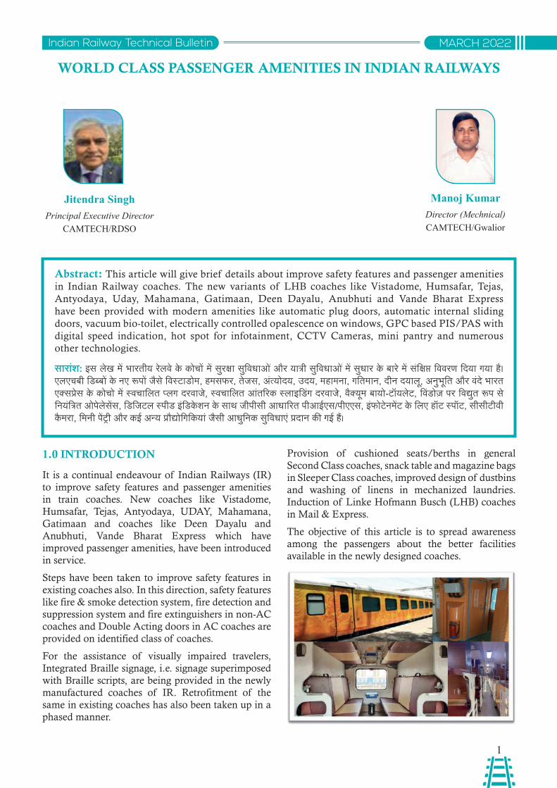
It is a continual endeavour of Indian Railways (IR) to improve safety features and passenger amenities in train coaches. New coaches like Vistadome, Humsafar, Tejas, Antyodaya, UDAY, Mahamana, Gatimaan and coaches like Deen Dayalu and Anubhuti, Vande Bharat Express which have improved passenger amenities, have been introduced in service.
Steps have been taken to improve safety features in existing coaches also. In this direction, safety features like fire & smoke detection system, fire detection and suppression system and fire extinguishers in non-AC coaches and Double Acting doors in AC coaches are provided on identified class of coaches.
For the assistance of visually impaired travelers, Integrated Braille signage, i.e. signage superimposed with Braille scripts, are being provided in the newly manufactured coaches of IR. Retrofitment of the same in existing coaches has also been taken up in a phased manner.
Provision of cushioned seats/berths in general Second Class coaches, snack table and magazine bags in Sleeper Class coaches, improved design of dustbins and washing of linens in mechanized laundries. Induction of Linke Hofmann Busch (LHB) coaches in Mail & Express.
The objective of this article is to spread awareness among the passengers about the better facilities available in the newly designed coaches.
Abstract: This article will give brief details about improve safety features and passenger amenities in Indian Railway coaches. The new variants of LHB coaches like Vistadome, Humsafar, Tejas, Antyodaya, Uday, Mahamana, Gatimaan, Deen Dayalu, Anubhuti and Vande Bharat Express have been provided with modern amenities like automatic plug doors, automatic internal sliding doors, vacuum bio-toilet, electrically controlled opalescence on windows, GPC based PIS/PAS with digital speed indication, hot spot for infotainment, CCTV Cameras, mini pantry and numerous other technologies.
साराशं: इस लेख में भारतीय रेलवे के कोचों में सुरक्ा सुववधाओ ंऔर यात्ी सुववधाओ ंमें सुधार के बारे में संवक्प्त वववरण विया गया है। एलएचबी विबबों के नए रूपों जैसे ववस्ािोम, हमसफर, तेजस, अंतयोिय, उिय, महामना, गवतमान, िीन ियालू, अनुभूवत और वंिे भारत एकसपे्स के कोचो में सवचावलत पलग िरवाजे, सवचावलत आंतररक सलाइविंग िरवाजे, वैकयूम बायो-्ॉयले्, ववंिोज़ पर ववद्ुत रूप से वनयंवत्त ओपेलेसेंस, विवज्ल सपीि इंविकेशन के साथ जीपीसी आधाररत पीआईएस/पीएएस, इंफो्ेनमें् के वलए हॉ् सपॉ्, सीसी्ीवी कैमरा, वमनी पेंट्ी और कई अनय प्रौद्ोवगवकयां जैसी आधुवनक सुववधाए ंप्िान की गई हैं।
2
Indian Railway Technical BulletinMARCH 2022
2.0 PASSENGER AMENITIES OF LHB COACHES
2.1 Coach Shell Body: Economical light weight steel construction with interlocking technique. Roof of beaded sheet construction with roof arches. Corrugated sheet floor and roof sheeting are made of stainless steel.
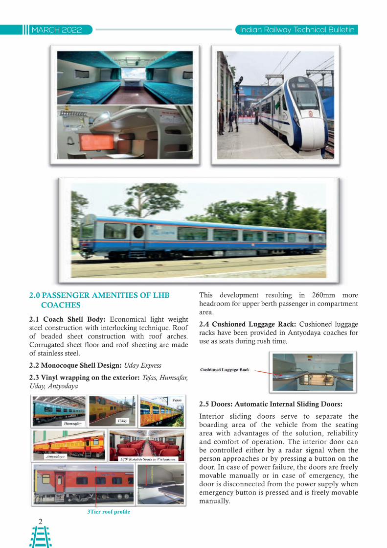
2.2 Monocoque Shell Design: Uday Express
2.3 Vinyl wrapping on the exterior: Tejas, Humsafar, Uday, Antyodaya
This development resulting in 260mm more headroom for upper berth passenger in compartment area.
2.4 Cushioned Luggage Rack: Cushioned luggage racks have been provided in Antyodaya coaches for use as seats during rush time.
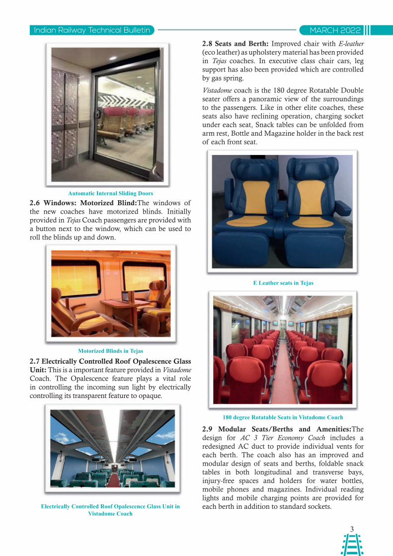
2.5 Doors: Automatic Internal Sliding Doors:
Interior sliding doors serve to separate the boarding area of the vehicle from the seating area with advantages of the solution, reliability and comfort of operation. The interior door can be controlled either by a radar signal when the person approaches or by pressing a button on the door. In case of power failure, the doors are freely movable manually or in case of emergency, the door is disconnected from the power supply when emergency button is pressed and is freely movable manually.
3Tier roof profile
3
Indian Railway Technical Bulletin MARCH 2022
2.6 Windows: Motorized Blind:The windows of the new coaches have motorized blinds. Initially provided in Tejas Coach passengers are provided with a button next to the window, which can be used to roll the blinds up and down.
2.7 Electrically Controlled Roof Opalescence Glass Unit: This is a important feature provided in Vistadome Coach. The Opalescence feature plays a vital role in controlling the incoming sun light by electrically controlling its transparent feature to opaque.
2.8 Seats and Berth: Improved chair with E-leather (eco leather) as upholstery material has been provided in Tejas coaches. In executive class chair cars, leg support has also been provided which are controlled by gas spring.
Vistadome coach is the 180 degree Rotatable Double seater offers a panoramic view of the surroundings to the passengers. Like in other elite coaches, these seats also have reclining operation, charging socket under each seat, Snack tables can be unfolded from arm rest, Bottle and Magazine holder in the back rest of each front seat.
2.9 Modular Seats/Berths and Amenities:The design for AC 3 Tier Economy Coach includes a redesigned AC duct to provide individual vents for each berth. The coach also has an improved and modular design of seats and berths, foldable snack tables in both longitudinal and transverse bays, injury-free spaces and holders for water bottles, mobile phones and magazines. Individual reading lights and mobile charging points are provided for each berth in addition to standard sockets.
Motorized Blinds in Tejas
E Leather seats in Tejas
180 degree Rotatable Seats in Vistadome Coach
Electrically Controlled Roof Opalescence Glass Unit in Vistadome Coach
Automatic Internal Sliding Doors
4
Indian Railway Technical BulletinMARCH 2022
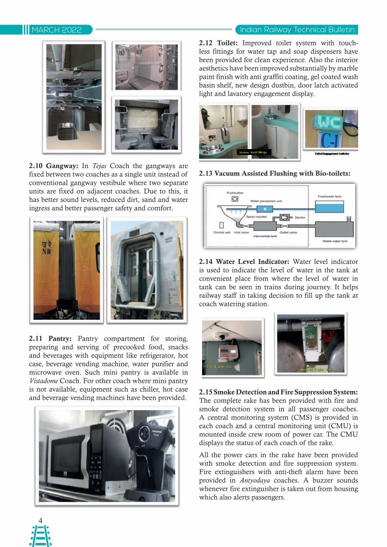
2.10 Gangway: In Tejas Coach the gangways are fixed between two coaches as a single unit instead of conventional gangway vestibule where two separate units are fixed on adjacent coaches. Due to this, it has better sound levels, reduced dirt, sand and water ingress and better passenger safety and comfort.
2.11 Pantry: Pantry compartment for storing, preparing and serving of precooked food, snacks and beverages with equipment like refrigerator, hot case, beverage vending machine, water purifier and microwave oven. Such mini pantry is available in Vistadome Coach. For other coach where mini pantry is not available, equipment such as chiller, hot case and beverage vending machines have been provided.
2.12 Toilet: Improved toilet system with touch-less fittings for water tap and soap dispensers have been provided for clean experience. Also the interior aesthetics have been improved substantially by marble paint finish with anti graffiti coating, gel coated wash basin shelf, new design dustbin, door latch activated light and lavatory engagement display.
2.13 Vacuum Assisted Flushing with Bio-toilets:
2.14 Water Level Indicator: Water level indicator is used to indicate the level of water in the tank at convenient place from where the level of water in tank can be seen in trains during journey. It helps railway staff in taking decision to fill up the tank at coach watering station.
2.15 Smoke Detection and Fire Suppression System: The complete rake has been provided with fire and smoke detection system in all passenger coaches. A central monitoring system (CMS) is provided in each coach and a central monitoring unit (CMU) is mounted inside crew room of power car. The CMU displays the status of each coach of the rake.
All the power cars in the rake have been provided with smoke detection and fire suppression system. Fire extinguishers with anti-theft alarm have been provided in Antyodaya coaches. A buzzer sounds whenever fire extinguisher is taken out from housing which also alerts passengers.
5
Indian Railway Technical Bulletin MARCH 2022
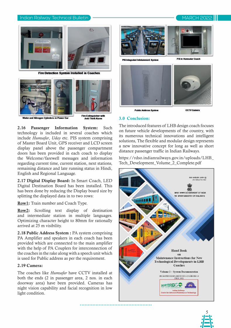
2.16 Passenger Information System: Such technology is included in several coaches which include Humsafar, Uday etc. PIS system comprising of Master Board Unit, GPS receiver and LCD screen display panel above the passenger compartment doors has been provided in each coach to display the Welcome/farewell messages and information regarding current time, current station, next stations, remaining distance and late running status in Hindi, English and Regional Language.
2.17 Digital Display Board: In Smart Coach, LED Digital Destination Board has been installed. This has been done by reducing the Display board size by splitting the displayed data in to two rows:
Row1: Train number and Coach Type.
Row2: Scrolling text display of destination and intermediate station in multiple languages. Optimizing character height to 80mm for rationally arrived at 25 m visibility.
2.18 Public Address System : PA system comprising PA Amplifier and speakers in each coach has been provided which are connected to the main amplifier with the help of PA Couplers for interconnection of the coaches in the rake along with a speech unit which is used for Public address as per the requirement.
2.19 Camera:
The coaches like Humsafar have CCTV installed at both the ends (2 in passenger area, 2 nos. in each doorway area) have been provided. Cameras has night vision capability and facial recognition in low light condition.
3.0 Conclusion:
The introduced features of LHB design coach focuses on future vehicle developments of the country, with its numerous technical innovations and intelligent solutions, The flexible and modular design represents a new innovative concept for long as well as short distance passenger traffic in Indian Railways.
https://rdso.indianrailways.gov.in/uploads/LHB_Tech_Development_Volume_2_Complete.pdf
6
Indian Railway Technical BulletinMARCH 2022
यूटीएचएस निदेशालय, आरडीएसओ द्ारा मटे्रो प्रमाणि के ऑिलाइि परोट्टल का निकास
एच.के. रघुकार्यकारी निदशेक(समन्वर)
यू्ीएचएस/आरिीएसओ
एम. एम. िाररसनिदशेक/एस एडं टी
यू्ीएचएस/आरिीएसओ
आर. के. रस्रोगीए.डी.ई./ एस एडं टी
यू्ीएचएस/आरिीएसओ
साराशं: भार् में निकनस् की जा रही मटे्रो प्रणानलयों की ्किीकी यरोजिा और सरुक्ा प्रमाणि की नजममदेारी सपष्ट रूप स ेभार्ीय रलेिे करो दी गई है। भार् के निनभनि शहरों में िए-िए मटे्रो रले पररयरोजिाओ ंपर काय्ट प्रस्ानि् है नजसके समय पर ् रीके स ेप्रमाण एि ं् किीकी मजूंरी की आिशयक्ा है अ्ः समय की मागं करो देख्े हुए आरडीएसओ (रले मतं्ालय) द्ारा एक ऑिलाइि परोट्टल का निकास नकया गया है जरो पेपरलेस कामकाज के साथ साथ समय बद्ध ्रीके स ेमजूंरी प्रदाि करि ेमें सहायक हैI यह लेख ऑिलाइि परोट्टल की निशेष्ाओ ंऔर इसके काया्टनियि के कारण हुए सधुारों करो सूचीबद्ध कर्ा है।
1.0 पृष्ठभूनम:
भारत में लागू की जा रही मेट्ो प्णावलयों की तकनीकी योजना और सरुक्ा प्माणन की वजममेिारी रले मंत्ालय को िी गई है। मेट्ो प्ावधकरण द्ारा अपने मेट्ो वसस्म की तकनीकी मंजूरी और सरुक्ा प्माणन के आवेिन करने के वलए उन िसतावेजों को जमा करना आवशयक है वजनकी जांच आरिीएसओ के यू्ीएचएस वनिशेालय द्ारा की जाती है। यह "मेट्ो वसस्म की सरुक्ा प्माणन और तकनीकी मंजूरी की प्वरिया" के अनसुार वकया जाता है।
काय्ट सूची:
• आयामों की अनसूुची (एसओिी) को जमा और उनकी जांच करना।
• वववनिदेशों, अवभकलपन और परीक्ण प्माणपत्ों जैसे तकनीकी िसतावेजों को जमा करना और उनकी जांच करना।
• प्सताववत उप-प्णावलयों की परीक्ण ररपो ््ट
• िोलन और ईबीिी परीक्ण करना और अतंररम गवत प्माण पत् जारी करना।
• मेट्ो प्ावधकरण द्ारा मेट्ो सचंालन शरुू होने से पहले आवशयक िसतावेज, परीक्ण ररपो ््ट और परीक्ण प्माण पत् जमा करना।
इन गवतवववधयों के वलए मेट्ो द्ारा बडे पैमाने पर िसतावेज जमा करने और यू्ीएचएस वनिशेालय/आरिीएसओ द्ारा इसकी जांच और सधुार/सझुाव के बाि मेट्ो द्ारा िसतावेजों को वफर से जमा करने की आवशयकता होती है। माच्ट 2020 तक ये िसतावेज कागज कॉपी में जमा वकए जाते थे। इन िसतावेजों की बडी मात्ा के कारण, मेट्ो प्ावधकरणों द्ारा िसतावेजों की वववधवत हसताक्ररत प्वतयां जमा करने और उसके बाि आरिीएसओ में एक अवधकारी से िूसर ेअवधकारी को सथानांतररत करने में, हैंिवलंग और ट्ांवज् समय के कारण, इस गवतवववध में काफी समय लगता था।
माच्ट 2020 में COVID-19 महामारी के आगमन के साथ, सामानय काया्टलय के कामकाज में भारी वयवधान आया और कुछ महीनों के वलए कागजी कामकाज लगभग पूरी तरह से प्वतबवंधत हो गया। इसवलए, इन िसतावेजों के भरौवतक आिान प्िान से बचने और इस प्वरिया में मानवीय भूल से बचने के वलए एक प्णाली ववकवसत करने की ततकाल आवशयकता थी। िशेवयापी लॉकिाउन की घोषणा के साथ ही मेट्ो की तरफ से होने वाली गवतवववधयों में भी कमी आई है, वजसमें मेट्ो द्ारा िसतावेज तैयार करना भी शावमल है। माच्ट 2020 से मई 2020 तक यू्ीएचएस वनिशेालय/आरिीएसओ में वसथवत की आवशयकता को िखेते हुए और कम काय्टभार का लाभ उठाते हुए, यू्ीएचएस वनिशेालय ने आई्ी पले्फॉम्ट का उपयोग करते हुए मेट्ो से िसतावेज़ प्ाप्त करने व परखने की एक ऑनलाइन प्णाली तैयार की है। इस ऑनलाइन पो ््टल का ववकास 6 मई 2020 को मेसस्ट रले्ेल के साथ समझरौता (MoU) के तहत वकया गया और इसे 06.Nov.2020 पर यानी 6 महीने की अववध के भीतर चालू कर विया गया था। इस ऑनलाइन पो ््टल की मखुय ववशेषताए ंवनमनवलवखत है:
2.0 पररचय:
"मेट्ो वसस्म की सरुक्ा प्माणन और तकनीकी मंजूरी" के वलए ऑनलाइन पो ््टल का ववकास वकया गया और 06.11.2020 को इस ेलाइव बनाया गया। पो ््टल का वेबसाइ् वलकं आरिीएसओ वेबसाइ् के होमपेज (http://www.rdso.indianrailways.gov.in) और यू्ीएचएस वनिशेालय के वेबपेज के तहत उपलबध है। इसे सीधे वलकं से भी एकसेस वकया जा सकता है: https://uths.rcil.gov.in/uths वेब पो ््टल से आरिीएसओ की तकनीकी मजूंरी और रले मंत्ालय द्ारा सरुक्ा प्माणन के वलए मेट्ो द्ारा वववभनन िसतावेजों को अपलोि करने से लेकर पेपरलेस कामकाज की पूरी सवुवधा प्िान की। अभी तक यानी जब हमारा िशे भारत अपना "आजािी का अमतृ महोतसव" मना रहा है, कुल 12 मेट्ो ने इस पो ््टल पर अपना पजंीकरण कराया और आरिीएसओ की तकनीकी मजूंरी के वलए अपने िसतावेज अपलोि वकए।
7
Indian Railway Technical Bulletin MARCH 2022
यह पो ््टल अपने िैशबोि्ट के माधयम से उवचत काय्ट ववतरण और इसकी कडी वनगरानी की सवुवधा प्िान करता है। यह एक सतर से िूसर ेसतर तक िसतावेज़ का फलोचा ््ट भी प्िान करता है, वजससे िसतावेजों के आिान-प्िान की वसथवत को पूण्ट रूप से िखेा जा सकता है
मेट्ो से आरिीएसओ और इसके ववपरीत िसतावेज़/पत् के पारगमन समय में कमी के कारण, समय पर कुल बचत 20-25% तक पहुचंने की उममीि है। यह पो ््टल व्पपणी, वसफाररश/पत् आवि के मानक प्ारूप तैयार करता है वजससे यह कुल प्ससंकरण समय को 5-10% तक कम कर ितेा है, वजसके पररणामसवरूप प्भावी रूप से 25-30% की सीमा में कुल समय की बचत होती है। वनक् भववषय में मेट्ो प्शासन एव ंयू्ीएचएस वनिशेालय के कम्टचारी इस प्णाली पर काय्ट के हसत हो जाने पर समय की और भी बचत होगी I
3.0 मटे्रो प्रानधकरण के नलए सनुिधाए:ँ
यात्ी सेवा के वलए मेट्ो प्णाली को चालू करने के वलए सरुक्ा प्माणन और तकनीकी मंजूरी की पूरी कवायि को मो्े तरौर पर वनमनवलवखत भागों में ववभावजत वकया गया है।
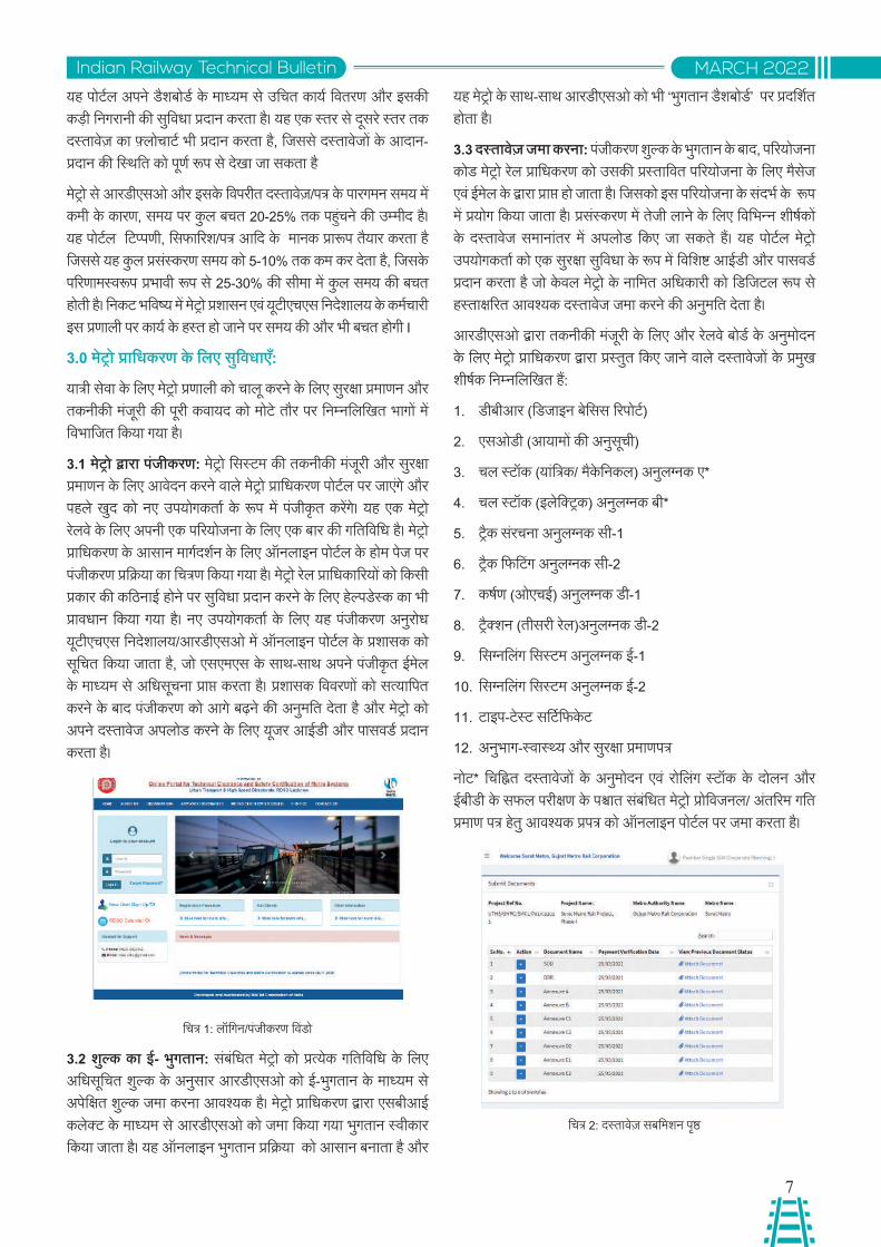
3.1 मटे्रो द्ारा पजंीकरण: मेट्ो वसस्म की तकनीकी मंजूरी और सरुक्ा प्माणन के वलए आवेिन करने वाले मेट्ो प्ावधकरण पो ््टल पर जाएगें और पहले खिु को नए उपयोगकता्ट के रूप में पजंीकृत करेंगे। यह एक मेट्ो रलेवे के वलए अपनी एक पररयोजना के वलए एक बार की गवतवववध है। मेट्ो प्ावधकरण के आसान माग्टिश्टन के वलए ऑनलाइन पो ््टल के होम पेज पर पजंीकरण प्वरिया का वचत्ण वकया गया है। मेट्ो रले प्ावधकाररयों को वकसी प्कार की कवठनाई होने पर सवुवधा प्िान करने के वलए हेलपिेसक का भी प्ावधान वकया गया है। नए उपयोगकता्ट के वलए यह पजंीकरण अनरुोध यू्ीएचएस वनिशेालय/आरिीएसओ में ऑनलाइन पो ््टल के प्शासक को सूवचत वकया जाता है, जो एसएमएस के साथ-साथ अपने पजंीकृत ईमेल के माधयम से अवधसूचना प्ाप्त करता है। प्शासक वववरणों को सतयावपत करने के बाि पजंीकरण को आगे बढ़ने की अनमुवत ितेा है और मेट्ो को अपने िसतावेज अपलोि करने के वलए यूजर आईिी और पासवि्ट प्िान करता है।
वचत् 1: लॉवगन/पजंीकरण वविंो
3.2 शुलक का ई- भुग्ाि: सबंवंधत मेट्ो को प्तयेक गवतवववध के वलए अवधसूवचत शलुक के अनसुार आरिीएसओ को ई-भगुतान के माधयम से अपेवक्त शलुक जमा करना आवशयक है। मेट्ो प्ावधकरण द्ारा एसबीआई कलेक् के माधयम से आरिीएसओ को जमा वकया गया भगुतान सवीकार वकया जाता है। यह ऑनलाइन भगुतान प्वरिया को आसान बनाता है और
वचत् 2: िसतावेज़ सबवमशन पषृ्ठ
यह मेट्ो के साथ-साथ आरिीएसओ को भी ‘भगुतान िैशबोि्ट ’ पर प्िवश्टत होता है।
3.3 दस्ािेज़ जमा करिा: पजंीकरण शलुक के भगुतान के बाि, पररयोजना कोि मेट्ो रले प्ावधकरण को उसकी प्सताववत पररयोजना के वलए मैसेज एव ंईमेल के द्ारा प्ाप्त हो जाता है। वजसको इस पररयोजना के सिंभ्ट के रूप में प्योग वकया जाता है। प्ससंकरण में तेजी लाने के वलए वववभनन शीष्टकों के िसतावेज समानांतर में अपलोि वकए जा सकते हैं। यह पो ््टल मेट्ो उपयोगकता्ट को एक सरुक्ा सवुवधा के रूप में वववशष्ट आईिी और पासवि्ट प्िान करता है जो केवल मेट्ो के नावमत अवधकारी को विवज्ल रूप से हसताक्ररत आवशयक िसतावेज जमा करने की अनमुवत ितेा है।
आरिीएसओ द्ारा तकनीकी मंजूरी के वलए और रलेवे बोि्ट के अनमुोिन के वलए मेट्ो प्ावधकरण द्ारा प्सततु वकए जाने वाले िसतावेजों के प्मखु शीष्टक वनमनवलवखत हैं:
1. िीबीआर (विजाइन बेवसस ररपो ््ट )
2. एसओिी (आयामों की अनसूुची)
3. चल स्ॉक (यांवत्क/ मैकेवनकल) अनलुगनक ए*
4. चल स्ॉक (इलेवकट्क) अनलुगनक बी*
5. टै्क सरंचना अनलुगनक सी-1
6. टै्क वफव्ंग अनलुगनक सी-2
7. कष्टण (ओएचई) अनलुगनक िी-1
8. टै्कशन (तीसरी रले)अनलुगनक िी-2
9. वसगनवलंग वसस्म अनलुगनक ई-1
10. वसगनवलंग वसस्म अनलुगनक ई-2
11. ्ाइप-्ेस् सव ््ट वफके्
12. अनभुाग-सवास्थय और सरुक्ा प्माणपत्
नो्* वचवनित िसतावेजों के अनमुोिन एव ं रोवलंग स्ॉक के िोलन और ईबीिी के सफल परीक्ण के पश्ात सबंवंधत मेट्ो प्ोववजनल/ अतंररम गवत प्माण पत् हेत ुआवशयक प्पत् को ऑनलाइन पो ््टल पर जमा करता है।
8
Indian Railway Technical BulletinMARCH 2022
इन िसतावेजों को सबंवंधत मेट्ो अवधकारी द्ारा विवज्ल रूप से हसताक्ररत वकया जाता है जो आरिीएसओ को जमा करने के वलए िसतावेजों को अपलोि करने के वलए अवधकृत है। आरिीएसओ द्ारा सलाह विए जाने पर मेट्ो उपयोगकता्ट कवमयों के अनपुालन में सशंोवधत िसतावेज जमा कर सकते हैं, इससे मेट्ो प्माणन के तवररत वनप्ान के वलए बहुत समय की बचत होती है।
3.4 डैशबरोड्ट: मेट्ो उपयोगकता्ट को उसके िसतावेजों के प्माणीकरण की पूरी प्वरिया की एक नज़र वसथवत के वलए एक िैशबोि्ट प्िान वकया जाता है। इसी प्कार आरिीएसओ में चल रही गवतवववधयों और कार्टवाई की आवशयकता वाली गवतवववधयों को भी प्तयेक वनिशेक, प्धान काय्टकारी वनिशेक और काय्टकारी वनिशेक (समनवय)/यू्ीएचएस/आरिीएसओ को िैशबोि्ट पर पररलवक्त होता है। इसे वगगीकृत वकया गया है जैसे वक शलुक का भगुतान, िसतावेज़ अनमुोिन, और िसतावेज़ वापस वकया गया, िसतावेज़ अभी जमा वकया जाना है आवि।
वचत् 3: मेट्ो का िैशबोि्ट
3.5 आरडीएसओ के नलए डैशबरोड्ट: सभी मेट्ो प्ावधकरणों से प्ाप्त िसतावेजों की वसथवत और सबंवंधत अवधकारी द्ारा इसकी जाचं को िशा्टने वाले आरिीएसओ अवधकाररयों को एक िैशबोि्ट प्िान वकया जाता ह।ै यह सवंीक्ा अवधकारी से प्ाप्त व्पपवणयों की वसथवत को भी िशा्टता है। िसतावेजों को मो्े तरौर पर "िसतावेजों की सवीकृवत", "परीक्ण प्माण पत् / ररपो ््ट", सरुक्ा प्माण पत् ", परीक्ण ररपो ््ट" आवि शे्वणयों में विखाया गया ह।ै
वचत् 4: आरिीएसओ का िैशबोि्ट
इं्रफेस प्तयेक सतर (एसएसई, एिीई/िीिी, वनिशेक, ईिी/पीईिी) के वलए उनके काय्टके्त् और अवधकार के अनसुार अलग-अलग बनाया गया है, तावक वे उनहें सौंपे गए काय्ट को पूण्ट कर सकें ।
3.6 ररपरोट्ट अिभुाग: आरिीएसओ उपयोगकता्ट को एक "ररपो ््ट अनभुाग" प्िान वकया जाता है जो पररयोजना की वसथवत, समयरखेा, भेजे गए मामलों आवि को िशा्टता है। ये वववरण वकसी भी प्वरिया के तहत मेट्ो की वसथवत का पता लगाने के साथ-साथ नए प्सतावों से वनप्ने में सिंभ्ट लेने के वलए पहले से ससंावधत लोगों के वलए उपयोगी हैं।
एक "मानकों का सगं्रह" भी है जहां सभी आवशयक राषट्ीय / अतंरा्टषट्ीय मानकों की प्वतयां सबंवंधत वनिशेक द्ारा अपलोि की जाती हैं और सभी आरिीएसओ उपयोगकता्टओ ंद्ारा उपयोग के वलए उपलबध हैं। यह मेट्ो पररयोजना के तकनीकी िसतावेजों की जांच के वलए आवशयक प्ासवंगक और नवीनतम मानक को सिंवभ्टत करने में सहायक है। विपावज्री में सशंोवधत मानकों को अपलोि करने की सवुवधा भी प्िान की जाती है तावक जब भी मानक का कोई सशंोधन जारी हो, सशंोवधत मानकों को अपलोि वकया जा सके।
वचत् 5: मानकों का भिंार
3.7 सिचालि: पो ््टल में ववशेषताए ं हैं वक एक बार जब सबंवंधत अवधकाररयों द्ारा िसतावेजों की जांच की जाती है, तो उनकी व्पपवणयों को रलेवे बोि्ट को आगे भेजने/पनुरीक्ण के वलए मेट्ो रले में वापस करने के वलए मसरौिा पत् के अनलुगनक के रूप में सवचावलत रूप से सकंवलत वकया जाता है। यह ववशेष रूप से एसओिी और सपीि सव ््ट वफके् जैसे वववभनन ववगं (वसववल, इलेवकट्कल, एस एिं ्ी, और मैकेवनकल) के बहु-अनशुासनातमक अवधकाररयों से जडेु िसतावेजों के वलए बहुत मििगार है। इससे समय की काफी बचत होती है और िसतावेजों के तवररत वनप्ान में भी मिि वमलती है।
4.0 निषकष्ट:
ऑनलाइन पो ््टल ने मेट्ो अवधकाररयों द्ारा िसतावेजों को अपलोि करने और जमा करने, आरिीएसओ अवधकाररयों द्ारा इसकी जाचं और अतं में तेजी से आने वाली मेट्ो पररयोजनाओ ंकी तकनीकी मंजूरी और सरुक्ा प्माणन वकया है। मेट्ो के साथ-साथ आरिीएसओ द्ारा पेपरलेस ववकिं ग, ऑनलाइन भगुतान और प्तयेक गवतवववध की ऑनलाइन वसथवत की वनगरानी ने तकनीकी मंजूरी की प्भावकाररता में सधुार वकया है और मेट्ो प्माणन प्वरिया में पूण्ट पारिवश्टता भी आई ह।ै ट्ांवज् समय में कमी और रलेवे बोि्ट को वसफाररशों के वलए पत्ों और अनलुगनकों के ऑ्ो-जनरशेन और मेट्ो रले प्ावधकरण को आरिीएसओ तकनीकी इनपु् की सलाह िनेे के कारण, पूरी प्वरिया में समय पर कुल बचत 30% तक पहुचंने की उममीि है।
"ऑनलाइन पो ््टल" का ववकास अवधारणातमक रूप से वत्टमान ई.िी.(समनवय)/यू्ीएचएस/आरिीएसओ द्ारा विजाइन वकया गया था, और कम समय के भीतर इसे यू्ीएचएस वनिशेालय ् ीम और मैसस्ट रले्ेल, लखनऊ ्ीम के वनरतंर प्यासों द्ारा ववकवसत वकया गया है। मैसस्ट रले्ेल ने वनवविा की पूरी प्वरिया में तेजी लाई है और यू.्ी.एच.एस. वनिशेालय ्ीम के साथ वनयवमत साप्तावहक वीवियो काफं्ें वसगं कर इसे छह महीने के ररकॉि्ट समय में ववकवसत वकया है। यू्ीएचएस वनिशेालय इस पो ््टल को ववकवसत करने और इसे मैसस्ट रले्ेल, लखनऊ के साथ एमओयू के माधयम से करने के वलए यू्ीएचएस वनिशेालय के प्सताव को शीघ्र मजूंरी िनेे के वलए आरिीएसओ
प्शासन और ववशेष रूप से महावनिशेक आरिीएसओ का आभारी है।
9
Indian Railway Technical Bulletin MARCH 2022
REPLACEMENT OF BRAKEVAN WITH EOTT SYSTEM
Dr. Veena K. VermaED/Traffic,
RDSO, Lucknow
Surendra Kumar MishraCTA/Traffic,
RDSO, Lucknow
Abstract: End on Train Telemetry (EoTT) system is designed to work as an aid to facilitate running of freight trains without guard and brakevan. Brakevan of freight trains may be replaced with loaded wagons as a last vehicle equipped with the said system. This System consists of three units out of which one is Head of Train unit (HoT), placed in the cabs of locomotive while the second one is End of Train (EoT) unit which is mounted on the CBC of the rearmost wagon along with its connection to BP pipe of the last vehicle of the train and the third one is an antennae unit which is fitted on the rooftop of the locomotive. EoT is also equipped with auto ON/OFF HVML (High Visibility Marker Light) and with inbuilt DTWL (Disable Train Warning Light) feature. Both HoT and EoT devices work in co-ordination with each other during the run to ensure safe working of the system. Duties of Guard which is being replaced by the system are very important in safe operation of trains. Since all the duties of guard have not been covered in EoTT system, left over duties may be assigned to other staff working in the operation of train. Running of EoTT equipped freight trains on a mixed route with both freight and passenger trains is a matter of great concern for the safety. Communication between EoTT and station has also not been covered in the system which is also a major gap in the operation system. In view of safety credibility of the Indian Railways, EoTT system must perform with an extremely high degree of reliability.
सारांश: xkMZ o czsdoku jfgr ekyxkfM;ksa dks lqxerkiwoZd pykus ds fy, ,.M vkQ Vªsu VsyhesVªh ¼bZ-vks-Vh-Vh½ iz.kkyh dk fMtkbu rS;kj fd;k x;k gS] ftlds QyLo:i ekyxkfM;ksa ds czsdoku ds LFkku ij bZ-vks-Vh-Vh- ls ;qDr ,d [kfy;k@yksMsM oSxu yxk;k tk ldrk gSA bl iz.kkyh esa rhu ;wfuV gksrh gSa ftlds varZxr ,d gsM vkQ Vªsu ¼,p-vks-Vh½ ;wfuV gksrh gS tks yksdkseksfVo ds dSc esa yxh gksrh gS ,oa nwljh ;wfuV ,.M vkQ Vªsu ¼bZ-vks-Vh-½ gksrh gS tks Vªsu ds lcls fiNys oSxu ds ckgj dh vksj fudys lh-ch-lh- dIyj ij yxh gksrh gS vkSj mlds ch-ih- ikbi ls tqMh gksrh gS tcfd rhljh ;wfuV ,aVhuk gksrk gS tks yksdkseksfVo dh Nr ij yxk gksrk gSA bZ-vks-Vh- fMokbl esa Lopkfyr vku@vkQ lqfo/kk ;qDr gkbZ foftfcfyVh ekdZj ykbZV ¼,p-oh-,e-,y-½ ,oe fMlscy Vªsu okfuZx ykbZV ¼Mh-Vh-MCY;w-,y-½ Hkh yxk gksrk gSA bZ-vks-Vh-Vh iz.kkyh ds lqjf{kr lapkyu dks lqfuf'pr djus ds fy, ;g vko’;d gS fd ,p-vks-Vh o bZ-vks-Vh- fMokbl ,d nwljs ds lkFk leUo; esa dk;Z djrs jgsaA mijksDr iz.kkyh }kjk foLFkkfir gks jgs xkMZ dh M;wVh] lqjf{kr Vªsu&lapkyu gsrq cgqr egRoiw.kZ gksrh gSA pwWafd xkMZ dh lHkh M;wVh] bZ-vks-Vh-Vh- iz.kkyh esa lfEefyr ugha gS] blfy, xkMZ dh 'ks’k M;wVh dks] Vªsu&lapkyu esa tqMss vU; deZpkfj;ksa dks lkSaik tk ldrk gSA bZ-vks-Vh-Vh iz.kkyh ;qDr ekyxkMh dk feDLM :V ¼tgkWa ;k=h ,oa ekyxkM+h nksuksa gh pyrh gaSA½ ij pyuk] laj{kk ds fy, fo'ks’k fpark dk fo’k; gSA bl iz.kkyh ds varxZr LVs'ku o bZ-vks-Vh-Vh- ds chp lh/kh lapkj O;oLFkk LFkkfir ugha dh x;h gS] tksfd Vªsu ds lqjf{kr lapkyu dks izHkkfor djsxkA Hkkjrh; jsyos dh laj{kk laca/kh foÜoluh;rk ds n`f’Vxr] bl iz.kkyh dh vR;ar mPpLrjh; foÜoluh;rk visf{kr gSA
10
Indian Railway Technical BulletinMARCH 2022
1.0 INTRODUCTION:
Initially, freight trains used to run at a very low speed because wagons were coupled with chain and there was no brake continuity across the train. Entire train was reliant on the braking capacity of the locomotive due to which train length was kept short. There was a great need to control the train from rear end to enhance the length and speed of freight trains. To mitigate this problem, a railway vehicle equipped with a hand brake was introduced and marshalled at the rear of the train. Brakevan was attached to provide additional braking for freight trains and manned with Guard who could take action in case of any abnormality occurred during the run.
In continuation to modernisation of train operation Indian Railways has emphasised on technological aid to reduce dependency on manual system. End of Train Telemetry (EoTT) system is also such an aid to facilitate running of freight trains without guard and brakevan. This technology driven initiative envisages replacement of brake vans as last vehicle with loaded wagons protected with a sophisticated device EoTT. It is a digital device communicating over radio frequency between loco (HoT), last wagon (EoT) and control room (Server). This system is being used in foreign countries such as USA and South Africa.
2.0 EOTT (END OF TRAIN TELEMETRY)SYSTEM
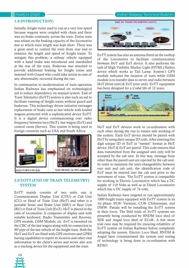
EoTT mainly consists of two units, one is Communication Display Unit (CDU) or Cab Unit (CU) or Head of Train Unit (HoT) and other is a portable Sense and Brake Unit (SBU) or Rear Unit (RU) or End of Train Unit (EoT). HoT is placed in the cabs of locomotive. It comprises of display unit with suitable keyboard, Radio Transmitter and Receiver, GPS module, GSM Module, etc. EoT is mounted on the CBC of the last wagon along with its connection to BP pipe of the last vehicle of the freight train. Both the HoT and EoT are fitted with GPS receivers and GPRS having capabilities to report its location and other vital information to the client’s server and server also acts as a tracking device for the equipment and the train.
EoTT system has also an antenna fitted on the rooftop of the Locomotive to facilitate communication between HoT and EoT device. It also performs the task of High Visibility Marker Light (HVML) flasher device which works as Tail Lamp. System’s GPS module indicates the location of train while GSM module is to transfer data to server and radio between HoT (front unit) & EoT (rear unit). EoTT equipment has been designed for a Codal life of 12 years.
HoT and EoT devices work in co-ordination with each other during the run to ensure safe working of the system. Each EoT device should be paired with HoT by using their unique ID code. After entering five digit unique ID of EoT in “nnnnn” format in HoT device, HoT & EoT are paired. This code ensures that data transmitted from the assigned unit only will be accepted by the cab unit. In this way, message from other than the paired unit are rejected by the cab unit. In order to maintain the inter-changeability between rear unit and cab unit, the identification code of EoT must be entered into the cab unit prior to the movement of train. The EoTT system is compatible for working in Electric Locomotive which has a DC supply of 110 Volts as well as in Diesel Locomotive which has a DC supply of 74 volts.
Indian Railways have targeted to run approximately 1000 freight trains equipped with EoTT system in its 1st phase. BLW- Varanasi, CLW- Chittaranjan, and DMW- Patiala will be installing the EoTT system in their locos. The field trials of EoTT systems are presently being conducted by BNDM loco shed of SER and Angul loco shed of ECoR. A few more trial runs may be required for ensuring reliability of EoTT system on Indian Railways before completely adopting the system. Electric Loco Shed, BNDM & Angul have commissioned the system and testing of technology is being done in co-ordination with RDSO.
11
Indian Railway Technical Bulletin MARCH 2022
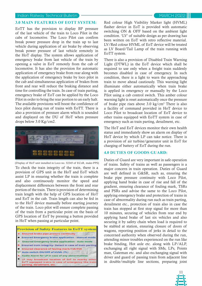
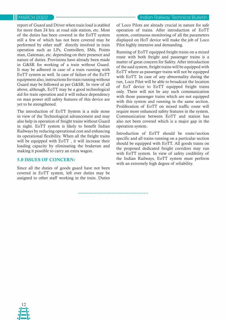
3.0 MAIN FEATURES OF EOTT SYSTEM:EoTT has the provision to display BP pressure of the last vehicle of the train to Loco Pilot in the cabs of locomotive. The Loco Pilot can confirm break power pressure drop in the train up to last vehicle during application of air brake by observing break power pressure of last vehicle remotely in the HoT display. The system allows application of emergency brake from last vehicle of the train by opening a valve in EoT remotely from the cab of locomotive. It has also the provision for automatic application of emergency brake from rear along with the application of emergency brake by loco pilot in the cab and simultaneous application of brakes from front and rear will reduce the braking distance and time for controlling the train. In case of train parting, emergency brake of EoT can be applied by the Loco Pilot in order to bring the rear portion to an early halt. The available provisions will boost the confidence of loco pilot during run of trains with EoTT. There is also a provision of pressure alarm which is sounded and displayed on the DU of HoT when pressure drops below 3.0 Kg/cm2.
To check the train integrity of the train, there is a provision of GPS unit in the HoT and EoT which assist LP in ensuring whether the train is complete and also continuously monitor the speed and displacement differences between the front and rear portion of the train. There is provision of determining train length with the help of GPS location of HoT and EoT in the cab. Train length can also be fed in to the HoT device manually before starting journey of the train. Loco pilot will ensure complete passing of the train from a particular point on the basis of GPS location of EoT by pressing a button provided in HoT when passing at particular point.
Red colour High Visibility Marker light (HVML) flasher device in EoT is provided with automatic switching ON & OFF based on the ambient light condition. ‘LV’ of suitable design as per drawing has been written on EoT with retro reflective material. LV/Red colour HVML of EoT device will be treated as LV Board/Tail Lamp of the train running with EoTT system.
There is also a provision of Disabled Train Warning Light (DTWL) in the EoT device which shall be required to use only when a freight train suddenly becomes disabled in case of emergency. In such condition, there is a light to warn the approaching train to move ahead cautiously. This warning light illuminate either automatically when train brake is applied in emergency or manually by the Loco Pilot using a cab control switch. This amber colour warning light is reset automatically once the pressure of brake pipe rises above 3.0 kg/cm2. There is also a facility of command provided in HoT device to Loco Pilot to broadcast location of EoT device to other trains equipped with EoTT system in case of emergency such as train parting, derailment, etc.
The HoT and EoT devices monitor their own health status and immediately show an alarm on display of HoT device by which LP can take notice. There is a provision of air turbine/generator unit in EoT for charging of battery of EoT during the run.
4.0 DUTIES OF GOODS GUARD:
Duties of Guard are very important in safe operation of trains. Safety of trains as well as passengers is a major concern in train operation. Duties of Guard are well defined in G&SR, such as, ensuring the brake pipe pressure continuity with Loco Pilot, applying hand brake in case of rise and fall of the gradient, ensuring clearance of fouling mark, TSRs and PSRs and advise the same to the Loco Pilot, applying emergency brake and protection of trains in case of abnormality during run such as train parting, derailment etc., protection of train also in case the train has stopped at first stop signal for more than 10 minutes, securing of vehicles from rear end by applying hand brake of last six vehicles and also securing it by safety chain when load is required to be stabled at station, ensuring closure of doors of wagons, reporting position of jerks in detail to the concerned authority when observed during the run, attending minor troubles experienced on the run like brake binding, Hot axle etc. along with LP/ALP, exchanging all right signal with SMs, LPs, Points man, Gateman etc. and also exchanging signal with driver and guard of passing train from adjacent line in double/multiple line sections, preparing joint
(Display of HoT unit installed in Loco no. 32245 of ECoR, make-PPS)
12
Indian Railway Technical BulletinMARCH 2022
report of Guard and Driver when train load is stabled for more than 24 hrs. at road side station, etc. Most of the duties has been covered in the EoTT system still a few of which has not been covered may be performed by other staff directly involved in train operation such as LPs, Controllers, SMs, Points man, Gateman, etc. depending on their presence and nature of duties. Provisions have already been made in G&SR for working of a train without Guard. It may be adhered in case of a train running with EoTT system as well. In case of failure of the EoTT equipment also, instructions for train running without Guard may be followed as per G&SR. In view of all above, although, EoTT may be a good technological aid for train operation and it will reduce dependency on man power still safety features of this device are yet to be strengthened.
The introduction of EoTT System is a mile stone in view of the Technological advancement and may also help in operation of freight trains without Guard in night. EoTT system is likely to benefit Indian Railways by reducing operational cost and enhancing its operational flexibility. When all the freight trains will be equipped with EoTT , it will increase their loading capacity by eliminating the brakevan and making it possible to carry an extra wagon.
5.0 ISSUES OF CONCERN:
Since all the duties of goods guard have not been covered in EoTT system, left over duties may be assigned to other staff working in the train. Duties
of Loco Pilots are already crucial in nature for safe operation of trains. After introduction of EoTT system, continuous monitoring of all the parameters displayed on HoT device will make the job of Loco Pilot highly intensive and demanding.
Running of EoTT equipped freight trains on a mixed route with both freight and passenger trains is a matter of great concern for Safety. After introduction of the said system, freight trains will be equipped with EoTT where as passenger trains will not be equipped with EoTT. In case of any abnormality during the run, Loco Pilot will be able to broadcast the location of EoT device to EoTT equipped freight trains only. There will not be any such communication with those passenger trains which are not equipped with this system and running in the same section. Proliferation of EoTT on mixed traffic route will require more enhanced safety features in the system. Communication between EoTT and station has also not been covered which is a major gap in the operation system.
Introduction of EoTT should be route/section specific and all trains running on a particular section should be equipped with EoTT. All goods trains on the proposed dedicated freight corridors may run with EoTT system. In view of safety credibility of the Indian Railways, EoTT system must perform with an extremely high degree of reliability.
13
Indian Railway Technical Bulletin MARCH 2022
Abstract: The ballast layer is designed to absorb the impact and dynamic energy of a passing train and to distribute the loads evenly over the formation layer to preserve a smooth ride. It is important that the ballast layer remains free of fines. Contaminated ballast causes an unstable pressure distribution on the subgrade and may lead to unwanted and undesired rates of deterioration of assets. On Indian Railways, assessment of attention required to Ballast in the form of deep screening of track was earlier based on criteria of passing of 500 GMT or 10 years. The assessment criteria for deep screening of main line tracks have now been modified on the basis of available clean ballast cushions. At present, there is no scientific method being adopted to check the available clean cushion and it is done by manual methods of collecting samples which is time taking, expensive and highly subjective. In the present paper an effort has been made to bring out the advantages of adopting Ground Penetration Radar technology for analysing the condition of Track Ballast and to assess the availability of a clean cushion for making scientific decisions about ballast renewal.
साराशं: रलेवे टै्क में वगट्ी की परत को गजुरती टे्न के प्भाव और गवतशील ऊजा्ट को अवशोवषत करने के वलए एव ंआरामिायक यात्ा को बनाए रखने हेत ुफारमेशन की परत पर समान रूप से भार ववतररत करने के वलए विजाइन वकया गया है। यह महतवपूण्ट है वक वगट्ी की परत अवांवछत िूवषत पिाथथो से मकु्त रहे। िूवषत वगट्ी सबगे्रि पर एक अवसथर िबाव ववतरण का कारण बनती है और रलेपथ के वबगडने की अवांवछत और अनअपेवक्त िरों को जनम ि ेसकती है। भारतीय रलेवे पर टै्क की िीप सरिीवनंग के रूप में, वगट्ी को िूवषत अवसथा से उवचत अवसथा में लाने का आकलन पहले 500 जीएम्ी या 10 वष्ट वयतीत होने के मापििं पर आधाररत था। उपलबध कलीन वगट्ी कुशन के आधार पर अब मेन लाइन टै्कस की िीप सरिीवनंग के वलए मूलयांकन मानििं को सशंोवधत वकया गया है। वत्टमान में उपलबध सवचछ कुशन की जॉच के वलए कोई भी वैज्ावनक प्वरिया ज्ात नही है और यह मैनअुल तरीको से नमूने एकत् करके वकया जाता रहा है जो वक अवतररक्त समय लेने वाला, महगंा और अतयवधक ववसततृ है। प्सततु लेख में टै्क बैलास् की वसथवत का ववशे्षण करने हेत ुग्राउंि पेनेटे्शन रिार तकनीक को अपनाने के लाभों को िशा्टने हेत ुएव ंवगट्ी नवीनीकरण के बार ेमें वैज्ावनक वनण्टय लेने के वलए सवचछ कुशन की आवशयकता पर प्काश िालने का प्यास वकया गया है।
GROUND PENETRATION RADAR TECHNOLOGY IN INDIAN RAILWAYS
S.K.BarnwalED/Track Monitoring
RDSO, Lucknow
Rahul SinghDirector/Track Machine
RDSO, Lucknow
INTRODUCTION:
Ground Penetrating Radar (GPR) is a fast and effective electromagnetic survey technique utilized in the field of subsurface and underground explorations and is widely used in highways, archaeology and other fields. This technology uses electromagnetic waves of the frequency of radio waves for assessing conditions of subsurface strata.
The principle of GPR operation is based on transmission of short electromagnetic waves by an antenna into the subsurface, the subsequent
reflection, scattering, and refraction of this energy from subsurface interfaces, and the receiving, recording, and display of this reflected energy. The data obtained from GPR testing represents the energy that is reflected off subsurface boundaries back to the radar antenna.
GPR requires two main pieces of equipment – a transmitter and a receiving antenna. The transmitter sends electromagnetic energy into the soil and other material. Ground Penetrating Radar works by emitting a pulse into the ground and recording the echoes that result from subsurface objects. GPR imaging devices
14
Indian Railway Technical BulletinMARCH 2022
also detect variation in the composition of the ground material. If the electromagnetic impulse hits an object, the density of the object reflects, refracts, and scatters the signal. The receiver detects the returning signals and records variations within them. The GPR system has software that translates these signals into images of the objects in the subsurface. This is how it is used to map structures and utilities buried in the ground or in man-made structures.
Ground Penetrating Radar signals can be used to find a wide range of items. GPR is often used to map items made of materials such as Metal, Plastic, PVC,
Concrete, Natural materials etc. GPR is frequently utilized to detect underground utility lines and pipes, changes in ground strata, geological features and rock obstructions, air pockets or voids, excavated and back-filled areas, groundwater tables, bedrock and many more.
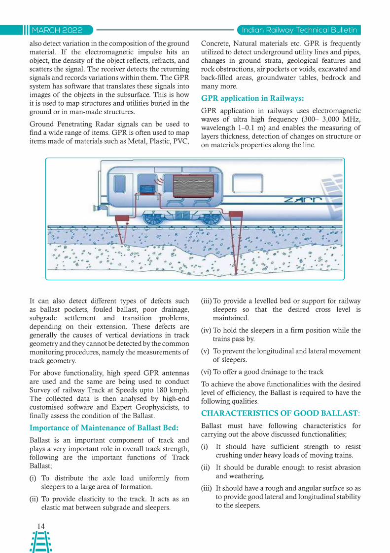
GPR application in Railways:
GPR application in railways uses electromagnetic waves of ultra high frequency (300– 3,000 MHz, wavelength 1–0.1 m) and enables the measuring of layers thickness, detection of changes on structure or on materials properties along the line.
It can also detect different types of defects such as ballast pockets, fouled ballast, poor drainage, subgrade settlement and transition problems, depending on their extension. These defects are generally the causes of vertical deviations in track geometry and they cannot be detected by the common monitoring procedures, namely the measurements of track geometry.
For above functionality, high speed GPR antennas are used and the same are being used to conduct Survey of railway Track at Speeds upto 180 kmph. The collected data is then analysed by high-end customised software and Expert Geophysicists, to finally assess the condition of the Ballast.
Importance of Maintenance of Ballast Bed:
Ballast is an important component of track and plays a very important role in overall track strength, following are the important functions of Track Ballast;
(i) To distribute the axle load uniformly from sleepers to a large area of formation.
(ii) To provide elasticity to the track. It acts as an elastic mat between subgrade and sleepers.
(iii) To provide a levelled bed or support for railway sleepers so that the desired cross level is maintained.
(iv) To hold the sleepers in a firm position while the trains pass by.
(v) To prevent the longitudinal and lateral movement of sleepers.
(vi) To offer a good drainage to the track
To achieve the above functionalities with the desired level of efficiency, the Ballast is required to have the following qualities.
CHARACTERISTICS OF GOOD BALLAST:
Ballast must have following characteristics for carrying out the above discussed functionalities;
(i) It should have sufficient strength to resist crushing under heavy loads of moving trains.
(ii) It should be durable enough to resist abrasion and weathering.
(iii) It should have a rough and angular surface so as to provide good lateral and longitudinal stability to the sleepers.
15
Indian Railway Technical Bulletin MARCH 2022
(iv) It should not make the track dusty or muddy due to its crushing to powder under wheel loads.
(v) It should allow for easy and quick drainage of the track.
Deterioration of Ballast:
During the course of usage, the ballast laid in track gets deteriorated and loses its required properties which are essential for effectiveness of the Ballast, following are the few reasons as why the track ballast gets deteriorated;
(i) Under heavy axle loads, ballast gets crushed at a faster rate and thus the ballast loses its required property of Gradation.
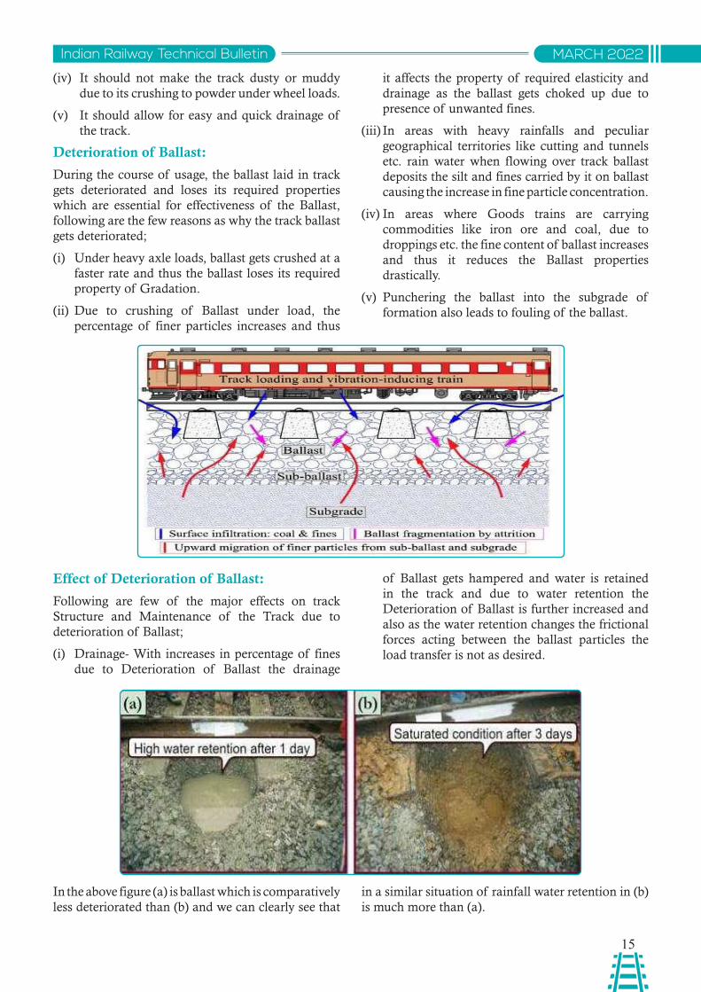
(ii) Due to crushing of Ballast under load, the percentage of finer particles increases and thus
it affects the property of required elasticity and drainage as the ballast gets choked up due to presence of unwanted fines.
(iii) In areas with heavy rainfalls and peculiar geographical territories like cutting and tunnels etc. rain water when flowing over track ballast deposits the silt and fines carried by it on ballast causing the increase in fine particle concentration.
(iv) In areas where Goods trains are carrying commodities like iron ore and coal, due to droppings etc. the fine content of ballast increases and thus it reduces the Ballast properties drastically.
(v) Punchering the ballast into the subgrade of formation also leads to fouling of the ballast.
Effect of Deterioration of Ballast:
Following are few of the major effects on track Structure and Maintenance of the Track due to deterioration of Ballast;
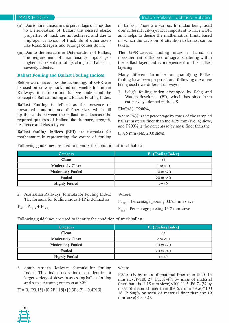
(i) Drainage- With increases in percentage of fines due to Deterioration of Ballast the drainage
of Ballast gets hampered and water is retained in the track and due to water retention the Deterioration of Ballast is further increased and also as the water retention changes the frictional forces acting between the ballast particles the load transfer is not as desired.
In the above figure (a) is ballast which is comparatively less deteriorated than (b) and we can clearly see that
in a similar situation of rainfall water retention in (b) is much more than (a).
16
Indian Railway Technical BulletinMARCH 2022
(ii) Due to an increase in the percentage of fines due to Deterioration of Ballast the desired elastic properties of track are not achieved and due to improper behaviour of track life of other assets like Rails, Sleepers and Fittings comes down.
(iii) Due to the increase in Deterioration of Ballast, the requirement of maintenance inputs gets higher as retention of packing of ballast is severely affected.
Ballast Fouling and Ballast Fouling Indices:
Before we discuss how the technology of GPR can be used on railway track and its benefits for Indian Railways, it is important that we understand the concept of Ballast fouling and Ballast Fouling Index.
Ballast Fouling is defined as the presence of unwanted contaminants of finer sizes which fill up the voids between the ballast and decrease the required qualities of Ballast like drainage, strength, resilience and elasticity etc.
Ballast fouling Indices (BFI) are formulas for mathematically representing the extent of fouling
of ballast. There are various formulae being used over different railways. It is important to have a BFI as it helps to decide the mathematical limits based on which the decision of attention to ballast can be taken.
The GPR-derived fouling index is based on measurement of the level of signal scattering within the ballast layer and is independent of the ballast layering.
Many different formulae for quantifying Ballast fouling have been proposed and following are a few being used over different railways;
1. Selig’s fouling index developed by Selig and Waters developed (FI), which has since been extensively adopted in the US.
FI=P4%+P200%,
where P4% is the percentage by mass of the sampled ballast material finer than the 4.75 mm (No. 4) sieve, and P200% is the percentage by mass finer than the
0.075 mm (No. 200) sieve.
Following guidelines are used to identify the condition of track ballast.
Category F1 (Fouling Index)
Clean ˂1Moderately Clean 1 to ˂10Moderately Fouled 10 to ˂20
Fouled 20 to ˂40Highly Fouled ˃= 40
2. Australian Railways’ formula for Fouling Index; The formula for fouling index F1P is defined as
F1P
= P0.075
+ P13.2
Where,
P0.075
= Percentage passing 0.075 mm sieve
P13.2
= Percentage passing 13.2 mm sieve
Following guidelines are used to identify the condition of track ballast.
Category F1 (Fouling Index)
Clean ˂2Moderately Clean 2 to ˂10Moderately Fouled 10 to ˂20
Fouled 20 to ˂40Highly Fouled ˃= 40
3. South African Railways’ formula for Fouling Index; This index takes into consideration a larger variety of sieves in assessing ballast fouling and sets a cleaning criterion at 80%.
FI=[0.1P0.15]+[0.2P1.18]+[0.3P6.7]+[0.4P19],
where
P0.15=(% by mass of material finer than the 0.15 mm sieve)×100 27, P1.18=(% by mass of material finer than the 1.18 mm sieve)×100 11.5, P6.7=(% by mass of material finer than the 6.7 mm sieve)×100 18, P19=(% by mass of material finer than the 19 mm sieve)×100 27.
17
Indian Railway Technical Bulletin MARCH 2022
4. Volumetric fouling index: a volumetric fouling index (VFI) was established by Ebrahimi et al. to evaluate the actual volumes of contaminants in ballasts subjected to different fouling agents; the VFI is expressed as
VFI=FI×GrsGfs,
where FI is the fouling index expressed in Equation selig’s fouling index, Grs is the specific gravity value of the reference ballast material (approximately = 2.6), and Gfs is the specific gravity value of the present fouling agent.
GPR technology is also now being used for assessing the condition of ballast for Ballast fouling (presence of unwanted percentage of finer particles) and clean ballast depth.
Advantages of GPR of Indian Railway Track:
Monitoring ballasted trackbed with ground penetrating radar (GPR) will allow decisions to be made on timely and cost effective maintenance interventions.
Generation of exception reports for track-bed condition including ballast fouling and formation failure will result in accurate prioritisation of problem trackbed and delineation of the extent of remedial works required by,
• Deployment of ballast cleaning and tamping machines to where they are most needed,
• Reduction in the number of interventions during the life of the ballast through condition-based planning.
Planning of GPR on Indian Railways
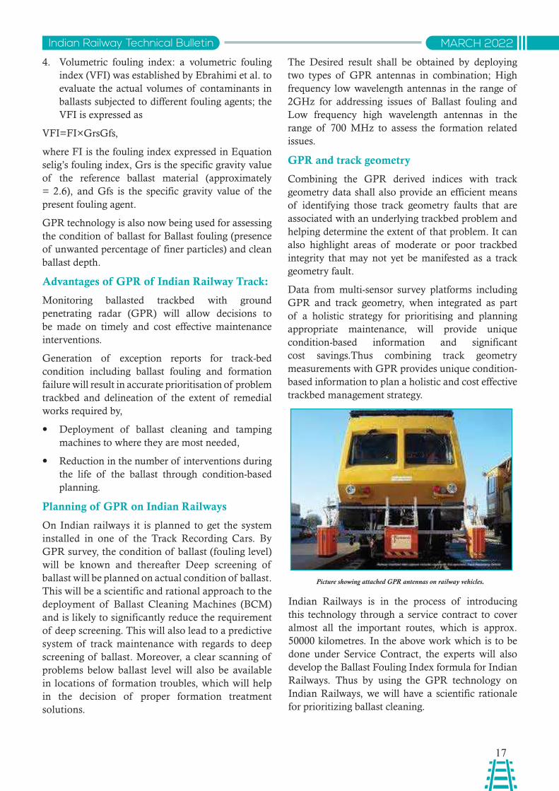
On Indian railways it is planned to get the system installed in one of the Track Recording Cars. By GPR survey, the condition of ballast (fouling level) will be known and thereafter Deep screening of ballast will be planned on actual condition of ballast. This will be a scientific and rational approach to the deployment of Ballast Cleaning Machines (BCM) and is likely to significantly reduce the requirement of deep screening. This will also lead to a predictive system of track maintenance with regards to deep screening of ballast. Moreover, a clear scanning of problems below ballast level will also be available in locations of formation troubles, which will help in the decision of proper formation treatment solutions.
Picture showing attached GPR antennas on railway vehicles.
The Desired result shall be obtained by deploying two types of GPR antennas in combination; High frequency low wavelength antennas in the range of 2GHz for addressing issues of Ballast fouling and Low frequency high wavelength antennas in the range of 700 MHz to assess the formation related issues.
GPR and track geometry
Combining the GPR derived indices with track geometry data shall also provide an efficient means of identifying those track geometry faults that are associated with an underlying trackbed problem and helping determine the extent of that problem. It can also highlight areas of moderate or poor trackbed integrity that may not yet be manifested as a track geometry fault.
Data from multi-sensor survey platforms including GPR and track geometry, when integrated as part of a holistic strategy for prioritising and planning appropriate maintenance, will provide unique condition-based information and significant cost savings.Thus combining track geometry measurements with GPR provides unique condition-based information to plan a holistic and cost effective trackbed management strategy.
Indian Railways is in the process of introducing this technology through a service contract to cover almost all the important routes, which is approx. 50000 kilometres. In the above work which is to be done under Service Contract, the experts will also develop the Ballast Fouling Index formula for Indian Railways. Thus by using the GPR technology on Indian Railways, we will have a scientific rationale for prioritizing ballast cleaning.
18
Indian Railway Technical BulletinMARCH 2022
Previous experience of IR on GPR vis-a-vis TRC Mounted GPR Survey:
Earlier the Subsurface Interface Radar System was procured by RDSO in 1999 from the USA It was a Push trolley mounted system – bulky and heavy, difficult in handling, very less speed of survey and limited applicability, only display on monitor without any analysing software for report generation. System provided limited useful results as the required expertise to interpret the output of the survey was not available with RDSO. Displayed images of the ballast were not very clear as the frequency used was inadequate (1000 MHz as compared to the tentative frequency of 2 GHz being used at present for GPR survey of ballast). Advanced modelling techniques were required to allow complex GPR data to be interpreted by defining probable subsurface properties causing the signal which was not possible at that time due to limitation of technology.
The current system is an advanced version which uses hardware capable of recording data at high speed
along with software application to interpret the data which was done earlier by experts. Present system being planned for induction in IR on service mode will be a vehicle (TRC) mounted with capability for recording at high speed, higher output (3000-4000 km per month), analysing software and involvement of firms geophysicists for interpretation of GPR data for generation of user friendly reports.
Cost effectiveness of TRC mounted GPR Survey:
This system of survey for ballast fouling Other than being a scientific method of assessing the requirement of ballast cleaning is also a very cost effective method as the average cost of survey of ballast bed would come out to be around Rs.6500/- per kilometre. The average cost of ballast cleaning is to the tune of Rs 25-30 Lakhs per kilometre. Therefore the survey cost is only around 0.2%-0.3% of the cost of Ballast Cleaning. Further there are quite likely chances of reduction in the total number of kilometres where ballast cleaning is required when the GPR system is adopted on IR.
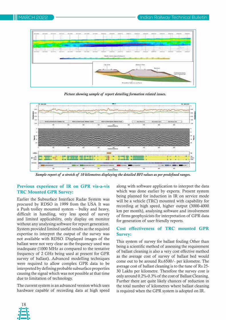
Picture showing sample of report detailing formation related issues.
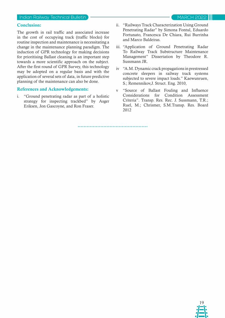
Sample report of a stretch of 10 kilometres displaying the detailed BFI values as per predefined ranges.
19
Indian Railway Technical Bulletin MARCH 2022
Conclusion:
The growth in rail traffic and associated increase in the cost of occupying track (traffic blocks) for routine inspection and maintenance is necessitating a change in the maintenance planning paradigm. The induction of GPR technology for making decisions for prioritising Ballast cleaning is an important step towards a more scientific approach on the subject. After the first round of GPR Survey, this technology may be adopted on a regular basis and with the application of several sets of data, in future predictive planning of the maintenance can also be done.
References and Acknowledgements:
i. “Ground penetrating radar as part of a holistic strategy for inspecting trackbed” by Asger Eriksen, Jon Gascoyne, and Ron Fraser.
ii. “Railways Track Characterization Using Ground Penetrating Radar” by Simona Fontul, Eduardo Fortunato, Francesca De Chiara, Rui Burrinha and Marco Baldeiras.
iii. “Application of Ground Penetrating Radar To Railway Track Substructure Maintenance Management” Dissertation by Theodore R. Sussmann JR.
iv “A.M. Dynamic crack propagations in prestressed concrete sleepers in railway track systems subjected to severe impact loads.” Kaewunruen, S.; Remennikov,J. Struct. Eng. 2010,
v “Source of Ballast Fouling and Influence Considerations for Condition Assessment Criteria”. Transp. Res. Rec. J. Sussmann, T.R.; Ruel, M.; Chrismer, S.M.Transp. Res. Board 2012
20
Indian Railway Technical BulletinMARCH 2022
Abstract: This article deals with the design and development of Supervisory Control and Data Acquisition (SCADA) system being adopted over Western Dedicated Freight Corridor (WDFC) to meet special requirements of 2x25kV ac traction system. The existing scenario of protection and SCADA systems on IR and improvements there upon to develop the new system for WDFC have been covered. The salient features, key equipment used, major advantages etc. are deliberated in detail. The merits of TCP/IP communication protocol working on IEC 60870-5-104 are also briefly discussed in the paper.
साराशं: यह लेख 2x25kV एसी टै्कशन वसस्म की ववशेष आवशयकताओ ंको पूरा करने के वलए वेस्न्ट िेविके्ेि फे्् कॉररिोर (WDFC) पर अपनाए जा रहे पय्टवेक्ी वनयतं्ण और िे्ा अवधग्रहण (SCADA) प्णाली के विजाइन और ववकास से सबंवंधत है। आईआर पर सरुक्ा के मरौजूिा पररदृशय और सकािा वसस्म और िबलयूिीएफसी के वलए नई प्णाली ववकवसत करने के वलए सधुारों को शावमल वकया गया है। मखुय ववशेषताए,ं उपयोग वकए जाने वाले प्मखु उपकरण, प्मखु लाभ आवि पर ववसतार से ववचार वकया गया है। आईईसी 60870-5-104 पर काम कर रहे ्ीसीपी/आईपी सचंार प्ो्ोकॉल की खूवबयों पर भी इस पेपर में सकें्प में चचा्ट की गई है।
SUPERVISORY CONTROL AND DATA ACQUISITION (SCADA) SYSTEM OVER WESTERN DEDICATED FREIGHT CORRIDOR
Dr. Vipin KumarCVO/RDSO
1.0 Introduction
The Western Dedicated Freight Corridor (WDFC) is currently undergoing its project implementation in India. The project, partly financed by Japan International Cooperation Agency (JICA) at an estimated cost of 470 Billion Indian Rupees (INR), has the unique feature of being the world’s first electrified dedicated freight corridor suitable for running of double stack containers having a height of 7.1 meter from the rail level. This requirement of running double stack containers of height 7.1 meter on WDFC shall create the need for developing the traction contact lines at 7.54 meter height, which leads to several challenges in construction stage of electric traction system. WDFC has adopted 2x25kV system, which in itself poses several challenges due to additional feeder wire and Aerial earth wire running along the OHE masts/portals.
The supervision of traction equipment on a routine and continuous basis is an extremely arduous task, as it involves checking of monitors and analyzing
lines and lines of logs to ensure that all the systems are in order. Thankfully, the advances in technology have made it possible to deploy computers to carry out these important tasks with near perfection levels. Supervisory Control and Data Acquisition (SCADA) system offers the ease of monitoring of sensors placed at distances apart from one central location.
SCADA system is a collection of both software and hardware components that allow supervision and control of entire traction network, both locally and remotely. The SCADA also examines, collects, processes data in real time and logs for historical purposes too.
SACDA is one of the most critical systems of electric traction network over WDFC, as all the switching and control posts are unmanned and needs to be monitored on continuous basis round the clock. The SCADA system for WDFC’s traction power network consists of two major parts namely, one no. Operations Control Center (OCC) being developed at Ahmedabad and large no. of Remote Terminal
21
Indian Railway Technical Bulletin MARCH 2022
Units (RTUs) spread across the entire route of WDFC. The OCC controls the activities of the entire network through RTUs. Large no. of RTUs have been deployed for interfacing with other elements of the traction network. The end devices which are to be monitored by OCC are interfaced through RTUs only. The RTU polls the end devices and collects status/alarm information of these end devices. The RTU uploads the information to OCC as and when required. This information collected through RTUs is kept in database and is displayed through Graphical User Interface (GUI) at OCC. The OCC configures and controls the RTUs according to the network requirements, which is dynamically available on GUIs.
2.0 Brief Description of 2x25kV AC System
The 2x25 kV, 50 Hz system is used for high-performance traffic in worldwide railways. This type of feeding is characterized by additional auto-transformers and a return line at a potential of 25 kV. In this system, the line is supplied by a Scott Connected traction transformer without center tapping. The power is fed from the TSS at 50 kV and utilization is achieved at 25 kV by providing Auto-Transformers of adequate capacity and by providing one additional conductor normally referred to as a negative feeder wire between the auto-transformer stations and the traction substations. The center point of the Auto Transformer is connected to the earth/rail. This arrangement facilitates +25 kV voltage between OHE and rail and -25 kV voltage between Rail/earth and the Feeder Wire.
The substations need to be designed for two phases instead of one. Because of this, twin-pole switch gear is required in the overhead line network. Also, the protection of the contact line is more cost-effective because of the double-phase design.
3.0 Developments in SCADA System
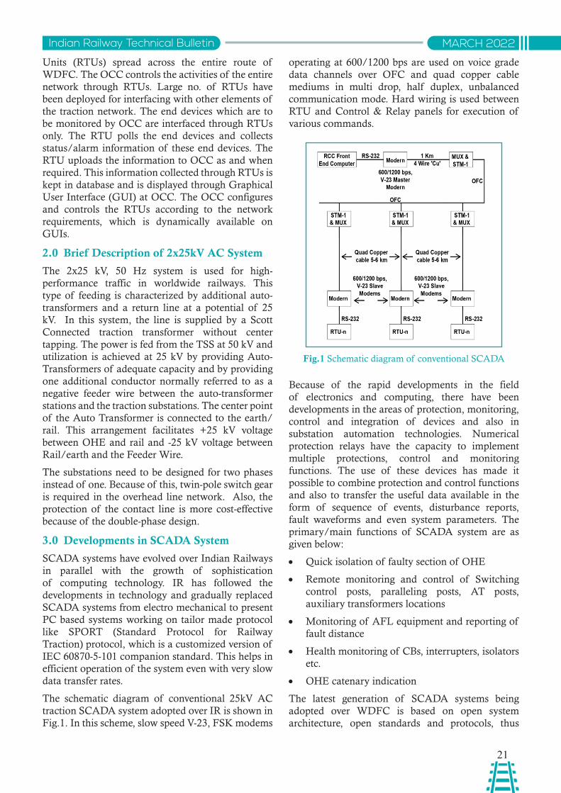
SCADA systems have evolved over Indian Railways in parallel with the growth of sophistication of computing technology. IR has followed the developments in technology and gradually replaced SCADA systems from electro mechanical to present PC based systems working on tailor made protocol like SPORT (Standard Protocol for Railway Traction) protocol, which is a customized version of IEC 60870-5-101 companion standard. This helps in efficient operation of the system even with very slow data transfer rates.
The schematic diagram of conventional 25kV AC traction SCADA system adopted over IR is shown in Fig.1. In this scheme, slow speed V-23, FSK modems
Fig.1 Schematic diagram of conventional SCADA
operating at 600/1200 bps are used on voice grade data channels over OFC and quad copper cable mediums in multi drop, half duplex, unbalanced communication mode. Hard wiring is used between RTU and Control & Relay panels for execution of various commands.
Because of the rapid developments in the field of electronics and computing, there have been developments in the areas of protection, monitoring, control and integration of devices and also in substation automation technologies. Numerical protection relays have the capacity to implement multiple protections, control and monitoring functions. The use of these devices has made it possible to combine protection and control functions and also to transfer the useful data available in the form of sequence of events, disturbance reports, fault waveforms and even system parameters. The primary/main functions of SCADA system are as given below:
• Quick isolation of faulty section of OHE
• Remote monitoring and control of Switching control posts, paralleling posts, AT posts, auxiliary transformers locations
• Monitoring of AFL equipment and reporting of fault distance
• Health monitoring of CBs, interrupters, isolators etc.
• OHE catenary indication
The latest generation of SCADA systems being adopted over WDFC is based on open system architecture, open standards and protocols, thus
22
Indian Railway Technical BulletinMARCH 2022
making it possible to distribute SCADA functionality across a Wide Area Network (WAN). With the adoption of modern IT standards such as SQL and web-based applications, SCADA allows for real-time information of the entire network to be accessed from anywhere around the world.
The major difference in the above SCADA system comes from the use of WAN protocols such as Internet Protocol (IP) for communication between the master station and communication equipment. The RTUs adopted are wall mounted and equipped with RS 485 ports and can easily communicate with the master station using an Ethernet connection.
It uses 100Mbps Ethernet substation LAN and switches, object oriented data model having logical nodes under client server architecture for non critical data transmission and Generic Object Oriented Substation Event (GOOSE) for exchange of time critical data between same or horizontal communication. The protection relays that allow for control and acquisition of parameters have also helped in reduction of hard wiring to a great extent.
The computers at OCC, LAN and SCADA software have also undergone many changes and improvements to enhance optimization and improved performance. The completely dependable and stand-by server in case of failure of main server has also been successfully implemented.
4.0 Merits of Latest generation SCADA System
The adopted system of SCADA over WDFC offers the following advantages cum merits:
(i) Reduced hard wiring due to use of numerical protection relays
(ii) Compact size of RTUs, leading to saving in space
(iii) Use of lesser components, leading to higher reliability and reduced maintenance.
(iv) Reduced communication load on relays in RTUs due to use of 485 ports
(v) Ease in setting of local parameters due to local HMI in RTUs
(vi) Use of satellite time using GPS time server to ensure same time stamping at OCC and RTUs.
(vii) Compatibility with Auto Fault Locators
(viii) No need of separate transducers for acquisition of analogue parameters like voltage, current, power factor etc.
(ix) The built-in logic in the feeder protection relay distinguishes the operation of breaker due to the operation of some protection element or by the controller at OCC.
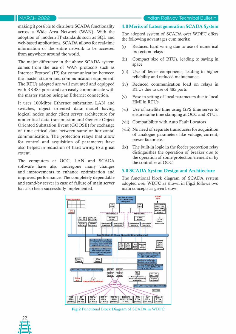
5.0 SCADA System Design and Architecture
The functional block diagram of SCADA system adopted over WDFC as shown in Fig.2 follows two main concepts as given below:
Fig.2 Functional Block Diagram of SCADA in WDFC
23
Indian Railway Technical Bulletin MARCH 2022
(i) Distributed Architecture - to ensure that various components can assume different responsibilities. Moreover, it is easier to increase the capacity of system in future by including more no. of similar components.
(ii) Modular Design - to make it possible to configure the whole of the system in a single computer, thereby, leading to flexibility in terms of sizing of the system.
5.1 SCADA Functioning
The SACDA servers, operator workstations and other front end devices located at OCC are used for monitoring and control of the entire traction network over WDFC. The RTUs provided along the network will interact with local switchgear equipment, other IEDs and shall act as a gateway between the OCC and the field equipment.
The SCADA servers operate in hot standby mode thereby, offering dual redundancy of the SACADA server functions. These servers also host historian database, thereby, ensuring dual redundancy of the historian too. Two sets of Communication Front Ends (CFEs) have been configured in hot-standby mode, which will communicate with the RTUs. Additionally, two work stations grade machines have been provided for Man Machine Interface (MMI) functions to the Traction power controller. The main computer interacts with communication processor and work station computers. It collects the formatted RTU information from communication processor and sends the processed information to Operating work station (OWS) computer. The main computer also responds to the requests of the OWS computer which receives commands from TPC. This information is sent to the communication processor. The SCADA server also provides the following third part interfaces:
• Open database connectivity (ODBC), SQL to its historical and real time database
• IEC 60870-5-101/104 for transfer of data to other SCADA systems
• OPC unified architecture (OPCUA)
These interfaces allow exchange of data between SCADA and third party systems. For preventing cyber attacks from external world, the SCADA LAN has been isolated through suitable firewalls placed at the point of interface with external world. These firewalls create an electronic security perimeter (ESP) as per IEEE 1686 guidelines.
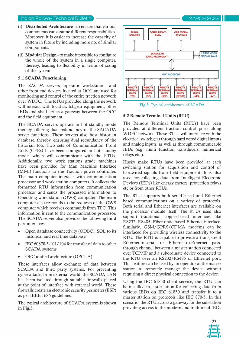
The typical architecture of SCADA system is shown in Fig.3.
Fig.3 Typical architecture of SCADA
5.2 Remote Terminal Units (RTU)
The Remote Terminal Units (RTUs) have been provided at different traction control posts along WDFC network. These RTUs will interface with the electrical switchgear through hard wired digital inputs and analog inputs, as well as through communicable IEDs (e.g. multi function transducers, numerical relays etc.).
Husky make RTUs have been provided at each switching station for acquisition and control of hardwired signals from field equipment. It is also used for collecting data from Intelligent Electronic Devices (IEDs) like energy meters, protection relays etc or from other RTUs.
The RTU supports both serial-based and Ethernet based communications on a variety of protocols. Both serial and Ethernet interfaces are available on the processor module itself. The RTUs used also support traditional copper-based interfaces like RS232, RS485, Fiber-optic based Ethernet interface. Similarly, GSM/GPRS/CDMA modems can be interfaced for providing wireless connectivity to the RTU. The RTU is capable to provide a transparent Ethernet-to-serial or Ethernet-to-Ethernet pass-through channel between a master station connected over TCP/IP and a subordinate device connected to the RTU over an RS232/RS485 or Ethernet port. This feature can be used by an operator at the master station to remotely manage the device without requiring a direct physical connection to the device.
Using the IEC 61850 client service, the RTU can be installed in a substation for collecting data from various IEDs on IEC 61850 and transfer it to a master station on protocols like IEC 870-5. In this scenario, the RTU acts as a gateway for the substation providing access to the modern and traditional IEDs
24
Indian Railway Technical BulletinMARCH 2022
in a substation. The IEC 61850 server service can be used for transfer of RTU’s I/O and any IED data to an IEC 61850 client device using the standard data models.
Some of the salient features of Husky Studio are:
• I/O module configuration including parameters like SoE, chattering, filtering, dead-band etc.
• Protocol configuration along with variable mapping.
• IEC61850 objects configuration and Object browser.
• Time synchronization.
• Upload / Download of RTU configuration.
• Real time monitoring of comm. status with subordinate devices.
• Fault Table View.
• Real-time monitoring of I/O variables with quality.
• Integrated Events viewer with millisecond resolution.
• Offline Logic Simulator for testing of logics without RTU.
• Online Logic Debugger. Import/Export of I/O configuration from MS Excel.
• Protocol data capture & viewing.
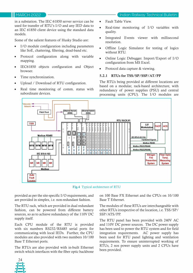
5.2.1 RTUs for TSS/SP/SSP/AT/PP
The RTUs being provided at different locations are based on a modular, rack-based architecture, with redundancy of power supplies (PSU) and central processing units (CPU). The I/O modules are
Fig.4 Typical architecture of RTU
provided as per the site-specific I/O requirements, and are provided in simplex, i.e. non-redundant fashion.
The RTU rack, which are provided in dual redundant fashion, can be powered from different battery sources, so as to achieve redundancy of the 110V DC supply itself.
Each CPU module of the RTU is provided with six numbers RS232/RS485 serial ports for communicating with local IEDs. Further, the CPU modules are also provided with two numbers 10/100 Base T Ethernet ports.
The RTUs are also provided with in-built Ethernet switch which interfaces with the fiber optic backbone
on 100 Base FX Ethernet and the CPUs on 10/100 Base T Ethernet.
The modules of these RTUs are interchangeable with other RTUs irrespective of the location, i.e. TSS/SP/SSP/ATS/PP.
The RTU panel has been provided with 240V AC and 110V DC power sources. The DC power supply has been used to power the RTU system and for field integration requirements. AC power supply has been used for RTU panel lighting and ventilation requirements. To ensure uninterrupted working of RTUs, 2 nos power supply units and 2 CPUs have been provided.
25
Indian Railway Technical Bulletin MARCH 2022
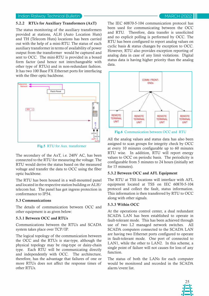
5.2.2 RTUs for Auxiliary Transformers (AxT)
The status monitoring of the auxiliary transformers provided at stations, ALH (Auto Location Huts) and TH (Telecom Huts) locations has been carried out with the help of a mini-RTU. The status of each auxiliary transformer in terms of availability of power output from the transformer would be captured and sent to OCC. The mini-RTU is provided in a boxed form factor (and hence not interchangeable with other type of RTUs) and in non-redundant fashion. It has two 100 Base FX Ethernet ports for interfacing with the fiber optic backbone.
Fig.6 Communication between OCC and RTU
Fig.5 RTU for Aux. transformer
The IEC 60870-5-104 communication protocol has been used for communicating between the OCC and RTU. Therefore, data transfer is unsolicited and no explicit polling is performed by OCC. The RTU has been configured to report analog values on cyclic basis & status changes by exception to OCC. However, RTU also provides exception reporting of analog data in case of any limit violations. Digital status data is having higher priority than the analog data.
The secondary of the AxT, i.e. 240V AC, has been connected to the RTU for measuring the voltage. The RTU would derive the status based on the measured voltage and transfer the data to OCC using the fiber optic backbone.
The RTU has been housed in a wall-mounted panel and located in the respective station building or ALH/ telecom hut. The panel has got ingress protection in conformance to IP54.
5.3 Communications
The details of communication between OCC and other equipment is as given below:
5.3.1 Between OCC and RTUs
Communications between the RTUs and SCADA system takes place over TCP/IP.
The logical topology of the communication between the OCC and the RTUs is star-type, although the physical topology may be ring-type or daisy-chain type. Each RTU will be communicating directly and independently with OCC. The architecture, therefore, has the advantage that failures of one or more RTUs does not affect the response times of other RTUs.
All the analog values and status data has also been assigned to scan groups for integrity check by OCC at every 10 minutes configurable up to 60 minutes RTU wise. In addition, RTU will report energy values to OCC on periodic basis. The periodicity is configurable from 5 minutes to 24 hours (initially set for 15 minutes).
5.3.2 Between OCC and AFL Equipment
The RTU at TSS locations will interface with AFL equipment located at TSS on IEC 60870-5-104 protocol and collect the fault, status information. This information is then transferred by RTU to OCC along with other signals.
5.3.3 Within OCC
At the operations control center, a dual redundant SCADA LAN has been established to operate in fault-tolerant mode. This has been achieved through use of two L2 managed network switches. All SCADA computers connected to the SCADA LAN are having two Ethernet ports configured to operate in fault-tolerant mode. One port of connected to LAN1, while the other to LAN2. In this scheme, a single point of failure will not causes for loss of any function.
The status of both the LANs for each computer would be monitored and recorded in the SCADA alarm/event list.
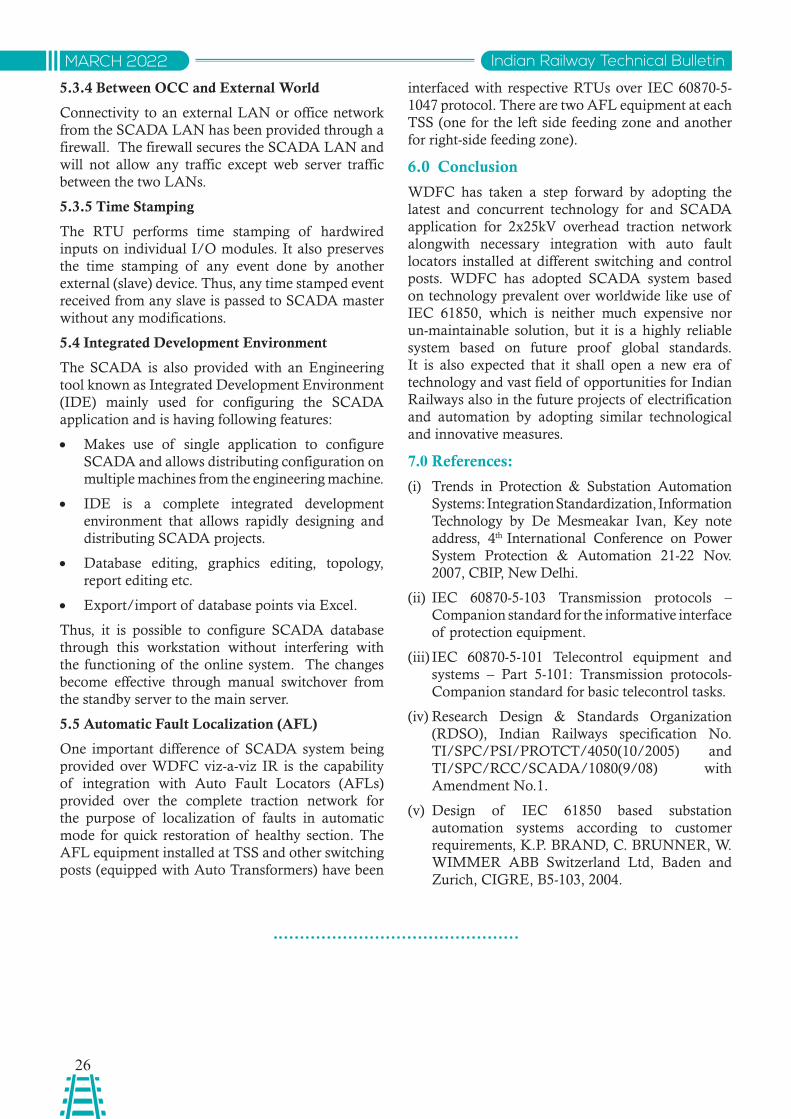
26
Indian Railway Technical BulletinMARCH 2022
5.3.4 Between OCC and External World
Connectivity to an external LAN or office network from the SCADA LAN has been provided through a firewall. The firewall secures the SCADA LAN and will not allow any traffic except web server traffic between the two LANs.
5.3.5 Time Stamping
The RTU performs time stamping of hardwired inputs on individual I/O modules. It also preserves the time stamping of any event done by another external (slave) device. Thus, any time stamped event received from any slave is passed to SCADA master without any modifications.
5.4 Integrated Development Environment
The SCADA is also provided with an Engineering tool known as Integrated Development Environment (IDE) mainly used for configuring the SCADA application and is having following features:
• Makes use of single application to configure SCADA and allows distributing configuration on multiple machines from the engineering machine.
• IDE is a complete integrated development environment that allows rapidly designing and distributing SCADA projects.
• Database editing, graphics editing, topology, report editing etc.
• Export/import of database points via Excel.
Thus, it is possible to configure SCADA database through this workstation without interfering with the functioning of the online system. The changes become effective through manual switchover from the standby server to the main server.
5.5 Automatic Fault Localization (AFL)
One important difference of SCADA system being provided over WDFC viz-a-viz IR is the capability of integration with Auto Fault Locators (AFLs) provided over the complete traction network for the purpose of localization of faults in automatic mode for quick restoration of healthy section. The AFL equipment installed at TSS and other switching posts (equipped with Auto Transformers) have been
interfaced with respective RTUs over IEC 60870-5-1047 protocol. There are two AFL equipment at each TSS (one for the left side feeding zone and another for right-side feeding zone).
6.0 Conclusion
WDFC has taken a step forward by adopting the latest and concurrent technology for and SCADA application for 2x25kV overhead traction network alongwith necessary integration with auto fault locators installed at different switching and control posts. WDFC has adopted SCADA system based on technology prevalent over worldwide like use of IEC 61850, which is neither much expensive nor un-maintainable solution, but it is a highly reliable system based on future proof global standards. It is also expected that it shall open a new era of technology and vast field of opportunities for Indian Railways also in the future projects of electrification and automation by adopting similar technological and innovative measures.
7.0 References:
(i) Trends in Protection & Substation Automation Systems: Integration Standardization, Information Technology by De Mesmeakar Ivan, Key note address, 4th International Conference on Power System Protection & Automation 21-22 Nov. 2007, CBIP, New Delhi.
(ii) IEC 60870-5-103 Transmission protocols – Companion standard for the informative interface of protection equipment.
(iii) IEC 60870-5-101 Telecontrol equipment and systems – Part 5-101: Transmission protocols-Companion standard for basic telecontrol tasks.
(iv) Research Design & Standards Organization (RDSO), Indian Railways specification No. TI/SPC/PSI/PROTCT/4050(10/2005) and TI/SPC/RCC/SCADA/1080(9/08) with Amendment No.1.
(v) Design of IEC 61850 based substation automation systems according to customer requirements, K.P. BRAND, C. BRUNNER, W. WIMMER ABB Switzerland Ltd, Baden and Zurich, CIGRE, B5-103, 2004.
27
Indian Railway Technical Bulletin MARCH 2022
Abstract: Most rolling stocks over Indian Railway such as EMU, MEMU, Locomotive etc. are equipped with IGBT based propulsion system with active front end converter. In few cases, OHE voltage and current fluctuation has been observed when these rolling stocks interact with Electrical power supply system. An effort through this paper has been made to analyze the phenomenon and suggest mitigation measures to address the same.
साराशं: आज के समय में भारतीय रलेवे मे लोकमोव्व, ई.एम.यू., एम.ई.एम.यू. प्कार के सभी रोवलंग स्ॉक प्ायः ऐवक्व फ्न् एिं कनव ््टर के साथ आई.जी.बी.्ी. प्पलशन से लैस है। जब यह रोवलंग स्ॉक वकनही ्ी.एस.एस. के अिंर काम करता है तब कुछ मामलों में ओ.एच.ई वोल्ेज और करं् में अवसथरता पाई गई है। प्सततु पेपर में इस घ्ना का ववशे्षण करने का प्यास वकया गया है एव ंइसके बचाव के वलए कुछ उपाय सझुाए गए है।
Amit Kumar SarafDirector Standard Electrical
RDSO, Lucknow
Rajesh Singh YadavSenior Section Engineer (Research)
RDSO, Lucknow
OHE VOLTAGE & CURRENT FLUCTUATION OVER INDIAN RAILWAY
1. Introduction
First reported OHE voltage fluctuation had been observed over Western Railway when IGBT converter-based EMU operated in low speed in yard during month of August 2017. The case was taken up with senior professors of Electrical Power system, Power Electronics and Control System Branch of IIT, Bombay. On the basis of preliminary analysis, IIT, Bombay had opined that the nature of growth of the oscillations seems indicative of a small-signal instability (normally associated with closed loop control) under specific operating conditions i.e. Voltage fluctuation problem is correlated with converter controls of EMU rakes lying in the section.
Further, introduction of High Horse Power goods locomotive (WAG12B power 9MW) over Indian Railway, problem of OHE Voltage & Current fluctuation had been again observed in some of the Indian Railway Traction Sub-station such as Pt. Deen Dayal Upadhyaya (DDU) (Jivanathpur TSS), Ray TSS over East Central Railway, Kanpur (Panki TSS) over North Central Railway and Paradeep over East Cost Railway in January 2021. Different relays
of TSS had been tripped when these phenomena occurred such as Distance protection relay (DPR), wrong phase coupling relay (WPC), Delta relay etc. When the tripping relay data analysis had been taken, it is found that the voltage and current fluctuation in the waveform had occurred.
Fig: 1 Current wave form of DPR relay before tripping
Fig: 2 voltage and current waveform of DPR relay before tripping
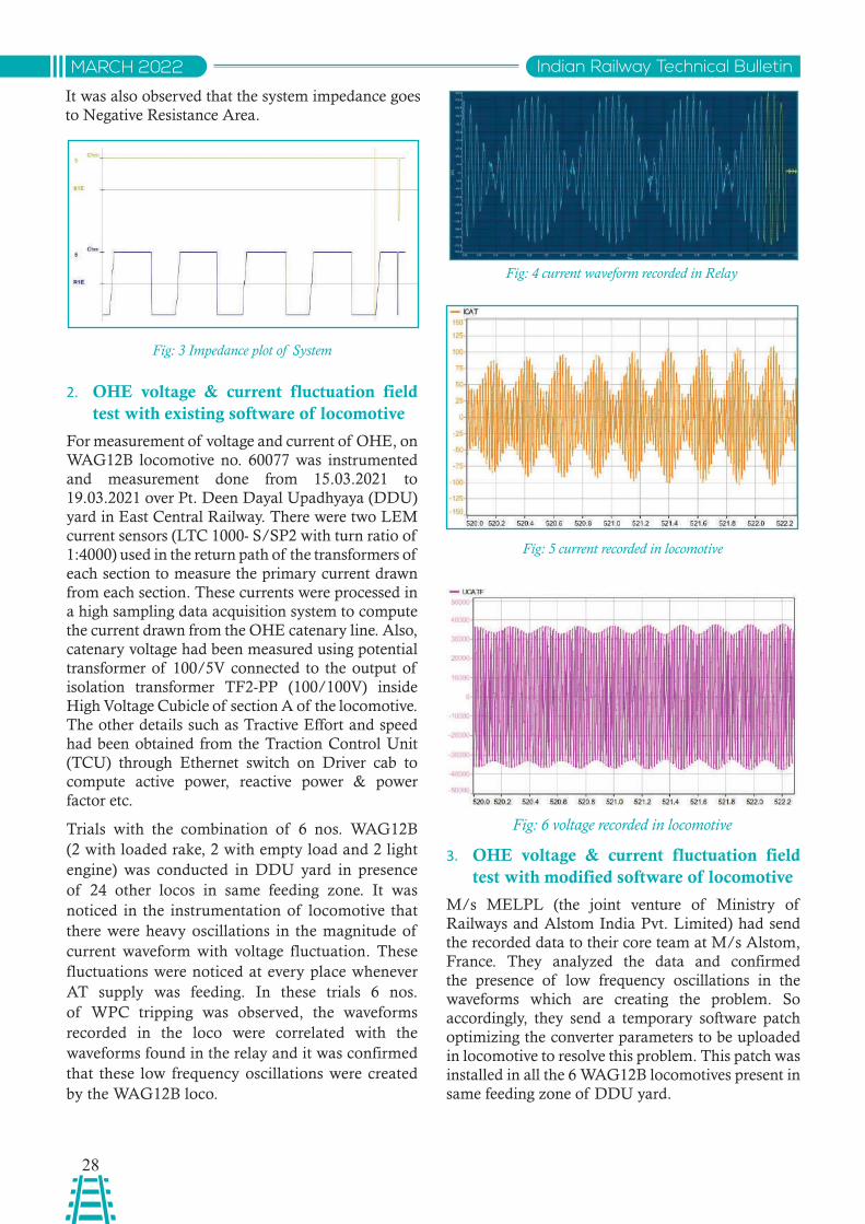
28
Indian Railway Technical BulletinMARCH 2022
It was also observed that the system impedance goes to Negative Resistance Area.
Fig: 3 Impedance plot of System
2. OHE voltage & current fluctuation field test with existing software of locomotive
For measurement of voltage and current of OHE, on WAG12B locomotive no. 60077 was instrumented and measurement done from 15.03.2021 to 19.03.2021 over Pt. Deen Dayal Upadhyaya (DDU) yard in East Central Railway. There were two LEM current sensors (LTC 1000- S/SP2 with turn ratio of 1:4000) used in the return path of the transformers of each section to measure the primary current drawn from each section. These currents were processed in a high sampling data acquisition system to compute the current drawn from the OHE catenary line. Also, catenary voltage had been measured using potential transformer of 100/5V connected to the output of isolation transformer TF2-PP (100/100V) inside High Voltage Cubicle of section A of the locomotive. The other details such as Tractive Effort and speed had been obtained from the Traction Control Unit (TCU) through Ethernet switch on Driver cab to compute active power, reactive power & power factor etc.
Trials with the combination of 6 nos. WAG12B (2 with loaded rake, 2 with empty load and 2 light engine) was conducted in DDU yard in presence of 24 other locos in same feeding zone. It was noticed in the instrumentation of locomotive that there were heavy oscillations in the magnitude of current waveform with voltage fluctuation. These fluctuations were noticed at every place whenever AT supply was feeding. In these trials 6 nos. of WPC tripping was observed, the waveforms recorded in the loco were correlated with the waveforms found in the relay and it was confirmed that these low frequency oscillations were created by the WAG12B loco.
Fig: 4 current waveform recorded in Relay
Fig: 5 current recorded in locomotive
3. OHE voltage & current fluctuation field test with modified software of locomotive
M/s MELPL (the joint venture of Ministry of Railways and Alstom India Pvt. Limited) had send the recorded data to their core team at M/s Alstom, France. They analyzed the data and confirmed the presence of low frequency oscillations in the waveforms which are creating the problem. So accordingly, they send a temporary software patch optimizing the converter parameters to be uploaded in locomotive to resolve this problem. This patch was installed in all the 6 WAG12B locomotives present in same feeding zone of DDU yard.
Fig: 6 voltage recorded in locomotive
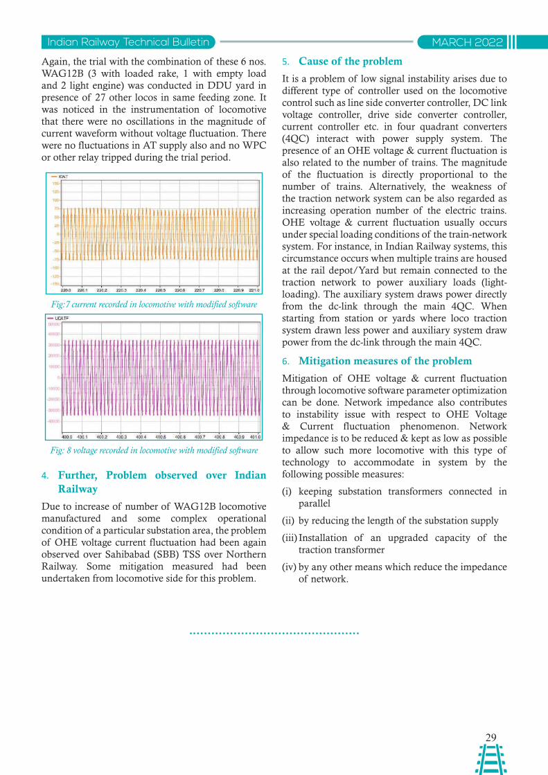
29
Indian Railway Technical Bulletin MARCH 2022
Again, the trial with the combination of these 6 nos. WAG12B (3 with loaded rake, 1 with empty load and 2 light engine) was conducted in DDU yard in presence of 27 other locos in same feeding zone. It was noticed in the instrumentation of locomotive that there were no oscillations in the magnitude of current waveform without voltage fluctuation. There were no fluctuations in AT supply also and no WPC or other relay tripped during the trial period.
Fig:7 current recorded in locomotive with modified software
4. Further, Problem observed over Indian Railway
Due to increase of number of WAG12B locomotive manufactured and some complex operational condition of a particular substation area, the problem of OHE voltage current fluctuation had been again observed over Sahibabad (SBB) TSS over Northern Railway. Some mitigation measured had been undertaken from locomotive side for this problem.
Fig: 8 voltage recorded in locomotive with modified software
5. Cause of the problem
It is a problem of low signal instability arises due to different type of controller used on the locomotive control such as line side converter controller, DC link voltage controller, drive side converter controller, current controller etc. in four quadrant converters (4QC) interact with power supply system. The presence of an OHE voltage & current fluctuation is also related to the number of trains. The magnitude of the fluctuation is directly proportional to the number of trains. Alternatively, the weakness of the traction network system can be also regarded as increasing operation number of the electric trains. OHE voltage & current fluctuation usually occurs under special loading conditions of the train-network system. For instance, in Indian Railway systems, this circumstance occurs when multiple trains are housed at the rail depot/Yard but remain connected to the traction network to power auxiliary loads (light- loading). The auxiliary system draws power directly from the dc-link through the main 4QC. When starting from station or yards where loco traction system drawn less power and auxiliary system draw power from the dc-link through the main 4QC.
6. Mitigation measures of the problem
Mitigation of OHE voltage & current fluctuation through locomotive software parameter optimization can be done. Network impedance also contributes to instability issue with respect to OHE Voltage & Current fluctuation phenomenon. Network impedance is to be reduced & kept as low as possible to allow such more locomotive with this type of technology to accommodate in system by the following possible measures:
(i) keeping substation transformers connected in parallel
(ii) by reducing the length of the substation supply
(iii) Installation of an upgraded capacity of the traction transformer
(iv) by any other means which reduce the impedance of network.
30
Indian Railway Technical BulletinMARCH 2022
HYDROGEN FUEL CELL BASED TRAIN
Sanjeev GargDirector Research Mechanical
RDSO, Lucknow
Abstract: Presently, Indian Railways have Diesel and Electrical locomotives to haul the mainlines & suburban trains. Diesel Locomotives consists of internal combustion diesel engine which uses diesel as fuel to generate required power. Combustion of diesel fuel resulting exhaust emissions containing air pollutants.
Hydrogen fuel cell based rail propulsion technologies powered by Proton Exchange Membrane based Fuel Cell (PEMFC) along with a suitably sized battery bank are being tried out globally for powering railroad vehicles. Dependency on fossil fuel and very low emissions are inherent advantages of Hydrogen fuel cell based train.
सारांश: orZeku esa] Hkkjrh; jsyos ds ikl esuykbu vkSj miuxjh; Vªsuksa dks pykus ds fy, Mhty vkSj bysfDVªdy batu gSaA Mhty yksdkseksfVo esa vkarfjd ngu Mhty batu gksrk gS tks vko';d fctyh mRiUu djus ds fy, bZa/ku ds :i esa Mhty dk mi;ksx djrk gSA Mhty bZa/ku ds ngu ds ifj.kkeLo:i ok;q çnw"kd ;qä fudkl mRltZu gksrk gSA
çksV‚u ,Dlpsat esEczsu vk/kkfjr ¶;wy lsy ¼ihbZ,e,Qlh½ }kjk lapkfyr gkbMªkstu bZa/ku lsy vk/kkfjr jsy ç.kksnu çkS|ksfxfd;ksa ds lkFk&lkFk ,d mi;qä vkdkj ds cSVjh cSad dks jsyjksM okguksa dks 'kfä çnku djus ds fy, fo'o Lrj ij vktek;k tk jgk gSA thok'e bZa/ku ij fuHkZjrk vkSj cgqr de mRltZu gkbMªkstu bZa/ku lsy vk/kkfjr Vªsu ds varfuZfgr ykHk gSaA
1.0 INTRODUCTION:
Presently, Indian Railways have Diesel and Electrical locomotives to haul the mainlines & suburban trains. Diesel Locomotives consists of internal combustion diesel engine which uses diesel as fuel to generate required power. Combustion of diesel fuel resulting exhaust emissions containing air pollutants.
Hydrogen fuel cell based rail propulsion technologies powered by Proton Exchange Membrane based Fuel Cell (PEMFC) along with a suitably sized battery bank are being tried out globally for powering railroad vehicles. Dependency on fossil fuel and very low emissions are inherent advantages of Hydrogen fuel cell based train.
2.0 HYDROGEN FUEL CELL BASED HYBRID POWER TRAIN:
Hydrogen fuel Cell based hybrid power train consists of following major components:
2.1 Fuel Cell:
Proton-exchange membrane fuel cells (PEMFC), also known as polymer electrolyte membrane (PEM) fuel cells, are a type of fuel cell being developed mainly for transport applications, as well as for stationary fuel-cell applications and portable fuel-cell applications. Their distinguishing features include lower temperature/pressure ranges (50 to 100 °C) and a special proton-conducting polymer electrolyte membrane.
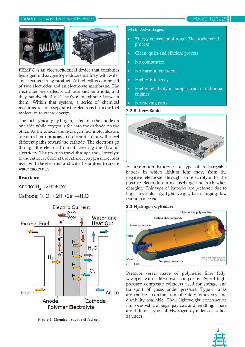
31
Indian Railway Technical Bulletin MARCH 2022
PEMFC is an electrochemical device that combines hydrogen and oxygen to produce electricity, with water and heat as it’s by product. A fuel cell is comprised of two electrodes and an electrolyte membrane. The electrodes are called a cathode and an anode, and they sandwich the electrolyte membrane between them. Within that system, a series of chemical reactions occur to separate the electrons from the fuel molecules to create energy.
The fuel, typically hydrogen, is fed into the anode on one side while oxygen is fed into the cathode on the other. At the anode, the hydrogen fuel molecules are separated into protons and electrons that will travel different paths toward the cathode. The electrons go through the electrical circuit, creating the flow of electricity. The protons travel through the electrolyte to the cathode. Once at the cathode, oxygen molecules react with the electrons and with the protons to create water molecules.
Reactions:
Anode: H2→2H+ + 2e-
Cathode: ½ O2 + 2H++2e- →H2O
Main Advantages:
• Energy conversion through Electrochemical process
• Clean, quiet and efficient process
• No combustion
• No harmful emissions
• Higher Efficiency
• Higher reliability in comparison to traditional engines
• No moving parts
2.2 Battery Bank:
A lithium-ion battery is a type of rechargeable battery in which lithium ions move from the negative electrode through an electrolyte to the positive electrode during discharge and back when charging. This type of batteries are preferred due to high power density, light weight, fast charging, low maintenance etc.
2.3 Hydrogen Cylinder:
Pressure vessel made of polymeric liner fully-wrapped with a fiber-resin composite. Type-4 high-pressure composite cylinders used for storage and transport of gases under pressure. Type-4 tanks are the best combination of safety, efficiency and durability available. Their lightweight construction improves vehicle range, payload and handling. There are different types of Hydrogen cylinders classified as under:
Figure 1: Chemical reaction of fuel cell
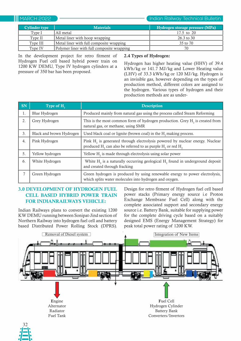
32
Indian Railway Technical BulletinMARCH 2022
Removal of Diesel system Integration of New Items
EngineAlternatorRadiator
Fuel Tank
Fuel CellHydrogen Cylinder
Battery BankConverters/Invertors
Cylinder type Materials Hydrogen storage pressure (MPa)Type I All metal 17.5 to 20Type II Metal liner with hoop wrapping 26.3 to 30Type III Metal liner with full composite wrapping 35 to 70Type IV Polymer liner with full composite wrapping 70
In the development project for retro fitment of Hydrogen Fuel cell based hybrid power train on 1200 KW DEMU, Type IV hydrogen cylinders at a pressure of 350 bar has been proposed.
2.4 Types of Hydrogen:
Hydrogen has higher heating value (HHV) of 39.4 kWh/kg or 141.7 MJ/kg and Lower Heating value (LHV) of 33.3 kWh/kg or 120 MJ/kg. Hydrogen is an invisible gas, however depending on the types of production method, different colors are assigned to the hydrogen. Various types of hydrogen and their production methods are as under-
SN Type of H2
Description
1. Blue Hydrogen Produced mainly from natural gas using the process called Steam Reforming
2. Grey Hydrogen This is the most common form of hydrogen production. Grey H2 is created from
natural gas, or methane, using SMR
3. Black and brown Hydrogen Used black coal or lignite (brown coal) in the H2 making process.
4. Pink Hydrogen Pink H2 is generated through electrolysis powered by nuclear energy. Nuclear
produced H2 can also be referred to as purple H
2 or red H
2
5. Yellow hydrogen Yellow H2 is made through electrolysis using solar power
6. White Hydrogen White H2 is a naturally occurring geological H
2 found in underground deposit
and created through fracking
7 Green Hydrogen Green hydrogen is produced by using renewable energy to power electrolysis, which splits water molecules into hydrogen and oxygen.
3.0 DEVELOPMENT OF HYDROGEN FUEL CELL BASED HYBRID POWER TRAIN FOR INDIANRAILWAYS VEHICLE:
Indian Railways plans to convert the existing 1200 KW DEMU running between Sonipat-Jind section of Northern Railway into hydrogen fuel cell and battery based Distributed Power Rolling Stock (DPRS).
Design for retro fitment of Hydrogen fuel cell based power stacks (Primary energy source i.e Proton Exchange Membrane Fuel Cell) along with the complete associated support and secondary energy source i.e. Battery Bank, suitable for supplying power for the complete driving cycle based on a suitably designed EMS (Energy Management Strategy) for peak total power rating of 1200 KW.
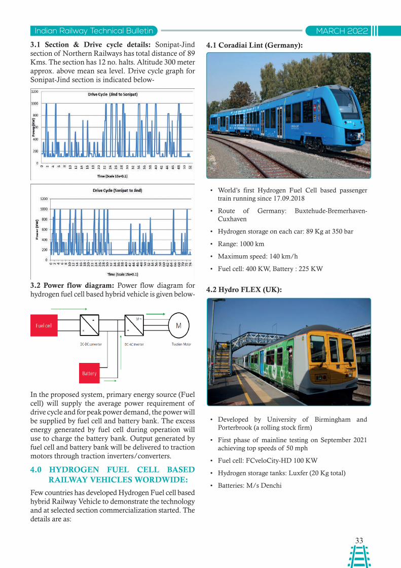
33
Indian Railway Technical Bulletin MARCH 2022
3.1 Section & Drive cycle details: Sonipat-Jind section of Northern Railways has total distance of 89 Kms. The section has 12 no. halts. Altitude 300 meter approx. above mean sea level. Drive cycle graph for Sonipat-Jind section is indicated below-
3.2 Power flow diagram: Power flow diagram for hydrogen fuel cell based hybrid vehicle is given below-
In the proposed system, primary energy source (Fuel cell) will supply the average power requirement of drive cycle and for peak power demand, the power will be supplied by fuel cell and battery bank. The excess energy generated by fuel cell during operation will use to charge the battery bank. Output generated by fuel cell and battery bank will be delivered to traction motors through traction inverters/converters.
4.0 HYDROGEN FUEL CELL BASED RAILWAY VEHICLES WORDWIDE:
Few countries has developed Hydrogen Fuel cell based hybrid Railway Vehicle to demonstrate the technology and at selected section commercialization started. The details are as:
4.1 Coradiai Lint (Germany):
4.2 Hydro FLEX (UK):
• World’s first Hydrogen Fuel Cell based passenger train running since 17.09.2018
• Route of Germany: Buxtehude-Bremerhaven- Cuxhaven
• Hydrogen storage on each car: 89 Kg at 350 bar
• Range: 1000 km
• Maximum speed: 140 km/h
• Fuel cell: 400 KW, Battery : 225 KW
• Developed by University of Birmingham and Porterbrook (a rolling stock firm)
• First phase of mainline testing on September 2021 achieving top speeds of 50 mph
• Fuel cell: FCveloCity-HD 100 KW
• Hydrogen storage tanks: Luxfer (20 Kg total)
• Batteries: M/s Denchi
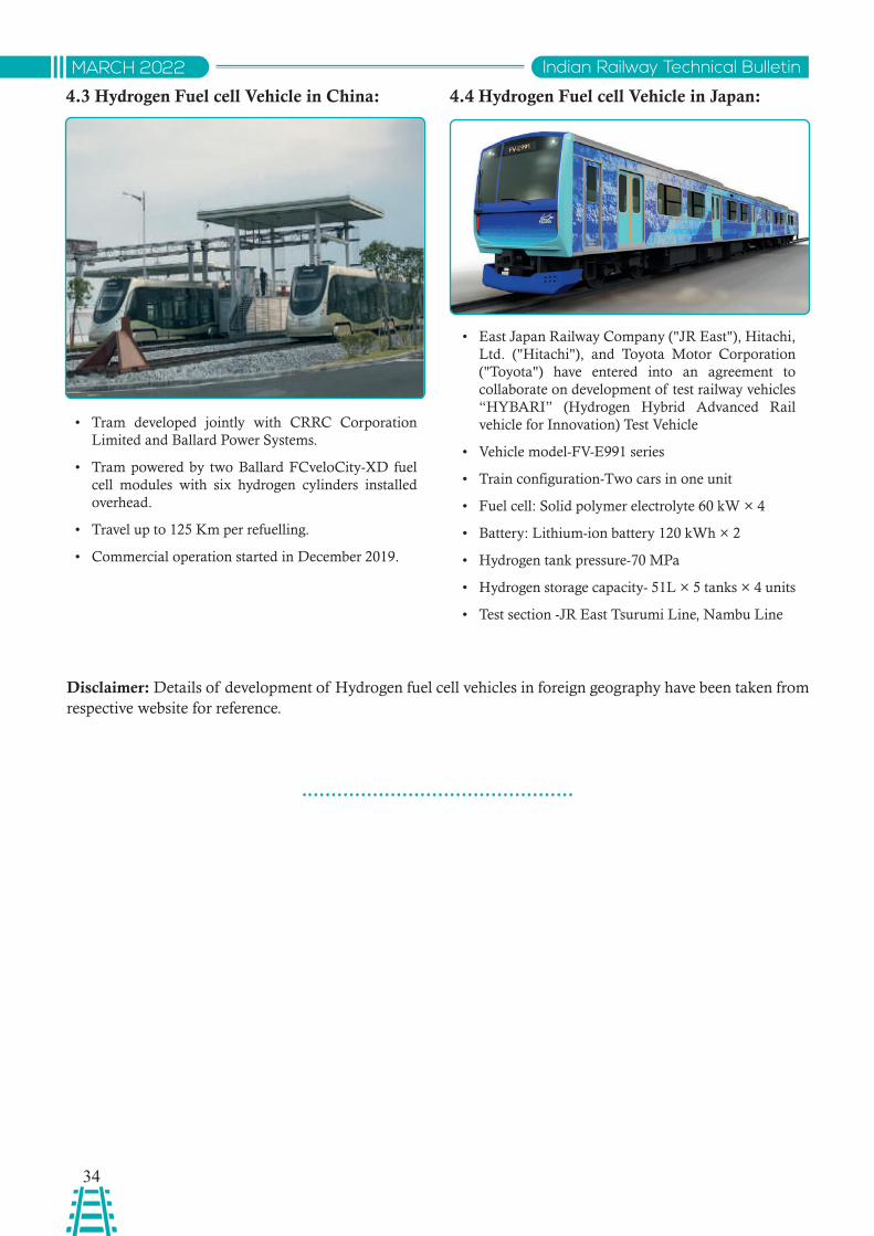
34
Indian Railway Technical BulletinMARCH 2022
4.3 Hydrogen Fuel cell Vehicle in China: 4.4 Hydrogen Fuel cell Vehicle in Japan:
• Tram developed jointly with CRRC Corporation Limited and Ballard Power Systems.
• Tram powered by two Ballard FCveloCity-XD fuel cell modules with six hydrogen cylinders installed overhead.
• Travel up to 125 Km per refuelling.
• Commercial operation started in December 2019.
• East Japan Railway Company ("JR East"), Hitachi, Ltd. ("Hitachi"), and Toyota Motor Corporation ("Toyota") have entered into an agreement to collaborate on development of test railway vehicles “HYBARI” (Hydrogen Hybrid Advanced Rail vehicle for Innovation) Test Vehicle
• Vehicle model-FV-E991 series
• Train configuration-Two cars in one unit
• Fuel cell: Solid polymer electrolyte 60 kW × 4
• Battery: Lithium-ion battery 120 kWh × 2
• Hydrogen tank pressure-70 MPa
• Hydrogen storage capacity- 51L × 5 tanks × 4 units
• Test section -JR East Tsurumi Line, Nambu Line
Disclaimer: Details of development of Hydrogen fuel cell vehicles in foreign geography have been taken from respective website for reference.
35
Indian Railway Technical Bulletin MARCH 2022
EVALUATION OF SHRINKAGE AND CREEP RELATED PROVISIONS OF IRS: CONCRETE BRIDGE CODE
A.K. PandeyADE/B&S
RDSO, Lucknow
Sandeep SinghJoint Director/B&SRDSO, Lucknow
Mukesh KumarSSE/D/CB-I
RDSO, Lucknow
Abstract: Shrinkage and creep are complex phenomenon concrete so it is almost impossible to accurately assess them. Approximate evaluations from various models can be seen for shrinkage and creep. For many common design problems, various codal provisions allowing simple solutions can be used. It is observed that the provisions in IRS:CBC are simple and serve the purpose. Shrinkage and creep have to be taken into account only when they are considered important. The provisions of various codes and the evolution of the provisions over time in the Indian Railway Standards have been compiled in this paper.
साराशं: कंरिी् में सकुंचन और ववसप्टण एक जव्ल समसया है, इसवलए इसका स्ीक मूलयांकन करना लगभग असभंव है| सकुंचन और ववसप्टण का अवभकलपन वववभनन मॉिलों से अनमुावनत मूलयांकन कर िखेा जा सकता है। कई सामानय विजाइन समसयाओ ंके वलए, सरल समाधान की अनमुवत िनेे वाले वववभनन कोिल प्ावधानों का उपयोग वकया जा सकता है। यह िखेा गया है वक आई आर एस: सी बी सी में प्ावधान सरल हैं और प्ावधान उदे्शय की पूवत्ट करते हैं | सकुंचन और ववसप्टण को तभी धयान में रखना होगा जब उनहें महतवपूण्ट माना जाए। वववभनन सवंहताओ ंके प्ावधान और भारतीय रलेवे मानक में समय के साथ प्ावधानों का ववकास को इस पेपर में सकंवलत वकया गया है।
1.0 INTRODUCTION
Shrinkage and Creep are time dependent deformations which are important in Concrete Structures specially where deflections are important and in the design of the articulation for a bridge. Consideration of shrinkage & creep is important in Railway bridge where live load to dead load ratio is high and long service life is expected. The factors affecting the shrinkage of concrete are the variations in moisture conditions, cement and water content, composition and fineness of cement, type, amount, and gradation of aggregate, ambient conditions, moisture, temperature, admixtures, size & shape of specimen, etc. The different factors that affect the creep of concrete are level of stress, duration of loading, strength and age of concrete, ambient conditions, rate of loading, percentage and distribution of steel reinforcement in a reinforced concrete member, size of the concrete mass, type, fineness, content of cement, water-cement ratio, type and grading of aggregate, type of curing, etc. Many approaches
to estimate shrinkage and creep are available in literature and different Codes follow different approaches/Mathematical models. The provision of different Codes and evolution of provisions with time in Indian Railway Standard: Concrete Bridge Code (IRS: CBC, Second Revision 1997-Reprint Sep-2014) have been compiled in this paper. It is observed that the latest provisions in the IRS:CBC are with a view to realistically assess and simplify the calculation for the concrete bridge girders, commonly used in Indian Railway.
2.0 SHRINKAGE AND CREEP
SHRINKAGE- The Shrinkage is defined as the time-dependent strain measured at constant temperature in an unloaded and unrestrained specimen. Shrinkage is expressed as a strain. The change in the volume of drying concrete is not equal to the volume of water removed. The evaporation of free water causes little or no shrinkage. As concrete continues to dry, water evaporates and the volume of the restrained cement
36
Indian Railway Technical BulletinMARCH 2022
paste changes, causing concrete to shrink, probably due to the capillary tension that develops in the water remaining in concrete. Emptying of the capillaries causes a loss of water without shrinkage, but once the absorbed water is removed, shrinkage occurs. The shrinkage of concrete has a direct influence on pre-stress losses of pre-stressed concrete members and the long-term deformation of girders. Generally, concrete shrinks at a high rate during the initial period of hardening, but at a later stage the rate diminishes gradually. It can be said that 40% to 80% of the shrinkage occurs in one month and 80% to 85% occurs in one year.
CREEP- Concrete is an Elastoplastic material, and beyond a small elastic range, plastic strains develop in addition to elastic strains. Under sustained load, plastic deformation continues to develop over a period that may last for years. Such deformation increases at a high rate during the first 4 months after application of the load. This slow plastic deformation under constant stress is called creep. The ratio of creep strain to that of the initial elastic strain due to a sustained stress is used as a measurement of creep deformation. It is called as the Creep Coefficient.
Pre-stressed concrete structures are sensitive to long-term deformations due to creep and shrinkage. Over estimation of the camber due to these effects leads to inefficient designs and improper utilization of the material strength. Under estimation may result in the failure of structures with serious consequences.
Creep develops not only in compression, but also in tension, bending and torsion. The ratio of the rate of creep in tension to that in compression will be greater than 1 in the first two weeks, then decreases over long period.
3.0 LITERATURE SURVEY:
Different models being used for predicting the shrinkage & creep of concrete.
(i) The ACI 209 Model
The model is named after the code ACI 209R-92. Branson and Christianson first developed this model in 1970. The ACI 209 model was used for many years in the design of concrete structures. This model is simple to use.
Calculation of shrinkage & creep using the ACI 209R-92 model can be performed if the following parameters and conditions are known: curing method (moist-cured or steam-cured concrete), relative humidity, type of cement, specimen shape, ultimate shrinkage strain, age of concrete after casting, age of the concrete when drying commenced, (usually taken as the age at the end of moist curing).
(ii) B3 Model
The model was developed by Bazant and Baweja and is described by ACI. Parameters required for calculation of shrinkage strain & creep using the B3 Model are, concrete mean compressive strength at 28 days, curing conditions, cement type, relative humidity, water content in concrete and specimen shape.
(iii) GL 2000 Model
The GL 2000 model was developed by Gardner et. al. Parameters required for calculation of shrinkage strain & creep using the GL 2000 Model are mean 28-day concrete compressive strength, relative humidity, age of concrete at the beginning of shrinkage, type of cement and shape & size of specimen.
(iv) CEB 90 Model
The CEB 90 model was developed by Muller and Hillsdorf. Parameters required for calculation of shrinkage strain & creep using the CEB 90 Model are mean 28-day concrete compressive strength, relative humidity, age of concrete at the beginning of shrinkage, type of cement and shape & size of specimen.
(v) CEB MC 90-99 Model
The CEB MC 90-99 is a modification of the CEB 90. Parameters required for calculation of shrinkage strain & creep using this model are mean 28-day concrete compressive strength, relative humidity, age of concrete at the beginning of shrinkage, type of cement and shape & size of specimen. In this new model, total shrinkage strain is sum of autogenous and drying shrinkage component. In high-performance concrete, autogenous shrinkage is significant and needs to be considered in prediction of shrinkage. This approach was necessary so that shrinkage of normal as well as high-performance concrete can be predicted with sufficient accuracy.
(vi) The AASHTO Model
The model is described by AASHTO LRFD bridge design specifications. Parameters required for calculation of shrinkage strain using the AASHTO Model are curing method (moist-cured or steam-cured concrete), 28 day concrete compressive strength, relative humidity, drying time of concrete, type of cement and shape & size of specimen.
4.0 COMPARISON OF RESULTS OF VARIOUS MODELS
Different model predicts different values of shrinkage strain and creep as illustrated below with an example with various parameters considered below:
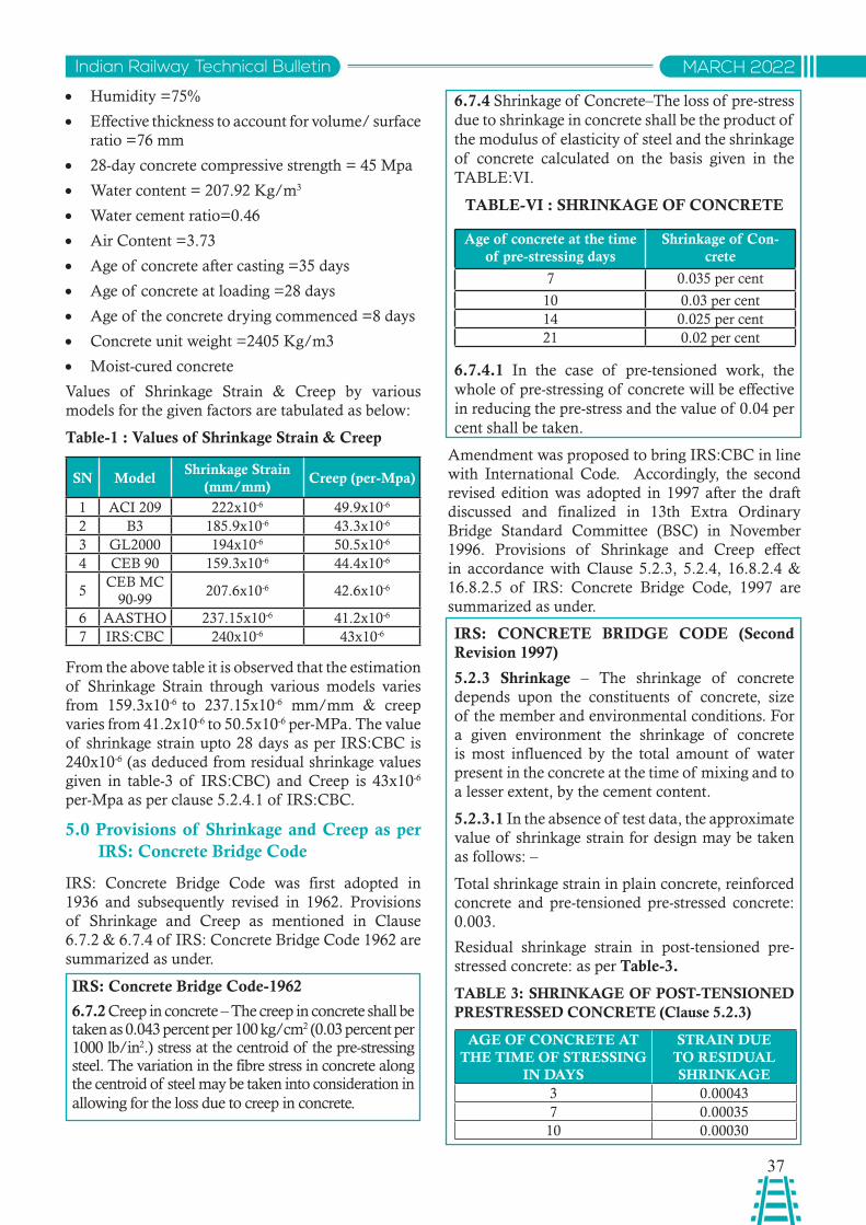
37
Indian Railway Technical Bulletin MARCH 2022
• Humidity =75%
• Effective thickness to account for volume/ surface ratio =76 mm
• 28-day concrete compressive strength = 45 Mpa
• Water content = 207.92 Kg/m3
• Water cement ratio=0.46
• Air Content =3.73
• Age of concrete after casting =35 days
• Age of concrete at loading =28 days
• Age of the concrete drying commenced =8 days
• Concrete unit weight =2405 Kg/m3
• Moist-cured concrete
Values of Shrinkage Strain & Creep by various models for the given factors are tabulated as below:
Table-1 : Values of Shrinkage Strain & Creep
SN ModelShrinkage Strain
(mm/mm)Creep (per-Mpa)
1 ACI 209 222x10-6 49.9x10⁻⁶
2 B3 185.9x10⁻⁶ 43.3x10⁻⁶
3 GL2000 194x10-6 50.5x10⁻⁶
4 CEB 90 159.3x10⁻⁶ 44.4x10⁻⁶
5CEB MC
90-99207.6x10-6 42.6x10⁻⁶
6 AASTHO 237.15x10⁻⁶ 41.2x10⁻⁶
7 IRS:CBC 240x10-6 43x10-6
From the above table it is observed that the estimation of Shrinkage Strain through various models varies from 159.3x10⁻⁶ to 237.15x10⁻⁶ mm/mm & creep varies from 41.2x10⁻⁶ to 50.5x10⁻⁶ per-MPa. The value of shrinkage strain upto 28 days as per IRS:CBC is 240x10-6 (as deduced from residual shrinkage values given in table-3 of IRS:CBC) and Creep is 43x10-6
per-Mpa as per clause 5.2.4.1 of IRS:CBC.
5.0 Provisions of Shrinkage and Creep as per IRS: Concrete Bridge Code
IRS: Concrete Bridge Code was first adopted in 1936 and subsequently revised in 1962. Provisions of Shrinkage and Creep as mentioned in Clause 6.7.2 & 6.7.4 of IRS: Concrete Bridge Code 1962 are summarized as under.
IRS: Concrete Bridge Code-1962
6.7.2 Creep in concrete – The creep in concrete shall be taken as 0.043 percent per 100 kg/cm2 (0.03 percent per 1000 lb/in2.) stress at the centroid of the pre-stressing steel. The variation in the fibre stress in concrete along the centroid of steel may be taken into consideration in allowing for the loss due to creep in concrete.
6.7.4 Shrinkage of Concrete–The loss of pre-stress due to shrinkage in concrete shall be the product of the modulus of elasticity of steel and the shrinkage of concrete calculated on the basis given in the TABLE:VI.
TABLE-VI : SHRINKAGE OF CONCRETE
Age of concrete at the time of pre-stressing days
Shrinkage of Con-crete
7 0.035 per cent
10 0.03 per cent14 0.025 per cent21 0.02 per cent
6.7.4.1 In the case of pre-tensioned work, the whole of pre-stressing of concrete will be effective in reducing the pre-stress and the value of 0.04 per cent shall be taken.
Amendment was proposed to bring IRS:CBC in line with International Code. Accordingly, the second revised edition was adopted in 1997 after the draft discussed and finalized in 13th Extra Ordinary Bridge Standard Committee (BSC) in November 1996. Provisions of Shrinkage and Creep effect in accordance with Clause 5.2.3, 5.2.4, 16.8.2.4 & 16.8.2.5 of IRS: Concrete Bridge Code, 1997 are summarized as under.
IRS: CONCRETE BRIDGE CODE (Second Revision 1997)
5.2.3 Shrinkage – The shrinkage of concrete depends upon the constituents of concrete, size of the member and environmental conditions. For a given environment the shrinkage of concrete is most influenced by the total amount of water present in the concrete at the time of mixing and to a lesser extent, by the cement content.
5.2.3.1 In the absence of test data, the approximate value of shrinkage strain for design may be taken as follows: –
Total shrinkage strain in plain concrete, reinforced concrete and pre-tensioned pre-stressed concrete: 0.003.
Residual shrinkage strain in post-tensioned pre-stressed concrete: as per Table-3.
TABLE 3: SHRINKAGE OF POST-TENSIONED PRESTRESSED CONCRETE (Clause 5.2.3)
AGE OF CONCRETE AT THE TIME OF STRESSING
IN DAYS
STRAIN DUE TO RESIDUAL SHRINKAGE
3 0.000437 0.0003510 0.00030
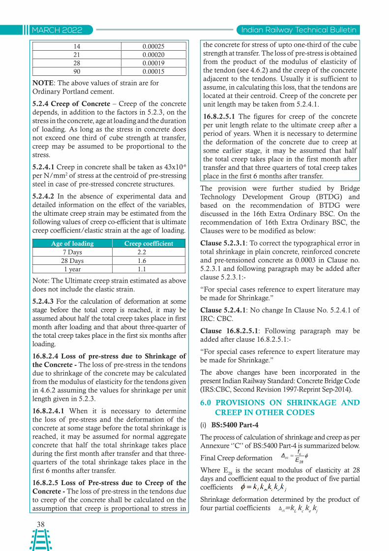
38
Indian Railway Technical BulletinMARCH 2022
14 0.0002521 0.0002028 0.0001990 0.00015
NOTE: The above values of strain are for Ordinary Portland cement.
5.2.4 Creep of Concrete – Creep of the concrete depends, in addition to the factors in 5.2.3, on the stress in the concrete, age at loading and the duration of loading. As long as the stress in concrete does not exceed one third of cube strength at transfer, creep may be assumed to be proportional to the stress.
5.2.4.1 Creep in concrete shall be taken as 43x10-6 per N/mm2 of stress at the centroid of pre-stressing steel in case of pre-stressed concrete structures.
5.2.4.2 In the absence of experimental data and detailed information on the effect of the variables, the ultimate creep strain may be estimated from the following values of creep co-efficient that is ultimate creep coefficient/elastic strain at the age of loading.
Age of loading Creep coefficient7 Days 2.228 Days 1.61 year 1.1
Note: The Ultimate creep strain estimated as above does not include the elastic strain.
5.2.4.3 For the calculation of deformation at some stage before the total creep is reached, it may be assumed about half the total creep takes place in first month after loading and that about three-quarter of the total creep takes place in the first six months after loading.
16.8.2.4 Loss of pre-stress due to Shrinkage of the Concrete - The loss of pre-stress in the tendons due to shrinkage of the concrete may be calculated from the modulus of elasticity for the tendons given in 4.6.2 assuming the values for shrinkage per unit length given in 5.2.3.
16.8.2.4.1 When it is necessary to determine the loss of pre-stress and the deformation of the concrete at some stage before the total shrinkage is reached, it may be assumed for normal aggregate concrete that half the total shrinkage takes place during the first month after transfer and that three-quarters of the total shrinkage takes place in the first 6 months after transfer.
16.8.2.5 Loss of Pre-stress due to Creep of the Concrete - The loss of pre-stress in the tendons due to creep of the concrete shall be calculated on the assumption that creep is proportional to stress in
the concrete for stress of upto one-third of the cube strength at transfer. The loss of pre-stress is obtained from the product of the modulus of elasticity of the tendon (see 4.6.2) and the creep of the concrete adjacent to the tendons. Usually it is sufficient to assume, in calculating this loss, that the tendons are located at their centroid. Creep of the concrete per unit length may be taken from 5.2.4.1.
16.8.2.5.1 The figures for creep of the concrete per unit length relate to the ultimate creep after a period of years. When it is necessary to determine the deformation of the concrete due to creep at some earlier stage, it may be assumed that half the total creep takes place in the first month after transfer and that three quarters of total creep takes place in the first 6 months after transfer.
The provision were further studied by Bridge Technology Development Group (BTDG) and based on the recommendation of BTDG were discussed in the 16th Extra Ordinary BSC. On the recommendation of 16th Extra Ordinary BSC, the Clauses were to be modified as below:
Clause 5.2.3.1: To correct the typographical error in total shrinkage in plain concrete, reinforced concrete and pre-tensioned concrete as 0.0003 in Clause no. 5.2.3.1 and following paragraph may be added after clause 5.2.3.1:-
“For special cases reference to expert literature may be made for Shrinkage.”
Clause 5.2.4.1: No change In Clause No. 5.2.4.1 of IRC: CBC.
Clause 16.8.2.5.1: Following paragraph may be added after clause 16.8.2.5.1:-
“For special cases reference to expert literature may be made for Shrinkage.”
The above changes have been incorporated in the present Indian Railway Standard: Concrete Bridge Code (IRS:CBC, Second Revision 1997-Reprint Sep-2014).
6.0 PROVISIONS ON SHRINKAGE AND CREEP IN OTHER CODES
(i) BS:5400 Part-4
The process of calculation of shrinkage and creep as per Annexure ‘’C’’ of BS:5400 Part-4 is summarized below.
Final Creep deformation
Where E28
is the secant modulus of elasticity at 28 days and coefficient equal to the product of five partial coefficients
Shrinkage deformation determined by the product of four partial coefficients ΔcS=kL kc ke kj
39
Indian Railway Technical Bulletin MARCH 2022
kL depends on environmental conditions, k
m depends
on hardening (maturity) of the concrete at the age of loading, k
c depends on composition of the concrete,
ke depends on effective thickness of the member and
kj depends on time-dependent deformation. Values
of these can be work out from the different charts given in Code.
(ii) IRC:112-2020
Provision in IRC 112:2020 for Shrinkage and Creep have different methodology for determining the shrinkage strain & creep coefficient. Factor affecting the Creep and Shrinkage are shown in tabular form in IRC 112:2020.
The total shrinkage of concrete depends upon the constituents of concrete, size of the member and environmental conditions.
The total shrinkage strain is composed of two components, the autogenous shrinkage strain and the drying shrinkage strain. The major part of the autogenous shrinkage strain develops during hardening of the concrete in the early days after casting. The drying shrinkage strain develops slowly, since it is a function of the migration of water through the hardened concrete.
The value of the total shrinkage strain is given by :
εcs=εcd+εca
where
εcs is the total shrinkage strain
εcd is the drying shrinkage strain
εca is the autogenous shrinkage strain
In absence of accurate field/laboratory data, the value of autogenous shrinkage strain given in table 6.6 of the Code has to be considered in design.
Creep of concrete depends, on the stress in the concrete, age at loading and duration of loading, constituents of concrete, size of the member and environmental conditions.
The values given at Table-6.9 of the code applicable for M35 grade concrete can be considered as final creep co-efficient for design for normal weight concrete, subject to certain conditions.
The coefficient may be multiplied by to estimate the value for lower grade of concrete.
However for higher grades of concrete the coefficient may be worked out separately or for simplification, the values given in the Table 6.9 of the code can also be adopted for higher grades.
(iii) EN Code 1992-1-1
Shrinkage:
The method for estimation of shrinkage is almost
similar to IRC 112-2020, however the values of the drying shrinkage strain εcd to be taken as per table given in the code and autogenous shrinkage strain εca have to be worked out by separate equations.
As per EN Code 1992-1-1, the creep coefficient
φ(t,to ) is related to Ec, (tangent modulus), However, where great accuracy is not required, the creep coefficient may be found from Figure 3.1 mentioned in code, provided the compressive stress is less than 0.45 f
ck at the time of loading.
When the compressive stress of concrete at the time of loading exceeds the value 0.45 f
ck . then creep non-linearity should be considered. In such cases the Non linear notional creep coefficient should be obtained from equation 3.7 of the code.
7.0 CONCLUSION
There are various models for predicting the shrinkage and creep of concrete. The ACI 209, B3, GL2000, CEB 90, CEB 90-99 and AASTHO are some of them. The detailed procedure where mentioned in the codes is based on one of these models.
In this paper, provisions regarding Shrinkage and creep in various models and IRS: Concrete Bridge Code, BS-5400, EURO/EN and IRC have been discussed. It is observed that the provisions in IRS: CBC are simple and serve the purpose as the values as per IRS:CBC are in conformity with values worked out based on the Models. Shrinkage and creep have to be taken into account only when they are considered to be important. Shrinkage and creep being complex phenomenon so accurate prediction of the same is almost impossible as can be seen from the range of values predicted from various models. For a number of ordinary design problems, various codal provisions that allow simple solution may be used. In view of above, the provision in IRS:CBC are sufficient and in rare cases reference of specialist literature may be required which is also permitted in IRS:CBC.
REFERENCES:
1. IRS: CONCRETE BRIDGE CODE -1962
2. IRS: CONCRETE BRIDGE CODE -1997
3. IRS: CONCRETE BRIDGE CODE-1997 (Reprint-2014)
4. 13th EXTRA ORDINARY BSC (November 1996)
5. 16th EXTRA ORDINARY BSC (June 2008)
6. Concrete Bridge Design to BS:5400, by L.A. Clark
7. IRC 112-2020
8. EN 1992-1-1
9. BS 5400 Part-4
10. Structural Concrete: Theory and Design- M.Nadim Hassoun, Akthem Al-Manaseer

40
Indian Railway Technical BulletinMARCH 2022
Aditya UjjwalSr.DME/C&W/SEE
Sonpur Division
Use of ‘SELF-LEARNING ROBOTIC FLOOR CLEANER’ IN IR Coaches
Abstract: To enhance cleaning standards and passengers’ satisfaction, IR introduced Mechanized cleaning as a tool for improvement over conventional cleaning methods. Various cleaning equipment are being used for mechanized cleaning of the railway station platforms and coaches such as high-pressure water jet cleaners, wet & dry vacuum cleaners, floor scrubbers, stain cleaners etc. However, there is ample room for improvement. Benefits of ongoing technological advancements has made products and services cost-effective while efficiently meeting customer satisfaction levels. This report is prepared based on the tests conducted regarding the performance and efficacy of self-learning robotic cleaner over conventional cleaning method.
साराशं: सफाई मानकों और यावत्यों की सतंवुष्ट को बढ़ाने के वलए भारतीय रले ने पारपंररक सफाई के तरीकों में सधुार के वलए यतं्ीकृत सफाई को एक उपकरण के रूप में पेश वकया। रलेवे स्ेशन के पले्फाममों और विबबों की मशीनीकृत सफाई के वलए वववभनन सफाई उपकरणों जैसे उचच िबाव वाले वॉ्र जे् कलीनर गीले और सूखे वैकयूम कलीनर फश्ट सरिबर स्ेन कलीनर आवि का उपयोग वकया जा रहा है । हालांवक सधुार के वलए पया्टप्त जगह है। चल रही तकनीकी प्गवत के लाभों ने ग्राहकों की सतंवुष्ट के सतर को कुशलतापूव्टक पूरा करते हुए उतपािों और सेवाओ ंको लागत प्भावी बना विया है। यह ररपो ््ट पारपंररक सफाई पद्धवत पर सेलफ-लवनिंग रोबोव्क कलीनर के प्िश्टन और प्भावकाररता के सबंधं में वकए गए परीक्णों के आधार पर तैयार की गई है।
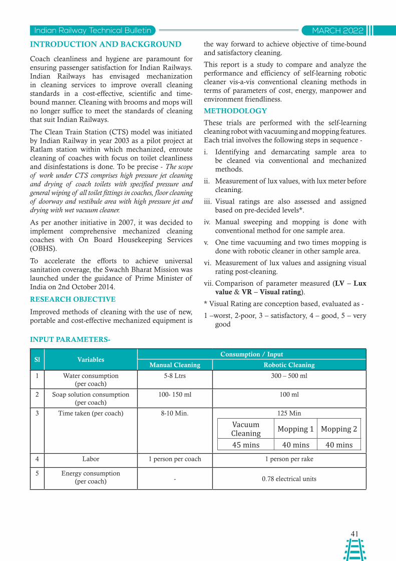
41
Indian Railway Technical Bulletin MARCH 2022
INTRODUCTION AND BACKGROUND
Coach cleanliness and hygiene are paramount for ensuring passenger satisfaction for Indian Railways. Indian Railways has envisaged mechanization in cleaning services to improve overall cleaning standards in a cost-effective, scientific and time-bound manner. Cleaning with brooms and mops will no longer suffice to meet the standards of cleaning that suit Indian Railways.
The Clean Train Station (CTS) model was initiated by Indian Railway in year 2003 as a pilot project at Ratlam station within which mechanized, enroute cleaning of coaches with focus on toilet cleanliness and disinfestations is done. To be precise - The scope of work under CTS comprises high pressure jet cleaning and drying of coach toilets with specified pressure and general wiping of all toilet fittings in coaches, floor cleaning of doorway and vestibule area with high pressure jet and drying with wet vacuum cleaner.
As per another initiative in 2007, it was decided to implement comprehensive mechanized cleaning coaches with On Board Housekeeping Services (OBHS).
To accelerate the efforts to achieve universal sanitation coverage, the Swachh Bharat Mission was launched under the guidance of Prime Minister of India on 2nd October 2014.
RESEARCH OBJECTIVE
Improved methods of cleaning with the use of new, portable and cost-effective mechanized equipment is
the way forward to achieve objective of time-bound and satisfactory cleaning.
This report is a study to compare and analyze the performance and efficiency of self-learning robotic cleaner vis-a-vis conventional cleaning methods in terms of parameters of cost, energy, manpower and environment friendliness.
METHODOLOGY
These trials are performed with the self-learning cleaning robot with vacuuming and mopping features. Each trial involves the following steps in sequence -
i. Identifying and demarcating sample area to be cleaned via conventional and mechanized methods.
ii. Measurement of lux values, with lux meter before cleaning.
iii. Visual ratings are also assessed and assigned based on pre-decided levels*.
iv. Manual sweeping and mopping is done with conventional method for one sample area.
v. One time vacuuming and two times mopping is done with robotic cleaner in other sample area.
vi. Measurement of lux values and assigning visual rating post-cleaning.
vii. Comparison of parameter measured (LV – Lux value & VR – Visual rating).
* Visual Rating are conception based, evaluated as -
1 –worst, 2-poor, 3 – satisfactory, 4 – good, 5 – very good
INPUT PARAMETERS-
Sl VariablesConsumption / Input
Manual Cleaning Robotic Cleaning
1 Water consumption (per coach)
5-8 Ltrs 300 – 500 ml
2 Soap solution consumption (per coach)
100- 150 ml 100 ml
3 Time taken (per coach) 8-10 Min. 125 Min
Vacuum Cleaning Mopping 1 Mopping 2
45 mins 40 mins 40 mins
4 Labor 1 person per coach 1 person per rake
5 Energy consumption (per coach) - 0.78 electrical units
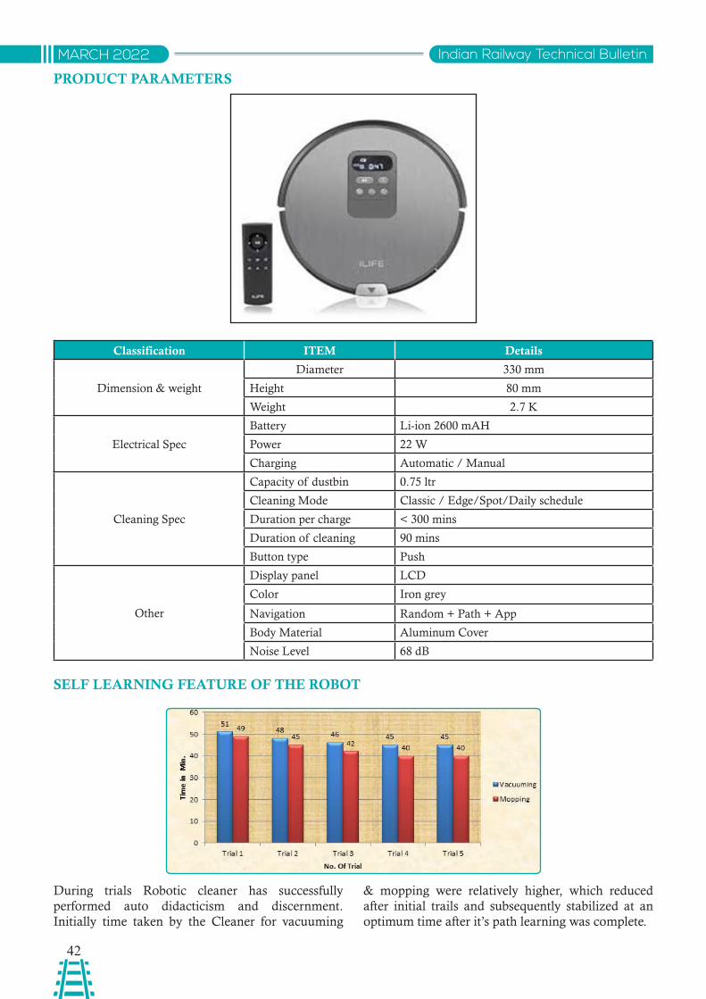
42
Indian Railway Technical BulletinMARCH 2022
PRODUCT PARAMETERS
Classification ITEM Details
Dimension & weight
Diameter 330 mm
Height 80 mm
Weight 2.7 K
Electrical Spec
Battery Li-ion 2600 mAH
Power 22 W
Charging Automatic / Manual
Cleaning Spec
Capacity of dustbin 0.75 ltr
Cleaning Mode Classic / Edge/Spot/Daily schedule
Duration per charge < 300 mins
Duration of cleaning 90 mins
Button type Push
Other
Display panel LCD
Color Iron grey
Navigation Random + Path + App
Body Material Aluminum Cover
Noise Level 68 dB
SELF LEARNING FEATURE OF THE ROBOT
During trials Robotic cleaner has successfully performed auto didacticism and discernment. Initially time taken by the Cleaner for vacuuming
& mopping were relatively higher, which reduced after initial trails and subsequently stabilized at an optimum time after it’s path learning was complete.
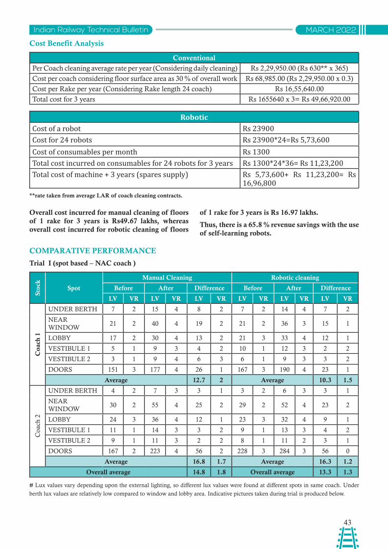
43
Indian Railway Technical Bulletin MARCH 2022
Cost Benefit Analysis
Conventional
Per Coach cleaning average rate per year (Considering daily cleaning) Rs 2,29,950.00 (Rs 630** x 365)
Cost per coach considering floor surface area as 30 % of overall work Rs 68,985.00 (Rs 2,29,950.00 x 0.3)
Cost per Rake per year (Considering Rake length 24 coach) Rs 16,55,640.00
Total cost for 3 years Rs 1655640 x 3= Rs 49,66,920.00
RoboticCost of a robot Rs 23900Cost for 24 robots Rs 23900*24=Rs 5,73,600Cost of consumables per month Rs 1300Total cost incurred on consumables for 24 robots for 3 years Rs 1300*24*36= Rs 11,23,200Total cost of machine + 3 years (spares supply) Rs 5,73,600+ Rs 11,23,200= Rs
16,96,800**rate taken from average LAR of coach cleaning contracts.
Overall cost incurred for manual cleaning of floors of 1 rake for 3 years is Rs49.67 lakhs, whereas overall cost incurred for robotic cleaning of floors
of 1 rake for 3 years is Rs 16.97 lakhs.
Thus, there is a 65.8 % revenue savings with the use of self-learning robots.
COMPARATIVE PERFORMANCE
Trial I (spot based – NAC coach )
Stoc
k
Spot
Manual Cleaning Robotic cleaning
Before After Difference Before After Difference
LV VR LV VR LV VR LV VR LV VR LV VR
Coa
ch 1
UNDER BERTH 7 2 15 4 8 2 7 2 14 4 7 2
NEAR WINDOW
21 2 40 4 19 2 21 2 36 3 15 1
LOBBY 17 2 30 4 13 2 21 3 33 4 12 1
VESTIBULE 1 5 1 9 3 4 2 10 1 12 3 2 2
VESTIBULE 2 3 1 9 4 6 3 6 1 9 3 3 2
DOORS 151 3 177 4 26 1 167 3 190 4 23 1
Average 12.7 2 Average 10.3 1.5
Coa
ch 2
UNDER BERTH 4 2 7 3 3 1 3 2 6 3 3 1
NEAR WINDOW
30 2 55 4 25 2 29 2 52 4 23 2
LOBBY 24 3 36 4 12 1 23 3 32 4 9 1
VESTIBULE 1 11 1 14 3 3 2 9 1 13 3 4 2
VESTIBULE 2 9 1 11 3 2 2 8 1 11 2 3 1
DOORS 167 2 223 4 56 2 228 3 284 3 56 0
Average 16.8 1.7 Average 16.3 1.2
Overall average 14.8 1.8 Overall average 13.3 1.3
# Lux values vary depending upon the external lighting, so different lux values were found at different spots in same coach. Under
berth lux values are relatively low compared to window and lobby area. Indicative pictures taken during trial is produced below.
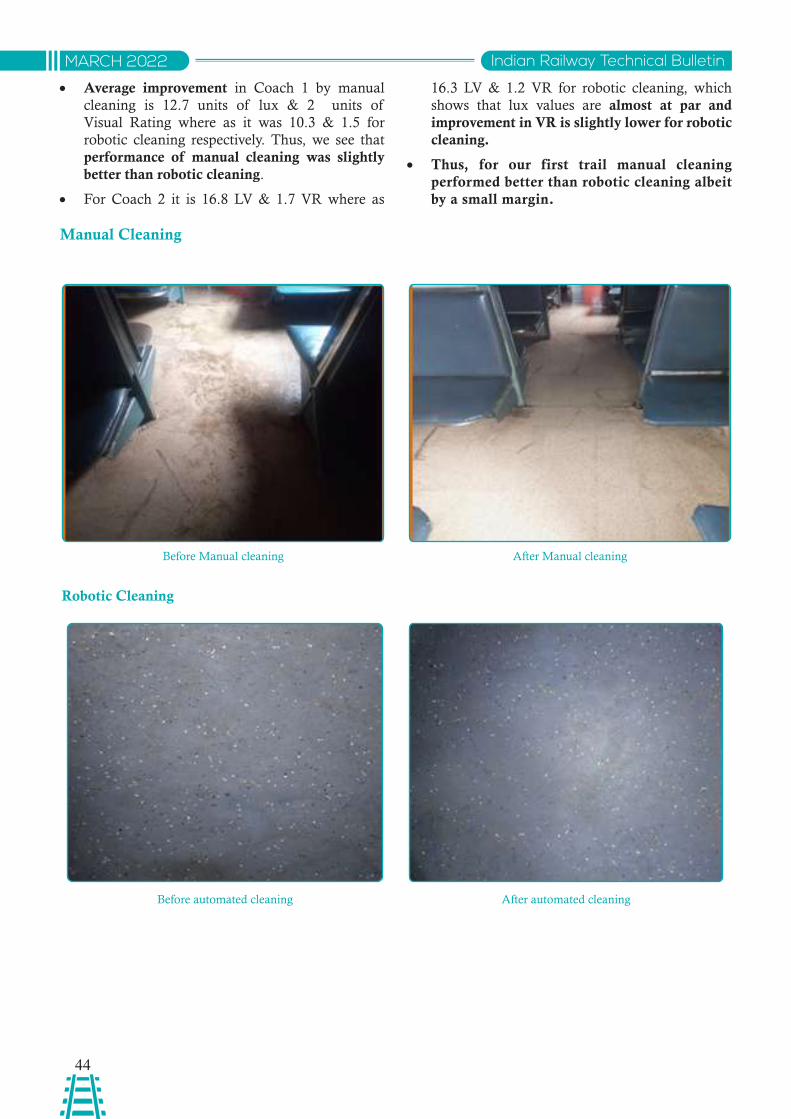
44
Indian Railway Technical BulletinMARCH 2022
• Average improvement in Coach 1 by manual cleaning is 12.7 units of lux & 2 units of Visual Rating where as it was 10.3 & 1.5 for robotic cleaning respectively. Thus, we see that performance of manual cleaning was slightly better than robotic cleaning.
• For Coach 2 it is 16.8 LV & 1.7 VR where as
16.3 LV & 1.2 VR for robotic cleaning, which shows that lux values are almost at par and improvement in VR is slightly lower for robotic cleaning.
• Thus, for our first trail manual cleaning performed better than robotic cleaning albeit by a small margin.
Before Manual cleaning
Before automated cleaning
After Manual cleaning
After automated cleaning
Manual Cleaning
Robotic Cleaning
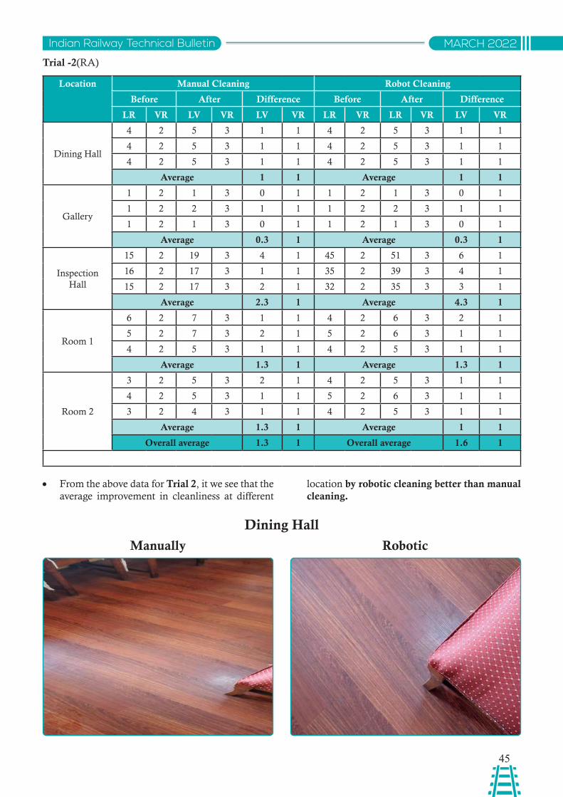
45
Indian Railway Technical Bulletin MARCH 2022
Trial -2(RA)
Location Manual Cleaning Robot Cleaning
Before After Difference Before After Difference
LR VR LV VR LV VR LR VR LR VR LV VR
Dining Hall
4 2 5 3 1 1 4 2 5 3 1 1
4 2 5 3 1 1 4 2 5 3 1 1
4 2 5 3 1 1 4 2 5 3 1 1
Average 1 1 Average 1 1
Gallery
1 2 1 3 0 1 1 2 1 3 0 1
1 2 2 3 1 1 1 2 2 3 1 1
1 2 1 3 0 1 1 2 1 3 0 1
Average 0.3 1 Average 0.3 1
Inspection Hall
15 2 19 3 4 1 45 2 51 3 6 1
16 2 17 3 1 1 35 2 39 3 4 1
15 2 17 3 2 1 32 2 35 3 3 1
Average 2.3 1 Average 4.3 1
Room 1
6 2 7 3 1 1 4 2 6 3 2 1
5 2 7 3 2 1 5 2 6 3 1 1
4 2 5 3 1 1 4 2 5 3 1 1
Average 1.3 1 Average 1.3 1
Room 2
3 2 5 3 2 1 4 2 5 3 1 1
4 2 5 3 1 1 5 2 6 3 1 1
3 2 4 3 1 1 4 2 5 3 1 1
Average 1.3 1 Average 1 1
Overall average 1.3 1 Overall average 1.6 1
• From the above data for Trial 2, it we see that the average improvement in cleanliness at different
location by robotic cleaning better than manual cleaning.
Dining Hall
Dining Hall
Manually Robotic
Gallery
Inspection hall
Manually Robotic
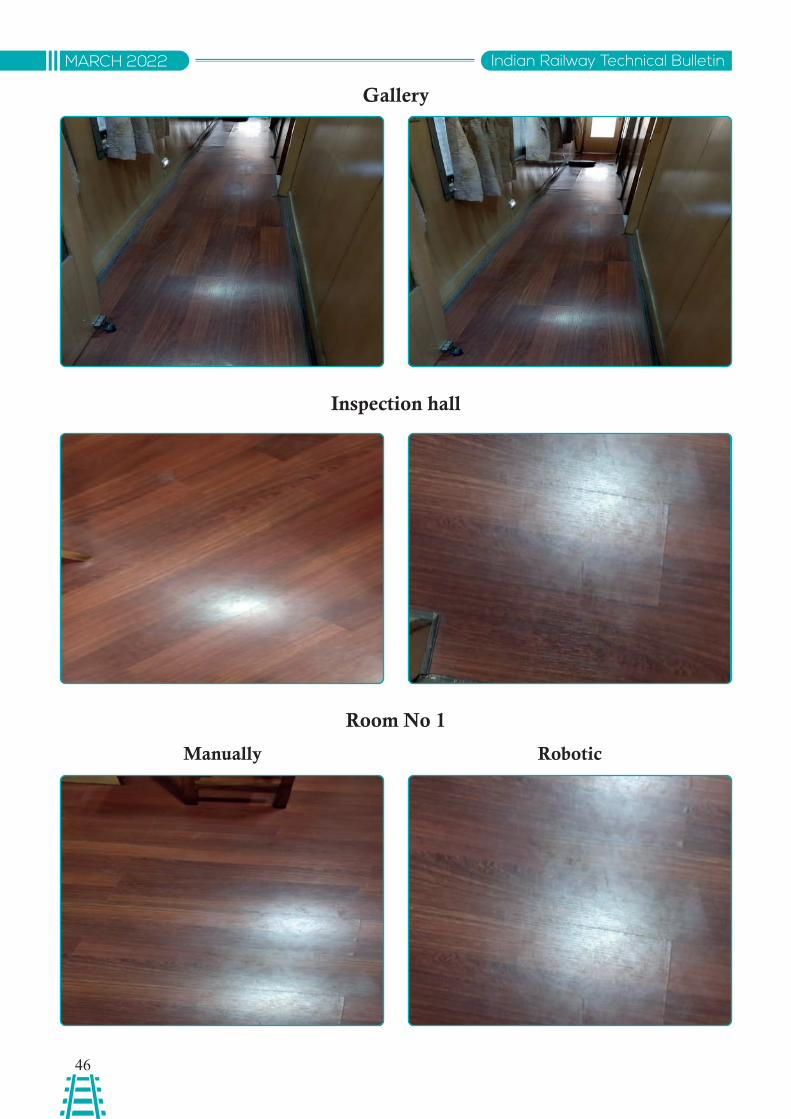
46
Indian Railway Technical BulletinMARCH 2022
Gallery
Inspection hall
Room No 1
Manually Robotic
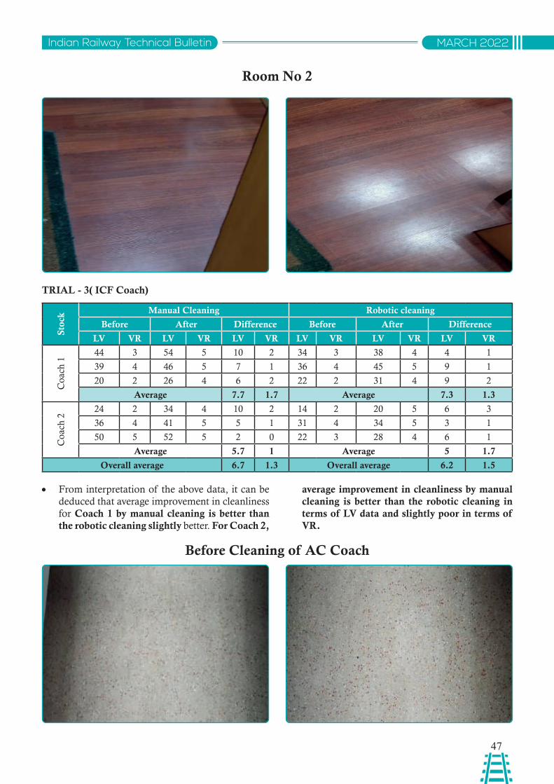
47
Indian Railway Technical Bulletin MARCH 2022
Room No 2
TRIAL - 3( ICF Coach)
Stoc
k Manual Cleaning Robotic cleaning
Before After Difference Before After Difference
LV VR LV VR LV VR LV VR LV VR LV VR
Coa
ch 1
44 3 54 5 10 2 34 3 38 4 4 1
39 4 46 5 7 1 36 4 45 5 9 1
20 2 26 4 6 2 22 2 31 4 9 2
Average 7.7 1.7 Average 7.3 1.3
Coa
ch 2
24 2 34 4 10 2 14 2 20 5 6 3
36 4 41 5 5 1 31 4 34 5 3 1
50 5 52 5 2 0 22 3 28 4 6 1
Average 5.7 1 Average 5 1.7
Overall average 6.7 1.3 Overall average 6.2 1.5
• From interpretation of the above data, it can be deduced that average improvement in cleanliness for Coach 1 by manual cleaning is better than the robotic cleaning slightly better. For Coach 2,
average improvement in cleanliness by manual cleaning is better than the robotic cleaning in terms of LV data and slightly poor in terms of VR.
Before Cleaning of AC Coach
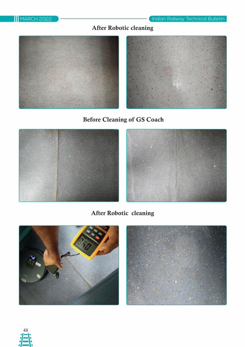
48
Indian Railway Technical BulletinMARCH 2022
After Robotic cleaning
Before Cleaning of GS Coach
After Robotic cleaning
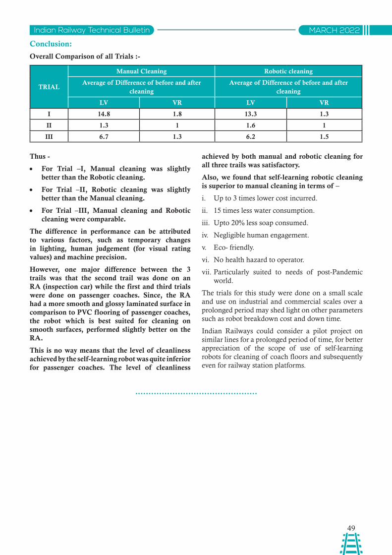
49
Indian Railway Technical Bulletin MARCH 2022
Conclusion:
Overall Comparison of all Trials :-
TRIAL
Manual Cleaning Robotic cleaning
Average of Difference of before and after cleaning
Average of Difference of before and after cleaning
LV VR LV VR
I 14.8 1.8 13.3 1.3
II 1.3 1 1.6 1
III 6.7 1.3 6.2 1.5
Thus -
• For Trial –I, Manual cleaning was slightly better than the Robotic cleaning.
• For Trial –II, Robotic cleaning was slightly better than the Manual cleaning.
• For Trial –III, Manual cleaning and Robotic cleaning were comparable.
The difference in performance can be attributed to various factors, such as temporary changes in lighting, human judgement (for visual rating values) and machine precision.
However, one major difference between the 3 trails was that the second trail was done on an RA (inspection car) while the first and third trials were done on passenger coaches. Since, the RA had a more smooth and glossy laminated surface in comparison to PVC flooring of passenger coaches, the robot which is best suited for cleaning on smooth surfaces, performed slightly better on the RA.
This is no way means that the level of cleanliness achieved by the self-learning robot was quite inferior for passenger coaches. The level of cleanliness
achieved by both manual and robotic cleaning for all three trails was satisfactory.
Also, we found that self-learning robotic cleaning is superior to manual cleaning in terms of –
i. Up to 3 times lower cost incurred.
ii. 15 times less water consumption.
iii. Upto 20% less soap consumed.
iv. Negligible human engagement.
v. Eco- friendly.
vi. No health hazard to operator.
vii. Particularly suited to needs of post-Pandemic world.
The trials for this study were done on a small scale and use on industrial and commercial scales over a prolonged period may shed light on other parameters such as robot breakdown cost and down time.
Indian Railways could consider a pilot project on similar lines for a prolonged period of time, for better appreciation of the scope of use of self-learning robots for cleaning of coach floors and subsequently even for railway station platforms.
50
Indian Railway Technical BulletinMARCH 2022
Abstract: Metal inert gas welding process with pulsating current for metals is a popular state-of-art joining process being used due to the associated benefit of lower heat input and controlled rate of metal transfer in the form of pulsed-spray to the weld cavity in comparison to the conventional metal inert gas welding where heat input was in higher side with unrestrained spray transfer of weld metal. This review article throws light on the process methodology, optimization of process parameters and variable applications consolidated by researchers. Considering important process parameters, materials, modelling and simulation studies undertaken by authors and optimized with suitable numerical methods. Selected experimentation studies are also reviewed and presented along with application on different material and process variables.
साराशं: धातओु ंके वलए पलसेव्ंग करे्ं के साथ मे्ल इन ््ट गैस वेवलिंग प्वरिया एक लोकवप्य अतयाधवुनक जॉइवनगं प्वरिया है वजसका उपयोग कम ही् इनपु् के सबंद्ध लाभ और वेलि कैवव्ी में पलसि-सपे् के रूप में मे्ल ट्ासंफर की वनयवंत्त िर के कारण वकया जाता ह।ै यह पारपंररक मे्ल इन ््ट गैस वेवलिंग की तलुना में जहा ंवेलि धात ुके अवनयवंत्त सपे् हसतातंरण के साथ ही् इनपु् अवधक था। यह समीक्ा लेख शोधकता्टओ ंद्ारा समेवकत प्वरिया पद्धवत, प्वरिया मापििंों के अनकूुलन और पररवत्टनीय अनपु्योगों पर प्काश िालता है। इसे लेखकों द्ारा वकए गए महतवपूण्ट प्वरिया मापििंों, सामवग्रयों, मॉिवलंग और वसमलेुशन अधययनों को धयान में रखते हुए और उपयकु्त सखंयातमक वववधयों के साथ अनकूुवलत वकया जाता ह।ै चयवनत प्योग अधययनों की भी समीक्ा की जाती ह ैऔर वववभनन सामग्री और प्ोसेस वैररएबलस पर आवेिन के साथ प्सततु वकया जाता ह।ै
Ravindra Kumar MisraDy. Director/SRESTHA
RDSO, Lucknow
AN OVERVIEW OF METAL INERT GAS WELDING USING PULSED CURRENT
Introduction
In conventional MIGW process, weld metal transfer takes place under constant current and voltage i.e. higher heat input in the four type of metal transfer modes viz. Globular, Short-Circuiting, cold metal transfer and Spray type metal transfer. Conventional MIGW process is having some inherent dis-advantages like spattered bead, high heat input to the parent metal and associated losses. Pulsed Metal Inert Gas welding, a variant of the regular Metal Inert Gas weldment procedure in which the amplitude of the current is fluctuated for managing the rate of metal transfer at low average current levels by applying small duration high current which produces smooth and un-spattered welding at variable currents, which would otherwise be too low for all except dip transfer with its irregular transfer and associated spatter. The
cycle consists of applying the repeated pulse current over a constant background current to achieve desired metal transfer i.e. size of droplet and detachment rate for smooth weld bead. Choice of pulsing factors for a specified wire feed rate is an intricate action. Pulsation amplitude and duration are functions of feed wire composition, dia and to a lesser extent, shielding gas consist.
Pulsed-MIG welding process is a time tested method of welding and a lot of work is already done by researchers in the simulation, modelling and experimentation of Pulsed-MIGW to establish the process parameters, their variables and effectiveness on different materials. This article is an effort to consolidate the work done in the past on the process parameter and other variables of Pulsed MIG welding.
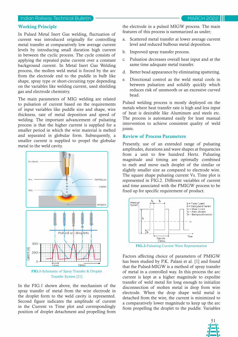
51
Indian Railway Technical Bulletin MARCH 2022
Working Principle
In Pulsed Metal Inert Gas welding, fluctuation of current was introduced originally for controlling metal transfer at comparatively low average current levels by introducing small duration high current in between the cyclic process. The cycle consists of applying the repeated pulse current over a constant background current. In Metal Inert Gas Welding process, the molten weld metal is forced by the arc from the electrode end to the puddle in bulb like shape, spray type or short-circuiting type depending on the variables like welding current, used shielding gas and electrode chemistry.
The main parameters of MIG welding are related to pulsation of current based on the requirements of input variables like puddle size and shape, wire thickness, rate of metal deposition and speed of welding. The important advancement of pulsating process is that the higher current is supplied for a smaller period in which the wire material is melted and separated in globular form. Subsequently, a smaller current is supplied to propel the globular metal to the weld cavity.
FIG.1-Schematic of Spray Transfer & Droplet
Transfer System [21]
In the FIG.1 shown above, the mechanism of the spray transfer of metal from the wire electrode in the droplet form to the weld cavity is represented. Second figure indicates the amplitude of current in the Current vs Time plot and correspondingly position of droplet detachment and propelling from
the electrode in a pulsed MIGW process. The main features of this process is summarized as under;
a. Scattered metal transfer at lower average current level and reduced bulbous metal deposition.
b. Improved spray transfer process.
c. Pulsation decreases overall heat input and at the same time adequate metal transfer.
d. Better bead appearance by eliminating spattering.
e. Directional control as the weld metal cools in between pulsation and solidify quickly which reduces risk of unsmooth or an excessive curved bead.
Pulsed welding process is mostly deployed on the metals where heat transfer rate is high and less input of heat is desirable like Aluminum and steels etc. The process is automated easily for least manual intervention to achieve consistent quality of weld joints.
Review of Process Parameters
Presently, use of an extended range of pulsating amplitudes, durations and wave shapes at frequencies from a unit to few hundred Hertz. Pulsating magnitude and timing are optimally combined to melt and move each droplet of the similar or slightly smaller size as compared to electrode wire. The square shape pulsating current Vs. Time plot is represented in FIG.2. Different variables of current and time associated with the PMIGW process to be fixed up for specific requirement of product.
FIG.2-Pulsating Current Wave Representation
Factors affecting choice of parameters of PMIGW has been studied by P.K. Palani et al. [1] and found that the Pulsed-MIGW is a method of spray transfer of metal in a controlled way. In this process the arc current is kept at a higher magnitude to expedite transfer of weld metal for long enough to initialize disconnection of molten metal in drop from wire electrode. When the drop shape weld metal is detached from the wire, the current is minimized to a comparatively lower magnitude to keep up the arc from propelling the droplet to the puddle. Variables
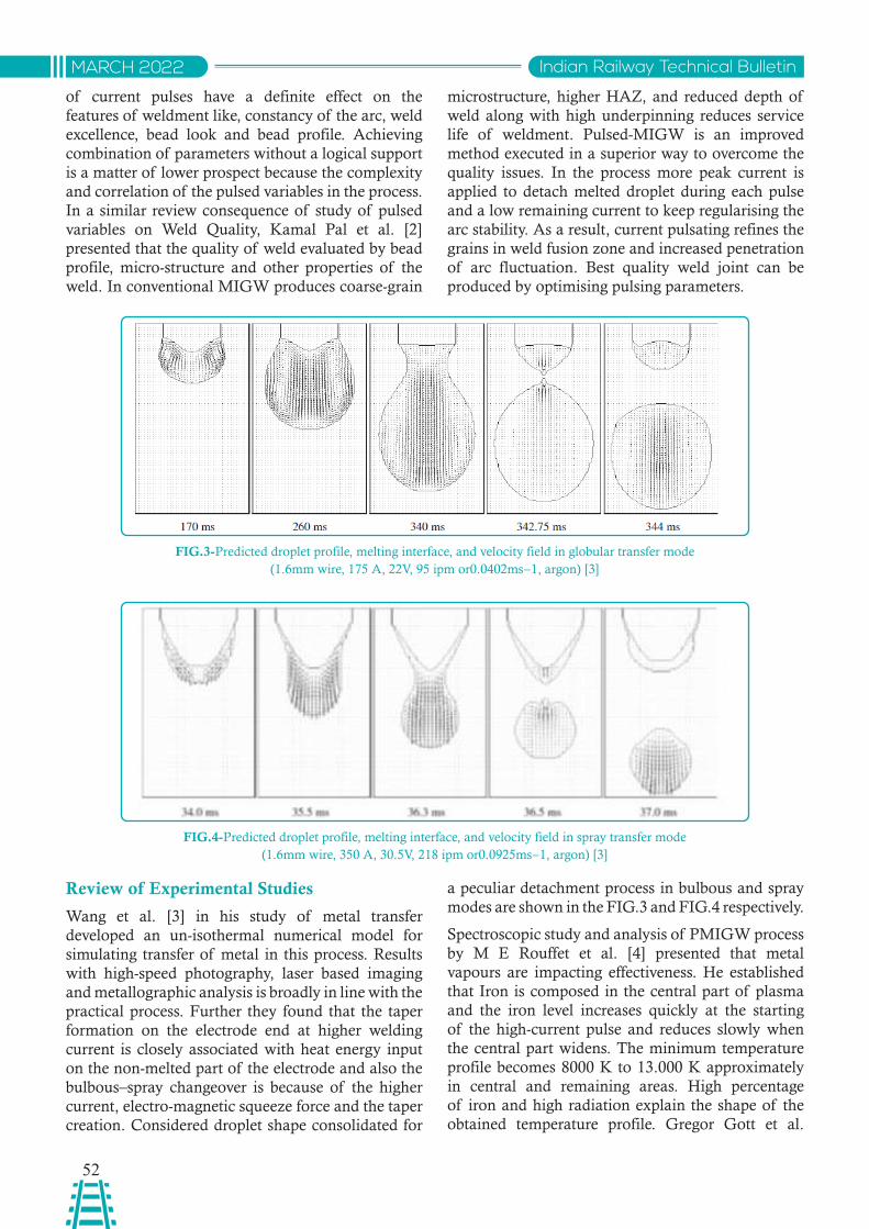
52
Indian Railway Technical BulletinMARCH 2022
of current pulses have a definite effect on the features of weldment like, constancy of the arc, weld excellence, bead look and bead profile. Achieving combination of parameters without a logical support is a matter of lower prospect because the complexity and correlation of the pulsed variables in the process. In a similar review consequence of study of pulsed variables on Weld Quality, Kamal Pal et al. [2] presented that the quality of weld evaluated by bead profile, micro-structure and other properties of the weld. In conventional MIGW produces coarse-grain
microstructure, higher HAZ, and reduced depth of weld along with high underpinning reduces service life of weldment. Pulsed-MIGW is an improved method executed in a superior way to overcome the quality issues. In the process more peak current is applied to detach melted droplet during each pulse and a low remaining current to keep regularising the arc stability. As a result, current pulsating refines the grains in weld fusion zone and increased penetration of arc fluctuation. Best quality weld joint can be produced by optimising pulsing parameters.
FIG.3-Predicted droplet profile, melting interface, and velocity field in globular transfer mode (1.6mm wire, 175 A, 22V, 95 ipm or0.0402ms−1, argon) [3]
FIG.4-Predicted droplet profile, melting interface, and velocity field in spray transfer mode (1.6mm wire, 350 A, 30.5V, 218 ipm or0.0925ms−1, argon) [3]
Review of Experimental Studies
Wang et al. [3] in his study of metal transfer developed an un-isothermal numerical model for simulating transfer of metal in this process. Results with high-speed photography, laser based imaging and metallographic analysis is broadly in line with the practical process. Further they found that the taper formation on the electrode end at higher welding current is closely associated with heat energy input on the non-melted part of the electrode and also the bulbous–spray changeover is because of the higher current, electro-magnetic squeeze force and the taper creation. Considered droplet shape consolidated for
a peculiar detachment process in bulbous and spray modes are shown in the FIG.3 and FIG.4 respectively.
Spectroscopic study and analysis of PMIGW process by M E Rouffet et al. [4] presented that metal vapours are impacting effectiveness. He established that Iron is composed in the central part of plasma and the iron level increases quickly at the starting of the high-current pulse and reduces slowly when the central part widens. The minimum temperature profile becomes 8000 K to 13.000 K approximately in central and remaining areas. High percentage of iron and high radiation explain the shape of the obtained temperature profile. Gregor Gott et al.
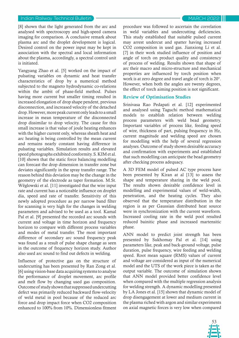
53
Indian Railway Technical Bulletin MARCH 2022
[8] shown that the light generated from the arc and analysed with spectroscopy and high-speed camera imaging for comparison. A conclusive remark about plasma arc and the droplet development is logical. Desired control on the power input may be kept in association with the spectral and local information about the plasma, accordingly, a spectral control unit is initiated.
Yangyang Zhao et al. [5] worked on the impact of pulsating variables on dynamic and heat transfer characteristics of drop by a numerical method subjected to the magneto hydrodynamic co-relations within the ambit of phase-field method. Pulses having more current but smaller timing resulted in increased elongation of drop shape pendent, previous disconnection, and increased velocity of the detached drop. However, more peak current only leads to a small increase in mean temperature of the disconnected drop dissimilar to drop velocity. The cause for this small increase is that value of joule heating enhances with the higher current only, whereas sheath heat and arc heating is being controlled by the mean current and remains nearly constant having difference in pulsating variables. Simulation results and elevated speed photographs exhibited conformity. S. KIM et al. [10] shown that the static force balancing modelling can forecast the drop dimension in transfer zone but deviates significantly in the spray transfer range. The reason behind this deviation may be the change in the geometry of the electrode as taper formation. M.St. Wêglowski et al. [11] investigated that the wire input rate and current has a noticeable influence on droplet dia, speed and rate of transfer. Sensitivity of this newly adopted procedure as per narrow band filter for scanning is very high for the changes in welding parameters and advised to be used as a tool. Kamal Pal et al. [9] presented the recorded arc sounds with current and voltage in time horizon and frequency horizon to compare with different process variables and modes of metal transfer. The most important difference of secondary arc sound frequency peak was found as a result of pulse shape change as seen in the outcome of frequency horizon study. Author also used arc sound to find out defects in welding.
Influence of protective gas on the structure of undercutting has been presented by Ran Zong et al. [6] using vision-base data acquiring systems to analyse the performance of droplet movement, arc profile and melt flow by changing used gas composition. Outcome of study shown that suppressed undercutting defect was primarily reduced backward flow-velocity of weld metal in pool because of the reduced arc force and drop impact force when CO2 composition enhanced to 100% from 10%. Dimensionless fitment
procedure was followed to ascertain the correlation in weld variables and undercutting deficiencies. This study established that suitable pulsed current may arrest undercut and spatter having increased CO2 composition in used gas. Jianxiong Li et al. [7] in their work studied influence of position and angle of torch on product quality and consistency of process of welding. Results shown that shape of arc their macro and micro-structure and mechanical properties are influenced by torch position when work is at zero degree and travel angle of torch is 20°. However, when both the angles are twenty degrees, the effect of torch aiming position is not significant.
Review of Optimisation Studies
Srinivasa Rao Pedapati et al. [12] experimented and analysed using Taguchi method mathematical models to establish relation between welding process parameters with weld bead geometry. Important variables of process like, feeding speed of wire, thickness of part, pulsing frequency in Hz, current magnitude and welding speed are chosen for modelling with the help of several regression analyses. Outcome of study shown desirable accuracy and confirmation with experiments and established that such modelling can anticipate the bead geometry after checking process adequacy.
A 3D FEM model of pulsed AC type process have been presented by Kiran at al [13] to assess the shape and temperature sharing in the weld pool. The results shown desirable confidence level in modelling and experimental values of weld-width, penetration, and the heating cycles. They also observed that the temperature distribution in the region is as per Gaussian distributed heat source were in synchronization with the current waveform. Increased cooling rate in the weld pool resulted reduced bainitic phase and increased martensitic phase.
ANN model to predict joint strength has been presented by Sukhomay Pal et al. [14] using parameters like, peak and back-ground voltage, pulse duration, pulse frequency, wire feeding and welding speed. Root mean square (RMS) values of current and voltage are considered as input of the numerical model and the UTS of the work piece is taken as the output variable. The outcome of simulation shown that ANN model provided better confidence level when compared with the multiple regression analysis for welding strength. A dynamic modelling presented by LA Jones et al. [15] shown that dynamic model of drop disengagement at lower and medium current in the plasma riched with argon and similar experiments on axial magnetic forces is very low when compared
54
Indian Railway Technical BulletinMARCH 2022
with simulation results may be due to the hypothesis of internal flaws during development of droplet.
Optimisation of Parameters with a Neuro-GA Technique using genetic algorithm by minimizing objective function considering weld strength, bead geometry, distortion and deposition efficiency into the account for desired output quality presented by Surjya K Pal et al. [16] and observed that Neuro-GA technique is a potent tool in optimization of process in comparatively lesser experiments and variation in results was within 3% only. Taguchi orthogonal array method is used by S. R. Patil et al. [17] for optimization to improve weld strength and observed that speed of welding has high influence on weld joints strength in tensile mode. Parametric optimization by Using Factorial Design method is presented by Manoj Singla et al. [18] and found that process parameters has a bearing on the bead area to noticeable level in which welding current was most bearing variable to welds made using negative polarity electrodes with a small diameter electrode, long electrode, low voltage and low welding speed which produces large bead area.
Similar works to optimize quality parameters using grey-based Taguchi method has been presented by Surjya K. Pal et al. [19] and observed that the pulse voltage and frequency are the most significant factors who affect the weld quality whereas other factors contribution can also not be neglected. Wire feed rate for welding of Al sheets is optimised by H.J. Park et al. [20] and noticed that best quality weld is achievable with 0.5 m/min, 1.0 m/min, and 1.5 m/min welding speed.
Conclusions
Many remarkable works have been done in different sub-domains of GMAW process and optimizations and automation of the processes for different type of applications are done with pulsed MIG welding. The important conclusions drawn in review study are:
Quality of welds may be effectively optimised by proper selection and regulation of process parameters like, pulsed current and voltage, welding speed, wire feed rate and shielding gas etc. and is achievable in State-of-art Pulsed-MIG.
Modelling, simulation and optimisation studies are successfully done to review process parameters and improve overall product quality using suitable numerical methods.
Experimental modelling with pre-defined boundary conditions and welding parameters studies shown matching results with simulation modelling up to the desired confidence levels.
Lower heat affected zone (HAZ), higher production rate (welding speed), instantaneous overlapping beads, easy automation and welding on dissimilar materials are the encouraging features of the Pulsed-MIGW process and is being used predominantly with materials like steel, Aluminium, tungsten and magnesium etc.
Automation and implementation of Robotics with least manual intervention is comparatively easier in pulsed current metal inert gas welding for achieving consistent quality.
References
[1] P.K. Palani, N. Murugan. Selection of parameters of pulsed current gas metal arc welding. Journal of Materials Processing Technology, (172) 1–10, 2006.
[2] Kamal Pal and Surjya K. Pal. Effect of Pulse Parameters on Weld Quality in Pulsed Gas Metal Arc Welding: A Review. Journal of Materials Engineering and Performance, 20(6), 2010.
[3] FWang, W K Hou1, S J Hu1, E Kannatey-Asibu1, W W Schultzand P C Wang. Modelling and analysis of metal transfer in gas metal arc welding.
[4] M E Rouffet, M Wendt, G Goett, R Kozakov, H Schoepp, K D Weltmann, D Uhrlandt. Spectroscopic investigation of the high-current phase of a pulsed GMAW process. Journal of Physics D: Applied Physics, IOP Publishing, 43 (43), 2010.
[5] Yangyang Zhao, Phill-Seung Lee, Hyun Chung. Effect of pulsing parameters on drop transfer dynamics and heat transfer behavior in pulsed gas metal arc welding. International Journal of Heat and Mass Transfer. (129) 1110–1122, 2019.
[6] Ran Zong, Ji Chen, Chuansong Wu, Girish Kumar Padhy. Influence of shielding gas on undercutting formation in gas metal arc welding. Journal of Materials Processing Technology. 2016.
[7] Jianxiong Li & Huan Li & Huiliang Wei & Ying Gao. Effect of torch position and angle on welding quality and welding process stability in Pulse on Pulse MIG welding–brazing of aluminium alloy to stainless steel. Springer-Verlag London. 2015.
[8] Gregor G¨ott, Heinz Sch¨opp, FrankHofmann and Gerd Heinz. Improvement of the control of a gas metal arc welding process. Measurement Science and Technology. 2009.
55
Indian Railway Technical Bulletin MARCH 2022
[9] Kamal Pal, Sandip Bhattacharya, Surjya K. Pal. Investigation on arc sound and metal transfer modes for on-line monitoring in pulsed gas metal arc welding.
[10] S. KIM & T.W. Eager. Analysis of metal transfer in gas metal arc welding. Welding Research Supplement. 269s-278s, 1993.
[11] M.St. Wêglowski, Y. Huang, Y.M. Zhang. Effect of welding current on metal transfer in GMAW. International Scientific Journal published monthly by the World Academy of Materials and Manufacturing Engineering. (33)1 49-56. 2008.
[12] Srinivasa Rao Pedapati, Dr.O.P. Gupta. Effect of process parameters and mathematical model for the prediction of bead geometry in pulsed GMA welding. Article in International Journal of Advanced Manufacturing Technology, 2009.
[13] Degala Venkata Kiran & Jason Cheon & Nabeel Arif & Hyun Chung & Suck-Joo Na. Three-dimensional finite element modeling of pulsed AC gas metal arc welding process. Springer-Verlag London, 2016.
[14] Sukhomay Pal, Surjya K. Pal and Arun K. Samantaray. Artificial neural network modeling of weld joint strength prediction of a pulsed metal inert gas welding process using arc signals. Department of Mechanical Engineering, Indian Institute of Technology Kharagpur.
[15] LA Jones, TW Eager and JH Lang. A dynamic model of drops detaching from a gas metal arc
welding electrode. J.Phys. D: Appl.Phys 31 107-123, 1998.
[16] Surjya K Pal, Arun Kumar Samantaray. Optimization of quality characteristics parameters in a pulsed metal inert gaswelding process using grey-based Taguchi method. International Journal of Advanced Manufacturing Technology, 2009.
[17] S. R. Patil, C. A. Waghmare. Optimization of Mig Welding Parameters for Improving Strength of Welded Joints. International Journal of Advanced Engineering Research and Studies E-ISSN2249–8974.
[18] Manoj Singla, Dharminder Singh, Dharmpal Deepak. Parametric Optimization of Gas Metal Arc Welding Processes by Using Factorial Design Approach. Journal of Minerals & Materials Characterization & Engineering. 9 (353-363), 2010.
[19] Surjya K Pal, Arun Kumar Samantaray. Determination of Optimal Pulse Metal Inert Gas Welding Parameters with a Neuro-GA Technique. Article in Materials and Manufacturing Processes. 2010.
[20] H.J. Park, D.C. Kim, M.J. Kang, S. Rhee. Optimisation of the wire feed rate during pulse MIG welding of Al sheets. Journal of of Achievements in Materials and Manufacturing Engineering. 2008.
[21] Web literature on Pulsed MIG Welding-2019.
56
Indian Railway Technical BulletinMARCH 2022
STUDY OF TOTAL HARMONIC DISTORTION IN RAILWAY SIGNALLING POWER SUPPLY SYSTEMS AND ITS IMPACT ON
ELECTRICAL POWER FACTOR
Abstract: This paper deals with the topic of Power Quality in Power Supply Systems used for Railway Signalling which with the advent of Integrated Power Supply System (IPS) has largely shifted its dependence towards power electronic and other switching equipments. These power electronic equipments have non linear characteristics which induce Power Quality issues in the supply provided by Utility. There are different types of Power Quality issues such as Voltage Sags/Interruptions, Flicker, Transients and Harmonics. Here Total Harmonic Distortion (THD) is used as the parameter for analysis. For Harmonic analysis in case of non linear loads power factor has to be split into two components, i.e. Distortion Power Factor and Displacement Power Factor and each component must be dealt individually. This paper also covers the importance for S&T and Electrical Department to measure and regulate the component known as Distortion Power Factor in the upcoming time. Further an amendment in RDSO Specification No. RDSO/SPN/165/2012 is also proposed for integrating filters (active, passive or hybrid) with IPS systems to deal with Distortion Power Factor due to ever increasing IPS loads especially in Distributed EI systems.
साराशं: यह पेपर रलेवे वसगनवलंग के वलए उपयोग की जाने वाली वबजली आपूवत्ट प्णावलयों में वबजली की गणुवत्ा के ववषय से सबंवंधत है, जो एकीकृत वबजली आपूवत्ट प्णाली (आईपीएस) के आगमन के साथ वबजली इलेकट्ॉवनक और अनय वसववचगं उपकरणों की ओर अपनी वनभ्टरता को काफी हि तक सथानांतररत कर विया है। इन वबजली इलेकट्ॉवनक उपकरणों में गैर रखेीय ववशेषताए ंहैं जो उपयोवगता द्ारा प्िान की गई आपूवत्ट में वबजली की गणुवत्ा के मदु्ों को पे्ररत करती हैं। वववभनन प्कार की वबजली की गणुवत्ा के मदेु् हैं जैसे वोल्ेज सैग / रुकाव्, वझलवमलाह्, क्वणक और हामथोवनकस। यहां ्ो्ल हामथोवनक विस्ॉश्टन का उपयोग ववशे्षण के वलए पैरामी्र के रूप में वकया जाता है। गैर रखेीय भार के मामले में हामथोवनक ववशे्षण के वलए पावर फैक्र को िो घ्कों में ववभावजत वकया जाना चावहए, अथा्टत विस्ॉश्टन पावर फैक्र और ववसथापन पावर फैक्र और प्तयेक घ्क को वयवक्तगत रूप से वनप्ाया जाना चावहए। यह पेपर आने वाले समय में ववरूपण पावर फैक्र के रूप में ज्ात घ्क को मापने और वववनयवमत करने के वलए एस एिं ्ी और ववद्तु ववभाग के महतव को भी शावमल करता है। इसके अलावा आरिीएसओ वववशष्टता सखंया आरिीएसओ/एसपीएन/165/2012 में एक सशंोधन भी आईपीएस वसस्म के साथ वफल्र (सवरिय, वनवषरिय या हाइवरिि) को एकीकृत करने के वलए प्सताववत है तावक ववशेष रूप से ववतररत ईआई वसस्म में लगातार बढ़ते आईपीएस लोि के कारण विस्ॉश्टन पावर फैक्र से वनप्ा जा सके।
Jojo JosephApprentice Junior Engineer (Signal)Delhi Division, Northern Railway
1.0 Introduction
A large number of equipments are associated with Railway Signalling system and all these require different types of Power Supply based on their function and make. The different types of equipments used in signalling system and the power supply required is given as follows: Signal LED (110V AC), Track Circuits (110V AC), Relays – Internal/External (24V
DC), DC Motor operated points (110V DC), Block Instruments (12V DC), Data Logger (24V DC), Audio Frequency Track Circuits (110V AC), Axle Counter (24V DC) etc.
To cater with the needs of different Power Supplies for all the signalling equpiments at one station any one the four types of Power Supplies Systems may be used:
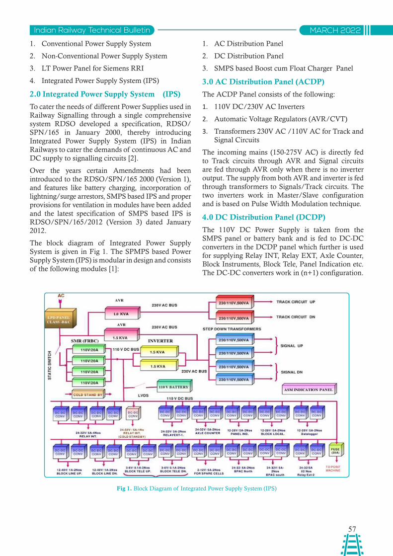
57
Indian Railway Technical Bulletin MARCH 2022
1. Conventional Power Supply System
2. Non-Conventional Power Supply System
3. LT Power Panel for Siemens RRI
4. Integrated Power Supply System (IPS)
2.0 Integrated Power Supply System (IPS)
To cater the needs of different Power Supplies used in Railway Signalling through a single comprehensive system RDSO developed a specification, RDSO/SPN/165 in January 2000, thereby introducing Integrated Power Supply System (IPS) in Indian Railways to cater the demands of continuous AC and DC supply to signalling circuits [2].
Over the years certain Amendments had been introduced to the RDSO/SPN/165 2000 (Version 1), and features like battery charging, incorporation of lightning/surge arrestors, SMPS based IPS and proper provisions for ventilation in modules have been added and the latest specification of SMPS based IPS is RDSO/SPN/165/2012 (Version 3) dated January 2012.
The block diagram of Integrated Power Supply System is given in Fig 1. The SPMPS based Power Supply System (IPS) is modular in design and consists of the following modules [1]:
1. AC Distribution Panel
2. DC Distribution Panel
3. SMPS based Boost cum Float Charger Panel
3.0 AC Distribution Panel (ACDP)
The ACDP Panel consists of the following:
1. 110V DC/230V AC Inverters
2. Automatic Voltage Regulators (AVR/CVT)
3. Transformers 230V AC /110V AC for Track and Signal Circuits
The incoming mains (150-275V AC) is directly fed to Track circuits through AVR and Signal circuits are fed through AVR only when there is no inverter output. The supply from both AVR and inverter is fed through transformers to Signals/Track circuits. The two inverters work in Master/Slave configuration and is based on Pulse Width Modulation technique.
4.0 DC Distribution Panel (DCDP)
The 110V DC Power Supply is taken from the SMPS panel or battery bank and is fed to DC-DC converters in the DCDP panel which further is used for supplying Relay INT, Relay EXT, Axle Counter, Block Instruments, Block Tele, Panel Indication etc. The DC-DC converters work in (n+1) configuration.
Fig 1. Block Diagram of Integrated Power Supply System (IPS)
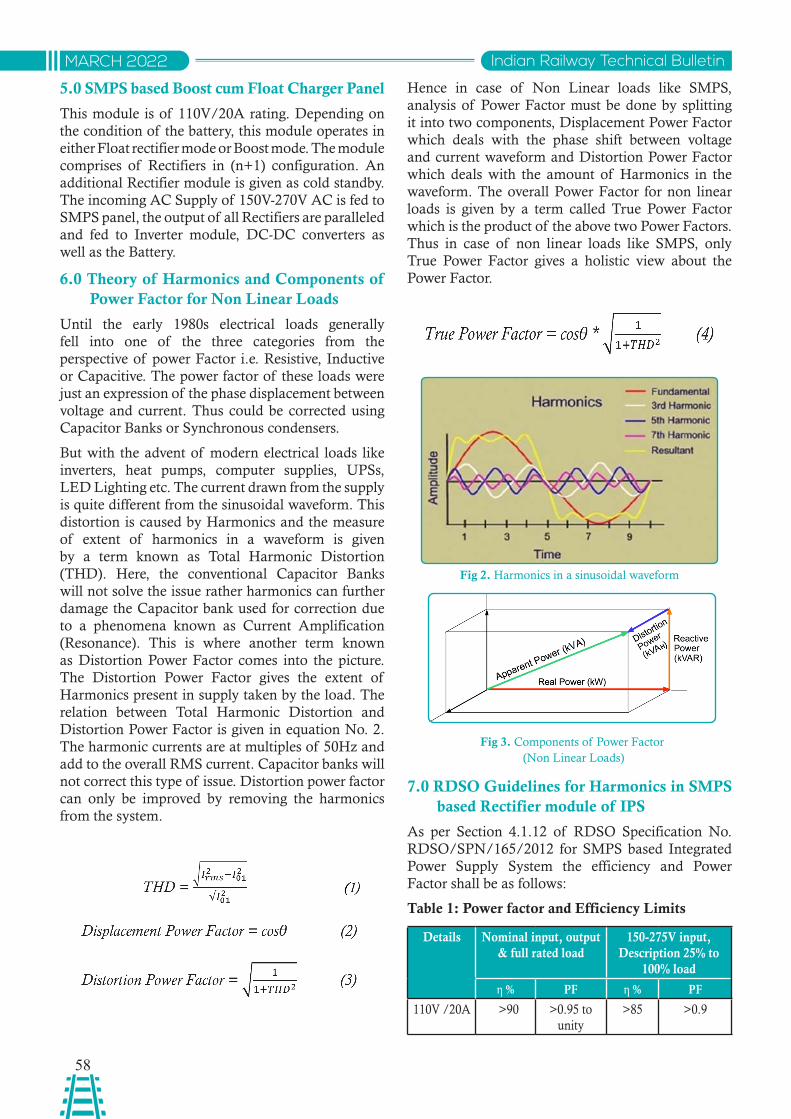
58
Indian Railway Technical BulletinMARCH 2022
5.0 SMPS based Boost cum Float Charger Panel
This module is of 110V/20A rating. Depending on the condition of the battery, this module operates in either Float rectifier mode or Boost mode. The module comprises of Rectifiers in (n+1) configuration. An additional Rectifier module is given as cold standby. The incoming AC Supply of 150V-270V AC is fed to SMPS panel, the output of all Rectifiers are paralleled and fed to Inverter module, DC-DC converters as well as the Battery.
6.0 Theory of Harmonics and Components of Power Factor for Non Linear Loads
Until the early 1980s electrical loads generally fell into one of the three categories from the perspective of power Factor i.e. Resistive, Inductive or Capacitive. The power factor of these loads were just an expression of the phase displacement between voltage and current. Thus could be corrected using Capacitor Banks or Synchronous condensers.
But with the advent of modern electrical loads like inverters, heat pumps, computer supplies, UPSs, LED Lighting etc. The current drawn from the supply is quite different from the sinusoidal waveform. This distortion is caused by Harmonics and the measure of extent of harmonics in a waveform is given by a term known as Total Harmonic Distortion (THD). Here, the conventional Capacitor Banks will not solve the issue rather harmonics can further damage the Capacitor bank used for correction due to a phenomena known as Current Amplification (Resonance). This is where another term known as Distortion Power Factor comes into the picture. The Distortion Power Factor gives the extent of Harmonics present in supply taken by the load. The relation between Total Harmonic Distortion and Distortion Power Factor is given in equation No. 2. The harmonic currents are at multiples of 50Hz and add to the overall RMS current. Capacitor banks will not correct this type of issue. Distortion power factor can only be improved by removing the harmonics from the system.
Fig 2. Harmonics in a sinusoidal waveform
Fig 3. Components of Power Factor (Non Linear Loads)
Hence in case of Non Linear loads like SMPS, analysis of Power Factor must be done by splitting it into two components, Displacement Power Factor which deals with the phase shift between voltage and current waveform and Distortion Power Factor which deals with the amount of Harmonics in the waveform. The overall Power Factor for non linear loads is given by a term called True Power Factor which is the product of the above two Power Factors. Thus in case of non linear loads like SMPS, only True Power Factor gives a holistic view about the Power Factor.
7.0 RDSO Guidelines for Harmonics in SMPS based Rectifier module of IPS
As per Section 4.1.12 of RDSO Specification No. RDSO/SPN/165/2012 for SMPS based Integrated Power Supply System the efficiency and Power Factor shall be as follows:
Table 1: Power factor and Efficiency Limits
Details Nominal input, output & full rated load
150-275V input, Description 25% to
100% load
η % PF η % PF110V /20A >90 >0.95 to
unity >85 >0.9
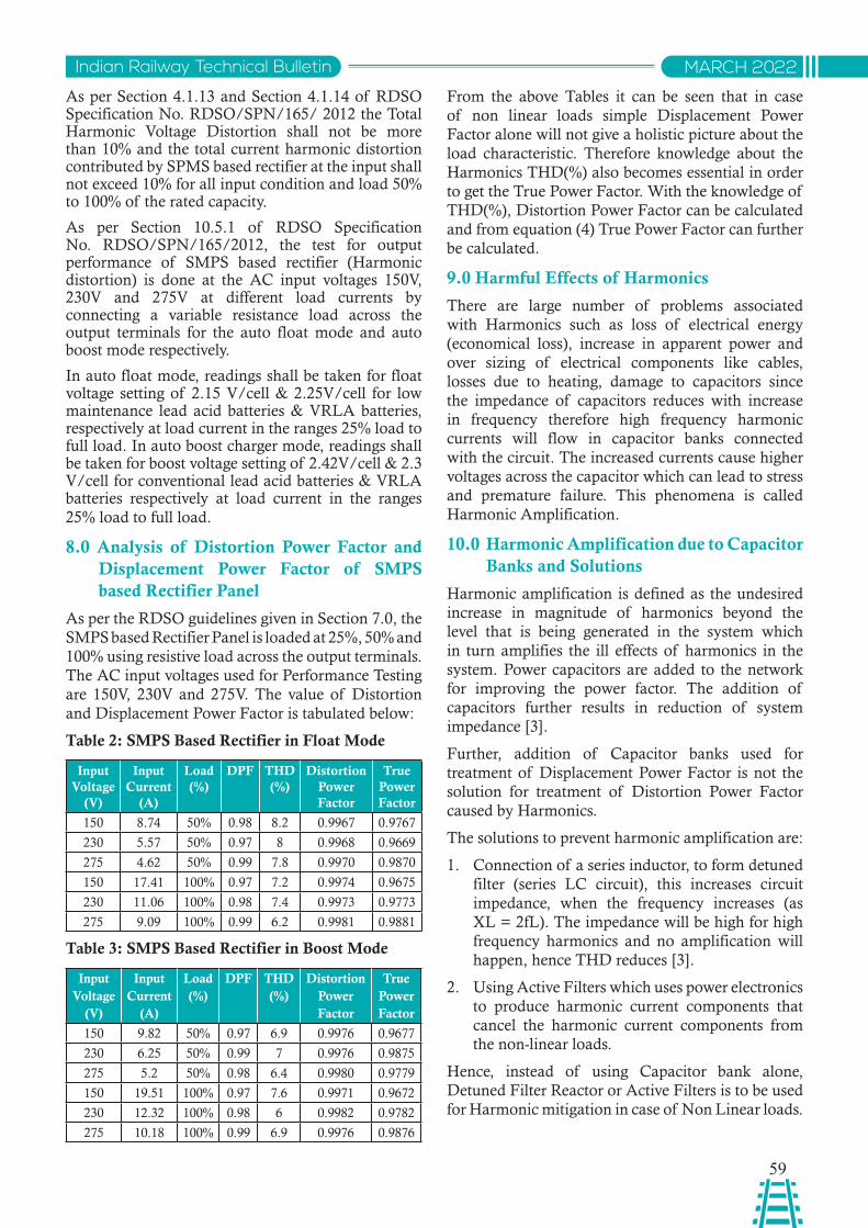
59
Indian Railway Technical Bulletin MARCH 2022
As per Section 4.1.13 and Section 4.1.14 of RDSO Specification No. RDSO/SPN/165/ 2012 the Total Harmonic Voltage Distortion shall not be more than 10% and the total current harmonic distortion contributed by SPMS based rectifier at the input shall not exceed 10% for all input condition and load 50% to 100% of the rated capacity.
As per Section 10.5.1 of RDSO Specification No. RDSO/SPN/165/2012, the test for output performance of SMPS based rectifier (Harmonic distortion) is done at the AC input voltages 150V, 230V and 275V at different load currents by connecting a variable resistance load across the output terminals for the auto float mode and auto boost mode respectively.
In auto float mode, readings shall be taken for float voltage setting of 2.15 V/cell & 2.25V/cell for low maintenance lead acid batteries & VRLA batteries, respectively at load current in the ranges 25% load to full load. In auto boost charger mode, readings shall be taken for boost voltage setting of 2.42V/cell & 2.3 V/cell for conventional lead acid batteries & VRLA batteries respectively at load current in the ranges 25% load to full load.
8.0 Analysis of Distortion Power Factor and Displacement Power Factor of SMPS based Rectifier Panel
As per the RDSO guidelines given in Section 7.0, the SMPS based Rectifier Panel is loaded at 25%, 50% and 100% using resistive load across the output terminals. The AC input voltages used for Performance Testing are 150V, 230V and 275V. The value of Distortion and Displacement Power Factor is tabulated below:
Table 2: SMPS Based Rectifier in Float Mode
Input Voltage
(V)
Input Current
(A)
Load (%)
DPF THD (%)
Distortion Power Factor
True Power Factor
150 8.74 50% 0.98 8.2 0.9967 0.9767
230 5.57 50% 0.97 8 0.9968 0.9669
275 4.62 50% 0.99 7.8 0.9970 0.9870
150 17.41 100% 0.97 7.2 0.9974 0.9675
230 11.06 100% 0.98 7.4 0.9973 0.9773
275 9.09 100% 0.99 6.2 0.9981 0.9881
Table 3: SMPS Based Rectifier in Boost Mode
Input Voltage
(V)
Input Current
(A)
Load (%)
DPF THD (%)
Distortion Power Factor
True Power Factor
150 9.82 50% 0.97 6.9 0.9976 0.9677
230 6.25 50% 0.99 7 0.9976 0.9875
275 5.2 50% 0.98 6.4 0.9980 0.9779
150 19.51 100% 0.97 7.6 0.9971 0.9672
230 12.32 100% 0.98 6 0.9982 0.9782
275 10.18 100% 0.99 6.9 0.9976 0.9876
From the above Tables it can be seen that in case of non linear loads simple Displacement Power Factor alone will not give a holistic picture about the load characteristic. Therefore knowledge about the Harmonics THD(%) also becomes essential in order to get the True Power Factor. With the knowledge of THD(%), Distortion Power Factor can be calculated and from equation (4) True Power Factor can further be calculated.
9.0 Harmful Effects of Harmonics
There are large number of problems associated with Harmonics such as loss of electrical energy (economical loss), increase in apparent power and over sizing of electrical components like cables, losses due to heating, damage to capacitors since the impedance of capacitors reduces with increase in frequency therefore high frequency harmonic currents will flow in capacitor banks connected with the circuit. The increased currents cause higher voltages across the capacitor which can lead to stress and premature failure. This phenomena is called Harmonic Amplification.
10.0 Harmonic Amplification due to Capacitor Banks and Solutions
Harmonic amplification is defined as the undesired increase in magnitude of harmonics beyond the level that is being generated in the system which in turn amplifies the ill effects of harmonics in the system. Power capacitors are added to the network for improving the power factor. The addition of capacitors further results in reduction of system impedance [3].
Further, addition of Capacitor banks used for treatment of Displacement Power Factor is not the solution for treatment of Distortion Power Factor caused by Harmonics.
The solutions to prevent harmonic amplification are:
1. Connection of a series inductor, to form detuned filter (series LC circuit), this increases circuit impedance, when the frequency increases (as XL = 2fL). The impedance will be high for high frequency harmonics and no amplification will happen, hence THD reduces [3].
2. Using Active Filters which uses power electronics to produce harmonic current components that cancel the harmonic current components from the non-linear loads.
Hence, instead of using Capacitor bank alone, Detuned Filter Reactor or Active Filters is to be used for Harmonic mitigation in case of Non Linear loads.
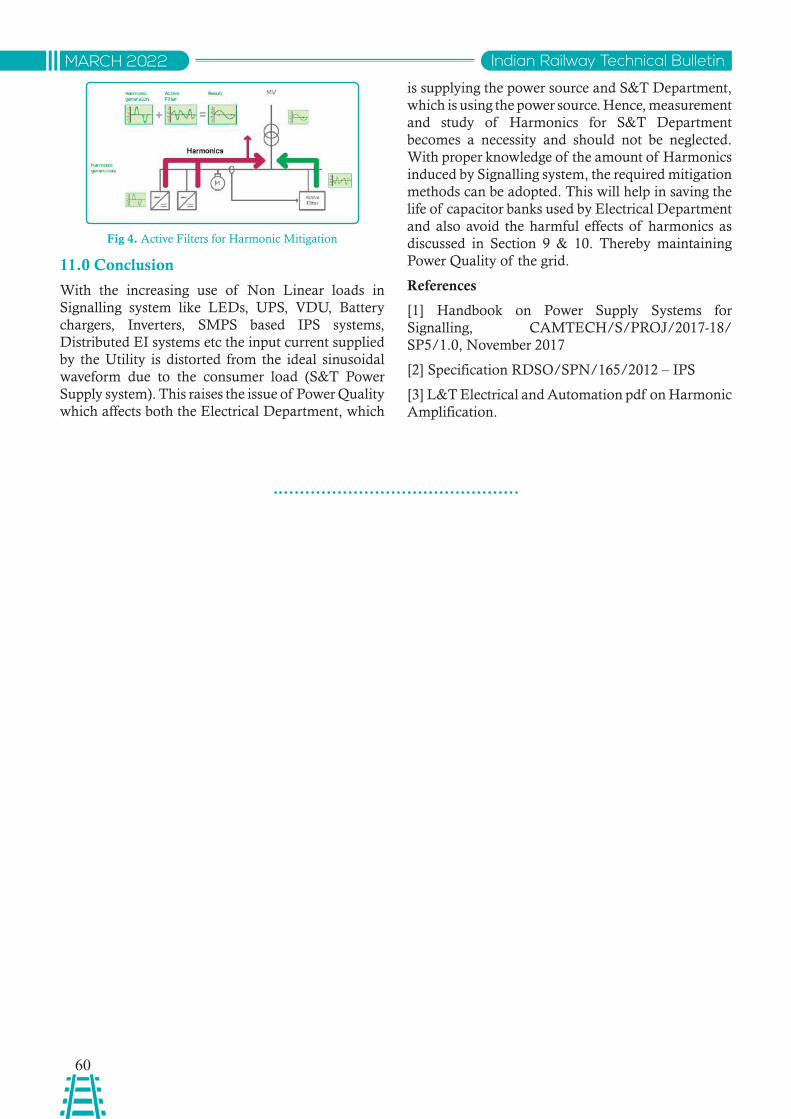
60
Indian Railway Technical BulletinMARCH 2022
Fig 4. Active Filters for Harmonic Mitigation
11.0 Conclusion
With the increasing use of Non Linear loads in Signalling system like LEDs, UPS, VDU, Battery chargers, Inverters, SMPS based IPS systems, Distributed EI systems etc the input current supplied by the Utility is distorted from the ideal sinusoidal waveform due to the consumer load (S&T Power Supply system). This raises the issue of Power Quality which affects both the Electrical Department, which
is supplying the power source and S&T Department, which is using the power source. Hence, measurement and study of Harmonics for S&T Department becomes a necessity and should not be neglected. With proper knowledge of the amount of Harmonics induced by Signalling system, the required mitigation methods can be adopted. This will help in saving the life of capacitor banks used by Electrical Department and also avoid the harmful effects of harmonics as discussed in Section 9 & 10. Thereby maintaining Power Quality of the grid.
References
[1] Handbook on Power Supply Systems for Signalling, CAMTECH/S/PROJ/2017-18/SP5/1.0, November 2017
[2] Specification RDSO/SPN/165/2012 – IPS
[3] L&T Electrical and Automation pdf on Harmonic Amplification.
Instructions for the guidance for contribution to theIndian Railway Technical Bulletin published by RDSO
Articles are invited from the serving and retired Railway personnel of the Zonal Railways, Railway Institutes and Production Units for publication in Indian Railway Technical Bulletin (IRTB) on:
(i) Technical articles relevant to railway working.
(ii) Reference to Railway-relevant good articles from reputed magazines.
(iii) Short notes on handy gadgets or practical hints on care, maintenance and operation of equipment used in railway working.
About the article: ¾ Article should normally not exceed 3000 words. Article should begin with a synopsis, both
in English & Hindi not exceeding 100 words. Reference should be quoted numerically in a bibliography at the end. Standard or well recognized notations should be used. Personal reference and lengthy quotations should be avoided. In case of reference to articles (item ii above), whereabouts of the article (name of magazine, publication month, article’s name, author’s name), and 2-3 lines about what the article is about and how it is so good - should be sent.
¾ Author’s full name, designation and photograph should be sent.
¾ The authors should certify that the articles sent for publication in the Indian Railway Technical Bulletin have not been sent elsewhere for publication.
¾ The entire content (article, photograph, certification etc.) should be sent in hard copy to Executive Director (Administration 1), Research Designs and Standards Organisation, Manak Nagar, Lucknow-226011 as well as in soft copy (editable e.g. .doc as well as non-editable, e.g. .pdf formats) to e-mail: [email protected] and [email protected].
Articles from officials of RDSO should be routed through, and approved by, the concerned Principal Executive Director/ Executive Director. In case of articles from outside RDSO, they should be duly forwarded by department head ( SA Grade and above). Retired Railway personnel may send their article directly.
Decision of Executive Director ( Administration-I ) regarding selection of article for publication in IRTB shall be final.
In order to incentivize better articles, every year there shall be a first prize of Rs.2,000/-, a second prize of Rs. 1,500/- and two third prizes of Rs. 1,000/- each.
Comments and criticism in the form of ‘Letters to the Editor’ on articles which have appeared in earlier issues of the bulletin are welcome. Suggestions about improving the IRTB are also welcome.
Instructions for the guidance for contribution to the Indian Railway Technical Bulletin published by RDSO

Related Documents