INDEX HEATING GAS VALVES 38 – 41 Description Model(s) Page(s) Standing Pilot / HSI / DSI / Intermittent Pilot / Cycle Pilot / Thermocouple Pilot Safety Valves ................................................................. 36C / 36H / 36J / 764 ............................................. 38 – 41 IGNITION MODULES 42 – 58 Description Model(s) Page(s) Universal Integrated HSI Furnace Controls ................................................... 50A55 / 50M56U / 50A65 ...................................... 42 – 44 Universal HSI Integrated Two Stage with Nitride Upgrade ............................ 21M51U-843 / 21V51U-843 / Cross Reference ... 45 – 46 Direct Replacement HSI Integrated Single Stage ......................................... 50M56U / 50A55 / 50T35 / 50M56 / 50A66 / 21D83M/ 50A65 / 50A56 / Cross Reference........ 47 – 55 Universal Non-Integrated HSI Modules ......................................................... 50E47..................................................................... 56 Universal Direct Spark Modules / Proven Pilot .............................................. 50D50 .................................................................... 57 Pilot Relite / Relite Lockout Timer / Ignition Electrodes ................................. 5059 / 760 .............................................................. 58 MERCURY FLAME SENSORS 64 – 66 Description Model(s) Page(s) Mercury Flame Sensors ................................................................................ 3046 / 30A46 / 3049 / 3098 ................................... 64 – 65 Mercury Flame Sensors and Cross Reference ............................................. 3046 / 3098 / CROSS REFERENCE ..................... 66 WARM AIR FAN CONTROLS/SNAP DISC FAN AND LIMITS 67 – 73 Description Model(s) Page(s) Attic Fan / Duct Temperature Controls .......................................................... 775 / 230 ............................................................... 67 Fan / Limit Controls and Board Mount Limits ................................................ 5D51 / 3L09 ........................................................... 68 Snap Disc Fan Controls................................................................................. 3F01 ....................................................................... 69 Snap Disc Fan / Limit Controls ...................................................................... 3L01 / 3L02 / 3L03 ................................................ 70 Adjustable Snap Disc Fan and Limit Controls ............................................... 3F05 / 3L05............................................................ 71 Bimetal Disc Thermostats.............................................................................. 3F11 / 3L11 / 3L12 ................................................. 72 – 73 ELECTRIC HEAT PRODUCTS 74 – 75 Description Model(s) Page(s) Level-Temp Low Voltage Control Systems for Electric Heat ......................... 24A00 Series......................................................... 74 Electric Heat Sequencers .............................................................................. 24A34 Series......................................................... 75 DUAL PURPOSE AIR SWITCH 76 Description Model(s) Page(s) Positive / Negative / Differential Air Switch .................................................... 770 ......................................................................... 76 GAS VALVE CONVERSION KITS / HEATING PARTS AND ACCESSORIES 77 HSI IGNITORS 59 – 61 Description Model(s) Page(s) HotRod Nitride Upgrade Kit, Hot Surface Flame Sensor / Nitride Ignitors .... 21D64 / 768A......................................................... 59 Silicon Carbide Ignitors / Cross Reference.................................................... 767A ...................................................................... 60 – 61 THERMOCOUPLES / GENERATORS 62 – 63 Description Model(s) Page(s) Thermocouples .............................................................................................. H06E / H06F .......................................................... 62 Generators / Pilot Generators / Pilot Couples ............................................... 101934 / G01A / PG9............................................. 63 www.white-rodgers.com 37 HEATING

Welcome message from author
This document is posted to help you gain knowledge. Please leave a comment to let me know what you think about it! Share it to your friends and learn new things together.
Transcript

INDEX HEATING
GAS VALVES 38 – 41 Description Model(s) Page(s) Standing Pilot / HSI / DSI / Intermittent Pilot / Cycle Pilot / Thermocouple Pilot Safety Valves ................................................................. 36C / 36H / 36J / 764 ............................................. 38 – 41
IGNITION MODULES 42 – 58 Description Model(s) Page(s) Universal Integrated HSI Furnace Controls ................................................... 50A55 / 50M56U / 50A65 ...................................... 42 – 44 Universal HSI Integrated Two Stage with Nitride Upgrade ............................ 21M51U-843 / 21V51U-843 / Cross Reference ... 45 – 46 Direct Replacement HSI Integrated Single Stage ......................................... 50M56U / 50A55 / 50T35 / 50M56 / 50A66 / 21D83M/ 50A65 / 50A56 / Cross Reference ........ 47 – 55 Universal Non-Integrated HSI Modules ......................................................... 50E47 ..................................................................... 56 UniversalDirectSparkModules/ProvenPilot .............................................. 50D50 .................................................................... 57 PilotRelite/ReliteLockoutTimer/IgnitionElectrodes ................................. 5059 / 760 .............................................................. 58
MERCURY FLAME SENSORS 64 – 66 Description Model(s) Page(s) Mercury Flame Sensors ................................................................................ 3046 / 30A46 / 3049 / 3098 ................................... 64 – 65 Mercury Flame Sensors and Cross Reference ............................................. 3046 / 3098 / CROSS REFERENCE ..................... 66
WARM AIR FAN CONTROLS/SNAP DISC FAN AND LIMITS 67 – 73 Description Model(s) Page(s) Attic Fan / Duct Temperature Controls .......................................................... 775 / 230 ............................................................... 67 Fan / Limit Controls and Board Mount Limits ................................................ 5D51 / 3L09 ........................................................... 68 Snap Disc Fan Controls................................................................................. 3F01 ....................................................................... 69 Snap Disc Fan / Limit Controls ...................................................................... 3L01 / 3L02 / 3L03 ................................................ 70 Adjustable Snap Disc Fan and Limit Controls ............................................... 3F05 / 3L05 ............................................................ 71 Bimetal Disc Thermostats .............................................................................. 3F11 / 3L11 / 3L12 ................................................. 72 – 73
ELECTRIC HEAT PRODUCTS 74 – 75 Description Model(s) Page(s) Level-Temp Low Voltage Control Systems for Electric Heat ......................... 24A00 Series ......................................................... 74 Electric Heat Sequencers .............................................................................. 24A34 Series ......................................................... 75
DUAL PURPOSE AIR SWITCH 76 Description Model(s) Page(s) Positive / Negative / Differential Air Switch .................................................... 770 ......................................................................... 76
GAS VALVE CONVERSION KITS / HEATING PARTS AND ACCESSORIES 77
HSI IGNITORS 59 – 61 Description Model(s) Page(s) HotRod Nitride Upgrade Kit, Hot Surface Flame Sensor / Nitride Ignitors .... 21D64 / 768A ......................................................... 59 Silicon Carbide Ignitors / Cross Reference.................................................... 767A ...................................................................... 60 – 61
THERMOCOUPLES / GENERATORS 62 – 63 Description Model(s) Page(s) Thermocouples .............................................................................................. H06E / H06F .......................................................... 62 Generators / Pilot Generators / Pilot Couples ............................................... 101934 / G01A / PG9............................................. 63
www.white-rodgers.com 37
HEA
TIN
G
36C Series
PARTS AND ACCESSORIES See end of this section for parts and accessories
36C SERIESGAS VALVES
GAS BURNERCONTROLS
?WIRING 172–175
HSI/DSI VALVES, INTERMITTANT IGNITION36C74-913 Step
Open24VAC Natural 3/4 x 3/4 Step 0.9”/3.5” 2.5”-5.0” No No No Str. Thru Yes Yes No 5
36C94-303 Intermit-tent
IgnitionSystems
24VAC NaturalorLP
1/2 x 3/4 DelaySlow
3.5” 2.5”-5.0”7.0”-12.0”
Yes Yes No Str. Thru No Yes No 15
➀ Wiring diagrams – see pages 172–175 Indicates Canadian Model Number U = Universal
36C SERIES STANDING PILOT SNAP OPEN, STEP OPEN, HSI, DSI, AND INTERMITTENT IGNITION GAS VALVESA Wide Range of Replacement Valves for the Professional Installer
SPECIFICATIONSElectrical Rating . . . . . . . . . . . . . . . . . . . . . . . . 0.23 ampsAmbient Operating Range . . . . . . . . . . . . . . . . -40to+175°F(-40to79°C)Maximum Pressure Rating . . . . . . . . . . . . . . . . 1/2 PSI (14.0” W.C.)Pilot Gas Connection . . . . . . . . . . . . . . . . . . . . 1/4”compressionfittingPressure Tap . . . . . . . . . . . . . . . . . . . . . . . . . . 1/8” N.P.T.
Pipe Size
1” Pressure Drop Capacity Rated Range of RegulationBTU/HR BTU/HR
STD. NAT GAS1000 BTU/CU. FT.
LP GAS2500 BTU/CU. FT.
STD. NAT GAS1000 BTU/CU. FT.
LP GAS2500 BTU/CU. FT.
1/2 X 3/8 100,000 162,000 15,000-100,000 15,000-162,0001/2 X 1/2 230,000 372,600 30,000-290,000 30,000-469,0001/2 X 3/4 230,000 372,600 30,000-290,000 30,000-469,0003/4 X 3/4 280,000 453,600 50,000-400,000 50,000-648,000
SNAP OPEN, SINGLE FUNCTION, STANDING PILOT GAS VALVES
ModelNumber
TypicalApp.
CoilVoltage
GasType
PipeSize
OpeningCharacter-
isticRegulator
Setting
Regulator Adjustment
RangeConvertible
Nat. / LP
LP Conversion Kit Included
Line Interrupter
FlowDirection
ReducerBushing
Kit
Inlet Pressure
TapSideTaps
Internal Wiring See Figure ➀
36C01-405 SnapOpen
24VAC NaturalorLP
3/4 x 3/4 Fast Open 3.5” 2.5”-5.0” Yes Yes No Str. Thru Yes No No 1
36C01A-405 SnapOpen
120VAC NaturalorLP
3/4 x 3/4 Fast Open 3.5” 2.5”-5.0” Yes Yes No Str. Thru Yes No No 3
36C03-300 StandingPilot
24VAC NaturalorLP
1/2 x 3/4 Fast Open 3.5” 2.5”-5.0” Yes Yes Yes Str. Thru Yes No No 1
36C03-333 StandingPilot
24VAC NaturalorLP
1/2 x 3/4 Fast Open 3.5” 2.5”-5.0” Yes Yes Yes Str. Thru Yes No Yes 1
36C03-400 StandingPilot
24VAC NaturalorLP
3/4 x 3/4 Fast Open 3.5” 2.5”-5.0” Yes Yes Yes Str. Thru Yes No No 1
36C03-433 StandingPilot
24VAC NaturalorLP
3/4 x 3/4 Fast Open 3.5” 2.5”-5.0” Yes Yes Yes Str. Thru Yes Yes Yes 1
36C03A-410 StandingPilot
120VAC NaturalorLP
3/4 x 3/4 Fast Open 3.5” 2.5”-5.0” Yes Yes Yes Str. Thru Yes No No 3
36C03U-333 StandingPilot
750mV NaturalorLP
1/2 x 3/4 Fast Open 3.5” 2.5”-5.0” Yes Yes Yes Str. Thru Yes Yes Yes 2
36C03U-433 StandingPilot
750mV NaturalorLP
3/4 x 3/4 Fast Open 3.5” 2.5”-5.0” Yes Yes Yes Str. Thru Yes Yes Yes 2
36C04U-438 StandingPilot
750mV NaturalorLP
3/4 x 3/4 Step Open0.7"
0.7 / 3.5” 2.5”-5.0” No No Yes Str. Thru Yes No No 2
36C53-418 StandingPilot
24VAC NaturalorLP
3/4 x 3/4 Slow Open 3.5” 2.5”-5.0” Yes No Yes Str. Thru Yes No No 1
36C03-258 StandingPilot
24VAC NaturalorLP
1/2 x 1/2 Fast Open 3.5” 2.5”-5.0” No No Yes Str. Thru No Yes No 1
U
U
www.white-rodgers.com38
HEA
TIN
G

764 / 36C SERIES GAS VALVES
GAS BURNERCONTROLS
764-702
764 SERIES THERMOCOUPLE OPERATEDGAS PILOT SAFETY/GAS FIREPLACE VALVESIn Line Appliance Control with 100% Shut Off
FEATURES / SPECIFICATIONS / PART AND ACCESSORIES
•Redesignedtoinclude100PSIprotection,inletscreenandinletpipestop.•Optionalrearinlettappedandplugged.•Maybemountedhorizontal,verticaland90°fromhorizontal(multipoise).
Electrical Rating . . . . . . . . . . . . . . . . . . . . 20 to 30 mV (Thermocouple)Regulator Adjustment Range . . . . . . . . . . Non-regulatedMaximum Pressure Rating . . . . . . . . . . . . 1/2 PSI (14.0” W.C.)Ambient Operating Range . . . . . . . . . . . . -40 to 250°FSwing Radius . . . . . . . . . . . . . . . . . . . . . . 2.5”Agency . . . . . . . . . . . . . . . . . . . . . . . . . . . C.S.A. approved
•F42-0895—Replacementknob
Model Number Coil VoltageInlet-Outlet
SizeCapacity A.G.A. Standard Gas ➀ Electrical Connections
764-702 20 to 30 mV 3/8” x 3/8” 132,000 Thermocouple764-742 20 to 30 mV 1/2” x 1/2” 142,000 Thermocouple
➀ See page 221 for capacities of other gases
?
36C84-912
PAGES172–175
36C CYCLE PILOT GAS VALVESWith Redundant Pilot Solenoid Main Gas Regulator, Integral Gas Pressure Switch and Electrical Connection on the Gas Valve for Mercury Flame Sensor Connection
SPECIFICATIONS
Electrical Rating . . . . . . . . . . . . . . . . . . . . 0.6 ampsEnd to End Dimensions . . . . . . . . . . . . . . 315/16”Ambient Operating Range . . . . . . . . . . . . -40to+175°F(-40to79°C)Maximum Pressure Rating . . . . . . . . . . . . 1/2 PSI (14.0” W.C.)Agency . . . . . . . . . . . . . . . . . . . . . . . . . . . C.S.A. approved
PARTS AND ACCESSORIES See end of this section for parts and accessories
TECHNICAL HELP
Wiring Diagrams. . . . . . . . . . . . . . . . . . . . . . See pages 172–175
Pipe Size
1” Pressure Drop Capacity Rated Range of RegulationBTU/HR BTU/HR
STD. NAT GAS1000 BTU/CU. FT.
LP GAS2500 BTU/CU. FT.
STD. NAT GAS1000 BTU/CU. FT.
LP GAS2500 BTU/CU. FT.
1/2 X 3/8 100,000 162,000 15,000-100,000 15,000-162,0001/2 X 1/2 230,000 372,600 30,000-290,000 30,000-469,0001/2 X 3/4 230,000 372,600 30,000-290,000 30,000-469,0003/4 X 3/4 280,000 453,600 50,000-400,000 50,000-648,000
ModelNumber
Coil Voltage
Gas Type
PipeSize
OpeningCharacteristic
RegulatorSetting
Regulator Adjustment
RangeConvertible
Nat. / LP
LPConversion
KitIncluded
LineInterrupter
FlowDirection
ReducerBushing
Kit
Inlet Pressure
TapSideTaps
InternalWiring
SeeFigure ➀
36C84-912 24 VAC Nat./LP 3/4 x 3/4 Fast Open 3.5” 2.5”–5.0” Yes Yes No Str. Thru Yes Yes No 736C84-913 24 VAC Nat./LP 3/4 x 3/4 Fast Open 3.5” 2.5”–5.0” Yes Yes No Str. Thru Yes Yes No 1236C84-921 24 VAC Nat./LP 3/4 x 3/4 Fast Open 3.5” 2.5”–5.0” Yes Yes No Str. Thru Yes Yes No 736C84-923 24 VAC Nat./LP 3/4 x 3/4 Fast Open 3.5” 2.5”–5.0” No No No Str. Thru No Yes No 1436C84-926 24 VAC Natural 3/4 x 3/4 Fast Open 3.5” 2.5”–5.0” No No No Str. Thru Yes No No 436C84-945 24 VAC Nat./LP 3/4 x 3/4 Fast Open 3.5” 2.5”–5.0” Yes Yes No Str. Thru Yes Yes No 836C94-906 24 VAC Natural 3/4 x 3/4 Slow Open 3.5” 2.5”–5.0” No No No Str. Thru Yes No No 736C94-907 24 VAC Nat./LP 3/4 x 3/4 Slow Open 3.5” 2.5”–5.0” Yes Yes No Str. Thru Yes No No 4
➀ Wiring diagrams – see pages 172–175 NOTE: -9XX series replaces -4XX series. Knob replaced with an ON-OFF switch.
www.white-rodgers.com 39
HEA
TIN
G

36H SERIESGAS VALVES
GAS BURNERCONTROLS
Pipe Size(36 H)
1” PD Capacity Rated Range of RegulationBTU/HR BTU/HR
Std. Gas .64Sp. Gr. (1000BTU/CU FT)
LP Gas 1.53Sp. Gr. (2500BTU/CU FT)
Gas .64Sp. Gr. (1000BTU/CU FT)
Gas 1.53Sp. Gr. (2500BTU/CU FT)
3/4” x 3/4” 300,000 486,000 50,000 to 400,000
81,000 to 648,000
1/2” x 3/4” 230,000 372,600 50,000 to 300,000
80,000 to 500,000
1/2” x 1/2” 170,000 275,500 40,000 to 240,000
40,000 to 400,000
ValveStages
RegulatorAdjustment
Range
Nat. Gas
Single 2.5” to 5.0”
Two-Stage1.0”-3.5” Low2.5”-5.0” High
36H32-423
36H64-463
?PAGE177
ModelNumber Voltage
Type ofGas
PipeSize
OpeningCharacteristic Stages HSI/DSI
ProvenPilot
StandingPilot
IntermittentPilot
ConvertibleNat/LP
Kit Included
ReducerBushing
KitInlet & OutletPressure Tap
SideTaps
36H32-214 24 Volt Nat./LP 1/2 x 1/2 Fast 1 Yes Yes No Yes Yes No Yes* No36H32-304 24 Volt Nat./LP 1/2 x 3/4 Fast 1 Yes Yes No Yes Yes Yes Yes* No36H32-423 24 Volt Nat./LP 3/4 x 3/4 Fast 1 Yes Yes No Yes Yes Yes Yes* No36H33-412 24 VAC Nat./LP 3/4 x 3/4 Slow 1 Yes Yes No Yes Yes Yes Yes* No36H64-463 24 VAC Nat./LP 3/4 x 3/4 Fast 2 Yes Yes No Yes Yes Yes Yes* No36H65-401 24 VAC Nat./LP 3/4 x 3/4 Slow 2 Yes Yes No Yes Yes Yes Yes* No
U = Universal* To measure outlet pressure on valves, loosen outlet pressure tap screw one quarter turn and put manometerhose over the top of the outlet pressure tap.Wiring diagrams – see page 177
36H SERIES GAS VALVESCombination Multi-function Controls for a Wide Range of Applications.The 36H Combination Gas Control Valve is a Versatile Multifunction Control Designed to Meet the Requirements for Use with Intermittent Ignition Systems (Direct Ignition, Proven Pilot, HSI). 36H is Our Highest Capacity Combination Gas Valve
FEATURES
•Adjustableregulator.•Quietoperationredundantdesign.• Inlet/outletscreens.•Tamperresistantscrews.
SPECIFICATIONS
Electrical Rating (36H) . . . . . . . . . . . . 0.41 amps (Single stage) 0.54 amps (Two-stage)Ambient Temp. . . . . . . . . . . . . . . . . . . -40° to 175°F (-40° to 79°C)Pressure Rating . . . . . . . . . . . . . . . . . 1/2 PSI (14.0” W.C.)Voltage . . . . . . . . . . . . . . . . . . . . . . . . 24 VACFrequency. . . . . . . . . . . . . . . . . . . . . . 50/60 Hz
PARTS AND ACCESSORIES See end of this section for parts and accessories
TECHNICAL HELP
Wiring Diagram. . . . . . . . . . . . . . . . . . . . . . . See page 177
UNEW
www.white-rodgers.com40
HEA
TIN
G
36G, 36J SERIESGAS VALVES
GAS BURNERCONTROLS
PARTS AND ACCESSORIES See end of this section for parts and accessories
TECHNICAL HELPWiring Diagrams. . . . . . . . . . . . . . . . . . . . . . See page 178?
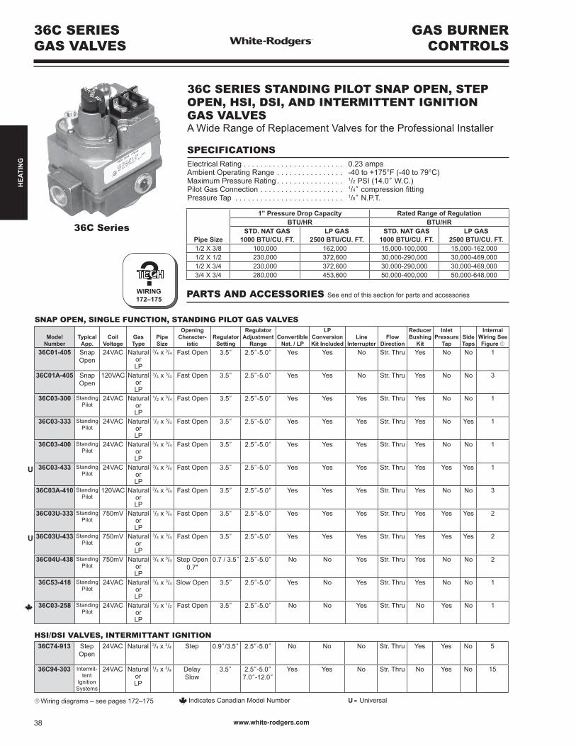
36J Series
PAGE 178
36G, 36J SERIES GAS VALVESThe 36G, 36J is a Combination Gas Control Valve Designed for Use with Non-Piloted Intermittent Ignition Systems. The Control isDesignedtoMeetToday’sMaximumCapacity,SmallerSizeandHighEfficiencyGasSystems
FEATURES
• Inletandoutletscreens.•Quietredundant.•Built-inpressuretap.•Quick-connectterminals(1/4”).
SPECIFICATIONS
Ambient Temperature . . . . . . . . . . . . . . . . -40 to 175°FMaximum Pressure Rating . . . . . . . . . . . . 1/2” PSI (14.0” W.C.)Capacity (1” P.D.). . . . . . . . . . . . . . . . . . . Natural 140,000 Btu/Hr. L.P. 226,800 Btu/Hr.Electrical Rating . . . . . . . . . . . . . . . . . . . . Single stage 24V, 50 / 60Hz at .3A Two stage at .43ASwing Radius . . . . . . . . . . . . . . . . . . . . . . 2.75”Mounting. . . . . . . . . . . . . . . . . . . . . . . . . . Any positionAgency . . . . . . . . . . . . . . . . . . . . . . . . . . . C.S.A. approved
Valve(Stages) Pipe Size
1” Pressure Drop Capacity Range of RegulationBTU/HR BTU/HR
AdjustmentRange
(Nat. IN. W.C.)
AdjustmentRange
(L.P. IN. W.C.)
Std. Gas.64 Sp. Gr.
(1000 BTU/CU. FT.)
LP Gas1.53 Sp. Gr.
(2500 BTU/FT.)
Std Gas.64 Sp. Gr.
(1000 BTU/CU. FT.)
LP Gas1.53 Sp. Gr.
(2500 BTU/FT.)Single 1/2” x 1/2”NPT 140,000 BTU/HR 226,800 BTU/HR 40,000-210,000 60,000-340,000 2.5”-5.0” 7.0”-12.0”
Two 1/2” x 1/2”NPT 140,000 BTU/HR 226,800 BTU/HR 20,000 Low- 210,000 High
32,000 Low- 340,000 High
1.0”-4.0” Low 2.0”-5.0” High
4.0”-10.0” Low6.0”-12.0” High
Modulating 1/2” x 1/2”NPT 140,000 BTU/HR 226,800 BTU/HR 20,000 - 210,000 32,600 - 340,000 0.40”-4.0” 1.3”-11.5”
ModelNumber
Coil Voltage Gas Type
PipeSize
OpeningCharacteristic
RegulatorSetting
RegulatorAdjustment
RangeConvertible
Nat. / LP
LPConversion
KitIncluded
FlowDirection
ReducerBushing
KitFilter
Screen
Inlet Pressure
Tap
OutletPressure
Tap
InternalWiring
SeeFigure ➀
36G22-254 24 VAC Natural orLP
1/2 x 1/2 Fast OpeningSingle Stage
3.5” Nat. 2.5”- 5.0”L.P. 7.0”- 12.0”
Yes No** Str. Thru No Yes Yes Yes* 1
36J22-214 24 VAC Natural orLP
1/2 x 1/2 Fast OpeningSingle Stage
3.5” Nat. 2.5”- 5.0”L.P. 7.0”- 12.0”
Yes Yes Str. Thru Yes Yes Yes Yes 1
36J24-214 24 VAC Natural orLP
1/2 x 1/2 Slow OpeningSingle Stage
3.5” Nat. 2.5”- 5.0”L.P. 7.0”- 12.0”
Yes Yes Str. Thru Yes Yes Yes Yes 1
36J54-214 24 VAC Natural orLP
1/2 x 1/2 Two-StageFast Opening
LO 1.5”HI3.5”
Nat. 2.5”- 5.0”L.P. 6.0”- 12.0”
Yes Yes Str. Thru Yes Yes Yes Yes* 2
36J55-214 24 VAC Natural orLP
1/2 x 1/2 Two-StageSlow Opening
3.5” Nat. 2.5”- 5.0”L.P. 6.0”- 12.0”
Yes Yes Str. Thru Yes Yes Yes Yes* 2
36J24-614 24 VAC Natural orLP
1/2 x 1/2 Single StageSlow Opening
3.5” Nat. 2.5”- 5.0”L.P. 7.0”- 12.0”
Yes Yes 90o
BottomOutlet
No Yes Yes Yes* 2
36J55-614 24 VAC Natural orLP
1/2 x 1/2 Two-StageSlow Opening
3.5” Nat. 2.5”- 5.0”L.P. 6.0”- 12.0”
Yes Yes 90o
BottomOutlet
No Yes Yes Yes* 2
* To measure outlet pressure on valves, loosen outlet pressure tap screw one quarter turn and put manometer hose over the top of the outlet pressure tap.** Use F92-0659 to convert to regulated L.P. gas➀ Wiring diagrams – see page 178
www.white-rodgers.com 41
HEA
TIN
G

INTEGRATED HSI FURNACE CONTROL
UNIVERSAL REPLACEMENT
?PAGES183–184
50A55-843 UNIVERSAL SILICON CARBIDE IGNITIONINTEGRATED HSI FURNACE CONTROL KITControlsGasValve,Ignitor,Blower,Inducer,HumidifierandAirCleaner.ReplacesMostTrane,York,ICPandAmanaWhite-RodgersModels
FEATURES
• Includesflashcodediagnostics.•Replaces50A50and50A55controls(consultIntegratedSiliconCarbideModule Reference Chart below).•Fusedtoprotectlowvoltagesystemtransformers.• Includesmountingholetemplate.•Adjustableblowerrelay.
SPECIFICATIONS
Input Voltage. . . . . . . . . . . . . . . . . . . . . 25 VAC 50 / 60 HzMaximum Input Current @ 25 VAC . . . 0.45 ampValve Relay. . . . . . . . . . . . . . . . . . . . . . 1.5 amp @ 25 VAC 50 / 60 Hz 0.6 pfIgnitor Relay . . . . . . . . . . . . . . . . . . . . . 6.0 amp @ 120 VAC 50 / 60 Hz (resistive)Inducer Relay . . . . . . . . . . . . . . . . . . . . 2.2 FLA – 3.5 LRA @ 120 VACCirculator Relay . . . . . . . . . . . . . . . . . . 14.5 FLA – 25.0 LRA @ 120 VACOperating Temperature Range . . . . . . . -40to+175°F(-40to+79°C)Humidity Range . . . . . . . . . . . . . . . . . . 5% to 93% relative humidity (non-condensing)
TECHNICAL HELP
Wiring/configuration/troubleshooting see pages 183–184
Model Number Pre-Purge
Delay Heat Delay CoolAuto ResetON OFF ON OFF
50A55-843 30 sec. 30 / 45 60 / 90 / 120 / 180 5 45 / 90 60 minutes
CROSS REFERENCE
50A55-843 Replaces:
031-00662-000 117284 50A50-131 50A50-405 50A55-843 D340035P01031-00662-700 12L4201 50A50-142 50A50-406 52537074000 D340774P0103101250000 1380686 50A50-143 50A50-408 52537077000 D341122P01031-01250-000 1380698 50A50-205 50A50-438 56L8501 D341235P01031-01250-700 1380699 50A50-206 50A50-471 75671 D341235P02031-01266-000 14028 50A50-207 50A50-472 75672 D341235P03031-01266-700 14029 50A50-208 50A50-473 78712 L38-798031-01284-000 14030 50A50-209 50A50-474 8068142 L38-799084141 14031 50A50-210 50A50-475 8068561 L38-8001010806 194300330001 50A50-215 50A50-571 8068563 L38-801102077-02 30757 50A50-216 50A55-143 83388 PCBBF117102077-03 350486 50A50-229 50A55-241 99958174 X1312066601010207704 3XA75 50A50-230 50A55-245 99958175 X13130436-01102077-04 4DG53 50A50-240 50A55-250 CNT02789 X1313043601010207706 4DG54 50A50-241 50A55-285 CNT02891 X13130436-02102077-06 4DG55 50A50-245 50A55-286 CNT03799 X13130436-04102077-09 4DG56 50A50-285 50A55-288 CNT1684 X1313043604010207710 50A50-110 50A50-286 50A55-3797 CNT1686 X13640678040102077-10 50A50-111 50A50-288 50A55-438 CNT1687 X1365059701010207714 50A50-112 50A50-295 50A55-474 D330927P01 X4459102077-14 50A50-113 50A50-296 50A55-476 D330930P01 X44590110207719 50A50-130 50A50-298 50A55-571 D330934P01
NOTE: Can also be replaced by 50M56U-843
www.white-rodgers.com42
HEA
TIN
G

50M56U-843 UNIVERSAL INTEGRATED HSI FURNACE CONTROL KIT Replaces Virtually All White-Rodgers and Competitive Single Stage Carbide and Nitride HSI Systems with 80V or 120V Ignitors.Replaces More Models than Honeywell S9200U1000
FEATURES
•3FanSpeeds–cool,lowheat&highheatspeeds.•UniversalHotRodnitrideignitorkit–21D64-2.•9quick-select/quick-connectwiringharnesses.•RedLEDdiagnosticflashcodeswithstoredfaultrecall.•Lowvoltagefuseprotection,3Areplaceableautomotivetype.•Humidifier&ElectronicAirCleanerconnections(optional).
SPECIFICATIONS
Electrical Rating:Input Voltage. . . . . . . . . . . . . . . . . . . . 25 VAC 50/60 HzMax. Input Current . . . . . . . . . . . . . . . 25 VAC: 0.45 ampGas Valve Relays . . . . . . . . . . . . . . . . 1.5 amp @ 25 VAC 50/60 HzInducer Relay . . . . . . . . . . . . . . . . . . . 2.2 FLA–3.5 LRA @ 120 VACCirculator Relay . . . . . . . . . . . . . . . . . 14.5 FLA–25.0 LRA @ 120 VACIgnitor Relay . . . . . . . . . . . . . . . . . . . . 6.0 amp @ 120 VAC 50/60 Hz (resistive)Flame Current Requirements:Minimum current to insure flame detection 1μaDC*Maximum current for non-detection . . 0.1μaDC*Maximumallowableleakageresistance100Mohms*Measured with a DC microameter in the flame probe leadOperating Temperature Range . . . . . . -40° to 176°F (-40° to 80°C)Flame Failure Response Time . . . . . . 2.0 sec
PARTS AND ACCESSORIES See end of this section for parts and accessories
TECHNICAL HELP
Wiring Diagram. . . . . . . . . . . . . . . . . . . . . . . See pages 190–192
UNIVERSAL REPLACEMENT
INTEGRATED HSI FURNACE CONTROL
Model Number Pre-Purge
Ignitor Warm-Up Retries
Heat Delay to Fan ON
Heat Delay to Fan OFF
Cool Delay to Fan ON
Cool Delay to Fan OFF
AutomaticResetTime
50M56U-843 30 17 2 30 100/150 6 45 60 minutes
?PAGES190–192
50M56U-843
Includes: •Module•WiringHarness•HotRod Ignitor Kit
Consult online Cross Reference for other suggested replacements for this item.
CROSS REFERENCE
www.white-rodgers.com 43
HEA
TIN
G

INTEGRATED HSI FURNACE CONTROLS
UNIVERSALREPLACEMENT
?PAGES185–186
50A65-843
50A65-843 UNIVERSAL NITRIDE IGNITIONINTEGRATED HSI FURNACE CONTROLControlsGasValve,Ignitor,Blower,Inducer,HumidifierandAirCleaner.ReplacesOEM,Trane,York,ICPandAmanaModels
FEATURES
• Includesdiagnosticindicatorflashcodes.•Replaces50A65-120,-143,-288,-474,-475controls(consultIntegratedNitride Module Reference Chart below).•Replaceable3Afuse.•60minuteautoreset.•Singlechannelflamesense.
SPECIFICATIONS
Input Voltage. . . . . . . . . . . . . . . . . . . . . 25 VAC 50 / 60 HzMaximum Input Current @ 25 VAC . . . 0.45 ampValve Relay. . . . . . . . . . . . . . . . . . . . . . 1.5 amp @ 25 VAC 50 / 60 Hz 0.6 pfIgnitor Relay . . . . . . . . . . . . . . . . . . . . . 6.0 amp @ 120 VAC 50 / 60 Hz (resistive)Inducer Relay . . . . . . . . . . . . . . . . . . . . 2.2 FLA – 3.5 LRA @ 120 VACCirculator Relay . . . . . . . . . . . . . . . . . . 14.5 FLA – 25.0 LRA @ 120 VACElectronicAirCleanerandHumidifier. . 1 A @ 120 VACOperating Temperature Range . . . . . . . -40to+175°F(-40to+79°C)Humidity Range . . . . . . . . . . . . . . . . . . 5% to 93% relative humidity (non-condensing)
TECHNICAL HELP
Wiringandconfiguration. . . . . . . . . . . . see pages 185–186
Model Number Pre-Purge
Delay Heat Delay CoolAuto Reset
ON OFF ON OFF50A65-843 30 sec. 30 / 45 60 / 90 / 120 / 180 5 45 / 90 60 minutes
50A65-843 Replaces:
10207717 50A65-5165102077-17 50A65-84310M93 56L8410M9301 56L840112L69 CNT0307612L6901 CNT0374232M88 CNT0379832M8801 CNT05164350836 CNT051654DG57 D341213P0150A65-120 D341396P0150A65-121 D341396P0350A65-143 D341396P0450A65-288 D341396P0550A65-474 PCBBF118S50A65-475 X1312066701050A65-476
CROSS REFERENCE
www.white-rodgers.com44
HEA
TIN
G
21M51U-843 Replaces:
18M3401 50M61-49520300001 50M61-84320300003 83L930121M51U-843 CNT0307746M9901 CNT642450M51-242 D344301P0150M51-495 PCBBF120S50M61-120 PCBBF12550M61-288 X1365083901050M61-289
CROSS REFERENCE
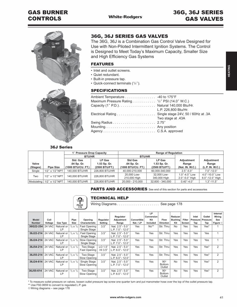
21M51U-843 KitIncludes: •Module•HotRod Ignitor Kit
Model Number Pre-Purge
Ignitor Warm-Up Retries
Heat Delay to Fan ON
Heat Delay to Fan OFF
Cool Delay to Fan ON
Cool Delay to Fan OFF
AutomaticResetTime
21M51U-843 15 17 2 45 90/120/150/180 5 60 60 minutes
?PAGES179–180
21M51U-843 UNIVERSAL INTEGRATED HSI FURNACE CONTROL KIT Replaces White-Rodgers 50M51-242 and 50M61-XXX's Two-Stage HSI Systems with 80V or 120V Ignitors
FEATURES
•120VAC3-speedPSC(PermanentSplitCapacitor)circulatoroutput,two-speed inducer output, two-stage gas valve output.•Pushbuttonfaulthistoryretrieval.•FurnacestatusLED–tri-color(green,redandamber).•Heatfanoffdelay(dipswitchselectable),fanondelayforcooling.•Autosecondstagedelay(dipswitchselectable).•120VAChumidifieroutput/120VACelectronicaircleaneroutput.
SPECIFICATIONS
Electrical Rating:Input Voltage. . . . . . . . . . . . . . . . . . . . 24 VAC, 60 Hz (Class II transformer required)Nom. Input Current @ 24 VAC . . . . . . 530mA+MVRelay Load Ratings:Gas Valve Relays . . . . . . . . . . . . . . . . 1.5 amps @ 24 VAC, 60 HzInducer Relays . . . . . . . . . . . . . . . . . . 2.2 FLA – 3.5 LRA @ 120 VACCirculator Relays . . . . . . . . . . . . . . . . 14.5 FLA – 25.0 LRA @ 120 VACHumidifierLoad . . . . . . . . . . . . . . . . . 1.0 amp max. @ 120 VACElectronic Air Cleaner Load . . . . . . . . 1.0 amp max. @ 120 VACIgnitor Relay . . . . . . . . . . . . . . . . . . . . 4.0 amps max. @ 132 VAC, 60 HzFlame Current Requirements:Minimumcurrenttoinsureflamedetection 0.3 µa DC*Maximum current for non-detection . . 0.1 µa DC*Maximumallowableleakageresistance100Mohms*Measured with a DC microameter in the flame probe leadOperating Temperature Range . . . . . . -40o to 175oF (-40 to 80oC)Humidity Range . . . . . . . . . . . . . . . . . 5% to 93% relative humidity (non-condensing)Flame Failure Response Time . . . . . . 2.0 sec. max. @ 60Hz
TECHNICAL HELP
Wiring Diagram/Operation . . . . . . . . . . . . . . See pages 179–180
TWO-STAGE INTEGRATED 3-SPEED (PSC)
HSI FURNACE CONTROLUNIVERSAL REPLACEMENT
www.white-rodgers.com 45
HEA
TIN
G
Model Number Pre-Purge
Ignitor Warm-Up Retries
Heat Delay to Fan ON
Heat Delay to Fan OFF
Cool Delay to Fan ON
Cool Delay to Fan OFF
AutomaticResetTime
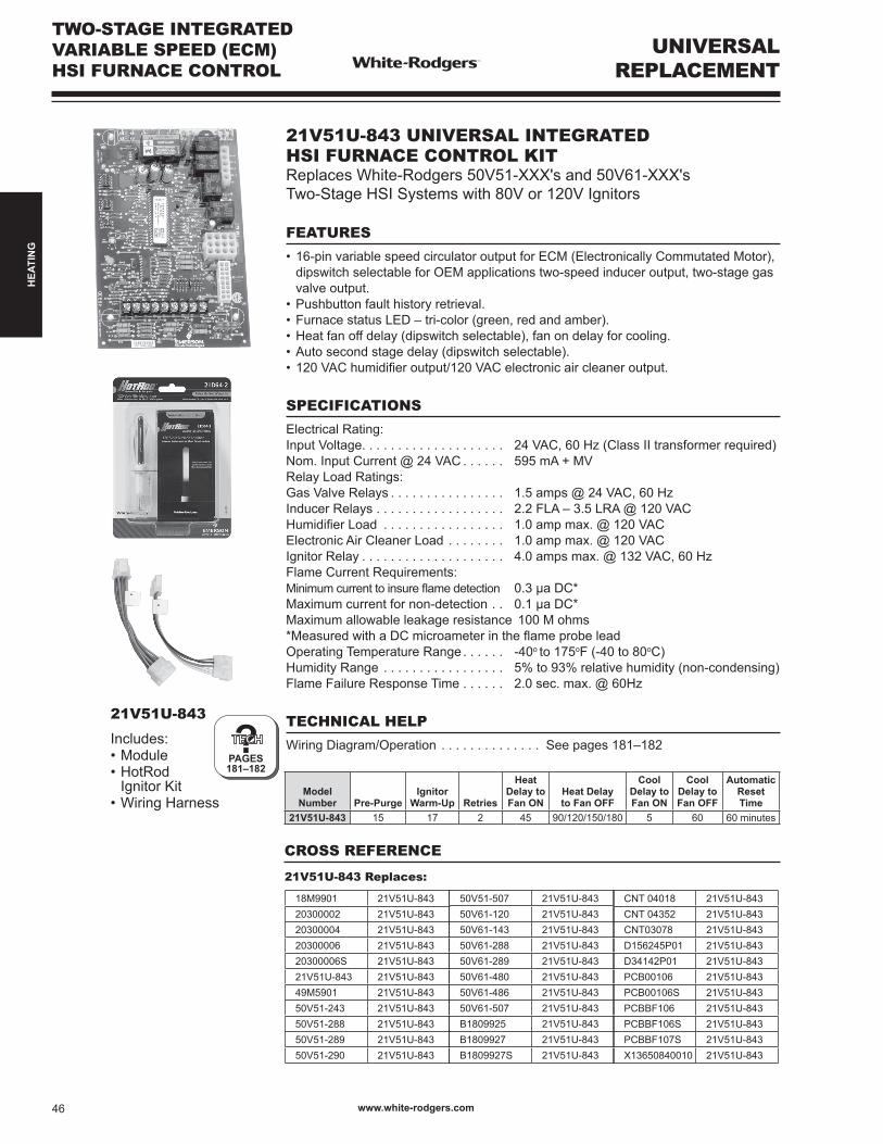
21V51U-843 15 17 2 45 90/120/150/180 5 60 60 minutes
?PAGES181–182
21V51U-843
Includes: •Module•HotRod Ignitor Kit•WiringHarness
21V51U-843 UNIVERSAL INTEGRATED HSI FURNACE CONTROL KIT Replaces White-Rodgers 50V51-XXX's and 50V61-XXX's Two-Stage HSI Systems with 80V or 120V Ignitors
FEATURES
•16-pinvariablespeedcirculatoroutputforECM(ElectronicallyCommutatedMotor), dipswitch selectable for OEM applications two-speed inducer output, two-stage gas valve output.•Pushbuttonfaulthistoryretrieval.•FurnacestatusLED–tri-color(green,redandamber).•Heatfanoffdelay(dipswitchselectable),fanondelayforcooling.•Autosecondstagedelay(dipswitchselectable).•120VAChumidifieroutput/120VACelectronicaircleaneroutput.
SPECIFICATIONS
Electrical Rating: Input Voltage. . . . . . . . . . . . . . . . . . . . 24 VAC, 60 Hz (Class II transformer required)Nom. Input Current @ 24 VAC . . . . . . 595mA+MVRelay Load Ratings:Gas Valve Relays . . . . . . . . . . . . . . . . 1.5 amps @ 24 VAC, 60 HzInducer Relays . . . . . . . . . . . . . . . . . . 2.2 FLA – 3.5 LRA @ 120 VACHumidifierLoad . . . . . . . . . . . . . . . . . 1.0 amp max. @ 120 VACElectronic Air Cleaner Load . . . . . . . . 1.0 amp max. @ 120 VACIgnitor Relay . . . . . . . . . . . . . . . . . . . . 4.0 amps max. @ 132 VAC, 60 HzFlame Current Requirements:Minimumcurrenttoinsureflamedetection 0.3 µa DC*Maximum current for non-detection . . 0.1 µa DC*Maximumallowableleakageresistance100Mohms*Measured with a DC microameter in the flame probe leadOperating Temperature Range . . . . . . -40o to 175oF (-40 to 80oC)Humidity Range . . . . . . . . . . . . . . . . . 5% to 93% relative humidity (non-condensing)Flame Failure Response Time . . . . . . 2.0 sec. max. @ 60Hz
TECHNICAL HELP
Wiring Diagram/Operation . . . . . . . . . . . . . . See pages 181–182
UNIVERSALREPLACEMENT
TWO-STAGE INTEGRATED VARIABLE SPEED (ECM) HSI FURNACE CONTROL
CROSS REFERENCE
18M9901 21V51U-84320300002 21V51U-84320300004 21V51U-84320300006 21V51U-84320300006S 21V51U-84321V51U-843 21V51U-84349M5901 21V51U-84350V51-243 21V51U-84350V51-288 21V51U-84350V51-289 21V51U-84350V51-290 21V51U-843
50V51-507 21V51U-84350V61-120 21V51U-84350V61-143 21V51U-84350V61-288 21V51U-84350V61-289 21V51U-84350V61-480 21V51U-84350V61-486 21V51U-84350V61-507 21V51U-843B1809925 21V51U-843B1809927 21V51U-843B1809927S 21V51U-843
CNT 04018 21V51U-843CNT 04352 21V51U-843CNT03078 21V51U-843D156245P01 21V51U-843D34142P01 21V51U-843PCB00106 21V51U-843PCB00106S 21V51U-843PCBBF106 21V51U-843PCBBF106S 21V51U-843PCBBF107S 21V51U-843X13650840010 21V51U-843
21V51U-843 Replaces:
www.white-rodgers.com46
HEA
TIN
G
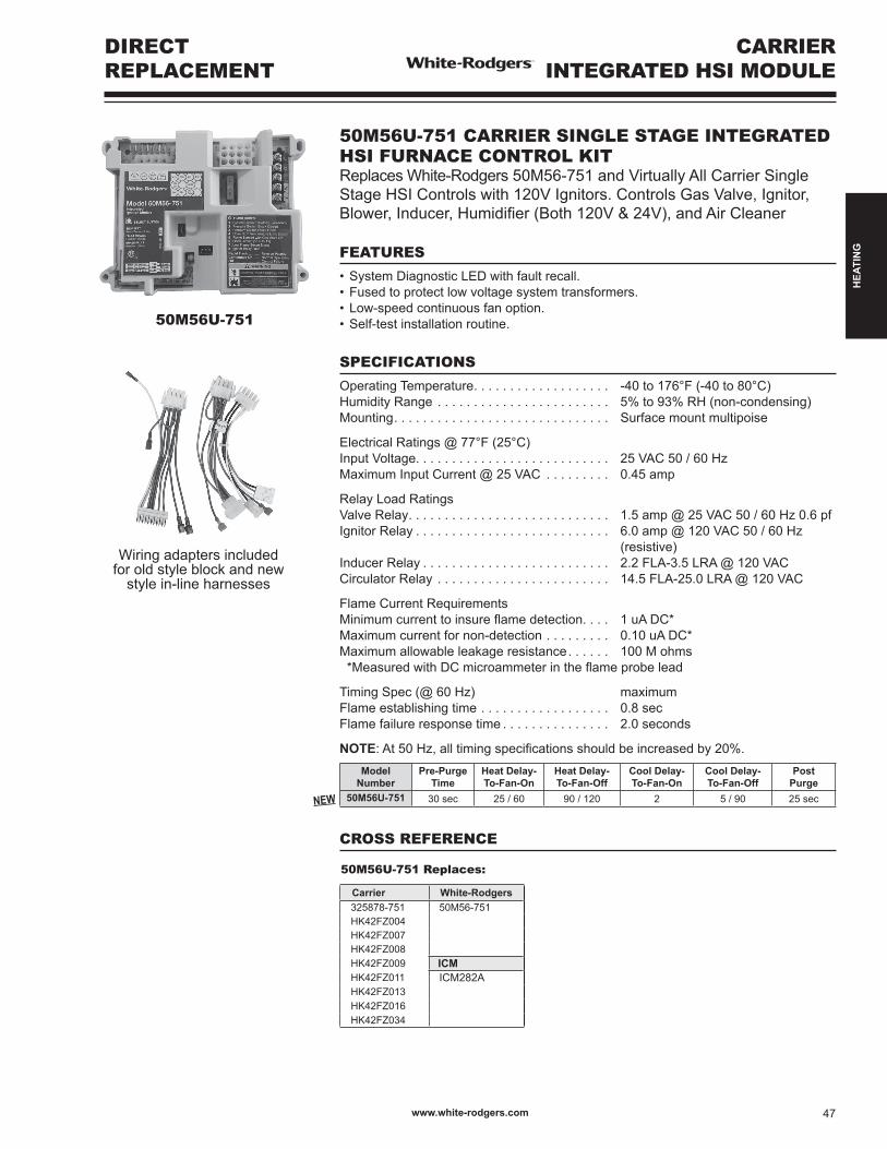
Wiring adapters included foroldstyleblockandnew
style in-line harnesses
50M56U-751 Replaces:
Carrier White-Rodgers325878-751 50M56-751HK42FZ004HK42FZ007HK42FZ008HK42FZ009 ICMHK42FZ011 ICM282AHK42FZ013HK42FZ016HK42FZ034
CARRIERINTEGRATED HSI MODULE
DIRECT REPLACEMENT
50M56U-751
CROSS REFERENCE
Model Number
Pre-Purge Time
Heat Delay-To-Fan-On
Heat Delay- To-Fan-Off
Cool Delay- To-Fan-On
Cool Delay- To-Fan-Off
Post Purge
50M56U-751 30 sec 25 / 60 90 / 120 2 5 / 90 25 sec
50M56U-751 CARRIER SINGLE STAGE INTEGRATED HSI FURNACE CONTROL KIT Replaces White-Rodgers 50M56-751 and Virtually All Carrier Single Stage HSI Controls with 120V Ignitors. Controls Gas Valve, Ignitor, Blower,Inducer,Humidifier(Both120V&24V),andAirCleaner
FEATURES
•SystemDiagnosticLEDwithfaultrecall.•Fusedtoprotectlowvoltagesystemtransformers.•Low-speedcontinuousfanoption.•Self-testinstallationroutine.
SPECIFICATIONS
Operating Temperature. . . . . . . . . . . . . . . . . . . -40 to 176°F (-40 to 80°C)Humidity Range . . . . . . . . . . . . . . . . . . . . . . . . 5% to 93% RH (non-condensing)Mounting. . . . . . . . . . . . . . . . . . . . . . . . . . . . . . Surface mount multipoise
Electrical Ratings @ 77°F (25°C)Input Voltage. . . . . . . . . . . . . . . . . . . . . . . . . . . 25 VAC 50 / 60 HzMaximum Input Current @ 25 VAC . . . . . . . . . 0.45 amp
Relay Load RatingsValve Relay. . . . . . . . . . . . . . . . . . . . . . . . . . . . 1.5 amp @ 25 VAC 50 / 60 Hz 0.6 pfIgnitor Relay . . . . . . . . . . . . . . . . . . . . . . . . . . . 6.0 amp @ 120 VAC 50 / 60 Hz (resistive)Inducer Relay . . . . . . . . . . . . . . . . . . . . . . . . . . 2.2 FLA-3.5 LRA @ 120 VACCirculator Relay . . . . . . . . . . . . . . . . . . . . . . . . 14.5 FLA-25.0 LRA @ 120 VAC
Flame Current RequirementsMinimumcurrenttoinsureflamedetection. . . . 1 uA DC*Maximum current for non-detection . . . . . . . . . 0.10 uA DC*Maximumallowableleakageresistance . . . . . . 100 M ohms*MeasuredwithDCmicroammeterintheflameprobelead
Timing Spec (@ 60 Hz) maximumFlame establishing time . . . . . . . . . . . . . . . . . . 0.8 sec Flame failure response time . . . . . . . . . . . . . . . 2.0 seconds
NOTE:At50Hz,alltimingspecificationsshouldbeincreasedby20%.
New
www.white-rodgers.com 47
HEA
TIN
G
GOODMAN INTEGRATED HSI MODULE
DIRECT REPLACEMENT
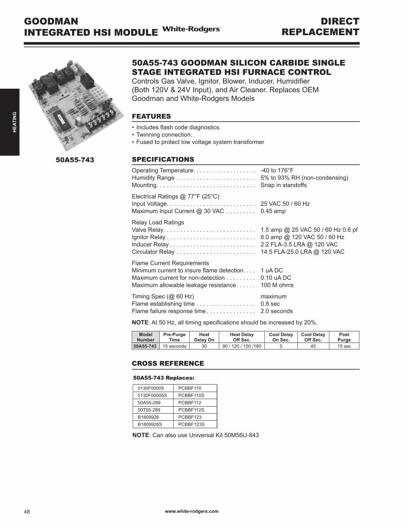
50A55-743
50A55-743 GOODMAN SILICON CARBIDE SINGLE STAGE INTEGRATED HSI FURNACE CONTROLControlsGasValve,Ignitor,Blower,Inducer,Humidifier(Both 120V & 24V Input), and Air Cleaner. Replaces OEM Goodman and White-Rodgers Models
FEATURES
• Includesflashcodediagnostics.•Twinningconnection.•Fusedtoprotectlowvoltagesystemtransformer
SPECIFICATIONS
Operating Temperature. . . . . . . . . . . . . . . . . . . -40 to 176°FHumidity Range . . . . . . . . . . . . . . . . . . . . . . . . 5% to 93% RH (non-condensing)Mounting. . . . . . . . . . . . . . . . . . . . . . . . . . . . . . Snap in standoffs
Electrical Ratings @ 77°F (25°C)Input Voltage. . . . . . . . . . . . . . . . . . . . . . . . . . . 25 VAC 50 / 60 HzMaximum Input Current @ 30 VAC . . . . . . . . . 0.45 amp
Relay Load RatingsValve Relay. . . . . . . . . . . . . . . . . . . . . . . . . . . . 1.5 amp @ 25 VAC 50 / 60 Hz 0.6 pfIgnitor Relay . . . . . . . . . . . . . . . . . . . . . . . . . . . 6.0 amp @ 120 VAC 50 / 60 HzInducer Relay . . . . . . . . . . . . . . . . . . . . . . . . . . 2.2 FLA-3.5 LRA @ 120 VACCirculator Relay . . . . . . . . . . . . . . . . . . . . . . . . 14.5 FLA-25.0 LRA @ 120 VAC
Flame Current RequirementsMinimumcurrenttoinsureflamedetection. . . . 1 uA DCMaximum current for non-detection . . . . . . . . . 0.10 uA DCMaximumallowableleakageresistance . . . . . . 100 M ohms
Timing Spec (@ 60 Hz) maximumFlame establishing time . . . . . . . . . . . . . . . . . . 0.8 sec Flame failure response time . . . . . . . . . . . . . . . 2.0 seconds
NOTE:At50Hz,alltimingspecificationsshouldbeincreasedby20%.
Model Number
Pre-PurgeTime
HeatDelay On
Heat DelayOff Sec.
Cool DelayOn Sec.
Cool DelayOff Sec.
PostPurge
50A55-743 15 seconds 30 90 / 120 / 150 /180 5 45 15 sec
50A55-743 Replaces:
0130F00005 PCBBF1100130F00005S PCBBF110S50A55-289 PCBBF11250T55-289 PCBBF112SB1809926 PCBBF123B1809926S PCBBF123S
CROSS REFERENCE
NOTE: Can also use Universal Kit 50M56U-843
www.white-rodgers.com48
HEA
TIN
G

50T35-743 Replaces:
Goodman White-RodgersB18099-06 50T35-730B18099-08 50T35-730-1B18099-10B18099-13B18099-13SCNT04664
CROSS REFERENCE
GOODMAN INTEGRATED HSI MODULE
DIRECTREPLACEMENT
50T35-743
50T35-743 GOODMAN SILICON CARBIDE INTEGRATED HSI FURNACE CONTROLControls Gas Valve, Ignitor, Two-Speed Blower Motor, Inducer, Humidifier(Both120v&24vInput),andAirCleaner.ReplacesOEMGoodman, UTEC and TI Models
FEATURES
• Includesflashcodediagnostics.•Twinning.• Includesmountingholetemplate.•Fusedtoprotectlowvoltagesystemtransformers.•Adjustableblowerrelay.•90+furnaceoption.
SPECIFICATIONS
Operating Temperature. . . . . . . . . . . . . . . . . . . -40 to 176°FHumidity Range . . . . . . . . . . . . . . . . . . . . . . . . 95% RH (non-condensing)Mounting. . . . . . . . . . . . . . . . . . . . . . . . . . . . . . Plastic standoffs
Electrical Ratings @ 77°F (25°C)Input Voltage. . . . . . . . . . . . . . . . . . . . . . . . . . . 20-30 VAC RMS 50 / 60 HzMaximum Input Current @ 30 VAC . . . . . . . . . 0.35 amp
Relay Load RatingsValve Relay. . . . . . . . . . . . . . . . . . . . . . . . . . . . 1.5 amp @ 30 VAC 50 / 60 Hz 0.6 pfIgnitor Relay . . . . . . . . . . . . . . . . . . . . . . . . . . . 5.0 amp @ 120 VAC 50 / 60 HzInducer Relay . . . . . . . . . . . . . . . . . . . . . . . . . . 4.0 FLA-8.0 LRA @ 120 VACCirculator Relay . . . . . . . . . . . . . . . . . . . . . . . . 14.5 FLA-25.0 LRA @ 120 VAC
Flame Current RequirementsMinimumcurrenttoinsureflamedetection. . . . 75 uA DCMaximum current for non-detection . . . . . . . . . 0.10 uA DCMaximumallowableleakageresistance . . . . . . 100 M ohms
Timing Spec @ 60 HzFlame establishing time . . . . . . . . . . . . . . . . . . n/aFlame failure response time . . . . . . . . . . . . . . . 2.0 seconds maximum
NOTE:At50Hz,alltimingspecificationsshouldbeincreasedby20%.
Model Number
Pre-PurgeTime
Heat Delay On
Heat DelayOff Sec.
Cool DelayOn Sec.
Cool DelayOff Sec.
PostPurge
50T35-743 15 seconds 30 90 / 120 / 150 5 60 25sec(29w/90+)
www.white-rodgers.com 49
HEA
TIN
G
GOODMAN MULTI-SPEED INTEGRATED HSI MODULE
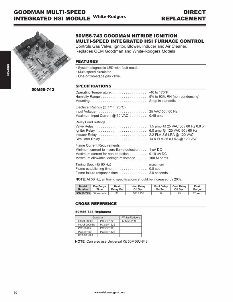
50M56-743
50M56-743 GOODMAN NITRIDE IGNITION MULTI-SPEED INTEGRATED HSI FURNACE CONTROLControls Gas Valve, Ignitor, Blower, Inducer and Air Cleaner. Replaces OEM Goodman and White-Rodgers Models
FEATURES
•SystemdiagnosticLEDwithfaultrecall.•Multi-speedcirculator.•Oneortwo-stagegasvalve.
SPECIFICATIONS
Operating Temperature. . . . . . . . . . . . . . . . . . . -40 to 176°FHumidity Range . . . . . . . . . . . . . . . . . . . . . . . . 5% to 93% RH (non-condensing)Mounting. . . . . . . . . . . . . . . . . . . . . . . . . . . . . . Snap in standoffs
Electrical Ratings @ 77°F (25°C)Input Voltage. . . . . . . . . . . . . . . . . . . . . . . . . . . 25 VAC 50 / 60 HzMaximum Input Current @ 30 VAC . . . . . . . . . 0.45 amp
Relay Load RatingsValve Relay. . . . . . . . . . . . . . . . . . . . . . . . . . . . 1.5 amp @ 25 VAC 50 / 60 Hz 0.6 pfIgnitor Relay . . . . . . . . . . . . . . . . . . . . . . . . . . . 6.0 amp @ 120 VAC 50 / 60 HzInducer Relay . . . . . . . . . . . . . . . . . . . . . . . . . . 2.2 FLA-3.5 LRA @ 120 VACCirculator Relay . . . . . . . . . . . . . . . . . . . . . . . . 14.5 FLA-25.0 LRA @ 120 VAC
Flame Current RequirementsMinimumcurrenttoinsureflamedetection. . . . 1 uA DCMaximum current for non-detection . . . . . . . . . 0.10 uA DCMaximumallowableleakageresistance . . . . . . 100 M ohms
Timing Spec (@ 60 Hz) maximumFlame establishing time . . . . . . . . . . . . . . . . . . 0.8 sec Flame failure response time . . . . . . . . . . . . . . . 2.0 seconds
NOTE:At50Hz,alltimingspecificationsshouldbeincreasedby20%.
Model Number
Pre-PurgeTime
Heat Delay On
Heat DelayOff Sec.
Cool DelayOn Sec.
Cool DelayOff Sec.
PostPurge
50M56-743 30 seconds 30 100 / 150 6 45 25 sec
DIRECT REPLACEMENT
CROSS REFERENCE
NOTE: Can also use Universal Kit 50M56U-843
50M56-743 Replaces:
Goodman White-Rodgers0130F00006 PCBBF122 50M56-2890130F00006S PCBBF122SPCB00109 PCBBF132PCBBF109 PCBBF132SPCBBF109S
www.white-rodgers.com50
HEA
TIN
G
DIRECT REPLACEMENT
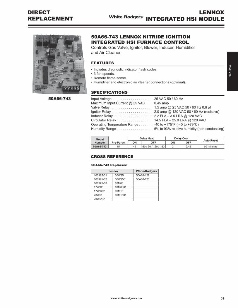
50A66-743
50A66-743 LENNOX NITRIDE IGNITION INTEGRATED HSI FURNACE CONTROLControlsGasValve,Ignitor,Blower,Inducer,Humidifier and Air Cleaner
FEATURES
• Includesdiagnosticindicatorflashcodes.•3fanspeeds.•Remoteflamesense.•Humidifierandelectronicaircleanerconnections(optional).
SPECIFICATIONS
Input Voltage. . . . . . . . . . . . . . . . . . . . . 25 VAC 50 / 60 HzMaximum Input Current @ 25 VAC . . . 0.45 ampValve Relay. . . . . . . . . . . . . . . . . . . . . . 1.5 amp @ 25 VAC 50 / 60 Hz 0.6 pfIgnitor Relay . . . . . . . . . . . . . . . . . . . . . 2.0 amp @ 120 VAC 50 / 60 Hz (resistive)Inducer Relay . . . . . . . . . . . . . . . . . . . . 2.2 FLA – 3.5 LRA @ 120 VACCirculator Relay . . . . . . . . . . . . . . . . . . 14.5 FLA – 25.0 LRA @ 120 VACOperating Temperature Range . . . . . . . -40to+175°F(-40to+79°C)Humidity Range . . . . . . . . . . . . . . . . . . 5% to 93% relative humidity (non-condensing)
Model Number Pre-Purge
Delay Heat Delay CoolAuto Reset
ON OFF ON OFF50A66-743 15 45 60 / 90 / 120 / 180 2 2/45 60 minutes
50A66-743 Replaces:
Lennox White-Rodgers100925-01 30W25 50A66-122100925-02 30W2501 50A66-123100925-03 69M0817W92 69M080117W9201 69M1523W51 69M150123W5101
CROSS REFERENCE
LENNOX INTEGRATED HSI MODULE
www.white-rodgers.com 51
HEA
TIN
G
DIRECTREPLACEMENT
LENNOX INTEGRATED HSI MODULE
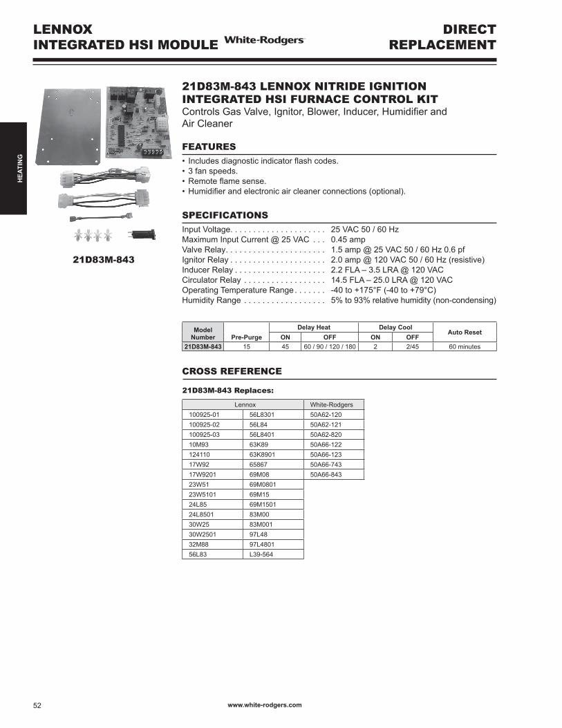
21D83M-843 LENNOX NITRIDE IGNITION INTEGRATED HSI FURNACE CONTROL KITControlsGasValve,Ignitor,Blower,Inducer,Humidifierand Air Cleaner
FEATURES• Includesdiagnosticindicatorflashcodes.•3fanspeeds.•Remoteflamesense.•Humidifierandelectronicaircleanerconnections(optional).
SPECIFICATIONSInput Voltage. . . . . . . . . . . . . . . . . . . . . 25 VAC 50 / 60 HzMaximum Input Current @ 25 VAC . . . 0.45 ampValve Relay. . . . . . . . . . . . . . . . . . . . . . 1.5 amp @ 25 VAC 50 / 60 Hz 0.6 pfIgnitor Relay . . . . . . . . . . . . . . . . . . . . . 2.0 amp @ 120 VAC 50 / 60 Hz (resistive)Inducer Relay . . . . . . . . . . . . . . . . . . . . 2.2 FLA – 3.5 LRA @ 120 VACCirculator Relay . . . . . . . . . . . . . . . . . . 14.5 FLA – 25.0 LRA @ 120 VACOperating Temperature Range . . . . . . . -40to+175°F(-40to+79°C)Humidity Range . . . . . . . . . . . . . . . . . . 5% to 93% relative humidity (non-condensing)
21D83M-843
Model Number Pre-Purge
Delay Heat Delay CoolAuto Reset
ON OFF ON OFF21D83M-843 15 45 60 / 90 / 120 / 180 2 2/45 60 minutes
CROSS REFERENCE
21D83M-843 Replaces:
Lennox White-Rodgers100925-01 56L8301 50A62-120100925-02 56L84 50A62-121100925-03 56L8401 50A62-82010M93 63K89 50A66-122124110 63K8901 50A66-12317W92 65867 50A66-74317W9201 69M08 50A66-84323W51 69M080123W5101 69M1524L85 69M150124L8501 83M0030W25 83M00130W2501 97L4832M88 97L480156L83 L39-564
www.white-rodgers.com52
HEA
TIN
G

50A55-3797 Replaces:
Trane White-RodgersCNT02789 50A55-474CNT02891 50A55-476CNT03799 50A55-571D341122P01D341235P01D341235P03
TRANE INTEGRATED HSI MODULE
DIRECT REPLACEMENT
50A55-3797
CROSS REFERENCE
Model Number
Pre-Purge Time
Heat Delay-To-Fan-On
Heat Delay- To-Fan-Off
Cool Delay- To-Fan-On
Cool Delay- To-Fan-Off
Post Purge
50A55-3797 0 sec 45 60 / 100 / 140 / 180 2 0 / 180 5 sec
50A55-3797 TRANE SINGLE STAGE 120V IGNITION INTEGRATED HSI FURNACE CONTROLControlsGasValve,Ignitor,Blower,Inducer,Humidifier(120V),and Air Cleaner. Replaces OEM Trane and White-Rodgers Models
FEATURES
• Includesflashcodediagnostics.•Fusedtoprotectlowvoltagesystemtransformers.
SPECIFICATIONS
Operating Temperature. . . . . . . . . . . . . . . . . . . -40 to 176°FHumidity Range . . . . . . . . . . . . . . . . . . . . . . . . 5% to 93% RH (non-condensing)Mounting. . . . . . . . . . . . . . . . . . . . . . . . . . . . . . Snap in standoffs
Electrical Ratings @ 77°F (25°C)Input Voltage. . . . . . . . . . . . . . . . . . . . . . . . . . . 25 VAC 50 / 60 HzMaximum Input Current @ 30 VAC . . . . . . . . . 0.45 amp
Relay Load RatingsValve Relay. . . . . . . . . . . . . . . . . . . . . . . . . . . . 1.5 amp @ 25 VAC 50 / 60 Hz 0.6 pfIgnitor Relay . . . . . . . . . . . . . . . . . . . . . . . . . . . 6.0 amp @ 120 VAC 50 / 60 HzInducer Relay . . . . . . . . . . . . . . . . . . . . . . . . . . 2.2 FLA-3.5 LRA @ 120 VACCirculator Relay . . . . . . . . . . . . . . . . . . . . . . . . 14.5 FLA-25.0 LRA @ 120 VAC
Flame Current RequirementsMinimumcurrenttoinsureflamedetection. . . . 1 uA DCMaximum current for non-detection . . . . . . . . . 0.10 uA DCMaximumallowableleakageresistance . . . . . . 100 M ohms
Timing Spec (@ 60 Hz) maximumFlame establishing time . . . . . . . . . . . . . . . . . . 0.8 sec Flame failure response time . . . . . . . . . . . . . . . 2.0 seconds
NOTE:At50Hz,alltimingspecificationsshouldbeincreasedby20%.
NOTE: Can also use Universal Kit 50M56U-843
New
www.white-rodgers.com 53
HEA
TIN
G

50A55-5165 Replaces:
Trane White-RodgersCNT03076 50A65-474CNT03798 50A65-475CNT05164 50A65-476CNT05165D341213P01D341396P01D341396P03D341396P04D341396P05
TRANE INTEGRATED HSI MODULE
DIRECT REPLACEMENT
CROSS REFERENCE
Model Number
Pre-Purge Time
Heat Delay-To-Fan-On
Heat Delay- To-Fan-Off
Cool Delay- To-Fan-On
Cool Delay- To-Fan-Off
Post Purge
50A65-5165 0 sec 45 60 / 100 / 140 / 180 2 0 / 80 5 sec
50A65-5165 TRANE SINGLE STAGE 80V IGNITION INTEGRATED HSI FURNACE CONTROLControlsGasValve,Ignitor,Blower,Inducer,Humidifier(120V),and Air Cleaner. Replaces OEM Trane and White-Rodgers Models
FEATURES
• Includesflashcodediagnostics.•Twinningconnection.•Fusedtoprotectlowvoltagesystemtransformers.
SPECIFICATIONS
Operating Temperature. . . . . . . . . . . . . . . . . . . -40 to 176°FHumidity Range . . . . . . . . . . . . . . . . . . . . . . . . 5% to 93% RH (non-condensing)Mounting. . . . . . . . . . . . . . . . . . . . . . . . . . . . . . Snap in standoffs
Electrical Ratings @ 77°F (25°C)Input Voltage. . . . . . . . . . . . . . . . . . . . . . . . . . . 25 VAC 50 / 60 HzMaximum Input Current @ 30 VAC . . . . . . . . . 0.45 amp
Relay Load RatingsValve Relay. . . . . . . . . . . . . . . . . . . . . . . . . . . . 1.5 amp @ 25 VAC 50 / 60 Hz 0.6 pfIgnitor Relay . . . . . . . . . . . . . . . . . . . . . . . . . . . 2.0 amp @ 120 VAC 50 / 60 HzInducer Relay . . . . . . . . . . . . . . . . . . . . . . . . . . 2.2 FLA-3.5 LRA @ 120 VACCirculator Relay . . . . . . . . . . . . . . . . . . . . . . . . 14.5 FLA-25.0 LRA @ 120 VAC
Flame Current RequirementsMinimumcurrenttoinsureflamedetection. . . . 1 uA DCMaximum current for non-detection . . . . . . . . . 0.10 uA DCMaximumallowableleakageresistance . . . . . . 100 M ohms
Timing Spec (@ 60 Hz) maximumFlame establishing time . . . . . . . . . . . . . . . . . . 0.8 sec Flame failure response time . . . . . . . . . . . . . . . 2.0 seconds
NOTE:At50Hz,alltimingspecificationsshouldbeincreasedby20%.
NOTE: Can also use Universal Kit 50M56U-843
50A55-5165
New
www.white-rodgers.com54
HEA
TIN
G

YORK INTEGRATED HSI MODULE
DIRECTREPLACEMENT
50A56-956
50A56-956 Replaces:
York White-Rodgers265901 S1-03101284000 50A56-242265902 S1-03101933000 50A56-243S1-03100662000 S1-03101972000 ICMS1-03101250000 S1-03101973000 ICM2808S1-03101266000 S1-03109167000 (PCB Only)S1-03101267000 S1-33102956000S1-03101267001 S1-33103010000
CROSS REFERENCE
Model Number
Pre-Purge Time
Heat Delay-To-Fan-On
Heat Delay- To-Fan-Off
Cool Delay- To-Fan-On
Cool Delay- To-Fan-Off
Post Purge
50A56-956 0 sec 30 60 / 90 / 120 / 180 0 60 15 sec
50A56-956 YORK SINGLE STAGE INTEGRATED HSI FURNACE CONTROL KITControlsGasValve,Ignitor,Blower,Inducer,Humidifier(120V),andAirCleaner.ReplacesOEMYorkandWhite-RodgersModels
FEATURES
•SystemDiagnosticsLEDwithfaultrecall.•Twinningconnection.•Fusedtoprotectlowvoltagesystemtransformers.•Selectablecontinuousfanspeed.•Thirdfanspeed.•Two-stagecoolingY2input.
SPECIFICATIONS
Operating Temperature. . . . . . . . . . . . . . . . . . . -40 to 176°FHumidity Range . . . . . . . . . . . . . . . . . . . . . . . . 5% to 93% RH (non-condensing)Mounting. . . . . . . . . . . . . . . . . . . . . . . . . . . . . . Snap in standoffs
Electrical Ratings @ 77°F (25°C)Input Voltage. . . . . . . . . . . . . . . . . . . . . . . . . . . 25 VAC 50 / 60 HzMaximum Input Current @ 30 VAC . . . . . . . . . 0.45 amp
Relay Load RatingsValve Relay. . . . . . . . . . . . . . . . . . . . . . . . . . . . 1.5 amp @ 25 VAC 50 / 60 Hz 0.6 pfIgnitor Relay . . . . . . . . . . . . . . . . . . . . . . . . . . . 6.0 amp @ 120 VAC 50 / 60 HzInducer Relay . . . . . . . . . . . . . . . . . . . . . . . . . . 2.2 FLA-3.5 LRA @ 120 VACCirculator Relay . . . . . . . . . . . . . . . . . . . . . . . . 14.5 FLA-25.0 LRA @ 120 VAC
Flame Current RequirementsMinimumcurrenttoinsureflamedetection. . . . 1 uA DCMaximum current for non-detection . . . . . . . . . 0.10 uA DCMaximumallowableleakageresistance . . . . . . 100 M ohms
Timing Spec (@ 60 Hz) maximumFlame establishing time . . . . . . . . . . . . . . . . . . 0.8 sec Flame failure response time . . . . . . . . . . . . . . . 2.0 seconds
NOTE:At50Hz,alltimingspecificationsshouldbeincreasedby20%.
NOTE: Can also use Universal Kit 50M56U-843
New
www.white-rodgers.com 55
HEA
TIN
G
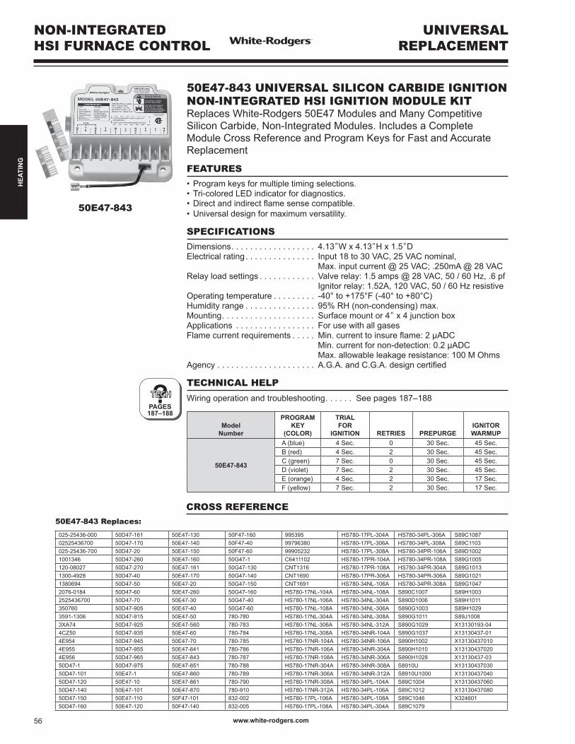
50E47-843
NON-INTEGRATED HSI FURNACE CONTROL
UNIVERSALREPLACEMENT
?PAGES187–188
50E47-843 UNIVERSAL SILICON CARBIDE IGNITION NON-INTEGRATED HSI IGNITION MODULE KITReplaces White-Rodgers 50E47 Modules and Many Competitive Silicon Carbide, Non-Integrated Modules. Includes a Complete Module Cross Reference and Program Keys for Fast and Accurate Replacement
FEATURES•Programkeysformultipletimingselections.•Tri-coloredLEDindicatorfordiagnostics.•Directandindirectflamesensecompatible.•Universaldesignformaximumversatility.
SPECIFICATIONSDimensions. . . . . . . . . . . . . . . . . . 4.13”W x 4.13”H x 1.5”DElectrical rating. . . . . . . . . . . . . . . Input 18 to 30 VAC, 25 VAC nominal, Max. input current @ 25 VAC; .250mA @ 28 VACRelay load settings . . . . . . . . . . . . Valve relay: 1.5 amps @ 28 VAC, 50 / 60 Hz, .6 pf Ignitor relay: 1.52A, 120 VAC, 50 / 60 Hz resistiveOperating temperature . . . . . . . . . -40°to+175°F(-40°to+80°C)Humidity range . . . . . . . . . . . . . . . 95% RH (non-condensing) max.Mounting. . . . . . . . . . . . . . . . . . . . Surface mount or 4” x 4 junction boxApplications . . . . . . . . . . . . . . . . . For use with all gasesFlame current requirements . . . . . Min.currenttoinsureflame:2µADC Min. current for non-detection: 0.2 µADC Max.allowableleakageresistance:100MOhmsAgency . . . . . . . . . . . . . . . . . . . . . A.G.A.andC.G.A.designcertified
TECHNICAL HELP
Wiring operation and troubleshooting. . . . . . See pages 187–188
Model Number
PROGRAMKEY
(COLOR)
TRIALFOR
IGNITION RETRIES PREPURGEIGNITORWARMUP
50E47-843
A (blue) 4 Sec. 0 30 Sec. 45 Sec.B (red) 4 Sec. 2 30 Sec. 45 Sec.C (green) 7 Sec. 0 30 Sec. 45 Sec.D (violet) 7 Sec. 2 30 Sec. 45 Sec.E (orange) 4 Sec. 2 30 Sec. 17 Sec.F (yellow) 7 Sec. 2 30 Sec. 17 Sec.
50E47-843 Replaces:
025-25436-000 50D47-161 50E47-130 50F47-160 995395 HS780-17PL-304A HS780-34PL-306A S89C108702525436700 50D47-170 50E47-140 50F47-40 99796380 HS780-17PL-306A HS780-34PL-308A S89C1103025-25436-700 50D47-20 50E47-150 50F47-60 99905232 HS780-17PL-308A HS780-34PR-106A S89D10021001346 50D47-260 50E47-160 50G47-1 C6411102 HS780-17PR-104A HS780-34PR-108A S89G1005120-08027 50D47-270 50E47-161 50G47-130 CNT1316 HS780-17PR-108A HS780-34PR-304A S89G10131300-4928 50D47-40 50E47-170 50G47-140 CNT1690 HS780-17PR-306A HS780-34PR-306A S89G10211380694 50D47-50 50E47-20 50G47-150 CNT1691 HS780-34NL-106A HS780-34PR-308A S89G10472076-0184 50D47-60 50E47-260 50G47-160 HS780-17NL-104A HS780-34NL-108A S890C1007 S89H10032525436700 50D47-70 50E47-30 50G47-40 HS780-17NL-106A HS780-34NL-304A S890D1006 S89H1011350760 50D47-905 50E47-40 50G47-60 HS780-17NL-108A HS780-34NL-306A S890G1003 S89H10293591-1306 50D47-915 50E47-50 780-780 HS780-17NL-304A HS780-34NL-308A S890G1011 S89J10083XA74 50D47-925 50E47-560 780-783 HS780-17NL-306A HS780-34NL-312A S890G1029 X13130193-044CZ50 50D47-935 50E47-60 780-784 HS780-17NL-308A HS780-34NR-104A S890G1037 X13130437-014E954 50D47-945 50E47-70 780-785 HS780-17NR-104A HS780-34NR-106A S890H1002 X131304370104E955 50D47-955 50E47-841 780-786 HS780-17NR-106A HS780-34NR-304A S890H1010 X131304370204E956 50D47-965 50E47-843 780-787 HS780-17NR-108A HS780-34NR-306A S890H1028 X13130437-0350D47-1 50D47-975 50E47-851 780-788 HS780-17NR-304A HS780-34NR-308A S8910U X1313043703050D47-101 50E47-1 50E47-860 780-789 HS780-17NR-306A HS780-34NR-312A S8910U1000 X1313043704050D47-120 50E47-10 50E47-861 780-790 HS780-17NR-308A HS780-34PL-104A S89C1004 X1313043706050D47-140 50E47-101 50E47-870 780-910 HS780-17NR-312A HS780-34PL-106A S89C1012 X1313043708050D47-150 50E47-110 50F47-101 832-002 HS780-17PL-106A HS780-34PL-108A S89C1046 X32460150D47-160 50E47-120 50F47-140 832-005 HS780-17PL-108A HS780-34PL-304A S89C1079
CROSS REFERENCE
www.white-rodgers.com56
HEA
TIN
G
?PAGE189
?PAGE189
UNIVERSAL REPLACEMENT
DIRECT SPARKPROVEN PILOT CONTROL
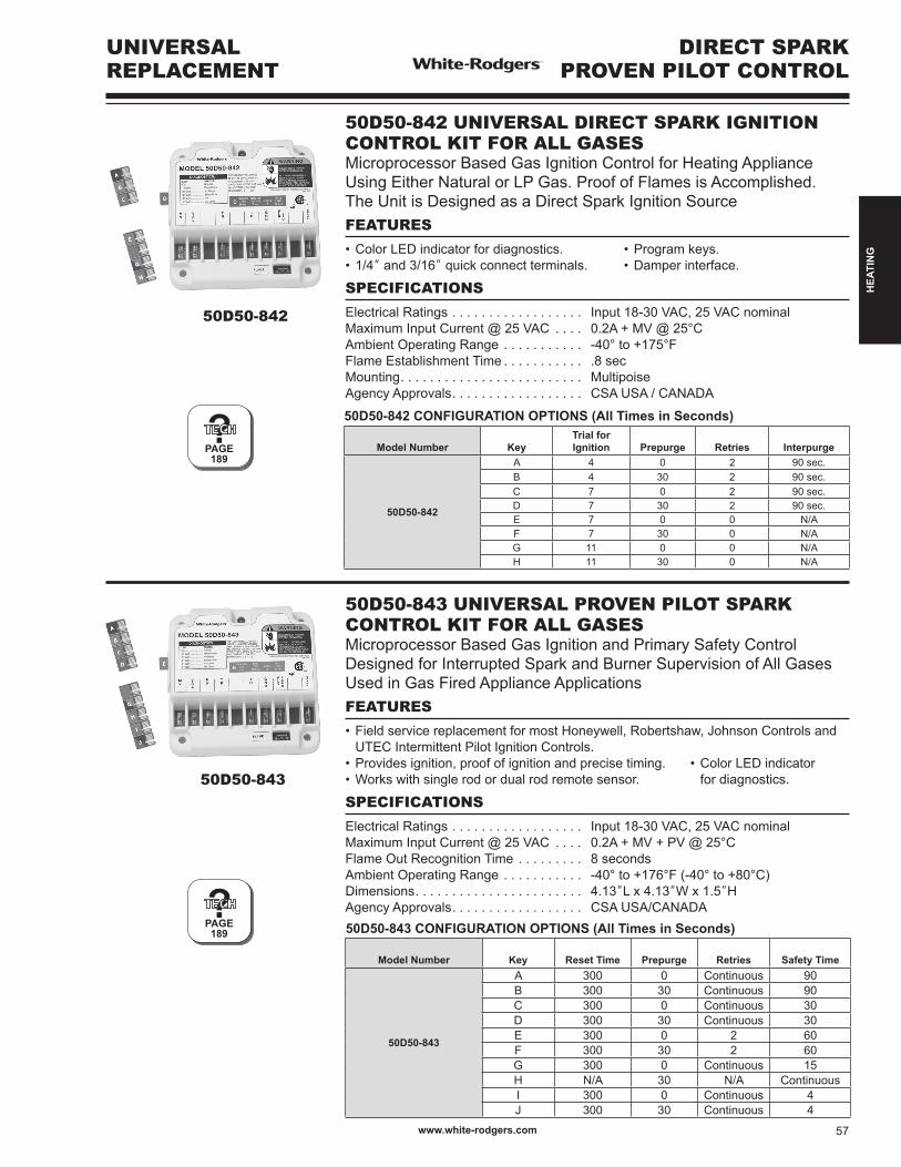
50D50-843
50D50-842
50D50-842 UNIVERSAL DIRECT SPARK IGNITION CONTROL KIT FOR ALL GASESMicroprocessor Based Gas Ignition Control for Heating Appliance Using Either Natural or LP Gas. Proof of Flames is Accomplished. TheUnitisDesignedasaDirectSparkIgnitionSourceFEATURES
•ColorLEDindicatorfordiagnostics. •Programkeys.•1/4” and 3/16”quickconnectterminals. •Damperinterface.
SPECIFICATIONS
Electrical Ratings . . . . . . . . . . . . . . . . . . Input 18-30 VAC, 25 VAC nominalMaximum Input Current @ 25 VAC . . . . 0.2A+MV@25°CAmbient Operating Range . . . . . . . . . . . -40°to+175°FFlame Establishment Time . . . . . . . . . . . .8 secMounting. . . . . . . . . . . . . . . . . . . . . . . . . MultipoiseAgency Approvals. . . . . . . . . . . . . . . . . . CSA USA / CANADA
50D50-842 CONFIGURATION OPTIONS (All Times in Seconds)
Model Number KeyTrial for Ignition Prepurge Retries Interpurge
50D50-842
A 4 0 2 90 sec.B 4 30 2 90 sec.C 7 0 2 90 sec.D 7 30 2 90 sec.E 7 0 0 N/AF 7 30 0 N/AG 11 0 0 N/AH 11 30 0 N/A
50D50-843 CONFIGURATION OPTIONS (All Times in Seconds)
Model Number Key Reset Time Prepurge Retries Safety Time
50D50-843
A 300 0 Continuous 90B 300 30 Continuous 90C 300 0 Continuous 30D 300 30 Continuous 30E 300 0 2 60F 300 30 2 60G 300 0 Continuous 15H N/A 30 N/A ContinuousI 300 0 Continuous 4J 300 30 Continuous 4
50D50-843 UNIVERSAL PROVEN PILOT SPARK CONTROL KIT FOR ALL GASESMicroprocessor Based Gas Ignition and Primary Safety Control DesignedforInterruptedSparkandBurnerSupervisionofAllGasesUsed in Gas Fired Appliance ApplicationsFEATURES
•FieldservicereplacementformostHoneywell,Robertshaw,JohnsonControlsand UTEC Intermittent Pilot Ignition Controls.•Providesignition,proofofignitionandprecisetiming. •ColorLEDindicator•Workswithsinglerodordualrodremotesensor. fordiagnostics.
SPECIFICATIONS
Electrical Ratings . . . . . . . . . . . . . . . . . . Input 18-30 VAC, 25 VAC nominalMaximum Input Current @ 25 VAC . . . . 0.2A+MV+PV@25°CFlame Out Recognition Time . . . . . . . . . 8 secondsAmbient Operating Range . . . . . . . . . . . -40°to+176°F(-40°to+80°C)Dimensions. . . . . . . . . . . . . . . . . . . . . . . 4.13”L x 4.13”W x 1.5”HAgency Approvals. . . . . . . . . . . . . . . . . . CSA USA/CANADA
www.white-rodgers.com 57
HEA
TIN
G
760-56
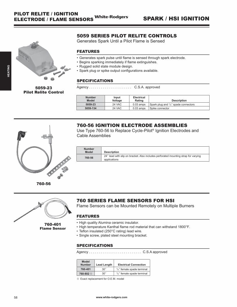
760-56 IGNITION ELECTRODE ASSEMBLIESUse Type 760-56 to Replace Cycle-Pilot® Ignition Electrodes andCable Assemblies
5059-23Pilot Relite Control
PILOT RELITE / IGNITIONELECTRODE / FLAME SENSORS SPARK / HSI IGNITION
5059 SERIES PILOT RELITE CONTROLS GeneratesSparkUntilaPilotFlameisSensed
FEATURES
•Generatessparkpulseuntilflameissensedthroughsparkelectrode.•Beginssparkingimmediatelyifflameextinguishes.•Ruggedsolidstatemoduledesign.•Sparkplugorspikeoutputconfigurationsavailable.
SPECIFICATIONS
Agency . . . . . . . . . . . . . . . . . . . . . . C.S.A. approved
Number Model
InputVoltage
ElectricalRating Description
5059-23 24 VAC 0.03 amps Sparkplugand1/4” spade connectors5059-134 24 VAC 0.03 amps Spikeconnector
Number Model Description
760-56 24”leadwithsliponbracket.Alsoincludesperforatedmountingstrapforvaryingapplications
Model Number Lead Length Electrical Connection760-401 30” 1/4” female spade terminal
760-802 ➀ 30” 1/4” female spade terminal
➀ Exact replacement for O.E.M. model
760 SERIES FLAME SENSORS FOR HSIFlame Sensors can be Mounted Remotely on Multiple Burners
FEATURES
•HighqualityAluminaceramicinsulator.•HightemperatureKanthalflamerodmaterialthatcanwithstand1800°F.•Tefloninsulated(250°Crating)leadwire.•Singlescrew,platedsteelmountingbracket.
SPECIFICATIONS
Agency . . . . . . . . . . . . . . . . . . . . . . . . . . . C.S.A approved
760-401Flame Sensor
www.white-rodgers.com58
HEA
TIN
G

21D64 SERIES HOTROD UNIVERSAL NITRIDE IGNITOR UPGRADE KIT120V Nitride Upgrade Kit for Conversion of Silicon Carbide (Flat or Spiral)
FEATURES
•RobustIgnitorDesign–forlongerlifeandfewercallbacks–5yearwarranty•NitrideIgnitorwith15.5” leads •“Universal”mountingbracketandscrewandceramicwirenuts
SPECIFICATIONS
Input Voltage. . . . . . . . . . . . . . . . . . . . . . 102-132 VAC, 60 HzMax. Load Current . . . . . . . . . . . . . . . . . 3.0 A @ 132 VAC, 25°CTiming Rating . . . . . . . . . . . . . . . . . . . . . 17 sec. minimumLoad Insulation Temp. Rating . . . . . . . . . 250oC
CARBIDE TO NITRIDEIGNITOR UPGRADE KIT
HOT SURFACE IGNITION (HSI)
21D64-2
21D64-5PK
Model Number Lead Length Description21D64-2 15.5” Kitincludesnitrideignitor,universalmountingbracket
and connection harness21D64-5PK 15.5” HotRod5-packcontains5singlepackignitorkits
768A-815
768A SERIES NITRIDE IGNITORSOEM Replacement for Nitride Ignitors
Model Number Terminal Type Replace OEM Models
768A-815 2terminalAMPreceptacle,.083femalesockets Trane
A341947P01768A-015
A341990P01IGN00117
768A-842 2terminalAMPreceptacle,.093femalesockets Amana11111701768A-2
768A-842
768A-843 2terminalAMPreceptacle,.084femalesockets Thermo Products
380650768A-843768A-843
768A-844 2terminalAMPreceptacle,.084femalesocketsLennox
Industries
41K5601768A-4
768A-844Rheem 62-24134-02
768A-845 2terminalAMPreceptacle,.084femalesockets Trane
768A-5768A-845IGN00104
X13130524010768A-842
768A-843768A-844 768A-845
New!
www.white-rodgers.com 59
HEA
TIN
G
767A-356767A-357
767A-361
767A-366
767A-365
SILICON CARBIDEHOT SURFACE IGNITION
CONTROLS (HSI)
767A-369
767A-370
767A-372767A-371
767A-373 767A-374767A-375
767A-376 767A-377
767A-382 767A-383 767A-384
767A-378767A-379
767A-380
767A-381
Model Number
Lead Length
Lead InsulationTemp. Rating
ElectricalConnection
Ceramic Insulator & ElectricalConnections (See Fig.)
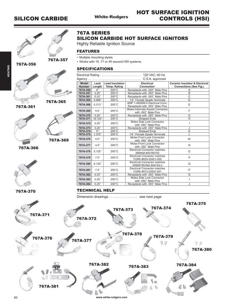
767A-356 6” 200°C Receptacle with .093” Male Pins A767A-357 5.25” 200°C Receptacle with .093” Male Pins B767A-361 5.25” 200°C Receptacle with .093” Male Pins C767A-365 5.688” 200°C 1/4” Female Spade Terminals D
767A-366 5.313” 200°C AMP 1-480699-0 Electrical Conn. Receptacle with .093” Male Pins E
767A-369 5.5” 200°C Molex Internally Keyed Connectorwith .093” Male Pins F
767A-370 5.25” 200°C Receptacle with .093” Male Pins G767A-371 19.125” 200°C Stripped Ends H
767A-372 5.25” 200°C MolexSideLockConnectorwith .092” Male Pins I
767A-373 5.25” 200°C Receptacle with .093” Male Pins J767A-374 11” 200°C Stripped Ends K767A-375 1.375” 200°C 1/4” Female Spade Terminals L
767A-376 4.5” 200°C MolexFrontLockConnectorwith .092” Male Pins M
767A-377 4.5” 200°C MolexFrontLockConnectorwith .092” Male Pins N
767A-378 5.125” 200°C Electrical Connector matches AMANA #20165702 O
767A-379 7.5” 200°C Electrical Connector matches YORK#025-33421-000 P
767A-380 6.125” 200°C Electrical Connector matches ARMSTRONG #44744-2 Q
767A-381 7.5” 200°C Electrical Connector matches YORK#473-20937-001 P
767A-382 5.25” 200°C Receptacle with .093” Male Pins G
767A-383 5.25” 200°C MolexSideLockConnectorwith .092” Male Pins I
767A-384 5.25” 200°C Receptacle with .093” Male Pins J
767A SERIES SILICON CARBIDE HOT SURFACE IGNITORSHighly Reliable Ignition Source
FEATURES• Multiplemountingstyles.• Workswith15,17or45secondHSIsystems.
SPECIFICATIONSElectrical Rating . . . . . . . . . . . . . . . . . . . . . . . . 120 VAC, 60 HzAgency . . . . . . . . . . . . . . . . . . . . . . . . . . . . . . . C.S.A. approved
TECHNICAL HELP
Dimension drawings . . . . . . . . . . . . . . . see next page
www.white-rodgers.com60
HEA
TIN
G

SILICON CARBIDEHOT SURFACE IGNITION CONTROLS (HSI)
053.1
055.1526.
526.
1
767A-356
407.000.2
052.1 052.1 052.1
052.1
521.1052.2
023.
767A-357.
NIM
081.
.NI
M081. .
NIM
081.
.NI
M071.
.NI
M081.
767A-361
578.1521.1
521.1
767A-365 767A-366
052.1
053.1
055.1526.1
767A-369 767A-371767A-370/767A-382
407.000.2
052.1
521.1052.2
023.
023.
023.
052. 2
052. 2
052.1
812.2
000.2
739.010.+020.-
.312
.170
028.1
025..FE
R
294.
081.1
.NI
M071.
767A-372/767A-384
052.2
052.1
294.
081.1
A B C D E F G H I
.093 Dia. MalePin Terminals
526.
.093 Dia. MalePin Terminals
526.
.093 Dia. MalePin Terminals
Uninsulated .250 FemaleSpade Terminals
AMP Type 1-480699-0.093 Dia. MalePin Terminals
.093 Dia. MalePin Terminals
022.
Lead Length5.25
Lead Length6.0
Lead Length5.25
.500
.093 Dia. MalePin Terminals
Lead Length5.50
Lead Length5.688
Lead Length5.313
Lead Length19.125
526.
Lead Length5.25
Lead Length5.25
.550
2.25
0. 11
80
526.
.093 DIA. MALEPIN TERMINALS
MOLEXCONNECTOR
MOLEXCONNECTOR
Lead Length5.25
Lead Length11.00
Lead Length1.375
Lead Length5.00
Lead Length5.25
022.
767A-375767A-374767A-373/767A-384
J K L
.NI
M071.
767A-377
052.2
052.1
294.
081.1
N767A-376
812.2
000.2
739.010.+020.-
.312
.170
028.1
025..FE
R
M
1.93
9
2.00
1.25
1.351.25
.170 2.666
2.00
O P
Q
Lead Length5.125
Lead Length7.500
Lead Length6.125
1.25
01.00
0
1.50
0
2.25
0
2.50
0
2.12
0
.425
767-379/767A-381
767A-380
767A-378
3.37
5
4.00
0
.425
www.white-rodgers.com 61
HEA
TIN
G
GAS BURNERCONTROLSTHERMOCOUPLES
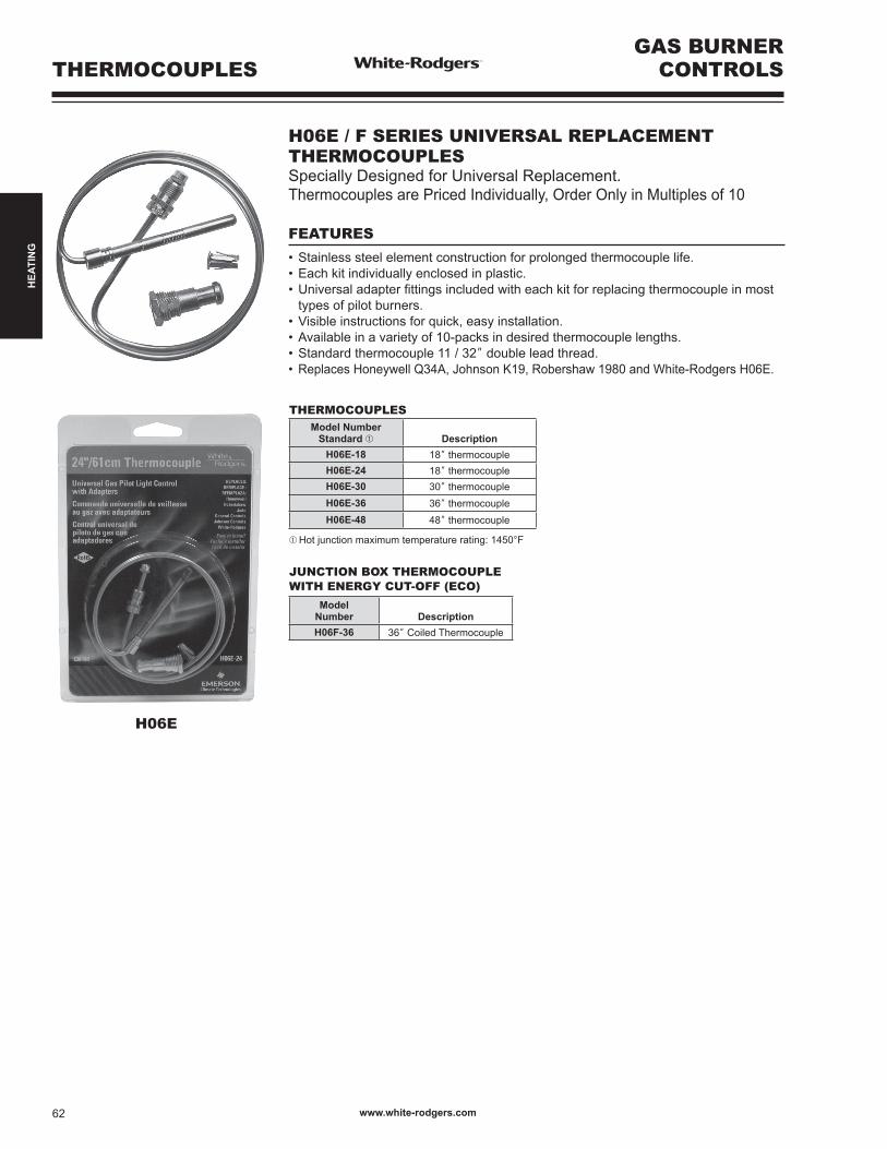
THERMOCOUPLESModel Number
Standard ➀ DescriptionH06E-18 18” thermocoupleH06E-24 18” thermocoupleH06E-30 30” thermocoupleH06E-36 36” thermocoupleH06E-48 48” thermocouple
➀ Hot junction maximum temperature rating: 1450°F
JUNCTION BOX THERMOCOUPLEWITH ENERGY CUT-OFF (ECO)
Model Number DescriptionH06F-36 36” Coiled Thermocouple
H06E / F SERIES UNIVERSAL REPLACEMENT THERMOCOUPLESSpecially Designed for Universal Replacement.Thermocouples are Priced Individually, Order Only in Multiples of 10
FEATURES
•Stainlesssteelelementconstructionforprolongedthermocouplelife.•Eachkitindividuallyenclosedinplastic.•Universaladapterfittingsincludedwitheachkitforreplacingthermocoupleinmost types of pilot burners.•Visibleinstructionsforquick,easyinstallation.•Availableinavarietyof10-packsindesiredthermocouplelengths.•Standardthermocouple11/32” double lead thread.• ReplacesHoneywellQ34A,JohnsonK19,Robershaw1980andWhite-RodgersH06E.
H06E
www.white-rodgers.com62
HEA
TIN
G
G01A-332
GAS BURNERCONTROLS GENERATORS
G01A-501
Indicates Canadian Model Number: call 1-800-305-6953 to order
750 MV
ModelNumber
MVOutput Length
FiberglassCable Leads
ArmoredCable Leads
PG9Adapter Clip
ConnectorType
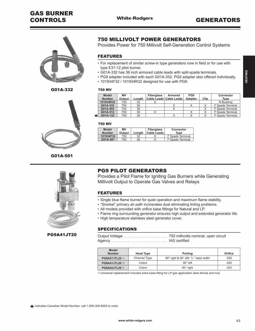
101934R32 750 32 X R BushingG01A-332 750 36 X X X F Spade TerminalG01A-502 750 36 X X F Spade TerminalG01A-512 750 36 X X X F Spade Terminal
G01A-132 750 36 X X X F Spade Terminal
750 MV
ModelNumber
MVOutput Length
FiberglassCable Leads
ConnectorType
101934F32 750 32 X F Spade Terminal G01A-501 750 36 X F Spade Terminal
PG9A41JT20
750 MILLIVOLT POWER GENERATORSProvides Power for 750 Millivolt Self-Generation Control Systems
FEATURES
•Forreplacementofsimilarscrew-intypegeneratorsnowinfieldorforusewith type E31-12 pilot burner.•G01A-332has36incharmoredcableleadswithsplit-spadeterminals.•PG9adapterincludedwitheachG01A-332.PG9adapteralsoofferedindividually.•101934F32/101934R32designedforusewithPG9.
PG9 PILOT GENERATORSProvides a Pilot Flame for Igniting Gas Burners while GeneratingMillivolt Output to Operate Gas Valves and Relays
FEATURES
•Singleblueflameburnerforquietoperationandmaximumflamestability.• “Snorkel”primaryairpathincineratesdusteliminatinglintingproblems.•AllmodelsprovidedwithorificebasefittingsforNaturalandLP.•Flameringsurroundinggeneratorensureshighoutputandextendedgeneratorlife.•Hightemperaturestainlesssteelgeneratorcover.
SPECIFICATIONS
Output Voltage . . . . . . . . . . . . . . . . . . . . . 750 millivolts nominal, open circuitAgency . . . . . . . . . . . . . . . . . . . . . . . . . . . IAScertified
Model Number Head Type Porting Orifice
PG9A27JTL22 ➀ Channel Type 90° right & 90° left, 3/4” head width .022
PG9A41JTL20 ➀ Cobra 90° left .020
PG9A42JTL20 ➀ Cobra 90° right .020
➀UniversalreplacementincludesextrabasefittingforLPgasapplication(lessferruleandnut)
www.white-rodgers.com 63
HEA
TIN
G
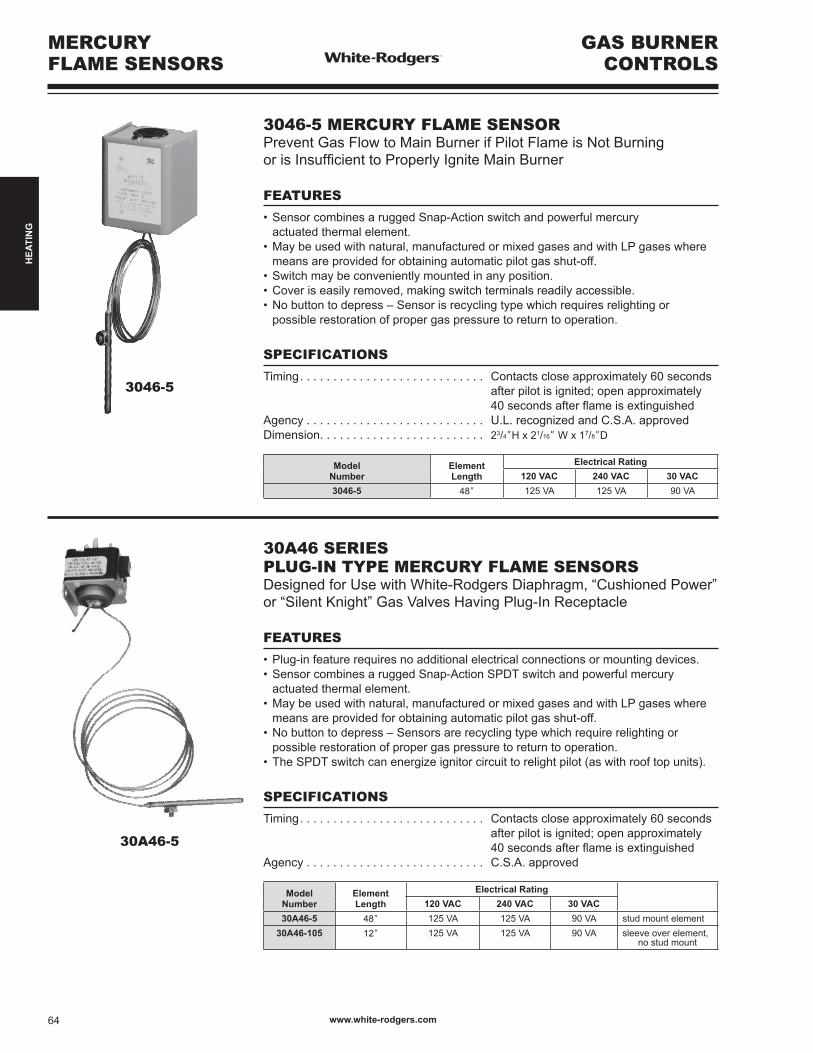
Model Number
ElementLength
Electrical Rating120 VAC 240 VAC 30 VAC
30A46-5 48” 125 VA 125 VA 90 VA stud mount element30A46-105 12” 125 VA 125 VA 90 VA sleeve over element,
no stud mount
30A46-5
3046-5
GAS BURNERCONTROLS
MERCURYFLAME SENSORS
3046-5 MERCURY FLAME SENSORPrevent Gas Flow to Main Burner if Pilot Flame is Not Burning orisInsufficienttoProperlyIgniteMainBurner
FEATURES
•SensorcombinesaruggedSnap-Actionswitchandpowerfulmercury actuated thermal element.•Maybeusedwithnatural,manufacturedormixedgasesandwithLPgaseswhere means are provided for obtaining automatic pilot gas shut-off.•Switchmaybeconvenientlymountedinanyposition.•Coveriseasilyremoved,makingswitchterminalsreadilyaccessible.•Nobuttontodepress–Sensorisrecyclingtypewhichrequiresrelightingor possible restoration of proper gas pressure to return to operation.
SPECIFICATIONS
Timing. . . . . . . . . . . . . . . . . . . . . . . . . . . . Contacts close approximately 60 seconds after pilot is ignited; open approximately 40secondsafterflameisextinguishedAgency . . . . . . . . . . . . . . . . . . . . . . . . . . . U.L. recognized and C.S.A. approved Dimension. . . . . . . . . . . . . . . . . . . . . . . . . 23/4”H x 21/16” W x 17/8”D
30A46 SERIES PLUG-IN TYPE MERCURY FLAME SENSORSDesignedforUsewithWhite-RodgersDiaphragm,“CushionedPower”or“SilentKnight”GasValvesHavingPlug-InReceptacle
FEATURES
•Plug-infeaturerequiresnoadditionalelectricalconnectionsormountingdevices.•SensorcombinesaruggedSnap-ActionSPDTswitchandpowerfulmercury actuated thermal element.•Maybeusedwithnatural,manufacturedormixedgasesandwithLPgaseswhere means are provided for obtaining automatic pilot gas shut-off.•Nobuttontodepress–Sensorsarerecyclingtypewhichrequirerelightingor possible restoration of proper gas pressure to return to operation.•TheSPDTswitchcanenergizeignitorcircuittorelightpilot(aswithrooftopunits).
SPECIFICATIONS
Timing. . . . . . . . . . . . . . . . . . . . . . . . . . . . Contacts close approximately 60 seconds after pilot is ignited; open approximately 40secondsafterflameisextinguishedAgency . . . . . . . . . . . . . . . . . . . . . . . . . . . C.S.A. approved
Model Number
ElementLength
Electrical Rating120 VAC 240 VAC 30 VAC
3046-5 48” 125 VA 125 VA 90 VA
www.white-rodgers.com64
HEA
TIN
G
MERCURYFLAME SENSORS
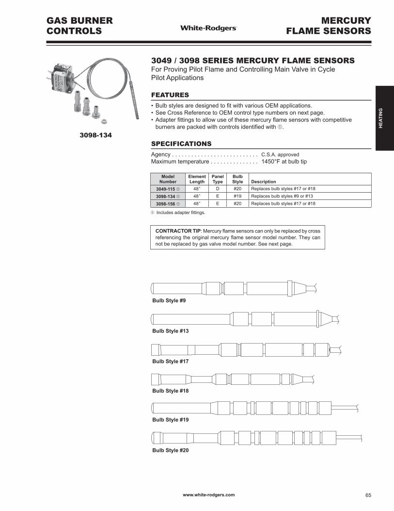
3098-134
GAS BURNERCONTROLS
3049 / 3098 SERIES MERCURY FLAME SENSORSFor Proving Pilot Flame and Controlling Main Valve in Cycle Pilot Applications
FEATURES
•BulbstylesaredesignedtofitwithvariousOEMapplications.•SeeCrossReferencetoOEMcontroltypenumbersonnextpage.•Adapterfittingstoallowuseofthesemercuryflamesensorswithcompetitive burnersarepackedwithcontrolsidentifiedwith➀.
SPECIFICATIONS
Agency . . . . . . . . . . . . . . . . . . . . . . . . . . . C.S.A. approvedMaximum temperature . . . . . . . . . . . . . . . 1450°F at bulb tip
Model Number
ElementLength
PanelType
BulbStyle Description
3049-115 ➀ 48” D #20 Replaces bulb styles #17 or #18
3098-134 ➀ 48” E #19 Replaces bulb styles #9 or #13
3098-156 ➀ 48” E #20 Replaces bulb styles #17 or #18
➀ Includesadapterfittings.
CONTRACTOR TIP:Mercuryflamesensorscanonlybereplacedbycrossreferencingtheoriginalmercuryflamesensormodelnumber.Theycannot be replaced by gas valve model number. See next page.
Bulb Style #7
Bulb Style #13
Bulb Style #9
Bulb Style #17
Bulb Style #18
Bulb Style #19
Bulb Style #20
www.white-rodgers.com 65
HEA
TIN
G
O.E.M.Number
OriginalCapillaryLength
OriginalPanel
Types➁
SuggestedReplacementType Number
3094-102 30” C ➂ None3094-111 30” C ➂ None ➀3094-118 48” C ➂ None3094-122 30” C ➂ None ➀3094-123 30” G None3094-127 48” C ➂ None3094-131 22” C ➂ None ➀3098-111 30” E 3098-1343098-117 24” E None ➀3098-120 30” E None ➀3098-122 30” E 3098-1563098-126 30” E 3098-1563098-127 24” E 3098-1563098-130 24” E 3098-1563098-131 30” E 3098-1563098-134 48” E 3098-1343098-135 48” E None ➀3098-136 30” E 3098-1343098-137 12” E None ➀3098-139 36” E None ➀
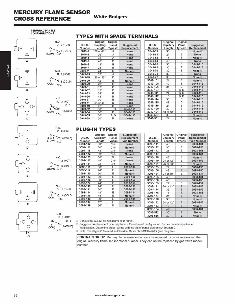
MERCURY FLAME SENSORCROSS REFERENCE
TYPES WITH SPADE TERMINALS
PLUG-IN TYPES
➀ ConsulttheO.E.M.forreplacementorretrofit.➁ Suggestedreplacementtypemayhavedifferentpanelconfiguration.Somecontrolsexperienced modification.DetermineproperwiringwiththeaidofpaneldiagramsAthroughG.➂ Note:PaneltypeCfeaturedanElectricalQuickShut-OffResistor(seediagram)
CONTRACTOR TIP:Mercuryflamesensorscanonlybereplacedbycrossreferencingtheoriginalmercuryflamesensormodelnumber.Theycannotbereplacedbygasvalvemodelnumber.
O.E.M.Number
OriginalCapillaryLength
OriginalPanel
Types➁
SuggestedReplacementType Number
3098-141 48” E 3098-1343098-142 30” E 3098-1563098-143 36” E 3098-1563098-147 18” E 3098-1343098-148 48” E None ➀3098-149 24 or 42” E 3098-1563098-151 26 or 33” E None ➀3098-153 24” E 3098-1563098-156 48” E 3098-1563098-161 24 or 30” E 3098-1343098-165 48” E 3098-1343098-168 48” E 3098-1563098-169 27” E 3098-1343098-171 30 or 42” E 3098-1563094-174 36” E 3098-1563098-175 18” E 3098-1563098-177 24” E None ➀3098-178 30” E None ➀3098-182 24 or 42” E 3098-1563098-183 12” E None ➀3098-184 42” E 3098-1343098-522 30” E None3098-536 30” E None ➀
O.E.M.Number
OriginalCapillaryLength
OriginalPanel
Types➁Suggested
Replacement3049-59 30” B None ➀3049-61 24” B None3049-62 18” B None ➀3049-64 48” D None3049-66 30” B 3049-1153049-68 30” B 3049-1153049-70 30” B None ➀3049-71 30” B None3049-72 30” E None ➀
3049-101 24” B None ➀3049-105 42” B 3049-1153049-106 24” D 3049-1153049-107 12” B, D 3049-1153049-111 24” B, D 3049-1153049-112 18” B, D 3049-1153049-114 30” D 3049-1153049-115 48” D 3049-1153049-119 24” B 3049-1153049-120 30” B 3049-1153049-121 18 or 42” B 3049-1153049-537 30” B None ➀3049-561 24” B None ➀
O.E.M.Number
OriginalCapillaryLength
OriginalPanel
Types➁Suggested
Replacement3049-1 30 or 48” A None3049-3 26” A None3049-4 33” A None3049-5 48” B None3049-6 12” B None3049-7 24” B None3049-11 24” B None ➀3049-15 33” A None3049-18 30 or 33” D None3049-20 42” B None ➀3049-29 20” B None3049-31 12” B None3049-32 12” B None3049-33 24” B None3049-36 48” B None3049-37 30” B None3049-41 24 or 48” B None3049-49 42” B None3049-52 30” B, D 3049-1153049-54 30” B 3049-1153049-55 30” A, D 3049-1153049-58 30” B None
www.white-rodgers.com66
HEA
TIN
G
WARM AIR CONTROLS
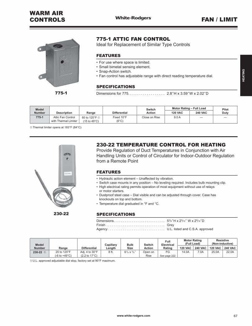
230-22
775-1
FAN / LIMIT
775-1 ATTIC FAN CONTROLIdeal for Replacement of Similar Type Controls
FEATURES
•Forusewherespaceislimited.•Smallbimetalsensingelement.•Snap-Actionswitch.•Fancontrolhasadjustablerangewithdirectreadingtemperaturedial.
SPECIFICATIONS
Dimensions for 775. . . . . . . . . . . . . . . . . . 2.8”H x 3.59”W x 2.02”D
Model Number Description Range Differential
SwitchAction
Motor Rating – Full Load PilotDuty120 VAC 240 VAC
775-1 Attic Fan Controlwith Thermal Limiter
60 to 120°F ➀(15 to 49°C)
Fixed 10°F(6°C)
Close on Rise 9.0 A — —
➀ Thermal limiter opens at 183°F (84°C)
Model Number Range Differential
CapillaryLength
BulbSize
SwitchAction
FullElectrical
Rating
Motor Rating (Full Load)
Resistive(Non-inductive)
120 VAC 240 VAC 120 VAC 240 VAC230-22 ➀ 20 to 120°F
(-6to+49°C)Adj. 4 to 30°F(2.2 to 17°C)
8 ft. 61/4 x 3/8” Open onRise
FGSee page 222
14.0A 7.0A 25.0A 22.0A
➀ U.L. approved adjustable dial stop, factory set at 90°F maximum.
230-22 TEMPERATURE CONTROL FOR HEATINGProvide Regulation of Duct Temperatures in Conjunction with Air Handling Units or Control of Circulator for Indoor-Outdoor Regulation from a Remote Point
FEATURES• Hydraulicactionelement–Unaffectedbyvibration.• Switchcasemountsinanyposition–Nolevelingrequired.Includesbulbmountingclip.• Highelectricalratingpermitsoperationofmostequipmentwithoutuseofrelays or motor starters.• Dustproofsteelcase–Dialvisibleandcanbeadjustedthroughcover.Casehas knockoutsontopandbottom.• Temperaturedialgraduatedin°Fand°C.
SPECIFICATIONSDimensions. . . . . . . . . . . . . . . . . . . . . . . . . . . . 53/4”H x 25/16” W x 29/16”DFinish . . . . . . . . . . . . . . . . . . . . . . . . . . . . . . . . GreyAgency . . . . . . . . . . . . . . . . . . . . . . . . . . . . . . . U.L. listed and C.S.A. approved
www.white-rodgers.com 67
HEA
TIN
G
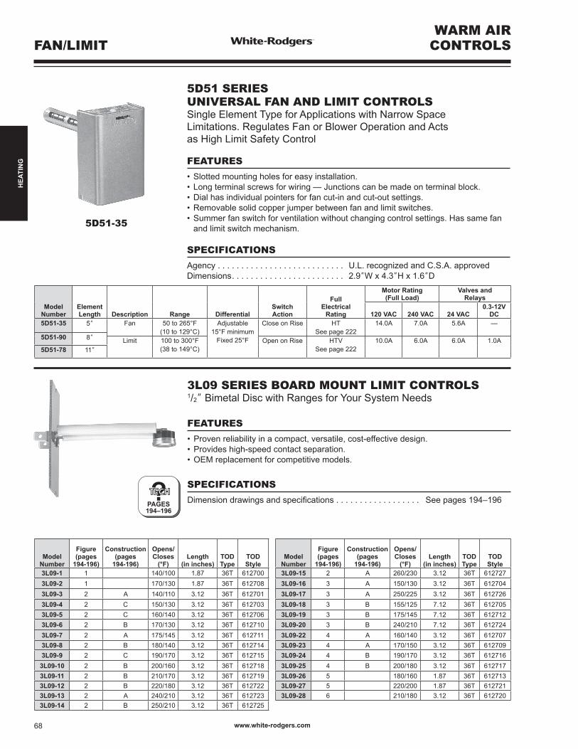
5D51-35
WARM AIRCONTROLSFAN/LIMIT
?PAGES194–196
5D51 SERIESUNIVERSAL FAN AND LIMIT CONTROLSSingle Element Type for Applications with Narrow Space Limitations. Regulates Fan or Blower Operation and Acts as High Limit Safety Control
FEATURES
•Slottedmountingholesforeasyinstallation.•Longterminalscrewsforwiring—Junctionscanbemadeonterminalblock.•Dialhasindividualpointersforfancut-inandcut-outsettings.•Removablesolidcopperjumperbetweenfanandlimitswitches.•Summerfanswitchforventilationwithoutchangingcontrolsettings.Hassamefan and limit switch mechanism.
SPECIFICATIONS
Agency . . . . . . . . . . . . . . . . . . . . . . . . . . . U.L. recognized and C.S.A. approvedDimensions. . . . . . . . . . . . . . . . . . . . . . . . 2.9”W x 4.3”H x 1.6”D
Model Number
ElementLength Description Range Differential
SwitchAction
FullElectrical
Rating
Motor Rating (Full Load)
Valves andRelays
120 VAC 240 VAC 24 VAC0.3-12V
DC5D51-35 5” Fan 50 to 265°F
(10 to 129°C)Adjustable
15°F minimumFixed 25°F
Close on Rise HTSee page 222
14.0A 7.0A 5.6A —
5D51-90 8” Limit 100 to 300°F(38 to 149°C)
Open on Rise HTVSee page 222
10.0A 6.0A 6.0A 1.0A5D51-78 11”
3L09 SERIES BOARD MOUNT LIMIT CONTROLS1/2”BimetalDiscwithRangesforYourSystemNeeds
FEATURES
•Provenreliabilityinacompact,versatile,cost-effectivedesign.•Provideshigh-speedcontactseparation.•OEMreplacementforcompetitivemodels.
SPECIFICATIONS
Dimensiondrawingsandspecifications . . . . . . . . . . . . . . . . . . See pages 194–196
ModelNumber
Figure (pages
194-196)
Construction(pages
194-196)
Opens/ Closes
(°F)Length
(in inches)TODType
TODStyle
3L09-1 1 140/100 1.87 36T 6127003L09-2 1 170/130 1.87 36T 6127083L09-3 2 A 140/110 3.12 36T 6127013L09-4 2 C 150/130 3.12 36T 6127033L09-5 2 C 160/140 3.12 36T 6127063L09-6 2 B 170/130 3.12 36T 6127103L09-7 2 A 175/145 3.12 36T 6127113L09-8 2 B 180/140 3.12 36T 6127143L09-9 2 C 190/170 3.12 36T 612715
3L09-10 2 B 200/160 3.12 36T 6127183L09-11 2 B 210/170 3.12 36T 6127193L09-12 2 B 220/180 3.12 36T 6127223L09-13 2 A 240/210 3.12 36T 6127233L09-14 2 B 250/210 3.12 36T 612725
ModelNumber
Figure (pages
194-196)
Construction(pages
194-196)
Opens/ Closes
(°F)Length
(in inches)TODType
TODStyle
3L09-15 2 A 260/230 3.12 36T 6127273L09-16 3 A 150/130 3.12 36T 6127043L09-17 3 A 250/225 3.12 36T 6127263L09-18 3 B 155/125 7.12 36T 6127053L09-19 3 B 175/145 7.12 36T 6127123L09-20 3 B 240/210 7.12 36T 6127243L09-22 4 A 160/140 3.12 36T 6127073L09-23 4 A 170/150 3.12 36T 6127093L09-24 4 B 190/170 3.12 36T 6127163L09-25 4 B 200/180 3.12 36T 6127173L09-26 5 180/160 1.87 36T 6127133L09-27 5 220/200 1.87 36T 6127213L09-28 6 210/180 3.12 36T 612720
www.white-rodgers.com68
HEA
TIN
G
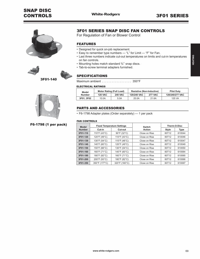
3F01-140
SNAP DISCCONTROLS 3F01 SERIES
F6-1798 (1 per pack)
3F01 SERIES SNAP DISC FAN CONTROLSFor Regulation of Fan or Blower Control
FEATURES
•Designedforquickon-jobreplacement.•Easytoremembertypenumbers—“L”forLimit—“F”forFan.•Lastthreenumbersindicatecut-outtemperaturesonlimitsandcut-intemperatures on fan controls.•Mountingholesmatchstandard¾” snap discs.•Tab-to-screwterminaladaptersfurnished.
SPECIFICATIONS
Maximum ambient . . . . . . . . . . . . . . . . . . 350°F
PARTS AND ACCESSORIES
•F6-1798Adapterplates(Orderseparately)—1perpack
ELECTRICAL RATINGS
Model Number
Motor Rating (Full Load) Resistive (Non-Inductive) Pilot Duty120 VAC 240 VAC 120/240 VAC 277 VAC 120/240/277 VAC
3F01, 3F02 10.0A 5.0A 25.0A 21.6A 125 VA
FAN CONTROLS
Model Number
Fixed Temperature Settings SwitchAction
Therm-O-DiscCut-in Cut-out Style Type
3F01-110 110°F (43°C) 90°F (32°C) Close on Rise 60T12 6100443F01-120 120°F (49°C) 110°F (43°C) Close on Rise 60T12 6100463F01-130 130°F (54°C) 115°F (46°C) Close on Rise 60T12 6100473F01-140 140°F (60°C) 120°F (49°C) Close on Rise 60T12 6100493F01-150 150°F (66°C) 130°F (54°C) Close on Rise 60T12 6100503F01-160 160°F (71°C) 140°F (60°C) Close on Rise 60T12 6100643F01-180 180°F (82°C) 160°F (71°C) Close on Rise 60T12 6100653F01-200 200°F (93°C) 180°F (82°C) Close on Rise 60T12 6100663F01-350 350°F (177°C) 320°F (160°C) Close on Rise 60T12 610067
www.white-rodgers.com 69
HEA
TIN
G

SNAP DISCCONTROLS3L SERIES
SPECIFICATIONS
3L SERIES SNAP DISC FAN OR LIMIT CONTROLSFor Regulation of Fan, Blower or High Limit Safety Control
3L02-190
3L01-180
3L03-140
ELECTRICAL RATINGS
Electrical Rating(AC) for
Model Numbers
Motor Rating(Full Load)
Resistive(Non-Inductive)
PilotDuty
120 VAC 240 VAC 120/240 VAC 277 VAC 120/240/277 VAC3L01 10.0A 5.0A 25.0A 21.6A 125 VA3L02 10.0A 5.0A 25.0A 21.6A 125 VA
3L03: 1 & 2 Close on Rise 5.8A 2.9A — — 125 VA3L03: 1 & 3 Open on Rise 10.0A 5.0A 25.0A 21.6A 125 VA
Model Number
Fixed Temperature Settings SwitchAction
Therm-O-DiscCut-in Cut-out Style Type
3L01-120 110°F (43°C) 120°F (49°C) Open on Rise 60T11 6100003L01-130* 115°F (46°C) 130°F (54°C) Open on Rise 60T11 6100023L01-140 100°F (38°C) 140°F (60°C) Open on Rise 60T11 6100063L01-150 110°F (43°C) 150°F (66°C) Open on Rise 60T11 6100093L01-165 125°F (52°C) 165°F (74°C) Open on Rise 60T11 6100693L01-170 130°F (54°C) 170°F (77°C) Open on Rise 60T11 6100123L01-180 140°F (60°C) 180°F (82°C) Open on Rise 60T11 6100133L01-190 150°F (66°C) 190°F (88°C) Open on Rise 60T11 6100153L01-200 160°F (71°C) 200°F (93°C) Open on Rise 60T11 6100163L01-230 190°F (88°C) 230°F (110°C) Open on Rise 60T11 610021
3L01-250** 210°F (99°C) 250°F (121°C) Open on Rise 60T11 6100233L01-300* 250°F (121°C) 300°F (149°C) Open on Rise 60T11 6100263L01-350 310°F (154°C) 350°F (177°C) Open on Rise 60T11 610068
*3L01-130 and -300 terminals at 45° angle**3L01-250terminalshorizontaltobracket
LIMIT CONTROLS – MANUAL RESET
Model Number
Fixed Temperature Settings SwitchAction
Therm-O-DiscCut-in Cut-out Style Type
3L02-160
ManualReset
160°F (71°C) Open on Rise 60T15 3305343L02-170 170°F (77°C) Open on Rise 60T15 3305353L02-180 180°F (82°C) Open on Rise 60T15 3305363L02-190 190°F (88°C) Open on Rise 60T15 3305373L02-200 200°F (93°C) Open on Rise 60T15 330538
SPDT CONTROLS
Model Number
Fixed Temperature Settings
SwitchAction
Therm-O-DiscTerminal 1 & 3 Terminal 1 & 2Cut-in Cut-out Cut-in Cut-out Style Type
3L03-140 140°F (60°C) 120°F (49°C) 190°F (88°C) 170°F (77°C) SPDT 60T13 6110153L03-190 190°F (88°C) 170°F (77°C) 140°F (60°C) 120°F (49°C) SPDT 60T13 611014
www.white-rodgers.com70
HEA
TIN
G
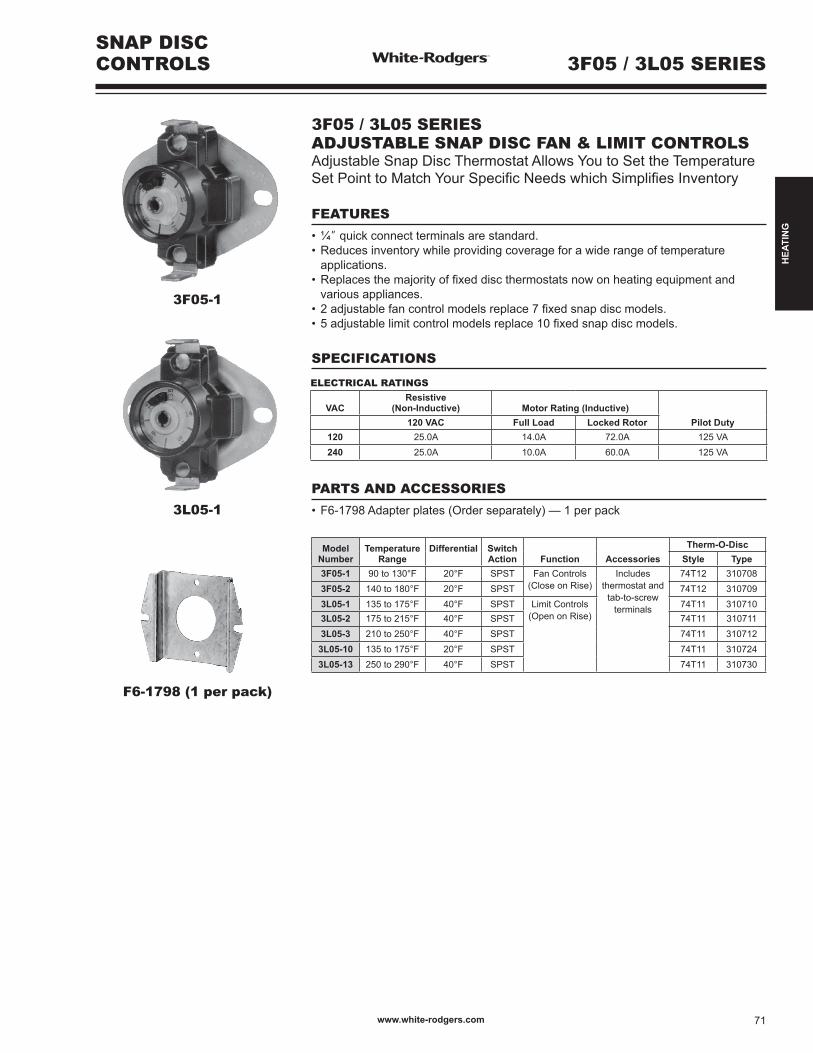
SNAP DISCCONTROLS 3F05 / 3L05 SERIES
3F05-1
3L05-1
F6-1798 (1 per pack)
3F05 / 3L05 SERIESADJUSTABLE SNAP DISC FAN & LIMIT CONTROLSAdjustableSnapDiscThermostatAllowsYoutoSettheTemperatureSetPointtoMatchYourSpecificNeedswhichSimplifiesInventory
FEATURES
•¼”quickconnectterminalsarestandard.•Reducesinventorywhileprovidingcoverageforawiderangeoftemperature applications.•Replacesthemajorityoffixeddiscthermostatsnowonheatingequipmentand various appliances.•2adjustablefancontrolmodelsreplace7fixedsnapdiscmodels.•5adjustablelimitcontrolmodelsreplace10fixedsnapdiscmodels.
SPECIFICATIONS
PARTS AND ACCESSORIES
•F6-1798Adapterplates(Orderseparately)—1perpack
ELECTRICAL RATINGS
VACResistive
(Non-Inductive) Motor Rating (Inductive)Pilot Duty120 VAC Full Load Locked Rotor
120 25.0A 14.0A 72.0A 125 VA240 25.0A 10.0A 60.0A 125 VA
Model Number
TemperatureRange
Differential Switch Action Function Accessories
Therm-O-DiscStyle Type
3F05-1 90 to 130°F 20°F SPST Fan Controls (Close on Rise)
Includes thermostat and
tab-to-screw terminals
74T12 3107083F05-2 140 to 180°F 20°F SPST 74T12 3107093L05-1 135 to 175°F 40°F SPST Limit Controls
(Open on Rise)74T11 310710
3L05-2 175 to 215°F 40°F SPST 74T11 3107113L05-3 210 to 250°F 40°F SPST 74T11 310712
3L05-10 135 to 175°F 20°F SPST 74T11 3107243L05-13 250 to 290°F 40°F SPST 74T11 310730
www.white-rodgers.com 71
HEA
TIN
G
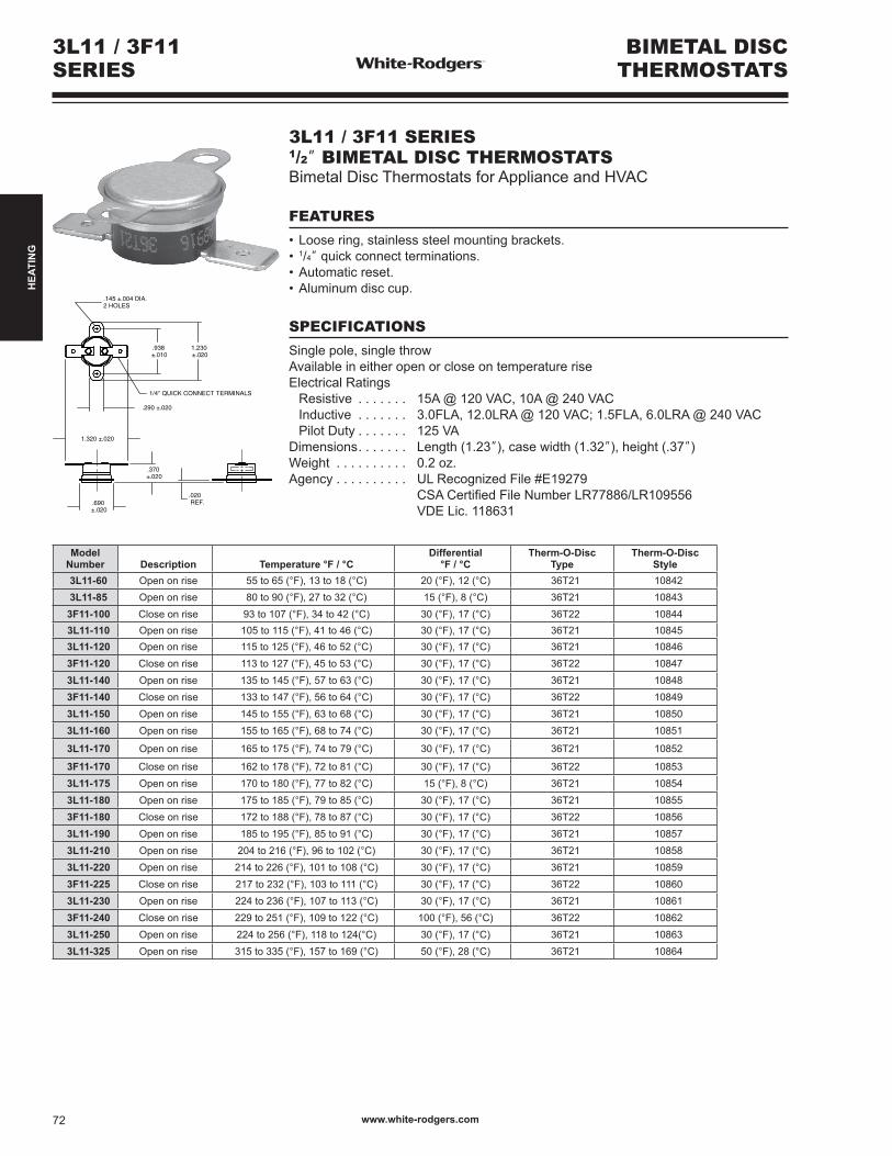
3L11 / 3F11SERIES
BIMETAL DISCTHERMOSTATS
3L11 / 3F11 SERIES1/2” BIMETAL DISC THERMOSTATSBimetal Disc Thermostats for Appliance and HVAC
FEATURES
•Loosering,stainlesssteelmountingbrackets.• 1/4”quickconnectterminations.•Automaticreset.•Aluminumdisccup.
SPECIFICATIONS
Single pole, single throwAvailable in either open or close on temperature riseElectrical Ratings Resistive . . . . . . . 15A @ 120 VAC, 10A @ 240 VAC Inductive . . . . . . . 3.0FLA, 12.0LRA @ 120 VAC; 1.5FLA, 6.0LRA @ 240 VAC Pilot Duty . . . . . . . 125 VADimensions. . . . . . . Length (1.23”), case width (1.32”), height (.37”)Weight . . . . . . . . . . 0.2 oz.Agency . . . . . . . . . . UL Recognized File #E19279 CSACertifiedFileNumberLR77886/LR109556 VDE Lic. 118631
Model Number Description Temperature °F / °C
Differential°F / °C
Therm-O-DiscType
Therm-O-DiscStyle
3L11-60 Open on rise 55 to 65 (°F), 13 to 18 (°C) 20 (°F), 12 (°C) 36T21 108423L11-85 Open on rise 80 to 90 (°F), 27 to 32 (°C) 15 (°F), 8 (°C) 36T21 10843
3F11-100 Close on rise 93 to 107 (°F), 34 to 42 (°C) 30 (°F), 17 (°C) 36T22 108443L11-110 Open on rise 105 to 115 (°F), 41 to 46 (°C) 30 (°F), 17 (°C) 36T21 108453L11-120 Open on rise 115 to 125 (°F), 46 to 52 (°C) 30 (°F), 17 (°C) 36T21 108463F11-120 Close on rise 113 to 127 (°F), 45 to 53 (°C) 30 (°F), 17 (°C) 36T22 108473L11-140 Open on rise 135 to 145 (°F), 57 to 63 (°C) 30 (°F), 17 (°C) 36T21 108483F11-140 Close on rise 133 to 147 (°F), 56 to 64 (°C) 30 (°F), 17 (°C) 36T22 108493L11-150 Open on rise 145 to 155 (°F), 63 to 68 (°C) 30 (°F), 17 (°C) 36T21 108503L11-160 Open on rise 155 to 165 (°F), 68 to 74 (°C) 30 (°F), 17 (°C) 36T21 10851
3L11-170 Open on rise 165 to 175 (°F), 74 to 79 (°C) 30 (°F), 17 (°C) 36T21 10852
3F11-170 Close on rise 162 to 178 (°F), 72 to 81 (°C) 30 (°F), 17 (°C) 36T22 108533L11-175 Open on rise 170 to 180 (°F), 77 to 82 (°C) 15 (°F), 8 (°C) 36T21 108543L11-180 Open on rise 175 to 185 (°F), 79 to 85 (°C) 30 (°F), 17 (°C) 36T21 108553F11-180 Close on rise 172 to 188 (°F), 78 to 87 (°C) 30 (°F), 17 (°C) 36T22 108563L11-190 Open on rise 185 to 195 (°F), 85 to 91 (°C) 30 (°F), 17 (°C) 36T21 108573L11-210 Open on rise 204 to 216 (°F), 96 to 102 (°C) 30 (°F), 17 (°C) 36T21 108583L11-220 Open on rise 214 to 226 (°F), 101 to 108 (°C) 30 (°F), 17 (°C) 36T21 108593F11-225 Close on rise 217 to 232 (°F), 103 to 111 (°C) 30 (°F), 17 (°C) 36T22 108603L11-230 Open on rise 224 to 236 (°F), 107 to 113 (°C) 30 (°F), 17 (°C) 36T21 108613F11-240 Close on rise 229 to 251 (°F), 109 to 122 (°C) 100 (°F), 56 (°C) 36T22 108623L11-250 Open on rise 224 to 256 (°F), 118 to 124(°C) 30 (°F), 17 (°C) 36T21 108633L11-325 Open on rise 315 to 335 (°F), 157 to 169 (°C) 50 (°F), 28 (°C) 36T21 10864
www.white-rodgers.com72
HEA
TIN
G
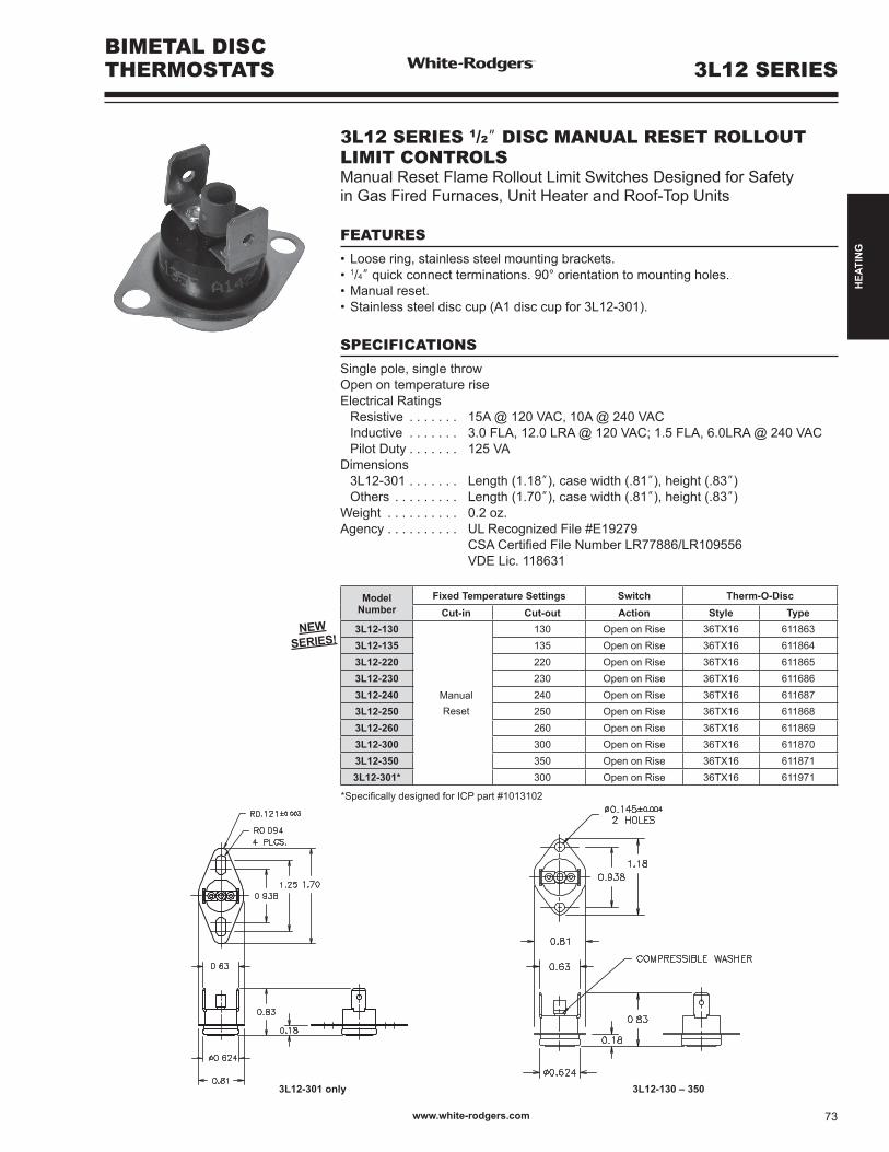
3L12 SERIESBIMETAL DISCTHERMOSTATS
3L12 SERIES 1/2” DISC MANUAL RESET ROLLOUT LIMIT CONTROLSManual Reset Flame Rollout Limit Switches Designed for Safety in Gas Fired Furnaces, Unit Heater and Roof-Top Units
FEATURES
•Loosering,stainlesssteelmountingbrackets.• 1/4”quickconnectterminations.90°orientationtomountingholes.•Manualreset.•Stainlesssteeldisccup(A1disccupfor3L12-301).
SPECIFICATIONS
Single pole, single throwOpen on temperature riseElectrical Ratings Resistive . . . . . . . 15A @ 120 VAC, 10A @ 240 VAC Inductive . . . . . . . 3.0 FLA, 12.0 LRA @ 120 VAC; 1.5 FLA, 6.0LRA @ 240 VAC Pilot Duty . . . . . . . 125 VADimensions 3L12-301 . . . . . . . Length (1.18”), case width (.81”), height (.83”) Others . . . . . . . . . Length (1.70”), case width (.81”), height (.83”)Weight . . . . . . . . . . 0.2 oz.Agency . . . . . . . . . . UL Recognized File #E19279 CSACertifiedFileNumberLR77886/LR109556 VDE Lic. 118631
Model Number
Fixed Temperature Settings Switch Therm-O-DiscCut-in Cut-out Action Style Type
3L12-130
ManualReset
130 Open on Rise 36TX16 6118633L12-135 135 Open on Rise 36TX16 6118643L12-220 220 Open on Rise 36TX16 6118653L12-230 230 Open on Rise 36TX16 6116863L12-240 240 Open on Rise 36TX16 6116873L12-250 250 Open on Rise 36TX16 6118683L12-260 260 Open on Rise 36TX16 6118693L12-300 300 Open on Rise 36TX16 6118703L12-350 350 Open on Rise 36TX16 6118713L12-301* 300 Open on Rise 36TX16 611971
*SpecificallydesignedforICPpart#1013102
3L12-301 only 3L12-130 – 350
NEW SERIES!
www.white-rodgers.com 73
HEA
TIN
G
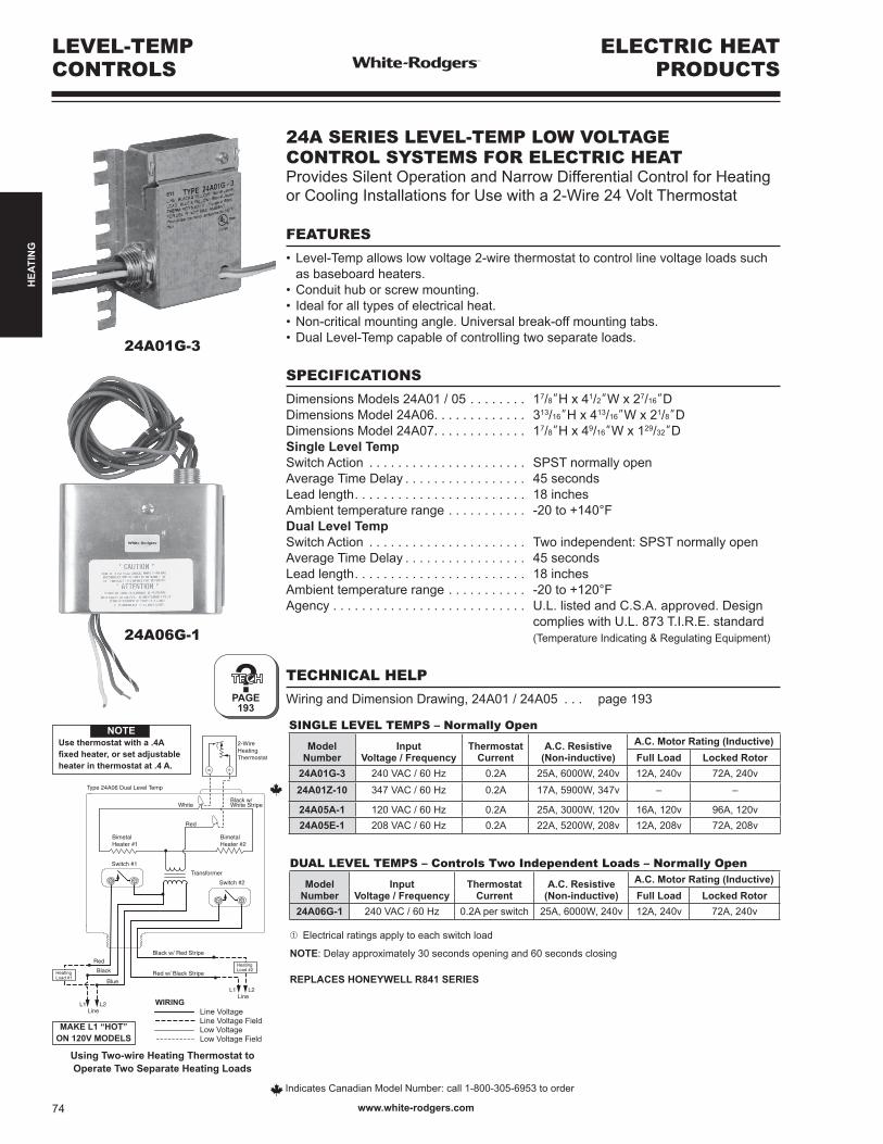
RW
Type 24A06 Dual Level Temp
White
BimetalHeater #1
Switch #1
Switch #2
BimetalHeater #2
Transformer
2-WireHeatingThermostat
Black w/ Red Stripe
Red w/ Black Stripe
L1Line
L2
L1Line
L2
HeatingLoad #2
HeatingLoad #1
Red
Black
Blue
Black w/White Stripe
Red
Line Voltage
Low VoltageLine Voltage Field
Low Voltage Field
WIRING
24A01G-3
24A06G-1
Using Two-wire Heating Thermostat to Operate Two Separate Heating Loads
ELECTRIC HEATPRODUCTS
LEVEL-TEMPCONTROLS
MAKE L1 “HOT”ON 120V MODELS
NOTEUse thermostat with a .4A fixed heater, or set adjustable heater in thermostat at .4 A.
Indicates Canadian Model Number: call 1-800-305-6953 to order
?PAGE193
24A SERIES LEVEL-TEMP LOW VOLTAGECONTROL SYSTEMS FOR ELECTRIC HEATProvides Silent Operation and Narrow Differential Control for Heating or Cooling Installations for Use with a 2-Wire 24 Volt Thermostat
FEATURES
•Level-Tempallowslowvoltage2-wirethermostattocontrollinevoltageloadssuch as baseboard heaters.•Conduithuborscrewmounting.• Idealforalltypesofelectricalheat.•Non-criticalmountingangle.Universalbreak-offmountingtabs.•DualLevel-Tempcapableofcontrollingtwoseparateloads.
SPECIFICATIONS
Dimensions Models 24A01 / 05 . . . . . . . . 17/8”H x 41/2”W x 27/16”DDimensions Model 24A06. . . . . . . . . . . . . 313/16”H x 413/16”W x 21/8”DDimensions Model 24A07. . . . . . . . . . . . . 17/8”H x 49/16”W x 129/32”DSingle Level TempSwitch Action . . . . . . . . . . . . . . . . . . . . . . SPST normally openAverage Time Delay . . . . . . . . . . . . . . . . . 45 secondsLead length. . . . . . . . . . . . . . . . . . . . . . . . 18 inchesAmbient temperature range . . . . . . . . . . . -20to+140°FDual Level TempSwitch Action . . . . . . . . . . . . . . . . . . . . . . Two independent: SPST normally openAverage Time Delay . . . . . . . . . . . . . . . . . 45 secondsLead length. . . . . . . . . . . . . . . . . . . . . . . . 18 inchesAmbient temperature range . . . . . . . . . . . -20to+120°FAgency . . . . . . . . . . . . . . . . . . . . . . . . . . . U.L. listed and C.S.A. approved. Design complies with U.L. 873 T.I.R.E. standard (Temperature Indicating & Regulating Equipment)
TECHNICAL HELP
Wiring and Dimension Drawing, 24A01 / 24A05 . . . page 193
SINGLE LEVEL TEMPS – Normally Open
Model Number
InputVoltage / Frequency
ThermostatCurrent
A.C. Resistive(Non-inductive)
A.C. Motor Rating (Inductive)Full Load Locked Rotor
24A01G-3 240 VAC / 60 Hz 0.2A 25A, 6000W, 240v 12A, 240v 72A, 240v
24A01Z-10 347 VAC / 60 Hz 0.2A 17A, 5900W, 347v – –
24A05A-1 120 VAC / 60 Hz 0.2A 25A, 3000W, 120v 16A, 120v 96A, 120v24A05E-1 208 VAC / 60 Hz 0.2A 22A, 5200W, 208v 12A, 208v 72A, 208v
DUAL LEVEL TEMPS – Controls Two Independent Loads – Normally Open
Model Number
InputVoltage / Frequency
ThermostatCurrent
A.C. Resistive(Non-inductive)
A.C. Motor Rating (Inductive)Full Load Locked Rotor
24A06G-1 240 VAC / 60 Hz 0.2A per switch 25A, 6000W, 240v 12A, 240v 72A, 240v
➀ Electrical ratings apply to each switch load
NOTE: Delay approximately 30 seconds opening and 60 seconds closing
REPLACES HONEYWELL R841 SERIES
www.white-rodgers.com74
HEA
TIN
G
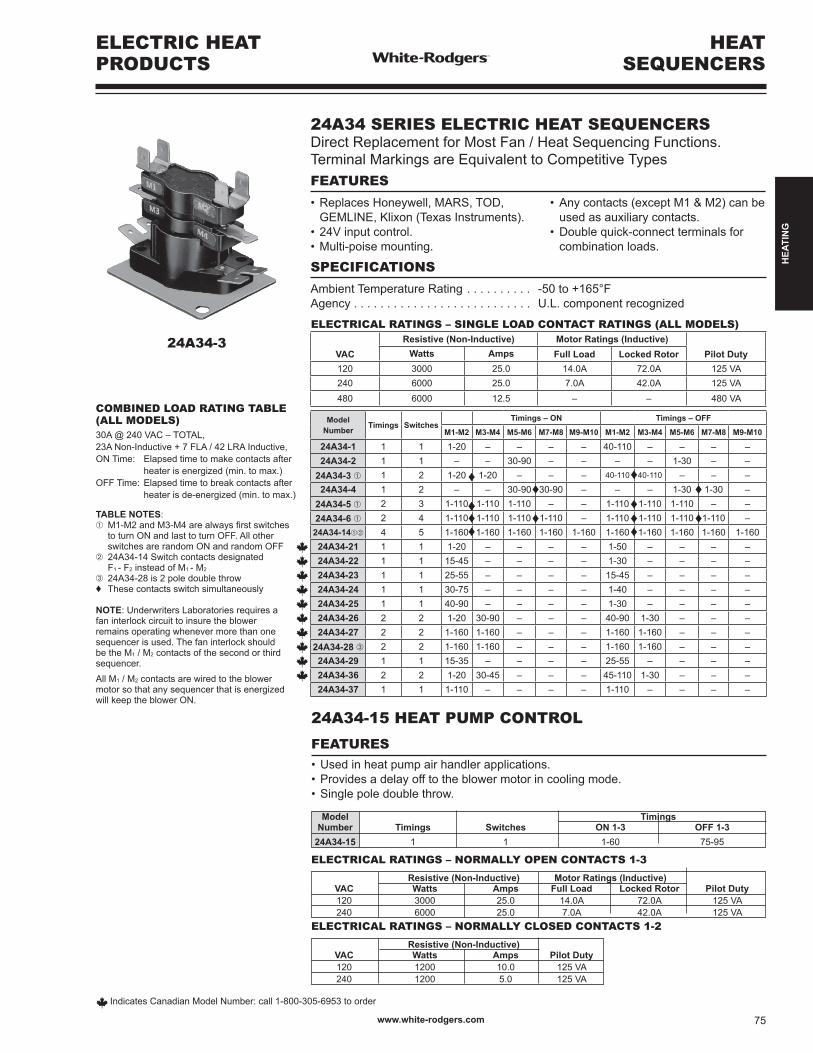
TABLE NOTES:➀ M1-M2andM3-M4arealwaysfirstswitches to turn ON and last to turn OFF. All other switches are random ON and random OFF➁ 24A34-14 Switch contacts designated F1 - F2 instead of M1 - M2
➂ 24A34-28 is 2 pole double throw♦ These contacts switch simultaneously
NOTE: Underwriters Laboratories requires afaninterlockcircuittoinsuretheblowerremains operating whenever more than one sequencerisused.Thefaninterlockshouldbe the M1 / M2 contacts of the second or third sequencer.All M1 / M2 contacts are wired to the blower motor so that any sequencer that is energized willkeeptheblowerON.
COMBINED LOAD RATING TABLE(ALL MODELS)30A @ 240 VAC – TOTAL,23ANon-Inductive+7FLA/42LRAInductive,ONTime: Elapsedtimetomakecontactsafter heater is energized (min. to max.)OFFTime:Elapsedtimetobreakcontactsafter heater is de-energized (min. to max.)
24A34-3
Model Timings Number Timings Switches ON 1-3 OFF 1-3 24A34-15 1 1 1-60 75-95
24A34-15 HEAT PUMP CONTROL
FEATURES•Usedinheatpumpairhandlerapplications.•Providesadelayofftotheblowermotorincoolingmode.•Singlepoledoublethrow.
Resistive (Non-Inductive) Motor Ratings (Inductive) VAC Watts Amps Full Load Locked Rotor Pilot Duty 120 3000 25.0 14.0A 72.0A 125 VA 240 6000 25.0 7.0A 42.0A 125 VA
ELECTRICAL RATINGS – NORMALLY OPEN CONTACTS 1-3
Resistive (Non-Inductive) VAC Watts Amps Pilot Duty 120 1200 10.0 125 VA 240 1200 5.0 125 VA
ELECTRICAL RATINGS – NORMALLY CLOSED CONTACTS 1-2
ELECTRIC HEATPRODUCTS
HEATSEQUENCERS
Indicates Canadian Model Number: call 1-800-305-6953 to order
24A34 SERIES ELECTRIC HEAT SEQUENCERSDirect Replacement for Most Fan / Heat Sequencing Functions.TerminalMarkingsareEquivalenttoCompetitiveTypesFEATURES
•ReplacesHoneywell,MARS,TOD, • Anycontacts(exceptM1&M2)canbe GEMLINE, Klixon (Texas Instruments). used as auxiliary contacts.•24Vinputcontrol. •Doublequick-connectterminalsfor•Multi-poisemounting. combinationloads.
SPECIFICATIONS
Ambient Temperature Rating . . . . . . . . . . -50to+165°FAgency . . . . . . . . . . . . . . . . . . . . . . . . . . . U.L. component recognized
ELECTRICAL RATINGS – SINGLE LOAD CONTACT RATINGS (ALL MODELS)
VACResistive (Non-Inductive) Motor Ratings (Inductive)
Pilot DutyWatts Amps Full Load Locked Rotor120 3000 25.0 14.0A 72.0A 125 VA240 6000 25.0 7.0A 42.0A 125 VA480 6000 12.5 – – 480 VA
ModelNumber Timings Switches
Timings – ON Timings – OFF
M1-M2 M3-M4 M5-M6 M7-M8 M9-M10 M1-M2 M3-M4 M5-M6 M7-M8 M9-M10
24A34-1 1 1 1-20 – – – – 40-110 – – – –24A34-2 1 1 – – 30-90 – – – – 1-30 – –
24A34-3 ➀ 1 2 1-20 1-20 – – – 40-110 40-110 – – –24A34-4 1 2 – – 30-90 30-90 – – – 1-30 1-30 –
24A34-5 ➀ 2 3 1-110 1-110 1-110 – – 1-110 1-110 1-110 – –24A34-6 ➀ 2 4 1-110 1-110 1-110 1-110 – 1-110 1-110 1-110 1-110 –
24A34-14➀➁ 4 5 1-160 1-160 1-160 1-160 1-160 1-160 1-160 1-160 1-160 1-160
24A34-21 1 1 1-20 – – – – 1-50 – – – –
24A34-22 1 1 15-45 – – – – 1-30 – – – –
24A34-23 1 1 25-55 – – – – 15-45 – – – –
24A34-24 1 1 30-75 – – – – 1-40 – – – –
24A34-25 1 1 40-90 – – – – 1-30 – – – –
24A34-26 2 2 1-20 30-90 – – – 40-90 1-30 – – –
24A34-27 2 2 1-160 1-160 – – – 1-160 1-160 – – –
24A34-28 ➂ 2 2 1-160 1-160 – – – 1-160 1-160 – – –
24A34-29 1 1 15-35 – – – – 25-55 – – – –
24A34-36 2 2 1-20 30-45 – – – 45-110 1-30 – – –24A34-37 1 1 1-110 – – – – 1-110 – – – –
♦
♦♦♦♦
♦
♦
♦
♦
♦
♦♦♦
www.white-rodgers.com 75
HEA
TIN
G
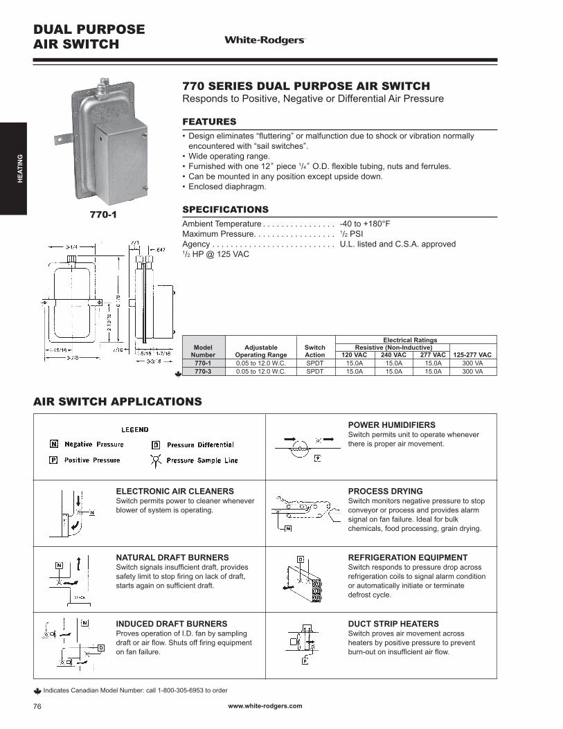
Electrical Ratings Model Adjustable Switch Resistive (Non-Inductive) Number Operating Range Action 120 VAC 240 VAC 277 VAC 125-277 VAC 770-1 0.05 to 12.0 W.C. SPDT 15.0A 15.0A 15.0A 300 VA 770-3 0.05 to 12.0 W.C. SPDT 15.0A 15.0A 15.0A 300 VA
770 SERIES DUAL PURPOSE AIR SWITCHResponds to Positive, Negative or Differential Air Pressure
FEATURES•Designeliminates“fluttering”ormalfunctionduetoshockorvibrationnormally encounteredwith“sailswitches”.•Wideoperatingrange.•Furnishedwithone12” piece 1/4”O.D.flexibletubing,nutsandferrules.•Canbemountedinanypositionexceptupsidedown.•Encloseddiaphragm.
SPECIFICATIONSAmbient Temperature . . . . . . . . . . . . . . . . -40to+180°FMaximum Pressure. . . . . . . . . . . . . . . . . . 1/2 PSIAgency . . . . . . . . . . . . . . . . . . . . . . . . . . . U.L. listed and C.S.A. approved1/2 HP @ 125 VAC
770-1
AIR SWITCH APPLICATIONS
ELECTRONIC AIR CLEANERSSwitch permits power to cleaner wheneverblower of system is operating.
PROCESS DRYINGSwitch monitors negative pressure to stopconveyor or process and provides alarmsignalonfanfailure.Idealforbulkchemicals, food processing, grain drying.
POWER HUMIDIFIERSSwitch permits unit to operate wheneverthere is proper air movement.
NATURAL DRAFT BURNERSSwitchsignalsinsufficientdraft,providessafetylimittostopfiringonlackofdraft,startsagainonsufficientdraft.
REFRIGERATION EQUIPMENTSwitch responds to pressure drop acrossrefrigeration coils to signal alarm conditionor automatically initiate or terminatedefrost cycle.
INDUCED DRAFT BURNERSProves operation of I.D. fan by samplingdraftorairflow.Shutsofffiringequipmenton fan failure.
DUCT STRIP HEATERSSwitch proves air movement acrossheaters by positive pressure to preventburn-outoninsufficientairflow.
DUAL PURPOSEAIR SWITCH
Indicates Canadian Model Number: call 1-800-305-6953 to order
www.white-rodgers.com76
HEA
TIN
G
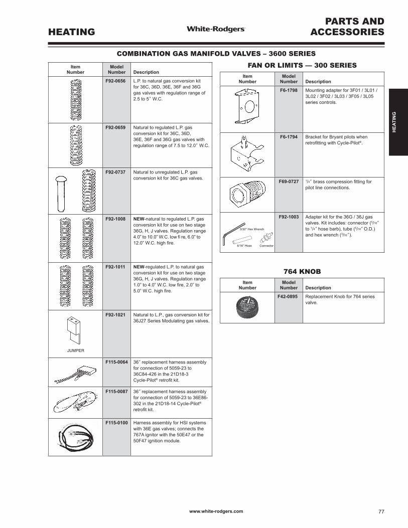
ItemNumber
ModelNumber Description
F92-0656 L.P.tonaturalgasconversionkit for 36C, 36D, 36E, 36F and 36G gas valves with regulation range of 2.5 to 5” W.C.
F92-0659 Natural to regulated L.P. gasconversionkitfor36C,36D,36E, 36F and 36G gas valves with regulation range of 7.5 to 12.0” W.C.
F92-0737 Natural to unregulated L.P. gas conversionkitfor36Cgasvalves.
F92-1008 NEW-natural to regulated L.P. gas conversionkitforuseontwostage 36G, H, J valves. Regulation range 4.0”to10.0”W.C.lowfire,6.0”to12.0”W.C.highfire.
F92-1011 NEW-regulated L.P. to natural gas conversionkitforuseontwostage36G, H, J valves. Regulation range 1.0”to4.0”W.C.lowfire,2.0”to5.0”W.C.highfire.VALVE CONVERTED FOR USE ON L.P.
GAS. IMPROPER OPERATION COULDRESULT IN DEATH OR SERIOUSINJURY.
WARNING!
SOUPAPE CONVERTIE POUR USAGESUR GAZ DE PÉTROLE LIQUÉFIÉ.UN FONCTIONNEMENT INAPPROPRIÉPEUT PROVOQUER LA MORT OU DESBLESSURES GRAVES.
MISE EN GARDE!
WARNING LABEL
L .P . LABEL
JUMPER
LP
F92-1021 NaturaltoL.P.,gasconversionkitfor36J27 Series Modulating gas valves.
F115-0064 36” replacement harness assembly for connection of 5059-23 to 36C84-426 in the 21D18-3 Cycle-Pilot®retrofitkit.
F115-0087 36” replacement harness assembly for connection of 5059-23 to 36E86-302 in the 21D18-14 Cycle-Pilot® retrofitkit.
F115-0100 Harness assembly for HSI systems with 36E gas valves; connects the 767A ignitor with the 50E47 or the 50F47 ignition module.
FAN OR LIMITS — 300 SERIESItem
NumberModel
Number Description
F6-1798 Mounting adapter for 3F01 / 3L01 / 3L02 / 3F02 / 3L03 / 3F05 / 3L05 series controls.
F6-1794 BracketforBryantpilotswhenretrofittingwithCycle-Pilot®.
F69-0727 1/4”brasscompressionfittingforpilot line connections.
Figure 2. Contents of kit
5/16" Hose
3/32" Hex Wrench
Connector
F92-1003 Adapterkitforthe36G/36Jgasvalves. Kit includes: connector (5/16”
to 1/4” hose barb), tube (5/16” O.D.) and hex wrench (3/32”).
764 KNOB Item
NumberModel
Number Description
F42-0895 Replacement Knob for 764 seriesvalve.
COMBINATION GAS MANIFOLD VALVES – 3600 SERIES
PARTS ANDACCESSORIESHEATING
VALVE CONVERTED FOR USE ON L.P.GAS. IMPROPER OPERATION COULDRESULT IN DEATH OR SERIOUSINJURY.
WARNING!
SOUPAPE CONVERTIE POUR USAGESUR GAZ DE PÉTROLE LIQUÉFIÉ.UN FONCTIONNEMENT INAPPROPRIÉPEUT PROVOQUER LA MORT OU DESBLESSURES GRAVES.
MISE EN GARDE!
WARNING LABEL
L .P . LABEL
JUMPER
LP
www.white-rodgers.com 77
HEA
TIN
G
Related Documents