Index: (click with mouse) Düker in general Preamble The complete product range –> Index Location plan Flag / Addresses FITTINGS AND VALVES We designed the electronic version of our product catalogue user-friendly. In addition to useful information you will find the complete product range of Düker “fittings and valves”. To see each detailed information, please click on the desired category within the index. To get back to the Index please click on the blue area (chapter) at the top margin. Fittings, Flanged pipes and Valves made of Ductile Cast Iron ( GGG ) http://www.dueker.de

Welcome message from author
This document is posted to help you gain knowledge. Please leave a comment to let me know what you think about it! Share it to your friends and learn new things together.
Transcript
Fittings, flanged pipes and valves made of
ductile cast iron (GGG)
Index: (click with mouse)
Düker in general
Preamble
The complete product range –> Index
Location plan
Flag / Addresses
FITTINGS AND VALVES
We designed the electronic version of our product catalogue user-friendly.
In addition to useful information you will find the complete product range of Düker “fittings and valves”.
To see each detailed information, please click on the desired category within the index.
To get back to the Index please click on the blue area (chapter) at the top margin.
Fittings, Flanged pipes andValves made of Ductile Cast Iron ( GGG )
http://www.dueker.de
© 05.2015 E
Hauptstraße 39–41, 63846 Laufach, Germany
All rights reserved, including copying as a whole or in part.
Deviations in dimensions and weights and in the illustrations are possible. In the interest of technical progress, we reserve the right to implement changes and improvements to the products without previous announcement.
Düker GmbH & Co. KGaAHauptstraße 39 – 41, 63846 Laufach, GermanyPhone: + 49 6093 87-560 Telefax: + 49 6093 87-246e-mail: [email protected] Internet: http://www.dueker.de
Member ofFGR / EADIPS association
Back to summary
Düker GmbH & Co. KGaA76
As early as in 1469, official documents mentioned a mine, which developed more or less continually into today’s company Düker.The foundry and enamelling works cover a production area of more than 80,000 square meters with approx. 650 employees.
At Laufach / Spessart and Karlstadt / Main, Düker manufactures products used in:
Drainage technology• Hubless drainage pipe systems• couplings for hubless drainage pipe systems Underground construction• flanged pressure pipes• fittings and• valves Chemical industry Acid-proof glass-lined … • pipes• valves • special valves and• columns Jobbing foundry• castings in small, medium and large series• various cast iron qualities (grey cast iron and spheroidal cast iron), raw and machined• various casting procedures (hand moulding, machine casting, centrifugal casting)
Back to summary

98
How to find Düker …Back to summary

1110
1
2
3
4
5
6
Joints for fittings, flanged pipes and valves made of ductile cast iron (GGG)
Ductile cast iron (GGG) fittings and flanged pressure pipes
Ductile cast iron (GGG) valves
Accessories
Laying and assembly instructions
Contacts
Back to summaryWe keep on moving …
Dear customer, dear business friends,We are glad to present you the new edition of our product catalogue for fittings, flanged pipes and valves made of ductile cast iron for underground construction.In addition to quality and reliability as well as to the extension and specifying of our product range we always assist you with planning, service and individual customer care.You can always depend on Düker consultants, technicians and designing engineers regarding questions, particular tasks and demands. Of course we also appreciate your incitations and criticism.Demand us – give us a call !
Your Sales Department
Phone: +49 6093 87-560

Description Code Page
1 Joints for fittings, flanged pipes and valves made of ductile cast iron (GGG) 21
1.1 Socket joints TYTON® socket joints TYT 22 Screw-gland socket joints SMU 23 Bolted-gland socket joints STB 24
1.2 Restrained socket joints TYTON® socket joints with TYTON® SIT® 26 with TYTON SIT PLUS® ( TSP® ) 27
Novo socket joints with NOVO-SIT® 28 with NOVO-Grip® III 29
Screw-gland socket joints with Düker SMU thrust resisting joint 30 with Düker SPEZIAL 31
1.3 Flanged joints PN 10 32 – 33 PN 16 34 – 35 PN 25 36 – 37 PN 40 38 – 39 Hexagon head screws for flanges 40 – 41 Flat gaskets for flanges 42 Arrangement of screw holes 43
Index1312
To page down within the categories please use the navigation bar of the acrobat-reader as well.
IndexIndex
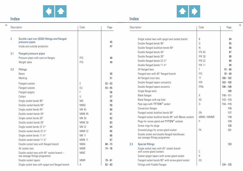
Description Code Page
Single socket tees with spigot and socket branch B 84 Double flanged bends 90° Q 85 Double flanged duckfoot bends 90° N 86 Double flanged bends 45° FFK 45 87 Double flanged bends 30° FFK 30 88 Double flanged bends 22 1/2° FFK 22 89 Double flanged bends 11 1/4° FFK 11 90 All flanged tees T 91 – 96 Flanged tees with 45° flanged branch FFC 97 – 99 All flanged cross tees TT 100 – 102 Double flanged tapers concentric FFR 103 – 105 Double flanged tapers eccentric FFRe 106 – 108 Single flange bells 109 Blank flanges X 110 – 111 Blank flanges with tap hole XG 112 – 113 Pipe caps with TYTON® socket O 114 – 115 Conversion flanges 116 Flanged socket duckfoot bends 90° EN 117 Flanged socket duckfoot bends 90° with Novo sockets MMN / MMNR 118 Plugs for screw-gland and TYTON® sockets P 119 Screw rings for plugs 120 Screwed plugs for screw-gland socket PX 121 Double socket and double flanged hatchboxes: see sewage fittings programme
2.3 Special fittings 123 Single socket tees with 45° socket branch
with screw-gland sockets C Socket-spigot tapers with screw-gland socket R Flanged socket bends 90° with screw-gland socket EQ Fittings with Puddle Flanges 124 – 125
1514Description Code Page
2 Ductile cast iron (GGG) fittings and flanged pressure pipes 45 Inside and outside protection 47
2.1 Flanged pressure pipes Pressure pipes with cast-on flanges FFG 48 Weight table FFG 49
2.2 Fittings Notes 50 Marking 51
Flanged sockets E 52 – 53 Flanged sockets EU 54 – 55 Flanged spigots F 56 Collars U 57 Single socket bends 90° MQ 58 Double socket bends 90° MMQ 59 Single socket bends 45° MK 45 60 Double socket bends 45° MMK 45 61 Single socket bends 30° MK 30 62 Double socket bends 30° MMK 30 63 Single socket bends 22 1/2° MK 22 64 Double socket bends 22 1/2° MMK 22 65 Single socket bends 11 1/4° MK 11 66 Double socket bends 11 1/4° MMK 11 67 Double socket tees with flanged branch MMA 68 – 73 All socket tees MMB 74 – 78 Double socket tees with 45° socket branch – MMC see sewage fittings programme Double socket tapers MMR 79 – 81 Single socket tees with spigot and flanged branch A 82 – 83

IndexIndex
Description Code Page
2.4 Fittings for plastic pipelines (KS fittings) Notes 127
Flanged sockets E-KS 128 Flanged spigots F-KS 129 Flanged socket duckfoot bends 90° EN-KS 130 Double socket tees with flanged branch MMA-KS 131 – 132 All socket tees MMB-KS 133 Double socket tapers MMR-KS 134 Double sockets with internal thread branch MMI-KS 135 – 136
2.5 Sewage fittings Notes 137
Drilling saddle pieces with 90° branch with clay pipe socket SM 90 138 with 45° branch with clay pipe socket SM 45 139 with 90° branch with spigot for ductile iron pipe or for clay pipe SI 90 140 with 45° branch with spigot for ductile
iron pipe SI 45 141 TYTON® coupling MM 142 Spigot end branches 67° ICI 67 143 Double socket branch with TYTON® sockets, with 67°/45° branch with spigot for ductile iron pipe MMI 144 Double socket branch with TYTON® sockets, with 45° branch with clay pipe socket MMM 145 Pipe sealing cap with ventilation valve RVD 146 Manhole connection pieces with TYTON® socket SA 147 Double flanged hatchboxes 148 Double socket hatchboxes 149 Double socket tees with 45° socket branch MMC 150 – 151
Description Code Page
3 Ductile cast iron (GGG) valves
3.1 Gate valves Type 4004 with flanges 154 – 155 Type 2004 with flanges (short face-to-face length) 156 – 157 Type 4004 with Novo sockets 158 – 159 Type 4004 with Novo socket and spigot 160 – 161 Type 4004 with screw-gland sockets 162 – 163 Type 2004 with flange and screw-gland socket 164 – 165 (short face-to-face length) Type 4004 with PE welding studs 166 – 167 Type 4004 replacement and repair valve 168 – 169 with rotatable flanges Type 2004 replacement and repair valve 170 – 171 with rotatable flanges (short face-to-face length) Type 3004 with welding studs for steel pipes 172 – 173 Type 4004 with blow-off pipes and PE welding studs 174 – 175 Type 3004 with blow-off pipes and welding studs for steel pipes 176 – 177 Type 3004 with blow-off pipes and PE welding studs 178 – 179
3.2 Service connection valves Tapping valve TOP (top drilling) 180 – 181 Tapping valve TOPsi (horizontal drilling) 182 – 183 Tapping valve TOP with PE connection 184 – 185 Tapping clamps 186 Clapping bands 187 Type 1004 with internal thread 188 – 189 Type 1004 with PE welding studs 190 – 191 Type 1004 with flange and PE welding stud 192 – 193 Type 1004 with internal thread and PE welding stud 194 – 195 Gate valve combination Multi I 196 – 197
1716
IndexIndex
Description Code Page
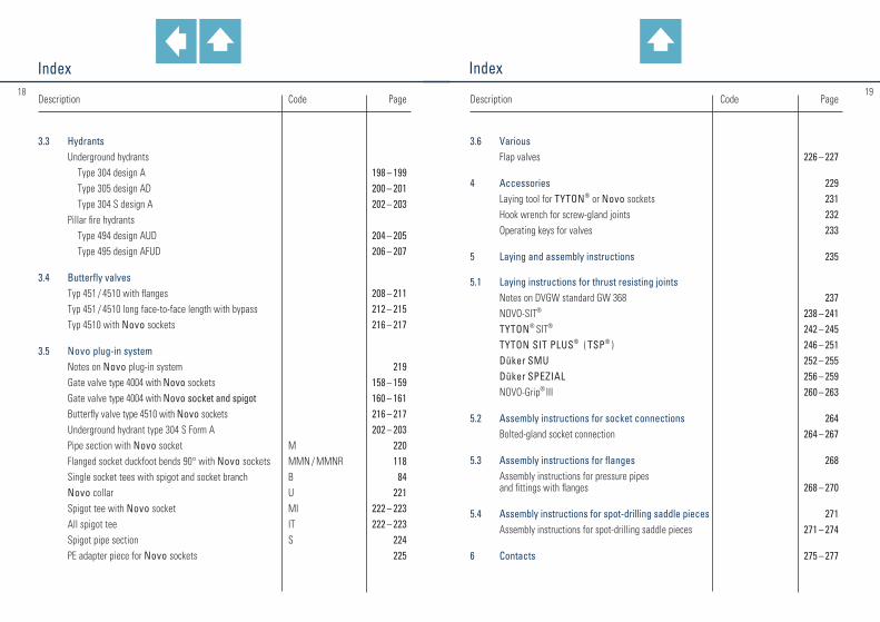
3.6 Various Flap valves 226 – 227
4 Accessories 229 Laying tool for TYTON® or Novo sockets 231 Hook wrench for screw-gland joints 232 Operating keys for valves 233
5 Laying and assembly instructions 235
5.1 Laying instructions for thrust resisting joints Notes on DVGW standard GW 368 237 NOVO-SIT® 238 – 241 TYTON® SIT® 242 – 245 TYTON SIT PLUS® ( TSP® ) 246 – 251 Düker SMU 252 – 255 Düker SPEZIAL 256 – 259 NOVO-Grip® III 260 – 263
5.2 Assembly instructions for socket connections 264 Bolted-gland socket connection 264 – 267
5.3 Assembly instructions for flanges 268 Assembly instructions for pressure pipes
and fittings with flanges 268 – 270
5.4 Assembly instructions for spot-drilling saddle pieces 271 Assembly instructions for spot-drilling saddle pieces 271 – 274
6 Contacts 275 – 277
1918Description Code Page
3.3 Hydrants Underground hydrants Type 304 design A 198 – 199 Type 305 design AD 200 – 201 Type 304 S design A 202 – 203 Pillar fire hydrants Type 494 design AUD 204 – 205 Type 495 design AFUD 206 – 207
3.4 Butterfly valves Typ 451 / 4510 with flanges 208 – 211 Typ 451 / 4510 long face-to-face length with bypass 212 – 215 Typ 4510 with Novo sockets 216 – 217
3.5 Novo plug-in system Notes on Novo plug-in system 219 Gate valve type 4004 with Novo sockets 158 – 159 Gate valve type 4004 with Novo socket and spigot 160 – 161 Butterfly valve type 4510 with Novo sockets 216 – 217 Underground hydrant type 304 S Form A 202 – 203 Pipe section with Novo socket M 220 Flanged socket duckfoot bends 90° with Novo sockets MMN / MMNR 118 Single socket tees with spigot and socket branch B 84 Novo collar U 221 Spigot tee with Novo socket MI 222 – 223 All spigot tee IT 222 – 223 Spigot pipe section S 224 PE adapter piece for Novo sockets 225
11
Joints for fittings, flanged pipes and valves made of ductile cast iron (GGG)
20
Back to summary

22 23
11.1
TYTON® socket joints ( TYT ) acc. to DIN 28 603
Screw-gland socket joints ( SMU ) PN 16 1) acc. to DIN 28 601
DN
40 50 65 80100125150200250300350400
450* 500*
ø d1
56 66 82 98118144170222274326378429480532
ø D
101113129146166197224280336391450503572626
t
74 77 80 84 88 91 94100106110113116164174
Pipes
— ——
3,4 4,3 5,7 7,110,314,218,623,729,3——
Fittings
1,4 1,8 2,2 2,8 3,3 4,5 5,6 8,011,114,318,622,2——
Flanged sockets
1,3 1,6 1,9 2,4 3,1 4,0 4,9 7,1 9,712,516,219,5
28,5
Dimensions in mm Weight in kg ≈ socketScrew ring
0,84 0,90 1,30 1,40 1,90 3,00 3,20 4,50 6,30 8,1010,5013,5025,0031,50
Gliding ring
0,050,060,060,070,080,100,110,170,210,300,350,400,600,87
Gasket
0,060,080,100,120,150,190,230,360,500,660,841,051,501,85
Dimensions and weights
* acc. to manufacturer’s standard 1) higher pressures on request
Socket for flanged sockets and collars Socket for pipes
Socket for fittings
DN
80 100 125 150 200 250 300 350 400
450* 500 600 700 800 900100012001400
ø d1
98 118 144 170 222 274 326 378 429 480 532 635 738 842 945104812551462
ø D
141 161 188 215 271 324 381 434 489
541,5 598 707 825 9351042115013681610
t
84 88 91 94100105110110110120120120150160175185215240
Pipes
3,4 4,3 5,7 7,1 10,3 14,2 18,6 23,7 29,3 37,8 42,8 59,3 79,1102,6129,9161,3
——
Fittings
2,8 3,3 4,5 5,6 8,0 11,1 14,3 17,1 20,8 27,6 31,7 42,3 71,2 95,4150,3186,9250,0468,7
Flanged sockets
2,43,14,04,97,19,7
12,515,218,624,327,636,259,179,8
122,7152,1193,0373,0
Gasket
0,130,160,190,220,370,480,670,771,091,401,602,294,005,206,508,009,50
17,20
Dimensions in mm Weight in kg ≈ socket
Dimensions and weights
Socket for flanged sockets and collars Socket for pipes
Socket for fittings
* acc. to manufacturer’s standard

2524
11.11.1
Bolted-gland socket joints ( STB ) PN 16 1) acc. to DIN 28 602
Assembly instructions see page 264 – 267
DN
100*150*200*250*300*350*400*450*500600700800900
1000120014001600
ø d1
118170222274326378429480532635738842945
1048125514621668
ø D
235 290 345 400 460 515 570 625 680 790 900101011251250145017141920
t
116118121124127129132135138143149154160165176187198
ø d2
M 20M 20M 20M 20M 20M 20M 20M 20M 20M 20M 20M 20M 20M 24M 24M 24M 24
l
80 80 80 80 90 90 90100100100110110120120130150150
n
4 8 8 8 8 12 1212 16 16 20 242424283236
Pipes
— ————26,632,245,345,361,280,0
101,0128,0162,9232,4
Flanged sockets collars
————18,722,927,638,738,752,267,985,4
108,4138,7196,5292,3319,5
Dimensions in mm Weight in kg ≈ socketBolted- gland ring
2,74,0 5,06,07,19,6
10,613,015,020,927,234,144,057,075,0
128,5142,8
Gasket
0,100,200,270,500,600,700,801,001,001,501,902,302,803,303,806,907,90
Hammer head
screws
0,24 0,24 0,24 0,24 0,27 5,5 5,5 6,0 7,7 7,7 10,0 12,0 12,0 13,0 18,0 19,5 22,0
Dimensions and weights
* acc. to manufacturer’s standard 1) higher pressures on request
Socket for pipes and fittings Socket for flanged sockets
2726
11.2
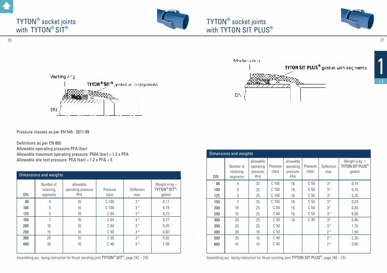
TYTON® socket joints with TYTON® SIT®
DN
80100125150200250300400
Number of retaining segments
4 5 5 710152030
allowable operating pressure
PFA
1616161616101010
Deflection max.
3 °3 °3 °3 °3 °3 °3 °3 °
Weight in kg ≈ TYTON® SIT®-
gasket
0,170,190,230,270,450,600,921,58
Dimensions and weights
Assembling acc. laying instruction for thrust resisting joint TYTON® SIT®, page 242 – 245
Pressure classes as per EN 545 : 2011-09
Definitions as per EN 805Allowable operating pressure PFA (bar)Allowable maximum operating pressure: PMA (bar) = 1.2 x PFAAllowable site test pressure: PEA (bar) = 1.2 x PFA + 5
Pressure class
C 100C 100C 64C 64C 64C 50C 50C 40
TYTON® socket joints with TYTON SIT PLUS®
Assembling acc. laying instruction for thrust resisting joint TYTON SIT PLUS®, page 246 – 251
DN
80 100 125 150 200 250 300 350 400 500 600
Number of retaining segments
4 5 5 710152025283542
Pressure class
C 100C 100C 100C 100 C 64 C 64 C 50 C 50 C 50 C 40 C 40
Pressure class
C 50 C 50 C 50 C 50 C 50 C 50 C 40
allowable operating pressure
PFA
16161616161616
allowable operating pressure
PFA
3232252525252525161610
Deflection max.
3 °3 °3 °3 °3 °3 °3 °3 ° 2 ° 2 ° 2 °
Weight in kg ≈ TYTON SIT PLUS®
gasket
0,140,160,200,230,450,600,951,251,502,303,00
Dimensions and weights

28 29
11.2
Novo socket joints with NOVO-SIT®
Assembling acc. laying instruction for thrust resisting joint NOVO-SIT®, page 238 – 241
DN
80 100 125 150 200 250 300 350 400 450 500 600 700 800
d1
98 118 140 170 222 274 326 378 429 480 532 635 738 842
D
141 161 188 215 271 324 381 434 505 572 598 707 824 934
t
119123126129138143152154154164168168205217
Pressure class
C 100C 100C 100C 100 C 64 C 64 C 50 C 50 C 50 C 40 C 40 C 40 C 40 C 40
Pressure class
C 50 C 50 C 50 C 50 C 50 C 50 C 50
allow. o. p.PFA
25161616161616
allow. o. p.PFA
4025252525252516161616161010
Deflectionmax.
3 °3 °3 °3 °3 °3 °3 °3 °3 °3 °2 °2 °2 °1 °
NovoPre-
chamber
1,2 1,4 1,8 2,1 3,1 4,8 5,7 6,4 8,3 9,512,016,629,536,6
NOVO-SIT®
ring
0,150,200,250,350,650,801,001,301,502,002,503,003,503,60
Dimensions in mm Weight in kg ≈
Dimensions and weights
Number of
locking segments
5571013182222252835456270 Assembling acc. laying instruction for thrust resisting joint NOVO-Grip® III, page 260 – 263
* Note: in DN 200, it is not possible to use the standard Novo socket for NOVO-Grip®; use only items with adapted geometry and marking „for PE-HD pipes“.
Restrained socket joints for plastic pipelines with NOVO-Grip® III
Locking ringCompression ring
Gasket (GKS)
DN
80100125150200*
ø d1
plastic pipelines DN/OD in mm
90110140160225
t
119123126129138
Weight in kg ≈ assembly set
0,200,250,300,501,00
PFA at SDR 11 bar
1616161616
PFA at SDR 17 bar
1010101010
Dimensions and weights
Note: The Novo socket does not change the standardised length of fittings and valves.
313030
11.2
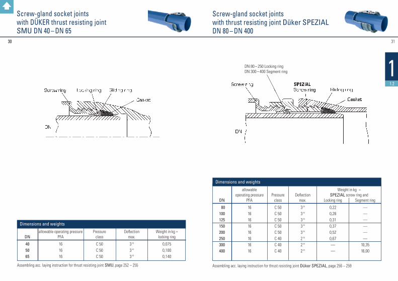
Screw-gland socket jointswith DÜKER thrust resisting joint SMU DN 40 – DN 65
Assembling acc. laying instruction for thrust resisting joint SMU, page 252 – 255
DN
40 5065
allowable operating pressurePFA
161616
Deflectionmax.
3 °3 °3 °
Pressureclass
C 50C 50C 50
Weight in kg ≈ locking ring
0,0750,1000,140
Dimensions and weights
Screw-gland socket joints with thrust resisting joint Düker SPEZIALDN 80 – DN 400
Assembling acc. laying instruction for thrust resisting joint Düker SPEZIAL, page 256 – 259
DN 80 – 250 Locking ringDN 300 – 400 Segment ring
DN
80100125150200250300400
allowable operating pressure
PFA
1616161616161616
Pressure class
C 50C 50C 50C 50C 50C 40C 40C 40
Deflectionmax.
3 °3 °3 °3 °3 °2 °2 °2 °
Locking ring
0,220,260,310,370,520,67——
Weight in kg ≈ SPEZIAL screw ring and
Dimensions and weights
Segment ring
——————
10,3516,00
3332
11.3
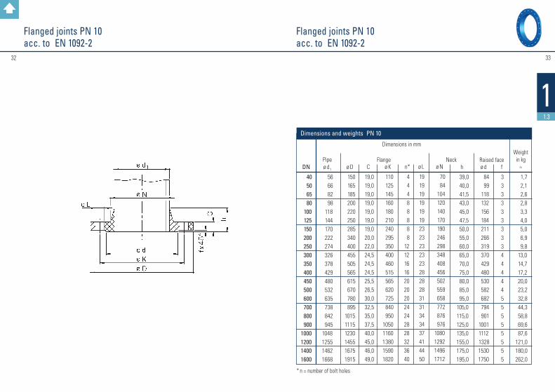
Flanged joints PN 10 acc. to EN 1092-2
Flanged joints PN 10 acc. to EN 1092-2
* n = number of bolt holes
DN
40 50 65 80 100 125 150 200 250 300 350 400 450 500 600 700 800 9001000120014001600
Pipe ø d1
56 66 82 98 118 144 170 222 274 326 378 429 480 532 635 738 842 9451048125514621668
ø D
150 165 185 200 220 250 285 340 400 455 505 565 615 670 780 895101511151230145516751915
C
19,019,019,019,019,019,019,020,022,024,524,524,525,526,530,032,535,037,540,045,046,049,0
ø K
110 125 145 160 180 210 240 295 350 400 460 515 565 620 725 840 95010501160138015901820
n*
4 4 4 8 8 8 8 81212161620202024242828323640
ø L
19191919191923232323232828283131343437414450
ø N
70 84 104 120 140 170 190 246 298 348 408 456 502 559 658 772 876 9761080129214961712
Dimensions in mm h
39,0 40,0 41,5 43,0 45,0 47,5 50,0 55,0 60,0 65,0 70,0 75,0 80,0 85,0 95,0105,0115,0125,0135,0155,0175,0195,0
ø d
84 99 118 132 156 184 211 266 319 370 429 480 530 582 682 794 901 10011112 132815301750
f
3333333334444455555555
Weight in kg
≈
1,7 2,1 2,6 2,8 3,3 4,0 5,0 6,9 9,8 13,0 14,7 17,2 20,0 23,2 32,8 44,3 58,8 69,6 87,6121,0180,0262,0
Flange Neck Raised face
Dimensions and weights PN 10
3534
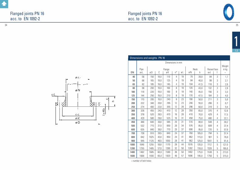
11.3
Flanged joints PN 16acc. to EN 1092-2
Flanged joints PN 16acc. to EN 1092-2
* n = number of bolt holes
DN
40 50 65 80 100 125 150 200 250 300 350 400 450 500 600 700 800 9001000120014001600
Pipe ø d1
56 66 82 98 118 144 170 222 274 326 378 429 480 532 635 738 842 9451048125514621668
ø D
150 165 185 200 220 250 285 340 400 455 520 580 640 715 840 910102511251255148516851930
C
19,0 19,0 19,0 19,0 19,0 19,019,020,022,0 24,5 26,528,030,031,536,039,543,046,550,057,060,065,0
ø K
110 125 145 160 180 210 240 295 355 410 470 525 585 650 770 840 95010501170139015901820
n*
4 4 4 8 8 8 8121212161620202024242828323640
ø L
19191919191923232828283131343737414144505057
ø N
70 84 104 120 140 170 190 246 296 350 410 458 516 576 690 760 862 9621076128214821696
Dimensions in mm h
39,0 40,0 41,5 43,0 45,0 47,5 50,0 55,0 60,0 65,0 70,0 75,0 80,0 85,0 95,0 105,0 115,0 125,0 135,0 155,0175,0195,0
ø d
84 99 118 132 156 184 211 266 319 370 429 480 548 609 720 794 90110011112132815301750
f
3333333334444455555555
Weight in kg
≈
1,7 2,1 2,6 2,8 3,3 4,0 5,0 6,7 9,4 12,6 17,5 22,1 30,2 37,4 57,6 57,4 76,8 91,4127,0185,0213,0315,0
Flange Neck Raised face
Dimensions and weights PN 16

36 37
11.3
Flanged joints PN 25acc. to EN 1092-2
Flanged joints PN 25acc. to EN 1092-2
* n = number of bolt holes
DN
40 50 65 80 100 125 150 200 250 300 350 400 450 500 600 700 800 9001000120014001600
Pipe ø d1
56 66 82 98 118 144 170 222 274 326 378 429 480 532 635 738 842 9451048125514621668
ø D
150 165 185 200 235 270 300 360 425 485 555 620 670 730 845 960108511851320153017551975
C
19,019,019,019,019,019,020,022,024,527,530,032,034,536,542,046,551,055,560,069,074,081,0
ø K
110 125 145 160 190 220 250 310 370 430 490 550 600 660 770 875 99010901210142016401860
n*
4 4 8 8 8 8 8121216161620202024242828323640
ø L
19191919 23 28 28 28 31 31 34 37 37 37 41 44 50 50 57 576262
ø N
70 84 104 120 142 162 192 252 304 364 418 472 520 580 684 780 882 9821086129615081726
Dimensions in mm h
39 4041,5 43 4547,5 50 55 60 65 70 75 80 85 95105115125135155175195
ø d
84 99 118 132 156 184 211 274 330 389 448 503 548 609 720 820 92810281140135015601780
f
3333333334444455555555
Weight in kg
≈
1,7 2,1 2,4 2,8 3,8 4,7 6,0 8,7 13,0 17,7 25,4 33,2 40,2 47,2 71,5 90,0123,0149,0201,0 285,0357,0484,0
Flange Neck Raised face
Dimensions and weights PN 25
3938
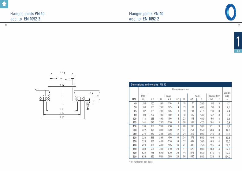
11.3
Flanged joints PN 40acc. to EN 1092-2
DN
40 50 65 80 100 125 150 200 250 300 350 400 450 500 600
Pipe ø d1
56 66 82 98 118 144 170 222 274 326 378 429 480 532 635
ø D
150165185200235270300375450515580660685755890
C
19,019,019,019,019,023,526,030,034,539,544,048,049,052,058,0
ø K
110125145160190220250320385450510585610670795
n*
4 4 8 8 8 8 81212161616202020
ø L
191919192328283134343741414450
ø N
70 84104120142162192254312378432498522576686
Dimensions in mm h
39,0 40,0 41,5 43,0 45,0 47,5 50,0 55,0 60,0 65,0 70,0 75,0 80,0 85,0 95,0
ø d
84 99 118 132 156 184 211 284 345 409 465 535 560 615 735
f
333333333444445
Weight in kg
≈
1,7 2,1 2,4 2,8 3,8 5,9 8,0 14,0 23,5 33,5 43,0 62,0 57,0 82,0124,0
Flange Neck Raised face
Dimensions and weights PN 40
Flanged joints PN 40acc. to EN 1092-2
* n = number of bolt holes

4140
11.3
Hexagon head screws for flanges PN 25 and PN 40 acc. to EN 1092-2
Hexagon head screws for flanges PN 10 and PN 16 acc. to EN 1092-2
l1* = Screw length for connection with one washer l2** = Screw length for connection with two washersSpecial stipulations: M16 x 80: Thread length min. 44 mm, M20 x 90: Thread length min. 52 mm, M24 x 100/110: Thread length min. 60 mm; l1* = Screw length for connection with one washer l2** = Screw length for connection with two washers
qty per joint
4 4 8 8 8 8 81212161616202020
DN
40 50 65 80 100 125 150 200 250 300 350 400 450 500 600 700 800 90010001200
ø d1
M 16M 16M 16M 16M 20M 24M 24M 24M 27M 27M 30M 33M 33M 33M 36M 39M 45M 45M 52M 52
l1*
80 80 80 80 80 90 90 90 100 110120 130 130 140150170180190210230
l2**
80 80 80 80 90 90 90
100 110 110120 130 130 140150170190200210230
qty per joint
4 4 8 8 8 8 812121616162020202424282832
Dimensions in mm Dimensions in mm
ø d1
M 16M 16M 16M 16M 20M 24M 24M 27M 30M 30M 33M 36M 36M 39M 45
l1*
80 80 80 80 80
100100110120140 150160160170190
l2**
80 80 80 80 90
100110120130140 150170170180200
PN 40PN 25
Not specified in EN 1092-2
DN
40 50 65 80 100 125 150 200 250 300 350 400 450 500 600 700 800 9001000120014001600
ø d1
M 16M 16M 16M 16M 16M 16M 20M 20M 20M 20M 20M 24M 24M 24M 27M 27M 30M 30M 33M 36M 39M 45
l1*
80 80 80 80 80 80 80 80 90 90 90
100 100 100 110 120130130
140160170180
l2**
80 80 80 80 80 80 90 90 90 90 90
100 110 110 120 120130140 150160170190
qty per joint
4 4 4 8 8 8 8 81212161620202024242828323640
Dimensions in mm Dimensions in mm
ø d1
M 16M 16M 16M 16M 16M 16M 20M 20M 24M 24M 24M 27M 27M 30M 33M 33M 36M 36M 39M 45M 45M 52
l1*
80 80 80 80 80 80 80 80 90
100 100 110 110120 130 140150160170190200220
l2**
80 80 80 80 80 80 90 90
100 100 110 110 120120 140 150160160180200210230
qty per joint
4 4 4 8 8 8 8121212161620202024242828323640
PN 16PN 10

4342
11.3
Arrangement of bolt holesFlat gaskets for Flanges acc. to EN 1514-1, type IBC
Dimensions for gaskets with steel inlay.The number of bolt holes is always divisible by 4.The bolt holes are arranged symmetrically to the two main axes, but not on them.
DN
40 50 65 80 100 125 150 200 250 300 350 400 500 600 700 800 9001000120014001600
ø D 1
49 61 77 90 115 141 169 220 274 325 368 420 520 620 720 820 9201020122014201620
PN 10
328 378 438 490 595 695 810 91510151120
15451770
ø D 2
92 107 127 142 162 192 218 273
1340
PN 16
330 385 445 497 618 735 805 91010051110
15401760
s
444455566677778888888
DN
40 50 65 80 100 125 150 200 250 300 350 400 450 500 600 700 800 9001000120014001600
EN 1092-2PN 10
4 4 4 8 8 8 8 81212161620202024242828323640
EN 1092-2PN 16
4 4 4 8 8 8 8121212161620202024242828323640
EN 1092-2PN 25
4 4 8 8 8 8 812121616162020202424282832——
EN 1092-2PN 40
4 4 8 8 8 8 81212161616202020———————
Dimensions and weights
Number of bolts
44
22
Ductile cast iron ( GGG ) fittings and flanged pressure pipes
Back to summary
4746
2
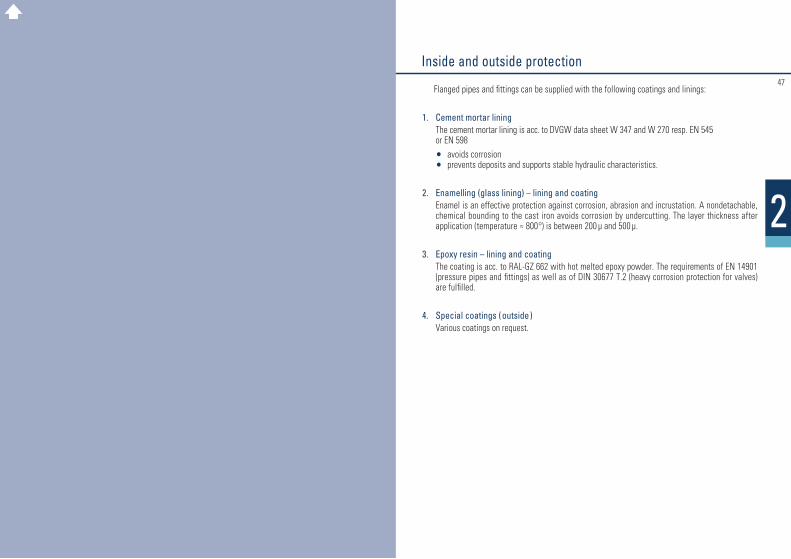
Flanged pipes and fittings can be supplied with the following coatings and linings:
1. Cement mortar lining The cement mortar lining is acc. to DVGW data sheet W 347 and W 270 resp. EN 545
or EN 598 • avoids corrosion
• prevents deposits and supports stable hydraulic characteristics.
2. Enamelling (glass lining) – lining and coating Enamel is an effective protection against corrosion, abrasion and incrustation. A non detachable,
chemical bounding to the cast iron avoids corrosion by undercutting. The layer thickness after application ( temperature ≈ 800 ° ) is between 200 µ and 500 µ.
3. Epoxy resin – lining and coating The coating is acc. to RAL-GZ 662 with hot melted epoxy powder. The requirements of EN 14901
(pressure pipes and fittings) as well as of DIN 30677 T.2 (heavy corrosion protection for valves) are fulfilled.
4. Special coatings (outside ) Various coatings on request.
Inside and outside protection

4948
22.1
Pressure pipes with cast-on flanges FFG-pipes
Further lengths are available on request.
Weight of pressure pipes with cast-on flanges PN 10 FFG-pipes
DN
40 50 65 80 100 125 150 200 250 300 350 400 450 500 600 700 800 9001000120014001600
e
7,0 7,0 7,0 7,0 7,2 7,5 7,8 8,4 9,0 9,610,210,811,412,013,214,415,616,818,020,422,825,2
L max.
1000100010002000200020002000200030003000300030003000300030002000200020002000200020002000
1 m pipe
without flange
6,9 10,7 11,0 16,1 20,4 26,4 32,4 46,1 61,3 78,1 96,5116,2132,8160,6211,3268,5332,1401,7477,7565,2740,0932,0
PN 10
1,7 2,1 2,6 2,8 3,3 4,0 5,0 6,9 9,813,014,717,2—
23,232,844,358,569,687,6
121,0——
PN 16
1,7 2,1 2,6 2,8 3,3 4,0 5,0 6,7 9,4 12,6 17,5 22,1 —
37,4 57,6 57,4 76,8 91,4 127,0 185,0349,6504,2
PN 25
1,7 2,1 2,6 2,8 3,8 4,7 6,0 8,7 13,0 17,725,4 33,2—
47,2 68,090,0
123,0149,0201,0285,0
——
Weight in kg ≈one flangeDimensions in mm
Dimensions and weights
DN
80 100 125 150 200 250 300 350 400 500 600 700 800 9001000120014001600
100
7,6 8,610,613,218,425,534,0———————————
200
9,2 10,7 13,3 16,5 23,0 32,0 41,5 48,5 57,5 78,5108,0
———————
300
10,8 12,7 15,9 19,7 27,5 38,0 49,5 58,5 69,5 94,5129,0169,0
——————
400
12,4 14,8 18,6 23,0 32,0 44,0 57,0 68,0 81,0111,0150,0196,0250,0300,0366,0468,0738,0
1018,0
500
14,1 16,8 21,0 26,0 37,0 50,5 65,0 77,5 92,5127,0171,0223,0284,0340,0414,0525,0812,0
1111,0
600
15,7 18,8 24,0 29,5 41,5 56,5 73,0 87,5104,0143,0192,0250,0317,0380,0462,0581,0886,0
1204,0
700
17,3 21,0 26,5 32,5 46,0 62,5 80,5 97,0116,0159,0214,0276,0350,0420,0510,0638,0960,0
1297,0
800
18,9 23,0 29,0 36,0 50,5 68,5 88,5107,0127,0175,0235,0303,0383,0461,0557,0694,0
1034,01390,0
900
20,5 25,0 32,0 39,0 55,5 75,0 96,5116,0139,0191,0256,0330,0416,0501,0605,0751,0
1108,01483,0
1000
22,0 27,0 34,5 42,5 60,0 81,0104,0126,0151,0207,0277,0357,0450,0541,0653,0807,0
1182,01576,0
Weight in kg ≈
Length L in mm
5150
22.2
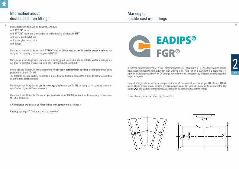
Marking forductile cast iron fittings
All German manufacturers member of the “Fachgemeinschaft Guss-Rohrsysteme” (FGR-EADIPS) association mark all ductile cast iron products manufactured by them with the label “FGR”, which is equivalent to a quality mark. In addition, fittings are marked with the DVGW sign, nominal diameter, the casting day and bends with the respective angles in degrees.
Flanged fittings bear a cast-on or stamped indication of the nominal pressure ranges PN 10 up to PN 40. Socket fittings are not marked with the nominal pressure range. The material “ductile cast iron” is identified by 3 dots (ll
l ), arranged in a triangle symbol, positioned on the exterior surface of the fittings.
In special cases, further indications may be provided.
Ductile cast iron fittings will be delivered as follows:with TYTON® socketwith TYTON® socket and pre-chamber for thrust resisting joint NOVO-SIT®
with screw-gland socket jointwith bolted-gland socket jointwith flanges
Ductile cast iron socket fittings with TYTON® sockets ( flangeless ) for use in potable water pipelines are designed for operating pressures as given in EN 545.
Ductile cast iron fittings with screw-gland or bolted-gland sockets for use in potable water pipelines are designed for operating pressures up to 16 bar. Higher pressures on request.
Ductile cast iron fittings with one flange or more, for the use in potable water pipelines are designed for operating pressures as given in EN 545.The operating pressure has to be mentioned in orders, because the flange dimensions of these fittings vary depending on the nominal pressures rates.
Ductile cast iron fittings for the use in sewerage pipelines as per EN 598 are designed for operating pressures up to 16 bar. Higher pressures on request.
Ductile cast iron fittings for the use in gas pipelines as per EN 969 are available for operating pressures up to 16 bar on request.
> All indicated weights are valid for fittings with cement-mortar linings <
Coating: see page 47 “Inside and outside protection”.
Information aboutductile cast iron fittings
52
22.2
53
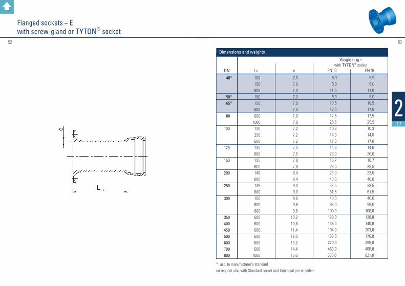
Flanged sockets – Ewith screw-gland or TYTON® socket
* acc. to manufacturer’s standardon request also with Standard socket and Universal pre-chamber
DN
40*
50* 65*
80
100
125
150
200
250
300
350400450500600700800
Lu
100 150 600 150 150 600 600 1000 130 250 600 135 600 135 600 140 600 145 600 150 600 800 600 600 600 600 600 6001000
e
7,0 7,0 7,0 7,0 7,0 7,0 7,0 7,0 7,2 7,2 7,2 7,5 7,5 7,8 7,8 8,4 8,4 9,0 9,0 9,6 9,6 9,610,210,811,412,013,214,415,6
PN 10
5,9 6,0 11,0 8,0 10,5 17,0 17,5 25,5 10,3 14,0 17,0 14,6 26,0 16,7 28,5 23,0 40,0 33,5 61,5 40,0 96,0 100,0 128,0 135,0 194,0 163,0 270,0 453,0603,0
Weight in kg ≈ with TYTON® socket
PN 16
5,9 6,0 11,0 8,0 10,5 17,0 17,5 25,5 10,3 14,0 17,0 14,6 26,0 16,7 28,5 23,0 40,0 33,5 61,5 40,0 96,0100,0130,0140,0203,0176,0295,0466,0621,0
Dimensions and weights
54
22.2
55
➜
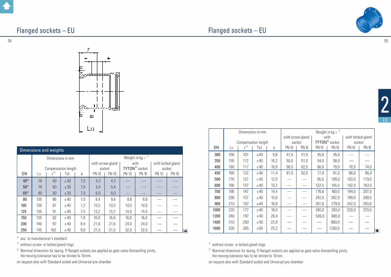
Flanged sockets – EU Flanged sockets – EU
DN
40* 50* 65* 80 100 125 150 200 250
Lu
76 78 80130130135135140145
z 2)
50 50 50 86 87 91 92 97102
Tol.
± 30± 30± 30± 40± 40± 40± 40± 40± 40
e
7,0 7,0 7,0 7,0 7,2 7,5 7,8 8,4 9,0
PN 10
4,3 5,4 6,0 8,4 10,513,216,021,631,5
PN 16
4,3 5,4 6,0 8,4 10,513,216,021,631,5
PN 10
— — —
8,6 10,5 14,5 16,0 24,0 32,5
Dimensions in mm
Compensation lengthwith screw-gland
socketwith
TYTON® socketwith bolted-gland
socket
Weight in kg ≈ 1)
PN 16
— — —
8,6 10,5 14,5 16,0 24,0 32,5
PN 10
— — — — — — — — —
PN 16
— — — — — — — — —
* acc. to manufacturer’s standard1) without screw- or bolted-gland rings2) Nominal dimension for laying. If flanged sockets are applied as gate valve dismantling joints,
the moving tolerance has to be limited to 10 mm.on request also with Standard socket and Universal pre-chamber
Dimensions and weights
1) without screw- or bolted-gland rings2) Nominal dimension for laying. If flanged sockets are applied as gate valve dismantling joints,
the moving tolerance has to be limited to 10 mm.on request also with Standard socket and Universal pre-chamber
l
DN
300 350 400 450 500 600 700 800 9001000120014001600
Lu
150 155 160 165170180190 200 210 220240310330
z 2)
107112 117122127137147157 167 177197250265
Tol.
± 40± 40 ± 40 ± 40± 40± 40± 40± 40 ± 40 ± 40 ± 40± 50± 60
e
9,610,210,811,412,013,214,415,616,818,020,422,825,2
PN 10
41,0 50,0 56,5 91,0———— — — ———
PN 16
41,051,062,092,0—— — — —— ———
PN 10
45,0 54,0 66,0 77,0 95,5 122,5 176,6 242,0 281,0 340,0 536,0
——
Dimensions in mm
Compensation lengthwith screw-gland
socketwith
TYTON® socketwith bolted-gland
socket
Weight in kg ≈ 1)
PN 16
45,0 58,0 70,0 91,0 109,0 145,5 160,0 262,0 278,0 355,0 600,0900,0
1200,0
PN 10
——
70,5 88,0103,0 142,0194,0 189,0 242,0 320,0———
PN 16
——
74,0 95,0 119,0 163,5207,0 208,0 263,0370,0
———
5756
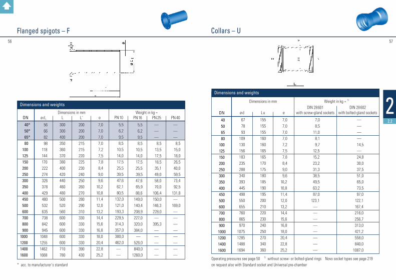
22.2
Collars – U Flanged spigots – F
* acc. to manufacturer’s standard Operating pressures see page 50 1) without screw- or bolted-gland rings Novo socket types see page 219 on request also with Standard socket and Universal pre-chamber
DN
40* 50* 65* 80 100 125 150 200 250 300 350 400 450 500 600 700 800 900 1000 1200 1400 1600
ø d1
56 66 82 98 118 144 170 222 274 326 378 429 480 532 635 738 842 945 1048125514621668
L
300300400350360370380400420440460480500520560600600600600600710780
e
7,0 7,0 7,0 7,0 7,2 7,5 7,8 8,4 9,0 9,610,210,811,412,013,214,415,616,818,020,422,825,2
PN 10
5,5 6,2 9,5 8,5 10,5 14,0 17,5 25,5 39,5 47,6 62,1 80,5132,0121,0193,3229,5314,3357,0380,0462,0——
PN 16
5,5 6,2 9,5 8,5 10,5 14,0 17,5 25,5 39,5 47,6 65,9 88,6149,0140,4208,9227,0320,0384,0
—526,0840,0
1260,0
Dimensions in mm Weight in kg ≈
L´
200200200215215220225230240250260270280290310330330330330330390430
PN 25
———
8,5 13,5 17,5 18,5 35,1 49,0 58,0 70,0106,4150,0146,3228,0—
395,3—————
PN 40
———
8,5 15,0 18,0 26,5 40,0 59,5 73,4 92,5131,8—
169,0————————
Dimensions and weights
DN
40 50 65 80100125150200250300350400450500600700800900
1000120014001600
ø d
67 78 93109130156183235288340393445498550655760865970
1075128514881694
Lu
155155155160160165165170175180185190195200210220230240250270340360
DIN 28 601
with screw-gland sockets
7,0 8,5 11,0 8,1 9,7 12,5 15,2 23,2 31,3 38,5 49,5 63,2 87,0123,1
————————
DIN 28 602
with bolted-gland sockets
————
14,5—
24,8 30,0 37,5 51,0 65,0 73,5 97,0122,1167,4216,0256,7313,0421,2558,0840,0
1087,0
e
7,0 7,0 7,0 7,0 7,2 7,5 7,8 8,4 9,0 9,610,210,811,412,013,214,415,616,818,020,422,825,2
Weight in kg ≈ 1) Dimensions in mm
Dimensions and weights

5958
22.2
Double socket bends 90° – MMQ Single socket bends 90° – MQacc. to manufacturer’s standard
Operating pressures see page 50 1) without screw- or bolted-gland ring on request also with Standard socket and Universal pre-chamber
DN
40 50 65 80100125150200250300350400500600700800
L
200 300 370 312 333 374 419 491 583 660 580 625 715 805 9001080
Lu
60,0150,0215,0102,4123,0148,8174,5226,0280,0330,0410,0430,0550,0645,0720,0800,0
with screw-gland
socket
9,5 11,0 15,0 8,0 10,8 16,1 23,8 43,2 70,0 96,0
——————
with bolted-gland
socket
——————————
150,0156,0225,0 325,0482,0651,0
with
TYTON® socket
———
9,0 11,2 18,4 25,4 43,8 76,1 83,2 139,0 186,3 235,4 314,0 473,0 644,5
e
7,0 7,0 7,0 7,0 7,2 7,5 7,8 8,4 9,0 9,610,210,812,013,214,415,6
Weight in kg ≈ 1) Dimensions in mm
Dimensions and weights
Operating pressures see page 50 1) without screw- or bolted-gland rings * acc. to manufacturer’s standardon request also with Standard socket and Universal pre-chamber
DN
40* 50* 65*
80 100 125 150 200 250 300
350* 400* 450* 500* 600* 700* 800* 900* 1000* 1200*
Lu
60,0 150,0 85,0 100,0 125,0 150,0 175,0 225,0 280,0 330,0 410,0 430,0 457,0 550,0 645,0 720,0 800,0 950,01050,01205,0
e
7,0 7,0 7,0 7,0 7,2 7,5 7,8 8,4 9,0 9,6 10,2 10,8 11,4 12,0 13,2 14,4 15,6 16,8 18,0 20,4
with screw-gland
sockets
8,010,514,0 8,610,515,119,231,354,069,8——————————
with
TYTON® sockets
———
8,5 11,0 16,2 20,5 32,4 52,9 72,4 104,8 128,0 208,0 214,4 314,3 480,0 650,0 869,01060,01600,0
with
bolted-gland sockets
————————————
187,0262,0357,0198,0662,0
———
Weight in kg ≈ 1) Dimensions in mm
Dimensions and weights
6160
22.2
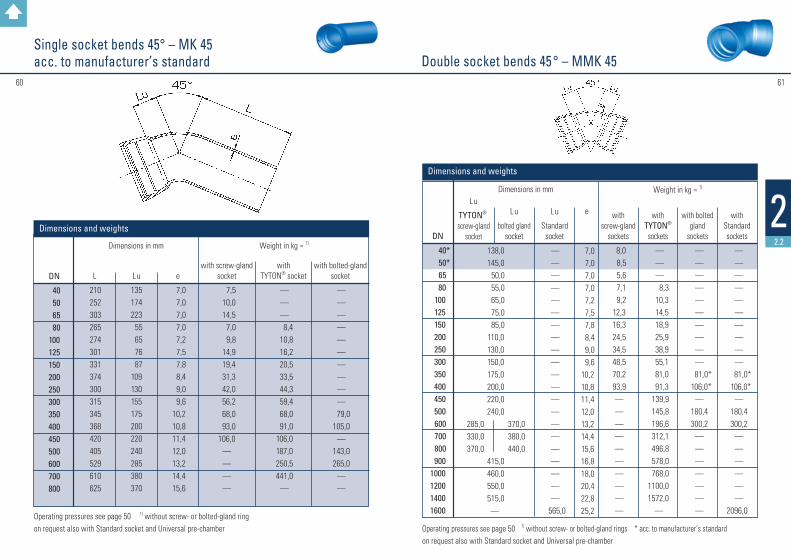
Double socket bends 45 ° – MMK 45Single socket bends 45° – MK 45acc. to manufacturer’s standard
Operating pressures see page 50 1) without screw- or bolted-gland rings * acc. to manufacturer’s standardon request also with Standard socket and Universal pre-chamber
Operating pressures see page 50 1) without screw- or bolted-gland ring on request also with Standard socket and Universal pre-chamber
DN
40 50 65 80100 125 150200250300350
400450500600700800
L
210252303265274301331374300315345368420405529610625
Lu
135174223 55 65 76 87109130155175200220240285380370
with screw-gland
socket
7,5 10,0 14,5 7,0 9,8 14,9 19,4 31,3 42,0 56,2 68,0 93,0106,0
————
with bolted-gland
socket
——————————
79,0105,0
—143,0265,0
——
with
TYTON® socket
———
8,4 10,8 16,2 20,5 33,5 44,3 59,4 68,0 91,0106,0187,0250,5441,0
—
e
7,0 7,0 7,0 7,0 7,2 7,5 7,8 8,4 9,0 9,610,210,811,412,013,214,415,6
Weight in kg ≈ 1) Dimensions in mm
Dimensions and weightsDN
40* 50* 65
80 100 125 150 200 250 300 350 400 450 500
600 700 800
9001000120014001600
Lu
TYTON®
screw-gland socket
e
7,0 7,0 7,0 7,0 7,2 7,5 7,8 8,4 9,0 9,610,210,811,412,013,214,415,616,818,020,422,825,2
with screw-gland
sockets
8,0 8,5 5,6 7,1 9,212,316,324,534,548,570,293,9——————————
with
TYTON® sockets
———
8,3 10,3 14,5 18,9 25,9 38,9 55,1 81,0 91,3 139,9 145,8 196,6 312,1 496,8 578,0 768,0
1100,01572,0
—
with bolted
gland sockets
——————————
81,0* 106,0*
—180,4300,2
———————
with
Standard sockets
——————————
81,0* 106,0*
—180,4300,2
————— —
2096,0
Weight in kg ≈ 1) Dimensions in mm
Dimensions and weights
138,0145,0 50,0 55,0 65,0 75,0 85,0110,0130,0150,0175,0200,0220,0240,0
415,0460,0550,0515,0—
Lu
bolted gland socket
Lu
Standard socket
285,0330,0370,0
370,0380,0440,0
—————————————————————
565,0
Operating pressures see page 50 1) without screw- or bolted-gland ring on request also with Standard socket and Universal pre-chamber
DN
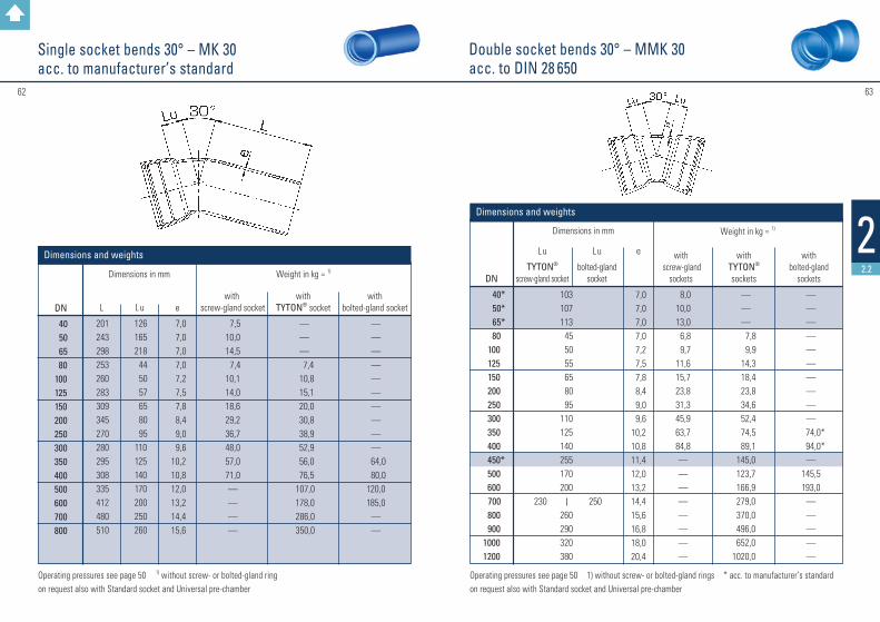
40 50 65 80100125150200250300350400500600700800
L
201243298253260283309345270280295308335412480510
Lu
126165218 44 50 57 65 80 95110125140170200250260
with screw-gland socket
7,510,014,5 7,410,114,018,629,236,748,057,071,0————
with bolted-gland socket
——————————
64,0 80,0120,0185,0
——
with
TYTON® socket
———
7,4 10,8 15,1 20,0 30,8 38,9 52,9 56,0 76,5 107,0 178,0 286,0 350,0
e
7,0 7,0 7,0 7,0 7,2 7,5 7,8 8,4 9,0 9,610,210,812,013,214,415,6
Weight in kg ≈ 1) Dimensions in mm
Dimensions and weights
62
22.2
63
Double socket bends 30° – MMK 30acc. to DIN 28 650
Single socket bends 30° – MK 30acc. to manufacturer’s standard
Operating pressures see page 50 1) without screw- or bolted-gland rings * acc. to manufacturer’s standardon request also with Standard socket and Universal pre-chamber
DN
40* 50* 65*
80 100 125 150 200 250 300 350
400 450*
500 600
700 800 90010001200
103107113 45 50 55 65 80 95110125140255170200
260290320380
e
7,0 7,0 7,0 7,0 7,2 7,5 7,8 8,4 9,0 9,610,210,811,412,013,214,415,616,818,020,4
with screw-gland
sockets
8,0 10,0 13,0 6,8 9,711,615,723,831,345,963,784,8————————
Weight in kg ≈ 1) Dimensions in mm
with TYTON® sockets
———
7,8 9,9 14,3 18,4 23,8 34,6 52,4 74,5 89,1145,0123,7166,9279,0370,0496,0652,0
1020,0
with bolted-gland
sockets
——————————
74,0* 94,0*
—145,5193,0
—————
Dimensions and weights
230 250
Lu
TYTON® screw-gland socket
Lu
bolted-gland socket

6564
22.2
Double socket bends 22 1/2° – MMK 22Single socket bends 22 1/2° – MK 22acc. to manufacturer’s standard
Operating pressures see page 50 1) without screw- or bolted-gland rings on request also with Standard socket and Universal pre-chamber
DN
40 50 65 80100125150200250300350400500600700800
L
179240232248253274299331260265270278300357420455
Lu
142162152 38 43 49 55 66 75 90100110135155190205
e
7,0 7,0 7,0 7,0 7,2 7,5 7,8 8,4 9,0 9,610,210,812,013,214,415,6
with screw-gland
socket
7,510,012,0 7,0 9,213,517,327,036,047,553,065,0————
with
TYTON® socket
———
8,1 9,7 15,1 18,4 29,2 37,8 50,2 52,0 76,7 97,0163,0336,0460,0
with bolted-gland
socket
——————————
60,0 74,0110,0185,0
——
Dimensions in mm Weight in kg ≈ 1)
Dimensions and weights
Operating pressures see page 50 1) without screw- or bolted-gland rings * acc. to manufacturer’s standardon request also with Standard socket and Universal pre-chamber
DN
40* 50* 65
80 100 125 150 200 250 300 350 400 450 500 600
700 800
9001000120014001600
87,0 90,0 35,0 40,0 45,0 50,0 55,0 65,0 75,0 90,0100,0110,0120,0135,0155,0
195,0220,0240,0285,0
—
e
7,0 7,0 7,0 7,0 7,2 7,5 7,8 8,4 9,0 9,610,210,811,412,013,214,415,616,818,020,422,825,2
with
screw-gland sockets
7,5 9,512,5 4,9 8,611,514,621,030,542,162,174,5——————————
with
TYTON® sockets
———
7,8 9,6 13,5 17,8 22,7 33,5 50,8 67,0 83,2128,0 112,9 154,4 242,0 311,0 422,0 593,0 820,01224,0
—
with
bolted-gland sockets
——————————
70,0* 88,0*
—127,0179,0
———————
with
Standard sockets
—————————————————————
1607,0
Weight in kg ≈ 1) Dimensions in mm
Dimensions and weights
Lu
TYTON®
screw-gland socket
Lu
bolted-gland socket
Lu
Standard socket
175,0
260,0
190,0
—
—————————————————————
280,0

6766
22.2
Double socket bends 11 1/4° – MMK 11Single socket bends 11 1/4° – MK 11acc. to manufacturer’s standard
Operating pressures see page 50 1) without screw- or bolted-gland ring on request also with Standard socket and Universal pre-chamber
DN
40 50 65 80100125150200250300350400500600700800
L
175171187240243261284311255260235238250287340375
Lu
83131 67 30 33 36 40 46 50 60 65 70 85 95110125
with screw-gland
socket
6,5 8,511,5 7,1 9,212,416,724,833,544,047,056,0————
with bolted-gland socket
——————————
54,0 65,0 95,0 185,0 258,0 292,0
with
TYTON® socket
— — —
7,6 9,8 14,0 18,0 27,0 37,8 47,0 46,0 66,9 83,2 163,0 249,0 286,0
e
7,0 7,0 7,0 7,0 7,2 7,5 7,8 8,4 9,0 9,610,210,812,013,214,415,6
Weight in kg ≈ 1) Dimensions in mm
Dimensions and weights
Operating pressures see page 50 1) without screw- or bolted-gland rings * acc. to manufacturer’s standard on request also with Standard socket and Universal pre-chamber
DN
40* 50* 65
80 100 125 150 200 250 300 350 400 450 500 600
700 800 9001000120014001600
63,0 65,0 25,0 30,0 35,0 35,0 40,0 45,0 50,0 60,0 65,0 70,0 70,0 85,0 95,0
110,0 120,0 130,0150,0
—
e
7,0 7,0 7,0 7,0 7,2 7,5 7,8 8,4 9,0 9,6 10,2 10,8 11,4 12,0 13,2 14,4 15,6 16,8 18,0 20,4 22,8 25,2
with screw-gland
sockets
7,0 9,011,5 6,5 8,110,613,420,528,138,349,767,5——————————
with
TYTON® sockets
7,6 8,6 13,0 16,7 21,1 30,2 45,4 62,1 73,4 92,5 86,4 125,3 201,0 294,3 350,0 506,0 650,01078,0
—
with
bolted-gland sockets
———————
64,0* 79,0*
—120,5 158,0 164,0 283,0
—————
with
Standard sockets
——————————————————
1416,0
Weight in kg ≈ 1) Dimensions in mm
Dimensions and weights
Lu
TYTON®
screw-gland socket
Lu
bolted-gland socket
Lu
Standard socket
95,0
160,0
110,0
—
—————————————————————
175,0

6968
22.2
➜
Double socket tees with flanged branch – MMADouble socket tees with flanged branch – MMA
Operating pressures see page 50 1) without screw- or bolted-gland ring * acc. manufacturer’s standardon request also with Standard socket and Universal pre-chamber
DN 1
40* 50*
65*
DN 2
404050405065
Lu
155170170190190190
l u
140150150165165165
e1
7,0 7,0 7,0 7,0 7,0 7,0
e2
7,0 7,0 7,0 7,0 7,0 7,0
with screw-gland
sockets
10,512,513,516,016,518,0
with bolted-gland
sockets
——————
with
TYTON® sockets
——————
Weight in kg ≈ 1) Dimensions in mm
Dimensions and weights
Operating pressures see page 50 1) without screw rings * acc. manufacturer’s standard on request also with Standard socket and Universal pre-chamber
➜
DN 1
80
100
125
150
200
DN 2
40* 50* 65*
80 40* 50* 65* 80*
100 40* 50* 80*
100 125
40* 50* 80*
100 125*
150 40* 50* 80*
100 125*
150 200
Lu
170170170170190190190190190195195195195225195195195195255255200200200200 255 255 315
l u
155160160165170170175175180185185190195200195200205210220220230230235240250250260
e2
7,07,07,07,07,07,07,07,07,27,07,07,07,27,57,07,07,07,27,57,87,07,07,07,27,57,88,4
e1
7,0
7,2
7,5
7,8
8,4
with screw-gland
sockets
11,813,012,515,113,014,015,016,217,417,317,518,920,522,121,622,723,824,828,030,827,830,031,332,437,038,946,4
with bolted-gland
sockets
———————————————————————————
Weight in kg ≈ 1) Dimensions in mm
with TYTON® sockets
13,013,013,514,014,915,716,917,518,619,420,021,622,724,323,824,325,927,031,332,930,831,332,934,041,043,249,7

7170
22.2
Double socket tees with flanged branch – MMADouble socket tees with flanged branch – MMA
Operating pressures see page 50 1) without screw rings * acc. to manufacturer’s standardon request also with Standard socket and Universal pre-chamber
Operating pressures see page 50 1) without screw rings * acc. to manufacturer’s standardon request also with Standard socket and Universal pre-chamber
➜➜
DN 1
250
300
350
400
DN 2
40* 80*
100150 200 250
80*100150 200
250* 300
80*100
150* 200
250* 300*
350 80*
100150 200
250* 300
350* 400
Lu
200200200260 315 375205205260320430435205205325325495495495210210270325440440560560
lu
265265270280290300295300310320330340325330340350360370380355360370380390400415420
e1
9,0
9,6
10,2
10,8
e2
7,0 7,0 7,2 7,8 8,4 9,0 7,0 7,2 7,8 8,4 9,0 9,6 7,0 7,2 7,8 8,4 9,0 9,610,2 7,0 7,2 7,8 8,4 9,0 9,6 10,2 10,8
with screw-gland
sockets
36,0 40,0 42,0 52,4 53,5 62,5 51,8 52,9 65,9 72,4 89,0 90,7 63,0 62,0 82,0 89,5101,0114,0
119,0 / 122,0 79,9 81,0 93,4 109,0 118,5 125,5
147,0 / 150,0158,0 / 172,0
with bolted-gland
sockets
———————————————————————————
with
TYTON® sockets
45,4 48,0 48,1 56,2 60,5 75,6 58,9 60,5 70,7 70,0 91,8 95,6 73,4 73,4 89,1 97,2 98,0114,0
119,0 / 125,0 92,9 94,0105,8113,9115,0132,3
147,0 / 150,0177,0 / 170,0
Weight in kg ≈ 1) Dimensions in mm
DN 1
400*
450*
500
DN 2
80100150 200 300 400 80 100 150 200 250 300 350 400 450
80*100150200
300*400500
Lu
210210270325440560215215270300450450560560620215215330330450565680
lu
355360370380400420390390400410420430450450460415420430440460480500
e1
10,8
11,4
12,0
e2
7,0 7,2 7,8 8,4 9,6 10,8 7,0 7,2 7,8 8,4 9,0 9,6 10,2 10,8 11,4 7,0 7,2 7,8 8,4 9,6 10,8 12,0
with screw-gland
sockets
——————————————————————
with bolted-gland
sockets
94,0 95,0104,0114,0139,0
164,0 / 169,0—————————
110,7110,7130,0140,4174,4
215,0 / 220,0 244,0
with
TYTON® sockets
——————
110,0110,0128,0132,0145,5161,5
220,0 / 226,0230,0 / 236,0260,0 / 267,0
103,0104,0138,0140,0156,0
188,0 / 193,0222,0 / 236,0
Weight in kg ≈ 1) Dimensions in mm

7372
22.2
Double socket tees with flanged branch – MMADouble socket tees with flanged branch – MMA
Operating pressures see page 50 1) without screw rings * acc. to manufacturer’s standardon request also with Standard socket and Universal pre-chamber
Operating pressures see page 50 1) without screw rings * acc. manufacturer’s standardon request also with Standard socket and Universal pre-chamber
l➜
DN 1
600
700
800
DN 2
80* 100* 150*
200 300*
400 500*
600 80* 100* 150*
200 250* 300* 350*
400 500* 600*
700 80* 100* 150*
200 250* 300* 350*
400 500*
600800
Lu
340340340340460570800800345345345345575575575575925925925350
350 350 350 580 580 580 580 1045 1045 1045
lu
475470480500520540550580510510520525535540555555570585600570570580585590600615615630645 675
e1
13,2
14,4
15,6
e2
7,0 7,2 7,8 8,4 9,6 10,8 12,0 13,2 7,0 7,2 7,8 8,4 9,0 9,610,210,812,013,214,4 7,0 7,2 7,8 8,4 9,0 9,6 10,2 10,8 12,0 13,2 15,6
with screw-gland
sockets
——————————————————————————————
with bolted-gland
sockets
182,5 183,6 189,0 187,6 233,8
286,0 / 256,5340,0 / 336,4361,0 / 386,0
266,0 278,0 263,0 262,0 287,0 381,0
276,0 / 279,0381,0 / 392,0468,0 / 482,0599,0 / 523,0550,0 / 563,0
319,0 339,9 322,9 298,0 433,0 408,2
432,0 / 435,0 / 429,8 / 685,8 / 685,8755,0 / 755,0
with TYTON® sockets
169,0170,0174,0178,0210,0
240,0 / 245,0315,0 / 330,0323,0 / 339,0
248,0260,0263,0266,0269,0340,0
258,0 / 261,0363,0 / 374,0450,0 / 464,0481,0 / 505,0532,0 / 545,0
307,0324,0332,0342,0415,0431,0
420,0 / 423,0398,0 / 437,0614,0 / 628,0630,0 / 640,0716,0 / 743,0
Weight in kg ≈ 1) Dimensions in mm
DN 1
900
1000
1200
1400
1600
DN 2
80* 100* 150*
200 250* 300*
400600
700*900
150*200
250*400600
1000 200* 400* 500*
600 700*
800 900*1000600800
1000600800
10001200
Lu
355
590
1170
360360380595
12901290840840840840
10701070130013001030126014951040127515051740
lu
630635640645645660675705720750700705710735765825835835850885900915930945980
101010401090112011501180
e1
16,8
18,0
20,4
22,8
25,2
e2
7,0 7,2 7,8 8,4 9,0 9,6 10,8 13,2 14,4 16,8 7,8 8,4 9,0 10,8 13,2 18,0 8,4 10,8 12,0 13,2 14,4 15,6 16,8 18,0 13,2 15,6 18,0 13,2 15,6 18,0 20,4
with
Standard sockets
—————————————————————— —————
2130,02359,02643,02938,0
with bolted-gland
sockets
———————————————————————————————
with
TYTON® sockets
400,0470,0472,0
/ 540,0 475,0 /
/ 561,0567,0 / 572,0810,0 / 820,0 / 868,0930,0 / 898,0 / 650,0
561,0 / 691,0 /
639,0 / 644,0 1162,0 / 1205,0 / 1248,0
/ 949,0 / 960,0 / 969,0 / 985,0
/ 1135,0 / 1160,0 / 1296,0 / 1428,0 / 1655,0 / 1850,0 / 2100,0
————
Weight in kg ≈ 1) Dimensions in mm

7574
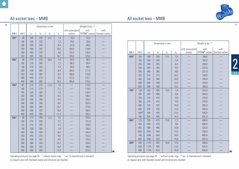
22.2
All socket tees – MMBAll socket tees – MMB
Operating pressures see page 50 1) without screw rings * acc. to manufacturer’s standardon request also with Standard socket and Universal pre-chamber
Operating pressures see page 50 1) without screw rings * acc. to manufacturer’s standardon request also with Standard socket and Universal pre-chamber
➜
DN 1
40* 50*
65*
80
100
125
DN 2
40 40
50* 40 50
65* 40* 50* 65*
80 40* 50* 65* 80*
100 40* 50* 80*
100 125
Lu
156170170190190190170170170170190190190190190195195195195225
lu
78 83 85 90 92 95 80 80 80 85 90 90 90 95 95100105105110110
e1
7,0 7,0
7,0
7,0
7,0 7,2
7,5
e2
7,0 7,0 7,0 7,0 7,0 7,0 7,0
7,0 7,0 7,0 7,0 7,0 7,27,07,0 7,07,27,5
with screw-gland
sockets
11,012,513,516,017,018,010,110,511,013,011,712,513,014,614,916,216,516,618,119,4
with
TYTON® sockets
——————
10,811,9—
14,014,015,113,015,117,018,418,520,521,623,2
with
Standard sockets
————————————————————
Weight in kg ≈ 1) Dimensions in mm
Dimensions and weights
➜
DN 1
150
200
250*
300*
DN 2
40* 50* 80*
100 125* 150
40* 50*
65 80 100
125* 150 200 80 100 125 150 200 250 50 65 80 100 125 150 200 250 300
Lu
195195195195255255200200200200200255255315200200200260315375205205205205205320320430430
lu
115115120120125125140140140145145145150155170175175180185190195195195200200200205210215
e1
7,8
8,4
9,0
9,6
e2
7,0 7,0 7,0 7,2 7,5 7,8 7,0 7,0 7,0 8,1 8,4 8,8 9,1 9,8 7,0 7,2 7,5 7,8 8,4 9,0 7,0 7,0 7,0 7,2 7,5 7,8 8,4 9,0 9,6
with screw-gland
sockets
19,4 20,0 22,7 22,7 25,0 27,0 25,5 26,5 28,0 30,8 31,9 35,0 37,8 40,0 38,0 38,9 43,0 44,5 51,5 61,0 44,0 44,5 50,0 47,0 55,0 59,4 61,0 74,0 81,0
with
TYTON® sockets
22,7 22,5 24,8 25,4 30,2 30,8 30,2 31,3 28,0 38,4 31,9 37,8 42,1 45,9 45,4 46,4 46,4 51,8 56,2 65,9 44,0 44,5 56,7 58,3 58,4 62,4 66,4 82,1 92,1
with
Standard sockets
—————————————————————————————
Weight in kg ≈ 1) Dimensions in mm
7776
22.2
All socket tees – MMBAll socket tees – MMB
Operating pressures see page 50 1) without screw rings * acc. to manufacturer’s standardon request also with Standard socket and Universal pre-chamber
Operating pressures see page 50 1) without screw rings * acc. to manufacturer’s standardon request also with Standard socket and Universal pre-chamber
➜
DN 1
350*
400*
450*
500*
DN 2
80100200250300350 8010015020025030040080100150200250300350400450 80100125150200250300350400500
Lu
205205325495495495210210270440440440560 215 215 330 330 450 450 560 560 620 215 215 215 330 330 450 450 565 565 680
lu
220220240245250260245245250260265270285 270 270 280 280 290 290 305 320 380 295 295 295 305 305 315 320 330 335 350
e1
10,2
10,8
11,4
12,0
e2
7,0 7,2 8,4 10,5 9,6 10,2 7,0 7,2 7,8 8,4 9,0 9,6 10,8 7,0 7,2 7,8 8,4 9,0 9,610,210,811,4 7,0 7,2 7,5 7,8 8,4 9,0 9,6 10,2 10,8 12,0
with screw-gland
sockets
74,0 79,0 91,0 103,0 115,0 128,0 83,5 86,5 94,0 100,0 108,0 122,0 145,0
———————————————————
with
TYTON® sockets
74,0 79,0 88,0 118,8 126,4 125,0 95,5 93,4 94,0 111,8 118,8 123,7 175,5 110,0 110,0 128,0 146,5 155,0 162,5 174,0 180,0 185,0 128,0 131,0 134,0 136,0 145,0 155,0 170,0 183,0 195,0 233,3
with
Standard sockets
————————————————————————————————
Weight in kg ≈ 1) Dimensions in mm
➜
DN 1
600*
700*
800*
900*
DN 2
125150200250300350400500600150200250300400500
6002)
700125300400600700800500600900
Lu
340340340460460570570800800345345575575575925925925350580580104510451045117011701170
lu
345345365365365375380390400395400410415425435430455475470480490500520535540610
e1
13,2
14,4
15,6
16,8
e2
7,5 7,8 8,4 9,0 9,610,210,812,013,2 7,8 8,4 9,0 9,6 10,8 12,0 13,2 14,4 7,5 9,6 10,813,2 14,4 15,6 12,0 13,2 16,8
with screw-gland
sockets
——————————————————————————
with
TYTON® sockets
189,0 197,0 205,0 222,0 231,0 236,0 245,0 325,0 340,0253,0264,0275,0370,0355,0445,0545,0497,0408,0490,0520,0760,0805,0820,0500,0525,0850,0
with
Standard sockets
——————————————————————————
Weight in kg ≈ 1) Dimensions in mm
78
22.2
All socket tees – MMB
Operating pressures see page 50 1) without screw rings * acc. to manufacturer’s standardon request also with Standard socket and Universal pre-chamber
➜
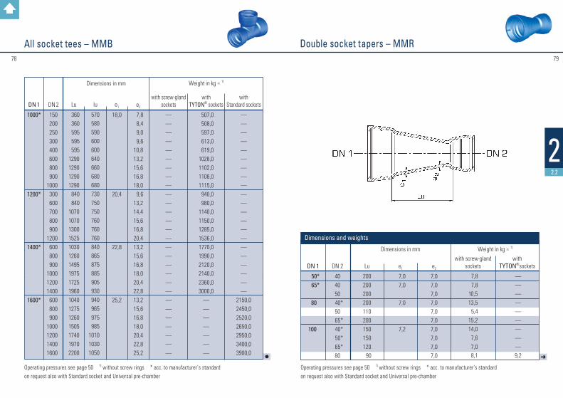
Double socket tapers – MMR
Operating pressures see page 50 1) without screw rings * acc. to manufacturer’s standardon request also with Standard socket and Universal pre-chamber
DN 1
50* 65*
80
100
DN 2
404050
40*50
65* 40* 50* 65*
80
Lu
200200200200110200150150120 90
e1
7,0 7,0
7,0
7,2
e2
7,07,07,07,07,07,07,07,07,07,0
with screw-gland
sockets
7,8 7,810,513,5 5,415,214,0 7,6 7,0 8,1
with
TYTON® sockets
— — — — — — — — — 9,2
Dimensions and weights
Weight in kg ≈ 1) Dimensions in mm
79
l
DN 1
1000*
1200*
1400*
1600*
DN 2
150200250300400600800900
1000300600700800900
1200600800900
100012001400600800900
1000120014001600
Lu
360 360 595 595 5951290129012901290 840 84010701070130015251030126014951975172519601040127512601505174019702200
lu
570580590600600640660680680730750750760760760840865875885905930940965975985
101010301050
e1
18,0
20,4
22,8
25,2
e2
7,8 8,4 9,0 9,610,813,215,616,818,0 9,613,214,415,616,820,413,215,616,818,020,422,813,215,616,818,020,422,825,2
with screw-gland
sockets
————————————————————————————
with
TYTON® sockets
507,0 508,0 597,0 613,0 619,01028,01102,01108,01115,0 940,0 980,01140,01150,01285,01536,01770,01990,02120,02140,02360,03000,0
———————
with
Standard sockets
—————————————————————
2150,02450,02520,02650,02950,03400,03900,0
Weight in kg ≈ 1) Dimensions in mm

8180
22.2
Double socket tapers – MMRDouble socket tapers – MMR
Operating pressures see page 50 1) without screw rings * acc. to manufacturer’s standardon request also with Standard socket and Universal pre-chamber
Operating pressures see page 50 1) without screw rings * acc. to manufacturer’s standardon request also with Standard socket and Universal pre-chamber
➜
DN 1
125
150
175200
250
300
350
DN 2
65* 80100 65 80100125150 80100125150175 80100125150200 80100150200250150200250300
Lu
170140100180190150100200280250200150200300300300250150300300350250150500360260160
e1
7,5
7,8
8,18,4
9,0
9,6
10,2
e2
7,0 7,0 7,2 7,0 7,0 7,2 7,5 7,8 7,0 7,2 7,5 7,8 8,1 7,0 7,2 7,5 7,8 8,4 7,0 7,2 7,8 8,4 9,0 7,8 8,4 9,0 9,6
with screw-gland
sockets
9,6 9,9 9,814,012,313,412,636,525,918,317,517,830,033,029,026,528,030,229,555,141,037,836,778,048,047,045,0
with
TYTON® sockets
— 11,311,813,015,115,715,7—
22,720,522,722,1—
33,029,031,334,634,629,536,250,243,243,778,048,047,045,0
Weight in kg ≈ 1)Dimensions in mm
l
DN 1
400
450
500
600
700
800
900
1000
120014001600
DN 2
200250300350300
350*400250300
350* 400*
450300350
400* 500*
400 500* 600*
500600700700800
600*800900
10001200
1200*1400
Lu
400360260160500500160500500500500500500600460500500500500500480280480280880480280480360560360
e1
10,8
11,4
12,0
13,2
14,4
15,6
16,8
18,0
20,422,825,2
e2
8,4 9,0 9,610,2 9,610,210,8 9,0 9,610,210,812,0 9,610,210,812,010,812,013,212,013,214,414,415,613,215,616,818,020,420,422,8
with screw-gland
sockets
79,9 73,5 68,0 70,0139,3129,0156,6101,0133,0150,0139,5267,0
——————————————— ————
with
TYTON® sockets
65,0 73,5 68,0 70,0120,0129,0 75,0127,4134,0143,6150,7155,0157,0184,0185,8186,8
296,0341,5252,5275,0288,0296,0382,0347,0476,0460,0420,0652,0880,0
1200,01260,0
Dimensions in mm Weight in kg ≈ 1)

8382
22.2
l➜
Single socket tees with flanged branch – Aacc. to manufacturer’s standard
Single socket tees with flanged branch – Aacc. to manufacturer’s standard
Operating pressures see page 50 1) without screw ringon request also with Standard socket and Universal pre-chamber
DN 1
40 50
80
100
DN 2
40 40 50 40 50 80 40 50 65 80 100
Lu
400400400400400400400400400400400
l
150150150180180180200200200200200
z
78 85 85106106106120120120120120
e1
7,07,0
7,0
7,2
e2
7,07,0
7,0
7,07,07,07,07,2
with screw- gland socket
10,010,512,012,313,015,115,715,516,017,818,7
with
TYTON® socket
———12,313,015,716,215,516,018,418,8
Weight in kg ≈ 1) Dimensions in mm
Dimensions and weights
Operating pressures see page 50 1) without screw ringon request also with Standard socket and Universal pre-chamber
DN 1
125
150
200
300
4001000
DN 2
40 50 80 100 125 40 50 80 100 125 150 50 80 100 150 200 80 100 150 400600
Lu
425 425 425 425 425 450 450 450 450 450 450 600 600 600 600 600 800 800 80010001770
l
190190190195200205205205210210210240240250275300300300300450825
z
112112112112112128128128128128128190190190240240260260260330645
e1
7,5
7,8
8,4
9,6
10,818,0
e2
7,0 7,0 7,0 7,2 7,5 7,0 7,0 7,0 7,2 7,5 7,8 7,0 7,0 7,2 7,8 8,4 7,0 7,2 7,810,812,0
with screw- gland socket
17,5 18,0 20,0 21,6 26,0 24,8 24,0 26,4 25,0 28,5 30,4 46,0 50,0 55,0 58,0 64,8119,5121,0126,5186,0—
with
TYTON® socket
17,5 18,0 22,5 23,5 26,0 23,0 24,0 28,0 29,2 28,5 30,4 46,0 55,0 51,0 58,0 60,0 119,5 121,0 126,5 186,01160,0
Weight in kg ≈ 1) Dimensions in mm

8584
22.2
Double flanged bends 90° – QSingle socket tees with socket branch – Bacc. to manufacturer’s standard
Operating pressures see page 50 1) without screw ringson request also with Standard socket and Universal pre-chamber
DN 1
40 80100
150
DN 2
40 80 80100 80100125
Lu
400400400400450450450
lu
105 86 95 95120120125
z
132106120120128128128
e1
7,07,07,2
7,8
8,514,015,016,0 25,0 45,0 28,0
Weight in kg ≈ 1) Dimensions in mm
e2
7,07,07,07,27,07,27,5
Dimensions and weights
* acc. to manufacturer’s standard
DN
40* 50* 65*
80 100 125 150 200 250 300 350 400 450 500 600 700 800 9001000120014001600
L
140 150 165 165 180 200 220 260 350 400 450 500 550 600 700 800 90010001100130013501450
e
7,0 7,0 7,0 7,0 7,2 7,5 7,8 8,4 9,0 9,610,210,811,412,013,214,415,616,818,020,422,825,2
PN 10
5,5 7,5 10,2 10,2 12,9 18,9 29,3 36,2 58,3 82,1 102,1 144,7 234,0 266,0 370,0 539,0 774,0 745,01010,0
———
PN 16
5,5 7,5 10,2 10,2 12,9 22,0 29,2 36,2 58,3 82,1 111,2 157,7 234,0 277,5 404,0 420,0 720,0 836,01099,01463,02150,02970,0
PN 25
5,5 7,5 10,2 11,0 12,9 22,0 33,5 45,9 81,0116,6155,0217,0241,0305,0346,0575,0672,0—————
PN 40
5,5 7,5 10,2 11,0 12,9 23,2 33,5 53,0101,0144,2199,0284,0308,0375,0458,0———————
Weight in kg ≈ Dimensions in mm
Dimensions and weights

8786
22.2
Double flanged bends 45° – FFK 45Double flanged duckfoot bends 90° – N
DN
40* 50* 65*
80 100 125 150 200 250 300 350 400 450 500 600
700* 800*
90010001200
L
—150165165180200220260350400450500550600700800900
100011001300
c
— 90 99110125140160190225255290320355385450480540645710845
PN 10
10,5 10,5 16,0 15,7 18,9 27,0 34,6 55,6 84,0 117,7 137,0 263,5
— 374,8 538,9 752,0 926,0——
2311,0
PN 16
10,5 10,5 16,0 15,7 18,9 27,0 38,9 55,6 84,0 117,7 142,0 248,0 295,0 311,0 482,0 705,0 970,0
—1626,0
—
PN 25
10,5 10,5 16,0 15,7 25,4 22,7 31,0 48,5 80,5 114,0 154,8 209,0 309,0 335,0 506,0 769,0 1086,0
———
PN 40
10,5 10,5 16,0 15,7 25,4 23,9 35,5 60,0 101,0 145,0 201,0 277,0 395,0 402,0 612,0
—————
d
— 150165180200225250300350400450500550600700800900
100010001300
e
— 7,0 7,0 7,0 7,2 7,5 7,8 8,4 9,0 9,6 10,2 10,8 11,4 12,0 13,2 16,0 19,016,818,020,4
Weight in kg ≈Dimensions in mm
Dimensions and weights
* ac
c. to
man
ufac
ture
r’s st
anda
rd
Base borehole on request. * acc. to manufacturer’s standard
350* 400* 500*
215243290
10,511,012,0
64,0 85,0129,0
69,094,5157
85,5114,5178,0
115,5184,5246,0
Short length acc. to manufacturer’s standard
DN
40* 50* 65*
80 100 125 150 200 250 300 350 400 450 500 600 700 800 900100012001400
L
140150165130140150160180350400298324350375426478529581632750775
e
7,0 7,0 7,0 7,0 7,2 7,5 7,8 8,4 9,0 9,610,210,811,412,013,214,415,616,818,020,422,8
PN 10
7,0 9,0 12,0 10,3 12,6 17,5 21,6 32,4 60,9 90,2 96,1 117,2 150,0 185,8 288,0 489,0 403,0
— 727,9
——
PN 16
7,0 9,0 12,0 10,3 12,6 17,5 21,6 32,4 60,9 90,2 102,6129,1 150,0 235,4 347,0 481,0 442,0480,0 685,0
1251,01626,0
PN 25
7,0 9,0 12,0 10,3 —
17,5 33,0 34,0 101,0 87,5 111,0 191,3 180,0 259,2 292,0 392,0 535,0
—1099,0
——
PN 40
7,0 9,0 12,0 10,3 —
18,3 24,5 41,5 83,0 118,0 141,0 196,0248,0264,0397,0
——————
Weight in kg ≈ Dimensions in mm
Dimensions and weights
8988
22.2
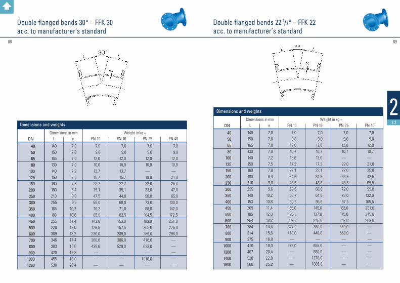
Double flanged bends 22 1/2 ° – FFK 22acc. to manufacturer’s standard
Double flanged bends 30° – FFK 30acc. to manufacturer’s standard
DN
40 50 65 80 100 125 150 200 250 300 350 400 450 500 600 700 800 90010001200
L
140150165130140150160180 210255165183255220309346383420455530
e
7,0 7,0 7,0 7,0 7,2 7,5 7,8 8,4 9,0 9,510,210,811,412,013,214,415,616,818,020,4
PN 10
7,0 9,0 12,0 10,0 13,7 15,7 22,7 35,1 47,5 68,0 70,2 85,9143,0129,5230,0360,0439,6
———
PN 16
7,0 9,0 12,0 10,0 13,7 15,7 22,7 35,1 44,0 68,0 71,0 82,5153,0157,5289,0386,0529,0
———
PN 25
7,0 9,0 12,0 10,0
— 18,0 22,0 33,0 90,0 73,0 88,0 104,5 183,0 205,0 289,0 416,0 623,0
—1018,0
—
PN 40
7,0 9,0 12,0 10,0
— 21,0 25,0 42,0 65,0 100,0 142,0 172,5 251,0275,0298,0
—————
Weight in kg ≈ Dimensions in mm
Dimensions and weights DN
40 50 65 80 100 125 150 200 250 300 350 400 450 500 600 700 800 9001000120014001600
L
140150165130140150160180210255140153209185254284314375410467520560
e
7,0 7,0 7,0 7,0 7,2 7,5 7,8 8,4 9,0 9,610,210,811,412,013,214,415,616,818,020,422,825,2
PN 10
7,0 9,0 12,0 10,7 13,6 17,2 22,1 34,6 48,6 68,6 63,7 80,5 135,0 125,8 203,0 327,0418,0
—575,0
———
PN 16
7,0 9,0 12,0 10,7 13,6 17,2 22,1 34,6 48,6 68,6 64,8 95,6 145,0 137,0245,0360,0448,0
—655,0850,0
1278,01805,0
PN 25
7,0 9,0 12,0 10,7
— 29,0 22,0 33,5 48,5 72,0 78,0 97,5 183,0 175,0 247,0 369,0 558,0
—————
PN 40
7,0 9,0 12,0 10,7—
21,0 25,0 42,5 65,5 99,0 132,0 165,5 251,0 345,0 268,0
———————
Weight in kg ≈ Dimensions in mm
Dimensions and weights

9190
22.2
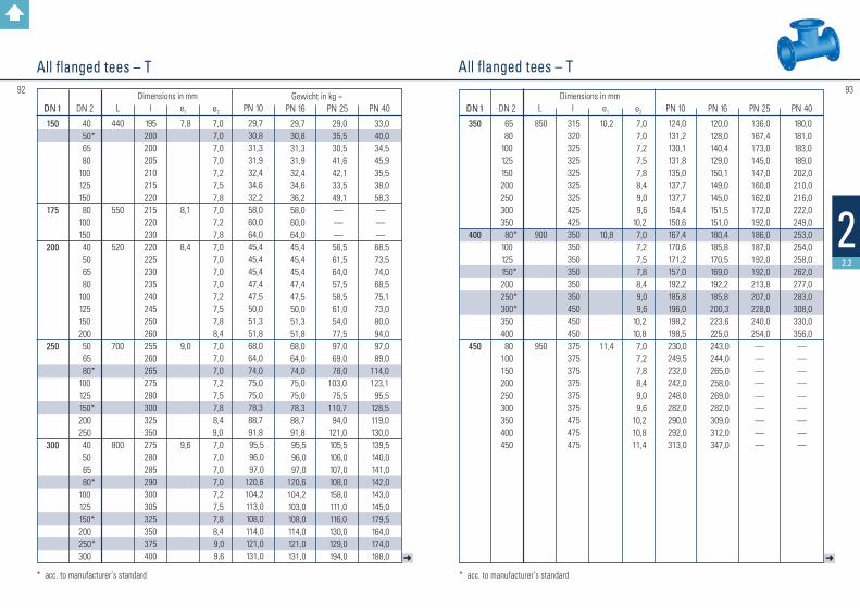
All flanged tees – TDouble flanged bends 11 1/4 ° – FFK 11acc. to manufacturer’s standard
* acc. to manufacturer’s standard
➜
DN 1
40 50
65
80
100
125
DN 2
40 40 50 40 50 65
40* 50 65 80
40* 50 65 80 100
40* 50* 65 80 100 125
L
280300
330
330
360
400
l
140145150153158165155160160165170170170175180185185185190195200
e1
7,0 7,0
7,0
7,0
7,2
7,5
e2
7,0 7,0 7,0 7,0 7,0 7,0 7,0 7,0 7,0 7,0 7,0 7,0 7,0 7,0 7,2 7,0 7,0 7,0 7,0 7,2 7,5
PN 10
10,512,012,515,015,516,514,715,716,417,017,818,719,420,221,3 23,8 24,3 24,8 25,4 27,0 28,1
PN 16
— — — — — —14,715,716,417,017,818,719,420,221,3 23,8 24,3 24,8 25,4 27,0 28,1
PN 25
— — — — — —14,715,716,417,017,222,720,424,522,0 22,5 23,0 24,0 30,0 26,0 32,5
PN 40
— — — — — —14,715,716,417,017,222,718,624,5 22,0 24,0 24,5 25,5 26,0 28,5 31,0
Weight in kg ≈Dimensions in mm
Dimensions and weights
DN
40 50 65 80 100 125 150 200 250 300 350 400 450 500 600 700 800 9001000120014001600
L
140150165130140150160180210255105113144135 174 194213280310346405405
e
7,0 7,0 7,0 7,0 7,2 7,5 7,8 8,4 9,0 9,610,210,811,412,013,214,415,616,818,020,422,825,2
PN 10
7,0 9,0 12,0 10,6 13,7 17,2 23,2 34,6 47,0 69,1 57,2 71,8 108,0106,9 170,0265,0321,8
—588,0
———
PN 16
7,0 9,0 12,0 10,6 13,7 17,2 23,2 34,6 47,0 69,1 53,0 72,5 118,0 140,8222,5292,0396,0397,5656,0870,0
1111,01520,0
PN 25
7,0 9,0 12,0 10,6
— 18,0 22,0 54,5 48,0 69,5 70,0 89,5 145,0 137,0 229,0 370,0490,0
—722,0
———
PN 40
7,0 9,0 12,0 10,6
— 21,0 25,0 39,0 65,0 96,5 138,5 168,5 213,5 237,5 260,5
———————
Weight in kg ≈Dimensions in mm
Dimensions and weights
Gewicht in kg ≈ 9392
22.2
➜➜
All flanged tees – T All flanged tees – T
* acc. to manufacturer’s standard
DN 1
150
175
200
250
300
DN 2
40 50*
65 80 100 125 150 80 100 150 40 50 65 80 100 125 150 200 50 65
80* 100 125
150* 200 250 40 50 65
80* 100 125
150* 200
250* 300
L
440
550
520
700
800
l
195200200205210215220215220230220225230235240245250260255260265275280300325350275280285290300305325350375400
e1
7,8
8,1
8,4
9,0
9,6
e2
7,0 7,0 7,0 7,0 7,2 7,5 7,8 7,0 7,2 7,8 7,0 7,0 7,0 7,0 7,2 7,5 7,8 8,4 7,0 7,0 7,0 7,2 7,5 7,8 8,4 9,0 7,0 7,0 7,0 7,0 7,2 7,5 7,8 8,4 9,0 9,6
PN 10
29,7 30,8 31,3 31,9 32,4 34,6 32,2 58,0 60,0 64,0 45,4 45,4 45,4 47,4 47,5 50,0 51,3 51,8 68,0 64,0 74,0 75,0 75,0 78,3 88,7 91,8 95,5 96,0 97,0 120,6104,2 113,0 108,0 114,0 121,0 131,0
PN 16
29,7 30,8 31,3 31,9 32,4 34,6 36,2 58,0 60,0 64,0 45,4 45,4 45,4 47,4 47,5 50,0 51,3 51,8 68,0 64,0 74,0 75,0 75,0 78,3 88,7 91,8 95,5 96,0 97,0 120,6104,2 103,0 108,0 114,0 121,0 131,0
PN 25
29,0 35,5 30,5 41,6 42,1 33,5 49,1 — — —
56,5 61,5 64,0 57,5 58,5 61,0 54,0 77,5 97,0 69,0 78,0103,0 75,5110,7 94,0 121,0105,5106,0107,0108,0158,0111,0116,0130,0129,0194,0
PN 40
33,0 40,0 34,5 45,9 35,5 38,0 58,3 — — —
68,5 73,5 74,0 68,5 75,1 73,0 80,0 94,0 97,0 89,0114,0123,1 95,5 128,5 119,0 130,0139,5140,0141,0142,0143,0145,0179,5164,0174,0188,0
Dimensions in mm
* acc. to manufacturer’s standard
DN 1
350
400
450
DN 2
65 80 100 125 150 200 250 300 350
80* 100 125
150* 200
250* 300*
350 400 80 100 150 200 250 300 350 400 450
L
850
900
950
l
315320325325325325325425425350350350350350350450450450375375375375375375475475475
e1
10,2
10,8
11,4
e2
7,0 7,0 7,2 7,5 7,8 8,4 9,0 9,6 10,2 7,0 7,2 7,5 7,8 8,4 9,0 9,6 10,2 10,8 7,0 7,2 7,8 8,4 9,0 9,6 10,2 10,8 11,4
PN 10
124,0 131,2 130,1 131,8 135,0 137,7 137,7 154,4 150,6 167,4 170,6 171,2 157,0 192,2 185,8 196,0 198,2 198,5 230,0 249,5 232,0 242,0 248,0 282,0 290,0 292,0 313,0
PN 16
120,0 128,0 140,4 129,0 150,1 149,0 145,0 151,5 151,0 180,4 185,8 170,5 169,0 192,2 185,8 200,3 223,6 225,0 243,0 244,0 265,0 258,0 269,0 282,0 309,0 312,0 347,0
PN 25
136,0167,4173,0145,0147,0160,0162,0172,0192,0186,0187,0192,0192,0213,8207,0228,0240,0254,0—————————
PN 40
180,0181,0183,0189,0202,0210,0216,0222,0249,0253,0254,0258,0262,0277,0283,0308,0330,0356,0—————————
Dimensions in mm
9594
22.2
➜➜
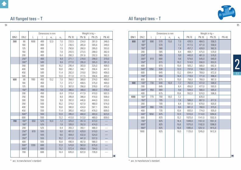
All flanged tees – T All flanged tees – T
* acc. to manufacturer’s standard * acc. to manufacturer’s standard
DN 1
500
600
700
DN 2
80 100 125 150 200
250* 300*
350 400 450 500 80 100 125
150* 200 250 300 350 400 450
500* 600
100* 150*200
250* 300* 350*
400 500* 600*
700
L
1000
1100
650
870
1200
l
400400400400400400500500500500500450450450450450450550550550550550550525525525555555555555600600600
e1
12,0
13,2
14,4
e2
7,0 7,2 7,5 7,8 8,4 9,0 9,6 10,2 10,8 11,4 12,0 7,0 7,2 7,5 7,8 8,4 9,0 9,6 10,2 10,8 11,4 12,0 13,2 7,2 7,8 8,4 9,0 9,6 10,2 10,8 12,0 13,2 14,4
PN 10
233,5236,5250,6243,5260,3271,1277,0295,4286,2282,0311,0 358,0373,7307,0386,6319,4395,8392,0374,0380,0385,0395,0413,0325,0326,0355,3401,0404,0411,0490,9570,8572,4635,0
PN 16
234,0265,0260,0273,5291,6278,0285,0303,0346,7319,0317,5389,0408,5356,0388,0417,9386,0440,6427,0434,0443,0460,0513,0351,0352,0393,1429,0432,0441,0467,0563,0658,8622,0
PN 25
281,0305,6285,0288,0292,0298,0305,0325,0356,4354,0356,6374,0375,0378,0380,0410,0416,0444,0460,0507,1476,0493,0480,0473,0474,0486,0519,0524,0537,0566,0675,0704,0726,0
PN 40
348,0349,0353,0362,0362,0370,0391,0408,0447,0458,0469,0468,0469,0473,0476,0502,0508,0530,0574,0594,0609,0623,0659,0
——————————
Weight in kg ≈Dimensions in mm
DN 1
800
900
1000
DN 2
80* 100* 150* 200
250* 300* 350* 400
500* 600
700* 800
100* 200
300* 400
100* 150* 200
300* 400
500* 600
700* 800* 900*
1000
L
690
910
1350
730
950
770
990
1650
l
570570580585585600615615630645650675640645660675700705705735735825825825825825825
e1
15,6
16,8
18,0
e2
7,0 7,2 7,8 8,4 9,0 9,6 10,2 10,8 12,0 13,2 14,4 15,6 7,2 8,4 9,610,8 7,2 7,8 8,4 9,610,812,013,214,415,616,818,0
PN 10
426,5 417,5 457,2 468,7 443,0 574,6 514,0 583,2 737,6 694,4 719,0 756,0 702,0 455,0 544,0 552,0
588,0 591,0 681,0 693,01010,01025,01048,01075,01095,01125,0
PN 16
464,5 471,0 428,0 475,0 481,0 545,0 556,0 580,0 738,0 769,0 771,0 760,0 472,0 477,0 566,0 574,0 635,0 667,0 670,0 760,0 774,01114,01141,01161,01182,01207,01245,0
PN 25
556,5 558,0 562,0 570,0 578,0 640,0 653,0 682,0 841,0 872,0 896,0 967,0 588,0 593,0 685,0 596,0
817,0 820,0 915,0 935,01284,01302,01351,01398,01415,01472,0
PN 40Weight in kg ≈Dimensions in mm
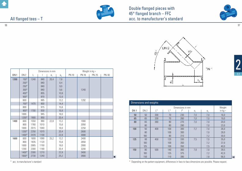
9796
22.2
Double flanged pieces with 45 ° flanged branch – FFCacc. to manufacturer’s standardAll flanged tees – T
➜
DN 1
50 65 80
100
125
150
DN 2
50 65 65 80 50 80 100 80 100 125 80 100 150
L*
300330360
400
450
500
l1*
70 70 90 80100100 90120 100 100 140 125 110
l*
230260270280300300310330350350360375390
e1
7,0 7,0 7,0
7,2
7,5
7,8
e2
7,0 7,0 7,0 7,0 7,0 7,0 7,2 7,0 7,2 7,5 7,0 7,2 7,8
Weight in kg ≈
16,019,020,023,026,028,030,035,037,040,039,542,056,5
Dimensions in mm
Dimensions and weights
* acc. to manufacturer’s standard * Depending on the pattern equipment, differences in face-to-face dimensions are possible. Please request.
l
DN 1
1200
1400
1600
DN 2
150* 200* 250* 300* 400* 500*
600 700*
800 900*
1000 1200*
600 8001000
1200* 1400*
600 80010001200
1400* 1600*
L
1240
1470
1700
190015501760201522502470160018352065230023002730
l
840840840840855870885900915930945950980
1010104010701100109011201150118012101240
e1
20,4
22,8
25,2
e2
7,88,49,09,610,812,013,214,415,616,818,020,413,215,618,020,422,813,215,618,020,422,825,2
PN 10
PN 16
1240
1292
19002050225026003000240026502900320034003900
PN 25
PN 40Weight in kg ≈ Dimensions in mm

9998
22.2
Double flanged pieces with 45 ° flanged branch – FFCacc. to manufacturer’s standard
Double flanged pieces with 45 ° flanged branch – FFCacc. to manufacturer’s standard
➜
DN 1
200
250
300
350
400
DN 2
100125150200100125150200250 80100125150200250300100125150200250300350100150200250300350400
L*
600
700
800
900
1000
l1*
170180170130250225200175150320320320300250180130350360340300240230200420420350300250280200
l*
430420430470450475500525550480480480500550620670550540560600660670700580580650700750720800
e1
8,4
9,0
9,6
10,2
10,8
e2
7,2 7,5 7,8 8,4 7,2 7,5 7,8 8,4 9,0 7,0 7,2 7,5 7,8 8,4 9,0 9,6 7,2 7,5 7,8 8,4 9,0 9,610,2 7,2 7,8 8,4 9,0 9,610,210,8
Weight in kg ≈
68,0 70,0 73,0 82,5 90,0 95,0 102,0 106,5 126,5 140,0 141,0 150,0 145,0 153,0 178,0 183,0 180,0 183,0 186,0 190,0 200,0 220,0 225,0 228,0 230,0235,0255,0275,0290,0300,0
Dimensions in mm
l
DN 1
450
500
600
700
800
9001000
DN 2
250300350400450200250300350400450500200250300350400450500600300350500700400500600800900
1000
L*
1000
1000
12001100
13001000100014001500147011001270160020002200
l1*
250200200150150250230180200120130350300250200250100100130200 50 30350350380 50100300500550
l*
75080080085085075077082080088087085080085090085010001000970110095097010501150109010501170130015001650
e1
11,4
12,0
13,2
14,4
15,6
16,818,0
e2
9,0 9,610,210,811,4 8,4 9,0 9,610,210,811,412,0 8,4 9,0 9,610,210,811,412,013,2 9,610,212,014,410,812,013,215,616,818,0
Weight in kg ≈
320,0335,0345,0370,0380,0350,0360,0380,0400,0420,0440,0480,0430,0445,0460,0485,0520,0545,0560,0650,0580,0600,0680,0750,0835,0750,0836,0945,0
1350,01820,0
Dimensions in mm
* Depending on the pattern equipment, differences in face-to-face dimensions are possible. Please request.* Depending on the pattern equipment, differences in face-to-face dimensions are possible. Please request.

101100
22.2
➜➜
All flanged cross tees – TTacc. to manufacturer’s standard
All flanged cross tees – TTacc. to manufacturer’s standard
DN 1
40 50 65 80100
125
150
DN 2
40 50 65 80 50 80 100 100 125 50 80100 125 150
L
280300330330360
400
440
l
140150165165175175180195 200 200 205 210 215 220
e1
7,0 7,0 7,0 7,0 7,2
7,5
7,8
e2
7,0 7,0 7,0 7,0 7,0 7,0 7,2 7,2 7,5 7,0 7,0 7,2 7,5 7,8
PN 10
11,015,024,024,025,024,828,635,536,737,045,440,543,048,6
PN 16
11,015,024,024,025,024,828,635,536,737,045,440,543,048,6
Weight in kg ≈Dimensions in mm
Dimensions and weights
DN 1
200
250
300
350
400
450
DN 2
50 80100 150 200 80 100 125 150 200 250 80 100 150 200 250 300 100 300 350 80 100 150 200 250 300 350 400 150 450
L
520
700
800
850
900
950
l
230 235 240 250 260 270 275 275 300325 350 295 300 325 350 375 400 325 425 425 345 350 350 350 350 450 450 450 375 375
e1
8,4
9,0
9,6
10,2
10,8
11,4
e2
7,0 7,0 7,2 7,8 8,4 7,0 7,2 7,5 7,8 8,4 9,0 7,0 7,2 7,8 8,4 9,0 9,6 7,2 9,610,2 7,0 7,2 7,8 8,4 9,0 9,610,210,8 7,811,4
PN 10
42,0 48,0 54,0 62,1 71,3102,0104,0107,0111,0124,5119,3135,0148,0152,0177,0174,0203,0136,5184,0209,0164,0168,0173,0177,5197,5212,0234,0268,0306,0314,0
PN 16
42,0 48,0 54,0 62,1 71,3102,0104,0107,0111,0124,5119,3135,0148,0152,0164,0174,0203,0142,5190,0203,0174,0178,0183,0188,0193,0225,0247,0273,0324,0341,0
Weight in kg ≈Dimensions in mm

103102
22.2
l
Double flanged tapers, concentric – FFRAll flanged cross tees – TTacc. to manufacturer’s standard
Further lengths are available on request. * acc. to manufacturer’s standard
DN 1
500
600
700
DN 2
80150200250300400500150200250300350400500600150200250400500700
L
1000
1100
650 650 870 87012001200
l
400400400400500500500 450 450 450 550 550 550 550 550315325435 555600 600
e1
12,0
13,2
14,4
e2
7,0 7,8 8,4 9,0 9,610,812,0 7,8 8,4 9,0 9,610,210,812,013,2 7,8 8,4 9,010,812,014,4
PN 10
232,0355,0358,0362,0392,0397,0365,0389,0334,0339,0397,0401,0406,0440,0555,0———479,0—691,0
PN 16
260,0383,0386,0390,0420,0430,0450,0381,0384,0389,0447,0453,0469,0503,0572,0333,0458,0465,0515,0655,0729,0
Weight in kg ≈ Dimensions in mm
➜
DN 1
50* 65* 80
100
125
150
DN 2
40 40 50
40* 50* 65
40* 50* 65* 80
50* 65* 80*100
80* 100*125
L
200200200200200200200200200200200200200200200200200
e1
7,07,0
7,0
7,2
7,5
7,8
e2
7,07,07,07,07,07,07,07,07,07,07,07,07,07,27,07,27,5
PN 10
7,2 8,0 9,7 8,1 8,6 9,5 9,1 9,7—
11,5———
13,6——
17,0
PN 16
7,2 8,0 9,7 8,1 8,6 9,5 9,1 9,710,811,515,013,512,913,615,416,4—
PN 25
7,2 8,0 9,7 8,1 8,610,3 9,1 9,7—
13,5——
19,418,516,216,419,0
PN 40
7,2 8,0 9,7 8,1 8,611,0 9,112,914,014,0——
19,4—
19,523,823,0
Weight in kg ≈Dimensions in mm
Dimensions and weights
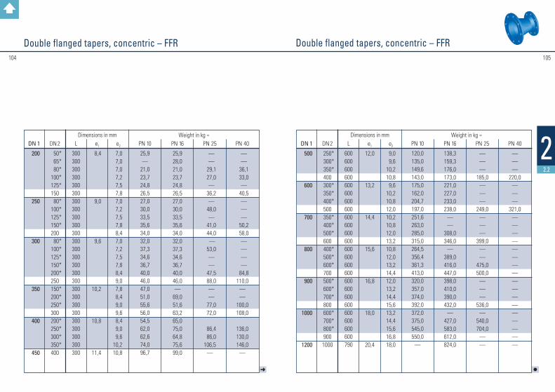
105104
22.2
Double flanged tapers, concentric – FFRDouble flanged tapers, concentric – FFR
➜
DN 1
200
250
300
350
400
450
DN 2
50* 65* 80* 100* 125*
150 80* 100* 125* 150*
200 80* 100* 125* 150* 200*
250 150* 200* 250*
300 200* 250* 300* 350*
400
L
300300300300300300300300300300300300300300300300300300300300300300300300300300
e1
8,4
9,0
9,6
10,2
10,8
11,4
e2
7,07,07,07,27,57,87,07,27,57,88,47,07,27,57,88,49,07,88,49,09,68,49,09,6
10,210,8
PN 10
25,9—
21,023,724,826,527,030,033,535,634,032,037,334,636,740,046,047,051,055,656,054,562,062,674,096,7
PN 16
25,928,021,023,724,826,527,030,033,535,634,032,037,334,636,740,046,0—
69,051,663,265,075,064,875,699,0
PN 25
— —
29,1 27,0 —
36,2 —
48,0 —
41,0 44,0 — 53,0 — —
47,5 88,0 — —
77,0 72,0
86,4 86,0106,5
—
PN 40
— —
36,1 33,0 —
40,5 — — —
50,2 58,0 — — — —
84,8110,0
——
100,0108,0
136,0130,0146,0
—
Weight in kg ≈Dimensions in mm
l
DN 1
500
600
700
800
900
1000
1200
DN 2
250* 300* 350*400
300* 350* 400*500
350* 400* 500*600
400* 500* 600*700
500* 600* 700*800
600* 700* 800*9001000
L
600600600600600600600600600600600600600600600600600600600600600600600600790
e1
12,0
13,2
14,4
15,6
16,8
18,0
20,4
e2
9,09,6
10,210,89,6
10,210,812,010,210,812,013,210,812,013,214,412,013,214,415,613,214,415,616,818,0
PN 10
120,0135,0149,6143,0175,0162,0204,7197,0251,6263,0285,0315,0264,5356,4361,3413,0320,0357,0374,0392,0372,0375,0545,0550,0
—
PN 16
138,3159,3176,0173,0221,0227,0233,0238,0
——
308,0346,0
—389,0416,0447,0398,0410,0390,0432,0
—427,0583,0612,0824,0
PN 25
———
185,0———
249,0———
399,0——
475,0500,0
———
536,0—
540,0704,0
——
PN 40
———
220,0———
321,0—————————————————
Weight in kg ≈Dimensions in mm

107106
22.2
➜
Double flanged tapers, eccentric – FFReacc. to manufacturer’s standard
Double flanged tapers, eccentric – FFReacc. to manufacturer’s standard
DN 1
50 65
80
100
125
150
DN 2
40 40 50 40 50 65 40 50 65 80 50 65 80 100 50 80 100 100 125
L
200 200 200 200 200 200 200 200 200 200 200 200 200 300 300 300 200 300 300
e1
7,0 7,0
7,0
7,2
7,5
7,8
e2
7,0 7,0 7,0 7,0 7,0 7,0 7,0 7,0 7,0 7,0 7,0 7,0 7,0 7,2 7,0 7,0 7,2 7,2 7,5
PN 10
——————
11,513,012,513,514,015,016,017,021,020,021,518,426,5
PN 16
——————
11,513,012,513,514,015,016,017,021,020,021,518,426,5
PN 25
——————
12,012,513,013,514,615,516,617,622,024,023,025,526,5
PN 40
7,0 8,5 9,0 9,510,011,012,012,513,013,516,516,817,918,924,026,025,027,530,0
Weight in kg ≈Dimensions in mm
Dimensions and weights
Manufacturing of other dimensions and face-to-face lengths possible.
DN 1
200
250
300
350
400
450500
DN 2
80100125150100125150200100150200250200250250300300150200250300300350250250300350400450
L
300300300300300300300300300300300300500500600300500500600500500600500600500500500500500
e1
8,4
9,0
9,6
10,2
10,8
11,412,0
e2
7,0 7,2 7,5 7,8 7,2 7,5 7,8 8,4 7,2 7,8 8,4 9,0 8,4 9,0 9,0 9,6 9,6 7,8 8,4 9,0 9,6 9,610,2 9,0 9,0 9,610,210,811,4
PN 10
26,0 27,0 32,4 25,4 37,0 42,0 42,0 45,9 42,5 45,0 58,0 55,6 88,0 90,0 98,0102,0108,0 88,0 98,0 92,0113,0115,0125,0113,0124,0123,5130,5172,0166,0
PN 16
26,0 27,0 28,5 29,5 37,0 38,0 39,5 44,0 42,5 48,6 58,0 55,6 91,0 92,5103,0 97,0114,0 97,0 98,0109,0112,0129,0134,0125,0136,0144,0151,0172,0188,0
PN 25
28,0 29,5 30,5 31,5 40,5 41,5 44,5 50,0 47,0 61,5 61,5 69,5105,0108,0114,0108,0125,0109,0117,5130,0132,0141,0153,0135,0149,5162,0168,0204,0
—
PN 40
34,5 35,5 36,5 38,5 50,5 52,5 53,5 66,0 62,0 84,5 —
97,0128,0135,0141,0135,0162,0145,0157,5170,0191,0200,0208,0182,0195,0213,0217,0172,0
—
Weight in kg ≈Dimensions in mm
➜
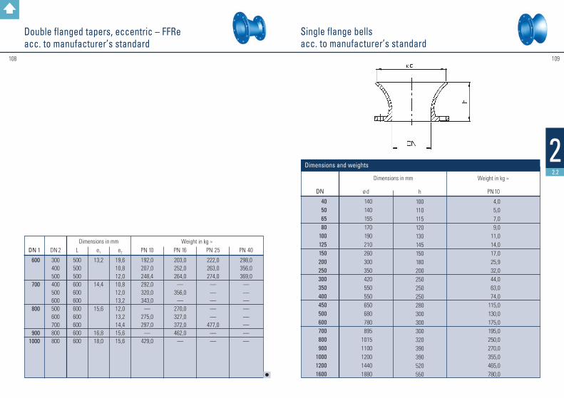
108 109
22.2
Single flange bellsacc. to manufacturer’s standard
Double flanged tapers, eccentric – FFReacc. to manufacturer’s standard
Weight in kg ≈Dimensions in mm
DN 1
600
700
800
9001000
DN 2
300400500400500600500600700800800
L
500500500600600600600600600600600
e1
13,2
14,4
15,6
16,818,0
e2
19,610,812,010,812,013,212,013,214,415,615,6
PN 10
192,0207,0248,4292,0320,0343,0
—275,0297,0
—429,0
PN 16
203,0252,0264,0
—356,0
—270,0327,0372,0462,0
—
PN 25
222,0263,0274,0
—————
477,0——
PN 40
298,0356,0369,0
————————
l
DN
40506580
100125150200250300350400450500600700800900
100012001600
ø d
140140155170190210260300350420550550650680780895
10151100120014401880
h
100110115120130145150180200250250250280300300300320390390520550
PN 10
4,05,07,09,0
11,014,017,025,932,044,063,074,0
115,0130,0175,0195,0250,0270,0355,0465,0780,0
Dimensions in mm Weight in kg ≈
Dimensions and weights

bb
110 111
22.2
Blank flanges – X
* acc. to manufacturer’s standard
Flange connection dimension acc. to EN 1092–2
DN 25 – 250 DN 300 – 1000
DN
25* 32* 40* 50* 65*
80 100 125 150 200 250 275 300 350 400 450 500 600 700 800 9001000120014001600
PN 10
16,016,022,022,022,016,016,016,016,017,019,020,520,520,520,521,522,525,027,530,032,535,040,041,044,0
PN 16
16,016,022,022,022,016,016,016,016,017,019,0—
20,522,524,0—
27,531,034,538,041,545,052,055,060,0
PN 25
16,016,022,022,022,016,016,016,017,019,021,5—
23,526,028,0—
32,537,0———————
PN 40
16,016,022,022,022,016,016,020,523,027,031,5—
35,5————————————
PN 10
1,0 1,8 2,1 2,5 3,0 4,0 4,6 6,0 7,6 11,4 17,2 25,0 25,0 30,5 38,0 67,0 56,0 86,0 127,0 176,0 230,0 334,0582,0
—896,0
PN 16
1,0 1,8 2,1 2,5 3,0 4,0 4,6 6,0 7,6 11,4 16,8
— 24,5 34,5 46,0 91,5 79,0123,0174,0244,0323,0480,0737,0895,0
1221,0
PN 25
1,0 1,8 2,1 2,5 3,0 5,0 5,1 6,6 8,6 13,6 21,0
— 31,0 43,5 59,5
— 96,0147,0
———————
PN 40
1,0 1,8 2,1 2,5 3,0 5,0 5,1 8,2 11,4 20,0 33,0
— 51,0
————————————
Weight in kg ≈ Dimensions in mmb
Dimensions and weights
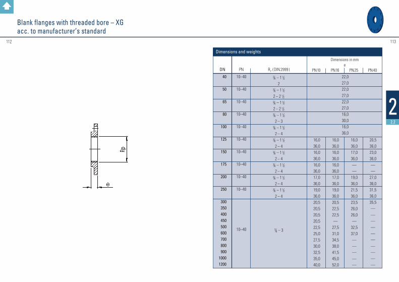
Maße und Gewichte
112 113
22.2
Blank flanges with threaded bore – XGacc. to manufacturer’s standard
DN
40
50
65
80
100
125
150
175
200
250
300 350 400 450 500 600 700 800 90010001200
PN
10–40
10–40
10–40
10–40
10–40
10–40
10–40
10–40
10–40
10–40
10–40
RP (DIN 2999 )
3/8 – 1 1/22
3/8 – 1 1/22 – 2 1/23/8 – 1 1/22 – 2 1/23/8 – 1 1/2
2 – 3 3/8 – 1 1/2
2 – 4 3/8 – 1 1/2
2 – 43/8 – 1 1/2
2 – 4 3/8 – 1 1/2
2 – 4 3/8 – 1 1/2
2 – 43/8 – 1 1/2
2 – 4
3/8 – 3
PN 10
16,036,016,036,016,036,017,036,019,036,020,520,520,520,522,525,027,530,032,535,040,0
PN 16
16,036,016,036,016,036,017,036,019,036,020,522,522,5—
27,531,034,538,041,545,052,0
PN 25
16,036,017,036,0——
19,036,021,536,023,526,026,0—
32,537,0—————
PN 40
20,536,023,036,0——
27,036,031,536,035,5——————————
Dimensions in mme
Dimensions and weights
22,027,022,027,022,027,016,030,016,036,0
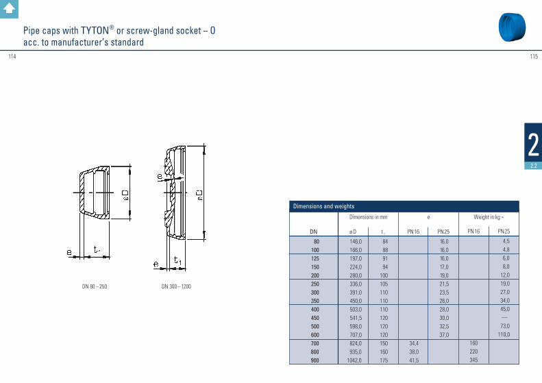
115114
22.2
Pipe caps with TYTON® or screw-gland socket – Oacc. to manufacturer’s standard
DN 80 – 250 DN 300 – 1200
DN
80 100 125 150 200 250 300 350 400 450 500 600 700 800 900
ø D
146,0 166,0 197,0 224,0 280,0 336,0 391,0 450,0 503,0 541,5 598,0 707,0 824,0 935,01042,0
t 1 84 88 91 94100105110110110120120120150160175
PN 16
34,438,041,5
PN 25
16,016,016,017,019,021,523,526,028,030,032,537,0
PN 16
160220345
PN 25
4,5 4,8 6,0 8,0 12,0 19,0 27,0 34,0 45,0
— 73,0110,0
Weight in kg ≈Dimensions in mm
Dimensions and weights
e

116 117
22.2
Flanged socket duckfoot bends 90° – ENacc. to DIN 28 650
Conversion flanges DN 80 4 / 8 holesacc. to manufacturer’s standard
DN
80
PN
10 / 40
ø D
200
e
27
3,9
Dimensions in mm Weight in kg ≈
Dimensions and weights
1) without screw ring
DN
80100150
L1
165180220
L2
145158265
c
110125160
d
180200250
e
7,07,27,8
Weight in kg ≈ 1) Dimensions in mmwith
screw-gland socket PN 10 / PN 16
14,618,4
with TYTON® socket
PN 10 / PN 16
15,719,036,5
Dimensions and weights
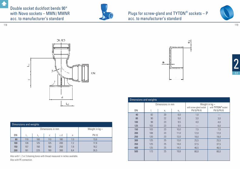
119118
22.2
Plugs for screw-gland and TYTON® sockets – Pacc. to manufacturer’s standard
Double socket duckfoot bends 90° with Novo sockets – MMN / MMNRacc. to manufacturer’s standard
DN
80100150200
L1
119128157181
L2
100125150225
c
110125160190
d
180200250300
PN 10
13,617,819,230,5
Dimensions in mm Weight in kg ≈ e
7,07,27,88,4
Dimensions and weights
Also with 1, 2 or 3 draining bores with thread measured in inches available.Also with PE connection.
DN
40 80100125150200250300350400500
L
82 90 98103103108120125125125173
e1
20 22 23 23 23 23 23 25 25 25 25
e2
8,0 9,0 9,5 9,510,011,012,013,014,014,519,8
with screw-gland socket
PN 10 / PN 16
1,0 3,0 4,0 —
7,512,018,025,537,546,580,0
with TYTON® socket
PN 10 / PN 16
— 3,0 4,0 6,0 7,512,018,025,537,546,580,0
Dimensions in mm Weight in kg ≈
Dimensions and weights
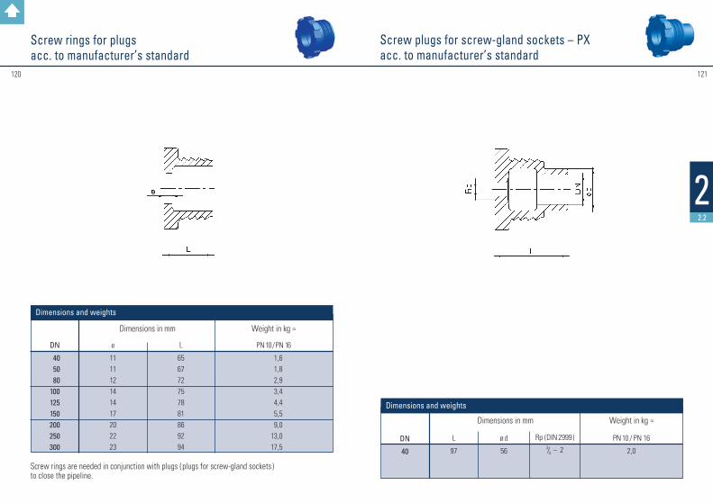
121120
22.2
Screw plugs for screw-gland sockets – PXacc. to manufacturer’s standard
Screw rings for plugsacc. to manufacturer’s standard
Screw rings are needed in conjunction with plugs ( plugs for screw-gland sockets ) to close the pipeline.
DN
40 50 80100125150200250300
e
111112141417202223
L
656772757881869294
PN 10 / PN 16
1,61,82,93,44,45,59,0
13,017,5
Dimensions in mm Weight in kg ≈
Dimensions and weights
DN
40
L
97
ø d
56
Rp ( DIN 2999 )3/4 – 2
PN 10 / PN 16
2,0
Dimensions in mm Weight in kg ≈
Dimensions and weights

123122
22.3
Ductile cast iron ( GGG ) special fittings
• Single socket pieces with angled branch 45° – C with screw-gland socket – acc. to manufacturer’s standard
• Socket spigot tapers – R with screw-gland socket – acc. to manufacturer’s standard
• Flanged socket bends 90 ° – EQ with screw-gland socket – acc. to manufacturer’s standard
For further information please give us a call or contact your specialist dealer. We look forward to your questions.
Contact: Export Department, Phone: +49 6093 87 560, e-mail: [email protected]

#125124
DN
40506580
100125150200250300350400450500600700800900
1000120014001600
d1
56668298
118144170222274326378429480532635738842945
1048125514621668
D
150165185200220250285340400455505565615670780895
101511151230145516751915
b
16161616161616171920202021222527303235404144
Dimensions
The dimension L is subject to customer specification and is to be measured from the flange sealing seat or from the socket length up to the centre of the puddle flange.
Fittingswith Puddle Flanges
Fittingswith Puddle Flanges
Dimensions in mm 22.3
Flanged fittings:
Socket fittings:
* t = Socket length
127126
22.4
These fittings for plastic pipelines are made of ductile cast iron (GGG) and they are manufactured acc. to EN 12 842.The flanges of the KS fittings are acc. to EN 1092-2. All KS fittings are delivered with gaskets.
Coatings: see page 47.
Remarks forductile cast iron fittings for plastic pipelines
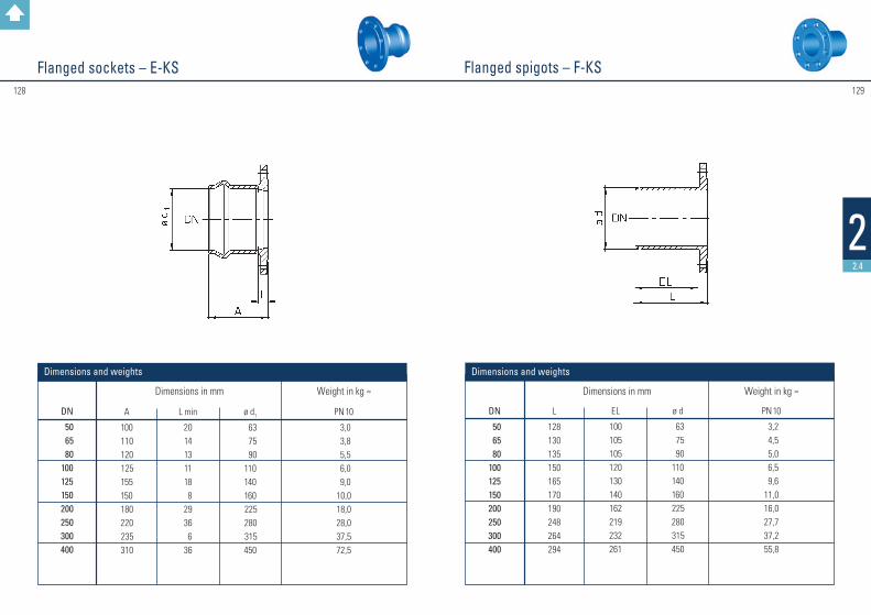
129128
22.4
Flanged spigots – F-KSFlanged sockets – E-KS
DN
50 65 80100125150200250300400
A
100 110 120 125 155 150 180 220 235 310
L min
2014131118 82936 636
ø d1
63 75 90110140160 225 280 315450
PN 10
3,0 3,8 5,5 6,0 9,010,018,028,037,572,5
Dimensions in mm Weight in kg ≈
DN
50 65 80100125150200250300400
L
128130135150165170190248264294
EL
100105105120130140162219232261
ø d
63 75 90110140160 225 280 315 450
PN 10
3,2 4,5 5,0 6,5 9,611,016,027,737,255,8
Dimensions in mm Weight in kg ≈
Dimensions and weights Dimensions and weights
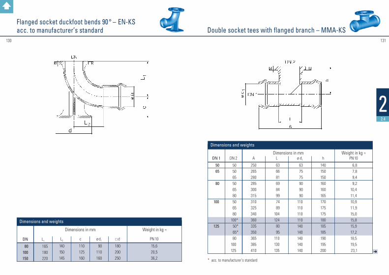
131130
22.4
➜
Double socket tees with flanged branch – MMA-KSFlanged socket duckfoot bends 90 ° – EN-KSacc. to manufacturer’s standard
DN
80 100150
L1
165180220
L2
140150145
c
110125160
ø d1
90110160
PN 10
15,620,536,2
Dimensions in mm Weight in kg ≈ d
180200250
DN 1
50 65
80
100
125
DN 2
50 50 65 50 65 80 50 65 80
100* 50* 65*
80100125
A
250265280285300315310325340360335350365385410
L
63 66 81 69 84 99 74 89104124 80 95110130135
ø d1
63 75 75 90 90 90110110110110140140140140140
h
140150150160160165170175175180185185190195200
PN 10
6,8 7,8 9,4 9,210,411,410,911,915,015,815,917,218,519,5 23,1
Weight in kg ≈ Dimensions in mm
Dimensions and weights
Dimensions and weights
* acc. to manufacturer’s standard

133132
22.4
l
All socket tees – MMB-KSDouble socket tees with flanged branch – MMA-KS
DN 1
150
200
250
300
400
DN 2
50 65 80100125150
80* 100*
125150
200* 80100150200250 80100150
200* 250* 300* 80*100
200* 400*
A
360375390410435460455475500525575515535585635885550570620670720770660680780980
L
98 98116136161186128148173198248140160210260310152172222272322372200220320520
ø d1
160 160 160 160 160 160225225225225225280280280280280315315315315315315450450450450
h
205210205210215220235240245250260265270280290300295300310320330340355360380420
PN 10
19,2 21,0 20,8 24,2 26,5 29,7 34,9 37,6 39,8 44,7 51,4 48,0 52,0 57,6 65,6 73,6 58,9 61,6 71,1 79,4 89,2 93,0124,7130,5168,1219,0
Weight in kg ≈ Dimensions in mm
* acc. to manufacturer’s standard * ac
c. to
man
ufac
ture
r’s st
anda
rd
DN 1
5065
80
100
125
150
200
DN 2
50 50 65 50 65 80 50 65
80*100 80
100*125 80100
125*150 80100125150200
A
257272283292303216317328341360366385412391410437455456475502520578
L
70 73 84 76 87101 81 92106124112130157118136163181130148175 193 252
ø d1
63 75 75 90 90 90110110110110140140140160160160160225225225225225
l1
35 35 45 50 50 55 60 60 60 65 75 80 80 82 85 90 95115115120120130
PN 10
4,1 5,0 5,4 6,5 7,0 7,3 8,7 9,110,512,512,814,316,015,318,520,422,728,730,732,439,842,7
Weight in kg ≈ Dimensions in mm
h
128,5 134,0 141,5 140,5 148,0 158,0 150,0 157,5 167,7 180,0 181,5 193,5 206,0 190,0 202,5 115,0 227,5 219,0 231,5 244,0 256,5 289,0
ø d2
63 63 75 63 75 90 63 75 90110 90110140 90110140160 90110140160225
Dimensions and weights
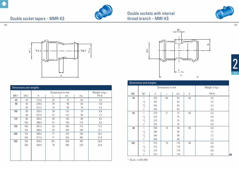
135134
22.4
➜
Double sockets with internal thread branch – MMI-KSDouble socket tapers – MMR-KS
DN
50
65
80
100
Rp*
11 1/41 1/221
1 1/41 1/221
1 1/41 1/221
1 1/41 1/22
A
255255255255270270270270290290290290315315315315
L
68
71
74
79
ø d1
636363637575757590909090110110110110
PN 10
3,64,34,34,55,05,65,65,86,67,27,27,48,49,09,09,2
Dimensions in mm Weight in kg ≈ h
60
65
85
90
Dimensions and weights
DN 1
65 80
100
125
150
200
250
DN 2
50 50 65 65 80 80 100 100 125 125 150 150 200
A
213,0229,5231,5253,5257,0283,0286,0307,5306,5368,0371,5426,5430,0
L
20 28 24 36 31 48 41 53 42 77 71 102 79
ø d1
75 90 90 110 110 140 140 160 160 225 225 280 280
ø d2
63 63 75 75 90 90110110140140160160 225
PN 10
3,6 4,8 5,5 6,8 7,2 8,3 9,2 11,012,120,221,828,832,6
Weight in kg ≈ Dimensions in mm
Dimensions and weights
* Rp acc. to DIN 2999
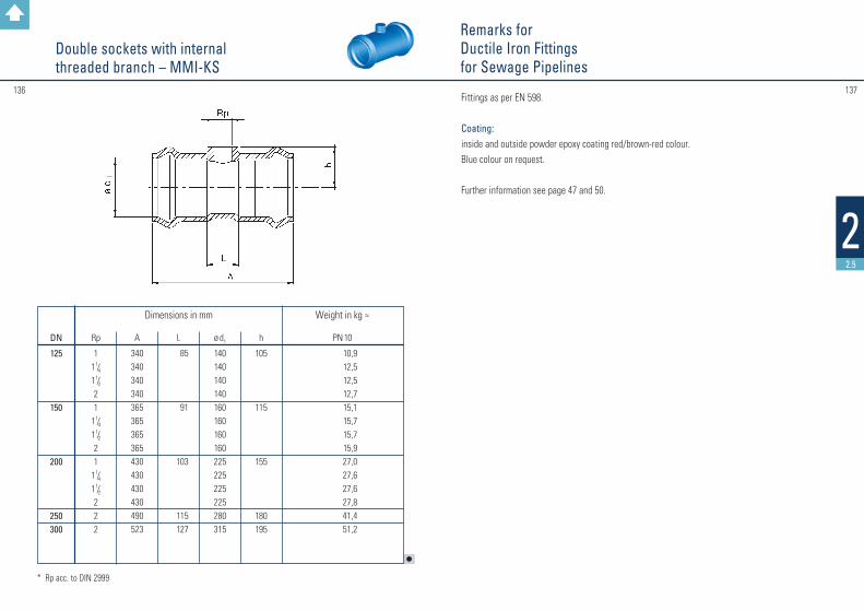
137136
22.5
Fittings as per EN 598.
Coating: inside and outside powder epoxy coating red/brown-red colour.Blue colour on request.
Further information see page 47 and 50.
Remarks forDuctile Iron Fittingsfor Sewage Pipelines
l
Double sockets with internal threaded branch – MMI-KS
* Rp acc. to DIN 2999
DN
125
150
200
250300
Rp
11 1/41 1/221
1 1/41 1/221
1 1/41 1/2222
A
340340340340365365365365430430430430490523
L
85
91
103
115127
ø d1
140140140140160160160160225225225225280315
PN 10
10,912,512,512,715,115,715,715,927,027,627,627,841,451,2
Dimensions in mm Weight in kg ≈ h
105
115
155
180195
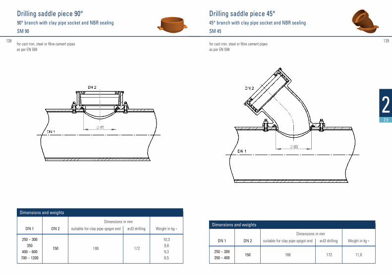
#139138
22.5
Drilling saddle piece 90° 90° branch with clay pipe socket and NBR sealing
SM 90
Drilling saddle piece 45° 45° branch with clay pipe socket and NBR sealing
SM 45
for cast iron, steel or fibre cement pipes as per EN 598
for cast iron, steel or fibre cement pipes as per EN 598
DN 1
250 – 300350
400 – 600700 – 1200
DN 2
150
suitable for clay pipe spigot end
186
Weight in kg ≈
10,39,89,38,5
Dimensions and weights
ø d3 drilling
172
Dimensions in mm
DN 1
250 – 300350 – 400
DN 2
150
suitable for clay pipe spigot end
186
Weight in kg ≈
11,0
Dimensions and weights
ø d3 drilling
172
Dimensions in mm

#141140
22.5
Drilling saddle piece 90° 90° branch with spigot for ductile iron pipeSI 90
Drilling saddle piece 90° 45° branch with spigot for ductile iron pipeSI 45
DN 1
250 – 300300350400
400 – 600500 – 600700 – 800
700 – 1200900 – 1200
DN 2
150200200200150200200150200
ø d2 Weight in kg ≈
9,115,316,014,17,213,212,66,613,0
Dimensions and weights
ø d3
ductile iron
170222222222170222222170222
clay pipe
186242242242186242242186242
drilling
172232232232172232232172232
Dimensions in mm
DN 1
250 – 300
DN 2
150
ø d2 ductile iron
170
Weight in kg ≈
9,1
Dimensions and weights
ø d3 drilling
172
Dimensions in mm
for cast iron, steel or fibre cement pipes as per EN 598
for cast iron, steel or fibre cement pipes as per EN 598

#143142
22.5
TYTON®-couplings with TYTON® NBR sealsMM
Spigot end branch 67° ICI 67
as per EN 598 suitable for ductile iron sewage pipes
as per EN 598
DN 1
150200250300350400500600700800
DN 1
200
DN 2
150
ø d1
222
ø d2
170
L 1
568
L 2
326
h
310
Weight in kg ≈
26,0
ø d1
170222274326378429532635738842
Weight in kg ≈
8,011,514,721,029,036,058,079,0125,0126,0
Dimensions and weights
Dimensions and weights
ø D
210262315370425480590695810920
L
160165180200215210225250305325
Deviation per socket
5°
4°
3°
Dimensions in mm
Dimensions in mm

#145144
22.5
as per EN 598 with NBR sealing
as per EN 598
DN 1
200
DN 2
150 STZ
ø d2
186
L 1
370
L 2
310
h
400
Deviation per socket
5°
Weight in kg ≈
38,0
Dimensions and weights
Dimensions in mm
Double socket branch with TYTON® sockets 45° branch with spigot for clay pipe MMI 45 or67° branch with spigot for ductile iron pipe MMI 67
Double socket branch with TYTON® sockets 45° branch with clay pipe socketMMM
DN 1
200200
DN 2
150 STZ150 GGG
ø d2
186170
L 1
370360
L 2
310222
h
400310
45°67°
Deviation per socket
5°5°
Weight in kg ≈
34,531,0
Dimensions and weights
Dimensions in mm
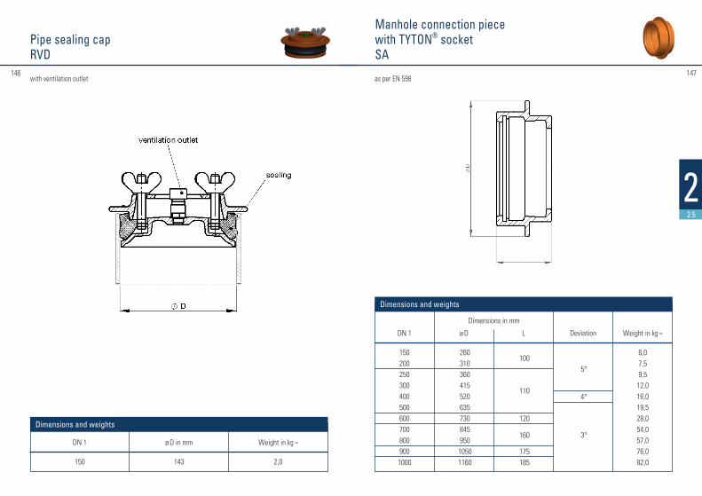
#147146
22.5
Pipe sealing capRVD
DN 1
150
ø D in mm
143
Weight in kg ≈
2,0
Dimensions and weights
Manhole connection piece with TYTON® socketSA
as per EN 598
DN 1
1502002503004005006007008009001000
Weight in kg ≈
6,07,59,512,016,019,528,054,057,076,082,0
Dimensions and weights
ø D
260310360415520635730845950
10501160
L
100
110
120
160
175185
Deviation
5°
4°
3°
Dimensions in mm
with ventilation outlet
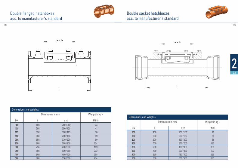
#149148
22.5
DN
80100125150200250300350400500
L
500500550550650700750800900900
a x b
250 / 80250 / 100300 / 125290 / 150330 / 200360 / 250400 / 300500 / 350480 / 400550 / 500
PN 10
33 41 56 59
90124163232268414
Dimensions in mm Weight in kg ≈
Dimensions and weights
Double flanged hatchboxesacc. to manufacturer’s standard
Double socket hatchboxesacc. to manufacturer’s standard
DN
100150200250300350400500
L
450550600650700750850850
a x b
250 / 100290 / 150330 / 200360 / 250400 / 300500 / 350480 / 400550 / 500
PN 10
40 68 88120159227265385
Dimensions in mm Weight in kg ≈
Dimensions and weights

#151150
22.5
➜
Double socket pieces with 45° socket branch – MMCacc. to manufacturer’s standard
DN 1
80100
125
150
200
250
300
DN 2
80 80100100125 80100150100150200100150200250100150200250300
Lu
270300300350350380380380500500500600500500600700450450700700
lu
200250250250250300300300360380380395400400460430470470500525
z
200250250250250300300300360380380395395430460430430420500525
e1
7,0 7,2
7,5
7,8
8,4
9,0
9,6
Dimensions in mm
e2
7,0 7,0 7,2 7,2 7,5 7,0 7,2 7,8 7,2 7,8 8,4 7,2 7,8 8,4 9,0 7,2 7,8 8,4 9,0 9,6
with TYTON® sockets
22,0 25,0 30,0 40,0 41,0 33,0 36,0 39,0 56,2 62,0 65,0 67,0 71,0101,0120,0 89,6 93,4 95,0128,0142,6
Weight in kg ≈
Dimensions and weights
l
Double socket pieces with 45° socket branch – MMCacc. to manufacturer’s standard
DN 1
350
400
500
600
700
800
DN 2
150200250300350100125150200300400100150200250300400500150200250300400500600200300400500600700600800
Lu
700 700 700 700 880 440 440 440 640 850 850 450 450 740 740 740 850 1040 750 750 750 750 1150 1210 1210 575 925 92510801380138012501550
lu
470 510 530 570 690 480 490 490 570 650 650 590 590 620 640 720 720 845 750 750 775 800 800 920 985 825 885 94010201070114011501275
z
470 510 530 610 760 440 450 450 580 700 650 515 515 550 620 680 750 845 620 620 680 740 765 915 975 675 810 890 9901055114011101275
e1
10,2
10,8
12,0
13,2
14,4
15,6
Dimensions in mm
e2
7,8 8,4 9,0 9,6 10,2 7,2 7,5 7,8 8,4 9,6 10,8 7,2 7,8 8,4 9,0 9,6 10,8 12,0 7,8 8,4 9,0 9,6 10,8 12,0 13,2 8,4 9,6 10,8 12,0 13,2 14,4 13,2 15,6
with TYTON® sockets
153,0 160,0 172,0 177,0 195,0 131,0 138,0 141,0 159,0 181,0 209,0 167,0 177,0 220,0 231,0 237,0 266,0 385,0 240,0 245,0 250,0 260,0 400,0 482,0 506,0 298,0 433,0 445,0 635,0 693,0 750,0 745,01013,0
Weight in kg ≈
#153152
33
Ductile cast iron (GGG) valves
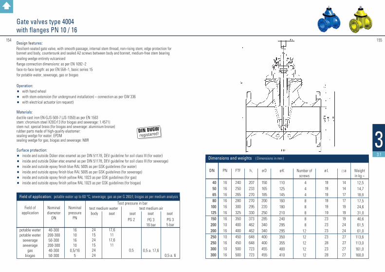
Design features: Resilient-seated gate valve, with smooth passage, internal stem thread, non-rising stem; edge protection for bonnet and body, countersunk and sealed A2 screws between body and bonnet, medium-free stem bearingsealing wedge entirely vulcanisedflange connection dimensions: as per EN 1092–2face-to-face length: as per EN 558–1, basic series 15for potable water, sewerage, gas or biogas
Operation: • with hand wheel• with stem extension (for underground installation) – connection as per GW 336• with electrical actuator (on request)
Materials: ductile cast iron EN-GJS-500-7 (JS-1050) as per EN 1563stem: chromium steel X20Cr13 (for biogas and sewerage: 1.4571)stem nut: special brass (for biogas and sewerage: aluminium bronze)rubber parts made of high-quality elastomer:sealing wedge for water: EPDMsealing wedge for gas, biogas and sewerage: NBR
Surface protection: • inside and outside Düker etec enamel as per DIN 51178, DEV guideline for soil class III (for water)• inside and outside Düker etec enamel as per DIN 51178, DEV guideline for soil class III (for sewerage)• inside and outside epoxy finish blue RAL 5005 as per GSK guidelines (for water)• inside and outside epoxy finish blue RAL 5005 as per GSK guidelines (for sewerage)• inside and outside epoxy finish yellow RAL 1023 as per GSK guidelines (for gas)• inside and outside epoxy finish yellow RAL 1023 as per GSK guidelines (for biogas)
PG 3 5 bar
0,5 a. 6
PG 3 16 bar
0,5 a. 17,6
PG 2
0,5
17,6 11
17,6 11
24 15 24 15 24 24
Test pressure in bar test medium water test medium air body seat seat seat seat
Field of application: potable water up to 60 °C; sewerage; gas as per G 260/I; biogas as per medium analysis
Nominal diameter
DN
40-300
200-300 50-300
200-300 40-300 50-300
Nominal pressure
PN
16 10 16 10
0,5/16 5
Field of
application
potable water potable water
sewerage sewerage
gas biogas
3
155
3.1
154
Gate valves type 4004with flanges PN 10 / 16
DN
40506580
100125150200200250250300300
PN
16161616161616101610161016
FTF
240250265280300325350400400450450500500
ø K
110125145160180210240295295350355400410
h1
207233270270295330 373462462648648723723
ø D
150165185200220250285340340400400455455
a
141417171919192424 27 272727
Weight in kg ≈
12,5 14,7 18,8 17,5 24,6 31,0 40,6 61,5 61,0113,6113,0161,0160,0
Number of
screws
4 4 4 8 8 8 8 8 1212121212
ø L
19191919191923232323282328
Dimensions and weights ( Dimensions in mm )
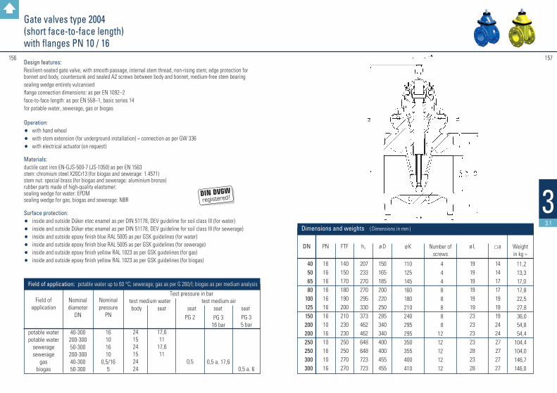
Design features: Resilient-seated gate valve, with smooth passage, internal stem thread, non-rising stem; edge protection for bonnet and body, countersunk and sealed A2 screws between body and bonnet, medium-free stem bearingsealing wedge entirely vulcanised flange connection dimensions: as per EN 1092–2face-to-face length: as per EN 558–1, basic series 14for potable water, sewerage, gas or biogas
Operation: • with hand wheel• with stem extension (for underground installation) – connection as per GW 336• with electrical actuator (on request)
Materials: ductile cast iron EN-GJS-500-7 (JS-1050) as per EN 1563stem: chromium steel X20Cr13 (for biogas and sewerage: 1.4571)stem nut: special brass (for biogas and sewerage: aluminium bronze)rubber parts made of high-quality elastomer:sealing wedge for water: EPDMsealing wedge for gas, biogas and sewerage: NBR
Surface protection: • inside and outside Düker etec enamel as per DIN 51178, DEV guideline for soil class III (for water)• inside and outside Düker etec enamel as per DIN 51178, DEV guideline for soil class III (for sewerage)• inside and outside epoxy finish blue RAL 5005 as per GSK guidelines (for water)• inside and outside epoxy finish blue RAL 5005 as per GSK guidelines (for sewerage)• inside and outside epoxy finish yellow RAL 1023 as per GSK guidelines (for gas)• inside and outside epoxy finish yellow RAL 1023 as per GSK guidelines (for biogas)
PG 3 5 bar
0,5 a. 6
PG 3 16 bar
0,5 a. 17,6
PG 2
0,5
17,6 11
17,6 11
24 15 24 15 24 24
Test pressure in bar test medium water test medium air body seat seat seat seat
Field of application: potable water up to 60 °C; sewerage; gas as per G 260/I; biogas as per medium analysis
Nominal diameter
DN
40-300
200-300 50-300
200-300 40-300 50-300
Nominal pressure
PN
16 10 16 10
0,5/16 5
Field of
application
potable water potable water
sewerage sewerage
gas biogas
157156
33.1
Gate valves type 2004 (short face-to-face length)with flanges PN 10 / 16
DN
40506580
100125150200200250250300300
PN
16161616161616101610161016
FTF
140150170180190200210230230250250270270
ø K
110125145160180210240295295350355400410
h1
207233270270295330 373462462648648723723
ø D
150165185200220250285340340400400455455
a
141417171919192424 27 272727
Weight in kg ≈
11,2 13,3 17,0 17,8 22,5 27,8 36,0 54,8 54,4104,4104,0146,7146,0
Number of
screws
4 4 4 8 8 8 8 8 1212121212
ø L
19191919191923232323282328
Dimensions and weights ( Dimensions in mm )
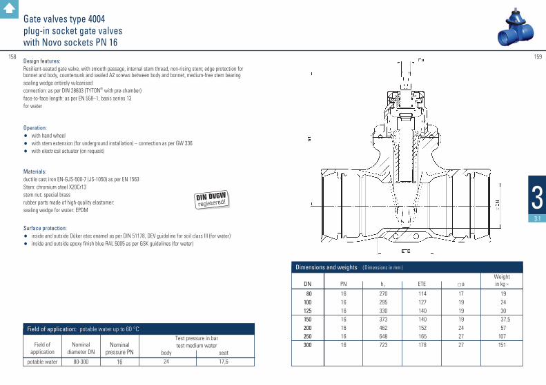
Design features: Resilient-seated gate valve, with smooth passage, internal stem thread, non-rising stem; edge protection for bonnet and body, countersunk and sealed A2 screws between body and bonnet, medium-free stem bearingsealing wedge entirely vulcanisedconnection: as per DIN 28603 (TYTON® with pre-chamber)face-to-face length: as per EN 558–1, basic series 13for water
Operation: • with hand wheel• with stem extension (for underground installation) – connection as per GW 336• with electrical actuator (on request)
Materials: ductile cast iron EN-GJS-500-7 (JS-1050) as per EN 1563Stem: chromium steel X20Cr13stem nut: special brassrubber parts made of high-quality elastomer:sealing wedge for water: EPDM
Surface protection: • inside and outside Düker etec enamel as per DIN 51178, DEV guideline for soil class III (for water)• inside and outside epoxy finish blue RAL 5005 as per GSK guidelines (for water)
Test pressure in bartest medium water
body seat 24 17,6
Field of application: potable water up to 60 °C
Nominal diameter DN
80-300
Nominal
pressure PN
16
Field of
application
potable water
159158
33.1
DN
80100125150200250300
PN
16161616161616
h1
270295330373462648723
Weight in kg ≈
19 24 30
37,5 57 107 151
Dimensions and weights ( Dimensions in mm )
ETE
114127140140152165178
a
17191919242727
Gate valves type 4004 plug-in socket gate valves with Novo sockets PN 16

Design features: Resilient-seated gate valve, with smooth passage, internal stem thread, non-rising stem; edge protection for bonnet and body, countersunk and sealed A2 screws between body and bonnet, medium-free stem bearing sealing wedge entirely vulcanisedconnection: as per DIN 28603 (TYTON® with pre-chamber)face-to-face length: as per EN 558–1, basic series 13for water
Operation: • with hand wheel • with stem extension (for underground installation) – connection as per GW 336 • with electrical actuator (on request)
Materials: ductile cast iron EN-GJS-500-7 (JS-1050) as per EN 1563 stem: chromium steel X20Cr13 stem nut: special brass rubber parts made of high-quality elastomer: sealing wedge for water: EPDM
Surface protection: • inside and outside Düker etec enamel as per DIN 51178, DEV guideline for
soil class III (for water) • inside and outside epoxy finish blue RAL 5005 as per GSK guidelines (for water)
Gate valves type 4004 Single socket gate valves with Novo sockets and spigot end PN 16
DN
80100125150200250300
PN
16161616161616
ø D
97117143169221274326
h1
270295330373462648723
ø D1
141161188215271324381
Weightin kg ≈ 18,2 22,5 29,3 36,6 56,0109,0120,0
Dimensions and weights ( Dimensions in mm )
L1
235235290290310310310
L
410422485490525535550
a
17191919242727
160
33.1
161
Test pressure in bartest medium water
body seat 24 17,6
Field of application: potable water up to 60 °C
Nominal diameter DN
80-300
Nominal
pressure PN
16
Field of
application
potable water

Design features: Resilient-seated gate valve, with smooth passage, internal stem thread, non-rising stem; edge protection for bonnet and body, countersunk and sealed A2 screws between body and bonnet, medium-free stem bearing sealing wedge entirely vulcanisedconnection: as per DIN 28601face-to-face length: as per EN 558–1, basic series 13 for water
Operation: • with hand wheel • with stem extension (for underground installation) – connection as per GW 336 • with electrical actuator (on request)
Materials: ductile cast iron EN-GJS-500-7 (JS-1050) as per EN 1563stem: chromium steel X20Cr13stem nut: special brassrubber parts made of high-quality elastomer:sealing wedge for water: EPDM
Surface protection: • inside and outside Düker etec enamel as per DIN 51178, DEV guideline for soil class III (for water)• inside and outside epoxy finish blue RAL 5005 as per GSK guidelines (for water)
163162
33.1
Gate valves type 4004 socket gate valves with screw-gland sockets PN 16
1) without screw ring
DN
40 50 80100125150200
ETE
106108114127140140152
L
240250282303322328352
h1
207233270295330373462
ø D
150165200220250285340
Weight in kg 1)
10,011,818,022,028,036,053,6
Dimensions and weights ( Dimensions in mm )
a
14141719191924
PN
16161616161616
Test pressure in bartest medium water
body seat 24 17,6
Field of application: potable water up to 60 °C
Nominal diameter DN
40-200
Nominal
pressure PN
16
Field of
application
potable water
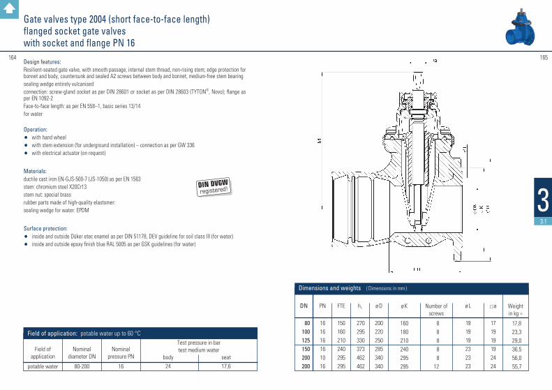
165164
33.1
Gate valves type 2004 (short face-to-face length) flanged socket gate valves with socket and flange PN 16
DN
80100125150200200
PN
161616161016
FTE
150160210240295295
ø K
160180210240295295
h1
270295330373462462
ø D
200220250285340340
a
171919192424
Weight in kg ≈
17,8 23,3 29,0 36,5 56,0 55,7
Number of
screws
8 8 8 8 812
ø L
191919232323
Dimensions and weights ( Dimensions in mm )
Design features: Resilient-seated gate valve, with smooth passage, internal stem thread, non-rising stem; edge protection for bonnet and body, countersunk and sealed A2 screws between body and bonnet, medium-free stem bearingsealing wedge entirely vulcanised connection: screw-gland socket as per DIN 28601 or socket as per DIN 28603 (TYTON®, Novo); flange as per EN 1092-2Face-to-face length: as per EN 558–1, basic series 13/14for water
Operation: • with hand wheel• with stem extension (for underground installation) – connection as per GW 336• with electrical actuator (on request)
Materials: ductile cast iron EN-GJS-500-7 (JS-1050) as per EN 1563stem: chromium steel X20Cr13stem nut: special brassrubber parts made of high-quality elastomer:sealing wedge for water: EPDM
Surface protection: • inside and outside Düker etec enamel as per DIN 51178, DEV guideline for soil class III (for water)• inside and outside epoxy finish blue RAL 5005 as per GSK guidelines (for water)
Test pressure in bartest medium water
body seat 24 17,6
Field of application: potable water up to 60 °C
Nominal diameter DN
80-200
Nominal
pressure PN
16
Field of
application
potable water

167166
33.1
Gate valves type 4004 with welding studs PE PN 10/16
DN
80100100125150150200200
PN
1616161616161616
ø d1
90110125140160180200225
Weightin kg ≈
22,730,531,040,555,554,886,785,5
Dimensions and weights ( Dimensions in mm )
L
650 710 760 790 840 890 970 960
h1
270295295330373373462462
ETE
114127127140140140152152
a
1719191919192424
Design features: Resilient-seated gate valve, with smooth passage, internal stem thread, non-rising stem; edge protection for bonnet and body, countersunk and sealed A2 screws between body and bonnet, medium-free stem bearingsealing wedge entirely vulcanised connection: pre-installed PE-HD welding studs as per DVGW VP 600 with connection dimensions as per DIN 8074/8075. Suitable for electro-welding and butt-weldingface-to-face length: as per EN 558–1, basic series 13for potable water, gas or biogas
Operation: • with hand wheel• with stem extension (for underground installation) – connection as per GW 336
Materials: ductile cast iron EN-GJS-500-7 (JS-1050) as per EN 1563stem: chromium steel X20Cr13 (for biogas: 1.4571)stem nut: special brass (for biogas: aluminium bronze)rubber parts made of high-quality elastomer:sealing wedge for water: EPDMsealing wedge for gas, biogas and sewerage: NBR
Surface protection: • inside and outside Düker etec enamel as per DIN 51178, DEV guideline for soil class III (for water)• inside and outside epoxy finish yellow RAL 1023 as per GSK guidelines (for gas) • inside and outside epoxy finish yellow RAL 1023 as per GSK guidelines (for biogas)
Test pressure in bar test medium water test medium air body seat seat PG 3 5 bar or 10 bar 24 17,6
15 11 24 0,5 and 6 24 0,5 and 11 24 0,5 and 6
Field of application: potable water up to 20 °C; gas as per G 260/I; biogas as per medium analysis
Nominal diameter DN
80-200 80-200 80-200 80-200 80-200
Nominal
pressure PN
16 10 5
10 5
SDR
17 11
11/17 11
11/17
Field of
application
potable water potable water
gas gas
biogas
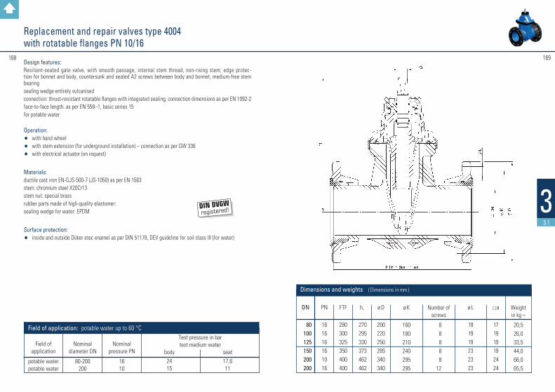
169168
33.1
Replacement and repair valves type 4004 with rotatable flanges PN 10/16
DN
80100125150200200
PN
161616161016
FTF
280300325350400400
ø K
160180210240295295
h1
270295330373462462
ø D
200220250285340340
a
171919192424
Weight in kg ≈
20,526,033,544,066,065,5
Number of
screws
8 8 8 8 812
ø L
191919232323
Dimensions and weights ( Dimensions in mm )
Design features: Resilient-seated gate valve, with smooth passage, internal stem thread, non-rising stem; edge protec-tion for bonnet and body, countersunk and sealed A2 screws between body and bonnet, medium-free stem bearing sealing wedge entirely vulcanised connection: thrust-resistant rotatable flanges with integrated sealing, connection dimensions as per EN 1092-2face-to-face length: as per EN 558–1, basic series 15for potable water
Operation: • with hand wheel• with stem extension (for underground installation) – connection as per GW 336• with electrical actuator (on request)
Materials: ductile cast iron EN-GJS-500-7 (JS-1050) as per EN 1563stem: chromium steel X20Cr13stem nut: special brassrubber parts made of high-quality elastomer:sealing wedge for water: EPDM
Surface protection:• inside and outside Düker etec enamel as per DIN 51178, DEV guideline for soil class III (for water)
Test pressure in bartest medium water
body seat 24 17,6 15 11
Field of application: potable water up to 60 °C
Nominal diameter DN
80-200 200
Nominal
pressure PN
16 10
Field of
application
potable water potable water

#171170
33.1
Design features: Resilient-seated gate valve, with smooth passage, internal stem thread, non-rising stem; edge protec-tion for bonnet and body, countersunk and sealed A2 screws between body and bonnet, medium-free stem bearing sealing wedge entirely vulcanised connection: thrust-resistant rotatable flanges with integrated sealing, connection dimensions as per EN 1092-2face-to-face length: as per EN 558–1, basic series 14for potable water
Operation: • with hand wheel• with stem extension (for underground installation) – connection as per GW 336• with electrical actuator (on request)
Materials: ductile cast iron EN-GJS-500-7 (JS-1050) as per EN 1563stem: chromium steel X20Cr13stem nut: special brassrubber parts made of high-quality elastomer:sealing wedge for water: EPDM
Surface protection:• inside and outside Düker etec enamel as per DIN 51178, DEV guideline for soil class III (for water)
Replacement and repair valves type 2004 with rotatable flanges PN 10/16
DN
80100125150200200
PN
161616161016
FTF
180190200210230230
ø K
160180210240295295
h1
270295330373462462
ø D
200220250285340340
a
171919192424
Weight in kg ≈
19,021,028,036,055,055,0
Number of
screws
8 8 8 8 812
ø L
191919232323
Dimensions and weights ( Dimensions in mm )
Test pressure in bartest medium water
body seat 24 17,6 15 11
Field of application: potable water up to 60 °C
Nominal diameter DN
80-200 200
Nominal
pressure PN
16 10
Field of
application
potable water potable water
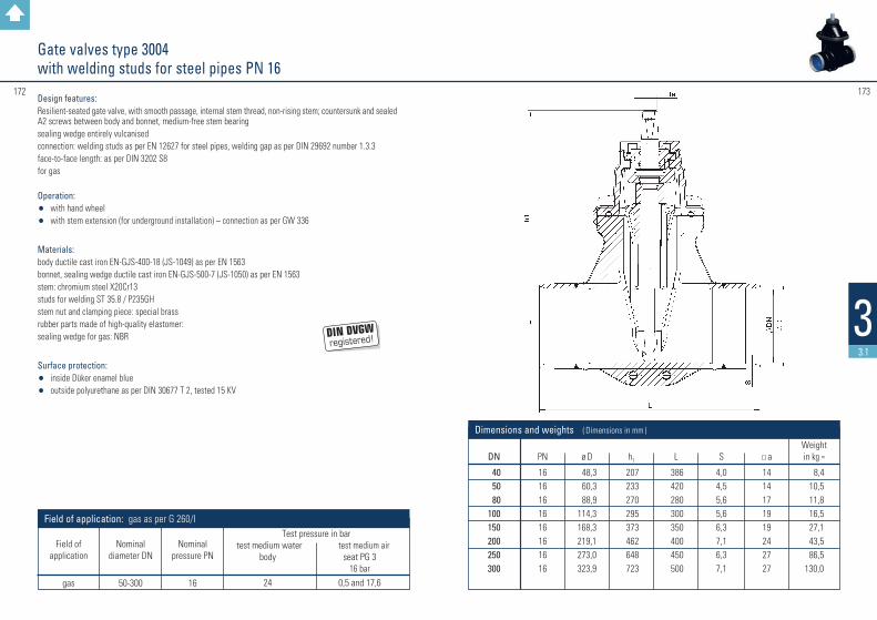
172
33.1
Gate valves type 3004with welding studs for steel pipes PN 16
DN
40 50 80100150200250300
PN
1616161616161616
ø D
48,3 60,3 88,9114,3168,3219,1273,0323,9
Weightin kg ≈
8,4 10,5 11,8 16,5 27,1 43,5 86,5130,0
Dimensions and weights ( Dimensions in mm )
h1
207233270295373462648723
L
386420280300350400450500
S
4,04,55,65,66,37,16,37,1
a
1414171919242727
Design features: Resilient-seated gate valve, with smooth passage, internal stem thread, non-rising stem; countersunk and sealed A2 screws between body and bonnet, medium-free stem bearingsealing wedge entirely vulcanised connection: welding studs as per EN 12627 for steel pipes, welding gap as per DIN 29692 number 1.3.3face-to-face length: as per DIN 3202 S8for gas
Operation: • with hand wheel• with stem extension (for underground installation) – connection as per GW 336
Materials: body ductile cast iron EN-GJS-400-18 (JS-1049) as per EN 1563bonnet, sealing wedge ductile cast iron EN-GJS-500-7 (JS-1050) as per EN 1563stem: chromium steel X20Cr13studs for welding ST 35.8 / P235GHstem nut and clamping piece: special brass rubber parts made of high-quality elastomer:sealing wedge for gas: NBR
Surface protection:• inside Düker enamel blue• outside polyurethane as per DIN 30677 T 2, tested 15 KV
Nominal
diameter DN
50-300
Test pressure in bar test medium water test medium air body seat PG 3 16 bar 24 0,5 and 17,6
Field of application: gas as per G 260/I
Nominal pressure PN
16
Field of
application
gas
173
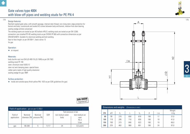
174
33.1
DN
80100150200
h2
818830923951
A
190190180190
L
650710840960
h1
270295373462
Weight in kg 37,041,066,097,0
Dimensions and weights ( Dimensions in mm )
a
17191924
ø D
90110160225
Gate valves type 4004 with blow-off pipes and welding studs for PE PN 4
Design features: Resilient-seated gate valve, with smooth passage, internal stem thread, non-rising stem; edge protection for bonnet and body, countersunk and sealed A2 screws between body and bonnet, medium-free stem bearingsealing wedge entirely vulcanisedThe welding seams are tested as per AD bulletin HF5/3, welding studs are tested as per EN 12266.connection: pre-installed PE-HD welding studs as per DVGW VP 600 with connection dimensions as perDIN 8074/8075. Suitable for electrical welding and butt welding.face-to-face length: as per EN 558–1, basic series 13for gas
Operation: • on request
Materials: body ductile cast iron EN-GJS-400-18 (JS-1049) as per EN 1563welding studs PE 100stem: chromium steel X20Cr13 stem nut and clamping piece: special brass rubber parts made of high-quality elastomer:sealing wedge for gas: NBR
Surface protection:• inside and outside epoxy finish yellow RAL 1023 as per GSK guidelines (for gas)
test medium air
seat PG 3 5 bar
0,5 and 6
Test pressure in bar
Field of application: gas as per G 260/I
Nominal
diameter DN
80-200
Nominal
pressure PN
5
SDR
11/17
test medium water
body
24
Field of
application
gas
175

DN
80100150200250300
h2
1107112211841140995980
A
180180224224224220
L
660680730780
10501084
h1
270295373462648723
Dimensions and weights ( Dimensions in mm )
a
171919242727
ø D
88,9114,3168,3219,1273,0323,9
Gate valves type 3004 with blow-off pipes and welding studs for steel pipes PN 4
Design features: Resilient-seated gate valve, with smooth passage, internal stem thread, non-rising stem; countersunk and sealed A2 screws between body and bonnet, medium-free stem bearingsealing wedge entirely vulcanisedAll welding seams are tested as per AD bulletin HP5/3, all welding studs are tested as per EN 12266.connection: welding studs as per EN 12627 for steel pipes, welding gap as per DIN 29692 number 1.3.3face-to-face length: as per DIN 3202 S8for gas
Operation: • on request
Materials: body ductile cast iron EN-GJS-400-18 (JS-1049) as per EN 1563bonnet, sealing wedge ductile cast iron EN-GJS-500-7 (JS-1050) as per EN 1563 stem: chromium steel X20Cr13studs for welding ST 35.8 / P235GHsteam nut and clamping piece: special brass rubber parts made of high-quality elastomer:sealing wedge for gas: NBR
Surface protection:• inside Düker enamel blue• outside polyurethane as per DIN 30677 T 2, tested 15 KV
177176
33.1
Weight in kg 28,0 33,0 65,0 82,0120,0138,0
Nominal
diameter DN
80-300
Test pressure in bar test medium water test medium air body seat PG 3 5 bar 24 0,5 and 6
Field of application: gas as per G 260/I
Nominal pressure PN
5
Field of
application
gas
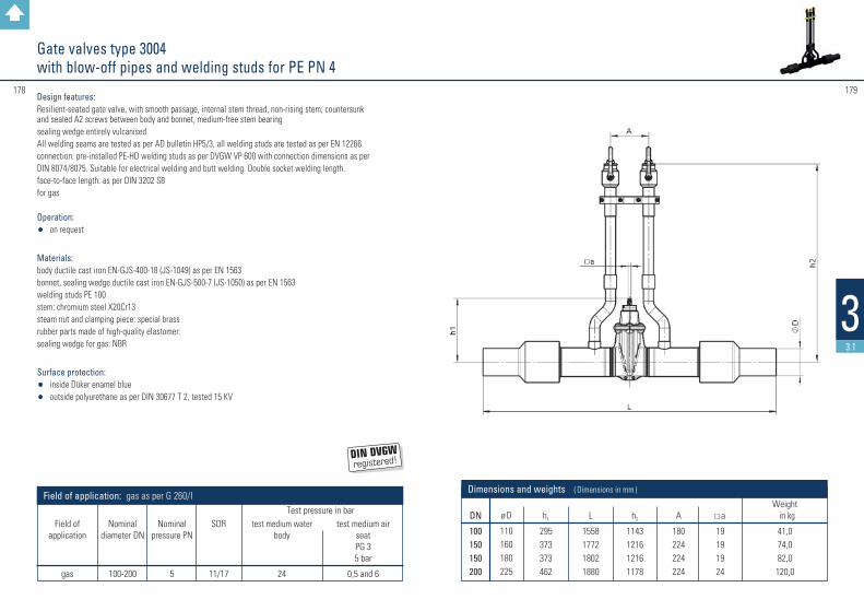
178
33.1
179
DN
100150150200
h2
1143121612161178
A
180224224224
L
1558177218021880
h1
295373373462
Weight in kg 41,074,082,0120,0
Dimensions and weights ( Dimensions in mm )
a
19191924
ø D
110160180225
Gate valves type 3004 with blow-off pipes and welding studs for PE PN 4
Design features: Resilient-seated gate valve, with smooth passage, internal stem thread, non-rising stem; countersunk and sealed A2 screws between body and bonnet, medium-free stem bearingsealing wedge entirely vulcanisedAll welding seams are tested as per AD bulletin HP5/3, all welding studs are tested as per EN 12266.connection: pre-installed PE-HD welding studs as per DVGW VP 600 with connection dimensions as perDIN 8074/8075. Suitable for electrical welding and butt welding. Double socket welding length. face-to-face length: as per DIN 3202 S8for gas
Operation: • on request
Materials: body ductile cast iron EN-GJS-400-18 (JS-1049) as per EN 1563bonnet, sealing wedge ductile cast iron EN-GJS-500-7 (JS-1050) as per EN 1563welding studs PE 100stem: chromium steel X20Cr13 steam nut and clamping piece: special brass rubber parts made of high-quality elastomer:sealing wedge for gas: NBR
Surface protection:• inside Düker enamel blue• outside polyurethane as per DIN 30677 T 2, tested 15 KV
test medium air
seat PG 3 5 bar
0,5 and 6
Test pressure in bar
Field of application: gas as per G 260/I
Nominal
diameter DN
100-200
Nominal
pressure PN
5
SDR
11/17
test medium water
body
24
Field of
application
gas
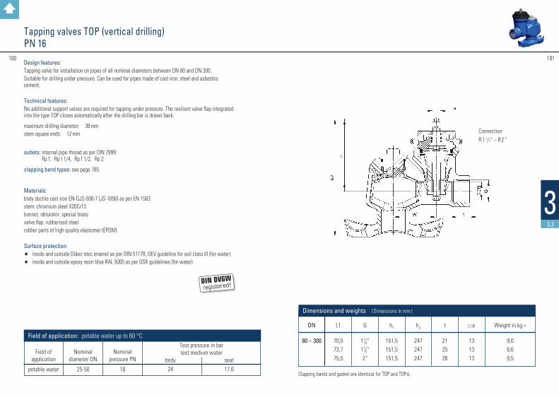
Clapping bands and gasket are identical for TOP and TOPsi.
DN
80 – 300
G
1 1/4 "1 1/2 "2"
h1
151,5151,5151,5
h2
247247247
a
131313
L1
70,573,775,5
Dimensions and weights ( Dimensions in mm )
ConnectionR 1 1/4" – R 2 "
t
212526
Weight in kg ≈
9,08,69,5
181180
33.2
Tapping valves TOP (vertical drilling) PN 16
Design features: Tapping valve for installation on pipes of all nominal diameters between DN 80 and DN 300.Suitable for drilling under pressure. Can be used for pipes made of cast iron, steel and asbestos cement.
Technical features: No additional support valves are required for tapping under pressure. The resilient valve flap integrated into the type TOP closes automatically after the drilling bar is drawn back.
maximum drilling diameter: 38 mmstem square ends: 12 mm
outlets: internal pipe thread as per DIN 2999: Rp 1, Rp 1 1/4, Rp 1 1/2, Rp 2
clapping band types: see page 185
Materials: body ductile cast iron EN-GJS-500-7 (JS-1050) as per EN 1563stem: chromium steel X20Cr13bonnet, obturator: special brassvalve flap: rubberised steelrubber parts of high-quality elastomer (EPDM)
Surface protection: • inside and outside Düker etec enamel as per DIN 51178, DEV guideline for soil class III (for water)• inside and outside epoxy resin blue RAL 5005 as per GSK guidelines (for water)
Nominal
diameter DN
25-50
Test pressure in bartest medium water
body seat 24 17,6
Field of application: potable water up to 60 °C
Nominal pressure PN
16
Field of
application
potable water
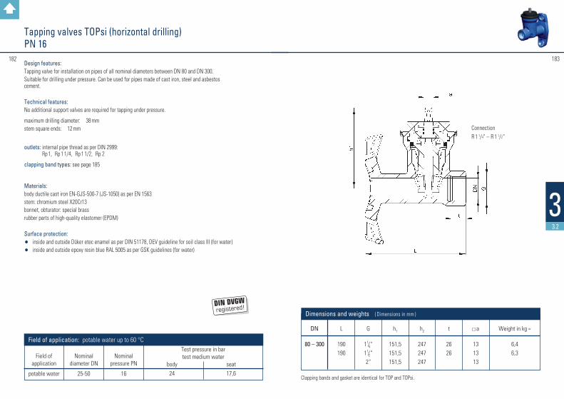
#183182
33.2
Clapping bands and gasket are identical for TOP and TOPsi.
ConnectionR 1 1/4" – R 1 1/2“
DN
80 – 300
G
1 1/4 "1 1/2 "2"
h1
151,5151,5151,5
h2
247247247
a
131313
L
190190
Dimensions and weights ( Dimensions in mm ) t
2626
Weight in kg ≈
6,46,3
Nominal
diameter DN
25-50
Test pressure in bartest medium water
body seat 24 17,6
Field of application: potable water up to 60 °C
Nominal pressure PN
16
Field of
application
potable water
Tapping valves TOPsi (horizontal drilling)PN 16
Design features: Tapping valve for installation on pipes of all nominal diameters between DN 80 and DN 300.Suitable for drilling under pressure. Can be used for pipes made of cast iron, steel and asbestos cement.
Technical features: No additional support valves are required for tapping under pressure.
maximum drilling diameter: 38 mmstem square ends: 12 mm
outlets: internal pipe thread as per DIN 2999: Rp 1, Rp 1 1/4, Rp 1 1/2, Rp 2
clapping band types: see page 185
Materials: body ductile cast iron EN-GJS-500-7 (JS-1050) as per EN 1563stem: chromium steel X20Cr13bonnet, obturator: special brassrubber parts of high-quality elastomer (EPDM)
Surface protection: • inside and outside Düker etec enamel as per DIN 51178, DEV guideline for soil class III (for water)• inside and outside epoxy resin blue RAL 5005 as per GSK guidelines (for water)
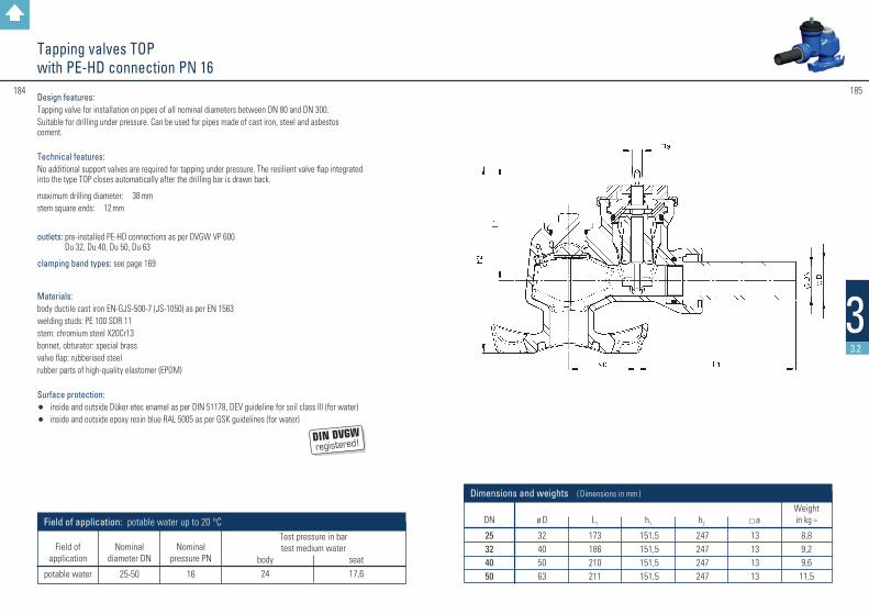
184
33.2
DN
25324050
ø D
32405063
L1
173186210211
Weightin kg ≈
8,89,29,611,5
Dimensions and weights ( Dimensions in mm )
h1
151,5151,5151,5151,5
h2
247247247247
a
13131313
185
Tapping valves TOP with PE-HD connection PN 16
Design features: Tapping valve for installation on pipes of all nominal diameters between DN 80 and DN 300.Suitable for drilling under pressure. Can be used for pipes made of cast iron, steel and asbestos cement.
Technical features: No additional support valves are required for tapping under pressure. The resilient valve flap integrated into the type TOP closes automatically after the drilling bar is drawn back.
maximum drilling diameter: 38 mmstem square ends: 12 mm
outlets: pre-installed PE-HD connections as per DVGW VP 600 Du 32, Du 40, Du 50, Du 63
clamping band types: see page 169
Materials: body ductile cast iron EN-GJS-500-7 (JS-1050) as per EN 1563welding studs: PE 100 SDR 11stem: chromium steel X20Cr13 bonnet, obturator: special brass valve flap: rubberised steelrubber parts of high-quality elastomer (EPDM)
Surface protection: • inside and outside Düker etec enamel as per DIN 51178, DEV guideline for soil class III (for water)• inside and outside epoxy resin blue RAL 5005 as per GSK guidelines (for water)
Nominal
diameter DN
25-50
Test pressure in bartest medium water
body seat 24 17,6
Field of application: potable water up to 20 °C
Nominal pressure PN
16
Field of
application
potable water

186 187
33.2
Clapping bands for tapping clamps type 88 and tapping valves TOP and TOPsi
DN
80100125150200250300
a pipe outside
Ø
98118144170222274326
b pipe outside
Ø
106126154180232286338
c pipe outside
Ø
88,9114,3139,7168,3219,1273,0323,9
d pipe outside
Ø
—108
—159———
e pipe outside
Ø
series aseries aseries bseries bseries bseries b
352
Dimensions ( Dimensions in mm )
Design features: flat clapping band for the nominal diameters DN 80 up to 300 and for pipes made of cast iron, cast iron with cement coating, steel or asbestos cement PN 12.5 The clapping bands are packed as a unit with all necessary accessories and marked for the pipe type and diameter.
Materials: flat band with welded-on threaded bolt: stainless steel 1.4301, passivated and plastic-coated washers: stainless steel 1.4104hexagonal nuts: stainless steel 1.4571 with slide coatingthread protectors: plasticsaddle gaskets: EPDM, KTW, W 270
Types: a = for cast iron pipes (bitumen / PE-coated)b = for cast iron pipes (cement-coated)c = steel pipes as per DIN 2448, series 1d = steel pipes as per DIN 2448, series 3e = asbestos cement pipes PN 12.5 as per DIN 19 800
187
Tapping clamp type 88 PN 10/16
DN
80 - 300
Weight in kg ≈ outlet ø d
1" / 1 1/4 " 1 1/2 " / 2"
3 3
Dimensions
* also available as blind clamp
Design features:Tapping clamp type 88 with internal pipe thread as per DIN 2999 for vertical or horizontal drilling
suitable for installation on pipes of all nominal dimensions between DN 80 and DN 300; can be used on pipes of cast iron, steel and asbestos cement. for water
Materials:Tapping clamp: ductile cast iron EN-GJS-500-7 (JS-1050) as per EN 1563
Surface protection:• inside and outside epoxy resin black RAL 9005 as per GSK guidelines
Test pressure in bar test medium water
body
21
Field of application: potable water up to 60 °C
Nominal pressure PN
16
Field of
application
potable water
Nominal
diameter DN
40 - 50 1"– 2"

DN
25324050
L
105120130150
h1
132,5151,5151,5178,5
SW
46556070
G
R 1R 1 1/4
R 1 1/2
R 2
T
20242732
a
13131313
Dimensions and weights ( Dimensions in mm )
Weight in kg≈
2,63,84,56,0
188 189
33.2
Service connection valves type 1004 with internal pipe thread PN 16
Design features: Resilient-seated gate valve, with smooth passage, interior stem thread, non-rising stemobturator entirely vulcanisedconnection dimensions: as per DIN 2999-1stem square ends: 12 mmface-to-face length: as per DIN 3202 part 4, basic series M 4for potable water or gas
outlets: internal pipe thread as per DIN 2999: Rp 1, Rp 11/4, Rp 11/2, Rp 2
Operation: • with hand wheel• with stem extension set (for underground installation) – connection as per GW 336
Materials: body: ductile cast iron EN-GJS-500-7 (JS-1050) as per EN 1563stem: chromium steel X20Cr13 bonnet, obturator: special brassrubber parts of high-quality elastomer:obturator for water: EPDMobturator for gas: NBR
Surface protection:• inside and outside Düker etec enamel as per DIN 51178, DEV guideline for soil
class III (for water)• inside and outside epoxy resin blue RAL 5005 as per GSK guidelines (for water,
on request)• inside and outside epoxy resin yellow RAL 1023 as per GSK guidelines (for gas)
Test pressure in bar test medium water test medium air body seat seat PG 3 5 bar 24 17,6
24 0,5 and 6
Field of application: potable water up to 60 °; gas as per G 260/I
Nominal diameter DN
25-50 25-50
Nominal
pressure PN
16 5
Field of
application
potable water
gas
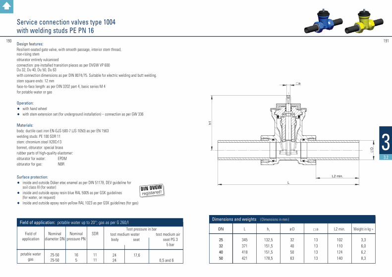
191190
33.2
DN
25324050
L
345371418421
h1
132,5151,5151,5178,5
Weight in kg ≈
3,36,06,28,3
ø D
32405063
a
13131313
L2 min.
102110124140
Dimensions and weights ( Dimensions in mm )
Service connection valves type 1004 with welding studs PE PN 16
Design features: Resilient-seated gate valve, with smooth passage, interior stem thread, non-rising stem obturator entirely vulcanised connection: pre-installed transition pieces as per DVGW VP 600 Du 32, Du 40, Du 50, Du 63 with connection dimensions as per DIN 8074/75. Suitable for electric welding and butt welding. stem square ends: 12 mmface-to-face length: as per DIN 3202 part 4, basic series M 4for potable water or gas
Operation: • with hand wheel• with stem extension set (for underground installation) – connection as per GW 336
Materials: body: ductile cast iron EN-GJS-500-7 (JS-1050) as per EN 1563 welding studs: PE 100 SDR 11 stem: chromium steel X20Cr13 bonnet, obturator: special brass rubber parts of high-quality elastomer: obturator for water: EPDM obturator for gas: NBR
Surface protection:• inside and outside Düker etec enamel as per DIN 51178, DEV guideline for
soil class III (for water) • inside and outside epoxy resin blue RAL 5005 as per GSK guidelines
(for water, on request) • inside and outside epoxy resin yellow RAL 1023 as per GSK guidelines (for gas)
Test pressure in bar test medium water test medium air body seat seat PG 3
5 bar
24 17,6 24 0,5 and 6
Field of application: potable water up to 20°; gas as per G 260/I
Nominal diameter DN
25-50 25-50
Nominal
pressure PN
16 5
SDR
11 11
Field of
application
potable water gas
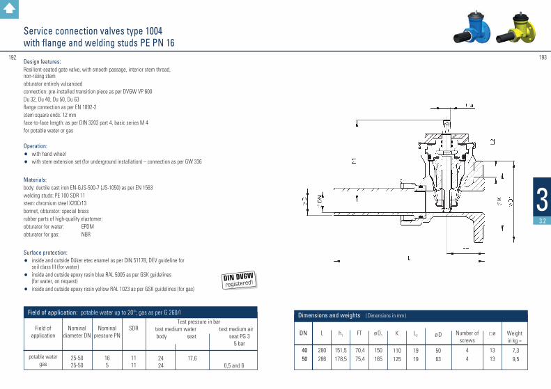
DN
4050
L
280286
h1
151,5178,5
K
110125
FT
70,475,4
ø D1
150165
a
1313
Weight in kg ≈
7,3 9,5
Number of screws
44
L2
1919
ø D
5063
Dimensions and weights ( Dimensions in mm )
193192
33.2
Service connection valves type 1004 with flange and welding studs PE PN 16
Design features: Resilient-seated gate valve, with smooth passage, interior stem thread, non-rising stem obturator entirely vulcanisedconnection: pre-installed transition piece as per DVGW VP 600Du 32, Du 40, Du 50, Du 63 flange connection as per EN 1092-2stem square ends: 12 mmface-to-face length: as per DIN 3202 part 4, basic series M 4for potable water or gas
Operation: • with hand wheel• with stem extension set (for underground installation) – connection as per GW 336
Materials: body: ductile cast iron EN-GJS-500-7 (JS-1050) as per EN 1563 welding studs: PE 100 SDR 11 stem: chromium steel X20Cr13 bonnet, obturator: special brass rubber parts of high-quality elastomer: obturator for water: EPDM obturator for gas: NBR
Surface protection:• inside and outside Düker etec enamel as per DIN 51178, DEV guideline for
soil class III (for water)• inside and outside epoxy resin blue RAL 5005 as per GSK guidelines
(for water, on request)• inside and outside epoxy resin yellow RAL 1023 as per GSK guidelines (for gas)
Test pressure in bar test medium water test medium air body seat seat PG 3
5 bar
24 17,6 24 0,5 and 6
Field of application: potable water up to 20°; gas as per G 260/I
Nominal diameter DN
25-50 25-50
Nominal
pressure PN
16 5
SDR
11 11
Field of
application
potable water gas

195194
33.2
DN
4050
L
300
SW1
95
a
13
SW2
70
h1
178,5
G2
2"
Weight in kg ≈
7,4
t
32
l1
210
ø D
63
Dimensions and weights ( Dimensions in mm )
Service connection valves type 1004 with internal pipe thread and welding studs PE PN 16
Design features: Resilient-seated gate valve, with smooth passage, interior stem thread, non-rising stemobturator entirely vulcanisedconnection: pre-installed transition piece as per DVGW VP 600 Du 32, Du 40, Du 50, Du 63 internal pipe thread as per DIN 2999-1stem square ends: 12 mmface-to-face length: as per DIN 3202 part 4, basic series M 4for potable water or gas
Operation: • with hand wheel• with stem extension set (for underground installation) – connection as per GW 336
Materials: body: ductile cast iron EN-GJS-500-7 (JS-1050) as per EN 1563 welding studs: PE 100 SDR 11 stem: chromium steel X20Cr13 bonnet, obturator: special brass rubber parts of high-quality elastomer: obturator for water: EPDM obturator for gas: NBR
Surface protection:• inside and outside Düker etec enamel as per DIN 51178, DEV guideline for
soil class III (for water)• inside and outside epoxy resin yellow RAL 1023 as per GSK guidelines (for gas)
Test pressure in bar test medium water test medium air body seat seat PG 3
5 bar
24 17,6 24 0,5 and 6
Field of application: potable water up to 20°; gas as per G 260/I
Nominal diameter DN
25-50 25-50
Nominal
pressure PN
16 5
SDR
11 11
Field of
application
potable water gas

197196
33.2
Gate valve combinations Multi I with Novo sockets PN 10 / 16
DN 50PN16
GJS-500-7PE-HD63
EL
Design features: Collar with Novo sockets with lateral outlet combined with gate valve type 1004 DN 50, resilient-seated, with smooth passage, interior stem thread, non-rising stemobturator entirely vulcanisedconnection: pre-installed transition piece as per DVGW VP 600with connection dimensions as per DIN 8074/75. Suitable for electric welding and butt welding. in graduated diameters of 63, 50 and 40 mmstem square ends: 12 mm face-to-face length of the gate valve: as per DIN 3202 part 4, basic series M 4for potable water
Operation: • with hand wheel• with stem extension set (for underground installation) – connection as per GW 336
Materials: body: ductile cast iron EN-GJS-500-7 (JS-1050) as per EN 1563welding studs: PE 100 SDR 11stem: chromium steel X20Cr13 bonnet, obturator: special brassrubber parts of high-quality elastomer:obturator for water: EPDM
Surface protection:• inside and outside Düker etec enamel as per DIN 51178, DEV guideline for
soil class III (for water)
Test pressure in bartest medium water
body seat 24 17,6
Field of application: potable water up to 20°
Nominal diameter DN
25-50
Nominal
pressure PN
16
SDR
11
Field of
application
potable water
DN
100125150200250300
L1
568581594620647673
L2
482495508534561587
Weightin kg ≈
212428364558
Dimensions and weights ( Dimensions in mm )
L3
382395408434461487
L4
192205218244271297
Lu
160165165170175180
t1
123126129138143152
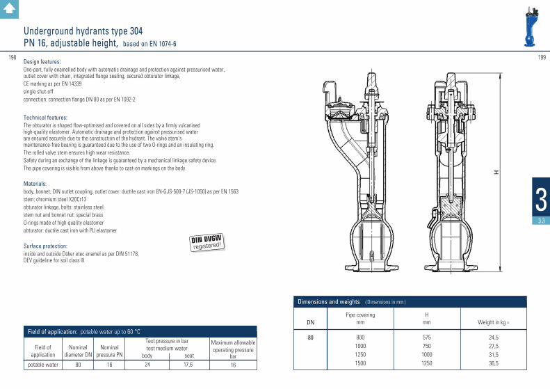
DN
80
Pipe covering mm
800100012501500
H mm
575750
10001250
Dimensions and weights ( Dimensions in mm )
Weight in kg ≈
24,527,531,536,5
199198
33.3
Underground hydrants type 304 PN 16, adjustable height, based on EN 1074-6
Design features: One-part, fully enamelled body with automatic drainage and protection against pressurised water, outlet cover with chain, integrated flange sealing, secured obturator linkage, CE marking as per EN 14339 single shut-off connection: connection flange DN 80 as per EN 1092-2
Technical features: The obturator is shaped flow-optimised and covered on all sides by a firmly vulcanised high-quality elastomer. Automatic drainage and protection against pressurised water are ensured securely due to the construction of the hydrant. The valve stem’s maintenance-free bearing is guaranteed due to the use of two O-rings and an insulating ring. The rolled valve stem ensures high wear resistance.Safety during an exchange of the linkage is guaranteed by a mechanical linkage safety device.The pipe covering is visible from above thanks to cast-on markings on the body.
Materials: body, bonnet, DIN outlet coupling, outlet cover: ductile cast iron EN-GJS-500-7 (JS-1050) as per EN 1563stem: chromium steel X20Cr13obturator linkage, bolts: stainless steelstem nut and bonnet nut: special brassO-rings made of high-quality elastomerobturator: ductile cast iron with PU elastomer
Surface protection: inside and outside Düker etec enamel as per DIN 51178, DEV guideline for soil class III
Maximum allowable operating pressure
bar16
Test pressure in bartest medium water
body seat 24 17,6
Field of application: potable water up to 60 °C
Nominal diameter DN
80
Nominal
pressure PN
16
Field of
application
potable water

#201200
33.3
DN
80
Pipe covering mm
800100012501500
H mm
575750
10001250
Dimensions and weights ( Dimensions in mm )
Weight in kg ≈
25,028,032,037,0
Underground hydrants type 305 PN 16, adjustable height, based on EN 1074-6
Design features: One-part, fully enamelled body with automatic drainage and protection against pressurised water, outlet cover with chain, integrated flange sealing, secured obturator linkage, CE marking as per EN 14339 double shut-off connection: connection flange DN 80 as per EN 1092-2
Technical features: The obturator is shaped flow-optimised and covered on all sides by a firmly vulcanised high-quality elastomer. Automatic drainage and protection against pressurised water are ensured securely due to the construction of the hydrant. The valve stem’s maintenance-free bearing is guaranteed due to the use of two O-rings and an insulating ring. The rolled valve stem ensures high wear resistance.Safety during an exchange of the linkage is guaranteed by a mechanical linkage safety device.The pipe covering is visible from above thanks to cast-on markings on the body.
Materials: body, bonnet, DIN outlet coupling, outlet cover: ductile cast iron EN-GJS-500-7 (JS-1050) as per EN 1563stem: chromium steel X20Cr13obturator linkage, bolts: stainless steelstem nut and bonnet nut: special brassO-rings made of high-quality elastomerobturator: ductile cast iron with PU elastomersealing ball: steel with EPDM cover
Surface protection: inside and outside Düker etec enamel as per DIN 51178, DEV guideline for soil class III
Maximum allowable operating pressure
bar16
Test pressure in bartest medium water
body seat 24 17,6
Field of application: potable water up to 60 °C
Nominal diameter DN
80
Nominal
pressure PN
16
Field of
application
potable water
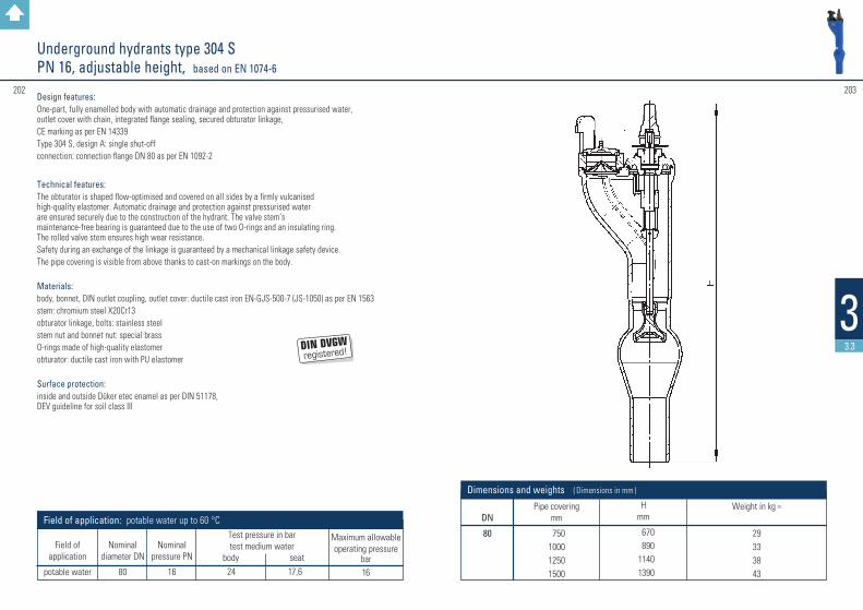
Underground hydrants type 304 S PN 16, adjustable height, based on EN 1074-6
DN
80
Pipe covering mm
750100012501500
H mm
670890
11401390
Dimensions and weights ( Dimensions in mm )
Weight in kg ≈
29333843
203202
33.3
Design features: One-part, fully enamelled body with automatic drainage and protection against pressurised water, outlet cover with chain, integrated flange sealing, secured obturator linkage,CE marking as per EN 14339Type 304 S, design A: single shut-offconnection: connection flange DN 80 as per EN 1092-2
Technical features: The obturator is shaped flow-optimised and covered on all sides by a firmly vulcanised high-quality elastomer. Automatic drainage and protection against pressurised water are ensured securely due to the construction of the hydrant. The valve stem’s maintenance-free bearing is guaranteed due to the use of two O-rings and an insulating ring. The rolled valve stem ensures high wear resistance.Safety during an exchange of the linkage is guaranteed by a mechanical linkage safety device.The pipe covering is visible from above thanks to cast-on markings on the body.
Materials: body, bonnet, DIN outlet coupling, outlet cover: ductile cast iron EN-GJS-500-7 (JS-1050) as per EN 1563stem: chromium steel X20Cr13obturator linkage, bolts: stainless steelstem nut and bonnet nut: special brassO-rings made of high-quality elastomerobturator: ductile cast iron with PU elastomer
Surface protection: inside and outside Düker etec enamel as per DIN 51178, DEV guideline for soil class III
Maximum allowable operating pressure
bar16
Test pressure in bartest medium water
body seat 24 17,6
Field of application: potable water up to 60 °C
Nominal diameter DN
80
Nominal
pressure PN
16
Field of
application
potable water

DN
8080
100100
Pipe covering mm
1250150012501500
L2
1050105010501050
L1
2190244021902440
L3
680680680680
L4
——355355
e
——200200
L5
55555555
Dimensions and weights ( Dimensions in mm )
Weight / kg≈
136147140151
204 205
33.3
Design features: Pillar hydrant with additional shut-off, automatic drainage and protection against pressurised water, safety lock of the internal mountings, traffic-area version with installation-friendly pre-determined breaking point, Pillar hydrant with additional shut-off, automatic drainage and protection against pressurised water, safety lock of the internal mountings, traffic-area version with installation-friendly pre-determined breaking point,connection: connection flange as per EN 1092-2
Technical features: maintenance-free bearing of the stem extension
Materials: bottom, upper and lower part of the pillar, and bonnet nut: ductile cast iron EN-GJS-500-7 (JS-1050) as per EN 1563operating cap, outlets and outlet covers: aluminiumstem: chromium steel X20Cr13linkage, pin, drainage plate, bolts: stainless steelstem nut, stem bearing, predetermined breaking coupling and bonnet nut: special brassseat ring: rubberized brass O-rings made of high-quality elastomerobturator: entirely vulcanized with high-quality elastomer (EPDM)
Surface protection: • inside Düker enamel• bottom and lower part of the pillar outside: base coat enamel with epoxy resin cover coat
signal red RAL 3001• upper part of the pillar outside: base coat enamel, cover coat 2-components PU paint
signal red RAL 3001• on request: upper part of the pillar inside Düker etec enamel blue, outside Düker enamel red
Pillar hydrants Type 494, design AUD PN 16, adjustable height, based on EN 1074-6
Maximum allowable operating pressure
bar16
Test pressure in bartest medium water
body seat 24 17,6
Field of application: potable water up to 60 °C
Nominal diameter DN
80-100
Nominal
pressure PN
16
Field of
application
potable water
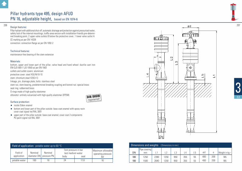
DN
100100
Pipe covering mm
12501500
L2
12501250
L1
23902640
L3
950950
L4
355355
ø d
400400
L5
5555
e
200200
Dimensions and weights ( Dimensions in mm )
Weight in kg ≈
185185
207206
33.3
Pillar hydrants type 495, design AFUD PN 16, adjustable height, based on EN 1074-6
Design features: Pillar hydrant with additional shut-off, automatic drainage and protection against pressurised water, safety lock of the internal mountings, traffic-area version with installation-friendly pre-determi-ned breaking point, 2 upper valve outlets B below the protective cover, 1 lower valve outlet ACE marking as per EN 14339connection: connection flange as per EN 1092-2
Technical features: maintenance-free bearing of the stem extension
Materials: bottom, upper and lower part of the pillar, valve head and hand wheel: ductile cast iron EN-GJS-500-7 (JS-1050) as per EN 1563outlets and outlet covers: aluminiumprotective cover: steel X5CrNi18-10stem: chromium steel X20Cr13linkage, pin, drainage plate, bolts: stainless steelstem nut, stem bearing, predetermined breaking coupling and bonnet nut: special brassseat ring: rubberized brass O-rings made of high-quality elastomerobturator: entirely vulcanized with high-quality elastomer (EPDM)
Surface protection: • inside Düker enamel• bottom and lower part of the pillar outside: base coat enamel with epoxy resin
cover coat signal red RAL 3001• upper part of the pillar outside: base coat enamel, cover coat 2-components
PU paint signal red RAL 3001
Maximum allowable operating pressure
bar16
Test pressure in bartest medium water
body seat 24 17,6
Field of application: potable water up to 60 °C
Nominal diameter DN
100
Nominal
pressure PN
16
Field of
application
potable water
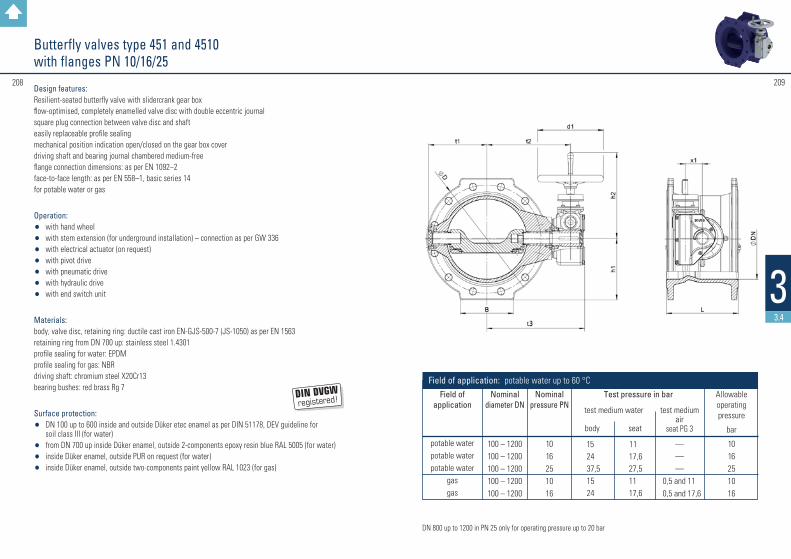
208 209
Butterfly valves type 451 and 4510 with flanges PN 10/16/25
DN 800 up to 1200 in PN 25 only for operating pressure up to 20 bar
Design features: Resilient-seated butterfly valve with slidercrank gear box flow-optimised, completely enamelled valve disc with double eccentric journal square plug connection between valve disc and shaft easily replaceable profile sealing mechanical position indication open/closed on the gear box cover driving shaft and bearing journal chambered medium-free flange connection dimensions: as per EN 1092–2 face-to-face length: as per EN 558–1, basic series 14 for potable water or gas
Operation: • with hand wheel • with stem extension (for underground installation) – connection as per GW 336 • with electrical actuator (on request) • with pivot drive • with pneumatic drive • with hydraulic drive • with end switch unit
Materials: body, valve disc, retaining ring: ductile cast iron EN-GJS-500-7 (JS-1050) as per EN 1563 retaining ring from DN 700 up: stainless steel 1.4301 profile sealing for water: EPDM profile sealing for gas: NBR driving shaft: chromium steel X20Cr13 bearing bushes: red brass Rg 7
Surface protection: • DN 100 up to 600 inside and outside Düker etec enamel as per DIN 51178, DEV guideline for
soil class III (for water)• from DN 700 up inside Düker enamel, outside 2-components epoxy resin blue RAL 5005 (for water) • inside Düker enamel, outside PUR on request (for water)• inside Düker enamel, outside two-components paint yellow RAL 1023 (for gas)
33.4
Nominal diameter DN
100 – 1200100 – 1200100 – 1200100 – 1200100 – 1200
Field of application
potable waterpotable waterpotable water
gasgas
Nominal pressure PN
1016251016
Allowable operating pressure
bar
1016251016
test medium air
seat PG 3
———
0,5 and 11 0,5 and 17,6
test medium water
body seat
15 11 24 17,6 37,5 27,5 15 11 24 17,6
Field of application: potable water up to 60 °CTest pressure in bar
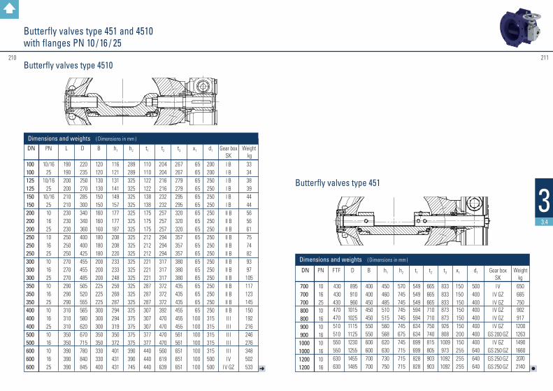
210 211
33.4
l➜
Butterfly valves type 451 and 4510 with flanges PN 10 / 16 / 25
Butterfly valves type 4510
Butterfly valves type 451
DN
100100125125150150200200200250250250300300300350350350400400400500500600600600
PN
10/16 25
10/1625
10/162510 16251016 25 1016 25 1016 25 1016 25 1016 1016 25
L
190190200200210210230230230250250250270270270290290290310310310350350390390390
Gear box SKI BI BI BI BI BI BII BII BII BII BII BII BII BII BII BII BII BII BII BI I II I II I II I II I IIV
IV GZ
D
220 235 250 270 285 300 340 340 360 400 400 425 455 455 485 505 520 555 565 580 620 670 715 780 840 845
B
120120130130150150160160160180180180200200200225225225300300300350350330330400
h1
116121131141149157177177187208208220233233248259269287294294319350372401431431
h2
289289325325325325325325325325325325325325325325325325325375375375375390390745
t1
110110122122138138175175175212212212221221221287287287307307307377377440440440
t2
204204216216232232257257257294294294317317317372372372392470470470470560619639
t3
267267279279295295320320320357357357380380380435435435455455455561561651651651
x1
65656565656565656565656565656565656565
100100100100100100100
d1
200200250250250250250250250250250250250250250250250250250315315315315315500500
Dimensions and weights ( Dimensions in mm )
Weight kg3334383944445656617574829397105117123145150192216246276348502533
DN
700700700 8008009009001000100012001200
PN
1016 25 1016 1016 1016 1016
FTF
430430430 470470510510550550630630
Gear box SKIV
IV GZIV GZ IV GZIV GZIV GZ
GS 200 GZIV GZ
GS 250 GZGS 250 GZGS 250 GZ
D
895 910 960 10151025111511251230125514551485
B
400400450 450450550550600600700700
h1
450460485 510515560568620630730750
h2
570745745 745745745675745715715715
t1
549549549 594594634634699699828828
t2
665665665 710710750740815805903903
t3
833833833 873873926808
1009973
10921092
x1
150150150 150150150200150255255255
d1
500400400 400400400400400640640640
Weight kg
650665750 902917120012631490166020702140
Dimensions and weights ( Dimensions in mm )

#213212
33.4
Butterfly valves type 451 and 4510 with flanges PN 10/16/25 Long face-to-face length, with or without bypass
Nominal diameter DN
100 – 1000100 – 1000
Field of application
potable waterpotable water
Nominal pressure PN
1016
Allowable operating pressure
bar
1016
Test pressure in bar
test medium water body seat
15 11 24 17,6
Field of application: potable water up to 60 °C
Design features: Resilient-seated butterfly valve with slidercrank gear box flow-optimised, completely enamelled valve disc with double eccentric journal square plug connection between valve disc and shafteasily replaceable profile sealingmechanical position indication open/closed on the gear box coverdriving shaft and bearing journal chambered medium-freeflange connection dimensions: as per EN 1092–2face-to-face length: as per EN 558–1, basic series 15with bypass (without bypass on request)bypass approx. 1/10 of the main diameterfor potable water
Operation: • with stem extension – connection as per GW 336
Materials: body, valve disc, retaining ring: ductile cast iron EN-GJS-500-7 (JS-1050) as per EN 1563retaining ring from DN 700 up: stainless steel 1.4301 profile sealing for water: EPDM driving shaft: chromium steel X20Cr13 bearing bushes: red brass Rg 7
Surface protection: • DN 100 up to 600 inside and outside Düker etec enamel as per DIN 51178, DEV guideline for
soil class III (for water)• from DN 700 up inside Düker enamel, outside 2-components epoxy resin blue RAL 5005 (for water)

#215214
33.4
l
➜
Butterfly valves type 451 and 4510 with flanges PN 10/16/25 Long face-to-face length, with or without bypass
Klappenscheibe Typ 451
Klappenscheibe Typ 4510
Klappenscheibe Typ 451
Klappenscheibe Typ 4510
Butterfly valve type 4510
Butterfly valve type 451
DN 900 PN 10/16 on request
DN
300300400400500500600600
DN
70070080080010001000
PN
10 161016101610 16
PN
10 1610161016
L
500500600600700700800800
L
900900
1000100012001200
Gear box SKII BII BII BIII
III / GS 125 GZIII
III / GS 160 GZIV
Gear box SKIVIV
IV GZIV GZIV GZIV GZ
D
455455565580670715780840
D
8959101015102512301255
B
200200300300350350330330
B
400400450450600600
h1
233233294294350372401431
h1
450460510515620630
h2
223223223223278278278278
h2
403608608608608608
t1
480480559559568568637637
t1
745745840840965965
t2
405405485485505505554554
t2
650650730730845845
t3
380380485455561561651651
t3
833833872872
10091009
DN bypass
4040404050505050
DN bypass
80808080
100100
Dimensions and weights ( Dimensions in mm )
Dimensions and weights ( Dimensions in mm )
Weight kg150150218259333366462635
Weight kg680680
1085108520602060
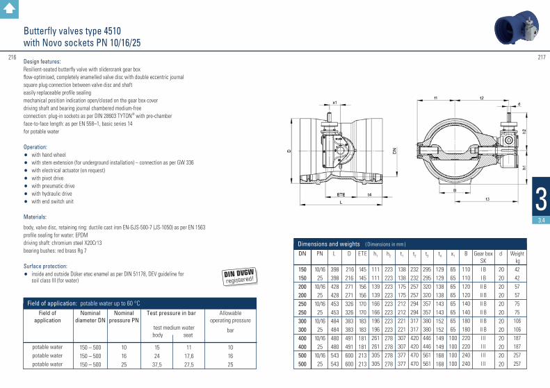
Butterfly valves type 4510 with Novo sockets PN 10/16/25
Design features: Resilient-seated butterfly valve with slidercrank gear boxflow-optimised, completely enamelled valve disc with double eccentric journal square plug connection between valve disc and shaft easily replaceable profile sealingmechanical position indication open/closed on the gear box cover driving shaft and bearing journal chambered medium-freeconnection: plug-in sockets as per DIN 28603 TYTON® with pre-chamberface-to-face length: as per EN 558–1, basic series 14for potable water
Operation: • with hand wheel• with stem extension (for underground installation) – connection as per GW 336 • with electrical actuator (on request) • with pivot drive • with pneumatic drive • with hydraulic drive • with end switch unit
Materials:
body, valve disc, retaining ring: ductile cast iron EN-GJS-500-7 (JS-1050) as per EN 1563profile sealing for water: EPDM driving shaft: chromium steel X20Cr13 bearing bushes: red brass Rg 7
Surface protection: • inside and outside Düker etec enamel as per DIN 51178, DEV guideline for
soil class III (for water)
Nominal diameter DN
150 – 500150 – 500150 – 500
Field of application
potable waterpotable waterpotable water
Nominal pressure PN
101625
Allowable operating pressure
bar
101625
Test pressure in bar
test medium water body seat
15 11 24 17,6 37,5 27,5
Field of application: potable water up to 60 °C
217216
33.4
DN
150150200200250250300300400400500500
PN
10/1625
10/1625
10/1625
10/1625
10/1625
10/1625
L
398398428428453453484484480480543543
Gear box SKI BI BII BII BII BII BII BII BI I II I II I II I I
D
216216271271326326383383491491600600
B
110110120120140140180180220220240240
h1
111111139139166166196196261261305305
h2
223223223223223223223223278278278278
t4
129129138138143143152152149149168168
t1
138138175175212212221221307307377377
t2
232232257257294294317317420420470470
t3
295295320320357357380380446446561561
x1
6565656565656565
100100100100
d
202020202020202020202020
Dimensions and weights ( Dimensions in mm )
Weight kg424257577575
106106187187257257
ETE
145145156156170170183183181181213213

219218
33.5
Novo plug-in system
On the following pages you will find items which are particularly suited for use in the Novo plug-in system.
Further items can be found here:
Gate valves type 4004 with Novo sockets page 158-159
Gate valves type 4004 with Novo socket and spigot end page 160-161
Butterfly valves type 4510 with Novo sockets page 216-217
Underground hydrants type 304 S design A page 202-203
Flanged socket duckfoot bends 90° with Novo sockets page 118MMN/MMNR
Single socket tees with spigot and socket branch page 84B
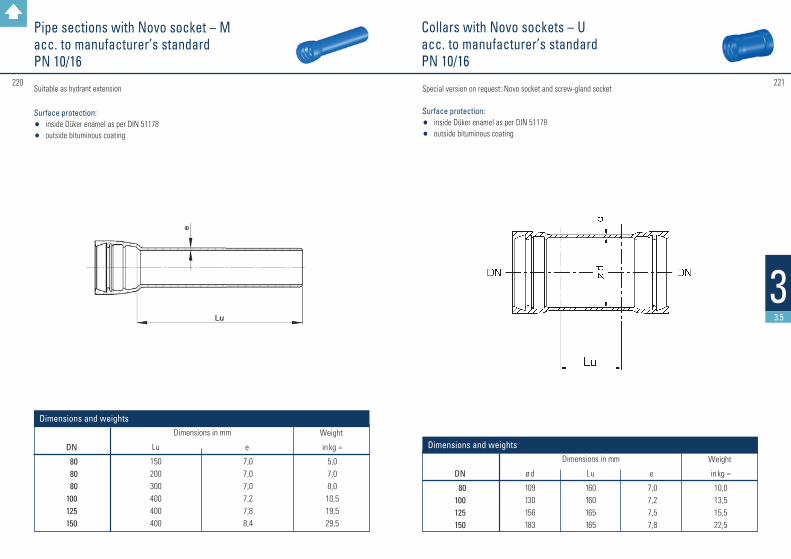
221220
33.5
Collars with Novo sockets – Uacc. to manufacturer’s standardPN 10/16
DN
80100125150
DN
80 80 80100125150
Lu
160160165165
Lu
150200300400400400
ø d
109130156183
e
7,0 7,2 7,5 7,8
e
7,0 7,0 7,0 7,2 7,8 8,4
Weight
in kg ≈
10,013,515,522,5
Weight
in kg ≈
5,07,08,010,519,529,5
Dimensions and weights
Dimensions and weights
Dimensions in mm
Dimensions in mm
Pipe sections with Novo socket – Macc. to manufacturer’s standardPN 10/16
Suitable as hydrant extension
Surface protection: • inside Düker enamel as per DIN 51178 • outside bituminous coating
Special version on request: Novo socket and screw-gland socket
Surface protection: • inside Düker enamel as per DIN 51178 • outside bituminous coating
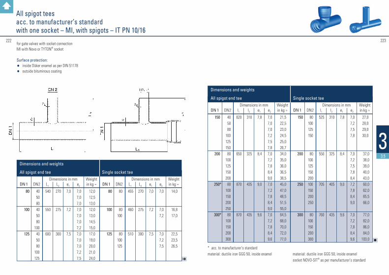
223222
33.5
All spigot teesacc. to manufacturer’s standardwith one socket – MI, with spigots – IT PN 10/16
➜
DN 1
80
100
125
DN 2
40 50 80 40 50 80100 40 50 80100125
L1
540
550
600
L2
270
275
300
e1
7,0
7,2
7,5
e2
7,07,07,07,07,07,07,27,07,07,07,27,5
12,012,513,012,013,014,515,017,019,020,021,024,0
Weight in kg ≈
Dimensions in mm
DN 1
80
100
125
DN 2
80
80100
80100125
L1
455
460
510
L2
270
275
300
e1
7,0
7,2
7,5
e2
7,0
7,07,2
7,07,27,5
14,0
16,817,0
22,523,526,5
Weight in kg ≈
Dimensions in mm
All spigot end tee Single socket tee
Dimensions and weights
for gate valves with socket connectionMI with Novo or TYTON® socket
Surface protection: • inside Düker enamel as per DIN 51178 • outside bituminous coating
l
DN 1
150
200
250*
300*
DN 2
40 50 80100125150 80100125150200 80100150200250 80100150200300
l1
620
650
870
870
l2
310
325
435
435
e1
7,8
8,4
9,0
9,6
e2
7,07,07,07,27,57,87,07,27,88,49,07,07,27,88,49,07,07,27,88,49,6
21,522,523,024,525,026,734,035,036,036,538,545,047,048,551,555,064,568,070,072,077,0
Weight in kg ≈
Dimensions in mm
DN 1
150
200
250
300
DN 2
80100125150
80 100 125 150 200 100 150 200 250
80 100 150 200 300
l1
525
550
705
760
l2
310
325
405
435
e1
7,8
8,4
9,0
9,6
e2
7,07,27,57,8
7,07,27,57,88,47,27,88,49,0
7,07,27,88,49,6
27,028,029,030,0
37,0 38,0 39,0 40,0 43,0 60,0 62,0 65,5 66,0
77,0 82,0 86,0 84,0103,0
Weight in kg ≈
Dimensions in mm
Dimensions and weights
All spigot end tee Single socket tee
* acc. to manufacturer’s standard material: ductile iron GGG 50, inside enamel material: ductile iron GGG 50, inside enamel socket NOVO-SIT® as per manufacturer‘s standard

225224
33.5
Smooth pipe sections with spigot ends – Sas per EN 545PN 10/16
PE adapter pieces for Novo socketsacc. to manufacturer’s standardPN 10/16
for gate valves with socket connection
Surface protection: • inside Düker enamel as per DIN 51178 • outside bituminous coating
Thrust resisting adapter piece for fittings, gate valves and butterfly valves for plug-in sockets NOVO-SIT® PE adapter piece with pre-installed support sleeve and circumferential retaining ringfor retaining the locking segments; PE spigot end for all usual welding procedures, SDR 11for water, transition from ductile cast iron to PE
Materials: • fitting: PE 100 black • support sleeve and retaining ring: stainless steel
DN
80100150200
DN
80100100125150150200200
L
800800800800
L
290315340355360380410426
ø d
98118170222
ø d
90110125140160180200225
e
7,0 7,2 7,5 7,8
e
8,2 10,011,212,814,616,418,220,5
Weight
in kg ≈
12,015,020,030,0
Weight
in kg ≈
1,32,252,63,34,05,57,07,8
Dimensions and weights
Dimensions and weights
Dimensions in mm
Dimensions in mm

Fig. 125 with flange connection PN 10 / 16
227226
33.6
DN
50 65 80100125150200250300350400
Face-to-face dimension
L ≈
210210210250250280300350360390390
Weight in
kg ≈
5,5 7,6 9,4 13,0 16,0 22,0 35,0 60,0 70,0 92,0117,0
Dimensions and weights
Flap valves figure 125 PN 10/16
Design features: Flange connection dimensions: as per EN 1092–2for potable water
Materials: body and bonnet: ductile cast iron EN-GJS-500-7 (JS-1050)as per EN 1563flap shaft: brassflap sealing: elastomer
Surface protection: • inside and outside epoxy resin black RAL 9005 as per GSK guidelines (for water)
Field of application: potable water up to 60 °C
Nominal diameter DN
200-400 50-400
Nominal pressure
PN
10 16
Field of
application
potable water potable water
229228
44
Accessories
Back to summary
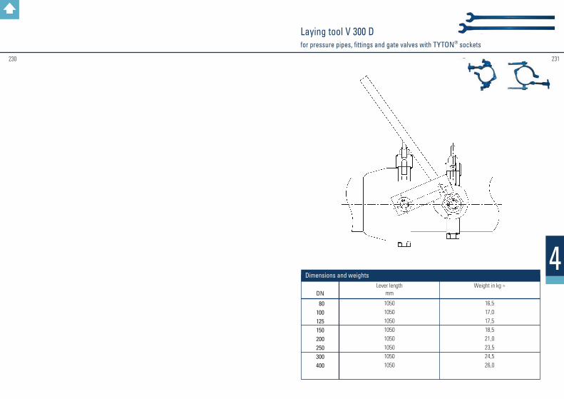
231230
4
Laying tool V 300 Dfor pressure pipes, fittings and gate valves with TYTON® sockets
DN
80100125150200250300400
Lever length
mm
10501050105010501050105010501050
Weight in kg ≈
16,517,017,518,521,023,524,526,0
Dimensions and weights
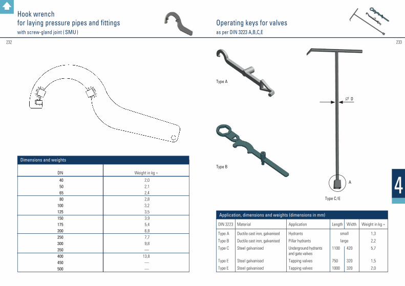
Operating keys for valvesas per DIN 3223 A,B,C,E
233232
4DIN 3223
Type A
Type B
Type C
Type E
Type E
Material
Ductile cast iron, galvanised
Ductile cast iron, galvanised
Steel galvanised
Steel galvanised
Steel galvanised
Application
Hydrants
Pillar hydrants
Underground hydrants and gate valves
Tapping valves
Tapping valves
Length
1100
750
1000
Width
420
320
320
Weight in kg ≈
1,3
2,2
5,7
1,5
2,0
Application, dimensions and weights (dimensions in mm)
small
large
Type A
Type B
Type C / E
A
D
Hook wrench for laying pressure pipes and fittingswith screw-gland joint ( SMU )
DN
40 50 65 80100125150175200250300350400450500
Weight in kg ≈
2,0 2,1 2,4 2,8 3,2 3,5 3,9 5,4 6,8 7,7 9,8 —13,8 — —
Dimensions and weights
235234 235
55
Laying and assembly instructions
Back to summary
237236
5
Note
The DVGW standard GW 368 „Thrust-resistant socket joints for pipes, fittings and valves made of ductile cast iron or steel“ is presently being modified.
For up-to-date information please refer to the FGR/EADIPS website at
www.eadips.org.
5.1
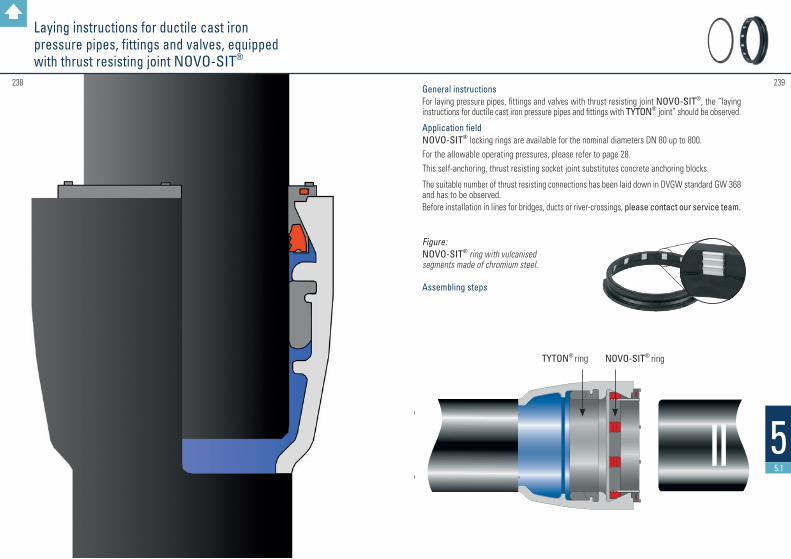
TYTON® ring NOVO-SIT® ring
239238
55.1
General instructionsFor laying pressure pipes, fittings and valves with thrust resisting joint NOVO-SIT®, the “laying instructions for ductile cast iron pressure pipes and fittings with TYTON® joint” should be observed.
Application fieldNOVO-SIT® locking rings are available for the nominal diameters DN 80 up to 800.For the allowable operating pressures, please refer to page 28.This self-anchoring, thrust resisting socket joint substitutes concrete anchoring blocks.
The suitable number of thrust resisting connections has been laid down in DVGW standard GW 368 and has to be observed.Before installation in lines for bridges, ducts or river-crossings, please contact our service team.
Figure: NOVO-SIT® ring with vulcanised segments made of chromium steel. Assembling steps
Laying instructions for ductile cast iron pressure pipes, fittings and valves, equipped with thrust resisting joint NOVO-SIT®

240 241
55.1
Segment marking dots
Plates
The exact position of the TYTON® ring has to be tested with a suitable gauge between the segments on the whole circumference.
Note: Deviation of the installed thrust resisting joint is possible as follows: up to DN 400 – 3° up to DN 700 – 2° up to DN 800 – 1°
A pipe with 6 m length and 1° deflection deviates approx. 10 cm off the neutral pipe axis.
Dismantling of thrust resisting joints
Push the spigot completely into the socket.Lubricate the dismantling blades on both sides and drive them into the socket gap at the segment marking dots, with the help of the hammering device.Use the pipe laying tool or dismantling collar to draw the spigot out of the socket.
Laying instructions for ductile cast iron pressure pipes, fittings and valves, equipped with thrust resisting joint NOVO-SIT®
1. Clean the inside of the socket, particularly the TYTON® groove.2. Insert gasket (TYTON® ring) by deflecting and squeezing, so that the gasket is firmly bedded
in its seating. The inner part of the inserted TYTON® ring should be slightly lubricated.3. Insert NOVO-SIT® ring into the pre-chamber.4. Clean the spigot end and slightly lubricate it, particularly at the rounded end; then insert through
the NOVO-SIT® ring until it touches the the TYTON® ring concentrically. From DN 300 up, this already requires a laying tool.5. Further assembly can be made, depending on the nominal dimension, with a lever or a laying tool.
Deviation should be avoided.
Important:Changes of circumferential directions have to be arranged before connecting ( e.g. installation of outlets, tees a. s. o. ).
Laying device V 300 D
Attention:After connecting both parts, the locking of the segments has to be accomplished by moving the levers in the opposite direction.
Alternate moving of the levers draws the spigot end into the socket Locking
Gauge
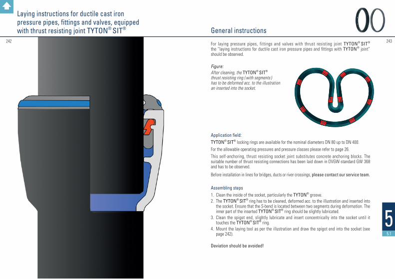
243242
55.1
General instructions
For laying pressure pipes, fittings and valves with thrust resisting joint TYTON® SIT® the “laying instructions for ductile cast iron pressure pipes and fittings with TYTON® joint” should be observed.
Figure: After cleaning, the TYTON® SIT®
thrust resisting ring ( with segments ) has to be deformed acc. to the illustration an inserted into the socket.
Application field: TYTON® SIT® locking rings are available for the nominal diameters DN 80 up to DN 400.For the allowable operating pressures and pressure classes please refer to page 26. This self-anchoring, thrust resisting socket joint substitutes concrete anchoring blocks. The suitable number of thrust resisting connections has been laid down in DVGW-standard GW 368 and has to be observed.
Before installation in lines for bridges, ducts or river crossings, please contact our service team.
Assembling steps 1. Clean the inside of the socket, particularly the TYTON® groove.2. The TYTON® SIT® ring has to be cleaned, deformed acc. to the illustration and inserted into
the socket. Ensure that the S-bend is located between two segments during deformation. The inner part of the inserted TYTON® SIT® ring should be slightly lubricated.
3. Clean the spigot end, slightly lubricate and insert concentrically into the socket until it touches the TYTON® SIT® ring.
4. Mount the laying tool as per the illustration and draw the spigot end into the socket (see page 242).
Deviation should be avoided!
Laying instructions for ductile cast iron pressure pipes, fittings and valves, equipped with thrust resisting joint TYTON® SIT®
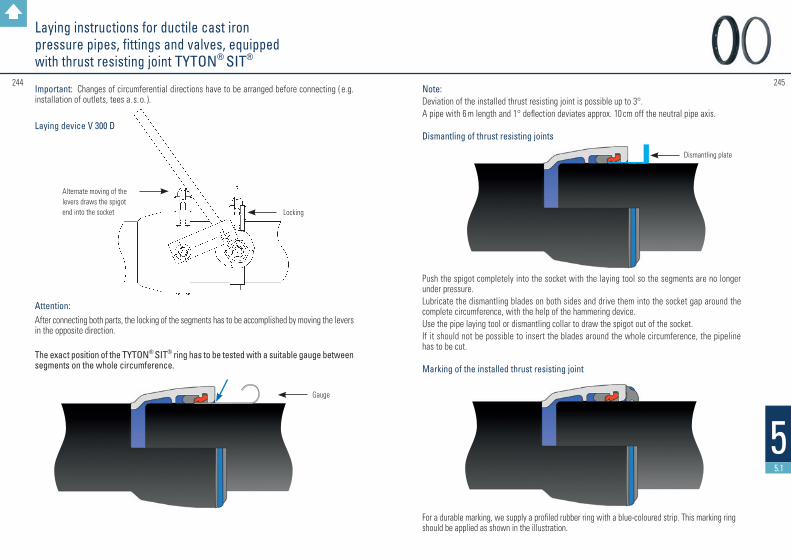
Alternate moving of the levers draws the spigot end into the socket Locking
Laying instructions for ductile cast iron pressure pipes, fittings and valves, equipped with thrust resisting joint TYTON® SIT®
Important: Changes of circumferential directions have to be arranged before connecting ( e.g. installation of outlets, tees a. s. o. ).
Laying device V 300 D
Attention: After connecting both parts, the locking of the segments has to be accomplished by moving the levers in the opposite direction.
The exact position of the TYTON® SIT® ring has to be tested with a suitable gauge between segments on the whole circumference.
245244
55.1
Dismantling plate
Note:Deviation of the installed thrust resisting joint is possible up to 3°.A pipe with 6 m length and 1° deflection deviates approx. 10 cm off the neutral pipe axis. Dismantling of thrust resisting joints
Push the spigot completely into the socket with the laying tool so the segments are no longer under pressure.Lubricate the dismantling blades on both sides and drive them into the socket gap around the complete circumference, with the help of the hammering device.Use the pipe laying tool or dismantling collar to draw the spigot out of the socket.If it should not be possible to insert the blades around the whole circumference, the pipeline has to be cut. Marking of the installed thrust resisting joint
For a durable marking, we supply a profiled rubber ring with a blue-coloured strip. This marking ring should be applied as shown in the illustration.
Gauge

Laying instructions for ductile cast iron pressure pipes, fittings and valves, equipped with thrust resisting joint TYTON SIT PLUS® (TSP®)
247246
55.1
General instructions
For laying pressure pipes, fittings and valves with thrust resisting joint TYTON SIT PLUS® ( TSP® ), the “laying instructions for ductile cast iron pressure pipes and fittings with TYTON® joint” as well as special installation instructions of the pressure pipe manufacturer should be observed.The TYTON SIT PLUS® sealing and locking ring is available for dimensions DN 80 up to DN 600.
Three basic attributes of the TYTON SIT PLUS® ring are:
Joint construction
marking: “TYTON SIT PLUS®“
notch within the sealing bulge
4 teeth in each segment
TSP® ring with stainless steel segments
TYTON® socket Cast iron pipe
Marking ring
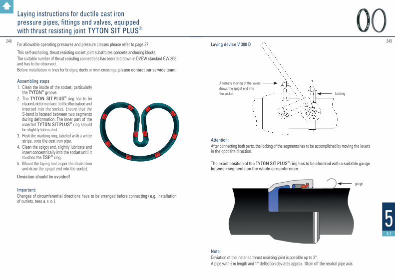
249248
55.1
Alternate moving of the levers draws the spigot end into the socket Locking
Laying instructions for ductile cast iron pressure pipes, fittings and valves, equipped with thrust resisting joint TYTON SIT PLUS®
For allowable operating pressures and pressure classes please refer to page 27.
This self-anchoring, thrust resisting socket joint substitutes concrete anchoring blocks. The suitable number of thrust resisting connections has been laid down in DVGW standard GW 368 and has to be observed.Before installation in lines for bridges, ducts or river-crossings, please contact our service team. Assembling steps1. Clean the inside of the socket, particularly
the TYTON® groove.2. The TYTON SIT PLUS® ring has to be
cleaned, deformed acc. to the illustration and inserted into the socket. Ensure that the S-bend is located between two segments during deformation. The inner part of the inserted TYTON SIT PLUS® ring should be slightly lubricated.
3. Push the marking ring, labeled with a white stripe, onto the cast iron pipe.
4. Clean the spigot end, slightly lubricate and insert concentrically into the socket until it touches the TSP® ring.
5. Mount the laying tool as per the illustration and draw the spigot end into the socket.
Deviation should be avoided!
Important:Changes of circumferential directions have to be arranged before connecting ( e.g. installation of outlets, tees a. s. o. ).
Laying device V 300 D
Attention: After connecting both parts, the locking of the segments has to be accomplished by moving the levers in the opposite direction.
The exact position of the TYTON SIT PLUS® ring has to be checked with a suitable gauge between segments on the whole circumference.
Note:Deviation of the installed thrust resisting joint is possible up to 3°.A pipe with 6 m length and 1° deflection deviates approx. 10 cm off the neutral pipe axis.
gauge
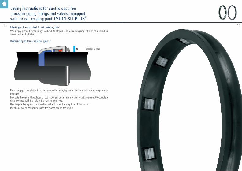
251250Marking of the installed thrust resisting jointWe supply profiled rubber-rings with white stripes. These marking rings should be applied as shown in the illustration. Dismantling of thrust resisting joints
Push the spigot completely into the socket with the laying tool so the segments are no longer under pressure.Lubricate the dismantling blades on both sides and drive them into the socket gap around the complete circumference, with the help of the hammering device.Use the pipe laying tool or dismantling collar to draw the spigot out of the socket.If it should not be possible to insert the blades around the whole
Dismantling plate
Laying instructions for ductile cast iron pressure pipes, fittings and valves, equipped with thrust resisting joint TYTON SIT PLUS®
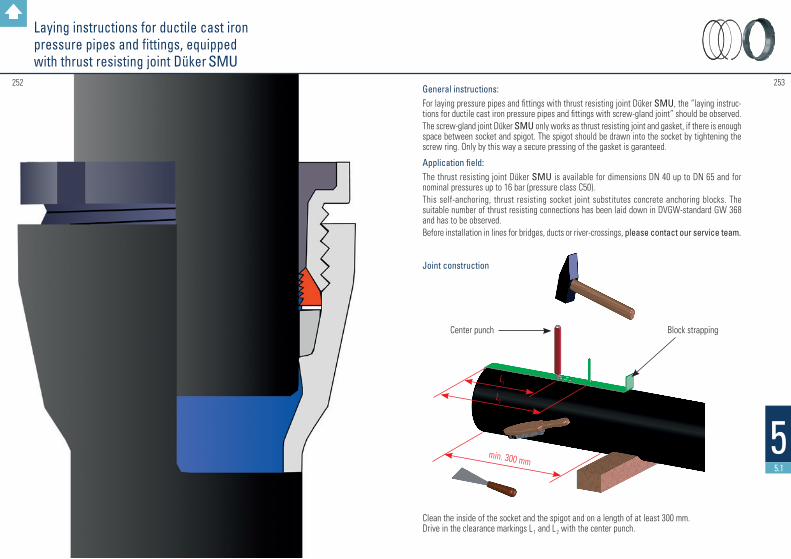
Laying instructions for ductile cast iron pressure pipes and fittings, equipped with thrust resisting joint Düker SMU
253252
55.1
General instructions:For laying pressure pipes and fittings with thrust resisting joint Düker SMU, the “laying instruc-tions for ductile cast iron pressure pipes and fittings with screw-gland joint” should be observed. The screw-gland joint Düker SMU only works as thrust resisting joint and gasket, if there is enough space between socket and spigot. The spigot should be drawn into the socket by tightening the screw ring. Only by this way a secure pressing of the gasket is garanteed.
Application field:The thrust resisting joint Düker SMU is available for dimensions DN 40 up to DN 65 and for nominal pressures up to 16 bar (pressure class C50).This self-anchoring, thrust resisting socket joint substitutes concrete anchoring blocks. The suitable number of thrust resisting connections has been laid down in DVGW-standard GW 368 and has to be observed.Before installation in lines for bridges, ducts or river-crossings, please contact our service team. Joint construction
Clean the inside of the socket and the spigot and on a length of at least 300 mm. Drive in the clearance markings L 1 and L 2 with the center punch.
Center punch Block strapping
min. 300 mm
L1
L2
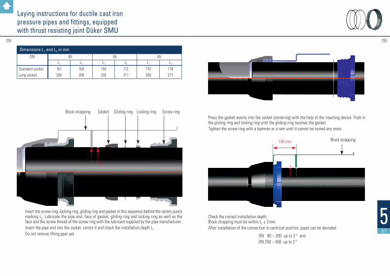
255254
55.1
Press the gasket evenly into the socket (centering) with the help of the inserting device. Push in the gliding ring and locking ring until the gliding ring touches the gasket.Tighten the screw ring with a hammer or a ram until it cannot be turned any more.
Check the correct installation depth: Block strapping must be within L2 ± 3 mm.After installation of the connection in centrical position, pipes can be deviated
DN 80 – 200 up to 3 ° and DN 250 – 400 up to 2 °
Laying instructions for ductile cast iron pressure pipes and fittings, equipped with thrust resisting joint Düker SMU
Insert the screw ring, locking ring, gliding ring and gasket in this sequence behind the centre punch marking L2. Lubricate the pipe end, face of gasket, gliding ring and locking ring as well as the face and the screw thread of the screw ring with the lubricant supplied by the pipe manufacturer.Insert the pipe end into the socket, centre it and check the installation depth L1.Do not remove lifting gear yet.
Block strapping Gasket Gliding ring Locking ring Screw ring
L1 L2
Block strapping100 mm
DN
Standard socketLong socket
L1
170209
L2
178217
65 L1
164203
L2
172211
50 L1
161200
L2
169208
40
Dimensions L1 and L2 in mm

Laying instructions for ductile cast iron pressure pipes and fittings, equipped with thrust resisting joint Düker SPEZIAL, particulary for flanged sockets and collars
257256
55.1
General instructions: For laying pressure pipes and fittings with thrust resisting joint Düker SPEZIAL, the “laying instructions for ductile cast iron pressure pipes and fittings with screw-gland joint” should be observed.
Enables mounting without block strapping as well as the thrusted-restisting end connection of flanged sockets and collars. Screw ring and SPEZIAL-Screw ring are delivered in blue-grey colour.
Application field: DN 80 – 400, PN 16
For allowable operating pressures and pressures classes please refer to page 31.
Gasket Gliding ring
Element rubber ring with segments / locking ring
SPEZIAL-Screw ring Screw ring
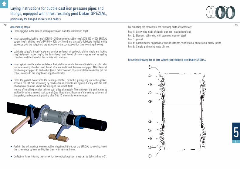
259258
55.1
For mounting the connection, the following parts are necessary:
Pos. 1: Screw ring made of ductile cast iron, inside chamferedPos. 2: Element rubber-ring with segments made of steelPos. 3: gasketPos. 4: Special screw ring made of ductile cast iron, with internal and external screw threadPos. 5: Simple gliding ring made of steel
Assembling steps:• Clean spigot/s in the area of sealing moves and mark the installation depth.
• Insert screw ring, locking ring/s (DN 80 – 250) or element rubber ring/s (DN 300 + 400), SPEZIAL screw ring/s, gliding ring/s (DN 80 – 400, t = 3 mm) and gasket/s (lubricate inside) in this sequence onto the spigot and pay attention to the correct position (see mounting drawing).
• Lubricate spigot/s, thrust-face/s and outside surface/s of gasket/s, gliding ring/s and locking ring/s (element rubber ring/s), the thrust-face/s and thread of screw rings as well as sealing chambers and the thread of the sockets with lubricant.
• Insert spigot into the socket and check the installation depth. In case of installing a collar also lubricate sealing chambers and thread of screw and insert them onto a spigot. After the axial positioning of spigots to each other (avoid deflection and observe installation depth), put the collar in centre to the spigots and adjust centrically.
• Press the gasket evenly into the sealing chamber, push the gliding ring up to the gasket, screw in the SPEZIAL screw ring by hand as far as possible and tighten it firmly with the help of a hammer or a ram. Avoid the turning of the socket itself.
In case of installing a collar tighten both sides alternately. The turning of the socket can be avoided by using a second hook wrench (see illustration). Because of the setting behaviour of the gasket, a subsequent tightening after 5 to 10 minutes is recommended.
• Push in the locking rings (element rubber rings) until it touches the SPEZIAL screw ring. Insert the screw rings by hand and tighten them with hammer blows.
• Deflection: After finishing the connection in centrical position, pipes can be deflected up to 3°.
258
Laying instructions for ductile cast iron pressure pipes and fittings, equipped with thrust resisting joint Düker SPEZIAL, particulary for flanged sockets and collars
Mounting drawing for collars with thrust resisting joint Düker SPEZIAL

Laying instructions for ductile cast iron pressure pipes, fittings and valves, equipped with thrust resisting joint NOVO-Grip® III
261260
55.1
Gasket NOVO-Grip® III-ring
PE-HD pipe
Application field:NOVO-Grip® III locking rings are available for dimensions DN 90 / 110 / 140 / 160 / 225 and for operating pressures PN 10/16. This self-anchoring, thrust resisting socket joint substitutes concrete anchoring blocks.The suitable number of thrust resisting connections has been laid down in DVGW-standard GW 368 and has to be observed.
Before installation in lines for bridges, ducts or river-crossings, please contact our service team.
Assembling steps1. Clean the inside of the socket and the spigot end.2. Insert gasket into TYTON® chamber.3. Insert NOVO-Grip® III ring into pre-chamber.4. Spigot of pipe has to be rounded and smoothened.5. Insert stabilising bush completely.6. Drive the spreading wedge into the stabilising bush until stretching. Any protruding end of the
spreading wegde has to be cut off so it is flush with the bush.7. Insert pipe into the socket through NOVO-Grip® III ring until touching the gasket.8. Connect the joint by employing commercial pipe-laying tools.
Please avoid deviation while drawing the spigot into the socket!
Important: Changes of circumferential directions have to be arranged before connecting. ( e.g. installation of outlets, tees a. s. o. )
Note: Fittings and valves with a nominal dimension of DN 200 for pipeline diameters of 225 mm do not have a standard Novo socket! These parts are equipped with an adapted geometry and are marked with the sign „for PE-HD Pipes“. Please consider this when you order your pipeline components.

263262
Laying instructions for ductile cast iron pressure pipes, fittings and valves, equipped with thrust resisting joint NOVO-Grip® III
Gasket (GKS) NOVO-Grip® III ring PE-HD pipe
Dismantling of thrust resisting joints
1. Push in the spigot until it touches the ground of the socket.
2. Lubricate the dismantling plates and drive them in on the whole circumference with the help of the hammering device.
3. Dismantle by using the laying tool.
Attention: Take care of length differences because of variation in temperature when laying plastic pipes.
E.g. PE-HD pipe length 10 m, D t = 10 °; D l approx. 20 mm.
Gasket (GKS)NOVO-Grip® III ring
Dismantling plate
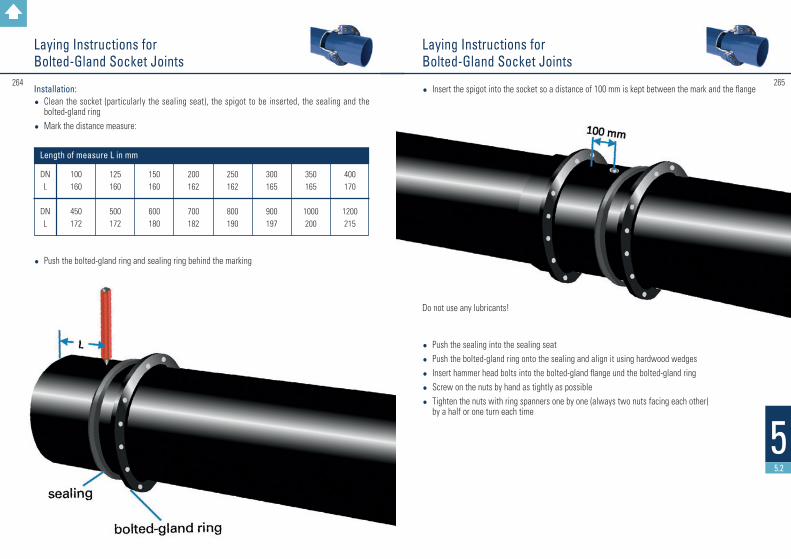
#265264
55.2
Laying Instructions for Bolted-Gland Socket Joints
Laying Instructions for Bolted-Gland Socket Joints
Installation: • Clean the socket (particularly the sealing seat), the spigot to be inserted, the sealing and the
bolted-gland ring
• Mark the distance measure:
• Push the bolted-gland ring and sealing ring behind the marking
DNL
DNL
100160
450172
125160
500172
150160
600180
200162
700182
250162
800190
300165
900197
350165
1000200
400170
1200215
Length of measure L in mm
• Insert the spigot into the socket so a distance of 100 mm is kept between the mark and the flange
Do not use any lubricants!
• Push the sealing into the sealing seat
• Push the bolted-gland ring onto the sealing and align it using hardwood wedges
• Insert hammer head bolts into the bolted-gland flange und the bolted-gland ring
• Screw on the nuts by hand as tightly as possible
• Tighten the nuts with ring spanners one by one (always two nuts facing each other) by a half or one turn each time
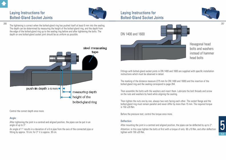
#267266
55.2
Laying Instructions for Bolted-Gland Socket Joints
Laying Instructions for Bolted-Gland Socket Joints
The tightening is correct when the bolted-gland ring has pushed itself at least 6 mm into the sealing. The depth can be determined by measuring the height of the bolted-gland ring, and the depth from the edge of the bolted-gland ring up to the sealing ring before and after tightening the bolts. The depth on one bolted-gland socket joint should be as uniform as possible.
Control the correct depth once more.
Angle: After tightening the joint in a centred and aligned position, the pipes can be put in an angle of up to 3°.An angle of 1° results in a deviation of a 6 m pipe from the axis of the connected pipe or fitting by approx. 10 cm; for 3° it is approx. 30 cm.
Fittings with bolted-gland socket joints in DN 1400 and 1600 are supplied with specific installation instructions which must be observed in detail.
The marking of the distance measure (275 mm for DN 1400 and 1600) and the insertion of the bolted-gland ring and the sealing correspond to page 264.
Then assemble the bolts with the washers and insert them. Lubricate the bolt threads and screw on the nuts and washers by hand while aligning the sealing.
Then tighten the nuts one by one, always two nuts facing each other. The socket flange and the bolted-gland ring must remain parallel and never differ by more than 15 mm. The required torque is 150 ±20 Nm.
Before the pressure test, control the torque once more.
Deflection: After mounting the joint in a centred and aligned position, the pipes can be deflected by up to 2°.Attention: in this case tighten the bolts at first with a torque of only 60 ±10 Nm, and after deflection tighten with 150 ±20 Nm.
DN 1400 and 1600
Hexagonal head bolts and washers instead of hammer head bolts

Assembly instructions for pressure pipes and fittings with flanges
269268
55.3
Assembly instructions for pressure pipes and fittings with flanges
1. Clean the flange, raised face and gasket. Check all parts for proper conditions. Do not use damaged parts.
2. In case of installation with unprotected screws, especially in soils with corrosion risk, the screw connections must be protected ( f. e. with bituminous tapes ).
3. Pipes and fittings must be bedded carefully and the filling and compacting of the pipe ditch must be done carefully as well. Pipes and fittings should never be supported with stones or similar hard material and must be laid on stonefree base. Rocky base must be covered with min. 15 cm layer of sand, gravel or split.
4. For flanged pipes and fittings the general rule for the arrangements of the boltholes is that no bolthole is located in the flange axis, which is upright to the pipeline level.
5. Notes for the installation of flanged fittings ( in particular double flanged tapers / FFR ):
To avoid installation errors, special installation marks ( notches ) are cast on at the flanges in opposite positions. It is necessary to ensure that these marks are arranged for installation in vertical or horizontal direction.

271270
55.4
Assembly instructions for drilling saddle pieces
Required tools: • core drilling machine• core bit Ø 172 +1,5/-0 mm for DN 150• core bit Ø 232 +1,5/-0 mm for DN 200• drilling machine or cordless electric drill• hammer• punch• carbide drill Ø 13 mm (e.g. DIN 8037)• file• brush• lubricant (included in the delivery)• protective paint
Assembly:
Step 1: Drill into the sewage pipe with the core drilling machine and the corresponding core bit.
Example: Double flanged taper ( FFR ) 350 / 250, PN 10
right wrong
In case of wrong installation and due to the unequal number of boltholes on double-flanged tapers, the connecting valves or fittings will be slanting from the vertical axis. Possible deviations are up to 22.5°, depending on the diameter.
Attention:On large diameters, a deviation is hardly detectable!
Remarks:Please note that DVGW standard-workingsheet GW 368 should be observed.
Assembly instructions for pressure pipes and fittings with flanges

#273272
55.4
Step 2: Deburr, clean, dry and repaint the drilling edges with a fast-drying epoxy resin paint. On sewage pipes with external cement mortar coating, this coating is to be removed in the contact area of the spot-drilling saddle piece.
Step 3: Insert the saddle sealing into the drill hole. Fit on the saddle piece and mark the position of the screw holes on the pipe by punching through the screw holes of the saddle piece. Then remove the saddle piece and the sealing.
Assembly instructions for drilling saddle pieces
Assembly instructions for drilling saddle pieces
Step 4: Drill two holes on the punch marks with the 13 mm carbide drill. Then insert the screws and sealing sleeves contained in the delivery into the drill holes from the inside and drive them cautiously through with a hammer.
Step 5: Re-insert the saddle sealing into the drill hole. Watch out for exact positioning. Apply lubricant to the sealing and put on the saddle piece.

#275274
66
Contacts
Assembly instructions for drilling saddle pieces
Step 6: Screw on the nuts lightly, then tighten alternatively and evenly until the saddle piece connects. Do not use any lever that might damage the coating (use e.g. a square timber).
277276
6
Contacts
Mr Gerald WernerExport ManagerTel. +49 6093 87 250E-Mail [email protected]
Mr Thomas EckelTel. +49 6093 87 211E-Mail [email protected]
Ms Julia RossmanithTel. +49 6093 87 252E-Mail [email protected]
Düker GmbH & Co. KGaAExport Dept. Fittings and ValvesD-63846 LaufachTel. +49 6093 87 560Fax +49 6093 87 246E-Mail [email protected]
Ms Nicole EichTel. +49 6093 87 181E-Mail [email protected]
Ms Tanja RaabTel. 49 6093 87 237E-Mail [email protected]
Ms Dorothee FleckensteinTel. +49 6093 87 262E-Mail [email protected]
Ms Lena RüthTel. +49 6093 87 414E-Mail [email protected]

FITTINGS AND VALVES
DRAINAGE TECHNOLOGY
GLASS LINING TECHNOLOGIES
JOBBING FOUNDRY
For further information on our product programme please refer to our web site:
http://www.dueker.de
Back to summary

Related Documents