Budapest University of Technology and Economics Department of Measurement and Information Systems Incremental Model Queries in Model-Driven Design PhD Thesis Gábor Bergmann MSc in Technical Informatics Supervisor: Dr. Dániel Varró, DSc associate professor Budapest, July 2013

Welcome message from author
This document is posted to help you gain knowledge. Please leave a comment to let me know what you think about it! Share it to your friends and learn new things together.
Transcript

Budapest University of Technology and EconomicsDepartment of Measurement and Information Systems
Incremental Model Queries
in Model-Driven Design
PhD Thesis
Gábor Bergmann
MSc in Technical Informatics
Supervisor:Dr. Dániel Varró, DSc
associate professor
Budapest, July 2013


i
Nyilatkozat önálló munkáról, hivatkozások átvételéről
Alulírott Bergmann Gábor kijelentem, hogy ezt a doktori értekezést magam készítettem, ésabban csak a megadott forrásokat használtam fel. Minden olyan részt, amelyet szó szerint,vagy azonos tartalomban, de átfogalmazva más forrásból átvettem, egyértelműen, a forrásmegadásával megjelöltem.
Declaration of own work and references
I, Gábor Bergmann, hereby declare, that this thesis, and all results claimed therein are myown work, and rely solely on the references given. All segments taken word-by-word, orin the same meaning from others have been clearly marked as citations and included in thereferences.
Budapest, 2013. 07. 11.
Bergmann Gábor

ii
Acknowledgements
First and foremost, I would like to thank Dr. Dániel Varró. As my advisor, he has continuouslyprovided me with guidance, valuable feedback, and interesting challenges to solve.
I would have never gotten this far without the team of colleagues here at the Fault Tolerant Sys-tems Research Group, Budapest University of Technology and Economics. I am grateful to Prof. Dr.András Pataricza and Dr. István Majzik, for providing nancial and other kinds of support for myresearch during their leadership of the group. Dr. István Ráth, Ákos Horváth, Ábel Hegedüs, ZoltánUjhelyi, Benedek Izsó, along with past collaborators András Ökrös, Dr. Gergely Varró, and others, de-serve my thanks for being excellent team players, co-authors, co-developers, professional role models,and often a sounding board for my ideas. I had the great opportunity to build upon their work, and Ind it a very satisfying feeling whenever I see that they are also benet from my results.
As pursuing the PhD required a lot of work and eort, with many harsh deadlines along the way,I have amassed a great debt towards my family and my girlfriend by not always being able to spendenough time with them. I have to thank them for showing great tolerance, as well as invaluablesupport.
This research was realized in the frames of TÁMOP 4.2.4. A/1-11-1-2012-0001 „National Excel-lence Program – Elaborating and operating an inland student and researcher personal support sys-tem”. The project was subsidized by the European Union and co-nanced by the European SocialFund. The research was also partially supported by the Hungarian grant project TÁMOP 4.2.1. B-09/1/KMR-2010-0002, the Hungarian CERTIMOT (ERC-HU-09) project, the Hungarian–French In-tergovernmental S&T Cooperation Program under the "Methods and algorithms to enhance the de-pendability of services in sensor networks" (F-Egide-PHC-19476SH, FR 6/2008), as well as EU projectsSENSORIA (IST-3-016004) FP6 and SecureChange (ICT-FET-231101) FP7. My publishing was partiallysupported by the Schnell László Foundation.
Besides the nancial support, some of these projects have also provided me with the opportunityfor fruitful cooperation with excellent international colleagues who are too numerous to list, manyof whom are now also my co-authors. I am extending my thanks to them as well.

iii
Summary
The discipline of model-driven engineering (MDE) is gaining more acceptance in several areas of soft-ware and system engineering as it delivers higher-quality products in a shorter development lifecycle.MDE redenes the engineering process as driven by the creation, revision, communication, analysisand automated derivation of formal models of system structure and behavior.
Years of extensive academic research and industrial innovation in modeling technology and lan-guage engineering have made the development of domain-specic modeling environments a practicalchoice. The key contributing factors are ecient and exible support for creating modeling tools thatrepresent, display, edit, and automatically process models. In the specic application domain of se-curity requirement engineering, for instance, an integrated tool may oer various features in additionto simply modeling security requirements. The requirement model may be processed automaticallyto check security properties. Additional manual analysis may be carried out to reason about risksand security. Finally, the requirement model may be mapped to other models conforming to dierentformalisms.
Engineering processes, especially those in software engineering, are typically iterative in nature.Thus, in model-driven engineering, evolving models are to be expected, posing a challenge to mod-eling tools and model queries in particular. In terms of the security requirement modeling example,when the requirement model is changed during the engineering process, the results of any previouslyperformed analysis and transformation tasks become obsolete, and updating them will require timeand other resources.
The main target of research in automated model processing has been the development of vari-ous model transformation approaches. The challenge of providing declarative languages and ecientevaluation strategies for model queries has received limited attention, despite being a crucial com-ponent of specifying and executing transformations and a valuable building block in other use casesincluding model validation.
This thesis is centered around providing languages, methods and technologies for model queriesand transformations to deal with the evolving nature of models.
As a cornerstone of all contributions in the thesis, (a) I propose an incremental computation strat-
egy for the evaluation of queries over evolving models to mitigate the cost of repeated applicationof processing steps. This proposal is supported by a detailed formal underpinning and experimentalevaluation results. For practical feasability, (b) I integrate the solution to the modeling technology of
Eclipse Modeling Framework (EMF) and validate the approach by performance measurements. Contri-butions include a query syntax tailored to EMF, and the design of an interface between the executionengine and the model management platform. To lift the concern of evolving models to the level ofchange-driven transformations, (c) I designed an extended query language that can specically ex-press the way the model evolves. The language is supplemented by execution strategies specic tothe application scenario. To illustrate the practical application of the theoretical contributions of thethesis in the context of a case study, (d) I additionally present a complex integrated environment thatsupports modeling and analysis of security requirements, taking advantage of the previously proposedtechniques.
The results of this thesis form an integral part of the Viatra2 model transformation frameworkand the EMF-Incery model query technology. The thesis contains a case study from the domainof security requirement engineering investigated in the SecureChange European Union FP7 researchproject. A second case study is from automotive engineering.

iv
Összefoglaló
Napjainkban a modellvezérelt tervezés (MDE) a szoftver- és rendszerfejlesztés számos területén egyreelfogadottabbá válik, mivel rövidebb fejlesztési ciklussal képes emelt minőségű termékek előállítá-sára. Az MDE alapján a mérnöki folyamat középpontjában a rendszer felépítését és viselkedését leíróformális modellek készítése, felülvizsgálata, közlése, elemzése és automatizált származtatása áll.
A modellezési és nyelvtervezési technikák területén évek óta tartó kiterjedt akadémiai kuta-tás és ipari innováció elérhető választási lehetőséggé emelte a szakterület-specikus modellezésikörnyezetek fejlesztését. Az ebben szerepet játszó kulcstényező a modellek reprezentálására, meg-jelenítésére, szerkesztésére, valamint automatizált feldolgozására képes modellező eszközök létreho-zásának rugalmas és hatékony támogatása. Például a biztonsági követelmények elemzésének szak-területén egy integrált eszköz a biztonsági követelmények modellezésén túl többféle szolgáltatástnyújthat. A követelménymodell automatikus feldolgozásával biztonsági tulajdonságok ellenőrizhe-tők. A biztonság és a kockázatok további, manuális elemezése is lehetséges. Végül a követelménymo-dell leképezhető más formalizmusokhoz igazodó modellekre.
A mérnöki folyamatok jellemzően iteratív természetűek, különösen a szoftvertervezésben. Ígya modellvezérelt szoftvertervezés során változó modellekre kell számítani, ami kihívást jelent a mo-dellező eszközök, kiemelten a modell-lekérdezések számára. A biztonsági követelmények kontex-tusában maradva, valahányszor megváltozik a követelménymodell a mérnöki folyamat során, a ko-rábban elvégzett elemzési és transzformációs feladatok eredménye elavulttá válik, így naprakésszétételük időt és egyéb erőforrásokat igényel.
Az automatizált modellfeldolgozás területén a legtöbb kutatás a modelltranszformációk fejlesz-tésére irányult. Ezzel szemben a modell-lekérdezések számára biztosítható deklaratív nyelvek éshatékony kiértékelési stratégiák kevesebb gyelmet kaptak, holott a transzformációk specikációjá-nak és végrehajtásának kritikus összetevőjéről van szó, amely többek között a modellvalidáció fontosépítőköve is egyben.
Jelen értekezés központi célja olyan nyelveket, módszereket és technológiákat biztosítani amodell-lekérdezések és modelltranszformációk számára, amelyek megbirkóznak a modellek változótermészetével.
Az értekezés legalapvetőbb eredményeként (a) egy inkrementális számítási stratégiát javasoltama változó modellek feletti lekérdezések kiértékelésére, hogy a feldolgozási lépések ismételt alkalma-zásának költségét enyhítsem. A javaslatot részletes formális megalapozás és kísérleti eredményektámogatják. A koncepció gyakorlati megvalósulásának támogatására (b) integráltam a megoldást azEclipse Modeling Framework (EMF) modellezési technológiához, és teljesítménymérésekkel validáltam.Az eredmények közé tartozik egy EMF-hez tervezett lekérdezés szintaxis, továbbá a végrehajtómo-tor és a modellkezelő platform közötti interfész megtervezése. Annak érdekében, hogy a változómodellek kérdését változásvezérelt transzformációk szintjére emeljem, (c) terveztem egy kiterjesztettlekérdezőnyelvet, amely képes a modell változásának módját kifejezni. A nyelvet az egyes alkalma-zási helyzetekre jellemző kiértékelési stratégiák egészítik ki. Az elméleti eredményeim gyakorlati al-kalmazhatóságának esettanulmányon keresztüli kimutatására (d) kidolgoztam egy komplex integráltkörnyezetet biztonsági követelmények modellezésére és elemzésére, amely a korábban javasolt tech-nikákra épít.
Az értekezés eredményei a Viatra2 modelltranszformációs keretrendszer és az EMF-Incerymodell-lekérdező technológia szerves részét alkotják. Az értekezésben megjelenik a SecureChange EUFP7-es kutatási projekt egyik esettanulmánya a biztonságikövetelmény-modellezés szakterületéről.Egy második esettanulmány a gépjármű-elektronika területéről származik.

Contents
Contents v
1 Introduction 1
1.1 Model-driven engineering . . . . . . . . . . . . . . . . . . . . . . . . . . . . . . . . . 11.1.1 The paradigm of model-driven engineering . . . . . . . . . . . . . . . . . . . 11.1.2 Model transformation and model queries . . . . . . . . . . . . . . . . . . . . . 21.1.3 Incremental, live and change-driven transformations . . . . . . . . . . . . . . 31.1.4 Example application domains . . . . . . . . . . . . . . . . . . . . . . . . . . . 4
1.2 Challenges and contributions . . . . . . . . . . . . . . . . . . . . . . . . . . . . . . . . 51.2.1 Use cases of model queries . . . . . . . . . . . . . . . . . . . . . . . . . . . . . 51.2.2 Challenges . . . . . . . . . . . . . . . . . . . . . . . . . . . . . . . . . . . . . . 61.2.3 Contributions of the thesis . . . . . . . . . . . . . . . . . . . . . . . . . . . . . 7
1.3 The structure of the thesis . . . . . . . . . . . . . . . . . . . . . . . . . . . . . . . . . 7
2 Background 9
2.1 Modeling preliminaries . . . . . . . . . . . . . . . . . . . . . . . . . . . . . . . . . . . 92.1.1 Running example: Petri nets . . . . . . . . . . . . . . . . . . . . . . . . . . . . 92.1.2 Graph models and metamodeling . . . . . . . . . . . . . . . . . . . . . . . . . 102.1.3 Operations on metamodels . . . . . . . . . . . . . . . . . . . . . . . . . . . . . 132.1.4 Attribute values . . . . . . . . . . . . . . . . . . . . . . . . . . . . . . . . . . . 162.1.5 Model access operations . . . . . . . . . . . . . . . . . . . . . . . . . . . . . . 172.1.6 Modeling paradigms . . . . . . . . . . . . . . . . . . . . . . . . . . . . . . . . 21
2.2 Graph patterns and graph transformation . . . . . . . . . . . . . . . . . . . . . . . . . 232.2.1 Graph pattern basics . . . . . . . . . . . . . . . . . . . . . . . . . . . . . . . . 232.2.2 Complex graph patterns . . . . . . . . . . . . . . . . . . . . . . . . . . . . . . 252.2.3 Graph pattern matching . . . . . . . . . . . . . . . . . . . . . . . . . . . . . . 332.2.4 Graph transformation rules . . . . . . . . . . . . . . . . . . . . . . . . . . . . 34
3 Incremental Graph Pattern Matching 37
3.1 Incremental graph pattern matching basics . . . . . . . . . . . . . . . . . . . . . . . . 373.1.1 Stateful pattern matching . . . . . . . . . . . . . . . . . . . . . . . . . . . . . 373.1.2 Algorithmic complexity of stateful pattern matching . . . . . . . . . . . . . . 39
3.2 Related work . . . . . . . . . . . . . . . . . . . . . . . . . . . . . . . . . . . . . . . . . 413.2.1 Related work: incremental graph pattern matching in graph transformation . 413.2.2 Related work: incremental matcher algorithms for production rule systems . 433.2.3 Related work: incremental maintenance in databases . . . . . . . . . . . . . . 443.2.4 Related work: incremental maintenance of queries in MDE . . . . . . . . . . 45
3.3 Principles of the Rete algorithm . . . . . . . . . . . . . . . . . . . . . . . . . . . . . . 453.3.1 High-level overview of components and structure . . . . . . . . . . . . . . . . 46
v
vi CONTENTS
3.3.2 High-level overview of operation . . . . . . . . . . . . . . . . . . . . . . . . . 473.3.3 Formalization . . . . . . . . . . . . . . . . . . . . . . . . . . . . . . . . . . . . 493.3.4 Discussion of algorithmic complexity . . . . . . . . . . . . . . . . . . . . . . . 52
3.4 Adapting Rete for graph pattern matching . . . . . . . . . . . . . . . . . . . . . . . . 533.4.1 Basic graph pattern matching with Rete . . . . . . . . . . . . . . . . . . . . . 533.4.2 Rete pattern matching with advanced pattern language features . . . . . . . . 563.4.3 Rete pattern matching with attributes . . . . . . . . . . . . . . . . . . . . . . 613.4.4 Realization considerations . . . . . . . . . . . . . . . . . . . . . . . . . . . . . 64
3.5 Performance evaluation . . . . . . . . . . . . . . . . . . . . . . . . . . . . . . . . . . . 673.5.1 Petri net ring: a model simulation benchmark . . . . . . . . . . . . . . . . . 673.5.2 Measurement results . . . . . . . . . . . . . . . . . . . . . . . . . . . . . . . . 683.5.3 Related work in graph transformation benchmarking . . . . . . . . . . . . . . 703.5.4 Performance discussion . . . . . . . . . . . . . . . . . . . . . . . . . . . . . . 70
3.6 Chapter conclusions . . . . . . . . . . . . . . . . . . . . . . . . . . . . . . . . . . . . . 71
4 Advanced Incremental Pattern Matching 73
4.1 Incremental pattern matching on multi-core platforms . . . . . . . . . . . . . . . . . 734.1.1 Introduction . . . . . . . . . . . . . . . . . . . . . . . . . . . . . . . . . . . . . 734.1.2 Related work . . . . . . . . . . . . . . . . . . . . . . . . . . . . . . . . . . . . 744.1.3 Concurrent pattern matching and model manipulation . . . . . . . . . . . . . 754.1.4 Multi-threaded pattern matching with Rete . . . . . . . . . . . . . . . . . . . 77
4.2 Graph patterns with transitive closure . . . . . . . . . . . . . . . . . . . . . . . . . . . 804.2.1 Introduction . . . . . . . . . . . . . . . . . . . . . . . . . . . . . . . . . . . . . 804.2.2 The transitive closure problem . . . . . . . . . . . . . . . . . . . . . . . . . . 814.2.3 Integration of transitive closure into Rete . . . . . . . . . . . . . . . . . . . . 834.2.4 Incremental graph transitive closure maintenance algorithms . . . . . . . . . 844.2.5 Related work . . . . . . . . . . . . . . . . . . . . . . . . . . . . . . . . . . . . 87
4.3 Incrementality on top of existing relational databases . . . . . . . . . . . . . . . . . . 874.3.1 Motivation . . . . . . . . . . . . . . . . . . . . . . . . . . . . . . . . . . . . . . 874.3.2 Overview of the approach . . . . . . . . . . . . . . . . . . . . . . . . . . . . . 884.3.3 Basic pattern matching over a relational database . . . . . . . . . . . . . . . . 904.3.4 Incrementality using cache tables and triggers . . . . . . . . . . . . . . . . . . 904.3.5 Advanced pattern language features . . . . . . . . . . . . . . . . . . . . . . . 924.3.6 Performance observations . . . . . . . . . . . . . . . . . . . . . . . . . . . . . 93
5 Incremental Model Queries over Industrial EMF Models 95
5.1 Platform and case study . . . . . . . . . . . . . . . . . . . . . . . . . . . . . . . . . . . 955.1.1 EMF technical preliminaries . . . . . . . . . . . . . . . . . . . . . . . . . . . . 955.1.2 Motivating example: security requirements . . . . . . . . . . . . . . . . . . . 97
5.2 EMF model queries based on graph patterns . . . . . . . . . . . . . . . . . . . . . . . 995.2.1 Structural constraints . . . . . . . . . . . . . . . . . . . . . . . . . . . . . . . 995.2.2 Attribute and arithmetic constraints . . . . . . . . . . . . . . . . . . . . . . . 1005.2.3 Query language structure . . . . . . . . . . . . . . . . . . . . . . . . . . . . . 102
5.3 Integrating incremental pattern matching to EMF . . . . . . . . . . . . . . . . . . . . 1025.3.1 EMF as graph model with elementary queries . . . . . . . . . . . . . . . . . . 1025.3.2 Translating from EMF notications to graph delta . . . . . . . . . . . . . . . . 103
5.4 Performance analysis of EMF model queries . . . . . . . . . . . . . . . . . . . . . . . 105

CONTENTS vii
5.4.1 Measurement scenario: constraint checking in AUTOSAR models . . . . . . . 1055.4.2 Benchmarking . . . . . . . . . . . . . . . . . . . . . . . . . . . . . . . . . . . 1085.4.3 Analysis of the results . . . . . . . . . . . . . . . . . . . . . . . . . . . . . . . 109
5.5 Chapter conclusions . . . . . . . . . . . . . . . . . . . . . . . . . . . . . . . . . . . . . 111
6 Queries and Transformations for Security Requirements 113
6.1 Introduction . . . . . . . . . . . . . . . . . . . . . . . . . . . . . . . . . . . . . . . . . 1136.1.1 Overview of the SeCMER tool . . . . . . . . . . . . . . . . . . . . . . . . . . . 1146.1.2 Metamodels in the SeCMER tool . . . . . . . . . . . . . . . . . . . . . . . . . 1156.1.3 Example scenarios from the ATM domain . . . . . . . . . . . . . . . . . . . . 115
6.2 Continuous validation of security requirements models . . . . . . . . . . . . . . . . . 1226.3 Change impact analysis on informal arguments . . . . . . . . . . . . . . . . . . . . . 1246.4 Bidirectional change-driven requirements synchronization . . . . . . . . . . . . . . . 125
6.4.1 Properties of the Si* metamodel . . . . . . . . . . . . . . . . . . . . . . . . . . 1256.4.2 Mapping between the languages . . . . . . . . . . . . . . . . . . . . . . . . . 126
6.5 Chapter conclusions . . . . . . . . . . . . . . . . . . . . . . . . . . . . . . . . . . . . . 127
7 Queries for Change-driven Transformations 129
7.1 Terminology of change in change-driven transformations . . . . . . . . . . . . . . . . 1297.1.1 Aspects of change . . . . . . . . . . . . . . . . . . . . . . . . . . . . . . . . . 1307.1.2 Transformations of change . . . . . . . . . . . . . . . . . . . . . . . . . . . . 132
7.2 Language for change-driven transformations . . . . . . . . . . . . . . . . . . . . . . . 1347.2.1 Requirements and motivation for change-driven rules . . . . . . . . . . . . . 1347.2.2 Change patterns . . . . . . . . . . . . . . . . . . . . . . . . . . . . . . . . . . 1357.2.3 Change-driven rules . . . . . . . . . . . . . . . . . . . . . . . . . . . . . . . . 1407.2.4 Challenges addressed . . . . . . . . . . . . . . . . . . . . . . . . . . . . . . . . 143
7.3 Case study: bidirectional synchronization . . . . . . . . . . . . . . . . . . . . . . . . . 1447.4 Case study: change impact analysis by evolutionary constraints . . . . . . . . . . . . 1477.5 Implementation strategies for evaluating graph change patterns . . . . . . . . . . . . 149
7.5.1 Change query evaluation in documented or invisible change scenarios . . . . 1497.5.2 Change query evaluation in live change scenarios . . . . . . . . . . . . . . . . 1517.5.3 Implementing change-driven rules . . . . . . . . . . . . . . . . . . . . . . . . 153
7.6 Discussion . . . . . . . . . . . . . . . . . . . . . . . . . . . . . . . . . . . . . . . . . . 1547.6.1 Theoretical discussion . . . . . . . . . . . . . . . . . . . . . . . . . . . . . . . 1547.6.2 Expressiveness wrt. model synchronization languages . . . . . . . . . . . . . 1557.6.3 Practical discussion . . . . . . . . . . . . . . . . . . . . . . . . . . . . . . . . . 156
7.7 Related work . . . . . . . . . . . . . . . . . . . . . . . . . . . . . . . . . . . . . . . . . 1577.8 Chapter conclusions . . . . . . . . . . . . . . . . . . . . . . . . . . . . . . . . . . . . . 160
8 Conclusions 161
8.1 New scientic results . . . . . . . . . . . . . . . . . . . . . . . . . . . . . . . . . . . . 1618.1.1 Ecient, incremental pattern matching in a model-driven environment . . . 1618.1.2 Incremental model queries over industrial EMF models . . . . . . . . . . . . . 1628.1.3 Supporting change-driven transformation specication by queries . . . . . . 1638.1.4 Queries and transformation in modeling security requirements . . . . . . . . 164
8.2 Future directions . . . . . . . . . . . . . . . . . . . . . . . . . . . . . . . . . . . . . . . 1658.3 Applications of new scientic results . . . . . . . . . . . . . . . . . . . . . . . . . . . 166

viii CONTENTS
8.3.1 Incremental pattern matcher module of the Viatra2 model transformationframework . . . . . . . . . . . . . . . . . . . . . . . . . . . . . . . . . . . . . . 166
8.3.2 EMF-IncQuery . . . . . . . . . . . . . . . . . . . . . . . . . . . . . . . . . . . 1668.3.3 SeCMER tool prototype . . . . . . . . . . . . . . . . . . . . . . . . . . . . . . 167
List of publications . . . . . . . . . . . . . . . . . . . . . . . . . . . . . . . . . . . . . . . . . 169
Bibliography 175

Chapter
1
Introduction
1.1 Model-driven engineering
1.1.1 The paradigm of model-driven engineering
The discipline of model-driven engineering (MDE) is gaining more and more prominence in certainareas of software and system engineering, primarily where faults can lead to human injury or signi-cant damage in property, as it delivers higher-quality products in a shorter development lifecycle (seee.g. [HWR13]). According to MDE, the focus of the engineering process is on creating and analyzingmodels at dierent levels of abstraction, and deriving them from other models. These models conformto various modeling languages.
Modeling may start in an early phase of the engineering process, when requirements for the sys-tem under design are elicited. In light of the requirements, system design commences with creatinghigh-level abstract models, then producing lower-level models enriched with design decisions andrealization considerations after a series of rening steps. The models can be continuously veried inorder to identify design faults as soon as possible.
Model Driven Architecture (MDA [OMG01]) by the Object Management Group is one of theMDE-based design approaches with the following characteristics. As the system under design isoften required to be realized upon various target platforms corresponding to dierent technologies,such design processes may involve a platform-independent model (PIM), which encompasses signi-cant application-specic behavioral principles and realization parameters, but technological aspectsare not detailed yet. Afterwards, depending on the available technological context, the PIM may bemapped to various platform-specic models (PSM), from which program modules realizing the de-signed software components can nally be produced (partially automatically).
The concept of models in MDE is vague in the sense that it may even involve dierential equationsor spatial congurations in certain domains of system engineering. However, models involved insoftware engineering are essentially labeled graphs, and are typically sparse (i.e. the number of edgesis roughly linearly proportional to the number of vertices). The labels applicable for vertices and edgesof a modeling language (including types and attributes), along with their rules of interconnection,are dened by the metamodel of the language. Note that only the abstract, formal structure of themodel (the so-called abstract syntax) is characterized here as graph-like; while the user-friendly visualdepiction of the model (concrete syntax) can independently be of diagram, text, or any other form.
While there are some extensible formalisms intended as a general purpose way of representing
1

2 CHAPTER 1. INTRODUCTION
models (such as UML [OMG11], SysML [OMG12b]), industrial practice seems to increasingly preferdomain-specic modeling languages (DSML) instead, which can be tailored to the needs of applicationdomains and actual design processes. However, developing such a DSML (along with its associatedtool support) is a cost-intensive task requiring special skills; therefore domain-specicmodeling (DSM)technologies have emerged to provide aid. Built on the successful Eclipse platform [ECLb], the EclipseModeling Framework (EMF, [EMF]) is a leading DSM technology that is considered a de facto industrialstandard. A DSML development process with EMF involves dening a metamodel (using the Ecore
formalism), from which several components of the modeling tool can be automatically derived. Nu-merous generative and generic technologies assist the creation of tool support for EMF-based DSMLs;one can dene a textual concrete syntax using a grammar or a visual concrete syntax using graphi-cal elements, while code generators can be created by specifying textual templates for the modelinglanguage.
1.1.2 Model transformation and model queries
Several steps of MDE can be partially or completely automated by model transformation (MT). Firstto gain wide-spread use was code generation, more precisely, model-to-text transformation (M2T).Code generators map models (such as PSM in case of MDA) to source code artifacts that will runon the target implementation platform. Deployment descriptors, test suites or documentation couldbe synthetized as well in addition to program code. Model-to-model transformation (M2M) is alsogaining importance. A usage example from MDA would be the automated support of PIM-to-PSMmappings, which adds platform-specic knowledge to the PIM. Other kinds of model transformationsmay include the synchronization between dierent models representing the same system in dierentways, for experts of dierent domains (e.g. security requirements and threat analysis). Finally, model
validation or design rule checking can be thought of as a special case of model transformation, wherethe output is the detected violations of constraints.
A model transformation program can be implemented using any general-purpose programminglanguage and toolkit. However, there are platforms specically designed to support the creation ofmodel transformations. There are basically three kinds of help one can expect from an MT system: (i)it can aid the transformation developer in processing the source model, such as in the form of queries,(ii) it can simplify the creation of elements of the target model, (iii) nally it can provide the controlow of the model transformation, managing state and traceability information.
From all these services, my work focuses primarily on investigating declarative model queries.Queries evaluated over model elements play an important role in code generation from PSM models,in M2M transformations for analysis or other purposes, in the simulation of behavioral models, instate space exploration, in report generation, etc. One of the important applications in DSM is auto-mated validation of well-formedness constraints associated with the language. For instance, the AU-TOSAR [AUT] standard denes hundreds of such constraints. DSM frameworks may provide an abil-ity to express queries in a query language designed specically for this task (see e.g. OCL [OMG12a],QVT [OMG08] queries), and evaluate them by a query engine.
The mathematical formalism of graph rewriting or graph transformation (GT [EEKR99, BV06])provides a declarative, rule-based paradigm that can used, among many other purposes, to specifyM2M transformations. The basic building block of GT is the graph pattern, which is essentially adeclarative query: it identies certain parts of the graph model based on structural and other criteria.Model manipulation is expressed in the form of graph transformation rules that consist of two graphpatterns, and describe the transformation step where a subgraph matching the LHS pattern is substi-tuted with a subgraph conforming to the RHS pattern. Therefore the GT formalism covers both the

1.1. MODEL-DRIVEN ENGINEERING 3
Figure 1.1: Roles of model transformations in MDE (inspired by [Pat06])
source model processing and target model manipulation aspects of MT, and in certain cases it doesnot require an externally dened control ow. Declarative model queries using graph patterns is acore topic of my thesis.
For the special task of model-to-model synchronization, Triple Graph Grammars (TGG, [Sch95,KW07]) and QVT [OMG08] provide an even higher level of abstraction in specifying transformations.TGG is based on GT, and TGG rules can be translated to GT rules. These languages allow very concisedenition of common model mapping tasks; e.g. a single TGG rule can immediately be interpreted asa bidirectional, incremental (see Section 1.1.3) synchronization.
The above mentioned variety of roles and application areas of MT in MDE are illustrated onFigure 1.1.
1.1.3 Incremental, live and change-driven transformations
In a model-driven engineering process, models usually do not exist as static, immutable facts, but arerather undergoing constant evolution; implying that any previously conducted model analysis mustbe re-evaluated, and the eect of changes may propagate to other models as well. This evolution mayhappen due to requirement changes (potentially as late as years after the delivery of the system), oron a shorter time-scale the creation of ever newer model versions according to agile, iterative devel-opment methodologies, or simply the consequence of xing problems detected by model validation.In fact, model editing actually consists of a sequence of small, atomic manipulation operations; thiscan also be regarded as the continuous evolution of a model, during which e.g. immediate feedbackof model validation would be useful.
Repeatedly processing a (large scale) model after each small change can lead to signicant per-formance issues. It can be more advantageous to apply incremental evaluation techniques [HLR06],taking into account the evolving nature of the model. In certain use cases (e.g. well-formednesschecks) incremental queries have a great performance advantage [11][ISR+13].
4 CHAPTER 1. INTRODUCTION
Source incrementality is the property of a transformation that it only re-evaluates the modiedparts of the source model. One of the central topics of my thesis is ecient evaluation of queriesagainst evolving models through providing source incrementality.
Target incrementality, on the other hand, means that only the necessary parts of the target modelare modied by the transformation, there is no need to recreate the new target model from scratch.The latter property, beyond direct gains in performance, has the benet that connections, referencesbetween the target model and other external models are left intact and need not be recreated. More-over, if the target model contains pieces of information (such as platform-specic design decisions in aPSM mapped from PIM) that do not stem from the source model, then the lack of target incrementalitywould lead to outright information loss.
After model evolution, the traditional MT approach restores the logical correspondence betweensource and target models by re-executing the transformation (which is ecient in case of source andtarget incrementality). A live transformation [HLR06], however, is continuously active, immediatelyreacting to events (changes of the source model) by keeping the target model synchronized. In thiscase source and target incrementality is highly benecial.
Change-driven transformations [RVV09] are transformations that process changes of models –more precisely, even their specication is given in terms of consuming changes of the source modeland producing changes of the target model. In this sense, source and target incrementality is a prereq-uisite for them. A transformation specied in a change-driven way can be executed as a live transfor-mation, but this is far from being the only application scenario. It is possible to execute change-driventransformations even in cases where the source and target models of the M2M mapping are not actu-ally available at the same computing resource, and can only communicate through the propagationof change information.
1.1.4 Example application domains
1.1.4.1 Modeling security requirements
Complex systems are typically designed to meet the needs of multiple stakeholders. Requirement mod-
els (such as the UML [OMG11] or SysML [OMG12b] standards, or KAOS [LL04]) help the designersobtain an overview of the needs and goals of various stakeholders, i.e. their requirements.
Security is a design concern aiming to avoid damages caused by adversarial persons, includingdamages to information assets (data security). It should not be confused with the related designconcern of safety, which, regardless whether the damage is intentional, attempts to avoid primarilyhuman injury, secondarily disproportionate physical damage to property. The thesis will addresssome concepts related to security.
System security is a broad area involving diverse design challenges. Software aspects includeconstructing secure cryptographic algorithms, communication protocols, and techniques for the pre-vention or detection of weaknesses and vulnerabilities in their implementation. Beyond software,technical aspects involve hardware solutions and also physical security. Finally, social aspects involvetraining humans involved with the system and establishing appropriate procedures for handling nor-mal business and incidents. However, none of these techniques can be applied unless we know what isthere to protect and who should have access; therefore security design must be preceded by gatheringsecurity requirements.
Security requirement modeling [M+02, NNY10] is the process of creating and using requirementmodels that record the security needs and goals of stakeholders. For example, the modeling languageSi* [MMZ07] can express trust between stakeholders and the delegation of responsibilities and permis-

1.2. CHALLENGES AND CONTRIBUTIONS 5
sions. The related eld of security risk modeling [LSS+11] focuses on assessing the impact of potentialthreats to the system, the vulnerabilities against these threats, the characteristics of attackers that canexploit these vulnerabilities, and their associated risk of doing so.
With the application of model queries and transformations, security requirement models have thepotential for conducting analysis that reveals inconsistent security needs, as well as for automaticallyproviding solutions and guidelines for later phases of system design.
1.1.4.2 Embedded systems engineering in the automotive industry
As onboard electronic systems in automobiles are embedded systems with high safety requirements,the automotive industry benets from rigorous methods of software and system engineering, callingfor the use of model-driven techniques. In particular, proper analysis of models may lead to detectingdesign aws early, which is a signicant boost in eciency. Due to the heterogeneity of software andhardware modules produced by various vendors, their integration is a challenge on the level of designmodels as well as on the level of implementation.
AUTOSAR (short for Automotive Open System Architecture, [AUT]) is an open and standardizedautomotive software architecture, jointly developed by automobile manufacturers, suppliers and tooldevelopers. The objectives of the AUTOSAR partnership include the implementation and standard-ization of basic system functions while providing a highly customizable platform which continuesto encourage competition on innovative functions. The purpose of the common standard is to helpthe integration of functional modules from multiple suppliers and increase scalability to dierent ve-hicle and platform variants. It aims to be prepared for the upcoming technologies and to improvecost-eciency without making any compromise with respect to quality.
1.2 Challenges and contributions
1.2.1 Use cases of model queries
While declarative specication and execution of model transformations have now been widely studiedand regarded as a signicant eld of research (see for instance the series International Conferenceon Model Transformations [ICM13]), the enabling support technology of declarative model queriesdeserves its own research focus. Use cases of model queries include the following:
Declarative model-to-model and model-to-text transformations. Model transformations pro-vide automation for bridges between artifacts of an MDE workow; see Figure 1.1 for roles ofMT. Transformations are commonly dened in rule-based declarative formalisms. Queries areused for specifying when and where one can apply the rules of the transformation specica-tion; query evaluation then involves processing the source model to nd the parts that will betransformed into the target model according to the rule.
Simulation of behavioral models with operational semantics dened using rules. Modelsimulation is the representation of system states and the application of state changes (tran-sitions, evolution paths) to reach dierent system states, as described by the behavioralmodel. Model simulation is used for various dynamic analysis techniques such as modelchecking [JRG12], design space exploration [HV10], or stochastic simulation of trajectories tocharacterize typical behavior [3]. These analysis techniques may be used to verify a systemunder design, to assess its properties, and/or to support designing a safe and ecient system.

6 CHAPTER 1. INTRODUCTION
Once again, the precondition of a transition rule is essentially a query that nds the applicabletransitions in any given state of the model.
Analysis and reporting on models. Many kinds of static analysis can be formulated declarativelyin a model query formalism, including gathering aggregated statistics, discovering correspon-dences of elements, or design rule checks by nding violations of well-formedness constraintsand modeling conventions. In static analysis and reporting, queries can be used to provide avery direct and immediate feedback to the engineers.
1.2.2 Challenges
As models in engineering practice are often subject to change, their evolving nature raises manychallenges with respect to the engineering process and model transformation in particular. Theseproblems may range from organizational issues of a change request approval process to propagatingor migrating changes between models (see also Section 1.1.3). My thesis focuses on a single overallchallenge: model queries over evolving models.
Solving this challenge may present various ways to improve the engineering process in the previ-ously indicated use cases. Source incrementality may radically increase query performance in model-to-model transformation, simulation and static analysis. In some cases, this might bring a qualitativeimprovement in addition to the quantitative one. For instance, immediate feedback in static veri-cation may elevate modeling to a highly productive interactive process. Finally, extending the querylanguage into a change-driven formalism may make the specication of change-propagating trans-formations and evolutionary analysis easier.
This top-level challenge naturally involves the following aspects:
Language. The rst challenge is nding a query language that is:
• expressive enough to capture complex relationships of model elements such as rich struc-tural interconnections, attribute conditions, quantication, aggregation and transitivereachability;
• concise enough to formulate complex relationships in a straightforward way, withoutwasting eort;
• compositional to support top-down or bottom-up thinking and reuse;• intuitive to understand in light of its direct correspondence to model structure;• able to express conditions relating to the change between two versions of a model, in
addition to the structure of a single static model, in order to support change-driven trans-formation specication;
• declarative in order to support various evaluation strategies.
Evaluation method. The second challenge is nding an evaluation strategy to the declarative querylanguage that is
• source-incremental;• ecient in terms of execution time, and also regarding memory footprint;• capable of taking advantage of the parallel execution provided by modern symmetric mul-
tiprocessing hardware;

1.3. THE STRUCTURE OF THE THESIS 7
• supports the features of the query language.
Adaptation to technological platforms. The nal challenge is realizing both the language con-cepts and the evaluation engine in context of technologies with industrial relevance, namely:
• primarily the Eclipse Modeling Framework (EMF);• alternatively relational databases, especially in-memory implementations;• while addressing compatibility with all scenarios of model evolution in case of change-
driven execution.
1.2.3 Contributions of the thesis
My thesis will oer the following improvements over the state-of-the-art of model query technology:
• I propose an incremental evaluation strategy for model queries formulated as graph patterns,and demonstrate its eciency. (Contribution 1)
• I integrate this strategy into the industrial Eclipse Modeling Framework by designing a run-timetranslation layer and adapting the query syntax, and evaluate the performance of the resultingsolution. (Contribution 2)
• I extend the query formalism to support change-driven transformations by transparently cap-turing changes of the model regardless of the scenario, and design scenario-specic strategiesfor execution. (Contribution 3)
• I provide bidirectional model synchronization, change impact analysis and consistency check-ing in the domain of security requirement engineering, by applying the above techniques. (Con-tribution 4)
For each of these contributions, Figure 1.2 depicts the challenges that are addressed, as well as theapplication domains and use cases where the results are demonstrated.
1.3 The structure of the thesis
• First Chapter 2 will provide the background knowledge that is necessary to follow the newscientic results of later chapters, as well as introduce the terminology I will use throughoutthe thesis.
• The following chapters address Contribution 1.
– Chapter 3 presents the rst of the new contributions: a formal treatment of incrementalpattern matching, the adaptation of an incremental evaluation algorithm to the languageof graph patterns and the previously introduced formalization, and nally empirical eval-uation.
– Chapter 4 follows by introducing a number of extensions regarding language, executionstrategy and platform technology.
• Chapter 5 presents the realization of this solution on the modeling platform of EMF, includ-ing questions of language design, overcoming technological hurdles, and again experimentalvalidation of performance, thereby fullling Contribution 2.

8 CHAPTER 1. INTRODUCTION
Figure 1.2: Contributions (C1-4), challenges, use cases and application domains
• Chapter 6 deals with Contribution 4, demonstrating the application of thesis results in a domain-specic modeling environment from the domain of security requirement engineering. Afterpresenting the tool environment, queries and transformations will be shown validating securityproperties, analyzing change impact on human arguments, and providing live synchronizationbetween model representations. Some of these problems are beyond the previously proposedtechniques, providing a source of motivation for Chapter 7.
• Chapter 7 introduces change-driven transformations, a novel framework for specifying reactivebehavior for evolving models, according to Contribution 3. After clarifying terminology andanalyzing possible application scenarios, language and semantics will be provided for change-driven transformations, as well as execution algorithms. The new techniques will then bedemonstrated on case studies previously introduced in Chapter 6, followed by a detailed eval-uation and discussion of the new approach.
• Finally, Chapter 8 concludes the thesis by summarizing the new scientic results that wereachieved by fullling the goals of Section 1.2.3, as well as their application and dissemination.
Chapter
2
Background
This chapter will lay down the formal foundations of my thesis, upon which novel scientic con-tributions will be built in subsequent chapters. Section 2.1 will present a formalization of models,metamodels, query and manipulation operations, which are central concepts of MDE. As a declarativeformalism for specifying query and manipulation operations, graph patterns and graph transforma-tion will be introduced in Section 2.2.
2.1 Modeling preliminaries
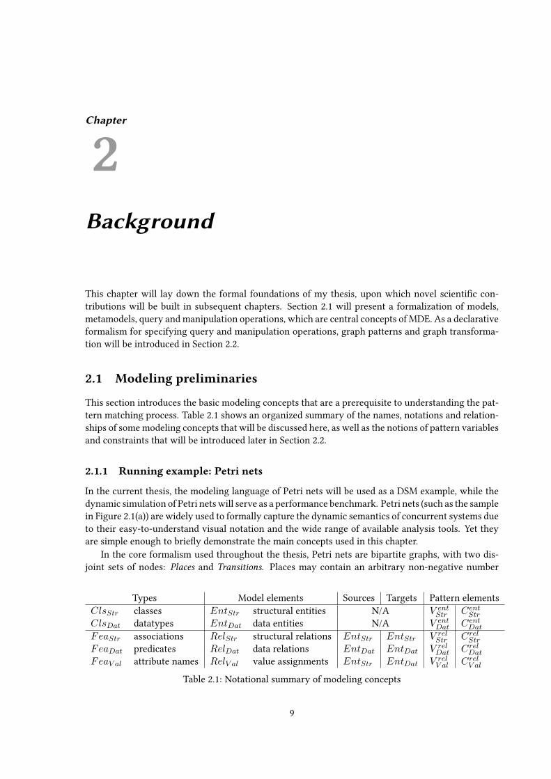
This section introduces the basic modeling concepts that are a prerequisite to understanding the pat-tern matching process. Table 2.1 shows an organized summary of the names, notations and relation-ships of some modeling concepts that will be discussed here, as well as the notions of pattern variablesand constraints that will be introduced later in Section 2.2.
2.1.1 Running example: Petri nets
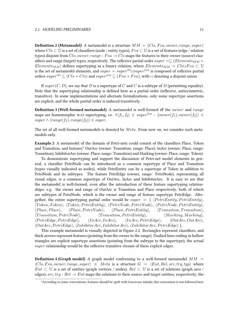
In the current thesis, the modeling language of Petri nets will be used as a DSM example, while thedynamic simulation of Petri nets will serve as a performance benchmark. Petri nets (such as the samplein Figure 2.1(a)) are widely used to formally capture the dynamic semantics of concurrent systems dueto their easy-to-understand visual notation and the wide range of available analysis tools. Yet theyare simple enough to briey demonstrate the main concepts used in this chapter.
In the core formalism used throughout the thesis, Petri nets are bipartite graphs, with two dis-joint sets of nodes: Places and Transitions. Places may contain an arbitrary non-negative number
Types Model elements Sources Targets Pattern elementsClsStr classes EntStr structural entities N/A V ent
Str CentStr
ClsDat datatypes EntDat data entities N/A V entDat CentDat
FeaStr associations RelStr structural relations EntStr EntStr V relStr CrelStr
FeaDat predicates RelDat data relations EntDat EntDat V relDat CrelDat
FeaV al attribute names RelV al value assignments EntStr EntDat V relV al CrelV al
Table 2.1: Notational summary of modeling concepts
9

10 CHAPTER 2. BACKGROUND
(a) Initial state
(b) After ring t1 (c) After ring t2
Figure 2.1: A sample Petri-net model.
of (indistinguishable) Tokens. Such a token distribution (marking) denes the state of the modeledsystem.
The state of the net can be changed by ring enabled transitions. A transition is enabled (reable)if each of its input places (connected to the transition via input arcs) contains at least one token, andfurthermore no place connected via an inhibitor arc contains any tokens. When ring a transition,we remove a token from all input places and add a token to all output places (as dened by outputarcs).
Figure 2.1(a) shows a sample Petri-net in its domain-specic concrete syntax. Each hollow circlerepresents a place, while each elongated black block represents a transition. Black circles within aplace indicate tokens belonging to that place. Input arcs are depicted as arrows pointing from a placeto a transition, output arcs are arrows pointing from a transition to a place. Inhibitor arcs look similarto input arcs, but terminate in a small circular disc instead of an arrowhead.
Example 1 In the example Petri-net of Figure 2.1(a), both transitions t1 and t2 are reable. If oneres t1 once (see Figure 2.1(b)), it will reduce the token count of p1 to 2, while p3 will continue tohave a single token; both transitions will remain reable. Firing t2 (see Figure 2.1(c)), on the otherhand, would remove a token from p3 and add one to p2; after this step neither transitions are enabledanymore.
2.1.2 Graph models and metamodeling
The following paragraphs introduce a formal foundation of graph models. Note that several ap-proaches in literature are largely similar, such as graph schemata [SWZ99], type graphs with in-heritance [TR05], certain semantics of MOF [AP08], or VPM [Var04].
Denition 1 (Universe) The universe U is an innite set consisting of all potential model and meta-model elements, as well as all potential data values (numbers, text strings, etc.).
2.1. MODELING PRELIMINARIES 11
Denition 2 (Metamodel) A metamodel is a structure MM = 〈Cls, Fea, owner, range, super〉where Cls ⊂ U is a set of classiers (node / entity types), Fea ⊂ U is a set of features (edge / relationtypes) disjoint from Cls; owner, range : Fea→ Cls maps the features to their owner (source) clas-siers and range (target) types, respectively. The reexive partial order super =⊆ (ElementsMM ×ElementsMM ) denes supertyping as a binary relation, where ElementsMM = Cls ·∪Fea ⊂ Uis the set of metamodel elements, and super = supercls ·∪superfea is composed of reexive partialorders supercls ⊆ (Cls× Cls) and superfea ⊆ (Fea× Fea), with ·∪ denoting a disjoint union.
If super(C,D), we say that D is a supertype of C and C is a subtype of D (permitting equality).Note that the supertyping relationship is dened here as a partial order (reexive, antisymmetric,transitive). In some implementations and alternate formalizations, only some supertype assertionsare explicit, and the whole partial order is induced transitively.
Denition 3 (Well-formed metamodel) A metamodel is well-formed i the owner and rangemaps are homomorphic w.r.t supertyping, i.e. ∀〈f1, f2〉 ∈ superfea : 〈owner(f1), owner(f2)〉 ∈super ∧ 〈range(f1), range(f2)〉 ∈ super.
The set of all well-formed metamodels is denoted by Meta. From now on, we consider such meta-models only.
Example 2 A metamodel of the domain of Petri-nets could consist of the classiers Place, Tokenand Transition, and features1 OutArc (owner: Transition: range: Place), InArc (owner: Place, range:Transition), InhibitorArc (owner: Place, range: Transition) and Marking (owner: Place, range: Token).
To demonstrate supertyping and support the discussion of Petri-net model elements in gen-eral, a classier PetriNode can be introduced as a common supertype of Place and Transition(types visually indicated as nodes), while PetriEntity can be a supertype of Token in addition toPetriNode and its subtypes. The feature PetriEdge (owner, range: PetriNode), representing allvisual edges, is a common supertype of OutArc, InArc and InhibitorArc. It is easy to see thatthe metamodel is well-formed, even after the introduction of these feature supertyping relation-ships; e.g. the owner and range of OutArc is Transition and Place respectively, both of whichare subtypes of PetriNode, which is the owner and range of feature supertype PetriEdge. Alto-gether, the entire supertyping partial order would be super = 〈PetriEntity, PetriEntity〉,〈Token, Token〉, 〈Token, PetriEntity〉, 〈PetriNode, PetriNode〉, 〈PetriNode, PetriEntity〉,〈Place, P lace〉, 〈Place, PetriNode〉, 〈Place, PetriEntity〉, 〈Transition, Transition〉,〈Transition, PetriNode〉, 〈Transition, PetriEntity〉, 〈Marking,Marking〉,〈PetriEdge, PetriEdge〉, 〈InArc, InArc〉, 〈InArc, PetriEdge〉, 〈OutArc,OutArc〉,〈OutArc, PetriEdge〉, 〈InhibitorArc, InhibitorArc〉, 〈InhibitorArc, PetriEdge〉 .
This example metamodel is visually depicted in Figure 2.2. Rectangles represent classiers, andthick arrows represent features (pointing from the owner to the range). Dashed lines ending in hollowtriangles are explicit supertype assertions (pointing from the subtype to the supertype); the actualsuper relationship would be the reexive transitive closure of these explicit edges.
Denition 4 (Graph model) A graph model conforming to a well-formed metamodel MM =〈Cls, Fea, owner, range, super〉 ∈ Meta is a structure G = 〈Ent,Rel, src, trg, typ〉 whereEnt ⊂ U is a set of entities (graph vertices / nodes), Rel ⊂ U is a set of relations (graph arcs /edges); src, trg : Rel → Ent maps the relations to their source and target entities, respectively; the
1According to some conventions, features should be spelt with lowercase initials; this convention is not followed here

12 CHAPTER 2. BACKGROUND
Figure 2.2: A possible Petri net metamodel, with supertypes
typing of elements is the function typ : ElementsG → ElementsMM where ElementsG ⊂ U is anabbreviation for the set of graph elements Ent ·∪Rel; and nally the following properties are met bythe typing function typ:
• ∀e ∈ Ent : typ(e) ∈ Cls
• ∀r ∈ Rel : typ(r) ∈ Fea
• ∀r ∈ Rel : super(typ(src(r)), owner(typ(r))) ∧ super(typ(trg(r)), range(typ(r)))
The concept of instantiation will be useful for discussing graph models both on the model leveland on the level of individual model elements.
Denition 5 (Instantiation (model level)) Graph model G instantiates (alternatively “is an in-stance of” or “is dened by”) metamodel MM , denoted as G : MM , if and only if G is conformingto MM . The set of all graph models instantiating a given metamodel MM ∈Meta will be denotedas GraphsMM = G | G : MM .
Denition 6 (Instantiation (element level)) In a graph model G = 〈Ent,Rel, src, trg, typ〉 con-forming to a well-formed metamodel MM = 〈Cls, Fea, owner, range, super〉, the graph elemente ∈ ElementsG instantiates (or is an instance of) type t ∈ ElementsMM i super(typ(e), t); thisis denoted as G |= e : t. The analogous notation G |= e :: t denotes the meaning typ(e) = t whichexcludes strict supertypes.
Using the terminology of instantiation, we can restate the third property of the typing functionin Denition 4: the source and target of a relation must instantiate the owner type and the rangetype of the relation type, respectively. Due to the well-formedness of the metamodel, this can befurther rephrased in the following way to take feature supertypes into account: the source/target ofan instance of a feature must instantiate the owner/range of the feature.
It is also possible to use a similar schema to represent hypergraphs, where relations / hyperedgesmay have more than two incidence maps instead of just src and trg. Metamodels in such formalismsemploy more edge type maps in addition to just owner and range. While detailed denitions are
2.1. MODELING PRELIMINARIES 13
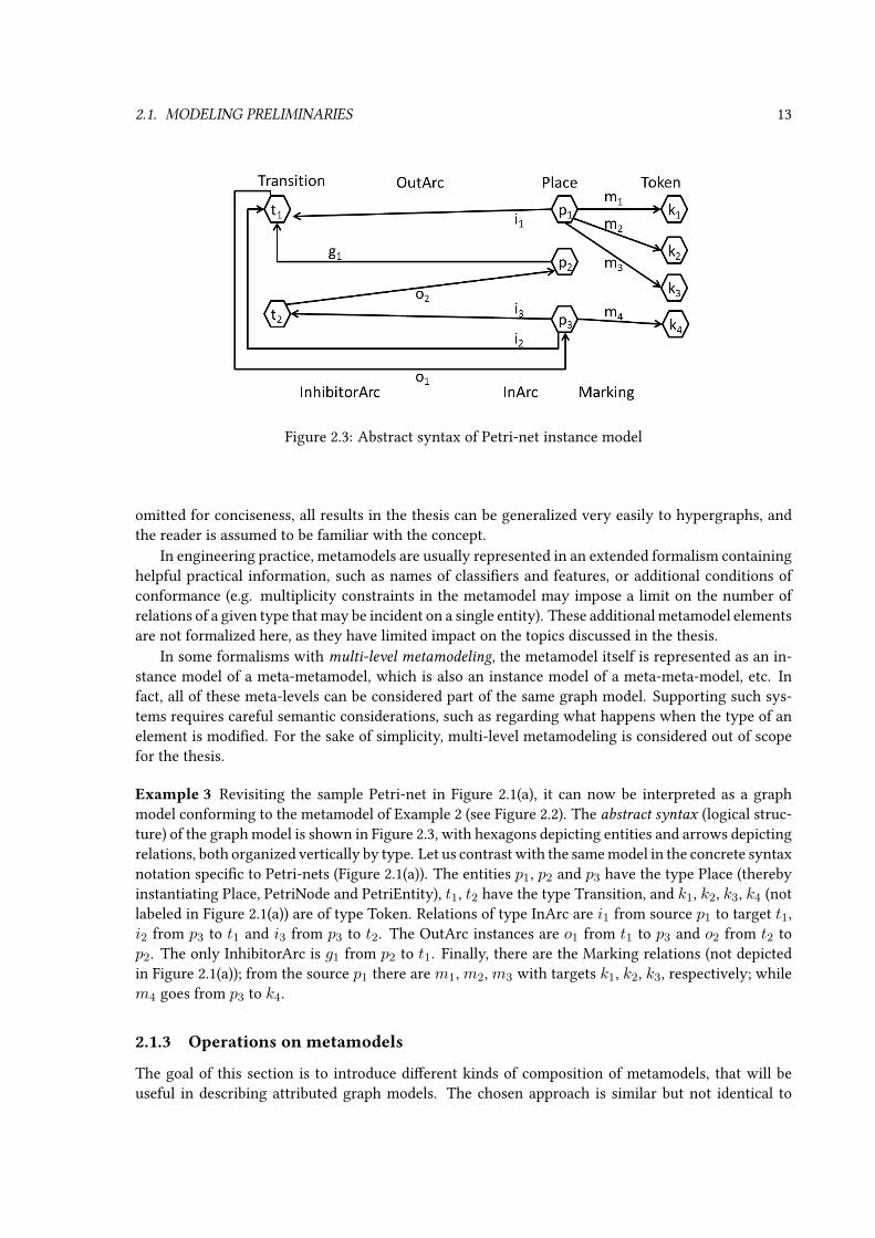
Figure 2.3: Abstract syntax of Petri-net instance model
omitted for conciseness, all results in the thesis can be generalized very easily to hypergraphs, andthe reader is assumed to be familiar with the concept.
In engineering practice, metamodels are usually represented in an extended formalism containinghelpful practical information, such as names of classiers and features, or additional conditions ofconformance (e.g. multiplicity constraints in the metamodel may impose a limit on the number ofrelations of a given type that may be incident on a single entity). These additional metamodel elementsare not formalized here, as they have limited impact on the topics discussed in the thesis.
In some formalisms with multi-level metamodeling, the metamodel itself is represented as an in-stance model of a meta-metamodel, which is also an instance model of a meta-meta-model, etc. Infact, all of these meta-levels can be considered part of the same graph model. Supporting such sys-tems requires careful semantic considerations, such as regarding what happens when the type of anelement is modied. For the sake of simplicity, multi-level metamodeling is considered out of scopefor the thesis.
Example 3 Revisiting the sample Petri-net in Figure 2.1(a), it can now be interpreted as a graphmodel conforming to the metamodel of Example 2 (see Figure 2.2). The abstract syntax (logical struc-ture) of the graph model is shown in Figure 2.3, with hexagons depicting entities and arrows depictingrelations, both organized vertically by type. Let us contrast with the same model in the concrete syntaxnotation specic to Petri-nets (Figure 2.1(a)). The entities p1, p2 and p3 have the type Place (therebyinstantiating Place, PetriNode and PetriEntity), t1, t2 have the type Transition, and k1, k2, k3, k4 (notlabeled in Figure 2.1(a)) are of type Token. Relations of type InArc are i1 from source p1 to target t1,i2 from p3 to t1 and i3 from p3 to t2. The OutArc instances are o1 from t1 to p3 and o2 from t2 top2. The only InhibitorArc is g1 from p2 to t1. Finally, there are the Marking relations (not depictedin Figure 2.1(a)); from the source p1 there are m1, m2, m3 with targets k1, k2, k3, respectively; whilem4 goes from p3 to k4.
2.1.3 Operations on metamodels
The goal of this section is to introduce dierent kinds of composition of metamodels, that will beuseful in describing attributed graph models. The chosen approach is similar but not identical to

14 CHAPTER 2. BACKGROUND
UML package merge (formalized in [ZD06]), as it provides formal treatment of (a) supertyping, (b)relation types forming an unidirectional glue between two metamodels, and (c) the decompositionof instance models along the structure of the metamodel. More metamodel operations are availablein [ES06].
For the purposes of this thesis, it is enough to analyze metamodel merging in three specialcases. This way, it will be trivial to preserve the partial order property of supertyping and the well-formedness property of metamodels.
Denition 7 (Disjoint metamodels) MetamodelsMM1 = 〈Cls1, Fea1, owner1, range1, super1〉and MM2 = 〈Cls2, Fea2, owner2, range2, super2〉 are feature-disjoint i Fea1 ∩ Fea2 = ∅ andtotally disjoint i Cls1 ∩ Cls2 = ∅ and Fea1 ∩ Fea2 = ∅.
Denition 8 (Disjoint merge of metamodels) For the totally disjoint metamodels MM1 =〈Cls1, F ea1, owner1, range1, super1〉 and MM2 = 〈Cls2, Fea2, owner2, range2, super2〉, theirdisjoint merge is a metamodel MM1 ·∪MM2 = 〈Cls, Fea, owner, range, super〉 with Cls =Cls1 ·∪Cls2, Fea = Fea1 ·∪Fea2, owner = owner1 ·∪owner2, range = range1 ·∪range2, super =super1 ·∪super2.
The supertyping relationship super remains a partial order because super1 and super2 are partialorders on disjoint sets. Trivially, if the constituent metamodels MM1 and MM2 are well-formed, sois the resulting MM .
This rst merge operation deals with two metamodels describing two completely independentdomains. In this case it is trivial that we can obtain a merged metamodel whose instance modelsmay contain elements of either kind. For example, if we take the Petri-net metamodel MMPetri
of Example 2 and the totally disjoint metamodel MMProcess of process ows, instance models ofMM1 ·∪MM2 may contain Petri-nets and processes, but no connections between them.
Denition 9 (Feature-merge of metamodels) For the pair of feature-disjoint meta-models MM1 and MM2 sharing their classiers Cls along with classier supertyp-ing supercls, where MM1 = 〈Cls, Fea1, owner1, range1, supercls ·∪superfea1 〉 andMM2 = 〈Cls, Fea2, owner2, range2, supercls ·∪superfea2 〉, their feature-merge is a meta-model MM1 ] MM2 = 〈Cls, Fea, owner, range, super〉 with Fea = Fea1 ·∪Fea2,owner = owner1 ·∪owner2, range = range1 ·∪range2, super = supercls ·∪superfea1 ·∪superfea2 .
Now the supertyping relationship super, while preserving all supertyping information from MM1
andMM2, remains a partial order because supercls and superfea1 and superfea2 are partial orders onpairwise disjoint sets. Well-formedness is preserved in the resulting metamodel MM for the trivialreasons.
This second operation deals with the composition of two disjoint set of features over the sameset of classiers; models instantiating the merged metamodel may contain entities that instantiatethe common classiers, and relations typed by either set of features. For example, the MMPetri
of Example 2 (without the relation supertype PetriEdge) could be decomposed as MMPetri =MMPetriArcs ] MMPetriMarking , where MMPetriArcs only includes the arc features, the featureset of MMPetriMarking is reduced to Marking, but both have the original set of classiers.
Denition 10 (Unidirectional glue between metamodels) For totally disjointmetamodels MM1 = 〈Cls1, Fea1, owner1, range1, super1〉 and MM2 =〈Cls2, Fea2, owner2, range2, super2〉, the metamodel MM = 〈Cls, Fea, owner, range, super〉 is

2.1. MODELING PRELIMINARIES 15
Figure 2.4: Petri-net metamodel glue-merged with a process metamodel
a unidirectional glue from MM1 to MM2 i MM is feature-disjoint from MM1 and MM2, withCls = Cls1 ·∪Cls2, supercls = supercls1 ·∪supercls2 and nally owner(Fea) ⊆ Cls1∧range(Fea) ⊆Cls2.
In other words, the glue metamodel only contains features pointing from the rst metamodel MM1to the second metamodel MM2. It would be equally easy to dene the concept of bidirectional gluebetween metamodels.
Denition 11 (Glue-merge of metamodels) For the totally disjoint metamodels MM1 =〈Cls1, Fea1, owner1, range1, super1〉 andMM2 = 〈Cls2, Fea2, owner2, range2, super2〉 and uni-directional glue MMglue = 〈Cls1 ·∪Cls2, F eaglue, ownerglue, rangeglue, superglue〉 from MM1 toMM2, their glue-merge is the metamodel MM1
MMglue−−−−−→MM2 = (MM1 ·∪MM2) ]MMglue.
The feature-merge operation is applicable here, since the glue and the result of the disjoint mergeshare their classiers and are feature-disjoint. If all three initial metamodels are well-formed, so isthe result of the glue-merge, due to the preserving properties of the two previous merge operations.Note that in general, disjoint merges are special cases of the glue-merge.
This third kind of metamodel operation lets us compose complex metamodels from simpler onesand their interconnections. As a quick example, let us assume that Petri-nets are automatically gen-erated from process models, and we would like to preserve traceability from Petri-net elements tothe corresponding process model elements. It is possible to dene an unidirectional glue metamodelMMglue between MMPetri and MMProcess that would contain all Petri-net and process classiers(along with their subtyping relationships), and various traceability features pointing from a Petri netelement to a process element (such as trFork pointing from a Transition element in the Petri-netto the Fork node in the process model that the transition was generated from). Model instantiatingthe glue-merge MMPetri
MMglue−−−−−→ MMProcess (illustrated on Figure 2.4) therefore contain Petri-nets, process models, and relations instantiating the traceability features, pointing from the Petri-netelements to the process elements.
Denition 12 (Decomposition of instance models along a glue-merge) A graph model G =
〈Ent,Rel, src, trg, typ〉 instantiating a glue-merged metamodel MM1MMglue−−−−−→ MM2 decomposes
along the glue-merge into 〈G1, Relglue, G2〉, where i ∈ 1, 2 : Gi = 〈Enti, Reli, srci, trgi, typi〉with Enti = r | r ∈ Ent∧ typ(r) ∈ Clsi , Reli = r | r ∈ Rel∧ typ(r) ∈ Feai ; srci, trgi andtypi are restricted on the corresponding sets; and nallyRelglue = r | r ∈ Rel∧typ(r) ∈ Feaglue .
In essence, an instance model of a glue-merged metamodel can be decomposed into instances ofthe two glued metamodels, and glue relations connecting the rst one to the second. Continuing

16 CHAPTER 2. BACKGROUND
the previous example, instances of MMPetriMMglue−−−−−→ MMProcess would decompose into a simple
Petri-net model, a simple process model, and a set of Petri-net-to-process traceability relations.
2.1.4 Attribute values
While the previous denition of graph model is sucient for describing abstract structures, mostpractical purposes also require the assignment of textual, numerical, categorical or other sorts of at-tributes. This assumes that there are structural entities determining the structure of the model, as wellas a pool of potential attribute values that can be assigned to structural entities. Relationships betweenthese attribute values (e.g. ordering or operators) are also modeled. See [Kas06] for a more formaltreatment of data algebrae in graph modeling, which heavily inuenced the following denitions, or[EEPT06] for a category-theory-based formulation.
Denition 13 (Data values and data algebra) EntDat ⊂ U is the immutable and innite set of allpotential attribute values. These values are classied into special attribute types (such as integers,strings, enumerable categories, etc.), also called datatypes, denoted as ClsDat ⊂ U. The data algebraDat is the graph model 〈EntDat, RelDat, srcDat, trgDat, typDat〉, which also introduces data rela-tions RelDat ⊂ U, the immutable and innite set of relations between data values (e.g. ordering,substring, etc.), typed by so-called data predicates FeaDat ⊂ U. Dat instantiates the well-formedmetamodel called data signature MMDat = 〈ClsDat, F eaDat, ownerDat, rangeDat, superDat〉.
Relations of higher arity (e.g. operators such as multiplication, concatenation, etc.) can be simi-larly represented using hypergraphs, or by auxiliary nodes. For a simple example involving aux-iliary nodes, let us assume the data signature MMDat contains a data type and an auxiliary nodetype Number,Division ∈ ClsDat, and data predicates dividend, divisor, quotient ∈ FeaDat withDivision as owner and Number as range. Instantiating this data signature, the fact that 3/4 = 0.75can be represented by the auxiliary node /〈3,4,0.75〉 : Division in EntDat, with three outgoing re-lations (elements in RelDat) pointing to numbers: one of type dividend to 3, one of type divisorto 4, and one of type quotient to 0.75. Neither the option of auxiliary nodes nor the alternativehypergraph-based formalization is explored in detail here, but it is assumed that higher-arity rela-tions are available.
Denition 14 (Metamodel of attributed graph) An attributed graph metamodel over dataDat isthe glue-merge MMStr
MMV al−−−−−→ MMDat = MM = 〈Cls, Fea, owner, range, super〉 for somestructural metamodel MMStr = 〈ClsStr, F eaStr, ownerStr, rangeStr, superStr〉 that is totally dis-joint from MMDat, and for appropriate FeaV al glue features. ClsStr is the set of classes (structuralclassiers), FeaStr are the so-called structural associations. FeaV al are called attribute names withowner(FeaV al) ⊆ ClsStr ∧ range(FeaV al) ⊆ ClsDat (i.e. from classes to datatypes).
Denition 15 (Attributed graph model) An attributed graph is any graph model G =
〈Ent,Rel, src, trg, typ〉 conforming to an attributed metamodel MMStrMMV al−−−−−→ MMDat =
MM = 〈Cls, Fea, owner, range, super〉 that decomposes along the glue-merge into〈GStr, RelV al, GDat〉, where GDat = Dat (i.e. G must contain Dat as its sub-model). EntStr iscalled the set of structural entities, RelStr is the set of structural relations, and RelV al is the set ofvalue assignment relations that assign attribute values to structural entities. G |= obj.attr = valdenotes the fact that ∃r ∈ RelV al(G) where src(r) = obj, trg(r) = val and typ(r) = attr.

2.1. MODELING PRELIMINARIES 17
Figure 2.5: Alternate Petri net metamodel, with data attributes
In most practical cases, the structural instance modelGStr and value assignmentsRelV al are requiredto be nite. Another frequent restriction is that each structural entity must have at most one outgoingrelation per attribute name (many-to-one multiplicity, may be indicated in the metamodel as well).
Obviously, any implementation in a nite computer can only manifest a nite subset of the inniteDat at a time, such as trg(RelV al). Because of the innite degrees, RelDat arcs are rarely storedor enumerated even for those parts of EntDat that are kept in memory; but it is assumed that theexistence of a data relation of a given type between given data entities is easily decidable. Somepredicate types in FeaDat might be function-like, meaning that one (or more) of their incident nodescan be eciently deduced from the others (e.g. the value of a product is derivable from the value ofits factors, or the value of a complex arithmetic expression is computable from the value of its freevariables).
Example 4 An alternate Petri-net metamodel (see Figure 2.5) serves as an example application of theattributed graph concept. The key idea is that tokens are indistinguishable, therefore it is enough tokeept track of the number of tokens at a given place. Most of the previous metamodel is retained as thestructural metamodel (depicted as solid boxes and arrows). Without a Token class, the Marking featureis now an attribute name (depicted as a dashed arrow) pointing to the Integer datatype (depicted asadashed box). There is also a data predicate Successor (depicted as striped arrow) with Integer asowner and range; its instances are pointing from each number to the subsequent one. Note that thesupertypes were omitted for the sake of simplicity.
The instance model depicted in Figure 2.1(a) can be described by a dierent graph model con-forming to the new, attributed metamodel; the new abstract syntax is depicted in Figure 2.6. First ofall, the innite data algebra part of the graph model consist of all integer numbers, each connectedto the next by a data relation (s0, s1, s2, . . . ) of type Successor. The structural graph consist of thealready discussed instances (see Example 3) of Place, Transition and the three Arc associations. Thetwo are glued together by value assignment relations of type Marking: m1 has p1 as source and thedata entity 3 as target; m2 points from p2 to 0, and nally m3 goes from p3 to 1.
2.1.5 Model access operations
In addition to the static structure of graph models, it is also important to study their evolution overtime, and identify the various operations that access the model. Two main kinds of operations canbe distinguished: queries that do not change the model but yield useful output, and manipulation
operations that change the model.

18 CHAPTER 2. BACKGROUND
Figure 2.6: Alternative abstract syntax of Petri-net instance model, with data attributes
Denition 16 (Model access operation) The model access operation Op : GraphsMM →(GraphsMM × OutOp) over metamodel MM = 〈Cls, Fea, owner, range, super〉 is a partialfunction that maps a graph model G ∈ GraphsMM to the tuple 〈G′, out〉 with result modelG′ ∈ GraphsMM and output out ∈ OutOp from output range OutOp ⊆ 2DG×DG×...×DG whereDG = ElementsG ·∪ElementsMM . The application of the operation on graph model G is denotedas G.Op, while G.Op.r denotes the result model and G.Op.out denotes the yielded output so thatG.Op = 〈G.Op.r,G.Op.out〉. The set Dom(Op) of models on which Op can be applied is indicatedby the precondition of Op.
In essence, if the precondition permits, a model access operation may transform an actual graph modelto an updated graph model, and yield an output that is a set of tuples formed of graph elements andmetamodel elements.
2.1.5.1 Query operations
Denition 17 (Graph query operation) The graph query operation Q over metamodel MM =〈Cls, Fea, owner, range, super〉 is a model access operation with G.Q.r ≡ G for ∀G ∈ Dom(Q).
Note that the above formalization imposes no restrictions on the specication and internal struc-ture of query operations. However, there is a xed set of elementary model query operations on graphmodel G = 〈Ent,Rel, src, trg, typ〉 : MM = 〈Cls, Fea, owner, range, super〉. These queriesare organized into four families of parameterized operations: entity queries Query1(E : C) andQuery2(E :: C) are query operations for each E,C ∈ U ·∪∗ (where ∗ 6∈ U is a special token exter-nal to the universe); as well as relation queries Query3(Es
(R:F )−−−→ Et) and Query4(Es(R::F )−−−−→ Et)
for each R,F,Es, Et ∈ U ·∪∗. Here E : C and E :: C are used as notational shorthands for thetuple 〈E,C〉 while Es
(R:F )−−−→ Et and Es(R::F )−−−−→ Et are a shorthand for tuple 〈R,F,Es, Et〉. The
subscripts Queryi can be inferred from the notation used to parameterize the operation, so they willbe omitted for brevity.
These elementary query operations have no precondition (Dom(Q) = GraphsMM ), and arespecied in the following paragraphs by the output yielded by their application on a model:

2.1. MODELING PRELIMINARIES 19
G.Query(E : C) queries the graph model G for an entity E as an instance of classier C . Bothparameters E and C can be specied as a concrete entity respectively classier to restrict theresults of the query, or can be given as the special token ∗ that allows all values of the parameter.The result of the query is all valid entity-classier pairs (restricted by the input parameters):G.Query(E : C).out := 〈e, c〉 | e ∈ Ent∧G |= e : c∧ (E 6= ∗ =⇒ e = E)∧ (C 6= ∗ =⇒c = C) .
G.Query(E :: C) queries the graph model G for an entity E with the classier C as its direct type:G.Query(E :: C).out := 〈e, c〉 | 〈e, c〉 ∈ G.Query(E : C).out∧ typ(e) = c . The :: symboldistinguishes this query from the previous one (with the : symbol) which includes supertypesin addition to the direct type.
G.Query(Es(R:F )−−−→ Et) queries the graph model G for the relation R as an instance of feature F ,
pointing from entity Es to Et. All four parameters can be specied as a concrete element torestrict the query, or can be given as the special token ∗ that allows all values of the parameter.The result of the query is all valid relation-classier-source-target tuples (restricted by the inputparameters): G.Query(Es
(R:F )−−−→ Et).out := 〈r, f, es, et〉 | r ∈ Rel ∧G |= r : f ∧ src(r) =es ∧ trg(r) = et ∧ (R 6= ∗ =⇒ r = R) ∧ (F 6= ∗ =⇒ f = F ) ∧ (Es 6= ∗ =⇒ es =Es) ∧ (Et 6= ∗ =⇒ et = Et) .
G.Query(Es(R::F )−−−−→ Et) queries the graph model G for the relation R with direct type F , point-
ing from entity Es to Et: G.Query(Es(R::F )−−−−→ Et).out := 〈r, f, es, et〉 | 〈r, f, es, et〉 ∈
G.Query(Es(R:F )−−−→ Et).out ∧ typ(r) = f . The :: symbol distinguishes this query from the
previous one (with the : symbol) which includes supertypes in addition to the direct type.
In attributed graphs, depending on details of data algebra Dat, there may also be further limita-tions on queries regarding instances ofClsDat andFeaDat due to practical diculties in enumeratinginnite sets. Typically, instances of a datatype are not possible to enumerate; instances of some datapredicates, however, are nitely enumerable if the source or target entity is specied as a concretevalue. For instance, one can nd out the upper or lower neighbor of a given integer by a model queryof type Successor (see Example 4). In a more general case, even if a source does not correspond to asingle target, the set of targets may be enumerable by a nite computation.
Denition 18 (Enumerable and functional data predicates) A data predicate f ∈ FeaDat isenumerable by source if the value es of the source data entity corresponds to a set of valid values forthe data relation r that is enumerable using nite resources, i.e. f(es) = Dat.Query(es
∗:f−−→ ∗).outis nitely computable. Analogously, a data predicate is enumerable by target if valid instantiating datarelations can be enumerated for any given value of the target data entity.
Enumerable data predicates like this will play an important role later in attributed graph patternmatching. The above denition can be generalized for hypergraph data algebrae, e.g. aDivision datapredicate is functionally determined by any two of its three operands dividend, divisor, quotient.Note that data predicates are always assumed to be functionally determined by the full set of theirentities (e.g. a source and the target will always uniquely identify a data relation of a given binarydata predicate).
As a nal observation, any graph modelG can be completely and uniquely reconstructed from thejoint query resultsG.Query(∗ :: ∗).out andG.Query(∗ (∗::∗)−−−→ ∗).out, i.e. by knowing all elements of

20 CHAPTER 2. BACKGROUND
the universe U that are entities, along with their types, as well as all elements of U that are relations,along with their sources, targets and types.
Example 5 For any entity e, the example query Isolated(e) checks whether e is contained in thegraph model as an entity that has no incoming or outgoing relations. Formally, G.Isolated(e).out =
e if G.Query(e :: ∗).out 6= ∅ ∧G.Query(e(∗::∗)−−−→ ∗).out = ∅ = G.Query(∗ (∗::∗)−−−→ e).out, while
G.Isolated(e).out = ∅ otherwise. Such a query might be useful to consult before deleting e from themodel.
2.1.5.2 Manipulation and delta
Denition 19 (Graph manipulation operation) The graph manipulation operation Mod overmetamodel MM = 〈Cls, Fea, owner, range, super〉 is a graph access operation that is not a query,i.e. the resulting model may dier from the original graph model that operation is applied on.
Discussing how model manipulation operations can be specied is out of scope for the currentthesis. As one example, graph transformation rules will be introduced in Section 2.2.4, but there is noassumption whatsoever that the model is allowed to change along graph transformation rules only.
The original and result graph models take their elements from the same universe:ElementsG, ElementsG′ ⊂ U. Consequently, there may be some entities or relations that are sharedbetween them; others may be created by the manipulation operation (i.e. only appearing in the result-ing model), yet others may be deleted (only present in the original model). In order to be able to handlethe eect of such general manipulation operations, we need to introduce one more concept to expresshow G′ diers from G. The delta between two graph models is a set of graph element insertions anddeletions that transforms the rst model into the second. In other words, it is the dierence betweenrespective entity denitions and relation denitions (where such a denition includes the type, andin case of relations the source and target as well). For the sake of simplicity, element retyping, edgeredirection, etc. are simply interpreted in the delta as the deletion of the old element and insertion ofthe updated version. In this case, we can use the notational shorthand −(e :: c) to represent that theinstance e of classier c was deleted, +(es
(r::f)−−−→ et to represent that the instance r of feature f wasinserted pointing from es to et, and so on.
Denition 20 (Graph delta) The dierence between two graph models, the pre-graph G1 =〈Ent1, Rel1, src1, trg1, typ1〉 and the post-graphG2 = 〈Ent2, Rel2, src2, trg2, typ2〉, both conform-ing to the same metamodel MM , is dened to be δ = G2 −G1 := 〈δent− , δrel− , δent+ , δrel+ 〉, containingentity deletions δent− = −(e :: c) | 〈e, c〉 ∈ G1.Query(∗ :: ∗).out\G2.Query(∗ :: ∗).out , relationdeletions δrel− = − (es
(r::f)−−−→ et) | 〈r, f, es, et〉 ∈ G1.Query(∗ (∗::∗)−−−→ ∗).out \G2.Query(∗ (∗::∗)−−−→∗).out , entity insertions δent+ = + (e :: c) | 〈e, c〉 ∈ G2.Query(∗ :: ∗).out \ G1.Query(∗ ::
∗).out , and relation insertions δrel+ = + (es(r::f)−−−→ et) | 〈r, f, es, et〉 ∈ G2.Query(∗ (∗::∗)−−−→
∗).out \G1.Query(∗ (∗::∗)−−−→ ∗).out . The set of all potential graph deltas over a metamodel MM isDeltasMM .
Note that G2 can be reconstructed from G1 and δ = G2 − G1, while G1 can be reconstructedfrom G2 and δ; these reconstruction operations are denoted as G1 + δ and G2 − δ, resp. Finally,for model manipulation operation Mod, let G.Mod.δ denote the dierence G.Mod.r − G. Due tothese reconstruction properties, it would be possible to alternatively dene manipulation operations

2.1. MODELING PRELIMINARIES 21
as maps from source models to valid update deltas that can be added to the source model to obtain aresult model, in the style of e.g. ASM [BS03].
A manipulation operation is called elementary if it has a constant, single-element delta: the inser-tion or deletion of a single entity or relation.
In attributed graphs, Dat is required to be immutable, so manipulation operation Mod is notpermitted to have G.Mod.δ contain ±(e :: c) if e ∈ EntDat, or ±(es
(r::t)−−−→ et) if r ∈ RelDat; theseare additional preconditions to modication operations. The creation or deletion of value assignmentedges (r ∈ RelV al), however, is allowed and interpreted as updating the value of attributes.
Example 6 For a Petri net transition t, Fire(t) is a manipulation operation parameterized by a tran-sition t that transforms a Petri net model into the result of ring t according to the transition ringsemantics. The precondition ofG.Fire(t) is thatG contains t as a transition and that this transition isreable according to Petri net semantics. When applied on the sample instance model from Example 3on page 13 (which will be referred to as G1), the result G′1 = G1.F ire(t2).r is identical to G1 exceptfor the omission of markingm4 and token k4, as well as the addition of new token k5 and new markingedge m5 from p2 to k5. In other words, G1.F ire(t2).δ = 〈−(k4 :: Token), −(p3
(m4::Marking)−−−−−−−−−→k4), +(k5 :: Token), +(p2
(m5::Marking)−−−−−−−−−→ k5)〉. Analogously, for the attributed metamodel andthe instance model from Example 4 on page 17 denoted as G2, the eect of the model manipulationis G2.F ire(t2).δ = 〈∅, −(p2
(m2::Marking)−−−−−−−−−→ 0),−(p3(m3::Marking)−−−−−−−−−→ 1), ∅, +(p3
(m4::Marking)−−−−−−−−−→0),+(p2
(m5::Marking)−−−−−−−−−→ 1)〉.
2.1.6 Modeling paradigms
There are several industrial paradigms of modeling. They do not conform perfectly to the genericdenitions of Section 2.1, but are similar to a degree. A few modeling frameworks are briey describedin the following, to illustrate how the theoretical concepts of this chapter translate into modelingpractice.
Although the paradigms discussed below can be investigated and compared regarding numerousaspects, the focus here is on signicant deviations from and extensions to the specic formalization ofgraph models and metamodels used in Section 2.1 and throughout the thesis. Some of their importantproperties are summarized by Table 2.2.
2.1.6.1 MOF
One of the most well-known modeling ecosystems is the Meta Object Facility (MOF) [OMG03] bythe Object Management Group (OMG). The agship metamodel of OMG is the multi-purpose UniedModeling Language (UML) [OMG11], whose instance models - and the associated intuitive concretesyntax diagrams - support various phases of object-oriented software development, such as require-ments gathering, architecture, design, etc. Additional MOF-based standard metamodels include theCommon Warehouse Metamodel (CWM) [PCTM02].
A model in MOF consists of objects (structural entities in terms of Section 2.1.2). They have at-tribute slots (value assignments) and are interconnected by potentially ordered links (structural re-lations). The association type determines whether links are navigable in one or both directions. Ingeneral, however, it is dicult to say which kind of elementary model queries are (eciently) sup-ported in addition to navigation, as there is no single standard implementation for representing MOFmodels.

22 CHAPTER 2. BACKGROUND
MOF EMF VPM
Terminology
structural entity object EObject entitystructural relation link reference relationclass Class EClass entityassociation Association EReference relation
Feature matrix
multiplicities yes yes yescontainment type-specic type-specic type may implynavigation type-specic unidirectional bidirectionalabstract types classes classes associations and classessupertyping classes classes associations and classesmulti-typing no no yesattribute names type-specic type-specic xeddata types extensible extensible string onlyrelation identity yes no yesrelation ends object EObject entity or relationrelation ordering yes yes nooperations yes yes no
Table 2.2: Comparison of modeling paradigms
MOF metamodels can be thought of as an extension to the metamodel denition given in Sec-tion 2.1.2, with additional information such as the packaging of types or executable operations. Thestructural part of MOF metamodels dene Classes (classes) and interconnecting Associations (associa-tions), as well as Generalizations (supertyping). Some Classes can be designated as abstract, meaningthat they can have no direct instances. Associations may be restricted in multiplicity. Some Associ-ations are containments: they have one-to-many multiplicity and strictly enforce their instances toform an acyclic containment hierarchy. Class supertyping is allowed, but Association supertyping isnot. The structural metamodel is complemented by the data algebra which is standardized but ex-tensible by enumerations, etc. Finally as unidirectional glue there are Attributes (attribute names)characterized by a class, a datatype and multiplicity.
2.1.6.2 EMF
The Eclipse Modeling Framework (EMF) [EMF] by the Eclipse Foundation [ECLb] is similar to MOF,but it is more wide-spread in DSM applications, and therefore more important for this thesis.
An EMF model consists of EObjects (structural entities in terms of Section 2.1.2). EObjects haveelds (value assignments) and are interconnected by ordered references (structural relations). Bothkinds of relations are uniquely identied by feature, source EObject and target/value; “parallel edges”are not allowed, and the relation instance does not even exist as an individual Java object. Further-more, relations can only be navigated in one direction (see Section 5.1.1 for further restrictions inbasic model queries).
EMF uses Ecore metamodels to describe the abstract syntax of a modeling language. Ecore meta-models can be thought of as an extension to the metamodel denition given in Section 2.1.2, withadditional information such as the packaging of types, or executable operations. The structural meta-model consist of EClasses (classes) and interconnecting EReferences (associations). EClasses may beabstract, forbidding direct instantiation. EReferences may be restricted in multiplicity. Two ERef-erences can be designated as each other’s EOpposite (inverse); this symmetric relationship will be

2.2. GRAPH PATTERNS AND GRAPH TRANSFORMATION 23
automatically maintained for their instance relations. Some EReferences are containments: they haveone-to-many multiplicity and strictly enforce their instances to form an acyclic containment hierar-chy. EClass supertyping is allowed, but feature supertyping is not. The structural metamodel is com-plemented by the data algebra which includes Java primitive values, enumerations, etc., for whichone can dene EDataTypes as “aliases” of these datatypes. Finally as unidirectional glue there areEAttributes (attribute names) characterized by an EClass, an EDataType and multiplicity.
More technical details on EMF are presented in Section 5.1.1.
2.1.6.3 VPM
The thesis also relies on the VPM (Visual and Precise Metamodeling) [VP03] metamodeling approach.VPM was chosen as the basis of the Viatra2 model transformation framework, as it is specicallydesigned to support transformation between heterogeneous modeling formalism, and thus oers avery rich and permissive modeling platform.
An VPM model consists of two kinds of model elements: Entity elements (structural entities interms of Section 2.1.2) and Relations (structural relations). Entities are organized in a containmenthierarchy (forest), and each of them also has a value, which is always a string. Relations are unorderedand have a source and a target (and they are bidirectionally navigable); due to the exibility of VPM,these Relation ends can be Relations as well as Entities. Elements of both kinds have a name that isstring that must be unique within the namespace, which is the container (in case of Entities) or source(in case of Relations). VPM aims at ecient evaluation for each kind of elementary model query (seeSection 2.1.5), regardless which parameters are wildcards.
The structural part of VPM metamodels is represented in VPM and does not necessarily conformto any specic meta-metamodel: it consists of Entities as classes and interconnecting Relations asassociations. VPM supports multi-typing, i.e. each model element can have zero or more metamodelelements designated as its type (therefore typ actually maps to the power set of metamodel elements).Metamodel elements can be designated as nal (analogous to abstract), so that they cannot be directlyinstantiated. Relations may be restricted in multiplicity. Some Relations are containments: their in-stances imply that the target is contained in the container (however, Entity instances may also containeach other without containment Relations), forming an acyclic containment hierarchy. Supertypingcan be established both between Entity and between Relation elements. The structural metamodel iscomplemented by the data algebra which in this case is the set of character strings; all data valuesmust be represented as a string. As unidirectional glue, there are two built-in attribute names (nameand value, as already mentioned) and further ones can not be dened. This simplied descriptionof the data algebra and attribute names omits some properties (e.g. multiplicity) only relevant inspecifying metamodels.
2.2 Graph patterns and graph transformation
Having introduced core modeling concepts, there is a second important topic that is a prerequisite forthe contributions of this work. Graph patterns, pattern matching and other notions will be dened inthe following, that originate from the eld of Graph Transformation (GT) [EEKR99].
2.2.1 Graph pattern basics
Graph patterns are one of the central notions used throughout the thesis. Although a constraintsatisfaction problem-based denition is given below in the style of [VB07], it should be noted that
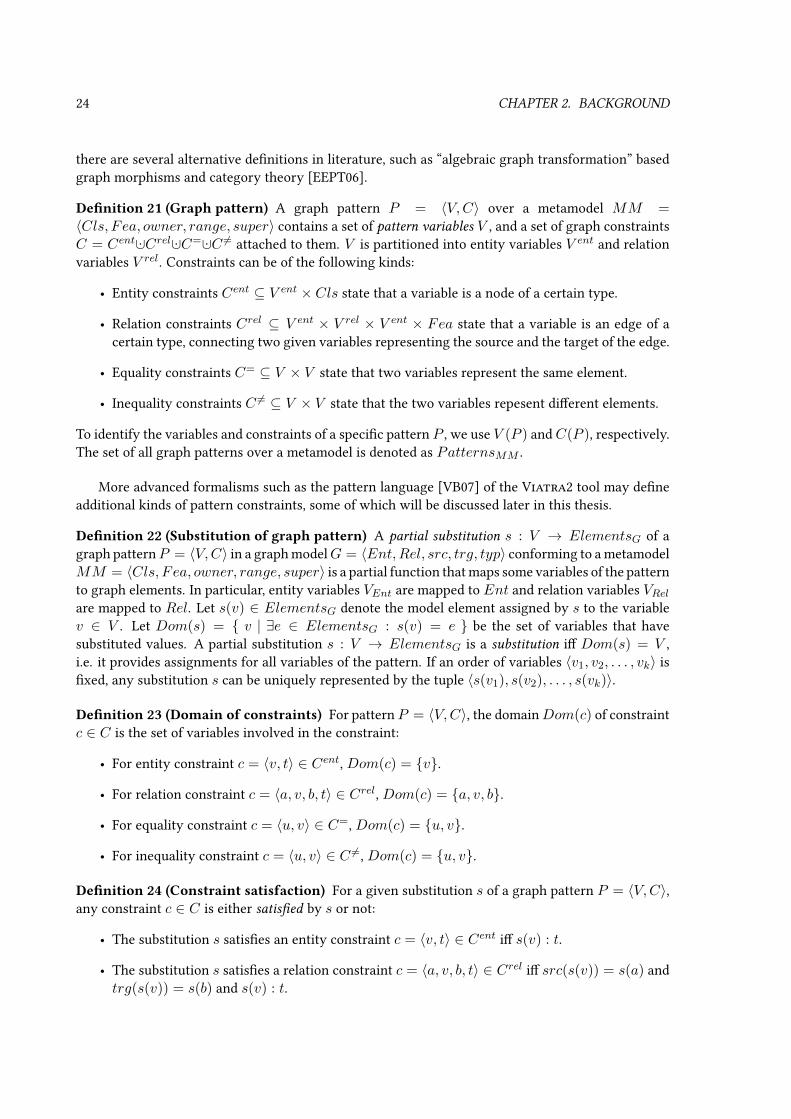
24 CHAPTER 2. BACKGROUND
there are several alternative denitions in literature, such as “algebraic graph transformation” basedgraph morphisms and category theory [EEPT06].
Denition 21 (Graph pattern) A graph pattern P = 〈V,C〉 over a metamodel MM =〈Cls, Fea, owner, range, super〉 contains a set of pattern variables V , and a set of graph constraintsC = Cent ·∪Crel ·∪C= ·∪C 6= attached to them. V is partitioned into entity variables V ent and relationvariables V rel. Constraints can be of the following kinds:
• Entity constraints Cent ⊆ V ent × Cls state that a variable is a node of a certain type.
• Relation constraints Crel ⊆ V ent × V rel × V ent × Fea state that a variable is an edge of acertain type, connecting two given variables representing the source and the target of the edge.
• Equality constraints C= ⊆ V × V state that two variables represent the same element.
• Inequality constraints C 6= ⊆ V × V state that the two variables repesent dierent elements.
To identify the variables and constraints of a specic pattern P , we use V (P ) andC(P ), respectively.The set of all graph patterns over a metamodel is denoted as PatternsMM .
More advanced formalisms such as the pattern language [VB07] of the Viatra2 tool may deneadditional kinds of pattern constraints, some of which will be discussed later in this thesis.
Denition 22 (Substitution of graph pattern) A partial substitution s : V → ElementsG of agraph patternP = 〈V,C〉 in a graph modelG = 〈Ent,Rel, src, trg, typ〉 conforming to a metamodelMM = 〈Cls, Fea, owner, range, super〉 is a partial function that maps some variables of the patternto graph elements. In particular, entity variables VEnt are mapped to Ent and relation variables VRelare mapped to Rel. Let s(v) ∈ ElementsG denote the model element assigned by s to the variablev ∈ V . Let Dom(s) = v | ∃e ∈ ElementsG : s(v) = e be the set of variables that havesubstituted values. A partial substitution s : V → ElementsG is a substitution i Dom(s) = V ,i.e. it provides assignments for all variables of the pattern. If an order of variables 〈v1, v2, . . . , vk〉 isxed, any substitution s can be uniquely represented by the tuple 〈s(v1), s(v2), . . . , s(vk)〉.
Denition 23 (Domain of constraints) For pattern P = 〈V,C〉, the domainDom(c) of constraintc ∈ C is the set of variables involved in the constraint:
• For entity constraint c = 〈v, t〉 ∈ Cent, Dom(c) = v.
• For relation constraint c = 〈a, v, b, t〉 ∈ Crel, Dom(c) = a, v, b.
• For equality constraint c = 〈u, v〉 ∈ C=, Dom(c) = u, v.
• For inequality constraint c = 〈u, v〉 ∈ C 6=, Dom(c) = u, v.
Denition 24 (Constraint satisfaction) For a given substitution s of a graph pattern P = 〈V,C〉,any constraint c ∈ C is either satised by s or not:
• The substitution s satises an entity constraint c = 〈v, t〉 ∈ Cent i s(v) : t.
• The substitution s satises a relation constraint c = 〈a, v, b, t〉 ∈ Crel i src(s(v)) = s(a) andtrg(s(v)) = s(b) and s(v) : t.

2.2. GRAPH PATTERNS AND GRAPH TRANSFORMATION 25
VariablesP V ent
M V rel
K V ent
Constraintsc1 Cent 〈P, P lace〉c2 Cent 〈K,Token〉c3 Crel 〈P,M,K,Marking〉
Figure 2.7: A sample graph pattern capturing marked places
• The substitution s satises an equality constraint c = 〈u, v〉 ∈ C= i s(u) = s(v).
• The substitution s satises an inequality constraint c = 〈u, v〉 ∈ C 6= i s(u) 6= s(v).
Satisfaction can be dened in the same way if s is a partial substitution with Dom(s) ⊇ Dom(c).
Denition 25 (Graph pattern match) A match m : V → ElementsG is a substitution of thevariables V of P that satises all constraints c ∈ C of P . This will be denoted as G,m |= P . Thematch set MatchSetPG = m | G,m |= P is the set of all matches of a pattern in a graph model.
Remark: from now on, a single metamodel MM = 〈Cls, Fea, owner, range, super〉 is assumedwithout loss of generality, and the metamodel will often be omitted from further denitions.
Example 7 Our rst graph pattern marked is dened over the purely structural metamodel inExample 2 on page 11 and it identies places marked by tokens. The pattern is visualized in Figure 2.7.
The pattern variables are P , M and K . P and K are entity variables (depicted as boxes withinthe pattern), while M is a relation variable. Contraint c1 = 〈P, P lace〉 ∈ Cent claims that the imageof P should instantiate Place, and is depicted as the type name within the box of P , delimited bya colon. Similarly, c2 = 〈K,Token〉 ∈ Cent claims that the image of K should instantiate Token.Finally, the relation constraint c3 = 〈P,M,K,Marking〉 ∈ Crel states that the image of M shouldbe a relation that instantiates Marking, has the image of P as its source and the image of K as itstarget; it is visualised as an arrow from P toK , labeled by variable nameM and type nameMarkingdelimited by a colon.
Considering the graph model of Figure 2.3 and Example 3 on page 13, the pattern will have fourmatches altogether, as displayed by Figure 2.8. There is one match for each token: m(1) = P 7→p1,M 7→ m1,K 7→ k1, m(2) = P 7→ p1,M 7→ m2,K 7→ k2, m(3) = P 7→ p1,M 7→ m3,K 7→k3 and m(4) = P 7→ p3,M 7→ m4,K 7→ k4. If the order of variables is dened as 〈P,M,K〉 (asindicated in the header of Figure 2.7), matches can be denoted as 〈p1,m1, k1〉 and so on.
2.2.2 Complex graph patterns
2.2.2.1 Negative application conditions
A negative application condition (NAC) prescribes contextual conditions that, if satisable, invalidatea match of the pattern.
Denition 26 (Graph pattern with negative application condition) A pattern with NAC isPN = 〈P,N∗〉 where P = 〈V,C〉 is a (positive) graph pattern, and N∗ is a set of negative ap-plication conditions Ni = 〈Vi, Ci〉, each being a graph pattern, such that P ⊆ Ni (meaning thatV ⊆ Vi and C ⊆ Ci).

26 CHAPTER 2. BACKGROUND
MatchesP M K
m(1) p1 m1 k1
m(2) p1 m2 k2
m(3) p1 m3 k3
m(4) p3 m4 k4
Figure 2.8: Matches of the sample graph pattern marked
Commonly, only the subpattern Ni = Ni \ P is explicitly indicated and depicted in gures and codeextracts, which is dened as Ni = 〈Vi, Ci〉, where Ci = Ci \ C and Vi ⊆ Vi is the set of variablesinvolved in Ci.
Denition 27 (Match of graph pattern with NAC) A match m : V → ElementsG of PN =〈P,N∗〉 in graph model G is a match of the positive pattern G,m |= P , where there is no Ni ∈ N∗and match mi : Ni → G such that m ⊆ mi (meaning that mi(v) = m(v) for all v ∈ Dom(m) = Vvariables of P ).
Some pattern formalisms [Ren04a, VB07] even permit NACs to have NACs of their own. In fact,it is possible to formalize NACs as special pattern constraints Ni ∈ CNAC (see also Section 2.2.2.3),eliminating the need for a distinct concept of graph pattern with NACs. If there is no limit on thenumber of negations that can be nested within each other, graph patterns (without attribute con-straints) become expressively equivalent to rst order formulae over the predicates describing thegraph model [Ren04b].
Example 8 An unmarked place, i.e. a place without tokens, can be expressed with pattern un-marked, which is a graph pattern with NAC (see Figure 2.9). The positive pattern has a singlevariable P and a single entity constraint c1 = 〈P, P lace〉 ∈ Cent. There is a single negative appli-cation condition N1, which is the pattern marked dened before in Example 7. Overall, the patternwill match Place instances for which there are no corresponding Token instances with which theywould form a match of marked; in other word, tokenless places. In the graph model of Figure 2.1(a)and Example 3, the pattern will have a single match 〈p2〉.
Figure 2.10 shows the alternative, more concise notation where the negative application conditionis represented by a negative subpattern N1 instead of the full NAC pattern N1. N1 is essentially thedierence between the negative pattern and the positive one. Here the duplication of P and its entityconstraint is avoided.
2.2.2.2 Attributed graph patterns
Next the structure of graph patterns over attributed models is discussed.
Denition 28 (Graph pattern with attributes) In case of attributed metamodels, V ent of a graphpattern is further partitioned into structural and data entity variables (V ent
Str and V entDat); similarly V rel
is partitioned into three sets: structural relations V relStr between structural elements, value assignments

2.2. GRAPH PATTERNS AND GRAPH TRANSFORMATION 27
Positive variablesP V ent
Positive constraintsc1 Cent 〈P, P lace〉
N1 NAC variablesP V ent
M V rel
K V ent
N1 NAC constraintsc2 Cent 〈P, P lace〉c3 Cent 〈K,Token〉c4 Crel 〈P,M,K,Marking〉
Figure 2.9: Graph pattern with NAC capturing unmarked places
Figure 2.10: Graph pattern with NAC capturing unmarked places (concise version)
V relV al that connect structural elements to their attribute values, and data relations V rel
Dat between at-tribute values. Each of these partitions have a corresponding constraint type:
• Class constraints CentStr ⊆ V entStr × ClsStr express that a variable represents a structural entity
of a certain type;
• Datatype constraints CentDat ⊆ V entDat × ClsDat assert attribute types such as integer;
• Association constraints CrelStr ⊆ V entStr ×V rel
Str ×V entStr ×FeaStr express that a variable represent
a structural edge of a certain association type;
• Attribute assignment constraintsCrelV al ⊆ V entStr ×V rel
V al×V entDat×FeaV al mean that a certain value
assignment, associated with an attribute name, links a structural variable to a data variable asits attribute value;
• Data predicate constraints CrelDat ⊆ V entDat × V rel
Dat × V entDat × FeaDat express that the variable
represents a data relation instantiating a data predicate between given data entities; this es-sentially means an attribute constraint check among the variables corresponding to attributevalues.
The reader is referred to Table 2.1 on page 9 for an overview of these variables and constraints andtheir relationship to model element kinds.
It is possible for graph patterns to reference the data algebra Dat, since Dat is known a prioriunlike the structural instance models.This gives rise to a new kind of pattern constraint:
Denition 29 (Value literal pattern constraint) In an attributed graph pattern P = 〈V,C〉 overdata algebraDat, literal constraintsC lit ⊆ V ent×EntDat state that the given variable must represent

28 CHAPTER 2. BACKGROUND
VariablesP V ent
Str
M V relV al
Z V entDat
Constraintsc1 Cent
Str 〈P, P lace〉c2 Cent
Dat 〈Z, Integer〉c3 Crel
V al 〈P,M,Z,Marking〉c4 Clit 〈Z, 0〉
Figure 2.11: Attributed graph pattern capturing unmarked places
VariablesP V ent
Str
M V relV al
NZ V entDat
Z V entDat
Constraintsc1 Cent
Str 〈P, P lace〉c2 Cent
Dat 〈NZ, Integer〉c3 Crel
V al 〈P,M,NZ,Marking〉c4 Cent
Dat 〈Z, Integer〉c5 Clit 〈Z, 0〉c6 C 6= 〈Z,NZ〉
Figure 2.12: Attributed graph pattern capturing marked places
an a priori known constant data value. A substitution s satises a literal constraint c = 〈v, x〉 ∈ C liti s(v) = x. Dom(c) = v.
Value literal constraints allow a pattern to capture data entities in variables; further structural ordata variables may be connected to these variables via constraints.
Example 9 Over the alternative attributed metamodel of Example 4 on page 17, the attributedversion of graph pattern unmarked (see Figure 2.11) can be dened as follows: the three vari-ables are structural entity variable P ∈ V ent
Str (depicted as a solid box), value assignment vari-able M ∈ V rel
V al (depicted as a dashed arrow), and data entity variable Z ∈ V entDat (depicted as a
dashed box). The type constraints are c1 = 〈P, P lace〉 ∈ CentStr , c2 = 〈Z, Integer〉 ∈ CentDat andc3 = 〈P,M,Z,Marking〉 ∈ CrelV al. So far, these constraint ascertain that P is a place having Ztokens. Finally the literal constraint c4 = 〈Z, 0〉 ∈ C lit (depicted as a white oval within the box ofZ) identies Z as the data value 0. Overall, the pattern matches a place p i G |= p.Marking = 0,i.e. it has no tokens. Now it is evident how this pattern is functionally equivalent to the version ofunmarked in Example 8 on page 26, that was specied in context of a pure structural metamodel.
Example 10 The related marked pattern is shown in Figure 2.12. There are now two variableswith Integer datatype constraints: Z and NZ . NZ is the marking of P , while Z is identied with0 as before. An inequality constraint c6 = 〈Z,NZ〉 ∈ C 6= (depicted as a oating oval connected toboth variables) states that Z and NZ should be mapped to dierent elements. (A possible alternativewould include a data relation variable and a data relation constraint of type> fromNZ toZ instead ofthe inequality constraint; the eect would be the same since markings in reachable states are alwaysnon-negative.) Overall, the pattern identies places with non-zero (respectively positive) marking;and is therefore functionally equivalent to the version of marked in Example 7.

2.2. GRAPH PATTERNS AND GRAPH TRANSFORMATION 29
There is a nal issue that requires attention. Including Dat in the graph model raises new kindsof problems for pattern matching, as the entirety of the innite data algebra Dat cannot be mani-fested (i.e. enumerated, stored in memory). More precisely, some patterns cannot be matched by anite matcher; a trivial example would be the pattern P = 〈V,C〉 with single variable v ∈ V ent
Dat andconstraint c ∈ CentDat where c = 〈v,Number〉; a pattern matcher would have to enumerate all num-bers to compute the match set of the pattern, which is impossible to perform with nite resources. Amore complex example would be the marked pattern in Example 10 if we omitted the value literalconstraint on Z : the matcher would have to enumerate all integer values for variable Z that are dif-ferent from NZ . Naturally there are other kinds of mathematical reasoning that could be performedto obtain a nite characterization of the match set of such a pattern; however, graph pattern matchersare not aimed to be equation solvers. To avoid such problems, we have to identify those attributedpatterns that can be matched by a pattern matcher without requiring an equation solver or othermathematical reasoning; for this purpose we distinguish assignable variables.
Denition 30 (Assignable entity variable) Structural entity variables are always assignable. Adata entity variable is assignable i
• it has an associated value literal pattern constraint, therefore its value is known; or
• appears as the target variable of a value assignment constraint, thus it is available as an attributevalue of a model element from the structural model; or
• it is determined by a data predicate that is enumerable (see Denition 18) by assignable vari-ables, thus it can be computed from other variables that are already substituted. Here functionalor otherwise computable relationships (e.g. division) are asserted by appropriate data predicateconstraints (using either the hypergraph or the auxiliary node representation).
Denition 31 (Matchable attributed graph pattern) A graph pattern is matchable i each entityvariable v ∈ V ent is assignable, and any NACs (as well as called patterns, to be introduced in Sec-tion 2.2.2.3) are also matchable patterns.
The current thesis focuses on graph pattern matching, as opposed to integer-domain constraintsolving, (in)equation solving, etc., therefore all graph patterns will be assumed to be matchable.
2.2.2.3 Pattern composition
The next advanced feature will help us build more complex patterns. Composing (calling) previouslydened graph patterns as a kind of hyperedge pattern constraint [HVV07] can improve the concise-ness of the language.
Denition 32 (Pattern composition constraint) In a composite graph pattern P = 〈V,C〉, apattern composition constraint for a called pattern Pcalled is ccall = 〈Pcalled, composer〉, wherecomposer : V → Vcalled is a (partial) mapping from the variables V of the composite pattern tovariables Vcalled = V (Pcalled) of the called pattern. The composition constraint states that matchesof the composite pattern must be aligned with a match of the called pattern. A substitution s sat-ises a pattern composition constraint c = 〈Pcalled, composer〉 ∈ Ccall i incidents 6= ∅, whereincidents = m | G,m |= Pcalled ∧ ∀v∈Dom(composer)s(v) = m(composer(v)) . Dom(c) =Dom(composer).

30 CHAPTER 2. BACKGROUND
VariablesP V ent
I V rel
T V ent
Constraintsc1 Cent 〈T, Transition〉c2 Crel 〈P, I, T, InArc〉c3 Ccall 〈unmarked, composer1〉
Figure 2.13: Composite graph pattern capturing transitions disabled by unmarked incoming places
Note that NACs can alternatively be dened as a pattern constraint that is analogous to patterncomposition, by simply negating the truth value of the satisfaction condition in the previous deni-tion: ci ∈ CNAC is satised by s i 6 ∃m : G,m |= Ni ∧ . . .. Negative composition is sometimes usedas an alternative name for NACs.
Example 11 The conciseness of pattern composition is demonstrated by pattern unmarkedDis-ables (see Figure 2.13) that identies transitions that cannot be red because an unmarked place isconnected by an InArc. The unmarked pattern can clearly be reused here. Pattern unmarked-Disables uses variablesP , I , andT , with respectively a relation constraint and an entity constraintfor the latter two. The composition constraint c3 = 〈unmarked, composer1〉 ∈ Ccall calls the un-marked pattern, with composer1 (not detailed in the gure) mapping the variable P to the variablein pattern unmarked with the same name; in essence it states that P is an unmarked Place. Inthe graph model of Figure 2.1(a) on page 10, the composite pattern will have no matches; however,〈p3, i3, t2〉 and 〈p3, i2, t1〉 would become valid matches if t2 was red (Figure 2.1(c)).
Discussion on cyclic and acyclic composition. Let us now assume that pattern compositionsare acyclic. In this case it can be shown that pattern composition is mainly a syntactic sugar. Foracyclic composition, we can always (recursively) embed the variables and constraints of the calledpattern into the composite pattern by applying composer−1 as “variable renaming”2. This process,called pattern attening [HVV07], transforms a composite graph pattern and its called patterns intoa single pattern with equivalent semantics but without composition. It immediately follows that theexpressiveness of the pattern language is not aected by the composition language element, as longas recursive pattern calls are disallowed.
With strictly acyclic composition, expressiveness is equivalent to rst-order logic [Ren04b]. Withrecursion, however, some higher-order properties such as transitive closure become expressible.
Pattern composition will be assumed throughout the thesis to be acyclic, because there are noknown methods that can eciently and incrementally evaluate such recursive queries. There arenon-incremental techniques such as magic sets [BMSU86], with application for graph pattern match-ing [VHV08, HJG08], capable of dealing with recursive pattern composition; supported, for instance,by Viatra2.
Unfortunately, recursion signicantly increases the diculty of incremental maintenance (seeSection 3.2.3). Simpler incremental techniques designed for the non-recursive case are prone to fail,due to the fact that a xpoint operator would be required to unambiguously dene the match set ofrecursive queries in rst-order logic (see also Section 4.2.3, page 84). Recursive patterns thereforeremain future work, and will not be addresed in general by this thesis. However, in many practi-
2Variables in Vcalled \ Im(composer) must in this case be mapped to variables that are not used elsewhere.

2.2. GRAPH PATTERNS AND GRAPH TRANSFORMATION 31
cal cases, the typical purpose of recursion is to express some sort of transitive closure, for which aspecialized solution is provided in Section 4.2.
2.2.2.4 Aggregate constraints
Aggregation is a useful capability that has its roots in pattern composition and lets the pattern matcheraggregate the matches of a called pattern into a single value that will be used in a match of theaggregating pattern. Example use cases include counting matches, summing up variables, taking themaximum, etc.
Denition 33 (Match aggregate constraint) In a aggregating graph pattern P =〈V,C〉, a match aggregate constraint for a called pattern Pcalled is caggregate =〈Pcalled, composer, aggregator, vresult〉, where
• composer : V → Vcalled is a (partial) mapping from the variables V of the aggregating patternto variables Vcalled = V (Pcalled) of the called pattern,
• aggregator = 〈mapper, reducer, unmapper〉 describes how matches should be aggregatedusing the following elements,
• reducer = 〈A,⊗〉 is an Abelian group that will reduce (aggregate) the result,
• mapper is a function that maps matches of Pcalled to the reducer group A,
• unmapper is a function that maps an element of the reducer group A to EntDat ·∪⊥, where⊥ 6∈ U is a special value indicating that aggregation is not possible,
• vresult is a data entity variable for storing the result, with vresult 6∈ Dom(composer).
The aggregate constraint states that in matches of the aggregating pattern, the result vari-able must be the aggregate of all incident matches of the called pattern, by mapping saidmatches rst by mapper, then taking their product in reducer to reduce them to a sin-gle value, and then applying unmapper. A substitution s satises a match aggregate con-straint caggregate = 〈Pcalled, composer, aggregator, vresult〉 ∈ Caggregate with aggregator =〈mapper, reducer, unmapper〉 i m(vresult) = unmapper(
∏⊗m∈incidentsmapper(m)), where
incidents = m | G,m |= Pcalled ∧ ∀v∈Dom(composer)s(v) = m(composer(v)) . The ⊗-product used in this condition is well-dened since ⊗ is associative and commutative. Dom(c) =Dom(composer) ·∪vresult.
Note that it follows from the denition that if unmappermaps the⊗-product to⊥, then the constraintcannot be satised by any substitution s, since s(vresult) ∈ U is required, so the aggregating patternwill not match.
In analogy with data relation constraints, an aggregate constraint is not always enumerable, butfunctionally determined by variables Dom(composer). In the special case os ⊥ discussed above, theset of enumerated variable substitutions would be empty.
Example 12 A common use case for the aggregate constraint is counting the matches of thecalled pattern that are incident on variables of the aggregating pattern. This is achieved byaggregatorcount = 〈mappercount, reducercount, unmappercount〉 where reducercount = 〈Z,+〉 isthe group of integers w.r.t. addition, mappercount = m 7→ 1 maps all matches to the integer value 1,

32 CHAPTER 2. BACKGROUND
and unmappercount is the identity (where Z ⊆ EntDat is assumed). This counting aggregator worksby taking the number 1 for each incident match of the called pattern; then taking their “product”along the group operation, which is addition in this case, yielding the number of incident matchesthat were considered; and nally storing this result value in the result variable.
The pattern constraint-based formalization of NACs, mentioned earlier, can be thought of as aspecial case of counting aggregate, where the result variable (i.e. the number of incident matches ofthe called pattern) is constrained to be the value literal 0.
Example 13 A further common example is summing up a numerical data value over matchesof a called pattern that exposes this number as a parameter variable v. aggregatorsum(v) =〈mappersum(v), reducersum(v), unmappersum(v)〉 where reducersum(v) = 〈R,+〉 is the group of(real) numbers w.r.t. addition, mappersum(v) = m 7→ m(v) maps all incident matches to the valuethey assign to their parameter v, and unmappersum(v) is once again the identity (where R ⊆ EntDatis assumed).
Example 14 To show an example where unmapper is not the identity function, consider aver-aging the value of a parameter v of the called pattern over incident matches of the called pat-tern. aggregatoravg(v) = 〈mapperavg(v), reduceravg(v), unmapperavg(v)〉 where reduceravg(v) =〈R,+〉 × 〈Z,+〉 is the Cartesian product group of (real) numbers w.r.t. addition and integers w.r.taddition, mapperavg(v) = m 7→ 〈m(v), 1〉, and nally the actual averaging: unmapperavg(v) =
〈sum, count〉 7→sum/count if count 6= 0⊥ if count = 0
(where R ⊆ EntDat is assumed).
2.2.2.5 Disjunction
Finally, disjunctive graph patterns allow multiple ways to be satised.
Denition 34 (Graph pattern with disjunction) A disjunctive pattern is PD = 〈V, PN∗〉 whereV is the set of variables of the disjunctive pattern, and PN∗ is a set of graph patterns (called pattern
bodies) PNj = 〈Pj , N∗j 〉, having (positive) variables Vj = V (PNj) such that V ⊆ Vj .
To distinguish from the variables of the pattern bodies, V is also called parameter variables or patternheader variables.
Denition 35 (Match of graph pattern with disjunction) A match m : V → Elements(G) ofPD = 〈V, PN∗〉 in graph model G is a substitution m : V → Elements(G) that can be extended toa match of at least one of the pattern bodies: ∃PNj ∈ PN∗,mj ⊇ m : G,mj |= PNj .
From now on, disjunctive, attributed patterns with NACs are allowed whenever graph patternsare used, unless otherwise noted.
Example 15 The disjunctive pattern disables (see Figure 2.14) identies a transition disabledby a place. There can be two reasons for this: either the place is unmarked and connected by anInArc, or is marked but connected by an inhibitor arc. These two cases (the rst of which is alreadyintroduced as unmarkedDisables) form the two pattern bodies. The disjunctive pattern exposesvariables P and T , found in both bodies. Body-specic variables like H do not have a correspondingvariable in the other body, therefore they cannot be parameters. In the graph model of Figure 2.1(a),the disjunctive pattern will have no matches; however, 〈p2, g1, t1〉, 〈p3, i3, t2〉 and 〈p3, i2, t1〉 wouldbecome valid matches if t2 was red.

2.2. GRAPH PATTERNS AND GRAPH TRANSFORMATION 33
Parameter variablesP V ent
T V ent
Body1 variablesP V ent
I V rel
T V ent
Body1 constraintsc1 Cent 〈T, Transition〉c2 Crel 〈P, I, T, InArc〉c3 Ccall 〈unmarked, composer1〉
Body2 variablesP V ent
H V rel
T V ent
Body2 constraintsc4 Cent 〈T, Transition〉c5 Crel 〈P,H, T, InhibitorArc〉c6 Ccall 〈marked, composer2〉
Figure 2.14: Disjunctive graph pattern capturing disabled transitions
2.2.3 Graph pattern matching
For a software exerting rule-based behavior specied by graph transformation rules, as well as anyother application based on graph patterns, a graph pattern matcher (PM) is a component of key im-portance. Given a graph model conforming to a metamodel and a set of graph patterns over the samemetamodel, the role of the pattern matcher is to compute the set of matches of each graph pattern. Inother words, it exposes the following query operation:
Denition 36 (Graph pattern matching) For graph pattern P ∈ PatternsMM over a metamodelMM , graph pattern matching Match(P ) is a query operation that, when executed on model G ∈GraphsMM , yields the output G.Match(P ).out = MatchSetPG consisting of all matches of P in G.
As query results were specied to be sets of tuples, this denition assumes the tuple-based represen-tation of matches at an arbitrary but xed ordering of variables.
In some cases, only a specic subset of matches are of interest, that are incident on a given setof elements. Therefore (similarly to the elementary query operations dened in Section 2.1.5) an ad-vanced pattern matcher may oer query operations Match(P, Input) where some of the parametervariables V of the graph pattern P may be specied as a concrete graph element in model G usinga partial substitution Input : V → G. This generalization is called seeded pattern matching, and theresulting ltered match set ResultSetPG(Input) = m | m ∈ MatchSetPG ∧ ∀v ∈ Dom(Input) :m(v) = Input(v) is its result set (whereas the match set MatchSetPG ⊇ ResultSetPG(Input) willalways refer to all matches of a pattern).
Performance is a serious issue in any system that oers graph pattern matching. It is easy tosee that even for nite graph models, a graph pattern with only entity constraints can have a matchset size up to |Ent||V | that is polynomial in model size and exponential in pattern size; this is alower bound for the time cost of pattern matching. Even if additional constraints (such as Crel)reduce the match set size, graph pattern matching is still NP-complete [Roz97] in the size of thegraph pattern. However, in our use cases, graph patterns can be considered xed, and only the graphmodel is considered as “input”; matching a given pattern on models is only polynomial in modelsize. While in software engineering practice graph patterns (and thus the order of these polynomials)rarely grow very large, and the constraints are rarely permissive enough to manifest the worst-case

34 CHAPTER 2. BACKGROUND
Figure 2.15: Graph pattern identifying reable transitions
cost, it is a general practical observation that pattern matching is still the most resource-consumingphase of model transformation.
The most common way of performing graph pattern matching are local search (LS) pattern match-ing techniques that traverse a search tree of partial substitutions according to a search plan [VHV08].An alternative approach will be introduced in Chapter 3.
Example 16 Take for example the pattern fireable (see Figure 2.15) that identies the reabletransitions of the Petri-net (i.e. those that are not disabled by any input place), relying on the patterndisables dened earlier in Example 15. IfG1 is the graph model of Figure 2.1(a) and Example 3, theapplication of the pattern matching operation would yield G1.Match(fireable).out = 〈t1〉, 〈t2〉,as both transitions are enabled. If Fire(t) is the manipulation operation of Example 6 on page 21 thatres the given transition (precondition: t is in the match set of fireable), and G1.F ire(t2) leadsto the new state G′1, then G′1.Match(fireable).out = ∅ as both transitions will become disabled.
2.2.4 Graph transformation rules
The mathematical formalism of Graph Transformation (GT) [EEKR99] provides a high-level rule andpattern-based manipulation language for graph models. This formalism is often preferred for itspowerful behavior analysis techniques such as critical pairs [Plu93, LEO06]; and can be used forvarious purposes, including to specify model transformations (see e.g. [Var04], whose formalizationwill be loosely followed here).
Denition 37 (Graph transformation rule) A graph transformation rule GTR = 〈LHS,RHS〉is specied by two graph patterns: a precondition (or left-hand side) pattern (with NAC)LHS deningthe applicability of the rule, and a postcondition (or right-hand side) positive pattern RHS whichdeclaratively species the result model after rule application. The variable sets of LHS and RHSare allowed to intersect3.
When the rule is applied on a match of the LHS, elements that are present only in (the imageof) the LHS are deleted, elements that are present only in the RHS are created, and other modelelements remain unchanged. Without bothering with precise and fundamental formalization (whichis available e.g. in [EEPT06]), the following denition expresses the essence of GT rule application.
Denition 38 (Application of graph transformation rule) The application of graph transforma-tion rule GTR = 〈LHS,RHS〉 on a match m : Elements(G) → ElementsG in a graph
3or, alternatively, the variable sets are disjoint, but connected through a mapping

2.2. GRAPH PATTERNS AND GRAPH TRANSFORMATION 35
model G is the model manipulation operation ApplyRule(GTR,m), dened here by its eectG.ApplyRule(GTR,m).δ:
• Deletion. For each v ∈ VLHS \ VRHS , the model element m(v) is deleted.
• Insertion. For each v ∈ VRHS \ VLHS , a new model element is created and assigned to v ina way that RHS becomes satised (i.e. the new element is created in a type-conforming andstructurally consistent way).
If LHS has no matches in G, then GTR is not applicable.
Semantic variations. There are some semantic variation points in dierent GT formalisms. Forexample, in valid graph models, the source and target of a relation must be an entity of the graph;therefore a GT rule that deletes an entity must either also delete incident (“dangling edge”) relationsas a side eect, or impose a precondition that no such dangling relations exist.
A further issue is a potential conict between deletion operations and insertion/preserving, whichmay arise if some pattern variables are mapped to the same model elements in a match. One of thesolutions is to assign some kind of semantics to such rule execution, e.g. deletion overrides preser-vation. An alternative one is to impose the precondition that the match must be “injective” (dierentvariables must be mapped to dierent elements). As a compromise between the two approaches, it ispossible to allow mapping variables to the same value as long as certain identication conditions aremet, which essentially state that the postcondition must impose compatible actions on them.
There are also variation which allow more rened change operations, such as redirecting existingrelations, or changing the types of existing elements.
For the sake of determinism, RHS is typically required to be non-disjunctive. Some patternconstraints that cannot be directly enforced by the model manipulation operations creating the imageof the RHS, such as inequality or NACs, may either be disallowed in the RHS, or interpreted as apostcondition check.
Note that this core formalism of GT rules only denes which rules are applicable (and what hap-pens if they are applied); it does not dene e.g. how to react to changes of the model. It is up toimplementations and extended formalisms to specify whether any GT rules should be applied at agiven time, and which rule to apply on which match if there are several options.
Example 17 The graph transformation rule removeToken (see Figure 2.16) over the purely struc-tural metamodel of Example 2 is applicable on a marked place (hence reusing as LHS the markedpattern dened in Example 7), the eect of application is the removal of one token from that place.The rule behaves so because variables M and K are only present in the LHS, therefore the token andthe marking relation will be deleted. No new elements will be created, since Vplace \ Vmarked = ∅.For the graph instance model G1 of Example 3, m(2) is established in Example 7 as one of thematches of the LHS pattern marked, and the eect of applying the rule on this match would beG1.ApplyRule(removeToken,m(2)).δ = 〈−(k2 :: Token), −(p1
(m2::Marking)−−−−−−−−−→ k2), ∅, ∅〉.The attributed version of the rule removeToken, in context of the attributed metamodel of
Example 4, is shown in Figure 2.17. The LHS matches a marked place P and nds its Marking valueassignment MX , which points to non-zero Integer X , which is - as expressed by a Successor datarelation - one more than Integer Y . The RHS pattern is similar to the LHS, but containsMY insteadof MX , which points to Y instead of X . Since VLHS \ VRHS = MX and VRHS \ VLHS =MY , applying the rule will remove the MX value assignment, and insert MY in its place, ineect decreasing the marking of P by one.

36 CHAPTER 2. BACKGROUND
LHS variablesP V ent
M V rel
K V ent
LHS constraintsc1 Cent 〈P, P lace〉c2 Cent 〈K,Token〉c3 Crel 〈P,M,K,Marking〉
RHS variablesP V ent
RHS constraintsc4 Cent 〈P, P lace〉
Figure 2.16: GT rule for removing a token
Figure 2.17: GT rule for removing a token (attributed version)

Chapter
3
Incremental Graph Paern Matching
3.1 Incremental graph pattern matching basics
Incremental pattern matching is an approach that has been shown by numerous studies over the years(e.g. [VV04, VVS06, GJR10][16]) to exert favorable performance characteristics in many practicaluse cases. The core idea is to improve the pattern matching phase by storing (caching) precomputedresults and maintaining them as the model changes.
In the following sections, I introduce a formal treatment of incrementality and related concepts inthe context of graph pattern pattern matching. The language introduced here will be used to reviewvarious incremental approaches and describe the proposed solution.
3.1.1 Stateful pattern matching
The following paragraphs introduce a formalization of pattern matchers that take advantage of incre-mentally maintained cache storages. The previously introduced formal description has to be extendedby the notion of the stateful pattern matcher PM . A stateful pattern matcher has an internal state s,with s ∈ S for a set S of valid states (state space). The matcher internal state can preserve results ofcalculations between pattern matcher invocations; it may be responsible e.g. for storing the matchsets of patterns. This means that the conguration of the evolving model can only be described byboth the graph model and the matcher internal state.
Denition 39 (Conguration of evolving graph with stateful pattern matching) In case ofstateful pattern matching with state space S on a graph model over metamodel MM , the currentconguration of the evolving graph is a pair 〈G, s〉 ∈ GraphsSMM that consists of the current graphmodel G and the matcher internal state s, where the set of valid congurations GraphsSMM ⊂GraphsMM × S is characteristic to the stateful pattern matcher.
Denition 40 (Operations with stateful pattern matching) A model access operation Op incase of stateful pattern matching is a partial function Op : GraphsSMM → (GraphsSMM × OutOp)that maps a conguration 〈G, s〉 to the tuple 〈G′, s′, out〉 with resulting conguration 〈G′, s′〉 ∈GraphsSMM and output out ∈ OutOp. The application of the operation on conguration 〈G, s〉 is de-noted as 〈G, s〉.Op, while 〈G, s〉.Op.r denotes the resulting conguration and 〈G, s〉.Op.out denotesthe yielded output. All operations conforming to Denition 16, are also considered compatible withthe updated denition, with 〈G, s〉.Op = 〈G.Op.r, s,G.Op.out〉.
37

38 CHAPTER 3. INCREMENTAL GRAPH PATTERN MATCHING
The last statement essentially means that all queries and model manipulation operations dened sofar are also able to act on the composite conguration, but they do not directly use or change theinternal storage of the stateful matcher (though manipulative operations will result in subsequentmaintenance of the internal state).
Now the stateful pattern matcher can be dened as follows. Since in a stateful context, patternmatching is a model access operation that is applied on conguration 〈G, s〉, the stateful matcher canrely on its internal state s when evaluating queries, in addition to the graph model G. For example,the match operation could be trivial if the match set is stored in its entirety within s. A statefulpattern matcher may even update its internal state after a query operation, e.g. to store new resultscomputed during query evaluation for later reuse. Finally, a stateful pattern matcher additionallyprovides a function that updates its state s to s′ as a reaction to a model manipulation operationcausing change δ in the graph model G; the dierence between s′ and s is expected to reect theeects of δ.
Denition 41 (Stateful pattern matcher) A stateful matcher is a structure PM =〈S, s0,Match,Maintain〉, where S is the set of valid internal states, s0 ∈ S is the matcher null state,Match : PatternsMM → GraphsSMM → (GraphsSMM ×OutMatch) is a query operation parame-terized by a pattern, and Maintain : DeltasMM → GraphsSMM → (GraphsSMM )→ OutMaintain
is an operation parameterized by a graph delta:
• For a given pattern P ∈ PatternsMM , the pattern matching query Match(P ) computes theresult 〈G, s〉.Match(P ).out = MatchSetPG of this pattern matching operation; it also com-putes a new internal state s′ ∈ S for the matcher as 〈G, s〉.Match(P ).r = 〈G, s′〉, with thegraph model itself unchanged (hence it is a query).
• For a given δ ∈ DeltasMM , the matcher maintenance routine Maintain(δ) yieldsno useful output (OutMaintain contains a single element), but results in a conguration〈G, s〉.Maintain(δ).r = 〈G′, s′〉 composed of a new internal state s′ ∈ S of the PM validfor the new graph model G′ = G+ δ.
• The null state s0 is the default internal state associated with an empty graph model, so that〈∅, s0〉 is considered a valid conguration.
For an evolving graph model, the net eect of manipulation operations between two PM querieswill be fed into Maintain to update the matcher internal state, as shown in the next denition.
Denition 42 (Execution trace of evolving graph with stateful pattern matcher) The execu-tion trace of an evolving graph is the sequence 〈G1, s1〉
step1−−−→ 〈G2, s2〉step2−−−→ 〈G3, s3〉, . . . , 〈Gn, sn〉
of congurations and trace steps inbetween. Each conguration 〈Gi, si〉 ∈ GraphsSMM is a validconguration with respect to the same metamodel MM and same matcher state space S. Each tracestep stepi is associated with a transaction operationOpi, which is either a pattern matching operationMatch(Pi), or a model manipulation operation Modi. Each subsequent conguration 〈Gi, si〉 alongthe trace is obtained from the previous by applying the transaction operation and if needed, maintain-ing the pattern matcher internal state to reect the changes; i.e. 〈Gi, si〉.Match(Pi).r = 〈Gi+1, si+1〉with Gi+1 = Gi in case of a PM query; and 〈Gi, si〉.Maintain(〈Gi, si〉.Modi.δ).r = 〈Gi+1, si+1〉in case of a manipulative transaction.
As a special case of applying Maintain, the stateful matcher can be initialized on any graphmodel G as 〈G, s〉 = 〈∅, s0〉.Maintain(G−∅).r. This formula means that the current conguration
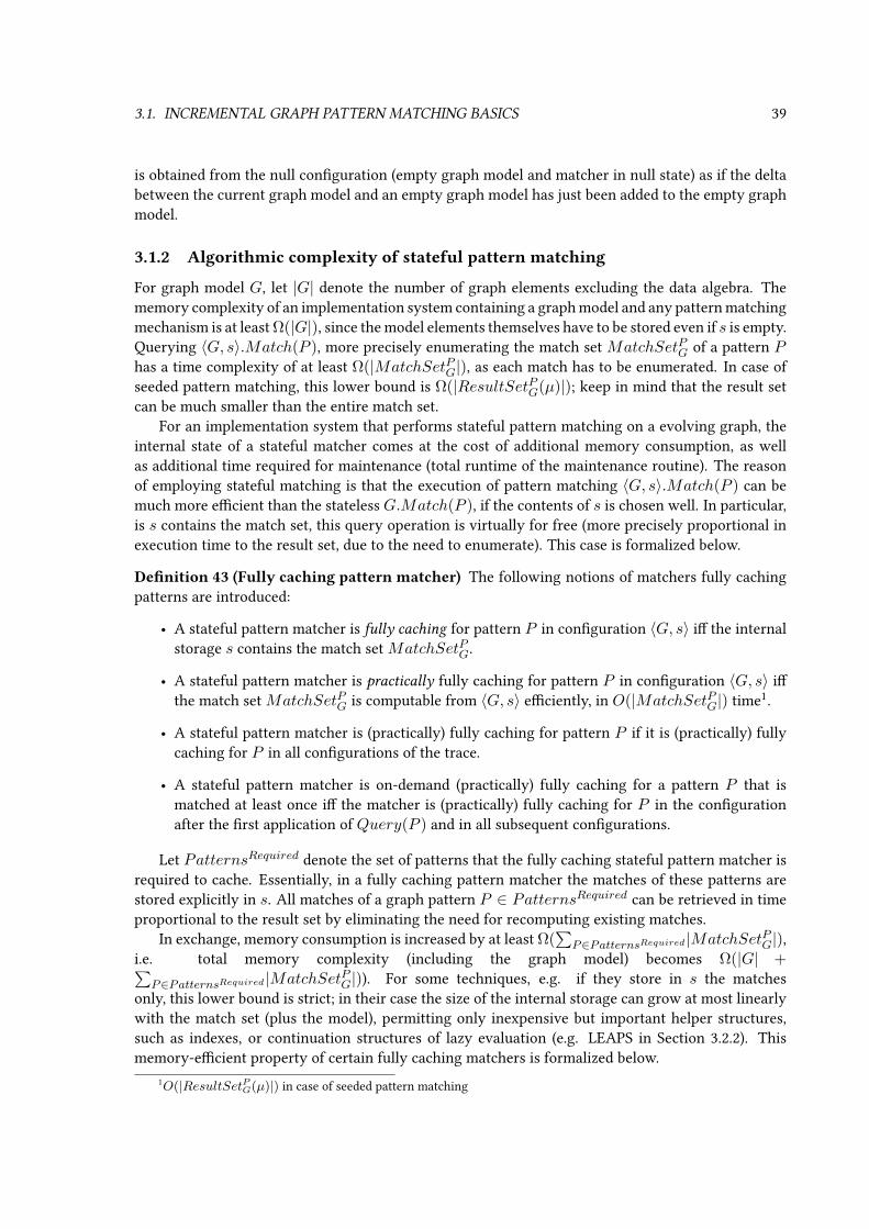
3.1. INCREMENTAL GRAPH PATTERN MATCHING BASICS 39
is obtained from the null conguration (empty graph model and matcher in null state) as if the deltabetween the current graph model and an empty graph model has just been added to the empty graphmodel.
3.1.2 Algorithmic complexity of stateful pattern matching
For graph model G, let |G| denote the number of graph elements excluding the data algebra. Thememory complexity of an implementation system containing a graph model and any pattern matchingmechanism is at least Ω(|G|), since the model elements themselves have to be stored even if s is empty.Querying 〈G, s〉.Match(P ), more precisely enumerating the match set MatchSetPG of a pattern Phas a time complexity of at least Ω(|MatchSetPG|), as each match has to be enumerated. In case ofseeded pattern matching, this lower bound is Ω(|ResultSetPG(µ)|); keep in mind that the result setcan be much smaller than the entire match set.
For an implementation system that performs stateful pattern matching on a evolving graph, theinternal state of a stateful matcher comes at the cost of additional memory consumption, as wellas additional time required for maintenance (total runtime of the maintenance routine). The reasonof employing stateful matching is that the execution of pattern matching 〈G, s〉.Match(P ) can bemuch more ecient than the stateless G.Match(P ), if the contents of s is chosen well. In particular,is s contains the match set, this query operation is virtually for free (more precisely proportional inexecution time to the result set, due to the need to enumerate). This case is formalized below.
Denition 43 (Fully caching pattern matcher) The following notions of matchers fully cachingpatterns are introduced:
• A stateful pattern matcher is fully caching for pattern P in conguration 〈G, s〉 i the internalstorage s contains the match set MatchSetPG.
• A stateful pattern matcher is practically fully caching for pattern P in conguration 〈G, s〉 ithe match set MatchSetPG is computable from 〈G, s〉 eciently, in O(|MatchSetPG|) time1.
• A stateful pattern matcher is (practically) fully caching for pattern P if it is (practically) fullycaching for P in all congurations of the trace.
• A stateful pattern matcher is on-demand (practically) fully caching for a pattern P that ismatched at least once i the matcher is (practically) fully caching for P in the congurationafter the rst application of Query(P ) and in all subsequent congurations.
Let PatternsRequired denote the set of patterns that the fully caching stateful pattern matcher isrequired to cache. Essentially, in a fully caching pattern matcher the matches of these patterns arestored explicitly in s. All matches of a graph pattern P ∈ PatternsRequired can be retrieved in timeproportional to the result set by eliminating the need for recomputing existing matches.
In exchange, memory consumption is increased by at least Ω(∑
P∈PatternsRequired |MatchSetPG|),i.e. total memory complexity (including the graph model) becomes Ω(|G| +∑
P∈PatternsRequired |MatchSetPG|)). For some techniques, e.g. if they store in s the matchesonly, this lower bound is strict; in their case the size of the internal storage can grow at most linearlywith the match set (plus the model), permitting only inexpensive but important helper structures,such as indexes, or continuation structures of lazy evaluation (e.g. LEAPS in Section 3.2.2). Thismemory-ecient property of certain fully caching matchers is formalized below.
1O(|ResultSetPG(µ)|) in case of seeded pattern matching
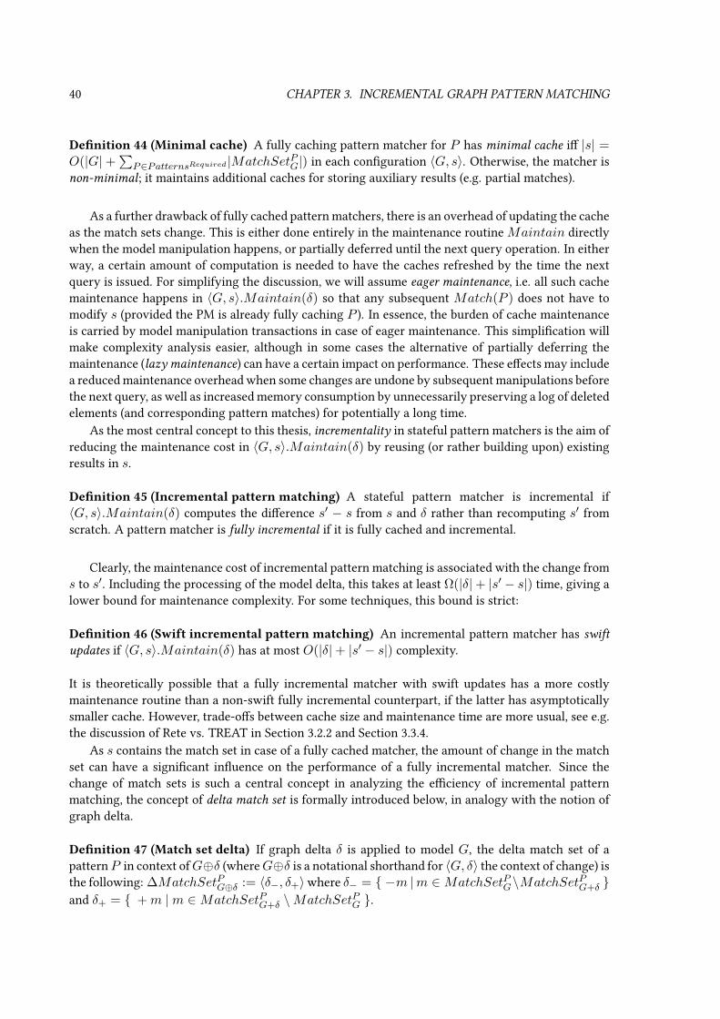
40 CHAPTER 3. INCREMENTAL GRAPH PATTERN MATCHING
Denition 44 (Minimal cache) A fully caching pattern matcher for P has minimal cache i |s| =O(|G| +
∑P∈PatternsRequired |MatchSetPG|) in each conguration 〈G, s〉. Otherwise, the matcher is
non-minimal; it maintains additional caches for storing auxiliary results (e.g. partial matches).
As a further drawback of fully cached pattern matchers, there is an overhead of updating the cacheas the match sets change. This is either done entirely in the maintenance routine Maintain directlywhen the model manipulation happens, or partially deferred until the next query operation. In eitherway, a certain amount of computation is needed to have the caches refreshed by the time the nextquery is issued. For simplifying the discussion, we will assume eager maintenance, i.e. all such cachemaintenance happens in 〈G, s〉.Maintain(δ) so that any subsequent Match(P ) does not have tomodify s (provided the PM is already fully caching P ). In essence, the burden of cache maintenanceis carried by model manipulation transactions in case of eager maintenance. This simplication willmake complexity analysis easier, although in some cases the alternative of partially deferring themaintenance (lazy maintenance) can have a certain impact on performance. These eects may includea reduced maintenance overhead when some changes are undone by subsequent manipulations beforethe next query, as well as increased memory consumption by unnecessarily preserving a log of deletedelements (and corresponding pattern matches) for potentially a long time.
As the most central concept to this thesis, incrementality in stateful pattern matchers is the aim ofreducing the maintenance cost in 〈G, s〉.Maintain(δ) by reusing (or rather building upon) existingresults in s.
Denition 45 (Incremental pattern matching) A stateful pattern matcher is incremental if〈G, s〉.Maintain(δ) computes the dierence s′ − s from s and δ rather than recomputing s′ fromscratch. A pattern matcher is fully incremental if it is fully cached and incremental.
Clearly, the maintenance cost of incremental pattern matching is associated with the change froms to s′. Including the processing of the model delta, this takes at least Ω(|δ|+ |s′ − s|) time, giving alower bound for maintenance complexity. For some techniques, this bound is strict:
Denition 46 (Swift incremental pattern matching) An incremental pattern matcher has swift
updates if 〈G, s〉.Maintain(δ) has at most O(|δ|+ |s′ − s|) complexity.
It is theoretically possible that a fully incremental matcher with swift updates has a more costlymaintenance routine than a non-swift fully incremental counterpart, if the latter has asymptoticallysmaller cache. However, trade-os between cache size and maintenance time are more usual, see e.g.the discussion of Rete vs. TREAT in Section 3.2.2 and Section 3.3.4.
As s contains the match set in case of a fully cached matcher, the amount of change in the matchset can have a signicant inuence on the performance of a fully incremental matcher. Since thechange of match sets is such a central concept in analyzing the eciency of incremental patternmatching, the concept of delta match set is formally introduced below, in analogy with the notion ofgraph delta.
Denition 47 (Match set delta) If graph delta δ is applied to model G, the delta match set of apatternP in context ofG⊕δ (whereG⊕δ is a notational shorthand for 〈G, δ〉 the context of change) isthe following: ∆MatchSetPG⊕δ := 〈δ−, δ+〉where δ− = −m |m ∈MatchSetPG\MatchSetPG+δ and δ+ = +m |m ∈MatchSetPG+δ \MatchSetPG .

3.2. RELATED WORK 41
Due to the busy nature of this notation, the specication of change context G ⊕ δ can be omittedwhen clear, resulting in the notation ∆MatchSetP . Deltas of result sets of seeded pattern matchingcan be dened analogously.
In case of fully cached matchers, the change of the cache contains at least the change of the cachedmatch sets, so |s′ − s| = Ω(
∑P∈PatternsRequired |∆MatchSetP |), making the time complexity of
maintenance at least Ω(|δ|+∑
P∈PatternsRequired |∆MatchSetP |).The latter lower bound is not strict; unfortunately, no fully cached pattern matcher can deliver
Θ(|δ|+∑
P∈PatternsRequired |∆MatchSetP |) maintenance complexity.
Theorem 1 It is not possible for a fully cached matcher to have a maintenance time complexity of
O(|δ|+∑
P∈PatternsRequired |∆MatchSetP |) for any arbitrary set of patterns PatternsRequired.
Proof If one grows a graph model G′ from scratch (i.e. G = ∅ and the context is ∅ ⊕ δ), such a veryecient fully cached matcher would compute the matches of the graph patterns in linear time. Thatwould contradict the theorem [Grö92] that subgraph isomorphism (a sub-problem of PM) is at leastof Ω(|G′|
32 ) complexity.
Theorem 2 It is not possible for a fully incremental matcher to have both minimal cache and swift
updates.
Proof In case of minimal cache, |s′− s0| = O(|s′|) = O(|G′|+∑
P∈PatternsRequired |MatchSetPG′ |).Due to swiftness, 〈∅, s0〉.Maintain(G′ − ∅) has a time complexity of O(|G′ − ∅| + |s′ − s0|) =O(|G′|+
∑P∈PatternsRequired |MatchSetPG′ |), contradicting [Grö92] once again.
In workloads where large models are aected by manipulative transactions with a relatively mod-erate delta, the match sets typically also experience only relatively minor change (∆MatchSetP willbe small), and thus the updated internal state s′ is expected not to dier greatly from s. In these cases,signicant runtime performance benets are expected from incrementality.
3.2 Related work
Incremental updating strategies have been widely used in dierent elds of computer science. Eachof the following sections reviews incremental techniques in a given eld, assessing them in light ofSection 3.1. Some of the properties of these algorithms are summarized by Table 3.1.
3.2.1 Related work: incremental graph pattern matching in graph transformation
Now we give a brief overview on incremental techniques that are used in the context of graph trans-formation.
Attribute updates. The PROGRES [Sch90] graph transformation tool supports an incrementaltechnique called attribute updates [Hud87]. At compile-time, an evaluation order of pattern variablesis xed by a dependency graph. At run-time, a bit vector is maintained in s for each model entityexpressing whether it can be bound to the variables of the pattern. When model entities are deleted,some validity bits are set to false by the maintenance routine, which might invalidate partial matchesimmediately. On the other hand, new partial matches are only lazily computed duringQuery, takingadvantage of the bit vectors, therefore this strategy is not fully caching.
Notication arrays. [VVS06] proposes a fully incremental graph pattern matching technique,which constructs and stores in s a tree (essentially a search tree) for partial and complete matches of

42 CHAPTER 3. INCREMENTAL GRAPH PATTERN MATCHING
Paper Fully caching Minimal cache Swift RecursionPROGRES [Hud87] - N/A N/A -Notication arrays [VVS06] + - + -Incremental SLD [HLR06] + - + -Rete [For82] + - + -TREAT [ML91] + + - -Rete* [WM03] + - - -Gator [HH93] + - - -LEAPS [Bat94] + + - -RDB helper tables [VV04] + + - -Counting [GMS93] + + - -DRed [GMS93] + + - +Chain query FOIES [DDS+93] + + - +OCL (Cabot et al.) [CT09] + + - -OCL Impact Analyzer [UGH11] + + - +Groher-Reder-Egyed [GRE10] + - - +Praxis [FBB+12] + + - +
Table 3.1: Reviewed incremental evaluation approaches
a pattern as nodes. The tree is incrementally updated in the maintenance routine when the modelchanges. The complete matches are available to Query as lowest-level leaves of the tree. As a nov-elty, notication arrays are introduced for speeding up the identication of such partial matches thatshould be incrementally modied by Maintain. The main advantage of this solution is that eachnode of the tree contains very little information (a single variable assignment, which is shared by theentire subtree of the node), which possibly saves a signicant amount of memory by reducing thesize of s. Still, the cache is non-minimal, as s also includes partial matches that cannot be extendedto valid matches of the pattern, and in some cases these superuous partial matches may dominatelegitimate matches in memory consumption.
Incremental SLD resolution. The fully incremental approach of [HLR06] performs patternmatching by building and incrementally maintaining Prolog-like SLD resolution trees in s that evalu-ate patterns formulated as logical predicates. This resolution tree, unlike a simple search tree, can beincrementally maintained not only upon model modication, but also when patterns themselves aremodied. Such uniform, incremental handling of model elements and patterns can be considered aunique, advanced feature of the approach. However, it is also expected to consume signicantly morememory than the approach in [VVS06] (and it is similarly non-minimal).
Production rule techniques. Bunke et al. [BGT91] adapted the Rete algorithm originally de-veloped in the domain of production rule systems (see the following section for details) for patternmatching in a GT engine. The presented solution supported a simple core graph pattern language,without any of the advanced language elements discussed in Section 2.2. Performance evaluation waslimited to small synthetic example models up to 80 elements, therefore its conclusions do not trans-late directly to industrial models that can be several orders of magnitude larger and run on modernhardware. My work extends this approach by providing support for all pattern language constructs ofSection 2.2, as well as providing measurements on a wide range of benchmarks, including industrialmodels.

3.2. RELATED WORK 43
3.2.2 Related work: incremental matcher algorithms for production rule systems
Outside the context of GT and graph pattern matching, production rule engines (including rule-basedexpert systems such as OPS5 [BFKM85] or business rule systems such as Drools [P+]) apply variousincremental techniques for nding and maintaining the conict set, i.e. the set of fact tuples thatsatisfy preconditions of production rules. Such a precondition can be analogous to an LHS graphpattern, where the conict set would correspond to the match set.
Rete networks [For82] is a well-known algorithm stemming from rule-based expert systems. Retehas already been used as an incremental pattern matching technique in several application scenariosincluding the recognition of structures in images [BGT91], and the co-operative guidance of multipleuninhabited aerial vehicles in assistant systems as suggested by [MMS07]. Rete stores in its internalstate s the matches of the patterns (makingQuery instantaneous), as well as the match sets of certainpartial patterns (used to speed up the maintenance routine); this makes Rete fully incremental, swiftand non-minimal. See Section 3.3 for a more detailed introduction and formalization of Rete. Being aexible and easy-to-implement technique with swift updates, Rete was chosen to be used throughoutmy thesis. Extending the original application [BGT91] of Rete for GT, it is adapted as a graph patternmatcher for a more expressive graph pattern language in Section 3.4 and my publication [23].
TREAT [Mir87, ML91] aims at minimizing memory usage while retaining the incremental prop-erty of pattern matching and instant accessibility of the entire conict set. Only the match sets arestored in s, no partial matches are memoized in the matcher state; thus TREAT is fully incremen-tal, non-swift and has minimal cache. Advantages include a reduced memory consumption, and (incase of restricted pattern languages) a simpler maintenance routine for deletion. The performance ofthe maintenance routine for insertion, however, may be negatively impacted by the unavailability ofcached partial matches. Some sources claim [Mir87] that TREAT is faster than Rete (the dierenceis in constant coecients, not in terms of complexity class), others disagree ([NGR88] states variousarguments and measurements in favor of Rete). Note, however, that this performance assessment hasbeen carried out for rule-based expert systems with usage workloads signicantly dierent from theMDE context (see more explanation at LEAPS).
Rete* [WM03] is a common generalization of Rete and TREAT that attempts to strike a balancebetween memory size and performance by storing in s and maintaining partial matches only for themost frequently needed partial patterns; the two extreme cases for this memory retention policy areTREAT and Rete. Gator networks [HH93] are a similar hybrid approach, where a TREAT-like algo-rithm can be embedded into a multi-input node participating in the Rete net. Both of these approachesare therefore fully incremental and non-minimal (unless they degenerate into TREAT).
The LEAPS algorithm [Bat94] is a fully incremental approach with minimal cache; similarly toTREAT, no partial matches are stored in s, only the match sets (and potentially continuations forlazy evaluation). The approach can be characterized by lazy evaluation to avoid manifesting tuplesunnecessarily, by depth-rst ring, and by the introduction of timestamps to be able to reconstructearlier conditions (’time travel’) for the lazy evaluation. LEAPS is claimed to be substantially betterthan either Rete or TREAT at both time and space complexity. However, these investigations are aimedat production rule systems, where the conict set (match set) is empty during steady state, and thusrule ring order and temporary storage used in the maintenance routine have a signicant impact onperformance. Most of the optimizations in LEAPS are therefore ineective in other applications ofpattern matching, including many use cases of graph pattern matching where uncontrollable depth-rst rule ring is not acceptable. However, a LEAPS-based trigger engine (see Section 7.5.3.2 for adiscussion of event-driven rule execution) is still worth considering in the future.

44 CHAPTER 3. INCREMENTAL GRAPH PATTERN MATCHING
3.2.3 Related work: incremental maintenance in databases
Relational databases. Industrially wide-spread and among the most successful products of softwareengineering, relational databases (RDBs) manage large quantities of information structured accordingto the well-known relational data model (schema, table/relation, row/tuple, column, key). Conven-tional RDBs store all data on disk (using memory as cache), while others are specically designed tooperate entirely in-memory for better performance. The most common interface language for RDBsby far is SQL, capable of schema denition, data manipulation and querying alike.
SQL dialects typically support code reuse to help programmers and also to take advantage ofperformance benets associated with e.g. pre-compiling and pre-optimization. A reusable data ma-nipulation program segment is called a stored procedure, while a reusable query expression denesa view. A trigger on a table is a special stored procedure that is invoked upon each row manipula-tion aecting the table (receiving the description of the change as input), thereby facilitating event-driven programming. The technological advantage of an RDB-based implementation would be thecompatibility with existing models stored in o-the-shelf RBD products, preferably not requiring themodictation of any legacy programs that already exist and manipulate the model.
In the context of relational databases, the cached result of a query is called materialized view,although it is not assumed by default to be up-to-date. Some commercial database engines provide thisfeature along with the option of automatic and incremental maintenance (i.e. automatically calling themaintenance routine as described in Section 3.1.1). In this case, reads from the materialized view s area drop-in replacement for the original query, making the system fully incremental with minimal cache.However, in mainstream databases this non-standard feature is typically restricted to a subset of SQLqueries which is insucient to express complex graph patterns (especially NACs); therefore it wasnot possible for this thesis to rely on it. For example, Flexviews for MySQL and Indexed Views in MSSQL do not support outer joins (or existence checking) that is required for ecient NAC enforcement,while Oracle’s Materialized Views do not even support top-level inner joins, and nally there is nobuilt-in incremental maintenance at all in PostGreSQL.
The lack of built-in support can be compensated by dening helper tables (instead of material-ized views) as the internal state s of the matcher and maintaining them programmatically via anSQL maintenance routine. Like the materialized views solution, this strategy is also fully incremen-tal with minimal cache. The paper [VV04] is one of the rst to suggest the idea of incremental LHSevaluation in graph transformation, and describes a proof-of-concept experiment implemented in aRDB, following this approach. Since the main focus of the paper was the feasibility of incrementalpattern matching in general, the particulatities of the RDB-based implementation and the automatedmapping were not elaborated in detail. Furthermore, the consistency of the incremental cache s isonly guaranteed if the graph model is restricted to evolve along the specied GT rules only: externalprograms manipulating the underlying database may cause inconsistency of the match results. Thisis a consequence of making the incremental maintenance of the results (the invocation ofMaintain)an explicit part of the manipulation phase of GT rule execution, which is not invoked when pre-existing programs manipulate the model, as opposed to the reliable built-in mechanism envisionedin Section 3.1.1. I have addressed these drawbacks in Section 4.3 and my paper [7] by a signicantconceptual extension over [VV04]. The advanced solution features trigger-based automated mainte-nance of pattern match sets according to LEAPS (see in Section 3.2.2), even upon model manipulationscarried out by unmodied legacy programs.
The incremental matching algorithm Rete (already discussed in Section 3.2.2) is integrated intoan RDB in [JCH05], but the user formulates queries in SQL as opposed to declarative graph patterns;also, Rete maintenance is performed periodically, not by event-driven triggers, which is an additional
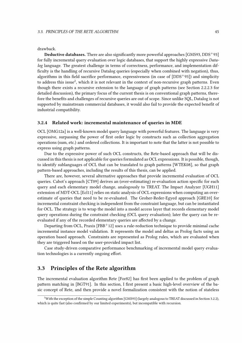
3.3. PRINCIPLES OF THE RETE ALGORITHM 45
drawback.Deductive databases. There are also signicantly more powerful approaches [GMS93, DDS+93]
for fully incremental query evaluation over logic databases, that support the highly expressive Data-
log language. The greatest challenge in terms of correctness, performance, and implementation dif-culty is the handling of recursive Datalog queries (especially when combined with negation), thus,algorithms in this eld sacrice performance, expressiveness (in case of [DDS+93]) and simplicityto address this issue2, which it is not relevant in the context of non-recursive graph patterns. Eventhough there exists a recursive extension to the language of graph patterns (see Section 2.2.2.3 fordetailed discussion), the primary focus of the current thesis is on conventional graph patterns, there-fore the benets and challenges of recursive queries are out of scope. Since unlike SQL, Datalog is notsupported by mainstream commercial databases, it would also fail to provide the expected benet ofindustrial compatibility.
3.2.4 Related work: incremental maintenance of queries in MDE
OCL [OMG12a] is a well-known model query language with powerful features. The language is veryexpressive, surpassing the power of rst order logic by constructs such as collection aggregationoperations (sum, etc.) and ordered collections. It is important to note that the latter is not possible toexpress using graph patterns.
Due to the expressive power of such OCL constructs, the Rete-based approach that will be dis-cussed in this thesis is not applicable for queries formulated as OCL expressions. It is possible, though,to identify sublanguages of OCL that can be translated to graph patterns [WTEK08], so that graphpattern-based approaches, including the results of this thesis, can be applied.
There are, however, several alternative approaches that provide incremental evaluation of OCLqueries. Cabot’s approach [CT09] derives an (over-estimating) re-evaluation action specic for eachquery and each elementary model change, analogously to TREAT. The Impact Analyzer [UGH11]extension of MDT-OCL [Ecl11] relies on static analysis of OCL expressions when computing an over-estimate of queries that need to be re-evaluated. The Groher-Reder-Egyed approach [GRE10] forincremental constraint checking is independent from the constraint language, but can be instantiatedfor OCL. The strategy is to wrap the model into a model access layer that records elementary modelquery operations during the constraint checking (OCL query evaluation); later the query can be re-evaluated if any of the recorded elementary queries are aected by a change.
Departing from OCL, Praxis [FBB+12] uses a rule-reduction technique to provide minimal cacheincremental instance model validation. It represents the model and deltas as Prolog facts using anoperation based approach. Constraints are represented as Prolog rules, which are evaluated whenthey are triggered based on the user-provided impact list.
Case study-driven comparative performance benchmarking of incremental model query evalua-tion technologies is a currently ongoing eort.
3.3 Principles of the Rete algorithm
The incremental evaluation algorithm Rete [For82] has rst been applied to the problem of graphpattern matching in [BGT91]. In this section, I rst present a basic high-level overview of the ba-sic concept of Rete, and then provide a novel formalization consistent with the notion of stateless
2With the exception of the simple Counting algorithm [GMS93] (largely analogous to TREAT discussed in Section 3.2.2),which is quite fast (also conrmed by our limited experiments), but incompatible with recursion.
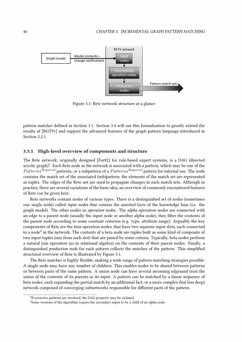
46 CHAPTER 3. INCREMENTAL GRAPH PATTERN MATCHING
Figure 3.1: Rete network structure at a glance
pattern matcher dened in Section 3.1. Section 3.4 will use this formalization to greatly extend theresults of [BGT91] and support the advanced features of the graph pattern language introduced inSection 2.2.1.
3.3.1 High-level overview of components and structure
The Rete network, originally designed [For82] for rule-based expert systems, is a DAG (directedacyclic graph)3. Each Rete node in the network is associated with a pattern, which may be one of thePatternsRequired patterns, or a subpattern of a PatternsRequired pattern for internal use. The nodecontains the match set of the associated (sub)pattern; the elements of the match set are representedas tuples. The edges of the Rete net are used to propagate changes in such match sets. Although inpractice, there are several variations of the basic idea, an overview of commonly encountered featuresof Rete can be given here.
Rete networks contain nodes of various types. There is a distinguished set of nodes (sometimesone single node) called input nodes that contain the asserted facts of the knowledge base (i.e. thegraph model). The other nodes as operation nodes. The alpha operation nodes are connected withan edge to a parent node (usually the input node or another alpha node); they lter the contents ofthe parent node according to some constant criterion (e.g. type, attribute range). Arguably the keycomponents of Rete are the beta operation nodes, that have two separate input slots, each connectedto a node4 in the network. The contents of a beta node are tuples built as some kind of composite oftwo input tuples (one from each slot) that are paired by some criteria. Typically, beta nodes performa natural join operation (as in relational algebra) on the contents of their parent nodes. Finally, adistinguished production node for each pattern collects the matches of the pattern. This simpliedstructural overview of Rete is illustrated by Figure 3.1.
The Rete matcher is highly exible, making a wide range of pattern matching strategies possible.A single node may have any number of children. This enables nodes to be shared between patternsor between parts of the same pattern. A union node can have several incoming edgesand treat theunion of the contents of its parents as its input. A pattern can be matched by a linear sequence ofbeta nodes, each expanding the partial match by an additional fact, or a more complex (but less deep)network composed of converging subnetworks responsible for dierent parts of the pattern.
3If recursive patterns are involved, the DAG property may be violated4Some versions of the algorithm require the secondary input to be a child of an alpha node

3.3. PRINCIPLES OF THE RETE ALGORITHM 47
VariablesP V ent
M V rel
K V ent
H V rel
T V ent
Constraintsc1 Crel 〈P,M,K,Marking〉c2 Crel 〈P,H, T, InhibitorArc〉
Figure 3.2: Basic graph pattern capturing inhibition
Note that while this high-level overview refers to tuples as actually being stored at nodes, this ismerely a way of explaining the basics of the Rete concept. In actual implementations this may not bethe case, as it is possible for some nodes not to contain a memory. Some Rete network descriptionsput emphasis on isolating local memory storages, that are components responsible for storing (andpossibly indexing) tuples, and all memories together form a distributed working memory. It is possibleto distinguish between alpha memories and beta memories, based on whether they store tuples thatare simple asserted facts or compound tuples output by beta nodes. Section 3.4 covers the memoryaspects of my implementation in detail.
Example 18 The following example relies on the inhibits pattern, which expresses that a markedplace inhibits a transition via an inhibitor arc. The pattern was used before in Example 15 on page 32;it is redened here using the basic formalism (i.e. without pattern composition) and depicted byFigure 3.2. A Rete net that matches this pattern is depicted in Figure 3.3, where each Rete node isshown as a grey box, interconnected by grey arrows pointing from parent node to child node. TheRete net is composed of input nodes r1 and r2, and a beta operation node r3. The role of the inputnode r1 is to cache all relations of type Marking, while InhibitorArc relations are stored atr2. From these two parent nodes, r3 derives the set of Petri places that are marked and are inhibitinga transition, by applying the relational algebra operation of natural join. The result computed at thisoperation node is, by denition, the match set of the inhibits pattern, making r3 a productionnode that is fully caching inhibits.
If this Rete net is initialized on the instance model of Example 3 on page 13, nodes will contain intheir memories the matches of their associated patterns. This is shown in Figure 3.4, with individualmatches represented as white boxes inside the node that contains them (ignore the red and greenboxes for now). Input node r1 will contain one tuple for each of the Marking relations m1, m2, m3
and m4. Input node r2 will cache the single InhibitorArc relation g1. Finally, join node r3 willcombine Markings with incident InhibitorArcs, and thereby compute the relational join ofthese match sets, which now happens to be the empty set. This means that the pattern inhibitshas no matches, i.e. there is no inhibited transition in the model.
3.3.2 High-level overview of operation
Once the Rete net is built, nding the matches of a pattern is as simple as retrieving the contents ofthe production node corresponding to the pattern.
If the graph model undergoes changes, the Rete network has to be updated in order to keep thematch sets up-to-date. Whenever a new graph element is inserted, a positive update token containingthe new fact is passed to the input node. This will start a propagation of change information throughthe Rete net. Nodes receive change tokens on their input, update their memories accordingly, and
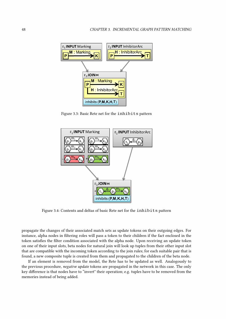
48 CHAPTER 3. INCREMENTAL GRAPH PATTERN MATCHING
Figure 3.3: Basic Rete net for the inhibits pattern
Figure 3.4: Contents and deltas of basic Rete net for the inhibits pattern
propagate the changes of their associated match sets as update tokens on their outgoing edges. Forinstance, alpha nodes in ltering roles will pass a token to their children if the fact enclosed in thetoken satises the lter condition associated with the alpha node. Upon receiving an update tokenon one of their input slots, beta nodes for natural join will look up tuples from their other input slotthat are compatible with the incoming token according to the join rules; for each suitable pair that isfound, a new composite tuple is created from them and propagated to the children of the beta node.
If an element is removed from the model, the Rete has to be updated as well. Analogously tothe previous procedure, negative update tokens are propagated in the network in this case. The onlykey dierence is that nodes have to “invert" their operation; e.g. tuples have to be removed from thememories instead of being added.

3.3. PRINCIPLES OF THE RETE ALGORITHM 49
Example 19 Continuing from Example 18, let us now observe the consequences of executing themanipulative transaction Fire(t2) (see Example 6 on page 21). The contents of the Rete net will bemaintained according to the graph delta; rst the changes are performed in the input nodes (directlyreecting the graph delta), and then they propagate down from parent node to child node, until thereis nothing left to update.
Figure 3.4 shows matches in the negative delta of a node as red boxes, and matches in the positivedelta as green boxes. In this case, the delta of r1 will remove one match (Marking m4) and addone match (Marking m5), while the match set of r2 is unchanged. Then, the join node r3 willincrementally compute its own delta, by examining each incoming change and consulting the otherparent node to determine how it aects the outcome. As no matches stored in r3 were derived fromm4, none will have to be removed afterm4 is deleted. Whenm5 is inserted, however, it can be joinedwith InhibitorArc g1 from the other parent, as both are connected to the same Place p2.Therefore r3 registers one new match in the cached match set of pattern inhibits, that identiesp2 as a marked place inhibiting t1. Were there any child nodes of r3, they would have to be updatedaccording to this delta.
If the Rete net is queried for the matches of pattern inhibits, the query operation consist ofenumerating the matches that are stored directly at r3. In this case, there are no matches before theupdate, and the single match with p2 after the update.
3.3.3 Formalization
In the following, a simplied formal treatment of the structure and operation of a Rete-based incre-mental pattern matcher is given, on a very high level of abstraction. Some details are chosen in a wayto make the formalization as simple as possible, not necessarily reecting the details of an implemen-tation. Individual computation operations are not discussed, neither are implementation questionsand performance improvement techniques. These will be discussed in Section 3.4, along with theadaptation to a pattern language / modeling platform, and the procedure of constructing a Rete netto match a given pattern.
If Rete is utilized to fully cache a pattern P , there will be a Rete node that contains the match setof P . Due to the way Rete works, there need to be additional Rete nodes that cache subpatterns ofP , which contain a subset of variables and constraints. Each node has a dedicated “storage area” inthe internal state of the matcher, where it can store its own internal node memory including (but notnecessarily restricted to) the match set of its associated pattern. There are two main kinds of Retenodes: input nodes and operation nodes.
Operation nodes (including alpha and beta nodes) compute and incrementally maintain their con-tents based on the contents of a set of parent nodes. An operation node denes this computationthrough the initial “null state” of its internal memory (when all parent nodes have empty match sets)and a node maintenance routine that updates the node internal memory based on the deltas (and orig-inal contents) of parent nodes.
Denition 48 (Rete operation node) A Rete operation node is a structure r =〈Pr, Parentsr,M
0r ,Maintainr〉 that is associated with:
• a subpattern Pr ⊆ P where P is a pattern cached by the pattern matcher
• a tuple of parent nodes Parentsr = 〈r1, r2, . . . , rk〉
• a null state of the node memoryM0r that should be valid in case all parent nodes have an empty
match set

50 CHAPTER 3. INCREMENTAL GRAPH PATTERN MATCHING
• a node maintenance routine Maintainr, which can incrementally calculate the new internalmemory M ′r of the node from the current internal memory Mr, when parameterized for eachparent node by the current match set of the associated pattern of the parent and the correspond-ing match set delta: M ′r = Mr.Maintain(MatchSetPr1 ⊕ ∆MatchSetPr1 ,MatchSetPr2 ⊕∆MatchSetPr2 , . . . ,MatchSetPrk ⊕ ∆MatchSetPrk ). Since the emphasis is on incremen-tal calculation, the result of the maintenance routine should preferably be dened as ∆r =M ′r −Mr.
The number of parent nodes, the null state memory and the maintenance routine are determinedby the node type, along with the way how the subpattern is derived from the subpatterns associatedwith the parent nodes. Various operations require dierent node types; they will be discussed laterin Section 3.4.
Input nodes are responsible for injecting basic knowledge of the graph model into the Rete net.Their associated subpattern must be primitive, i.e. either consist of a single entity constraint of typecls ∈ Cls (plus a single variable for that entity) or a single relation constraint of type fea ∈ Fea(plus three dierent variables for relation, source and target). In essence, matching these patternsis equivalent to evaluating respectively the elementary model query operation Query(∗ : cls) orQuery(∗ ∗:fea−−−→ ∗) (see Section 2.1.5). The only signicant dierence between the match set of theprimitive pattern and the corresponding elementary entity (resp. relation) query result is the follow-ing: the primitive pattern has a variable associated to the returned entity (resp. returned relation andsource / target entity).
Due to the connection between primitive patterns and elementary model queries, the content ofinput nodes can be determined from the underlying model in a trivial and atomic query step. Thusthere is no need for parent nodes, a null state or a node maintenance routine.
Note that the above denition of primitive pattern does not allow the source and target variablesof the single relation constraint to coincide, as Section 2.1.5 did not introduce a corresponding elemen-tary model query for self-loop relations. Unlike some graph model formalizations such as [Ren04a],where entity types are represented by self-loop relations, this kind of elementary model query is notvital to graph models formulated as in Section 2.1. Nevertheless, the Rete-based pattern matcher iscapable of matching patterns containing self-loops, see Section 3.4.1.3.
Denition 49 (Rete input node) A Rete input node r = 〈Pr, Qr〉 is associated with:
• a primitive subpattern Pr ⊆ P where P is a pattern cached by the pattern matcher
• an elementary model query operation Qr that is equivalent to the primitive subpattern.
For the sake of uniformity, we can consider a trivial parent set Parentsr = ∅ for any input node r.
Denition 50 (Rete net) A Rete net R = 〈N,N I ,M〉 contains a set of Rete nodes N =〈r1, r2, . . . , rn〉, a subset of which are input nodes N I ⊆ N (the rest are operation nodes), and amemory M = 〈Mr1 ,Mr2 , . . . ,Mrn〉 composed of the internal memories Mri of all nodes, each ofwhich is required to contain Mri .matches, the match set of the associated subpattern. The Rete netis required to be closed and acyclic w.r.t. node-parent relationships.
Note that since node-parent relationships in the Rete net are required to be acyclic, and also closed(∀r ∈ N : Parentsr ⊂ N ), there exists a topological ordering of the nodes so that each node comesafter all of its parent nodes.

3.3. PRINCIPLES OF THE RETE ALGORITHM 51
Denition 51 (Rete-based incremental pattern matcher) The Rete-based pattern matcherPMR = 〈SRete, sRete0 ,MatchRete,MaintainRete〉 based on Rete net R = 〈N,N I ,M〉 is a fullycached and incremental stateful pattern matcher that uses the memory of the Rete net as itsinternal state s = M . The Rete-based incremental pattern matcher is consistent at state 〈G, s〉 iMr.matches = MatchSetPr
G for all nodes r ∈ N .
Since the matcher state is formed of the memories of individual nodes, here SRete is simply theCartesian product of the possible range of memory contents of the individual nodes, which is thepowerset of potential matches of the pattern associated with the node over the given universe U.
According to the denitions in Section 3.1.2, a pattern P is (fully) cached i there exists a noder(P ) such that its associated subpattern Pr(P ) = P equals to the complete pattern. In case of analready cached P , it is trivial to retrieve 〈G, s〉.Match(P ).out = Mr(P ).matches. On-demand fullycaching can be achieved if, in case P is not fully cached yet, Match(P ) extends the Rete network(and thus modies the internal matcher state5) with new nodes so that a production node r(P ) andits ancestors are created before yielding the output. Constructing Rete nets for matching a patternwill be discussed in Section 3.4.
Denition 52 (Rete maintenance routine) The matcher maintenance routine MaintainRete isdened here through its application 〈G, s〉.MaintainRete(δ). The new matcher state s′ = M ′ =〈M ′r1 ,M
′r2 , . . . ,M
′rn〉 is computed using temporary storage 〈∆r1 ,∆r2 , . . . ,∆rn〉with semantics ∆r =
M ′r.matches−Mr.matches. The following computations are performed individually for each node,in any order (or even in parallel) that observes the precedence of nodes induced by the node-parentrelationship, i.e. the new memories of parent nodes must be available for the maintenance of childnodes. Such a topological ordering exists, since the node-parent relationship is required to be acyclic.
• The maintenance computation for input node r ∈ N I consists of rst determining ∆r by sim-ply ltering δ to elements relevant for the equivalent elementary query Qr, and then incre-mentally updating the node memory to the new M ′r = M ′r.matches := Mr.matches + ∆r =MatchSetPr
G+δ .
• The computation for operation node r ∈ N \N I , with parents Parentsr = 〈r1, r2, . . . , rk〉 al-ready maintained, consists of incrementally calculating M ′r = Mr.Maintain(Mr1 .matches⊕∆r1 ,Mr2 .matches⊕∆r2 , . . . ,Mrk .matches⊕∆rk) and storing the delta ∆r := M ′r −Mr.
The consistency of the matcher must be an invariant of MaintainRete, i.e. ∀r ∈ N :Mr.matches = MatchSetPr
G implies ∀r ∈ N : M ′r.matches = MatchSetPrG+δ or equivalently
∀r ∈ N : ∆r.matches = ∆MatchSetPrG⊕δ . This trivially holds for input nodes, but imposes proof
obligations on Maintainr of each operation node r (with the assumption that all parent nodes al-ready comply).
Finally, the initialization of the Rete net, i.e. determining sRete0 , deserves some technical discus-sion. The method of initialization described below is not very interesting from the point of view ofthe thesis, but is included here for the sake of completeness. Each operation node r provided a nullstate M0
r which assumed all parent nodes had empty contents; while this is typically true, there canbe exceptions (such as the unit node of Denition 55), so the null state has to be adjusted accordingto the actual, not necessarily empty content of parent nodes (in their adjusted null state), as if that
5In this case, the mutable structure of the Rete net must also be part of the pattern matcher state; this was omitted fromthe previous formalization for brevity

52 CHAPTER 3. INCREMENTAL GRAPH PATTERN MATCHING
content had just been inserted into the parent nodes. Therefore the matcher null state is dened asfollows.
Denition 53 (Rete null state) The matcher null state sRete0 = 〈A0r1 , A
0r2 , . . . , A
0rn〉 is composed of
the adjusted null states of each node, where
• the adjusted null state A0r of an input node r ∈ N I is the empty set; while
• the adjusted null state A0r of an operation node r ∈ N \ N I is derived from the (unadjusted)
null stateM0r asA0
r = M0r .Maintain(∅⊕(A0
r1 .matches− ∅), ∅⊕(A0r2 .matches− ∅), . . . , ∅⊕
(A0rk.matches− ∅))
This computation, analogously to the net maintenance, can be done in any order that observes theprecedence of nodes induced by the node-parent relationship.
3.3.4 Discussion of algorithmic complexity
As before, let PatternsRequired denote the set of patterns that the Rete-based incremental patternmatcher PMR is required to cache. Let PatternsInternal denote any patterns cached at Rete nodesof PMR that are not in PatternsRequired and are not primitive patterns.
Query time complexity for patternP ∈ PatternsRequired. SinceP is fully cached, enumeratingthrough all matches takes at most O(|MatchSetP |) time. Recall that Ω(|MatchSetP |) is the lowerbound for any pattern matcher.
Memory complexity for model G. For node r, let OutputSizer = |Mr.matches| be the num-ber of partial matches cached at the node, and let InputSizer =
∑ri∈Parentsr OutputSizeri be
the combined size of the partial match sets cached at parent nodes. The memory of a node cancache additional data in addition to the partial matches. However, if |Mr| = O(OutputSizer +InputSizer), then r is called locally compact. If the matcher is consistent and all nodes are locallycompact, then the entire Rete net will have a memory complexity of at most O(
∑r(OutputSizer +
InputSizer)); due to consistency this is O(∑
r|MatchSetPrG |). Taking account that cached pat-
terns are either primitive, required or internal, we get O(|G|+∑
P∈PatternsRequired |MatchSetPG|+∑P∈PatternsInternal |MatchSetPG|). Recall that the lower bound for any fully incremental matcher is
Ω(|G|+∑
P∈PatternsRequired |MatchSetPG|).Maintenance time complexity for G ⊕ δ. For node r, let OutputDeltar = |M ′r.matches −
Mr.matches| be the size of the match set delta at the node, and let InputDeltar =∑ri∈Parentsr OutputDeltari be the combined size of the match set deltas at parent nodes. Pro-
cessing input deltas and maintaining the entire memory of a node may not be proportionalto the match set delta at the node. However, If Maintainr has time complexity of at mostO(OutputDeltar + InputDeltar), then r is called locally swift. If the matcher is consistent andall nodes are locally swift, then the entire Rete net will have a maintenance time complexity of atmost O(
∑r(OutputDeltar + InputDeltar)); due to consistency this is O(
∑r|∆MatchSetPr
G⊕δ|).Taking account that cached patterns are either primitive, required or internal, we get O(|δ| +∑
P∈PatternsRequired |∆MatchSetPG⊕δ|+∑
P∈PatternsInternal |∆MatchSetPG⊕δ|). This makes the pat-tern matcher swift. Furthermore, recall that the lower bound for any fully incremental matcher isΩ(|δ|+
∑P∈PatternsRequired |∆MatchSetPG⊕δ|).
Discussion. All Rete nodes that will be discussed in Section 3.4 are locally swift and compact.Therefore Rete only exceeds theoretical lower bounds by the match set size resp. match set deltas ofinternally cached patterns. These quantities are dependent heavily on the choice of PatternsInternal,

3.4. ADAPTING RETE FOR GRAPH PATTERN MATCHING 53
which is determined by the quality of the query plan, i.e. the way the Rete net is constructed to cachethe PatternsRequired patterns. This component of performance is therefore hard to give a generalprediction for.
As Rete is a fully cached matcher, the query times are in stark contrast with non-caching ap-proaches, where query complexity is often a higher-order polynomial of model size, even for smallmatch sets. The memory complexity of Rete is higher than many fully cached approaches, especiallyminimal cache matchers like TREAT. This is, however, compensated with a maintenance time that isonly proportional to the amount of change, which is predictable based on PatternsInternal. TREAT,for instance, does not have this swiftness property, and its maintenance complexity may be a poly-nomial of the model size, even if the changes have little impact.
3.4 Adapting Rete for graph pattern matching
The following sections will present the adaptation of the overall Rete concept to the specic graphpattern formalism used in the thesis. Throughout the discussion, concepts of relational alge-
bra [GMUW08] will be used frequently; familiarity with the topic is assumed.
3.4.1 Basic graph pattern matching with Rete
3.4.1.1 Join nodes
To match graph patterns of the core formalism using Rete, it is sucient to introduce the most basickind of beta node type. The join node is a beta node (i.e. it has two parent nodes, the left parent andthe right parent) that computes the relational operation natural join (traditionally denoted by ./) ofthe match sets represented by its two parent nodes.
The join node corresponds to a combined subpattern that contains the union of variables of thesubpatterns of parent nodes, and the union of constraints enforced by the parent nodes. The result ofthe relational join is the match set of this combined subpattern since the matches in the result will beexactly those substitutions that correspond to a match of each of the parent nodes (when projectedto their variables).
The following formal denition uses a natural extension of relational join to an operation amongmatch set deltas: for δ1 = 〈δ1+, δ1−〉 and δ2 = 〈δ2+, δ2−〉, their relational join is dened to be δ1 ./δ2 = 〈δ+, δ−〉 with δ+ = (δ1+ ./ δ2+) ·∪(δ1− ./ δ2−) and δ− = (δ1− ./ δ2+) ·∪(δ1+ ./ δ2−); whereentire match sets participate in such joins as deltas δ = M − ∅ = 〈M, ∅〉. This way, the usualalgebraic properties such as bilinearity will hold, allowing us to simplify the maintenance routine toan incremental calculation.
Denition 54 (Join node) For left and right parents rleft and rright, the join node is a type of oper-ational node r./ = 〈P./, Parents./,M0
./,Maintain./〉, where
• Parents: the set of parent nodes consist of the given left and right parent, Parents./ =rleft, rright, with Pleft = Prleft and Pright = Prright
• Pattern: P./ = 〈V,C〉 with V = V (Pleft) ∪ V (Pright) and C = C(Pleft) ∪ C(Pright) (thesedo not have to be disjoint unions),
• Memory: the memory stores only the match set M./ = M./.matches,

54 CHAPTER 3. INCREMENTAL GRAPH PATTERN MATCHING
• Invariant: the consistency invariant is M./ = MatchSetP./ = MatchSetPleft ./MatchSetPright
• Initialization: M0./ = ∅ ./ ∅ = ∅
• Maintenance: M./.Maintain./(Mrleft .matches ⊕∆rleft , Mrright .matches ⊕∆rright) is de-ned in the following, using notation Mleft = Mrleft .matches, Mright = Mrright .matches,∆left = ∆rleft .matches, and ∆right = ∆rright .matches, by specifying the delta it calculates:∆./ = M ′./ −M./ = ((Mleft + ∆left) ./ (Mright + ∆right))− (Mleft ./ Mright) = (Mleft ./∆right) + (∆left ./ ∆right) + (∆left ./ Mright).
It follows easily from the denitions of M0./ and Maintain./ that the consistency invariant is
preserved, the node is locally compact, and that the maintenance computation is incremental andlocally swift.
3.4.1.2 Rete net construction
Using the join node type, it is trivial to build a Rete net that matches any simple graph pattern(conforming to the rst denition of the concept in Section 2.2.1) that consists only of entity andrelation constraints, where the relation constraints are not self-loops. Assume that the pattern tobe cached is P = 〈V,C〉 where C = Cent ·∪Crel is the set of constraints. For each entity con-straint c = 〈v, t〉 ∈ Cent the Rete net contains an input node rc = 〈Pc, Qc〉 with primitive patternPc = 〈Vc, Cc〉 consisting of just this constraint (Vc = v, Cc = c) and associated elementaryquery equivalent Qc = Query(∗ : t). Similarly for each relation constraint c = 〈a, v, b, t〉 ∈ Crelthe Rete net contains an input node rc = 〈Pc, Qc〉 with primitive pattern Pc = 〈Vc, Cc〉 consist-ing of just this constraint (Vc = a, v, b, t, Cc = c) and associated elementary query equivalentQc = Query(∗ ∗:t−→ ∗). Finally, there are |C| − 1 join nodes forming a tree structure (w.r.t. node-parent relationships) with the above input nodes as leaves and a single tree root r. There are manyways to build the tree, all of which suce here, although they may dier greatly from a performancepoint of view (see Section 3.4.4). Now, due to the properties of join nodes, Pr is composed of all con-straints and variables of the primitive patterns at the input nodes, therefore Pr = P and r = r(P ),i.e. P is fully cached.
Example 20 The following example elaborates Example 18 on page 47 and Example 19 in more detail.The example relies on (the redened version of) the inhibits pattern, which expresses that a markedplace inhibits a transition via an inhibitor arc, as depicted by Figure 3.2 on page 47. The patternPinhibits = 〈V,C〉 is dened on variables V = P,M,K,H, T with constraints Cent = ∅ andCrel = c1 = 〈P,M,K,Marking〉, c2 = 〈P,H, T, InhibitorArc〉. For the sake of brevity, noentity constraints are specied, as c1 and c2 already imply the required types of entity variablesP,K, T according to the metamodel of Example 2 on page 11.
The minimal Rete net that matches this pattern is R = 〈N,N I ,M〉, as depicted before in Fig-ure 3.3 on page 48. Here N I = r1, r2 with input node ri corresponding to constraint ci, i.e. thememory of r1 contains all marking relations as tuples (matches of Pr1 = 〈P,M,K, c1〉), whiler2 contains all inhibitor arcs as tuples (matches of Pr2 = 〈P,H, T, c2〉). N = N I ·∪r3 con-tains a single operation node that is a join node with parents r1 and r2. This r3 is associated withPr3 = 〈P,M,K,H, T, c1, c2〉 = 〈V,C〉 = Pinhibits, thus the pattern is fully cached. Figure 3.3shows each Rete node as a grey box that displays its associated pattern, interconnected by grey arrowspointing from parent node to child node.

3.4. ADAPTING RETE FOR GRAPH PATTERN MATCHING 55
Figure 3.5: Rete net memory contents and deltas for the inhibits pattern
If this Rete net is initialized on the instance model of Example 3 on page 13, nodes will containin their memories the matches of their associated patterns. This is shown in Figure 3.5, with indi-vidual matches represented as white boxes inside the node that contains them (ignore the red andgreen boxes for now). Input node r1 will contain the matches of Pr1 , one for each Marking rela-tion: 〈p1,m1, k1〉, 〈p1,m2, k2〉, 〈p1,m3, k3〉, 〈p3,m4, k4〉 (using the tuple notation). Input node r2will cache the single InhibitorArc relation: 〈p2, g1, t1〉. Finally, join node r3 will compute therelational join of these match sets, which happens to be the empty set. This means that the patterninhibits has no matches.
If the graph model is changed by the manipulative transaction Fire(t2) (see Example 6 onpage 21), the Rete-based pattern matcher will be maintained according to the graph delta. Figure 3.5shows matches in the negative delta of a node as red boxes, and matches in the positive delta as greenboxes. First, the delta match set of input nodes follows directly from the delta of the graph model;in this case, the delta of r1 will remove one match and add one match, while the match set of r2 isunchanged. Then, the delta of the join node r3 is computed: ∆3 = (M1 ./ ∆2)+(∆2 ./ ∆1)+(∆1 ./M2) = ∅+ ∅+ +〈p2,m5, k5, g1, t1〉. Therefore one new match appears in the cached match set ofpattern inhibits.
3.4.1.3 Corner cases
Note that self-loop relation constraints (where the source and target variables coincide) are disallowedin primitive patterns, therefore the above Rete net construction schema does not work in this case.However, any self-loop relation constraint cloop = 〈a, v, a, t〉 ∈ Crel can be equivalently substitutedwith the following two constraints: (i) crel = 〈a, v, b, t〉 ∈ Crel for an additional variable b and (ii)the equality constraint c= = 〈a, b〉 ∈ C=. Equality constraints will be dealt with in Section 3.4.2.
A minor detail should not be overlooked here: Pr will not contain all variables if there are loose
variables that are not aected by any entity or relation constraint, and therefore do not appear atthe input nodes. While the usefulness of such variables is debatable, it is possible to work aroundthe problem: when building the Rete net according to the above schema, one should assume a specialconstraint c∗ = 〈v, ∗〉 ∈ Cent for any v ∈ V ent in order to assert that v should be mapped to an entity,and c∗ = 〈a, v, b, ∗〉 ∈ Crel for any v ∈ V rel in order to assert that v should be mapped to a relation.

56 CHAPTER 3. INCREMENTAL GRAPH PATTERN MATCHING
Note that the elementary query equivalents at the corresponding input nodes will be unrestricted byentity or relation type.
As a nal special case, the construction process cannot be applied if there are no input nodes; it isnot possible to build a tree of joins operations and to provide a nal node that caches the pattern. Sinceeach variable, including loose variables, would be involved in at least one input node, this situation canonly arise if the pattern has no variables (thus no constraints) at all. The pattern without variablesand constraints has a single match that is empty (nullary tuple). While such a pattern by itself isnot very useful, Rete construction procedures for more advanced language elements (e.g. NAC, seeSection 3.4.2) might require a corresponding Rete node in special cases. Thus a special Rete nodecalled unit node is provided; named for the fact that its constant match set acts as the neutral elementfor natural join. Due to this property, it could have been included in the previously introduced jointree without eect.
Denition 55 (Unit node) The unit node is a type of operational Rete node r∅ =〈P∅, Parents∅,M0
∅ ,Maintain∅〉, where
• Parents: there are no parents: Parents∅ = ∅,
• Pattern: P∅ = 〈V,C〉 with V = ∅ and C = ∅,
• Memory: the memory stores only the match set Mc = Mc.matches,
• Invariant: the consistency invariant is M∅ = MatchSetP∅ = 〈〉
• Initialization: M0∅ = 〈〉
• Maintenance: Maintain∅ is a no-op (returns an empty delta).
3.4.2 Rete pattern matching with advanced pattern language features
3.4.2.1 Equality and inequality
Equality and inequality constraints cannot be associated with primitive patterns, as there is no ele-mentary model query to enumerate all pairs of model elements that are respectively equal or dierent.Although it would be theoretically possible to dene such queries, one can easily see that their real-ization would not be practical (and, in case of attributed models, impossible). In short, we say thatthese constraints are checkable, but not nitely enumerable. However, a remarkable property of bothof these constraints is that it can be decided without knowledge of the graph model whether a givensubstitution satises them or not; these will be called lter constraints.
Denition 56 (Filter constraint) A constraint c expressed over variables Dom(c) is a lter con-straint if it can be associated with a Boole-valued deterministic selector function selc : UDom(c) → 2on substitutions of variables Dom(c), such that for any (partial) substitution s over any graph modelG with Dom(s) ⊇ Dom(c), s satises c i selc(s) is true.
The standard solution in Rete nets for lter constraints is the alpha node. Alpha nodes are op-eration nodes that have a single parent node, and their role is to lter the match set of the parentaccording to the selector function. In terms of relational algebra, alpha nodes perform a selection
operation (traditionally denoted by σ).The following formal denition uses a natural extension of relational selection to an operation
among match set deltas: for δ = 〈δ+, δ−〉, its selection is dened to be σselδ = 〈δsel+ , δsel− 〉 with

3.4. ADAPTING RETE FOR GRAPH PATTERN MATCHING 57
δsel+ = σselδ+ and δsel− = σselδ−. This way, the usual algebraic properties such as linearity will hold,allowing us to simplify the maintenance routine to an incremental calculation.
Denition 57 (Alpha node for lter constraint) For parent node rparent and lter constraint cwith selector sel, the alpha node is a type of operational node rc = 〈Pc, Parentsc,M0
c ,Maintainc〉,where
• Parents: there is a single parent Parentsc = rparent, with Pparent = Prparent
• Pattern: Pc = 〈V,C〉 with V = V (Pparent) and C = C(Pparent) ∪ c,
• Memory: the memory stores only the match set Mc = Mc.matches,
• Invariant: the consistency invariant is Mc = MatchSetPc = σselMatchSetPparent
• Initialization: M0c = σsel∅ = ∅
• Maintenance:Mc.Maintainc(Mrparent .matches⊕∆rparent) is dened in the following, usingnotation Mparent = Mrparent .matches, ∆parent = ∆rparent .matches, by specifying the delta itcalculates: ∆c = M ′c −Mc = σsel(Mparent + ∆parent)− σselMparent = σsel∆parent.
It follows easily from the denitions of M0c and Maintainc that the consistency invariant is
preserved, the node is locally compact, and that the maintenance computation is incremental andlocally swift.
The alpha node type enables us to construct Rete nets that match a graph pattern that containslter constraints in addition to the already discussed entity constraints and non-loop relation con-straints. The method of construction is similar to the tree schema described in Section 3.4.1; but foreach lter constraint c, an alpha node rc has to be inserted (interjected) in the tree between a parentnode rparent and a child node rchild, such that the variables of rparent are sucient to evaluate theconstraint (V (Pparent) ⊇ Dom(c)). For improving performance (e.g. to prelter both sides of a join),the constructed tree may contain more than one such alpha node for a given lter constraint.
As equality and inequality constraints are examples of lter constraints, we have shown a wayof matching them. A complex example involving an inequality lter node will be demonstrated byExample 23 on page 62. Note that no claim is made that an implementation should always follow thisapproach in constructing a Rete net for patterns with equality constraints. For example, it might bemore ecient (due to more specic joins) to consider sets of variables that are connected by equalityconstraints as a single “unied” variable, and use equality checkers only when necessitated by theelimination (see Section 3.4.1.3) of self-loops.
Since self-loop relation constraints were already shown to be substitutable by a non-loop relationconstraint and an equality constraint, the method described so far is sucient for matching any graphpattern according to Denition 21, with entity constraints, relation constraints (possibly self-loops),equalities and inequalities.
3.4.2.2 Composition
Handling pattern composition ccall = 〈Pcalled, composer〉 is straightforward, assuming that thecalled pattern Pcalled is already fully cached. As there is a r(Pcalled) containing in its memory thematches of the called pattern, it can be included alongside the input nodes as a leaf node. The treestructure of joins and alpha nodes will be built according to the procedure described before. In theterminology introduced before, this means that pattern call constraints are enumerable.
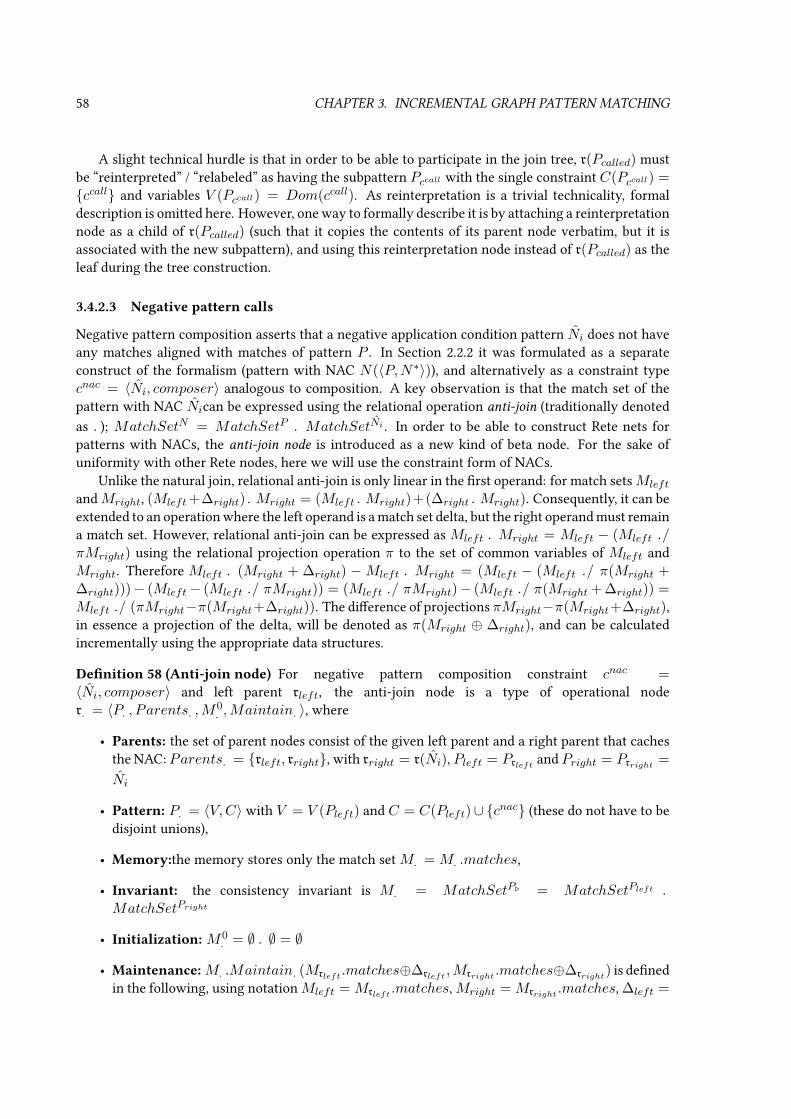
58 CHAPTER 3. INCREMENTAL GRAPH PATTERN MATCHING
A slight technical hurdle is that in order to be able to participate in the join tree, r(Pcalled) mustbe “reinterpreted” / “relabeled” as having the subpattern Pccall with the single constraint C(Pccall) =ccall and variables V (Pccall) = Dom(ccall). As reinterpretation is a trivial technicality, formaldescription is omitted here. However, one way to formally describe it is by attaching a reinterpretationnode as a child of r(Pcalled) (such that it copies the contents of its parent node verbatim, but it isassociated with the new subpattern), and using this reinterpretation node instead of r(Pcalled) as theleaf during the tree construction.
3.4.2.3 Negative pattern calls
Negative pattern composition asserts that a negative application condition pattern Ni does not haveany matches aligned with matches of pattern P . In Section 2.2.2 it was formulated as a separateconstruct of the formalism (pattern with NAC N(〈P,N∗〉)), and alternatively as a constraint typecnac = 〈Ni, composer〉 analogous to composition. A key observation is that the match set of thepattern with NAC Nican be expressed using the relational operation anti-join (traditionally denotedas .); MatchSetN = MatchSetP . MatchSetNi . In order to be able to construct Rete nets forpatterns with NACs, the anti-join node is introduced as a new kind of beta node. For the sake ofuniformity with other Rete nodes, here we will use the constraint form of NACs.
Unlike the natural join, relational anti-join is only linear in the rst operand: for match setsMleft
andMright, (Mleft+∆right).Mright = (Mleft .Mright)+(∆right .Mright). Consequently, it can beextended to an operation where the left operand is a match set delta, but the right operand must remaina match set. However, relational anti-join can be expressed as Mleft . Mright = Mleft − (Mleft ./πMright) using the relational projection operation π to the set of common variables of Mleft andMright. Therefore Mleft . (Mright + ∆right) −Mleft . Mright = (Mleft − (Mleft ./ π(Mright +∆right)))− (Mleft− (Mleft ./ πMright)) = (Mleft ./ πMright)− (Mleft ./ π(Mright + ∆right)) =Mleft ./ (πMright−π(Mright+∆right)). The dierence of projections πMright−π(Mright+∆right),in essence a projection of the delta, will be denoted as π(Mright ⊕ ∆right), and can be calculatedincrementally using the appropriate data structures.
Denition 58 (Anti-join node) For negative pattern composition constraint cnac =〈Ni, composer〉 and left parent rleft, the anti-join node is a type of operational noder. = 〈P., Parents.,M0
. ,Maintain.〉, where
• Parents: the set of parent nodes consist of the given left parent and a right parent that cachesthe NAC:Parents. = rleft, rright, with rright = r(Ni), Pleft = Prleft and Pright = Prright =
Ni
• Pattern: P. = 〈V,C〉 with V = V (Pleft) and C = C(Pleft)∪ cnac (these do not have to bedisjoint unions),
• Memory:the memory stores only the match set M. = M..matches,
• Invariant: the consistency invariant is M. = MatchSetP. = MatchSetPleft .MatchSetPright
• Initialization: M0. = ∅ . ∅ = ∅
• Maintenance:M..Maintain.(Mrleft .matches⊕∆rleft ,Mrright .matches⊕∆rright) is denedin the following, using notationMleft = Mrleft .matches,Mright = Mrright .matches, ∆left =

3.4. ADAPTING RETE FOR GRAPH PATTERN MATCHING 59
Figure 3.6: Rete net for composite pattern and NAC
∆rleft .matches, and ∆right = ∆rright .matches, by specifying the delta it calculates: ∆. =M ′. −M. = ((Mleft + ∆left) . (Mright + ∆right))− (Mleft . Mright) = (Mleft . (Mright +∆right))− (Mleft .Mright) + (∆left . (Mright + ∆right)) = (Mleft ./ π(Mright⊕∆right)) +(∆left . (Mright + ∆right)).
It follows easily from the denitions of M0. and Maintain. that the consistency invariant is
preserved, the node is locally compact, and that the maintenance computation is incremental andlocally swift.
The anti-join node type enables us to construct Rete nets that match a graph pattern with NAC;its utilization is similar to that of alpha nodes. For a negative composition constraint cnac =〈Ni, composer〉, a corresponding check has to be inserted in the tree as a child of a node r withV (Pr) ⊇ Dom(cnac); the check will be performed by an anti-join node with left parent rleft = r.Analogously to alpha nodes, it is possible to include multiple copies of this check in the tree.
Example 21 Recalling Example 11 on page 30, pattern unmarkedDisables calls pattern un-marked, and the latter (dened in Example 8 on page 26) has a NAC of its own, namely patternmarked (see Example 7 on page 25). The corresponding Rete nodes are shown here in Figure 3.6. Theinput node r4 enumerates entities of typePlace, while input node r5 immediately matches the patternmarked (unnecessary entity constraints were removed as usual). Their anti-join r6 (with node5 asright parent / NAC) matches pattern unmarked. Pattern unmarkedDisables is matched in r8by joining input node r7 for feature InArc against the already constructed r6 representing the calledpattern.
3.4.2.4 Disjunction
In terms of relational algebra, the match set of a disjunctive pattern PD = 〈V, P ∗〉 is the union ofrelational projections onto the set of common variables V (traditionally denoted by πV ) of the match

60 CHAPTER 3. INCREMENTAL GRAPH PATTERN MATCHING
sets of each pattern body Pj ∈ P ∗; formally, MatchSetPD =⋃Pj∈P ∗ πVMatchSetPj . Note that
this union is not guaranteed to be disjoint, as multiple pattern bodies may justify the same match.In fact, recalling the set theoretical denition of relational projection, it should be noted that even asingle pattern body may have multiple matches that, when projected onto V , correspond to the samematch of the disjunctive pattern.
The node type projection node is introduced to address this task; it will use amultiset data structureas its node memory to eciently keep track how many separate derivations are there for a singlematch.
Denition 59 (Projection node) For disjunctive pattern PD = 〈V, P ∗〉 with bod-ies P ∗ = P1, P2, . . . , Pk, the projection node is a type of operational node rπ =〈Pπ, Parentsπ,M0
π ,Maintainπ〉, where
• Parents: the set of parent nodes consist of the nodes caching the pattern bodies, Parentsπ =r1, r2, . . . , rk, with P (rj) = Pj for each of them,
• Pattern: Pπ = PD = 〈V, P ∗〉,
• Memory: the memory stores a multiset of matches: Mπ = Mπ.counter : (U × U × . . . ×U)→ N; this of course contains the match setMπ.matches = Dom(Mπ.counter) (where thedomain of a multiset is dened as the elements mapped to a non-zero value),
• Invariant: the consistency invariant is that occurrences of matches m : V → U are countedby the multiset: Mπ.counter = m 7→
∑Pj∈P ∗ |ResultSet
Pj (m)|; this impliesMπ.matches =
MatchSetPπ =⋃Pj∈P ∗ πV (MatchSetPj ),
• Initialization: M0π .matches =
⋃Pj∈P ∗ πV ∅ = ∅, therefore M0
π .counter = ∅ as well,
• Maintenance:Mπ.Maintainπ(Mr1 .matches⊕∆r1 , . . . ,Mrk .matches⊕∆rk) is dened in thefollowing, using notation Mj = Mrj .matches and ∆j = 〈δ+j , δ
−j 〉 = ∆rj .matches, by speci-
fying the delta it calculates: ∆π = M ′π.counter −Mπ.counter = m 7→ (∑
Pj∈P ∗ |m′ |m′ ∈
(Mj + ∆j) ∧ m ⊆ m′ | − | m′ | m′ ∈ Mj ∧ m ⊆ m′ |) = m 7→ (∑
Pj∈P ∗ | m′ | m′ ∈
δ+j ∧m ⊆ m′ |−|m′ |m′ ∈ δ−j ∧m ⊆ m′ |), i.e. the counters of the multiset are incremented
by each match in the positive delta and decremented by matches of the negative delta.
It follows easily from the denitions of M0π and Maintainπ that the consistency invariant is
preserved, the node is locally compact, and that the maintenance computation is incremental andlocally swift.
Now disjunctive patterns can be matched by constructing separate Rete trees (using the approachintroduced in earlier sections) for each pattern body, and then nally using a projection node thatprojects each body to the set of parameter variables to obtain the match set of the disjunctive pattern.
Example 22 Recalling Example 15 on page 32, disjunctive pattern disables has two bodies, pat-terns unmarkedDisables and inhibits. Example 20 and Example 21 show how Rete nodesare constructed to match each of the bodies. Assuming all these Rete nodes are built in a single net,Figure 3.7 shows how a projection node r9 computes the union of the projected match sets of bothbodies to obtain the match set of the disjunctive pattern.

3.4. ADAPTING RETE FOR GRAPH PATTERN MATCHING 61
Figure 3.7: Rete net for disjunctive pattern
3.4.3 Rete pattern matching with attributes
3.4.3.1 Data entity, data relation and value literal constraints
Matching attributed patterns in general is impossible for any nite pattern matcher, since data entityand data relation constraints are not enumerable. The previously introduced Rete building mechanismwill fail: with no corresponding elementary model query, as it was already established in Section 2.1.5,data entity and data relation constraints are not suitable as primitive patterns for input nodes. Thenarrower set of matchable graph patterns (see Denition 31), however, will be handled in the followingparagraphs.
For a data predicate constraint c = 〈a, v, b, t〉 ∈ CrelDat, a corresponding primitive pattern Pc couldbe dened, although it can not be included as in input node in a Rete net, as the corresponding ele-mentary model query cannot be nitely evaluated. However, in case of an enumerable data predicate(see Denition 18), the data predicate constraint can be matched by a compute node instead, takingadvantage of the corresponding computable query:
Denition 60 (Compute node) For a data predicate constraint c = 〈a, v, b, t〉 ∈ CrelDat where tis a data predicate enumerable by source, and parent node rparent with a ∈ V (P (rparent)) (i.e. itcontains values for the source element), the compute node is a type of operational node rcomp =〈Pcomp, Parentseval,M0
comp,Maintaincomp〉, where
• Parents: the set of parent nodes consist of the given single parent, Parentseval = rparent,with Pparent = Prparent ,
• Pattern: Pcomp = 〈V,C〉 with V = V (Pparent) ∪ v, b, t and C = C(Pparent) ∪ c,
• Memory: the memory stores only the match set Mcomp = Mcomp.matches,
• Invariant: the consistency invariant is Mcomp = MatchSetPcomp = MatchSetPparent ./MatchSetPc (even if the latter is not nitely enumerable),
• Initialization: M0comp = ∅ ./ MatchSetPc = ∅

62 CHAPTER 3. INCREMENTAL GRAPH PATTERN MATCHING
• Maintenance: Mcomp.Maintaincomp(Mrparent .matches ⊕ ∆rparent) is dened in the fol-lowing, using notation Mparent = Mrparent .matches, Mc = Mrc .matches and ∆parent =∆rparent .matches, by specifying the delta it calculates: ∆comp = M ′comp − Mcomp =((Mparent + ∆parent) ./ Mc)− (Mparent ./ Mright) = ∆parent ./ Mc.
An analogous node can be constructed if the data predicate is enumerable by target.
The expression ∆parent ./ Mc is nitely computable as all delta tuples m in ∆parent contain avalue for variable a, and thus it will be joined against Dat.Query(m(a)
∗:t−→ ∗).out which is com-putable since t is enumerable by source. Furthermore, it follows easily from the denitions of M0
comp
and Maintaincomp that the consistency invariant is preserved, the node is locally compact, and thatthe maintenance computation is incremental and locally swift.
Constraints of attributed patterns can be matched in the following way:
• Structural entity and relation constraints (CentStr and CrelStr) correspond to input nodes, as before.
• It is easy to see that value assignment attribute constraints (CrelV al) are also enumerable.
• For value literal constraint clit = 〈v, x〉, one can construct input nodes associated with theequivalent elementary model query Query(x : ∗); these input nodes can be used in the con-struction process analogously to the input nodes for entity and relation constraints.
• An attribute type constraint c = 〈v, t〉 ∈ CentDat expresses that the substituted value of variable vis of the data type t, which can be determined independently of the current graph model (as theimmutable data algebra Dat is known a priori). Therefore c is a lter constraint with selectorselc = s 7→ (Dat |= s(v) : t), and can be handled like any other lter constraint.
• A data predicate constraint c = 〈a, v, b, t〉 ∈ CrelDat can also be considered a simple lter checklike attribute type constraints above. Alternatively, if the data predicate is enumerable by sourceor target, the constraint can be matched by interjecting in the tree a compute node as a childof a node that contains the variable a respectively b.
• Further elements of the pattern language can be supported in the same way as described before.
Finally, all that is left to show is that the Rete construction procedure successfully reaches a pointwhere attribute type and data predicate constraints can be evaluated (using a lter node or computenode), since there are Rete nodes that contain the required variables. This follows (inductively) fromthe denition of matchable patterns (see Denition 31). Each entity variable is assignable. Thereforeeither there is an associated value literal / value assignment constraint, or else there must be anassociated data predicate constraint that is enumberable by some assignable variable(s). In the rstcase, the variable appears in at least one input node. In the latter case, the variable can be introducedby a compute node whose required variable (established to be assignable) can be made available insome suitable parent node.
Example 23 Figure 3.8 shows the Rete net built for the left-hand-side pattern of the attributed ver-sion of the GT rule removeToken, introduced in Example 17. Node r1 is a value assignment inputnode capturing the attributed version of the Marking type. Node r2 is a value literal input nodecontainting 0 as the single value of Z . Node r3 joins this zero value alongside each Marking in-stance. Next, lter node r4 checks whether X 6= Z , i.e. the marking value is non-zero; so far this isthe attributed version of the pattern marked from Example 10. Finally, knowing that data predicate

3.4. ADAPTING RETE FOR GRAPH PATTERN MATCHING 63
Figure 3.8: Rete net for the attributed version of the LHS pattern of rule removeToken
Successor is functionally determined by target, compute node r5 computes the single value Y forwhich X is the next integer. This completes the LHS pattern; each match cached at r5 is now readyfor the application of the GT rule removeToken (i.e. redirecting MX to Y ).
3.4.3.2 Aggregate constraints
Aggregate constraints, like certain kinds of data predicate constraints, are only enumerable by certainvariables (see Section 2.2.2.4 on page 31), thus it is subject to restriction associated with matchablepatterns (see Denition 31). Constructing a Rete net for a matchable pattern containing an aggregateconstraint can be achieved by the same procedure that was presented in Section 3.4.3.1 for attributedpatterns, where aggregation is treated similarly to functionally determined data predicates. Insteadof a compute node, however, an aggregate node is used:
Denition 61 (Aggregate node) For a match aggregate constraint caggregate =〈Pcalled, composer, aggregator, vresult〉 ∈ Caggregate with aggregator =〈mapper, reducer, unmapper〉 containing reducer = 〈A,⊗〉, and left par-ent rleft, the aggregate node is a type of operational node raggregate =〈Paggregate, Parentsaggregate,M0
aggregate,Maintainaggregate〉, where
• Parents: the set of parent nodes consists of the given left parent and a right parent that cachesthe called pattern: Parentsaggregate = rleft, rright, with rright = r(Pcalled), Pleft = Prleft

64 CHAPTER 3. INCREMENTAL GRAPH PATTERN MATCHING
and Pright = Prright = Pcalled
• Pattern: Paggregate = 〈V,C〉 with V = V (Pleft) ∪ vresult and C = C(Pleft) ∪ caggregate(these do not have to be disjoint unions),
• Memory: in addition to the match set, the memory stores a map from matches of the left parentto elements of the reducer group: Maggregate = 〈Maggregate.matches,Maggregate.reduced〉with Maggregate.reduced : (U × U × . . . × U) → A; the match set is derived asMaggregate.matches = mleft ./ vresult 7→ unmapper(a) | 〈mleft, a〉 ∈Maggregate.reduced ∧ unmapper(a) 6= ⊥ ,
• Invariant: the consistency invariant is dened not on the matches, but onMaggregate.reduced (from which the matches can be trivially derived) as Maggregate.reduced= 〈mleft, unmapper(
∏⊗mright∈incidentsmapper(mright))〉 |mleft ∈MatchSetPleft where
incidents is dened as before,
• Initialization: M0aggregate = ∅ since MatchSetPleft = ∅.
The lengthy formalization ofMaintainaggregate is omitted here for brevity, but it is fairly easy toexplain intuitively: new matches of Pleft are composer-joined against MatchSetPright , the resultsare mapped to A by mapper, reduced along ⊗ (which yields 1⊗ if there are no joining matches)and stored in Maggregate.reduced; then it is mapped back by unmapper into the value of vresultin the new match of Paggregate (or, if ⊥, there is no new match). Removed matches of Pleft arepurged from Maggregate.reduced and thus from Maggregate.matches (if it was present). The delta ofMatchSetPright is mapped by mapper, then composer-joined against Pleft, then each insertion inthis delta will ⊗-multiply the corresponding entry stored in Maggregate.reduced, and each removalwill ⊗-multiply it with the ⊗-inverse; afterwards, Maggregate.matches is updated accordingly.
Example 24 In the non-attributed version of the metamodel, tokens are individual entities, eachattached by a Marking relation to a place. Figure 3.9 shows a Rete net that counts the number of to-kens at a place, thereby deriving a substitute of the integer-valuedMarking feature of the attributedversion of the metamodel.
TheMarking relations to be counted are contained in r2. At the same time r1 simply enumeratesPlace instances. Their child node r3 is an aggregate node joining left parent r1 against right parentr2 by common variable P . The aggregator is aggregatorcount (see Example 12 on page 31), and theresult is captured as new variable X . There will be one match in r3 for every Place, consisting of theplace itself and an integer X indicating the number of its tokens.
3.4.4 Realization considerations
3.4.4.1 Performance
When building an actual software implementation of the Rete approach, many low-level practicaldecisions have to be made. The choices can have a major impact on performance.
Some important aspects will be addressed below. Further issues specic to Rete implementationsare discussed in literature, see for example [Doo95].

3.4. ADAPTING RETE FOR GRAPH PATTERN MATCHING 65
Figure 3.9: Rete net for the counting the tokens at a Place (non-attributed metamodel)
Query plan. As one important degree of freedom, the Rete construction procedures outlinedthroughout Section 3.4 do not specify the exact join order of the tree, and the placement of alphanodes, compute nodes, anti-join nodes etc. within the tree; in short, the query plan is subject to opti-mization. Rete is not a minimal cache algorithm; while storing the match set of fully cached patternsis unavoidable, the size of match sets of subpatterns can vary greatly. As already discussed in Sec-tion 3.3.4, the choice of Internal patterns has a large inuence on both memory consumption andmaintenance overhead. Therefore a reasonable implementation should employ some strategy thataims at keeping these auxiliary match sets as small as possible, thereby reducing memory footprintand maintenance time. Match set sizes are dicult to predict without actually matching the pattern,but various optimization heuristics can be applied, such as avoiding joins where the two parent nodeshave no variables in common.
Node sharing. A Rete net can cache multiple patterns, some of which may use the same classiersor features. Even a single pattern may have multiple entity or relation pattern constraints using thesame classier or feature. Therefore there will be several input nodes whose primitive patterns arelabeled with dierent variable names, but their elementary query is the same. This redundancy can beeliminated if these nodes share their memory, which is maintained in a single coordinated action. Anequivalent view of node sharing is to treat these input nodes as a single node, with multiple “facets”characterised by dierent patterns. This is analogous to the “reinterpretation” / “relabeling” used forpattern composition (see Section 3.4.2). Node sharing can be propagated to child nodes; e.g. if two joinnodes have the same pair of parents (parents that are facets of the same node memory) and they joinon the same variables (or at least variables consistent with the relabeling between facets), then thejoin nodes themselves can be considered as multiple facets of the same node with a single memory.There are techniques associated with Rete [BGT91] that build the query plan in a way that it attemptsto maximize node sharing among operation nodes.
Indexing. The performance of join operations can be greatly enhanced if the content of a parentnode is indexed according to the value(s) of variables(s) that are shared between both parent nodes.Using the notations from Denition 54, instead of calculating ∆left ./ Mright by a nested iterationthrough both sets, it is more ecient to iterate through ∆left (where a delta is frequently muchsmaller than a whole match set) and look up corresponding tuples via the index structures built ontop of Mright. Such an index structure can be stored as part of the memory associated with node

66 CHAPTER 3. INCREMENTAL GRAPH PATTERN MATCHING
rright, e.g. Mrright .index, in addition to Mrright .matches. The size of such indices is asymptoticallybounded by the size of the match set, therefore memory complexity is not increased.
Memoryless nodes. An important observation is that several kinds of operation nodes computetheir stored match set (and its deltas) from the match set in their parent incrementally, only using thedeltas of the parent node (and index structures, in case of a join). This means that after the initial Reteconstruction, the match set of the parent node is never read again. Furthermore, the content of inputnodes can always be reconstructed using the elementary model queries. Many nodes can thereforebe memoryless, i.e. they do not need to store their match sets in their memory, thus the size of thematcher internal state s can be reduced. An important exception is nodes associated with a patternthat is required to be fully cached. Note that this improvement does not make Rete a minimal cachematcher, as many internal nodes have to maintain one or more index structures (see above) for thesake of join/anti-join child nodes.
Redundant constraints. Constraints that are enforced by a given node according to the nodetype, may themselves entail additional constraints according to reasoning based on type inferenceor metamodel-specic well-formedness rules. For example, an input node for a relation constraintadditionally enforces entity constraints: the source entity must instantiate the owner of the feature,while the target must instantiate the range. In these cases, it is safe to add the inferred constraints tothe pattern associated with the node, if it is required by the pattern to be matched. This way, buildinginput nodes, alpha nodes, etc. for certain pattern constraints can be avoided, reducing the size ofthe Rete net. The examples throughout Section 3.4 assumed for the sake of brevity that the patterndoes not contain such redundant constraints; but even if it did contain such constraints, it could bematched by the same Rete net structure.
3.4.4.2 Integration
A further implementation question is how the Rete-based pattern matcher is integrated with theunderlying modeling technology (such as the platforms introduced in Section 2.1.6). The modelinglayer needs to provide the following services:
Elementary model queries In order to be able to populate the caches, the pattern matcher needs tobe able to execute the elementary model queries associated with input nodes. There are no suchrequirements for the operation nodes, as they derive their contents from their parent nodes. Theeciency of these model queries may vary greatly between modeling platforms. In the Viatra2implementation of VPM, enumerating all instances of an entity/relation type is very ecient,while EMF requires a full traversal of the entire model to identify which elements instantiatethe given type. Full model traversals are expensive for large models, therefore the integrationsolution either has to ensure that all input nodes are initialized during a single traversal of theEMF model, or that a suitable index structure is initialized in a single traversal, after whichinput nodes may be eciently populated at any time using the index. Note that constructingsuch a model-wide index has additional memory requirements, and upon changes to the modelthe index will have to be maintained afterwards. However, one can argue that such a statefulintegration is required to extend EMF capabilities so that it can provide the required elementarymodel query operations of Section 2.1.5; it can be regarded as a useful abstraction layer to hidethe idiosyncratic details of the modeling platform.
3.5. PERFORMANCE EVALUATION 67
Change notications The other required interface between the model and the matcher is the main-tenance phase. The modeling platform must be able to provide notications of its change deltaswhenever the model undergoes any kind of change, so that the maintenance routine of thestateful matcher can be called. Once again, it may be benecial to use an abstraction layer totranslate change notications specic to the modeling platform into deltas consumed by theRete-based pattern matcher. For instance, when a new containment subtree is attached to themodel in case of EMF, such a translation is required to obtain individual model element inser-tions from the EMF notication which contains a reference to the root of the subtree only, alongwith the description of where it is inserted.
3.5 Performance evaluation
In the following, I will present an experimental evaluation that contrasts the performance of incre-mental pattern matching against non-incremental approaches in a model simulation scenario. Inparticular, the Viatra2-based implementation [23] of the Rete algorithm was compared against theoriginal non-incremental matcher [VHV08] of Viatra2, as well as GrGEN.NET [JBK10], which isconsidered to be one of the fastest graph transformation engines.
The presented measurement is only one among many experiments [23,16,14,2,11] that have beenconducted under dierent workloads and scenarios (including model-to-model transformation andwell-formedness checks) in order to nd the conditions under which incremental pattern matchingis benecial.
This section follows [16]. The description of the benchmark is available in Section 3.5.1, followedby the presentation of measurement results in Section 3.5.2. Finally, Section 3.5.3 summarizes therelated work.
3.5.1 Petri net ring: a model simulation benchmark
Description. The scenario of simulating visual languages with dynamic operational semantics is afrequent and important use case for graph models and graph pattern matching. Therefore Petri netsimulation was selected [16] as a representative performance test from this category.
This scenario involves typical domain specic language simulation with the following character-istics: (i) mostly static graph structure, (ii) relatively small and local model manipulations, and (iii)typical as-long-as-possible (ALAP) execution mode. The workload focuses on the eective reusabilityof already matched elements as typical ring of a transition only involves a small part of the net.While an incremental pattern matcher can track the changes of the Petri net and update the involvedpartial matches only, non-incremental local search based approaches will have to restart the matchingfrom scratch after the net changed.
Test case generation. In the Petri net test set, “regular” Petri nets were selected as test cases, whichare generated automatically. Here regular means that the number of places and transitions are approx-imately equal. Furthermore, the net has only a low number of tokens, and thus, there are few reabletransitions in each marking.
The elements of the test set were generated from a small initial net by repeatedly applying sixgrowth operations. These growth operations are dened by reversing the reduction operations thatwere described in [Mur89] as means to preserve safety and liveness properties of the net. At eachiteration of the Petri net generation process, a growth operation was selected by weighted random

68 CHAPTER 3. INCREMENTAL GRAPH PATTERN MATCHING
sampling; this allows ne parametrization of the number of transitions and places with an averagefan-out of 3-5 incoming and outgoing edges. In all test cases, the generation started from the Petrinet depicted in Figure 3.10 (which is trivially a live net) and the nal test graphs are available inPNML [JKW02] format at [PNB08]. As the size of a Petri net cannot be described by only a singleparameter, generated Petri nets were characterized by the number of growth operations that wereapplied to produce the model, indicative of the relative ”size” of test cases.
Figure 3.10: The initial Petri net from which the test cases were grown
Execution. A step in the iterative execution sequence contains two phases: (i) rst a reable tran-sition t is randomly selected from the match set of pattern fireable (see Example 16) and then (ii) themanipulation operation Fire(t) (see Example 6) is applied to change of token markings according toPetri net ring semantics.
Despite its simple execution semantics, it is easy to derive additional Petri nets as new benchmarkscenarios with signicantly dierent run-time characteristics for the dierent graph transformationtools. For example, a Petri net with an equal number of transitions, places and tokens but with fewreable transitions can be used as a benchmark where type-based search space reduction strategies ofpattern matcher algorithms are neutralized, which forces the pattern matchers to use other heuristics.
Note that the only assumption on these Petri net test cases is to use live and bounded nets to havea potentially unbounded execution sequence. In the benchmark runs, 1 000 consecutive transitionrings were designated as Short execution sequences and 1 000 000 transition rings as Long executionsequences.
Benchmarking. For this benchmark, the total execution time of the simulation sequences are com-pared. As the actual selection of transitions to be red are non-deterministically determined by thetools, dierent tools (and indeed dierent test runs with a single tool) may select their own executionpaths, but this random factor turned out to have only insignicant eects on execution times.
More benchmarks for incremental pattern matching are presented in [16].
3.5.2 Measurement results
The measurements reported here have been carried out in 2008, on a standard desktop computer witha 2 GHz Intel Core2 processor with 2 gigabytes of system RAM available, running version 1.6.0_05 ofthe 32-bit Sun Java SE Runtime (for Viatra2) and version 3.0 of the .NET Framework on WindowsVista (for GrGEN.NET). Ten test runs were executed, and the results were calculated by averaging thevalues excluding the highest and lowest number. The transformation sequences were implementedso that little or no textual output was generated (lest its emission should dominate execution time);but in the case of Viatra2, the GUI was not completely disabled. Execution times were measuredwith millisecond precision as allowed by the operating system calls.

3.5. PERFORMANCE EVALUATION 69
The Petri net simulation benchmark was executed with short (1 000 red transitions) and long (1000 000 rings) execution sequences.
Figure 3.11: # growth operations applied (“net size”) vs. # model elements in test cases
The size parameters of the nets used as test cases are depicted in Figure 3.11. Net size representsthe number of randomly applied inverse property preserving operations used during their generation,while Places, Transitions and Tokens represent the actual number of model elements of each type. Themeasurement results are shown in Figure 3.12 with logarithmically scaled axes, where model sizeindicates the net size of the test case.
100 1000 10000 10000010
100
1000
10000
100000
Petri Net Simulation
VIATRA/RETE *1kVIATRA/LS *1kGrGen.NET * 1kVIATRA/RETE *1MGrGen.NET * 1M
Net Size [operation count]
Exe
cutio
n tim
e [m
s]
100 1000 10000 10000010
100
1000
10000
100000
Petri Net Simulation
VIATRA/RETE (small)VIATRA/LS (small)GrGen.NET (small)VIATRA/RETE l(arge)GrGen.NET (large)
Net Size [operation count]
Exe
cutio
n tim
e [m
s]
100 1000 10000 10000010
100
1000
10000
100000
Petri Net Simulation
VIATRA/RETE (small)VIATRA/LS (small)GrGen.NET (small)VIATRA/RETE (large)GrGen.NET (large)
Net Size [operation count]
Exe
cutio
n tim
e [m
s]
Figure 3.12: Results for the Petri net ring benchmark
As it can be seen from the graph, VIATRA/RETE scales predictably up to model size of 105 witha speed of at least two orders of magnitude faster than VIATRA/LS.
This dierence is the consequence of the advantage that the incremental approach does not needto re-evaluate patterns on the whole model after each manipulative transaction (i.e. transition ring),only on the delta. In fact, the execution time is seemingly almost a constant function of model size,due to the property that the average size of the local context of the model delta of a ring (hence thecost of the maintenance routine) does not grow signicantly with model size.
As expected, the incremental approach works well for large model sizes as long as there is enoughmemory (the spike in case of long transformation sequences occured because of garbage collectionas the heap was exceeded).
VIATRA/RETE matches and outperforms the GrGEN.NET tool for very large models in caseof both short and long execution sequences. This result is a signicant achievement considering

70 CHAPTER 3. INCREMENTAL GRAPH PATTERN MATCHING
the architectural and run-time dierences between Viatra2 and GrGEN.NET. Most notably, Gr-GEN.NET uses compile-time optimizations and an entirely dierent model persistence approach basedon compile-time generated type information, whereas Viatra2 uses a generic model storage support-ing dynamic typing and support for interactive applications such as a notication and transactionmanagement mechanism (note that the Viatra2 GUI was not disabled for the measurement, whileGrGEN.NET was used without GUI through GrShell). However, for fairness, it should be pointed outthat the GrGEN.NET implementation of this benchmark was prepared by the author (i.e. by a Gr-GEN non-expert), thus additional language or tool-specic optimizations might be available. No suchmanual ne-tuning was applied for Viatra2 either.
The results show that incremental matching performance is superior in case of the specic work-load induced by the Petri net ring case study. Overall, the results clearly demonstrate the viabilityof the incremental approach in analogous model simulation scenarios: very fast execution with pre-dictable, linear scaling up to memory limitations.
3.5.3 Related work in graph transformation benchmarking
The presented benchmark is an excerpt from [16], which aims to design and evaluate graph transfor-mation benchmark cases for the purpose of measuring the performance of incremental approaches.These scenarios are conceptual continuations of the comprehensive graph transformation bench-mark library proposed earlier in [VSV05a] (described more extensively in [VSV05b]), which gave anoverview on typical application scenarios of graph transformation together with their characteristicfeatures.
[GK07] suggested some improvements to the benchmarks described in [VSV05a] and re-ported measurement results for many graph transformation tools including AGG [ERT99], PRO-GRES [Sch90], Fujaba [NNZ00], and GrGEN.NET [JBK10].
A similar approach to graph transformation benchmarking was used for the AGTIVE Tool Con-test [The07], including a simulation problem for the Ludo table game. The Petri net ring test casethat was presented here is better suited for benchmarking performance since it can be parameterizedto scale up to large model sizes and long transformation sequences. Later, the GraBaTs tool con-test [Gra08] introduced an AntWorld case study [Alb08] that had similar properties; see [2] for anexperimental assessment of the Rete implementation on this benchmark.
3.5.4 Performance discussion
For more investigation of cases where incremental matching is benecial or disadvantageous, seepapers [23,14,2]. The general observation is that as long as there is sucient available memory tot the non-minimal incremental caches of Rete, choosing the incremental strategy usually pays o inexecution time.
There are some exceptions, when incremental approaches are not benecial. If there is very in-tensive model manipulation (such as the replacement of a signicant portion of the model) betweeninfrequent queries, the update overhead may eventually oset the benets of instantaneous queries.Additionally if queries are not invoked regularly (“re-and-forget”), then constructing the caches waspointless as well. This is especially true if the query was only invoked in seeded pattern matching,and there was no need for the entire match set to be computed in the rst place.
Memory overhead is proportional to the size of the match sets cached at Rete nodes. This meansthat the memory cost of Rete may be prohibitively high at large models if patterns are dened in away that their match sets grow superlinearly in model size. Rete is not a minimal cache matcher,

3.6. CHAPTER CONCLUSIONS 71
thus match sets of subpatterns cached at nodes may potentially dominate memory footprint, even ifuser-specied patterns are expected to have small match sets.
On the other hand, the various measurements have identied frequently occurring scenarioswhere incremental matching has great benets due to frequent model queries with limited changeinbetween. They include the use case of on-the-y model validation (checking of design rules, well-formedness constraints) with instantaneous feedback; the simulation or state space exploration ofbehavioral models (such as the Petri net example above); and model-to-model transformation, espe-cially in a live and incremental synchronization scenario.
In some cases, the best performance can be achieved by combining pattern matching strate-gies [14,2].
3.6 Chapter conclusions
The current chapter has formalized incremental pattern matching, adapted the Rete algorithm forincrementally matching the rich pattern language used in the thesis, and demonstrated the perfor-mance benets of the approach. This is the central contribution that will serve as the backbone ofall other scientic results presented in the next chapters. Chapter 4 will introduce three separatenovel extensions to this core technique. Chapter 5 will show how this approach for model queriescan be realized in context of an industrial technology platform. Chapter 6 will apply these results inincremental pattern matching to the domain of security requirement engineering. Finally, Chapter 7will generalize the concept of graph patterns to change-driven model queries, and provide evaluationstrategies built upon the Rete-based technique discussed here.


Chapter
4
Advanced Incremental PaernMatching
This chapter presents three separate novel extensions to the core incremental pattern matching ap-proach introduced in Chapter 3. First, Section 4.1 shows ways to improve execution performanceby taking advantage of the parallel processing capabilities of modern hardware. As an importantextension to the non-recursive graph pattern language that was addressed so far, Section 4.2 intro-duces transitive closure as a query language element, and presents a demonstratedly ecient evalua-tion technique. Finally, Section 4.3 discusses experiments on incremental matching within relationaldatabases.
4.1 Incremental pattern matching on multi-core platforms
This section partially follows [4] and [36].
4.1.1 Introduction
Nowadays, a main challenge of software engineering is the adaptation to parallel computing architec-tures. In order to increase execution speed, algorithm designers need to think of new ways to exploitthe computing power of multi core processors instead of purely relying on more ecient processordesigns. Experience has shown that this is a complicated task: whether parallel execution can actuallybe eectively applied depends largely on the problem itself.
Model transformation is an application domain where speed optimization based on parallel exe-cution has a lot of potential, especially in case of large, industrial models. In fact, model transforma-tions seem to be an ideal target for parallel execution as in practical transformations, many similar, oralmost identical model structures need to be traversed and transformed. Frequently, these model ma-nipulation sequences are non-conicting, which naturally calls for an execution model where thesesequences are executed on the available processors in parallel.
However, parallelization strategies must be revised if incremental pattern matching (see Chap-ter 3) is applied, since the latter oers an entirely dierent execution model compared to local search-based pattern matcher approaches traditionally found in literature. The LHS matching phase of GTexecution is reduced to fast read-from-cache operations, in exchange for the overhead imposed bymaintenance phases which are triggered by the model manipulation operations on parallel transfor-
73

74 CHAPTER 4. ADVANCED INCREMENTAL PATTERN MATCHING
mation threads. Therefore in case of parallel GT execution, incremental pattern matching raises thefollowing additional issues:
1. pattern matcher speedup is only expected from the parallelization of the maintenance routine,as opposed to the cheap match queries;
2. the implementation of the stateful pattern matcher must cope with model manipulation andmodel queries on separate threads of execution, if model manipulation is made parallel;
3. interaction with the stateful pattern matcher may inuence (i.e. delay) the execution of modelmanipulation thread(s), possibly diminishing the expected performance benets.
I propose a novel solution that aims to address these issues. First, Section 4.1.3 will discuss in detailhow cache maintenance phases may be executed concurrently to the main execution thread of the model
transformation. In this case, model manipulation (or textual output emission, e.g. in the case of codegeneration transformations) may continue uninterrupted while the Rete memories are maintainedconcurrently in a separate thread. This approach aims to reduce the execution time overhead imposedby the matcher maintenance routine, in the case when parallel computing power is available.
Then, if further scaling up is required, Section 4.1.4 generalizes this approach by a multi-threaded
maintenance routine that can take advantage of multiple processing cores by itself. It is important topoint out that both of these approaches are signicantly dierent from parallel pattern search.
Finally, the proposed pattern matcher can also be applied to a multi-threaded model manipula-tion context to let the model manipulation transactions take advantage of the number of CPU cores.As fully cached incremental pattern matching provides instantaneous match operations, it supportsparallel transformation execution by allowing simultaneous access to the stateful pattern matcherfrom multiple model manipulation threads. By improving this scenario with concurrent maintenancephases, model manipulation (protected by concurrent programming mechanisms such as locks) willno longer force other transformation threads to wait for the termination of the time-consuming main-tenance phase. As a consequence, read-intensive transformations are expected to scale well with par-allel computational capacity. Since this thesis focuses on pattern matching, therefore the method ofsplitting the transformation into multiple model manipulation threads is not detailed here; see [4] foran elaboration of this approach including low-level implementation considerations.
4.1.2 Related work
Parallel graph transformations. In addition to large amount of theoretical work on concurrentand parallel aspects of graph transformation, relatively little practical work has been carried out.Some advanced solutions were proposed by G. Mezei [Mez07] who analyses pattern conicts andgroups executable rules into independence blocks to execute them in parallel. Further contributionsalso introduced parallel pattern search for rst occurrence and all occurrences. My current work iscomplementary to his work, as it oers parallelization with a dierent pattern matching paradigm.Future research shall be conducted to identify how to combine the strength of the two approaches.
The GrGen.NET transformation system follows a dierent approach [Sch08] to avoiding paral-lelization conicts: the model itself is split into several partitions, and dierent threads operate ondierent fragments. Pattern matches bridging multiple partitions are dealt with separately.
As an alternative solution to managing conicts, Roberto Bruni has recommended1 investigatingthe possibility of employing an optimistic concurrency strategy in the future.
1discussion during GT-VMT’09 in York, UK, March 2009

4.1. INCREMENTAL PATTERN MATCHING ON MULTI-CORE PLATFORMS 75
Parallel incremental pattern matching There is some work in literature in the context of par-allel or distributed Rete implementations. For instance, [AT98] focuses on parallel rule applications,[MK90] aims at parallel pattern matching. Unfortunately, certain approaches focusing on expert sys-tems are hard to be accessed, e.g. due to vague patent descriptions [Lin05], and certain industrialsolutions might not be published at all. Anyhow, these approaches rarely provide proofs to guaranteethe global termination of local updates as mentioned in Section 4.1.4, which is a requirement specicto the model transformation context.
The maintenance routine of the incremental matching approach TREAT [ML91], an alternativefor Rete, invokes search-based pattern matching, therefore the parallel graph pattern matching tech-niques discussed earlier can be applied for it.
4.1.3 Concurrent pattern matching and model manipulation
The specic Rete net implementation used throughout Section 4.1 relies on asynchronous messagepassing, which is a distinct way of implementing the Rete maintenance routine MaintainRete.
Denition 62 (Rete maintenance with asynchronous message passing) The asynchronousmessage passing version of Rete involves a message queue data structure attached to the Rete net,containing update messages that carry the match set delta of a parent node to a child node. Anupdate message from node rparent to rchild is 〈rchild, δparent〉. There is a message consumption cycle
that loops fetching the rst message 〈rchild, δparent〉 from the queue and delivers it to the appropriaterecipient rchild, as long as there are any messages in the queue. Here delivery means that theMaintainchild(δparent) routine of the node will compute a delta match set δchild; subsequently foreach child rgrandchild of rchild, a propagated output message 〈rgrandchild, δchild〉 will be placed to theend of the queue, thereby achieving asynchronous messaging. At the entry point of the matchermaintenance routine MaintainRete, input node updates (derived from the model delta) are similarlyput into the queue as messages. The rest of maintenance tasks simply consist of looping the messageconsumption cycle until the queue becomes empty.
Using asynchronous messaging in a multi-threaded context, the load on the main thread of thetransformation can be reduced by executing the above message consumption cycle in a separatethread, as opposed to the model manipulation thread where the model was changed. When the trans-formation manipulates the model (see Figure 4.1(a)), it only has to send the new update message tothe message queue, and can immediately resume its operation. The thread of the pattern matcherwill execute the Rete cache maintenance in the background, ideally, without imposing a performancepenalty on the transformation thread. When the message queue becomes empty, the Rete network hasreached a xpoint; the pattern matcher thread then goes to sleep and will only resume its operationwhen a new update message is posted.
When the transformation issues a pattern query, it has to assure that all ongoing backgroundmessage passing has terminated and the matches cached by Rete are up-to-date; so if necessary, itwill have to wait (sleep) until Rete reaches its xpoint.
Example 25 Assuming that a reable transition t was already identied in the Petri-net (using pat-tern fireable from Example 16), Figure 4.1(b) shows how the Petri-net ring operation Fire(t)
(dened in Example 6) may behave in presence of concurrent Rete maintenance.
1. First, to determine the applicability of GT ruleremoveToken (see Example 17) on the selectedtransition t, matches of its its LHS pattern sourcePlace is fetched instantaneously from thepattern matcher.

76 CHAPTER 4. ADVANCED INCREMENTAL PATTERN MATCHING
transformation RETE
change notification
change notification
pattern query
(a) General concept
transformation RETE
sourcePlace query
token removed notification
targetPlace query
token removed notification
token added notification
(b) Fire(t) concurrently (c) Petri net states
Figure 4.1: Concurrent pattern matching
2. Then, applying the GT rule deletes one token in every source place, each of them issuing anupdate message to the pattern matcher thread that results in some asynchronous cache main-tenance in the Rete net (e.g. to update the matches of the fireable pattern).
3. Next, after Rete maintenance is nished, the list of target places can retrieved from the patternmatcher.
4. Finally, a new token is created at each target place, resulting in subsequent notications of theRete maintenance thread.
Figure 4.1(c) displays the corresponding states of the Petri net model.
4.1.3.1 Initial performance results
While the local search based pattern matchers operate with cheap model changes and costly patternqueries, the sequential Rete-based matcher has a moderate overhead on model change balanced byinstant pattern queries. This novel concurrent incremental pattern matching approach combines theadvantages of the former two: it has cheap model manipulation costs, and potentially instant patternqueries. Although the transformation might have to wait for the termination of the background pat-tern matcher thread, the worst case of this time loss is still comparable to the update overhead of theoriginal Rete approach.
This concurrent approach is expected to improve performance over a non-concurrent implemen-tation (as described in Section 3.4.4) if there are comparatively infrequent pattern matcher queries andcomplex model changes between them. This would correspond to a “for all matches” style control owwhen all matches of a pattern are obtained rst, and then each of them is processed (potentially) si-multaneously, which is common in model-to-model transformation scenarios. This complements thebasic advantage of incremental pattern matching, which manifests especially on as long as possible

4.1. INCREMENTAL PATTERN MATCHING ON MULTI-CORE PLATFORMS 77
style control ows: when single matches are selected and processed one by one until there are nomatches of the pattern.
Initial experiments carried out in 20092 have shown that the concurrent approach improves per-formance by up to 20% on the Sierpinsky benchmark of [The07]. For building a Sierpinsky-triangleof 8, 9 and 10 generations, the single-threaded Rete-based solution ran for 2.6s, 8.3s, and 26.2s, whilethe concurrent solution took 2.2s, 6.9s, 22.8s to terminate, respectively, with an average performancegain of 18%.
4.1.4 Multi-threaded pattern matching with Rete
The concurrent patten matching approach can be improved further given that the hardware architec-ture is capable of running multiple threads eciently. There are various approaches of parallelizingthe Rete algorithm, see Section 4.1.2 for details. Here a simple solution is presented.
The basic idea is to employ multiple pattern matcher threads to consume update messages. How-ever, if these threads share the same message queue and Rete nodes, and multiple threads could accessthe same node simultaneously, this could easily lead to complex inconsistency problems, which couldnot be easily avoided by locks.
The proposed soluton splits the network into separate Rete containers. Each Rete container has itsown distinct set of Rete nodes with a separate message queue, and is assigned to a dedicated patternmatcher thread running the message consumption cycle on the corresponding queue. Each containeris responsible for delivering messages to its nodes using its message queue. This way, no two threadsare allowed to operate on the same Rete node, thus implementing node-level mutual exclusion is notnecessary. Forwarding messages between two containers is accomplished by enqueueing the messagein the target container.
Example 26 Figure 4.2(a) depicts a parallel version version of the Rete matcher in Example 21, illus-trating how a Rete net can be split into several containers for parallel execution.
(a) Rete containers
transformation RETE1
change notification
pattern query
RETE2
forward update
synchronize
change notification
(b) Message sequence
Figure 4.2: Multi-threaded pattern matching
2Environment: 2.2GHz Intel Core 2 Duo processor, Windows Vista, Sun Java 1.6.0_11, 1GB heap memory

78 CHAPTER 4. ADVANCED INCREMENTAL PATTERN MATCHING
Example 27 Figure 4.2(b) illustrates how changes performed by the transformation induce propa-gation of update messages in the Rete net. The update messages spread between containers, and areprocessed in parallel. When the transformation needs to match a pattern, however, it will have tosynchronize with the pattern matcher and wait until all Rete activities have settled.
Denition 63 (Fixpoint states of multi-container Rete net) If a Rete container runs out of up-date messages to process, it reaches a local xpoint, otherwise it remains active. The global xpoint isreached when all containers are in a local xpoint.
In order to retrieve up-to-date and consistent match sets, the transformation thread has to waitfor a global xpoint. This thread synchronisation goal, however, is not trivial to accomplish, since acontainer can leave its local xpoint and become active again before a global xpoint is reached dueto incoming messages from other, still active containers. To address this issue, a termination protocolbased on logical clocks has been developed and implemented.
4.1.4.1 Termination protocol for Rete containers (algorithm sketch)
Each container Ci is equipped with a logical clock (denoted as clocki) that is incremented whenever alocal xpoint is reached by the message consumption thread of the container (denoted threadi). Eachtime container Ci sends an update message to container Ck, the message is appended to the messagequeue ofCk and the value of clockk is retrieved and stored inCi as criterioni[k], all as a single atomicstep3. The retrieved clock value imposes a termination criterion: the network can only reach a globalxpoint if the value of clockk exceeds the received snapshot. This means that the relayed messagehas been delivered to the recipient node in Ck and all of the (local) consequences have been resolved,resulting in a new local xpoint in Ck, which is required for a global xpoint.
When Ci reaches its local xpoint, it atomically increments its clock and reports the event toa global Rete network object; this report includes the incremented clocki, along with the valuescriterioni[k] for each k. Similarly, when the transformation changes the model and consequentlysends a change notication (formulated as an update message) to an input node in container Ck,it hands over the message to the message queue of Ck, fetches the clockk from that container andreports it to the network object as a termination criterion, also performed as a single atomic step.
The global network object maintains an array criterionglobal[k] storing the largest reported crite-rion for each k, and clockreported[i] for the latest clock value reported byCi. Upon receiving the report,the global network object evaluates whether a global xpoint is reached and wakes the transforma-tion thread when appropriate. Determining whether a global xpoint holds is as simple as checking,for each container, whether the highest reported termination criterion value stemming from that con-tainer is exceeded by its the latest reported xpoint-time clock value. This Termination Condition isformulated as:
∀k : clockreported[k] > criterionglobal[k] (4.1)
4.1.4.2 Proof of correctness and liveness
I will formally prove that the outlined termination algorithm is correct and deadlock-free. Correctnessrefers to the design goal that the Termination Condition (Equation 4.1) holds exactly when the systemis in a global xpoint. The deadlock-free property is valid for the maintenance (message consumption)
3The outlined procedure is only necessary if k 6= i; messages sent and received within the same container can use themessage queue without any interaction with clocks
4.1. INCREMENTAL PATTERN MATCHING ON MULTI-CORE PLATFORMS 79
threads, as well as for the model manipulation thread that can possibly wait for a global xpoint tomatch a pattern.
Theorem 3 During the execution of the Termination protocol in Section 4.1.4.1, the Termination Condi-
tion (Equation 4.1) holds exactly when the distributed Rete net is in a global xpoint.
Proof (Termination Condition =⇒ all containers are in a local fixpoint) Proof by contra-diction: let us assume that some containers are not in a xpoint. From those containers, select the onethat has been active (not in a xpoint) for the longest time (this time interval is nite, as all containersinitialise in a xpoint); name that container Ck. Termination Condition (Equation 4.1) implies thatclockk = clockreported[k] > criterionglobal[k], meaning that a termination criterion of value clockkwas never reported for Ck, since criterionglobal[k] can only increase.
Whichever message marked the end of the last xpoint ofCk, its sender received the value clockkas a termination criterion; this criterion was never reported. Had the sender been a transformation,the criterion would have been atomically reported to the network according to the protocol; thismeans that the sender must have been a container Ci. Since Ck is asserted to have been active longerthan Ci, Ci must have reached a local xpoint since sending that message, and then it should havereported criterioni[k] = clockk to the global network object. This is a contradiction.
Proof (Termination Condition⇐= all containers are in a local fixpoint) Proof by contra-diction: let’s assume that some k violates the Termination Condition (Equation 4.1), i.e. clockk =clockreported[k] = criterionglobal[k]. The criterion was reported either by a transformation or by an-other container. In the former case, the transformation was sending a message to Ck when deliveringthis report; in the latter case, a container Ci delivered a message to Ck before reporting. In eithercase, at some point in the past, Ck received a message when clockk already had its present value.Even if it had been in a local xpoint, receiving the message made Ck active. Since according to theassumption, Ck is in a xpoint at the present time, it must have reached a new xpoint since themessage was received. This means that clockk must have been incremented since the message wasreceived, but clockk = clockreported[k] is still the same, which is a contradiction.
Theorem 4 The execution of the Termination protocol in Section 4.1.4.1 will not halt at a deadlock before
reaching the global xpoint.
Proof (The protocol cannot halt in a deadlock) The critical section of the global network objectis only entered for short reporting routines, during which there is no waiting, so the critical sectionwill eventually be free again. This also means that waiting to enter this critical section will not causea deadlock. A thread can, however, suspend execution and wait within critical sections of a message
queue, but the only way this can happen is while trying to enter the inner critical section. As the innercritical section belongs to the global network object and is already shown to be live, critical sectionsof a message queue can also be freed.
The only remaining way a message consumption thread can be forced to wait is when it is in alocal xpoint and waiting for a new message. In this case, if there are active containers remaining,they can operate further. Finally, if all message consumption threads are waiting, then all containersare in a local xpoint, so global xpoint is reached, and the transformation thread is not forced towait.

80 CHAPTER 4. ADVANCED INCREMENTAL PATTERN MATCHING
4.1.4.3 Performance expectations
It is important to point out that the performance of such a system may depend highly on the amountof synchronization and replication that is necessary when messages are passed between the contain-ers. If only one of the containers is active most of the time, there is little performance gain. Evenworse, if there is continuous message passing between the containers, the overhead may even reduceperformance. Using a naive strategy to distribute the nodes of Rete nets, I was not able to observesignicant performance improvements in any of my experiments.
In theory, it would seem benecial if subpatterns deployed to separate Rete containers had a lownumber of interconnections, but further research is necessitated to achieve this in practice. An idealapplication scenario would be several transformations or parts of the same transformation that areknown to use dierent patterns; allowing easy, straightforward splitting and parallelization of the Retenet, with a low amount of inter-connectedness. By partitioning the patterns into relatively indepen-dent containers, a multi-threaded Rete pattern matcher may achieve high performance. Investigatingsuch partitioning strategies requires future research.
4.2 Graph patterns with transitive closure
This section partially follows [8].
4.2.1 Introduction
In modeling scenarios, transitive closure is generally needed to express model properties which arerecursively dened, often used in reasoning about partial orders, and thus widely found in modelingapplications, e.g. to compute model partitions or reachability regions in traceability model manage-ment [AKM+10] and business process model analysis [KGV08]. In graph transformations, recursivegraph patterns are most frequently used to specify transitive closure for processing recursive modelstructures [VB07]. At the meta-level, they may provide the underpinnings for n-level metamodelinghierarchies where transitive type-subtype-instance relationships need to be maintained [MLM08], orfor maintaining order structures such as those proposed in [3] for spatially aware stochastic simula-tion.
Incremental graph pattern matching has already demonstrated scalability in a number of such sce-narios [2,16,11], especially when pattern matching operations are dominating at runtime (e.g. viewmaintenance, model synchronization, well-formedness checking and state space traversal [GJR10]).However, recursive incremental pattern matching is supported only for acyclic subgraphs (see Sec-tion 2.2.2.3). Therefore, as it has been recently recognized in [JRG12], the ecient integration oftransitive closure computation algorithms for graphs would provide a crucial extension to the cur-rent capabilities of incremental pattern matchers.
In order to eciently adapt transitive closure computation for the specic needs of incrementalgraph pattern matching, three key challenges need to be addressed.
• First, cyclic closure is not addressed by the presented pattern matching solution so far. TheRete algorithm does not handle recursive graph pattern composition correctly (which is other-wise out of scope for the thesis, see Section 2.2.2.3), i.e. in the presence of cycles in the graph,incremental updates of recursive patterns may yield false matching results. Even if initial com-putations (s0) are correct, incremental updates may be incorrect. This means that transitiveclosure, while expressible as a recursive graph pattern, can not in general be provided by Rete(see Denition 4.2.3 on page 84).

4.2. GRAPH PATTERNS WITH TRANSITIVE CLOSURE 81
• Second, for functionally complete pattern matching it is important to support generic transitiveclosure, i.e. the ability to compute the closure of not only simple graph relations (features),but also derived features dened by binary graph patterns that establish a complex logical linkbetween a source and a target vertex.
• Finally, the adaptation should align with the general performance characteristics of incremental
pattern matching and impose a low computational overhead on model manipulation operationsand minimize runtime memory overhead.
To address the above challenges, a generic transitive closure extension is introduced to the graphpattern formalism. To facilitate the needs of incremental graph pattern matching, several generalpurpose incremental graph transitive closure algorithms [PvL88, FMNZ00] were investigated. Af-ter analyzing common characteristics of several modeling scenarios, I co-developed IncSCC, a novelversion of an incremental transitive computation algorithm [PvL88] based on the maintenance ofstrongly connected components.
Section 4.2.2 formally introduces concepts related to transitive closure and provides a languageextension to the graph pattern formalism. Section 4.2.3 elaborates the Rete-based approach for theextended language. Section 4.2.4 presents the general purpose incremental graph transitive closurealgorithms that were adapted in the solution.
Further details of the approach, description of the implementation in Viatra2, and case study-driven performance evaluation reports are available in [8].
4.2.2 The transitive closure problem
4.2.2.1 The notion of transitive closure
Denition 64 (Transitive closure of a binary relationship) For a binary relationship E ⊆ D ×D over a domainD ⊂ U, the irreexive transitive closureE+ ⊆ D×D consists of 〈u, v〉 ∈ D×D pairsof elements for which there is a non-empty nite linked sequence 〈w0, w1〉, 〈w1, w2〉, . . . , 〈wk−1, wk〉of pairs where 〈wi, wi+1〉 ∈ E for each pair in the sequence and u = w0 and wk = v. On the otherhand, the reexive transitive closure E∗ ⊆ D ×D consists of E+ ∪ 〈v, v〉 | v ∈ D .
In case of generic transitive closure, the base relationship is a “derived feature”, not restricted tosimple graph edges (relations/features in our graph model terminology), but dened by any two-parameter graph pattern (e.g. with path expressions, attribute checks). We focus on the most generalapproach: generic, irreexive transitive closure.
Denition 65 (Binary pattern) A binary pattern is a graph pattern P(2) = 〈V,C〉 ∈ PatternsMM
with two (parameter) variables V = vfrom, vto where the order of the (parameter) variables is well-dened. The set of all binary patterns over a metamodel MM is Patterns(2)MM .
Using the tuple notation for matches and observing the variable order associated with the binary pat-tern, the match setMatchSet
P(2)
G of the binary pattern in a graph modelG : MM can be representedas a binary relationship: MatchSet
P(2)
G ⊆ ElementsG × ElementsG.
Denition 66 (Irreexive transitive closure of binary pattern) For binary pattern P(2) ∈Patterns
(2)MM and graph model G ∈ GraphsMM over the same metamodel MM , the irreexive
transitive closure P+(2) of the pattern is dened as the irreexive transitive closure (MatchSet
P(2)
G )+.

82 CHAPTER 4. ADVANCED INCREMENTAL PATTERN MATCHING
Denition 67 (Transitive closure pattern constraint) In a graph pattern P = 〈V,C〉 over meta-model MM , (irreexive) transitive closure constraints Ctc ⊆ V ent × V ent × Patterns
(2)MM state
that the given pair of variables represent a pair in the irreexive transitive closure of the given bi-nary pattern. A substitution s satises a transitive closure constraint c = 〈u, v, P(2)〉 ∈ Ctc i〈s(u), s(v)〉 ∈ P+
(2). Dom(c) = u, v.
Example 28 Using the structural metamodel of Example 2 on page 11, the fact that the ringof a given Transition may potentially enable another one is expressed by the binary, disjunctivegraph pattern PmayEnable = 〈from, to, Pgive, Ptake〉 with parameter variables from, to andbody patterns Pgive and Ptake. Here Pgive = 〈from, outArc, place, inArc, to, c1, c2〉 ex-presses that ring the transition from may put a token in place place and thus enable transitionto, with c1 = 〈from, outArc, place,OutArc〉 ∈ Crel and c2 = 〈place, inArc, to, InArc〉 ∈Crel. Also, Ptake = 〈from, inArc, place, inhibit, to, c3, c4〉 expresses that ring the transi-tion from may remove a token from place place and thus stop the inhibition of transition to, withc3 = 〈place, inArc, from, IncArc〉 ∈ Crel and c2 = 〈place, inhibit, to, InArc〉 ∈ Crel. Now thetransitive closure of this binary pattern (with ordering convention from → to) would express aprimitive approximation of what transitions may potentially become enabled after a sequence of r-ings starting with a selected transition. In a model checker or other state space exploration scenario,this transitive closure may be useful in a NAC subpattern, to reduce the search space by avoidingtransitions that are provably not going to help in enabling a certain goal transition.
Note that a reexive version of transitive closure pattern constraint can be dened similarly, withone important dierence: reexive closure cannot be computed from the base relationship E alone,without knowledge of the domain D. Thus the reexive transitive closure is not well-dened forbinary patterns; it is usable with e.g. relation types, however. From an implementation point of view,the reexive closure is trivial to derive from the irreexive one by adding 〈d, d〉 | d ∈ D , thereforethe thesis will focus on the latter case.
4.2.2.2 Transitive closure in graph theory
The following important concepts will be related to transitive reachability in digraphs of the graphtheory sense (not to be confused with the more complex notion of graph model, see Section 2.1).
Denition 68 (Directed graph (digraph)) A digraph G = 〈V,E〉 is a set of vertices V ⊂ U and abinary relation E ⊆ V × V , also called the set of edges.
Denition 69 (Strongly connected component (SCC)) A digraph 〈V,E〉 is strongly connected iall pairs of its vertices u, v ∈ V are mutually transitively reachable (〈u, v〉 ∈ E+). An SCC of a digraphis a maximal subset of vertices si ⊆ V within the digraph that is strongly connected.
As the SCC of a vertex v is the intersection of the set of ancestors and descendants of the vertex, eachdigraph G has a unique decomposition SG into disjoint SCCs.
Denition 70 (Condensed graph) For a digraphG = 〈V,E〉, the SCCs form a digraphGc(SG, Ec)called condensed graph. The condensed graph has the SCCs as its vertices, where two SCCs are con-nected i any of their vertices are connected in the original digraph: Ec = 〈si, sj〉 | si, sj ∈SG ∧ ∃u ∈ si, v ∈ sj : 〈u, v〉 ∈ E .
It follows from the denitions that a condensed graph is always acyclic.

4.2. GRAPH PATTERNS WITH TRANSITIVE CLOSURE 83
4.2.2.3 Stateful computation of transitive closure
In analogy to stateful pattern matchers (see Section 3.1), I now introduce the notion of stateful transi-tive closure computation. The algorithm state is initially constructed from a binary base relationship;this state is a data structure for storing the result and possibly auxiliary information as well. Thealgorithm can subsequently answer transitive reachability queries (e.g. which elements are reachablefrom a given element, etc.) eciently, using information cached in the state. When the base relation-ship is changed by a delta, the stored state can be maintained, and a delta of the transitive closure ofthe base relationship is calculated.
A stateful transitive closure algorithmCL = 〈SCL, ConstructCL, QueryCL,MaintainCL〉 overa domain D consists of:
• a set of all permitted states SCL;
• ConstructCL : 2D×D → SCL a function that maps a binary relationship E ⊆ D ×D to thestate of the algorithm corresponding to E;
• QueryCL(Src, Trg) : SCL → 2D×D is a function that extracts a binary relationship (the tran-sitive closure or a selected reduced subset) from the state, parameterized bySrc, Trg ∈ D ·∪∗,so that for relationship E and algorithm state sCL ∈ SCL with sCL = ConstructCL(E),sCL.QueryCL(Src, Trg) = 〈u, v〉 | 〈u, v〉 ∈ E+ ∧ (Src 6= ∗ =⇒ u = Src) ∧ (Trg 6=∗ =⇒ v = Trg) ;
• MaintainCL(∆E) : SCL → (SCL × −1, 0,+1D×D) is a function that, upon a change∆E of base relationship E, updates algorithm state sCL to s′CL = sCL.MaintainCL(∆E).rwhere s′CL = ConstructCL(E + ∆E), and returns the delta sCL.MaintainCL(∆E).δ =(E + ∆E)+ − E+.
The maintenance routine of such a stateful algorithm is often more conveniently dened forsingle-element deltas. If sCL.InsertCL(Src, Trg) maintains transitive closure after the insertionof 〈Src, Trg〉 into E and sCL.DeleteCL(Src, Trg) is the maintenance routine after the deletion of〈Src, Trg〉 from E, then sCL.MaintainCL(∆E) can be decomposed into sequential invocations ofInsertCL and DeleteCL for each element of ∆E .
Analogously to matchers, a stateful transitive closure algorithm is incremental ifMaintain com-putes the delta of the algorithm state eciently from the delta of the base relationship. Note thatthe word “incremental” has a more restrictive meaning in the transitive closure algorithm researchcommunity, therefore this case is frequently called in literature the (fully) dynamic transitive closureproblem.
4.2.3 Integration of transitive closure into Rete
Following [JRG12], a transitive closure result will be represented by a Rete node. Dynamic (incremen-tal) transitive closure algorithms are integrated into Rete nodes by exploiting the operations speciedin Section 4.2.2.3. Generic transitive closure (see Section 4.2.2.1) is achieved by attaching such a Retenode to a parent node that matches an arbitrary binary graph pattern (derived feature).
The transitive closure Rete node is an operation node which receives updates from a parent noderepresenting a binary graph pattern P(2) and forms a two-way interface between Rete and an incre-mental transitive closure maintenance algorithm CL. Whenever the Rete node for P+
(2) has to be
84 CHAPTER 4. ADVANCED INCREMENTAL PATTERN MATCHING
maintained according to the delta from its parent node r(P(2)), MaintainCL is invoked. The sub-routine computes the necessary updates to P+
(2), and returns these delta pairs, which will then bepropagated to child nodes.
Denition 71 (Transitive closure node) For transitive closure constraint c = 〈u, v, P(2)〉 ∈Ctc, the transitive closure node associated with stateful transitive closure algorithmCL = 〈SCL, ConstructCL, QueryCL,MaintainCL〉 is a type of operational noderc = 〈Pc, Parentsc,M0
c ,Maintainc〉, where
• Parents: there is a single parent Parentsc = r(P(2)),
• Pattern: Pc = 〈V,C〉 with V = u, v and C = c,
• Memory: the memory stores the algorithm state Mc = sCL with Mc.matches =sCL.QueryCL(∗, ∗) ,
• Invariant: the consistency invariant is Mc.matches = MatchSetPc = P+(2)
• Initialization: M0c = ConstructCL(∅) with M0
c .matches = ∅+ = ∅
• Maintenance:Mc.Maintainc(Mr(P(2)).matches⊕∆r(P(2))) is dened in the following, usingnotation M(2) = Mr(P(2)).matches, ∆(2) = ∆r(P(2)).matches, by specifying the new memoryand the calculated delta: M ′c = Mc.MaintainCL(∆(2)).r and ∆c.matches = M ′c.matches−Mc.matches = (M(2) + ∆(2))
+ −M+(2) = Mc.MaintainCL(∆(2)).δ.
It follows easily from the denitions ofM0c andMaintainc and additionally the properties ofCL
that the consistency invariant is preserved, and that the maintenance computation is incremental.Once the transitive closure node is constructed for a transitive closure pattern constraint, it can
be used as a leaf node in the join tree along with input nodes.In practice, ConstructCL may be used as a shortcut for initializing the transitive closure node. In
addition to obtaining Mc.matches when initializing the child nodes, transitive reachability queriesmay be invoked as a quick lookup to speed up join operations on the node contents.
As an alternative approach, transitive closure can be expressed as a recursive graph pattern (seeSection 2.2.2.3 on page 29). This solution was rejected as Rete has rst-order semantics without x-point operators, and might therefore incorrectly yield a (still transitive) superset of the transitiveclosure when attempting to match such a recursive pattern. This would mean that in graph modelscontaining cycles (or taking the closure of a derived feature that is otherwise cyclic), when such cy-cles are broken by model manipulation, obsolete reachabilities could cyclically justify each other aftertheir original justication was deleted. Note that on the other hand, if the derived feature is acyclic, orpairs in the binary relationship are never removed, then the results are correct. Similarly, the resultsof the initial computation are also correct (as no relations have been removed yet).
4.2.4 Incremental graph transitive closure maintenance algorithms
An incremental transitive closure algorithm is required to operate the Rete node proposed in Sec-tion 4.2.3. From the rich literature (see Section 4.2.4.1), two such algorithms were selected and adapted.An overview of their core ideas is provided in Section 4.2.4.2 and Section 4.2.4.3.

4.2. GRAPH PATTERNS WITH TRANSITIVE CLOSURE 85
4.2.4.1 State of the art
While there are several classical algorithms (depth-rst search, etc.) for computing transitive reacha-bility in digraphs, ecient incremental maintenance of transitive closure is a more challenging task.As transitive closure can be dened as a recursive Datalog query, incremental Datalog view mainte-nance algorithms such as DRed [GMS93] can be applied as a generic solution. There is also a widevariety [DI06] of algorithms that are specically tailored for the fully dynamic transitive reachabilityproblem. Some of these algorithms provide additional information (shortest path, transitive reduc-tion), others may be randomized algorithms (typically with one-sided error); the majority focuseson worst-case characteristics on dense digraphs. The spectrum of solutions oers various trade-osbetween the cost of operations specied in Section 4.2.2.3.
Even if the original digraph has a moderate amount of edges (sparse graph), the size of thetransitive closure relationship can easily be a quadratic function of the number of vertices, rais-ing the relative cost of maintenance. A key observation, however, is that in many typical cases ofsoftware engineering models, vertices will form large SCCs. This is exploited in a family of algo-rithms [PvL88, FMNZ00] that maintain (a) the set of SCCs using a dynamic algorithm, and also (b) thetransitive reachability relationship between SCCs. Choosing such an algorithm is justied by sim-plicity of implementation, the sparse property of typical graph models and the practical observationthat large SCCs tend to form.
4.2.4.2 DRed - Delete and REDerive
DRed [GMS93] is a general-purpose approach for incremental result maintenance of recursive Datalogqueries, applied here specically for the transitive closure problem.
The dynamic transitive closure algorithm DRed = 〈SDRed, ConstructDRed, QueryDRed,MaintainDRed〉 explicitly stores the transitive closure, i.e. sDRed = E+. ConstructDRed is thereforesimply a non-incremental transitive closure computation, using any known algorithm for the staticproblem. QueryDRed is directly answered based on E+. The update operations are derived from theDRed algorithm for recursive Datalog queries.
InsertDRed(Src, Trg) computes the newly reachable pairs as E∗ 〈Src, Trg〉 E∗, and addsthem to E+ (unless already reachable), where A B := 〈u, v〉 | ∃w : 〈u,w〉 ∈ A ∧ 〈w, v〉 ∈ B .
DeleteDRed(Src, Trg) computes an overestimation of the delta as E+D = (E∗ 〈Src, Trg〉
E∗) \E, and marks these pairs for deletion. Then it attempts to ieratively derive again these markedreachability pairs using unaected ones as E+
D
⋂(E (E+ \ E+
D)); successfully rederived pairs areremoved fromE+
D , allowing further ones to be rederived until a xpoint is reached. The nal contentsof E+
D are the deleted reachability pairs that should be removed from E+.
4.2.4.3 IncSCC - Incremental Maintenance of Strongly Connected Components
IncSCC = 〈SIncSCC , ConstructIncSCC , QueryIncSCC ,MaintainIncSCC〉 is a fully dynamic tran-sitive closure algorithm, the adaptation of an original algorithm from [PvL88]. In the following, a briefoverview is given of IncSCC. For details and analysis, refer to [PvL88].
The main idea is to reduce update time and memory usage by eliminating unnecessary reacha-bility information. The fact that each vertex is reachable from every other vertex within the sameSCC is identied as unnecessary to store. Thus, instead of storing the entire transitive closure re-lationship, the two concerns of the algorithm are maintaining (i) a decomposition into SCCs, and(ii) transitive reachability within the condensed graph. The latter is a simpler problem with sev-eral ecient solutions, as the condensed graph is acyclic; the presented implementation relies on

86 CHAPTER 4. ADVANCED INCREMENTAL PATTERN MATCHING
the “basic algorithm” from the original paper [PvL88], that will be called the Counting Algorithm
Counting = 〈SCounting, ConstructCounting, QueryCounting,MaintainCounting〉, as it simply keepstrack of the number of derivations for each transitive reachability pair.
As the most signicant improvement over [PvL88], the transitive closure relationE+ is not storedexplicitly in IncSCC. The state sIncSCC maintained by the algorithm consist of:
• a decomposition sIncSCC .SG of the digraph G into SCCs, and
• algorithm state sIncSCC .sCounting for incremental computation of transitive reachability withinthe condensed graph Gc using the Counting Algorithm.
ConstructIncSCC(E): The SCC partitioning of the initial graph is computed using Tarjan’s algo-
rithm [Tar72] based on depth-rst search. Afterwards, the condensed graph is constructed, and theCounting Algorithm is initialized to provide reachability information between SCCs.
QueryIncSCC(Src, Trg): E+ in digraph G(V,E) can be reconstructed from the partitioning SGof SCCs and the reachability relation E+
c of condensed graph Gc(S,Ec), since for s1, s2 ∈ SG, s1 6=s2, u ∈ s1, v ∈ s2 : 〈s1, s2〉 ∈ E+
c ⇔ 〈u, v〉 ∈ E+. Therefore when receiving a reachability queryQueryIncSCC(Src, Trg), the parameter vertices Src and Trg are mapped to SCCs (unless they are∗); reachability information in the condensed graph is provided by the Counting Algorithm. Verticesenumerated in the answer are obtained by tracing back the SCCs to vertices.
For example, sIncSCC .QueryIncSCC(Src, ∗) is answered bysIncSCC .S
−1G (sIncSCC .sCounting.QueryCounting(sIncSCC .SG(Src), ∗)).
InsertIncSCC(Src, Trg): First, a lookup in sIncSCC .SG maps the vertices to SCCs. Afterwards,there are three possible cases to distinguish.
• If 〈Src, Trg〉 are in dierent SCCs, the new edge of the condensed graph is handled by theCounting Algorithm, which can conrm that no cycle is created in the condensed graph.
• If, however, the inserted edge caused a cycle in the condensed graph, then the cycle is collapsedinto a single SCC.
• Finally, if (iii) 〈Src, Trg〉 are in the same SCC, there is no required action.
DeleteIncSCC(Src, Trg): The algorithm rst performs a lookup in sIncSCC .SG to map the verticesto SCCs; afterwards, we once again distinguish three possible cases.
• If 〈Src, Trg〉 are in the same SCC but Trg remains reachable from Src after the edge deletion(as conrmed by a depth-rst-search), no further actions are required.
• If 〈Src, Trg〉 are in the same SCC but Trg is no longer reachable from Src after the edgedeletion, then the SCC is broken up (using Tarjan’s algorithm) into smaller SCCs, because it isno longer strongly connected.
• Finally, if 〈Src, Trg〉 are in dierent SCCs, then the edge is deleted from the condensed graph,which is in turn is handled by the Counting Algorithm.

4.3. INCREMENTALITY ON TOP OF EXISTING RELATIONAL DATABASES 87
4.2.5 Related work
Apart from Viatra2, GROOVE [GJR10] also features a Rete-based incremental pattern matcher, andis therefore the most closely related work. In fact, the Rete implementation in GROOVE has recentlybeen extended [JRG12] by the capability of incrementally maintaining transitive closure relations.The solution presented above is based on their idea of introducing a new type of Rete node that ac-cepts a binary relationship as input and emits its transitive closure as output. The transitive closurenode in GROOVE implements a simple algorithm that maintains the set of all paths (walks) of anylength that can be composed from the original binary relationship, even if many of those paths areredundant due to having the same sources and targets. This results in factorial time and space com-plexity, as opposed to the various polynomial solutions found in literature and also in the approachpresented here. Furthermore, their solution is only capable of computing the transitive closures ofso called regular (path) expressions; the notion of “derived feature” as presented here is more general,as it includes arbitrary graph structures (e.g. circular patterns as context, attribute restrictions, etc.).Finally, the experimental assessment in [JRG12] is conducted under special conditions, such as thegraph being linear; in contrast, [8] nds the Viatra2 implementation of the presented approach to bescalable on a graph structure without such restrictions (P2P network modeled as graph with branchesand cycles).
In the future, it would be interesting to carry out experimental comparison of the transitive clo-sure features of GROOVE and Viatra2. This will need signicant additional eort, as the runningexample of [8] relies on a complex peer-to-peer model and a stochastic simulator engine that wouldbe dicult to replicate on GROOVE, while the case study example in [JRG12] relies on model checkingcapabilities that are not supported in Viatra2.
Some other graph transformation tools [Sch90, NNZ00] feature path expressions, including tran-sitive closure, without maintaining the result incrementally. In a graph with a low branching factor,they can still be a feasible alternative of incremental approaches in practice.
There are other model transformation tools that oer incremental evaluation. The incremen-tal transformation solution in ATL [JT10], among other approaches, relies on impact analysis ofOCL [OMG12a] expressions, meaning that the entire OCL expression will be re-evaluated whenever arelevant element in the model changes; however standard OCL can only very recently express transi-tive closure in arbitrary graphs. There is an incremental evaluation technique for Tefkat [HLR06] thatmaintains an SLD resolution tree of the pattern expression; but without special handling of transitiveclosure, the SLD tree expands all possible paths from source to target, leading to factorial complexitysimilarly to GROOVE.
4.3 Incrementality on top of existing relational databases
This section partially follows [7].
4.3.1 Motivation
As industrial practice demands ever larger system models, the scalability of storage, query and manip-ulation of complex graph-based model structures gains importance, including the ecient execution
graph transformation, and graph pattern matching in particular. For industrial applications, compat-ibility and integration with already well-established technologies is preferred to custom solutions.Relational Databases (RDBs) have successfully served as the storage medium for business critical data

88 CHAPTER 4. ADVANCED INCREMENTAL PATTERN MATCHING
for large companies. As explored in [VFV05], RDBs oer a promising implementation environmentfor large graph models and graph transformation.
Regarding execution performance of graph transformation, however, RDBs have had mixed suc-cess [VSV05a]. Graph transformation with incremental pattern matching in RDBs has been proposedin [VV04]. However, this approach guarantees the consistency of incremental caches only if the modelis resticted to evolve along the specied GT rules. Therefore this solution is not compatible with al-ready deployed (legacy) software, which may manipulate the underlying database in an arbitrary way.In fact, in many industrial scenarios, the underlying relational database (where the graph model isstored) is accessed in multiple ways (client programs, server side scripts), which are unaware of theincremental caches, hence they do not update them properly. For consistent behavior, these programswould have to be re-engineered with high eort.
I propose to extend existing solutions of incremental pattern matching over RDBs in order to ob-tain an ecient system in an industrial environment that can complement already deployed software.With the presented approach, incrementality will be guaranteed regardless of any external changesto the underlying database.
Goals To summarize, the proposed solution will keep the benecial properties of [VV04], includingDeclarativity (automatic execution based on GT specication, without requiring manually writtencode) and Incrementality (incremental evaluation techniques for the graph pattern matching phase,to improve performance on certain types of tasks). Additionally, the new requirement of Compati-
bility will also be addressed, permitting side-by-side operation with any existing legacy scripts andprograms already reading or writing the database contents.
Section 4.3.2 will give an overview of the approach that is proposed to meet these goals, the keycomponent of which is the incremental pattern matcher. Before elaborating the details of the solu-tion, Section 4.3.3 will describe a method from [VFV05] for (stateless) pattern matching in relationaldatabases. This known technique is then extended in Section 4.3.3 to achieve the remaining goal ofIncrementality (while observing Compatibility) in case of the basic graph pattern formalism. Finally,Section 4.3.5 discusses advanced pattern language elements.
See [7] for a performance evaluation on a prototype implementation.
4.3.2 Overview of the approach
The presented novel approach aims to conduct graph transformations over models represented inrelational databases. The most important dierence to prior work [VFV05] is the application of in-crementality to improve the performance of the graph pattern matching phase (see Incrementalityin Section 4.3.1); while [VV04] is extended by (i) the detailed description of a universal procedure(inspired by TREAT [ML91]) that achieves incrementality for any GT program (see Declarativity inSection 4.3.1), (ii) the non-interference with existing programs that manipulate the graph model (seeCompatibility in Section 4.3.1), and (iii) some pattern language features (see Section 4.3.4).
Incremental pattern matching requires (a) caches preserving previously computed results and (b)mechanisms to update such caches upon changes of the input. The rst is achieved by using addi-tional database tables to store cached relations. One possible solution to the second problem couldbe a global policy stating that all operations writing to the graph model must conclude by explicitlyinvoking cache maintenance routines that propagate the changes to the pattern match results [VV04].However, in order to satisfy the goal of Compatibility (see Section 4.3.1), the presented novel solutiondoes not require the modication of any existing programsmanipulating the graphmodel. This approach

4.3. INCREMENTALITY ON TOP OF EXISTING RELATIONAL DATABASES 89
Figure 4.3: Overview of the mapping process
employs database triggers instead to refresh the contents of the cache tables in an event-driven fash-ion, after arbitrary transactions manipulating the model.
An algorithm is provided to generate SQL code from the graph transformation program, in accor-dance with the Declarativity goal (see Section 4.3.1). The proposed approach, depicted in Figure 4.3,has three main phases:
1. Mapping between the graph metamodel and the relational schema is the well-knownproblem of Object-Relational Mapping (ORM) [GMUW08] executed in either direction. Toretain Compatibility (see Section 4.3.1) with systems already deployed in RDB, a relationalschema can be used as input if available. In a particular ORM strategy for example, eachclass C ∈ ClsStr in the structural metamodel corresponds to a RDB table EntityC(ID, . . .),with a separate column for each associated data attribute name attr ∈ FeaV al, and aprimary key column as unique identier. Structural entities appear as a row in the tableof their class and those of the superclasses, logically connected by the common identier.An association R ∈ FeaStr from class SrcT to type TrgT corresponds to a separate tableRelationR(ID, SrcID, TrgID) (or, alternatively, RelationR(SrcID, TrgID) if parallelassociations of the same type are not permitted, and relations are identiable by source andtarget). Each row ofRelationR represents one structural relation instance, and the two foreignkey columns reference the identiers of the source and target entity (rows in EntitySrcT andEntityTrgT , respectively). A featureRwith a multiplicity of 1 could alternatively be associatedwith a column of EntitySrcT referencing the TrgT.ID key of the single target entity. Notethat there are several other possible ORM methods, and the general approach outlined in thefollowing is applicable to all of them.
2. Cache tables and maintenance triggers for patterns are the main contribution for this thesis.A database tableMemoP is created for each patternP to preserve its match set. Unlike [VV04],incremental maintenance of the contents of these tables is performed by database triggers, thatare automatically generated from the declarative pattern description. The triggers are activatedby updates to the database tables representing the graph elements, and potentially the othercache tables as well. The solution is described in detail in Section 4.3.4.
3. Mapping GT rules to stored procedures is performed according to [VFV05], no modicationsto the existing approach are required. The main idea is that the application of the GT rule
90 CHAPTER 4. ADVANCED INCREMENTAL PATTERN MATCHING
1 CREATE VIEW View_inhibits AS2 SELECT TM.SrcID AS P, TM.ID AS M, TM.TrgID AS K, TH.ID AS H, TH.TrgID AS T3 FROM Relation_Marking AS TM, Relation_InhibitorArc AS TH4 WHERE TM.SrcID=TH.SrcID
Listing 4.1: SQL View Denition to return matches of the pattern inhibits (subscripts indicated byunderscores)
is decomposed into individual elementary model manipulation operations (see Section 2.1.5),which are then simply transcribed into SQL manipulation commands. The resulting sequence isthen automatically assembled into an SQL stored procedure that takes the LHS match as input.
4.3.3 Basic pattern matching over a relational database
In the following, a basic solution is described for matching graph patterns on graph models storedin relational databases; this procedure will be the building block of the incremental solution in Sec-tion 4.3.4. The original idea can be found in [VFV05] along with more details and examples.
Let us assume that the metamodel has already been mapped into a relational schema (see Sec-tion 4.3.2). For a simple graph pattern P consisting of entity and relation constraints, the SQL viewdenition V iewP is a relational join operation on several tables that yields the matches of pattern P .This solution from [VFV05] is not yet incremental, as each evaluation of V iewP will re-execute thejoin.
With the ORM mapping in Section 4.3.2, for each class constraint 〈v, C〉 ∈ CentStr that restrictsthe pattern variable v to class C , V iewP will involve the table EntityC as a participant in the joinoperation. Likewise for each association constraint 〈u, r, v, R〉 ∈ CrelStr expressing that there is arelation r of type R from pattern variable u to v, the join in V iewP will include the table RelationR.The incidence of entities and relations are enforced by join conditions. A single table can appearseveral times in the join, if the graph pattern has multiple association or class constraints with thesame type. Equality and inequality constraints are easily checked by comparing identiers.
Example 29 The pattern inhibits of Figure 3.2 is mapped into the SQL view denition V iewinhibitsin Listing 4.1. The pattern expresses two relation constraints; therefore the join expression involveseach of RelationMarking and RelationInhibitorArc exactly once. Aliases TM and TH are assignedto the corresponding table rows constituting a result row, partly for brevity, partly to avoid nameclashes if there are multiple relation constraints of the same type. There are no entity constraints torestrict the types of variables to a subtype of the feature owner/range, therefore no tables such asEntityPlace are involved.
4.3.4 Incrementality using cache tables and triggers
In the following, an approach is introduced for incrementally maintaining match sets of graph pat-terns in relational databases. The presented solution adapts the well-known TREAT algorithm [ML91]to relational databases and a basic graph pattern formalism. The reasoning behind the choice of thisalgorithm over Rete is that it is more suited to the RDB environment, since the RDB provides an e-cient, optimized SQL query infrastructure that can fulll the role of TREAT maintenance, alleviatingthe need for Rete query planning.

4.3. INCREMENTALITY ON TOP OF EXISTING RELATIONAL DATABASES 91
For each pattern P , a table MemoP will be created that caches the matches of P . These tableswill store exactly the match sets of the associated patterns, thus the algorithm has minimal cache (thisis a property of the TREAT algorithm). The previously dened view V iewP can be used to initializethe table (or alternatively, it can be constructed from an empty table by the incremental maintenancemechanisms). For each class C referenced by P , the match set of the pattern may change wheneverentities of type C are created or deleted (or retyped). The match set may also change when relationsof typeR are created or deleted, providedR is mentioned in P . All of these changes are observable asrow insertions / deletions in tables EntityC or RelationR, the entirety of which consists the graphdelta. Therefore database triggers can deal with maintaining the match set. Triggers for row insertionand deletion are registered for each entity table EntityC or relation table RelationR that P dependson. Taking the graph delta that has triggered them, they execute the maintenance routine to compute∆MatchSetP , and update MemoP accordingly. More formally:
Denition 72 (TREAT-based stateful pattern matcher in relational database) The TREATalgorithm over a relational database is a stateful pattern matcher PMTREAT−RDB =〈STREAT−RDB, sTREAT−RDB0 ,MatchTREAT−RDB,MaintainTREAT−RDB〉 where
• the state s consist of a table MemoP for each pattern P that needs to be fully cached (and,where needed, additional index structures for ecient retireval);
• sTREAT−RDB0 contains empty tables MemoP ;
• the match routine MatchTREAT−RDB(P ) simply queries the cache table MemoP ;
• the TREAT maintenance routineMaintainTREAT−RDB(δ), executed by triggers registered inthe RDB, incrementally updates each aected cache table MemoP using insertions and dele-tions.
The following paragraphs elaborate the maintenance routine of the TREAT approach.
Relation insertion. First, let us consider the case where there is an association constraint c =〈u, r, v, R〉 ∈ CrelStr and the change is the creation of a new relation instance of type R, appearingas a new row 〈IDSrc, IDTrg〉 in table RelationR. The delta will be the set of matches that con-tain the newly created relation. Therefore the trigger will insert the result of query ∆+
c intoMemoP ,where ∆+
c is a modied (“seeded”) version of V iewP , restricted to the new matches that are producedby this relation insertion (using seeded pattern matching). ∆+
c is formed by omitting the RelationRoperand that corresponded to the association constraint c from the join expression computing V iewP ,and substituting its source and target identier values respectively with the triggering IDSrc andIDTrg. These input values reduce the cardinality of the result relation signicantly, making incre-mental maintenance ecient.
If the pattern contains k relation constraints for the type R, then V iewP is seeded similarly foreach of them, and the delta is the union of the results. However, one must take caution with thematches where several variables take the same value. In this case it is also possible that the newrelation produces a match by simultaneously satisfying several of these k constraints. One possiblesolution is to compute the delta as the union of 2k− 1 branches, depending on which of the variablesare substituted with the given new relation (at least one of the k is the new relation). There are othersolutions that are not detailed here for brevity.

92 CHAPTER 4. ADVANCED INCREMENTAL PATTERN MATCHING
1 SELECT ID_Src AS P, ID_new AS M, ID_Trg AS K, TH.ID AS H, TH.TrgID AS T2 FROM Relation_InhibitorArc AS TH3 WHERE ID_Src=TH.SrcID
Listing 4.2: Seeded SQL query for computing the delta (relation insertion, case of Marking M)
Relation deletion. With deletion, there are two basic options in variants of TREAT. The straight-forward solution is to implement deletion triggers that are symmetric to creation triggers, evaluateseeded ∆−c queries, and remove the results from MemoP . A potentially faster solution would beto directly scan MemoP and remove all matches that were produced by the deleted relation. Thisapproach may speed up deletion, but it will not improve the overall update overhead by more than50% as insertion triggers are unaected. Furthermore, selecting aected rows from MemoP is onlyfast if the appropriate index structures are established onMemoP , which will in turn exert a mainte-nance overhead (though some of these indexes would be neccessary for handling pattern composition,see Section 4.3.5).
Entity manipulation. Insertion and removal of instances of classes are processed analogously torelation operations. In addition to the creation and deletion of entities, which is only possible whenthere are no incident relations, this might include entity retyping as well. However, retyping is oftendisallowed, in which case these trigger will only run if there are no relations to join the entity against.Thus it is possible to improve performance of entity triggers by only seeding patterns where the cor-responding entity constraint is isolated (without relation constraints incident on the same variable);if there are no such patterns, no trigger is required at all. Given the nature of the graph pattern for-malism, isolated entity variables in the LHS are uncommon, save for the case where the entire LHS isa single entity (which makes the trigger trivial anyway).
Example 30 Let us consider pattern inhibits again (see Figure 3.2), for which V iewinhibits is con-structed in Example 29. In order to maintain the cache table Memoinhibits, triggers will have to beregistered for the insertion (and, symmetrically, deletion) of rows into tables RelationMarking andRelationInhibitorArc. Since both these tables were involved in the original join expression a singletime, each row insertion / deletion involving them has to be considered in a single way only to con-tribute to a new match / invalidated match. Focusing now on the Marking relation constraint cM , incase of the insertion of the row 〈IDnew, IDSrc, IDTrg〉 into RelationMarking , the trigger will evalu-ate a seeded query to obtain the delta relation ∆+
cM, and add the contents of the delta to the cached
match set Memoinhibits . The contents of the seeded query are displayed in Listing 4.2; it simply ndsthe InhibitorArc instances connected to the Place where the new token was put.
4.3.5 Advanced pattern language features
Attribute checks. Attributes are columns of the EntityC tables, and value assignment constraintsare translated into accessing the appropriate attribute of the table. Polymorphism (type inheritance)may require the query to rst join the table EntityC to the table EntityC ′ if C ′ is the supertype ofC that denes the particular attribute. Data predicate constraints are enforced as attribute checks inthe WHERE SQL clause.
Composition. Pattern composition is not supported in [VV04]. The proposed approach treatsa pattern composition constraints similarly to association constraints. If such a constraint in pat-tern Caller references pattern Called, the MemoCalled table will participate in the join operation

4.3. INCREMENTALITY ON TOP OF EXISTING RELATIONAL DATABASES 93
computing the deltas of MemoCaller . As columns in MemoCalled will be used as join keys, SQLdata denition commands have to be issued that build index structures on these columns to improveperformance. Triggers on MemoCalled will also be registered to propagate the changes between thematch sets of the patterns. Recursive graph patterns cannot be handled this way, just like they cannotbe handled by Rete (see Section 2.2.2.3); and also because many RDB environments disallow circular-ity in triggers. On the other hand, using pattern composition with INC can in some cases have a verybenecial eect on performance, as the computed result of the called pattern can be reused manytimes during the maintenance of the calling pattern.
NAC support. In the presence of a NAC, the join operation computing the match set will involvean outer join ofMemoNAC which checks that there are no corresponding matches of theNAC pattern(thereby implementing an anti-join). Insertion triggers on MemoNAC will delete matches of thepositive pattern; and deletion triggers will produce new matches if no remaining rows of MemoNAC
inhibit it.Parameters and disjunction. Disjunctive patterns and non-parameter variables are not handled
in [VV04]. There are a number of ways to implement these in SQL. One solution is to create a separateinternal cache table for each of the pattern bodies, which will be updated by triggers according to theprocedures described above. An externally visible cache table will also be created for the pattern itself,that contains the union of the individual match sets (projected onto the set of parameter variables).This table will be incrementally maintained by triggers dened on the internal cache tables.
4.3.6 Performance observations
The paper [7] reports on performance measurements carried out on graph transformation sequences.The benchmarks included a model-to-model synchronization task, a model simulation task, and -nally a synthetic example where incremental approaches are known to be at a disadvantage. Theperformance of a prototype implementation of this approach was measured against non-incrementalpattern matching using SQL queries, as well as incremental (Rete-based) and non-incremental solu-tions in Viatra2.
The measurements conrmed that the RDB model representation is generally slower than VPMbut more compact in memory. Furthermore, the TREAT approach used for the RDB-based incrementalmatcher also makes a similar trade when compared against Rete: it uses less cache memory, though itmay have worse performance. Finally, in the two use case-oriented benchmarks (but not the syntheticcounterexample), incremental approaches were demonstratedly faster than their non-incremental al-ternatives, at the cost of cache memory.
The Petri net ring benchmark of Section 3.5.1 on page 67 and [16] was essentially reused as themodel simulation case; see Figure 4.4 for a performance comparison of the four approaches on thesame hardware. For more discussion and the other two case studies, see paper [7].

94 CHAPTER 4. ADVANCED INCREMENTAL PATTERN MATCHING
Figure 4.4: Petri net ring benchmark, average from 1000 transition rings

Chapter
5
Incremental Model eries overIndustrial EMF Models
As a leading industrial modeling ecosystem, EMF provides automated code generation and tooling(e.g. notication, editor) for model representation in Java. It is successfully applied in a wide rangeof industries, including automotive, aerospace, nance, energy, and health. This provides plenty ofmotivation to bring academic modeling results into industrial practice. While earlier chapters havepresented graph patterns as a formal query representation, along with Rete as a theoretical algo-rithm, here they will be adapted to the industrial platform of EMF in form of the model query toolEMF-Incery. The chapter will present an EMF-specic query language syntax, an translationmechanism that integrates the Rete-based approach to technological constraints of EMF, and experi-ments that measure performance in an industrial context.
This chapter partially follows [10] and [11].
5.1 Platform and case study
Here, I give a quick overview of the relevant technical aspects of the EMF modeling platform, and thenproceed to introduce an example problem that will be used in Section 5.2 to motivate the constructionof model queries over EMF.
5.1.1 EMF technical preliminaries
An introduction to EMF model elements, metamodels and idiosyncrasies of the EMF modelingparadigm was given in Section 2.1.6. Some further technical details are presented below.
EMF model elements are organized into Resources, which can be loaded from and saved to somelocation and format (such as an XMI le, a le of some domain-specic format, or a registered meta-model from a plug-in component) that is identied by a URI (unique resource identier). A Resourceholds a containment tree (or sometimes containment forest) of EObjects and is closed with respect tocontainment in both directions. However, there can be non-containment references (cross-references)crossing the boundaries of Resources. A group of Resources that are also closed (with some minor ex-ceptions) with respect to cross-references is a ResourceSet. For the sake of conciseness, Resources aretypically considered to be contained within their ResourceSet, and top-level (containerless) EObjectsare considered to be contained within their respective Resources in the same way that other EObjects
95

96 CHAPTER 5. INCREMENTAL MODEL QUERIES OVER INDUSTRIAL EMF MODELS
are contained (transitively) in them, so that the entire ResourceSet forms a single unied containmenttree. This containment hierarchy is illustrated in Figure 5.1.
Figure 5.1: Illustration of the EMF containment hierarchy
EObjects are analogous to structural entities in the terminology of Section 2.1. It is importantto keep in mind that structural relations (references in EMF terminology) are not individual ob-jects in EMF, and therefore one cannot refer to a specic relation instance, except by the triple〈source, association, target〉. The same holds for value assignment relations (EObject elds) as well.
Only a restricted set of elementary model query operations introduced in Section 2.1.5 is supported(eciently) in EMF, the rest can only be evaluated via exhaustive search. In particular, Query(E :C) and Query(E :: C) can only be evaluated if E is specied as an actual EObject (i.e. it cannotbe the wildcard ∗). Query(Es
(R:F )−−−→ Et) can only be evaluated if Es and F are both given asa concrete value, and Query(Es
(R::F )−−−−→ Et) is equivalent to it as there is no feature subtyping.However, assuming an imaginary association contains that is thought of as the common supertypeof all containment associations (EReferences), Query(Es
(R:contains)−−−−−−−−→ Et) can be evaluated if eitherEs or Et is given as a concrete EObject, i.e. both the container and contained objects of an EObjectcan be found out.
EObjects support notication adapters. If such an adapter is registered at an EObject, it will receivenotications whenever an outgoing relation is added to / removed from that entity. The noticationmessage indicates whether the relation was added or removed (or retargeted), the source EObject,the type of the relation (EReference or EAttribute) and the old/new target entity (which is a datavalue in case of EAttributes). Similarly to EObjects, ResourceSets and Resources are also Notiers;one can attach notication adapters and receive notications when the set of contained Resources,respectively top-level EObjects is changed.
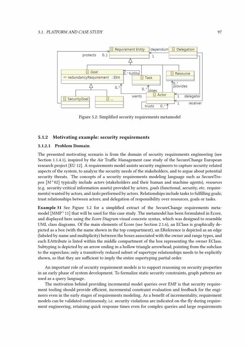
5.1. PLATFORM AND CASE STUDY 97
Figure 5.2: Simplied security requirements metamodel
5.1.2 Motivating example: security requirements
5.1.2.1 Problem Domain
The presented motivating scenario is from the domain of security requirements engineering (seeSection 1.1.4.1), inspired by the Air Trac Management case study of the SecureChange Europeanresearch project [EU 12]. A requirements model assists security engineers to capture security relatedaspects of the system, to analyze the security needs of the stakeholders, and to argue about potentialsecurity threats. The concepts of a security requirements modeling language such as SecureTro-pos [M+02] typically include actors (stakeholders and their human and machine agents), resources(e.g. security-critical information assets) provided by actors, goals (functional, security, etc. require-ments) wanted by actors, and tasks performed by actors. Relationships include tasks to fullling goals;trust relationships between actors; and delegation of responsibility over resources, goals or tasks.
Example 31 See Figure 5.2 for a simplied extract of the SecureChange requirements meta-model [MMP+11] that will be used for this case study. The metamodel has been formulated in Ecore,and displayed here using the Ecore Diagram visual concrete syntax, which was designed to resembleUML class diagrams. Of the main elements of Ecore (see Section 2.1.6), an EClass is graphically de-picted as a box (with the name shown in the top compartment), an EReference is depicted as an edge(labeled by name and multiplicity) between the boxes associated with the owner and range types, andeach EAttribute is listed within the middle compartment of the box representing the owner EClass.Subtyping is depicted by an arrow ending in a hollow triangle arrowhead, pointing from the subclassto the superclass; only a transitively reduced subset of supertype relationships needs to be explicitlyshown, so that they are sucient to imply the entire supertyping partial order.
An important role of security requirement models is to support reasoning on security propertiesin an early phase of system development. To formalize static security constraints, graph patterns areused as a query language.
The motivation behind providing incremental model queries over EMF is that security require-ment tooling should provide ecient, incremental constraint evaluation and feedback for the engi-neers even in the early stages of requirements modeling. As a benet of incrementality, requirementmodels can be validated continuously, i.e. security violations are indicated on-the-y during require-ment engineering, retaining quick response times even for complex queries and large requirements

98 CHAPTER 5. INCREMENTAL MODEL QUERIES OVER INDUSTRIAL EMF MODELS
models. Such a service provides a shortened feedback cycle, raising the eciency of the engineeringprocess.
Example 32 Figure 5.3 shows an example security requirement model with two actors A1 and A2;three goals G1, G2 and G3; four tasks T1, T2, T3, T4; and the wants, does, fulfills edgesbetween them, as well as mutual trust between the two actors. As the abstract model of [MMP+11] hasno associated visual concrete syntax, symbols were loosely based on Si*/Tropos [MMZ07] diagrams:actors are depicted here by large red discs, goals by rounded green rectangles, and tasks by bluehexagons. Each goal also has a redundancy requirement enclosed by curly braces.
Figure 5.3: Example security requirement model with redundancy requirements
Another example tied to a real case study will be shown in Section 6.1.3.3, and more elaboratemodels from a related case study will be shown in Section 6.1.3.
5.1.2.2 Analysis Tasks
Early-stage analysis of requirements models is carried out by (local and global) model queries. Supportcan range from nding violations of structural semantic constraints that represent security propertiesof the model, to generating reports that guide the engineer to x these problems.
One challenge where early-stage analysis is benecial is to detect violations of the trusted path
security constraint. The context is the following: a valuable data asset is provided by one actor, and iseventually delivered to a recipient actor, through potentially unreliable intermediate actors. A securitygoal requires the protection of the integrity and condentiality of this data resource. The trusted pathsecurity constraint states that either a trusted actor has to perform an action that explicitly fullls thegoal (e.g. time-stamping, digital signature and encryption), or else the entire data path must be trusted;indirect trust is permitted. The challenge is to formulate a query noTrustedPath which nds theviolations of this security constraint, so that the security problem can be reported to the engineer.
A second application of model queries is related to the redundancy security constraint. Redun-dancy is important for resilience against failures and attacks, and is therefore an integral part ofsecurity; thus requirements often have a minimal degree of redundancy associated with them. Forexample, the availability requirement of a service task or data asset can be augmented with the de-mand of triple modular redundancy, i.e. 3 replicas of the given data / service must be available. A goalwith the redundancyRequirement attribute set must be fullled by at least this number ofseparate tasks (performed by trusted actors). Two queries will be formulated in connection with thissecurity constraint: (a) redundancyViolated to nd goals whose redundancy requirement isnot met, and (b) totalMissingReplicas to compute an actor-centric progress indicator thatinforms of the total number of missing replicas for all the goals wanted by a given actor.

5.2. EMF MODEL QUERIES BASED ON GRAPH PATTERNS 99
All three of these constraints will be formulated in the sequel using a query language.
Example 33 Given the example model depicted in Figure 5.3, the rst redundancy query redun-dancyViolated will nd goals G1 and G2. The second redundancy query totalMissin-gReplicas will return 3 for actor A1 (as two fullling actions are missing for G1 and one for G2),and 0 for actor A2.
5.2 EMF model queries based on graph patterns
EMF-Incery [11,9] is a framework with a language for dening declarative local and global queriesover EMF models, and a runtime engine for executing them eciently without manual coding. The querylanguage of EMF-Incery is built on the concepts of graph patterns and partially reuses the syntaxof Viatra2 [VB07] as a concise and easy way to specify complex structural model queries.
In the subsequent sections, I will present the syntax of EMF-Incery step-by-step, by present-ing a solution to the motivating problem. The new language introduces some signicant semanticextensions over its precursor Viatra2, as well as syntactic sugar for conciseness. The two main areaswhere EMF-Incery diers from the original VTCL syntax are the structural/navigational languageelements and the handling of attributes and arithmetic expressions.
5.2.1 Structural constraints
The graph pattern based query language of EMF-Incery is based on the graph pattern formalismof Section 2.2. The type system is based on Ecore: pattern constraints use EClasses as classiers,EReferences and EAttributes as (association resp. attribute name) features. Pattern variables will bemapped to EObjects of the instance model (or values from the data algebra, see later). All patternsconform to the notion of disjunctive pattern (see Section 2.2.2), even if they have a single patternbody; thus not all variables have to be exposed as parameters.
Due to the fact that EMF lacks relation objects, the most important deviation from the formal-ization in Section 2.2 is that relation constraints do not have a relation variable. Or as an equivalentalternative, the relation variable exists but must not be used anywhere else, i.e. it is not allowed as aparameter and cannot be in the domain of any other constraint. In either case, the textual syntax forrelation constraints simply omits the relation variable.
Example 34 The rst example demonstrates the structural pattern constraints of the EMF-Incerylanguage. The trusted path security constraint is checked by the graph pattern noTrustedPathdened in Listing 5.1. As introduced in Section 5.1.2.2, the trusted path security constraint states thatthe delegation paths of resources protected by security goals must entirely consist of trusted actors,unless there is an explicit fullling task carried out by a trusted party. Line 1 introduces the nameof the pattern and lists the four parameter variables concernedActor, secGoal, asset anduntrustedActor; all other variables will be local to a body. In the following lines, curly bracesenclose the single pattern body; multiple bodies would be separated by the keyword or. The bodycontains pattern constraints separated by semicolons:
• Line 3 represents an entity constraint that states that variable secGoal corresponds to anEObject of type SecurityGoal.
• Line 2 expresses a relation constraint that navigates from variable concernedActor alongan EReference of type wants, and the EObject reached that way should be the one associatedwith variable secGoal. Note that there is no separate variable for the relation itself.

100 CHAPTER 5. INCREMENTAL MODEL QUERIES OVER INDUSTRIAL EMF MODELS
1 pattern noTrustedPath(concernedActor, secGoal, asset, untrustedActor)=2 Actor.wants(concernedActor, secGoal);3 SecurityGoal(secGoal);4 SecurityGoal.protects(secGoal, asset);5 Actor.provides(providerActor, asset);6 find transitiveDelegation(providerActor, untrustedActor, asset);7 neg Actor.trust*(concernedActor, untrustedActor);8 neg find trustedFulfillment(concernedActor, _anyActor, _anyTask, secGoal);9
Listing 5.1: Violations of the trusted path security constraint, EMF-specic syntax
• Similarly, Line 4 and Line 5 introduce additional structural relation constraints. Achain of two or more such relation constraints can be abbreviated as e.g. Ac-tor.wants.protects(concernedActor, asset); instead of Line 2 and Line 4;the more verbose form was chosen here so that secGoal can be a parameter variable.
• Line 6 shows an example for pattern composition. The called pattern is transitiveDel-egation (dened elsewhere) and the variables providerActor, untrustedActor,and asset are mapped to its parameters in the composition mapping (see Section 2.2.2.3).
• Line 8 expresses a NAC in a negative pattern call constraint; it can alternatively be under-stood as the equivalent case of a negative subpattern holding a single pattern compositionconstraint that call pattern trustedFulfillment (dened elsewhere). Variables _any-Actor and _anyTask, as indicated by a Prolog-style underscore, are single-use variablesappearing only in the negative subpattern. Altogether pattern noTrustedPath matchesfor a given concernedActor and secGoal only if there exists no substitution of _any-Actor and _anyTask that satises the call of trustedFulfillment.
• Line 7 computes a transitive closure inside a negative subpattern. The closure is indicatedusing the transitive closure operator (the symbol is * for reexive transitive closure, whilewould + denote irreexive closure). Here, the reexive operator is applied to the EReferenceActor.trust, instead of a pattern call of a binary pattern (which would be only possible incase of irreexive transitive closure).
Two major limitations of the core EMF API are the lack of (i) ecient enumeration of all instancesof a class regardless of location, and (ii) backwards navigation along uni-directional references. Asseen here, the structural graph constraints of EMF-Incery can provide these missing features forend-users, via EMF-Incery Base [SU].
5.2.2 Attribute and arithmetic constraints
Example 35 The next example demonstrates the value assignment and data predicate pattern con-straints of the EMF-Incery language. The redundancy security constraint is checked by the graphpatternredundancyViolated dened in Listing 5.2. As introduced in Section 5.1.2.2, the redun-dancy security constraint states that a goal goal with a redundancyRequirement attributemust be fullled at least as many times (by trusted actors) as specied by the attribute value. First weinvestigate the helper pattern redundantReplicas that counts the number of replicas fulllingthe given goal wanted by the given actor, and also extract the required redundancy. Line 6 asserts a

5.2. EMF MODEL QUERIES BASED ON GRAPH PATTERNS 101
1 pattern redundancyViolated(concernedActor, goal)=2 find redundantReplicas(concernedActor, goal, redundancyFound, requiredRedundancy);3 check (redundancyFound < requiredRedundancy);4 5 pattern redundantReplicas(concernedActor, goal, redundancyFound, requiredRedundancy)=6 Actor.wants(concernedActor, goal);7 Goal.redundancyRequirement(goal, requiredRedundancy);8 redundancyFound == count find9 trustedFulfillment(concernedActor, _anyFulfillerActor, _anyTask, goal);
10 Listing 5.2: Violations of the redundancy security constraint
structural relation (reference) of association typeActor.wants, while line 7 asserts a value assign-ment of typeGoal.redundancyRequirement. Both kind of relation constraints are expressedby similar syntax, but the type is an EReference in the rst case and an EAttribute in the second. Asa consequence, requiredRedundancy will be a data entity variable of type EInt (equivalent toInteger). Lines 8-9 express an aggregate pattern constraint (see Section 2.2.2.4) that aggregates thecount of those matches of pattern trustedFulfillment that are incident on the given actorand goal, and the aggregate result is stored in redundancyFound, which is once again a data en-tity variable of type EInt. Note the use of the underscore notation (similar to the NAC in Listing 5.1)for variables _anyFulfillerActor and _anyTask that are not part of the main pattern re-dundantReplicas, merely aggregated over. This pattern redundantReplicas is called bypattern redundancyViolated on Line 2. Line 3 contains the attribute check verifying that thevalue of variable redundancyFound is less than the value of requiredRedundancy; this isactually a relation constraint between the two variables, where the type is the data predicate < (morecomplicated checks would be interpreted as data predicates with higher arity).
The pattern redundancyViolated described in Listing 5.2 identies violations of this secu-rity constraint, using a helper pattern.
Example 36 The secondary challenge is to provide an actor-centric indicator report on the numberof missing replicas; the solution is shown in Listing 5.3. The number of further replicas needed thatare trusted by a given actor to fulll a given goal is computed by pattern missingReplicas.Line 6 reuses patternredundantReplicas dened by Listing 5.2. Line 7 computes the dierencebetween the required and present degrees of redundancy, and stores the result in variable missing;this line expresses a data predicate constraint of ternary arity that is functionally determined (seeDenition 18) by two of its variables. The check in line 8 uses variable missing and the value literal0; as it introduces no new variable, it does not have to be functionally determined (hence the use of thecheck() syntax instead of eval()). Pattern totalMissingReplicas uses the aggregateexpression in line 3 to add up all these missing replica counts through all goals of a given actor;sum(missing) species that it is variable missing that should be summed (i.e. the match ismapped into the Abelian group of integers as the value of missing). Note the use of the underscorenotation for variable _anyGoal that is not part of the main pattern totalMissingReplicas,merely aggregated over.

102 CHAPTER 5. INCREMENTAL MODEL QUERIES OVER INDUSTRIAL EMF MODELS
1 pattern totalMissingReplicas(concernedActor, totalMissing)=2 Actor(concernedActor);3 totalMissing == sum(missing) find missingReplicas(concernedActor, _anyGoal, missing);4 5 pattern missingReplicas(concernedActor, goal, missing)=6 find redundantReplicas(concernedActor, goal, redundancyFound, requiredRedundancy);7 missing == eval(requiredRedundancy - redundancyFound);8 check (missing > 0);9
Listing 5.3: Missing replicas per actor and goal
5.2.3 Query language structure
Summarizing the preceding example-driven introduction, the abstract structure of the query languageis presented here, without going into the details of the actual grammar.
Patterns have a name, a list of named parameter variables (with optional type constraints), andone or more pattern bodies. A pattern body is a list of pattern constraints that are expressed overarguments.
Certain constraints are enumerable constraints; this means that the fullling value combinationscan be enumerated from the model, without any prior knowledge. These include the entity con-straint, the relation constraint, longer path expressions (consisting of a chain of two or more relationtypes), the pattern call and transitive closure (which is the irreexive closure of a binary enumerableconstraint). Non-enumerable constraint types include NAC (which is the negation of an enumerableconstraint), equality, inequality and extensible Boolean-valued check expressions on variables.
The argument expressions can be variables (which are either local to the body or one of the pat-tern parameters), constant literal values and computed values. Computed values include extensibleexpression evaluation on variables, and aggregation of an enumerable constraint by a suitable aggre-gator.
All of these language elements have been demonstrated by the above examples.
5.3 Integrating incremental pattern matching to EMF
Here an approach is described for realizing the Rete-based incremental matcher above EMF, facingthe technical constraints described in Section 5.1.1, in order to match patterns dened in the languageof Section 5.2. According to Chapter 3, sustaining a stateful pattern matcher requires the modelingplatform to provide elementary model query operations, and to invoke the maintenance routine withgraph deltas upon each change to the model. The following paragraphs investigate how this can beachieved over EMF.
5.3.1 EMF as graph model with elementary queries
The rst issue to address is that of elementary model queries. Since EMF does not provide an ecientimplementation for all elementary query cases, a straightforward solution is to extend the platform byestablishing index structures that can eciently answer these queries. For example, one such indexmay map each EClass (or, for better performance, a restricted subset of EClasses) to the set of itsinstance EObjects. Another one may index EObjects of a given type according to the value of one oftheir EAttributes, or keep track of the references (structural relations) incoming to an EObject. These

5.3. INTEGRATING INCREMENTAL PATTERN MATCHING TO EMF 103
index structures can be initialized by a traversal of the EObjects constituting the model, and theycan be incrementally maintained based on the graph delta by the maintenance routine of the statefulmatcher (before updating the Rete structure).
The expanded set of ecient elementary model queries is publicly available as a separate servicecalled EMF-Incery Base [9][SU], since it is useful in a wide range of applications beyond theinitialization of Rete input nodes. The following paragraphs will discuss how EMF models can betraversed to initialize these indexes (which in turn will be used to initialize the input nodes of Rete),and how to obtain a graph delta upon changes to the EMF model so that the maintenance of both Reteand these indexes can be carried out.
While there can be many EObject instances existing simultaneously within the system memory,they probably should not all belong to the same model; and even if they do, there should be a way ofnding and enumerating them, so that the model can be traversed and EMF-Incery Base cachescan be initialized. Therefore, a query engine must have a way to nd out which model elementsconstitute a model, i.e. which elements are within the scope of the pattern matcher. The most practicalchoice is to dene an EMF instance model as the contents of the containment forest below a given setof roots (which may be EObjects, Resources and ResourceSets). The typically case is the containmenttree of a single ResourceSet. There may be cross-references egressing or ingressing the boundary ofthis containment forest; the question whether they should be considered part of the model will notbe discussed here, but (normally) there are no such references if the model is a single ResourceSet.
Example 37 Suppose that the requirements model described in Example 32 on page 98 resides in anEMF Resource R1 within ResourceSet S. Suppose also that there is a separate Security Goal G4 withredundancy requirement 2 that resides in EMF ResourceR2, which is not contained in the ResourceSetS. If this ResourceSet S is the scope of EMF-based graph model g, then for instance g.Query(∗ ::SecurityGoal).out = 〈G1, SecurityGoal〉, 〈G2, SecurityGoal〉, 〈G3, SecurityGoal〉, since thefourth goal instance is outside the scope.
5.3.2 Translating from EMF notications to graph delta
Containment hierarchies from given starting points can be traversed using the allowed elementarymodel query operations, therefore the contents of an EMF model can be discovered. Determining thegraph delta is more dicult.
An EMF model can be changed by modifying members (EAttribute values, EReference targets) ofan EObject, or by adding/removing EObjects to/from a Resource, adding/removing Resources to/froma ResourceSet (some miscellaneous cases omitted). Upon the change, an EMF change noticationmessage emanates from the model. If a relation is inserted or removed, the notication contains thedirection of change (insertion/deletion) and the source, target and type of the changed relation (onlythe relation identier itself is omitted, which does not exist in EMF). If the contents of a Resource orResourceSet is changed, the notication message is similar, but lacks a relation type. As described inSection 5.1.1, the change notication is then delivered to notication listeners/adapters registered atthe source Notier. Then the challenge is to translate from this notication schema to graph deltasas required by the incremental pattern matcher.
The rst approximate solution is to attach notication listeners to each EObject in the modelscope, and then treat the received notications as graph model deltas. This initial solution has someshortcomings:
• Deleting a containment relation would remove the whole containment subtree of the targetobject from the model (according to the above denition of model boundaries); the model delta

104 CHAPTER 5. INCREMENTAL MODEL QUERIES OVER INDUSTRIAL EMF MODELS
should therefore contain several entity and relation deletions even though only a single noti-cation is received about the deletion of the containment relation.
• Conversely, a whole containment subtree can be inserted into the model at once with a singleoperation.
• If new entities are added to or removed from the models, the set of Notiers that have registeredadapters must be adjusted accordingly, so that no notications are missed from newly insertedNotiers, and no irrelevant/misleading notications are received from Notiers no longer be-longing to the model.
The chosen solution relies on EContentAdapter, an advanced notication adapter mechanism shippedwith EMF. An EContentAdapter, when attached to a Notier, will also attach itself recursively toall contained Notiers; conversely, when it is removed, it will also remove itself from all containedelements. Furthermore, while attached to a Notier, it will also monitor notications of containmentrelations to maintain itself as an adapter attached to all contained elements. Consequently, after anEContentAdapter is manually attached to one or more Notiers, it will keep itself attached exactlyto those Notiers that constitute the containment forest rooted at the given elements, i.e. the extentof graph model. This mechanism can be extended by the following additional notication handlingbehavior to meet our needs:
• Relation notications will be treated as relation insertions/deletions in the graph delta.
• When the adapter is attached to a new EObject, the entity itself as well as all outgoing relationsare considered as insertions in the graph delta.
• When the adapter is removed from a new EObject, the entity itself as well as all outgoingrelations are considered as deletions in the graph delta.
There are still some minor technical details that require attention in an implementation, but areomitted here for brevity. These include EMF derived features in general and special cases such asFeatureMaps; exceptional situations when a ResourceSet is not closed with respect to cross-references;and so on.
Example 38 Continuing from Example 37, the EContentAdapter is attached to ResourceSet S, Re-source R1, and the EObjects contained in R1 (namely A1, A2, G1, G2, G3, T1, T2, T3, T4); it is notattached to R2, since it is not contained in S.
Supposing now that ResourceR2 is loaded within ResourseSetS, a single EMF change noticationis received at S: an insertion, with S as source, R2 as target, and no feature (since this is a changeof the ResourceSet contents). As a consequence, the EContentAdapter installs itself to R2, and thenrecursively to its contents, which consists currently of the new Security Goal G4. Since G4 is anEObject, its insertion will be part of the graph delta, as well as the insertion of all outgoing relations.The latter currently includes the redundancy requirement value assignment from G4 to data value 2.Altogether, the incremental pattern matcher will receive the graph delta δ = 〈δent− , δrel− , δent+ , δrel+ 〉,with δent− = ∅, δrel− = ∅, δent+ = +(G4 :: SecurityGoal), δrel+ = +(G4
(::redundancyRequirement)−−−−−−−−−−−−−−−−−→2).
Finally, consider that if the redundancy requirement of G4 is now changed from 2 to 1, theEObject G4 emits an EMF change notication, which is likewise received by the newly attached
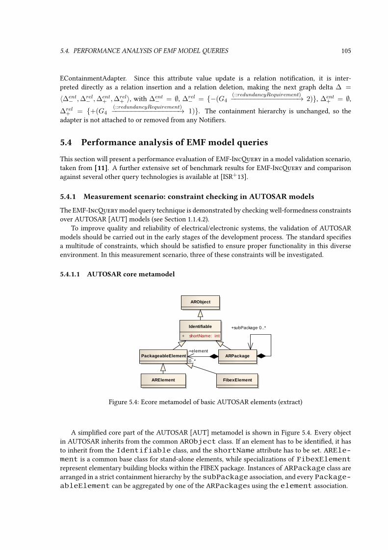
5.4. PERFORMANCE ANALYSIS OF EMF MODEL QUERIES 105
EContainmentAdapter. Since this attribute value update is a relation notication, it is inter-preted directly as a relation insertion and a relation deletion, making the next graph delta ∆ =
〈∆ent− ,∆rel
− ,∆ent+ ,∆rel
+ 〉, with ∆ent− = ∅, ∆rel
− = −(G4(::redundancyRequirement)−−−−−−−−−−−−−−−−−→ 2), ∆ent
+ = ∅,∆rel
+ = +(G4(::redundancyRequirement)−−−−−−−−−−−−−−−−−→ 1). The containment hierarchy is unchanged, so the
adapter is not attached to or removed from any Notiers.
5.4 Performance analysis of EMF model queries
This section will present a performance evaluation of EMF-Incery in a model validation scenario,taken from [11]. A further extensive set of benchmark results for EMF-Incery and comparisonagainst several other query technologies is available at [ISR+13].
5.4.1 Measurement scenario: constraint checking in AUTOSAR models
The EMF-Incery model query technique is demonstrated by checking well-formedness constraintsover AUTOSAR [AUT] models (see Section 1.1.4.2).
To improve quality and reliability of electrical/electronic systems, the validation of AUTOSARmodels should be carried out in the early stages of the development process. The standard speciesa multitude of constraints, which should be satised to ensure proper functionality in this diverseenvironment. In this measurement scenario, three of these constraints will be investigated.
5.4.1.1 AUTOSAR core metamodel
ARElement
ARObject
ARPackage
FibexElement
Identifiable
+ shortName: int
PackageableElement
+subPackage 0..*
+element
0..*
Figure 5.4: Ecore metamodel of basic AUTOSAR elements (extract)
A simplied core part of the AUTOSAR [AUT] metamodel is shown in Figure 5.4. Every objectin AUTOSAR inherits from the common ARObject class. If an element has to be identied, it hasto inherit from the Identifiable class, and the shortName attribute has to be set. AREle-ment is a common base class for stand-alone elements, while specializations of FibexElementrepresent elementary building blocks within the FIBEX package. Instances of ARPackage class arearranged in a strict containment hierarchy by the subPackage association, and every Package-ableElement can be aggregated by one of the ARPackages using the element association.

106 CHAPTER 5. INCREMENTAL MODEL QUERIES OVER INDUSTRIAL EMF MODELS
More specic subtypes will be introduced for the validation rules below.
5.4.1.2 ISignal constraint check
The rst consistency check chosen from the AUTOSAR standard is the ISignal check, which is essen-tially a cardinality enforcement.
The two metamodel elements for this constraint (SystemSignal and ISignal) are illus-trated in Figure 5.5, extending Figure 5.4. A SystemSignal is the smallest unit of data (it is unique perSystem) and it is characterized by its length (in bits). (Also two optional elements can be specied,Datatypes and DataPrototype constants, but they are not used in this example.) An ISignal must becreated for each SystemSignal (these will be the signals of the Interaction Layer). Conversely, eachISignal must be associated with either a SystemSignal or a SystemSignalGroup. A signal group refersto a set of signals that must always be kept together to ensure the atomic transfer of information inthem.
FibexElement
ISignal
ARElement
AbstractSignal
IPduIdentifiable
ISignalToIPduMapping
FibexElement
Pdu
SignalIPdu
SystemSignal
SystemSignalGroup
+systemSignal
+signal
+signalToPduMapping+systemSignal
Figure 5.5: AUTOSAR metamodel extract (ISignal)
1 pattern CC_ISignal(iSig)=2 ISignal(iSig);3 neg ISignal.systemSignal(iSig, _anySysSig);4
Listing 5.4: Graph pattern for the ISignal consistency check
Listing 5.4 encodes the graph pattern CC_ISignal. The structural part contains only a singlestructural entity variable of type ISignal, but the NAC connects this entity to a SystemSignalinstance via the ISignal.systemSignal association. Thus the graph pattern CC_ISignalmatches ISignal instances that are not connected to a SystemSignal (or a group). This graphpattern can be used as a declarative model query, in order to validate the model against the structuralwell-formedness constraint that requires each ISignal to be connected to a SystemSignal.
5.4.1.3 Constraint check for system signal group (SSG) mapping
The second consistency check is signicantly more complex than the previous one.The required metamodel elements for this constraint check are likewise illustrated in Figure 5.5.
A PDU (Protocol data unit) is the smallest information which is delivered through a network layer.It is an abstract element in AUTOSAR, and has multiple dierent subtypes according to the avail-able network layers. This case study will only examine IPdu (Interaction Layer PDU), particularly

5.4. PERFORMANCE ANALYSIS OF EMF MODEL QUERIES 107
SignalIPdu elements. These SignalIPdus are used to transfer ISignals. The positions of these ISignalsare dened by the ISignalToIPduMappings. As discussed before, ISignal are associated with either aSystemSignal or a SystemSignalGroup.
To ensure the atomic transfer of a SystemSignalGroup, they have to be packed properly intoSignalIPdus. This means that if a SystemSignalGroup is referenced from a given SignalIPdu (via anISignalToIPduMapping), then every SystemSignal in it should be referenced as well from that Sig-nalIPdu (note that an ISignalToIPduMapping references ISignals, but as every SystemSignal and Sys-temSignalGroup must have an ISignal, this is not a problem – the parent-child relationship is thusexpressed between the SystemSignal and SystemSignalGroup instances). Conversely, if a SystemSig-nal is mapped to an SignalIPdu, then its parent SystemSignalGroup must be mapped to it as well.
This latter constraint is formulated as graph pattern CC_SystemSignal (shown in Listing 5.5along with helper patterns), matching one of the two cases of violation where the mapping elementcorresponding to the SystemSignalGroup is missing (as indicated by the NEG condition), even thoughthe child SystemSignal is mapped.
1 pattern CC_SystemSignal(mChild, isParent, ssParent) = 2 find systemChild(isChild, ssChild, ssParent, isParent);34 find signalOfPDU(pdu, mChild, isChild);5 neg find signalOfPDU(pdu, mParent, isParent);6 78 pattern systemChild(isChild, ssChild, ssParent, isParent) = 9 SystemSignalGroup.systemSignal(ssParent, ssChild);
10 ISignal.systemSignal(isChild, ssChild);11 ISignal.systemSignal(isParent, ssParent);12 13 pattern signalOfPDU(pdu, map, iSig) = 14 SignalIPdu.signalToPduMapping(pdu, map);15 ISignalToIPduMapping.signal(map, iSig);16
Listing 5.5: Pattern to nd invalid signal group mappings
5.4.1.4 Simple Channel consistency check
To demonstrate the third consistency check, some additional AUTOSAR elements have to be de-scribed. These elements are illustrated by Figure 5.6, extending Figure 5.4.
In AUTOSAR, ECU (Electronic Control Unit) instances can communicate with each other througha communication medium represented by a PhysicalChannel. Physical Channels are aggre-gated by a CommunicationCluster, which is the main element to describe the topologicalconnection of communicating ECUs. A Physical Channel can contain ISignalTriggering andIPduTriggering elements. The IPduTriggering and ISignalTriggering describethe usage of IPdus and Signals on physical channels. ISignalTriggering denes the manner of trigger-ing of an ISignal on the channel, on which it is sent. IPduTriggering describes on which channel theIPdu is transmitted.
The following constraint has to be satised for a physical channel: if a PhysicalChannel chancontains a SignalIPdu iPdu (through an IPduTriggering), then each ISignal iSig that is containedby iPdu (through an ISignalToIPduMapping) must have a related ISignalTriggering in the channelchan. In other words the channel is invalid if there is at least one ISignal iSig that has no related

108 CHAPTER 5. INCREMENTAL MODEL QUERIES OVER INDUSTRIAL EMF MODELS
Identifiable
IPduTriggering
FibexElement
CommunicationCluster
Pdu
IPdu
FibexElement
ISignal
Identifiable
ISignalToIPduMapping
Identifiable
ISignalTriggering
Identifiable
PhysicalChannelSignalIPdu
+signal
+signalToPduMapping
+signal
+iPdu
+iSignalTriggering
+iPduTriggering
+physicalChannel
Figure 5.6: AUTOSAR metamodel extract (Channel)
ISignalTriggering in the channel. This informal denition is formalized in Listing 5.6 as a graphpattern. If pattern CC_Channel(chan) can be matched for a Physical channel chan, then it isconsidered to be invalid.
1 pattern CC_Channel(chan) = 2 PhysicalChannel.iPduTriggering.iPdu(chan, iPdu);3 SignalIPdu.signalToPduMapping.signal(iPdu, iSig);4 neg PhysicalChannel.iSignalTriggering.signal(chan, iSig);5
Listing 5.6: Pattern to nd invalid physical channels
5.4.2 Benchmarking
The benchmark simulates the typical scenario of model validation. The user is working with a largemodel, the modications are small and local, but the result of the validation needs to be computedas fast as possible. To emulate this, the benchmark sequence consists of the following sequence ofoperations:
1. First, the model is loaded into memory. In the case of EMF-Incery, most of the overhead isexpected to be registered in this phase, as the pattern matcher cache needs to be constructed.Note however, that this is a one-time penalty, meaning that the cache will be maintained incre-mentally as long as the model is kept in memory.
2. Next, in the rst query phase, the entire match set of the constraints is queried. This meansthat a complete validation is performed on the model, looking for all elements for which theconstraint is violated.
3. After the rst query, model manipulations are executed. These operations only aect a smallxed subset of elements, but change the constraint’s validity.
4. Finally, in the second query phase, the complete validation is performed again, to check the neteect of the manipulation operations on the model.

5.4. PERFORMANCE ANALYSIS OF EMF MODEL QUERIES 109
In addition to the EMF-Incery-based implementation, two alternative prototypes were in-volved in the performance comparison: a plain Java variant and an OCL variant that uses MDT-OCL[Ecl11]; neither of which apply incremental techniques.
The benchmark models were generated automatically to be large enough for performance mea-surements, and at the same time contain some violations of the constraints in the case study. Thesimulated model editing performed in Step 3 is a relatively short automated manipulation sequencethat was designed to cause new violations or repair existing violations. See [11] for details on thegenerated instance models and the applied model modications.
The measurement was carried out in 2010. The exact versions of EMF and MDT-OCL were 2.5.0and 1.2.0 respectively, running on Eclipse Galileo SR1 20090920-1017. The benchmarks ran on an IntelCore2 E8400-based PC clocked at 3.00GHz with 3.25GBs of RAM on Windows XP SP3 (32 bit), usingthe Sun JDK version 1.6.0_17 (with a maximum heap size of 1536 MBs). Execution times were recordedusing thejava.lang.System class, while memory usage data has been recorded in separate runsusing the java.lang.Runtime class (with several garbage collector invocations to minimizethe transient eects of Java memory management). The data shown in the results correspond to theaverages of 10 runs each.
All implementations share the same code for model manipulation. They dier only in the queryphases:
• The EMF-Incery variant uses the EMF-Incery for reading the match set of the graphpatterns corresponding to constraints. These operations are only dependent on the size of thegraph pattern and the size of the matching set itself (this is empirically conrmed by the results,see Section 5.4.3). To better reect memory consumption, the RETE nets for all three constraintswere built in each case.
• The plain Java variant performs model traversal using the generated model API of EMF. Thisapproach is not naive, but intuitively manually optimized based on the constraint itself (but noton the actual structure of the model [14]).
• The OCL variant has been created by systematically mapping the contents of the graph patternsto OCL concepts, to ensure equivalence. We did not perform any OCL-specic optimization.
To ensure the correctness of the Java implementation, a set of small test models was created in orderto verify the results manually. The rest of the implementations have been checked against the Javavariant as the reference, by comparing the number of valid and invalid matches found in each round.See [11] for more information about the exact EMF-Incery queries, OCL expressions and Javacode used for the benchmarks.
5.4.3 Analysis of the results
Based on the results (Table 5.1), we have made the following observations:
1. As expected, query operations with EMF-Incery are nearly instantaneous, they are onlymeasurable for larger models (where the match set itself is large, and it takes a considerableamount of time just to go through all matches). In contrast, both Java and OCL variants ex-hibit a polynomially increasing characteristic, with respect to model size. The optimized Javaimplementation outperforms OCL, but only by a constant multiplier.
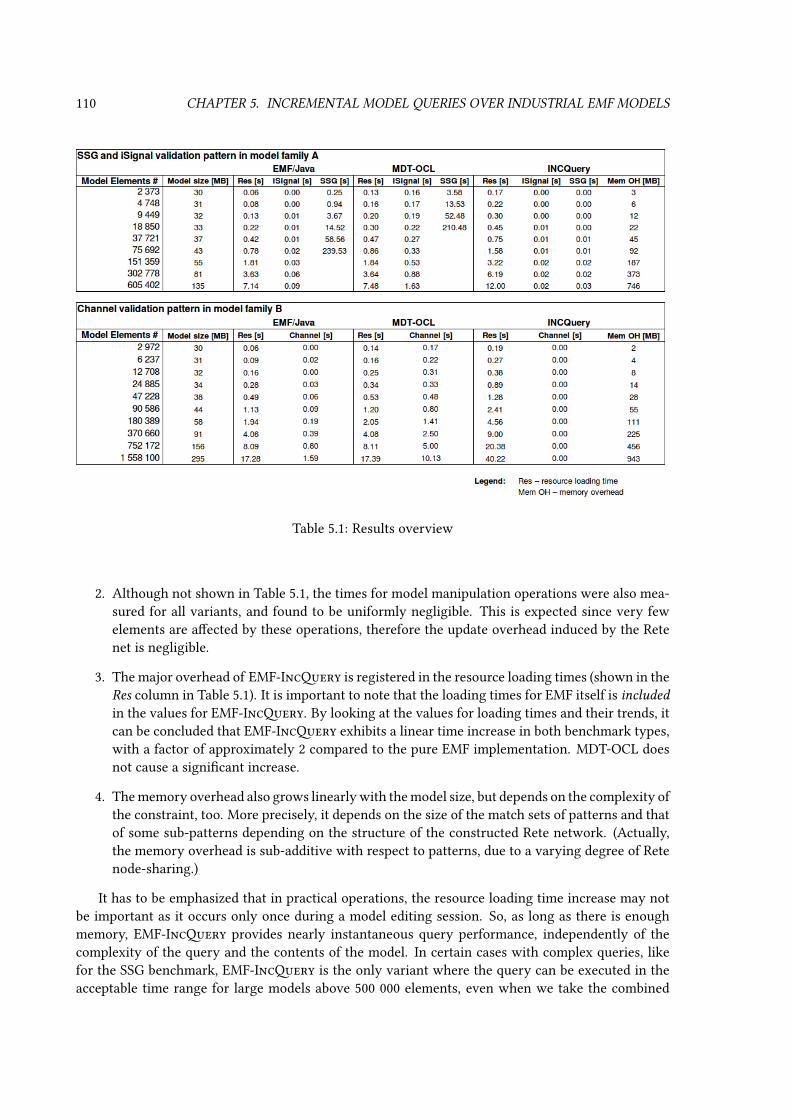
110 CHAPTER 5. INCREMENTAL MODEL QUERIES OVER INDUSTRIAL EMF MODELS
Table 5.1: Results overview
2. Although not shown in Table 5.1, the times for model manipulation operations were also mea-sured for all variants, and found to be uniformly negligible. This is expected since very fewelements are aected by these operations, therefore the update overhead induced by the Retenet is negligible.
3. The major overhead of EMF-Incery is registered in the resource loading times (shown in theRes column in Table 5.1). It is important to note that the loading times for EMF itself is includedin the values for EMF-Incery. By looking at the values for loading times and their trends, itcan be concluded that EMF-Incery exhibits a linear time increase in both benchmark types,with a factor of approximately 2 compared to the pure EMF implementation. MDT-OCL doesnot cause a signicant increase.
4. The memory overhead also grows linearly with the model size, but depends on the complexity ofthe constraint, too. More precisely, it depends on the size of the match sets of patterns and thatof some sub-patterns depending on the structure of the constructed Rete network. (Actually,the memory overhead is sub-additive with respect to patterns, due to a varying degree of Retenode-sharing.)
It has to be emphasized that in practical operations, the resource loading time increase may notbe important as it occurs only once during a model editing session. So, as long as there is enoughmemory, EMF-Incery provides nearly instantaneous query performance, independently of thecomplexity of the query and the contents of the model. In certain cases with complex queries, likefor the SSG benchmark, EMF-Incery is the only variant where the query can be executed in theacceptable time range for large models above 500 000 elements, even when we take the combined

5.5. CHAPTER CONCLUSIONS 111
times for resource loading and query execution into consideration. The performance advantage is lessstriking in other cases, as indicated by the gures for the Channel and ISignal benchmarks, where thedierence remains in the range of a few seconds even for large models.
Overall, EMF-Incery suits application scenarios with complex queries, which are invokedmany times, with relatively small model manipulations in-between. Even though the memory con-sumption overhead is acceptable even for large models on today’s PCs, the optimization techniquesbased on combining various pattern matching techniques [14] previously presented for Viatra2 ap-ply to EMF-Incery too (even if their implementation over EMF will require some future work).
5.5 Chapter conclusions
The chapter presented EMF-Incery as the next evolutionary step in eciently executing complexqueries over EMF models by adapting incremental graph pattern matching technology.
The proposed query language syntax is derived from the graph pattern fragment of the Viatra2transformation language [VB07] and tailored to the task of querying EMF models, with additionalsignicant semantic extensions to its predecessor. The execution mechanism reuses the core conceptsof Rete networks from my previous results and integrates it to EMF. Measurements have conrmedthat the technique provides fast evaluation of complex model queries.


Chapter
6
eries and Transformations forSecurity Requirements
This chapter partially follows [18] and [33].
6.1 Introduction
Modern software systems are increasingly complex and the environments where they operate areincreasingly dynamic. The number and needs of stakeholders are also changing constantly as theyadjust to changing environments. A consequence of this trend is that the requirements for a softwaresystem are numerous and they change continuously. To deal with evolution, we need analysis tech-niques that assess the impact of system evolution on the satisfaction of requirements. Requirementsfor system security, in particular, are very sensitive to evolution: security properties that are satisedbefore the evolution might no longer hold or as result of the evolution.
Another important aspect is the change management process itself which is a major problemin practice. Changes make the traceability of requirements dicult and the monitoring of require-ments unreliable: requirements management is time-consuming and error-prone when done manu-ally. Thus, a semi-automated requirements evolution management environment, supported by a tool,will improve requirement management with respect to keeping requirements traceability consistent,realizing reliable requirements monitoring, improving the quality of the documentation, and reducingthe manual eort.
Section 6.1.1 presents SeCMER [18], a tool developed in the context of the SecureChange Euro-pean project [EU 12]. The tool supports the dierent steps of SeCMER methodology for evolutionaryrequirements [31].
The SeCMER tool provides an opportunity for leveraging a synergy of novel techniques intro-duced throughout the thesis. Change-driven transformations (addressed in Chapter 7) with incre-mental pattern matching (addressed in Chapter 3) are employed on an industrial EMF platform (ad-dressed in Chapter 5) to ensure change propagation (see Section 6.4) monitor argument validity (seeSection 6.3), to automatically detect violations or fulllment of security properties (see Section 6.2),and to issue alerts prompting human intervention, a manual analysis or argumentation process, ortrigger automated reactions in certain cases.
113

114 CHAPTER 6. QUERIES AND TRANSFORMATIONS FOR SECURITY REQUIREMENTS
6.1.1 Overview of the SeCMER tool
The goal of the SeCMER tool is to support the requirement engineers in following the associatedSeCMER methodology. During the entire activity of requirements engineering, requirements modelcan undergo automated, pattern-based static analysis and manual, informal argumentation analysisto discover security issues.
The tool provides basic viewing and editing functionality:
• Requirements elicitation: editing the security requirements model to identify e.g. stakeholders,resources provided, actions performed, functional and security goals stated and met, decompo-sition, input / output dependencies of actions or goals, trust between stakeholders and nallydelegation of duties or access. Requirements models are represented internally in the SeCMERconceptual model for security requirements (see [MMP+11] or Section 5.1.2.1 for a simpliedextract). Instead of displaying the abstract model, however, the user interface uses a modiedversion of the Si* / Tropos visual syntax [MMZ07].
• Recording arguments carried out by security experts that identify security liabilities and prob-lems. Also modeling the breakdown structure of arguments, the interrelation with counter-arguments (rebuttals, mitigations), and the back-tracing of elementary facts to concepts in therequirements model. See [TYHN10] to learn more.
Additionally, the following added-value mechanisms are implemented:
• An automated static security analysis considers a class of security problems that are dened byan extensible set of security constraints. Each security constraint is a graph pattern-based modelquery that identies parts in the model that violate a given security property. The analysisdetect violations of the given security properties and oer automated solutions. Violationsappear as Eclipse problem markers (warnings). The suggested solutions appear as Quick Fixrules. For details, see Section 6.2.
• Traceability links (“evidence”) can be established between the argument and requirement mod-els. They enable automatic detection of requirement changes that make a manually conductedargument obsolete. Model changes involving the ground facts may trigger a notication thatalerts the user about the possibility that the argument may have become invalid due to thechange. The security experts can then revisit these arguments to reect the evolution, while nocostly revision process is required for unaected arguments. For details, see Section 6.3.
• The requirements model is always represented as a visual Si*/Tropos diagram, and also as amore abstract underlying SeCMER model. There is on-the-y bi-directional synchronizationbetween the abstract SeCMER requirement model and its Si* concrete syntax representation.Changes made in either model, whether initiated by the editor functionality or e.g. via a QuickFix, are transformed and synchronized between the SeCMER abstract syntax and Si* aspect onthe y. For details, see Section 6.4.
A screencast1 demonstrates the SeCMER tool in action, via a feature tour that presents variousscenarios including most of the examples that will be used throughout Section 6.1.
1http://www.youtube.com/watch?v=OWwzcNeSuJM

6.1. INTRODUCTION 115
6.1.2 Metamodels in the SeCMER tool
As follows from Section 6.1.1, the tool integrates heterogeneous models conforming to dierent meta-models. The abstract security requirement model conforms to metamodel MMSeCMER, a simpliedextract of which has already been introduced in Section 5.1.2 on page 97.
6.1.2.1 Concrete syntax: Si*
The concrete syntax of the requirement model is based on the Si*/Tropos diagram, thus there is also anSi* model conforming to metamodel MMSi∗. Section 6.4 will provide more information on MMSi∗.
The SeCMER tool provides bidirectional synchronization between the abstract and concrete rep-resentations. Most traditional approaches for implementing bidirectional synchronization require acorrespondence model between them conforming to MMcorr , and also an unidirectional glue (seeSection 2.1.3) for each ofMMSeCMER andMMSi∗ that points fromMMcorr to the respective require-ments formalism: MMSeCMER
MMglue1←−−−−−− MMcorr
MMglue2−−−−−−→ MMSi∗. Note however, that Section 7.3will present a way to dene the bidirectional synchronizing transformation with no need for suchcorrespondence models whatsoever.
6.1.2.2 Argumentation support
The goal of the argument models is to support or refute the satisfaction of security requirements.The arguments are recorded in a structured fashion, so that overall conclusions are drawn from morebasic statements, which may themselves be the consequence of earlier claims; this tree of argumentsis ultimately based on assumptions and ground facts. Some of these facts originate from the securityrequirement model, and will be called here evidence.
The actual argument model has rich structure. Yet for the purposes of the case study in this the-sis, the argument metamodel MMarg can be simplied to a single class Argument. The case studymetamodel is then obtained by the glue-merge MMarg
MMevidence−−−−−−−→ MMSeCMER of this argumentmetamodel to the security requirement metamodel (see Figure 5.2) along the single glue associationevidence, which is pointing from Argument of the argumentation metamodel to Require-ment Entity of the security requirement metamodel.
6.1.3 Example scenarios from the ATM domain
The features supported by the SeCMER tool will be illustrated using one of the case studies of theSecureChange research project [EU 12], the ongoing evolution of ATM (Air Trac Management) sys-tems as planned by the ATM 2000+ Strategic Agenda [ATM03] and the SESAR Initiative. Section 5.1.2on page 97 provides an example scenario of security requirements unrelated to the ATM domain.
Part of ATM system’s evolution process is the introduction of the Arrival Manager (AMAN), whichis an aircraft arrival sequencing tool to help manage and better organize the air trac ow in theapproach phase. The introduction of the AMAN requires new operational procedures and functions.
It is necessary to preserve specic security properties after the deployment of the identiedchanges. In particular, an operational need-to-know principle can be dened in terms of the followingsecurity properties:
Information Access. Authorized actors must have access to condential information regardingqueue management in the terminal area. Access to information needs to comply with specicrole-based access control rules drawn from the operational requirements.

116 CHAPTER 6. QUERIES AND TRANSFORMATIONS FOR SECURITY REQUIREMENTS
Information Protection. Unauthorized actors are not allowed to access condential queue man-agement information.
Information Need. Condential queue management information can be accessed by authorized ac-tors only when the information is necessary for operational purposes, which may vary even inreal time, due to particular conditions (bad weather, emergency status, etc.).
6.1.3.1 Scenario 1: trusted path violation
The new, electronic administration and management functions of AMAN are supported by a new in-formation management system for the whole ATM, an IP based data transport network called SystemWide Information Management (SWIM) that will replace the current point to point communicationsystems with a ground/ground data sharing network which connects all the principal actors involvedin the Airport Management and the Area Control Centers.
The actors involved in the simple scenario are the AMAN, the Meteo Data Center (MDC), theSWIM-Box and the SWIM-Network. The SWIM-Box is a terminal of the SWIM information manage-ment system which provides access via dened services to data that belong to dierent domain suchas ight, surveillance, meteo, etc. The introduction of the SWIM poses new questions of security, assensitive data assets may be routed through components of a centralized network.
Figure 6.1(a) shows the pre-state requirement model in the Si* concrete syntax (the image is anactual screenshot from the SeCMER tool). The requirement model contains two actors: the AMAN
and MDC, both depicted as red circles, each with a so-called sphere of inuence. MDC provides theasset MeteoData and delegates (communicates) it to the AMAN. In the Si* syntax, this is expressed byMeteoData being present in the sphere of inuence of MDC, and being delegated (“Dp” arrow) fromthere into the sphere of inuence of AMAN. The AMAN has an integrity security goal MDIntegrity
for MeteoData, likewise indicated by showing the goal in the sphere of inuence of the actor. MDC isentrusted (“Te” arrow) to comply with this security goal, i.e. it will provide correct weather informa-tion. AMAN also performs a Task, SecurityScreening (once again indicated by the sphere of inuence),to regularly conduct a background check on its employees to ensure that they do not expose to riskthe information processed by the AMAN.
As the evolution of the system introduces SWIM to mediate the communication between theAMAN and MDC, the model evolves as follows (see Figure 6.1(b)):
• The Actors SWIM, SWIMBox_MDC and SWIMBox_AMAN are introduced in the SI* model
• As the meteo data is no longer directly provided by MDC to AMAN, the delegation relationbetween the two is removed.
• Delegation relationships are established between the Actors MDC, SWIMBox_MDC, SWIM,SWIMBox_AMAN, AMAN, according to the route of the MeteoData data resource.
• As the SWIM network can be accessed by multiple parties, the AMAN has a new security goalMDAccessControl protecting the MeteoData asset.
6.1.3.2 Scenario 2: least privilege violation
The introduction of the Arrival Management subsystem (AMAN) aects Controller Working Positions(CWPs) as well as the Area Control Center (ACC) environment as a whole. The main foreseen changein the ACC from an operational and organizational point of view is the automation of tasks (i.e. the

6.1. INTRODUCTION 117
(a) Evolution pre-state
(b) Evolution post-state (changes highlighted)
Figure 6.1: Scenario 1 evolution as Si* diagram

118 CHAPTER 6. QUERIES AND TRANSFORMATIONS FOR SECURITY REQUIREMENTS
usage of the AMAN for the computation of the Arrival Sequence) that in advance were carried outby Air Trac Controllers (ATCOs), a major involvement of the ATCOs of the upstream Sectors in themanagement of the inbound trac.
See Figure 6.2 for the pre-state of the model, and Figure 6.3 for the post-state after the introductionof AMAN (both images are actual screenshots from the SeCMER tool, with change highlighting addedto the second one).
Among other duties, the AMAN schedules the arrival of a State Flight, which is a highly sensitiveight with high-ranking state ocials on board. In the post-state of the evolution, due to the uniedelectronic representation of ights required by AMAN, information regarding the State Flight mustbe handled by the ACC systems as part of the Flight Data.
ATCOs that are currently on duty in the ACC control room are aware of this sensitive informationand take that into account while working on their trac control sectors. The ATCO supervisor, amongother goals, is responsible for the security of condential information. Each operation CWP showsany relevant information about the ights. It is necessary to guarantee that condential informationbecomes available to actors operating inside and outside the ACC control room only when informa-tion is necessary for achieving their operational goals. For instance, an external contractor’s SystemEngineer who is authorized to access the control room and a CWP to perform system maintenanceshould not be allowed to access condential information such as the State Flight.
6.1.3.3 Scenario 3: argumentation
The following scenario will involve a recorded argument and a linked security requirement modelthat provides evidence to the argument. As the arguments and especially the evidence relations arenot visually depicted on the Si* diagram, the scenario is illustrated by a non-standard visual syntaxof the abstract SeCMER requirement model (similarly to Section 5.1.2 on page 97) and its relationshipwith the relevant argument.
Sample model Figure 6.4(a) shows a security model for air trac communication systems. Thethree actors are Air Trac Controller (ATCO), Airlines (AL) and Catering Services (CS). ActorATCO provides resource RAS (runway assignment), and delegates (i.e. communicates) it to AL.Actor AL provides resource MO (meal orders), and delegates it to CS.
The integrity of data assetRAS is security-critical, because if terrorists were able to changeRAS,they could make planes crash. To ensure the integrity ofRAS,ATCO carries out the following Tasks:
• T1 “Use data security and secure communication technologies”, to make sure the Air TracController is in control of RAS.
• T2 “Conduct a yearly IT security training of the whole sta”, to reduce the likelihood of socialengineering attacks.
• T3 “Enforce policy that every manual decision has to be approved by a second member of thecontroller sta”, to reduce the impact of human error or malice.
• T4 “Perform a quarterly security screening of employees”, monitoring whether an employeehas big debts, or can be blackmailed into helping criminals, or has befriended terrorists, etc. toreduce the likelihood of malice.
To decide whether the integrity ofRAS will be maintained, security experts conduct an informalargumentation analysis ARG. Based on the model and their background knowledge, they judge that

6.1. INTRODUCTION 119
Figure 6.2: Scenario 2 evolution pre-state as Si* diagram

120 CHAPTER 6. QUERIES AND TRANSFORMATIONS FOR SECURITY REQUIREMENTS
Figure 6.3: Scenario 2 evolution post-state-state as Si* diagram (changes highlighted)

6.1. INTRODUCTION 121
(a) Evolution pre-state
(b) Post-state of an evolution not requiring re-evaluation (changes highlighted)
Figure 6.4: Scenario 3: link between a SeCMER security model and an argument
they are condent in this security requirement. Tasks T1−4 and Resource RAS are used in theirargument, so they are recorded in the model as the evidences for ARG.
An evolution triggering re-evaluation A possible evolution of the model is the following: tocut back costs, ATCO plans to reduce the frequency of security screenings, so T4 will be modiedto "Perform a yearly security screening of employees". Thus change is inicted on an evidence forARG. Since we have no formal way to determine whether the modied Task can fulll the securityneeds, the argumentation experts must be alerted to revisit argument ARG. They will then decidee.g. that the security requirement is still met with the weakened guarantees, based on regulation,previous experience and a risk analysis conducted by Risk Engineers.
An evolution not requiring re-evaluation Another possible evolution is that the communicationbetween AL and CS is now routed through a new Actor SWIM (System-Wide Information Man-agement), as shown in Figure 6.4(b). This change can have a wide inuence on the system, but it does

122 CHAPTER 6. QUERIES AND TRANSFORMATIONS FOR SECURITY REQUIREMENTS
not invalidate the argument ARG, as no evidence of ARG was involved in the change. Thereforethis time there is no need for the argumentation experts to exert further manual eort.
6.2 Continuous validation of security requirements models
The SeCMER methodology includes a lightweight automated analysis step that evaluatesrequirements-level compliance with security principles. These security principles are declarativelyspecied by an extensible set of security constraints.
A security constraint expresses a situation (a graph-like conguration of model elements) thatleads to the violation of a security property. Whenever a new match of the security constraint (i.e.a new violation of the security property) emerges in the model, it can be automatically detected andreported. The specication of security constraints may also be augmented by automatic remedies (i.e.templates of corrective actions) that can be applied in case of a violation to x the model and satisfythe security property once again.
The ecient and continuous validation of the EMF-based requirement models is provided bythe incremental matching functionality of EMF-Incery (see Chapter 5). Incrementally evaluatedqueries indicate violations of these security constraints, which will appear as problem markers (warn-ings). The suggested solutions appear as Quick Fix rules oered for the problem marker.
SeCMER includes extension facilities that allow plug-ins to contribute the declarative denitionof security constraints in the high-level model query language of EMF-Incery (see Section 5.2).Automated solution templates (dened programmatically) can also be contributed.
Although the set of security constraints is extensible, the tool prototype is delivered with a defaultset that should be suitable for most application domains of security requirements engineering. Themain focus points of these security constraints are the following concepts: trust (which can be explic-itly modeled, and interpreted transitively), access (which can also be granted / delegated transitively),and need (expressed by carrying out an action that consumes a resource). The patterns are furthercharacterised by the following:
• The security constraints only consider assets that are protected by security goals.
• If a trusted actor performs an action that is known to fulll the security goal, then no furtherinvestigation of that goal is required.
• If an actor has access to an asset without trust (regardless of need), then it is considered aviolation of the trusted path security constraint.
• If an actor has access to an asset without the need thereof (regardless of trust), then it is con-sidered a violation of the least privilege security constraint.
• The above security violation reports can be suppressed by manual arguments supporting thesatisfaction of the security goal.
• If an actor has need for an asset but no actual access to it, then the model is reported as incon-sistent / incomplete.
Example 39 For instance, the trusted path security constraint introduced in Section 5.1.2.2 onpage 98, nds security violations where an asset is communicated via an untrusted path. The pat-tern has the following structure: if a concerned actor wants a security goal that expresses that a
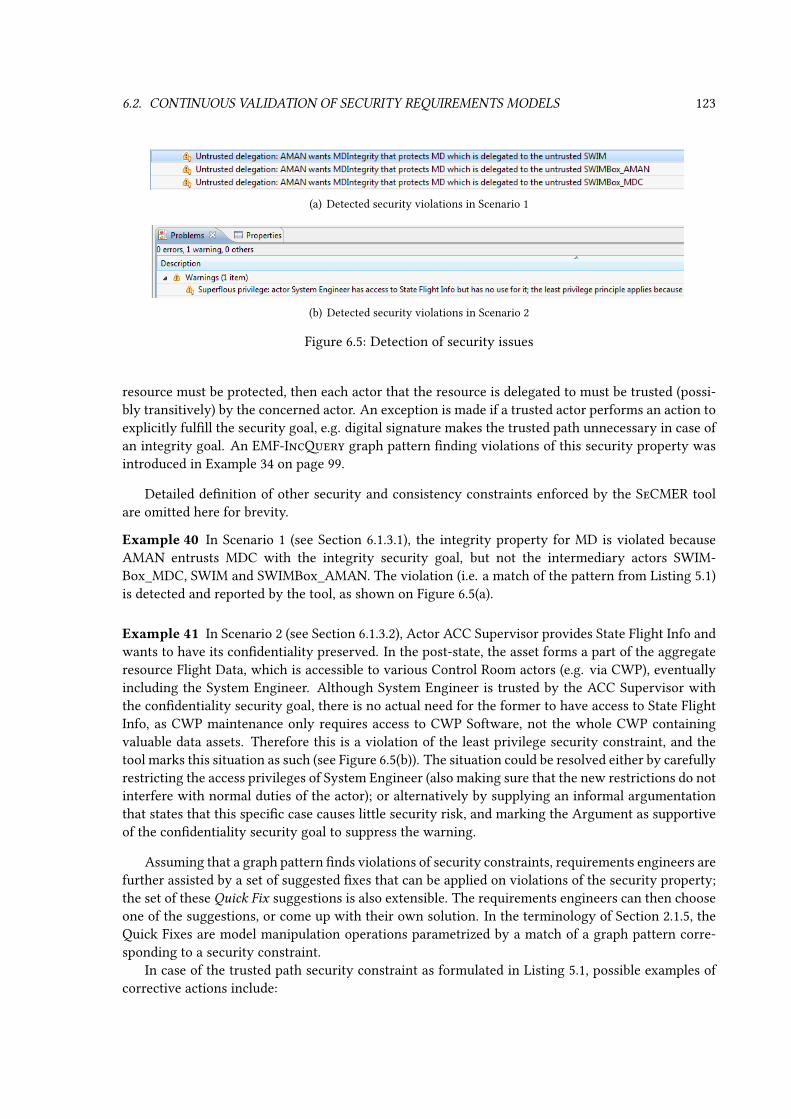
6.2. CONTINUOUS VALIDATION OF SECURITY REQUIREMENTS MODELS 123
(a) Detected security violations in Scenario 1
(b) Detected security violations in Scenario 2
Figure 6.5: Detection of security issues
resource must be protected, then each actor that the resource is delegated to must be trusted (possi-bly transitively) by the concerned actor. An exception is made if a trusted actor performs an action toexplicitly fulll the security goal, e.g. digital signature makes the trusted path unnecessary in case ofan integrity goal. An EMF-Incery graph pattern nding violations of this security property wasintroduced in Example 34 on page 99.
Detailed denition of other security and consistency constraints enforced by the SeCMER toolare omitted here for brevity.
Example 40 In Scenario 1 (see Section 6.1.3.1), the integrity property for MD is violated becauseAMAN entrusts MDC with the integrity security goal, but not the intermediary actors SWIM-Box_MDC, SWIM and SWIMBox_AMAN. The violation (i.e. a match of the pattern from Listing 5.1)is detected and reported by the tool, as shown on Figure 6.5(a).
Example 41 In Scenario 2 (see Section 6.1.3.2), Actor ACC Supervisor provides State Flight Info andwants to have its condentiality preserved. In the post-state, the asset forms a part of the aggregateresource Flight Data, which is accessible to various Control Room actors (e.g. via CWP), eventuallyincluding the System Engineer. Although System Engineer is trusted by the ACC Supervisor withthe condentiality security goal, there is no actual need for the former to have access to State FlightInfo, as CWP maintenance only requires access to CWP Software, not the whole CWP containingvaluable data assets. Therefore this is a violation of the least privilege security constraint, and thetool marks this situation as such (see Figure 6.5(b)). The situation could be resolved either by carefullyrestricting the access privileges of System Engineer (also making sure that the new restrictions do notinterfere with normal duties of the actor); or alternatively by supplying an informal argumentationthat states that this specic case causes little security risk, and marking the Argument as supportiveof the condentiality security goal to suppress the warning.
Assuming that a graph pattern nds violations of security constraints, requirements engineers arefurther assisted by a set of suggested xes that can be applied on violations of the security property;the set of these Quick Fix suggestions is also extensible. The requirements engineers can then chooseone of the suggestions, or come up with their own solution. In the terminology of Section 2.1.5, theQuick Fixes are model manipulation operations parametrized by a match of a graph pattern corre-sponding to a security constraint.
In case of the trusted path security constraint as formulated in Listing 5.1, possible examples ofcorrective actions include:

124 CHAPTER 6. QUERIES AND TRANSFORMATIONS FOR SECURITY REQUIREMENTS
• Add a trust relationship from concernedActor to untrustedActor to reect that the securitydecision was that there must be trust between these actors (e.g. by establishing a liability con-tract between them).
• Alternatively, a task can be created that explicitly fullls secGoal, such as introducing a policyor technological process that makes it impossible for untrustedActor to abuse the situation(e.g. digital signature to ensure the security goal of data integrity). The task must be performedby concernedActor or someone trusted by concernedActor.
These solution templates can be attached to the security constraint so that they are oered whenevera violation of the corresponding security property is detected. The solutions can be implementedby arbitrary program code, typically short Java snippets that manipulate the model according to thedescription of the solution.
Example 42 In case of Scenario 1, the suggested Quick Fixes for the specic violation related to theSWIM actor are shown in Figure 6.6.
Figure 6.6: Suggested corrective actions (Scenario 1)
6.3 Change impact analysis on informal arguments
Security requirement models have their set of well-formedness and security constraints, ensuringthat the model is meaningful, consistent and secure. Graph pattern-based on-the-y validation ofsuch constraints was already addressed earlier. These constraints are static in the sense that theyonly restrict the current state of the model. However, there are cases where evolutionary constraints
are needed, that can take into account how the model changes.In the example evolutions outlined in Scenario 3 of Section 6.1.3.3, invalidating informal argu-
ments was such a problem. Formal and informal argumentation is carried out using the requirementmodel, to determine which security requirements are met. This argumentation is a laborious and

6.4. BIDIRECTIONAL CHANGE-DRIVEN REQUIREMENTS SYNCHRONIZATION 125
costly process requiring signicant human expertise. In evolving security-critical applications, it isimportant that the argumentation is only revised for those security requirements that are inuencedby the change of the model. Thanks to the traceability from Argument to evidence, there is enoughinformation to determine which arguments need to be re-evaluated.
The argument has to be invalidated if one of its evidences is involved in a change. This, however,cannot directly be determined by using only the present (post-state) of the security model. The trivialreason for this is that there could have been various histories leading up to the same post-state;revisiting the arguments is only needed in some of the cases, but static constraints cannot distinguishthem.
Since supporting evolving systems is a major goal of SeCMER, the argumentation phase has todeal with change as well; therefore the tool provides enforcement of this evolutionary constraint.Constructing such an invalidation mechanism is simplied by the change-driven transformation for-malism that will be proposed in Chapter 7. See Section 7.4 for a solution demonstrating the applica-bility of change-driven techniques to this problem.
6.4 Bidirectional change-driven requirements synchronization
Internally, the SeCMER tool represents requirements in a model conforming to the SeCMER require-ments metamodel [MMP+11], a heavily simplied extract of which is shown in Section 5.1.2. Theuser interface, however, features a graphical editor using the Si* concrete syntax [MMZ07], which isa well-known type of requirements modeling diagram.
The SeCMER tool maintains a bidirectional synchronizing live transformation between Si* andthe SeCMER model, in analogy to bidirectional transformations between abstract syntax and concretesyntax graphs of other modeling languages [RÖV10]. This way, changes made to the Si* diagram viathe user interface are immediately propagated to the abstract syntax conforming to the SeCMERconceptual metamodel, and changes made directly to the abstract syntax (e.g. via invoking a QuickFix) are likewise propagated to the Si* concrete syntax.
The following sections give an outline of the most important challenges of this transformation,without presenting a solution. Constructing such a solution is greatly simplied by change-driventransformation specication, for which a language will be proposed in Chapter 7. Based on that lan-guage, Section 7.3 will showcase some interesting parts of a transformation specication that satisesthe bidirectional live synchronization requirements proposed here. The solution will also demonstratehow the change-driven technique is an appropriate answer for the specic challenges of this bidirec-tional live synchronization task.
6.4.1 Properties of the Si* metamodel
The Si* (short for Secure i*) diagram notation is based on i* [Yu96]. Its purpose is to represent anactor-goal model of security requirements, and has therefore more or less similar elements as theSeCMER metamodel. Between the two metamodels, there are also some slight deviations in termi-nology, structure and the renement of certain types of information (e.g. an Actor can be either aStakeholder or an Agent); these are however uninteresting from the point of view of the thesis andwill not be discussed further.
There is, however, a signicant characteristic of the version of Si* metamodel integrated intothe SeCMER tool that has a large inuence on the transformation. While the SeCMER RequirementEntity has a unique name attribute (meaning that no two of them have the same name), the name ofSi* elements is not unique. For example, each Actor may appear multiple times on a Si* diagram; this

126 CHAPTER 6. QUERIES AND TRANSFORMATIONS FOR SECURITY REQUIREMENTS
Requirement name and multiplicity Si* elements SeCMER elementsR1 Actor2Actor *:1 Actors of the same name ActorR2 Resource2Resource *:1 Resources of the same name Resource that is providedR3 Resource2provides 1:1 original copy of Resource, owned by an Actor and not
received through delegationprovides relation from Actor to Resource
R4 Resource2consumes 1:1 additional copy of Resource, received by an Actorthrough delegation and not delegated further
consumes relation from Actor to Resource
R5 Task2Task *:1 Tasks of the same name Task that has incoming does relationR6 Task2does 1:1 nal copy of Task, owned by an Actor and not dele-
gated furtherdoes relation from Actor to Task
R7 SoftG2SecG *:1 Softgoals of the same name Security Goal that is wantedR8 Goal2Goal *:1 hard Goals of the same name non-Security Goal that is wanted (default mapping to
type Goal proper, not any of its subtypes)R9 Goal2wants 1:1 original copy of a Si* Goal or Softgoal, owned by an
Actor and not received through delegationwants relation from Actor to Goal
R10 AND2AND 1:1 AND Composition And Decomposition between Tasks or between Goals,if both endpoints are mapped
R11 OR2OR 1:1 OR Composition Or Decomposition between Tasks or between Goals,if both endpoints are mapped
R12 MeansEnd2fullls 1:1 MeansEnd relation from a Task to a Goal or Softgoal fullls relation between Task and Goal, if both end-points are mapped
R13 MeansEnd2consumes 1:1 MeansEnd relation from a Resource to a Task or Goal consumes relation between Task / Requirement andResource, if both endpoints are mapped
R14 MeansEnd2produces 1:1 MeansEnd relation from a Task or Goal to a Resource produces relation between Task / Requirement andResource, if both endpoints are mapped
R15 Custom2protects 1:1 Custom relation from a Softgoal to a Resource / Task protects relation between Security Goal and asset, ifboth endpoints are mapped
R16 Dp2Delegation 1:1 Delegation of Permission, pointing from a Resourceowned by a (“delegator”) Actor to a “receiver” Actor
Delegation with a delegator and a receiver Actorand Resource as dependum, if all three endpoints aremapped
R17 De2Delegation 1:1 Delegation of Permission, pointing from a Task orGoal or Softgoal owned by a (“delegator”) Actor toa “receiver” Actor
Delegation with a delegator and a receiver Actor andTask or Goal as dependum, if all three endpoints aremapped
R18 Tp2Trust 1:1 Trust of Permission, pointing from a Resource ownedby a (“trustee”) Actor to a “trusted” Actor
Trust with a trustee and trusted Actor and Resourceas dependum, if all three endpoints are mapped
R19 Te2Trust 1:1 Trust of Execution, pointing from a Task or Goalowned by a (“trustee”) Actor to a “trusted” Actor
Trust with a trustee and trusted Actor and Task orGoal as dependum, if all three endpoints are mapped
Table 6.1: Transformation requirements
helps in constructing large requirement models as the sphere of inuence of the actor does not have tobe contiguous. Similarly, other kinds of modeling elements may also appear multiple times on an Si*diagram, such as the two occurrences of MeteoData in Figure 6.1(a). As a perhaps surprising designchoice of the originals creators of the Si* metamodel, this duplication would actually correspond tomultiple elements in the Si* model that share a common name and are otherwise unlinked. Fromthe point of view of the transformation, the entire collection of Si* elements sharing a name wouldcorrespond to a single SeCMER model element with the same name.
6.4.2 Mapping between the languages
As the two modeling languages have slightly dierent expressive power and dierent structure, there-fore the following challenges arise in the model-to-model synchronization:
1. some concepts are not mapped from one formalism to the other or vice versa,
2. some model elements may be mapped into multiple (even an unbounded amount of) corre-sponding model elements in the other formalism, and nally
3. it is possible that a single model element has multiple possible translations (due to the sourceformalism being more abstract); one of them is created as a default choice, but the other optionsare also accepted.

6.5. CHAPTER CONCLUSIONS 127
Without delving into detailed explanations, the mapping requirements concisely summarized onTable 6.1 specify the transformation.
6.5 Chapter conclusions
I have designed an integrated environment for security requirement engineering. The capabilities ofthe tool include validating security properties of the model, seamlessly representing the knowledgein two modeling formalisms using bidirectional live transformation, and minimizing the impact ofchanges on security arguments.
Model validation can be carried out using incremental model queries, as shown before. Actuallyimplementing the transformation in a live and bidirectional way, however, poses a number of technicaland conceptual challenges, and so does the realization of change impact analysis. Chapter 7 willpresent my contributions towards change-driven transformations, providing a solution to these issues.


Chapter
7
eries for Change-drivenTransformations
In the chapter, I investigate change-driven model transformations, a novel class of transformations,which are directly dened to be triggered by complex model changes carried out by arbitrary trans-actions on the model (e.g. editing operation, transformation, etc).
After a classication of relevant change scenarios, challenges are identied for change-driventransformations. As the main technical contribution of the chapter, an expressive, high-level lan-guage is dened for specifying change-driven transformations as an extension of graph patterns andgraph transformation rules. This language generalizes previous results on live model transformationsby oering trigger events for arbitrarily complex model changes, and dedicated reactions for specickinds of changes, making this way the concept of change to be a rst-class citizen of the transforma-tion language. I discuss how the underlying transformation engine needs to be adapted in order touse the same language uniformly for dierent change scenarios.
The technicalities of the approach will be discussed on a (1) model synchronization case study and(2) a case study on detecting the violation of evolutionary (temporal) constraints. Both case studiesstem from the security requirements engineering domain, and solve problems posed by Chapter 6.
This chapter follows [1].
7.1 Terminology of change in change-driven transformations
Changes are inherent to modeling. In model-driven engineering, models are rarely static, in fact, theyare evolving continuously. Most of this evolution is driven by user input in modeling environmentsand editors. In other cases, changes are automatically introduced by batch model manipulations suchas model import, transformation and export.
Change is considered to be the transition of a model from a pre-state, to a post-state, and the dif-ference between the two is called the change delta (or model delta). This terminology is independentfrom the granularity and the abstraction level; it applies for changes that are just elementary modelmanipulation operations as well as for batch transactions encompassing a long sequence of transac-tions (see Section 3.1) or even for complex business decisions. In a long model manipulation sequence,any arbitrary intermediate stage can be considered the pre-state from the point of view of a change-driven transformation; but it is most useful to consider changes relative to the latest state when the
129

130 CHAPTER 7. QUERIES FOR CHANGE-DRIVEN TRANSFORMATIONS
model was “consistent” for purposes of the transformation.A model-driven design setup requires these changes to be propagated along a chain of tools into
derived models or generated source code. The workow may also involve the merging of models,back-annotating the results of an analysis performed on a transformation’s target model to the sourcemodel, or identifying interesting or erroneous parts within models. Thus there is a need for capturingthe changes precisely.
In this chapter, a novel model transformation technology is presented that was designed to addressthis problem by operating on changes of models as rst-class citizens. First, Section 7.1.1 proposes aclassication scheme for changes that will be handled uniformly with change-driven transformations.This taxonomy will be useful to describe which cases the change-driven transformation approachaims to deal with, and what its advantages are. Building on this terminology, Section 7.1.2 explainsthe challenges of change-driven transformations.
7.1.1 Aspects of change
I dene four perspectives (control, observability, information source, delta representation), distin-guishing several dierent ways to perceive changes to a model. An overview is shown in Figure 7.1.
Figure 7.1: Change scenarios (ignoring controllability)
7.1.1.1 The controllability perspective
There are scenarios where changes are controllable, meaning only an explicitly dened set of changesis permitted in each state of the model. A common example is when models are required to be editedexclusively using dedicated editors that only allow a limited set of high-level domain-specic modelmanipulation operations. Such modeling languages are often described by generating graph gram-mars [KM00, dLV02], where the grammar rules coincide with the editing rules.
However, in a wider range of scenarios, the transformation designer has no control over the pos-sible ways a model may change during its lifecycle. It can happen through manual editing in a visualtool, batch refactoring, model transformation, model merging, etc. Any type of model manipulation ispossible: creation/deletion of entities and relations of arbitrary type, modifying attribute values or el-ement names, in any arbitrary sequence, in unforeseeable ways. Furthermore, it is even possible thatmodels temporarily violate certain domain-specic well-formedness constraints during the changes.In this case, one needs to handle non-controllable changes.
7.1. TERMINOLOGY OF CHANGE IN CHANGE-DRIVEN TRANSFORMATIONS 131
7.1.1.2 The observability perspective
After the transformation is completed and any derived model(s) are created, it is possible that thesource or target models are changed without any model management support (e.g. when the gener-ated source code is changed in model-to-text scenarios). When the transformation is invoked nexttime, it can only access the current updated version (post-state), without having any additional infor-mation sources revealing how the models were changed since the last transformation execution. Inthis case, the change is invisible.
However, with support from a model management environment, there may be ways to trace thechanges made to a model, such as change logs. When the transformation system has to determinethe appropriate reactions to execute, it can take advantage of such information sources. The changeis observable if it can be deduced what the pre-state was, what change delta has been applied to it,and what the resulting post-state is.
7.1.1.3 The source of information perspective
If the change is observable, further distinction is possible based on what kinds of information sourcesare available. As previously mentioned, a change consists of a pre-state, a post-state and a changedelta between them. The change is observable if and only if at least two of these three informationsources are directly available, since the third one can be derived. Although this derivation is pos-sible, it might not always be ecient in an actual implementation. Therefore three scenarios canbe distinguished based on which two of these three information sources are provided by the model-ing platform, acknowledging that each scenario oers a dierent kind of support for implementingchange propagating transformations. A similar categorization is presented in [Men02].
Some model management systems may preserve a previous version of the model from the last exe-cution of the transformation, in addition to the current version. This can be the case if version controlis enabled in the model repository. When the pre-state and the post-state are directly observable, itis called the snapshot scenario (state-based in the terminology of [Men02]).
In other situations, a description of the change may be available before it was applied on themodel. An example of such a situation would be applying a patch onto the model, that consistsof changes performed on a remote copy of the model. This is also the case when change requestshave to be analyzed in a change management system, before the changes are actually carried out. Ifthe pre-state and the delta are directly available, is is called command scenario (forward delta in theterminology of [Men02]), and the delta can also be called a change command.
Finally in the history scenario (called backward delta in [Men02]), the post-state is directly avail-able along with the delta (which can be called a change history). A typical example would be manuallyediting a model in an editor environment, which produces notications of the editing operations af-ter they have been carried out, or saves transaction logs (e.g. redo stack) together with the updatedversion of the model.
It is a rare but possible case that all three information sources are directly available (this is calledthe change-based case in [Men02]). For example, an editor may save change logs, while the modelrepository captures the pre-state and the post-state as well. In this case any of the implementationstrategies proposed for the above three scenarios is applicable, and the choice can be made on thebasis of eciency.

132 CHAPTER 7. QUERIES FOR CHANGE-DRIVEN TRANSFORMATIONS
7.1.1.4 The delta representation perspective
In the history and command scenarios, the change delta is available as an information source. In thiscase, we dene a fourth perspective that indicates how the change delta is perceived by the modeltransformation environment.
In the documented change scenario, the delta is available as a data structure called the delta doc-
ument, that species exactly how the pre-state and the post-state diers. One example (history sce-nario) is a model editor maintaining a redo log during editing, that may be retained when the model issaved. The previously mentioned change management system with change requests can be thoughtof an example in the command scenario.
In the live change scenario, the change is experienced on-the-y, as it is happening, by a per-sistently existing transformation continuously receiving run-time notications on the change. Thenotications (e.g. method calls) can be issued before or after the actual change (command or history).The notication granularity (frequency) can range from the level of elementary model manipula-tions to aggregated eects of longer transactions, smoothly transitioning into the documented case.Such a live transformation can be found frequently in model editing environments and centralizedmodel management solutions. As a great advantage of this scenario, changes to a source model canbe on-the-y reected in the target model, and other kinds of live transformation can be performedeciently, facilitating valuable feedback [15][HLR06, RÖV10].
7.1.2 Transformations of change
Change driven model transformations are model transformations which consume changes of the hostmodel M as input (see Fig. 7.2), and turn these changes into model manipulation operations, nativeoperations (such as asynchronous messages, or external API calls), or traceability records for persis-tent storage of changes.
Figure 7.2: Change-driven transformations
Essentially, a change driven transformation rule is enabled by some changes in the host model. Theactual change representation can be of dierent nature (in accordance with Figure 7.1), e.g. a sequenceof model manipulation operations or a change delta.
7.1.2.1 Challenges for change-driven transformations
This interpretation of change-driven transformations needs to be rened in many practical applicationscenarios with dierent model handling characteristics, which are discussed in the following.

7.1. TERMINOLOGY OF CHANGE IN CHANGE-DRIVEN TRANSFORMATIONS 133
• Unied handling of complex changes in all change processing scenarios. Analogouslyto high-level formalisms of model and graph transformations, change-driven transformationsshould support a declarative, high-level specication of changes that can be seamlessly inte-grated into a "host" model or graph transformation language. Moreover, this formalism (and theunderlying execution semantics) should support a uniform specication and execution modelfor all change processing scenarios discussed previously, in order to relieve the transformationdeveloper from a signicant amount of manual coding (notication, adapters etc.), especiallyin the case of non-controllable changes. As an additional benet, this independence will makea transformation portable across dierent change scenarios without modifying its code.The language can then be used as (i) a complete stand-alone formalism for handling modeltransformation scenarios such as incremental model synchronization, model simulation (ani-mation) in discrete systems, and on-the-y well-formedness constraint evaluation. Addition-ally, (ii) it is also useful as an intermediate formalism bridging the gap between the technicalchallenges of the dierent change scenarios and high-level languages tailored for certain usesof model transformations (e.g. QVT Relations for model synchronization, or other GT-basedlanguages for behavioral simulation).
• Ability to handle traditional model transformation scenarios.
Ideally, the change-driven rule formalism should support traditional execution semantics aswell (based on an empty pre-state), so that the rules can be used without additional changese.g. to perform the "rst" transformation phase in model synchronization scenarios.
• Handling both materialized and non-materialized models.A typical assumption of most model transformation approaches is that the host model M isavailable as a materialized model in a common model store (e.g. as in-memory EMF modelsinside the MT framework). However, in some model transformation scenarios, this may not betechnically feasible (e.g. for performance reasons – the model may be too large to t in memory,or not trivial to import and convert). Practically, this means that only an external interfaceof its native environment is available for querying and manipulating M , but still using somemodel transformation approach is desirable to incrementally synchronize the model (e.g. formaintaining consistent views).
• Traceability models are used ubiquitously in many MT scenarios for correspondence map-ping and also to preserve some information on the execution state of the transformation itself.Often, the only use of this information is to help the specication of target-incremental rules sothat they only operate on changed parts of the model (e.g. incremental change propagation inmodel synchronization). In invisible change processing scenarios, the proposed change-driventranformation technology will automatically maintain a cache containing the (historical) in-formation about the pre-state. As a result, traceability models (as well as rule preconditions)can be simplied signicantly: they are only used for correspondence mapping between sourceand target models, but not for storing the past. For instance, old values of attributes would nolonger be required to be stored as part of the traceability model to support attribute changes,which is typically the case for existing transformation technology.
• Checking properties of the model evolution can also be a challenging task for change-driven transformations. Here certain constraints can be evolutionary in the sense that theyneed to be evaluated over a sequence of model evolution steps and not over a single snapshot

134 CHAPTER 7. QUERIES FOR CHANGE-DRIVEN TRANSFORMATIONS
of the model. Traditional constraint languages (like OCL) can only handle these properties byencoding the trajectory as part of the models, which may blow up models signicantly.
In addition to providing support for traditional traceability use-cases, change-driven transforma-tions also allow the changes themselves to be represented as models (attached to the host model onwhich they are evaluated). Moreover, the model-based representation should be completely equiva-lent to the in-memory representation of live changes so that both the "documented" and "live" changeprocessing scenarios can be handled uniformly.
7.2 Language for change-driven transformations
7.2.1 Requirements and motivation for change-driven rules
For many transformation engineers, declarative, rule-based techniques may oer an easy-to-understand way to specify model transformations. Consequently, I propose such a high-level change-driven rule formalism where transformation rules are augmented with a guard. The guard is evaluatedin context of the changes that the graph model has undergone to determine whether the rule is anappropriate reaction to the change. In rule-based expert systems, this idea of change as a distin-guished representation of information has been used for decades; for instance, in the well-knownterminology of Event-Condition-Action (ECA) systems [DGG95], the guards of the presented for-malism correspond to the notions of "triggering event" and the contextual condition of rules. As acomplete adaptation of these techniques to model transformation technology (which is able to handleall relevant change processing scenarios using a unied, high-level formalism) does not yet exist tomy best knowledge, I believe that such a language – architected as an extension to an existing graphtransformation language – will serve practical applications well, in a number of application scenar-ios (e.g. model synchronization [RVV09], on-the-y constraint validation [15] and model animation[RVV08]).
There are a number of requirements that such a language needs to fulll:
• reactivity to be able to specify dynamic model changes as events that activate a rule
• conciseness to result in compact specications for change-driven transformations
• high-level specication to be able to abstract from irrelevant details
• intuitiveness so that rules can be easily understood by those who are familiar with other modeltransformation languages
• expressiveness in order to be able to specify a large class of change-driven transformationsusing this language.
In this section, I will propose a language for change-driven transformations. This language willbe based on the query language proposed in Section 5.2 (albeit relation variables will be allowed, asthe context is no longer only EMF), and its model manipulation capabilities will be an extension ofthe Viatra2 transformation language [VB07]. A quick overview of the new language concepts ispresented in Figure 7.3, which will be gradually discussed in the sequel: Section 7.2.2 denes changepatterns, while Section 7.2.3 specify change driven transformation rules on the foundations of changepatterns.

7.2. LANGUAGE FOR CHANGE-DRIVEN TRANSFORMATIONS 135
Figure 7.3: Simplied metamodel of the proposed transformation language
7.2.2 Change patterns
The high-level rule guards (preconditions) for change-driven rules are dened the form of changepatterns. In addition to conventional graph patterns matched against the post-state, guards shouldalso contain constructs for expressing the dierence between the pre-state and post-state in the formof change queries. An appearance query indicates a graph pattern with a new match in the post-state,while the disappearance query indicates that a match of a given graph pattern is invalidated by thechange. Introduced later in Section 7.2.2.1 as a useful syntactical sugar for expressing changes to valueassignment relations (i.e. attribute value update), an attribute update query captures that an attributechanges from an old value to a new one, i.e. it detects if an old value of an attribute disappeared, or anew value appeared.
The benet of using graph patterns instead of elementary changes as appearance/disappearancequeries is that a change pattern will match regardless of the order of elementary model manipulationsthat ultimately satised the appearance / disappearance / attribute update queries. Thus, in case amatch appearance was detected, it is irrelevant what the last operation was that completed the matchof the appearance query, and so on. As a result, a single change pattern compactly captures a largeset of dierent change sequences.
Denition 73 (Graph change pattern) Graph change patterns (CP) can be dened as a tupleCP =〈P, P ∗+, P ∗−〉, where
• P is the main graph pattern, which is permitted to be disjunctive, have NACs, etc.
• P ∗+ is a set of graph patterns Pi = 〈Vi, Ci〉 called appearance queries. Each appearancequery Pi with variables (pattern elements) Vi and their constraints Ci represents that a certaingraph pattern appears due to the change. Pi is allowed to share variables with P .
• P ∗− is a set of graph patterns Pj = 〈Vj , Cj〉 called disappearance queries. Each disappear-ance query Pj with variables (pattern elements) Vj and their constraints Cj represents that acertain graph pattern disappears due to the change. Pj is allowed to share variables with P .

136 CHAPTER 7. QUERIES FOR CHANGE-DRIVEN TRANSFORMATIONS
Figure 7.4: Change pattern concepts
• Appearance and disappearance queries altogether are called change queries.
• The set of common variables of a given change query and the main pattern is called its inter-face. Ii = Vi ∩ V (P ), Ij = Vj ∩ V (P ).
• The pre-state pattern Ppre(CP ) = ∪Pi∈P ∗−Pi∪P summarizes disappearance queries and themain positive pattern, i.e. all patterns representing existence in the pre-state.
• The post-state pattern Ppost(CP ) = ∪Pi∈P ∗+Pi ∪ P summarizes appearance queries and themain positive pattern, i.e. all patterns representing existence in the post-state.
The match of change patterns (Figure 7.4) is dened against a pair of graph modelsGpre andGpostover the same metamodelMM , such thatGpost is derived fromGpre by some (maybe only observable,but not controllable) model manipulation. Thus the sets of model entities (Entpre and Entpost) andrelations (Relpre and Relpost), all subsets of the same universe U, may intersect on elements thatwere preserved by the change from Gpre to Gpost. Furthermore, the metamodel and the data algebrais the same in both cases. HereGpre andGpost represent the pre-state and post-state respectively, buttheir presence in the denition does not imply that the concept of change patterns is restricted to thesnapshot scenario (see Section 7.1) – only to unify the semantic discussion.
Denition 74 (Match of change pattern) A match of the Change Pattern CP = 〈P, P ∗+, P ∗−〉in 〈Gpre, Gpost〉 over the same metamodel MM is the mapping m = 〈mP ,m
∗+,m
∗−〉 : CP →
〈Gpre, Gpost〉, where
• mP : P → Gpost is a match of P , in the post-state Gpost: Gpost,mP |= P .
• For each Pi ∈ P ∗+, the set m∗+ contains a mapping mi : Pi → Gpost, such that
– Gpost,mi |= Pi, i.e. mi a match of pattern Pi in graph Gpost,– mi(v) = mP (v) for interface variables v ∈ Ii, i.e. mi interfaces with the match of the
main pattern, and

7.2. LANGUAGE FOR CHANGE-DRIVEN TRANSFORMATIONS 137
– Gpre,mi 6 |=Pi, i.e. the same mi is not a match in the pre-state.
• For each Pj ∈ P ∗−, the set m∗− contains a mapping mj : Pj → Gpre, such that
– Gpre,mj |= Pj , i.e. mj a match of pattern Pj in graph Gpre,– mj(v) = mP (v) for interface variables v ∈ Ij , i.e. mj interfaces with the match of the
main pattern, and– Gpost,mj 6 |=Pj , i.e. the same mj is not a match in the post-state.
Denition 75 (Pre-state and post-state match) For a match m = 〈mP ,m∗+,m
∗−〉 : CP →
〈Gpre, Gpost〉,
• the pre-state match is dened as mpre =⋃Pj∈P ∗−
mj , i.e. the unication of the match com-ponents corresponding to the pre-state pattern Ppre(CP ); consequentlympre is a match of thepre-state pattern in Gpre, i.e. Gpre,mpre |= Ppre(CP );
• the post-state match is dened as mpost = (⋃Pi∈P ∗+
mi) ∪ mP , i.e. the unication of thematch components corresponding to the post-state pattern Ppost(CP ); consequently mpost isa match of the post-state pattern in Gpost, i.e. Gpost,mpost |= Ppost(CP ).
Note that this denition is deliberately asymmetric for Gpre and Gpost, as the main pattern P isinterpreted on Gpost only.
The concept of matchable attributed graph patterns (see Denition 31 on page 29) can be naturallyextended to change patterns to restrict uses of attribute variables to cases that a pattern matcher canhandle.
Example 43 The following example is part of the case study of Section 7.3 about the bidirectionalchange propagating transformation (see Section 6.4) between a Si* and a SeCMER model. Figure 7.5(a)and Figure 7.5(b) show two CPs that detect newly created Si* Goals (to be mapped to a Goal entityin the SeCMER model), and deleted SeCMER Goals (in order to delete the corresponding Si* Goal),respectively. NACs are here visually represented as special sub-patterns (enclosed in a “NEG” box),while the rectangles marked by appear or disappear indicate that the enclosed subpattern is anappearance or disappearance query, respectively. As said earlier, the CP of Figure 7.5(a) is insensitiveto the last operation that caused the Si* Goal to appear, be it the creation of the Goal, reassigningto a dierent Actor, etc. Listing 7.1 displays the same CP as Figure 7.5(a) with a textual syntax. Asan extension to the graph pattern language of EMF-Incery (see Section 5.2), change queries areavailable as a (sub)pattern denition with appear or disappear prexes, in a syntax analogous to NACs.
The change patterns presented here are somewhat simplied compared to what is actually re-quired for the transformation problem. For instance, if an Si* Actor has a Goal that was delegatedto it, then there is no corresponding wants relation in SeCMER, therefore a NAC should have beenadded to the appearance query of Figure 7.5(a).
Example 44 For demonstration purposes, these CPs are matched against the transaction of Scenario1 of Section 6.1.3.1, between the pre-state in Figure 6.1(a) and the post-state in Figure 6.1(b). The pre-and post-states of the Si* diagram are shown in Figure 6.1(a) and Figure 6.1(b), respectively. Whilethe diagrams show the visual syntax of Si* only, it is assumed that there is a corresponding SeCMERmodel that is synchronized with the Si* one in the pre-state. It is further assumed that the transaction

138 CHAPTER 7. QUERIES FOR CHANGE-DRIVEN TRANSFORMATIONS
(a) Detecting creation of Si* goal
(b) Detecting deletion of SeCMER goal
Figure 7.5: Example change patterns
(e.g. performed by the Si* graphical editor) changed the Si* model only, while the SeCMER model hasbeen unaected; it is the job of a change-driven transformation to propagate the changes from theconcrete syntax to the abstract model.
The CP in Figure 7.5(b) will not match against this change, as it contains a disappearance queryin the SeCMER domain, but the SeCMER model was not changed. However, the CP in Figure 7.5(a)has a match. The post-state contains an Actor called “AMAN” in both models. A goal called “MDAc-cessControl” was added during the transaction in Si*, satisfying the appearance query. As the modelmanipulation did not change the SeCMER part, the new Goal “MDAccessControl” is not yet part of it,so this constitutes a match of the CP. More precisely, the appearing variable g in the change patternwill be substituted for the Si* Goal MDAccessControl, a for the Si* Actor AMAN, A for its SeCMERcounterpart, while gN will be the string “MDAccessControl” and aN will be the string “AMAN”. Theoccurrence of the CP will trigger a transformation rule that will be responsible for creating a newGoal in the SeCMER model.
Note that the post-state by itself is not enough to determine which of the two CPs have a match; inboth cases, there is a Goal in Si* with no corresponding element in SeCMER. If the CP in Figure 7.5(b)had a match instead, the correct reaction would be the deletion the Si* Goal as opposed to the creationof a SeCMER goal. This demonstrates the added value of change patterns over regular graph patterns.
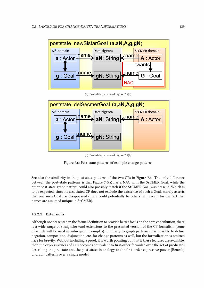
7.2. LANGUAGE FOR CHANGE-DRIVEN TRANSFORMATIONS 139
(a) Post-state pattern of Figure 7.5(a)
(b) Post-state pattern of Figure 7.5(b)
Figure 7.6: Post-state patterns of example change patterns
See also the similarity in the post-state patterns of the two CPs in Figure 7.6. The only dierencebetween the post-state patterns is that Figure 7.6(a) has a NAC with the SeCMER Goal, while theother post-state graph pattern could also possibly match if the SeCMER Goal was present. Which isto be expected, since its associated CP does not exclude the existence of such a Goal, merely assertsthat one such Goal has disappeared (there could potentially be others left, except for the fact thatnames are assumed unique in SeCMER).
7.2.2.1 Extensions
Although not presented in the formal denition to provide better focus on the core contribution, thereis a wide range of straightforward extensions to the presented version of the CP formalism (someof which will be used in subsequent examples). Similarly to graph patterns, it is possible to denenegation, composition, disjunction, etc. for change patterns as well, but the formalization is omittedhere for brevity. Without including a proof, it is worth pointing out that if these features are available,then the expressiveness of CPs becomes equivalent to rst-order formulae over the set of predicatesdescribing the pre-state and the post-state; in analogy to the rst-order expressive power [Ren04b]of graph patterns over a single model.

140 CHAPTER 7. QUERIES FOR CHANGE-DRIVEN TRANSFORMATIONS
1 change pattern newSistarGoal(a,aN,A,g,gN) = 2 sistar.Actor.name(a,aN);3 secmer.Actor.name(A,aN);4 appear 5 find sistarActorHasGoal(a,g);6 sistar.Goal.name(g,gN);7 8 neg 9 secmer.Actor.wants.name(A,gn);
10 11
Listing 7.1: Textual version of the example change pattern of Figure 7.5(a)
This suggests that the CP formalism is powerful enough justifying the choice to be used to triggerchange-driven rules.
A dierent family of extension does not extend the expressiveness of the language, but improvesconciseness. One can imagine several kinds of composite change queries that are expressible withappearance and disappearance queries (elementary change queries) and graph pattern elements, yetare added to the language as useful syntactic sugar to enable more concise specication of changepatterns. Attribute update queries are one kind of such composite change queries that are specicallyaimed at expressing attribute updates:
Denition 76 (Attribute update queries) A change pattern specication can rely on attribute
update queries U∗:= that is a set of tuples Uh = 〈vModh , attrh, v
preh , vposth 〉. Each attribute update
query represents that a certain model element has one of its attributes changed, where vModh ∈ V (P )
is a structural entity variable of P that represents the model element, attrh is the attribute name,and the (optional) variables vpreh , vposth ∈ V (P ) represent the pre-state and post-state values of theattribute, respectively. The interface is Ih = vMod
h , vpreh , vposth . The attribute update query is equiv-alent to a single-constraint disappearance query of a value assignment relation of type attrh fromvModh to vpreh , and a similar appearance query where the value assignment target is vposth .
Further composite change queries may include, for instance, a query for a pattern match that waspresent in both pre-state and post-state. This “persistence” change query is expressible by elementarychange queries: it should be added to the main pattern P and also as a negated appearance constraint,taking advantage of CP negation.
Similarly, statements can be made of what is present in the pre-state (regardless whether it stillholds in the post-state).
7.2.3 Change-driven rules
Change-driven transformation rules are now introduced based on the formalism of change patterns.GT-style rules consisting of a CP as a LHS/guard (instead of a conventional LHS pattern) and a graphpattern as RHS are Change-driven GT rules (CDR). A CDR species a reaction to the CP used as itsguard. As explained on Figure 7.7, the reaction is a controlled change transformingGpost into an evennewer state Gnew. The transformation substitutes a match m of the guard (more precisely, the post-state match mpost of the post-state pattern Ppost(CP )) with the image of the RHS pattern, using thesame semantics as a GT rule application. In fact, the application of the CDR will be formally denedby a reduction to an application of a GT rule.

7.2. LANGUAGE FOR CHANGE-DRIVEN TRANSFORMATIONS 141
Figure 7.7: Change-driven rule concepts
Denition 77 (Change-driven graph transformation rule) Change-driven graph transforma-tion rules CDR = 〈CP,RHS〉 are specied by a guard change pattern CP = 〈PN,P ∗+, P ∗−〉 den-ing the applicability of the rule, and a postcondition (or right-hand side) positive pattern RHS whichdeclaratively species the result model after rule application. The post-state pattern Ppost(CP ) andRHS are allowed to share variables.
Obviously, the postcondition may only use/delete elements that are not already deleted when theguard matches, hence the usage of the post-state pattern. Ppost and its match mpost in Gpost will alsobe used to dene the application of the rule. CDR application is the replacement of the post-statepattern with the RHS, or equivalently, the application of a conventional GT rule obtained from thechange-driven rule with Ppost substituted for LHS.
Denition 78 (Post-state reduction of a change-driven graph transformation rule) Thepost-state reduction of a change-driven graph transformation rule CDR = 〈CP,RHS〉 is the(conventional) graph transformation rule RCDR = 〈Ppost(CP ), RHS〉, whose left-hand-side is thepost-state pattern of the guard change pattern CP , and the right-hand-side is shared with CDR.
Denition 79 (Application of change-driven graph transformation rule) A change-drivenrule CDR = 〈CP,RHS〉 can be applied on a guard match m = 〈mP ,m
∗+,m
∗−〉 : CP →
〈Gpre, Gpost〉 after a change from pre-state Gpre to post-state Gpost. The application of the CDRresults in a new graph model Gnew derived from Gpost, where the transition from Gpost to Gnew

142 CHAPTER 7. QUERIES FOR CHANGE-DRIVEN TRANSFORMATIONS
is identical to the application of the post-state reduction GT rule RCDR = 〈Ppost(CP ), RHS〉 onpost-state match mpost. If CP has no matches in 〈Gpre, Gpost〉, then CDR is not applicable.
After applying a change-driven rule (or any other form of model manipulation), the current stateof the model will be Gnew, so it will play the role of post-state in further evaluations of changepatterns.
Example 45 Figure 7.8 and Listing 7.1 show the CDR that propagates transitions deleted in the work-ow models to the jPDL domain. The guard CP, identical to Figure 7.5(a), activates whenever a newGoal appears in Si*, which is still unmapped to a SeCMER Goal. The RHS contains such a SeCMERGoal, therefore it will be created when the rule is applied.
For example, as already discussed, the CP guard will have a match on the pair of states depictedin Figure 6.1(a) and Figure 6.1(b). The rule will be applied as a reaction, resulting in the creation ofa SeCMER Goal with the name “MDAccessControl” that is connected by a wants relation from theActor “AMAN”. As a result, that the modication of the Si* model is successfully propagated to theSeCMER model.
Figure 7.8: Change-driven rule to propagate creation of a Goal in Si*

7.2. LANGUAGE FOR CHANGE-DRIVEN TRANSFORMATIONS 143
1 cdrule newGoalFromSistar = 2 guard find newSistarGoal(a,aN,A,g,gN);3 postcondition pattern mappedGoal (a,aN,A,g,gN,G) = 4 sistar.Actor.name(a,aN);5 secmer.Actor.name(A,aN);6 find sistarActorHasGoal(a,g);7 secmer.Actor.wants(A,G);8 sistar.Goal.name(g,gN);9 secmer.Goal.name(G,gn);
10 11
Listing 7.1: Textual version of the sample change-driven rule
7.2.3.1 Extensions
Recalling that graph transformations in Section 2.2.4 were introduced merely as a special case ofmodel manipulation operations (see Section 2.1.5), there is a natural extension of the change-drivengraph transformation rule family towards a more general form of change-driven rules. For a givenCP, any model manipulation operation that is parameterized by post-state matches of the CP can beconsidered a CDR with the CP as guard/precondition.
From the point of view of the actual textual language, the same issue can be raised. While thedeclarative specication of GT rules and CDRs can be very concise in some cases (especially withpattern reuse by composition), in other applications it is more practical to also associate imperativeactions to the rule that should be executed on the match of the guard. Examples include logging ordebugging, chaining related rules, performing nontrivial computation, etc. Therefore the transfor-mation language used in the examples contains an extension to the core CDR formalism, so that anaction sequence can be attached to the rules using the action keyword. This technique provides acomplete imperative alternative to using the declarative RHS formalism.
Change-driven rules vs. GT rules. It is worth pointing out that both traditional GT rules and anearlier event-driven rule formalism (graph triggers in [15]) can be thought of as special cases of themore expressive CDR formalism. CDR rules reduce to GT rules in case there are no change queries,while graph triggers are equivalent to CDR rules consisting of an empty main pattern and a singlechange query (graph triggers use the appearance/disappearance of the entire precondition pattern asguard condition).
7.2.4 Challenges addressed
In the following, I summarize my arguments supporting that this transformation language extensionanswers the challenges of Section 7.1.2.1 and satises the requirements given in Section 7.2.1:
• reactivity: the transformation can react to changes in the model using change patterns asguards for transformation rules.
• conciseness: change queries capture the relevant information in the delta without the need forindividually addressing possible sequences of elementary changes that have lead to the givenpost-state.

144 CHAPTER 7. QUERIES FOR CHANGE-DRIVEN TRANSFORMATIONS
• high-level specication: model changes can be abstractly captured as appearance and disap-pearance of graph pattern matches; and change-driven transformations are also independentfrom the source of the triggering changes.
• intuitiveness: the proposed language extends declarative static model queries and model ma-nipulation (as provided by graph patterns and graph transformation rules) in a natural wayby introducing change patterns (which are guards that specify elements which must appear ordisappear) and change-driven rules (which describe reaction to changes).
• expressiveness: change patterns allows the transformation designer to specify rules whichcan distinguish between identical post-states of the model based on the modication trajectories
which led to that state, without (i) having to encode these modications into complex trace-ability models and (ii) bloating transformation rules with them. In other words, change-drivenrules extend the expressive power of graph transformation rules by high-level queries corre-sponding to the changes exhibited by the graph. (These queries have the full expressive powerof rst-order predicates over the pre-state and post-state model.)
7.3 Case study: bidirectional synchronization
The rst motivating scenario is from the from the SeCMER tool (see Chapter 6). Here extracts willbe given from a change-driven live transformation that solves the bidirectional model synchroniza-tion problem (see Section 6.4 for the special challenges of this transformation) between the abstractsyntax of SeCMER requirement models and the visual concrete syntax (Si* diagrams). Note that thepaper [1] contains a dierent model-to-model transformation case study that demonstrates a dierentapplication scenario involving non-materialized models.
An important property of this change-driven transformation is that no correspondence or trace-ability model is required that maps Si* elements to SeCMER. This is a consequence of the fact thatthe correspondence can be established based on matching element names in the two models. CDRscan take advantage of this and eliminate the correspondence models. As the post-state of modelsdoes not always convey enough information to determine the correct action (see Example 44 for ademonstration), many other M2M formalisms may still require a correspondence model essentiallyto “remember the past”, i.e. use it as a shadow copy in the terminology of Section 7.5.1.3. The fol-lowing partial case study solution will show how CDRs achieve the same goal without maintainingand using a correspondence model, which would impose an overhead on transformation specica-tion size (unless implicit, as with QVT), and also on model storage size and execution time. Note thatthe implementation strategy for CDRs that will be proposed in Section 7.5 would also induce suchshadow copies, but only in the invisible scenario. Although in such a case there is no advantage overother approaches in the execution time and model size, but (a) this service is transparent and does notcomplicate the rule specications, (b) the SeCMER tool, which serves as the current case study, wouldexecute the CDT in the live scenario anyway, in which creating such shadow copies is not necessary.
The complete solution will not be detailed here, but change-driven transformation rules (andhelper graph patterns and change patterns) will be specied that provide the following functionality:
• If an Actor is created in the SeCMER model, a corresponding Actor is created in Si* (specicallya Stakeholder by default, as an Actor could also be an Agent).
• If an Actor is deleted in the SeCMER model, each of the corresponding Actor elements (that allshare the same name) are deleted in Si*.

7.3. CASE STUDY: BIDIRECTIONAL SYNCHRONIZATION 145
• If an Actor is renamed in the SeCMER model, each corresponding Actor element is renamed inthe same way in Si*.
• If an Actor element (either Stakeholder or Agent) is created in the Si* model whose name wasunused before, a corresponding Actor is created in the SeCMER model.
• If the last of the Actor elements having a given name is deleted in Si*, the corresponding Actorelement is deleted in the SeCMER model.
• If the Actor elements in Si* sharing a given name are renamed together (the Si* editor does thisas a single transaction), the corresponding Actor in the SeCMER model is renamed along withthem.
Only high-level specications will be given for the action parts of CDRs; they will not be detailedhere, as they contain miscellaneous technical tasks that are not important from the point of view ofthe thesis. Nevertheless, it should be noted that (a) in case of deletions, all connections/referencesto the deleted element should be properly removed, (b) the manipulation of the Si* model must hap-pen through Si* API calls rather than by direct model modications, as the visual appearance of thediagram has to be maintained accordingly.
The rst of these rules is shown in Listing 7.2. The helper patternsistarActorNamematchesany string that is the name of a Si* actor; note that for any given string, there will be up to one match ofthis pattern regardless how many duplicate Si* Actors share that name. If a new match of this patternappears, that means that there is a new Si* Actor that is not simply a duplicate of existing ones, andthus must be propagated to SeCMER. The action part (not shown) of CDRnewActorFromSistardoes just this: creates a new SeCMER Actor in the SeCMER model and sets its name to the value ofvariable name. Note that the guard CP has an additional NAC constraint to make sure that such aSeCMER Actor does not exist yet; this constraint is important to add since it is possible that a singletransaction modies the SeCMER model in synch with the Si* one. This can occur if e.g. a new partof the requirement model is loaded from a le where both representations are already available, orsimply if the same rule has already been applied earlier in the transaction (see Section 7.5.3.2).
1 pattern sistarActorName(name) = 2 sistar.Actor.name(_a,name);3 4 cdrule newActorFromSistar = 5 guard change pattern newSistarActor(name) = 6 appear find sistarActorName(name);7 neg secmer.Actor.name(_anyActor,name);8 9 action
10 // create new SeCMER Actor with given name11 12
Listing 7.2: Propagating creation of Si* Actor
When one of the Si* Actors is deleted, while others with the same name remain, the correspondingSeCMER Actor should be preserved. The pattern sistarActorName will only lose a match whenthe last duplicate copy of an Actor is removed from Si*. This triggers the CDR in Listing 7.2, providedthat the corresponding SeCMER Actor exists, to delete it as well.

146 CHAPTER 7. QUERIES FOR CHANGE-DRIVEN TRANSFORMATIONS
1 cdrule delActorFromSistar = 2 guard change pattern missingSistarActor(actor,name) = 3 disappear find sistarActorName(name);4 secmer.Actor.name(actor,name);5 6 action 7 // delete the SeCMER Actor actor8 9
Listing 7.3: Propagating deletion of Si* Actor
Similarly to the above, the CDR in Listing 7.4 will be triggered if a SeCMER Actor is removed withone or more corresponding Si* Actors still present; the latter will be deleted by the action part. Asdiscussed earlier, here the action part must interface with the Si* API to make sure that the deletionsare displayed correctly by the diagram.
1 cdrule delActorToSistar = 2 guard change pattern newSistarActor(name) = 3 disappear secmer.Actor.name(_anyActor,name);4 find sistarActorName(name);5 6 action 7 // remove all Si* Actors from the diagram with the given name8 9
Listing 7.4: Propagating deletion of SeCMER Actor
When a new SeCMER Actor appears without a corresponding Si* Actor, the CDR in Listing 7.5 willpropagate this change. Note that creating only one Si* Actor with the given name or having e.g. 58of them would be equally valid, as both versions of the Si* model would be compatible with the sameSeCMER model, without any changes to be propagated according to the transformation requirementsin Section 6.4. The fact that the rule creates a single Si* Actor only is a choice of the transformationdeveloper. Moreover, there are two kinds of actors in Si*, Agents and Stakeholders. These are notdistinguished by the SeCMER model, a SeCMER Actor is compatible with either kind in Si*; the factthat the rule creates a Stakeholder by default (which can later be switched to an Agent if required) isonce again a choice of the transformation engineer.
1 cdrule newActorToSistar = 2 guard change pattern newSeCMERActor(actor,name) = 3 appear secmer.Actor.name(actor,name);4 neg find sistarActorName(name);5 6 action 7 // add an Si* Actor (Stakeholder) to the diagram with the given name8 9
Listing 7.5: Propagating creation of SeCMER Actor
The CDR of Listing 7.6 propagates an attribute change, using attribute update queries and persis-
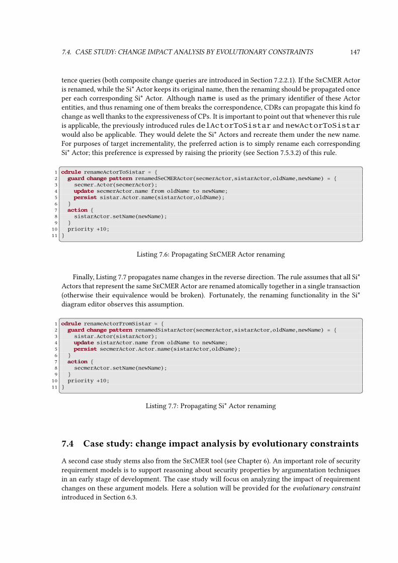
7.4. CASE STUDY: CHANGE IMPACT ANALYSIS BY EVOLUTIONARY CONSTRAINTS 147
tence queries (both composite change queries are introduced in Section 7.2.2.1). If the SeCMER Actoris renamed, while the Si* Actor keeps its original name, then the renaming should be propagated onceper each corresponding Si* Actor. Although name is used as the primary identier of these Actorentities, and thus renaming one of them breaks the correspondence, CDRs can propagate this kind fochange as well thanks to the expressiveness of CPs. It is important to point out that whenever this ruleis applicable, the previously introduced rules delActorToSistar and newActorToSistarwould also be applicable. They would delete the Si* Actors and recreate them under the new name.For purposes of target incrementality, the preferred action is to simply rename each correspondingSi* Actor; this preference is expressed by raising the priority (see Section 7.5.3.2) of this rule.
1 cdrule renameActorToSistar = 2 guard change pattern renamedSeCMERActor(secmerActor,sistarActor,oldName,newName) = 3 secmer.Actor(secmerActor);4 update secmerActor.name from oldName to newName;5 persist sistar.Actor.name(sistarActor,oldName);6 7 action 8 sistarActor.setName(newName);9
10 priority +10;11
Listing 7.6: Propagating SeCMER Actor renaming
Finally, Listing 7.7 propagates name changes in the reverse direction. The rule assumes that all Si*Actors that represent the same SeCMER Actor are renamed atomically together in a single transaction(otherwise their equivalence would be broken). Fortunately, the renaming functionality in the Si*diagram editor observes this assumption.
1 cdrule renameActorFromSistar = 2 guard change pattern renamedSistarActor(secmerActor,sistarActor,oldName,newName) = 3 sistar.Actor(sistarActor);4 update sistarActor.name from oldName to newName;5 persist secmerActor.Actor.name(sistarActor,oldName);6 7 action 8 secmerActor.setName(newName);9
10 priority +10;11
Listing 7.7: Propagating Si* Actor renaming
7.4 Case study: change impact analysis by evolutionary constraints
A second case study stems also from the SeCMER tool (see Chapter 6). An important role of securityrequirement models is to support reasoning about security properties by argumentation techniquesin an early stage of development. The case study will focus on analyzing the impact of requirementchanges on these argument models. Here a solution will be provided for the evolutionary constraint
introduced in Section 6.3.
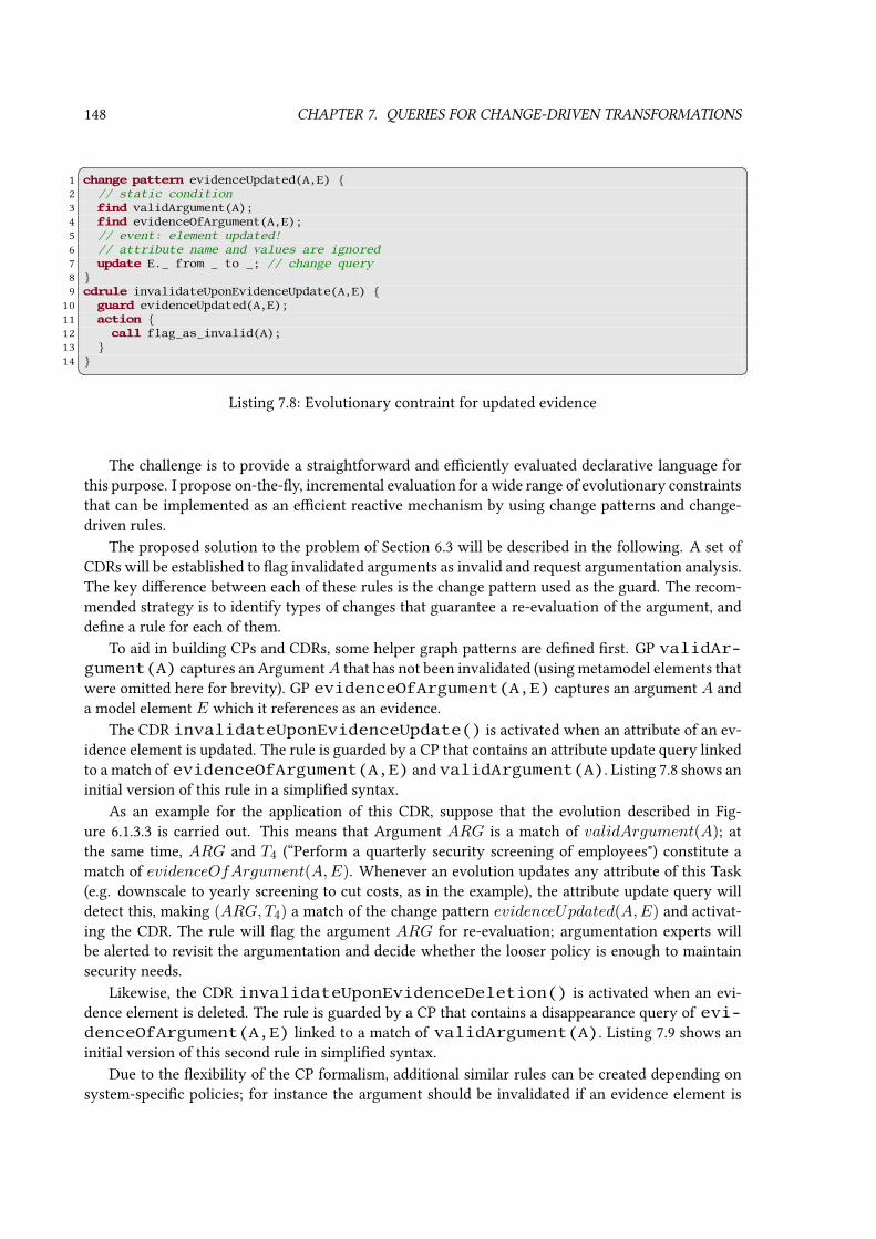
148 CHAPTER 7. QUERIES FOR CHANGE-DRIVEN TRANSFORMATIONS
1 change pattern evidenceUpdated(A,E) 2 // static condition3 find validArgument(A);4 find evidenceOfArgument(A,E);5 // event: element updated!6 // attribute name and values are ignored7 update E._ from _ to _; // change query8 9 cdrule invalidateUponEvidenceUpdate(A,E)
10 guard evidenceUpdated(A,E);11 action 12 call flag_as_invalid(A);13 14
Listing 7.8: Evolutionary contraint for updated evidence
The challenge is to provide a straightforward and eciently evaluated declarative language forthis purpose. I propose on-the-y, incremental evaluation for a wide range of evolutionary constraintsthat can be implemented as an ecient reactive mechanism by using change patterns and change-driven rules.
The proposed solution to the problem of Section 6.3 will be described in the following. A set ofCDRs will be established to ag invalidated arguments as invalid and request argumentation analysis.The key dierence between each of these rules is the change pattern used as the guard. The recom-mended strategy is to identify types of changes that guarantee a re-evaluation of the argument, anddene a rule for each of them.
To aid in building CPs and CDRs, some helper graph patterns are dened rst. GP validAr-gument(A) captures an ArgumentA that has not been invalidated (using metamodel elements thatwere omitted here for brevity). GP evidenceOfArgument(A,E) captures an argument A anda model element E which it references as an evidence.
The CDR invalidateUponEvidenceUpdate() is activated when an attribute of an ev-idence element is updated. The rule is guarded by a CP that contains an attribute update query linkedto a match of evidenceOfArgument(A,E) and validArgument(A). Listing 7.8 shows aninitial version of this rule in a simplied syntax.
As an example for the application of this CDR, suppose that the evolution described in Fig-ure 6.1.3.3 is carried out. This means that Argument ARG is a match of validArgument(A); atthe same time, ARG and T4 (“Perform a quarterly security screening of employees") constitute amatch of evidenceOfArgument(A,E). Whenever an evolution updates any attribute of this Task(e.g. downscale to yearly screening to cut costs, as in the example), the attribute update query willdetect this, making (ARG,T4) a match of the change pattern evidenceUpdated(A,E) and activat-ing the CDR. The rule will ag the argument ARG for re-evaluation; argumentation experts willbe alerted to revisit the argumentation and decide whether the looser policy is enough to maintainsecurity needs.
Likewise, the CDR invalidateUponEvidenceDeletion() is activated when an evi-dence element is deleted. The rule is guarded by a CP that contains a disappearance query of evi-denceOfArgument(A,E) linked to a match of validArgument(A). Listing 7.9 shows aninitial version of this second rule in simplied syntax.
Due to the exibility of the CP formalism, additional similar rules can be created depending onsystem-specic policies; for instance the argument should be invalidated if an evidence element is

7.5. IMPLEMENTATION STRATEGIES FOR EVALUATING GRAPH CHANGE PATTERNS 149
1 change pattern evidenceDeleted(A,E) 2 // static condition3 find validArgument(A);4 // event: element disappeared!5 disappear evidenceOfArgument(A,E); // change query6 7 cdrule invalidateUponEvidenceDeletion(A,E) 8 guard evidenceDeleted(A,F,M);9 action
10 call flag_as_invalid(A);11 12
Listing 7.9: Evolutionary contraint for deleted evidence
of a certain type, and edges of certain types are connected to (or disconnected from) it. Finally, incase of more complex argument metamodels that can represent various associations between argu-ments, invalidation ags can be propagated between them by CDRs, implementing a form of truthmaintenance.
7.5 Implementation strategies for evaluating graph change patterns
The following sections outline a system architecture that implements change-driven transformation.Solutions to the following task items are required:
1. (positive and negative) graph pattern matching of the CP’s main pattern in the post-state
2. evaluating and matching appearance and disappearance queries (and composite change queriessuch as update queries)
3. matching change patterns, relying on the solutions to the above two tasks
4. applying change driven rules on matches of the guard change pattern
The rst two of these tasks require dierent implementation techniques in dierent change sce-narios (see Section 7.1), to take advantage of the benets and avoid unnecessary operations that maydegrade performance. First, Section 7.5.1 discusses the proposed solutions to the rst two tasks inall change scenarios except for the live case. Next, Section 7.5.2 still addresses the rst two tasks,but focuses on the live scenario with its unique execution model. Finally, the last two task items areaddressed in Section 7.5.3.
7.5.1 Change query evaluation in documented or invisible change scenarios
7.5.1.1 Documented history and command scenarios
In the documented change scenarios, either the pre-state or the post-state of the model is availablealong with a delta document recording the changes. In order to match appearance and disappearancequeries, existing graph pattern matcher algorithms have to be slightly modied.
The modied matcher algorithm have to consider the elements of the available snapshot and alsothe elements that only occur in the delta document, essentially unifying the pre-state and post-state.
150 CHAPTER 7. QUERIES FOR CHANGE-DRIVEN TRANSFORMATIONS
Elements of this unied model can be classied as unchanged, deleted or created. In case of docu-mented history, elements of the post-state that were created in the change history are classied ascreated elements, elements of the post-state that were not created in the delta are considered un-changed, and elements only appearing in the delta are classied as deleted elements. In the changecommand scenario, elements in the pre-state that are deleted by the command are classied as deletedelements, elements in the pre-state that are not deleted by the command are unchanged, and elementsonly present in the delta are classied as created elements.
A match of a positive graph pattern is only considered valid in the post-state, i it contains nodeleted elements. A pattern with NACs has a valid match in the post-state i it is a valid post-statematch of the positive pattern, and all NAC matches (if any) are disappearing (see later). A patternmatch is considered appearing i it is valid in the post-state (as dened above), and contains at leastone created element, or has at least one NAC match (which is – as stated above - disappearing). Finally,a pattern match is considered disappearing if it contains no created elements, all of its NAC matches(if any) are appearing, and there is either at least one deleted element of the positive match, or a NACmatch (which must be appearing). Other kinds of pattern composition (including aggregation) can betreated analogously.
Using these rules, the pattern matcher can determine the match set of the main pattern in thepost-state, as well as that of the appearance and disappearance queries. The evaluation of compositechange queries can be derived from elementary change queries; although in some cases, more ecientprocedures can be given.
7.5.1.2 Snapshot scenario
In the snapshot scenario, both the pre-state and the post-state are directly available, therefore changequery evaluation is reduced to fairly simple steps. An appearance query is satised if the pattern ismatched in the post-state, but the same match is invalid in the pre-state; and vice versa for disap-pearance queries. Therefore evaluating these queries require pattern matcher techniques similar tomatching NACs in regular graph patterns.
However, one of our assumptions here was that if a model element exists in both states, it is trivialto recognize that they are in fact the same element; denitions in Section 7.2.2 assumed that they arein fact the same element of the universe U. In some technological contexts, this assumption may posea challenge, but adherence is possible if model elements have a unique identier that is preservedacross dierent versions. Unfortunately, in some modeling environments this is not guaranteed; forexample, generic EMF objects are not identiable by default in a way that is valid across snapshots(but fortunately EMF provides both live notications and redo stacks instead). In this case, the twoversions of the model have to be reconciled against each other (by either a generic heuristic or adomain-specic way) before the changes can be computed and CDR can be applied; see the relatedliterature on model comparison [ASW09].
7.5.1.3 Invisible change scenario
As only the post-state is available, post-state matching of the main pattern is trivial in this case, butevaluating change queries is not. The common solution to this problem has signicant time and spaceoverhead: the transformation creates a shadow copy of the model each time it is invoked. On the nexttransformation run, the model itself represents the post-state, but the shadow copy preserves thepre-state, therefore the change queries can be evaluated. Of course, there is no need to replicate theentire model; it is sucient to store the match sets of patterns used as appearance and disappearance

7.5. IMPLEMENTATION STRATEGIES FOR EVALUATING GRAPH CHANGE PATTERNS 151
queries. The appearance and disappearance queries can be evaluated by matching the patterns againstthe post-state and comparing the match set against the one preserved in the shadow copy. Likewise,update queries can be evaluated by comparing the current attribute value against its shadow copy.
To prevent inconsistencies, the shadow copy should be inaccessible to normal model editing op-erations, which can be achieved either storing it separately (e.g. in a dierent le), or by using specialmodel element types, markers, etc., that visual editors and other transformations ignore. If it is storedseparately, the problem of preserving model element identity has to be dealt with, similarly to thesnapshot scenario.
A widespread practice [Tra08, ELF08] in model-to-model transformations is to use the traceabil-ity model (sometimes called reference model or correspondence model) in a way that it preserves theLHS (or a signicant subset thereof) of all executed rules. Thus the traceability connections essen-tially store a copy of the source model (or at least relevant match sets), thereby providing a shadowcopy functionality. In those model transformation approaches where this is not handled automat-ically, signicant manual eort is required for maintaining this shadow copy. With change-driventransformations, however, the platform can provide change queries as a service, hiding implementa-tion details. The hidden implementation will involve an automatic shadow copy mechanism in theinvisible change scenario (and less resource intensive solutions in the other change scenarios). Onthe rule specication level, the availability of change queries may allow a much simpler maintenanceof traceability in many cases (especially bidirectional synchronization), sometimes as simple as usingthe same name for a source and target element, as there is no need to manually preserve the entireLHS.
7.5.2 Change query evaluation in live change scenarios
7.5.2.1 Challenge of live scenarios
While all techniques for the documented scenarios are functionally correct in the live scenario aswell, there may be an additional important requirement in this case. Live notications can be usedto perform live transformation, meaning that change-driven rules are executed on-the-y. Since livenotication is received about changes that are in progress, and reactions are triggered during aninteractive session, pattern matching is required to be responsive and ecient. We propose an archi-tecture capable of eciently matching change patterns and applying change-driven rules with livemonitoring of the model as it evolves.
The entire architecture is illustrated in Figure 7.9. The rest of Section 7.5.2 discusses how changequeries are evaluated eciently in live scenarios.
7.5.2.2 Incremental pattern matching
As discussed earlier and shown by benchmarks (see Section 3.5), incremental pattern matching canimprove performance or scalability by several orders of magnitude in certain scenarios; with a con-tinuously evolving model, its benets are likely to outweight its drawbacks. Moreover, incrementalpattern matching leads to easy discovery of appearing or disappearing pattern matches, thus it can beused to eciently implement the change query feature of change patterns by incremental calculationof match set deltas (e.g. the Rete algorithm discussed in Chapter 3 computes the match set deltasalongside with the match sets).
Having received change notications, the incremental pattern matcher shows an up-to-date pic-ture of the post-state. This is true even in the command scenario where these changes might nothave been applied to the model itself yet, still retaining the pre-state. Therefore the post-state graph

152 CHAPTER 7. QUERIES FOR CHANGE-DRIVEN TRANSFORMATIONS
Figure 7.9: Implementation architecture for change-driven rules in the live scenario
pattern matching of the main pattern can be performed by the incremental pattern matcher in bothhistory and command scenarios. In the history scenario, the model itself reects the post-state, there-fore an unmodied non-incremental (local search) pattern matcher is also applicable for this task, ifit is preferrable for performance reasons.
7.5.2.3 Delta monitoring
A delta monitor is a component that can be attached to a match set cache of the incremental patternmatcher at any time, and it will start to feed on the match set deltas provided by the incrementalmatcher to cumulatively record changes aecting the match set from that time on. At any point inthe future, the delta monitor will be able to report which new matches appeared and which matchesdisappeared since it was initialized. If delta monitors are initialized when the model is in its pre-state, it will be able to continuously provide the delta match set between the pre-state and the specicpost-state that is reached after the latest live notications.
The tasks of the delta monitor are eciently achieved by hooking into the internal notication/up-date mechanism of the incremental pattern matcher. Changes of a single match (e.g. the same matchappearing and then disappearing later) may invalidate each other, therefore the delta monitor reallyreects (a projection of) the delta between the two states, and not just recorded history.
7.5.2.4 Change query evaluation
Change queries can be eciently evaluated using delta monitors and incremental pattern matching.Before the change is performed or notications are received, i.e. in the pre-state, a delta monitor is tobe attached (or reinitialized, if already attached) onto the incrementally maintained match set of eachgraph pattern that occurs as a change query within a CP. After the change, the contents of the deltamonitors will reect the graph pattern matches that have appeared or disappeared. This complements

7.5. IMPLEMENTATION STRATEGIES FOR EVALUATING GRAPH CHANGE PATTERNS 153
the post-state reected by the incremental pattern matcher (or alternatively, in the history scenario,the model itself), to provide all necessary information for matching change patterns.
7.5.3 Implementing change-driven rules
7.5.3.1 Matching guard change patterns
Change patterns are equivalent to an extended graph pattern formalism, where the set of admissiblepattern constraints contains change sets of pattern matches as special composition constraints. In theend, the match set of a change pattern can be determined from the match set of the change queries andthe main positive pattern; and such a pattern matcher architecture is conceptually similar to existingones dealing with negative application conditions or other pattern call constraints. Therefore graphpattern matching mechanisms can be used to evaluate change patterns, based on the partial solutions(change queries and post-state pattern matching of the main pattern) obtained dierently in eachchange scenario.
7.5.3.2 Rule execution
The sequence of elementary model manipulation operations executed by any transformation unit,GUI-based manipulation, model merge or other job can be arbitrarily segmented into transactions,that are assumed to result in a consistent state of the aected model. The transaction is the unit ofchange that CDRs will react to; the starting and the end points of the transaction will be considered thepre-state and the post-state, respectively. In documented change scenarios, the whole change processbetween the given pre- and post-states can be considered a single transaction. In live scenarios, asnotications may be continuously sent, it is a nontrivial question how to segment transactions; ithelps if there is some support for explicitly dening transaction boundaries and commit points. Atypical transaction can be e.g. the execution of single functionality through the UI, corresponding tomultiple elementary operations.
Upon the end of each transaction, the change patterns are evaluated to determine which change-driven rules are applicable. If there are any such CDRs, they are applied on the model, using algo-rithms that are identical to regular GT rule application. As this rule application phase modies themodel, there are two important execution schemata to distinguish regarding the transactionality ofrule executions.
One strategy is to take one applicable CDR, and prolong the transaction by appending this ruleapplication. If there are multiple applicable rules, the choice might be made according to some strat-egy, e.g according to rule priority. While the pre-state is unchanged, the post-state is advanced bythe eects of the rule, thus the set of applicable rules may change. Once again, a rule applicationis selected; this loop can go on until there are no more applicable rules. At that point, the transac-tion can nally conclude; the newly reached state will be considered the pre-state henceforth. Thisexecution strategy guarantees the important postcondition that there are no applicable rules at theboundaries of transactions. This can be used as a very useful precondition in dening the rules thatwill be applied in reaction to the next transaction.
According to an alternative approach, all applicable rules can be executed (eectively in parallel)after closing the original transaction; this rule application phase can be considered a change transac-tion itself, with its eects wrapped into a separate transaction. At the end of this second transaction,the eects of executed CDRs can be reacted to as well, as long as there are triggered CDRs.
In both cases, the rule application loop is actually a live scenario, regardless of the circumstancesof the original triggering change. Execution schemata have been previously elaborated in [15].

154 CHAPTER 7. QUERIES FOR CHANGE-DRIVEN TRANSFORMATIONS
7.6 Discussion
The potential advantages and limitations of change-driven transformation over traditional modeltransformation techniques will be discussed here.
7.6.1 Theoretical discussion
In this theoretical discussion, the primary focus is on graph transformation based approaches, whichprovide the closest correspondence to the new techniques, moreover, they have a sound, well-established underlying theory.
Theoretical expressiveness of change-driven graph transformations
While not formally proven here for space considerations, it is worth pointing out that for each change-driven graph transformation system (CDGTS) a corresponding graph transformation system (GTS)can be derived, which simulates the CDGTS. As a result, the proposed change-driven graph transforma-
tion rule formalism is not more expressive in a pure theoretical point of view, which is hardly surprisingsince GT rules are already Turing complete.
The construction relies on the concept of shadow copies: it essentially stores an explicit represen-tation of the pre-state as a dedicated part of the model. Then a separate set of GT rules would beresponsible for (1) the detection of change and management of pre-states and post-states (based onthe dierence between Gpre and Gpost ) and (2) simulating the eect of a CDTS (based on the dier-ence between Gpost and RHS). As a consequence, both the underlying model and the rule set wouldexplode.
Note that the above construction required a change in both the metamodel and the instance mod-els. Without this special encoding, the GT rules are less expressive as they take only the post-stateinto account to determine which action to take while CD rules can refer to the pre-state as well.
As a side remark, a model-to-model CDTS can be constructed even if the model transformationproblem itself is non-deterministic by its nature (e.g. a tree-based hierarchy model needs to be at-tened to an arbitrary sequence respecting the partial order induced by the hierarchy). Thus the cor-respondence relationship from source to target models is not necessarily one-to-one. The case studyof Section 7.3 provides an example of such nonfunctional correspondence, with an arbitrary numberof Actor duplicates in the Si* model.
Analysis of change-driven transformations
The main practical relevance of this simulation property from CDGTS and GTS is that it enables toinvestigate traditional semantic properties like termination or determinism using the rich theory andproof techniques (e.g [VVGE+06, HKT02]) of graph transformation systems. For instance, if the simu-lating GTS can be proven to be terminating, then the original CDTS must be terminating as well; whileGTS termination is undecidable in general, there are established proof techniques (see [VVGE+06])for concrete systems. As a consequence, I believe that some existing analysis techniques of GTS are
reusable for CDGTSs. Exploring this idea in detail is left as future work.
Constraint detection by change-driven transformations
Declarative specications (like graph patterns, graph transformation rules, OCL constraints) are fre-quently used for detecting the violation of well-formedness constraints in domain-specic models.

7.6. DISCUSSION 155
However, evolutionary constraints related to the temporal behavior or the evolution of models arevery hard to specify and detect as it requires to explicitly encode the sequence of model snapshots aspart of the model, and thus also part of the constraint. Change patterns provide a direct and succinct
way to detect a class of constraints related to the trajectory of model evolution (see the case study ofSection 7.4).
Relationship with temporal logics
As an alternative to the language of change patterns, there is a wide family of temporal logics. Theyare able to express temporal relationships of more than two model snapshots. On the other hand,commonly used temporal logics can only describe a single model snapshot with propositional logicformulae, while graph patterns are equivalent to more powerful rst-order logic formulae [Ren04b].It is of course possible, though uncommon, to use temporal logics based on rst-order formulae aswell, thus they are strictly more expressive than the proposed language of graph change patterns.
The use case of change-driven transformations, however, does not require formulae over an ar-bitrarily long chain of model snapshots; a pre-state and a post-state are sucient to express howthe current state diers from a previous, consistent state. Therefore change-driven transformationswould not take advantage of the increased temporal expressiveness. The language of change pat-terns was chosen over temporal logics for its simplicity, conciseness and the availability of ecientexecution strategies in the various change scenarios.
7.6.2 Expressiveness wrt. model synchronization languages
As a single CDT rule is unidirectional, CDT specications of bidirectional M2M transformations canbe more complex than that of high-level bidirectional approaches (like TGG or QVT Relations), astwo separate rule sets are required for change propagation in the two directions. The case study ofSection 7.3 also demonstrated that separate rules are required for propagating creation, deletion andattribute update. In concise and high-level formalisms such mapping relationships may be expressibleusing a single rule.
However, CDT specications are also not as verbose as they appear to be at rst sight. First,the change pattern of a CDT rule compacts many dierent change trajectories, and only triggers forreaction once a complex (aggregated) change has been detected (disregarding the order of elementarychanges). Consequently, traceability representation can be signicantly simplied in contrast to TGGsand QVT (and often altogether omitted), since traceability models are not required to contain complexinformation about change trajectories (in contrast to e.g. [Tra08]).
Furthermore, dierent changes requiring the same reaction can be grouped together in one CDTrule (e.g. as an extension to the case study of Section 7.3, a single pair of slightly more general rulescan be used to propagate the deletion of several element types in both directions).
TGG and QVT model synchronizations handle deletion of source elements by fully revoking theeects of the corresponding synchronization rules. As a result, the dependency between TGG ruleshas a signicant eect on which parts of the target model need to be removed as a consequent undoaction. CDTs allow a more ne-grained and explicit control for delete and move operations in sourcemodels to signicantly reduce the amount of undos in the target model (by allowing temporal incon-sistencies, for instance); see the case study of Section 7.3 for examples of such ne-tuning.
Finally, in real-world transformations, often very dierent reactions are required for each kindof change (creation, deletion, edge redirecting, etc.) and each direction of the propagation. Thismight be due to technological hurdles, e.g. properly interfacing with a diagram editor during live

156 CHAPTER 7. QUERIES FOR CHANGE-DRIVEN TRANSFORMATIONS
transformation. An additional reason is to encode defaults and choices made by the transformationengineer in case the correspondence relationship between source and target models is not a one-to-one function. The case study of Section 7.3 provides examples for both cases. In very high-levelformalisms, it is dicult to express such level of ne-tuning. Therefore TGG or QVT Relations mightbe used to derive an initial set of CDR rules, but CDR-level ne-tuning might be required afterwards.
Change patterns vs. elementary changes as guards.
A naive approach would be to use elementary change events (e.g. element creation / deletion) asguards [Egy06]. It is not a priori known which kind of elementary model manipulation operationwill eventually trigger a transformation step. Therefore this low-level formalism forces us to dene aseparate copy of the transformation rule (or very complex disjunctive preconditions) for each possibletriggering elementary change, and augment each rule with a check to see whether the elementarychange really triggers the reaction. The high-level formalism of change patterns can trigger reactionwhen a compound event occurs, thus it signicantly compacts the specication of guards.
Causality and dependency between CDT rules
First, causality and dependency between CDT rules can be handled implicitly using some traceabilitylinks in change patterns, which is conceptually similar to the TGG approach, and it does not re-quire the additional use of when and where clauses as in QVT Relations. However, dependency and
reusability are oered on the (change-)pattern level, thus complex main patterns, appearance and dis-appearance patterns can be assembled using pattern composition. Furthermore, CDT rules in the moregeneral sense may (imperatively) call an arbitrarily complex batch transformation as a reaction to aspecic aggregated change.
In the future, further investigation is needed in how existing MT languages can be translated intoCDTs to further reduce the complexity of CDT specications in case of model synchronization.
7.6.3 Practical discussion
From a practice-oriented viewpoint, the following discussion will investigate (1) the traceability rep-resentation between source and target models, (2) the representation of the pre-states for model syn-chronization scenarios.
The most apparent advantage of change driven transformations compared to traditional declara-tive model transformation approaches (like TGGs or QVT Relations) is that they impose signicantlyweaker assumptions on the nature of traceability models required during the transformation. BothTGGs and QVT require a real mapping (correspondence) model to interconnect source and targetmodels with typed traceability links which need to be persisted either in a model store (in case of TGG)or in the transformation context (in case of QVT). Furthermore, both of these approaches to modelsynchronization are driven by the traceability information between the source and target models. Forinstance, if a source (or target) element is freshly created, it is detected by the lack of correspondingtraceability element. Alternatively, the deletion of a source (resp. target) element can be observed by adangling traceability element, which is only linked to a target (resp. source) element. This means thata large amount of information about the past is stored explicitly as part of the traceability model inthe model store (or transformation context) in case of traditional model synchronization approaches.
In case of CDTs, the eects of transactions are propagated incrementally to the change patternsand change-driven rules, and instead of storing information about the past, it is the change in thematch sets of patterns and rules which can be observed to trigger synchronization. Depending on the
7.7. RELATED WORK 157
actual change scenarios, CDTs signicantly reduce what information needs to be stored about the past in
model synchronization problem, since the traceability model is no longer used to “remember the past".As a consequence, explicit traceability information can be reduced.
In most cases, traceability links for CDT can be as simple as pairs of source and target elements;these mapping can often be untyped, they can be stored in an external repository (independentlyof the model store or the transformation context), which may only persist the unique identiers ofsource and target model elements.
As the extreme case, which is demonstrated by the case study in Section 7.3, there is no need fora traceability model at all. Traceability can also be provided on-the-y by a function (e.g. a namingconvention or identier map) between the source and target models without persisting traceabilityinformation to a dedicated store. As a result, in case of CDTs, source and target models can be al-most fully detached from each other in case of model synchronization scenarios using very simple
traceability links or on-the-y, non-persisted traceability information (traceability function) [HHRV12].Note that in the invisible change scenario, the underlying change pattern evaluation mechanism
will automatically manage shadow copies to “remember the past” like e.g. TGG traceability models(see discussion of shadow copies in Section 7.5.1.3). However, similarly to QVT, this is completelytransparent, and has no impact on the transformation specication. If better guarantees can be madeabout the observability of the change, such as in the snapshot scenario (the pre-state of the model ispreserved in version control) or in the live transformation scenario, no shadow copies will be stored.
7.7 Related work
Now an overview is given on various approaches showing similarity to the proposed change-driventransformations.
Event-driven techniques
Event-driven techniques, which are the technological basis of change-driven model transformations,have been used in many elds. In relational database management systems (RDBMS), even the con-cept of triggers [GMUW08] can be considered as simple operations whose execution is initiated byevents. Later, event-condition-action (ECA) rules [DGG95] were introduced for active database sys-tems as a generalization of triggers, and the same idea was adopted in rule engines [SB05] as well.However, ECA-based approaches lack the support for triggering by complex graph patterns, which isan essential scenario in model-driven development.
High-level transformation requirements and specication.
There are numerous high-level properties of bidirectional transformations that may be desirable incertain contexts. Such requirements include Undoability, Hippocraticness, etc. formulated in [Ste10];see [Dis08] for an algebraic treatment of several properties and their relationship with transformationcomposition. The approach of change-driven transformations does not inherently guarantee any ofthese properties, as it expresses transformation rules on a lower level of abstraction. As a benet, thisoers more freedom; e.g. the change impact analysis case study of Section 7.4 could not have beenimplemented with restrictions like History Ignorance. On the other hand, if any of these properties arefound desirable, then the burden of ensuring their satisfaction lies on the transformation developer.
Both event-driven transformation specication and manual enforcement of some of the previouslymentioned high-level transformation requirements can be avoided by using very high-level transfor-

158 CHAPTER 7. QUERIES FOR CHANGE-DRIVEN TRANSFORMATIONS
mation specication formalisms. OMG’s Query/View/Transformation (QVT) specication [OMG08],in particular the Relations part, aims at declaratively dening a relation between corresponding sourceand target models. It is up to the QVT execution platform to exert event-driven behavior in order tomaintain this model while adhering to properties such as Undoability. While pointing out the advan-tages of such a solution, [Ste10] highlights issues with the ambiguity of interpretation and implemen-tation of QVT in the context of bidirectionality.
Inconsistency management
Inconsistency management systems aim at ensuring the consistency of multiple views of a software,which is designed by several engineers using tightly or loosely integrated tools. Views can be for-mulated on dierent levels of abstraction, and a bidirectional consistency of views is maintained byinconsistency detection and resolution.
Since these systems should typically support informal (e.g., natural language-based) descriptionsas views, inconsistency resolution can never be fully automated, and manual user interaction in cer-tain scenarios is unavoidably required, in contrast to the CDT approach, which automatically propa-
gates and transforms change descriptions in a well-dened, rule-based way to the target domain to avoidthe appearance of inconsistencies in the target model. Note that this is not necessarily an advantageof CDT, but rather a dierence in focus.
[GHM98] presents a characteristic representative of inconsistency management systems, whichrecords modication histories in the form of (model-based) change description objects (documentedchange in the current terminology). In contrast to CDTs, [GHM98] additionally saves and storesthe detected inconsistencies for their possible resolution at a later time. The so-called grouping ofinconsistencies in this approach would possibly allow for reaching a goal that is similar to the aim ofpattern matching in the current chapter, however, in [GHM98] grouping is only used for presentationpurposes, i.e., to create change and inconsistency lists for users to interact with.
[OG02] provides a conceptual architecture and prototype for supporting traceability and incon-sistency management between software requirements descriptions, UML-style use case models andblack-box test plans. Relationships between high-level software artefacts are represented by trace-ability links, which can be dened manually or in a semi-automated way. In contrast to the CDTsolution, this approach supports change notications on a low abstraction level, it can transform onlysimple modications automatically, while other changes still need developer intervention.
In graph transformation, [GdL07] presents an approach for consistency management betweenabstract and concrete syntax representations of visual modeling languages. By their approach, thecommands executed through the user interface are explicitly materialized as special command modelelements and then processed by triple graph grammar (TGG) rules. This approach is a prime examplefor the "controlled" change processing scenario, where all possible editing operations are a-prioriknown; in contrast, the CDT technique primarily targets non-controllable change processing.
[ELF08] deals with consistency maintenance in UML models. This paper proposes target incre-mental techniques to eciently detect inconsistencies and derive proposed corrections; recommendedchanges are represented explicitly (such as "DoesExist" and "ShouldExist"). This approach is based onstoring very detailed traceability information about rule execution in order to determine when andhow a rule should be re-executed for xing inconsistences; in contrast, the CDT approach is focusedon reducing the amount of necessary information that is explicitly persisted in models.
[Tra08] presents a unidirectional, target incremental batch transformation language for modelsynchronization. Between two synchronization runs, the user may modify the source as well as targetmodels, and the system will then propagate the changes incrementally, leaving manual target modi-

7.7. RELATED WORK 159
cations intact. This technique again relies on massive amounts of information explicitly cached intraceability models, by copying certain parts of the source model intro traceability models.
Software evolution approaches
Software evolution approaches, which focus on the temporal development of system (meta)models,can be considered as a possible application area of the CDT technique, which could generate deltas(for dierent modeling domains) as inputs for the merging process required in software evolution.However, note that the CDT approach does not further support the merge conict resolution subtaskin any sense.
[Men02] lays down a wide-range terminology used in software evolution. According to this frame-work, snapshot, command, and history scenarios of Section 7.1 directly correspond to state-based, for-ward and backward delta approaches, respectively. Moreover, the CDT solution can be categorizedas an operation and intensional change-based approach as model changes are explicitly expressed astransformations, and they are independent from the versions to which they are applied.
The FAMOOS project [DD99] whose aim was to build a framework to support the evolutionand reengineering of object-oriented software systems used languages FAMIX [TDD00] and Hismo[GD06] for modeling purposes. More specically, FAMIX is a language-independent model of object-oriented systems, which can be used for exchanging information between reengineering tools. FAMIXcan be considered as a simplied metamodel for class diagrams without any support for describingchanges. Hismo [GD06] extends metamodels by adding a time layer on top of the structural informa-tion, and it provides a common infrastructure for expressing and combining evolution and structuralanalyses. The additional time layer enables Hismo to support version control and to calculate changesof models, and in this sense, it could serve as a source of input for our approach, but Hismo has nometamodel for describing changes on a high abstraction level.
Visualization tools in the FAMOOS framework use side-eect-free OCL-based queries, which caneven involve constructs from the time layer, but these queries are imperative from the viewpoint ofstructural constraint navigation, and they have been used for quantitative structural measurements(e.g., for counting the number of changed methods), in contrast to the CDT approach, which providesdeclarative graph patterns, which are used to drive and initiate the transformation of change descrip-tions. Additionally, the Goose tool in FAMOOS uses Prolog rules to search for violations of certaindesign guidelines. Prolog rules show similarity to graph patterns in their structure, however, the CDTapproach requires no conversion of underlying models, in contrast to Goose, which can operate onlyon Prolog facts that have to be extracted in advance from FAMIX models.
[NLBK09] applies graph transformation for metamodel evolution in domain-specic languages. Inthis approach, GT rules evolve models in a metamodel compliance preserving way. More specically,they describe the changes themselves inside a single modeling domain, but not the transformation ofchanges between dierent domains as in the CDT solution. Moreover, [NLBK09] lacks live transfor-mation support.
Calculation of model correspondence and dierences
Frameworks such as AMW [FBJ+05] allow discovering and representing hierarchical correspondencesand dierences between models. The approach presented by [SNG09] operates on a hierarchicaltraceability model to maintain high- and low-level correspondence between models, and outlines amechanism for incrementally and eciently maintaining traceability relationships. This technology
160 CHAPTER 7. QUERIES FOR CHANGE-DRIVEN TRANSFORMATIONS
can also be used to create transformations that incrementally propagate changes to target models. Thekey challenge of these approaches is establishing this correspondence, using heuristics if necessary.
Calculating dierences (deltas) of models has been widely studied due to its important role inthe process of model editing, which requires undo and redo operations to be supported. In [AP03],metamodel-independent algorithms are proposed for calculating directed (backward and forward)deltas, which can later be merged with the initial model to produce the resulting model. Unfortu-nately, the algorithms proposed by [AP03] for dierence and merge calculation may only operateon a single model, and they are not specied by model transformation. In [CDRP07], a metamodel-independent approach is presented for visualizing backward and forward directed deltas betweenconsecutive versions of models. Dierences (i.e., change history models) have a model-based rep-resentation (similarly to [GKP07]), and calculations are driven by (higher order) transformations inboth [CDRP07] and the proposed CDT approach. However, in contrast to [CDRP07] and [GKP07],CDT is applicable in a wide range of change scenarios (see Section 7.1).
Incremental synchronization for exogeneous model transformations
Various advantages of specifying transformations in terms of the deltas of models has been presentedbefore in both [RVV09] (coining the term “change-driven” transformations) and [DXC10] (using theterminology “delta-based”). However, neither of these approaches propose a full CDT language thatmeets the challenges of Section 7.1.2.1.
Incremental synchronization techniques already exist in model-to-model transformation context(e.g., [XLH+07]). One representative approach is to use triple graph grammars [Sch95] for maintain-ing the consistency of source and target models in a rule-based manner. The proposal of [GW06] relieson various heuristics of the correspondence structure. Dependencies between correspondence nodesare stored explicitly, which drives the incremental engine to undo an applied transformation rule incase of inconsistencies. There are other triple graph grammar approaches for model synchronization(e.g., [KKS07]) that do not address incrementality. Triple graph grammar techniques are also used in[SMB05] for tool integration based on UML models. The aim of the approach is to provide supportfor change synchronization between various languages in several development phases. Based on anintegration algorithm, the system merges changed models on user request. In this sense, contrarilyto CDT, none of these approaches performs live transformation, but such a technique could possiblybe easily integrated into these tools as well.
The approach of [Jim05] shows the largest similarity to CDT as both (i) focus on change prop-agation in the context of model-to-model transformation, (ii) describe changes in a metamodel-independent way, and (iii) use rule-driven algorithms for propagating changes of source models tothe target side. In the proposal of [Jim05], the target model is nalized in a complex manual mergeoperation. In contrast, models using CDT are computed automatically on the target side.
7.8 Chapter conclusions
Change-driven transformations are a novel class of model transformations that are specied on thelevel of processing changes as their input. The chapter presented a novel language for specifyingchange-driven transformations, extending the well-established graph transformation language. I alsooutlined how the same language can be executed in dierent change scenarios by adapting incre-mental graph pattern matching engines. The language was successfully applied on issues raised inChapter 6.

Chapter
8
Conclusions
8.1 New scientic results
I summarize the novel scientic contributions of my PhD thesis below. Each of the contributionsstated here corresponds respectively to one of the goals that were set in Section 1.2.3.
8.1.1 Ecient, incremental pattern matching in a model-driven environment
In case of large-scale models, execution time may be a critical factor in the success of model trans-formation. A possible way to speed up transformations and queries is the application of incrementaltechniques. Source incrementality is not unavailable in most model transformation frameworks, andincremental graph pattern matching based approaches were in an early phase [BGT91, VVS06] ofinvestigation at the beginning of my research.
Contribution 1 I have adapted incremental algorithms of expert systems to realize graph pattern
matching over large evolving models. I have demonstrated the eciency of the approach in dierent
application scenarios with performance measurements.
1. Adapting Rete for incremental graph paernmatching. I introduced a general theoreti-cal framework for the semantics and algorithmic complexity of incremental pattern matching.
In this context, I formalized the Rete [For82] algorithm from the eld of rule-based expert sys-
tems. I have implemented the algorithm to operate on a rich graph pattern language as used
in a model-driven context. [23]
2. Parallel incremental paern matching. I proposed parallel execution methods for incre-
mental model query evaluation. I have identied three ways of parallelization: (a) concurrent
execution of model manipulation and pattern matching (the maintenance phase in particular),
and applying a multi-threaded strategy separately and independently (b) in model manipula-
tion and (c) in matcher maintenance. [26,4]
3. Extending incremental paern matching by transitive closure. I proposed an ecient,
incremental query evaluation method for handling generic transitive closure of graph edges
and binary graph patterns. [8]
161

162 CHAPTER 8. CONCLUSIONS
4. Adapting incremental graph paern matching to relational databases. I proposed anincremental method of query evaluation over models persisted in relational databases, which
integrates with existing data manipulation software. I proposed a mapping from graph pat-
terns to an event-driven SQL program that implements the TREAT [ML91] incremental algo-
rithm. [7]
5. Quantitative performance analysis of incremental graph paernmatching. I demon-
strated the eciency of the proposed incremental pattern matching strategy on model trans-
formation benchmarks. I have identied scenarios (such as behavioral model simulation, M2M
live synchronization) when its application is benecial compared to traditional search-based
approaches [16,4,14,2]
Several research results of my colleagues István Ráth and Ákos Horváth rely on the incrementalpattern matcher I have implemented in the Viatra2 framework, including simulation-based analy-sis of DSM languages [RVV08], model-based design constraint satisfaction by design space explo-ration [HV09, HV10], or stochastic graph transformation [3][THR10, KHTR10]. I applied the incre-mental query technique for simulation-based calibration of sensor networks [13].
The core idea of incremental pattern matching was presented in the DSc thesis of my PhD su-pervisor Dániel Varró. I have developed the prototype implementation used for my investigations asa pattern matcher plug-in module for the Viatra2 [VIA] model transformation framework. GergelyVarró oered extensive help in starting my research as my master thesis supervisor. Elaboratingmeasurements was joint work with István Ráth and Ákos Horváth, and the strategies for combiningdierent pattern matching approaches is now part of the PhD thesis of Ákos Horváth. Under my su-pervision, Tamás Szabó contributed the prototype implementation and conducted the measurementsof incremental pattern matching extended by generic transitive closure. Under my supervision, DóraHorváth contributed a prototype implementation and performed the measurements for incrementalpattern matching over relational databases.
8.1.2 Incremental model queries over industrial EMF models
Model queries have various use cases in MDE. My aim is to allow declarative specication of thesequeries in a high-level language, and enable ecient evaluation.
Industrially accepted technologies oer various languages for specifying model queries (such asOCL [OMG12a]), but these formalism cannot always easily express the connection structure of severalobjects, which is important for use cases such as complex well-formedness constraints. Furthermore,most query evaluators for these languages are not incremental, and the exceptions are mostly aca-demic tools. Therefore industrial platforms such as EMF could benet greatly from a graph patternbased language that would be able to express complex queries that would be eciently evaluated byan incremental matcher.
Contribution 2 I proposed a declarative and expressive query language for specifying queries over
the industrial Eclipse Modeling Framework. I have designed an incremental pattern matcher for the
ecient evaluation of these queries. I have demonstrated the eciency of the approach by perfor-
mance measurements.

8.1. NEW SCIENTIFIC RESULTS 163
1. Graph paern based query language for EMF models. I proposed a graph pattern based
model query language for EMF models. The syntax is based on the pattern language [BV06]
of Viatra2, extending it by new features including path expressions, and adjusting it to the
characteristics of the EMF model representation. [10]
2. Incremental evaluation for EMF model queries. I integrated the Rete-based incremental
pattern matcher algorithm into the context of EMF models, and provided a translation that
performs Rete maintenance according to the EMF notication scheme [11,9,28,29,24].
3. Performance analysis of model query frameworks over EMF. I have demonstrated the
expressiveness of the proposed language and the eciency of incremental evaluation based on
static model validation problems from the automotive domain. [11]
The EMF-Incery model query technology has been presented at multiple public tutorial ses-sions (including [28,29]), and gained signicant attention in both academic and industrial audiences.These presentations have been a joint work with István Ráth, Ákos Horváth, Ábel Hegedüs, andothers.
The dened query language contains ideas of István Ráth, Zoltán Ujhelyi and the authors of theoriginal VTCL pattern syntax [BV06] on which it is based, and has since been used in further research(e.g. [17]). I built the prototype implementation into the EMF-Incery [11] tool in cooperation withÁkos Horváth. The above tutorials were joint work of this team. The case study and experimentsfrom the domain of automotive industry is joint work with our industrial co-authors (András Balogh,Zoltán Balogh, András Ökrös). As a result of our joint work, EMF-Incery is now an ocial partof the Modeling project of the Eclipse Foundation [ECLb].
8.1.3 Supporting change-driven transformation specication by queries
The specication of transformations which process evolving models can greatly benet from change-driven reactions. While some modeling platforms (VPM, EMF) provide notications of elementarymodel deltas, their granularity is too low. In order to support the detection of complex changes, allpreceding changes and their context must be taken into account. My results provide these capabilitiesfor the concept of change-driven transformations that was proposed in [RVV09].
A further challenge is posed by the wide range of application scenarios where change detectionmay be necessary. One of these cases is live transformation (see [15]), where a continuously activetransformation reacts immediately to model changes. However, if live transformation is not applica-ble, processing changes requires a dierent strategy.
Contribution 3 By extending the formalism of graph patterns, I designed a new change pattern
language for high-level, context-aware detection of structural changes of models. For each application
scenario characterized by the information available on the model and its changes, I have proposed a
dedicated strategy to eciently evaluate a change pattern according to its formal semantics.

164 CHAPTER 8. CONCLUSIONS
1. Categorizing change scenarios. I proposed a taxonomy of application scenarios for change-
driven transformations, based on the available information describing themodel and its change
(such as model dierence, change notication, archive version). [1]
2. Language for dening change paerns. I designed a change-driven transformation lan-
guage based on graph patterns. The language can express queries against the changes of a
model, independently of the application scenario. [25,27,1]
3. Formal semantics of change paerns. I formally dened the match set of a change pattern,
in context of the change of a model. [1]
4. Paern matcher strategies for change-driven transformations I have designed strate-
gies for evaluating change patterns in accordance with their formal semantics. There is a
separate implementation strategy for each of the identied change scenarios, which eciently
computes the match set of change patterns based on the information available in the specic
change scenario. [15,1]
The proposed results were used by Ábel Hegedüs for back-propagating simulation results [12].My work extends the concepts of change-driven transformations [RVV09], used in the PhD thesis ofIstván Ráth.
8.1.4 Queries and transformation in modeling security requirements
In requirement modeling, requirements may have to be represented in multiple formalisms. Moreover,in security engineering processes, the requirement model is often interrelated with other models.Security experts can investigate security issues in requirements in a long and costly process, andtheir system of arguments can only be recorded in structured informal models. Automatic detectionof simple security problems is not supported, and if the requirements evolve, all arguments need togo through the costly process of re-evaluation.
Contribution 4 I designed an integrated environment for security requirement analysis, by using
model queries and change-driven transformations,
1. Bidirectional change-driven synchronization between security requirement modelsI proposed change-driven, live transformations to support security requirement elicitation and
analysis. I designed an environment architecture with a central abstract model (conforming
to the SeCMER [MMP+11] formalism) in a bidirectional synchronization relationship with a
dierent requirement model syntax (Si* [MMZ07]). [19]
2. Continuous validation of security criteria over evolving requirement models. I pro-posed automated analysis of security requirements to check simple security criteria and iden-
tify violations. I applied graph pattern based queries to formalize the security constraints.
I designed an implementation architecture where the requirements engineer is continuously
informed by problem markers maintained according to incrementally evaluated queries. [19]

8.2. FUTURE DIRECTIONS 165
3. Analyzing the impact of requirement changes on informal argument models. I pro-posed a traceability relationship between ground facts used in informal argument models and
requirement model elements that serve as evidence. I designed a method based on change-
driven techniques that identies invalidated elements of the argument model for further con-
sideration of argumentation experts, based on the changes of the requirement model. [19]
The work was performed in the security requirements workgroup of the SecureChange [EU 12]EU research project, in close collaboration with Fabio Massacci, Federica Paci, Thein Tun and YijunYu, as well as my PhD supervisor. The results presented above are my contributions. The proposedtechniques were applied in the SeCMER prototype security requirements engineering tool of theSecureChange project.
8.2 Future directions
There are a number areas where I envision signicant future improvements to current results.The Rete algorithm has been chosen as the incremental pattern matching engine behind most of
the scientic contributions of this thesis. It would be interesting to adapt other incremental matcheralgorithms that have likewise emerged from the eld of rule-based expert systems (see Section 3.2.3 onpage 44), and contrast their performance characteristics against that of Rete in the use cases specicto model-driven engineering (as opposed to earlier comparisons designed for expert systems). Notethat one of my experiments (see Section 4.3 on page 87) has already been performed with a matcherbased on TREAT [ML91].
Remaining in the context of Rete, parallelization oers a dierent path towards increasing perfor-mance. There are three approaches introduced in Section 4.1 on page 73, two of which can demon-stratedly speed up execution under the right circumstances. The third approach, which distributes aRete net into several containers (execution threads), still lacks good heuristics before its potential canbe realized. Discovering such ecient distribution strategies is left for future research.
A nal way to improve performance is to apply various query plan optimization strategies andother improvements to the Rete implementation; these will also be investigated in the future.
An important limitation of the pattern matching strategy used throughout the thesis is that itdoes not fully support recursive pattern composition, unlike some other approaches [VHV08, HJG08].There exists at least one approach [GMS93] that is both incremental and capable of dealing withrecursively formulated queries; investigating the applicability and performance of such algorithms isan important future work. Note though that my proposed incremental strategy includes a solution fora special case of recursive pattern composition, namely transitive closure computation (see Section 4.2on page 80). Our implementation has been shown to perform well, although comparisons againstalternative approaches have not yet been performed.
In Chapter 7 on page 129, I have proposed a high-level query and rule formalism for change-driventransformations. The newly introduced change-driven graph transformation systems currently lacksuch analysis techniques that are already known for graph transformation; adapting or inventingsuitable methods is a signicant research direction to consider into the future. Additionally, I planto investigate how change-driven graph transformation systems can simulate well-established modeltransformation specication formalisms, in order to grant them change-driven execution properties.

166 CHAPTER 8. CONCLUSIONS
8.3 Applications of new scientic results
Finally, I showcase some practical applications of my new conceptual results.
8.3.1 Incremental pattern matcher module of the Viatra2model transformation
framework
Viatra2 is a general-purpose graph transformation-based model transformation framework, whichis part of the Generative Modeling Technologies project [ECLa] of the Eclipse Foundation [ECLb]. Ithas been developed for almost 10 years at the Department of Measurement and Information Systems,Budapest University of Technology and Economics. The incremental graph pattern matching moduleof the current Viatra2 version is built on conceptual results of Contribution 1.
Viatra2 itself has been applied in numerous international research projects, for tool integration(DECOS FP6, DIANA FP6 [6], MOGENTES FP7, SecureChange FP7 [EU 12] EU projects), model val-idation (HIDENETS FP6 EU project), source code synthesis (SENSORIA FP6 [5], E-Freight FP7 EUprojects), and even behavior model simulation (sensor network analysis [13] in French-Hungarianintergovermental project). Viatra2 has regularly appeared in tool contests for transformation frame-works [34,35], where the incremental pattern matcher module was used.
8.3.2 EMF-IncQuery
A recent project of the developer group behind Viatra2 is the EMF-Incery [11] framework, whichenables wide-spread immediate application of results in Viatra2 and Contribution 2 on the EMF plat-form. The main run-time component of EMF-Incery implements the EMF-based query languageand incremental pattern matching method of Contribution 2.
Through EMF-Incery, many of the results of the thesis can now be integrated with numerousopen and proprietary products. Our research group, partners and early external adopters have alreadyapplied the tool in several projects. The tool was used in multiple national research grants (Jedlik,CertiMoT, TÁMOP) and for the realization of the SeCMER tool prototype (see Section 8.3.3) in the EUFP7 project SecureChange.
EMF-Incery already has a number of foreign uses. At least the following organizations haveintroduced EMF-Incery to their development practice, or conducted pilot investigations:
• Thales Group
• Itemis AG
• Obeo
• ThyssenKrupp Presta Hungary Ltd
• Montages
• evopro Informatikai és Automatizálási Kft.
• CERN
• CEA
• INRIA

8.3. APPLICATIONS OF NEW SCIENTIFIC RESULTS 167
• TU München
• KU Leuven
• University of York
• University of Nantes
• Austria Institute of Technology
• TU Eindhoven
• Universität Innsbruck
The following example applications of EMF-Incery have all been carried out independentlyof me:
• Incremental dependency analysis in large source code models at CERN
• Detection of change patterns in security architecture modeling at KU Leuven
• Declarative denition and incremental maintenance of derived features at Itemis
• Driving test oracles in MT testing at University of Nantes
• Providing query-driven soft interconnection of EMF models at BME
8.3.3 SeCMER tool prototype
The EU FP7 project SecureChange [EU 12] is concerned with the evolution of security critical systems;the demonstrator tool [19] of the project for security requirements engineering relies on several ofmy results. The tool provides the query and transformation based support proposed in Contribution 4,and EMF-Incery (see Section 8.3.2) played a big role in its implementation.
The validation of this demonstrator tool was performed in September 2011, according to the rulesof the SecureChange project. At the validation event, the tool was presented through an air tracmanagement case study to participating ight security and air trac control experts, who providedfeedback that was incorporated in the tool.
The SeCMER prototype was highly acknowledged by project reviews.


LIST OF PUBLICATIONS 169
List of publications
Number of publications: 36Number of peer-reviewed publications: 26Number of known independent citations: over 120
Journal papers (4)
[1] Gábor Bergmann, István Ráth, Gergely Varró, and Dániel Varró. Change-driven model trans-formations. Change (in) the rule to rule the change. Software and SystemsModeling, 11:431–461,2012. Known independent citations: 4. Impact factor: 1.061.
[2] Ákos Horváth, Gábor Bergmann, István Ráth, and Dániel Varró. Experimental assessment ofcombining pattern matching strategies with VIATRA2. International Journal on Software Tools
for Technology Transfer, 12:211–230, 2010. Known independent citations: 6.
[3] Paolo Torrini, Reiko Heckel, István Ráth, and Gábor Bergmann. Stochastic graph transforma-tion with regions. Electronic Communications of the EASST, Proceedings of the Ninth Interna-
tional Workshop on Graph Transformation and Visual Modeling Techniques, 29, 2010. Knownindependent citations: 5.
[4] Gábor Bergmann, István Ráth, and Dániel Varró. Parallelization of graph transformation basedon incremental pattern matching. Electronic Communications of the EASST, Proceedings of the
Eighth International Workshop on Graph Transformation and Visual Modeling Techniques, 18,2009. Known independent citations: 8.
Book chapters (2)
[5] Gábor Bergmann, Artur Boronat, Reiko Heckel, Paolo Torrini, István Ráth, and Dániel Varró.Rigorous Software Engineering for Service-Oriented Systems - Results of the SENSORIA project on
Software Engineering for Service-Oriented Computing, chapter Advances in model transforma-tion by graph transformations: Specication, Analysis and Execution. Springer, 2010. Knownindependent citations: 2.
[6] András Balogh, Gábor Bergmann, György Csertán, László Gönczy, Ákos Horváth, István Ma-jzik, András Pataricza, Balázs Polgár, István Ráth, Dániel Varró, and Gergely Varró. Workow-driven tool integration using model transformations. In Gregor Engels, Claus Lewerentz,Wilhelm Schäfer, Andy Schürr, and Bernhard Westfechtel, editors, Graph Transformations and
Model-Driven Engineering, volume 5765 of Lecture Notes in Computer Science, pages 224–248.Springer Berlin / Heidelberg, 2010. 10.1007/978-3-642-17322-6_11. Known independent cita-tions: 9.
International conferences (10)
[7] Gábor Bergmann, Dóra Horváth, and Ákos Horváth. Applying incremental graph transfor-mation to existing models in relational databases. In Sixth International Conference on Graph
Transformation (ICGT 2012), Bremen, Germany, 09 2012.

170 CHAPTER 8. CONCLUSIONS
[8] Gábor Bergmann, István Ráth, Tamás Szabó, Paolo Torrini, and Dániel Varró. Incrementalpattern matching for the ecient computation of transitive closure. In Sixth International
Conference on Graph Transformation (ICGT 2012), Bremen, Germany, 09 2012.
[9] Gábor Bergmann, Ábel Hegedüs, Ákos Horváth, Zoltán Ujhelyi, István Ráth, and Dániel Varró.Integrating ecient model queries in state-of-the-art EMF tools. In TOOLS Europe 2012, Prague,2012. Springer. Acceptance rate: 31%. Known independent citations: 1.
[10] Gábor Bergmann, Zoltán Ujhelyi, István Ráth, and Dániel Varró. A graph query language forEMF models. In Jordi Cabot and Eelco Visser, editors, Theory and Practice of Model Trans-
formations, Fourth International Conference, ICMT 2011, Zurich, Switzerland, June 27-28, 2011.
Proceedings, volume 6707 of Lecture Notes in Computer Science, pages 167–182. Springer, 2011.Acceptance rate: 27%. Known independent citations: 1.
[11] Gábor Bergmann, Ákos Horváth, István Ráth, Dániel Varró, András Balogh, Zoltán Balogh,and András Ökrös. Incremental evaluation of model queries over EMF models. In Model
Driven Engineering Languages and Systems, 13th International Conference, MODELS’10. Springer,Springer, 10/2010 2010. Acceptance rate: 21%. Known independent citations: 9.
[12] Ábel Hegedüs, Gábor Bergmann, István Ráth, and Dániel Varró. Back-annotation of simulationtraces with change-driven model transformations. In Proceedings of the Eighth International
Conference on Software Engineering and Formal Methods, pages 145–155, Pisa, 09/2010 2010.IEEE Computer Society, IEEE Computer Society. Acceptance rate: 22%. Known independentcitations: 7.
[13] Gábor Bergmann, Miklós Molnár, László Gönczy, and Bernard Cousin. Optimal period lengthfor the CGS sensor network scheduling algorithm. In International Conference on Networking
and Services, pages 192–199. IEEE Computer Society, IEEE Computer Society, 2010. Knownindependent citations: 3.
[14] Gábor Bergmann, Ákos Horváth, István Ráth, and Dániel Varró. Ecient model transforma-tions by combining pattern matching strategies. In Richard F. Paige, editor, Theory and Prac-
tice of Model Transformations, Second International Conference, ICMT 2009, Zurich, Switzerland,
June 29-30, 2009. Proceedings, volume 5563 of Lecture Notes in Computer Science, pages 20–34.Springer, Springer, 2009. Acceptance rate: 22%. Known independent citations: 3.
[15] István Ráth, Gábor Bergmann, András Ökrös, and Dániel Varró. Live model transformationsdriven by incremental pattern matching. In Antonio Vallecillo, Je Gray, and Alfonso Pieran-tonio, editors, Proc. First International Conference on the Theory and Practice of Model Trans-
formations (ICMT 2008), volume 5063/2008 of Lecture Notes in Computer Science, page 107–121.Springer Berlin / Heidelberg, Springer Berlin / Heidelberg, 2008. Acceptance rate: 31%. Knownindependent citations: over 25.
[16] Gábor Bergmann, Ákos Horváth, István Ráth, and Dániel Varró. A benchmark evaluationof incremental pattern matching in graph transformation. In Hartmut Ehrig, Reiko Heckel,Grzegorz Rozenberg, and Gabriele Taentzer, editors, Proc. 4th International Conference on GraphTransformations, ICGT 2008, volume 5214 of Lecture Notes in Computer Science, pages 396–410.Springer, Springer, 2008. Acceptance rate: 40%. Known independent citations: over 10.

LIST OF PUBLICATIONS 171
International workshops (7)
[17] Benedek Izsó, Zoltán Szatmári, Gábor Bergmann, Ákos Horváth, István Ráth, and Dániel Varró.Ontology driven design of EMF metamodels and well-formedness constraints. In Mira Balaban,Jordi Cabot, Martin Gogolla, Claas Wilke, editors, Proc. 12th Workshop on OCL and Textual
Modeling, pages 37–42. ACM New York, 2012. 10.1145/2428516.2428523.
[18] Gábor Bergmann, Fabio Massacci, Federica Paci, Thein Than Tun, Dániel Varró, and Yijun Yu.A tool for managing evolving security requirements. In Selmin Nurcan, Wil Aalst, John My-lopoulos, Michael Rosemann, Michael J. Shaw, and Clemens Szyperski, editors, IS Olympics:
Information Systems in a Diverse World, volume 107 of Lecture Notes in Business Information
Processing, pages 110–125. Springer Berlin Heidelberg, 2012. 10.1007/978-3-642-29749-6_8.
[19] Gábor Bergmann, Fabio Massacci, Federica Paci, Thein Tun, Dániel Varró, and Yijun Yu. A toolfor managing evolving security requirements. In Selmin Nurcan, editor, CAiSE’11 Forum at the
23rd International Conference on Advanced Information Systems Engineering, volume 734, pages49–56, London, UK, 06/2011 2011. CEUR-WS, CEUR-WS. urn:nbn:de:0074-734-7.
[20] Gábor Bergmann, Fabio Massacci, Federica Paci, Thein Tun, Dániel Varró, and Yijun Yu.SeCMER: A tool to gain control of security requirements evolution. In Witold Abramowicz, Ig-nacio Llorente, Mike Surridge, Andrea Zisman, and Julien Vayssière, editors, Towards a Service-Based Internet, volume 6994 of Lecture Notes in Computer Science, pages 321–322. Springer Berlin/ Heidelberg, 2011. 10.1007/978-3-642-24755-2_35.
[21] Ábel Hegedüs, Zoltán Ujhelyi, and Gábor Bergmann. Saying Hello World with VIATRA2 - ASolution to the TTC 2011 Instructive Case. In Pieter Van Gorp, Steen Mazanek, and Louis Rose,editors, TTC 2011: Fifth Transformation Tool Contest, Zürich, Switzerland, June 29-30 2011, Post-
Proceedings, volume 74, pages 302–324, Zürich, Switzerland, 11/2011 2011. Open PublishingAssociation, Open Publishing Association.
[22] Ábel Hegedüs, Zoltán Ujhelyi, and Gábor Bergmann. Solving the TTC 2011 reengineering casewith VIATRA2. In Pieter Van Gorp, Steen Mazanek, and Louis Rose, editors, TTC 2011: Fifth
Transformation Tool Contest, Zürich, Switzerland, June 29-30 2011, Post-Proceedings, volume 74,pages 136–148, Zürich, Switzerland, 11/2011 2011. Open Publishing Association, Open Publish-ing Association.
[23] Gábor Bergmann, András Ökrös, István Ráth, Dániel Varró, and Gergely Varró. Incrementalpattern matching in the VIATRA model transformation system. In G. Karsai and GabrieleTaentzer, editors, Proc. Graph and Model Transformations (GRAMOT 2008). ACM, 2008. Knownindependent citations: over 25.
Domestic conference proceedings (3)
[24] Gábor Bergmann. Graph triggers and incrementally evaluated queries over EMF models. InProceedings of the 18th PhD Minisymposium, pages 38–41, Budapest, 02/2011 2011. BudapestUniversity of Technology and Economics, Department of Measurement and Information Sys-tems, Budapest University of Technology and Economics, Department of Measurement andInformation Systems.

172 CHAPTER 8. CONCLUSIONS
[25] Gábor Bergmann. Contextual graph triggers. In Proceedings of the 17th PhD Minisymposium,page 22–25. Budapest University of Technology and Economics, Department of Measurementand Information Systems, Budapest University of Technology and Economics, Department ofMeasurement and Information Systems, 2010.
[26] Gábor Bergmann. Parallelization of incremental pattern matching in graph transformation. InProceedings of the 16th PhD Minisymposium, page 10–11. Budapest University of Technologyand Economics, Department of Measurement and Information Systems, Budapest University ofTechnology and Economics, Department of Measurement and Information Systems, 2009.
Hungarian-language conference article (1)
[27] Bergmann Gábor. Új formalizmus eseményvezérelt gráftranszformációhoz. In XV. Fiatal
Műszakiak Tudományos Ülésszaka. Erdélyi Múzeum-Egyesület, Erdélyi Múzeum-Egyesület,2010.
Tutorials (3)
[28] Gábor Bergmann, Ákos Horváth, István Ráth, and Dániel Varró. Incremental Pattern Matchingover EMF: a Tutorial on EMF-INCQuery, October 2010. Tutorials track of the ACM/IEEE 13thInternational Conference on Model Driven Engineering Languages and Systems (MODELS).
[29] Gábor Bergmann, Ákos Horváth, István Ráth, and Dániel Varró. Incremental evaluation ofmodel queries over EMF models: a tutorial on EMF-INCQuery, June 2011. Tutorials track ofthe Seventh European Conference on Modelling Foundations and Applications (ECMFA 2011).
[30] Gábor Bergmann, Ábel Hegedüs, Ákos Horváth, István Ráth, Zoltán Ujhelyi, and Dániel Varró.Implementing ecient model validation in EMF tools. In 26th IEEE/ACM International Con-
ference on Automated Software Engineering (ASE 2011), Lawrence, Kansas, USA, 11/2011 2011.IEEE Computer Society, IEEE Computer Society. Known independent citations: 2.
EU research project deliverables (3)
[31] Gábor Bergmann, Elisa Chiarani, Edith Felix, Stefanie Francois, Benjamin Fontan, CharlesHaley, Fabio Massacci, Zoltán Micskei, John Mylopolous, Bashar Nuseibeh, FedericaPaci, Thein Tun, Yijun Yu, and Dániel Varró. SecureChange Deliverable D3.2 Method-
ology for Evolutionary Requirements, 2011. http://www.securechange.eu/sites/default/files/deliverables/D3.2-%20Methodology%20for%20Evolutionary%20Requirements_v3.pdf.
[32] Michela Angeli, Gábor Bergmann, Fabio Massacci, Bashar Nuseibeh, Federica Paci,Bjornar Solhaug, Thein Tun, Yijun Yu, and Dániel Varró. SecureChange Deliverable D3.3
Algorithms for Incremental Requirements Models Evaluation and Transformation, 2012.http://www.securechange.eu/sites/default/files/deliverables/D3.3b%20Algorithms%20for%20Incremental%20Requirements%20Models%20Evaluation%20and%20Transformation.pdf.
[33] Michela Angeli, Karmel Bekoutou, Gábor Bergmann, Elisa Chiarani, Olivier Delande, EdithFelix, Fabio Massacci, Bashar Nuseibeh, Federica Paci, Thein Tun, Dániel Varró, Koen

LIST OF PUBLICATIONS 173
Yskout and Yijun Yu. SecureChange Deliverable D3.4 Proof of Concept Case Tool, 2012.http://www.securechange.eu/sites/default/files/deliverables/D3.4%20Proof-of-Concept%20CASE%20Tool%20%28Y3%29.pdf.
Reports (2)
[34] Ábel Hegedüs, Zoltán Ujhelyi, Gábor Bergmann, and Ákos Horváth. Ecore to Genmodel casestudy solution using the VIATRA2 framework. In Pieter Van Gorp, Steen Mazanek, and ArendRensink, editors, Transformation Tool Contest (TTC ’10), Malaga, Spain, 07/2010 2010.
[35] Gábor Bergmann and Ákos Horváth. BPMN to BPEL case study solution in VIATRA2. In5th International Workshop on Graph-Based Tools,, Zürich, Switzerland, 07/2009 2009. Springer,Springer.
Master’s thesis (1)
[36] Gábor Bergmann. Incremental graph pattern matching and applications. Master’s thesis,Budapest University of Technology and Economics, May 2008.


Bibliography
[AKM+10] Nicolas Anquetil, Uirá Kulesza, Ralf Mitschke, Ana Moreira, Jean-Claude Royer, AndreasRummler, and André Sousa. A model-driven traceability framework for software productlines. Software and Systems Modeling, 9:427–451, 2010. 10.1007/s10270-009-0120-9.
[Alb08] Albert Zündorf. AntWorld benchmark specication, GraBaTs 2008, 2008.http://is.tm.tue.nl/staff/pvgorp/events/grabats2009/cases/grabats2008performancecase.pdf.
[AP03] Marcus Alanen and Ivan Porres. Dierence and union of models. In Perdita Stevens,Jon Whittle, and Grady Booch, editors, Proc. of the 6th International Conference on the
Unied Modeling Language, Modeling Languages and Applications (UML 2003), volume2863 of LNCS, pages 2–17, San Francisco, California, USA, October 2003. Springer.
[AP08] Marcus Alanen and Ivan Porres. A metamodeling language supporting subset and unionproperties. Software and Systems Modeling, 7:103–124, 2008. 10.1007/s10270-007-0049-9.
[ASW09] Kerstin Altmanninger, Martina Seidl, and Manuel Wimmer. A survey on model version-ing approaches. International Journal of Web Information Systems (IJWIS), 5(3):271–304,2009.
[AT98] Mostafa M. Aref and Mohammed A. Tayyib. Lana—match algorithm: a parallel versionof the rete—match algorithm. Parallel Comput., 24(5-6):763–775, 1998.
[ATM03] EUROCONTROL ATM Strategy for the Years 2000+ Executive Summary, 2003.
[AUT] AUTOSAR Consortium. The AUTOSAR Standard. http://www.autosar.org/.
[Bat94] Don Batory. The LEAPS algorithm. Technical Report CS-TR-94-28, 1, 1994.
[BFKM85] Lee Brownston, Robert Farrell, Elaine Kant, and Nancy Martin. Programming expert
systems in OPS5: an introduction to rule-based programming. Addison-Wesley LongmanPublishing Co., Inc., Boston, MA, USA, 1985.
[BGT91] Horst Bunke, Thomas Glauser, and T.-H. Tran. An ecient implementation of graphgrammars based on the RETE matching algorithm. In Hartmut Ehrig, Hans-Jörg Kre-owski, and Grzegorz Rozenberg, editors, Graph-Grammars and Their Application to Com-
puter Science, volume 532 of Lecture Notes in Computer Science, pages 174–189. Springer,1991.
[BMSU86] Francois Bancilhon, David Maier, Yehoshua Sagiv, and Jerey D Ullman. Magic sets andother strange ways to implement logic programs (extended abstract). In Proceedings of
the fth ACM SIGACT-SIGMOD symposium on Principles of database systems, PODS ’86,pages 1–15, New York, NY, USA, 1986. ACM.
175

176 BIBLIOGRAPHY
[BS03] E. Borger and Robert F. Stark. Abstract State Machines: A Method for High-Level System
Design and Analysis. Springer-Verlag New York, Inc., Secaucus, NJ, USA, 2003.
[BV06] András Balogh and Dániel Varró. Advanced Model Transformation Language Constructsin the VIATRA2 Framework. In ACM Symposium on Applied Computing — Model Trans-
formation Track (SAC 2006), 2006. In press.
[CDRP07] Antonio Cicchetti, Davide Di Ruscio, and Alfonso Pierantonio. A metamodel indepen-dent approach to dierence representation. Journal of Object Technology, 6(9):165–185,October 2007.
[CT09] Jordi Cabot and Ernest Teniente. Incremental integrity checking of UML/OCL conceptualschemas. J. Syst. Softw., 82(9):1459–1478, 2009.
[DD99] Stéphane Ducasse and Serge Demeyer. The FAMOOS Object-Oriented Reengineer-
ing Handbook, October 1999. http://scg.unibe.ch/archive/famoos/handbook/4handbook.pdf.
[DDS+93] Guozhu Dong, Guozhu Dong, Jianwen Su, Jianwen Su, Rodney Topor, and Rodney Topor.First-order incremental evaluation of datalog queries. In Annals of Mathematics and
Articial Intelligence, pages 282–296. Springer-Verlag, 1993.
[DGG95] Klaus R. Dittrich, Stella Gatziu, and Andreas Geppert. The active database managementsystem manifesto: A rulebase of ADBMS features. In Timos Sellis, editor, Proc. 2ndInternational Workshop on Rules in Database Systems, volume 985 of LNCS, pages 1–17.Springer, September 1995.
[DI06] Camil Demetrescu and Giuseppe F. Italiano. Dynamic shortest paths and transitive clo-sure: algorithmic techniques and data structures. J. Discr. Algor, 4:353–383, 2006.
[Dis08] Zinovy Diskin. Algebraic models for bidirectional model synchronization. In MoDELS,pages 21–36, 2008.
[dLV02] Juan de Lara and Hans Vangheluwe. AToM3: A Tool for Multi-formalism and Meta-modelling. In Ralf-Detlef Kutsche and Herbert Weber, editors, 5th International Confer-
ence, FASE 2002: Fundamental Approaches to Software Engineering, Grenoble, France, April
8-12, 2002, Proceedings, volume 2306 of LNCS, pages 174–188. Springer, 2002.
[Doo95] Robert B. Doorenbos. Production matching for large learning systems. PhD thesis, Pitts-burgh, PA, USA, 1995. UMI Order No. GAX95-22942.
[DXC10] Zinovy Diskin, Yingfei Xiong, and Krzysztof Czarnecki. From state- to delta-based bidi-rectional model transformations. In ICMT, pages 61–76, 2010.
[ECLa] Generative Modeling Technologies. http://www.eclipse.org/gmt/.
[ECLb] The Eclipse Foundation. The Eclipse Project. http://www.eclipse.org.
[Ecl11] Eclipse Model Development Tools Project. MDT-OCL website, 2011. http://www.eclipse.org/modeling/mdt/?project=ocl.

BIBLIOGRAPHY 177
[EEKR99] Hartmut Ehrig, Gregor Engels, Hans-Jörg Kreowski, and Grzegorz Rozenberg, editors.Handbook on Graph Grammars and Computing by Graph Transformation, volume 2: Ap-plications, Languages and Tools. World Scientic, 1999.
[EEPT06] Hartmut Ehrig, Karsten Ehrig, Ulrike Prange, and Gabriele Taentzer. Fundamental the-ory for typed attributed graphs and graph transformation based on adhesive hlr cate-gories. Fundam. Inf., 74(1):31–61, October 2006.
[Egy06] Alexander Egyed. Instant consistency checking for the UML. In Proceedings of the 28th
international conference on Software engineering, pages 381–390, New York, NY, USA,2006. ACM.
[ELF08] Alexander Egyed, Emmanuel Letier, and Anthony Finkelstein. Generating and evalu-ating choices for xing inconsistencies in UML design models. In ASE ’08: Proceedings
of the 2008 23rd IEEE/ACM International Conference on Automated Software Engineering,pages 99–108, Washington, DC, USA, 2008. IEEE Computer Society.
[EMF] The Eclipse Foundation. Eclipse Modeling Framework. http://www.eclipse.org/emf/.
[ERT99] Cladia Ermel, Michael Rudolf, and Gabriele Taentzer. In [EEKR99], chapter The AGG-Approach: Language and Tool Environment, pages 551–603. World Scientic, 1999.
[ES06] Matthew Emerson and Janos Sztipanovits. Techniques for metamodel composition. In6th OOPSLA Workshop on Domain Specic Modeling, pages 123–139, October 2006.
[EU 12] EU FP7 research project ICT-FET-231101. SecureChange: Security Engineering for LifelongEvolvable Systems, 2009-2012. http://www.securechange.eu.
[FBB+12] Jean-Rémy Falleri, Xavier Blanc, Reda Bendraou, Marcos Aurélio Almeida da Silva, andCédric Teyton. Incremental inconsistency detection with low memory overhead. Soft-
ware: Practice and Experience, 2012.
[FBJ+05] Marcos Didonet Del Fabro, Jean Bezivin, Frederic Jouault, Erwan Breton, and GuillaumeGueltas. AMW: a generic model weaver. In Proceedings of the 1ère Journée sur l’Ingénierie
Dirigée par les Modèles (IDM05), 2005.
[FMNZ00] Daniele Frigioni, Tobias Miller, Umberto Nanni, and Christos Zaroliagis. An experimen-tal study of dynamic algorithms for transitive closure. ACM JOURNAL OF EXPERIMEN-
TAL ALGORITHMICS, 6:2001, 2000.
[For82] Charles L. Forgy. Rete: A fast algorithm for the many pattern/many object pattern matchproblem. Articial Intelligence, 19(1):17–37, September 1982.
[GD06] Tudor Gîrba and Stéphane Ducasse. Modeling history to analyze software evolution.Journal of SoftwareMaintenance and Evolution: Research and Practice, 18(3):207–236, May2006.
[GdL07] Esther Guerra and Juan de Lara. Event-driven grammars: Relating abstract and concretelevels of visual languages. Software and Systems Modeling, 6(3):317–347, 2007.

178 BIBLIOGRAPHY
[GHM98] John Grundy, John Hosking, and Warwick B. Mugridge. Inconsistency managementfor multiple-view software development environments. IEEE Transactions on Software
Engineering, 24(11):960–981, 1998.
[GJR10] Amir Hossein Ghamarian, Arash Jalali, and Arend Rensink. Incremental pattern match-ing in graph-based state space exploration. Electronic Communications of the EASST,2010. GraBaTs 2010, Enschede.
[GK07] Rubino Geiß and Moritz Kroll. On improvements of the Varro benchmark for graphtransformation tools. Technical Report 2007-7, Universität Karlsruhe, IPD Goos, 12 2007.ISSN 1432-7864.
[GKP07] Boris Gruschko, Dimitros S. Kolovos, and Richard F. Paige. Towards synchronizing mod-els with evolving metamodels. In Proc. Int. Workshop on Model-Driven Software Evolution
held with the ECSMR, 2007.
[GMS93] Ashish Gupta, Inderpal Singh Mumick, and V. S. Subrahmanian. Maintaining viewsincrementally. In Proc. Int. Conf. on Management of Data, ACM, pages 157–166, 1993.
[GMUW08] Hector Garcia-Molina, Jerey D. Ullman, and Jennifer Widom. Database Systems: The
Complete Book. Prentice Hall Press, Upper Saddle River, NJ, USA, 2 edition, 2008.
[Gra08] GraBaTs - Graph-Based Tools: The Contest. ocial website, 2008. http://www.fots.ua.ac.be/events/grabats2008/.
[GRE10] Iris Groher, Alexander Reder, and Alexander Egyed. Incremental consistency checkingof dynamic constraints. In Fundamental Approaches to Software Engineering (FASE 2009),volume 6013 of Lecture Notes in Computer Science, pages 203–217. Springer, 2010.
[Grö92] Hans Dietmar Gröger. On the randomized complexity of monotone graph properties.Acta Cybernetica, 10(3):119–127, 1992.
[GW06] Holger Giese and Robert Wagner. Incremental model synchronization with triple graphgrammars. In Oscar Nierstrasz, Jon Whittle, David Harel, and Gianna Reggio, editors,Proc. of 9th International Conference on Model Driven Engineering Languages and Systems,
(MoDELS 2006), volume 4199 of LNCS, pages 543–557. Springer, 2006.
[HH93] Eric Hanson and Mohammed S. Hasan. Gator: An optimized discrimination network foractive database rule condition testing. Technical report, 1993.
[HHRV12] Ábel Hegedüs, Ákos Horváth, István Ráth, and Dániel Varró. Query-driven soft intercon-nection of emf models. In ACM/IEEE 15th International Conference on Model Driven En-
gineering Languages & Systems, Innsbruck, Austria, 09/2012 2012. Springer, LNCS 7590,Springer, LNCS 7590. Acceptance rate: 23%.
[HJG08] Berthold Homann, Edgar Jakumeit, and Rubino Geiss. Graph rewrite rules with struc-tural recursion. In Workshop on Graph Computation Models, Leicester, UK, 2008.
[HKT02] Reiko Heckel, Jochen Malte Küster, and Gabriele Taentzer. Conuence of typed at-tributed graph transformation systems. In In: Proc. ICGT 2002. Volume 2505 of LNCS,pages 161–176. Springer, 2002.

BIBLIOGRAPHY 179
[HLR06] David Hearnden, Michael Lawley, and Kerry Raymond. Incremental model transforma-tion for the evolution of model-driven systems. In Oscar Nierstrasz, Jon Whittle, DavidHarel, and Gianna Reggio, editors, Proc. of the 9th International Conference on Model
Driven Engineering Languages and Systems, volume 4199 of Lecture Notes in Computer
Science, pages 321–335, Genova, Italy, October 2006. Springer.
[Hud87] Scott E. Hudson. Incremental attribute evaluation: an algorithm for lazy evaluation ingraphs. Technical Report 87-20, University of Arizona, 1987.
[HV09] Ákos Horváth and Dániel Varró. CSP(M): Constraint Satisfaction Problem over Models.In Andy Schürr and Bran Selic, editors, Model Driven Engineering Languages and Sys-
tems, 12th International Conference, MODELS 2009, Denver, CO, USA, October 4-9, 2009.
Proceedings, volume 5795 of Lecture Notes in Computer Science, pages 107–121. Springer,2009. Acceptance rate: 18%.
[HV10] Ákos Horváth and Dániel Varró. Dynamic constraint satisfaction problems over mod-els. International Journal on Software and Systems Modeling, December 2010. Ociallyappeared online, DOI: 10.1007/s10270-010-0185-5, IF = 1,533.
[HVV07] Ákos Horváth, Gergely Varró, and Dániel Varró. Generic Search Plans for MatchingAdvanced Graph Patterns. Graph Transformation and Visual Modeling Techniques (2007),6:57–68, 2007.
[HWR13] John Hutchinson, Jon Whittle, and Mark Rounceeld. Model-driven engineering prac-tices in industry: Social, organizational and managerial factors that lead to success orfailure. Science of Computer Programming, (0):–, 2013.
[ICM13] International Conference on Model Transformation (ICMT). http://www.model-transformation.org/, 2008-2013.
[ISR+13] Benedek Izsó, Zoltán Szatmári, István Ráth, Ákos Horváth, Gábor Bergmann, BalázsPolgár, Gergely Varró, and Dániel Varró. Ecient Instance-level Ontology Valida-
tion by Incremental Model Query Techniques, 2013. http://incquery.net/publications/trainbenchmark.
[JBK10] Edgar Jakumeit, Sebastian Buchwald, and Moritz Kroll. GrGen.NET. International Jour-nal on Software Tools for Technology Transfer (STTT), 12(3):263–271, July 2010.
[JCH05] Chun Jin, Jaime Carbonell, and Phil Hayes. ARGUS: Rete + DBMS = ecient persistentprole matching on large-volume data streams. In Proceedings of the 15th international
conference on Foundations of Intelligent Systems, ISMIS’05, pages 142–151, Berlin, Heidel-berg, 2005. Springer-Verlag.
[Jim05] Alejandro Metke Jimenez. Change propagation in the MDA: A model merging approach.Master’s thesis, The University of Queensland, June 2005.
[JKW02] M. Jungel, E. Kindler, and M. Weber. The petri net markup language. In In S. Philipi,
editor, Algorithmen und Werkzeuge fur Petrinetze (AWPN), Koblenz, June 2002.
[JRG12] Arash Jalali, Arend Rensink, and Amir Hossein Ghamarian. Incremental pattern match-ing for regular expressions. ECEASST, 47, 2012.

180 BIBLIOGRAPHY
[JT10] Frédéric Jouault and Massimo Tisi. Towards incremental execution of ATL transforma-tions. In Laurence Tratt and Martin Gogolla, editors, Theory and Practice of Model Trans-
formations, volume 6142 of Lecture Notes in Computer Science, pages 123–137. SpringerBerlin / Heidelberg, 2010. 10.1007/978-3-642-13688-7_9.
[Kas06] Harmen Kastenberg. Towards attributed graphs in groove: Work in progress. Elec-
tronic Notes in Theoretical Computer Science, 154(2):47 – 54, 2006. <ce:title>Proceedingsof the Workshop on Graph Transformation for Verication and Concurrency (GT-VC2005)</ce:title> <xocs:full-name>Proceedings of the Workshop on Graph Transforma-tion for Verication and Concurrency</xocs:full-name>.
[KGV08] Máté Kovács, László Gönczy, and Dániel Varró. Formal analysis of bpel workows withcompensation by model checking. International Journal of Computer Systems and Engi-
neering, 23(5), 2008.
[KHTR10] Ajab Khan, Reiko Heckel, Paolo Torrini, and István Ráth. Model-based stochastic simu-lation of P2P VoIP using graph transformation. In Proceedings of the 17th International
Conference on Analytical and Stochastic Modeling Techniques and Applications, 2010.
[KKS07] Felix Klar, Alexander Königs, and Andy Schürr. Model transformation in the large. InESEC-FSE ’07: Proceedings of the the 6th joint meeting of the European software engineering
conference and the ACM SIGSOFT symposium on The foundations of software engineering,pages 285–294, New York, NY, USA, 2007. ACM.
[KM00] Oliver Köth and Mark Minas. Generating diagram editors providing free-hand editingas well as syntax-directed editing. In Hartmut Ehrig and Gabriele Taentzer, editors,GRATRA 2000 Joint APPLIGRAPH and GETGRATS Workshop on Graph Transformation
Systems, pages 32–39, Berlin, Germany, March 25–27 2000.
[KW07] Ekkart Kindler and Robert Wagner. Triple Graph Grammars: Concepts, Extensions,Implementations, and Application Scenarios . Technical Report TR-RI-07-428, 2007.
[LEO06] Leen Lambers, Hartmut Ehrig, and Fernando Orejas. Conict detection for graph trans-formation with negative application conditions. In Proceedings of the Third international
conference on Graph Transformations, ICGT’06, pages 61–76, Berlin, Heidelberg, 2006.Springer-Verlag.
[Lin05] Peter Lin. System and method to distribute reasoning and pattern matching in forwardand backward chaining rule engines. US Patent application 20050246301, 02 2005.
[LL04] Axel Lamsweerde and Emmanuel Letier. From object orientation to goal orientation: Aparadigm shift for requirements engineering. In Martin Wirsing, Alexander Knapp, andSimonetta Balsamo, editors, Radical Innovations of Software and Systems Engineering in
the Future, volume 2941 of Lecture Notes in Computer Science, pages 325–340. SpringerBerlin Heidelberg, 2004.
[LSS+11] Mass Soldal Lund, Bjørnar Solhaug, Ketil Stølen, Mass Soldal Lund, Bjørnar Solhaug, andKetil Stølen. The CORAS risk modelling language. In Model-Driven Risk Analysis, pages47–72. Springer Berlin Heidelberg, 2011. 10.1007/978-3-642-12323-8_4.

BIBLIOGRAPHY 181
[M+02] Haralambos Mouratidis et al. A natural extension of Tropos methodology for modellingsecurity. In Agent Oriented Methodologies Workshop. Object Oriented Programming, Sys-
tems, Languages (OOPSLA), Seattle-USA. ACM, 2002.
[Men02] Tom Mens. A state-of-the-art survey on software merging. IEEE Transactions on SoftwareEngineering, 28:449–462, 2002.
[Mez07] Gergely Mezei. Supporting Transformation-Level Parallelism in Model Transformations.In Automation and Applied Computer Science Workshop, Budapest, Hungary, 2007.
[Mir87] Daniel P. Miranker. TREAT: a better match algorithm for ai production systems. InProceedings of the sixth National conference on Articial intelligence - Volume 1, AAAI’87,pages 42–47. AAAI Press, 1987.
[MK90] Milind Mahajan and V. K. Prasanna Kumar. Ecient parallel implementation of retepattern matching. Comput. Syst. Sci. Eng., 5(3):187–192, 1990.
[ML91] D. P. Miranker and B. J. Lofaso. The organization and performance of a TREAT-basedproduction system compiler. IEEE Transactions on Knowledge and Data Engineering,3(1):3–10, 1991.
[MLM08] I. Madari, L. Lengyel, and G. Mezei. Incremental model synchronization by bi-directionalmodel transformations. In Computational Cybernetics, 2008. ICCC 2008. IEEE Interna-
tional Conference on, pages 215–218. IEEE, 2008.
[MMP+11] Fabio Massacci, John Mylopoulos, Federica Paci, Thein Than Tun, and Yijun Yu. Anextended ontology for security requirements. In CAiSE Workshops, pages 622–636, 2011.
[MMS07] Alexander Matzner, Mark Minas, and Axel Schulte. Ecient graph matching with ap-plication to cognitive automation. In Manfred Nagl and Andy Schürr, editors, Proc. ofthe 3rd International Workshop and Symposium on Applications of Graph Transformation
with Industrial Relevance, pages 293–308, Kassel, Germany, October 2007.
[MMZ07] Fabio Massacci, John Mylopoulos, and Nicola Zannone. Computer-aided support forsecure tropos. Automated Software Engg., 14:341–364, September 2007.
[Mur89] Tadao Murata. Petri nets: Properties, analysis and applications. In Proceedings of the
IEEE, pages 541–580, April 1989. NewsletterInfo: 33Published as Proceedings of theIEEE, volume 77, number 4.
[NGR88] P. Pandurang Nayak, Anoop Gupta, and Paul S. Rosenbloom. Comparison of the Reteand Treat production matchers for Soar. In National Conference on Articial Intelligence,pages 693–698, 1988.
[NLBK09] Anantha Narayanan, Tihamér Levendovszky, Daniel Balasubramanian, and Gabor Kar-sai. Automatic domain model migration to manage metamodel evolution. In Andy Schürrand Bran Selic, editors, Proc. of the 12th International Conference on Model Driven Engi-
neering Languages and Systems, volume 5795 of Lecture Notes in Computer Science, pages706–711, Denver, Colorado, USA, October 2009. Springer.

182 BIBLIOGRAPHY
[NNY10] Armstrong Nhlabatsi, Bashar Nuseibeh, and Yijun Yu. Security requirements engineer-ing for evolving software systems: a survey. International Journal of Secure Software
Engineering (IJSSE), 1(1):54–73, 2010.
[NNZ00] U. Nickel, J. Niere, and A. Zündorf. Tool demonstration: The FUJABA environment.In The 22nd International Conference on Software Engineering (ICSE), Limerick, Ireland,2000. ACM Press.
[OG02] Thomas Olsson and John Grundy. Supporting traceability and inconsistency manage-ment between software artefacts. In Mohamed H. Hamza, editor, Proceedings of the 2002IASTED International Conference on Software Engineering and Applications, Cambridge,USA, November 2002.
[OMG01] Object Management Group. Model Driven Architecture —ATechnical Perspective, Septem-ber 2001. http://www.omg.org/mda/.
[OMG03] Object Management Group. Meta Object Facility Version 2.0, 2003. http://www.omg.org.
[OMG08] OMG. MOF Query View Transformation Specication. Object Management Group, April2008.
[OMG11] Object Management Group. UML Version 2.4.1, August 2011. http://www.omg.org/spec/UML/2.4.1/.
[OMG12a] Object Management Group. Object Constraint Language Specication (Version 2.3.1), 2012.http://www.omg.org/spec/OCL/2.3.1/.
[OMG12b] Object Management Group. OMG SysML, v1.3, June 2012. http://www.omg.org/spec/SysML/1.3/.
[P+] Mark Proctor et al. Drools Documentation. JBoss. http://www.jboss.org/drools/documentation.
[Pat06] András Pataricza. Model-based Dependability Analysis. Hungarian Academy of Sciences,Budapest, 2006. DSc thesis.
[PCTM02] John Poole, Dan Chang, Douglas Tolbert, and David Mellor. Common Warehouse Meta-
model. John Wiley & Sons, Inc., 2002.
[Plu93] Detlef Plump. Term graph rewriting. chapter Hypergraph rewriting: critical pairs andundecidability of conuence, pages 201–213. John Wiley and Sons Ltd., Chichester, UK,1993.
[PNB08] The ocial website of the VIATRA2 Petri net benchmark, 2008. wiki.eclipse.org/VIATRA2/Petri-net_Simulation_Benchmark.
[PvL88] Johannes A. La Poutré and Jan van Leeuwen. Maintenance of transitive closures andtransitive reductions of graphs. In Graph-Theoretic Concepts in Computer Science, In-
ternational Workshop, WG ’87, volume 314 of Lecture Notes in Computer Science, pages106–120. Springer, 1988.

BIBLIOGRAPHY 183
[Ren04a] Arend Rensink. The GROOVE simulator: A tool for state space generation. In Applica-
tions of Graph Transformations with Industrial Relevance (AGTIVE), pages 479–485, 2004.
[Ren04b] Arend Rensink. Representing rst-order logic using graphs. In Hartmut Ehrig, Gre-gor Engels, Francesco Parisi-Presicce, and Grzegorz Rozenberg, editors, Proc. 2nd Inter-
national Conference on Graph Transformation (ICGT 2004), Rome, Italy, volume 3256 ofLNCS, pages 319–335. Springer, 2004.
[RÖV10] István Ráth, András Ökrös, and Dániel Varró. Synchronization of abstract and concretesyntax in domain-specic modeling languages. Software and Systems Modeling, 9:453–471, 2010.
[Roz97] Grzegorz Rozenberg, editor. Handbook of Graph Grammars and Computing by Graph
Transformation, volume 1: Foundations. World Scientic, 1997.
[RVV08] István Ráth, Dávid Vágó, and Dániel Varró. Design-time Simulation of Domain-specicModels By Incremental Pattern Matching. In 2008 IEEE Symposium on Visual Languages
and Human-Centric Computing (VL/HCC), 2008.
[RVV09] István Ráth, Gergely Varró, and Dániel Varró. Change-driven model transformations.In Proc. of MODELS’09, ACM/IEEE 12th International Conference On Model Driven Engi-
neering Languages And Systems, volume 5795/2009 of Lecture Notes in Computer Science,pages 342–356, 2009.
[SB05] Marco Seiriö and Mikael Berndtsson. Design and implementation of an ECA rule markuplanguage. In Asaf Adi, Suzette Stoutenburg, and Said Tabet, editors, Proc. of the 1st Inter-national Conference on Rules and Rule Markup Languages for the Semantic Web, volume3791 of LNCS, pages 98–112, Galway, Ireland, October 2005. Springer.
[Sch90] A. Schürr. Introduction to PROGRES, an attributed graph grammar based specicationlanguage. In M. Nagl, editor, Graph–Theoretic Concepts in Computer Science, volume 411of LNCS, pages 151–165, Berlin, 1990. Springer.
[Sch95] A. Schürr. Specication of graph translators with triple graph grammars. In Proc. of the
20th Int. Workshop on Graph-Theoretic Concepts in Computer Science (WG ‘94). Springer,1995.
[Sch08] Jochen Schimmel. Parallelisierung von Graphersetzungssystemen. Master’s thesis, Uni-versitat Karlsruhe, 2008.
[SMB05] Bernhard Westfechtel Simon M. Becker, Thomas Haase. Model-based a-posteriori in-tegration of engineering tools for incremental development processes. Software and
Systems Modeling, 4(2):123–140, May 2005.
[SNG09] Andreas Seibel, Stefan Neumann, and Holger Giese. Dynamic hierarchical mega models:Comprehensive traceability and its ecient maintenance. Software and SystemModeling,009(s10270), 0 2009.
[Ste10] Perdita Stevens. Bidirectional model transformations in QVT: semantic issues and openquestions. Software & Systems Modeling, 9(1):7–20, January 2010.
184 BIBLIOGRAPHY
[SU] Tamás Szabó and Zoltán Ujhelyi. EMF-IncQuery Base Documentation. http://incquery.net/incquery/documentation/base.
[SWZ99] Andy Schürr, Andreas J. Winter, and A. Zündorf. In [EEKR99], chapter The PROGRESApproach: Language and Environment, pages 487–550. World Scientic, 1999.
[Tar72] Robert Tarjan. Depth-rst search and linear graph algorithms. SIAM Journal on Com-
puting, 1(2):146–160, 1972.
[TDD00] Sander Tichelaar, Stéphane Ducasse, and Serge Demeyer. FAMIX and XMI. In Proceed-
ings of the Seventh Working Conference on Reverse Engineering, pages 296–298, Brisbane,Australia, November 2000. IEEE Computer Society.
[The07] The AGTIVE Tool Contest. ocial website, 2007. http://www.informatik.uni-marburg.de/~swt/agtive-contest.
[THR10] Paolo Torrini, Reiko Heckel, and István Ráth. Stochastic simulation of graph transfor-mation systems. In Proc. of FASE2010, Fundamental Approaches to Software Engineering,2010.
[TR05] Gabriele Taentzer and Arend Rensink. Ensuring structural constraints in graph-basedmodels with type inheritance. In Maura Cerioli, editor, Fundamental Approaches to
Software Engineering, volume 3442 of Lecture Notes in Computer Science, pages 64–79.Springer Berlin / Heidelberg, 2005. 10.1007/978-3-540-31984-9_6.
[Tra08] Laurence Tratt. A change propagating model transformation language. Journal of ObjectTechnology, 7(3):107–126, March-April 2008.
[TYHN10] Thein Than Tun, Yijun Yu, Charles Haley, and Bashar Nuseibeh. Model-based argumentanalysis for evolving security requirements. In Proceedings of the 2010 Fourth Interna-
tional Conference on Secure Software Integration and Reliability Improvement, SSIRI ’10,pages 88–97, Washington, DC, USA, 2010. IEEE Computer Society.
[UGH11] Axel Uhl, Thomas Goldschmidt, and Manuel Holzleitner. Using an OCL Impact AnalysisAlgorithm for View-Based Textual Modelling. In Proc. 11th workshop on OCL and Textual
Modelling (OCL 2011), volume 44 of ECEASST, 2011.
[Var04] Dániel Varró. Automated Model Transformations for the Analysis of IT Systems. PhDthesis, Budapest University of Technology and Economics, Department of Measurementand Information Systems, May 2004.
[VB07] Dániel Varró and András Balogh. The model transformation language of the VIATRA2framework. Science of Computer Programming, 68(3):214–234, October 2007.
[VFV05] Gergely Varró, Katalin Friedl, and Dániel Varró. Graph transformation in relationaldatabases. Journal of Software and Systems Modelling, 2005. In press.
[VHV08] Gergely Varró, Ákos Horváth, and Dániel Varró. Recursive Graph Pattern MatchingWith Magic Sets and Global Search Plans. In A. Schürr, M. Nagl, and A. Zündorf, editors,Proc. 3rd Intl. Workshop on Applications of Graph Transformation with Industrial Relevance
(AGTIVE ’07), volume 5088 of LNCS. Springer, 2008.

BIBLIOGRAPHY 185
[VIA] VIATRA2 Framework. An Eclipse GMT Subproject (http://www.eclipse.org/gmt/).
[VP03] Dániel Varró and András Pataricza. VPM: A visual, precise and multilevel metamodel-ing framework for describing mathematical domains and UML. Journal of Software andSystems Modeling, 2(3):187–210, October 2003.
[VSV05a] Gergely Varró, Andy Schürr, and Dániel Varró. Benchmarking for graph transformation.In Proc. IEEE Symposium on Visual Languages and Human-Centric Computing (VL/HCC
05), pages 79–88, Dallas, Texas, USA, September 2005. IEEE Press.
[VSV05b] Gergely Varró, Andy Schürr, and Dániel Varró. Benchmarking for Graph Trans-formation. Technical Report TUB-TR-05-EE17, Budapest University of Technol-ogy and Economics, March 2005. http://www.cs.bme.hu/~gervarro/publication/TUB-TR-05-EE17.pdf.
[VV04] Gergely Varró and Dániel Varró. Graph transformation with incremental updates. InReiko Heckel, editor, Proc. of the 4th Workshop on Graph Transformation and Visual Mod-
eling Techniques (GT-VMT 2004), volume 109 of ENTCS, pages 71–83, Barcelona, Spain,December 2004. Elsevier.
[VVGE+06] Dániel Varró, Szilvia Varró-Gyapay, Hartmut Ehrig, Ulrike Prange, and GabrieleTaentzer. Termination analysis of model transformations by Petri nets. In Andrea Cor-radini, Hartmut Ehrig, Ugo Montanari, Leila Ribeiro, and Grzegorz Rozenberg, editors,Proc. Third International Conference on Graph Transformation (ICGT 2006), volume 4178of LNCS, page 260–274, Natal, Brazil, 2006. Springer, Springer.
[VVS06] Gergely Varró, Dániel Varró, and Andy Schürr. Incremental Graph Pattern Matching:Data Structures and Initial Experiments. In Gabor Karsai and Gabi Taentzer, editors,Graph and Model Transformation (GraMoT 2006), volume 4 of Electronic Communications
of the EASST. EASST, 2006.
[WM03] Ian Wright and James Marshall. The execution kernel of RC++: RETE*, a faster RETEwith TREAT as a special case. International Journal of Intelligent Games and Simulation,2(1):36–48, February 2003.
[WTEK08] Jessica Winkelmann, Gabriele Taentzer, Karsten Ehrig, and Jochen M. Küster. Transla-tion of Restricted OCL Constraints into Graph Constraints for Generating Meta ModelInstances by Graph Grammars. Electronic Notes in Theoretical Computer Science, 211:159–170, April 2008.
[XLH+07] Yingfei Xiong, Dongxi Liu, Zhenjiang Hu, Haiyan Zhao, Masato Takeichi, and HongMei. Towards automatic model synchronization from model transformations. In ASE
’07: Proceedings of the twenty-second IEEE/ACM international conference on Automated
software engineering, pages 164–173, 2007.
[Yu96] Eric Siu-Kwong Yu. Modelling strategic relationships for process reengineering. PhD thesis,Toronto, Ont., Canada, Canada, 1996. UMI Order No. GAXNN-02887 (Canadian disser-tation).

186 BIBLIOGRAPHY
[ZD06] Alanna Zito and Juergen Dingel. Modeling UML 2 package merge with alloy. In 1st Alloy
Workshop (Alloy ’06), pages 86–95, November 2006.
Related Documents


![Integrated Network Model Management Supplemental …incremental. model exchange . 2003 [CIM10] •full/incremental model exchange, messages 2004, 2005, 2006 [CIM10] •full/incremental](https://static.cupdf.com/doc/110x72/5faf82c0b357771a895138a0/integrated-network-model-management-supplemental-incremental-model-exchange-2003.jpg)
