34 IP -40° ... +85°C 2/22 RoHS www.kuebler.com © Fritz Kübler GmbH, subject to errors and changes. 04/2014 Incremental Encoders 1) US version 2) Only in conjunction with shaft type B 3) Only in conjunction with flange type G a Flange 5 = synchro flange, IP67 ø 50.8 mm [2“] 6 = synchro flange, IP65 ø 50.8 mm [2“] 7 = clamping flange, IP67 ø 58 mm [2.28“] 8 = clamping flange, IP65 ø 58 mm [2.28“] A = synchro flange, IP67 ø 58 mm [2.28“] B = synchro flange, IP65 ø 58 mm [2.28“] C = square flange, IP67 63.5 mm [2.5“] D = square flange, IP65 63.5 mm [2.5“] G = euro flange, IP67 ø 115 mm [4.53“] 2) 1 = servo flange, IP67 ø 50.8 mm [2“] 1) 2 = servo flange, IP65 ø 50.8 mm [2“] 1) 3 = square flange, IP67 50.8 mm [2“] 1) 4 = square flange, IP65 50.8 mm [2“] 1) E = servo flange, IP67 ø 63.5 mm [2.5“] 1) F = servo flange, IP65 ø 63.5 mm [2.5“] 1) b Shaft (ø x L), with flat 1 = ø 6 x 10 mm [0.24 x 0.39“] 2 = ø 1/4 x 5/8“ 6 = ø 8 x 15 mm [0.32 x 0.59“] 4 = ø 3/8 x 5/8“ 3 = ø 10 x 20 mm [0.39 x 0.79“] B = ø 11 x 33 mm [0.43 x 1.30“], with feather key shaft slot 3) 5 = ø 12 x 20 mm [0.47 x 0.79“] 7 = ø 1/4 x 7/8“ 1) 8 = ø 3/8 x 7/8“ 1) c Output circuit / Power supply 4 = RS422 (with inverted signal) / 5 V DC 1 = RS422 (with inverted signal) / 5 ... 30 V DC 2 = Push-Pull (7272 compatible with inverted signal) / 5 ... 30 V DC 5 = Push-Pull (with inverted signal) / 10 ... 30 V DC 3 = Open collector (with inverted signal) / 5 ... 30 V DC 1) 8 = Push-Pull (7272 with inverted signal), without capacitor / 5 ... 30 V DC 1) Stock types 8.5000.8358.0200 8.5000.8358.1000 8.5000.B157.5000 8.5000.8358.0360 8.5000.8358.5000 8.5000.8354.1024 8.5000.8358.0500 8.5000.B157.1024 8.5000.8354.5000 d Type of connection 1 = axial cable, 1 m [3.28‘] PVC cable 2 = radial cable, 1 m [3.28‘] PVC cable 3 = M12 connector, 8-pin, axial 4 = M12 connector, 8-pin, radial 7 = M23 connector, 12-pin, axial 8 = M23 connector, 12-pin, radial Y = MIL connector, 10-pin, radial W = MIL connector, 7-pin, radial 9 = MIL connector, 6-pin, radial 1) e Pulse rate 1, 5, 10, 12, 36, 100, 200, 250, 256, 360, 400, 500, 512, 600, 800, 1000, 1024, 1200, 2000, 2048, 2500, 3600, 4096, 5000 (e.g. 100 pulses => 0100) Other pulse rates on request optional on request - Ex 2/22 - seawater-resistant - special cable length Push-Pull / RS422 Standard Optical Sendix 5000 / 5020 (Shaft / Hollow shaft) Order code Shaft version 8.5000 Type . X X X X . XXXX a b c d e If for each parameter of an encoder the underlined preferred option is selected, then the delivery time will be 10 working days for a maximum of 10 pieces. Qts. up to 50 pcs. of these types generally have a delivery time of 15 working days. Seawater-resistant version on request Optical sensor Robust performance • Increased resistance against vibrations and tolerance of installation errors, elimination of machine downtime and repairs thanks to sturdy bearing construction in “Safety-Lock TM Design” • Ensures highest safety against field breakdowns and is thus suitable also for outside use thanks to its resistant die-cast housing and protection up to IP67 • Wide temperature range, -40°C ... +85°C • Also available in seawater resistant version Many variants • Suitable connection variant for every specific case: cable connection, M23, M12 and MIL connector • Reliable mounting in a wide variety of installation situations: comprehensive and proven fixing possibilities • Compatible with all US and European standards • Max. 5000 ppr Due to their sturdy bearing construction in Safety-Lock™ Design, the Sendix 5000 and 5020 offer high resistance against vibration and installation errors. The rugged housing, high protection level of up to IP67, as well as the wide temperature range of -40°C up to +85°C, make this product range the perfect encoder for all applications. Safety-Lock TM High rotational speed Temperature range High protection level High shaft load capacity Shock / vibration resistant Magnetic field proof Short-circuit proof Reverse polarity protection

Welcome message from author
This document is posted to help you gain knowledge. Please leave a comment to let me know what you think about it! Share it to your friends and learn new things together.
Transcript

34
IP-40°... +85°C
2/22
RoHS
www.kuebler.com © Fritz Kübler GmbH, subject to errors and changes. 04/2014
Incremental Encoders
1) US version2) Only in conjunction with shaft type B3) Only in conjunction with flange type G
a Flange 5 = synchro flange, IP67 ø 50.8 mm [2“] 6 = synchro flange, IP65 ø 50.8 mm [2“] 7 = clamping flange, IP67 ø 58 mm [2.28“] 8 = clamping flange, IP65 ø 58 mm [2.28“] A = synchro flange, IP67 ø 58 mm [2.28“] B = synchro flange, IP65 ø 58 mm [2.28“] C = square flange, IP67 63.5 mm [2.5“] D = square flange, IP65 63.5 mm [2.5“] G = euro flange, IP67 ø 115 mm [4.53“] 2)
1 = servo flange, IP67 ø 50.8 mm [2“] 1)
2 = servo flange, IP65 ø 50.8 mm [2“] 1)
3 = square flange, IP67 50.8 mm [2“] 1)
4 = square flange, IP65 50.8 mm [2“] 1)
E = servo flange, IP67 ø 63.5 mm [2.5“] 1)
F = servo flange, IP65 ø 63.5 mm [2.5“] 1)
b Shaft (ø x L), with flat 1 = ø 6 x 10 mm [0.24 x 0.39“] 2 = ø 1/4 x 5/8“ 6 = ø 8 x 15 mm [0.32 x 0.59“] 4 = ø 3/8 x 5/8“ 3 = ø 10 x 20 mm [0.39 x 0.79“] B = ø 11 x 33 mm [0.43 x 1.30“], with feather key shaft slot 3)
5 = ø 12 x 20 mm [0.47 x 0.79“]
7 = ø 1/4 x 7/8“ 1)
8 = ø 3/8 x 7/8“ 1)
c Output circuit / Power supply 4 = RS422 (with inverted signal) / 5 V DC 1 = RS422 (with inverted signal) / 5 ... 30 V DC 2 = Push-Pull (7272 compatible with inverted signal) / 5 ... 30 V DC 5 = Push-Pull (with inverted signal) / 10 ... 30 V DC
3 = Open collector (with inverted signal) / 5 ... 30 V DC 1)
8 = Push-Pull (7272 with inverted signal), without capacitor / 5 ... 30 V DC 1)
Stock types 8.5000.8358.0200 8.5000.8358.1000 8.5000.B157.5000 8.5000.8358.0360 8.5000.8358.5000 8.5000.8354.1024 8.5000.8358.0500 8.5000.B157.1024 8.5000.8354.5000
d Type of connection 1 = axial cable, 1 m [3.28‘] PVC cable 2 = radial cable, 1 m [3.28‘] PVC cable 3 = M12 connector, 8-pin, axial 4 = M12 connector, 8-pin, radial 7 = M23 connector, 12-pin, axial 8 = M23 connector, 12-pin, radial Y = MIL connector, 10-pin, radial W = MIL connector, 7-pin, radial
9 = MIL connector, 6-pin, radial 1)
e Pulse rate 1, 5, 10, 12, 36, 100, 200, 250, 256, 360, 400, 500, 512, 600, 800, 1000, 1024, 1200, 2000, 2048, 2500, 3600, 4096, 5000 (e.g. 100 pulses => 0100) Other pulse rates on request
optional on request - Ex 2/22 - seawater-resistant - special cable length
Push-Pull / RS422 StandardOptical Sendix 5000 / 5020 (Shaft / Hollow shaft)
Order codeShaft version
8.5000Type
. X X X X . XXXXa b c d e
If for each parameter of an encoder the underlined preferred option is selected, then the delivery time will be 10 working days for a maximum of 10 pieces. Qts. up to 50 pcs. of these types generally have a delivery time of 15 working days.
Seawater-resistantversion on request
Optical sensor
Robust performance• Increased resistance against vibrations and tolerance of
installation errors, elimination of machine downtime and repairs thanks to sturdy bearing construction in “Safety-LockTM Design”
• Ensures highest safety against field breakdowns and is thus suitable also for outside use thanks to its resistant die-cast housing and protection up to IP67
• Wide temperature range, -40°C ... +85°C • Also available in seawater resistant version
Many variants• Suitable connection variant for every specific case:
cable connection, M23, M12 and MIL connector• Reliable mounting in a wide variety of installation situations:
comprehensive and proven fixing possibilities• Compatible with all US and European standards• Max. 5000 ppr
Due to their sturdy bearing construction in Safety-Lock™ Design, the Sendix 5000 and 5020 offer high resistance against vibration and installation errors.
The rugged housing, high protection level of up to IP67, as well as the wide temperature range of -40°C up to +85°C, make this product range the perfect encoder for all applications.
Safety-LockTM High rotationalspeed
Temperaturerange
High protection level
High shaft loadcapacity
Shock / vibrationresistant
Magnetic fieldproof
Short-circuitproof
Reverse polarityprotection
35
15
15,5
[0.6
1]
]87.1[
15 [0
.59]
2,54
[0.5
9]
]68.1[ 2,74
D1
H7
SW7 [0,28]0,25
8 0,31
0,16
0,287
m8
4
M4 R
30 1,18
0,16
www.kuebler.com© Fritz Kübler GmbH, subject to errors and changes. 04/2014
Incr
emen
tal
Enco
ders
1) US version
Incremental Encoders
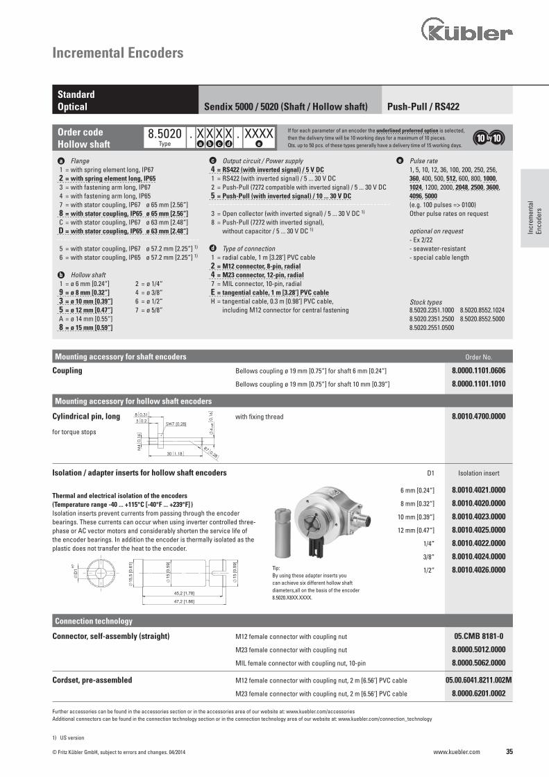
a Flange 1 = with spring element long, IP67 2 = with spring element long, IP65 3 = with fastening arm long, IP67 4 = with fastening arm long, IP65 7 = with stator coupling, IP67 ø 65 mm [2.56“] 8 = with stator coupling, IP65 ø 65 mm [2.56“] C = with stator coupling, IP67 ø 63 mm [2.48“] D = with stator coupling, IP65 ø 63 mm [2.48“]
5 = with stator coupling, IP67 ø 57.2 mm [2.25“] 1)
6 = with stator coupling, IP65 ø 57.2 mm [2.25“] 1)
b Hollow shaft 1 = ø 6 mm [0.24“] 2 = ø 1/4“ 9 = ø 8 mm [0.32“] 4 = ø 3/8“ 3 = ø 10 mm [0.39“] 6 = ø 1/2“ 5 = ø 12 mm [0.47“] 7 = ø 5/8“ A = ø 14 mm [0.55“] 8 = ø 15 mm [0.59“]
c Output circuit / Power supply 4 = RS422 (with inverted signal) / 5 V DC 1 = RS422 (with inverted signal) / 5 ... 30 V DC 2 = Push-Pull (7272 compatible with inverted signal) / 5 ... 30 V DC 5 = Push-Pull (with inverted signal) / 10 ... 30 V DC
3 = Open collector (with inverted signal) / 5 ... 30 V DC 1)
8 = Push-Pull (7272 with inverted signal), without capacitor / 5 ... 30 V DC 1)
d Type of connection 1 = radial cable, 1 m [3.28‘] PVC cable 2 = M12 connector, 8-pin, radial 4 = M23 connector, 12-pin, radial 7 = MIL connector, 10-pin, radial E = tangential cable, 1 m [3.28‘] PVC cable H = tangential cable, 0.3 m [0.98‘] PVC cable, including M12 connector for central fastening
e Pulse rate 1, 5, 10, 12, 36, 100, 200, 250, 256, 360, 400, 500, 512, 600, 800, 1000, 1024, 1200, 2000, 2048, 2500, 3600, 4096, 5000 (e.g. 100 pulses => 0100) Other pulse rates on request
optional on request - Ex 2/22 - seawater-resistant - special cable length
Stock types 8.5020.2351.1000 8.5020.8552.1024 8.5020.2351.2500 8.5020.8552.5000 8.5020.2551.0500
Push-Pull / RS422 StandardOptical Sendix 5000 / 5020 (Shaft / Hollow shaft)
Order codeHollow shaft
8.5020 . X X X X . XXXX If for each parameter of an encoder the underlined preferred option is selected, then the delivery time will be 10 working days for a maximum of 10 pieces. Qts. up to 50 pcs. of these types generally have a delivery time of 15 working days.Type a b c d e
Mounting accessory for hollow shaft encoders
Connection technology
Mounting accessory for shaft encoders Order No.
Coupling Bellows coupling ø 19 mm [0.75“] for shaft 6 mm [0.24“] 8.0000.1101.0606
Bellows coupling ø 19 mm [0.75“] for shaft 10 mm [0.39“] 8.0000.1101.1010
Cylindrical pin, long with fixing thread 8.0010.4700.0000
for torque stops
Isolation / adapter inserts for hollow shaft encoders D1 Isolation insert
6 mm [0.24“] 8.0010.4021.0000
8 mm [0.32“] 8.0010.4020.0000
10 mm [0.39“] 8.0010.4023.0000
12 mm [0.47“] 8.0010.4025.0000
1/4“ 8.0010.4022.0000
3/8“ 8.0010.4024.0000
1/2“ 8.0010.4026.0000
Connector, self-assembly (straight) M12 female connector with coupling nut 05.CMB 8181-0
M23 female connector with coupling nut 8.0000.5012.0000
MIL female connector with coupling nut, 10-pin 8.0000.5062.0000
Cordset, pre-assembled M12 female connector with coupling nut, 2 m [6.56‘] PVC cable 05.00.6041.8211.002M
M23 female connector with coupling nut, 2 m [6.56‘] PVC cable 8.0000.6201.0002
Further accessories can be found in the accessories section or in the accessories area of our website at: www.kuebler.com/accessoriesAdditional connectors can be found in the connection technology section or in the connection technology area of our website at: www.kuebler.com/connection_technology
Tip: By using these adapter inserts you can achieve six different hollow shaft diameters,all on the basis of the encoder 8.5020.X8XX.XXXX.
Thermal and electrical isolation of the encoders(Temperature range -40 ... +115°C [-40°F ... +239°F] )Isolation inserts prevent currents from passing through the encoder bearings. These currents can occur when using inverter controlled three-phase or AC vector motors and considerably shorten the service life of the encoder bearings. In addition the encoder is thermally isolated as the plastic does not transfer the heat to the encoder.
36 www.kuebler.com © Fritz Kübler GmbH, subject to errors and changes. 04/2014
Mechanical characteristics
Technical data
Max. Speed IP65 12 000 min-1
6 000 min-1 (continuous) IP67 6 000 min-1
3 000 min-1 (continuous)
Moment of intertia shaft version approx. 1.8 x 10⁻⁶ kgm2 hollow shaft version approx. 6 x 10⁻⁶ kgm2
Starting torque IP65 < 0.01 Nm at 20°C [68°F] IP67 < 0.05 Nm
Shaft load capacity radial 80 N axial 40 N
Electrical characteristicsOutput circuit RS422 RS422 Push-Pull Push-Pull Push-Pull Open collector (TTL compatible) (TTL compatible) (7272 compatible) (7272, without capacitor) (7273) Ordercode 1 4 5 2 8 3
Power supply 5 ... 30 V DC 5 V DC ±5% 10 ... 30 V DC 5 ... 30 V DC 5 ... 30 V DC 5 ... 30 V DC
Power consumption (no load) typ. 40 mA typ. 40 mA typ. 50 mA typ. 50 mA typ. 50 mA 100 mA max. 90 mA max. 90 mA max. 100 mA max. 100 mA max. 100 mA
Permissible load / channel max. ±20 mA max. ±20 mA max. ±20 mA max. ±20 mA max. ±20 mA 20 mA sink at 30 V DC
Pulse frequency max. 300 kHz max. 300 kHz max. 300 kHz max. 300 kHz 2) max. 300 kHz max. 300 kHz
Signal level HIGH min. 2.5 V min. 2.5 V min +V - 1 V min. +V - 2.0 V min. +V - 2.0 V LOW max. 0.5 V max. 0.5 V max. 0.5 V max. 0.5 V max. 0.5 V
Rising edge time tr max. 200 ns max. 200 ns max. 1 μs max. 1 μs max. 1 μs
Falling edge time tf max. 200 ns max. 200 ns max. 1 μs max. 1 μs max. 1 μs
Short circuit proof outputs 3) yes 4) yes 4) yes yes yes 4) yes
Reverse polarity protection yes no yes no no no of the power supply
UL approval File 224618
CE compliant acc. to EMC guideline 2004/108/EC
RoHS compliant acc. to guideline 2011/65/EU
1) With connector: -40°C [-40°F], cable fixed: -30°C [-22°F], cable moved: -20°C [-4°F]2) Max. recommended cable length 30 m [98.43‘]3) If supply voltage correctly applied4) Only one channel allowed to be shorted-out: If +V= 5 V DC, short-circuit to channel, 0 V, or +V is permitted. If +V= 5 ... 30 V DC, short-circuit to channel or 0 V is permitted.
Weight approx. 0.4 kg [14.11 oz]
Protection acc. to EN 60529 without shaft seal IP65 with shaft seal IP67
EX approval for hazardous areas optional Zone 2 and 22
Working temperature range -40°C 1) ... +85°C [-40°F 1) ... +185°F]
Material shaft stainless steel
Shock resistance acc. to EN 60068-2-27 2500 m/s2, 6 ms
Vibration resistance acc. to EN 60068-2-6 100 m/s2, 10 ... 2000 Hz
Incremental Encoders
Push-Pull / RS422 StandardOptical Sendix 5000 / 5020 (Shaft / Hollow shaft)
37
85 7
34 1
2
6 11
1
2
3
4 56
7
89
10 12
AB
CD
E
AB
CDE
F
GH
IJ
AB
CD
E
FG F
AB
CD
E
AB
CDE
F
GH
IJ
AB
CD
E
FG F
AB
CD
E
AB
CDE
F
GH
IJ
AB
CD
E
FG F
www.kuebler.com© Fritz Kübler GmbH, subject to errors and changes. 04/2014
Incr
emen
tal
Enco
ders
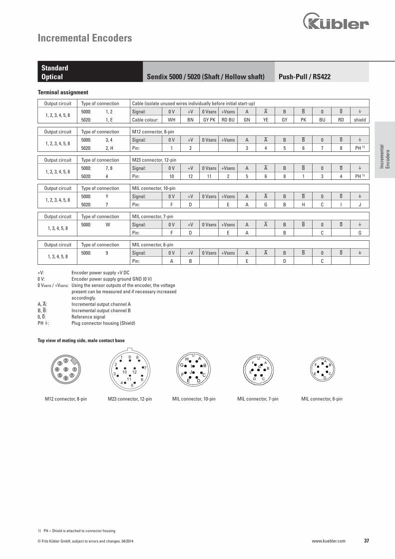
Output circuit Type of connection Cable (isolate unused wires individually before initial start-up)
5000: 1, 2 Signal: 0 V +V 0 Vsens +Vsens A B 0 H 1, 2, 3, 4, 5, 8
5020: 1, E Cable colour: WH BN GY PK RD BU GN YE GY PK BU RD shield
Output circuit Type of connection M12 connector, 8-pin
5000: 3, 4 Signal: 0 V +V 0 Vsens +Vsens A B 0 H 1, 2, 3, 4, 5, 8
5020: 2, H Pin: 1 2 3 4 5 6 7 8 PH 1)
Output circuit Type of connection M23 connector, 12-pin
5000: 7, 8 Signal: 0 V +V 0 Vsens +Vsens A B 0 H 1, 2, 3, 4, 5, 8
5020: 4 Pin: 10 12 11 2 5 6 8 1 3 4 PH 1)
Output circuit Type of connection MIL connector, 7-pin
5000: W Signal: 0 V +V 0 Vsens +Vsens A B 0 H 1, 3, 4, 5, 8
Pin: F D E A B C G
Output circuit Type of connection MIL connector, 10-pin
5000: Y Signal: 0 V +V 0 Vsens +Vsens A B 0 H 1, 2, 3, 4, 5, 8
5020: 7 Pin: F D E A G B H C I J
Output circuit Type of connection MIL connector, 6-pin
5000: 9 Signal: 0 V +V 0 Vsens +Vsens A B 0 H 1, 3, 4, 5, 8
Pin: A B E D C
1) PH = Shield is attached to connector housing
Terminal assignment
MIL connector, 10-pin MIL connector, 7-pin MIL connector, 6-pin
Incremental Encoders
Push-Pull / RS422 StandardOptical Sendix 5000 / 5020 (Shaft / Hollow shaft)
Top view of mating side, male contact base
M12 connector, 8-pin M23 connector, 12-pin
+V: Encoder power supply +V DC0 V: Encoder power supply ground GND (0 V)0 Vsens / +Vsens: Using the sensor outputs of the encoder, the voltage present can be measured and if necessary increased accordingly. A, : Incremental output channel AB, : Incremental output channel B0, : Reference signalPH H: Plug connector housing (Shield)
38
3x120°
40 1,57
1,3935,2
2,0953,2
2,81
71,4
90,4
3,56
1
2,81
2,26
3
L
3
71,4
0,12
0,13
43,7 1,72
57,4
47 1,85
1,84
h7
4730
250
,8
30,45
0,12
1,85
1,2
46,7
3,3
64 2,52
D
1,
18
3x120°
421,
65
943,
7
2,2256,5
2,95
75
38,5 1,52
1
[1,9
7]
1,33
max
.50
0,16
0,123
0,123
33,75
2,28
0,83
58
D
L
1,97
50 h7
max.21
4
47 1,85
3x120°
481,
89[1,4
2]
50
21
23,8
1,97
0,83
L
0,39
1,46
D
582,
28
0,94
3710
36
f8
1
1,5238,5
3,7
942,95
750,3910
46,5 1,83
3x120°
481,
89[1,4
2]
50
21
23,8
1,97
0,83
L
0,39
1,46
D
582,
28
0,94
3710
36
f8
1
1,5238,5
3,7
942,95
750,3910
46,5 1,83
3x120°
481,
89[1,4
2]
50
21
23,8
1,97
0,83
L
0,39
1,46
D
582,
28
0,94
3710
36
f8
1
1,5238,5
3,7
942,95
75
0,3910
46,5 1,83
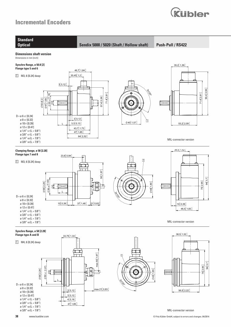
D = ø 6 h7 [0.24] ø 8 h7 [0.32] ø 10 f7 [0.39] ø 12 h7 [0.47] ø 1/4“ h7 (L = 5/8“) ø 3/8“ h7 (L = 5/8“) ø 1/4“ h8 (L = 7/8“) ø 3/8“ h8 (L = 7/8“)
D = ø 6 h7 [0.24] ø 8 h7 [0.32] ø 10 f7 [0.39] ø 12 h7 [0.47] ø 1/4“ h7 (L = 5/8“) ø 3/8“ h7 (L = 5/8“) ø 1/4“ h8 (L = 7/8“) ø 3/8“ h8 (L = 7/8“)
D = ø 6 h7 [0.24] ø 8 h7 [0.32] ø 10 f7 [0.39] ø 12 h7 [0.47] ø 1/4“ h7 (L = 5/8“) ø 3/8“ h7 (L = 5/8“) ø 1/4“ h8 (L = 7/8“) ø 3/8“ h8 (L = 7/8“)
www.kuebler.com © Fritz Kübler GmbH, subject to errors and changes. 04/2014
Synchro flange, ø 50.8 [2] Flange type 5 and 6
1 M3, 6 [0.24] deep
Dimensions shaft versionDimensions in mm [inch]
Synchro flange, ø 58 [2.28]Flange type A and B
1 M4, 6 [0.24] deep
MIL-connector version
MIL-connector version
MIL-connector version
Incremental Encoders
Push-Pull / RS422 StandardOptical Sendix 5000 / 5020 (Shaft / Hollow shaft)
Clamping flange, ø 58 [2.28]Flange type 7 and 8
1 M3, 6 [0.24] deep
39
[3,94]
115 4,53±0,1100
6,6
0,26
6x60°
85h5
61,6
33 1,3k611
2,43
8
1,4236
1,2231
50,8
0,31
0,123
4
2
0,16
582,
28
54,6
2,15
0,26
6,6
6 0,24
16 0,630,28
100,
39
7
13,25 0,52
[3,3
5]
1
[0,4
3]
1
[1,25]
1,03
7,5
2,5
7,1
63,5
1,97
39,5 1,56
D
31,7
5
h7
L
0,8321
0,28
0,3
26,25
max
.50
50,8
2 2,06
52,4
5,50,2
2
0,3
96,7
5
1,9349
3,06
77,7
5
3,81
7,5
31 1,22[1,25]
1,03
7,5
2,5
7,1
63,5
1,97
39,5 1,56
D
31,7
5
h7
L
0,8321
0,28
0,3
26,25
max
.50
50,8
2 2,06
52,4
5,50,2
2
0,3
96,7
5
1,9349
3,06
77,7
5
3,81
7,5
31 1,22
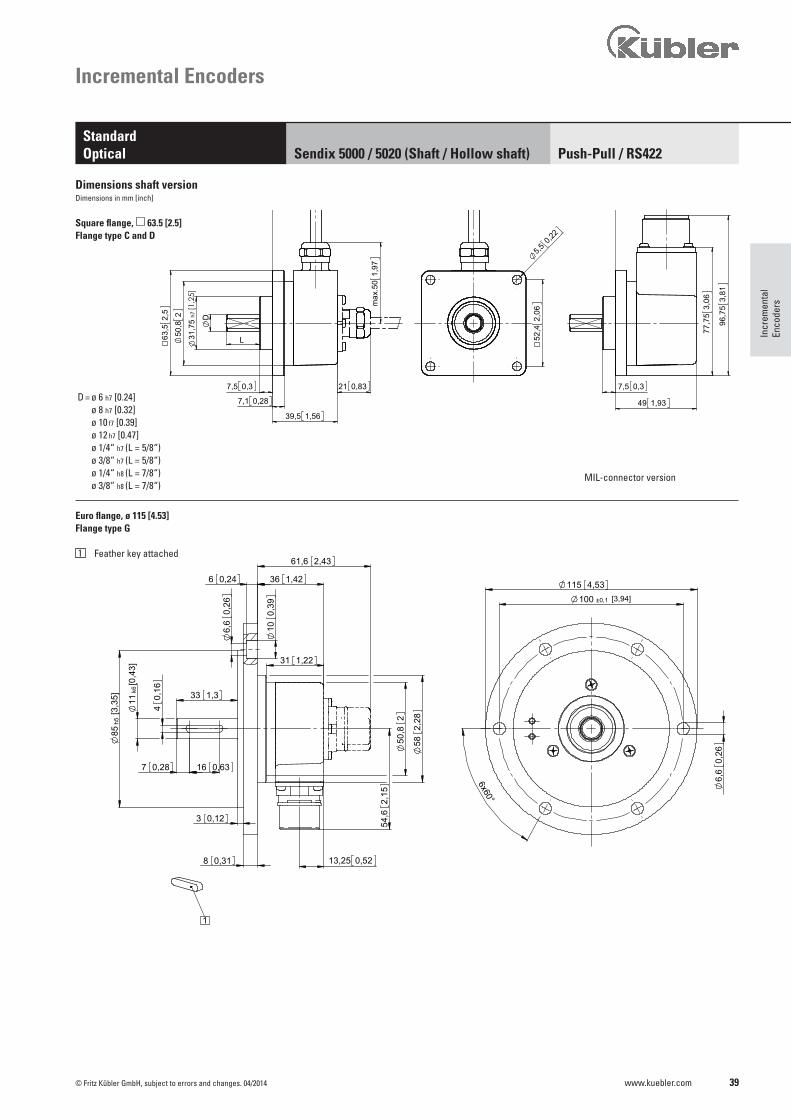
D = ø 6 h7 [0.24] ø 8 h7 [0.32] ø 10 f7 [0.39] ø 12 h7 [0.47] ø 1/4“ h7 (L = 5/8“) ø 3/8“ h7 (L = 5/8“) ø 1/4“ h8 (L = 7/8“) ø 3/8“ h8 (L = 7/8“)
www.kuebler.com© Fritz Kübler GmbH, subject to errors and changes. 04/2014
Incr
emen
tal
Enco
ders
Dimensions shaft versionDimensions in mm [inch]
MIL-connector version
Square flange, 63.5 [2.5]Flange type C and D
Euro flange, ø 115 [4.53]Flange type G
1 Feather key attached
Incremental Encoders
Push-Pull / RS422 StandardOptical Sendix 5000 / 5020 (Shaft / Hollow shaft)

40
45°
3x120° 4x90° 1,6341,3
38,1 1,5
1
2
[1,2
5]
L
46
1,85
0,52
h7
13,25
31,7
5
47
1,81
0,1
D 2
2,540,1
50,8
2,54
60,7 2,39
0,133,3
43,7 1,72
1,3935,2
0,13
2,84
72,1
5 91,1
53,
59
3,353,2 2,09
45°
3x120° 4x90°
1,6341,338,1 1,5
1
2
[1,2
5]
L
46
1,85
0,52
h7
13,25
31,7
5
47
1,81
0,1
D 2
2,540,1
50,8
2,54
60,7 2,39
0,133,3
43,7 1,72
1,3935,2
0,13
2,84
72,1
5 91,1
53,
59
3,353,2 2,09
45°
3x120° 4x90°
1,6341,338,1 1,5
1
2
[1,2
5]
L
46
1,85
0,52
h7
13,25
31,7
5
47
1,81
0,1
D 2
2,540,1
50,8
2,54
60,7 2,39
0,133,3
43,7 1,72
1,3935,2
0,13
2,84
72,1
5 91,1
53,
59
3,353,2 2,09
50,8 2
1
2
52,3
2,06
44,4
51,
75[1,2
5]
0,52
1,97
max
.50
0,83max.21
D
43,7
0,133,30,3
1,72
7,7
13,25
31
,75
h7
L
0,13
2,84
72,1
5
3,59
91,1
5
35,2 1,39
3,353,2 2,09
50,8 2
1
2
52,3
2,06
44,4
51,
75[1,2
5]
0,52
1,97
max
.50
0,83max.21
D
43,7
0,133,30,3
1,72
7,7
13,25
31
,75
h7
L
0,132,
8472
,15
3,59
91,1
5
35,2 1,39
3,353,2 2,09
50,8 2
1
2
52,3
2,06
44,4
51,
75[1,2
5]
0,52
1,97
max
.50
0,83max.21
D
43,7
0,133,30,3
1,72
7,7
13,25
31
,75
h7
L
0,13
2,84
72,1
5
3,59
91,1
5
35,2 1,39
3,353,2 2,09
1,88
47,6
3
3x120°
[1,2
5]
58,8
72,
32 h7
31,7
5
39,5
1,81
0,52
2,65 0,10,1
D
46
13,25
7,5 0,3
63,5
L
2,5
1,56
2,65
56,5 2,22
49 1,93
3,06
77,7
5
96,7
53,
81
0,37,5
31 1,22
1 1,88
47,6
3
3x120°
[1,2
5]
58,8
72,
32 h7
31,7
5
39,5
1,81
0,52
2,65 0,10,1
D
46
13,25
7,5 0,3
63,5
L
2,5
1,56
2,65
56,5 2,22
49 1,93
3,06
77,7
5
96,7
53,
81
0,37,5
31 1,22
1 1,88
47,6
3
3x120°
[1,2
5]
58,8
72,
32 h7
31,7
5
39,5
1,81
0,52
2,65 0,10,1
D
46
13,25
7,5 0,3
63,5
L
2,5
1,56
2,65
56,5 2,22
49 1,93
3,06
77,7
5
96,7
53,
81
0,37,5
31 1,22
1
D = ø 6 h7 [0.24] ø 8 h7 [0.32] ø 10 f7 [0.39] ø 12 h7 [0.47] ø 1/4“ h7 (L = 5/8“) ø 3/8“ h7 (L = 5/8“) ø 1/4“ h8 (L = 7/8“) ø 3/8“ h8 (L = 7/8“)
D = ø 6 h7 [0.24] ø 8 h7 [0.32] ø 10 f7 [0.39] ø 12 h7 [0.47] ø 1/4“ h7 (L = 5/8“) ø 3/8“ h7 (L = 5/8“) ø 1/4“ h8 (L = 7/8“) ø 3/8“ h8 (L = 7/8“)
D = ø 6 h7 [0.24] ø 8 h7 [0.32] ø 10 f7 [0.39] ø 12 h7 [0.47] ø 1/4“ h7 (L = 5/8“) ø 3/8“ h7 (L = 5/8“) ø 1/4“ h8 (L = 7/8“) ø 3/8“ h8 (L = 7/8“)
www.kuebler.com © Fritz Kübler GmbH, subject to errors and changes. 04/2014
Servo flange, ø 50.8 [2] Flange type 1 and 2
1 6-32 UNC x 5 [0.2] deep
2 4-40 UNC x 6 [0.24] deep
Square flange, 50.8 [2] Flange type 3 and 4
1 ø 4 [0.16]
2 6-32 UNC x 5 [0.2] deep
Servo flange, ø 63.5 [2.5] Flange type E and F
1 6-32 UNC
Incremental Encoders
Push-Pull / RS422 StandardOptical Sendix 5000 / 5020 (Shaft / Hollow shaft)
Dimensions shaft versionDimensions in mm [inch]
MIL-connector version
MIL-connector version
MIL-connector version
41
3x12
0°
42 1,65
33,7 1,33
1
2
[0,1
6]
37,9
0,09 3
,99
1,49
-0,0
2
0,55
2,4
14 D H7
3
1,25
31,7
5 33
250
,8
0,8221
1,81
46
1,26
32
1,3534,2
1,4837,5
1,3
max
.
45,1 1,78
90,4
3,56
36,2 1,43
43,7 1,72
2,81
71,4
54,2 2,13
50,2
1 1,5740
2,95753,3986
0,45
11,4
220,87
www.kuebler.com© Fritz Kübler GmbH, subject to errors and changes. 04/2014
Incr
emen
tal
Enco
ders
Incremental Encoders
Push-Pull / RS422 StandardOptical Sendix 5000 / 5020 (Shaft / Hollow shaft)
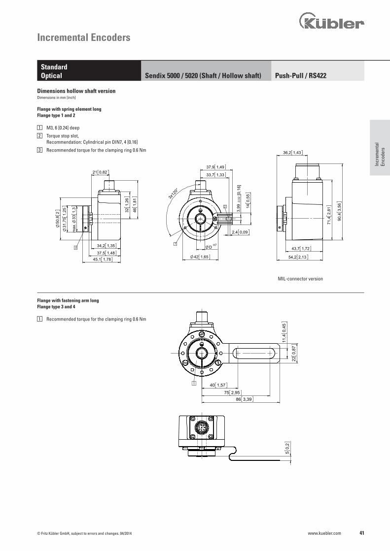
Flange with spring element long Flange type 1 and 2
1 M3, 6 [0.24] deep
2 Torque stop slot, Recommendation: Cylindrical pin DIN7, 4 [0.16]
3 Recommended torque for the clamping ring 0.6 Nm
Flange with fastening arm longFlange type 3 and 4
1 Recommended torque for the clamping ring 0.6 Nm
Dimensions hollow shaft versionDimensions in mm [inch]
MIL-connector version
42
25°
40°
632,
48
0,12
3,1
682,6
8
1
0,020,5
45,2 1,78
65 [2,56]
3x 1
20°
30°
57,15 2,25
31,5
1,24
54,6
2,15
DH7
3,2
0,13
1
50,2 [1.98]
50,8
[2.0
]
6,5 0,26
65 [2,56]
3x 1
20°
30°
37 [1
.46]
461,
81
1
50,2 [1.98]
50,8
[2.0
]
6,5 0,26
74 [2,91]
H7D
4,3 [0.17]
www.kuebler.com © Fritz Kübler GmbH, subject to errors and changes. 04/2014
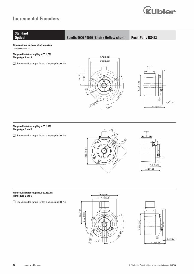
Flange with stator coupling, ø 63 [2.48]Flange type C and D
1 Recommended torque for the clamping ring 0.6 Nm
Incremental Encoders
Push-Pull / RS422 StandardOptical Sendix 5000 / 5020 (Shaft / Hollow shaft)
Flange with stator coupling, ø 57.2 [2.25]Flange type 5 and 6
1 Recommended torque for the clamping ring 0.6 Nm
Flange with stator coupling, ø 65 [2.56]Flange type 7 and 8
1 Recommended torque for the clamping ring 0.6 Nm
Dimensions hollow shaft versionDimensions in mm [inch]
43
3x12
0°
33,7 [1.33]
42 [1.65]
M12
3
31,7
5 [1
.25]
50,8
[2.0
]
[1.54]39,1
33 [1
.3]
35,8 [1.41]
max
46,3 [1.82]
1
2
[1.49]
14
37,9
[0.09]2,43,
99 [0
.16]
[0.5
5]
DH7
www.kuebler.com© Fritz Kübler GmbH, subject to errors and changes. 04/2014
Incr
emen
tal
Enco
ders
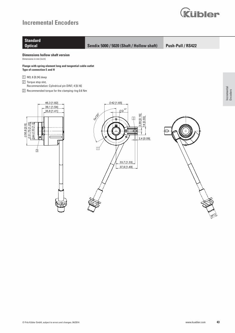
Flange with spring element long and tangential cable outletType of connection E and H
1 M3, 6 [0.24] deep
2 Torque stop slot, Recommendation: Cylindrical pin DIN7, 4 [0.16]
3 Recommended torque for the clamping ring 0.6 Nm
Incremental Encoders
Push-Pull / RS422 StandardOptical Sendix 5000 / 5020 (Shaft / Hollow shaft)
Dimensions hollow shaft versionDimensions in mm [inch]
Related Documents