HAL Id: hal-00451884 https://hal.archives-ouvertes.fr/hal-00451884 Submitted on 25 Jun 2019 HAL is a multi-disciplinary open access archive for the deposit and dissemination of sci- entific research documents, whether they are pub- lished or not. The documents may come from teaching and research institutions in France or abroad, or from public or private research centers. L’archive ouverte pluridisciplinaire HAL, est destinée au dépôt et à la diffusion de documents scientifiques de niveau recherche, publiés ou non, émanant des établissements d’enseignement et de recherche français ou étrangers, des laboratoires publics ou privés. Increase of Singularity-Free Zones in the Workspace of Parallel Manipulators Using Mechanisms of Variable Structure Vigen Arakelian, Sébastien Briot, Victor Glazunov To cite this version: Vigen Arakelian, Sébastien Briot, Victor Glazunov. Increase of Singularity-Free Zones in the Workspace of Parallel Manipulators Using Mechanisms of Variable Structure. Mechanism and Machine Theory, Elsevier, 2008, 43 (9), pp.1129-1140. hal-00451884

Welcome message from author
This document is posted to help you gain knowledge. Please leave a comment to let me know what you think about it! Share it to your friends and learn new things together.
Transcript
HAL Id: hal-00451884https://hal.archives-ouvertes.fr/hal-00451884
Submitted on 25 Jun 2019
HAL is a multi-disciplinary open accessarchive for the deposit and dissemination of sci-entific research documents, whether they are pub-lished or not. The documents may come fromteaching and research institutions in France orabroad, or from public or private research centers.
L’archive ouverte pluridisciplinaire HAL, estdestinée au dépôt et à la diffusion de documentsscientifiques de niveau recherche, publiés ou non,émanant des établissements d’enseignement et derecherche français ou étrangers, des laboratoirespublics ou privés.
Increase of Singularity-Free Zones in the Workspace ofParallel Manipulators Using Mechanisms of Variable
StructureVigen Arakelian, Sébastien Briot, Victor Glazunov
To cite this version:Vigen Arakelian, Sébastien Briot, Victor Glazunov. Increase of Singularity-Free Zones in theWorkspace of Parallel Manipulators Using Mechanisms of Variable Structure. Mechanism and MachineTheory, Elsevier, 2008, 43 (9), pp.1129-1140. �hal-00451884�
Increase of singularity-free zones in the workspace of parallel manipulators
using mechanisms of variable structure
Vigen Arakelian a)
, Sébastien Briot a)
, Victor Glazunov b)
a) Département de Génie Mécanique et Automatique - L.G.C.G.M. EA3913
Institut National des Sciences Appliquées (I.N.S.A.)
20 avenue des Buttes de Coësmes – CS 14315
F-35043 Rennes, France
E-mails : [email protected]
b)
Mechanical Engineering Research Institute
Russian Academy of Sciences
M.Kharitonyevski str. 4,
101990 Moscow, Russia
E-mail: [email protected]
Abstract
This paper is focused on the study of singularity of planar parallel manipulators taking
into account the force transmission, i.e. study of singularity of planar manipulator by
introducing the force transmission factor. Thus the singularity zones in the workspace of the
manipulator are defined not only by kinematic criterions from the theoretical perfect model of
the manipulator but also by the quality of force transmission. For this purpose, the pressure
angle is used as an indicator of force transmission. The optimal control of the pressure angle
for a given trajectory of the manipulator is realized by means of legs with variable structure.
The suggested procedure to determination of the optimal structure of the planar parallel
manipulator 3-RPR is illustrated by two numerical simulations.
Keywords: Parallel manipulator, singularity-free zones, pressure angle, force transmissivity
analysis
1. Introduction
It is well-known that the closed-loop of parallel manipulators limits the motion of the
platform and creates special singular zones inside the workspace [1]. The workspace of the
parallel manipulators which is less than the serial manipulators becomes smaller and limits
their functional performance.
One of the most evident solutions of this problem is the introduction in the initial system
of complementary actuators, which make it possible to eliminate the singular configurations
of the parallel manipulator by means of optimal control of the motion [2, 3]. However, it is an
expensive solution to the problem because of the additional actuators and the complicated
control of the manipulator caused by actuation redundancy.
In this paper we propose a new solution, which carried out by using mechanisms of
variable structure, i.e. a mechanism whose structure parameters can be altered. With regard to
the determination of singularity-free zones inside the workspace we propose a kinetostatic
approach taking account of the force transmission.
The physical interpretation of a singularity in kinematics refers to those configurations in
which the number of degrees of freedom of the mechanical structure changes instantaneously,
either the manipulator gains some additional, uncontrollable degrees of freedom or loses some
degrees of freedom. Algebraically, a singularity analysis is based on the properties of the
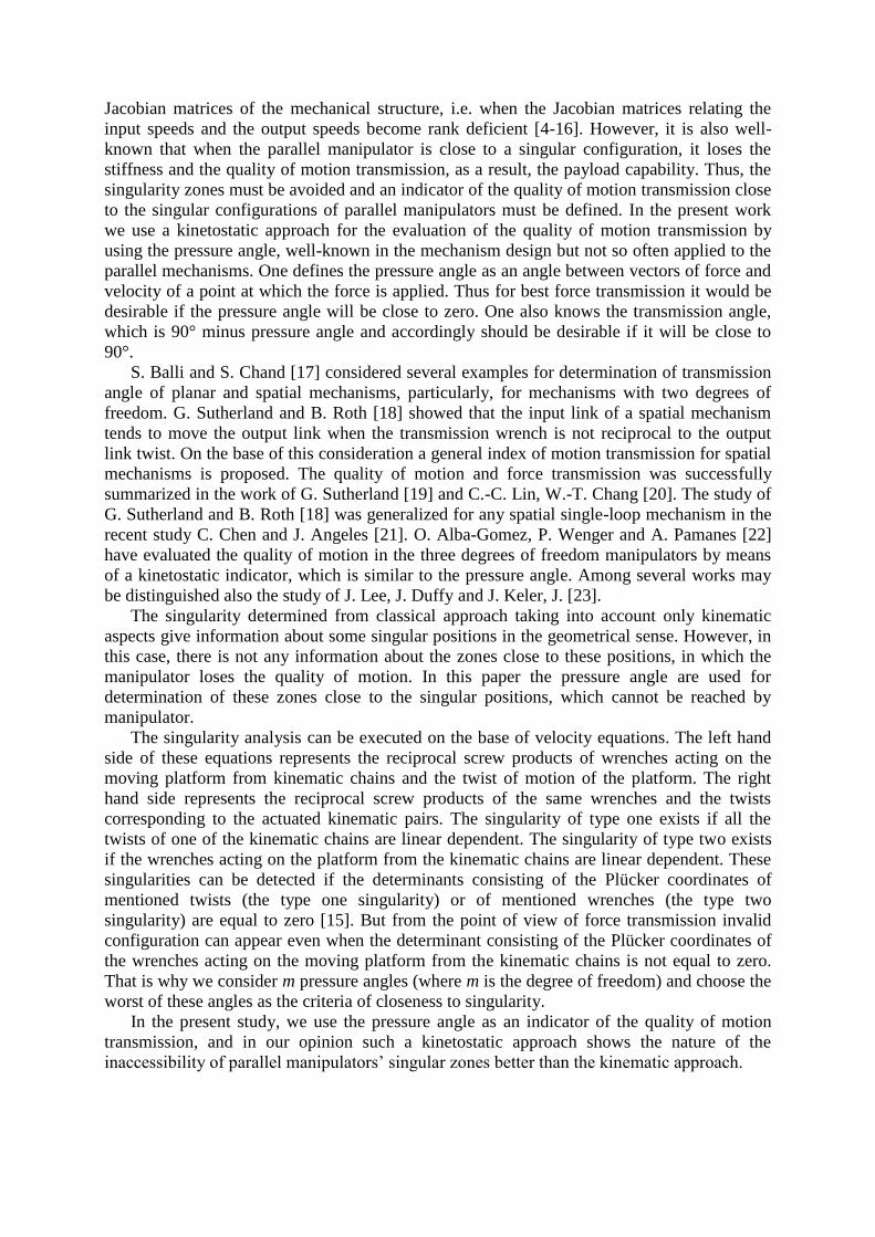
Jacobian matrices of the mechanical structure, i.e. when the Jacobian matrices relating the
input speeds and the output speeds become rank deficient [4-16]. However, it is also well-
known that when the parallel manipulator is close to a singular configuration, it loses the
stiffness and the quality of motion transmission, as a result, the payload capability. Thus, the
singularity zones must be avoided and an indicator of the quality of motion transmission close
to the singular configurations of parallel manipulators must be defined. In the present work
we use a kinetostatic approach for the evaluation of the quality of motion transmission by
using the pressure angle, well-known in the mechanism design but not so often applied to the
parallel mechanisms. One defines the pressure angle as an angle between vectors of force and
velocity of a point at which the force is applied. Thus for best force transmission it would be
desirable if the pressure angle will be close to zero. One also knows the transmission angle,
which is 90° minus pressure angle and accordingly should be desirable if it will be close to
90°.
S. Balli and S. Chand [17] considered several examples for determination of transmission
angle of planar and spatial mechanisms, particularly, for mechanisms with two degrees of
freedom. G. Sutherland and B. Roth [18] showed that the input link of a spatial mechanism
tends to move the output link when the transmission wrench is not reciprocal to the output
link twist. On the base of this consideration a general index of motion transmission for spatial
mechanisms is proposed. The quality of motion and force transmission was successfully
summarized in the work of G. Sutherland [19] and C.-C. Lin, W.-T. Chang [20]. The study of
G. Sutherland and B. Roth [18] was generalized for any spatial single-loop mechanism in the
recent study C. Chen and J. Angeles [21]. O. Alba-Gomez, P. Wenger and A. Pamanes [22]
have evaluated the quality of motion in the three degrees of freedom manipulators by means
of a kinetostatic indicator, which is similar to the pressure angle. Among several works may
be distinguished also the study of J. Lee, J. Duffy and J. Keler, J. [23].
The singularity determined from classical approach taking into account only kinematic
aspects give information about some singular positions in the geometrical sense. However, in
this case, there is not any information about the zones close to these positions, in which the
manipulator loses the quality of motion. In this paper the pressure angle are used for
determination of these zones close to the singular positions, which cannot be reached by
manipulator.
The singularity analysis can be executed on the base of velocity equations. The left hand
side of these equations represents the reciprocal screw products of wrenches acting on the
moving platform from kinematic chains and the twist of motion of the platform. The right
hand side represents the reciprocal screw products of the same wrenches and the twists
corresponding to the actuated kinematic pairs. The singularity of type one exists if all the
twists of one of the kinematic chains are linear dependent. The singularity of type two exists
if the wrenches acting on the platform from the kinematic chains are linear dependent. These
singularities can be detected if the determinants consisting of the Plücker coordinates of
mentioned twists (the type one singularity) or of mentioned wrenches (the type two
singularity) are equal to zero [15]. But from the point of view of force transmission invalid
configuration can appear even when the determinant consisting of the Plücker coordinates of
the wrenches acting on the moving platform from the kinematic chains is not equal to zero.
That is why we consider m pressure angles (where m is the degree of freedom) and choose the
worst of these angles as the criteria of closeness to singularity.
In the present study, we use the pressure angle as an indicator of the quality of motion
transmission, and in our opinion such a kinetostatic approach shows the nature of the
inaccessibility of parallel manipulators’ singular zones better than the kinematic approach.
2. The quality of motion transmission and pressure angle
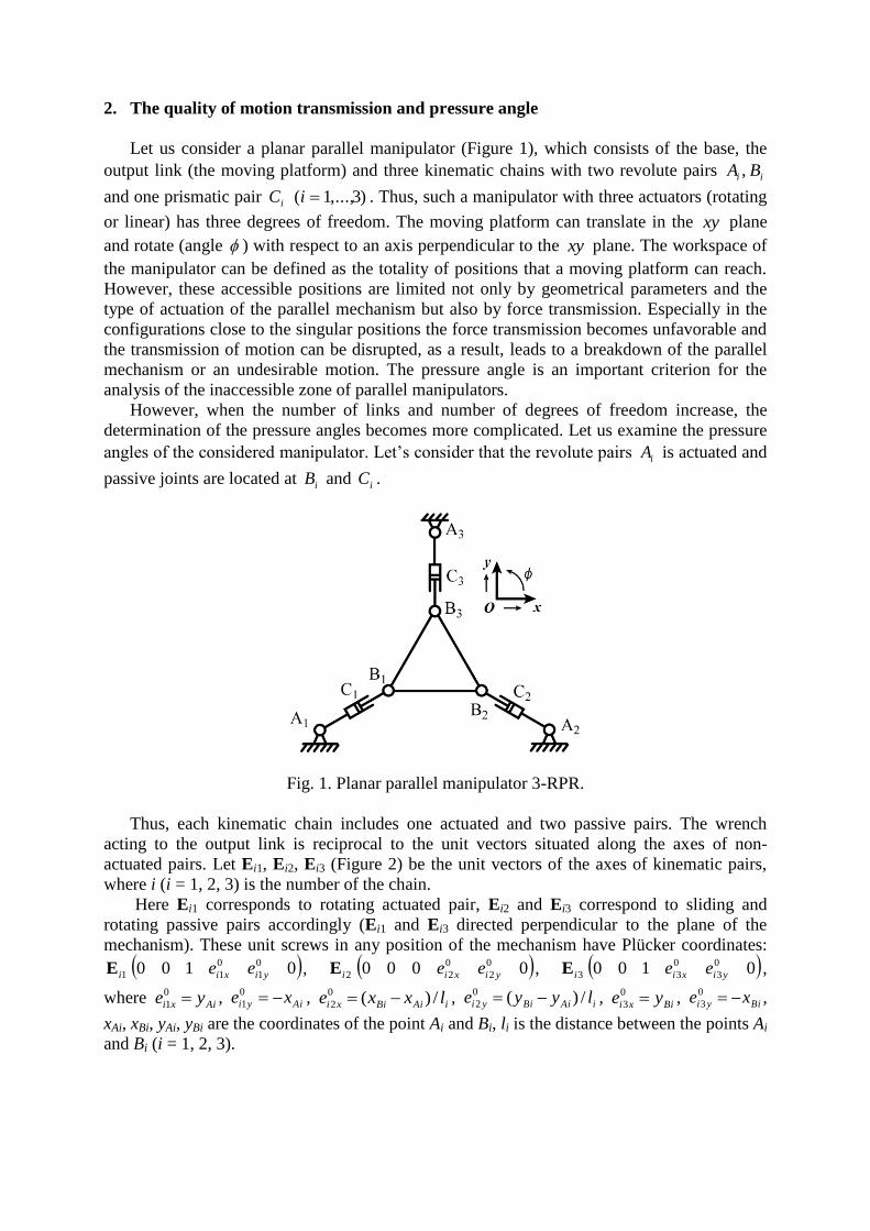
Let us consider a planar parallel manipulator (Figure 1), which consists of the base, the
output link (the moving platform) and three kinematic chains with two revolute pairs ii BA ,
and one prismatic pair iC )3,...,1( i . Thus, such a manipulator with three actuators (rotating
or linear) has three degrees of freedom. The moving platform can translate in the xy plane
and rotate (angle ) with respect to an axis perpendicular to the xy plane. The workspace of
the manipulator can be defined as the totality of positions that a moving platform can reach.
However, these accessible positions are limited not only by geometrical parameters and the
type of actuation of the parallel mechanism but also by force transmission. Especially in the
configurations close to the singular positions the force transmission becomes unfavorable and
the transmission of motion can be disrupted, as a result, leads to a breakdown of the parallel
mechanism or an undesirable motion. The pressure angle is an important criterion for the
analysis of the inaccessible zone of parallel manipulators.
However, when the number of links and number of degrees of freedom increase, the
determination of the pressure angles becomes more complicated. Let us examine the pressure
angles of the considered manipulator. Let’s consider that the revolute pairs iA is actuated and
passive joints are located at iB and iC .
Fig. 1. Planar parallel manipulator 3-RPR.
Thus, each kinematic chain includes one actuated and two passive pairs. The wrench
acting to the output link is reciprocal to the unit vectors situated along the axes of non-
actuated pairs. Let Ei1, Ei2, Ei3 (Figure 2) be the unit vectors of the axes of kinematic pairs,
where i (i = 1, 2, 3) is the number of the chain.
Here Ei1 corresponds to rotating actuated pair, Ei2 and Ei3 correspond to sliding and
rotating passive pairs accordingly (Ei1 and Ei3 directed perpendicular to the plane of the
mechanism). These unit screws in any position of the mechanism have Plücker coordinates:
0100 0
1
0
11 yixii eeE , 0000 0
2
0
22 yixii eeE , 0100 0
3
0
33 yixii eeE ,
where Aixi ye 0
1 , Aiyi xe 0
1 , iAiBixi lxxe /)(0
2 , iAiBiyi lyye /)(0
2 , Bixi ye 0
3 , Biyi xe 0
3 ,
xAi, xBi, yAi, yBi are the coordinates of the point Ai and Bi, li is the distance between the points Ai
and Bi (i = 1, 2, 3).

Fig. 2. Representation of the planar parallel manipulator 3-RPR in 3D.
For planar mechanisms 3-entries screws can be used [24]. The Plücker coordinates of
the unit screws can be described in the matrix (E)i (i = 1, 2, 3):
yizi
yizi
yizi
i
ee
ee
ee
33
22
11
1
0
1
(E)
The determinant of the matrix (E) vanishes if the axes Ei1 and Ei3 coincide. It means the
occurrence of singularity when the actuator causes only rotation in the joint Ei3.
We can obtain the wrenches Ri (i = 1, 2, 3), which are reciprocal to the unit vectors of the
axes of the passive kinematic pairs [24]. They can be written as: 0000 iziyixi rrrR (i
= 1, 2, 3). The conditions of reciprocity are:
00
2
0
2 iyyiixxi rere ; 000
3
0
3 iziyyiixxi rrere (1)
The equation (1) means that each connecting kinematic chain determines one wrench of
zero pitch (vector). It is perpendicular to the axis Ei2 and intersects the point Bi. The
coordinates of wrenches in the form of the matrix (R) is given by:
zyx
zyx
zyx
rrr
rrr
rrr
333
222
111
(R)
In singular configurations the system of the wrenches Ri degenerates and they intersect in
the same point or are parallel [25]. It can be shown by the representation of the components of
this matrix. If all the wrenches are parallel then the first two columns are proportional. If all
the wrenches intersect in the same point 0WW yxW then the coordinate 0
izr (i = 1, 2, 3)
can be written as WyWxiz xryrr 11
0 . In this case in the matrix (R) the third column is a linear
combination of the first and seconds columns.
To find the pressure angle we consider the wrenches Ri and the directions of the velocities
of the points Bi determined by the twists reciprocal to these wrenches. The velocity of the
point B1 is determined by two wrenches R2 and R3. One can find the twist
000 1111 yxz vvwW reciprocal to the wrenches R2 and R3 using the equations:
00
212121 zzyyxx rwrvrv ; 00
313131 zzyyxx rwrvrv (2)
It is obvious that the axis of the twist W1 is situated perpendicular to the plane of the
mechanism and intersects the center Q1 of velocities of the platform according to the
wrenches R2 and R3 (Figure 2). Without interruption of generality the twist W1 can be
expressed as 0100 11 QQ xy . The velocity VB1 has the coordinates
111111 BQBzxxB yyywvv , 111111 BQBzyyB xxxwvv . If the wrenches R2 and R3 are
parallel ( xx rr 32 , yy rr 32 , 0
3
0
2 zz rr ) then 01 zw and VB1 is perpendicular to these wrenches
R2 and R3. Finally, the pressure angle can be written as:
11111 /arccos RVRV BB (3)
It was noted that in the singular configurations all the pressure angles are equal to 90°.
Indeed, in this case the axis of the wrench R1 intersects the axes of the wrenches R2 and R3
and the velocity VB1 is perpendicular to the axis of the wrench R1.
Thus, the pressure angles can be determined at the joints of each kinematic chain then the
maximum value of the pressure angles can be compared with their limit values. In this way
we have mapped whole workspace of the parallel manipulator to detect the inaccessible zones
with unfavourable values of the pressure angles.
It should be noted that the singularity analysis can be executed on the base of velocity
equations. The left hand side of these equations represents the reciprocal screw products of
wrenches acting on the moving platform from kinematic chains and the twist of motion of the
platform. The right hand side represents the reciprocal screw products of the same wrenches
and the twists corresponding to the actuated kinematic pairs. The singularity of type one
exists if all the twists of one of the kinematic chains are linear dependent. The singularity of
type two exists if the wrenches acting on the platform from the kinematic chains are linear
dependent. These singularities can be detected if the determinants consisting of the Plücker
coordinates of mentioned twists (the type one singularity) or of mentioned wrenches (the type
two singularity) are equal to zero [15]. But from the point of view of force transmission
invalid configuration can appear even when the determinant consisting of the Plücker
coordinates of the wrenches acting on the moving platform from the kinematic chains is not
equal to zero. That is why we consider m pressure angles (where m is the degree of freedom)
and choose the worst of these angles as the criteria of closeness to singularity. Thus the
standard screw method allows the determination of singular positions only in geometrical
sense. By using the pressure angle we determine the volumes, in which the force transmission
ability is invalid.
If the prescribed path of the parallel manipulator intersects any unacceptable zone in
which the pressure angle has an inadmissible value the transmission of the motion can be
disrupted. In this case, it is necessary to change the structural parameters of the mechanism,
i.e. the input motions. It will be shown in the following section.
3. Legs with variable structure
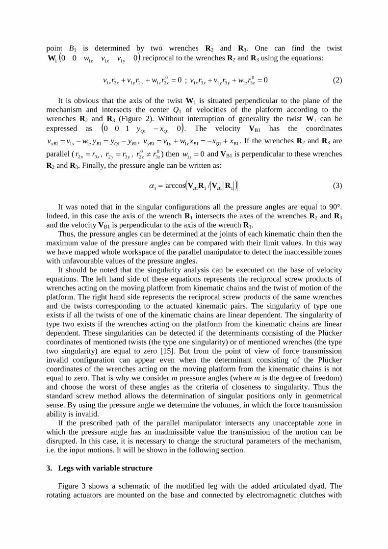
Figure 3 shows a schematic of the modified leg with the added articulated dyad. The
rotating actuators are mounted on the base and connected by electromagnetic clutches with
the links ii DA and iiCA . These two input links cannot actuate simultaneously and the input
motion can be transmitted either by the link ii DA or iiCA (i = 1, 2, 3). In this way we can
obtain the leg of the mechanisms with different structural parameters, which allow increasing
the singularity-free zones in the workspace of the considered parallel manipulator.
a) b)
Fig. 3. Leg with variable structure: a) input link iiCA ; b) input link ii DA .
By example, one or all of the pairs Ai (Figure 1) can be passive and the prismatic pairs (i =
1, 2, 3) can be actuated by the chain AiDiCi. In this case, the actuator torque is transmitted to
the link AiDi, which becomes an input link and moves the prismatic pair.
It should be noted that the mobility of the modified manipulator is not changed and it is
always equal to three.
Let us consider the system of wrenches existing in this case. In the previous case by fixed
actuator the link BiCi had translation mobility along the axis of the prismatic pair. In this case
the link BiCi is constrained by two wrenches of zero pitch Ti1 and Ti2. The wrench Ti1 is
reciprocal to the unit screws of the axes of two kinematic pairs. One of them is rotating and its
axis intersects the plane of the mechanism in the point Ai. The second of them is prismatic and
its axis is directed along the line AiBi. The Plücker coordinates of the unit screws of the axes
of these kinematic pairs are the same as the coordinates of 1iE and 2iE of the previous case.
Therefore the axis of the wrench Ti1 is perpendicular to the line AiBi and intersects the point
Ai.
The wrench Ti2 is reciprocal to the unit screws of the axes of two rotating kinematic pairs
Ci and Di. Therefore the axis of the wrench Ti2 coincides with the axis of the link CiDi.
The unit screw 0100' '0
2
'0
22 yixii eeE of the twist of the link BiCi is reciprocal to
the wrenches Ti1 and Ti2. This twist is of zero pitch and is perpendicular to the plane of the
mechanism. Corresponding to this the point of intersection of the wrenches Ti1 and Ti2
coincides with the point of intersection of the axis E’i2 and the plane of mechanism. If the link
CiDi is perpendicular to the link BiCi then the wrenches Ti1 and Ti2 are parallel and the
instantaneous motion of the link BiCi is translational. The wrench 0000 iziyixi rrrR
(i = 1, 2, 3) can be determined using the equation analogous to (1). The pressure angle can be
found using the equation (3).
Thus, in each position we determine m pressure angles corresponding to all m degrees of
freedom. Then we consider the maximum value of these angles. By such a way, we can
determine the pressure angles corresponding to the different structures distinguished by
different input links and obtain all possible workspace with singularity-free zones. It is
examined in the next section.
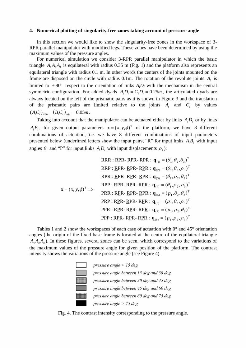
4. Numerical plotting of singularity-free zones taking account of pressure angle
In this section we would like to show the singularity-free zones in the workspace of 3-
RPR parallel manipulator with modified legs. These zones have been determined by using the
maximum values of the pressure angles.
For numerical simulation we consider 3-RPR parallel manipulator in which the basic
triangle 321 AAA is equilateral with radius 0.35 m (Fig. 1) and the platform also represents an
equilateral triangle with radius 0.1 m. In other words the centers of the joints mounted on the
frame are disposed on the circle with radius 0.1m. The rotation of the revolute joints iA is
limited to 90 respect to the orientation of links AiDi with the mechanism in the central
symmetric configuration. For added dyads mDCDA iiii 25.0 , the articulated dyads are
always located on the left of the prismatic pairs as it is shown in Figure 3 and the translation
of the prismatic pairs are limited relative to the joints iA and iC by values
mCBCA iiii 05.0)(minmin .
Taking into account that the manipulator can be actuated either by links ii DA or by links
ii BA , for given output parameters T),,( yxx of the platform, we have 8 different
combinations of actuation, i.e. we have 8 different combinations of input parameters
presented below (underlined letters show the input pairs, “R” for input links ii BA with input
angles i and “P” for input links ii DA with input displacements i ):
T),,( yxx
RRR : RPR- RPR- RPR : T
32)1( ),,( 1q
RRP : RPR- RPR- RPR : T
32)2( ),,( 1q
RPR : RPR- RPR- RPR : T
32)3( ),,( 1q
RPP : RPR- RPR- RPR : T
32)4( ),,( 1q
PRR : RPR- RPR- RPR : T
32)5( ),,( 1q p
PRP : RPR- RPR- RPR : T
32)6( ),,( 1q
PPR : RPR- RPR- RPR : T
32)7( ),,( 1q p
PPP : RPR- RPR- RPR : T
32)8( ),,( 1q p
Tables 1 and 2 show the workspaces of each case of actuation with 0° and 45° orientation
angles (the origin of the fixed base frame is located at the centre of the equilateral triangle
321 AAA ). In these figures, several zones can be seen, which correspond to the variations of
the maximum values of the pressure angle for given position of the platform. The contrast
intensity shows the variations of the pressure angle (see Figure 4).
Fig. 4. The contrast intensity corresponding to the pressure angle.
Thus, the black zones are the surfaces where the pressure angle has inadmissible values,
and as a result, these are the zones, which cannot be reached by the parallel mechanism.
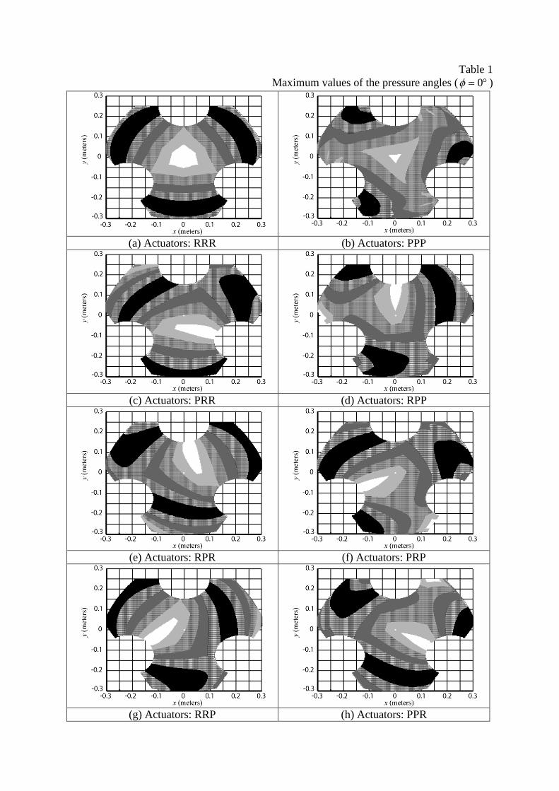
Table 1
Maximum values of the pressure angles ( 0 )
(a) Actuators: RRR (b) Actuators: PPP
(c) Actuators: PRR (d) Actuators: RPP
(e) Actuators: RPR (f) Actuators: PRP
(g) Actuators: RRP (h) Actuators: PPR
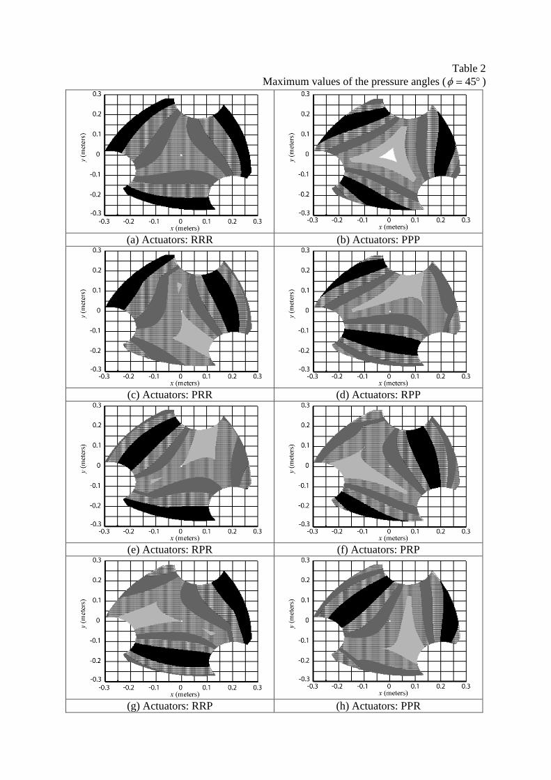
Table 2
Maximum values of the pressure angles ( 45 )
(a) Actuators: RRR (b) Actuators: PPP
(c) Actuators: PRR (d) Actuators: RPP
(e) Actuators: RPR (f) Actuators: PRP
(g) Actuators: RRP (h) Actuators: PPR
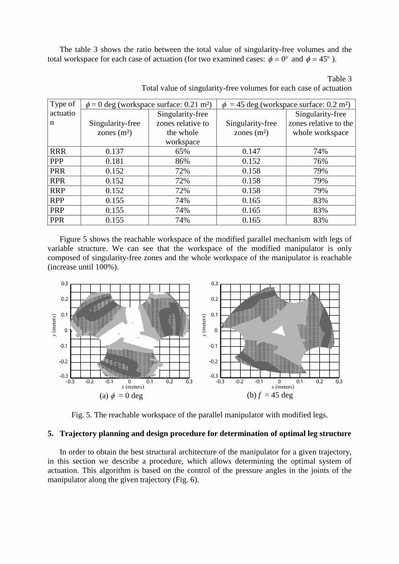
The table 3 shows the ratio between the total value of singularity-free volumes and the
total workspace for each case of actuation (for two examined cases: 0 and 45 ).
Table 3
Total value of singularity-free volumes for each case of actuation
Type of
actuatio
n
= 0 deg (workspace surface: 0.21 m²) = 45 deg (workspace surface: 0.2 m²)
Singularity-free
zones (m²)
Singularity-free
zones relative to
the whole
workspace
Singularity-free
zones (m²)
Singularity-free
zones relative to the
whole workspace
RRR 0.137 65% 0.147 74%
PPP 0.181 86% 0.152 76%
PRR 0.152 72% 0.158 79%
RPR 0.152 72% 0.158 79%
RRP 0.152 72% 0.158 79%
RPP 0.155 74% 0.165 83%
PRP 0.155 74% 0.165 83%
PPR 0.155 74% 0.165 83%
Figure 5 shows the reachable workspace of the modified parallel mechanism with legs of
variable structure. We can see that the workspace of the modified manipulator is only
composed of singularity-free zones and the whole workspace of the manipulator is reachable
(increase until 100%).
(a) = 0 deg (b) f = 45 deg
Fig. 5. The reachable workspace of the parallel manipulator with modified legs.
5. Trajectory planning and design procedure for determination of optimal leg structure
In order to obtain the best structural architecture of the manipulator for a given trajectory,
in this section we describe a procedure, which allows determining the optimal system of
actuation. This algorithm is based on the control of the pressure angles in the joints of the
manipulator along the given trajectory (Fig. 6).
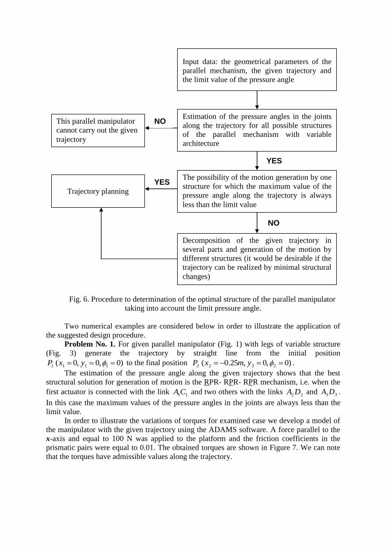
Fig. 6. Procedure to determination of the optimal structure of the parallel manipulator
taking into account the limit pressure angle.
Two numerical examples are considered below in order to illustrate the application of
the suggested design procedure.
Problem No. 1. For given parallel manipulator (Fig. 1) with legs of variable structure
(Fig. 3) generate the trajectory by straight line from the initial position
)0 ,0 ,0( 1111 yxP to the final position )0 ,0 ,25.0( 2222 ymxP .
The estimation of the pressure angle along the given trajectory shows that the best
structural solution for generation of motion is the RPR- RPR- RPR mechanism, i.e. when the
first actuator is connected with the link 11CA and two others with the links 22 DA and 33DA .
In this case the maximum values of the pressure angles in the joints are always less than the
limit value.
In order to illustrate the variations of torques for examined case we develop a model of
the manipulator with the given trajectory using the ADAMS software. A force parallel to the
x-axis and equal to 100 N was applied to the platform and the friction coefficients in the
prismatic pairs were equal to 0.01. The obtained torques are shown in Figure 7. We can note
that the torques have admissible values along the trajectory.
YES
Input data: the geometrical parameters of the
parallel mechanism, the given trajectory and
the limit value of the pressure angle
Estimation of the pressure angles in the joints
along the trajectory for all possible structures
of the parallel mechanism with variable
architecture
(pressure angles are less than the limit value)
This parallel manipulator
cannot carry out the given
trajectory
The possibility of the motion generation by one
structure for which the maximum value of the
pressure angle along the trajectory is always
less than the limit value
Trajectory planning
Decomposition of the given trajectory in
several parts and generation of the motion by
different structures (it would be desirable if the
trajectory can be realized by minimal structural
changes)
NO
YES
NO
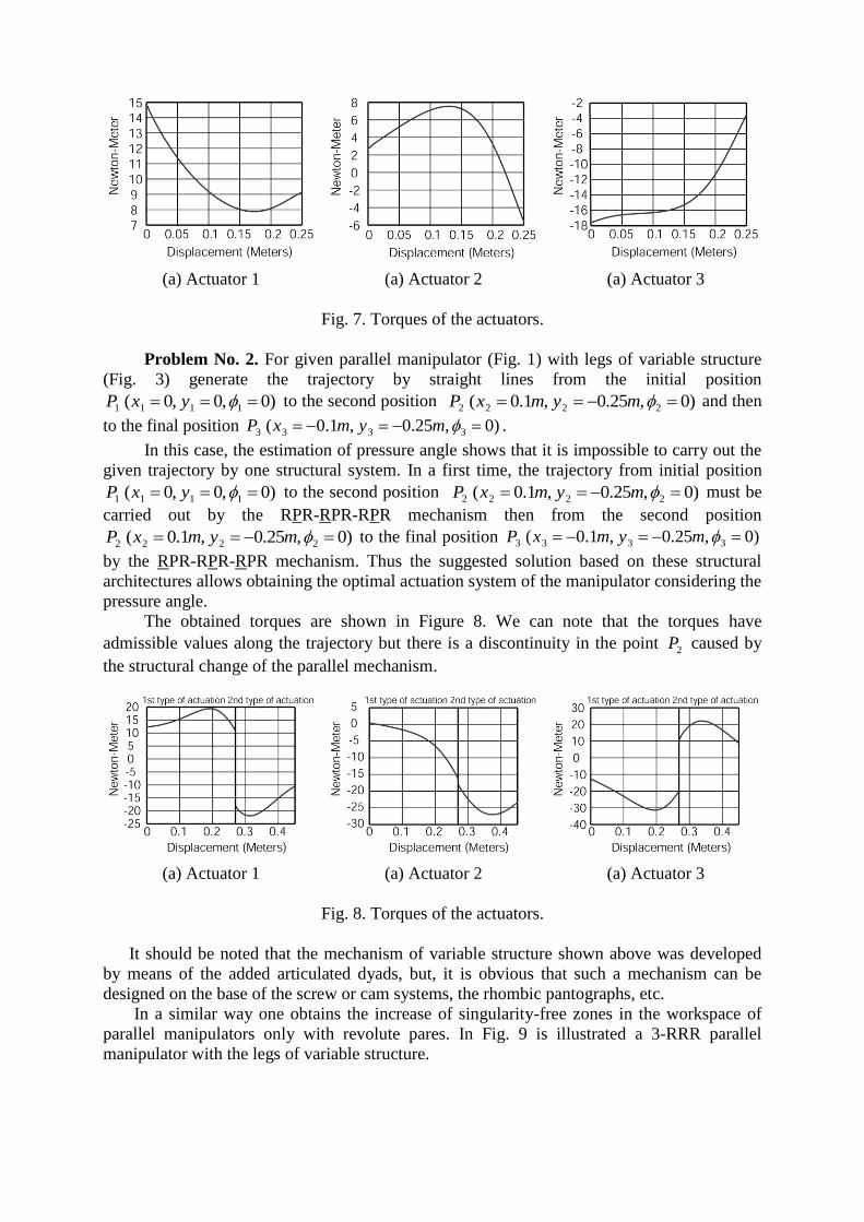
(a) Actuator 1 (a) Actuator 2 (a) Actuator 3
Fig. 7. Torques of the actuators.
Problem No. 2. For given parallel manipulator (Fig. 1) with legs of variable structure
(Fig. 3) generate the trajectory by straight lines from the initial position
)0 ,0 ,0( 1111 yxP to the second position )0 ,25.0 ,1.0( 2222 mymxP and then
to the final position )0 ,25.0 ,1.0( 3333 mymxP .
In this case, the estimation of pressure angle shows that it is impossible to carry out the
given trajectory by one structural system. In a first time, the trajectory from initial position
)0 ,0 ,0( 1111 yxP to the second position )0 ,25.0 ,1.0( 2222 mymxP must be
carried out by the RPR-RPR-RPR mechanism then from the second position
)0 ,25.0 ,1.0( 2222 mymxP to the final position )0 ,25.0 ,1.0( 3333 mymxP
by the RPR-RPR-RPR mechanism. Thus the suggested solution based on these structural
architectures allows obtaining the optimal actuation system of the manipulator considering the
pressure angle.
The obtained torques are shown in Figure 8. We can note that the torques have
admissible values along the trajectory but there is a discontinuity in the point 2P caused by
the structural change of the parallel mechanism.
(a) Actuator 1 (a) Actuator 2 (a) Actuator 3
Fig. 8. Torques of the actuators.
It should be noted that the mechanism of variable structure shown above was developed
by means of the added articulated dyads, but, it is obvious that such a mechanism can be
designed on the base of the screw or cam systems, the rhombic pantographs, etc.
In a similar way one obtains the increase of singularity-free zones in the workspace of
parallel manipulators only with revolute pares. In Fig. 9 is illustrated a 3-RRR parallel
manipulator with the legs of variable structure.
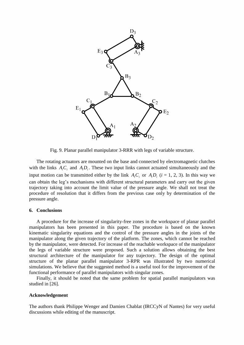
Fig. 9. Planar parallel manipulator 3-RRR with legs of variable structure.
The rotating actuators are mounted on the base and connected by electromagnetic clutches
with the links iiCA and ii DA . These two input links cannot actuated simultaneously and the
input motion can be transmitted either by the link iiCA or ii DA (i = 1, 2, 3). In this way we
can obtain the leg’s mechanisms with different structural parameters and carry out the given
trajectory taking into account the limit value of the pressure angle. We shall not treat the
procedure of resolution that it differs from the previous case only by determination of the
pressure angle.
6. Conclusions
A procedure for the increase of singularity-free zones in the workspace of planar parallel
manipulators has been presented in this paper. The procedure is based on the known
kinematic singularity equations and the control of the pressure angles in the joints of the
manipulator along the given trajectory of the platform. The zones, which cannot be reached
by the manipulator, were detected. For increase of the reachable workspace of the manipulator
the legs of variable structure were proposed. Such a solution allows obtaining the best
structural architecture of the manipulator for any trajectory. The design of the optimal
structure of the planar parallel manipulator 3-RPR was illustrated by two numerical
simulations. We believe that the suggested method is a useful tool for the improvement of the
functional performance of parallel manipulators with singular zones.
Finally, it should be noted that the same problem for spatial parallel manipulators was
studied in [26].
Acknowledgement
The authors thank Philippe Wenger and Damien Chablat (IRCCyN of Nantes) for very useful
discussions while editing of the manuscript.
References
[1] J. P. Merlet. Parallel robots. Kluwer Academic Publishers (2000) 372p.
[2] V. Glazunov, A. Kraynev, R. Bykov, G. Rashoyan, N Novikova. Parallel manipulator
control while intersecting singular zones. Proceedings of the 15th Symposium on Theory
and Practice of Robots and Manipulators (RoManSy) CISM-IFToMM, Montreal (2004).
[3] K. Alvan, A. Slousch. On the control of the spatial parallel manipulators with several
degrees of freedom. Mechanism and Machine Theory, Saint-Petersburg, n°1 (2003) pp.
63—69.
[4] C.M. Gosselin, J. Angeles. Singularity analysis of closed-loop kinematic chains. IEEE
Transactions on Robotics and Automatics. 6(3) (1990) pp.281-290.
[5] O. Ma, J. Angeles. Architecture singularities of parallel manipulators. The International
Journal of Robotics and Automation, 7(1) (1992) pp.23-29.
[6] D. Zlatanov, R.G. Fenton and B. Benhabib. Singularity analysis of mechanisms and
robots via a velocity-equation model of the instantaneous kinematics. Proceedings of the
1994 IEEE International Conference on Robotics and Automation, 2 (1994) pp. 980-991.
[7] J.-P. Merlet. Singular configurations of parallel manipulators and Grassmann geometry.
The international Journal of Robotics Research. 8(5) (1989) pp. 45-56.
[8] B.M. St-Onge, C.M. Gosselin. Singularity analysis and representation of the general
Gough-Stewart platform. The International Journal of Robotics Research. 19(3) (2000)
pp.271-288.
[9] F. Pernkopf, M. Husty. Singularity analysis of spatial Stewart-Gough platforms with
planar base and platform. Proceedings of the DECT 2002, Montreal (2002).
[10] J.T. Wen, J.F. Oapos Brien. Singularities in three-legged platform-type parallel
mechanisms. IEEE Transactions on Robotics and Automation. 19(4) (2003) pp.720- 726.
[11] S. Bandyopadhyay, A. Ghosal. Analysis of configuration space singularities of closed-
loop mechanisms and parallel manipulators. Mechanism and Machine Theory, 39 (5)
(2004) pp.519-544.
[12] J.-S. Zhao, Z.-J. Feng, K. Zhou and J.-X. Dong. Analysis of the singularity of spatial
parallel manipulator with terminal constraints. Mechanism and Machine Theory, 40(3)
(2005) pp.275-284.
[13] P. Ben-Horin and M. Shoham. Singularity analysis of a class of parallel robots based on
Grassmann–Cayley algebra. Mechanism and Machine Theory, Vol. 41 (8), (2006), pp.
958-970.
[14] Haidong Li, Clément M. Gosselin and Marc J. Richard. Determination of maximal
singularity-free zones in the workspace of planar three-degree-of-freedom parallel
mechanisms. Mechanism and Machine Theory, Vol. 41(10) (2006), pp. 1157-1167.
[15] Glazunov V.A. Koliskor A.Sh., Krainev A.F., and Model B.I. Classification principles
and analysis methods for parallel-structure spatial mechanisms. / Journal of Machinery
Manufacture and Reliability, Allerton Press Inc., 1990, No 1, p. 30-37.
[16] V. Glazunov. Twists of movements of parallel mechanisms inside their singularities.
Mechanism and Machine Theory, Vol. 41 (10), (2006), pp. 1185-1195.
[17] S. Balli, S. Chand. Transmission angle in mechanisms. Mechanism and Machine Theory,
37 (2002) pp. 175-195.
[18] G. Sutherland, B. Roth. A transmission index for spatial mechanisms. Transactions of the
ASME. Journal of Engineering for Industry. (1973) pp. 589-597.
[19] G. Sutherland. Quality of motion and force transmission. Mechanism and Machine
Theory. 16(3) 191 p. 221-225.
[20] C.-C. Lin, W.-T. Chang. The force transmissivity index of planar linkage mechanisms.
Mechanism and Machine Theory, 37 (2002) p. 1465-1485.
[21] C. Chen, J. Angeles. A generalized transmission index for spatial linkages. Proceedings
of the ASME 2005 IDETC/CIE Conference, September 24-28, Long Beach, California
(2005).
[22] O. Alba-Gomez, P. Wenger, and A. Pamanes. Consistent kinetostatic indices for planar 3-
DOF parallel manipulators, application to the optimal kinematic inversion. Proceedings
of the ASME 2005 IDETC/CIE Conference, September 24-28, Long Beach, California
(2005).
[23] Lee, J., Duffy, J., Keler, J., "The Optimum Quality Index for the Stability of In Parallel
Planar Platform Devices, Trans. ASME, Journal of Mechanical Design, Vol. 121, March,
1999, pp. 15-20.
[24] F.M. Dimentberg. The screw calculus and its applications in mechanics. Moscow, (1965)
327p. (English translation: AD680993, Clearinghouse for Federal Technical and
Scientific Information, Virginia).
[25] I.A. Bonev, D. Zlatanov, C.M. Gosselin. Singularity analysis of 3-DOF planar parallel
mechanisms via Screw Theory. Transactions of the ASME. Journal of Mechanical
Design. 2003, Vol. 125, pp. 573-581.
[26] V. Arakelian, S. Briot and V. Glazunov. Improvement of Functional Performance of
Spatial Parallel Manipulators Using Mechanisms of Variable Structure. In the
Proceedings of the 12th World Congress in Mechanism and Machine Science, June 18-
21, 2007, Besançon, France.
Related Documents