1 INCORPORATION OF HUMAN FACTORS IN THE DESIGN PROCESS This guide was prepared by: Gitahi Kariuki Katharina Löwe Institute for Plant and Process Technology, Process Safety and Plant Technology Technische Universität Berlin Germany Tel (+49) 30 314 26949 Fax (+49) 30 26907 E-mail: mailto:[email protected] http://www.ast.tu-berlin.de

Welcome message from author
This document is posted to help you gain knowledge. Please leave a comment to let me know what you think about it! Share it to your friends and learn new things together.
Transcript

1
INCORPORATION OF HUMAN
FACTORS IN THE DESIGN PROCESS
This guide was prepared by:
Gitahi Kariuki Katharina Löwe
Institute for Plant and Process Technology, Process Safety and
Plant Technology Technische Universität Berlin
Germany
Tel (+49) 30 314 26949 Fax (+49) 30 26907
E-mail: mailto:[email protected]
http://www.ast.tu-berlin.de

2
Table of Contents 1. General………………………………………………………………………………...4 1.1 Definition of Human Factors…………………………………………………………..4 1.2 Objective……………………………………………………………………………….4 1.3 The Scope………………………………………………………………………………4 1.4 General HF Requirements……………………………………………………………...4 1.4.1 Analysis…………………………………………………………………………….4 1.4.2 Human-Centred Design…………………………………………………………….4 1.4.3 HF Evaluation and Validation……………………………………………………...5 1.5 General Safety Requirements…………………………………………………………..5 1.5.1 Chemical Hazards………………………………………………………………….6 1.5.2 Fire Hazards………………………………………………………………………..6 1.5.3 Physical Hazards…………………………………………………………………...7 1.6 Anthropometrical Data…………………………………………………………………7 1.7 Manual Material Handling……………………………………………………………10 1.7.1 Lifting Tasks……………………………………………………………………...10 1.7.2 Health Problems Related to Manual Material Handling………………………….11 1.7.3 Designing for Manual Material Handling………………………………………...11 2. Automation and Control Room Design…………………………………………….13 2.1 Automation……………………………………………………………………………13 2.2 Reason for Automation……………………………………………………………….13 2.3 Usability and Simplicity………………………………………………………………13 2.4 Fault Management and False Alarms…………………………………………………14 2.4.1 Fault Detection……………………………………………………………………14 2.4.2 Diagnoses…………………………………………………………………………14 2.4.3 Remedial Actions…………………………………………………………………14 2.4.4 Automation Failure……………………………………………………………….14 2.5 Control Room Design………………………………………………………………...14 2.5.1 Structural Design………………………………………………………………….15 2.5.2 Control Room Layout…………………………………………………………….15 3. Control and Monitoring Instrumentation………………………… ………………18 3.1 Process Operator……………………………………………………………………...18 3.2 Field Panel Controls…………………………………………………………………..18 3.2.1 Introduction……………………………………………………………………….18 3.2.2 Control-Display Relationship…………………………………………………….18 3.2.3 Controls…………………………………………………………………………...19 3.2.4 Digital (Screen) Displays…………………………………………………………24 3.2.5 Analogue Displays………………………………………………………………..27 3.2.6 Alarms…………………………………………………………………………….28
4. Designing for Maintainability and Operability……………………………………30 4.1 Accessibility…………………………………………………………………………..30 4.2 Process Equipment……………………………………………………………………36

3
4.2.1 Compressors and Pumps………………………………………………………….36 4.2.2 Reactors…………………………………………………………………………...38 4.2.3 Centrifuges………………………………………………………………………..38 4.2.4 Fired Equipment and Furnaces…………………………………………………...39 4.2.5 Loading and Unloading Racks……………………………………………………40 4.2.6 Sample Points……………………………………………………………………..41 4.2.7 Tanks and Vessels………………………………………………………………...41 4.3 Valves…………………………………………………………………………………42 4.3.1 Accessibility Issues……………………………………………………………….42 4.4 Pipes, Blinds and Blanks……………………………………………………………...43 4.4.1 Marking and Labelling……………………………………………………………43 4.4.2 Layout…………………………………………………………………………….44 4.4.3 Hazardous Operations…………………………………………………………….45 4.5 Fasteners, Gaskets and Seals………………………………………………………….45 5. Working Environment………………………………………………………………46 5.1 Illumination…………………………………………………………………………...46 5.1.1 Distribution of Light……………………………………………………………...46 5.1.2 Reflectance………………………………………………………………………..46 5.1.3 Glare………………………………………………………………………………46 5.2 Noise Levels…………………………………………………………………………..47 5.2.1 Continuous Noise…………………………………………………………………47 5.2.2 Impulse Noise…………………………………………………………………….48 5.2.3 Noise Control……………………………………………………………………..49 5.3 Climate………………………………………………………………………………..49 5.3.1 Heat Stress………………………………………………………………………..49 6. Plant Labelling and Signing………………………………………………………...52 6.1 Introduction…………………………………………………………………………..52 6.2 Transmission of Right Information…………………………………………………..52 6.3 Visibility and Legibility………………………………………………………………53 6.4 Style of Writing……………………………………………………………………….54 6.5 Signs and Labels Layout……………………………………………………………...54 6.6 Location………………………………………………………………………………55 6.7 Equipment Labelling………………………………………………………………….56 6.8 Hazard Signing and Marking…………………………………………………………57 7. References……………………………………………………………………………58

4
1 General
1.1 Definition of Human Factors Human Factors is a body of science that incorporates the physical and cognitive capabilities and limitations of populations of people into the design and operation of a system, process, or equipment. Appropriate inclusion of human factors during the design process, also known as human engineering, results in improved operability, maintainability, and manufacturability of equipment, processes, and systems.
1.2 Objective The aim of this guideline is to assist engineers to design a process facility that addresses the capability of the operator. The workload, time constraint, accuracy requirements, mental processing and communication shall be within the limit that the operator can handle in order to reduce the opportunity for the error occurrence. It shall be applicable to Small and Medium Enterprises (SMEs) as well as large process industry set-ups. The guidelines are written to act as a one-stop source of information on HF requirements in an engineering design. The could be used by both engineers with HF background as well as those with no practical experience in this field.
1.3 The scope This document applies for the design of the new process plants and facilities as well as the improvement of the existing ones. The guidance organises findings and good practice from literature and the industry, both process and non-process, into a document available for designers’ reference.
1.4 General HF Design requirements
1.4.1 Analysis
i. Function analysis and Function allocations Functions to achieve the overall objective of the plant should be identified, analysed and allocated according to which would be best performed by human alone (manual), hardware/software alone (automatic) or combination thereof (semi-automatic). ii. Task and Workload Analysis. During the design phase the key operation and maintenance tasks together with associated human performance parameters should be identified. The tasks should then be systematically analysed to determine the operator’s needs to complete each particular task. The possible occurrence of human failures during the task execution and there consequences shall dictate the areas that need improvement. Workload analysis should be done to identify demands imposed on the operator by the tasks to be performed in comparison to the time and resources available.
1.4.2 Human-Centred Design After the analysis stage the requirements obtained are transformed into design. The design shall in principle take into account all the factors that affect human performance, i.e. performance shaping factors (PSF). This includes:
5
a. Work environment
• Noise levels, illumination, temperatures and humidity. b. Design of displays and controls
• Arrangement of controls, information on displays and control-display relationship.
c. Work station layout • Adequate space, accessibility for normal working situations and for
escape routes during emergencies. d. Plant signing and labelling
• Visibility and legibility of labels, location and information transmission.
1.4.3 HF Evaluation and validation Evaluation and validation is a continuous process that aims at ensuring that the plant can be effectively and safely operated and maintained by the targeted people within the intended environment to achieve both operational and safety goals.
1.5 General Safety requirements
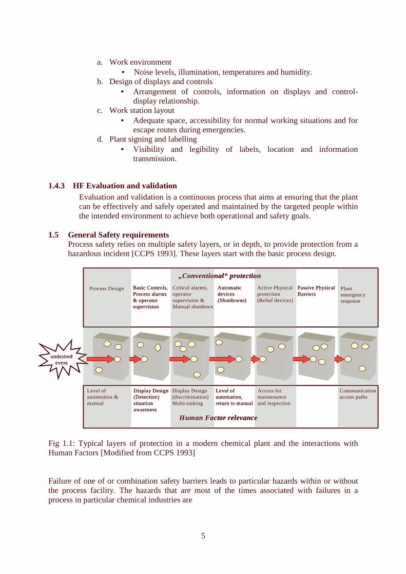
Process safety relies on multiple safety layers, or in depth, to provide protection from a hazardous incident [CCPS 1993]. These layers start with the basic process design.
Fig 1.1: Typical layers of protection in a modern chemical plant and the interactions with Human Factors [Modified from CCPS 1993] Failure of one of or combination safety barriers leads to particular hazards within or without the process facility. The hazards that are most of the times associated with failures in a process in particular chemical industries are
undesiredevent
Process Design
Display Design(Detection)situation awareness
Level of automation & manual
Basic Controls,Process alarms& operator supervision
„Conventional“ protection
Human Factor relevance
Critical alarms,operator supervision &Manual shutdown
Display Design(discrimination)Multi-tasking
Automaticdevices(Shutdowns)
Level ofautomation,return to manual
Active Physical protection(Relief devices)
Access for maintenanceand inspection
Passive Physical Barriers
Plant emergencyresponse
Communicationaccess paths

6
i. Chemical hazards ii. Fire Hazards iii. Physical Hazards
1.5.1 Chemical hazards The human factor design and engineering of a process facility should address the following key principles concerning chemical hazards: 1.5.1.1 Flushing facilities and Safety Showers A provision to contain, neutralise or flush hazardous chemicals that might spill due to human error. Eyebaths and showers should be available at strategic locations where corrosive materials e.g. acids and caustics are handled and these areas should be free of contamination. The travel distance should not exceed 30 m or 10 seconds time of travel. The paths should be unobstructed and stairs or ladders should not be used to reach the facilities. Lighting should be a minimum of 5 foot-candles (50 lx). Safety Showers should be clearly marked, see section 6 1.5.1.2 Access Routes Access routes should be designed taking into consideration PPE used and equipment required during emergency evacuation. Permanent area for emergency vehicles and supplies should be provided.
1.5.1.3 Hazard Identification and detection systems All hazardous material and locations shall be labelled clearly and with consistency, see section 6. Hazard alert and leak detection systems should be visible or audible from any point in the hazardous area. High level alarms and/ or shut off devices at all loading and filling points to prevent overfill should be considered.
1.5.2 Fire hazards The human factor design and engineering of a process facility should address the following key principles concerning fire hazards: 1.5.2.1 Fire Extinguishing Systems There should be a provision for well-identifiable fire extinguishers in places where hazards exist. Alternative ways to access hydrants should be provided. Deluges should be separated and well labelled in a way that the operator does not easily activate the wrong location. Any action taken should be communicated to the control station and the operator should receive a feedback. Portable fire extinguishing systems shall be provided for high-risk areas such as blinds. 1.5.2.2 Emergency exits Well-labelled emergency exits should be provided. The deluge activation area should be labelled and signed properly to make it easy for the operator to start the deluge as he or she leaves the area. The deluge system should be able to give feedback to the operator and this should also be communicated to the emergency control station.

7
1.5.2.3 Product/process isolation Well labelled and strategically located manual and automatic isolation valves/devices stopping and shutting off products fuelling that may be fuelling the fire. The isolation point should be accessible from different directions in case on way get blocked by fire.
1.5.3 Physical Hazards The human factor design and engineering of a process facility should address the following key principles concerning physical hazards: 1.5.3.1 Moving equipment Warning labels should be placed at strategic positions for moving and rotating equipment like belts, pulleys, gears, and blades. Paths for equipment like forklifts shall as far as practicable remain clear.
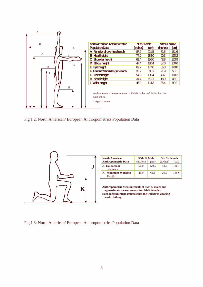
1.5.3.2 Hot Surfaces Equipment that require heat conservation and are located at a distance of 0.3m horizontally or 2.1m vertically from the normal access paths should be insulated to provide a surface heat not greater than 65°C. If the surface temperature is greater than 65°C then cages or guards to protect personnel from contact should be provided. Thermal isolation shall be used where continuous temperature of operation is over 149°C. 1.5.3.3 Lifting devices Weight capacity on hoists, cranes, and all other lifting devices shall be clearly visible. They shall be made available in areas that the weight exceeds 23kg (see section NIOSH lifting equation). They should be designed in way that they are able to grip the weight without introducing any hazard to the operator or surrounding equipment. 1.5.3.4 Stairs and ladders Stairs should be provided for the most frequented workstations of a raised level e.g. continuous monitoring on top of a tank. Otherwise for areas that are rarely visited provision for ladders should be ensured. Staircases and flooring should be non-slippery. 1.6 Anthropometrical Data: It is part of human factors that looks at the physical capabilities and limitations of populations of people and how this would be incorporated into the design and operation of a system, process, or equipment. The overall aim is to obtain improved results in operability, maintainability, and manufacturability of equipment, processes, and systems. Design the workplace for the human needs. The physical features of human beings across the globe vary in size, strength, visual and hearing ability. In addition gender and age increases the scope of human variability. Incorporating human factors in the early stages of design needs to address workplace access and design: e.g. unobstructed body movement, unrestricted hand/arm access, unrestricted access of spaces with full Personnel Protection Equipment (PPE), safe access by stairs and ladders. Various human body data [Pheasant, 1996] is as shown here below, fig 1.2 to 1.6:
8
Fig 1.2: North American/ European Anthropometrics Population Data
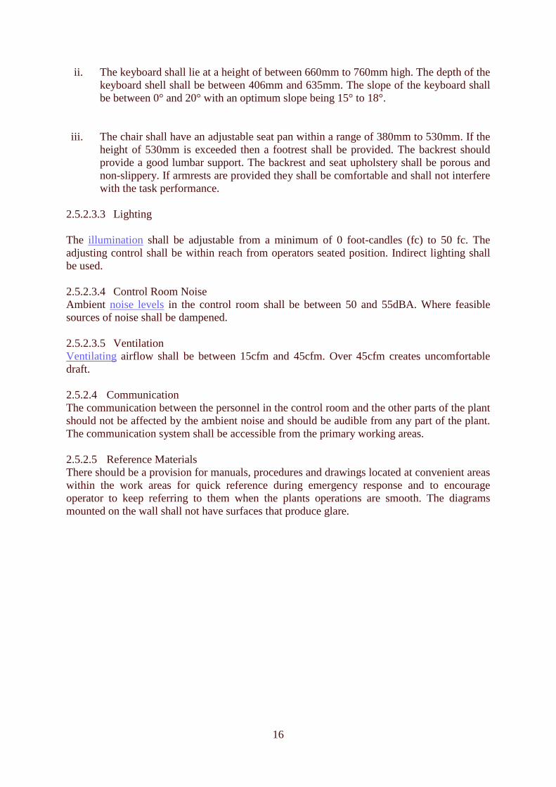
Fig 1.3: North American/ European Anthropometrics Population Data
A
B
C
D
E
F
G
H
Anthropometric measurements of 95th% males and 5th% femaleswith shoes.
* Approximate
I
North American Anthropometric 95th % Male 5th % Female Population Data (inches) (cm) (inches) (cm) A. Functional overhead reach 87.2 221.5 71.5 181.6 B. Head height 74.0 188.0 60.3 153.2 C. Shoulder height 61.4 156.0 48.8 123.9 D. Elbow height 47.4 120.4 37.6 100.6 E. Eye height 69.7 177.0 56.3 143.0 F. Forward/shoulder grip reach 28.2 71.6 21.9 55.6 G. Chest height 54.9 139.4 43.7 110.2 H. Knee height 24.4 62.0 18.9 48.0 I. Waist height 45.0 114.3 35.4 90.0
J
K Anthropometric Measurements of 95th% males and approximate measurements for 5th% females.
Each measurement assumes that the worker is wearing work clothing.
North American 95th % Male 5th % FemaleAnthropometric Data (inches) (cm) (inches) (cm)
J. Eye to floor distance
51.0 129.5 42.0 106.7
K. Minimum WorkingHeight
25.0 63.5 20.0 146.6

9
Fig 1.4: Japanese and Hong Kong Anthropometrics Data
Fig 1.5: Asian Male Anthropometrics Data
J
KAnthropometric measurements of 95th% and 5th% males.
Each measurement assumes that the worker is wearing work clothing.
Male Anthropometric 95th % 5th %Population Data (inches) (cm) (inches) (cm)
J. Eye to floor distance
46.7 118.6 43.1 109.5
K. Minimum WorkingHeight
25.0 63.5 22.7 57.7
A
B
C
D
E
H
I
G
F
All measurements are for unclothed people. Add 25mm to height related measurements (A, B, C, D, E, G, H, I) for safety shoes. For female office workers add 45mm for shoes.
Anthropometric Dimension 95th % Male 5th % FemaleMm Inches Mm Iinches
A. Vertical Grip Reach 2075 81.7 1680 66.1B. Stature (head height) 1750 68.9 1450 57.1C. Shoulder Height 1430 56.3 1075 42.3D. Elbow Height 1105 43.5 895 35.2E. Eye Height 1635 64.4 1350 53.1F. Forward Grip Reach 750 29.5 570 22.4G. Knuckle Height 805 31.7 650 25.6H. Knee height 530 20.9 420 16.5I. Hip Height 895 35.2 700 27.6Body Weight (kg) 74 40
Anthropometric Dimension 95th % Male 5th % FemaleMm Inches Mm Inches
A. Vertical Grip Reach 2105 82.9 1685 66.3B. Stature (head height) 1775 69.9 1455 57.3C. Shoulder Height 1460 57.5 1180 46.5D. Elbow Height 1080 42.5 870 34.3E. Eye Height 1640 64.6 1330 52.4F. Forward Grip Reach 770 30.3 580 22.8G. Knuckle Height 815 32.1 650 25.6H. Knee height 540 21.3 410 16.1I. Hip Height 920 36.2 715 28.1Body Weight (kg) 75 39
Japanese Data
Hong Kong Data

10
1.7 Manual Material Handling
Operations and maintenance involves physical and manual handling of tools, parts and equipment; often in awkward positions. It also involves movement to and from the workstation and standing for long duration of time. It results to the operator having to expend from moderate to high levels of energy. This can lead to strains and stresses making the performance of tasks less accurate with higher probability of error occurrence. The level of energy output in this case will depend on many factors as illustrated on Fig 1.6. If high precision of task execution is required these factors need to be considered in the workplace design. Fig 1.6: Factors influencing the power and capacity of Physical activity [Adopted from Sanders and McCormick, 1993, pg 238] Working posture, the duration, fitness and technique, gender, anthropometrics all affect the affect amount of energy we expend and therefore the physical performance. Awkward positions reduce strength and capability. The load (includes weight, size, handles), frequency, and environmental factors are other factors to consider. Too much load exerts mechanical stresses on the body joints and muscles and if repeated for long durations may result to strains and discomforts. An operator working under such conditions is prone to making errors, which may lead to an undesired event or incident involving both the person and the machine (process).
1.7.1 Lifting Tasks: Process operations and maintenance tasks involve frequent lifting and lowering. Lifting is the manual activity that is associated with most injuries [Ayoub et al, 1989]. This also implies that these tasks play a major role in the build up of body stress and strain build-up for the operator (technician). The National Institute of Safety and Health (NIOSH) has come up with the lifting equation that was designed to meet specific lifting-related criteria that encompass biomechanical, work physiology, and psychophysical assumptions and data. Biomechanical views the body as a system of links and connecting joints corresponding to segments of the body such as upper arm and lower arm links joined by the elbow. Physiological is concerned
Somatic factors Sex & Age Body dimensions Health
Training adaptation
Psychic factors Attitude Motivation
Nature of exercise Intensity Duration Technique Duration Position/posture Rhythm Schedule
Environment High gas pressure Heat Cold Noise Air pollution
Physical performance

11
with energy consumption and the stresses acting on cardiovascular system. Psychophysical integrates both the physiological and biomechanical assumptions. [Sanders and McCormick, 1993, pg 255] 1.7.1.1 NIOSH lifting equation The NIOSH lifting equation is a tool to evaluate two-handed lifting tasks. The equation was developed by the National Institute for Occupational Safety and Health to assist in the identification of solutions for reducing the physical stress associated with manual lifting. It is based on limits for the human body and these involve acceptable forces applied to the musculoskeletal frame, body fatigue, and acceptability to a large percentile of the user population. The NIOSH equation considers weight, starting point, distance of lift, duration of job, frequency of lift, effectiveness of coupling (handles on the object), and symmetry of lift (twisting of the torso).
1.7.2 Health Problems Related to Manual Handling With strenuous physical activities short term or long term health problems are likely to develop. This could include muscular fatigue, back pains, higher heart rate and blood pressure [NIOSH, 1981]. Apart from the cost of injuries, the performance of the worker as well as efficiency and effectiveness are drastically lowered. 1.7.2.1 Cumulative Trauma Disorders ( CTD) This is also referred to as Muskuloskeletal Disorders, Repetitive strain injuries or Overuse injuries. It could be with or without physical signs of injuries. It is caused by work as a result of the following risk factors:
i. Exerted force
ii. Awkward posture iii. Frequency (Repetition) iv. Recovery time
Conditions are usually ignored until permanent injury occurs. Common CTD disorders include Tendon disorders, nerve disorders and Neuro-vascular Disorders. The carpal tunnel syndrome is a specific CTD involving the median nerve in the wrist. Frequent operating of valves can cause the very painful illness that in the extreme can only be cured by surgical decompression of the transverse carpal ligament resulting in permanent hand wrist moving limitation.
1.7.3 Designing for Manual Handling The design for manual handling should meet the following requirements: 1.7.3.1 Lifting Load limits The design shall ensure that the load is within the RWL (23kg) and where this is not possible the task shall be altered. For example lifting instead of lowering, reduce the lifting heights, reduce the frequency of lifting, and reduce bending and twisting motions. 1.7.3.2 Handles Handles shall have firm grips that are poor conductors of heat and electricity. They shall as close as possible to the centre of gravity. Where the weights exceed the requirement for one person then handling provision for more than one person shall be provided.

12
1.7.3.3 Physical activities Where possible physical activities shall be eliminated. This shall be made possible by:
i. Provision of lifting devices like hoists, jerks, conveyors ii. Providing work benches that allow all tasks to be carried out at one level iii. Eliminate long walking distance to transfer load
1.7.3.4 Selection and Training Personnel selection needs to include the assessment of the tasks people have to execute in the particular process and maintenance jobs. Job training need to include the control of physical hazards and the effect physical tasks have on the body.

13
2 Automation and Control Room Design 2.1 Automation Automation has increased the complexity in the process industry (systems) and this mostly leaves the operator with very little or no knowledge on the inner functioning of the system. During the abnormal situation the operator becomes less confident of what actions to take. However, a well-designed automated system enhances safety, reduces operator’s workload and is able to undertake tasks that the operator is unable to do, for instance, those with a very short time constant. The role of the operator in an automated system is to i.) Detect the fault through sensory inputs such as vision and sound ii.) Diagnose the cause of the fault iii.) Taking corrective action to return the plant to normal operating condition or shutdown of the plant. To achieve these three tasks a the following shall be taken into consideration during the design of automation: 2.2 Reason for automation The automation shall be implemented for good reason and not for the sake of replacing the operator. The following should be the reasons to carry out automation:
2.2.1 The system shall be automated only if it improves performance but this shall not reduce the human knowledge on the inner functioning of the system and thus the capability of undertaking a particular task.
2.2.2 Automation shall be used to assist operator to undertake his task safely and efficiently. It should make the tasks easier to perform than the manual ones. Cognitive workload should not be increased.
2.3 Usability and simplicity
2.3.1 The automated system shall be easy to understand and to use. The operator shall be able to interpret all the messages that come on the screen and shall be able to detect any malfunction.
2.3.2 The automated system should either be error tolerant or error resistant. It shall have a way of verifying the input data to avoid errors that occur during entry.
2.3.3 The system shall be easy to learn. Training shall be provided to the operator to adequately understand how the system works so that he can effectively and confidently use the automation.
2.3.4 Effective feedback information shall be provided to help the user and system have a good and constant interaction. It should be able to show the status of the system and show which parts are failed. The information provided shall be reliable and accurate.
2.3.5 The operator shall be able to actively monitor and control the process through automated system. Automation should not transform operators to passive observers. Incase only passive monitoring is required then it should not be too long. A monitoring time of 20 min at a time is recommended. An intermittent manual control shall be provided to ensure active monitoring by the operator.

14
2.3.6 The automated system shall be able to pick out potential errors by the operator and alert the operator.
2.4 Fault Management and False Alarms Fault management involves fault detection, diagnosis and correction or shutdown. It can therefore be described as the function of control system to avert the development of conditions that may lead to shutdown, but if necessary execute the shutdown. To design an effective fault management system and thus reduce the number of false alarms the following shall be considered:
2.4.1 Fault Detection The system should be able to adequately detect the onset of a plant disturbance. The failures should be detected without disassembly of any components of the equipment. The audio alarms shall be clear and unambiguous and all the visual displays shall be at good viewing locations.
2.4.2 Fault Diagnoses The system shall be able to identify and isolate failures without ambiguity. If the diagnosis tools are not in-built then detachable equipment shall be provided. The diagnosis should be able to rank the faults according to their criticality. Where the operator is supposed to do the diagnosis, sufficient information on the failure should be provided.
2.4.3 Remedial Actions Where the plant or equipment is fully automated, the automation shall be able to carry out corrective action and a shutdown if need be in case of disturbance. If the operator is to carry out remedial action adequate information shall be provided to help him make the right decision.
2.4.4 Automation failure Incase the automation or part of it fails it shall necessitate return to manual operation without degradation of the whole system. A warning that the automation is about to fail shall be made available to the operator. When the failure occurs it should be made unambiguous.
2.4.5 False Alarms The frequency of false alarms shall be maintained as low as possible to make the operator trust the automated system. Care should be taken because creation of too many informative alarms tends to create nuisance. 2.5 Control Room Design Designing control rooms taking into account human factors could greatly improve the performance of the process operator and therefore reduce operator error that would lead to undesired events. The design consists of two major aspects [HSE], namely the control room structural design and the workplace layout.

15
2.5.1 Structural Design By the nature of its importance in the plant operations and up to and including shutdown in case of abnormal situation, the control room should be as much as possible be made the safest place within the whole plant. The risk to the operators shall be within acceptable limits. The following shall be taken into consideration: 2.5.1.1 Location The control room shall be located away from the main process plants. This is to control the level of vibrations and noise. This also reduces the risk of damage of the entire room should there occur an undesired event that has major consequences. 2.5.1.2 Isolation The control room shall be tight sealed to avoid ingress of toxic gases in event of a release. Ventilators shall be located in areas where no intoxicated air could be drawn into the system.
2.5.2 Control Room Layout 2.5.2.1 Control room arrangement The equipment in the control room should be arranged considering the operators functions. A link analysis to show the interactions required between the operators in the control room and between operators and equipment, both visual and audio should be carried out. It shall be aimed at reducing movements across the room where at times the operator has to leave one console to attend another. The operator’s normal sitting position shall be close to the most frequently used console. 2.5.2.2 Accessibility The design shall provide for simultaneous access for operator and the maintenance team. At any seated position the operator should be facing the display board. The visibility should not be hindered by any console. Paths shall be designed in a way that all non-essential personnel are restricted from the main working areas. 2.5.2.3 Workstation 2.5.2.3.1 Standing Operation Normal operating controls shall be located between the 510mm to 1780mm according to the society they are designed for. Critical control shall be located on the range between 1015mm to 1780mm. Displays shall lie within the same range but the critical ones shall be located between 1040mm to 1780mm. See fig 4.1. [Eastman Kodak Company] 2.5.2.3.2 Seated Operation The seating position shall allow the operator to perform the required task efficiently and effectively without inflicting long lasting pains and/or injuries.
i. To ensure sufficient foot room the minimum distance from the floor to the underside of the console shall be a minimum of 635mm, 510mm wide, and 460mm deep.
16
ii. The keyboard shall lie at a height of between 660mm to 760mm high. The depth of the keyboard shell shall be between 406mm and 635mm. The slope of the keyboard shall be between 0° and 20° with an optimum slope being 15° to 18°.
iii. The chair shall have an adjustable seat pan within a range of 380mm to 530mm. If the height of 530mm is exceeded then a footrest shall be provided. The backrest should provide a good lumbar support. The backrest and seat upholstery shall be porous and non-slippery. If armrests are provided they shall be comfortable and shall not interfere with the task performance.
2.5.2.3.3 Lighting The illumination shall be adjustable from a minimum of 0 foot-candles (fc) to 50 fc. The adjusting control shall be within reach from operators seated position. Indirect lighting shall be used.
2.5.2.3.4 Control Room Noise Ambient noise levels in the control room shall be between 50 and 55dBA. Where feasible sources of noise shall be dampened. 2.5.2.3.5 Ventilation Ventilating airflow shall be between 15cfm and 45cfm. Over 45cfm creates uncomfortable draft. 2.5.2.4 Communication The communication between the personnel in the control room and the other parts of the plant should not be affected by the ambient noise and should be audible from any part of the plant. The communication system shall be accessible from the primary working areas. 2.5.2.5 Reference Materials There should be a provision for manuals, procedures and drawings located at convenient areas within the work areas for quick reference during emergency response and to encourage operator to keep referring to them when the plants operations are smooth. The diagrams mounted on the wall shall not have surfaces that produce glare.

17
Fig 2.1: Location of Controls and Displays on Local Control Panels [Eastman Kodak Company, 1983]
60
50
40
30
20
10
0
1525
1270
1015
785
510
255
0 mm
Inches
Displays
Controls
Range 20 to 55 in.
(510 to 1400 mm)
Range 20 to 64 in.
(510 to 1625 mm)
Optimum 48 to 64 in.
(1220 to 1625 mm)
Optimum 40 to 55 in.
(1050 to 1400 mm)
STANDING CONTROL PANEL
Inches
Optimum 30 to 48 in.
(760 to 1220 mm)
Optimum 26 to 40 in.
(660 to 1015 mm)
Controls
Displays
SIT DOWN CONTROL PANEL
Range 26 to 45 in. (650 to 1145 mm)
Range 30 to 60 in.
(750 to 1525 mm)
NOTES: (1) Safety critical and high accuracy controls and displays, which require accurate and specific settings, shall be
located in the optimum range (2) Gross controls and displays, which require low accuracy, can be located outside the optimum range.
80
70
60
50
40
30
20
10
0
2030
1780
1525
1270
1015
765
510
255
0 mm
Clearance Minimum = 28 in. (710 mm) Preferred = 35 in. (915 mm)
18
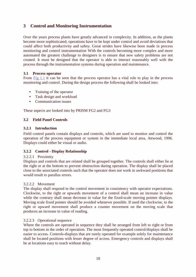
3 Control and Monitoring Instrumentation Over the years process plants have greatly advanced in complexity. In addition, as the plants become more sophisticated, operations have to be kept under control and avoid deviations that could affect both productivity and safety. Great strides have likewise been made in process monitoring and control instrumentation. With the controls becoming more complex and more automated the greatest challenge to designers is to ensure that new safety problems are not created. It must be designed that the operator is able to interact reasonably well with the process through the instrumentation systems during operation and maintenance. 3.1 Process operator From Fig 1.1 it can be seen that the process operator has a vital role to play in the process monitoring and control. During the design process the following shall be looked into:
• Training of the operator • Task design and workload • Communication issues
These aspects are looked into by PRISM FG2 and FG3 3.2 Field Panel Controls
3.2.1 Introduction Field control panels contain displays and controls, which are used to monitor and control the operation of the process equipment or system in the immediate local area, Attwood, 1996. Displays could either be visual or audio.
3.2.2 Control - Display Relationship 3.2.2.1 Proximity Displays and controls that are related shall be grouped together. The controls shall either lie at the right or at the bottom to prevent obstruction during operation. The display shall be placed close to the associated controls such that the operator does not work in awkward positions that would result to parallax errors. 3.2.2.2 Movement The display shall respond to the control movement in consistency with operator expectations. Clockwise, to the right or upwards movement of a control shall mean an increase in value while the contrary shall mean decrease in value for the fixed-scale moving pointer displays. Moving scale fixed pointer should be avoided whenever possible. If used the clockwise, to the right or upward movement shall produce a counter movement on the moving scale that produces an increase in value of reading. 3.2.2.3 Operational sequence Where the controls are operated in sequence they shall be arranged from left to right or from top to bottom in the order of operation. The most frequently operated control/displays shall be easier to access. Controls-displays that are rarely operated for example solely for maintenance shall be located positions with lesser degree of access. Emergency controls and displays shall be at locations easy to reach without delay.

19
3.2.2.4 Feedback There shall be minimal delay between the time the control is manipulated and the time the results are displayed. For any delay there shall be a feedback that the operation has stalled or has been interrupted. Critical control functions especially those entered through a keyboard shall feedback give to the operator before a confirmed entry to eliminate possibility of error.
3.2.3 Controls Based on the control information they transmit, controls can be divided into discrete or continuous. Examples of discreet are push buttons, toggle switches, rotary selector switches and rocker switches. Continuous include rotary knobs, cranks, wheels, levers and cursor based. Controls shall be designed and selected according to the accuracy and speed of operation required, the force to be applied and the space available. This is illustrated on Table 3a.
Table 3a: Factors to consider during the selection of controls 3.2.3.1 Identification of controls Quick identification of the right controls is very important especially during the abnormal situation when the activation of a wrong control leads to a major consequence. 3.2.3.1.1 Shape coding Shape coding is used for improvement of identification by touch where the operator’s visual attention may at times be focused on other controls. When using shape coding:
i. The shape used shall be identifiable in cases where the operator has to use gloves. ii. The shape used shall not affect the operability of the control. iii. The shape shall be identifiable visually and by touch from any position control.
Control Function
Accuracy Speed Force Space Recommended Control
Discreet (2 settings)
High
Low
High
High
High
High
Small
Small
Large
Small
Small
Medium/Large
Toggle switch
Push button
Rotary selector, lever
Discreet (3 settings)
High
High
High
High
Small
Small
Small
Medium
Toggle switch, thumbwheel
Rotary selector
Discreet (3–24 settings)
High
Low
High
High
Small
Large
Medium
Medium/Large
Rotary selector
Lever
Continuous (small range)
High
High
High
Low
Low
High
High
Low
High
High
Small
Small
Large
Small
Large
Small
Medium
Large
Small/Medium
Medium/Large
Thumbwheel
Rotary selector
Handwheel
Slide switch
Lever
Continuous (large range)
Low
Low
Low
Low
Low
Low
Low
High
Small
Small
Large
Large
Small/Medium
Medium/Large
Large
Medium/Large
Knob
Crank
Crank
Foot pedal

20
3.2.3.1.2 Texture coding This is a compliment to shape coding. Smooth, fluted and knurled are the most distinguishable features of knobs. Texture coding shall not be used in areas perceptible to dirt because they the texture is easily altered by dirt. 3.2.3.1.3 Size coding Differences in sizes of controls especially the ones with similar shape improve discrimination. Controls serving the same purpose on the same equipment or system shall be of the same size. A maximum of three different sizes shall be used in case discrimination is absolute size. 3.2.3.1.4 Location Coding This is significant where the controls are not necessarily visible. Controls shall be arranged on the panel according to priority. The controls coded this way shall be located relatively to the same position on different control panels. 3.2.3.1.5 Colour coding Colour coding shall be used in areas with good illumination and free of dirt. The background shall be able to provide a good contrast to improve detection. The color should not be used solely as a method of coding. It must be used in combination with others like size or shape. In areas with low illumination, (see section 5.1) controls should have an implanted lighting system. 3.2.3.1.6 Label coding Labels, though much used, should not be a stand-alone coding method. They take long to read especially during abnormal situations. This method shall be used in combination with other methods. All labeling should conform to the labeling guidelines on chapter 6. For critical controls, redundant coding shall be considered, for example, a different colour and a different size for each control. 3.2.3.2 Arrangement of controls Controls shall be grouped according to there functions and they should be close to there respective displays. The grouping shall be similar from panel to panel. The arrangement of these controls shall be according to:
i. The sequence of operation. These shall be from left to right or top to bottom. The first control to be actuated shall be the first left or top respectively.
ii. Priority of operation The most frequently operated control shall be closest to the operator with ease of reach. Those meant for occasional tasks like maintenance only shall be isolated from the primary ones. 3.2.3.3 Accidental actuation prevention The controls shall be designed and located in a way that the operator shall not actuate them accidentally. Barriers or guards shall be installed to protect the controls whose accidental actuation means major consequences to the operations. Although the controls are required to

21
be easily operable, they require having a resistance against manipulation with just a minor touch. 3.2.3.4 Design of Controls 3.2.3.4.1 Discrete Controls 3.2.3.4.1.1 Rotary selector switch
i. Rotary selector switches shall be used where more than two dented positions are required. The positions shall, however, not exceed 24.
ii. The design should be a moving pointer fixed scale. iii. Rotary selector switches shall be bar shaped to provide good grasp. If round knobs
have to be used they should be either serrated or knurled. iv. To avoid parallax the pointer shall lie very close to the scale. The pointer should snap
to the next position when the switch is rotated moved without an intermediate stop between two positions.
The design parameters for the rotary switch are as shown on Fig 3.1.
Fig 3.1: Design features of a rotary selector switch

22
3.2.3.4.1.2 Toggle and Rocker switches i. Toggle and rocker switches should be used for a two state selection, for example, ON
/OFF. When three positions are used a snap action shall be provided for to hold the switch at intermediate (center) position
ii. Switches that are safety critical should be guarded against accidental actuation. The guard shall not interfere with the operation of the switch or the adjacent controls while in the open position.
Fig 3.2: Toggle Switch Fig 3.3: Rocker switch iii. An actuation shall have an indication for example lighting or a click sound. iv. Where practicable toggle and rocker switches shall be placed vertically. The actuation
to the upper side shall denote ON or increase in value being measured.

23
The design criteria for the toggle and rocker switches are as shown on fig 3.2 and fig 3.3 respectively. 3.2.3.4.1.3 Push Buttons
i. The most commonly used push buttons in the process industry are hand and finger operated. The push buttons surface shall have high friction surface or shaped in a way that a finger would fit. Emergency Stop buttons, which are palm/hand operated, shall be dome shaped and located in isolation to the other buttons to avoid actuation by error.
Fig 3.4: Push buttons. Fig 3.5: Rotary Knobs

24
ii. The actuation of the buttons shall have an immediate feedback for example an audible click. If beeps are used the tone shall be selected such that it is not too sharp to annoy the operator.
iii. Push buttons that are safety critical shall be have guards against accidental activation but the guards must not hinder operation of any control within its perimeter.
3.2.4 Digital (Screen) Displays Displays are important because of the crucial role they play in human-machine interactions. The broad spectrum of displays covers computer monitors, annunciator panels, traditional instruments (for example dials) and audio signals.
Table 3b: Factors to consider during selection of displays 3.2.4.1 General The display shall contain the summary of the key process variables (or parameters) and critical status information to provide the operator with a clear picture of the system (process) conditions. As an overview the displays shall provide a situation awareness of the process (i.e. the operator is able to perceive the occurrence, the location at that time and the projection of the changes within a certain frame of time). The display shall also as much as possible show direction of change and trends. A primary display shall be dedicated to each major process unit to display details for emergency and high priority alarms for the process unit. Display of lower priority alarms shall be included in secondary displays. For special information that maybe required a selected detail display shall be provided. Where possible all this information shall be displayed simultaneously.
Information Needed/Task
Examples of Data
Recommended
Display Comments
Quantitative reading (an exact numerical value)
Production volum e
Digital display
Fastest and m ost accurate to read
LCD more effective than LED in am bient light conditions
Qualitative reading (approximate value, rate of change, or trend and magnitude of deviation from a desired value)
Temperature and pressure readings, process value changes during startup, flow rates
Moving pointer
Graph
Relative position is easy to notice, especially with zones m arking acceptable operating ranges
Changes are easy to detect
Num bers shall increase in clockwise, upward, or left-to right direction, and the scale shall be single and linear Pointer shall not cover graduation m arks
Color-coded zones help m ake rapid qualitative readings
Adjustment (setting an indicator to a desired value)
Set point for instruments
Digital display
Moving pointer
Moving pointer has better stereotypes for control setting
Status indication (verification that a specific, discrete condition is or is not occurring)
High pressure indicator
Status light
Lighted message display
Fastest to comprehend
Can be alarm ed at a flashing rate of 2–3 Hz
Min. light size 1/2 in. (13 m m), lum inance at least twice the background lum inance

25
3.2.4.2 Information Content The amount and quality of information on a given display affects tremendously the operator’s reaction time to a given task. When relevant information is readily available the detection and identification time is reduced. The following HF principles shall be considered during the design of the displays: 3.2.4.2.1 Clear and complete information required for the control, monitoring and
troubleshooting activities shall be provided. The operator does not have to calculate essential information to find if the process is within limits. To monitor trend the operator may use perceptual pattern rather than performing computation over time.
3.2.4.2.2 Only the most relevant information shall be displayed at all times. The safety
critical information shall be retrievable (recall) any time that need arises. 3.2.4.2.3 Clutter and complexity on the displays shall be reduced to improve speed and
accuracy of response from operator. Equipment shall be depicted without too much detail to help in quick identification. Detailed information shall be hidden and should be easily accessible whenever required by the operator.
3.2.4.2.4 Display shall hold the information or the alarm long enough that the operator will
detect it with the given workload at any time.
3.2.4.2.5 The objects shall be sized and/or highlighted according to their importance in the process.
3.2.4.2.6 The schematic displays shall have the direction of flow from left to right, depicting
the input to the output of the process. Gas rising or a drainage, for instance, shall be upwards and downwards respectively, as the low of nature dictates.
3.2.4.3 Display arrangement and operating features The following shall be considered during the display design: 3.2.4.3.1 Displays shall be oriented in a way that the operator is able to read them in the
normal working positions and postures without having to use ladders or climbing on equipment or components. Display faces shall be not less than 45° from the operator’s normal line of sight.
3.2.4.3.2 For execution of a certain task, the display shall contain adequate information
rather than having to go through multiple display changes to complete the task. The arrangement of displays shall be to their sequence of use. Arrangement should be from left to right or top to bottom.
3.2.4.3.3 Primary displays shall be accessible with a single keystroke and for non-primary
displays not more than two keystrokes. Display call-up time should be on average 1 second. For displays that take longer (multilateral) priority shall be given to high priority information.

26
3.2.4.3.4 The distance from the eye of the operator to the face of the display screen shall not be less than 510mm and the maximum distance that is defined by legibility criteria shall not exceed the font size multiplied by 200.
Fig 3.6: Recommended Display Inclination from Line of Sight 3.2.4.4 Colour Coding and Illumination The background illumination and colour affects the ability of the operator to detect and discriminate different details on the display. Too many colours shall not be used because they slow the speed of response and increases the possibility of error in perception. The recommendations made are as follows: 3.2.4.4.1 Specific colours shall be used for specific state of the process. Red shall be used
for upset conditions only, orange and yellow shall be used for failures only, cyan for warnings, and grey for normal operation conditions. This colour coding is meant only for the displays and shall not be confused with the electric colour coding.
3.2.4.4.2 Minimum number of colours shall be used. Seven is the suggested maximum across
display hierarchy levels. These colours could each have a different intensity to depict the next level of the process condition.
3.2.4.4.3 The contrast between the background and the objects on the foreground shall be
maximized. Grey background shall be used because it reduces glare and therefore gives a good condition for discrimination of different colours in an appropriately lighted control room.
3.2.4.4.4 Combination of colours that are not easily distinguishable (causes colour
blindness), for instance, green/yellow, and white/ cyan shall be avoided. In case colour separation is not possible then brightness and intensity shall be manipulated to give a sharp contrast.
Horizontal Line of Site
������Line����
Disp
lay
Face
MIN 45°
15°

27
3.2.4.4.5 Colour coding shall take care of stereotypes and difference in cultural meanings attached to individual colours.
3.2.4.5 Text, Numbers and Symbols Symbols are used to represent the status of process equipment and control objects while text and numbers improves both qualitative and quantitative understanding of the process. Ease of detection and discrimination of the symbols and text affects the perceptions and mental calculations of the state of the process. During the design of visual displays the following HF issues have to be taken into consideration: 3.2.4.5.1 Each symbol shall be designated for only one object or operation in the display.
The symbol shall be consistent with the conventional standards within the industry. The symbol should be simple while colour and the size shall represent the importance of the object within that particular operation.
3.2.4.5.2 Line patterns used shall be kept to a minimum. A maximum of three patterns on
each display is suggested and up to three sizes should be used.
3.2.4.5.3 Text shall be legible from the operators working position without much strain. From a distance of 60cm, a font size of 3.5mm is preferred. This should Arial or Helvetica. Black text on a white background provides a good contrast for legibility.
3.2.4.5.4 Coding of words and abbreviations shall be consistence and recognisable according
to the conventions within the industry. For example, AMP, PSI, temp. Glossary shall be used for and new coding or abbreviation that may be used.
3.2.4.5.5 Text shall be as short and clear as possible for the operator to understand quickly
the intended meaning.
3.2.4.5.6 For numbers, a zero shall not be used in front of a digit but should always precede a decimal point. For lower precision requirements, one decimal point values (truncated or rounded) shall be used (e. g. 0.2, 0.4).
3.2.5 Analogue Displays Analogue displays could be mechanical or consist of electronically generated features. Scales for these displays could be either circular or linear (vertical or horizontal). In general moving pointer-fixed scale display is preferred. Since these displays are mainly quantitative their design is important to obtain accurate visual discrimination. The following shall be considered: 3.2.5.1 Whenever possible the scale shall start at zero apart from where this is inappropriate
for the function involved. The scale progression shall be by 1s, with minor markers as 1, 2, 3,…, intermediate markers as 5, 15, 25, …. and major markers as 0, 10, 20…. Or their multiples. Whenever the decimals are used for the scale the zero in front should be omitted. Unusual progressions like 3, 7… should not be used.
3.2.5.2 Pointer tip shall be tipped 20° and should be extended to touch and not overlap the
shortest graduation mark on the scale. To minimize parallax the pointer shall be

28
mounted very close to the surface of the dial. Maximum contrast (for example black/ white) between the dial surface and the pointer shall be provided.
3.2.5.3 On moving-pointer fixed scale all numbers should be upright and for fixed-pointer
moving scale all numbers shall be upright at the reading position.
3.2.6 Alarms 3.2.6.1 General Alarm configuration should be well designed to properly guide and not to confuse the operator while handling plant disturbances. The number of alarms shall be kept at a minimum. Each alarm configuration shall contain the following the following information:
- The consequences if the operator fails to correct the process disturbance and - The amount of time the operator has to correct the problem.
Alarms shall be prioritised. Those grouped under priority 1 shall have the highest significance in terms of safety and should always override the other groups. An example of priority grouping is as follows: Priority 1: The abnormal situation may result in major consequences. The operator must act immediately. (Emergency action) Priority 2: An abnormal situation may bring major process upset but the operator still has some time to act. (Warning) Priority 3: The existence of abnormal situation has no immediate effect on the process and calls for the operator to monitor the situation. (Monitoring). To reduce nuisance alarms the design criteria should be as follows:
Alarm Type % Distribution Emergency 10 - 15 Warning 35 - 40 Monitoring 50 - 55
Table 3c: Alarm distribution 3.2.6.2 Audio Alarms When designing for audio alarms, the following shall be taken into consideration: 3.2.6.2.1 Alarms shall be loud enough for detection but not annoying to the ears of the
operator. Ways of achieving this are as follows:
- Setting the alarms 15dB higher than the ambient noise. The alarm should be progressively louder each time until the highest pitch is reached. The increase of the sound level should not exceed 30dB during any 0.5 seconds.

29
- The frequency of the alarms shall be different from ambient noise when feasible to be audible even when the operator is wearing protective clothing (ear masks). If the ambient is more than 115 dB then the alarms shall be directed to the ear of the operator. Otherwise, visual alarms should be used.
3.2.6.2.2 Each level of priority should have a distinctively detectable tone. ‘Voice’ or visible
signal shall be used to isolate different consoles.
3.2.6.2.3 Alarms of higher criticality shall override those of lower lever. If more than one abnormal situation occurs simultaneously then the most critical shall be given the first priority followed by order of significance of the other alarms. If the whole (sub) system has failed, all the alarms shall be integrated to represent the whole (sub) system.
3.2.6.2.4 Critical warning signals shall be repeated at an interval of 3 seconds until
overridden by the operator. After a lower priority alarm has been overridden by an alarm for upset conditions, reactivation should be automatic.
3.2.6.2.5 When the alarm is turned off manually, a visual indication shall appear to show the
alarm off-status. 3.2.6.2.6 The alarms shall be provided with volume control, which the operator can
manipulate. Nevertheless, the lowest volume shall neither go below audible level (85 dB) recommended nor too high (115 dB).
3.2.6.3 Visual alarms (indicators) Visual alarms orientate the operator to the status and the location of the abnormal process condition. Visual alarms should present the process condition without ambiguity to enable the operator to respond fast and accurately. A dedicated screen for alarm summary and the process overview shall be used. This shall be placed on the position the operator is able to see at his working position. The text description of the alarms shall be complete conveying the direct meaning of the alarm. Flashing of the text or icons shall be avoided because they interfere with legibility.

30
4 Designing for Maintainability and Operability The human factors design and engineering for a process facility should address the following key principles concerning maintainability and operability: 4.1 Accessibility
4.1.1 The design shall ensure easy manoeuvre through all equipment and parts during operations, inspection, maintenance and/or repair. Body access from all sides and sufficient headroom should be ensured so that tasks are done avoiding crawling or other awkward positions.
4.1.2 The design shall provide for the shortest path possible to the most frequented equipment or machinery (workstation). No equipment or machinery shall be disconnected or moved to reach the one under maintenance.
4.1.3 Good and logical labelling on all equipment shall be done. The labelling shall reflect the order in which the equipments are arranged. See Section 6.
4.1.4 Good lighting shall be taken into consideration to avoid errors that could occur when the operator is working in under-illuminated or over-illuminated conditions. See section 5.1.
4.1.5 Pathways should be sufficiently large to accommodate personnel with PPE and all required equipment for the task to be undertaken. See Fig 2.1 to 2.3. There shall be no protrusion or hanging objects onto the access path.
4.1.6 The clearance shall be big enough to accommodate the biggest tools to be used together with the technicians’ hands or part of the body that is involved in task performance.
4.1.7 Cranes are not able to access some parts. In such a case special lifting devices shall be taken into consideration and/ or the parts to be lifted shall have a provision for handling by more than one person.
4.1.8 Pathways shall be clearly marked for emergency situations to reduce confusion and increase reaction time. This should apply to emergency switches and controls too.

31
Fig 4.1: Access Dimensions Through Manholes
Fig 4.2: Access dimensions for Squatting and Kneeling Work Spaces
Minimum Preferred Arctic Clothedinches mm inches mm inches mm
Vertical entry hatchF. Square Round
1822
459560
2224
560610
32-
810-
Horizontal entry hatchG1. Shoulder widthG2. Height
2115
535380
2420
610510
3224
810610
Crawl through pipeH. Round or square 25 635 30 760 32 810
Minimum Preferred Arctic Clothedinches mm inches mm inches mm
Vertical entry hatchF. Square Round
1822
459560
2224
560610
32-
810-
Horizontal entry hatchG1. Shoulder widthG2. Height
2115
535380
2420
610510
3224
810610
Crawl through pipeH. Round or square 25 635 30 760 32 810
Minimum Preferred Arctic Clothedinches mm inches mm inches mm
Squatting Work SpaceK. HeightL. DepthM. Depth
483026
1120785660
-3640
-9101020
51-
44
1290-
1220
Minimum Preferred Arctic Clothedinches mm inches mm inches mm
Squatting Work SpaceK. HeightL. DepthM. Depth
483026
1120785660
-3640
-9101020
51-
44
1290-
1220

32
Fig 4.3: Access dimensions for standing Workspace
4.1.9 Ladders, Stairs, Ramps 4.1.9.1 General The optimal degree of elevation of either the stairs, ladders or the ramps is on recommendations based on the physiological and biomechanical criteria in a way to minimize the movement of the ankle, knee, hip joints [Mital et al, 1983] or energy expenditure and missteps. Fig 4.4: Stairs, ladders and ramps
Ladders >50°
Stairs 20° to 50°
Ramps < 20°
Minimum Preferred Arctic Clothedinches mm inches mm inches mm
Standing WorkspaceA. HeightB. Width
7528
1905710
7831
1981785
7636
1910915
Catwalk DimensionsC. HeightD. Shoulder WidthE. Walking Width
752212
1905560305
782415
1981610380
763215
1910810380
33
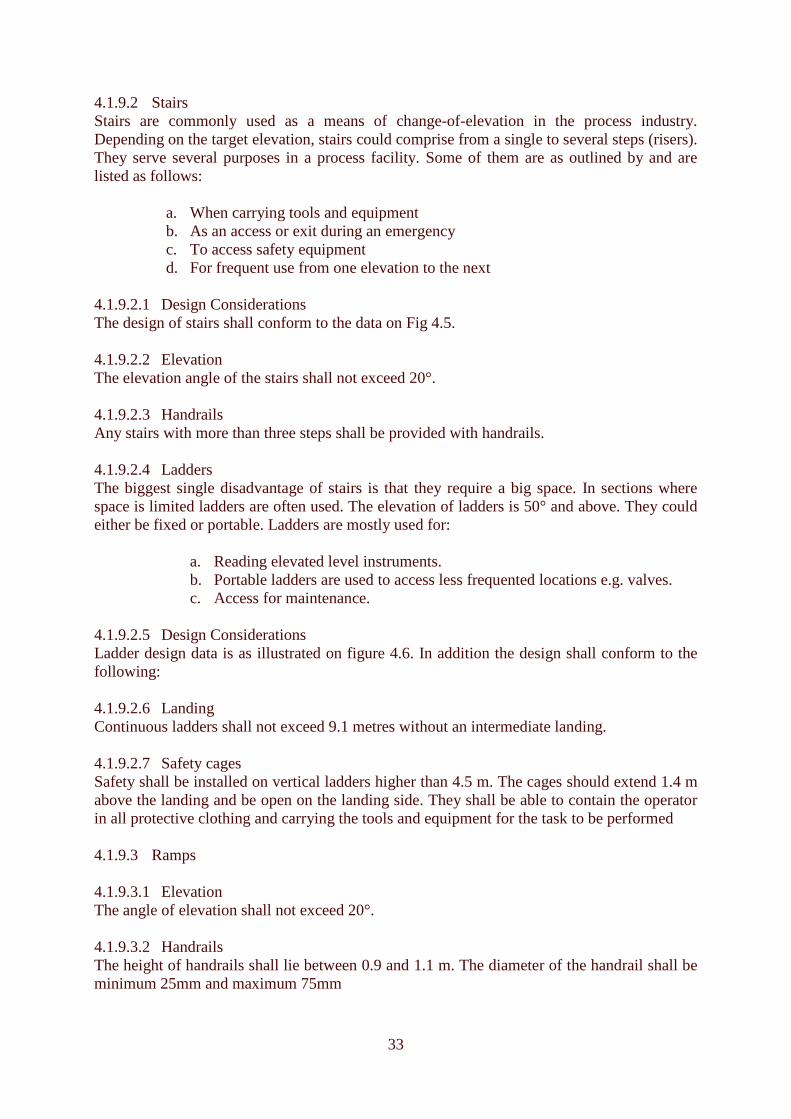
4.1.9.2 Stairs Stairs are commonly used as a means of change-of-elevation in the process industry. Depending on the target elevation, stairs could comprise from a single to several steps (risers). They serve several purposes in a process facility. Some of them are as outlined by and are listed as follows:
a. When carrying tools and equipment b. As an access or exit during an emergency c. To access safety equipment d. For frequent use from one elevation to the next
4.1.9.2.1 Design Considerations The design of stairs shall conform to the data on Fig 4.5. 4.1.9.2.2 Elevation The elevation angle of the stairs shall not exceed 20°. 4.1.9.2.3 Handrails Any stairs with more than three steps shall be provided with handrails. 4.1.9.2.4 Ladders The biggest single disadvantage of stairs is that they require a big space. In sections where space is limited ladders are often used. The elevation of ladders is 50° and above. They could either be fixed or portable. Ladders are mostly used for:
a. Reading elevated level instruments. b. Portable ladders are used to access less frequented locations e.g. valves. c. Access for maintenance.
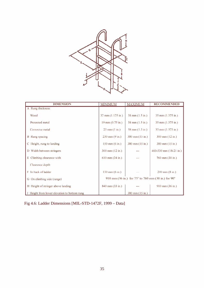
4.1.9.2.5 Design Considerations Ladder design data is as illustrated on figure 4.6. In addition the design shall conform to the following: 4.1.9.2.6 Landing Continuous ladders shall not exceed 9.1 metres without an intermediate landing. 4.1.9.2.7 Safety cages Safety shall be installed on vertical ladders higher than 4.5 m. The cages should extend 1.4 m above the landing and be open on the landing side. They shall be able to contain the operator in all protective clothing and carrying the tools and equipment for the task to be performed 4.1.9.3 Ramps 4.1.9.3.1 Elevation The angle of elevation shall not exceed 20°. 4.1.9.3.2 Handrails The height of handrails shall lie between 0.9 and 1.1 m. The diameter of the handrail shall be minimum 25mm and maximum 75mm

34
Fig 4.5: Stair Dimensions (MIL-STD-1472F, 1999 – Data)
35
Fig 4.6: Ladder Dimensions [MIL-STD-1472F, 1999 – Data]

36
4.2 Process Equipment
4.2.1 Compressors and Pumps Key human factors that need to be considered during the design of compressor and pumps layout are:
4.2.1.1 Accessibility issues Anthropometrics and accessibility data provided in section 1.6 and section 2.1 should be used when designing for the addressing accessibility issues. For packaged units these factors should be reviewed before the transporting to the site for installation. Clearance for lifting devices should be allowed. 4.2.1.2 Local Controls and displays Local controls and displays shall be functionally grouped together. See section 3. The operator must be able to operate the controls while observing the displays without changing his working position. They shall be identifiable with the equipment controlled. Mirror arrangement should be avoided. 4.2.1.3 Emergency controls The emergency controls (emergency shutoff) shall be located at locations where they are clearly visible and should be reached without much effort even at times of duress. 4.2.1.4 Lubrication
• Lubrication points for normal preventive maintenance shall be within reach without disconnecting any fittings or parts.
• The oil level shall be visible from the most frequented side. • The lubrication port shall be well labelled and the type of lubrication indicated.
4.2.1.5 Traps, blow-downs and drain system Pumps handling hazardous products should be designed such that the connections are made to a closed blow-down or drain system. The drain or blow-down should be located near the equipment for ease of accessibility. 4.2.1.6 Safety Showers They shall be located at strategic locations free of the contamination. See Section 1.5.1.1. 4.2.1.7 Location All equipment shall be located at grade. In case installed on raised location, landing platforms shall be provided.

37
Fig 4.7: Recommended Layout of Equipment and Piping at Pumps
NOTES: These layouts intends to keep one side of the base plate clear of all obstructions for maintenance access and to orient instrumentation such that it is clearly visible from the on/off switch or the driver control station. 1. Terminal Box 2. Motor 3. Start/Stop Switch 4. Pump 5. Vent Connection 6. Casing Drain 6a. Base-plate Drain 7. Seal Flush Piping 8. Seal Flush Piping 9. Seal Flush Piping 10. Cooling Water Out 11. Cooling Water In 12. Seal Flush Piping 13. Cooling Water Out 14. Cooling Water In 15. Seal Flush Piping 16. Seal Pot 17. Pressure Gauge (*) 18. Temperature Gauge (*) 19. Level Gauge (*) 20. Bearing Housing Cooling Water Out 21. Bearing Housing Cooling Water In (*) Local instrument readable from the Start/Stop switch
VERTICAL INLINE PUMP
SINGLE STAGE BETWEEN BEARINGS PUMP
16 19
18 17
3
1 2
4
5 7
8 9
12
10 11 14 13
20 21
15
16 17 18
19
17 18 19
3
2 1
21 20
6 *
* * 12
9 9 7
5
12
* * *
14 13 11 10 11 10 14 13
22 21 20
6A
16 19
18 17
3
15
4
5
6
7
9
12 8
2 1 10 11 13 14
OVERHUNG PUMP
MULTISTAGE BETWEEN BEARINGS PUMP
16 17 18
19
16 17 18 19
3
2 1
21 20 6
* *
* 12
9 9
7
5
12
* * *
14 13 11 10 11 10 14 13
22 21 20
6A
4 8
6A 6
16
* *
*

38
4.2.2 Reactors To avoid some of the accidents that occur during the maintenance and/or operation of reactors the following HF issues should be taken into consideration during the design phase: 4.2.2.1 Entry Entry to the reactor shall be large enough to accommodate a healthy operator with PPE. The manhole should also be large enough for evacuation in case of an accident caused by intoxication, see accessibility on section 4.1. In case of a smaller reactor the operator shall be able to reach with ease the centre when the reactor is open for maintenance or feeding of catalyst. Provision for lifting equipment shall be made if the catalyst is staged above the grade. 4.2.2.2 Situation awareness The displays shall provide the operator with the exact conditions within the reactor. Critical parameters shall be given priorities. See display design on section 3.2.4. This is to avoid confusion of status that may lead to errors. 4.2.2.3 Ventilation Ventilation and filtration systems shall provided in cases where the atmosphere may be contaminated. 4.2.2.4 Purging A provision that requires introduction of purging of toxic material shall be ensured. This is necessary for loading, unloading or maintenance work. 4.2.2.5 Reactor Charging The reactor shall be designed with controls to avoid excess or deficient charging of reactant. Where possible the order and rate of reactor charging shall be taken into consideration. An example is to introduce automatic feeding system to eliminate possible human error, for example charging of wrong product. 4.2.2.6 Temperature control Temperature controls shall show conditions inside the reactor and where applicable the feed and the discharge. The coolant flow shall be fitted with both local and remote alarms. 4.2.2.7 Reactor Control All reactors related tasks should be located on the same level to reduce the requirement of the operator to access different levels frequently.
4.2.3 Centrifuges 4.2.3.1 Accessibility Centrifuges shall have sufficient work place for cleaning, have an easy and convenient access that accommodates the operator with all the PPE. When possible continuous centrifuges shall be used instead of batch process whenever hazardous material is being handled.

39
4.2.3.2 Interlocks Centrifuges shall be fitted with interlocks to prevent accidental restart when open for maintenance or cleaning. Displays shall be installed to indicate all open apertures. 4.2.3.3 Warning Signs Warning against hazardous materials that are handled and also physical hazards shall be displayed at locations easy to read.
4.2.4 Filters The primary safety concerns associated filters are loss of containment of flammable and toxic material and operator’s safety. The key principle human factors that should be considered during the design of filters are as listed here below: 4.2.4.1 Access for maintenance Filters are frequently cleaned and maintained; therefore the design shall include access for these tasks. The work area shall be able to accommodate the maximum number of operators to perform a task taking into consideration the PPE, equipment and all tools required. Strainers and filters cleaning and flushing connections should be accessible from platform and access for lifting devices where necessary should be provided. 4.2.4.2 Working bench If cleaning is to be done on site proper cleaning basins shall be provided. This shall include the provision for drainage. The platform should be able to accommodate all filter components and should have enough space to allow proper disassembly, assembly and reinstallation. 4.2.4.3 Gauges and interlocks For high pressure filters local pressure gauges shall be provided in the design to indicate the internal pressure of the filter. Interlocks to prevent opening while the pressure is still high shall be included. 4.2.4.4 Manual Handling Filters to be handled by one operator shall not exceed the Recommended Weight for Lifting, RWL, (23kg). If it is more than this weight then a provision for more than one person shall be included or include lifting aids. The height of the filter should cover the both extremes of user (operator) population.
4.2.5 Fired Equipment and furnaces Fired heaters are prime sources of hazards. The main problems with these equipments are explosions in the firebox that occur during lighting up or as a result of flame failure, [Lees, 1996]. The following HF issues should be taken into consideration during the design process: 4.2.5.1 Accessibility All the places that require monitoring shall be easily accessible. Insulation shall be provided against all the hot surfaces. Heat blankets shall be provided to avoid excessively high temperature.

40
4.2.5.2 Flame Monitoring Flame sensors shall be provided to detect any anomalies of the flame conditions. The displays shall face the approach side of the surveillance paths and access should be made easier e.g. providing stairs instead of ladders. 4.2.5.3 Ignition For manually ignited furnaces the igniter and valve should be located close to the window. The pilot valve and the igniter switch should be positioned in a way that operator is able to see the pilot flame through an observation window. For automatically ignited furnaces from a remote location proper display, see section 3.2.4, should be installed to show position of valves and burner operation. 4.2.5.4 Interlocks Where possible an interlock shall be provided to prevent ignition before the ignition box is purged with air and tested. 4.2.5.5 Manual tasks Manual tasks like decoking and operation of valves shall be tested to ensure that the operator is not excessively fatigued. Mounting and demounting of refractory material should be taken into consideration during the design.
4.2.6 Loading and unloading Racks Several human activities take place during these processes. Human factors design shall consider the following: 4.2.6.1 Top of truck If the task is at the top of the truck, emergency controls from the work place should be provided. Good landing and barriers against falling be provided around the top of the truck. 4.2.6.2 Communication Good communication system between the operator and the tank driver shall be provided. 4.2.6.3 Manual Handling Tasks All theses tasks shall be analysed to make sure that they do not supersede the recommended weight, see NIOSH equation. 4.2.6.4 Level gauges and alarms Level alarms shall be fitted and shall be located to areas where the operator will detect them while undertaking the task of loading or unloading. In case continuous monitoring is required the standing space should be included in the design. 4.2.6.5 Coupling Different coupling shall be provided for different product to prevent erroneous filling of a product to the wrong tanks. 4.2.6.6 Ventilation Ventilation shall be provided in case of toxic fumes. Where possible remote operations shall be used. Operator should be provided with PPE and this means the design should take into consideration this factor to avoid error occurrence due to PPE.

41
4.2.6.7 Safety showers The showers shall be provided close to the loading rack in case of splash of product on the operator. See section 1.5.1.1 4.2.6.8 Lighting Lighting shall be provided for night operations or in case the loading rack is located in a dark area.
4.2.7 Sample Points When designing for the following HF key principles should be taken into consideration: 4.2.7.1 Lighting and Identification. Lighting levels of 20-foot candles shall be provided for sampling facilities. See illumination. The identification of the sample points should include unit name, sample identification, physical state (solid, liquid, gas), pressure and temperature. If hazardous material is involved then a warning sign should be posted. See section 6. 4.2.7.2 Accessibility All obstruction for the operator when wearing PPE and carrying sample equipment shall be designed out in cases that sampling is not a closed purge. Safety showers shall be located conveniently and accordingly close to the sample points and the access paths must be clear of obstructions. 4.2.7.3 Location of Sample Points. As much as possible the sample points shall be located on the ground level. If they have to be on a raised platform then stairs and not ladders should be used. More than one escape route should be made available in case harmful material is being handled. If sample points are located in an open area, the sample area should allow personnel to stand away from the prevailing wind patterns. 4.2.7.4 Sampling Taps Where feasible sample taps shall be installed on vertical lines, which have an upward flow for liquids and downward flow for gases/vapours. If the flow pipes are horizontally oriented, then the liquid taps shall be on the sides and those of solids on the top. 4.2.7.5 Sampling Area Sampling area should have enough clearance to permit placing and removing of sample containers. The design shall consider both the largest or heaviest container as well as the smallest. Pressure and flow indications should be located at locations clearly visible by the personnel without leaving the workstation. Drainage system should be designated to a closed system. 4.2.7.6 Sample Connections Sample connections shall be quick coupling type. They should not allow the connections of instruments not used for sampling purposes.

42
4.2.8 Tanks and Vessels HF have to be taken into serious consideration when designing these storage containers. Some key principles are listed here below: 4.2.8.1 Accessibility The containments shall have stairs from ground level to the top. The stairs shall be spiral with handrails and shall be non-slippery including those on the top of the tanks. The design of stairs shall conform to the details on section 4.1.1. 4.2.8.2 Platform The top of the containment shall be fitted with a landing platform. This must be guarded by raised barriers to avoid accidental fall of operator. All the frequented areas (for inspection and operation) shall have unobstructed walkways. 4.2.8.3 Similar containments For tanks and vessels that are next to each other due to the nature of the products they contain, a stairway to connect them shall be provided to avoid operator coming down one tank and going up another. 4.2.8.4 Valves The operator shall be able to see clearly the level displays as he is operating the valves. Task analysis shall be done to see that the operator does not exert a lot of energy while operating the valves. 4.2.8.5 Tanks maintenance and cleaning Access for a healthy human being shall be provided when wearing all protective clothing. Paths shall be left for an evacuation when need arises. Vents for pressure vessels especially for hazardous materials should be routed away from the personnel and where feasible shall be to a closed drain. 4.2.8.6 Pipe protection All the above surface pipes on the tank farms shall be protected against being stepped on by constructing crossover stairs at the most accessed areas. 4.3 Valves The following HF key principles should be considered:
4.3.1 Accessibility issues 4.3.1.1 Valves shall be installed on easily accessible locations with no obstruction. 4.3.1.2 The drain valves shall have enough clearance from the ground to allow hose
connection. If PPE is required for hazardous operations, then clearance should be included.
4.3.1.3 For several valves located close to each other a minimum clearance of 80 mm
between adjacent valve hand wheels or adjacent equipment shall be provided. Additional clearance should be provided for any tools required to operate the valves and handles for ball valves.

43
4.3.1.4 The valves shall have, if they are horizontally oriented, enough clearance to the sides while fully open. The valve handles should not obstruct the access in front of the valves.
4.3.2 Priority and functionality arrangement
4.3.2.1 Critical valves should be identified. Those that are operated manually in emergency situations should have large handles to enable easy manipulation with both hands.
4.3.2.2 The most operated valves shall be on the ground level. If they have to be mounted on
a platform then stairs and not ladders shall be provided. 4.3.2.3 Too much bending or stretching during the operations shall be minimised, see
details of dimensions on fig 4.8. 4.3.2.4 Valves shall be grouped according to there functionality. A task analysis should be
carried out to identify the sequence of operation of the valves and the operator movements. The valves operated in sequences shall be mounted on the logical order and close to each other.
4.3.2.5 The shutoff valves, which are not manipulated during the normal operations, shall be
made tamper proof.
4.3.3 Closing and opening
4.3.3.1 For all the manual operated valves, clockwise or forward direction shall mean closing and anti clockwise or backward movement shall mean opening. The operator should be able to tell when the valve is open or closed.
4.3.3.2 For Motor Operated Valves (MOV) the exact position of the valve shall appear on
the display. It should indicate clearly when the valve is open or closed. 4.4 Pipes, blinds and blanks The key factors that must be considered during the design are as follows:
4.4.1 Marking and labelling Pipes carrying similar product shall bear a similar colour or other marking. This mark shall be permanent and consistent. The blinding locations should be identified both on drawings and actual piping system. Pipes going through a wall should have the same label in points of entry and exit, See section 6.

44
Notes: 1) Valves operated more than four times per year should be located in the first choice reach area 2) Dimensions in this chart are for the male Caucasian population.
Fig 4.8: Location of Valve Hand wheels
4.4.2 Layout 4.4.2.1 The pipes shall not cross over each other to eliminate confusion during maintenance. 4.4.2.2 All the areas that require regular maintenance for example the flanges shall have an
access path left for this purpose. 4.4.2.3 Where crossing is required the pipes shall have stairs above them to avoid operator
stepping on them. Pipes at raised levels should have walking platform next to them to prevent operators using them as the walking rails.
4.4.2.4 Pipe flanges and blinds shall provide adequate clearance for handling. The
insulation should obstruct neither operations nor maintenance work. All blinds should be accessed from the ground or on a platform.
4.4.2.5 If the blinds are more than the RWL (23 kg) then they should be fitted with handles
for more than one person. Accessibility for the lifting aids should be provided.
90°
24610
18460
12305
6150
0 in.0 mm
Acceptable
2ndChoice
1stChoice
80°70°
60°
50°
40°
30°
20°
2ndChoice
00
24610
18460
12305
6150
in.mm
1stChoice Acceptable
2ndChoice
1st Choice1st
Choice
2ndChoice
Acceptable
SmallValves
AcceptableAcceptable
but Prefer SmallValves Only
2ndChoice
2ndChoice
EmergencyOperation
NormalOperation
mm
2135
1980
1830
1680
1520
1370
1220
1070
915
760
610
460
305
150
ft - in.
7 - 0
963
6 - 0963
963
963
963
963
96
5 - 0
4 - 0
2 - 0
3 - 0
1 - 0
45
4.4.3 Hazardous operations 4.4.3.1 For systems containing hazardous products warning signs should be installed to warn
operator about the hazards involved. See labelling and Markings on section 6. Operating procedures on how to install and remove blinds should be provided on or near the blinds and operators trained on the procedures.
4.4.3.2 Pressure vents or drains should be installed and routed to a safe area. Pressure
indication to display the inside pressure of the system should be installed. 4.5 Fasteners, Gaskets and Seals To reduce operator errors a HF design should take the following into account:
4.5.1 Frequency of opening
Frequently opened fasteners for maintenance and inspection shall be quick release type, easy to open and close.
4.5.2 Number of fasteners
Number of fasteners used and the diversity shall be kept as low as reasonably feasible.
4.5.3 Safety critical areas
The safety critical areas shall have special fasteners to prevent interference.
4.5.4 Inaccessible areas
For areas that are hard to access with the whole body the operator shall be able to open the fastener using one hand and a tool. It must be easy to infer the location of such fasteners.
4.5.5 Gaskets & Seals
• The operator shall where possible be able to see whenever a gasket and seals are omitted after repair work.
• Gasket and seals shall be easy to install. Minimum disassembly of the unit should take place.

46
5 Working Environment 5.1 Illumination The design of artificial illumination system has a direct impact on the performance and comfort of those using the environment. This is because good illumination makes details easier to see and colours easier to discriminate without producing discomfort or distraction. Colour Rendering Index (CRI) was developed for quantifying the accuracy with which any specific light source renders to colours. As the CRI increases, the colour judgement errors tend to decrease. For any recommendation to be made the type of task to be performed has to be identified.
5.1.1 Distribution of Light Light should be distributed in such a way as to have a positive effect on visual comfort and task performance. Large differences force the eye to adapt to the new level of luminance each time there is a shift of gaze. This results to an instantaneous reduction in visibility. Maximum luminance ratios as suggested by Illumination Engineers Society (IES) shall be as follows: Task : adjacent darker surrounding 3 : 1 Task : adjacent lighter surrounding 1 : 3 Task : remote darker areas 10 : 1 Task : Remote lighter areas 1 : 10 Luminaries : adjacent surface 20 : 1 Immediate work area : rest of the environment 40 : 1
5.1.2 Reflectance Reflectance is the ratio of the amount of light being reflected by a surface (luminance) to the amount of light striking the surface (illuminance). Reflections from the walls, ceilings and other surfaces affect the distribution of light within a working environment. The values of recommended reflectance from different surfaces of a room are as shown here below:
Floors 20 – 40 % Surface of machines and furniture 25 – 45 % Partitions and screens 40 – 70 % Windows and window blinds 40 – 60 % Ceiling and upper walls 80 % and above
5.1.3 Glare Glare is produced by brightness within the line field of vision that is sufficiently greater than the luminance that an eye is adapted to. Glare causes annoyance, discomfort or loss of visibility. Glare could be broadly divided into two categories; direct glare and reflected glare. 5.1.3.1 Direct Glare This arises from sources of light in the field of view. To reduce this type of glare the luminance of the light source should be used for instance to use many low intensity luminaries instead of few high intensity. Luminaries should be placed as far as feasible from the line of sight. Using light shields, filters, visors or polarised lights would also reduce glare. Windows

47
should be placed some distance above the floor and where feasible an outdoor overhang above the windows should be constructed. 5.1.3.2 Reflected Glare Reflected glare results from light being reflected by a surface on the field of view. Reflected glare could be specular as from a smooth, polished mirror like surfaces; spread as from brushed, etched or pebbled surfaces; or diffuse as from flat-painted or matte surfaces. To reduce reflected glare indirect light should be used where feasible. Light sources should be positioned in a way that the working surfaces do not reflect light directly to the eyes of the operator. Surfaces where feasible should not reflect light and machine surfaces should be crinkled. Bright, shiny or glossy-paper surfaces should be avoided.
Table 5a: Recommended tasks illumination levels. 5.2 Noise Levels Noise interferes with understanding of speech, causes stress, reduces efficiency and interferes with concentration (OSHA, 1983). Detrimental effects of noise are associated with difficult tasks that place high demand on the perceptual and/or information processing capacity, (Eschenbrenner, 1971). Exposure to noise over a long period of time could lead to loss of hearing.
5.2.1 Continuous Noise The permissible levels of noise exposures depend on the duration of a particular exposure. See table 5b. The maximum level of noise exposure recommended by OSHA is 80dBA. Any level higher than this exposes user to partial dose of noise. Partial dose of noise is defined as
Illumination levels Type of Task (Work area) Illuminances Range, lx
(fc) Simple orientation for short temporary visits e.g. corridors, hallways, stairways
50 – 100 (5 – 10)
Visual tasks of high contrast or large size e.g. rough assembly and bench work, console surface, reading of dials, meters and gauges, electric equipment testing, rough inspection work, general repair work, screw fastening.
200 – 500 (20 – 50)
Visual tasks of medium contrast or small size e.g. medium assembly and bench work, circuits and P & I diagrams, medium inspection tasks, general office work, prolonged reading, recording.
500-1000 (50 – 100)
Performance of visual tasks of low contrast or very small size e.g. fine assembly and bench work, fine inspection.
1000-2000 (100-200)
Performance of visual tasks of low contrast and very small size over a prolonged period of time e.g. precise assembly, extra fine bench work and extra fine inspection, instrument repair.
2000- 5000 (200 – 500)

48
Time spent at the sound level
Maximum permissible time at that sound level, (Table 5b) The daily noise dose is the sum of all partial doses. The noise dose is then converted to 8h time weighted average (TWA) level as illustrated on table 5c.
Duration per day, hrs Sound level, dBA 8.0 90 6.0 92 4.0 95 2.0 100 1.0 105 0.5 110 0.25 115
Table 1g: OSHA permissible noise exposure levels TWA of 85dBA (by 2006 it should be 80dBA) is designated as the action level when a hearing observation program has to be put in place. At this level the noise dose is 50%. When TWA reaches 90 dBA (85dBA by 2006) then this is the permissible exposure level and measure to reduce noise exposure should be put in place. To calculate TWA the following formula is applicable: TWA = 16.61 log D/100 + 90 Table 5c: Conversion from "% noise exposure" or "dose" to 8-hour TWA
5.2.2 Impulse Noise Impulse noise is created at a transient pulse with a single frequency pattern. Exposure to impulse or impact noise in excess of 160 dBA peak sound pressure level should not be permitted. Maximum impacts/ impulses for various peak intensity values is as shown on table 5d.
Noise dose TWA, dBA 15 76.3 25 80.0 50 85.0 75 87.9 100 90.0 125 91.6 200 95.0 300 97.9 400 100.0

49
Permitted number of impulses per 8 hrs.
Peak Sound level, dBA
0 160 10 150 100 140 1000 130 3162 125 10000 130
Table5d: Permissible Noise Exposure (Impulse of Impact Noise)
5.2.3 Noise Control
The most important factors to take into consideration to attenuate noise include; intensity of the noise, duration of exposure and distance from the source of noise. When designing the following should be taken into consideration:
5.2.3.1 The noise should be reduced by use of acoustic material with high sound absorption coefficient for construction of floors, walls and ceiling of areas that need noise control.
5.2.3.2 Areas that require frequent use of communication tasks should not have noise levels
exceeding 65dBA. 5.2.3.3 All hazardous noise areas must be clearly identified by signs located at the entry
point to these areas. 5.2.3.4 All equipment that require continuous operation should not produce more than
80dBA, and the cumulative noise levels of all the machines should not exceed 90dBA.
5.2.3.5 If a certain equipment or tool produces hazardous noise levels, then it should be
clearly marked unless the whole working area is designated as hazardous noise area. 5.2.3.6 Protective equipment to be worn in the areas marked shall be indicated. They should
have the capacity to attenuate noise levels to 80dBA. 5.3 Climate Climate is a powerful influence on our comfort, health, and performance. Environmental factors that affect heat exchange are air temperature, humidity, airflow and wall temperatures.
5.3.1 Heat Stress This is the situation where the body absorbs and/or produces more heat than it can dissipate. Body temperatures rise and illness or death would occur. Impermeable clothing and heavy physical work would result to heat stress. Forms of illnesses associated with heat stresses are heat rush, heat cramps, heat exhaustion and heatstroke that is more acute. Heat stress reduces the performance on physical work. In a hotter environment exhaustion occurs sooner than in

50
temperate ones. Illustrated on table 5e are the proposed temperature limits when carrying different tasks.
Energy Consumption, kcal per min
Type of work Maximum effective temperature
6.7 Heavy work e.g. walking with 30kg 26°C– 28 °C 4.2 Moderate heavy work e.g. walking at
4km/hr 29°C – 31°C
1.7 Light sitting work 33°C – 35°C Table 5e: Proposed temperature limits for acceptable heat load (Grandjean, 1986) 5.3.1.1 Heat Stress Index This is the general combination of air temperature and relative humidity how they affect the human body. See Fig 5.1. The effects of heat on people are as shown by the four categories on table 5f.
Category Description Heat Index General effects I Extremely hot 55°C and above Heat stroke with continue exposure II Very Hot 41°C - 55°C Sunstroke, heat cramps, and heat
exhaustion likely III Hot 32°C – 41°C Sunstroke, heat crumps and heat
possible IV Very warm 27°C – 32°C Fatigue possible with prolonged
exposure and/physical activity Table 5f: Categories of the effects of heat on people (Source OSHA, 1981) 5.3.1.2 Reducing Heat Stress The design should aim at reducing heat stresses associated with the task to be undertaken. The following are the methods to be used: 5.3.1.2.1 The design should provide air-conditioned working areas where feasible. When this
is not possible, air-conditioned rest rooms should be provided for. 5.3.1.2.2 Lifting devices and other work aides should be provided to bring down the
metabolism rate by reducing the amount of physical work. 5.3.1.2.3 Hot surfaces should be insulated or a shield to be provided between the operator
and the source of radiated heat. 5.3.1.2.4 Humidity should be kept low but above 15% to avoid irritating and drying of body
tissues.

51
Fig 5.1: The Heat Index used by US Nation weather service. (Steadman, 1979)

52
6 Plant Labeling and Signing 6.1 Introduction The effectiveness of signs and labels is the quality of the message transmitted. This includes the message layout, legibility and visibility. This is aimed at minimising the mental effort in any way by easing cognitive processing. The information on signs and labels should be arranged consistently and a preferred format is as follows indicated on Table 6a. Labels should be able to withstand the operating conditions of the environment in which they are used. They should be resistance to wear and easy to clean.
Sign or Label Type Format Piping label First line: Pipe contents (Text code required, colour code
maybe included. Second line: From – To (Optional)
Equipment label First line: Functional description Third line: Tag number (as it appears on P & ID)
Control Panel Label First line: Equipment description Second line: Functional description Third line: Tag number
Warning Sign First line: Rating word (DANGER, CAUTION) Second line: Description of hazard and its consequences Third line: Ways to avoid hazard
Table 6a: Contents of various labels 6.2 Transmission of Right Information
6.2.1 Familiar words should be used. Words that are too technical or uncommon vocabulary should be avoided. Abbreviations must be avoided. If they have to be used it they should be understood by the most inexperienced user.
6.2.2 Unambiguous, brief and clear sentences must be used. Whenever feasible punctuation must be avoided. If too long the sentences should be broken into sequential steps. In fig 6.1 the full stop maybe missed and this sign will mean exactly the opposite.
Fig 6.1: Use of punctuation could lead to error in reading a sign.
NO ENTRY. CLEARANCE CERTIFICATE
REQUIRED

53
6.2.3 Procedures should be sequential. Each step must be on a separate line depending on the length of the sentence and should be according to priority.
Not this This Example 1 To use the phone lift the handset and press the button. Wait for the control room to answer before speaking. Speak clearly and replace receiver when finished. OR Example 2 Press the green button after turning off the gas.
��Pick up the phone ��Press button on handset ��Wait for control room to answer ��Speak clearly ��Replace handset when finished
OR Turn of the gas then press the green button
Table 6b: Procedures as sequential steps
6.2.4 Preferably messages should be active and positive
Not this This DO NOT CLOSE BOTH INLET AND OUTLET VALVES UNLESS YOU OPEN THE DRAIN OR THE SMALL BYPASS.
OPEN THE DRAIN OR SMALL BYPASS BEFORE CLOSING BOTH THE INLET AND THE OUTLET VALVES
Table 6c: Positive message 6.3 Visibility and Legibility
6.3.1 A maximum contrast must be provided between the contrast and the background to provide good discrimination. Bright background for label should be avoided. White letters on a black background or the reverse provides the maximum contrast.
6.3.2 Distance and size of letters shall be calculated using this formula:
H and D should maintain the same units.
Letter height, H = Viewing distance, D 200

54
6.3.3 On good illumination when dark characters are used on a light background the ratio of the stroke width, S to character height, H shall be between 1:6 to 1:8. When light characters are used on dark background then S : H should be between 1:8 and 1: 10.
In general W : H should be 3: 5 6.4 Style of writing
6.4.1 Simple style (sans serifs) should be used e.g. Arial. These are uniform letters without serifs.
6.4.2 Minimum character spacing shall be one stroke width S. Word spacing should be preferably between ½ the width of each character. The exception is “I” and “1”.
6.5 Signs and labels layout
6.5.1 Long instructions should be numbered and located to the left.
Not this This Do not lift load over people. No one shall be under the hoisting load. Never lift the load over the rated capacity. Never leave the suspended load unattended.
1. Do not lift load over people. No one shall be under the hoisting load.
2. Never lift the load over the rated capacity. 3.Never leave the suspended load
unattended.
Table 6d: Layout of instructions
6.5.2 Short messages should be centrally placed. Upper case letters only should be used for messages with three letters or less. For longer sentences mixed cased must be used as illustrated on table 6e.
S
W
H

55
Not this This CAUTION Chemical storage area Authorised personnel only
OR
CAUTION SLIPPERY FLOOR
CAUTION Chemical storage area Authorised personnel only
OR
CAUTION SLIPPERY FLOOR
Table 6e: Short instructions centralised.
6.5.3 Whenever feasible, labels shall be coded using shape (use of symbols) and/or colour. Only familiar symbols should be used. But colour code shall be used only for hazard warnings.
6.5.4 Where feasible all text shall be oriented horizontally. For vertical installation like piping and electric cables the label should be rotated 90°clockwise to be legible from normal viewing position.
6.5.5 Italics and underlining should be used only on words that need to be emphasised.
6.6 Location
6.6.1 Labels should be located close to the items they identify. Confusion with other items or labels should be eliminated.
Fig 6.2: Unambiguous location of labels
6.6.2 Labels should be located at the operator’s line of site. Both short and tall operators must be considered. They should be placed such that they are not obscured during operation or maintenance. Duplication shall be made for panels are removable or when approach directions are different. Except when there the panel is located above the operator’s line of site labels should consistently be located above controls. They
Label
Not this way
Label
This way

56
should not be located on controls where they are turned upside down as the controls are operated.
Fig 6.3: Labels on control panels
6.6.3 Pipe labels shall be placed at the inlet and at the outlet of the equipment, at valves, on both sides of a penetration (for example through a wall) and approximately 15m on straight stretches. For direction of flow indicators, arrows should lead the text and shall be of solid form as shown on Fig 6.4. If the pipes lie next to each other then all the labels should be located at the same point. Labels that are located 2m high shall be placed at an angle such that they are read from normal line of view.
Fig 6.4: Pipe labelling 6.7 Equipment Labelling
6.7.1 Equipment labels should be placed close to the access aisle. Remotely controlled equipment should have labels at control station and also at the side of the equipment close to the access aisle.
6.7.2 Durability of labels should be emphasised by use of engraved plastic or stainless steel. The labels should be attached to the machines by use of welds, screws or rivets. Adhesives shall be avoided.
Label
Label
Label
Label
FUEL GAS
PROPANE
WATER
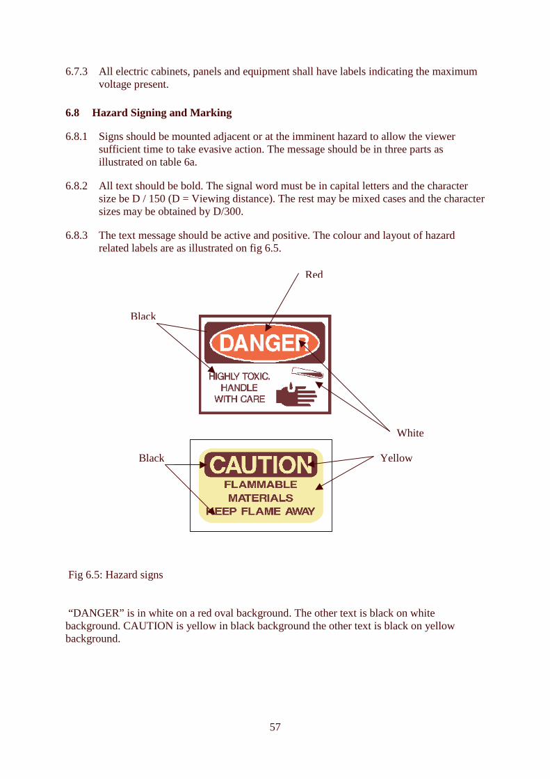
57
6.7.3 All electric cabinets, panels and equipment shall have labels indicating the maximum voltage present.
6.8 Hazard Signing and Marking
6.8.1 Signs should be mounted adjacent or at the imminent hazard to allow the viewer sufficient time to take evasive action. The message should be in three parts as illustrated on table 6a.
6.8.2 All text should be bold. The signal word must be in capital letters and the character size be D / 150 (D = Viewing distance). The rest may be mixed cases and the character sizes may be obtained by D/300.
6.8.3 The text message should be active and positive. The colour and layout of hazard related labels are as illustrated on fig 6.5.
Fig 6.5: Hazard signs “DANGER” is in white on a red oval background. The other text is black on white background. CAUTION is yellow in black background the other text is black on yellow background.
Black
Red
White
Black Yellow

58
7 References Attwood, D. A ., Office Relocation Source Book: Managing Staff Throughout the Move,. John Wiley and Sons, New York (1996) Attwood, D. A et al., Ergonomics Solutions for the Process Industries, Elsevier, Oxford (2004) Ayoub, M. and Mital A., Manual Materials Handling. Taylor & Francis (1989). Ayoub, M. et al, A guide to Manual Materials Handling. Taylor & Francis (1992). Ball, P.W. Ed, The guide to reducing human error in process operations, The Human Factors In Reliability Group, The SRD Association, 1991. Eschenbrenner, A.J., Effects of Intermittent Noise on The Performance of a Complex Psychomotor Task. Human Factors, 13 (1), 59-63 (1971)
Guidelines for Chemical Process Quantitative Risk Analysis, Chemical Centre for Process Safety, 1989
Eastman Kodak Company, Ergonomics for people at Work, New York (1986)
Engineering Equipment and Materials Users Association (EEMUA), Alarm Systems - A Guide to Design, Management and Procurement, Guideline 191 (1999) Grandjean, E., Fitting the Task to the Man, Taylor & Francis (1986) Health and Safety Executive (HSE), Guidance for the Assessment of COMAH Safety Reports, 2002 Lees, Frank P.: Loss Prevention in the Process industries, Vol 1, pp.14/5, 1996 MIL-STD-1472d, Design Criteria Standard, Human Engineering, Washington D.C, Department of Defence. Mital A., The Psychophysical approach in Manual Lifting: A verification Study. Human Factors. 25, 485-491 (1983) NIOSH, Work Practices Guide for Manual Lifting, Cincinnati, US Department of Health and Human Services (1981) Occupational Safety and Health Administration (OSHA), Occupational Noise Exposure: Hearing Conservation Amendment, Federal Register, 48, 9738 – 9783 (1983). O’Hara, J. M. et al Human-system interface design review guideline (NUREG-0700 Rev.1). Washington, DC: U.S. Nuclear Regulatory Commission (1995).

59
Pheasant S., Body Space: Antropometry Ergonomics and the Design of Work, Taylor & Francis (1996) PHSC: Productivity, Health, & Safety Concepts Website: http://www.ergodoc.com Sanders, M.S and McCormick, E.J. Human Factors in Engineering and Design. McGraw-Hill, Inc (1993) Steadman, R.C, The Assessment of Sultriness: Journal of Applied Meteorology, 18(7), 861-884 (1979) Council Directive 89/654/EEC of 30 November 1989 concerning the minimum safety and health requirements for the workplace (first individual directive within the meaning of Article 16 (1) of Directive 89/391/EEC), Official Journal n� L 393 of 30.12.1989, p. 1. Council Directive 89/655/EEC of 30 November 1989 concerning the minimum safety and health requirements for the use of work equipment by workers at work (second individual Directive within the meaning of Article 16 (1) of Directive 89/391/EEC, Official Journal n� L 393, 30.12.1989, p. 13. Council Directive 89/656/EEC of 30 November 1989 on the minimum health and safety requirements for the use by workers of personal protective equipment at the workplace (third individual directive within the meaning of Article 16 (1) of Directive 89/391/EEC), Official Journal n� L 393 of 30.12.1989, p. 18. Council Directive 90/270/EEC of 29 May 1990 on the minimum safety and health requirements for work with display screen equipment (fifth individual Directive within the meaning of Article 16 (1) of Directive 89/391/EEC), Official Journal n� L 156 of 21.06.1990, p. 14. Council Directive 90/269/EEC of 29 May 1990 on the minimum health and safety requirements for the manual handling of loads where there is a risk particularly of back injury to workers (fourth individual Directive within the meaning of Article 16 (1) of Directive 89/391/EEC), Official Journal n� L 156, 21.06.1990, p. 9. Council Directive 92/58/EEC of 24 June 1992 on the minimum requirements for the provision of safety and/or health signs at work (ninth individual Directive within the meaning of Article 16 (1) of Directive 89/391/EEC), Official Journal n� L 245 of 26.08.1992, p. 23. Directive 2003/10/EC of the European Parliament and of the Council of 6 February 2003 on the minimum health and safety requirements regarding the exposure of workers to the risks arising from physical agents (noise) (Seventeenth individual Directive within the meaning of Article 16(1) of Directive 89/391/EEC) European Parliament and Council Directive 2002/44/EC of the of 25 June 2002 on the minimum health and safety requirements regarding the exposure of workers to the risks arising from physical agents (vibration) (sixteenth individual Directive within the meaning of Article 16(1) of Directive 89/391/EEC) - Joint Statement by the European Parliament and the Council, Official Journal L 177 , 06/07/2002 P. 0013 � 0020.

60
PRISM FG3, Best Practice Guide: Human Factors in High Demand Situations for the Process Industries, 2004 PRISM FG2, Best Guidance on Procedures for Small and Medium sized Enterprises, 2004 PRISM FG2, Best Guidance on Training for Small and Medium sized Enterprises, 2004 http://www.hse.gov.uk/humanfactors/ http://www.fda.gov/cdrh/humfac/hufacgwo.html
Related Documents