Incorporation of Creep Model with Hardening Soil Model for Deformation Analysis of Rockfill Dam Pornthap Pramthawee 1) , *Pornkasem Jongpradist 2) , Chana Phutthananon 3) and Raksiri Sukkarak 4) 1), 2), 3), 4) King Mongkut’s University of Technology Thonburi, Bangkok, Thailand 2) [email protected] ABSTRACT Finite element approach is broadly used for dam design and safety assessment of concrete face rockfill dams (CFRDs). A crucial element of this approach is a constitutive model representing the stress-strain behaviour of rockfill material. Creep of rockfill material, being time-dependent deformation, is increasingly of interest in geotechnical engineering because it can be a major cause of the separation between the concrete face slabs and a cushion layer, potentially resulting to dam leakage. To avoid the mathematical complexity, creep analysis has been mostly carried out separately from an elastoplastic analysis for deformation prediction after impounding state. The time-dependent behavior is also omitted for analysis during construction state. This paper presents the incorporation of a developed creep model with the elastoplastic model, so called Hardening Soil model (HS), for prediction of time- dependent deformation of CFRD analysis. One-dimensional (1-D) creep model was adopted based on power function, for general stress-strain analysis and incorporated with HS model via modified hardening function. The models were implemented into finite element program ABAQUS as a subroutine, so called UMAT. The 2D Plane Strain analysis of CFRD during construction was carried out and its results were compared with the selected monitoring results. The comparisons demonstrate that the incorporated model can efficiently predict the deformation of CFRD. 1. INTRODUCTION Concrete face rockfill dams (CFRDs) having upstream concrete slabs as a watertight element are increasingly constructed in recent years because they are often the lowest-cost dam type. The main concern of the safety analysis is the stress and deformation behaviour of the dam. In the design and safety assessment, finite element approach is broadly used as a tool for the stress and deformation analysis under 1), 4) Ph.D. Candidate 2) Associate Professor 3) Ph.D. Student

Welcome message from author
This document is posted to help you gain knowledge. Please leave a comment to let me know what you think about it! Share it to your friends and learn new things together.
Transcript

Incorporation of Creep Model with Hardening Soil Model for Deformation Analysis of Rockfill Dam
Pornthap Pramthawee1), *Pornkasem Jongpradist2), Chana Phutthananon3) and Raksiri Sukkarak4)
1), 2), 3), 4) King Mongkut’s University of Technology Thonburi, Bangkok, Thailand
ABSTRACT
Finite element approach is broadly used for dam design and safety assessment of concrete face rockfill dams (CFRDs). A crucial element of this approach is a constitutive model representing the stress-strain behaviour of rockfill material. Creep of rockfill material, being time-dependent deformation, is increasingly of interest in geotechnical engineering because it can be a major cause of the separation between the concrete face slabs and a cushion layer, potentially resulting to dam leakage. To avoid the mathematical complexity, creep analysis has been mostly carried out separately from an elastoplastic analysis for deformation prediction after impounding state. The time-dependent behavior is also omitted for analysis during construction state. This paper presents the incorporation of a developed creep model with the elastoplastic model, so called Hardening Soil model (HS), for prediction of time-dependent deformation of CFRD analysis. One-dimensional (1-D) creep model was adopted based on power function, for general stress-strain analysis and incorporated with HS model via modified hardening function. The models were implemented into finite element program ABAQUS as a subroutine, so called UMAT. The 2D Plane Strain analysis of CFRD during construction was carried out and its results were compared with the selected monitoring results. The comparisons demonstrate that the incorporated model can efficiently predict the deformation of CFRD. 1. INTRODUCTION Concrete face rockfill dams (CFRDs) having upstream concrete slabs as a watertight element are increasingly constructed in recent years because they are often the lowest-cost dam type. The main concern of the safety analysis is the stress and deformation behaviour of the dam. In the design and safety assessment, finite element approach is broadly used as a tool for the stress and deformation analysis under
1), 4)
Ph.D. Candidate 2)
Associate Professor 3)
Ph.D. Student
various important situations of the dam. A crucial element of this approach is a constitutive model, well known as Soil Model, representing the stress-strain behaviour of rockfill material.
The heights of CFRDs are recently larger than 200 m. With these heights, the rockfill materials in dams would be subjected by a broad stress range. The compaction of rockfill in thin layers during the construction results in density variation of rockfill. For such granular media, the stress and density dependent properties play an important role in its behaviors, particularly, the shear dilatancy behaviors of dense granular materials (Charles and Watts, 1980). Numerous studies have investigated the influencing factors on mechanical behaviours of rockfill material in several viewpoints such as strength, stress-strain relationship, shear dilatancy and breakage behaviour.
Selection of the model depends on the particular assumption of analysis which can be divided into two major categories including time-dependent and time-independent analyses. Creep of rockfill material, being time-dependent deformation, is increasingly of interest in geotechnical engineering because it can be a major cause of the separation between the concrete face slabs and a cushion layer, potentially resulting in dam leakage (Zhang et al., 2004). Creep behaviour of rockfill dam is usually seen during the construction stage and impounding stage. Cracks and damages in concrete faced slab of CFRD are mainly caused by the separation between the slabs and rockfill embankment because of creep deformation. Investigations of the key factors affecting the creep behavior of rockfill material were carried out via laboratory test (Li & Zhang, 2012; Cheng & Ding, 2004; Oldecop and Alonso, 2007).
To avoid the mathematical complexity, only the elasto-plastic analysis has been
commonly considered during the construction stage while creep analysis has been mostly performed for post-construction stage. In the other word, the elastoplasticity and creep are separately considered. However, rockfill material is time-dependent material and it is time-consuming for the construction process of CFRD. Time-independent analysis during the dam construction is, therefore, inadequate for deformation control of rockfill body during the construction process. This paper presents the incorporation of a developed creep model with the elastoplastic model, so called Hardening Soil model (HS), for prediction of time-dependent deformation of CFRD analysis. One-dimensional (1-D) creep model is adopted, based on power function, for general stress-strain analysis and incorporated into HS model via modified hardening function. These models are implemented into finite element program ABAQUS as a subroutine, so called UMAT. Then, the 2D Plane Strain analysis of CFRD during construction procedure is carried out and the analysis results are compared with the measured data for evaluation of the incorporated model.
2. CONSTITUTIVE MODELS AND THEIR INCORPORATION
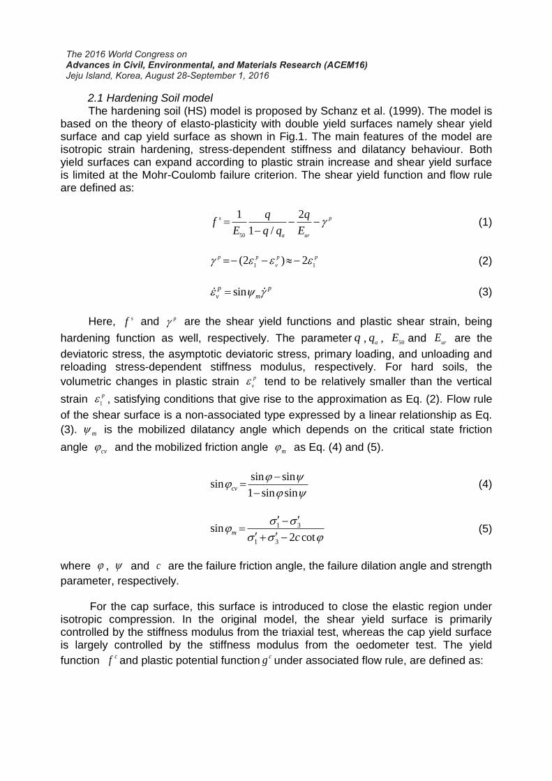
2.1 Hardening Soil model The hardening soil (HS) model is proposed by Schanz et al. (1999). The model is based on the theory of elasto-plasticity with double yield surfaces namely shear yield surface and cap yield surface as shown in Fig.1. The main features of the model are isotropic strain hardening, stress-dependent stiffness and dilatancy behaviour. Both yield surfaces can expand according to plastic strain increase and shear yield surface is limited at the Mohr-Coulomb failure criterion. The shear yield function and flow rule are defined as:
50
1 2
1 /
s p
a ur
q qf
E q q E
(1)
1 1(2 ) 2p p p p
v (2)
sinp p
v m (3)
Here, sf and p are the shear yield functions and plastic shear strain, being
hardening function as well, respectively. The parameter q , aq , 50
E and urE are the
deviatoric stress, the asymptotic deviatoric stress, primary loading, and unloading and reloading stress-dependent stiffness modulus, respectively. For hard soils, the
volumetric changes in plastic strain p
v tend to be relatively smaller than the vertical
strain 1
p , satisfying conditions that give rise to the approximation as Eq. (2). Flow rule
of the shear surface is a non-associated type expressed by a linear relationship as Eq.
(3). m is the mobilized dilatancy angle which depends on the critical state friction
angle cv and the mobilized friction angle m as Eq. (4) and (5).
sin sin
sin1 sin sin
cv
(4)
1 3
1 3
sin2 cot
mc
(5)
where , and c are the failure friction angle, the failure dilation angle and strength
parameter, respectively.
For the cap surface, this surface is introduced to close the elastic region under isotropic compression. In the original model, the shear yield surface is primarily controlled by the stiffness modulus from the triaxial test, whereas the cap yield surface is largely controlled by the stiffness modulus from the oedometer test. The yield
function cf and plastic potential function
cg under associated flow rule, are defined as:
2
2 2
2( cot ) ( cot )c c
p
qf g p p c
M (6)
The magnitude of the yield cap is determined by the isotropic pre-consolidation
stresspp . The hardening function relating
pp to the volumetric cap strainpc
v is
1
1
m
ppc
v ref
pH
m p
(7)
where H and m is an auxiliary model parameter which related to the oedometer
tangent stiffness modulus defined for a reference stress ref
oedE and 0
ncK , respectively.
Fig. 1 Yield surfaces of Hardening Soil model (Schanz et al., 1999) The HS model has been adopted in several rockfill dams stress-deformation analyses (e.g., Ö zkuzukiran et al., 2006; Soroush and Araei, 2006; Pramthawee et al., 2011).
2.2 Developed creep model and parameter determination This section presents the creep model which is derived from triaxial creep tests of rockfill materials. Since only 1D-creep testing results are available for rockfills of the reference case (see later), the approach of parameter determination obtaining from one-dimensional (1-D) creep test is also described. The creep model developed by the authors (Phutthananon, 2015) is based on basic power function on account of simplifying numerical implementation. It has been carried out by regression analysis of experimental results which stress level and confining pressure have been considered as the main factors influencing on the creep behaviour. According to the model, the
creep strains are explained in term of axial creep strain a
c and volumetric creep strain
c
v as following:

a
a
nc
at A t (8)
vnc
v vt A t (9)
1 3
3
( ) aaa
a
A
p
(10)
1 3
3
( ) vvv
a
A
p
(11)
1 3( ) am
a a
a
np
(12)
1 3( ) vm
v v
a
np
(13)
where:
t = time (minutes);
1 , 3 = major and minor principal stress, respectively;
ap = atmospheric pressure is equal to 101.325 kPa
aA , vA = initial axial and volume creep parameter, respectively;
an , vn = axial and volume creep rate parameter, respectively;
, ,a a a and am = coefficient creep parameters for axial creep strain;
, ,v v v and vm = coefficient creep parameters for volume creep strain.
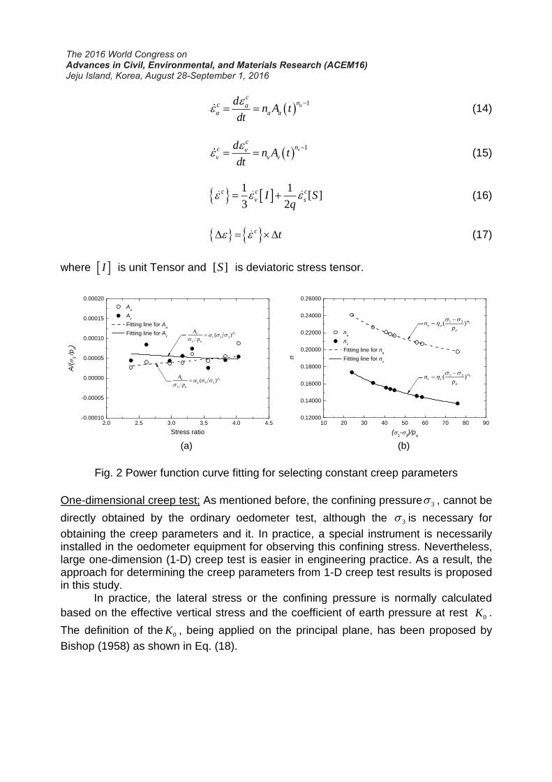
The initial creep parameter A and the creep rate parameter n
can be
determined from the best fit curve with the power function. Then, ,a vA A and ,a vn n are
further used to determine the constant creep parameters, , , , , , ,a a a a v v vm , vm as
illustrated in Fig. 2. The creep parameters , ,a a v and v can be determined from
the correlation between normalized parameters A by 3 ap and 1 3 as described
by Eqs. (10) and (11), respectively. Similarly, the creep parameters , ,a a vm and vm
can be obtained from the correlation as Eq. (11) and (12), respectively. In order to implement the creep model in FEM, Eq. (8) and (9) must be transformed into rate form as Eqs. (14)-(15) of which the duration time t of creep should be divided into several
periods t . By adopting the Prandtl–Reuss flow law, the creep strain increments are consequently calculated by:
1a
cnc a
a a a
dn A t
dt
(14)
1v
cnc v
v v v
dn A t
dt
(15)
1 1
[ ]3 2
c c c
v sI Sq
(16)
c t (17)
where I is unit Tensor and [ ]S is deviatoric stress tensor.
Fig. 2 Power function curve fitting for selecting constant creep parameters
One-dimensional creep test; As mentioned before, the confining pressure 3 , cannot be
directly obtained by the ordinary oedometer test, although the 3 is necessary for
obtaining the creep parameters and it. In practice, a special instrument is necessarily installed in the oedometer equipment for observing this confining stress. Nevertheless, large one-dimension (1-D) creep test is easier in engineering practice. As a result, the approach for determining the creep parameters from 1-D creep test results is proposed in this study.
In practice, the lateral stress or the confining pressure is normally calculated
based on the effective vertical stress and the coefficient of earth pressure at rest 0K .
The definition of the 0K , being applied on the principal plane, has been proposed by
Bishop (1958) as shown in Eq. (18).
2.0 2.5 3.0 3.5 4.0 4.5-0.00010
-0.00005
0.00000
0.00005
0.00010
0.00015
0.00020
1 3
3
( ) vv
v
a
A
p
1 3
3
( ) aa
a
a
A
p
Aa
Av
Fitting line for Aa
Fitting line for Av
A/(
3 /p
a)
Stress ratio
10 20 30 40 50 60 70 80 900.12000
0.14000
0.16000
0.18000
0.20000
0.22000
0.24000
0.26000
1 3( ) vm
v v
a
np
1 3( ) am
a a
a
np
na
nv
Fitting line for na
Fitting line for nv
n
(1-
3)/p
a
(a) (b)

'
0 '
h
v
K
(18)
The effective horizontal stress '
h and the effective vertical stress '
v are similar to
minor 3 and major 1 principal stresses, respectively. For granular material, the
equation developed by Jacky (1944) has widely used for the 0K estimation as given
by:
0 1 sin 'K (19)
where ' is the effective internal friction angle. Lirer et al. (2011) have found that the
0K’
given by Eq. (19) with the effective critical state friction angle, have shown a good
agreement with the experimental results for Melito Rockfill. Gu et al. (2015) have examined the effectiveness of Jacky’s equation for granular material by using discrete element method and suggested that using peak friction angle has provided a better
prediction of the 0K value which is consistent with Guo (2010). Numerous studies
have revealed that 0K generally decreases with an increase in internal friction angle
under primary loading case. It becomes opposite for unloading-reloading case
(Yamamuro et al., 1996; Lee et al., 2013). Moreover, 0K also depends on void ratio,
stress level, and material strength (Guo, 2010; Chu and Gan, 2004). For the internal friction angle, a number of large-scale triaxial experiments have illustrated that the friction angle of a rockfill material decreases according to a function of the confining pressure as the following equation
30 log
ap
(20)
where aP is the atmospheric pressure (101.33 kPa), 0 is the reference friction angle,
and is the reduction factor. Substituting Eq. (20) in Eq. (19), we can obtain 0K by
using the Newton-Raphson’s method as Eq. (21)-(23):
1
'
i
i i
i
f xx x
f x (21)
00 0 0
1*1 sin log( ) 0
a
Kf K K
P
(22)
0
0 0
1
0
*ln[ ]
* [ ]ln(10)
1ln(10)*
aCoP
s
K
df
dK K
(23)
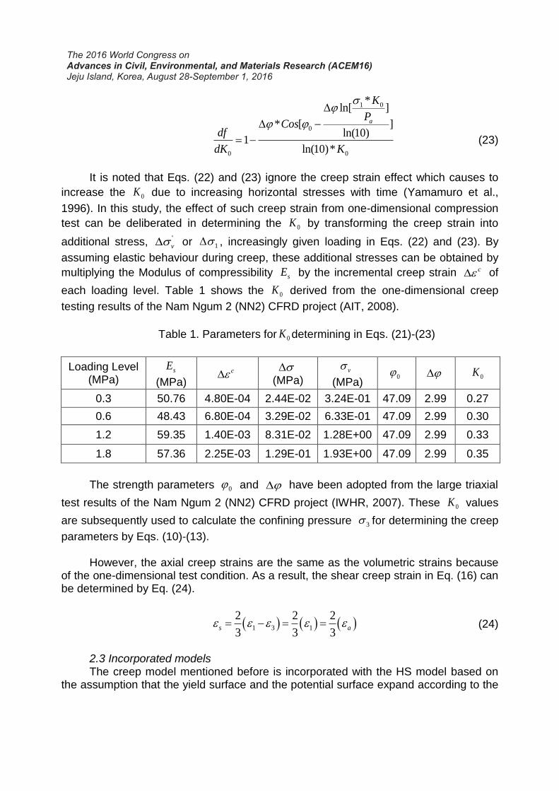
It is noted that Eqs. (22) and (23) ignore the creep strain effect which causes to
increase the 0K due to increasing horizontal stresses with time (Yamamuro et al.,
1996). In this study, the effect of such creep strain from one-dimensional compression
test can be deliberated in determining the 0K by transforming the creep strain into
additional stress, '
v or 1 , increasingly given loading in Eqs. (22) and (23). By
assuming elastic behaviour during creep, these additional stresses can be obtained by
multiplying the Modulus of compressibility sE by the incremental creep strain c of
each loading level. Table 1 shows the 0K derived from the one-dimensional creep
testing results of the Nam Ngum 2 (NN2) CFRD project (AIT, 2008).
Table 1. Parameters for 0K determining in Eqs. (21)-(23)
Loading Level (MPa)
sE
(MPa) c
(MPa)v
(MPa)0 0K
0.3 50.76 4.80E-04 2.44E-02 3.24E-01 47.09 2.99 0.27
0.6 48.43 6.80E-04 3.29E-02 6.33E-01 47.09 2.99 0.30
1.2 59.35 1.40E-03 8.31E-02 1.28E+00 47.09 2.99 0.33
1.8 57.36 2.25E-03 1.29E-01 1.93E+00 47.09 2.99 0.35
The strength parameters 0 and have been adopted from the large triaxial
test results of the Nam Ngum 2 (NN2) CFRD project (IWHR, 2007). These 0K values
are subsequently used to calculate the confining pressure 3 for determining the creep
parameters by Eqs. (10)-(13). However, the axial creep strains are the same as the volumetric strains because of the one-dimensional test condition. As a result, the shear creep strain in Eq. (16) can be determined by Eq. (24).
1 3 1
2 2 2
3 3 3s a (24)
2.3 Incorporated models The creep model mentioned before is incorporated with the HS model based on the assumption that the yield surface and the potential surface expand according to the

creep strain change. Fig.3 illustrates the movement of the yield surface and the plastic potential during the creep strain change presumed in this study. A, B and C are the yield points on monotonic stress-strain curve which assumed the time-independent
relationship. If Aq is constant during given time t , an increase of the strain from A – a
which is the creep strain, affects the yield point movement from A to B on the monotonic stress-strain curve. The stiffness is, therefore, the elastic stiffness if the load is increased from a – B. Then it is the same as the monotonic stress-strain curve. This means that the yield stresses move according to the creep strain magnitude and the material is harder due to the creep strain. According to Lade and Liu (1998), they indicated that the nature of creep strain is similar to that of plastic strains predicted by hardening plasticity framework, i.e., the yield surface and the plastic potential surface move out together during creep. Moreover, the prediction of creep strains could be determined by the same potential surface as from plasticity theory, which is related to the flow rule. From Eq. (2) and (7), the hardening parameters are the function of plastic strains derived from the particular potential of each surface. These plastic strains are assumed to be the same as the creep strains from Eq. (8) and (9) which are the function of the plastic strains with time. This study consequently supposes that the creep strains are the hardening parameter for the HS model. Therefore, the hardening function can be formulated as Eq. (25) and (26). For Shear surface
1
, 33
s a v
p p c c ch t t t t (25)
and for Cap surface
, v
p pc c
vh t t (26)
Fig. 3 Movement of the yield surface and the plastic potential during creep strain change

3. UTILIZATION OF THE HSC MODEL IN CFRD DEFORMATION ANALYSIS 3.1 Implementation of incorporated model into FEM program computer The incorporated model, named as HSC model, is implemented into finite element program ABAQUS via a user material subroutine so-called UMAT. Algorithm of UMAT in ABAQUS is illustrated as a schematic in Fig. 4. Note that it requires specification of a time condition and the duration time of creep, if the time-dependent is specified at each step of the analysis. In this study, the implicit integration method was employed for time-independent analysis while the explicit integration method was adopted for time-dependent analysis.
Fig. 4 The algorithm of UMAT in ABAQUS for the HSC model 3.2 Model Parameters and calibration Model parameters of this study were obtained from the experimental results of the Nam Ngum 2 (NN2) CFRD project including the large triaxial test (IWHR, 2007) and one-dimensional creep test of rockfill materials (AIT, 2008). Table 2 shows the parameters for the HS model which has been calibrated by the authors in Sukkarak et
Start UMAT
Read inputs
Update stresses,
Update state variable
Jacobian, DDSDDE
Incremental stresses,
Check yielding
f<0 ?
Consider yielding state
Shear,Cap,
Double(Shear+Cap)
Return to main
program
Yes
No
t t
Time-dependent
Strain ?
No
Calculate total strains,
Calculate trial (elastic) stresses,tr
t t
Yes
Hardening Soil Model
(HS)
- Axial Creep Strain,
- Volumetric Creep Strain,
Creep Model
ca
cvΔε
Δ
anc
a at A t
vnc
v vt A t
Calculate plastic strains,Δε p Calculate Hardening
parameters,Pp ,Δγp
Δε p
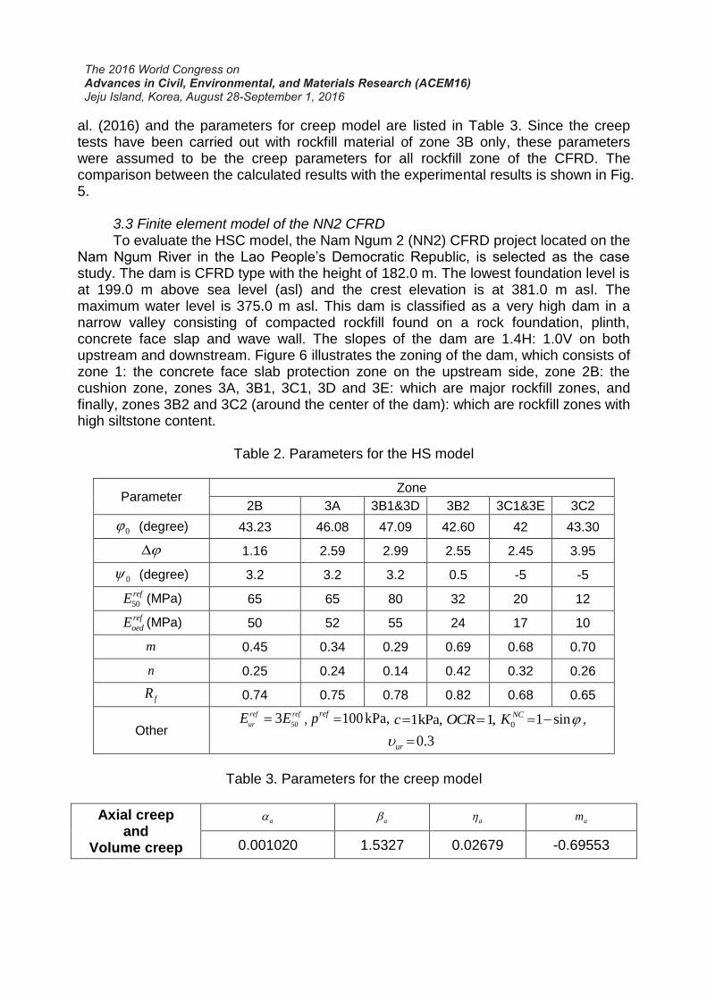
al. (2016) and the parameters for creep model are listed in Table 3. Since the creep tests have been carried out with rockfill material of zone 3B only, these parameters were assumed to be the creep parameters for all rockfill zone of the CFRD. The comparison between the calculated results with the experimental results is shown in Fig. 5. 3.3 Finite element model of the NN2 CFRD To evaluate the HSC model, the Nam Ngum 2 (NN2) CFRD project located on the Nam Ngum River in the Lao People’s Democratic Republic, is selected as the case study. The dam is CFRD type with the height of 182.0 m. The lowest foundation level is at 199.0 m above sea level (asl) and the crest elevation is at 381.0 m asl. The maximum water level is 375.0 m asl. This dam is classified as a very high dam in a narrow valley consisting of compacted rockfill found on a rock foundation, plinth, concrete face slap and wave wall. The slopes of the dam are 1.4H: 1.0V on both upstream and downstream. Figure 6 illustrates the zoning of the dam, which consists of zone 1: the concrete face slab protection zone on the upstream side, zone 2B: the cushion zone, zones 3A, 3B1, 3C1, 3D and 3E: which are major rockfill zones, and finally, zones 3B2 and 3C2 (around the center of the dam): which are rockfill zones with high siltstone content.
Table 2. Parameters for the HS model
Parameter Zone
2B 3A 3B1&3D 3B2 3C1&3E 3C2
0 (degree) 43.23 46.08 47.09 42.60 42 43.30
1.16 2.59 2.99 2.55 2.45 3.95
0 (degree) 3.2 3.2 3.2 0.5 -5 -5
50
refE (MPa) 65 65 80 32 20 12
ref
oedE (MPa) 50 52 55 24 17 10
m 0.45 0.34 0.29 0.69 0.68 0.70
n 0.25 0.24 0.14 0.42 0.32 0.26
fR 0.74 0.75 0.78 0.82 0.68 0.65
Other
503ref ref
urE E , 100 kPa,refp 1kPa,c 1,OCR 0 1 sinNCK ,
0.3 ur
Table 3. Parameters for the creep model
Axial creep and
Volume creep
a a a am
0.001020 1.5327 0.02679 -0.69553

Fig. 5 Compared simulation results with testing results
Fig. 6 Typical Section of the Nam Ngum 2 CFRD The dam embankment is modelled by the finite element program ABAQUS as 2-D Plane Strain of the largest cross-section of the dam. The finite element mesh is 3-node triangular elements consists of 2,374 elements and 1,263 nodes as shown in Fig.7. The concrete membrane and a parapet are not the issue in this study. They are thus not modelled. The boundary conditions were defined in terms of fixed displacements at the bottom and outer sides of the rock foundation, whose dimensions are 100×1000×1000 m (height×width×depth). The rock foundation and abutment were assumed to be linearly elastic, with a Young's modulus of 5.0 GPa and a Poisson's ratio of 0.2. The purposes of the simulation are to analyses and compare the settlement results at the end of construction stage of the dam between by using the HS and HSC models. Consequently, the construction loading is divided into 21 steps and the duration time of rockfill creep for each step is 15 days. As calibrated results in Fig.6, it shows the
adequacy of the time period size t , that is 1 min, for this study.
1E-3 0.01 0.1 1 10 100 1000 10000
1E-3
0.01
0.1
Test 0.30 MPa
Simulatiom 0.30 MPa
Test 0.60 MPa
Simulatiom 0.60 MPa
Test 1.20 MPa
Simulatiom 1.20 MPa
Test 1.80 MPa
Simulatiom 1.80 MPa
a (
%)
Time (min)

Fig. 7 The finite element mesh of the Nam Ngum 2 CFRD 3.4 Analysis results The contours of vertical displacement or settlement of the simulated dam are shown in Fig. 8 for both the HS and HSC models. It can be seen that both models display the same tendency but different magnitude. The settlement predicted by the HSC model is generally greater than that predicted by the HS model. The maximum settlement calculated by the HS model is 1.686 m. while it is 1.922 m. for the HSC model. The maximum settlements for both cases occur in zones 3C (slightly downstream) because the stiffness of this zone is lower than those of the other zones.
Fig. 8 The finite element mesh of the Nam Ngum 2 CFRD
-250 -200 -150 -100 -50 0 50 100 150 200 250
2B
3A 3E
3B1
3C23B2
3C1
3D
-250 -200 -150 -100 -50 0 50 100 150 200 250
2B
3A 3E
3B1
3C23B2
3C1
3D
Dam offset (m)
(b) Simulation results from
HSC model
(a) Simulation results from
HS model
-250 -200 -150 -100 -50 0 50 100 150 200 250
-2.0-1.9-1.8-1.7-1.6-1.5-1.4-1.3-1.2-1.1-1.0-0.9-0.8-0.7-0.6-0.5-0.4-0.3-0.2-0.10.0
2B
3A 3E
-250 -200 -150 -100 -50 0 50 100 150 200 250
-2.0-1.9-1.8-1.7-1.6-1.5-1.4-1.3-1.2-1.1-1.0-0.9-0.8-0.7-0.6-0.5-0.4-0.3-0.2-0.10.0
2B
3A 3E
Material zones
Vertical displacement (m)
Settlement (-)
Elev. 259 m.asl.
Elev. 319 m.asl.
Elev. 259 m.asl.
Elev. 319 m.asl.

Fig.9 displays the comparison between the predicted results and the monitored data by Hydrostatic Settlement Cells at Elev. 259 m.asl and Elev. 319 m.asl. The predicted results by the HSC model are closer to the monitoring data than those by the HS model. From the described comparisons, it is clear that the HS and HSC models reproduce different behaviors in terms of the magnitude of deformations because of the effect of time. Moreover, the predicted results achieve satisfactory agreement with the field monitoring data, although slight different in prediction is apparent.
Fig. 9 Compared result of simulation with monitoring data
4. CONCLUSIONS In this paper, the creep model was incorporated with the Hardening soil (HS) model, so called HSC model. The developed creep model had been developed from the large triaxial testing results of rockfill material considering the influence of confining pressure. It was further developed for applying to the one-dimensional creep tests which the calibration show in good agreement between calculated results and experimental results. The HSC model was incorporated via the modified hardening function depending on the time effect. This model was implemented into finite element program ABAQUS as a subroutine, so called UMAT. To evaluate the model, the 2D Plane Strain analysis of the Nam Ngum 2 (NN2) CFRD project was performed. Comparisons between the predicted results and the monitoring data indicate that the HSC model is able to reasonably predict the settlement behaviors in the dam body. The trends of the settlement contours are reasonably well captured and the computed magnitudes are generally in acceptable agreement with the observed data. However,
the duration time of creep and the time period size t are the significantly influence on the predicted settlement. In addition, this dam is classified as a very high dam in a narrow valley, consequently, full three-dimensional analysis is necessary. ACKNOWLEDGMENTS The authors gratefully acknowledge the financial support of the Thailand Research Fund (TRF) and King Mongkut’s University of Technology Thonburi through
-2
-1
0-160 -120 -80 -40 0 40 80 120 160
Settle
men
t (m
)
-2
-1
0-160 -120 -80 -40 0 40 80 120 160
Settle
men
t (m
)
-2
-1
0-160 -120 -80 -40 0 40 80 120 160
Settle
men
t (m
)
Hydraulic Settlement Cells
3.1-3.5
-2
-1
0-160 -120 -80 -40 0 40 80 120 160
End of Stage Construction
Monitoring data at Elev. 259 m.asl.
Monitoring data at Elev. 319 m.asl.
Simulation results from HS model
Simulation results from HSC model
Settle
men
t (m
)
Hydraulic Settlement Cells
3.7-3.12
Dam offset (m)
Upstream
Downstream
Dis
p. (m
)
Dis
p. (m
)
Dam axis
Elev. 259 m.asl.
Elev. 199 m.asl.
Elev. 319 m.asl.
Elev. 381 m.asl.

the Royal Golden Jubilee Ph.D. program, under contract grant PHD/0006/2556. They are also indebted to the CK Power Public Company Limited and Nam Ngum 2 Power Company Limited for providing the valuable data. REFERENCES AIT (2008), Creep Testing on Rockfill Material, Laboratory Test Report, Geotechnical and Geoenvironmental Laboratory, Asian Institute of Technology, Thailand. Arici, Y.L. (2011), “Investigation of the cracking of CFRD face plates.” Computers and Geotechnics, Vol. 38, 905-916. Bishop, A.W. (1958), “Test Requirements for Measuring the Coefficient of Earth Pressure at Rest”, Proceedings, Brussels Conference on Earth Pressure Problems, Vol. 1, 2-14. Charles, J.A. and Watts, K.S. (1980) “The influence of confining pressure on the shear strength of compacted rockfill.” Géotechnique, Vol. 30(4) 353-367. Chen, W., Jian-Wei, Z. and Peng, H. (2014), “Creep Properties of Rockfill Materials with Fractal Structure in Mass.” Electronic Journal of Geotechnical Engineering, Vol. 19, 2713-2722. Cheng, Z.L. and Ding, H.S. (2004), “Creep test for rockfill.” Chinese Journal of Geotechnical, Vol. 26(4), 473-476. Chu, J. and Gan, C.L. (2004), “Effect of void ratio on K0 of loose sand.” Géotechnique, Vol. 54(4), 285–288. Gu, X.Q., Hu, J. and Huang, M.S. (2015), “K0 of granular soils: a particulate approach.” Granular Matter, Vol. 17(6), 703–715. Guo, P. (2010), “Effect of density and compressibility on K0 of cohesionless soils.” Acta Geotechnica. Vol. 5(4), 225–238. IWHR (2007), Report on Laboratory Tests of the Rockfill Materials of Nam Ngum 2 CFRD, Institute of Water Resources and Hydropower Research, Beijing, China. Jaky, J. (1944). "The Coefficient of Earth Pressure at Rest." Journal of the Society of Hungarian Architects and Engineers, Vol. 7, 355-358. Lade, P.V. and Liu, C.-T. (1998), “Experimental Study of Drained Creep Behavior of Sand.” J. Engrg. Mech., ASCE, Vol. 124(8), 912-920. Lee, J., Yun, T.S., Lee, D. and Lee, J. (2013), “Assessment of K0 correlation to strength for granular materials.” Soils and Foundations, Vol. 53(4), 584-595.

The 2016 World Congress on Advances in Civil, Environmental, and Materials Research
Li, H.F. and Zhang, Y.Q. (2012), “Creep rate and creep model of rockfill.” Procedia Engineering, Vol. 28, 796-802. Lirer, S., Flora, A. and Nicotera M.V. (2011), “Some remarks on the coefficient of earth pressure at rest in compacted sandy gravel.” Acta Geotechnica, Vol. 6, 1–12. Oldecop, L.A. and Alonso, E.E. (2007), “Theoretical investigation of time-dependent behaviour of rockfill.” Géotechnique, Vol. 57(3), 289-301. Ö zkuzukiran, S., Ö zkan, M.Y., Ö zyazicioğlu, M. and Yildiz, G.S. (2006), “Settlement behaviour of a concrete faced rock-fill dam.” Geotechnical and Geological Engineering, Vol. 24, 1665–1678. Phutthananon, C. (2015), Deformation Analysis of CFRD with Consideration of Time-Dependent Behaviour, Master of Engineering Thesis, King Mongkut’s University of Technology Thonburi, Thailand. Pramthawee P., Jongpradist P. and Kongkitkul W. (2011), “Evaluation of hardening soil model on numerical simulation of behaviors of high rockfill dams,” Songklanakarin J. Sci. Technol., Vol. 33(3), 325-334. Schanz, T., Vermeer, P.A. and Bonnier, P.G. (1999), “The hardening soil model -formulation and verification”, Proceedings plaxis symposium Beyond 2000 in computational geotechnics, Amsterdam, Rotterdam, Balkema, 281–96. Soroush, A. and Araei, A.A. (2006), “Analysis of behaviour of a high rockfill dam” Proceedings of the ICE - Geotechnical Engineering, Vol. 159(1), 49-59. Sukkarak, R., Pramthawee, P. and Jongpradist, P. (2016), “A Modified Elasto-plastic Model with Double Yield Surfaces and Considering Particle Breakage for the Settlement Analysis of High Rockfill Dams.” KSCE Journal of Civil Engineering, Geotechnical Engineering, Vol. 0(0), 1-12. Yamamuro, J.A., Bopp, P.A. and Lade, P.V. (1996), "One-Dimensional Compression of Sands at High Pressures." Journal of Geotechnical Engineering, ASCE, Vol. 122(2), 147-154. Zhang, B.Y., Wang, J.G. and Shi, R.F. (2004), “Time-dependent deformation in high concrete faced rockfill dam and separation between concrete face slab and cushion layer.” Computers and Geotechnics, Vol. 31, 559-573.
Related Documents