Incorporation of a laser range scanner into image-guided liver surgery: Surface acquisition, registration, and tracking David M. Cash a) and Tuhin K. Sinha Department of Biomedical Engineering, Vanderbilt University, Box 351631, Station B, Nashville, Tennessee 37235 William C. Chapman Department of Surgery and Cell Biology, Section of Transplantation, Washington University School of Medicine, 6107 Queeny Tower, St. Louis, Missouri63110 Hiromi Terawaki Department of Biomedical Engineering, Duke University, Durham, North Carolina 27708 Benoit M. Dawant Department of Electrical Engineering and Computer Sciences, Vanderbilt University, Box 1662, Station B, Nashville, Tennessee 37235 Robert L. Galloway and Michael I. Miga Department of Biomedical Engineering, Vanderbilt University, Box 351631, Station B, Nashville, Tennessee 37235 ~Received 16 December 2002; revised 15 March 2003; accepted for publication 14 April 2003; published 23 June 2003! As image guided surgical procedures become increasingly diverse, there will be more scenarios where point-based fiducials cannot be accurately localized for registration and rigid body assump- tions no longer hold. As a result, procedures will rely more frequently on anatomical surfaces for the basis of image alignment and will require intraoperative geometric data to measure and com- pensate for tissue deformation in the organ. In this paper we outline methods for which a laser range scanner may be used to accomplish these tasks intraoperatively. A laser range scanner based on the optical principle of triangulation acquires a dense set of three-dimensional point data in a very rapid, noncontact fashion. Phantom studies were performed to test the ability to link range scan data with traditional modes of image-guided surgery data through localization, registration, and tracking in physical space. The experiments demonstrate that the scanner is capable of localizing point-based fiducials to within 0.2 mm and capable of achieving point and surface based registrations with target registration error of less than 2.0 mm. Tracking points in physical space with the range scanning system yields an error of 1.460.8 mm. Surface deformation studies were performed with the range scanner in order to determine if this device was capable of acquiring enough information for compensation algorithms. In the surface deformation studies, the range scanner was able to detect changes in surface shape due to deformation comparable to those detected by tomographic image studies. Use of the range scanner has been approved for clinical trials, and an initial intra- operative range scan experiment is presented. In all of these studies, the primary source of error in range scan data is deterministically related to the position and orientation of the surface within the scanner’s field of view. However, this systematic error can be corrected, allowing the range scanner to provide a rapid, robust method of acquiring anatomical surfaces intraoperatively. © 2003 American Association of Physicists in Medicine. @DOI: 10.1118/1.1578911# I. INTRODUCTION Tissue deformation and organ shift are presently one of the largest challenges that image-guided surgery research faces today. To overcome these obstacles, there have been numer- ous efforts to incorporate intraoperative data into surgical navigation as well as to model the deformation using biome- chanical principles. The most accurate and complete method to account for tissue deformation is to acquire image data during surgery with intraoperative tomographic imaging. In- traoperative CT was proposed, 1 but it was found to expose the patient to excessive amounts of radiation. More recently, intraoperative MR ~iMR! imaging has become a candidate to account for tissue deformation. There have been many groups who have implemented iMR into their image-guided surgical systems, and a sampling of the research can be found in the literature. 2–7 While iMR does provide a complete set of updated volu- metric data, there are some disadvantages. Currently, it is difficult, time-consuming, and expensive to install an intra- operative magnetic resonance unit into an operating suite. MR scanners ~including open magnet configurations! and head receiver coils, combined with the limited space gener- ally available in operating rooms, can hinder access to the surgical site. 8 Nonferrous surgical instruments, often not of the same quality as standard surgical instruments, must be used during procedures close to the magnet. 8,9 Finally, there are issues with image quality, whether from low field 1671 1671 Med. Phys. 30 „7…, July 2003 0094-2405Õ2003Õ30„7…Õ1671Õ12Õ$20.00 © 2003 Am. Assoc. Phys. Med.

Welcome message from author
This document is posted to help you gain knowledge. Please leave a comment to let me know what you think about it! Share it to your friends and learn new things together.
Transcript

Incorporation of a laser range scanner into image-guided liver surgery:Surface acquisition, registration, and tracking
David M. Casha) and Tuhin K. SinhaDepartment of Biomedical Engineering, Vanderbilt University, Box 351631, Station B, Nashville,Tennessee 37235
William C. ChapmanDepartment of Surgery and Cell Biology, Section of Transplantation, Washington University School ofMedicine, 6107 Queeny Tower, St. Louis, Missouri 63110
Hiromi TerawakiDepartment of Biomedical Engineering, Duke University, Durham, North Carolina 27708
Benoit M. DawantDepartment of Electrical Engineering and Computer Sciences, Vanderbilt University, Box 1662, Station B,Nashville, Tennessee 37235
Robert L. Galloway and Michael I. MigaDepartment of Biomedical Engineering, Vanderbilt University, Box 351631, Station B, Nashville,Tennessee 37235
~Received 16 December 2002; revised 15 March 2003; accepted for publication 14 April 2003;published 23 June 2003!
As image guided surgical procedures become increasingly diverse, there will be more scenarioswhere point-based fiducials cannot be accurately localized for registration and rigid body assump-tions no longer hold. As a result, procedures will rely more frequently on anatomical surfaces forthe basis of image alignment and will require intraoperative geometric data to measure and com-pensate for tissue deformation in the organ. In this paper we outline methods for which a laser rangescanner may be used to accomplish these tasks intraoperatively. A laser range scanner based on theoptical principle of triangulation acquires a dense set of three-dimensional point data in a veryrapid, noncontact fashion. Phantom studies were performed to test the ability to link range scan datawith traditional modes of image-guided surgery data through localization, registration, and trackingin physical space. The experiments demonstrate that the scanner is capable of localizing point-basedfiducials to within 0.2 mm and capable of achieving point and surface based registrations withtarget registration error of less than 2.0 mm. Tracking points in physical space with the rangescanning system yields an error of 1.460.8 mm. Surface deformation studies were performed withthe range scanner in order to determine if this device was capable of acquiring enough informationfor compensation algorithms. In the surface deformation studies, the range scanner was able todetect changes in surface shape due to deformation comparable to those detected by tomographicimage studies. Use of the range scanner has been approved for clinical trials, and an initial intra-operative range scan experiment is presented. In all of these studies, the primary source of error inrange scan data is deterministically related to the position and orientation of the surface within thescanner’s field of view. However, this systematic error can be corrected, allowing the range scannerto provide a rapid, robust method of acquiring anatomical surfaces intraoperatively. ©2003American Association of Physicists in Medicine.@DOI: 10.1118/1.1578911#
tham
icae
thaIn
ttoan
edbe
lu-it isa-ite.
er-theoft be
ld
I. INTRODUCTION
Tissue deformation and organ shift are presently one oflargest challenges that image-guided surgery research ftoday. To overcome these obstacles, there have been nuous efforts to incorporate intraoperative data into surgnavigation as well as to model the deformation using biomchanical principles. The most accurate and complete meto account for tissue deformation is to acquire image dduring surgery with intraoperative tomographic imaging.traoperative CT was proposed,1 but it was found to exposethe patient to excessive amounts of radiation. More recenintraoperative MR~iMR! imaging has become a candidateaccount for tissue deformation. There have been m
1671 Med. Phys. 30 „7…, July 2003 0094-2405 Õ2003Õ30„7…
eceser-l-
odta-
ly,
y
groups who have implemented iMR into their image-guidsurgical systems, and a sampling of the research canfound in the literature.2–7
While iMR does provide a complete set of updated vometric data, there are some disadvantages. Currently,difficult, time-consuming, and expensive to install an introperative magnetic resonance unit into an operating suMR scanners~including open magnet configurations! andhead receiver coils, combined with the limited space genally available in operating rooms, can hinder access tosurgical site.8 Nonferrous surgical instruments, often notthe same quality as standard surgical instruments, musused during procedures close to the magnet.8,9 Finally, thereare issues with image quality, whether from low fie
1671Õ1671Õ12Õ$20.00 © 2003 Am. Assoc. Phys. Med.
as
sencejenr
un
inelu
erli
om
th
a
ra.w
a
gsii
ua
ioioda
ac
s
s
our
ntcg
idswth
m-
n-er,offned
re-wnandnse. It500
is-de-in-s.
.
ere
oftheAhnisver-ss.
n aainte,
hani-
1672 Cash et al. : Laser range scanning in image-guided liver surgery 1672
strength magnets or from surgically induced contrenhancement.10
Other methods have been proposed to help compenfor tissue deformation during surgery. Ultrasound is convtionally used to provide real-time information for guidanduring surgical procedures. Currently, most surgeons subtively analyze data from ultrasound to make their decisioregarding tissue deformation. However, there is somesearch concerned with mathematically integrating ultrasointo image-guided neurosurgery systems.11–14
Some methods of deformation compensation do notvolve any intraoperative imaging. Finite element modhave been used to predict organ deformation that resfrom various events that occur during surgery. Since a mjority of image-guided research is based in neurosurgwhere accuracy is paramount, most surgical-based modestudies have been performed with respect to the brain. Srecent strategies used for modeling the biomechanicsbrain deformation have included biphasic descriptions ofcontinuum based on consolidation theory.15 These modelssimulate deformation effects from mechanical loadingwell as from interstitial fluid flow.16,17 Edwardset al.18 de-veloped a three-component model to account for the intetions between bone, cerebrospinal fluid, and brain tissueother cases, finite element modeling is not as concernedthe underlying biomechanics of the tissue, but rather asinterpolation method for registration.6 Other models of thebrain that have been proposed use linear elastic19 andviscoelastic20 models. In large part, finite element modelinhas not been used for image-guided surgical updating outthe neurosurgical context. However, computer models arecreasingly being used for planning, simulation, and evaltion applications for a host of surgical procedures.21–25
One novel method of intraoperative data acquisitionlaser range scanning. This modality acquires a dense amof surface data, which is represented as a three-dimenspoint cloud. Unlike most surface acquisition methods usean operating room, laser range scanners do not requirecontact with the patient. Preliminary work by Audetteet al.26
has examined laser range scanning for cortical surface tring and brain shift issues. Raabeet al.27 illuminated the skinsurface with a laser and used optical localization systemtriangulate the depth of the laser spot. Furushiroet al.28 haveused range scanners to detect ridgelines in liver phantomregistration purposes. In other phantom studies, Sinhaet al.29
registered range scanner data with texture mapped videformation to MR volumes using the simulated cortical sface vessel patterns.
We present accuracy studies characterizing the rascanner’s ability to capture organ shape. Registration tomographic image data and optical localization methods teniques are implemented to determine the ability for ranscan data to be used accurately with common image-gusurgery components. Additionally, the range scanner is uto observe deformation in an organ phantom. Finally,present some of our initial experiences with the use oflaser range scanner in a clinical setting.
Medical Physics, Vol. 30, No. 7, July 2003
t
ate-
c-se-d
-sltsa-y,ng
eofe
s
c-Inithn
den--
suntnalinny
k-
to
for
in--
geo-h-eededee
II. METHODS
A. Laser scanner
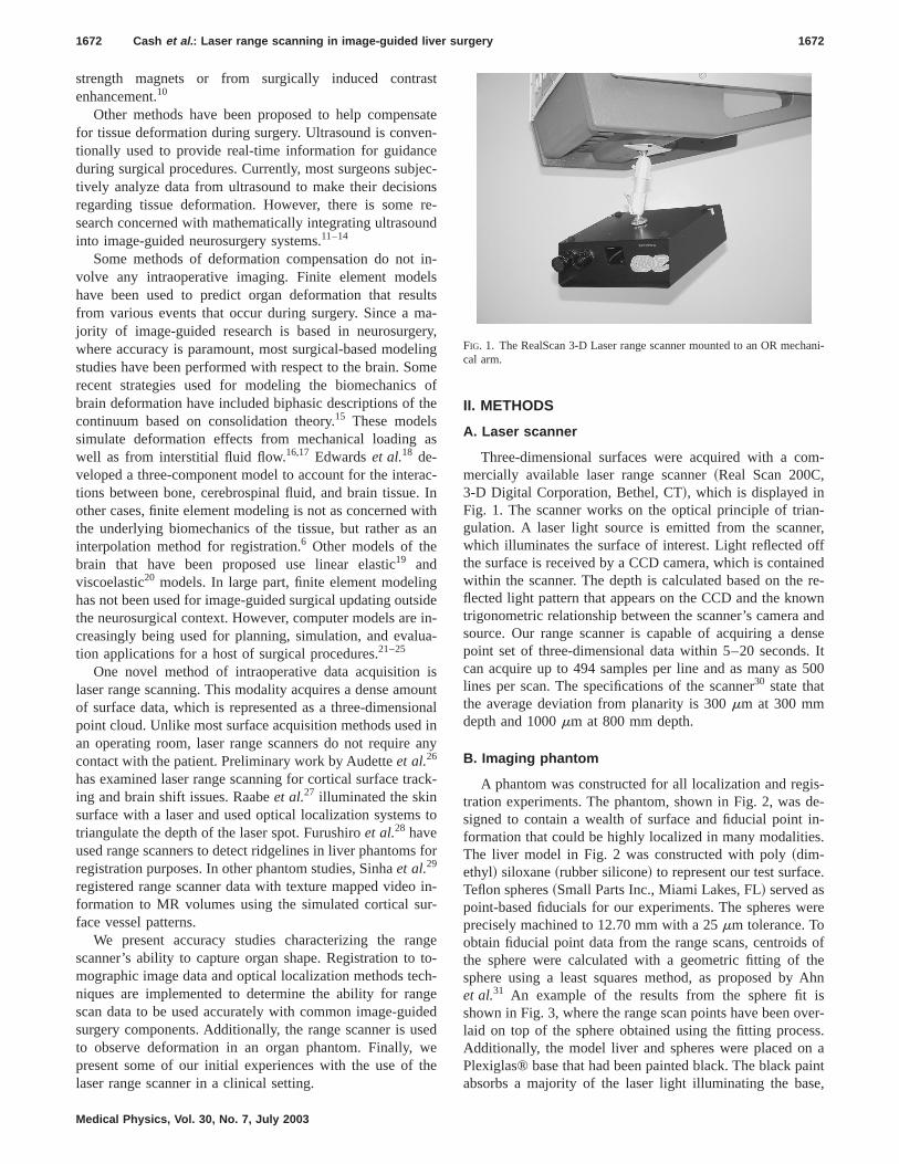
Three-dimensional surfaces were acquired with a comercially available laser range scanner~Real Scan 200C,3-D Digital Corporation, Bethel, CT!, which is displayed inFig. 1. The scanner works on the optical principle of triagulation. A laser light source is emitted from the scannwhich illuminates the surface of interest. Light reflectedthe surface is received by a CCD camera, which is contaiwithin the scanner. The depth is calculated based on theflected light pattern that appears on the CCD and the knotrigonometric relationship between the scanner’s camerasource. Our range scanner is capable of acquiring a depoint set of three-dimensional data within 5–20 secondscan acquire up to 494 samples per line and as many aslines per scan. The specifications of the scanner30 state thatthe average deviation from planarity is 300mm at 300 mmdepth and 1000mm at 800 mm depth.
B. Imaging phantom
A phantom was constructed for all localization and regtration experiments. The phantom, shown in Fig. 2, wassigned to contain a wealth of surface and fiducial pointformation that could be highly localized in many modalitieThe liver model in Fig. 2 was constructed with poly~dim-ethyl! siloxane~rubber silicone! to represent our test surfaceTeflon spheres~Small Parts Inc., Miami Lakes, FL! served aspoint-based fiducials for our experiments. The spheres wprecisely machined to 12.70 mm with a 25mm tolerance. Toobtain fiducial point data from the range scans, centroidsthe sphere were calculated with a geometric fitting ofsphere using a least squares method, as proposed byet al.31 An example of the results from the sphere fitshown in Fig. 3, where the range scan points have been olaid on top of the sphere obtained using the fitting proceAdditionally, the model liver and spheres were placed oPlexiglas® base that had been painted black. The black pabsorbs a majority of the laser light illuminating the bas
FIG. 1. The RealScan 3-D Laser range scanner mounted to an OR meccal arm.

aseu
tinat tnTykll
. F
vech
rfacelized
ithinthewithereis-
ial inan-us-
eved
toandng al,tryen.du-
y
c-the
l-mP
ror,urcergetylonnot
t fortiontheyace
theandthe. Inan-in
co-p-ed
llsela
efr
er
1673 Cash et al. : Laser range scanning in image-guided liver surgery 1673
and the reflected light signal is so small that it simulatesinfinite distance. As a result, no range scan data of the baacquired, making the phantom liver and the spheres measier to identify.
C. Point-based localization
To determine the scanner’s accuracy in acquiring spasurface information, three sets of localization experimewere performed. The first experiment investigated the scner’s ability to acquire images of the sphere with respecthe scanner’s field of view. A sphere was placed on a tralation stage and repeatedly scanned while varying depth.next set of experiments attempted to test the repeatabilitthe scanner output. A total of ten range scans were tawhile holding the phantom and range scanner fixed. Ideathe centroid of each sphere should remain unchanged
FIG. 2. The imaging phantom consists of a model organ surface as wewhite Teflon balls used as fiducials. To eliminate unwanted data, the bathe phantom has been painted black so there will not be enough signathe range scanner to calculate depth at that point, making the surfacefiducials easier to identify.
FIG. 3. An example of the sphere-fitting algorithm. The black dots represpoints from the range scanner and the gray sphere is the sphere fittedthis data. If a point is completely visible, then it lies outside the sphsurface. Points inside the sphere are partially or completely obscured.
Medical Physics, Vol. 30, No. 7, July 2003
nis
ch
altsn-os-heofeny,i-
nally, the ability to track objects in space as they mothroughout the scanner’s field of view was tested. After easphere was acquired from the range scan image, the suof each sphere was collected using a probe that was locain physical space using an infrared optical camera~OP-TOTRAK 3020, Northern Digital, Waterloo, Ontario!. TheOPTOTRAK system has an RMS accuracy of 0.1 mm, wa resolution of 0.01 mm.32 After each sphere was acquiredthe scene, the phantom was manually moved away fromrange scanner. Three sets of sphere data were acquiredthe range scanner and the OPTOTRAK; all three sets wpositioned at varying depths from the range scanner. Dtance measurements were calculated between each fiducone data set and its corresponding position when the phtom was placed at a different depth. Distances measureding range scan data were compared to the results achiwith the OPTOTRAK localization system.
D. Registration
A set of experiments was performed to test the abilityregister range scan data with CT image data using pointsurface based information. The phantom was imaged usiCT scanner~Mx8000—Phillips Medical Systems, BothelWA!. While the phantom remained on the imaging ganafter volume acquisition, range scan images were takPoint-based registrations with the sphere centroids as ficials were achieved using Horn’s quaternion method33 tosolve the singular value decomposition~SVD!, as well as amodification which allows for incorporating a similarittransform with an isotropic scaling factor.34 The use of ascaling factor is explained further in the ‘‘Discussion’’ setion. Surface based registrations were performed usingIterative Closest Point~ICP! algorithm postulated by Besand McKay,35 altered to usek-d dimensional trees to decrease search time.36,37 Landmarks on the surface phantowere used to obtain an initial transformation for the ICmethod. ICP minimizes the mean surface residual erwhich is the mean distance between each point in the sodataset and its corresponding closest point in the tadataset. One point-based landmark, the head of a nscrew that secured the liver phantom to the base, wasused in either registration process. It served as a targeerror analysis of the registration. For the surface registraresults, the Teflon balls also served as targets, sincewere not used to determine the transformation in the surfregistration process.
E. Physical space tracking
One of the foundations of image-guided surgery isestablishment of a registration between image spacephysical space. By incorporating a range scanner intosystem, a third coordinate system has been introducedorder to interpret geometric data from the laser range scner, it is critical that the range scanner can be trackedphysical space. Tracking is accomplished by defining aordinate system for physical space with the OPTOTRAK otical localization system. A star-shaped rigid body embedd
asof
fornd
ntome

izon
gel
a-n
ithrt
rvmK
o-hateis
midkca
in
siedntiriva
dyqa
trix
er-ac-
chtain-
itso-ono-ed
ixnewalach
anddataing
e
ofrial.ac-ys-
l so
forfor-calpro-rnot
tio
bttin eri-
1674 Cash et al. : Laser range scanning in image-guided liver surgery 1674
with infrared emitting diodes~IREDs! was attached to therange scanner. This rigid body was calibrated and recognby the OPTOTRAK localization system, so that its positiand orientation could be established in real-time.
The tracking setup is shown in Fig. 4. Points in ranscanner space,Xrange, are transformed into the physicaspace,Xopto, by determining two intermediate transformtions. The first transformation is between the range scanand the star-shaped rigid body attached to it,Trange-star. Acalibration process, described below, is needed to determthis transformation, which remains constant as long asstar-shaped emitter remains rigidly fixed to range scannethe same position. The second transformation is betweenstar-shaped rigid body, and the reference emitter that seas the origin for the OPTOTRAK coordinate systeTstar-opto. This transformation is handled by the OPTOTRAsystem, and it is refreshed at a rate of 40 Hz.
A calibration phantom was designed for the processdetermining the transformationTrange-starbetween the starshaped emitter and the range scanner. The calibration ptom consisted of nine white disks of radius 9.53 mm locaon nine separate black platforms. At the center of the dwas a 3 mmhemispherical divot. When placing the 3 mball tip of a tracked surgical probe in the divot, the centroof the tip will be localized near the center of the white disFigure 5 shows an optically localized probe with its spheritip located in the divot.
The first step in calibrating the range scanner for trackin physical space~i.e., OPTOTRAK space! is to establish atransformation between range scanner space and physpace (Trange-opto) while the range scanner is held at a fixposition. This transformation is achieved through a poibased registration between the centroid of each disk acqufrom the range scanner, and the nine corresponding dlocations from the OPTOTRAK probe. Once this transformtion is known, the position and orientation of the rigid boemitter attached to the range scanner is ascertained byrying the OPTOTRAK system, which gives the transformtion Tstar-opto. Using Trange-optoand Tstar-optoat a given fixed
FIG. 4. The calibration process used to determine the transforma(Trange-star) between the range scanner (Xrange) and the attached rigid body(Xstar). Once this transformation is known, range scanner points cantransformed into physical space, since the OPTOTRAK is always outputhe transformation between the two emitters (Tstar-opto).
Medical Physics, Vol. 30, No. 7, July 2003
ed
er
neeinhees,
f
n-dk
.l
g
cal
-edot-
ue--
range scanner position, the calibration transformation maTrange-starcan be determined.
To test the calibration process, multiple trials were undtaken and compared against each other to determine thecuracy and repeatability of this protocol. In between eatrial, the range scanner was moved out of the scene coning the phantom and then returned approximately back tooriginal position, in order to mimic the data acquisition prcess during surgery; however, for all trials the calibratiphantom was held fixed in relation to the OPTOTRAK cordinate system. The calibration procedure was performand a calibration transformation matrixTrange-star was ob-tained for each trial. If the calibration transformation matrwas accurate, then new range scan data acquired at aposition in space should ideally result in identical physicspace locations as those acquired during calibration. For eset of trials, one was designated as the calibration trial,the others were designated as test trials. Range scanfrom the test trials was transformed into physical space usEq. ~1!;
Xopto5Tstar-optoTrange-starXrange. ~1!
The calibration trial was responsible for providing thcalibration transformation matrixTrange-star, while Tstar-opto
was used from a test trial, since it represents the positionthe range scanner in physical space for that particular tThe result from this transformation was compared to thetual physical space data acquired from the localization stem. Every trial was selected once as the calibration triathat all the calibration results could be examined.
F. Deformation effects on registration
One important aspect to developing an IGS platformliver surgery is to understand the effects of soft-tissue demation on registration accuracy. Within the neurosurgicontext, soft tissue deformations have been show to commise IGS fidelity.38,39 To date, a systematic study of livedeformations and their effects on target localization have
n
egFIG. 5. The calibration phantom with an optical probe and its 3 mm sphcal tip placed in the divot of one of the nine white disks.
sesu
CerdeCaimricde
donale
tioau
thileieigeonerootore
ugfoatngf
CTnadataesmonoith
-gerean
Thnh
calitialandtheint
Fig.
nernge
icalrs ofthetantthe
aswereroid
foridualposi-ver
ntssedach.1–theces
e Ieans isnot
he;om
1675 Cash et al. : Laser range scanning in image-guided liver surgery 1675
been reported. In this study, realistic liver phantoms are uto estimate the effects of misregistration due to soft tisdeformation.
The nondeformed surface phantom was placed on thegantry and imaged. This volume represented our preoptive baseline. After imaging, a range scan of the nonformed liver phantom was acquired. Two more sets ofand range scanning were obtained while deforming the phtom surface in two separate areas, resulting in three CTage sets and three range scanner point clouds. A cylindobject of height 3.7 cm and radius 7.5 cm was placed unneath the organ phantom to cause the deformation. Thisformation was intended to mimic the physical manipulatiand repositioning of the mobilized liver during a surgicprocedure. In the first scan, the object was under thelobe, and in the second, it was located under the juncbetween segments III and IV, as defined by the Couinsegmental anatomy of the liver.40 The rest of the organ isheld in place with a screw, which has been inserted intobase, allowing a portion of the organ model to deform whthe rest stays relatively fixed. The initial phantom studexamined the effects of deformation on an ICP-based rregistration algorithm. A registration between nondeformand deformed data was calculated. Six mock tumors, cstructed out of Styrofoam, were inserted into the silicoorgan model before it solidified. These mock tumors wspherical in shape with a radius of 11.0 mm. The tumcentroids served as targets for this registration. Both tomraphic data and range scan data of the deformed phanwere used to determine the effectiveness of ICP in thisgard.
It is imperative that the range scanner provides enointraoperative surface data to correctly discern organ demation. If the transformation resulting from range scan dis similar to results using tomographic data, then the rascanner should be capturing enough surface informationthis task. All range scan data is first transformed intospace, so that all data are aligned in the same coordisystem. Two registrations between deformed and nonformed data are performed: one using range scan dataone using tomographic data. The deformed range scan datransformed into nondeformed space using both of thtransformations. Since the same point set was transfortwice, it has generated two new point sets with a one-to-correspondence. The distance between corresponding pis calculated in order to determine the similarity betweentwo transformations.
G. Intraoperative acquisition
Institutional Review Board~IRB! approval has been obtained at Vanderbilt University for the acquisition of ranscan and optical localization data during surgical proceduon the liver. Once informed consent has been obtainedthe preparation for surgery is underway, the range scanand star-shaped emitter are mounted to a surgical arm.surgical arm can be swiveled into the scene so that the rascanner is approximately 1 to 2 feet away from the liver. T
Medical Physics, Vol. 30, No. 7, July 2003
de
Ta--
Tn--alr-e-
lftnd
e
siddn-eerg-m-
hr-ae
or
tee-ndise
edentse
snderis
gee
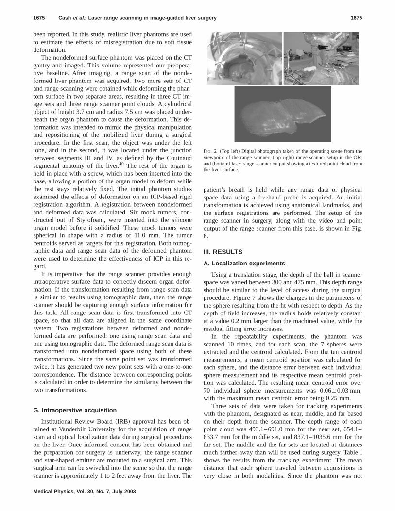
patient’s breath is held while any range data or physispace data using a freehand probe is acquired. An intransformation is achieved using anatomical landmarks,the surface registrations are performed. The setup ofrange scanner in surgery, along with the video and pooutput of the range scanner from this case, is shown in6.
III. RESULTS
A. Localization experiments
Using a translation stage, the depth of the ball in scanspace was varied between 300 and 475 mm. This depth rashould be similar to the level of access during the surgprocedure. Figure 7 shows the changes in the parametethe sphere resulting from the fit with respect to depth. Asdepth of field increases, the radius holds relatively consat a value 0.2 mm larger than the machined value, whileresidual fitting error increases.
In the repeatability experiments, the phantom wscanned 10 times, and for each scan, the 7 spheresextracted and the centroid calculated. From the ten centmeasurements, a mean centroid position was calculatedeach sphere, and the distance error between each indivsphere measurement and its respective mean centroidtion was calculated. The resulting mean centroid error o70 individual sphere measurements was 0.0660.03 mm,with the maximum mean centroid error being 0.25 mm.
Three sets of data were taken for tracking experimewith the phantom, designated as near, middle, and far baon their depth from the scanner. The depth range of epoint cloud was 493.1–691.0 mm for the near set, 654833.7 mm for the middle set, and 837.1–1035.6 mm forfar set. The middle and the far sets are located at distanmuch farther away than will be used during surgery. Tablshows the results from the tracking experiment. The mdistance that each sphere traveled between acquisitionvery close in both modalities. Since the phantom was
FIG. 6. ~Top left! Digital photograph taken of the operating scene from tviewpoint of the range scanner;~top right! range scanner setup in the ORand~bottom! laser range scanner output showing a textured point cloud frthe liver surface.

w.
1676 Cash et al. : Laser range scanning in image-guided liver surgery 1676
FIG. 7. The radius~left graph! and the error residual~right graph! resulting from the sphere fit as a function of the depth in the scanner’s field of vie
avestcmo
nnth
ustraa
ksequftm
les
ch-city
ase,1 ofed
edoth
ionanceing
onsas5l-
eg-the
pointres,
on.
placed on a translation stage, moving the phantom by hresulted in a slight rotation, causing some spheres to moshorter distance than others. This is represented by thedard deviation in the first two columns. The mean differenbetween each individual sphere distance is less than 0.5for the two subset motions, and 0.75 mm for the entire mtion.
B. Registration experiments
The results from point-based and surface-based rascanner registration experiments on phantoms are showTable II. Point based registration between CT images ofphantom and the respective range scans were acquiredthe white Teflon spheres. A total of 17 point-based registions were performed, using 7 spheres as fiducials in eregistration. Fiducial registration error~FRE! and target reg-istration error ~TRE! as defined by Maurer, Fitzpatricet al.41 are used to determine the accuracy of the point-baregistrations. These measurements are the root mean s~RMS! distances between corresponding landmarks aimplementing the transformation. FRE is calculated fropoints ~fiducials! that were used in the registration, whiTRE uses points independent from the registration proce
Medical Physics, Vol. 30, No. 7, July 2003
nda
an-em-
geineing-
ch
dare
er
s.
Using the conventional rigid point-based registration tenique, FRE was 2.261.3 mm. However, when an isotropiscaling factor was introduced in order to obtain a similartransform, the FRE dropped to 1.160.8 mm. The nylonscrew head, securing the silicone organ model to the bwas not used in the registration, served as a target in 1the registrations. The resulting TRE from the point-basregistration was 1.760.5 mm for rigid and 1.860.5 mmwhen scaling was allowed.
The closest corresponding metric to FRE for ICP-bassurface registrations is the mean residual error, since bserve as cost functions to be minimized in the registratprocess. The mean surface residual error is the mean distbetween every point on one surface and its correspondclosest point on the other surface. For the six registratiperformed with the organ phantom, the mean residual w0.7560.07 mm using rigid transformations and 0.660.04 mm when incorporating the similarity isotropic scaing factor into the ICP algorithm. For the surface-based ristrations, there were two sets of targets. One target wassame nylon screw head that was used as a target in theregistrations. The other set of targets were the Teflon sphesince they were not used at all during the ICP registrati
ing ballOTRAKking field
TABLE I. Tracking experiments. The first two columns represent the mean distance that each correspondmoved between trials. The last column presents the difference between the range scanner and OPTdistance measurements of corresponding fiducials. The depth range spanned most of the scanner’s worof view, with a minimum depth of 493.1 mm and a maximum of 1035.6 mm.
Mean distance of fiducial movement between sets
Difference ofcorresponding fiducial
distances between rangescanner and OPTOTRAK
Range scan, mm OPTOTRAK, mm ~max!
Near to middle 154.060.6 154.060.4 0.460.2 ~0.8!Middle to far 220.765.7 220.765.6 0.460.3 ~1.0!Near to far 374.665.4 374.665.2 0.860.6 ~1.7!

d in thee 12
1677 Cash et al. : Laser range scanning in image-guided liver surgery 1677
Medical Physics, Vo
TABLE II. Registration results of range scan data to CT data~organ phantom! and physical space data~calibra-tion phantom!. Target set~a! represents a nylon screw head on the liver’s surface. Target set~b! refers to theperipheral Teflon spheres that were used as fiducials in the point-based registration but were not usesurface registration. Target set~c! are points on the calibration phantom not used as fiducials. For each of thtrials, there were 126 unique combinations of five fiducials and four targets.
Phantom ScalingRegistration
method
FRE ~points!/Residual~surface!,
mm TRE, mm
Organ Rigid Point 2.261.3 ~6.0!nÄ119
~a! 1.760.5 ~2.5! nÄ11
Organ Similarity Point 1.160.8 ~3.5!nÄ119
~a! 1.860.5 ~2.7! nÄ11
Organ Rigid Surface 0.7560.07 ~0.83!nÄ6
~a! 2.060.6 ~2.7! nÄ6~b! 4.161.7 ~8.1! nÄ42
Organ Similarity Surface 0.6560.04 ~0.70!nÄ6
~a! 2.460.5 ~3.0! nÄ6~b! 3.661.7 ~7.2! nÄ42
Calibrationphantom
Rigid Point 1.060.6 ~3.8!nÄ7560
~c! 1.460.7 ~4.8!nÄ6048
a2.
asysaloninaaninlss4
oint
teseia
r o
0ahp
du
fortedht.tely
ckton,ond-re
Thedinge-
medeencanCPfteriteialde-CTses
edmedthe
The resulting TRE’s were 2.060.6 mm for the screw headand 4.161.7 mm for the spheres using a rigid transformtion; when using the similarity factor, these values were60.5 mm and 3.661.7 mm.
Point-based registrations were also performed on the cbration phantom between range scanner space and physpace as defined by the OPTOTRAK optical localization stem. This registration serves as the initial step for the cbration procedure that is discussed in the ‘‘Tracking’’ portiof the Methods and Results sections. There are nine poextracted from the calibration phantom that are used forsessing the accuracy of the registration. The nine pointsseparated into 5 fiducials and 4 targets. Every combinatioused with each data set, resulting in 126 unique combtions for every trial. Overall there were 12 registration triawith the calibration phantom. The resulting FRE for theexperiments was 1.060.6 mm, and the TRE was 1.60.7 mm.
C. Tracking experiments
A total of 8 trials were performed to test the robustnessthe calibration procedure, with five trials being performedone set and three in a second set. The data generated aof n536 points for the first set of trials~9 data points foreach trial and 4 test trials! andn518 points for the secondset of trials~9 points, 2 test trials!. Table III shows the resultsfrom the tracking experiments. Every trial was designaonce as the calibration trial, and all other trials in thewere compared to the data acquired in the calibration trOverall, points on the phantom were tracked with an erro1.460.8 mm.
D. Deformation experiments
For the deformation experiments, approximately 120,0points were acquired from each segmented CT surface,40,000 points of the liver surface were acquired with trange scanner. The number of range scanner points resents the sample size for calculations of the surface resi
l. 30, No. 7, July 2003
-4
li-ical-
i-
tss-reisa-
e
f
otal
dtl.f
0ndere-al
error. CT tomographic volume contours were acquiredthe entire surface, while range scanner data only originafrom surface points available to the scanner’s line of sigFor the phantom, the range scanner covers approxima52% of the entire surface area of the phantom.
Table IV shows the target registration error of the mosubsurface tumors. The position of the tumors in relationthe liver phantom is shown in Fig. 8. For each deformatiothe first column represents the distances between corresping tumor centroids after the initial alignment used befoICP. This distance represents shift due to deformation.second column shows the distance between correspontumor centroids after performing a registration with ICP btween the deformed CT image contours and the nondeforcontours. The third column represents the distance betwtumor centroids after registering the deformed range ssurface with the nondeformed CT surface using the Imethod. Overall, the target error decreased significantly athe rigid registration, especially for tumors very near the sof deformation, such as tumor 1 in the first deformation trand tumor 4 in the second trial. Figure 9 shows a nonformed and a deformed contour set from a segmentedimage, before and after registration. There are a few ca
TABLE III. Tracking results for the calibration phantom. Each trial servonce as the calibration trial, and all other trials in the set were transforusing this trial’s calibration transformation matrix and compared againstphysical data obtained from that trial.
Calibrationtrial Samples Tracking error, mm
1 36 1.360.5 ~2.4!2 36 1.060.5 ~2.3!3 36 1.661.0 ~4.3!4 36 1.160.6 ~2.5!5 36 2.161.0 ~3.7!6 18 1.760.6 ~2.6!7 18 1.560.6 ~2.3!8 18 1.460.6 ~2.2!
Overall 234 1.460.8 ~4.3!

sed as
1678 Cash et al. : Laser range scanning in image-guided liver surgery 1678
Medical Physics, Vo
TABLE IV. Target registration results from deformation experiments. Six subsurface mock tumors were utargets.
Tumor
Deformation # 1 Deformation # 2
Initialdeformation
RegistrationCT
Registrationrange scan
Initialdeformation
Surfaceregistration
CT
Surfaceregistrationrange scan
1 46.83 mm 6.98 mm 3.81 mm 12.89 mm 2.39 mm 2.93 mm2 33.65 mm 4.92 mm 3.69 mm 8.71 mm 0.74 mm 0.88 mm3 11.48 mm 7.42 mm 6.43 mm 5.30 mm 0.71 mm 0.60 mm4 5.96 mm 5.82 mm 6.20 mm 18.12 mm 4.09 mm 3.97 mm5 3.67 mm 3.08 mm 6.64 mm 5.09 mm 3.65 mm 3.95 mm6 4.67 mm 6.26 mm 7.74 mm 10.01 mm 3.39 mm 4.61 mm
ndt
ina
thnofoatwltiti
anw0
solse-
tasetu
.62og-
in
ngectedhattheisthe
o
fore
od.false
~Tumors 4, 5, and 6! where the target error increased, athis was due to nondeformed areas being misaligned byrigid transformation in order to minimize the closest pometric, as can be seen in Fig. 9, indicated by the whiterows.
In Table V, it can be seen that before registration,mean closest point distance between the deformed anddeformed state is large, up to 50% of the maximum demation. The ICP algorithm, whether using range scan datCT data, decreases this residual error by 65–78%. Theregistrations can be compared by using each of the resutransformations to bring the range scan point set represendeformed data into nondeformed space. The mean distbetween corresponding points after the transformations1.8360.65 mm for the first deformation trial and 1.860.71 mm for the second.
E. Clinical data
The first range scanner data of a human liver surface uin a surface registration was acquired from a 68 yearfemale patient, who was undergoing standard surgical retion for a large primary liver tumor in her right lobe, occupying most of Couinaud segments VI and VII, as well asportion of Secs. V and VIII. The scanner acquired a to28,672 points of the exposed organ surface during a 15ond scan. This point set represents approximately 25% ofsurface area of the entire liver. The resulting mean resid
FIG. 8. Segmented CT surfaces of the liver phantom and subsurface tumThe tumors are labeled in accordance with Table IV.
l. 30, No. 7, July 2003
hetr-
en-
r-oro
ngngceas
eddc-
alc-
heal
error from the surface registration was 1.7261.43 mm, withthe closest point distances ranging from 0.03 mm to 11mm. An overlay of the range scanner data onto CT tomraphic volume data is shown using two-dimensional slicesFig. 10, and a three-dimensional visualization in Fig. 11.
IV. DISCUSSION
A. Surface curvature
The accuracy of an optical triangulation-based laser rascanner depends on the correct interpretation of the reflelight patterns received by the CCD array. Any deviations tarise from the ideal case lead to error and uncertainty ofdepth measurement. A fundamental limit on accuracypresent due to the use of a coherent light source and
rs.
FIG. 9. ~Top! Nondeformed CT contour~white! and deformed CT contour~gray! of a phantom surface aligned by a point-based registration, beICP. Notice the significant deformation on the right side of the image.~Bot-tom! The two CT contours after implementing the ICP registration methNow the right surface now matches much better, at the expense of arotation that misaligns the left side of the surface.

1679 Cash et al. : Laser range scanning in image-guided liver surgery 1679
Medical Physics, Vo
TABLE V. Registration results from deformation studies.
Trial 1: mean6s.d. ~max! Trial 2: mean6s.d. ~max!
Residual before registration 15.67614.30 mm~42.08! 4.4964.09 mm~23.23!Residual after scanner registration 3.4162.35 mm~16.40! 1.5861.22 mm~16.82!Residual after CT registration 3.6362.34 mm~14.37! 1.6361.32 mm~15.87!Mean corresponding pointdistance~scan and CT!
1.8360.65 mm~4.11! 1.8060.71 mm~3.71!
ecnc
r.ticacorsunththoul
owlulibaot
thesg
in
t ft
dthle
evrser
peanthethethe
byery
e of
y athere-
willthe, thers toiallingt.g-
theabletherorserethetionThem.icble
re.essme
subsequent introduction of speckle noise. As the laser refloff any optically rough surface, the coherence is lost aphotons constructively and destructively interfere with eaother.42 However, this limit is usually on the order of 10mm,and does not play a significant factor in range scan erro
The most significant component of error is determinisand it depends on the position and orientation of the surfwithin the scanner’s field of view. The ideal scenario faccurate data acquisition with a range scanner is for theface to be planar and facing normal to the range scanFenget al.43 characterized three parameters that definederror. The first parameter was the depth of the surface inscanner’s field of view. As the depth increases and mattenuation is present, localization becomes more difficThe second parameter is the angle in the scanning planetween the incident laser beam and the surface normal, knas the incident angle. Many range scanning systems, incing the one used in this study, sweep a defocused laseracross the field of view. As a result, the laser will nevercompletely normal to the surface for the duration of the scSince this is a property of the laser scanning system, almall range scanners have been calibrated to account forchange in incident angle. The third error parameter isprojection angle, defined as the out-of-plane angle betwthe surface normal and the scanning plane. Any changediscontinuities in surface shape changes the projection anand results in distortions of the received light pattern.
Feng constructed a carefully designed experimentwhich a plane attached to a sphere was repeatedly scanThe projection angle and scan depth was held constaneach scan, and then adjusted by changing the incline ofplane-ball apparatus or the depth of the scanner. Basethese scans, a large amount of the error resulting fromsurface depth and the projection was quantified and modeOnce the model was created, an iterative scheme was doped to correct for the error arising from these paramete44
Curlesset al.45 developed a method to account for these
l. 30, No. 7, July 2003
tsdh
e
r-er.ise
ret.be-
nd-neen.stheeenorle,
ned.orheoned.el-.-
rors, along with errors arising from discontinuities in sha~i.e., corners! and of the index of reflectance. Rather thdeveloping a model to account for all of these errors,group changed the method of depth calculation based onrange scan calculation. Most range scanners calculatedepth from centroid calculation for each frame receivedthe CCD and then discard these frames. By saving evframe and analyzing the centroid patterns over time, somthe deterministic error was corrected.
The changes of surface depth and projection angle placentral role in the registration error of our studies. Givenfact that the spheres have a high rate of curvature withspect to the field of view of the laser range scanner, therebe significant errors in calculating the depth that causesphere to appear larger than its actual radius. As a resultposition of the fiducial spheres in the range scans appeabe farther away with respect to the centroid of the fiducconfiguration, as seen in Fig. 12. Thus, an isotropic scafactor was employed to account for the ‘‘bloom’’ effecHowever, while the scaling factor improved the fiducial reistration error, it had very little effect on the target error.
The surface registration methods were able to alignsurfaces with a high degree of accuracy, and they wereto align the central target to a comparable accuracy withpoint-based methods. However, the target registration erwere much higher for the Teflon spheres. These points won the periphery of the scene and farther away fromcentroid of the organ. Thus, any slight changes in the rotacreated a lever arm effect with respect to these targets.implementation of a scaling factor within the ICP algorithalso did not play a very significant role in target accuracy
Similarity transformations, which incorporate an isotropscaling factor into a point-based registration, seem desirasince they will not require a lengthy calibration proceduHowever, the scaling factor loses much of its effectivenwhen two surfaces with different shape are part of the sa
to-
et
FIG. 10. Range scan data registeredand overlaid on the preoperative tomographic sets. From left to right, theslices become more superior. The largprimary tumor can be seen in the righimage.

cutionmteucede
rm
exthblantio
o
ocn
areerhcqTacththgcou
he
beoneare
ngethe
therobeface
inns,s ofce-lgo-ersam-for
etr-
essin
. Inionleft
els.
aree.
1680 Cash et al. : Laser range scanning in image-guided liver surgery 1680
registration. Our fiducial spheres have a high degree ofvature over a small area and thus the error due to projecangle will be much greater than compared to the more plasurface of the liver phantom or the calibration phantoSince the scaling factor is optimized for the error associawith the spheres, it will not aid the overall registration accracy for the organ surface. As a result, a calibration produre, not unlike those seen in Refs. 45 or 43 will be neeto better account for the systematic error.
To obtain a better assessment of the accuracy limitsgarding registration between the range scanner and otherdalities, results from the calibration phantom should beamined. From Table II, the FRE and TRE results fromrigid registration of the calibration phantom are comparato those obtained with a similarity transform of the orgphantom. The two factors for the decrease in registraerror with respect to the phantom are the implementationplanar fiducials and targets as well as the smaller regionthe scanner’s field of view that the calibration phantomcupies. In both cases, these changes reduce the amouerror caused by the projection angle.
Despite these considerations when analyzing the dfrom the range scanner, its potential to acquire useful thdimensional information for image-guided surgery is ovwhelming. In contrast to surface acquisition methods witfreehand probe, the laser range scanner provides rapid asition, dense sampling, and does not require contact.freehand probe, localized by the OPTOTRAK system,quires new point data at a rate of 40 Hz. Table VI showscomparison for a surface registration of a phantom wherenumber of range scan and freehand probe points are rouequal. The freehand probe takes 6 minutes to the 21-seacquisition time of the range scanner, and the error residis twice as large for the freehand probe. In Table VII, t
FIG. 11. CT to range scanner registration of clinical trial data. The dpoints indicate that the range scanner points are outside the CT surfacthe white points indicate that these surface points are inside the surfac
Medical Physics, Vol. 30, No. 7, July 2003
r-n
ar.d--d
e-o--
ee
nf
of-t of
tae--aui-
he-ee
hlyndal
acquisition time is held constant. Only 800 points cancollected by the freehand probe in the same duration asrange scan. 800 random points from the range scan dataselected to keep the number of points equal. While the rascanner sampling is so robust that no change is noticed inregistration residual error, there is a significant change infreehand probe results. The surgeon cannot move the pfast enough with the needed accuracy to sample the suras well as the range scanner. While all the registrationsthese tables appeared to result in similar transformatiothese studies do not include all the variables and sourceerror that will be encountered during a real surgical produre. The variations to the system could cause the ICP arithm to reach a local minimum and result in an impropregistration. It appears that the range scanner’s densepling and rapid acquisition seem better suited to correctthese problems.
B. ICP and deformation
Overall, the ICP method significantly diminished targregistration error due to deformation by distributing this eror across the entire surface through its minimization procof the closest point metric. However, it also added errorsome areas where there was very little or no deformationFig. 9, the bottom image shows that most of the deformaton the right side has been corrected. However, on the
FIG. 12. Observed ‘‘bloom’’ in the fiducial configuration. Notice how all thscanner fiducials are further away from the centroid than the CT fiducia
kand
range
TABLE VI. A comparison of surface acquisition using the freehand probe and the range scanner. Thescanner takes significantly less time to acquire the data and results in smaller error residuals.Data type PointsAcquisition
timeInitial guess
FRERegistration
timeMean distance, mm
~max!
Freehandprobe
12870 360 sec 7.15 mm 36 sec 0.9760.95 ~10.95!
Rangescanner
13054 21 sec 5.02 mm 37 sec 0.4860.42 ~4.55!

ber ofbe in 20
1681 Cash et al. : Laser range scanning in image-guided liver surgery 1681
Medical Physics, Vo
TABLE VII. A comparison of surface acquisition using the freehand probe and the range scanner. The numscanner points was randomly down-sampled to match the number of points acquired by a freehand proseconds. The resulting residual actually improves.
Data type PointsAcquisition
timeInitial guess
FRERegistration
timeMean distance, mm
~max!
Freehandprobe
797 20 sec 7.15 mm 15 sec 1.2361.22 ~8.21!
Rangescanner
804 21 sec 5.02 mm 13 sec 0.4760.40 ~3.06!
thbethes
toa
ma
ese
tuvermsaanonahth
oerctetInthcaenisy
piyanticomntrd
tioneldtlyill
are
ationtail.
ntgeinirthek
er-cein
teinPhiliononithorsirge
a-
ch,avi-
L.z,nce
g
nddi-
K.ining
side of the surface, there is some new misalignment fromrotation and translation of the rigid registration. It wouldat these areas where deformation would be exhibited infinite element model. Overall, the accuracy obtained in thphantom studies is comparable to what will be neededtumor resection of image-guided liver surgery. In orderobtain this level of accuracy in a clinical setting, there isstrong likelihood that the metric used in the ICP algorithwill need to be altered, so that false, nonexistent deformtions that can arise from a rigid registration will not bpresent. Possible solutions include weighting each clopoint calculation according to an addition metric.
One of the goals for using range scanner data is to capand correct for deformation during surgery. To be effectithe range scanner must accurately acquire shape infotion that can be used effectively in deformation compention strategies. The ICP algorithm, between deformednondeformed surface data, results in similar transformatiwhether using tomographic volume data or range scan dThe transformations place the point sets very close, witmean distance between the corresponding points of less2.0 mm.
C. Intraoperative acquisition Õsurface registrationmetric
From the above studies, it has been shown that the ption and orientation of the target surface with in the scannfield of view plays an important role in the accuracy. In fathere has been a definite region that has been considideal for accurate scanning. This area is located in the cenportion of the scanner’s field of view, 300–500 mm away.order to determine the highest limits of accuracy, most ofstudies were performed in this area. It will also be the lotion where the calibration phantom and the surgical scwill be located. Using the calibration phantom and its precmachining, further studies are being performed to emplocalibration procedure similar to the one developed by Xi.44
V. CONCLUSION
The range scanner is an effective tool for acquiring rathree-dimensional location data. It can be used effectivelregister with CT image volumes, using both-point basedsurface-based methods. It can also be tracked with an oplocalization system. Studies with the calibration phantshow that registration and tracking errors are consisteless than 2 mm. However, there are some concerns rega
l. 30, No. 7, July 2003
e
ee
in
-
st
re,a--ds
ta.aan
si-’s,redral
e-eea
dtodal
lying
a large component of error that is dependent on the posiand orientation of the target surface within the scanner’s fiof view. Calibration and correction algorithms are currenbeing examined, but for most of the surgery studies that wbe performed, the target surface will lie relatively planwithin the ideal region of the scanner’s field of view. Thrange scan data is best suited for surface based registrtechniques since it captures entire surfaces with great de
ACKNOWLEDGMENTS
This work was supported in part by the NIH R21 GraNo. CA 91352-01. The authors would like to acknowledTina Herron, Nita Collins, and the rest of the CT staffVanderbilt University’s Department of Radiology for theaid in acquiring tomographic images of the phantom andpatient. In addition, the authors would like to thanStephanie Cook and Karin Mayes of the Vanderbilt Univsity Hepatic Surgery Nursing Team for their aid and patienwith regards to acquiring intraoperative data. Assistanceconstructing the phantoms was provided by John Fellensand Robert Patchin from the Department of Physics, andDavis from the School of Engineering. Some segmentatand calculation were performed using Analyze AVW Versi3.1—Biomedical Resource, provided in collaboration wthe Mayo Foundation, Rochester, MN. Finally, the authwould like to acknowledge 3-D Digital Corporation for thetechnical support and training regarding their laser ranscanner.
a!Electronic mail: [email protected]. J. Engle and L. D. Lunsford, ‘‘Brain tumor resection guided by introperative computed tomography,’’ J. Neuro-Oncol.4, 361–370~1987!.
2C. Nimsky, O. Ganslandt, H. Kober, M. Buchfelder, and R. Fahlbus‘‘Intraoperative magnetic resonance imaging combined with neurongation: a new concept,’’ Neurosurgery48, 1082–1089~2001!.
3P. M. Black, T. Moriarty, E. Alexander III, P. Stieg, E. J. Woodard, P.Gleason, C. H. Martin, R. Kikinis, R. B. Schwartz, and F. A. Joles‘‘Development and implementation of intraoperative magnetic resonaimaging and its neurosurgical applications,’’ Neurosurgery41, 831–842~1997!.
4T. Kaibara, S. T. Myles, M. A. Lee, and G. R. Sutherland, ‘‘Optimizinepilepsy surgery with intraoperative MR imaging,’’ Epilepsia43, 425–429 ~2002!.
5S. K. Yrjana, J. P. Katisko, R. O. Ojala, O. Tervonen, H. Schiffbauer, aJ. Koivukangas, ‘‘Versatile Intraoperative MRI in neurosurgery and raology,’’ Acta Neurochir.144, 271–278~2002!.
6M. Ferrant, A. Nabavi, B. Macq, F. A. Jolesz, R. Kikinis, and S.Warfield, ‘‘Registration of 3-D intraoperative MR images of the brausing a finite-element biomechanical model,’’ IEEE Trans. Med. Imag20, 1384–1397~2001!.

F.iveac
-n
ieneu
.ga
r,rcl.
,tioti.rade
ckinion
Fse
J.
Ddeng
.for
ne
chon
-
iee-
d.
u-
fo
andur-
n-ical
V.ial
onsed
ed
,u-
dis-tern
/
it
r
,’’
g
S..
o-
R.forsur-
J.ing
—
sion
al
me
1682 Cash et al. : Laser range scanning in image-guided liver surgery 1682
7C. R. Wirtz, V. M. Tronnier, M. M. Bonsanto, M. Knauth, A. Staubert,K. Albert, and S. Kunze, ‘‘Image-guided neurosurgery with intraoperatMRI: Update of frameless stereotaxy and radicality control,’’ StereotFunct Neurosurg.68, 39–43~1997!.
8M. Bernstein, A. R. Al Anazi, W. Kucharczyk, P. Manninen, M. Bronskill, and M. Henkelman, ‘‘Brain tumor surgery with the Toronto opemagnetic resonance imaging system: Preliminary results for 36 patand analysis of advantages, disadvantages, and future prospects,’’ Nsurgery46, 900–907~2000!.
9C. R. Wirtz, M. M. Bonsanto, M. Knauth, V. M. Tronnier, F. K. Albert, AStaubert, and S. Kunze, ‘‘Intraoperative magnetic resonance imaginupdate interactive navigation in neurosurgery: method and preliminexperience,’’ Comput. Aided Surg.2, 172–179~1997!.
10M. Knauth, N. Aras, C. R. Wirtz, A. Dorfler, T. Engelhorn, and K. Sarto‘‘Surgically induced intracranial contrast enhancement: potential souof diagnostic error in intraoperative MR imaging,’’ Am. J. Neuroradio20, 1547–1553~1999!.
11R. D. Bucholz, D. D. Yeh, J. Trobaugh, L. L. McDurmont, C. D. SturmC. Baumann, J. M. Henderson, A. Levy, and P. Kessman, ‘‘The correcof stereotactic inaccuracy caused by brain shift using an intraoperaultrasound device,’’ Cvrmed-Mrcas’97, 1997, Vol. 1205, pp. 459–466
12R. M. Comeau, A. F. Sadikot, A. Fenster, and T. M. Peters, ‘‘Intraopetive ultrasound for guidance and tissue shift correction in image-guineurosurgery,’’ Med. Phys.27, 787–800~2000!.
13D. G. Gobbi, R. M. Comeau, and T. M. Peters, ‘‘Ultrasound probe traing for real-time ultrasound/MRI overlay and visualization of brashift,’’ Medical Image Computing and Computer-Assisted Intervent,Miccai’99, Proceedings, 1999, Vol. 1679, pp. 920–927.
14A. Gronningsaeter, A. Kleven, S. Ommedal, T. E. Aarseth, T. Lie,Lindseth, T. Lango, and G. Unsgard, ‘‘SonoWand, an ultrasound-baneuronavigation system,’’ Neurosurgery47, 1373–1379~2000!.
15M. A. Biot, ‘‘General theory of three-dimensional consolidation,’’Appl. Phys.12, 155–164~1941!.
16K. D. Paulsen, M. I. Miga, F. E. Kennedy, P. J. Hoopes, A. Hartov, andW. Roberts, ‘‘A computational model for tracking subsurface tissueformation during stereotactic neurosurgery,’’ IEEE Trans. Biomed. E46, 213–225~1999!.
17M. I. Miga, D. W. Roberts, F. E. Kennedy, L. A. Platenik, A. Hartov, KE. Lunn, and K. D. Paulsen, ‘‘Modeling of retraction and resectionintraoperative updating of images,’’ Neurosurgery49, 75–84~2001!.
18P. J. Edwards, D. L. G. Hill, J. A. Little, and D. J. Hawkes, ‘‘Deformatiofor image guided interventions using a three component tissue modMed. Image Anal2, 355–367~1998!.
19A. Hagemann, K. Rohr, H. S. Stiehl, U. Spetzger, and J. M. Gilsba‘‘Biomechanical modeling of the human head for physically based, nrigid image registration,’’ IEEE Trans. Med. Imaging18, 875–884~1999!.
20K. Miller and K. Chinzei, ‘‘Constitutive modelling of brain tissue: experiment and theory,’’ J. Biomech.30, 1115–1121~1997!.
21J. Marescaux, J. M. Clement, V. Tassetti, C. Koehl, S. Cotin, Y. RussD. Mutter, H. Delingette, and N. Ayache, ‘‘Virtual reality applied to hpatic surgery simulation: the next revolution,’’ Ann. Surg.228, 627–634~1998!.
22M. Bro-Nielsen, ‘‘Fast finite elements for surgery simulation,’’ StuHealth Technol. Inform.39, 395–400~1997!.
23H. Delingette, ‘‘Towards realistic soft tissue modeling in medical simlation,’’ Proc. IEEE86, 512–523~1998!.
24M. Chabanas and Y. Payan, ‘‘A 3D finite element model of the facesimulation in plastic and maxillo-facial surgery,’’Medical Image Com-puting and Computer-Assisted Intervention, Miccai 2000, 2000, Vol.1935, pp. 1068–1075.
Medical Physics, Vol. 30, No. 7, July 2003
t
tsro-
tory
e
nve
-d
-
.d
.-.
l,’’
,-
r,
r
25G. Szekely, C. Brechbuhler, R. Hutter, A. Rhomberg, N. Ironmonger,P. Schmid, ‘‘Modelling of soft tissue deformation for laparoscopic sgery simulation,’’ Med. Image Anal4, 57–66~2000!.
26M. A. Audette, K. Siddiqi, and T. M. Peters, ‘‘Level-set surface segmetation and fast cortical range image tracking for computing intrasurgdeformations,’’ in Ref. 13, pp. 788–797.
27A. Raabe, R. Krishnan, R. Wolff, E. Hermann, M. Zimmermann, andSeifert, ‘‘Laser surface scanning for patient registration in intracranimage-guided surgery,’’ Neurosurgery50, 797–801~2002!.
28N. Furushiro, T. Saito, Y. Masutani, and I. Sakuma, ‘‘Specificatimethod of surface measurement for surgical navigation: Ridgeline baorgan registration,’’Medical Image Computing and Computer-AssistIntervention, Miccai’02, 2002, Vol. 2489, pp. 109–115.
29T. K. Sinha, D. M. Cash, R. J. Weil, R. L. Galloway, and M. I. Miga‘‘Cortical surface registration using texture mapped point clouds and mtual information,’’ in Ref. 28, 2489, pp. 533–540.
303D Digital Corporation, ‘‘RealScan USB Brochure,’’ 2001.31S. J. Ahn, W. Rauh, and H. J. Warnecke, ‘‘Least-squares orthogonal
tances fitting of circle, sphere, ellipse, hyperbola, and parabola,’’ PatRecogn.34, 2283–2303~2001!.
32Northern Digital Inc., ‘‘OPTOTRAK—Technical Specifications,’’ http:/www.ndigital.com/optotrak–technical.html, 2002.
33B. K. P. Horn, ‘‘Closed-form solution of absolute orientation using unquaternions,’’ J. Opt. Soc. Am.4, 629–642~1987!.
34P. H. Scho¨nemann and R. M. Carroll, ‘‘Fitting one matrix to anotheunder choice of a central dilation and a rigid motion,’’ Psychometrika35,245–255~1970!.
35P. J. Besl and N. D. Mckay, ‘‘A method for registration of 3-D shapesIEEE Trans. Pattern Anal. Mach. Intell.14, 239–256~1992!.
36Z. Y. Zhang, ‘‘Iterative point matching for registration of free-formcurves and surfaces,’’ Int. J. Comput. Vis.13, 119–152~1994!.
37J. H. Friedman, J. L. Bentley, and R. A. Finkel, ‘‘An algorithm for findinbest matches in logarithmic expected time,’’ ACM Trans. Math. Softw.3,209–226~1977!.
38A. Nabavi, P. M. Black, D. T. Gering, C. F. Westin, V. Mehta, R.Pergolizzi, M. Ferrant, S. K. Warfield, N. Hata, R. B. Schwartz, W. MWells, R. Kikinis, and F. A. Jolesz, ‘‘Serial intraoperative magnetic resnance imaging of brain shift,’’ Neurosurgery48, 787–797~2001!.
39C. Nimsky, O. Ganslandt, S. Cerny, P. Hastreiter, G. Greiner, andFahlbusch, ‘‘Quantification of, visualization of, and compensationbrain shift using intraoperative magnetic resonance imaging,’’ Neurogery 47, 1070–1079~2000!.
40C. Couinaud,Le Foie: Etudes Anatomiques et Chirurgicales~Masson,Paris, 1957!.
41C. R. Maurer, Jr., J. M. Fitzpatrick, M. Y. Wang, R. L. Galloway, Jr., R.Maciunas, and G. S. Allen, ‘‘Registration of head volume images usimplantable fiducial markers,’’ IEEE Trans. Med. Imaging16, 447–462~1997!.
42R. G. Dorsch, G. Hausler, and J. M. Herrmann, ‘‘Laser triangulationfundamental uncertainty in distance measurement,’’Appl. Opt.33, 1306–1314 ~1994!.
43H. Y. Feng, Y. X. Liu, and F. F. Xi, ‘‘Analysis of digitizing errors of alaser scanning system,’’ Precision Engineering - J. Inter. Soc. PreciEng. Nanotechnology25, 185–191~2001!.
44F. Xi, Y. Liu, and H. Y. Feng, ‘‘Error compensation for three-dimensionline laser scanning data,’’ Int. J. Adv. Manufacturing Technol.18, 211–216 ~2001!.
45B. Curless and M. Levoy, ‘‘Better optical triangulation through spacetianalysis,’’IEEE 5th International Conference on Computer Vision, Bos-ton, MA, 1995, pp. 987–994.
Related Documents