Incorporating Protection Mechanisms in the Dynamic Multi-layer Routing Schemes Anna Urra, Eusebi Calle Ortega, Jose L. Marzo, and Pere Vila Institute of Informatics and Applications (IIiA), University of Girona, 17071 Girona, Spain Abstract. In the next generation backbone networks, IP/MPLS over optical networks, the ability to maintain an acceptable level of relia- bility has become crucial since a failure can result in a loss of several terabits of data per second. Although routing schemes with protection exist, they generally relate to a single switching layer: either wavelength or packet switching oriented. This paper presents a new dynamic and multi-layer routing scheme with protection that considers cooperation between IP/MPLS and optical switching domains. A complete set of ex- periments proves that the proposed scheme is more efficient when com- pared to routing algorithms with full optical protection or full IP/MPLS protection. 1 Introduction The use of optical technology in core networks combined with IP/Multi-Protocol Label Switching (MPLS) [1] solution has been presented as a suitable choice for the next generation Internet architecture. The integration of both layers is facil- itated by the development of Generalized MPLS (GMPLS) [2]. In this network architecture, a single fiber failure can result in potentially huge data losses as the effects propagate up and through the network causing disruptions in the service of many applications. Thus, survivability has become a key issue to improve and satisfy the increasing requirements of reliability and Quality of Service (QoS) of these applications. Fault recovery schemes have been adopted in the network in order to provide such survivability. These schemes are based on switching the traffic affected by the failure to a backup path. The computation of the work- ing and backup paths is a crucial step to offer the required QoS to the traffic services. Some relevant parameters, such as resource consumption and recovery time, could be affected negatively if suitable routing algorithms are not used. According to the timing of backup path computation, recovery mechanisms are classified in protection and restoration [3]. Although restoration is flexible in terms of resource consumption, it offers low recovery time and the recovery This work was supported by the Spanish Research Council (TEC2006-03883/TCM) and the Generalitat de Catalunya through grant SGR-00296. The work of A. Urra was also supported by the Ministry Universities, Research and Information Society (DURSI) and European Social Funds. I.F. Akyildiz et al. (Eds.): NETWORKING 2007, LNCS 4479, pp. 786–796, 2007. c IFIP International Federation for Information Processing 2007

Welcome message from author
This document is posted to help you gain knowledge. Please leave a comment to let me know what you think about it! Share it to your friends and learn new things together.
Transcript
Incorporating Protection Mechanisms in theDynamic Multi-layer Routing Schemes�
Anna Urra, Eusebi Calle Ortega, Jose L. Marzo, and Pere Vila
Institute of Informatics and Applications (IIiA),University of Girona, 17071 Girona, Spain
Abstract. In the next generation backbone networks, IP/MPLS overoptical networks, the ability to maintain an acceptable level of relia-bility has become crucial since a failure can result in a loss of severalterabits of data per second. Although routing schemes with protectionexist, they generally relate to a single switching layer: either wavelengthor packet switching oriented. This paper presents a new dynamic andmulti-layer routing scheme with protection that considers cooperationbetween IP/MPLS and optical switching domains. A complete set of ex-periments proves that the proposed scheme is more efficient when com-pared to routing algorithms with full optical protection or full IP/MPLSprotection.
1 Introduction
The use of optical technology in core networks combined with IP/Multi-ProtocolLabel Switching (MPLS) [1] solution has been presented as a suitable choice forthe next generation Internet architecture. The integration of both layers is facil-itated by the development of Generalized MPLS (GMPLS) [2]. In this networkarchitecture, a single fiber failure can result in potentially huge data losses as theeffects propagate up and through the network causing disruptions in the serviceof many applications. Thus, survivability has become a key issue to improve andsatisfy the increasing requirements of reliability and Quality of Service (QoS) ofthese applications. Fault recovery schemes have been adopted in the network inorder to provide such survivability. These schemes are based on switching thetraffic affected by the failure to a backup path. The computation of the work-ing and backup paths is a crucial step to offer the required QoS to the trafficservices. Some relevant parameters, such as resource consumption and recoverytime, could be affected negatively if suitable routing algorithms are not used.
According to the timing of backup path computation, recovery mechanismsare classified in protection and restoration [3]. Although restoration is flexiblein terms of resource consumption, it offers low recovery time and the recovery� This work was supported by the Spanish Research Council (TEC2006-03883/TCM)
and the Generalitat de Catalunya through grant SGR-00296. The work of A. Urrawas also supported by the Ministry Universities, Research and Information Society(DURSI) and European Social Funds.
I.F. Akyildiz et al. (Eds.): NETWORKING 2007, LNCS 4479, pp. 786–796, 2007.c© IFIP International Federation for Information Processing 2007
Incorporating Protection Mechanisms 787
action may not be successful because of insufficient network resources. Protec-tion describes recovery schemes that are pre-planned for both spare capacity andbackup paths achieving the shortest recovery time and providing high availabilityagainst network failures. The accuracy and performance of routing algorithmswith protection in terms of resource consumption depends on the available net-work information. The availability of full or partial network information influ-ences the management of the network capacity [4]. The reduction of the recoverytime is another parameter to be considered for backup path selection and it isachieved by applying segment or local backup path methods instead of pathprotection [5].
NowadaysdifferentQoS routing algorithms exist that consider protectionmech-anisms, full/partial network information and local/segment backups [4,6,7,8].However, these routing schemes operate in a single switching layer: either opticaland wavelength oriented or IP/MPLS and Label Switched Path (LSP) oriented.Thus, both optical and IP/MPLS layers independently deploy their own faultrecovery methods.This results in protection duplications making fault manage-ment more difficult and poor resource utilization. Two network scenarios may beconsidered in order to improve network management and resources: 1) the staticmulti-layer network scenario or 2) the dynamic multi-layer network scenario. Inthe static multi-layer network scenario [9,10], the logical topology defined by theoptical layer is given, fixed and partially protected. Some of the logical links areassumed to be already protected at the optical layer. Thereby, at the IP/MPLSlayer, spare capacity is reserved to protect only those logical links that are un-protected. In the dynamic multi-layer network scenario, interoperability betweeneach IP/MPLS and optical switching domain is considered. Although effort hasbeen devoted in developing dynamic multi-layer routing schemes that considerboth switching domains [11], protection is not considered amongst them. In thispaper, a dynamic cooperation between wavelength and LSP domain is taken intoaccount in order to provide protected paths cost-effectively.
2 Multi-layer Architecture Overview
In the multi-layer architecture, Label Switched Paths (LSPs) are routed in theoptical network through lightpaths. For better utilization of the network re-sources, LSPs should be efficiently multiplexed into lightpaths and then, theselightpaths should be demultiplexed into LSPs at some router. This procedure ofmultiplexing/demultiplexing and switching LSPs onto/from lightpaths is calledtraffic grooming. Traffic grooming is an important issue for next generation op-tical networks. Photonic multi-layer routers have the technology to implementtraffic grooming [11]. Each consists of a number of Packet-Switching Capable(PSC) ports (p) and number of wavelengths (w). The number of PSC indicateshow many lightpaths can be demultiplexed into this router, whereas the numberof wavelengths corresponds to the number of wavelengths connected to the sameadjacent router. Three scenarios are associated with p according to the followingswitch architectures [12]:
788 A. Urra et al.
– Single-hop grooming: p = 0. Using this type of switching architecture, thenetwork does not offer packet switching capability at intermediate nodes.Thus, traffic from a source node is multiplexed onto a direct lightpath tothe destination node. In this case, either backup lightpaths at the opticaldomain or global backup LSPs (path protection) at the IP/MPLS domainare established to protect the connections.
– Multihop partial-grooming: 0 < p < w. In this case, some wavelengths maybe demultiplexed at the intermediate nodes for switching at finer granularity.Therefore, some LSPs will be able to perform segment/local protection.
– Multihop full-grooming: p = w. Every wavelength on each fiber link forms alightpath between adjacent node pairs. Thus, the logical topology is prede-termined and exactly the same as the physical topology. All the IP/MPLSprotection strategies, i.e. global, segment and local, are suitable for all LSPs.
Note that, although the PSC ports at intermediate nodes allow performingpacket segment/local protection, the number of optical-electrical-optical (o-e-o) conversions increases. Thus, the cost of o-e-o conversions must be consideredduring the path computation because they represent a bottleneck to networkthroughput and also influence the overall delay.
The granularity of the recovery strategy is also an important parameter interms of time recovery and fault management. Diverse switching granularity lev-els exist into the optical IP/MPLS network scenario. Going from coarser to finer,there is fiber, wavelength (lightpath) and LSP switching. The level of recovery atthe optical layer is bundle of lightpaths or individual lightpaths. Since recoveringat the optical layer recovers affected connections in-group, the recovery actionis fast and easier to manage than recovering each affected LSP individually inthe IP/MPLS layer. However, the coarser is the granularity; the higher the re-source consumption. The finer IP/MPLS granularity results in better resourceconsumption.
3 Problem Statement
In this section we discuss the basis of our proposed routing scheme. A tradeoffexists between the resource consumption and the cost added to the network interms of recovery time, failure management and node technology. Better use ofnetwork resources is achieved by recovering at IP/MPLS layer due to its finerswitching granularity. However, the recovery actions at optical domain are muchfaster and easier to manage, since the affected connections are recovered in group.Therefore, a cooperation between both layers seems to be the solution in orderto take the advantages of each switching domain.
The proposal presented in this paper is a first order approach that takes intoaccount the dynamic multi-layer network scenario. This proposal is based onthe establishment of link-disjoint lightpath/LSP pairs: the lightpath/LSP andthe backup lightpath/LSP. When a failure occurs at a lightpath, the traffic isswitched to the respective backup lightpath. If no backup lightpath exists, the
Incorporating Protection Mechanisms 789
traffic is switched to the respective backup LSPs. The main objective is to takeadvantage of both switching domains.
3.1 Network Definition
Let GP = (V, EP ) and GL = (V, EL) represent the physical topology and thelogical topology respectively, where V is the set of photonic MPLS routers;EP and EL are the set of network physical links and lightpath respectively.Each router has p input and output PSC ports, where PSCi(u) input ports andPCSo(u) output ports of node u are already not assigned to any lightpath. Eachphysical link has w wavelengths. When a LSP is requested, the proposed routingscheme considers both physical links and lightpaths, i.e. EP ∪ EL. In order tounivocally identify the physical links and existing lightpaths that connect nodepair (i, j) the 3-tuple (i, j, k) is used. Thus, the link (i, j, k) is a physical link ifk = 0, otherwise (k > 0) it is a lightpath.
Each (i, j, k) lightpath has an associated Rijk residual capacity; Suvijk total
capacity reserved to protect the physical link (u, v, 0); and Tijk the total sharedcapacity allocated in link (i, j, k). LSP requests are defined by (s, d, b) where(s, d) is the source and destination node pair; and b, specifies the amount ofcapacity required for this request. For each request, a working LSP (WP) hasto be set-up. A backup LSP (BP) must be also set-up, whenever the WP has,at least, one unprotected lightpath. If there are not sufficient resources in thenetwork, for either the WP or the BP, the request is rejected.
3.2 Lightpath and LSP Computation
In the proposed scheme, a new procedure to compute the WP is presented. Inthis procedure the following cost parameters are taken into account:
1. The residual capacity of the link candidates, Rijk.2. The maximum number of hops, H , i.e. maximum number of lightpaths that
the WP may traverse.3. The free packet switching ports of each router, PCSi and PSCo.
Note that the residual capacity of the physical links with free wavelengths isthe capacity of the wavelength. The proposed procedure, called Dynamic Multi-Layer Routing (DMR) algorithm (Algorithm 1), computes the min-hop WPbased on a variation of the Dijkstra algorithm. In this case, the number ofhops coincides with the number of lightpaths. Thus, the consecutive sequence ofphysical links, that constitutes a lightpath, is only considered as one hop. TheDMR procedure uses the network graph composed by lightpaths and physicallinks, i.e. G = (V, EP ∪EL). This procedure ends when it reaches the destinationnode or there is no feasible path between source and destination nodes. If afeasible path exists then the procedure may return:
1. A sequence of existing protected lightpaths.2. A sequence of physical links. In this case, a new unprotected lightpath is set
up between source and destination node.

790 A. Urra et al.
4
1 2
5 6
3
Lambda LSP
6
G=(V, EP U EL)
Physical linkUnprotected lambda LSP
Packet LSPNewunprotected -LSP
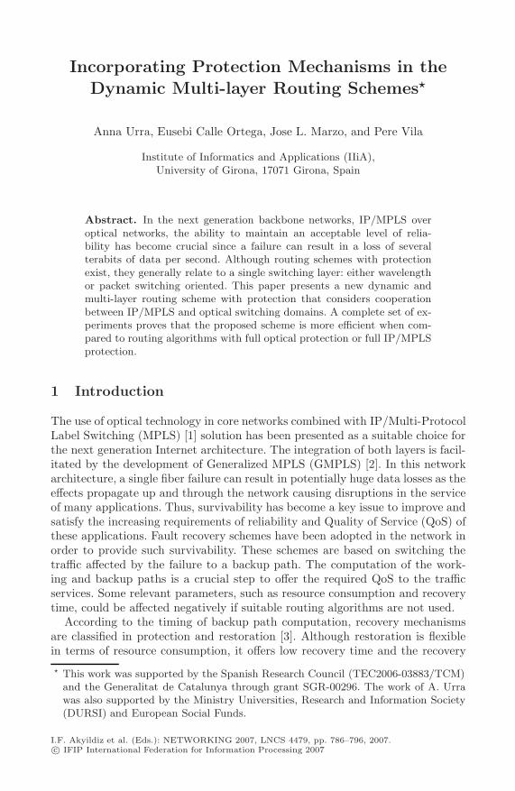
Fig. 1. Working p-LSP computation. Creation of a new unprotected lightpath usingthe physical links (5,4) and (4,1).
3. A sequence of physical links, protected and unprotected lightpaths. In thiscase, new unprotected lightpaths are setup for each consecutive sequenceof physical links as shown in Fig. 1. In this example, a new unprotectedlightpath is set up with the physical links (5,4) and (4,1).
Algorithm 1. Dynamic Multi-Layer Routingfor all v ∈ V do
Cost(v) = ∞Pred(v) = sWPlast(v) = s
Cost(s) = 0Q ← swhile (d /∈ Q and Q �= �) do
u ← min cost(Q)Q = Q − {u}for all v ∈ adjacency(u, G) do
for all (u, v, k) ∈ E doif (Rijk ≥ b) and ((k = WPlast(u) = 0)or (Cost(u) + 1 < Cost(v) < H)) then
if (PSCi(v) > 0 and WPLast(u) > 0and k = 0) or (PSCo(v) > 0 and k > 0and WPlast(u) = 0) or (WPlast(u) > 0and k > 0) or (k = WPlast(u) = 0) then
Pred(v) = uWPlast(v) = kQ ← vif not (k = WPlast(u) = 0) then
Cost(v) = Cost(u) + 1
In the DMR algorithm (Alg. 1), Cost(v) is a vector containing the path costfrom s to v; Pred(v) contains the v’s predecessor node; and WPlast(v) containsthe identifier k of link (u, v). Q represents the list of adjacent vertices which arenot visited yet. Function min cost(Q) returns the element u ∈ Q with the lowestCost(u); and adjacency(u) is the adjacency list of vertex u in graph G.

Incorporating Protection Mechanisms 791
3.3 Backup Lightpath and LSP Computation
Once the WP is known, the BP is computed. Three different procedures couldbe applied depending on the WP characteristics:
Step 1. If the WP is a sequence of existing protected lightpaths, the computa-tion of the BP is not required.
Step 2. If the WP is a new unprotected lightpath and an available and shareablebackup lightpath exists, this is used to protect the lightpath. Otherwise, anew backup lightpath is set-up applying DMR algorithm (Algorithm 1) withG = (V, EP ). If the procedure fails to find a backup lightpath, go to Step 3.
Step 3. If the WP is a combination of protected and unprotected lightpaths,then a variation of the Partial Disjoint Path (PDP) algorithm [9] is used tocompute the BP. The variations are the ones included to the Dijkstra algo-rithm in order to consider the packet switching ports in the DMR algorithm.The PDP may overlap with protected lightpaths of the WP, since they arealready protected, and the nodes of the WP. Therefore, no extra resourcesare necessary in the IP/MPLS layer against failure of protected lightpathsin the optical layer. When the BP overlaps the WP, more than one segmentbackup paths are established.
4 Performance Evaluation
4.1 Restorable Routing Algorithms
Our proposed Dynamic Multi-layer Routing scheme with Protection (DMP) isevaluated. DMP computes the WP using the DMR algorithm (Alg. 1) and the BPaccording to the criteria presented in Section 3.3. In order to compare the meritsof the new routing scheme, the following algorithms based on Oki policies [11]are also considered:
– Policy 1 with Protection (P1P). The routing policy 1 first tries to allocatethe LSPs to an existing lightpath. If a lightpath is not available then a se-quence of existing lightpaths with two or more hops that connects the sourceand destination nodes are selected. Otherwise, a new one-hop lightpath isestablished. When a new lightpath is created, then a backup lightpath is alsoset up.
– Policy 2 with Protection (P2P). The routing policy 2 first tries to allocatethe LSPs to an existing lightpath. If the lightpath is not available then a newone-hop lightpath is established and selected as the new LSP. Otherwise, asequence of existing lightpaths with two or more hops are selected. As in thecase of the P1P algorithm, a backup lightpath is set up when a new lightpathis created.
If P1P and P2P fail to find a feasible LSP or backup lightpath, then the requestis rejected.
As shown in Table 1, the Full Routing Information (FIR) algorithm [4] isalso considered in order to evaluate the performance of the new routing scheme
792 A. Urra et al.
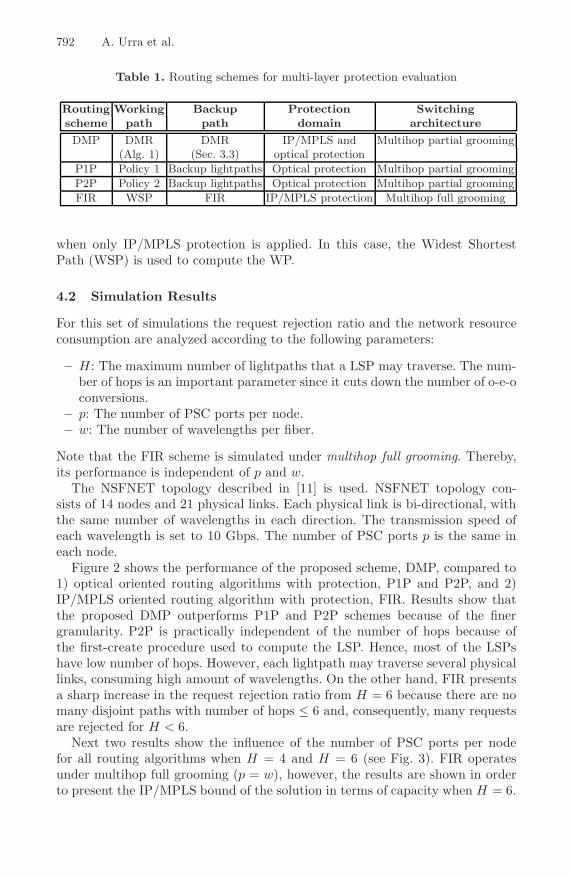
Table 1. Routing schemes for multi-layer protection evaluation
Routing Working Backup Protection Switchingscheme path path domain architectureDMP DMR DMR IP/MPLS and Multihop partial grooming
(Alg. 1) (Sec. 3.3) optical protectionP1P Policy 1 Backup lightpaths Optical protection Multihop partial groomingP2P Policy 2 Backup lightpaths Optical protection Multihop partial groomingFIR WSP FIR IP/MPLS protection Multihop full grooming
when only IP/MPLS protection is applied. In this case, the Widest ShortestPath (WSP) is used to compute the WP.
4.2 Simulation Results
For this set of simulations the request rejection ratio and the network resourceconsumption are analyzed according to the following parameters:
– H : The maximum number of lightpaths that a LSP may traverse. The num-ber of hops is an important parameter since it cuts down the number of o-e-oconversions.
– p: The number of PSC ports per node.– w: The number of wavelengths per fiber.
Note that the FIR scheme is simulated under multihop full grooming. Thereby,its performance is independent of p and w.
The NSFNET topology described in [11] is used. NSFNET topology con-sists of 14 nodes and 21 physical links. Each physical link is bi-directional, withthe same number of wavelengths in each direction. The transmission speed ofeach wavelength is set to 10 Gbps. The number of PSC ports p is the same ineach node.
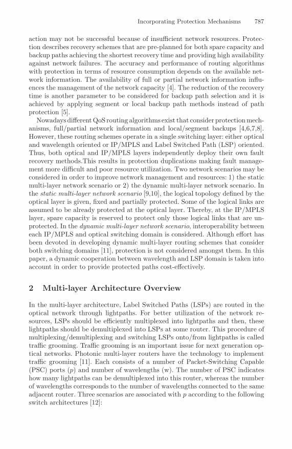
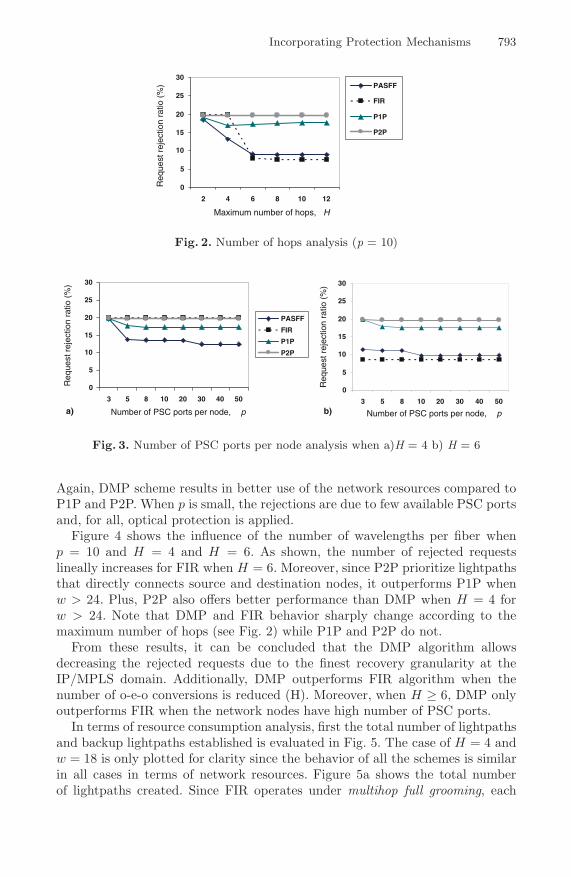
Figure 2 shows the performance of the proposed scheme, DMP, compared to1) optical oriented routing algorithms with protection, P1P and P2P, and 2)IP/MPLS oriented routing algorithm with protection, FIR. Results show thatthe proposed DMP outperforms P1P and P2P schemes because of the finergranularity. P2P is practically independent of the number of hops because ofthe first-create procedure used to compute the LSP. Hence, most of the LSPshave low number of hops. However, each lightpath may traverse several physicallinks, consuming high amount of wavelengths. On the other hand, FIR presentsa sharp increase in the request rejection ratio from H = 6 because there are nomany disjoint paths with number of hops ≤ 6 and, consequently, many requestsare rejected for H < 6.
Next two results show the influence of the number of PSC ports per nodefor all routing algorithms when H = 4 and H = 6 (see Fig. 3). FIR operatesunder multihop full grooming (p = w), however, the results are shown in orderto present the IP/MPLS bound of the solution in terms of capacity when H = 6.
Incorporating Protection Mechanisms 793
0
5
10
15
20
25
30
2 4 6 8 10 12
PASFF
FIR
P1P
P2P
Maximum number of hops, H
Req
uest
rej
ectio
n ra
tio (
%)
Fig. 2. Number of hops analysis (p = 10)
0
5
10
15
20
25
30
3 5 8 10 20 30 40 50
PASFF
FIR
P1P
P2P
Number of PSC ports per node, p
Req
uest
rej
ectio
n ra
tio (
%)
Number of PSC ports per node, p
Req
uest
rej
ectio
n ra
tio (
%)
0
5
10
15
20
25
30
3 5 8 10 20 30 40 50a) b)
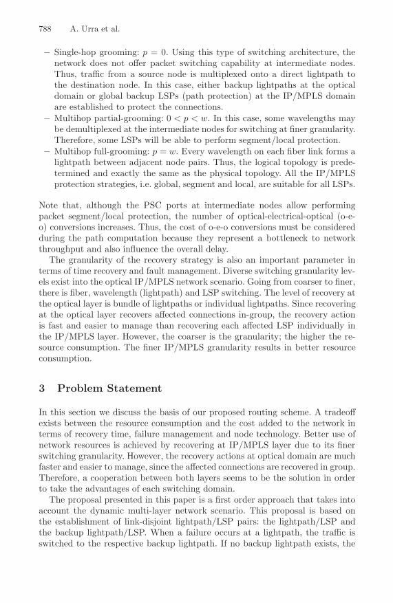
Fig. 3. Number of PSC ports per node analysis when a)H = 4 b) H = 6
Again, DMP scheme results in better use of the network resources compared toP1P and P2P. When p is small, the rejections are due to few available PSC portsand, for all, optical protection is applied.
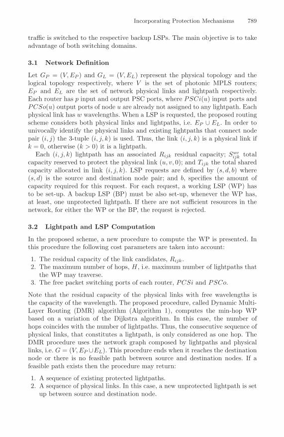
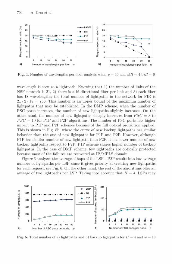
Figure 4 shows the influence of the number of wavelengths per fiber whenp = 10 and H = 4 and H = 6. As shown, the number of rejected requestslineally increases for FIR when H = 6. Moreover, since P2P prioritize lightpathsthat directly connects source and destination nodes, it outperforms P1P whenw > 24. Plus, P2P also offers better performance than DMP when H = 4 forw > 24. Note that DMP and FIR behavior sharply change according to themaximum number of hops (see Fig. 2) while P1P and P2P do not.
From these results, it can be concluded that the DMP algorithm allowsdecreasing the rejected requests due to the finest recovery granularity at theIP/MPLS domain. Additionally, DMP outperforms FIR algorithm when thenumber of o-e-o conversions is reduced (H). Moreover, when H ≥ 6, DMP onlyoutperforms FIR when the network nodes have high number of PSC ports.
In terms of resource consumption analysis, first the total number of lightpathsand backup lightpaths established is evaluated in Fig. 5. The case of H = 4 andw = 18 is only plotted for clarity since the behavior of all the schemes is similarin all cases in terms of network resources. Figure 5a shows the total numberof lightpaths created. Since FIR operates under multihop full grooming, each
794 A. Urra et al.
0
5
10
15
20
25
30
6 12 18 24 30 36
PASFF
FIR
P1P
P2P
Number of wavelengths per fiber, w
Req
uest
rej
ectio
n ra
tio (
%)
Number of wavelengths per fiber, w
Req
uest
rej
ectio
n ra
tio (
%)
0
5
10
15
20
25
30
6 12 18 24 30 36
a) b)
Fig. 4. Number of wavelengths per fiber analysis when p = 10 and a)H = 4 b)H = 6
wavelength is seen as a lightpath. Knowing that 1) the number of links of theNSF network is 21, 2) there is a bi-directional fiber per link and 3) each fiberhas 18 wavelengths; the total number of lightpaths in the network for FIR is21 · 2 · 18 = 756. This number is an upper bound of the maximum number oflightpaths that may be established. In the DMP scheme, when the number ofPSC ports increases, the number of new lightpaths slightly increases. On theother hand, the number of new lightpaths sharply increases from PSC = 3 toPSC = 10 for P1P and P2P algorithms. The number of PSC ports has higherimpact to P1P and P2P schemes because of the full optical protection applied.This is shown in Fig. 5b, where the curve of new backup lightpaths has similarbehavior than the one of new lightpaths for P1P and P2P. However, althoughP1P has similar number of new lightpath than P2P, it has lower number of newbackup lightpaths respect to P2P; P1P scheme shares higher number of backuplightpaths. In the case of DMP scheme, few lightpaths are optically protectedbecause most of the failures are recovered at IP/MPLS domain.
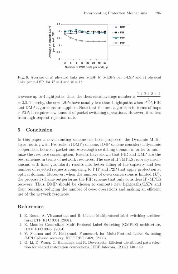
Figure 6 analyzes the average of hops of the LSPs. P2P results into low averagenumber of lightpaths per LSP since it gives priority at creating new lightpathsfor each request, see Fig. 6. On the other hand, the rest of the algorithms offer anaverage of two lightpaths per LSP. Taking into account that H = 4, LSPs may
0
200
400
600
800
1000
3 5 8 10 20 30 40 50
DMP
FIR
P1P
P2P
Number of PSC ports per node, p
Num
ber
of la
mbd
a LS
Ps
Number of PSC ports per node, p
Num
ber
of b
acku
p la
mbd
a LS
Ps
0
100
200
300
3 5 8 10 20 30 40 50
a) b)
Fig. 5. Total number of a) lightpaths and b) backup lightpaths for H = 4 and w = 18
Incorporating Protection Mechanisms 795
Number of PSC ports per node, p
Ave
rage
of l
ambd
a LS
Ps
per
pack
et L
SP
0
0.5
1
1.5
2
2.5
3 5 8 10 20 30 40 50
DMP
FIR
P1P
P2P
Fig. 6. Average of a) physical links per λ-LSP b) λ-LSPs per p-LSP and c) physicallinks per p-LSP, for H = 4 and w = 18
traverse up to 4 lightpaths, thus, the theoretical average number is1 + 2 + 3 + 4
4= 2.5. Thereby, the new LSPs have usually less than 4 lightpaths when P1P, FIRand DMP algorithms are applied. Note that the best algorithm in terms of hopsis P2P; it requires low amount of packet switching operations. However, it suffersfrom high request rejection ratio.
5 Conclusion
In this paper a novel routing scheme has been proposed: the Dynamic Multi-layer routing with Protection (DMP) scheme. DMP scheme considers a dynamiccooperation between packet and wavelength switching domain in order to mini-mize the resource consumption. Results have shown that FIR and DMP are thebest schemes in terms of network resources. The use of IP/MPLS recovery mech-anisms with finer granularity results into better filling of the capacity and lessnumber of rejected requests comparing to P1P and P2P that apply protection atoptical domain. Moreover, when the number of o-e-o conversions is limited (H),the proposed scheme outperforms the FIR scheme that only considers IP/MPLSrecovery. Thus, DMP should be chosen to compute new lightpaths/LSPs andtheir backups; reducing the number of o-e-o operations and making an efficientuse of the network resources.
References
1. E. Rosen, A. Viswanathan and R. Callon: Multiprotocol label switching architec-ture,IETF RFC 3031,(2001).
2. E. Mannie: Generalized Multi-Protocol Label Switching (GMPLS) architecture,IETF RFC 3945, (2004).
3. V. Sharma and F. Hellstrand: Framework for Multi-Protocol Label Switching(MPLS)-based recovery, IETF RFC 3469, (2003).
4. G. Li, D. Wang, C. Kalmanek and R. Doverspike: Efficient distributed path selec-tion for shared restoration connections, IEEE Infocom, (2002) 140–149.

796 A. Urra et al.
5. J. L. Marzo, E. Calle, C. Scoglio and T. Anjali: QoS on-line routing and MPLSmultilevel protection: a survey, IEEE Commun. Mag. 41, (2003) 126–132.
6. P.-H. Ho, J. Tapolcai and H. T. Mouftah: On achieving optimal survivable routingfor shared protection in survivable next-generation Internet, IEEE Trans. Reliab.53, (2004) 216–225.
7. D. Xu, Y. Xiong and C. Qiao: Novel algorithms for shared segment protection,IEEE J. Sel. Areas Commun. 21, (2003) 1320–1331.
8. K. Kar, M. Kodialam and T. V. Lakshman: Routing restorable bandwidth guar-anteed connections using maximum 2-route flows, IEEE Infocom, (2002) 772–781.
9. A. Urra, E. Calle and J. L. Marzo: Reliable services with fast protection inIP/MPLS over optical networks, Journal of Optical Networking 5, (2006) 870–880.
10. A. Urra, E. Calle and J. L. Marzo: Enhanced multi-layer protection in multi-serviceGMPLS networks, IEEE Globecom, (2005) 286–290.
11. E. Oki, K. Shiomoto, D. Shimazaki, N. Yamanaka, W. Imajuku and Y. Takigawa:Dynamic multilayer routing schemes in GMPLS-based IP+Optical networks, IEEECommun. Mag. 43, (2005) 108–114.
12. K. Zhu, H. Sang and B. Mukherje: A comprehensive study on next-generationoptical grooming switches, J. Sel. Areas Comm. 21, (2003) 1173–1186.
Related Documents