Calhoun: The NPS Institutional Archive DSpace Repository Theses and Dissertations Thesis and Dissertation Collection 1994-06 Inband radar cross section of phased arrays with parallel feeds Flokas, Vassilios Monterey, California. Naval Postgraduate School http://hdl.handle.net/10945/30853 Downloaded from NPS Archive: Calhoun

Welcome message from author
This document is posted to help you gain knowledge. Please leave a comment to let me know what you think about it! Share it to your friends and learn new things together.
Transcript
Calhoun: The NPS Institutional Archive
DSpace Repository
Theses and Dissertations Thesis and Dissertation Collection
1994-06
Inband radar cross section of phased arrays
with parallel feeds
Flokas, Vassilios
Monterey, California. Naval Postgraduate School
http://hdl.handle.net/10945/30853
Downloaded from NPS Archive: Calhoun

NAVAL POSTGRADUATE SCHOOL Monterey, California
THESIS INBAND RADAR CROSS SECTION OF PHASEDARRA YS
WITH PARALLEL FEEDS
by
VassiliosFiokas
June 1994
ThCSLSAd\'isor DavidC.Jenn
Appro'ed for public rele~se. dLSinbullon IS unlnnued

DUDLEY KNOX LIBRARY NAVN.. POSTGRADUATE SCHOOl MONTEREY CA 93943-5101

SIN 0102-LF-014-6603 Unclassified

Approved for public release, d1stnbut1on 1s unhm1ted
lnband Radarlro~\ SC'ction c•r'Ph,\scd A.:JJ\"5
\\ith Pa1aUel Feeds
LJeutenam .I '\<tv\
B S Hellenic ~ava! Academy 1985
Subnuttcd m partial fulfillment
of the requuemt:nts for the dcgrct: uf
"\1ASTER OF SClE:'\JCE II\ ELECTRICAL E\GlNLERl.'\G
fiom the
'\A\Al POSTGRADLAf.t SCHOOL June 1994
,\mhm -----Vas>ilws Flo"-as
Reader
Departmcnt ofEicctncal <tnJ ( (•rnpulel Engmeermg

4-BSTRACT
Approximak t~1rmul~1s f,ll th-: :nn,.md tddar c:t·o-,-., ~t:Llttlll ur mr.1ys \\ith
parallel ;,;:cd~ <1rc presented To oDldin tho: t(mnulas. multtptc rl"l~c:ctmn\ Jrc
neglected. and d.:\ icc~ <Jf the: ~am<: t:pc are assumed to ha\C Jdenucal cb:trical
rcrf(ml'.ancc:
The: appro'.tmatc rc~ulb \\ere comp~m:d to the results obramed u~ing a
ocancrmg mZ!ltl \ furrnulatwn Both methods were in agreement in prt:dictmg RCS
lobtc po~l!Jnn~. k\d~ .. md hcha\!Of \\Ilh ~canning. lhe ~ci\~nt~ges ui the
approxunatc method :lrt: 11~ eomputatwnal efficiency and its f1ex1btl1t;. tn lwndlmt!
an CJrbm:u; numbct of coupler k\ els.

·r ABLE OF CO'iTET\TS
l. JNTRODIJCTIO"\"
l1 llii:OR.LTICAL B.\CKGROl1\'D
,\. DLH'\IITJON OF RCS
SC ·\ TTf.RT\C, !·l iNDA.i'vlU\ IALS
C. SC'ATTfRTI'\:(, CHAR.ACTERISTICS OF PH.'\SED AJUZ.\Y
D ~PPROX1MAI"I: ~1ETHOD 13
lll. RCS ANALYSIS FOR THE RTGOROCS SOU 'TION 2R
I\ R.CS Of LINEAR AND I"WO-DHv1EN)JON.\L ARRA Y:S 1:::
.'\. RCS D.·\TA I OK llir~ APPROXli\.1ATf ~OLCTIUN 3::
LineJJ arra: J:
T\\(1 Jimcns10nal arra~ ..J.()
IZCS D...\L\ !-OR !Ill: RlCJ-UROliS ':>OL\ 'I JO:-< ..J.:'
CCli\lPAR.ISON S\jMMARY

DUDLEY i(r>.IOX LIBH;l,RY NAVAL FCSTGRADUATE SCHOOl MONTEREY CA 93943-5101
\1'1'1 '\DIX 1\. l\1/\ rL\8 PRO< JR.\ \I H lR LJ'\rL\R .\RR,\ y:-, s::::
\l'l'l::.\.1)1'\ H ~1-\TL:\B !'R()lJR.A\1 HH<.l'l .-\1\AR .\RR.\Y') :>-:.
LISJ Of 1\HlJ{I '\CI.:'i s~
l'\lllt\1 DI~TR.IB\.1101\ LJS"I 5•J


I. INTRODUCTION
The design of radar-stealthy platforms has become an important engineering
problem. The principles of radar stealth have been well known for several decades.
but only recently have technological advances allowed practical implementation of
these principles. Some examples of stealthy platforms are the SR-71 spyplane. the
F-117A fighter. and the B-2 bomber. All of them have low radar cross section
(RCS), low infrared (IR) emissions by control of heat sources, and low microwave
emissions by using "quiet" radar and communications.
The RCS of future military platforms will be lowered significantly by the use
of shaping and materials selection. Consequently, attention is now being focused
on the onboard sensors in order to ensure that their signatures do not become
predominant. Of particular interest are wideband phased arrays, which can possibly
operate at the same frequencies as those of an illuminating threat radar. Thus a
high performance array must not only meet the system antenna operating
requirements (gain. sidelobe level. etc.) but also the RCS requirements. It is
essential that any technique applied to minimize the radar cross section does not
seriously degrade the primary operation of the antenna system.
Solid state microelectronic devices now permit integrated transmit/receive or
receive-only elements to be collocated with array apertures. Self-calibrating and

adaptive "smart skin" conformal arrays are now practical. Increased efficiency,
reliability, and reduced cost are the benefits of this technology. This technology
makes phased arrays more appealing than other antenna types.
In characterizing and, subsequently, minimizing the RCS of phased arrays,
reliable computation of scattering is crucial. It is necessary to consider both inband
and out-of-band threat frequencies because the scattering characteristics of an array
are distinctly different in the two frequency regions. If the incident wave is in the
array's operating band, the radiating elements are well matched and threat signal
can penetrate into the feed and be reflected at internal mismatches and junctions.
Even for a well-matched array, there can be a large number of scattering sources
that add constructively under some conditions. This effect depends on the type of
feed and the devices incorporated therein. In some cases. these reflections can
significantly modify the RCS.
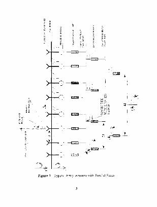
In this thesis. the inband RCS of a phased array with a parallel (corporate)
feed. as shown in Figure I, is examined. The main objectives are:
I. to find approximate equations for the inband RCS of phased arrays with parallel feed networks,
2. to compare the approximate solution with a rigorous solution based on scattering parameters, and
3. to determine the RCS behavior for various feed parameters for both linear and two-dimensional arrays.
"t I I
.. I -r--'"..1:_)
- ~~
-,_____.
-Figure I. I~p!Cal Array Antennn w1th Pnr~:lllel Feeds
.... jL-,

In g-:naal. antenna sc.mermg anat,:~i-; is wr;. dinicult. HarN.:n [Rl:t 1)
muck. \\JW:n i.- Jetcrmmcd h~ the r.1di:11ivn prop<Or!r6 of the nntennJ. :me \.tiibh<O'
\\lrcn the antenna 1.., conjugate matclwd to its r.ldrmwnlmpcdJnce l he: 'ecum! i~
the \liLiclur.II mode. \\hrch i~ ;;cncrared fl"om currents :nduccd \lll the :nneuna
.-;url~lCC'> Tho: t\\O mt1dc., :m: not c:.~srly l{kntlfiabk. in particular. \\ho:r. the .1rw:
h m.,talkJ on .1 pLltform. In thi~ the:~!~ onl~ th~: antenna mode i~ cxannned \\hich
1s thc Jommanl RC5:. u>!ll])llno:nt l\1r a pha-;ed anay in 11., opennm~ b:lfld
Chapter II prm ides the thcpr~:tical background for am1,: antenna RC~ ana·: Sb
and tncludc., the dcri\·ution of the appro'<anate formula., It prc~cnt:, informclll(ln
nbout the correspondence between RCS Jobes and the locntion oi periodic ~..-:dttcnng
sources \\"ithm the feed network. Chapter Ill Jc~cnbes th~ formation or the ~o-
cal cd rl,!!tlrc>Us solution. I hh mdhoU include~ multiple reflections hcl\\c~·n de\"JCC'
n t:1e kcd \\ hcrl'as tile <~ppro>..Jmate solution on I;. nm~iUcb the lirst rdkcuon :md
neglcctc: lll!'ileJ order rclledton<.; Chapter ]\' deals \lllh th~ compari~o\J .mtl
annly~1s llfresults !-mall~. Chapter\. conclude~ \-\ith a d~:,cu~:.ion on the h"nctlts.
:md rcc,Jmmendation~ that can be <~ppli..:d k> the ,mal:',!~ c>f lO\\
p-oh 1hiln: •Jf mtcrccpt rad.lr ,md conmJumcatwn~ ~: <okms

[1. THEORETICAL BACKGHOL ~D
Anlc.:nn.l~ \\Hh tdenttcal : .. unplitud..: ,HJd phas..: p,llt..:rr:., cun difil:r 111 the \Ia)
rhe;. The pus<,lhk nnporwncc ofthls pnimtn c,mncctton with e\aluatinn
ot antl:rma~ Lle>rgned 1\l ha1·..: 1denttcal paltt.:rns was fiN <.'\atnmed by R. H. Dicke
If{ ct. :::' 1. » ho proposed ''to what can be done m the 11 ay ot lhfterentratmg
bCt\\L'<.:ll (\ !elllld ,md bad .tllkllna On the ba~l> of ~cattennc>"
A. DEFII\1110~ OF RCS
The <tsstgmng of J radar eros~ ~..:c\Hin l<' a .2:111.:1"! larg..:t. 11h"-'ther tt IS em
.urcraft or a sh~p. ic, ha.xd on the fact that thts object t'LUlCllon' dS an antenna The
back">cattcnng cross sect10n ma)- therd"on.: he imcrrr"-'ted a measure of the
::mtenna curr..:nl' -.:\.~it..:J 1m -;uch obJect. Radar Cflb' ·":..:tl<lll ts a measUJc l'f
pO\\er -;canned in~~ g:tY..:n Jit..:ction whcu ,l t:ugd ~> tlJU!lll!latcd b) d!l in..:ident
I An older term tm RCS IS echo ,;re.t.J 1\la!hemJttc .. dl:, the RCS i, definc:d
(11
where R is th~ dlSlancc Jrorn the target to the observation point (receiver). £)8) i~
the scattered ckunc Jicld 111 th~ dtrectwa of the recei\'Cf. and £,(8,) is the mctckn:
electric tleld 1~h~u:11d tll be a phme \\one). The term monostatic mean~ th:1t rh:
transmitter and receiver are co-located \\ith respect to the target. 0 = 8. RCS has
umts of ~quare meters
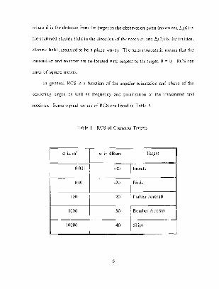
In general, RCS IS a function of the angular orientation and shape of the
scattering target. as well as frequency and polarization of the transmitter and
recei\'er. Some typical values of RCS are listed in Table I.
I able 1 RCS of Common Targets
0 in m: I cr in dBsm Target
0.001 -30 Insects
I
0.01 -20 I B1rd~
100 20 righter Aircratt
1000 30 BomberAJrcraft
10000 40 Ships

The ~emtenn;; chamctcnstics wr all Urgct., tJll Jnt<l thn_T natur.ll h·ginnc,
1Cg1ur: is the \·lie or IT\OJJan.:c :cg10r .. \1hcrc 1:1 i.' or; :he orlkr (>[una;. The thmJ
B. SC.\TTEHII\C Fli'IDAI\IEI\TALS
.\nknna ~cattcnng n,J-; b:::cn the sub_j.;et ot stuJ\ ~mcc 105tl, 10\\t\Cl t:1crc
lntk pnbli-,hL·d (>11 the subJeCt in the open lllcrJturc. Until the m1U 19~0\.
W<JI!-. hao cnnccntr,ncd Oil the ana!y51~ l'f kl\Y g:nn antenna, Rc~cntl1. ingh !.!::un
:mtcnnas h:t\c reccl\cd atterni,>n because it ~~ c~nlKlpatc:d tiMl \\ill
\\ !dcsnread use un future lov-. RC ~ plattunw ..
1-m a:1 dlltcnna ~ubttcteJ :u an JllCtdent dectr<Jmauncti.__ \Ia\ c. thc ~C.lllc1-cJ
the 'itructur,tl modc tT,) fRd 1 he: total ~Ccltlcrcd fidd (!-") .'>the:
(:?.)

\\here
11 = dkcli\C hcight of the ~lllcnna
I.-
t.- 1!1\.-l(knt tldd
J he strm:turdl mode: ari~e~ 11-om LUtTenL~ \\ hieh arc mlluced on the: .mtenna
,md the ~urroundmg \trw..:tun: \\hen the tcrmitMlmg load i~ equal to rht: U'mrk\.
c'\'ll]Ugdle of the antenna tmpedancc. !he .:mtenna mode re~ult~ \\hen :he: inJuenl
wrrent deli>ered to the amcnna ked ruint is rdkctc:d and then rcradwted. The
.unenn:t mode: i'i prorortional to the gam of the nntenna for a ~1ven dtrcdwr: ~md
a modified reflection coeftlucnL \\hkh i~ equal to
(3)
\\'hen the antc:nnd is CLllll\l~:Jte matchcd. the: modified ret1eetum uJetlie:cni
(•·) goe~ to ?cro and the .mtenna mode Yanishes. Usuctl!~. thi~ i~ ddncn:d \\hen the
.mc,;nn:t impedance has a real \~-tluc :~nd th<' termma.s ,1rc con!lct:led to .1 111~1\Chcd
transmitter dnd or tt(Tl\l:r Con~elluc·n(l:;. tlwn: ~~no rctlcction at tnc llllll.:twn
h..:l\\een (he ;mtcnn.J and the tran\1111~'-Wll tin..:. llm,e\er. /, tor ~Ill dement Ill an

<~rr~1: ~~ dependent on the angle uf arrn al Df tlw mcident \\<1\'e hee.1use of r:mtual
;tlllultane<lll~l;
If there i~ .1 rmsmatch a~ defined by tl1e moJilicJ rc·t\:ctwn cociTi~tent. then
J h.:: .JmoutH uf cutknr:.t lli<Hk ~c:ttkr r; depencts
:cam nf the antL'Illla in :1 p.Jrllcul& Jitcc:tion rhu~. if the ,mtl.'tl!l~ dcJes not
lliH<' :>:1111 <lllh!Lie ol 11~ ''pc!cttlllg band, tht"n ll 1\ill J:<ll h:l\L' -;tgm:ieant
C<'L'Ilicicnt
~ahn and Kur-;\ [Ref~] ha\e demonstrated tb:Jt for aldrgc cl.t\<., o: antennas
krmm<Jkd hy matched rcc..:i\ ~·r~. the \L'at!ered power 1~ general!) ~'TedtL'T ~IMn the
ab~orbed prmcr. cqu:dity being attained ror rnrntrnum-scattenng antenna~ ·1 his
IT'ult ha" lrcctuentl;. been mklplctcd to mean that m> L<lniug:Jle-matchcd .mtcrma
can a:y,,,rh more than 11 "~·.Jncr~ Thh tmp tc-; that garn mu.~: h: ln\\dCJ \u reJuc..:
RCS !j(,\\T\l'r Citt:c'n [Ref -1-1 ha~ -;hm\n thai an ar:lc:ma c1n ah~orb murc than
gc~m mthe ba~·k dirn:t:,m L'\.LTL'(h 11, g~tlrr m the t,,n\ard dirc~tJOn
Tin~ h the ca<.;L' lc'r all hi;:h p..:rtlmlMncc pha\cd .l!Ta; atll\:mta~
C. Sl'ATTEHI~G CIIARACTERJSTICS ()F PHASED AHR,'\ Y
·\ swgk dtpolc l'rO\ id~~ j(,\\ dit~eti\ ll_\ To tncrt:.h<" dnte!llld ~!Lt: c~ncll:ct:..:e
du.:Ct!\ j(\ ,j C(l]]cCtiLlll uf c],·me!lb l.:~lll !Jc dff<ltl\lL'J ,Ulll lllkr~OilllClkd l<' 1(11111 clll

array. 'The basic element can be an aperture or slot, hom, microstrip patch, spiral,
or d ipole depending on the application. In order to provide very directive patterns.
the fields from the array clements must interfere constmctively (add) in the desired
directions and interfere destructively (cancel each other) in the remaining space.
Tht: RCS of an array antenna can be decomposed into the components
described in the previous section: the antenna mode and th e structural mode. The
relative importance of the two terms w ill depend primarily on the threat frequency
As shown in Figure 2 the frequency domain is separated into l!ve bands. for a
well-designed antenna, the RCS in the operating band shou ld be low because most
of the incident energy is delivered to the antenna load. llowever, even though the
individual reflections from the antctma are small, a large array can have have tens
of thousands of such sources. Thus the RCS can achieve significan t levels under
some conditions .
Low out-ofhand
Figure 2. Antenna Frequency Band
High out-ofband
In this thesis. only thrt:at signals in the operating band of the antenna will be
considered. In this case. the wave penetrates into the fet:d network and is reflected
at internal junctions and devices. The total RCS is dt:tcrmined by the vector sum
10

,,f i!L' mdJ\Jdnal ~uucn:d !idUo that n:turn tu the .1p::rtur..: and rerad1Jk These
mdudc
mpub t>fthc: lir~t lnc:l t>l umplc:rs.'
luacb at the ~um <tiid dilkrenn: arm~ of the first le\d l'C coupkr\. , r:o.
trnanufacturing and m;llenal. etc.)
Ill3tched due to lanitatJons propcrtie~ ul
'iurt:Kc wughncss !a~sembly toleJc~ncc.., di~conllllUltiC~. Ji-;cmtiom.
I dgcdfl::cts
The J:Jhaml .mtenna mode RCS ~~ oht<tmcd I rom cquatJOJb {I J an,J (.::! 1 ;~nd
ot0.lp) - (4)
])

\\here
l.{!:lJPI total retkcteJ ~1!--'TI~tl rc:turncd to thl' aperture for c:kmrnt n
\\hen the waYc ts mctdc!ll !i-,ml th..: tO.n) dirccll\'11
- \~J - lt:::)
,, - ~tnOcuo.;o
1· = "inO:m10
H = co~8
d.., -- position \ector to eknwnt 11
- norm.1lurJ dcm..::nt \Calk! ing pattern
To arri\C at (~J tdentical clements have been assumed: the \ariatJOn in mutu<!l
coupling ne.u the nrray eJ.rres has h..:en neglcned. This allows the RCS to be
se~mr::ned uno all ana: factor and an drrnem tactor. JUSt ns tn the mJiatJOn c::tsc
b nluatmg t--1) requne~ th<:: total retlected field at each dement. /\ ng\)nJUS
\Olutmn mu~t c:mplo: a network matrix f"ormulatton .~uch as scattenng parameters
!f multipk rdlcctwns \\ithin the feed can be nc:glc:ctc:d, an approxmMk ~olutwn
be: obtalllc:d h;. tracing "ig.nals through the ked and h<~ck tu the aperture.

D. APPROXIMATE METHOD
In this section approximate RCS formulas are derived. The following
assumptions are made:
1. All the devices of the same type are assumed to have identical electrical characteristics. That means that all the radiating elements have the same reflection coefficient r, and the same transmission coefficient tr- None of the elements is ideaJ, because each reflection coefficient r, is not equal to zero. By the same token. all phase shifters have a reflection coefficient rP, etc.
'1 All couplers are represented by magic tees. which implies equal power splitting. (This is not a low sidelobe feed).
3. In the operating frequency band, all feed devices are well matched and therefore higher order reflections are neglected (r << I).
4. Only scattering from the aperture, phase shifter inputs, coupler inputs. and the sum and difference arms of the first and second levels of couplers are considered. Couplers in higher levels of the network are assumed to be perfectly matched.
5. Lossless devices are assumed for simplicity, which implies
lrl' + ltl' = 1 (5)
for a device where r is the reflection coefficient. and t is the transmission coefficient.
6. Identical apenure elements with a Lambertian scattering pattern (cos2e).
7. Edge effects are not included.
13

8. Assuming that only one scattering source dominates at any given angle, the coherent sum of the scattered signals is represented by a non coherent sum
IE, +E, + ... +E,I'" IE, I'+ IE, I'+ ... + IE, I' (6)
where E~ is the reflected signal of the nlh element. Thus, the total RCS can be expressed as o = aa + aP + O;c 1 + OA1 + O;c2 + OA2 + ···
9. Random errors are neglected since they only contribute to an average RCS level.
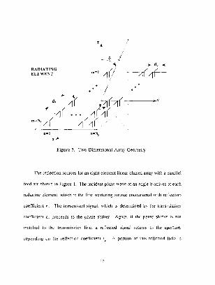
Parallel feeds are suited to rectangular element arrangements, and therefore
linear and rectangular array geometries will be studied. Array quantities are
defined in Figure 3. Note that:
1. For the case of linear arrays, all elements are aligned along the x-axis and equally spaced, d. The z-axis is broadside to the array.
2. For the case of two dimensional planar arrays all elements are in the xyplane, uniformly spaced with dimensions dx and d,., and numbers of elements N~ and N>.
3. There is only a e polarized incident field. (For linearly polarized elements in the xy plane, this gives rise to the cos:lf! scattering pattern.)
4. The phase shift per element introduced by the phase shifter in Figure 1 is !1. Furthermore, the phase shifters are reciprocal.
14
RADIATI"\G EU\TF: .... f
9 : ,., m=l 4
- __ .,_~
Figure 3. 1 wo-Dim..:nswnal Array Geometry
l he rd1ectic)n sourc..:s for an etght dement linear phased array mth a parallel
feed an: shU\\Tl in hgure 1. The inctdent p!ane wave at an ang:e 0 arn>6 Jt each
radtJ.ting ~'kmcnt. which h the first scanenng source encountered \\ 1th rctkctwn
coe!tlc1ent r, The transmmcd signaL which 1~ determmcd b:. the transmtsston
Clldfictent r, proceed~ to the pha~c shilier .-\g:nn. 11 the phase shther IS not
matched to the transnusston line. a retlcctcd ~igna.l rctums ll> the aperture.
11epcnd1:1g on the rctlcdwn ~ueffiCJent ··1 ·\ portion of this rctlecred tielli b
15

ret1ecred ag,.lln h:; the ra.diatinf! element srnce It is a~~UIHed to he re<.:1prm:al I h1s
1, a second-('rtkr rc:ll.:-..lJ\lll, :.md ''ill ht: n..:gkncJ 1nthc: cakulati(>n ufl~C<;, lht
porurm of the stgn.1lnut rdkcted at the pha,c sh1her IS tran.~nlltttd to tht: lir~l Je\'d
uf coupler~. and so on
propa~1ale~ through 1t 1\!ll c:ncDuntcr .1 pha~c .~hlil Lkpcndmg un the antenn.t heam
scan angle 0, 1-nr a linear pha~t prugre~ston. th.: transmJSSton coerlicJcnt l{>r th..:
phase shifter at ekmcnt 11 IS
(71
\\her~· z, kdsl!l8, fur the linem anay
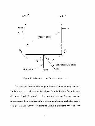
Figur..: -1- ~how~ th<.: iir~t magic tee 111 the arra:; \\ llh tht: ti.HJrth pmc loaded
(It can n::pn.:.~t:nt an~ three-port power di\idcr a~ \\ell) l·~ually mismat~.:he~ exist
m hoth ,1ck arnb. and in the ~um and difft:rcncc:: arm~ The mismatd1es result 111
rdlcction<> back to the aperture. wtth reflection codfici~.:nt~ oi" r J.t ports 2 anJ 3
r~ at port L and r~ at port -1 The angle-~ is the ~~~JMl phase at the coupler port
3 relative to the stgnal phase at tht: coupler port 2. and m..:lude~ <.~11 ol"the m~ertwn
phases ofth<' deYtee~ between the l-Ouplers of the fir~t k\clund 1hc aperture It
abo mclude.\ an: ~pace path dcla:- rela1in~ to the ongm for the incident \\d\C If
the phase\ of all rellectwn coctfictellt~ (except the ]'ha~~: ~lufterl are zero. then
_:>, - u. - wiKrc u ~ hhintl
PORT 2
£'
'•
SCMARi\1
PORT J
SIDE AR!\lS
.., .._DlEEEREi\CE ARM
PORT 1 ORT ~
Figure 4. Retlectwm a.t the Ports of a. I\fagrc Tee
rhc magic ll'C ~hm\n combmes ~1gnah from the first t\\0 r:~diating clements
Simliatl:. the: next magic tee comhmrs ~ignals I rom the third and fourth clements
1 ::'~\ :n port j and at port .2) The pL1rtJO!l of the ~tgnai that cnt.:r~ the '>lllll
cmn propagates d('\\fllD thc second JC\el ufcoup!crs \\here SC'ID.: rcJkctwn oLCUf'>.
\11th the :emainrng Slgnar t:<tnsnrrncc! t,1 the third IL:\ cl or cuupkrs. J.nd so on. For

a parallel feed network. the number of radiating elements is always of the fonn ~'"
\Vhere m i:. the number of levels of couplers
rhe ~i_,:nals renecteJ lfom the magic tee can be determined ±rom its scattering
matnx. F1rst assume that the magit: tee i~ perfect!:- matched ;:md therefOre has the
followinp. scattering matrix:
c 0 E ~ ~ ~ ~I 2 1 0 0 -1 .
_0 1 -1 0
(8)
Relt:rrrng to fJ:;:wre ..J.. the mput signals at ports 2 and 3 are E 1 and E::
respectively. Both signals have unit amplitude but differ in phase h_:.- L'l. radians.
The subscripts on E refer to the element numbers to which tee's s1de arms arc
connected. In the sum arm the combined signal 1s
Er., = £1 + £2 = if + lejil. 4 '
= ..f2/2 cos(j).
Similarly. for the dif!Crcncc arm the combined signal is
£4, = £1 - Ez = if -if eJ4
sin(~).
18
(9)
(10)

The next magic tee in the arra) combines the input SJt-'Tlals £_, ami E 1 from
dt:ments 3 and 4. Again. both signah have unit amplitude but differ in phase b~
\ (bt:Lause has a phase of ~.3. and L, has a phase of 3.3.)
and
sin(%) (12)
In generaL the s1gnals in the sum ami difference arms are
(13a)
ami
E!>,. = (13bl
for n = L 2 . .. N12
Tht: rdkut:d "ignnb from the ~um and diffcn.:ncc arm~ ,,f the tirq le\el ot
couplers hm e the form
I'!

and
E~. = E~. r~ (14b)
Thereton: tht total n::nected signals remming at the side arm inputs are
' E; = [rEcos(%)- jr~sm(%)]/2 e1H, (17)
E; o [,,cos(%) • j,,,;n(%)]/% ,,, . (18)
As expected, these equations indicate that the RCS depends on the relatiYe phase:.
of the signals cntcnng the side arms.
The tow\ scanercd signal due to first level of couplers is obtained b:;.
\ummmg all rcfkctions returned to the nperture
20

(19)
111clwkJ Summm;r the terms in r ll));. kid~ [Rd. ~ I
(20)
Th1~ c.m lw mtc'rprcted the ~um of retums !rc1m ~um c1rm pluc, rclu:·n~ from
the differenc<.' anm Appl: ing the ddinaion ,,f RCS
(21a)
1}::., = (21b)
rr:.u1~mnkd dm\ll It' tile- ~c:crmJ .e\d \\hen: the enure pt·\lce:i~ 1~ n:peatcd ·1 he
Cl

·e'3.:. 122)
·\gam. th1s JS a sum of RCS contrihuttons from the sum dnd dilkrcnc~.: amt~.
f23a)
..fr.A2 ·sin 1 ~. sin(NLq
~sin(4.1.)1 (23b)
fhe coupler RCS C(>ntrihution contaim three fachm. The first one i~
(..fTC.·fr~.'/.~J. the RCS o1 a reflector of area A reduced b~ the reilection cocflicienl
I he squared term-, m hlJ_g:c brad.d~ arc dll Jrray !actor fm the coupler~
Final!~. the rcmmmm: tactors are equi\'alent tn nn clement !Jctor for the coupler
~um or di fkrcncc a.rm~.
For linca.rl;. p<li.Jri?cd radiatmg elements nlong th<.: '>:-axis and ,1 8-polari?cd
incident \\aYe. the element factor is
'lhl~ t:tctot can be lumpeJ 111th .1 to lorm <~ prOJeCt<=d ;uca I he ph~~Kal ar<.:a i-.

Jdakd ld th~ number oJ'ckmenh and the ~pacin;; lhu~ lur d lmcnr arrJ~
A - ,Vd!wsO (25)
11ln.:rc
\"15 the number orc:lcmcnh
r('l RCS ,'ontnbutwn, tnc lirst and the: last fnctor of(-1-J n:IJ.dlil che s,mw. but
~.Hll,llldll dem~:11t dJlllr1huuon
AF, I sin(No:)] = rr, N~iil\a) .
(26)
l hc ;1rr:l\ ::ILIL'I" rur the std., arms olthc firsl k\<:1 ul· cuupln' h..:L·o:nL''
(2SJ
ul coupkr', h<:CLllllC:\

AF~, =
\\hlch o...:curs m (2ial. !he arra~· factor for the Jifferenc<'" arm~ of the fiN kHl
\\hich abu occurs m (2\h)
~ ~~· ~in(N~) ·~ -:.m(2.l)
\2 /
(JII)
rhe arra;. ll.tctor for the sum arms of the ~econJ level of coupkr.-; b~.:cumes
AF1., = 'in(N;) l N 4 odn(4h.)
(Jl)
\\hid1 is related to t23a). The array factor for the difference arms of the second
[e,·c[ ol coupler~ bcC('!lles
AF.:'.." = {32)
''ilicn ~~ aho related to 1:Jh) 1!:; combinm~ (·11 :md thJ. the total 1mmos1aliL

inband antenna mode RCS is
Consider a oftwo~dimensional planar array in the xy~plane with a rectangular
grid as shown in Figure 3. The array has N, by N, elements spaced d., by d_.
Parallel feeds are used to combine signals for elements along the x~axis. Thus the
results for the linear array can be applied directly to the two~dimensional array by
choosing 6. properly and multiplying all terms by a y~direction array factor. If
9, and cp, are the scanned antenna beam angles. then let
(34a)
and
(34b)
be the interelement phases to scan the antenna beam. Now 6. in the linear array
formulas is replaced by S,. where
(35)
All scattering terms for the linear array must be multiplied by an array factor for
the y-dimension. For scattering sources ahead of the phase shifters
25

AF • (sin(N,kd,v)J Y l Nysin(kdy v) '
and tbr scattering sources behind the phase shifters
where
(sin(N,(,)l AF, • lN,sin((,) '
Thus, for a two~dimensional array equations (26) through (32) become
(36)
(37)
(38)
, , (sin(N,(Jl(sin(N,(,)l (4!) AFc ""t,tprclNxsin(C,,) lN,sin(C,) '
AF • t't'r coi1J[ sin(N,(,) l(sin(N,(,)l, (42) l:t r P E l2 ~sin(2C) lNYsin({,)
2 '
26

(43)
(44)
AF • t't'r cos'[.S)sin'(('[ 'in(N,(,) ]l'in(N,(,Jl· A2 ' P "' 2 v N N sin(()
-fsin(4(_.) Y
(45)
Finall~. the totaJ RCS is
where
(47)
27

III. RCS ANALYSIS FOR THE RIGOROUS SOLUTION
In the approximate method, the higher order reflections are neglected because
they vary as?,?, etc., where r << l. A rigorous solution based on a scattering
matrix formulation contains the effects of multiple reflections. Furthermore, it is
possible to combine scattering matrices with the method of moments to include
interactions between the feed and aperture as well as reflections inside the feed.
This method solves the problem rigorously by obtaining an antenna impedance
matrix that describes the electrical characteristics of the antenna surfaces and feed
network. The method of moments (MM) impedance matrix is combined with the
feed scattering matrix and continuity equations that relate the MM expansion
coefficients to the feed signals as described in [Ref. 6].
In this thesis a variation of the rigorous method in [Ref. 6] is used, where the
radiating element is represented by a simple two-port device with reflection
coefficient r,. This eliminates the method of moments portion of the antenna
matrix in the rigorous solution of [Ref. 6], and the problem reduces to a pure
scattering matrix one. This allows direct comparison of the rigorous solution with
the approximate solution, because the radiating elements are modelled the same.
28

.\ t~·plcdl scattcTing m~lln\. equi\aknlnd\\ork \'.llh C!fht elements is sh0\\11
multiple or-! Ill~ mL:J>CJll pldrk \',d\c ilcld
s, - !.2. N (-18)
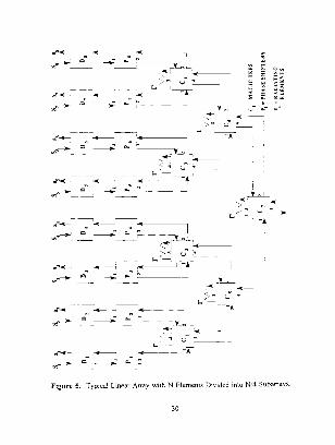
The:-,.- ckrncnb oi the drrd~ canl'c dnrdcd into:".. ..J subnrro~~ ns slwnnm fig:urc
E'- L {4Q)
dccoupled
a, - {[5 - a, a, ~ a" ~ all, 150) a, ~ a, a, a, - "~
I he J•,ul IZ( \ i'> ubta!llcd tfr>m 11)
- § ~
<..-_._- ""(------~
~
" :::, - _,;;. 0:... N 0-
~"~ -----=-.-,_,~____.._ :::. ~ ~ ~-------:?' C<
~ . __ -- t- -
.. ...,..~ ...C:-------1 ,._ __ ~-r
:::."' ______;. =--"' ~-- --
Figure 5. Typical I.in~ar Array '"lth N Element~ Di\tJed into "J'.f :-,ubarra~~-
30
4-elementliocararray
A A A I<
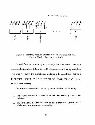
AA T Figure 6 Scattering Matnx Net\\urk \\hen the Radiating
Element Matcl1 Con.'>tant with Angle
For ench four-dement sub.:trray. there are C1_2ht 2-port de\ ices 1 tOur radiating
elements plus tOur phase shifters) that yield 16 eyuJtions, and three ·1-port d<.:>Iccs
(1\\0 m:~gic tees in the fi.rst levtl plu~ one magic h:c in the second level) that: icld
12 equations There is a total of 2X equations :1nd 28 unknO\\flS (28 a's) tor the
four -+-~·lcmmt subarra;
The Imp0rl<lnt charactl:'ristJC\ of th:: rigr,rou~ method arc the f(,]lrmmg
lntcrc~euun~ bet\\Cen ml dn1ee~ m the feed and radwting elements ctre mcluded.
The tr::msmi'>'dUn I me ot· ch<tngmg I me
bet\\ ecn de> JCe., h mcluded Thus thc cl f<::~' '-.111 be muddlt:d
31

1\'. RCS OF UN EAR A~D T\\'0-DI\lENSTO'IAL AJ{RAY~
In orclo:1 10 ~unp!d~ llw anal) ,j~ ant.! n:t.!w.:o;: tho;: demand tor COlllf'Ulcr t11nc
L>nl~ "in car arr~l\-.. h:J\'C heen cxamim:d u~mg the ngorou" mcthoJ l hu-; .1
comp~m~on of the twn methods is only giH'll for lmcar arra:;.s. RCS contour pl<lh
for t\\o-dimcnsJonal arra;.s \\ere also obtamcd to illustrate RCS l'clM\JOr \\llh
beam s,;annJn?. The M-\II.:..H program~ arc mcludcd in the Appcnd1ce~
A. RCS DATA FOR THE APPROXIMATE SOLL TIO~
1. Linear arra}
rm th~· approximate method. RCS pattern data t~or linl'ar amt\S \\CJS
computed "]he line;:u arraJ program cmnpult:s the RCS per ~quarcd \\a\ckn!!th
itl dH for an;r monostc~tic anf!lc 8, numhcr ol"JadiJting dcm~.:nb N. and .\c;mned
dllf'k 8 The: contnhutwns from each scatt.:rmg ~outcc can he brokc:n out
mdnidu.lll;. if" dc"-,m~d
lhe inband RCS ofltncar arra;.<; \\ith 16. 6..J-. and 12~ clements fN
0 = 0 degrees (no "canmng) is sh0\\11 in figure~ 7 throu§:h <J. ,;]] rdktllon
..:oc:ttim.:nls iOr feed de\·icc:> and the radwtmg elements ;:trc equal [,) 0 2
·· -1 r,- ():

In Band RCS of a l1near array with parallel feed N= 16 and thetas=O
20r Approx1mate Method
·10
·20
·30
·40
-so ~-a=-o ------::::.so~-40 -20 o 20 40 Bo Monostatic Angle {deg)
33
BO
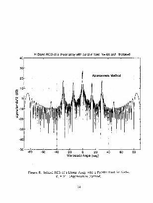
In Band RCS of a linear array with parallel feed N= 64 and thetas=O
-SO- --8~0_--_~60c--_ _L40 -----2L0 __ 0 ___ 2,0 ___ 4L0--6~0--8L0-
MonostatiC Angle {deg)
figure 8. lnh:md RCS of a. I int:ar ~rraY with a Parallel Feed (or :-J-64 8,- o- (Approxunate _\'iethud)
34
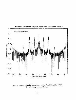
In Band RCS of a linear array with parallel feed N= 128 and thetas=O
Approximate Method
-80 -60 -40 ~20 0 Monostatic Angle {deg)
Figure 9. lnband RCS of a Linear Array with a Parallel Feed for N=l28. e, = oo (Approximate Method).
35

For all linear array calculations the spacing is d = JJ2 and the effective height (or
length) of the elements in they direction is l = IJ2 .
Referring to the figures, note that the number of major lobes (spikes) is
the same in all cases. For a small number of elements (e.g., N = 16) the lobes are
not as well defined because they are broader and lower. The RCS contributions
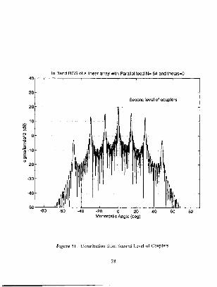
from first and second levels of couplers are shown in Figures 10 and 11,
respectively. The lobe spacing in the RCS pattern for the first level of couplers is
determined by the physical spacing of the couplers (2d). This can be generalized
for higher levels also. For instance, the effective spacing of the second level of
couplers is 4d. Therefore, as more levels of couplers are added to the feed, more
lobes appear between already existing lobes.
Figure 12 illustrates the effect of beam scanning. Assuming that the phase
shifters are reciprocal devices, the lobes associated with mismatches behind the
phase shifters scan with the antenna beam because of the factor lo . The large
lobe. at 9 = 45 degrees in Figure 12 is due to in-phase addition of the scattered
signals passing through the phase shifters, as expected. Note that the specular lobe
at 9 = 0 degrees does not scan. The high lobes near ± 85° are due to Bragg
diffraction (the RCS equivalent of grating lobes).
36
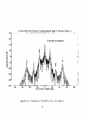
In Band RCS of a linear array With parallel feed N= 64 and thetas=O 40
30 First level of couplers l
20
Figure 10 Con:nbtltwn frurn first I nc!L•f Couplt:r~
37
40
30
20
10 m "-~ 0
~ 'iij-10
·~ -20
-30
-40
-50 -80
In Band RCS of a linear array with Parallel feed N= 64 and thetas=O
Second level of couplers
-20 0 20 Monostatic Angle (deg)
Fi:!;ure 11 Contribution from Second Level of Couplers.
80
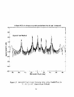
In Band RCS of a linear array with parallel feed N"' 64 and thetas=45 40·r-o---~-----r----r----r----r----r----r----r--
30
Approximate Method 20
-30
-40
-SO -80 -60 -40 ~20 0 20 Monostatic Angle (deg)
40 60 80
Figure 12. Inband RCS of a Linear Scanning Array with a Parallel Feed for N;; 64. e, = 45° (Approximate Method).
39

2. T wo dimensional array
A second MATLAB program, which is shown in Appendix B, was used
to generate contour plots of inband RCS for two-dimensional arrays For
simplicity. only square arrays are examined ( N, = N, and d, = dY = N 2) for a
specified scan angle (8,, <p, ). Again it is assumed that a ll reflection coeffk1~nts
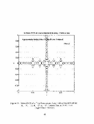
arc 0.2. RCS contours are shown in Figures 13 through 16. They are plotted in
direction cosine space (u and v) and the contours enclose spatial regions of ~{CS
above a specified leve l. This level is chosen to be 10 dB when N, = N,.= 16. and
20 dB when N, = NY = 64 elements.
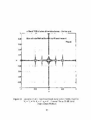
The only difference between the arrays of Figures 13 and 14 is the
number of clements: 16 by 16 versus 64 by 64. Both plots are symmetric about
the horizontal axis at v = 0. High RCS is present along the principal planes of the
array and then drops off away from these axes because of the separable product in
the array factors. It can be seen that the lobes are narrower and higher as the
number of clements increase. The specular lobe appears at the center of each plot.
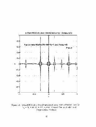
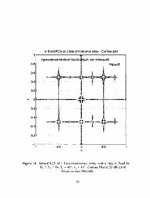
Figures 15 and 16 show the RCS of scanned arrays. The fi rst one has
8, = 45 degrees and <p , = 0 degrees. and the second 8, = 45 degrees and <p, = 45
degrees. Both plots are symmetric around the axis v = 0 As in the linear array
case, the lobes originating from reflections behind the phase shifters scan along.
with the antenna beam
40
In Band RCS of a two-dimensional array- Contour plot
0.8 Phis·O
0.6
-0.6
-0.8
-!~,------~-0~.5~----~~------~0~.5------~
Figure 13. Inband RCS of a Two-Dimensional Array with a Parallel Feed for Nx = N, = 16. 8, = 0°, (jl• = 0°. Contour Plot at 10 dB Level
(Approximate Method).
41
In Band RCS of a two-dimensional array - Contour plot
Approximrlte Method.Nx=1=Ny=N .and.thetas=O
Phis=D
0.8
o.6 I
··=tffi<·~· . I
·!-1L -------;.():':.5:---__;~----;0;':.5:-------!
Figure 14. Inband RCS of a Two-Dimensional Array with a Parallel Feed for Nx ""'NY= 64, e, == 0°, 'P, = 0°. Contour Plot at 20 dB Level
(Approximate Method).
42
In Band RCS of a two-dimensional array - Contour plot
0.8
Approximate Metl Nx•64j.Ny•N and thetas-45
-~ 1~ Phis=O
I 0.6
0.4
0.2
-0.2
-0.4
-0.6
-0.8
-~~c_ ___ -o..,...,_s---~'---=---o.~s---_j
Figure 15. Inband RCS of a Two-Dimensional Array with a Parallel Feed for Nx = N, = 64, 9, = 45°, q~, = 0°. Contour Plot at 20 dB Level
(Approximate Method).
43
In Band RCS of a MQ..dimensionaJ array~ Contour plot
y=N and thetas•45
~0.6
-0.8
Figure 16. Inband RCS of a Two~Dimensional Array with a Parallel Feed for N" =NY= 64, a.= 45°, cp, = 45°. Contour Plot at 20 dB Level
(Approximate Method).
44

B. RCS OAT4. FOR THE RIGOROUS SOU,'JIO"\
dlmputc~ the RC') pn squnn:d 1><J\C l:ll?th m dR t{Jr .!11) lllllli(l)!:Hic angle tl
.'\rra:;. p:unmdcr~ t:JC!uck the number ol ralhatin? dcm·:nts Y 1 Y ha.\ l<l l'e a
rT:ullq1lc uf :":). \C<l!l angle H .md ckt::uical p<1th k:1gth hct11<.:en dc·\·Jce~ \jl, tin
r~tdwmJ rhc Putput !S 11nnen to MATl AR fik" Lhut can he u"c:d to piot the Rl'S
pattern~
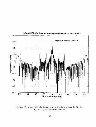
.f-igure l~ sho11~ the: RCS 1alues of d lrn.:ar arr,l\ f,Jr S ~ h..t 11ith no
~canmng tO = 0) :md path length~ of li!rJ - 0 radians A~ in thL· ~1pproximnte
!lJethod. the ;;pecu!J.r ],Jb<.: at A - 0. coupkr lobes. and Brag)! lobe:. at 0 = ~-R:'
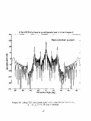
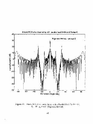
deg-ree~ are endent. I he same arr;:ry is examined in r:1~urcs lfl and 19 11ith 'I''-
~ 4 cmd r. :?.. rTspccti1elJ \ compan"on <liTigurc~ -through ·9 ~hu\\" that the
lobe\ ba1 c the ~~lnlt: posnwn but chtkr in <~mplitt:Je ~pec·dicall:. :or .1 ~" -1- the
\ptculilr aml coupler lohr" halT bigger mnplitndc tnan tor\!,- 0 ll(J\\e\'L":, I(Jr
,,,,-;;: -1-. the Bragg f,Jtx;-; h~n~' ~mailer ampl!tudc th:m k 1r 1 , = 11 Tiw \ariatJon
1'- du~· w th<: beat1ng ('( mi~m~ncbc::, in th<:: teed 1 he ;,ddilluJ: <lr Cdllt:c!ldti()Jl
depend~ un the !me lengTh\ umnellin.l! the de\ Jtc:.-; l!', 1 h1~ dtec:t becomes more
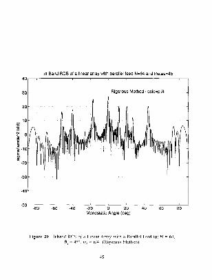
cumphcakd .h th: lw:un I\ ~c',mned d lf'Ure '),1mc J,Jhc' :n<~: d:~dppear :ll
sum<.: \Call ,mgks beeau.'e the rh~hc '-.h11kr-; mtroduc:c: .1 ~lntl that L~IU\e comnktc
-1-5
·80
In Band RCS of a linear array with parallel feed N=64 and thetas:O
·60 -40
Rigorous Method - psio=O
-20 0 20 Monostatic Angle (deg)
40 60
Figure 17 lnband RC~ of a Linear Array with a Parallel Feed for:.;:= 64. 8 = 0°. \.jJ,, ~ 0 (Rigorous Method).
46
80
-80
In Band RCS of a linear array with parallel feed N:::64 and thetas=O
-60
Rigorous Method - psio=pi/4
-20 0 20 Monostatic Angle (deg)
40 60
Figure 18. lnhanJ RCS of a lmc:ar A.rrn: with a Parallel Feed for N = 6..\. 8, u \ , ~ -: -1 (R1gorous Method).
80
30
lnband RCS of a linear array with parallel feed N=64 and thetas=O
·40
Rigorous Method - psio=pi/2
-20 0 20 Monostatic Angle (deg)
40 60
Figure 19. lnhand RCS o! a Linear :\rray with a Parallel Feed for N = 6-+, !::1, = o~. \),1 """"' ;c'2 lRigorous Method).
48
so
In Band RCS of a linear array with parallel feed N=64 and thetas=45 40r-.----.-----,---,,----.----r----.----,----.-,
30 Rigorous Method· psio=pi/4
-50 -80 -80 -40 ·20 0 20 Monostatic Angle (deg)
40 60
Figure 20. Inband RCS of a Linear Array with a Parallel Feed for N = 64, 9, = 45"', lfo = 1tl4 (Rigorous Method).
49
80

cancellation of two scattering contributions. This is not predicted by the
approximate method because it sums the individual contributions noncoherently.
C. COMPARISON SUMMARY
The rigorous and approximate results have been presented for broadside and
scanned linear arrays. In both cases the specular lobes have almost the same
magnitude (within about ldB) but the coupler lobes vary about 3 dB. This is
attributed to the noncoherent summation in the approximation. When the beam is
scanned, both methods predict the proper lobe locations. unless complete
cancellation occurs.
From a practical point of view, the approximate results are very close to the
rigorous. One major difference is the computation times. For N""'- 64, the rigorous
method takes about eight times longer than the approximate method and increases
dramatically when N increases (for N = 128 over 12 times). A more important
difference is that if the number of levels of couplers is increased. the scattering
equations must be completely rewritten and programmed. For the approximate
method. more terms only need to be added to equation (33).
50

V. CONCLUSIONS
An approximate scattering model for arrays with parallel feed networks has
been presented. Calculations for several cases were compared to a rigorous method
which includes all the interactions between the feed devices and aperture. The
approximate method was in good agreement with the rigorous method in predicting
RCS lobe positions. heights, and behavior with scanning.
There are several advantages to the approximate approach. First, it is
computationally efficient, allowing two-dimensional contours to be generated in
minutes. Second, it can be easily extended to an arbitrary number of elements and
coupler levels. The disadvantage is that a non coherent addition of terms does not
predict total cancellation conditions. However, most RCS designers are primarily
concerned with the "worst case" conditions for highest RCS, and in this sense the
approximate method is sufficient.
Future efforts should be directed at increasing the number of coupler levels.
and adding a coupling network in the y dimension of the two-dimensional array.
Also. methods of reducing the inband RCS should be investigated.
51

APPENDIX A
MATLAB PROGRAM FOR LINEAR ARRAYS
% Phased arrays X Wntten by V .FLOKAS - 22 APR.1994 X In band RCS of a linear array vi th parallel feed clear clg thetas•input ('Enter scanned angle in degrees thetas= ') Y. Scanning at Phis=O this..-thetas•pi/180; c=3e8; f=input('Enter operating frequency in Hz, f .. ') la.mda•c/f; k=2*pi/lamda; -d=O.S•la.mda; -chi•k•d•sin(this); theta=linspace( -89,89,660) ; thi•theta•pi/180; ~alpha•k*d*sin(thi);
jeta=alphk-chi•ones(l,length(alpha)); l=O.S•la.mda; Ae=d•l; N•~nput('Enter the number of elements N• ') A=N•Ae; r=0.2; t•sqrt(1-(rA2)); al=(sin(N•alpha)) ./(N*sJ.n(alpha.)); hl=find(isnan(al)); al (hi) =ones (size (hi)) ; a2 .. (sin(N•jeta)) ./(N•sin(jeta)); h2=find(isnan(a2)); a2 (h2) •ones (s~ze(h2)) ; a3=(sin(N•jeta.)) ./( (N/2)*sin(2•jeta)); h3=find(isnan(a3)); a3(h3)•ones(size(h3)); a4=(sin(N•jeta)) ./( (N/4)•sin(4*jeta)); h4-find{isnan(a4)); a4(h4)=ones{size(h4)); sigma•(4•pi•(A/la.mda)A2)•((cos(thi)). -2) .•{(r-2)•(a1. -2)+{ (rA2)•Ct-4)*
(al. A2))+((t-e)•(rA2)*{a2. -2))+((t-e)•(r-2)*((cos{Jeta/2)). -4) .•
52

tltlc(['In Band R::::S of a l1.near
and thetas= ,J,am2str(-:heta:::;),
gtext ( 'S"lcond level of COUJ:lers')
axls(=-90 90 -50 40] ',
(dB))
t~tle(:' ln band and thetas=' ,num2str•:U.Ptas;,
aXIS([ -90 90 -50 40])
A:tgle (dec;l ·) ,ylat;el ·: 1 Slgma/lamda-:;;.
w1th Parallel feed N"' ',:um2slr(N),'
1nth par:;lle_ feed t;oe ',!ol;m?st.r(ll).'

_\PPE:'-rDLX R
.\IATLAB PROGRA:\1 FOR PL.\1'\AR ARRAYS
Y, ~lntten by V FLDKAS - 22 APP..1994
'!.Part : 1ne2.:c plot 2-d arr:l.y
scar_ned angle 1n degrees thetas"
scanned angle 1n degrees Fh1 s= '·
c=Je8;
£=Input('L'lter operat1ng frequency 1n Ez=
lamC.a=c/f;
dy=dx;
~hl=theta*pl/180;
PHI=Ph1s; (PHI G'JT = PHl
:Jx=1np..1t( '.tnter t:'le r.umber of elemen";s Nx= Ny,Nx;
A"'llx*Ny*dX*dy,
/(NPsln(alpha))
a1(h1),ones(slz<e(h1));
:U"f ~nd:)snan(.a2)),

h4=fmd(Is::an(d4)),
c.4(h4J=ones(slzc(h4;):
l:5=flnd(lsna..c(a'i));
a5(h5)=ou.,s(slze(n5)),
d6"' (s1::(Nx*1etaxl) I ( (Nx/4) *s.:_n(4*J otax)),
L6=finci(ls:J.an(aG))
c.6(hG)=on~s(slze(h6;),

xlabel ( '~:or.ostat t::
- Nx: ,uu:n2str(Nx;, '=!Jy:;J o:~nd ...:hetas:'
g;text(['?h:.s"'' ,nut:J2s...:r:::>lns), ] )
pause
R:=:s of a pla..'lar 2-D a.n-,y 1.11th paralle::. f""d -Second Level. of Couplers')
Methoc: - Nx:' ,num2s'tr(Nx), '=Ny:K and tne'tas=
gtext( ['Plus=' ,nu:n2str(Phls) , j)
Part(b) - Conto·~r plot for the same a.:-ray clear th1 ph1 u v
du=0.005;
nv=:'lX(2/dvj+:;
for 1=1 :n'cl u(1) =-1 + ~l ~} -du;
cth(l,J)=O;
end
be'ta=k*dy*y;

Jetax•alpha-chiox*ones(length(alpha) ,length(alpha)); Jetay=beta-chJ.oy*ones(length(beta) ,length(beta)); al=(sin(Nx*alpha)) ./(Nx*sm(alpha)); zl=find(isnan(al));
al(zl)=ones{size(zl)); a2=(sin(Nx*jetax)) ./(Nx*sin(jetax)); z2=find(isnan{a2)); a2(z2)=ones(size(z2));
a3=(sin(Nx* j eta.x)) ./ ( (Nx/2) *sin (2*j etax)) ; z3=find(isnan(a3)); a3(z3)=ones(size(z3));
a4-(sin{Ny*beta)) ./(Ny*sin(beta)); z4=find(isnan(a4));
a4(z4)=ones(size(z4)); aS=(sin(Ny*jetay)) ./(Ny*sln(jetay)); z5afmd(isnan(a5)); a5(z5)=ones(size(z5));
a6=(sl.n(Nx*jetax)) ./((Nx/4)*sin(4*jetax)); z6-find(isnan(a6));
a6{z6)=ones(size(z6)); q=(4*pi*(A/lamda) -2)*(cth); n={r-2)*( (al.*a4). •2)+(r.2)*(t•4)*((al.*a4). •2)+(t•B)*(r-2)* ((a2.•a5). ·2)+(t•8)*(r•2)*( (cos(jeta.x/2)). ·4) ·*
((a3. *aS). -2)+(t-8)*(r-2)*((dn(jetax/2)). ·4). *( (a3. *a5). -2)+ (t•a)*(r•2)*((cos(Jetax/2)). ·4) .*( (cos(jetax)). ·4) .*((a6 .*aS). -2)+ (t-8)* cr-2)*({cos(jetax/2)). -4) .*( (sin(jetax)). -4) .*( (a6. *aS). •2) j
sig111a=q.*n; sJ.gma=abs(sigma); sig .. lO*loglO( (sigma/ (lamda ·2)) +eps*ones (length(sigma) , length(sJ.gma))) ; lev=[BO 20]; fl.gure(4) axis('square') contour(sig,lev ,u, v) ,grJ.d axis('square') xlabel( 'u') ,ylabel( 'v') title(' In Band RCS of a two-dJ.mensional array - Contour plot') gtext( ['Approximate Method Nx=' ,num2str(Nx), '•Ny•N and thetas•' ,num2str(thetas) ,]
gtext(['Phis""' ,num2str(Phis), ])
5i

LIST OF REFERENCES
Hansen. R. C., "Relationships BetWeen Antennas as Scanerers and as Radiators," Proc. IEEE, VoL 77. pp. 659~662, May 1989.
2. Montgomery, C. G., R. H. Dicke. and E. M. Purcell, Principles of Microwave Circuits, in Radiation Laboratory Series, Vol. 8, pp. 317-333, New York, McGraw-Hill, 1968.
3. Kahn, W. K., and H. Kurss, "Minimum Scattering Antennas." IEEE Trans. on Antennas and Propagation, Vol. AP-13, pp. 671-675, September 1965.
4. Green, R. B., "Scattering from Conjugate Matched Antennas." IEEE Trans. Antennas and Propagation, Vol. AP-14, pp. 17, January 1966.
5. Jenn, D. C .. Radar Cross Section Engineering, in publication, AIAA Press.
6. Jenn, D. C., "A Complete Matrix Solution for Antenna Analysis," IEEE International Symposium Digest, Vol. I, AP-S, pp. 126-129, June 1989.
58

INITIAL DISTRIBUTION LIST
1. Defense Technical Information Center Cameron Station Alexandria, Virginia 22304-6145
2 library, Code 52 Naval Postgraduate School Monterey, California 93943-5101
3 Chairman, Code EC Department of Electrical and Computer Engineering Naval Postgraduate School Monterey, California 93943-5121
4. Prof. David C. Jenn, Code EC/ Jn Department of Electrical and Computer Engineenng Naval Postgraduate School Monterey, California 93943-5121
5 Prof. Ramakrishna Janaswamy, Code EC/Js Department of Electrical and Computer Engineering Naval Postgraduate School Monterey, California 93943-5121
6 Prof. Phillip E. Pace, Code EC/Pc Department of Electrical and Computer Engineering Naval Postgraduate School Monterey, California 93943-5121
7. Embassy of Greece Naval Attache 2228 Massachusetts Ave, NW Washington, DC 20008
8. LTJG Vassilios Flakes, Hellenic Navy 1, lofontos St 11634, Athens Greece
59
No. Copies 2


DUDLEY KNOX LIBRARY NAVN. P031GRADUATE SCHOOl MONTEREY CA 93943·5101

Related Documents


