Please read these instructions carefully to prevent missing important steps. Please Note: Improper installations may result in damage to the lock and void the factory warranty. Important: The accuracy of the door preparation is critical for proper functioning and security of this lock. Misalignment can cause premature wear and a lessening of security. For Technical Assistance call Corbin Russwin at 1-800-810-WIRE (9473) Copyright © 2016 Corbin Russwin, Inc., an ASSA ABLOY Group company. All rights reserved. Reproduction in whole or in part without the express written permission of Corbin Russwin, Inc. is prohibited. Attention Installer FM433 04/16 Installation Instructions ED5200(S)N Series Exit Devices (Includes: Rim and SecureBolt™) IN220 PoE

Welcome message from author
This document is posted to help you gain knowledge. Please leave a comment to let me know what you think about it! Share it to your friends and learn new things together.
Transcript

Please read these instructions carefully to prevent missing important steps.
Please Note: Improper installations may result in damage to the lock and void the factory warranty.
Important: The accuracy of the door preparation is critical for proper functioning and security of this lock.
Misalignment can cause premature wear and a lessening of security.
For Technical Assistance call Corbin Russwin at 1-800-810-WIRE (9473)
Copyright © 2016 Corbin Russwin, Inc., an ASSA ABLOY Group company. All rights reserved. Reproduction in whole or in part without the express written permission of Corbin Russwin, Inc. is prohibited.
Attention Installer
FM433 04/16
Installation Instructions ED5200(S)N Series Exit Devices (Includes: Rim and SecureBolt™)
IN220 PoE


3Copyright © 2016 Corbin Russwin, Inc., an ASSA ABLOY Group company. All rights reserved. Reproduction in whole or in part without the express written permission of Corbin Russwin, Inc. is prohibited.
ED5200N Series Exit Devices For 9700 IN220 Series Trim
1) Warning
Table of Contents
1) Warning .................................................................................... 32) General Description .................................................................. 43) Specifications / Features ......................................................... 44) Product Illustration .................................................................. 55) Rim Exit Installation Instructions ............................................ 66) Mortise Exit Installation Instructions......................................107) PoE Installation & Wiring ........................................................148) IN220 Installation Instructions................................................18 9) Operational Check....................................................................23
Warning: Changes or modifications to this unit not expressly approved by the party responsible for compliance could void the user’s authority to operate the equipment.
This device complies with Part 15 of the FCC Rules. Operation is subject to the following two conditions: (1) this device may not cause harmful interference, and (2) this device must accept any interference received, including interference that may cause undesired operation.
Note: This equipment has been tested and found to comply with the limits for a Class B digital device, pursuant to Part 15 of the FCC Rules. These limits are designed to provide reasonable protection against harmful interference in a residential installation.
This equipment generates, uses and can radiate radio frequency energy and if not installed and used in accordance with the instructions, may cause harmful interference to radio communications. However, there is no guarantee that the interference will not occur in a particu-lar installation. If this equipment does cause harmful interference to radio or television reception, which can be determined by turning the equipment off and on, the user is encouraged to try to correct the interference by one or more of the following measures:
• Reorient or relocate the receiving antenna
• Increase the separation between the equipment and receiver
• Connect the equipment into an outlet on a circuit different from that to which the receiver is connected
• Consult the dealer or an experienced technician for help
The term “IC:” before the radio certification number only signifies that Industry Canada technical specifications were met. This Class B digital apparatus meets all requirements of the Canadian Interference Causing Equipment Regulations. Operation is subject to the follow-ing two conditions: (1) this device may not cause harmful interference, and (2) this device must accept any interference received, including interference that may cause undesired operation.
Cet appareillage numérique de la classe B répond à toutes les exigences de l’interférence canadienne causant des règlements d’équipement. L’opération est sujette aux deux conditions suivantes: (1) ce dispositif peut ne pas causer l’interférence nocive, et (2) ce dispositif doit accepter n’importe quelle interférence reçue, y compris l’interférence qui peut causer l’opération peu désirée.
!
!To avoid possible damage from electrostatic discharge (ESD), some basic precautions should be used when handling electronic components:
• Minimize build-up of static by touching and/or maintaining contact with unpainted metal surfaces such as door hinges, latches, and mounting plates especially when mounting electronic components such as readers and controllers onto the door.
• Leave components (reader and controller) protected in their respective anti-static bags until ready for installation
• Do not touch pins, leads or solder connections on the circuit boards
*Any retrofit or other field modification to a fire rated opening can potentially impact the fire rating of the opening, and Corbin Russwin, Inc. makes no representations or warranties concerning what such impact may be in any specific situation. When retrofitting any portion of an existing fire rated opening, or specifying and installing a new fire-rated opening, please consult with a code specialist or local code official (Authority Having Jurisdiction) to ensure compliance with all applicable codes and ratings.
To comply with “Fire Listed” doors, the batteries must be replaced with alkaline batteries only.!

4Copyright © 2016 Corbin Russwin, Inc., an ASSA ABLOY Group company. All rights reserved. Reproduction in whole or in part without the express written permission of Corbin Russwin, Inc. is prohibited.
ED5200N Series Exit Devices For 9700 IN220 Series Trim
2) General Description
3) Specifications / Features
Hardware Specifications
Electrical Specifications:
The Corbin Russwin IN220 Exit device combines superior aesthetics with the energy efficiency and streamlined architecture of Power-over-Ethernet (PoE) access control. PoE-enabled access control allows facilities to leverage existing network infrastructure for enhanced security and easier, more cost-effective installations.
Featuring multiCLASS SE® technology, it supports multiple credential types, including mobile devices, for a future-proof solution that is convenient and secure.
*UL testing was conducted on product powered by UL Listed model 9001GR/AC injector; manufactured by Microsemi Corp.
• Input Power: PoE Class 1 Device, as defined by IEEE 802.3af, requires less than 3.84 watts over structured cabling
• Multiple time zone and holiday access scheduling
• First-in unlock or automatic unlock configuration, based on specified time schedule
• 2,400 users per lock; 10,000 event audit trail
• Privacy button
• Power Requirements: 55VDC, 90mA
• HID® multiCLASS SE® technology offers support for the following credentials:
• 2.4 GHz credential compatibility:
• 125 kHz credential compatibilty:• HID Prox®
• 13.56 MHz credential compatibility:• iCLASS® • iCLASS SE® (SIO-enabled)• iCLASS Seos®
• SIO on MIFARE® Classic• SIO on MIFARE® DESfire® EV1• MIFARE® Classic• DESfire® EV1• NFC-enabled mobile phones
• Secure Identity Object™ (SIO) on Mobile IDs (Bluetooth Smart)
• UL 294 Access Control Ratings:
Destructive Attack Level 1
Line Security Level 1
Endurance Level 4
Standby Power Level 1
• UL Listed* - UL 294 Indoor Use
• CUL Listed - S319: Class 1
• Latch – Stainless steel, Deadlocking latch prevents manipulation when door closed
• Door Thickness: – 1-3/4” (44mm) to 2” (50mm) Standard – 2” (50mm) to 2-1/4” (57mm) Optional
• Outside lever controlled by any combination of keypad, magnetic swipe, iCLASS reader, or mechanical key
• Complete locksets with on-board memory
• ADA Compliant
• ANSI/BHMA A156.25 Listed Grade 1 Compliant
5Copyright © 2016 Corbin Russwin, Inc., an ASSA ABLOY Group company. All rights reserved. Reproduction in whole or in part without the express written permission of Corbin Russwin, Inc. is prohibited.
ED5200N Series Exit Devices For 9700 IN220 Series Trim
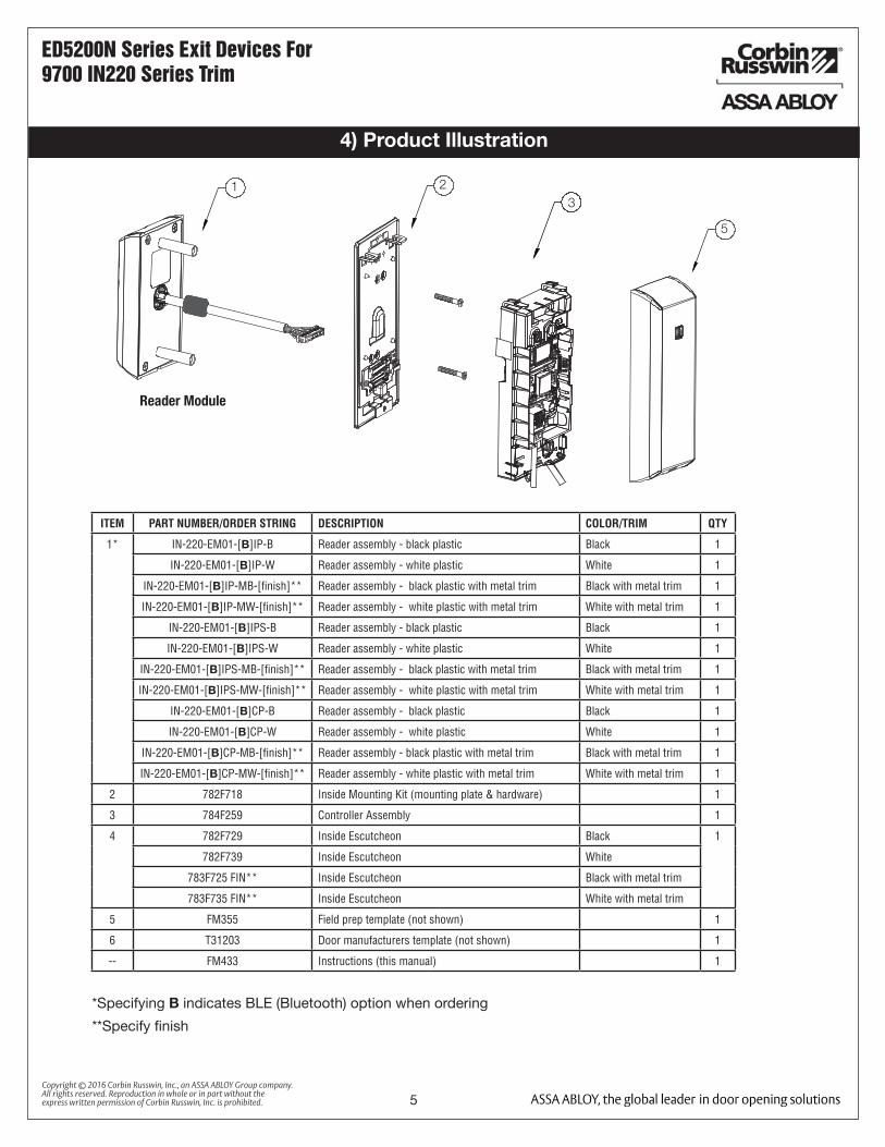
4) Product Illustration
1
5
32
Reader Module
**Specify finish
ITEM PART NUMBER/ORDER STRING DESCRIPTION COLOR/TRIM QTY
1* IN-220-EM01-[B]IP-B Reader assembly - black plastic Black 1
IN-220-EM01-[B]IP-W Reader assembly - white plastic White 1
IN-220-EM01-[B]IP-MB-[finish]** Reader assembly - black plastic with metal trim Black with metal trim 1
IN-220-EM01-[B]IP-MW-[finish]** Reader assembly - white plastic with metal trim White with metal trim 1
IN-220-EM01-[B]IPS-B Reader assembly - black plastic Black 1
IN-220-EM01-[B]IPS-W Reader assembly - white plastic White 1
IN-220-EM01-[B]IPS-MB-[finish]** Reader assembly - black plastic with metal trim Black with metal trim 1
IN-220-EM01-[B]IPS-MW-[finish]** Reader assembly - white plastic with metal trim White with metal trim 1
IN-220-EM01-[B]CP-B Reader assembly - black plastic Black 1
IN-220-EM01-[B]CP-W Reader assembly - white plastic White 1
IN-220-EM01-[B]CP-MB-[finish]** Reader assembly - black plastic with metal trim Black with metal trim 1
IN-220-EM01-[B]CP-MW-[finish]** Reader assembly - white plastic with metal trim White with metal trim 1
2 782F718 Inside Mounting Kit (mounting plate & hardware) 1
3 784F259 Controller Assembly 1
4 782F729 Inside Escutcheon Black 1
782F739 Inside Escutcheon White
783F725 FIN** Inside Escutcheon Black with metal trim
783F735 FIN** Inside Escutcheon White with metal trim
5 FM355 Field prep template (not shown) 1
6 T31203 Door manufacturers template (not shown) 1
-- FM433 Instructions (this manual) 1
*Specifying B indicates BLE (Bluetooth) option when ordering

6Copyright © 2016 Corbin Russwin, Inc., an ASSA ABLOY Group company. All rights reserved. Reproduction in whole or in part without the express written permission of Corbin Russwin, Inc. is prohibited.
ED5200N Series Exit Devices For 9700 IN220 Series Trim
5) Rim Exit Installation Instructions
1. Verify Hand and Bevel of door:Door should be fitted and hung.
Verify box label for size of exit device, function and hand.
Left HandReverse
LHROutside
Inside
Right HandReverse
RHR
Inside of Door
2. Prep door according to supplied Door Marker (FM429)
Wood Door Preparation
Fig. 1
Fig. 2
Wire Harness Cutout
Backplate Mount Holes
Wire Hole
Trim Tailpiece Hole
Door Position Switch (DPS) Raceway
For door manufacturer templates visit www.corbinrusswin.com and reference template #’s T31235 & T31236.
Outside of Door
Through-bolt Holes
Wire Harness Cutout
Through-bolt Holes
Raceway for PoE wiring Raceway
for PoE wiring
7Copyright © 2016 Corbin Russwin, Inc., an ASSA ABLOY Group company. All rights reserved. Reproduction in whole or in part without the express written permission of Corbin Russwin, Inc. is prohibited.
ED5200N Series Exit Devices For 9700 IN220 Series Trim
5) Rim Exit Installation Instructions (Continued)
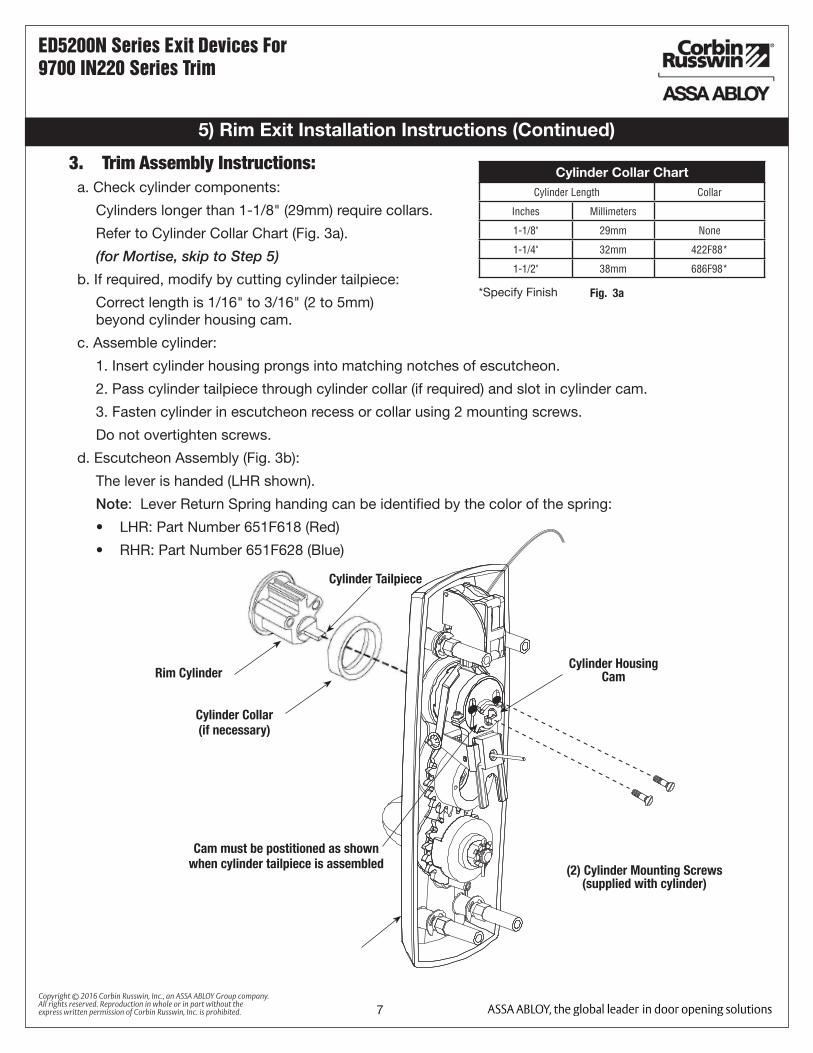
Cylinder Collar ChartCylinder Length Collar
Inches Millimeters
1-1/8" 29mm None
1-1/4" 32mm 422F88*
1-1/2" 38mm 686F98*
*Specify Finish Fig. 3a
Cylinder Tailpiece
Rim Cylinder
Cylinder Collar(if necessary)
Cam must be postitioned as shown when cylinder tailpiece is assembled (2) Cylinder Mounting Screws
(supplied with cylinder)
Cylinder Housing Cam
3. Trim Assembly Instructions:a. Check cylinder components:
Cylinders longer than 1-1/8" (29mm) require collars.
Refer to Cylinder Collar Chart (Fig. 3a).
(for Mortise, skip to Step 5)
b. If required, modify by cutting cylinder tailpiece:
Correct length is 1/16" to 3/16" (2 to 5mm) beyond cylinder housing cam.
c. Assemble cylinder:
1. Insert cylinder housing prongs into matching notches of escutcheon.
2. Pass cylinder tailpiece through cylinder collar (if required) and slot in cylinder cam.
3. Fasten cylinder in escutcheon recess or collar using 2 mounting screws.
Do not overtighten screws.
d. Escutcheon Assembly (Fig. 3b):
The lever is handed (LHR shown).
Note: Lever Return Spring handing can be identified by the color of the spring:
• LHR: Part Number 651F618 (Red)
• RHR: Part Number 651F628 (Blue)
8Copyright © 2016 Corbin Russwin, Inc., an ASSA ABLOY Group company. All rights reserved. Reproduction in whole or in part without the express written permission of Corbin Russwin, Inc. is prohibited.
ED5200N Series Exit Devices For 9700 IN220 Series Trim
5) Rim Exit Installation Instructions (Continued)
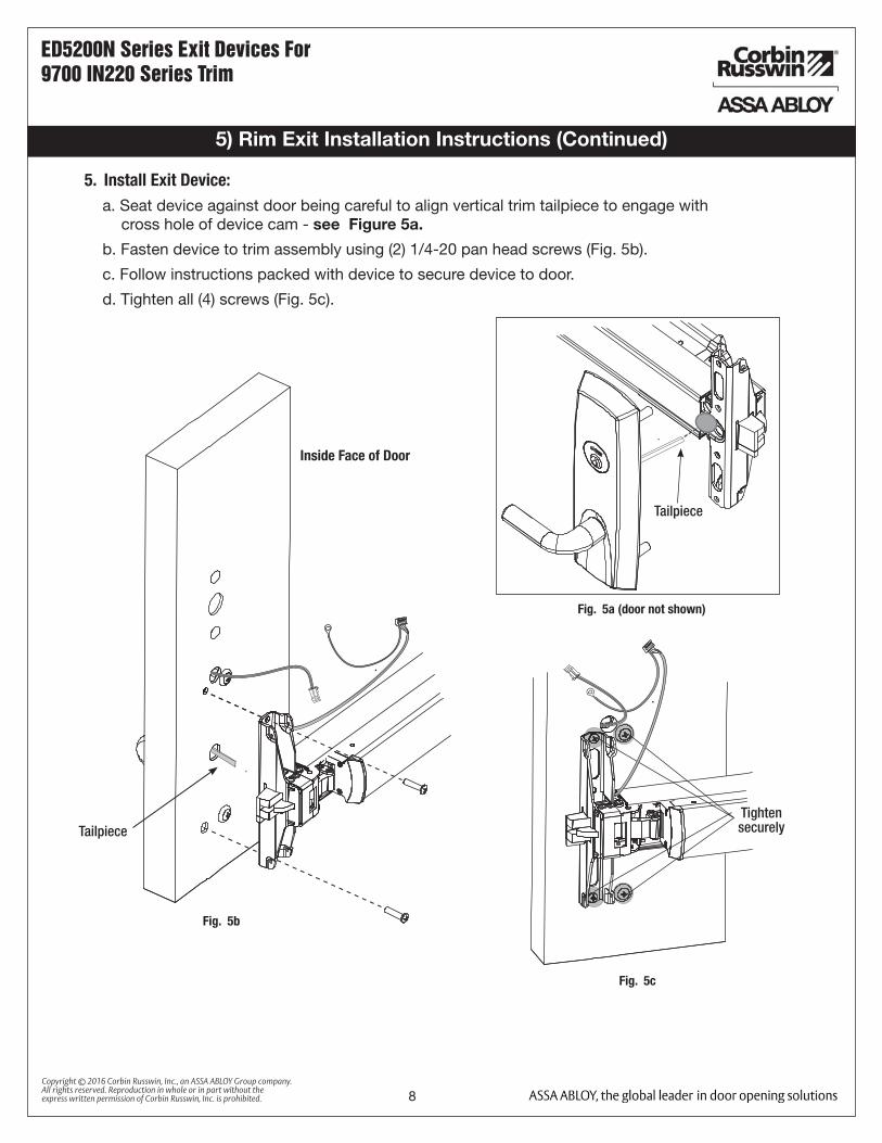
Fig. 5c
5. Install Exit Device:a. Seat device against door being careful to align vertical trim tailpiece to engage with
cross hole of device cam - see Figure 5a.
b. Fasten device to trim assembly using (2) 1/4-20 pan head screws (Fig. 5b).
c. Follow instructions packed with device to secure device to door.
d. Tighten all (4) screws (Fig. 5c).
Fig. 5b
Fig. 5a (door not shown)
Inside Face of Door
Tighten securely
Tailpiece
Tailpiece

9Copyright © 2016 Corbin Russwin, Inc., an ASSA ABLOY Group company. All rights reserved. Reproduction in whole or in part without the express written permission of Corbin Russwin, Inc. is prohibited.
ED5200N Series Exit Devices For 9700 IN220 Series Trim
5) Rim Exit Installation Instructions (Continued)
6. Install Head Cover:
a. Lay device wire harnesses across ¾” hole (Fig. 6a).
b. Tuck wires into hole when installing cover so that wires are not pinched between head cover and door.
c. Attach head cover using (2) #8-32 flat head screws (Fig. 6b).
Use 3/4” hole totuck trim anddevice wire
harness underhead cover
Fig. 6a Fig. 6b
Important Note: Rim Exit Installation Continues on Page 14 - Section 7

10Copyright © 2016 Corbin Russwin, Inc., an ASSA ABLOY Group company. All rights reserved. Reproduction in whole or in part without the express written permission of Corbin Russwin, Inc. is prohibited.
ED5200N Series Exit Devices For 9700 IN220 Series Trim
1. Verify Hand and Bevel of door:Door should be fitted and hung.
Verify box label for size of exit device, function and hand.
Left HandReverse
LHROutside
Inside
Right HandReverse
RHR
Inside of Door
2. Prep door according to supplied Door Marker (FM429)
Wood Door Preparation
Fig. 1
Fig. 2
Wire Harness Cutout
For door manufacturer templates visit www.corbinrusswin.com and reference template #’s T31235 & T31236.
Outside of Door
Raceway for PoE harness
Raceway for PoE harness
Through-bolt Holes Trim Tailpiece Hole
Through-bolt Holes
6) Mortise Exit Installation Instructions

11Copyright © 2016 Corbin Russwin, Inc., an ASSA ABLOY Group company. All rights reserved. Reproduction in whole or in part without the express written permission of Corbin Russwin, Inc. is prohibited.
ED5200N Series Exit Devices For 9700 IN220 Series Trim
6) Mortise Exit Installation Instructions (Continued)
3. Install Mortise and Outside Trim Assembly:
Fig. 3a
a. Make sure tailpiece is oriented vertically.
b. Feed trim wire harness through wire harness hole (Fig. 3a).
c. Mount trim assembly to door pulling slack wire towards device side of door.
Note: Be careful not to pinch wire harness.
d. When mounting trim, lift tailpiece to pass through hole on device side (Fig. 3b).
Note: Ensure tailpiece is still oriented vertically.
e. Fasten trim assembly to door using (2) 1/4-20 oval head screws and (2) finish washers (Fig. 3b).
Note: Finger tighten only.
Fig. 3b

12Copyright © 2016 Corbin Russwin, Inc., an ASSA ABLOY Group company. All rights reserved. Reproduction in whole or in part without the express written permission of Corbin Russwin, Inc. is prohibited.
ED5200N Series Exit Devices For 9700 IN220 Series Trim
5. Install Exit Device:
a. Seat device against door being careful to align vertical trim tailpiece to engage with cross hole of device cam - see Figure 5a.
b. Fasten device to trim assembly using (2) 1/4-20 pan head screws (Fig. 5b).
c. Follow instructions packed with device to secure device to door.
d. Tighten all (4) screws (Fig. 5b).
Inside Face of Door
Tighten securely
6) Mortise Exit Installation Instructions (Continued)
Fig. 5a
Fig. 5b

13Copyright © 2016 Corbin Russwin, Inc., an ASSA ABLOY Group company. All rights reserved. Reproduction in whole or in part without the express written permission of Corbin Russwin, Inc. is prohibited.
ED5200N Series Exit Devices For 9700 IN220 Series Trim
6) Mortise Exit Installation Instructions (Continued)
a. Lay device wire harnesses across ¾” hole (Fig. 6a).
b. Tuck wires into hole when installing cover so that wires are not pinched between head cover and door.
c. Attach head cover using (2) #8-32 flat head screws (Fig. 6b).
Use 3/4” hole totuck trim anddevice wire
harness underhead cover
Fig. 6a Fig. 6b
6. Install Head Cover:
Important Note: Mortise Exit Installation Continues on Next Page - Section 7

14Copyright © 2016 Corbin Russwin, Inc., an ASSA ABLOY Group company. All rights reserved. Reproduction in whole or in part without the express written permission of Corbin Russwin, Inc. is prohibited.
ED5200N Series Exit Devices For 9700 IN220 Series Trim
OverviewCorbin Russwin IN220 PoE Typical Application
LMT: Lock Management Tool
A. PoE frame harness assembly
B. PoE data hinge from McKinney (patent pending)
C. PoE door harness* from McKinney
D. IN220 PoE Lock
E. DPS: Door Position Switch (not required on ML207xx)
* Door width determines length
Network Cable
Network Switch (802.3af)Surface Mount RJ45
A
BC
D
E
7) IN220 (PoE) Wiring & Installation

15Copyright © 2016 Corbin Russwin, Inc., an ASSA ABLOY Group company. All rights reserved. Reproduction in whole or in part without the express written permission of Corbin Russwin, Inc. is prohibited.
ED5200N Series Exit Devices For 9700 IN220 Series Trim
Cable: CAT 5e or higher24 AWG
RJ45-M
Molex-F Molex-F Molex-M
Cable: CAT 5e,26 AWG stranded,shielded, 100ohm
TIA/EIA 568-B Standard Wiring
RJ45-M
Molex-M
RJ45-F Jack
Cabl
e: C
AT 5
e or
hig
her
24 A
WG
shi
elde
d, 1
00oh
m
Approved Software
B-Splice Crimp Connector
Certified Integrator (CI) supplies and terminates the B-Splice connector and the
Male RJ45 connector from harness to end user provided facility cable
Supplied by End User
PoE Switch
PoE Lock
Ceiling
Supplied by CI
C
B
A
PoE Patch Panel
D
GroundRing Terminal
Secured to Lock Mounting Plate
PoE SwitchRack isTerminated toEarth Ground
Patch Cable: PoE Panel to
PoE Switch
PoE Frame harness assembly (From McKinney)B PoE data hinge (Patent Pending) (From McKinney)
C. PoE Door harness* (From McKinney)D. IN220 PIP (PoE Lock) * Order of installation may vary. Refer to appropriate sections for instructions.
Frame-SideHarness
Assembly(15' length)
24AWG Stranded
Drain Wire for
Earth Ground in 15' Frame
Harness
Cable drain wire
concealed in shrink
tubing
A
B
C
D
To building or electrical ground
NOTE: TIA/EIA 568-B added
only at lock side
7) IN220 (PoE) Wiring & Installation (Continued)
Notes:• Connectors go on only one
way. They cannot be placed in an incorrect position.
• Do not force and do not offset connectors
• Be sure they are completely seated (flush)
• PoE power source cannot be connected to a receptacle controlled by a switch
16Copyright © 2016 Corbin Russwin, Inc., an ASSA ABLOY Group company. All rights reserved. Reproduction in whole or in part without the express written permission of Corbin Russwin, Inc. is prohibited.
ED5200N Series Exit Devices For 9700 IN220 Series Trim
7) IN220 (PoE) Wiring & Installation (Continued)
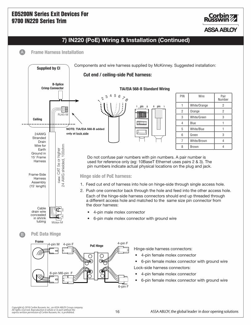
Components and wire harness supplied by McKinney. Suggested installation:
RJ45-M
Molex-M
Cab
le: C
AT 5
e or
hig
her
24 A
WG
shi
elde
d, 1
00oh
m
B-Splice Crimp Connector
Ceiling
Supplied by CI
Cut end / ceiling-side PoE harness:
TIA/EIA 568-B Standard Wiring
1 2 3 4 5 6 7 8
Do not confuse pair numbers with pin numbers. A pair number is used for reference only (eg: 10BaseT Ethernet uses pairs 2 & 3). The pin numbers indicate actual physical locations on the plug and jack.
Frame-SideHarness
Assembly(15' length)
24AWG Stranded
Drain Wire for
Earth Ground in 15' Frame
Harness
Cable drain wire
concealed in shrink
tubing
Frame Harness Installation
Hinge side of PoE harness:
A
1. Feed cut end of harness into hole on hinge-side through single access hole.
2. Push one connector back through the hole and feed into the other access hole.Each of the hinge-side harness connectors should end up threaded through a different access hole and matched to the same size pin connector from the door harness:
• 4-pin male molex connector
• 6-pin male molex connector with ground wire
NOTE: TIA/EIA 568-B added
only at lock side
PIN Wire Pair Number
1 White/Orange 2
2 Orange 2
3 White/Green 3
4 Blue 1
5 White/Blue 1
6 Green 3
7 White/Brown 4
8 Brown 4
1 8pin 8 1pin
4-pin M
6-pin M
FramePoE Hinge
PoE Data Hinge
Hinge-side harness connectors:
• 4-pin female molex connector
• 6-pin female molex connector with ground wire
Lock-side harness connectors:
• 4-pin female molex connector
• 6-pin female molex connector with ground wire
B
4-pin F
6-pin F
4-pin F
6-pin F

17Copyright © 2016 Corbin Russwin, Inc., an ASSA ABLOY Group company. All rights reserved. Reproduction in whole or in part without the express written permission of Corbin Russwin, Inc. is prohibited.
ED5200N Series Exit Devices For 9700 IN220 Series Trim
7) IN220 (PoE) Wiring & Installation (Continued)
Hinge Installation
4-pin M 4-pin F4-pin F
6-pin F 6-pin F 6-pin M
Drain Wire
C
RJ45-M
Cable: CAT 5e,26 AWG stranded,shielded, 100ohm
Order of installation may vary. Refer to appropriate sections for instructions.
1. Prop door open.
2. Using the ring terminal, carefully route the assembly through the door channel to the lock.
3. Remove tape from ring terminal and door harness connectors.
Hinge-side harness connectors:
• 4-pin male Molex connector
• 6-pin male Molex connector with ground wire
Lock-side harness connectors:
• Ring terminal
• (1) male RJ45 connector
Notes:
• Connectors go on only one way. They cannot be plugged to incorrect position.
• Do not force and do not offset connectors.
• Be sure they are completely seated (flush).
PoE Harness (cat5e)
Order of installation may vary. Refer to appropriate sections for instructions.
Hinge-side harness connectors:
• 4-pin male Molex connector
• 6-pin male Molex connector with ground wire
Lock-side harness connectors:
• Ring terminal
• Male RJ45 connector (crimped after cable is fed through door)
Notes:
• Connectors go on only one way. They cannot be plugged to incorrect position.
• Do not force and do not offset connectors.
• Be sure they are completely seated (flush).
18Copyright © 2016 Corbin Russwin, Inc., an ASSA ABLOY Group company. All rights reserved. Reproduction in whole or in part without the express written permission of Corbin Russwin, Inc. is prohibited.
ED5200N Series Exit Devices For 9700 IN220 Series Trim
8) IN220 Installation Instructions
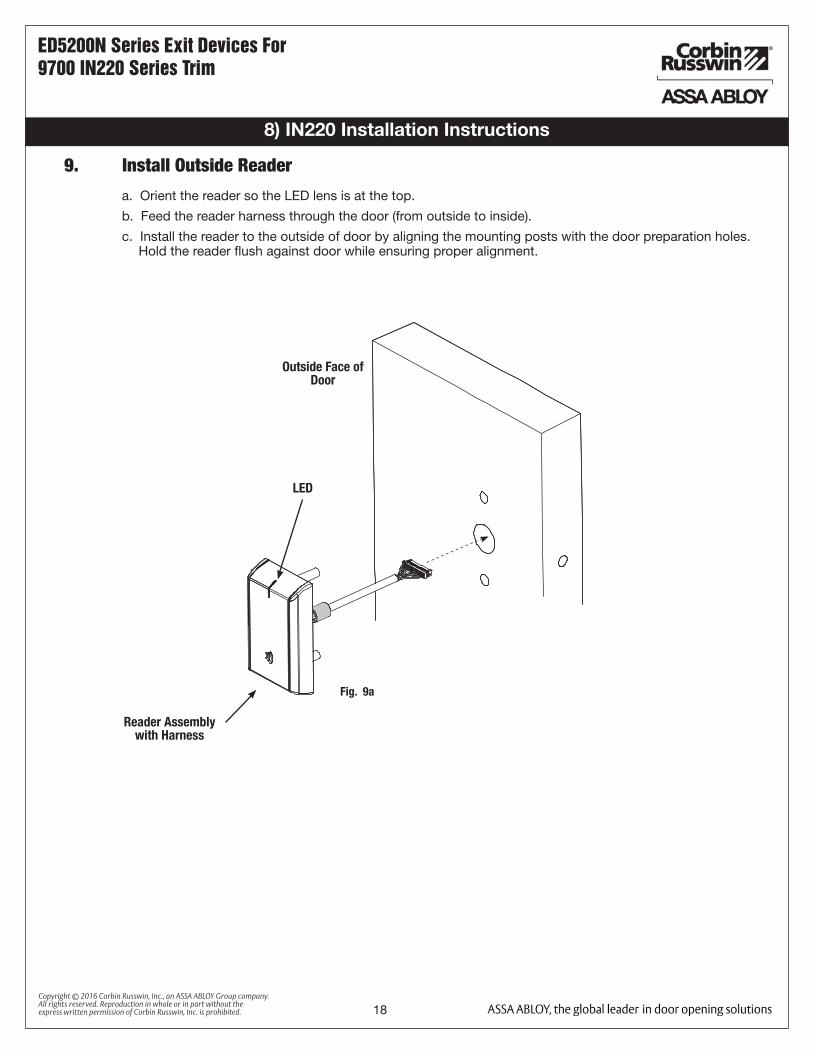
Fig. 9a
Outside Face of Door
Reader Assembly with Harness
LED
9. Install Outside Reader
a. Orient the reader so the LED lens is at the top.
b. Feed the reader harness through the door (from outside to inside).
c. Install the reader to the outside of door by aligning the mounting posts with the door preparation holes. Hold the reader flush against door while ensuring proper alignment.

19Copyright © 2016 Corbin Russwin, Inc., an ASSA ABLOY Group company. All rights reserved. Reproduction in whole or in part without the express written permission of Corbin Russwin, Inc. is prohibited.
ED5200N Series Exit Devices For 9700 IN220 Series Trim
8) IN220 Installation Instructions (Continued)
9. Install Outside Reader - (Continued)
Gasket*
Mounting Plate
*Gasket is required for outdoor installations.
If installing with gasket; separate gasket from mounting plate to feed cables/connectors through holes as indicated (Fig. 9b).
Once cables/connectors are fed through, reattach gasket to mounting plate.
Lock body Harness
Ground Lugs
DPS
Reader Harness
NOTE: Cable lengths exaggerated for illustrative purposes.
Inside of Door
Through - bolt
Through - bolt
d. Next feed the cables/connectors through the inside mounting assembly (and gasket if required*).
e. Insert and partially tighten (2) through-bolts prior to installation of connectors.
f. Secure both ground lugs with #6-32 machine screw (Fig.9C).
Fig. 9B
Fig. 9C
Cat5e cable from
hinge

20Copyright © 2016 Corbin Russwin, Inc., an ASSA ABLOY Group company. All rights reserved. Reproduction in whole or in part without the express written permission of Corbin Russwin, Inc. is prohibited.
ED5200N Series Exit Devices For 9700 IN220 Series Trim
8) IN220 Installation Instructions (Continued)
10. Installation of Connectors
Secure the following connectors to their respective terminals (Fig. 10a ):
A. Secure the 4-pin DPS connector.
B. Secure the 10-pin lock body assembly connector.
CAUTION - Do not touch or allow debris to enter connector contacts.
DPS (4-pin)
A
Lock Body (10-pin)
Fig. 10a
Ground Lugs
B
CIMPORTANT: Do not run wires through hole in plate (Fig. 10b) - this will damage wires and the controller connector.
Route wires around flange, do not route wires through the flange hole (Fig. 10c,d).
1. Tuck excess cable into wire hole on inside of door.
2. Secure the mounting assembly while ensuring proper alignment of outside reader and fully tighten the (2) through- bolts on the inside of the door to secure the reader and plate to the door.
Secure Mounting Plate
C. Secure the 24-pin card reader connector (Fig. 10b).
D. Crimp* RJ45 to cat5e cable from hinge (Fig. 10c).
*For more detail, refer to section (5) ‘Installation Wiring’, “A - Frame Harness Installation”.
TIA/EIA 568-B Standard Wiring
1 2 3 4 5 6 7 8
Do not confuse pair numbers with pin numbers. A pair number is used for reference only (eg: 10BaseT Ethernet uses pairs 2 & 3). The pin numbers indicate actual physical locations on the plug and jack.
PIN Wire Pair Number
1 White/Orange 2
2 Orange 2
3 White/Green 3
4 Blue 1
5 White/Blue 1
6 Green 3
7 White/Brown 4
8 Brown 4
1 8pin 8 1pin
Reader (24-pin)
Board-to-Board Connector
Fig. 10b
Crimp* to RJ45-M Connector
Cat5e cable from hinge
RJ45-M
Fig. 10c
C
D
21Copyright © 2016 Corbin Russwin, Inc., an ASSA ABLOY Group company. All rights reserved. Reproduction in whole or in part without the express written permission of Corbin Russwin, Inc. is prohibited.
ED5200N Series Exit Devices For 9700 IN220 Series Trim
8) IN220 Installation Instructions (Continued)
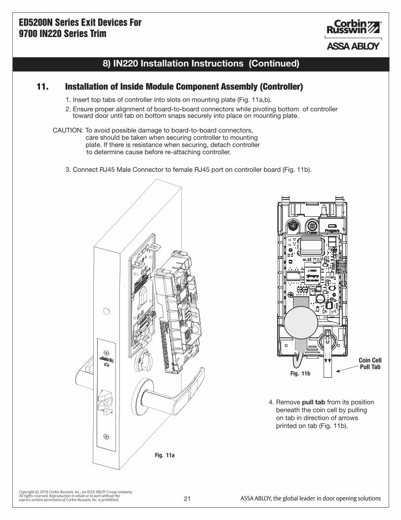
11. Installation of Inside Module Component Assembly (Controller)1. Insert top tabs of controller into slots on mounting plate (Fig. 11a,b).2. Ensure proper alignment of board-to-board connectors while pivoting bottom of controller toward door until tab on bottom snaps securely into place on mounting plate.
CAUTION: To avoid possible damage to board-to-board connectors, care should be taken when securing controller to mounting plate. If there is resistance when securing, detach controller to determine cause before re-attaching controller.
3. Connect RJ45 Male Connector to female RJ45 port on controller board (Fig. 11b).
Fig. 11b
4. Remove pull tab from its position beneath the coin cell by pulling on tab in direction of arrows printed on tab (Fig. 11b).
Coin Cell Pull Tab
Fig. 11a
22Copyright © 2016 Corbin Russwin, Inc., an ASSA ABLOY Group company. All rights reserved. Reproduction in whole or in part without the express written permission of Corbin Russwin, Inc. is prohibited.
ED5200N Series Exit Devices For 9700 IN220 Series Trim
8) IN220 Installation Instructions (Continued)
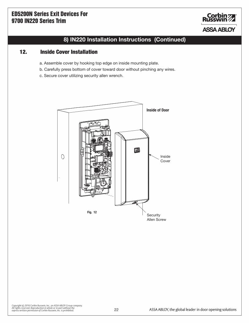
a. Assemble cover by hooking top edge on inside mounting plate.
b. Carefully press bottom of cover toward door without pinching any wires.
c. Secure cover utilizing security allen wrench.
12. Inside Cover Installation
Inside Cover
Inside of Door
Security Allen Screw
Fig. 12
23Copyright © 2016 Corbin Russwin, Inc., an ASSA ABLOY Group company. All rights reserved. Reproduction in whole or in part without the express written permission of Corbin Russwin, Inc. is prohibited.
ED5200N Series Exit Devices For 9700 IN220 Series Trim
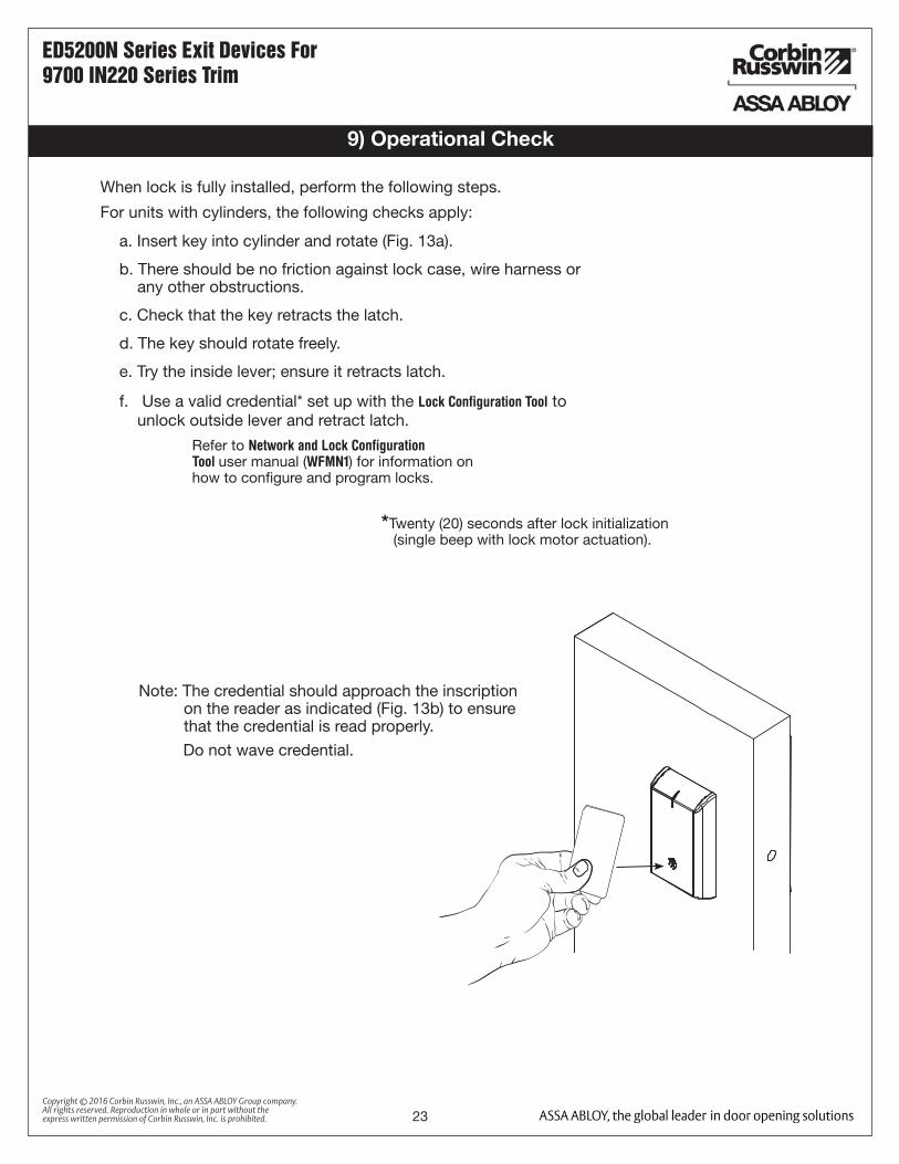
9) Operational Check
a. Insert key into cylinder and rotate (Fig. 13a).
b. There should be no friction against lock case, wire harness or any other obstructions.
c. Check that the key retracts the latch.
d. The key should rotate freely.
e. Try the inside lever; ensure it retracts latch.
f. Use a valid credential* set up with the Lock Configuration Tool to unlock outside lever and retract latch.
Refer to Network and Lock Configuration Tool user manual (WFMN1) for information on how to configure and program locks.
When lock is fully installed, perform the following steps.
For units with cylinders, the following checks apply:
*Twenty (20) seconds after lock initialization (single beep with lock motor actuation).
Note: The credential should approach the inscription on the reader as indicated (Fig. 13b) to ensure that the credential is read properly.
Do not wave credential.

ED5200N Series Exit Devices
24Copyright © 2016 Corbin Russwin, Inc., an ASSA ABLOY Group company. All rights reserved. Reproduction in whole or in part without the express written permission of Corbin Russwin, Inc. is prohibited.
Related Documents