In situ observations on deformation behavior and stretching- induced failure of fine pitch stretchable interconnect Yung-Yu Hsu a) IMEC, Kapeldreef 75, 3001, Leuven, Belgium; and Department of Materials Engineering, Katholieke Universiteit Leuven, 3000 Belgium Mario Gonzalez IMEC, Kapeldreef 75, 3001, Leuven, Belgium Frederick Bossuyt, Fabrice Axisa, and Jan Vanfleteren IMEC-Centre for Microsystems Technology, 9052 Gent-Zwijnaarde, Belgium Ingrid De Wolf IMEC, Kapeldreef 75, 3001, Leuven, Belgium; and Department of Materials Engineering, Katholieke Universiteit Leuven, 3000 Belgium (Received 15 June 2009; accepted 29 July 2009) Electronic devices capable of performing in extreme mechanical conditions such as stretching, bending, or twisting will improve biomedical and wearable systems. The required capabilities cannot be achieved with conventional building geometries, because of structural rigidity and lack of mechanical stretchability. In this article, a zigzag-patterned structure representing a stretchable interconnect is presented as a promising type of building block. In situ experimental observations on the deformed interconnect are correlated with numerical analysis, providing an understanding of the deformation and failure mechanisms. The experimental results demonstrate that the zigzag-patterned interconnect enables stretchability up to 60% without rupture. This stretchability is accommodated by in-plane rotation of arms and out-of-plane deformation of crests. Numerical analysis shows that the dominating failure cause is interfacial in-plane shear stress. The plastic strain concentration at the arms close to the crests, obtained by numerical simulation, agrees well with the failure location observed in the experiment. I. INTRODUCTION Large area deformable macroelectronics have attract- ed increasing attention in recent years, particularly be- cause they cannot only withstand bending and twisting but also the most challenging deformations, such as stretching. This deformability allows the macroelectron- ics to be used in applications that are hard to cover by conventional semiconductor microelectronics. 1,2 There- fore, various concepts have been developed in recent years to fulfill the demands of extreme deformations. For most of these concepts, thin and lightweight sheets of elastic polymers represent ideal substrates. By depos- iting conductive polymers or small molecule organics on top of these substrates, it is believed that flexibility and modest stretchability can be achieved. However, the main disadvantage of this concept is that the electrical performances are often limited by the material properties of the polymers or molecules used. For example, the mobility of polymers and molecules is weaker than those composed of inorganic materials. This consideration, combined with the uncertain reliability of the organics, has recently led to interest in using hybrid systems. These hybrid systems are usually composed of inorganic-based rigid or bendable elements and an organic-stretchable substrate such as rubber. To achieve deformability, the rigid or bendable inorganic-based elements are con- nected by stretchable conductors on or in the stretchable substrate. This hybrid system concept can be applied in biomedical systems that require high reliability and per- formance. Because the thin conductor lines that connect the active components have to withstand deformations, a proper structural design is essential to avoid losing structural integrity and electrical functionality during extreme deformations. Several technologies for stretchable conductors have been proposed in recent years. For example, by design- ing thin film with a wavy or buckling period, adhered on polymer substrate, 3,4 the level of stretchability can be controlled. More recently, this wavy thin film technol- ogy has been applied in stretchable systems, such as a) Address all correspondence to this author. e-mail: [email protected] DOI: 10.1557/JMR.2009.0447 J. Mater. Res., Vol. 24, No. 12, Dec 2009 © 2009 Materials Research Society 3573

Welcome message from author
This document is posted to help you gain knowledge. Please leave a comment to let me know what you think about it! Share it to your friends and learn new things together.
Transcript
In situ observations on deformation behavior and stretching-induced failure of fine pitch stretchable interconnect
Yung-Yu Hsua)
IMEC, Kapeldreef 75, 3001, Leuven, Belgium; and Department of Materials Engineering,Katholieke Universiteit Leuven, 3000 Belgium
Mario GonzalezIMEC, Kapeldreef 75, 3001, Leuven, Belgium
Frederick Bossuyt, Fabrice Axisa, and Jan VanfleterenIMEC-Centre for Microsystems Technology, 9052 Gent-Zwijnaarde, Belgium
Ingrid De WolfIMEC, Kapeldreef 75, 3001, Leuven, Belgium; and Department of Materials Engineering,Katholieke Universiteit Leuven, 3000 Belgium
(Received 15 June 2009; accepted 29 July 2009)
Electronic devices capable of performing in extreme mechanical conditions suchas stretching, bending, or twisting will improve biomedical and wearable systems.The required capabilities cannot be achieved with conventional building geometries,because of structural rigidity and lack of mechanical stretchability. In this article, azigzag-patterned structure representing a stretchable interconnect is presented as apromising type of building block. In situ experimental observations on the deformedinterconnect are correlated with numerical analysis, providing an understanding of thedeformation and failure mechanisms. The experimental results demonstrate that thezigzag-patterned interconnect enables stretchability up to 60% without rupture. Thisstretchability is accommodated by in-plane rotation of arms and out-of-planedeformation of crests. Numerical analysis shows that the dominating failure cause isinterfacial in-plane shear stress. The plastic strain concentration at the arms close to thecrests, obtained by numerical simulation, agrees well with the failure location observedin the experiment.
I. INTRODUCTION
Large area deformable macroelectronics have attract-ed increasing attention in recent years, particularly be-cause they cannot only withstand bending and twistingbut also the most challenging deformations, such asstretching. This deformability allows the macroelectron-ics to be used in applications that are hard to cover byconventional semiconductor microelectronics.1,2 There-fore, various concepts have been developed in recentyears to fulfill the demands of extreme deformations.For most of these concepts, thin and lightweight sheetsof elastic polymers represent ideal substrates. By depos-iting conductive polymers or small molecule organics ontop of these substrates, it is believed that flexibility andmodest stretchability can be achieved. However, themain disadvantage of this concept is that the electricalperformances are often limited by the material propertiesof the polymers or molecules used. For example, the
mobility of polymers and molecules is weaker than thosecomposed of inorganic materials. This consideration,combined with the uncertain reliability of the organics,has recently led to interest in using hybrid systems. Thesehybrid systems are usually composed of inorganic-basedrigid or bendable elements and an organic-stretchablesubstrate such as rubber. To achieve deformability, therigid or bendable inorganic-based elements are con-nected by stretchable conductors on or in the stretchablesubstrate. This hybrid system concept can be applied inbiomedical systems that require high reliability and per-formance. Because the thin conductor lines that connectthe active components have to withstand deformations,a proper structural design is essential to avoid losingstructural integrity and electrical functionality duringextreme deformations.
Several technologies for stretchable conductors havebeen proposed in recent years. For example, by design-ing thin film with a wavy or buckling period, adhered onpolymer substrate,3,4 the level of stretchability can becontrolled. More recently, this wavy thin film technol-ogy has been applied in stretchable systems, such as
a)Address all correspondence to this author.e-mail: [email protected]
DOI: 10.1557/JMR.2009.0447
J. Mater. Res., Vol. 24, No. 12, Dec 2009 © 2009 Materials Research Society 3573
photodetectors5 and oscillators.6,7 A similar technologyinvolving spontaneous wrinkling metal films8–10 has alsobeen studied. However, microcracking often plays animportant role in the mechanics of stretching of suchfilms. With microcracking in wrinkling metal film, theelectrical resistance changes with elongation. This unsta-ble electrical property is certainly a disadvantage of astretchable conductor for certain applications.
An alternative technology involves in-plane patternedmetal conductors. For example, sinusoidal shaped thinmetal film deposited on an elastomeric substrate hasbeen studied through parametric analysis.11 It is alsoreported that the horseshoe-shaped conductors12–14 canbe stretched up to 100% without material rupture. An-other simpler example for an in-plane patterned metalconductor is the zigzag structure.15 The advantage ofthe zigzag structure above the horseshoe is that it can beapplied in a high I/O density device while maintaininghigh stretchability and stable electrical resistance. With aproper structural design, the metal interconnect acts likea spring while stretching, even though the intrinsic frac-ture limit of the material is at strains of 1�2%.16 Byapplying these in-plane patterned metal conductors asinterconnects, a hybrid system can reach high stretch-ability without losing its electrical performance. In otherwords, the performance of a stretchable system is thesame as that of a conventional bulk system. In addition,this attractive coplanar technology is easy to use in cur-rent conventional planar microfabrication technologywithout requiring many processing modifications. Thisapproach allows a cost reduction, which is one of themajor concerns in industry.
In this article, we comprehensively investigate thedeformation behavior of a zigzag structure during stretch-ing by using both experimental observations and numeri-cal analysis. Analytical models are developed tounderstand the mechanical relationship between thestress induced by external loading and deformability ofthe zigzag interconnect. To study the failure mechanics,the in situ observations of stretching zigzag interconnectsare correlated to numerical analysis. These observationsand numerical analysis explain all failure mechanisms.By combining analytical, numerical, and experimentalanalysis, design guidelines for future improvement onthe mechanical robustness can be provided.
II. NUMERICAL MODELING
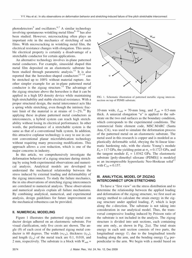
Figure 1 illustrates the patterned zigzag metal con-ductor design adhered on an elastomeric substrate. Forvisual clarification, only five crests are shown. The an-gle (y) of each crest of the patterned zigzag metal con-ductor is 60 degrees. The width (wCu), thickness (tCu),and length (lCu) of the metal track are 0.1, 0.018, and2 mm, respectively. The substrate is a block with Wsub =
10-mm wide, Lsub = 70-mm long, and Tsub = 0.5-mmthick. A uniaxial elongation “u” is applied to the sub-strate on the two end surfaces as the boundary condition,which corresponds to the experimental conditions. Thecommercial finite element code, MSC.MARC (SantaAna, CA), was used to simulate the deformation processof the patterned metal on an elastomeric substrate. Themetal used in this research is copper and is modeled as aplastically deformable solid, obeying the bi-linear kine-matic hardening rule, with the elastic Young’s moduleE0 = 117 GPa, the yielding point at sy = 0.1723 GPa, andthe tangent module Et = 1.0342 GPa. The elastomericsubstrate [poly-dimethyl siloxane (PDMS)] is modeledas an incompressible hyperelastic Neo-Hookean solid17
with C10 = 0.157.
III. ANALYTICAL MODEL OF ZIGZAGINTERCONNECT UPON STRETCHING
To have a “first view” on the stress distribution and todetermine the relationship between the applied loadingand deformation of the zigzag structure, we first used anenergy method to calculate the strain energy in the zig-zag structure under applied loading, P, which is keptalong the x-direction. The substrate is not taking intoconsideration in our analytical model. Thus, the trans-versal compressive loading induced by Poisson ratio ofthe substrate is not included in the analysis. The zigzagstructure is divided into unit sections, each containingone arm only, as shown in Fig. 2(a). The total strainenergy in each unit section consists of two parts, thelongitudinal energy Ul due to the longitudinal tensileloading along the arm, and the bending energy UM per-pendicular to the arm. We begin with a model based on
FIG. 1. Schematic illustration of patterned metallic zigzag intercon-
nection on top of PDMS substrate.
Y-Y. Hsu et al.: In situ observations on deformation behavior and stretching-induced failure of fine pitch stretchable interconnect
J. Mater. Res., Vol. 24, No. 12, Dec 20093574
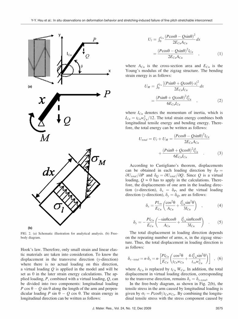
Hook’s law. Therefore, only small strain and linear elas-tic materials are taken into consideration. To know thedisplacement in the transverse direction (y-direction)where there is no actual loading on this direction,a virtual loading Q is applied in the model and will beset as 0 in the later strain energy calculations. The ap-plied loading, P, combined with a virtual loading, Q, canbe divided into two components: longitudinal loadingP cos y � Q sin y along the length of the arm and perpen-dicular loading P sin y � Q cos y. The strain energy inlongitudinal direction can be written as follows:
Ul ¼R lCu0
ðPcosy� QsinyÞ22ECuACu
dx
¼ ðPcosy� QsinyÞ2lCu2ECuACu
; ð1Þ
where ACu is the cross-section area and ECu is theYoung’s modulus of the zigzag structure. The bendingstrain energy is as follows:
UM ¼ R lCu0
½ðPsinyþ QcosyÞ�x�22ECuICu
dx
¼ ðPsinyþ QcosyÞ2l3Cu6ECuICu
; ð2Þ
where ICu denotes the momentum of inertia, which is
ICu ¼ tCuw3Cu=12. The total strain energy combines both
longitudinal tensile energy and bending energy. There-fore, the total energy can be written as follows:
Utotal ¼ Ul þ UM ¼ Pcosy� Qsinyð Þ2lCu2ECuACu
þ Psinyþ Qcosyð Þ2l3Cu6ECuICu
: ð3Þ
According to Castigliano’s theorem, displacementscan be obtained in each loading direction by dP ¼@Utotal=@P and dQ ¼ @Utotal=@Q. Since Q is a virtualloading, Q = 0 has to apply in the calculations. There-fore, the displacements of one arm in the loading direc-tion (x-direction), dx ¼ dP, and the virtual loadingdirection (y-direction), dy ¼ dQ, are as follows:
dx ¼ PlcuECu
cos2yACu
þ l2Cusin2y
3ICu
� �; ð4Þ
dy ¼ �PlCuECu
�sinycosyACu
þ l2Cusinycosy3ICu
� �: ð5Þ
The total displacement in loading direction dependson the repeating number of arms, n, in the zigzag struc-ture. Thus, the total displacement in loading direction isas follows:
dx�total ¼ n�dx ¼ n� PlCuECu
cos2ytCuwCu
þ 4�l2Cusin2ytcuw
3Cu
� �� �; ð6Þ
where ACu is replaced by tCu WCu. In addition, the totaldisplacement in virtual loading direction, correspondingto the transverse direction, remains dy ¼ dy-total.
In the free-body diagram, as shown in Fig. 2(b), thetensile stress in the arm caused by longitudinal loading isgiven by sl ¼ Pcosy=tCuwCu . By combining the longitu-dinal tensile stress with the stress component caused by
FIG. 2. (a) Schematic illustration for analytical analysis. (b) Free-
body diagram.
Y-Y. Hsu et al.: In situ observations on deformation behavior and stretching-induced failure of fine pitch stretchable interconnect
J. Mater. Res., Vol. 24, No. 12, Dec 2009 3575
bending sM ¼ 6PlCusiny=tCuw2Cu , the maximal tensile
stress (smax) in the arm is as follows:
smax ¼ PcosytCuwCu
þ 6PlCusinytCuw2
Cu
: ð7Þ
The stress distribution at the crest at (x,y) = (0,0) inFig. 2(a) is shown in Fig. 2(b). It is clear from this figurethat this maximal tensile stress, which causes structuralfailure, occurs at the inner concave edge of the arm.Therefore, to prevent the structural failure, by increasingthe width (wCu) or thickness (tCu), the tensile stress in theinner concave corner can be reduced. In other words,application-wise, the reliability of the zigzag intercon-nect can be improved. However, the stretchability,which equals to the total displacement in loading direc-tion as shown in Eq. (6), reduces dramatically with in-creasing wCu and tCu. Thus, the optimum design of thiszigzag interconnect is an important challenge. This strat-egy is discussed in detail in our publication elsewhere.
The analytical models developed above only hold forsmall strain and linear elastic behavior because ofHook’s law. However, in reality, a stretchable system iseasily stretched more than 10%, which causes largestrain and plasticity in the stretchable interconnect. Inaddition, when a zigzag structure adhered on a polymersubstrate is subjected to mechanical stretching, interfa-cial stress and peeling stress are generated. These effectsare less easy to be implemented in analytical models.Therefore, the finite element method is used to simulatethese complex behaviors. This process is discussed be-low in Sec. V. C.
IV. SAMPLE PREPARATION
PDMS (Sylgard 186; Dow Corning, Midland, MI) waschosen as the elastomeric substrate, to carry a patternedmetal on top. To achieve a stable resistance, low cost,and large area fabrication capability, we used a stand-alone 0.018-mm thick commercially available copperfoil. To improve the weak adhesion between the organicand the inorganic interface, a potassium monopersulfatesolution was used for microetching the copper surface.The surface of the copper foil was 2 mm in roughness asmeasured by an interferometer. The prepared copper foilwas then temporarily adhered to a 0.5-mm-thick Teflonmold, with an opening window for casting the PDMS ontop of the copper foil. The PDMS was prepared at roomtemperature in a 10:1 weight ratio of the polymer baseand curing agent. After degassing air bubbles, the PDMSwas poured in the Teflon window and cured at 60 �C for12 h. Then, the Cu/PDMS lamination was released fromthe Teflon mold and placed on top of the ceramic carrier.Both conventional photolithography and wet etchingprocesses were used for patterning the zigzag structure.In the final step, the Cu/PDMS lamination was cut
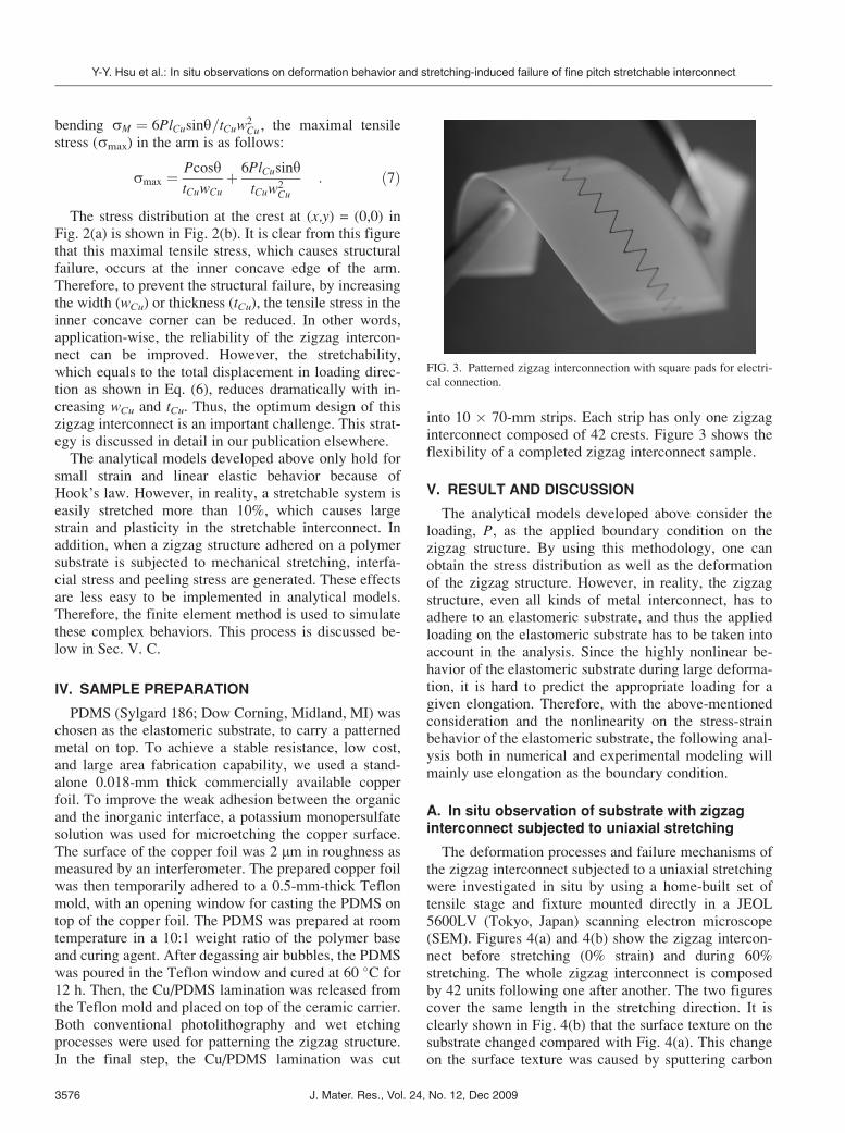
into 10 � 70-mm strips. Each strip has only one zigzaginterconnect composed of 42 crests. Figure 3 shows theflexibility of a completed zigzag interconnect sample.
V. RESULT AND DISCUSSION
The analytical models developed above consider theloading, P, as the applied boundary condition on thezigzag structure. By using this methodology, one canobtain the stress distribution as well as the deformationof the zigzag structure. However, in reality, the zigzagstructure, even all kinds of metal interconnect, has toadhere to an elastomeric substrate, and thus the appliedloading on the elastomeric substrate has to be taken intoaccount in the analysis. Since the highly nonlinear be-havior of the elastomeric substrate during large deforma-tion, it is hard to predict the appropriate loading for agiven elongation. Therefore, with the above-mentionedconsideration and the nonlinearity on the stress-strainbehavior of the elastomeric substrate, the following anal-ysis both in numerical and experimental modeling willmainly use elongation as the boundary condition.
A. In situ observation of substrate with zigzaginterconnect subjected to uniaxial stretching
The deformation processes and failure mechanisms ofthe zigzag interconnect subjected to a uniaxial stretchingwere investigated in situ by using a home-built set oftensile stage and fixture mounted directly in a JEOL5600LV (Tokyo, Japan) scanning electron microscope(SEM). Figures 4(a) and 4(b) show the zigzag intercon-nect before stretching (0% strain) and during 60%stretching. The whole zigzag interconnect is composedby 42 units following one after another. The two figurescover the same length in the stretching direction. It isclearly shown in Fig. 4(b) that the surface texture on thesubstrate changed compared with Fig. 4(a). This changeon the surface texture was caused by sputtering carbon
FIG. 3. Patterned zigzag interconnection with square pads for electri-
cal connection.
Y-Y. Hsu et al.: In situ observations on deformation behavior and stretching-induced failure of fine pitch stretchable interconnect
J. Mater. Res., Vol. 24, No. 12, Dec 20093576
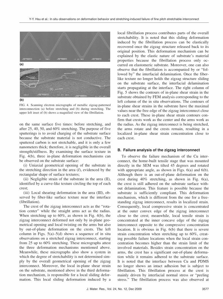
on the same surface five times: before stretching, andafter 25, 40, 50, and 60% stretching. The purpose of fivesputterings is to avoid charging of the substrate surfacebecause the substrate material is not conductive. Thesputtered carbon is not stretchable, and it is only a fewnanometers thick; therefore, it is negligible in the overallstrength/stiffness. By examining the surface texture inFig. 4(b), three in-plane deformation mechanisms canbe observed on the substrate surface:
(i) Uniaxial geometrical opening of the substrate inthe stretching direction in the area (I), evidenced by therectangular shape of surface textures;
(ii) Negligible strain of the substrate in the area (II),identified by a curve-like texture circling the top of eachcrest;
(iii) Local shearing deformation in the area (III), ob-served by fiber-like surface texture near the interface(fibrillation).
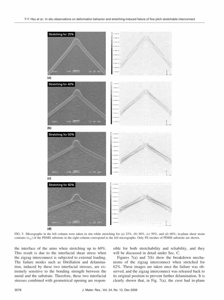
The crest of the zigzag interconnect acts as the “rota-tion center” while the straight arms act as the radius.When stretching up to 60%, as shown in Fig. 4(b), thezigzag interconnect deformed not only by in-plane geo-metrical opening and local twisting on the arms but alsoby out-of-plane deformation on the crests. The leftcolumn in Figs. 5(a)–5(d) shows a sequence of in situobservations on a stretched zigzag interconnect, startingfrom 25 up to 60% stretching. These micrographs attestthe three deformation mechanisms mentioned above.Meanwhile, these micrographs also show a system inwhich the degree of stretchability is not determined sim-ply by the overall geometrical opening of the zigzaginterconnect. Moreover, the local in-plane shear strainon the substrate, mentioned above in the third deforma-tion mechanism, is responsible for a local sliding defor-mation. This local sliding deformation induced by a
local fibrillation process contributes parts of the overallstretchability. It is noted that this sliding deformationinduced by the fibrillation process can be elasticallyrecovered once the zigzag structure released back to itsoriginal position. This deformation mechanism can beexplained by the elastic nature of substrate’s materialproperties because the fibrillation process only oc-curred on elastomeric substrate. Moreover, one can alsoobserve that the fibrillation is accompanied by or “fol-lowed by” the interfacial delamination. Once the fiber-like texture no longer holds the zigzag structure slidingon the substrate surface, the interfacial delaminationstarts propagating at the interface. The right column ofFig. 5 shows the contours of in-plane shear strain in thesubstrate obtained by FEM analysis corresponding to theleft column of the in situ observations. The contours ofin-plane shear strains in the substrate have the maximalvalues near the free edge of the zigzag interconnect closeto each crest. These in-plane shear strain contours con-firm that crests work as the center and the arms work asthe radius. As the zigzag interconnect is being stretched,the arms rotate and the crests remain, resulting in alocalized in-plane shear strain concentration close toeach crest.
B. Failure analysis of the zigzag interconnect
To observe the failure mechanism of the Cu inter-connect, the home-built tensile stage that was mounteddirectly in the SEM was tilted 45 degrees and rotatedwith appropriate angle, as shown in Figs. 6(a) and 6(b).Although there is an out-of-plane deformation on thecrest during 40% stretching, as shown in Fig. 6(a),the crest is still adhered on the substrate surface with-out delamination. This feature is possible because thesubstrate is sufficiently compliant. This deformationmechanism, which is different from the one for a free-standing zigzag interconnect, results in localized strain.Consequently, local compressive strain is concentratedat the outer convex edge of the zigzag interconnectclose to the crest; meanwhile, local tensile strain isconcentrated at the inner concave edge of the zigzaginterconnect opposite to the compressive concentrationlocation. It is obvious in Fig. 6(b) that there is severestrain concentration when stretching up to 60%, creat-ing possible failure locations when the local strain con-centration becomes higher than the strain limit of theinvolved materials. Besides strain concentration on thearms, the crest has a significant out-of-plane deforma-tion while it remains adhered to the substrate surface.It is noted that the interface between Cu and PDMSno longer shows an intact adhesion but is subject tofibrillation. This fibrillation process at the crest ismainly driven by interfacial normal stress or “peelingstress.” The fibrillation process was also observed at
FIG. 4. Scanning electron micrographs of metallic zigzag-patterned
interconnection (a) before stretching and (b) during stretching. The
upper left inset of (b) shows a magnified view of the fibrillation.
Y-Y. Hsu et al.: In situ observations on deformation behavior and stretching-induced failure of fine pitch stretchable interconnect
J. Mater. Res., Vol. 24, No. 12, Dec 2009 3577
the interface of the arms when stretching up to 60%.This result is due to the interfacial shear stress whenthe zigzag interconnect is subjected to external loading.The failure modes such as fibrillation and delamina-tion, induced by these two interfacial stresses, are ex-tremely sensitive to the bonding strength between themetal and the substrate. Therefore, these two interfacialstresses combined with geometrical opening are respon-
sible for both stretchability and reliability, and theywill be discussed in detail under Sec. C.Figures 7(a) and 7(b) show the breakdown mecha-
nisms of the zigzag interconnect when stretched for62%. These images are taken once the failure was ob-served, and the zigzag interconnect was released back toits original position to prevent further delamination. It isclearly shown that, in Fig. 7(a), the crest had in-plane
FIG. 5. Micrographs in the left column were taken in situ while stretching for (a) 25%, (b) 40%, (c) 50%, and (d) 60%; in-plane shear strain
contours (exy) of the PDMS substrate in the right column correspond to the left micrographs. Only FE meshes of PDMS substrate are shown.
Y-Y. Hsu et al.: In situ observations on deformation behavior and stretching-induced failure of fine pitch stretchable interconnect
J. Mater. Res., Vol. 24, No. 12, Dec 20093578
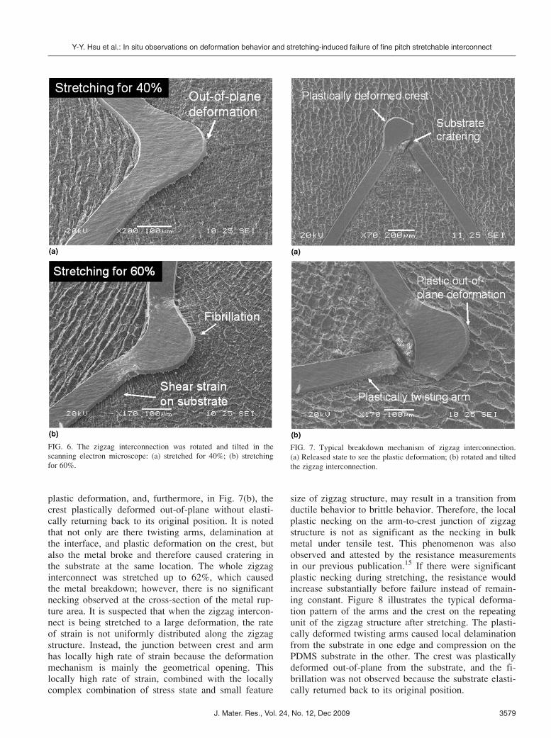
plastic deformation, and, furthermore, in Fig. 7(b), thecrest plastically deformed out-of-plane without elasti-cally returning back to its original position. It is notedthat not only are there twisting arms, delamination atthe interface, and plastic deformation on the crest, butalso the metal broke and therefore caused cratering inthe substrate at the same location. The whole zigzaginterconnect was stretched up to 62%, which causedthe metal breakdown; however, there is no significantnecking observed at the cross-section of the metal rup-ture area. It is suspected that when the zigzag intercon-nect is being stretched to a large deformation, the rateof strain is not uniformly distributed along the zigzagstructure. Instead, the junction between crest and armhas locally high rate of strain because the deformationmechanism is mainly the geometrical opening. Thislocally high rate of strain, combined with the locallycomplex combination of stress state and small feature
size of zigzag structure, may result in a transition fromductile behavior to brittle behavior. Therefore, the localplastic necking on the arm-to-crest junction of zigzagstructure is not as significant as the necking in bulkmetal under tensile test. This phenomenon was alsoobserved and attested by the resistance measurementsin our previous publication.15 If there were significantplastic necking during stretching, the resistance wouldincrease substantially before failure instead of remain-ing constant. Figure 8 illustrates the typical deforma-tion pattern of the arms and the crest on the repeatingunit of the zigzag structure after stretching. The plasti-cally deformed twisting arms caused local delaminationfrom the substrate in one edge and compression on thePDMS substrate in the other. The crest was plasticallydeformed out-of-plane from the substrate, and the fi-brillation was not observed because the substrate elasti-cally returned back to its original position.
FIG. 6. The zigzag interconnection was rotated and tilted in the
scanning electron microscope: (a) stretched for 40%; (b) stretching
for 60%.
FIG. 7. Typical breakdown mechanism of zigzag interconnection.
(a) Released state to see the plastic deformation; (b) rotated and tilted
the zigzag interconnection.
Y-Y. Hsu et al.: In situ observations on deformation behavior and stretching-induced failure of fine pitch stretchable interconnect
J. Mater. Res., Vol. 24, No. 12, Dec 2009 3579
C. Mechanical modeling
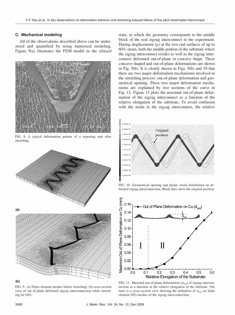
All of the observations described above can be under-stood and quantified by using numerical modeling.Figure 9(a) illustrates the FEM model in the relaxed
state, in which the geometry corresponds to the middleblock of the real zigzag interconnect in the experiment.During displacement (m) at the two end surfaces of up to60% strain, both the middle portion of the substrate wherethe zigzag interconnect resides as well as the zigzag inter-connect deformed out-of-plane in concave shape. Theseconcave shaped and out-of-plane deformations are shownin Fig. 9(b). It is clearly shown in Figs. 9(b) and 10 thatthere are two major deformation mechanisms involved inthe stretching process: out-of-plane deformation and geo-metrical opening. These two major deformation mecha-nisms are explained by two sections of the curve inFig. 11. Figure 11 plots the maximal out-of-plane defor-mation of the zigzag interconnect as a function of therelative elongation of the substrate. To avoid confusionwith the strain in the zigzag interconnect, the relative
FIG. 8. A typical deformation pattern of a repeating unit after
stretching.
FIG. 9. (a) Finite element meshes before stretching; (b) cross-section
view of out-of-plane deformed zigzag interconnection while stretch-
ing for 60%.
FIG. 10. Geometrical opening and plastic strain distribution on de-
formed zigzag interconnection. Black lines show the original position.
FIG. 11. Maximal out-of-plane deformation (dout) of zigzag intercon-
nection as a function of the relative elongation of the substrate. The
inset is a cross-section view showing the definition of dout on finite
element (FE) meshes of the zigzag interconnection.
Y-Y. Hsu et al.: In situ observations on deformation behavior and stretching-induced failure of fine pitch stretchable interconnect
J. Mater. Res., Vol. 24, No. 12, Dec 20093580
elongation of the substrate is expressed as m/Lsub. InFig. 11, the maximal out-of-plane deformation of the zig-zag interconnect occurs on its outer convex edges of thecrests. As the relative elongation of the substrate increasesfrom 0 to 12% in Sec. I, the maximal out-of-plane defor-mation of the zigzag interconnect increases only slightly.The major deformation mechanism in this stage is mainlyin-plane geometrical opening, initiating strain concentra-tion on the arms. This process is seen as local tensile strainconcentration at the inner concave edge of the arms andlocal compressive strain concentration at the outer convexedge of the arms. Furthermore, as the relative elongationincreases from 12 to 60%, in Sec. II, the maximal out-of-plane deformation of the zigzag interconnect increasessubstantially. The substrate is no longer able to keep thezigzag interconnect deforming in the same plane. Instead,out-of-plane deformation takes place to accommodate thefurther stretching loading, so that even a large elongationinduces only small strain in the zigzag interconnect.
Figure 10 not only shows the geometrical opening butalso the plastic strain distribution on the deformed zig-zag interconnect. Plastic strain keeps accumulating onthe inner concave edge of the arms during stretching,and, consequently, the metal breaks down. Referringback to Fig. 7, it is found that the strain distribution onthe zigzag interconnect reached by numerical analysisagrees well with the failure location observed experi-mentally. Moreover, this result corresponds with thelocation of maximal stress concentration in our analyti-cal models.
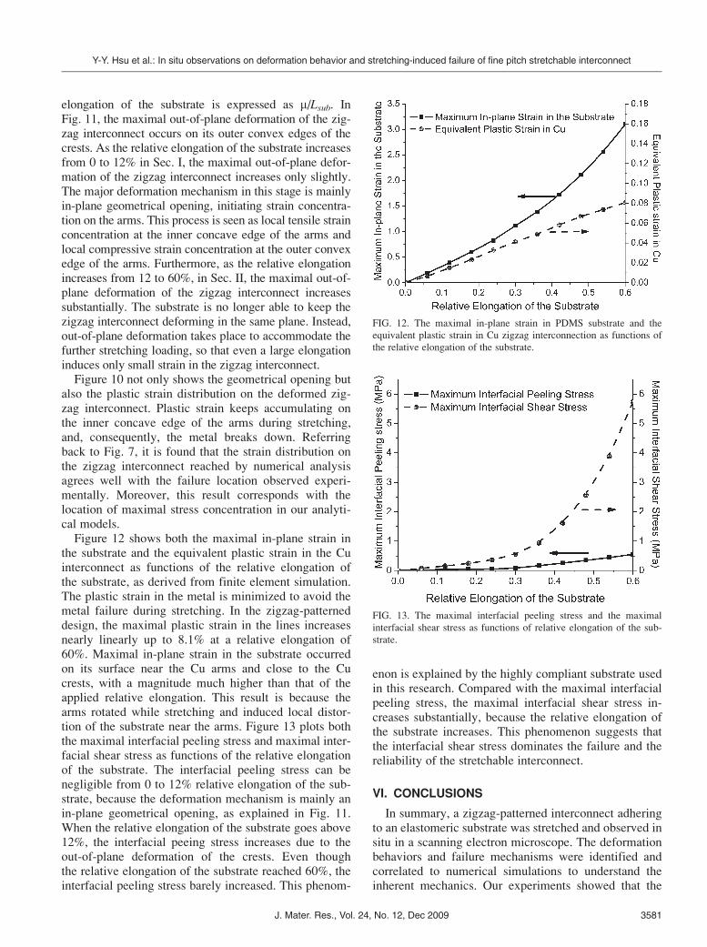
Figure 12 shows both the maximal in-plane strain inthe substrate and the equivalent plastic strain in the Cuinterconnect as functions of the relative elongation ofthe substrate, as derived from finite element simulation.The plastic strain in the metal is minimized to avoid themetal failure during stretching. In the zigzag-patterneddesign, the maximal plastic strain in the lines increasesnearly linearly up to 8.1% at a relative elongation of60%. Maximal in-plane strain in the substrate occurredon its surface near the Cu arms and close to the Cucrests, with a magnitude much higher than that of theapplied relative elongation. This result is because thearms rotated while stretching and induced local distor-tion of the substrate near the arms. Figure 13 plots boththe maximal interfacial peeling stress and maximal inter-facial shear stress as functions of the relative elongationof the substrate. The interfacial peeling stress can benegligible from 0 to 12% relative elongation of the sub-strate, because the deformation mechanism is mainly anin-plane geometrical opening, as explained in Fig. 11.When the relative elongation of the substrate goes above12%, the interfacial peeing stress increases due to theout-of-plane deformation of the crests. Even thoughthe relative elongation of the substrate reached 60%, theinterfacial peeling stress barely increased. This phenom-
enon is explained by the highly compliant substrate usedin this research. Compared with the maximal interfacialpeeling stress, the maximal interfacial shear stress in-creases substantially, because the relative elongation ofthe substrate increases. This phenomenon suggests thatthe interfacial shear stress dominates the failure and thereliability of the stretchable interconnect.
VI. CONCLUSIONS
In summary, a zigzag-patterned interconnect adheringto an elastomeric substrate was stretched and observed insitu in a scanning electron microscope. The deformationbehaviors and failure mechanisms were identified andcorrelated to numerical simulations to understand theinherent mechanics. Our experiments showed that the
FIG. 12. The maximal in-plane strain in PDMS substrate and the
equivalent plastic strain in Cu zigzag interconnection as functions of
the relative elongation of the substrate.
FIG. 13. The maximal interfacial peeling stress and the maximal
interfacial shear stress as functions of relative elongation of the sub-
strate.
Y-Y. Hsu et al.: In situ observations on deformation behavior and stretching-induced failure of fine pitch stretchable interconnect
J. Mater. Res., Vol. 24, No. 12, Dec 2009 3581
zigzag interconnect can be stretched up to 62% whileexperiencing three different failure modes: fibrillationof the substrate near the edge of the arms, out-of-planedeformation of the crest, and breaking on the metalarms. These failure modes were governed by interfacialin-plane shear stress in the substrate, interfacial peelingstress, and local plastic strain in the metal, respectively.The interfacial in-plane shear stress dominated failure andstretchability compared with the interfacial peeling stress.Nevertheless, there was a significant out-of-plane defor-mation, confirmed both by numerical and experimentalresults. By examining the metal breakdown area, it wasfound that there was no significant local plastic necking.This observation was also confirmed by electrical resis-tance measurements in our previous publication.15
It is also observed through analytical analysis that thestretchability highly depends on the zigzag structure de-sign. Based on the analytical model in this article andnumerical analysis,11,14 it is suggested by choosing acompliant, thin substrate, and high length-to-width ratioof the arm, soft metal, the high stretchability zigzaginterconnect can be realized.
The above analysis and results show that the zigzaginterconnect offers promising possibilities for stretchableinterconnects, especially for fine pitch applications. Inthe future, further studies will focus on metal ductility,interfacial separation energy, and the mechanics of co-hesive cracking. This approach will allow us to furtherunderstand, and to improve through design, the stretch-ability and reliability of this zigzag interconnect.
ACKNOWLEDGMENT
This work was supported by European Commission,under the STELLA research project (Contract No. 028026).
REFERENCES
1. V.J. Lumelsky, M.S. Shur, and S. Wagner: Sensitive skin. IEEESensors J. 1, 41 (2001).
2. S. Wagner, E. Bonderover, W.B. Jordan, and J.C. Sturm: Electro-
textiles: Concepts and challenges. Int. J. High Speed Electron.Syst. 12, 1 (2002).
3. H. Jiang, D.Y. Khang, J. Song, Y. Sun, Y. Huang, and
J.A. Rogers: Finite deformation mechanics in buckled thin films
on compliant supports. Proc. Nat. Acad. Sci. U.S.A. 104(40),15607 (2007).
4. H. Jiang, Y. Sun, J.A. Rogers, and Y. Huang: Mechanics of
precisely controlled thin film buckling on elastomeric substrate.
Appl. Phys. Lett. 90, 133119 (2007).
5. H.C. Ko, M.P. Stoykovich, J. Song, V. Malyarchuk, W.M. Choi,
C.J. Yu, J.B. Geddes, J. Xiao, S. Wang, Y. Huang, and
J.A. Rogers: A hemispherical electronic eye camera based on
compressible silicon optoelectronics. Nature 454, 748 (2008).
6. D.H. Kim, J.H. Ahn, W.M. Choi, H.S. Kim, T.H. Kim, J. Song,
Y.Y. Huang, L. Zhuangjian, L. Chun, and J.A. Rogers: Stretch-
able and foldable silicon integrated circuits. Science 320, 507(2008).
7. J.H. Ahn, H.S. Kim, E. Menard, K.J. Lee, Z. Zhu, D.H. Kim,
R.G. Nuzzo, J.A. Rogers, I. Amlani, V. Kushner, S.G. Thomas,
and T. Duenas: Bendable integrated circuits on plastic substrates
by use of printed ribbons of single-crystalline silicon. Appl. Phys.Lett. 90, 213501 (2007).
8. S.P. Lacour, S. Wagner, Z. Huang, and Z. Suo: Stretchable gold
conductors on elastomeric substrates. Appl. Phys. Lett. 82(15),2404 (2003).
9. S. Wagner, S.P. Lacour, J. Jones, P.I. Hsu, J.C. Sturm, T. Li, and
Z. Suo: Electronic skin: Architecture and components. Physica E25, 326 (2004).
10. T. Li, Z. Huang, Z. Suo, S.P. Lacour, and S. Wagner: Stretchabil-
ity of thin metal films on elastomer substrates. Appl. Phys. Lett.85(16), 3435 (2004).
11. T. Li, Z. Suo, S.P. Lacour, and S. Wagner: Compliant thin film
patterns of stiff materials as platforms for stretchable electronics.
J. Mater. Res. 20(12), 3274 (2005).
12. D.S. Gray, J. Tien, and C.S. Chen: High-conductive elastomeric
electronics. Adv. Mater. 16(5), 393 (2004).
13. D. Brosteaux, F. Axisa, M. Gonzalez, and J. Vanfleteren: Design
and fabrication of elastic interconnections for stretchable elec-
tronic circuits. IEEE Electron Device Lett. 28(7), 552 (2007).
14. M. Gonzalez, F. Axisa, M. Vanden Bulcke, D. Brosteaux,
B. Vandevelde, and J. Vanfleteren: Design of metal interconnects
for stretchable electronic circuits. Microelectron. Reliab. 48, 825(2008).
15. Y.Y. Hsu, M. Gonzalez, F. Bossuyt, F. Axisa, J. Vanfleteren, and
I. DeWolf: A novel interconnect design with high stretchability
and fine pitch capability in applications of stretchable electronics.
Mater. Res. Soc. Symp. Proc. (2009).16. S.L. Chiu, J. Leu, and P.S. Ho: Fracture of metal-polymer line
structures. I: Semiflexible polyimide. J. Appl. Phys. 76(9), 5136(1994).
17. MSC Marc User Manual.
Y-Y. Hsu et al.: In situ observations on deformation behavior and stretching-induced failure of fine pitch stretchable interconnect
J. Mater. Res., Vol. 24, No. 12, Dec 20093582
Related Documents