IN-SITU MEASUREMENT OF GROUND STIFFNESS USING SUPER FALLING WEIGHT DEFLECTOMETER TEST METHOD Masaaki NAGASAWA, Hirotaka KAWASAKI Geotechnical Group, Civil Engineering Technology Division, Shimizu Corporation 1-2-3 Shibaura Minato-ku, Tokyo, Japan [email protected] ABSTRACT In the design and construction of the road and structure foundations, in order to effectively prevent the residual settlement and the insufficiency of bearing capacity, reliable in-situ test methods which enable the measurement at high accuracy and repeatability are necessary. Plate loading test is the most commonly used method for in-situ measurement of ground stiffness. However, this method is considered to be time-consuming and costly for multi-point measurement. Therefore, based on the simple principle of Falling Weight Deflectometer (FWD) method for pavement investigation, this Super Falling Weight Deflectometer (SFWD) method for measuring ground stiffness at high accuracy thanks to escalating rapid loading and accumulative displacement measurement was developed and applied at actual construction site. The ground stiffness measured by this method was found to be equivalent to that measured with plate loading test. In addition, with the advantage of simple and quick measurement using this method, it is now possible to early evaluate the ground stiffness to provide reliable information for consideration of construction method and process. This paper describes the outline of this test method and the result of the actual application at some construction sites. 1. INTRODUCTION For evaluating the stiffness of ground, there are two approaches as can be seen in Table 1: One is the direct calculation of ground stiffness based on load and displacement (Plate Loading Test, In-Situ CBR Test, FWD, Light Weight Deflectometer, SFWD), the other is the indirect evaluation using acceleration index (Automatic Compression Testing Machine, Intelligent Compaction). The ground stiffness evaluation using loading plate is applicable for grounds of which maximum size of soil particles is less than one third, and measured depth is less than twice of plate diameter Though plate loading test is the most commonly used method, it requires a large reaction base. Furthermore, it is quite labor and time-consuming, taking several hours for one measurement. On the other hand, though the indirect method using acceleration index value is quite simple, its range of applicable ground as well as the measuring accuracy remains great challenges. FWD and Light Weight Deflectometer are common methods in which a weight is dropped repeatedly 6 times from the same height and the ground stiffness is evaluated based on the measured results. The first drop is preparatory loading for eliminating the bedding error. It also creates a loading history in the tested ground. Therefore, the ground stiffness obtained after first drop is the one under repeat loading, and is, therefore, different from the ground stiffness in term of K value obtained under monotonous loading of conventional plate loading test. SFWD system (Figure 1) utilizes the principle of FWD but the way of applying load is quite different. In this system, the load is applied in multi stages with escalating rapid loading while the accumulative displacement is measured. The ground stiffness is defined as the envelope gradient of load-displacement curves. As a result, it is quite simple to obtain equivalent K-value as in case of using plate loading test, and in-situ evaluation of ground stiffness is relatively easy with this method.

Welcome message from author
This document is posted to help you gain knowledge. Please leave a comment to let me know what you think about it! Share it to your friends and learn new things together.
Transcript

IN-SITU MEASUREMENT OF GROUND STIFFNESS USING SUPER FALLING WEIGHT DEFLECTOMETER TEST METHOD
Masaaki NAGASAWA, Hirotaka KAWASAKI
Geotechnical Group, Civil Engineering Technology Division, Shimizu Corporation
1-2-3 Shibaura Minato-ku, Tokyo, Japan [email protected]
ABSTRACT
In the design and construction of the road and structure foundations, in order to effectively prevent the residual settlement and the insufficiency of bearing capacity, reliable in-situ test methods which enable the measurement at high accuracy and repeatability are necessary. Plate loading test is the most commonly used method for in-situ measurement of ground stiffness. However, this method is considered to be time-consuming and costly for multi-point measurement.
Therefore, based on the simple principle of Falling Weight Deflectometer (FWD) method for pavement investigation, this Super Falling Weight Deflectometer (SFWD) method for measuring ground stiffness at high accuracy thanks to escalating rapid loading and accumulative displacement measurement was developed and applied at actual construction site. The ground stiffness measured by this method was found to be equivalent to that measured with plate loading test. In addition, with the advantage of simple and quick measurement using this method, it is now possible to early evaluate the ground stiffness to provide reliable information for consideration of construction method and process.
This paper describes the outline of this test method and the result of the actual application at some construction sites. 1. INTRODUCTION
For evaluating the stiffness of ground, there are two approaches as can be seen in Table 1: One is the direct calculation of ground stiffness based on load and displacement (Plate Loading Test, In-Situ CBR Test, FWD, Light Weight Deflectometer, SFWD), the other is the indirect evaluation using acceleration index (Automatic Compression Testing Machine, Intelligent Compaction).
The ground stiffness evaluation using loading plate is applicable for grounds of which maximum size of soil particles is less than one third, and measured depth is less than twice of plate diameter
Though plate loading test is the most commonly used method, it requires a large reaction base. Furthermore, it is quite labor and time-consuming, taking several hours for one measurement. On the other hand, though the indirect method using acceleration index value is quite simple, its range of applicable ground as well as the measuring accuracy remains great challenges.
FWD and Light Weight Deflectometer are common methods in which a weight is dropped repeatedly 6 times from the same height and the ground stiffness is evaluated based on the measured results. The first drop is preparatory loading for eliminating the bedding error. It also creates a loading history in the tested ground. Therefore, the ground stiffness obtained after first drop is the one under repeat loading, and is, therefore, different from the ground stiffness in term of K value obtained under monotonous loading of conventional plate loading test.
SFWD system (Figure 1) utilizes the principle of FWD but the way of applying load is quite different. In this system, the load is applied in multi stages with escalating rapid loading while the accumulative displacement is measured. The ground stiffness is defined as the envelope gradient of load-displacement curves.
As a result, it is quite simple to obtain equivalent K-value as in case of using plate loading test, and in-situ evaluation of ground stiffness is relatively easy with this method.

Table 1 In-Situ Measurement Methods for Ground Stiffness Correlation to
K-value of plate loading test
Measured item
displacement plate size Evaluation of K-value pre-loadingaccuracy (mm)
Direct
Plate Loading displacement φ300~ & load high φ750 no ── ── Test
In-Situ CBR Test
displacement & load high φ50 no conversion
low in gravelly soil
FWD displacement & load high
φ300~ φ450 applied cyclic loading
2. OUTLINES OF SFWD SYSTEM AND DATA PROCESSING METHOD
In SFWD measurement, a weight of 200kg is repeatedly dropped onto ground from gradually increased heights. It means that load with increasing intensity is applied continuously on ground and the ground stiffness is evaluated from the measured accumulative displacement. The maximum load corresponding to the maximum dropping height of 300mm is as large as 90kN, which means that a great impact on the ground is possible.
As can be seen in Figure 2, this system is an integration of load and displacement measuring functions. Devices for loading, displacement measurement, GPS signal, etc are controlled by a computer which is also used for analyzing measured results and evaluating ground stiffness. Table 2 shows the parameters of this system.
It is a totally automatic system which enables a fast, highly accurate and simple method for evaluation of ground stiffness. Therefore, the measurement of ground stiffness is largely optimized, the construction is more effective, and the quality assurance is very much simpler than before. Example of ground stiffness evaluation based on measured results is shown in Figure 3.
Figure 4 shows the load and displacement results in which the weight was dropped from different heights of 60, 175 and 300mm.As can be seen in this figure, the time duration from the start to the pick of loading is as small as 0.01 second. It means a great impacting load has been applied.
Figure 5 is a computer display showing the “Result Analysis” dialog of SFWD system. In the same display, one can see such information as load, displacement, load-displacement relation, and load–cyclic deformation modulus relation on the real time basis. Besides, the ground stiffness is also evaluated and shown at the same time.
medium
Light WeightDeflectomter
acceleration & load medium
φ100~ φ300 applied cyclic loading slightly low
SFWD displacement & load high
φ300~ φ450 no
equivalent to plate loading test high
Indirect
ACTM*1) acceleration ── φ50 applied conversion extremely
low
Intelligent Compaction acceleration ── roller width no conversion low
*1) Automatic Compression Testing Machine
Figure 1 Measurement at a Construction Site using SFWD

Figure 2 Super Falling Weight Deflectometer(SFWD)
Displacement sensor
GPS antenna GPS receiver
PC
Weight(200kg)
Damper Load Cell
Table 2 SFWD Specification Weight 200kg
Maximum Falling Height 300mm
Maximum Rapid Loading 90kN
Diameter of Plate φ 450、φ300
Loading Sensor load cell
Displacement Sensor GY & LVDT
Range of Displacement 0~30mm
Loading Plate(φ450mm, φ300mm)
Control
PositionMeasuring Data
Figure 3 Sample of a Distribution Map of Ground Stiffness
Deformation Modulus
2
Measured by SFWD
0.0
0.2
0.4
0.6
0.8
1.0
30 50 70 90 110
時 間 t (ms)
変
位
δ
(m
m)
0
200
400
600
800
1000
荷
重
P
(kN
/m
2)
変位h=60mm変位h=175mm変位h=300mm荷重h=60mm荷重h=175mm荷重h=300mm
Displacement (h= 60mm) Displacement (h=175mm) Displacement (h=300mm) Load (h= 60mm) Load (h=175mm) Load (h=300mm)
Dis
plac
emen
t, δ
(mm
)
Load
, P (k
N/m
2 )
Time (ms) Figure 4 Time History of Displacement and Load

s Elsf of SFWD system is calculated using the following formula in which the co
Elsf=0.25π D (1-ν ) Klsf (1) r sand or gravel, 0.4 for clay)
荷重・変位波形 Time History of Displacement and Load
Figure 6 shows the concept of [multi-stage rapid loading - accumulative displacement] method
used in SFWD system. As seen in this figure, the coefficient of bearing capacity, Klsf, is defined as the envelope gradient of all load and displacement peak values of each loading stage, and the coefficient of cyclic subgrade reaction, Krsf, is defined as the gradient of each load and displacement start and peak values of each loading stage.
The deformation moduluefficient of bearing capacity, Klsf, under plate loading condition is a variable.
2
Here, ν: Poison’s ratio (0.3 foD: Diameter of loading plate
荷重・変位関係 荷重・繰返し弾性係数関係 Relation between Relation between Load and Cyclic Deformation Modulus Load and Displacement
Figure 5 Sample of Output Obtained by SFWD Measurement
0
100
200
300
400
500
600
0.0 2.0 4.0 6.0 8.0変 位 δ (mm)
荷
重
P (
kN
/m
)2
2Lo
ad, P
(kN
/m)
Displacement, δ (mm)
E=0.25π・D(1-ν2)・K
Coefficient of Bearing Capacity, Klsf
Coefficient of Cyclic Subgrade Reaction, Krsf
Figure 6 Multi-Stage Rapid Loading-Accumulative Displacement Method used in SFWD
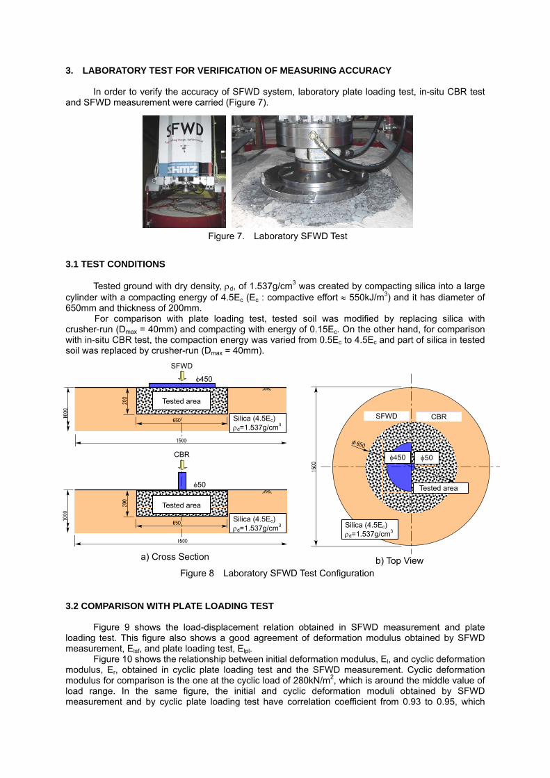
3. LABORAT N OF MEASURING ACCURACY
CBR test nd SFWD measurement were carried (Figure 7).
acting silica into a large
ylinder with a com and it has diameter of 650mm
comparison with in
tion obtained in SFWD measurement and plate ading test. This figure also shows a good agreement of deformation modulus obtained by SFWD
measu
st and the SFWD measurement. Cyclic deformation modul
ORY TEST FOR VERIFICATIO
In order to verify the accuracy of SFWD system, laboratory plate loading test, in-situ a
3.1 TEST CONDITIONS
Tested ground with dry density, ρd, of 1.537g/cm3 was created by comppacting energy of 4.5E (E : compactive effort ≈ 550kJ/m3)
mpacting with energy of 0.15E . On the other hand, for
Figure 7. Laboratory SFWD Test
c c c and thickness of 200mm. For comparison with plate loading test, tested soil was modified by replacing silica with
crusher-run (Dmax = 40mm) and co c-situ CBR test, the compaction energy was varied from 0.5Ec to 4.5Ec and part of silica in tested
soil was replaced by crusher-run (Dmax = 40mm).
3.2 COMPARISON WITH PLATE LOADING TEST
SFWD試験
Figure 9 shows the load-displacement rela
lorement, Elsf, and plate loading test, Elpl. Figure 10 shows the relationship between initial deformation modulus, El, and cyclic deformation
modulus, Er, obtained in cyclic plate loading teus for comparison is the one at the cyclic load of 280kN/m2, which is around the middle value of
load range. In the same figure, the initial and cyclic deformation moduli obtained by SFWD measurement and by cyclic plate loading test have correlation coefficient from 0.93 to 0.95, which
載荷板φ450
試験領域
貫入体φ50
SFWD試験 現場 験CBR試
Tested area
Silica (4.5Ec) ρd=1.537g/cm3
φ50 φ450
SFWD CBR
Figure 8 Laboratory SFWD Test Configuration
a) Cross Section b) Top View
載 50荷板φ4
6号硅砂・4.5Ecρd=1.537 g/cm3
試験領域Tested area
SFWD
φ450
Silica (4.5Ec) ρd=1.537g/cm3
現場CBR試験
貫 50入体φ
6号硅砂・4.5Ecρd=1.537 g/cm3
試験領域
φ50
Tested area
CBR
Silica (4.5Ec) ρd=1.537g/cm3

means relatively high correlation. Therefore, it can be concluded that it is highly reliable using SFWD in replace of plate loading
test for quality control in compacting work of man-made ground like fill.
and in-situ CBR test in case tested area contains rusher-run (1.5Ec). On this load-displacement relation line of in-situ CBR test, CBR deformation
modul
easurement and C
3.3 COMPARISON WITH IN-SITU CBR TEST
Figure 11 shows the results of SFWDc
us, Ecbr, is defined as gradient of linear part at initial stage under monotonous load. In this case, in-situ CBR test and SFWD measurement yields almost the same deformation modulus.
Figure 12 shows the correlation between deformation modulus obtained by SFWD measurement and CBR. As can be seen in this figure, deformation modulus by SFWD m
BR are in very good agreement.
SFWD
PLT
Load
, P (k
N/m
2 )
Elpl=13.78MN/m2
Elsf=14.20MN/m2
Displacement, δ (mm)
Figure 9 Comparison of Load Displacement obtained in SFWD Measurement and Plate Loading Test
0
20
40
60
80
0 20 40 60 80
初期弾性係数Eℓ
繰返し弾性係数Er
Initial deformation modulus
Ersf=1.099Erpl r=0.95
Cyclic deformation modulus
Elsf=0.960Elpl r=0.93
Initial deformation modulus, El Cyclic deformation modulus, Er
SFW
Df(
MN
/m
)の
弾性
係数
E
s2
Def
orm
atio
n M
odul
us o
f SFW
D,
E sf (
MN
/m2 )
平板試験の弾性係数 Epl(MN/m2)Deformation Modulus of Plate Loading Test, Epl (MN/m2)
Figure 10 Relation between Deformation Modulus of Plate Loading Test and SFWD

Therefore, it can be concluded that it is possible to use SFWD in replace of in-situ CBR test for quality control in compacting work of man-made ground like road foundation.
dy soil (decomposed granite oil) are selected as typical examples of in-situ measurement and stiffness evaluation using SFWD.
easurement is the first ecessary step in which SFWD measurement (φ450mm or φ300mm), Plate Loading Test (φ750mm or
φ300m
4. EXAMPLE OF ACTUAL APPLICATION ON MAN-MADE GROUND
Actual applications on mudstone soil, cement-stabilized soil and sans
4.1 METHOD FOR EVALUATION OF GROUND STIFFNESS USING SFWD
For evaluating the ground stiffness using SFWD, the calibration mn
m), in-situ CBR test (φ50mm), density and water content measurement are carried out. Based
Figure 12 Relation between Initial Deformation Modulus of SFWD and CBR
y = 5.680x0.594
r = 0.957
0
20
40
60
80
100
SF
0 20 40 60 80 100
CBR (%)
2)
WD
初期
弾性
係数
Eℓ(
MN
/m
砕石
硅砂
Initi
al D
efor
mat
ion
Mod
ulus
o
f SFW
D, E
lsf (
MN
/m2 )
Crusher-run Silica
Figure 11 Relation between Normalized Load and Displacement of CBR and SFWD
0
0.0 1.0 2.0 3.0 4.0 5.0
m)
25
50
75
100
125
150
175
正規
化荷
重
P*
(kN
/
Nor
mal
ized
load
, P* (
kN/m
2 ) P*
=0.
25π
D(1
-ν2 ) P
Initial deformation modulus of CBR test
Ecbr=46.0MN/m2
Initial deformation modulus of SFWD
Elsf=48.0MN/m2
CBR
SFWD
変 位 δ (mm)Displacement, δ (mm)

on the results obtained in these tests and measurements, correlation between entities like deformation modulus, bearing capacity coefficient, CBR, dry density, water content, etc can be figured out.
As shown in Figure 13, the measurement points are arranged in order to avoid the effect of load history caused by plate loading test, and the results of measurement are the average values of SFWD measu
4.2 STIFFNESS EVALUATION OF MUDSTONE GROUND, CEMENT STABILIZED GROUND
an-made ground at an airport, including lower subgrade d and roller-compacted upper subgrade of fill (t = 300mm),
upper
ues of RI measurement after compacting work are dry density (ρd) of 1.89
nd compacting by 20-ton
.2.2 MEASURED RESULTS AND DISCUSSION
ts at the same position using plate loading test and s of plate loading test and SFWD have similar cyclic
history
ding test, respectively.
in-situ CBR test is quite sensitive to the fluctuation of ground condit
evalua
OMPOSED GRANITE GROUND)
nd including a fill made of decomposed granite soil and a
rement at 4 positions, in-situ CBR test as well as measurement of density and water content at 2 positions.
Figure 13 Outlines of Calibration Tests
200
200
Plate Loading Test(φ750 or φ300)
SFWD(φ450 or φ300)
CBR(φ 50)
Density and Water Content
4.2.1 OUTLINES OF MAN-MADE GROUND
The measured ground was 4 types of mf fill, lower subgrade of cut, cement-stabilizeo
subgrade of cut (t = 150mm). Lower subgrade of fill is formed by mudstone soil (Dmax = 150mm) and compacted with 20-ton
vibrating roller (4 times). Average val7g/cm3, water content(w) of 11.6%, and degree of compaction (Dc) of 98.7% Lower subgrade of cut is made of new mudstone and leveled with bulldozer. Upper subgrade of
fill and cut are cement-stabilized layers created by mixing with cement (50kg/m3) a vibrating roller (6 times)
4
Figure 14 shows the results of measuremenFWD measurement. This figure shows that resultS
loops. Figure 15 and 16 show the correlation between SFWD measurement and in-situ CBR test as
well as plate loaAs shown in figure 15, a correlation of CBR values is relatively low. The result is believed due to
the fact that the loading φ50mm rod usedion. As shown in figure 16, a correlation between results of SFWD measurement and those of
plate loading test is extremely high. By using this correlation, it is possible to use SFWD instead of plate loading test for investigating
the ground stiffness. It makes the work on quality control at site, especially for ground stiffness tion at large construction site, simpler and speedier.
4.3 STIFFNESS EVALUATION OF SANDY GROUND (DEC 4.3.1 OUTLINES OF MAN-MADE GROUND
The tested ground was man-made groucut made of decomposed granite soil.

0
100
200
300
400
0
50
100
150
200
SFWDの
弾性
係数
E
sf (MN/m2)
0 50 100 150 200
平板試験の弾性係数 Epℓ (MN/m2)
盛土/下部路床/無処理切土/下部路床/無処理盛土/上部路床/C処理t=300
切土/上部路床/C処理t=150
y=3 .534x0.806
r=0 .876
Figure 16 Relation between Initial Deformation Moduli of SFWD and that of Plate Loading Test
Initial Deformation Modulus of Plate Loading Test, Elpl (MN/m2)
Initi
al D
efor
mat
ion
Mod
ulus
of S
FWD
, E
lsf (
MN
/m2 )
Fill/Lower subgrade Cut/Lower subgrade Fill/Upper subgrade Cut/Upper subgrade
0
0 50 100 150 20
50
100
150
200
0
現場CBR (%)
SFWDの
弾性
係数
E
sf (MN/m2)
盛土/下部路床/無処理
切土/下部路床/無処理盛土/上部路床/C処理t=300
切土/上部路床/C処理t=150
y=1 .198x r=0 .530
Figure 15 Relation between Initial Deformation Modulus of SFWD and CBR
Initi
al D
efor
mat
ion
Mod
ulus
of S
FWD
, E
lsf (
MN
/m2 )
CBR (%)
Fill/Lower subgrade Cut/Lower subgrade Fill/Upper subgrade Cut/Upper subgrade
Figure 14 Relation between Load and Normalized Displacement
500
2)
600
0.0 2.0 4.0 6.0 8.0 10.0 12.0
正規化変位 δ*
[δ*=δ/{0.25π(1-ν2)D}]
荷重
強さ
p
(kN
/m
平板載荷試験φ750
SFWDφ450
E=0.25π・D(1-ν2)・K
SFWD E
sf=65.0MN/m
2
平板 E
pl=39.7MN/m2
Plate Loading Test(PLT) (φ750)
Load
, P (k
N/m
2 )
Normalized Displacement , δ* (mm)

The decomposed granite soil for m imum size of 19mm. Each 30cm layer is compacted by 10-ton roller in 8 times. After completing the required compaction, the sand replacement method is applied for confirming that the degree of compaction is at least 90%.
Cut is created by motor scraper. 4.3.2 MEASURED RESUL D DISCUSSION
Figure 17 shows the s of plate loading test and SFWD measurement on the same position. It can be seen that the plate loading test has similar record with SFWD measurement.
Figure 18 shows the correlation between SFWD result and that of plate loading test. It is clear that there is a good agreem t between these methods. Therefore, the evaluation of bearing capacity coefficient and deformation modulus by using SFWD is as accurate as by using plate loading test.
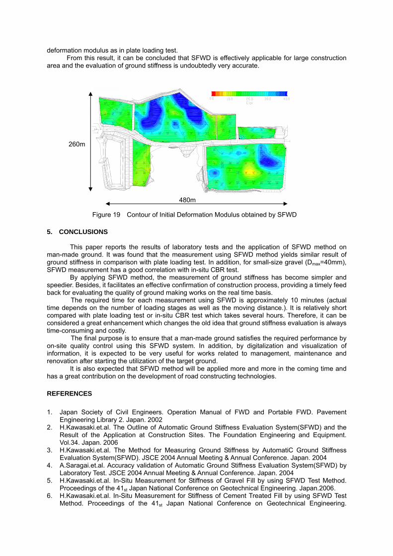
SFWD was applied on the whole 5.6-hectre area of man-made ground for evaluating the deformation modulus. Figure 19 shows the contour of SFWD results that have been converted into initial
aking fill has the max
TS AN
result
en
0
200
400
0.0
600
m)
800
1.0 2.0 3 5.0
変位 δ (
荷重強さ
p (kN
/2
平板載荷試験φ300
.0 4.0
mm)
SFWDφ300
E=0.25π・D(1-ν2)・K
平板 E
pl=30.9MN/m2
SFWD E
sf=35
/m
.4MN
2
Plate Loading Test (PLT) (φ300)SFWD (φ300)
Load
, P (k
N/m
2 )
Displacement, δ (mm)Figure 17 Relation between Loa nt d and Displaceme
0
20
40
60
80
0 20 40 60 80 100
平板試験の弾性係数 Epℓ (MN/m2)
SFWDの弾性係数
Esf (MN/m2)
100
盛土
切土
y=1.347x0.991
r=0.836
Fill
Initi
al D
efor
mat
ion
Mod
ulus
of S
FWD
, E
lsf (
MN
/m2 )
Cut
2Initial Deformation Modulus of PLT, Elpl (MN/m )
Figure 18 Relation between Initial Deformation Moduli of SFWD and Plate Loading Test (PLT)
deform
ethod on r result of =40mm),
r and mely feed
ctual
compared with plate loading test or in-s several hours. Therefore, it can be considered a great e ffness evaluation is always time-consuming and costly.
The final purpose is to ensure that a man-made ground satisfies the required performance by on-site quality control using this SFWD system. In addition, by digitalization and visualization of information, it is expected to be very useful for works related to management, maintenance and renovation after starting the utilization of the target ground.
It is also ex ted that SFWD method will be applied more and more in the coming time and has a great contribu on the development of road constructing technologies. REFERENCES 1. Japan Society of Civil Engineers. Operation Manual of FWD and Portable FWD. Pavement
Engineering Lib . Japan. 2002 2. H.Kawasaki.et.al. The Outline of Automatic Ground Stiffness Evaluation System(SFWD) and the
Result of the Application at Construction Sites. The Foundation Engineering and Equipment. Vol.34. Japan. 2006
3. H.Kawasaki.et.al. The Method for Measuring Ground Stiffness by AutomatiC Ground Stiffness Evaluation System(SFWD). JSCE 2004 Annual Meeting & Annual Conference. Japan. 2004
4. A.Saragai.et.al. Accuracy validation of Automatic Ground Stiffness Evaluation System(SFWD) by Laboratory Test. JSCE 2 n. 2004
5. H.Kawasaki.et.al. In-Situ Measurement for Stiffness of Gravel Fill by using SFWD Test Method. Proceedings o eering. Japan.2006.
6. H.Kawasaki.et.al. sing SFWD Test Method. Proceedings of st on Geotechnical Engineering.
ation modulus as in plate loading test. From this result, it can be concluded that SFWD is effectively applicable for large construction
area and the evaluation of ground stiffness is undoubtedly very accurate.
5. CONCLUSION
This pape ports the results of laboratory tests and the application of SFWD mman-made ground. It was found that the measurement using SFWD method yields similaground stiffness in comparison with plate loading test. In addition, for small-size gravel (DmaxSFWD measurement has a good correlation with in-situ CBR test.
By applying SFWD method, the measurement of ground stiffness has become simplespeedier. Besides, it facilitates an effective confirmation of construction process, providing a tiback for evaluating the quality of ground making works on the real time basis.
The required time for each measurement using SFWD is approximately 10 minutes (atime depends on the number of loading ng distance.). It is relatively short
S
r re
stages as well as the moviitu CBR test which takes
nhancement which changes the old idea that ground sti
pection
rary 2
004 Annual Meeting & Annual Conference. Japa
f the 41st Japan National Conference on Geotechnical EnginIn-Situ Treated Fill by u Measurement for Stiffness of Cement
the 41 Japan National Conference
Figure 19 Contour of Initial Deformation Modulus obtained by SFWD
480m
260m

Japan.2006. 7. S.
. H.Kawasaki.et.al. Relation between In-Situ CBR and SFWD Test Method. JSCE 2007 Annual Meeting & Annual Conference. Japan.2007.
9. T.Sugimoto.et.al. In-Situ Measurement of Mudstone Ground Stiffness by using SFWD Test Method. Proceedings of the 43rd Japan National Conference on Geotechnical Engineering. Japan.2008.
10. K.Iwamura.et.al. In-Situ Measurement of Decomposed Granite Ground Stiffness by using SFWD Test Method. Proceedings of the 43rd Japan National Conference on Geotechnical Engineering. Japan.2008.
Horita.et.al. In-Situ Measurement for Stiffness of Airport Fill by using SFWD Test Method. JSCE 2007 Annual Meeting & Annual Conference. Japan.2007.
8
Related Documents