In-situ HRTEM study of the reactive carbide phase of Co/MoS 2 catalyst Manuel Ramos a,b,n , Domingo Ferrer c , Eduan Martinez-Soto d , Hugo Lopez-Lippmann b , Brenda Torres b , Gilles Berhault e , Russell R. Chianelli b a Departamento de Fı ´sica y Matema ´ticas, Instituto de Ingenierı ´a y Tecnologı ´a, UACJ, 32310 Ciudad Jua ´rez,Me´xico b Materials Research and Technology Institute, UT-El Paso, El Paso, TX 79902, USA c Microelectronics Research Laboratory, UT-Austin, Austin, TX 78758, USA d Departamento de Quı ´mica, Universidad Metropolitana, San Juan, PR 00926-2602, USA e Institut de Recherches sur la Catalyse et l’Environnement, IRCELYON, CNRS, Universite´ de Lyon, Villeurbanne 69100, France article info Available online 27 July 2012 Keywords: Carbide MoS 2 HRTEM Carbon Silicon abstract Hydrotreatment catalytic operations are commonly performed industrially by layered molybdenum sulfide promoted by cobalt or nickel in order to remove heteroelements (S, N, O) from fossil fuels and biofuels. Indeed, these heteroelements are responsible of the emission of pollutants when these fuels are used in vehicles. In this respect, previous studies made by our research group have shown that the active phase under steady state conditions is partially carbided while strong bending effects of MoS 2 slabs were also observed. However, up to now, the morphology of the resulting Co/MoS x C y carbided catalyst has not been fully characterized. In the present study, for the first time, a chemical reaction between the carbon content of a TEM Cu/C grid and a freshly sulfide Co/MoS 2 catalyst was in situ observed at 300 1C and 450 1C by HRTEM experimental techniques at 10 nm of resolution. Results indicate that bending of MoS 2 layers occurred due to carbon addition on MoS 2 edge sites, as observed in stabilized catalysts after HDS reaction. Using a silicon grid, only cracks of MoS 2 slabs were observed without bending effect confirming the role of structural-carbon in this change of morphology. & 2012 Elsevier B.V. All rights reserved. 1. Introduction Layered transition metal sulfides (LTMS) have been widely used in oil refineries for removal of sulfur and other undesirable components responsible for atmospheric pollution [1–3]. In particular, cobalt-promoted MoS 2 catalytic nanostructures have been a topic of extensive research in past decades due to their use as industrial hydrotreating catalysts. Worldwide environmental agencies and legislation in recent years have pushed towards a reduction in emission of pollutants due to oil combustion leading to intensive research on the improvement of hydrodesulfurization (HDS) catalysts since sulfur is a major source of pollution either directly through the formation of SO x or indirectly through the poisoning of catalytic converters or NO x traps [4–6]. MoS 2 has a lamellar structure composed of S–Mo–S bonds ordered in a hexagonal array forming layers maintained stacked in the c direction due to van der Waals forces with an interlayer distance of 0.62 nm as presented in fig. 1A. This layered organization also makes this material ideal for lubrication applications [7]. MoS 2 catalytic activity is strongly increased when promoted by cobalt. In most cases, the synergetic effect of Co was achieved by combining MoS 2 and Co 9 S 8 leading to the so-called surface promoted ‘‘CoMoS’’ phase [8]. This behavior results from both direct and indirect metal–metal interactions existing between both structures [9]. In the Co 9 S 8 structure, cobalt atoms occupy 1/8th of the available octahedral sites and half of the tetrahedral sites. Due to its anisotropic layered structure, not all the surface sites of molybdenum sulfide are identical. While on (0 0 0 1)- basal planes, sites are expected to be catalytically inert due to a fully sulfur coordination of molybdenum, the presence of dangling bonds on (1 0 1 0) and (1 0 1 0) edge planes leads to the formation of active sites and provides ideal locations to accom- modate promoters such as Co or Ni [9]. It is also known that by varying chemical synthesis parameters (temperature, pressure and chemical precursors), specific MoS 2 nanostructures can be obtained like nanorods [10], spheres [11], flower-like [12], or triangular prism [13]. The promoted phase formed by the interaction of cobalt with MoS 2 edges was first observed using M¨ ossbauer emission spectroscopy [14] and more recently through the use and implementation of field emission gun TEM instrumentation enabling to study the detailed MoS 2 structural environment. These studies indicated a characteristic layered Contents lists available at SciVerse ScienceDirect journal homepage: www.elsevier.com/locate/ultramic Ultramicroscopy 0304-3991/$ - see front matter & 2012 Elsevier B.V. All rights reserved. http://dx.doi.org/10.1016/j.ultramic.2012.07.012 n Corresponding author at: Instituto de Ingenierı ´a y Tecnologı ´a, Departamento de Fı ´sica y Matema ´ ticas, 500W University Ave, Physical Science Bldg. Rm 217A, El Paso, TX. 79902 UACJ, 32310 Ciudad Jua ´ rez, Mexico. E-mail addresses: [email protected], [email protected] (M. Ramos). Ultramicroscopy 127 (2013) 64–69

Welcome message from author
This document is posted to help you gain knowledge. Please leave a comment to let me know what you think about it! Share it to your friends and learn new things together.
Transcript
Ultramicroscopy 127 (2013) 64–69
Contents lists available at SciVerse ScienceDirect
Ultramicroscopy
0304-39
http://d
n Corr
de Fısic
Paso, TX
E-m
maramo
journal homepage: www.elsevier.com/locate/ultramic
In-situ HRTEM study of the reactive carbide phase of Co/MoS2 catalyst
Manuel Ramos a,b,n, Domingo Ferrer c, Eduan Martinez-Soto d, Hugo Lopez-Lippmann b, Brenda Torres b,Gilles Berhault e, Russell R. Chianelli b
a Departamento de Fısica y Matematicas, Instituto de Ingenierıa y Tecnologıa, UACJ, 32310 Ciudad Juarez, Mexicob Materials Research and Technology Institute, UT-El Paso, El Paso, TX 79902, USAc Microelectronics Research Laboratory, UT-Austin, Austin, TX 78758, USAd Departamento de Quımica, Universidad Metropolitana, San Juan, PR 00926-2602, USAe Institut de Recherches sur la Catalyse et l’Environnement, IRCELYON, CNRS, Universite de Lyon, Villeurbanne 69100, France
a r t i c l e i n f o
Available online 27 July 2012
Keywords:
Carbide
MoS2
HRTEM
Carbon
Silicon
91/$ - see front matter & 2012 Elsevier B.V. A
x.doi.org/10.1016/j.ultramic.2012.07.012
esponding author at: Instituto de Ingenierıa
a y Matematicas, 500W University Ave, Physi
. 79902 UACJ, 32310 Ciudad Juarez, Mexico.
ail addresses: [email protected],
[email protected] (M. Ramos).
a b s t r a c t
Hydrotreatment catalytic operations are commonly performed industrially by layered molybdenum
sulfide promoted by cobalt or nickel in order to remove heteroelements (S, N, O) from fossil fuels and
biofuels. Indeed, these heteroelements are responsible of the emission of pollutants when these fuels
are used in vehicles. In this respect, previous studies made by our research group have shown that the
active phase under steady state conditions is partially carbided while strong bending effects of MoS2
slabs were also observed. However, up to now, the morphology of the resulting Co/MoSxCy carbided
catalyst has not been fully characterized. In the present study, for the first time, a chemical reaction
between the carbon content of a TEM Cu/C grid and a freshly sulfide Co/MoS2 catalyst was in situ
observed at 300 1C and 450 1C by HRTEM experimental techniques at �10 nm of resolution. Results
indicate that bending of MoS2 layers occurred due to carbon addition on MoS2 edge sites, as observed in
stabilized catalysts after HDS reaction. Using a silicon grid, only cracks of MoS2 slabs were observed
without bending effect confirming the role of structural-carbon in this change of morphology.
& 2012 Elsevier B.V. All rights reserved.
1. Introduction
Layered transition metal sulfides (LTMS) have been widelyused in oil refineries for removal of sulfur and other undesirablecomponents responsible for atmospheric pollution [1–3]. Inparticular, cobalt-promoted MoS2 catalytic nanostructures havebeen a topic of extensive research in past decades due to their useas industrial hydrotreating catalysts. Worldwide environmentalagencies and legislation in recent years have pushed towards areduction in emission of pollutants due to oil combustion leadingto intensive research on the improvement of hydrodesulfurization(HDS) catalysts since sulfur is a major source of pollution eitherdirectly through the formation of SOx or indirectly through thepoisoning of catalytic converters or NOx traps [4–6]. MoS2 has alamellar structure composed of S–Mo–S bonds ordered in ahexagonal array forming layers maintained stacked in the c
direction due to van der Waals forces with an interlayer distanceof 0.62 nm as presented in fig. 1A. This layered organization also
ll rights reserved.
y Tecnologıa, Departamento
cal Science Bldg. Rm 217A, El
makes this material ideal for lubrication applications [7]. MoS2
catalytic activity is strongly increased when promoted by cobalt.In most cases, the synergetic effect of Co was achieved bycombining MoS2 and Co9S8 leading to the so-called surfacepromoted ‘‘CoMoS’’ phase [8]. This behavior results from bothdirect and indirect metal–metal interactions existing betweenboth structures [9]. In the Co9S8 structure, cobalt atoms occupy1/8th of the available octahedral sites and half of the tetrahedralsites. Due to its anisotropic layered structure, not all the surfacesites of molybdenum sulfide are identical. While on (0 0 0 1)-basal planes, sites are expected to be catalytically inert dueto a fully sulfur coordination of molybdenum, the presence ofdangling bonds on (1 0 1 0) and (1 0 1 0) edge planes leads to theformation of active sites and provides ideal locations to accom-modate promoters such as Co or Ni [9]. It is also known that byvarying chemical synthesis parameters (temperature, pressureand chemical precursors), specific MoS2 nanostructures can beobtained like nanorods [10], spheres [11], flower-like [12],or triangular prism [13]. The promoted phase formed by theinteraction of cobalt with MoS2 edges was first observed usingMossbauer emission spectroscopy [14] and more recentlythrough the use and implementation of field emission gun TEMinstrumentation enabling to study the detailed MoS2 structuralenvironment. These studies indicated a characteristic layered
Co9S8
MoS2
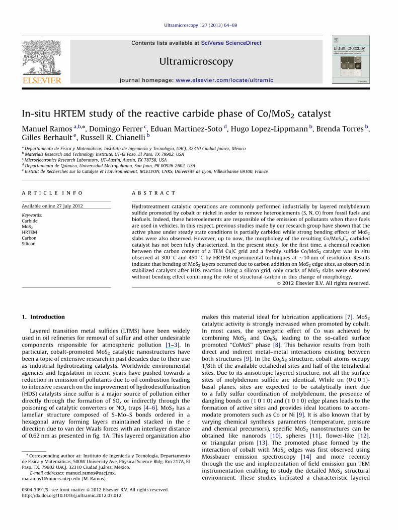
Fig. 1. (A) Molecular model of MoS2 showing its lamellar structure and (B) molecular model of the interface region between MoS2 and Co9S8 as present on unsupported
Co/MoS2 catalyst.
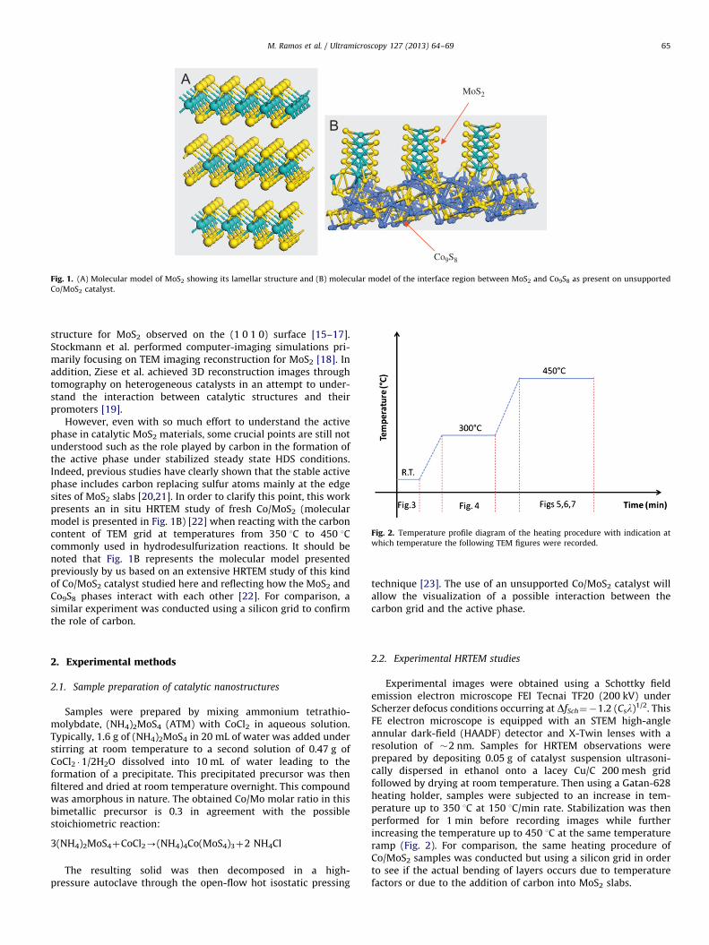
Fig. 2. Temperature profile diagram of the heating procedure with indication at
which temperature the following TEM figures were recorded.
M. Ramos et al. / Ultramicroscopy 127 (2013) 64–69 65
structure for MoS2 observed on the (1 0 1 0) surface [15–17].Stockmann et al. performed computer-imaging simulations pri-marily focusing on TEM imaging reconstruction for MoS2 [18]. Inaddition, Ziese et al. achieved 3D reconstruction images throughtomography on heterogeneous catalysts in an attempt to under-stand the interaction between catalytic structures and theirpromoters [19].
However, even with so much effort to understand the activephase in catalytic MoS2 materials, some crucial points are still notunderstood such as the role played by carbon in the formation ofthe active phase under stabilized steady state HDS conditions.Indeed, previous studies have clearly shown that the stable activephase includes carbon replacing sulfur atoms mainly at the edgesites of MoS2 slabs [20,21]. In order to clarify this point, this workpresents an in situ HRTEM study of fresh Co/MoS2 (molecularmodel is presented in Fig. 1B) [22] when reacting with the carboncontent of TEM grid at temperatures from 350 1C to 450 1Ccommonly used in hydrodesulfurization reactions. It should benoted that Fig. 1B represents the molecular model presentedpreviously by us based on an extensive HRTEM study of this kindof Co/MoS2 catalyst studied here and reflecting how the MoS2 andCo9S8 phases interact with each other [22]. For comparison, asimilar experiment was conducted using a silicon grid to confirmthe role of carbon.
2. Experimental methods
2.1. Sample preparation of catalytic nanostructures
Samples were prepared by mixing ammonium tetrathio-molybdate, (NH4)2MoS4 (ATM) with CoCl2 in aqueous solution.Typically, 1.6 g of (NH4)2MoS4 in 20 mL of water was added understirring at room temperature to a second solution of 0.47 g ofCoCl2 �1/2H2O dissolved into 10 mL of water leading to theformation of a precipitate. This precipitated precursor was thenfiltered and dried at room temperature overnight. This compoundwas amorphous in nature. The obtained Co/Mo molar ratio in thisbimetallic precursor is 0.3 in agreement with the possiblestoichiometric reaction:
3(NH4)2MoS4þCoCl2-(NH4)4Co(MoS4)3þ2 NH4Cl
The resulting solid was then decomposed in a high-pressure autoclave through the open-flow hot isostatic pressing
technique [23]. The use of an unsupported Co/MoS2 catalyst willallow the visualization of a possible interaction between thecarbon grid and the active phase.
2.2. Experimental HRTEM studies
Experimental images were obtained using a Schottky fieldemission electron microscope FEI Tecnai TF20 (200 kV) underScherzer defocus conditions occurring at DfSch¼�1.2 (Csl)1/2. ThisFE electron microscope is equipped with an STEM high-angleannular dark-field (HAADF) detector and X-Twin lenses with aresolution of �2 nm. Samples for HRTEM observations wereprepared by depositing 0.05 g of catalyst suspension ultrasoni-cally dispersed in ethanol onto a lacey Cu/C 200 mesh gridfollowed by drying at room temperature. Then using a Gatan-628heating holder, samples were subjected to an increase in tem-perature up to 350 1C at 150 1C/min rate. Stabilization was thenperformed for 1 min before recording images while furtherincreasing the temperature up to 450 1C at the same temperatureramp (Fig. 2). For comparison, the same heating procedure ofCo/MoS2 samples was conducted but using a silicon grid in orderto see if the actual bending of layers occurs due to temperaturefactors or due to the addition of carbon into MoS2 slabs.
M. Ramos et al. / Ultramicroscopy 127 (2013) 64–6966
3. Results and discussion
3.1. Co/MoS2 and amorphous carbon (TEM grid) at
300 1CoTo450 1C
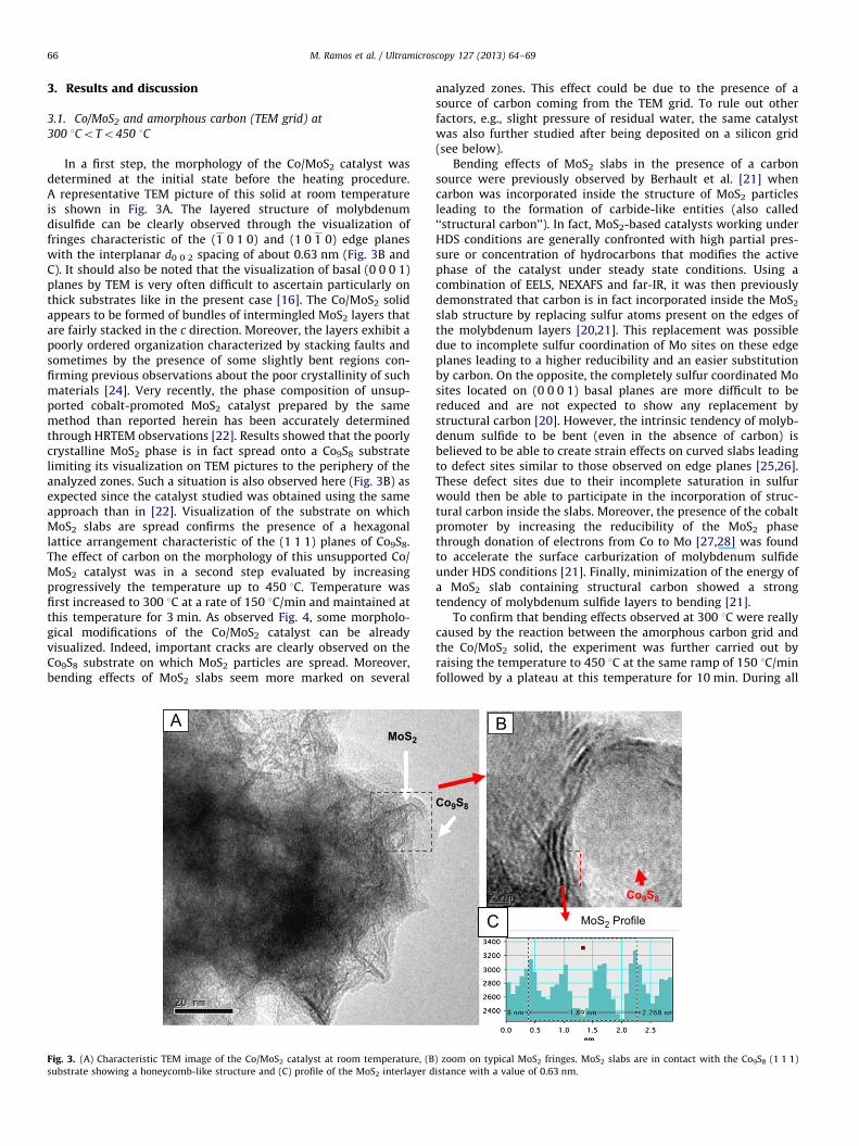
In a first step, the morphology of the Co/MoS2 catalyst wasdetermined at the initial state before the heating procedure.A representative TEM picture of this solid at room temperatureis shown in Fig. 3A. The layered structure of molybdenumdisulfide can be clearly observed through the visualization offringes characteristic of the (1 0 1 0) and (1 0 1 0) edge planeswith the interplanar d0 0 2 spacing of about 0.63 nm (Fig. 3B andC). It should also be noted that the visualization of basal (0 0 0 1)planes by TEM is very often difficult to ascertain particularly onthick substrates like in the present case [16]. The Co/MoS2 solidappears to be formed of bundles of intermingled MoS2 layers thatare fairly stacked in the c direction. Moreover, the layers exhibit apoorly ordered organization characterized by stacking faults andsometimes by the presence of some slightly bent regions con-firming previous observations about the poor crystallinity of suchmaterials [24]. Very recently, the phase composition of unsup-ported cobalt-promoted MoS2 catalyst prepared by the samemethod than reported herein has been accurately determinedthrough HRTEM observations [22]. Results showed that the poorlycrystalline MoS2 phase is in fact spread onto a Co9S8 substratelimiting its visualization on TEM pictures to the periphery of theanalyzed zones. Such a situation is also observed here (Fig. 3B) asexpected since the catalyst studied was obtained using the sameapproach than in [22]. Visualization of the substrate on whichMoS2 slabs are spread confirms the presence of a hexagonallattice arrangement characteristic of the (1 1 1) planes of Co9S8.The effect of carbon on the morphology of this unsupported Co/MoS2 catalyst was in a second step evaluated by increasingprogressively the temperature up to 450 1C. Temperature wasfirst increased to 300 1C at a rate of 150 1C/min and maintained atthis temperature for 3 min. As observed Fig. 4, some morpholo-gical modifications of the Co/MoS2 catalyst can be alreadyvisualized. Indeed, important cracks are clearly observed on theCo9S8 substrate on which MoS2 particles are spread. Moreover,bending effects of MoS2 slabs seem more marked on several
MoS2
Fig. 3. (A) Characteristic TEM image of the Co/MoS2 catalyst at room temperature, (B
substrate showing a honeycomb-like structure and (C) profile of the MoS2 interlayer d
analyzed zones. This effect could be due to the presence of asource of carbon coming from the TEM grid. To rule out otherfactors, e.g., slight pressure of residual water, the same catalystwas also further studied after being deposited on a silicon grid(see below).
Bending effects of MoS2 slabs in the presence of a carbonsource were previously observed by Berhault et al. [21] whencarbon was incorporated inside the structure of MoS2 particlesleading to the formation of carbide-like entities (also called‘‘structural carbon’’). In fact, MoS2-based catalysts working underHDS conditions are generally confronted with high partial pres-sure or concentration of hydrocarbons that modifies the activephase of the catalyst under steady state conditions. Using acombination of EELS, NEXAFS and far-IR, it was then previouslydemonstrated that carbon is in fact incorporated inside the MoS2
slab structure by replacing sulfur atoms present on the edges ofthe molybdenum layers [20,21]. This replacement was possibledue to incomplete sulfur coordination of Mo sites on these edgeplanes leading to a higher reducibility and an easier substitutionby carbon. On the opposite, the completely sulfur coordinated Mosites located on (0 0 0 1) basal planes are more difficult to bereduced and are not expected to show any replacement bystructural carbon [20]. However, the intrinsic tendency of molyb-denum sulfide to be bent (even in the absence of carbon) isbelieved to be able to create strain effects on curved slabs leadingto defect sites similar to those observed on edge planes [25,26].These defect sites due to their incomplete saturation in sulfurwould then be able to participate in the incorporation of struc-tural carbon inside the slabs. Moreover, the presence of the cobaltpromoter by increasing the reducibility of the MoS2 phasethrough donation of electrons from Co to Mo [27,28] was foundto accelerate the surface carburization of molybdenum sulfideunder HDS conditions [21]. Finally, minimization of the energy ofa MoS2 slab containing structural carbon showed a strongtendency of molybdenum sulfide layers to bending [21].
To confirm that bending effects observed at 300 1C were reallycaused by the reaction between the amorphous carbon grid andthe Co/MoS2 solid, the experiment was further carried out byraising the temperature to 450 1C at the same ramp of 150 1C/minfollowed by a plateau at this temperature for 10 min. During all
Co9S8
Co9S8
MoS2 Profile
) zoom on typical MoS2 fringes. MoS2 slabs are in contact with the Co9S8 (1 1 1)
istance with a value of 0.63 nm.
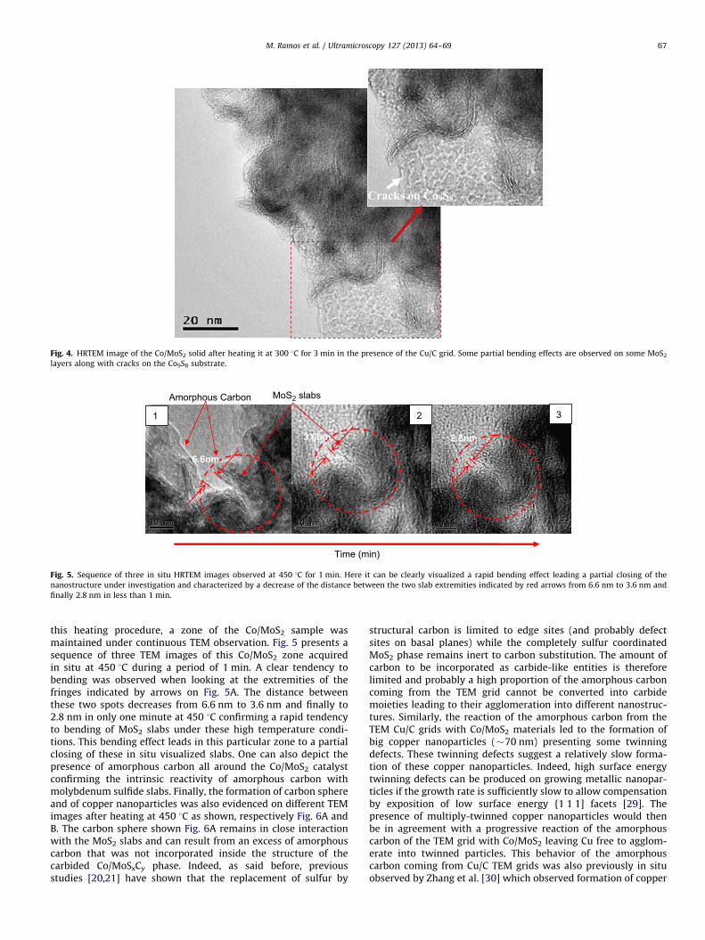
Fig. 4. HRTEM image of the Co/MoS2 solid after heating it at 300 1C for 3 min in the presence of the Cu/C grid. Some partial bending effects are observed on some MoS2
layers along with cracks on the Co9S8 substrate.
Amorphous Carbon
1 2 3
Time (min)
MoS2 slabs
6.6nm
3.6nm 2.8nm
Fig. 5. Sequence of three in situ HRTEM images observed at 450 1C for 1 min. Here it can be clearly visualized a rapid bending effect leading a partial closing of the
nanostructure under investigation and characterized by a decrease of the distance between the two slab extremities indicated by red arrows from 6.6 nm to 3.6 nm and
finally 2.8 nm in less than 1 min.
M. Ramos et al. / Ultramicroscopy 127 (2013) 64–69 67
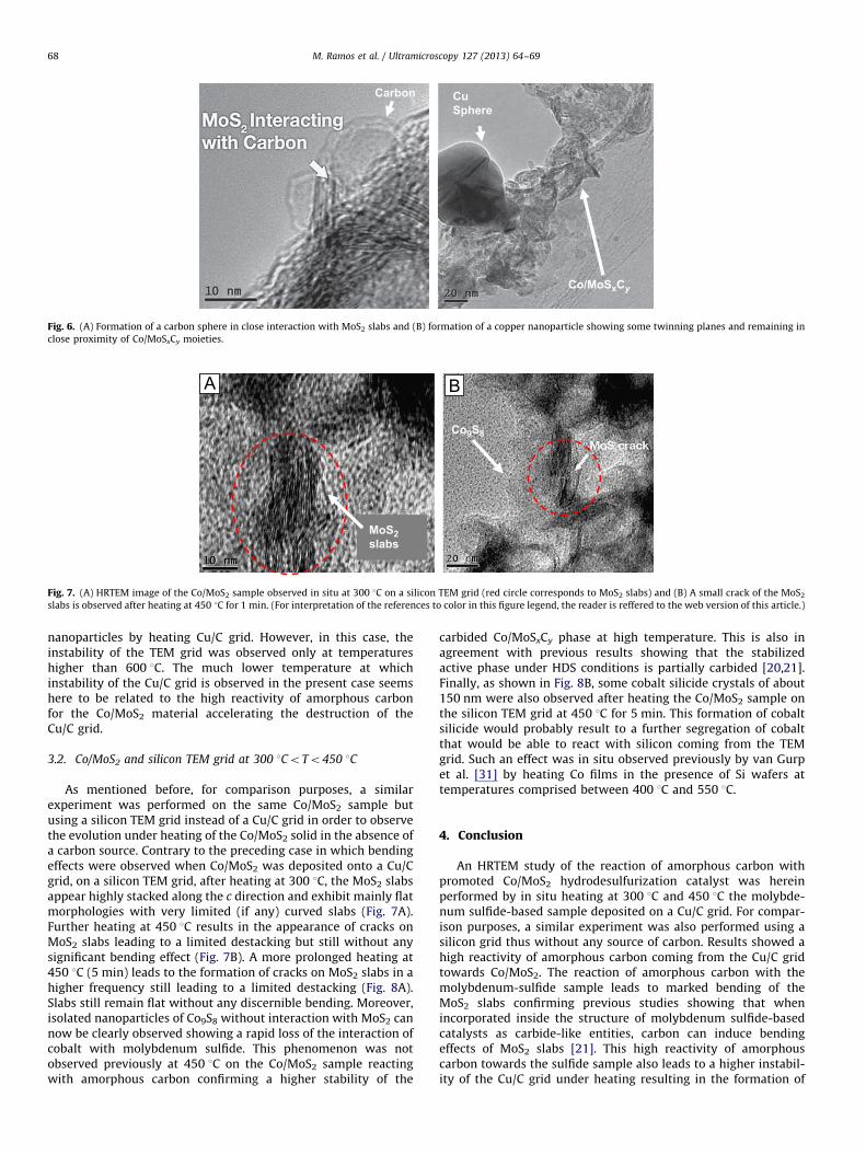
this heating procedure, a zone of the Co/MoS2 sample wasmaintained under continuous TEM observation. Fig. 5 presents asequence of three TEM images of this Co/MoS2 zone acquiredin situ at 450 1C during a period of 1 min. A clear tendency tobending was observed when looking at the extremities of thefringes indicated by arrows on Fig. 5A. The distance betweenthese two spots decreases from 6.6 nm to 3.6 nm and finally to2.8 nm in only one minute at 450 1C confirming a rapid tendencyto bending of MoS2 slabs under these high temperature condi-tions. This bending effect leads in this particular zone to a partialclosing of these in situ visualized slabs. One can also depict thepresence of amorphous carbon all around the Co/MoS2 catalystconfirming the intrinsic reactivity of amorphous carbon withmolybdenum sulfide slabs. Finally, the formation of carbon sphereand of copper nanoparticles was also evidenced on different TEMimages after heating at 450 1C as shown, respectively Fig. 6A andB. The carbon sphere shown Fig. 6A remains in close interactionwith the MoS2 slabs and can result from an excess of amorphouscarbon that was not incorporated inside the structure of thecarbided Co/MoSxCy phase. Indeed, as said before, previousstudies [20,21] have shown that the replacement of sulfur by
structural carbon is limited to edge sites (and probably defectsites on basal planes) while the completely sulfur coordinatedMoS2 phase remains inert to carbon substitution. The amount ofcarbon to be incorporated as carbide-like entities is thereforelimited and probably a high proportion of the amorphous carboncoming from the TEM grid cannot be converted into carbidemoieties leading to their agglomeration into different nanostruc-tures. Similarly, the reaction of the amorphous carbon from theTEM Cu/C grids with Co/MoS2 materials led to the formation ofbig copper nanoparticles (�70 nm) presenting some twinningdefects. These twinning defects suggest a relatively slow forma-tion of these copper nanoparticles. Indeed, high surface energytwinning defects can be produced on growing metallic nanopar-ticles if the growth rate is sufficiently slow to allow compensationby exposition of low surface energy {1 1 1] facets [29]. Thepresence of multiply-twinned copper nanoparticles would thenbe in agreement with a progressive reaction of the amorphouscarbon of the TEM grid with Co/MoS2 leaving Cu free to agglom-erate into twinned particles. This behavior of the amorphouscarbon coming from Cu/C TEM grids was also previously in situobserved by Zhang et al. [30] which observed formation of copper
CuSphere
Co/MoSxCy
Carbon
Fig. 6. (A) Formation of a carbon sphere in close interaction with MoS2 slabs and (B) formation of a copper nanoparticle showing some twinning planes and remaining in
close proximity of Co/MoSxCy moieties.
MoS2slabs
Co9S8
Fig. 7. (A) HRTEM image of the Co/MoS2 sample observed in situ at 300 1C on a silicon TEM grid (red circle corresponds to MoS2 slabs) and (B) A small crack of the MoS2
slabs is observed after heating at 450 1C for 1 min. (For interpretation of the references to color in this figure legend, the reader is reffered to the web version of this article.)
M. Ramos et al. / Ultramicroscopy 127 (2013) 64–6968
nanoparticles by heating Cu/C grid. However, in this case, theinstability of the TEM grid was observed only at temperatureshigher than 600 1C. The much lower temperature at whichinstability of the Cu/C grid is observed in the present case seemshere to be related to the high reactivity of amorphous carbonfor the Co/MoS2 material accelerating the destruction of theCu/C grid.
3.2. Co/MoS2 and silicon TEM grid at 300 1CoTo450 1C
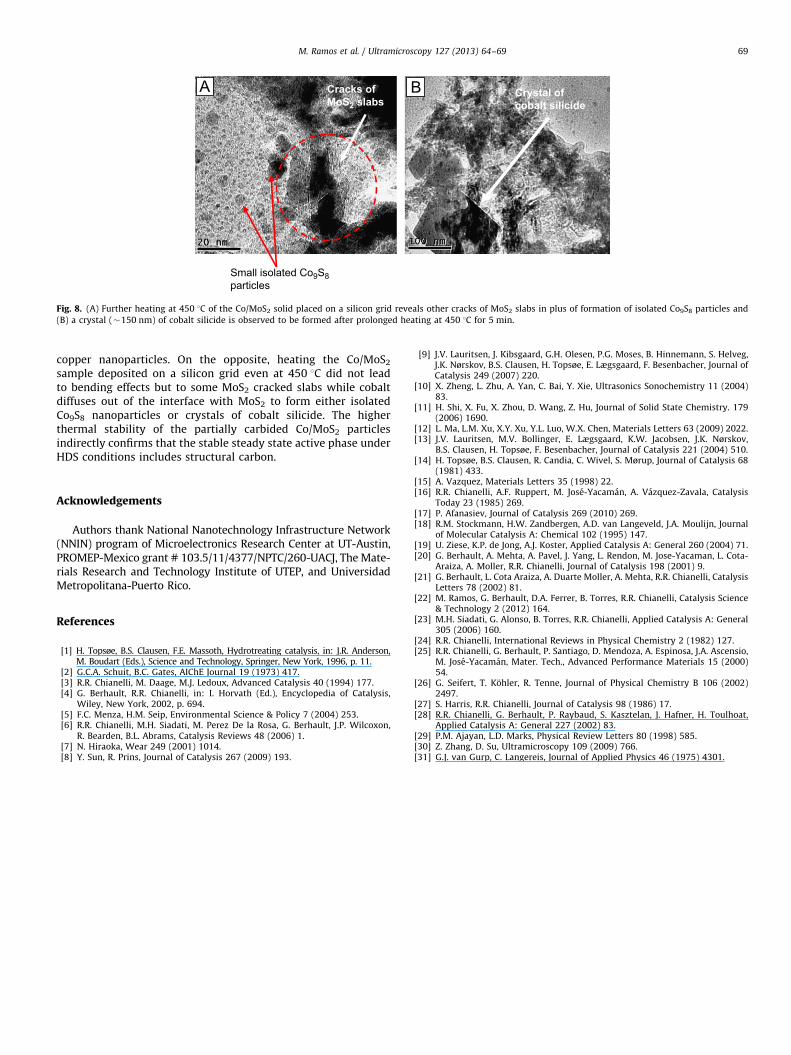
As mentioned before, for comparison purposes, a similarexperiment was performed on the same Co/MoS2 sample butusing a silicon TEM grid instead of a Cu/C grid in order to observethe evolution under heating of the Co/MoS2 solid in the absence ofa carbon source. Contrary to the preceding case in which bendingeffects were observed when Co/MoS2 was deposited onto a Cu/Cgrid, on a silicon TEM grid, after heating at 300 1C, the MoS2 slabsappear highly stacked along the c direction and exhibit mainly flatmorphologies with very limited (if any) curved slabs (Fig. 7A).Further heating at 450 1C results in the appearance of cracks onMoS2 slabs leading to a limited destacking but still without anysignificant bending effect (Fig. 7B). A more prolonged heating at450 1C (5 min) leads to the formation of cracks on MoS2 slabs in ahigher frequency still leading to a limited destacking (Fig. 8A).Slabs still remain flat without any discernible bending. Moreover,isolated nanoparticles of Co9S8 without interaction with MoS2 cannow be clearly observed showing a rapid loss of the interaction ofcobalt with molybdenum sulfide. This phenomenon was notobserved previously at 450 1C on the Co/MoS2 sample reactingwith amorphous carbon confirming a higher stability of the
carbided Co/MoSxCy phase at high temperature. This is also inagreement with previous results showing that the stabilizedactive phase under HDS conditions is partially carbided [20,21].Finally, as shown in Fig. 8B, some cobalt silicide crystals of about150 nm were also observed after heating the Co/MoS2 sample onthe silicon TEM grid at 450 1C for 5 min. This formation of cobaltsilicide would probably result to a further segregation of cobaltthat would be able to react with silicon coming from the TEMgrid. Such an effect was in situ observed previously by van Gurpet al. [31] by heating Co films in the presence of Si wafers attemperatures comprised between 400 1C and 550 1C.
4. Conclusion
An HRTEM study of the reaction of amorphous carbon withpromoted Co/MoS2 hydrodesulfurization catalyst was hereinperformed by in situ heating at 300 1C and 450 1C the molybde-num sulfide-based sample deposited on a Cu/C grid. For compar-ison purposes, a similar experiment was also performed using asilicon grid thus without any source of carbon. Results showed ahigh reactivity of amorphous carbon coming from the Cu/C gridtowards Co/MoS2. The reaction of amorphous carbon with themolybdenum-sulfide sample leads to marked bending of theMoS2 slabs confirming previous studies showing that whenincorporated inside the structure of molybdenum sulfide-basedcatalysts as carbide-like entities, carbon can induce bendingeffects of MoS2 slabs [21]. This high reactivity of amorphouscarbon towards the sulfide sample also leads to a higher instabil-ity of the Cu/C grid under heating resulting in the formation of
Small isolated Co9S8particles
Cracks ofMoS2 slabs
Crystal ofcobalt silicide
Fig. 8. (A) Further heating at 450 1C of the Co/MoS2 solid placed on a silicon grid reveals other cracks of MoS2 slabs in plus of formation of isolated Co9S8 particles and
(B) a crystal (�150 nm) of cobalt silicide is observed to be formed after prolonged heating at 450 1C for 5 min.
M. Ramos et al. / Ultramicroscopy 127 (2013) 64–69 69
copper nanoparticles. On the opposite, heating the Co/MoS2
sample deposited on a silicon grid even at 450 1C did not leadto bending effects but to some MoS2 cracked slabs while cobaltdiffuses out of the interface with MoS2 to form either isolatedCo9S8 nanoparticles or crystals of cobalt silicide. The higherthermal stability of the partially carbided Co/MoS2 particlesindirectly confirms that the stable steady state active phase underHDS conditions includes structural carbon.
Acknowledgements
Authors thank National Nanotechnology Infrastructure Network(NNIN) program of Microelectronics Research Center at UT-Austin,PROMEP-Mexico grant # 103.5/11/4377/NPTC/260-UACJ, The Mate-rials Research and Technology Institute of UTEP, and UniversidadMetropolitana-Puerto Rico.
References
[1] H. Topsøe, B.S. Clausen, F.E. Massoth, Hydrotreating catalysis, in: J.R. Anderson,M. Boudart (Eds.), Science and Technology, Springer, New York, 1996, p. 11.
[2] G.C.A. Schuit, B.C. Gates, AIChE Journal 19 (1973) 417.[3] R.R. Chianelli, M. Daage, M.J. Ledoux, Advanced Catalysis 40 (1994) 177.[4] G. Berhault, R.R. Chianelli, in: I. Horvath (Ed.), Encyclopedia of Catalysis,
Wiley, New York, 2002, p. 694.[5] F.C. Menza, H.M. Seip, Environmental Science & Policy 7 (2004) 253.[6] R.R. Chianelli, M.H. Siadati, M. Perez De la Rosa, G. Berhault, J.P. Wilcoxon,
R. Bearden, B.L. Abrams, Catalysis Reviews 48 (2006) 1.[7] N. Hiraoka, Wear 249 (2001) 1014.[8] Y. Sun, R. Prins, Journal of Catalysis 267 (2009) 193.
[9] J.V. Lauritsen, J. Kibsgaard, G.H. Olesen, P.G. Moses, B. Hinnemann, S. Helveg,J.K. Nørskov, B.S. Clausen, H. Topsøe, E. Lægsgaard, F. Besenbacher, Journal ofCatalysis 249 (2007) 220.
[10] X. Zheng, L. Zhu, A. Yan, C. Bai, Y. Xie, Ultrasonics Sonochemistry 11 (2004)83.
[11] H. Shi, X. Fu, X. Zhou, D. Wang, Z. Hu, Journal of Solid State Chemistry. 179(2006) 1690.
[12] L. Ma, L.M. Xu, X.Y. Xu, Y.L. Luo, W.X. Chen, Materials Letters 63 (2009) 2022.[13] J.V. Lauritsen, M.V. Bollinger, E. Lægsgaard, K.W. Jacobsen, J.K. Nørskov,
B.S. Clausen, H. Topsøe, F. Besenbacher, Journal of Catalysis 221 (2004) 510.[14] H. Topsøe, B.S. Clausen, R. Candia, C. Wivel, S. Mørup, Journal of Catalysis 68
(1981) 433.[15] A. Vazquez, Materials Letters 35 (1998) 22.[16] R.R. Chianelli, A.F. Ruppert, M. Jose-Yacaman, A. Vazquez-Zavala, Catalysis
Today 23 (1985) 269.[17] P. Afanasiev, Journal of Catalysis 269 (2010) 269.[18] R.M. Stockmann, H.W. Zandbergen, A.D. van Langeveld, J.A. Moulijn, Journal
of Molecular Catalysis A: Chemical 102 (1995) 147.[19] U. Ziese, K.P. de Jong, A.J. Koster, Applied Catalysis A: General 260 (2004) 71.[20] G. Berhault, A. Mehta, A. Pavel, J. Yang, L. Rendon, M. Jose-Yacaman, L. Cota-
Araiza, A. Moller, R.R. Chianelli, Journal of Catalysis 198 (2001) 9.[21] G. Berhault, L. Cota Araiza, A. Duarte Moller, A. Mehta, R.R. Chianelli, Catalysis
Letters 78 (2002) 81.[22] M. Ramos, G. Berhault, D.A. Ferrer, B. Torres, R.R. Chianelli, Catalysis Science
& Technology 2 (2012) 164.[23] M.H. Siadati, G. Alonso, B. Torres, R.R. Chianelli, Applied Catalysis A: General
305 (2006) 160.[24] R.R. Chianelli, International Reviews in Physical Chemistry 2 (1982) 127.[25] R.R. Chianelli, G. Berhault, P. Santiago, D. Mendoza, A. Espinosa, J.A. Ascensio,
M. Jose-Yacaman, Mater. Tech., Advanced Performance Materials 15 (2000)54.
[26] G. Seifert, T. Kohler, R. Tenne, Journal of Physical Chemistry B 106 (2002)2497.
[27] S. Harris, R.R. Chianelli, Journal of Catalysis 98 (1986) 17.[28] R.R. Chianelli, G. Berhault, P. Raybaud, S. Kasztelan, J. Hafner, H. Toulhoat,
Applied Catalysis A: General 227 (2002) 83.[29] P.M. Ajayan, L.D. Marks, Physical Review Letters 80 (1998) 585.[30] Z. Zhang, D. Su, Ultramicroscopy 109 (2009) 766.[31] G.J. van Gurp, C. Langereis, Journal of Applied Physics 46 (1975) 4301.
Related Documents