In-Situ Diagnostic Methods for SOFC G. Schiller, K.A. Friedrich, M. Lang, P. Metzger, N. Wagner German Aerospace Center (DLR), Institute of Technical Thermodynamics, Pfaffenwaldring 38-48, D-70569 Stuttgart, Germany International Symposium on Diagnostic Tools for Fuel Cell Technologies, Trondheim, Norway, June 23-24, 2009

Welcome message from author
This document is posted to help you gain knowledge. Please leave a comment to let me know what you think about it! Share it to your friends and learn new things together.
Transcript

In-Situ Diagnostic Methods for SOFC
G. Schiller, K.A. Friedrich, M. Lang, P. Metzger, N. Wagner
German Aerospace Center (DLR), Institute of Technical Thermodynamics, Pfaffenwaldring 38-48, D-70569 Stuttgart, Germany
International Symposium on Diagnostic Tools for Fuel Cell Technologies,Trondheim, Norway, June 23-24, 2009

Outline
IntroductionElectrochemical Impedance Spectroscopy on Stacks Spatially Resolved Measurements: Current density
VoltageImpedanceTemperatureGas Composition
Optical Spectroscopy X-Ray TomographyConclusion

Investigation of Degradation and Cell Failures
Insufficient understanding of cell degradation and cell failures in SOFC Extensive experimental experience is not generally available which would allow accurate analysis and improvementsLong term experiments are demanding and expensiveOnly few tools and diagnostic methods available for developers due to the restrictions of the elevated temperatures

Conventional Test Stand Diagnostics
Conventional test stand diagnostics: provide important and essential information about fuel cell performance and behaviour:
U(i) characteristics, OCV…EIS on single cellsCurrent interrupt methodsPerformance degradation with time U(t); i(t) …Cell voltage distribution Ustack= U1 + U2 + U3….Pressure loss / Gas tighness testGas utilization measurementTemperature distribution and control

„Sophisticated“ (non-traditional) in-situ Diagnostics
Electrochemical impedance spectroscopy on stacks
Spatially resolved measuring techniques for current, voltage, temperature and gas composition
Optical imaging
Optical spectroscopy
Acoustic emission detection
X-ray tomography

Challenges for EIS for Stack Investigations
Large areas (e.g. 100 cm2) lead to high current and low impedances of about 1 mOhm.Electrochemical processes appear at high frequencies (up to 100 kHz) due to the high reaction rates at high temperatures. Stacks generally contain metallic components leading to high frequency disturbances.Contacting of all cells and sensing in specific cells does not account for the voltage distribution in the stack.The sensor wires are at high temperatures: an optimization of the measurement system is not possible during operation.Strong overlapping of electrode processes; evaluation with equivalent circuits can be inaccurate.For system with current > 40 A no commercial equipment available.

Mitigation of EIS Problems
Reduction of the high frequency disturbances by optimization of the wiring of the electrical sensing of the SOFC stack.Variation of the operating conditions (gases, temperature) in order to determine the different impedances of the electrode processesModeling of the spectra by an equivalent circuit.Development of advanced EIS equipment for high currents / high frequencies in corporation with instrument manufacturer (ZahnerElektrik GmbH).

Experimental Set-up for EIS Measurements of Stacks at DLR

CSZ05-DGF09-CT, 750°C5H2+5N2+3%H2O / 20air (SLPM)
94h
0,0
0,2
0,4
0,6
0,8
1,0
1,2
0 200 400 600 800current density i [mA/cm²]
cell
volta
ge U
[V]
0
200
400
600
pow
er d
ensi
ty p
[mW
/cm
²]
cell 5 (top)cell 4cell 3cell 2cell 1 (bottom)
p
U
Performance of the 5-Cell Short Stack at 750°C(5 H2+5 N2+3%H2O / 20 air (SLPM), 94 h)
Cell 1-4 : 1.10 VCell 5 : 1.05 V
Cell 5: 404 mW/cm²Cell 4: 476 mW/cm²Cell 3: 447 mW/cm²Cell 2: 472 mW/cm²Cell 1: 415 mW/cm²
@ 3,5VPstack = 184 WFU = 37%

-0,5
-0,25
0
0,25
0,5
0,75
1
1,25
0 0,25 0,5 0,75 1 1,25 1,5 1,75 2 2,25
Re Z [Ohm*cm²]
Im Z
[Ohm
cm²]
0 mA/cm260 mA/cm2120 mA/cm2180 mA/cm2240 mA/cm2300 mA/cm2360 mA/cm2420 mA/cm2
80 Hz
5-Zellen Short Stack [CSZ-05-83-CT], cell 5T=750°C, Zellfl. 84cm²
Gas Concentration
CathodeAnode
50mHz
1 Hz
6 Hz
100 kHz
Nyquist Plot of one Cell of a 5-Cell Short Stack at Different Current Densities(750°C, 2.5 H2+2.5 N2 / 20 air (SLPM), 142 h)
0.14 - 0.17 Ωcm2 0.55 - 2.2 Ωcm2

Equivalent Circuit for the Fitting of the Impedance Spectra
Gas Concentration
InductivityCathodeOhmic
RΩ
Rp(C)
ZL
Anode
Cdl(A)
RP(A)
Cdl(C)
RN(A)
CN(A)

CSZ-05-83-CT, 750°C2,5H2+2,5N2 / 21 Air (SLPM)
cell 5, 142 h
0,0
0,2
0,4
0,6
0,8
1,0
1,2
0 50 100 150 200 250 300 350 400 450current density i [mA/cm²]
cell
volta
ge U
[V]
0
20
40
60
80
100
volta
ge lo
ss [m
V]
U cellΔU (Anode)ΔU (Cathode)ΔU (Gas Concentr.)ΔU (Ohm)
Cell5 @ 700mV : 380 mW/cm2
U cell
ΔU
Voltage Losses at one Cell of a 5-cell Short Stack at Different Current Densities(750°C, 2.5 H2+2.5 N2 / 20 air (SLPM), 142 h)
Contact resistances
Polarisation resistances

Motivation
Strong local variation of gas composition, temperature, current density Distribution of electrical and chemical potential dependent on local concentrations of reactants and products
Reduced efficiencyTemperature gradientsThermo mechanical stressDegradation of electrodes
H2 H O2
O2 O2
H2 H O2
O2

Measurement Setup for Segmented Cells
16 galvanically isolated segmentsLocal and global i-V characteristicsLocal and global impedance measurements
Local temperature measurementsLocal fuel concentrationsFlexible design: substrate-, anode-, and electrolyte-supported cellsCo- and counter-flow
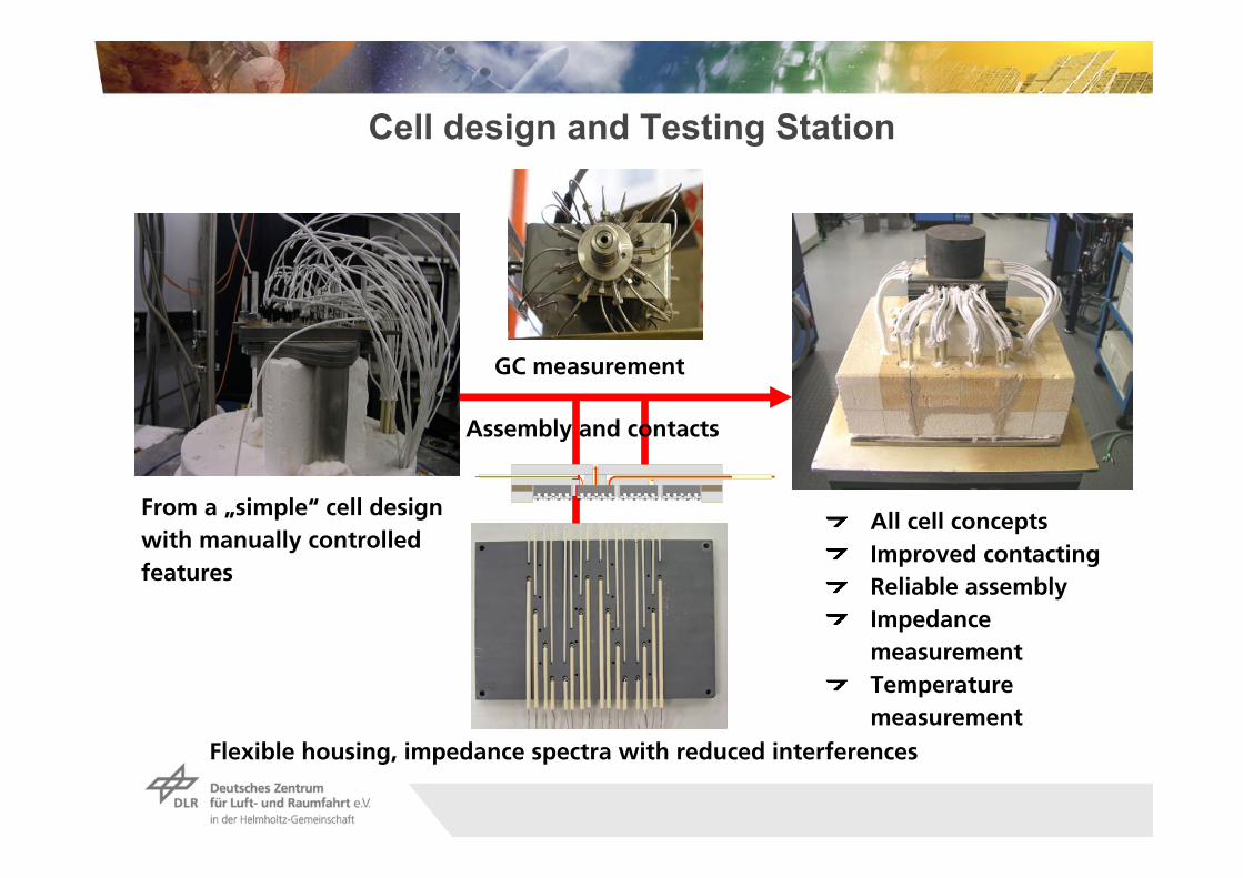
Cell design and Testing Station
From a „simple“ cell design with manually controlled features
GC measurement
Flexible housing, impedance spectra with reduced interferences
Assembly and contacts
All cell conceptsImproved contactingReliable assemblyImpedance measurementTemperature measurement

Schematic Lay-out of the Electrical Circuit of the Segmented Cell Configuration
curr
ent b
usba
r eq
uipo
tent
ial l
ine
curr
ent b
usba
r eq
uipo
tent
ial l
ine
Internal cell resistances: Ri,j,
Resistances of the wires contacting the anode: RLA,j
Resistances of the wires contacting the cathode: RLK,j
Only segments 1, 2, 3, 16 are illustrated

OCV Voltage Measurement for Determination of Humidity
• Voltage distribution at standard flow rates:• 48.5% H2, 48.5% N2 + 3% H2O, 0.08 SlpM/cm² air
13 14 15 16
9 10 11 12
5 6 7 8
1 2 3 4
fuel gas air
⎟⎟⎠
⎞⎜⎜⎝
⎛−=
22
20 lnHO
OHrevrev pp
pzFRTUU
Nernst equation:
Produced water:S4: 0.61%, S8: 0.72%, S12: 0.78%, S16: 3.30%

Variation of Load - Reformate
Anode supported cell, LSCF cathode, 73,96 cm², gas concentrations (current density equivalent): 54.9% N2, 16.7% H2, 16.5% CO, 6,6% CH4, 2.2% CO2, 3.2% H2O (0.552 A/cm²), 0.02 SlpM/cm² air
0,0
50,0
100,0
150,0
200,0
250,0
300,0
Segment 9 Segment 10 Segment 11 Segment 12
pow
er d
ensi
ty p
[mW
/cm
²]
0,0
15,0
30,0
45,0
60,0
75,0
90,0
fuel
util
isat
ion
fu [%
]
p(i) 100 mA/cm² p(i) 200 mA/cm² p(i) 400 mA/cm² p(i) 435 mA/cm²
fu 100 mA/cm² fu 200 mA/cm² fu 400 mA/cm² fu 435 mA/cm²
fu
100
200
400435
100
200
400435
Pow
er d
ensi
tym
W/c
m2
Fuel
util
isat
ion
(%)

0
0,05
0,1
0,15
0,2
0,25
0,3
Segment 9 Segment 10 Segment 11 Segment 12
Gas
konz
entra
tion
/ %
H2 CO CH4 CO2 H2O
KS4X050609-7 in Metallischem Gehäuse; Substrat: Anodensubstrat, aktive Zellfläche:73,78 cm²,A: 542 µm NiO/YSZ, E: 14 µm YSZ + YDC,
K: 28 µm LSCF, Kontaktierung: 30 µm LSP16+Pt3600,Integral, Gasflüsse: 0,552 A/cm² Stromdichteäquivalent (54,9% N2, 16,7% H2,
16,5% CO, 6,6%CH4, 2,2%CO2, 3,2% H20) // 0,08 SlpM/cm² Luft, 800 °C, 0 mA/cm²
Reformate: Changes of the Gas Compositionat 0 mA/cm²
Metallic housing, anode substrate, active area 73.78 cm²Anode: 542 µm NiO/YSZ, Electrolyte: 14 µm YSZ + YDC,Cathode: 28 µm LSCFOperation conditions: 0.10 A/cm² - Anode λ = 5.52(54.9% N2, 16.7% H2, 16.5% CO, 6.6% CH4, 2.2% CO2, 3.2% H2O0.08 Nlpm/cm² Air, 800°C)
Con
cent
ratio
n/ %
9 10 11 12
H2
CO
H2OCO2
CH4

Alteration of the gas composition at 435 mA/cm²
0
0,05
0,1
0,15
0,2
0,25
0,3
Segment 9 Segment 10 Segment 11 Segment 12
Gas
konz
entra
tion
/ %
H2 CO CH4 CO2 H2O
Con
cent
ratio
n/ %
H2
10 11 12
CO
CH4
H2O
CO2
9

Combined Experimental and Modeling Approach
Objectives of the study:Better understanding of the local variations
Identification of critical conditionsOptimisation of cell components
Experiments on single Experiments on single segmented SOFCsegmented SOFC
Electrochemical model of Electrochemical model of local distributionslocal distributions
H2H2/CO
CH4
H2OCO2
anode
electrolyte
cathode
O2/N2 N2 xy
xy
elyt eldegas z
interconnector
interconnector

Potential for Optical Spectroscopies
Raman spectroscopyLaser Doppler Anemometry (LDA)Particle Image Velocimetry (PIV)Fast-Fourier Infrared (FTIR)Coherent Anti-Stokes Raman Spectroscopy (CARS)Electronic Speckle Pattern Interferometry (ESPI)
Digital CCD camera
Distance microscope(resolution1 µm)
Quarz window
Transparentflow field
Imagingspectrograph
Lenses/filter
Pulsed Nd:YAG laser(532 nm, 10 ns)
Open tube(5 mm)
a) In situ microscopy b) In situ Raman laser diagnostics
15 cm
Heat & radiation shield
SOFC

neutrontomography
in-situ synchrotronradiography
in-situ neutronradiography
Tomography Diagnosis of PEM Fuel Cells
Investigation of water management under operating conditions

X-Ray Tomography (CT) Facility at DLR
3 dimensional non intrusiveimaging of SOFC cassette
X-Ray CT Facility v|tome|x L450 at DLR Stuttgart

Summary
The operating conditions (elevated temperature) reduce significantly the possibilities for in-situ SOFC diagnostic methods.EIS will remain the main diagnostic probe of the state of SOFC.Non-traditional in-situ diagnostics methods can provide additional important information:
Spatially resolved measurements to obtain local distributionof cell properties (current, voltage, impedance, gas compo-sition, temperature)Combined analytical and modeling approach
Large future potential for optical spectroscopies (e.g. Ramanspectroscopy) and x-ray tomography.
Related Documents