In-Service Testing Handbook - Version 3.2 Page 1 of 63 Office for Product Safety & Standards In-Service Testing (IST) Handbook: This guide is designed to provide all parties with an interest in IST, or undertaking an alternative In-Service Testing regime for whole current electricity meters and/or domestic type gas meters installed under the Measuring Instruments Directive (MID) 2004/22/EC and 2014/32/EU, an understanding of its methodology and an overview of timescales and testing requirements.

Welcome message from author
This document is posted to help you gain knowledge. Please leave a comment to let me know what you think about it! Share it to your friends and learn new things together.
Transcript
In-Service Testing Handbook - Version 3.2 Page 1 of 63 Office for Product Safety & Standards
In-Service Testing (IST) Handbook:
This guide is designed to provide all parties with an interest in IST, or
undertaking an alternative In-Service Testing regime for whole current
electricity meters and/or domestic type gas meters installed under the
Measuring Instruments Directive (MID) 2004/22/EC and 2014/32/EU, an
understanding of its methodology and an overview of timescales and testing
requirements.

In-Service Testing Handbook - Version 3.2 Page 2 of 63 Office for Product Safety & Standards
PAGE INTENTIONALLY LEFT BLANK
In-Service Testing Handbook - Version 3.2 Page 3 of 63 Office for Product Safety & Standards
TABLE OF CONTENTS
1.0 Background 5
2.0 Introduction 7
3.0 Methodology Overview 8
4.0 What is a MID meter? 9
5.0 Definition of Meter Populations 11
5.1 Standard meter populations 11
5.2 Splitting of populations (sub-populations) 11
5.3 Combination of different populations 12
5.4 Combination of populations of the same type of meter (super-populations)
12
5.5 Repaired meters 12
6.0 Time Intervals for In-Service Monitoring 13
7.0 Sampling Plan and Criteria for Meter Populations
Requiring Replacement.
14
8.0 Assessment of Results - Including Criteria 16
8.1 Criteria 16
8.2 Outliers 17
8.3 Assessment method 18
8.4 Overall population assessment 20
8.5 Backstop arrangements 21
8.6 Overall population assessment 21
9.0
10.0
Removal of Unacceptable Populations
Assessment Failures (Appeals & Investigations)
22
22
In-Service Testing Handbook - Version 3.2 Page 4 of 63 Office for Product Safety & Standards
ANNEXES
Annex 1 Testing Timetable 23
Annex 2 Approved Test Stations 25
Annex 3 Drawing of Samples & Test Requirements 28
Annex 4 Rust/Corrosion Guide for Gas Meter Cases 37
Annex 5 Electricity Meter Testing Example 45
Annex 6 Worked Example 47
Annex 7 Calculation of AQL Values 48
Annex 8 Treatment of Electricity Meter Super-Populations
Assessed Individually
54
Annex 9 Measuring Instruments Directive (MID) 55
Annex 10 Testing of Nationally Approved Electricity Meters for Extending Certification Period
56
Annex 11 Reference Documents 58
Annex
Annex
12
13
General Definitions
IST4 Membership
59
62

In-Service Testing Handbook - Version 3.2 Page 5 of 63 Office for Product Safety & Standards
1.0 Background
The statutory responsibility for the metrological performance of gas and electricity meters
was transferred from the Gas and Electricity Markets Authority (i.e. Ofgem), the energy
regulator, to the Secretary of State on 1st April 2009. These functions are currently fulfilled
by The Office for Product Safety & Standards, part of the Department for Business, Energy
& Industrial Strategy (BEIS).
In the United Kingdom, prior to October 2006, gas and electricity meters were placed on
the market in accordance with the requirements of the Gas Act 1986 and the Electricity Act
1989. In October 2006, the Measuring Instruments Directive (MID) 2004/22/EC was
implemented which allowed for the free movement of weighing and measuring instruments
(including gas and electricity meters) across the European Union. This has since been
repealed and from April 2016 has been replaced by the recast MID 2014/32/EU. However
the MID is only applicable to meters up to the point at which they are first placed onto the
market. Once in-service, the national provisions set out in the Gas and Electricity Acts apply.
The MID for ‘Gas Meters and Volume Conversion Devices’ Annex IV (MI-002) is implemented
by The Measuring Instruments Regulations (SI 2016/1153)1 and meters placed on the
market in accordance with these regulations are “deemed to be stamped” as required by
Section 17 of the Gas Act 1986. As with meters approved under national legislation, there
is no defined service period for MID gas meters and these can remain in-service for as long
as they conform to the legal requirements.
The MID for ‘Active Electrical Energy Meters’ Annex V (MI-003) is implemented by The
Measuring Instruments Regulations (SI 2016/1153)2. Meters placed on the market in
accordance with these regulations are “deemed to be of an approved pattern or construction
and installed in an approved manner” as required by Schedule 7 of the Electricity Act 1989.
Under national legislation the vast majority of electricity meters are required to be certified
and meters are issued with a defined certification life, the exception being meters used for
secondary billing and to non-domestic customers where the supplier and customer may
agree to dispense with this requirement. At the end of this certification period meters are
no longer permitted to be used for billing and should be removed from service (although
BEIS will consider extending the certification life if there is evidence that meters are still
conforming to the statutory requirements). There are no such requirements for MID
approved electricity meters which are “deemed to be certified” and may therefore remain
in-service for as long as they conform to the legal requirements.
Following a consultation with industry stakeholders, it was agreed to develop procedures for
monitoring the in-service performance of MID approved gas and electricity meters to enable
suppliers and asset owners to demonstrate their meter populations continued conformance
to the legal requirements. This concluded with the In-Service Testing (IST) 1/2 report which
established the procedures and testing methodology for monitoring in-service performance.
The IST 1/2 report was approved by the Industry Metering Advisory Group (IMAG) and
Ofgem in 2008. Thereafter, the IST 3 report consulted on the governance arrangements for
the IST scheme and the majority of stakeholders were in favour of the Secretary of State
governing the scheme. Details of both reports can be found on the BEIS website, with links
under Annex 11 Reference Documents.
1 Previously The Measuring Instruments (Gas Meters) Regulations (SI 2006/2647)
2 Previously The Measuring Instruments (Active Electrical Energy Meters) Regulations (SI
2006/1679)

In-Service Testing Handbook - Version 3.2 Page 6 of 63 Office for Product Safety & Standards
The IST4 Group, chaired by BEIS, is responsible for the development of this handbook and
the implementation of the IST scheme.
In-Service Testing Handbook - Version 3.2 Page 7 of 63 Office for Product Safety & Standards
2.0 Introduction
This guide covers the in-service testing of MID approved domestic type3 gas and whole
current electricity meters that are subject to legal metrological control for the purpose of
consumer protection and with a population size of an individual meter make/type model
greater than (or equal to) 1,201. It is intended to be a minimum process for assessing
legislative compliance.
For the purpose of this document domestic type gas meters are defined as a meter with a
maximum flow rate (Qmax) not exceeding 6 m3/h, and electricity meters are Single Phase
and Polyphase whole current meters4 (i.e. excluding meters used with Current Transformers
(CTs).)
This guide has been prepared to provide the methodology and guideline procedures for the
in-service testing of MID-approved gas and electricity meters to ensure continued
compliance with the MID implementing regulations. Adoption of this guide shall assist a
supplier to demonstrate they have conformed to the requirements of Schedule 2B section
3(3) of the Gas Act 1986 (as amended) and Schedule 7 section 10(2) of the Electricity Act
1989 (as amended).
Following this guide will ensure those responsible for ensuring the compliance of meters
used for ascertaining or registering quantities of gas/electricity fulfil the minimum statutory
requirements. Should a supplier wish to utilise an alternative method for maintaining the
accuracy of its meter population, the onus will lie with that supplier to demonstrate to BEIS
that the alternative method is equivalent to, or better than, the approach described in this
document.
Finally, this guide defines the test criteria to be undertaken by meter test stations approved
by BEIS for testing the samples and sets out methods for the assessment of an overall
population against defined criteria.
Note: The Gas Act Owner (GAO) or Electricity Supplier has a legal duty to ensure that
meters are deemed to be stamped (gas meters) or certified (electricity meters) and continue
to comply with the MID implementing regulations; however this responsibility may be
passed onto their MAPs/MAMs (Meter Asset Provider, Meter Asset Manager) or MOPs (Meter
Operator) through a service contract.
Application of IST via this guide may also be used by BEIS to control the certification life of
electricity meters approved under GB national legislation. (see Annex 10)
The MAMCoP5 (Code of Practice for Gas Meter Asset Managers) requires MAMs to maintain
meters in proper working order for registering the quantity of gas supplied. This can be
achieved by an appropriate maintenance regime or by sample testing as described in sub-
section 17.5.2. IST provides a method whereby MAMs can fulfil this requirement.
3 IMAG agreed the IST methodology may not be suitable for monitoring the smaller
populations of larger capacity meters
4 As agreed by the IST 4 Electricity Sub Group on 24th September 2015
5 https://www.spaa.co.uk/SitePages/SPAA-documents.aspx?btn=MAMCoP

In-Service Testing Handbook - Version 3.2 Page 8 of 63 Office for Product Safety & Standards
3.0 Methodology Overview
The method used for IST is based on the requirements of BS 6002-1:1993 (ISO 3951:1989)
‘Sampling Procedures for Inspection by Variables’.
The IST scheme tests samples of meters which are representative of those in-service with
customers, the number of samples (based on population size) being in accordance with the
above standard. BEIS allocates samples to each supplier in proportion to the number of
meters in that supplier’s portfolio. The suppliers acquire their allocated meters and send
these to an appropriate Test Station.
The samples are tested against the IST assessment criteria, most notably accuracy. Testing
is conducted by Test Stations approved and audited by BEIS. The suppliers receive their
results from the Test Stations and forward these to BEIS who determine whether the meter
population conforms to the assessment criteria outlined in section 8.0.
The evaluation of results from each population can be used to demonstrate a systematic
approach to maintaining the accuracy of those gas and electricity meters within an individual
portfolio. Where sampling of a particular meter type has been carried out by a number of
parties, BEIS will compile the resulting data from these parties and analyse the results
collectively so a conclusion can be reached.
In-Service Testing Handbook - Version 3.2 Page 9 of 63 Office for Product Safety & Standards
4.0 What is a MID meter?
A meter manufactured in accordance with the MID is distinguished from nationally approved
meters by the process in which it makes it to the market place and the visible markings.
MID meters are approved by Notified Bodies designated by Member States.
The process is implemented through the application of specific annexes as set out in the
Directive. These annexes relate to the conformity assessment procedures the manufacturer
can choose to ensure the instrument is compliant with the Directive when placing the
instrument on the market.
The three conformity assessment options available for MID approval of Gas and Electricity
meters are:
• B+D (i.e. Type Examination and Quality Assurance of the Production Process)
• B+F (i.e. Type Examination and Product Verification)
• H1 (Full Quality Assurance plus Design Exanimation)
A meter manufacturer can have a meter type assessed against any of the assessments
(B,D,F,H1), and by any notified body but at least one of the combinations above is required
to gain MID approval.
The annexes which are applicable to gas and electricity meters are B, D, F and H1.
• Annex B refers to Type Examination, where the notified body examines the technical
design of the instrument and declares that it meets the appropriate requirements of
the Directive.
• Annex D refers to Declaration of Conformity to Type based on the quality assurance
of the production process. This is where the manufacturer fulfils the obligations set
out in the annex and ensures the instrument is in conformity with the type, as
described in the EC Type Examination Certificate.
• Annex F is Declaration of Conformity to Type based on product verification. This is
in relation to paragraph 3 of the annex where examinations and tests to check
conformity with the EC Type examination certificate are conducted.
• Annex H1 is Declaration of Conformity based on full quality assurance plus design
examination, where the manufacturer declares that the instrument satisfies the
requirements of the Directive based upon their quality procedures and product
design.
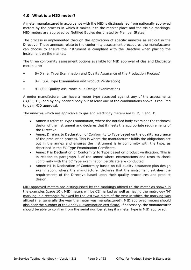
MID approved meters are distinguished by the markings affixed to the meter as shown in
the examples (page 10). MID meters will be CE marked as well as having the metrology ‘M’
marking in a rectangle followed by the last two-digits of the year in which the marking was
affixed (i.e. generally the year the meter was manufactured). MID approved meters should
also bear the number of the Annex B examination certificate. If necessary, the manufacturer
should be able to confirm from the serial number string if a meter type is MID approved.
In-Service Testing Handbook - Version 3.2 Page 10 of 63 Office for Product Safety & Standards
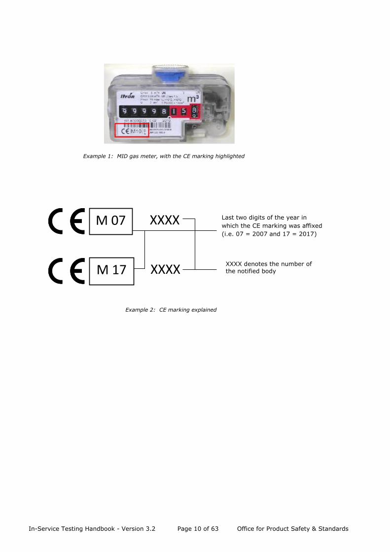
M 07 XXXX
M 17 XXXX
XXXX denotes the number of the notified body
Last two digits of the year in
which the CE marking was affixed
(i.e. 07 = 2007 and 17 = 2017)
Example 1: MID gas meter, with the CE marking highlighted
Example 2: CE marking explained
In-Service Testing Handbook - Version 3.2 Page 11 of 63 Office for Product Safety & Standards
5.0 Definition of Meter Populations
5.1 Standard meter populations
In-service testing by sampling should only be carried out on homogeneous populations of
meters. For a population of meters to be considered homogeneous, they shall have the
same characteristics, namely:
▪ Manufacturer
▪ Type or model
▪ Capacity/rating
▪ Year of manufacture
▪ Number of the EC type examination certificate or the EC design examination
certificate
The following shall be identical in all meters:
(a) Electricity meters
▪ Number of registers (unless multi–rate version shares approval characteristics and
is metrologically equivalent)
(b) Gas meters
▪ Diaphragm material (where applicable)
▪ Diaphragm credit only meter populations (where applicable)
▪ Diaphragm pre-payment only meter populations (where applicable)
▪ Integral temperature conversion (where applicable)
5.2 Splitting of populations (sub-populations)
Meters that share the common characteristics defined above may be combined to form a
single population, although this does not prevent such a population being split on other
basis (e.g. by serial number range, etc.).

In-Service Testing Handbook - Version 3.2 Page 12 of 63 Office for Product Safety & Standards
5.3 Combination of different populations
With the approval of BEIS and subject to the conditions stated below, combined lots of
meters may be formed which are of different characteristics (e.g. single rate/two rate),
provided that appropriate conditions for the assembly into such lots have been clearly
stipulated by BEIS, and which are owned or managed by different parties.
5.4 Combination of populations of the same type of meter (super-populations)
In the case of electricity meters of the same type (i.e. having the same approval number or
EC conformity certificate) and subject to Quality Assurance control of manufacture, a meter
type with a number of years since manufacture of up to, but not exceeding, five years may
be combined to form a ‘super population’ of that type. The results obtained from tests on
samples from the first year’s population may be applied to subsequent years’ production
comprising the super-population without requiring further testing.
Note 1: Treatment of meters in this way is dependent upon the continuing consistency of
metrological characteristics and, on a periodic basis, assurances should be sought from the
manufacturer concerned that there have been no modifications to the pattern as submitted
for EC conformity assessment which might affect such consistency.
Note 2: This method is not considered satisfactory for gas meters where experience has
shown that populations from various years of manufacture may perform differently.
5.5 Repaired meters
Meters that are repaired without disturbing the metrological seal (e.g. gas meters that have
had a pressure test point replaced) are still to be considered as part of the original population
to which they belonged before repair as they retain their original metrological approval.
Meters that require a new metrological seal after being repaired will have to be considered
as a separate population. This is because they will have a different sealing date from similar
meters manufactured at the same time. If any repair done on the meter involves a change
to the meter (e.g. a change of an electronic part), this may require a new metrological
approval or an extension to an existing approval.
When a meter is repaired the onus is on the person placing the meter back on the market
to ensure that it meets all the requirements of the original approval.
In-Service Testing Handbook - Version 3.2 Page 13 of 63 Office for Product Safety & Standards
6.0 Time Intervals for In-Service Monitoring
Because of the inherent design of gas meters, and the conditions under which they are used,
the accuracy may be more susceptible to variation over time. As a result, the testing period
for gas meters will start sooner and they will be tested more frequently than electricity
meters.
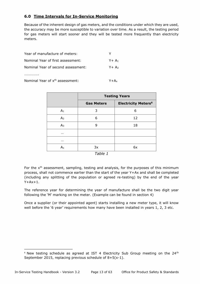
Year of manufacture of meters: Y
Nominal Year of first assessment: Y+ A1
Nominal Year of second assessment: Y+ A2
…………….
Nominal Year of xth assessment: Y+Ax
Testing Years
Gas Meters Electricity Meters6
A1 3 6
A2 6 12
A3 9 18
…
…
Ax 3x 6x
Table 1
For the xth assessment, sampling, testing and analysis, for the purposes of this minimum
process, shall not commence earlier than the start of the year Y+Ax and shall be completed
(including any splitting of the population or agreed re-testing) by the end of the year
Y+Ax+1.
The reference year for determining the year of manufacture shall be the two digit year
following the ‘M’ marking on the meter. (Example can be found in section 4)
Once a supplier (or their appointed agent) starts installing a new meter type, it will know
well before the ‘6 year’ requirements how many have been installed in years 1, 2, 3 etc.
6 New testing schedule as agreed at IST 4 Electricity Sub Group meeting on the 24th
September 2015, replacing previous schedule of 8+5(x-1).

In-Service Testing Handbook - Version 3.2 Page 14 of 63 Office for Product Safety & Standards
7.0 Sampling Plan and Criteria for Meter Populations Requiring Replacement.
The number of samples required for a known population size is given in the following table:
Population by type
and year
Sample Size
1,201 to 3,200 50
3,201 to 10,000 75
10,001 to 35,000 100
35,001 to 150,000 150
>150,000 200
Table 2
Note 1: Populations to be sampled may be the combined populations of a meter type within
the control of a number of responsible persons. For example, should IST participants have
a total of 140,000 meters between them of a particular meter type and year, the total
sample to be obtained is 150 meters. The sample required from a particular entity shall be
in proportion to the population of that meter held by the entity.
Note 2: It is not considered that the testing of populations smaller than 1,201 will be
economically viable for domestic type gas and whole current electricity meters.
BEIS shall contact suppliers to ascertain meter population information in accordance with
Annex 1 (Testing Timetable) of this document. As the total population of each meter type is
required, suppliers are asked to respond as gas/electricity suppliers – not as MAMs or asset
owners, etc. For each meter type BEIS will then calculate the number of samples required
according to Table 2 and apportion these between the participants.
The participants are required to submit these meters for testing at one of the approved test
stations detailed in Annex 2. To minimise disturbance to customers and reduce costs,
samples may be drawn from “off supply” stock although BEIS recognise that this may not
be possible and samples may have to be taken “off the wall”. Suppliers are free to choose
any approved test station with the testing cost a commercial arrangement between the
supplier and test station concerned. Suppliers are responsible for this cost although there is
no direct cost to the IST participants for BEIS’s governance of the scheme. It is intended
that competition between test stations will serve to reduce the meter testing cost.
The test station will perform the tests detailed in Annex 3 and provide the results to the
suppliers that have engaged their services, together with details of any excluded or
discarded meters. BEIS will provide all approved test stations with suitable test report forms7
and the test station shall maintain records that can be made available for BEIS audit at any
time.
7 The test report templates can be found here: https://www.gov.uk/guidance/in-service-
testing-for-gas-and-electricity-meters, under the Templates for gas and electricity meters
tested section.
In-Service Testing Handbook - Version 3.2 Page 15 of 63 Office for Product Safety & Standards
Suppliers shall provide test results to BEIS as soon as possible after they have received
them from the test station; and BEIS will assess the acceptability of the meter populations
as detailed in the following pages.
Sampled meters (including those classed as Excluded and any outliers) shall be quarantined
by the supplier, as they have the legal responsibility, pending BEIS’s decision as to the
acceptability of the population. BEIS will notify the supplier in writing when this decision has
been made. Suppliers may choose a commercial arrangement to store quarantined meters
at the test station used, on the agreement of both parties, if it is more convenient.
When the population is deemed acceptable the sampled meters that passed the tests may
be placed back in-service by the supplier or their appointed agent. Meters that did not pass
the tests or were Discarded/Excluded cannot be placed back in-service without repair or
refurbishment.
In-Service Testing Handbook - Version 3.2 Page 16 of 63 Office for Product Safety & Standards
8.0 Assessment of Results - Including Criteria
8.1 Criteria
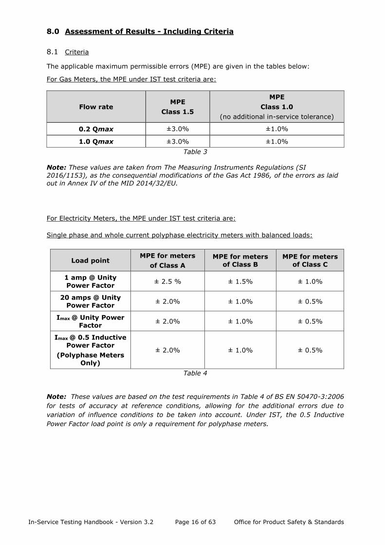
The applicable maximum permissible errors (MPE) are given in the tables below:
For Gas Meters, the MPE under IST test criteria are:
Flow rate MPE
Class 1.5
MPE
Class 1.0
(no additional in-service tolerance)
0.2 Qmax ±3.0% ±1.0%
1.0 Qmax ±3.0% ±1.0%
Table 3
Note: These values are taken from The Measuring Instruments Regulations (SI
2016/1153), as the consequential modifications of the Gas Act 1986, of the errors as laid
out in Annex IV of the MID 2014/32/EU.
For Electricity Meters, the MPE under IST test criteria are:
Single phase and whole current polyphase electricity meters with balanced loads:
Load point MPE for meters
of Class A
MPE for meters
of Class B
MPE for meters
of Class C
1 amp @ Unity
Power Factor ± 2.5 % ± 1.5% ± 1.0%
20 amps @ Unity
Power Factor ± 2.0% ± 1.0% ± 0.5%
Imax @ Unity Power
Factor ± 2.0% ± 1.0% ± 0.5%
Imax @ 0.5 Inductive
Power Factor
(Polyphase Meters
Only)
± 2.0% ± 1.0% ± 0.5%
Table 4
Note: These values are based on the test requirements in Table 4 of BS EN 50470-3:2006
for tests of accuracy at reference conditions, allowing for the additional errors due to
variation of influence conditions to be taken into account. Under IST, the 0.5 Inductive
Power Factor load point is only a requirement for polyphase meters.
In-Service Testing Handbook - Version 3.2 Page 17 of 63 Office for Product Safety & Standards
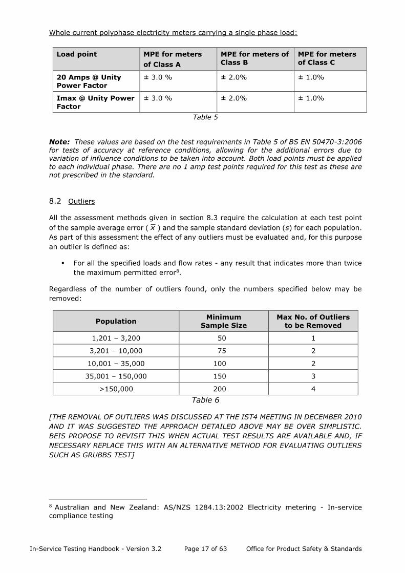
Whole current polyphase electricity meters carrying a single phase load:
Load point MPE for meters
of Class A
MPE for meters of
Class B
MPE for meters
of Class C
20 Amps @ Unity
Power Factor
± 3.0 % ± 2.0% ± 1.0%
Imax @ Unity Power
Factor
± 3.0 % ± 2.0% ± 1.0%
Table 5
Note: These values are based on the test requirements in Table 5 of BS EN 50470-3:2006
for tests of accuracy at reference conditions, allowing for the additional errors due to
variation of influence conditions to be taken into account. Both load points must be applied
to each individual phase. There are no 1 amp test points required for this test as these are
not prescribed in the standard.
8.2 Outliers
All the assessment methods given in section 8.3 require the calculation at each test point
of the sample average error ( x ) and the sample standard deviation (s) for each population.
As part of this assessment the effect of any outliers must be evaluated and, for this purpose
an outlier is defined as:
▪ For all the specified loads and flow rates - any result that indicates more than twice
the maximum permitted error8.
Regardless of the number of outliers found, only the numbers specified below may be
removed:
Population Minimum
Sample Size
Max No. of Outliers
to be Removed
1,201 – 3,200 50 1
3,201 – 10,000 75 2
10,001 – 35,000 100 2
35,001 – 150,000 150 3
>150,000 200 4
Table 6
[THE REMOVAL OF OUTLIERS WAS DISCUSSED AT THE IST4 MEETING IN DECEMBER 2010
AND IT WAS SUGGESTED THE APPROACH DETAILED ABOVE MAY BE OVER SIMPLISTIC.
BEIS PROPOSE TO REVISIT THIS WHEN ACTUAL TEST RESULTS ARE AVAILABLE AND, IF
NECESSARY REPLACE THIS WITH AN ALTERNATIVE METHOD FOR EVALUATING OUTLIERS
SUCH AS GRUBBS TEST]
8 Australian and New Zealand: AS/NZS 1284.13:2002 Electricity metering - In-service
compliance testing

In-Service Testing Handbook - Version 3.2 Page 18 of 63 Office for Product Safety & Standards
8.3 Assessment method
As explained previously populations may be assessed individually or as part of an overall
population and electricity meters may also be assessed as super-populations.
To assess an individual population the sample average error ( x ) and the sample standard
deviation (s) are calculated.
Determine the value of the following two expressions:
and where:
k is the acceptability constant9 for an AQL of 2.5 given in Table 7
USL (the upper specification limit) is the positive tolerance given in 8.1
LSL (the lower specification limit) is the negative tolerance given in 8.1
If for any test point where:
k s
x - USL or
the population shall be deemed unacceptable. (However, see section 8.4 for Overall
Population Assessment.)
HISTORICAL INFORMATION ON METER PERFORMANCE SHOULD BE CONSIDERED BEFORE
ANY METER POPULATIONS ARE DEEMED UNACCEPTABLE. THIS WILL PROVIDE
CONFIDENCE IN THE IST PROCEDURES AND ENSURE THAT ONLY METERS NOT MEETING
THE STATUTORY REQUIREMENTS ARE REMOVED FROM SERVICE. ANALYSING HISTORICAL
DATA WILL ALSO ENABLE SUPPLIERS AND ASSET OWNERS TO MONITOR THE ONGOING
PERFORMANCE OF METERS IN THEIR PORTFOLIOS AND PROVIDE AN EARLY WARNING OF
POPULATIONS THAT ARE GETTING CLOSE TO BEING DEEMED UNACCEPTABLE.
HISTORICAL DATA FOR MID GAS METERS WILL NOT BE AVAILABLE UNTIL METERS HAVE
BEEN SAMPLED FOR THE SECOND TIME AS THE PERFORMANCE CHARACTERISTICS OF
THESE METERS ARE SIGNIFICANTLY DIFFERENT THAN THOSE APPROVED UNDER
NATIONAL LEGISLATION.
WHERE A METER POPULATION IS DEEMED UNACCEPTABLE THE POPULATIONS WILL
THEREFORE BE RESAMPLED PRIOR TO ANY FINAL DECISION BEING MADE. THIS WILL TAKE
PLACE IN THE SAME YEAR AS THE INITIAL SAMPLING AND WILL REQUIRE THE TESTING OF
ADDITIONAL METERS – THE SAMPLE SIZE BEING EQUAL TO THAT SAMPLED INTIALLY AS
DERIVED FROM TABLE 2.
METERS APPROVED UNDER GB NATIONAL LEGISLATION (“LEGACY”) WILL NOT BE SUBJECT
TO RESAMPLING AS HISTORICAL INFORMATION ON METER PERFORMANCE SHOULD
9 The value of k is dependent on the population size (and hence the sample size) and the
defined acceptable quality level (AQL). Table II-A – Single sampling plans for normal
inspection (master table): “s” method for ISO3951: 1989 has been utilised to derive the
appropriate values of k.
s
x - USL
s
LSL - x
k s
LSL - x
In-Service Testing Handbook - Version 3.2 Page 19 of 63 Office for Product Safety & Standards
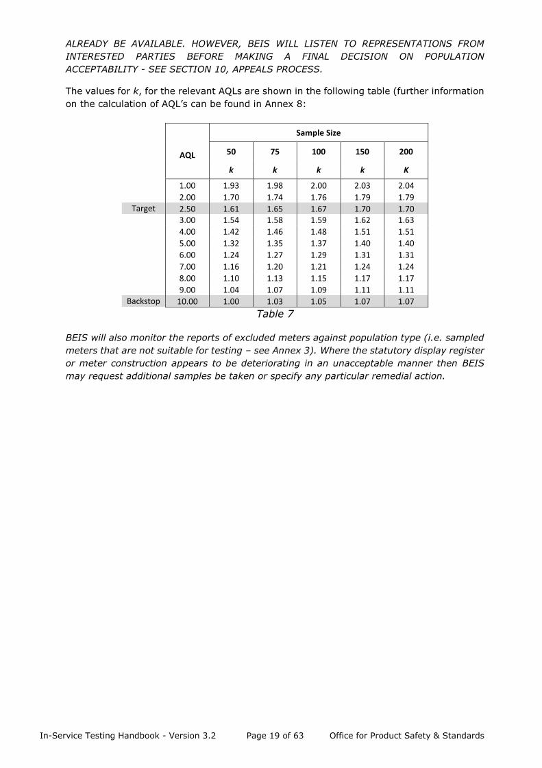
ALREADY BE AVAILABLE. HOWEVER, BEIS WILL LISTEN TO REPRESENTATIONS FROM
INTERESTED PARTIES BEFORE MAKING A FINAL DECISION ON POPULATION
ACCEPTABILITY - SEE SECTION 10, APPEALS PROCESS.
The values for k, for the relevant AQLs are shown in the following table (further information
on the calculation of AQL’s can be found in Annex 8:
Sample Size
AQL 50 75 100 150 200
k k k k K
1.00 1.93 1.98 2.00 2.03 2.04 2.00 1.70 1.74 1.76 1.79 1.79
Target 2.50 1.61 1.65 1.67 1.70 1.70 3.00 1.54 1.58 1.59 1.62 1.63 4.00 1.42 1.46 1.48 1.51 1.51 5.00 1.32 1.35 1.37 1.40 1.40 6.00 1.24 1.27 1.29 1.31 1.31 7.00 1.16 1.20 1.21 1.24 1.24 8.00 1.10 1.13 1.15 1.17 1.17 9.00 1.04 1.07 1.09 1.11 1.11 Backstop 10.00 1.00 1.03 1.05 1.07 1.07
Table 7
BEIS will also monitor the reports of excluded meters against population type (i.e. sampled
meters that are not suitable for testing – see Annex 3). Where the statutory display register
or meter construction appears to be deteriorating in an unacceptable manner then BEIS
may request additional samples be taken or specify any particular remedial action.

In-Service Testing Handbook - Version 3.2 Page 20 of 63 Office for Product Safety & Standards
8.4 Overall population assessment
A supplier may choose to maintain its overall portfolio to a specified level of accuracy (e.g.
the MAM maintains that 95% of its total portfolio of meters is within the MPE limits). The
overall portfolio of a supplier shall be assessed each year from sample results as follows:
▪ For each individual population of meters tested (Ni), calculate the percentage of
meters within the MPE (Pi) i.e. find the lowest AQL that satisfies the two inequalities
given in Section 8.3.
▪ Multiply the total number of meters in the individual population by the fraction that
is within the MPE (Ni*Pi).
▪ Calculate this figure for each individual population and sum to find the total number
of meters in the overall portfolio that are predicted to be within MPE.
▪ Divide the total number of meters within MPE by the total portfolio to determine the
overall performance measure.
Where there are ‘n’ individual populations and for the ith population, Ni is the total number
of meters of that type in the overall portfolio and Pi is the proportion of meters of that
individual type that are estimated from the testing results to perform within the MPE limits.
Note: The following rules shall apply in respect of meters for which test data is limited:
▪ Until a particular meter population is tested for the first time (A1) it will be assumed
that 100% are within MPE.
▪ For populations that have been tested once, the fraction within MPE as tested at time
A1 years shall be applied until the meters are next tested.
▪ For populations that have been tested twice, the fraction within MPE as tested at
time A2 will be applied until the meters are next tested
▪ After 3rd testing in year A3, estimates based upon a trend line shall be used to
estimate performance in intervening years, using all previous test results, e.g. A1,
A2, A3.
▪ If there are meter types within the portfolio that have been identified under the
backstop arrangements below then these shall be excluded from the calculation of
the overall population assessment.
n
i
i
n
i
ii
N
PN
Overall
1
1
*

In-Service Testing Handbook - Version 3.2 Page 21 of 63 Office for Product Safety & Standards
8.5 Backstop arrangements
In order to ensure that poorly performing meters are always removed from the system, any
meter types where the sample shows their acceptance AQL is [10%] or higher shall be
removed from the system within 2 years. This shall apply under both the individual
population assessment and the overall population assessment methods.
[WHEN DEVELOPING THE IST METHODOLOGY THE INDUSTRY WAS UNABLE TO AGREE ON
THE VALUE OF THE ACCEPTANCE AQL WITH SOME MEMBERS FAVOURING A HIGHER VALUE
SO THE METHODOLOGY COULD BE EXTENDED TO LEGACY METERS MORE EASILY. BEIS
PROPOSES TO REVISIT THIS WHEN ACTUAL TEST RESULTS AND POPULATION
ASSESSMENTS ARE AVAILABLE].
8.6 Overall population assessment
Where a supplier chooses to manage the overall population, action taken as a result of the
testing should ensure that the overall percentage of his portfolio estimated to be within MPE
never drops below 95%. If less than 95% of the population is estimated to be within the
MPE then urgent action shall be taken to restore the population to the target status within
two years.
Note: that the backstop arrangements shall be applied before the overall population
assessment is made. If the overall population assessment is above the required level, taking
into account any exclusion made as a result of the backstop arrangement, then no further
meter replacements other than those subject to the backstop arrangements shall be
required.
In-Service Testing Handbook - Version 3.2 Page 22 of 63 Office for Product Safety & Standards
9.0 Removal of Unacceptable Populations
If the assessments above call for a meter population to be replaced then the replacement
shall be completed within two years from the decision being taken, subject to reasonable
efforts taken to gain access to the consumers’ premises. An extension to this period may be
granted for large replacement volumes.
Note: Nothing in this document shall remove the legal obligation to maintain individual
meters within the prescribed levels of accuracy. The Regulatory Authority (BEIS) may
request additional sampling of any meter population in cases where there is evidence of
certain types of ‘disputed meters’ that are not performing to the required standard.
10.0 Assessment Failures (Appeals & Investigations)
Where a meter type is deemed to have failed IST during its first sample selection
assessment, an investigation may be required / requested to ascertain a) the reason for the
failure and b) the consistency of the failure across industry participants. Information for the
investigation may be obtained from relevant parties (such as manufacturers, asset owners,
meter operators, suppliers, industry trade associations etc). Such information shall be
considered and, if required, a second sample selection may be utilised to corroborate data
obtained from any investigation. BEIS shall review the information obtained from the
investigation and any subsequent second sample selection to reach a decision within
reasonable timescales.
Information supporting any decision made by BEIS shall be made available for scrutiny (with
the exception of commercially sensitive material judged to be exempt from Freedom of
Information requests).
NOTE: No more than one additional sample selection (i.e. nothing further than a 2nd sample
selection) shall be utilised to ascertain the current status of the submitted meter type. A
meter type failing on a second or subsequent scheduled assessment will not be subject to
any repeat testing, but further discussions will continue with all relevant stakeholders and
similar processes, using all available data, to ascertain reasons for failure within reasonable
timescales.
BEIS has statutory responsibility for the metrological performance of gas and electricity
meters and there will be no formal appeals process for IST once a considered decision has
been reached. BEIS will, however, discuss the test results with all relevant parties prior to
making any decision.
Any decision made by BEIS will be final.
In-Service Testing Handbook - Version 3.2 Page 23 of 63 Office for Product Safety & Standards
ANNEXES
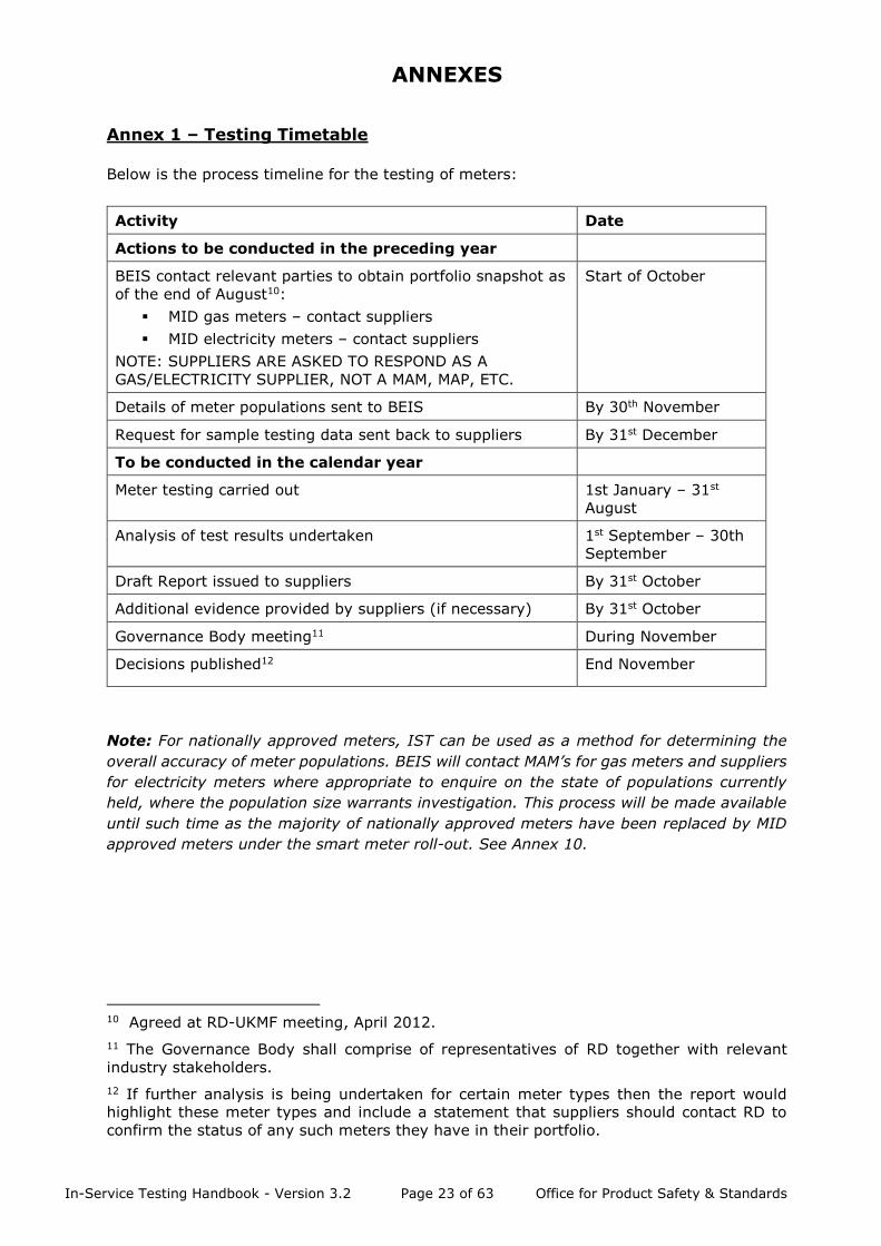
Annex 1 – Testing Timetable
Below is the process timeline for the testing of meters:
Activity Date
Actions to be conducted in the preceding year
BEIS contact relevant parties to obtain portfolio snapshot as
of the end of August10:
▪ MID gas meters – contact suppliers
▪ MID electricity meters – contact suppliers
NOTE: SUPPLIERS ARE ASKED TO RESPOND AS A
GAS/ELECTRICITY SUPPLIER, NOT A MAM, MAP, ETC.
Start of October
Details of meter populations sent to BEIS By 30th November
Request for sample testing data sent back to suppliers By 31st December
To be conducted in the calendar year
Meter testing carried out 1st January – 31st
August
Analysis of test results undertaken 1st September – 30th
September
Draft Report issued to suppliers By 31st October
Additional evidence provided by suppliers (if necessary) By 31st October
Governance Body meeting11 During November
Decisions published12 End November
Note: For nationally approved meters, IST can be used as a method for determining the
overall accuracy of meter populations. BEIS will contact MAM’s for gas meters and suppliers
for electricity meters where appropriate to enquire on the state of populations currently
held, where the population size warrants investigation. This process will be made available
until such time as the majority of nationally approved meters have been replaced by MID
approved meters under the smart meter roll-out. See Annex 10.
10 Agreed at RD-UKMF meeting, April 2012.
11 The Governance Body shall comprise of representatives of RD together with relevant
industry stakeholders.
12 If further analysis is being undertaken for certain meter types then the report would
highlight these meter types and include a statement that suppliers should contact RD to
confirm the status of any such meters they have in their portfolio.
In-Service Testing Handbook - Version 3.2 Page 24 of 63 Office for Product Safety & Standards
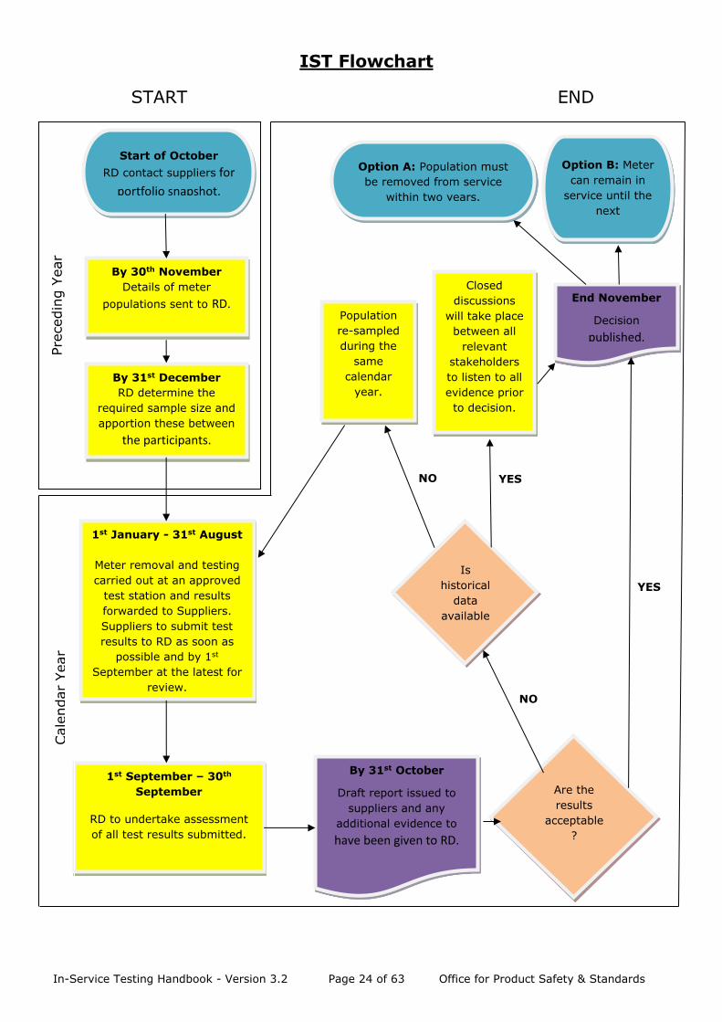
IST Flowchart
START END
By 30th November
Details of meter
populations sent to RD.
By 31st December
RD determine the
required sample size and
apportion these between
the participants.
1st January - 31st August
Meter removal and testing
carried out at an approved
test station and results
forwarded to Suppliers.
Suppliers to submit test
results to RD as soon as
possible and by 1st
September at the latest for
review.
1st September – 30th
September
RD to undertake assessment
of all test results submitted.
Are the
results
acceptable
?
Start of October
RD contact suppliers for
portfolio snapshot.
By 31st October
Draft report issued to
suppliers and any
additional evidence to
have been given to RD.
Closed
discussions
will take place
between all
relevant
stakeholders
to listen to all
evidence prior
to decision.
End November
Decision
published.
Population
re-sampled
during the
same
calendar
year.
Is
historical
data
available
?
Option A: Population must
be removed from service
within two years.
Option B: Meter
can remain in
service until the
next
assessment.
NO
NO YES
YES
Pre
cedin
g Y
ear
Cale
ndar
Year
In-Service Testing Handbook - Version 3.2 Page 25 of 63 Office for Product Safety & Standards
Annex 2 - Approved Test Stations
Test results will only be accepted from organisations formally designated by BEIS for the
purpose of IST testing. Appointments will be valid for three years and, to ensure the validity
of test results will be subject to audit by BEIS following a clearly defined audit schedule.
Organisations That Will Be Considered:
▪ Notified bodies approved under the Measuring Instruments Directive for the
conformity assessment of gas and electricity meters under Annex B of the Directive.
▪ Manufacturers and repairers of gas and electricity meters that have been authorised
by BEIS to self-stamp (gas) and self-certify (electricity) meters.
▪ Other organisations with appropriate test equipment, experience, etc.
Organisations wishing to be designated as approved IST stations should contact
[email protected] or [email protected] as appropriate.
Test Station Requirements:
▪ Appropriate quality procedure in place documenting specifically how IST will be
undertaken, how meters are tested and how the process will operate
▪ Calibrated test equipment traceable to national standards
▪ Appropriately trained staff
▪ Dedicated IST provisions, notably goods in and warehouse storage
▪ Secure and traceable data storage
▪ Controlled testing environment
Note: The equipment used for IST testing shall have a total uncertainty of measurement of
less than or equal to 0.5% for gas meters and 0.4% (at unity power factor) for electricity
meters13.
Test measurements made by equipment satisfying the above uncertainty levels shall be
deemed to be accurate (i.e. in assessing the population, no allowance shall be made
regarding the uncertainty of measurement).
Note: For electricity meters where Imax is not achievable under normal safe operating
conditions, as listed under the BEIS approved IST electricity test stations accreditation on
page 27, written agreement must be provided from BEIS to allow testing at 0.8 Imax for
electricity meters up to 120A.
13 These values represent best practice rather than the normal applicable criteria for
measurement accuracy
In-Service Testing Handbook - Version 3.2 Page 26 of 63 Office for Product Safety & Standards
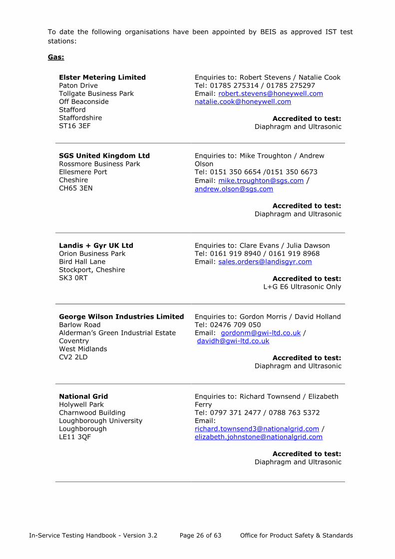
To date the following organisations have been appointed by BEIS as approved IST test
stations:
Gas:
Elster Metering Limited
Paton Drive
Tollgate Business Park
Off Beaconside
Stafford
Staffordshire
ST16 3EF
Enquiries to: Robert Stevens / Natalie Cook
Tel: 01785 275314 / 01785 275297
Email: [email protected]
Accredited to test:
Diaphragm and Ultrasonic
SGS United Kingdom Ltd
Rossmore Business Park
Ellesmere Port
Cheshire
CH65 3EN
Enquiries to: Mike Troughton / Andrew
Olson
Tel: 0151 350 6654 /0151 350 6673
Email: [email protected] / [email protected]
Accredited to test:
Diaphragm and Ultrasonic
Landis + Gyr UK Ltd
Orion Business Park
Bird Hall Lane
Stockport, Cheshire
SK3 0RT
Enquiries to: Clare Evans / Julia Dawson
Tel: 0161 919 8940 / 0161 919 8968
Email: [email protected]
Accredited to test:
L+G E6 Ultrasonic Only
George Wilson Industries Limited
Barlow Road
Alderman’s Green Industrial Estate
Coventry
West Midlands
CV2 2LD
Enquiries to: Gordon Morris / David Holland
Tel: 02476 709 050
Email: [email protected] /
Accredited to test:
Diaphragm and Ultrasonic
National Grid
Holywell Park
Charnwood Building
Loughborough University
Loughborough
LE11 3QF
Enquiries to: Richard Townsend / Elizabeth
Ferry
Tel: 0797 371 2477 / 0788 763 5372
Email: [email protected] /
Accredited to test:
Diaphragm and Ultrasonic
In-Service Testing Handbook - Version 3.2 Page 27 of 63 Office for Product Safety & Standards
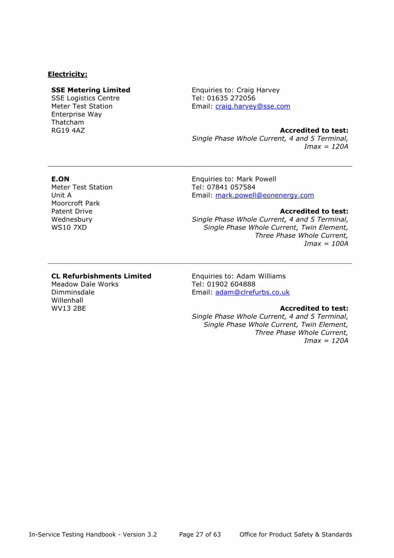
Electricity:
SSE Metering Limited
SSE Logistics Centre
Meter Test Station
Enterprise Way
Thatcham
RG19 4AZ
Enquiries to: Craig Harvey
Tel: 01635 272056
Email: [email protected]
Accredited to test: Single Phase Whole Current, 4 and 5 Terminal,
Imax = 120A
E.ON
Meter Test Station
Unit A
Moorcroft Park
Patent Drive
Wednesbury
WS10 7XD
Enquiries to: Mark Powell
Tel: 07841 057584
Email: [email protected]
Accredited to test: Single Phase Whole Current, 4 and 5 Terminal,
Single Phase Whole Current, Twin Element,
Three Phase Whole Current,
Imax = 100A
CL Refurbishments Limited
Meadow Dale Works
Dimminsdale
Willenhall
WV13 2BE
Enquiries to: Adam Williams
Tel: 01902 604888
Email: [email protected]
Accredited to test: Single Phase Whole Current, 4 and 5 Terminal,
Single Phase Whole Current, Twin Element,
Three Phase Whole Current,
Imax = 120A

In-Service Testing Handbook - Version 3.2 Page 28 of 63 Office for Product Safety & Standards
Annex 3 – Drawing of Samples & Test Requirements
To minimise the disturbance to customers and to reduce costs, samples may be drawn from
“off supply” stock. To ensure that there are sufficient samples suitable for testing, extra
samples may be drawn to allow for samples that may be unsuitable for testing. Even when
drawn from “off supply” stock, reasonable efforts shall be made to select meters as randomly
as possible.
The following table determines which meters may be used for assessment:
METER CLASSIFICATION INCLUDED
(-suitable for
accuracy
test)
DISCARDED
(-unsuitable
for accuracy
test)
EXCLUDED
(-unsuitable for
accuracy test but
the reason for
exclusion is to be
recorded)
Gas and Electricity meters Normal condition ✓ Disputed ✓ Tampered (Physical evidence) ✓ Missing security seals ✓ Unsafe or broken case ✓ Meter contaminated (i.e. water) ✓ Faulty display ✓
Deteriorated case14 ✓
PPM which cannot be enabled for
test with a new key or token ✓
Gas Meters Advances under no load16 ✓
Passes un-registered gas15 16 ✓
Fails gas tightness ✓
Dents on case ✓
Electricity Meters
Advances under no load16 ✓
Fails Dial test17 ✓
Twin Element Meters –
One element is not recording ✓
Three Phase Meters –
One (or more) phase(s) is ‘open
circuit’
✓
Table 8
14 The level of corrosion on gas meters and its position is to be recorded on the test report
sheets as detailed in Annex 4. Only meters deemed to have “High” levels of corrosion are
to be excluded from testing. Meters deemed to have “Zero”, “Medium” and “Low” levels of
corrosion are suitable for testing although the information is to be recorded for asset
management purposes.
15 A meter is deemed to pass unregistered gas if the test drum fails to rotate at least 3 dm3
in less than 1 hour when air is passed through the meter at 14 dm3/h.
16 See test requirements. 17 Please see Register Advance Test (Dial Test) page 33

In-Service Testing Handbook - Version 3.2 Page 29 of 63 Office for Product Safety & Standards
Discarded/Excluded definitions:
Discarded The characteristics of a discarded meter will relate to faults that are
likely to occur in individual meters and are unlikely to be
representative of the whole population. Those deemed to be
discarded are not suitable for accuracy testing.
Excluded The characteristics of an excluded meter will relate to faults that are
likely to occur in individual meters that could be related to the
population as a whole or an individual batch, in which case the reason
for test exclusion will be noted.
The following table should be used to determine whether meters showing error indications
or flag operation can be used:
Flag Operation
-Ultrasonic Gas Meters to BS
EN 14236:2007
INCLUDED
(-suitable for
accuracy test)
DISCARDED
(-unsuitable for
accuracy test)
EXCLUDED
(-unsuitable for
accuracy test but
the reason for
exclusion is to be
recorded)
unsatisfactory reading ✓
‘A’ – catastrophic failure ✓
‘b’ – event – possible tamper ✓
‘C’ – operational problem ✓
‘d’ – and below flag ratings ✓18
‘r’ – battery change imminent ✓19
‘F’ – battery change overdue ✓20
Flag Operation
- Electricity
EEPROM Error
(may be due to meter
interference)
✓
Microprocessor Failure
(may be due to meter
interference)
✓
Volatile Memory Failure
(may be due to meter
interference)
✓
Token/key communication
failure
✓
Phase Imbalance ✓
Power Loss ✓
Overload ✓
Default Date and Time ✓
Battery Low ✓
Battery dead ✓
Low Voltage ✓
Signal Failure ✓
Table 9
18 See page 28 “Procedure for sorting of Electronic Index (E6) meters for IST.
19 The battery may be changed before accuracy testing
20 The battery may be changed before accuracy testing
In-Service Testing Handbook - Version 3.2 Page 30 of 63 Office for Product Safety & Standards
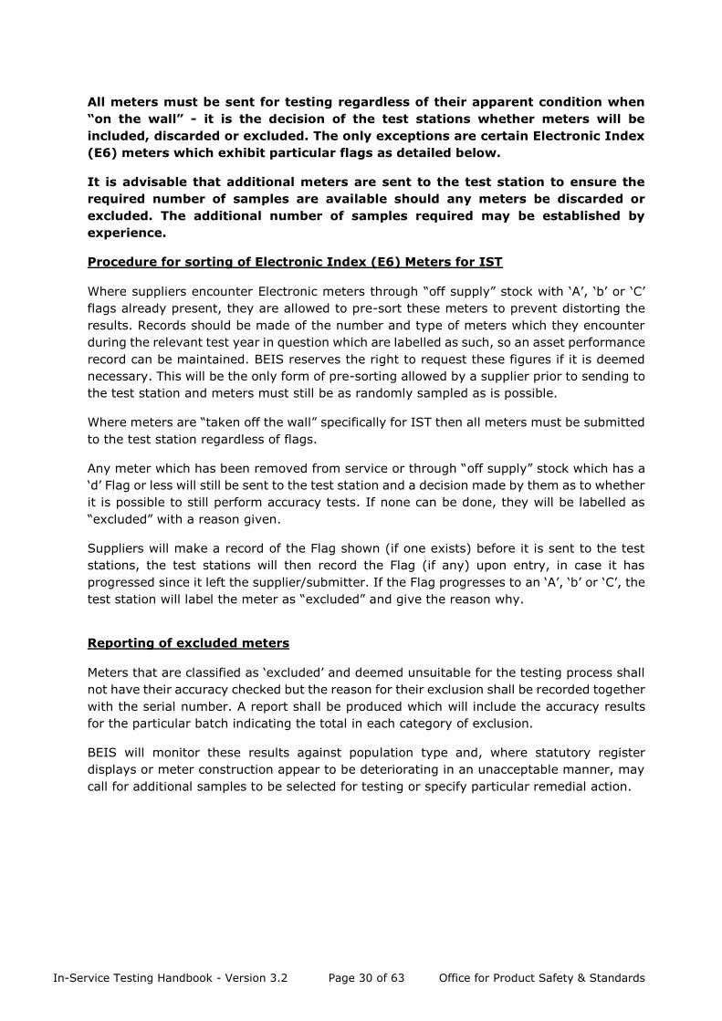
All meters must be sent for testing regardless of their apparent condition when
“on the wall” - it is the decision of the test stations whether meters will be
included, discarded or excluded. The only exceptions are certain Electronic Index
(E6) meters which exhibit particular flags as detailed below.
It is advisable that additional meters are sent to the test station to ensure the
required number of samples are available should any meters be discarded or
excluded. The additional number of samples required may be established by
experience.
Procedure for sorting of Electronic Index (E6) Meters for IST
Where suppliers encounter Electronic meters through “off supply” stock with ‘A’, ‘b’ or ‘C’
flags already present, they are allowed to pre-sort these meters to prevent distorting the
results. Records should be made of the number and type of meters which they encounter
during the relevant test year in question which are labelled as such, so an asset performance
record can be maintained. BEIS reserves the right to request these figures if it is deemed
necessary. This will be the only form of pre-sorting allowed by a supplier prior to sending to
the test station and meters must still be as randomly sampled as is possible.
Where meters are “taken off the wall” specifically for IST then all meters must be submitted
to the test station regardless of flags.
Any meter which has been removed from service or through “off supply” stock which has a
‘d’ Flag or less will still be sent to the test station and a decision made by them as to whether
it is possible to still perform accuracy tests. If none can be done, they will be labelled as
“excluded” with a reason given.
Suppliers will make a record of the Flag shown (if one exists) before it is sent to the test
stations, the test stations will then record the Flag (if any) upon entry, in case it has
progressed since it left the supplier/submitter. If the Flag progresses to an ‘A’, ‘b’ or ‘C’, the
test station will label the meter as “excluded” and give the reason why.
Reporting of excluded meters
Meters that are classified as ‘excluded’ and deemed unsuitable for the testing process shall
not have their accuracy checked but the reason for their exclusion shall be recorded together
with the serial number. A report shall be produced which will include the accuracy results
for the particular batch indicating the total in each category of exclusion.
BEIS will monitor these results against population type and, where statutory register
displays or meter construction appear to be deteriorating in an unacceptable manner, may
call for additional samples to be selected for testing or specify particular remedial action.
In-Service Testing Handbook - Version 3.2 Page 31 of 63 Office for Product Safety & Standards
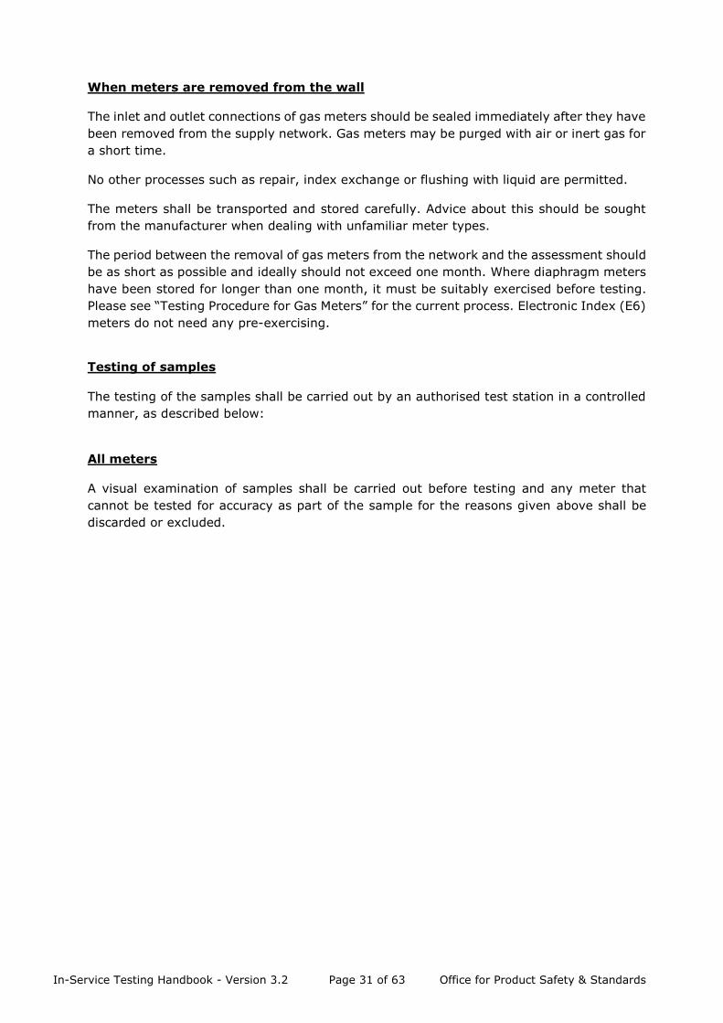
When meters are removed from the wall
The inlet and outlet connections of gas meters should be sealed immediately after they have
been removed from the supply network. Gas meters may be purged with air or inert gas for
a short time.
No other processes such as repair, index exchange or flushing with liquid are permitted.
The meters shall be transported and stored carefully. Advice about this should be sought
from the manufacturer when dealing with unfamiliar meter types.
The period between the removal of gas meters from the network and the assessment should
be as short as possible and ideally should not exceed one month. Where diaphragm meters
have been stored for longer than one month, it must be suitably exercised before testing.
Please see “Testing Procedure for Gas Meters” for the current process. Electronic Index (E6)
meters do not need any pre-exercising.
Testing of samples
The testing of the samples shall be carried out by an authorised test station in a controlled
manner, as described below:
All meters
A visual examination of samples shall be carried out before testing and any meter that
cannot be tested for accuracy as part of the sample for the reasons given above shall be
discarded or excluded.
In-Service Testing Handbook - Version 3.2 Page 32 of 63 Office for Product Safety & Standards
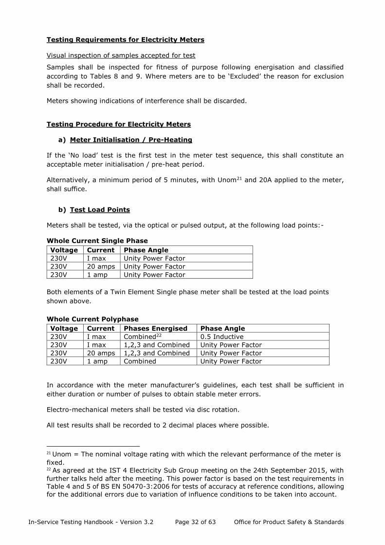
Testing Requirements for Electricity Meters
Visual inspection of samples accepted for test
Samples shall be inspected for fitness of purpose following energisation and classified
according to Tables 8 and 9. Where meters are to be ‘Excluded’ the reason for exclusion
shall be recorded.
Meters showing indications of interference shall be discarded.
Testing Procedure for Electricity Meters
a) Meter Initialisation / Pre-Heating
If the ‘No load’ test is the first test in the meter test sequence, this shall constitute an
acceptable meter initialisation / pre-heat period.
Alternatively, a minimum period of 5 minutes, with Unom21 and 20A applied to the meter,
shall suffice.
b) Test Load Points
Meters shall be tested, via the optical or pulsed output, at the following load points:-
Whole Current Single Phase
Voltage Current Phase Angle
230V I max Unity Power Factor
230V 20 amps Unity Power Factor
230V 1 amp Unity Power Factor
Both elements of a Twin Element Single phase meter shall be tested at the load points
shown above.
Whole Current Polyphase
Voltage Current Phases Energised Phase Angle
230V I max Combined22 0.5 Inductive
230V I max 1,2,3 and Combined Unity Power Factor
230V 20 amps 1,2,3 and Combined Unity Power Factor
230V 1 amp Combined Unity Power Factor
In accordance with the meter manufacturer’s guidelines, each test shall be sufficient in
either duration or number of pulses to obtain stable meter errors.
Electro-mechanical meters shall be tested via disc rotation.
All test results shall be recorded to 2 decimal places where possible.
21 Unom = The nominal voltage rating with which the relevant performance of the meter is
fixed. 22 As agreed at the IST 4 Electricity Sub Group meeting on the 24th September 2015, with
further talks held after the meeting. This power factor is based on the test requirements in
Table 4 and 5 of BS EN 50470-3:2006 for tests of accuracy at reference conditions, allowing
for the additional errors due to variation of influence conditions to be taken into account.
In-Service Testing Handbook - Version 3.2 Page 33 of 63 Office for Product Safety & Standards
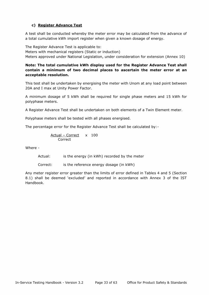
c) Register Advance Test
A test shall be conducted whereby the meter error may be calculated from the advance of
a total cumulative kWh import register when given a known dosage of energy.
The Register Advance Test is applicable to:
Meters with mechanical registers (Static or induction)
Meters approved under National Legislation, under consideration for extension (Annex 10)
Note: The total cumulative kWh display used for the Register Advance Test shall
contain a minimum of two decimal places to ascertain the meter error at an
acceptable resolution.
This test shall be undertaken by energising the meter with Unom at any load point between
20A and I max at Unity Power Factor.
A minimum dosage of 5 kWh shall be required for single phase meters and 15 kWh for
polyphase meters.
A Register Advance Test shall be undertaken on both elements of a Twin Element meter.
Polyphase meters shall be tested with all phases energised.
The percentage error for the Register Advance Test shall be calculated by:-
Actual – Correct x 100
Correct
Where -
Actual: is the energy (in kWh) recorded by the meter
Correct: is the reference energy dosage (in kWh)
Any meter register error greater than the limits of error defined in Tables 4 and 5 (Section
8.1) shall be deemed ‘excluded’ and reported in accordance with Annex 3 of the IST
Handbook.
In-Service Testing Handbook - Version 3.2 Page 34 of 63 Office for Product Safety & Standards
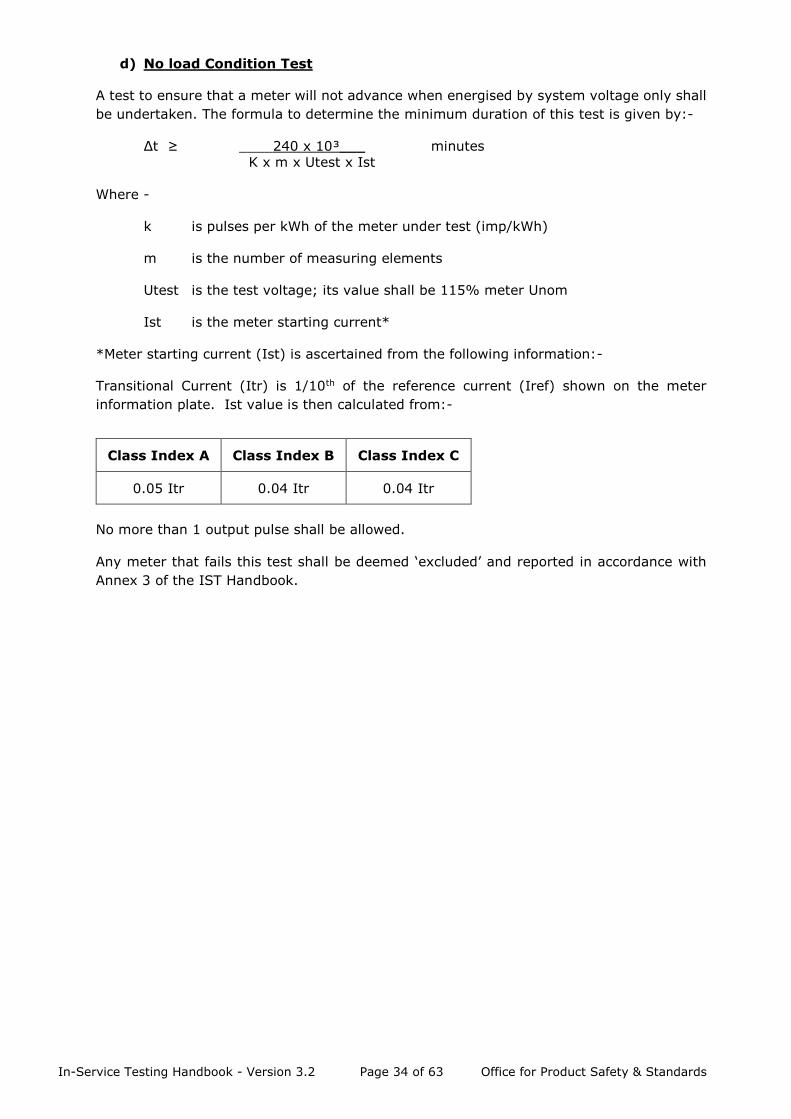
d) No load Condition Test
A test to ensure that a meter will not advance when energised by system voltage only shall
be undertaken. The formula to determine the minimum duration of this test is given by:-
Δt ≥ ____240 x 10³___ minutes
K x m x Utest x Ist
Where -
k is pulses per kWh of the meter under test (imp/kWh)
m is the number of measuring elements
Utest is the test voltage; its value shall be 115% meter Unom
Ist is the meter starting current*
*Meter starting current (Ist) is ascertained from the following information:-
Transitional Current (Itr) is 1/10th of the reference current (Iref) shown on the meter
information plate. Ist value is then calculated from:-
Class Index A Class Index B Class Index C
0.05 Itr 0.04 Itr 0.04 Itr
No more than 1 output pulse shall be allowed.
Any meter that fails this test shall be deemed ‘excluded’ and reported in accordance with
Annex 3 of the IST Handbook.
In-Service Testing Handbook - Version 3.2 Page 35 of 63 Office for Product Safety & Standards
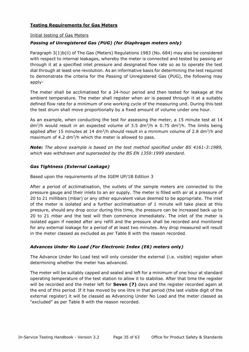
Testing Requirements for Gas Meters
Initial testing of Gas Meters
Passing of Unregistered Gas (PUG) (for Diaphragm meters only)
Paragraph 3(1)b(ii) of The Gas (Meters) Regulations 1983 (No. 684) may also be considered
with respect to internal leakages, whereby the meter is connected and tested by passing air
through it at a specified inlet pressure and designated flow rate so as to operate the test
dial through at least one revolution. As an informative basis for determining the test required
to demonstrate the criteria for the Passing of Unregistered Gas (PUG), the following may
apply-
The meter shall be acclimatised for a 24-hour period and then tested for leakage at the
ambient temperature. The meter shall register when air is passed through it at a suitably
defined flow rate for a minimum of one working cycle of the measuring unit. During this test
the test drum shall move proportionally by a fixed amount of volume under one hour.
As an example, when conducting the test for assessing the meter, a 15 minute test at 14
dm3/h would result in an expected volume of 3.5 dm3/h ± 0.75 dm3/h. The limits being
applied after 15 minutes at 14 dm3/h should result in a minimum volume of 2.8 dm3/h and
maximum of 4.2 dm3/h which the meter is allowed to pass.
Note: The above example is based on the test method specified under BS 4161-3:1989,
which was withdrawn and superseded by the BS EN 1359:1999 standard.
Gas Tightness (External Leakage)
Based upon the requirements of the IGEM UP/1B Edition 3
After a period of acclimatisation, the outlets of the sample meters are connected to the
pressure gauge and their inlets to an air supply. The meter is filled with air at a pressure of
20 to 21 millibars (mbar) or any other equivalent value deemed to be appropriate. The inlet
of the meter is isolated and a further acclimatisation of 1 minute will take place at this
pressure, should any drop occur during this time, the pressure can be increased back up to
20 to 21 mbar and the test will then commence immediately. The inlet of the meter is
isolated again if needed after any refill and the pressure shall be recorded and monitored
for any external leakage for a period of at least two minutes. Any drop measured will result
in the meter classed as excluded as per Table 8 with the reason recorded.
Advances Under No Load (For Electronic Index (E6) meters only)
The Advance Under No Load test will only consider the external (i.e. visible) register when
determining whether the meter has advanced.
The meter will be suitably capped and sealed and left for a minimum of one hour at standard
operating temperature of the test station to allow it to stabilise. After that time the register
will be recorded and the meter left for Seven (7) days and the register recorded again at
the end of this period. If it has moved by one litre in that period (the last visible digit of the
external register) it will be classed as Advancing Under No Load and the meter classed as
“excluded” as per Table 8 with the reason recorded.
In-Service Testing Handbook - Version 3.2 Page 36 of 63 Office for Product Safety & Standards
Suppliers are permitted to ask the test station to record the internal register before and
after, if the test station has the capabilities to analyse the meter in that way, should they
wish for asset management purposes.
Testing Procedure for Gas Meters
For diaphragm meters, before starting the tests, a volume of air equal to at least one
hundred (100) times the cyclic volume of the meter shall be passed through the meter. IST
test stations can determine the exact nature of this exercising depending on the test
equipment available but 100 or 200 litres at half Qmax is felt adequate.
The accuracy of the gas meter shall be tested once at each of the following flow rates:
0.2 Qmax and 1.0 Qmax
All test results shall be recorded to 2 decimal places where possible.
Test Results
BEIS will combine the test results provided by contributing suppliers and analyse the
performance of each population type in accordance with the procedure detailed in Section
8.

In-Service Testing Handbook - Version 3.2 Page 37 of 63 Office for Product Safety & Standards
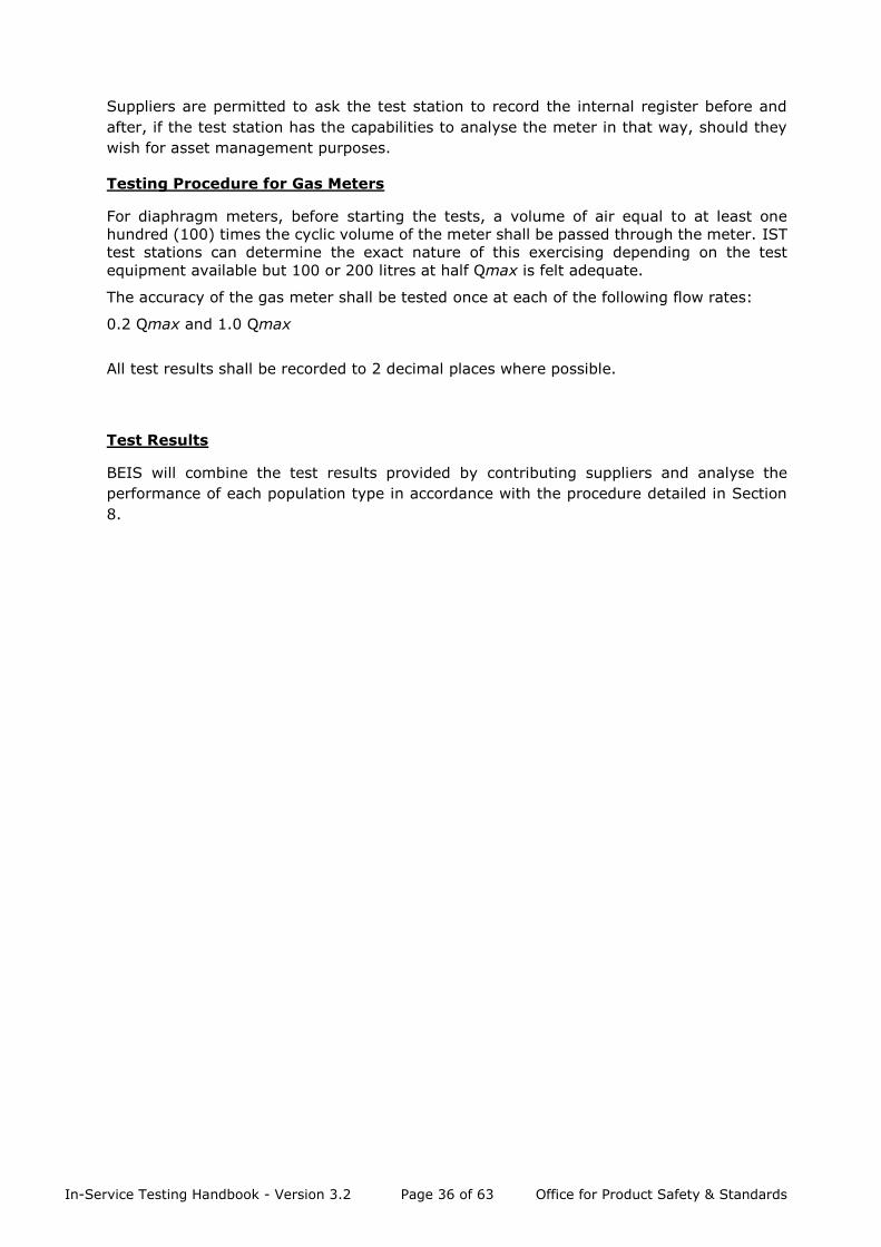
Annex 4 – Rust/Corrosion Guide for Gas Meter Cases
The following photographs are to be used as a guide for determining the level of any
corrosion of gas meters submitted for testing. When the meters are inspected prior to any
possible commencement of testing, the testers should grade each case for the extent of any
corrosion. An example of a meter with zero corrosion has also been included as a guide,
which will be labelled as N/A on the test report. Where corrosion/rust is found, the
location(s) on the meter needs to be recorded, using the list below for positions and the
level of corrosion stated as per the statements below. Where any part of the meter is
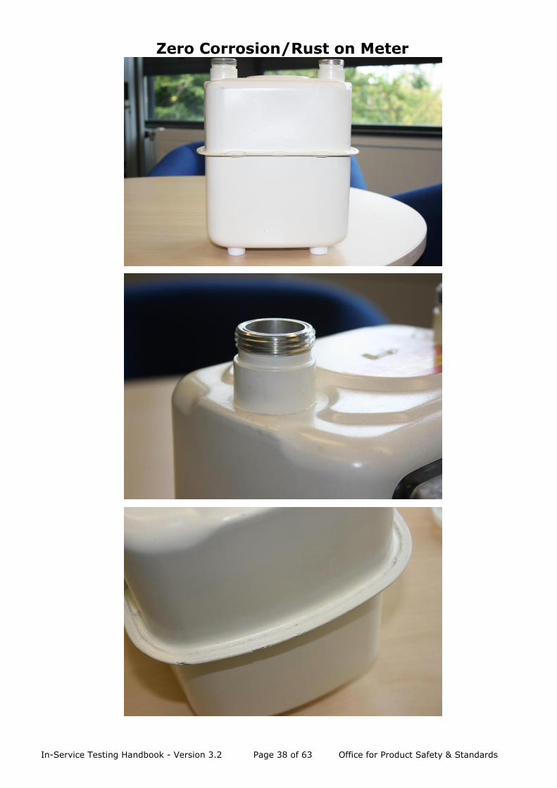
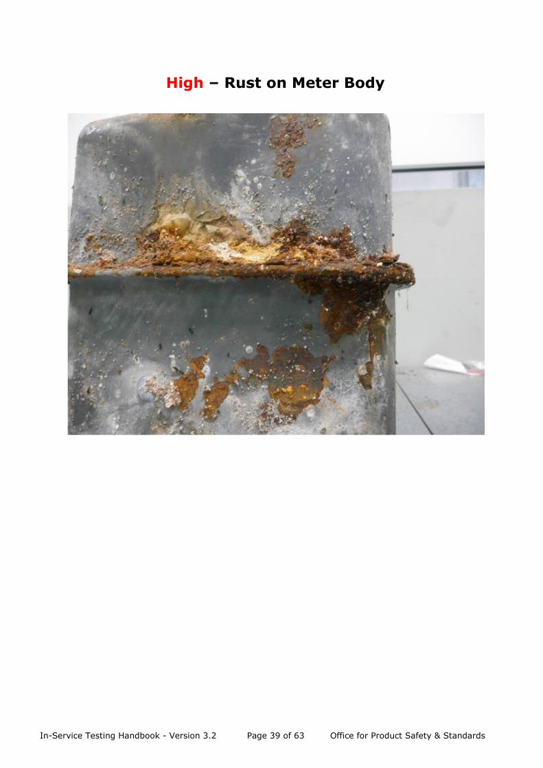
classified with a “High” level of corrosion/rust, that meter will be EXCLUDED as per Table 8,
with the reason recorded. Meters with zero, low or medium levels of corrosion can be
included in the accuracy tests.
1 - Boss
2 - Band
3 - Body
The statements below will help in establishing what each level corresponds to.
High – heavy rust/corrosion is evident that appears to be causing localised and or general
corrosion and is likely to pose a safety issue in the short term. The metal has multiple signs
of being ‘eaten’ away. These meters are to be EXCLUDED – i.e. unsuitable for the accuracy
test with the level and position of the corrosion recorded on the test report format.
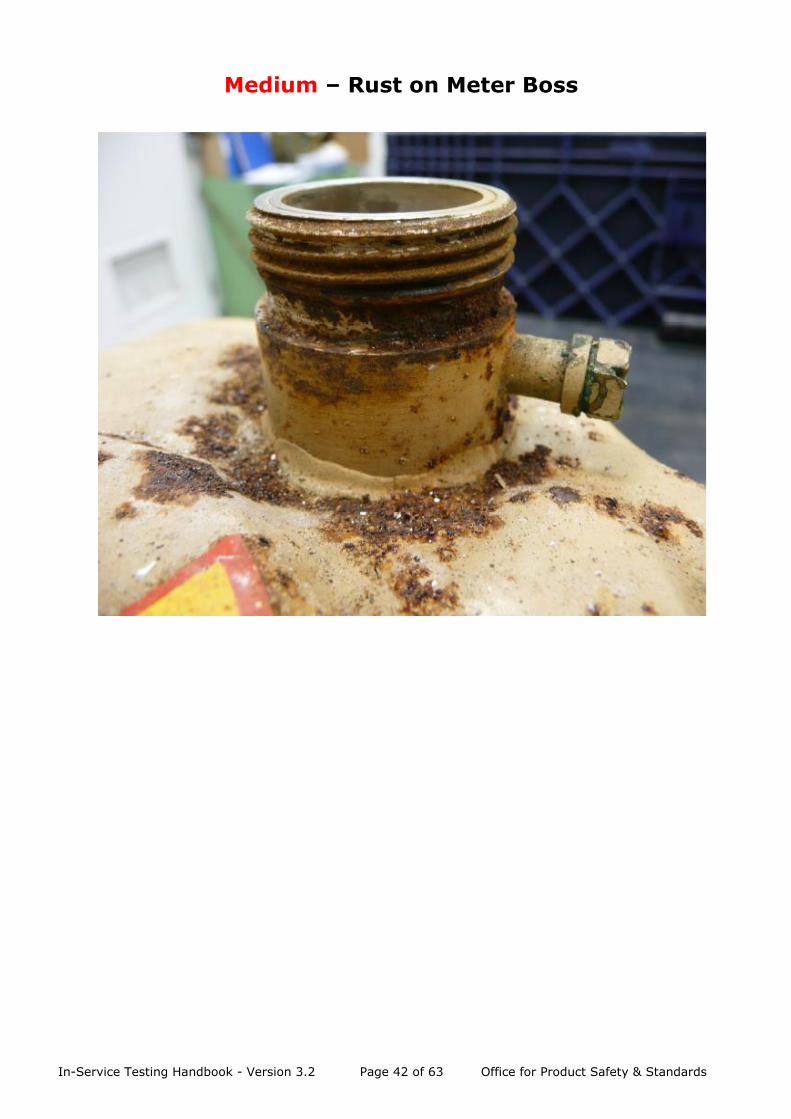
Medium – rust/corrosion is evident but is unlikely to be at a point where localised/general
corrosion is likely to pose a safety issue in the medium term. Evidence of metal being ‘eaten’
away is detected but is not considered to be ‘High’. These meters are to be INCLUDED – i.e.
suitable for the accuracy test with the level and position of the corrosion recorded on the
test report for asset management purposes only.
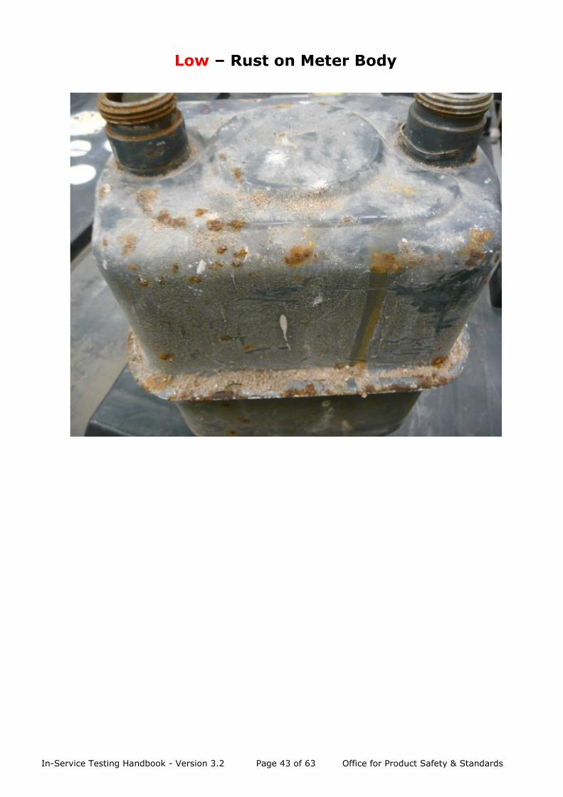
Low – evidence of surface rust only. This will normally be indicated by light / dark brown
deposits only with no apparent ‘eating’ away of the metal. These meters are to be INCLUDED
– i.e. suitable for the accuracy test with the level and position of the corrosion recorded on
the test report for asset management purposes only.
In-Service Testing Handbook - Version 3.2 Page 38 of 63 Office for Product Safety & Standards
Zero Corrosion/Rust on Meter
In-Service Testing Handbook - Version 3.2 Page 39 of 63 Office for Product Safety & Standards
High – Rust on Meter Body
In-Service Testing Handbook - Version 3.2 Page 40 of 63 Office for Product Safety & Standards
High – Rust on Meter Boss

In-Service Testing Handbook - Version 3.2 Page 41 of 63 Office for Product Safety & Standards
Medium – Rust on Meter Band
In-Service Testing Handbook - Version 3.2 Page 42 of 63 Office for Product Safety & Standards
Medium – Rust on Meter Boss
In-Service Testing Handbook - Version 3.2 Page 43 of 63 Office for Product Safety & Standards
Low – Rust on Meter Body

In-Service Testing Handbook - Version 3.2 Page 44 of 63 Office for Product Safety & Standards
Low – Rust on Meter Boss

In-Service Testing Handbook - Version 3.2 Page 45 of 63 Office for Product Safety & Standards
Annex 5 – Electricity Meter Testing Example
Sample Meter: Single Phase
Class B accuracy
230V, 1-20(100)A,
1000 imp / kWh
2 decimal place cumulative kWh test display
a) Meter Initialisation / Pre-Heat
Undertake ‘No load’ test first in test sequence or energise at 230V, 20A for a minimum of
5 minutes.
b) Test Load Points
Voltage Current Phase Angle Meter Error
230V I max Unity Power Factor +0.26%
230V 20 amps Unity Power Factor +0.45%
230V 1 amp Unity Power Factor +1.07%
c) Register Advance Test
5 kWh is applied for a single phase meter.
Actual advance = 5.02 kWh
Correct advance should be 5.00 kWh
Register % error = Actual – Correct x 100
Correct
= 5.02 – 5.00 x 100
5.00
= +0.40%
d) No Load Condition Test
Ascertain Ist :-
Itr = 1/10 x 20A = 2A
Ist = 0.04 x 2A = 80mA
No load test duration:-
Δt ≥ ____ 240 x 10³___ minutes
k x m x Utest x Ist
= _______240 x 1000________ minutes
1000 x 1 x (230 x 1.15) x 0.08
Δt ≥ 11.34 minutes
In-Service Testing Handbook - Version 3.2 Page 46 of 63 Office for Product Safety & Standards
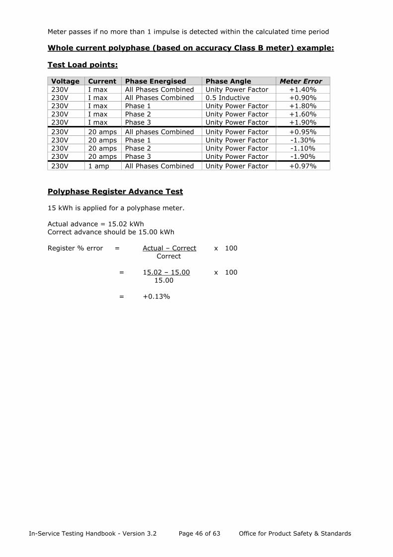
Meter passes if no more than 1 impulse is detected within the calculated time period
Whole current polyphase (based on accuracy Class B meter) example:
Test Load points:
Voltage Current Phase Energised Phase Angle Meter Error
230V I max All Phases Combined Unity Power Factor +1.40%
230V I max All Phases Combined 0.5 Inductive +0.90%
230V I max Phase 1 Unity Power Factor +1.80%
230V I max Phase 2 Unity Power Factor +1.60%
230V I max Phase 3 Unity Power Factor +1.90%
230V 20 amps All phases Combined Unity Power Factor +0.95%
230V 20 amps Phase 1 Unity Power Factor -1.30%
230V 20 amps Phase 2 Unity Power Factor -1.10%
230V 20 amps Phase 3 Unity Power Factor -1.90%
230V 1 amp All Phases Combined Unity Power Factor +0.97%
Polyphase Register Advance Test
15 kWh is applied for a polyphase meter.
Actual advance = 15.02 kWh
Correct advance should be 15.00 kWh
Register % error = Actual – Correct x 100
Correct
= 15.02 – 15.00 x 100
15.00
= +0.13%
In-Service Testing Handbook - Version 3.2 Page 47 of 63 Office for Product Safety & Standards
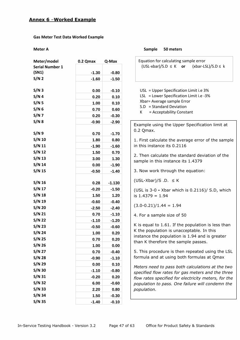
Annex 6 –Worked Example
Gas Meter Test Data Worked Example
Meter A Sample 50 meters
Meter/model 0.2 Qmax Q-Max Serial Number 1 (SN1) -1.30 -0.80 S/N 2 -1.60 -1.50
S/N 3 0.00 -0.10
S/N 4 0.20 0.10 S/N 5 1.00 0.10 S/N 6 0.70 0.60 S/N 7 0.20 -0.30 S/N 8 -0.90 -2.90
S/N 9 0.70 -1.70
S/N 10 1.80 0.80 S/N 11 -1.90 -1.60 S/N 12 1.50 0.70 S/N 13 3.00 1.30 S/N 14 0.00 -1.90 S/N 15 -0.50 -1.40
S/N 16 0.28 -1.130
S/N 17 -0.20 -1.50 S/N 18 1.50 1.20 S/N 19 -0.60 -0.40 S/N 20 -2.50 -2.40 S/N 21 0.70 -1.10 S/N 22 -1.10 -1.20 S/N 23 -0.50 -0.60 S/N 24 1.00 0.20 S/N 25 0.70 0.20 S/N 26 1.00 0.00 S/N 27 0.70 -0.40 S/N 28 -0.90 -1.10 S/N 29 0.00 0.10 S/N 30 -1.10 -0.80 S/N 31 -0.20 0.20 S/N 32 6.00 -0.60 S/N 33 2.20 0.80 S/N 34 1.50 -0.30 S/N 35 -1.40 -0.10
Equation for calculating sample error (USL-xbar)/S.D ≤ K or (xbar-LSL)/S.D ≤ k
USL = Upper Specification Limit i.e 3% LSL = Lower Specification Limit i.e -3% Xbar= Average sample Error S.D = Standard Deviation K = Acceptability Constant
Example using the Upper Specification limit at
0.2 Qmax.
1. First calculate the average error of the sample
in this instance its 0.2116
2. Then calculate the standard deviation of the
sample in this instance its 1.4379
3. Now work through the equation:
(USL-Xbar)/S .D. ≤ K
(USL is 3-0 - Xbar which is 0.2116)/ S.D, which
is 1.4379 = 1.94
(3.0-0.21)/1.44 = 1.94
4. For a sample size of 50
K is equal to 1.61. If the population is less than
K the population is unacceptable. In this
instance the population is 1.94 and is greater
than K therefore the sample passes.
5. This procedure is then repeated using the LSL
formula and at using both formulas at Qmax
Meters need to pass both calculations at the two
specified flow rates for gas meters and the three
flow rates specified for electricity meters, for the
population to pass. One failure will condemn the
population.
In-Service Testing Handbook - Version 3.2 Page 48 of 63 Office for Product Safety & Standards
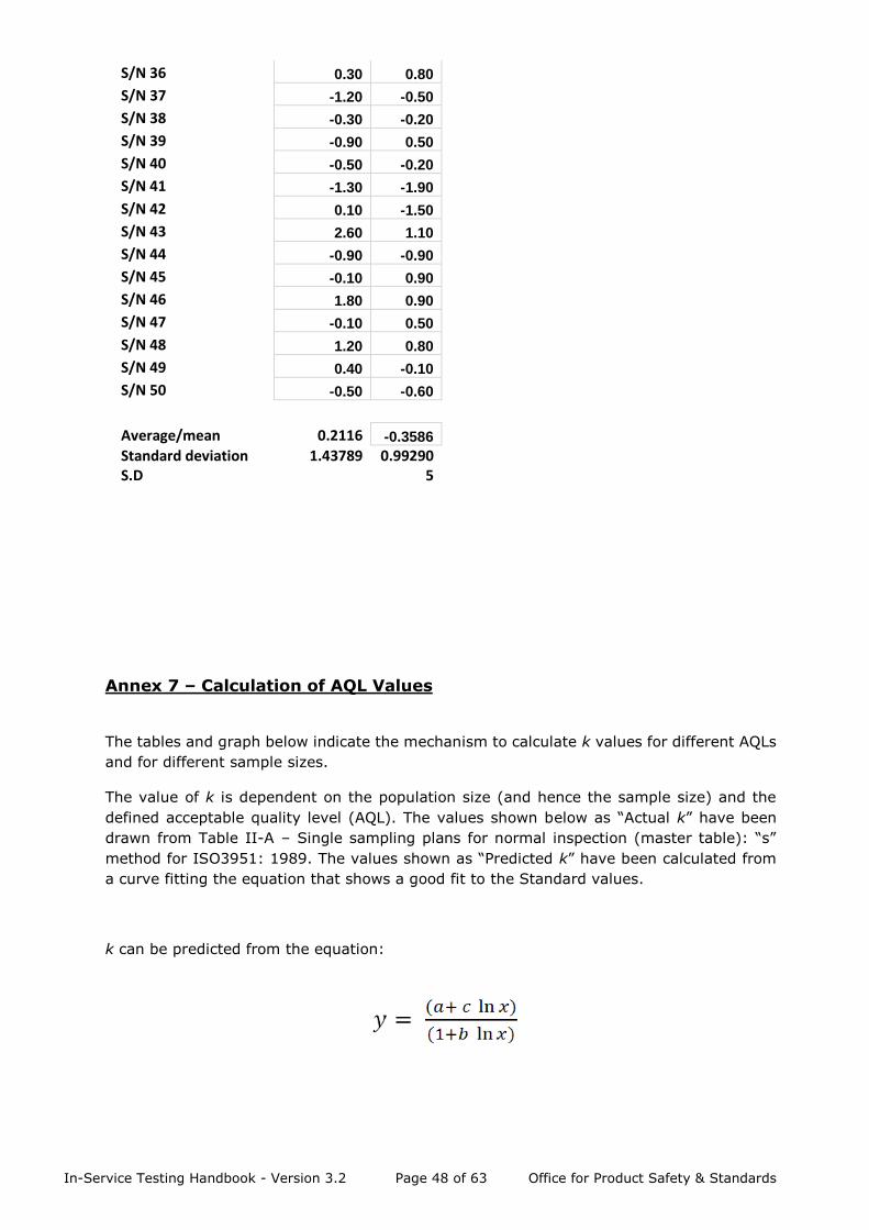
S/N 36 0.30 0.80 S/N 37 -1.20 -0.50 S/N 38 -0.30 -0.20 S/N 39 -0.90 0.50 S/N 40 -0.50 -0.20 S/N 41 -1.30 -1.90 S/N 42 0.10 -1.50 S/N 43 2.60 1.10 S/N 44 -0.90 -0.90 S/N 45 -0.10 0.90 S/N 46 1.80 0.90 S/N 47 -0.10 0.50 S/N 48 1.20 0.80 S/N 49 0.40 -0.10 S/N 50 -0.50 -0.60
Average/mean 0.2116 -0.3586 Standard deviation S.D
1.43789
0.992905
Annex 7 – Calculation of AQL Values
The tables and graph below indicate the mechanism to calculate k values for different AQLs
and for different sample sizes.
The value of k is dependent on the population size (and hence the sample size) and the
defined acceptable quality level (AQL). The values shown below as “Actual k” have been
drawn from Table II-A – Single sampling plans for normal inspection (master table): “s”
method for ISO3951: 1989. The values shown as “Predicted k” have been calculated from
a curve fitting the equation that shows a good fit to the Standard values.
k can be predicted from the equation:

In-Service Testing Handbook - Version 3.2 Page 49 of 63 Office for Product Safety & Standards
For:
SAMPLE SIZE = 50
a = 1.942
b = -0.082
c = -0.495
AQL Actual k Predicted k
0.10 2.60 2.59
0.15 2.50 2.49
0.25 2.35 2.36
0.40 2.22 2.23
0.65 2.08 2.08
1.00 1.93 1.94
1.50 1.80 1.80
2.00 N/A 1.70
2.50 1.61 1.61
3.00 N/A 1.54
4.00 1.42 1.42
5.00 N/A 1.32
6.00 N/A 1.24
6.50 1.21 1.20
7.00 N/A 1.16
8.00 N/A 1.10
9.00 N/A 1.04
10.00 1.00 0.99

In-Service Testing Handbook - Version 3.2 Page 50 of 63 Office for Product Safety & Standards
SAMPLE SIZE = 75
a = 1.988
b = -0.083
c = -0.506
AQL Actual k Predicted k
0.10 2.66 2.65
0.15 2.55 2.55
0.25 2.41 2.41
0.40 2.27 2.28
0.65 2.12 2.13
1.00 1.98 1.99
1.50 1.84 1.84
2.00 N/A 1.74
2.50 1.65 1.65
3.00 N/A 1.58
4.00 1.46 1.45
5.00 N/A 1.35
6.00 N/A 1.27
6.50 1.24 1.23
7.00 N/A 1.20
8.00 N/A 1.13
9.00 N/A 1.07
10.00 1.03 1.02
In-Service Testing Handbook - Version 3.2 Page 51 of 63 Office for Product Safety & Standards
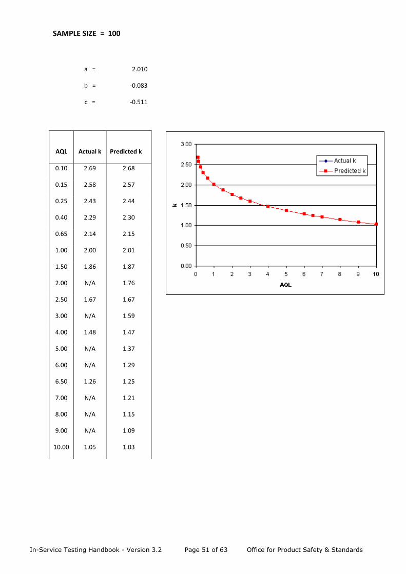
SAMPLE SIZE = 100
a = 2.010
b = -0.083
c = -0.511
AQL Actual k Predicted k
0.10 2.69 2.68
0.15 2.58 2.57
0.25 2.43 2.44
0.40 2.29 2.30
0.65 2.14 2.15
1.00 2.00 2.01
1.50 1.86 1.87
2.00 N/A 1.76
2.50 1.67 1.67
3.00 N/A 1.59
4.00 1.48 1.47
5.00 N/A 1.37
6.00 N/A 1.29
6.50 1.26 1.25
7.00 N/A 1.21
8.00 N/A 1.15
9.00 N/A 1.09
10.00 1.05 1.03

In-Service Testing Handbook - Version 3.2 Page 52 of 63 Office for Product Safety & Standards
SAMPLE SIZE = 150
a = 2.044
b = -0.085
c = -0.520
AQL Actual k Predicted k
0.10 2.73 2.71
0.15 2.61 2.61
0.25 2.47 2.47
0.40 2.33 2.34
0.65 2.18 2.19
1.00 2.03 2.04
1.50 1.89 1.90
2.00 N/A 1.79
2.50 1.70 1.70
3.00 N/A 1.62
4.00 1.51 1.50
5.00 N/A 1.40
6.00 N/A 1.31
6.50 1.29 1.27
7.00 N/A 1.24
8.00 N/A 1.17
9.00 N/A 1.11
10.00 1.07 1.05
In-Service Testing Handbook - Version 3.2 Page 53 of 63 Office for Product Safety & Standards
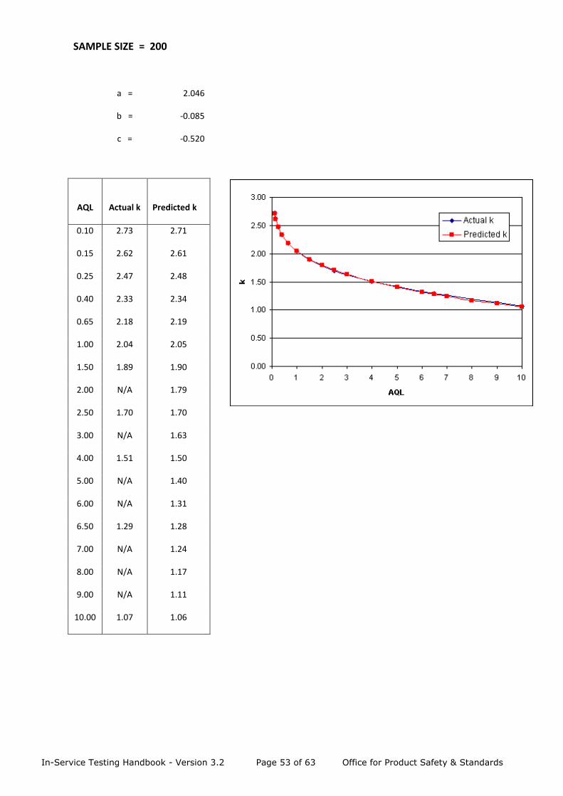
SAMPLE SIZE = 200
a = 2.046
b = -0.085
c = -0.520
AQL Actual k Predicted k
0.10 2.73 2.71
0.15 2.62 2.61
0.25 2.47 2.48
0.40 2.33 2.34
0.65 2.18 2.19
1.00 2.04 2.05
1.50 1.89 1.90
2.00 N/A 1.79
2.50 1.70 1.70
3.00 N/A 1.63
4.00 1.51 1.50
5.00 N/A 1.40
6.00 N/A 1.31
6.50 1.29 1.28
7.00 N/A 1.24
8.00 N/A 1.17
9.00 N/A 1.11
10.00 1.07 1.06

In-Service Testing Handbook - Version 3.2 Page 54 of 63 Office for Product Safety & Standards
Annex 8 – Treatment of Electricity Meter Super-Populations - Assessed Individually Tests on meters of the first year’s production Y of a super-population (as defined in 5.4)
dictate what happens to all meters in that super population, subject to the safeguards below.
If the tests in year Y+A1 are satisfactory (for explanation of A1 etc see section 6.0 and for
population acceptance criteria see section 8.3) then no further tests are carried out until
year Y+A2, when that year’s population is tested again. Meters produced in years Y+1, Y+2,
Y+3, etc are deemed to meet requirements until the next tests.
Annex 9.1 Safeguards
For assurance in this process it is important that:
• the super-population comprises meters having consistent metrological properties
(see section 5.4);
• the first year’s production is of sufficient volume to be representative of the yearly
populations to follow; and
• the sample size (as indicated in Table 2) is related to the total super population - not
the population of the year(s) tested.
With respect to the second point, a population below the threshold as indicated in Table 2
(i.e. less than 1,201) would not be considered satisfactory and testing should be deferred
until year Y+A1+1. Where the population exceeds 1,201 but is less than [30%] of the next
year’s population, testing may be done in year Y+A1. In both cases samples should be taken
from both years Y and Y + 1 to make up the sample size as dictated by the total super
population. Where the first year’s population is greater than [30%] of the next year’s
population, then samples may be drawn from year Y only.
[WHEN DEVELOPING THE IST METHODOLOGY THE INDUSTRY WAS UNABLE TO AGREE ON
THIS PERCENTAGE. BEIS PROPOSE TO REVISIT THIS WHEN ACTUAL TEST RESULTS ARE
AVAILABLE].
Annex 9.2 Removal of Defective Meters
If the tests in any year Y+Ax do not meet the acceptance criteria of an AQL of 2.5% but the
actual AQL is less than 10%, then the meters produced in year Y shall be removed within
2 years. Meters produced in year Y+1 shall be removed within 2 years from year Y+Ax+1,
meters of year Y+2 within 2 years of year Y+Ax +2, and so on.
If the results of the tests indicate an AQL of 10% or greater, then the entire super-population
shall be removed within 2 years of year Y+Ax
Note: In the event that this causes logistical problems additional testing may be carried out
on meters produced in other years which may confirm the need for such action or indicate
that additional time for removal could be justified.
In-Service Testing Handbook - Version 3.2 Page 55 of 63 Office for Product Safety & Standards
Annex 9 – Measuring Instruments Directive (MID)
The Measuring Instruments Directive (MID) is a European Directive (2004/22/EC), originally
adopted in March 2004 and recast in February 2014 (2014/32/EU), that covers a number of
different measuring instrument types including gas meters and active electrical energy
meters. The aim of the MID is to create a single market in measuring instruments for the
benefit of manufacturers and, ultimately, consumers across Europe:
https://ec.europa.eu/growth/single-market/european-standards/harmonised-
standards/measuring-instruments_en
In the UK, the MID for gas and electricity meters is implemented by The Measuring
Instruments Regulations (SI 2016/1153) available to download from
www.legislation.gov.uk.
The original MID implementing Regulations23 came fully into force on 30 October 2006, while
the Regulations listed above, to implement the recast MID, came fully into force on 28
December 2016. Since 30 October 2006, all new designs of gas and electricity meters that
are within the scope of the Directive must meet the requirements of the Regulations.
Note: Any meter approved under national legislation and placed on the market prior to 30
October 2016, after the 10 year transition period from implementing the MID into UK law,
may continue to be used indefinitely, as long as it meets the requirements of the
Regulations.
23 The Measuring Instruments (Gas Meters) Regulations (SI 2006/2647) and The Measuring Instruments (Active Electrical Energy Meters) (SI 2006/1679)

In-Service Testing Handbook - Version 3.2 Page 56 of 63 Office for Product Safety & Standards
Annex 10 – Nationally Approved Electricity Meter Testing for Extension to
Certification Period
Schedule 7 of the Electricity Act 1989 (as amended) requires suppliers to ensure their
meters are kept in proper order at all times and that all meters are certified unless used in
connection with an exempt supply24 where the supplier and consumer have agreed in writing
to dispense with the requirement. Where certification is required, it is an offence for an
authorised supplier to supply electricity through a meter which is not certified.
Certification is the process whereby it is confirmed meters conform to the relevant
standards, and meters can reasonably be expected to operate within the permitted margins
of error for not less than the certification period.
Meters approved under GB national legislation have a statutory certification life which is the
maximum number of years the meter may legally remain in service. Certification periods
are specified in Schedule 4 of The Meters (Certification) Regulations (SI 1998/1566), (as
amended) which is published on the BEIS website at:
https://www.gov.uk/government/publications/schedule-4-uk-nationally-approved-
electricity-meters
Certification periods are set by Meter Examiners appointed by BEIS and have historically
been controlled via the National Sample Survey (NSS) organised by the UKMF. Following
discussions with the UKMF it was agreed IST could be used as an alternative to the NSS to
control the certification periods of meters approved under national legislation.
Extensions to certification periods of up to 5 years per meter type will be considered for
meter populations that meet the criteria set in this handbook.
IST has been used by several suppliers to extend the certification periods of a number of
meter types in their portfolios. This enables suppliers to fulfil their legal obligations and
maximise asset life, while ensuring only meters operating within the statutory limits are
used for billing consumers.
Authorised suppliers wishing to apply for an extension to the certification period of a
particular meter type should first contact BEIS and confirm the Manufacturer, Meter Type,
Approval Number and current Certification period as listed under Schedule 4.
Sample Size and Criteria for Testing
Acceptable sample sizes must be provided according to Table 2 in Section 7. Certification
periods apply nationally and, as the national population is generally unknown, the minimum
sample size required is 200 meters.
Subject to agreement with BEIS, samples submitted for testing should comprise of meters
with the same type and following the previously adopted procedures that:
▪ Single and twin element variants need to be sampled separately
▪ Single and multi-rate variants need to be sampled separately for electro-mechanical
meters (or meters with mechanical registers)
▪ Single and multi-rate variants can be combined for electronic meters
24 An exempt supply, as defined in Schedule 7 of the Electricity Act 1989, is a supply of
electricity to any premises not used wholly or mainly for domestic purposes.
In-Service Testing Handbook - Version 3.2 Page 57 of 63 Office for Product Safety & Standards
Sample testing normally takes place at 5 year intervals and BEIS will not normally consider
further testing within this period.
Samples submitted for testing must be predominantly from the particular year being
considered although BEIS will accept meters from two years either side of this (e.g. meters
from 2000,01,02,03 and 04 with the majority of meters from 2002).
For meters certified before 1990 samples are required from at least three MPAN’s/locations.
This is because pre-1990 meters were certified at the meter test stations to the limits that
were in force at that time (i.e. +2.5% to –3.5%). In contrast post-1990 meters were
generally certified at one location (i.e. the manufacturers premises) in accordance with an
approved sampling plan to +/– 1.9%.
For this reason, populations of pre-1990 meters are not considered to be homogenous and,
as with the NSS, only in extreme circumstances and with the written agreement of BEIS,
can samples be selected from one or two locations.
Samples may be drawn from “off supply” meters although BEIS recognise this may not be
possible and samples may have to be taken “off the wall”.
Suppliers should ensure meters submitted for testing are representative of the installed
population and do not have faulty displays, missing security seals or damaged cases, etc.
Disputed meters or those showing evidence of tamper are also not suitable for sampling
(see Annex 3).
Testing must take place at one or more of the official BEIS approved IST test stations, as
listed in Annex 2.
Analysis of Test Results
Suppliers must provide BEIS with the test results for evaluation in accordance with Section
7. BEIS will analyse the performance of each population type in accordance with the
procedure detailed in Section 8.
BEIS will consider extending the certification period by a maximum of five years for meter
types that achieve an Acceptable Quality Level of 2.5% (or better) at all test loads.
The certification period will not be extended for meter types that do not achieve an
Acceptable Quality Level of 2.5% at all test loads.
BEIS reserve the right to reduce the certification period for any meter types where the
Acceptable Quality Level is 10% (or worse) at any test load or where there are other
concerns about the conformity of the meters.
Certification is a legal requirement and, where the test results do not justify the extension
to the certification period of a particular meter type (or the certification period is reduced)
these meters must be removed as soon as possible in accordance with Section 9. See also
the comment in section 8.3 with regards to meters approved under GB national legislation.
Assessment Failures
Where the IST process is used for testing nationally approved meters, BEIS will listen to any
appeals on an individual basis and will consider evidence that may be produced by meter
manufacturers, asset owners, suppliers, etc. Further sampling may be permitted should a
supplier or asset owner feel the test results are not indicative of their meter population as
a whole or should they be able to provide reasonable grounds as to why re-testing may be
warranted, but this would only be undertaken as a last resort where no historical sampling
records exist and overwhelming evidence points to further sampling being necessary in
assessing the population correctly.
In-Service Testing Handbook - Version 3.2 Page 58 of 63 Office for Product Safety & Standards
Annex 11 – Reference Documents
The following documents have been used in the preparation of this guide:
A) The Measuring Instruments Directive (MID) 2014/32/EU
B) The Measuring Instruments Regulations, 2016 — SI 2016/1153
C) AS/NZS 1284.13:2002 — Electricity metering - In-service compliance testing
D) BS 6002-1:1993 ISO 3951:1989 — Sampling Procedures for Inspection by Variables25
E) BS EN 50470-3:2006 — Electricity metering equipment (a.c.) - Part 3: Particular
requirements — Static meters for active energy (class indexes A, B and C)
F) BS EN 14236:2007 — Ultrasonic domestic gas meters
G) BS 4161-3:1989 — Part 3: Specifications for Diaphragm Meters of 6 Cubic Metres (or
212 Cubic Feet) Per Hour Rating for Working Pressures up To 50 mbar26
H) The Gas (Meters) Regulations, 1983 — SI 1983/684
I) The Gas Act, 1986
J) The Electricity Act, 1989
K) The Meters (Certification) Regulations, 1998 — SI 1998/1566
L) IGEM UP/1B Edition 3, Communication 1759 — Tightness testing and direct purging of
small Liquefied Petroleum Gas/Air, Natural Gas and Liquefied Petroleum Gas
installations
M) WELMEC 4.2 — Issue 1, June 2006: Elements for deciding the appropriate level of
confidence in regulated measurements (Accuracy classes, MPE in-service, non-
conformity, principles of uncertainty) –
http://www.welmec.org/fileadmin/user_files/publications/4-2.pdf
N) Committee Draft (CD 2) for a Document of OIML drawn up within TC 3/SC 4 December
2005 Surveillance of utility meters in service on the basis of sampling inspections -
http://www.oiml.org/en/technical-work/committee-drafts/files/tc3-sc4-2cd.pdf
O) Industry Metering Advisory Group In-service Testing Report (IST 1/2 report) -
https://www.gov.uk/government/publications/in-service-testing-group-1-and-2-report
P) In-service Testing Governance Arrangements (IST 3 report) -
https://www.gov.uk/government/publications/in-service-testing-group-3-report
25 This document has since been superseded by “BS ISO 3951-1:2013 – Sampling
procedures for inspection by variables. Specification for single sampling plans indexed by
acceptance quality limit (AQL) for lot-by-lot inspection for a single quality characteristic and
a single AQL”
26 This document has since been superseded by “BS EN 1359:1999 – Diaphragm gas
meters”.
In-Service Testing Handbook - Version 3.2 Page 59 of 63 Office for Product Safety & Standards
Annex 12 – General Definitions
Acceptability constant (k)
The value of k is dependent on the population size (and hence the sample size) and the
defined acceptable quality level (AQL).
AQL
Acceptable Quality Level/Acceptance Quality Limit. A measure of the quality routinely
accepted. AQL is defined as the percent defective that the sampling plan will accept 95% of
the time – i.e. lots at, or better than, the AQL will be accepted at least 95% of the time and
rejected at most 5% of the time.
BEIS
The Department for Business, Energy and Industrial Strategy.
Discarded meter
A meter deemed by initial inspection to be unfit for inclusion in the sampling process and
which may be replaced with an acceptable meter.
Defective meter
A meter which fails to comply with the pass criteria.
Domestic type gas meter
For the purposes of this document a meter with a maximum flow rate (Qmax) not exceeding
6 m3/h.
Electricity meter
For the purposes of this document a single phase meter (4 terminal, 5 terminal and Twin
Element) or whole current polyphase meter.
Excluded meter
A meter that is deemed to be ‘abnormally’ defective and which is excluded from any
statistical data but whose reason for exclusion is recorded.
Governance board
A group of industry representatives chaired by BEIS and established to ensure that any
changes to processes and procedures for the maintenance of in-service accuracy and
suitability of electricity and gas meters are implemented.
Grubb’s test
A method for identifying data outliers
Imax
The maximum rated current of an electricity meter
LSL
Lower specification limits i.e. the maximum permissible negative error for the class of meter.
MAP – Meter Asset Provider.
The party responsible for the ongoing provision of the meter installation at that meter point.
This could be the Meter Title Owner of the Meter, or a third party with whom the MAM
contracts for the provision of a meter. For Gas meters where the Title Owner is not directly
involved in the Gas Act Ownership of the Meter, the Meter Asset Provider needs to be
identified so that the incoming MAM can make appropriate contractual arrangements for the
ongoing provision of the metering equipment in-situ at the Meter Point.
MAM – Meter Asset Manager (Gas)
A party approved by SPAA as conforming to the Meter Asset Manager’s Code of Practice
(MAMCoP).

In-Service Testing Handbook - Version 3.2 Page 60 of 63 Office for Product Safety & Standards
Manufacturer
A person responsible for the conformity of a relevant instrument with the essential
requirements with a view to either placing it on the market under his own name or putting
it into use for his own purposes, or both.
Meter Worker
Actual person or organisation that will do physical work on the Assets at a Meter Point. If
they are not registered as an Ofgem Approved Meter Inspector (OAMI) or on the Gas Safe
Register then the Supplier will have to arrange an inspection by an OAMI to check that the
installation registers accurately.
MID
The European Measuring Instrument Directive 2014/32/EU and the legislation implementing
it in the UK – The Measuring Instruments Regulations (SI 2016/1153). Previously Directive
2004/22/EC and The Measuring Instruments (Gas Meters) Regulations (SI 2006/2647) and
The Measuring Instruments (Active Electrical Energy Meters) Regulations (SI 2016/1679).
MO - Meter Operator (Electricity)
A party qualified by Elexon under the Balancing and Settlement Code (BSC) as a Meter
Operator Agent.
MO - Meter Operator (Gas)
Term used to group the MAM, Meter Worker and possibly also Legal Title (Meter) Owner.
MPE
Maximum Permissible Error.
Off Supply (formerly known as “Churn”)
Meters which have been removed from premises as part of routine operations e.g. changing
the customer from credit to prepayment, removal before the demolition of a property,
removal because the supply is no longer required, etc.
The Office for Product Safety & Standards
The Office for Product Safety & Standards was set up in January 2018 in the Department
for Business, Energy and Industrial Strategy, to enhance protections for consumers and the
environment and to drive increased productivity, growth and business confidence.
Title (Meter) Owner
This is also referred to as Legal Title Owner. The person or organisation to which the asset
belongs, and who makes such assets available for the purpose of the Gas Act Owner.
Inspection lot
Quantity of items (measuring instruments, parts of measuring instruments) submitted for
testing or inspection.
Inspection lot size (N)
Number of items in the inspection lot.
Qmax
The maximum rated flow rate of a gas meter
Sample
Number of items taken from an inspection lot for inspection.
Sample average error ( x )
Average error of a sample i.e. the sum of the errors divided by the sample size (n).

In-Service Testing Handbook - Version 3.2 Page 61 of 63 Office for Product Safety & Standards
Sample size (n)
The number of items in the sample.
Sample standard deviation (s)
Standard deviation of the sample i.e. a measure of the spread of the test results about the
average error.
Sampling inspection
Inspection based on a sampling instruction in the case of which the inspection lot is assessed
in accordance with the result obtained for a single sample or, if necessary, for various
samples.
Single Phase 4 Terminal Meter
A single phase meter with one metrology element.
Single Phase 5 Terminal Meter
A single phase meter with one metrology element and an additional (integral) contactor.
Single Phase Twin Element Meter
A single phase meter with two metrology elements and an additional (integral) contactor.
SPAA
The Supply Point Administration Agreement sets out the inter-operational arrangements
between gas suppliers and transporters in the UK retail market. It is a multi-party
agreement to which all domestic gas suppliers and all gas transporters are required by their
Licences to accede.
Polyphase Meter (also known as Multi phase or Three Phase meters)
A meter with three, single phase measuring elements combined to provide a single
metrological output.
USL
Upper specification limits i.e. the maximum permissible positive error for the class of meter.
Year of manufacture
The MID requires that a meter be marked with the 'CE' mark, followed by the 'M' mark, then
"the last two digits of the year of its affixing surrounded by a rectangle" – equivalent to the
year of manufacture for these purposes.
In-Service Testing Handbook - Version 3.2 Page 62 of 63 Office for Product Safety & Standards
Annex 13 – IST4 Membership
To date, the following suppliers are members of IST4:
British Gas
EDF Energy
E.ON
Npower
Scottish Power
SSE
It must be noted that ALL suppliers, regardless of size, have the legal responsibility to
maintain their meters in proper order for correctly registering the quantity of electricity/gas
supplied. IST is a method all suppliers can use to demonstrate they are conforming to the
legal requirements.
The following MAM’s/MAP’s/MOP’s and other stakeholders have contributed to the
development of the IST process and/or are active members of the IST4 implementation
group:
AMO (Association of Meter Operators)
BEAMA
Calvin Capital
CL Refurbishments Limited
DNV-GL
Energetics
Energy Assets
Engage Consulting
Elster Metering Ltd
EM-Lite
EUA (Energy and Utilities Alliance)
GTC
George Wilson Industries Limited
Inexus
Itron
Landis + Gyr UK Ltd
Macquarie Energy Leasing
National Grid Metering
Remote Energy Management
Siemens
SGN
SGS UK Ltd
UKMF (UK Metering Forum)
As mentioned in the introduction, MAM’s as part of their obligation in the MAMCoP can use
IST to verify the meter accuracy of those meters in their portfolio. The MAMCoP applies to
Independent Gas Transporters (IGTs) undertaking meter asset management services, or
MAMs who work on behalf of a gas supplier, Gas Transporter (GT) or a gas consumer, to
manage primary meter installations connected to the Network as defined by the Gas Safety
(Management) Regulations (GS(M)R) in Great Britain.
All interested and relevant parties are welcome to contact BEIS regarding IST and to attend
meetings where appropriate. For more information email:
Or
In-Service Testing Handbook - Version 3.2 Page 63 of 63 Office for Product Safety & Standards
Stanton Avenue
Teddington
Middlesex TW11 0JZ
United Kingdom
Tel: +44(0)20 8943 7272
Fax: +44(0)20 8943 7270
Website: https://www.gov.uk/guidance/in-service-testing-for-gas-and-electricity-meters
Version 3.2 March 2018
The Office of Product Safety & Standards is an Office within The Department for Business, Energy
and Industrial Strategy
Related Documents