User Manual Software InPower™ Pro English 10-2012 901-0110 (Issue 10) Original Instructions

In Power Pro 9.5 User Guide
Oct 26, 2015
In Power Pro 9.5 User Guide
Welcome message from author
This document is posted to help you gain knowledge. Please leave a comment to let me know what you think about it! Share it to your friends and learn new things together.
Transcript

User Manual
Software
InPower™ Pro
English10-2012 901-0110 (Issue 10)Original Instructions


Table of Contents
1. INPOWER™ SOFTWARE LICENSE AGREEMENT..................................................................... 1
2. INTRODUCTION............................................................................................................................ 52.1 Warning................................................................................................................................... 52.2 InPower................................................................................................................................... 5
2.2.1 Commercial Products................................................................................................... 52.2.2 Consumer Products ..................................................................................................... 62.2.3 Null Modem Cable Configuration ................................................................................. 8
2.3 About This User's Guide......................................................................................................... 82.4 Supported Devices.................................................................................................................. 82.5 System Requirements........................................................................................................... 10
2.5.1 Recommended PC..................................................................................................... 102.5.2 Administrative Rights ................................................................................................. 11
2.6 Program Directories Installed with InPower.......................................................................... 112.6.1 Monitor ....................................................................................................................... 142.6.2 Strip Chart .................................................................................................................. 142.6.3 Data............................................................................................................................ 152.6.4 Captured Files............................................................................................................ 152.6.5 Simulator .................................................................................................................... 15
2.7 Calibration Directories Installed with InPower ...................................................................... 152.8 Service File and Logical DFA Directories Installed with InPower......................................... 172.9 Start Menu Group Shortcuts ................................................................................................. 17
2.9.1 Readme File............................................................................................................... 172.10 User Interface ..................................................................................................................... 172.11 How to Get Service............................................................................................................. 182.12 Notification of Tool Expiration ............................................................................................. 18
3. SETUP ......................................................................................................................................... 193.1 General Setup....................................................................................................................... 193.2 Unit of Measurement............................................................................................................. 193.3 User Setup - System Administration..................................................................................... 203.4 Capture File Options............................................................................................................. 203.5 Site Setup ............................................................................................................................. 213.6 Create Site ............................................................................................................................ 233.7 Device Setup......................................................................................................................... 253.8 Communications Setup......................................................................................................... 263.9 PCC 1300 and PCC 1301 InPower Setup............................................................................ 273.10 PCC 1302 InPower Setup................................................................................................... 283.11 PCC 2300 and PCC 3300 InPower OEM Setup................................................................. 303.12 PCC 3100 InPower Setup................................................................................................... 303.13 PCC 3200 w/CAN (PCC 3201) InPower Setup .................................................................. 313.14 MCM 3320 InPower Setup.................................................................................................. 32
901-0110 (Issue 10) i
Table of Contents 10-2012
3.15 Monnet InPower Setup ....................................................................................................... 343.16 HMI InPower Setup............................................................................................................. 353.17 Core II ECS Device Setup .................................................................................................. 37
4. INPOWER BASICS...................................................................................................................... 394.1 How to Start InPower............................................................................................................ 394.2 The Main Window ................................................................................................................. 40
4.2.1 Main Window Example .............................................................................................. 414.3 Menu Descriptions ................................................................................................................ 41
4.3.1 Port............................................................................................................................. 424.3.2 Device ........................................................................................................................ 424.3.3 Edit ............................................................................................................................. 434.3.4 Utilities........................................................................................................................ 434.3.5 View ........................................................................................................................... 434.3.6 Help............................................................................................................................ 43
4.4 User Interface ....................................................................................................................... 434.4.1 Keyboard Access ....................................................................................................... 434.4.2 Toolbar ....................................................................................................................... 434.4.3 Dialog Boxes.............................................................................................................. 444.4.4 Mouse Menu Functions.............................................................................................. 44
4.5 How to Terminate InPower ................................................................................................... 45
5. GENSET SERVICE...................................................................................................................... 475.1 Commercial Genset Service ................................................................................................. 47
5.1.1 Connecting to a Genset ............................................................................................. 475.2 Consumer Genset Service.................................................................................................... 58
5.2.1 Connecting to a Genset ............................................................................................. 595.2.2 Connecting to an HQD Inverter/Charger, Transfer Switch, or Display and an RV
Inverter and GSAA ...................................................................................................... 625.2.3 Connecting to Marine Devices ................................................................................... 64
5.3 Starting InPower ................................................................................................................... 675.4 Genset Adjustments.............................................................................................................. 70
5.4.1 Adjustment Basics...................................................................................................... 705.4.2 Adjustment Features.................................................................................................. 715.4.3 Making Adjustments................................................................................................... 735.4.4 Saving Adjustments ................................................................................................... 73
5.5 Adjustment Examples ........................................................................................................... 745.6 Test ....................................................................................................................................... 82
5.6.1 Commercial Gensets.................................................................................................. 825.6.2 Consumer Gensets .................................................................................................... 835.6.3 Override Requests ..................................................................................................... 845.6.4 Override Commands.................................................................................................. 845.6.5 Override Status .......................................................................................................... 845.6.6 Set High Idle .............................................................................................................. 845.6.7 Inputs ......................................................................................................................... 855.6.8 Manual Operation....................................................................................................... 865.6.9 Outputs....................................................................................................................... 86
ii 901-0110 (Issue 10)
10-2012 Table of Contents
5.6.10 Fault Simulation ....................................................................................................... 875.6.11 Self Test ................................................................................................................... 885.6.12 Speed Override........................................................................................................ 895.6.13 Single Cylinder Cutout Test ..................................................................................... 89
6. ATS SERVICE.............................................................................................................................. 916.1 ATS Service .......................................................................................................................... 91
6.1.1 Connecting to An ATS with the Original Digital Display ............................................ 916.1.2 Starting InPower......................................................................................................... 92
6.2 ATS Adjustments .................................................................................................................. 936.2.1 Adjustment Basics...................................................................................................... 936.2.2 Adjustment Features.................................................................................................. 94
6.3 Service Replacement Controls ............................................................................................. 956.3.1 Making Adjustments................................................................................................... 976.3.2 Saving Adjustments ................................................................................................... 98
6.4 Adjustment Examples ........................................................................................................... 986.4.1 Controller Mode.......................................................................................................... 986.4.2 List of Parameters Requiring the Refresh Controller Feature ................................. 1006.4.3 Exerciser Clock ........................................................................................................ 1026.4.4 Exception Table ....................................................................................................... 1026.4.5 Time Delays ............................................................................................................. 1036.4.6 Voltage Adjustment - For Display ............................................................................ 1046.4.7 Feature Enable......................................................................................................... 1066.4.8 PTC Settings............................................................................................................ 107
6.5 Test ..................................................................................................................................... 1086.5.1 Test - Remote Features ........................................................................................... 1086.5.2 Test - Setup Features .............................................................................................. 1096.5.3 Test - S1 Protection (PTC Test) .............................................................................. 110
7. MASTER CONTROL MODULE SERVICE ................................................................................ 1137.1 Connecting an MCM3320 ................................................................................................... 1137.2 Configuring the MCM3320.................................................................................................. 114
8. G-DRIVE SERVICE.................................................................................................................... 1158.1 G-Drive Service................................................................................................................... 115
8.1.1 Connecting to an ECM............................................................................................. 1158.1.2 Starting InPower....................................................................................................... 115
8.2 ECM Adjustments ............................................................................................................... 1168.2.1 Adjustment Basics.................................................................................................... 1168.2.2 Adjustment Features................................................................................................ 1178.2.3 Making Adjustments................................................................................................. 1198.2.4 Saving Adjustments ................................................................................................. 120
8.3 Adjustment Examples ......................................................................................................... 1208.4 Test ..................................................................................................................................... 127
8.4.1 Inputs - Oil Pressure ................................................................................................ 1288.4.2 Inputs - Switches...................................................................................................... 1298.4.3 Fault Simulation ....................................................................................................... 130
901-0110 (Issue 10) iii
Table of Contents 10-2012
8.4.4 Self Test ................................................................................................................... 1318.4.5 Speed Override........................................................................................................ 1328.4.6 Fuel Rack Position Test ........................................................................................... 1328.4.7 Single Cylinder Cutout Test ..................................................................................... 133
9. INITIAL CALIBRATION FOR COMMERCIAL GENSETS.......................................................... 1359.1 About Initial Calibration....................................................................................................... 1359.2 Initial Calibration ................................................................................................................. 135
9.2.1 Selecting Calibration Part Number........................................................................... 1389.2.2 History ...................................................................................................................... 1389.2.3 Save and Restore Parameters................................................................................. 1399.2.4 Use Capture File Feature......................................................................................... 1409.2.5 Feature List .............................................................................................................. 1419.2.6 Calibration Download............................................................................................... 1439.2.7 Correcting a Corrupted Calibration of a Control ...................................................... 1439.2.8 Correcting a Corrupted Calibration of a AMMPS or BEAR Control ......................... 1449.2.9 Correcting a Corrupted Calibration of an HMI ......................................................... 145
9.3 Writing Adjustments From a Capture File........................................................................... 1469.4 Final Adjustments ............................................................................................................... 146
10. UPDATE CALIBRATION FOR COMMERCIAL GENSETS...................................................... 14710.1 About Update Calibration.................................................................................................. 14710.2 Update Calibration ............................................................................................................ 147
10.2.1 History .................................................................................................................... 148
11. PCC OPERATOR PANEL UPDATES ...................................................................................... 15111.1 About Genset Operator Panel Updates ............................................................................ 15111.2 Operator Panel Update..................................................................................................... 151
11.2.1 Selecting Calibration Part Number......................................................................... 15211.2.2 History .................................................................................................................... 15211.2.3 During Download.................................................................................................... 153
11.3 Final Check ....................................................................................................................... 153
12. INITIAL CALIBRATION FOR CONSUMER PRODUCTS......................................................... 15512.1 About Initial Calibration..................................................................................................... 15512.2 Initial Calibration ............................................................................................................... 155
12.2.1 Selecting Calibration Part Number......................................................................... 15812.2.2 History .................................................................................................................... 15812.2.3 Save and Restore Parameters............................................................................... 15912.2.4 Use Capture File Feature....................................................................................... 15912.2.5 Calibration Download............................................................................................. 162
12.3 Writing Adjustments From a Capture File......................................................................... 16212.4 Final Adjustments ............................................................................................................. 162
13. UPDATE CALIBRATION FOR CONSUMER PRODUCTS ...................................................... 16313.1 About Update Calibration.................................................................................................. 16313.2 Update Calibration ............................................................................................................ 163
13.2.1 History .................................................................................................................... 164
iv 901-0110 (Issue 10)

10-2012 Table of Contents
14. INITIAL CALIBRATION FOR ATS............................................................................................ 16714.1 About Initial Calibration..................................................................................................... 16714.2 Initial Calibration ............................................................................................................... 167
14.2.1 Selecting Calibration Part Number......................................................................... 16814.2.2 History .................................................................................................................... 16814.2.3 Feature List ............................................................................................................ 17014.2.4 Calibration Download............................................................................................. 173
14.3 Writing Adjustments From a Capture File......................................................................... 17414.4 Final Adjustments ............................................................................................................. 174
15. UPDATE CALIBRATION FOR ATS ......................................................................................... 17515.1 About Update Calibration.................................................................................................. 17515.2 Update Calibration ............................................................................................................ 175
15.2.1 History .................................................................................................................... 176
16. INITIAL CALIBRATION FOR G-DRIVE.................................................................................... 17916.1 About Initial Calibration..................................................................................................... 17916.2 Initial Calibration ............................................................................................................... 179
16.2.1 Selecting Calibration Part Number......................................................................... 18116.2.2 History .................................................................................................................... 18216.2.3 Save and Restore Parameters............................................................................... 18316.2.4 Use Capture File Feature....................................................................................... 18316.2.5 Feature List ............................................................................................................ 18516.2.6 Calibration Download............................................................................................. 186
16.3 Writing Adjustments From a Capture File......................................................................... 18616.4 Final Adjustments ............................................................................................................. 186
17. UPDATE CALIBRATION FOR G-DRIVE ................................................................................. 18717.1 About Update Calibration.................................................................................................. 18717.2 Update Calibration Setup.................................................................................................. 187
17.2.1 Connecting to the Device....................................................................................... 18717.3 Update Calibration ............................................................................................................ 188
17.3.1 History .................................................................................................................... 188
18. CORE II ECM ENGINE PROTECTION WITNESS TEST PROCEDURE ................................ 19118.1 Adding a Core II ECS Site from InPower.......................................................................... 191
18.1.1 Adding a Site Using the Port Menu........................................................................ 19118.1.2 Adding a Site Using the Setup Menu..................................................................... 193
18.2 How to Start an Engine Protection Witness Test.............................................................. 195
19. UPDATE FEATURES ............................................................................................................... 20119.1 About Update Features..................................................................................................... 20119.2 Update Features Setup..................................................................................................... 20119.3 Update Features ............................................................................................................... 20119.4 Changing a Feature Setting.............................................................................................. 203
19.4.1 Feature Change Example: ..................................................................................... 20419.5 Enabling a Feature............................................................................................................ 204
901-0110 (Issue 10) v
Table of Contents 10-2012
20. MONITOR................................................................................................................................. 20720.1 Monitor and Datalog.......................................................................................................... 20720.2 Monitor Dialog................................................................................................................... 207
20.2.1 Monitor Dialog Features......................................................................................... 20720.2.2 Adding Parameters ................................................................................................ 209
21. FAULTS AND THE FAULT INFORMATION SYSTEM............................................................. 21121.1 Commercial Device Fault Information............................................................................... 211
21.1.1 Fault Information Window ...................................................................................... 21121.1.2 Clearing Inactive Faults ......................................................................................... 21221.1.3 Snapshot ................................................................................................................ 21221.1.4 Fault Information System ....................................................................................... 212
21.2 Consumer Device Fault Information ................................................................................. 22321.2.1 Fault Information .................................................................................................... 22321.2.2 Advanced Fault Information ................................................................................... 22321.2.3 Fault History........................................................................................................... 22321.2.4 Fault Occurrences.................................................................................................. 22421.2.5 Fault Bypass Info ................................................................................................... 22521.2.6 Clearing Inactive Faults ......................................................................................... 22621.2.7 Consumer Device Fault Information ...................................................................... 226
21.3 ATS Faults ........................................................................................................................ 22621.3.1 Clear Faults............................................................................................................ 22721.3.2 Event History Log................................................................................................... 22721.3.3 Event Records........................................................................................................ 228
21.4 Description of Operator/Interface Modes.......................................................................... 229
22. EVENT HANDLER.................................................................................................................... 23322.1 Receiving Events .............................................................................................................. 233
22.1.1 Devices That Cannot Receive Events ................................................................... 23322.2 Displaying Events ............................................................................................................. 233
22.2.1 Alarms Popup......................................................................................................... 23322.2.2 Event Detail............................................................................................................ 234
23. STRIP CHART.......................................................................................................................... 23723.1 Strip Chart......................................................................................................................... 237
23.1.1 Example of a Strip Chart........................................................................................ 23723.1.2 Starting the Strip Chart Feature............................................................................. 237
23.2 Creating a Custom Strip Chart.......................................................................................... 23823.2.1 Adding Parameters ................................................................................................ 23823.2.2 Parameter Properties Dialog.................................................................................. 23923.2.3 Sampling Rate Dialog ............................................................................................ 23923.2.4 Strip Chart Menu Bar Functions ............................................................................ 24023.2.5 Context Menu Features ......................................................................................... 24123.2.6 Chart Customization Dialog ................................................................................... 24223.2.7 Printing a Strip Chart.............................................................................................. 24323.2.8 Viewing Logged Data............................................................................................. 243
vi 901-0110 (Issue 10)
10-2012 Table of Contents
24. CAPTURE FILE........................................................................................................................ 24524.1 PCC 1100 Limitation......................................................................................................... 24524.2 Capture File ...................................................................................................................... 24524.3 Creating a Capture File..................................................................................................... 245
24.3.1 Creating a Capture File Automatically ................................................................... 24524.4 Viewing a Capture File...................................................................................................... 24524.5 Writing to a Device............................................................................................................ 245
25. SIMULATOR............................................................................................................................. 247
26. REPORTS ................................................................................................................................ 24926.1 Creating a Report.............................................................................................................. 24926.2 Support Reports................................................................................................................ 250
27. EVENT CONFIGURATION....................................................................................................... 25527.1 Devices That Do Not Support Event Configuration .......................................................... 25527.2 Fault Effect........................................................................................................................ 25527.3 Event Configuration in the PowerCommand 2.x and 3.x.................................................. 25627.4 Notification ........................................................................................................................ 257
28. REMOTE COMMUNICATION .................................................................................................. 25928.1 Remote Connections ........................................................................................................ 25928.2 Remote Site Setup............................................................................................................ 260
28.2.1 Site Setup............................................................................................................... 26028.2.2 Create Site ............................................................................................................. 26028.2.3 Device Setup.......................................................................................................... 26128.2.4 Communications Setup.......................................................................................... 262
28.3 Remote Connection with InPower .................................................................................... 26328.4 Dialout Configuration ........................................................................................................ 26428.5 Modems ............................................................................................................................ 265
28.5.1 Modem Configuration Strings ................................................................................ 26628.6 Remote Monitoring............................................................................................................ 266
29. NETWORK APPLICATIONS .................................................................................................... 26729.1 Network Configuration ...................................................................................................... 26729.2 PCC 2100 ......................................................................................................................... 267
29.2.1 Custom Annunciation............................................................................................. 26729.2.2 Custom Relay Events ............................................................................................ 26829.2.3 Device .................................................................................................................... 26929.2.4 Dialout .................................................................................................................... 27029.2.5 Fault Settings ......................................................................................................... 27129.2.6 PCC 2100 Events and Faults Configuration .......................................................... 272
29.3 PCC 3200 ......................................................................................................................... 27329.3.1 Custom Annunciation............................................................................................. 27429.3.2 Custom Outputs ..................................................................................................... 27529.3.3 Device .................................................................................................................... 27629.3.4 Dialout .................................................................................................................... 27729.3.5 Fault Settings ......................................................................................................... 278
901-0110 (Issue 10) vii

Table of Contents 10-2012
29.3.6 PCC 3200 Events Configuration ............................................................................ 27929.4 PCC ATS .......................................................................................................................... 280
29.4.1 PCC ATS Event Configuration............................................................................... 28229.5 Network Connection Setup ............................................................................................... 282
29.5.1 Gateway Settings................................................................................................... 28329.5.2 Alarm Settings........................................................................................................ 28629.5.3 Importing the Network Site Database .................................................................... 28629.5.4 Local Network Site Setup....................................................................................... 28729.5.5 Site Setup............................................................................................................... 28729.5.6 Create Site ............................................................................................................. 28729.5.7 Remote Network Site Setup................................................................................... 28829.5.8 Site Setup............................................................................................................... 28829.5.9 Create Site ............................................................................................................. 28829.5.10 InPower Communications Setup.......................................................................... 289
29.6 Network Connection Example........................................................................................... 29029.6.1 Setup Dialout.......................................................................................................... 292
30. HELP ........................................................................................................................................ 29730.1 Search for Help On... ........................................................................................................ 29730.2 Contents............................................................................................................................ 29730.3 How to Use Help............................................................................................................... 29730.4 Service and Support ......................................................................................................... 29730.5 About Device Explorer ...................................................................................................... 297
31. GLOSSARY .............................................................................................................................. 299
32. ADJUSTMENT AND TEST DESCRIPTIONS........................................................................... 30132.1 Engine Protection Adjustments......................................................................................... 301
32.1.1 Feature Description................................................................................................ 30132.1.2 Adjustable Parameters........................................................................................... 30132.1.3 Interaction with other Features and Parameters.................................................... 30432.1.4 Special Instructions................................................................................................ 30432.1.5 Possible Customer Complaints.............................................................................. 30432.1.6 Visual Aids ............................................................................................................. 305
32.2 Adjustments – Features - Centinel ................................................................................... 30532.2.1 Feature Description................................................................................................ 30532.2.2 Adjustable Parameters........................................................................................... 30532.2.3 Interaction with other Features and Parameters.................................................... 30532.2.4 Special Instructions................................................................................................ 30532.2.5 Possible Customer Complaints.............................................................................. 30532.2.6 Visual Aids ............................................................................................................. 30532.2.7 Product Coverage .................................................................................................. 305
32.3 Adjustments – Features - CORS ...................................................................................... 30632.3.1 Feature Description................................................................................................ 30632.3.2 Adjustable Parameters........................................................................................... 30632.3.3 Interaction with other Features and Parameters.................................................... 30632.3.4 Special Instructions................................................................................................ 306
viii 901-0110 (Issue 10)
10-2012 Table of Contents
32.3.5 Possible Customer Complaints.............................................................................. 30632.3.6 Visual Aids ............................................................................................................. 30632.3.7 Product Coverage .................................................................................................. 306
32.4 Adjustments – Features – Fuel Lift Pump ........................................................................ 30732.4.1 Feature Description................................................................................................ 30732.4.2 Adjustable Parameters........................................................................................... 30732.4.3 Interaction with other Features and Parameters.................................................... 30732.4.4 Special Instructions................................................................................................ 30732.4.5 Possible Customer Complaints.............................................................................. 30832.4.6 Visual Aids ............................................................................................................. 30832.4.7 Product Coverage .................................................................................................. 308
32.5 Adjustments - Features - Inputs........................................................................................ 30832.5.1 Feature Description................................................................................................ 30832.5.2 Adjustable Parameters........................................................................................... 30832.5.3 Interaction with other Features and Parameters.................................................... 31032.5.4 Special Instructions................................................................................................ 31032.5.5 Possible Customer Complaints.............................................................................. 31032.5.6 Visual Aids ............................................................................................................. 31032.5.7 Product Coverage .................................................................................................. 311
32.6 Adjustments - Features – Meter Drivers........................................................................... 31132.6.1 Feature Description................................................................................................ 31132.6.2 Adjustable Parameters........................................................................................... 31132.6.3 Interaction with other Features and Parameters.................................................... 31232.6.4 Special Instructions................................................................................................ 31232.6.5 Possible Customer Complaints.............................................................................. 31232.6.6 Visual Aids ............................................................................................................. 31232.6.7 Product Coverage .................................................................................................. 312
32.7 Adjustments – Features – Power Limiter.......................................................................... 31232.7.1 Feature Description................................................................................................ 31232.7.2 Adjustable Parameters........................................................................................... 31232.7.3 Interaction with other Features and Parameters.................................................... 31332.7.4 Special Instructions................................................................................................ 31332.7.5 Possible Customer Complaints.............................................................................. 31332.7.6 Visual Aids ............................................................................................................. 31332.7.7 Product Coverage .................................................................................................. 313
32.8 Adjustments – Features – Relay Drivers .......................................................................... 31432.8.1 Feature Description................................................................................................ 31432.8.2 Adjustable Parameters........................................................................................... 31432.8.3 Interaction with other Features and Parameters.................................................... 31532.8.4 Special Instructions................................................................................................ 31532.8.5 Possible Customer Complaints.............................................................................. 31532.8.6 Visual Aids ............................................................................................................. 31532.8.7 Product Coverage .................................................................................................. 315
32.9 Adjustments – Features – Shutdown Override................................................................. 31632.9.1 Feature Description................................................................................................ 31632.9.2 Adjustable Parameters........................................................................................... 316
901-0110 (Issue 10) ix
Table of Contents 10-2012
32.9.3 Interaction with other Features and Parameters.................................................... 31632.9.4 Special Instructions................................................................................................ 31632.9.5 Possible Customer Complaints.............................................................................. 31632.9.6 Visual Aids ............................................................................................................. 31632.9.7 Product Coverage .................................................................................................. 316
32.10 Adjustments – Governor - Frequency............................................................................. 31732.10.1 Feature Description.............................................................................................. 31732.10.2 Adjustable Parameters......................................................................................... 31732.10.3 Interaction with other Features and Parameters.................................................. 31832.10.4 Special Instructions.............................................................................................. 31832.10.5 Possible Customer Complaints............................................................................ 31832.10.6 Visual Aids ........................................................................................................... 31832.10.7 Product Coverage ................................................................................................ 318
32.11 Adjustments – Governor – Gain and Droop ................................................................... 31932.11.1 Feature Description.............................................................................................. 31932.11.2 Adjustable Parameters......................................................................................... 31932.11.3 Interaction with other Features and Parameters.................................................. 32032.11.4 Special Instructions.............................................................................................. 32032.11.5 Possible Customer Complaints............................................................................ 32032.11.6 Visual Aids ........................................................................................................... 32032.11.7 Product Coverage ................................................................................................ 321
32.12 Adjustments – Governor – Idle and Ramping................................................................. 32132.12.1 Feature Description.............................................................................................. 32132.12.2 Adjustable Parameters......................................................................................... 32132.12.3 Interaction with other Features and Parameters.................................................. 32232.12.4 Special Instructions.............................................................................................. 32232.12.5 Possible Customer Complaints............................................................................ 32232.12.6 Visual Aids ........................................................................................................... 32232.12.7 Product Coverage ................................................................................................ 322
32.13 Adjustments – Passwords – Change Passwords ........................................................... 32232.13.1 Feature Description.............................................................................................. 32232.13.2 Adjustable Parameters......................................................................................... 32232.13.3 Interaction with other Features and Parameters.................................................. 32332.13.4 Special Instructions.............................................................................................. 32332.13.5 Possible Customer Complaints............................................................................ 32332.13.6 Visual Aids ........................................................................................................... 32332.13.7 Product Coverage ................................................................................................ 323
32.14 Adjustments – Passwords – Clear Passwords ............................................................... 32332.14.1 Feature Description.............................................................................................. 32332.14.2 Adjustable Parameters......................................................................................... 32332.14.3 Interaction with other Features and Parameters.................................................. 32332.14.4 Special Instructions.............................................................................................. 32432.14.5 Possible Customer Complaints............................................................................ 32432.14.6 Visual Aids ........................................................................................................... 32432.14.7 Product Coverage ................................................................................................ 324
32.15 Adjustments – Passwords – Enter Passwords ............................................................... 324
x 901-0110 (Issue 10)

10-2012 Table of Contents
32.15.1 Feature Description.............................................................................................. 32432.15.2 Adjustable Parameters......................................................................................... 32432.15.3 Interaction with other Features and Parameters.................................................. 32432.15.4 Special Instructions.............................................................................................. 32532.15.5 Possible Customer Complaints............................................................................ 32532.15.6 Visual Aids ........................................................................................................... 32532.15.7 Product Coverage ................................................................................................ 325
32.16 Adjustments – Reset History Counters – Fuel................................................................ 32532.16.1 Feature Description.............................................................................................. 32532.16.2 Adjustable Parameters......................................................................................... 32532.16.3 Interaction with other Features and Parameters.................................................. 32632.16.4 Special Instructions.............................................................................................. 32632.16.5 Possible Customer Complaints............................................................................ 32632.16.6 Visual Aids ........................................................................................................... 32632.16.7 Product Coverage ................................................................................................ 326
32.17 Adjustments – Starting.................................................................................................... 32732.17.1 Feature Description.............................................................................................. 32732.17.2 Adjustable Parameters......................................................................................... 32732.17.3 Interaction with other Features and Parameters.................................................. 32832.17.4 Special Instructions.............................................................................................. 32832.17.5 Possible Customer Complaints............................................................................ 32832.17.6 Visual Aids ........................................................................................................... 32832.17.7 Product Coverage ................................................................................................ 328
32.18 Faults .............................................................................................................................. 32832.18.1 Feature Description.............................................................................................. 32832.18.2 Adjustable Parameters......................................................................................... 32832.18.3 Interaction with other Features and Parameters.................................................. 32832.18.4 Special Instructions.............................................................................................. 32832.18.5 Possible Customer Complaints............................................................................ 32932.18.6 Visual Aids ........................................................................................................... 32932.18.7 Product Coverage ................................................................................................ 329
32.19 Monitor - About ............................................................................................................... 32932.19.1 Feature Description.............................................................................................. 32932.19.2 Adjustable Parameters......................................................................................... 32932.19.3 Interaction with other Features and Parameters None........................................ 33132.19.4 Special Instructions None .................................................................................... 33132.19.5 Possible Customer Complaints None .................................................................. 33132.19.6 Visual Aids None.................................................................................................. 33132.19.7 Product Coverage ................................................................................................ 331
32.20 Monitor – Control – Starting / Stopping .......................................................................... 33132.20.1 Feature Description.............................................................................................. 33132.20.2 Adjustable Parameters......................................................................................... 33132.20.3 Interaction with other Features and Parameters.................................................. 33232.20.4 Special Instructions.............................................................................................. 33232.20.5 Possible Customer Complaints............................................................................ 33232.20.6 Visual Aids ........................................................................................................... 332
901-0110 (Issue 10) xi

Table of Contents 10-2012
32.20.7 Product Coverage ................................................................................................ 33232.21 Monitor – Engine Data – Centinel................................................................................... 333
32.21.1 Feature Description.............................................................................................. 33332.21.2 Adjustable Parameters......................................................................................... 33332.21.3 Interaction with other Features and Parameters.................................................. 33332.21.4 Special Instructions.............................................................................................. 33332.21.5 Possible Customer Complaints............................................................................ 33332.21.6 Visual Aids ........................................................................................................... 33432.21.7 Product Coverage ................................................................................................ 334
32.22 Monitor – Engine Data – Fuel Use ................................................................................. 33432.22.1 Feature Description.............................................................................................. 33432.22.2 Adjustable Parameters......................................................................................... 33432.22.3 Interaction with other Features and Parameters.................................................. 33432.22.4 Special Instructions.............................................................................................. 33532.22.5 Possible Customer Complaints............................................................................ 33532.22.6 Visual Aids ........................................................................................................... 33532.22.7 Product Coverage ................................................................................................ 335
32.23 Monitor – Engine Data – Governing ............................................................................... 33532.23.1 Feature Description.............................................................................................. 33532.23.2 Adjustable Parameters......................................................................................... 33532.23.3 Interaction with other Features and Parameters.................................................. 33732.23.4 Special Instructions.............................................................................................. 33732.23.5 Possible Customer Complaints............................................................................ 33732.23.6 Visual Aids ........................................................................................................... 33732.23.7 Product Coverage ................................................................................................ 337
32.24 Monitor – Engine Data – Priming.................................................................................... 33732.24.1 Feature Description.............................................................................................. 33732.24.2 Adjustable Parameters......................................................................................... 33732.24.3 Interaction with other Features and Parameters.................................................. 33832.24.4 Special Instructions.............................................................................................. 33832.24.5 Possible Customer Complaints............................................................................ 33832.24.6 Visual Aids ........................................................................................................... 33832.24.7 Product Coverage ................................................................................................ 338
32.25 Monitor – Engine Data – Sensors / Actuators ................................................................ 33832.25.1 Feature Description.............................................................................................. 33832.25.2 Adjustable Parameters......................................................................................... 33832.25.3 Interaction with other Features and Parameters.................................................. 33832.25.4 None..................................................................................................................... 33832.25.5 Special Instructions.............................................................................................. 33832.25.6 Possible Customer Complaints............................................................................ 33932.25.7 Visual Aids ........................................................................................................... 33932.25.8 Product Coverage ................................................................................................ 339
32.26 Monitor – History – 50 Hz Duty Cycle Histogram ........................................................... 33932.26.1 Feature Description.............................................................................................. 33932.26.2 Adjustable Parameters......................................................................................... 33932.26.3 Interaction with other Features and Parameters.................................................. 339
xii 901-0110 (Issue 10)

10-2012 Table of Contents
32.26.4 Special Instructions.............................................................................................. 33932.26.5 Possible Customer Complaints............................................................................ 33932.26.6 Visual Aids ........................................................................................................... 33932.26.7 Product Coverage ................................................................................................ 339
32.27 Monitor – History – 60 Hz Duty Cycle Histogram ........................................................... 34032.27.1 Feature Description.............................................................................................. 34032.27.2 Adjustable Parameters......................................................................................... 34032.27.3 Interaction with other Features and Parameters.................................................. 34032.27.4 Special Instructions.............................................................................................. 34032.27.5 Possible Customer Complaints............................................................................ 34032.27.6 Visual Aids ........................................................................................................... 34032.27.7 Product Coverage ................................................................................................ 340
32.28 Monitor – History – Audit Trail ........................................................................................ 34132.28.1 Feature Description.............................................................................................. 34132.28.2 Adjustable Parameters......................................................................................... 34132.28.3 Interaction with other Features and Parameters.................................................. 34132.28.4 Special Instructions.............................................................................................. 34132.28.5 Possible Customer Complaints............................................................................ 34132.28.6 Visual Aids ........................................................................................................... 34132.28.7 Product Coverage ................................................................................................ 341
32.29 Monitor – History – Engine Protection History................................................................ 34232.29.1 Feature Description.............................................................................................. 34232.29.2 Adjustable Parameters......................................................................................... 34232.29.3 Interaction with other Features and Parameters.................................................. 34232.29.4 Special Instructions.............................................................................................. 34232.29.5 Possible Customer Complaints............................................................................ 34232.29.6 Visual Aids ........................................................................................................... 34232.29.7 Product Coverage ................................................................................................ 342
32.30 Monitor – History – Run History...................................................................................... 34332.30.1 Feature Description.............................................................................................. 34332.30.2 Adjustable Parameters......................................................................................... 34332.30.3 Interaction with other Features and Parameters.................................................. 34332.30.4 Special Instructions.............................................................................................. 34332.30.5 Possible Customer Complaints............................................................................ 34432.30.6 Visual Aids ........................................................................................................... 34432.30.7 Product Coverage ................................................................................................ 344
32.31 Monitor – OEM Connection – Analog Settings ............................................................... 34432.31.1 Feature Description.............................................................................................. 34432.31.2 Adjustable Parameters......................................................................................... 34432.31.3 Interaction with other Features and Parameters.................................................. 34532.31.4 Special Instructions.............................................................................................. 34532.31.5 Possible Customer Complaints............................................................................ 34532.31.6 Visual Aids ........................................................................................................... 34532.31.7 Product Coverage ................................................................................................ 345
32.32 Monitor – OEM Connections - Outputs........................................................................... 34632.32.1 Feature Description.............................................................................................. 346
901-0110 (Issue 10) xiii
Table of Contents 10-2012
32.32.2 Adjustable Parameters......................................................................................... 34632.32.3 Interaction with other Features and Parameters.................................................. 34732.32.4 Special Instructions.............................................................................................. 34732.32.5 Possible Customer Complaints............................................................................ 34832.32.6 Visual Aids ........................................................................................................... 34832.32.7 Product Coverage ................................................................................................ 348
32.33 Monitor – OEM Connections – Switch Settings - Other ................................................. 34832.33.1 Feature Description.............................................................................................. 34832.33.2 Adjustable Parameters......................................................................................... 34832.33.3 Interaction with other Features and Parameters.................................................. 34932.33.4 Special Instructions.............................................................................................. 34932.33.5 Possible Customer Complaints............................................................................ 34932.33.6 Visual Aids ........................................................................................................... 34932.33.7 Product Coverage ................................................................................................ 349
32.34 Monitor – OEM Connections – Switch Settings – Start/Stop.......................................... 34932.34.1 Feature Description.............................................................................................. 34932.34.2 Adjustable Parameters......................................................................................... 35032.34.3 Interaction with other Features and Parameters.................................................. 35032.34.4 Special Instructions.............................................................................................. 35032.34.5 Possible Customer Complaints............................................................................ 35032.34.6 Visual Aids ........................................................................................................... 35132.34.7 Product Coverage ................................................................................................ 351
32.35 Test – Fault Simulation – Engine Protection Test – Aftercooler Water Temp................ 35132.35.1 How to Perform the Test - Option 1..................................................................... 35132.35.2 How to Perform the Tests - Option 2 ................................................................... 35232.35.3 HAT Shutdown Threshold: High Aftercooler Water Temp................................... 352
32.36 Test – Fault Simulation – Engine Protection Test – Blowby Flow.................................. 35332.36.1 How to Perform the Test - Option 1..................................................................... 35332.36.2 How to Perform the Tests - Option 2 ................................................................... 354
32.37 Test – Fault Simulation – Engine Protection Test – Coolant Pressure .......................... 35532.37.1 How to Perform the Test...................................................................................... 35532.37.2 How to Perform the Tests - Option 2 ................................................................... 356
32.38 Test – Fault Simulation – Engine Protection Test – Coolant Temp................................ 35732.38.1 How to Perform the Tests - Option 1 ................................................................... 35732.38.2 How to Perform the Tests - Option 2 ................................................................... 358
32.39 Test – Fault Simulation – Engine Protection Test – Fuel Temp..................................... 35932.39.1 How to Perform the Test - Option 1..................................................................... 35932.39.2 How to Perform the Tests - Option 2 ................................................................... 360
32.40 Test – Fault Simulation – Engine Protection Test – Intake Manifold Temp ................... 36132.40.1 How to Perform the Tests - Option 1 ................................................................... 36132.40.2 How to Perform the Tests - Option 2 ................................................................... 362
32.41 Test – Fault Simulation – Engine Protection Test – Oil Pressure .................................. 36332.41.1 How to Perform the Tests - Option 1 ................................................................... 36332.41.2 How to Perform the Tests - Option 2 ................................................................... 364
32.42 Test – Fault Simulation – Engine Protection Test – Oil Temp........................................ 36532.42.1 How to Perform the Tests - Option 1 ................................................................... 365
xiv 901-0110 (Issue 10)

10-2012 Table of Contents
32.42.2 How to Perform the Tests - Option 2 ................................................................... 36632.43 Test – Fault Simulation – Engine Protection Test – Overspeeding................................ 367
32.43.1 How to Perform the Tests - Option 1 ................................................................... 36732.43.2 How to Perform the Tests - Option 2 ................................................................... 367
32.44 Test – Fault Simulation – Engine Protection Test – Torque Input Command ................ 36832.44.1 How to Perform the Tests .................................................................................... 368
32.45 Test – Fuel System Test................................................................................................. 36932.45.1 Fuel Rack Position Test for G-Drive QST30 Engines.......................................... 36932.45.2 How to Perform the Test...................................................................................... 36932.45.3 Single Cylinder Cut Out Test for G-Drive QSX15 Engines.................................. 37032.45.4 How to Perform the Test...................................................................................... 370
32.46 Test – Inputs - Analog..................................................................................................... 37032.47 Test – Inputs – Engine Inputs......................................................................................... 37132.48 Test – Inputs – Switches................................................................................................. 371
32.48.1 Feature Description.............................................................................................. 37132.48.2 Adjustable Parameters......................................................................................... 371
32.49 Test – Outputs - Centinel................................................................................................ 37232.49.1 How to Perform the Tests .................................................................................... 373
32.50 Test – Outputs – Meter Drivers Test – Coolant Temp Test............................................ 37332.50.1 How to Perform the Test...................................................................................... 373
32.51 Test – Outputs – Fuel Shutoff......................................................................................... 37432.52 Test – Outputs – Meter Drivers Test – Engine Speed Test............................................ 374
32.52.1 How to Perform the Test...................................................................................... 37432.53 Test – Outputs – Meter Drivers Test – Oil Pressure Test .............................................. 374
32.53.1 How to Perform the Test...................................................................................... 37432.54 Test – Outputs – Relay Drivers – Common Shutdown................................................... 375
32.54.1 How to Perform the Test...................................................................................... 37532.55 Test – Outputs – Relay Drivers – Common Warning ..................................................... 375
32.55.1 How to Perform the Test...................................................................................... 37632.56 Test – Outputs – Relay Drivers – Crank Relay .............................................................. 37632.57 Test – Outputs – Relay Drivers – Fail to Start................................................................ 376
32.57.1 How to Perform the Test...................................................................................... 37632.58 Test – Outputs – Relay Drivers – Fuel Lift Pump........................................................... 377
32.58.1 How to Perform the Test...................................................................................... 37732.59 Test – Outputs – Relay Drivers – HET Shutdown .......................................................... 378
32.59.1 How to Perform the Test...................................................................................... 37832.60 Test – Outputs – Relay Drivers – LOP Shutdown .......................................................... 378
32.60.1 How to Perform the Test...................................................................................... 37832.61 Test – Outputs – Relay Drivers – Overspeed Shutdown................................................ 379
32.61.1 How to Perform the Test...................................................................................... 37932.61.2 How to Perform the Test...................................................................................... 380
32.62 Test – Outputs – Relay Drivers – Pre-LOP (Low Oil Pressure) Warning....................... 38032.62.1 How to Perform the Test...................................................................................... 380
32.63 Test – Self Test............................................................................................................... 38132.63.1 How to Perform the Test...................................................................................... 381
32.64 Test – Speed Override.................................................................................................... 382
901-0110 (Issue 10) xv

Table of Contents 10-2012
32.64.1 How to Perform the Tests - Option 1 ................................................................... 38232.64.2 How to Perform the Tests - Option 2 ................................................................... 382
xvi 901-0110 (Issue 10)

1 InPower™ Software LicenseAgreementIMPORTANT NOTICE -- READ CAREFULLY: InPower software ("InPower") is owned byCummins Power Generations and is used to monitor and control power generation systems byauthorized users. This License Agreement ("License") governs the use of InPower which maybe provided via various mediums or in a downloadable form herefrom. By downloading,installing, copying, or otherwise using InPower, You ("Licensee") agree to be bound by theterms of this License. If you do not agree to the terms of this License, do not download, install,copy, or otherwise use InPower in any manner or form.
RECITALS:
WHEREAS, Cummins Power Generation and Licensee desire to establish a relationshippursuant to which Licensee will obtain certain rights from Cummins Power Generation withrespect to InPower, and Cummins Power Generation will provide certain information andupdates to Licensee, all for the mutual benefit of Cummins Power Generation and Licensee;THEREFORE, in consideration of the above premise and the mutual covenants containedherein, Cummins Power Generation and Licensee agree as follows:
1. License Grant and Restrictions
a. Cummins Power Generation hereby grants to Licensee a non-exclusive, non-transferable and non-sublicensable license to use InPower to monitor and controlpower generation systems manufactured or sold by Cummins Power Generation.Each copy of InPower is specifically licensed for use in a single facility of Licensee forits intended purpose, and it may not be sublicensed, sold, or otherwise distributed.
b. Licensee agrees to use InPower and any updates to InPower in strict accordance withCummins Power Generation's published service practices and/or product warrantyguidelines for the sole purpose of setting up, servicing and maintaining powergeneration systems manufactured or sold by Cummins Power Generation.
c. Licensee acknowledges that Cummins Power Generation may, at its option and at nocost to the Licensee, provide updates to InPower so that the most current version ofInPower is used to monitor and control power generation systems. Cummins PowerGeneration may also offer for sale upgrades of InPower which the Licensee is underno obligation to purchase.
d. All rights relating to InPower not specifically granted to Licensee pursuant to thisAgreement shall be retained by Cummins Power Generation.
e. Licensee acknowledges that InPower may include software that Cummins PowerGeneration has obtained or licensed from a third party, and Licensee agrees that theterms and conditions of this License shall be applicable to any such third partysoftware. Licensee agrees to abide by any additional or modified terms and conditionswith respect to such third party software if reasonably requested in writing byCummins Power Generation and/or the third party.
2. Markings
Licensee shall use its best efforts to preserve all copyright, trademark, ownership or othernotices, legends or markings on InPower as originally provided by Cummins PowerGeneration. In the event InPower contains any copyright or other message imbeddedtherein, Licensee shall not modify or remove such embedded message.
901-0110 (Issue 10) 1

1. InPower™ Software License Agreement 10-2012
3. Title
Title and full ownership rights to InPower and any updates thereto, including all copyrightstherein, shall remain with Cummins Power Generation and/or its subsidiaries. CumminsPower Generation expressly retains all rights that it may have under U.S. or foreign laws orinternational treaties relating to InPower, except for those rights expressly granted toLicensee herein.
4. Licensee Expenses
Costs and expenses incurred by Licensee relating to any use of InPower, or any othercosts not specifically agreed upon by the parties in writing, shall be responsibility ofLicensee.
5. Payment
The Sales Price does not include any federal, state, local or other governmental taxes, orother tariffs which may be imposed on the sale, transportation, production, storage, orexport of InPower. Any and all such taxes and costs shall be paid by Licensee andCummins Power Generation shall have no liability therefore.
6. Updates and Maintenance
a. Cummins Power Generation agrees to provide reasonable free support for the currentversion and the latest prior version of InPower at hours, and or terms and conditions,determined solely by Cummins Power Generation.
b. In the event of an error or defect in InPower or periodic update thereto, CumminsPower Generation agrees to repair or remedy such errors or effects which CumminsPower Generation deems necessary. Licensee shall, promptly upon discovery thereof,notify Cummins Power Generation, in writing, of any errors or defects in InPowerand/or periodic update thereto. Cummins Power Generation shall use its best effortsto remedy or repair such errors or defects, devoting reasonable resources to suchtask in view of the particular business situation and customer need.
7. No Modification by Licensee
Licensee agrees not to reverse engineer, translate, reverse assemble, reverse compile,adapt, alter, modify or change in any way InPower, or any update thereto, without the priorwritten authorization of Cummins Power Generation.
8. Warranties
Cummins Power Generation warrants that InPower shall be delivered free of any rightfulclaim of infringement of any copyright, trademark, trade secret or other proprietary right ofany third party, provided that prompt notice of, and control over, such claim is provided toCummins Power Generation by Licensee. In the event of such claim, Cummins PowerGeneration may, at its sole option, defend the claim, procure for Licensee the continuedrights as described herein, modify InPower so the claim is avoided without reducedfunctionality, or refund Licensee's sales price paid. Cummins Power Generation's optionshall be its sole obligation and Licensee's sole remedy in such event.
9. Warranty Disclaimer
InPower and any and all updates thereto are licensed “As Is" with the exception of thewarranties specifically provided herein. Cummins Power Generation does not claim anddoes not warrant that InPower will run error free. WITH THE EXCEPTION OF THEWARRANTIES PROVIDED HEREIN, CUMMINS POWER GENERATION DISCLAIMS ALLWARRANTIES, EITHER EXPRESS OR IMPLIED, REGARDING INPOWER, ITS
2 901-0110 (Issue 10)

10-2012 1. InPower™ Software License Agreement
MERCHANTABILITY OR ITS FITNESS FOR ANY PARTICULAR PURPOSE, ANDCUMMINS POWER GENERATION WILL NOT OTHERWISE BE LIABLE FOR INDIRECT,INCIDENTAL OR CONSEQUENTIAL DAMAGES RESULTING FROM LICENSEE'S USEOF INPOWER OR FOR ANY ERROR OR DEFECT IN INPOWER. CUMMINS POWERGENERATION'S NET LIABILITY TO LICENSEE SHALL NOT EXCEED THE TOTALAGGREGATE PAYMENTS BY LICENSEE TO CUMMINS POWER GENERATION WITHRESPECT TO INPOWER.
10. Government Licensee
If Licensee is acquiring InPower as, or on behalf of, a unit of the United StatesGovernment, the following provisions shall be applicable: The Government acknowledgesand agrees that InPower and documentation relating thereto were developed at privateexpense and no part of InPower or documentation relating thereto is in the public domain.The Government acknowledges Cummins Power Generation's representation that InPoweris “Restricted Computer Software" as that item is defined in Clause 52.227-19 of theDepartment of Federal Acquisition Regulation Supplement (DFARS). The Governmentagrees that:
a. If InPower is supplied to the Department of Defense (DOD), InPower is classified as“Commercial Computer Software" and the Government is acquiring only “restrictedrights" in InPower and documentation relating thereto as that term is defined in Clause252.227-7202-3 of the DFARS, and
b. If InPower is supplied to any unit or agency of the United States Government otherthan the Department of Defense, the Government's rights in InPower anddocumentation relating thereto will be defined in Clause 52.227-19(b)(2) of the FAR.
11. Confidentiality
a. Licensee hereby acknowledges that InPower and periodic updates thereto containvaluable information belonging to Cummins Power Generation that Cummins PowerGeneration considers “confidential". Consistent with the purpose of this License,Licensee agrees to use its best efforts not to release, disclose or otherwise permitunauthorized access to such confidential information.
b. Cummins Power Generation and Licensee agree to clearly mark written materials as"confidential" if they are to be treated as confidential. Verbal communications that areconfidential in nature will be identified as so before, during or immediately after thecommunication.
c. Licensee agrees to ensure that all individuals who are provided access to InPowerunder this License are bound by this nondisclosure convenant.
12. Termination of Agreement
a. Cummins Power Generation may terminate this License at will for any reasonwhatsoever, furthermore this License will automatically terminate if Licensee fails tocomply with any of the terms and conditions herein. In the event Licensee attempts tocontinue to use InPower after termination of this License, Cummins Power Generationreserves the right to restrict, limit, and otherwise void warranty claims associated withany Cummins Power Generation product associated therwith and reserves its rights toall other legal remedies.
b. Defensive Suspension. If Licensee commences or participates in any legal proceedingagainst Cummins, then Cummins may, in its sole discretion, suspend or terminate alllicense grants and any other rights provided under this License during the pendencyof such legal proceedings.
901-0110 (Issue 10) 3

1. InPower™ Software License Agreement 10-2012
c. In the event of termination of this License, all rights granted by this License shallrevert to Cummins Power Generation. Upon termination of this License, Licensee willdeliver to Cummins Power Generation all material furnished by Cummins PowerGeneration pertaining to InPower and will also warrant that all copies thereof havebeen returned to Cummins Power Generation or destroyed.
d. In the evnet of termination of this License, Licensee shall remain obligated withrespect to ther provisions of this License relating to confidentiality of information.
13. Completeness
Licensee and Cummins Power Generation agree that this License constitutes the completeLicense and understanding between the parties relating to InPower and updates thereto.This License supersedes all prior agreements, understandings, and negotiations whetherwritten or verbal with respect to the subject matter thereof. This License can only bemodified by a written agreement signed by both parties.
14. Export Regulations
Licensee understands that the Export Administration Regulations of the Department ofCommerce of the United States may prohibit the export of InPower to certain countries andagrees to conform to those regulations. Licensee shall indemnify Cummins PowerGeneration against any loss related to Licensee's failure to conform to those regulations.
15. Governing Law
This Agreement shall be governed by and construed in accordance with the laws of theState of Indiana, United States of America and NOT the UNCISG. To the extent required inorder to comply with the laws and regulations of any country in which InPower is distributedor used, the terms and conditions of this Agreement shall be construed to most nearlyeffectuate the purposes of the License as set forth herein. If any provision of this Licenseshall be held to be unenforceable, such holding shall not affect the enforceability of anyother provision hereof.
16. Attorney's Fee's
In the event of any legal action or other proceeding that is brought about to enforce thisLicense, the prevailing or successful party shall be entitled to recover reasonable attorneys'fees as well as other costs incurred in that action or proceeding in addition to anycompensation to which it may be entitled as a result.
17. Agreement Successors and Assigns
The terms and conditions of this License shall inure to the benefit of and enforceable byCummins Power Generation and the successors and assigns of Cummins PowerGeneration's interest in this License and/or Cummins Power Generation's ownership ofInPower.
4 901-0110 (Issue 10)
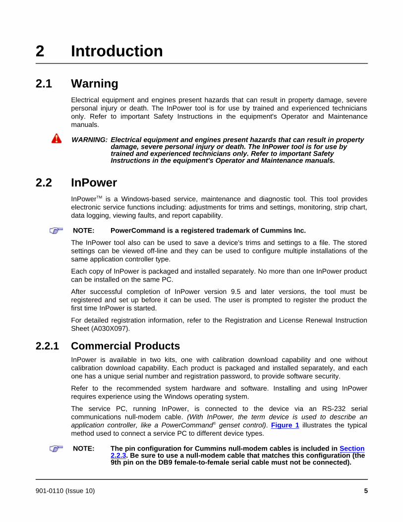
2 Introduction
2.1 WarningElectrical equipment and engines present hazards that can result in property damage, severepersonal injury or death. The InPower tool is for use by trained and experienced techniciansonly. Refer to important Safety Instructions in the equipment's Operator and Maintenancemanuals.
WARNING: Electrical equipment and engines present hazards that can result in propertydamage, severe personal injury or death. The InPower tool is for use bytrained and experienced technicians only. Refer to important SafetyInstructions in the equipment's Operator and Maintenance manuals.
2.2 InPowerInPowerTM is a Windows-based service, maintenance and diagnostic tool. This tool provideselectronic service functions including: adjustments for trims and settings, monitoring, strip chart,data logging, viewing faults, and report capability.
NOTE: PowerCommand is a registered trademark of Cummins Inc.
The InPower tool also can be used to save a device's trims and settings to a file. The storedsettings can be viewed off-line and they can be used to configure multiple installations of thesame application controller type.
Each copy of InPower is packaged and installed separately. No more than one InPower productcan be installed on the same PC.
After successful completion of InPower version 9.5 and later versions, the tool must beregistered and set up before it can be used. The user is prompted to register the product thefirst time InPower is started.
For detailed registration information, refer to the Registration and License Renewal InstructionSheet (A030X097).
2.2.1 Commercial ProductsInPower is available in two kits, one with calibration download capability and one withoutcalibration download capability. Each product is packaged and installed separately, and eachone has a unique serial number and registration password, to provide software security.
Refer to the recommended system hardware and software. Installing and using InPowerrequires experience using the Windows operating system.
The service PC, running InPower, is connected to the device via an RS-232 serialcommunications null-modem cable. (With InPower, the term device is used to describe anapplication controller, like a PowerCommand® genset control). Figure 1 illustrates the typicalmethod used to connect a service PC to different device types.
NOTE: The pin configuration for Cummins null-modem cables is included in Section2.2.3. Be sure to use a null-modem cable that matches this configuration (the9th pin on the DB9 female-to-female serial cable must not be connected).
901-0110 (Issue 10) 5
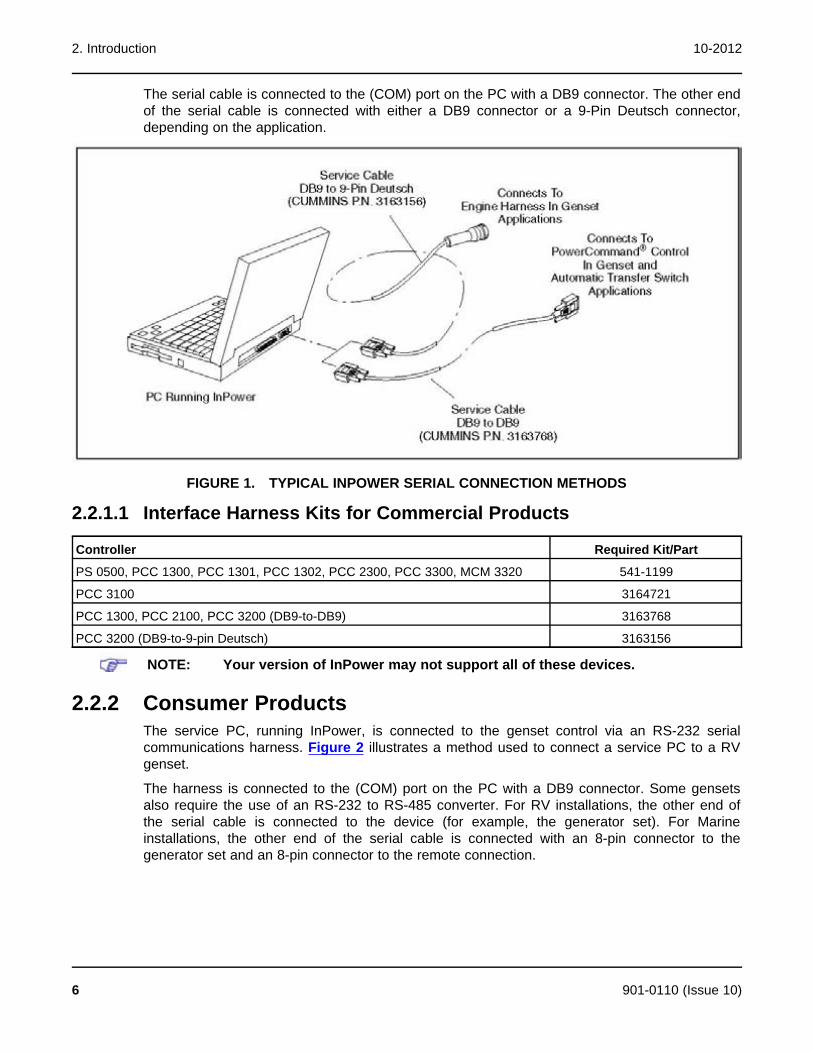
2. Introduction 10-2012
The serial cable is connected to the (COM) port on the PC with a DB9 connector. The other endof the serial cable is connected with either a DB9 connector or a 9-Pin Deutsch connector,depending on the application.
FIGURE 1. TYPICAL INPOWER SERIAL CONNECTION METHODS
2.2.1.1 Interface Harness Kits for Commercial Products
Controller Required Kit/Part
PS 0500, PCC 1300, PCC 1301, PCC 1302, PCC 2300, PCC 3300, MCM 3320 541-1199
PCC 3100 3164721
PCC 1300, PCC 2100, PCC 3200 (DB9-to-DB9) 3163768
PCC 3200 (DB9-to-9-pin Deutsch) 3163156
NOTE: Your version of InPower may not support all of these devices.
2.2.2 Consumer ProductsThe service PC, running InPower, is connected to the genset control via an RS-232 serialcommunications harness. Figure 2 illustrates a method used to connect a service PC to a RVgenset.
The harness is connected to the (COM) port on the PC with a DB9 connector. Some gensetsalso require the use of an RS-232 to RS-485 converter. For RV installations, the other end ofthe serial cable is connected to the device (for example, the generator set). For Marineinstallations, the other end of the serial cable is connected with an 8-pin connector to thegenerator set and an 8-pin connector to the remote connection.
6 901-0110 (Issue 10)
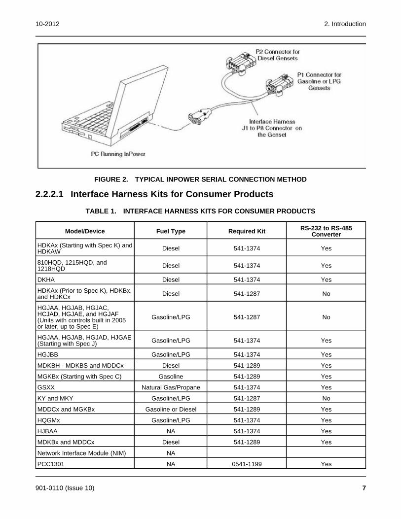
10-2012 2. Introduction
FIGURE 2. TYPICAL INPOWER SERIAL CONNECTION METHOD
2.2.2.1 Interface Harness Kits for Consumer Products
TABLE 1. INTERFACE HARNESS KITS FOR CONSUMER PRODUCTS
RS-232 to RS-485Model/Device Fuel Type Required Kit Converter
HDKAx (Starting with Spec K) and Diesel 541-1374 YesHDKAW
810HQD, 1215HQD, and Diesel 541-1374 Yes1218HQD
DKHA Diesel 541-1374 Yes
HDKAx (Prior to Spec K), HDKBx, Diesel 541-1287 Noand HDKCx
HGJAA, HGJAB, HGJAC,HCJAD, HGJAE, and HGJAF Gasoline/LPG 541-1287 No(Units with controls built in 2005or later, up to Spec E)
HGJAA, HGJAB, HGJAD, HJGAE Gasoline/LPG 541-1374 Yes(Starting with Spec J)
HGJBB Gasoline/LPG 541-1374 Yes
MDKBH - MDKBS and MDDCx Diesel 541-1289 Yes
MGKBx (Starting with Spec C) Gasoline 541-1289 Yes
GSXX Natural Gas/Propane 541-1374 Yes
KY and MKY Gasoline/LPG 541-1287 No
MDDCx and MGKBx Gasoline or Diesel 541-1289 Yes
HQGMx Gasoline/LPG 541-1374 Yes
HJBAA NA 541-1374 Yes
MDKBx and MDDCx Diesel 541-1289 Yes
Network Interface Module (NIM) NA
PCC1301 NA 0541-1199 Yes
901-0110 (Issue 10) 7

2. Introduction 10-2012
RS-232 to RS-485Model/Device Fuel Type Required Kit Converter
PCC1302 NA 0541-1199 Yes
HMI211RS NA 0541-1199 Yes
RV/CM Display NA 541-1374 Yes
Marine Display NA 541-1289 Yes
All Gasoline or Diesel 541-1389 Yes
2.2.3 Null Modem Cable Configuration
FIGURE 3. NULL MODEM CABLE CONFIGURATION
2.3 About This User's GuideThis User's Guide covers installation and operation of the InPower service tool. Last minutesoftware changes and corrections may be found in the InPower ReadMe file.
2.4 Supported DevicesThis version of InPower supports the following devices:
· Dominion (PCC3200)
· PCC3200 with CAN
· Operator Panel
· PCC 3100
· ATS(PCATS)
· Dynasty (PCC2100)
· GCP PCS
8 901-0110 (Issue 10)
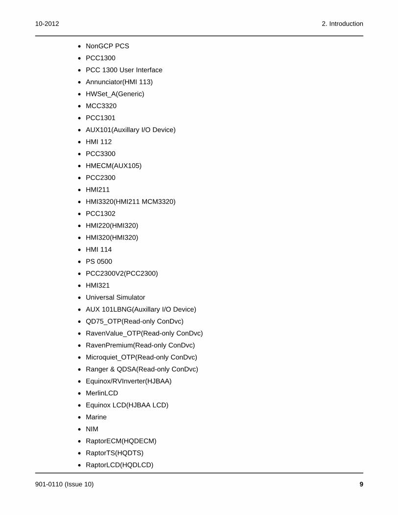
10-2012 2. Introduction
· NonGCP PCS
· PCC1300
· PCC 1300 User Interface
· Annunciator(HMI 113)
· HWSet_A(Generic)
· MCC3320
· PCC1301
· AUX101(Auxillary I/O Device)
· HMI 112
· PCC3300
· HMECM(AUX105)
· PCC2300
· HMI211
· HMI3320(HMI211 MCM3320)
· PCC1302
· HMI220(HMI320)
· HMI320(HMI320)
· HMI 114
· PS 0500
· PCC2300V2(PCC2300)
· HMI321
· Universal Simulator
· AUX 101LBNG(Auxillary I/O Device)
· QD75_OTP(Read-only ConDvc)
· RavenValue_OTP(Read-only ConDvc)
· RavenPremium(Read-only ConDvc)
· Microquiet_OTP(Read-only ConDvc)
· Ranger & QDSA(Read-only ConDvc)
· Equinox/RVInverter(HJBAA)
· MerlinLCD
· Equinox LCD(HJBAA LCD)
· Marine
· NIM
· RaptorECM(HQDECM)
· RaptorTS(HQDTS)
· RaptorLCD(HQDLCD)
901-0110 (Issue 10) 9
2. Introduction 10-2012
· QD1012(HDKC)
· QD1012(RS485)
· QD55(RS485)
· Marquis(Marquis Premium)
· Raven Commercial
· HWSet_A(Generic)
· HQD Inverter(HQDInverter)
· QD75(HDKAJ)
· QDSA(HDCA)
· Raven485
· Generic device (Generic485)
· APU LCD
· GENERICINV4KW
· APU(DKHA)
· Stealth
· Stealth LCD(GSAALCD)
· APU DPF LCD(APUDPFLCD_96)
· Coyote
· Generic CommMobile(GeCommMobile)
· MARINE3LCD(MARINE3LCD)
· Razor(QG1012)
· EC30W Genset Module(EC30WGenmod)
· EC30W Display(EC30WDisplay)
· GENERICUMC3(GENERICUMC3)
· MARINE3(MARINE3)
· Annunciator
· CCMT
· CCMG
· DIM
2.5 System Requirements2.5.1 Recommended PC
The following are the recommended laptop PC specifications.
· An IBM PC or 100% compatible PC
10 901-0110 (Issue 10)
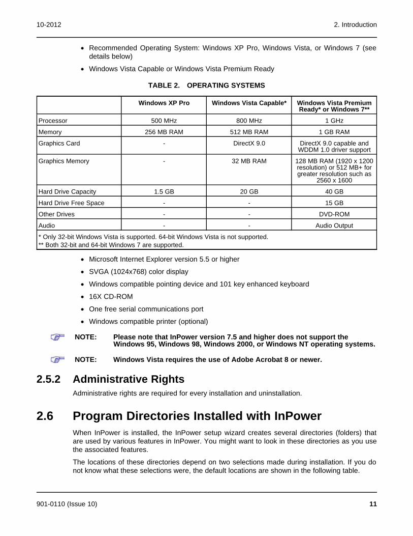
10-2012 2. Introduction
· Recommended Operating System: Windows XP Pro, Windows Vista, or Windows 7 (seedetails below)
· Windows Vista Capable or Windows Vista Premium Ready
TABLE 2. OPERATING SYSTEMS
Windows XP Pro Windows Vista Capable* Windows Vista PremiumReady* or Windows 7**
Processor 500 MHz 800 MHz 1 GHz
Memory 256 MB RAM 512 MB RAM 1 GB RAM
Graphics Card - DirectX 9.0 DirectX 9.0 capable andWDDM 1.0 driver support
Graphics Memory - 32 MB RAM 128 MB RAM (1920 x 1200resolution) or 512 MB+ forgreater resolution such as
2560 x 1600
Hard Drive Capacity 1.5 GB 20 GB 40 GB
Hard Drive Free Space - - 15 GB
Other Drives - - DVD-ROM
Audio - - Audio Output
* Only 32-bit Windows Vista is supported. 64-bit Windows Vista is not supported.** Both 32-bit and 64-bit Windows 7 are supported.
· Microsoft Internet Explorer version 5.5 or higher
· SVGA (1024x768) color display
· Windows compatible pointing device and 101 key enhanced keyboard
· 16X CD-ROM
· One free serial communications port
· Windows compatible printer (optional)
NOTE: Please note that InPower version 7.5 and higher does not support theWindows 95, Windows 98, Windows 2000, or Windows NT operating systems.
NOTE: Windows Vista requires the use of Adobe Acrobat 8 or newer.
2.5.2 Administrative RightsAdministrative rights are required for every installation and uninstallation.
2.6 Program Directories Installed with InPowerWhen InPower is installed, the InPower setup wizard creates several directories (folders) thatare used by various features in InPower. You might want to look in these directories as you usethe associated features.
The locations of these directories depend on two selections made during installation. If you donot know what these selections were, the default locations are shown in the following table.
901-0110 (Issue 10) 11
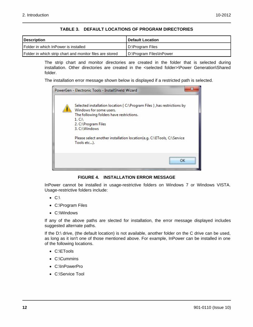
2. Introduction 10-2012
TABLE 3. DEFAULT LOCATIONS OF PROGRAM DIRECTORIES
Description Default Location
Folder in which InPower is installed D:\Program Files
Folder in which strip chart and monitor files are stored D:\Program Files\InPower
The strip chart and monitor directories are created in the folder that is selected duringinstallation. Other directories are created in the <selected folder>\Power Generation\Sharedfolder.
The installation error message shown below is displayed if a restricted path is selected.
FIGURE 4. INSTALLATION ERROR MESSAGE
InPower cannot be installed in usage-restrictive folders on Windows 7 or Windows VISTA.Usage-restrictive folders include:
· C:\
· C:\Program Files
· C:\Windows
If any of the above paths are slected for installation, the error message displayed includessuggested alternate paths.
If the D:\ drive, (the default location) is not available, another folder on the C drive can be used,as long as it isn't one of those mentioned above. For example, InPower can be installed in oneof the following locations.
· C:\ETools
· C:\Cummins
· C:\InPowerPro
· C:\Service Tool
12 901-0110 (Issue 10)
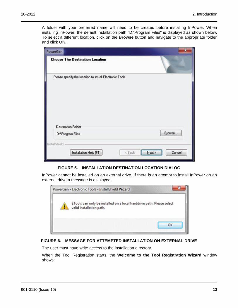
10-2012 2. Introduction
A folder with your preferred name will need to be created before installing InPower. Wheninstalling InPower, the default installation path "D:\Program Files" is displayed as shown below.To select a different location, click on the Browse button and navigate to the appropriate folderand click OK.
FIGURE 5. INSTALLATION DESTINATION LOCATION DIALOG
InPower cannot be installed on an external drive. If there is an attempt to install InPower on anexternal drive a message is displayed.
FIGURE 6. MESSAGE FOR ATTEMPTED INSTALLATION ON EXTERNAL DRIVE
The user must have write access to the installation directory.
When the Tool Registration starts, the Welcome to the Tool Registration Wizard windowshows:
901-0110 (Issue 10) 13

2. Introduction 10-2012
FIGURE 7. WELCOME TO THE TOOL REGISTRATION WIZARD WINDOW
If the user does not have write access to the installation directory when Next is selected forManual or Web Registration, then a message window shows.
FIGURE 8. MESSAGE WINDOW FOR READ-ONLY ACCESS
2.6.1 MonitorThe Monitor folder contains the Target Parameter List files (.TPL). This folder will contain one ormore .TPL files. These files support the InPower software. The user will not need to view oraccess any of these files.
2.6.2 Strip ChartThe Strip Chart folder contains one or more strip chart parameter listing files (.TPL).
14 901-0110 (Issue 10)

10-2012 2. Introduction
The files contain chart design parameters, the user will not need to view or access these files.
2.6.3 DataThe two Data folders contain data files. These files support the InPower software. The user willnot need to view or access any of these files.
2.6.4 Captured FilesThe Captured Files folder stores extracted (captured) device information. Initially this folder willnot contain any files. Files are created when the user chooses to Capture to File from aconnected device (Device menu). The user names the file and InPower appends a .CAPextension.
Captured files are read-only files. You can connect to, and view these files, but you cannotmodify the file contents. Captured files can be copied (written) to a connected device, as long asthe captured file is from the same device type.
Example: The Captured file is from a Genset controller, this file can be written to another(connected) Genset controller. This file cannot be written to a G-Drive controller.
2.6.5 SimulatorThe Simulator folder contains Captured (.CAP) files that are used to simulate a connecteddevice. The files are read only; however, the user can simulate editing (the changes are notactually written to the file). The Simulator feature does not allow for simulating Edit-SaveAdjustments operations.
2.7 Calibration Directories Installed with InPowerStarting with InPower version 6.0, an empty directory structure is created in the PGA directoryduring installation (Figure 9). This file structure is used for downloading calibration files from theInCal website.
901-0110 (Issue 10) 15
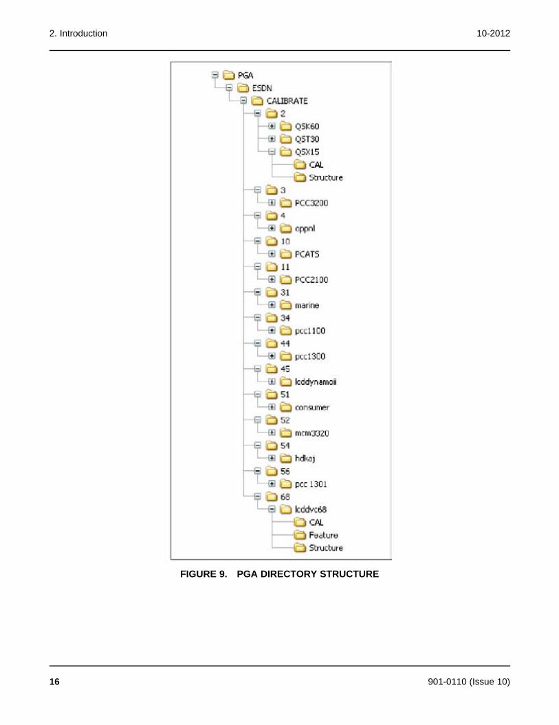
2. Introduction 10-2012
FIGURE 9. PGA DIRECTORY STRUCTURE
16 901-0110 (Issue 10)

10-2012 2. Introduction
2.8 Service File and Logical DFA Directories Installedwith InPowerService files and logical DFAs are also part of the website InCal distribution and need to becopied to their respective folders.
· Service Files: <Installed Location>\InPower\Data
· Logical DFAs: <Installed Location>\Shared\Data
2.9 Start Menu Group ShortcutsInPower installs Start-Menu shortcuts for the InPower applications. Clicking on any one of theseshortcuts will launch the selected application.
FIGURE 10. START MENU GROUP SHORTCUTS
2.9.1 Readme FileWhen InPower is installed, a Readme file is copied to the Power Generation group. This filecontains last minute instructions for using InPower. Open and review these instructions after theinitial software installation.
2.10 User InterfaceThe InPower software operates in the Windows graphical environment and is compatible withWindows. You can access the system like any other Windows application. If you are unfamiliarwith Windows, or have questions, refer to the Microsoft Windows User's Guide for your specificoperating system, or click on Help, from the Windows Start menu, to view the Windows HelpTopics.
All system commands are accessible by mouse and keyboard. Frequently used commandshave keyboard shortcuts and tool bar access.
InPower uses the Windows Explorer tree hierarchy for navigating a connected file or device(referred to as Device Explorer, in InPower).
The tool's main window displays a Menu Bar and a Toolbar for access to the tool's functions.Only commands applicable to the current active window are enabled, all other commands fromthe Menu Bar or Toolbar are grayed out.
901-0110 (Issue 10) 17
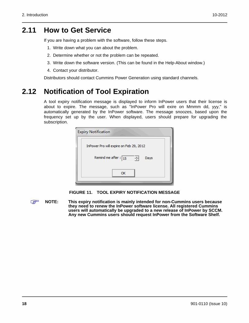
2. Introduction 10-2012
2.11 How to Get ServiceIf you are having a problem with the software, follow these steps.
1. Write down what you can about the problem.
2. Determine whether or not the problem can be repeated.
3. Write down the software version. (This can be found in the Help-About window.)
4. Contact your distributor.
Distributors should contact Cummins Power Generation using standard channels.
2.12 Notification of Tool ExpirationA tool expiry notification message is displayed to inform InPower users that their license isabout to expire. The message, such as "InPower Pro will exire on Mmmm dd, yyy," isautomatically generated by the InPower software. The message snoozes, based upon thefrequency set up by the user. When displayed, users should prepare for upgrading thesubscription.
FIGURE 11. TOOL EXPIRY NOTIFICATION MESSAGE
NOTE: This expiry notification is mainly intended for non-Cummins users becausethey need to renew the InPower software license. All registered Cumminsusers will automatically be upgraded to a new release of InPower by SCCM.Any new Cummins users should request InPower from the Software Shelf.
18 901-0110 (Issue 10)

3 SetupThe Setup dialog allows the installer, or System Administrator, to set user preferences andmake changes to both Sites and Devices.
NOTE: If you attempt to access the Setup program while InPower is running, themessage “Initialization mode failed" is displayed. Make sure InPower is notrunning before accessing the Setup program.
3.1 General SetupThe Setup feature can be accessed from the Start menu (Start -> All Programs -> PowerGeneration -> Setup).
Four Setup tabs are displayed; the Unit of Measurement tab is the default tab selection. Toselect another tab, click on the desired tab. When the Site Setup tab is selected, clicking on anitem from the Site List will add a button, named Device Setup.
The Communications tab is used in genset applications to configure the service PC for remotecommunications.
If you need to set up another COM port, refer to Create Site.
3.2 Unit of MeasurementThis feature allows selection of a list of pre-defined units of measure, based on their region orcountry. InPower will convert and display values according to the units of measure selectedfrom the System Of Measurement drop down list.
Users can create their own list by entering a name in the System of Measurement dialog. Tocustomize a setup, select individual Unit Descriptions, by Unit Type, from the drop down lists.Click on the Apply button to save the changes.
901-0110 (Issue 10) 19
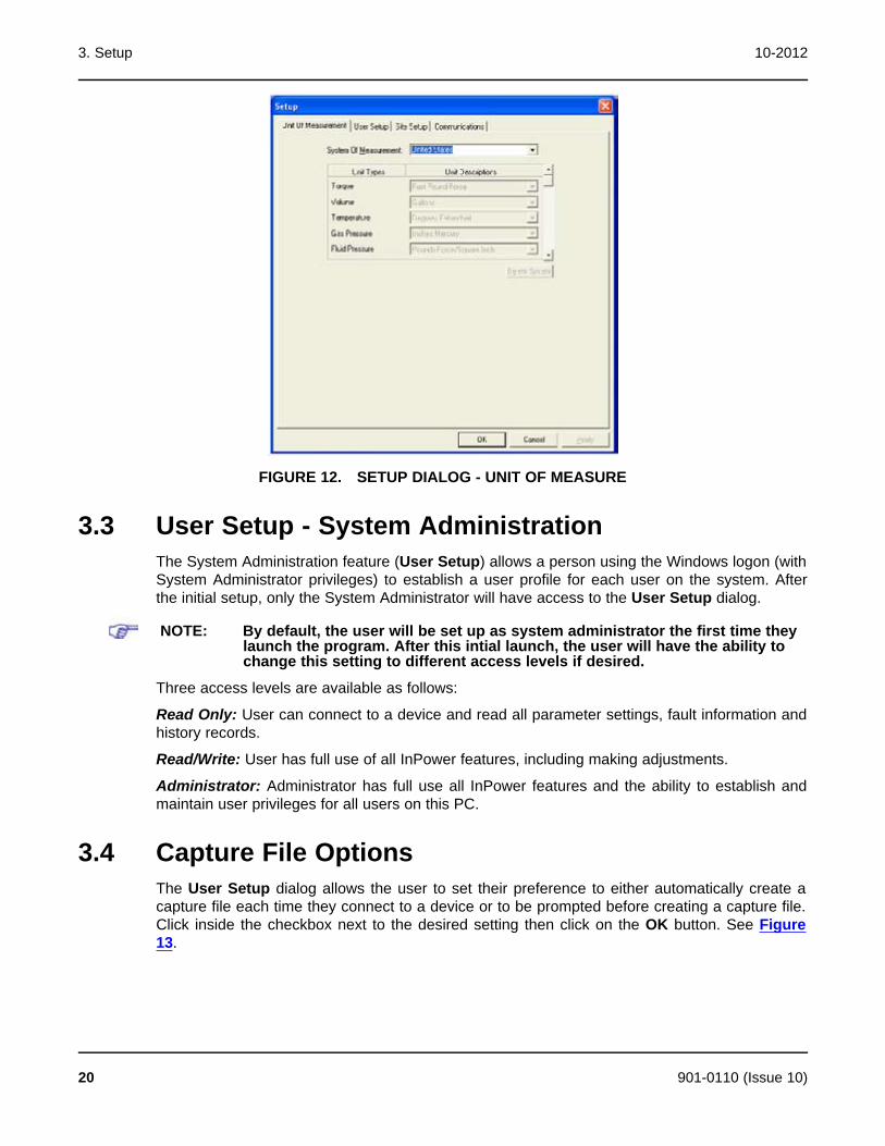
3. Setup 10-2012
FIGURE 12. SETUP DIALOG - UNIT OF MEASURE
3.3 User Setup - System AdministrationThe System Administration feature (User Setup) allows a person using the Windows logon (withSystem Administrator privileges) to establish a user profile for each user on the system. Afterthe initial setup, only the System Administrator will have access to the User Setup dialog.
NOTE: By default, the user will be set up as system administrator the first time theylaunch the program. After this intial launch, the user will have the ability tochange this setting to different access levels if desired.
Three access levels are available as follows:
Read Only: User can connect to a device and read all parameter settings, fault information andhistory records.
Read/Write: User has full use of all InPower features, including making adjustments.
Administrator: Administrator has full use all InPower features and the ability to establish andmaintain user privileges for all users on this PC.
3.4 Capture File OptionsThe User Setup dialog allows the user to set their preference to either automatically create acapture file each time they connect to a device or to be prompted before creating a capture file.Click inside the checkbox next to the desired setting then click on the OK button. See Figure13.
20 901-0110 (Issue 10)
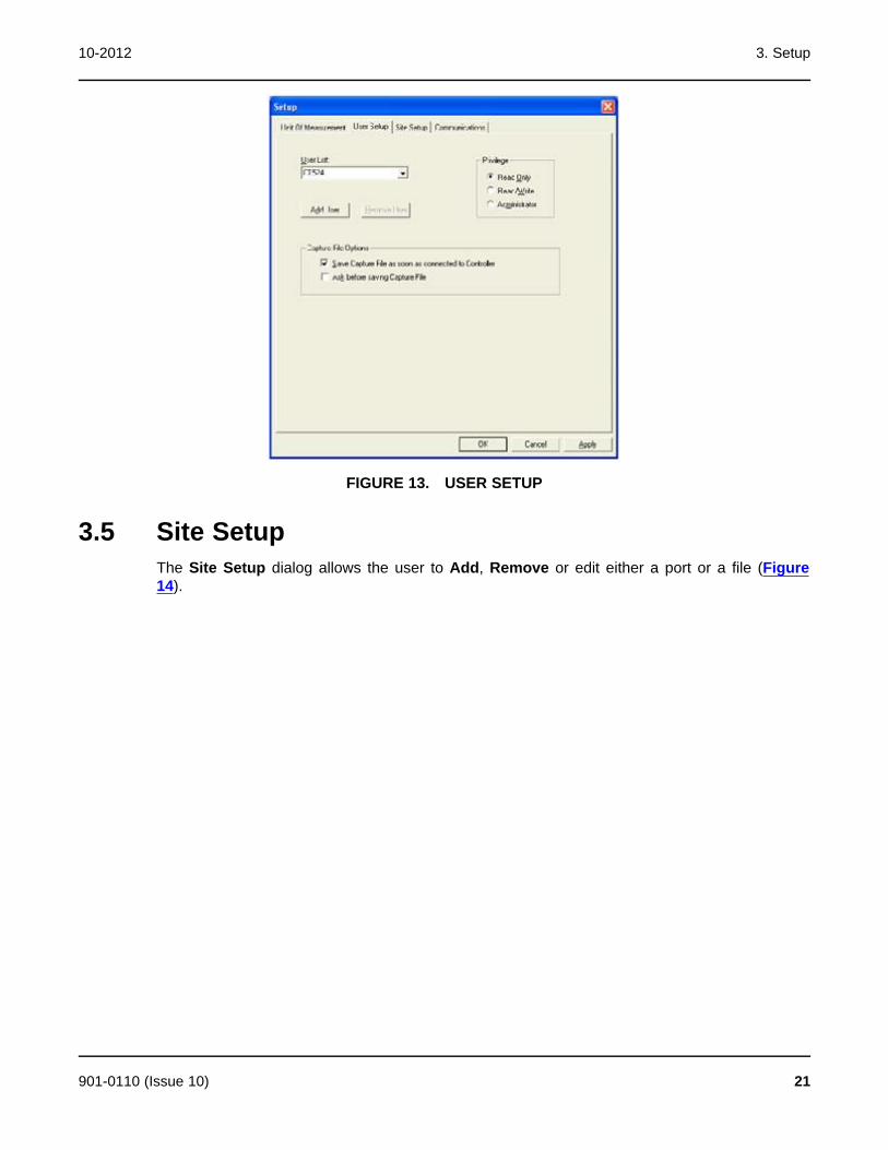
10-2012 3. Setup
FIGURE 13. USER SETUP
3.5 Site SetupThe Site Setup dialog allows the user to Add, Remove or edit either a port or a file (Figure14).
901-0110 (Issue 10) 21
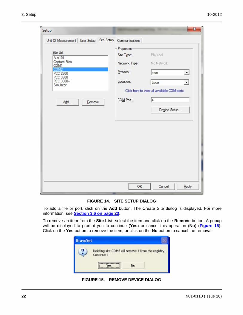
3. Setup 10-2012
FIGURE 14. SITE SETUP DIALOG
To add a file or port, click on the Add button. The Create Site dialog is displayed. For moreinformation, see Section 3.6 on page 23.
To remove an item from the Site List, select the item and click on the Remove button. A popupwill be displayed to prompt you to continue (Yes) or cancel this operation (No) (Figure 15).Click on the Yes button to remove the item, or click on the No button to cancel the removal.
FIGURE 15. REMOVE DEVICE DIALOG
22 901-0110 (Issue 10)
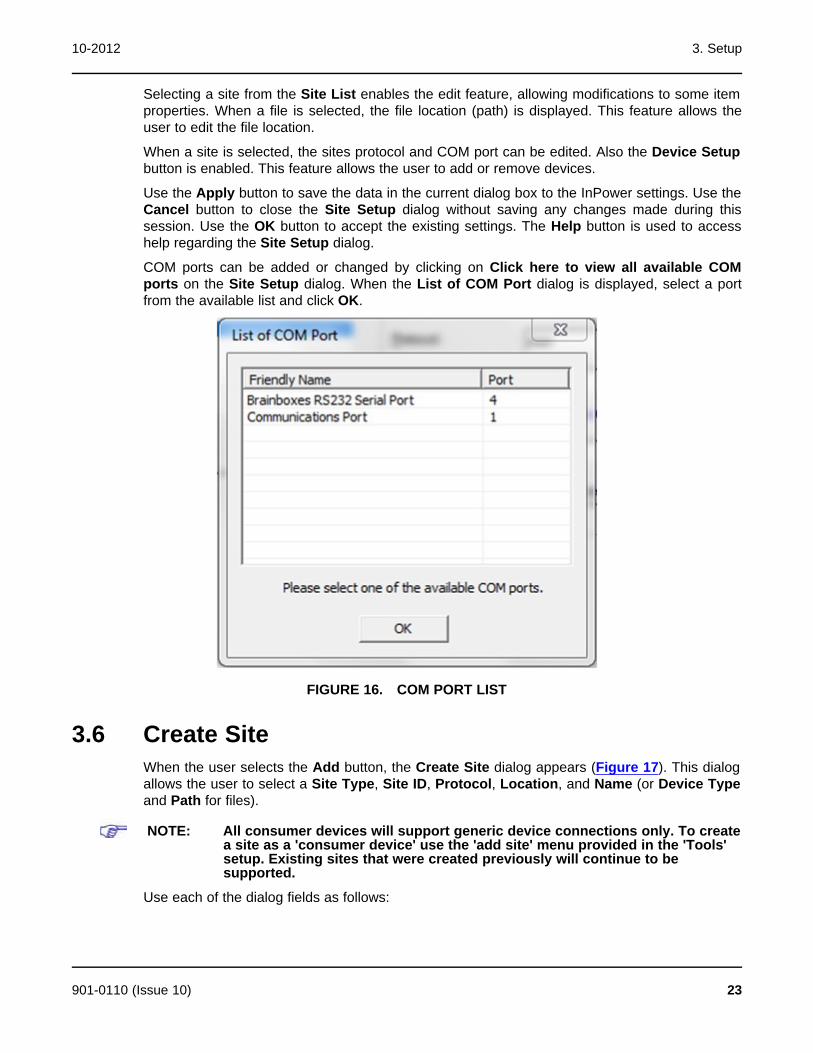
10-2012 3. Setup
Selecting a site from the Site List enables the edit feature, allowing modifications to some itemproperties. When a file is selected, the file location (path) is displayed. This feature allows theuser to edit the file location.
When a site is selected, the sites protocol and COM port can be edited. Also the Device Setupbutton is enabled. This feature allows the user to add or remove devices.
Use the Apply button to save the data in the current dialog box to the InPower settings. Use theCancel button to close the Site Setup dialog without saving any changes made during thissession. Use the OK button to accept the existing settings. The Help button is used to accesshelp regarding the Site Setup dialog.
COM ports can be added or changed by clicking on Click here to view all available COMports on the Site Setup dialog. When the List of COM Port dialog is displayed, select a portfrom the available list and click OK.
FIGURE 16. COM PORT LIST
3.6 Create SiteWhen the user selects the Add button, the Create Site dialog appears (Figure 17). This dialogallows the user to select a Site Type, Site ID, Protocol, Location, and Name (or Device Typeand Path for files).
NOTE: All consumer devices will support generic device connections only. To createa site as a 'consumer device' use the 'add site' menu provided in the 'Tools'setup. Existing sites that were created previously will continue to besupported.
Use each of the dialog fields as follows:
901-0110 (Issue 10) 23
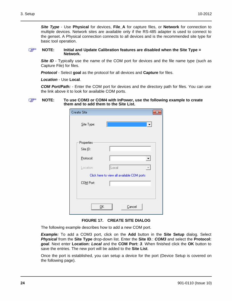
3. Setup 10-2012
Site Type - Use Physical for devices, File_A for capture files, or Network for connection tomultiple devices. Network sites are available only if the RS-485 adapter is used to connect tothe genset. A Physical connection connects to all devices and is the recommended site type forbasic tool operation.
NOTE: Initial and Update Calibration features are disabled when the Site Type =Network.
Site ID - Typically use the name of the COM port for devices and the file name type (such asCapture File) for files.
Protocol - Select goal as the protocol for all devices and Capture for files.
Location - Use Local.
COM Port/Path: - Enter the COM port for devices and the directory path for files. You can usethe link above it to look for available COM ports.
NOTE: To use COM3 or COM4 with InPower, use the following example to createthem and to add them to the Site List.
FIGURE 17. CREATE SITE DIALOG
The following example describes how to add a new COM port.
Example: To add a COM3 port, click on the Add button in the Site Setup dialog. SelectPhysical from the Site Type drop-down list. Enter the Site ID.: COM3 and select the Protocol:goal. Next enter Location: Local and the COM Port: 3. When finished click the OK button tosave the entries. The new port will be added to the Site List.
Once the port is established, you can setup a device for the port (Device Setup is covered onthe following page).
24 901-0110 (Issue 10)
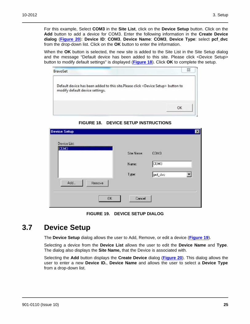
10-2012 3. Setup
For this example, Select COM3 in the Site List, click on the Device Setup button. Click on theAdd button to add a device for COM3. Enter the following information in the Create Devicedialog (Figure 20): Device ID: COM3, Device Name: COM3, Device Type: select pcf_dvcfrom the drop-down list. Click on the OK button to enter the information.
When the OK button is selected, the new site is added to the Site List in the Site Setup dialogand the message “Default device has been added to this site. Please click <Device Setup>button to modify default settings" is displayed (Figure 18). Click OK to complete the setup.
FIGURE 18. DEVICE SETUP INSTRUCTIONS
FIGURE 19. DEVICE SETUP DIALOG
3.7 Device SetupThe Device Setup dialog allows the user to Add, Remove, or edit a device (Figure 19).
Selecting a device from the Device List allows the user to edit the Device Name and Type.The dialog also displays the Site Name, that the Device is associated with.
Selecting the Add button displays the Create Device dialog (Figure 20). This dialog allows theuser to enter a new Device ID., Device Name and allows the user to select a Device Typefrom a drop-down list.
901-0110 (Issue 10) 25
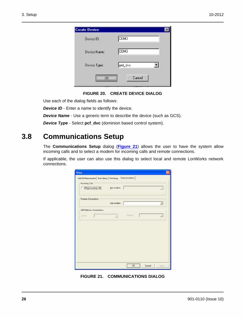
3. Setup 10-2012
FIGURE 20. CREATE DEVICE DIALOG
Use each of the dialog fields as follows:
Device ID - Enter a name to identify the device.
Device Name - Use a generic term to describe the device (such as GCS).
Device Type - Select pcf_dvc (dominion based control system).
3.8 Communications SetupThe Communications Setup dialog (Figure 21) allows the user to have the system allowincoming calls and to select a modem for incoming calls and remote connections.
If applicable, the user can also use this dialog to select local and remote LonWorks networkconnections.
FIGURE 21. COMMUNICATIONS DIALOG
26 901-0110 (Issue 10)
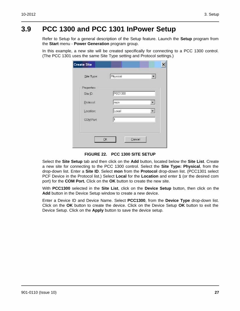
10-2012 3. Setup
3.9 PCC 1300 and PCC 1301 InPower SetupRefer to Setup for a general description of the Setup feature. Launch the Setup program fromthe Start menu - Power Generation program group.
In this example, a new site will be created specifically for connecting to a PCC 1300 control.(The PCC 1301 uses the same Site Type setting and Protocol settings.)
FIGURE 22. PCC 1300 SITE SETUP
Select the Site Setup tab and then click on the Add button, located below the Site List. Createa new site for connecting to the PCC 1300 control. Select the Site Type: Physical, from thedrop-down list. Enter a Site ID. Select mon from the Protocol drop-down list. (PCC1301 selectPCF Device in the Protocol list.) Select Local for the Location and enter 1 (or the desired comport) for the COM Port. Click on the OK button to create the new site.
With PCC1300 selected in the Site List, click on the Device Setup button, then click on theAdd button in the Device Setup window to create a new device.
Enter a Device ID and Device Name. Select PCC1300, from the Device Type drop-down list.Click on the OK button to create the device. Click on the Device Setup OK button to exit theDevice Setup. Click on the Apply button to save the device setup.
901-0110 (Issue 10) 27
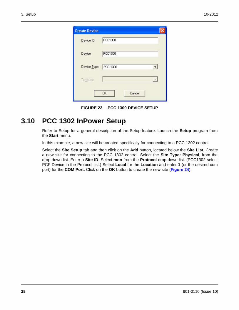
3. Setup 10-2012
FIGURE 23. PCC 1300 DEVICE SETUP
3.10 PCC 1302 InPower SetupRefer to Setup for a general description of the Setup feature. Launch the Setup program fromthe Start menu.
In this example, a new site will be created specifically for connecting to a PCC 1302 control.
Select the Site Setup tab and then click on the Add button, located below the Site List. Createa new site for connecting to the PCC 1302 control. Select the Site Type: Physical, from thedrop-down list. Enter a Site ID. Select mon from the Protocol drop-down list. (PCC1302 selectPCF Device in the Protocol list.) Select Local for the Location and enter 1 (or the desired comport) for the COM Port. Click on the OK button to create the new site (Figure 24).
28 901-0110 (Issue 10)

10-2012 3. Setup
FIGURE 24. PCC 1302 SITE SETUP
With PCC1302 selected in the Site List, click on the Device Setup button, then click on theAdd button in the Device Setup window to create a new device.
Enter a Device ID and Device Name (Figure 25). Select PCC1302, from the Device Type drop-down list. Click on the OK button to create the device. Click on the Device Setup OK button toexit the Device Setup. Click on the Apply button in the Setup dialog to save the device setup.
FIGURE 25. PCC 1302 DEVICE SETUP
901-0110 (Issue 10) 29

3. Setup 10-2012
3.11 PCC 2300 and PCC 3300 InPower OEM SetupTo set up a generator set with a PCC 2300 or PCC 3300 control, select the control name fromthe device list, right click and select Genset OEM Setup... to view the Genset OEM Setupmenus. An example for the PCC 2300 is shown in the following figure.
FIGURE 26. ACCESSING THE GENSET OEM SETUP MENUS FOR THE PCC 2300 CONTROL
The Genset OEM Setup menus consist of various tabs. Many parameters cannot be modifiedwithout first clicking on the Enable Setup Mode button.
3.12 PCC 3100 InPower SetupRefer to the information included earlier in this section for a general description of the Setupfeature. Launch the Setup program from the Start menu - Power Generation program group.
In this example a new site will be created specifically for connecting to a PCC 3100 control.
Select the Site Setup tab and then click on the Add button, located below the Site List. Createa new site for connecting to the PCC 3100 control. Select the Site Type: Physical, from thedrop down list. Enter a Site ID. Selecting mon from the Protocol drop-down list. Select Localfor the Location and enter 1 (or the desired com port) for the COM Port. Click on the OKbutton to create the new site (Figure 27).
With PCC_3100 selected in the Site List, click on the Device Setup button, then click on theAdd button to create a new device.
30 901-0110 (Issue 10)
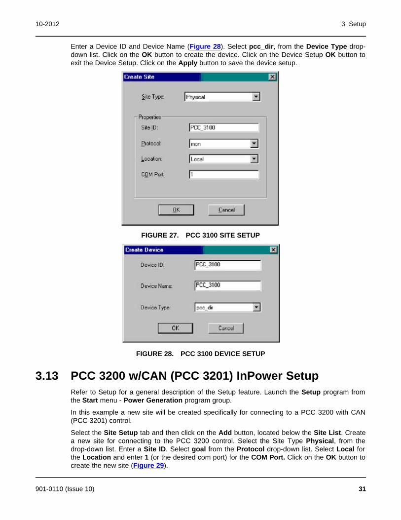
10-2012 3. Setup
Enter a Device ID and Device Name (Figure 28). Select pcc_dir, from the Device Type drop-down list. Click on the OK button to create the device. Click on the Device Setup OK button toexit the Device Setup. Click on the Apply button to save the device setup.
FIGURE 27. PCC 3100 SITE SETUP
FIGURE 28. PCC 3100 DEVICE SETUP
3.13 PCC 3200 w/CAN (PCC 3201) InPower SetupRefer to Setup for a general description of the Setup feature. Launch the Setup program fromthe Start menu - Power Generation program group.
In this example a new site will be created specifically for connecting to a PCC 3200 with CAN(PCC 3201) control.
Select the Site Setup tab and then click on the Add button, located below the Site List. Createa new site for connecting to the PCC 3200 control. Select the Site Type Physical, from thedrop-down list. Enter a Site ID. Select goal from the Protocol drop-down list. Select Local forthe Location and enter 1 (or the desired com port) for the COM Port. Click on the OK button tocreate the new site (Figure 29).
901-0110 (Issue 10) 31
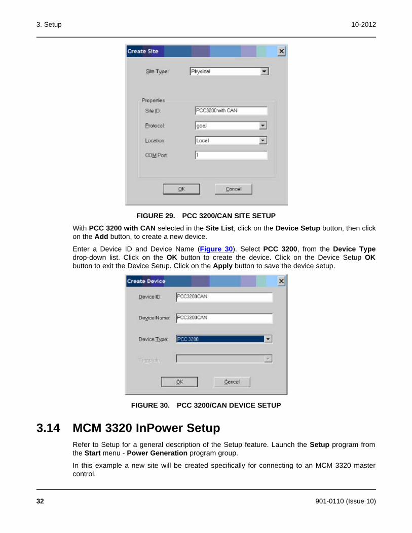
3. Setup 10-2012
FIGURE 29. PCC 3200/CAN SITE SETUP
With PCC 3200 with CAN selected in the Site List, click on the Device Setup button, then clickon the Add button, to create a new device.
Enter a Device ID and Device Name (Figure 30). Select PCC 3200, from the Device Typedrop-down list. Click on the OK button to create the device. Click on the Device Setup OKbutton to exit the Device Setup. Click on the Apply button to save the device setup.
FIGURE 30. PCC 3200/CAN DEVICE SETUP
3.14 MCM 3320 InPower SetupRefer to Setup for a general description of the Setup feature. Launch the Setup program fromthe Start menu - Power Generation program group.
In this example a new site will be created specifically for connecting to an MCM 3320 mastercontrol.
32 901-0110 (Issue 10)
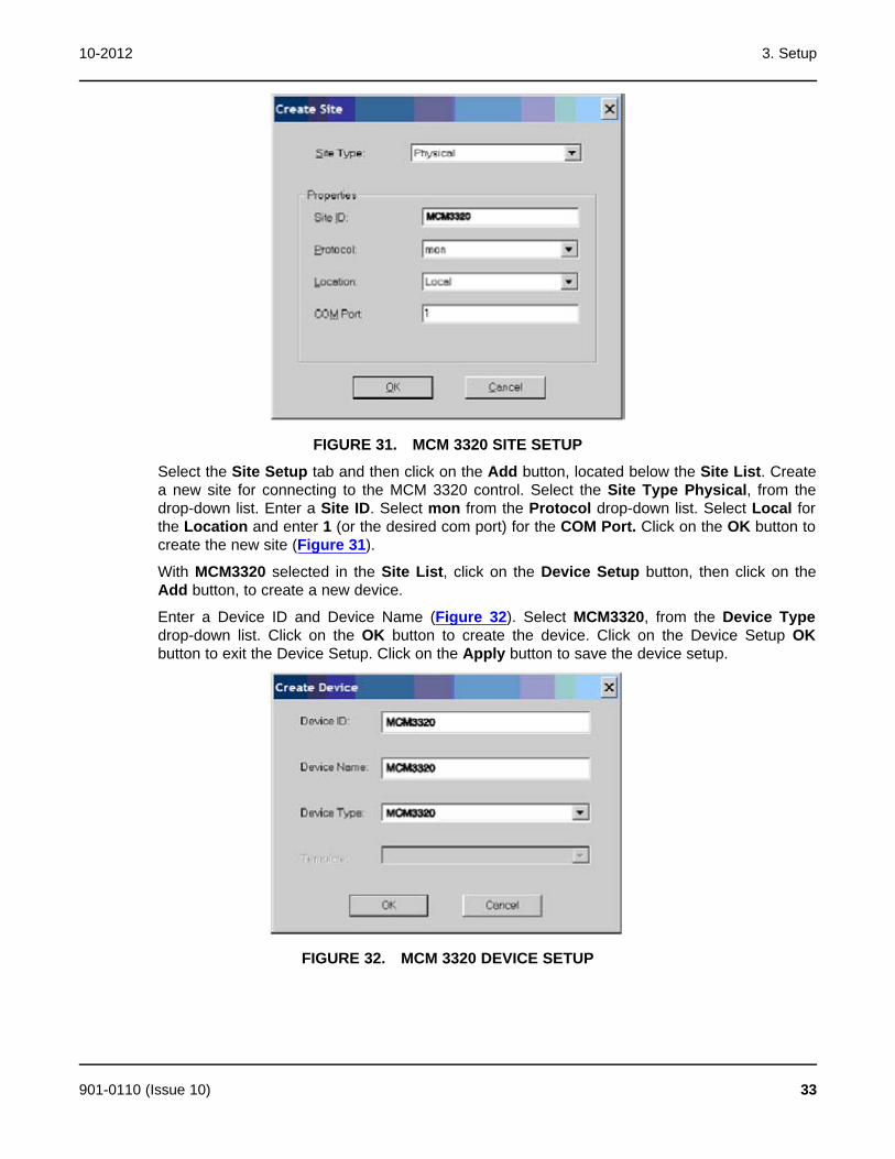
10-2012 3. Setup
FIGURE 31. MCM 3320 SITE SETUP
Select the Site Setup tab and then click on the Add button, located below the Site List. Createa new site for connecting to the MCM 3320 control. Select the Site Type Physical, from thedrop-down list. Enter a Site ID. Select mon from the Protocol drop-down list. Select Local forthe Location and enter 1 (or the desired com port) for the COM Port. Click on the OK button tocreate the new site (Figure 31).
With MCM3320 selected in the Site List, click on the Device Setup button, then click on theAdd button, to create a new device.
Enter a Device ID and Device Name (Figure 32). Select MCM3320, from the Device Typedrop-down list. Click on the OK button to create the device. Click on the Device Setup OKbutton to exit the Device Setup. Click on the Apply button to save the device setup.
FIGURE 32. MCM 3320 DEVICE SETUP
901-0110 (Issue 10) 33

3. Setup 10-2012
3.15 Monnet InPower SetupRefer to Setup for a general description of the Setup feature. Launch the Setup program fromthe Start menu - Power Generation program group.
In this example a new site will be created specifically for connecting to a MONNet (PCCnet)network.
FIGURE 33. MONNET SITE SETUP
Select the Site Setup tab and then click on the Add button, located below the Site List. Createa new site for connecting to the MONNet. Select the Site Type Network, from the drop-downlist. Select Network Type MONNet. Enter a Site ID. Enter 1 (or the desired com port) for theCOM Port. Click on the OK button to create the new site (Figure 33).
Select the MONNet site from the site list and note that the Device Setup feature is disabled(Figure 34). When InPower is connected to a MONNet site it automatically checks the numberof devices that are connected to the site and shows the active devices under the site.
34 901-0110 (Issue 10)
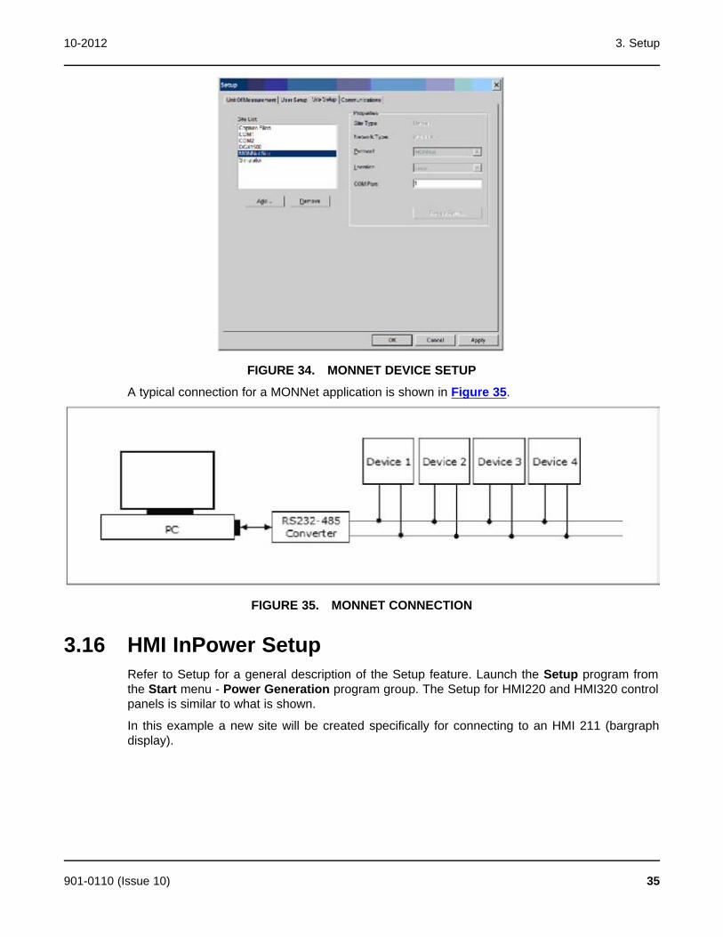
10-2012 3. Setup
FIGURE 34. MONNET DEVICE SETUP
A typical connection for a MONNet application is shown in Figure 35.
FIGURE 35. MONNET CONNECTION
3.16 HMI InPower SetupRefer to Setup for a general description of the Setup feature. Launch the Setup program fromthe Start menu - Power Generation program group. The Setup for HMI220 and HMI320 controlpanels is similar to what is shown.
In this example a new site will be created specifically for connecting to an HMI 211 (bargraphdisplay).
901-0110 (Issue 10) 35

3. Setup 10-2012
FIGURE 36. HMI SITE SETUP
Select the Site Setup tab and then click on the Add button, located below the Site List. Createa new site for connecting to the HMI. Select the Site Type Physical from the drop-down list.Enter a Site ID. Select mon from the Protocol drop-down list. Select Local for the Locationand enter 1 (or the desired com port) for the COM Port. Click on the OK button to create thenew site (Figure 36).
With HMI 211 selected in the Site List, click on the Device Setup button, then click on the Addbutton, to create a new device.
Enter a Device ID and Device Name (Figure 36). Select HMI211 from the Device Type drop-down list. Click on the OK button to create the device. Click on the Device Setup OK button toexit the Device Setup. Click on the Apply button to save the device setup.
FIGURE 37. HMI DEVICE SETUP
36 901-0110 (Issue 10)

10-2012 3. Setup
3.17 Core II ECS Device SetupMake sure that the network adapter drivers are installed (supplied by adapter manufacturer)prior to performing this setup.
Launch the Setup program from the Start menu — Power Generation program group.
In this example, a new site will be created specifically for connecting to a Core II ECS (ECM)device.
Select the Site Setup tab and then click on the Add button, located below the Site List. Create anew site for connecting to the Core II ECS. Select Network from the Site Type drop-down list.Select ECS Configuration from the Network Type drop-down list. Enter a Site ID. Use the drop-down arrow to select the Adapter type and COM Port. Click on the OK button to create the newsite (Figure 38). With Core II ECS selected in the Site List, note that the Device Setup button isdisabled. A device setup is not necessary with this site type.
FIGURE 38. CORE II ECS SITE SETUP
901-0110 (Issue 10) 37

3. Setup 10-2012
This page is intentionally blank.
38 901-0110 (Issue 10)

4 InPower BasicsThis section describes InPower's user interface features.
4.1 How to Start InPower1. Open the Start menu.
2. Click All Programs > Power Generation > InPower Pro > InPower Pro.
Attempting to launch InPower or the Bravo Setup when one of these programs is alreadyrunning will result in an error message.
· If an attempt is made to run a second instance of Bravo Setup (Start > All Programs >Power Generation > Setup), the following message is displayed.
FIGURE 39. BRAVO SETUP MESSAGE FOR WHEN BRAVO SETUP IS ALREADY IN USE
· If InPower is launched and then an attempt is made to launch Bravo Setup (Start > AllPrograms > Power Generation > Setup while InPower is still running), the followingmessage is displayed.
FIGURE 40. INPOWER IS RUNNING MESSAGE FOR WHEN ATTEMPTING TO USE BRAVO SETUP
· If the Bravo Setup is launched and then an attempt to launch InPower is made while BravoSetup is still running, the following message is displayed.
901-0110 (Issue 10) 39
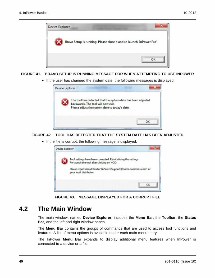
4. InPower Basics 10-2012
FIGURE 41. BRAVO SETUP IS RUNNING MESSAGE FOR WHEN ATTEMPTING TO USE INPOWER
· If the user has changed the system date, the following messages is displayed.
FIGURE 42. TOOL HAS DETECTED THAT THE SYSTEM DATE HAS BEEN ADJUSTED
· If the file is corrupt, the following message is displayed.
FIGURE 43. MESSAGE DISPLAYED FOR A CORRUPT FILE
4.2 The Main WindowThe main window, named Device Explorer, includes the Menu Bar, the Toolbar, the StatusBar, and the left and right window panes.
The Menu Bar contains the groups of commands that are used to access tool functions andfeatures. A list of menu options is available under each main menu entry.
The InPower Menu Bar expands to display additional menu features when InPower isconnected to a device or a file.
40 901-0110 (Issue 10)

10-2012 4. InPower Basics
When a Menu Bar command is grayed (dimmed), the command is not available. You may needto select another action (such as connecting to a port or device) before the grayed commandwill be displayed in black type—indicating that the feature is available.
· To display the list of options under a menu entry, move the mouse pointer to the menuname and click on the mouse button. (Clicking refers to using the mouse select button,typically the left button.)
· To select an option from a menu list, move the mouse pointer to the option name and clickon it.
The Toolbar provides direct graphical interface shortcuts to some of the more frequently usedmenu options. Buttons on the Toolbar represent frequently used tool functions.
When a Toolbar button is grayed (dimmed), the shortcut to that command is not available. Youmay need to select another action (such as connecting to a device or file) before the grayedcommand will be displayed in color (or black type)—indicating that it is available.
Placing the mouse pointer on a Toolbar button, the Status Bar describes the function of thebutton. The Status Bar also shows a description of operations as they occur.
The left window pane works like Windows Explorer to navigate the directory tree. The rightwindow pane displays the contents (or screens) for the item selected in the left window pane.
4.2.1 Main Window Example
FIGURE 44. MAIN WINDOW
4.3 Menu DescriptionsThis section provides a brief description of the functions performed by each of the InPowermenu commands. Some of the menus are not displayed until the tool is connected to a Port(COM port or .CAP file).
Several of the menu features have Toolbar shortcuts and some features can be enabled simplyby double clicking on the item from the directory tree in the left window.
901-0110 (Issue 10) 41

4. InPower Basics 10-2012
4.3.1 PortThe Port menu allows the user to Connect to and Disconnect from a port. InPower uses theterm Port to refer to either a COM Port or a .CAP(ture) File, including Simulator files. The Portmenu also allows the user to Add a local or remote Site, find InCAL calibrations, and it has anExit selection for exiting InPower.
In order to connect to a COM port, the PC must be physically connected to a device via a serialcommunications null-modem cable.
COM port error messages are displayed at the following times:
· In Bravo Setup when the user selects add site
· In Bravo Setup when the user selects apply
· In Bravo Setup when the user selects another site
· When the user closes bravo setup
· In Engineering Tool when the user selects add site
· In InPower Tool when the user selects add site.
The following shows an example error message:
FIGURE 45. MESSAGE DISPLAYED FOR COM PORT
4.3.2 DeviceThe Device menu is used to Connect to, and Disconnect from, a device, and for performingread and write functions with a connected device. InPower uses the term device when referringto a controller such as the generator set control.
Use InPower to change a device's trims and settings, and then use the Device menu to SaveAdjustments. The device's parameters can be Captured (saved) to a File.
The Device Menu can also be used to Clear Faults (inactive faults only) and to Prepare CSVfile with All Selected Features of the device's settings.
When the InPower service tool is connected to a device, three new features are added to theDevice menu; Initial Calibration, Update Calibration, and Update Features.
42 901-0110 (Issue 10)
10-2012 4. InPower Basics
4.3.3 EditThe Edit menu works within the directory of the connected device to Find a specified string ofdata. The Edit menu can also be used to Copy and Paste selected data.
4.3.4 UtilitiesThe Utilities menu is used to download simulator files from an InCal CD. When Utilities ->Universal Simulator Download is selected, a pop-up menu is displayed allowing you to set theCOM port and baud rate. If the InCal CD is inserted in your local drive, you can navigate to thesimulator file(s) you wish to download and then click on Download.
4.3.5 ViewThe View menu is used to view data from the connected device in a Monitor display or StripChart display. The View menu can also be used to access the FIS Fault Tree Main Window,view faults and refresh (update) all of the parameters displayed in the Value field.
4.3.6 HelpThe Help menu commands are used to find online information about using InPower andWindows. Help is also used to display Service and Support information and to obtain InPowerproduct and version information. A separate Help file contains information on consumer devicefault codes for marine and RV products. The menu also allows the user to launch theregistration program.
4.4 User InterfaceFrequently used commands have keyboard shortcuts and toolbar access. Only commandsapplicable to the current active window are enabled. All other commands are grayed out.
4.4.1 Keyboard AccessInPower uses standard Windows keyboard conventions.
The underlined letter indicates the keyboard selection for a given menu option. For example, toselect the Port menu, press and hold the “Alt" key and type a “P" (Alt P).
Once the menu is open, type just the underlined letter to select a specific menu item. Forexample, once the Port menu is open, type a (C) to select Connect.
4.4.2 ToolbarSome frequently used commands have toolbar shortcut buttons. Each button is associated withone or more menu items. The buttons have the same effect as the menu items.
901-0110 (Issue 10) 43
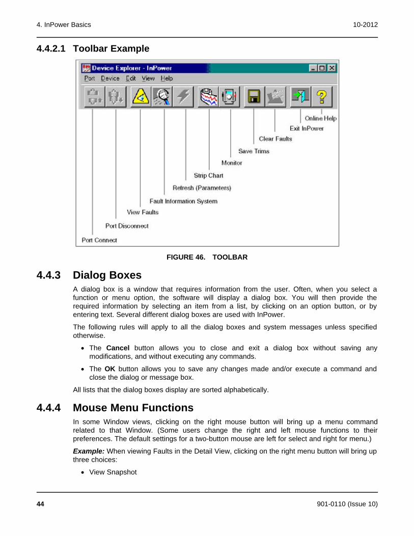
4. InPower Basics 10-2012
4.4.2.1 Toolbar Example
FIGURE 46. TOOLBAR
4.4.3 Dialog BoxesA dialog box is a window that requires information from the user. Often, when you select afunction or menu option, the software will display a dialog box. You will then provide therequired information by selecting an item from a list, by clicking on an option button, or byentering text. Several different dialog boxes are used with InPower.
The following rules will apply to all the dialog boxes and system messages unless specifiedotherwise.
· The Cancel button allows you to close and exit a dialog box without saving anymodifications, and without executing any commands.
· The OK button allows you to save any changes made and/or execute a command andclose the dialog or message box.
All lists that the dialog boxes display are sorted alphabetically.
4.4.4 Mouse Menu FunctionsIn some Window views, clicking on the right mouse button will bring up a menu commandrelated to that Window. (Some users change the right and left mouse functions to theirpreferences. The default settings for a two-button mouse are left for select and right for menu.)
Example: When viewing Faults in the Detail View, clicking on the right menu button will bring upthree choices:
· View Snapshot
44 901-0110 (Issue 10)
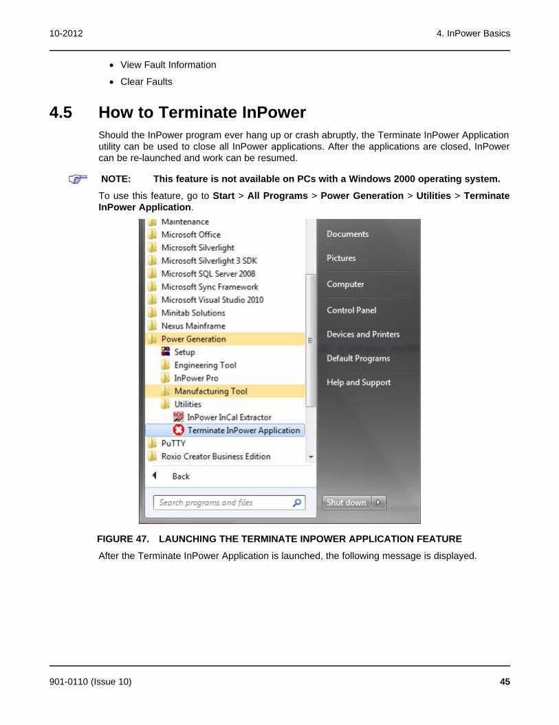
10-2012 4. InPower Basics
· View Fault Information
· Clear Faults
4.5 How to Terminate InPowerShould the InPower program ever hang up or crash abruptly, the Terminate InPower Applicationutility can be used to close all InPower applications. After the applications are closed, InPowercan be re-launched and work can be resumed.
NOTE: This feature is not available on PCs with a Windows 2000 operating system.
To use this feature, go to Start > All Programs > Power Generation > Utilities > TerminateInPower Application.
FIGURE 47. LAUNCHING THE TERMINATE INPOWER APPLICATION FEATURE
After the Terminate InPower Application is launched, the following message is displayed.
901-0110 (Issue 10) 45

4. InPower Basics 10-2012
FIGURE 48. TERMINATING INPOWER APPLICATIONS MESSAGE
Afer clicking Yes, all Etool applications are terminated and the following message is displayed.Click OK.
FIGURE 49. ETOOL TERMINATION MESSAGE
46 901-0110 (Issue 10)
5 Genset ServiceThis section describes how to use InPower for making adjustments and performing tests oncommercial or consumer gensets. When the user is connected to a genset, they can alsoaccess the Monitor, Faults, and Events Configuration features.
5.1 Commercial Genset ServiceInPower performs several functions including genset service and diagnostic functions. TheAdjustment feature is used to perform service adjustments and trims.
The Test feature is used for diagnostics. Test is used to temporarily override a variety of inputand output parameters. (The PCC 3100 does not include the Test Feature).
WARNING: Electrical shock and moving parts can cause severe personal injury or death.Notify personnel before starting a generator set and before performing loadtransfer on a transfer switch. Refer to the equipment Operator's Manual forimportant safety precautions.
You must be connected to the genset in order to write adjustment trims and setting changes tothe controller, and to temporary send test commands to the genset controller. The featuresdescribed may not apply to all control types.
5.1.1 Connecting to a GensetConnection between the service PC and some gensets is made with a special RS-232 serialnull-modem cable. Some connections between the generator set and the PC require aninterface wiring harness and an RS-232 to RS-485 converter.
If the service PC does not have a serial port, a USB-to-serial converter may be required as well.
5.1.1.1 Connecting to PS 0500The PS 0500 control requires an RS-232 to RS-485 data converter and a unique cable. Figure50 shows the PS 0500 InPower connection.
Kit number 541-1199 is available for use with the PS 0500. The kit includes the RS-232 to RS-485 converter and the cable used for these applications. The 5-pin connector is used to connectto the back of the display at the TB15 connector.
901-0110 (Issue 10) 47
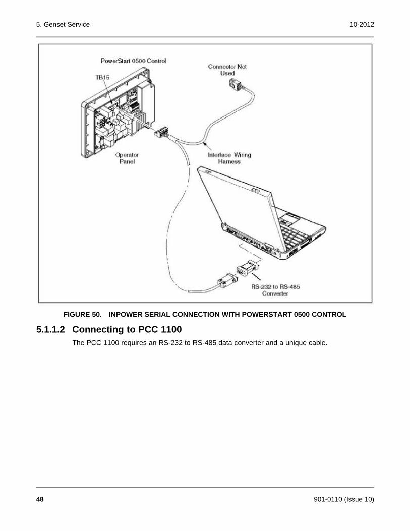
5. Genset Service 10-2012
FIGURE 50. INPOWER SERIAL CONNECTION WITH POWERSTART 0500 CONTROL
5.1.1.2 Connecting to PCC 1100The PCC 1100 requires an RS-232 to RS-485 data converter and a unique cable.
48 901-0110 (Issue 10)
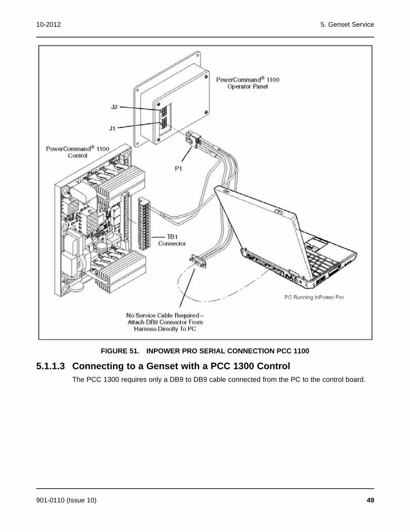
10-2012 5. Genset Service
FIGURE 51. INPOWER PRO SERIAL CONNECTION PCC 1100
5.1.1.3 Connecting to a Genset with a PCC 1300 ControlThe PCC 1300 requires only a DB9 to DB9 cable connected from the PC to the control board.
901-0110 (Issue 10) 49
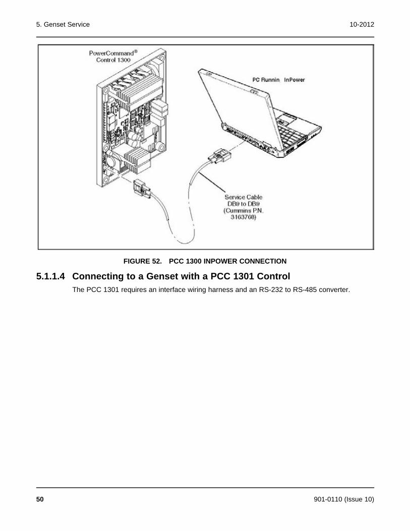
5. Genset Service 10-2012
FIGURE 52. PCC 1300 INPOWER CONNECTION
5.1.1.4 Connecting to a Genset with a PCC 1301 ControlThe PCC 1301 requires an interface wiring harness and an RS-232 to RS-485 converter.
50 901-0110 (Issue 10)

10-2012 5. Genset Service
FIGURE 53. PCC 1301 INPOWER CONNECTION
5.1.1.5 Connecting to PCC 1302The PCC 1302 control requires an RS-232 to RS-485 data converter and a unique cable. ThePCC 1302 also requires an extension harness connected from the display to the engine harnessJ2 connector. Figure 54 shows the PCC 1302 InPower connection.
901-0110 (Issue 10) 51

5. Genset Service 10-2012
FIGURE 54. KIT INSTALLATION FOR POWERCOMMAND CONTROL 1302 WITH HMI211
5.1.1.6 Connecting to a Genset with a PCC 2100 ControlThe PCC 2100 requires only a DB9 to DB9 cable connected from the PC to the control boardinside the control box.
52 901-0110 (Issue 10)

10-2012 5. Genset Service
FIGURE 55. PCC 2100 INPOWER CONNECTION
5.1.1.7 Connecting to PCC2300 and PCC3300The PCC2300 and PCC3300 controls require an RS-232 to RS-485 data converter and aunique cable. Figure 56 shows the PCC2300 InPower connection and Figure 57 shows thePCC3300 InPower connection.
Kit number 541-1199 is available for use with the PCC2300 and PCC3300. The kit includes theRS-232 to RS-485 converter and the cable used for these applications. The 5-pin connector isused to connect either to the control board or the display.
901-0110 (Issue 10) 53

5. Genset Service 10-2012
FIGURE 56. KIT INSTALLATION FOR PCC2300 WITH HMI220 OR HMI320 DISPLAY
54 901-0110 (Issue 10)
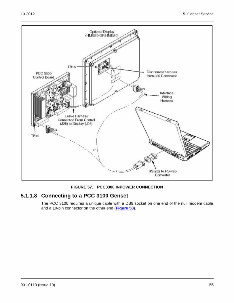
10-2012 5. Genset Service
FIGURE 57. PCC3300 INPOWER CONNECTION
5.1.1.8 Connecting to a PCC 3100 GensetThe PCC 3100 requires a unique cable with a DB9 socket on one end of the null modem cableand a 10-pin connector on the other end (Figure 58).
901-0110 (Issue 10) 55

5. Genset Service 10-2012
FIGURE 58. PCC 3100 INPOWER CONNECTION
5.1.1.9 Connecting to a PCC 3200 GensetFigure 59, Figure 60, and Figure 61 show three methods of connecting to a PCC 3200 genset.The cable has a DB9 socket on each end. The serial cable from the service PC can beconnected to the engine harness or to the customer connection box.
FIGURE 59. INPOWER CONNECTION (PCC 3200 TYPE 1 CONNECTION BOX)
56 901-0110 (Issue 10)

10-2012 5. Genset Service
FIGURE 60. INPOWER CONNECTION (PCC 3200 TYPE 2 CONNECTION BOX)
901-0110 (Issue 10) 57
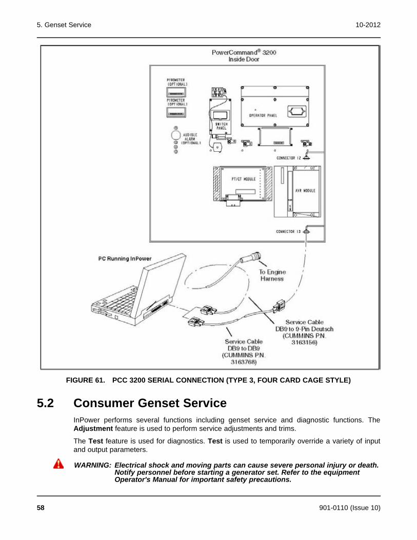
5. Genset Service 10-2012
FIGURE 61. PCC 3200 SERIAL CONNECTION (TYPE 3, FOUR CARD CAGE STYLE)
5.2 Consumer Genset ServiceInPower performs several functions including genset service and diagnostic functions. TheAdjustment feature is used to perform service adjustments and trims.
The Test feature is used for diagnostics. Test is used to temporarily override a variety of inputand output parameters.
WARNING: Electrical shock and moving parts can cause severe personal injury or death.Notify personnel before starting a generator set. Refer to the equipmentOperator's Manual for important safety precautions.
58 901-0110 (Issue 10)
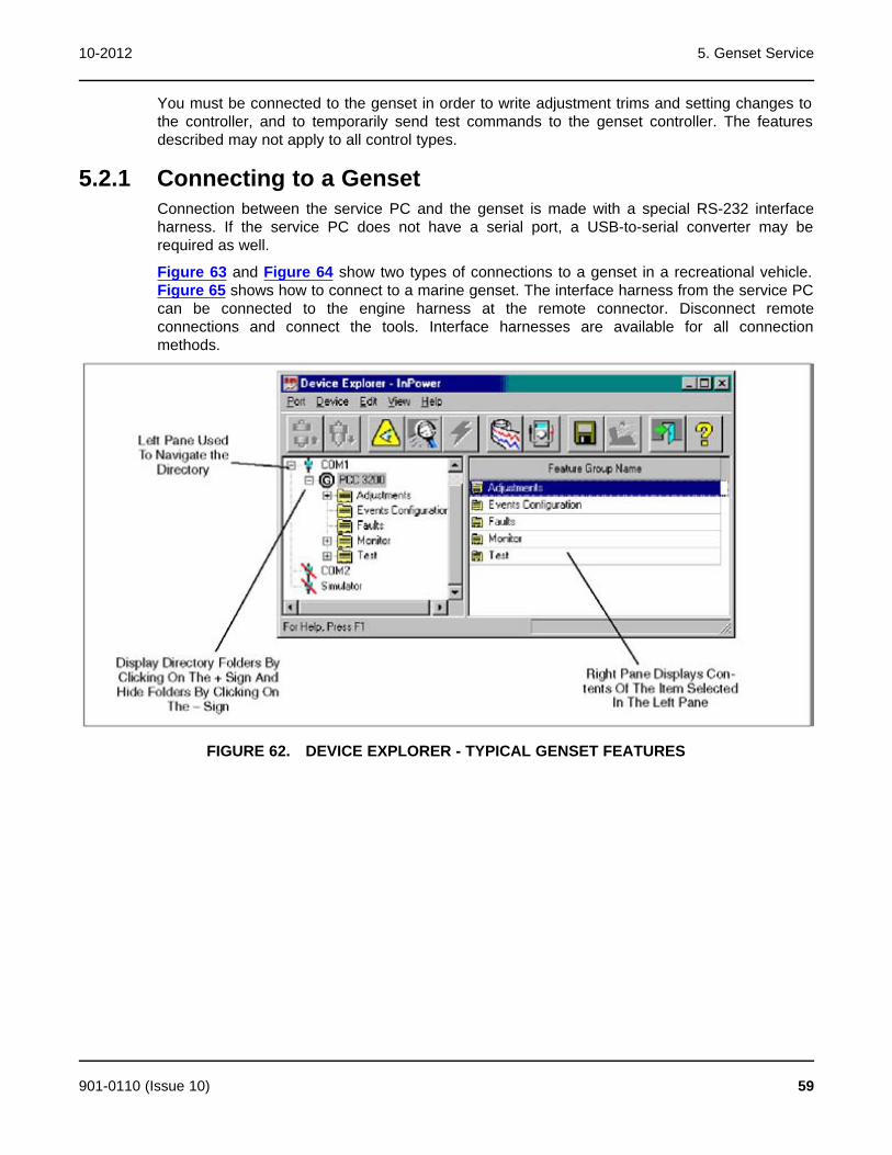
10-2012 5. Genset Service
You must be connected to the genset in order to write adjustment trims and setting changes tothe controller, and to temporarily send test commands to the genset controller. The featuresdescribed may not apply to all control types.
5.2.1 Connecting to a GensetConnection between the service PC and the genset is made with a special RS-232 interfaceharness. If the service PC does not have a serial port, a USB-to-serial converter may berequired as well.
Figure 63 and Figure 64 show two types of connections to a genset in a recreational vehicle.Figure 65 shows how to connect to a marine genset. The interface harness from the service PCcan be connected to the engine harness at the remote connector. Disconnect remoteconnections and connect the tools. Interface harnesses are available for all connectionmethods.
FIGURE 62. DEVICE EXPLORER - TYPICAL GENSET FEATURES
901-0110 (Issue 10) 59
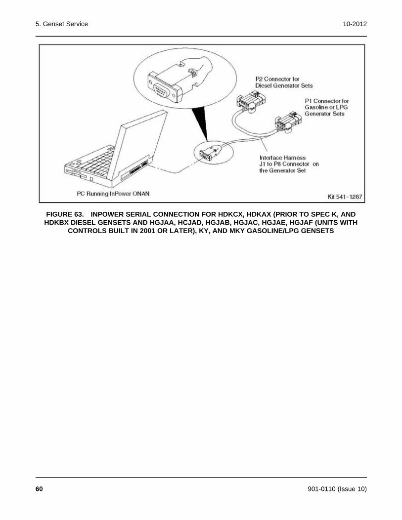
5. Genset Service 10-2012
FIGURE 63. INPOWER SERIAL CONNECTION FOR HDKCX, HDKAX (PRIOR TO SPEC K, ANDHDKBX DIESEL GENSETS AND HGJAA, HCJAD, HGJAB, HGJAC, HGJAE, HGJAF (UNITS WITH
CONTROLS BUILT IN 2001 OR LATER), KY, AND MKY GASOLINE/LPG GENSETS
60 901-0110 (Issue 10)
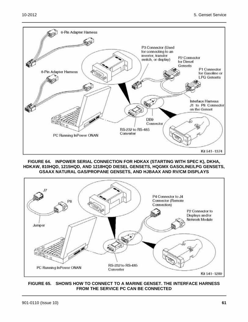
10-2012 5. Genset Service
FIGURE 64. INPOWER SERIAL CONNECTION FOR HDKAX (STARTING WITH SPEC K), DKHA,HDKAW, 810HQD, 1215HQD, AND 1218HQD DIESEL GENSETS, HQGMX GASOLINE/LPG GENSETS,
GSAAX NATURAL GAS/PROPANE GENSETS, AND HJBAAX AND RV/CM DISPLAYS
FIGURE 65. SHOWS HOW TO CONNECT TO A MARINE GENSET. THE INTERFACE HARNESSFROM THE SERVICE PC CAN BE CONNECTED
901-0110 (Issue 10) 61

5. Genset Service 10-2012
5.2.2 Connecting to an HQD Inverter/Charger, Transfer Switch,or Display and an RV Inverter and GSAAInPower can also be used with recreational vehicles with an HQD generator to communicatewith the inverter/charger, transfer switch, or the display.
Connection between the service PC and the device is made with a special RS-232 interfaceharness.
Figure 66 shows how to connect to an inverter/charger or a transfer switch. Figure 67 andFigure 68 show how to connect to a display. The interface harness from the service PC can beconnected to the inverter/charger or transfer switch. The interface harness from the service PCmust be connected to an adapter harness that is connected to the display and a power source.Connections to these devices require an RS-232 to RS-485 communications converter.Interface harnesses are available for all connection methods.
NOTE: When using InPower is connected to the transfer switch to do an update oran initial calibration, the display must either be asleep or disconnected.
FIGURE 66. INPOWER SERIAL CONNECTION FOR AN HQD INVERTER/CHARGER OR TRANSFERSWITCH, RV INVERTER, AND GSAA
62 901-0110 (Issue 10)

10-2012 5. Genset Service
FIGURE 67. INPOWER SERIAL CONNECTION FOR 6-PIN RV/COMMERCIAL MOBILE DISPLAYS
FIGURE 68. INPOWER SERIAL CONNECTION FOR 8-PIN RV/COMMERCIAL MOBILE DISPLAYS
901-0110 (Issue 10) 63

5. Genset Service 10-2012
5.2.3 Connecting to Marine Devices5.2.3.1 Programming A Marine Control
NOTE: For communicating and troubleshooting only, use a MONnet connection andplug into the remote control. For programming using MON, refer to the wiringdiagrams.
To program a Marine control, refer to the connections shown in Figure 69.
1. If you installation includes a display or a Network Interface Module (NIM),
a. Disconnect the generator set remote control connector.
b. Connect the interface harness (P4) to the generator set remote control connector.
c. Connect the jumper (J7) to the interface harness (P2).
d. Connect the jumper (P8) to the adapter harness.
e. Install the RS-232 to RS-485 converter on the PC.
f. Connect the interface harness to the RS-232 to RS-485 converter.
2. If your installation does not include a display or a NIM, plug the interface harness into theremote control connector.
3. Wake up the control using the display or the Start/Stop switch. Press Stop until the statuslight comes on or the LCD screen shows genset data.
4. Program the control.
5. Remove the battery and reconnect the wiring to its original configuration.
64 901-0110 (Issue 10)
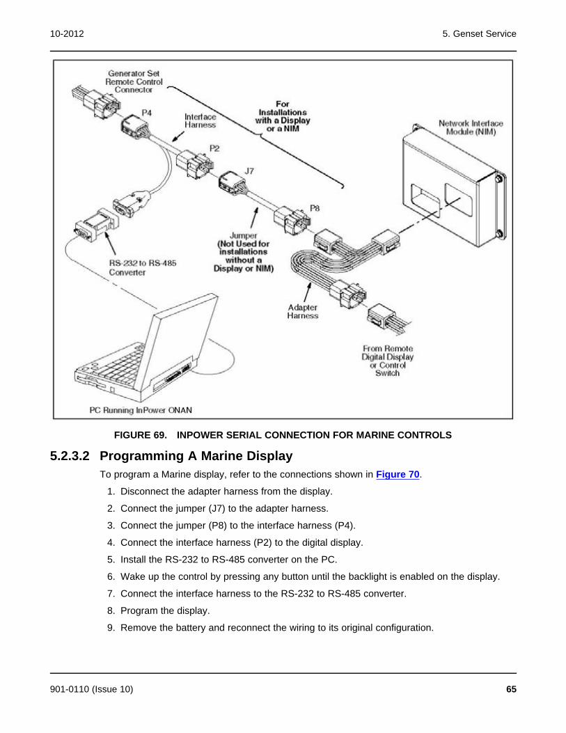
10-2012 5. Genset Service
FIGURE 69. INPOWER SERIAL CONNECTION FOR MARINE CONTROLS
5.2.3.2 Programming A Marine DisplayTo program a Marine display, refer to the connections shown in Figure 70.
1. Disconnect the adapter harness from the display.
2. Connect the jumper (J7) to the adapter harness.
3. Connect the jumper (P8) to the interface harness (P4).
4. Connect the interface harness (P2) to the digital display.
5. Install the RS-232 to RS-485 converter on the PC.
6. Wake up the control by pressing any button until the backlight is enabled on the display.
7. Connect the interface harness to the RS-232 to RS-485 converter.
8. Program the display.
9. Remove the battery and reconnect the wiring to its original configuration.
901-0110 (Issue 10) 65
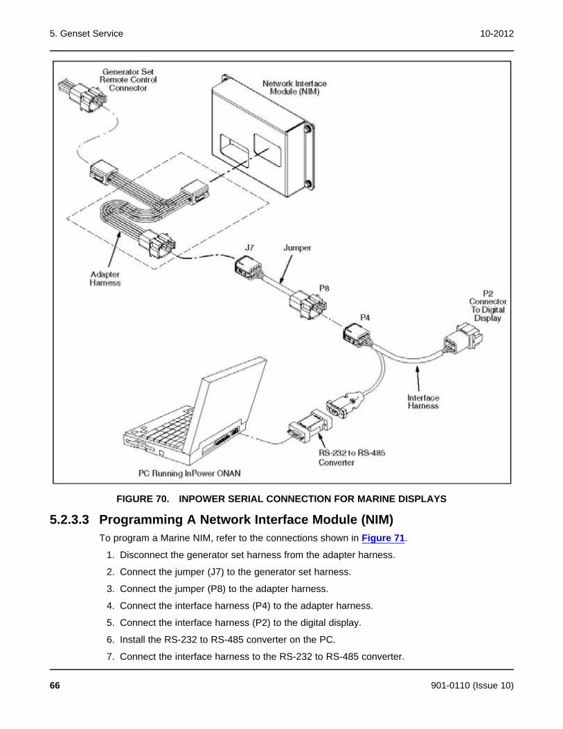
5. Genset Service 10-2012
FIGURE 70. INPOWER SERIAL CONNECTION FOR MARINE DISPLAYS
5.2.3.3 Programming A Network Interface Module (NIM)To program a Marine NIM, refer to the connections shown in Figure 71.
1. Disconnect the generator set harness from the adapter harness.
2. Connect the jumper (J7) to the generator set harness.
3. Connect the jumper (P8) to the adapter harness.
4. Connect the interface harness (P4) to the adapter harness.
5. Connect the interface harness (P2) to the digital display.
6. Install the RS-232 to RS-485 converter on the PC.
7. Connect the interface harness to the RS-232 to RS-485 converter.
66 901-0110 (Issue 10)
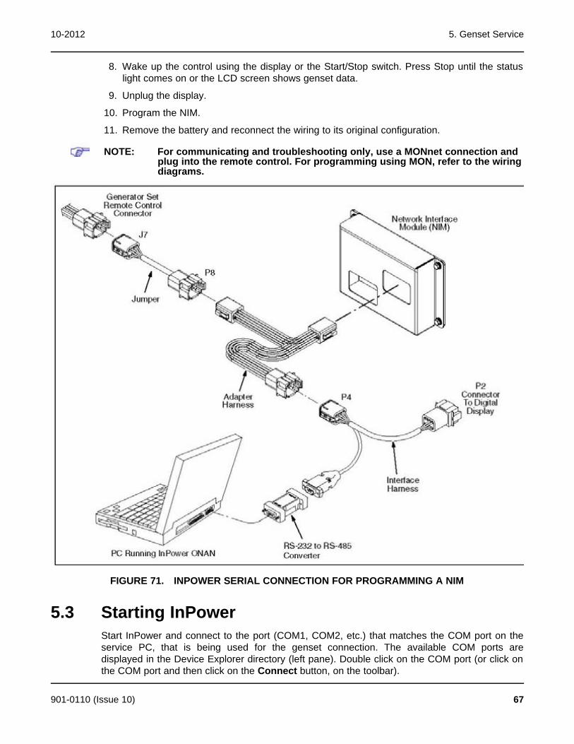
10-2012 5. Genset Service
8. Wake up the control using the display or the Start/Stop switch. Press Stop until the statuslight comes on or the LCD screen shows genset data.
9. Unplug the display.
10. Program the NIM.
11. Remove the battery and reconnect the wiring to its original configuration.
NOTE: For communicating and troubleshooting only, use a MONnet connection andplug into the remote control. For programming using MON, refer to the wiringdiagrams.
FIGURE 71. INPOWER SERIAL CONNECTION FOR PROGRAMMING A NIM
5.3 Starting InPowerStart InPower and connect to the port (COM1, COM2, etc.) that matches the COM port on theservice PC, that is being used for the genset connection. The available COM ports aredisplayed in the Device Explorer directory (left pane). Double click on the COM port (or click onthe COM port and then click on the Connect button, on the toolbar).
901-0110 (Issue 10) 67
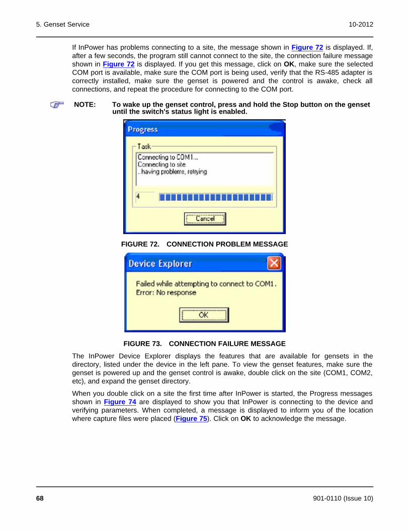
5. Genset Service 10-2012
If InPower has problems connecting to a site, the message shown in Figure 72 is displayed. If,after a few seconds, the program still cannot connect to the site, the connection failure messageshown in Figure 72 is displayed. If you get this message, click on OK, make sure the selectedCOM port is available, make sure the COM port is being used, verify that the RS-485 adapter iscorrectly installed, make sure the genset is powered and the control is awake, check allconnections, and repeat the procedure for connecting to the COM port.
NOTE: To wake up the genset control, press and hold the Stop button on the gensetuntil the switch's status light is enabled.
FIGURE 72. CONNECTION PROBLEM MESSAGE
FIGURE 73. CONNECTION FAILURE MESSAGE
The InPower Device Explorer displays the features that are available for gensets in thedirectory, listed under the device in the left pane. To view the genset features, make sure thegenset is powered up and the genset control is awake, double click on the site (COM1, COM2,etc), and expand the genset directory.
When you double click on a site the first time after InPower is started, the Progress messagesshown in Figure 74 are displayed to show you that InPower is connecting to the device andverifying parameters. When completed, a message is displayed to inform you of the locationwhere capture files were placed (Figure 75). Click on OK to acknowledge the message.
68 901-0110 (Issue 10)

10-2012 5. Genset Service
FIGURE 74. DEVICE PROGRESS MESSAGES
FIGURE 75. ANNOUNCEMENT OF CAPTURE FILE LOCATION
If a connection failure message is displayed when attempting to connect to an available device,make sure the device is turned on and check all connections.
901-0110 (Issue 10) 69
5. Genset Service 10-2012
The following is a typical list of available features.
· Adjustments
· Events Configuration
· Faults
· Monitor
· Test
· CAN Control
· Events and Faults
NOTE: The available features vary from genset to genset.
When you are connected to a genset, the Capture File feature is enabled. This feature is usedto create a copy of the gensets existing parameter values. Always create a Capture file of thedevice parameters for reference, prior to making any adjustments.
5.4 Genset AdjustmentsThis section describes how to make genset parameter value adjustments for trims and settings.There are a large number of adjustable trims and settings available for gensets. Not all gensetmodels will have the same adjustments available. This section will cover typical adjustmentexamples, to help demonstrate basic procedures for using the adjustment features.
CAUTION: Improper adjustment can cause equipment malfunction or damage. Adjustmentsmust be performed by trained and experienced personnel only. Refer to theequipment's Installation and Service manuals for adjustment sequences andprocedures.
5.4.1 Adjustment BasicsTo access a group of adjustments or an individual adjustment, use Device Explorer to navigatethe left pane until you reach the desired folder, and click on it. The right pane will display theparameter(s) associated with the adjustments for that feature.
Figure 76 shows a list of parameters for the Governor - Frequency selection.
The right pane displays the Parameter description, Value, Units of measure and the Last Timethat the value was Read.
Placing the mouse pointer over a parameter will bring up an information popup box. The popupprovides a brief description of how the parameter value is used.
NOTE: Some values may require that the genset is running or stopped before theycan be edited. Refer to the parameter's information pop-up for details.
70 901-0110 (Issue 10)

10-2012 5. Genset Service
FIGURE 76. TYPICAL PARAMETER INFORMATION
5.4.2 Adjustment FeaturesThe groups and the contents of the Adjustment features can vary by genset model, controlsoftware version, and InPower version.
The Adjustments directory for a typical genset contains the following groups (folders) ofAdjustment options:
AC Measurement Calibration: This group contains Current, Voltage and Power Factormeasurement parameters for the graphical display. Also contained in this group is thecalibration for Voltage Measurement for Regulation.
Alternator Protection: Contains adjustments for Over and Under Frequency, High and Low ACVoltage, and related time delay settings.
Automatic Voltage Regulator: Contains adjustments for the Voltage Adjust trim for thenominal voltage offset, overall AVR gain adjust, and the V/Hz rolloff table.
Engine Protection Adjustments: Engine protection settings for high and low temperature,pressure settings, and related time delays.
Features: This group contains several genset setup and feature settings. For example, theExercise Setup parameter allows the user to set the genset exercise duration, in hours.
Genset Power Ratings: Contains adjustments for setting up the application information such asStandby or Prime Power, Delta or Wye alternator connection, KVA rating, line-to-line voltageand generator connection for single or three phase.
Governor: This group contains Governor adjustments for Frequency settings, Gain and Droopsettings, and Idle and Ramping.
LONWORKS: This group contains network settings, Controller Identification, modem DialoutSetup, network Fault Setup and Network Setup.
Paralleling: This group contains parameters for Breaker Interface, Bus Voltage Setup, LoadShare Setup, Paralleling Mode, Protection, and Synchronizing.
901-0110 (Issue 10) 71

5. Genset Service 10-2012
Passwords: This group contains three features that are used for password administration.
The Change Passwords feature is used to establish initial passwords and to change existingpasswords.
Passwords must be 5 to 8 characters in length. They may consist of any combination of alphaor numeric characters. Do not use special characters.
The Clear Passwords feature allows users, with a password, to clear the password. This istypically used if you wish to permanently remove the password. If you want to change anexisting password, use the Change Passwords feature.
The Enter Passwords feature is used to gain access to password protected parameters.Entering the password allows the user to write changes to password protected parameters.
There are two predefined groups of parameters that can be protected by passwords, these arenamed User and Application. When a password is established for either of these groups,access becomes password protected. Users can view password protected parameters, but theycannot write changes to them without Entering the password first.
The Site Password feature is used to provide password protection when accessing a devicefrom a remote (dial-in) location. This feature can also be used to administer an existing sitepassword.
Refer to the examples of changing, entering and clearing passwords, in this section.
Reset History Counters: Allows the user to reset the history records for Fuel, Power, andStarts and Runs in a genset control.
Starting: Contains parameters for setting cranking time settings and attempts, and for StartTime Delay.
Switch Setup: Contains a group of miscellaneous switch parameters for monitoring and forsetting switches to a specific state. An example of switch some states are: Enable or Disabled,Started or Stopped, On or Off, Active Open or Active Closed, etc., The settings depends on thetype switch selected.
Many of these features contain sub menus of additional adjustment features. Use DeviceExplorer to expand each of these categories to view the sub-menu of adjustments.
FIGURE 77. TYPICAL ADJUSTMENT FEATURES
72 901-0110 (Issue 10)
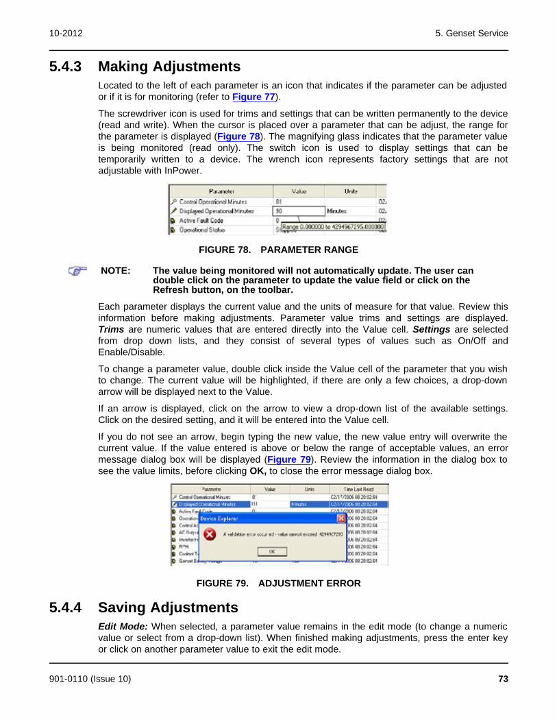
10-2012 5. Genset Service
5.4.3 Making AdjustmentsLocated to the left of each parameter is an icon that indicates if the parameter can be adjustedor if it is for monitoring (refer to Figure 77).
The screwdriver icon is used for trims and settings that can be written permanently to the device(read and write). When the cursor is placed over a parameter that can be adjust, the range forthe parameter is displayed (Figure 78). The magnifying glass indicates that the parameter valueis being monitored (read only). The switch icon is used to display settings that can betemporarily written to a device. The wrench icon represents factory settings that are notadjustable with InPower.
FIGURE 78. PARAMETER RANGE
NOTE: The value being monitored will not automatically update. The user candouble click on the parameter to update the value field or click on theRefresh button, on the toolbar.
Each parameter displays the current value and the units of measure for that value. Review thisinformation before making adjustments. Parameter value trims and settings are displayed.Trims are numeric values that are entered directly into the Value cell. Settings are selectedfrom drop down lists, and they consist of several types of values such as On/Off andEnable/Disable.
To change a parameter value, double click inside the Value cell of the parameter that you wishto change. The current value will be highlighted, if there are only a few choices, a drop-downarrow will be displayed next to the Value.
If an arrow is displayed, click on the arrow to view a drop-down list of the available settings.Click on the desired setting, and it will be entered into the Value cell.
If you do not see an arrow, begin typing the new value, the new value entry will overwrite thecurrent value. If the value entered is above or below the range of acceptable values, an errormessage dialog box will be displayed (Figure 79). Review the information in the dialog box tosee the value limits, before clicking OK, to close the error message dialog box.
FIGURE 79. ADJUSTMENT ERROR
5.4.4 Saving AdjustmentsEdit Mode: When selected, a parameter value remains in the edit mode (to change a numericvalue or select from a drop-down list). When finished making adjustments, press the enter keyor click on another parameter value to exit the edit mode.
901-0110 (Issue 10) 73
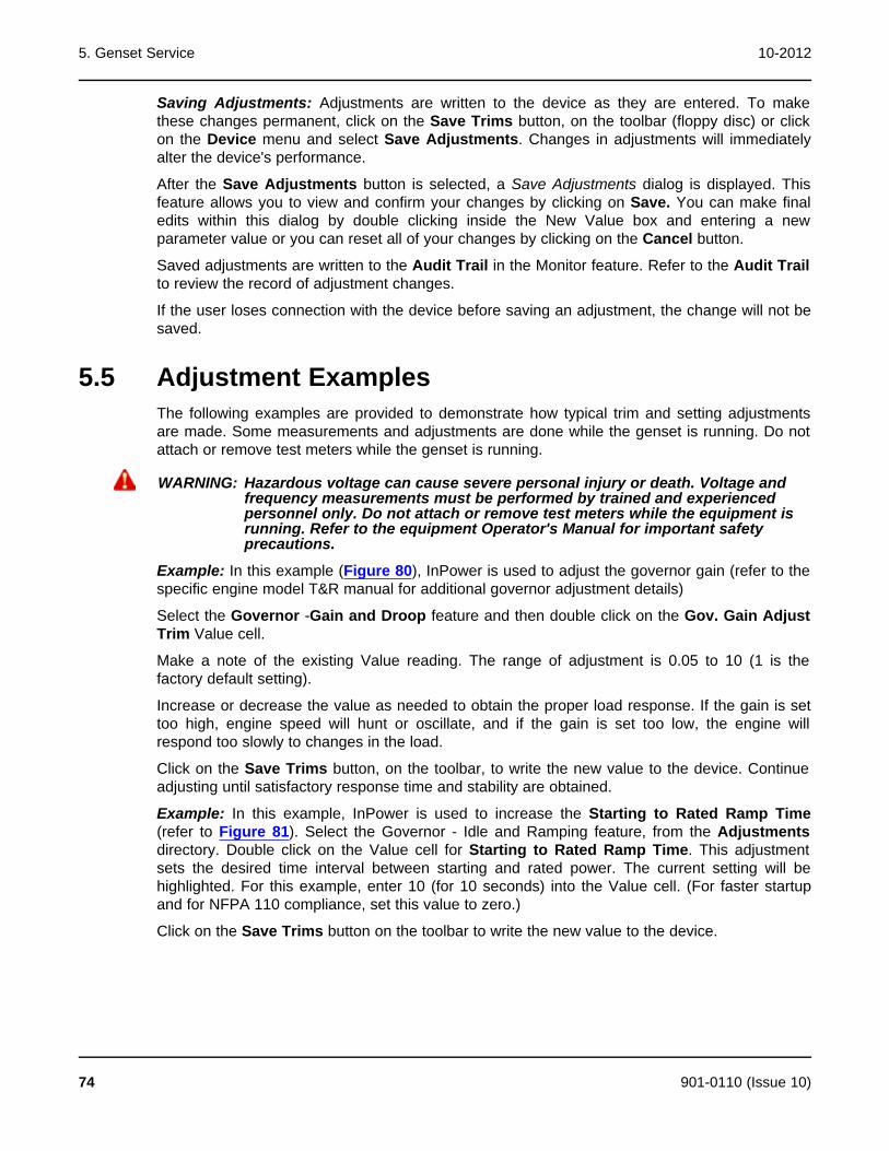
5. Genset Service 10-2012
Saving Adjustments: Adjustments are written to the device as they are entered. To makethese changes permanent, click on the Save Trims button, on the toolbar (floppy disc) or clickon the Device menu and select Save Adjustments. Changes in adjustments will immediatelyalter the device's performance.
After the Save Adjustments button is selected, a Save Adjustments dialog is displayed. Thisfeature allows you to view and confirm your changes by clicking on Save. You can make finaledits within this dialog by double clicking inside the New Value box and entering a newparameter value or you can reset all of your changes by clicking on the Cancel button.
Saved adjustments are written to the Audit Trail in the Monitor feature. Refer to the Audit Trailto review the record of adjustment changes.
If the user loses connection with the device before saving an adjustment, the change will not besaved.
5.5 Adjustment ExamplesThe following examples are provided to demonstrate how typical trim and setting adjustmentsare made. Some measurements and adjustments are done while the genset is running. Do notattach or remove test meters while the genset is running.
WARNING: Hazardous voltage can cause severe personal injury or death. Voltage andfrequency measurements must be performed by trained and experiencedpersonnel only. Do not attach or remove test meters while the equipment isrunning. Refer to the equipment Operator's Manual for important safetyprecautions.
Example: In this example (Figure 80), InPower is used to adjust the governor gain (refer to thespecific engine model T&R manual for additional governor adjustment details)
Select the Governor -Gain and Droop feature and then double click on the Gov. Gain AdjustTrim Value cell.
Make a note of the existing Value reading. The range of adjustment is 0.05 to 10 (1 is thefactory default setting).
Increase or decrease the value as needed to obtain the proper load response. If the gain is settoo high, engine speed will hunt or oscillate, and if the gain is set too low, the engine willrespond too slowly to changes in the load.
Click on the Save Trims button, on the toolbar, to write the new value to the device. Continueadjusting until satisfactory response time and stability are obtained.
Example: In this example, InPower is used to increase the Starting to Rated Ramp Time(refer to Figure 81). Select the Governor - Idle and Ramping feature, from the Adjustmentsdirectory. Double click on the Value cell for Starting to Rated Ramp Time. This adjustmentsets the desired time interval between starting and rated power. The current setting will behighlighted. For this example, enter 10 (for 10 seconds) into the Value cell. (For faster startupand for NFPA 110 compliance, set this value to zero.)
Click on the Save Trims button on the toolbar to write the new value to the device.
74 901-0110 (Issue 10)
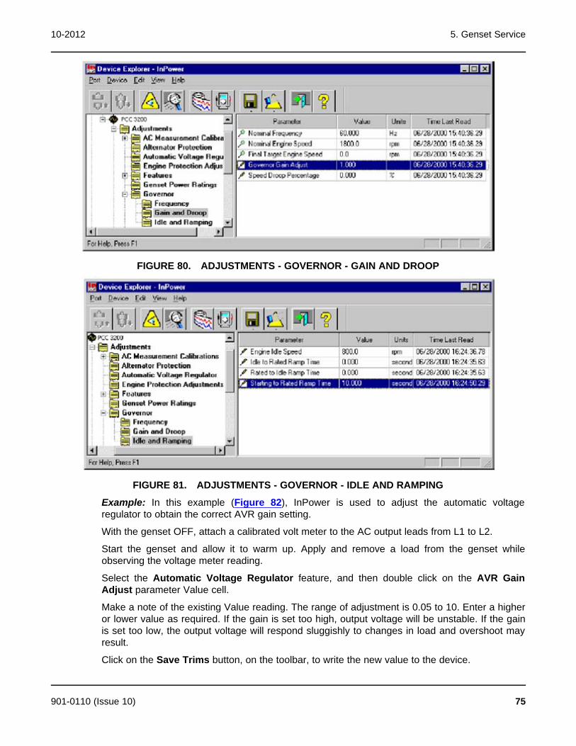
10-2012 5. Genset Service
FIGURE 80. ADJUSTMENTS - GOVERNOR - GAIN AND DROOP
FIGURE 81. ADJUSTMENTS - GOVERNOR - IDLE AND RAMPING
Example: In this example (Figure 82), InPower is used to adjust the automatic voltageregulator to obtain the correct AVR gain setting.
With the genset OFF, attach a calibrated volt meter to the AC output leads from L1 to L2.
Start the genset and allow it to warm up. Apply and remove a load from the genset whileobserving the voltage meter reading.
Select the Automatic Voltage Regulator feature, and then double click on the AVR GainAdjust parameter Value cell.
Make a note of the existing Value reading. The range of adjustment is 0.05 to 10. Enter a higheror lower value as required. If the gain is set too high, output voltage will be unstable. If the gainis set too low, the output voltage will respond sluggishly to changes in load and overshoot mayresult.
Click on the Save Trims button, on the toolbar, to write the new value to the device.
901-0110 (Issue 10) 75
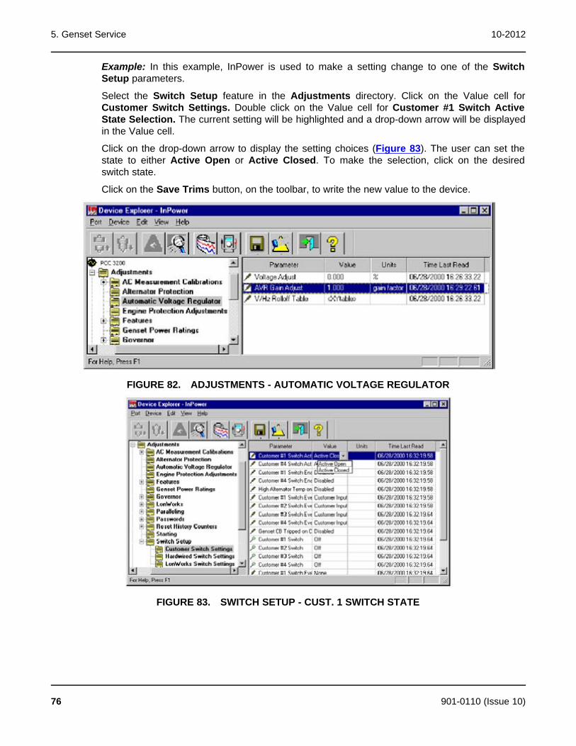
5. Genset Service 10-2012
Example: In this example, InPower is used to make a setting change to one of the SwitchSetup parameters.
Select the Switch Setup feature in the Adjustments directory. Click on the Value cell forCustomer Switch Settings. Double click on the Value cell for Customer #1 Switch ActiveState Selection. The current setting will be highlighted and a drop-down arrow will be displayedin the Value cell.
Click on the drop-down arrow to display the setting choices (Figure 83). The user can set thestate to either Active Open or Active Closed. To make the selection, click on the desiredswitch state.
Click on the Save Trims button, on the toolbar, to write the new value to the device.
FIGURE 82. ADJUSTMENTS - AUTOMATIC VOLTAGE REGULATOR
FIGURE 83. SWITCH SETUP - CUST. 1 SWITCH STATE
76 901-0110 (Issue 10)

10-2012 5. Genset Service
FIGURE 84. ENGINE PROTECTION ADJ. - LCP WARNING THRESHOLD
Example: In this example InPower is used to adjust an XY table.
NOTE: InPower will only allow adjustments to engine protection parameters thatresult in increased engine protection.
Select the Engine Protection Adjustments feature and double click on the Value cell for LCPWarning Threshold (Figure 84). The current threshold settings are displayed in a graph.Pressure, in psi, is displayed on the Y-axis and engine speed is displayed on the X-axis.
Editing can be performed in the Graph Mode (Figure 85) or in the Spreadsheet Mode (Figure86). To change to the Spreadsheet Mode, click on the Graph Mode checkbox to remove thecheck mark.
Edit in the Graph Mode by dragging a threshold point on the graph to the desired setting. Whenthe cursor is in the correct location, a pointing hand will appear on the graph. Select the hand byholding down on the mouse button, continue to hold down on the mouse button while draggingthe point to the desired location.
Click on Save, to update the most recent changes. Click on Close when you are finished makingchanges.
Click on the Save Trims button, on the toolbar, to write the new value to the device.
901-0110 (Issue 10) 77
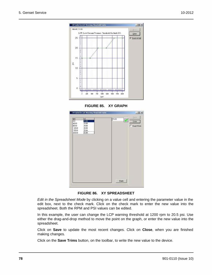
5. Genset Service 10-2012
FIGURE 85. XY GRAPH
FIGURE 86. XY SPREADSHEET
Edit in the Spreadsheet Mode by clicking on a value cell and entering the parameter value in theedit box, next to the check mark. Click on the check mark to enter the new value into thespreadsheet. Both the RPM and PSI values can be edited.
In this example, the user can change the LCP warning threshold at 1200 rpm to 20.5 psi. Useeither the drag-and-drop method to move the point on the graph, or enter the new value into thespreadsheet.
Click on Save to update the most recent changes. Click on Close, when you are finishedmaking changes.
Click on the Save Trims button, on the toolbar, to write the new value to the device.
78 901-0110 (Issue 10)

10-2012 5. Genset Service
The Paste button (Figure 86) is used to import spreadsheet value data from an Excelspreadsheet. Service personnel will not need to use this feature because the data isalready provided. Generally, only minor adjustments are required.
Password Example 1: In this example (Figure 87), InPower is used to create both anApplication password and a User password. These passwords are used to prevent unauthorizedInPower users from writing changes to password protected parameters.
In examples 2 and 3, InPower is used to Enter these passwords to write changes to protectedparameters and to Clear these Application and User passwords.
Connect to the device and open the Adjustments - Passwords parameter group. Click on theChange Passwords folder.
Double click on the value cell for the Change Application Password parameter. Enter thepassword test21 (passwords must be 5 to 8 characters in length and may consist of anycombination of alpha or numeric characters).
Make a note of the Application password.
Click on the Save Trims button, on the toolbar, to write the new password to the device.
Repeat this process for the Change User Password value cell. Enter test22 and click on theSave Trims button again to write the new password to the device.
Make a note of the User password.
Close the connection to the device and exit InPower. Proceed to the next Password Example.
FIGURE 87. CHANGE PASSWORDS
Password Example 2: In this example (Figure 88), InPower is used to adjust parameters thathave password protection.
Start InPower, connect to the device, and open the Adjustments - Passwords parametergroup. Click on the Enter Passwords folder.
Double click on the value cell for the Enter Application Password parameter. Enter thepassword test21. Click on the Save Trims button. Repeat by entering test22 in the Enter UserPassword value cell, and click on the Save Trims button.
901-0110 (Issue 10) 79
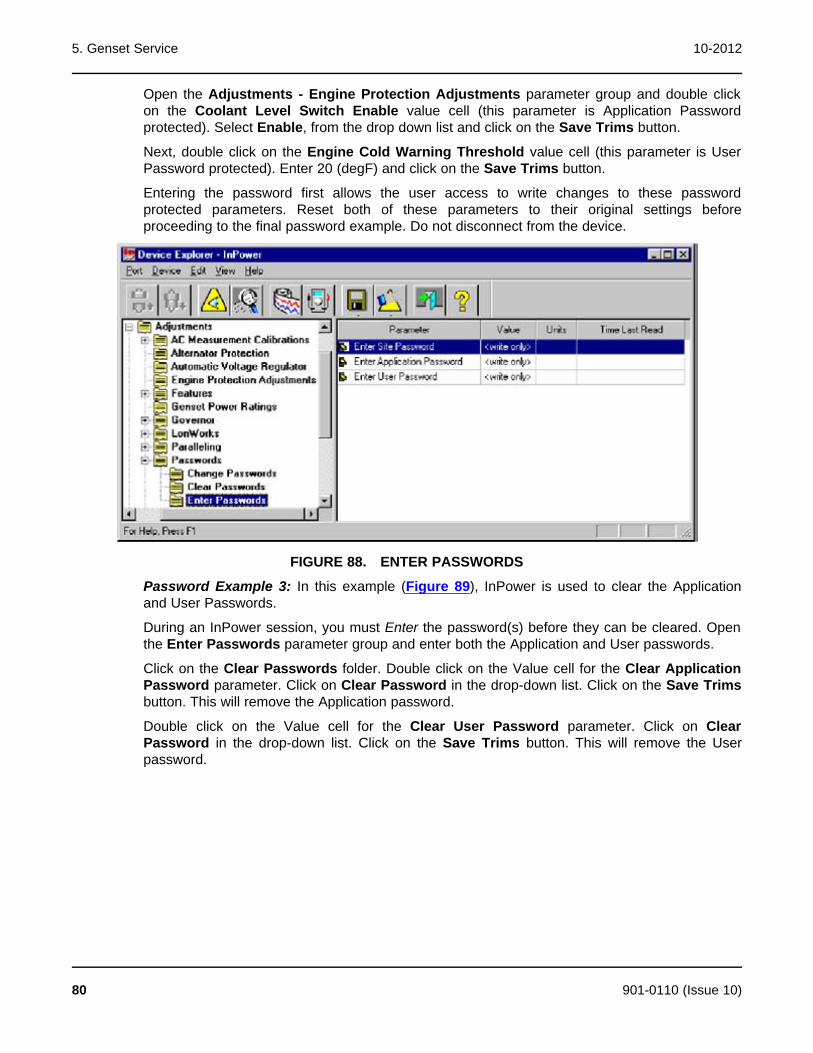
5. Genset Service 10-2012
Open the Adjustments - Engine Protection Adjustments parameter group and double clickon the Coolant Level Switch Enable value cell (this parameter is Application Passwordprotected). Select Enable, from the drop down list and click on the Save Trims button.
Next, double click on the Engine Cold Warning Threshold value cell (this parameter is UserPassword protected). Enter 20 (degF) and click on the Save Trims button.
Entering the password first allows the user access to write changes to these passwordprotected parameters. Reset both of these parameters to their original settings beforeproceeding to the final password example. Do not disconnect from the device.
FIGURE 88. ENTER PASSWORDS
Password Example 3: In this example (Figure 89), InPower is used to clear the Applicationand User Passwords.
During an InPower session, you must Enter the password(s) before they can be cleared. Openthe Enter Passwords parameter group and enter both the Application and User passwords.
Click on the Clear Passwords folder. Double click on the Value cell for the Clear ApplicationPassword parameter. Click on Clear Password in the drop-down list. Click on the Save Trimsbutton. This will remove the Application password.
Double click on the Value cell for the Clear User Password parameter. Click on ClearPassword in the drop-down list. Click on the Save Trims button. This will remove the Userpassword.
80 901-0110 (Issue 10)

10-2012 5. Genset Service
FIGURE 89. CLEAR PASSWORDS
Example: In this example (Figure 91), InPower is used to display a load profile for a PCC 3100genset.
Connect to the PCC 3100 device and open the Monitor feature group. Select the Genset Datafeature and double click on the Value cell to display a chart showing the for Genset LoadProfile (Figure 90).
The load profile displays the number of hours that the generator set has operated between zeroand 120 percent of rated power. The table is divided into 10 percent increments.
Click on the Close button when you are finished viewing the data.
FIGURE 90. PCC 3100 LOAD PROFILE
901-0110 (Issue 10) 81

5. Genset Service 10-2012
FIGURE 91. PCC 3100 GENSET LOAD PROFILE
5.6 TestThe Test feature is a diagnostic tool that is used to perform internal self-checks on the device(Self Test). Use InPower to verify inputs and outputs of the device, and test device protectionfunctions (like Overspeed).
After changing a Test parameter, the user can observe or measure the results of the changes.
NOTE: There are two types of Test Commands: maintained inputs and momentaryinputs. When a maintained input is set to active, the input will remain active.The InPower user MUST set the input back to inactive, when they are finishedwith the test or before leaving the site, otherwise the command will remainactive.
Momentary inputs automatically change state to inactive after one second.
Maintained inputs generally have the screwdriver icon next to the parameter name, andmomentary inputs have the switch icon next to the parameter name.
This section describes each group of tests listed in the Test directory. The Self Test feature canbe used as a quick check to determine if the genset control is responding, by sending controlinputs that should activate the control outputs. The other Tests are used for performing morespecific test functions.
The Test parameter values are adjustable (Figure 92). Some parameters have a numeric valuethat can be changed while others have values that can be selected from a drop-down list.
5.6.1 Commercial GensetsThe Test directory for a typical commercial genset may contain the following groups (folders) ofTest options:
· Fault Simulation
· Inputs
· Manual Operation
82 901-0110 (Issue 10)
10-2012 5. Genset Service
· Outputs
· Self Test
· Speed Override
· Protection Verification
· Annunciator
The Test directory for a typical consumer genset may contain the following groups (folders) ofTest options:
5.6.2 Consumer GensetsThe Test directory may contain the following groups (folders) of Test options for consumergensets:
· Starter Override Request
· Starter Override Command
· Starter Override Status
· Glow Plugs Override Request
· Glow Plugs Override Command
· Glow Plugs Override Status
· Fuel Pump Override Request
· Fuel Pump Override Command
· Fuel Pump Override Status
· Run Output Override Request
· Run Output Override Command
· Run Override Status
· Status Light Override Request
· Status Light Override Command
· Status Light Override Status
· Power Latch Override Request
· Power Latch Override Command
· Power Latch Override Status
· Inverter Enable Override Request
· Inverter Enable Override Command
· Inverter Enable Output Status
· Governor Output Override Request
· Governor Output Override Command (in percent)
· Governor Output Override Status
· Set High Idle
901-0110 (Issue 10) 83
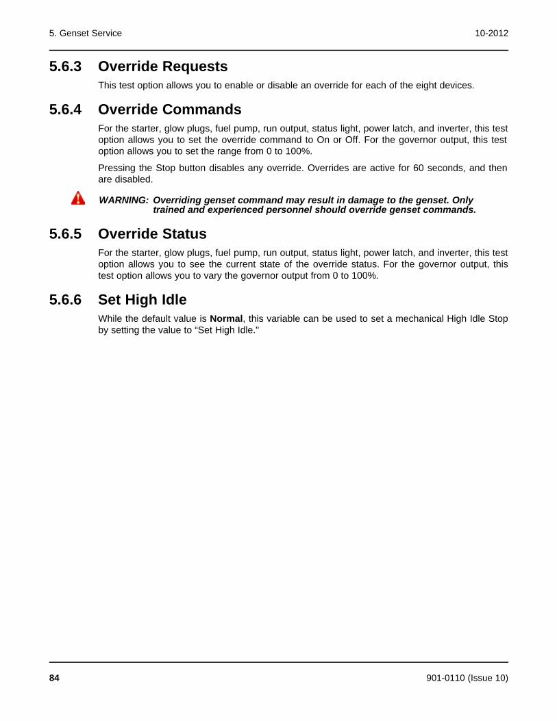
5. Genset Service 10-2012
5.6.3 Override RequestsThis test option allows you to enable or disable an override for each of the eight devices.
5.6.4 Override CommandsFor the starter, glow plugs, fuel pump, run output, status light, power latch, and inverter, this testoption allows you to set the override command to On or Off. For the governor output, this testoption allows you to set the range from 0 to 100%.
Pressing the Stop button disables any override. Overrides are active for 60 seconds, and thenare disabled.
WARNING: Overriding genset command may result in damage to the genset. Onlytrained and experienced personnel should override genset commands.
5.6.5 Override StatusFor the starter, glow plugs, fuel pump, run output, status light, power latch, and inverter, this testoption allows you to see the current state of the override status. For the governor output, thistest option allows you to vary the governor output from 0 to 100%.
5.6.6 Set High IdleWhile the default value is Normal, this variable can be used to set a mechanical High Idle Stopby setting the value to “Set High Idle."
84 901-0110 (Issue 10)
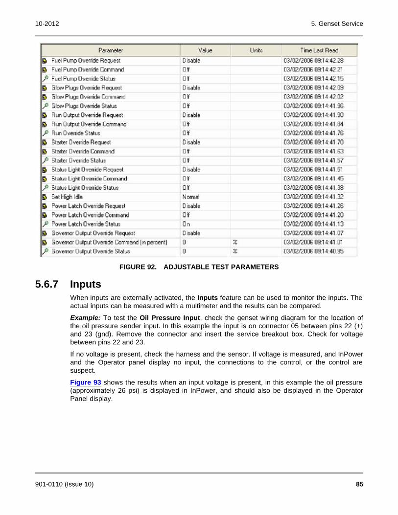
10-2012 5. Genset Service
FIGURE 92. ADJUSTABLE TEST PARAMETERS
5.6.7 InputsWhen inputs are externally activated, the Inputs feature can be used to monitor the inputs. Theactual inputs can be measured with a multimeter and the results can be compared.
Example: To test the Oil Pressure Input, check the genset wiring diagram for the location ofthe oil pressure sender input. In this example the input is on connector 05 between pins 22 (+)and 23 (gnd). Remove the connector and insert the service breakout box. Check for voltagebetween pins 22 and 23.
If no voltage is present, check the harness and the sensor. If voltage is measured, and InPowerand the Operator panel display no input, the connections to the control, or the control aresuspect.
Figure 93 shows the results when an input voltage is present, in this example the oil pressure(approximately 26 psi) is displayed in InPower, and should also be displayed in the OperatorPanel display.
901-0110 (Issue 10) 85
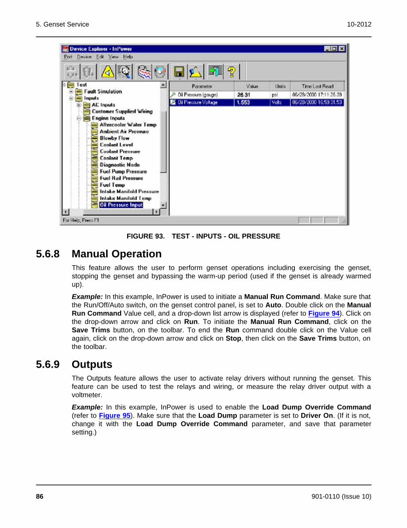
5. Genset Service 10-2012
FIGURE 93. TEST - INPUTS - OIL PRESSURE
5.6.8 Manual OperationThis feature allows the user to perform genset operations including exercising the genset,stopping the genset and bypassing the warm-up period (used if the genset is already warmedup).
Example: In this example, InPower is used to initiate a Manual Run Command. Make sure thatthe Run/Off/Auto switch, on the genset control panel, is set to Auto. Double click on the ManualRun Command Value cell, and a drop-down list arrow is displayed (refer to Figure 94). Click onthe drop-down arrow and click on Run. To initiate the Manual Run Command, click on theSave Trims button, on the toolbar. To end the Run command double click on the Value cellagain, click on the drop-down arrow and click on Stop, then click on the Save Trims button, onthe toolbar.
5.6.9 OutputsThe Outputs feature allows the user to activate relay drivers without running the genset. Thisfeature can be used to test the relays and wiring, or measure the relay driver output with avoltmeter.
Example: In this example, InPower is used to enable the Load Dump Override Command(refer to Figure 95). Make sure that the Load Dump parameter is set to Driver On. (If it is not,change it with the Load Dump Override Command parameter, and save that parametersetting.)
86 901-0110 (Issue 10)
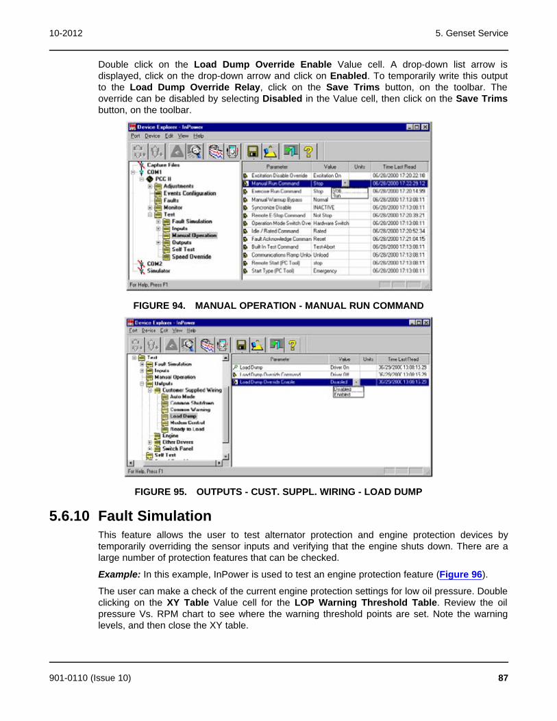
10-2012 5. Genset Service
Double click on the Load Dump Override Enable Value cell. A drop-down list arrow isdisplayed, click on the drop-down arrow and click on Enabled. To temporarily write this outputto the Load Dump Override Relay, click on the Save Trims button, on the toolbar. Theoverride can be disabled by selecting Disabled in the Value cell, then click on the Save Trimsbutton, on the toolbar.
FIGURE 94. MANUAL OPERATION - MANUAL RUN COMMAND
FIGURE 95. OUTPUTS - CUST. SUPPL. WIRING - LOAD DUMP
5.6.10 Fault SimulationThis feature allows the user to test alternator protection and engine protection devices bytemporarily overriding the sensor inputs and verifying that the engine shuts down. There are alarge number of protection features that can be checked.
Example: In this example, InPower is used to test an engine protection feature (Figure 96).
The user can make a check of the current engine protection settings for low oil pressure. Doubleclicking on the XY Table Value cell for the LOP Warning Threshold Table. Review the oilpressure Vs. RPM chart to see where the warning threshold points are set. Note the warninglevels, and then close the XY table.
901-0110 (Issue 10) 87
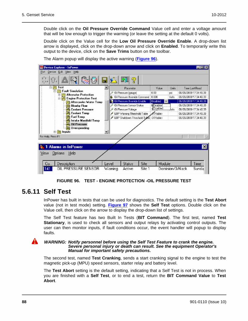
5. Genset Service 10-2012
Double click on the Oil Pressure Override Command Value cell and enter a voltage amountthat will be low enough to trigger the warning (or leave the setting at the default 0 volts).
Double click on the Value cell for the Low Oil Pressure Override Enable. A drop-down listarrow is displayed, click on the drop-down arrow and click on Enabled. To temporarily write thisoutput to the device, click on the Save Trims button on the toolbar.
The Alarm popup will display the active warning (Figure 96).
FIGURE 96. TEST - ENGINE PROTECTION -OIL PRESSURE TEST
5.6.11 Self TestInPower has built in tests that can be used for diagnostics. The default setting is the Test Abortvalue (not in test mode) setting. Figure 97 shows the Self Test options. Double click on theValue cell, then click on the arrow to display the drop-down list of settings.
The Self Test feature has two Built In Tests (BIT Command). The first test, named TestStationary, is used to check all sensors and output relays by activating control outputs. Theuser can then monitor inputs, if fault conditions occur, the event handler will popup to displayfaults.
WARNING: Notify personnel before using the Self Test Feature to crank the engine.Severe personal injury or death can result. See the equipment Operator'sManual for important safety precautions.
The second test, named Test Cranking, sends a start cranking signal to the engine to test themagnetic pick-up (MPU) speed sensors, starter relay and battery level.
The Test Abort setting is the default setting, indicating that a Self Test is not in process. Whenyou are finished with a Self Test, or to end a test, return the BIT Command Value to TestAbort.
88 901-0110 (Issue 10)
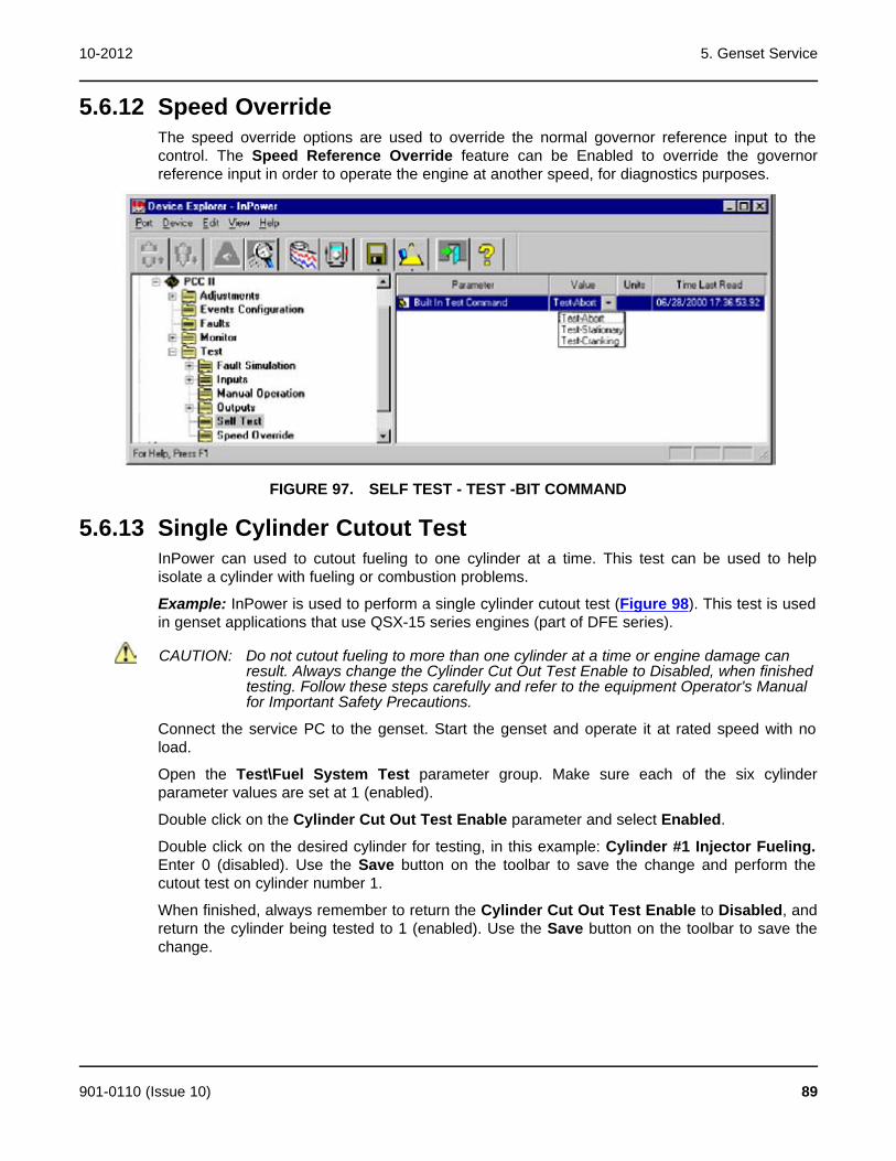
10-2012 5. Genset Service
5.6.12 Speed OverrideThe speed override options are used to override the normal governor reference input to thecontrol. The Speed Reference Override feature can be Enabled to override the governorreference input in order to operate the engine at another speed, for diagnostics purposes.
FIGURE 97. SELF TEST - TEST -BIT COMMAND
5.6.13 Single Cylinder Cutout TestInPower can used to cutout fueling to one cylinder at a time. This test can be used to helpisolate a cylinder with fueling or combustion problems.
Example: InPower is used to perform a single cylinder cutout test (Figure 98). This test is usedin genset applications that use QSX-15 series engines (part of DFE series).
CAUTION: Do not cutout fueling to more than one cylinder at a time or engine damage canresult. Always change the Cylinder Cut Out Test Enable to Disabled, when finishedtesting. Follow these steps carefully and refer to the equipment Operator's Manualfor Important Safety Precautions.
Connect the service PC to the genset. Start the genset and operate it at rated speed with noload.
Open the Test\Fuel System Test parameter group. Make sure each of the six cylinderparameter values are set at 1 (enabled).
Double click on the Cylinder Cut Out Test Enable parameter and select Enabled.
Double click on the desired cylinder for testing, in this example: Cylinder #1 Injector Fueling.Enter 0 (disabled). Use the Save button on the toolbar to save the change and perform thecutout test on cylinder number 1.
When finished, always remember to return the Cylinder Cut Out Test Enable to Disabled, andreturn the cylinder being tested to 1 (enabled). Use the Save button on the toolbar to save thechange.
901-0110 (Issue 10) 89
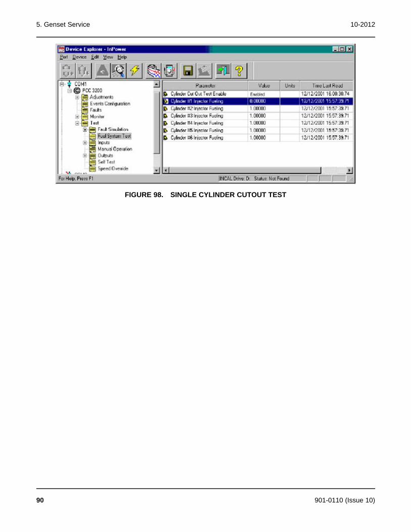
5. Genset Service 10-2012
FIGURE 98. SINGLE CYLINDER CUTOUT TEST
90 901-0110 (Issue 10)

6 ATS ServiceThis section describes how to use InPower to configure and make adjustments to aPowerCommand® controlled Automatic Transfer Switch (ATS). When the user is connected tothe ATS, they can configure the transfer switch, make adjustments, and access the Monitorand Faults features.
6.1 ATS ServiceThe Adjustment feature is used to configure the ATS for the application, set exercise times andexceptions, and perform service adjustments and trims. The Test feature is used to configurethe Test Mode, and for diagnostics.
You must be connected to the ATS in order to write adjustment trims and setting changes to thecontroller, and to use the Test feature.
WARNING: AC power within the cabinet and the rear side of cabinet door present ashock hazard that can cause severe personal injury or death. Use extremecaution to avoid touching electrical contacts with hair, clothing, tools orbody. Do not wear jewelry. Stand on a rubber mat or dry wood platform. Thefollowing procedures are to be performed by trained and experiencedpersonnel only.
6.1.1 Connecting to An ATS with the Original Digital DisplayA connection between the service PC and the ATS is made with a special RS-232 serial null-modem cable. The cable has a DB9 socket on each end. If the service PC does not have aserial port, a USB-to-serial converter may be required as well.
The serial cable from the service PC is connected to the upper right side of the Digital Module.This module is located inside the ATS (Figure 99).
901-0110 (Issue 10) 91

6. ATS Service 10-2012
FIGURE 99. INPOWER SERVICE CONNECTION (ORIGINAL ATS APPLICATIONS)
6.1.2 Starting InPowerStart InPower and connect to the port that matches the COM port on the service PC being usedfor the ATS connection (COM1, COM2, etc.). The available COM ports are displayed in theDevice Explorer directory (left pane). Double click on the COM port (or click on the COM portand then click on the Connect button on the tool bar).
The InPower Device Explorer displays the features that are available for the ATS in thedirectory, listed under the device in the left pane.
Figure 100 shows the features listed for an ATS. These features are:
· Adjustments
· Faults
· Monitor
· Test
When you are connected to an ATS, the Capture File feature is enabled. This feature is used tocreate a copy of the existing parameter values for the ATS. Always create a Capture file ofthe ATS parameters for reference, prior to making adjustments.
92 901-0110 (Issue 10)

10-2012 6. ATS Service
FIGURE 100. DEVICE EXPLORER - TYPICAL ATS FEATURES
6.2 ATS AdjustmentsThis section describes how to make ATS parameter value adjustments for trims and settings.Not all ATS models will have the same adjustments or features available. This section will covertypical adjustment examples, to demonstrate basic procedures for using the Adjustmentsfeature.
CAUTION: Improper adjustment can cause equipment malfunction or damage. Adjustmentmust be performed by technically qualified personnel only. Refer to the equipment'sInstallation and Service manuals for adjustment sequences and procedures.
6.2.1 Adjustment BasicsTo access an individual adjustment, or group of adjustments, use Device Explorer to navigatethe left pane until you reach the desired folder, and then click on it. The right pane will displaythe parameter(s) associated with the adjustments for that feature. Figure 101 shows a list ofparameters for the Time Delays selection.
The right pane displays the Parameter description, Value, Units of measure and the Last Timethat the value was Read.
Placing the mouse pointer over a parameter will bring up an information popup box. The popupprovides a brief description of how the parameter value is used.
901-0110 (Issue 10) 93
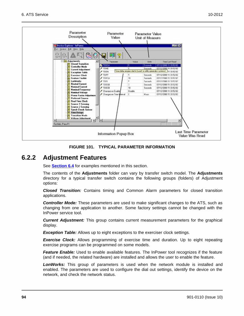
6. ATS Service 10-2012
FIGURE 101. TYPICAL PARAMETER INFORMATION
6.2.2 Adjustment FeaturesSee Section 6.4 for examples mentioned in this section.
The contents of the Adjustments folder can vary by transfer switch model. The Adjustmentsdirectory for a typical transfer switch contains the following groups (folders) of Adjustmentoptions:
Closed Transition: Contains timing and Common Alarm parameters for closed transitionapplications.
Controller Mode: These parameters are used to make significant changes to the ATS, such aschanging from one application to another. Some factory settings cannot be changed with theInPower service tool.
Current Adjustment: This group contains current measurement parameters for the graphicaldisplay.
Exception Table: Allows up to eight exceptions to the exerciser clock settings.
Exercise Clock: Allows programming of exercise time and duration. Up to eight repeatingexercise programs can be programmed on some models.
Feature Enable: Used to enable available features. The InPower tool recognizes if the feature(and if needed, the related hardware) are installed and allows the user to enable the feature.
LonWorks: This group of parameters is used when the network module is installed andenabled. The parameters are used to configure the dial out settings, identify the device on thenetwork, and check the network status.
94 901-0110 (Issue 10)
10-2012 6. ATS Service
Neutral Current: Used to set the neutral current warning threshold in amperes and the timedelay for the neutral current warning.
Nominal Current: Displays the nominal current for the transfer switch. Do not adjust thisparameter without reviewing the Controller Mode example.
Nominal Frequency: Displays the nominal frequency for Source 1 and Source 2 in the currentapplication. Do not adjust this parameter without reviewing the Controller Mode example.
Nominal Voltage: Displays the nominal Voltage for Source 1 and Source 2 in the currentapplication. Do not adjust this parameter without reviewing the Controller Mode example.
Power Factor Adjustment: This group contains Power Factor measurement parameters for thegraphical display. The multiplier and trim offset are shown for each phase. Do not adjust thisparameter without reviewing the Voltage Adjustment example.
Preferred Source: This parameter is used to select the preferred source in utility-to-utilityapplications and for genset-to-genset applications.
Real Time Clock: These parameters set the time and date information, Hours are displayed inmilitary time only (no A.M and P.M. designations). the control will automatically adjust for leapyear and daylight savings time (if enabled).
Source-1 Sensing: This group contains all of the Source 1 sensor settings normally associatedwith transfer switch operation (refer to the equipment's Operator's or Installation Manual for adetailed description of each sensor setting.
Source-2 Sensing: This group contains all of the Source 2 sensor settings normally associatedwith transfer switch operation (refer to the equipment's Operator's or Installation Manual for adetailed description of each sensor setting.
NOTE: Level 1 controls do not support 3-phase sensing on Source 2. Do not selectthe 3-phase option for the Source 2 Sensing adjustment, with Level 1controls, even if the system is three phase. This setting will prevent Source 2from becoming available.
Sync Check Sensor: Used in closed transition applications only, this group sets the acceptableconditions for closed-transition transfers.
Time Delays: This group contains all of time delay settings normally associated with transferswitch operation (refer to the equipment's Operator's or Installation Manual for a detaileddescription of each time delay. This group also contains the Changeover Timer used in genset-to-genset applications only.
Transition (Transfer) Mode: Used to select one of five possible transfer modes used forvarious applications. Initial product offerings only support the Open Program Transition mode.
Voltage Adjustment: This group contains voltage measurement parameters for the graphicaldisplay.
6.3 Service Replacement ControlsService replacement controls for the OTPC/BTPC series transfer switches are factory set toConfiguration - Offline. They are also set to Switch Configuration Type - Zenith. Thesesettings, along with the voltage and current settings will need to be changed when thereplacement control is installed.
The switch mechanism types available are shown below, along with their descriptions:
901-0110 (Issue 10) 95

6. ATS Service 10-2012
OTPC/BTPC - OTPC and BTPC models less than 1,200 Amps
Zenith - Use on all OTPC/BTPC models 1,200 Amp to 4,000 Amp capable ofDelayed Transition (Programmed Transition) or Closed Transition
Zenith2 - Use on all OTPC/BTPC models 1,200 Amp to 4,000 Amp capable ofIn-Phase Transition
OHPC/CHPC - OHPC and CHPC models
PLT - PLTH and PLTS models
After identifying the Configuration Type, check the transfer switch nameplate voltage andamperage. Use InPower to adjust the replacement control to the appropriate settings, beforechanging the Configuration from Offline to the application configuration (Utility-to-Genset, etc.).Review the first adjustment example in this section.
Source 1 and Source 2 Sensing features Voltage Imbalance Sensing and Loss of PhaseDetection are disabled by default. These features may not be needed in most applications. Donot enable these features without an understanding of the feature.
Voltage Imbalance Sensing: This feature is used in three-phase applications. It informs theoperator when there is a significant voltage imbalance between the phases of Source 1 orSource 2. The imbalance is typically caused by severe single phase loading. To preventnuisance faults, the setting can be increased up to ten percent of the nominal voltage. Thisfeature is used for equipment protection.
Loss of Phase Detection: Only used with Level 2 controls, in three phase applications. Thisfeature will initiate a transfer away from a source that has lost a single phase and it preventstransfer to a source that has lost a single phase. This is generally caused by a single phase toline ground or open. This feature is mainly used to protect three phase devices, like motors.
Phase Rotation Sensing: This feature is required in fire pump applications and it is enabled bydefault. The feature monitors the phase rotation of the source opposite from the connectedsource. When the alternate source is out of phase rotation with the connected source, transfer isinhibited. This generally occurs on new installations or after storm damage or generatorrewiring.
This feature is used to protect against equipment damage.
96 901-0110 (Issue 10)

10-2012 6. ATS Service
FIGURE 102. TYPICAL ADJUSTMENT FEATURES
6.3.1 Making AdjustmentsFigure 102 shows a typical set of parameters from the Adjustments group. Located to the left ofeach parameter is an icon that indicates if the parameter is used for adjustment or monitoring.
The screwdriver icon is used for trims and settings that can be written to the device (read andwrite). The magnifying glass indicates that the parameter value is being monitored (read only).The switch icon is used to display settings that can be temporarily written to a device. Thewrench icon represents factory settings that are not adjustable with InPower.
NOTE: The value being monitored will not automatically update. The user candouble click on the parameter to update the value field or click on the toolbarRefresh button.
Each parameter displays the current value and the units of measure for that value. Review thisinformation before making adjustments. Parameter value trims and settings are displayed.Trims are numeric values that are entered directly into the Value cell. Settings are selectedfrom drop down lists, and they consist of several type of values such as On/Off, 50Hz/60Hz,Enable/Disable, etc.
To change a parameter value, double click inside the Value cell of the parameter that you wishto change. The current value will be highlighted, if there are only a few choices, an arrow will bedisplayed next to the Value.
If an arrow is displayed, click on the arrow to view a drop-down list of the available settings.Click on the desired setting, and it will be entered into the Value cell.
If you do not see an arrow, enter the new value, to overwrite the current value. If the valueentered is above or below the range of acceptable values, an error message dialog box will bedisplayed (Figure 103). Review the information in the error message box to see the value limits,before clicking OK.
901-0110 (Issue 10) 97
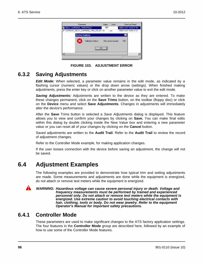
6. ATS Service 10-2012
FIGURE 103. ADJUSTMENT ERROR
6.3.2 Saving AdjustmentsEdit Mode: When selected, a parameter value remains in the edit mode, as indicated by aflashing cursor (numeric values) or the drop down arrow (settings). When finished makingadjustments, press the enter key or click on another parameter value to exit the edit mode.
Saving Adjustments: Adjustments are written to the device as they are entered. To makethese changes permanent, click on the Save Trims button, on the toolbar (floppy disc) or clickon the Device menu and select Save Adjustments. Changes in adjustments will immediatelyalter the device's performance.
After the Save Trims button is selected a Save Adjustments dialog is displayed. This featureallows you to view and confirm your changes by clicking on Save. You can make final editswithin this dialog by double clicking inside the New Value box and entering a new parametervalue or you can reset all of your changes by clicking on the Cancel button.
Saved adjustments are written to the Audit Trail. Refer to the Audit Trail to review the recordof adjustment changes.
Refer to the Controller Mode example, for making application changes.
If the user looses connection with the device before saving an adjustment, the change will notbe saved.
6.4 Adjustment ExamplesThe following examples are provided to demonstrate how typical trim and setting adjustmentsare made. Some measurements and adjustments are done while the equipment is energized,do not attach or remove test meters while the equipment is energized.
WARNING: Hazardous voltage can cause severe personal injury or death. Voltage andfrequency measurements must be performed by trained and experiencedpersonnel only. Do not attach or remove test meters while the equipment isenergized. Use extreme caution to avoid touching electrical contacts withhair, clothing, tools or body. Do not wear jewelry. Refer to the equipmentOperator's Manual for important safety precautions.
6.4.1 Controller ModeThese parameters are used to make significant changes to the ATS factory application settings.The four features in the Controller Mode group are described here, followed by an example ofhow to use some of the Controller Mode features.
98 901-0110 (Issue 10)

10-2012 6. ATS Service
Configuration: This feature contains four settings. The Offline feature puts the controller into astandby, or non-automatic state. The control will continue to monitor conditions, but it will notperform any automatic functions, like initiating a transfer. This prevents faults from occurringwhile you are making adjustments to a transfer switch that is in use.
The other three Configuration features are application choices: Utility-to-Genset, Utility-to-Utility, and Genset-to-Genset.
Refresh_Controller: Updates the device for changes made to voltage, current, frequency orpower. This feature must be used after saving changes to any trims for voltage, current,frequency or power. For a complete listing of the changes that require use of this feature, referto the end of this example.
CAUTION: The Refresh feature uses a lot of the control processing resources. Do not use thisfeature during paralleling or critical applications, because the control may notrespond as needed during the refresh process.
Permanent_Save_Settings: Used to permanently change the device settings.
Restore_Factory_Settings: Restores all parameter changes to the original factory settings.Use caution, this change overwrites previous adjustments. Previous adjustments cannot berestored unless a capture file was created. The Operator must remove all power from the device(including the batteries) after changing this setting, for the changes to take effect.
Example: In this example, InPower is used to change the Source 1 and Source 2 nominalvoltage, on an ATS with a Level 1 control, from 208 VAC, line to line, to 240 VAC, line to line.Use step 1 if the transfer switch has power applied to Source 1, otherwise begin at step 2.
1. Open the Adjustments folder, in the left pane and click on the Controller Mode folder.Select the value field for the Configuration parameter and click on Offline, in the drop downlist.
2. Click on the Nominal Voltage folder in the left pane. Enter the new nominal voltage in theSource 1 and Source 2 value fields.
3. Go back to the left pane and click on the Controller Mode folder again. Change theRefresh Controller value setting to update the device settings for changes to the nominalvoltage.
4. Verify Nominal Voltage settings. If step one was used, change the Configuration valuesetting, in the Controller Mode folder, from Offline to the original application.
5. To permanently preserve this change, click on the Controller Mode folder again andchange the Permanent_Save_Settings to On.
901-0110 (Issue 10) 99
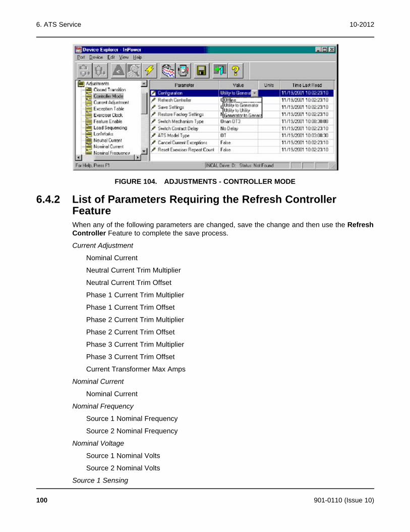
6. ATS Service 10-2012
FIGURE 104. ADJUSTMENTS - CONTROLLER MODE
6.4.2 List of Parameters Requiring the Refresh ControllerFeatureWhen any of the following parameters are changed, save the change and then use the RefreshController Feature to complete the save process.
Current Adjustment
Nominal Current
Neutral Current Trim Multiplier
Neutral Current Trim Offset
Phase 1 Current Trim Multiplier
Phase 1 Current Trim Offset
Phase 2 Current Trim Multiplier
Phase 2 Current Trim Offset
Phase 3 Current Trim Multiplier
Phase 3 Current Trim Offset
Current Transformer Max Amps
Nominal Current
Nominal Current
Nominal Frequency
Source 1 Nominal Frequency
Source 2 Nominal Frequency
Nominal Voltage
Source 1 Nominal Volts
Source 2 Nominal Volts
Source 1 Sensing
100 901-0110 (Issue 10)

10-2012 6. ATS Service
Source 1 Sensing
Source 1 Nominal Volts
Source 1 Under Voltage Pickup
Source 1 Under Voltage Dropout
Source 1 Over Voltage Pickup
Source 1 Over Voltage Dropout
Source 1 Nominal Frequency
Source 1 Frequency Pickup
Source 1 Frequency Dropout
Source 1 Voltage Imbalance Dropout
Source 2 Sensing
Source 2 Sensing
Source 2 Nominal Volts
Source 2 Under Voltage Pickup
Source 2 Under Voltage Dropout
Source 2 Over Voltage Pickup
Source 2 Over Voltage Dropout
Source 2 Nominal Frequency
Source 2 Frequency Pickup
Source 2 Frequency Dropout
Source 2 Voltage Imbalance Dropout
Synch Check Sensor
Frequency Bandwidth
Voltage Window
Voltage Adjustment
Source 1 Phase 1 Trim Multiplier
Source 1 Phase 1 Trim Offset
Source 2 Phase 1 Trim Multiplier
Source 2 Phase 1 Trim Offset
Source 1 Phase 2 Trim Multiplier
Source 1 Phase 2 Trim Offset
Source 2 Phase 2 Trim Multiplier
Source 2 Phase 2 Trim Offset
Source 1 Phase 3 Trim Multiplier
Source 1 Phase 3 Trim Offset
Source 2 Phase 3 Trim Multiplier
901-0110 (Issue 10) 101
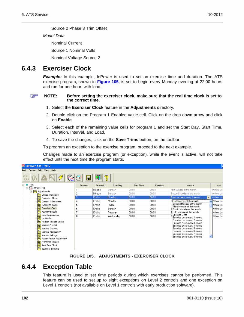
6. ATS Service 10-2012
Source 2 Phase 3 Trim Offset
Model Data
Nominal Current
Source 1 Nominal Volts
Nominal Voltage Source 2
6.4.3 Exerciser ClockExample: In this example, InPower is used to set an exercise time and duration. The ATSexercise program, shown in Figure 105, is set to begin every Monday evening at 22:00 hoursand run for one hour, with load.
NOTE: Before setting the exerciser clock, make sure that the real time clock is set tothe correct time.
1. Select the Exerciser Clock feature in the Adjustments directory.
2. Double click on the Program 1 Enabled value cell. Click on the drop down arrow and clickon Enable.
3. Select each of the remaining value cells for program 1 and set the Start Day, Start Time,Duration, Interval, and Load.
4. To save the changes, click on the Save Trims button, on the toolbar.
To program an exception to the exercise program, proceed to the next example.
Changes made to an exercise program (or exception), while the event is active, will not takeeffect until the next time the program starts.
FIGURE 105. ADJUSTMENTS - EXERCISER CLOCK
6.4.4 Exception TableThis feature is used to set time periods during which exercises cannot be performed. Thisfeature can be used to set up to eight exceptions on Level 2 controls and one exception onLevel 1 controls (not available on Level 1 controls with early production software).
102 901-0110 (Issue 10)

10-2012 6. ATS Service
Example: In this example, InPower is used to set one exception period. This will prevent anypreviously programmed exercise from starting during that time period.
1. Select the Exception Table feature in the Adjustments directory.
2. Double click on the Exception 1 Enabled value cell. Click on the drop down arrow and clickon Enable.
3. Select each of the remaining value cells for program 1 and Start Month, Start Day, StartTime, Duration Days and Repeat.
4. (The duration in days and Time (hours) are additive, 1 day and 26 hours equals 2 days and2 hours.
5. The Repeat can be either False, for a one time exception, or True, to repeat the exceptioneach year.
6. To save the changes, click on the Save Trims button, on the toolbar.
FIGURE 106. ADJUSTMENTS - EXCEPTION TABLE
6.4.5 Time DelaysExample: In this example, InPower is used to change the time delay for transferring fromEmergency to Normal (TDEN). The Default factory setting for each of the time delays aredisplayed. A brief description of time delay is displayed in the pop-up box. Refer to the ATSOperator's manual for a complete description of each time delay.
1. Select the Time Delays feature in the Adjustments directory.
2. Double click on the TDEN Value cell. Enter the desired time (in seconds).
3. To save the changes, click on the Save Trims button, on the toolbar.
901-0110 (Issue 10) 103
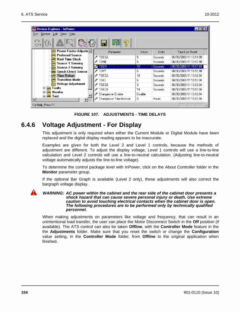
6. ATS Service 10-2012
FIGURE 107. ADJUSTMENTS - TIME DELAYS
6.4.6 Voltage Adjustment - For DisplayThis adjustment is only required when either the Current Module or Digital Module have beenreplaced and the digital display reading appears to be inaccurate.
Examples are given for both the Level 2 and Level 1 controls, because the methods ofadjustment are different. To adjust the display voltage, Level 1 controls will use a line-to-linecalculation and Level 2 controls will use a line-to-neutral calculation. (Adjusting line-to-neutralvoltage automatically adjusts the line-to-line voltage).
To determine the control package level with InPower, click on the About Controller folder in theMonitor parameter group.
If the optional Bar Graph is available (Level 2 only), these adjustments will also correct thebargraph voltage display.
WARNING: AC power within the cabinet and the rear side of the cabinet door presents ashock hazard that can cause severe personal injury or death. Use extremecaution to avoid touching electrical contacts when the cabinet door is open.The following procedures are to be performed only by technically qualifiedpersonnel.
When making adjustments on parameters like voltage and frequency, that can result in anunintentional load transfer, the user can place the Motor Disconnect Switch in the Off position (ifavailable). The ATS control can also be taken Offline, with the Controller Mode feature in thethe Adjustments folder. Make sure that you reset the switch or change the Configurationvalue setting, in the Controller Mode folder, from Offline to the original application whenfinished.
104 901-0110 (Issue 10)

10-2012 6. ATS Service
FIGURE 108. ADJUSTMENTS - DISPLAY VOLTAGE
Example 1 (Level 2 Control): InPower is used to adjust the voltage as displayed in the digitaldisplay (and optional bargraph) on a Level 2 control).
In this example, the transfer switch is configured for 3 phase, and a nominal 208 VAC line-to-line. The digital display is displaying source 1 line-to-neutral voltage as 118 VAC. The bargraphis displaying 98% for Line 1, with Source 1 connected.
1. Select the Voltage Adjustment feature in the Adjustments directory. Observe the Source 1V1-Neutral value that is being monitored (signified by magnifying glass). This is the displayvoltage.
2. Measure the actual Source 1 voltage at the power Module between NA and NN (Line 1 toneutral). (Line 2 would be measured from NB to NN and line 3 would be measured fromNC to NN).
3. Calculate the Trim Multiplier (K) needed to adjust the displayed voltage as follows:
4. Double click on the Voltage PH1S1 Trim Mult (multiplier) Value cell, and enter 1041.
5. To save the changes, click on the Save Trims button, on the toolbar.
6. Check the results to make sure the displayed voltage is close to the actual voltage.
901-0110 (Issue 10) 105
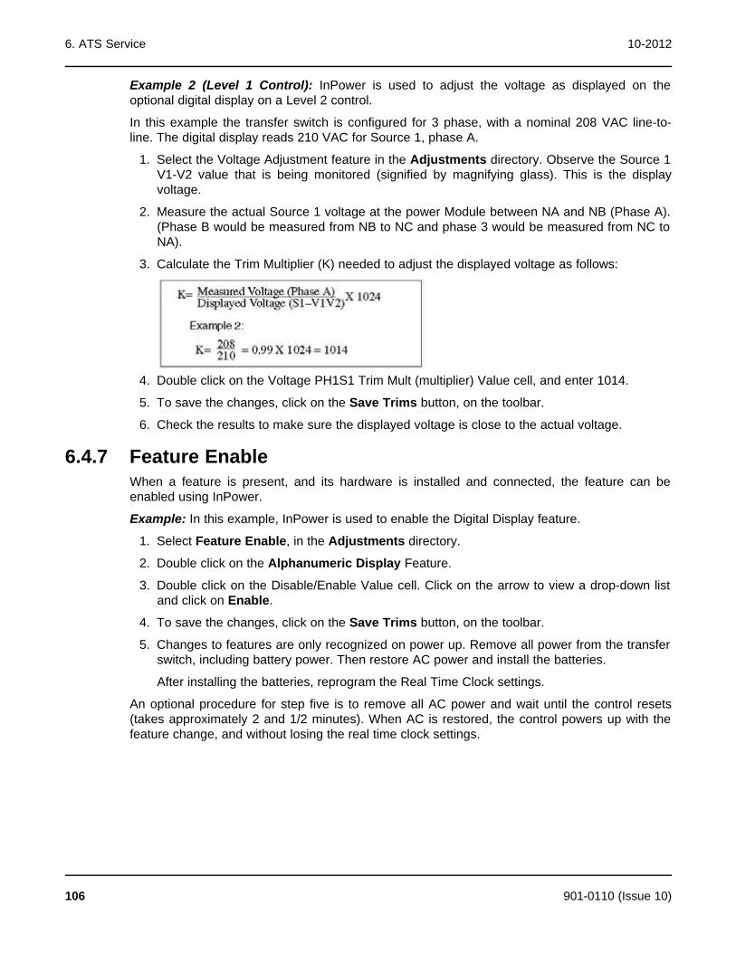
6. ATS Service 10-2012
Example 2 (Level 1 Control): InPower is used to adjust the voltage as displayed on theoptional digital display on a Level 2 control.
In this example the transfer switch is configured for 3 phase, with a nominal 208 VAC line-to-line. The digital display reads 210 VAC for Source 1, phase A.
1. Select the Voltage Adjustment feature in the Adjustments directory. Observe the Source 1V1-V2 value that is being monitored (signified by magnifying glass). This is the displayvoltage.
2. Measure the actual Source 1 voltage at the power Module between NA and NB (Phase A).(Phase B would be measured from NB to NC and phase 3 would be measured from NC toNA).
3. Calculate the Trim Multiplier (K) needed to adjust the displayed voltage as follows:
4. Double click on the Voltage PH1S1 Trim Mult (multiplier) Value cell, and enter 1014.
5. To save the changes, click on the Save Trims button, on the toolbar.
6. Check the results to make sure the displayed voltage is close to the actual voltage.
6.4.7 Feature EnableWhen a feature is present, and its hardware is installed and connected, the feature can beenabled using InPower.
Example: In this example, InPower is used to enable the Digital Display feature.
1. Select Feature Enable, in the Adjustments directory.
2. Double click on the Alphanumeric Display Feature.
3. Double click on the Disable/Enable Value cell. Click on the arrow to view a drop-down listand click on Enable.
4. To save the changes, click on the Save Trims button, on the toolbar.
5. Changes to features are only recognized on power up. Remove all power from the transferswitch, including battery power. Then restore AC power and install the batteries.
After installing the batteries, reprogram the Real Time Clock settings.
An optional procedure for step five is to remove all AC power and wait until the control resets(takes approximately 2 and 1/2 minutes). When AC is restored, the control powers up with thefeature change, and without losing the real time clock settings.
106 901-0110 (Issue 10)
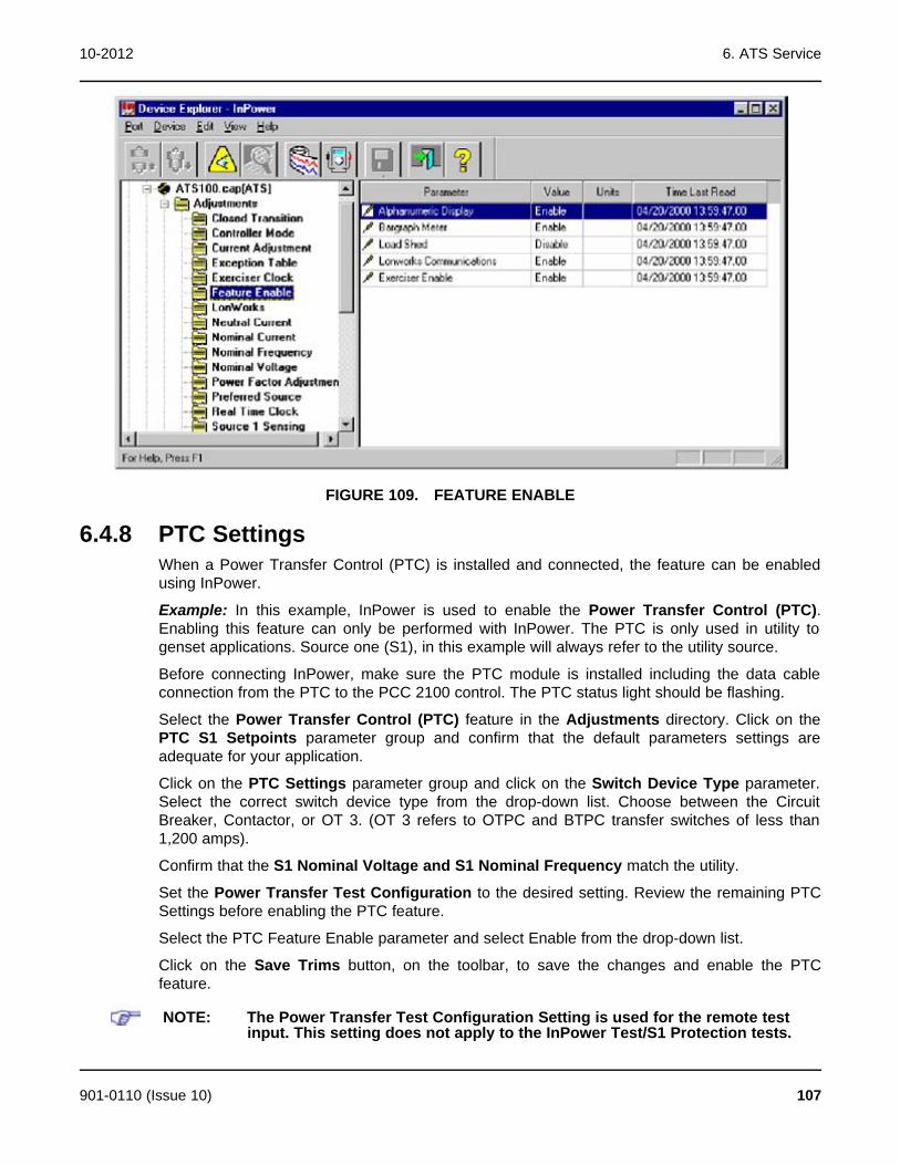
10-2012 6. ATS Service
FIGURE 109. FEATURE ENABLE
6.4.8 PTC SettingsWhen a Power Transfer Control (PTC) is installed and connected, the feature can be enabledusing InPower.
Example: In this example, InPower is used to enable the Power Transfer Control (PTC).Enabling this feature can only be performed with InPower. The PTC is only used in utility togenset applications. Source one (S1), in this example will always refer to the utility source.
Before connecting InPower, make sure the PTC module is installed including the data cableconnection from the PTC to the PCC 2100 control. The PTC status light should be flashing.
Select the Power Transfer Control (PTC) feature in the Adjustments directory. Click on thePTC S1 Setpoints parameter group and confirm that the default parameters settings areadequate for your application.
Click on the PTC Settings parameter group and click on the Switch Device Type parameter.Select the correct switch device type from the drop-down list. Choose between the CircuitBreaker, Contactor, or OT 3. (OT 3 refers to OTPC and BTPC transfer switches of less than1,200 amps).
Confirm that the S1 Nominal Voltage and S1 Nominal Frequency match the utility.
Set the Power Transfer Test Configuration to the desired setting. Review the remaining PTCSettings before enabling the PTC feature.
Select the PTC Feature Enable parameter and select Enable from the drop-down list.
Click on the Save Trims button, on the toolbar, to save the changes and enable the PTCfeature.
NOTE: The Power Transfer Test Configuration Setting is used for the remote testinput. This setting does not apply to the InPower Test/S1 Protection tests.
901-0110 (Issue 10) 107
6. ATS Service 10-2012
FIGURE 110. PCC 2100 POWER TRANSFER CONTROL (PTC) SETUP
6.5 TestThe Test feature contains two groups of parameters, Remote and Setup. The Remoteparameters are used for diagnostics and the Setup parameter is used to set the with/withoutload setting for the Test button on the front panel of the ATS.
Typically, the Test button on the front panel is used to perform a transfer switch test. Pressingthe Test button a second time will stop a test in progress. As a diagnostics example, if the Testbutton does not appear to work, the InPower Test Command can be used to initiate a test.
WARNING: Notify personnel before using the Test button or InPower Test features onthe ATS, to start the genset or transfer the load. Severe personal injury ordeath can result. See the equipment Operator's Manual for important safetyprecautions.
6.5.1 Test - Remote FeaturesThe commands that are available in this group interact with the corresponding hardware inputs.For example, if the Load Shed Command is deactivated, but the Load Shed input is activated,the ATS will shed the load.
NOTE: There are two types of Test Commands: maintained inputs and momentaryinputs. When a maintained input is set to active, the input will remain active.The InPower user MUST set the input back to inactive, when they are finishedwith the test or before leaving the site, otherwise the command will remainactive.
Momentary inputs automatically change state to inactive after one second.
Maintained Inputs for Test are: Test Command, Remote Start (Dual Standby), Load ShedCommand, Transfer Inhibit, Retransfer Inhibit
Momentary Inputs for Test are: Reset Command and Override Command.
108 901-0110 (Issue 10)
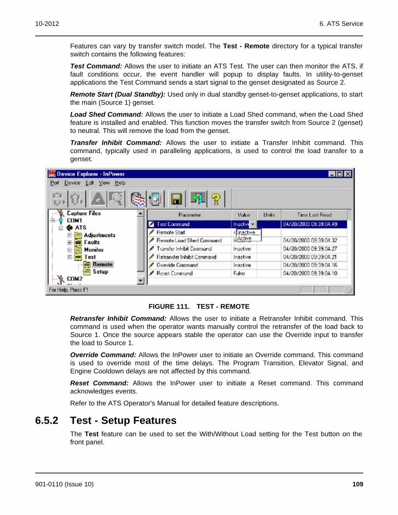
10-2012 6. ATS Service
Features can vary by transfer switch model. The Test - Remote directory for a typical transferswitch contains the following features:
Test Command: Allows the user to initiate an ATS Test. The user can then monitor the ATS, iffault conditions occur, the event handler will popup to display faults. In utility-to-gensetapplications the Test Command sends a start signal to the genset designated as Source 2.
Remote Start (Dual Standby): Used only in dual standby genset-to-genset applications, to startthe main (Source 1) genset.
Load Shed Command: Allows the user to initiate a Load Shed command, when the Load Shedfeature is installed and enabled. This function moves the transfer switch from Source 2 (genset)to neutral. This will remove the load from the genset.
Transfer Inhibit Command: Allows the user to initiate a Transfer Inhibit command. Thiscommand, typically used in paralleling applications, is used to control the load transfer to agenset.
FIGURE 111. TEST - REMOTE
Retransfer Inhibit Command: Allows the user to initiate a Retransfer Inhibit command. Thiscommand is used when the operator wants manually control the retransfer of the load back toSource 1. Once the source appears stable the operator can use the Override input to transferthe load to Source 1.
Override Command: Allows the InPower user to initiate an Override command. This commandis used to override most of the time delays. The Program Transition, Elevator Signal, andEngine Cooldown delays are not affected by this command.
Reset Command: Allows the InPower user to initiate a Reset command. This commandacknowledges events.
Refer to the ATS Operator's Manual for detailed feature descriptions.
6.5.2 Test - Setup FeaturesThe Test feature can be used to set the With/Without Load setting for the Test button on thefront panel.
901-0110 (Issue 10) 109
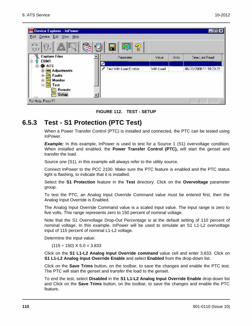
6. ATS Service 10-2012
FIGURE 112. TEST - SETUP
6.5.3 Test - S1 Protection (PTC Test)When a Power Transfer Control (PTC) is installed and connected, the PTC can be tested usingInPower.
Example: In this example, InPower is used to test for a Source 1 (S1) overvoltage condition.When installed and enabled, the Power Transfer Control (PTC), will start the genset andtransfer the load.
Source one (S1), in this example will always refer to the utility source.
Connect InPower to the PCC 2100. Make sure the PTC feature is enabled and the PTC statuslight is flashing, to indicate that it is installed.
Select the S1 Protection feature in the Test directory. Click on the Overvoltage parametergroup.
To test the PTC, an Analog Input Override Command value must be entered first, then theAnalog Input Override is Enabled.
The Analog Input Override Command value is a scaled input value. The input range is zero tofive volts. This range represents zero to 150 percent of nominal voltage.
Note that the S1 Overvoltage Drop-Out Percentage is at the default setting of 110 percent ofnominal voltage. In this example, InPower will be used to simulate an S1 L1-L2 overvoltageinput of 115 percent of nominal L1-L2 voltage.
Determine the input value:
(115 ÷ 150) X 5.0 = 3.833
Click on the S1 L1-L2 Analog Input Override command value cell and enter 3.833. Click onS1 L1-L2 Analog Input Override Enable and select Enabled from the drop-down list.
Click on the Save Trims button, on the toolbar, to save the changes and enable the PTC test.The PTC will start the genset and transfer the load to the genset.
To end the test, select Disabled in the S1 L1-L2 Analog Input Override Enable drop-down listand Click on the Save Trims button, on the toolbar, to save the changes and enable the PTCfeature.
110 901-0110 (Issue 10)

10-2012 6. ATS Service
FIGURE 113. PCC 2100 POWER TRANSFER CONTROL (PTC) TEST
901-0110 (Issue 10) 111

6. ATS Service 10-2012
This page is intentionally blank.
112 901-0110 (Issue 10)
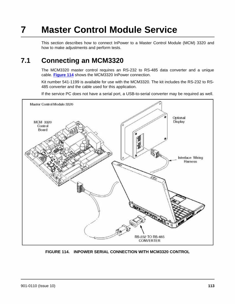
7 Master Control Module ServiceThis section describes how to connect InPower to a Master Control Module (MCM) 3320 andhow to make adjustments and perform tests.
7.1 Connecting an MCM3320The MCM3320 master control requires an RS-232 to RS-485 data converter and a uniquecable. Figure 114 shows the MCM3320 InPower connection.
Kit number 541-1199 is available for use with the MCM3320. The kit includes the RS-232 to RS-485 converter and the cable used for this application.
If the service PC does not have a serial port, a USB-to-serial converter may be required as well.
FIGURE 114. INPOWER SERIAL CONNECTION WITH MCM3320 CONTROL
901-0110 (Issue 10) 113

7. Master Control Module Service 10-2012
7.2 Configuring the MCM3320There are two ways to configure the MCM3320 in InPower.
· Use the folders in the device explorer, the same way you configure any device.
· Use the MCM3320 setup screens. Right-click on the device to open these screens.
114 901-0110 (Issue 10)

8 G-Drive ServiceThis section describes how to use InPower for making adjustments and performing tests on aG-Drive control. The G-Drive control is referred to as an ECM (Electronic Control Module).When the user connects InPower to an ECM, they can also access the Monitor and Faultsfeatures.
8.1 G-Drive ServiceInPower performs several functions including service and diagnostic functions. The Adjustmentfeature is used to perform service adjustments and trims.
The Test feature is used for diagnostics. Test is used to temporarily override a variety of inputand output parameters.
You must be connected to the ECM, via the engine harness, in order to write adjustment trimsand setting changes to the controller, and to temporary send test commands to the ECM.
WARNING: Notify personnel before starting an engine. Severe personal injury or deathcan result. Refer to the equipment Operator's Manual for important safetyprecautions.
8.1.1 Connecting to an ECMConnection between the service PC and the ECM is made with a special RS-232 serial null-modem cable. Figure 115 shows the connections needed on the service PC. The serial cablefrom the service PC must be connected to the engine harness. The service cable and partnumber are shown in Figure 115.
FIGURE 115. INPOWER SERIAL CONNECTION
8.1.2 Starting InPowerStart InPower and connect to the port (COM1, COM2, etc.) that matches the COM port on theservice PC, that is being used for the G-Drive connection. The available COM ports aredisplayed in the Device Explorer directory (left pane). Double click on the COM port (or click onthe COM port and then click on the Connect button, on the toolbar).
901-0110 (Issue 10) 115
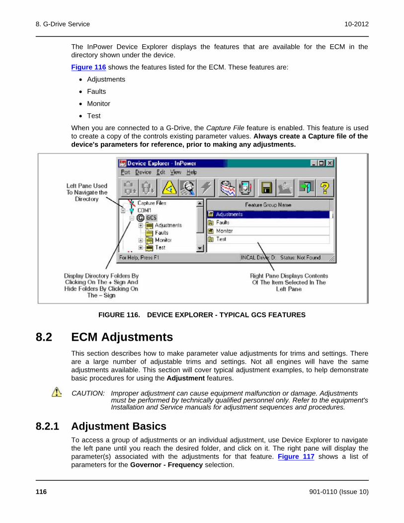
8. G-Drive Service 10-2012
The InPower Device Explorer displays the features that are available for the ECM in thedirectory shown under the device.
Figure 116 shows the features listed for the ECM. These features are:
· Adjustments
· Faults
· Monitor
· Test
When you are connected to a G-Drive, the Capture File feature is enabled. This feature is usedto create a copy of the controls existing parameter values. Always create a Capture file of thedevice's parameters for reference, prior to making any adjustments.
FIGURE 116. DEVICE EXPLORER - TYPICAL GCS FEATURES
8.2 ECM AdjustmentsThis section describes how to make parameter value adjustments for trims and settings. Thereare a large number of adjustable trims and settings. Not all engines will have the sameadjustments available. This section will cover typical adjustment examples, to help demonstratebasic procedures for using the Adjustment features.
CAUTION: Improper adjustment can cause equipment malfunction or damage. Adjustmentsmust be performed by technically qualified personnel only. Refer to the equipment'sInstallation and Service manuals for adjustment sequences and procedures.
8.2.1 Adjustment BasicsTo access a group of adjustments or an individual adjustment, use Device Explorer to navigatethe left pane until you reach the desired folder, and click on it. The right pane will display theparameter(s) associated with the adjustments for that feature. Figure 117 shows a list ofparameters for the Governor - Frequency selection.
116 901-0110 (Issue 10)
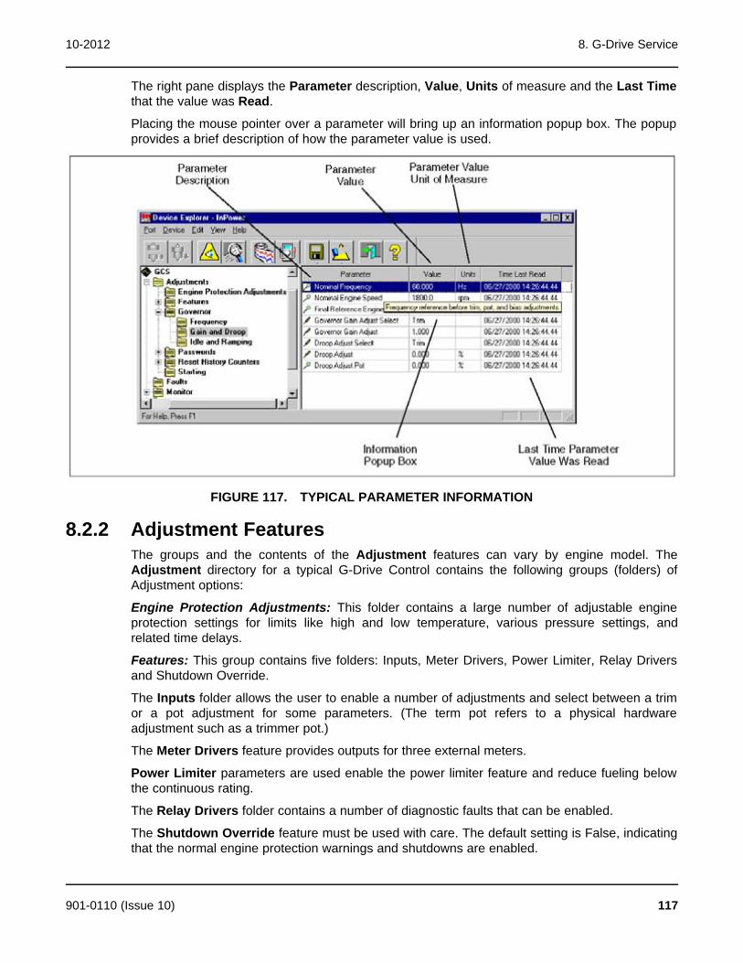
10-2012 8. G-Drive Service
The right pane displays the Parameter description, Value, Units of measure and the Last Timethat the value was Read.
Placing the mouse pointer over a parameter will bring up an information popup box. The popupprovides a brief description of how the parameter value is used.
FIGURE 117. TYPICAL PARAMETER INFORMATION
8.2.2 Adjustment FeaturesThe groups and the contents of the Adjustment features can vary by engine model. TheAdjustment directory for a typical G-Drive Control contains the following groups (folders) ofAdjustment options:
Engine Protection Adjustments: This folder contains a large number of adjustable engineprotection settings for limits like high and low temperature, various pressure settings, andrelated time delays.
Features: This group contains five folders: Inputs, Meter Drivers, Power Limiter, Relay Driversand Shutdown Override.
The Inputs folder allows the user to enable a number of adjustments and select between a trimor a pot adjustment for some parameters. (The term pot refers to a physical hardwareadjustment such as a trimmer pot.)
The Meter Drivers feature provides outputs for three external meters.
Power Limiter parameters are used enable the power limiter feature and reduce fueling belowthe continuous rating.
The Relay Drivers folder contains a number of diagnostic faults that can be enabled.
The Shutdown Override feature must be used with care. The default setting is False, indicatingthat the normal engine protection warnings and shutdowns are enabled.
901-0110 (Issue 10) 117
8. G-Drive Service 10-2012
WARNING: The Shutdown Override setting bypasses all engine protection warnings andshutdowns. Operating the engine under these conditions can cause severepersonal injury or death and can result in equipment damage. Refer to theequipment Operator's Manual for important safety precautions.
When the Shutdown Override Enable value is set to True, the engine will not be protected andwill not shutdown under abnormal operating conditions. The engine will still shutdown due toengine overspeed, loss of speed signal or loss of power to the E-Stop input.
Setting the Shutdown Override value to True can void the engine warranty. If enginedamage occurs from operating the engine beyond the normal shutdown limits, the resultingdamage is not covered under warranty.
The Shutdown Override feature will not prevent shutdown due to: engine overspeed, loss ofspeed sensor signal, E-Stop, or loss of power in the E-Stop circuit.
Governor: This group contains Governor adjustments for Frequency settings, Gain and Droopsettings, and Idle and Ramping. Many of these parameters must be enabled before theadjustments can be made (Refer to the Features - Inputs folder).
Passwords: This group contains three features that are used for password administration.
The Change Passwords feature is used to establish initial passwords and to change existingpasswords.
Passwords must be 5 to 8 characters in length. They may consist of any combination of alphaor numeric characters. Do not use special characters.
The Clear Passwords feature allows users, with a password, to clear the password. This istypically used if you wish to permanently remove the password. If you want to change anexisting password, use the Change Passwords feature.
The Enter Passwords feature is used to gain access to password protected parameters.Entering the password allows the user to write changes to password protected parameters.
There are two predefined groups of parameters that can be protected by passwords, these arenamed User and Application. When a password is established for either of these groups,access becomes password protected. Users can view password protected parameters, but theycannot write changes to them without Entering the password first.
Reset History: Allows the user to reset the history records for Fuel consumption.
Starting: Contains parameters for all of the engine cranking settings.
Many of these features contain sub menus of additional adjustment features. Use DeviceExplorer to expand each of these categories to view the sub-menu of adjustments. Hold themouse pointer over the parameters to display the information pop-up box describing how theparameter is used.
118 901-0110 (Issue 10)

10-2012 8. G-Drive Service
FIGURE 118. TYPICAL ADJUSTMENT FEATURES
8.2.3 Making AdjustmentsLocated to the left of each parameter is an icon that indicates if the parameter is for adjustmentor monitoring (refer to Figure 118).
The screwdriver icon is used for trims and settings that can be written to the device (read andwrite). The magnifying glass indicates that the parameter value is being monitored (read only).The switch icon is used to display settings that can be temporarily written to a device. Thewrench icon represents factory settings that are not adjustable with InPower.
NOTE: The value being monitored will not automatically update. The user candouble click on the parameter to update the value field or click on theRefresh button, on the toolbar.
Each parameter displays the current value and the units of measure for that value. Review thisinformation before making adjustments. Parameter value trims and settings are displayed.Trims are numeric values that are entered directly into the Value cell. Settings are selectedfrom drop down lists, and they consist of several type of values such as On/Off, Enable/Disable,etc.
To change a parameter value, double click inside the Value cell of the parameter that you wishto change. The current value will be highlighted, if there are only a few choices, a drop-downarrow will be displayed next to the Value.
If an arrow is displayed, click on the arrow to view a drop-down list of the available settings.Click on the desired setting, and it will be entered into the value cell.
If you do not see an arrow, begin typing the new value, the new value entry will overwrite thecurrent value. If the value entered is above or below the range of acceptable values, an errormessage dialog box will be displayed (Figure 119). Review the information in the dialog box tosee the value limits, before clicking OK, to close the error message dialog box.
901-0110 (Issue 10) 119

8. G-Drive Service 10-2012
FIGURE 119. ADJUSTMENT ERROR
8.2.4 Saving AdjustmentsEdit Mode: When selected, a parameter value remains in the edit mode, as indicated by aflashing cursor (numeric values) or the drop down arrow (settings). When finished makingadjustments, press the enter key or click on another parameter value to exit the edit mode.
Saving Adjustments: Adjustments are written to the device as they are entered. To makethese changes permanent, click on the Save Trims button, on the toolbar (floppy disc) or clickon the Device menu and select Save Adjustments. Changes in adjustments will immediatelyalter the device's performance.
Saved adjustments are written to the Audit Trail. Refer to the Audit Trail to review the recordof adjustment changes.
If the user loses connection with the device before saving an adjustment, the change will not besaved.
8.3 Adjustment ExamplesThe following examples are provided to demonstrate how typical trim and setting adjustmentsare made. Some measurements and adjustments are done while the engine is running, do notattach or remove test meters while the engine is running.
WARNING: Hazardous voltage can cause electrocution, resulting in severe personalinjury or death. Voltage and frequency measurements must be performed bytechnically qualified personnel only. Do not attach or remove test meterswhile the equipment is running. Refer to the equipment Operator's Manual forimportant safety precautions.
Example: In this example, InPower is used to adjust the governor gain (refer to the specificengine model T&R manual for additional governor adjustment details)
Begin by setting the Governor Gain Adjust Select value setting to Trim. Then double click onthe Governor Gain Adjust value cell.
120 901-0110 (Issue 10)

10-2012 8. G-Drive Service
Make a note of the existing Value reading. The range of adjustment is 0.05 to 10 (1.0 is thefactory default setting). Increase or decrease the value as needed to obtain the proper loadresponse. If the gain is set too high, engine speed will hunt or oscillate, and if the gain is set toolow, the engine will respond too slowly to changes in the load.
Click on the Save Trims button, on the toolbar, to write the new value to the device. Continueadjusting until satisfactory response time and stability are obtained.
FIGURE 120. ADJUSTMENTS - GOVERNOR - GAIN AND DROOP
Example: In this example, InPower is used to increase the Starting to Rated Ramp Time(refer to Figure 121). Select the Governor - Idle and Ramping feature, from the Adjustmentsdirectory. Double click on the Value cell for Starting to Rated Ramp Time. This adjustmentsets the desired time interval between starting and rated power. The current setting will behighlighted, for this example enter 5 (for 5 seconds) into the Value cell. (For faster startup andfor NFPA 110 compliance, set this value to zero.)
Click on the Save Trims button, on the toolbar, to write the new value to the device.
901-0110 (Issue 10) 121
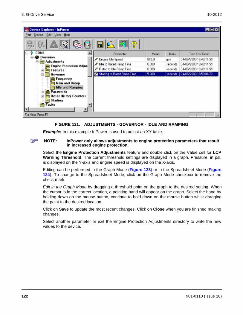
8. G-Drive Service 10-2012
FIGURE 121. ADJUSTMENTS - GOVERNOR - IDLE AND RAMPING
Example: In this example InPower is used to adjust an XY table.
NOTE: InPower only allows adjustments to engine protection parameters that resultin increased engine protection.
Select the Engine Protection Adjustments feature and double click on the Value cell for LCPWarning Threshold. The current threshold settings are displayed in a graph. Pressure, in psi,is displayed on the Y-axis and engine speed is displayed on the X-axis.
Editing can be performed in the Graph Mode (Figure 123) or in the Spreadsheet Mode (Figure124). To change to the Spreadsheet Mode, click on the Graph Mode checkbox to remove thecheck mark.
Edit in the Graph Mode by dragging a threshold point on the graph to the desired setting. Whenthe cursor is in the correct location, a pointing hand will appear on the graph. Select the hand byholding down on the mouse button, continue to hold down on the mouse button while draggingthe point to the desired location.
Click on Save to update the most recent changes. Click on Close when you are finished makingchanges.
Select another parameter or exit the Engine Protection Adjustments directory to write the newvalues to the device.
122 901-0110 (Issue 10)

10-2012 8. G-Drive Service
FIGURE 122. ENGINE PROTECTION ADJ. - LCP WARNING THRESHOLD
FIGURE 123. XY GRAPH
901-0110 (Issue 10) 123
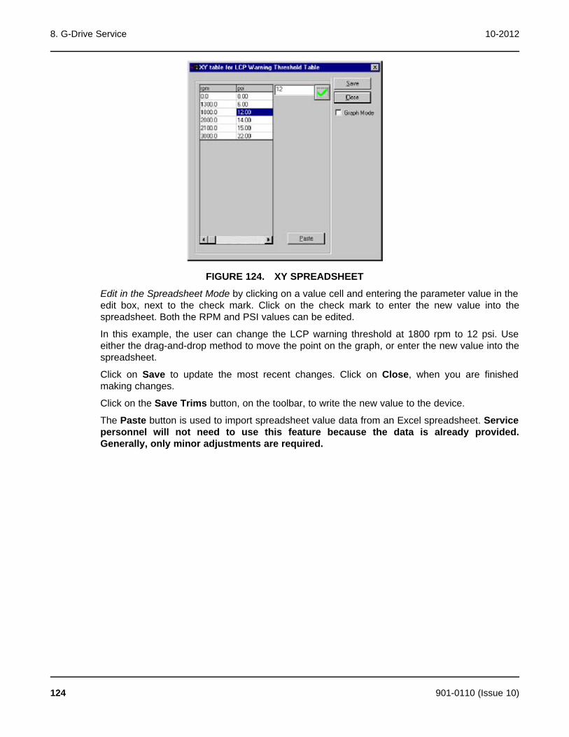
8. G-Drive Service 10-2012
FIGURE 124. XY SPREADSHEET
Edit in the Spreadsheet Mode by clicking on a value cell and entering the parameter value in theedit box, next to the check mark. Click on the check mark to enter the new value into thespreadsheet. Both the RPM and PSI values can be edited.
In this example, the user can change the LCP warning threshold at 1800 rpm to 12 psi. Useeither the drag-and-drop method to move the point on the graph, or enter the new value into thespreadsheet.
Click on Save to update the most recent changes. Click on Close, when you are finishedmaking changes.
Click on the Save Trims button, on the toolbar, to write the new value to the device.
The Paste button is used to import spreadsheet value data from an Excel spreadsheet. Servicepersonnel will not need to use this feature because the data is already provided.Generally, only minor adjustments are required.
124 901-0110 (Issue 10)
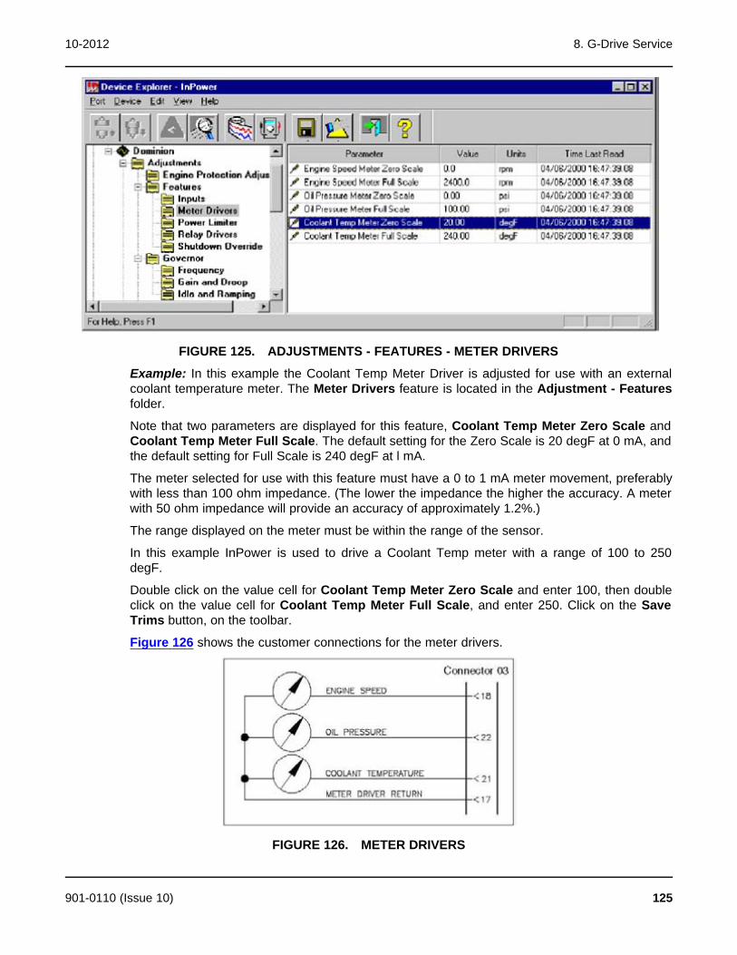
10-2012 8. G-Drive Service
FIGURE 125. ADJUSTMENTS - FEATURES - METER DRIVERS
Example: In this example the Coolant Temp Meter Driver is adjusted for use with an externalcoolant temperature meter. The Meter Drivers feature is located in the Adjustment - Featuresfolder.
Note that two parameters are displayed for this feature, Coolant Temp Meter Zero Scale andCoolant Temp Meter Full Scale. The default setting for the Zero Scale is 20 degF at 0 mA, andthe default setting for Full Scale is 240 degF at l mA.
The meter selected for use with this feature must have a 0 to 1 mA meter movement, preferablywith less than 100 ohm impedance. (The lower the impedance the higher the accuracy. A meterwith 50 ohm impedance will provide an accuracy of approximately 1.2%.)
The range displayed on the meter must be within the range of the sensor.
In this example InPower is used to drive a Coolant Temp meter with a range of 100 to 250degF.
Double click on the value cell for Coolant Temp Meter Zero Scale and enter 100, then doubleclick on the value cell for Coolant Temp Meter Full Scale, and enter 250. Click on the SaveTrims button, on the toolbar.
Figure 126 shows the customer connections for the meter drivers.
FIGURE 126. METER DRIVERS
901-0110 (Issue 10) 125

8. G-Drive Service 10-2012
Password Example 1: In this example, InPower is used to create both an Application passwordand a User password. These passwords are used to prevent unauthorized InPower users fromwriting changes to password protected parameters.
In examples 2 and 3, InPower is used to Enter these passwords to write changes to protectedparameters and to Clear these Application and User passwords.
Connect to the ECM and open the Adjustments - Passwords parameter group. Click on theChange Passwords folder.
Double click on the value cell for the Change Application Password parameter. Enter thepassword test21 (passwords must be 5 to 8 characters in length and may consist of anycombination of alpha or numeric characters).
Make a note of the Application password.
Click on the Save Trims button, on the toolbar, to write the new password to the device.
Repeat this process for the Change User Password value cell. Enter test22 and click on theSave Trims button again to write the new password to the device.
Make a note of the User password.
Close the connection to the ECM and exit InPower. Proceed to the next Password Example.
FIGURE 127. CHANGE PASSWORDS
Password Example 2: In this example, InPower is used to adjust parameters that havepassword protection.
Start InPower, connect to the ECM, and open the Adjustments - Passwords parameter group.Click on the Enter Passwords folder.
Double click on the value cell for the Enter Application Password parameter. Enter thepassword test21. Click on the Save Trims button. Repeat by entering test22 in the Enter UserPassword value cell, and click on the Save Trims button.
Open the Adjustments - Engine Protection Adjustments parameter group and double clickon the Coolant Level Switch Enable value cell (this parameter is Application Passwordprotected). Select Enable, from the drop down list and click on the Save Trims button.
Next, double click on the Engine Cold Warning Threshold value cell (this parameter is UserPassword protected). Enter 20 (degF) and click on the Save Trims button.
126 901-0110 (Issue 10)
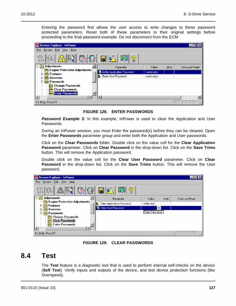
10-2012 8. G-Drive Service
Entering the password first allows the user access to write changes to these passwordprotected parameters. Reset both of these parameters to their original settings beforeproceeding to the final password example. Do not disconnect from the ECM.
FIGURE 128. ENTER PASSWORDS
Password Example 3: In this example, InPower is used to clear the Application and UserPasswords.
During an InPower session, you must Enter the password(s) before they can be cleared. Openthe Enter Passwords parameter group and enter both the Application and User passwords.
Click on the Clear Passwords folder. Double click on the value cell for the Clear ApplicationPassword parameter. Click on Clear Password in the drop-down list. Click on the Save Trimsbutton. This will remove the Application password.
Double click on the value cell for the Clear User Password parameter. Click on ClearPassword in the drop-down list. Click on the Save Trims button. This will remove the Userpassword.
FIGURE 129. CLEAR PASSWORDS
8.4 TestThe Test feature is a diagnostic tool that is used to perform internal self-checks on the device(Self Test). Verify inputs and outputs of the device, and test device protection functions (likeOverspeed).
901-0110 (Issue 10) 127
8. G-Drive Service 10-2012
After changing a Test parameter, the user can observe or measure the results of the changes.
Changes made to test parameter values are retained until they are changed back, usingInPower, or until power is removed from the device (ECM). When finished with a test,make sure that you return the parameters to their original setting. To permanently writechanges to the control, you must use the Adjustment feature.
The Test directory for a typical ECM contains the following groups (folders) of Test options:
· Fault Simulation
· Inputs
· Output
· Self Test
· Speed Override
This section describes each of the groups of tests listed in the Test directory. The Self Testfeature can be used as a quick check to determine if the ECM is responding, by sending controlinputs that should activate the control outputs. The other Tests are used for performing morespecific test functions.
8.4.1 Inputs - Oil PressureWhen inputs are externally activated, the Engine Inputs feature can be used to monitor theinputs. The actual inputs can be measured with a multimeter and the results can be compared.
Example: To test the Oil Pressure Input, check the G-Drive Control System Wiring Diagramfor the location of the oil pressure sender input. In this example the input is on connector 02,between pins 22 (+) and 10 (gnd). Remove the connector and insert the service breakout box.Check for voltage between pins 22 and 10.
If no voltage is present, check the harness and the sensor. If voltage is measured, and InPowerand the Operator panel display no input, the connections to the control, or the control aresuspect.
Figure 130 shows the results when an input voltage is present, in this example the oil pressure(approximately 85 psi) is displayed in InPower, and should also be displayed in the OperatorPanel display (if equipped).
128 901-0110 (Issue 10)
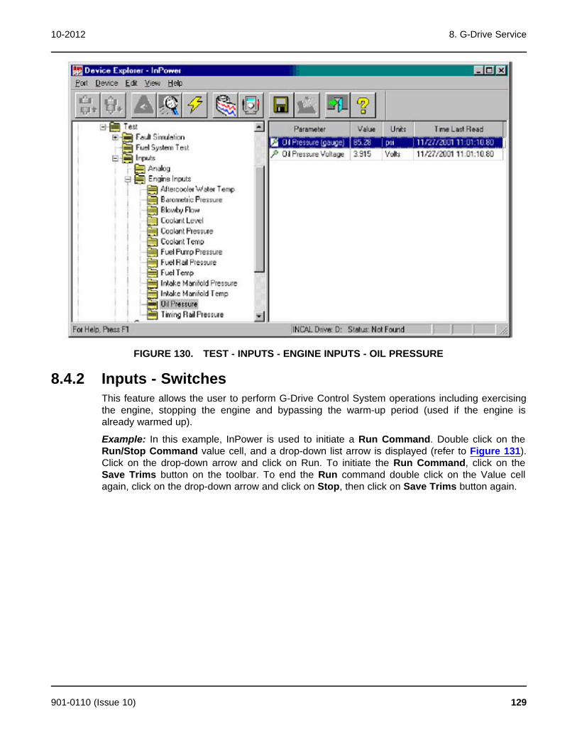
10-2012 8. G-Drive Service
FIGURE 130. TEST - INPUTS - ENGINE INPUTS - OIL PRESSURE
8.4.2 Inputs - SwitchesThis feature allows the user to perform G-Drive Control System operations including exercisingthe engine, stopping the engine and bypassing the warm-up period (used if the engine isalready warmed up).
Example: In this example, InPower is used to initiate a Run Command. Double click on theRun/Stop Command value cell, and a drop-down list arrow is displayed (refer to Figure 131).Click on the drop-down arrow and click on Run. To initiate the Run Command, click on theSave Trims button on the toolbar. To end the Run command double click on the Value cellagain, click on the drop-down arrow and click on Stop, then click on Save Trims button again.
901-0110 (Issue 10) 129
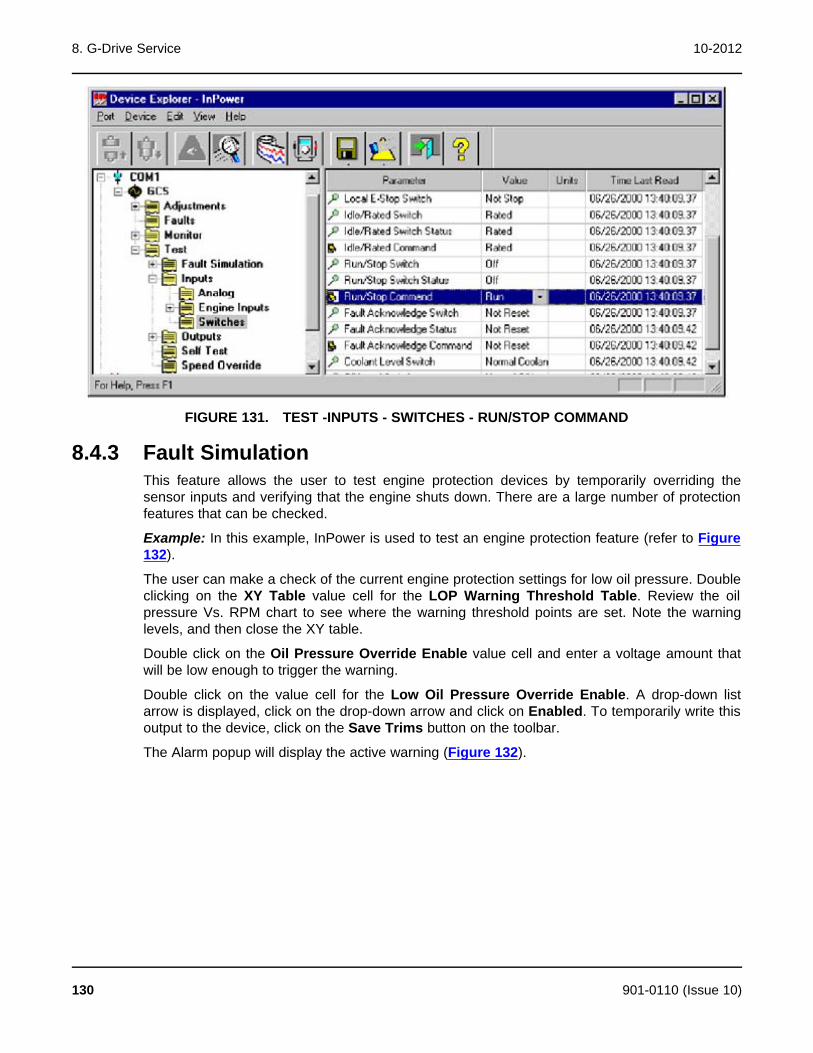
8. G-Drive Service 10-2012
FIGURE 131. TEST -INPUTS - SWITCHES - RUN/STOP COMMAND
8.4.3 Fault SimulationThis feature allows the user to test engine protection devices by temporarily overriding thesensor inputs and verifying that the engine shuts down. There are a large number of protectionfeatures that can be checked.
Example: In this example, InPower is used to test an engine protection feature (refer to Figure132).
The user can make a check of the current engine protection settings for low oil pressure. Doubleclicking on the XY Table value cell for the LOP Warning Threshold Table. Review the oilpressure Vs. RPM chart to see where the warning threshold points are set. Note the warninglevels, and then close the XY table.
Double click on the Oil Pressure Override Enable value cell and enter a voltage amount thatwill be low enough to trigger the warning.
Double click on the value cell for the Low Oil Pressure Override Enable. A drop-down listarrow is displayed, click on the drop-down arrow and click on Enabled. To temporarily write thisoutput to the device, click on the Save Trims button on the toolbar.
The Alarm popup will display the active warning (Figure 132).
130 901-0110 (Issue 10)

10-2012 8. G-Drive Service
FIGURE 132. TEST - ENGINE PROTECTION - OIL PRESSURE TEST
8.4.4 Self TestInPower has built in tests that can be used for diagnostics. The default setting is the Test Abortvalue (not in test mode) setting. Figure 133 shows the Self Test options. Double click on theValue cell, then click on the arrow to display the drop-down list of settings.
The Self Test feature has two Built In Tests (BIT Command). The first test, named TestStationary, is used to check all sensors and output relays by activating control outputs. The usercan then monitor inputs, if fault conditions occur, the event handler will popup to display faults.
WARNING: Notify personnel before using the Self Test Feature to crank the engine.Severe personal injury or death can result. See the equipment Operator'sManual for important safety precautions.
The second test, named Test Cranking, sends a start cranking signal to the engine to test themag pick-up (MPU) speed sensors, starter relay and battery level.
The Test Abort setting is the default setting, indicating that a Self Test is not in process. To enda test in process, return the BIT Command Value to Test Abort.
901-0110 (Issue 10) 131
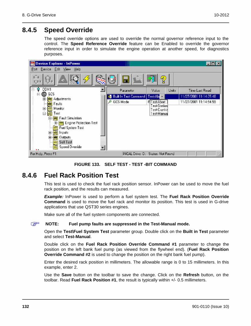
8. G-Drive Service 10-2012
8.4.5 Speed OverrideThe speed override options are used to override the normal governor reference input to thecontrol. The Speed Reference Override feature can be Enabled to override the governorreference input in order to simulate the engine operation at another speed, for diagnosticspurposes.
FIGURE 133. SELF TEST - TEST -BIT COMMAND
8.4.6 Fuel Rack Position TestThis test is used to check the fuel rack position sensor. InPower can be used to move the fuelrack position, and the results can measured.
Example: InPower is used to perform a fuel system test. The Fuel Rack Position OverrideCommand is used to move the fuel rack and monitor its position. This test is used in G-driveapplications that use QST30 series engines.
Make sure all of the fuel system components are connected.
NOTE: Fuel pump faults are suppressed in the Test-Manual mode.
Open the Test\Fuel System Test parameter group. Double click on the Built in Test parameterand select Test-Manual.
Double click on the Fuel Rack Position Override Command #1 parameter to change theposition on the left bank fuel pump (as viewed from the flywheel end). (Fuel Rack PositionOverride Command #2 is used to change the position on the right bank fuel pump).
Enter the desired rack position in millimeters. The allowable range is 0 to 15 millimeters. In thisexample, enter 2.
Use the Save button on the toolbar to save the change. Click on the Refresh button, on thetoolbar. Read Fuel Rack Position #1, the result is typically within +/- 0.5 millimeters.
132 901-0110 (Issue 10)

10-2012 8. G-Drive Service
FIGURE 134. FUEL RACK POSITION TEST
8.4.7 Single Cylinder Cutout TestInPower can used to cutout fueling to one cylinder at a time. This test can be used to helpisolate a cylinder with fueling or combustion problems.
Example: InPower is used to perform a single cylinder cutout test. This test is used inapplications that use QSX15 series engines.
CAUTION: Do not cutout fueling to more than one cylinder at a time or engine damage canresult. Always change the Cylinder Cut Out Test Enable to Disabled, when finishedtesting. Follow these steps carefully and refer to the equipment Operator's Manualfor Important Safety Precautions.
Connect the service PC to the genset. Start the genset and operate it at rated speed with noload.
Open the Test\Fuel System Test parameter group. Make sure each of the six cylinderparameter values are set at 1 (enabled).
Double click on the Cylinder Cut Out Test Enable parameter and select Enabled.
Double click on the desired cylinder for testing, in this example: Cylinder #1 Injector Fueling.Enter 0 (disabled). Use the Save button on the toolbar to save the change and perform thecutout test on cylinder number 1.
When finished, always remember to return the Cylinder Cut Out Test Enable to Disabled, andreturn the cylinder being tested to 1 (enabled). Use the Save button on the toolbar to save thechange.
901-0110 (Issue 10) 133
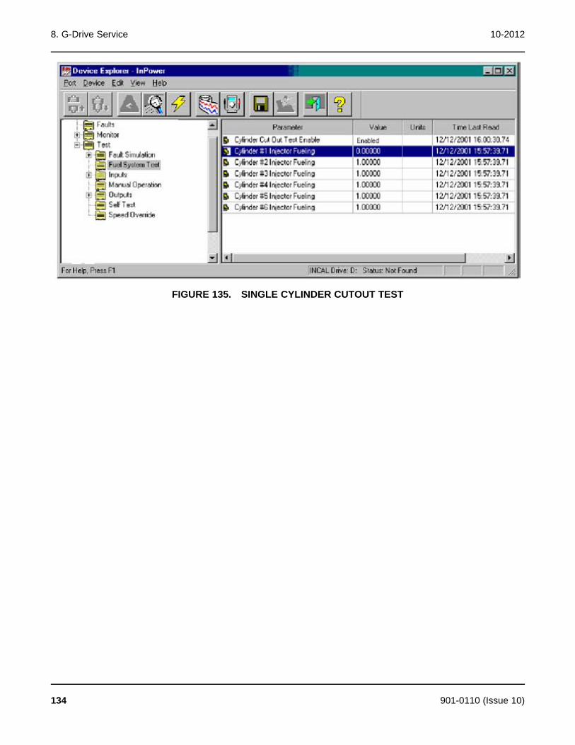
8. G-Drive Service 10-2012
FIGURE 135. SINGLE CYLINDER CUTOUT TEST
134 901-0110 (Issue 10)
9 Initial Calibration for CommercialGensets
9.1 About Initial CalibrationThe Initial Calibration feature is used to download a calibration file into a service replacementgenset control (base board). This section covers the procedures for performing an InitialCalibration on commercial gensets.
Starting with version 5.5, InPower calibration files for commercial and consumer controllers canbe downloaded from the InCal CD or from the CPG InCal website.
9.2 Initial CalibrationUse of a Capture File can reduce the amount of adjustment that may be required whenreplacing the base board. If the old base board is operational, and a capture file has not alreadybeen created, correct any active faults (if possible).
Refer to the generator set service manual for control replacement procedures. Before replacingthe control, remove power from the battery charger and block heater, if equipped, and removepower from the genset control.
Complete all necessary service replacement procedures and power the control.
Reconnect power to the battery charger and block heater, if applicable.
Connect the serial communication cable from the service PC to the device.
Start InPower and launch the Alarm Popup Window by clicking on the firecracker icon, locatedon the lower right corner of the Windows status bar. Click on the Alarm Popup Options menu,then click on AutoAnnounce to deselect (uncheck) it. Disabling this feature prevents nuisancealarms during the calibration download.
Connect to the port by double clicking on the port that matches the COM port on the service PCbeing used for the genset connection (COM1, COM2, etc.). The available COM ports aredisplayed in the Device Explorer directory (left pane).
Select the device DVC1 (or PCC##00, if the device already has a calibration file) by clicking onit (Figure 136).
After connecting to the device, click on the Device menu and click on Initial Calibration(Figure 137).
If prompted to select between G-Drive and Genset applications, select Genset; then selectNext.
Refer to the genset calibration label, located inside the control housing, for the calibration partnumber (Figure 138).
This label also lists the features that were originally installed in this device.
In this example, calibration part number 0326-0264 is displayed on the label.
901-0110 (Issue 10) 135
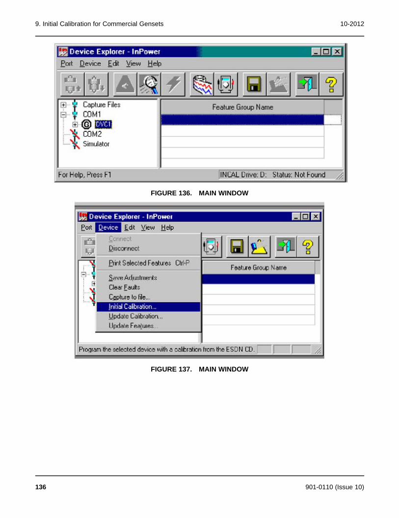
9. Initial Calibration for Commercial Gensets 10-2012
FIGURE 136. MAIN WINDOW
FIGURE 137. MAIN WINDOW
136 901-0110 (Issue 10)

10-2012 9. Initial Calibration for Commercial Gensets
FIGURE 138. GENSET DATAPLATE AND CALIBRATION LABEL
If a pop-up message indicates that there is an error loading from the INCAL CD, either the CDdrive letter was not correctly specified during InPower installation, or the CD is not installed or isdefective. If the CD is in the CD drive, click on Yes, and specify the correct CD drivedesignation. If the CD is not in the drive, insert the CD and click on No.
The INCAL CD location can be verified by clicking on the Port menu and clicking on Find InCal(Figure 139). Select INCAL CD drive designation from the drop-down list, then click on VerifyINCAL Structure. A popup message will verify the INCAL location (Figure 140).
FIGURE 139. FIND INCAL
901-0110 (Issue 10) 137
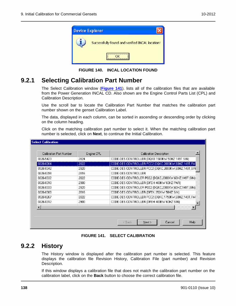
9. Initial Calibration for Commercial Gensets 10-2012
FIGURE 140. INCAL LOCATION FOUND
9.2.1 Selecting Calibration Part NumberThe Select Calibration window (Figure 141). lists all of the calibration files that are availablefrom the Power Generation INCAL CD. Also shown are the Engine Control Parts List (CPL) andCalibration Description.
Use the scroll bar to locate the Calibration Part Number that matches the calibration partnumber shown on the genset Calibration Label.
The data, displayed in each column, can be sorted in ascending or descending order by clickingon the column heading.
Click on the matching calibration part number to select it. When the matching calibration partnumber is selected, click on Next, to continue the Initial Calibration.
FIGURE 141. SELECT CALIBRATION
9.2.2 HistoryThe History window is displayed after the calibration part number is selected. This featuredisplays the calibration file Revision History, Calibration File (part number) and RevisionDescription.
If this window displays a calibration file that does not match the calibration part number on thecalibration label, click on the Back button to choose the correct calibration file.
138 901-0110 (Issue 10)

10-2012 9. Initial Calibration for Commercial Gensets
If History displays the calibration file part number that was previously selected, click on the Nextbutton to proceed to the Save and Restore Parameters feature.
9.2.3 Save and Restore ParametersThe Save and Restore Parameters window displays the Parameter Descriptions, Value, andUnits of measure information (Figure 143).
FIGURE 142. HISTORY
FIGURE 143. SAVE AND RESTORE PARAMETERS
901-0110 (Issue 10) 139
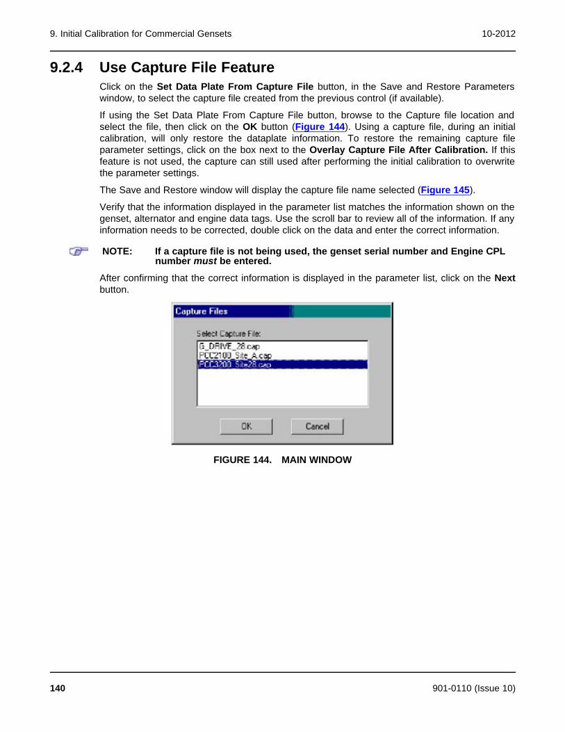
9. Initial Calibration for Commercial Gensets 10-2012
9.2.4 Use Capture File FeatureClick on the Set Data Plate From Capture File button, in the Save and Restore Parameterswindow, to select the capture file created from the previous control (if available).
If using the Set Data Plate From Capture File button, browse to the Capture file location andselect the file, then click on the OK button (Figure 144). Using a capture file, during an initialcalibration, will only restore the dataplate information. To restore the remaining capture fileparameter settings, click on the box next to the Overlay Capture File After Calibration. If thisfeature is not used, the capture can still used after performing the initial calibration to overwritethe parameter settings.
The Save and Restore window will display the capture file name selected (Figure 145).
Verify that the information displayed in the parameter list matches the information shown on thegenset, alternator and engine data tags. Use the scroll bar to review all of the information. If anyinformation needs to be corrected, double click on the data and enter the correct information.
NOTE: If a capture file is not being used, the genset serial number and Engine CPLnumber must be entered.
After confirming that the correct information is displayed in the parameter list, click on the Nextbutton.
FIGURE 144. MAIN WINDOW
140 901-0110 (Issue 10)

10-2012 9. Initial Calibration for Commercial Gensets
FIGURE 145. CAPTURE FILE SELECTED
9.2.5 Feature ListThe Feature List window displays all of the feature part numbers that are available for theselected calibration file (Figure 146). This screen also displays the feature descriptions and adialog for entering the dataplate checksum data from the calibration label.
FIGURE 146. FEATURE LIST
901-0110 (Issue 10) 141

9. Initial Calibration for Commercial Gensets 10-2012
Refer to the calibration label (Figure 138), located inside the control housing, for the list offeatures that were factory installed on this genset.
Click on the checkbox, next to each of the feature part numbers, that correspond to the featurepart numbers on the calibration label.
Enter the Checksum data into the Dataplate Checksum dialog. The checksum data must beentered exactly as it appears on the calibration label (case sensitive). Click on the Next buttonto continue. PCC 1300, PCC 1301, PCC 1302, PCC 2100, PCC2300, PCC3300, and MCM3320applications do not use the checksum feature. Beginning with InPower v4.5 only PCC3200/PCC 3201 controls require the checksum.
If all of the information has been entered correctly, a popup window prompts the user with thequestion “Do you wish to calibrate the controller now?" (Figure 147). Click on the Yes button tocontinue.
If you receive an “Invalid Checksum" error message, check the calibration part number, theSave and Restore information, the Feature part numbers, and the Checksum. Use the Backbutton to navigate through the information. Make any necessary corrections, and reenter thechecksum data exactly as it appears on the calibration label.
NOTE: The genset serial number and the checksum are case sensitive.
FIGURE 147. CALIBRATION POPUP
FIGURE 148. FEATURE LIST
A popup window informs the user that the calibration file download will erase all adjustments,and it prompts the user with the question “Do you choose to continue?" (Figure 148). Click onthe Yes button, to begin the initial calibration download.
NOTE: Pop-up messages may be displayed behind an open window. To view allopen windows, including popup messages, hold down the Alt key andrepeatedly press the Tab key to view each open window.
142 901-0110 (Issue 10)
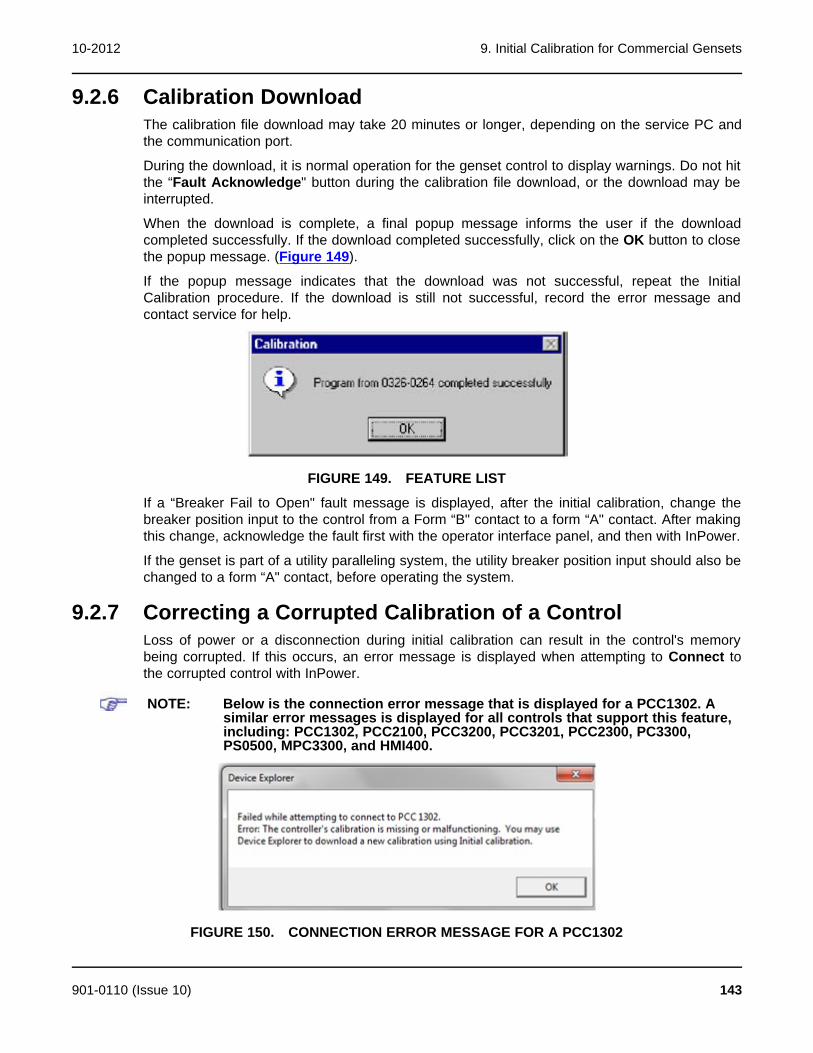
10-2012 9. Initial Calibration for Commercial Gensets
9.2.6 Calibration DownloadThe calibration file download may take 20 minutes or longer, depending on the service PC andthe communication port.
During the download, it is normal operation for the genset control to display warnings. Do not hitthe “Fault Acknowledge" button during the calibration file download, or the download may beinterrupted.
When the download is complete, a final popup message informs the user if the downloadcompleted successfully. If the download completed successfully, click on the OK button to closethe popup message. (Figure 149).
If the popup message indicates that the download was not successful, repeat the InitialCalibration procedure. If the download is still not successful, record the error message andcontact service for help.
FIGURE 149. FEATURE LIST
If a “Breaker Fail to Open" fault message is displayed, after the initial calibration, change thebreaker position input to the control from a Form “B" contact to a form “A" contact. After makingthis change, acknowledge the fault first with the operator interface panel, and then with InPower.
If the genset is part of a utility paralleling system, the utility breaker position input should also bechanged to a form “A" contact, before operating the system.
9.2.7 Correcting a Corrupted Calibration of a ControlLoss of power or a disconnection during initial calibration can result in the control's memorybeing corrupted. If this occurs, an error message is displayed when attempting to Connect tothe corrupted control with InPower.
NOTE: Below is the connection error message that is displayed for a PCC1302. Asimilar error messages is displayed for all controls that support this feature,including: PCC1302, PCC2100, PCC3200, PCC3201, PCC2300, PC3300,PS0500, MPC3300, and HMI400.
FIGURE 150. CONNECTION ERROR MESSAGE FOR A PCC1302
901-0110 (Issue 10) 143

9. Initial Calibration for Commercial Gensets 10-2012
To recover the corrupted control, use the control's Initial Calibration menu selection. After thecontrol has been calibrated, use the Connect command to verify that the control has beenrecovered.
NOTE: The following figure shows the Initial Calibration and Connect commands forthe PCC1302. These commands are also available for the other controls thatsupport this feature.
FIGURE 151. INITIAL CALIBRATION MENU SELECTION FOR A PCC1302
9.2.8 Correcting a Corrupted Calibration of a AMMPS or BEARControlLoss of power or a disconnection during initial calibration can result in the control's memorybeing corrupted. If this occurs, an error message is displayed when attempting to Connect tothe corrupted control with InPower.
FIGURE 152. CONNECTION ERROR MESSAGE
To recover the corrupted control, use the control's Initial Calibration menu selection. After thecontrol has been calibrated, use the Connect command to verify that the control has beenrecovered.
144 901-0110 (Issue 10)
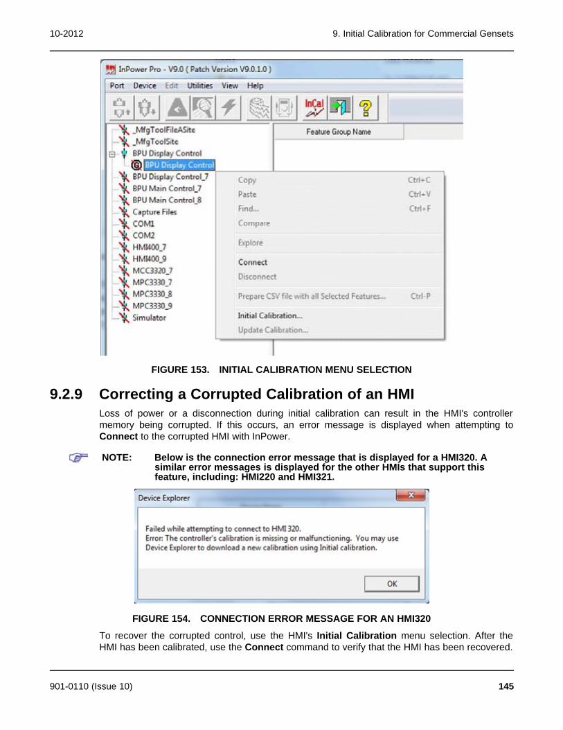
10-2012 9. Initial Calibration for Commercial Gensets
FIGURE 153. INITIAL CALIBRATION MENU SELECTION
9.2.9 Correcting a Corrupted Calibration of an HMILoss of power or a disconnection during initial calibration can result in the HMI's controllermemory being corrupted. If this occurs, an error message is displayed when attempting toConnect to the corrupted HMI with InPower.
NOTE: Below is the connection error message that is displayed for a HMI320. Asimilar error messages is displayed for the other HMIs that support thisfeature, including: HMI220 and HMI321.
FIGURE 154. CONNECTION ERROR MESSAGE FOR AN HMI320
To recover the corrupted control, use the HMI's Initial Calibration menu selection. After theHMI has been calibrated, use the Connect command to verify that the HMI has been recovered.
901-0110 (Issue 10) 145
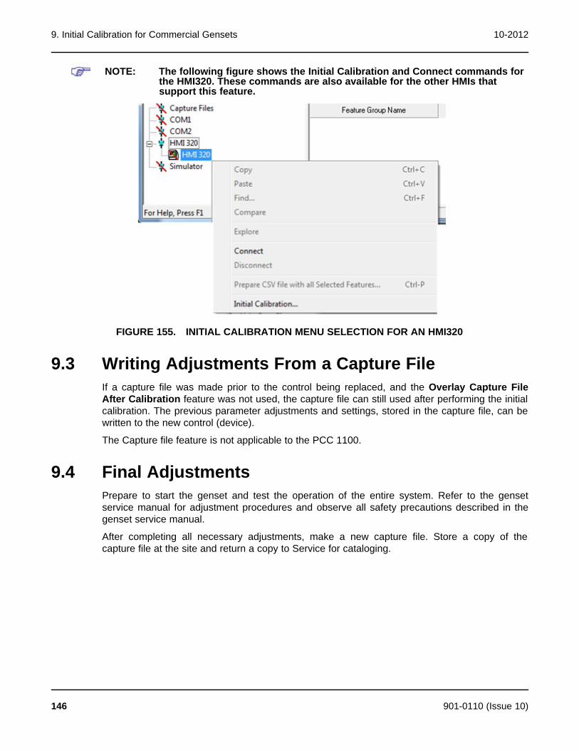
9. Initial Calibration for Commercial Gensets 10-2012
NOTE: The following figure shows the Initial Calibration and Connect commands forthe HMI320. These commands are also available for the other HMIs thatsupport this feature.
FIGURE 155. INITIAL CALIBRATION MENU SELECTION FOR AN HMI320
9.3 Writing Adjustments From a Capture FileIf a capture file was made prior to the control being replaced, and the Overlay Capture FileAfter Calibration feature was not used, the capture file can still used after performing the initialcalibration. The previous parameter adjustments and settings, stored in the capture file, can bewritten to the new control (device).
The Capture file feature is not applicable to the PCC 1100.
9.4 Final AdjustmentsPrepare to start the genset and test the operation of the entire system. Refer to the gensetservice manual for adjustment procedures and observe all safety precautions described in thegenset service manual.
After completing all necessary adjustments, make a new capture file. Store a copy of thecapture file at the site and return a copy to Service for cataloging.
146 901-0110 (Issue 10)

10 Update Calibration for CommercialGensets
10.1 About Update CalibrationThe Update Calibration feature is used to replace a current calibration file with a newer versionfrom the Power Generation INCAL CD or downloaded from the CPG InCal website. The newcalibration file is written over the current calibration file in the genset baseboard.
Calibration updates are performed at the site, using InPower. This section covers theprocedures for performing Update Calibration for commercial gensets.
Starting with version 5.5, InPower calibration files for commercial and consumer controllers canbe downloaded from the InCal CD or from the CPG InCal website.
10.2 Update CalibrationAfter connecting to the device, click on the Device menu and click on Update Calibration(Figure 156). If prompted to select between G-Drive and Genset applications, select Genset,then select Next.
If prompted with the message, “Could not find a matching Calibration Part Number ...," click onthe OK button. Use the Initial Calibration feature to update the calibration file.
After selecting Update Calibration, the History window is displayed.
FIGURE 156. UPDATE - DEVICE MENU
901-0110 (Issue 10) 147
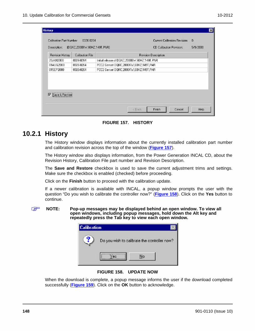
10. Update Calibration for Commercial Gensets 10-2012
FIGURE 157. HISTORY
10.2.1 HistoryThe History window displays information about the currently installed calibration part numberand calibration revision across the top of the window (Figure 157).
The History window also displays information, from the Power Generation INCAL CD, about theRevision History, Calibration File part number and Revision Description.
The Save and Restore checkbox is used to save the current adjustment trims and settings.Make sure the checkbox is enabled (checked) before proceeding.
Click on the Finish button to proceed with the calibration update.
If a newer calibration is available with INCAL, a popup window prompts the user with thequestion “Do you wish to calibrate the controller now?" (Figure 158). Click on the Yes button tocontinue.
NOTE: Pop-up messages may be displayed behind an open window. To view allopen windows, including popup messages, hold down the Alt key andrepeatedly press the Tab key to view each open window.
FIGURE 158. UPDATE NOW
When the download is complete, a popup message informs the user if the download completedsuccessfully (Figure 159). Click on the OK button to acknowledge.
148 901-0110 (Issue 10)

10-2012 10. Update Calibration for Commercial Gensets
FIGURE 159. COMPLETED
901-0110 (Issue 10) 149

10. Update Calibration for Commercial Gensets 10-2012
This page is intentionally blank.
150 901-0110 (Issue 10)
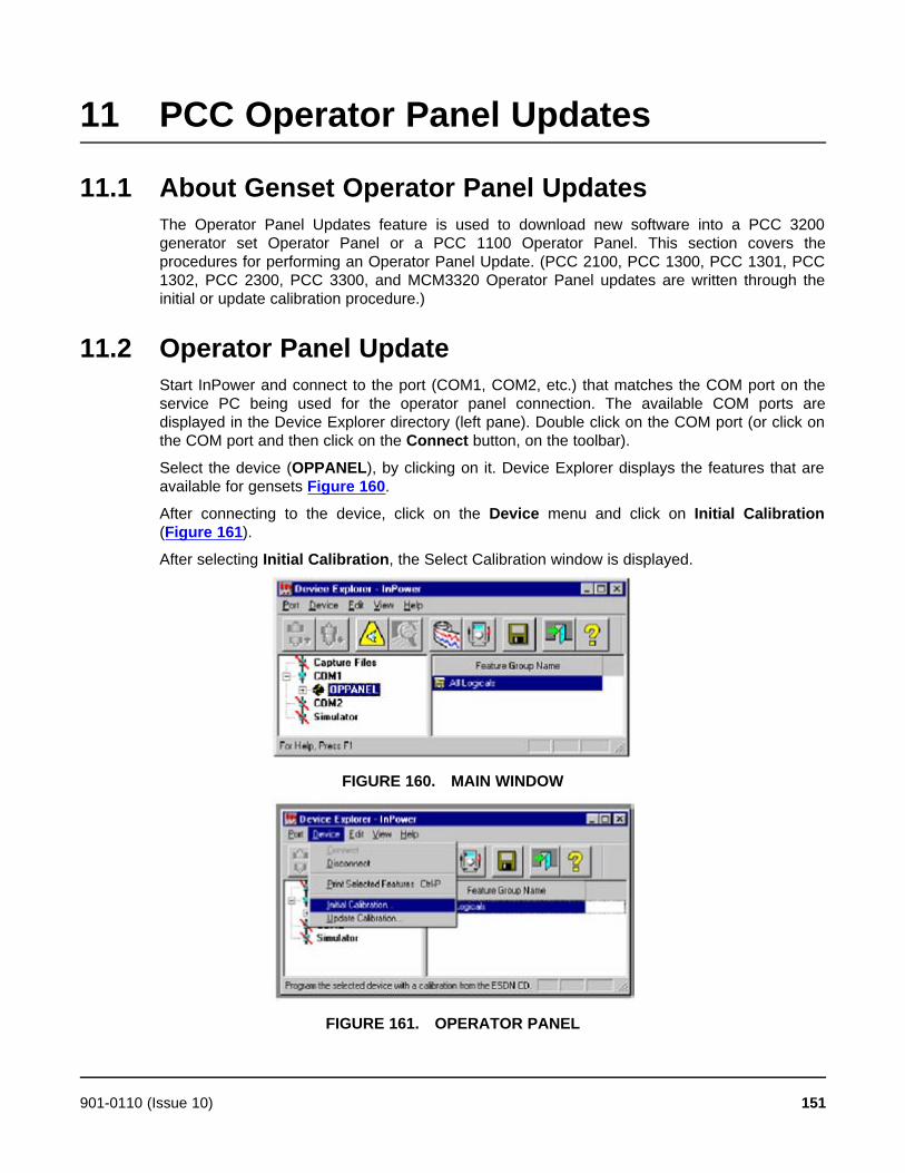
11 PCC Operator Panel Updates
11.1 About Genset Operator Panel UpdatesThe Operator Panel Updates feature is used to download new software into a PCC 3200generator set Operator Panel or a PCC 1100 Operator Panel. This section covers theprocedures for performing an Operator Panel Update. (PCC 2100, PCC 1300, PCC 1301, PCC1302, PCC 2300, PCC 3300, and MCM3320 Operator Panel updates are written through theinitial or update calibration procedure.)
11.2 Operator Panel UpdateStart InPower and connect to the port (COM1, COM2, etc.) that matches the COM port on theservice PC being used for the operator panel connection. The available COM ports aredisplayed in the Device Explorer directory (left pane). Double click on the COM port (or click onthe COM port and then click on the Connect button, on the toolbar).
Select the device (OPPANEL), by clicking on it. Device Explorer displays the features that areavailable for gensets Figure 160.
After connecting to the device, click on the Device menu and click on Initial Calibration(Figure 161).
After selecting Initial Calibration, the Select Calibration window is displayed.
FIGURE 160. MAIN WINDOW
FIGURE 161. OPERATOR PANEL
901-0110 (Issue 10) 151
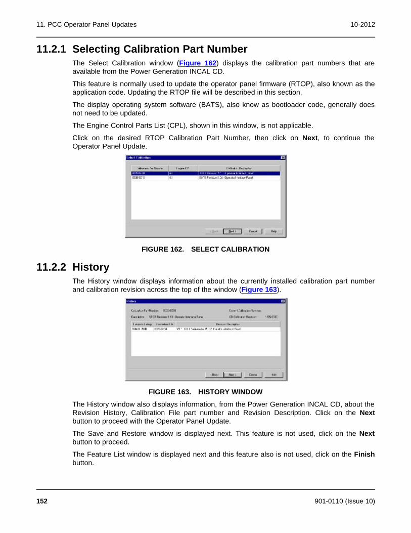
11. PCC Operator Panel Updates 10-2012
11.2.1 Selecting Calibration Part NumberThe Select Calibration window (Figure 162) displays the calibration part numbers that areavailable from the Power Generation INCAL CD.
This feature is normally used to update the operator panel firmware (RTOP), also known as theapplication code. Updating the RTOP file will be described in this section.
The display operating system software (BATS), also know as bootloader code, generally doesnot need to be updated.
The Engine Control Parts List (CPL), shown in this window, is not applicable.
Click on the desired RTOP Calibration Part Number, then click on Next, to continue theOperator Panel Update.
FIGURE 162. SELECT CALIBRATION
11.2.2 HistoryThe History window displays information about the currently installed calibration part numberand calibration revision across the top of the window (Figure 163).
FIGURE 163. HISTORY WINDOW
The History window also displays information, from the Power Generation INCAL CD, about theRevision History, Calibration File part number and Revision Description. Click on the Nextbutton to proceed with the Operator Panel Update.
The Save and Restore window is displayed next. This feature is not used, click on the Nextbutton to proceed.
The Feature List window is displayed next and this feature also is not used, click on the Finishbutton.
152 901-0110 (Issue 10)

10-2012 11. PCC Operator Panel Updates
If a newer calibration file is available with INCAL, a popup window prompts the user with thequestion “Do you wish to calibrate the controller now?" (Figure 164). Click on the Yes button tocontinue.
NOTE: Pop-up messages may be displayed behind an open window. To view allopen windows, including pop-up messages, hold down the Alt key andrepeatedly press the Tab key to view each open window.
FIGURE 164. UPDATE NOW
11.2.3 During DownloadDuring the download procedure, the current BATS file software version is displayed in thegenset operator display panel. This is normal operation, do not confuse this with the RTOPversion that is being downloaded in the background with InPower.
When the download process completes, a popup message displays the INCAL file path andinforms the user if the download completed successfully (Figure 165). Click on the OK button toacknowledge.
FIGURE 165. COMPLETED FROM INCAL PATH
A second pop-up message confirms that the download completed successfully (Figure 166).Click on the OK button to acknowledge.
FIGURE 166. DOWNLOAD COMPLETED
If a pop-up messages indicate that the download was not successful, repeat the InitialCalibration procedure. If the download was still not successful, record any error messages andcontact service for help.
11.3 Final CheckThe results of the RTOP file download can be viewed in the genset operator display panel (ifequipped). View the History - About screen, to see the currently installed RTOP softwareversion.
901-0110 (Issue 10) 153

11. PCC Operator Panel Updates 10-2012
This page is intentionally blank.
154 901-0110 (Issue 10)
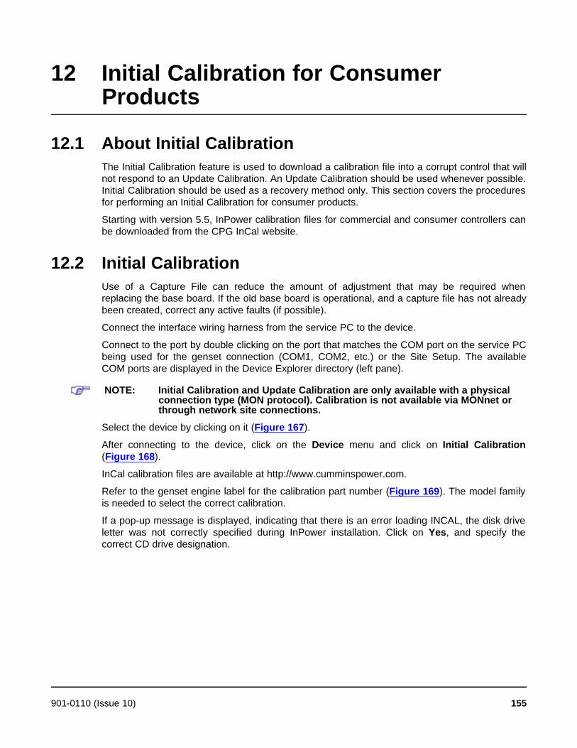
12 Initial Calibration for ConsumerProducts
12.1 About Initial CalibrationThe Initial Calibration feature is used to download a calibration file into a corrupt control that willnot respond to an Update Calibration. An Update Calibration should be used whenever possible.Initial Calibration should be used as a recovery method only. This section covers the proceduresfor performing an Initial Calibration for consumer products.
Starting with version 5.5, InPower calibration files for commercial and consumer controllers canbe downloaded from the CPG InCal website.
12.2 Initial CalibrationUse of a Capture File can reduce the amount of adjustment that may be required whenreplacing the base board. If the old base board is operational, and a capture file has not alreadybeen created, correct any active faults (if possible).
Connect the interface wiring harness from the service PC to the device.
Connect to the port by double clicking on the port that matches the COM port on the service PCbeing used for the genset connection (COM1, COM2, etc.) or the Site Setup. The availableCOM ports are displayed in the Device Explorer directory (left pane).
NOTE: Initial Calibration and Update Calibration are only available with a physicalconnection type (MON protocol). Calibration is not available via MONnet orthrough network site connections.
Select the device by clicking on it (Figure 167).
After connecting to the device, click on the Device menu and click on Initial Calibration(Figure 168).
InCal calibration files are available at http://www.cumminspower.com.
Refer to the genset engine label for the calibration part number (Figure 169). The model familyis needed to select the correct calibration.
If a pop-up message is displayed, indicating that there is an error loading INCAL, the disk driveletter was not correctly specified during InPower installation. Click on Yes, and specify thecorrect CD drive designation.
901-0110 (Issue 10) 155

12. Initial Calibration for Consumer Products 10-2012
FIGURE 167. MAIN WINDOW
FIGURE 168. MAIN WINDOW
156 901-0110 (Issue 10)
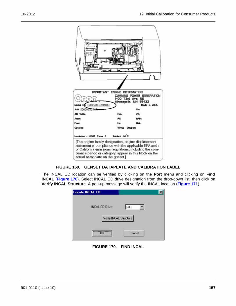
10-2012 12. Initial Calibration for Consumer Products
FIGURE 169. GENSET DATAPLATE AND CALIBRATION LABEL
The INCAL CD location can be verified by clicking on the Port menu and clicking on FindINCAL (Figure 170). Select INCAL CD drive designation from the drop-down list, then click onVerify INCAL Structure. A pop-up message will verify the INCAL location (Figure 171).
FIGURE 170. FIND INCAL
901-0110 (Issue 10) 157

12. Initial Calibration for Consumer Products 10-2012
FIGURE 171. INCAL LOCATION FOUND
12.2.1 Selecting Calibration Part NumberThe Select Calibration window (Figure 172). lists all of the calibration files that are availablefrom the Power Generation INCAL CD.
Use the scroll bar to locate the Calibration model that matches the model shown on the gensetengine label (Figure 169).
The data, displayed in each column, can be sorted in ascending or descending order by clickingon the column heading.
Click on the matching calibration part number to select it. When the matching calibration partnumber for the genset model is selected, click on Next, to continue the Initial Calibration.
12.2.2 HistoryThe History window is displayed when the NEXT button is selected (Figure 173). This featuredisplays the calibration file Revision History, Calibration File (part number) and RevisionDescription.
If this window displays a calibration file that does not match the model listed on the gensetengine label, click on the Back button to choose the correct calibration file.
If History displays the calibration file part number that was previously selected, click on the Nextbutton to proceed to the Save and Restore Parameters feature.
158 901-0110 (Issue 10)
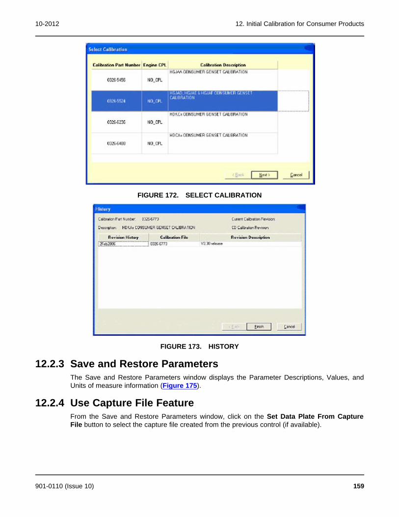
10-2012 12. Initial Calibration for Consumer Products
FIGURE 172. SELECT CALIBRATION
FIGURE 173. HISTORY
12.2.3 Save and Restore ParametersThe Save and Restore Parameters window displays the Parameter Descriptions, Values, andUnits of measure information (Figure 175).
12.2.4 Use Capture File FeatureFrom the Save and Restore Parameters window, click on the Set Data Plate From CaptureFile button to select the capture file created from the previous control (if available).
901-0110 (Issue 10) 159

12. Initial Calibration for Consumer Products 10-2012
If using the Set Data Plate From Capture File button, browse to the Capture file location andselect the file, then click on the OK button (Figure 174). Using a capture file, during an initialcalibration, will only restore the dataplate information. To restore the remaining capture fileparameter settings, click on the box next to the Overlay Capture File After Calibration. If thisfeature is not used, the capture file can still be used after performing the initial calibration tooverwrite the parameter settings. This is not recommended because user data will be clearedduring the download.
FIGURE 174. SELECTING A CAPTURE FILE
The Save and Restore window will display the capture file name selected (Figure 176).
Verify that the information displayed in the parameter list matches the information shown on thegenset, alternator and engine data tags. Use the scroll bar to review all of the information. If anyinformation needs to be corrected, double click on the data and enter the correct information.
After confirming that the correct information is displayed in the parameter list, click on the Nextbutton.
160 901-0110 (Issue 10)

10-2012 12. Initial Calibration for Consumer Products
FIGURE 175. SAVE AND RESTORE PARAMETERS
FIGURE 176. CAPTURE FILE SELECTED
901-0110 (Issue 10) 161

12. Initial Calibration for Consumer Products 10-2012
12.2.5 Calibration DownloadThe calibration file download may take a few minutes or longer, depending on the service PCand the communication port.
When the download is complete, a final pop-up message informs the user if the downloadcompleted successfully. If the download completed successfully, click on the OK button to closethe pop-up message. (Figure 177).
If the pop-up message indicates that the download was not successful, repeat the InitialCalibration procedure. If the download is still not successful, record the error message andcontact service for help.
FIGURE 177. FEATURE LIST
12.3 Writing Adjustments From a Capture FileIf a capture file was made prior to the control being replaced, and the Overlay Capture FileAfter Calibration feature was not used, the capture file can still used after performing the initialcalibration. The previous parameter adjustments and settings, stored in the capture file, can bewritten to the new control (device).
NOTE: Read only information cannot be written to when overlaying a capture file.
12.4 Final AdjustmentsPrepare to start the genset and test the operation of the entire system. Refer to the gensetservice manual for adjustment procedures and observe all safety precautions described in thegenset service manual.
After completing all necessary adjustments, make a new capture file. Store a copy of thecapture file at the site and return a copy to Service for cataloging.
162 901-0110 (Issue 10)
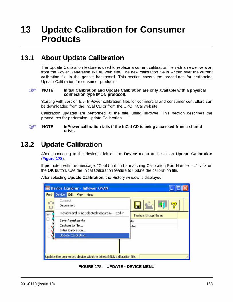
13 Update Calibration for ConsumerProducts
13.1 About Update CalibrationThe Update Calibration feature is used to replace a current calibration file with a newer versionfrom the Power Generation INCAL web site. The new calibration file is written over the currentcalibration file in the genset baseboard. This section covers the procedures for performingUpdate Calibration for consumer products.
NOTE: Initial Calibration and Update Calibration are only available with a physicalconnection type (MON protocol).
Starting with version 5.5, InPower calibration files for commercial and consumer controllers canbe downloaded from the InCal CD or from the CPG InCal website.
Calibration updates are performed at the site, using InPower. This section describes theprocedures for performing Update Calibration.
NOTE: InPower calibration fails if the InCal CD is being accessed from a shareddrive.
13.2 Update CalibrationAfter connecting to the device, click on the Device menu and click on Update Calibration(Figure 178).
If prompted with the message, “Could not find a matching Calibration Part Number ...," click onthe OK button. Use the Initial Calibration feature to update the calibration file.
After selecting Update Calibration, the History window is displayed.
FIGURE 178. UPDATE - DEVICE MENU
901-0110 (Issue 10) 163
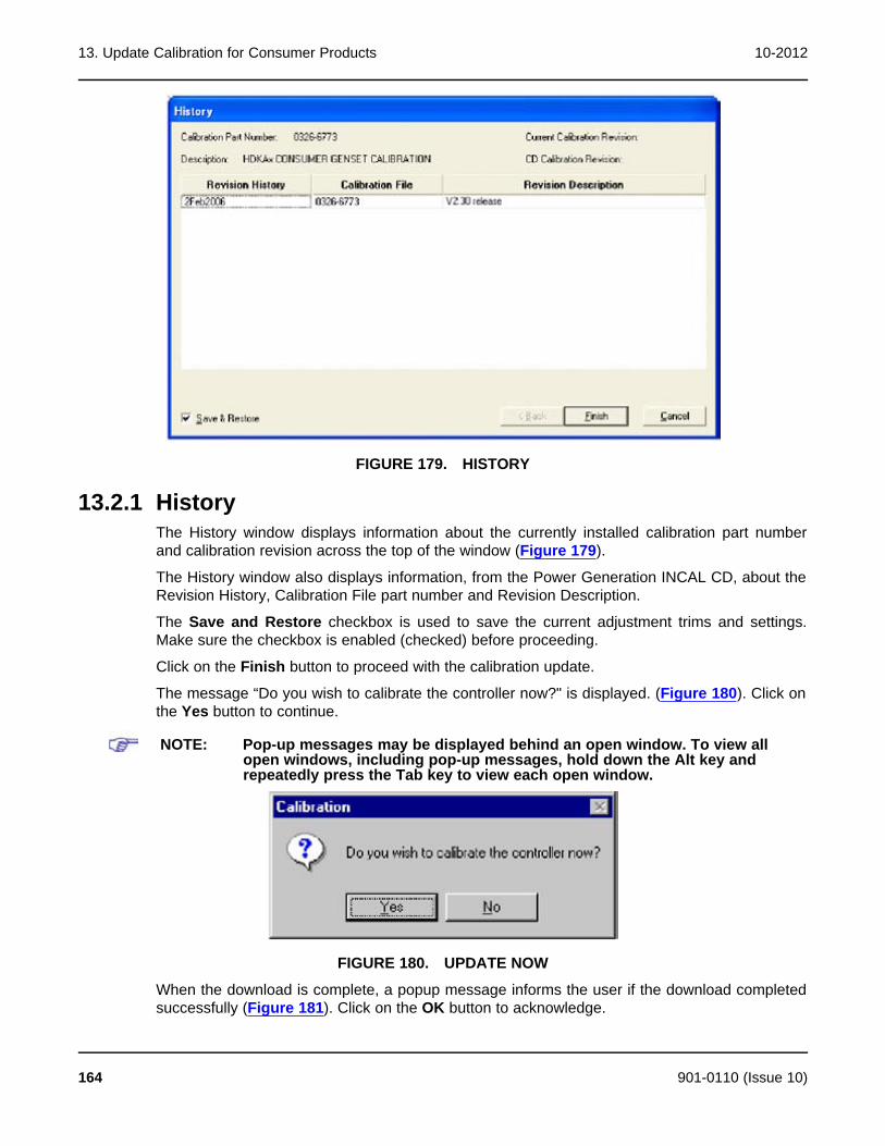
13. Update Calibration for Consumer Products 10-2012
FIGURE 179. HISTORY
13.2.1 HistoryThe History window displays information about the currently installed calibration part numberand calibration revision across the top of the window (Figure 179).
The History window also displays information, from the Power Generation INCAL CD, about theRevision History, Calibration File part number and Revision Description.
The Save and Restore checkbox is used to save the current adjustment trims and settings.Make sure the checkbox is enabled (checked) before proceeding.
Click on the Finish button to proceed with the calibration update.
The message “Do you wish to calibrate the controller now?" is displayed. (Figure 180). Click onthe Yes button to continue.
NOTE: Pop-up messages may be displayed behind an open window. To view allopen windows, including pop-up messages, hold down the Alt key andrepeatedly press the Tab key to view each open window.
FIGURE 180. UPDATE NOW
When the download is complete, a popup message informs the user if the download completedsuccessfully (Figure 181). Click on the OK button to acknowledge.
164 901-0110 (Issue 10)

10-2012 13. Update Calibration for Consumer Products
FIGURE 181. COMPLETED
901-0110 (Issue 10) 165

13. Update Calibration for Consumer Products 10-2012
This page is intentionally blank.
166 901-0110 (Issue 10)
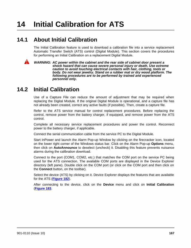
14 Initial Calibration for ATS
14.1 About Initial CalibrationThe Initial Calibration feature is used to download a calibration file into a service replacementAutomatic Transfer Switch (ATS) control (Digital Module). This section covers the proceduresfor performing an Initial Calibration on a replacement Digital Module.
WARNING: AC power within the cabinet and the rear side of cabinet door present ashock hazard that can cause severe personal injury or death. Use extremecaution to avoid touching electrical contacts with hair, clothing, tools orbody. Do not wear jewelry. Stand on a rubber mat or dry wood platform. Thefollowing procedures are to be performed by trained and experiencedpersonnel only.
14.2 Initial CalibrationUse of a Capture File can reduce the amount of adjustment that may be required whenreplacing the Digital Module. If the original Digital Module is operational, and a capture file hasnot already been created, correct any active faults (if possible). Then, create a capture file.
Refer to the ATS service manual for control replacement procedures. Before replacing thecontrol, remove power from the battery charger, if equipped, and remove power from the ATScontrol.
Complete all necessary service replacement procedures and power the control. Reconnectpower to the battery charger, if applicable.
Connect the serial communication cable from the service PC to the Digital Module.
Start InPower and launch the Alarm Pop-up Window by clicking on the firecracker icon, locatedon the lower right corner of the Windows status bar. Click on the Alarm Pop-up Options menu,then click on AutoAnnounce to deselect (uncheck) it. Disabling this feature prevents nuisancealarms during the calibration download.
Connect to the port (COM1, COM2, etc.) that matches the COM port on the service PC beingused for the ATS connection. The available COM ports are displayed in the Device Explorerdirectory (left pane). Double click on the COM port (or click on the COM port and then click onthe Connect button, on the toolbar).
Select the device (ATS) by clicking on it. Device Explorer displays the features that are availablefor the ATS (Figure 182).
After connecting to the device, click on the Device menu and click on Initial Calibration(Figure 183.
901-0110 (Issue 10) 167
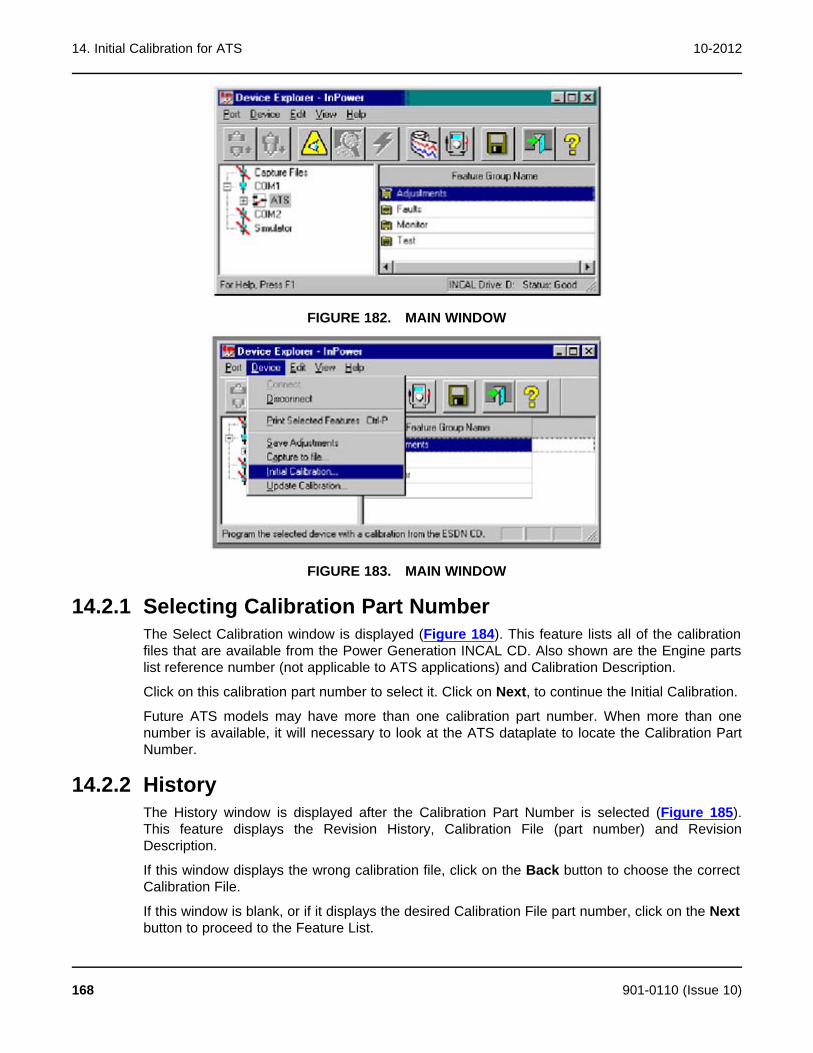
14. Initial Calibration for ATS 10-2012
FIGURE 182. MAIN WINDOW
FIGURE 183. MAIN WINDOW
14.2.1 Selecting Calibration Part NumberThe Select Calibration window is displayed (Figure 184). This feature lists all of the calibrationfiles that are available from the Power Generation INCAL CD. Also shown are the Engine partslist reference number (not applicable to ATS applications) and Calibration Description.
Click on this calibration part number to select it. Click on Next, to continue the Initial Calibration.
Future ATS models may have more than one calibration part number. When more than onenumber is available, it will necessary to look at the ATS dataplate to locate the Calibration PartNumber.
14.2.2 HistoryThe History window is displayed after the Calibration Part Number is selected (Figure 185).This feature displays the Revision History, Calibration File (part number) and RevisionDescription.
If this window displays the wrong calibration file, click on the Back button to choose the correctCalibration File.
If this window is blank, or if it displays the desired Calibration File part number, click on the Nextbutton to proceed to the Feature List.
168 901-0110 (Issue 10)

10-2012 14. Initial Calibration for ATS
FIGURE 184. SELECT CALIBRATION
FIGURE 185. HISTORY
901-0110 (Issue 10) 169
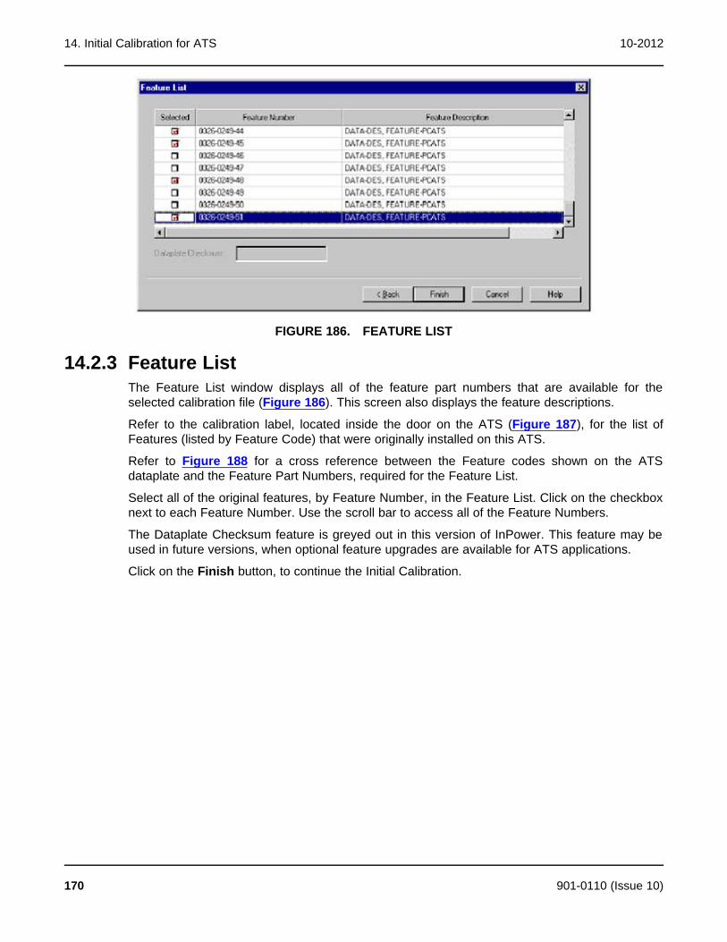
14. Initial Calibration for ATS 10-2012
FIGURE 186. FEATURE LIST
14.2.3 Feature ListThe Feature List window displays all of the feature part numbers that are available for theselected calibration file (Figure 186). This screen also displays the feature descriptions.
Refer to the calibration label, located inside the door on the ATS (Figure 187), for the list ofFeatures (listed by Feature Code) that were originally installed on this ATS.
Refer to Figure 188 for a cross reference between the Feature codes shown on the ATSdataplate and the Feature Part Numbers, required for the Feature List.
Select all of the original features, by Feature Number, in the Feature List. Click on the checkboxnext to each Feature Number. Use the scroll bar to access all of the Feature Numbers.
The Dataplate Checksum feature is greyed out in this version of InPower. This feature may beused in future versions, when optional feature upgrades are available for ATS applications.
Click on the Finish button, to continue the Initial Calibration.
170 901-0110 (Issue 10)
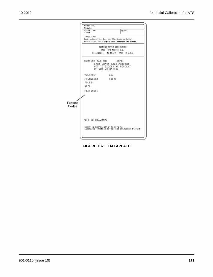
10-2012 14. Initial Calibration for ATS
FIGURE 187. DATAPLATE
901-0110 (Issue 10) 171
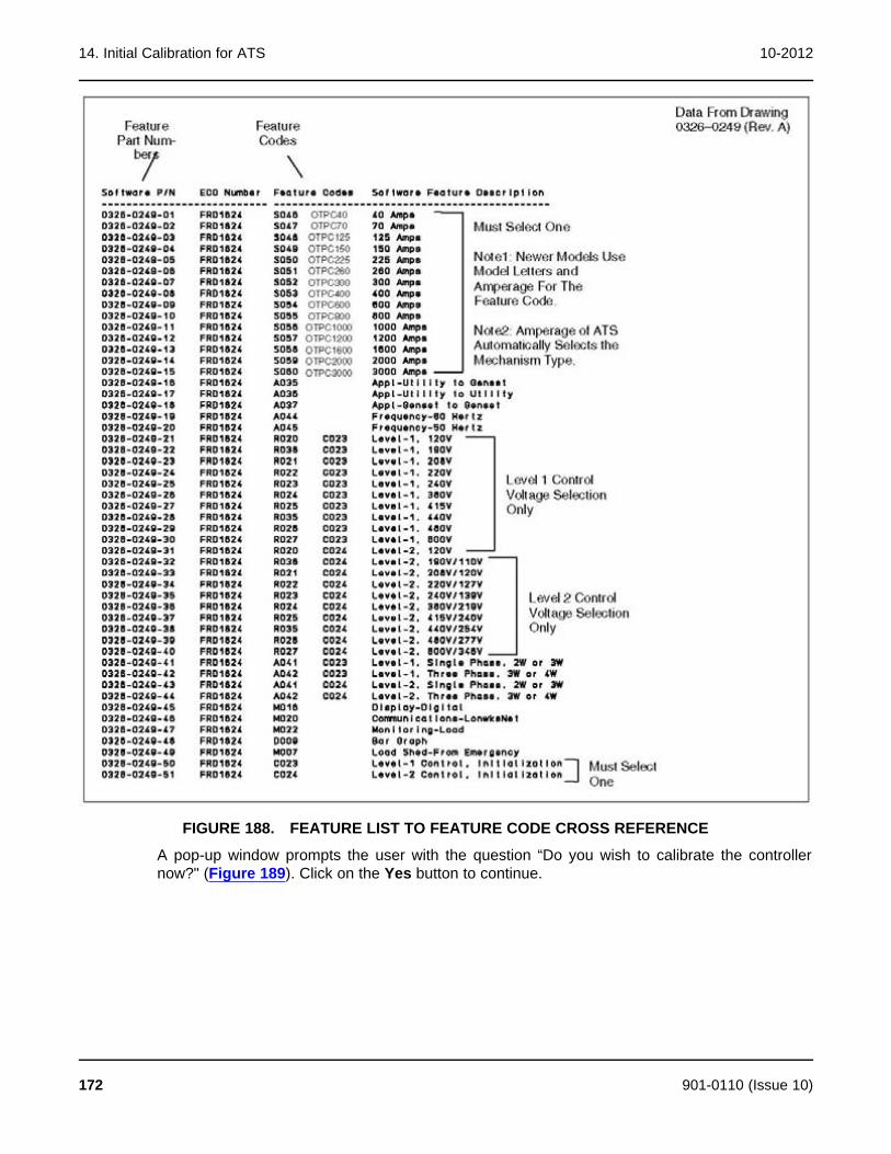
14. Initial Calibration for ATS 10-2012
FIGURE 188. FEATURE LIST TO FEATURE CODE CROSS REFERENCE
A pop-up window prompts the user with the question “Do you wish to calibrate the controllernow?" (Figure 189). Click on the Yes button to continue.
172 901-0110 (Issue 10)
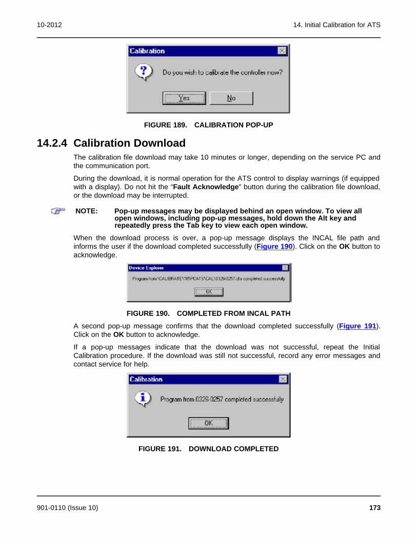
10-2012 14. Initial Calibration for ATS
FIGURE 189. CALIBRATION POP-UP
14.2.4 Calibration DownloadThe calibration file download may take 10 minutes or longer, depending on the service PC andthe communication port.
During the download, it is normal operation for the ATS control to display warnings (if equippedwith a display). Do not hit the “Fault Acknowledge" button during the calibration file download,or the download may be interrupted.
NOTE: Pop-up messages may be displayed behind an open window. To view allopen windows, including pop-up messages, hold down the Alt key andrepeatedly press the Tab key to view each open window.
When the download process is over, a pop-up message displays the INCAL file path andinforms the user if the download completed successfully (Figure 190). Click on the OK button toacknowledge.
FIGURE 190. COMPLETED FROM INCAL PATH
A second pop-up message confirms that the download completed successfully (Figure 191).Click on the OK button to acknowledge.
If a pop-up messages indicate that the download was not successful, repeat the InitialCalibration procedure. If the download was still not successful, record any error messages andcontact service for help.
FIGURE 191. DOWNLOAD COMPLETED
901-0110 (Issue 10) 173

14. Initial Calibration for ATS 10-2012
14.3 Writing Adjustments From a Capture FileIf a capture file was made prior to the Digital Module being replaced, the previous parameteradjustments and settings, that were stored in the capture file, can be written to the new DigitalModule.
14.4 Final AdjustmentsAfter writing the initial calibration, repower the control by removing all power from the control,including the battery power.
Prepare to operate the ATS and test the operation of the entire system. Refer to the ATSservice manual for adjustment procedures and observe all of the safety precautions described inthe ATS service manual.
After completing all necessary adjustments, make a new capture file. Store a copy of thecapture file at the site and return a copy to Service for cataloging.
174 901-0110 (Issue 10)
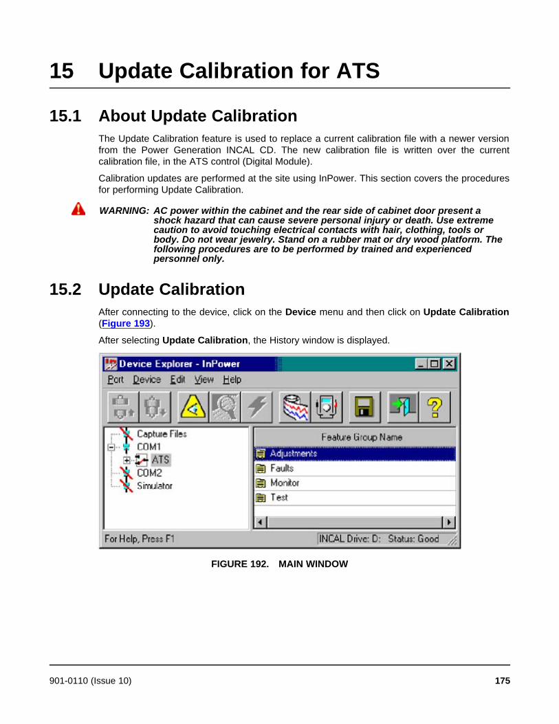
15 Update Calibration for ATS
15.1 About Update CalibrationThe Update Calibration feature is used to replace a current calibration file with a newer versionfrom the Power Generation INCAL CD. The new calibration file is written over the currentcalibration file, in the ATS control (Digital Module).
Calibration updates are performed at the site using InPower. This section covers the proceduresfor performing Update Calibration.
WARNING: AC power within the cabinet and the rear side of cabinet door present ashock hazard that can cause severe personal injury or death. Use extremecaution to avoid touching electrical contacts with hair, clothing, tools orbody. Do not wear jewelry. Stand on a rubber mat or dry wood platform. Thefollowing procedures are to be performed by trained and experiencedpersonnel only.
15.2 Update CalibrationAfter connecting to the device, click on the Device menu and then click on Update Calibration(Figure 193).
After selecting Update Calibration, the History window is displayed.
FIGURE 192. MAIN WINDOW
901-0110 (Issue 10) 175
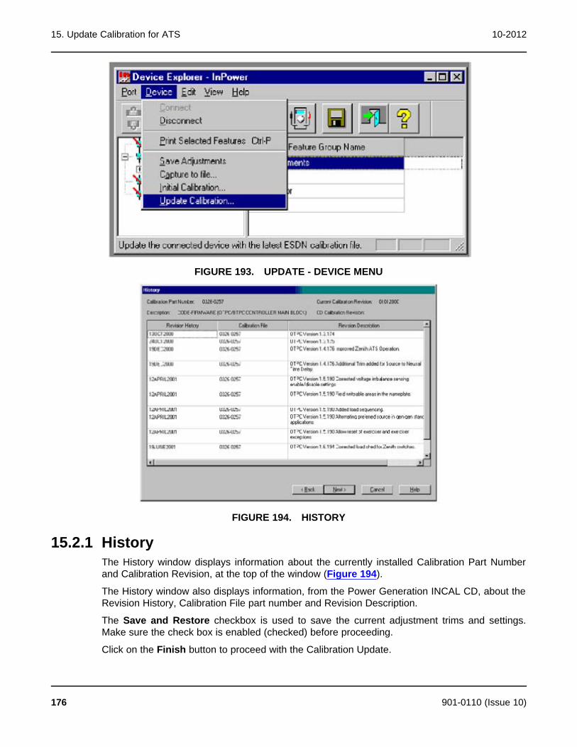
15. Update Calibration for ATS 10-2012
FIGURE 193. UPDATE - DEVICE MENU
FIGURE 194. HISTORY
15.2.1 HistoryThe History window displays information about the currently installed Calibration Part Numberand Calibration Revision, at the top of the window (Figure 194).
The History window also displays information, from the Power Generation INCAL CD, about theRevision History, Calibration File part number and Revision Description.
The Save and Restore checkbox is used to save the current adjustment trims and settings.Make sure the check box is enabled (checked) before proceeding.
Click on the Finish button to proceed with the Calibration Update.
176 901-0110 (Issue 10)

10-2012 15. Update Calibration for ATS
If a newer calibration is available with INCAL, a pop-up window prompts the user with thequestion “Do you wish to calibrate the controller now?" (Figure 195). Click on the Yes button tocontinue.
NOTE: Pop-up messages may be displayed behind an open window. To view allopen windows, including pop-up messages, hold down the Alt key andrepeatedly press the Tab key to view each open window.
When the download process is over, a popup message displaying the INCAL file path informsthe user if the download completed successfully (Figure 196. Click on the OK button toacknowledge.
FIGURE 195. UPDATE NOW
FIGURE 196. COMPLETED FROM INCAL PATH
A second popup message confirms that the download completed successfully (Figure 197).Click on the OK button to acknowledge.
If a popup messages indicate that the download was not successful, repeat the UpdateCalibration procedure. If the download was still not successful, record the error message andcontact service for help.
FIGURE 197. DOWNLOAD COMPLETED
901-0110 (Issue 10) 177

15. Update Calibration for ATS 10-2012
This page is intentionally blank.
178 901-0110 (Issue 10)
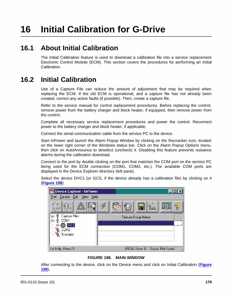
16 Initial Calibration for G-Drive
16.1 About Initial CalibrationThe Initial Calibration feature is used to download a calibration file into a service replacementElectronic Control Module (ECM). This section covers the procedures for performing an InitialCalibration.
16.2 Initial CalibrationUse of a Capture File can reduce the amount of adjustment that may be required whenreplacing the ECM. If the old ECM is operational, and a capture file has not already beencreated, correct any active faults (if possible). Then, create a capture file.
Refer to the service manual for control replacement procedures. Before replacing the control,remove power from the battery charger and block heater, if equipped, then remove power fromthe control.
Complete all necessary service replacement procedures and power the control. Reconnectpower to the battery charger and block heater, if applicable.
Connect the serial communication cable from the service PC to the device.
Start InPower and launch the Alarm Popup Window by clicking on the firecracker icon, locatedon the lower right corner of the Windows status bar. Click on the Alarm Popup Options menu,then click on AutoAnnounce to deselect (uncheck) it. Disabling this feature prevents nuisancealarms during the calibration download.
Connect to the port by double clicking on the port that matches the COM port on the service PCbeing used for the ECM connection (COM1, COM2, etc.). The available COM ports aredisplayed in the Device Explorer directory (left pane).
Select the device DVC1 (or GCS, if the device already has a calibration file) by clicking on it(Figure 198).
FIGURE 198. MAIN WINDOW
After connecting to the device, click on the Device menu and click on Initial Calibration (Figure199).
901-0110 (Issue 10) 179

16. Initial Calibration for G-Drive 10-2012
If prompted to select between G-Drive and Genset applications, select G-Drive, then selectNext.
Refer to the Dataplate, located on the side of the ECM, for the electronic configuration(calibration part number). See Figure 200.
If a popup message indicates that there is an error loading from the INCAL CD, either the CDdrive letter was not correctly specified during InPower installation, or the CD is not installed or isdefective. If the CD is in the CD drive, click on Yes, and specify the correct CD drivedesignation. If the CD is not in the drive, insert the CD and click on No.
FIGURE 199. MAIN WINDOW
FIGURE 200. DATAPLATE
The INCAL CD location can be verified by clicking on the Port menu and clicking on Find InCal(Figure 201). Select the INCAL CD drive designation from the drop-down list, then click onVerify INCAL Structure. A popup message will verify the INCAL location (Figure 202).
180 901-0110 (Issue 10)

10-2012 16. Initial Calibration for G-Drive
FIGURE 201. FIND INCAL
FIGURE 202. INCAL LOCATION FOUND
16.2.1 Selecting Calibration Part NumberAfter clicking on Initial Calibration, the Select Calibration window is displayed (Figure 203). Thisfeature lists the calibration files (ECM Codes) that are available from the Power GenerationINCAL CD. Also shown are the Engine Control Parts List (CPL) and other related applicationdescriptions.
Refer to the Dataplate, located on the side of the ECM, for the electronic configuration (ECMCode). See Figure 200.
Use the scroll bar to locate the ECM Code that matches the number shown on the Dataplate(Figure 200). The data, displayed in each column, can be sorted in ascending or descendingorder by clicking on the column heading.
Select the matching calibration part number by clicking on it. When the matching calibration partnumber is selected, click on Next to continue the initial calibration.
901-0110 (Issue 10) 181
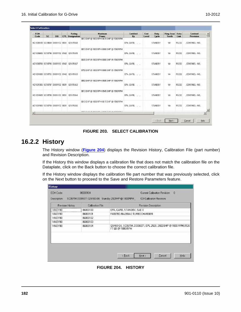
16. Initial Calibration for G-Drive 10-2012
FIGURE 203. SELECT CALIBRATION
16.2.2 HistoryThe History window (Figure 204) displays the Revision History, Calibration File (part number)and Revision Description.
If the History this window displays a calibration file that does not match the calibration file on theDataplate, click on the Back button to choose the correct calibration file.
If the History window displays the calibration file part number that was previously selected, clickon the Next button to proceed to the Save and Restore Parameters feature.
FIGURE 204. HISTORY
182 901-0110 (Issue 10)
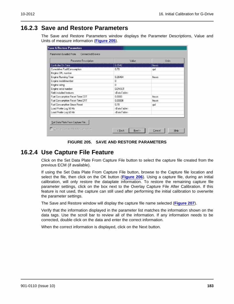
10-2012 16. Initial Calibration for G-Drive
16.2.3 Save and Restore ParametersThe Save and Restore Parameters window displays the Parameter Descriptions, Value andUnits of measure information (Figure 205).
FIGURE 205. SAVE AND RESTORE PARAMETERS
16.2.4 Use Capture File FeatureClick on the Set Data Plate From Capture File button to select the capture file created from theprevious ECM (if available).
If using the Set Data Plate From Capture File button, browse to the Capture file location andselect the file, then click on the OK button (Figure 206). Using a capture file, during an initialcalibration, will only restore the dataplate information. To restore the remaining capture fileparameter settings, click on the box next to the Overlay Capture File After Calibration. If thisfeature is not used, the capture can still used after performing the initial calibration to overwritethe parameter settings.
The Save and Restore window will display the capture file name selected (Figure 207).
Verify that the information displayed in the parameter list matches the information shown on thedata tags. Use the scroll bar to review all of the information. If any information needs to becorrected, double click on the data and enter the correct information.
When the correct information is displayed, click on the Next button.
901-0110 (Issue 10) 183
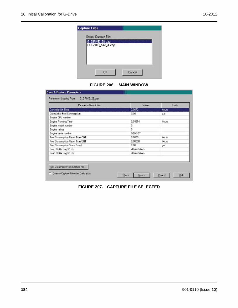
16. Initial Calibration for G-Drive 10-2012
FIGURE 206. MAIN WINDOW
FIGURE 207. CAPTURE FILE SELECTED
184 901-0110 (Issue 10)

10-2012 16. Initial Calibration for G-Drive
16.2.5 Feature List
FIGURE 208. FEATURE LIST
The Feature List window is displayed (Figure 208) following the Save and Restore Parameterswindow. Feature selection is not used with G-Drive applications. Click on the Finish button tocontinue.
If all of the information has been entered correctly, a popup window prompts the user with thequestion “Do you wish to calibrate the controller now?" (Figure 209). Click on the Yes button tocontinue.
FIGURE 209. CALIBRATION POPUP
Next, a pop-up window informs the user that the calibration file download will erase alladjustments and prompts the user with the question “Do you choose to continue?" (Figure 210).Click on the Yes button, to begin the initial calibration download.
FIGURE 210. FEATURE LIST
NOTE: Pop-up messages may be displayed behind an open window. To view allopen windows, including popup messages, hold down the Alt key andrepeatedly press the Tab key to view each open window.
901-0110 (Issue 10) 185
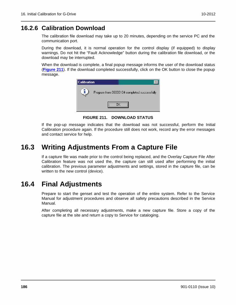
16. Initial Calibration for G-Drive 10-2012
16.2.6 Calibration DownloadThe calibration file download may take up to 20 minutes, depending on the service PC and thecommunication port.
During the download, it is normal operation for the control display (if equipped) to displaywarnings. Do not hit the “Fault Acknowledge” button during the calibration file download, or thedownload may be interrupted.
When the download is complete, a final popup message informs the user of the download status(Figure 211). If the download completed successfully, click on the OK button to close the popupmessage.
FIGURE 211. DOWNLOAD STATUS
If the pop-up message indicates that the download was not successful, perform the InitialCalibration procedure again. If the procedure still does not work, record any the error messagesand contact service for help.
16.3 Writing Adjustments From a Capture FileIf a capture file was made prior to the control being replaced, and the Overlay Capture File AfterCalibration feature was not used the, the capture can still used after performing the initialcalibration. The previous parameter adjustments and settings, stored in the capture file, can bewritten to the new control (device).
16.4 Final AdjustmentsPrepare to start the genset and test the operation of the entire system. Refer to the ServiceManual for adjustment procedures and observe all safety precautions described in the ServiceManual.
After completing all necessary adjustments, make a new capture file. Store a copy of thecapture file at the site and return a copy to Service for cataloging.
186 901-0110 (Issue 10)
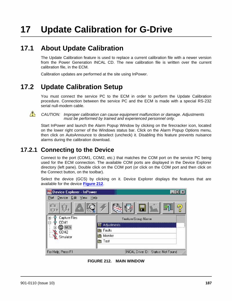
17 Update Calibration for G-Drive
17.1 About Update CalibrationThe Update Calibration feature is used to replace a current calibration file with a newer versionfrom the Power Generation INCAL CD. The new calibration file is written over the currentcalibration file, in the ECM.
Calibration updates are performed at the site using InPower.
17.2 Update Calibration SetupYou must connect the service PC to the ECM in order to perform the Update Calibrationprocedure. Connection between the service PC and the ECM is made with a special RS-232serial null-modem cable.
CAUTION: Improper calibration can cause equipment malfunction or damage. Adjustmentsmust be performed by trained and experienced personnel only.
Start InPower and launch the Alarm Popup Window by clicking on the firecracker icon, locatedon the lower right corner of the Windows status bar. Click on the Alarm Popup Options menu,then click on AutoAnnounce to deselect (uncheck) it. Disabling this feature prevents nuisancealarms during the calibration download.
17.2.1 Connecting to the DeviceConnect to the port (COM1, COM2, etc.) that matches the COM port on the service PC beingused for the ECM connection. The available COM ports are displayed in the Device Explorerdirectory (left pane). Double click on the COM port (or click on the COM port and then click onthe Connect button, on the toolbar).
Select the device (GCS) by clicking on it. Device Explorer displays the features that areavailable for the device Figure 212.
FIGURE 212. MAIN WINDOW
901-0110 (Issue 10) 187
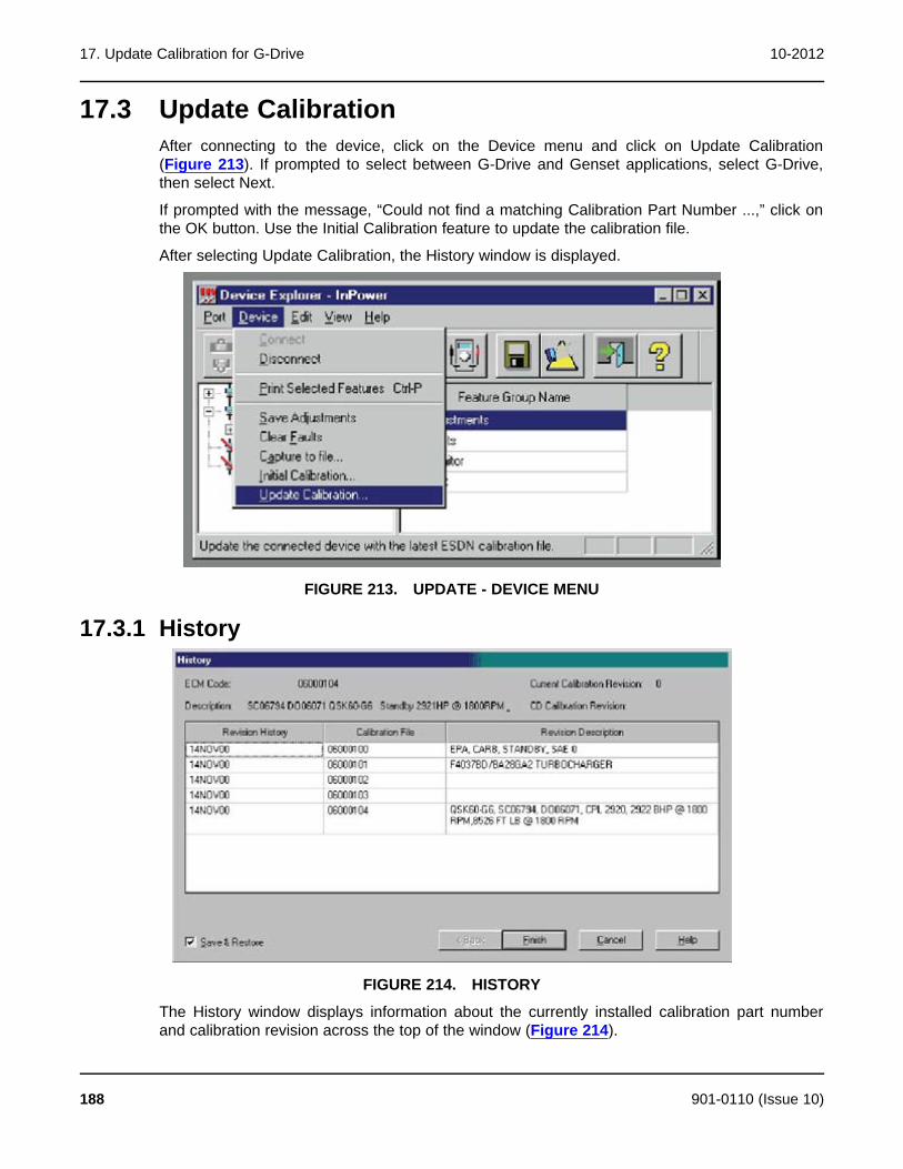
17. Update Calibration for G-Drive 10-2012
17.3 Update CalibrationAfter connecting to the device, click on the Device menu and click on Update Calibration(Figure 213). If prompted to select between G-Drive and Genset applications, select G-Drive,then select Next.
If prompted with the message, “Could not find a matching Calibration Part Number ...,” click onthe OK button. Use the Initial Calibration feature to update the calibration file.
After selecting Update Calibration, the History window is displayed.
FIGURE 213. UPDATE - DEVICE MENU
17.3.1 History
FIGURE 214. HISTORY
The History window displays information about the currently installed calibration part numberand calibration revision across the top of the window (Figure 214).
188 901-0110 (Issue 10)
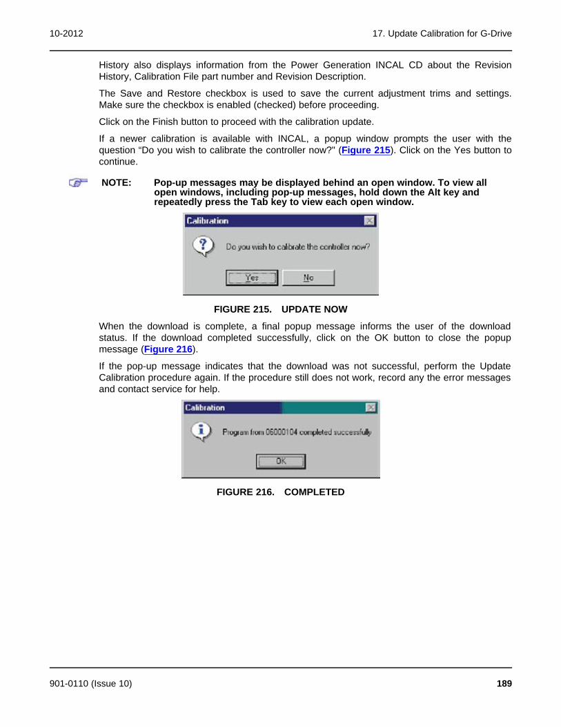
10-2012 17. Update Calibration for G-Drive
History also displays information from the Power Generation INCAL CD about the RevisionHistory, Calibration File part number and Revision Description.
The Save and Restore checkbox is used to save the current adjustment trims and settings.Make sure the checkbox is enabled (checked) before proceeding.
Click on the Finish button to proceed with the calibration update.
If a newer calibration is available with INCAL, a popup window prompts the user with thequestion “Do you wish to calibrate the controller now?" (Figure 215). Click on the Yes button tocontinue.
NOTE: Pop-up messages may be displayed behind an open window. To view allopen windows, including pop-up messages, hold down the Alt key andrepeatedly press the Tab key to view each open window.
FIGURE 215. UPDATE NOW
When the download is complete, a final popup message informs the user of the downloadstatus. If the download completed successfully, click on the OK button to close the popupmessage (Figure 216).
If the pop-up message indicates that the download was not successful, perform the UpdateCalibration procedure again. If the procedure still does not work, record any the error messagesand contact service for help.
FIGURE 216. COMPLETED
901-0110 (Issue 10) 189

17. Update Calibration for G-Drive 10-2012
This page is intentionally blank.
190 901-0110 (Issue 10)
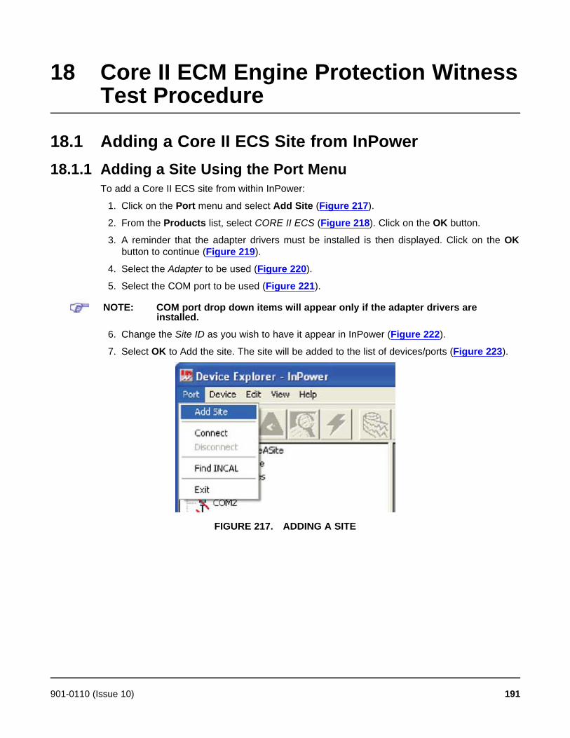
18 Core II ECM Engine Protection WitnessTest Procedure
18.1 Adding a Core II ECS Site from InPower18.1.1 Adding a Site Using the Port Menu
To add a Core II ECS site from within InPower:
1. Click on the Port menu and select Add Site (Figure 217).
2. From the Products list, select CORE II ECS (Figure 218). Click on the OK button.
3. A reminder that the adapter drivers must be installed is then displayed. Click on the OKbutton to continue (Figure 219).
4. Select the Adapter to be used (Figure 220).
5. Select the COM port to be used (Figure 221).
NOTE: COM port drop down items will appear only if the adapter drivers areinstalled.
6. Change the Site ID as you wish to have it appear in InPower (Figure 222).
7. Select OK to Add the site. The site will be added to the list of devices/ports (Figure 223).
FIGURE 217. ADDING A SITE
901-0110 (Issue 10) 191
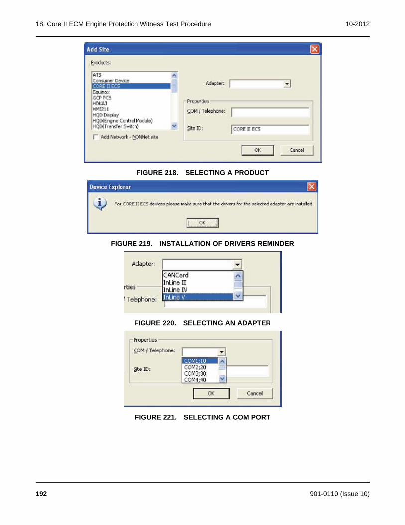
18. Core II ECM Engine Protection Witness Test Procedure 10-2012
FIGURE 218. SELECTING A PRODUCT
FIGURE 219. INSTALLATION OF DRIVERS REMINDER
FIGURE 220. SELECTING AN ADAPTER
FIGURE 221. SELECTING A COM PORT
192 901-0110 (Issue 10)

10-2012 18. Core II ECM Engine Protection Witness Test Procedure
FIGURE 222. NAMING THE SITE ID
FIGURE 223. ADDED SITE
18.1.2 Adding a Site Using the Setup MenuTo add a Core II ECS site using the Setup menu:
1. Go to Start -> Programs -> Power Generation -> Setup. The Setup window is displayed(Figure 224).
2. Select a site from the Site List and click on Add.
3. The Create Site window is displayed (Figure 225). Select `Network' for the Site Type,select `ECS Configuration' for the Network Type, type in the appropriate Site ID, select theAdapter being used, and select the COM Port being used. Click on OK.
4. Connect to the Site - QSB7 – The ECM(s) on the generator will be listed (Figure 226).
NOTE: If there is only one ECM it will be connected by default.
901-0110 (Issue 10) 193

18. Core II ECM Engine Protection Witness Test Procedure 10-2012
FIGURE 224. THE SETUP WINDOW
FIGURE 225. ADDING SITE INFORMATION
194 901-0110 (Issue 10)
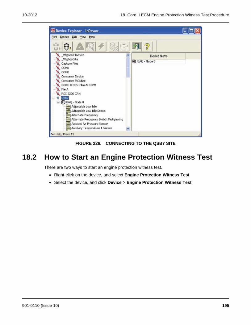
10-2012 18. Core II ECM Engine Protection Witness Test Procedure
FIGURE 226. CONNECTING TO THE QSB7 SITE
18.2 How to Start an Engine Protection Witness TestThere are two ways to start an engine protection witness test.
· Right-click on the device, and select Engine Protection Witness Test.
· Select the device, and click Device > Engine Protection Witness Test.
901-0110 (Issue 10) 195
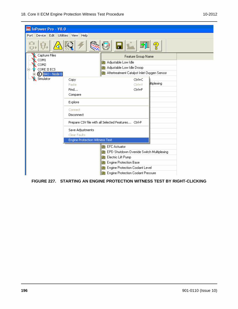
18. Core II ECM Engine Protection Witness Test Procedure 10-2012
FIGURE 227. STARTING AN ENGINE PROTECTION WITNESS TEST BY RIGHT-CLICKING
196 901-0110 (Issue 10)

10-2012 18. Core II ECM Engine Protection Witness Test Procedure
FIGURE 228. STARTING AN ENGINE PROTECTION WITNESS TEST USING THE DEVICE MENU
Use the Engine Protection Witness Test dialog to execute the witness test.
901-0110 (Issue 10) 197
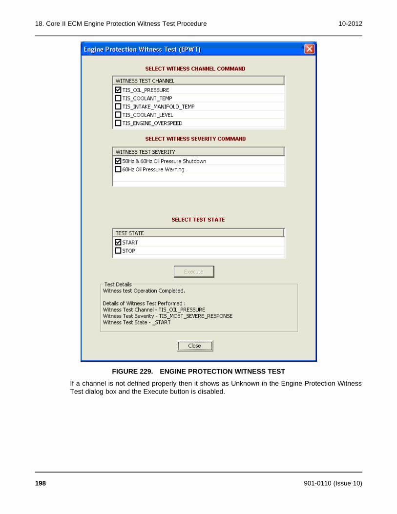
18. Core II ECM Engine Protection Witness Test Procedure 10-2012
FIGURE 229. ENGINE PROTECTION WITNESS TEST
If a channel is not defined properly then it shows as Unknown in the Engine Protection WitnessTest dialog box and the Execute button is disabled.
198 901-0110 (Issue 10)
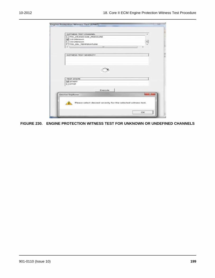
10-2012 18. Core II ECM Engine Protection Witness Test Procedure
FIGURE 230. ENGINE PROTECTION WITNESS TEST FOR UNKNOWN OR UNDEFINED CHANNELS
901-0110 (Issue 10) 199

18. Core II ECM Engine Protection Witness Test Procedure 10-2012
This page is intentionally blank.
200 901-0110 (Issue 10)

19 Update Features
19.1 About Update FeaturesUpdate Features can be used to enable features or change feature settings. Feature changesare performed at the site, using InPower. This section covers the procedures for changing afeature setting, and describes how to enable a feature.
19.2 Update Features SetupThe service PC must be connected to the genset in order to perform the Feature Updateprocedure. Connection between the service PC and the genset is made with a special RS-232serial null-modem cable.
The serial cable from the service PC can be connected to the engine harness or to thecustomer connection box. Service cables are available for both connection methods.
CAUTION: Improper feature changes can cause equipment malfunction or damage. Featurechanges must be performed by trained and experienced personnel only.
Connect the serial communication cable from the service PC to the device.
Start InPower. Launch the Alarm Pop-up Window by clicking on the firecracker icon, located onthe lower right corner of the Windows status bar. Click on the Alarm Popup Options menu, thenclick on AutoAnnounce to deselect (uncheck) it. Disabling this feature prevents nuisancealarms during feature updates.
19.3 Update FeaturesThere are two ways to look at the list of features available for a device.
1. After connecting to the device, click on the Device menu and click on Update Features. Ifprompted to select between G-Drive and Genset applications, select Genset, then selectNext. After selecting Update Features, the Feature List window is displayed.
2. After connecting to the device, select the Factory Installed Feature List or Field InstalledFeature List folder.
901-0110 (Issue 10) 201

19. Update Features 10-2012
FIGURE 231. UPDATE FEATURES IN DEVICE MENU
FIGURE 232. FACTORY-INSTALLED FEATURE LIST
202 901-0110 (Issue 10)
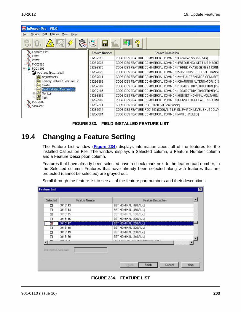
10-2012 19. Update Features
FIGURE 233. FIELD-INSTALLED FEATURE LIST
19.4 Changing a Feature SettingThe Feature List window (Figure 234) displays information about all of the features for theinstalled Calibration File. The window displays a Selected column, a Feature Number columnand a Feature Description column.
Features that have already been selected have a check mark next to the feature part number, inthe Selected column. Features that have already been selected along with features that areprotected (cannot be selected) are grayed out.
Scroll through the feature list to see all of the feature part numbers and their descriptions.
FIGURE 234. FEATURE LIST
901-0110 (Issue 10) 203

19. Update Features 10-2012
19.4.1 Feature Change Example:In this example, Update Features will be used to change from a 190V L-L setting, to a 208V L-Lsetting.
Scroll past the Set Range & Nominal (voltage settings) to the Set Nominal (voltage settings).Note in this example that the 190V L-L setting is already checked and greyed out. This indicatesthat 190V L-L is the current voltage setting.
Click on the checkbox for the Set Nominal (208V L-L). A check mark will appear in thecheckbox.
Click on the Finish button to change this voltage setting.
NOTE: On reconnectable gensets, when making voltage changes that requirereconnection of the alternator output leads (like a change from 208V L-L to480V L-L), you must also change the CT tap connections.
CAUTION: If reconnection is required, Do Not start the generator set until the reconnectionand CT tap changes are complete or equipment damage could result. Refer to thegenset reconnection diagram.
If a feature was selected that is not allowed, the pop-up shown in Figure 235 is displayed,indicating that the feature could not be written (changed or enabled).
FIGURE 235. ERROR MESSAGE
To check if the feature changed successfully, use Update Features to view the Feature List.Scroll to the Set Nominal (voltage settings). The new setting should have a check mark in thecheckbox, and the feature should be greyed out, as shown in Figure 236. Click the Cancelbutton when finished checking the results.
If no error messages were received, and the change did not occur, repeat the Update Featuresprocedure. If the download was still not successful, record any error messages and contactservice for help.
19.5 Enabling a FeatureThere are a limited number of features that can be enabled. Some features can only be set atthe factory (greyed out), while others, like the network module (LonWorks), can only be enabledafter the network module has been installed.
Enabling a feature is similar to changing a feature. Start InPower, connect to the device, andclick on Update Features. Scroll to the desired feature and click on the checkbox, then click onthe Finish button, to enable the feature.
204 901-0110 (Issue 10)

10-2012 19. Update Features
FIGURE 236. FEATURE LIST - AFTER UPDATE
901-0110 (Issue 10) 205

19. Update Features 10-2012
This page is intentionally blank.
206 901-0110 (Issue 10)
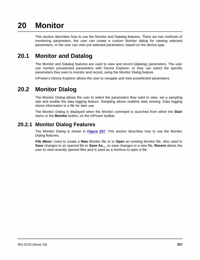
20 MonitorThis section describes how to use the Monitor and Datalog features. There are two methods ofmonitoring parameters, the user can create a custom Monitor dialog for viewing selectedparameters, or the user can view pre-selected parameters, based on the device type.
20.1 Monitor and DatalogThe Monitor and Datalog features are used to view and record (datalog) parameters. The usercan monitor preselected parameters with Device Explorer, or they can select the specificparameters they want to monitor and record, using the Monitor Dialog feature.
InPower's Device Explorer allows the user to navigate and view preselected parameters.
20.2 Monitor DialogThe Monitor Dialog allows the user to select the parameters they want to view, set a samplingrate and enable the data logging feature. Sampling allows realtime data viewing. Data loggingstores information in a file for later use.
The Monitor Dialog is displayed when the Monitor command is launched from either the Startmenu or the Monitor button, on the InPower toolbar.
20.2.1 Monitor Dialog FeaturesThe Monitor Dialog is shown in Figure 237. This section describes how to use the MonitorDialog features.
File Menu: Used to create a New Monitor file or to Open an existing Monitor file. Also used toSave changes to an opened file or Save As..., to save changes to a new file. Recent allows theuser to view recently opened files and is used as a shortcut to open a file.
901-0110 (Issue 10) 207

20. Monitor 10-2012
FIGURE 237. MONITOR DIALOG FEATURES
Edit Menu: Use the Edit menu commands to Add, Delete, Edit, Cut, Copy, and Pasteparameters into and out of the Monitor Dialog.
View Menu: Use the View command to hide or display the Toolbar and Status Bar.
Help Menu: Provides InPower Help Topics and About Monitor help.
Sampling: The Monitor dialog will sample at the selected setting. To select the sample rate,click on the Sampling - Enabled check box (enabled when checked). Enabling the Samplingfeature activates the Sampling Rate list box. Select the desired sampling rate from the list box.Sample rates are available from 0.05 seconds to 60 seconds.
Logging: Logging al lows the user to log parameter information to a .LOG file (at the selectedSampling Rate). Sampling must be enabled to use this feature. Before enabling data logging,enter a name in the file dialog. The log file uses the tab delimited file format. To select theLogging feature, click on the Start Logging button. When data logging begins, the button textswitches from Start Logging to Stop Logging. Click on the Stop Logging button to stop datalogging.
Data can be logged to the default (Monitor_<Time Stamp>.001.log) file where the time stamp is"MM_DD_YYYY_HH_MM_SS" (for example, Monitor_12_22_2011_13_46_10.001.log). If thisfile exceeds the size limit of 4 MB, a new file is created where the last digits that were 001 areincremented to 002 (for example, Monitor_12_22_2011_13_46_10.002.log).
A report can be generated if you click on the Generate Report button. The Browse buttonallows the user to locate and overwrite a .log file in another directory.
NOTE: If the list of variables is long, the actual log rate may be longer than theselected rate.
If logging is stopped and started again, the message shown below is displayed.
208 901-0110 (Issue 10)

10-2012 20. Monitor
FIGURE 238. LOG FILE ALREADY EXISTS MESSAGE
Three buttons are available.
· Click the OVERWRITE button if the existing log file is to be overwritten.
NOTE: Because all previously saved data will be erased, overwriting an existing fileis not advisable.
If the OVERWRITE button is selected, the following message is displayed to remind theoperator that using this feature will result in the existing file being overwritten. Click Yes tooverwrite the existing log. If No is selected, the message shown above will be redisplayed.
FIGURE 239. OVERWRITE CONFIGURATION MESSAGE
· Click the APPEND button if the existing log file is to be appended with the new data logs.
· Click the CREATE NEW LOG FILE button if the data logging is to be continued in a newlog file.
20.2.2 Adding ParametersParameters can be added to the Monitor Dialog by selecting Edit - Add from the Menu bar orby clicking on the Add button, on the toolbar. The Add command launches InPower. UseDevice Explorer to locate, select and copy the parameters that you want to add to the Monitordialog.
901-0110 (Issue 10) 209

20. Monitor 10-2012
After selecting a parameter, use the drag-and-drop procedure to add the parameter to theMonitor Dialog. (Or use the right menu button to Copy it, then move the cursor to the MonitorDialog and use the right menu button again to Paste the parameter into the Monitor Dialog.)
Monitor settings can be saved to a template (.TPL file). These files are saved in the Monitorsubdirectory of InPower. The template file stores the COM port information, this prevents the filefrom working on another COM port.
Each monitor screen provides the ability to log sampled values into a tab delimited .LOG file.This file format allows the data to be imported into Microsoft Excel.
210 901-0110 (Issue 10)

21 Faults and the Fault InformationSystemThis section describes the fault information features available for various types of devices.
21.1 Commercial Device Fault InformationThe features include a Fault Information Window listing all active and inactive faults for aconnected device, a Snapshot dialog displaying additional details about those faults, and theFault Information System (FIS). The FIS feature is an online manual used to help diagnosethe fault.
21.1.1 Fault Information WindowUse the InPower Device Explorer to view Faults for a connected device. Fault information for adevice is only available when you are connected to the device.
To access the Fault Information Window, start InPower and connect to a port, then connect toa device. Click on the Faults directory, listed under the device, to display fault information in theright pane of Device Explorer.
Faults can also be viewed when connected to a device by clicking on the View Faults button,on the toolbar. This shortcut displays the faults in the Faults directory.
Each fault is represented by a fault code indicating a particular malfunction or abnormalcondition within the device. The Service Manual and FIS reference this fault code to identify thefault condition and facilitate diagnosis and repair.
Faults are either active or inactive. Active faults indicate that the fault condition is present now.Inactive faults indicate a conditions that are no longer active. To change an active fault toinactive, make the necessary adjustment or repair to correct the fault condition.
The Fault Information Window displays an entry for each fault that has been generated by thedevice. All active faults are displayed first, followed by all inactive faults. The most recent fault isdisplayed at the top of each list.
The following information describes the titles in the Fault Information dialog.
Fault Code: A numeric code that identifies the fault.
Description: A brief description of the fault.
Fault Status: Indicates whether the fault is active or inactive, at this time.
Count: Indicates the number of times that the fault has occurred since the last time the faultdata was cleared.
Last Occurrence: Indicates the amount of controller on time at the last occurrence. Time isgiven in hours.
First Occurrence: Indicates the amount of controller on time at the first occurrence. Time isgiven in hours.
Effect: Displays the effect of the fault on the device. The effect can be a Warning, Derate,Shutdown with Cool Down, Shutdown, or none.
901-0110 (Issue 10) 211
21. Faults and the Fault Information System 10-2012
Use this information to match a specific fault to the symptoms observed by the operator. Thisinformation can help you determine which fault to address first.
21.1.2 Clearing Inactive FaultsInactive faults can be cleared when the user is connected to the device. Click on the ClearFaults button, on the toolbar (or select the Device menu, and click on Clear Faults, to removethe faults). All inactive faults will be removed.
InPower does not allow removal of an individual inactive fault. If no inactive faults are present,the Clear Faults button is disabled.
21.1.3 SnapshotSnapshot contains sensor and switch values that are captured when the fault occurred.Snapshot information is displayed in a separate Snapshot dialog.
To see snapshot information, double click on the Fault, or right click the mouse and select theView-Snapshot menu item. The Snapshot dialog has a Previous (<<) and Next (>>) button tomove between the faults.
An engine related fault will have a Snapshot containing engine operating conditions at the timethe fault occurred. Some faults may not have a Snapshot.
NOTE: COT is Controller on Time and ERT stands for Engine Run Time.
21.1.3.1 Devices That Do Not Support SnapshotSnapshot is not available with the PCC 1100, PCC 1300, PCC 1301, PCC 1302, PCC 2300,and PCC 3300.
21.1.4 Fault Information SystemThe Fault Information System (FIS) contains an online manual that displays troubleshooting andrepair (help) files for commercial gensets.
To access the main Fault Information Window, select Fault Trees from the View menu or clickthe View Fault Info. (magnifying glass icon), on the toolbar. The main Fault Information SystemWindow is displayed (Figure 240).
The FIS is designed as a standard Windows Help system. The system uses conventionalWindows Help techniques to display and find information. For example, you can:
· Click on text marked by a solid underline to open the window for that topic.
· Click on text marked by a dashed underline to display a pop-up window related to the text.Click once to close the pop-up window.
· Use the buttons on the Button Bar to perform common Windows Help functions (Contents,Search, Back, etc.).
· Use the Print Topic command from the File menu to print information related to thecurrent screen. (Note: pop-up windows and secondary Help windows will not print.)
Use the FIS main window to navigate to each of the systems main features as follows:
· Click on Fault Code Diagnostics to display descriptive information about a specific,identifiable fault, or to display a troubleshooting step to correct a specific fault.
212 901-0110 (Issue 10)
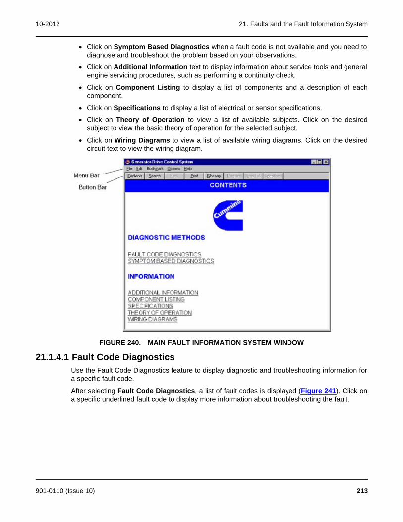
10-2012 21. Faults and the Fault Information System
· Click on Symptom Based Diagnostics when a fault code is not available and you need todiagnose and troubleshoot the problem based on your observations.
· Click on Additional Information text to display information about service tools and generalengine servicing procedures, such as performing a continuity check.
· Click on Component Listing to display a list of components and a description of eachcomponent.
· Click on Specifications to display a list of electrical or sensor specifications.
· Click on Theory of Operation to view a list of available subjects. Click on the desiredsubject to view the basic theory of operation for the selected subject.
· Click on Wiring Diagrams to view a list of available wiring diagrams. Click on the desiredcircuit text to view the wiring diagram.
FIGURE 240. MAIN FAULT INFORMATION SYSTEM WINDOW
21.1.4.1 Fault Code DiagnosticsUse the Fault Code Diagnostics feature to display diagnostic and troubleshooting information fora specific fault code.
After selecting Fault Code Diagnostics, a list of fault codes is displayed (Figure 241). Click ona specific underlined fault code to display more information about troubleshooting the fault.
901-0110 (Issue 10) 213

21. Faults and the Fault Information System 10-2012
FIGURE 241. FAULT CODE DIAGNOSTICS
After clicking on a fault code, the Diagnostic Method window is displayed (Figure 242).
FIGURE 242. DIAGNOSTIC METHOD
Two diagnostic methods are provided, choose one these options:
· Click on Fault Code Overview to display the fault code, the cause of the fault and theeffect of the fault. This information will determine which fault to address first. You candisplay a variety of other information related to the fault including fault location, descriptionand troubleshooting steps. (Refer to Fault Overview.)
· Click on Troubleshooting Steps to display a list of corrective actions to troubleshoot thefault. You can display various levels of detail for each troubleshooting step. (Refer toTroubleshooting Steps.)
21.1.4.2 Fault Code OverviewThe Fault Code Overview feature is used to view summary information about the selected fault,including the fault code, reason for the fault, and possible effects of the fault.
To display the fault Overview window (Figure 243), click on the Fault Code Overview text inthe Diagnostic Method window (Figure 242).
214 901-0110 (Issue 10)
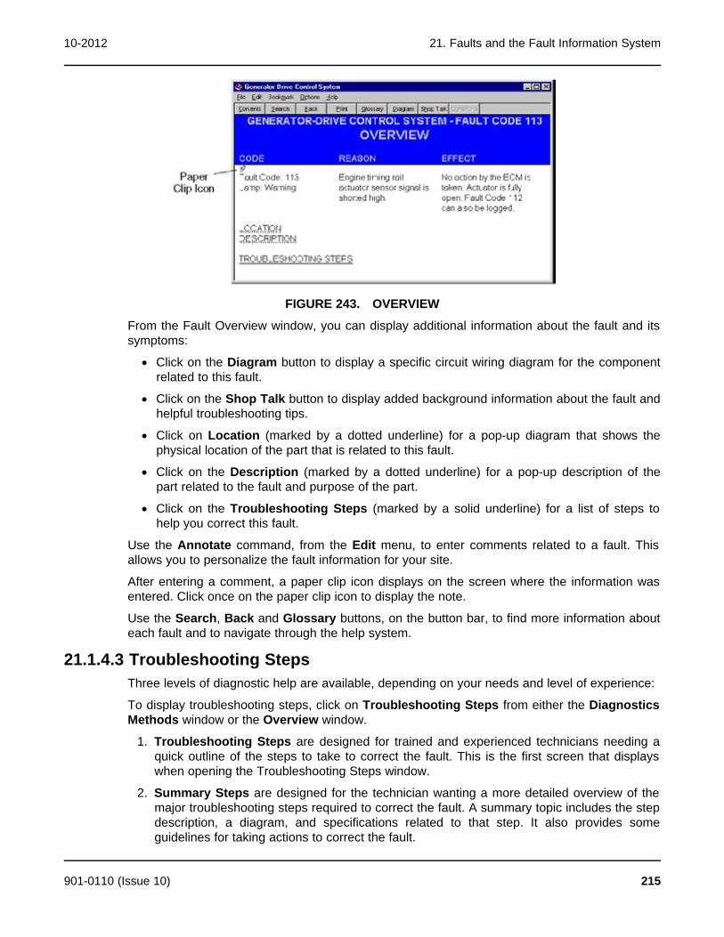
10-2012 21. Faults and the Fault Information System
FIGURE 243. OVERVIEW
From the Fault Overview window, you can display additional information about the fault and itssymptoms:
· Click on the Diagram button to display a specific circuit wiring diagram for the componentrelated to this fault.
· Click on the Shop Talk button to display added background information about the fault andhelpful troubleshooting tips.
· Click on Location (marked by a dotted underline) for a pop-up diagram that shows thephysical location of the part that is related to this fault.
· Click on the Description (marked by a dotted underline) for a pop-up description of thepart related to the fault and purpose of the part.
· Click on the Troubleshooting Steps (marked by a solid underline) for a list of steps tohelp you correct this fault.
Use the Annotate command, from the Edit menu, to enter comments related to a fault. Thisallows you to personalize the fault information for your site.
After entering a comment, a paper clip icon displays on the screen where the information wasentered. Click once on the paper clip icon to display the note.
Use the Search, Back and Glossary buttons, on the button bar, to find more information abouteach fault and to navigate through the help system.
21.1.4.3 Troubleshooting StepsThree levels of diagnostic help are available, depending on your needs and level of experience:
To display troubleshooting steps, click on Troubleshooting Steps from either the DiagnosticsMethods window or the Overview window.
1. Troubleshooting Steps are designed for trained and experienced technicians needing aquick outline of the steps to take to correct the fault. This is the first screen that displayswhen opening the Troubleshooting Steps window.
2. Summary Steps are designed for the technician wanting a more detailed overview of themajor troubleshooting steps required to correct the fault. A summary topic includes the stepdescription, a diagram, and specifications related to that step. It also provides someguidelines for taking actions to correct the fault.
901-0110 (Issue 10) 215
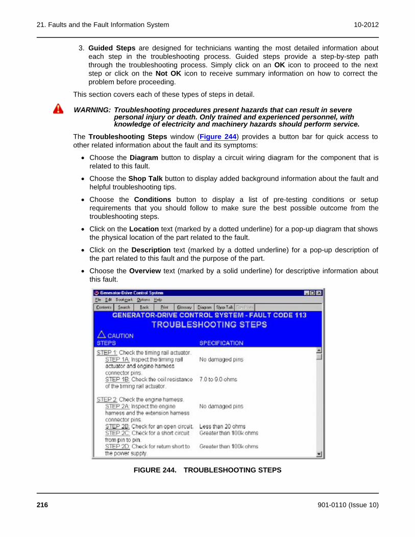
21. Faults and the Fault Information System 10-2012
3. Guided Steps are designed for technicians wanting the most detailed information abouteach step in the troubleshooting process. Guided steps provide a step-by-step paththrough the troubleshooting process. Simply click on an OK icon to proceed to the nextstep or click on the Not OK icon to receive summary information on how to correct theproblem before proceeding.
This section covers each of these types of steps in detail.
WARNING: Troubleshooting procedures present hazards that can result in severepersonal injury or death. Only trained and experienced personnel, withknowledge of electricity and machinery hazards should perform service.
The Troubleshooting Steps window (Figure 244) provides a button bar for quick access toother related information about the fault and its symptoms:
· Choose the Diagram button to display a circuit wiring diagram for the component that isrelated to this fault.
· Choose the Shop Talk button to display added background information about the fault andhelpful troubleshooting tips.
· Choose the Conditions button to display a list of pre-testing conditions or setuprequirements that you should follow to make sure the best possible outcome from thetroubleshooting steps.
· Click on the Location text (marked by a dotted underline) for a pop-up diagram that showsthe physical location of the part related to the fault.
· Click on the Description text (marked by a dotted underline) for a pop-up description ofthe part related to this fault and the purpose of the part.
· Choose the Overview text (marked by a solid underline) for descriptive information aboutthis fault.
FIGURE 244. TROUBLESHOOTING STEPS
216 901-0110 (Issue 10)
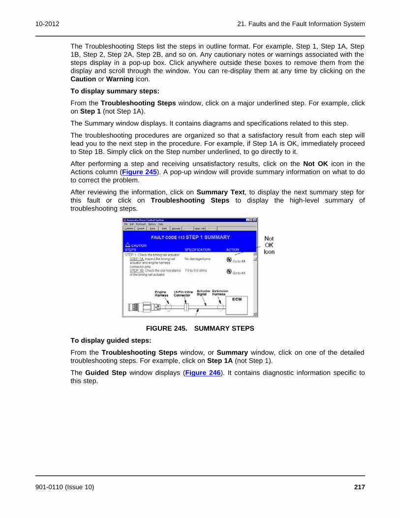
10-2012 21. Faults and the Fault Information System
The Troubleshooting Steps list the steps in outline format. For example, Step 1, Step 1A, Step1B, Step 2, Step 2A, Step 2B, and so on. Any cautionary notes or warnings associated with thesteps display in a pop-up box. Click anywhere outside these boxes to remove them from thedisplay and scroll through the window. You can re-display them at any time by clicking on theCaution or Warning icon.
To display summary steps:
From the Troubleshooting Steps window, click on a major underlined step. For example, clickon Step 1 (not Step 1A).
The Summary window displays. It contains diagrams and specifications related to this step.
The troubleshooting procedures are organized so that a satisfactory result from each step willlead you to the next step in the procedure. For example, if Step 1A is OK, immediately proceedto Step 1B. Simply click on the Step number underlined, to go directly to it.
After performing a step and receiving unsatisfactory results, click on the Not OK icon in theActions column (Figure 245). A pop-up window will provide summary information on what to doto correct the problem.
After reviewing the information, click on Summary Text, to display the next summary step forthis fault or click on Troubleshooting Steps to display the high-level summary oftroubleshooting steps.
FIGURE 245. SUMMARY STEPS
To display guided steps:
From the Troubleshooting Steps window, or Summary window, click on one of the detailedtroubleshooting steps. For example, click on Step 1A (not Step 1).
The Guided Step window displays (Figure 246). It contains diagnostic information specific tothis step.
901-0110 (Issue 10) 217

21. Faults and the Fault Information System 10-2012
FIGURE 246. GUIDED STEPS
Any general conditions that should be met prior to performing the steps will display in a pop-upbox. Click once to remove the pop-up window from the display, then scroll through the window.You can display these pop-up messages again by clicking on the Conditions button, on thebutton bar.
If satisfactory results are received from this step, click on the OK icon to display the next guidedstep for troubleshooting this fault.
If unsatisfactory results are received, click on the Not OK icon. A pop-up window will providesummary information on how to correct the problem. Once the program is repaired, click on theRepair Complete text in the pop-up window to go to the next guided step.
Click on Summary Text to display the next summary step for this fault, or click onTroubleshooting Steps to display the high-level outline of troubleshooting steps.
21.1.4.4 Symptom Based DiagnosticsUse Symptom Based Diagnostics when the fault code is not known, but are aware of thesymptom.
This feature displays a list of common symptoms (Figure 247). Click on a symptom to view adisplay of the possible cause of the symptom and a list of corrective actions (Figure 248).
218 901-0110 (Issue 10)

10-2012 21. Faults and the Fault Information System
FIGURE 247. SYMPTOM BASED DIAGNOSTICS
FIGURE 248. SYMPTOM BASED TROUBLESHOOTING
21.1.4.5 Additional InformationAfter clicking on Additional Information, a list of general service topics are displayed (Figure249). These topics contain general information about troubleshooting and service. Click on anentry in the list to display more information about that topic. For example, click on How to Use aMultimeter for basic instructions on how to use a multimeter.
When you are finished, use the buttons on the toolbar (such as Contents) to navigate anotherpart of the online manual. Close the Fault Tree window to return to InPower.
901-0110 (Issue 10) 219

21. Faults and the Fault Information System 10-2012
FIGURE 249. ADDITIONAL INFORMATION
21.1.4.6 Component ListingThe Component Listing feature provides details about engine and control component locationsand descriptions. Click on the text in the Location column for a pop-up description of thecomponents location. Click on the text in the Description column for a pop-up description of thecomponent (Figure 250).
When finished, use the buttons on the toolbar (such as Contents) to navigate another part ofthe online manual. Close the Fault Tree window, to return to InPower.
FIGURE 250. COMPONENT LISTING
21.1.4.7 SpecificationsClick on Specifications to display a list of the selected specifications.
When finished viewing the specifications, use buttons on the toolbar (such as Contents) tonavigate another part of the online manual. Close the Fault Tree window to return to InPower.
220 901-0110 (Issue 10)

10-2012 21. Faults and the Fault Information System
FIGURE 251. SPECIFICATIONS
21.1.4.8 Theory of OperationThe Theory of Operation feature describes operation of the selected component. Use the scrollbars to view the text.
When you are finished, use the buttons on the toolbar (such as Contents) to navigate anotherpart of the online manual. Close the Fault Tree window to return to InPower.
FIGURE 252. THEORY OF OPERATION
21.1.4.9 Wiring DiagramsThe Wiring Diagrams feature displays a list of engine system components (Figure 254). Clickon one of the components to view a wiring diagram for that component.
When finished, use the buttons on the toolbar (such as Contents) to navigate another part ofthe online manual. Close the Fault Tree window to return to InPower.
901-0110 (Issue 10) 221

21. Faults and the Fault Information System 10-2012
CAUTION: Wiring Diagrams are subject to change. Refer to the wiring diagram supplied withthe equipment or in the manufacturer's service manual. Failure to use the correctwiring diagram can result in severe personal injury or equipment damage.
21.1.4.10 GlossaryThe Glossary contains an alphabetical listing of frequently used terms and their descriptions(Figure 253). Use the Search feature, or the scroll bar to locate the desired term.
When finished, use the buttons on the toolbar (such as Contents) to navigate another part ofthe online manual. Or close the Fault Tree window to return to InPower.
FIGURE 253. ONLINE GLOSSARY
FIGURE 254. WIRING DIAGRAM WINDOW
222 901-0110 (Issue 10)
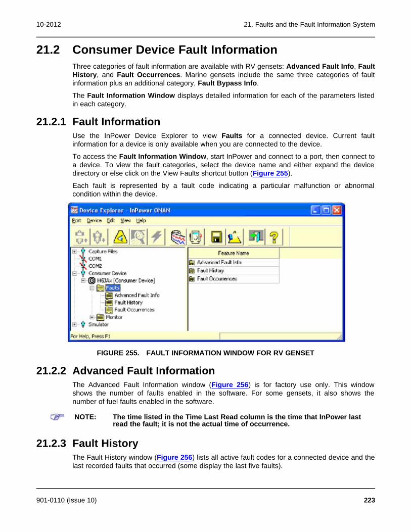
10-2012 21. Faults and the Fault Information System
21.2 Consumer Device Fault InformationThree categories of fault information are available with RV gensets: Advanced Fault Info, FaultHistory, and Fault Occurrences. Marine gensets include the same three categories of faultinformation plus an additional category, Fault Bypass Info.
The Fault Information Window displays detailed information for each of the parameters listedin each category.
21.2.1 Fault InformationUse the InPower Device Explorer to view Faults for a connected device. Current faultinformation for a device is only available when you are connected to the device.
To access the Fault Information Window, start InPower and connect to a port, then connect toa device. To view the fault categories, select the device name and either expand the devicedirectory or else click on the View Faults shortcut button (Figure 255).
Each fault is represented by a fault code indicating a particular malfunction or abnormalcondition within the device.
FIGURE 255. FAULT INFORMATION WINDOW FOR RV GENSET
21.2.2 Advanced Fault InformationThe Advanced Fault Information window (Figure 256) is for factory use only. This windowshows the number of faults enabled in the software. For some gensets, it also shows thenumber of fuel faults enabled in the software.
NOTE: The time listed in the Time Last Read column is the time that InPower lastread the fault; it is not the actual time of occurrence.
21.2.3 Fault HistoryThe Fault History window (Figure 256) lists all active fault codes for a connected device and thelast recorded faults that occurred (some display the last five faults).
901-0110 (Issue 10) 223

21. Faults and the Fault Information System 10-2012
To find information about fault codes and how to correct faults, refer to the Fault Help menu.Use this information to match a specific fault to the symptoms observed by the operator. Thisinformation can help you determine which fault to address first.
NOTE: The time listed in the Time Last Read column is the time that InPower lastread the fault; it is not the actual time of occurrence.
FIGURE 256. ADVANCED FAULT INFORMATION
FIGURE 257. FAULT HISTORY
21.2.4 Fault OccurrencesThe Fault Occurrences window (Figure 258) lists all possible faults that are available with thedevice and the number of times each fault occurred.
NOTE: The time listed in the Time Last Read column is the time that InPower lastread the fault; it is not the actual time of occurrence.
224 901-0110 (Issue 10)
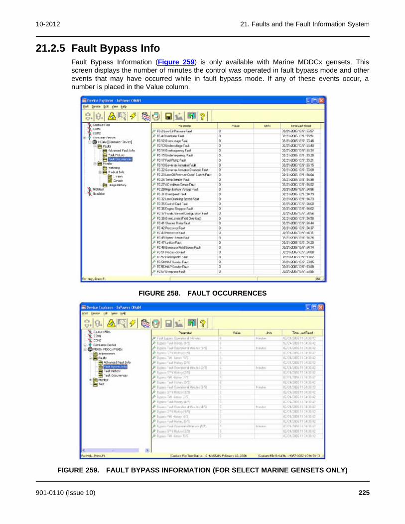
10-2012 21. Faults and the Fault Information System
21.2.5 Fault Bypass InfoFault Bypass Information (Figure 259) is only available with Marine MDDCx gensets. Thisscreen displays the number of minutes the control was operated in fault bypass mode and otherevents that may have occurred while in fault bypass mode. If any of these events occur, anumber is placed in the Value column.
FIGURE 258. FAULT OCCURRENCES
FIGURE 259. FAULT BYPASS INFORMATION (FOR SELECT MARINE GENSETS ONLY)
901-0110 (Issue 10) 225
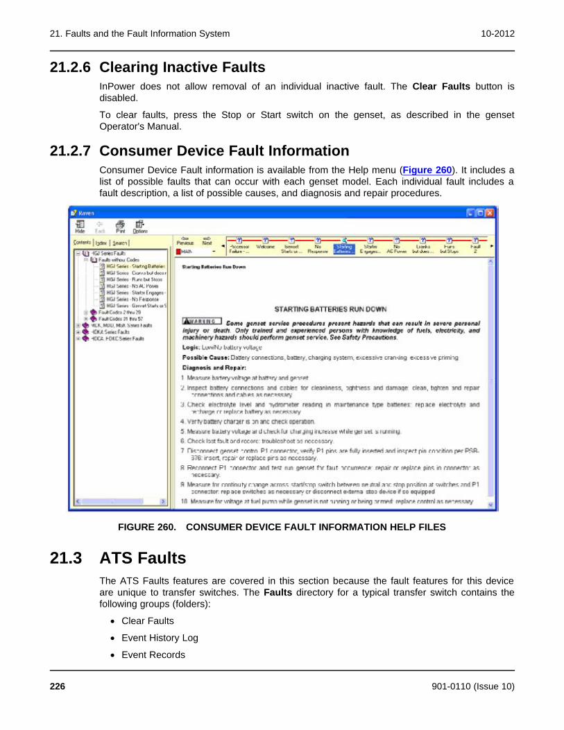
21. Faults and the Fault Information System 10-2012
21.2.6 Clearing Inactive FaultsInPower does not allow removal of an individual inactive fault. The Clear Faults button isdisabled.
To clear faults, press the Stop or Start switch on the genset, as described in the gensetOperator's Manual.
21.2.7 Consumer Device Fault InformationConsumer Device Fault information is available from the Help menu (Figure 260). It includes alist of possible faults that can occur with each genset model. Each individual fault includes afault description, a list of possible causes, and diagnosis and repair procedures.
FIGURE 260. CONSUMER DEVICE FAULT INFORMATION HELP FILES
21.3 ATS FaultsThe ATS Faults features are covered in this section because the fault features for this deviceare unique to transfer switches. The Faults directory for a typical transfer switch contains thefollowing groups (folders):
· Clear Faults
· Event History Log
· Event Records
226 901-0110 (Issue 10)
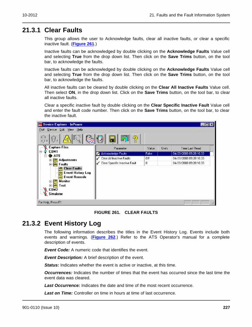
10-2012 21. Faults and the Fault Information System
21.3.1 Clear FaultsThis group allows the user to Acknowledge faults, clear all inactive faults, or clear a specificinactive fault. (Figure 261.)
Inactive faults can be acknowledged by double clicking on the Acknowledge Faults Value celland selecting True from the drop down list. Then click on the Save Trims button, on the toolbar, to acknowledge the faults.
Inactive faults can be acknowledged by double clicking on the Acknowledge Faults Value celland selecting True from the drop down list. Then click on the Save Trims button, on the toolbar, to acknowledge the faults.
All inactive faults can be cleared by double clicking on the Clear All Inactive Faults Value cell.Then select ON, in the drop down list. Click on the Save Trims button, on the tool bar, to clearall inactive faults.
Clear a specific inactive fault by double clicking on the Clear Specific Inactive Fault Value celland enter the fault code number. Then click on the Save Trims button, on the tool bar, to clearthe inactive fault.
FIGURE 261. CLEAR FAULTS
21.3.2 Event History LogThe following information describes the titles in the Event History Log. Events include bothevents and warnings. (Figure 262.) Refer to the ATS Operator's manual for a completedescription of events.
Event Code: A numeric code that identifies the event.
Event Description: A brief description of the event.
Status: Indicates whether the event is active or inactive, at this time.
Occurrences: Indicates the number of times that the event has occurred since the last time theevent data was cleared.
Last Occurrence: Indicates the date and time of the most recent occurrence.
Last on Time: Controller on time in hours at time of last occurrence.
901-0110 (Issue 10) 227
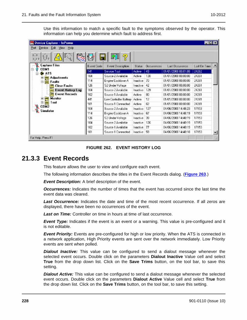
21. Faults and the Fault Information System 10-2012
Use this information to match a specific fault to the symptoms observed by the operator. Thisinformation can help you determine which fault to address first.
FIGURE 262. EVENT HISTORY LOG
21.3.3 Event RecordsThis feature allows the user to view and configure each event.
The following information describes the titles in the Event Records dialog. (Figure 263.)
Event Description: A brief description of the event.
Occurrences: Indicates the number of times that the event has occurred since the last time theevent data was cleared.
Last Occurrence: Indicates the date and time of the most recent occurrence. If all zeros aredisplayed, there have been no occurrences of the event.
Last on Time: Controller on time in hours at time of last occurrence.
Event Type: Indicates if the event is an event or a warning. This value is pre-configured and itis not editable.
Event Priority: Events are pre-configured for high or low priority. When the ATS is connected ina network application, High Priority events are sent over the network immediately. Low Priorityevents are sent when polled.
Dialout Inactive: This value can be configured to send a dialout message whenever theselected event occurs. Double click on the parameters Dialout Inactive Value cell and selectTrue from the drop down list. Click on the Save Trims button, on the tool bar, to save thissetting.
Dialout Active: This value can be configured to send a dialout message whenever the selectedevent occurs. Double click on the parameters Dialout Active Value cell and select True fromthe drop down list. Click on the Save Trims button, on the tool bar, to save this setting.
228 901-0110 (Issue 10)
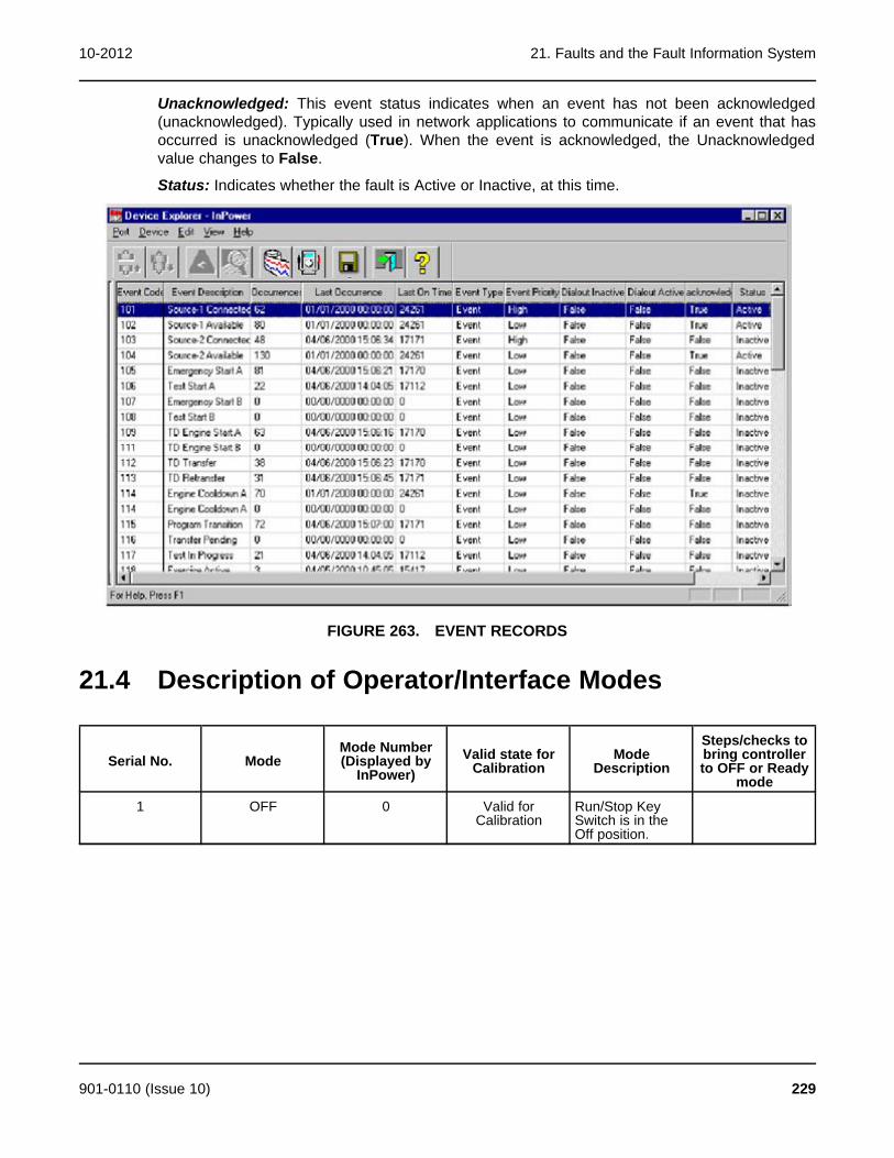
10-2012 21. Faults and the Fault Information System
Unacknowledged: This event status indicates when an event has not been acknowledged(unacknowledged). Typically used in network applications to communicate if an event that hasoccurred is unacknowledged (True). When the event is acknowledged, the Unacknowledgedvalue changes to False.
Status: Indicates whether the fault is Active or Inactive, at this time.
FIGURE 263. EVENT RECORDS
21.4 Description of Operator/Interface Modes
Steps/checks toMode Number Valid state for Mode bring controllerSerial No. Mode (Displayed by Calibration Description to OFF or ReadyInPower) mode
1 OFF 0 Valid for Run/Stop KeyCalibration Switch is in the
Off position.
901-0110 (Issue 10) 229
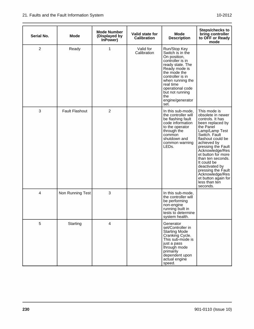
21. Faults and the Fault Information System 10-2012
Steps/checks toMode Number Valid state for Mode bring controllerSerial No. Mode (Displayed by Calibration Description to OFF or ReadyInPower) mode
2 Ready 1 Valid for Run/Stop KeyCalibration Switch is in the
On position,controller is inready state. TheReady mode isthe mode thecontroller is inwhen running thereal timeoperational codebut not runningtheengine/generatorset.
3 Fault Flashout 2 In this sub-mode, This mode isthe controller will obsolete in newerbe flashing fault controls. It hascode information been replaced byto the operator the Panelthrough the Lamp/Lamp Testcommon Switch. Faultshutdown and flashout could becommon warning achieved byLEDs. pressing the Fault
Acknowledge/Reset button for morethan ten seconds.It could bedeactivated bypressing the FaultAcknowledge/Reset button again forless than tenseconds.
4 Non Running Test 3 In this sub-mode,the controller willbe performingnon-enginerunning built intests to determinesystem health.
5 Starting 4 Generatorset/Controller inStarting ModeCranking Cycle.This sub-mode isjust a passthrough modeprimarilydependent uponactual enginespeed.
230 901-0110 (Issue 10)

10-2012 21. Faults and the Fault Information System
Steps/checks toMode Number Valid state for Mode bring controllerSerial No. Mode (Displayed by Calibration Description to OFF or ReadyInPower) mode
6 Idle 5 Generatorset/Controlleroperating at idle.This sub-mode isan engine runningcondition whereengine speed iscommanded tothe idle RPMvalue.
7 Rated 6 Generatorset/Conmtrolleroperating atRated. This sub-mode is anengine runningcondition whereengine speed iscommanded tothe rated RPMvalue
8 Stop Normal 7 Generator Run/Stop/KeySet/Controller switch. Switch isStopping in Stop position.normally. Thecontroller entersthis sub-modewhen the enginehas been runningand the reason forthe return to anon-running stateis for normalconditions.
901-0110 (Issue 10) 231
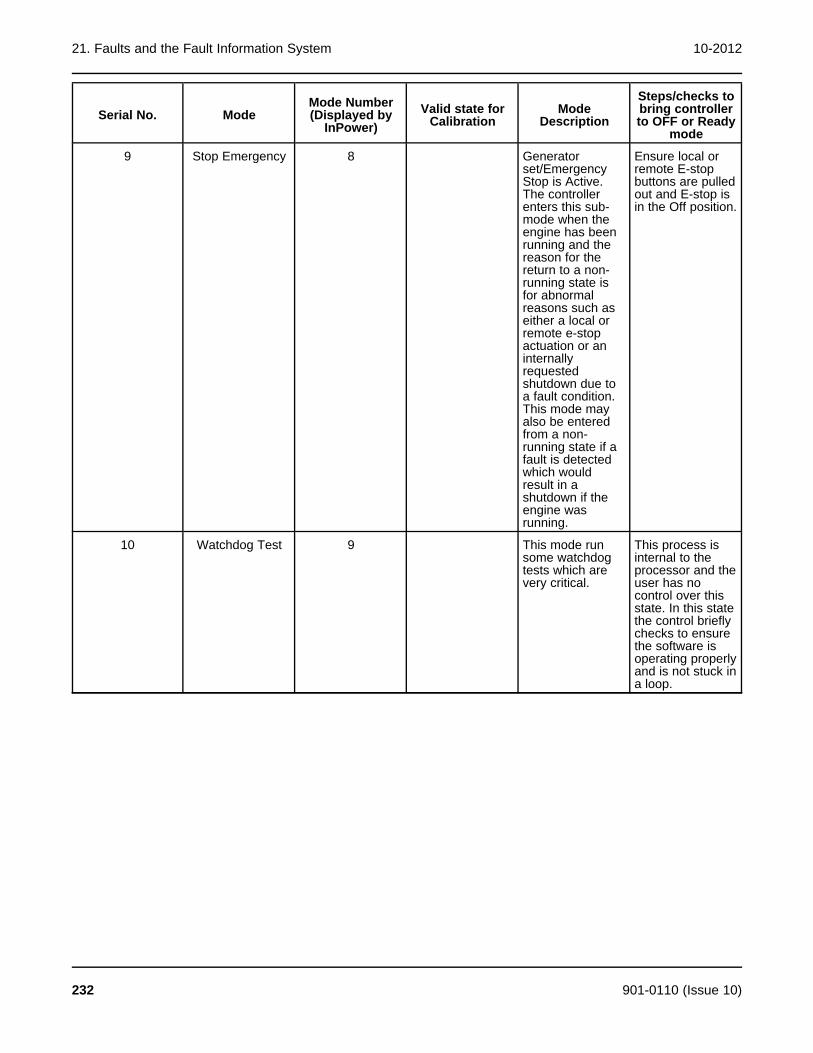
21. Faults and the Fault Information System 10-2012
Steps/checks toMode Number Valid state for Mode bring controllerSerial No. Mode (Displayed by Calibration Description to OFF or ReadyInPower) mode
9 Stop Emergency 8 Generator Ensure local orset/Emergency remote E-stopStop is Active. buttons are pulledThe controller out and E-stop isenters this sub- in the Off position.mode when theengine has beenrunning and thereason for thereturn to a non-running state isfor abnormalreasons such aseither a local orremote e-stopactuation or aninternallyrequestedshutdown due toa fault condition.This mode mayalso be enteredfrom a non-running state if afault is detectedwhich wouldresult in ashutdown if theengine wasrunning.
10 Watchdog Test 9 This mode run This process issome watchdog internal to thetests which are processor and thevery critical. user has no
control over thisstate. In this statethe control brieflychecks to ensurethe software isoperating properlyand is not stuck ina loop.
232 901-0110 (Issue 10)

22 Event Handler
22.1 Receiving EventsWhen connected to a device, InPower will receive events, and allow the user to acknowledgeevents.
It is important to note that InPower is a service tool. InPower will receive and display events, butit does not acknowledge events within the device. Monitoring should be performed withoperating software that is specifically designed for monitoring and event acknowledgment.
The Event Handler feature launches when InPower is started, and it closes when the InPowersession is ended.
Events are displayed in the Alarm dialog until InPower is closed, or the user clears(acknowledges) the events. The record of event announcements is not stored from one sessionof InPower to the next.
Acknowledging events removes the events displayed to the InPower user only.Acknowledgement with InPower will not remove the event from the control.
InPower displays an Alarms popup dialog to view event information as soon as the event isreceived. Users can clear events, view more information about an event, or simply close theAlarm popup until the next time the device announces an event.
Be aware that event announcement and fault code diagnostics are not the same function.InPower provides fault code and diagnostic information that is not related to eventannouncement.
22.1.1 Devices That Cannot Receive EventsThis feature is not applicable to PCC 1100, PCC 1300, PCC 1301, and PCC 1302.
22.2 Displaying EventsInPower will display all events that have been received in an Alarm dialog. When the Auto-Announce feature is enabled (default setting), the Alarm dialog pops up to displays of all theevents it contains. Additional details about the events are available in the Event Detail dialog.
22.2.1 Alarms PopupThe Alarm Popup provides details about events. The Alarms popup dialog menu features canbe used to view more details about an event, clear the event, or dock the Alarm Pop-up back tothe Windows taskbar. To launch the Alarms pop-up from the taskbar, click on the Alarmsbutton.
The Alarm Popup provides the following menu bar and button options.
View-Acknowledge All: Selects all displayed alarms and removes them from the Event popupview.
View-Detail: Displays the Event Details dialog of the selected event.
901-0110 (Issue 10) 233

22. Event Handler 10-2012
Options-AutoAnnounce: Displays a check box for displaying the Alarms Popup. If checked,(default setting) the Alarms popup displays each time a new event is received. If unchecked,the Alarms Popup will not open automatically to announce new events.
Help-Contents: Displays InPower help contents.
Help-Search: Used to searching for an InPower help topic.
Close Button: Used to dock the Alarms popup dialog to the Windows task bar.
Help Button: Used to access Event Announcement help.
The most recent event is added at the top of the list. One event will always be selected(highlighted). Events received while the Alarm dialog is displayed will appear in the dialogimmediately.
22.2.1.1 Columns in the Alarms PopupThe Alarms popup provides the following columns:
Code: This displays the fault code associated with the event.
Description: This displays a textual description associated with the event. The descriptioncomes from the controller.
Level: This indicates the type of event that occurred; for example, shutdown, warning, or none.If this is not applicable to the controller (for example, a G-drive controller), the value is "None".
Status: This indicates whether the associated fault code became active or inactive in this event.
Site:
Module: This displays the type of device that reported the event.
Time: This displays the time at which the event occurred.
22.2.2 Event DetailEvents have additional detail associated with them. The user can view these details in theEvent Details dialog by selecting an event, then selecting View-Detail from the View menu.
The Event Details dialog provides the following button options:
Close Button: Closes the Event Details dialog and returns the user to the Alarms dialog.
Navigation Buttons: The left arrow button changes the Event Details dialog to display the nextevent (down) on the Alarm dialog list. The right arrow changes the Event Detail dialog to displaythe previous event (up) on the Alarm dialog list.
Help Button: Used to access Event Details help.
22.2.2.1 Columns in the Event Details DialogThe Event Details dialog provides the following fields:
In the Alarms section,
Description: This displays a textual description associated with the event. The descriptioncomes from the controller.
Status: This indicates whether the associated fault code became active or inactive in this event.
Level: This indicates the type of event that occurred; for example, shutdown, warning, or none.If this is not applicable to the controller (for example, a G-drive controller), the value is "None".
234 901-0110 (Issue 10)
10-2012 22. Event Handler
Code: This displays the fault code associated with the event.
Version:
Occurrences: This displays the number of times the event has occurred.
Last Occurrence: This field is blank.
Run Time Last: This displays the most recent time the event occurred.
First Occurrence: This field is blank.
Run Time First: This displays the first time the event occurred.
In the Module section,
Type: This displays the type of device that reported the event.
Address: This displays the network address of the device that reported the event.
In the Site section,
Site Id: This displays the name of the site; typically, the name of the COM port for devices orthe file name type for files, such as capture files.
901-0110 (Issue 10) 235

22. Event Handler 10-2012
This page is intentionally blank.
236 901-0110 (Issue 10)
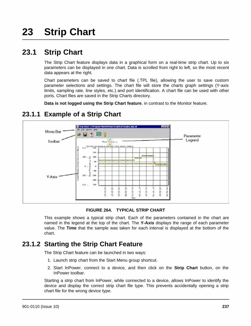
23 Strip Chart
23.1 Strip ChartThe Strip Chart feature displays data in a graphical form on a real-time strip chart. Up to sixparameters can be displayed in one chart. Data is scrolled from right to left, so the most recentdata appears at the right.
Chart parameters can be saved to chart file (.TPL file), allowing the user to save customparameter selections and settings. The chart file will store the charts graph settings (Y-axislimits, sampling rate, line styles, etc.) and port identification. A chart file can be used with otherports. Chart files are saved in the Strip Charts directory.
Data is not logged using the Strip Chart feature, in contrast to the Monitor feature.
23.1.1 Example of a Strip Chart
FIGURE 264. TYPICAL STRIP CHART
This example shows a typical strip chart. Each of the parameters contained in the chart arenamed in the legend at the top of the chart. The Y-Axis displays the range of each parametervalue. The Time that the sample was taken for each interval is displayed at the bottom of thechart.
23.1.2 Starting the Strip Chart FeatureThe Strip Chart feature can be launched in two ways:
1. Launch strip chart from the Start Menu group shortcut.
2. Start InPower, connect to a device, and then click on the Strip Chart button, on theInPower toolbar.
Starting a strip chart from InPower, while connected to a device, allows InPower to identify thedevice and display the correct strip chart file type. This prevents accidentally opening a stripchart file for the wrong device type.
901-0110 (Issue 10) 237
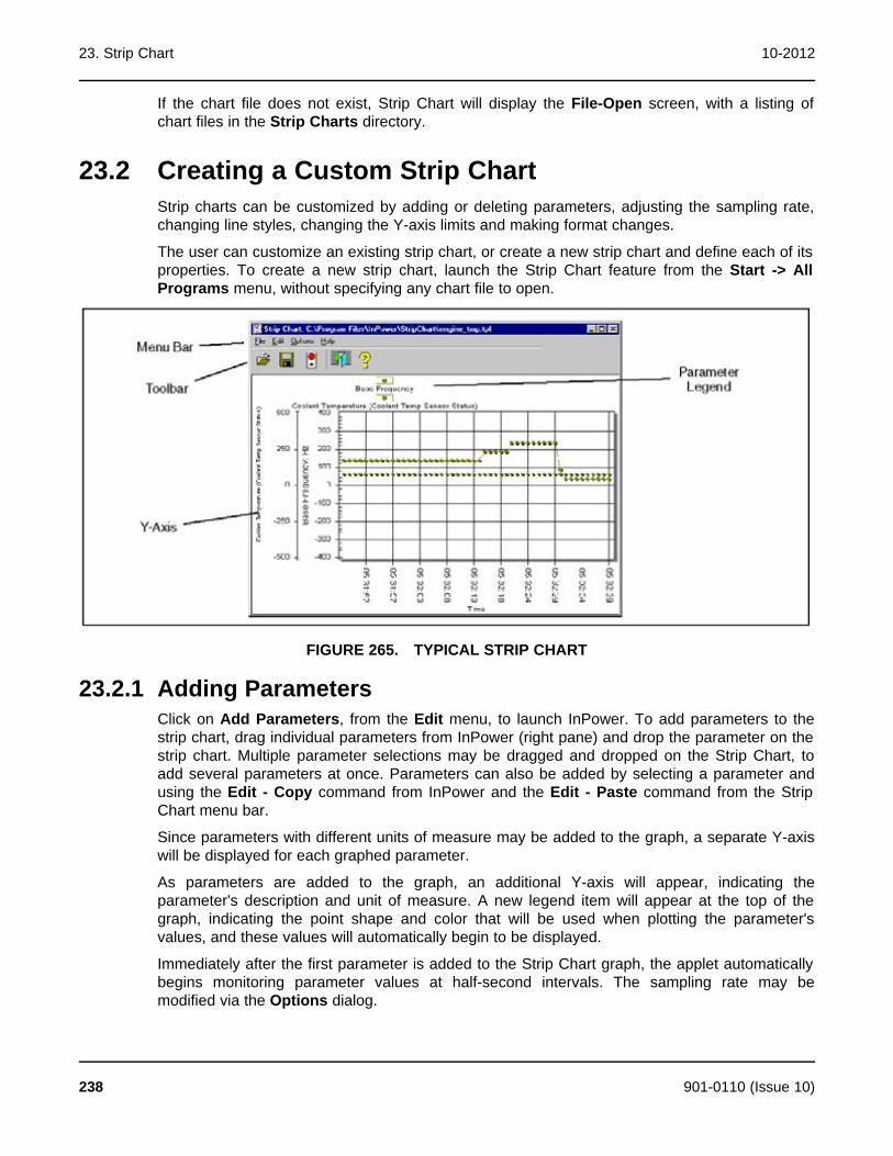
23. Strip Chart 10-2012
If the chart file does not exist, Strip Chart will display the File-Open screen, with a listing ofchart files in the Strip Charts directory.
23.2 Creating a Custom Strip ChartStrip charts can be customized by adding or deleting parameters, adjusting the sampling rate,changing line styles, changing the Y-axis limits and making format changes.
The user can customize an existing strip chart, or create a new strip chart and define each of itsproperties. To create a new strip chart, launch the Strip Chart feature from the Start -> AllPrograms menu, without specifying any chart file to open.
FIGURE 265. TYPICAL STRIP CHART
23.2.1 Adding ParametersClick on Add Parameters, from the Edit menu, to launch InPower. To add parameters to thestrip chart, drag individual parameters from InPower (right pane) and drop the parameter on thestrip chart. Multiple parameter selections may be dragged and dropped on the Strip Chart, toadd several parameters at once. Parameters can also be added by selecting a parameter andusing the Edit - Copy command from InPower and the Edit - Paste command from the StripChart menu bar.
Since parameters with different units of measure may be added to the graph, a separate Y-axiswill be displayed for each graphed parameter.
As parameters are added to the graph, an additional Y-axis will appear, indicating theparameter's description and unit of measure. A new legend item will appear at the top of thegraph, indicating the point shape and color that will be used when plotting the parameter'svalues, and these values will automatically begin to be displayed.
Immediately after the first parameter is added to the Strip Chart graph, the applet automaticallybegins monitoring parameter values at half-second intervals. The sampling rate may bemodified via the Options dialog.
238 901-0110 (Issue 10)
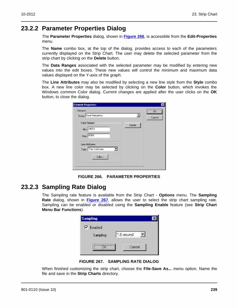
10-2012 23. Strip Chart
23.2.2 Parameter Properties DialogThe Parameter Properties dialog, shown in Figure 266, is accessible from the Edit-Propertiesmenu.
The Name combo box, at the top of the dialog, provides access to each of the parameterscurrently displayed on the Strip Chart. The user may delete the selected parameter from thestrip chart by clicking on the Delete button.
The Data Ranges associated with the selected parameter may be modified by entering newvalues into the edit boxes. These new values will control the minimum and maximum datavalues displayed on the Y-axis of the graph.
The Line Attributes may also be modified by selecting a new line style from the Style combobox. A new line color may be selected by clicking on the Color button, which invokes theWindows common Color dialog. Current changes are applied after the user clicks on the OKbutton, to close the dialog.
FIGURE 266. PARAMETER PROPERTIES
23.2.3 Sampling Rate DialogThe Sampling rate feature is available from the Strip Chart - Options menu. The SamplingRate dialog, shown in Figure 267, allows the user to select the strip chart sampling rate.Sampling can be enabled or disabled using the Sampling Enable feature (see Strip ChartMenu Bar Functions).
FIGURE 267. SAMPLING RATE DIALOG
When finished customizing the strip chart, choose the File-Save As... menu option. Name thefile and save in the Strip Charts directory.
901-0110 (Issue 10) 239

23. Strip Chart 10-2012
NOTE: Saving a Custom Strip Chart saves only the chart settings, it does not save(log) data.
See Context Menu for additional commands that are available for customizing strip charts.
23.2.4 Strip Chart Menu Bar FunctionsThis section describes each of the menu commands that are available from the Strip Chartmenu bar.
File-Open: Allows the user to specify a particular chart (.TPL) file to load from the list of chartfiles, in the Strip Chart directory. Logged data (.LOG file) can also be opened and viewed withthe Strip Chart feature.
After a .TPL file has been selected, the applet will open the file and load the parameters andsettings from that file. Since parameter values will be graphed, only the first six parameters thathave numeric values will be accepted.
File- Save: Allows saving the current selection of parameters to a chart file.
File - Save As: Allows saving the current set of parameters to a new chart file name and/orlocation.
File-Close: Closes the Strip Chart
Edit-Add Parameter: Allows adding parameters to the Strip Chart graph from InPower. Thiscommand opens InPower, allowing the user to select parameters to be added to the Strip Chart.Drag individual parameters from InPower and drop the parameter on the Strip Chart graph.
Edit-Paste: Allows pasting the parameter(s) from the Windows clipboard into the strip chart.The Paste menu option will remain disabled until one or more parameters have been cut orcopied to the Windows Clipboard.
Edit-Properties: Opens the Element Properties dialog. (This feature can also be activated bydouble clicking on the parameter names in the strip chart's legend.) The Element Propertiesdialog allows the user to perform a variety of commands relating to the display properties of theStrip Chart.
Options-Sampling: This option displays the Sampling Rate dialog, which allows the user tochange the strip chart sampling rate. The sample rate is adjustable from 0.05 seconds to 60seconds.
Options-Sampling Enable: This option is used to enable or disable the collection of sampledata. A check mark is displayed next to Sampling Enable on the Options drop down menu toindicate that the feature is enabled. Click once on Sampling Enable to stop collecting sampledata. Click on it again to start collecting sample data again.
Options-Logging: This option provides you with a means to assign a location for storing striplog files. The default file location is listed on the menu (Figure 268). If necessary, select theBrowse button to select another location. Logging can be enabled from this menu. When alladjustments are completed, click on the OK button.
240 901-0110 (Issue 10)

10-2012 23. Strip Chart
FIGURE 268. LOGGING DIALOG
Options-Logging Enabled: This option is used to enable the logging option to save a file at thelocation set up with the Logging dialog. If a strip chart log has already been created, themessage shown in Figure 269 is displayed.
FIGURE 269. LOGGING MESSAGE
23.2.5 Context Menu FeaturesThe Context Menu, shown in Figure 270, may be accessed by clicking on the right mousebutton (or equivalent pointing device button) while the cursor is inside the graph. This set ofmenu items provides the users with additional customization features.
FIGURE 270. CONTEXT MENU FEATURES (RIGHT MENU BUTTON)
Viewing Style: This controls the viewing style of the object. Possible values include color,monochrome, or monochrome with symbols.
901-0110 (Issue 10) 241

23. Strip Chart 10-2012
Font Size: This controls the font size used in the graph's image creation process. The font sizesavailable are large, medium, or small.
NOTE: It is recommended that the user change the Font Size to the Medium settingor Large setting if only a few parameters are being monitored. This selectionwill make it easier to read the parameter legends.
Numeric Precision: This controls the number of decimal places associated with the graph'sdata. Possible values include zero, one, two or three decimal places.
Data Shadows: This controls whether shadows will be placed behind plotting method graphics.The shadows add depth to the images; however, they will slow image creation significantlywhen graphing many subsets and/or points.
Grid Lines: This controls the horizontal and vertical lines that make up the graphs grid.Possible values include horizontal and vertical grid lines, horizontal grid lines only, vertical gridlines only, or no grid lines.
Grid In Front: This controls whether the graphs grid is placed behind or in front of the plottingmethod graphics.
Graph and/or Table: This controls what is displayed in the graph's area. Possible valuesinclude graph, table, or graph with table.
What to Table: This controls what information is included in the objects table. Possible valuesinclude tabling those subsets that are graphed or tabling all subsets.
Point Label Orientation: This controls the orientation of the point labels. Possible valuesinclude automatic, horizontal, or vertical.
Mark Data Points: This controls whether data-points are marked with a small circle.
Maximize: This function maximizes the graph display. To return to the default display size, clickinside the solid bar at the top of the window or use the Esc key.
Customization Dialog: This function displays the chart Customization dialog.
Export Dialog: Graphs can be exported in the formats shown in Table 4, for the listeddestinations. This dialog allows the user to print a Strip Chart.
TABLE 4. GRAPH EXPORTABLE FORMATS
FORMAT DESTINATIONS
Metafile Clipboard, File, and Printer
Bitmap Clipboard and File
OLE Object Clipboard
Text / Data Clipboard and File
Help: Displays graph-related help topics.
23.2.6 Chart Customization DialogAn additional level of editing is available that allows the user to customize the chart dialog. Toaccess this feature, double click within the chart to display the Customization dialog. Thisdialog has tabs for each of the editable features.
242 901-0110 (Issue 10)

10-2012 23. Strip Chart
Click on the desired tab to view the available settings for that feature. These features can beused to enhance the chart by changing border colors, text size and colors, and many other chartdisplay features.
FIGURE 271. CHART CUSTOMIZATION DIALOG
23.2.7 Printing a Strip ChartA Strip Chart can be printed by using the Export dialog (Figure 272). Use the right menu buttonto access the Export Dialog, then select the Printer radio button and select the Print button.
FIGURE 272. EXPORT - PRINT DIALOG
23.2.8 Viewing Logged DataLogged data, created with the Monitor feature can be displayed with the Strip Chart feature.Select Open from the Strip Chart File menu. Enter the .LOG file location and name.
Strip Chart will display the logged data. Since the data is not being displayed on a realtimebasis, the data is static. Use the left and right arrow buttons located on the keyboard to navigatethe data within the .LOG file.
901-0110 (Issue 10) 243

23. Strip Chart 10-2012
This page is intentionally blank.
244 901-0110 (Issue 10)
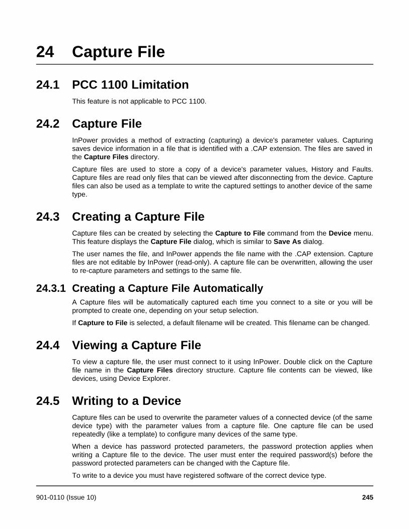
24 Capture File
24.1 PCC 1100 LimitationThis feature is not applicable to PCC 1100.
24.2 Capture FileInPower provides a method of extracting (capturing) a device's parameter values. Capturingsaves device information in a file that is identified with a .CAP extension. The files are saved inthe Capture Files directory.
Capture files are used to store a copy of a device's parameter values, History and Faults.Capture files are read only files that can be viewed after disconnecting from the device. Capturefiles can also be used as a template to write the captured settings to another device of the sametype.
24.3 Creating a Capture FileCapture files can be created by selecting the Capture to File command from the Device menu.This feature displays the Capture File dialog, which is similar to Save As dialog.
The user names the file, and InPower appends the file name with the .CAP extension. Capturefiles are not editable by InPower (read-only). A capture file can be overwritten, allowing the userto re-capture parameters and settings to the same file.
24.3.1 Creating a Capture File AutomaticallyA Capture files will be automatically captured each time you connect to a site or you will beprompted to create one, depending on your setup selection.
If Capture to File is selected, a default filename will be created. This filename can be changed.
24.4 Viewing a Capture FileTo view a capture file, the user must connect to it using InPower. Double click on the Capturefile name in the Capture Files directory structure. Capture file contents can be viewed, likedevices, using Device Explorer.
24.5 Writing to a DeviceCapture files can be used to overwrite the parameter values of a connected device (of the samedevice type) with the parameter values from a capture file. One capture file can be usedrepeatedly (like a template) to configure many devices of the same type.
When a device has password protected parameters, the password protection applies whenwriting a Capture file to the device. The user must enter the required password(s) before thepassword protected parameters can be changed with the Capture file.
To write to a device you must have registered software of the correct device type.
901-0110 (Issue 10) 245
24. Capture File 10-2012
To write from a Capture file, connect to the Capture file first, then click on the target device, andconnect to it. Next, select the Capture file and drag-and-drop the Capture file onto the targetdevice.
The Edit - Copy and Edit - Paste features can also be used to write parameter settings from aCapture file to a device. This feature can be used to copy the entire Capture file, or individualfolders or parameters.
Start by connecting to the Capture file, Use Edit - Copy to copy the desired information fromthe Capture file. When copying a folder or individual parameters, use Device explorer to displaythe desired folder or parameters in the right pane. Hold down the Control key while selecting thedesired folder (s) or parameter(s) then use the Edit - Copy command. Connect to the targetdevice and use the Edit - Paste feature to overwrite the target device's parameters with theparameter settings from the Capture file.
NOTE: A capture file from a genset (for example) can be copied to another genset,but it cannot be copied to a transfer switch control, or any other device type.
246 901-0110 (Issue 10)
25 SimulatorInPower provides a means of demonstrating the service tool without connecting to an actualdevice. A Capture file is used for simulation. This file contains most of the information that isnormally displayed when you are connected to a device.
Any capture file(s) used for simulation are added during InPower installation. These files aredevice specific, for example, if you install a genset InPower product, you will only receive gensetSimulator files.
Simulator files are read only, although during simulation, the user will be allowed to makeeditorial changes, to help demonstrate the tool. Any changes made during simulation will not besaved.
If an arrow is displayed, click on the arrow to view a drop-down list of the available settings.Click on the desired setting, and it will be entered into the Value cell.
The simulator file(s) are stored in the Simulator directory. To run an InPower simulation, doubleclick on the Simulator directory and then double click on the desired simulator file (*.CAP file).
901-0110 (Issue 10) 247

25. Simulator 10-2012
This page is intentionally blank.
248 901-0110 (Issue 10)

26 ReportsThis section describes how to create, save and print reports. Reports consist of parametergroups and their values at the time the report was created. Reports can be printed directly fromInPower, or they can be saved to a file for use in a spreadsheet, database, or word processingprogram.
26.1 Creating a ReportStart InPower and connect to a port, then connect to a device (or file). Use the Device Explorer(tree view) to locate and select the information you wish to include in the report.
NOTE: When selecting parameters for a report, be careful to avoid selecting toomany parameters. If a folder is selected that contains additional folders, theparameters of all of the folders in the group will be selected.
You can create a report from a single group of parameters or from several groups ofparameters. A few smaller reports are generally more manageable than a very large report.
To create a report for a single group of parameters: Select the group folder, if it containsadditional folders, double click on the folder to expand it. Select the desired folder and use themouse or keyboard menu button to display the pop-up menu (Figure 273). Select Print Featurefrom the pop-up menu, to create a report for the selected folder and display the Parameter ListReport window (Figure 274).
To create a report with more than one group of parameters: Select each folder individually,use the mouse or keyboard menu button to display the popup menu, click on Select Feature, inthe popup menu. Each folder selected will be marked with a check mark, to indicate that it hasbeen selected for use in the report (Figure 273).
After selecting the desired parameter groups, use the Prepare CSV file with all SelectedFeatures menu pick from the InPower Device menu to create a report and display theParameter List Report window (Figure 274).
NOTE: If you only want to create a report on one feature, select the feature, right-click and select the Prepare CSV file for Feature menu pick.
Selected folders can be deselected by clicking on a folder with a check mark, then use themouse or keyboard menu button to display the pop-up menu, click on Deselect Feature, in thepop-up menu.
The Parameter List Report window allows viewing the report contents. Each selectedparameter group is shown.
901-0110 (Issue 10) 249
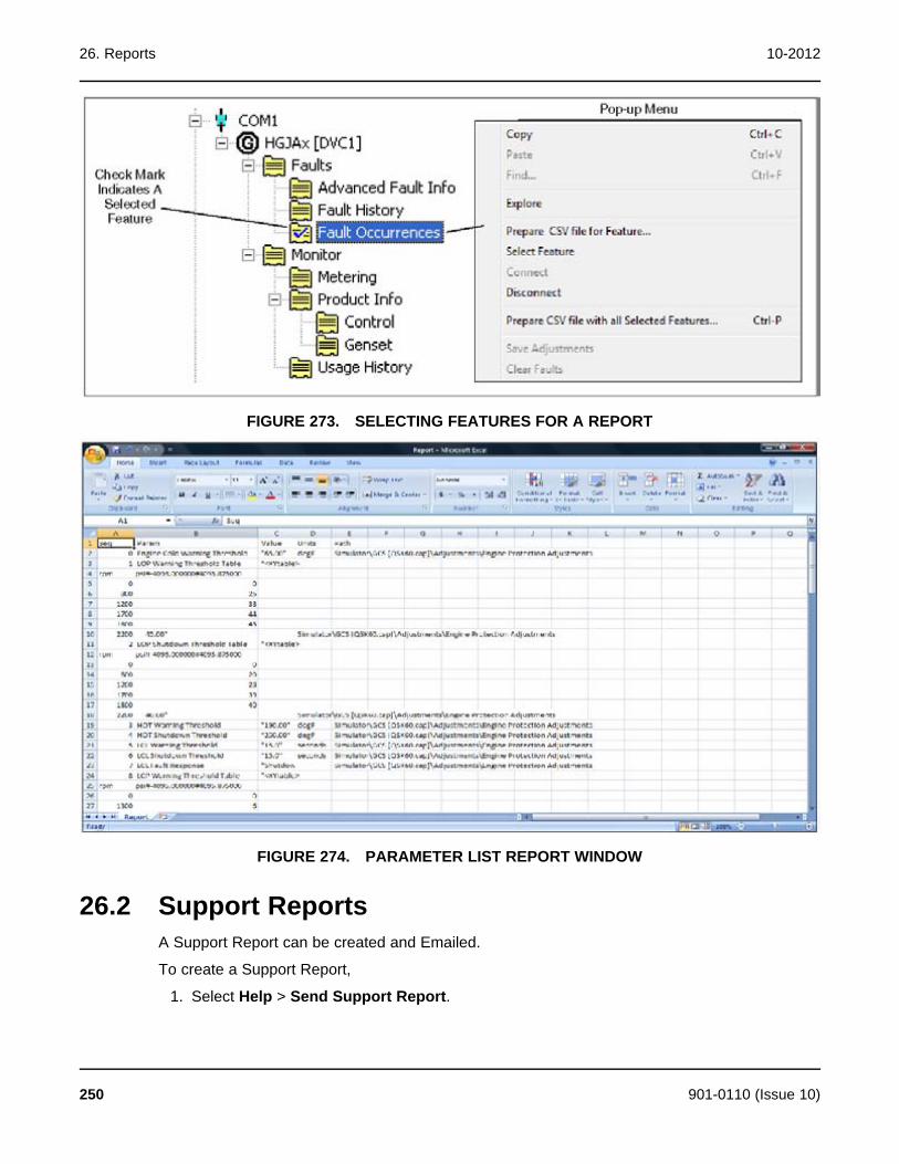
26. Reports 10-2012
FIGURE 273. SELECTING FEATURES FOR A REPORT
FIGURE 274. PARAMETER LIST REPORT WINDOW
26.2 Support ReportsA Support Report can be created and Emailed.
To create a Support Report,
1. Select Help > Send Support Report.
250 901-0110 (Issue 10)

10-2012 26. Reports
FIGURE 275. LAUNCHING THE SEND SUPPORT REPORT FEATURE
2. When the ETools Support Report Utility dialog is displayed, enter an Issue Title andIssue Description.
FIGURE 276. ETOOLS SUPPORT REPORT UTILITY DIALOG
901-0110 (Issue 10) 251
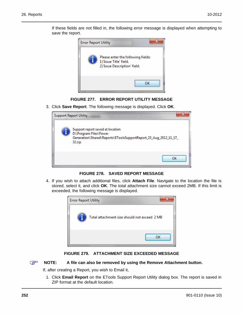
26. Reports 10-2012
If these fields are not filled in, the following error message is displayed when attempting tosave the report.
FIGURE 277. ERROR REPORT UTILITY MESSAGE
3. Click Save Report. The following message is displayed. Click OK.
FIGURE 278. SAVED REPORT MESSAGE
4. If you wish to attach additional files, click Attach File. Navigate to the location the file isstored, select it, and click OK. The total attachment size cannot exceed 2MB. If this limit isexceeded, the following message is displayed.
FIGURE 279. ATTACHMENT SIZE EXCEEDED MESSAGE
NOTE: A file can also be removed by using the Remove Attachment button.
If, after creating a Report, you wish to Email it,
1. Click Email Report on the ETools Support Report Utility dialog box. The report is saved inZIP format at the default location.
252 901-0110 (Issue 10)

10-2012 26. Reports
2. Once the Report is saved, an Email message with the default mailbox location forCummins InPower support is displayed. Click Send.
FIGURE 280. EMAIL FOR ERROR REPORT
If you wish to view an existing report, click Open Report Folder on the Error Report Utilitydialog box. The default error report location (D:\Program Files\PowerGeneration\Shared\Reports) is displayed.
FIGURE 281. ERROR REPORT DEFAULT LOCATION
901-0110 (Issue 10) 253

26. Reports 10-2012
This page is intentionally blank.
254 901-0110 (Issue 10)

27 Event ConfigurationThis section describes how to use the Events Configuration feature. This feature is only usedwith genset applications. Event Configuration allows the InPower user to configure both theFault Effect and the Notification settings for Faults.
The term events refers to status changes that can be viewed on a control display or withInPower. There are two types of events, fault events and non-fault events. The EventConfiguration feature is used to configure fault events (Faults). Faults represent gensetoperating conditions that are outside the normal operating range or setting.
Start InPower and connect to the port (COM1, COM2, etc.) being used for connection to thedevice.
Click on the Events Configuration folder to view the Events Configuration parameters (Figure282). This group displays all of the genset Faults numerically, by Fault Code. Also displayed arethe Fault Descriptions, current Fault Effect settings and current Notification settings.
27.1 Devices That Do Not Support Event ConfigurationThis feature is not applicable to PCC 1100, PCC 1300, PCC 1301, PCC 1302, and MCC 3320.
27.2 Fault EffectFault Effect is used to configure the action taken when a fault becomes active. All faults arepre-configured with a fault effect.
The severity of the effect generally cannot be decreased. For example: Engine Overspeedcannot be changed from Shutdown to Warning.
In genset applications, there are five possible Fault Effect settings.
None: When a Fault Effect is set to None, there is no effect when the fault becomes active(including no dialout notification).
Warning: A warning message is delivered to the control display and to InPower when InPoweris connected to the device.
Derate: Faults configured for Derate will act like a Warning when the fault is active. If aparameter has a factory set derate percentage the genset will derate to that setting when thefault is active.
Shutdown: Faults configured for Shutdown will cause the genset to shutdown immediatelywhen the fault is active.
Shutdown Cooldown: Faults configured for Shutdown Cooldown will shed the load (ifavailable) and shut the genset down after a cooldown period, when the fault is active.
To change the effect of a fault, double click on the Fault Effects value cell, for the desired fault.A drop-down arrow will be displayed. Click on the drop-down arrow to display the settingchoices (Figure 282). Click on the desired effect, to select it.. Click on the Save Trims button,on the toolbar, to write the new value to the device.
901-0110 (Issue 10) 255

27. Event Configuration 10-2012
FIGURE 282. FAULT EFFECT
27.3 Event Configuration in the PowerCommand 2.x and3.xIf LBNG Genset Enable is Disable, the Derate% column can be edited. If LBNG Genset Enableis Enable, the Derate% column is read-only.
256 901-0110 (Issue 10)
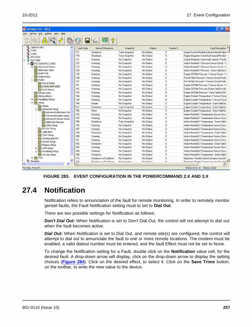
10-2012 27. Event Configuration
FIGURE 283. EVENT CONFIGURATION IN THE POWERCOMMAND 2.X AND 3.X
27.4 NotificationNotification refers to annunciation of the fault for remote monitoring. In order to remotely monitorgenset faults, the Fault Notification setting must to set to Dial Out.
There are two possible settings for Notification as follows:
Don't Dial Out: When Notification is set to Don't Dial Out, the control will not attempt to dial outwhen the fault becomes active.
Dial Out: When Notification is set to Dial Out, and remote site(s) are configured, the control willattempt to dial out to annunciate the fault to one or more remote locations. The modem must beenabled, a valid dialout number must be entered, and the fault Effect must not be set to None.
To change the Notification setting for a Fault, double click on the Notification value cell, for thedesired fault. A drop-down arrow will display, click on the drop-down arrow to display the settingchoices (Figure 284). Click on the desired effect, to select it. Click on the Save Trims button,on the toolbar, to write the new value to the device.
901-0110 (Issue 10) 257

27. Event Configuration 10-2012
FIGURE 284. NOTIFICATION
258 901-0110 (Issue 10)

28 Remote CommunicationThis section describes how to setup and use InPower for remote communication with aPowerCommand® controlled genset.
InPower cannot be used to remotely monitor Automatic Transfer Switches. Use the optionalnetwork module for remote communication with an Automatic Transfer Switch.
WARNING: Electrical shock and moving parts can cause severe personal injury or death.Notify personnel before starting a generator set and before performing loadtransfer on a transfer switch. Refer to the equipment Operator's Manual forimportant safety precautions.
InPower can also be used to configure a genset to dialout events for remote monitoring withmonitoring software or with InPower.
Read through this entire section to become familiar with the remote communication features anduses before configuring a genset control for remote communications.
28.1 Remote ConnectionsFigure 285 and Figure 286 show typical remote connections. Two modems are available foruse with InPower, a standard modem and one designed for mounting to a DIN rail.
FIGURE 285. INPOWER SERIAL CONNECTION (TYPE 1 CONNECTION BOX)
901-0110 (Issue 10) 259
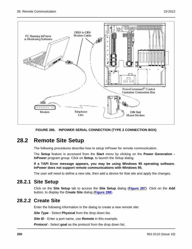
28. Remote Communication 10-2012
FIGURE 286. INPOWER SERIAL CONNECTION (TYPE 2 CONNECTION BOX)
28.2 Remote Site SetupThe following procedures describe how to setup InPower for remote communication.
The Setup feature is accessed from the Start menu by clicking on the Power Generation -InPower program group. Click on Setup, to launch the Setup dialog.
If a TAPI Error message appears, you may be using Windows 95 operating software.InPower does not support remote communications with Windows 95.
The user will need to define a new site, then add a device for that site and apply the changes.
28.2.1 Site SetupClick on the Site Setup tab to access the Site Setup dialog (Figure 287). Click on the Addbutton, to display the Create Site dialog (Figure 288).
28.2.2 Create SiteEnter the following information in the dialog to create a new remote site:
Site Type - Select Physical from the drop down list.
Site ID - Enter a port name, use Remote in this example.
Protocol - Select goal as the protocol from the drop down list.
260 901-0110 (Issue 10)
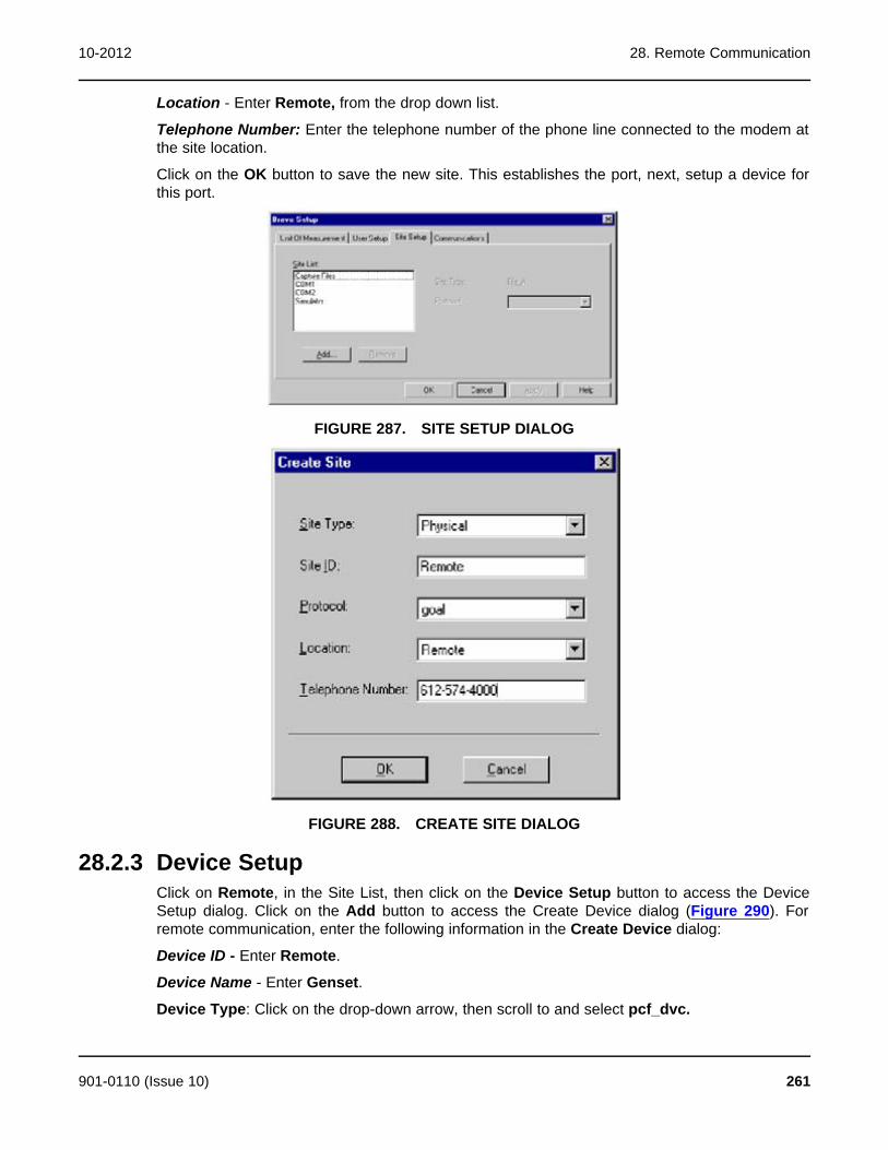
10-2012 28. Remote Communication
Location - Enter Remote, from the drop down list.
Telephone Number: Enter the telephone number of the phone line connected to the modem atthe site location.
Click on the OK button to save the new site. This establishes the port, next, setup a device forthis port.
FIGURE 287. SITE SETUP DIALOG
FIGURE 288. CREATE SITE DIALOG
28.2.3 Device SetupClick on Remote, in the Site List, then click on the Device Setup button to access the DeviceSetup dialog. Click on the Add button to access the Create Device dialog (Figure 290). Forremote communication, enter the following information in the Create Device dialog:
Device ID - Enter Remote.
Device Name - Enter Genset.
Device Type: Click on the drop-down arrow, then scroll to and select pcf_dvc.
901-0110 (Issue 10) 261
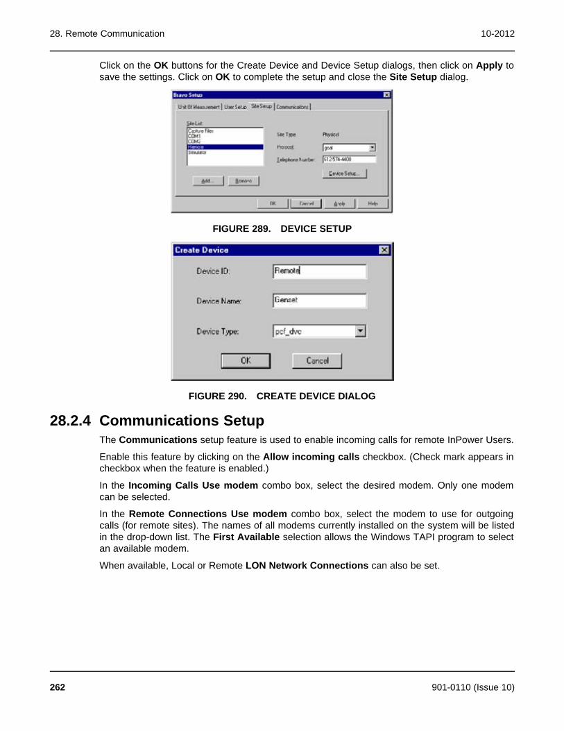
28. Remote Communication 10-2012
Click on the OK buttons for the Create Device and Device Setup dialogs, then click on Apply tosave the settings. Click on OK to complete the setup and close the Site Setup dialog.
FIGURE 289. DEVICE SETUP
FIGURE 290. CREATE DEVICE DIALOG
28.2.4 Communications SetupThe Communications setup feature is used to enable incoming calls for remote InPower Users.
Enable this feature by clicking on the Allow incoming calls checkbox. (Check mark appears incheckbox when the feature is enabled.)
In the Incoming Calls Use modem combo box, select the desired modem. Only one modemcan be selected.
In the Remote Connections Use modem combo box, select the modem to use for outgoingcalls (for remote sites). The names of all modems currently installed on the system will be listedin the drop-down list. The First Available selection allows the Windows TAPI program to selectan available modem.
When available, Local or Remote LON Network Connections can also be set.
262 901-0110 (Issue 10)

10-2012 28. Remote Communication
FIGURE 291. COMMUNICATIONS SETUP
28.3 Remote Connection with InPowerInPower can be used to remotely connect to a genset. Before attempting remotecommunication, perform the Remote Site Setup steps and make sure that the modem isenabled.
Start InPower and connect to the site that was used for remote connection (named Remote inthis example).
A dialing status window is displayed during dialout. When connected to the device, InPowerDevice Explorer opens and displays the device the same way it does with a local connection(Figure 292).
To write to a device you must have registered software of the correct device type.
When a device has password protected parameters, the password protection applies whenusing a remote connection. The user must enter the required password(s) before the passwordprotected parameters can be changed.
901-0110 (Issue 10) 263

28. Remote Communication 10-2012
FIGURE 292. REMOTE CONNECTION
28.4 Dialout ConfigurationThis section describes the modem setup parameters used for dialing out. To configure thedevice for dialout, the service PC must be directly connected to the device (DialoutConfiguration cannot be done remotely).
Start InPower and connect to the port (COM1, COM2, etc.) that matches the COM port on theservice PC, used for connection to the device. Double click on the COM port (or click on theCOM port and then click on the Connect button, on the toolbar).
The modem setup parameters are located in the Adjustments - Features folder. Double clickon these folders to display the Direct Connect Modem Setup folder. Click on this folder to viewthe modem setup parameters (Figure 293).
The following list describes the modem setup parameters:
Modem Hangup Delay: Enable this feature to remain connected for two minutes afterdelivering a dialout message.
Modem: This feature must be Enabled in order to use the modem.
Dial Out Attempts: Used to set the number of times a number will be dialed while attempting todeliver a dial out message. The default setting, zero, is equal to one attempt. (The recommendsetting is 10.)
Modem Configuration String: Used to enter the modem configuration string for the specificmodem in use. See Section 28.5 for the modem init strings for each of the modems that areused with InPower.
NOTE: The modem configuration string is preconfigured when one of the optionalmodems is factory installed.
264 901-0110 (Issue 10)

10-2012 28. Remote Communication
Dialout Numbers 1 through 4: These are the dialout numbers for the location(s) that aremonitoring the device. Use a comma (,) to pause, and start with a P for pulse dialing.
Dial Out Retry Delay: Enter the time delay between dialout attempts (in minutes).
Clear Undelivered Events: This feature clears all pending dialouts.
Dialout Break: When enabled, this feature breaks the connection after two minutes in order tocomplete a dialout.
Set the modem parameters, then click on the Save Trims button, on the toolbar, to writemodem setup values to the device.
FIGURE 293. DIRECT CONNECT MODEM SETUP
28.5 ModemsThere are two modems that can be used with InPower. The two modems each have a uniqueinit string (Modem Configuration String). When a modem is installed in the field, it is important toidentify the modem brand, and enter the proper init string using InPower.
Both of these modems can be powered with a DC power supply.
When using InPower locally, do not remove the modem connection from the serial port untilafter the modem power has been turned off. Do not re-apply power to the modem until after ithas been reconnected to the device's serial port. Failure to follow this sequence can result inloss of the modem configuration string.
CAUTION: The modem configuration string can be lost, preventing dialout of importantmessages if power to the modem is not turned off and on in the proper sequence.Whenever the dialout modem is disconnected for access to the device's serial port,the modem first must be turned off. The modem should not be turned on again untilafter it has been reconnected.
The modem used for dialout should be connected through the normally closed contacts of themodem power relay. This is required because when the control is off (and the driver is off) themodem has to be able to receive dial-in calls, to wake up the controller.
901-0110 (Issue 10) 265

28. Remote Communication 10-2012
28.5.1 Modem Configuration StringsUse the following information for configuring one of the two available modems for use withInPower:
Multitech Model MT3334ZDX
Modem Configuration String:
ATE0V0Q0&C1%C0&D0&K0N0\N0$SB9600S0=1S25=25S37=9&W0
Industrial Modem Model VT-Modem-1US by Sixnet.
Modem Configuration String:
ATE0V0Q0&C1%C0&D0&K0N0\N0S0=1S25=25S37=9&W0
28.6 Remote MonitoringPowerCommand controlled Gensets can be monitored from a remote location. Use InPower toperform the Setup and Dialout Configuration. Make sure that the Allow incoming calls featureis enabled, in the Communication setup.
After making the necessary remote connections (Figure 285 and Figure 286), the monitoringsoftware is used to receive dialout events from the genset control.
Using InPower for remote monitoring:
Start InPower, but do not connect to a port. Double click on the Alarm Popup icon (explodingfire cracker icon) located on the Task Bar in the lower right corner of your monitor. Enable theAutoAnnounce feature in the Alarm Popup Options menu.
When enabled (checked), the Alarms Popup displays each time a new event is received. Ifunchecked, the Alarms Popup will not open automatically to announce new events. InPowermust remain running when it is being used for monitoring a remote genset. The InPowerprogram can be minimized to the Task Bar.
The most recent event is added at the top of the list. One event will always be selected(highlighted). Events received while the Alarm dialog is displayed will appear in the dialogimmediately.
266 901-0110 (Issue 10)

29 Network ApplicationsThis section describes how to use InPower to configure network settings and how to configuredevices over a commissioned network.
29.1 Network ConfigurationA LonWorks folder has been added in the Adjustments directory for PCC 3200, PCC 2100and PowerCommand transfer switch controls. This group of parameters is used to configurenetwork settings. Each device type has a unique group of settings.
PCC 3100 controls use a GCM for network applications. Network settings for this device areavailable through a plug-in, used with LonMaker.
The service PC, with InPower version 3.0 or later, must be connected to the genset or ATS, inorder to configure the network settings.
29.2 PCC 2100Start InPower and connect to the port (COM1, COM2, etc.) that matches the COM port on theservice PC, that is being used for the PCC 2100 genset connection.
Open the Adjustments folder, and then the LonWorks folder (Figure 294). The following groupof parameters are available for network configuration:
· Custom Annunciation
· Customer Outputs
· Device
· Dialout
· Fault Settings
This section describes how to use each of the parameter groups, in the PCC 2100 LonWorksdirectory. Press the Reset button on the NCM, after saving changes to the PCC 2100, to writethe changes from the base board to the NCM.
29.2.1 Custom AnnunciationThe Custom Annunciation feature allows the customer to select up to 16 different fault codes tobe sent to an annunciator, when the fault becomes active. A listing of fault codes can be viewedwith InPower, in the Fault Settings folder.
The desired fault codes are entered directly into a Data Table (Figure 294). Select the CustomAnnunciation feature and double click on the Data Table Value cell. The Data Table will openin a new window.
To enter or edit data in the table, click on the first Event Identifier field, then enter the desiredfault code number into the edit box, next to the check mark. Click on the check mark to enterthe fault code number into the Event Identifier table. Repeat this process until all of the desiredfault codes have been entered.
Click on the Save button, to update the Data Table changes. Click on Close, when you arefinished adding fault codes or making changes.
901-0110 (Issue 10) 267

29. Network Applications 10-2012
Click on the Save Trims button, on the toolbar, to write the Custom Annunciation Data Tablesettings to the device. Press the Reset button, on the NCM, to download the new data tablesettings from the base board to the NCM.
The Paste button is used to import spreadsheet value data from an Excel spreadsheet. Thisfeature is useful for configuring multiple devices with the same event fault codes.
FIGURE 294. LONWORKS - PCC 2100 CUSTOM ANNUNCIATION
29.2.2 Custom Relay EventsThe Custom Relay Events feature allows the customer to enter up to 16 fault codes that willactuate a corresponding relay on the optional Digital I/O Module. When the selected faultbecomes active, the corresponding relay will energize, and remain energized until the faultbecomes inactive.
A listing of fault codes can be viewed with InPower, in the Fault Settings folder.
The fault codes are entered directly into a Data Table (Figure 295). Select the Custom RelayEvents feature and double click on the Data Table Value cell. The Data Table will open in anew window.
To enter or edit data in the table, click on the first Event Identifier field, then enter the desiredfault code number into the edit box, next to the check mark. Click on the check mark to enterthe fault code number into the Event Identifier table. Repeat this process until all of the desiredfault codes have been entered.
Click on the Save button, to update the Data Table changes. Click on Close, when you arefinished adding fault codes or making changes.
268 901-0110 (Issue 10)

10-2012 29. Network Applications
Click on the Save Trims button, on the toolbar, to write the Custom Annunciation Data Tablesettings to the device. Press the Reset button, on the NCM, to download the new data tablesettings from the base board to the NCM.
The Paste button is used to import spreadsheet value data from an Excel spreadsheet. Thisfeature is useful for configuring multiple devices with the same event fault codes.
FIGURE 295. LONWORKS - PCC 2100 CUSTOM RELAY EVENTS
29.2.3 DeviceThe Device group of parameters allows the user view and edit several parameters related to thenetwork site, the device and network performance. Use these settings as follows:
Site ID: The site ID must consist of no more than seven characters. The characters can only bea combination of upper case letters, numbers and underscores. Do not use spaces, specialcharacters, or lower case letters in the Site ID.
Location: Enter a description for the location of the unit (up to 16 characters).
Name: The device Name (tag) is used when sending system data. Provide a different name foreach device on the network (up to 16 characters).
Terminated: Displays the network termination switch setting on the network module (thenetwork module must be installed and enabled to be read).
Update Interval: Use to set the send time for analog network variables and the network statuscheck. The default 2 second interval is recommended.
901-0110 (Issue 10) 269

29. Network Applications 10-2012
Test Interval: Use to set the send time for the network test interval. The default 10 secondinterval is recommended.
LonWorks Card: Use to disable the network feature after the network module has beenremoved.
After making any necessary adjustments, click on the Save Trims button, on the toolbar, towrite the settings to the device. Press the Reset button, on the NCM, to download the new datafrom the base board to the NCM.
FIGURE 296. LONWORKS - PCC 2100 DEVICE
29.2.4 DialoutThe Dialout group of parameters allows the customer to configure the dialout settings for remotemonitoring of devices on the network. Use these settings as follows:
Host 1 thru 5: Enable the number of remote monitoring sites (hosts) that you want to sendalarm messages to. Click on the value cell and select Enabled from the drop-down list.
Dialout Retries: Used to set the number of dialout retries, if the first alarm dialout fails whileattempting to deliver a dial out message. The default setting 10, is the recommended setting. Asetting of zero, is equal to one attempt.
Retry Delay: Enter the time delay between dialout attempts. The recommended setting is 60seconds.
Dialout Break: When enabled, this feature breaks a current connection after two minutes inorder to complete a dialout.
Connection Timeout: After a dialout command has been sent to the modem, this featurespecifies how long to wait for the site to connect to the remote monitoring location. The defaultsetting is 60 seconds.
If the site does not connect with the remote monitoring location, it will dialout to Host 2, Host 3,etc. (if additional hosts are enabled) until it connects. If it still does not connect, it will repeat theprocess, beginning with Host 1, based on the number of retries that have been set.
270 901-0110 (Issue 10)

10-2012 29. Network Applications
After making any necessary adjustments, click on the Save Trims button, on the toolbar, towrite the settings to the device. Press the Reset button, on the NCM, to download the new datafrom the base board to the NCM.
FIGURE 297. LONWORKS - PCC 2100 DIALOUT
29.2.5 Fault SettingsThe Fault Settings group allows you to name the network input message (event name) forNetwork Inputs 1 through 8, and view their status. This feature also allows you to assign a faultcode to the Battery Charger AC Failure and S1 Circuit Breaker Trip.
Use these settings as follows:
Network Input Status (1 - 8): Displays the current status of the fault (Active or Inactive) in theValue field for each of the eight network inputs. Use the Refresh button, on the toolbar, toupdate the value fields.
Network Input Event Name (1 - 8): Allows the user to enter a description for network input 1through 8. Double click the value cell and enter the new description. The new name shoulddefine the customer network input such as Open Louvre or Remote Cooling Fan On. This eventname will be displayed when the network input becomes active.
Battery Charger AC Failure Fault Code: Enter a fault code number for an event related to thisfault. As an example for genset use fault code 1311 or 1312.
Refer to the Events and Faults folder for fault code descriptions.
Utility Circuit Breaker Trip Fault Code: Enter a fault code number for an event related to thisfault. As an example for paralleling use fault code 1317 or 1318.
After making any necessary adjustments, click on the Save Trims button, on the toolbar, towrite the settings to the device. Press the Reset button, on the NCM, to download the new datafrom the base board to the NCM.
901-0110 (Issue 10) 271

29. Network Applications 10-2012
FIGURE 298. LONWORKS - PCC 2100 FAULT SETTINGS
29.2.6 PCC 2100 Events and Faults ConfigurationWhen setting up the network settings for a PCC 2100 control, refer to the Events and Faultsfolder (Figure 299).
The last columns allow the user to Bypass (disable) the notification (Dial Out). This featureallows the user to eliminate nuisance event messages by setting the Bypass value to Enabled.Some events may not be bypassed, like Overspeed and Speed Governor Signal.
Review the settings in this parameter group to make sure the desired settings are configured.
To configure a fault to dial out for remote monitoring, go to the Notification value field for thefault and double click on the Notification value cell, select Dial Out from the drop-down list.
After making any necessary adjustments, click on the Save Trims button, on the toolbar, towrite the settings to the device. Press the Reset button, on the NCM, to download the new datafrom the base board to the NCM.
272 901-0110 (Issue 10)

10-2012 29. Network Applications
FIGURE 299. EVENTS AND FAULTS
29.3 PCC 3200Start InPower and connect to the port (COM1, COM2, etc.) that matches the COM port on theservice PC, that is being used for the PCC 3200 genset connection.
Open the Adjustments folder, and then the LonWorks folder (Figure 300). The followingparameter groups are available for network configuration:
· Custom Annunciation
· Customer Outputs
· Device
· Dialout
· Fault Settings
This section describes how to use each of the parameter groups, in the PCC 3200 LonWorksdirectory. Press the Reset button on the genset LonWorks card (GLC), after saving changes tothe PCC 3200, to write the changes from the base board to the GLC.
901-0110 (Issue 10) 273
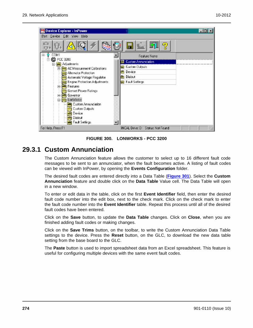
29. Network Applications 10-2012
FIGURE 300. LONWORKS - PCC 3200
29.3.1 Custom AnnunciationThe Custom Annunciation feature allows the customer to select up to 16 different fault codemessages to be sent to an annunciator, when the fault becomes active. A listing of fault codescan be viewed with InPower, by opening the Events Configuration folder.
The desired fault codes are entered directly into a Data Table (Figure 301). Select the CustomAnnunciation feature and double click on the Data Table Value cell. The Data Table will openin a new window.
To enter or edit data in the table, click on the first Event Identifier field, then enter the desiredfault code number into the edit box, next to the check mark. Click on the check mark to enterthe fault code number into the Event Identifier table. Repeat this process until all of the desiredfault codes have been entered.
Click on the Save button, to update the Data Table changes. Click on Close, when you arefinished adding fault codes or making changes.
Click on the Save Trims button, on the toolbar, to write the Custom Annunciation Data Tablesettings to the device. Press the Reset button, on the GLC, to download the new data tablesetting from the base board to the GLC.
The Paste button is used to import spreadsheet data from an Excel spreadsheet. This feature isuseful for configuring multiple devices with the same event fault codes.
274 901-0110 (Issue 10)
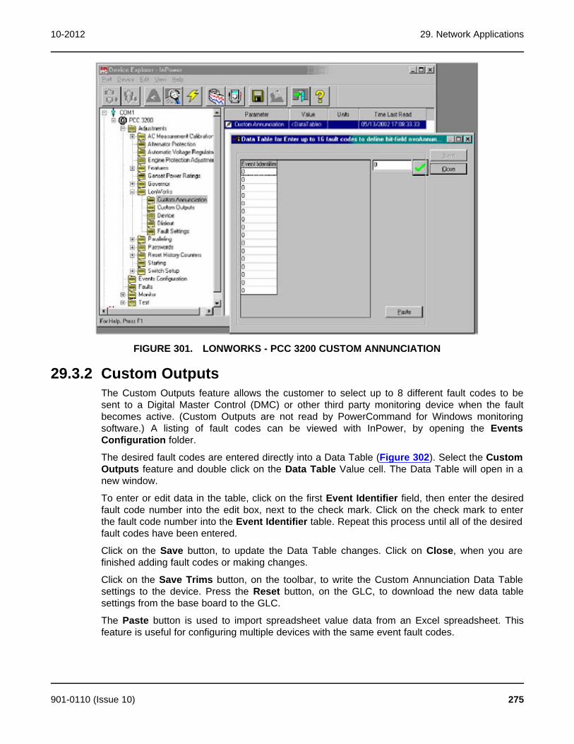
10-2012 29. Network Applications
FIGURE 301. LONWORKS - PCC 3200 CUSTOM ANNUNCIATION
29.3.2 Custom OutputsThe Custom Outputs feature allows the customer to select up to 8 different fault codes to besent to a Digital Master Control (DMC) or other third party monitoring device when the faultbecomes active. (Custom Outputs are not read by PowerCommand for Windows monitoringsoftware.) A listing of fault codes can be viewed with InPower, by opening the EventsConfiguration folder.
The desired fault codes are entered directly into a Data Table (Figure 302). Select the CustomOutputs feature and double click on the Data Table Value cell. The Data Table will open in anew window.
To enter or edit data in the table, click on the first Event Identifier field, then enter the desiredfault code number into the edit box, next to the check mark. Click on the check mark to enterthe fault code number into the Event Identifier table. Repeat this process until all of the desiredfault codes have been entered.
Click on the Save button, to update the Data Table changes. Click on Close, when you arefinished adding fault codes or making changes.
Click on the Save Trims button, on the toolbar, to write the Custom Annunciation Data Tablesettings to the device. Press the Reset button, on the GLC, to download the new data tablesettings from the base board to the GLC.
The Paste button is used to import spreadsheet value data from an Excel spreadsheet. Thisfeature is useful for configuring multiple devices with the same event fault codes.
901-0110 (Issue 10) 275
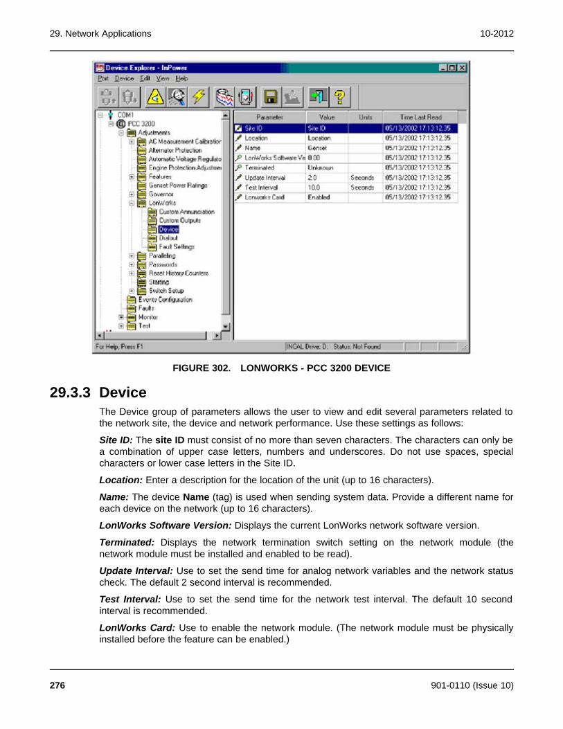
29. Network Applications 10-2012
FIGURE 302. LONWORKS - PCC 3200 DEVICE
29.3.3 DeviceThe Device group of parameters allows the user to view and edit several parameters related tothe network site, the device and network performance. Use these settings as follows:
Site ID: The site ID must consist of no more than seven characters. The characters can only bea combination of upper case letters, numbers and underscores. Do not use spaces, specialcharacters or lower case letters in the Site ID.
Location: Enter a description for the location of the unit (up to 16 characters).
Name: The device Name (tag) is used when sending system data. Provide a different name foreach device on the network (up to 16 characters).
LonWorks Software Version: Displays the current LonWorks network software version.
Terminated: Displays the network termination switch setting on the network module (thenetwork module must be installed and enabled to be read).
Update Interval: Use to set the send time for analog network variables and the network statuscheck. The default 2 second interval is recommended.
Test Interval: Use to set the send time for the network test interval. The default 10 secondinterval is recommended.
LonWorks Card: Use to enable the network module. (The network module must be physicallyinstalled before the feature can be enabled.)
276 901-0110 (Issue 10)
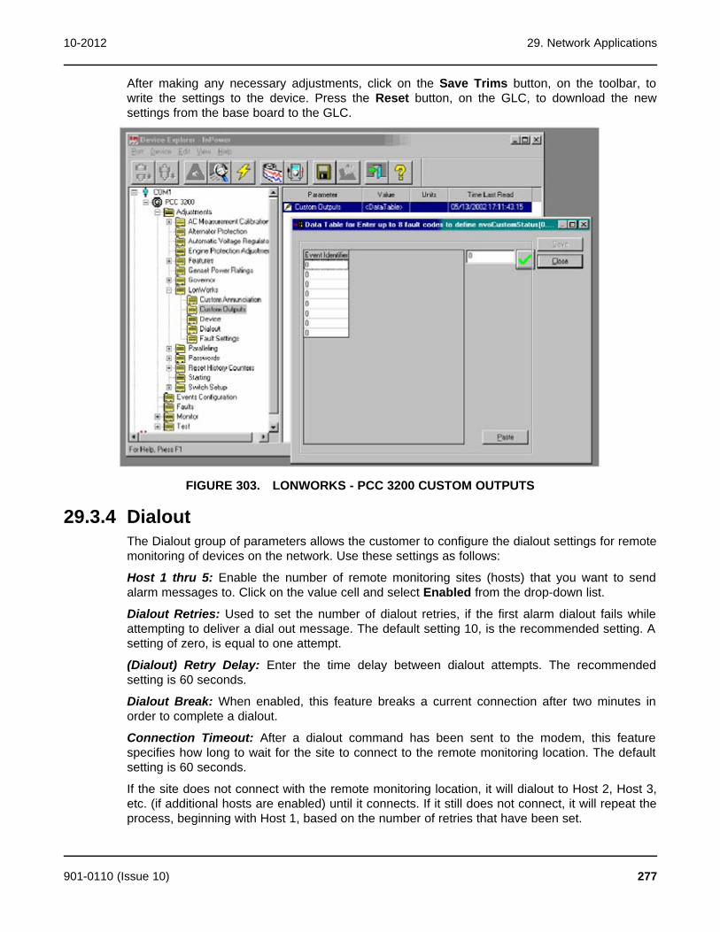
10-2012 29. Network Applications
After making any necessary adjustments, click on the Save Trims button, on the toolbar, towrite the settings to the device. Press the Reset button, on the GLC, to download the newsettings from the base board to the GLC.
FIGURE 303. LONWORKS - PCC 3200 CUSTOM OUTPUTS
29.3.4 DialoutThe Dialout group of parameters allows the customer to configure the dialout settings for remotemonitoring of devices on the network. Use these settings as follows:
Host 1 thru 5: Enable the number of remote monitoring sites (hosts) that you want to sendalarm messages to. Click on the value cell and select Enabled from the drop-down list.
Dialout Retries: Used to set the number of dialout retries, if the first alarm dialout fails whileattempting to deliver a dial out message. The default setting 10, is the recommended setting. Asetting of zero, is equal to one attempt.
(Dialout) Retry Delay: Enter the time delay between dialout attempts. The recommendedsetting is 60 seconds.
Dialout Break: When enabled, this feature breaks a current connection after two minutes inorder to complete a dialout.
Connection Timeout: After a dialout command has been sent to the modem, this featurespecifies how long to wait for the site to connect to the remote monitoring location. The defaultsetting is 60 seconds.
If the site does not connect with the remote monitoring location, it will dialout to Host 2, Host 3,etc. (if additional hosts are enabled) until it connects. If it still does not connect, it will repeat theprocess, beginning with Host 1, based on the number of retries that have been set.
901-0110 (Issue 10) 277

29. Network Applications 10-2012
After making any necessary adjustments, click on the Save Trims button, on the toolbar, towrite the settings to the device. Press the Reset button, on the GLC, to download the new datafrom the base board to the GLC.
FIGURE 304. LONWORKS - PCC 3200 DIALOUT
29.3.5 Fault SettingsThe Fault Settings group allows you to name the network message for Network Faults 1 through4, and view their status. This feature also allows you to assign a fault code to the BatteryCharger AC Failure and S1 Circuit Breaker Trip.
Use these settings as follows:
Network Fault Name 1 thru 4: Allows the user to enter a description for network input faults 1through 4. Double click the value cell and enter the new description. The new name shoulddefine the customer network input such as Open Louvre or Remote Cooling Fan On. This faultname will be displayed when the network input becomes active.
Network Fault Status 1 thru 4: Displays the current status of the network input fault (Active orInactive) for each of the four network faults. Use the Refresh button, on the toolbar, to updatethe value fields.
Battery Charger AC Failure Fault Code: Enter a fault code number for an event related to thisfault. As an example, use fault code 1311 or 1312.
Refer to the Event Configuration folder for fault code descriptions.
Utility Circuit Breaker Trip Fault Code: Enter a fault code number for an event related to thisfault. As an example, for paralleling applications, use fault code 1317 or 1318.
278 901-0110 (Issue 10)
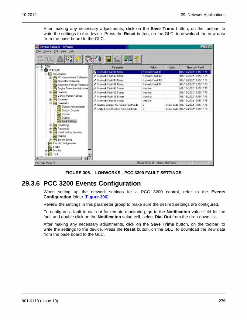
10-2012 29. Network Applications
After making any necessary adjustments, click on the Save Trims button, on the toolbar, towrite the settings to the device. Press the Reset button, on the GLC, to download the new datafrom the base board to the GLC.
FIGURE 305. LONWORKS - PCC 3200 FAULT SETTINGS
29.3.6 PCC 3200 Events ConfigurationWhen setting up the network settings for a PCC 3200 control, refer to the EventsConfiguration folder (Figure 306).
Review the settings in this parameter group to make sure the desired settings are configured.
To configure a fault to dial out for remote monitoring, go to the Notification value field for thefault and double click on the Notification value cell, select Dial Out from the drop-down list.
After making any necessary adjustments, click on the Save Trims button, on the toolbar, towrite the settings to the device. Press the Reset button, on the GLC, to download the new datafrom the base board to the GLC.
901-0110 (Issue 10) 279

29. Network Applications 10-2012
FIGURE 306. PCC 3200 - EVENT CONFIGURATION
29.4 PCC ATSThe LonWorks directory for a typical PowerCommand transfer switch (PCC ATS) contains all ofthe network settings within one folder. (To enable the network feature, use the Feature Enablefolder, in the Adjustments directory.)
Press the Reset button on the NCM, after saving changes to the PCC 2100, to write thechanges from the base board to the NCM.
Start InPower and connect to the port (COM1, COM2, etc.) that matches the COM port on theservice PC, that is being used for the PCC ATS connection.
Open the Adjustments folder, and then the LonWorks folder (Figure 307). This sectiondescribes how to use each of the parameter groups, in the LonWorks directory.
Network Error: Displays the current status of the Network Error fault (Active or Inactive) in theValue field. The Network Error fault signifies that the network is not working when the fault isactive. Use the Refresh button, on the toolbar, to update the value fields.
Network Wink: Use this feature to test a network module. Click on the Value cell and selectActive to send a test signal to the device. The service led will wink when the message isreceived, indicating that the network connection and the network module are working.
Host 1 thru 5: Enable the number of remote monitoring sites (hosts) that you want to sendalarm messages to. Click on the value cell and select Enable from the drop-down list.
Dialout Break: When enabled, this feature breaks the connection after two minutes in order tocomplete a dial out.
Dialout Retries: Used to set the number of dialout retries, if the first alarm dialout fails whileattempting to deliver a dial out message. The default setting 10, is the recommended setting. Asetting of zero, is equal to one attempt.
Dialout Retry Delay: Enter the time delay between dialout attempts. The recommended settingis 60 seconds.
280 901-0110 (Issue 10)
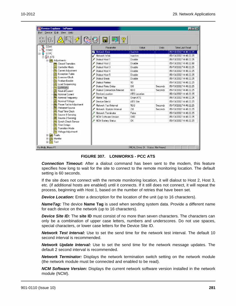
10-2012 29. Network Applications
FIGURE 307. LONWORKS - PCC ATS
Connection Timeout: After a dialout command has been sent to the modem, this featurespecifies how long to wait for the site to connect to the remote monitoring location. The defaultsetting is 60 seconds.
If the site does not connect with the remote monitoring location, it will dialout to Host 2, Host 3,etc. (if additional hosts are enabled) until it connects. If it still does not connect, it will repeat theprocess, beginning with Host 1, based on the number of retries that have been set.
Device Location: Enter a description for the location of the unit (up to 16 characters).
NameTag: The device Name Tag is used when sending system data. Provide a different namefor each device on the network (up to 16 characters).
Device Site ID: The site ID must consist of no more than seven characters. The characters canonly be a combination of upper case letters, numbers and underscores. Do not use spaces,special characters, or lower case letters for the Device Site ID.
Network Test Interval: Use to set the send time for the network test interval. The default 10second interval is recommended.
Network Update Interval: Use to set the send time for the network message updates. Thedefault 2 second interval is recommended.
Network Terminator: Displays the network termination switch setting on the network module(the network module must be connected and enabled to be read).
NCM Software Version: Displays the current network software version installed in the networkmodule (NCM).
901-0110 (Issue 10) 281

29. Network Applications 10-2012
NCM Battery Status: Displays the status (condition) of the batteries supplying voltage to thenetwork module (NCM).
After making any necessary adjustments, click on the Save Trims button, on the toolbar, towrite the settings to the device. Press the Reset button, on the NCM, to download the new datafrom the base board to the NCM.
29.4.1 PCC ATS Event ConfigurationWhen setting up the network settings for a transfer switch, refer to the Event Configurationfolder, in the Faults directory (Figure 308).
Review the last three columns of value settings. Dailout Active needs to be set to True, beforean event will dial out when it goes active. The Dailout Inactive must be set to True, to dial outwhen the event goes Inactive.
FIGURE 308. FAULTS - EVENT CONFIGURATION - PCC ATS
29.5 Network Connection SetupInPower, beginning with version 3.0, can configure devices over an FT-10 network. The servicePC must be setup for connecting to a network and the network must be commissioned andoperating.
The service PC must have LonMaker for Windows version 3.1 installed. This program isavailable from Echelon. The service PC will need a gateway driver (either PCC-10 or SLTA-10,depending on the device being used). Also, a copy of the network site database must beobtained from the network, and installed on the service PC.
This section covers the required service PC setup steps for local and remote networkconnections.
282 901-0110 (Issue 10)

10-2012 29. Network Applications
Familiarity with LonMaker for Windows and the SLTA Link Manager program would be helpfulfor creating a backup of the network site database and for troubleshooting connection problems.This experience can be gained thorough LonMaker for Windows training and from PGA FT-10Networks training.
Install LonMaker for Windows software on the service PC following the instructions provided byEchelon.
· Gateway Driver Installation and Setup
If the network gateway driver, has not already been installed, follow these instructions:
A copy of the SLTA-10 gateway driver is included on the LonMaker for Windows CD. Gatewaydrivers are also available from the Echelon web site at (www.echelong.com). Install the driverthat matches the gateway device type that will be used to connect to the network.
Most applications will use either an SLTA-10 external gateway, or a PCC-10 gateway card, inthe service PC.
In this example the SLTA-10 installation and setup will be described.
1. Locate the SLTA-10 gateway driver on the CD, double click on the slta10....exe file tobegin the driver installation.
2. From the Setup window, select Next to view the license agreement.
3. Review the license agreement and select Yes, to accept the terms of the agreement.
4. In the Choose Destination Location window, select Next, to use the default destination(recommended).
5. In the Select Program Folder window, select Next, to create the program folder.
6. Select No to the option of accessing the file from DOS.
7. Click on the Finish button to complete the installation setup.
29.5.1 Gateway SettingsLaunch the SLTALink Manager from the Start menu (or the taskbar icon ). Click on the Linkmenu and select New. To operate correctly, the name must be entered exactly as shown.
Local Setup: For a local network application, enter a name and type for the link, Name:LocalSLTALON1 and click on the Local button, click on the Update Identifier box to select it,then click on Next (Figure 310).
901-0110 (Issue 10) 283
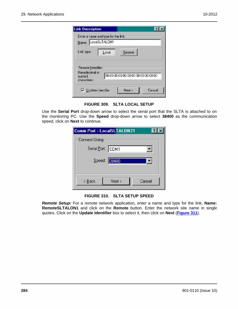
29. Network Applications 10-2012
FIGURE 309. SLTA LOCAL SETUP
Use the Serial Port drop-down arrow to select the serial port that the SLTA is attached to onthe monitoring PC. Use the Speed drop-down arrow to select 38400 as the communicationspeed, click on Next to continue.
FIGURE 310. SLTA SETUP SPEED
Remote Setup: For a remote network application, enter a name and type for the link, Name:RemoteSLTALON1 and click on the Remote button. Enter the network site name in singlequotes. Click on the Update Identifier box to select it, then click on Next (Figure 311).
284 901-0110 (Issue 10)
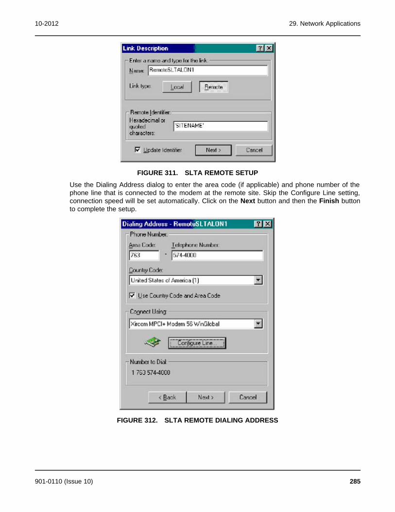
10-2012 29. Network Applications
FIGURE 311. SLTA REMOTE SETUP
Use the Dialing Address dialog to enter the area code (if applicable) and phone number of thephone line that is connected to the modem at the remote site. Skip the Configure Line setting,connection speed will be set automatically. Click on the Next button and then the Finish buttonto complete the setup.
FIGURE 312. SLTA REMOTE DIALING ADDRESS
901-0110 (Issue 10) 285
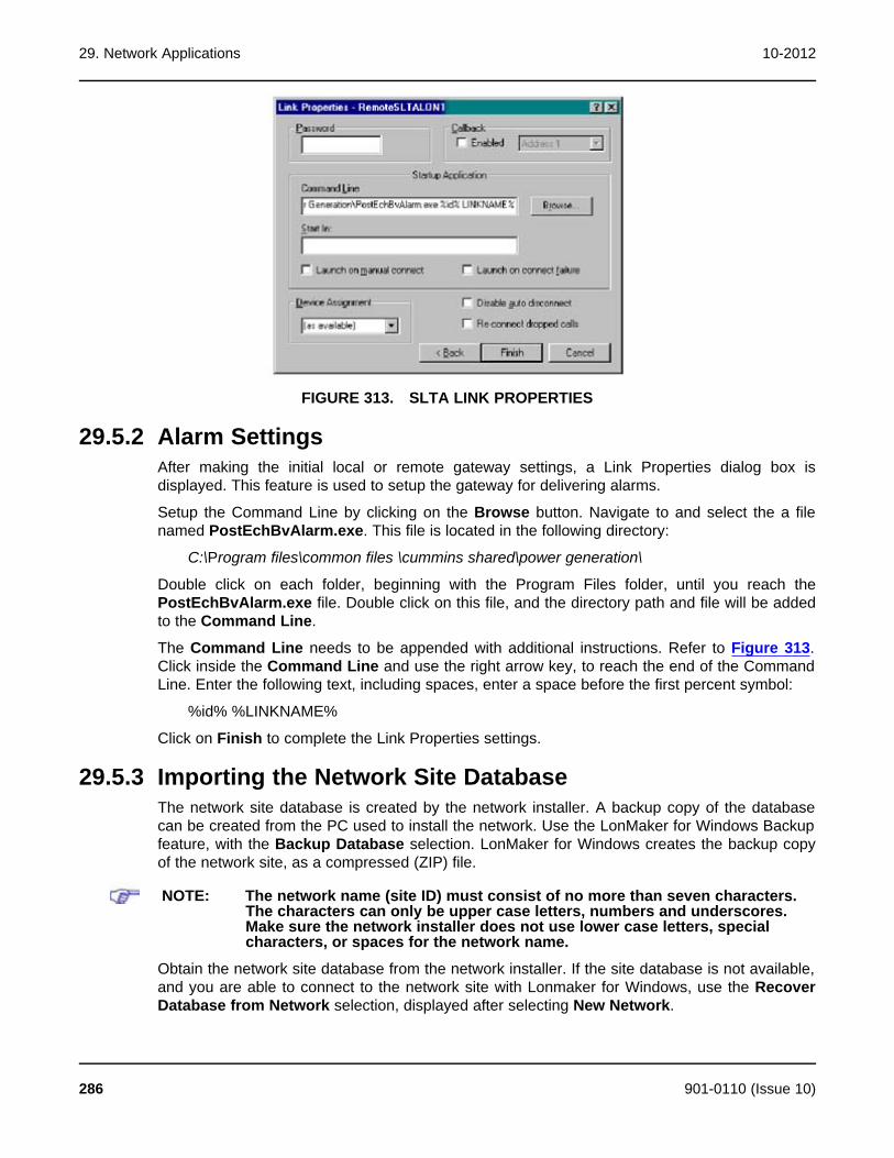
29. Network Applications 10-2012
FIGURE 313. SLTA LINK PROPERTIES
29.5.2 Alarm SettingsAfter making the initial local or remote gateway settings, a Link Properties dialog box isdisplayed. This feature is used to setup the gateway for delivering alarms.
Setup the Command Line by clicking on the Browse button. Navigate to and select the a filenamed PostEchBvAlarm.exe. This file is located in the following directory:
C:\Program files\common files \cummins shared\power generation\
Double click on each folder, beginning with the Program Files folder, until you reach thePostEchBvAlarm.exe file. Double click on this file, and the directory path and file will be addedto the Command Line.
The Command Line needs to be appended with additional instructions. Refer to Figure 313.Click inside the Command Line and use the right arrow key, to reach the end of the CommandLine. Enter the following text, including spaces, enter a space before the first percent symbol:
%id% %LINKNAME%
Click on Finish to complete the Link Properties settings.
29.5.3 Importing the Network Site DatabaseThe network site database is created by the network installer. A backup copy of the databasecan be created from the PC used to install the network. Use the LonMaker for Windows Backupfeature, with the Backup Database selection. LonMaker for Windows creates the backup copyof the network site, as a compressed (ZIP) file.
NOTE: The network name (site ID) must consist of no more than seven characters.The characters can only be upper case letters, numbers and underscores.Make sure the network installer does not use lower case letters, specialcharacters, or spaces for the network name.
Obtain the network site database from the network installer. If the site database is not available,and you are able to connect to the network site with Lonmaker for Windows, use the RecoverDatabase from Network selection, displayed after selecting New Network.
286 901-0110 (Issue 10)
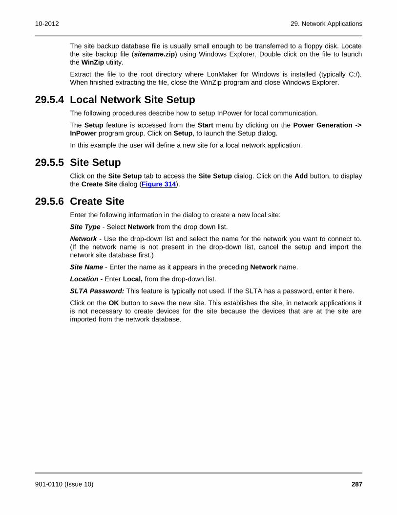
10-2012 29. Network Applications
The site backup database file is usually small enough to be transferred to a floppy disk. Locatethe site backup file (sitename.zip) using Windows Explorer. Double click on the file to launchthe WinZip utility.
Extract the file to the root directory where LonMaker for Windows is installed (typically C:/).When finished extracting the file, close the WinZip program and close Windows Explorer.
29.5.4 Local Network Site SetupThe following procedures describe how to setup InPower for local communication.
The Setup feature is accessed from the Start menu by clicking on the Power Generation ->InPower program group. Click on Setup, to launch the Setup dialog.
In this example the user will define a new site for a local network application.
29.5.5 Site SetupClick on the Site Setup tab to access the Site Setup dialog. Click on the Add button, to displaythe Create Site dialog (Figure 314).
29.5.6 Create SiteEnter the following information in the dialog to create a new local site:
Site Type - Select Network from the drop down list.
Network - Use the drop-down list and select the name for the network you want to connect to.(If the network name is not present in the drop-down list, cancel the setup and import thenetwork site database first.)
Site Name - Enter the name as it appears in the preceding Network name.
Location - Enter Local, from the drop-down list.
SLTA Password: This feature is typically not used. If the SLTA has a password, enter it here.
Click on the OK button to save the new site. This establishes the site, in network applications itis not necessary to create devices for the site because the devices that are at the site areimported from the network database.
901-0110 (Issue 10) 287
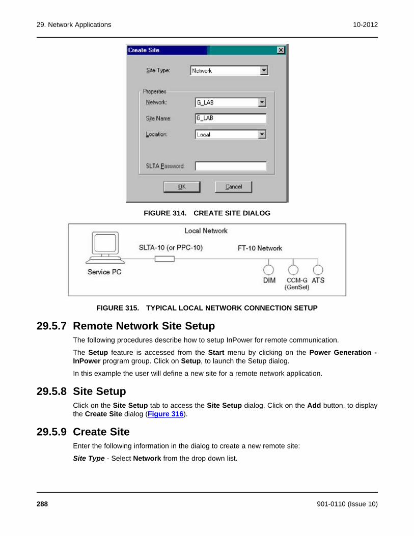
29. Network Applications 10-2012
FIGURE 314. CREATE SITE DIALOG
FIGURE 315. TYPICAL LOCAL NETWORK CONNECTION SETUP
29.5.7 Remote Network Site SetupThe following procedures describe how to setup InPower for remote communication.
The Setup feature is accessed from the Start menu by clicking on the Power Generation -InPower program group. Click on Setup, to launch the Setup dialog.
In this example the user will define a new site for a remote network application.
29.5.8 Site SetupClick on the Site Setup tab to access the Site Setup dialog. Click on the Add button, to displaythe Create Site dialog (Figure 316).
29.5.9 Create SiteEnter the following information in the dialog to create a new remote site:
Site Type - Select Network from the drop down list.
288 901-0110 (Issue 10)
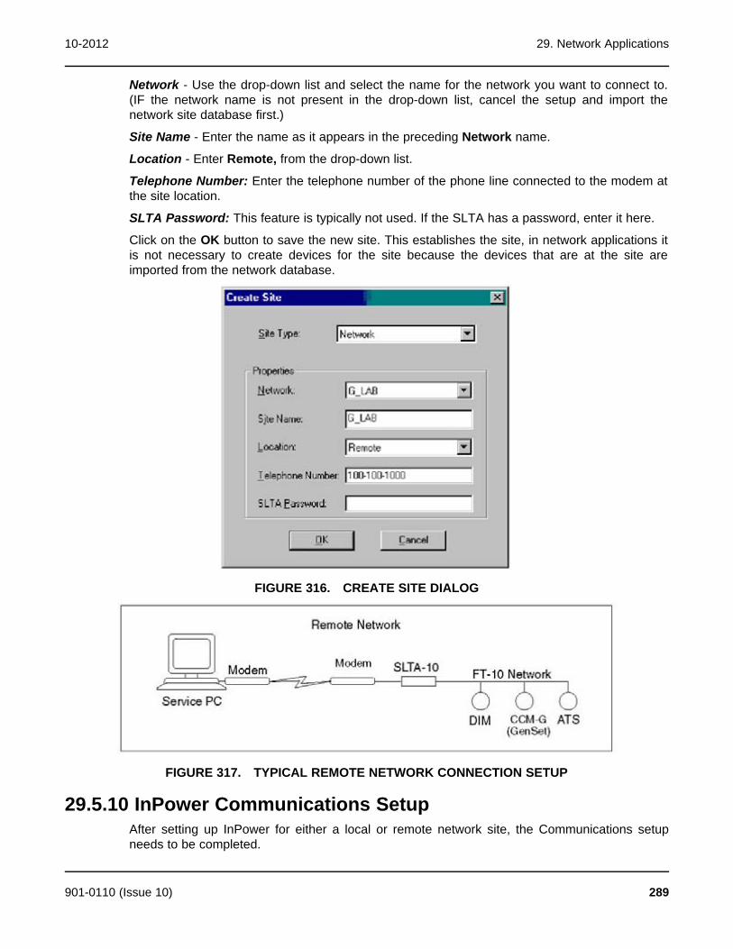
10-2012 29. Network Applications
Network - Use the drop-down list and select the name for the network you want to connect to.(IF the network name is not present in the drop-down list, cancel the setup and import thenetwork site database first.)
Site Name - Enter the name as it appears in the preceding Network name.
Location - Enter Remote, from the drop-down list.
Telephone Number: Enter the telephone number of the phone line connected to the modem atthe site location.
SLTA Password: This feature is typically not used. If the SLTA has a password, enter it here.
Click on the OK button to save the new site. This establishes the site, in network applications itis not necessary to create devices for the site because the devices that are at the site areimported from the network database.
FIGURE 316. CREATE SITE DIALOG
FIGURE 317. TYPICAL REMOTE NETWORK CONNECTION SETUP
29.5.10 InPower Communications SetupAfter setting up InPower for either a local or remote network site, the Communications setupneeds to be completed.
901-0110 (Issue 10) 289

29. Network Applications 10-2012
Click on the Communications setup tab, then establish a Lon Network Connection for Local orRemote, or both if you plan to make local and remote network connections.
Local: Click on the drop-down arrow and select SLTALON1 from the list (or use PCCLON1 ifusing PCC-10 card). Click on the Apply button (Figure 318).
Remote: Click on the drop-down arrow and select SLTALON1 from the list (or use PCCLON1 ifusing PCC-10 card). Click on the Apply button.
Click on the OK button when finished.
FIGURE 318. NETWORK COMMUNICATION SETUP
29.6 Network Connection ExampleStart InPower and connect to the port (typically the site name created in Site Setup). All of thedevices on the network will be displayed in the Device Explorer directory (Figure 319).
If the connection is not made, check the SLTALink Manager, to view the status of theconnection of the service PC to the gateway. Launch the SLTALink Manager from the Echelonfolder in the Start - Programs menu, or from the Taskbar.
If the service PC is not connected to the gateway, select the gateway device from theSelect/Action menu pick, in the Link menu, and click on the Connect Now button.
If the gateway is connected, and the network site still does not open, make sure the network isoperating. It may be necessary to resynchronize the network using LonMaker for Windows.
In this example, the network settings for the Controls Communication Module - Genset (CCM-G)are accessed over the network. Open the Adjustments folder, and then open the Networkfolder (Figure 320).
This section describes how to use each of the adjustable parameters, in the CCM-G Networkdirectory.
290 901-0110 (Issue 10)

10-2012 29. Network Applications
Network Wink: Use this feature to test a network module. Click on the Value cell and selectActive to send a test signal to the device. The service led will wink when the message isreceived, indicating that the network connection and the network module are working.
InPower Timeout: If displayed, do not adjust, this parameter will be removed.
Site ID: The site ID must consist of no more than seven characters. The characters can only bea combination of upper case letters, numbers and underscores. Do not use spaces, specialcharacters, or lower case letters for the Device Site ID.
Device Name Tag: The Device Name Tag is used when sending system data. Provide adifferent name for each device on the network (up to 16 characters).
(Network) Test Interval: Use to set the send time for the network test interval. The default 10second interval is recommended.
Minimum Send Time: Use to set the send time for the analog data network variables. Thedefault 2 second interval is recommended.
Network Configuration: Displays the device network application. Self installed devices readLocal (factory default) and are not available to InPower for adjustment or monitoring. Devicesthat are self installed are configured using the dip switches on the device.
When the self-installed feature is not used, the configuration is External and the device isavailable to InPower.
After making any necessary adjustments, click on the Save Trims button, on the toolbar, towrite the settings to the device.
FIGURE 319. NETWORK CONNECTION
901-0110 (Issue 10) 291
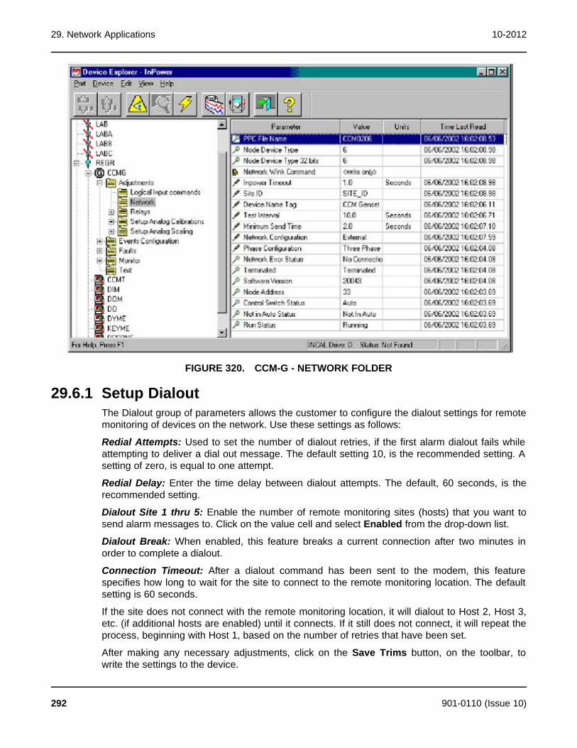
29. Network Applications 10-2012
FIGURE 320. CCM-G - NETWORK FOLDER
29.6.1 Setup DialoutThe Dialout group of parameters allows the customer to configure the dialout settings for remotemonitoring of devices on the network. Use these settings as follows:
Redial Attempts: Used to set the number of dialout retries, if the first alarm dialout fails whileattempting to deliver a dial out message. The default setting 10, is the recommended setting. Asetting of zero, is equal to one attempt.
Redial Delay: Enter the time delay between dialout attempts. The default, 60 seconds, is therecommended setting.
Dialout Site 1 thru 5: Enable the number of remote monitoring sites (hosts) that you want tosend alarm messages to. Click on the value cell and select Enabled from the drop-down list.
Dialout Break: When enabled, this feature breaks a current connection after two minutes inorder to complete a dialout.
Connection Timeout: After a dialout command has been sent to the modem, this featurespecifies how long to wait for the site to connect to the remote monitoring location. The defaultsetting is 60 seconds.
If the site does not connect with the remote monitoring location, it will dialout to Host 2, Host 3,etc. (if additional hosts are enabled) until it connects. If it still does not connect, it will repeat theprocess, beginning with Host 1, based on the number of retries that have been set.
After making any necessary adjustments, click on the Save Trims button, on the toolbar, towrite the settings to the device.
292 901-0110 (Issue 10)

10-2012 29. Network Applications
In this example, InPower is connected to an Annunciator over the network. Open theAdjustments folder, and then open the Setup LED's and Horn folder (Figure 322).
The LED Index (number) for each LED is listed in the first column. The Color, Horn and Flashcolumns are all adjustable to the desired type of annunciation. The Status column indicates ifthe input is active.
To change the setting for the color, the horn or to enable the LED flash setting, Click on thevalue cell for the desired item. The item selected will be displayed in the edit box, in the upperright of the dialog. Click on the drop-down arrow and a list of the choices will be displayed. Clickon the desired option. Click on the check mark to enter the selection in the Data Table. Repeatthis process until all of the desired settings have been chosen.
Click on the Save button, to update the Data Table changes. Click on Close, when you arefinished adding fault codes or making changes.
After making any necessary adjustments, click on the Save Trims button, on the toolbar, towrite the settings to the device.
FIGURE 321. CCM-G - SETUP DIALOUT
901-0110 (Issue 10) 293
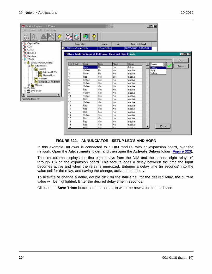
29. Network Applications 10-2012
FIGURE 322. ANNUNCIATOR - SETUP LED'S AND HORN
In this example, InPower is connected to a DIM module, with an expansion board, over thenetwork. Open the Adjustments folder, and then open the Activate Delays folder (Figure 323).
The first column displays the first eight relays from the DIM and the second eight relays (9through 16) on the expansion board. This feature adds a delay between the time the inputbecomes active and when the relay is energized. Entering a delay time (in seconds) into thevalue cell for the relay, and saving the change, activates the delay.
To activate or change a delay, double click on the Value cell for the desired relay, the currentvalue will be highlighted. Enter the desired delay time in seconds.
Click on the Save Trims button, on the toolbar, to write the new value to the device.
294 901-0110 (Issue 10)

10-2012 29. Network Applications
FIGURE 323. DIM - ACTIVATE DELAYS
901-0110 (Issue 10) 295

29. Network Applications 10-2012
This page is intentionally blank.
296 901-0110 (Issue 10)
30 HelpUse the Help menu to find information about using InPower, to find Service and Supportinformation, and to find out about the installed InPower product type and software version.
30.1 Search for Help On...The Help - Search for Help On... feature allows searching for help on a specific topic or keyword(standard Windows Help format). Access this feature by clicking on the Help menu, then click onSearch for Help On... .
30.2 ContentsThe Help - Contents feature provides access to the list of subjects in the InPower help file(standard Windows Help format). Access this information by clicking on the Help menu and thenclicking on Contents.
30.3 How to Use HelpThe Help - How to Use Help feature displays the standard Windows Help Topics dialog. Usethis feature to find answers to basic Windows operation questions. Access this information byclicking on the Help menu, and then click on How to Use Help.
30.4 Service and SupportThe Help - Service and Support feature lists information about where to call for InPower productsupport. To view this information, click on the Help menu, then click on Service and Support.
30.5 About Device ExplorerThe Help - About... feature initiates the About Device Explorer box. This box displays theproduct type and software version. The expiration date for the software is also shown. To viewthis information, click on the Help menu, and then click on About....
901-0110 (Issue 10) 297

30. Help 10-2012
This page is intentionally blank.
298 901-0110 (Issue 10)
31 GlossaryApplet - A sub-set of software functions that may be included in one or more Tools. Theyprovide the building-blocks from which the Tools are constructed.
ATS -Acronym for Automatic Transfer Switch.
Automatic Voltage Regulator (AVR) -An electronic unit used to control the output voltage of agenset.
BIT -Acronym for Built-in Test.
Calibrating -The process of reprogramming a device. This requires the ESDN version ofInPower.
Calibration -Term used to describe the program and factory settings for a device.
Calibration Table -Name used to refer to a Data Table, XY Table, or XYZ Table that containsone or more calibration variables.
Calibration Variable -Data that is stored in the controller's non-volatile memory, and which maynot be altered after sale by either a customer or service technician.
Capture File -A capture (.cap) file contains all of the trim values, monitor values, and tablevalues of a given device (e.g. Generator set). This file can be thought of as a “template” forconfiguring other devices of the same type, or it can be used as a backup file.
Channel - A channel is the physical communication media that connects the devices and theproperties of these media (such as transmission speed).
CSV File - Comma Separated Value file (same as a comma delimited file). The file format usedby InPower to save datalog information. Allows the file to imported into Microsoft Excel.
Data Table -Data table is a structure containing a variable in each of the columns. The datacells are viewed and edited in spreadsheet format.
Device -As used in InPower, refers to any one of a series of application controllers used inPower Generation applications. These include: Generator-drive engine controllers, Gensetcontrollers and Automatic Transfer Switch controllers.
Electronic Control Module (ECM) -The hardware residing on an engine which carries out allthe engine management functions (e.g. timing, fueling).
Electronic Software Database & Network (ESDN) -A worldwide Cummins corporate databaseof released electronic software. It provides calibration files reprogramming devices.
Genset Open Architecture Link (GOAL) -A proprietary protocol developed by PGG to supportthe communications functions of Power Generation Group controls.
Graphical User Interface (GUI) -A term used to describe the way in which a user interacts withthe software program.
HBF -Acronym for High Blowby Flow.
Initial Calibration -Manually select software to download.
InPower -Name given to the Power Generation Products based service tool. This tool is similarto INSITE in function, but it has a significantly different architecture.
MON -A communications protocol for one device connected to the service tool using RS-485and RS-232 serial communications. All devices can communicate with the service tool.
901-0110 (Issue 10) 299

31. Glossary 10-2012
MONNet -A communications protocol for more than one device connected to the service toolusing RS-485 communications only.
Network Connection -This term is used to describe a connection using the MONNet protocoland an RS-485 adapter.
Parameter - This term is used with InPower to refer to properties whose values determine thebehavior of a device. With InPower there are two main types of properties; trims that have arange of numeric values, and settings that consist of a small number of predefined values suchas On or Off.
Physical Connection -This term is used to describe a connection using the MON protocol andno RS-485 adapter.
Port -As used in InPower, it refers to the channel by which a connection can occur. Portconnections can occur with COM ports, or with Simulator or Capture files in the InPowerdirectory structure.
PowerCommand® Control (PCC) -A microprocessor based genset monitoring, metering andcontrol system with integrated AVR and engine governing.
Protocol -Protocol is a language that each node on a network knows how to speak andinterpret. The protocol is what allows devices to exchange messages with one another.
Save Trims -Term used with InPower to indicate the process of permanently storing parameterchanges to a device.
Site -The name of a connection setup (COM1, COM2, etc).
TAPI (Telephony API) -A programming interface that allows Windows client applications toaccess voice services on a server. Designed to provide interoperability between PCs andtelephone equipment.
Template -1. View template in InPower describes how to display data table information. 2.Template can also describe the Capture (.CAP) file that contains trim values that can be used toconfigure multiple-devices (e.g. genset controllers).
Tool -A set (or bundle) of software applets that are targeted at a specific customer or end-userfunction.
Trim -Data that is stored in the controller's non-volatile memory, but which may be altered aftersale by either a customer or service technician.
Update Calibration -Automatically updates software, saves user information, and transfers to anew control.
Volatile/Non-volatile Memory -The contents of volatile memory is lost following a loss of powerto the controller. Data stored in non-volatile memory is retained.
300 901-0110 (Issue 10)

32 Adjustment and Test DescriptionsThis section describes the engine adjustment features followed by the engine test and faultsimulation features.
32.1 Engine Protection Adjustments32.1.1 Feature Description
This feature allows the user to configure engine protection thresholds within pre-programmedlimits. The tool will only allow for adjustments that result in increased engine protection.
The engine protections designated with a single asterisk (*) are not available on QSX15 modelengines. The engine protections designated with a double asterisk (**) are not available on theQSX15, QSK23 or QST30 model engines.
32.1.2 Adjustable ParametersName: Engine Cold Warning Threshold
Range: Degrees
Description: The tool allows the user to increase the threshold for Low Engine CoolantTemperature Warning for when the engine is not running. This threshold is used to activate faultcode 1435.
Name: LOP Warning Threshold Table
Range: PSI Table
Description: The tool allows the user to increase the threshold for Low Oil Pressure Warning.This threshold is used to activate fault code 143.
Name: LOP Shutdown Threshold Table
Range: PSI Table
Description: The tool allows the user to increase the threshold for Low Oil Pressure Shutdown.This threshold is used to activate fault code 415.
Name: HOT Warning Threshold
Range: Degrees
Description: The tool allows the user to decrease the threshold for High Oil TemperatureWarning. This threshold is used to activate fault code 421.
Name: HOT Shutdown Threshold
Range: Degrees
901-0110 (Issue 10) 301

32. Adjustment and Test Descriptions 10-2012
Description: The tool allows the user to decrease the threshold for High Oil TemperatureShutdown. This threshold is used to activate fault code 214.
Name: LCL Warning Threshold
Range: Seconds
Description: The tool allows the user to decrease the time threshold for Low Coolant LevelWarning. This threshold is used to activate fault code 197.
Name: LCL Shutdown Threshold
Range: Seconds
Description: The tool allows the user to decrease the time threshold for Low Coolant LevelShutdown. This threshold is used to activate fault code 235.
Name: LCL Fault Response
Range: Shutdown/Warning
Description: This parameter allows the user to change the response to the Low Coolant Levelswitch.
Name: LCP Warning Threshold Table *
Range: PSI Table
Description: The tool allows the user to increase the threshold for Low Coolant PressureWarning. This threshold is used to activate fault code 233.
Name: LCP Shutdown Threshold Table *
Range: PSI Table
Description: The tool allows the user to increase the threshold for Low Coolant PressureShutdown. This threshold is used to activate fault code 228.
Name: LCT Warning Threshold
Range: Degrees
Description: The tool allows the user to increase the threshold for Low Engine CoolantTemperature Warning for when the engine is running. This threshold is used to activate faultcode 152.
Name: HCT Warning Threshold
Range: Degrees
Description: The tool allows the user to decrease the threshold for High Coolant TemperatureWarning. This threshold is used to activate fault code 146.
302 901-0110 (Issue 10)

10-2012 32. Adjustment and Test Descriptions
Name: HCT Shutdown Threshold
Range: Degrees
Description: The tool allows the user to decrease the threshold for High Coolant TemperatureShutdown. This threshold is used to activate fault code 151.
Name: HBF Warning Threshold Table **
Range: CFM Table
Description: The tool allows the user to decrease the threshold for High Crankcase Blowby FlowWarning. This threshold is used to activate fault code 555.
Name: HBF Shutdown Threshold Table **
Range: CFM Table
Description: The tool allows the user to decrease the threshold for High Crankcase Blowby FlowShutdown. This threshold is used to activate fault code 556.
Name: HFT Warning Threshold *
Range: Degrees
Description: The tool allows the user to decrease the threshold for High Fuel TemperatureWarning. This threshold is used to activate fault code 261.
Name: HFT Shutdown Threshold *
Range: Degrees
Description: The tool allows the user to decrease the threshold for High Fuel TemperatureShutdown. This threshold is used to activate fault code 266.
Name: HAT Warning Threshold **
Range: Degrees
Description: The tool allows the user to decrease the threshold for High Aftercooler WaterTemperature Warning. This threshold is used to activate fault code 2113.
Name: HAT Shutdown Threshold**
Range: Degrees
Description: The tool allows the user to decrease the threshold for High Aftercooler WaterTemperature Shutdown. This threshold is used to activate fault code 2114.
Name: HIT Warning Threshold
Range: Degrees
901-0110 (Issue 10) 303

32. Adjustment and Test Descriptions 10-2012
Description: The tool allows the user to decrease the threshold for High Intake ManifoldTemperature Warning. This threshold is used to activate fault code 488.
Name: HIT Shutdown Threshold
Range: Degrees
Description: The tool allows the user to decrease the threshold for High Intake ManifoldTemperature Shutdown. This threshold is used to activate fault code 155.
Name: Overspeed Shutdown Threshold
Range: RPM
Description: The tool allows the user to decrease the Engine Overspeed Threshold Shutdown.This threshold is used to activate fault code 234.
Name: Overspeed Shutdown Threshold (50Hz) (QSK50 and QSK60)
Range: RPM
Description: The tool allows the user to decrease the Engine Overspeed Threshold Shutdown.This threshold is used to activate fault code 234.
Name: Overspeed Shutdown Threshold (60Hz) (QSK50 and QSK60)
Range: RPM
Description: The tool allows the user to decrease the Engine Overspeed Threshold Shutdown.This threshold is used to activate fault code 234.
32.1.3 Interaction with other Features and ParametersThe Engine Protection Adjustments can also be viewed and adjusted using the Test – FaultSimulation – Engine Protection Test feature.
32.1.4 Special InstructionsWhen the engine coolant temperature is less than the LCT Warning Threshold when the engineis running, a Common Warning will be activated to signal that a Low Coolant Temperaturecondition exists.
The Engine Cold Warning Threshold is intended for use when block heaters are installed. Whenthe engine coolant temperature is less than the Engine Cold Warning Threshold prior to startingthe engine, a Common Warning will be activated to signal that an Engine Cold Warningcondition exists.
32.1.5 Possible Customer ComplaintsSetting the Engine Cold Warning Threshold at too high a level can cause nuisance Engine ColdWarning faults. The customer is responsible for properly setting the Engine Cold WarningThreshold at the proper level, dependent upon whether block heaters are used.
304 901-0110 (Issue 10)
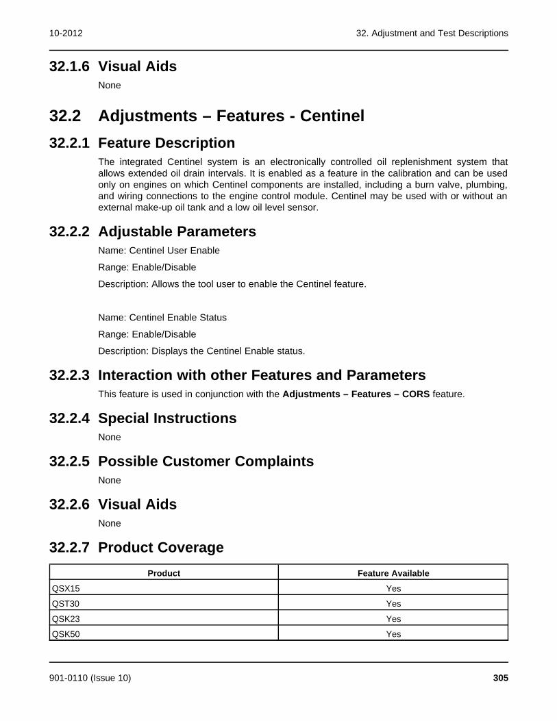
10-2012 32. Adjustment and Test Descriptions
32.1.6 Visual AidsNone
32.2 Adjustments – Features - Centinel32.2.1 Feature Description
The integrated Centinel system is an electronically controlled oil replenishment system thatallows extended oil drain intervals. It is enabled as a feature in the calibration and can be usedonly on engines on which Centinel components are installed, including a burn valve, plumbing,and wiring connections to the engine control module. Centinel may be used with or without anexternal make-up oil tank and a low oil level sensor.
32.2.2 Adjustable ParametersName: Centinel User Enable
Range: Enable/Disable
Description: Allows the tool user to enable the Centinel feature.
Name: Centinel Enable Status
Range: Enable/Disable
Description: Displays the Centinel Enable status.
32.2.3 Interaction with other Features and ParametersThis feature is used in conjunction with the Adjustments – Features – CORS feature.
32.2.4 Special InstructionsNone
32.2.5 Possible Customer ComplaintsNone
32.2.6 Visual AidsNone
32.2.7 Product CoverageProduct Feature Available
QSX15 Yes
QST30 Yes
QSK23 Yes
QSK50 Yes
901-0110 (Issue 10) 305
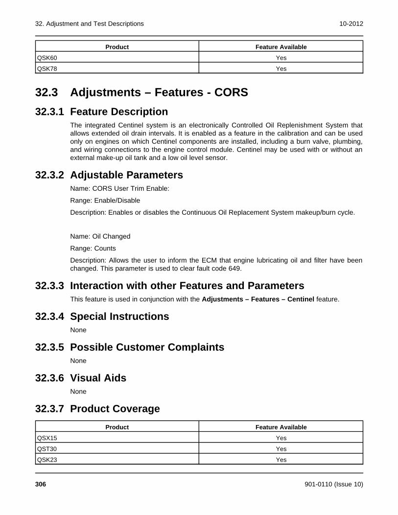
32. Adjustment and Test Descriptions 10-2012
Product Feature Available
QSK60 Yes
QSK78 Yes
32.3 Adjustments – Features - CORS32.3.1 Feature Description
The integrated Centinel system is an electronically Controlled Oil Replenishment System thatallows extended oil drain intervals. It is enabled as a feature in the calibration and can be usedonly on engines on which Centinel components are installed, including a burn valve, plumbing,and wiring connections to the engine control module. Centinel may be used with or without anexternal make-up oil tank and a low oil level sensor.
32.3.2 Adjustable ParametersName: CORS User Trim Enable:
Range: Enable/Disable
Description: Enables or disables the Continuous Oil Replacement System makeup/burn cycle.
Name: Oil Changed
Range: Counts
Description: Allows the user to inform the ECM that engine lubricating oil and filter have beenchanged. This parameter is used to clear fault code 649.
32.3.3 Interaction with other Features and ParametersThis feature is used in conjunction with the Adjustments – Features – Centinel feature.
32.3.4 Special InstructionsNone
32.3.5 Possible Customer ComplaintsNone
32.3.6 Visual AidsNone
32.3.7 Product CoverageProduct Feature Available
QSX15 Yes
QST30 Yes
QSK23 Yes
306 901-0110 (Issue 10)

10-2012 32. Adjustment and Test Descriptions
Product Feature Available
QSK50 Yes
QSK60 Yes
QSK78 Yes
32.4 Adjustments – Features – Fuel Lift Pump32.4.1 Feature Description
The fuel lift pump is an electric pump that is controlled by the ECM. The Pre-Start Primingfeature of the GCS provides a means to prime the fuel system prior to starting the engine. Whenthe Pre-Start Priming feature is enabled, the fuel lift pump will start the priming cycle. It beginsto pump fuel when either the Run/Stop switch changes from “Stop" to “Run" or when the Crankswitch input becomes active, and runs for a specified period of time prior to engaging thestarting system.
32.4.2 Adjustable ParametersName: Pre-start priming enable
Range: Enable/Disable
Description: The tool allows the user to Enable or Disable the Pre-Start priming pump.
Name: Pre-Start Priming Function Complete
Range: True/False
Description: The tool allows the user to monitor the Pre-Start Priming function state.
Name: Pre-Start Fuel Priming Time
Range: Seconds
Description: The tool allows the user to set the amount of time that the fuel lift pump will runprior to the starting system engagement.
Name: Fuel Lift Pump Relay Driver Command
Range: On/Off
Description: The tool allows the user to monitor the electric lift pump driver command.
32.4.3 Interaction with other Features and ParametersNone
32.4.4 Special InstructionsNone
901-0110 (Issue 10) 307

32. Adjustment and Test Descriptions 10-2012
32.4.5 Possible Customer ComplaintsNone
32.4.6 Visual AidsNone
32.4.7 Product CoverageProduct Feature Available
QSX15 No
QST30 Yes
QSK23 No
QSK50 No
QSK60 No
QSK78 No
32.5 Adjustments - Features - Inputs32.5.1 Feature Description
This feature allows the tool user to enable/disable and monitor OEM inputs to the ECM.
32.5.2 Adjustable ParametersName: Frequency Adjust Pot Enable
Range: Enable/Disable
Description: When enabled, the ECM is looking for the potentiometers input for frequencyadjust. If this parameter is enabled and no potentiometer is connected to the ECM then faultcode 1411 will become active.
Name: Frequency Adjust Pot
Range: Hertz
Description: The tool displays the position of the Frequency Adjust potentiometer in Hertz.
Name: Droop Adjust Select
Range: Trim/Pot
Description: The tool allows the user to select between the service tool Trim or thepotentiometer. If a potentiometer is used, the signal input must be enabled after the “Pot"selection is set-up.
Name: Droop Adjust Pot Enable
308 901-0110 (Issue 10)
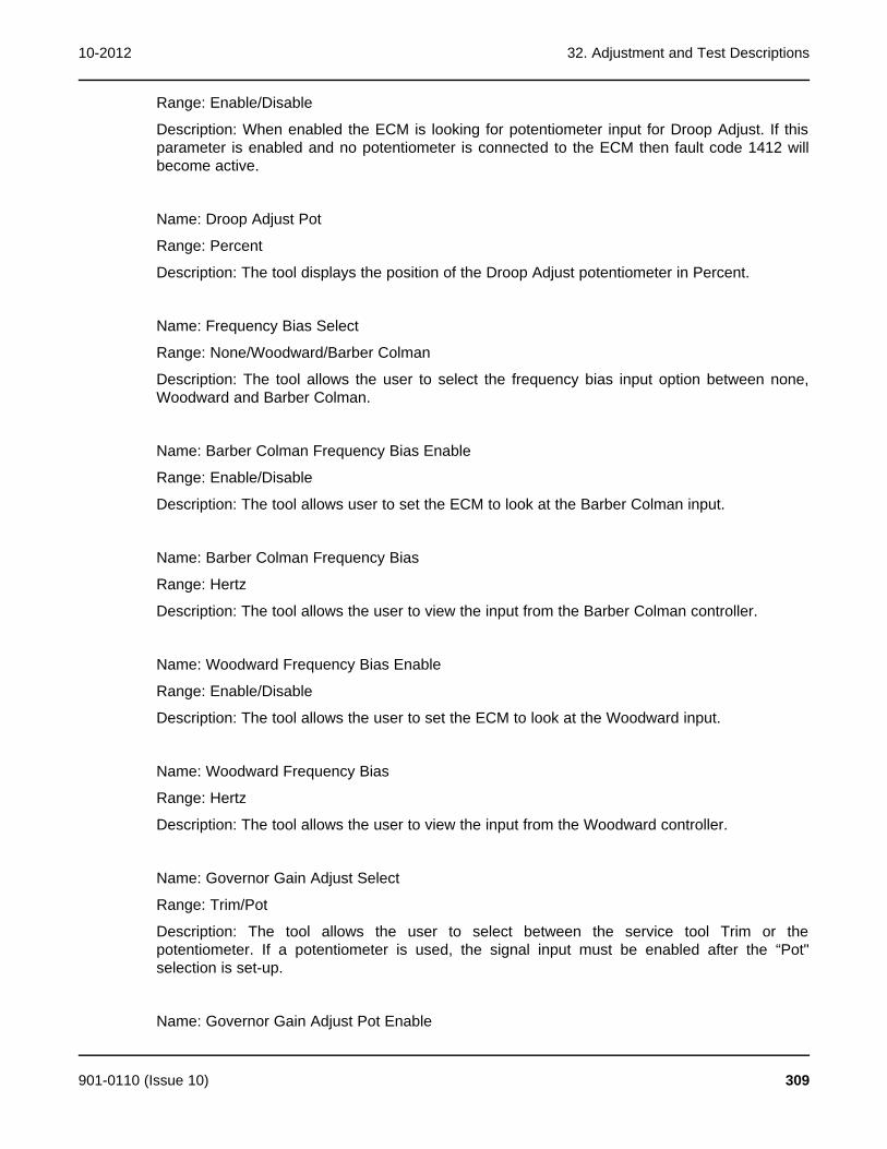
10-2012 32. Adjustment and Test Descriptions
Range: Enable/Disable
Description: When enabled the ECM is looking for potentiometer input for Droop Adjust. If thisparameter is enabled and no potentiometer is connected to the ECM then fault code 1412 willbecome active.
Name: Droop Adjust Pot
Range: Percent
Description: The tool displays the position of the Droop Adjust potentiometer in Percent.
Name: Frequency Bias Select
Range: None/Woodward/Barber Colman
Description: The tool allows the user to select the frequency bias input option between none,Woodward and Barber Colman.
Name: Barber Colman Frequency Bias Enable
Range: Enable/Disable
Description: The tool allows user to set the ECM to look at the Barber Colman input.
Name: Barber Colman Frequency Bias
Range: Hertz
Description: The tool allows the user to view the input from the Barber Colman controller.
Name: Woodward Frequency Bias Enable
Range: Enable/Disable
Description: The tool allows the user to set the ECM to look at the Woodward input.
Name: Woodward Frequency Bias
Range: Hertz
Description: The tool allows the user to view the input from the Woodward controller.
Name: Governor Gain Adjust Select
Range: Trim/Pot
Description: The tool allows the user to select between the service tool Trim or thepotentiometer. If a potentiometer is used, the signal input must be enabled after the “Pot"selection is set-up.
Name: Governor Gain Adjust Pot Enable
901-0110 (Issue 10) 309
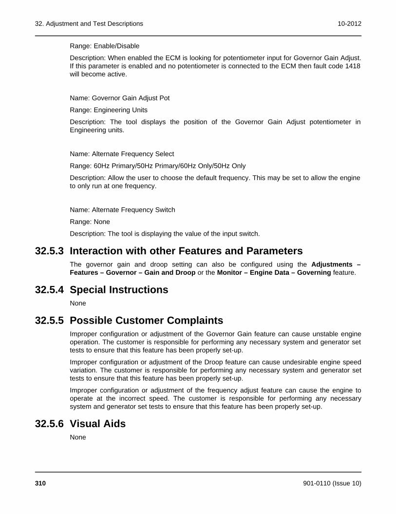
32. Adjustment and Test Descriptions 10-2012
Range: Enable/Disable
Description: When enabled the ECM is looking for potentiometer input for Governor Gain Adjust.If this parameter is enabled and no potentiometer is connected to the ECM then fault code 1418will become active.
Name: Governor Gain Adjust Pot
Range: Engineering Units
Description: The tool displays the position of the Governor Gain Adjust potentiometer inEngineering units.
Name: Alternate Frequency Select
Range: 60Hz Primary/50Hz Primary/60Hz Only/50Hz Only
Description: Allow the user to choose the default frequency. This may be set to allow the engineto only run at one frequency.
Name: Alternate Frequency Switch
Range: None
Description: The tool is displaying the value of the input switch.
32.5.3 Interaction with other Features and ParametersThe governor gain and droop setting can also be configured using the Adjustments –Features – Governor – Gain and Droop or the Monitor – Engine Data – Governing feature.
32.5.4 Special InstructionsNone
32.5.5 Possible Customer ComplaintsImproper configuration or adjustment of the Governor Gain feature can cause unstable engineoperation. The customer is responsible for performing any necessary system and generator settests to ensure that this feature has been properly set-up.
Improper configuration or adjustment of the Droop feature can cause undesirable engine speedvariation. The customer is responsible for performing any necessary system and generator settests to ensure that this feature has been properly set-up.
Improper configuration or adjustment of the frequency adjust feature can cause the engine tooperate at the incorrect speed. The customer is responsible for performing any necessarysystem and generator set tests to ensure that this feature has been properly set-up.
32.5.6 Visual AidsNone
310 901-0110 (Issue 10)
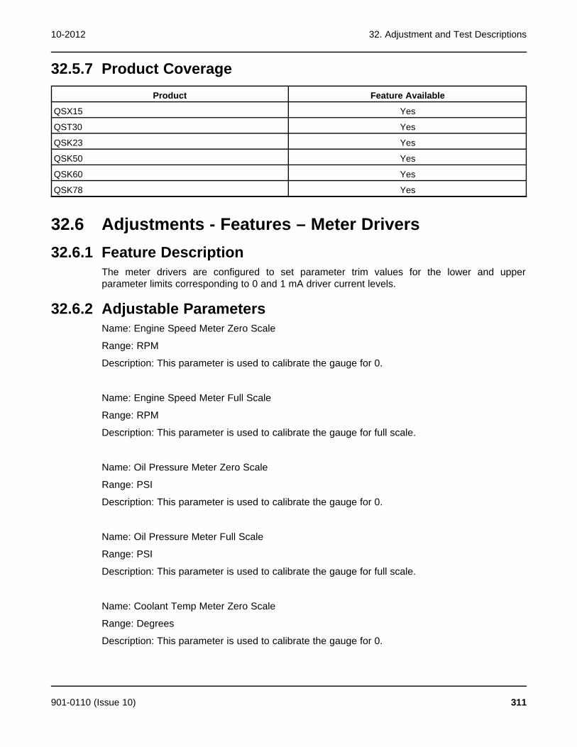
10-2012 32. Adjustment and Test Descriptions
32.5.7 Product CoverageProduct Feature Available
QSX15 Yes
QST30 Yes
QSK23 Yes
QSK50 Yes
QSK60 Yes
QSK78 Yes
32.6 Adjustments - Features – Meter Drivers32.6.1 Feature Description
The meter drivers are configured to set parameter trim values for the lower and upperparameter limits corresponding to 0 and 1 mA driver current levels.
32.6.2 Adjustable ParametersName: Engine Speed Meter Zero Scale
Range: RPM
Description: This parameter is used to calibrate the gauge for 0.
Name: Engine Speed Meter Full Scale
Range: RPM
Description: This parameter is used to calibrate the gauge for full scale.
Name: Oil Pressure Meter Zero Scale
Range: PSI
Description: This parameter is used to calibrate the gauge for 0.
Name: Oil Pressure Meter Full Scale
Range: PSI
Description: This parameter is used to calibrate the gauge for full scale.
Name: Coolant Temp Meter Zero Scale
Range: Degrees
Description: This parameter is used to calibrate the gauge for 0.
901-0110 (Issue 10) 311

32. Adjustment and Test Descriptions 10-2012
Name: Coolant Temp Meter Full Scale
Range: Degrees
Description: This parameter is used to calibrate the gauge for full scale.
32.6.3 Interaction with other Features and ParametersNone
32.6.4 Special InstructionsNone
32.6.5 Possible Customer ComplaintsNone
32.6.6 Visual Aids
32.6.7 Product CoverageProduct Feature Available
QSX15 Yes
QST30 Yes
QSK23 Yes
QSK50 Yes
QSK60 Yes
QSK78 Yes
32.7 Adjustments – Features – Power Limiter32.7.1 Feature Description
This feature allows the user to select a power limit best suited for the specific application inwhich the engine is being used (i.e. standby, prime or continuous power applications). This isaccomplished by setting the Power Limiter State parameter to the desired selection (Standby,Limited Time Prime, Unlimited Time Prime or Continuous) using InPower.
The Power Limiter feature must be enabled in order to make this feature operational. This isaccomplished by setting the Power Limiter Enable parameter to “Enabled". Once enabled, theengine power is limited by the maximum fueling that the fuel system is commanded to deliver tothe engine based on limits which are pre-programmed in the ECM.
32.7.2 Adjustable ParametersName: Power Limiter State
Range: Standby/Limited Time Prime/Unlimited Time Prime/Continuous
Description: The tool allows the user to set the rating to limit the power output.
312 901-0110 (Issue 10)

10-2012 32. Adjustment and Test Descriptions
Name: Power Limiter Enable
Range: Enable/Disable
Description: The Power Limiter feature must be Enabled in order to make the featureoperational.
Name: Continuous Scale Factor
Range: None
Description: When the Power Limiter State is set to Continuous the Continuous Scale Factorparameter can be used to control the maximum amount of continuous power the engine iscapable of providing. This is accomplished by setting the Continuous Scale Factor to a valuebetween 0 and 1, representing the percentage (between 0 and 100 %) of the total enginecontinuous rated power capability.
32.7.3 Interaction with other Features and ParametersNone
32.7.4 Special InstructionsThere is only a scale factor for use with continuous power applications. For engines used instandby or prime applications, the Power Limiter feature uses pre-programmed fueling limits andthe Continuous Scale Factor parameter setting has no effect.
32.7.5 Possible Customer ComplaintsNone
32.7.6 Visual AidsNone
32.7.7 Product CoverageProduct Feature Available
QSX15 Yes
QST30 Yes
QSK23 Yes
QSK50 Yes
QSK60 Yes
QSK78 Yes
901-0110 (Issue 10) 313

32. Adjustment and Test Descriptions 10-2012
32.8 Adjustments – Features – Relay Drivers32.8.1 Feature Description
Eight output drivers are provided to annunciate that specific engine protection alarm conditionshave occurred. Each output can be used to drive either a lamp or a relay.
32.8.2 Adjustable ParametersName: Relay Driver Supply Diagnostic Enable
Range: Enable/Disable
Description: The tool allows the user to enable fault code 1424 to be used to determine if aproblem exists with the relay supply circuit.
Name: Fail to Start Driver Diagnostic Enable
Range: Enable/Disable
Description: The tool allows the user to enable fault code 1479 to be used to determine if aproblem exists with the failed to start relay driver circuit.
Name: Common Warning Driver Diagnostic Enable
Range: Enable/Disable
Description: The tool allows the user to enable fault code 1426 to be used to determine if aproblem exists with the common warning relay driver circuit.
Name: Common Shutdown Driver Diagnostic Enable
Range: Enable/Disable
Description: The tool allows the user to enable fault code 1425 to be used to determine if aproblem exists with the common shutdown relay driver circuit.
Name: HET Driver Diagnostic Enable
Range: Enable/Disable
Description: The tool allows the user to enable fault code 1429 to be used to determine if aproblem exists with the High Engine Temperature relay driver circuit.
Name: LOP Driver Diagnostic Enable
Range: Enable/Disable
Description: The tool allows the user to enable fault code 1428 to be used to determine if aproblem exists with the Low Oil Pressure relay driver circuit.
Name: Overspeed Driver Diagnostic Enable
314 901-0110 (Issue 10)
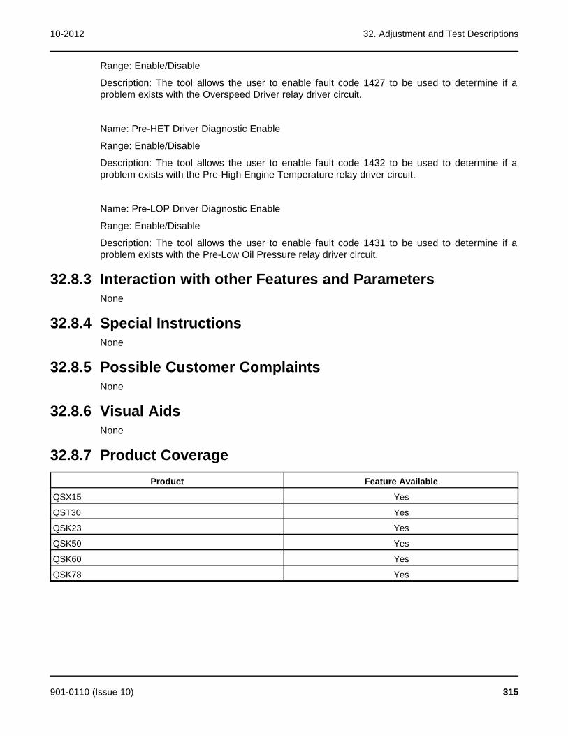
10-2012 32. Adjustment and Test Descriptions
Range: Enable/Disable
Description: The tool allows the user to enable fault code 1427 to be used to determine if aproblem exists with the Overspeed Driver relay driver circuit.
Name: Pre-HET Driver Diagnostic Enable
Range: Enable/Disable
Description: The tool allows the user to enable fault code 1432 to be used to determine if aproblem exists with the Pre-High Engine Temperature relay driver circuit.
Name: Pre-LOP Driver Diagnostic Enable
Range: Enable/Disable
Description: The tool allows the user to enable fault code 1431 to be used to determine if aproblem exists with the Pre-Low Oil Pressure relay driver circuit.
32.8.3 Interaction with other Features and ParametersNone
32.8.4 Special InstructionsNone
32.8.5 Possible Customer ComplaintsNone
32.8.6 Visual AidsNone
32.8.7 Product CoverageProduct Feature Available
QSX15 Yes
QST30 Yes
QSK23 Yes
QSK50 Yes
QSK60 Yes
QSK78 Yes
901-0110 (Issue 10) 315

32. Adjustment and Test Descriptions 10-2012
32.9 Adjustments – Features – Shutdown Override32.9.1 Feature Description
The ECM can be configured to allow continued engine operation while most shutdown faults areactive. When Enabled, the Shutdown Override feature does not allow engine operation whileoverspeed or loss of engine speed faults are active, or while the ECM detects that the Local E-Stop, Remote E-Stop or Backup Start Disconnect switches are in an open state. All othershutdown faults are overridden when this feature is Enabled.
32.9.2 Adjustable ParametersName: Shutdown Override Enable
Range: False/True
Description: When set to True, this feature allows the user to have the engine ECM ignore allengine protection shutdown faults. If an engine protection fault code becomes active, fault code1416 will also become active indicating that the engine has failed to shutdown due to the userengaged engine shutdown override feature.
32.9.3 Interaction with other Features and ParametersNone
32.9.4 Special InstructionsThe Shutdown Override feature prevents the ECM from shutting down the engine, even whenengine-damaging conditions are present. Damage done to the engine or GCS while inShutdown Override mode is NOT covered by the engine warranty.
This feature should only be used in applications where engine damage is an acceptable trade-off for keeping the engine running.
32.9.5 Possible Customer ComplaintsNone
32.9.6 Visual AidsNone
32.9.7 Product CoverageProduct Feature Available
QSX15 Yes
QST30 Yes
QSK23 Yes
QSK50 Yes
QSK60 Yes
QSK78 Yes
316 901-0110 (Issue 10)

10-2012 32. Adjustment and Test Descriptions
32.10 Adjustments – Governor - Frequency32.10.1 Feature Description
This feature allows the tool user to monitor and adjust frequency inputs. The governor frequencyis adjustable by +/-9Hz using a combination of both a remote mounted potentiometer and theFrequency Adjustment Trim.
The potentiometer allows an adjustment range of +/-3Hz, while the Frequency Adjustment Trimallows an additional adjustment range of +/-6Hz.
The alternate frequency selection feature is only enabled for engines that have been rated fordual speed operation. For engines rated for single operating speed, the Alternate Frequencyinput is non-operational and no connection needs to be made to this input.
32.10.2 Adjustable ParametersName: Alternate Frequency Select
Range: 60Hz Primary/50Hz Primary/60Hz Only/50Hz Only
Description: The frequency setting for the Primary/Secondary states of the Alternate Frequencyinput can be reversed (e.g. Primary = 50Hz / Secondary = 60Hz changed to Primary 60Hz /Secondary 50Hz) using InPower. This is accomplished be setting the Alternate FrequencySelect parameter to either 60Hz Primary or 50Hz Primary. Any change made to the AlternateFrequency Select state while the engine is running will not take effect until the engine is shutdown and re-started.
The Alternate Frequency setting can also be controlled electronically using InPower. This isaccomplished by setting the Alternate Frequency Select parameter to either 60Hz Only or 50Hzonly. These settings effectively disable the Alternate Frequency switch input, by overriding theswitch setting.
Name: Nominal Frequency
Range: Hertz
Description: Displays to the user the default frequency before trim, pot and bias adjustments.
Name: Frequency Adjust Trim
Range: Hertz
Description: Allows the user to input the frequency adjustment.
Name: Frequency Adjust Pot
Range: Hertz
Description: The tool displays the position of the Frequency Adjust potentiometer in Hertz.
Name: Final Reference Engine Speed
Range: RPM
901-0110 (Issue 10) 317
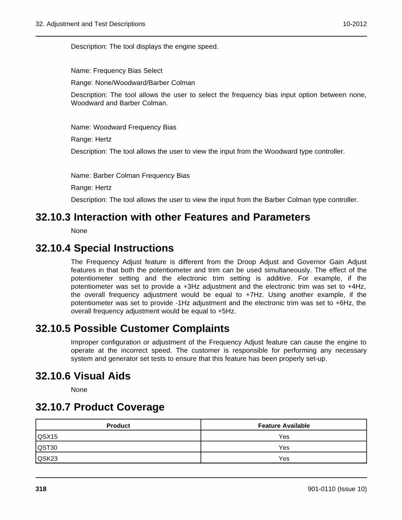
32. Adjustment and Test Descriptions 10-2012
Description: The tool displays the engine speed.
Name: Frequency Bias Select
Range: None/Woodward/Barber Colman
Description: The tool allows the user to select the frequency bias input option between none,Woodward and Barber Colman.
Name: Woodward Frequency Bias
Range: Hertz
Description: The tool allows the user to view the input from the Woodward type controller.
Name: Barber Colman Frequency Bias
Range: Hertz
Description: The tool allows the user to view the input from the Barber Colman type controller.
32.10.3 Interaction with other Features and ParametersNone
32.10.4 Special InstructionsThe Frequency Adjust feature is different from the Droop Adjust and Governor Gain Adjustfeatures in that both the potentiometer and trim can be used simultaneously. The effect of thepotentiometer setting and the electronic trim setting is additive. For example, if thepotentiometer was set to provide a +3Hz adjustment and the electronic trim was set to +4Hz,the overall frequency adjustment would be equal to +7Hz. Using another example, if thepotentiometer was set to provide -1Hz adjustment and the electronic trim was set to +6Hz, theoverall frequency adjustment would be equal to +5Hz.
32.10.5 Possible Customer ComplaintsImproper configuration or adjustment of the Frequency Adjust feature can cause the engine tooperate at the incorrect speed. The customer is responsible for performing any necessarysystem and generator set tests to ensure that this feature has been properly set-up.
32.10.6 Visual AidsNone
32.10.7 Product CoverageProduct Feature Available
QSX15 Yes
QST30 Yes
QSK23 Yes
318 901-0110 (Issue 10)
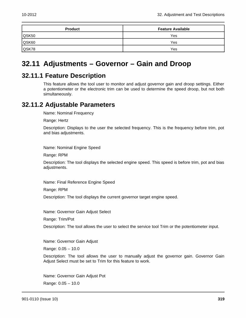
10-2012 32. Adjustment and Test Descriptions
Product Feature Available
QSK50 Yes
QSK60 Yes
QSK78 Yes
32.11 Adjustments – Governor – Gain and Droop32.11.1 Feature Description
This feature allows the tool user to monitor and adjust governor gain and droop settings. Eithera potentiometer or the electronic trim can be used to determine the speed droop, but not bothsimultaneously.
32.11.2 Adjustable ParametersName: Nominal Frequency
Range: Hertz
Description: Displays to the user the selected frequency. This is the frequency before trim, potand bias adjustments.
Name: Nominal Engine Speed
Range: RPM
Description: The tool displays the selected engine speed. This speed is before trim, pot and biasadjustments.
Name: Final Reference Engine Speed
Range: RPM
Description: The tool displays the current governor target engine speed.
Name: Governor Gain Adjust Select
Range: Trim/Pot
Description: The tool allows the user to select the service tool Trim or the potentiometer input.
Name: Governor Gain Adjust
Range: 0.05 – 10.0
Description: The tool allows the user to manually adjust the governor gain. Governor GainAdjust Select must be set to Trim for this feature to work.
Name: Governor Gain Adjust Pot
Range: 0.05 – 10.0
901-0110 (Issue 10) 319
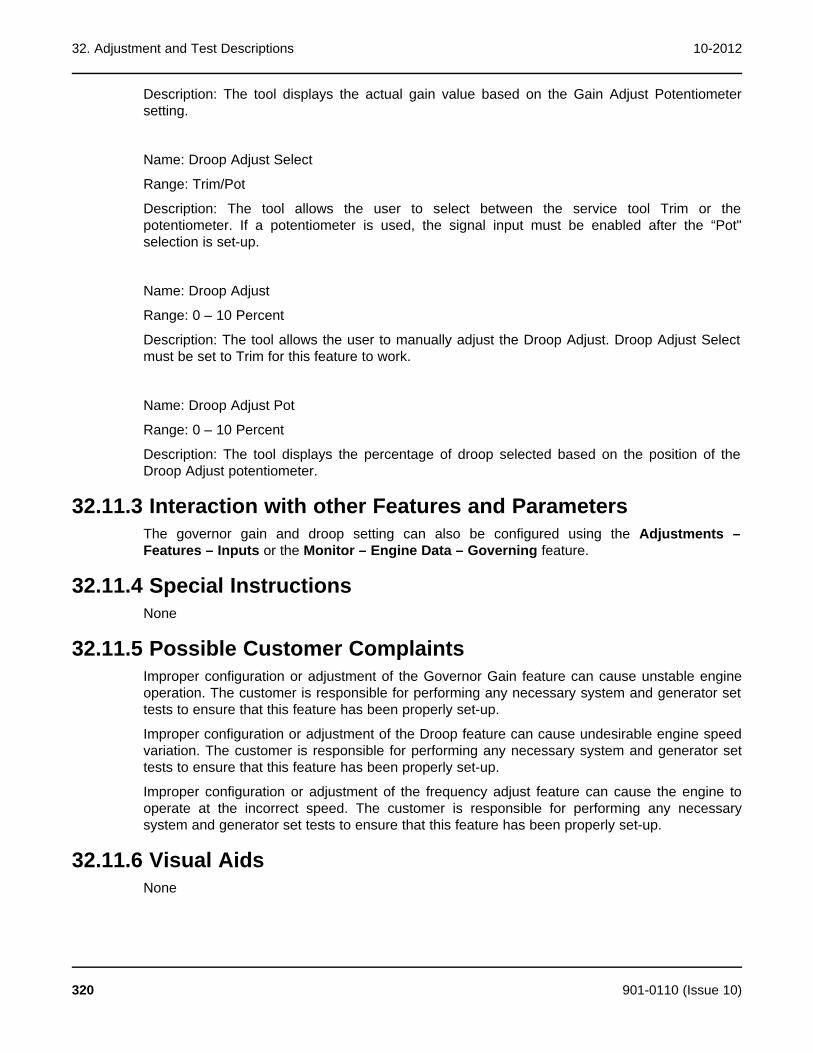
32. Adjustment and Test Descriptions 10-2012
Description: The tool displays the actual gain value based on the Gain Adjust Potentiometersetting.
Name: Droop Adjust Select
Range: Trim/Pot
Description: The tool allows the user to select between the service tool Trim or thepotentiometer. If a potentiometer is used, the signal input must be enabled after the “Pot"selection is set-up.
Name: Droop Adjust
Range: 0 – 10 Percent
Description: The tool allows the user to manually adjust the Droop Adjust. Droop Adjust Selectmust be set to Trim for this feature to work.
Name: Droop Adjust Pot
Range: 0 – 10 Percent
Description: The tool displays the percentage of droop selected based on the position of theDroop Adjust potentiometer.
32.11.3 Interaction with other Features and ParametersThe governor gain and droop setting can also be configured using the Adjustments –Features – Inputs or the Monitor – Engine Data – Governing feature.
32.11.4 Special InstructionsNone
32.11.5 Possible Customer ComplaintsImproper configuration or adjustment of the Governor Gain feature can cause unstable engineoperation. The customer is responsible for performing any necessary system and generator settests to ensure that this feature has been properly set-up.
Improper configuration or adjustment of the Droop feature can cause undesirable engine speedvariation. The customer is responsible for performing any necessary system and generator settests to ensure that this feature has been properly set-up.
Improper configuration or adjustment of the frequency adjust feature can cause the engine tooperate at the incorrect speed. The customer is responsible for performing any necessarysystem and generator set tests to ensure that this feature has been properly set-up.
32.11.6 Visual AidsNone
320 901-0110 (Issue 10)
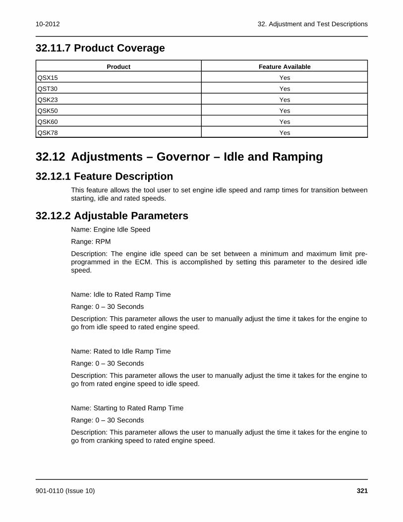
10-2012 32. Adjustment and Test Descriptions
32.11.7 Product CoverageProduct Feature Available
QSX15 Yes
QST30 Yes
QSK23 Yes
QSK50 Yes
QSK60 Yes
QSK78 Yes
32.12 Adjustments – Governor – Idle and Ramping32.12.1 Feature Description
This feature allows the tool user to set engine idle speed and ramp times for transition betweenstarting, idle and rated speeds.
32.12.2 Adjustable ParametersName: Engine Idle Speed
Range: RPM
Description: The engine idle speed can be set between a minimum and maximum limit pre-programmed in the ECM. This is accomplished by setting this parameter to the desired idlespeed.
Name: Idle to Rated Ramp Time
Range: 0 – 30 Seconds
Description: This parameter allows the user to manually adjust the time it takes for the engine togo from idle speed to rated engine speed.
Name: Rated to Idle Ramp Time
Range: 0 – 30 Seconds
Description: This parameter allows the user to manually adjust the time it takes for the engine togo from rated engine speed to idle speed.
Name: Starting to Rated Ramp Time
Range: 0 – 30 Seconds
Description: This parameter allows the user to manually adjust the time it takes for the engine togo from cranking speed to rated engine speed.
901-0110 (Issue 10) 321

32. Adjustment and Test Descriptions 10-2012
32.12.3 Interaction with other Features and ParametersNone
32.12.4 Special InstructionsIf the ramp rate is set at 0 seconds, the engine speed will accelerate or decelerate to achievethe desired target speed as quickly as possible based upon the governor gain settings and thegenerator set performance.
32.12.5 Possible Customer ComplaintsNone
32.12.6 Visual AidsNone
32.12.7 Product CoverageProduct Feature Available
QSX15 Yes
QST30 Yes
QSK23 Yes
QSK50 Yes
QSK60 Yes
QSK78 Yes
32.13 Adjustments – Passwords – Change Passwords32.13.1 Feature Description
This feature allows the user to change the application and user passwords stored in the ECM.Before the ECM will allow this, the user will have to enter the passwords. Passwords must be 5to 8 characters in length and may consist of any combination of alpha or numeric characters. Donot use special characters.
32.13.2 Adjustable ParametersName: Change Application Password
Range: None
Description: The tool allows the user to change the Application Password.
Name: Change User Password
Range: None
Description: The tool allows the user to change the User Password.
322 901-0110 (Issue 10)
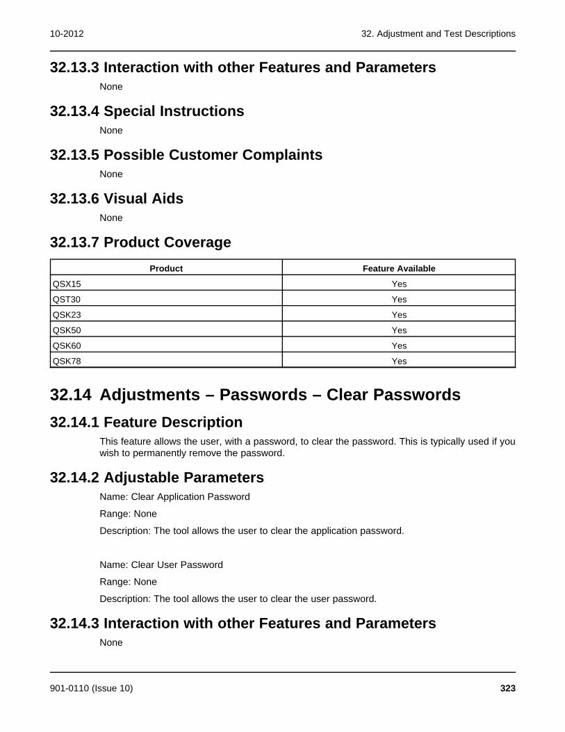
10-2012 32. Adjustment and Test Descriptions
32.13.3 Interaction with other Features and ParametersNone
32.13.4 Special InstructionsNone
32.13.5 Possible Customer ComplaintsNone
32.13.6 Visual AidsNone
32.13.7 Product CoverageProduct Feature Available
QSX15 Yes
QST30 Yes
QSK23 Yes
QSK50 Yes
QSK60 Yes
QSK78 Yes
32.14 Adjustments – Passwords – Clear Passwords32.14.1 Feature Description
This feature allows the user, with a password, to clear the password. This is typically used if youwish to permanently remove the password.
32.14.2 Adjustable ParametersName: Clear Application Password
Range: None
Description: The tool allows the user to clear the application password.
Name: Clear User Password
Range: None
Description: The tool allows the user to clear the user password.
32.14.3 Interaction with other Features and ParametersNone
901-0110 (Issue 10) 323

32. Adjustment and Test Descriptions 10-2012
32.14.4 Special InstructionsNone
32.14.5 Possible Customer ComplaintsNone
32.14.6 Visual AidsNone
32.14.7 Product CoverageProduct Feature Available
QSX15 Yes
QST30 Yes
QSK23 Yes
QSK50 Yes
QSK60 Yes
QSK78 Yes
32.15 Adjustments – Passwords – Enter Passwords32.15.1 Feature Description
There are two predefined groups of parameters that can be protected by passwords, these arenamed User and Application. When a password is established for either of these groups, accessbecomes password protected. Users can view password protected parameters, but they cannotwrite changes to them without entering the password first.
32.15.2 Adjustable ParametersName: Enter Application Password
Range: None
Description: The tool allows the user to enter the application password. This is not requiredunless the password is changed from the factory default.
Name: Enter User Password
Range: None
Description: The tool allows the user to enter the user password. This is not required unless thepassword is changed from the factory default.
32.15.3 Interaction with other Features and ParametersNone
324 901-0110 (Issue 10)
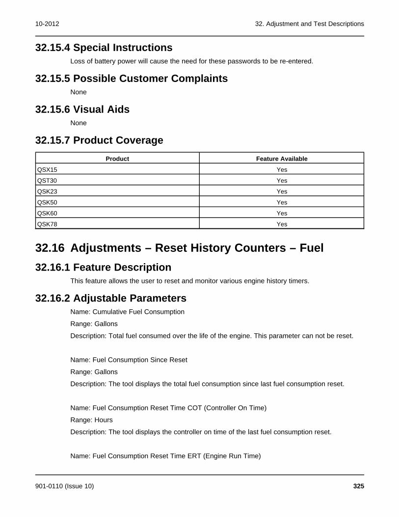
10-2012 32. Adjustment and Test Descriptions
32.15.4 Special InstructionsLoss of battery power will cause the need for these passwords to be re-entered.
32.15.5 Possible Customer ComplaintsNone
32.15.6 Visual AidsNone
32.15.7 Product CoverageProduct Feature Available
QSX15 Yes
QST30 Yes
QSK23 Yes
QSK50 Yes
QSK60 Yes
QSK78 Yes
32.16 Adjustments – Reset History Counters – Fuel32.16.1 Feature Description
This feature allows the user to reset and monitor various engine history timers.
32.16.2 Adjustable ParametersName: Cumulative Fuel Consumption
Range: Gallons
Description: Total fuel consumed over the life of the engine. This parameter can not be reset.
Name: Fuel Consumption Since Reset
Range: Gallons
Description: The tool displays the total fuel consumption since last fuel consumption reset.
Name: Fuel Consumption Reset Time COT (Controller On Time)
Range: Hours
Description: The tool displays the controller on time of the last fuel consumption reset.
Name: Fuel Consumption Reset Time ERT (Engine Run Time)
901-0110 (Issue 10) 325

32. Adjustment and Test Descriptions 10-2012
Range: Hours
Description: The tool displays the engine run time of the last fuel consumption reset.
Name: Reset Fuel Consumption
Range: Reset
Description: The tool allows the user to reset the Fuel Consumption Since Reset parameter.
Name: Controller On Time
Range: Hours
Description: The tool displays the current controller power on time since controller hour 0.
Name: Engine Running Time
Range: Hours
Description: Amount of time the engine has been running.
32.16.3 Interaction with other Features and ParametersThe ECM and fuel history data can also be viewed in the Monitor – History – Run Historyfeature.
32.16.4 Special InstructionsNone
32.16.5 Possible Customer ComplaintsNone
32.16.6 Visual AidsNone
32.16.7 Product CoverageProduct Feature Available
QSX15 Yes
QST30 Yes
QSK23 Yes
QSK50 Yes
QSK60 Yes
QSK78 Yes
326 901-0110 (Issue 10)
10-2012 32. Adjustment and Test Descriptions
32.17 Adjustments – Starting32.17.1 Feature Description
This feature allows the user to setup engine starting features. The starter control feature allowsthe use of either cycle or continuous cranking routines.
32.17.2 Adjustable ParametersName: Crank Switch Enable
Range: Enable/Disable
Description: Allows the user to enable the ECM controlled cranking feature.
Name: Cycle/Continuous Crank Select
Range: Cycle/Continuous
Description: Allows the user to select between a Continuous Cranking or Cycle Cranking. TheContinuous Cranking routine provides the capability to engage the starter once for aconfigurable length of time. The Cycle Cranking provides the capability to perform a maximumof seven starting attempts with configurable starter engage and rest times.
Name: Continuous Crank Engage Time
Range: Seconds
Description: Allows the user to set the maximum amount of time the ECM will continuouslycrank the starters until fault code 1438 becomes active. This parameter is used whenContinuous Cranking is selected.
Name: Cycle Crank Attempts
Range: 1 – 7 Attempts
Description: Allows the user to set the maximum number (up to 7) of crank cycle attemptsbefore it would log fault code 1438. This parameter is used when Cycle Cranking is selected.
Name: Cycle Crank Engage Time
Range: Seconds
Description: Allows the user to set the maximum amount time cranking while cycle cranking isengaged. This parameter is used when Cycle Cranking is selected.
Name: Cycle Crank Rest Time
Range: Seconds
Description: Allows the user to set the time between crank attempts while cyclic cranking isengaged. This parameter is used when Cycle Cranking is selected.
901-0110 (Issue 10) 327
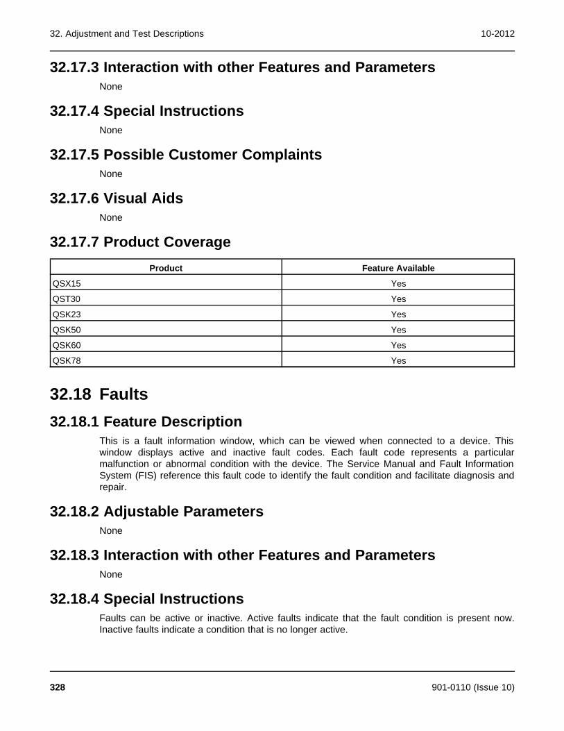
32. Adjustment and Test Descriptions 10-2012
32.17.3 Interaction with other Features and ParametersNone
32.17.4 Special InstructionsNone
32.17.5 Possible Customer ComplaintsNone
32.17.6 Visual AidsNone
32.17.7 Product CoverageProduct Feature Available
QSX15 Yes
QST30 Yes
QSK23 Yes
QSK50 Yes
QSK60 Yes
QSK78 Yes
32.18 Faults32.18.1 Feature Description
This is a fault information window, which can be viewed when connected to a device. Thiswindow displays active and inactive fault codes. Each fault code represents a particularmalfunction or abnormal condition with the device. The Service Manual and Fault InformationSystem (FIS) reference this fault code to identify the fault condition and facilitate diagnosis andrepair.
32.18.2 Adjustable ParametersNone
32.18.3 Interaction with other Features and ParametersNone
32.18.4 Special InstructionsFaults can be active or inactive. Active faults indicate that the fault condition is present now.Inactive faults indicate a condition that is no longer active.
328 901-0110 (Issue 10)

10-2012 32. Adjustment and Test Descriptions
32.18.5 Possible Customer ComplaintsNone
32.18.6 Visual AidsNone
32.18.7 Product CoverageProduct Feature Available
QSX15 Yes
QST30 Yes
QSK23 Yes
QSK50 Yes
QSK60 Yes
QSK78 Yes
32.19 Monitor - About32.19.1 Feature Description
This feature allows the user to view the Engine and calibration specifications as programmed atthe factory.
32.19.2 Adjustable ParametersName: Nominal Frequency
Range: Hertz
Description: Displays to the user the default frequency before trim, pot and bias adjustments.
Name: ECM Code
Range: None
Description: ECM Calibration top level identifier. XXYYYYYZZ. XX identifies the product type,YYYYY identifies the calibration number and ZZ identifies the calibration revision.
Name: Controller Part and Revision
Range: None
Description: Identifies the ECM part number.
Name: Controller Serial Number
Range: None
Description: Identifies the ECM unique serial number.
901-0110 (Issue 10) 329
32. Adjustment and Test Descriptions 10-2012
Name: Controller Manufacturing Date
Range: None
Description: Identifies the ECM manufacture date.
Name: Controller Manufacturing Location
Range: None
Description: Identifies the location of the ECM manufacturer.
Name: Controller Bootloader Version
Range: None
Description: Firmware date that is loaded in the ECM.
Name: Controller Software Version
Range: None
Description: Software firmware that was used to create the ECM calibration.
Name: Engine Model Number
Range: None
Description: Number describing the type of Engine.
Name: Engine Rating
Range: None
Description: Rating for which the engine was manufactured.
Name: Engine Serial Number
Range: None
Description: Serial number of the engine.
Name: Engine CPL Number
Range: None
Description: Critical parts list.
Name: G-Drive Build Date
Range: None
Description: Date the engine was manufactured.
330 901-0110 (Issue 10)
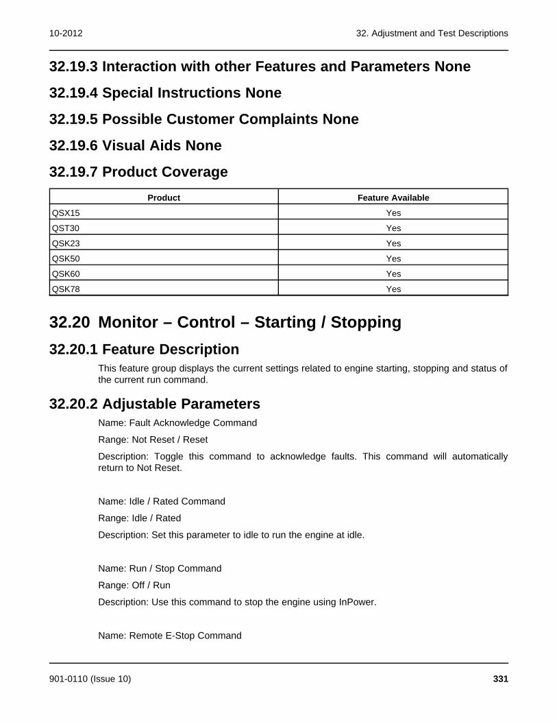
10-2012 32. Adjustment and Test Descriptions
32.19.3 Interaction with other Features and Parameters None
32.19.4 Special Instructions None
32.19.5 Possible Customer Complaints None
32.19.6 Visual Aids None
32.19.7 Product CoverageProduct Feature Available
QSX15 Yes
QST30 Yes
QSK23 Yes
QSK50 Yes
QSK60 Yes
QSK78 Yes
32.20 Monitor – Control – Starting / Stopping32.20.1 Feature Description
This feature group displays the current settings related to engine starting, stopping and status ofthe current run command.
32.20.2 Adjustable ParametersName: Fault Acknowledge Command
Range: Not Reset / Reset
Description: Toggle this command to acknowledge faults. This command will automaticallyreturn to Not Reset.
Name: Idle / Rated Command
Range: Idle / Rated
Description: Set this parameter to idle to run the engine at idle.
Name: Run / Stop Command
Range: Off / Run
Description: Use this command to stop the engine using InPower.
Name: Remote E-Stop Command
901-0110 (Issue 10) 331
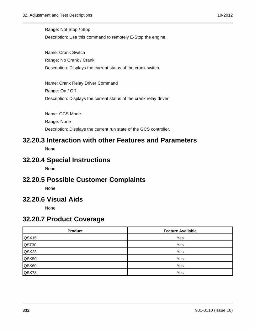
32. Adjustment and Test Descriptions 10-2012
Range: Not Stop / Stop
Description: Use this command to remotely E-Stop the engine.
Name: Crank Switch
Range: No Crank / Crank
Description: Displays the current status of the crank switch.
Name: Crank Relay Driver Command
Range: On / Off
Description: Displays the current status of the crank relay driver.
Name: GCS Mode
Range: None
Description: Displays the current run state of the GCS controller.
32.20.3 Interaction with other Features and ParametersNone
32.20.4 Special InstructionsNone
32.20.5 Possible Customer ComplaintsNone
32.20.6 Visual AidsNone
32.20.7 Product CoverageProduct Feature Available
QSX15 Yes
QST30 Yes
QSK23 Yes
QSK50 Yes
QSK60 Yes
QSK78 Yes
332 901-0110 (Issue 10)

10-2012 32. Adjustment and Test Descriptions
32.21 Monitor – Engine Data – Centinel32.21.1 Feature Description
This feature is used to monitor those parameters associated with Centinel. These parametersare only available on engines with the Centinel feature enabled in the calibration and theCentinel hardware is present.
32.21.2 Adjustable ParametersName: Centinel Oil Makeup Tank Level Switch
Range: Low Oil Level
Description: State of the level switch in the makeup oil tank.
Name: Centinel Valve Driver
Range: Driver Off / Driver On
Description: State of the Centinel Valve Driver.
Name: Centinel Missed Pulse Count
Range: Counts
Description: The number of missed valve cycles.
Name: Centinel Enable Status
Range: Enable / Disable
Description: Indicates if the Centinel function is Enabled or not.
Name: Centinel Operating Status
Range: Enable / Disable
Description: Indicates if Centinel is running or not.
32.21.3 Interaction with other Features and ParametersNone
32.21.4 Special InstructionsNone
32.21.5 Possible Customer ComplaintsNone
901-0110 (Issue 10) 333

32. Adjustment and Test Descriptions 10-2012
32.21.6 Visual AidsNone
32.21.7 Product CoverageProduct Feature Available
QSX15 Yes
QST30 Yes
QSK23 Yes
QSK50 Yes
QSK60 Yes
QSK78 Yes
32.22 Monitor – Engine Data – Fuel Use32.22.1 Feature Description
This feature will display the parameters associated with fuel consumption.
32.22.2 Adjustable ParametersName: Cumulative Fuel Consumption
Range: Gallons
Description: Total fuel consumed over the life of the engine. This parameter can not be reset.
Name: Fuel Consumption Since Reset
Range: Gallons
Description: The tool displays the total fuel consumption since last fuel consumption reset.
Name: Fuel Consumption Reset Time COT (Controller On Time)
Range: Hours
Description: Displays the controller on time of the last fuel consumption reset.
Name: Fuel Consumption Reset Time ERT (Engine Run Time)
Range: Hours
Description: Displays the engine run time of the last fuel consumption reset.
32.22.3 Interaction with other Features and ParametersNone
334 901-0110 (Issue 10)

10-2012 32. Adjustment and Test Descriptions
32.22.4 Special InstructionsNone
32.22.5 Possible Customer ComplaintsNone
32.22.6 Visual AidsNone
32.22.7 Product CoverageProduct Feature Available
QSX15 Yes
QST30 Yes
QSK23 Yes
QSK50 Yes
QSK60 Yes
QSK78 Yes
32.23 Monitor – Engine Data – Governing32.23.1 Feature Description
This feature will display the parameters associated with engine speed governing.
32.23.2 Adjustable ParametersName: Engine Speed
Range: RPM
Description: Displays the measured engine speed.
Name: Final Reference Engine Speed
Range: RPM
Description: Displays the current desired engine speed.
Name: Desired Engine Torque
Range: Ft-Lb
Description: Displays the current desired engine torque.
Name: Engine Torque
901-0110 (Issue 10) 335

32. Adjustment and Test Descriptions 10-2012
Range: Ft-Lb
Description: Displays the limited governor command.
Name: Engine Timing
Range: Degrees Before Top Dead Center
Description: Timing of engine fuel injection.
Name: Engine Fueling
Range: mm3
Description: Engine fuel delivered per stroke.
Name: Governor Gain Adjust Select
Range: Trim/Pot
Description: Allows the user to select the service tool Trim or the potentiometer input.
Name: Governor Gain Adjust
Range: 0.05 – 10
Description: Allows the user to manually adjust the governor gain. Governor Gain Adjust Selectmust be set to Trim for this feature to work.
Name: Governor Gain Adjust Pot
Range: 0.05 – 10
Description: The tool displays the actual gain value based on the Gain Adjust Potentiometersetting.
Name: Droop Adjust Select
Range: Trim/Pot
Description: Allows the user to select between the service tool Trim or the potentiometer.
Name: Droop Adjust
Range: 0 – 10 Percent
Description: Allows the user to manually adjust the Droop Adjust.
Name: Droop Adjust Pot
Range: 0 – 10 Percent
336 901-0110 (Issue 10)

10-2012 32. Adjustment and Test Descriptions
Description: The tool displays the percentage of droop selected based on the position of theDroop Adjust potentiometer setting.
32.23.3 Interaction with other Features and ParametersThe governor gain and droop setting can also be configured using the Adjustments –Features – Inputs or the Adjustments – Features - Governor – Gain and Droop feature.
32.23.4 Special InstructionsNone
32.23.5 Possible Customer ComplaintsImproper configuration or adjustment of the Governor Gain feature can cause unstable engineoperation. The customer is responsible for performing any necessary system and generator settests to ensure that this feature has been properly set-up.
Improper configuration or adjustment of the Droop feature can cause undesirable engine speedvariation. The customer is responsible for performing any necessary system and generator settests to ensure that this feature has been properly set-up.
Improper configuration or adjustment of the frequency adjust feature can cause the engine tooperate at the incorrect speed. The customer is responsible for performing any necessarysystem and generator set tests to ensure that this feature has been properly set-up.
32.23.6 Visual AidsNone
32.23.7 Product CoverageProduct Feature Available
QSX15 Yes
QST30 Yes
QSK23 Yes
QSK50 Yes
QSK60 Yes
QSK78 Yes
32.24 Monitor – Engine Data – Priming32.24.1 Feature Description
This feature is used to monitor the status of the priming pump driver.
32.24.2 Adjustable ParametersName: Priming Pump Driver
Range: On / Off
901-0110 (Issue 10) 337
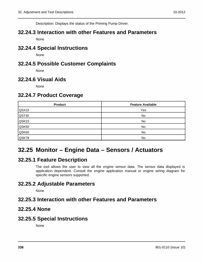
32. Adjustment and Test Descriptions 10-2012
Description: Displays the status of the Priming Pump Driver.
32.24.3 Interaction with other Features and ParametersNone
32.24.4 Special InstructionsNone
32.24.5 Possible Customer ComplaintsNone
32.24.6 Visual AidsNone
32.24.7 Product CoverageProduct Feature Available
QSX15 Yes
QST30 No
QSK23 No
QSK50 No
QSK60 No
QSK78 No
32.25 Monitor – Engine Data – Sensors / Actuators32.25.1 Feature Description
The tool allows the user to view all the engine sensor data. The sensor data displayed isapplication dependent. Consult the engine application manual or engine wiring diagram forspecific engine sensors supported.
32.25.2 Adjustable ParametersNone
32.25.3 Interaction with other Features and Parameters
32.25.4 None
32.25.5 Special InstructionsNone
338 901-0110 (Issue 10)

10-2012 32. Adjustment and Test Descriptions
32.25.6 Possible Customer ComplaintsNone
32.25.7 Visual AidsNone
32.25.8 Product CoverageProduct Feature Available
QSX15 Yes
QST30 Yes
QSK23 Yes
QSK50 Yes
QSK60 Yes
QSK78 Yes
32.26 Monitor – History – 50 Hz Duty Cycle Histogram32.26.1 Feature Description
This feature displays the amount of time in hours spent at various load points.
32.26.2 Adjustable ParametersNone
32.26.3 Interaction with other Features and ParametersThe 100% reference point is directly linked to the Power Limiter function. (See Adjustments –Features – Power Limiter)
32.26.4 Special InstructionsNone
32.26.5 Possible Customer ComplaintsNone
32.26.6 Visual AidsNone
32.26.7 Product CoverageProduct Feature Available
QSX15 Yes
901-0110 (Issue 10) 339
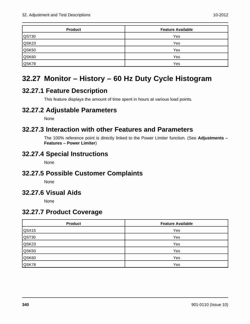
32. Adjustment and Test Descriptions 10-2012
Product Feature Available
QST30 Yes
QSK23 Yes
QSK50 Yes
QSK60 Yes
QSK78 Yes
32.27 Monitor – History – 60 Hz Duty Cycle Histogram32.27.1 Feature Description
This feature displays the amount of time spent in hours at various load points.
32.27.2 Adjustable ParametersNone
32.27.3 Interaction with other Features and ParametersThe 100% reference point is directly linked to the Power Limiter function. (See Adjustments –Features – Power Limiter)
32.27.4 Special InstructionsNone
32.27.5 Possible Customer ComplaintsNone
32.27.6 Visual AidsNone
32.27.7 Product CoverageProduct Feature Available
QSX15 Yes
QST30 Yes
QSK23 Yes
QSK50 Yes
QSK60 Yes
QSK78 Yes
340 901-0110 (Issue 10)
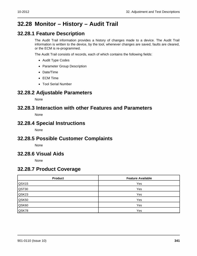
10-2012 32. Adjustment and Test Descriptions
32.28 Monitor – History – Audit Trail32.28.1 Feature Description
The Audit Trail information provides a history of changes made to a device. The Audit Trailinformation is written to the device, by the tool, whenever changes are saved, faults are cleared,or the ECM is re-programmed.
The Audit Trail consists of records, each of which contains the following fields:
· Audit Type Codes
· Parameter Group Description
· Date/Time
· ECM Time
· Tool Serial Number
32.28.2 Adjustable ParametersNone
32.28.3 Interaction with other Features and ParametersNone
32.28.4 Special InstructionsNone
32.28.5 Possible Customer ComplaintsNone
32.28.6 Visual AidsNone
32.28.7 Product CoverageProduct Feature Available
QSX15 Yes
QST30 Yes
QSK23 Yes
QSK50 Yes
QSK60 Yes
QSK78 Yes
901-0110 (Issue 10) 341

32. Adjustment and Test Descriptions 10-2012
32.29 Monitor – History – Engine Protection History32.29.1 Feature Description
This feature allows the user to view the Engine Protection History data for service use. EngineProtection is a control feature that protects the engine from severe operating conditions bymonitoring key sensor inputs and issuing a derate or shutdown condition.
The display shows the following parameters:
· Parameter
· Fault Code
· Parameter Value
· Units
· Duration
· Device Time
· Real Time
32.29.2 Adjustable ParametersNone
32.29.3 Interaction with other Features and ParametersNone
32.29.4 Special InstructionsNone
32.29.5 Possible Customer ComplaintsNone
32.29.6 Visual AidsNone
32.29.7 Product CoverageProduct Feature Available
QSX15 Yes
QST30 Yes
QSK23 Yes
QSK50 Yes
QSK60 Yes
QSK78 Yes
342 901-0110 (Issue 10)

10-2012 32. Adjustment and Test Descriptions
32.30 Monitor – History – Run History32.30.1 Feature Description
The feature allows the user to view the Run History data for service use.
32.30.2 Adjustable ParametersName: Cumulative Fuel Consumption
Range: Gallons
Description: Total fuel consumed over the life of the engine. This parameter can not be reset.
Name: Fuel Consumption Since Reset
Range: Gallons
Description: The total fuel consumption since last fuel consumption reset.
Name: Fuel Consumption Reset Time COT (Controller On Time)
Range: Hours
Description: The Controller On Time of the last fuel consumption reset.
Name: Fuel Consumption Reset Time ERT (Engine Run Time)
Range: Hours
Description: The Engine Run Time of the last fuel consumption reset.
Name: Controller On Time
Range: Hours
Description: The current Controller On Time since controller hour 0.
Name: Engine Running Time
Range: Hours
Description: Amount of time the engine has been running.
32.30.3 Interaction with other Features and ParametersThe ECM and fuel history can also be monitored in the Adjustments – Reset HistoryCounters – Fuel feature.
The Fuel Consumption Since Reset parameter can be reset by using the Adjustment – ResetHistory Counters – Fuel feature.
32.30.4 Special InstructionsNone
901-0110 (Issue 10) 343
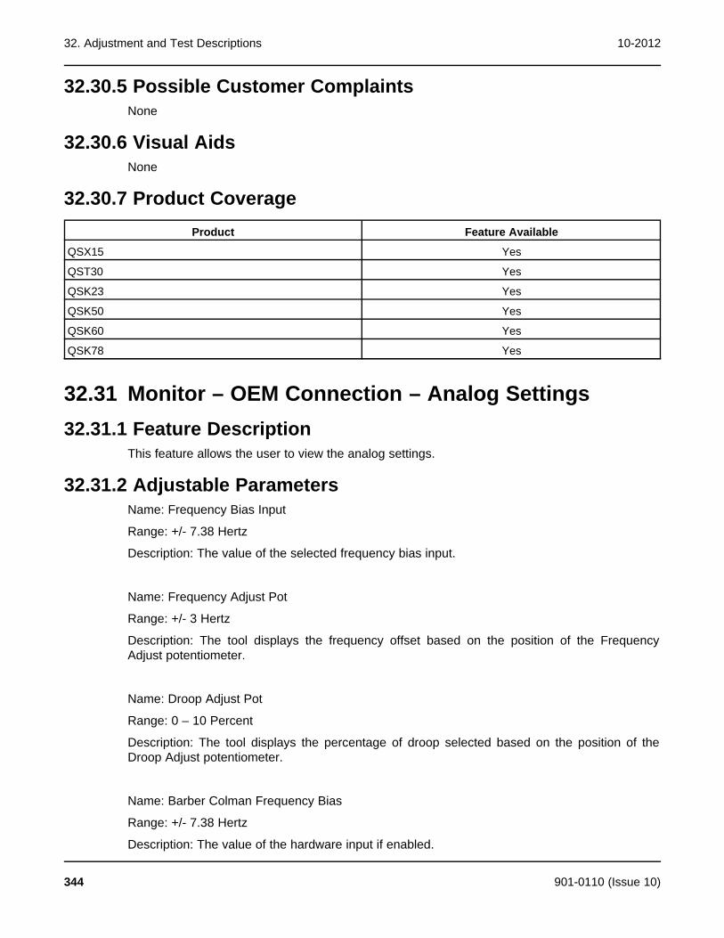
32. Adjustment and Test Descriptions 10-2012
32.30.5 Possible Customer ComplaintsNone
32.30.6 Visual AidsNone
32.30.7 Product CoverageProduct Feature Available
QSX15 Yes
QST30 Yes
QSK23 Yes
QSK50 Yes
QSK60 Yes
QSK78 Yes
32.31 Monitor – OEM Connection – Analog Settings32.31.1 Feature Description
This feature allows the user to view the analog settings.
32.31.2 Adjustable ParametersName: Frequency Bias Input
Range: +/- 7.38 Hertz
Description: The value of the selected frequency bias input.
Name: Frequency Adjust Pot
Range: +/- 3 Hertz
Description: The tool displays the frequency offset based on the position of the FrequencyAdjust potentiometer.
Name: Droop Adjust Pot
Range: 0 – 10 Percent
Description: The tool displays the percentage of droop selected based on the position of theDroop Adjust potentiometer.
Name: Barber Colman Frequency Bias
Range: +/- 7.38 Hertz
Description: The value of the hardware input if enabled.
344 901-0110 (Issue 10)
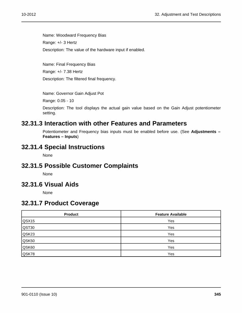
10-2012 32. Adjustment and Test Descriptions
Name: Woodward Frequency Bias
Range: +/- 3 Hertz
Description: The value of the hardware input if enabled.
Name: Final Frequency Bias
Range: +/- 7.38 Hertz
Description: The filtered final frequency.
Name: Governor Gain Adjust Pot
Range: 0.05 - 10
Description: The tool displays the actual gain value based on the Gain Adjust potentiometersetting.
32.31.3 Interaction with other Features and ParametersPotentiometer and Frequency bias inputs must be enabled before use. (See Adjustments –Features – Inputs)
32.31.4 Special InstructionsNone
32.31.5 Possible Customer ComplaintsNone
32.31.6 Visual AidsNone
32.31.7 Product CoverageProduct Feature Available
QSX15 Yes
QST30 Yes
QSK23 Yes
QSK50 Yes
QSK60 Yes
QSK78 Yes
901-0110 (Issue 10) 345

32. Adjustment and Test Descriptions 10-2012
32.32 Monitor – OEM Connections - Outputs32.32.1 Feature Description
The tool displays the status of the hardware outputs and LEDs. If configured these outputs candrive a lamp or relay.
32.32.2 Adjustable ParametersName: Fail to Start Driver Command
Range: Output Off / Output On
Description: This output activates when the engine fails to start after the number of startattempts, configured using the Cycle/Continuous Cranking feature, have expired withoutsuccessfully starting the engine.
Name: Common Warning Driver Command
Range: Driver On / Driver Off
Description: This output is activated when any engine warning alarm condition is active.
Name: Common Shutdown Driver Command
Range: Driver On / Driver Off
Description: This output is activated when any engine shutdown alarm condition is active. It alsoactivates when the local or remote emergency stop input is activated.
Name: Warning LED Command
Range: LED On / LED Off
Description: There are five diagnostic LEDs located on the side of the ECM that are visiblethrough the display window. This YELLOW LED indicates that a warning fault has occurred.
Name: Shutdown LED Command
Range: LED On / LED Off
Description: There are five diagnostic LEDs located on the side of the ECM that are visiblethrough the display window. This RED LED indicates that a shutdown fault, other than andOverspeed, Low Oil Pressure and High Engine Temperature has occurred.
Name: HET (High Engine Temperature) Driver / LED Command
Range: LED On/LED Off
Description: There are five diagnostic LEDs located on the side of the ECM that are visiblethrough the display window. This RED LED indicates that a High Coolant Temperature or a HighIntake Manifold Temperature shutdown fault has occurred.
346 901-0110 (Issue 10)
10-2012 32. Adjustment and Test Descriptions
Name: LOP (Low Oil Pressure) Driver / LED Command
Range: LED On / LED Off
Description: There are five diagnostic LEDs located on the side of the ECM that are visiblethrough the display window. This RED LED indicates that a Low Oil Pressure shutdown faulthas occurred.
Name: Overspeed Driver/LED Command
Range: LED On / LED Off
Description: There are five diagnostic LEDs located on the side of the ECM that are visiblethrough the display window. This RED LED indicates that an Overspeed shutdown fault hasoccurred.
Name: Pre-HET (High Engine Temperature) Driver Command
Range: Driver On / Driver Off
Description: The status of the Pre-High Engine Temperature engine warning alarm driver.
Name: Pre-LOP (Low Oil Pressure) Driver Command
Range: Driver On / Driver Off
Description: The status of the Pre-Low Oil Pressure engine warning alarm driver.
Name: Relay Driver Supply Command
Range: Driver On / Driver Off
Description: The status of the Relay Driver supply.
Name: Crank Relay Driver Command
Range: On / Off
Description: The status of the crank relay driver.
Name: Fuel Lift Pump Driver Command
Range: Driver On / Driver Off
Description: The status of the Fuel Lift Pump driver. This parameter is available only on QST30engines.
32.32.3 Interaction with other Features and ParametersNone
32.32.4 Special InstructionsNone
901-0110 (Issue 10) 347

32. Adjustment and Test Descriptions 10-2012
32.32.5 Possible Customer ComplaintsNone
32.32.6 Visual AidsNone
32.32.7 Product CoverageProduct Feature Available
QSX15 Yes
QST30 Yes
QSK23 Yes
QSK50 Yes
QSK60 Yes
QSK78 Yes
32.33 Monitor – OEM Connections – Switch Settings -Other
32.33.1 Feature DescriptionThese parameters allow the user to enable controller diagnostics, reset faults and changeengine operating conditions.
32.33.2 Adjustable ParametersName: Fault Acknowledge Command
Range: Not Reset/Reset
Description: Set to reset to acknowledge faults. This variable will return to Not Resetautomatically.
Name: Idle/Rated Command
Range: Idle/Rated
Description: Tool command to run the engine at Idle or at rated.
Name: Idle/Rated Switch
Range: Idle/Rated
Description: The tool displays the status of the hardwired Idle/Rated switch.
Name: Diagnostic Mode Switch
Range: Fault Flashout/Not Fault Flashout
348 901-0110 (Issue 10)
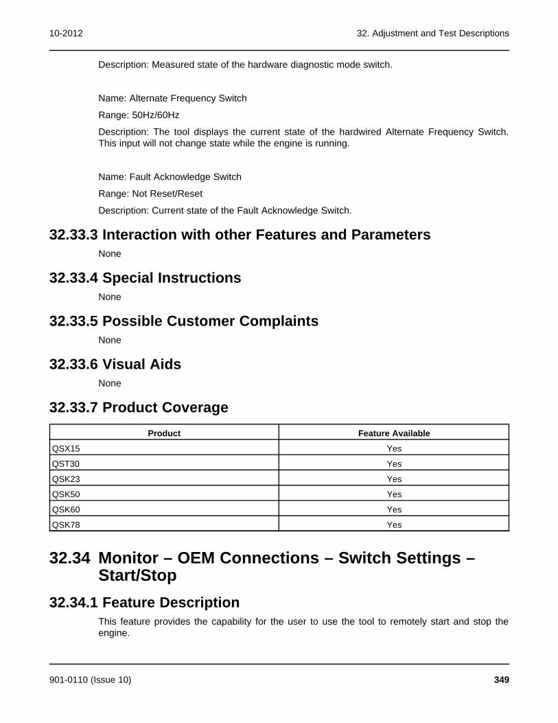
10-2012 32. Adjustment and Test Descriptions
Description: Measured state of the hardware diagnostic mode switch.
Name: Alternate Frequency Switch
Range: 50Hz/60Hz
Description: The tool displays the current state of the hardwired Alternate Frequency Switch.This input will not change state while the engine is running.
Name: Fault Acknowledge Switch
Range: Not Reset/Reset
Description: Current state of the Fault Acknowledge Switch.
32.33.3 Interaction with other Features and ParametersNone
32.33.4 Special InstructionsNone
32.33.5 Possible Customer ComplaintsNone
32.33.6 Visual AidsNone
32.33.7 Product CoverageProduct Feature Available
QSX15 Yes
QST30 Yes
QSK23 Yes
QSK50 Yes
QSK60 Yes
QSK78 Yes
32.34 Monitor – OEM Connections – Switch Settings –Start/Stop
32.34.1 Feature DescriptionThis feature provides the capability for the user to use the tool to remotely start and stop theengine.
901-0110 (Issue 10) 349
32. Adjustment and Test Descriptions 10-2012
32.34.2 Adjustable Parameters
Name: Remote E-Stop Command
Range: Not Stop/Stop
Description: The tool allows the user to command the engine E-Stop with a remote command.
Name: Local E-Stop Switch
Range: Not Stop/Stop
Description: The tool displays the status of the hardwired local E-Stop
Name: Remote E-Stop Switch
Range: Not Stop/Stop
Description: The tool displays the status of the remote E-Stop switch.
Name: Crank Switch
Range: No Crank/Crank
Description: The tool displays the status of the Crank Switch hardware input.
Name: Run/Stop Switch
Range: Run/Off
Description: The tool displays the status of the hardware run switch and the tool run enable.
Name: Run/Stop Command
Range: Run/Off
Description: When the Run/Stop hardware input is in the Run position, this command can beused to start and stop the engine.
32.34.3 Interaction with other Features and ParametersNone
32.34.4 Special InstructionsNone
32.34.5 Possible Customer ComplaintsNone
350 901-0110 (Issue 10)

10-2012 32. Adjustment and Test Descriptions
32.34.6 Visual AidsNone
32.34.7 Product CoverageProduct Feature Available
QSX15 Yes
QST30 Yes
QSK23 Yes
QSK50 Yes
QSK60 Yes
QSK78 Yes
32.35 Test – Fault Simulation – Engine Protection Test –Aftercooler Water TempThis feature allows the user to test engine protection devices by temporarily overriding thesensor inputs and verifying that the engine warning or shutdown is completed. This feature isonly available on QSK23, QSK50, QSK60, and QSK78 model engines.
Changes made to test parameter values are retained until they are changed back, usingInPower, or until power is removed from the controller. When finished with a test, make surethat you return the parameters to their original setting. To permanently write changes to thecontroller, you must use the Adjustment feature.
32.35.1 How to Perform the Test - Option 1HAT Warning Threshold High Aftercooler Water Inlet Temperature
1. Attach the InPower PC to a running engine and connect to the controller.
2. From the device explorer select Test – Fault Simulation – Engine Protection Test –Aftercooler Water Temp - HAT Warning Threshold and make a note of the currentsetting.
3. Double click on the value field for HAT Warning Threshold.
4. Edit the field and set to a value that is below the current Aftercooler Water InletTemperature. The current Aftercooler Water Inlet Temperature value can be obtained fromTest – Fault Simulation – Engine Protection Test – Aftercooler Water Temp –Aftercooler Water Temp.
5. To temporarily write these values to the device, click on the Save Adjustments button onthe tool bar.
6. The alarm popup will display an active 2113 fault.
7. Double click on the value field for HAT Warning Threshold and restore the value to itsoriginal setting.
8. Click on the Save Adjustments button on the tool bar and the fault will go inactive.
9. Click on the Clear Faults button on the tool bar to clear the inactive fault.
901-0110 (Issue 10) 351

32. Adjustment and Test Descriptions 10-2012
HAT Shutdown Threshold High Aftercooler Water Inlet Temperature
1. Attach the InPower PC to a running engine and connect to the controller.
2. From the device explorer select Test – Fault Simulation – Engine Protection Test –Aftercooler Water Temp - HAT Shutdown Threshold and make a note of the currentsetting.
3. Double click on the value field for HAT Shutdown Threshold.
4. Edit the field and set to a value that is below the current Aftercooler Water InletTemperature. The current Aftercooler Water Inlet Temperature value can be obtained fromTest – Fault Simulation – Engine Protection Test – Aftercooler Water Temp –Aftercooler Water Temp.
5. To temporarily write these values to the device, click on the Save Adjustments button onthe tool bar.
6. Fault code 2114 will go active and the engine will proceed to shutdown.
7. Double click on the value field for HAT Shutdown Threshold and restore the value to itsoriginal setting.
8. Click on the Save Adjustments button on the tool bar and the fault will go inactive.
9. Click on the Clear Faults button on the tool bar to clear the inactive fault.
10. Restart the engine.
32.35.2 How to Perform the Tests - Option 2HAT Warning Threshold High Aftercooler Water Temp
1. Attach the InPower PC to a running engine and connect to the controller.
2. From the device explorer select Test – Fault Simulation – Engine Protection Test –Aftercooler Water Temp - HAT Warning Threshold. Make a note of the current setting.
3. Double click on the Aftercooler Water Temp Override Command value cell and enter avoltage amount that will be high enough to trigger the warning. The appropriate voltageamount can be found on the engine wiring diagram.
4. Double click on the Aftercooler Water Temp Override Enable value cell. Click on thedrop down list arrow and select Enabled.
5. To temporarily write these values to the device, click on the Save Adjustments button onthe tool bar.
6. The alarm popup will display an active 2113 fault.
7. Double click on the Aftercooler Water Temp Override Enable value cell. Click on thedrop down list arrow and select Disabled.
8. Click on the Save Adjustments button on the tool bar and the fault will go inactive.
9. Click on the Clear Faults button on the tool bar to clear the inactive fault.
32.35.3 HAT Shutdown Threshold: High Aftercooler Water Temp1. Attach the InPower PC to a running engine and connect to the controller.
2. From the device explorer select Test – Fault Simulation – Engine Protection Test –Aftercooler Water Temp - HAT Shutdown Threshold. Make a note of the current setting.
352 901-0110 (Issue 10)

10-2012 32. Adjustment and Test Descriptions
3. Double click on the Aftercooler Water Temp Override Command value cell and enter avoltage amount that will be high enough to trigger the shutdown. The appropriate voltageamount can be found on the engine wiring diagram.
4. Double click on the Aftercooler Water Temp Override Enable value cell. Click on thedrop down list arrow and select Enabled.
5. To temporarily write these values to the device, click on the Save Adjustments button onthe tool bar.
6. Fault code 2114 will go active and the engine will proceed to shutdown.
7. Double click on the Aftercooler Water Temp Override Enable value cell. Click on thedrop down list arrow and select Disabled.
8. Click on the Save Adjustments button on the tool bar and the fault will go inactive.
9. Click on the Clear Faults button on the tool bar to clear the inactive fault.
10. Restart the engine.
32.36 Test – Fault Simulation – Engine Protection Test –Blowby FlowThis feature allows the user to test engine protection devices by temporarily overriding thesensor inputs and verifying that the engine warning or shutdown is completed. This feature isonly available on the QSK23, QSK50, QSK60 and QSK78 engine models.
Changes made to test parameter values are retained until they are changed back, usingInPower, or until power is removed from the controller. When finished with a test, make surethat you return the parameters to their original setting. To permanently write changes to thecontroller, you must use the Adjustment feature.
32.36.1 How to Perform the Test - Option 1HBF Warning Threshold Table High Blowby Flow
1. Attach the InPower PC to a running engine and connect to the controller.
2. From the device explorer select Test – Fault Simulation – Engine Protection Test –Blowby Flow - HBF Warning Threshold Table and make a note of the current setting.
3. Double click on the value field for HBF Warning Threshold Table.
4. Edit the table and set to a value that is below the current Blowby Flow. The current BlowbyFlow value can be obtained from Test – Fault Simulation – Engine Protection Test –Blowby Flow – Blowby Flow.
5. To temporarily write these values to the device, click on the Save Adjustments button onthe tool bar.
6. The alarm popup will display an active 555 fault.
7. Double click on the value field for HBF Warning Threshold Table and restore the value toits original setting.
8. Click on the Save Adjustments button on the tool bar and the fault will go inactive.
9. Click on the Clear Faults button on the tool bar to clear the inactive fault.
901-0110 (Issue 10) 353

32. Adjustment and Test Descriptions 10-2012
HBF Shutdown Threshold Table High Blowby Flow
1. Attach the InPower PC to a running engine and connect to the controller.
2. From the device explorer select Test – Fault Simulation – Engine Protection Test –Blowby Flow - HBF Shutdown Threshold Table and make a note of the current setting.
3. Double click on the value field for HBF Shutdown Threshold Table.
4. Edit the table and set to a value that is below the current Blowby Flow. The current BlowbyFlow value can be obtained from Test – Fault Simulation – Engine Protection Test –Blowby Flow – Blowby Flow
5. To temporarily write these values to the device, click on the Save Adjustments button onthe tool bar.
6. Fault code 556 will go active and the engine will proceed to shutdown.
7. Double click on the value field for HBF Shutdown Threshold Table and restore the valueto its original setting.
8. Click on the Save Adjustments button on the tool bar and the fault will go inactive.
9. Click on the Clear Faults button on the tool bar to clear the inactive fault.
10. Restart the engine.
32.36.2 How to Perform the Tests - Option 2HBF Warning Threshold Table High Blowby Flow
1. Attach the InPower PC to a running engine and connect to the controller.
2. From the device explorer select Test – Fault Simulation – Engine Protection Test –Blowby Flow - HBF Warning Threshold Table. Make a note of the current settings.
3. Double click on the Blowby Flow Override Command value cell and enter a voltageamount that will be high enough to trigger the warning. The appropriate voltage amount canbe found on the engine wiring diagram.
4. Double click on the Blowby Flow Override Enable value cell. Click on the drop down listarrow and select Enabled.
5. To temporarily write these values to the device, click on the Save Adjustments button onthe tool bar.
6. The alarm popup will display an active 555 fault.
7. Double click on the Blowby Flow Override Enable value cell. Click on the drop down listarrow and select Disabled.
8. Click on the Save Adjustments button on the tool bar and the fault will go inactive.
9. Click on the Clear Faults button on the tool bar to clear the inactive fault.
HBF Shutdown Threshold Table High Blowby Flow
1. Attach the InPower PC to a running engine and connect to the controller.
2. From the device explorer select Test – Fault Simulation – Engine Protection Test –Blowby Flow - HBF Shutdown Threshold Table. Make a note of the current setting.
354 901-0110 (Issue 10)

10-2012 32. Adjustment and Test Descriptions
3. Double click on the Blowby Flow Override Command value cell and enter a voltageamount that will be high enough to trigger the shutdown. The appropriate voltage amountcan be found on the engine wiring diagram.
4. Double click on the Blowby Flow Override Enable value cell. Click on the drop down listarrow and select Enabled.
5. To temporarily write these values to the device, click on the Save Adjustments button onthe tool bar.
6. Fault code 556 will go active and the engine will proceed to shutdown.
7. Double click on the Blowby Flow Override Enable value cell. Click on the drop down listarrow and select Disabled.
8. Click on the Save Adjustments button on the tool bar and the fault will go inactive.
9. Click on the Clear Faults button on the tool bar to clear the inactive fault.
10. Restart the engine.
32.37 Test – Fault Simulation – Engine Protection Test –Coolant PressureThis feature allows the user to test engine protection devices by temporarily overriding thesensor inputs and verifying that the engine warning or shutdown is completed. This feature isnot available on QSX15 engines.
Changes made to test parameter values are retained until they are changed back, usingInPower, or until power is removed from the controller. When finished with a test, make surethat you return the parameters to their original setting. To permanently write changes to thecontroller, you must use the Adjustment feature.
32.37.1 How to Perform the TestLCP Warning Threshold Table Low Coolant Pressure
1. Attach the InPower PC to a running engine and connect to the controller.
2. From the device explorer select Test – Fault Simulation – Engine Protection Test –Coolant Pressure - LCP Warning Threshold Table and make a note of the currentsettings.
3. Double click on the value field for LCP Warning Threshold Table.
4. Edit the table and set to a value that is above the current Coolant Pressure. The currentCoolant Pressure value can be obtained from Test – Fault Simulation – EngineProtection Test – Coolant Pressure – Coolant Pressure.
5. To temporarily write these values to the device, click on the Save Adjustments button onthe tool bar.
6. The alarm popup will display an active 233 fault.
7. Double click on the value field for LCP Warning Threshold Table and restore the value toits original setting.
8. Click on the Save Adjustments button on the tool bar and the fault will go inactive.
9. Click on the Clear Faults button on the tool bar to clear the inactive fault.
901-0110 (Issue 10) 355

32. Adjustment and Test Descriptions 10-2012
LCP Shutdown Threshold Table Low Coolant Pressure
1. Attach the InPower PC to a running engine and connect to the controller.
2. From the device explorer select Test – Fault Simulation – Engine Protection Test –Coolant Pressure – LCP Shutdown Threshold Table and make a note of the currentsettings.
3. Double click on the value field for LCP Shutdown Threshold Table.
4. Edit the table and set to a value that is above the current Coolant Pressure. The currentCoolant Pressure value can be obtained from Test – Fault Simulation – EngineProtection Test – Coolant Pressure – Coolant Pressure.
5. To temporarily write these values to the device, click on the Save Adjustments button onthe tool bar.
6. Fault code 228 will go active and the engine will proceed to shutdown.
7. Double click on the value field for LCP Shutdown Threshold Table and restore the valueto its original setting.
8. Click on the Save Adjustments button on the tool bar and the fault will go inactive.
9. Click on the Clear Faults button on the tool bar to clear the inactive fault.
10. Restart the engine.
32.37.2 How to Perform the Tests - Option 2LCP Warning Threshold Table Low Coolant Pressure
1. Attach the InPower PC to a running engine and connect to the controller.
2. From the device explorer select Test – Fault Simulation – Engine Protection Test –Coolant Pressure - LCP Warning Threshold Table. Make a note of the current settings.
3. Double click on the Coolant Pressure Override Command value cell and enter a voltageamount that will be low enough to trigger the warning. The appropriate voltage amount canbe found on the engine wiring diagram.
4. Double click on the Coolant Pressure Override Enable value cell. Click on the drop downlist arrow and select Enabled.
5. To temporarily write these values to the device, click on the Save Adjustments button onthe tool bar.
6. The alarm popup will display an active 223 fault.
7. Double click on the Coolant Pressure Override Enable value cell. Click on the drop downlist arrow and select Disabled.
8. Click on the Save Adjustments button on the tool bar and the fault will go inactive.
9. Click on the Clear Faults button on the tool bar to clear the inactive fault.
LCP Shutdown Threshold Table Low Coolant Pressure
1. Attach the InPower PC to a running engine and connect to the controller.
2. From the device explorer select Test – Fault Simulation – Engine Protection Test –Coolant Pressure - LCP Shutdown Threshold Table. Make a note of the current setting.
356 901-0110 (Issue 10)

10-2012 32. Adjustment and Test Descriptions
3. Double click on the Coolant Pressure Override Command value cell and enter a voltageamount that will be low enough to trigger the shutdown. The appropriate voltage amountcan be found on the engine wiring diagram.
4. Double click on the Coolant Pressure Override Enable value cell. Click on the drop downlist arrow and select Enabled.
5. To temporarily write these values to the device, click on the Save Adjustments button onthe tool bar.
6. Fault code 228 will go active and the engine will proceed to shutdown.
7. Double click on the Coolant Pressure Override Enable value cell. Click on the drop downlist arrow and select Disabled.
8. Click on the Save Adjustments button on the tool bar and the fault will go inactive.
9. Click on the Clear Faults button on the tool bar to clear the inactive fault.
10. Restart the engine.
32.38 Test – Fault Simulation – Engine Protection Test –Coolant TempThis feature allows the user to test engine protection devices by temporarily overriding thesensor inputs and verifying that the engine warning or shutdown is completed.
Changes made to test parameter values are retained until they are changed back, usingInPower, or until power is removed from the controller. When finished with a test, make surethat you return the parameters to their original setting. To permanently write changes to thecontroller, you must use the Adjustment feature.
32.38.1 How to Perform the Tests - Option 1HCT Warning Threshold High Coolant Temperature
1. Attach the InPower PC to a running engine and connect to the controller.
2. From the device explorer select Test – Fault Simulation – Engine Protection Test –Coolant Temp - HCT Warning Threshold and make a note of the current setting.
3. Double click on the value field for HCT Warning Threshold.
4. Edit the field and set to a value that is below the current Coolant Temperature. The currentCoolant Temperature value can be obtained from Test – Fault Simulation – EngineProtection Test – Coolant Temp – Coolant Temp.
5. To temporarily write these values to the device, click on the Save Adjustments button onthe tool bar.
6. The alarm popup will display an active 146 fault.
7. Double click on the value field for HCT Warning Threshold and restore the value to itsoriginal setting.
8. Click on the Save Adjustments button on the tool bar and the fault will go inactive.
9. Click on the Clear Faults button on the tool bar to clear the inactive fault.
901-0110 (Issue 10) 357

32. Adjustment and Test Descriptions 10-2012
HCT Shutdown Threshold High Coolant Temperature
1. Attach the InPower PC to a running engine and connect to the controller.
2. From the device explorer select Test – Fault Simulation – Engine Protection Test –Coolant Temp - HCT Shutdown Threshold and make a note of the current setting.
3. Double click on the value field for HCT Shutdown Threshold.
4. Edit the field and set to a value that is below the current Coolant Temperature. The currentCoolant Temperature value can be obtained from Test – Fault Simulation – EngineProtection Test – Coolant Temp – Coolant Temp.
5. To temporarily write these values to the device, click on the Save Adjustments button onthe tool bar.
6. Fault code 151 will go active and the engine will proceed to shutdown.
7. Double click on the value field for HCT Shutdown Threshold and restore the value to itsoriginal setting.
8. Click on the Save Adjustments button on the tool bar and the fault will go inactive.
9. Click on the Clear Faults button on the tool bar to clear the inactive fault.
10. Restart the engine.
32.38.2 How to Perform the Tests - Option 2HCT Warning Threshold High Coolant Temperature
1. Attach the InPower PC to a running engine and connect to the controller.
2. From the device explorer select Test – Fault Simulation – Engine Protection Test –Coolant Temp - HCT Warning Threshold. Make a note of the current setting.
3. Double click on the Coolant Temp Override Command value cell and enter a voltageamount that will be high enough to trigger the warning.
4. Double click on the Coolant Temp Override Enable value cell. Click on the drop down listarrow and select Enabled.
5. To temporarily write these values to the device, click on the Save Adjustments button onthe tool bar.
6. The alarm popup will display an active 146 fault.
7. Double click on the Coolant Temp Override Enable value cell. Click on the drop down listarrow and select Disabled.
8. Click on the Save Adjustments button on the tool bar and the fault will go inactive.
9. Click on the Clear Faults button on the tool bar to clear the inactive fault.
HCT Shutdown Threshold High Coolant Temperature
1. Attach the InPower PC to a running engine and connect to the controller.
2. From the device explorer select Test – Fault Simulation – Engine Protection Test –Coolant Temp - HCT Shutdown Threshold. Make a note of the current setting.
3. Double click on the Coolant Temp Override Command value cell and enter a voltageamount that will be high enough to trigger the shutdown.
358 901-0110 (Issue 10)

10-2012 32. Adjustment and Test Descriptions
4. Double click on the Coolant Temp Override Enable value cell. Click on the drop down listarrow and select Enabled.
5. To temporarily write these values to the device, click on the Save Adjustments button onthe tool bar.
6. Fault code 151 will go active and the engine will proceed to shutdown.
7. Double click on the Coolant Temp Override Enable value cell. Click on the drop down listarrow and select Disabled.
8. Click on the Save Adjustments button on the tool bar and the fault will go inactive.
9. Click on the Clear Faults button on the tool bar to clear the inactive fault.
10. Restart the engine.
32.39 Test – Fault Simulation – Engine Protection Test –Fuel TempThis feature allows the user to test engine protection devices by temporarily overriding thesensor inputs and verifying that the engine warning or shutdown is completed. This feature isnot available on QSX15 model engines.
Changes made to test parameter values are retained until they are changed back, usingInPower, or until power is removed from the controller. When finished with a test, make surethat you return the parameters to their original setting. To permanently write changes to thecontroller, you must use the Adjustment feature.
32.39.1 How to Perform the Test - Option 1HFT Warning Threshold High Fuel Temp
1. Attach the InPower PC to a running engine and connect to the controller.
2. From the device explorer select Test – Fault Simulation – Engine Protection Test – FuelTemp - HFT Warning Threshold and make a note of the current setting.
3. Double click on the value field for HFT Warning Threshold.
4. Edit the table and set to a value that is below the current Fuel Temp. The current FuelTemperature value can be obtained from Test – Fault Simulation – Engine ProtectionTest – Fuel Temp – Fuel Temperature.
5. To temporarily write these values to the device, click on the Save Adjustments button onthe tool bar.
6. The alarm popup will display an active 261 fault.
7. Double click on the value field for HFT Warning Threshold and restore the value to itsoriginal setting.
8. Click on the Save Adjustments button on the tool bar and the fault will go inactive.
9. Click on the Clear Faults button on the tool bar to clear the inactive fault.
HFT Shutdown Threshold High Fuel Temp
1. Attach the InPower PC to a running engine and connect to the controller.
901-0110 (Issue 10) 359

32. Adjustment and Test Descriptions 10-2012
2. From the device explorer select Test – Fault Simulation – Engine Protection Test – FuelTemp - HFT Shutdown Threshold and make a note of the current setting.
3. Double click on the value field for HFT Shutdown Threshold.
4. Edit the table and set to a value that is below the current Fuel Temp. The current FuelTemperature value can be obtained from Test – Fault Simulation – Engine ProtectionTest – Fuel Temp – Fuel Temperature.
5. To temporarily write these values to the device, click on the Save Adjustments button onthe tool bar.
6. Fault code 266 will go active and the engine will proceed to shutdown.
7. Double click on the value field for HFT Shutdown Threshold and restore the value to itsoriginal setting.
8. Click on the Save Adjustments button on the tool bar and the fault will go inactive.
9. Click on the Clear Faults button on the tool bar to clear the inactive fault.
10. Restart the engine.
32.39.2 How to Perform the Tests - Option 2HFT Warning Threshold High Fuel Temperature
1. Attach the InPower PC to a running engine and
2. From the device explorer select Test – Fault Simulation – Engine Protection Test – FuelTemp - HFT Warning Threshold. Make a note of the current setting.
3. Double click on the Fuel Temp Override Command value cell and enter a voltage amountthat will be high enough to trigger the warning. The appropriate voltage amount can befound on the engine wiring diagram.
4. Double click on the Fuel Temp Override Enable value cell. Click on the drop down listarrow and select Enabled.
5. To temporarily write these values to the device, click on the Save Adjustments button onthe tool bar.
6. The alarm popup will display an active 261 fault.
7. Double click on the Fuel Temp Override Enable value cell. Click on the drop down listarrow and select Disabled.
8. Click on the Save Adjustments button on the tool bar and the fault will go inactive.
9. Click on the Clear Faults button on the tool bar to clear the inactive fault.
HFT Shutdown Threshold High Fuel Temperature
1. Attach the InPower PC to a running engine and connect to the controller.
2. From the device explorer select Test – Fault Simulation – Engine Protection Test – FuelTemp - HFT Shutdown Threshold. Make a note of the current setting.
3. Double click on the Fuel Temp Override Command value cell and enter a voltage amountthat will be high enough to trigger the shutdown. The appropriate voltage amount can befound on the engine wiring diagram.
4. Double click on the Fuel Temp Override Enable value cell. Click on the drop down listarrow and select Enabled.
360 901-0110 (Issue 10)

10-2012 32. Adjustment and Test Descriptions
5. To temporarily write these values to the device, click on the Save Adjustments button onthe tool bar.
6. Fault code 266 will go active and the engine will proceed to shutdown.
7. Double click on the Fuel Temp Override Enable value cell. Click on the drop down listarrow and select Disabled.
8. Click on the Save Adjustments button on the tool bar and the fault will go inactive.
9. Click on the Clear Faults button on the tool bar to clear the inactive fault.
10. Restart the engine.
32.40 Test – Fault Simulation – Engine Protection Test –Intake Manifold TempThis feature allows the user to test engine protection devices by temporarily overriding thesensor inputs and verifying that the engine warning or shutdown is completed. This feature isavailable on all engine models. For the QST30 this can be applied for both intake manifoldtemperature #1 and #2.
Changes made to test parameter values are retained until they are changed back, usingInPower, or until power is removed from the controller. When finished with a test, make surethat you return the parameters to their original setting. To permanently write changes to thecontroller, you must use the Adjustment feature.
32.40.1 How to Perform the Tests - Option 1IMT Warning Threshold Intake Manifold Temperature
1. Attach the InPower PC to a running engine and connect to the controller.
2. From the device explorer select Test – Fault Simulation – Engine Protection Test –Intake Manifold Temp - IMT Warning Threshold and make a note of the current setting.
3. Double click on the value field for IMT Warning Threshold.
4. Edit the field and set to a value that is below the current Intake Manifold Temperature. Thecurrent Intake Manifold Temp value can be obtained from Test – Fault Simulation –Engine Protection Test – Intake Manifold Temp – Intake Manifold Temp.
5. To temporarily write these values to the device, click on the Save Adjustments button onthe tool bar.
6. The alarm popup will display an active 488 fault.
7. Double click on the value field for IMT Warning Threshold and restore the value to itsoriginal setting.
8. Click on the Save Adjustments button on the tool bar and the fault will go inactive.
9. Click on the Clear Faults button on the tool bar to clear the inactive fault.
IMT Shutdown Threshold Intake Manifold Temperature
1. Attach the InPower PC to a running engine and connect to the controller.
2. From the device explorer select Test – Fault Simulation – Engine Protection Test –Intake Manifold Temp - IMT Shutdown Threshold and make a note of the currentsetting.
901-0110 (Issue 10) 361

32. Adjustment and Test Descriptions 10-2012
3. Double click on the value field for IMT Shutdown Threshold.
4. Edit the field and set to a value that is below the current Intake Manifold Temperature. Thecurrent Intake Manifold Temp value can be obtained from Test – Fault Simulation –Engine Protection Test – Intake Manifold Temp – Intake Manifold Temp.
5. To temporarily write these values to the device, click on the Save Adjustments button onthe tool bar.
6. Fault code 155 will go active and the engine will pr
7. Double click on the value field for IMT Shutdown Threshold and restore the value to itsoriginal setting.
8. Click on the Save Adjustments button on the tool bar and the fault will go inactive.
9. Click on the Clear Faults button on the tool bar to clear the inactive fault.
10. Restart the engine.
32.40.2 How to Perform the Tests - Option 2IMT Warning Threshold Intake Manifold Temperature
1. Attach the InPower PC to a running engine and connect to the controller.
2. From the device explorer select Test – Fault Simulation – Engine Protection Test –Intake Manifold Temp - IMT Warning Threshold. Make a note of the current setting.
3. Double click on the Intake Manifold Temp Override Command value cell and enter avoltage amount that will be high enough to trigger the warning.
4. Double click on the Intake Manifold Temp Override Enable value cell. Click on the dropdown list arrow and select Enabled.
5. To temporarily write these values to the device, click on the Save Adjustments button onthe tool bar.
6. The alarm popup will display an active 488 fault.
7. Double click on the Intake Manifold Temp Override Enable value cell. Click on the dropdown list arrow and select Disabled.
8. Click on the Save Adjustments button on the tool bar and the fault will go inactive.
9. Click on the Clear Faults button on the tool bar to clear the inactive fault.
IMT Shutdown Threshold Intake Manifold Temperature
1. Attach the InPower PC to a running engine and connect to the controller.
2. From the device explorer select Test – Fault Simulation – Engine Protection Test –Intake Manifold Temp - IMT Shutdown Threshold. Make a note of the current setting.
3. Double click on the Intake Manifold Temp Override Command value cell and enter avoltage amount that will be high enough to trigger the shutdown.
4. Double click on the Intake Manifold Temp Override Enable value cell. Click on the dropdown list arrow and select Enabled.
5. To temporarily write these values to the device, click on the Save Adjustments button onthe tool bar.
6. Fault code 155 will go active and the engine will proceed to shutdown.
362 901-0110 (Issue 10)

10-2012 32. Adjustment and Test Descriptions
7. Double click on the Intake Manifold Temp Override Enable value cell. Click on the dropdown list arrow and select Disabled.
8. Click on the Save Adjustments button on the tool bar and the fault will go inactive.
9. Click on the Clear Faults button on the tool bar to clear the inactive fault.
10. Restart the engine.
32.41 Test – Fault Simulation – Engine Protection Test –Oil PressureThis feature allows the user to test engine protection devices by temporarily overriding thesensor inputs and verifying that the engine warning or shutdown is completed.
Changes made to test parameter values are retained until they are changed back, usingInPower, or until power is removed from the controller. When finished with a test, make surethat you return the parameters to their original setting. To permanently write changes to thecontroller, you must use the Adjustment feature.
32.41.1 How to Perform the Tests - Option 1LOP Warning Threshold Table Low Oil Pressure
1. Attach the InPower PC to a running engine and connect to the controller.
2. From the device explorer select Test – Fault Simulation – Engine Protection Test – OilPressure - LOP Warning Threshold Table and make a note of the current setting.
3. Double click on the value field for LOP Warning Threshold Table.
4. Edit the table and set to a value that is above the current Oil Pressure. The current OilPressure value can be obtained from Test – Fault Simulation – Engine Protection Test –Oil Pressure.
5. To temporarily write these values to the device, click on the Save Adjustments button onthe tool bar.
6. The alarm popup will display an active 144 fault.
7. Double click on the value field for LOP Warning Threshold Table and restore the value toits original setting.
8. Click on the Save Adjustments button on the tool bar and the fault will go inactive.
9. Click on the Clear Faults button on the tool bar to clear the inactive fault.
LOP Shutdown Threshold Table Low Oil Pressure
1. Attach the InPower PC to a running engine and connect to the controller.
2. From the device explorer select Test – Fault Simulation – Engine Protection Test – OilPressure - LOP Shutdown Threshold Table and make a note of the current setting.
3. Double click on the value field for LOP Shutdown Threshold Table.
4. Edit the table and set to a value that is above the current Oil Pressure. The current OilPressure value can be obtained from Test – Fault Simulation – Engine Protection Test –Oil Pressure.
5. To temporarily write these values to the device, click on the Save Adjustments b
901-0110 (Issue 10) 363

32. Adjustment and Test Descriptions 10-2012
6. Fault code 415 will go active and the engine will proceed to shutdown.
7. Double click on the value field for LOP Shutdown Threshold Table and restore the valueto its original setting.
8. Click on the Save Adjustments button on the tool bar and the fault will go inactive.
9. Click on the Clear Faults button on the tool bar to clear the inactive fault.
10. Restart the engine.
32.41.2 How to Perform the Tests - Option 2LOP Warning Threshold Table Low Oil Pressure
1. Attach the InPower PC to a running engine and connect to the controller.
2. From the device explorer select Test – Fault Simulation – Engine Protection Test – OilPressure - LOP Warning Threshold Table. Make a note of the current setting.
3. Double click on the Oil Pressure Override Command value cell and enter a voltageamount that will be low enough to trigger the warning. The appropriate voltage amount canbe found on the engine wiring diagram.
4. Double click on the Oil Pressure Override Enable value cell. Click on the drop down listarrow and select Enabled.
5. To temporarily write these values to the device, click on the Save Adjustments button onthe tool bar.
6. The alarm popup will display an active 144 fault.
7. Double click on the Oil Pressure Override Enable value cell. Click on the drop down listarrow and select Disabled.
8. Click on the Save Adjustments button on the tool bar and the fault will go inactive.
9. Click on the Clear Faults button on the tool bar to clear the inactive fault.
LOP Shutdown Threshold Table Low Oil Pressure
1. Attach the InPower PC to a running engine and connect to the controller.
2. From the device explorer select Test – Fault Simulation – Engine Protection Test – OilPressure - LOP Shutdown Threshold Table. Make a note of the current setting.
3. Double click on the Oil Pressure Override Command value cell and enter a voltageamount that will be low enough to trigger the shutdown. The appropriate voltage amountcan be found on the engine wiring diagram.
4. Double click on the Oil Pressure Override Enable value cell. Click on the drop down listarrow and select Enabled.
5. To temporarily write these values to the device, click on the Save Adjustments button onthe tool bar.
6. Fault code 415 will go active and the engine will proceed to shutdown.
7. Double click on the Oil Pressure Override Enable value cell. Click on the drop down listarrow and select Disabled.
8. Click on the Save Adjustments button on the tool bar and the fault will go inactive.
9. Click on the Clear Faults button on the tool bar to clear the inactive fault.
364 901-0110 (Issue 10)

10-2012 32. Adjustment and Test Descriptions
10. Restart the engine.
32.42 Test – Fault Simulation – Engine Protection Test –Oil TempThis feature allows the user to test engine protection devices by temporarily overriding thesensor inputs and verifying that the engine warning or shutdown is completed.
Changes made to test parameter values are retained until they are changed back, usingInPower, or until power is removed from the controller. When finished with a test, make surethat you return the parameters to their original setting. To permanently write changes to thecontroller, you must use the Adjustment feature.
32.42.1 How to Perform the Tests - Option 1HOT Warning Threshold High Oil Temperature
1. Attach the InPower PC to a running engine and connect to the controller.
2. From the device explorer select Test – Fault Simulation – Engine Protection Test – OilTemp - HOT Warning Threshold.
3. Double click on the value field for HOT Warning Threshold and make a note of the currentsetting.
4. Edit the field and set to a value that is below the current Oil Temperature. The current OilTemperature value can be obtained from Test – Fault Simulation – Engine ProtectionTest – Oil Temp – Oil Temperature.
5. To temporarily write these values to the device, click on the Save Adjustments button onthe tool bar.
6. The alarm popup will display an active 421 fault.
7. Double click on the value field for HOT Warning Threshold and restore the value to itsoriginal setting.
8. Click on the Save Adjustments button on the tool bar and the fault will go inactive.
9. Click on the Clear Faults button on the tool bar to clear the inactive fault.
HOT Shutdown Threshold Low Oil Temperature
1. Attach the InPower PC to a running engine and connect to the controller.
2. From the device explorer select Test – Fault Simulation – Engine Protection Test – OilTemp - HOT Shutdown Threshold.
3. Double click on the value field for HOT Shutdown Threshold and make a note of thecurrent setting.
4. Edit the field and set to a value that is below the current Oil Temperature. The current OilTemperature value can be obtained from Test – Fault Simulation – Engine ProtectionTest – Oil Temp – Oil Temperature.
5. To temporarily write these values to the device, click on the Save Adjustments button onthe tool bar.
6. Fault code 214 will go active and the engine will proceed to shutdown.
901-0110 (Issue 10) 365

32. Adjustment and Test Descriptions 10-2012
7. Double click on the value field for HOT Shutdown Threshold and restore the value to itsoriginal setting.
8. Click on the Save Adjustments button on the tool bar and the fault will go inactive.
9. Click on the Clear Faults button on the tool bar to clear the inactive fault.
10. Restart the engine.
32.42.2 How to Perform the Tests - Option 2HOT Warning Threshold Low Oil Temperature
1. Attach the InPower PC to a running engine and connect to the controller.
2. From the device explorer select Test – Fault Simulation – Engine Protection Test – OilTemp - HOT Warning Threshold. Make a note of the current setting.
3. Double click on the Oil Temp Override Command value cell and enter a voltage amountthat will be high enough to trigger the warning. The appropriate voltage amount can befound on the engine wiring diagram.
4. Double click on the Oil Temp Override Enable value cell. Click on the drop down listarrow and select Enabled.
5. To temporarily write these values to the device, click on the Save Adjustments button onthe tool bar.
6. The alarm popup will display an active 421 fault.
7. Double click on the Oil Temp Override Enable value cell. Click on the drop down listarrow and select Disabled.
8. Click on the Save Adjustments button on the tool bar and the fault will go inactive.
9. Click on the Clear Faults button on the tool bar to clear the inactive fault.
HOT Shutdown Threshold Low Oil Temperature
1. Attach the InPower PC to a running engine and connect to the controller.
2. From the device explorer select Test – Fault Simulation – Engine Protection Test – OilTemp - HOT Shutdown Threshold. Make a note of the current setting.
3. Double click on the Oil Temp Override Command value cell and enter a voltage amountthat will be high enough to trigger the shutdown. The appropriate voltage amount can befound on the engine wiring diagram.
4. Double click on the Oil Temp Override Enable value cell. Click on the drop down listarrow and select Enabled.
5. To temporarily write these values to the device, click on the Save Adjustments button onthe tool bar.
6. Fault code 214 will go active and the engine will proceed to shutdown.
7. Double click on the Oil Temp Override Enable value cell. Click on the drop down listarrow and select Disabled.
8. Click on the Save Adjustments button on the tool bar and the fault will go inactive.
9. Click on the Clear Faults button on the tool bar to clear the inactive fault.
10. Restart the engine.
366 901-0110 (Issue 10)
10-2012 32. Adjustment and Test Descriptions
32.43 Test – Fault Simulation – Engine Protection Test –OverspeedingThis feature allows the user to test engine protection devices by temporarily overriding thesensor inputs and verifying that the engine warning or shutdown is completed.
Changes made to test parameter values are retained until they are changed back, usingInPower, or until power is removed from the controller. When finished with a test, make surethat you return the parameters to their original setting. To permanently write changes to thecontroller, you must use the Adjustment feature.
Use caution when using this test feature and do not command the engine speed above 1800RPM for a 60Hz application and 1500 RPM for a 50Hz application.
32.43.1 How to Perform the Tests - Option 1Overspeed Shutdown Threshold (50Hz) or (60Hz)
1. Attach the InPower PC to a running engine and connect to the controller.
2. From the device explorer select Test – Fault Simulation – Engine Protection Test –Overspeeding – Overspeed Shutdown Threshold.
3. Double click on the value field for Overspeed Shutdown Threshold and make a note ofthe current setting.
4. Edit the field and set to a value that is below the current Engine Speed. The current EngineSpeed value can be obtained from Test – Fault Simulation – Engine Protection Test –Overspeeding – Engine Speed.
5. To write this value to the device, click on the Save Adjustments button on the tool bar.
6. The overspeed detector will trip and the engine will shutdown.
7. Double click on the value field for Overspeed Shutdown Threshold and restore the valueto its original setting.
8. Click on the Save Adjustments button on the tool bar.
9. Restart the engine.
32.43.2 How to Perform the Tests - Option 2Overspeed Shutdown Threshold (50Hz) or (60Hz)
NOTE: The example shown here is for a 60Hz, 1800 RPM application. The RPM mustbe adjusted accordingly for a 50Hz, 1500 RPM application.
1. Attach the InPower PC to a running engine and connect to the controller.
2. From the device explorer select Test – Fault Simulation – Engine Protection Test –Overspeeding – Engine Speed Reference Override Command. Make a note of thecurrent s
3. Double click on the Engine Speed Reference Override Command value cell and enter1700RPM.
4. Double click on the Engine Speed Reference Override Enable value cell. . Click on thedrop down list arrow and select Enabled.
901-0110 (Issue 10) 367

32. Adjustment and Test Descriptions 10-2012
5. To temporarily write these values to the device, click on the Save Adjustments button onthe tool bar. The engine should start running at 1700 RPM.
6. Double click on the value field for Overspeed Shutdown Threshold and make a note ofthe current setting.
7. Edit the Overspeed Shutdown Threshold value field and set it to 1750RPM.
8. To temporarily write these values to the device, click on the Save Adjustments button onthe tool bar.
9. Double click on the Engine Speed Reference Override Command value cell and enter1800RPM.
10. To temporarily write these values to the device, click on the Save Adjustments button onthe tool bar. The engine should attempt to ramp up to 1800RPM.
11. The overspeed detector will trip once it crosses the 1750RPM value and the engine willshutdown.
12. Double click on the Engine Speed Reference Override Enable value cell. . Click on thedrop down list arrow and select Disable.
13. Double click on the Overspeed Shutdown Threshold value cell and restore to the originalvalue.
14. Double click on the Engine Speed Reference Override Command value cell and restoreto the original value.
15. Click on the Save Adjustments button on the tool bar.
16. Restart the engine.
NOTE: The Accel Ramp for Engine Speed Override and Decel Ramp for EngineSpeed Override can be used to adjust the time it takes to reach the desiredoverride speed.
32.44 Test – Fault Simulation – Engine Protection Test –Torque Input CommandThis feature can be used as an alternative means to control engine fueling, effectivelybypassing the control system governor functions. This is used where more flexibility is requiredover what the integrated control system governor provides. This feature has been applied onDynamic Un-interruptible Power Supply applications.
Perform this test when you want to confirm that the fuel system is responding accordingly to thetorque input command.
Changes made to test parameter values are retained until they are changed back, usingInPower, or until power is removed from the controller. When finished with a test, make surethat you return the parameters to their original setting. To permanently write changes to thecontroller, you must use the Adjustment feature.
32.44.1 How to Perform the Tests1. Attach the InPower PC to a running engine and connect to the controller.
2. From the device explorer select Test – Fault Simulation – Engine Protection Test –Torque Input Command - Torque Input Override Command.
368 901-0110 (Issue 10)

10-2012 32. Adjustment and Test Descriptions
3. Double click on the value field for Torque Input Override Command and make a note ofthe current setting.
4. Edit the field and set to the desired torque input value.
5. Double click on the Torque Input Override Enable value cell. . Click on the drop down listarrow and select Enabled.
6. To temporarily write these values to the device, click on the Save Adjustments button onthe tool bar.
7. The engine torque should adjust accordingly.
NOTE: The Torque Input Command will not bypass the governor control to effectfueling unless the torque command is greater than the Desired EngineTorque commanded by the governor. The Desired Engine Torque isdisplayed on the Monitor - Engine Data - Governing INPOWER displayscreen.
8. Double click on the Torque Input Override Enable value cell. . Click on the d
9. Double click on the Torque Input Override Command value cell and restore to theoriginal value.
10. Click on the Save Adjustments button on the tool bar.
32.45 Test – Fuel System Test32.45.1 Fuel Rack Position Test for G-Drive QST30 Engines
This test is used to check the fuel rack driver, rack position sensor, and rack position feedbackinput. InPower can be used to move the fuel rack position, and the results can be measured.
NOTE: Fuel pump faults are suppressed in the Test – Manual mode
32.45.2 How to Perform the Test1. Attach the InPower PC to a non-running engine and connect to the controller.
2. From the device explorer select Test – Fuel System Test.
3. Double click on the Built in Test value field and select Test-Manual.
4. Double click on the value field for Fuel Rack Position Override Command #1 to changethe position on the left bank fuel pump (as viewed from the flywheel end).
5. Edit the field and set to the desired rack position in millimeters. The allowable range is 0 to15 millimeters.
6. To temporarily write these values to the device, click on the Save Adjustments button onthe tool bar.
7. Click on the refresh button on the tool bar and read the Fuel Rack Position #1. The result istypically within +/- 0.5 millimeters.
8. Double click on the Built in Test value field and select Test-Abort to stop the test.
901-0110 (Issue 10) 369

32. Adjustment and Test Descriptions 10-2012
32.45.3 Single Cylinder Cut Out Test for G-Drive QSX15 EnginesThis test is used to cut out fueling to one cylinder at a time. The test can be used to help isolatea cylinder with fueling or combustion problems.
CAUTION: Do not cut out fueling to more than one cylinder at a time or engine damage canresult. Always change the Cylinder Cut Out Test Enable to Disabled when finishedtesting. Follow these steps carefully and refer to the equipment operator's manualfor important safety precautions.
32.45.4 How to Perform the Test1. Attach the InPower PC to a running engine and connect to the controller. Operate the
engine at rated speed with no load.
2. From the device explorer select Test – Fuel System Test. Make sure that each of the sixcylinder parameter values are set at 1 (enabled).
3. Double click on the Cylinder Cut Out Enable value field and select Enabled.
4. Double click on the value field of the desired cylinder for testing and enter 0 (disabled).
5. To temporarily write these values to the device, click on the Save Adjustments button onthe tool bar.
6. To restore the cylinder, double click on the value field of the cylinder selected above andrestore the value to 1 (enabled).
7. Click on the Save Adjustments button on the tool bar.
8. Repeat steps 4-7 for each cylinder to be tested.
9. When finished testing always remember to return the Cylinder Cut Out Test Enable toDisabled.
10. Click on the Save Adjustments button on the tool bar.
32.46 Test – Inputs - AnalogThis test screen allows the user to view all the OEM analog inputs. The input values can beviewed in both engineering units and voltage. The following inputs can be monitored:
· Frequency Bias Input
· Barber Colman Frequency Bias
· Woodward Frequency Bias
· Barber Colman Frequency Bias Voltage
· Woodward Frequency Bias Voltage
· Droop Adjust Pot
· Droop Adjust Pot Voltage
· Frequency Adjust Pot
· Frequency Adjust Pot Voltage
· Governor Gain Adjust Pot
· Governor Gain Adjust Pot Voltage
370 901-0110 (Issue 10)
10-2012 32. Adjustment and Test Descriptions
32.47 Test – Inputs – Engine InputsThis feature is used to monitor engine sensor input values. The values are displayed inengineering units and in voltages.
32.48 Test – Inputs – Switches32.48.1 Feature Description
This test feature allows the user to view the state of hardware switches. It also allows the userthe ability to change PC tool inputs.
32.48.2 Adjustable ParametersName: Alternate Frequency Switch
Range: None
Description: The tool is displaying the value of the input switch.
Name: Alternate Frequency Select
Range: 60Hz Primary/50Hz Primary/60Hz Only/50Hz Only
Description: Allow the user to choose the default frequency. This may be set to allow the engineto only run at one frequency.
Name: Remote E-Stop Switch:
Range: Not Stop/Stop
Description: The tool displays the status of the remote E-Stop switch.
Name: Remote E-Stop Command
Range: Not Stop/Stop
Description: Use this command to remotely E-Stop the engine.
Name: Diagnostic Mode Switch
Range: Fault Flashout/Not Fault Flashout
Description: Measured state of the hardware diagnostic mode switch.
Name: Local E-Stop Switch
Range: Not Stop/Stop
Description: The tool displays the status of the hardwired local E-Stop
Name: Idle/Rated Switch
901-0110 (Issue 10) 371

32. Adjustment and Test Descriptions 10-2012
Range: Idle/Rated
Description: The tool displays the status of the hardwired Idle/Rated switch.
Name: Idle/Rated Command
Range: Idle/Rated
Description: Tool command to run the engine at Idle or at rated.
Name: Run/Stop Switch
Range: Run/Off
Description: The tool displays the status of the hardware run switch and the tool run enable.
Name: Run/Stop Command
Range: Run/Off
Description: When the Run/Stop hardware input is in the Run position, this command can beused to start and stop the engine.
Name: Crank Switch
Range: No Crank/Crank
Description: The tool displays the status of the Crank Switch hardware input.
Name: Fault Acknowledge Switch
Range: Not Reset/Reset
Description: Current state of the Fault Acknowledge Switch.
Name: Fault Acknowledge Command
Range: Not Reset/Reset
Description: Set to reset to acknowledge faults. This variable will return to Not Resetautomatically.
Name: Coolant Level Switch
Range: Valid/Invalid
Description: The tool displays the current state of the hardware input.
32.49 Test – Outputs - CentinelThis test feature allows the user to test the output driver for Centinel. This is accomplished byusing the tool to manually command the ECM driver on.
372 901-0110 (Issue 10)
10-2012 32. Adjustment and Test Descriptions
Changes made to test parameter values are retained until they are changed with InPower, oruntil power is removed from the controller. When finished with a test, return the parameters totheir original setting. To permanently write changes to the controller, use the Adjustment feature.
32.49.1 How to Perform the Tests1. Attach the InPower PC to a running engine and connect to the controller.
2. From the device explorer select Test – Outputs - Centinel.
3. Double click on the value field for Centinel Valve Driver Override Command. Click on thedrop down arrow and select Driver On.
4. Double click on the Centinel Valve Driver Override Enable value cell. . Click on the dropdown list arrow and select Enabled.
5. To temporarily write these values to the device, click on the Save Adjustments button onthe tool bar.
6. Verify that the Centinel valve is open.
7. Double click on the Centinel Valve Driver Override Enable value cell. Click on the dropdown list arrow and select Disable.
32.50 Test – Outputs – Meter Drivers Test – Coolant TempTestThe Coolant Temperature analog meter driver output can be overridden to command a specifiedtest output level. This is accomplished by setting the meter override enable command to“Enabled" and setting the override value to the desired meter output driver current.
Changes made to test parameter values are retained until they are changed with InPower, oruntil power is removed from the controller. When finished with a test, return the parameters totheir original setting. To permanently write changes to the controller, use the Adjustment feature.
32.50.1 How to Perform the Test1. Attach the InPower PC to the controller.
2. From the device explorer select Test – Outputs – Meter Driver Test – Coolant TempTest.
3. Double click on the value field for Coolant Temp Meter Override and enter the test value
4. Double click on the Coolant Temp Meter Override Enable value cell. Click on the dropdown list arrow and select Enabled.
5. To temporarily write these values to the device, click on the Save Adjustments button onthe tool bar.
6. Check the operator panel and verify the proper value is displayed.
7. Double click on the Coolant Temp Meter Override Enable value cell. Click on the dropdown list arrow and select Disable.
8. Click on the Save Adjustments button on the tool bar.
9. Double click on the Centinel Valve Driver Override Command value cell. Click on thedrop down list arrow and select Driver Off.
901-0110 (Issue 10) 373

32. Adjustment and Test Descriptions 10-2012
10. Click on the Save Adjustments button on the tool bar.
32.51 Test – Outputs – Fuel ShutoffThis test feature allows the user to view the state of the Fuel Shutoff Valve Driver output.
32.52 Test – Outputs – Meter Drivers Test – Engine SpeedTestThe Engine Speed analog meter driver output can be overridden to command a specified testoutput level. This is accomplished by setting the meter override enable command to “Enabled"and setting the override value to the desired meter output driver current.
Changes made to test parameter values are retained until they are changed with InPower, oruntil power is removed from the controller. When finished with a test, return the parameters totheir original setting. To permanently write changes to the controller, use the Adjustment feature.
32.52.1 How to Perform the Test1. Attach the InPower PC to the controller.
2. From the device explorer select Test – Outputs – Meter Driver Test – Engine SpeedTest.
3. Double click on the value field for Engine Speed Meter Override and enter the test value
4. Double click on the Engine Speed Meter Override Enable value cell. Click on the dropdown list arrow and select Enabled.
5. To temporarily write these values to the device, click on the Save Adjustments button onthe tool bar.
6. Check the operator panel and verify the proper value is displayed.
7. Double click on the Engine Speed Meter Override Enable value cell. Click on the dropdown list arrow and select Disable.
8. Click on the Save Adjustments button on the tool bar.
32.53 Test – Outputs – Meter Drivers Test – Oil PressureTestThe Oil Pressure analog meter driver output can be overridden to command a specified testoutput level. This is accomplished by setting the meter override enable command to “Enabled"and setting the override value to the desired meter output driver current.
Changes made to test parameter values are retained until they are changed with InPower, oruntil power is removed from the controller. When finished with a test, return the parameters totheir original setting. To permanently write changes to the controller, use the Adjustment feature.
32.53.1 How to Perform the Test1. Attach the InPower PC to the controller.
2. From the device explorer select Test – Outputs – Meter Driver Test – Oil Pressure Test.
374 901-0110 (Issue 10)

10-2012 32. Adjustment and Test Descriptions
3. Double click on the value field for Oil Pressure Meter Override and enter the test value
4. Double click on the Oil Pressure Meter Override Enable value cell. Click on the dropdown list arrow and select Enabled.
5. To temporarily write these values to the device, click on the Save Adjustments button onthe tool bar.
6. Check the operator panel and verify the proper value is displayed.
7. Double click on the Oil Pressure Meter Override Enable value cell. Click on the dropdown list arrow and select Disable.
8. Click on the Save Adjustments button on the tool bar.
32.54 Test – Outputs – Relay Drivers – CommonShutdownThe state of each alarm lamp/relay driver output can be overridden individually. This isaccomplished by setting the respective driver override enable command to “Enabled" andsetting the override value to the desired driver output state. Perform this test to confirm that theECM can turn on the output lamps/relays.
Changes made to test parameter values are retained until they are changed with InPower, oruntil power is removed from the controller. When finished with a test, return the parameters totheir original setting. To permanently write changes to the controller, use the Adjustment feature.
32.54.1 How to Perform the Test1. Attach the InPower PC to the controller.
2. From the device explorer select Test – Outputs – Relay Drivers – Common Shutdown.
3. Double click on the Common Shutdown Driver Override Command value cell. Click onthe drop down list arrow and select Driver On.
4. Double click on the Common Shutdown Driver Override Enable value cell. Click on thedrop down list arrow and select Enabled.
5. To temporarily write these values to the device, click on the Save Adjustments button onthe tool bar.
6. Verify that the output lamp or relay is turned on.
7. Double click on the Common Shutdown Driver Override Command value cell. Click onthe drop down list arrow and select Driver Off.
8. Double click on the Common Shutdown Driver Override Enable value cell. Click on thedrop down list arrow and select Disable.
9. Click on the Save Adjustments button on the tool bar.
32.55 Test – Outputs – Relay Drivers – Common WarningThe state of each alarm lamp/relay driver output can be overridden individually. This isaccomplished by setting the respective driver override enable command to “Enabled" andsetting the override value to the desired driver output state. Perform this test to confirm that theECM can turn on the output lamps/relays.
901-0110 (Issue 10) 375
32. Adjustment and Test Descriptions 10-2012
Changes made to test parameter values are retained until they are changed with InPower, oruntil power is removed from the controller. When finished with a test, return the parameters totheir original setting. To permanently write changes to the controller, use the Adjustment feature.
32.55.1 How to Perform the Test1. Attach the InPower PC to the controller.
2. From the device explorer select Test – Outputs – Relay Drivers – Common Warning.
3. Double click on the Common Warning Driver Override Command value cell. Click on thedrop down list arrow and select Driver On.
4. Double click on the Common Warning Driver Override Enable value cell. Click on thedrop down list arrow and select Enabled.
5. To temporarily write these values to the device, click on the Save Adjustments button onthe tool bar.
6. Verify that the output lamp or relay is turned on.
7. Double click on the Common Warning Driver Override Command value cell. Click on thedrop down list arrow and select Driver Off.
8. Double click on the Common Warning Driver Override Enable value cell. Click on thedrop down list arrow and select Disable.
9. Click on the Save Adjustments button on the tool bar.
32.56 Test – Outputs – Relay Drivers – Crank RelayUse this test to verify the Crank Relay Driver Command state.
Name: Crank Relay Driver Command
Range: On/Off
Description: The tool displays the status of the crank relay driver command.
32.57 Test – Outputs – Relay Drivers – Fail to StartThe state of each alarm lamp/relay driver output can be overridden individually. This isaccomplished by setting the respective driver override enable command to “Enabled" andsetting the override value to the desired driver output state. Perform this test to confirm that theECM can turn on the output lamps/relays.
Changes made to test parameter values are retained until they are changed with InPower, oruntil power is removed from the controller. When finished with a test, return the parameters totheir original setting. To permanently write changes to the controller, use the Adjustment feature.
32.57.1 How to Perform the Test1. Attach the InPower PC to the controller.
2. From the device explorer select Test – Outputs – Relay Drivers – Fail to Start.
376 901-0110 (Issue 10)
10-2012 32. Adjustment and Test Descriptions
3. Double click on the Fail to Start Driver Override Command value cell. Click on the dropdown list arrow and select Driver On.
4. Double click on the Fail to Start Driver Override Enable value cell. Click on the dropdown list arrow and select Enabled.
5. To temporarily write these values to the device, click on the Save Adjustments button onthe tool bar.
6. Verify that the output lamp or relay is turned on.
7. Double click on the Fail to Start Driver Override Command value cell. Click on the dropdown list arrow and select Driver Off.
8. Double click on the Fail to Start Driver Override Enable value cell. Click on the dropdown list arrow and select Disable.
9. Click on the Save Adjustments button on the tool bar.
32.58 Test – Outputs – Relay Drivers – Fuel Lift PumpThis test is for QST30 G-Drive engines only.
The state of each alarm lamp/relay driver output can be overridden individually. This isaccomplished by setting the respective driver override enable command to “Enabled" andsetting the override value to the desired driver output state. Perform this test when you want toconfirm that the ECM can turn on the output lamps/relays.
Changes made to test parameter values are retained until they are changed with InPower, oruntil power is removed from the controller. When finished with a test, return the parameters totheir original setting. To permanently write changes to the controller, use the Adjustment feature.
32.58.1 How to Perform the Test1. Attach the InPower PC to the controller.
2. From the device explorer select Test – Outputs – Relay Drivers – Fuel Lift Pump.
3. Double click on the Fuel Lift Pump Relay Driver Override Command value cell. Click onthe drop down list arrow and select Driver On.
4. Double click on the Fuel Lift Pump Relay Driver Override Enable value cell. Click on thedrop down list arrow and select Enabled.
5. To temporarily write these values to the device, click on the Save Adjustments button onthe tool bar.
6. Verify that the output lamp or relay is turned on.
7. Double click on the Fuel Lift Pump Relay Driver Override Command value cell. Click onthe drop down list arrow and select Driver Off.
8. Double click on the Fuel Lift Pump Relay Driver Override Enable value cell. Click on thedrop down list arrow and select Disable.
9. Click on the Save Adjustments button on the tool bar.
901-0110 (Issue 10) 377

32. Adjustment and Test Descriptions 10-2012
32.59 Test – Outputs – Relay Drivers – HET ShutdownThe state of each alarm lamp/relay driver output can be overridden individually. This isaccomplished by setting the respective driver override enable command to “Enabled" andsetting the override value to the desired driver output state. Perform this test to confirm that theECM can turn on the output lamps/relays.
Changes made to test parameter values are retained until they are changed with InPower, oruntil power is removed from the controller. When finished with a test, return the parameters totheir original setting. To permanently write changes to the controller, use the Adjustment feature.
32.59.1 How to Perform the Test1. Attach the InPower PC to the controller.
2. From the device explorer select Test – Outputs – Relay Drivers – HET Shutdown.
3. Double click on the HET Driver/LED Override Command value cell. Click on the dropdown list arrow and select Driver/LED On.
4. Double click on the HET Driver/LED Override Enable value cell. Click on the drop downlist arrow and select Enabled.
5. To temporarily write these values to the device, click on the Save Adjustments button onthe tool bar.
6. Verify that the output lamp or relay is turned on.
7. Double click on the HET Driver/LED Override Command value cell. Click on the dropdown list arrow and select Driver/LED Off.
8. Double click on the HET Driver/LED Override Enable value cell. Click on the drop downlist arrow and select Disable.
9. Click on the Save Adjustments button on the tool bar.
32.60 Test – Outputs – Relay Drivers – LOP ShutdownThe state of each alarm lamp/relay driver output can be overridden individually. This isaccomplished by setting the respective driver override enable command to “Enabled" andsetting the override value to the desired driver output state. Perform this test to confirm that theECM can turn on the output lamps/relays.
Changes made to test parameter values are retained until they are changed with InPower, oruntil power is removed from the controller. When finished with a test, return the parameters totheir original setting. To permanently write changes to the controller, use the Adjustment feature.
32.60.1 How to Perform the Test1. Attach the InPower PC to the controller.
2. From the device explorer select Test – Outputs – Relay Drivers – LOP Shutdown.
3. Double click on the LOP Driver/LED Override Command value cell. Click on the dropdown list arrow and select Driver/LED On.
4. Double click on the LOP Driver/LED Override Enable value cell. Click on the drop downlist arrow and select Enabled.
378 901-0110 (Issue 10)

10-2012 32. Adjustment and Test Descriptions
5. To temporarily write these values to the device, click on the Save Adjustments button onthe tool bar.
6. Verify that the output lamp or relay is turned on.
7. Double click on the LOP Driver/LED Override Command value cell. Click on the dropdown list arrow and select Driver/LED Off.
8. Double click on the LOP Driver/LED Override Enable value cell. Click on the drop downlist arrow and select Disable.
9. Click on the Save Adjustments button on the tool bar.
32.61 Test – Outputs – Relay Drivers – OverspeedShutdownThe state of each alarm lamp/relay driver output can be overridden individually. This isaccomplished by setting the respective driver override enable command to “Enabled" andsetting the override value to the desired driver output state. Perform this test to confirm that theECM can turn on the output lamps/relays.
Changes made to test parameter values are retained until they are changed with InPower, oruntil power is removed from the controller. When finished with a test, return the parameters totheir original setting. To permanently write changes to the controller, use the Adjustment feature.
32.61.1 How to Perform the Test1. Attach the InPower PC to the controller.
2. From the device explorer select Test – Outputs – Relay Drivers – Overspeed Shutdown.
3. Double click on the Overspeed Driver/LED Override Command value cell. Click on thedrop down list arrow and select Driver/LED On.
4. Double click on the Overspeed Driver/LED Override Enable value cell. Click on the dropdown list arrow and select Enabled.
5. To temporarily write these values to the device, click on the Save Adjustments button onthe tool bar.
6. Verify that the output lamp or relay is turned on.
7. Double click on the Overspeed Driver/LED Override Command value cell. Click on thedrop down list arrow and select Driver/LED Off.
8. Double click on the Overspeed Driver/LED Override Enable value cell. Click on the dropdown list arrow and select Disable.
9. Click on the Save Adjustments button on the tool bar.
· Test – Outputs – Relay Drivers – Pre-HET (High Engine Temperature) Warning
The state of each alarm lamp/relay driver output can be overridden individually. This isaccomplished by setting the respective driver override enable command to “Enabled" andsetting the override value to the desired driver output state. Perform this test to confirm that theECM can turn on the output lamps/relays.
Changes made to test parameter values are retained until they are changed with InPower, oruntil power is removed from the controller. When finished with a test, return the parameters totheir original setting. To permanently write changes to the controller, use the Adjustment feature.
901-0110 (Issue 10) 379

32. Adjustment and Test Descriptions 10-2012
32.61.2 How to Perform the Test1. Attach the InPower PC to the controller.
2. From the device explorer select Test – Outputs – Relay Drivers – Pre-HET Warning.
3. Double click on the Pre-HET Warning Override Command value cell. Click on the dropdown list arrow and select Driver On.
4. Double click on the Pre-HET Warning Override Enable value cell. Click on the drop downlist arrow and select Enabled.
5. To temporarily write these values to the device, click on the Save Adjustments button onthe tool bar.
6. Verify that the output lamp or relay is turned on.
7. Double click on the Pre-HET Warning Override Command value cell. Click on the dropdown list arrow and select Driver Off.
8. Double click on the Pre-HET Warning Override Enable value cell. Click on the drop downlist arrow and select Disable.
9. Click on the Save Adjustments button on the tool bar.
32.62 Test – Outputs – Relay Drivers – Pre-LOP (Low OilPressure) WarningThe state of each alarm lamp/relay driver output can be overridden individually. This isaccomplished by setting the respective driver override enable command to “Enabled" andsetting the override value to the desired driver output state. Perform this test when you want toconfirm that the ECM can turn on the output lamps/relays.
Changes made to test parameter values are retained until they are changed with InPower, oruntil power is removed from the controller. When finished with a test, return the parameters totheir original setting. To permanently write changes to the controller, use the Adjustment feature.
32.62.1 How to Perform the Test1. Attach the InPower PC to the controller.
2. From the device explorer select Test – Outputs – Relay Drivers – Pre-LOP Warning.
3. Double click on the Pre-LOP Warning Override Command value cell. Click on the dropdown list arrow and select Driver On.
4. Double click on the Pre-LOP Warning Override Enable value cell. Click on the drop downlist arrow and select Enabled.
5. To temporarily write these values to the device, click on the Save Adjustments button onthe tool bar.
6. Verify that the output lamp or relay is turned on.
7. Double click on the Pre-LOP Warning Override Command value cell. Click on the dropdown list arrow and select Driver Off.
8. Double click on the Pre-LOP Warning Override Enable value cell. Click on the drop downlist arrow and select Disable.
380 901-0110 (Issue 10)

10-2012 32. Adjustment and Test Descriptions
9. Click on the Save Adjustments button on the tool bar.
32.63 Test – Self TestThe following Built-In Tests are provided for the purpose of checking specific ECM electronicfeatures:
· Lamp/Relay Driver Start-Up Test
· Test-Stationary
· Test-Cranking
· Test-Manual
These tests allow the user to test ECM outputs while stationary and cranking. While conductingeach test, the standard ECM diagnostic routines are performed. If any faults are detected duringthis time, the faults are reported in the InPower alarms window. Consult your engineTroubleshooting and Repair manual for fault code descriptions and troubleshooting steps.
The Lamp/Relay Driver Start-Up Test is automatically performed whenever the engine isstarted. It is also the first test conducted in the sequence of tests performed during theStationary and Cranking Tests.
When the Test-Stationary is initiated the Outputs Tests and Fuel Shut-Off Test, as describebelow, will be performed sequentially. The Built-In Test Command toggle parameter willautomatically reset to Test-Abort once the test is completed.
When the Test-Cranking is initiated the Outputs Tests, Fuel Shut-Off Test and Starter Test, asdescribed below, will be performed sequentially. The Built-In Test Command toggle parameterwill automatically reset to Test-Abort once the test is completed.
For the Test-Manual test see the Test – Fuel System Test description.
32.63.1 How to Perform the Test1. Attach the InPower PC to a non-running engine and connect to the controller.
2. From the device explorer select Test – Self Test.
3. Double click on the Built In Test Command value cell. Click on the drop down list arrowand select Test-Stationary.
4. Click on the Save Adjustments button on the tool bar.
5. The test will be performed and the Built-In Test Command will reset to Test-Abort.
6. Repeat this test for the Test-Cranking if necessary.
Lamp/Relay Driver Start-Up Test The Lamp/Relay Driver supply voltage at connector 03 isnormally on when the ECM is powered. During engine start-up the ECM will turn this supplyvoltage off for a 1.5 second interval as a means of testing the lamps/relays driven by the supply.Any Lamp/Relay Driver output that is active during this test will extinguish/de-energize duringthe 1.5 second test duration.
Outputs Test During the Outputs test all meter drivers, lamp/relay drivers and diagnostic LED'swill be exercised. The Outputs Test for the lamps/relay drivers and the LED's are performedfirst, followed by the meter driver test. The Analog out test will ramp from 1ma to 0ma in 2seconds then ramp from 0ma to 1ma in 2 additional seconds.
901-0110 (Issue 10) 381

32. Adjustment and Test Descriptions 10-2012
Fuel Shut-Off Test Immediately following the Output Tests, the Fuel Shut-Off Test will beinitiated. During this test, the FSO driver will be activated/opened for 2 seconds, and then it willgo inactive/closed.
Starter Test The Starter Test will be performed immediately following the Fuel Shut-Off test,only when the Cranking Test is being performed. For this test, the Crank Relay driver output willbe activated for 2 seconds then it will go inactive.
32.64 Test – Speed OverrideThis feature allows the user to test engine protection devices by temporarily overriding thesensor inputs and verifying that the engine warning or shutdown is completed.
Changes made to test parameter values are retained until they are changed back, usingInPower, or until power is removed from the controller. When finished with a test, make surethat you return the parameters to their original setting. To permanently write changes to thecontroller, you must use the Adjustment feature.
Use caution when using this test feature and do not command the engine speed above 1800RPM for a 60Hz application and 1500 RPM for a 50Hz application.
32.64.1 How to Perform the Tests - Option 1Overspeed Shutdown Threshold (50Hz) or (60Hz)
NOTE: The example shown here is for a 60Hz, 1800 RPM application. The RPM mustbe adjusted accordingly for a 50Hz, 1500 RPM application.
1. Attach the InPower PC to a running engine and connect to the controller.
2. From the device explorer select Test – Speed Override.
3. Double click on the value field for Overspeed Shutdown Threshold and make a note ofthe current setting.
4. Edit the field and set to a value that is below the current Engine Speed. The current EngineSpeed value can be obtained from Test – Speed Override – Engine Speed.
5. To write this value to the device, click on the Save Adjustments button on the tool bar.
6. The overspeed detector will trip and the engine will shutdown. Fault code 234 will beactivated.
7. Double click on the value field for Overspeed Shutdown Threshold and restore the valueto its original setting.
8. Click on the Save Adjustments button on the tool bar.
9. Restart the engine and acknowledge the fault.
32.64.2 How to Perform the Tests - Option 2Overspeed Shutdown Threshold (50Hz) or (60Hz)
1. Attach the InPower PC to a running engine and connect to the controller.
2. From the device explorer select Test – Speed Override – Engine Speed ReferenceOverride Command. Make a note of the current setting.
382 901-0110 (Issue 10)

10-2012 32. Adjustment and Test Descriptions
3. Double click on the Engine Speed Reference Override Command value cell and enter1700RPM.
4. Double click on the Engine Speed Reference Override Enable value cell. . Click on thedrop down list arrow and select Enabled.
5. To temporarily write these values to the device, click on the Save Adjustments button onthe tool bar. The engine should start running at 1700 RPM.
6. Double click on the value field for Overspeed Shutdown Threshold and make a note ofthe current setting.
7. Edit the Overspeed Shutdown Threshold value field and set it to 1750RPM.
8. To temporarily write these values to the device, click on the Save Adjustments button onthe tool bar.
9. Double click on the Engine Speed Reference Override Command value cell and enter1800RPM.
10. To temporarily write these values to the device, click on the Save Adjustments button onthe tool bar. The engine should attempt to ramp up to 1800RPM.
11. The overspeed detector will trip once it crosses the 1750RPM value and the engine willshutdown.
12. Double click on the Engine Speed Reference Override Enable value cell. Click on thedrop down list arrow and select Disable.
13. Double click on the Overspeed Shutdown Threshold value cell and restore to the originalvalue.
14. Double click on the Engine Speed Reference Override Command value cell and restoreto the original value.
15. Click on the Save Adjustments button on the tool bar.
16. Restart the engine and acknowledge the fault.
NOTE: The Accel Ramp for Engine Speed Override and Decel Ramp for EngineSpeed Override can be used to adjust the time it takes to reach the desiredoverride speed.
901-0110 (Issue 10) 383

32. Adjustment and Test Descriptions 10-2012
This page is intentionally blank.
384 901-0110 (Issue 10)


Copyright © 2012 Cummins Power Generation, Inc. All rights reserved.Cummins, the "C" logo, and "Our energy working for you." are trademarks ofCummins Inc.InPower is a trademark of Cummins Inc.
Related Documents