IN-PILE TESTING AND INSTRUMENTATION FOR DEVELOPMENT OF GENERATION-IV FUELS AND MATERIALS

Welcome message from author
This document is posted to help you gain knowledge. Please leave a comment to let me know what you think about it! Share it to your friends and learn new things together.
Transcript

in-pile testing and instrumentation for development of generation-iv
fuels and materials

AFGHANISTANALBANIAALGERIAANGOLAARGENTINAARMENIAAUSTRALIAAUSTRIAAZERBAIJANBAHRAINBANGLADESHBELARUSBELGIUMBELIZEBENINBOLIVIABOSNIA AND HERZEGOVINABOTSWANABRAZILBULGARIABURKINA FASOBURUNDICAMBODIACAMEROONCANADACENTRAL AFRICAN
REPUBLICCHADCHILECHINACOLOMBIACONGOCOSTA RICACÔTE D’IVOIRECROATIACUBACYPRUSCZECH REPUBLICDEMOCRATIC REPUBLIC
OF THE CONGODENMARKDOMINICADOMINICAN REPUBLICECUADOREGYPTEL SALVADORERITREAESTONIAETHIOPIAFIJIFINLANDFRANCEGABONGEORGIAGERMANYGHANAGREECE
GUATEMALAHAITIHOLY SEEHONDURASHUNGARYICELANDINDIAINDONESIAIRAN, ISLAMIC REPUBLIC OF IRAQIRELANDISRAELITALYJAMAICAJAPANJORDANKAZAKHSTANKENYAKOREA, REPUBLIC OFKUWAITKYRGYZSTANLAO PEOPLE’S DEMOCRATIC
REPUBLICLATVIALEBANONLESOTHOLIBERIALIBYALIECHTENSTEINLITHUANIALUXEMBOURGMADAGASCARMALAWIMALAYSIAMALIMALTAMARSHALL ISLANDSMAURITANIAMAURITIUSMEXICOMONACOMONGOLIAMONTENEGROMOROCCOMOZAMBIQUEMYANMARNAMIBIANEPALNETHERLANDSNEW ZEALANDNICARAGUANIGERNIGERIANORWAYOMANPAKISTANPALAU
PANAMAPAPUA NEW GUINEAPARAGUAYPERUPHILIPPINESPOLANDPORTUGALQATARREPUBLIC OF MOLDOVAROMANIARUSSIAN FEDERATIONRWANDASAN MARINOSAUDI ARABIASENEGALSERBIASEYCHELLESSIERRA LEONESINGAPORESLOVAKIASLOVENIASOUTH AFRICASPAINSRI LANKASUDANSWAZILANDSWEDENSWITZERLANDSYRIAN ARAB REPUBLICTAJIKISTANTHAILANDTHE FORMER YUGOSLAV
REPUBLIC OF MACEDONIATOGOTRINIDAD AND TOBAGOTUNISIATURKEYUGANDAUKRAINEUNITED ARAB EMIRATESUNITED KINGDOM OF
GREAT BRITAIN AND NORTHERN IRELAND
UNITED REPUBLICOF TANZANIA
UNITED STATES OF AMERICAURUGUAYUZBEKISTANVENEZUELAVIET NAMYEMENZAMBIAZIMBABWE
The following States are Members of the International Atomic Energy Agency:
The Agency’s Statute was approved on 23 October 1956 by the Conference on the Statute of the IAEA held at United Nations Headquarters, New York; it entered into force on 29 July 1957. The Headquarters of the Agency are situated in Vienna. Its principal objective is “to accelerate and enlarge the contribution of atomic energy to peace, health and prosperity throughout the world’’.
iaea-tecdoc-cd-1726
in-pile testing and instrumentation for development of generation-iv
fuels and materialsproceedings of a technical meeting held
in halden, norway, 21–24 august 2012
international atomic energy agencyvienna, 2013

COPYRIGHT NOTICE
All IAEA scientific and technical publications are protected by the terms of the Universal Copyright Convention as adopted in 1952 (Berne) and as revised in 1972 (Paris). The copyright has since been extended by the World Intellectual Property Organization (Geneva) to include electronic and virtual intellectual property. Permission to use whole or parts of texts contained in IAEA publications in printed or electronic form must be obtained and is usually subject to royalty agreements. Proposals for non-commercial reproductions and translations are welcomed and considered on a case-by-case basis. Enquiries should be addressed to the IAEA Publishing Section at:
Marketing and Sales Unit, Publishing SectionInternational Atomic Energy AgencyVienna International CentrePO Box 1001400 Vienna, Austriafax: +43 1 2600 29302tel.: +43 1 2600 22417email: [email protected] http://www.iaea.org/books
For further information on this publication, please contact:
Nuclear Fuel Cycle and Materials SectionInternational Atomic Energy Agency
Vienna International CentrePO Box 100
1400 Vienna, AustriaEmail: [email protected]
© IAEA, 2013Printed by the IAEA in Austria
December 2013
IAEA Library Cataloguing in Publication Data
In-pile testing and instrumentation for development of generation-IV fuels and materials. — Vienna : International Atomic Energy Agency, 2013. p. ; 30 cm. — (IAEA-TECDOC-CD series, ISSN 1684–2073; no. 1726) ISBN 978–92–0–164213–4 Includes bibliographical references.
1. Nuclear reactors Materials testing. 2. Nuclear reactors — Instruments. 3. Nuclear fuels. I. International Atomic Energy Agency. II. Series.
IAEAL 13–00859

FOREWORD For many years, the increase in efficiency in the production of nuclear electricity has been an economic challenge in many countries which have developed this kind of energy. The increase in fuel burnup and fuel residence time leads to a reduction in the volume of fresh fuel loaded and spent fuel discharged, respectively. More demanding nuclear fuel cycle parameters are combined with a need to operate nuclear power plants with maximal availability and load factors, in load-follow mode and with longer fuel cycles. In meeting these requirements, fuel has to operate in a demanding environment of high radiation fields, high temperatures, high mechanical stresses and high coolant flow. Requirements of increased fuel reliability and minimal fuel failures also remain in force. Under such circumstances, continuous development of more radiation resistant fuel materials, especially advanced cladding, careful and incremental examinations, and improved understanding and modelling of high burnup fuel behaviour are required. Following a recommendation of the IAEA Technical Working Group on Fuel Performance and Technology, the Technical Meeting on In-pile Testing and Instrumentation for Development of Generation-IV Fuels and Materials was held in Halden, Norway, on 21–24 August 2012. The purpose of the meeting was to review the current status and the progress in methods and technologies used for the in-pile testing of nuclear fuel achieved since the previous IAEA meeting on In-core Instrumentation and Reactor Core Assessment, also held in Halden in 2007. Emphasis was placed on advanced techniques applied for the understanding of high burnup fuel behaviour of water cooled power reactors that represent the vast majority of the current nuclear reactor fleet. However, the meeting also included papers and discussion on testing techniques applied or developed specifically for new fuel and structural materials considered for Generation-IV systems. The meeting was attended by 43 specialists from 19 countries. The twenty papers presented were organized into three sessions covering the areas of instrumentation development, irradiation techniques and the description of some experimental studies. Although most papers focused on advanced techniques applied to aid the understanding of high burnup Generation III/III+ fuel behaviour, several presentations were devoted to the specific testing techniques applicable for new fuel and structural materials considered for Generation-IV systems. It was noted that research instrumentation for Generation-IV reactors requires devices capable of surviving in very high temperature and corrosive environments with very high neutron doses. Such developments are extremely challenging and are currently at a conceptual stage. The IAEA wishes to thank the hosts and all participants for their contributions to the meeting and especially R. Van Nieuwenhove and W. Wiesenack of the OECD Halden Reactor Project, Norway. The IAEA officer responsible for this publication was V. Inozemtsev of the Division of Nuclear Fuel Cycle and Waste Technology.

EDITORIAL NOTE
This publication has been prepared from the original material as submitted by the authors. The views expressed do not necessarily reflect those of the IAEA, the governments of the nominating Member States or the nominating organizations.
This publication has not been edited by the editorial staff of the IAEA. It does not address questions of responsibility, legal or otherwise, for acts or omissions on the part of any person.
The use of particular designations of countries or territories does not imply any judgement by the publisher, the IAEA, as to the legal status of such countries or territories, of their authorities and institutions or of the delimitation of their boundaries.
The mention of names of specific companies or products (whether or not indicated as registered) does not imply any intention to infringe proprietary rights, nor should it be construed as an endorsement or recommendation on the part of the IAEA.
The authors are responsible for having obtained the necessary permission for the IAEA to reproduce, translate or use material from sources already protected by copyrights.
The IAEA has no responsibility for the persistence or accuracy of URLs for external or third party Internet web sites referred to in this book and does not guarantee that any content on such web sites is, or will remain, accurate or appropriate.

CONTENTS
SUMMARY ....................................................................................................................................... 1
INSTRUMENTATION DEVELOPMENT (SESSION 1)
Development and testing of instruments for Generation-IV materials research at the Halden reactor project .............................................................................................................................................. 11
R. Van Nieuwenhove
Instrumentation and control for loop test ........................................................................................... 23 J.T. Hong, S.H. Ahn, H.Y. Jeong, C.Y. Joung
Development of instrumentations for fuel and material irradiation tests in JMTR .............................. 29 Hanakawa, A. Shibata, H. Nagata, N. Kimura, N. Ohtsuka, M. Tanimoto, T. Saito, J. Nakamura, K. Tsuchiya
New sensors for irradiation testing at materials and test reactors ....................................................... 33 J. Rempe, D. Knudson, J. Daw, T. Unruha, B. Chase, K. Davis, R. Schley, S. Taylora
Irradiation test for liner variable differential transformers in the WWR-K core, INP-KNNC, Kazakhstan and JAEA, Japan .............................................................................................................................. 45
A. Shaimerdenov, M. Tanimoto, A. Beisebaev, N. Kimura, Sh. Gizatulin, K. Tsuchiya, P. Chakrov, H.
Kawamura
Welding techniques for in-pile instrumentation at INR PITESTI ....................................................... 53 C. Truta, D. Dobrea, L. Aioanei
Improved in-pile measurement of nuclear fuels and core structural materials .................................... 64 C. Destouches, J-F. Villard
Rapid non-destructive detection and measurement of nuclear fuels and core structural materials ....... 71 J. A. Poncelow, J. Morrell, A. Lasseigne-Jackson
Measurement of the core axial power distribution by copper wire activation ..................................... 83 N. Aleksanyan
Generation-IV reactor coolant monitoring using adonis gamma-rays spectrometer ............................ 85 R. Coulon, S. Normand, F. Lainé, A. Sari, M. Bakkali, F. Carrel, H. Hamrita, C. Jammes, G. Rodriguez, J.P.
Jeannot, E.Barat, T. Montagu, T. Dautremer
IRRADIATION TECHNIQUES (SESSION 2)
Development of a drilling machine for the instrumentation of thermocouple in a fuel pellet ............ 101 J.T. Hong, S.H. Ahn, H.Y. Jeong, C.Y. Joung
Endeavor to improve in-pile testing techniques in the experimental fast reactor JOYO .................... 107 T. Soga, W. Itagaki, Y. Kihara, Y. Maeda
AECL’s experimental fuel and materials test loops in NRU ............................................................ 123 N.F. Harrison
NRU development of irradiation technique for in-pile tests in JMTR .............................................. 133 J. Nakamura, H. Nagata, Y. Okada, S. Kitagishi, T. Yamaura, K. Tomita And M. Ohmi

Reactor materials testing techniques and selected results ................................................................. 141 T.M. Karlsen, P. Bennett
Development of pneumatic bellows based loading devices for mechanical testing in LWR, SCWR and LFR relevant environmental conditions .......................................................................................... 150
R. Novotny, P. Moilanen, P. Hähner, P. Janik, J. Siegl, P. Hausild
EXPERIMENTAL STUDIES (SESSION 3)
Heavy neutron irradiation test of materials in JOYO instrumented rigs............................................ 165 T. Shikama, K. Maeda, M. Itoh,, Y. Maeda, T. Soga, M. Narui, M. Yamazaki
In-pile experiments in a uranium-zirconium-hydride TRIGA fuel ................................................... 171 D.A.P. Palma, A.Z. Mesquita
Reactor tests and post-irradiation investigations of HTGR core fuels and components..................... 183 M.P. Odeychuk
In-pile measurements of helium production and release in BODEX irradiation experiment ............. 201 A.V. Fedorov, F.C. Klaassen
ABBRIVIATIONS ......................................................................................................................... 214
LIST OF PARTICIPANTS ............................................................................................................. 217
1
SUMMARY
Generation-IV reactors are being designed as nuclear systems with revolutionary features, offering higher levels of safety, economics, proliferation resistance and sustainability than the current generation. At present six designs, at different levels of preparedness, have been selected as the most promising, and their implementation is planned around 2040. Having in mind that the process of new fuel design and licensing takes decades, development of their radiation testing techniques is an urgent task. At the same time about 96% of the currently operated 435 power units in 30 countries are water-cooled reactors, and the process of the evolutionary deployment of their upgraded Generation III+ is on-going with economically driven gradual increase of fuel burnup, that pushes down the fuel share in the overall cost of nuclear power. For example, light water reactor (LWR) batch average fuel burnup increased from 20—25 GW·d/t in 1970’s to 42—52 GW·d/t in 2010’s with respective increase of enrichment level from about 2.5—3.0 % to current maximum of 4.95% U-235. A similar tendency takes place in pressurised heavy water reactor (PHWR) with introduction of slightly enriched fuel. These advancements with corresponding increase of fuel in-core residence time, challenging radiation loads on in-core materials and new planned irradiation environments require adequate testing tools able to provide variable operational conditions that can simulate real in-pile fuel behaviour (e.g. during power ramps and accidental situations) with the use of special instrumentation for measurement of critical parameters of fuel materials and components. These tools and instrumentation were discussed during three sessions of the Technical Meeting on “In-pile testing and instrumentation for development of Generation-IV fuels and materials” (Halden, Norway, 21—24 August 2012) as presented in the current IAEA publication.
INSTRUMENTATION DEVELOPMENT (SESSION 1)
Chairman: R. Van Nieuwenhove (OECD), Chairwoman: J.L. Rempe (INL) 1. BACKGROUND
It is generally recognized that in-pile measurements on fuels and materials provide a wealth of data, in comparison to non-instrumented tests, followed by PIE examinations. With instrumented tests, one can see in real time the effect of various parameters on the fuel or materials under investigation. Instrumented tests are thus the most economical way to make progress, in view of the high cost related to the irradiation time. It is thus understandable that a considerable amount of effort is devoted by the various research organizations to the development of reliable in-core instruments. At the previous IAEA Technical meeting on In-Core Instrumentation and Reactor Core Assessment (2007, Halden), 33 external persons from 19 countries participated, while the present meeting is attended by about 36 external persons from 20 countries, clearly showing the interest in this field. Although the title of this technical meeting is “In-pile testing and instrumentation for development of generation-IV fuels and materials”, most of the presentations in this session were not related to Generation-IV instrumentation and in fact, according the scope description of the meeting this was also not required (“emphasis will be placed on advanced techniques applied for the understanding of high burnup fuel behaviour of water-cooled power reactors, but the meeting will also be open for discussion of testing techniques applied or to be developed specifically for new fuel or structural materials considered for Generation-IV systems”). Developing instruments for Generation-IV reactors requires instruments which can survive very high temperature, corrosive environments and very high neutron doses. Such developments are extremely challenging and it is not surprising therefore that only few papers in this session were devoted to this topic. In the field of sodium cooled or lead-cooled fast reactors, new instruments are needed for in-vessel inspection (acoustic techniques) or for boiling detection (acoustic) and activities in this field are going on at several institutes (such as for ASTRID (sodium-cooled fast reactor) or MYRRHA (lead-bismuth cooled accelerator driven system). It was therefore a bit disappointing that no presentations on such developments were present within this session.
2
2. SUMMARIES AND COMMENTS
It was interesting to note that new in-pile instrument developments, based on ultrasonic sensors, optical cables and electromagnetic probes, are in the pipeline. Further one could notice a trend that different institutes continue developing their own instruments, driven by a desire to have this technology in-house. The ten papers presented in this session covered recent developments in the area of in-pile instrumentation research in eight countries. Papers focused primarily on research that allows sensors to function in the harsher conditions characteristic of Generation-IV reactor designs. In particular, irradiation test conditions for Generation-IV reactors require sensors that can measure parameters when exposed to high temperature gases, high temperature supercritical water, or liquid metals. The presentation by Van Nieuwenhove R. described recent advances by the Institute for Energy Technology at the Halden Reactor Project (IET/HRP) to develop specialized sensors for use in advanced reactor designs. One such advance results from efforts to increase the operating temperature of linear variable differential transformers (LVDTs), which are used in numerous IFE/HRP sensors for measuring a range of parameters, such as fission gas release pressure, elongation, creep, fuel temperature, fuel swelling, etc. Through the use of alternate coil materials that are not susceptible to Curie temperature effects, these sensors are now capable of operating up to 700°C. Current efforts are focused on demonstrating their performance at temperatures as high as 900°C. Further, an Electrical Chemical Potential probe (Fe/Fe3O4 membrane reference electrode) suitable for use in supercritical water has been developed and tested successfully at VTT. The same sensor can in principle also be used as oxygen sensor in liquid metal, though further testing is required to demonstrate I performance. The presentation by Ahn S.H. discussed efforts by the Korean Atomic Energy Research Institute (KAERI) to deploy a new fuel test loop (FTL) at the High-flux Advanced Neutron Application Reactor (HANARO). In addition to safety functions, this instrumentation and control (I&C) system developed to support the FTL automatically maintains the irradiation test conditions and serves as a data acquisition system for monitoring the fuel and test conditions. Sensors installed in the in-pile test section (IPS) of the loop include SPNDs for reactor thermal flux, thermocouples for monitoring fuel temperature, LVDTs for monitoring fuel swelling and fission gas release, etc. The presentation by Hanakawa H. highlighted efforts by the Japan Atomic Energy Agency (JAEA) to develop, evaluate, and deploy enhanced sensors at the Japan Materials Test Reactor (JMTR). In particular, the paper discussed recent results from their efforts to deploy multi-paired (multi-point) thermocouples, fission gas pressure gauges, self-power neutron detectors, and self-powered gamma detectors. The multi-paired thermocouple contains multiple Type N thermocouple junctions allowing a temperature profile to be obtained in fuel samples up to 1000°C. The fission gas pressure gauge contains an enhanced LVDT that has been modified for use at temperatures up to 400°C. Specialized SPNDs have been developed, and their performance has been demonstrated for 17,000 hours at temperatures up to 700°C. Specialized SPGDs have been developed and are being evaluated for use. Rempe J.L. described recent efforts by the Idaho National Laboratory (INL) to develop and deploy new sensors at higher flux US Materials and Test Reactors (MTRs) such as the INL Advanced Test Reactor (ATR). New sensors and test rigs now available from these efforts include doped molybdenum niobium alloy thermocouples (for temperatures up to 1800°C), a transient hot wire needle probe (for temperatures up to 700°C and possibly higher), and a creep test rig based on LVDTs (for temperatures up to 500°C and possibly higher). Efforts are underway to develop and deploy sensors based on advanced ultrasonic and fiber optics technologies, including ultrasonic thermometers, with a single small diameter (down to 1 mm) probe that can yield a temperature profile up to 2000°C (or higher). To support the deployment of ultrasonics-based sensors, an ATR National Scientific User Facility (ATR NSUF) irradiation test will be conducted at the Massachusetts Institute of Technology Research Reactor

3
(MITR) to compare the survivability of ultrasonics transducers (magnetostrictive and piezoelectric transducers). Shaimerdenov A. described results from irradiation testing of two LVDTs in a WWR-K that was conducted as part of a joint effort between the Institute of Nuclear Physics at the Kazakhstan National Nuclear Center (INP-KNNC) and JAEA to develop standardized nuclear instrumentation. As reported in their paper, signal degradation in the LVDT containing ceramic coated wire was attributed to insulation resistance degradation at 270°C. The LVDT containing mineral-insulated cable remained stable throughout the test (for temperatures up to 300°C). The paper by Dobrea D. from the Institute for Nuclear Research (INR) in Romania focused upon efforts to improve welding and brazing techniques. The INR has performed evaluations of various approaches (such as eutectic vacuum brazing or micro-TIG) to weld Type K thermocouples to zircaloy cladding and Inconel Alloy 600 sheaths to stainless steel capsules to develop a robust and repeatable process that doesn’t adversely affect the thermocouple response. Gopal K.A., Indira Gaundi Center for Nuclear Research, described efforts to design and deploy an instrumented test capsule for irradiating proposed structural materials for the Fast Breeder Test Reactor (FBTR) that is being constructed in Kalpakkam, India. The capsule contains thermocouples and heater coils to ensure that the test temperature is maintained at nearly a constant value (+/- 1°C of the desired test temperature of 615°C). The paper presented by Ch. Destouches, Commissariat à l’Energie Atomique (CEA), highlights new sensors developed by CEA for the Jules Horwitz Reactor (JHR) being constructed in Cadarache, France. Recent efforts have focused on standardized test rigs that deploy miniaturized sensors that resist degradation at high temperatures and fluences. The paper highlights development and deployment efforts for subminiature fission chambers (1.5 mm in diameter) for thermal and fast flux detection, fiber optics-based length sensors, high temperature molybdenum/niobium thermocouples, and ultrasonics-based systems for simultaneously measuring fission gas composition and pressure, as well as a pressure sensor based upon a counter-pressure contact system. Morrell J., Oak Ridge National Laboratory (ORNL) presented a paper describing nondestructive techniques that might be deployed for in-pile detection of changes of fuels and materials during irradiation. Out-of-pile evaluations of non-contact electromagnetic systems indicate that changes in fuel enrichment and composition can be detected through various types of shielding materials. In addition, he described evaluations to use resonant ultrasound spectroscopy (RUS) for real-time evaluation of changes in elastic properties of material properties, such as Young’s Modulus, Poisson’s Ratio, etc. The presentation by Coulon R., Laboratoire Capteurs et Architectures Electroniques, highlights an advanced gamma-ray spectrometer using high purity germanium (HPGe) detectors and an innovating signal processing called ADONIS, in particular, the new apparatus system conception, its power monitoring application using radionuclides produced by activation of the coolant by the core neutron flux and clad failure detection application by measuring released fission products in accidental conditions, and describes the encouraging results investigations of coolant irradiation using SAPHIR linear accelerator.
4
IRRADIATION TECHNIQUES (SESSION 2)
Chairmen: K.W. Eriksen/HRP, M. Sepielli/ENEA
1. BACKGROUND
Irradiation techniques combine instrumentation and irradiation systems containing fuels and materials to be studied under prototypical conditions. Many such techniques have been developed at research reactors worldwide, mostly related to the testing requirements of water cooled and moderated reactors which dominate today’s nuclear generation. There is therefore a need to extend these techniques to the conditions of Generation-IV reactor types and to develop new techniques. This poses challenges as to the nuclear environment (hard neutron spectrum and high neutron and gamma fluxes), operation conditions (high temperature and pressure), and material compatibility (supercritical water, liquid metal cooling).
The papers in the session on “Irradiation techniques” describe efforts at various research reactors to improve their applicability both to the current fleet of reactors and to prospective Generation-IV reactors. 2. SUMMARIES AND COMMENTS
Hong J. T., KAERI, Korea, described the “Development of a drilling machine for the instrumentation of thermocouple in a fuel pellet”. Irradiation experiments where the fuel centreline temperature is measured with a thermocouple require hollow pellets. The machine can drill a hole with a diameter of 0.7 – 1.4 mm which was tested on alumina pellets (alumina is harder than UO2). Drill revolution and feed rate minimising drill wear and maximising the accuracy of the drilled hole were determined. The automated drilling machine removes chips automatically. Normally, ten test specimens (sintered Al2O3) could be drilled with a single drill bit without exceeding the required tolerance. Soga T., JAEA, Japan, reported on “Endeavor to improve in-pile testing techniques in the Experimental Fast Reactor Joyo”. The Oarai site with Joyo, a sodium cooled fast reactor (SFR), includes hot-laboratories and TRU fuel fabrication facilities. The reactor is among the most powerful in the world regarding fast and total neutron flux. While waiting for restart, off-line and on-line monitoring techniques were improved to support in-pile testing in Joyo. Mr. Soga highlighted the instrumented test assembly (INTA) equipped with thermocouples and gas pressure gauges, the upper core structure irradiation plug rig (UPR) in which temperature can be adjustable by an electric heater, and the material testing rig with temperature control (MARICO) within ± 4oC. Joyo is expected to play a role both in domestic Japanese and international research. Plans include the estimation of gap conductance of fuel pins, gamma heating of stainless steel, in-pile creep rapture tests for SFR fuel cladding materials, and investigation of irradiation effects in materials under constant temperature. Nakamura J., JAEA, Japan, presented the “Development of irradiation technique for in-pile tests in JMTR”. After extensive refurbishment work, the JMTR is scheduled for restart in 2012. The refurbishment includes the development of several irradiation facilities such as the BOCA/OSF-I facility for power transient tests of fuel rods in a boiling capsule and a temperature control facility for material irradiation in a capsule. The BOCA/OSF-I facility uses a He3 gas screen to control fuel rod power. Pre-irradiated test rods can be instrumented with a fuel center thermocouple and rod inner gas pressure sensor at the hot laboratory of JMTR. Water chemistry control and LWR thermal-hydraulic conditions are available for material tests such as IASCC tests of structure materials and corrosion tests of new type cladding materials. After restart, the JMTR will be applied to fusion material issues, HTGR development and basic nuclear research. Harrison N.F., AECL, Canada, presented “AECL’s Experimental Fuel and Material Test Loops in NRU”. Atomic Energy of Canada Ltd maintains two experimental fuel and material test loops, U1 and

5
U2, within the National Research Universal (NRU) reactor. Assemblies made up of six interchangeable bundles containing experimental fuels or material test specimens can be irradiated. The material test bundle has 30 fuel elements surrounding a 4.0 cm diameter tube. AECL has also performed instrumented test irradiations in the Blow-down Test Facility which simulates accident scenarios. A new top closure plug enables electrical signal connections through the pressure boundary and allows performing instrumented fuel test irradiations. The systems will be used for testing fuel for the Canadian Supercritical Water Reactor since little irradiation data exist for the reference fuel ((Th, Pu)O2
fuel with 13% Pu content). Karlsen T.M., IFE / OECD-HRP, gave an overview of “Halden Reactor Materials Testing Techniques and Selected Results”. The experimental programme at the Halden Reactor comprises studies on fuel cladding materials, core structural component materials (creep and stress relaxation, crack initiation, crack growth), reactor pressure vessel materials and concrete ageing. Irradiations are carried out in inert environments or in loop systems simulating pressurized water reactor (PWR), boiling water reactor (BWR) and CANDU thermal-hydraulics, water chemistry and radiation conditions. Systems for load application with bellows and measuring crack growth with the reversing direct current potential drop technique are available and can serve several experiments simultaneously. Van Nieuwenhove R., on behalf of R. Novotny (JRC-IE), presented the “Development of pneumatic bellows based loading devices for mechanical testing in LWR, SCWR and LFR relevant environmental conditions”. The project is a co-operation with VTT, Finland, and has the objective to develop a bellows based loading device for measurement of SCC CGR in supercritical water using actively loaded pre-cracked specimens. Some of the advantages of the device were listed as: no moving parts, easy to handle due to small size, high accuracy of pressure control, suitable for both laboratory and in-core testing, and possibility to test many specimens at the same time. 3. PROBLEMS, CHALLENGES AND PERSPECTIVES
Instrumentation is an important part of irradiation techniques. Related issues, especial as regards in-core applications in Generation-IV systems, were already mentioned in the summary of the session on instrumentation. The design and the operation of experimental systems which shall provide Generation-IV conditions meet the same material challenges which they are supposed to address and to solve for the large scale commercial applications. This bootstrapping is therefore by necessity a slow process. Although potential materials for high temperature applications are known, their suitability in the nuclear environment must yet be proved, and their availability in required quantities and quality is not always given. ODS steels and problems to obtain model alloys were mentioned in this context. Feeding the test reactors and their experimental systems with relevant experiments, thus securing their economic basis and existence, was termed as challenging several times. A research reactor network was proposed to alleviate the task.
EXPERIMENTAL STUDIES (SESSION 3)
Chairman: V. Inozemtsev (IAEA), T. Shikama (Tohoku University)
1. BACKGROUND
RR experimental support is a necessary and well established element of nuclear power practice, from materials R&D to fuel licensing-related activities. The priority is naturally given to assurance of safe operations of the existing reactor fleet and its evolutionary enhancements, with focus on higher burn-ups issues, transient regimes, and analysis of accidental situations. At the same time the planned

6
introduction of advanced GEN-IV reactor types defines new specific tasks and challenges for the RR community, which has now to intervene into often unknown areas of operational parameters (e.g. very high irradiation loads and temperatures, and new chemical environments).
2. SUMMARIES AND COMMENTS
The paper from JAEA-Oarai and Tohoku University presents the results of irradiation tests in fast reactor JOYO irradiation rigs, referring to the pros and cons of studies of heavy irradiation effects utilizing high flux fast reactors. A hard neutron spectrum will yield low nuclear transmutation and resultant low radioactivity in general, which will mitigate change of chemical compositions of irradiated materials and technical difficulty caused by high exposure rate in the post irradiation examination. In the meantime, a high displacement may cause substantial radiation-enhanced phenomena. One of the examples is the radiation enhanced diffusion and the diffusion behaviours of nickel and chromium in iron and its alloys studied in JOYO were reported. The detailed examination of the radiation enhanced diffusion is implying some contribution of the electronic excitation effects or spatial distribution of produced lattice vacancies. In general, a fast reactor, especially when its core size is compact, has steep spatial gradient in irradiation parameters, such as a neutron spectrum and its flux. Resultantly, the irradiation effects strongly depend on a position of the irradiation. For example, materials irradiated in a material irradiation rig sometimes show different radiation induced microstructures from those irradiated as a cladding of fuels. (High-dose fast neutron data is practically unique, so it is important to cross-check it wherever possible e.g. Phenix vs JOYO results on swelling). Paper from Brazil describes the in-pile experiments on Uranium-Zirconium-Hydride TRIGA fuel carried out in the IPR-R1 TRIGA nuclear research. The objective was to analyse the efficiency of heat removal from fuel cladding to coolant that should happen without excessive temperature in the fuel elements. As the reactor power increases the heat transfer regime changes from single-phase natural convection to sub-cooled nucleate boiling. Experimental results indicate that sub-cooled boiling occurs at the cladding surface in the reactor core central channels at power levels in excess of 60 kW. However, due to the high heat transfer coefficient in sub-cooled boiling the cladding temperature is quite uniform along the active fuel rod region, do not increase much with the reactor power, and can be considered acceptable. Kharkov Institute of Physics and Technology (KIPT) in Ukraine has developed designs and manufacturing technologies of fuels and core components for a number of HTGRs: VGR-50, VGM, VG-400. Research of radiation resistance of advanced micro-spherical fuel based on UO2, UO2(Al2O3,SiO2), UCN, (Th,U)O2 has been carried in a temperature range from 900 to up to 1600oC, burnup up to ∼ 20% fima and fast neutrons fluence (E>0.1 МeV) up to 3.0 × 1021 cm-2. Some features of fabricating carbon-graphite materials are also considered. At the moment Ukraine does not plan to construct HTGR, but utilizes relevant experience, participating in a number of international projects. The BODEX irradiation experiment conducted at HFR was aimed at studying helium retention in inert matrix materials used for transmutation of americium. In this experiment 10B is used to simulate the production of helium. The helium pressure build up is measured in-pile during irradiation, and the analysis of the in-pile data and calculations of helium retention in the inert matrix materials are presented in the paper from NRG, Netherlands. The results demonstrate the efficiency of the applied simulation approach. 3. ISSUES AND PERSPECTIVES
All GEN-IV systems are to sustain operational environments that are not sufficiently known and sometimes are absolutely new. For instance, fast reactor technologies have been being utilized from the very beginning of the nuclear era, but available experimental data can mostly help define issues for further research than justify selection of materials and technical solutions for selected GEN-IV systems. The levels of required fluences and temperatures for the most developed SRF designs are not achievable

7
with currently used claddings made of austenitic steels due to their swelling, but the use of ferritic-martencitic steels is limited due to their low high temperature strength (very high-temperature properties are of special importance for VHTRs, of course). The most promising move towards oxide dispersion strengthened (ODS) materials brings about concerns about the stability of nano-oxide dispersoid, mechanical anisotropy of cladding tubes made of powder, integrity of welds (that is a common problem for many new materials), etc. The issues of corrosion / erosion are essential for other fast neutron options like LFR, MSFR and SCWR (both fast and thermal variants). And all designs, particularly aimed at burning MA, are to be analysed in terms of their fuel transmutation characteristics. The available capacities of RR with fast neutron spectrum are not sufficient for testing candidate materials up to required integral doses (up to 200 dpa and more), and there is shortage of specialized loops for investigation of specific radiation phenomena in specific environments. So, the international collaboration is logical and desirable for very costly and durable high-dose RR experiments, and the IAEA could play an important role supporting organization of regional and global networks of RRs specialized in material testing. Share of best practices in some lower-dose effects studies, like use of filters for modification of neutron spectra in MA transmutation experiments, and specialized loops for e.g. corrosion, LOCA, etc. studies, would be also mutually beneficial. The importance and value of some experimental data can be extremely high, so organization of at least very limited round-robin tests is paid back by its increased credibility. Development of physical models of mechanisms of radiation effects and growing computer capacities allow deeper basic understanding of the nature of radiation damage, more adequate interpretation and better use of experimental results. There are experimental evidences of differences in radiation effects derived in different neutron spectra and/or with different dose rates. The present level of physical understanding of the nature of radiation damage is sometimes not sufficient for adequate comparison of results and interpretation of RR experiments compared to power reactor reality. The instrumentation technologies for diagnosing and controlling reactor irradiations have gradually advanced since the at most beginning of a research reactor development. The current technologies are, in general, based on the well-established engineering. However, the development of the Gen-IV and the demand for high and efficient burn-ups in the present water cooled reactors are revealing importance of more sophisticated and reliable instrumentations in much more harsh environments. The typical example will be instrumentations compatible with much more elevated temperatures. Also, the Fukushima accidents happened to reveal insufficientness and weakness of the present instrumentation systems. Especially, the present instrumentations were found to be vulnerable in accidental conditions, being not refractory, nor robust there, being too strongly dependent on the conventional electrical technologies. New instrumentations, based on other technologies such as ultrasonics and optics will be strongly recommended to develop. The instrumentation withstanding the blackout will be urgent to develop.


INSTRUMENTATION DEVELOPMENT
(Session 1)
Chairpersons
R. VAN NIEUWENHOVE OECD Halden Reactor Project, Norway
J.L. REMPE
United States of America


11
DEVELOPMENT AND TESTING OF INSTRUMENTS FOR GENERATION-IV
MATERIALS RESEARCH AT THE HALDEN REACTOR PROJECT
Institute for Energiteknikk, Halden, Norway Email: [email protected]
Abstract
A Linear Variable Displacement Transducer has been developed which can be used in-pile up to 700ºC. This LVDT forms the basic element for instruments which allow the measurement of pressure, fuel and cladding elongation, fuel temperature, creep, stress relaxation and crack growth. Further, an electrochemical potential reference electrode has been developed which can be used in supercritical water up to 650ºC and 250 bar. This electrode can also be used as an in-pile oxygen sensor for use in Generation-IV reactors which employ liquid metal as coolant. 1. INTRODUCTION The Halden Boiling Water Reactor (HBWR) started operation in 1958, being originally built in order to demonstrate the usefulness of nuclear power as an energy source for the process industry. The Halden Reactor Project (HRP) is a joint undertaking of national organizations in 19 countries sponsoring a jointly financed program under the auspices of the OECD - Nuclear Energy Agency. An important part of this project is related to the study of nuclear fuel and the behaviour of materials under nuclear radiation, typical for commercial power plants. Different types of instruments have been developed both for fuel and materials studies. The development of Generation-IV reactors requires extensive research into new materials and fuels which can tolerate the higher neutron doses, temperatures, pressures, and more corrosive environments. In order to study these new materials and fuels, there is a need to develop instruments which can cope with these harsh conditions. Over the last 3 years, the HRP has being active in the field of Generation-IV (Generation-IV) reactor research and more specifically in the field of instrument development. The most challenging requirement for these instruments is that they have to operate at very high temperatures (range 500ºC to 900ºC). Considerable effort has been made at the HRP to adapt the existing instruments, which were designed to operate under BWR or PWR conditions, to the conditions encountered in the various Generation-IV reactor concepts. 2. STANDARD HALDEN INSTRUMENTS AND THEIR OPERATIONAL PRINCIPLES The heart of many of our in-core instruments is the Linear Variable Displacement Transducer (LVDT). The LVDT is a versatile instrument used to transform a mechanical movement into an electrical signal. The primary coil is activated by a 400 Hz constant-current generator and the position of the magnetic core in relation to the coils affects the balance of the signal from the secondary coils. Thus any mechanical movement changes the position of the magnetic core, and the corresponding signal can be measured. The standard LVDTs are designed to operate under PWR conditions (350°C and 150 bar).
FIG. 1. Principle of the LVDT, showing primary (a), secondary coils (b) and the magnetic core (c).
Of the many different types of instruments which have been developed at the HRP, only 2 of these (based on the LVDT principle) are explained in more detail below: the pressure sensor and the fuel diameter gauge.
b c
a
db c
a
d
R. VAN NIEUWENHOVE

12
Other instruments (not detailed), based on the LVDT principle, are available to measure cladding and fuel elongation, material creep and stress relaxation, as well as crack initiation. 1.1 Fission gas pressure sensor
The pressure transducer provides data on fission gas release by means of measurements of the fuel rod internal pressure. The pressure transducer consists of a miniaturized bellows mounted in the fuel rod end plug. A magnetic core is fixed to the free moving end of the bellows; the other end of the bellows assembly is fixed to the end plug. The bellows is pressurized to typically 2 bar less than the initial rod pressure and seal welded. Bellows/core movements are sensed by an LVDT. A schematic drawing of the pressure sensor is shown in Fig. 2.
FIG. 2. Principle of the pressure transducer.
1.2 Fuel diameter measurements
The diameter gauge (DG) is based on the LVDT principle. The DG (see Fig. 3) differs from the LVDT however in several ways; the two primary coils and the two secondary coils are wound on a ferritic bobbin as opposed to the Inconel bobbin of the LVDT. The DG uses a ferritic armature instead of the ferritic core.
FIG. 3. Diameter gauge schematic drawing.
3. REQUIREMENTS FOR GENERATION-IV REACTORS In order to extend the operational range of the present instruments, several requirements need to be fulfilled. One of the most challenging requirements is the operation at high temperature, which means typically temperatures above 500ºC. For supercritical water reactors, temperatures up to 650ºC have to be considered, while for gas cooled reactors the temperature can reach 900ºC. These high temperatures limit considerably the available materials which can be used for the instrument. For the SCW reactor, also the pressure becomes significantly higher than in present day PWR reactors, namely up to 250 bar. Another important aspect is corrosion. In lead (or lead bismuth) cooled reactors for instance, corrosion can become quite severe for common reactor materials. Either one has to consider protective coatings, or one has to choose materials which are less prone to corrosion. At the HRP, an extensive program is on-going to test available industrial coatings by PVD (Physical Vapour Deposition) under SCW conditions and in liquid lead. It has been

13
demonstrated (in collaboration with VTT, Finland), that CrN provides an excellent corrosion protection for supercritical water conditions, whereas ZrO2 provides a good corrosion protection for liquid lead. Another, often forgotten aspect, are the signal cables. These mineral insulated (MI) cables have typically very thin metal sheaths and are even more vulnerable to corrosion. Finally, the cable insulation resistance can also become problematic. The insulation resistance of MI cables drops exponentially with temperature (due to the characteristics of the ceramic powder within) and, depending on the type of instrument, the insulation resistance could become too low such that the proper operation of the instrument cannot be ensured. In some cases, this problem cannot be avoided however and then one has to re-design the instrument in such a way that a lower insulation resistance can be tolerated. Another possibility is to model the signal output of the instrument, making use of the properties of the cable. In the latter case, a separate measurement of a dummy cable will probably be necessary. Especially for electrochemical sensors, the cable insulation resistance becomes a very critical point to consider.
4. HIGH TEMPERATURE LVDT For an LVDT over 500ºC, one needs thin insulated wire which can survive this temperature in order to avoid short-circuiting in the coils. Further, it should be possible to weld the coil wire to the signal wires. Considerable effort has been devoted to find suitable wires and welding methods. Two types of cables were identified which are suitable; 1) oxidized aluminium wire, for use up to 550 ºC and 2) a silver palladium wire for use up to 900ºC. Both types of LVDTs have already been successfully tested in-pile in the Halden reactor under BWR conditions. In order for an LVDT to work at high temperature, it is also essential that the magnetic material of the movable core does not lose its magnetic properties, i.e. that one remains below the Curie temperature of the material. For temperatures up to 700ºC, it is possible to use SiFe, while above 700 ºC, one can only use Permendur. In the Halden LVDTs, the magnetic core is encapsulated in a core holder, normally made in Inconel 600. To keep the magnetic core material in place, a small weld is made between the Inconel 600 and the magnetic material (SiFe or Permendur).
FIG. 4. LVDT Core holder, containing the magnetic core
It was found however that this weld results in the appearance of a curious transition in the output signal of the LVDT while varying the temperature and keeping the LVDT core at a fixed position. It was found that this was due to the formation of a eutectic alloy with low Curie point (about 170°C when using SiFe) at the location of the weld. Although the sensitivity of the LVDT does not change at this temperature, the presence of this eutectic alloy induces an offset signal which is of course undesirable for applications in which one wants to use the LVDT over a wide temperature range (which crosses this new Curie point). Therefore, a modified core holder was designed in which the magnetic core is held in place by means of a miniature spring in Inconel X-750. In this way, the troublesome offset change is avoided.
14
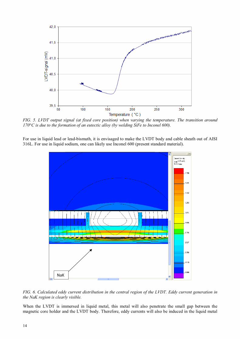
FIG. 5. LVDT output signal (at fixed core position) when varying the temperature. The transition around
170°C is due to the formation of an eutectic alloy (by welding SiFe to Inconel 600).
For use in liquid lead or lead-bismuth, it is envisaged to make the LVDT body and cable sheath out of AISI 316L. For use in liquid sodium, one can likely use Inconel 600 (present standard material).
FIG. 6. Calculated eddy current distribution in the central region of the LVDT. Eddy current generation in
the NaK region is clearly visible.
When the LVDT is immersed in liquid metal, this metal will also penetrate the small gap between the magnetic core holder and the LVDT body. Therefore, eddy currents will also be induced in the liquid metal
NaK NaK

15
and cause a drop in sensitivity. Finite element calculations have shown that in liquid sodium (example), this effect is not important (1% reduction in sensitivity at a temperature of 350ºC). An example of such a calculation is shown in Fig. 6. For liquid lead or lead bismuth, the resistivity is higher than that of NaK (roughly by a factor 2), such that eddy current generation would even be lower. Even when the problem of fabricating a high temperature LVDT up to 700 ºC has been solved, it has not yet been possible to calibrate it because of lack of the required set-up. For the diameter gauge, the same technological solutions which have been developed for the high temperature LVDT can also be used for the diameter gauge. However, an actual high temperature diameter gauge (up to 700 ºC) has not yet been fabricated as the need was presently insufficient. Similarly, it should also be possible to extend the temperature range of the previously developed eddy current probe [1] to 700ºC, using the same technology. The high temperature LVDT (first prototype) was tested at VTT in Finland (in 2009) in a supercritical water loop (see Fig. 7). A close-up view of the mounted electrodes is shown in Fig. 8. The total duration of the experiment was about 15 days, of which 11 days were at supercritical water conditions (temperature above 374°C and pressure above 220 bar). The experiments were performed in low oxygen (<7 ppb), high purity water. The maximum pressure and temperature were 614°C and 255 bar. The LVDT survived the test but an unexplained reversible lowering in sensitivity was observed at high temperature. Later on, it was found out that this effect could be avoided by drying (in vacuum) the inner parts of the LVDT at a higher temperature than the temperature at which the LVDT will be used in the experiments.
FIG. 7. LVDT and ECP electrodes mounted in a SCW-loop at VTT.

16
FIG. 8. Close-up view of the electrodes (ECPs and LVDT) mounted in the SCW-autoclave at VTT.
5. MEMBRANE REFERENCE ELECTRODE
5.1 Principle
The Iron / Iron oxide electrode consists of a ceramic tube, usually made of yttrium stabilized zirconium oxide (YSZ), and filled with a mixture of an iron and iron oxide powder which surrounds a Fe conductor. The zirconium oxide body becomes an ionic conductor of oxygen ions at high temperature (> 230°C) while being impermeable to other gases or water. These oxygen ions take part in the electrochemical reactions at the ceramic/water and at the ceramic/ iron oxide interface and thereby determine the potential of the inner Fe conductor. By measuring the potential difference between a working electrode (for instance a stainless steel sample) and this iron/iron oxide electrode, it thus becomes possible to measure its corrosion potential. The electrochemical reaction at the iron/iron oxide and YSZ layer is,
3 Fe + 4 O2- ↔Fe3O4 + 8 e- (1) and the electrochemical reaction at the interface between the YSZ layer and the water solution is,
H2O ↔ O2- + 2 H+ (2) Assuming the activities of water, Fe and Fe3O4 to be equal to one, one obtains
pHF
RTEE o
OFeFeSHE
303.243/ −= (3)
where o
OFeFeE43/ is the standard electrode potential of the metal – metal oxide half-cell (V), R is the gas
constant (8.314 J·mol-1·K-1), T is the water temperature (K), F is Faraday’s constant (96484 C·mol-1). Equation (3) shows that the electrode potential depends only on the pH and the temperature. The Fe/Fe3O4 electrode is thus essentially a pH electrode which can however be used as a reference electrode provided the pH is known sufficiently accurately. The total electrochemical reaction is given by
3 Fe + 4 H2O ↔ Fe3O4 + 8 H+ + 8 e- (4) The standard electrode potential E0
Fe/Fe3O4 in (3) is thus given by:
17
( )F
EOHFeHOFe
OFeFe⋅
⋅−⋅−⋅+=
8
4342243
43/0 µµµµ
(5)
in which µs is the chemical potential of species s .
5.2 Standard electrode potential up to 650°C
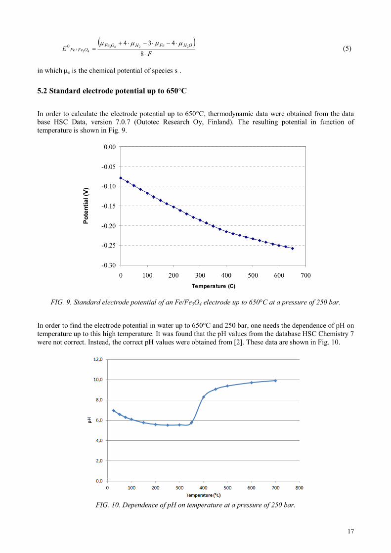
In order to calculate the electrode potential up to 650°C, thermodynamic data were obtained from the data base HSC Data, version 7.0.7 (Outotec Research Oy, Finland). The resulting potential in function of temperature is shown in Fig. 9.
FIG. 9. Standard electrode potential of an Fe/Fe3O4 electrode up to 650°C at a pressure of 250 bar.
In order to find the electrode potential in water up to 650°C and 250 bar, one needs the dependence of pH on temperature up to this high temperature. It was found that the pH values from the database HSC Chemistry 7 were not correct. Instead, the correct pH values were obtained from [2]. These data are shown in Fig. 10.
FIG. 10. Dependence of pH on temperature at a pressure of 250 bar.
-0.30
-0.25
-0.20
-0.15
-0.10
-0.05
0.00
0 100 200 300 400 500 600 700
Temperature (C)
Po
ten
tial (V
)
18
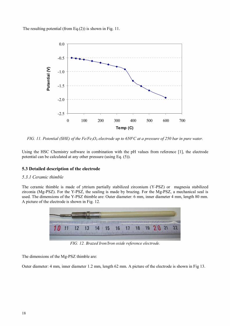
The resulting potential (from Eq.(2)) is shown in Fig. 11.
FIG. 11. Potential (SHE) of the Fe/Fe3O4 electrode up to 650°C at a pressure of 250 bar in pure water.
Using the HSC Chemistry software in combination with the pH values from reference [1], the electrode potential can be calculated at any other pressure (using Eq. (5)).
5.3 Detailed description of the electrode
5.3.1 Ceramic thimble
The ceramic thimble is made of yttrium partially stabilized zirconium (Y-PSZ) or magnesia stabilized zirconia (Mg-PSZ). For the Y-PSZ, the sealing is made by brazing. For the Mg-PSZ, a mechanical seal is used. The dimensions of the Y-PSZ thimble are: Outer diameter: 6 mm, inner diameter 4 mm, length 80 mm. A picture of the electrode is shown in Fig. 12.
FIG. 12. Brazed Iron/Iron oxide reference electrode.
The dimensions of the Mg-PSZ thimble are: Outer diameter: 4 mm, inner diameter 1.2 mm, length 62 mm. A picture of the electrode is shown in Fig 13.
-2.5
-2.0
-1.5
-1.0
-0.5
0.0
0 100 200 300 400 500 600 700
Temp (C)
Po
ten
tia
l (V
)

19
FIG. 13. Iron/Iron oxide reference electrode with mechanical seal
5.3.2 Cable
The mineral insulated cable has a sheath made of Inconel 600. Its outer diameter is 1mm. The length of the cable is specified by the customer and can be up to 16 m long. This cable has two conductors made of Inconel 600; one is connected to the inner iron wire, while the other conductor is left open at the level of the metal to ceramic transition. This second wire allows measuring the leak-tightness of the electrode during operation (using insulation measurements). A resistance (between this wire and the sheath) of a few Ohm up to a few hundred Ohms is an indication of water ingress into the detector. From the measured potentials (and insulation resistances) of both wires during operation (inserted in water) it can be determined which of the two wires is the active one. 5.3.3 Electronics
A high impedance multimeter can be used to monitor the electrode potential. Under non-ideal circumstances (discussed below), the measured voltage might deviate from the true electrode potential. To understand this, the electrical equivalent circuit of electrode, cable and multimeter is shown in Fig. 14.
FIG. 14. Equivalent electric circuit of an ECP electrode. Re is the internal electrode resistance, Rc is the cable insulation resistance, Rm is the internal resistance of the voltage meter.
The measured voltage Vm is related to the true electrode potential by:
Te
Tem
RR
RVV
+⋅= (7)
In which RT is the resistance of the parallel resistances Rc and Rm:
mc
mcT
RR
RRR
+
⋅= (8)
Ve
Re
Rc Rm
Vm
20
Both Re and Rc strongly depend on temperature. In case of very high temperature (600°C) and a long length of exposed cable, one could end up in a situation in which Rc is not anymore much larger than Re. In this case, the experimenter must use the appropriate corrections (as based on Eqs. 7—8). Therefore, a measurement of the cable insulation resistance of the passive wire (during operation) is most useful. 5.3.4 Testing in supercritical water
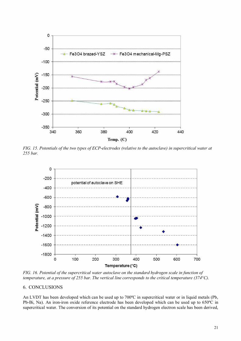
The ECP-electrodes (with brazed and mechanical seal) were tested at VTT in Finland (in 2009) in a supercritical water loop (see Fig. 7). A close-up view of the mounted electrodes is shown in Fig. 8. The total duration of the experiment was about 15 days, of which 11 days were at supercritical water conditions (temperature above 374°C and pressure above 220 bar). The experiments were performed in low oxygen (<7 ppb), high purity water. The maximum pressure and temperature were 614°C and 255 bar. Both types of electrodes survived the test. The potential of the brazed Y stabilized Fe/Fe3O4 electrode was found to be about 82 mV lower than the potential of the Mg PSZ electrode, similar to what was already observed during the autoclave tests at Halden. The potentials of these two electrodes start to deviate from each other above 400°C, reaching a difference of 154 mV at 423°C. Further it is interesting to see that nothing special happens to the measured potentials when crossing the critical temperature of 374°C. However, since the conversion of the electrode potential does show a transition at the critical temperature (see Fig. 11), the potential of the autoclave (on the SHE scale) also shows a transition at the critical temperature (see Fig. 16). A short
explanation on how the potential of the autoclave (on the SHE scale) was calculated is given
below. In general, the ECP of a sample is calculated using the following equation:
Potential of the sample with respect to the SHE
= Measured potential of the sample with respect to the reference electrode
+ Calculated potential of the reference electrode with respect to the SHE
Since the sample is here the autoclave and since the measured potential is the potential of the reference electrode with respect to the autoclave (thus minus the potential of the sample with respect to the reference electrode), the potential of the autoclave on the SHE is the calculated potential of the reference electrode (SHE) minus the measured electrode potential. The difference in potential between the ECPs based on yttrium and the magnesia stabilized zirconia could possibly be attributed to the fact that zirconia-based electrolytes show a significant proportion of n-type electronic conduction at low oxygen potentials and high temperatures [4] and methods have been developed to determine this electronic conductivity [5]. Such corrections have not yet been made to our Mg-PSZ based electrode and are the subject of further studies.
21
FIG. 15. Potentials of the two types of ECP-electrodes (relative to the autoclave) in supercritical water at 255 bar.
FIG. 16. Potential of the supercritical water autoclave on the standard hydrogen scale in function of
temperature, at a pressure of 255 bar. The vertical line corresponds to the critical temperature (374°C).
6. CONCLUSIONS An LVDT has been developed which can be used up to 700ºC in supercritical water or in liquid metals (Pb, Pb-Bi, Na). An iron-iron oxide reference electrode has been developed which can be used up to 650ºC in supercritical water. The conversion of its potential on the standard hydrogen electron scale has been derived,

22
as based on basic thermodynamic principles. Such an electrode could also be used as oxygen sensor in liquid lead (or lead bismuth). Other probes, such as the diameter gauge or the oxide thickness probe (eddy current) could be made to sustain higher temperatures (up to 700 ºC), using the same technology as for the LVDT. Protective coatings have been developed to protect the instruments for corrosion under SCW or liquid metal conditions.
ACKNOWLEDGEMENTS
The author wishes to acknowledge Tore Mathisen, Vidar Pettersen, Rolf Andreassen and Steinar Solstad for the realization and calibrations of the LVDT and the ECP electrodes.
REFERENCES
[1] VAN NIEUWENHOVE R., SOLSTAD S., In-Core fuel performance and material characterization in
the Halden Reactor, IEEE Transactions on Nuclear Science, Vol. 57, No.5 (2010) 2683—2688 [2] BANDURA A.V., LVOV S.N., The ionization constant of water over wide ranges of temperature and
density, J. Phys. Chem. Ref. Data, Vol. 35, No. 1, (2006), pp. 15—30 [3] INTERNATIONAL ASSOCIATION FOR THE PROPERTIES OF WATER AND STEAM, Release on
the Ionization Constant of H2O (2007), available from www.iapws.org [4] YAMADA K., MURASE M., IWASE M., Determination of mixed ionic and electronic conduction in
commercial-grade magnesia-stabilized zirconia electrolyte, Journal of Applied Electrochemistry 16 (1986) 712-718
[5] HUANG K., XIA Y., LIU Q., Radip determination of electronic conductivity in MgO-partially stabilized ZrO2 electrolytes using EMF method, Solid State Ionics 73 (1994) 41—48
23
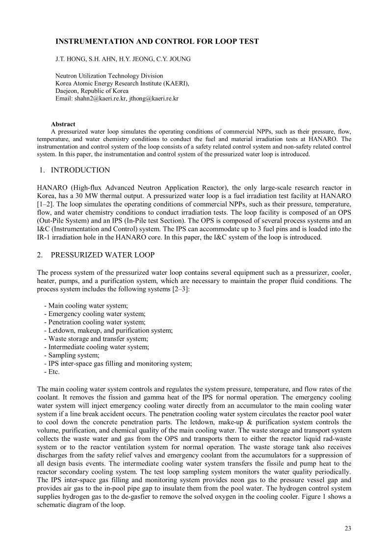
INSTRUMENTATION AND CONTROL FOR LOOP TEST
Neutron Utilization Technology Division Korea Atomic Energy Research Institute (KAERI), Daejeon, Republic of Korea Email: [email protected], [email protected]
Abstract
A pressurized water loop simulates the operating conditions of commercial NPPs, such as their pressure, flow, temperature, and water chemistry conditions to conduct the fuel and material irradiation tests at HANARO. The instrumentation and control system of the loop consists of a safety related control system and non-safety related control system. In this paper, the instrumentation and control system of the pressurized water loop is introduced.
1. INTRODUCTION
HANARO (High-flux Advanced Neutron Application Reactor), the only large-scale research reactor in Korea, has a 30 MW thermal output. A pressurized water loop is a fuel irradiation test facility at HANARO [1–2]. The loop simulates the operating conditions of commercial NPPs, such as their pressure, temperature, flow, and water chemistry conditions to conduct irradiation tests. The loop facility is composed of an OPS (Out-Pile System) and an IPS (In-Pile test Section). The OPS is composed of several process systems and an I&C (Instrumentation and Control) system. The IPS can accommodate up to 3 fuel pins and is loaded into the IR-1 irradiation hole in the HANARO core. In this paper, the I&C system of the loop is introduced. 2. PRESSURIZED WATER LOOP The process system of the pressurized water loop contains several equipment such as a pressurizer, cooler, heater, pumps, and a purification system, which are necessary to maintain the proper fluid conditions. The process system includes the following systems [2–3]:
- Main cooling water system; - Emergency cooling water system; - Penetration cooling water system; - Letdown, makeup, and purification system; - Waste storage and transfer system; - Intermediate cooling water system; - Sampling system; - IPS inter-space gas filling and monitoring system; - Etc.
The main cooling water system controls and regulates the system pressure, temperature, and flow rates of the coolant. It removes the fission and gamma heat of the IPS for normal operation. The emergency cooling water system will inject emergency cooling water directly from an accumulator to the main cooling water system if a line break accident occurs. The penetration cooling water system circulates the reactor pool water to cool down the concrete penetration parts. The letdown, make-up & purification system controls the volume, purification, and chemical quality of the main cooling water. The waste storage and transport system collects the waste water and gas from the OPS and transports them to either the reactor liquid rad-waste system or to the reactor ventilation system for normal operation. The waste storage tank also receives discharges from the safety relief valves and emergency coolant from the accumulators for a suppression of all design basis events. The intermediate cooling water system transfers the fissile and pump heat to the reactor secondary cooling system. The test loop sampling system monitors the water quality periodically. The IPS inter-space gas filling and monitoring system provides neon gas to the pressure vessel gap and provides air gas to the in-pool pipe gap to insulate them from the pool water. The hydrogen control system supplies hydrogen gas to the de-gasfier to remove the solved oxygen in the cooling cooler. Figure 1 shows a schematic diagram of the loop.
J.T. HONG, S.H. AHN, H.Y. JEONG, C.Y. JOUNG

24
The IPS, including the test fuel assembly, is to be loaded into the IR-1 position in the HANARO core [4]. Figure 2 shows a schematic diagram of the IPS. The IPS includes 3 pins of PWR fuel. Three SPNDs are installed in the upper, middle, and lower parts of the irradiated section. Three thermocouples are installed in the inlet, and the middle and outlet points of the test fuel assembly to measure the coolant temperature. A LVDT is installed to measure the fission product pressure, and thermocouples are installed to measure the centreline temperature of the test fuel.
FIG. 1. Schematic diagram of the loop.
FIG. 2. Schematic diagram of IPS.
3. INSTRUMENTATION AND CONTROL SYSTEM
The I&C system of the loop is divided into a safety control system and a non-safety control system. The I&C system has the following functions:
- Maintaining the irradiation test conditions through automatic control; - HANARO trip and a loop safe shutdown during transient or accident conditions; - Satisfaction of the safety design requirements such as redundancy, independency, and single-failure
criterion; - Simultaneous operation of the loop with the reactor.
HANARO PoolHANARO PoolHANARO PoolHANARO Pool
IPSIPSIPSIPSVesselVesselVesselVessel
Isolation ValvesIsolation ValvesIsolation ValvesIsolation Valves
Discharge Discharge Discharge Discharge ValvesValvesValvesValves
FlowFlowFlowFlowControlControlControlControlValveValveValveValve
Safety Relief ValveSafety Relief ValveSafety Relief ValveSafety Relief Valve
Main Cooling Main Cooling Main Cooling Main Cooling Water PumpWater PumpWater PumpWater Pump
MainMainMainMainHeaterHeaterHeaterHeater
Waste Disposal Waste Disposal Waste Disposal Waste Disposal TankTankTankTank
PressurizerPressurizerPressurizerPressurizer
Main CoolerMain CoolerMain CoolerMain Cooler
LMPLMPLMPLMP
Accumulator BAccumulator BAccumulator BAccumulator B Accumulator AAccumulator AAccumulator AAccumulator A
ReactorReactorReactorReactor
CoolingCoolingCoolingCoolingTowerTowerTowerTower
IntermediateIntermediateIntermediateIntermediateCooling WaterCooling WaterCooling WaterCooling Water
Heat ExchangerHeat ExchangerHeat ExchangerHeat Exchanger
OPSOPSOPSOPSHANARO HANARO HANARO HANARO Secondary Secondary Secondary Secondary
Cooling Cooling Cooling Cooling SystemSystemSystemSystem
IPSIPSIPSIPS
Safety Injection ValvesSafety Injection ValvesSafety Injection ValvesSafety Injection Valves
Isolation ValvesIsolation ValvesIsolation ValvesIsolation Valves
Safety Relief ValveSafety Relief ValveSafety Relief ValveSafety Relief Valve
Outer Pressure Vessel
Inner Pressure Vessel
Test Fuel Carrier Leg
Flow Divider
Insulation Gas Gap
Test Fuel
Downward Flow Path
Upward Flow Path
A-A
IPS HeadOutlet Nozzle
Intlet Nozzle
Fuel Carrier Head
Test Fuel
Flow Divider
AA
Fuel Carrier Leg
Inner Pressure Vessel
Outer Pressure Vessel
Outer Pressure Vessel
Inner Pressure Vessel
Test Fuel Carrier Leg
Flow Divider
Insulation Gas Gap
Test Fuel
Downward Flow Path
Upward Flow Path
A-A
Outer Pressure Vessel
Inner Pressure Vessel
Test Fuel Carrier Leg
Flow Divider
Insulation Gas Gap
Test Fuel
Downward Flow Path
Upward Flow Path
Outer Pressure Vessel
Inner Pressure Vessel
Test Fuel Carrier Leg
Flow Divider
Insulation Gas Gap
Test Fuel
Downward Flow Path
Upward Flow Path
A-A
IPS HeadOutlet Nozzle
Intlet Nozzle
Fuel Carrier Head
Test Fuel
Flow Divider
AA
Fuel Carrier Leg
Inner Pressure Vessel
Outer Pressure Vessel
IPS HeadOutlet Nozzle
Intlet Nozzle
Fuel Carrier Head
Test Fuel
Flow Divider
AA
Fuel Carrier Leg
Inner Pressure Vessel
Outer Pressure Vessel

25
The safety control system is used for controlling the safety related process systems and a shutdown of the reactor from abnormal operating conditions. The non-safety control system consists of a loop control system and a data acquisition system. Figure 3 shows a schematic diagram of the I&C system for the loop.
FIG. 3. Schematic diagram of the I&C system of the loop.
3.1 Safety control system
The safety control system consists of loop protection panels, loop safety control panels, and a loop safety indicator panel, and clarified to quality class Q and seismic category I. The loop protection panels are installed in the loop control room located on the first floor of the reactor hall. The loop safety control panels and the loop safety indicator panel are installed in the reactor control room. Figure 4 shows the signal flow diagram of the safety control system. The safety related control panels are designed with following safety regulation of IEEE std-603 to ensure the system reliability. - Single failure criterion; - Redundancy; - Independence; - Diversity; - Fail-safety design; - Manual initiation; - Channel checks; - Channel bypass; - Identification of protective action; - Interface with non-safety related system; - Equipment qualification; - etc.
Loop Safety
IndicatorPNL
Loop Protection
PNL-1/2/3
LoopControlSystem
CPUForDAS
LoopSafety
ControlPNL-1/2
J.B
- Thermal Neutron Flux
- IPS Temp.
- Coolant Temp.
- Fuel Pin Temp.
- Fission Gas Press.
- etc.
IPS System
- SWGR
- Load center
- MCC
- UPS
- etc.
Electrical System
J.B
- MCW
- ECW
- ICL
- LMP
- TLS
- etc.
Process System
Data Acquisition System Operator Station Operator Stations
Loop Control Room Reactor Control Room
Redundant Data Highway

26
FIG. 4. Signal flow diagram of the safety related control panels.
The safety related control panels were qualified by the IEEE std-323, qualifying Class 1E equipment for nuclear power generating stations, and the IEEE std-344, guide for seismic qualification of class 1E electric equipment for nuclear power generating stations. The loop protection panels composed of three channels receive signals from the corresponding field instruments, and generate a reactor trip signal and loop shutdown signal if the measurement signal exceeds the trip set point. The reactor trip signals from the protection panels are interfaced with the corresponding channels of the reactor RPS (Reactor Protection System) panels, which generate the reactor trip signal. The reactor RPS panels have a ‘2 out-of 3’ local coincidence logic for reliability. The main purpose of the loop safety control panels is to supply emergency cooling water to remove heat from the test fuels after a reactor shutdown. The loop safety control panels are composed of two independent panels, and have some manual switches and relays in each panel for a control of the safety related process systems. The safety control panels receive trip signals from the protection panels when the transient excursions of the process condition from the IPS main cooling water occur at unacceptable set point levels. The ‘2 out-of 3’ concept is also applied to the safety control panels to satisfy the reliability of overall plant. If any of the above input signals comes from the protection panels, the safety control panels automatically send the output command signals for safely cooling down the fuel temperature after a reactor shutdown. The loop safety indicator panel receives the following analogue signals to supervise the vital process status in the reactor control room together with the loop control room. Figure 5 shows a picture of the loop safety control panels and loop safety indicator panel installed in the reactor control room.
FIG. 5. Picture of loop safety control panels and safety indicator panel.
Reactor Trip Signal
LoopProtection
Panels
ReactorProtection
Panels
Loop Safety Control Panels
Loop Isolation Signal
Loop Safety
Indicator Panel
Trip Signals from Loop
Trip Signals from
Reactor

27
3.2 Non-safety control system
The non-safety control system consists of a loop control system and a data acquisition system. The operation is performed in two locations, the reactor control room and loop control room in the reactor hall. The start-up operation is done at the loop control room, while the normal operation is done at the reactor control room. The OWS (Operator Work Station) installed in the reactor control room is used for the integral operation of all facilities in the reactor as well as loop facility. The loop control system should communicate with the operator workstation in the reactor control room using the same communication protocol. The digitalized loop control system controls and monitors all field signals from the process systems such as the main cooling water system, and the intermediate cooling water system. The data acquisition system collects and stores the signals from the in-pile instruments. The irradiation data can be monitored in our office located in reactor outside on a real time basis through the network. Figure 6 shows a picture of the non-safety control system.
(a) Loop control system (b) screen of the OWS
FIG. 6. Picture of the non-safety control system.
3.3 In-pile instrumentation
In-pile instrumentation technology is under development for the application of fuel irradiation tests. The main measurement parameters include the centerline temperature of test fuel, the neutron flux, the coolant temperature, and the fission gap pressure. The data acquisition system collects and stores signals from the in-pile instruments (SPND, Thermocouple, LVDT, etc.) installed in the IPS. Figure 7 shows a schematic diagram of the IPS including in-pile instruments.
FIG. 7. Schematic diagram of the IPS including in-pile instruments.
Test fuels
Coolant temp.
Neutron flux
Fission gas pressure
Fuel centerline temp.

28
4. CONCLUSION
This paper introduces an instrumentation and control system of a pressurized water loop in HANARO. The instrumentation and control system is divided into a safety control system and a non-safety control system. The safety control system is used for controlling the safety related process systems and a shutdown of the reactor from abnormal operating conditions. The non-safety control system consists of a loop control system and a data acquisition system. The data acquisition system collects and stores the signals from the in-pile instruments installed in the IPS. The pressurized water loop will be applied to a fuel and material irradiation test.
ACKNOWLEDGMENTS
This research has been carried out as a part of the nuclear R&D program funded by the Ministry of Education Science and Technology in Korea.
REFERENCES
[1] AHN S.H., et al., “Fuel test loop in HANARO,” Proceedings of the 2008 Water Reactor Fuel Performance Meeting (WRFPM), Seoul, Korea, (2008).
[2] AHN S. H., et al., “High temperature performance test for fuel test loop,” Journal of the Korean Institute of Plant Engineering, Vol.15, No 3, p. 99—105, (2010).
[3] PARK S.K., et al., “Analyses of the small break loss-of-coolant accidents for the HANARO fuel test loop,” Journal of Korea Society of Mechanical Technology, Vol.10, No. 2, p. 35—41, (2008).
[4] PARK K.N., et al., “The high temperature and high pressure test of pressure vessel for the irradiation test,” Journal of Korea Society of Mechanical Technology, Vol.10, No. 4, p. 1—6, (2008).
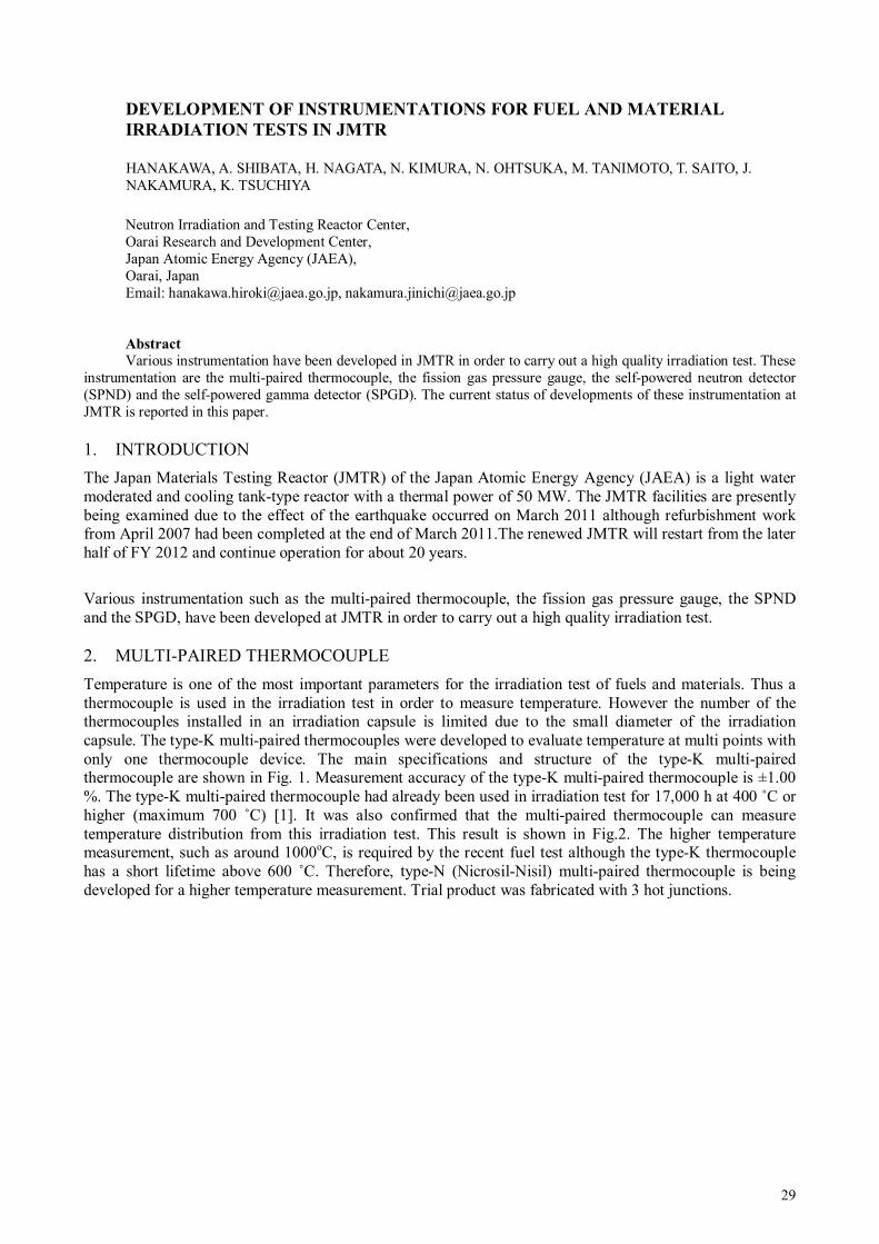
29
DEVELOPMENT OF INSTRUMENTATIONS FOR FUEL AND MATERIAL
IRRADIATION TESTS IN JMTR
Neutron Irradiation and Testing Reactor Center, Oarai Research and Development Center, Japan Atomic Energy Agency (JAEA), Oarai, Japan Email: [email protected], [email protected] Abstract
Various instrumentation have been developed in JMTR in order to carry out a high quality irradiation test. These instrumentation are the multi-paired thermocouple, the fission gas pressure gauge, the self-powered neutron detector (SPND) and the self-powered gamma detector (SPGD). The current status of developments of these instrumentation at JMTR is reported in this paper. 1. INTRODUCTION
The Japan Materials Testing Reactor (JMTR) of the Japan Atomic Energy Agency (JAEA) is a light water moderated and cooling tank-type reactor with a thermal power of 50 MW. The JMTR facilities are presently being examined due to the effect of the earthquake occurred on March 2011 although refurbishment work from April 2007 had been completed at the end of March 2011.The renewed JMTR will restart from the later half of FY 2012 and continue operation for about 20 years.
Various instrumentation such as the multi-paired thermocouple, the fission gas pressure gauge, the SPND and the SPGD, have been developed at JMTR in order to carry out a high quality irradiation test. 2. MULTI-PAIRED THERMOCOUPLE
Temperature is one of the most important parameters for the irradiation test of fuels and materials. Thus a thermocouple is used in the irradiation test in order to measure temperature. However the number of the thermocouples installed in an irradiation capsule is limited due to the small diameter of the irradiation capsule. The type-K multi-paired thermocouples were developed to evaluate temperature at multi points with only one thermocouple device. The main specifications and structure of the type-K multi-paired thermocouple are shown in Fig. 1. Measurement accuracy of the type-K multi-paired thermocouple is ±1.00 %. The type-K multi-paired thermocouple had already been used in irradiation test for 17,000 h at 400 ˚C or higher (maximum 700 ˚C) [1]. It was also confirmed that the multi-paired thermocouple can measure temperature distribution from this irradiation test. This result is shown in Fig.2. The higher temperature measurement, such as around 1000oC, is required by the recent fuel test although the type-K thermocouple has a short lifetime above 600 ˚C. Therefore, type-N (Nicrosil-Nisil) multi-paired thermocouple is being developed for a higher temperature measurement. Trial product was fabricated with 3 hot junctions.
HANAKAWA, A. SHIBATA, H. NAGATA, N. KIMURA, N. OHTSUKA, M. TANIMOTO, T. SAITO, J. NAKAMURA, K. TSUCHIYA

30
FIG.1 Structure of multi-paired thermocouple. FIG.2 Measuring result of temperature distribution. X-ray inspection for hot junction positions and the leakage test for protection sheath were carried out. From these inspections, the accuracy of hot junction axial positions was ±1 mm, the leakage rate of protection sheath was less than 10-7 Pa m3/s. The temperature characteristics of type N was confirmed through the demonstration test by using the reference thermocouples under un-irradiation conditions. Figure 3 shows the result of demonstration test. The accuracy of the measured temperatures was ±1 % up to 1100˚C based on the comparison with the temperatures measured by reference thermocouples. Then, endurance tests of N type multi-paired and N type thermocouple were performed with the infrared furnace [2]. The N type multi-paired thermocouples were heated up to 1000˚C for 3000 h. The N type thermocouple was heated up to 1200˚C for 1000 h. The N type multi-paired thermocouples showed excellent durability which is able to stand at 1000˚C with 3000 h in the endurance tests using the infrared furnace. The future development plans are to carry out in-pile test with Type N and to product the multi thermocouples with more hot junctions such as 5 or 7 hot junctions.
FIG. 3 Result of Demonstration test with type N multi-paired thermocouple.
3. FISSION GAS PRESSURE GAUGE
To measure the inner gas pressure of fuel pin is very important to evaluate the fuel behaviour such as fission gas release. Fuels are required higher burn-up recently in nuclear power plants due to efficiency. From this background, fission gas pressure gauge has been developed to measure higher rod inner gas pressure for the high burn up fuel test. The fission gas pressure gauge for 5 and 10 MPa has been developed. Figure 4 shows the schematic view of these fission gas pressure gauges. The fission gas pressure gauges are composed of a bellows, springs and a LVDT. In trial products, the LVDT was changed from a ceramic covered wire to a
φ106000
35
50
Plug
Sleeve
[unit:mm]
92
65
65
φ1.5
φ1.8φ1.8
Dummy chip
Dummy wire
Protectionsheath
Sheath typed T/C(MgO insulator)
Hot junctions
1000
0
200
400
600
800
1200
0 200 400 600 800 1000 1200
Temperature:RT-1100˚CAtmosphere :He
Refe
rence
valu
e (
˚C)
Measuring Value (˚C)
: Hot junction A: Hot junction B: Hot junction C
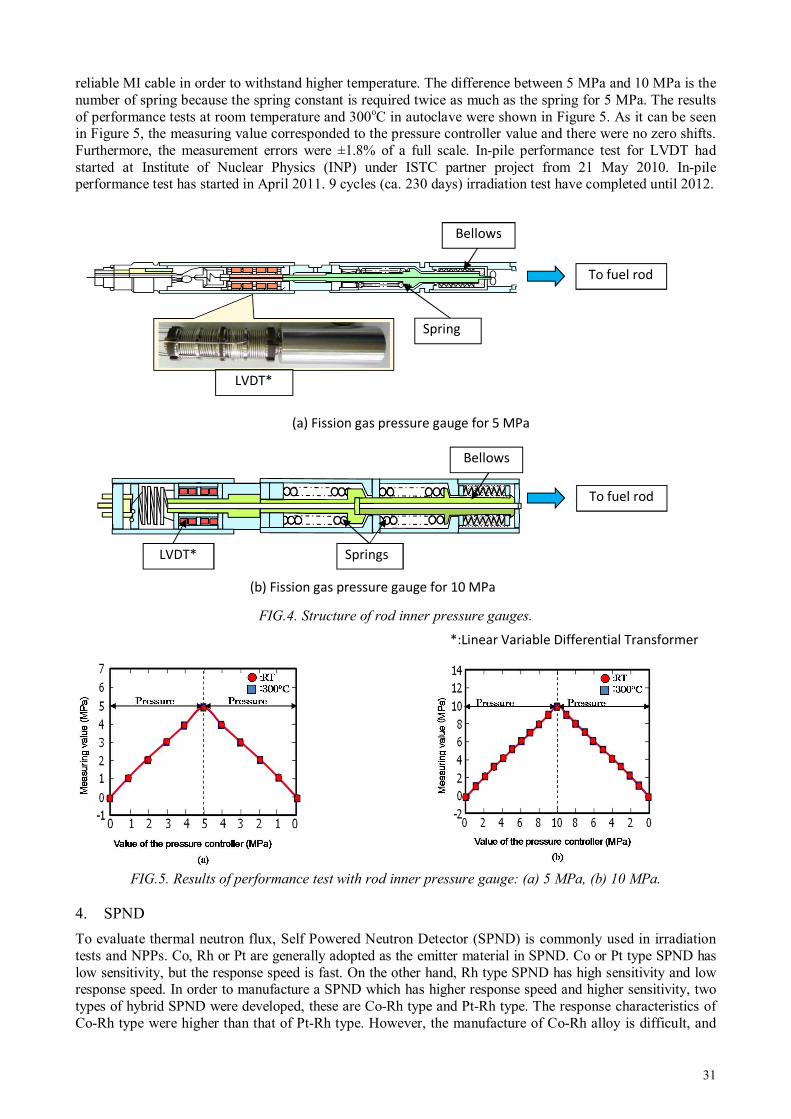
31
reliable MI cable in order to withstand higher temperature. The difference between 5 MPa and 10 MPa is the number of spring because the spring constant is required twice as much as the spring for 5 MPa. The results of performance tests at room temperature and 300oC in autoclave were shown in Figure 5. As it can be seen in Figure 5, the measuring value corresponded to the pressure controller value and there were no zero shifts. Furthermore, the measurement errors were ±1.8% of a full scale. In-pile performance test for LVDT had started at Institute of Nuclear Physics (INP) under ISTC partner project from 21 May 2010. In-pile performance test has started in April 2011. 9 cycles (ca. 230 days) irradiation test have completed until 2012.
FIG.4. Structure of rod inner pressure gauges.
FIG.5. Results of performance test with rod inner pressure gauge: (a) 5 MPa, (b) 10 MPa.
4. SPND
To evaluate thermal neutron flux, Self Powered Neutron Detector (SPND) is commonly used in irradiation tests and NPPs. Co, Rh or Pt are generally adopted as the emitter material in SPND. Co or Pt type SPND has low sensitivity, but the response speed is fast. On the other hand, Rh type SPND has high sensitivity and low response speed. In order to manufacture a SPND which has higher response speed and higher sensitivity, two types of hybrid SPND were developed, these are Co-Rh type and Pt-Rh type. The response characteristics of Co-Rh type were higher than that of Pt-Rh type. However, the manufacture of Co-Rh alloy is difficult, and
*:Linear Variable Differential Transformer
Spring
Bellows
To fuel rod
LVDT*
To fuel rod
LVDT*
Springs
Bellows
(a) Fission gas pressure gauge for 5 MPa
(b) Fission gas pressure gauge for 10 MPa
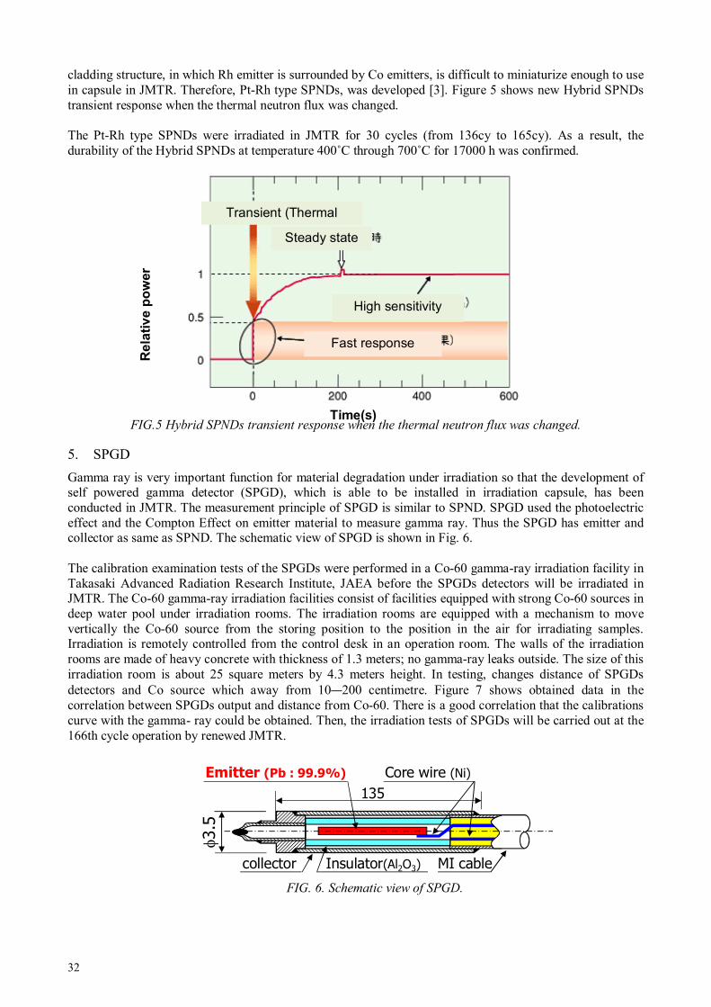
32
cladding structure, in which Rh emitter is surrounded by Co emitters, is difficult to miniaturize enough to use in capsule in JMTR. Therefore, Pt-Rh type SPNDs, was developed [3]. Figure 5 shows new Hybrid SPNDs transient response when the thermal neutron flux was changed. The Pt-Rh type SPNDs were irradiated in JMTR for 30 cycles (from 136cy to 165cy). As a result, the durability of the Hybrid SPNDs at temperature 400˚C through 700˚C for 17000 h was confirmed.
FIG.5 Hybrid SPNDs transient response when the thermal neutron flux was changed.
5. SPGD
Gamma ray is very important function for material degradation under irradiation so that the development of self powered gamma detector (SPGD), which is able to be installed in irradiation capsule, has been conducted in JMTR. The measurement principle of SPGD is similar to SPND. SPGD used the photoelectric effect and the Compton Effect on emitter material to measure gamma ray. Thus the SPGD has emitter and collector as same as SPND. The schematic view of SPGD is shown in Fig. 6. The calibration examination tests of the SPGDs were performed in a Co-60 gamma-ray irradiation facility in Takasaki Advanced Radiation Research Institute, JAEA before the SPGDs detectors will be irradiated in JMTR. The Co-60 gamma-ray irradiation facilities consist of facilities equipped with strong Co-60 sources in deep water pool under irradiation rooms. The irradiation rooms are equipped with a mechanism to move vertically the Co-60 source from the storing position to the position in the air for irradiating samples. Irradiation is remotely controlled from the control desk in an operation room. The walls of the irradiation rooms are made of heavy concrete with thickness of 1.3 meters; no gamma-ray leaks outside. The size of this irradiation room is about 25 square meters by 4.3 meters height. In testing, changes distance of SPGDs detectors and Co source which away from 10—200 centimetre. Figure 7 shows obtained data in the correlation between SPGDs output and distance from Co-60. There is a good correlation that the calibrations curve with the gamma- ray could be obtained. Then, the irradiation tests of SPGDs will be carried out at the 166th cycle operation by renewed JMTR.
FIG. 6. Schematic view of SPGD.
φ3.5
135
Emitter (Pb : 99.9%)
MI cableInsulator(Al2O3)
Core wire (Ni)
collector
Time(s)
Re
lati
ve p
ow
er
Fast response (Co,Pt)
High sensitivity
(Rh)
Steady state
Transient (Thermal neutron)

33
FIG. 7. Result of calibration test of SPGDs.
6. CONCLUSION
The development of instrumentation has been carried out in order to evaluate more detail data and to conduct a higher level irradiation test. The K-type multi-paired thermocouple and the hybrid SPND had developed and been applied to the irradiation test. This instrumentation produced meaningful in-pile data. For the future irradiation test, the trial products of type N multi-paired thermocouples, the fission gas pressure gauge and SPGD were manufactured and the out-pile test for these products were carried out. The out-pile performance tests of these instrumentation show that more developed and advanced irradiation test will be able to carry out by using these instrumentation. In future, the irradiation tests using this developed instrumentation will be carried out in JMTR. Moreover, the characteristics of these instrumentation will be evaluated in order to set up an international standards instrumentation in research/testing reactors
REFERENCES
[1] TSUCHIYA K., “In-Situ tritium Recovery Experiments of Blanket In-pile Mockup with Li2TiO3 Pebble
Bed in Japan”, J.Nucl. Sci. Techol. 996—1003 (2001) 38. [2] TANIMOTO M., AOYAMA S., KITAGISHI S., SHIBATA S., SAITO T., NAKAMURA J. and
TSUCHIYA K. “Development of Instrumentation for International Standard” 1st Asian Symposium on Material Testing Reactors (Proc. Symp. Kuala Lumpur) 62—70.
[3] NAKAMICHI M., NAGAO Y., YAMAMURA C., NAKAZAWA M., KAWAMURA H. “Characterization of hybrid self-powered neutron detector under neutron irradiation” Fusion Engineering and Design, 837—841 (2000) 51–52.
0
1
2
3
4
0 50 100 150 200
SP
GD
outp
ut(
×1
0-1
0A
)
Distance from Co-60 (cm)
Room temperatureRoom temperatureRoom temperatureRoom temperature::::14141414
: SPGD No.1: SPGD No.2: SPGD No.3
34
NEW SENSORS FOR IRRADIATION TESTING AT MATERIALS AND TEST
REACTORS
Idaho National Laboratory, Idaho Falls, Idaho, United States of America Email: [email protected] Abstract
Enhanced instrumentation, capable of providing real-time measurements of parameters during fuels and material irradiations, is required to support irradiation testing requested by US nuclear research programs. For example, several research programs funded by the US Department of Energy (US DOE) are emphasizing the use of first principle models to characterize the performance of fuels and materials. To facilitate this approach, high fidelity, real-time data are essential to demonstrate the performance of these new fuels and materials during irradiation testing. Furthermore, sensors that obtain such data in US MTRs, such as the Advanced Test Reactor (ATR) located at the Idaho National Laboratory (INL), must be miniature, reliable, and able to withstand high fluxes and high temperatures. Depending on program requirements, sensors may need to obtain data in inert gas, pressurized water, or liquid metal environments. To address these needs, INL has developed and deployed several new sensors to support irradiation testing in US DOE programs. The paper identifies the sensors currently available to support higher flux US MTR irradiations. Recent results and products from sensor research and development are highlighted. In particular, progress in deploying enhanced in-pile sensors for detecting temperature, elongation, and thermal conductivity is emphasized. Finally, initial results from research to evaluate the viability of ultrasonic and fiber optic technologies for irradiation testing are summarized.
1. INTRODUCTION
Several US nuclear research programs require enhanced in-pile instrumentation to provide real-time measurements of key parameters during irradiations. For example, high fidelity, real-time data are essential for characterizing the performance of new fuels and materials during irradiation testing. Furthermore, sensors that obtain such data must be miniature, reliable and able to withstand high temperature and high neutron flux conditions that are often present in US MTRs. Depending on user requirements, sensors may need to obtain data in inert gas, pressurized water, or liquid metal environments.
Many of the sensors deployed in foreign MTRs are not capable of supporting the high flux/high temperature test conditions often requested by customers at US MTRs, such as at the ATR located at the INL. To address this need, in-pile instrumentation development efforts have been funded by several US Department of Energy (DOE) programs, such as the ATR National Scientific User Facility (NSUF), the Fuel Cycle Research & Development (FCRD), the Next Generation Nuclear Plant (NGNP), and the Nuclear Energy Enabling Technology (NEET) programs. These efforts have led to new sensors that are deployed in the ATR and other domestic and foreign MTRs. This paper reports recent results from these efforts.
1.1 Typical Irradiation Options
MTR designs differ dramatically. Even at INL, where over fifty MTRs have been designed, built, and operated, no two MTR designs were identical. However, typical types of irradiation options included in MTRs are listed below with typical types of instrumentation that can be included in each option.
Static capsules – These capsules may be used to irradiate samples or engineered components. Static capsule experiments may be sealed or may contain material that can be in contact with MTR primary coolant (such capsules are in an open configuration without being sealed). In some MTRs, irradiation temperature may be selected (within limits) by providing a gas gap in the capsule with a known thermal conductance. Instrumentation in such irradiation locations is currently limited to sensors that detect peak temperature or accumulated neutron fluence.
Instrumented lead experiments - In these locations, experiments can have instrumentation, such as thermocouples, connected to individual capsules or single specimens. This instrumentation can be used to
J. REMPE, D. KNUDSON, J. DAW, T. UNRUHA, B. CHASE, K. DAVIS, R. SCHLEY, S. TAYLORA

35
measure and control conditions within the capsule. For example, temperature control in individual zones (within limits) is performed by varying the gas mixture (typically helium and neon) in the gas gap that thermally links the capsule to the reactor coolant. In addition to temperature, sensors can monitor the gas around the test specimen. In a fueled experiment, the presence of fission gases due to fuel failures or oxidation can be detected via gas chromatography. Leads extending from sensors in these locations allow real time display of experimental parameters on control consoles.
Pressurized water loop experiments - Many MTRs have flux traps equipped with pressurized water loops for fuels and materials testing. These water loops can be operated at different temperatures, pressures, flow rates, and water chemistry conditions. Often, these loops operate at or above the standard temperature and pressure of a commercial PWR power plant or at conditions typical of BWR power plant conditions. Water loops can be instrumented to measure and control coolant flows, temperatures, and pressures while sampling test data.
Hydraulic shuttle irradiation system (HSIS) - An HSIS or “rabbit” enables insertion and removal of experiment specimens while an MTR is operating. The ATR HSIS titanium experiment capsules, or shuttles, includes up to 14 capsules that can be used for irradiations simultaneously. Instrumentation in HSIS shuttles is limited to sensors that detect peak temperature or accumulated neutron fluence.
The ATR, which has a maximum power rating of 250 MWth, has a maximum unperturbed thermal neutron flux of 1 x 10¹⁵ n/cm2-s and a maximum fast neutron flux of 5 x 10¹⁴ n/cm2-s. The ATR includes all of the above types of irradiation locations. In addition, it is co-located with the ATR Critical (ATRC) facility, a full-size nuclear mock-up of the ATR core that allows researchers to characterize in advance, with precision and accuracy, the expected changes in ATR core reactivity due to a proposed test. This facility generally operates at a thermal power of less than 5 kW (with associated peak thermal fluxes of around 1010 n/cm2-s and a maximum fast neutron flux of around 109 n/cm2-s). Clearly, the ATR design offers unique advantages for testing. With additional in-pile instrumentation to support these testing capabilities, the features offered by this facility can be even more fully utilized.
1.2 Sensor Development Effort Status
In 2009, the ATR NSUF initiated an effort to develop unique instrumentation required for ATR irradiations. [1] As part of this effort, a review was first completed to identify instrumentation available to users at other MTRs located in the US and abroad. Table I presents an updated version of results from this initial review that reflects recent INL activities to develop and deploy new in-pile sensors.
The instrumentation initially developed by INL was primarily selected based on anticipated user needs and “technology readiness” (to provide users needed instrumentation as soon as possible). For example, many international MTRs have sensors available for real-time detection of parameters such as neutron flux (thermal and fast) and geometry changes (length and diameter). As indicated by the blue italic text in Table1, efforts are underway to explore using these technologies at the ATR and other US MTRs. However, adapting instrumentation used at lower power MTRs often requires special considerations because of the harsher irradiation conditions (e.g., higher neutron fluxes, higher temperatures, etc.) and test capsule geometries requested by users at US MTRs, such as ATR. As indicated by the red bold text in Table I, several new or enhanced sensors are now available to users at ATR and other MTRs as a result of this instrumentation development effort.

36
Using the same colour scheme as Table I, Table II provides additional details about the status of on-going sensor development and evaluation efforts at INL. As indicated in Table II, some level of research has been
TABLE I. INSTRUMENTATION AVAILABLE AT ATR AND OTHER MTRS
Parameter
Location
ATR Technology
Proposed Advanced Technology
Static
Capsule/
HSIS
Instr.
Lead
PWR
Loop
Available at Other
MTRs
Developmental
Temperature √ √ √ -Melt wires (peak temperature)a,b -SiC Temperature Monitors (peak temperature for range of values)
-Paint spots (peak )
√ √ -Thermocouples (Type N, K, C, and High
Temperature Irradiation
Resistant Thermocouples
(HTIR-TCs)d
- Fiber optics -Noise thermometry -UTs
Thermal Conductivity
√ √ - THWM techniques -Degradation using signal changes in thermocouples
Fluence (neutron)
√ √ √ -Flux wires -Activating foil dosimeters
√ √ -Self-Powered
Neutron Detectors
(SPNDs) -Subminiature/
miniature fission
chambers
-Moveable SPNDs -Micro-Pocket
Fission Detectors (MPFDs)
Gamma Heating
√ √ -Calorimeters -Gamma
thermometers
Dimensional √ √ -LVDTs
-Diameter gauge -Hyper-frequency resonant cavities
-Ultrasonic
techniques
-Fiber optics
Fission Gas (Amount, Composition)
√ √ - Gas Chromatography - Pressure Sensors - On-line Fission Product
Monitoring
- Sampling
-LVDT-based pressure monitors -Counter-pressure monitor
-Acoustic measurements with high-frequency echography
Loop Pressure √ -Differential pressure transmitters -Pressure gauges with impulse lines
Loop Flowrate
√ -Flow venturis -Orifice plates
Loop Water Chemistry
√ -Off-line sampling /analysis
-Electrical chemical potential probes
Crud Deposition
√ -Diameter gauge with neutron detectors and thermocouples
Crack Growth Rate
√ -Direct Current
Potential Drop
(DCPD) Techniques
a Blue italic text denotes instrumentation being investigated for ATR applications; red bold text denotes new instrumentation currently deployed at the ATR. b Although melt wires have been used at ATR, recent efforts have expanded the types offered to our users, allowing more accurate estimates of peak temperature, and enhanced encapsulation method. c Although listed under temperature, wireless technologies could be pursued for many parameters. d Type C thermocouple use requires a “correction factor” to correct for decalibration during irradiation.

37
initiated on most of the identified sensor technologies. INL sensor development and evaluation activities rely heavily on collaborations with other research organizations, such as the Institute for Energy Technology at the Halden Reactor Program (IFE/HRP) and Commissariat à l'Énergie Atomique et aux Energies Alternatives (CEA), to maximize the benefit from research expenditures. In addition, collaborations were initiated with universities possessing specialized capabilities in sensor development and evaluation areas. Section 2 of this paper highlights progress in sensors for detecting three types of parameters: temperature, thermal conductivity, and elongation.
TABLE II. STATUS OF ATR NSUF SENSOR DEVELOPMENT AND EVALUATION EFFORTS.
Parameter Sensor Status
Temperature Melt Wires Used to support various irradiation programs. Procedures completed for evaluating candidate melt wires; numerous melt wires evaluated for temperatures between 85 and 1470°C.
SiC Temperature
Monitors
Used to support various irradiation programs. Development and evaluation of post-irradiation measurement capability completed [including comparison evaluations with Oak Ridge National Laboratory].
HTIR-TCs Initial out-of-pile testing completed. In-pile testing (in the AGR-1 gas reactor fuel irradiation test) and sensor enhancement evaluations completed; HTIR-TCs provided to Massachusetts Institute of Technology (MIT) in 2010, and HTIR-TCs for high temperature (1600°C) irradiations shipped to IFE/HRP in 2011.
UTs Efforts initiated to develop and evaluate the accuracy and resolution of a prototype for FCRD evaluations initiated in 2011. Initial efforts focusing on use of magnetostrictive transducers, but instrumented lead irradiation test will be performed to compare survivability of piezoelectric and magnetostrictive transducers (which could enhance accuracy and resolution).
Thermal Conductivity
Multiple
thermocouples Initial laboratory testing completed. Inclusion of HTIR-TCs could allow detection at higher temperatures than current methods used by IFE/HRP.
THWM Prototype design developed and laboratory testing completed. Elongation, Crud deposition, Corrosion
LVDTs
Out-of-pile testing completed on developmental LVDT that resists high temperature degradation and eliminates Curie temperature effects.
Diameter gauge
Currently used in HBWR for detecting swelling, corrosion, and crud buildup. Investigations to be initiated when funding is available.
Ultrasonic
Techniques Scoping tests completed on prototype; additional prototype out-of-pile testing needed.
Fiber Optic Techniques
Efforts initiated in 2011 to develop and evaluate the accuracy of a candidate probe. Prior to deployment, instrumented lead test needed to evaluate fiber optic survivability in radiation environments.
In-pile Creep Test Rig
LVDT-based rig
with bellows
Design developed and prototype evaluated at PWR conditions in a laboratory autoclave. Ready for deployment in an ATR PWR loop. Follow-on work will develop design with variable load capability.
Neutron Flux
SPNDs
Specially-developed fixturing designed, fabricated, and installed at ATRC in 2010. New fixturing allows simultaneous placement of detectors in a flux trap. Evaluations of detectors continuing. Fission Chambers
MPFDs Initiated development of MPFDs in 2011. Gamma Heating
Gamma thermometers Currently used at HBWR; Investigations started in 2012.
Calorimeters Currently used at OSIRIS; investigations to be initiated when funding available. Crack propagation
DCPD method with CT specimens
Preliminary design (based on IFE/HRP method) developed by MIT in 2009; additional investigations started in 2012.
Ultrasonic techniques Investigations to be initiated when funding available. Fiber optics techniques
Investigations to be initiated when funding available.
2. SELECTED DEVELOPMENT AND DEPLOYMENT EFFORTS
2.1 Temperature
2.1.1 Available options
As indicated in Tables I and II, temperature detection sensors available to ATR NSUF users are comparable, if not superior, to those used at other MTRs. To meet recent customer requests, an increased selection of

38
melt wires with enhanced encapsulation and SiC temperature monitors are now available; and doped molybdenum/niobium alloy high temperature irradiation thermocouples (HTIR-TCs), in addition to lower temperature Type N and K thermocouples are now available.
HTIR-TCs were installed in a multi-capsule NGNP fuel experiment that was irradiated in INL's ATR. This multi-capsule experiment was designed to irradiate samples at temperatures up to 1200ºC. This test, which started in February 2007, ended in October 2009. Figure 1 shows signals from two INL-developed HTIR-TCs and one Type N thermocouple located at a cooler region within one of the test capsules. Signal variations are due to ATR power fluctuations and outages. As shown in this figure, at the beginning of this irradiation, the HTIR-TC located near the Type N thermocouple gave a signal consistent with the signal from this Type N thermocouple. In addition, the HTIR-TC located at a higher temperature region within the capsule yielded a consistent, but higher temperature, signal. However, in October 2008, the Type N thermocouple failed and its signal ceased, while the HTIR-TCs continued to function appropriately for the duration of the test.
Subsequent laboratory evaluations indicate that HTIR-TCs resist degradation associated with high temperature up to 1800ºC [1—2]. All of these temperature sensors (and other INL-developed sensors) are available to users at ATR NSUF facilities. In addition, other MTRs may obtain such sensors from INL. For example, INL provided four HTIR-TCs to the IFE/HRP for use in the HBWR in 2011.
2.1.2 Ultrasonic techniques
As discussed in [4], INL has started evaluating the use of ultrasonic thermometers (UTs) as an improved sensor for detecting temperature during irradiation testing of advanced fuels proposed within the FCRD program. As indicated in Figure 2, UTs operate on the principle that the speed at which sound travels through a material (acoustic velocity) is dependent on the temperature of the material. UTs have several advantages over other types of temperature sensors. UTs can be made very small, as the sensor consists only of a small diameter rod which may or may not require a sheath. Measurements may be made up to very high temperature (near the melting point of the sensor material) and, as no electrical insulation is required, shunting effects observed in traditional high temperature thermocouple applications are avoided. Most attractive, however, is the ability to introduce multiple acoustic discontinuities into the sensor, as this enables temperature profiling with a single sensor. INL evaluatations include development of improved methods for fabricating magnetostrictive transducers and joining them to waveguides, characterization of candidate sensor materials appropriate for use in FCRD fuels irradiations, enhanced signal processing techniques, and tests to determine maximum accuracy and resolution. In addition, results from an ATR NSUF irradiation test at the Massachusetts Institute Technology research reactor (MITR) that will compare the performance of piezoelectric and magnetostrictive transducers will be factored into recommendations for use of UTs in FCRD irradiations.
Fig.1. HTIR-TCs installed in AGR-1 test capsule and representative HTIR-TC and Type N data during ATR irradiation.

39
Initial INL evaluations (Fig. 3.) indicate that for FCRD irradiation conditions, doped molybdenum exhibits superior performance at higher temperatures (above 1000ºC) and stainless steel exhibits superior performance at temperatures below 1000ºC). INL evaluations have also identified appropriate damping techniques to reduce signal noise when multi-pass signals are employed. A miniature magnetostrictive transducer design developed by INL has been demonstrated to enhance UT accuracy. Initial benchtop evaluations demonstrate that resolutions of 1 cm are possible, and smaller resolutions are being evaluated.
2.2 Thermal Conductivity
Historically, in-pile thermal conductivity measurements were made using an approach with one (or more) thermocouples embedded near the center of the fuel rod and one exterior to the fuel (in the coolant or a structure outside the fuel element). As part of a collaborative effort to develop an in-pile thermal conductivity measurement technique, Utah State University (USU) and INL compared the steady-state thermal conductivity approach using multiple thermocouples and a transient hot wire method (THWM) using a single thermal conductivity probe (see Fig. 4). Results [4] indicate that the THWM needle probe, containing a line heat source and a thermocouple (see Fig. 4b) embedded in the fuel, offers an enhanced method for in-pile detection for thermal conductivity.
Fig. 2. Typical multi-sensor pulse/echo ultrasonic thermometry system and temperature dependent
acoustic velocities of candidate sensors.
Fig. 3. Representative INL UT evaluations and results.
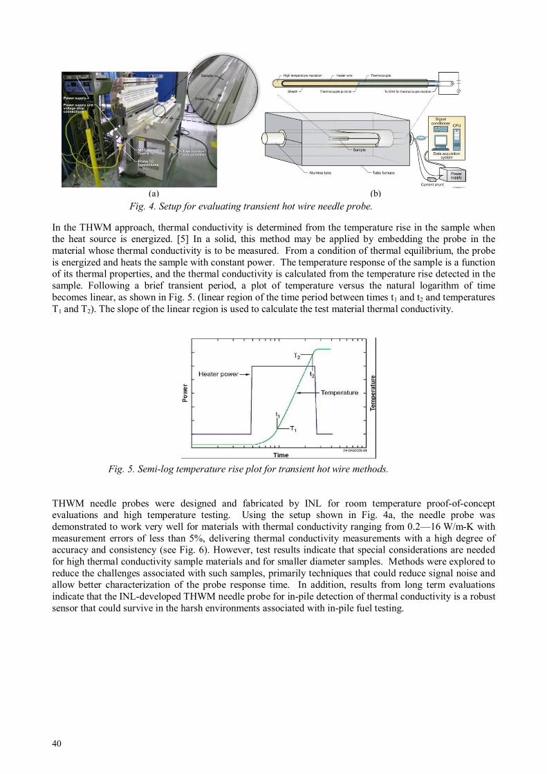
40
(a) (b)
In the THWM approach, thermal conductivity is determined from the temperature rise in the sample when the heat source is energized. [5] In a solid, this method may be applied by embedding the probe in the material whose thermal conductivity is to be measured. From a condition of thermal equilibrium, the probe is energized and heats the sample with constant power. The temperature response of the sample is a function of its thermal properties, and the thermal conductivity is calculated from the temperature rise detected in the sample. Following a brief transient period, a plot of temperature versus the natural logarithm of time becomes linear, as shown in Fig. 5. (linear region of the time period between times t1 and t2 and temperatures T1 and T2). The slope of the linear region is used to calculate the test material thermal conductivity.
THWM needle probes were designed and fabricated by INL for room temperature proof-of-concept evaluations and high temperature testing. Using the setup shown in Fig. 4a, the needle probe was demonstrated to work very well for materials with thermal conductivity ranging from 0.2—16 W/m-K with measurement errors of less than 5%, delivering thermal conductivity measurements with a high degree of accuracy and consistency (see Fig. 6). However, test results indicate that special considerations are needed for high thermal conductivity sample materials and for smaller diameter samples. Methods were explored to reduce the challenges associated with such samples, primarily techniques that could reduce signal noise and allow better characterization of the probe response time. In addition, results from long term evaluations indicate that the INL-developed THWM needle probe for in-pile detection of thermal conductivity is a robust sensor that could survive in the harsh environments associated with in-pile fuel testing.
Fig. 4. Setup for evaluating transient hot wire needle probe.
Fig. 5. Semi-log temperature rise plot for transient hot wire methods.

41
(a) (b)
2.3 Elongation
Today, most MTRs rely on LVDTs to detect changes in length during irradiation. Because of the higher temperatures required in many ATR irradiations, INL collaborated with IFE/HRP to develop an enhanced LVDT. This LVDT has been incorporated into a creep test rig for deployment in the new PWR loop that has been installed in the ATR. In addition, INL is exploring the use of ultrasonic and fiber optic technologies for in-pile detection of elongation.
2.3.1 LVDT Techniques
As shown in Fig. 7a, LVDTs are electrical transformers with three coils placed end-to-end around a tube. The center coil is the primary, and the two outer coils are the secondaries. A cylindrical, magnetically-permeable core, attached to the object whose position is to be measured, slides along the axis of the tube. An alternating current is driven through the primary, causing a voltage to be induced in each secondary, which is proportional to its mutual inductance in the primary. As the core moves, these mutual inductances change, causing the voltages induced in the secondaries to change. The coils are connected in reverse series, so that the output voltage is the difference between the two secondary voltages. When the core is in its central position, equidistant between the two secondaries, equal but opposite voltages are induced in these two coils, hence, the output voltage is zero (see Fig. 7b). Many features of LVDTs (e.g., near frictionless measurements, long lifetime, high resolution, etc.) make them ideal for in-pile applications.
Most research reactors rely on LVDTs made by the IFE/HRP. In the IFE/HRP LVDTs, the position of the magnetically-permeable core can be measured with an accuracy of ± 1—10 µm (references vary on this value). Since the IFE/HRP started with in-core measurements, more than 2200 LVDTs of different types have been installed in different test rigs in the HBWR and other test reactors around the world. IFE/HRP
Fig. 6. Comparison of THWM needle probe results for various power levels for (a) fused silica and (b)
Inconel Alloy 625.
Fig. 7. LVDT components (a) and operation (b).
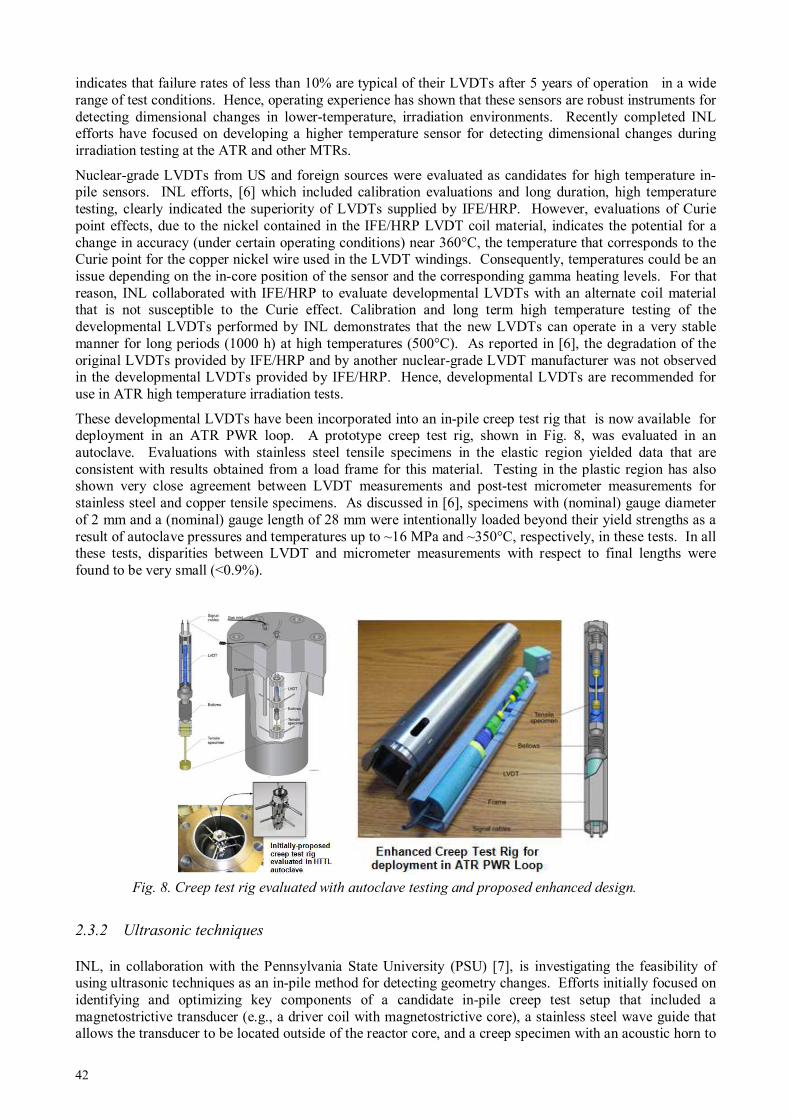
42
indicates that failure rates of less than 10% are typical of their LVDTs after 5 years of operation in a wide range of test conditions. Hence, operating experience has shown that these sensors are robust instruments for detecting dimensional changes in lower-temperature, irradiation environments. Recently completed INL efforts have focused on developing a higher temperature sensor for detecting dimensional changes during irradiation testing at the ATR and other MTRs.
Nuclear-grade LVDTs from US and foreign sources were evaluated as candidates for high temperature in-pile sensors. INL efforts, [6] which included calibration evaluations and long duration, high temperature testing, clearly indicated the superiority of LVDTs supplied by IFE/HRP. However, evaluations of Curie point effects, due to the nickel contained in the IFE/HRP LVDT coil material, indicates the potential for a change in accuracy (under certain operating conditions) near 360°C, the temperature that corresponds to the Curie point for the copper nickel wire used in the LVDT windings. Consequently, temperatures could be an issue depending on the in-core position of the sensor and the corresponding gamma heating levels. For that reason, INL collaborated with IFE/HRP to evaluate developmental LVDTs with an alternate coil material that is not susceptible to the Curie effect. Calibration and long term high temperature testing of the developmental LVDTs performed by INL demonstrates that the new LVDTs can operate in a very stable manner for long periods (1000 h) at high temperatures (500°C). As reported in [6], the degradation of the original LVDTs provided by IFE/HRP and by another nuclear-grade LVDT manufacturer was not observed in the developmental LVDTs provided by IFE/HRP. Hence, developmental LVDTs are recommended for use in ATR high temperature irradiation tests.
These developmental LVDTs have been incorporated into an in-pile creep test rig that is now available for deployment in an ATR PWR loop. A prototype creep test rig, shown in Fig. 8, was evaluated in an autoclave. Evaluations with stainless steel tensile specimens in the elastic region yielded data that are consistent with results obtained from a load frame for this material. Testing in the plastic region has also shown very close agreement between LVDT measurements and post-test micrometer measurements for stainless steel and copper tensile specimens. As discussed in [6], specimens with (nominal) gauge diameter of 2 mm and a (nominal) gauge length of 28 mm were intentionally loaded beyond their yield strengths as a result of autoclave pressures and temperatures up to ~16 MPa and ~350°C, respectively, in these tests. In all these tests, disparities between LVDT and micrometer measurements with respect to final lengths were found to be very small (<0.9%).
2.3.2 Ultrasonic techniques
INL, in collaboration with the Pennsylvania State University (PSU) [7], is investigating the feasibility of using ultrasonic techniques as an in-pile method for detecting geometry changes. Efforts initially focused on identifying and optimizing key components of a candidate in-pile creep test setup that included a magnetostrictive transducer (e.g., a driver coil with magnetostrictive core), a stainless steel wave guide that allows the transducer to be located outside of the reactor core, and a creep specimen with an acoustic horn to
Fig. 8. Creep test rig evaluated with autoclave testing and proposed enhanced design.
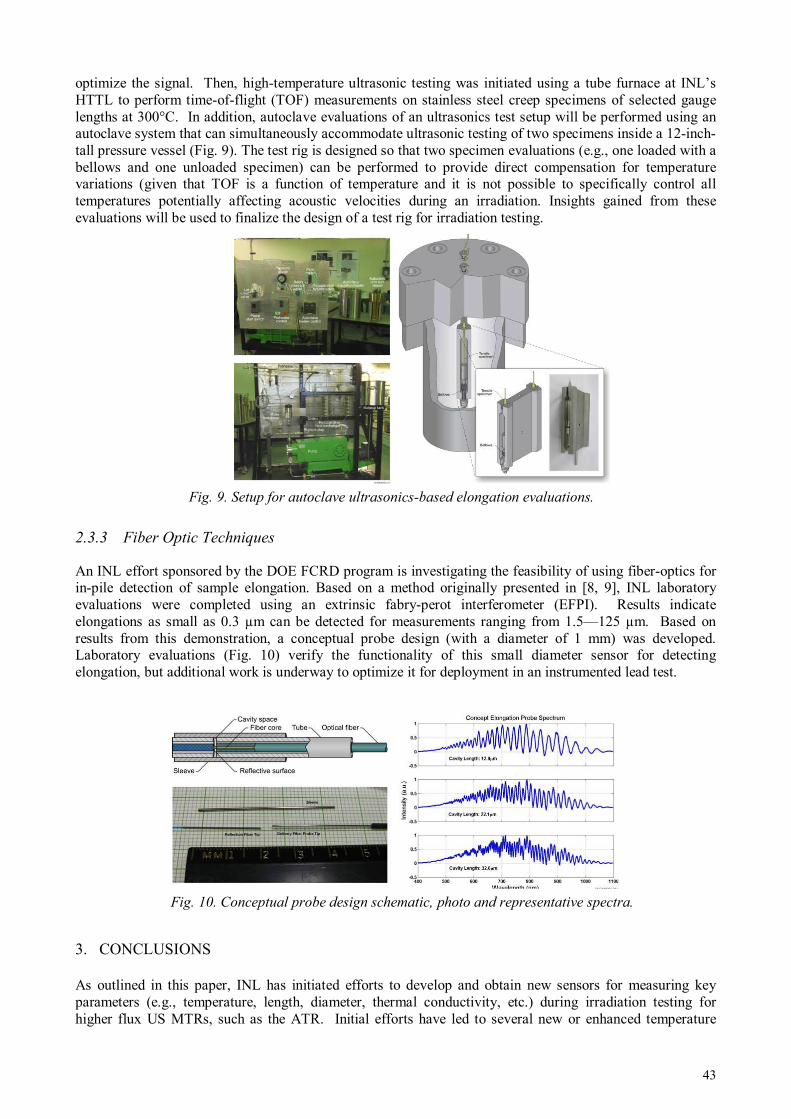
43
optimize the signal. Then, high-temperature ultrasonic testing was initiated using a tube furnace at INL’s HTTL to perform time-of-flight (TOF) measurements on stainless steel creep specimens of selected gauge lengths at 300°C. In addition, autoclave evaluations of an ultrasonics test setup will be performed using an autoclave system that can simultaneously accommodate ultrasonic testing of two specimens inside a 12-inch-tall pressure vessel (Fig. 9). The test rig is designed so that two specimen evaluations (e.g., one loaded with a bellows and one unloaded specimen) can be performed to provide direct compensation for temperature variations (given that TOF is a function of temperature and it is not possible to specifically control all temperatures potentially affecting acoustic velocities during an irradiation. Insights gained from these evaluations will be used to finalize the design of a test rig for irradiation testing.
2.3.3 Fiber Optic Techniques
An INL effort sponsored by the DOE FCRD program is investigating the feasibility of using fiber-optics for in-pile detection of sample elongation. Based on a method originally presented in [8, 9], INL laboratory evaluations were completed using an extrinsic fabry-perot interferometer (EFPI). Results indicate elongations as small as 0.3 µm can be detected for measurements ranging from 1.5—125 µm. Based on results from this demonstration, a conceptual probe design (with a diameter of 1 mm) was developed. Laboratory evaluations (Fig. 10) verify the functionality of this small diameter sensor for detecting elongation, but additional work is underway to optimize it for deployment in an instrumented lead test.
3. CONCLUSIONS
As outlined in this paper, INL has initiated efforts to develop and obtain new sensors for measuring key parameters (e.g., temperature, length, diameter, thermal conductivity, etc.) during irradiation testing for higher flux US MTRs, such as the ATR. Initial efforts have led to several new or enhanced temperature
Fig. 9. Setup for autoclave ultrasonics-based elongation evaluations.
Fig. 10. Conceptual probe design schematic, photo and representative spectra.
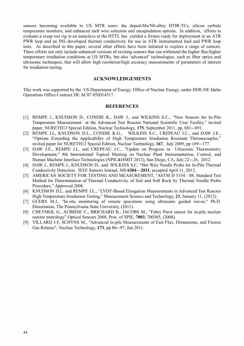
44
sensors becoming available to US MTR users: the doped-Mo/Nb-alloy HTIR-TCs, silicon carbide temperature monitors, and enhanced melt wire selection and encapsulation options. In addition, efforts to evaluate a creep test rig in an autoclave at the HTTL has yielded a fixture ready for deployment in an ATR PWR loop and an INL-developed thermal conductivity for use in ATR instrumented lead and PWR loop tests. As described in this paper, several other efforts have been initiated to explore a range of sensors. These efforts not only include enhanced versions of existing sensors that can withstand the higher flux/higher temperature irradiation conditions at US MTRs, but also ‘advanced’ technologies, such as fiber optics and ultrasonic techniques, that will allow high resolution/high accuracy measurements of parameters of interest for irradiation testing.
ACKNOWLEDGEMENTS
This work was supported by the US Department of Energy, Office of Nuclear Energy, under DOE-NE Idaho Operations Office Contract DE AC07 05ID14517.
REFERENCES
[1] REMPE J., KNUDSON D., CONDIE K., DAW J., and WILKINS S.C., “New Sensors for In-Pile Temperature Measurement at the Advanced Test Reactor National Scientific User Facility,” invited paper, NURETH13 Special Edition, Nuclear Technology, 175, September 2011, pp. 681—691.
[2] REMPE J.L, KNUDSON D.L., CONDIE K.G., WILKINS S.C., CREPEAU J.C., and DAW J.E., “Options Extending the Applicability of High Temperature Irradiation Resistant Thermocouples,” invited paper for NURETH12 Special Edition, Nuclear Technology, 167, July 2009, pp 169—177.
[3] DAW J.E., REMPE J.L. and CREPEAU J.C., "Update on Progress in Ultrasonic Thermometry Development," 8th International Topical Meeting on Nuclear Plant Instrumentation, Control, and Human Machine Interface Technologies (NPIC&HMIT 2012), San Diego, CA, July 22—26, 2012.
[4] DAW J., REMPE J., KNUDSON D., and. WILKINS S.C, “Hot Wire Needle Probe for In-Pile Thermal Conductivity Detection, IEEE Sensors Journal, MS 6204—2011, accepted April 11, 2012.
[5] AMERICAN SOCIETY FOR TESTING AND MEASUREMENT, "ASTM D 5334 - 08, Standard Test Method for Determination of Thermal Conductivity of Soil and Soft Rock by Thermal Needle Probe Procedure,” Approved 2008.
[6] KNUDSON D.L. and REMPE J.L., “LVDT-Based Elongation Measurements in Advanced Test Reactor High Temperature Irradiation Testing,” Measurement Science and Technology, 23, January 11, (2012).
[7] GUERS M.J., "In-situ monitoring of remote specimens using ultrasonic guided waves," Ph.D. Dissertation, The Pennsylvania State University, (2011).
[8] CHEYMOL G., AUBISSE C., BRICHARD B., JACOBS M., “Fabry Perot sensor for in-pile nuclear reactor metrology” Optical Sensors 2008, Proc. of SPIE, 7003, 700305, (2008).
[9] VILLARD J-F, SCHYNS M., "Advanced in-pile Measurements of Fast Flux, Dimensions, and Fission Gas Release", Nuclear Technology, 173, pp 86—97, Jan 2011.

45
IRRADIATION TEST FOR LINER VARIABLE DIFFERENTIAL TRANSFORMERS
IN THE WWR-K CORE, INP-KNNC, KAZAKHSTAN AND JAEA, JAPAN
1 The Kazakhstan Institute of Nuclear Physics (KINP), Almaty, Republic of Kazakhstan Email: [email protected]
2 The Japan Atomic Energy Agency (JAEA), Oarai-machi, Higashi-ibaraki-gun, Ibaraki-ken 311—1393, Japan
Abstract
A joint research is conducted between KINP and JAEA as a part of the international standard of instrumentation. In this research, the irradiation test of the LVDT is started under the partner project of the International Science and Technology Center (ISTC) from May 2010. The irradiation test is carried out to evaluate the durability of two kinds of LVDTs made of the MI-cable and the ceramic-wire under the neutron irradiation conditions. The nuclear and thermal-hydraulic design of the irradiation capsule was calculated by INP and JAEA. The irradiation capsule with LVDTs installed was developed in JAEA. This irradiation capsule is installed in the cell 5—9 in the WWR-K core. Irradiation tests are started on April 5, 2011. The total time of irradiation is 5465 hours. In each irradiation cycle, the ratio (E) of the primary-minus-secondary to primary-plus-secondary coil voltage and electrical resistance of the LVDTs are measured at various temperatures before and after the WWR-K operation. The value of E obtained for the shutdown reactor, of the MI cable-type LVDT is almost stable within the range from room temperature to 300˚C. On the other hand, the value of E for the ceramic wire-type LVDT changes greatly at 270˚C. The electrical resistance of MI cable-type LVDT is increased proportionally to the temperature. However the electrical resistance of ceramic wire-type LVDT changes at 270˚C. In the operating WWR-K, these phenomena are observed at 6MW. In this presentation, irradiation effect on the studied ratio and electrical resistance of these LVDTs is discussed.
1. INTRODUCTION
Joint research, as a part of the international standard of instrumentation, is conducted by KINP and JAEA. In frame of the study, tests of two kinds of LVDT in the WWR-K reactor core are performed. The durability test of two kinds of LVDTs - the MI-cable (mineral insulation cable) and the ceramic-coated wire - under long-term in-reactor irradiation are conducted to assess the strength of both kinds of LVDT (see Fig. 1). Table 1 shows the main characteristics of the transformers.
Differential transformers are widely applied in reactor technologies. For example, they are used:
• in pressure gauge for the measurement of gaseous fission products released in waste fuel and fuel elements under operation;
• to measure the swelling of fuel elements at their irradiation testing in the reactor, etc;
The transformer with mineral insulation coil was developed by JAEA for pressure gauges of gaseous fission products released.
Tests were conducted in the experimental channel of the WWR-K reactor core for 228 days at 6 MW
a) mineral insulation coil b) ceramic covered wire
FIG. 1. LVDT photographs.
A. SHAIMERDENOV1, M. TANIMOTO2, A. BEISEBAEV1, N. KIMURA2, SH. GIZATULIN1, K. TSUCHIYA2, P. CHAKROV1, H. KAWAMURA2

46
TABLE 1. MAIN CHARACTERISTICS OF TRANSFORMERS
Type Items
Ceramic covered wire
Mineral insulation cable
Wire Diameter of conductor, mm
0.12 0.05
Overall diameter, mm 0.17 0.5 Excitation 50 mA·1kHz 100 mA·1kHz
Output signal 0.9—1.1 V 60—70 mV Ineccuracy ±1.3% ±2.0%
Insulator PbO·SiO2·TiO2·Mg
O MgO, Al2O3
2. INSTRUMENTATION
Before the tests, the neutronic and thermal calculations have been carried out. The values of the specific radiation heat release have been calculated for structural materials used as materials of the inner capsule. The calculations have been carried out with the computer code MCNP-5. The following values of the specific radiation heat release have been obtained: 1.2 W/g for stainless steel and 1.0 W/g for aluminium. Thermal calculation has been carried out by the JAEA with the computer code EMRC. Following results of calculation, helium is to be used as working gas to provide transformer temperature at a level of (300±30)ºC. Special irradiation device has been developed for studies of differential transformers. The device is composed of an outer channel and an inner capsule. The outer channel has been developed and fabricated at the INP. The channel is aimed at provision of specified modes of transformer irradiation. It represents hermetic tube with the bottom and upper flange. Via flange, all electrical communications will pass, exhaustion will be carried out and filling of inner cavity of the channel with working gas. Self-powered neutron flux detector of the DPZ-1m type is fixed to outer wall of the channel. The inner capsule has been fabricated by the JAEA. Two transformers under studies are placed in the inner capsule. Each transformer is provided by electrical heater, thermocouple and fluence monitor. A gap 1 mm thick is available between the channel wall and the inner capsule; the gap filled with helium gas. Variation of helium pressure in the gap within a range from 30 to 105 Pa has made it possible controlling of the transformer temperature within a range from 300°C to 200°C. Electrical heater built in the inner capsule was used for more accurate control of the temperature. Figure 2 shows a photograph of the irradiation device in assemblage, and Fig. 3 - inner capsule. The test was carried out in 5—9 cell of WWR-K core. Relevant core configuration and location of the channel are shown in Fig. 4. Measurements of the thermal/fast neutron flux density in cell 5—9 have been carried out with activation detectors. Golden and Indium detectors and cadmium screens wave been used. The induced radioactivity of detectors has been measured by gamma spectrometer with germanium detector. The following results have been obtained:
- thermal neutron flux density: (5.9±0.9)·1013 cm-2s-1; - fast neutron flux density (En≥1.15 MeV): (7.9±2.0)·1012 cm-2s-1.
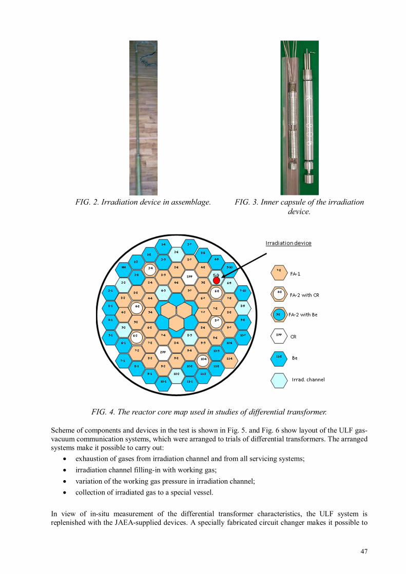
47
FIG. 2. Irradiation device in assemblage. FIG. 3. Inner capsule of the irradiation
device.
FIG. 4. The reactor core map used in studies of differential transformer.
Scheme of components and devices in the test is shown in Fig. 5. and Fig. 6 show layout of the ULF gas-vacuum communication systems, which were arranged to trials of differential transformers. The arranged systems make it possible to carry out:
• exhaustion of gases from irradiation channel and from all servicing systems;
• irradiation channel filling-in with working gas;
• variation of the working gas pressure in irradiation channel;
• collection of irradiated gas to a special vessel.
In view of in-situ measurement of the differential transformer characteristics, the ULF system is replenished with the JAEA-supplied devices. A specially fabricated circuit changer makes it possible to

48
measure periodically resistances of the differential transformer coils. The ULF information/measuring system (IMS) assures uninterrupted measuring, recording and storing of values of the transformer coil voltages and the neutron flux densities in place of location of the ampoule assembly.
A scheme of measurements is depicted in Fig. 7.
FIG.5. Layout of components and devices for testing.
1. Reactor core; 2. ULF monitoring systems; 3. Gas-vacuum communication systems; 4. The power-supply and gas-supply systems; 5. ULF control room; 6. Microcontrollers (ADAM).
FIG. 6. Block scheme of the ULF gas-vacuum communications.
1 – irradiation channel; 2 – manually-controlled valve to cut irradiation channel off after degassing, when transporting and after completion of trials; 3 – pressure sensors, which provide electronic control of pressure; 4 –
electrically-driven valves; 5 – a unit of working gas choice/supply; 6 – vacuum pump; 7 – vessels for irradiated gas.

49
FIG. 7. Block scheme for measurement of the differential transformer
3. LVDT CHARACTERISTICS DURING IRRADIATION
Prior to in-reactor irradiation, transformers were tested against increase in temperature from room one to 300°C. During in-reactor tests at 6 MW, the transformer temperatures were kept at a level of 300°C. Temporal variations in the transformer temperature, reactor power and signals from secondary coils of the transformers during all cycles of testing are presented graphically in Fig. 8, Fig. 9 and Fig. 10 shows variations of the transformer coil resistances as functions of time during the test.
Figure 11 clearly shows in the work of the differential transformer provided long-term in-reactor irradiation.

50
FIG. 8. Basic parameters of the differential transformers over all time of testing.
Temporal variation in the transformer temperature
Temporal variation in the voltage across coils of the ceramic-wire
transformer
Temporal variation in the voltage across coils of the MI-cable
transformer
Temporal variation in the SPND readings

51
FIG. 9. Resistances of the differential transformer over all time of irradiation.
FIG. 10. Resistance of insulation on the differential transformers over all time of irradiation.
Temporal variation in the resistance of the ceramic-wire
transformer
Temporal variation in the resistance of the MI-cable
transformer
Temporal variation in the insulation resistance of the ceramic-wire
transformer coils
Temporal variation in the insulation resistance of the MI-cable transformer
coils

52
FIG. 11. Variation in the transformer ratio of two differential transformers for all time irradiation tests.
4. CONCLUSION
1. Tests of two types of linear-variable differential transformers – a transformer with mineral insulation of wire and a transformer with ceramic coated wire - have been carried out under long-term in-reactor irradiation.
2. MI-cable LVDT demonstrated stable operation for 228 days.
3. Ceramic-wire LVDT worked properly for 171 days; then primary wire was broken.
4. The MI-cable LVDT transformation ratio was unvaried for the entire period of tests, staying independent of temperature within a range from room temperature to 300°C.
5. The ceramic-wire LVDT transformation ratio reduced permanently in course of irradiation for 171 days (from 0.22—0.12), changing dramatically at a temperature higher than 270°C.
REFERENCES
[1] ZHOTABAYEV Zh., KOLTOCHNIK S. Resumption of the operation the WWR-K reactor: collected articles, Almaty: A.D.IAE NNC RK, 247 p., (1998) –– in Russian
[2] KAWAMURA H. [et al], Status of international cooperation in nuclear technology on testing/research reactors between JAEA an INP-NNC, Japan: JAEA, 3—10 pp., (2011).
[3] KOMORI Y. [et. al ], Development of Reinstrumenting Technique of fuel rods with pressure gages – in and out-of-pile characteristics of developed fission gas pressure gages, Japan: JAERI-M88-156, (1988).
171 days

53
WELDING TECHNIQUES FOR IN-PILE INSTRUMENTATION AT INR PITESTI
Institute for Nuclear Research, Pitesti, Romania Email: [email protected]
Abstract Welding is widely involved in developing in-pile instrumentation, regarding both attaching sensors and joining components of the in-pile experimental devices. Although new methods were not developed, we combined existing techniques, aiming to master them and to ensure reproducibility, sensitivity, robustness, and fast response (for sensor welding). In this paper we present results regarding thermocouple welded on cladding, and dissimilar joints. Techniques for welding K-type thermocouples on cladding were designated to ensure robust joints able to resist during pressure and temperature transients, to minimize the perturbation on temperature field and on the cladding material structure, to reproduce the joint shape and dimension, and to ensure fast response. Welded or brazed joints between materials with properties suitable to nuclear applications are often required for in-pile instrumentation to allow coupling to other components of the experimental devices. The paper describes work related to Zircaloy-to-Stainless Steel joint through eutectic vacuum brazing. The eutectic was produced by thermal diffusion of the elements in the base materials at their interface, through formation of liquid phases of Zr-Fe and Zr-Ni systems at the Zy-SS interface. Clean, reduced roughness, oxide-free contact interface, and precise temperature control were aimed. The optimal interface was the joint
on perfectly matching truncated cone surfaces. Heating to 1030oC was obtained through vacuum induction at 10 kHz
frequency, with vacuum between 10-5
and 10-6
mbar. Other dissimilar joints were micro-TIG welds on SS capillary connected to Inconel-Incoloy capsules, for high pressure measurement lines with small internal volume. To evaluate the joints burst tests (for thermocouple welding only) polarized light metallography, macrography, backscattered electron tests, Helium leak test, tensile test, and thermal cycling tests were performed.
1. INTRODUCTION
The technology of welding thermocouples on cladding outer surface remains of interest for LOCA (loss of coolant accident) and RIA (reactivity initiated accident) experimental studies. Ensuring reproducibility, reducing thermo-mechanical effects on cladding, and obtaining fast response during transients are main objectives of such technology. Also the behaviour of the sheath-thermocouple contact during temperature transients leading to ballooning and sheath crack is of interest. Nuclear fuel elements manufacture requires end closures at both ends of the cladding. Usually, similar materials are welded. For instrumented fuel elements, mostly dedicated to experiments, dissimilar joints are needed, often between Zy (Zircaloy) and SS (stainless-steel), as end plugs or between Zr in the irradiation section and the SS of the ex-core section. Leak-tightness and coping with high mechanical stress are imposed on such joints. An axial penetration for transducers and cables traverses end plugs. The stainless steel ex-core end can be further welded with other stainless steel parts.
2. THERMOCOUPLE WELDING TECHNIQUE1
2.1 Ensuring welding reproducibility
Chromel and Alumel wires were used to obtain K-type thermocouples, being joined through micro-plasma welding (short discharge, 0.6 A, 0.2 s, Ar + 2% H as axial gas, and 100% Ar as radial gas), then attaching the ball joint on the sheath through resistive spot welding with controlled load. The wires were twisted two times to form the thermocouple hot junction. The ball joints have spherical shape with 0.5—0.6 mm diameters. Reproducible wire twisting and copper heat sink of the wire fixture proved important for reproducible ball joint shape and dimensions.
1 Preparatory work for a task in FP 6 MTR I+3 project
C. TRUTA, D. DOBREA, L. AIOANEI

54
For resistive spot welding a device with 1.6 mm flat polished electrode, 30—35 Ws pulse, 7.5 ms pulse duration, 200 g electrode load was constructed. Reproducibly clamping the sheath below the electrode in a V-shape copper grounding using two jumpers (see Fig. 1), and controlling the mechanical load of the spot welder electrode were most important for process reproducibility. Timing and load were adjusted to minimize the thermo-mechanical effects on the sheath.
FIG. 1. Spot welding device. Two thermocouples welded on a sheath.
2.2 Testing the welded thermocouples
Fuel sheaths with welded thermocouples were subject to burst tests, where temperature transients are suddenly ended by cracks. Fig. 4 shows the test configuration. The Ar gas at maximum pressure of 16 MPa gas is supplied through a pressure regulator, followed by an admission valve. The pressure transducer output is fed to the data acquisition system (DAS) together thermocouple signals. DAS also commands the DC power supply (0—700 A, 0—20 V) used to heat the sheath through copper connection devices that are in contact with the sheath sample. The left connection device in Fig. 2 tightly binds the sheath to the gas line, while the right one is closed. The thermocouple wires were connected directly, without expansion cables.
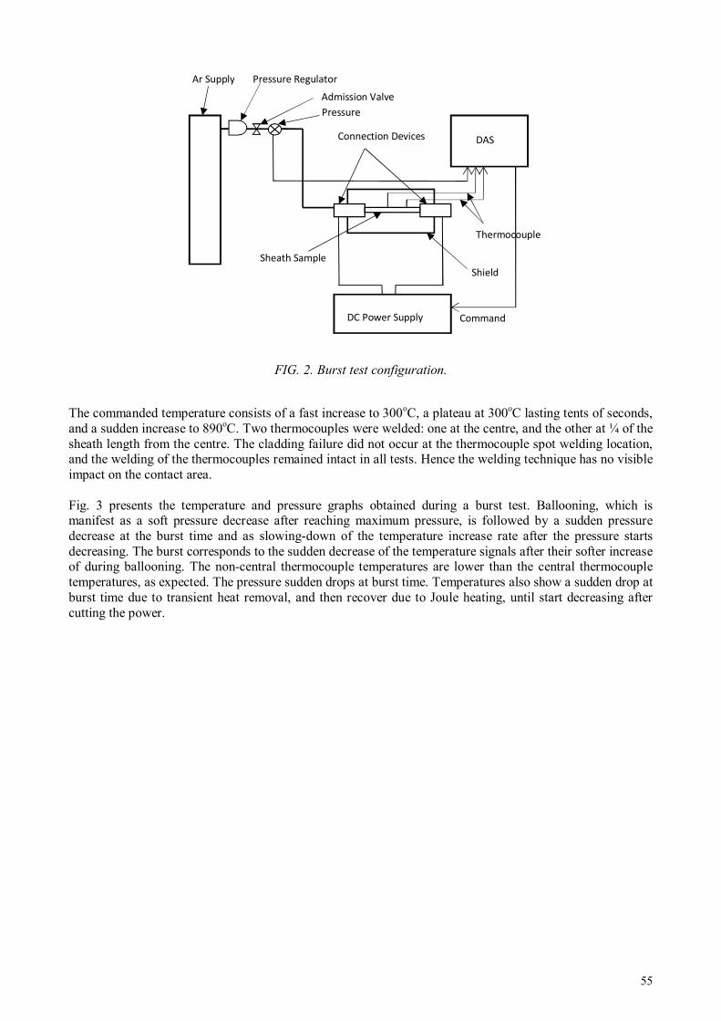
55
FIG. 2. Burst test configuration.
The commanded temperature consists of a fast increase to 300oC, a plateau at 300oC lasting tents of seconds, and a sudden increase to 890oC. Two thermocouples were welded: one at the centre, and the other at ¼ of the sheath length from the centre. The cladding failure did not occur at the thermocouple spot welding location, and the welding of the thermocouples remained intact in all tests. Hence the welding technique has no visible impact on the contact area. Fig. 3 presents the temperature and pressure graphs obtained during a burst test. Ballooning, which is manifest as a soft pressure decrease after reaching maximum pressure, is followed by a sudden pressure decrease at the burst time and as slowing-down of the temperature increase rate after the pressure starts decreasing. The burst corresponds to the sudden decrease of the temperature signals after their softer increase of during ballooning. The non-central thermocouple temperatures are lower than the central thermocouple temperatures, as expected. The pressure sudden drops at burst time. Temperatures also show a sudden drop at burst time due to transient heat removal, and then recover due to Joule heating, until start decreasing after cutting the power.
Sheath Sample
Pressure
Admission Valve
Ar Supply
Command
DAS
DC Power Supply
Pressure Regulator
Thermocouple
Shield
Connection Devices
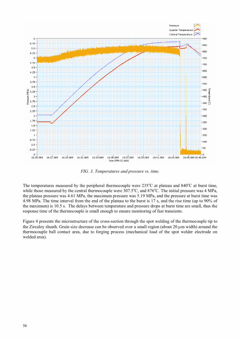
56
FIG. 3. Temperatures and pressure vs. time.
The temperatures measured by the peripheral thermocouple were 235oC at plateau and 840oC at burst time, while those measured by the central thermocouple were 307.5oC, and 876oC. The initial pressure was 4 MPa, the plateau pressure was 4.61 MPa, the maximum pressure was 5.19 MPa, and the pressure at burst time was 4.98 MPa. The time interval from the end of the plateau to the burst is 17 s, and the rise time (up to 90% of the maximum) is 10.5 s. The delays between temperature and pressure drops at burst time are small, thus the response time of the thermocouple is small enough to ensure monitoring of fast transients. Figure 4 presents the microstructure of the cross-section through the spot welding of the thermocouple tip to the Zircaloy sheath. Grain size decrease can be observed over a small region (about 20 µm width) around the thermocouple ball contact area, due to forging process (mechanical load of the spot welder electrode on welded area).

57
FIG. 4. Microstructure of the sheath and thermocouple welding (ball joint on the right).
3. DISSIMILAR JOINT TECHNIQUES
3.1 Devices and procedure
The furnace used to obtain Zy—SS dissimilar joints is an induction heating equipment, composed of water-cooled frequency converter (10kHz, max. 600V single phase), impedance adapter (single-turn secondary coil transformer, reactive power capacitor compensation), custom-made heating coil, glass vacuum chamber and vacuum system (rotary pump and diffusion pump, large range vacuum gauges), temperature monitors (sheathed thermocouples, electronic pyrometer, optical pyrometer with filament), control and automation for frequency converter, cooling and vacuum installation.
The autogenous brazing (without filler) of Zircaloy and stainless steel is based on phase diagrams of the
elements composing them. The main systems are [2]: Zr—Fe (~ 76% Zr, eutectic liquid at 936oC), Zr—Cr (~
28% Cr, eutectic liquid at ~ 1300oC), and Zr—Ni (~ 24% Ni, eutectic liquid at 961
oC). Thus, the joining
procedure should keep in contact the two pieces at ~950oC where the atomic diffusion dominates, until
critical mixture ratio is achieved; then a sudden temperature raise with several tens of degrees results in formation of a bonding liquid layer between parts, and its subsequent cooling completes the auto-brazing process [1]. The joint ‘father’ part is a Zircaloy truncated cone with a 5o taper, which penetrates and fits precisely into the correspondent cone-shaped bore of the stainless steel ‘mother’ part (see Fig. 5 [1]). Stainless steel (SS) should be ‘mother’ part as having larger expansion coefficient; thus SS part receives better the Zircaloy cone during heating, while a fretting effect occurs at cooling [1]. Contact surfaces roughness must not exceed 1.6 µm.

58
To obtain clean and oxide-free surfaces the following steps were performed: ultrasonic cleaning in a common detergent, degrease with alcohol–acetone mixture, pickling in acid mixture, soak in hot distilled water and drying in hot air flow. A Tantalum-sheathed thermocouple is placed in the axial hole of the pieces that were surrounded by the heating coil with a good radial symmetry, since part rotation during welding was not used. Several sample parts are provided with threads to be fixed for subsequent Helium leak test and tensile test. The vacuum chamber is locked and the vacuum system is turned on. When a pressure of 5x10⁻⁶ Torr is reached, temperature is gradually increased by increasing the excitation voltage of the generator, thus increasing the current in the coil. Until 500oC, vacuum quality may slightly decrease due to degassing. Hence, the temperature increase rate has to be controlled to maintain the vacuum level within the 10-6 decade. At 500oC the gettering effect of Zirconium starts, improving the vacuum quality, almost regardless the temperature increase rate; at this stage parts are gradually heated up to 950oC [1]. The final heating is achieved by raising the temperature to 1030 ± 10oC and maintaining it for ~150 seconds. During this step, observing the apparition of a fine liquid ‘collar’ means that eutectic filler mixture is formed, the joint being almost completed. The plateau at 1030oC ends by steep cooling down to 920oC. Steep heating/cooling profile is required to mark off the 1030oC process, and to obtain reproducible joints [1]. Finally, slow cooling to avoid solidification cracking of the eutectic zone follows.
3.2 Joint Examination and Testing
Macrography is useful for a general view of the whole joint, for fast measurement of the eutectic zone shape and thickness, while details may better reveal the cracks. It was performed on cross sections of the joints, either polished, or chemically attacked, to reveal the grains (see Fig. 5). Images were obtained with a metallurgy microscope and a camera with remote image acquisition software. Polarized light metallography [3] is recommended for Zircaloy samples. Samples were prepared through fine polishing and specific chemical attack through swabbing with acid solution. The microscope shots have been taken with a camera, at various magnifications (×20— 200). Figure 6 [1] shows three major zones from top to bottom: Zircaloy with characteristic coloured grains oversized by heating, the solidified eutectic mixture (a 300µm thick, quite straight and uniform darker band), and stainless steel.
FIG. 5. Macrography of Zy-SS joint. Average diameter of the Zircaloy cone is 7.7 mm.
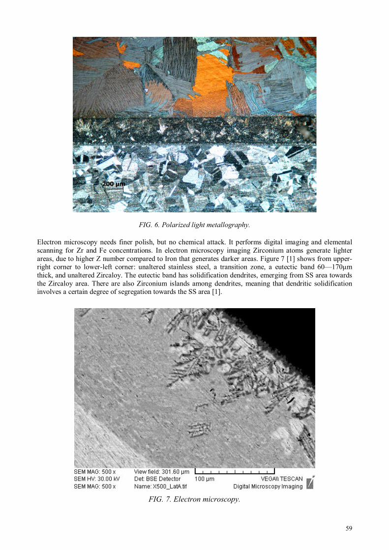
59
FIG. 6. Polarized light metallography.
Electron microscopy needs finer polish, but no chemical attack. It performs digital imaging and elemental scanning for Zr and Fe concentrations. In electron microscopy imaging Zirconium atoms generate lighter areas, due to higher Z number compared to Iron that generates darker areas. Figure 7 [1] shows from upper-right corner to lower-left corner: unaltered stainless steel, a transition zone, a eutectic band 60—170µm thick, and unaltered Zircaloy. The eutectic band has solidification dendrites, emerging from SS area towards the Zircaloy area. There are also Zirconium islands among dendrites, meaning that dendritic solidification involves a certain degree of segregation towards the SS area [1].
FIG. 7. Electron microscopy.
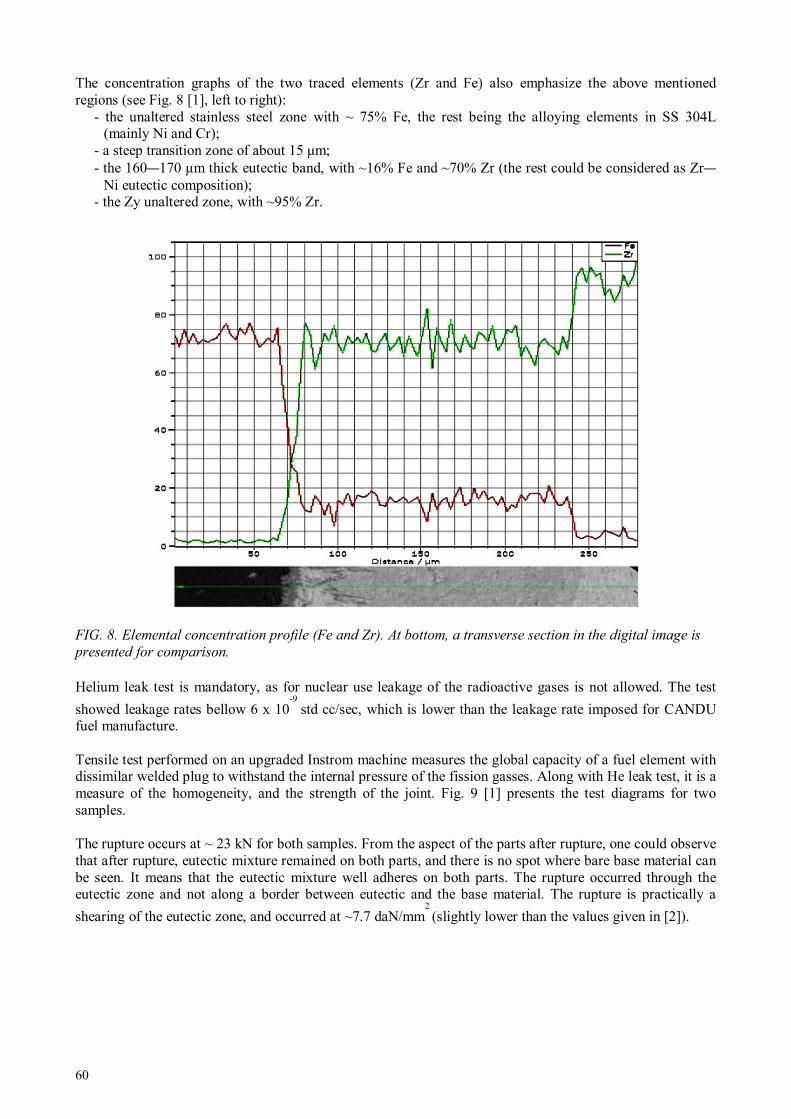
60
The concentration graphs of the two traced elements (Zr and Fe) also emphasize the above mentioned regions (see Fig. 8 [1], left to right):
- the unaltered stainless steel zone with ~ 75% Fe, the rest being the alloying elements in SS 304L (mainly Ni and Cr);
- a steep transition zone of about 15 µm; - the 160—170 µm thick eutectic band, with ~16% Fe and ~70% Zr (the rest could be considered as Zr—
Ni eutectic composition); - the Zy unaltered zone, with ~95% Zr.
FIG. 8. Elemental concentration profile (Fe and Zr). At bottom, a transverse section in the digital image is
presented for comparison.
Helium leak test is mandatory, as for nuclear use leakage of the radioactive gases is not allowed. The test
showed leakage rates bellow 6 x 10⁻⁹
std cc/sec, which is lower than the leakage rate imposed for CANDU fuel manufacture. Tensile test performed on an upgraded Instrom machine measures the global capacity of a fuel element with dissimilar welded plug to withstand the internal pressure of the fission gasses. Along with He leak test, it is a measure of the homogeneity, and the strength of the joint. Fig. 9 [1] presents the test diagrams for two samples. The rupture occurs at ~ 23 kN for both samples. From the aspect of the parts after rupture, one could observe that after rupture, eutectic mixture remained on both parts, and there is no spot where bare base material can be seen. It means that the eutectic mixture well adheres on both parts. The rupture occurred through the eutectic zone and not along a border between eutectic and the base material. The rupture is practically a
shearing of the eutectic zone, and occurred at ~7.7 daN/mm2 (slightly lower than the values given in [2]).

61
FIG. 9. Tensile test diagram.
3.3 MicroWelds for Instrumentation
Incoloy 800, in form of thin-walled tube is used for nuclear fuel cladding, welded with Inconel 600 end plugs. For instrumented elements, one or both end plugs need to be bored and prolonged with a stainless steel capillary tube as a duct for pressure measurements, or as passage for brazing a sheathed thermocouple.
The weld has to be leak-tight to a level acceptable in nuclear field (below 10-7
std cc/sec) even after repeated exposure to high temperature and internal pressure. Such joints were welded both with microTIG2 and microPAW3 using the welding machine used for thermocouple joints (Ch. 2). For these applications the welding parameters have to be adjusted such that the weld would be large enough to have a good dilution of the base materials (no filler used), but small enough not to melt inside the tube opening. A long taper is needed to avoid stress concentration points. One may see in Fig. 10 [1] such a microplasma weld.
2 TIG: tungsten inert gas (welding)
3 PAW: plasma arc welding

62
FIG. 10. Dissimilar welding of Inconel cap to SS capillar
For Incoloy capsules heated up to 1000oC, with internal pressure of 25 bars, with several cycles, a 3.2 mm
outer diameter tube was TIG welded. Metallography images of this weld emphasize metallurgical changes in the Inconel base metal near the weld due to the harsh treatment, but larger magnification images show no crack.
4. CONCLUSION
The micro-plasma technique for obtaining the thermocouple junction proved accurate and reproducible leading to ball diameters about twice the diameter of the wires. The resistive spot welding ensured reproducible timing and load. It also ensured minimizing thermo-mechanical effects of the spot welding on the sheath, as proved by metallographic examination after burst tests: the area affected by welding was small (around 20 µm). The vacuum induction device, the manufacture of parts and the working procedure itself are all fully suitable for obtaining joints through eutectic brazing between Zircaloy and Stainless Steel. The joints are leak-tight and have enough strength. The dissimilar welding process proved reproducible. The techniques presented in this paper work in conjunction for increasing the capability of the Institute in nuclear instrumentation field, for own projects or for potential partners.

63
ACKNOWLEDGEMENTS
We thank our colleagues, Ing. Constantin Pitigoi for burst test device setup and operation, Dr. Maria Mihalache and tech. Mihaela Ilie for performing electron microscopy and metallography.
REFERENCES
[1] TRUTA C. and COLAB – “Dissimilar Joints for Nuclear Equipment & Instrumentation” – Int. Conf on “Innovative Technologies for Joining Advanced Materials”, Timisoara (2012).
[2] JACQUES F. – “Jonctions diffusees Zircaloy2 – acier inoxydable” – Report CEA 2643, Saclay, (1964).
[3] DANIELSON P.E. and. SUTHERLIN R.C “Metallography and Microstructures of Zirconium, Hafnium, and Their Alloys, Metallography and Microstructures” - Vol 9, ASM Handbook, p. 942–958, (2004).
64
IMPROVED IN-PILE MEASUREMENT OF NUCLEAR FUELS AND CORE
STRUCTURAL MATERIALS
DEN-CAD/DER/SPEX, CEA Cadarache, Saint Paul lez durance, France E-mail: [email protected]
Abstract
Monitoring irradiation experiments in MTRs requires accurate and reliable in-pile instrumentation in order to meet the customer requirements. For more than a decade, CEA has been managing a large research program to develop and qualify innovative in-pile instrumentation, with the main goal to give to the future JHR (Jules Horowitz Reactor) a large and homogenous panel of qualified measurement techniques. The scope of these studies includes the irradiation location qualification as well as the physical parameter survey of the experimental load. Thus, several measurement techniques are studied in the following fields:
- Radiation measurements in the experimental locations or in the irradiation device: on-line and off line (dosimetry) measurements of the fast and thermal neutron flux and gamma heating. These parameters are crucial to improve the knowledge of MTR irradiation conditions.
- Measurements of physical parameters inside irradiation rigs: on-line and under irradiation measurements of the physical parameter evolution of the sample (temperature, pressure, dimension evolution, fission gas release rate, ect.)
After a presentation of the future JHR experimental devices dedicated to the fuel irradiation studies, an illustration of these developments, expected to have an interest for future fuel irradiation experiments, is presented in this paper through several examples.
1. INTRODUCTION
The realization of the fuel experimental programmes in MTRs requires a prior experimental qualification of the chosen irradiation locations to evaluate the neutron and gamma flux levels. The fine knowledge of these parameters are necessary firstly to estimate the irradiation conditions in order to be sure to meet the customer’s demand, and secondly to operate the experimental device itself (gamma heating, ect.). In addition, the validation of physical theories modelling the sample behaviour induces the need of acurate and reliable in-pile instrumentation, if possible on line and as close as possible to the sample. These in-pile measurements require sensors that must satisfy the following criteria:
1. High reliability, because irradiated sensors cannot be easily replaced; 2. Very high accuracy to satisfy continuously increasing scientific requirements; 3. Capability to operate in harsh nuclear environments (neutron flux and gamma radiation in MTRs
can exceed, respectively, 5.0 10E14 n/cm²/s and 1.5 MGy/s); 4. Capability to operate in pressurized water, liquid metals, or high-temperature gas; 5. Miniaturized body, to be implemented in small irradiation devices without altering the nominal
thermal conditions of the samples. Thus developments of either new instrumentation able to operate in the harsh device surrounding (high temperature, high neutron and gamma fluxes, miniaturization) or new interpretation methods mixing information provided by several kind of sensors are necessary to take advantage of the entire experimental potentialities of the JHR [1]. Consequently, for more than a decade, CEA (Commissariat à l’Energie Atomique) has been managing a large research program to develop and qualify innovative in-pile instrumentation, with the main goal to give to the future JHR (Jules Horowitz Reactor) a large and homogenous panel of qualified measurement techniques.
C. DESTOUCHES, J-F. VILLARD
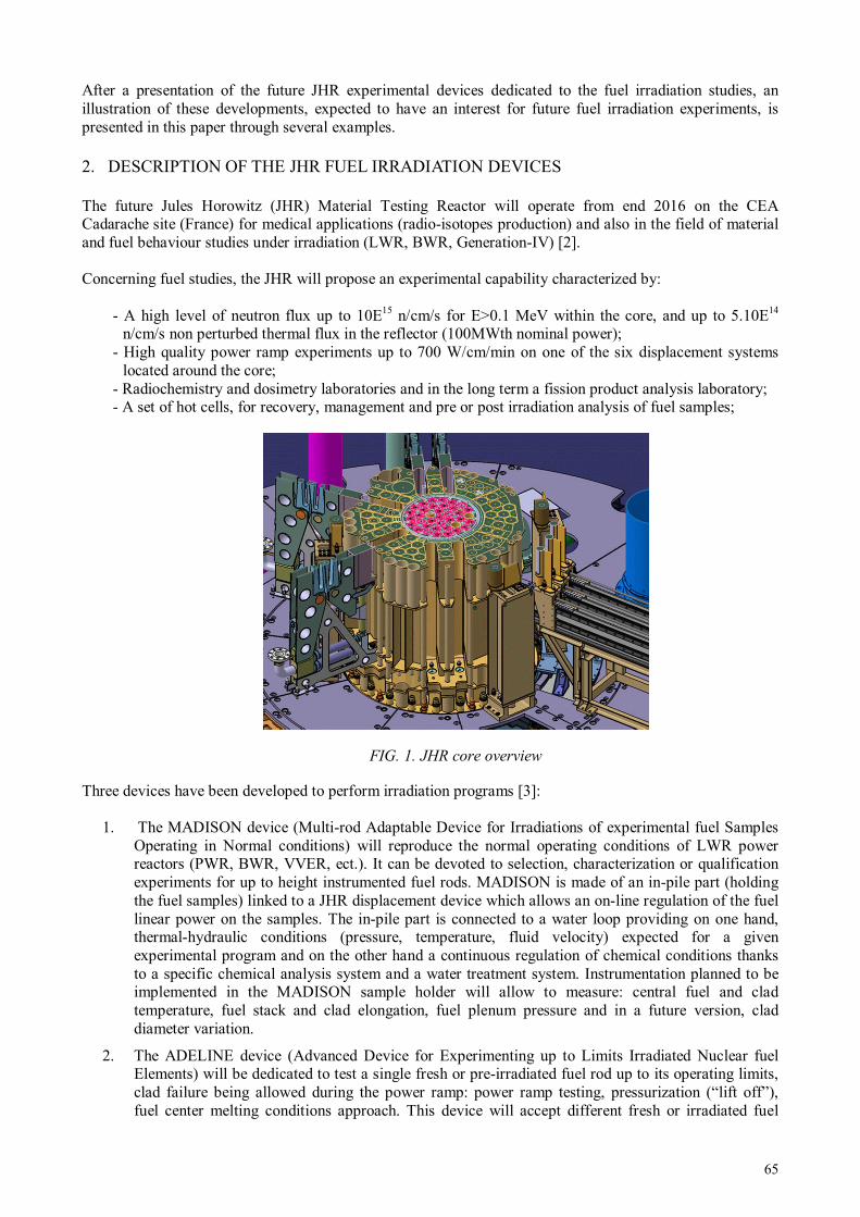
65
After a presentation of the future JHR experimental devices dedicated to the fuel irradiation studies, an illustration of these developments, expected to have an interest for future fuel irradiation experiments, is presented in this paper through several examples.
2. DESCRIPTION OF THE JHR FUEL IRRADIATION DEVICES
The future Jules Horowitz (JHR) Material Testing Reactor will operate from end 2016 on the CEA Cadarache site (France) for medical applications (radio-isotopes production) and also in the field of material and fuel behaviour studies under irradiation (LWR, BWR, Generation-IV) [2]. Concerning fuel studies, the JHR will propose an experimental capability characterized by:
- A high level of neutron flux up to 10E15 n/cm/s for E>0.1 MeV within the core, and up to 5.10E14 n/cm/s non perturbed thermal flux in the reflector (100MWth nominal power);
- High quality power ramp experiments up to 700 W/cm/min on one of the six displacement systems located around the core;
- Radiochemistry and dosimetry laboratories and in the long term a fission product analysis laboratory; - A set of hot cells, for recovery, management and pre or post irradiation analysis of fuel samples;
FIG. 1. JHR core overview
Three devices have been developed to perform irradiation programs [3]:
1. The MADISON device (Multi-rod Adaptable Device for Irradiations of experimental fuel Samples Operating in Normal conditions) will reproduce the normal operating conditions of LWR power reactors (PWR, BWR, VVER, ect.). It can be devoted to selection, characterization or qualification experiments for up to height instrumented fuel rods. MADISON is made of an in-pile part (holding the fuel samples) linked to a JHR displacement device which allows an on-line regulation of the fuel linear power on the samples. The in-pile part is connected to a water loop providing on one hand, thermal-hydraulic conditions (pressure, temperature, fluid velocity) expected for a given experimental program and on the other hand a continuous regulation of chemical conditions thanks to a specific chemical analysis system and a water treatment system. Instrumentation planned to be implemented in the MADISON sample holder will allow to measure: central fuel and clad temperature, fuel stack and clad elongation, fuel plenum pressure and in a future version, clad diameter variation.
2. The ADELINE device (Advanced Device for Experimenting up to Limits Irradiated Nuclear fuel Elements) will be dedicated to test a single fresh or pre-irradiated fuel rod up to its operating limits, clad failure being allowed during the power ramp: power ramp testing, pressurization (“lift off”), fuel center melting conditions approach. This device will accept different fresh or irradiated fuel
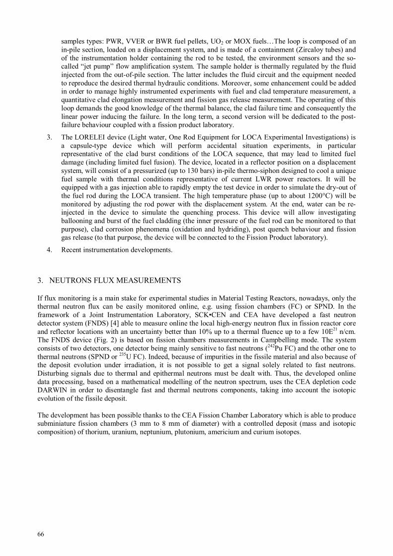
66
samples types: PWR, VVER or BWR fuel pellets, UO2 or MOX fuels…The loop is composed of an in-pile section, loaded on a displacement system, and is made of a containment (Zircaloy tubes) and of the instrumentation holder containing the rod to be tested, the environment sensors and the so-called “jet pump” flow amplification system. The sample holder is thermally regulated by the fluid injected from the out-of-pile section. The latter includes the fluid circuit and the equipment needed to reproduce the desired thermal hydraulic conditions. Moreover, some enhancement could be added in order to manage highly instrumented experiments with fuel and clad temperature measurement, a quantitative clad elongation measurement and fission gas release measurement. The operating of this loop demands the good knowledge of the thermal balance, the clad failure time and consequently the linear power inducing the failure. In the long term, a second version will be dedicated to the post-failure behaviour coupled with a fission product laboratory.
3. The LORELEI device (Light water, One Rod Equipment for LOCA Experimental Investigations) is a capsule-type device which will perform accidental situation experiments, in particular representative of the clad burst conditions of the LOCA sequence, that may lead to limited fuel damage (including limited fuel fusion). The device, located in a reflector position on a displacement system, will consist of a pressurized (up to 130 bars) in-pile thermo-siphon designed to cool a unique fuel sample with thermal conditions representative of current LWR power reactors. It will be equipped with a gas injection able to rapidly empty the test device in order to simulate the dry-out of the fuel rod during the LOCA transient. The high temperature phase (up to about 1200°C) will be monitored by adjusting the rod power with the displacement system. At the end, water can be re-injected in the device to simulate the quenching process. This device will allow investigating ballooning and burst of the fuel cladding (the inner pressure of the fuel rod can be monitored to that purpose), clad corrosion phenomena (oxidation and hydriding), post quench behaviour and fission gas release (to that purpose, the device will be connected to the Fission Product laboratory).
4. Recent instrumentation developments.
3. NEUTRONS FLUX MEASUREMENTS
If flux monitoring is a main stake for experimental studies in Material Testing Reactors, nowadays, only the thermal neutron flux can be easily monitored online, e.g. using fission chambers (FC) or SPND. In the framework of a Joint Instrumentation Laboratory, SCK•CEN and CEA have developed a fast neutron detector system (FNDS) [4] able to measure online the local high-energy neutron flux in fission reactor core and reflector locations with an uncertainty better than 10% up to a thermal fluence up to a few 10E21 n/cm. The FNDS device (Fig. 2) is based on fission chambers measurements in Campbelling mode. The system consists of two detectors, one detector being mainly sensitive to fast neutrons (242Pu FC) and the other one to thermal neutrons (SPND or 235U FC). Indeed, because of impurities in the fissile material and also because of the deposit evolution under irradiation, it is not possible to get a signal solely related to fast neutrons. Disturbing signals due to thermal and epithermal neutrons must be dealt with. Thus, the developed online data processing, based on a mathematical modelling of the neutron spectrum, uses the CEA depletion code DARWIN in order to disentangle fast and thermal neutrons components, taking into account the isotopic evolution of the fissile deposit. The development has been possible thanks to the CEA Fission Chamber Laboratory which is able to produce subminiature fission chambers (3 mm to 8 mm of diameter) with a controlled deposit (mass and isotopic composition) of thorium, uranium, neptunium, plutonium, americium and curium isotopes.
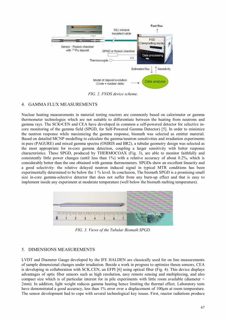
67
FIG. 2. FNDS device scheme.
4. GAMMA FLUX MEASUREMENTS
Nuclear heating measurements in material testing reactors are commonly based on calorimeter or gamma thermometer technologies which are not suitable to differentiate between the heating from neutrons and gamma rays. The SCK•CEN and CEA have developed in common a self-powered detector for selective in-core monitoring of the gamma field (SPGD, for Self-Powered Gamma Detector) [5]. In order to minimize the neutron response while maximizing the gamma response, bismuth was selected as emitter material. Based on detailed MCNP modelling to calculate the gamma/neutron sensitivities and irradiation experiments in pure (PAGURE) and mixed gamma spectra (OSIRIS and BR2), a tubular geometry design was selected as the most appropriate for in-core gamma detection, coupling a larger sensitivity with better response characteristics. These SPGD, produced by THERMOCOAX (Fig. 3), are able to monitor faithfully and consistently little power changes (until less than 1%) with a relative accuracy of about 0.2%, which is considerably better than the one obtained with gamma thermometers. SPGDs show an excellent linearity and a good selectivity: the relative delayed neutron induced signal in typical MTR conditions has been experimentally determined to be below the 1 % level. In conclusion, The bismuth SPGD is a promising small size in-core gamma-selective detector that does not suffer from any burn-up effect and that is easy to implement inside any experiment at moderate temperature (well below the bismuth melting temperature).
FIG. 3. Views of the Tubular Bismuth SPGD.
5. DIMENSIONS MEASUREMENTS
LVDT and Diameter Gauge developed by the IFE HALDEN are classically used for on line measurements of sample dimensional changes under irradiation. Beside a work in progress to optimize theses sensors, CEA is developing in collaboration with SCK.CEN, an EFPI [6] using optical fiber (Fig. 4). This device displays advantages of optic fiber sensors such as high resolution, easy remote sensing and multiplexing, and also compact size which is of particular interest for in pile experiments with little room available (diameter < 2mm). In addition, light weight reduces gamma heating hence limiting the thermal effect. Laboratory tests have demonstrated a good accuracy, less than 1% error over a displacement of 100µm at room temperature. The sensor development had to cope with several technological key issues. First, reactor radiations produce

68
huge losses in common optical fibre which have been minimized by selecting the fibres (mainly with high purity silica core), the wavelength range (800—1200nm), and the technique based on interferometry (low sensibility to losses in the fibre). Similarly, the compaction of silica induced by thermal neutron and gamma flux, resulting in a significant drift of the signal, has been lowered by an optimization of the EFPI design. Finally, temperature induced dilatation under temperatures up to 400°C had to be considered carefully in the sensor design and its fixing on the sample. Optimized sensors including all the above specifications are currently tested under irradiation in the BR2 reactor.
FIG. 4. View of the EFPI.
6. HIGH-TEMPERATURE MEASUREMENTS
Measuring on-line and in situ temperatures above 1000C under high level of neutron flux stays a major stake for fuels irradiation experiments. Thus, CEA, with technical contributions from the Thermocoax Company, has developed thermocouples (TC) based on molybdenum and niobium thermo-elements (Fig. 5) [7]. These thermocouples remain almost insensitive to the thermal neutron flux (low capture cross section), even under harsh nuclear environments, whereas typical high-temperature thermocouples (Types C or S) are altered by material transmutations inducing unacceptable signal drift. After promising laboratory tests showing good linearity and sensitivity and moreover a drift lower than 5°C after 1500 hours at 1100°C, the final qualification under irradiation up to a thermal neutron fluence of 10E21 n/cm² has to be performed.
FIG. 5. Mo-Nb high temperature thermocouple.
7. MEASUREMENTS OF FISSION GAS RELEASE
A dedicated acoustic sensor (containing a piezoelectric transducer) has been developed by CEA and the Institut d’Electronique du Sud (IES, a French joint entity of the University of Montpellier and the National Center for Scientific Research) to measure online fission gas release in a fuel rod during fuel irradiation experiments [8]. Figure 6 illustrates some of the details related to the design of this acoustic fission gas
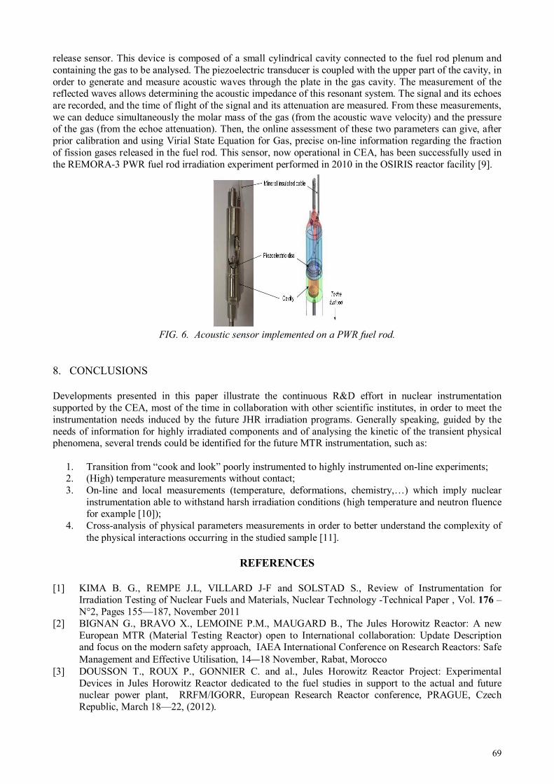
69
release sensor. This device is composed of a small cylindrical cavity connected to the fuel rod plenum and containing the gas to be analysed. The piezoelectric transducer is coupled with the upper part of the cavity, in order to generate and measure acoustic waves through the plate in the gas cavity. The measurement of the reflected waves allows determining the acoustic impedance of this resonant system. The signal and its echoes are recorded, and the time of flight of the signal and its attenuation are measured. From these measurements, we can deduce simultaneously the molar mass of the gas (from the acoustic wave velocity) and the pressure of the gas (from the echoe attenuation). Then, the online assessment of these two parameters can give, after prior calibration and using Virial State Equation for Gas, precise on-line information regarding the fraction of fission gases released in the fuel rod. This sensor, now operational in CEA, has been successfully used in the REMORA-3 PWR fuel rod irradiation experiment performed in 2010 in the OSIRIS reactor facility [9].
FIG. 6. Acoustic sensor implemented on a PWR fuel rod.
8. CONCLUSIONS
Developments presented in this paper illustrate the continuous R&D effort in nuclear instrumentation supported by the CEA, most of the time in collaboration with other scientific institutes, in order to meet the instrumentation needs induced by the future JHR irradiation programs. Generally speaking, guided by the needs of information for highly irradiated components and of analysing the kinetic of the transient physical phenomena, several trends could be identified for the future MTR instrumentation, such as:
1. Transition from “cook and look” poorly instrumented to highly instrumented on-line experiments; 2. (High) temperature measurements without contact; 3. On-line and local measurements (temperature, deformations, chemistry,…) which imply nuclear
instrumentation able to withstand harsh irradiation conditions (high temperature and neutron fluence for example [10]);
4. Cross-analysis of physical parameters measurements in order to better understand the complexity of the physical interactions occurring in the studied sample [11].
REFERENCES
[1] KIMA B. G., REMPE J.L, VILLARD J-F and SOLSTAD S., Review of Instrumentation for Irradiation Testing of Nuclear Fuels and Materials, Nuclear Technology -Technical Paper , Vol. 176 – N°2, Pages 155—187, November 2011
[2] BIGNAN G., BRAVO X., LEMOINE P.M., MAUGARD B., The Jules Horowitz Reactor: A new European MTR (Material Testing Reactor) open to International collaboration: Update Description and focus on the modern safety approach, IAEA International Conference on Research Reactors: Safe Management and Effective Utilisation, 14—18 November, Rabat, Morocco
[3] DOUSSON T., ROUX P., GONNIER C. and al., Jules Horowitz Reactor Project: Experimental Devices in Jules Horowitz Reactor dedicated to the fuel studies in support to the actual and future nuclear power plant, RRFM/IGORR, European Research Reactor conference, PRAGUE, Czech Republic, March 18—22, (2012).
70
[4] GESLOT B., VERMEEREN L. and al., New measurement system for on line in core high-energy neutron flux monitoring in materials testing reactor conditions, Review of Scientific Instruments, Vol. 82 , N° 33504, (2011).
[5] VERMEEREN L., CARCREFF H., BARBOT L. and al., Irradiation Tests of Prototype Self-Powered Gamma and Neutron Detectors, Proceeding of ANIMMA 2011 - 6—9 June, 2011- Ghent, Belgium - IEEE Catalog Number: CFP1124I-CDR - ISBN: 978-1-4577-0926-5
[6] CHEYMOL G., VILLARD J.F., GUSAROV A. and al., Fibre Optic Extensometer for High Radiation and High Temperature Nuclear Applications, Proceeding of ANIMMA 2011 - 6—9 June, 2011- Ghent, Belgium - IEEE Catalog Number: CFP1124I-CDR - ISBN: 978-1-4577-0926-5
[7] VILLARD J-F, FOURREZ S., FOURMENTEL D., LEGRAND A., Improving High-Temperature Measurements in Nuclear Reactors with Mo/Nb Thermocouples, International Journal of Thermophysic 2008, Volume 29, Number 5, Pages 1848—1857
[8] ROSENKRANTZ E., FERRANDIS J.Y., AUGEREAU F., LAMBERT T., FOURMENTEL D. and al., An Innovative Acoustic Sensor for First In-pile Fission Gas Release Determination – REMORA 3 Experiment, Proceeding of ANIMMA 2011 - 6—9 June, 2011- Ghent, Belgium - IEEE Catalog Number: CFP1124I-CDR - ISBN: 978-1-4577-0926-5
[9] LAMBERT T., MULLER E., FEDERICI E. and al., REMORA 3: the First Instrumented Fuel Experiment with On-Line Gas Composition Measurement by Acoustic Sensor, Proceeding of ANIMMA 2011 - 6—9 June, 2011- Ghent, Belgium - IEEE Catalog Number: CFP1124I-CDR - ISBN: 978-1-4577-0926-5
[10] JAMMES C., FILLIATRE P., GESLOT B., DOMENECH T. and NORMAND S., Assessment of the High Temperature Fission Chamber Technology for the French Fast Reactor Program, Proceeding of ANIMMA 2011 - 6—9 June, 2011- Ghent, Belgium - IEEE Catalog Number: CFP1124I-CDR - ISBN: 978-1-4577-0926-5
[11] FOURMENTEL D., VILLARD J-F., LYOUSSI A. and al., Combined Analysis of Neutron and Photon Flux Measurements for the Jules Horowitz Reactor Core Mapping, Proceeding of ANIMMA 2011 - 6—9 June, 2011- Ghent, Belgium - IEEE Catalog Number: CFP1124I-CDR - ISBN: 978-1-4577-0926-5
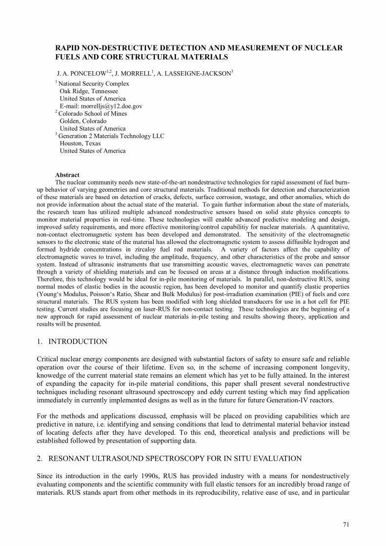
71
RAPID NON-DESTRUCTIVE DETECTION AND MEASUREMENT OF NUCLEAR
FUELS AND CORE STRUCTURAL MATERIALS
1 National Security Complex
Oak Ridge, Tennessee United States of America E-mail: [email protected]
2 Colorado School of Mines Golden, Colorado United States of America
3 Generation 2 Materials Technology LLC Houston, Texas United States of America
Abstract
The nuclear community needs new state-of-the-art nondestructive technologies for rapid assessment of fuel burn-up behavior of varying geometries and core structural materials. Traditional methods for detection and characterization of these materials are based on detection of cracks, defects, surface corrosion, wastage, and other anomalies, which do not provide information about the actual state of the material. To gain further information about the state of materials, the research team has utilized multiple advanced nondestructive sensors based on solid state physics concepts to monitor material properties in real-time. These technologies will enable advanced predictive modeling and design, improved safety requirements, and more effective monitoring/control capabilitiy for nuclear materials. A quantitative, non-contact electromagnetic system has been developed and demonstrated. The sensitivity of the electromagnetic sensors to the electronic state of the material has allowed the electromagnetic system to assess diffusible hydrogen and formed hydride concentrations in zircaloy fuel rod materials. A variety of factors affect the capability of electromagnetic waves to travel, including the amplitude, frequency, and other characteristics of the probe and sensor system. Instead of ultrasonic instruments that use transmitting acoustic waves, electromagnetic waves can penetrate through a variety of shielding materials and can be focused on areas at a distance through induction modifications. Therefore, this technology would be ideal for in-pile monitoring of materials. In parallel, non-destructive RUS, using normal modes of elastic bodies in the acoustic region, has been developed to monitor and quantify elastic properties (Young‘s Modulus, Poisson‘s Ratio, Shear and Bulk Modulus) for post-irradiation examination (PIE) of fuels and core structural materials. The RUS system has been modified with long shielded transducers for use in a hot cell for PIE testing. Current studies are focusing on laser-RUS for non-contact testing. These technologies are the beginning of a new approach for rapid assessment of nuclear materials in-pile testing and results showing theory, application and results will be presented.
1. INTRODUCTION
Critical nuclear energy components are designed with substantial factors of safety to ensure safe and reliable operation over the course of their lifetime. Even so, in the scheme of increasing component longevity, knowedge of the current material state remains an element which has yet to be fully attained. In the interest of expanding the capacity for in-pile material conditions, this paper shall present several nondestructive techniques including resonant ultrasound spectroscopy and eddy current testing which may find application immediately in currently implemented designs as well as in the future for future Generation-IV reactors.
For the methods and applications discussed, emphasis will be placed on providing capabilities which are predictive in nature, i.e. identifying and sensing conditions that lead to detrimental material behavior instead of locating defects after they have developed. To this end, theoretical analysis and predictions will be established followed by presentation of supporting data.
2. RESONANT ULTRASOUND SPECTROSCOPY FOR IN SITU EVALUATION
Since its introduction in the early 1990s, RUS has provided industry with a means for nondestructively evaluating components and the scientific community with full elastic tensors for an incredibly broad range of materials. RUS stands apart from other methods in its reproducibility, relative ease of use, and in particular
J. A. PONCELOW1,2, J. MORRELL1, A. LASSEIGNE-JACKSON3

72
its accuracy and precision. As a nondestructive technique RUS is coming of age, witnessing application in quality assurance in castings and laminates.
2.1 Background
In principle, RUS is composed of three parts. Successful implementation requires the acquisition of a resonant spectrum, i.e. the frequency domain response to an excitation for a given sample. An ability to predict, based on some computational model, the resonant spectrum from estimated parameters is also necessary. The iterative refinement of the estimated parameters into agreement with the measured spectrum constitutes the third and final component of the RUS routine. For each of the aforementioned steps, several possible solutions exist.
This paper is intended to inform the reader of some of the specific processes by which one can reliably establish a RUS technique. Further regard is given to extensions of the “classical” RUS problem with particular attention given to nondestructive evaluation of nuclear reactor components.
2.2 Spectrum Acquisition
Integral to the RUS process is the obtention of a resonant spectrum with frequencies and amplitude responses as the independent and dependent variables, respectively. Two methods are described here corresponding to the acquisition of such a spectrum by working in the time or frequency (Fourier) domains. The selection of the domain is not one of convenience but rather a matter of necessity, depending on the physical means by which the sample is excited.
2.2.1 Contact Piezoelectric Transducers
In the “canonical” RUS experiment, a sample is placed between two piezoelectric transducers (PZT). One PZT is driven by a continuous sinusoidal voltage at a frequency which is swept in time. The mechanical displacement (response) of the sample is detected by the second PZT and recorded as a frequency/amplitude pair. Frequently, use is made of a lock-in amplifier to filter spurious signals and noise, as such a device has an extremely narrow bandwidth and the source signal is readily available. The primary advantages of this contact technique are its relative simplicity and low cost, being on the order of a few tens of thousands of dollars for a unit.
There are a number of drawbacks to the use of PZT contact transducers, however. A major concern is mode identification, i.e. establishing a one-to-one relationship with predicted and measured resonant frequencies. If modes are incorrectly identified, the inversion routine will fail, and the elastic constants will be meaningless. Since the only information afforded by the PZT transducers is the amplitude at a single point, mode selection can be somewhat arbitrary especially when modes are missing (due to low amplitudes or transducer placement at a node) or degenerate (as occurs frequently in samples of high symmetry.
2.2.2 Laser-Based Broadband Excitation
An alternative to single-mode stimulation by discrete frequency sweep is the broadband excitation scheme whereby a short duration pulse is delivered to the sample and all modes are allowed to resonate simultaneously. The resulting ring-down of sample displacement or velocity is recorded as a time-domain waveform and Fourier-transformed to produce a frequency-domain spectrum consisting of Lorentzian peaks, as demonstrated in Fig. 1.
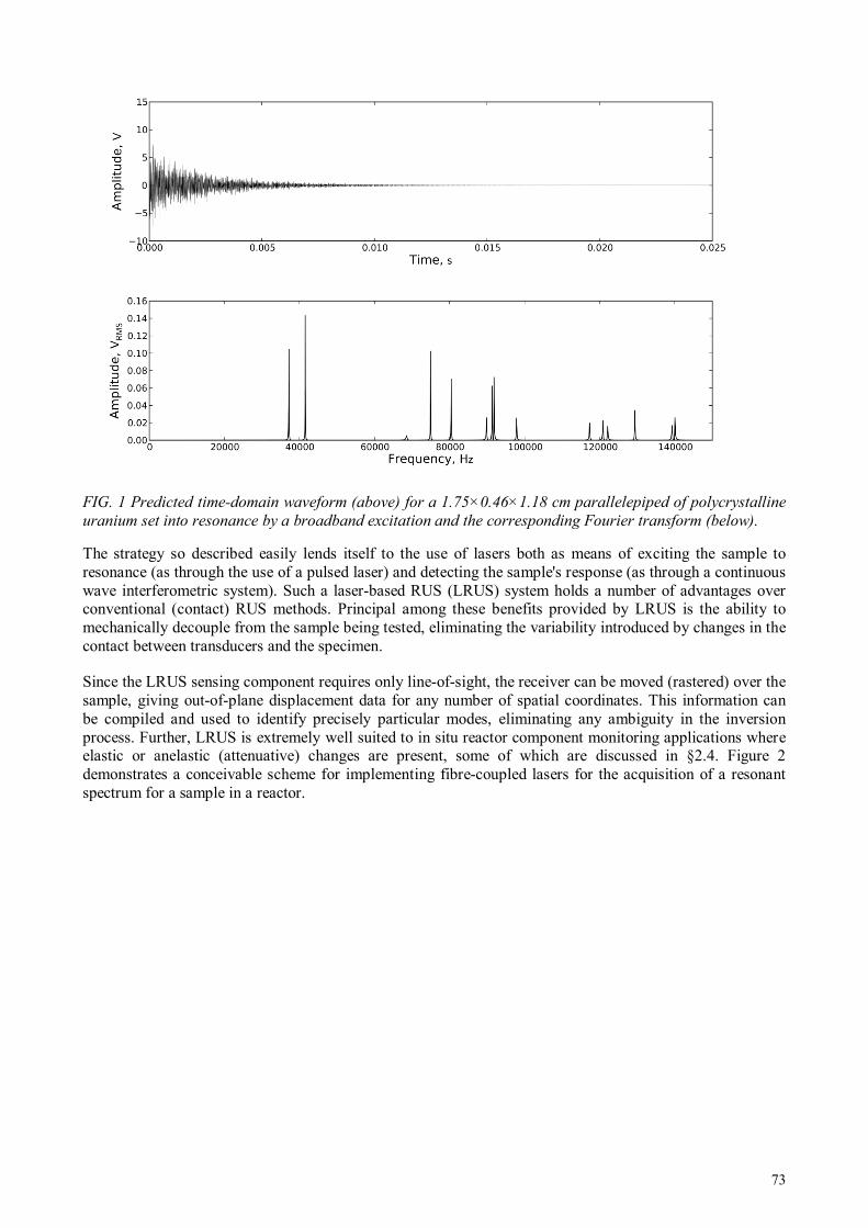
73
FIG. 1 Predicted time-domain waveform (above) for a 1.75×0.46×1.18 cm parallelepiped of polycrystalline
uranium set into resonance by a broadband excitation and the corresponding Fourier transform (below).
The strategy so described easily lends itself to the use of lasers both as means of exciting the sample to resonance (as through the use of a pulsed laser) and detecting the sample's response (as through a continuous wave interferometric system). Such a laser-based RUS (LRUS) system holds a number of advantages over conventional (contact) RUS methods. Principal among these benefits provided by LRUS is the ability to mechanically decouple from the sample being tested, eliminating the variability introduced by changes in the contact between transducers and the specimen.
Since the LRUS sensing component requires only line-of-sight, the receiver can be moved (rastered) over the sample, giving out-of-plane displacement data for any number of spatial coordinates. This information can be compiled and used to identify precisely particular modes, eliminating any ambiguity in the inversion process. Further, LRUS is extremely well suited to in situ reactor component monitoring applications where elastic or anelastic (attenuative) changes are present, some of which are discussed in §2.4. Figure 2 demonstrates a conceivable scheme for implementing fibre-coupled lasers for the acquisition of a resonant spectrum for a sample in a reactor.
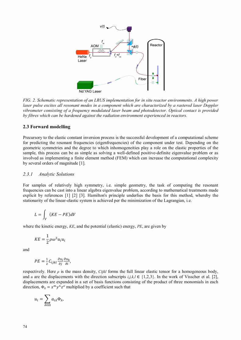
74
FIG. 2. Schematic representation of an LRUS implementation for in situ reactor environments. A high power
laser pulse excites all resonant modes in a component which are characterized by a rastered laser Doppler
vibrometer consisting of a frequency modulated laser beam and photodetector. Optical contact is provided by fibres which can be hardened against the radiation environment experienced in reactors.
2.3 Forward modelling
Precursory to the elastic constant inversion process is the successful development of a computational scheme for predicting the resonant frequencies (eigenfrequencies) of the component under test. Depending on the geometric symmetries and the degree to which inhomogeneities play a role on the elastic properties of the sample, this process can be as simple as solving a well-defined positive-definite eigenvalue problem or as involved as implementing a finite element method (FEM) which can increase the computational complexity by several orders of magnitude [1].
2.3.1 Analytic Solutions
For samples of relatively high symmetry, i.e. simple geometry, the task of computing the resonant frequencies can be cast into a linear algebra eigenvalue problem, according to mathematical treatments made explicit by references [1] [2] [3]. Hamilton's principle underlies the basis for this method, whereby the stationarity of the linear-elastic system is achieved per the minimization of the Lagrangian, i.e.
where the kinetic energy, KE, and the potential (elastic) energy, PE, are given by
12
and
,
respectively. Here ρ is the mass density, Cijkl forms the full linear elastic tensor for a homogeneous body, and u are the displacements with the direction subscripts i,j,k,l ∈ 1,2,3. In the work of Visscher et al. [2], displacements are expanded in a set of basis functions consisting of the product of three monomials in each direction, Φ !"#$% multiplied by a coefficient such that
& 'Φ∈(
,
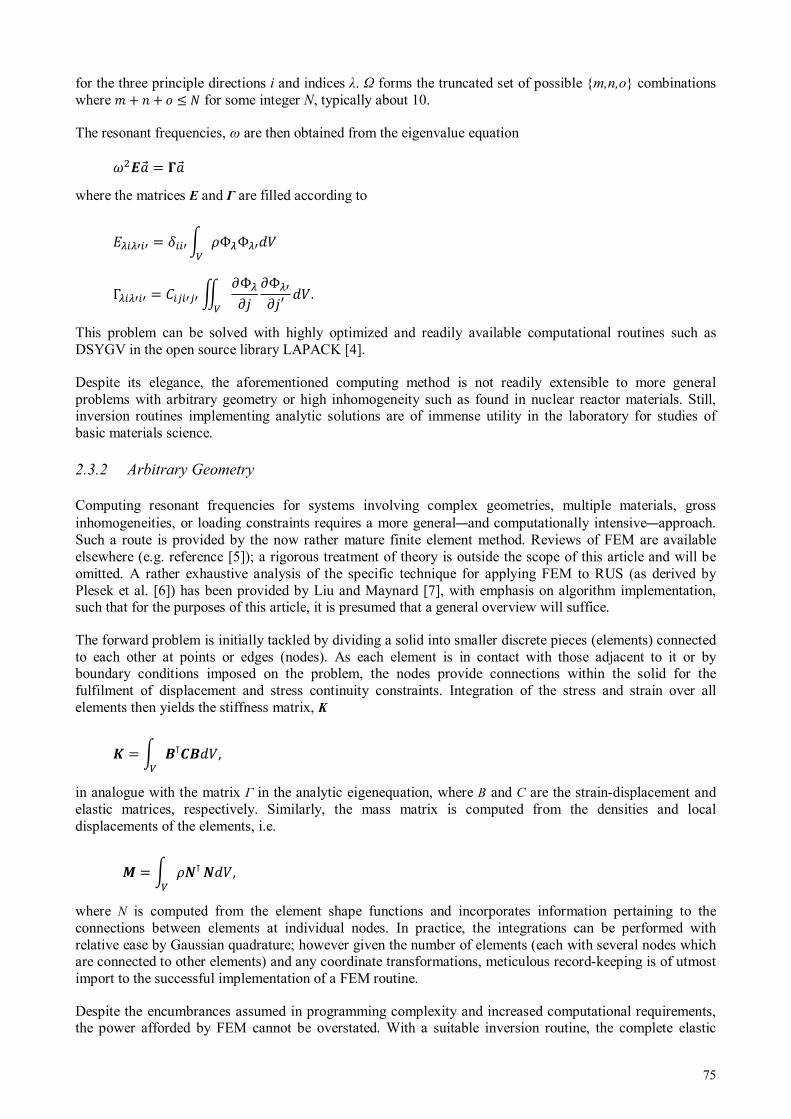
75
for the three principle directions i and indices λ. Ω forms the truncated set of possible m,n,o combinations where *+ , + - ≤ / for some integer N, typically about 10.
The resonant frequencies, ω are then obtained from the eigenvalue equation
0'1 2'1 where the matrices E and Γ are filled according to
33 43 ΦΦ3
Γ33 = 33 6 7Φ78
7Φ378′ .
This problem can be solved with highly optimized and readily available computational routines such as DSYGV in the open source library LAPACK [4].
Despite its elegance, the aforementioned computing method is not readily extensible to more general problems with arbitrary geometry or high inhomogeneity such as found in nuclear reactor materials. Still, inversion routines implementing analytic solutions are of immense utility in the laboratory for studies of basic materials science.
2.3.2 Arbitrary Geometry
Computing resonant frequencies for systems involving complex geometries, multiple materials, gross inhomogeneities, or loading constraints requires a more general—and computationally intensive—approach. Such a route is provided by the now rather mature finite element method. Reviews of FEM are available elsewhere (e.g. reference [5]); a rigorous treatment of theory is outside the scope of this article and will be omitted. A rather exhaustive analysis of the specific technique for applying FEM to RUS (as derived by Plesek et al. [6]) has been provided by Liu and Maynard [7], with emphasis on algorithm implementation, such that for the purposes of this article, it is presumed that a general overview will suffice.
The forward problem is initially tackled by dividing a solid into smaller discrete pieces (elements) connected to each other at points or edges (nodes). As each element is in contact with those adjacent to it or by boundary conditions imposed on the problem, the nodes provide connections within the solid for the fulfilment of displacement and stress continuity constraints. Integration of the stress and strain over all elements then yields the stiffness matrix, K
; = <⊺><,
in analogue with the matrix Γ in the analytic eigenequation, where B and C are the strain-displacement and elastic matrices, respectively. Similarly, the mass matrix is computed from the densities and local displacements of the elements, i.e.
? = @⊺
@, where N is computed from the element shape functions and incorporates information pertaining to the connections between elements at individual nodes. In practice, the integrations can be performed with relative ease by Gaussian quadrature; however given the number of elements (each with several nodes which are connected to other elements) and any coordinate transformations, meticulous record-keeping is of utmost import to the successful implementation of a FEM routine.
Despite the encumbrances assumed in programming complexity and increased computational requirements, the power afforded by FEM cannot be overstated. With a suitable inversion routine, the complete elastic

76
tensor can be attained for any geometry and loading constraint, extending the nondestructive applicability of RUS to real-world conditions such as those found in nuclear reactors.
2.4 Selected Applications and Extensions
With techniques in hand to physically measure and analyze the elastic properties of materials in-pile, one must take some account of how those properties relate to conditions throughout the fuel cycle. There are, of course, many distinct properties of interest to the nuclear engineer who may be qualifying a reactor material; a small selection is supplied in this section along with possible extensions or generalizations of RUS which complement information that the technique provides.
2.4.1 Hydrogenation Characterization
Of fundamental concern to the safe operation and longevity of reactor fuel elements employing zirconium-based cladding is the uptake and eventual precipitation of hydrogen and its compounds, a process which severely embrittles current alloys. A linear relationship between Young’s modulus and interstitial hydrogen content has been observed for an a zirconium alloy [8] at temperatures approaching those witnessed in reactors. Such phenomena suggest that foreknowledge of hydride formation can be provided by elastic and anelastic measurements made in-pile such as those which could be supplied by RUS. Further analysis of the quality factor, A ≜ C/ΔC for each resonant peak can lend additional information pertaining to the nature of the hydrogen present through phenomena such as scattering effects from hydrides or interstitial motion.
2.4.2 Thermal Contact Evaluation
When weakly interfaced, the boundary between fuel and cladding behaves hysteretically when an elastic perturbation is applied dynamically, manifesting a distinctly nonlinear response [9]. This behaviour is perceived as harmonics (specifically odd integral multiples [10]) of the fundamental driving frequency. To qualify the elastic—and, by inference, thermal—contact between the two fuel element materials, quantification of the third-order elastic tensor can be made. Such determinations can be performed by generalizing the RUS inversion process to account for higher order terms and measuring the harmonics generated by the interface.
Further, if the forward computational model accounts for deviations in the material state of the fuel itself (e.g. the degree of microcracking, porosity, etc.) then in-pile determination of these variations can be made, subsequent to the physical measurement of a complementary feature such as the resonant spectrum.
2.4.3 Cladding Failure Detection
Commensurate with any disruption to the structural integrity of a reactor material under load will be some degree of deformation. Any deformation will be immediately apparent through changes in the resonant modes, with deviations from the normal spectrum exhibiting one or more of the following characteristics (shown schematically in Fig. 3):
The degree to which the resonant mode is coupled to the optical system (out-of-plane displacement) may be disrupted, resulting in changes to the observed amplitude.
A particular mode may become more or less attenuative due to interactions with the geometry or by the formation of cracks, altering the quality factor.
New resonant frequencies may appear as degeneracies (artifacts of symmetry) break down. Any changes in dimensions will shift the centre frequency up or down, depending on the nature of the
deformation.

77
FIG. 3 Four possible changes in the resonant spectrum due to material deformation.
3. ELECTROMAGNETIC DETERMINATION OF PHASE STABILITY IN THE ZR-H SYSTEM
The zirconium-hydrogen/deuterium system has been widely studied both experimentally and from first principles owing to its relative simplicity as a d-band transition metal and its ubiquity in critical nuclear energy applications. Most nuclear power reactors currently operating in nations across the world are light water reactors using water as the coolant and moderator. Some nuclear reactors use heavy water as a moderator to increase their neutron efficiency. However, both of these reactors have very similar fuel elements consisting of natural and enriched uranium or mixed oxide pellets enclosed in tubes of varying geometry and sizes. To increase the fuel efficiency of these tubes the fuel cladding tubes are typically made of zirconium, or zirconium alloys [11]. Not only are the fuel cladding made of zirconium alloys, but many other components including the guide tubes, spacer grids, channel boxes (in BWR’s) and pressure tubes (in CANDU and RMBK reactors). Zirconium alloys are used because of their resilience against both radiation, and the harsh environments of the nuclear reactor with temperatures anywhere from 250—310 ˚C and pressures ranging from 7—15 MPa. Zirconium replaced most stainless steels that were used in past nuclear reactors because of its low neutron cross section, which helps increase neutron transmission and thus reduce radiation damage to the clad and increase clad service life.
Zircaloy also has a very high affinity to hydrogen. All zirconium alloys experience degradation of mechanical properties when exposed to hydrogen [12], [13]. Absorption of hydrogen leads to hydrogen embrittlement and may lead to local or total fuel element failure. One main issue addressed with the area of zirconium alloys is the integrity of fuel assemblies in spent fuel pools. When the fuel rods are removed from the reactors, they are stored in spent fuel pools between the reactor and dry storage. The light water environment of the fuel pools can promote the formation of zirconium hydrides in the alloy as well as the formation of a thick oxide layer on the zirconium alloy surface [11]. The formation of hydrides reduces the strength of the fuel cladding. During the movement between the spent fuel pools and dry storage the cladding can potentially break releasing radioactive elements into the otherwise “clean” water, creating an environmental hazard with a hefty clean up cost.
3.1 Role of hydrogen in zirconium metal
Hydrogen is present as a proton ion in metals, commensurate with a high electron affinity. Its interactions with other ions are frequently troublesome, often poorly characterized, and seldom well-understood. An attempt to qualify the effects of hydrogen on zirconium is made here, with emphasis on its electronic nature.
3.1.1 Phase Stability
Substantial disagreement has plagued the determination of the equilibrium phase diagram for the zirconium-hydrogen system, primarily over concerns of whether or not the γ-ZrH phase is metastable or should, in fact, be included in the diagram. Reviews of literature on this subject are available elsewhere [11] [12] and will not be presented here, as the stability of a phase is of limited concern to the field of NDE when contrasted

78
with the need to detect its presence. Figure 4 presents the equilibrium phase diagram with the γ-ZrH phase included.
FIG. 4. Equilibrium phase stability diagram for the zirconium-hydrogen system [13].
3.1.2 Electronic Considerations
In an effort to understand the effects of hydrogen on the electronic structure of zirconium, Gupta performed ab initio calculations using the augmented plane-wave (APW) method [11]. From the computed density of states (DOS), he was able to determine the nature of the bonding in zirconium hydrides, noting specifically the charge transfer from the metal to the hydrogen ion. This observation provided sufficient insight to account for the change in sign of the Hall coefficient, which occurs at an H/Zr ratio of about 1.7 [12], corresponding to a transition from electron- to hole- dominated charge transfer.
Another early theoretical treatment of the zirconium-hydrogen system was undertaken by Singh et al. [13], who performed self-consistent nonlinear screening calculations to compute the electron density (more appropriately, the change in electron density due to the addition of hydrogen.) The salient feature of the calculations was the high electron density at the tetrahedral sites where the hydrogen ion is located, and notable results included the estimation of the residual resistivity, Δ, found to be on the order of about 0.50 µΩ·cm/at. %, in agreement with available experiment.
More recent density functional theory (DFT) calculations have been performed by Zhu et al. [16], providing atom-resolved DOS (shown in Fig. 4) and elastic constant estimates for α-Zr, ζ-Zr2H, γ-ZrH, δ-ZrH1.5, and ε-ZrH2 phases. The insight afforded by this study extends to the stability of the respective phases and to the precise role the electron orbitals play in bonds between atoms. Among the notable features of the calculated DOS for the hydrides is the non-zero density of electrons at the Fermi level for each hydride, suggesting that metallic bonding behaviour is retained throughout the relevant range of hydrogen contents. Despite this observation, the broadening of the partial DOS for the hydrogen s-electrons indicates that bonds between zirconium and hydrogen become stronger with additional solute content.
In terms of electronic NDE, one might suspect that the influence of hydrogen on the electrical impedance will be piecewise linear with discontinuities at the phase boundaries. Indeed this behaviour is realized in preliminary data taken by eddy current measurements which are presented in §3.2.2.
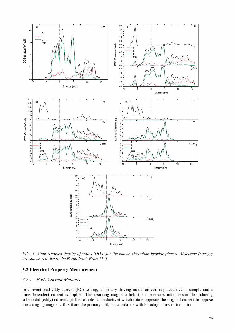
79
FIG. 5. Atom-resolved density of states (DOS) for the known zirconium hydride phases. Abscissae (energy)
are shown relative to the Fermi level. From [16]. 3.2 Electrical Property Measurement
3.2.1 Eddy Current Methods
In conventional eddy current (EC) testing, a primary driving induction coil is placed over a sample and a time-dependent current is applied. The resulting magnetic field then penetrates into the sample, inducing solenoidal (eddy) currents (if the sample is conductive) which rotate opposite the original current to oppose the changing magnetic flux from the primary coil, in accordance with Faraday’s Law of induction,

80
∇ × I1 = − 7JI17K ,
and the Ampere-Maxwell Law (for the secondary field),
∇ × LII1 = MNII1 + 7OII17K ,
where the quantities retain their usual meanings and M1 is the eddy current.
Such eddy currents can be detected by either a secondary coil, as shown in Fig. 6, or by observing changes in the inductance in the primary coil due to the presence of the sample, as through the use of an LCR meter. In either case, variations in the electrical impedance within the sample, e.g. as caused by formation of cracks, phase transformations, or increased concentration of scattering sites, will affect the degree to which eddy currents may propagate.
FIG. 6. Schematic view of eddy current induction and detection.
3.2.2 Features of Electrical Impedance in the Zr-H System
It was supposed in §3.1 that a piecewise linear behaviour might be observed in the electrical impedance variation with hydrogen content in zirconium. Figure 7 supports this prediction with some preliminary data for Zircaloy-4, obtained by EC (LCR) methods performed on samples charged in a high pressure hydrogen atmosphere. From this data it is clear that measurements made at a single frequency are insufficient to fully characterize the phases present in a sample of Zircaloy, owing to the lack of monotonicity in the impedance behaviour. Further, a sharp peak is observed in the low hydrogen region, which may be due to the influence of alloying elements (of which Zircaloy contains approximately 1.2—1.7, 0.18—0.24, and 0.07—0.13 weight percents of tin, iron and chromium, respectively), which could broaden the hydrogen solubility in the α-Zr phase region significantly. Additional experiments to fully quantify the frequency-dependent features of the Zircaloy-hydrogen system will hopefully elucidate the nature of this anomaly.
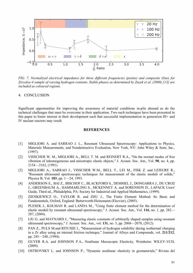
81
FIG. 7. Normalized electrical impedance for three different frequencies (points) and composite (line) for
Zircaloy-4 sample of varying hydrogen contents. Stable phases as determined by Zuzek et al. (2000) [13] are included as coloured regions.
4. CONCLUSION
Significant opportunities for improving the awareness of material conditions in-pile abound as do the technical challenges that must be overcome in their application. Two such techniques have been presented in this paper to foster interest in their development such that successful implementation in generation III+ and IV nuclear reactors may result.
REFERENCES
[1] MIGLIORI A. and SARRAO J. L., Resonant Ultrasound Spectroscopy: Applications to Physics,
Materials Measurements, and Nondestructive Evaluation, New York, NY: John Wiley & Sons, Inc., (1997).
[2] VISSCHER W. M., MIGLIORI A., BELL T. M. and REINERT R.A., "On the normal modes of free vibration of inhomogeneous and anisotropic elastic objects," J. Acoust. Soc. Am., Vol. 90, no. 4, pp. 2154—2162, (1991).
[3] MIGLIORI A., SARRAO J., VISSCHER W.M., BELL T., LEI M., FISK Z. and LEISURE R., "Resonant ultrasound spectroscopic techniques for measurement of the elastic moduli of solids," Physica B, Vol. 183, pp. 1—24, 1993.
[4] ANDERSON E., BAI Z., BISCHOF C., BLACKFORD S., DEMMEL J., DONGARRA J., DU CROZ J., GREENBAUM A., HAMMARLING S., MCKENNEY A. and SORENSON D., LAPACK Users' Guide, Third ed., Philadelphia, PA: Society for Industrial and Applied Mathematics, (1999).
[5] ZIENKIEWICZ O., TAYLOR R. and ZHU J., The Finite Element Method: Its Basis and Fundamentals, Oxford, England: Butterworth-Heinemann (Elsevier), (2005).
[6] PLESEK J., KOLMAN R. and LANDA M., "Using finite element method for the determination of elastic moduli by resonant ultrasound spectroscopy," J. Acoust. Soc. Am., Vol. 116, no. 1, pp. 282—287, (2004).
[7] LIU G. and MAYNARD J., "Measuring elastic constants of arbitrarily shaped samples using resonant ultrasound spectroscopy," J. Acoust. Soc. Am., vol. 131, no. 3, pp. 2068—2078, (2012).
[8] PAN Z., PULS M.and RITCHIE I., "Measurement of hydrogen solubility during isothermal charging in a Zr alloy using an internal friction technique," Journal of Alloys and Compounds, vol. 211/212, pp. 245—248, (1994).
[9] GUYER R.A. and JOHNSON P.A., Nonlinear Mesoscopic Elasticity, Weinheim: WILEY-VCH, (2009).
[10] OSTROVSKY L. and JOHNSON P., "Dynamic nonlinear elasticity in geomaterials," Rivista del

82
Nuovo Cimento, vol. 24, no. 7, pp. 1—46, (2001).
[11] LEMAIGNAN C., "Corrosion of Zirconium Alloy Components in Light Water Reactors," in ASM Handbook: Corrosion: Environment and Industries, vol. 13C, Materials Park, OH, ASM International, pp. 415—420, (2006).
[12] ZIELINSKI A., "Hydrogen-assisted degradation of some non-ferrous metals and alloys," Journal of Materials Processing Technology, vol. 109, pp. 206—214, (2001).
[13] BERTOLINO G., MEYER G. and J. PEREZ IPINA, "Degradation of the mechanical properties of Zircaloy-4 due to hydrogen embrittlement," Journal of Alloys and Compounds, Vols. 330—332, pp. 408—413, (2002).
[14] ZUZEK E. and ABRIATA J., "The H-Zr (hydrogen-zirconium) system," Bulletin of Alloy Phase Diagrams, vol. 11, no. 4, pp. 385—395, (1990).
[15] LANZANI L. and RUCH M., "Comments on the stability of zirconium hydride phases in zircaloy," Journal of Nuclear Materials, vol. 324, pp. 165—176, (2004).
[16] ZUZEK E., ABRIATA J., SAN-MARTIN A. and MANCHESTER F., Phase Diagrams of Binary Hydrogen Alloys, Materials Park, OH: ASM International, pp. 309—310, (2000).
[17] GUPTA M., "Electronic properties and electron-phonon coupling in zirconium and niobium hydrides," Physical Review B, vol. 25, no. 2, pp. 1027—1038, (1982).
[18] BICKEL P. and BERLINCOURT T., "Electrical properties of hydrides and deuterides of zirconium," Physical Review B, vol. 2, no. 12, pp. 4807—4813, (1970).
[19] SINGH N., SINGH S., MAHAJAN S., JINDAL V. and PRAKASH S., "Electron structure of interstitial hydrogen in alpha-Zr," J. Phys., vol. 26, no. 2, pp. 143—150, (1986).
[20] ZHU W., WANG R., SHU G., WU P. and XIAO H., "First-principles study of different polymorphs of crystalline zirconium hydride," J. Phys. Chem. C, vol. 114, pp. 22361—22368, (2010).
83
MEASUREMENT OF THE CORE AXIAL POWER DISTRIBUTION BY COPPER
WIRE ACTIVATION
“HAEK” CJSC /Armenian Nuclear Power Plant Metsamor, Armavir Marz, Republic of Armenia Email: [email protected] Abstract
Our nuclear power plant has never considered issues of the fourth generation fuel development. Since construction of a new power unit in Armenia is envisaged, for which use of the fourth generation fuel material may be required I, as a specialist, as well as a representative of our NPP, is interested in participation in this meeting and obtaining information on development of the fourth generation fuel material. I have prepared a report on "In-core Monitoring and Measurement Methods of Our NPP". Both types of the methods refer to determining the ratio of energy release non-uniformity according to the height of core level.
1. MEASUREMENT OF THE CORE AXIAL POWER DISTRIBUTION BY COPPER WIRE ACTIVATION
1.1 The first method is activation method
The specific power and energy release, in case of uniform distribution of all the components throughout the core and constant neutron spectrum availability are proportional to the neutron flux density which is distributed correspondingly throughout the core without a reflector:
Ф(z)=фoz × cos(πz/H) (1) Ф(r)= фoг × ψ0 × cos(2.45r/R) (2) Where: Ф(z) is neutron flux density along the core height; Ф® is neutron flux density along the core radius; H is core height; R is core radius; Z is coordinate along the core height; R is coordinate along the core radius; Ψ0 is Bessel function of zeros order; Фoz peak value of neutron flux density along the core height; Фoг is peak value of neutron flux density along the core radius.
The level of energy release deviation from the mean value at different points of the core is characterized by the core radius, height and volume no uniformity factors. Moreover, kv=kz×kz, and the peak factor of the volume no uniformity determines the boundary of nuclear reactor allowable power, kvmax = pmax/p. Which the given allowable value of the peak specific energy release, the reactor power is so much higher as kv is closer to the unit, i. e. the closer is energy release at each point of the core to the peak allowable value. Moreover, energy release equilibration, i. e. attempts to draw mean powers and heat loads nearer to the peak values, is the basis of modern approach to creating powerful nuclear reactors. The reduction of kv will allow to increase fuel burn-out depth, i. e. to decrease fuel cost-price of generated electric energy.
N. ALEKSANYAN

84
Modern large power reactors, for which dynamic no uniformity is characteristic, have got particular systems to control energy release in the core. The system enable to timely record deterioration of energy release distribution, and thus, prevent the most energy – intense fuel assemblies from being destroyed. In order to ensure safe operation of a reactor facility, exact information on energy – release fields distribution should be available. At the Armenian Nuclear Power Plant one of the systems mentioned is kz Measurement system that uses the activation method. The point of this method is in the following:
1. A wire made of a material easily activated by neutrons (e.g. copper) is inserted into the energy release channel, and the energy is measured according to the height of the core.
2. Following the irradiation, in several minutes the wire is extracted and is maintained some tens of hours so that the short-lived radioactive nuclides may decay.
3. By means of a scintillation spectrometer the γ-activity is measured according to the wire length, the curve of γ-activity distribution is plotted (which is proportionа1 to neutron flux density) according to the wire height (according to the core height).
1.2 Components of kz measurement system and their functioning
The system of measuring the neutron flux density distribution according to the reactor core height consists of a radiated wire advancement device and a scintillation spectrometer.
1.3 Activation of the wire (irradiation)
The copper wire should be inserted into the ampoule which represents a thin tube (with a diameter of 3mm) made of nickel with a threaded tip at the end, and should be connected to a rod. The latter is a thick wire (with a diameter of 5mm) with a threaded connector counterpart. The loaded rod should be taken off the reactor cap and inserted into the corresponding energy release channel. Irradiation time is 5 minutes. Following the irradiation, the rod should be lifted to the height of 6m ensuring the ampoule outlet and withdrawal from the core. Thus, the wire is prevented from being further irradiated. In a two-day interval (this period is required for the short-lived radio nuclides decay, the ampoule is to be withdrawn from the energy release channel. The ampoule is to be disconnected from the rod and taken directly to measuring bench room kz and installed into the cask.
1.4 Processing of the results
The processing of the chart strip with energy release distribution according to the core height constitutes in the following.
1.4.1 Approximation of distribution curve
For this Operation it is required to take into consideration the reflector contribution and that of the spacer lattices. This is performed manually directly at the chart strip.

85
The chart should be spited into fifty equal parts along the distance axe, and the amplitude value should be determined for each of the fifty values of length according to the core height. This operation is performed manually by means of a ruler, and the values derived are written on the distribution chart. Following this, the mean amplitude value in the distribution is determined by the formula:
And the value of kz is determined by the formula
where,
kz - is non-uniformity amplitude value; Ji - is distribution amplitude value; J - is mean amplitude value; Jmax- is amplitude peak value.
2. MEASUREMENT OF THE CORE AXIAL POWER DISTRIBUTION BY MEANS OF DCS
The DCS consists of an emitter, header and a dielectric which separates them. For the emitter those materials are used in which charged particles are generated under the influence of neutron irradiation. Leaving the emitter and being accumulated at the header, these particles create a difference of potentials. The current determined by it, is proportional to the neutron flux density in the place where the sensor is installed. Materials for the structural components of DCS are chosen in such a way that the quantity of charged particles generated in them and capable of affecting the DCS current was significantly less than in the emitter. The DCS represents a current generator, where the short circuit current is directly measured. Using DCS in short circuit mode identifies a range of advantages of this method. Among them is the significant reduction of the sensor insulation resistance, which enables to use DCS in high temperatures, and a relatively small impact of interferences on operation of low-resistance measuring device.
REFERENCES
[1] POGOSYAN X. A., MANUKYAN L. G., Determination of Energy Release Non – Uniformity Factor along the Core Height via Activation Method, Metsamor (2004).
∑=
=50
1 50i
iJJ
J
Jk z
max=
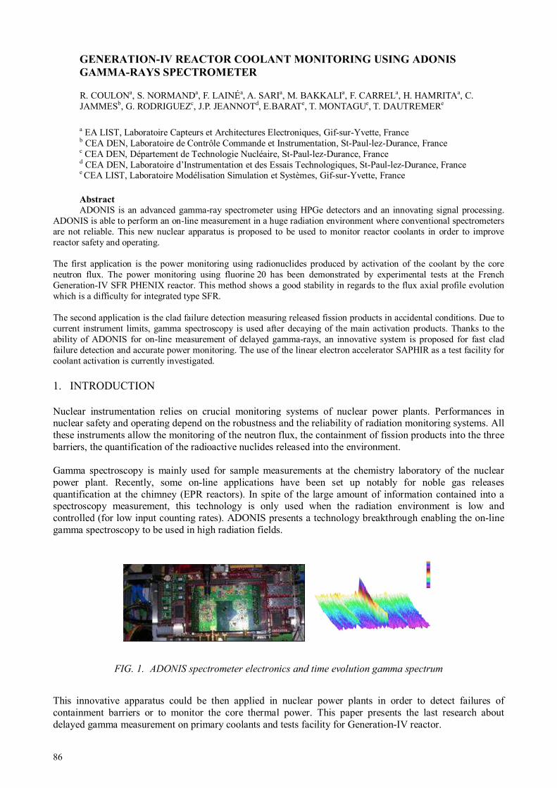
86
GENERATION-IV REACTOR COOLANT MONITORING USING ADONIS
GAMMA-RAYS SPECTROMETER
a EA LIST, Laboratoire Capteurs et Architectures Electroniques, Gif-sur-Yvette, France b CEA DEN, Laboratoire de Contrôle Commande et Instrumentation, St-Paul-lez-Durance, France c CEA DEN, Département de Technologie Nucléaire, St-Paul-lez-Durance, France d CEA DEN, Laboratoire d’Instrumentation et des Essais Technologiques, St-Paul-lez-Durance, France e CEA LIST, Laboratoire Modélisation Simulation et Systèmes, Gif-sur-Yvette, France
Abstract
ADONIS is an advanced gamma-ray spectrometer using HPGe detectors and an innovating signal processing. ADONIS is able to perform an on-line measurement in a huge radiation environment where conventional spectrometers are not reliable. This new nuclear apparatus is proposed to be used to monitor reactor coolants in order to improve reactor safety and operating. The first application is the power monitoring using radionuclides produced by activation of the coolant by the core neutron flux. The power monitoring using fluorine 20 has been demonstrated by experimental tests at the French Generation-IV SFR PHENIX reactor. This method shows a good stability in regards to the flux axial profile evolution which is a difficulty for integrated type SFR. The second application is the clad failure detection measuring released fission products in accidental conditions. Due to current instrument limits, gamma spectroscopy is used after decaying of the main activation products. Thanks to the ability of ADONIS for on-line measurement of delayed gamma-rays, an innovative system is proposed for fast clad failure detection and accurate power monitoring. The use of the linear electron accelerator SAPHIR as a test facility for coolant activation is currently investigated.
1. INTRODUCTION
Nuclear instrumentation relies on crucial monitoring systems of nuclear power plants. Performances in nuclear safety and operating depend on the robustness and the reliability of radiation monitoring systems. All these instruments allow the monitoring of the neutron flux, the containment of fission products into the three barriers, the quantification of the radioactive nuclides released into the environment. Gamma spectroscopy is mainly used for sample measurements at the chemistry laboratory of the nuclear power plant. Recently, some on-line applications have been set up notably for noble gas releases quantification at the chimney (EPR reactors). In spite of the large amount of information contained into a spectroscopy measurement, this technology is only used when the radiation environment is low and controlled (for low input counting rates). ADONIS presents a technology breakthrough enabling the on-line gamma spectroscopy to be used in high radiation fields.
FIG. 1. ADONIS spectrometer electronics and time evolution gamma spectrum
This innovative apparatus could be then applied in nuclear power plants in order to detect failures of containment barriers or to monitor the core thermal power. This paper presents the last research about delayed gamma measurement on primary coolants and tests facility for Generation-IV reactor.
R. COULONa, S. NORMANDa, F. LAINÉa, A. SARIa, M. BAKKALIa, F. CARRELa, H. HAMRITAa, C. JAMMESb, G. RODRIGUEZc, J.P. JEANNOTd, E.BARATe, T. MONTAGUe, T. DAUTREMERe

87
2. THE ADONIS SPECTROMETER
Current gamma spectrometers use trapezoidal or cups linear filters to increase photonic pulse signal in regards to the electronic noise [1—2]. This method covers a large range of gamma spectroscopy applications but shows metrological degradation when the spectrometer dead time gets above 40% due to the accuracy leakage of active time metrology. A nonlinear filtering based on bimodal Kalman smoother is implemented into ADONIS [3]. This algorithm allows maintaining the metrological stability whatever the radiation environment status and takes potential evolution of the latter into account. Figure 2 illustrates the ADONIS stability close to 100% of dead time and the discrepancy of the conventional spectrometer which has been optimized for high count rates. The measurement gap is evaluated using a reference source (137Cs) delivering a constant signal and a perturbation source (241Am) used for increase the total input count rate.
FIG. 2. Comparison of the metrological stability between the ADONIS spectrometer and a conventional
spectrometer optimized for high count rates.
The stability and the continuous adaption of ADONIS analyser associated with the autonomous of electrical or hybrid cryostat permit to consider the use of this spectrometer to monitor reactor coolants [4]. Potentials applications are then explained.
3. POWER MONITORING APPLICATION
Ex-core neutron measurements are used to calculate the thermal power or the doubling time in order to control the reactor. At each fuel cycle, a calibration is done by a heat balance measurement through primary and secondary thermodynamics measurements. The power measurement is also continuously corrected by core temperature to compensate the coolant transparency to neutron effect. In a pressurized water reactor, these neutron detectors using boron coated gas chambers are set up axially to the core. In pool type sodium-cooled fast reactor the core is shielded in order to avoid secondary coolant activation (see Fig. 4). Ex-core neutron chambers could then not be placed axially to the core but are set under the primary vessel where the flux is high enough to be measured. The axial evolution of neutron flux and fuel blankets enrichment induced a neutron signal drift over the time (see Fig 3.). Calibration to heat balance has then to be done more frequently to become closer to the normal operating conditions.
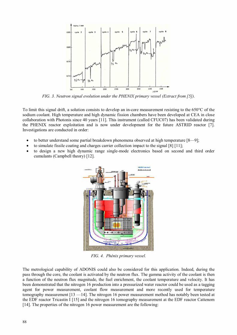
88
FIG. 3. Neutron signal evolution under the PHENIX primary vessel (Extract from [5]).
To limit this signal drift, a solution consists to develop an in-core measurement resisting to the 650°C of the sodium coolant. High temperature and high dynamic fission chambers have been developed at CEA in close collaboration with Photonis since 40 years [11]. This instrument (called CFUC07) has been validated during the PHENIX reactor exploitation and is now under development for the future ASTRID reactor [7]. Investigations are conducted in order:
• to better understand some partial breakdown phenomena observed at high temperature [8—9]; • to simulate fissile coating and charges carrier collection impact to the signal [8] [11]; • to design a new high dynamic range single-mode electronics based on second and third order
cumulants (Campbell theory) [12].
FIG. 4. Phénix primary vessel.
The metrological capability of ADONIS could also be considered for this application. Indeed, during the pass through the core, the coolant is activated by the neutron flux. The gamma activity of the coolant is then a function of the neutron flux magnitude, the fuel enrichment, the coolant temperature and velocity. It has been demonstrated that the nitrogen 16 production into a pressurized water reactor could be used as a tagging agent for power measurement, coolant flow measurement and more recently used for temperature tomography measurement [13 —14]. The nitrogen 16 power measurement method has notably been tested at the EDF reactor Tricastin I [15] and the nitrogen 16 tomography measurement at the EDF reactor Cattenom [14]. The properties of the nitrogen 16 power measurement are the following:

89
• The nitrogen 16 radioactive period is in the same range of the coolant cycle time. A compensation of the measurement is then needed.
• The 16O(n,p)16N reaction has a threshold up to 10 MeV that induces a dependency to the 239Pu concentration and then to the burn-up evolution during a fuel cycle [17].
• The impact of the axial offset is limited has shown in Fig. 5.
Thanks to its stability regarding to the axial offset, this methods presents an interest for integrated sodium-cooled fast reactors.
FIG. 5. Impact of the power axial offset to the measurement (Extract from [18]). The gap is the nitrogen 16
activity difference in regard to a flat power distribution.
The sodium 24 produced by radioactive captures is cumulated into the coolant (decay period of 15 h). The spectroscopy is then required to measure more conveniently radionuclides such as the fluorine 20 or the neon 23. Fluorine 20 is very suitable for this application thanks to:
• Its decay period of 11 s which is about 10 times lower than the mean coolant cycle time avoiding all build-up effects;
• Its fast spectrum representativeness thanks to the 23Na(n,α) reaction threshold at 7 MeV. The neon 23 has also a quite short decay period of 23 s and is produced by fast neutron reactions 23Na(n,p) occurring above 5 MeV. Notice that the ratio between 20F and 23Ne signal could give:
• an information about the sodium flow rate (using the differences in respective decay periods) and could allow detection of blockage into sub-assembly [19];
• an information about the neutron spectrum (using the difference in respective reaction thresholds).
The power monitoring method has been tested during the ultimate testing program of the PHENIX reactor in 2009 (CEA Marcoule) [20]. The ADONIS prototype has been installed close to the delayed neutron detecting system in order to measure the primary sodium circulating into it. Figure 2 presents a scheme of the system and photography of the final set-up.
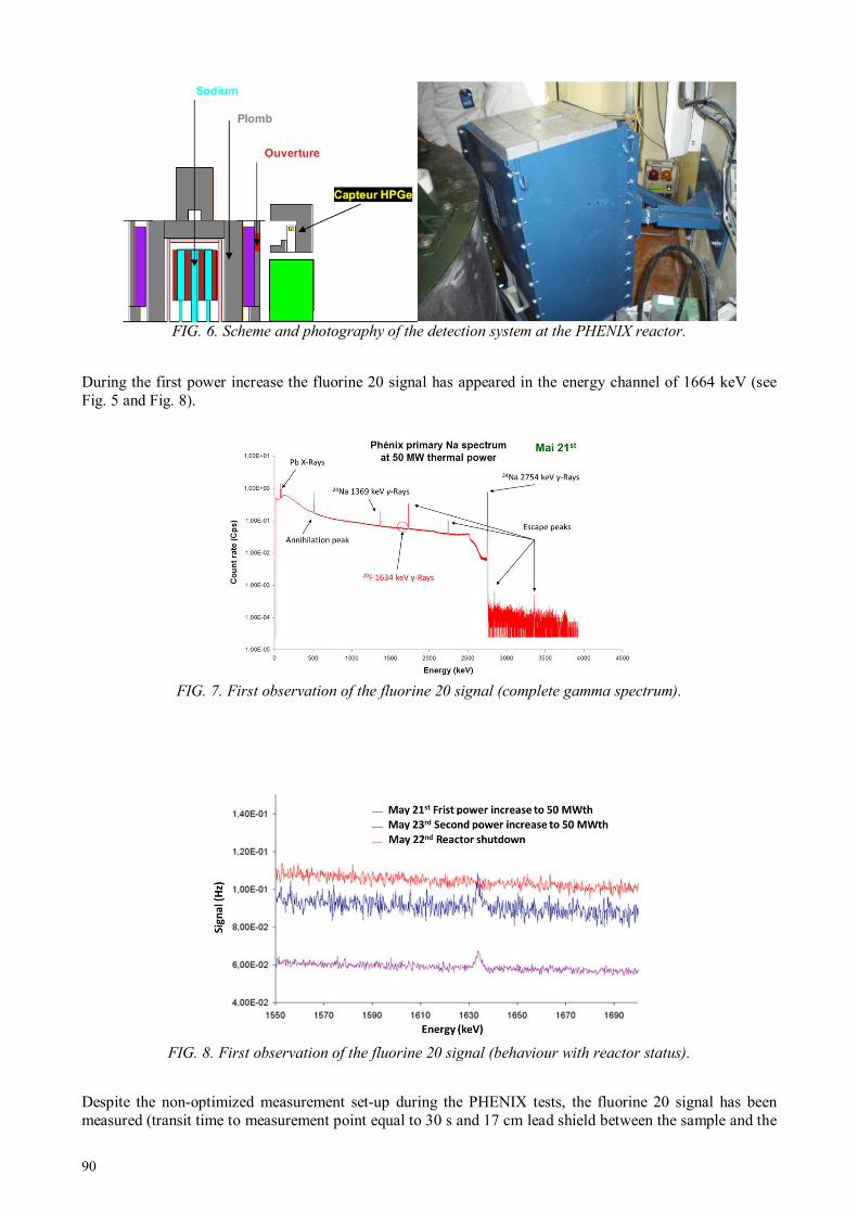
90
FIG. 6. Scheme and photography of the detection system at the PHENIX reactor.
During the first power increase the fluorine 20 signal has appeared in the energy channel of 1664 keV (see Fig. 5 and Fig. 8).
FIG. 7. First observation of the fluorine 20 signal (complete gamma spectrum).
FIG. 8. First observation of the fluorine 20 signal (behaviour with reactor status).
Despite the non-optimized measurement set-up during the PHENIX tests, the fluorine 20 signal has been measured (transit time to measurement point equal to 30 s and 17 cm lead shield between the sample and the

91
HPGe detector) and shows a good stability with the reactor power. The Fig.9 presents a comparison between the 20F signal and the heat balance power measurements. A linearity within a range of uncertainty of 20% and the absence of build-up effect has been observed.
FIG. 9.
20F signal to released power ratio at the reference power measurement points.
The fluorine 20 and also the neon 23 could then been monitored on primary coolant using the ADONIS spectrometer. The achievable statistical accuracy in optimized configuration is estimated at 3% for 2 s counting time. The other application of gamma spectroscopy is the clad failure detection introduced in the next section.
4. CLAD FAILURE DETECTION APPLICATION
Clad failure monitoring is an important issue for sodium-cooled fast reactor where the sodium reacts violently with fuel oxide inducing fast aggravation of the failure. Due to the high gamma activity of the activation products (24Na, 20F, 23Ne, 22Na) the failure are measured by gamma spectroscopy after degasing of the sodium and decaying of the 23Ne activity [21]. Another solution is the detection of delayed neutron precursors (137I, 87Br) released into the sodium coolant. The delayed neutron measurement could be done by sampling (3He counters) or by high temperature fission chambers installed into the primary vessel [22]. The proposed approach consists to perform a direct gamma spectroscopy measurement of the sodium coolant measuring short life fission products. Indeed the fission products activity increases more than activation products activity when transit time from sampling to measurement decrease (see Fig 10.). The detection sensitivity could then be increased in the same time of the response time diminution. Thanks to its input count rate adaptive filtering, the ADONIS spectrometer is particularly adapted to measure dramatically changing signals as a release of fission products. The ADONIS prototype has been tested in 2005 at the PHEBUS facility during core degradation experiment FPT3 (CEA Cadarache). It was the only system able to monitor the entire kinetics of the clad failure when conventional systems show their limits in regards to these fast changing activities [23].

92
FIG. 10. Gaseous and volatile fission products activities divided by activation products activities as a function of cooling time.
5. THE SYSTEM CONCEPTION
The system could be optimized for power monitoring and for clad failure detection.
• The sampling has to be done sufficiently close to the assembly output in order not to being impacted by the flow heterogeneity appearing into the hot plenum.
• A multi sampling is required at different points into the hot plenum in order to control the radial power heterogeneities and to allow a clad failure pre-localization to be performed.
• The transit time from core output to measurement point has to be as fast as possible. For the power measurement function, the shortest the transit time, the best the statistical accuracy. For clad failure function, a minimum transit time below 4.5 s would enable the krypton 92 detection which is released in high quantity at the beginning of a failure.
• The sample volume and the crystal volume have to be optimized for measurement of interesting radionuclides: 92Kr (1219 keV), 138I (589 keV), 133mI (647 keV), 20F (1634 keV), 23Ne (440 keV). To keep flexibility on the measurement efficiency, the use of a dynamic collimator is preferable (Mobile detector on rails) but all shielding between source and detector must be avoid to fully used the ADONIS capability and not damage low energy gamma signal.
• Real time net signal has to be processed for each monitored radionuclides. An advanced detection algorithm could be implemented to optimize fission products releases detection. The power measurement has to be calibrated by heat balance and corrected in real time by core flow rate and core temperature measurements.
Figure 11 illustrates a monitoring system of delayed gamma and neutron particles for sodium-cooled fast reactors.

93
FIG. 11. Monitoring system architecture for sodium-cooled fast reactor.
In parallel to the system design optimization some other validation of activation model should be conducted. The next section introduces the SAPHIR facility and its application for coolant activation tests.
6. THE SAPHIR FACILITY
The SAPHIR facility (CEA LIST) houses a linear electron accelerator using radiofrequency cavities (shown in Fig. 12). Electrons could achieve a kinetic energy up to 18 MeV and a conversion target (in a dense material like tungsten or tantalum) produces high energy photons by bremsstrahlung reactions. The SAPHIR facility enabled to develop photon activation analysis methods. Indeed, high energy photons above 6 MeV could produce photo-fission (γ,f) into a waste package. Delayed neutrons or delayed gamma-rays could then be measured in order to quantify fissile and fertile materials contained into it [24].
FIG. 12. SAPHIR accelerator beam-line.
The accelerator also produces photoneutrons by photonuclear reactions (γ,xn) into the conversion target. Current works are carried out in order to use the linear electron accelerator as a multi-device enabling to conduct active neutron interrogation in addition to active photon interrogation and high energy imaging [25]. It has been notably demonstrated that the target could be optimized in order to reach average emission
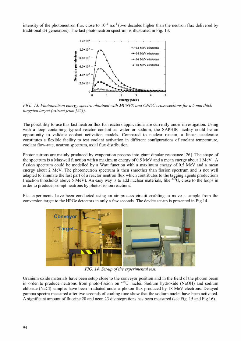
94
intensity of the photoneutron flux close to 1011 n.s-1 (two decades higher than the neutron flux delivered by traditional d-t generators). The fast photoneutron spectrum is illustrated in Fig. 13.
FIG. 13. Photoneutron energy spectra obtained with MCNPX and CNDC cross-sections for a 5 mm thick
tungsten target (extract from [25]).
The possibility to use this fast neutron flux for reactors applications are currently under investigation. Using with a loop containing typical reactor coolant as water or sodium, the SAPHIR facility could be an opportunity to validate coolant activation models. Compared to nuclear reactor, a linear accelerator constitutes a flexible facility to test coolant activation in different configurations of coolant temperature, coolant flow-rate, neutron spectrum, axial flux distribution. Photoneutrons are mainly produced by evaporation process into giant dipolar resonance [26]. The shape of the spectrum is a Maxwell function with a maximum energy of 0.5 MeV and a mean energy about 1 MeV. A fission spectrum could be modelled by a Watt function with a maximum energy of 0.5 MeV and a mean energy about 2 MeV. The photoneutron spectrum is then smoother than fission spectrum and is not well adapted to simulate the fast part of a reactor neutron flux which contributes to the tagging agents productions (reaction thresholds above 5 MeV). An easy way is to add nuclear materials, like 238U, close to the loops in order to produce prompt neutrons by photo-fission reactions. Fist experiments have been conducted using an air process circuit enabling to move a sample from the conversion target to the HPGe detectors in only a few seconds. The device set-up is presented in Fig 14.
FIG. 14. Set-up of the experimental test.
Uranium oxide materials have been setup close to the conveyor position and in the field of the photon beam in order to produce neutrons from photo-fission on 238U nuclei. Sodium hydroxide (NaOH) and sodium chloride (NaCl) samples have been irradiated under a photon flux produced by 18 MeV electrons. Delayed gamma spectra measured after two seconds of cooling time show that the sodium nuclei have been activated. A significant amount of fluorine 20 and neon 23 disintegrations has been measured (see Fig. 15 and Fig.16).
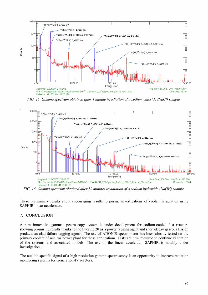
95
FIG. 15. Gamma spectrum obtained after 1 minute irradiation of a sodium chloride (NaCl) sample.
FIG. 16. Gamma spectrum obtained after 30 minutes irradiation of a sodium hydroxide (NaOH) sample.
These preliminary results show encouraging results to pursue investigations of coolant irradiation using SAPHIR linear accelerator.
7. CONCLUSION
A new innovative gamma spectroscopy system is under development for sodium-cooled fast reactors showing promising results thanks to the fluorine 20 as a power tagging agent and short-decay gaseous fission products as clad failure tagging agents. The use of ADONIS spectrometer has been already tested on the primary coolant of nuclear power plant for these applications. Tests are now required to continue validation of the systems and associated models. The use of the linear accelerator SAPHIR is notably under investigation. The nuclide specific signal of a high resolution gamma spectroscopy is an opportunity to improve radiation monitoring systems for Generation-IV reactors.
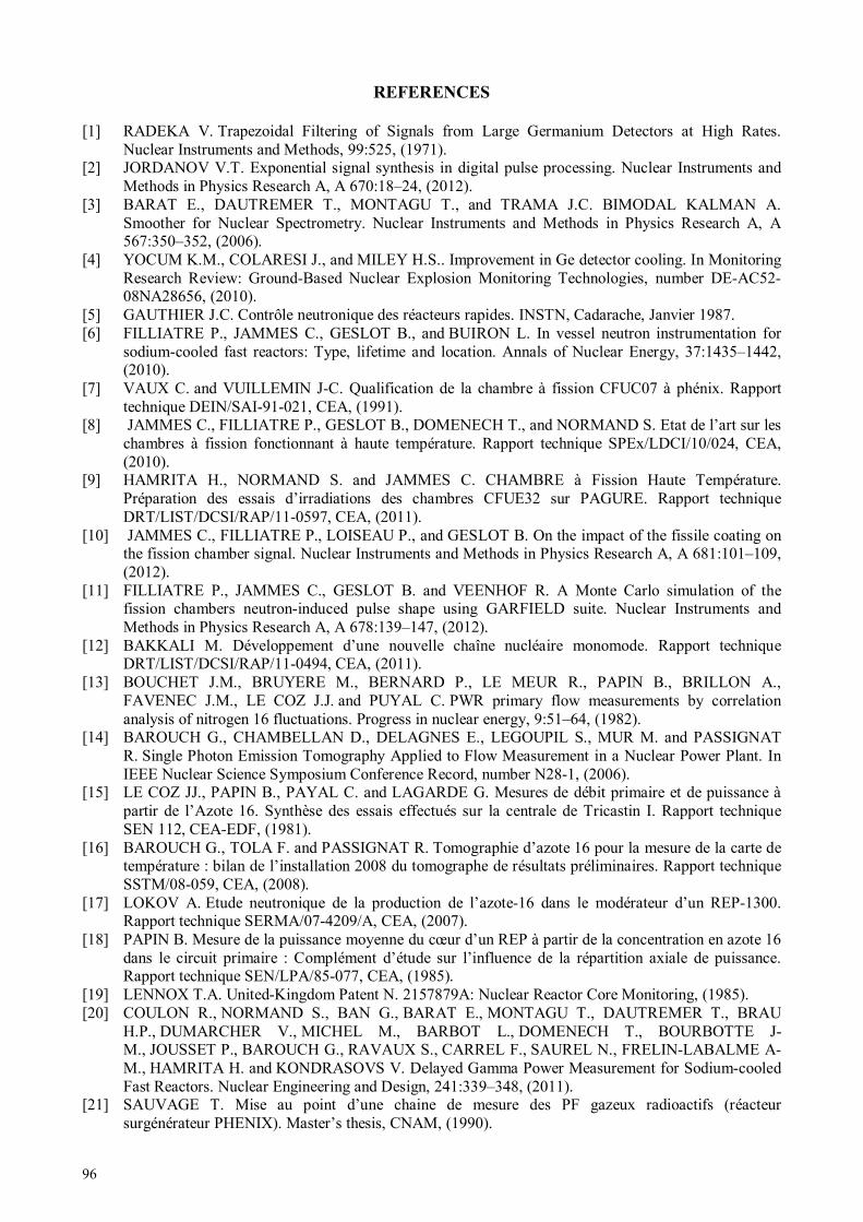
96
REFERENCES
[1] RADEKA V. Trapezoidal Filtering of Signals from Large Germanium Detectors at High Rates. Nuclear Instruments and Methods, 99:525, (1971).
[2] JORDANOV V.T. Exponential signal synthesis in digital pulse processing. Nuclear Instruments and Methods in Physics Research A, A 670:18–24, (2012).
[3] BARAT E., DAUTREMER T., MONTAGU T., and TRAMA J.C. BIMODAL KALMAN A. Smoother for Nuclear Spectrometry. Nuclear Instruments and Methods in Physics Research A, A 567:350–352, (2006).
[4] YOCUM K.M., COLARESI J., and MILEY H.S.. Improvement in Ge detector cooling. In Monitoring Research Review: Ground-Based Nuclear Explosion Monitoring Technologies, number DE-AC52-08NA28656, (2010).
[5] GAUTHIER J.C. Contrôle neutronique des réacteurs rapides. INSTN, Cadarache, Janvier 1987. [6] FILLIATRE P., JAMMES C., GESLOT B., and BUIRON L. In vessel neutron instrumentation for
sodium-cooled fast reactors: Type, lifetime and location. Annals of Nuclear Energy, 37:1435–1442, (2010).
[7] VAUX C. and VUILLEMIN J-C. Qualification de la chambre à fission CFUC07 à phénix. Rapport technique DEIN/SAI-91-021, CEA, (1991).
[8] JAMMES C., FILLIATRE P., GESLOT B., DOMENECH T., and NORMAND S. Etat de l’art sur les chambres à fission fonctionnant à haute température. Rapport technique SPEx/LDCI/10/024, CEA, (2010).
[9] HAMRITA H., NORMAND S. and JAMMES C. CHAMBRE à Fission Haute Température. Préparation des essais d’irradiations des chambres CFUE32 sur PAGURE. Rapport technique DRT/LIST/DCSI/RAP/11-0597, CEA, (2011).
[10] JAMMES C., FILLIATRE P., LOISEAU P., and GESLOT B. On the impact of the fissile coating on the fission chamber signal. Nuclear Instruments and Methods in Physics Research A, A 681:101–109, (2012).
[11] FILLIATRE P., JAMMES C., GESLOT B. and VEENHOF R. A Monte Carlo simulation of the fission chambers neutron-induced pulse shape using GARFIELD suite. Nuclear Instruments and Methods in Physics Research A, A 678:139–147, (2012).
[12] BAKKALI M. Développement d’une nouvelle chaîne nucléaire monomode. Rapport technique DRT/LIST/DCSI/RAP/11-0494, CEA, (2011).
[13] BOUCHET J.M., BRUYERE M., BERNARD P., LE MEUR R., PAPIN B., BRILLON A., FAVENEC J.M., LE COZ J.J. and PUYAL C. PWR primary flow measurements by correlation analysis of nitrogen 16 fluctuations. Progress in nuclear energy, 9:51–64, (1982).
[14] BAROUCH G., CHAMBELLAN D., DELAGNES E., LEGOUPIL S., MUR M. and PASSIGNAT R. Single Photon Emission Tomography Applied to Flow Measurement in a Nuclear Power Plant. In IEEE Nuclear Science Symposium Conference Record, number N28-1, (2006).
[15] LE COZ JJ., PAPIN B., PAYAL C. and LAGARDE G. Mesures de débit primaire et de puissance à partir de l’Azote 16. Synthèse des essais effectués sur la centrale de Tricastin I. Rapport technique SEN 112, CEA-EDF, (1981).
[16] BAROUCH G., TOLA F. and PASSIGNAT R. Tomographie d’azote 16 pour la mesure de la carte de température : bilan de l’installation 2008 du tomographe de résultats préliminaires. Rapport technique SSTM/08-059, CEA, (2008).
[17] LOKOV A. Etude neutronique de la production de l’azote-16 dans le modérateur d’un REP-1300. Rapport technique SERMA/07-4209/A, CEA, (2007).
[18] PAPIN B. Mesure de la puissance moyenne du cœur d’un REP à partir de la concentration en azote 16 dans le circuit primaire : Complément d’étude sur l’influence de la répartition axiale de puissance. Rapport technique SEN/LPA/85-077, CEA, (1985).
[19] LENNOX T.A. United-Kingdom Patent N. 2157879A: Nuclear Reactor Core Monitoring, (1985). [20] COULON R., NORMAND S., BAN G., BARAT E., MONTAGU T., DAUTREMER T., BRAU
H.P., DUMARCHER V., MICHEL M., BARBOT L., DOMENECH T., BOURBOTTE J-M., JOUSSET P., BAROUCH G., RAVAUX S., CARREL F., SAUREL N., FRELIN-LABALME A-M., HAMRITA H. and KONDRASOVS V. Delayed Gamma Power Measurement for Sodium-cooled Fast Reactors. Nuclear Engineering and Design, 241:339–348, (2011).
[21] SAUVAGE T. Mise au point d’une chaine de mesure des PF gazeux radioactifs (réacteur surgénérateur PHENIX). Master’s thesis, CNAM, (1990).

97
[22] JEANNOT J.P., RODRIGUEZ G., JAMMES C., BERNARDIN B., PORTIER JL, JADOT F., MAIRE S., VERRIER D., LOISY F., and PRÉLE G. R&D Program for Core Instrumentation Improvements Devoted for French Sodium Fast Reactors. In Proceeding of ANIMMA, (2011).
[23] BARAT E., DAUTREMER T., LARIBIÈRE L., LEFÈVRE J., MONTAGU T. and TRAMA J-C., ADONIS: A New System for High Count Rate HPGe Gamma Spectrometry. In IEEE Nuclear Science Symposium Conference Record, number N30-6, (2006).
[24] CARREL F., AGELOU M., GMAR M. and LAINÉ F. Detection of high-energy delayed gammas for nuclear waste packages characterization. Nuclear Instruments and Methods in Physics Research A, A 652:137–139, (2011).
[25] SARI A., CARREL F., GMAR M., LAINÉ F., LYOUSSI A. and NORMAND S. Detection of Actinides with an Electron Accelerator by Active Photoneutron Interrogation Measurements. IEEE Transactions on Nuclear Science, 59(3):605–611, (2012).
[26] MUTCHLER G. S.. The angular distributions and energy spectra of photoneutrons from heavy elements. PhD thesis, Massachusetts Institute of Technology, (1966).


IRRADIATION TECHNIQUES
(Session 2)
Chairperson
K.W. ERIKSEN
Norway
M. SEPIELLI Italy


101
DEVELOPMENT OF A DRILLING MACHINE FOR THE INSTRUMENTATION OF
THERMOCOUPLE IN A FUEL PELLET
Neutron Utilization Technology Division Korea Atomic Energy Research Institute (KAERI) Yuseong-gu, Daejeon, Republic of Korea Email: [email protected], [email protected] Abstract
To develop a new nuclear fuel, it needs to make a test fuel rod and carry out burn-up test in the test loop of a research reactor to check the performance of the nuclear fuel. At that time, it needs to attach sensors in and out of the fuel rod and connect them with instrumentation cables. Then, the instrumentation cables deliver the signals measured by the sensors to the measuring device located outside of the reactor pool. Especially, the internal temperature of the fuel pellet can be increased up to 1300£ due to the heat generated by the nuclear fissile activity during irradiating neutrons on the fuel rod. To analyse the temperature variation of the nuclear fuel during the burn-up test, a thermocouple needs to be instrumented at the center of the nuclear fuel located in each fuel rod. Therefore, a hole with the diameter of 0.7 mm ~ 1.4 mm needs to be drilled off on the fuel pellet to feed through the instrumentation cable and to install the thermocouple. However, because the hardness of a sintered UO2 pellet is 700HV (or HRC 61) and its density is 10.3g/cm3, it is difficult to make a small fine hole on die sintered UO2 pellet with a general drilling machine. Old studies about drilling machines which use a flat type electrodeposited drill bit have severe tool wear problem and breakage of drill bit problem due to the interference of chips generated during drilling process. Generally, it takes 3 pieces of drill bits to make a hole in a fuel pellet. The study deals with the development of an automated drilling machine which can remove chips automatically and enhance the tool life by relieving the tool wear. While old studies used electrodeposited diamond drill bit, a diamond coated twist drill bit was used in this study. And, a high-frequency spindle which has 2.2kW power and 30,000 rpm was adapted in the machine and controlled by PLC. The drill bit is fixed vertically to the spindle and the workpiece is fixed on the XY lable. Spindle is set to move repeatedly a step forward and back to the beginning position to prevent the interference between chips and drill bit by removing chips with cutting oil. Therefore, normally 10 pieces of test specimens (made of sintered AhOj) could be drilled off with a single drill bit without damaging to the tooling tolerance.
1. INTRODUCTION
To develop a new nuclear fuel, a test fuel rod and its burn-up test in the test loop of a research reactor are needed to check the performance of the nuclear fuel. At that time, sensors in and out of the fuel rod need to be connected with instrumentation cables. The instrumentation cables deliver the signals measured by the sensors to the measuring device located outside of the reactor pool. In particular, the internal temperature of the fuel pellet can be increased up to 1400 owing to the heat generated by the nuclear fissile activity while irradiating neutrons to the fuel rod. To analyse the temperature variation of the nuclear fuel during a burn-up test, a thermocouple needs to be instrumented at the center of the nuclear fuel located in each fuel rod. Therefore, a hole with the diameter of 0.7 mm—1.4 mm needs to be drilled into the fuel pellet to feed the instrumentation cable and install a thermocouple. However, because a sintered UO2 pellet is very hard and has a high density, it is difficult to make a fine hole in a sintered UO2 pellet with a general drilling machine. Old studies on drilling machines that use a flat type electrodeposited drill bit have severe tool wear and breakage problem owing to the interference of the chips generated during the drilling process. It generally consumes 3 pieces of drill bits to make a hole in a fuel pellet. Then, the drilled hole is not uniform and sometimes crack is initiated around the hole. The study deals with the development of an automated drilling machine for a sintered UO2 pellet, which can drill several fine holes with a drill bit in a short time.
J.T. HONG, S.H. AHN, H.Y. JEONG, C.Y. JOUNG
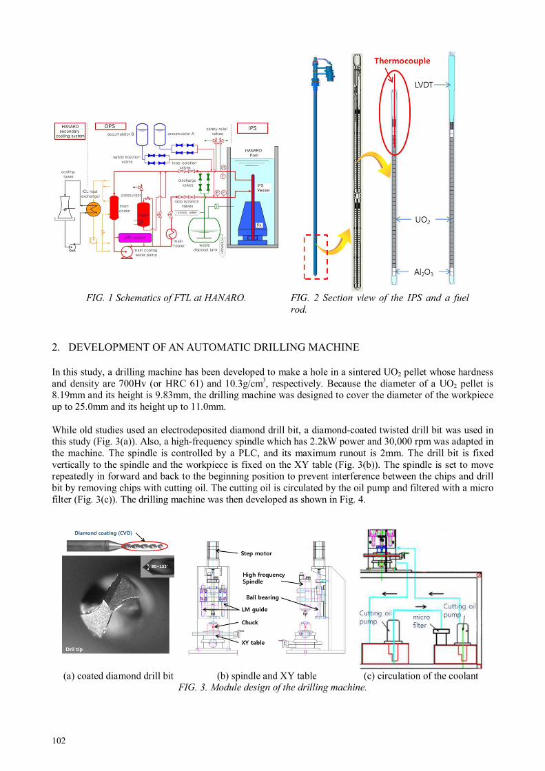
102
FIG. 1 Schematics of FTL at HANARO. FIG. 2 Section view of the IPS and a fuel
rod.
2. DEVELOPMENT OF AN AUTOMATIC DRILLING MACHINE
In this study, a drilling machine has been developed to make a hole in a sintered UO2 pellet whose hardness and density are 700Hv (or HRC 61) and 10.3g/cm3, respectively. Because the diameter of a UO2 pellet is 8.19mm and its height is 9.83mm, the drilling machine was designed to cover the diameter of the workpiece up to 25.0mm and its height up to 11.0mm. While old studies used an electrodeposited diamond drill bit, a diamond-coated twisted drill bit was used in this study (Fig. 3(a)). Also, a high-frequency spindle which has 2.2kW power and 30,000 rpm was adapted in the machine. The spindle is controlled by a PLC, and its maximum runout is 2mm. The drill bit is fixed vertically to the spindle and the workpiece is fixed on the XY table (Fig. 3(b)). The spindle is set to move repeatedly in forward and back to the beginning position to prevent interference between the chips and drill bit by removing chips with cutting oil. The cutting oil is circulated by the oil pump and filtered with a micro filter (Fig. 3(c)). The drilling machine was then developed as shown in Fig. 4.
(a) coated diamond drill bit (b) spindle and XY table (c) circulation of the coolant FIG. 3. Module design of the drilling machine.
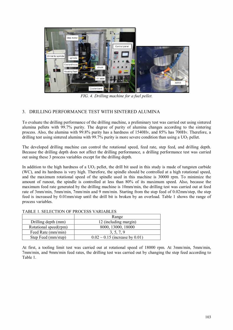
103
FIG. 4. Drilling machine for a fuel pellet.
3. DRILLING PERFORMANCE TEST WITH SINTERED ALUMINA
To evaluate the drilling performance of the drilling machine, a preliminary test was carried out using sintered alumina pellets with 99.7% purity. The degree of purity of alumina changes according to the sintering process. Also, the alumina with 99.8% purity has a hardness of 1540Hv, and 85% has 700Hv. Therefore, a drilling test using sintered alumina with 99.7% purity is more severe condition than using a UO2 pellet. The developed drilling machine can control the rotational speed, feed rate, step feed, and drilling depth. Because the drilling depth does not affect the drilling performance, a drilling performance test was carried out using these 3 process variables except for the drilling depth. In addition to the high hardness of a UO2 pellet, the drill bit used in this study is made of tungsten carbide (WC), and its hardness is very high. Therefore, the spindle should be controlled at a high rotational speed, and the maximum rotational speed of the spindle used in this machine is 30000 rpm. To minimize the amount of runout, the spindle is controlled at less than 80% of its maximum speed. Also, because the maximum feed rate generated by the drilling machine is 10mm/min, the drilling test was carried out at feed rate of 3mm/min, 5mm/min, 7mm/min and 9 mm/min. Starting from the step feed of 0.02mm/step, the step feed is increased by 0.01mm/step until the drill bit is broken by an overload. Table 1 shows the range of process variables.
TABLE 1. SELECTION OF PROCESS VARIABLES
Range Drilling depth (mm) 12 (including margin)
Rotational speed(rpm) 8000, 13000, 18000 Feed Rate (mm/min) 3, 5, 7, 9 Step Feed (mm/step) 0.02 ~ 0.15 (increase by 0.01)
At first, a tooling limit test was carried out at rotational speed of 18000 rpm. At 3mm/min, 5mm/min, 7mm/min, and 9mm/min feed rates, the drilling test was carried out by changing the step feed according to Table 1.
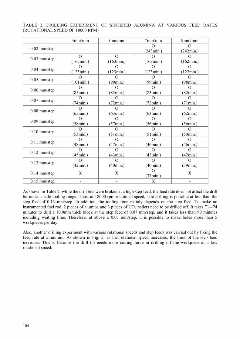
104
TABLE 2. DRILLING EXPERIMENT OF SINTERED ALUMINA AT VARIOUS FEED RATES (ROTATIONAL SPEED OF 18000 RPM)
3mm/min 5mm/min 7mm/min 9mm/min
0.02 mm/step - - O
(243min.) O
(242min.)
0.03 mm/step O
(165min.) O
(163min.) O
(163min.) O
(162min.)
0.04 mm/step O
(125min.) O
(123min.) O
(123min.) O
(122min.)
0.05 mm/step O
(101min.) O
(99min.) O
(99min.) O
(98min.)
0.06 mm/step O
(85min.) O
(83min.) O
(83min.) O
(82min.)
0.07 mm/step O
(74min.) O
(72min.) O
(72min.) O
(71min.)
0.08 mm/step O
(65min.) O
(63min.) O
(63min.) O
(62min.)
0.09 mm/step O
(58min.) O
(57min.) O
(56min.) O
(56min.)
0.10 mm/step O
(53min.) O
(51min.) O
(51min.) O
(50min.)
0.11 mm/step O
(48min.) O
(47min.) O
(46min.) O
(46min.)
0.12 mm/step O
(45min.) O
(43min.) O
(43min.) O
(42min.)
0.13 mm/step O
(42min.) O
(40min.) O
(40min.) O
(39min.)
0.14 mm/step X X O
(37min.) X
0.15 mm/step - - X -
As shown in Table 2, while the drill bits were broken at a high step feed, the feed rate does not affect the drill bit under a safe tooling range. Thus, at 18000 rpm rotational speed, safe drilling is possible at less than the step feed of 0.13 mm/step. In addition, the tooling time mainly depends on the step feed. To make an instrumented fuel rod, 2 pieces of alumina and 3 pieces of UO2 pellets need to be drilled off. It takes 71—74 minutes to drill a 10.0mm thick block at the step feed of 0.07 mm/step, and it takes less than 90 minutes including waiting time. Therefore, at above a 0.07 mm/step, it is possible to make holes more than 5 workpieces per day.
Also, another drilling experiment with various rotational speeds and step feeds was carried out by fixing the feed rate at 5mm/min. As shown in Fig. 5, as the rotational speed increases, the limit of the step feed increases. This is because the drill tip needs more cutting force in drilling off the workpiece at a low rotational speed.
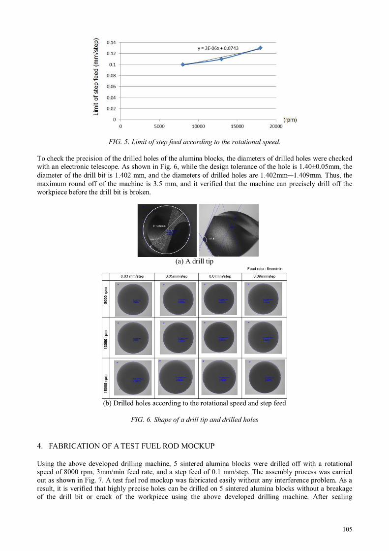
105
FIG. 5. Limit of step feed according to the rotational speed.
To check the precision of the drilled holes of the alumina blocks, the diameters of drilled holes were checked with an electronic telescope. As shown in Fig. 6, while the design tolerance of the hole is 1.40±0.05mm, the diameter of the drill bit is 1.402 mm, and the diameters of drilled holes are 1.402mm—1.409mm. Thus, the maximum round off of the machine is 3.5 mm, and it verified that the machine can precisely drill off the workpiece before the drill bit is broken.
(a) A drill tip
(b) Drilled holes according to the rotational speed and step feed
FIG. 6. Shape of a drill tip and drilled holes
4. FABRICATION OF A TEST FUEL ROD MOCKUP
Using the above developed drilling machine, 5 sintered alumina blocks were drilled off with a rotational speed of 8000 rpm, 3mm/min feed rate, and a step feed of 0.1 mm/step. The assembly process was carried out as shown in Fig. 7. A test fuel rod mockup was fabricated easily without any interference problem. As a result, it is verified that highly precise holes can be drilled on 5 sintered alumina blocks without a breakage of the drill bit or crack of the workpiece using the above developed drilling machine. After sealing

106
performance test of the test fuel rod mockup, it is used in the temperature measurement experiments in the furnace.
(a) Components of test fuel rod mockup
(b) Assembly of test fuel rod mockup
FIG. 7. Fabrication of a test fuel rod mockup.
5. CONCLUSION
In this study, an automatic drilling machine has been developed and a drilling limit test was carried out for 3 process variables, the rotational speed, feed rate, and step feed. While the feed rate does not affect the drill bit, a step feed at above 0.13 mm/step breaks the drill bit. In addition, as the rotational speed increases, the maximum available step feed also increases. The developed drilling machine is used in drilling the sintered alumina blocks to fabricate a test fuel rod mockup.
After stabilizing performance of the developed drilling machine, it will be used in drilling the UO2 pellets and alumina blocks which will be put into a test fuel rod.
ACKNOWLEDGEMENTS
This work is supported by the Nuclear Research & Development Program of the National Research Foundation of Korea (NRF) grant funded by the Korean government (MEST).
REFERENCES
[1] APPELHAN A.D., The Measured Temperature, Power, and Burn-up Dependence of Radioactive Fission Gas Release in LWR Fuel, HWR-40, OECD HRP, (1981).
[2] KIM J.Y., et. al., Drilling Experiments of Dummy Fuel Rods Using a Mock-up Drilling Device and Detail Design of Device for Drilling of Irradiated Nuclear Fuel Rods, KAERI/TR-3315, (2007)
[3] KIM B.G., et. al., A review on the development of the instrumentation technology for fuel irradiation test, KAERI/AR-513/98, (1998).
[4] USAMI K., et. al., Improvement of center boring device for irradiated fuel pellets, 4th International Symposium on Material Testing Reactors, p.34, (2011).
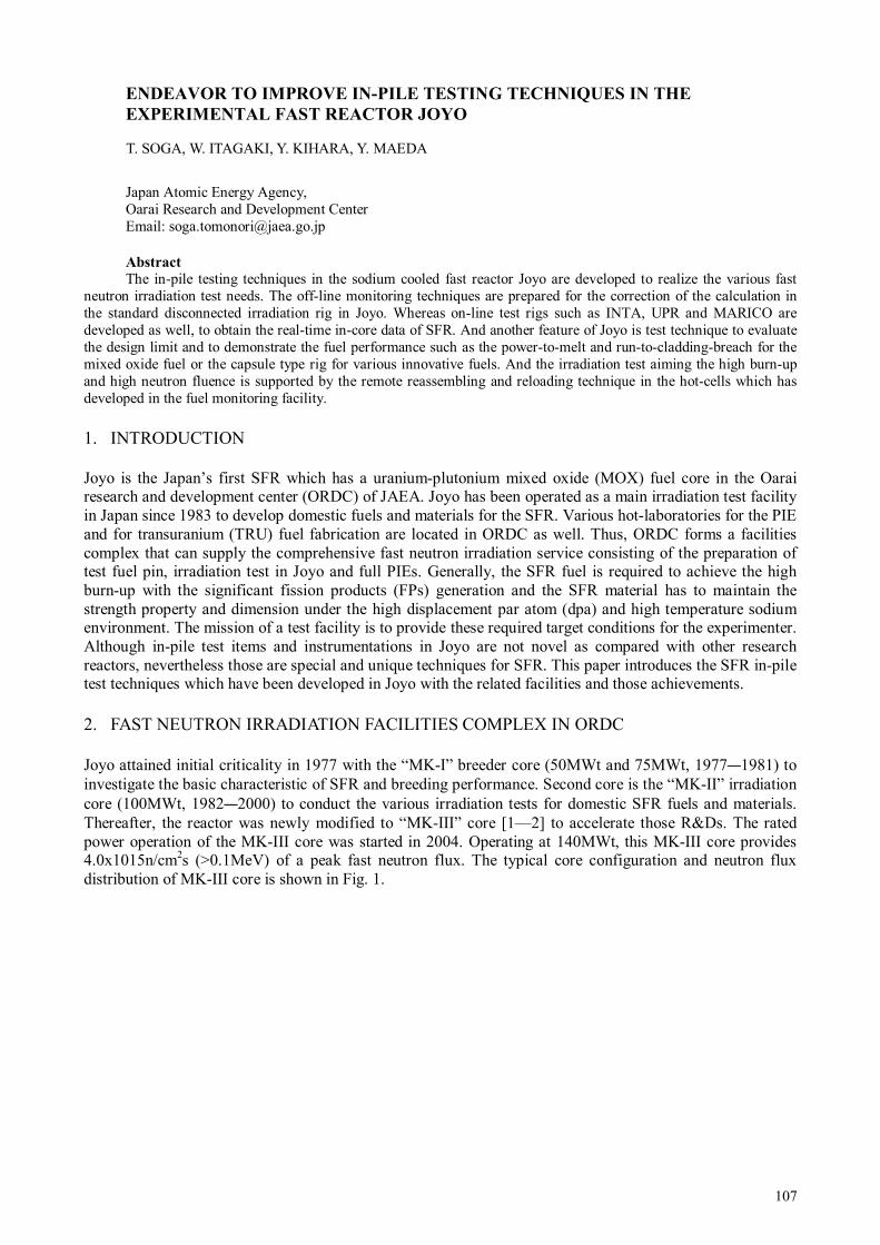
107
ENDEAVOR TO IMPROVE IN-PILE TESTING TECHNIQUES IN THE
EXPERIMENTAL FAST REACTOR JOYO
Japan Atomic Energy Agency, Oarai Research and Development Center Email: [email protected]
Abstract
The in-pile testing techniques in the sodium cooled fast reactor Joyo are developed to realize the various fast neutron irradiation test needs. The off-line monitoring techniques are prepared for the correction of the calculation in the standard disconnected irradiation rig in Joyo. Whereas on-line test rigs such as INTA, UPR and MARICO are developed as well, to obtain the real-time in-core data of SFR. And another feature of Joyo is test technique to evaluate the design limit and to demonstrate the fuel performance such as the power-to-melt and run-to-cladding-breach for the mixed oxide fuel or the capsule type rig for various innovative fuels. And the irradiation test aiming the high burn-up and high neutron fluence is supported by the remote reassembling and reloading technique in the hot-cells which has developed in the fuel monitoring facility.
1. INTRODUCTION
Joyo is the Japan’s first SFR which has a uranium-plutonium mixed oxide (MOX) fuel core in the Oarai research and development center (ORDC) of JAEA. Joyo has been operated as a main irradiation test facility in Japan since 1983 to develop domestic fuels and materials for the SFR. Various hot-laboratories for the PIE and for transuranium (TRU) fuel fabrication are located in ORDC as well. Thus, ORDC forms a facilities complex that can supply the comprehensive fast neutron irradiation service consisting of the preparation of test fuel pin, irradiation test in Joyo and full PIEs. Generally, the SFR fuel is required to achieve the high burn-up with the significant fission products (FPs) generation and the SFR material has to maintain the strength property and dimension under the high displacement par atom (dpa) and high temperature sodium environment. The mission of a test facility is to provide these required target conditions for the experimenter. Although in-pile test items and instrumentations in Joyo are not novel as compared with other research reactors, nevertheless those are special and unique techniques for SFR. This paper introduces the SFR in-pile test techniques which have been developed in Joyo with the related facilities and those achievements.
2. FAST NEUTRON IRRADIATION FACILITIES COMPLEX IN ORDC
Joyo attained initial criticality in 1977 with the “MK-I” breeder core (50MWt and 75MWt, 1977—1981) to investigate the basic characteristic of SFR and breeding performance. Second core is the “MK-II” irradiation core (100MWt, 1982—2000) to conduct the various irradiation tests for domestic SFR fuels and materials. Thereafter, the reactor was newly modified to “MK-III” core [1—2] to accelerate those R&Ds. The rated power operation of the MK-III core was started in 2004. Operating at 140MWt, this MK-III core provides 4.0x10¹⁵n/cm2s (>0.1MeV) of a peak fast neutron flux. The typical core configuration and neutron flux distribution of MK-III core is shown in Fig. 1.
T. SOGA, W. ITAGAKI, Y. KIHARA, Y. MAEDA

108
1.0
1.5
2.0
2.5
3.0
3.5
4.0
4.5
5.0
5.5
6.0
6 6 5 5 4 4 3 3 2 1 1 0 2
FIG. 1 Typical core configuration and neutron flux distribution of MK-III core.
Figure 2 shows the diagram of Joyo reactor cooling system. The primary coolant sodium enters the core at 350oC and exits the reactor vessel at 500oC. The heats transported by primary loops are conducted to non-radioactive sodium in secondary loops through the intermediate heat exchangers (IMS). The heat transported by secondary loops is removed by the air cooling using the dump heat exchangers (DHXs).
FIG. 2 Joyo Mk-III heat transport system
Three PIE facilities related to Joyo, FMF (Fuel Monitoring Facility), MMF (Materials Monitoring Facility) and AGF (Alpha Gamma Facility) are located in ORDC[3]. FMF is adjacent to Joyo as shown in Fig. 3.The irradiated test rig or core component is carried into the FMF and is started the non-destructive examination.
Loop B Loop A
Over Flow Tank
Auxiliary Dump
Heat
Exchanger
Auxiliary
Intermediate Heat
Exchanger
Reactor Vessel
Intermediate Heat Exchanger (IHX)
Dump Heat Exchanger (DHX)
EMP
Second.
PumpPrimary
Pump
EMP
EMP
EMP : Electro Magnetic Pump
Secondary Sodium Flow (1200 t/h)
Primary Sodium Flow (1350 t/h)
Air Flow
(7700 m3/min)
470
300300300300
500
350
Row where subassemblies are installed
Total neutron flux
Fast neutron flux
0000
5555
7777
6666
8888
1111
3333
2222
4444
1111 1111
2222 2222
3333 3333
4444 4444
5555 5555
6666 6666
7777 7777
8888 8888
1111
9999 9999
9999
Inner core fuel subassembly
Outer core fuel subassembly
Irradiation rig
Control rod
Reflector
Shielding subassembly (B4C)
Solid-white numbers represent the number of rows where subassemblies are installed.
Neutr
on flu
x(x
10
15n/c
m2/s
)
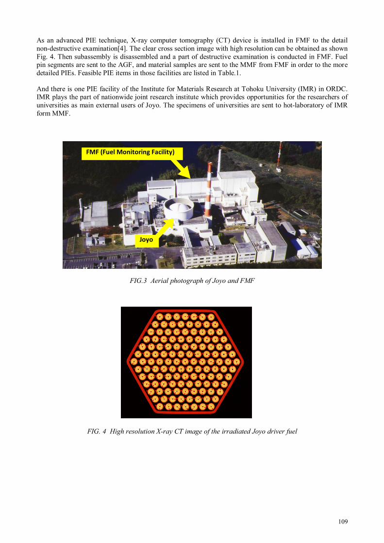
109
As an advanced PIE technique, X-ray computer tomography (CT) device is installed in FMF to the detail non-destructive examination[4]. The clear cross section image with high resolution can be obtained as shown Fig. 4. Then subassembly is disassembled and a part of destructive examination is conducted in FMF. Fuel pin segments are sent to the AGF, and material samples are sent to the MMF from FMF in order to the more detailed PIEs. Feasible PIE items in those facilities are listed in Table.1.
And there is one PIE facility of the Institute for Materials Research at Tohoku University (IMR) in ORDC. IMR plays the part of nationwide joint research institute which provides opportunities for the researchers of universities as main external users of Joyo. The specimens of universities are sent to hot-laboratory of IMR form MMF.
FIG.3 Aerial photograph of Joyo and FMF
FIG. 4 High resolution X-ray CT image of the irradiated Joyo driver fuel
Joyo
FMF (Fuel Monitoring Facility)

110
TABLE.1 PIE SERVICE IN THE RELATED HOT-FACILITIES TO JOYO
Facility FMF MMF AGF
PIE item - Visual inspection - Detailed visual inspection of the fuel
pin - Profilometry of the subassembly - Weight measurement of the fuel pin - Eddy current inspection - Profilometry of the fuel pin - γ-scanning of the fuel pin - Fuel pin puncture - X-ray radiography - X-ray CT test - Optical microscope - EPMA,IMA analysis - SEM observation
- Tensile test - Transient burst test of cladding - Density measurement - Charpy impact test - Fatigue test - Magnetization measurement - Uniaxial creep test - Optical microscope - FE/TEM observation - Gas analysis - TEM observation - ICP analysis - Hardness test - Thermal conductivity measurement - Thermal expansion coefficient
measurement - X-ray diffraction analysis
- X-ray radiographic inspection - Optical microscope - Measurement of melting point - FP release examination - Measurement of O/M ratio - X-ray diffraction analysis - EPMA analysis - Evaporative impurities analysis - ICP emission spectrometric analysis - Halogen analysis - Moisture analysis - MA analysis - Burn-up Measurement
Other functions
- Sodium removal equipment - Disassembling of the subassembly - Sample preparation to transport
to MMF or AGF
- Manufacture of specimen from irradiated steel parts
- Gas enclosing (only for un-irradiated specimens)
- Remote TRU fuel pellet production and inspection - Remote fuel pin welding and
inspection
3. IN-PILE TESTING TECHNIQUES IN JOYO
3.1 Direction of technical development
Figure 5 explains behaviours focused on the SFR fuels and material as a research subject. The objective of in-pile test in Joyo is to support these investigations. This paper describes such in-pile test techniques as classified into following four viewpoints.
1) Calculation and off-line monitoring technique;
2) On-line test technique;
3) Test technique of PTM (power to melt) and RTCB (run to cladding breach) and the development of a capsule type rig to evaluate the fuel design limit and to demonstrate fuel performance;
4) Re-assembling and reloading technique.

111
FIG. 5. Outline of the direction of development of in-pile testing technique in JOYO.
3.1.1 Calculation and off-line monitoring techniques
The disconnected (off-line) irradiation rig is the usual in-pile test tool in Joyo. The off-line rig can be loaded to an optional position of core and can be handled by a fuel handling system in Joyo because of that has the same shape with the Joyo core component. In irradiation test using off-line rig, the calculation code is main means to predict irradiation condition. The off-line monitor such as dosimeter and thermometer which gives the measured value in PIE is developed to correct the calculation. The majorities of Joyo off-line irradiation test rigs are instrumented by those off-line monitors.
3.1.2 On-line test techniques
On-line test rigs are developed to meet the R&D needs with well-monitored and controlled irradiation field from Joyo users and to distinguish from other SFRs. The on-line rig in the SFR needs some design requirements as follows:
- Heat-resistant and radiation-resistant; - Maintaining the airtight of argon cover gas; - Maintaining the radiation shielding; - Remote handling technique in turbid sodium; - Lift-up-down mechanism like control rod driving mechanism to rotate the rotating plug for refuelling
work between rated power operation cycles; - Disconnecting (cable or piping cutting) function to transfer to FMF via same route with off-line test
subassemblies after irradiation.
However several on-line rigs were practicalized and had realized some important in-pile experiments in Joyo. Especially the in-core test technique with temperature control in Joyo is unique in the word after FFTF shutdown in the US.
3.1.3 Test technique for PTM or RTCB and the development of capsule type rig
In the Fast Reactor Cycle Technology Development (FaCT) project in Japan, the driver fuel subassembly for the future SFR consists of minor actinide (MA) recycling, large diameter annular fuel pellets, ODS ferritic steel cladding fuel pins and a ferritic-martensitic steel duct[5]. The target burn-up is 150 GWd/t in discharge
SFR
core
Monju type fuel irradiated
in Joyo
- 127 GWd/t - 33.8 kW/m
Behavior focused on the SFR fuel and material
Material - swe lling & cree p strain
- m echan ica l proper ty
change
- sod iu m corrosion
Subassembly behavior
Bo wing, BD I
Technical development in Joyo- to know and control irradiation field- to achieve severe test target
Fuel Pin behaviorFCMI , FCCI
ga p co nducta nce
Fuel- Restructur in g
- Pu , MA m ig rat io n
- FP accu mulatio n a nd release
- t hermal property chan ge
-High burn-up
-High fluence(dpa)
-High heat density
-High temperature
Target for future SFR
1) Calculation and off- line monitoring
2) On-line test technique
3) Evaluation of fuel design l im it
Demonstrat ion of fuel performance - PTM (Power to melt )
- RTCB (Run to cladding breach)- Capsule type rig
4) Re-assembling and reloading
technique

112
average. That corresponds to 250 GWd/t of peak burn-up and 250 dpa of peak neutron dose. And the required linear heat rate as test target will be 70kW/m to evaluate a thermal design limit. The function of the PTM test and the RTCB test in Joyo are forceful to meet these test needs. In addition, the capsule type rig have been developed in order to accept the irradiation test programs for various innovative fuel concepts such as MOX fuel containing MA (MA-MOX) and ODS cladding with the high linear heat rate or high burn-up.
3.1.4 Re-assembling and reloading technique
The irradiation test aiming the high burn-up or the high fluence is supported by the reassembling and reloading technique developed by FMF. This technique is indispensable to run the irradiation test beyond the lifetime of irradiation rig. These techniques in Joyo are described in following sections in more detail.
3.2 Calculation and off-line monitoring
3.2.1 Neutron field evaluation
The HESTIA is the standard code for MK-III core and fuel management of three-dimensional multi-group diffusion theories. A change of compositions in each core subassembly and a neutron source distribution calculated HESTIA are used as input data for the detail neutron and gamma fluxes calculation by transport calculation codes. And Monte Carlo calculation code is also available for more precise evaluation in the irradiation rigs having heterogeneous internal structure. The calculation can be corrected by a neutron dosimeter set of activation and fission foils that is loaded to optional positions in the irradiation rig. Fig. 6 shows measured nuclear reactions in different neutron energy ranges. Multiple calculations together with dosimetry contribute the accurate neutron field evaluation in the MK-III core [6].
FIG. 6 Neutron monitor and covered energy range.
3.2.2 Temperature evaluation
The temperature in material specimens are evaluated by a heat transfer calculation using the finite element method code with input of gamma heating in the transport calculation. The thermal expansion difference (TED) monitor is one of the typical offline thermometers that is a small steel capsule filled up with sodium. Temperature is evaluated by volume change of TED in PIE. The illustration of TED monitor and out-of-pile correlation curve between temperature and volume increase of TED is shown in Fig. 7.
104
106
108
1010
1012
1014
1016
1 0-8
1 0-6
10-4
10-2
1 00
102
N eutron En erg y (M eV )
10
B (n,α )
63
Cu(n,α )
59
Co(n,γ)
58
Fe(n,γ)
235
U(n,f)
45
Sc(n,γ )
237
Np(n,f)
93
Nb(n,n')
238
U(n,f)
58
Ni(n,p)
54
Fe(n,p)
46
Ti(n,p)
9
Be(n,He)
Metal foils and vanadium
capsules

113
FIG. 7 TED monitor and correlation curve of temperature-volume increase.
3.3 On-line test technique
3.3.1 Instrumented test assembly
The Instrumented test assembly (INTA) is on-line test rig in Joyo equipped with thermocouples and gas pressure gauges etc. INTA-1 and INTA-2 were fuel bundle subassemblies as shown Fig. 8 and INTA-S was the subassembly installing material capsules. Instrumentation cables extend from core and penetrate the upper core structure (UCS) to send in-pile data. INTAs were utilized in MK-II core. Fig. 9 is a fuel centerline temperature history at reactor start-up obtained by INTA-1 with the calculated value.
FIG.8 Outline of INTA-1 and INTA-2.
Surface of sodium
Rotating plug
Irradiation equipmentUpper core structure
Reactor core
INTA
Cross section of test fuel pin
bundle
Fuel
pin
Dummy
pin
Un-instrumented
Pressure
Fuel centerline temp.
Coolant temp.
Flux
EMF leads conduit
INTA-1
INTA-2
300
400
500
600
700
800
0 1 2 3 4
Volume increase ∆V(×10-2cm3)
Te
mp
era
ture
(de
g-C
)
Calibration curve(Out-of-pile)
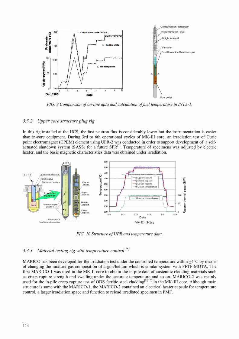
114
FIG. 9 Comparison of on-line data and calculation of fuel temperature in INTA-1.
3.3.2 Upper core structure plug rig
In this rig installed at the UCS, the fast neutron flux is considerably lower but the instrumentation is easier than in-core equipment. During 3rd to 6th operational cycles of MK-III core, an irradiation test of Curie point electromagnet (CPEM) element using UPR-2 was conducted in order to support development of a self-actuated shutdown system (SASS) for a future SFR[7]. Temperature of specimens was adjusted by electric heater, and the basic magnetic characteristics data was obtained under irradiation.
FIG. 10 Structure of UPR and temperature data.
3.3.3 Material testing rig with temperature control [8]
MARICO has been developed for the irradiation test under the controlled temperature within +4°C by means of changing the mixture gas composition of argon/helium which is similar system with FFTF-MOTA. The first MARICO-1 was used in the MK-II core to obtain the in-pile data of austenitic cladding materials such as creep rupture strength and swelling under the accurate temperature and so on. MARICO-2 was mainly used for the in-pile creep rupture test of ODS ferritic steel cladding[9][10] in the MK-III core. Although main structure is same with the MARICO-1, the MARICO-2 contained an electrical heater capsule for temperature control, a larger irradiation space and function to reload irradiated specimen in FMF.
Surface of sodium
Rotating plug
Upper core structure
φ150
UPR
Thermocoupleposition
Electricheater
Uppercapsule
Middlecapsule
Lowercapsule
core
Bottom of UCS
Top of core subassenblies
Irradiationequipment
①
②
③
④
0
70
140
210
280
350
420
200
250
300
350
400
450
500
550
600
650
5/1 5/3 5/5 5/7 5/9 5/11
Reactor therm
al pow
er(M
W)
Tem
perature(
)
Date
Reactor thermal power
①Upper capsule
②Middle capsule
③Lower capsule
④Outlet temperature
Mk-Ⅲ 3-1cy
Fuel Centerline Thermocouple
Transition
Airtight terminal
Instrumentation plug
Compensation conductor
A A
Fuel pellet

115
FIG. 11 Outline of MARICO.
3.4 Test technique for PTM or RTCB and the development of capsule type rig
3.4.1 PTM test
The First PTM test was conducted in 1991 as preliminary test using a test rig named B5D-1. The reactor power was maintained at target power (97MWt) for 10 minutes. The linear heat rate in tested fuel pins exceeded 60kW/m and overstepped the predicted power to melts in this reactor power. A ceramograph of the melting zone in B5D-1 are shown in Fig. 12. It was observed that the moving lens-shaped voids broke melting area boundary. More sharp power history was requested to avoid additional fuel structural change to clear melting boundary.
FIG. 12 Result of PTM test in 1991 (preliminary test).
The following main test was conducted in 1992 using a test rig named B5D-2[11]. The power history of the main test is shown in Fig. 13. The power ramp rate was increased to 0.5%/min from 0.4%/min in the preliminary test to reduce the structural change before irradiation at target temperature. And shutdown scram was adopted to avoid the additional structural change on molten area. And reactor power was increased to 100MWt as full-power of MK-II core based on the calibration of the temperature calculation code by B5D-1
A
Drive Mechanism
A
Housing
Long
Bellows
Short
Bellows
Latch and Cutter
Test Assembly
Capsule
Lower Guide Tube
Gas Exhaust Line
Sodium Outlet
Vent Line
Gas Gap
Irradiation
Specimen
Basket
Sodium Inlet Line
Gas Inlet Line
Capsule
Section A-A
Cable
Gas Pipe
Irradiation Specimen
Capsule
Thermocouple
Support Structure
MARICO
Rotating Plug
Loading Features
Upper Core
Structure
Core
Sodium Level
Upper Core
Structure
Thermocouple
0
20
40
60
80
100
8:00 10:00 12:00 14:00 16:00 18:00
RE
AC
TO
R P
OW
ER
[MW
]
TIME
Reactor Power History of Preliminary Test
Preliminary Test
17.JUNE.1991
0.4%/minSlow scram

116
results. The larger melting area and clearer boundary of melting area were observed in the PIE of B5D-2 than the result of B5D-1.
Fig . 13 Result of PTM test in 1992 (main test).
Fig. 14 is comparison of the experimentation and calibrated code calculation. The low-middle temperature range is calibrated by the INTA and the high temperature is calibrated by B5D. Thus, in-pile tests in Joyo contributed to upgrade the fuel thermal behaviour calculation code.
FIG. 14 Comparison of calculation and experimentation in INTA and PTM.
3.4.2 RTCB test
The RTCB test enables to evaluate the design limit (the lifetime) to fuel failure experimentally. And that is useful to investigate the fuel behaviour in the high burn-up and the cause and the mechanism of cladding breach in SFR fuel. Although the Joyo does not have the RTCB test experience, RTCB test is licensed with some special test rigs and function of FFD (fuel failure detection), FFDL (failed fuel detection and location) and primary coolant system cleaning.
3.4.3 Capsule type rig
The capsule type rig has developed for irradiation tests of various fuel forms including oxides, carbides, nitrides, metals, and containing MAs and FPs, for which irradiation behaviour is not well understood. Furthermore, this rig accepts the severe test conditions such as the high burn-up irradiation up to 200 GWd/t and high liner heat rate. About oxide fuel, intentional fuel melting is allowed up to 20% as the capability of PTM tests. These are licensed by the sufficient strength of capsule to withstand the pressure in the case of potential sodium-molten fuel interaction or significant fission gas release from a failed fuel in the high burn-up.
0
20
40
60
80
100
8:00 10:00 12:00 14:00 16:00 18:00
RE
AC
TO
RP
OW
ER
[MW
]
TIME
Reactor Power History of Main Test
Main Test
17.JUNE.1992
100MW (10min)
0.5%/min
scram

117
FIG. 15 Capsule type rig.
3.5 Re-assembling and reloading technique
FMF has function to re-install irradiated fuel pins and materials into a new subassembly after the interim examination of irradiated components. FMF is connected with Joyo by an underground cask corridor and the irradiation test subassemblies can be transferred between Joyo and the FMF via cask car as shown in Fig. 16. This techniques allows not only the long-term irradiation test up to high fluence or high burn-up beyond the lifetime of irradiation rig, but also repetition of short-term irradiation testing by reusing irradiated rig parts.
FIG. 16 Transportation to irradiated subassembly to FMF and reloading to Joyo.
Several in-pile tests which were realized by combinations with FMF are introduced as follows;
Material Specimen
Transportation truckService Area
Fuel Pin
Disassembling of Rig
Extraction of Specimen
Midterm inspection of Fuel Pin
Weighing Dimensionalmeasurement
Radiography Visual inspection
Test Cell
DecontaminateCell Clean Cell
Decontaminate
Reassembling
:Course to FMF in Joyo after irradiation of re-loading type rig
:Course to reassembling of fuel pin
:Course to reassembling of material specimen
:Courses from reassembling to re-loading in Joyo in-vessel of re-loading type rig
JoyoCask Car
FMF Cask CarCask Corridor
Joyo
FMF
To MMF
Fuel Rig From
MMF
Material Rig
MMF
Compartment
Wrapper Tube
Entrance Nozzle
Handling Head
Test Fuel Pin
Capsule
Compartment
Cross Section
Shroud Tube
Fuel FormsOxide, Carbide, Nitride, Metal
MA Contents ~ 50 %
Melting Area
of Pellet
Oxide: ~20 %
Others: No Melt
Burn-up ~ 200 GWd/t
Feasibility under license
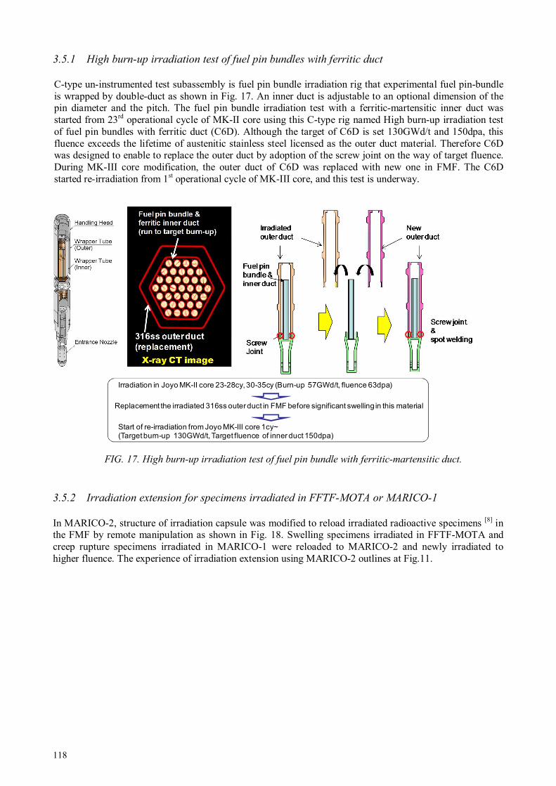
118
3.5.1 High burn-up irradiation test of fuel pin bundles with ferritic duct
C-type un-instrumented test subassembly is fuel pin bundle irradiation rig that experimental fuel pin-bundle is wrapped by double-duct as shown in Fig. 17. An inner duct is adjustable to an optional dimension of the pin diameter and the pitch. The fuel pin bundle irradiation test with a ferritic-martensitic inner duct was started from 23rd operational cycle of MK-II core using this C-type rig named High burn-up irradiation test of fuel pin bundles with ferritic duct (C6D). Although the target of C6D is set 130GWd/t and 150dpa, this fluence exceeds the lifetime of austenitic stainless steel licensed as the outer duct material. Therefore C6D was designed to enable to replace the outer duct by adoption of the screw joint on the way of target fluence. During MK-III core modification, the outer duct of C6D was replaced with new one in FMF. The C6D started re-irradiation from 1st operational cycle of MK-III core, and this test is underway.
FIG. 17. High burn-up irradiation test of fuel pin bundle with ferritic-martensitic duct.
3.5.2 Irradiation extension for specimens irradiated in FFTF-MOTA or MARICO-1
In MARICO-2, structure of irradiation capsule was modified to reload irradiated radioactive specimens [8] in the FMF by remote manipulation as shown in Fig. 18. Swelling specimens irradiated in FFTF-MOTA and creep rupture specimens irradiated in MARICO-1 were reloaded to MARICO-2 and newly irradiated to higher fluence. The experience of irradiation extension using MARICO-2 outlines at Fig.11.
Irradiation in Joyo MK-II core 23-28cy, 30-35cy (Burn-up 57GWd/t, fluence 63dpa)
Replacement the irradiated 316ss outer duct in FMF before significant swelling in this material
Start of re-irradiation from Joyo MK-III core 1cy~(Target burn-up 130GWd/t, Target fluence of inner duct 150dpa)
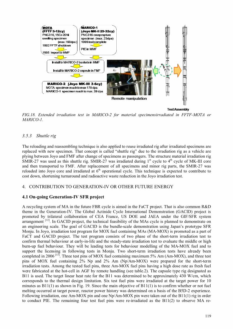
119
FIG.18. Extended irradiation test in MARICO-2 for material specimensirradiated in FFTF-MOTA or MARICO-1.
3.5.3 Shuttle rig
The reloading and reassembling technique is also applied to reuse irradiated rig after irradiated specimens are replaced with new specimen. That concept is called “shuttle rig” due to the irradiation rig as a vehicle are plying between Joyo and FMF after change of specimens as passengers. The structure material irradiation rig SMIR-27 was used as this shuttle rig. SMIR-27 was irradiated during 1st cycle to 4th cycle of MK-III core and then transported to FMF. After replacement of all specimens and minor rig parts, the SMIR-27 was reloaded into Joyo core and irradiated at 6th operational cycle. This technique is expected to contribute to cost down, shortening turnaround and radioactive waste reduction in the Joyo irradiation test.
4. CONTRIBUTION TO GENERATION-IV OR OTHER FUTURE ENERGY
4.1 On-going Generation-IV SFR project
A recycling system of MA in the future FBR cycle is aimed in the FaCT project. That is also common R&D theme in the Generation-IV. The Global Actinide Cycle International Demonstration (GACID) project is promoted by trilateral collaboration of CEA France, US DOE and JAEA under the GIF/SFR system arrangement [12]. In GACID project, the technical feasibility of the MAs cycle is planned to demonstrate on an engineering scale. The goal of GACID is the bundle-scale demonstration using Japan’s prototype SFR Monju. In Joyo, irradiation test program for MOX fuel containing MAs (MA-MOX) is promoted as a part of FaCT and GACID project. The test program consists of two phase of the short-term irradiation test to confirm thermal behaviour at early-in-life and the steady-state irradiation test to evaluate the middle or high burn-up fuel behaviour. They will be leading tests for behaviour modelling of the MA-MOX fuel and to support the licensing in following tests in Monju. Two short-term irradiation tests have already been completed in 2006 [13]. Three test pins of MOX fuel containing maximum 5% Am (Am-MOX), and three test pins of MOX fuel containing 2% Np and 2% Am (Np/Am-MOX) were prepared for the short-term irradiation tests. Among the tested fuel pins, three Am-MOX fuel pins having a high dose rate as fresh fuel were fabricated at the hot-cell in AGF by remote handling (see table.2). The capsule type rig designated as B11 is used. The target linear heat rate for the B11 was determined to be approximately 430 W/cm, which corresponds to the thermal design limitation. Six test fuel pins were irradiated at the target power for 10 minutes as B11(1) as shown in Fig. 19. Since the main objective of B11(1) is to confirm whether or not fuel melting occurred at target power, reactor power history was determined on a basis of the B5D-2 experience. Following irradiation, one Am-MOX pin and one Np/Am-MOX pin were taken out of the B11(1) rig in order to conduct PIE. The remaining four test fuel pins were re-irradiated as the B11(2) to observe MA re-

120
distribution for 24 hours. The PIE results of Am-MOX fuels[14][15] are shown in Fig. 19 as well. In B11(1), any sign of the fuel melting was not observed. Ceramographs and electron probe micro-analysis (EPMA) results obtained in AGF show that structural change and increase of americium at the periphery of the central void started within the 10 minute irradiation and those were grown by the following 24 hours irradiation as B11(2).
FIG. 19 Reactor power history and PIE results in Am-MOX fuel pins in B11.
4.2 Potential R&D field [16]
4.2.1 High temperature testing technique for other Generation-IV or fusion reactor
In the R&D field of the gas cooled fast reactor (GFR), the very high temperature reactor (VHTR) and the advanced fusion reactor systems, material irradiation test require the higher temperature than the conventional material irradiation temperature (~800oC) in Joyo. High temperature test technique is now developed in Joyo to meet these R&D needs. The irradiation capsule will be equipped with tungsten inner tube in order to obtain a higher gamma heating. The preliminary temperature calculation shows that the temperature of specimen achieves over 1000oC. As an off-line thermometer, the melt-wire type monitor is developed to cover the high temperature region because of the temperature monitoring range of the conventional TED monitor is below 800oC. Fig. 20 shows a result of the out-of-pile heating test at 1100oC.
FIG. 20 Out-of-pile test of the melt-wire type thermometer.
Heating
(1100oC,
1000hr)
Molten alloy

121
4.2.2 Lower temperature irradiation
In the conventional MK-III operation, the temperature of irradiation specimens is higher than the core inlet temperature of 350oC. Lowering the core inlet temperature operation is newly licensed based on the potential of the DHXs. This lower temperature operation will make the occasion for investigating the fundamental irradiation effect of the material and the behaviour of LWR materials or fusion reactor materials at low temperature. Assuming that the inlet temperature is 290oC, a fast neutron flux of about 2x10¹⁵ n/cm2s can be obtained in the LWR temperature range (320oC—370oC).
4.2.3 Neutron spectrum tailoring
The cross section of nuclear reaction depends on the neutron energy spectrum and generally neutron capture reactions are more sensitive to low energy neutron. The fast neutron irradiation field has potential to tailor the neutron spectrum individually by the neutron moderator such as beryllium or zirconium hydride surrounding the target. This concept enables to provide the irradiation field for the various transmutation experiments such as the long-lived FPs or MAs and the effective radio isotope production.
5. CONCLUSION
Irradiation test techniques to meet the R&D needs from Joyo users have been developed as follows: - The off-line monitoring techniques are developed and used to correct the irradiation condition
calculation for the disconnected irradiation rig as usual in-pile test tool in Joyo. - The on-line test rigs such as INTA, UPR and MARICO is developed to meet R&D needs from Joyo
users and to distinguish from other SFRs. These on-line rigs realized several important in-pile tests for SFR.
- The function of PTM test and RTCB test and capsule type rig are forceful to understand the design limit and the behaviour under the severe irradiation conditions in the SFR fuels.
- The reassembling and reloading technique developed in FMF allows the irradiation test up to high fluence beyond the lifetime of irradiation rig. And this technique is indispensable to plan flexible and efficient in-pile tests in Joyo.
Although Joyo has been suspended its operation since 2007 for the incident in the reactor vessel, recovery work already started aiming at the completion in 2014. We would like to play a role of center of fast neutron irradiation experiments in the world, using Joyo after restart and above mentioned test capabilities.
REFERENCES
[1] MAEDA Y. et al. Distinguished achievements of a quarter century operation and a promising project named MK-III in JOYO, Nuclear Technology, Vol. 150, No. 1, pp. 16—36, (2005).
[2] AOYAMA T. et al. Core Performance Tests for the JOYO MK-III Upgrade, Nuclear Engineering and Design, Vol. 237, pp. 353—368 (2007).
[3] ITO M. et al. Present status for post-irradiation examination facilities for fuels and materials development of fast reactor, Proc. the 4rd JAERI-KAERI joint seminar on the post irradiation examination technology; Korea (2002).
[4] KATSUYAMA K. et al. Development of a High Resolution X-Ray CT Technique for Irradiated Fuel Pellets, IEEE Transactions on Nuclear Science, Volume: 59, Issue: 4, Part 2, pp: 1397—1400 (2012).
[5] MIZUNO T., Fast reactor fuel development in Japan, Fast Reactors and Related Fuel Cycles: Challenges and Opportunities FR09 Proc. Int. Conf. Kyoto (2009).
[6] MAEDA S. et al., Characterization of Neutron Fields in the Experimental Fast Reactor Joyo MK-III Core,13th Int. Symp. on Reactor Dosimetry, Neth. (2008).
[7] TAKAMATSU M.et al., Demonstration of control rod holding stability of the self actuated shutdown system in Joyo for enhancement of fast reactor inherent safety, Journal of Nuclear Science and

122
Technology, Vol. 44, (2007). [8] KATAOKA H. et al. Development of material irradiation rig with precision temperature control in
experimental fast reactor JOYO Journal of Nuclear Materials 258—263 (1998) 677—681. [9] ITO C. et al., Experimental Method of In-pile Creep Rupture Behavior of ODS Cladding Materials in
the Experimental Fast Reactor Joyo, Journal of Power and Energy Systems,Vol. 2 (2008). [10] KAITO T. et al. In-pile creep rupture properties of ODS ferritic steel claddings, Journal of Nuclear
Materials 386–388 (2009) 294–298. [11] INOUE et M. al. Power-to-melts of uranium–plutonium oxide fuel pins at a beginning-of-life
condition in the experimental fast reactor JOYO, Journal of Nuclear Materials 323 (2003) 108–122. [12] NAKASHIMA F. et al. Current Status of Global Actinide Cycle International Demonstration Project
GIF Symposium, Paris, (2009). [13] SOGA T. et al. Irradiation Test of Fuel Containing Minor Actinides in the Experimental Fast Reactor
Joyo, Journal of Power and Energy Systems. Vol. 2 (2008), No. 2. [14] TANAKA K. et al. Microstructure and elemental distribution of americium-containing uranium
plutonium mixed oxide fuel under a short-term irradiation test in a fast reactor, Journal of Nuclear Materials 385 (2009) 407–412.
[15] TANAKA K. et al. Microstructural evolution and Am migration behaviour in Am-containing MOX fuels at the initial stage of irradiation, The 10th OECD Nuclear Energy Agency Information Exchange Meeting on Actinide and Fission Product Partitioning and Transmutation, Mito (2008).
[16] SOGA T. et al., Improvement of Irradiation Capability in the Experimental Fast Reactor Joyo, IAEA TM Research Reactor Application for Materials under High Neutron Fluence, Vienna (2008).

123
AECL’S EXPERIMENTAL FUEL AND MATERIALS TEST LOOPS IN NRU
Atomic Energy of Canada Limited Chalk River Laboratories Ontario, Canada Email: [email protected]
Abstract
Atomic Energy of Canada Ltd (AECL) maintains two experimental fuel and materials test loops, U1 and U2, within the National Research Universal (NRU) reactor at Chalk River Laboratories (CRL). These loops operate at conditions typical of CANDU reactors. Each vertical test section (one in U1, two in U2) has the capacity to irradiate a test assembly 3 m in length and 10.16 cm in diameter; equivalent to six CANDU fuel bundles. The assembly is made up of six interchangeable bundles containing experimental fuels or materials test specimens. The fuel bundles can be “fixed”, with elements welded together into a rigid bundle, or “demountable”, where a frame with some fixed elements and element mounting mechanisms facilitate the placement of additional removable fuel elements. The materials test bundle has 30 fuel elements surrounding a 4.0 cm diameter tube. Currently, there are two specimen holder designs which fit within the tube: a ring of six 13.1 mm diameter specimen tubes, and a triangular assembly, 2.9 cm per side. In addition to standard fuel and materials irradiations, AECL has also performed instrumented test irradiations with modified test assemblies in the NRU Loops. The instrumented test irradiations were conducted in the Blowdown Test Facility (BTF; formerly part of U1) which simulated accident scenarios. AECL has recently qualified a new top closure plug for use with chemistry experiments in the loops. The plug provides electrical connections between instruments and the data acquisition hardware, through the pressure boundary, which will facilitate instrumented irradiations. In addition, an online gamma spectrometer is being added to the U2 loop to monitor loop coolant gamma activity and to facilitate fuel defect detection and characterization. The Canadian Supercritical Water Reactor (SCWR) fuel design will require irradiation testing. The reference fuel design, (Th, Pu)O2 fuel with high Pu content (13%), will require supporting fuel irradiations. AECL plans to irradiate SCWR fuel in the NRU loops.
1. INTRODUCTION
The Canadian contribution to the Generation-IV program includes development of an SCWR fuel design. The development of a new fuel design requires the development of safety computer codes and models, and irradiation experiments to verify and validate those codes. AECL is in the process of establishing the necessary irradiations to support the new SCWR fuel design. At this early stage, it is yet to be determined if instrumented irradiations will be required; however there has been significant experience in performing such experiments at AECL. This paper provides background information on AECL and the specific facilities available for instrumented irradiations.
2. DESCRIPTION OF AECL, NRU, U1 AND U2
2.1 AECL and CRL
Since its establishment in 1952, AECL has been involved in the development of reactor fuel technology. This is evident through a significant fuel research programme that has been conducted at the Chalk River and Whiteshell Laboratory sites. The programme included irradiations of experimental fuel designs under normal operating and accident conditions utilizing loop facilities in multiple reactors across the two sites for over 50 years. This research program has had different areas of focus over the decades, including PHWR and CANDU-specific fuel development activities, and advanced fuel cycle research on fuels such as MOX [1], thoria [2], and inert matrix fuel [3]. Materials irradiations have also formed a significant portion of AECL research, studying the effects of radiation, stress, and chemistry on a wide range of sheath, pressure tube, and structural materials.
Currently, the Whiteshell laboratory in Pinawa, Manitoba, is being decommissioned. At Chalk River, the National Research Experimental (NRX) reactor, predecessor to the NRU, is also being decommissioned after a successful 40+ year history. Fuel irradiations are now limited to two reactors at Chalk River; NRU, with its loop facilities, and ZED-2, which performs low-power (<100 W) physics experiments on fuel [4].
N.F. HARRISON

124
2.2 NRU
NRU, now celebrating 55 years of operation, is the remaining facility for AECL’s normal operating conditions (NOC) irradiations program. With a current rating of 135 MW, the heavy-water-cooled and moderated reactor provides a neutron source for a wide range of experiments.
Designed in the early 1950’s, the NRU Reactor at CRL went critical in 1957. As the name implies, the design was intended to allow flexibility of reactor utilization. The large, aluminium cylindrical vessel, approx. 3.7 m tall and 3.5 m in diameter, with its heavy water moderator and coolant, provides a flexible fuelling platform, capable of many different arrangements of fuel rods, control rods, isotope production rods, and fuel and materials test facilities.
The reactor vessel top and bottom headers have a series of 227 openings, aligned in a hexagonal array (Fig.1). Each site in the array is assigned an alpha-numeric designation. Coolant is pumped up through the bottom header, and is drawn off from the top. Sites can remain open, allowing for coolant flow into and out of the moderator, or are assigned to specific uses, such as a fuel rod, or test loop. Fuel rods, fast-neutron rods, multi-capsule rods, and isotope production rods, are attached at the two headers to direct the flow of coolant up through internal channels of each rod. The fuel and materials test loops are isolated from the reactor moderator; the sites in the headers where the loop test sections pass through are larger and form complex pressure boundaries between the loops and the reactor vessel.
FIG. 1 NRU Lattice Diagram [5] (sites are out of date, for reference to lattice structure only).
There are currently four fast-neutron materials irradiation test sites, two fuel and materials test loops, one materials test loop, one hydraulic capsule facility, and eight beam tubes, in addition to multi-capsule, and isotope production sites in NRU. Not all facilities are in operation at this time.
2.3 Fuel and materials test loops
Currently installed within NRU are two fuel and materials test loops. The U1 and U2 loops provide the capability to irradiate fuels and materials in light water at high temperature (308°C) and pressure (10 MPa) in a thermal neutron flux of ~1014 n/cm2/s.
Each section of the loop that passes through the core (test-section) contains a Zr-Nb pressure tube, surrounded by a Zr liner tube, separated by a 1 mm diametral gap filled with helium (Fig. 2). The pressure tubes are unique materials experiments with fluence targets of their own, and are of the same dimensions as a

125
CANDU pressure tube, containing high pressure loop coolant. The liner tube, similar to a CANDU calandria tube, maintains the helium gap, providing thermal isolation of the ~300°C light-water coolant from the ~50°C moderator. It also functions as a second barrier of containment. Currently, U1 has one test section, and U2 has two, where experimental fuel in each test section is capable of generating up to 4.5 MW of thermal energy. In the past, the loops have been reconfigured with different numbers of test sections based on irradiation requirements. Although reconfiguration is a complex task, it would be considered for a
significant future program.
FIG.2 Pressure and containment tube schematic for each loop test section [5].
The out-of-core components of each light-water loop are installed in a shielded room on either side of the reactor. Pumps, boilers, condensers etc. are contained within these rooms to shield operations personnel from radiation associated with the coolant, and from the energy release from a postulated accident involving a rupture of the pressure boundary.
The U1 loop currently passes through the reactor core only once. In its previous configuration, there was a second in-core site (BTF), used for blowdown tests (refer to Section 4.1); it was also configured at one time to operate with high-temperature light-water or steam as coolant. Eight boilers and three condensers control loop pressure, provide steam (when required), and facilitate significant pressure ranges and rapid heat load changes. A steam separator, expansion tank for the extra volume of heated coolant and heat removal components are also part of the system. Following the shutdown of BTF, its test section was isolated from the rest of the loop and its pressure tube removed. The ability to operate using steam coolant is no longer necessary, but most of the equipment is still required to maintain temperature and pressure.
The U2 loop is the simpler of the two loops. Its function is the irradiation of fuel and materials under typical CANDU NOC: 308°C, 20 kg/s, 10 MPa, and nominal pH of 10. Without the need to generate steam, the out-of-core components of the U2 loop are relatively simple compared to that of the U1 loop. A surge tank is used to accommodate expanding coolant volumes. When bringing the loop up to temperature and pressure, electric heaters wrapped around the piping are used to raise temperature. While we typically irradiate CANDU-type fuel assemblies, each test section in NRU can contain a fuel assembly up to 3 m in length, and up to 10 cm in diameter; there is significant flexibility in the types of fuel assemblies that can be irradiated.
One other difference between the U1 and U2 loops, aside from the use of steam as coolant, and the number of test sections, is the control of loop coolant pH. In U1, pH is controlled by the addition and removal of
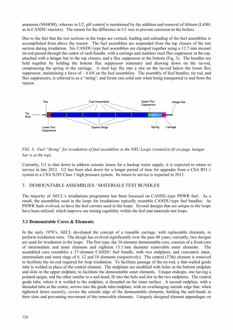
126
ammonia (NH4OH), whereas in U2, pH control is maintained by the addition and removal of lithium (LiOH; as in CANDU reactors). The reason for the difference in U1 was to prevent corrosion in the boilers.
Due to the fact that the test sections in the loops are vertical, loading and unloading of the fuel assemblies is accomplished from above the reactor. The fuel assemblies are suspended from the top closure of the test section during irradiation. Six CANDU-type fuel assemblies are clamped together using a 12.7 mm inconel tie-rod passed through the centre of each bundle, with a carriage and stainless steel flux suppressor at the top, attached with a hangar bar to the top closure, and a flux suppressor at the bottom (Fig. 3). The bundles are held together by holding the bottom flux suppressor stationary and drawing down on the tie-rod, compressing the spring in the carriage. A steel key fits into a slot on the tie-rod below the lower flux suppressor, maintaining a force of ~ 6 kN on the fuel assemblies. The assembly of fuel bundles, tie rod, and flux suppressors, is referred to as a “string”, and forms one solid unit when being transported to and from the reactor.
FIG. 3. Fuel “String” for irradiation of fuel assemblies in the NRU Loops (rotated to fit on page, hangar
bar is at the top).
Currently, U1 is shut down to address seismic issues for a backup water supply; it is expected to return to service in late 2012. U2 has been shut down for a longer period of time for upgrades from a CSA B31.1 system to a CSA N285 Class 1 high pressure system. Its return to service is expected in 2013.
3. DEMOUNTABLE ASSEMBLIES / MATERIALS TEST BUNDLES
The majority of AECL’s irradiations programme has been focussed on CANDU-type PHWR fuel. As a result, the assemblies used in the loops for irradiations typically resemble CANDU-type fuel bundles. As PHWR fuels evolved, so have the fuel carriers used in the loops. Several designs that are unique to the loops have been utilized, which improve our testing capability within the fuel and materials test loops.
3.1 Demountable Cores & Elements
In the early 1970’s, AECL developed the concept of a reusable carriage, with replaceable elements, to perform irradiation tests. The design has evolved significantly over the past 40 years; currently, two designs are used for irradiation in the loops. The first type, the 36-element demountable core, consists of a fixed core of intermediate and inner elements and eighteen 13.1 mm diameter removable outer elements. The assembled core resembles a 37-element CANDU fuel bundle, with two endplates, and concentric inner, intermediate and outer rings of 6, 12 and 18 elements (respectively). The central (37th) element is removed to facilitate the tie-rod required for loop irradiation. To facilitate passage of the tie-rod, a thin-walled guide tube is welded in place of the central element. The endplates are modified with holes in the bottom endplate and slots in the upper endplate, to facilitate the demountable outer elements. Unique endcaps, one having a pointed spigot, and the other similar to a nail-head, fit into the hole and slot in the two endplates. The central guide tube, where it is welded to the endplate, is threaded on the inner surface. A second endplate, with a threaded tube at the centre, screws into the guide tube/endplate, with an overhanging outside edge that, when tightened down securely, covers the outside edge of the demountable elements, holding the nail-heads in their slots and preventing movement of the removable elements. Uniquely designed element appendages on
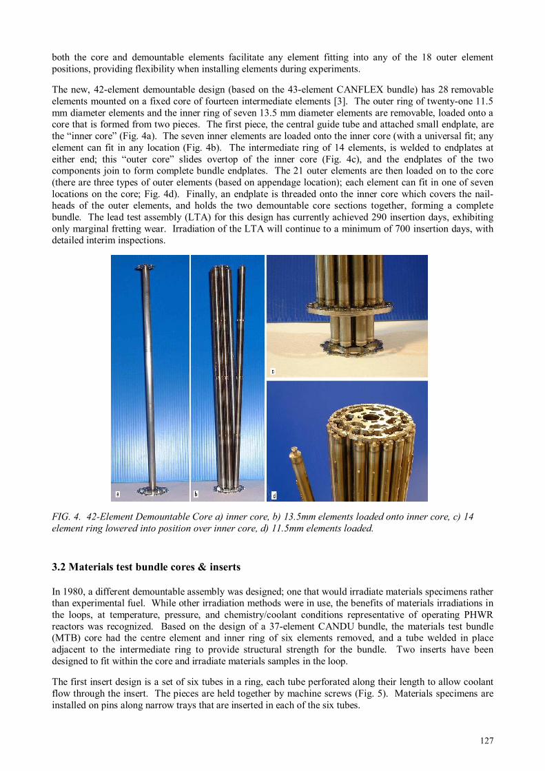
127
both the core and demountable elements facilitate any element fitting into any of the 18 outer element positions, providing flexibility when installing elements during experiments.
The new, 42-element demountable design (based on the 43-element CANFLEX bundle) has 28 removable elements mounted on a fixed core of fourteen intermediate elements [3]. The outer ring of twenty-one 11.5 mm diameter elements and the inner ring of seven 13.5 mm diameter elements are removable, loaded onto a core that is formed from two pieces. The first piece, the central guide tube and attached small endplate, are the “inner core” (Fig. 4a). The seven inner elements are loaded onto the inner core (with a universal fit; any element can fit in any location (Fig. 4b). The intermediate ring of 14 elements, is welded to endplates at either end; this “outer core” slides overtop of the inner core (Fig. 4c), and the endplates of the two components join to form complete bundle endplates. The 21 outer elements are then loaded on to the core (there are three types of outer elements (based on appendage location); each element can fit in one of seven locations on the core; Fig. 4d). Finally, an endplate is threaded onto the inner core which covers the nail-heads of the outer elements, and holds the two demountable core sections together, forming a complete bundle. The lead test assembly (LTA) for this design has currently achieved 290 insertion days, exhibiting only marginal fretting wear. Irradiation of the LTA will continue to a minimum of 700 insertion days, with detailed interim inspections.
FIG. 4. 42-Element Demountable Core a) inner core, b) 13.5mm elements loaded onto inner core, c) 14
element ring lowered into position over inner core, d) 11.5mm elements loaded.
3.2 Materials test bundle cores & inserts
In 1980, a different demountable assembly was designed; one that would irradiate materials specimens rather than experimental fuel. While other irradiation methods were in use, the benefits of materials irradiations in the loops, at temperature, pressure, and chemistry/coolant conditions representative of operating PHWR reactors was recognized. Based on the design of a 37-element CANDU bundle, the materials test bundle (MTB) core had the centre element and inner ring of six elements removed, and a tube welded in place adjacent to the intermediate ring to provide structural strength for the bundle. Two inserts have been designed to fit within the core and irradiate materials samples in the loop.
The first insert design is a set of six tubes in a ring, each tube perforated along their length to allow coolant flow through the insert. The pieces are held together by machine screws (Fig. 5). Materials specimens are installed on pins along narrow trays that are inserted in each of the six tubes.

128
The second insert is triangular, fitted inside a circular cylinder called a sleeve. The outer surface of this triangular cylinder is studded with pins, the numbers and locations of which depend on the materials samples to be irradiated. The sleeve fits over the samples, keeping them in place during irradiation.
Either insert will fit within the tube in the centre of the MTB core (Fig. 6). The large ring that is part of the bottom endplate of each insert fits against the base of the core; the compression of the string of six bundles holds the insert in place.
FIG. 5. MTB Insert #1: components (top) and fully assembled (bottom).
FIG. 6 Materials test bundle with insert #2

129
4. INSTRUMENTED EXPERIMENTS IN NRU
AECL has performed instrumented experiments since the late 1960’s. Although most were conducted in the National Research Experimental (NRX) reactor, which iscurrently being decommissioned and no longer available, instrumented experiments have been performed in NRU in the Blowdown Test Facility (1987—1997).
4.1 Blowdown test facility
One component of the Canadian in-reactor experimental program was a series of tests, designed to measure fuel and fission product behaviour during postulated accident events. The BTF was designed for this purpose, to incorporate all major phenomena in a single test to provide data for the development and validation of models and computer codes [6]. The BTF was the only instrumented facility operated in NRU for the irradiation of CANDU-sized fuel rods. Other instrumented tests have been conducted on non-fissile materials under irradiation conditions in Fast Neutron Rods [7] and on full-length LWR fuel rods.
BTF comprised two major components. The in-core test section was connected in parallel with the existing test section of U1, so that U1 could supply the BTF test section with coolant for normal operating conditions irradiations prior to “blowdown” transient experiments. The out-of-core section of BTF in the basement of NRU contained the equipment used to accommodate the coolant as it expanded to steam, and the various monitoring devices measuring fission product behaviour. A schematic is shown in Fig. 7.
To begin the tests, isolation valves were closed, isolating BTF from U1. Then, based on the experiment being conducted, valves to the blowdown tank (in the basement of NRU) were opened and the coolant in the BTF test section was allowed to convert to steam and expand into the blowdown tank. A low flow of steam or helium was used to draw any released fission products past a series of gamma spectrometers, aerosol sampling stations, and a grab sample ladder to measure the behaviour of the released fission products [9].
The instrumentation used in the BTF was specifically designed for each experiment, and would generally vary in the numbers and types of devices used. For the BTF-105 experiment [8], for example, the key parameters inside the BTF test section that required instrumentation were the pressure of the coolant, the internal pressure of the fuel element, the flow rate of the coolant past the fuel, and temperatures of fuel, sheath, coolant, and other components of the facility.
The coolant pressure transducers were located above the coolant and fuel, using long, small tubes to measure coolant pressure near the fuel. Despite this, the pressure transducers, an eddy-current type using matched gold coils, required modifications. The gold coils had to be replaced by molybdenum ones, as transmutations in the coils caused signal drift. A thermal buffer, to slow the change in temperature, was also required to counter the effect of rapid heating of the coils. Minor imperfections in the coils caused the inductance and resistance of the two to vary sufficiently to generate false readings at heating rates of up to 40°C/s. By slowing the heating rate on the transducers, the output error was reduced by an order of magnitude.
To measure the internal pressure of the fuel element, a null-balance pressure switch was developed. The switch consisted of a stainless steel diaphragm between two steel blocks. On one side of the diaphragm, a small port led to the inside of the fuel element, on the other side of the diaphragm, was a cavity to allow the diaphragm to flex. In the cavity was an electrical contact switch. The gas pressure inside the cavity was controlled remotely through a stainless steel tube. By varying the pressure in the cavity until the switch activated, the internal pressure of the element could be determined [9].
The turbine flowmeter had to be located as far away from the fuel as possible. In the downward flow of the BTF test section, this meant as high up in the test section as possible. The placement of the flowmeter was effective, and only minor modifications were required, a sealed coil cavity and carbide journal bearings, to protect the turbine blade shaft from contaminants.
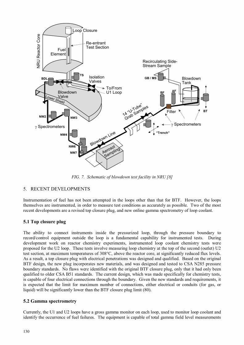
130
FIG. 7. Schematic of blowdown test facility in NRU [8]
5. RECENT DEVELOPMENTS
Instrumentation of fuel has not been attempted in the loops other than that for BTF. However, the loops themselves are instrumented, in order to measure test conditions as accurately as possible. Two of the most recent developments are a revised top closure plug, and new online gamma spectrometry of loop coolant.
5.1 Top closure plug
The ability to connect instruments inside the pressurized loop, through the pressure boundary to record/control equipment outside the loop is a fundamental capability for instrumented tests. During development work on reactor chemistry experiments, instrumented loop coolant chemistry tests were proposed for the U2 loop. These tests involve measuring loop chemistry at the top of the second (outlet) U2 test section, at maximum temperatures of 308°C, above the reactor core, at significantly reduced flux levels. As a result, a top closure plug with electrical penetrations was designed and qualified. Based on the original BTF design, the new plug incorporates new materials, and was designed and tested to CSA N285 pressure boundary standards. No flaws were identified with the original BTF closure plug, only that it had only been qualified to older CSA B51 standards. The current design, which was made specifically for chemistry tests, is capable of four electrical connections through the boundary. Given the new standards and requirements, it is expected that the limit for maximum number of connections, either electrical or conduits (for gas, or liquid) will be significantly lower than the BTF closure plug limit (80).
5.2 Gamma spectrometry
Currently, the U1 and U2 loops have a gross gamma monitor on each loop, used to monitor loop coolant and identify the occurrence of fuel failures. The equipment is capable of total gamma field level measurements
Recirculating Side-Stream Sample
Fuel Element
NR
U R
eacto
r C
ore
Lower Shield
Aerosol
Sampling
14 “U-Tube”
Grab Samples
Blowdown Tank
γ Spectrometersγ Spectrometers
Filter
Blowdown Line
NW2 NW3
NW4
NW6
NW7
“Trench”
BFAF
BT
TSBDL
Blowdown Valve
Isolation Valves
To/From U1 Loop
Loop Closure
GB / MS
Re-entrant Test Section

131
only, not a full energy spectrum; as a result, it is used only as gross indicator of radioactivity. Samples of the loop coolant are taken manually and placed in a remote gamma spectrometer to provide more detailed coolant isotopic analysis. A delayed neutron detector is also installed near the exit of the loop from the reactor, which identifies the presence of delayed-neutron-emitting fission products in the coolant, in the case of significant fuel defects. As part of a defected fuel research program, an online gamma spectrometer is being installed on U2 to provide near-continuous gamma spectrum data. Due to the conditions inside the shielded room that contains most of the U2 equipment, finding a location on the loop to attach the spectrometer has proven to be a challenge. The chosen site is a drain line leading from the main loop circuit that will maintain a continuous low flow rate during loop operation. The distance from the main circuit will affect some of the short-lived decay products in the coolant measurements, but will still provide an effective method of identifying when fuel defects have occurred, and assist in identifying which fuel has defected.
6. SCWR FUEL EXPERIMENTS
As with any new design, the Canadian SCWR fuel design will require testing to determine performance characteristics. The fuel concept, a homogeneous (Th, Pu)O2 mixture with 13% Pu by weight [9], [10],[11], is a material for which there is little irradiation data available. AECL is currently in the process of developing a “Thoria Roadmap”; a strategy that will specify areas of required research, including irradiations. Any need for instrumented irradiations of thoria-based fuel will be identified in the roadmap.
AECL’s current loops are not capable of achieving SCWR coolant conditions. If instrumented tests under SCWR conditions are identified as necessary, AECL will seek partners to achieve this goal. However, it is possible to develop instrumented and un-instrumented irradiations under normal PHWR operating conditions in order to address gaps in current understanding.
7. SUMMARY
AECL has a long history of fuel irradiations, including instrumented experiments. Two loops are currently installed in NRU, capable of irradiating the equivalent of six or twelve CANDU-type fuel bundles. The successful completion of BTF experiments in past, and the existence of key infrastructure make performing instrumented fuel irradiations feasible. In partnerships with other organizations who may offer facilities capable of irradiations under SCWR conditions, there are significant opportunities to conduct instrumented fuel irradiations in support of the SCWR concept.
REFERENCES
[1] DIMAYUGA, F.C., CANDU MOX Fuel Fabrication Development, Transactions of the American Nuclear Society, v. 77, Albuquerque, United States (1997) 150—152.
[2] FLOYD, M.R., Advanced Fuel Cycle Development at Chalk River Laboratories, Future of HWRs, Proc. Int. Conf. Ottawa, Canada, (2011).
[3] FLOYD, M.R., HARRISON, N.F., Recent Irradiations and PIE Supporting the Development of Advanced CANDU UO2 Fuel Technology, CANDU Fuel 2005, Proc. 9th Int. Conf. Belleville, Canada, (2005).
[4] BOYD, F.,ZED-2, The First 40 Years, Canadian Nuclear Society Bulletin, v. 21(1), ISSN 0714-7074, Toronto, Canada (2000) 2-5.
[5] ATOMIC ENERGY CANADA LIMITED, Summary of Loops in the Chalk River NRX and NRU Reactors, AECL-6980, Chalk River, Canada, (1980).
[6] ATOMIC ENERGY CANADA LIMITED, Description of the Blowdown Test Facility COG Program on In-Reactor Fission Product release, Transport, and Deposition Under Severe Accident Conditions, AECL-9343, Chalk River, Canada, (1987).
[7] LEUNG, T.C, Analysis of the Fast-neutron Spectrum Inside the Experimental Cavity of the NRU Mk4 FN Rod, Canadian Nuclear Society Simulation Symposium 1995, Proc. 19th Int. Sym. Hamilton, Canada, (1995).
[8] IRISH, J.D., et al, Preliminary Results of the BTF-105B Experiment: An In-Reactor Test of Fuel Behaviour and Fission Product Release and Transport Under LOCA/LOECC Conditions, Annual Conference of the Canadian Nuclear Society Proc. 19th Annual Conf. Toronto, Canada, (1998).

132
[9] DICKSON, L.W., et al, In-Core Instrumentation used to Monitor Severe-Fuel-Damage Tests at AECL Research, In-core instrumentation and in-situ measurement in connection with fuel behaviour, INIS-MF—14976, Vienna, Austria (1996), 21—32.
[10] PENCER, J., et al, Axial and Radial Graded Enrichment Options for the Canadian SCWR, 3rd China-Canada Joint Workshop on Supercritical-Water-Cooled Reactors, CCSC-2012, Xi’an, China (2012).
[11] MCDONALD M.H. et al., Pre-Conceptual Fuel Design Concepts for the Canadian Super Critical Water-Cooled Reactor, Super Critical Water Reactors 2011, Proc. 5th Int. Sym. Vancouver, Canada, (2011).
133
NRU DEVELOPMENT OF IRRADIATION TECHNIQUE FOR IN-PILE TESTS IN
JMTR
Neutron Irradiation and Testing Reactor Center, Oarai Research and Development Center, Japan Atomic Energy Agency (JAEA), Japan Email: [email protected]
Abstract
Several irradiation facilities have been developed and improved for the new JMTR during refurbishment. These are BOCA/OSF-1 facility for power transient test of fuel rod in a boiling water capsule (BOCA) and temperature control facility for irradiation capsule of material test. In this paper, irradiation facilities and techniques developed at JMTR are described in detail including the results of out-pile performance tests.
1. INTRODUCTION
The JMTR reached the first criticality in 1968, and has been used for many material and fuel irradiation studies [1—5]. The JMTR once stopped in 2006 and refurbishment works were almost finished now. However due to the influence of the Great-East-Japan-Earthquake, safety evaluation of JMTR against earthquake is underway. The JMTR is expected to restart in the latter half of JFY 2012.
Several irradiation facilities have been developed and improved for the new JMTR during refurbishment. These are BOCA/OSF-1 facility for power transient test of fuel rod in a BOCA and temperature control facility for irradiation capsule of material test. In addition, water chemistry control system was installed in JMTR to conduct in-pile material tests under simulated LWR conditions.
2. FUEL TRANSIENT TEST FACILITY
Fuel transient test facility has been developed to evaluate the integrity of high burn-up LWR fuels. The facility consists of a BOCA, a BOCA pressure control unit equipped with rod failure detection system, a He-3 gas pressure control unit and a BOCA cooling unit (Oarai Shroud Facility-1: OSF-1). Figure shows the schematic configuration of the facility. In-pile tube of the OSF-1 penetrates into the core of the JMTR through the lid of the reactor pressure vessel and forms an independent pressure boundary. The BOCA is a high pressure(about 7.3MPa) capsule made of stainless steel, in which instrumented segment fuel rod is loaded and cooled with high pressure water. The BOCA is inserted into the in-pile tube of the OSF-1. Figure 2 shows the schematic configuration of the core part of BOCA/OSF-1. BOCA is loaded into OSF-1 in JMTR. BOCA is surrounded with He-3 screen mounted in OSF-1. Rod power is increased rapidly by reducing the He-3 gas pressure in the gas screen between 4MPa and 0.03MPa. Figure 3 shows the typical transients of the He-3 gas pressure, the linear power of the fuel and the surface temperature of the fuel during a power ramping test.
J. NAKAMURA, H. NAGATA, Y. OKADA, S. KITAGISHI, T. YAMAURA, K. TOMITA AND M. OHMI
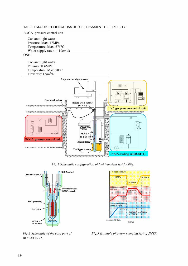
134
TABLE 1 MAJOR SPECIFICATIONS OF FUEL TRANSIENT TEST FACILITY
BOCA pressure control unit
Coolant: light water Pressure: Max. 17MPa Temperature: Max. 375°C Water supply rate : 1~10cm3/s
OSF-1
Coolant: light water Pressure: 0.4MPa Temperature: Max. 90°C Flow rate: 1.9m3/h
Fig.1 Schematic configuration of fuel transient test facility.
Fig.2 Schematic of the core part of
BOCA/OSF-1.
Fig.3 Example of power ramping test of JMTR.
4.0MPa 4.0MPa
0.03MPa
600W/cm
220W/cm
288
Surface temperature of test fuel pin
He-3 gas pressure
Linear power of test fuel
TimeInsertion of BOCA
Saturation temperature at 7.3MPa

135
The fuel rod power is determined with the coolant temperature increase measured at the entrance and exit of OSF-1. The temperature increase of coolant is calibrated with rod power by means of electrical heater just before the power ramp test. The accuracy of power measurement is about 5% at 40—60kW/m. Table 1 shows the major specifications of the facility. The BOCA is used to irradiate a fuel sample under the condition simulating the BWR coolant. The pressurized water adjusted by the BOCA pressure control unit is injected in the BOCA through a connection box. The pressurized water flows around the fuel sample, and is boiled by heat generation of the fuel sample under irradiation.
In the renewed JMTR, BOCA pressure control system connected with draining system was moved into a cubicle room, which is surrounded with shielding walls, to reduce the radiation dose incase due to fuel rod failure. The draining system was expanded to double system and it makes possible to continue the ramp tests even after severe fuel failure in ramp tests. The high pressure water supply rate in BOCA capsule was also increased from 1cc/s to 2—10cc/s to reduce the time for detecting fuel failure by germanium detector for drained high pressure water.
3. OUT-PILE TEST ABOUT COOLING CONDITIONS OF BOCA
To confirm the cooling conditions of fuel rod in BOCA/OSF-1 facility, out-pile test was performed [6]. Figure 4 shows the schematic configuration of the out-pile test facility. Table 2 shows design conditions of the out-pile test facility. The out-pile test facility consisted of a heater pin instead of the fuel, an inner tube simulated the outer tube of the BOCA, an outer tube simulated the in-pile tube of the OSF-1 and cooling systems for these tubes. The design of the heater pin was 9.5 mm in outer diameter and 400 mm in length of effective heating part and the maximum liner power of 750 W/cm. Type K thermocouple of 0.5 mm in outer diameter was set up at every 80 mm from the center of the effective heating part on surface of the heater pin. The outer tube and the cooling system were designed so that the maximum flow rate is 1.9m3/h. The coolant condition of the outer tube simulated the OSF-1. In the experiments, the surface temperature of the heater pin was measured when the linear power of the heater pin was heated up to 600 W/cm, which is the maximum linear power of the power ramping test. Figure 5 shows the results of the experiments. In the BWR condition, the maximum temperature was about 317°C at the liner power of 600 W/cm, which was 26°C higher than the saturation temperature 291°C at 7.5 MPa. In the range of 200~600 W/cm, the surface temperature was a little higher than the saturation temperature. In the PWR condition, the maximum temperature was about 370°C at the liner power of 600W/cm, which was 25°C higher than the saturation temperature 345°C at 15.5 MPa. In the range of 300~600 W/cm, the surface temperature was 4°C higher than the saturation temperature. From these results, it was confirmed that DNB is not occurred when the heater pin is heated up to 600 W/cm under coolant conditions at 7.5 MPa and 15.5 MPa. Therefore, there were
TABLE 2 DESIGN CONDITIONS OF THE OUT-OF-PILE TEST FACILITY
Inner tube
Coolant: light water Pressure: 10 MPa (BWR)
17.3 MPa (PWR) Temperature: 320°C (BWR) 375°C (PWR) Water supply rate : Max.10cm3/s
Outer tube Coolant: light water Pressure: 0.6 MPa Temperature: Max.100°C Flow rate: 1.9 m3/h
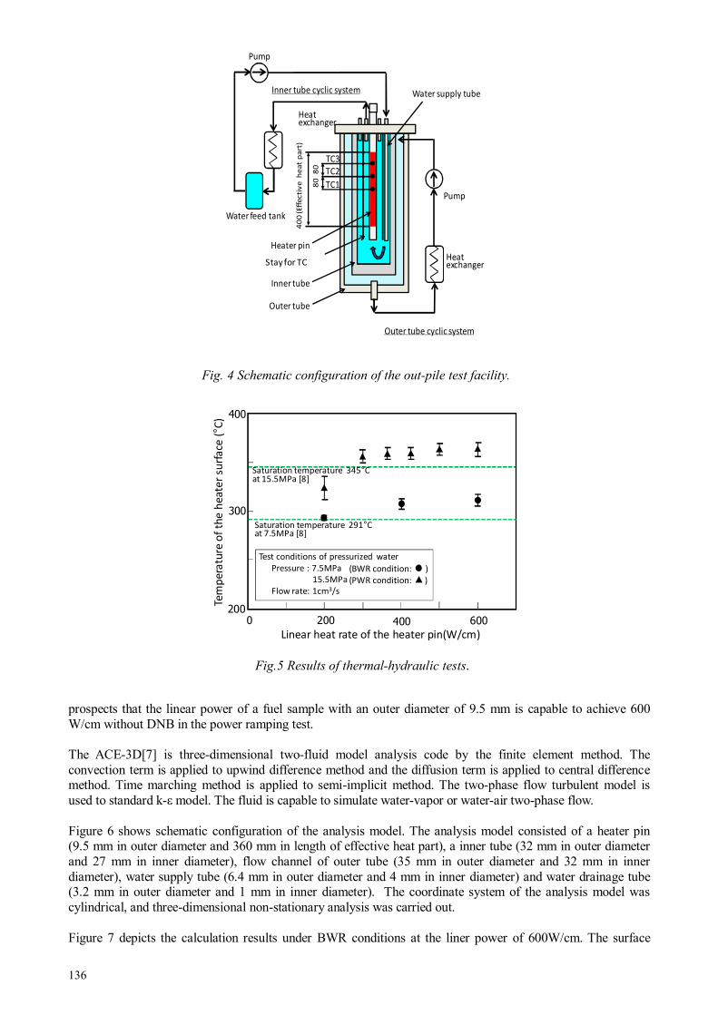
136
prospects that the linear power of a fuel sample with an outer diameter of 9.5 mm is capable to achieve 600 W/cm without DNB in the power ramping test. The ACE-3D[7] is three-dimensional two-fluid model analysis code by the finite element method. The convection term is applied to upwind difference method and the diffusion term is applied to central difference method. Time marching method is applied to semi-implicit method. The two-phase flow turbulent model is used to standard k-ε model. The fluid is capable to simulate water-vapor or water-air two-phase flow. Figure 6 shows schematic configuration of the analysis model. The analysis model consisted of a heater pin (9.5 mm in outer diameter and 360 mm in length of effective heat part), a inner tube (32 mm in outer diameter and 27 mm in inner diameter), flow channel of outer tube (35 mm in outer diameter and 32 mm in inner diameter), water supply tube (6.4 mm in outer diameter and 4 mm in inner diameter) and water drainage tube (3.2 mm in outer diameter and 1 mm in inner diameter). The coordinate system of the analysis model was cylindrical, and three-dimensional non-stationary analysis was carried out. Figure 7 depicts the calculation results under BWR conditions at the liner power of 600W/cm. The surface
Fig. 4 Schematic configuration of the out-pile test facility.
200 400 600
Linear heat rate of the heater pin(W/cm)
Saturation temperature 291°Cat 7.5MPa [8]
Saturation temperature 345°Cat 15.5MPa [8]
200
300
400
Tem
pe
ratu
re o
f th
e h
ea
ter
surf
ace
(°C
)
(BWR condition: )
(PWR condition: )
0
Test conditions of pressurized water
Pressure : 7.5MPa
15.5MPa
Flow rate: 1cm3/s
Fig.5 Results of thermal-hydraulic tests.
Outer tube
TC1
TC2
TC3
40
0 (Eff
ecti
ve
h
ea
t p
art
)
80
80
Inner tube
Heater pin
Heat exchanger
Pump
Outer tube cyclic system
Separate tube
Heat exchanger
Pump
Inner tube cyclic system
Water feed tank
Water supply tube
Stay for TC
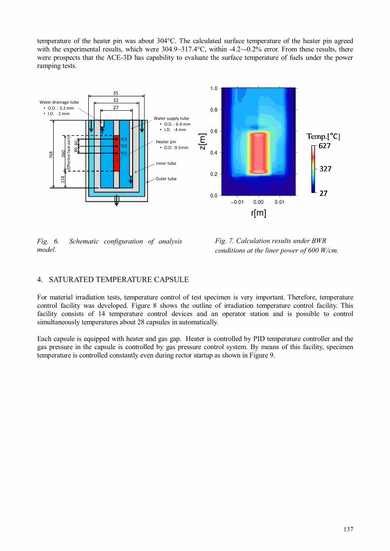
137
temperature of the heater pin was about 304°C. The calculated surface temperature of the heater pin agreed with the experimental results, which were 304.9~317.4°C, within -4.2~-0.2% error. From these results, there were prospects that the ACE-3D has capability to evaluate the surface temperature of fuels under the power ramping tests.
4. SATURATED TEMPERATURE CAPSULE
For material irradiation tests, temperature control of test specimen is very important. Therefore, temperature control facility was developed. Figure 8 shows the outline of irradiation temperature control facility. This facility consists of 14 temperature control devices and an operator station and is possible to control simultaneously temperatures about 28 capsules in automatically. Each capsule is equipped with heater and gas gap. Heater is controlled by PID temperature controller and the gas pressure in the capsule is controlled by gas pressure control system. By means of this facility, specimen temperature is controlled constantly even during rector startup as shown in Figure 9.
Outer tube
36
0(E
ffe
ctiv
e h
ea
t p
art
)
76
8
Water supply tube
• O.D. : 6.4 mm
• I.D. :4 mm
Water drainage tube
• O.D. : 3.2 mm
• I.D. :1 mm
35
32
27
15
8
Inner tube
Heater pin
• O.D. :9.5mm
TC1
TC2
TC3
80
80
Fig. 6. Schematic configuration of analysis
model. Fig. 7. Calculation results under BWR
conditions at the liner power of 600 W/cm.

138
5. ADVANCED WATER CHEMISTRY CONTROLLED IRRADIATION FACILITY
For IASCC (Irradiaation Assisted Stress Corrosion Cracking) study of structure components in LWR’s, water chemistry and irradiation conditions are very important. Therefore, JAEA developed advanced water chemistry controlled irradiation facility in JMTR. Saturated temperature capsule equipped with unit for crack growth test is connected to water chemistry control system. The water chemistry in the capsule is controlled to representative BWR conditions. Figure 10 shows the outline of advanced water chemistry controlled irradiation facility. By means of this facility, load to the CT specimen is applied by the pressure difference between capsule coolant and bellows pressurized by He gas. The crack length of CT specimen is measured by potential drop method (PDM) using mineral insulator (MI) cables.
Fig. 9. Specimen temperature change during reactor start up.
Fig. 8. Schematic configuration of irradiation temperature control facility.
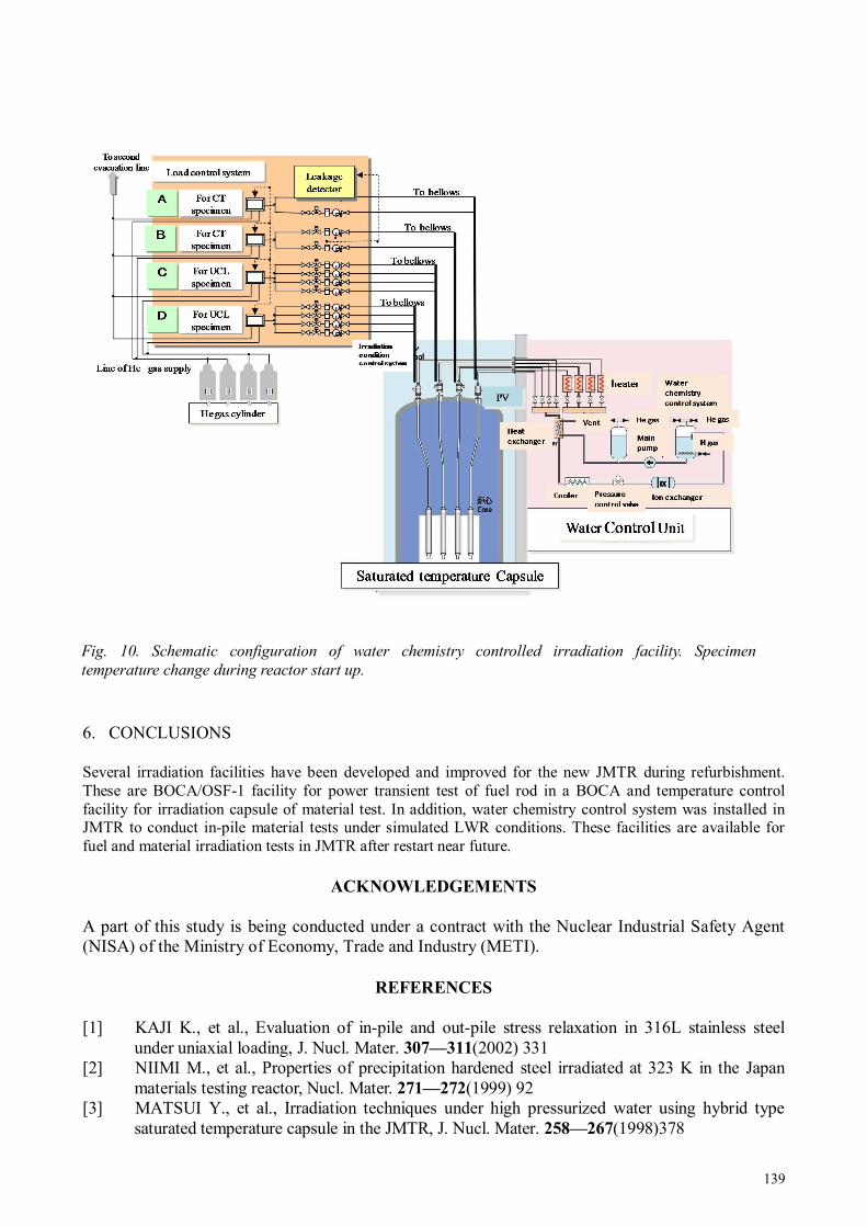
139
6. CONCLUSIONS
Several irradiation facilities have been developed and improved for the new JMTR during refurbishment. These are BOCA/OSF-1 facility for power transient test of fuel rod in a BOCA and temperature control facility for irradiation capsule of material test. In addition, water chemistry control system was installed in JMTR to conduct in-pile material tests under simulated LWR conditions. These facilities are available for fuel and material irradiation tests in JMTR after restart near future.
ACKNOWLEDGEMENTS
A part of this study is being conducted under a contract with the Nuclear Industrial Safety Agent (NISA) of the Ministry of Economy, Trade and Industry (METI).
REFERENCES
[1] KAJI K., et al., Evaluation of in-pile and out-pile stress relaxation in 316L stainless steel under uniaxial loading, J. Nucl. Mater. 307—311(2002) 331
[2] NIIMI M., et al., Properties of precipitation hardened steel irradiated at 323 K in the Japan materials testing reactor, Nucl. Mater. 271—272(1999) 92
[3] MATSUI Y., et al., Irradiation techniques under high pressurized water using hybrid type saturated temperature capsule in the JMTR, J. Nucl. Mater. 258—267(1998)378
Fig. 10. Schematic configuration of water chemistry controlled irradiation facility. Specimen
temperature change during reactor start up.

140
[4] SHIBATA A., et al., Development of remote welding techniques for in-pile IASCC capsules and evaluation of material integrity on capsules for long irradiation period, J. Nucl. Mater. 422(2012) 14
[5] SHIMADA S., et al., A metallographic and fractographic study of outside-in cracking caused by power ramp tests, J. Nucl. Mater. 327(2004)97
[6] KITAGISHI S., et al., Thermal-hydraulic tests with out–pile test facility for BOCA development, Paper presented KAERI/JAEA joint seminar on advanced irradiation and PIE technologies, March 28—30,2012 Mito, Japan, to be published as JAEA-Conf report.
[7] ONUKI A., et al., Improvement of multi-dimensional two-fluid model code ACE-3D and application to thermal-hydraulic analysis of water pool for passive residual heat removal, JAERI-Date/Code 99-038, (1999) (in Japanese).
141
REACTOR MATERIALS TESTING TECHNIQUES AND SELECTED RESULTS
OECD Halden Reactor Project Halden, Norway Email: [email protected]
Abstract
This paper describes some of the experimental facilities at the Halden Reactor Project which are dedicated to studying the behaviour of LWR core component materials in environments simulating those of operating nuclear power plants in terms of thermal hydraulic, neutronic and water chemistry conditions. The majority of the materials investigations make use of in-pile measurements. On-line monitoring techniques, such as the reversing direct current potential drop (DCPD) method for crack propagation monitoring and the use of LVDTs for crack initiation and creep and stress relaxation studies, are described and examples of results are presented.
1. INTRODUCTION
The OECD Halden Reactor Project is a joint undertaking of organisations in 18 countries sponsoring a jointly financed programme under the auspices of the OECD Nuclear Energy Agency. The research and development work conducted at the Project addresses issues related to fuel performance, cladding corrosion and the ageing and degradation phenomena of reactor vessel and internals materials.
The studies are performed in the HBWR. At any given time, around 30 test assemblies are in operation in the reactor. Typically, the reactor operates for two ~100-day reactor cycles each year. Depending on reactor position, fast fluxes in the range from 5 × 10¹² to 7 × 10¹³ n/cm2s can be achieved.
Many of the tests require representative light water reactor (LWR) conditions, which are achieved by housing the test rigs in pressure flasks that are positioned in fuel channels in the reactor and connected to dedicated water loops, in which BWR or pressurised water reactor (PWR) conditions are simulated. An important aspect of the materials tests is the use of on-line instrumentation situated within the reactor core. For irradiation assisted stress corrosion crack growth investigations, the DCPD method is employed, while LVDTs are utilized for crack initiation and stress relaxation studies. Both unirradiated and irradiated materials may be used for fabrication of the test specimens.
2. DESCRIPTION OF EXPERIMENTAL FACILITIES
The irradiation facilities in the HBWR enable studies to be conducted under HBWR conditions, in inert (helium and / or argon gas) environments and in conditions simulating LWR systems in terms of water chemistry, temperatures and pressures.
2.1 Dry irradiation capsules
Irradiation in inert or dry irradiation environments are commonly used for materials studies where dose and temperature are the key test variables.
The samples that are installed in the dry irradiation capsules include tensile specimens, Charpy-V samples, ¼T to 1T compact tension (CT) specimens and TEM foils, and may be prepared from unirradiated as well as irradiated materials. The capsules, with specimen-capsule gas-gaps designed to create a specific temperature for the specimens, are filled with gas and then sealed. The HBWR is suitable for performing dry irradiation since the gamma heating is relatively low, thus minimising temperature gradients across comparatively large specimens, such as 1 T CTs, to ~ 10°C.
In order to determine the temperature history and accumulated dose, melting alloy temperature monitors (MATMs) and Ni, Fe and Al/1%Co flux wires are installed in the capsules together with the specimens. The MATMs and flux wires are subjected to post test visual inspection / photography and activation analyses
T.M. KARLSEN, P. BENNETT
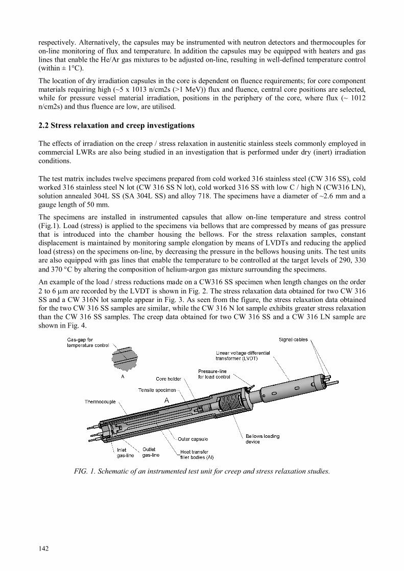
142
respectively. Alternatively, the capsules may be instrumented with neutron detectors and thermocouples for on-line monitoring of flux and temperature. In addition the capsules may be equipped with heaters and gas lines that enable the He/Ar gas mixtures to be adjusted on-line, resulting in well-defined temperature control (within ± 1°C).
The location of dry irradiation capsules in the core is dependent on fluence requirements; for core component materials requiring high (~5 x 10¹³ n/cm2s (>1 MeV)) flux and fluence, central core positions are selected, while for pressure vessel material irradiation, positions in the periphery of the core, where flux (~ 1012 n/cm2s) and thus fluence are low, are utilised.
2.2 Stress relaxation and creep investigations
The effects of irradiation on the creep / stress relaxation in austenitic stainless steels commonly employed in commercial LWRs are also being studied in an investigation that is performed under dry (inert) irradiation conditions.
The test matrix includes twelve specimens prepared from cold worked 316 stainless steel (CW 316 SS), cold worked 316 stainless steel N lot (CW 316 SS N lot), cold worked 316 SS with low C / high N (CW316 LN), solution annealed 304L SS (SA 304L SS) and alloy 718. The specimens have a diameter of ~2.6 mm and a gauge length of 50 mm.
The specimens are installed in instrumented capsules that allow on-line temperature and stress control (Fig.1). Load (stress) is applied to the specimens via bellows that are compressed by means of gas pressure that is introduced into the chamber housing the bellows. For the stress relaxation samples, constant displacement is maintained by monitoring sample elongation by means of LVDTs and reducing the applied load (stress) on the specimens on-line, by decreasing the pressure in the bellows housing units. The test units are also equipped with gas lines that enable the temperature to be controlled at the target levels of 290, 330 and 370 °C by altering the composition of helium-argon gas mixture surrounding the specimens.
An example of the load / stress reductions made on a CW316 SS specimen when length changes on the order 2 to 6 µm are recorded by the LVDT is shown in Fig. 2. The stress relaxation data obtained for two CW 316 SS and a CW 316N lot sample appear in Fig. 3. As seen from the figure, the stress relaxation data obtained for the two CW 316 SS samples are similar, while the CW 316 N lot sample exhibits greater stress relaxation than the CW 316 SS samples. The creep data obtained for two CW 316 SS and a CW 316 LN sample are shown in Fig. 4.
FIG. 1. Schematic of an instrumented test unit for creep and stress relaxation studies.

143
FIG. 2. Example of load reductions performed on a CW 316 SS stress relaxation sample.
FIG. 3. Summary of stress relaxation data for two CW 316 SS samples and a CW 316 N lot sample.
FIG. 4. Creep data for two CW 316 SS samples and a CW 316 LN sample.

144
2.3 Loop Systems
Test rigs for materials investigations requiring exposure to representative LWR environments are installed in pressure flasks which are connected to loop systems operating under PWR or BWR conditions. Tests can also be conducted under Canada deuterium uranium (CANDU) reactor water chemistry conditions. The flasks are often surrounded by highly enriched (typically 8—13% enrichment) booster fuel rods, for increasing the fast neutron flux levels.
Eleven loop systems, operating under either PWR, BWR or CANDU conditions, are currently inoperation at the Halden reactor. A simplified view of a loop system is shown in Figure 5. The loops have a volume (including the purification system) of between 60 and 120 litres. The loop circulation pumps have capacities from 100 litres to 10 tons per hour, and electric heating is used to achieve the desired temperature in the test section. Specific BWR, PWR or CANDU conditions are simulated by varying the pressure and temperature of the coolant and the concentrations of dissolved additives, such as LiOH, boric acid, oxygen and hydrogen. Each loop consists of three main sections: the loop itself, the purification system and the sampling system. Other components include the main circulation pump, heaters/coolers and valves. The main operating parameters, such as temperature, pressure and flow rate are automatically controlled within specified limits by the use of programmable logic control (PLC).
Chemistry conditions are controlled by the purification system.Typically the flow through the system is approximately 1 to 2 loop volumes per hour. Impurities are removed by lithium, boron or mixed bed ion exchange units. The sampling system is used to obtain representative water samples from the loop, to monitor continuously conductivity and dissolved oxygen and hydrogen concentrations in the coolant and to provide a facility for the controlled injection of additives into the loops. The flowrate through the sample loop is normally in the range from 20—50 l/h, at a temperature of 25°C.
FIG. 5. Schematic diagram of water loop system.
Cooler
Water
analysis
Purification
system
Pressure
control
systemControl
valve
In-core
test rig
Feed water tank
Cooler
Water
analysis
Purification
system
Pressure
control
systemControl
valve
In-core
test rig
Feed water tank
Cooler
Water
analysis
Purification
system
Pressure
control
systemControl
valve
In-core
test rig
Cooler
Water
analysis
Purification
system
Pressure
control
systemControl
valve
In-core
test rig
Feed water tank

145
2.4 Crack initiation (integrated time-to-failure) studies
In the crack initiation studies, which have been performed in both PWR and BWR conditions, use has been made of pressurised tube and tensile specimens. Both specimen geometries are equipped with LVDTs for on-line monitoring of specimen performance.
In an investigation utilizing the pressurised tube samples, the effects of accumulated dose, stress level and material type on the initiation of cracks were evaluated.
Unirradiated tube specimens with a 0.5 mm wall thickness (Fig. 6) were prepared from 304, 316 and CW 347 SS and pressurised with argon gas to hoop stress levels corresponding to 0.8— 2.75 x the yield strength (YS) of the material. The tube samples were arranged in strings, and each string was equipped with an LVDT for on-line monitoring of string length.
During irradiation, the specimens were exposed to a BWR conditions and, as described above, tube integrity was monitored by means of the LVDTs attached to the lower end of each specimen string and also by means of a gamma monitor installed in the outer loop system. In the event of crack initiation and subsequent propagation as a through-wall crack, the monitor was activated by the release of Ar-41 from the tube and into the coolant. An example of the on-line signal changes accompanying the rupture of a tube is illustrated in Fig. 7. The rupture is clearly detected by increases in the coolant activity levels and by the corresponding change in the LVDT signal.
FIG. 6. Pressurized tube specimens arranged in strings equipped with LVDTs to monitor specimen failure.
Outer Shroud (ø73/ 71 mm)
LVDT (EC)
SPND (V-Type)
Gamma Thermometer
LVDT (EC)
Internal pressurization
with Ar gas
EB weld
End plug
Wall thickness (0.5 mm)
(ID 8mm, OD 9mm)
EB weld
Outlet Coolant
Thermocouple (x2)
Upper
Specimen String
(6 tubes)
Lower
Specimen String
(6 tubes)
12 Surrounding
Booster Rods
Pressure Flask(ID x 33,5 mm)
Intermediate Coolant
Thermocouple (x1)
Inlet Coolant
Thermocouple (x3)
Seal welded after
filling with gas

146
FIG. 7. Specimen failure is indicated by the change in elongation signal and by the release of activated Ar-41 into the loop system.
In a second crack initiation study that is currently in progress, the main objective is to determine the number of specimen failures that occur in irradiated tensile stainless steel specimens as a function of the water chemistry (normal water chemistry (NWC) versus hydrogen water chemistry (HWC)), with the aim of providing information on the effectiveness of hydrogen additions in reducing the susceptibility to the initiation of cracks in high dose material.
The principle of the test method is illustrated in Fig. 8. A total of 30 small, irradiated tensile specimens, with a total length of 20 mm, a 1 mm diameter and a 4 mm gauge region, were prepared from a 13 dpa 304L SS control blade material. The specimens are arranged in pairs and constant load (75 % to 100 % of the irradiated yield strength) is applied by means of bellows that are compressed by the system pressure, thereby placing the specimens in tension. Each pair of specimens is equipped with an LVDT that enables on-line detection of failure and the specimens within each pair are identified by means of spacers placed internally in the bellows. In the event of specimen failure, the bellows collapse, with the extent of movement being recorded by the LVDT, which enables identification, on-line, of the failed sample. A typical example appears in Fig. 9 which shows a specimen failure accompanied by a change in LVDT signal ~50 hours after increasing the applied stress from ~60 to ~80 % YS.

147
FIG. 8. Schematic illustrating on-line monitoring techniques used in integrated time-to-failure study.
FIG. 9. Change in LVT signal (blue line) indicates tensile specimen failure during in-core testing.
2.5 Crack Growth Studies
The main objectives of the irradiation assisted stress corrosion crack growth studies are to assess the effects of stress intensity level, corrosion potential and temperature on the cracking behaviour of ¼T CT specimens prepared from irradiated (0.1—35 dpa) materials that have been retrieved from commercial plants. The tests are performed in BWR oxidizing (~5 ppm O2) and reducing (~2 ppm H2) environments or in PWR conditions (with 2—3 ppm Li, 1000—1200 ppm B and ~2 ppm H2).
LVDT
1. Always fixed
2. Always fixed
3. Moves up if upper specimen fails
4. Moves up if upper specimen fails
Step A
Both specimens intact
Step B
Upper specimen breaks
Step C
Lower specimen breaks
4. Moves up if lower specimen fails
Magnetic core
LVDT
1. Always fixed
2. Always fixed
3. Moves up if upper specimen fails
4. Moves up if upper specimen fails
Step A
Both specimens intact
Step B
Upper specimen breaks
Step C
Lower specimen breaks
4. Moves up if lower specimen fails
Magnetic core

148
A key requirement for the crack growth tests is the ability to monitor cracking response on-line in conjunction with the possibility for varying the load that is applied to the samples. Continuous crack monitoring allows the effects of different chemistry environments (e.g. oxidizing versus reducing conditions) to be assessed directly, as well as enabling the contributions of loading on cracking response to be evaluated.
The geometry of the CTs that are used in the tests is shown in Fig. 10. The specimens, with width W=16 mm, and thickness B = 5 mm, have 8 mm long machined chevron notches and 10 % side grooves. Specimen “arm” extensions are utilized for the attachment of wiring for the DCPD crack length measurements. The wiring consists of two pairs of potential wires and one pair of current wires.
Dynamic load is applied to the CTs by means of loading units which are equipped with bellows that are pressurised with helium gas through an outer system. During irradiation, the specimens may be subjected cyclic loading, periodic partial unloading or constant load. The cyclic and periodic partial unloading are usually performed with R = 0.5.
An example of the results obtained from a crack growth rate study performed in BWR conditions is shown in Fig. 11. In the figure the crack growth rates and applied stress intensity levels on a 6.7 dpa 316 L SS specimen that was exposed to oxidizing conditions with 5 ppm O2 is shown. At the start of the test, the CT was subjected to periodic partial unloading with R=0.5 in order to encourage stable crack advance. However, the calculated crack growth rate remained low (on the order 10-9 mm/s) and at ~960 hours the stress intensity level was increased from ~13.5—14.5 MPa√m while period partial unloading continued to be implemented. As a result of the stress level increase the crack growth rate increased to ~1.5 x 10⁻⁶ mm/s and remained stable on switching to constant load. At ~1100 hours HWC was introduced and the crack growth rate decreased by an order of magnitude.
FIG. 10. Schematic illustrations of CT specimen geometries. Red shading represents irradiated material.

149
FIG. 11. Example of crack growth rates measured on a CT prepared from 6.7 dpa 316L SS in oxidizing and
reducing conditions.
3. SUMMARY
The aim of the materials testing programme at the Halden Project is to improve the understanding of materials performance and ageing processes. The focus is on in-reactor experiments addressing core and vessel materials and, to this end, a range of different studies are being conducted.
Irradiation in inert environments is performed for materials that will later be subjected to post irradiation testing in out-of-pile facilities. Dry irradiation arrangements are also employed for in-core monitoring of the irradiation creep and stress relaxation of tensile specimens prepared from common LWR materials.
Studies which are performed in loop systems that simulate representative PWR or BWR conditions include crack initiation studies on pressurised tube and tensile samples. The crack initiation studies are complemented by crack growth investigations on irradiated CT specimens fabricated from commercial reactor component materials. The effects of stress intensity, temperature and water chemistry on cracking behaviour are addressed.
REFERENCES
[1] BENNETT P., KARLSEN T. M., Recent Developments in Instrumentation for In-core Materials Degradation Studies in the Halden Reactor, 11th International Conference on Environmental Degradation of Materials in Nuclear Power Systems – Water Reactors, Stevenson, Washington, August 10-14, (2003).
[2] FOSTER J. P. and KARLSEN T. M., Irradiation Creep and Irradiation Stress Relaxation of 316 and 304L Stainless Steels in Thermal and Fast Neutron Spectrum Reactors, 15th International Conference on Environmental Degradation of Materials in Nuclear Power Systems – Water Reactors, Colorado Springs, Colorado, August 7-11, (2011).
[3] BENNETT P., In-core measurements of fuel-clad interactions in the Halden Reactor, Presented at the IAEA Technical Meeting on Fuel Rod instrumentation and In-Pile Measurement Techniques, Halden, Norway 3-5 September, (2007).
[4] KARLSEN T.M., HØGBERG N-W and VAN NIEUWENHOVE R., Results from Irradiation Assisted Stress Corrosion Cracking and Stress Relaxation Studies Performed in the Halden Reactor, Proceedings of 6th Fontevraud Conference on Contributions of Materials Investigations to Improve Safety and Performance of LWRs, Fontevraud, France, September 18 – 22, (2006).

150
DEVELOPMENT OF PNEUMATIC BELLOWS BASED LOADING DEVICES FOR
MECHANICAL TESTING IN LWR, SCWR AND LFR RELEVANT
ENVIRONMENTAL CONDITIONS
1 European Commission, JRC-IE, Institute for Energy, Petten, Netherlands 2 VTT Technical Research Centre of Finland, Espoo, Finland 3 Institute of Chemical Technology, Prague, Czech Republic 4 Czech Technical University, Czech Republic
Email: [email protected]
Abstract
A detailed investigation of detrimental processes such as corrosion and stress corrosion cracking (SCC), ageing embrittlement, creep, fatigue liquid metal embrittlement (LME) and etc., which may significantly affect the materials performance in specific water chemistry environments, is of fundamental importance for current LWR and for the development of the Generation-IV reactor concepts such as SCWR and LFR. In particular, SCC crack growth rate testing is difficult to perform due to complex requirements for the experimental facilities which include water chemistry loops equipped with relevant pH, conductivity, dissolved O2 and H2 sensors, autoclaves with mechanical loading devices, incorporating crack growth rate measurement by direct current potential drop (DCPD) and displacement measurement by LVDT. All these requirements significantly advance the total materials qualification costs. JRC in cooperation with VTT has been working on a new type of loading devices which are expected to decrease these costs and at the same time guarantee enough reliability and flexibility for both SCC and future irradiation assisted stress corrosion cracking (IASCC) testing to be performed in LWR, SCWR and LFR environments. This paper summarizes the development of the devices for SCC crack growth rate measurements in LWR and SCWR conditions by using a pneumatic bellows based loading device developed in the frame of JRC-VTT cooperation. Examples of results of crack growth rates measured in LWR and SCWR autoclave tests are given. Furthermore, the conceptual design for future IASCC application and for pneumatically powered testing system capable of working in liquid lead environment up to 650ºC is presented.
1. INTRODUCTION
Six reactor concepts were chosen by GIF in 2002 [1] based on the particular criteria or requirements including sustainability of the fuel cycle and waste minimization, enhanced economics, safety, reliability and enhanced proliferation resistance compared to current generation of nuclear reactors either Gen II or Gen III represented e.g. by EPR concept. Although significant differences exist from one reactor concept to the other and a definitive design has not been established for any of them, the operating conditions envisaged in all the above mentioned innovative nuclear systems are quite demanding. In order to increase efficiency and enhance sustainability, high operating temperatures are an evident goal from the process engineering point of view. However, high operating temperatures, combined with prolonged exposure to high-energy neutron irradiation, as well as to corrosive coolants (e.g. supercritical water), under specific thermal-hydraulics conditions, will challenge the performance of structural materials. Special requirements set for the constructional materials used in future reactor systems will strongly influence the challenges in the component design work. Many material parameters such as corrosion, resistance to fracture, creep, fatigue, stress corrosion cracking, irradiation hardening and embrittlement, swelling, irradiation enhanced creep, irradiation induced segregation, high temperature He and H2 embrittlement and irradiation assisted stress corrosion cracking are needed as input data for such work. The generation of reliable data calls also for more sophisticated testing systems. The newly developed pneumatic loading technology which has already been successfully applied to testing many kinds of materials in different test environments can provide important potential benefits. The main goal of the presented work was to develop a pneumatic bellows based loading device, for SCC fracture mechanics crack growth rate tests, working up to supercritical water temperature (= 650oC). Following that, demonstrate the loading device operation in the SCW autoclave connected to water circulating loop. Next development was targeted to further miniaturization or more precisely to development of a device designed as a integral part of miniature autoclaves, which could be used for IASCC testing both pre-irradiated materials in hot-cell and for in-situ irradiation in in-pile facility in HFR Petten.
R. NOVOTNY1, P. MOILANEN2, P. HÄHNER1, P. JANIK1,3, J. SIEGL4, P. HAUSILD4

151
2. FEASIBILITY STUDY OF IN-PILE SCC TESTING FACILITY FOR HIGH FLUX REACTOR IN PETTEN
Within HPLWR Phase 2 FP6 Euroatom projects, which was primarily focused on the preparation of detailed design for European concept of SCWR, first in-pile facility operating in SCW (t=510oC, p=250 bar) environment was designed and constructed by NRI [2] in order radiolysis could be studied in SCWR relevant environment. On the other hand, the facility offers rather limited to examine the effect of neutron irradiation and radiolysis with respect to degradation processes such as corrosion and IASCC. Therefore, JRC IET JRC in cooperation with VTT has been working on a new type of loading devices which are expected to decrease these costs and at the same time could guarantee sufficient reliability and flexibility for both SCC and future IASCC testing to be performed in SCW or for liquid metal embrittlement studies liquid Pb/Pb-Bi eutectic environment.
The facility will consist of two main parts: an in-pile test section and an associated out-of-pile system. In-pile section will be designed as reloadable operating either in-core or side-pool irradiation conditions. The facility will be fed with water environment either in “once-through” or “circulation-loop” regime by a water loop. Facility will be designed to be operational in BWR, PWR and SCWR condition, i.e. the maximum reachable values of pressure and temperature should be up to 650oC and 35MPa, respectively. Water chemistry will be analysed in out-of-pile section of the rig. Conductivity, pH, dissolved O2, dissolved H2 respectively will be monitored at both the inlet and the outlet of the channel. The loop and rig instrumentation will include monitoring of temperature, neutron flux, pressure, flow rates as well as load, displacement, electrochemical potential and crack growth by DCPD. Future in-pile section should consist of two integral parts:
1. Thermosyphon rig, in order to maintain reliable test conditions as regards temperature, pressure and parameters of water solution in particular pH, conductivity and dissolved O2 and H2.
2. Pneumatic bellows based loading devices, designed with the purpose to reach maximum flexibility and reliability. Based on the design of thermosyphon rig, two or even more bellows based loading devices should be installed inside the active channel.
2.1 Thermosyphon rig
The idea of using thermosyphon rig (see Fig. 1) to control heating in the test section of in-pile facility is not new since similar thermosyphon rig was already successfully used in the project of irradiation testing of various metal coatings and alloys under PWR conditions in HFR Petten in 1995 [3]. Final design of the new rig will not be fundamentally different compared to the old one; however changes in the design of heating elements, coolers and construction materials will be necessary. If one takes into consideration that the rig was originally designed for general corrosion testing under irradiation, designers will face much more complicated assignment because this facility should be used also for tests under SCWR water chemistry parameters. Schematic drawing of the LIMA rig is given in Fig. 1.
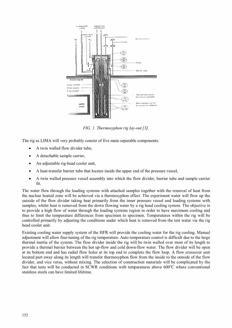
152
FIG. 1. Thermosyphon rig lay-out [3].
The rig as LIMA will very probably consist of five main separable components:
• A twin walled flow divider tube,
• A detachable sample carrier,
• An adjustable rig-head cooler unit,
• A heat-transfer barrier tube that locates inside the upper end of the pressure vessel,
• A twin walled pressure vessel assembly into which the flow divider, barrier tube and sample carrier fit.
The water flow through the loading systems with attached samples together with the removal of heat from the nuclear heated zone will be achieved via a thermosyphon effect. The experiment water will flow up the outside of the flow divider taking heat primarily from the inner pressure vessel and loading systems with samples, whilst heat is removed from the down flowing water by a rig head cooling system. The objective is to provide a high flow of water through the loading systems region in order to have maximum cooling and thus to limit the temperature differences from specimen to specimen. Temperatures within the rig will be controlled primarily by adjusting the conditions under which heat is removed from the test water via the rig head cooler unit.
Existing cooling water supply system of the HFR will provide the cooling water for the rig cooling. Manual adjustment will allow fine-tuning of the rig temperature. Auto temperature control is difficult due to the large thermal inertia of the system. The flow divider inside the rig will be twin walled over most of its length to provide a thermal barrier between the hot up-flow and cold down-flow water. The flow divider will be open at its bottom end and has radial flow holes at its top end to complete the flow loop. A flow crossover unit located part away along its length will transfer thermosyphon flow from the inside to the outside of the flow divider, and vice versa, without mixing. The selection of construction materials will be complicated by the fact that tests will be conducted in SCWR conditions with temperatures above 600oC where conventional stainless steels can have limited lifetime.

153
2.2 Development of pneumatic bellows based loading device for SCC testing in SCW
The pneumatic servo-controlled material testing system has earlier been used to perform fracture toughness, SCC, corrosion fatigue, tensile and electrochemical measurements in gas, high temperature aqueous solution and irradiation environments. The main advantages of pneumatic testing system include high sensitivity, accuracy and possibility to separate material testing and control systems by long (>30m) pressure tubes. Furthermore, several testing systems can be fitted simultaneously into one test chamber. As the moving parts that penetrate the pressure boundary are not needed, the friction force at the sealing element location is avoided. Therefore, the load control with pneumatic loading unit is more accurate than with the conventional servo-hydraulic and step-motor driven devices. This enables using of small size specimens, which is an advantage for testing irradiated materials in hot-cells, for in-pile experiments inside the reactor core of a research reactor or for environmentally assisted crack growth rates tests in supercritical water. For example, pneumatic bellows based loading devices have been successfully used for SCC or creep-fatigue testing at VTT [4] or at OECD Halden Reactor Project [5] in their in-pile IASCC facilities for BWR/PWR applications. Several BWR/PWR systems have already been also installed in JRC Petten autoclaves working up to 340oC and 16MPa high temperature water and some of the results have been published by Novotny et al. [6].
2.2.1 Bellows based loading device for testing of Charpy type 3PB specimens
SCC crack growth rate tests in SCW pose a very challenging task for obvious reasons. In 2008, VTT and JRC Petten started joint innovative project with the main target to design and demonstrate operability of pneumatic bellows loading device in SCW. The basic scheme of the first prototype is given in Fig. 2.
FIG. 2. Pneumatic bellows based loading device designed for SCW applications.
First of all, the inner built-in pistons were installed inside the bellows in order to restrict the bellow to uniaxial movement. The bellow was then closed from the outside environment by welding. Pressurized air, which served as a driving force for our loading system, was dosed via 1.8 mm o.d. stainless steel pressure tube to the bellows. The bellow was further attached to a loading cassette, set up based on what type of test one wants perform. In this particular case, the cassette was designed in order to perform three point bend (3PB) SCC tests in SCW by using Charpy type of specimens, as it is presented in Fig. 1. The accuracy of load applied by the bellow during the test was controlled and determined by pressure adjusting loop. The basic scheme of the loop is shown in Fig. 3.
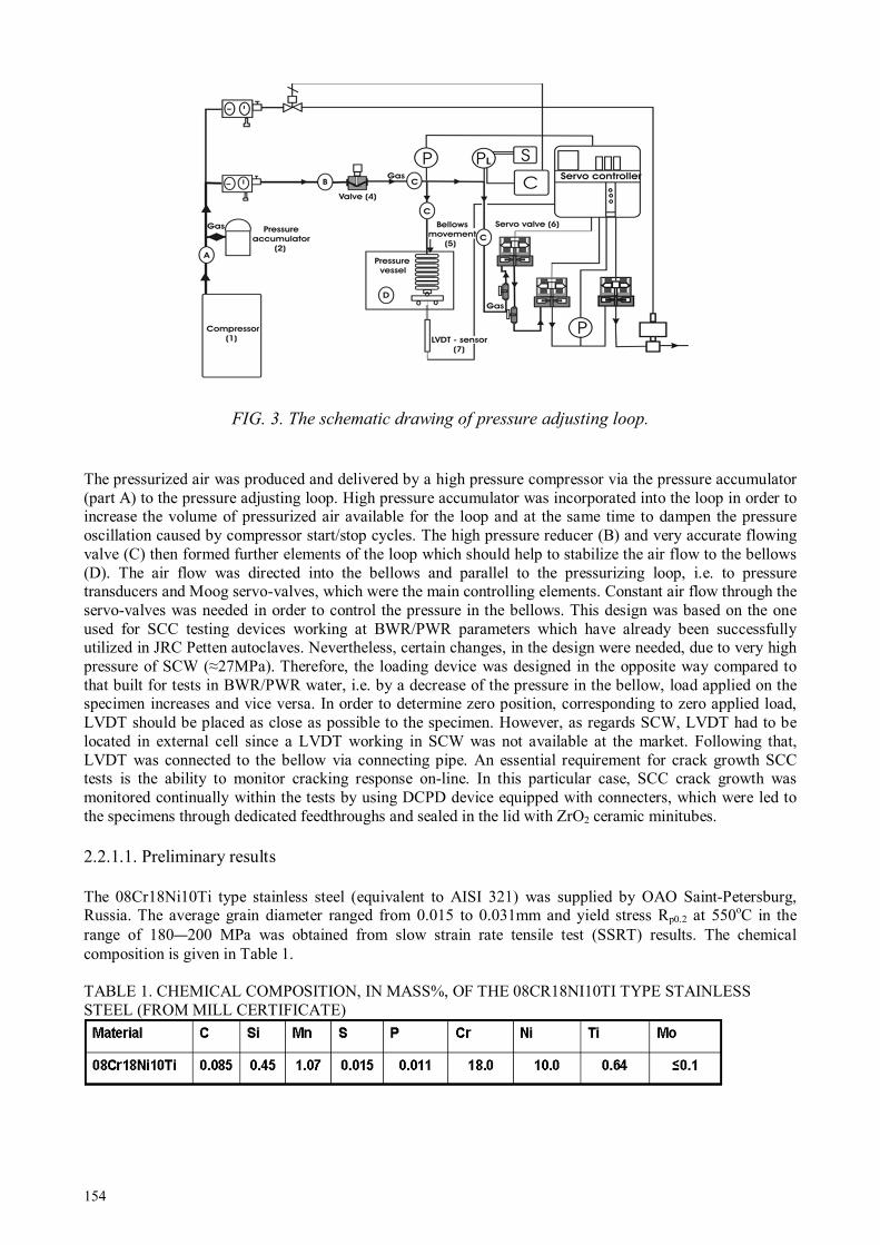
154
FIG. 3. The schematic drawing of pressure adjusting loop.
The pressurized air was produced and delivered by a high pressure compressor via the pressure accumulator (part A) to the pressure adjusting loop. High pressure accumulator was incorporated into the loop in order to increase the volume of pressurized air available for the loop and at the same time to dampen the pressure oscillation caused by compressor start/stop cycles. The high pressure reducer (B) and very accurate flowing valve (C) then formed further elements of the loop which should help to stabilize the air flow to the bellows (D). The air flow was directed into the bellows and parallel to the pressurizing loop, i.e. to pressure transducers and Moog servo-valves, which were the main controlling elements. Constant air flow through the servo-valves was needed in order to control the pressure in the bellows. This design was based on the one used for SCC testing devices working at BWR/PWR parameters which have already been successfully utilized in JRC Petten autoclaves. Nevertheless, certain changes, in the design were needed, due to very high pressure of SCW (≈27MPa). Therefore, the loading device was designed in the opposite way compared to that built for tests in BWR/PWR water, i.e. by a decrease of the pressure in the bellow, load applied on the specimen increases and vice versa. In order to determine zero position, corresponding to zero applied load, LVDT should be placed as close as possible to the specimen. However, as regards SCW, LVDT had to be located in external cell since a LVDT working in SCW was not available at the market. Following that, LVDT was connected to the bellow via connecting pipe. An essential requirement for crack growth SCC tests is the ability to monitor cracking response on-line. In this particular case, SCC crack growth was monitored continually within the tests by using DCPD device equipped with connecters, which were led to the specimens through dedicated feedthroughs and sealed in the lid with ZrO2 ceramic minitubes.
2.2.1.1. Preliminary results
The 08Cr18Ni10Ti type stainless steel (equivalent to AISI 321) was supplied by OAO Saint-Petersburg, Russia. The average grain diameter ranged from 0.015 to 0.031mm and yield stress Rp0.2 at 550oC in the range of 180—200 MPa was obtained from slow strain rate tensile test (SSRT) results. The chemical composition is given in Table 1. TABLE 1. CHEMICAL COMPOSITION, IN MASS%, OF THE 08CR18NI10TI TYPE STAINLESS STEEL (FROM MILL CERTIFICATE)
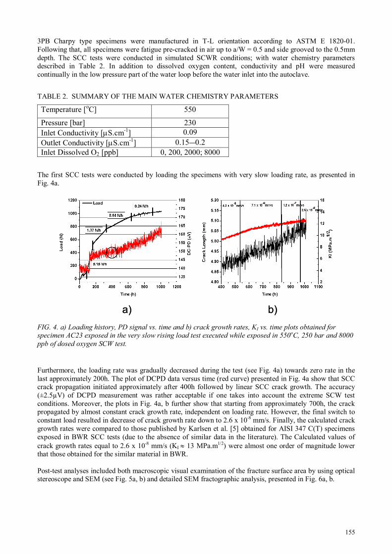
155
3PB Charpy type specimens were manufactured in T-L orientation according to ASTM E 1820-01. Following that, all specimens were fatigue pre-cracked in air up to a/W = 0.5 and side grooved to the 0.5mm depth. The SCC tests were conducted in simulated SCWR conditions; with water chemistry parameters described in Table 2. In addition to dissolved oxygen content, conductivity and pH were measured continually in the low pressure part of the water loop before the water inlet into the autoclave.
TABLE 2. SUMMARY OF THE MAIN WATER CHEMISTRY PARAMETERS
Temperature [oC] 550
Pressure [bar] 230 Inlet Conductivity [µS.cm-1] 0.09 Outlet Conductivity [µS.cm-1] 0.15—0.2 Inlet Dissolved O2 [ppb] 0, 200, 2000; 8000
The first SCC tests were conducted by loading the specimens with very slow loading rate, as presented in Fig. 4a.
FIG. 4. a) Loading history, PD signal vs. time and b) crack growth rates, KI vs. time plots obtained for specimen AC23 exposed in the very slow rising load test executed while exposed in 550
oC, 250 bar and 8000
ppb of dosed oxygen SCW test.
Furthermore, the loading rate was gradually decreased during the test (see Fig. 4a) towards zero rate in the last approximately 200h. The plot of DCPD data versus time (red curve) presented in Fig. 4a show that SCC crack propagation initiated approximately after 400h followed by linear SCC crack growth. The accuracy (±2.5µV) of DCPD measurement was rather acceptable if one takes into account the extreme SCW test conditions. Moreover, the plots in Fig. 4a, b further show that starting from approximately 700h, the crack propagated by almost constant crack growth rate, independent on loading rate. However, the final switch to constant load resulted in decrease of crack growth rate down to 2.6 x 10⁻⁸ mm/s. Finally, the calculated crack growth rates were compared to those published by Karlsen et al. [5] obtained for AISI 347 C(T) specimens exposed in BWR SCC tests (due to the absence of similar data in the literature). The Calculated values of crack growth rates equal to 2.6 x 10⁻⁸ mm/s (KI ≈ 13 MPa.m1/2) were almost one order of magnitude lower that those obtained for the similar material in BWR. Post-test analyses included both macroscopic visual examination of the fracture surface area by using optical stereoscope and SEM (see Fig. 5a, b) and detailed SEM fractographic analysis, presented in Fig. 6a, b.
a) b)a) b)

156
FIG. 5. SEM images of fracture surface of specimen AC23 loaded by very slow rising loading rate executed
in SCW (550oC, 250 bar and 8000ppb of dissolved oxygen) a) before b) after using the cleaning method
developed at CTU FNSPE Department of Materials in Prague [7].
The fracture surfaces (see Fig. 5a) were covered with a black Fe-oxide layer (top layer probably composed of magnetite Fe3O4) therefore, the fracture surface had to be carefully cleaned by using cleaning procedure developed at CTU FNSPE Department of Materials in Prague [7]. This procedure consisted in the ultrasonic cleaning in a solution prepared according to ASTM, followed by SEM examination in order to verify the efficiency of the cleaning. This procedure was repeated in several steps to avoid any damage of the fracture micromorphology. After the cleaning, four fractographically different areas were revealed in the fracture surface area: Primary transgranular crack developed during fatigue performed in air, followed by an approximately 300µm wide area of intergranular stress corrosion cracking (IGSCC) passing in the area of overload and final fracture. Further on, the Detailed SEM analysis was focused on the fracture surface area where IGSCC mechanism was observed, as it is given in Fig. 6a, b.
FIG. 6. Micromorphology corresponding to mechanism of Intergranular Stress Corrosion Cracking for
specimen AC23 exposed to very slow rising load test executed under SCW (550oC, 250 bar and 8000 ppb of
dosed oxygen).
SEM images in Fig. 6a, b show the zone of predominant IGSCC along the fracture surface with some indications or areas of transgranular SCC occurring, in particular, at the interfaces between the initial fatigue crack and IGSCC and between IGSCC area and the area of overload/final fracture. The results obtained from the first tests indicate that, despite of the different chemical and physical properties of SCW compared to BWR, the mechanism of the IGSCC crack growth in SCW could not be fundamentally different from that measured for the similar material (AISI 347 Nb stabilized stainless steels) under BWR conditions e.g. by Karlsen et al. [5], at least at the temperatures close to critical point of water equal or lower than 550oC.
a) b)a) b)
a) b)

157
2.2.2 Miniature size of the testing device for SCW environment
The prototype of miniature autoclave bellows based loading device (see Fig. 7) was designed, in order, to make further step for the development of IASCC testing facilities, which will located in NRG hot-cell laboratories and future HFR in-pile facility, as already discussed in previous sections.
FIG. 7. Schematic drawing of the miniature autoclave double-bellows based loading device.
The main drawback of the single bellows based loading device is that very high initial pressure inside the bellows and thus in servo-valves (equal to the autoclave pressure, at least 25MPa in case of tests in SCW) is needed to set the zero load position at the beginning of the test. Consequently, the higher risk of servo-valve and bellows failure can be unacceptable, in particular, if we consider future utilization in hot-cells or in-pile facilities. Therefore, double bellows based loading device concept was designed as an integral part of the miniature autoclave as given in Fig. 7 and principle of double bellows operation is presented in Fig. 8.
FIG. 8. Schematic drawing of the double bellows design.
While primary bellows (working bellows) that is installed into the pressure chamber generates the needed test load, secondary bellows, controlled by the independent pressurizing loop, eliminate the effect of SCW pressure. The system consists of two different pressure boundaries, i.e., (A) between working bellows and the chamber and (B) between secondary bellows and an environment. Inner pistons act as a support element for the corrugated bellows, as a connector between both primary and secondary bellows and finally in order to minimize the gas volume of the bellows. The load generation is based on operation of pressure boundaries between working bellows, chamber, secondary bellows and environmental pressure. Theoretical tensile load calculations for the double bellows loading device are based on the following equations:
Fsec = (p3-p2) Aeffsec – (Fown stiffness working and primary bellows) (1)
Fwork = (p2-p1) Aeffwork – ((Fown stiffness working and primary bellows) (2)
Connection rod
LVDT sensor
Double bellows
Loading frame
with the specimen
Aeffworking bellows
p1p2
p3
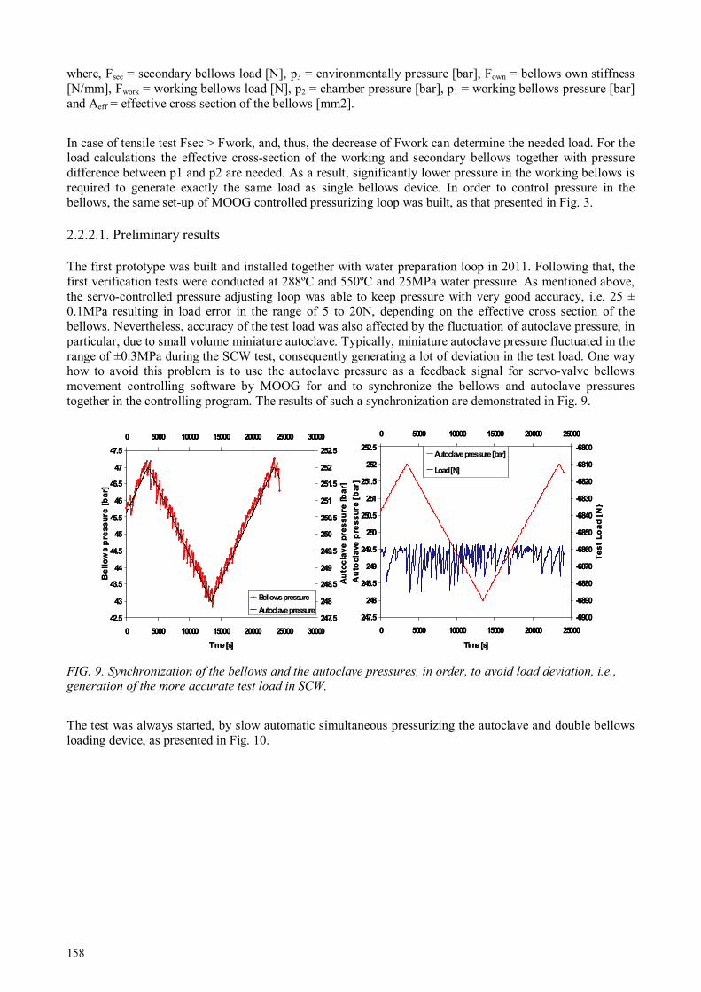
158
where, Fsec = secondary bellows load [N], p3 = environmentally pressure [bar], Fown = bellows own stiffness [N/mm], Fwork = working bellows load [N], p2 = chamber pressure [bar], p1 = working bellows pressure [bar] and Aeff = effective cross section of the bellows [mm2].
In case of tensile test Fsec > Fwork, and, thus, the decrease of Fwork can determine the needed load. For the load calculations the effective cross-section of the working and secondary bellows together with pressure difference between p1 and p2 are needed. As a result, significantly lower pressure in the working bellows is required to generate exactly the same load as single bellows device. In order to control pressure in the bellows, the same set-up of MOOG controlled pressurizing loop was built, as that presented in Fig. 3.
2.2.2.1. Preliminary results
The first prototype was built and installed together with water preparation loop in 2011. Following that, the first verification tests were conducted at 288ºC and 550ºC and 25MPa water pressure. As mentioned above, the servo-controlled pressure adjusting loop was able to keep pressure with very good accuracy, i.e. 25 ± 0.1MPa resulting in load error in the range of 5 to 20N, depending on the effective cross section of the bellows. Nevertheless, accuracy of the test load was also affected by the fluctuation of autoclave pressure, in particular, due to small volume miniature autoclave. Typically, miniature autoclave pressure fluctuated in the range of ±0.3MPa during the SCW test, consequently generating a lot of deviation in the test load. One way how to avoid this problem is to use the autoclave pressure as a feedback signal for servo-valve bellows movement controlling software by MOOG for and to synchronize the bellows and autoclave pressures together in the controlling program. The results of such a synchronization are demonstrated in Fig. 9.
FIG. 9. Synchronization of the bellows and the autoclave pressures, in order, to avoid load deviation, i.e., generation of the more accurate test load in SCW.
The test was always started, by slow automatic simultaneous pressurizing the autoclave and double bellows loading device, as presented in Fig. 10.
247.5
248
248.5
249
249.5
250
250.5
251
251.5
252
252.5
0 5000 10000 15000 20000 25000
Time [s]
Au
toc
lave
pre
ss
ure [
bar]
-6900
-6890
-6880
-6870
-6860
-6850
-6840
-6830
-6820
-6810
-6800
0 5000 10000 15000 20000 25000
Te
st
Lo
ad
[N
Autoclave pressure [bar]
Load [N]
42.5
43
43.5
44
44.5
45
45.5
46
46.5
47
47.5
0 5000 10000 15000 20000 25000 30000
Time [s]
Be
llo
ws p
res
su
re
[b
ar]
247.5
248
248.5
249
249.5
250
250.5
251
251.5
252
252.5
0 5000 10000 15000 20000 25000 30000
Au
toc
lav
e p
res
su
re [
ba
r]
Bellows pressure
Autoclave pressure247.5
248
248.5
249
249.5
250
250.5
251
251.5
252
252.5
0 5000 10000 15000 20000 25000
Time [s]
Au
toc
lave
pre
ss
ure [
bar]
-6900
-6890
-6880
-6870
-6860
-6850
-6840
-6830
-6820
-6810
-6800
0 5000 10000 15000 20000 25000
Te
st
Lo
ad
[N
Autoclave pressure [bar]
Load [N]
42.5
43
43.5
44
44.5
45
45.5
46
46.5
47
47.5
0 5000 10000 15000 20000 25000 30000
Time [s]
Be
llo
ws p
res
su
re
[b
ar]
247.5
248
248.5
249
249.5
250
250.5
251
251.5
252
252.5
0 5000 10000 15000 20000 25000 30000
Au
toc
lav
e p
res
su
re [
ba
r]
Bellows pressure
Autoclave pressure

159
FIG. 10. An example of simultaneous pressurizing of the autoclave and double bellows loading device (p1<p3).
In this particular example, the needed pressure for the primary bellows under environmentally pressure of 25MPa, without pre-loading the specimen, was calculated to be 54MPa (According to the formulas (1—2)). In reality, as illustrated in Fig. 10, the common practice is to hold a specimen unloaded during pressurizing phase, in order, to avoid sudden overloading of the specimens that could be caused by high frequency water flow fluctuation occurring outside of pressure dampener operation range (pressure dampener starts operating at ≈ 20MPa water pressure). Anyway, the deviation of the test load was less than 100N (bellows compressed compared to autoclave pressure) during the initial pressurizing phase. After the test temperature reached 550ºC and the water chemistry in the autoclave stabilized (outlet water chemistry parameters were measured in the low pressure part of the water loop), the zero load position had to be determined, since, due the thermal expansion of the loading frame and double bellows, the free clearance position was changing as a function of temperature. In order to find the position where free clearance of the loading pin was avoided, the following procedure, demonstrated in Fig. 11, was performed.
0
50
100
150
200
250
300
4180 4380 4580 4780 4980 5180 5380 5580 5780 5980
T ime [s]
Pre
ss
ure
[b
ar]
-1 00
-5 0
0
50
10 0
15 0
20 0
25 0
30 0
Lo
ad
[N
]
Primary be llow s pr ess ure [ bar]
Autoclave pres sure [bar]
Test loa d [N ]
Autoclave pres sure
Pri. Bello ws pressu re
Load
Autoclave pres sure
Pri. Bello ws pressu re
Load

160
FIG. 11. The zero load position that was determined for the 5DC(T) specimen in 550ºC SCW.
At first the pneumatic double bellows loading unit (primary bellows) was pressurized to give around +150N push load (unloaded specimen) as shown in Fig. 11. Note that this push load did not generate any load which would be applied on the specimen. Since the loading frame was fixed to primary bellows (see Fig. 7), it followed primary bellows movement. Therefore, the fixing post could generate load only if the pressure in the primary bellows was decreasing compared to the autoclave one and not the other way around. Finally, the long term operation (test time > 1 month) was verified during exposure at 288oC and 550ºC under 25MPa water pressure. The initial stage of one of the verification tests performed in 550ºC SCW is presented in Fig. 12.
FIG. 12. Start of the low frequency fatigue by using double bellows loading device at 550ºC and 25MPa
autoclave pressure.
-350
-300
-250
-200
-150
-100
-50
0
50
100
150
200
0.64 0.65 0.66 0.67 0.68 0.69 0.7 0.71 0.72
Displacement [mm]
Lo
ad
[N
]Autoclave pressure = 250 bar
Temperature = 500 oC
Specimen type = 5 DC(T)
Oxygen level = 2000 ppb
Autoclave water flow rate = 3 l/hour
Autoclave pressure = 250bar
Temperature = 550oC
Specimen type: 5DC(T)
Dissolved oxygen = 2000ppb
Flow rate = 3l/h
Point of zero load
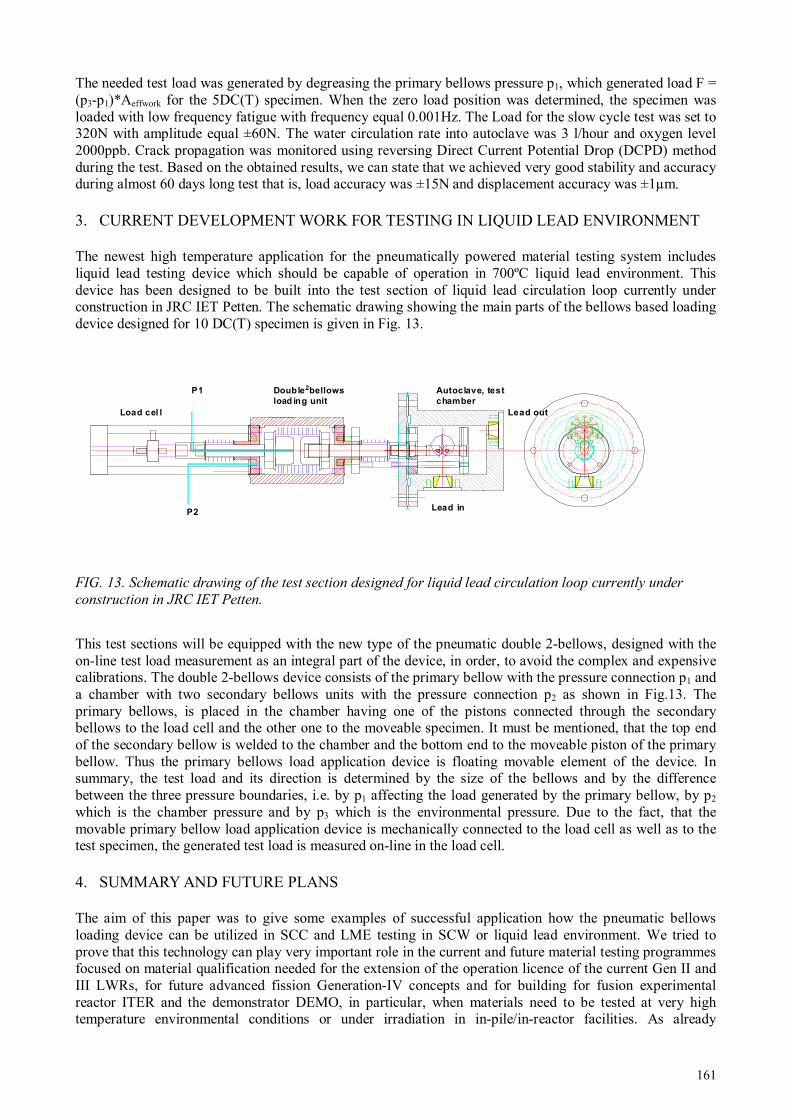
161
The needed test load was generated by degreasing the primary bellows pressure p1, which generated load F = (p3-p1)*Aeffwork for the 5DC(T) specimen. When the zero load position was determined, the specimen was loaded with low frequency fatigue with frequency equal 0.001Hz. The Load for the slow cycle test was set to 320N with amplitude equal ±60N. The water circulation rate into autoclave was 3 l/hour and oxygen level 2000ppb. Crack propagation was monitored using reversing Direct Current Potential Drop (DCPD) method during the test. Based on the obtained results, we can state that we achieved very good stability and accuracy during almost 60 days long test that is, load accuracy was ±15N and displacement accuracy was ±1µm.
3. CURRENT DEVELOPMENT WORK FOR TESTING IN LIQUID LEAD ENVIRONMENT
The newest high temperature application for the pneumatically powered material testing system includes liquid lead testing device which should be capable of operation in 700ºC liquid lead environment. This device has been designed to be built into the test section of liquid lead circulation loop currently under construction in JRC IET Petten. The schematic drawing showing the main parts of the bellows based loading device designed for 10 DC(T) specimen is given in Fig. 13.
FIG. 13. Schematic drawing of the test section designed for liquid lead circulation loop currently under
construction in JRC IET Petten.
This test sections will be equipped with the new type of the pneumatic double 2-bellows, designed with the on-line test load measurement as an integral part of the device, in order, to avoid the complex and expensive calibrations. The double 2-bellows device consists of the primary bellow with the pressure connection p1 and a chamber with two secondary bellows units with the pressure connection p2 as shown in Fig.13. The primary bellows, is placed in the chamber having one of the pistons connected through the secondary bellows to the load cell and the other one to the moveable specimen. It must be mentioned, that the top end of the secondary bellow is welded to the chamber and the bottom end to the moveable piston of the primary bellow. Thus the primary bellows load application device is floating movable element of the device. In summary, the test load and its direction is determined by the size of the bellows and by the difference between the three pressure boundaries, i.e. by p1 affecting the load generated by the primary bellow, by p2 which is the chamber pressure and by p3 which is the environmental pressure. Due to the fact, that the movable primary bellow load application device is mechanically connected to the load cell as well as to the test specimen, the generated test load is measured on-line in the load cell.
4. SUMMARY AND FUTURE PLANS
The aim of this paper was to give some examples of successful application how the pneumatic bellows loading device can be utilized in SCC and LME testing in SCW or liquid lead environment. We tried to prove that this technology can play very important role in the current and future material testing programmes focused on material qualification needed for the extension of the operation licence of the current Gen II and III LWRs, for future advanced fission Generation-IV concepts and for building for fusion experimental reactor ITER and the demonstrator DEMO, in particular, when materials need to be tested at very high temperature environmental conditions or under irradiation in in-pile/in-reactor facilities. As already
P1
P2
Load cel l
Autoclave, test
chamber
Double2bellows
load ing unit
Lead in
Lead out

162
mentioned above, successful expansion of the pneumatic bellows based technology is demonstrated via utilization in future experiments in high temperature liquid lead facilities or future hot-cell and in-pile facilities which design is under way. In order, to perform material testing in liquid re-circulation loop up to 700ºC and other very demanding environments the technological development path from single bellows towards the more demanding double bellows and double 2-bellows loading device needed for fatigue and combined tension/compression/internal pressure system is under development.
REFERENCES
[1] http://www.gen-4.org/ [2] RUZICKOVA M., HAJEK P., SMIDA S., VSOLAK R., PETR J., KYSELA J., Supercritical
water loop design for corrosion and water chemistry tests under irradiation, Nuclear Engineering and Technology – Special Issue on SCWR, Vol. 40, No. 2, November 15, 2007, pp. 127—132
[3] FISCHER B.G., GRAHAM T., ROSE M., MARKGRAF J.F.W., PAGE J., PUSCHEK P., Light water reactor materials irradiation at the HFR under pressurized water reactor conditions, Design and safety report, LIMA, Project 286-01, Joint Research Centre Institute for Energy, June 12, 1994
[4] MOILANEN P., HOLMSTRÖM S., New mechanical testing equipment for testing in real and simulated service environments (HIPS), Baltica VIII - Life Management and Maintenance for Power Plants Vol. 2, Helsinki-Stockholm-Helsinky, Finland 18—20.5. (2010).
[5] KARLSEN T.M., BENNET P., HØGBERG N-W., VAN NIEUWENHOVE R., Test facilities and on-line instrumentation capabilities for core component materials investigations at the HALDEN reactor project, Ageing issues in nuclear power plants, OECD Halden Reactor Project, Halden, Norway, (2005).
[6] NOVOTNY R., SEVINI F., DEBARBERIS L., SAJDL P., KYTKA M., Testing environmentally assisted cracking of reactor materials using pneumatic servo-controlled fracture mechanics device, International Journal of Pressure Vessels and Piping, Vol. 83, Issue 10 October, 2006, pp. 701—706.
[7] NOVOTNY R., HÄHNER P., SIEGL J., HAUSILD P., RIPPLINGER S., PENTTILÄ S., TOIVONEN A., Stress Corrosion Cracking Susceptibility of Austenitic Stainless Steels in Supercritical Water Conditions, Journal of Nuclear Materials, Vol. 409, No. 2, pp. 117—123.

EXPERIMENTAL STUDIES
(Session 3)
Chairpersons
V. INOZEMTSEV
IAEA
T. SHIKAMA
Japan


165
HEAVY NEUTRON IRRADIATION TEST OF MATERIALS IN JOYO
INSTRUMENTED RIGS
1 The Oarai Branch, Institute for Materials Research, Tohoku University, Oarai, Ibaraki, Japan
2 Japan Atomic Energy Agency, Orai, Japan Email: [email protected] Abstract
For studies of radiation effects in materials for advanced nuclear systems including a nuclear fusion reactor, heavy neutron irradiation by high energy neutrons is essential. A sodium cooled high flux fast reactor will be only a choice for realizing heavy neutron irradiation. The paper will describe the brief history of radiation effects study utilizing fission reactors in Japan, and the status of the fast reactor of JOYO in Japan, for applying it to the heavy irradiation of candidate materials for advanced nuclear systems.
1. INTRODUCTION
A study of radiation effects utilizing fission reactors started in early in 1960s after inspired by the declaration of “atoms for peace” by the International Atomic Energy Agency in 1954. Initially, medium power density reactors of JRR-2 and KUR were utilized for the irradiation up to 1023n/m2 for the fast neutron fluence. In the early 1970s, the Japan materials testing reactor, JOYO started its operation and the irradiation up to 1020n/m2 became possible. In the meantime, the program for developing nuclear fusion materials was launched, where the irradiation more than 1025n/m2 was strongly needed. While the high flux reactors in the USA, namely, the EBR-2 (Experimental Breeder Reacor 2 of the Argonne National Laboratory West), the FFTF (Fast Flux Test Facility of the Pacific Northwest National Laboratory), and the HFIR (High flux Isotope Reactor of the Oak Ridge National Laboratory) were used under the USA/Japan collaboration, the domestic fast reactor of JOYO, which is the experimental fast reactor for establishing base-line technologies for the prototype power generating fast reactor, was opened for university researchers for study of heavy irradiation effects in advanced materials for nuclear applications. Since then, extensive irradiation tests of various kinds of materials were carried out under close collaboration between the JAEA (in the early stage of the collaboration, the organization called Power Reactor Nuclear Fuel Developing Organization (PNC), which changed its name to Japan Nuclear Fuel Cycle Developing Organization (JNC)) and the universities. The Oarai Branch of the Institute for Materials Research of Tohoku University, has been working as a coordinator of the project and a liaison between the JAEA and universities. Recently, due to the technological problem, whose base-line cause was an inappropriate handling of the advanced instrumented irradiation rig, called MARICO-2, the JOYO had to stop its operation temporarily. Forthermore, the Fukushima accident made the situation for the restart of the JOYO unclear. However, it is unanimously understood that the study of heavy irradiation effects in nuclear materials important for establish reliable nuclear systems. Hoping a restart of the JOYO soon, reevaluation of accumulated data of heavy irradiation effects are extensively carried out I the JOYO. In the present paper, the merits and demerits of the fast reactor irradiation will be described, which will be the starting point for preparing new irradiation campaigns utilizing the JOYO in near future.
1.1 Studies of heavy irradiation effects in Japan
Figure 1 shows a brief history of studies of irradiation effects in Japan. Now, we are facing to a transient barrier from the stage III to the stage IV. There, a new irradiation technology, which will incarnate a heavy neutron irradiation under well controlled irradiation conditions. The term of the “well-controlled” means that the irradiation could be reproducible with well specified irradiation history. It also means that we need well sophisticated instrumentations for the irradiation rigs to record irradiation conditions appropriately.
T. SHIKAMA1, K. MAEDA2, M. ITOH2, Y. MAEDA2, T. SOGA2, M. NARUI1, M. YAMAZAKI1
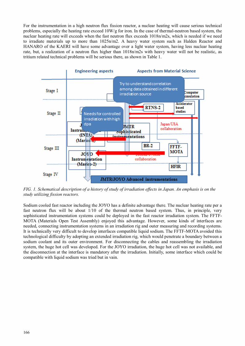
166
For the instrumentation in a high neutron flux fission reactor, a nuclear heating will cause serious technical problems, especially the heating rate exceed 10W/g for iron. In the case of thermal-neutron based system, the nuclear heating rate will exceeds when the fast neutron flux exceeds 1018n/m2s, which is needed if we need to irradiate materials up to more than 1025n/m2. A heavy water system such as Halden Reactor and HANARO of the KAERI will have some advantage over a light water system, having less nuclear heating rate, but, a realization of a neutron flux higher than 1018n/m2s with heavy water will not be realistic, as tritium related technical problems will be serious there, as shown in Table 1.
FIG. 1. Schematical description of a history of study of irradiation effects in Japan. An emphasis is on the study utilizing fission reactors.
Sodium cooled fast reactor including the JOYO has a definite advantage there. The nuclear heating rate per a fast neutron flux will be about 1/10 of the thermal neutron based system. Thus, in principle, very sophisticated instrumentation systems could be deployed in the fast reactor irradiation system. The FFTF-MOTA (Materials Open Test Assembly) enjoyed this advantage. However, some kinds of interfaces are needed, connecting instrumentation systems in an irradiation rig and outer measuring and recording systems. It is technically very difficult to develop interfaces compatible liquid sodium. The FFTF-MOTA avoided this technological difficulty by adopting an extended irradiation rig, which would penetrate a boundary between a sodium coolant and its outer environment. For disconnecting the cables and reassembling the irradiation system, the huge hot cell was developed. For the JOYO irradiation, the huge hot cell was not available, and the disconnection at the interface is mandatory after the irradiation. Initially, some interface which could be compatible with liquid sodium was tried but in vain.

167
TABLE 1 COMPARISON OF IRRADIATION PARAMETERS AMONG REACTORS FOR MATERIALS IRRADIATION
Comparison of irradiation test field
In the case of the first developed controlled irradiation rigs of INTA and MARICO, thermocouples and thin tubes for gas flows were installed and the disconnection in the liquid sodium was successfully done. However, in the case of the MARICO-II, the electrical heating systems were also installed to control irradiation temperatures being independent of the reactor operation mode. This would have made the disconnection procedures more difficult, and resultantly with other inappropriate procedures, the disconnection of the interface of the MARICO-II caused some structural damage on the upper core structure after the successful irradiation campaign. The trouble evoked serious debates in Japan and some criticism seriously accused that demands from materials science and engineering were too much over-specifications and they hampered the program of the fast reactor development seriously. However, it is confidently claimed that reliability of irradiation data is really essential for the development of radiation resistant materials which could be applied to advanced nuclear systems, especially the irradiation damage level exceeds more than a few tens dpa (displacement per atom). Thus, we need to overcome serious technical problems to incarnate reliable instrumented irradiation rigs in a high flux neutron environment. Table 1 shows some comparison of reactor parameters related with above discussions.
2. NUCLEAR TRANSMUTATION IN FAST RECTORS
Nuclear transmutation in the course of fission reactor irradiations will cause some concerns. One will be a radioactivity. In general, an induced radioactivity is very serious after materials are irradiated up to more than 10 dpa in a mixed spectrum high flux reactor such as the HFIR. Transportation of such heavily radioactivated materials are nearly inhibited even domestically but more seriously internationally. Of course, such strongly radioactivated materials could be only handled in a heavily shielded hot cells, which would make related post

168
irradiation examinations very expensive. In the case of the irradiation in fast reactors, the induced radioactivity is serious also in the fast reactors, however, compared with that in the mixed spectrum reactors, the induced radioactivity will be less than 1/10 for the nickel containing materials which will be main candidate structural materials. Figure 2 shows comparison of nuclear transmutations in the HFIR, the mixed spectrum reactor and the FFTF, the fast reactor, by Greenwood and Garner [1]. Nuclear transmutation is serious in general in the HFIR, which will cause additional effects upon the displacement damages. In the meantime, the nuclear transmutation effects are very important for the study of nuclear fusion materials, where the nuclear transmutation by high energy neutrons is serious. Comparing irradiation data in the mixed HFIR.
FIG. 2 Comparison of nuclear transmutation in HFIR and FFTF, by Greenwood and Garner [1].

169
FIG. 3. Dimensional change of isotope tailored aluminium nitride irradiated in JMTR, JOYO and spectrum
and fast reactors.
On Fig. 3 we may be able to study effects of nuclear transmutation upon the irradiation induced property changes. Fig. 3 shows dimensional change of aluminium nitride (AlN) irradiated in JMTR, JOYO and HFIR. One kind of AlN was sintered with the conventional nitrogen-14, and the other was sintered with the nitrogen-15. With the thermal neutrons, the nitrogen-14 nuclear reacts to form proton, through the reaction of 14N (n,P)14C. So, in the case of the HFIR irradiation, a substantial amount of hydrogen atoms were produced in Al14N but not in Al15N. In the case of the JOYO irradiation, neither of the Al14N nor the Al15N would generate the hydrogen atoms. The obtained data shown in Fig. 3 may imply that the hydrogen generation may enhance the swelling. The high rate nuclear transmutation will change chemical compositions of thermocouples and change resultantly their electro-thermal-motive force (EMF) as easily seen in Fig. 2 for the case of tungsten based high temperature thermocouples. It would be another advantage for the fast reactor. In the case of the JOYO irradiation, the calculation claims that the change of the EMF would be negligible even after 100 dpa irradiation. In the meantime, the distinct radiation-enhanced-diffusion was observed in the JOYO irradiation, which may cause another EMF change.
3. ADVANCED INSTRUMENTED RIG, MARICO-II IN JOYO
As described above, the appropriately instrumented irradiation rig is essential for the reliable heavy neutron irradiation. Some previous results showed peculiar differences in radiation induced nanostructural evolutions between an irradiation-rig irradiation and an irradiation as a fuel rod. The difference may imply the strong localized turbulence of irradiation conditions in the case of the fast rector. Among several irradiation parameters, the temperature will be one of the most important ones. Also, usually, the temperature control is dependent upon the nuclear heating rate, which will change with the reactor operation mode. The MARICO-I, which is the prototype controlled irradiation rig, based on the FFTF-MOTA, controlled the temperature by changing the thermal insulation of the gas layer. In the case of the MARICO-II, the temperature was actively controlled by the electrical heater, being independent of the reactor operation mode. Figure 4 shows the structure of the MARICO-II and its temperature ability under the reactor operation. In the case of the conventional gas-controlling system, the temperature control must be partially dependent on the reactor power, but in the case of the MARICO-II, the temperature could be kept constant, irrespective of the reactor power drifts.

170
FIG. 4. The structure of MARICO-II and its ability of temperature control.
4. CONCLUSION
The high flux fast reactor has desirable advantages for the well-controlled and well-monitored heavy neutron irradiation though it also has some disadvantages. The JOYO, the Japanese experimental fast reactor will work a good high flux neutron irradiation facility, assuming that the advanced and reliable instrumented irradiation rig could be developed. The MARICO-II would be a good starting base-line for the further development of such the irradiation rig. The materials researchers are looking forward to an early restart of the JOYO.
REFERENCES
[1] GREENWOOD L.R., GARNER F.A. Journal of Nuclear Materials 212—215 (1994) 635—639.

171
IN-PILE EXPERIMENTS IN A URANIUM-ZIRCONIUM-HYDRIDE TRIGA FUEL
a Brazilian Nuclear Energy Commission (CNEN), Rio de Janeiro, Brazil
b Nuclear Technology Development Centre (CDTN), Campus UFMG – Pampulha, Belo Horizonte, Brazil Email: [email protected]
Abstract The heat generated by nuclear fission in the reactor core is transferred from fuel elements to the cooling system
through the fuel/cladding (gap) and the cladding to coolant interfaces. The objective of the thermal and hydrodynamic projects of the reactors is to remove the heat safely, without producing excessive temperature in the fuel elements. The regions of the reactor core where boiling occurs at many different power levels can be determined from the heat transfer coefficient data. This paper describes in-pile experiments carried out in the IPR-R1 TRIGA nuclear research reactor at the Nuclear Technology Development Centre (CDTN), in Belo Horizonte (Brazil). The IPR-R1 maximum core power is 250 kW cooled by natural circulation of light water and an open surface. The TRIGA fuel was developed around the concept of inherent safety. The TRIGA core includes bounded hydrogen in zirconium hydride in its fuel meat allowing for fast reactivity transients. The safety mechanism is based on the immediate increase of neutron up-scattering by the hydrogen as a result of a fuel temperature increase. The temperature dependent resonance absorption is the second safety feature. Fuel to coolant heat transfer patterns must be evaluated as function of the reactor power in order to assess the thermal hydraulic performance of the core. As the reactor core power increases the heat transfer regime from the fuel cladding to the coolant changes from single-phase natural convection to subcooled nucleate boiling. Experimental results indicated that subcooled pool boiling occurs at the cladding surface in the reactor core central channels at power levels in excess of 60 kW. However, due to the high heat transfer coefficient in subcooled boiling the cladding temperature is quite uniform along most of the active fuel rod region and do not increase very much with the reactor power.
1. INTRODUCTION
Understanding the behaviour of the operational parameters of nuclear reactors allow the development of improved analytical models to predict the fuel temperature, and contributing to their safety. The recent natural disaster that caused damage in four reactors at the Fukushima nuclear power plant shows the importance of studies and experiments on natural convection to remove heat from the residual remaining after the shutdown. Experiments, developments and innovations used for research reactors can be later applied to larger power reactors. Their relatively low cost allows research reactors to provide an excellent testing ground for the reactors of tomorrow.
The IPR-R1 TRIGA (Training, Research, Isotopes, and General Atomic), is a pool type research reactor, with an open water surface and the core has a cylindrical configuration. The maximum core power is 250 kW, cooled by light water and with graphite reflectors. The prototypical cylindrical fuel elements are a homogeneous alloy of zirconium hydride (neutron moderator) and uranium enriched at 20% in 235U. The reactor core has 58 aluminum-clad fuel elements and 5 stainless steel-clad fuel elements. One of these steel-clad fuel elements is instrumented with three thermocouples along its centreline, and was inserted in the reactor core in order to evaluate the thermal hydraulic performance of the IPR-R1 reactor [1]. The fuel rod has about 3.5 cm diameter, the active length is about 37 cm closed by graphite slugs at the top and bottom ends which act as axial reflector. The moderating effects are carried out mainly by the zirconium hydride in the mixture, and on a smaller scale by light water coolant. The characteristic of the fuel elements gives a very high negative prompt temperature coefficient, is the main reason of the high inherent safety behaviour of the TRIGA reactors. The power level of the reactor is controlled with three independent control rods: a Regulating rod, a Shim rod, and a Safety rod.
The objective of the thermal and hydrodynamic projects of the reactors is to remove the heat safely, without producing excessive temperature in the fuel elements. The regions of the reactor core where boiling occurs at many different power levels can be determined from the heat transfer coefficient data. The thermal conductivity (k) of metallic alloys is mainly a function of temperature. In nuclear fuels, this relationship is more complicated because k also becomes a function of irradiation as a result of the changes in the chemical
D.A.P. PALMAa, A.Z. MESQUITAb
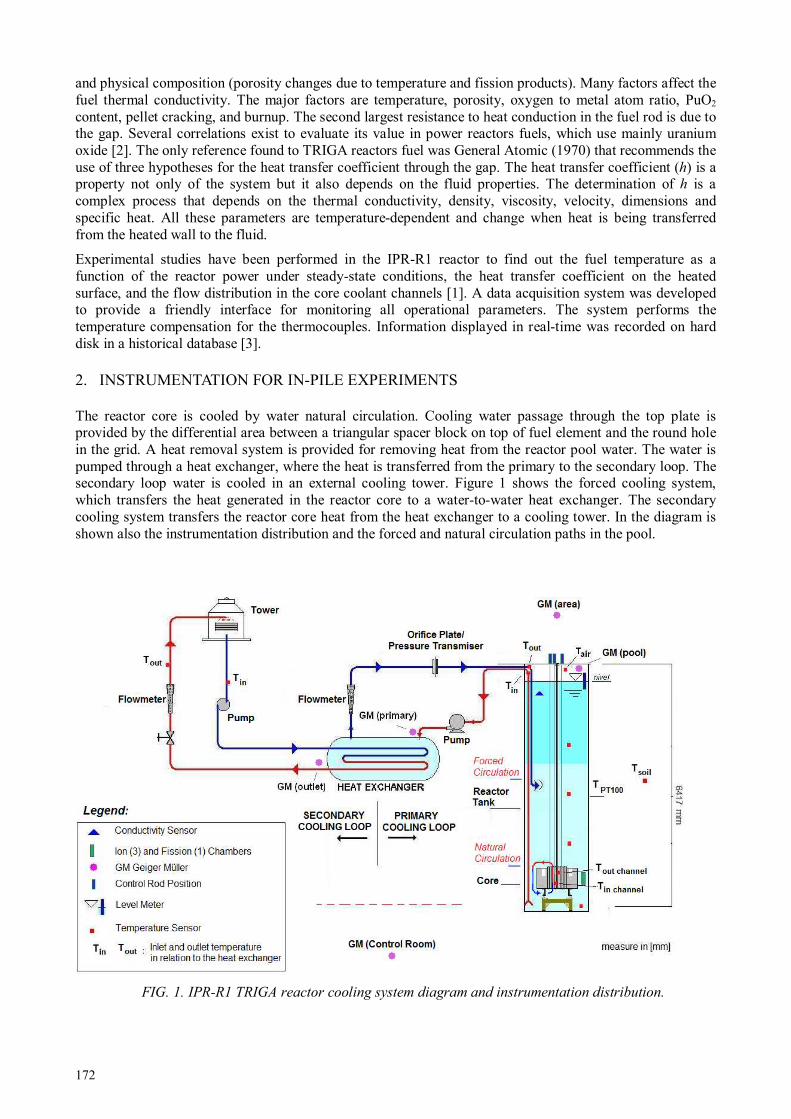
172
and physical composition (porosity changes due to temperature and fission products). Many factors affect the fuel thermal conductivity. The major factors are temperature, porosity, oxygen to metal atom ratio, PuO2 content, pellet cracking, and burnup. The second largest resistance to heat conduction in the fuel rod is due to the gap. Several correlations exist to evaluate its value in power reactors fuels, which use mainly uranium oxide [2]. The only reference found to TRIGA reactors fuel was General Atomic (1970) that recommends the use of three hypotheses for the heat transfer coefficient through the gap. The heat transfer coefficient (h) is a property not only of the system but it also depends on the fluid properties. The determination of h is a complex process that depends on the thermal conductivity, density, viscosity, velocity, dimensions and specific heat. All these parameters are temperature-dependent and change when heat is being transferred from the heated wall to the fluid.
Experimental studies have been performed in the IPR-R1 reactor to find out the fuel temperature as a function of the reactor power under steady-state conditions, the heat transfer coefficient on the heated surface, and the flow distribution in the core coolant channels [1]. A data acquisition system was developed to provide a friendly interface for monitoring all operational parameters. The system performs the temperature compensation for the thermocouples. Information displayed in real-time was recorded on hard disk in a historical database [3].
2. INSTRUMENTATION FOR IN-PILE EXPERIMENTS
The reactor core is cooled by water natural circulation. Cooling water passage through the top plate is provided by the differential area between a triangular spacer block on top of fuel element and the round hole in the grid. A heat removal system is provided for removing heat from the reactor pool water. The water is pumped through a heat exchanger, where the heat is transferred from the primary to the secondary loop. The secondary loop water is cooled in an external cooling tower. Figure 1 shows the forced cooling system, which transfers the heat generated in the reactor core to a water-to-water heat exchanger. The secondary cooling system transfers the reactor core heat from the heat exchanger to a cooling tower. In the diagram is shown also the instrumentation distribution and the forced and natural circulation paths in the pool.
FIG. 1. IPR-R1 TRIGA reactor cooling system diagram and instrumentation distribution.

173
Nine thermocouples and one platinum resistance thermometer (PT-100) were used to monitoring the reactor pool temperature. The thermocouples were positioned in a vertical aluminum probe and the first thermocouple was 143 mm above the core top grid plate. The reactor operated during a period of about eight hours at a thermal power of 265 kW before the steady state was obtained. The forced cooling system was turned on during the operation. This experiment is important to understand the behavior of the water temperature in the pool and evaluate the height of the chimney effect.
A fuel element instrumented with three chromel-alumel thermocouples (K type), embedded in the fuel meat was introduced into position B1 of the core. The sensitive tips of the thermocouples are located along the fuel centerline. Their axial position is one at the half-height of the fuel meat and the other two 2.54 mm above and 2.54 mm below. Two type K thermocouples were placed in two core channels adjacent to ring B, one at the channel exit and another at the channel entrance. Figure 2 shows the diagram of the instrumented fuel element and the Table 1 presents its mean characteristics. Figure 3 shows the reactor core configuration and Fig. 4 shows the instrumented fuel element and one thermocouple inside the core channel.
FIG. 2. Diagram of the instrumented fuel element.
TABLE 1. INSTRUMENTED FUEL ELEMENT FEATURES [1]
Parameter Quantity Heated length 38.1 cm Outside diameter 3.76 cm Active outside area 450.05 cm2 Fuel outside area (U-ZrH1.6) 434.49 cm2 Fuel element active volume 423.05 cm3 Fuel volume (U-ZrH1.6) 394.30 cm3 Power (total of the core = 265 kW) 4.518 kW

174
FIG.3. Simplified core diagram of the IPR-R1 TRIGA.
FIG. 4 IPR-R1 core top view with the instrumented fuel element in ring B and one thermocouple inside the core channel.
In the TRIGA type reactors the buoyancy force induced by the density differential across the core maintains the water circulation through the core. Countering this buoyancy force are the pressure losses due to the contraction and expansion at the entrance and exit of the core as well as the acceleration and friction pressure losses in the flow channels. Direct measurement of the flow rate in a coolant channel is difficult because of the bulky size and low accuracy of flow meters. The flow rate through the channel may be determined indirectly from the heat balance across the channel using measurements of the water inlet and outlet temperatures. Two type K (chromel–alumel) thermocouples fixed in two rigid aluminum probes (7.9 mm of diameter), were inserted into the core in two channels close to position B1 (Channel 1 and 1’ in Fig. 5) and measured the inlet and outlet coolant channel temperatures. The probes penetrated axially the channels
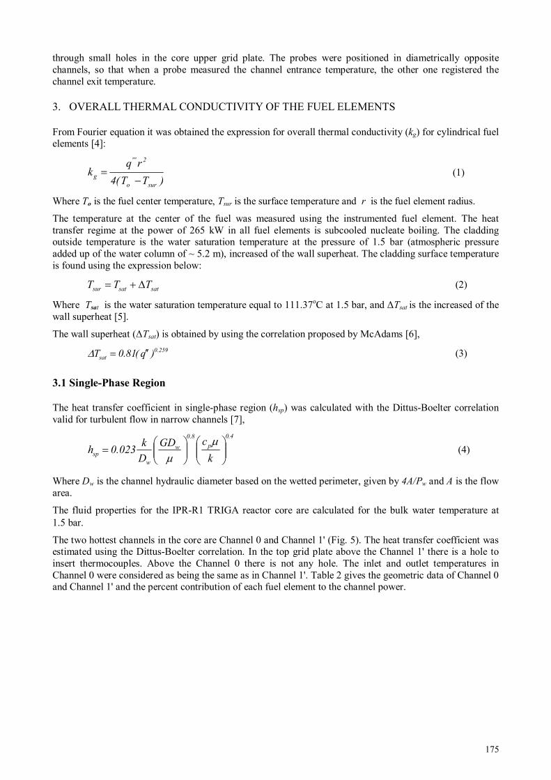
175
through small holes in the core upper grid plate. The probes were positioned in diametrically opposite channels, so that when a probe measured the channel entrance temperature, the other one registered the channel exit temperature.
3. OVERALL THERMAL CONDUCTIVITY OF THE FUEL ELEMENTS
From Fourier equation it was obtained the expression for overall thermal conductivity (kg) for cylindrical fuel elements [4]:
(1)
Where To is the fuel center temperature, Tsur is the surface temperature and r is the fuel element radius.
The temperature at the center of the fuel was measured using the instrumented fuel element. The heat transfer regime at the power of 265 kW in all fuel elements is subcooled nucleate boiling. The cladding outside temperature is the water saturation temperature at the pressure of 1.5 bar (atmospheric pressure added up of the water column of ~ 5.2 m), increased of the wall superheat. The cladding surface temperature is found using the expression below:
(2)
Where Tsat is the water saturation temperature equal to 111.37oC at 1.5 bar, and ∆Tsat is the increased of the wall superheat [5].
The wall superheat (∆Tsat) is obtained by using the correlation proposed by McAdams [6],
(3)
3.1 Single-Phase Region
The heat transfer coefficient in single-phase region (hsp) was calculated with the Dittus-Boelter correlation valid for turbulent flow in narrow channels [7],
(4)
Where Dw is the channel hydraulic diameter based on the wetted perimeter, given by 4A/Pw and A is the flow area.
The fluid properties for the IPR-R1 TRIGA reactor core are calculated for the bulk water temperature at 1.5 bar.
The two hottest channels in the core are Channel 0 and Channel 1' (Fig. 5). The heat transfer coefficient was estimated using the Dittus-Boelter correlation. In the top grid plate above the Channel 1' there is a hole to insert thermocouples. Above the Channel 0 there is not any hole. The inlet and outlet temperatures in Channel 0 were considered as being the same as in Channel 1'. Table 2 gives the geometric data of Channel 0 and Channel 1' and the percent contribution of each fuel element to the channel power.
)TT(4
rqk
suro
2'''
g −=
satsatsur TTT ∆+=
259.0
sat )q(81.0T ′′=∆
4.0
p
8.0
w
w
spk
cGD
D
k023.0h
=
µ
µ

176
FIG. 5. Core coolant channels geometry and radial power distribution.
The mass flow G is given by: G = m& / channel area. The velocity u is given by u = G / ρ, where ρ the water density (995 kg/m3). The mass flow rate in the hydraulic channel is given indirectly from the thermal balance along the channel using measurements of the water inlet and outlet temperatures. Although the channels are laterally open, in this work not considered the exchange of mass between adjacent channels. The channel heating process is the result of the thermal fraction contributions of the perimeter of each fuel around the channel.
The mass flow rate in the channel is given by:
(5)
Where qc is the power supplied to the channel [kW], cp is the isobaric specific heat of the water [J/kgK] and ∆T is the temperature difference along the channel [oC]. The mass flux G is given by: G = m& / channel area. The velocity u is given by u = G / ρ, where ρ is the water density (995 kg/m3). The values of the water thermodynamic properties were obtained as function of the bulk water temperature at the channel for the pressure 1.5 bar [5]. Reynolds number (Re), used to characterize the flow regime, is given by:
(2)
Where G is the mass flux in [kg/m2s], Dw is the hydraulic diameter in [m] and µ is the dynamic viscosity [kg/ms].
m&
Tc
qm
p
c
∆=&
µwGD
=Re

177
TABLE 2. CHANNEL 0 AND CHANNEL 1’ CHARACTERISTICS [1]
Channel 0 Channel 1’ Unit
Area ( A ) 1.574 8.214 cm2 Wetted Perimeter ( Pw ) 5.901 17.643 cm Heated Perimeter ( Ph ) 3.906 15.156 cm Hydraulic Diameter (Dw) 1.067 1.862 cm B1 and C1 Fuel Diameter (stainless) 3.76 3.76 cm B6 and C12 Fuel Diameter (Al) 3.73 3.73 cm C1 Control Rod Diameter 3.80 3.80 cm Central Thimble 3.81 3,81 cm Core Total Power (265kW) 100 100 % B1 Fuel Contribution 0.54 1.11 % B6 Fuel Contribution 0.46 0.94 % C11 Fuel Contribution - 0.57 % C12 Fuel Contribution - 1.08 % Channel Total Power 1.00 3.70 %
The reactor was operated on steps of about 50 kW until 265 kW and data were collected in function of the power supplied to Channel 1' and Channel 0. Table 3 presents the water proprieties. The values of the water thermodynamic properties at the pressure 1.5 bar as function of the bulk water temperature at the channel [5]. The curves of single-phase heat transfer, as function of ∆Tsat , are presented in the Fig. 6.

178
4. SUBCOOLED NUCLEATE BOILING REGION
For the subcooled nucleated boiling region (local or surface boiling), the expression used for the convective heat-transfer coefficient (hsur) from the fuel cladding outer surface to the water is [8]:
hsur = q” / ∆Tsat (6)
Where q" is the fuel surface heat flux and ∆Tsat is the surface superheat in contact with the water.
Table 4 presents the thermal parameter of the fuel element. Figure 6 shows the fuel element surface heat transfer coefficient for the coolant as a function of the superheat, in both regimes. This curve is specific for the IPR-R1 TRIGA nuclear reactor conditions. The transition point between single-phase convection regime to subcooled nucleate boiling regime, i.e. the onset of subcooled nucleate boiling is approximately 60 kW as shown in the graph.
TABLE 3. COOLING PROPRIETIES AND SINGLE PHASE CONVECTIVE COEFFICIENT
q Core q Channel ∆ T cp m& G u µ k Re Pr hsur
kW kW oC kJ/kgK kg/s kg/m
2s m/s 10
-3kg/ms W/mK kW/m
2K
Channel 1’ 265 9.81 13.9 4.1809 0.169 205.40 0.21 0.549 0.639 6968 3.6 1.562
212 7.84 9.6 4.1800 0.195 237.98 0.24 0.575 0.638 7708 3.8 1.724
160 5.92 7.0 4.1795 0.202 246.35 0.25 0.596 0.636 7697 3.9 1.743
108 4.00 4.6 4.1793 0.208 253.05 0.25 0.620 0.634 7601 4.1 1.750
53 1.96 2.5 4.1789 0.188 228.52 0.23 0.638 0.632 6670 4.2 1.591
35 1.30 1.8 4.1780 0.172 209.64 0.21 0.642 0.630 6081 4.3 1.479
Channel 0
265 2.65 13.9 4.1809
0.04
6 289.71 0.29 0.549 0.639 5630 3.6 2.300
212 2.12 9.6 4.1800
0.05
3 335.65 0.34 0.575 0.638 6228 3.8 2.537
160 1.6 7.0 4.1795
0.05
5 347.45 0.35 0.596 0.636 6220 3.9 2.566
108 1.08 4.6 4.1793
0.05
6 356.91 0.36 0.620 0.634 6142 4.1 2.576
53 0.53 2.5 4.1789
0.05
1 322.31 0.32 0.638 0.632 5390 4.2 2.342
35 0.35 1.8 4.1780
0.04
7 295.68 0.30 0.642 0.630 4914 4.3 2.176

179
FIG. 6. The onset of subcooled nucleate boiling in the fuel element surface of the IPR-R1 TRIGA Reactor.
Figure 7 presents the curves for the heat transfer coefficient (hsur) on the fuel element surface in the single-phase region and for the overall thermal conductivity (kg) in fuel element as function of the power, obtained with the instrumented fuel at core ring B.
FIG. 7. Overall fuel element thermal conductivity and cladding heat transfer coefficient.
TABLE 4. FUEL ELEMENT THERMAL PARAMETER
q core qB1 To q' q'' q''' ∆ Tsat Tsur kg hsur
[kW] [W] [oC] [W/m] [W/m
2] MW/m
3 [
oC] [
oC] [W/mK] [kW/m
2K]
265 8759 300.6 22988 194613 20.70 19.0 130.4 10.75 10.25
212 7007 278 18391 155690 16.56 17.9 129.3 9.84 8.69
160 5288 251.6 13880 117502 12.50 16.7 128.0 8.94 7.05
108 3570 216.1 9369 79314 8.44 15.0 126.4 8.31 5.27
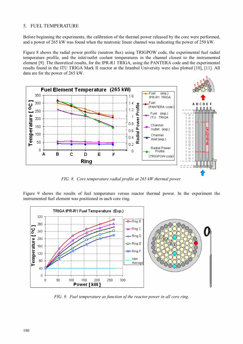
180
5. FUEL TEMPERATURE
Before beginning the experiments, the calibration of the thermal power released by the core were performed, and a power of 265 kW was found when the neutronic linear channel was indicating the power of 250 kW. Figure 8 shows the radial power profile (neutron flux) using TRIGPOW code, the experimental fuel radial temperature profile, and the inlet/outlet coolant temperatures in the channel closest to the instrumented element [9]. The theoretical results, for the IPR-R1 TRIGA, using the PANTERA code and the experimental results found in the ITU TRIGA Mark II reactor at the Istanbul University were also plotted [10], [11]. All data are for the power of 265 kW.
FIG. 8. Core temperature radial profile at 265 kW thermal power.
Figure 9 shows the results of fuel temperature versus reactor thermal power. In the experiment the instrumented fuel element was positioned in each core ring.
FIG. 9. Fuel temperature as function of the reactor power in all core ring.
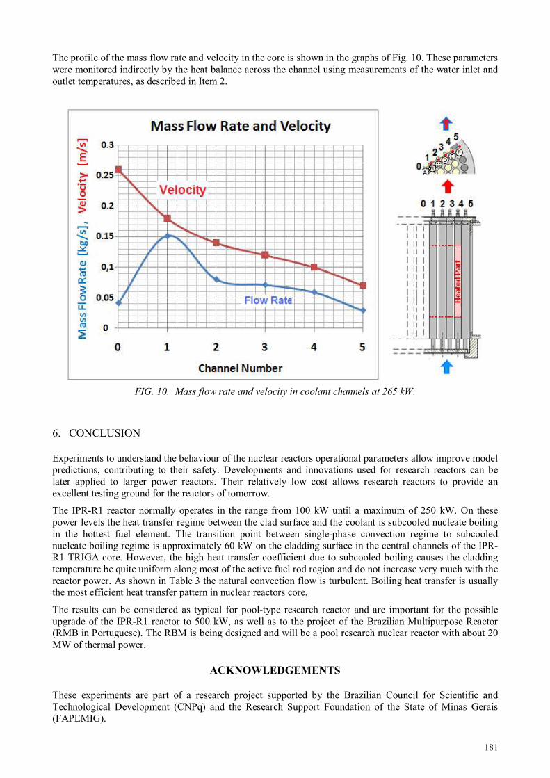
181
The profile of the mass flow rate and velocity in the core is shown in the graphs of Fig. 10. These parameters were monitored indirectly by the heat balance across the channel using measurements of the water inlet and outlet temperatures, as described in Item 2.
FIG. 10. Mass flow rate and velocity in coolant channels at 265 kW.
6. CONCLUSION
Experiments to understand the behaviour of the nuclear reactors operational parameters allow improve model predictions, contributing to their safety. Developments and innovations used for research reactors can be later applied to larger power reactors. Their relatively low cost allows research reactors to provide an excellent testing ground for the reactors of tomorrow.
The IPR-R1 reactor normally operates in the range from 100 kW until a maximum of 250 kW. On these power levels the heat transfer regime between the clad surface and the coolant is subcooled nucleate boiling in the hottest fuel element. The transition point between single-phase convection regime to subcooled nucleate boiling regime is approximately 60 kW on the cladding surface in the central channels of the IPR-R1 TRIGA core. However, the high heat transfer coefficient due to subcooled boiling causes the cladding temperature be quite uniform along most of the active fuel rod region and do not increase very much with the reactor power. As shown in Table 3 the natural convection flow is turbulent. Boiling heat transfer is usually the most efficient heat transfer pattern in nuclear reactors core.
The results can be considered as typical for pool-type research reactor and are important for the possible upgrade of the IPR-R1 reactor to 500 kW, as well as to the project of the Brazilian Multipurpose Reactor (RMB in Portuguese). The RBM is being designed and will be a pool research nuclear reactor with about 20 MW of thermal power.
ACKNOWLEDGEMENTS
These experiments are part of a research project supported by the Brazilian Council for Scientific and Technological Development (CNPq) and the Research Support Foundation of the State of Minas Gerais (FAPEMIG).

182
REFERENCES
[1] MESQUITA A.Z., Experimental Investigation on Temperatures Distributions in a Research Nuclear Reactor TRIGA IPR-R1, Ph.D Thesis, Universidade Estadual de Campinas, São Paulo, (in Portuguese), (2005).
[2] TODREAS N.E., KAZIMI M.S. Nuclear Systems Vol 1: Thermal hydraulic Fundamentals. CRC Press, New York, 1002p. (2012).
[3] MESQUITA, A.Z., SOUZA, R.M.G.P. The Operational Parameter Electronic Database of the IPR-R1 TRIGA Research Reactor. Proceedings of 4th World TRIGA Users Conference, Lyon, September 8—9, (2008).
[4] LAMARSH J.R., BARATTA A.J., Introduction to Nuclear Engineering, 3° ed., Upper Saddler River: Prendice Hall, (2001).
[5] WAGNER W., KRUSE A., Properties of Water and Steam – The Industrial Standard IAPWS-IF97 for the Thermodynamics Properties, Springer, Berlin, (1998).
[6] TONG, L.S., WEISMAN, J., Thermal Analysis of Pressurized Water Reactors, Third Edition, American Nuclear Society. Illinois, (1996).
[7] COLLIER J.G., THOME J.R., Convective Boiling and Condensation, Oxford Science Press, New York, (1994).
[8] TONG L.S., TANG Y.S., Boiling Heat Transfer and Two-Phase Flow, 2nd. Ed. Taylor & Francis, Washington, (1997).
[9] DALLE H.M., PEREIRA C., SOUZA R.M.G.P. Neutronic Calculation to the TRIGA IPR-R1 Reactor using the WIMSD4 and CITATION Codes. Annals of Nuclear Energy, Vol. 29, No. 8, (May 2002) , pp. 901–912, ISSN 0306-4549, (2002).
[10] VELOSO M.A. Thermal–Hydraulic Analysis of the IPR-R1 TRIGA Reactor in 250 kW, CDTN/CNEN, NI-EC3-05/05, Belo Horizonte, (in Portuguese), (2005).
[11] ÖZKUL E.H., DURMAYAZ A.A, Parametric Thermal-Hydraulic Analysis of ITU TRIGA Mark II Reactor. Proceedings of 16th European TRIGA Conference, pp. 3.23—3.42, Institute for Nuclear Research, Pitesti, Romania, (2000).
183
REACTOR TESTS AND POST-IRRADIATION INVESTIGATIONS OF HTGR
CORE FUELS AND COMPONENTS
National Science Center "Kharkov Institute of Physics & Technology", Kharkiv, Ukraine
Email: [email protected]
Abstract In NSC KIPT are created and proved designs and manufacturing technologies of fuels and core components for
the Generation-IV nuclear reactors – High Temperature Gas-cooled Reactors (HTGRs): VGR-50, VGM, VG-400. The special attention is given to discussion of the basic technological and reactor test schemes for fuels and graphite components of HTGR cores. Results of performance capacity researches of fuel elements and their components, materials and products with pyrocarbon binding in reactor irradiation conditions, are discussed: temperature up to 1600oC, burnup up to 20 % fima.
1. INTRODUCTION
On the background of critical situation in conventional power industry due to deficiency of organic fuels, physical and moral ageing of thermal power plants equipment and their harmful effect on the environment, nuclear power plants are stable enough and, by keeping all safety measures, are non-polluting energy source. In Ukraine, the nuclear power became one of the main sources of energy production and is an important factor for the Ukraine power independence. The main center on development of the components of nuclear reactors active zones in Ukraine is the National Science Centre "Kharkov institute of Physics and Technology" [1]. The significant place in institutes’ investigations was occupied with works on creation constructional materials and nuclear fuels for HTGRs, gas reactors on fast neutrons BGR and BRGD, and also other special reactors. Radiation tests and post-irradiation research confirm intended material-study, technological and design solutions of core components for this type reactors capacity work on the whole. The concept of atomic engineering evolution, alongside with the decision of problems of prolongation of the reactors operation life, provides conducting the researches on perspective nuclear technologies and creating the new reactor types on the basis of which the evolution of nuclear power for the proximal years will be planed. At the present conditions, it is necessary to pay special attention to development of the new, safe guaranteed nuclear energy sources. In Ukraine, work on research and development of new safe nuclear reactors is being progressing, including underground nuclear power plants; development reactors with the managed chain reaction of nucleus division in core with the help of an external source of neutrons; power thermonuclear installations; high-temperature helium-cooled reactors, which are especially actual now from the point of view of the hydrogen production; fast reactors [2—3]. Perspective and safe type of nuclear reactors is high-temperature molten salt nuclear reactor (MSR). HTGRs are a new development in the atomic power engineering. They differ advantageously from other types of reactors making an opportunity for combined production of electric and thermal power for industrial and public utility uses. So, it is possible to reduce substantially the part of oil and gases, being in very short supply, in the thermal energy production. Besides, these reactors possess a high safety, economic fuel cycle, high efficiency (up to 50%) and so on. For HTGR developed in the former USSR the concept of spherical fuel element (SFE), like to those applied in the AVR and THTR-300 reactors (Germany), was accepted. But, unlike the German reactor, there was provided the multiple passing of fuel elements and absorber elements through the reactor core, and for the VGR-50 plant also through the channels of the external gamma-irradiation source, intended for conducting
M.P. ODEYCHUK

184
radiation-chemical processes. Thus, the requirements to the strength characteristics, in particular the wear resistance, are very stiffened. A special feature of HTGR unlike other reactor modes, is the wide graphite application in the reactor core. Therein it acts both as a neutron moderator and a reflector. When fabricating carbon-graphite components of the HTGR core, the industrial fabrication methods for the graphite materials are principally used, which did not change much since the half of the century before last. They are based on pressing or extrusion of coke powder with a binder and a subsequent carbonizing and graphitizing annealing of the produced blocks [4—9]. At NSC KIPT the research work on fabricating the fuel elements and structural carbon-graphite materials by the CVI methods have been started since early sixties. For this period much researches have been done, production equipment developed, skilled researchers and technicians trained, special technology sections brought into action, wherein all the HTGR core components are fabricated. Simultaneously, the behavior of produced products is studied in bench and in-reactor tests. In NSC KIPT constructions and manufacturing techniques of components for cores of new perspective directions of nuclear engineering are created and proved, also was laid the foundation for the base design and technological decisions for the Generation-IV nuclear reactors. In our opinion, some of our developments are now ready for practical applications. Below we shall present some of our arguments.
2. SOME SPECIAL FEATURES OF FABRICATING MATERIALS AND COMPONENTS FOR THE HTGR CORE
During the last 50 years the National Science Center “Kharkov Institute of Physics and Technology” is the main designer of different materials and components for the HTGR core.
2.1 Uranium-graphite fuel/absorber element
The technology of manufacturing a uranium-graphite fuel/absorber element at the Kharkov Institute of Physics and Technology has no foreign analogs. We use the method with applying, instead of the pressing, the procedure of forming the billets with subsequent impregnation them with pyrocarbon precipitated from gaseous pyrocarbons and deposited onto the heated substrates. The technology of manufacturing a spherical uranium-graphite fuel element can be divided into three main stages [3,10,11,17—19]:
- production of spherical particles (SP); - production of coated particles (CP); - manufacturing of spherical fuel elements (SFE).
2.1.1 Spherical particles
For manufacturing of SP the specialists of the NSC KIPT have developed the method of mechanical spheroidizing of fuel billets, prepared on the base of plasticized masses. The method consists in rolling of cylindrical fuel billets from plasticized masses for obtaining perfect spherical particles. The technology under consideration includes the following main operations (for UO2) [20,21]: mixing the powder of high-melting actinide compound of a required quality with a paraffin-based binder at a temperature of (70—80)°C with subsequent cooling up to the room temperature for obtaining a plasticized mass, cutting from this mass of uniform cylindrical billets, spheroidizing of uniform billets, control of “green” SP, thermal treatment of SP in two stages (vacuum sublimation of a plasticizer at a temperature ~
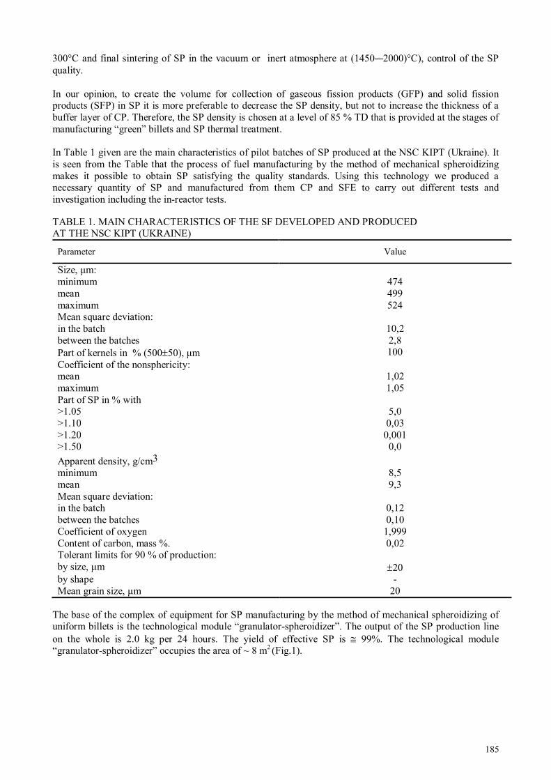
185
300°C and final sintering of SP in the vacuum or inert atmosphere at (1450—2000)°C), control of the SP quality. In our opinion, to create the volume for collection of gaseous fission products (GFP) and solid fission products (SFP) in SP it is more preferable to decrease the SP density, but not to increase the thickness of a buffer layer of CP. Therefore, the SP density is chosen at a level of 85 % TD that is provided at the stages of manufacturing “green” billets and SP thermal treatment. In Table 1 given are the main characteristics of pilot batches of SP produced at the NSC KIPT (Ukraine). It is seen from the Table that the process of fuel manufacturing by the method of mechanical spheroidizing makes it possible to obtain SP satisfying the quality standards. Using this technology we produced a necessary quantity of SP and manufactured from them CP and SFE to carry out different tests and investigation including the in-reactor tests. TABLE 1. MAIN CHARACTERISTICS OF THE SF DEVELOPED AND PRODUCED AT THE NSC KIPT (UKRAINE)
Parameter Value
Size, µm: minimum 474 mean 499 maximum 524 Mean square deviation: in the batch 10,2 between the batches 2,8 Part of kernels in % (500±50), µm 100 Coefficient of the nonsphericity: mean 1,02 maximum 1,05 Part of SP in % with >1.05 5,0 >1.10 0,03 >1.20 0,001 >1.50 0,0
Apparent density, g/cm3
minimum 8,5 mean 9,3 Mean square deviation: in the batch 0,12 between the batches 0,10 Coefficient of oxygen 1,999 Content of carbon, mass %. 0,02 Tolerant limits for 90 % of production: by size, µm ±20 by shape - Mean grain size, µm 20
The base of the complex of equipment for SP manufacturing by the method of mechanical spheroidizing of uniform billets is the technological module “granulator-spheroidizer”. The output of the SP production line on the whole is 2.0 kg per 24 hours. The yield of effective SP is ≅ 99%. The technological module “granulator-spheroidizer” occupies the area of ~ 8 m2 (Fig.1).
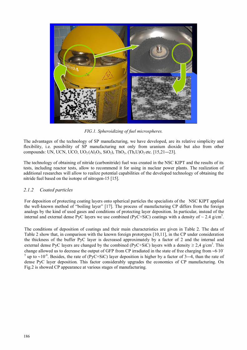
186
FIG.1. Spheroidizing of fuel microspheres. The advantages of the technology of SP manufacturing, we have developed, are its relative simplicity and flexibility, i.e. possibility of SP manufacturing not only from uranium dioxide but also from other compounds: UN, UCN, UCO, UO2 (Al2O3, SiO2), ThO2, (Th,U)O2 etc. [15,21—23]. The technology of obtaining of nitride (carbonitride) fuel was created in the NSC KIPT and the results of its tests, including reactor tests, allow to recommend it for using in nuclear power plants. The realization of additional researches will allow to realize potential capabilities of the developed technology of obtaining the nitride fuel based on the isotope of nitrogen-15 [15].
2.1.2 Coated particles
For deposition of protecting coating layers onto spherical particles the specialists of the NSC KIPT applied the well-known method of “boiling layer” [17]. The process of manufacturing CP differs from the foreign analogs by the kind of used gases and conditions of protecting layer deposition. In particular, instead of the internal and external dense PyC layers we use combined (PyC+SiC) coatings with a density of ~ 2.4 g/cm3.
The conditions of deposition of coatings and their main characteristics are given in Table 2. The data of Table 2 show that, in comparison with the known foreign prototypes [10,11], in the CP under consideration the thickness of the buffer PyC layer is decreased approximately by a factor of 2 and the internal and external dense PyC layers are changed by the combined (PyC+SiC) layers with a density ≥ 2,4 g/сm3. This change allowed us to decrease the output of GFP from CP irradiated in the state of free charging from ∼6⋅10-
5 up to ∼10-6. Besides, the rate of (PyC+SiC) layer deposition is higher by a factor of 3—4, than the rate of dense PyC layer deposition. This factor considerably upgrades the economics of CP manufacturing. On Fig.2 is showed CP appearance at various stages of manufacturing.

187
TABLE 2. DEPOSITION CONDITIONS AND MAIN CHARACTERISTICS OF PROTECTING COATINGS
Coating layer Gas mixture Temperature,
оС
Characteristics of coatings
Density, g/сm3 Thickness, µ
РуС buf. PB - Ar 1400 1,1±0,1 40—60
РуСtrans. PB - Ar 1300 1,5±0,1 10—20
PyC+SiC PB - МТCS - Н2 - Ar 1500 ≥ 2,4 50—60
SiC МТCS - Н2 - Ar 1500 ≥ 3,16 60—70
PyC+SiC PB - МТCS - Н2 - Ar 1500 ≥ 2,4 40—50
Note: PB- propane-butane, МТCS- methyl-trichlorsilane
FIG. 2. CP with РуС-layer (left) and SiC-layer (right).
2.1.3 Fabrication of fuel and absorbing elements
Fuel particles and commercial-grade graphite are used as basic materials for FE fabrication. An easily removable (no coke residue) plasticizer, e.g., glycerin, oil, is introduced into the graphite powder. The stock obtained is used to mold the FE cladding billets.
To mold core billets, the charge material is incorporated with the necessary amount of coated particles. From this charge the billet for a core of 40 mm in diameter is formed. Then the billet of the core and two billets of claddings are formed together. Thus, the spherical billets for fuel elements of 60 mm are made. Molding equipment for manufacturing of fuel element billets are presented on Fig. 3 [10,11,17].

188
FIG. 3. Molding equipment for core billets (left) and molding equipment for cladding billets and fuel elements
(right). On molding, we do not set as a goal to obtain a high density of billets. Generally, it is between 1,1 g/cm3 and 1.3 g/cm3 and this ensures a sufficient strength to withstand subsequent technological procedures. The billets, so molded, are placed in close rows in a porous form, then they are filled with a powder of graphite, coke, quarts, etc. (to retain the shape of the products after plasticizer evaporation) and are impregnated in the pyrolysis installations to the density required (usually up to (1.8—1.95) g/cm3). After the impregnation procedure is completed, the FE are grinded to get the necessary surface finish (Fig. 4).
FIG. 4. Spherical fuel and absorbing elements.
The fabrication process of absorber elements is the same except that in the core stock incorporated are not fuel particles but B4C powder or any other absorbing material [24]. Compared to the case of spherical FE, the fabrication of FE in the block form (Fig. 5) or rod fuel composites, etc., by the gas-phase technology appears to be simpler. Here, a mixture of fuel particles with a graphite powder is charged into the porous forms made of commercial-grade graphite or carbon cloth. The half-finished products are impregnated with pyrocarbon and then their surfaces are machined.

189
FIG. 5. Fuel and absorbing elements in the block form.
2.2 Manufacture of pyrocarbon-bound graphite blocks
For GSP4 production, we also use commercial-grade graphite powders [18]. After sieving, the required, mainly, fine-grained (the particle size being up to 630 µm) fraction is taken. The powder is charged into the porous forms and is compacted by vibration to an apparent density of 0.8 to 1.0 g/cm3, and then is impregnated in pyrolysis installations to a density of 1.7 to 1.97 g/cm3 (1.97 g/cm3 being the upper limit for us). In this way we can produce GSP blocks of different sizes (Fig. 6), ranging from small ones to 2500 mm in length and diameter (in GF-3) [25—27].
FIG. 2. GSP block: ∼ 900 mm in diameter and ∼ 2600 mm in length (without machining).
4 GSP is the Russian abbreviation for pyrocarbon-bound graphite.

190
2.3 Fabrication of constructions and products from Carbon-Carbon Composite Materials
The advantages of volume gas-phase impregnation are most successfully realized when using fillers of carbon fibers or fabrics. In this case, the moulding of required-size structures is substantially simplified. It is carried out without binders by using such known methods as winding, weaving, etc. The products obtained have a minimum of allowance for subsequent machining or even, after impregnating with pyrocarbon, can be used without any surface treatment. By this technology we produce blocks, plates, pipes, cylinders and other structures (Fig.7), which may have extensive applications in the HTGR core [14, 25—27].
FIG. 7. CCCM pipes.
As mentioned above, we have a possibility of fabricating CCCM cylinders up to 2500 mm in diameter and 2600 mm in height (in GF-3). Up to now we have had no need of larger sizes, but if necessary, there are no technical or economic barriers to the construction of the installations capable of producing larger-size structures, e.g. HTGR reflectors. This offers, in our opinion, radically new possibilities of increasing the HTGR reliability.
3. SOME PROPERTIES OF THE MATERIALS WITH A PYROCARBON MATRIX
As can be seen, these materials have a pronounced cellular structure, whose individual elements are constituted by particles of the powder-filler with pyrocarbon films deposited on their surfaces. In the regions of intersection, the pyrocarbon deposits coalesce to form a continuous multidimensional framework wrapping around all particles of the powder-filler [18]. The characteristics of the GSP materials such as electrical resistance, thermal conductivity, thermal expansion, strength are practically isotropic. Since the pyrocarbon, deposited from the gas phase, comprises very little of impurities (except for hydrogen), it is possible, with using high grades of graphite powder as a filler, to produce particularly pure materials which can find their application in the electronic industry. Some characteristics of the GSP and CCCM compared to those of industrial graphites are given in Table 3. The limiting (minimum and maximum) values of strength characteristics for the GSP are determined by the final density of the material. In contrast, the CCCM strength little depends on the density and is determined by the strength of carbon fibers and the reinforcement pattern. The main characteristics of the absorbing pyrocarbon-bound B4C composites are given in Table 4 (the B4C content is 1.6 g/cm3) [24]. Table 5 gives the main characteristics of spherical GSP FE compared to THTR FE.
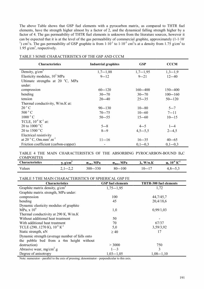
191
The above Table shows that GSP fuel elements with a pyrocarbon matrix, as compared to THTR fuel elements, have the strength higher almost by a factor of 2, and the dynamical falling strength higher by a factor of 4. The gas permeability of THTR fuel elements is unknown from the literature sources, however it can be expected that it is at the level of the gas permeability of commercial graphite, approximately (1-1⋅10-
1) cm2/s. The gas permeability of GSP graphite is from 1⋅10-1 to 1⋅10-5 сm2/s at a density from 1.75 g/сm3 to 1.95 g/сm3, respectively.
TABLE 3 SOME CHARACTERISTICS OF THE GSP AND CCCM
Characteristics Industrial graphites GSP CCCM
Density, g/cm3 1,7—1,88 1,7—1,95 1,3—1,9 Elasticity modulus, 103 MPa 9—12 9—21 12—40 Ultimate strengths at 20 оС, MPa under:
compression 60—120 160—400 150—400 bending 30—70 30—70 100—160 tension 20—40 25—35 50—120 Thermal conductivity, W/m.К at: 20 о С 90—130 10—80 5—7 500 о С 70—75 10—60 7—11 1000 о С 50—55 15—60 10—15 ТCLE, 10-6 К-1 at: 20 to 1000 о С 5—8 4—5 1—4 20 to 1500 о С 8—9 4,5—5,5 2—4,5 Electrical resistivity at 20 о С, Оm.mm2.m-1 11—16 16—35 40—65 Friction coefficient (carbon-copper) - 0,1—0,3 0,1—0,3
TABLE 4 THE MAIN CHARACTERISTICS OF THE ABSORBING PYROCARBON-BOUND B4C COMPOSITES Characteristics γγγγ, g/cm
3 σσσσсж., MPa σσσσизг., MPa λλλλ, W/м.К αααα, 10
-6 К
-1
Values 2,1—2,2 300—330 80—100 10—17 4,8—5,3
TABLE 5 THE MAIN CHARACTERISTICS OF SPHERICAL GSP FE
Characteristics GSP fuel elements THTR-300 fuel elements
Graphite matrix density, g/cm3 1,75—1,95 1,72 Graphite matrix strength, MPa under: compression 100 44,7/45,7 bending 45 20,4/18,6 Dynamic elasticity modulus of graphite MPa, х 104 1,0 0,99/1,03 Thermal conductivity at 290 К, W/m.К Without additional heat treatment 50 - With additional heat treatment 70 67/37 ТCLE (290..1270 К), 10-6 К-1 5,0 3,59/3,92 Static strength, кN ≥ 40 17 Dynamic strength (average number of falls onto the pebble bed from a 4m height without destruction) > 3000 750 Abrasive wear, mg/сm2.g 1—3 3 Degree of anisotropy 1,03—1,05 1,08—1,10 Note: numerator - parallel to the axis of pressing; denominator - perpendicular to this axis.
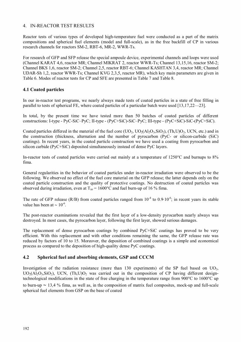
192
4. IN-REACTOR TEST RESULTS
Reactor tests of various types of developed high-temperature fuel were conducted as a part of the matrix compositions and spherical fuel elements (model and full-scale), as in the free backfill of CP in various research channels for reactors SM-2, RBT-6, MR-2, WWR-Ts. For research of GFP and SFP release the special ampoule device, experimental channels and loops were used (Channel KARAT 4,6, reactor MR; Channel MIKRAT 2, reactor WWR-Ts; Channel 13,15,16, reactor SM-2; Channel BKS 1,6, reactor SM-2; Channel 2,5, reactor RBT-6; Channel KASHTAN 3,4, reactor MR; Channel UDAR-Sh 1,2, reactor WWR-Ts; Channel KVG 2,3,5, reactor MR), which key main parameters are given in Table 6. Modes of reactor tests for CP and SFE are presented in Table 7 and Table 8.
4.1 Coated particles
In our in-reactor test programs, we nearly always made tests of coated particles in a state of free filling in parallel to tests of spherical FE, where coated particles of a particular batch were used [13,17,22—23]. In total, by the present time we have tested more than 50 batches of coated particles of different constructions: I-type - PyС-SiС–PyС; II-type - (PyС+SiС)-SiС–PyС; III-type - (PyС+SiС)-SiС-(PyС+SiС). Coated particles differed in the material of the fuel core (UO2, UO2(Al2O3,SiO2), (Th,U)O2, UCN, etc.) and in the construction (thickness, alternation and the number of pyrocarbon (PyC- or silicon-carbide (SiC) coatings). In recent years, in the coated particle construction we have used a coating from pyrocarbon and silicon carbide (PyC+SiC) deposited simultaneously instead of dense PyC layers. In-reactor tests of coated particles were carried out mainly at a temperature of 1250°C and burnups to 8% fima. General regularities in the behavior of coated particles under in-reactor irradiation were observed to be the following. We observed no effect of the fuel core material on the GFP release; the latter depends only on the coated particle construction and the quality of protective coatings. No destruction of coated particles was observed during irradiation, even at Tirr = 1600°C and fuel burn-up of 16 % fima. The rate of GFP release (R/B) from coated particles ranged from 10-4 to 0.9⋅10-6; in recent years its stable value has been at ∼ 10-6. The post-reactor examinations revealed that the first layer of a low-density pyrocarbon nearly always was destroyed. In most cases, the pyrocarbon layer, following the first layer, showed serious damages. The replacement of dense pyrocarbon coatings by combined PyC+SiC coatings has proved to be very efficient. With this replacement and with other conditions remaining the same, the GFP release rate was reduced by factors of 10 to 15. Moreover, the deposition of combined coatings is a simple and economical process as compared to the deposition of high-quality dense PyC coatings.
4.2 Spherical fuel and absorbing elements, GSP and CCCM
Investigation of the radiation resistance (more than 130 experiments) of the SP fuel based on UO2, UO2(Al2O3,SiO2), UCN, (Th,U)O2 was carried out in the composition of CP having different design-technological modifications in the state of free charging in the temperature range from 900°C to 1600°C up
to burn-up ∼ 13,4 % fima, as well as, in the composition of matrix fuel composites, mock-up and full-scale spherical fuel elements from GSP on the base of coated

193
TA
BL
E 6
. CH
AR
AC
TE
RIS
TIC
S O
F E
XP
ER
IME
NT
AL
CH
AN
NE
LS
OF
RE
SE
AR
CH
RE
AC
TO
RS
Rea
cto
r C
ha
nn
el
Th
erm
al
neu
tron
flu
x d
en
sity
,
10
13
n/c
m2.s
-1
Inte
gra
ted
fa
st n
eu
tron
flu
x,
10
13 n
/cm
2.s
-1
Ra
dio
acti
ve
en
erg
y
rele
ase
, W
/g
Irra
dia
tion
tim
e,
h
Irra
dia
tion
tem
pera
ture,
оС
U-2
35
loa
din
g,
g
1 2
E>
0,1M
eV
E>
0,85
MeV
13
23
,0
18,5
9,
7 1,
1 1,
35
700—
1100
11
00—
1500
0,
04
15
39
,0
26,0
8,
4 0,
8 4,
3 70
0—11
00
1100
—15
00
0,04
SM
-2
16
6,1
4,2
10,0
0,
5 1,
3 70
0—11
00
1100
—15
00
0,04
B
KS
1,6
31
,0
22,0
5,
5 2,
3 3,
52
8500
12
00—
1500
0,
255—
0,34
1
C
ore
5,0
- -
146,
0 40
,0
- -
- R
BT
-6
2 9,
73
3,35
2,
8 3,
7 1,
45
8500
12
00—
1600
1,
5—4,
2
5
9,23
3,
08
2,3
3,1
1,18
85
00
1200
—16
00
1,5—
4,2
K
AR
AT
4,6
12
,0
- -
- -
2000
11
00—
1600
1,
5
MR
-2
KA
SH
TA
N 3
,4
5,0
- -
- 6,
0 >
1700
0 60
0—14
00
0,5—
1,5
K
VG
2,3
,5
5,0
- -
- 5,
0—9,
0 >
2300
0 44
0—12
00
-
WW
R-T
s M
IKR
AT
2
11,7
-
- -
1,45
30
00
100—
1600
5,
0
U
DA
R 1
,2
6,0
- 4,
0 -
- >
1000
0 60
0—12
00
0,51
—0,
87
* 1
and
2 c
orre
spon
d to
the
top
and
low
er p
ositi
ons
of c
ompe
nsat
ing
rods
**
Exp
erim
enta
l cha
nnel
s ar
e fi
lled
with
hel
ium
of
high
pur
ity, p
ress
ure
~ 0.
1 M
Pa

194
TA
BL
E 7
. MO
DE
S O
F C
P R
EA
CT
OR
TE
STS
Pa
ra
mete
rs
Am
po
ule
ch
an
nel
s w
ith
ou
t G
FP
deri
va
tion
A
mp
ou
le c
ha
nn
els
wit
h G
FP
deriv
ati
on
KA
RA
T-4
K
AR
AT
-6
MIK
RA
T-2
2 R
BT
-6
1
3,1
5 S
M-2
Flu
en
ce
(Е>
0,5
MeV
),
х10
20 c
m-2
22,0
14
,5
7,6
1,1
0,4—
3,1
Bu
rn
up
, %
fim
a
6,2—
14,7
7,
0—13
,9
5,0
3,0
1,0—
9,0
Tem
per
atu
re,
оС
11
00—
1380
11
00—
1650
12
00
1250
—15
00
1200
—15
00
T
AB
LE
8. M
OD
ES
OF
SF
E R
EA
CT
OR
TE
STS
Pa
ra
mete
rs
Rea
cto
r
VG
-40
0
Rea
cto
r
VG
M
Loo
p c
ha
nn
els
PG
-10
0
Am
po
ule
ch
an
nel
s
KV
G-2
K
VG
-3
KV
G-5
K
AS
H
TA
N 3
KA
SH
TA
N 4
UD
AR
1
UD
AR
2
2
,5
RB
T-6
1
3,1
5
SM
-2
BK
S 1
,6
SM
-2
Flu
en
ce
(Е>
0,1
8
MeV
), х
10
21 c
m-2
1,56
—1,
92
1,3
1,39
0,
21
0,2-
0,6
0,57
0,
3 -
0,03
3,
9 0,
46—
2,3
0,53
-0,9
8
Max.
bu
rn
up
,
% f
ima
8,0
9,1
14,2
4,
3 8,
4 33
,1
21,0
-
1,1
20,5
20
,0
17,0
FE
tem
per
atu
re,
оС
49
5—12
40
700—
1400
80
0—10
80
640—
1350
80
0—12
70
550—
1250
12
00—
590
100— 370
400— 800
1250
—14
00
1200
—15
00
1200
—14
00
Не
tem
peratu
re
(in
pu
t-o
utp
ut)
, оС
35
0/ 9
50
300/
120
0 40
0/ 8
00
400/
920
40
0/ 9
00
- -
- -
- -
-
FE
en
ergy
rele
ase
,
kW
0,
1—4,
0 1,
2—2,
5 1,
3—2,
6 0,
9—5,
2 1,
0—4,
8 0,
4— 1,3
0,4— 1,0
- -
1,0
- -
Tota
l n
um
ber
o
f
ther
mal
cycle
s 20
0 15
/yea
r 10
0 10
30
12
0 70
50
12
00
- -
-

195
particles having different design-technological modifications in the temperature range from 900°C to
1500°C up to burn-up ∼ 13,4% fima and fast neutron fluencе up to 3.0⋅1021 cm-2 (E > 0.1 МeV). Some experiments were performed for fuel burn-up of (30—33) % fima, this being a few times higher than the design value [17,21,22]. During in-reactor testing in the experimental range of temperatures and fluences there were not observed any differences in the CP of a new structure (PyC+SiC)-SiC-(PyC+SiC), manufactured on the base of developed SP fuel: UO2, UO2(Al2O3,SiO2), UCN, (Th,U)O2. We have carried out long-duration working efficiency tests under irradiation of CP based on carbon-nitride fuel in the composition of SP fuel elements at a temperature 1250°C up to the burn-up of 18.5 % fima and at a temperature 1500°C up to the burn-up of 18 % fima. The tests have shown a high working efficiency of the developed type of fuel (R/B no more than 6.0.10-6 for the I-type of CP and 3.5.10-6 for the III-type of CP) that is more than twice higher than the required planned values for the burn-up. The working efficiency of CP based on carbon-nitride fuel in the composition of the full-scale spherical fuel element at 1250°C up to burn-up of 8.9% fima (campaign VGM – 8.0 % fima) was substantiated. The in-reactor service-life tests were performed on the mixed oxide uranium-thorium fuel. CP in the state of free charging remained the working efficiency at an irradiation temperature 1600°C up to the burning of 13.4% fima. The working efficiency of CP based on uranium-thorium fuel as part of mock-up spherical fuel elements at 1250°C up to a burn-up of 9.8% fima was substantiated. As could be expected, the GFP release from SFE was always lower than that from fuel particles of the same batch but tested in a state of free filling. In other words, the GSP matrix serves as an additional barrier, which reduced the GFP release rate; the efficiency being the greater the higher is the matrix density. Thus, the increase of the GSP density in FE from 1.65 g/cm3 up to 1.85 g/cm3 reduces the GFP release by factors of 10 to 20 [12, 13]. With a further increase in the density, this effect becomes still more prominent. The GFP release from SFE depends also on the thickness of the fuel-free GSP shell. To verity this, we have performed special experiments, namely, the U02 pellets, 3 nm in diameter, were "packed" into GSP shells of different thicknesses and were irradiated at 1100°C to a fuel burn-up of ∼ 8 % fima. The experiments have shown that with the increase in the thickness of the fuel-free GSP shell from 3 to 7 am, the GFP release rate decreased from 1.3.10-3 down to 5.10-4, i.e., by a factor of 2.6. Fig. 8 shows the GFP release from the GSP fuel elements under irradiation at 1250°C.

196
FIG. 8. 85
Kr release from GSP spherical fuel elements based on coated particles with protective coatings of different types:1 – PyC–SiC–PyC; 2 – (PyC+SiC)–SiC–PyC; 3 – (PyC+SiC)–SiC–
(PyC+SiC).
Here we can see, firstly, positive effects resulting from the replacement of one or two dense pyrocarbon layers by combined layers of PyC+SiC deposited simultaneously (see above); and, secondly, jumps in the GFP release rate. These jumps are typical only of the GSP fuel elements. They are always observed after fuel burn-ups of 4—5 % fima and are independent of Tirr, neutron spectrum, fuel enrichment. We attribute the jumps in the GFP release to damages caused by fission fragments and to loss of sealing by thin pyrocarbon films (Fig.19), deposited during FE impregnation with pyrocarbon, on the particles of the fissile material, impurities, which cannot be removed, in practice. Figure 9 shows the dimensional changes of spherical fuel and absorbing elements as functions of fast neutron fluence at different irradiation temperatures.
FIG. 9. Dimention charges of absorbing (x) and fuel (the other points) elements versus the neutron
fluence at irradiation temperatures of 400…1250 oC for absorbing elements and for fuel elements:∇ -
500 оС, - 600
оС, - 750
оС, - 800
оС, ◊ - 1100
оС, - 1200
оС, - 1250
оС, - 1400
оС, -
1500 оС.
The characteristic property in the behavior of FE, absorbing elements and GSP under irradiation is an insignificant isotropic shrinkage (not above 2 %) at fluences of (0.5—1.5)⋅1021 fn/cm2. The rate of the shrinkage and its absolute values are practically independent of the irradiation temperature. The shrinkage increases with the pyrocarbon content in the material. After fluences of 1.5⋅1021 fn/cm2 are attained, the shape changes are no longer observed, at least, up to fluences of (1—2)⋅1022 fn/cm2 ( the highest fluences attained in our experiments).

197
The strength characteristics of the materials vary little, but they do not deteriorate. On the contrary, they rather show tendency to improvement after irradiation. The thermal conductivity of FE and GSP also slightly increases after irradiation [14]. The results of in-reactor test analysis are used for optimization of main parameters of the SP fuel: type of CP structure: (PyC+SiC)-SiC-(PyC+SiC); fuel: UO2, UO2(Al2O3,SiO2), UCN, UN, (Th,U)O2; SP: density - 85 % TD; SP size - 500 µm; (the conditions of manufacturing the fuel having a size ranging from 300 to 1700 µm with a step 100 µm were optimized in the case of necessity); spread of SP sizes is ± 20 µm; nonsphericity is 1.02 (for CP of a new structure the nonsphericity up to 1.05 is permitted); oxygen coefficient is 1.98—2.00 (for oxide fuel); protecting coatings: thickness values of CP protecting coatings: РуСbuf. = (50±10) µm; РуСtrans. = (15±5) µm; (PyC+SiC)intern. = (55±5) µm; SiC = (65±5) µm; (PyC+SiC)extern. = (45±5) µm; density of layers of CP protecting coatings: РуСbuf. : 1,1 g/сm3 ; РуСtrans.: 1,5 g/сm3 ; (PyC+SiC)intern.: 2,4 g/сm3 ; SiC : 3,16 g/сm3; (PyC+SiC)extern. : 2,4 g/сm3. The spherical absorbing elements, the absorbing composites based on B4C dispersions in the GSP with a B4C (natural ) content up to 1.6 g/cm3 were also tested in wide ranges of temperatures (from 300°C to 1200°C) and fluences (see Fig. 9) [19,24]. All the materials have exhibited an extremely high radiation resistance. Even the materials containing 1.6 g/cm3 of B4C, irradiated at (1200—1250)°C to burn-up of 90 % in boron-10 showed dimensional changes of no more than 1 %, while it is commonly known that the hot-pressed boron carbide exhibits swelling at a level of 10 % for a 10B burn-up of 1 %. It should be noted that during irradiation of B4C - base dispersions in the GSP, the damages are mainly caused not by fast neutrons but rather by heavy fragments of He and Li produced on 10B nuclei as a result of (n,α) reactions. In the number of the displacements per atom (dpa), the damage level of the matrix in the B4C - GSP composite is much higher than one might expect in the most critical HTGR and are higher than that attained in our tests of GSP at fluences of (l—2) ⋅1022fn/cm2. Therefore, in our opinion, in the case when GSP is used in the HTGR core, even in the most stressed places of the lateral reflector, there is no problem of its radiation resistance at temperatures at least from 1200 to 1250 оС. The radiation resistance of CCCM with a pyrocarbon matrix has not been studied so extensively as in the GSP case. Tests were made mainly with 3D-structure composites only at 300°C and 600°C to fluences of 1021 fn/cm2 (Fig. 10).
a b FIG.10. Relative linear size changes in the specimens of GSP graphite (a) and carbon-carbon
composites with the three-dimentional reinforcement (b): a) Tirr = 1200 оС; b) Tirr = 300
оС (clear
circles) и 600 оС (full circles); - samples of x,y-cut-outs; -samples of z-cut-out
After irradiation, we investigated dimensional changes of the samples, as well as, changes in strength properties, thermal conductivity and thermal expansion.

198
The behaviour of CCCM under reactor irradiation is in many ways similar to the behaviour of GSP, and the results obtained give us grounds for optimistic estimations of the prospects of these materials in HTGR applications (Fig.11) [24—27].
FIG. 11. Suggested (forecasted) one-piece large-scale unit for HTGR made of composite materials
with carbon fiber fillers bound with pyrocarbon: 1 – side reflector 3—6 m in diameter, 2 – bottom
and top face reflector, 3 – bottom and top discharging tube NSC KIPT experiences in manufacturing of HTGR core components: Kernels: ∼ 400 batches (∼ 300,0 kg); Coated particles: ∼ 200 batches (∼ 400,0 kg); Fuel element: ∼ 50 lots (∼ 10,000 FE); Absorbing element: ∼ 100 lots (∼ 40,000 AE); GSP-graphite: > 100 t; CCCM: > 500 t.
REFERENCES
[1] ZELENSKIY V.F., ODEYCHUK N.P., YAKOVLEV V.K., GURIN V.A., Modern status of works on HTGRs in the world and prospects of their application in Ukraine. // Problems of atomic science and technology. Series: Physics of Radiation Effects and Radiation Materials Science , 94, 4, 2009, p. 247—255 (in Russian)
[2] ZELENSKIY V.F., ODEYCHUK N.P., ZYMA G.V., Perspectives of nuclear-technological complexes on the HTGR base application in Ukraine. // Problems of atomic science and technology. Series: Physics of Radiation Effects and Radiation Materials Science, 93, 2, 2009, p. 144—150. (in Russian)
[3] ODEYCHUK M.P., ZELENSKIY V.F., GURIN V.A., YAKOVLEV V.K., The current state of the HTGR core component fabrication technologies in the Ukraine and some properties of materials and products. // Status and Prospects for Gas Cooled Reactor Fuels. Proceedings of two IAEA meetings held in June 2004 and June 2005, IAEA-TECDOC-CD—1614, IAEA, Vienna, pp. 29—53, (2009).
[4] FIALKOV A.S., Carbon-graphite materials. Moscow: Energiya publ., 1979, 320 p. (in Russian) [5] PLATONOV P.A., SHTROMBAKH Ya.I., KARPUKHIN V.I., et al. Radiation effect on HTGR
graphite. // In book: Atomno-vodorodnaya ehnergetika i tekhnologiya. Moscow: Energoatomizdat publ., is.6 p.77—128, (1984) (in Russian)
[6] UNITED KINGDOM PATENT N 914776, (1963). [7] BUNDESREPUBLIK DEUTSCHLAND PATENTSCHRIFT N 1203657, (1965) [8] FITZER F. The future of carbon-carbon composites. Carbon, v.25, 2, pp.163—190, (1987). [9] ODEYCHUK, M.P., SIRENKO, S.A., YAKOVLEV, V.K., et al. Development of dispersion type
absorbers with burnable absorber. // Problems of atomic science and technology. Series: Vacuum, Pure Materials and Superconductors, 19, 6, p. 109—111., (2011), (in Russian)
[10] IVANOV V.E., ZELENSKIY V.F., TSYKANOV V.A., et al., Dispersion fuel and absorbing elements based on pyrocarbon-bound graphite for HTGR. // In book: Reactor materials science (Proceedings of the International Conference on Radiation Materials Science, Alushta, USSR, 29

199
May—1 June, 1978), Moscow, TsHIIAI publ., v.6, p.308—325, (1978) (in Russian) [11] GURIN V.A., ZELENSKY V.F., EVSEEV V.M., et al., Development of monolithic-type
pyrocarbon-bound fuel and absorber elements for HTGR. // In book: Nuclear-hydrogen energetics and technology, Moscow, Ehnergoatomizdat publ., is.5, p.213—225 (1983), (in Russian)
[12] PONOMAREV-STEPNOY N.N., KHROULEV A.A., MOMOT G.V., et. al. Microfuel elements and fuel elements studies with the use of pre-irradiation. // In: Specialists' Meeting on Gas-Cooled reactor fuel development and spent fuel treatment (Moscow, 18—21 October, 1983), Moscow (USSR), p.212—225, (1985).
[13] GURIN V.A., KONOTOP YU.F., ODEYCHUK N.P., et. al. Radiation resistance of pyrocarbon-bonded fuel and absorbing elements for HTGR. // In book: Gas-cooled reactor technology safety and sitting (Working material). Report of a technical committee meeting organized by the International Atomic Energy Agency and held in Dimitrovgrad, USSR, 21—23 June, 1989. Reproduced by the IAEA, Vienna, Austria, E-1, (1990).
[14] ZELENSKY V.F., GURIN V.A., KONOTOP YU.F., et. al. The effect on neutron irradiation on carbon-graphite materials with a pyrocarbon matrix. // In book: Radiation materials science (Proceedings of the International Conference on Radiation Materials Science, Alushta, USSR, 23—25 May, 1990). Kharkov-1990, MAEhP SSSR, v.3, p.160—171, (1990) (in Russian)
[15] ODEYCHUK N.P., High-temperature fuel based on uranium nitride. // The fifth International conference "Nuclear power in space". Proceedings of The fifth International conference. – Podolsk, NPO «Luch», p.55, (1999).
[16] GURIN V.A., ZELENSKY V.F., Gas-phase methods of producing carbon and carbon-carbon materials. // Problems of atomic science and technology. Series: Physics of Radiation Effects and Radiation Materials Science 3(69), 4(70), p.83—85, (1998) (in Russian)
[17] ZELENSKY V.F., GURIN V.A. KONOTOP YU.F., ODEYCHUK N.P., et al. Spherical fuel and absorber elements for HTGR. // Problems of atomic science and technology. Series: Physics of Radiation Effects and Radiation Materials Science 4(76), 2000, p.56—66 (in Russian)
[18] ZELENSKY V.F., GURIN V.A., KONOTOP YU.F., ODEYCHUK N.P., et al. GSP graphite. // Problems of atomic science and technology. Series: Physics of Radiation Effects and Radiation Materials Science 4(76), p.67—78, (2000) (in Russian)
[19] ZELENSKY V.F., GURIN V.A., KONOTOP YU. F., et. al. Radiation resistance of absorber composites with a pyrocarbon binder. // Proceedings of the International Conference on Radiation Materials Science (Alushta, 22—25 May, 1990). Kharkov, KIPT publ., v.8, p.68—76, (1991) (in Russian)
[20] VOLOSHRHUK A.I., GURIN V.A., ODEYCHUK N.P., CHAIKA S.S. Preparation of microspherical fuel kernels for high-temperature gas-cooled reactors using mechanical spheroidization. // In: Specialist's Meeting on gas-cooled reactor fuel development and spent fuel treatment.(Moscow,18—21 October 1983)-Moscow (USSR), p. 133—137, (1985).
[21] ZELENSKY V.F., GURIN V.A., KONOTOP YU.F., ODEYCHUK N.P., et. al. Fuel compositions for HTGR. - International Conference on Radiation Materials Science Alushta, 22—25 May, 1990. Kharkov, KIPT publ., v.4, p.73—82, (1990) (in Russian)
[22] ODEYCHUK N.P., ZELENSKY V.F., GURIN V.A., KONOTOP YU.F., Some peculiarities of thorium dioxide-based fuel production at NSC KIPT. // Thorium fuel utilization: Options and trends. Proceedings of three IAEA meetings held in Vienna in 1997, 1998 and 1999. Vienna, Austria, November 2002. IAEA-TECDOC-1319, p.280—285.
[23] ODEYCHUK N.P., LEVENETS V.V., KRASNORUTSKY V.S., Advanced methods of process/quality control in nuclear reactor fuel manufacture. // Proceedings of a Technical Committee meeting held in Lingen, Germany, 18—22 October 1999. IAEA-TECDOC-1166, Vienna, IAEA, p.79—84, (2000).
[24] ODEYCHUK N.P., ZELENSKY V.F., GURIN V.A., KONOTOP,YU.F., Nsc Kipt’s experience in production of absorber materials, composites and products for control mechanisms of various nuclear reactor types. // Control assembly materials for water reactors: Experience, performance and perspectives. Proceedings of a Technical Committee meeting held in Vienna 12—15 October 1998, IAEA-TECDOC-1132, Vienna, IAEA, p.113—120, (2000).
[25] ODEYCHUK M.P., ZELENSKIY V.F., GURIN V.A., YAKOVLEV V.K., The current state of HTGR core component fabrication technologies in Ukraine and some properties of materials and products. // Technical meeting on Current Status and Future Prospects of Gas Cooled Reactor Fuels,

200
Working material, (Vienna, 7—9 June, 2004), Vienna, Austria, IAEA-NEFW-651. T1. TM26471, 25 p., (2004).
[26] ODEYCHUK M.P., GRAPHITES and CCCM FOR NUCLEAR REACTOR PLANTS: UKRAINE’S EXPERIENCE. // PROCER. Proceedings of International Conference on Ceramic Processing. December 21—24, 2004. HRDD Guest House, Anushakti Nagar, Mumbai, India. - Bombay Metropolitan Regional Chapter, Indian Ceramic Society, p.103—123, (2004).
[27] ODEYCHUK M.P., Properties and performance of matrix materials: Experience and development in the Ukraine. // Advances in High Temperature Gas Cooled Reactor Fuel Technology. IAEA-TECDOC-1674 - Vienna: IAEA, p. 289—320, (2012).
201
IN-PILE MEASUREMENTS OF HELIUM PRODUCTION AND RELEASE IN
BODEX IRRADIATION EXPERIMENT
Nuclear Research & consultancy Group (NRG), Petten, The Netherlands Email: [email protected]
Abstract
The EUROTRANS BODEX (BOron-Doped EXperiment) irradiation experiment conducted at High Flux Reactor (HFR) in Petten was aimed at studying the behaviour of helium in inert matrix materials used for transmutation of americium. In the experiment 10B is used to simulate the production of helium during irradiation. The BODEX irradiation took place in the HFR Pool Side Facility (PSF) and lasted for 57 full power days, spread over three reactor cycles. Three inert matrix materials were selected: yttria-stabilised zirconia, magnesium oxide and molybdenum. The BODEX experiment consisted of two legs, warm and cold, with the set irradiation temperatures 1200°C and 800°C, respectively. Each leg contained three capsules with the inert matrix materials. For two capsules in the warm leg containing magnesium oxide matrix and molybdenum the pressure build up due to helium production was monitored on line with pressure transducers. Other in-pile instrumentation included 12 thermocouples and 16 neutron fluence monitoring sets. The amounts of helium obtained from the measured pressure build-up were confronted with the MCNP calculations of helium production. From these analysis the helium released fractions were determined: In case of MgO matrix the released fraction was fond to be 35±3%, and for Mo matrix the released fraction was 9±1 % (both at 1200°C).
1. INTRODUCTION
The BODEX experiment supports the assessment of the behaviour of inert ceramic matrices, suitable for incorporation and transmutation of americium. Envisaged matrixes for americium incorporation and transmutation are magnesium oxide, yttrium-stabilised zirconium dioxide and Mo-92 depleted molybdenum. The elements constituting these matrix materials have small neutron capture cross sections, preventing formation of additional long-lived waste during irradiation and are therefore called “inert”. During transmutation of americium, helium gas is formed, which potentially can lead to swelling of the matrix. In order to study the release of helium gas and swelling behaviour of the matrix, caused by entrapment of (a part of) the helium gas, the inert ceramic matrixes are doped with 10B [1]. Due to the large cross-section of 10B for thermal neutrons, a large amount of helium can be produced in a relative short irradiation time, providing fast insight in the behaviour of helium in the matrix materials. Another advantage of this approach is that only a small amount of 10B needed to produce representative amounts of helium. The chemical influence of boron on the matrix material itself is unknown, but is considered minimal. Additionally, the absence of fissile material and the inertness of the ceramics provide easy handling during post irradiation examination.
The BODEX experiment includes both online pressure and temperature monitoring while neutron fluence monitoring sets are used for the purpose of neutron dosimetry. The BODEX irradiation is performed at the HFR pool side facility position PSF-09. The sample holder is positioned in a PROMETEO rig. The irradiation proceeded during 57 full power days, spread over three reactor cycles.
A.V. FEDOROV, F.C. KLAASSEN
202
2. EXPERIMENTAL
Details about the design of the experiment can be found in the BODEX Design and Safety report [2]. Using inert ceramic pellets with approximately 1.5 mmole 10B per cm3 matrix material, a helium production comparable to that of experiment EFTRA-T4 can be achieved typically within 60 full power days (FPD) [3]. For the BODEX experiment, a sample holder has been designed with two legs, which are placed in the two channels of a PROMETEO rig [4][5]. The irradiation temperature of the pellets in the warm leg of the sample holder is approximately 1200°C and in the cold leg approximately 800°C. In this way the influence of the temperature on the helium gas release is addressed. The calculated sample holder averaged thermal neutron fluence φth = 2.7×10¹⁸ m-2s-1.
2.1 Irradiation assembly
The PROMETEO rig has two separate cooling channels, which are thermally and hydraulically independent of each other. In each coolant channel a leg of the sample holder was placed. Each leg (second containment) contains three capsules (first containment). These capsules contain pellets of different matrix materials. For monitoring the required parameters, two pressure transducers and 12 thermocouples (two per capsule) are used. Additionally, 16 neutron fluence monitoring sets are present for neutron dosimetry. By adapting the helium/neon gas mixture in the second containment of the sample holder and/or moving the PROMETEO rig on the PSF trolley towards or from the core box wall, the experiment temperature during irradiation can be controlled and adjusted. A schematic view of both sample holder legs with capsules is presented in Fig.1. The capsules tubes are made out of TZM and not out of AISI 316, because of the relative high irradiation temperature of 1200°C in the warm leg. The spacers of the capsules in the warm leg are out of WL 10 (99% tungsten) and in the cold leg out of TZM (99% molybdenum). The WL 10 spacers with a higher density than TZM are necessary to reach the irradiation temperature of 1200°C. The hollow filler piece is made out of TZM, the spring out of molybdenum (100% Mo) and the ceramic discs out of Alsint (96% Al2O3). Due to their high thermal conductivity the spacers have a uniform temperature. The spacers have a larger diameter than the pellets and the spacers (six pieces) are on both sides of the pellets (five pieces). So the spacers provide a uniform radial and axial temperature profile in the pellets. The inner diameter of the capsules is 10 mm, the diameter of the spacers is 8 mm and of the pellets is 5 mm.

203
FIG. 1 Schematic view of BODEX.
Each capsule contains 5 pellets (Ø 5 mm x 5 mm) of one matrix material and 6 spacers (Sp) for positioning the pellets and increased heating purposes (Fig. 2). From bottom to top, three pellets are doped with a 10B-compound, one pellet is doped with an 11B-compound and one pellet consists of the matrix material only. These last two types of pellets in each capsule are for reference purposes. In this way, neutron damage to the inert matrix and the (small) chemical influence of the presence of boron to the matrix can be distinguished from the changes to the matrix caused by the presence of helium. In Figure 3.2, the position of the pellets in each capsule, including the spacers is shown. Each capsule is filled in the same order. The gas volume surrounding the pellets and spacers, is filled with neon gas.
FIG. 2. Schematic capsule design.
Temperature measurements took place in both legs of the sample holder. The temperature is controlled in two independent ways: by changing the He/Ne gas mixture in the gas gaps of the sample holder and by changing the distance of the PSF trolley in respect to the core box wall. BODEX irradiation continued during three cycles with the total duration of 57 FPD. The begin time and end time for every cycle are given in Table 4.1. TABLE 8.1 PARAMETERS OF IRRADIATION CYCLES
HFR cycle 04—2008 05—2008 06—2008 total Cycle start 06-05-08 22-05-08 28-06-08 Cycle end 18-05-08 22-06-08 28-07-08 BODEX in irradiation, days
10.6 18.8 27.6 57.0

204
2.2 Instrumentation
The temperature of each capsule is measured by 2 thermocouples of type N with Inconel 600 sheave and MgO as insulating material. The thermocouples are positioned at the inner diameter of the shrouds, as close as possible to the capsules. The gas pressures in the two upper capsules of the warm leg are measured by Kulite miniature pressure transducers type XTM-190M-7BARSG. The gas pressure build up by the reaction under irradiation of 10B to helium is guided from the capsules through two 14.5 m long mini tubes to the two pressure transducers. The pressure transducers are connected to DACOS by a Kulite amplifier type AW 980. For determination of the actual fluence values for the particular PSF position a combination of monitor materials has been be used, each sensitive to a specific energy range. The two legs in the PROMETEO rig are operated at two different temperature levels; the warm leg at 1200 °C and the cold leg at 800 °C. Therefore two types of monitor sets are applied, a so-called standard set and a special high temperature set . The use of a more adequate high temperature resistant encapsulation material (Inconel 600) for the special high temperature sets is the main difference between these types of sets. The following activation monitor set content is chosen for both: an iron wire piece, nickel-cobalt (1 wt % Co) wire piece, a titanium wire piece, and a niobium wire piece.
2.3 Pellets composition
The inert matrix materials and the B-compounds that are used for the pellets to be irradiated are listed in Table 3.1. All three matrixes are doped with their corresponding B-compound in an amount that provides 1.5 mmole.cm-3 B.
TABLE 8.2: COMBINATIONS OF INERT MATRIX MATERIAL AND B-DOPED COMPOUND
Inert matrix material B-compound MgO Mg3B2O6
(Y,Zr)O2 ZrB2
Mo Mo2B The pellets preparation procedure is described in “Bodex Fabrication Report” [6]. After sintering, the dimensions and properties of the pellets are measured. The density of the pellets is measured in two ways; geometrically and by Helium-pycnometry. In order to generate He within the inert matrix itself, rather than in the B-compound, the smallest particles are the most desirable, typically particles with diameters below 1 µm. In order to differentiate between the helium induced changes in the inert matrix and changes caused by the chemical influence of the B-compound two reference pellets for every capsule were prepared, one with 1.5 mmole.cm-3 of 11B (no helium production) and one free of boron (see Fig. 2).
3. RESULTS AND DISCUSSION
3.1 Reconstruction of temperature
In the BODEX experiment the temperatures of 6 capsules were measured with 12 thermocouples, two thermocouples per capsule. The thermocouples were located outside the capsules in the shroud. The temperature distributions inside the capsules are calculated with a simple 1D transport model [7] and with the two-dimensional axi- symmetric finite element model [8]. The calculated axial and radial temperature profiles for the warm leg are demonstrated in Figure 4.4.
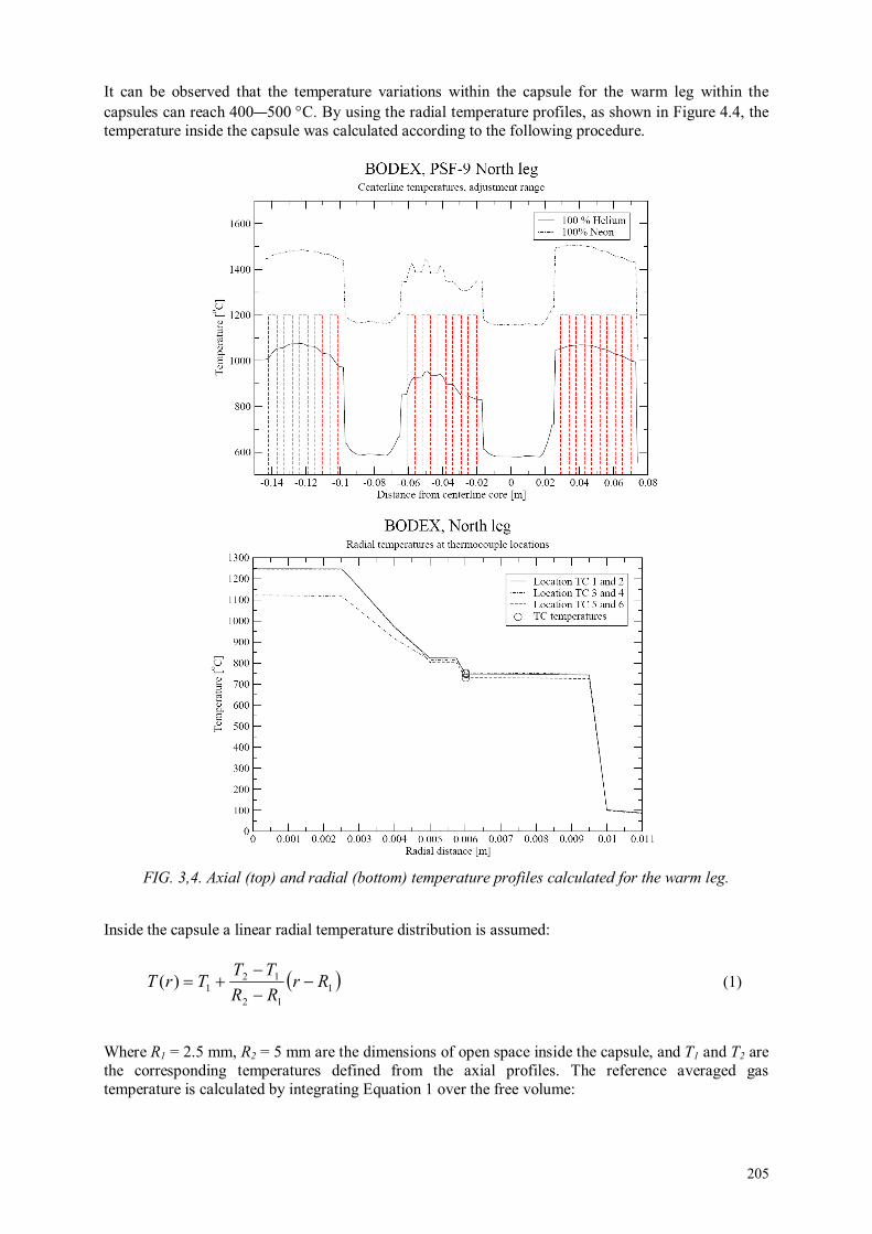
205
It can be observed that the temperature variations within the capsule for the warm leg within the capsules can reach 400—500 °C. By using the radial temperature profiles, as shown in Figure 4.4, the temperature inside the capsule was calculated according to the following procedure.
FIG. 3,4. Axial (top) and radial (bottom) temperature profiles calculated for the warm leg.
Inside the capsule a linear radial temperature distribution is assumed:
( )112
121)( Rr
RR
TTTrT −
−
−+= (1)
Where R1 = 2.5 mm, R2 = 5 mm are the dimensions of open space inside the capsule, and T1 and T2 are the corresponding temperatures defined from the axial profiles. The reference averaged gas temperature is calculated by integrating Equation 1 over the free volume:
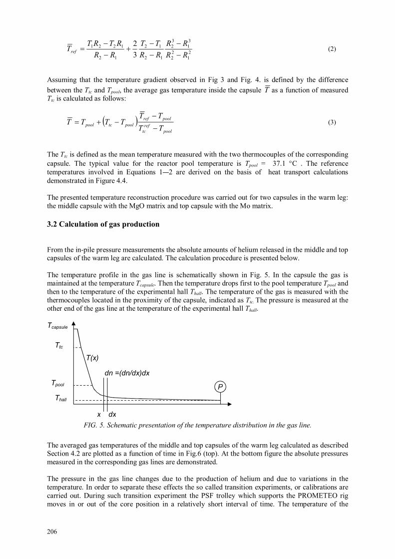
206
21
22
31
32
12
12
12
1221
3
2
RR
RR
RR
TT
RR
RTRTTref −
−
−
−+
−
−= (2)
Assuming that the temperature gradient observed in Fig 3 and Fig. 4. is defined by the difference
between the Ttc and Tpool, the average gas temperature inside the capsule T as a function of measured Ttc is calculated as follows:
( )pool
ref
tc
poolref
pooltcpoolTT
TTTTTT
−
−−+= (3)
The Ttc is defined as the mean temperature measured with the two thermocouples of the corresponding capsule. The typical value for the reactor pool temperature is Tpool = 37.1 °C . The reference temperatures involved in Equations 1—2 are derived on the basis of heat transport calculations demonstrated in Figure 4.4. The presented temperature reconstruction procedure was carried out for two capsules in the warm leg: the middle capsule with the MgO matrix and top capsule with the Mo matrix.
3.2 Calculation of gas production
From the in-pile pressure measurements the absolute amounts of helium released in the middle and top capsules of the warm leg are calculated. The calculation procedure is presented below. The temperature profile in the gas line is schematically shown in Fig. 5. In the capsule the gas is maintained at the temperature Tcapsule. Then the temperature drops first to the pool temperature Tpool and then to the temperature of the experimental hall Thall. The temperature of the gas is measured with the thermocouples located in the proximity of the capsule, indicated as Ttc. The pressure is measured at the other end of the gas line at the temperature of the experimental hall Thall.
FIG. 5. Schematic presentation of the temperature distribution in the gas line.
The averaged gas temperatures of the middle and top capsules of the warm leg calculated as described Section 4.2 are plotted as a function of time in Fig.6 (top). At the bottom figure the absolute pressures measured in the corresponding gas lines are demonstrated. The pressure in the gas line changes due to the production of helium and due to variations in the temperature. In order to separate these effects the so called transition experiments, or calibrations are carried out. During such transition experiment the PSF trolley which supports the PROMETEO rig moves in or out of the core position in a relatively short interval of time. The temperature of the
Tcapsule
Ttc
Tpool
Thall
x dx
dn =(dn/dx)dx
T(x)
P

207
capsule gradually changes while the amount of gas inside the gas line remains constant. The corresponding changes in the gas pressure are exclusively attributed to the temperature variations.
FIG. 6. Top: Averaged gas temperatures in the middle (blue) and top (green) capsules as a function
of time. Bottom: Absolute pressure in the gas lines of the two capsules. Calibrations are marked with red color. Five calibrations were carried out during BODEX irradiations. The positions of the calibrations are marked in Fig. 6 with red colour. During the calibrations the data points were recorded every 400 ms. Two calibrations, I and II, are demonstrated in Fig.7 . The calibration procedure provides the relation between the gas pressure measured at the cold end of the gas line and temperature measured close to the capsule at the hot end. Such a relation is established for the specific amount of gas present in the gas line at the moment of calibration.
0 10 20 30 40 50 60 70 80 900
200
400
600
800
1000
1200
Time days
Tem
pera
ture
/ °C
BODEX
0 10 20 30 40 50 60 70 80 901
1.05
1.1
1.15
1.2
Time days
Pre
ssure
/ b
ar
I IIIII IV
V
08-04 08-05 08-06

208
FIG. 7. Temperature and pressure variations measured during two calibrations, I and II.
Applying the ideal gas low the relation between the measured pressure P and the gas temperature T(x) can be described by the following expression:
∫
= dxdx
dnxTRPV )( (4)
where V is the total volume including the volume of the capsule and connecting tube, R is the
universal gas constant, dxdx
dn
is the amount of gas (neon and helium) within the elementary length
dx of the gas line. The gas density (measured in moles) varies with the local temperature T(x). It is assumed that there is an unique correspondence between the temperature distribution in the gas line and the temperature measured with the thermocouples: T(x) ↔ Ttc. Integration is taken along the whole length of the gas line. At the start of irradiation the initial amount of gas N0 and the initial pressure P0 are defined:
∫
= dxdx
dnN0 (5)
∫
== dxdx
dntxTRVP )0,(0 (6)
44.8 44.85 44.9 44.95 45 45.05 45.1 45.15 45.2 45.25 45.3
200
400
600
800
1000
1200
Time days
Tem
pera
ture
/ °C
BODEX
44.8 44.85 44.9 44.95 45 45.05 45.1 45.15 45.2 45.25 45.31.06
1.08
1.1
1.12
1.14
1.16
1.18
Time days
Pre
ssure
/ b
ar
III

209
Production of helium will not significantly affect the temperature distribution T(x) and the shape of
the density distribution
dx
dn
. The latter however is rescaled as follows:
∫
∆+
= dxN
tNN
dx
dntxTRVtP
0
0 )(),()( (7)
At the moment of the calibration ∆Ncal atoms of helium is released in the gas line. From the calibration experiment the relation between the measured temperature and pressure for the constant amount of gas (N0+∆Ncal) is obtained: )( tccal TP . Since Ttc uniquely defines the temperature distribution in the line
T(x), pressure in the line for any given temperature distribution T(x) can be calculated, including the distribution T(x,t) involved in Equation 7:
∫
∆+
= dxN
NN
dx
dntxTRVtP cal
cal
0
0);()( (8)
Such reconstruction of Pcal(t) carried out for the middle capsule is demonstrated in Fig.8. The difference between P(t) and Pcal(t), given by Equations 7 and 8 is attributed to the difference in the amount of gas in the line: (N0+∆N(t)) and (N0+∆Ncal). ∆Ncal is calculated by comparing the pressure measured at the begin of irradiation P0 and the calibration pressure Pcal(t=0) reconstructed at the moment t=0:
−==∆
0
00
)0(
P
PtPNN cal
cal (9)
FIG. 8. The measured pressure P(t) for the amount of gas in the line (N0+∆N(t)) and the reconstructed
pressure Pcal(t) for the fixed amount of gas in the line (N0+∆Ncal). In both cases the temperature distribution is the same T(x,t).
0 10 20 30 40 50 601
1.02
1.04
1.06
1.08
1.1
1.12
1.14
1.16
1.18
1.2
Time /days
pre
ssure
/atm
BODEX mid calibration I

210
By combining Equations 7—9 the gas production in the capsule is calculated:
−
−=+=∆ 1
)0(1
)(
)()(
0
00
P
PtP
tP
tPNtN cal
cal
(10 )
The initial amount of gas (neon) in the gas line is calculated as follows:
A
eff
NRT
VPN 0
0 = (11)
Where NA is the Avogadro constant and Teff is the effective temperature in the gas line. The Teff is bounded between the Tpool= 310.3 K and Thall = 296.0 K. From geometrical considerations the Teff is taken as [9]:
1
3/13/2−
+=
hallpool
effTT
T (12)
The relative error in the definition of Teff is less than 5%. In Fig. 9 the amounts of helium released in the gas line of the middle and top capsules are compared to the corresponding amounts of helium produced in the pellets due to the nuclear reaction and calculated with the MCNP coder [10][11]. In Fig. 10 the fractions of the helium released from the pellets are demonstrated. Relative increase of the released fractions in the beginning of irradiation is explained by little trapping inside the pellets. As the build up of irradiation induced defects proceeds, e.g. helium bubbles, the released fractions decrease in both matrices. Also the helium generation rate is strong at the beginning of irradiation and decreases with the burn up of boron-10, which reached 65-70% at the end of irradiation. Note that in the plots only pure irradiation time is taken into account. Discontinuities in the signal are caused by two reactor stops which took place between three irradiation cycles. There is also a small decrease in the pressure signal PT2 observed at the end of 08-04 cycle and at the beginning of 08—05 cycle (Figure 4.7 bottom). The reason for such behaviours is not completely understood. After about 30 days of irradiation the trapping inside the pellets saturates and the released fractions reach the steady state values: 35% for MgO (middle capsule) and 9% for Mo (top capsule).

211
FIG. 9. Amount of helium released in the gas line of the middle and top capsules are compared to the helium produced in the pellets calculated with the MCNP code.
0 10 20 30 40 50 6010
17
1018
1019
1020
1021
Time / days
4H
e /
ato
ms
BODEX-mid
0 10 20 30 40 50 6010
17
1018
1019
1020
1021
Time / days
4H
e /
ato
ms
BODEX-top

212
FIG. 10. Fraction of helium released in the gas line of the middle and top capsules normalized to the amount of helium produced in the pellets calculated with the MCNP code.
4. CONCLUSIONS
The objective of the BODEX experiment was to study the behaviour of inert ceramic matrices, suitable for incorporation and transmutation of americium. The helium production by americium was simulated in this experiment by doping the inert matrices with boron-10. The BODEX experiment consisted from two legs, irradiated at 800 °C and at 1200 °C. Each leg contained three inert matrix materials: magnesium oxide, yttrium-stabilised zirconium dioxide and Mo-92 depleted molybdenum. The targeted boron-10 burn-up for the cold and warm legs was 62% and 65%, respectively. The capsules temperatures were monitored with 12 thermocouples. Two of the capsules were equipped with pressure transducers. This enable to monitor the pressure build up on-line. Both capsules were positioned in the warm leg and contained MgO and Mo pellets. Making use of the MCNP calculations of the helium production in the pellets, it was calculated that the helium fraction released from the pellet material is 35±3% for MgO and 9±1 % for Mo.
REFERENCES
[1] KLAASSEN F.C. and SCHRAM R.P.C., Irradiation Proposal BISMAT (exp.353), Boron Implantation to Simulate Minor Actinide Transmutation”, NRG Report 20800/02.48339/C, Petten, 05 July (2002).
[2] BROEKHAUS K.O., Eurotrans-Bodex Boron-Doped Experiment (368-01), Design and Safety Report”, 25138/08.86970/I Rev.E, May (2008).
[3] KONINGS R J. M., CONRAD R., DASSEL G., PIJLGROMS B. J., SOMERS J., TOSCANO E., The EFTTRA-T4 experiment on americium transmutation, Journal of Nuclear Materials, Volume 282, Issues 2—3, , Pages 159—170, December (2000).
[4] VERBRUGGEN J.A.N.C. and BENNEKER P.B.J.M., Prometeo-Mod (266): Production of Molybdenum by Irradiation of fissile targets for IRE. Facility with optimized target holder design, NRG Design and Safety Report, Revision 4, 20096/07.82906/I, Petten, 10 January (2008).
[5] VAN KRANENBURG M.A.C., VERBAKEL W. and SCIOLLA C., Project-I PSF Irradiation (322-02), NRG Report 25138/01.42355/I, Petten, 22 November (2001).
0 10 20 30 40 50 600
10
20
30
40
50
60
70
80
90
100
Time /days
fraction %
BODEX He4 released fraction
MgO(mid)
Mo(top)

213
[6] KLAASSEN F.C., DEN EXTER M.J., OOIJEVAAR M.O., BRUIN J.D. and TÝNOVÁ E., Bodex Fabrication Report, NRG Report 2.1668/08.86994/C, Petten, 10 January (2008).
[7] JONKER B.P., 1D calculations for the BODEX experiment, NRG Note 21668/06.77691 PPT/BJ/MH, Petten, (2006).
[8] JONKER B.P., BODEX experiment, Thermomechanical Analysis, NRG Report 21668/07.86274 S&P/BJ/MH, Petten, 06 December (2007).
[9] SCHRAM R.P.C., VERBAKEL W., BAKKER K. and VAN KRANENBURG M.A.C., Final report of the Project-I PSF Irradiation, NRG Report 20224/03.52688/C, Petten, 21 March (2003).
[10] VAN DER MARCK S.C. and SCIOLLA C.M., BODEX (368-01) Nuclear Analysis, NRG Report 2.1668/07.86021/I, Revision B, Petten, December (2007).
[11] SCIOLLA C.M., BODEX 368-01 in PSF 9, LYRA in PSF 10/11, NRG Note 21668/08.87667 LCI/CS/MK, Petten, 27 February (2008).

214
ABBREVIATIONS
APW Augmented plane-wave
ATR Advanced test reactor
ATRC ATR critical
BOCA Boiling water capsule
BTF Blowdown test facility
BWR Boiling water reactor
CANDU Canada deuterium uranium
CP Coated particles
CPEM Curie point electromagnet
CT Computer tomography
CT Compact tension
DAS Data acquisition system
DCPD Direct current potential drop
DFT Density functional theory
DG Diameter gauge
DHXs Dump heat exchangers
DOS density of states
EC Eddy current
EFPI Extrinsic fabry-perot interferometer
EMF Electro-thermal-motive force
EPMA Electron probe micro-analysis
FBTR Fast breeder test reactor
FC Fission chambers
FCRD Fuel cycle research & development
FEM Finite element method
FNDS Fast neutron detector system
FPD Full power days
FPs Fission products
FTL Fuel test loop
GACID Global actinide cycle international demonstration
GFP Gaseous fission products
GFR Gas cooled fast reactor
HANARO High-flux advanced neutron application reactor
HBWR Halden boiling water reactor
HFR High flux reactor
HPGe High purity germanium

215
HRP Halden reactor project
HSIS Hydraulic shuttle irradiation system
HTGRs High temperature gas-cooled reactors
HTIR-TCs High temperature irradiation thermocouples
HWC hydrogen water chemistry
I&C Instrumentation and control
IASCC Irradiation assisted stress corrosion cracking
IGSCC Intergranular stress corrosion cracking
IHXs Intermediate heat exchangers
IMS Information/measuring system
IMS Intermediate heat exchangers
INTA Instrumented test assembly
IPS In-pile test section
JHR Jules Horowitz material testing reactor
JMTR Japan materials testing reactor
LME Liquid metal embrittlement
LRUS Laser-based resonant ultrasound spectroscopy
LTA Lead test assembly
LVDT Linear variable displacement transducer
LVDTs Linear variable differential transformers
LWR Light water reactor
MA Minor actinide
MA-MOX MOX fuel containing minor actinide
MARICO Material testing rig with temperature control
MATMs Melting alloy temperature monitors
MI Mineral insulated
MSR Molten salt nuclear reactor
MTB Materials test bundle
MTRs Materials and test reactors
NEET Nuclear energy enabling technology
NGNP Next generation nuclear plant
NISA Nuclear industrial safety agent
NOC Normal operating conditions
NWC Normal water chemistry
ODS Oxide dispersion strengthened
PDM Potential drop method
PHWR Pressurized heavy water reactor
PIE Post-irradiation examination

216
PLC Programmable logic control
PSF Pool side facility
PWR Pressurised water reactor
PZT Piezoelectric transducers
RMB Brazilian multipurpose reactor
RUS Resonant ultrasound spectroscopy
SASS Self-actuated shutdown system
SCC Stress corrosion cracking
SCWR Supercritical water reactor
SFE Spherical fuel element
SFP Solid fission products
SFR Sodium cooled fast reactor
SP Spherical particles
SPGD Self-powered gamma detector
SPND Self-powered neutron detector
SS Stainless steel
SSRT Slow strain rate tensile test
TC Thermocouples
THWM Thermocouples and a transient hot wire method
TOF Time-of-flight
UCS Upper core structure
UPR Upper core structure irradiation plug rig
UTs Ultrasonic thermometers
VHTR Very high temperature reactor
WRFPM Water reactor fuel performance meeting
YS Yield strength
YSZ Yttrium stabilized zirconium oxide

217
LIST OF PARTICIPANTS
Ahn S. H. Korea Atomic Energy Research Institute, Korea, Republic of
Aleksanyan A. Armenian Nuclear Power Plant, Armenia
Antalik R. Nuclear Regulatory Authority of Slovak Republic, Slovakia
Arunachalam G. K. Indira Gandhi Centre for Atomic Research, India
Bjørnstadt T. Institute for Energy Technology, Norway
Coulon R. CEA Saclay, France
Danielsen T. OECD Halden Reactor Project, Norway
Del Nevo A. Italian National Agency for New Technologies (ENEA), Italy
Destouches C. French Alternatives Energy and Atomic Energy Commission, France
Dobrea D. Institute for Nuclear Research, Romania
Dykin V. Chalmers University of Technology, Sweden
Eriksen K.W. OECD Halden Reactor Project, Norway
Fedorov A. Nuclear Research Consultancy Group, Netherlands
Giovedi C. Navy Technological Center in Sao Paulo, Brazil
Grando Q. IRSN/PSN-RES/SEREX, France
Håkansson A. Uppsala University, Sweden
Hanakawa H. Japan Atomic Energy Agency, Japan
Harrison N. Atomic Energy of Canada Limited, Canada
Hartmann C. OECD Halden Reactor Project, Norway
Helsengreen C. OECD Halden Reactor Project, Norway
Hong J. Korea Atomic Energy Research Institute, Korea, Republic of
Inozemtsev V. International Atomic Energy Agency
Karlsen T. OECD Halden Reactor Project, Norway
Klintenberg M. Uppsala University, Sweden
Marquié C. IRSN/PSN-RES/SEREX, France
Morrell J. U-12 National Security Complex, United States of America

218
Nakamura J. Japan Atomic Energy Agency, Japan
Okel R. Nuclear Research Consultancy Group, Netherlands
Ötvös N. A. Hungarian Atomic Energy Authority, Hungary
Palma D. Brazilian Nuclear Energy Commission, Brazil
Rempe J. L. Idaho National Laboratory, United States of America
Retegan T. Chalmers University of Technology, Ukraine
Sepoelli M. Italian National Agency for New Technologies (ENEA), Italy
Shaimerdenov A. Institute of Nuclear Physics at the Kazakhstan National Nuclear Centre,
Kazakhstan
Shang J. Nuclear Power Institute of China, China
Shikama T. TOHOKU, Japan
Soga T. Japan Atomic Energy Agency, Japan
Solstad S. OECD Halden Reactor Project, Norway
Van Nieuwenhove R. OECD Halden Reactor Project, Norway
Volkov B. OECD Halden Reactor Project, Norway
Wang H. Nuclear Power Institute of China, China
Wiesenack W. OECD Halden Reactor Project, Norway
Technical Meeting
Halden, Norway: 21—24 August 2012

@ No. 23
ORDERING LOCALLYIn the following countries, IAEA priced publications may be purchased from the sources listed below, or from major local booksellers. Orders for unpriced publications should be made directly to the IAEA. The contact details are given at the end of this list.
AUSTRALIADA Information Services648 Whitehorse Road, Mitcham, VIC 3132, AUSTRALIA Telephone: +61 3 9210 7777 Fax: +61 3 9210 7788 Email: [email protected] Web site: http://www.dadirect.com.au
BELGIUMJean de LannoyAvenue du Roi 202, 1190 Brussels, BELGIUM Telephone: +32 2 5384 308 Fax: +32 2 5380 841 Email: [email protected] Web site: http://www.jean-de-lannoy.be
CANADARenouf Publishing Co. Ltd.Telephone: +1 613 745 2665 Fax: +1 643 745 7660 5369 Canotek Road, Ottawa, ON K1J 9J3, CANADA Email: [email protected] Web site: http://www.renoufbooks.com
Bernan Associates4501 Forbes Blvd., Suite 200, Lanham, MD 20706-4391, USA Telephone: +1 800 865 3457 Fax: +1 800 865 3450 Email: [email protected] Web site: http://www.bernan.com
CZECH REPUBLICSuweco CZ, spol. S.r.o.Klecakova 347, 180 21 Prague 9, CZECH REPUBLIC Telephone: +420 242 459 202 Fax: +420 242 459 203 Email: [email protected] Web site: http://www.suweco.cz
FINLANDAkateeminen KirjakauppaPO Box 128 (Keskuskatu 1), 00101 Helsinki, FINLAND Telephone: +358 9 121 41 Fax: +358 9 121 4450 Email: [email protected] Web site: http://www.akateeminen.com
FRANCEForm-Edit5, rue Janssen, PO Box 25, 75921 Paris CEDEX, FRANCE Telephone: +33 1 42 01 49 49 Fax: +33 1 42 01 90 90 Email: [email protected] Web site: http://www.formedit.fr
Lavoisier SAS14, rue de Provigny, 94236 Cachan CEDEX, FRANCE Telephone: +33 1 47 40 67 00 Fax: +33 1 47 40 67 02 Email: [email protected] Web site: http://www.lavoisier.fr
L’Appel du livre99, rue de Charonne, 75011 Paris, FRANCE Telephone: +33 1 43 07 50 80 Fax: +33 1 43 07 50 80 Email: [email protected] Web site: http://www.appeldulivre.fr
GERMANYGoethe Buchhandlung Teubig GmbHSchweitzer Fachinformationen Willstaetterstrasse 15, 40549 Duesseldorf, GERMANY Telephone: +49 (0) 211 49 8740 Fax: +49 (0) 211 49 Email: [email protected] Web site: http://www.goethebuch.de/
HUNGARYLibrotade Ltd., Book ImportPF 126, 1656 Budapest, HUNGARY Telephone: +36 1 257 7777 Fax: +36 1 257 7472 Email: [email protected] Web site: http://www.librotade.hu

INDIAAllied Publishers Pvt. Ltd.1st Floor, Dubash House, 15, J.N. Heredi Marg Ballard Estate, Mumbai 400001, INDIA Telephone: +91 22 42126969/31 Fax: +91 22 2261 7928 Email: [email protected] Web site: http://www.alliedpublishers.com
Bookwell3/79 Nirankari, Dehli 110009, INDIA Tel.: +91 11 2760 1283 +91 11 27604536 Email: [email protected] Web site: http://www.bookwellindia.com/
ITALYLibreria Scientifica “AEIOU”Via Vincenzo Maria Coronelli 6, 20146 Milan, ITALY Tel.: +39 02 48 95 45 52 Fax: +39 02 48 95 45 48 Email: [email protected] Web site: http://www.libreriaaeiou.eu/
JAPANMaruzen Co., Ltd.1-9-18 Kaigan, Minato-ku, Tokyo 105-0022, JAPAN Tel.: +81 3 6367 6047 Fax: +81 3 6367 6160 Email: [email protected] Web site: http://maruzen.co.jp
NETHERLANDSMartinus Nijhoff InternationalKoraalrood 50, Postbus 1853, 2700 CZ Zoetermeer, NETHERLANDS Tel.: +31 793 684 400 Fax: +31 793 615 698 Email: [email protected] Web site: http://www.nijhoff.nl
Swets PO Box 26, 2300 AA Leiden Dellaertweg 9b, 2316 WZ Leiden, NETHERLANDS Telephone: +31 88 4679 263 Fax: +31 88 4679 388 Email: [email protected] Web site: www.swets.com
SLOVENIACankarjeva Zalozba ddKopitarjeva 2, 1515 Ljubljana, SLOVENIA Tel.: +386 1 432 31 44 Fax: +386 1 230 14 35 Email: [email protected] Web site: http://www.mladinska.com/cankarjeva_zalozba
SPAINDiaz de Santos, S.A.Librerias Bookshop Departamento de pedidos Calle Albasanz 2, esquina Hermanos Garcia Noblejas 21, 28037 Madrid, SPAIN Telephone: +34 917 43 48 90 Email: [email protected] Web site: http://www.diazdesantos.es/
UNITED KINGDOMThe Stationery Office Ltd. (TSO)PO Box 29, Norwich, Norfolk, NR3 1PD, UNITED KINGDOM Telephone: +44 870 600 5552 Email (orders): [email protected] (enquiries): [email protected] Web site: http://www.tso.co.uk
On-line orders:DELTA International Ltd.39, Alexandra Road, Addlestone, Surrey, KT15 2PQ, UNITED KINGDOM Email: [email protected] Web site: http://www.profbooks.com
United Nations (UN)300 East 42nd Street, IN-919J, New York, NY 1001, USA Telephone: +1 212 963 8302 Fax: +1 212 963 3489 Email: [email protected] Web site: http://www.unp.un.org
UNITED STATES OF AMERICABernan Associates4501 Forbes Blvd., Suite 200, Lanham, MD 20706-4391, USA Tel.: +1 800 865 3457 Fax: +1 800 865 3450 Email: [email protected] Web site: http://www.bernan.com
Renouf Publishing Co. Ltd.812 Proctor Avenue, Ogdensburg, NY 13669, USA Tel.: +800 551 7470 (toll free) +800 568 8546 (toll free) Email: [email protected] Web site: http://www.renoufbooks.com
Orders for both priced and unpriced publications may be addressed directly to:IAEA Publishing Section, Marketing and Sales Unit, International Atomic Energy Agency Vienna International Centre, PO Box 100, 1400 Vienna, Austria Telephone: +43 1 2600 22529 or 22488 • Fax: +43 1 2600 29302 Email: [email protected] • Web site: http://www.iaea.org/books 13
-42991
Schneidk
Highlight
Related Documents