Technical Information 14.06.13 ICE-166 In-Circuit Emulator for C166/ST10 - Out of Production ■ Full support for standard, VECON and GOLD ■ Full support for KEIL, TASKING and GNU compilers ■ Bondout and non-Bondout Probes ■ 25 MHz no-wait-state operation ■ Dual-port access for ROM and external bus ■ Trace on internal and local variables ■ Selective trace on registers, peripherals and local variables ■ Trigger on internal register access, bit, byte, and word variables ■ Mixed trace on external and BONDOUT busses ■ Clip-Over, Solder-On and YAMAICHI adapters ■ Support of all derivatives, also non-public versions The ICE-166 emulator module support bondout and non- bondout derivatives of the C166 family. All features of the BONDOUT chips are supported, trigger and selective trace is possible on internal addresses and data, on regis- ters and on peripheral accesses. 160 extra trace channels are used to trace all BONDOUT signals. The ROM and FLASH memory is emulated by an extra emulation system with separate breakpoints and execution flags for code coverage. The emulator can simulate bootstrap sequences and FLASH operation. C161CI C161CS C161JI C161K C161O C161PI C161RI C161S C161SI C161V C161XX C163 C163-16F C163-24D C164CH C164CI C164CL C165 C167 C167C C167CR C167CS C167CW C167SR PMB2705_GOLD_1.5 PMB2705_GOLD_2.1 PMB2705_GOLD_3.3 PMB2706GOLD PMB2800HIGOLD PMB2800HIGOLDV4 SAB80C166 SAB83C166 SAB88C166 ST10F163 ST10F166

Welcome message from author
This document is posted to help you gain knowledge. Please leave a comment to let me know what you think about it! Share it to your friends and learn new things together.
Transcript

Tech
nic
al In
form
atio
n
14.0
6.13
ICE-166
In-Circuit Emulator for C166/ST10 - Out of Production
■ Full support for standard, VECON and GOLD■ Full support for KEIL, TASKING and GNU
compilers■ Bondout and non-Bondout Probes■ 25 MHz no-wait-state operation■ Dual-port access for ROM and external bus■ Trace on internal and local variables■ Selective trace on registers, peripherals and
local variables■ Trigger on internal register access, bit, byte,
and word variables■ Mixed trace on external and BONDOUT
busses■ Clip-Over, Solder-On and YAMAICHI adapters■ Support of all derivatives, also non-public
versions
The ICE-166 emulator module support bondout and non-bondout derivatives of the C166 family. All features of theBONDOUT chips are supported, trigger and selectivetrace is possible on internal addresses and data, on regis-ters and on peripheral accesses. 160 extra trace channelsare used to trace all BONDOUT signals. The ROM andFLASH memory is emulated by an extra emulation systemwith separate breakpoints and execution flags for codecoverage. The emulator can simulate bootstrapsequences and FLASH operation.
C161CIC161CSC161JIC161KC161OC161PIC161RIC161SC161SIC161VC161XXC163C163-16FC163-24DC164CHC164CIC164CLC165C167C167CC167CRC167CSC167CWC167SRPMB2705_GOLD_1.5PMB2705_GOLD_2.1PMB2705_GOLD_3.3PMB2706GOLDPMB2800HIGOLDPMB2800HIGOLDV4SAB80C166SAB83C166SAB88C166ST10F163ST10F166

TRACE32 - Technical Information 2
Features
Basics of Operation
The TRACE32-ICE166 supports all features provided by the bondout chip. The bondout chip has 4 bus systems:
❏ External bus
❏ ROM emulation bus
❏ XPER bus
❏ Bondout trace bus
The ROM emulation bus emulatestogether with the 256K emulation RAMon the base module the on-chip ROMor FLASH memory. In addition theemulator supports 256K breakpointsand 256K flag memory on ROM emula-tion. The flag memory is useful for codecoverage and software analysis.
The XPER bus is needed for the emu-lation of CAN and VECON derivatives. Since the bondout chip does not con-tain any peripherals, there is a socket on the emulation module to add the specific CAN or VECON derivative. For the operation, the core of the derivative is disabled and the bondout CPU uses the XPER bus to emulate the peripher-als.
The Bondout trace bus provides allsignals for tracing on internal opera-tions. Since most of the transfers aremade between the internal RAM, reg-isters and internal peripherals, thesebusses are a big help for analyzing theapplication´s behaviour.
BondoutC167
ROM Emulation
Bondout Trigger
Bondout Trace
Exception Trigger
DualportControl
Mapper
XBUSChip
Target
Port Buffer
ExternalEmulation
WaitControl
PortAnalyzer
Emulation module Base module
Features

TRACE32 - Technical Information 3
Operating Modes The Emulator can work in stand-alone mode with internal clock or in active mode with internal or the target clock. On power-down of the target system the emulator tristates its output buffers and isolates its internal emulation cir-cuits.
The operation modes are as follows:
❏ Reset Down
❏ Reset Up
❏ Alone Internal
❏ Alone External
❏ Emulation Internal
❏ Emulation External
Clock
❏ Operation with external or internal Clock
❏ 1..35 MHz internal clock
Dual-Port Access
All TRACE32 memories are dual-ported. The dual-port access makes it possible to display and modify the con-tents of the overlay memory, to set or delete breakpoints or use the flag memory while the application is run-ning in real-time.
The dual-port access on the ROM bus(on-chip ROM and FLASH emualation)is always possible. Their are no limita-tions on breakpoint and flag usage.
The external bus has 3 modes for dual-port access
❏ GAP
❏ NoGAP
❏ NOP (BONDOUT only)The GAP modes need extra time, as the dual-port cycle is inserted between the bus cycles generated by the CPU. This means that the max. speed of
Features

TRACE32 - Technical Information 4
operation is not possible in this mode, or extra wait states are needed for cor-rect operation.
In the NOP mode the bus unit isstopped for a short time to allow dual-port cycles without any time limitations.This mode will be possible with futurebondout steps. The current bondoutCPUs have bugs in this mode.
ROM Emulation The ROM emulation circuits build a separate emulator system to emulate all on-chip FLASH or ROM based applications.
❏ 256K ROM emulation memory■ FLASH and ROM emulation■ Bootstrap loader support
❏ 256K Breakpoint memory on ROM area■ Program breakpoints■ ROM data breakpoints■ Trace points on execution
❏ 256K Flag Memory ■ Additional flag memory for
ROM■ Separate flags for OPFETCH
and ROMDATA
Bondout Trace128 additional trace channels are sup-ported by TRACE32-ICE166 to trace all signals delivered by the bondout busses.The trace can display internal operations like register to internal
memory, peripheral to registers, etc. Stack operations cannot be displayed because there is no information on the bus.
Trace ChannelsThe bondout trace samples the 128 channels for BONDOUT busses. These channels provide the following informa-
tion:
❏ Instruction execution address
Features

TRACE32 - Technical Information 5
❏ Operand read address
❏ Operand write address
❏ Operand data
❏ Control lines
❏ Instruction code
Trace OperationThe trace can work on the external bus, the internal bus or on both busses (mixed trace) to sample:
❏ Internal CPU cycles (BONDOUT only)
❏ External bus cycles
❏ Mixed trace (BONDOUT only)
Code Sequencer The code sequencer samples the code flow of the CPU and generates in real-time internal control signals, which
qualify the signals on the bondout bus-ses. This signals are used for the bond-out triggering.
Features

TRACE32 - Technical Information 6
Bondout Trigger SystemThe bondout trigger system works on the code flow and the other bondout signals to qualify states for internal trig-ger accesses. Trigger points can be set on operation results, on 24 bit addresses or on short and bit address-ing operations. Future software will support also triggering on register access. All trigger points can be quali-fied by program segments like func-tions, program lines, etc.
The following trigger points are availa-ble:
❏ 2 operand data breakpoints (Results of operation)
❏ 2 operand address read breakpoints on 24 bit adressing mode
❏ 2 operand read read breakpoint on 24 bit address mode
❏ 2 address write breakpoints on short address mode
❏ 2 address read breakpoints on short address mode
❏ 2 address write breakpoints on bit address mode
❏ 2 address read breakpoints on bit address mode
❏ 2 address write breakpoints on register address mode
❏ 2 address read breakpoints on register address mode
Every breakpoint can be used to break emulation or as a source signal for the trigger sequencer of the analyzer.
Execution Breakpoints
ROM Data Breakpoints
Bondout Breakpoints
Features

TRACE32 - Technical Information 7
Execution Breakpoints The emulator supports execution breakpoints on the ROM and external area. All breakpoints are ’break-before-make’ breakpoints. Emulation is stopped before execution.
❏ 256K ROM execution breakpoints
❏ Up to 16M breakpoints on external bus
HLL Debugging
Full support in real-time for:
❏ ROM and external busses
❏ Break-before-line operation
❏ HLL single step in real-time
Result in the trace bufferBreak conditionSelective traceAddress marker
Features

TRACE32 - Technical Information 8
❏ Trigger and trace on local variables
❏ Trigger on bit variables
Multitask Debugging
❏ 1 foreground task ❏ 1 background task
Wait System
❏ Additional wait cycles (1-15) may be specified
❏ Up to 250 wait cycles (4K blocks global and bytewise)
Features

TRACE32 - Technical Information 9
Voltage and Clock Monitors
❏ On-Line Display for SYSCON and BUSCON
Exception Control
The TRACE32 exception controller allows to permanently activate an exception, to enable or disable specific exceptions, to trigger on specific exceptions or to stimulate an excep-tion.
❏ Static exception setting■ RSTIN
❏ Target exception control■ RSTIN■ NMI
Features
TRACE32 - Technical Information 10
❏ Exception trigger■ RSTOUT■ RSTIN■ PWRDOWN■ IDLE■ TRAP■ PEC
Port Analyzer On the emulation base there is an extra slot for the TRACE32 Port Ana-lyzer. The following additional signals can be traced:
❏ Port 2
❏ Port 3
❏ Port 4
❏ Port 6
❏ Port 7
❏ Port 8
❏ READY
On-Circuit Emulation
❏ Support for Clip-Over adapters
Features

TRACE32 - Technical Information 11
Emulation Modules
Non-Bondout Modules
❏ Module 166 ■ Support for 80C166■ ROMless emulation only■ Adaption for ET100R and
ET100■ Adapter for QF49 available■
❏ Module 167 ■ ROMless emulation only■ Adaption for ET144 and
ET100R
Bondout Modules
❏ Module 166 bondout ■ ROM and ROMless emulation■ Adaption for ET-100 and
ET100R■ Adaption for QF49 available■
❏ Module 167 bondout ■ Support for C167 and C165■ Adaption for ET100R and
ET144■
❏ VECON■ Support for VECON
GOLD Support
❏ Module 166 GOLD-uC PMB 2705 ■ Adaption for ET-160
❏ Module 166 GOLD-uC PMB 2706 ■ Adaption for ET-144
Emulation Modules

TRACE32 - Technical Information 12
Modules Overview
C165 ET100-QF06 3.0..5.5V
C167 ET144-QF10 3.0..5.5V
C167 ET144-QF10 3.0..3.6VLA-7263
C165 ET100-QF06 3.0..5.5V
C167 ET144-QF10 3.0..5.5V
C167C ET144-QF10 3.0..5.5V
C167CR ET144-QF10 3.0..5.5V
C167CW ET144-QF10 3.0..5.5V
C167SR ET144-QF10 3.0..5.5V
LA-7265
PMB2705_GOLD_1.5 ET160-QF07LA-6593
PMB2705_GOLD_2.1 ET176-QF19
PMB2705_GOLD_3.3 ET176-QF19LA-6597
PMB2706GOLD ET144-QF63LA-6598
PMB2800HIGOLD ET144-QF63LA-7264
PMB2800HIGOLDV4 ET144-QF63LA-7269
SAB80C166 ET100-QF06LA-6592
SAB80C166 ET100-QF06LA-7268
SAB80C166 ET100-QS01LA-6592
SAB80C166 ET100-QS01LA-7268
SAB83C166 ET100-QF06
SAB88C166 ET100-QF06LA-6592
ST10F166 ET100-QF06LA-7268
ST10F167 ET144-QF10 3.0..5.5V
ST10R165 ET100-QF49 3.0..5.5V
C161CI ET128-QF63
C161CS ET128-QF63
C161JI ET128-QF63
LA-6613
C161K ET80-QF14
C161O ET80-QF14LA-6610
C161PI ET100-QF06 3.0..5.5VC161PI ET100-QF49 3.0..5.5V
LA-6611
LA-7265
LA-6601
Emulation Modules

TRACE32 - Technical Information 13
C161RI ET100-QF06 3.0..5.5VC161RI ET100-QF49 3.0..5.5V
LA-6611
C161S ET80-QF14LA-6610
C161SI ET128-QF63LA-6613
C161V ET80-QF14LA-6610
C161XX ET128-QF63LA-6613
C163 ET100-QF49
C163-16F ET100-QF49
C163-24D ET100-QF49
LA-6602
C164CH ET80-QF14
C164CI ET80-QF14
C164CL ET80-QF14
LA-6612
C165 ET100-QF06 3.0..3.6VLA-7263
C165 ET100-QF49 3.0..5.5V
C167CR ET144-QF10 3.0..5.5VLA-7266
C167CS ET144-QF10 3.0..5.5VLA-6615
C167CW ET144-QF10 3.0..5.5VLA-7266
ST10F163 ET100-QF49LA-6602
ST10F168 ET144-QF10 3.0..5.5VLA-6615
ST10R163 ET100-QF49LA-6602
LA-7265LA-6601
Emulation Modules
TRACE32 - Technical Information 14
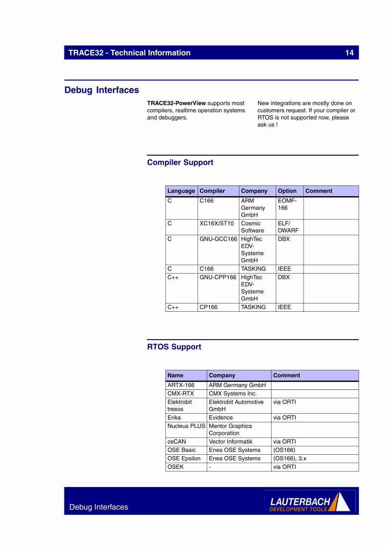
Debug InterfacesTRACE32-PowerView supports most compilers, realtime operation systems and debuggers.
New integrations are mostly done on customers request. If your compiler or RTOS is not supported now, please ask us !
Compiler Support
RTOS Support
Language Compiler Company Option Comment
C C166 ARM Germany GmbH
EOMF-166
C XC16X/ST10 Cosmic Software
ELF/DWARF
C GNU-GCC166 HighTec EDV-Systeme GmbH
DBX
C C166 TASKING IEEE
C++ GNU-CPP166 HighTec EDV-Systeme GmbH
DBX
C++ CP166 TASKING IEEE
Name Company Comment
ARTX-166 ARM Germany GmbHCMX-RTX CMX Systems Inc.
Elektrobit tresos
Elektrobit Automotive GmbH
via ORTI
Erika Evidence via ORTI
Nucleus PLUS Mentor Graphics Corporation
osCAN Vector Informatik via ORTIOSE Basic Enea OSE Systems (OS166)
OSE Epsilon Enea OSE Systems (OS166), 3.x
OSEK - via ORTI
Debug Interfaces

TRACE32 - Technical Information 15
Debugger Support
ProOSEK Elektrobit Automotive GmbH
via ORTI
PXROS HighTec EDV-Systeme GmbH
RTX166/-tiny ARM Germany GmbHRTXC 3.2 Quadros Systems Inc.
RTXC Quadros
Quadros Systems Inc.
Rubus OS Articus Systems AB
SDT-Cmicro IBM Corp.uC/OS-II Micrium Inc. 2.0 to 2.92
Name Company Comment
CPU Debugger Company Host
ALL X-TOOLS / X32
blue river software GmbH
Windows
ALL CODEWRIGHT
Borland Software Corporation
Windows
ALL CODE CONFIDENCE TOOLS
Code Confidence Ltd
Windows
ALL CODE CONFIDENCE TOOLS
Code Confidence Ltd
Linux
ALL EASYCODE EASYCODE GmbH
Windows
ALL ECLIPSE Eclipse Foundation, Inc
Windows
ALL RHAPSODY IN MICROC
IBM Corp. Windows
ALL RHAPSODY IN C++
IBM Corp. Windows
ALL LDRA TOOL SUITE
LDRA Technology, Inc.
Windows
ALL ATTOL TOOLS
MicroMax Inc. Windows
ALL VISUAL BASIC INTERFACE
Microsoft Corporation
Windows
Debug Interfaces

TRACE32 - Technical Information 16
ALL LABVIEW NATIONAL INSTRUMENTS Corporation
Windows
ALL CODE::BLOCKS
Open Source -
ALL C++TEST Parasoft Windows
ALL RAPITIME Rapita Systems Ltd.
Windows
ALL DA-C RistanCASE WindowsALL SIMULINK The
MathWorks Inc.
Windows
ALL WINDOWS CE PLATF. BUILDER
Windows Windows
C166 SDT CMICRO IBM Corp. Windows
CPU Debugger Company Host
Debug Interfaces

TRACE32 - Technical Information 17
Operation Voltage and FrequencyThe maximum operation frequency of TRACE32-ICE depends on:
❏ The max. frequency of the CPU
❏ The access time of the overlay memory (15ns or 35ns)
❏ The mapper mode (Slow or Fast)
❏ The number of waitstates (WO = 0 waitstates W1 = 1 waitstate)
❏ The dual-port access mode
Denied Access
Mo
du
le
CP
U
F-W
0-15
F-W
0-35
S-W
0-15
S-W
0-35
S-W
1-15
S-W
1-35
DR
AM
LA-7265 C161CI 20.0+ 18.8 20.0 15.8 20.0+ 20.0+
LA-7265 C161CS 20.0+ 18.8 20.0 15.8 20.0+ 20.0+
LA-7265 C161JI 20.0+ 18.8 20.0 15.8 20.0+ 20.0+
LA-7265 C161K 16.0+ 16.0+ 16.0+ 15.8 16.0+ 16.0+
LA-7265 C161O 16.0+ 16.0+ 16.0+ 15.8 16.0+ 16.0+
LA-7265 C161PI 25.0 18.8 20.0 15.8 25.0+ 25.0+
LA-7265 C161RI 16.0+ 16.0+ 16.0+ 15.8 16.0+ 16.0+
LA-7265 C161S 16.0+ 16.0+ 16.0+ 15.8 16.0+ 16.0+
LA-7265 C161SI 20.0+ 18.8 20.0 15.8 20.0+ 20.0+
LA-7265 C161V 16.0+ 16.0+ 16.0+ 15.8 16.0+ 16.0+
LA-7265 C161XX 20.0+ 18.8 20.0 15.8 20.0+ 20.0+
LA-7265 C163 25.0 18.8 20.0 15.8 25.0+ 25.0+
LA-7265 C163-16F 25.0 18.8 20.0 15.8 25.0+ 25.0+
LA-7265 C163-24D 25.0 18.8 20.0 15.8 25.0+ 25.0+
LA-7265 C164CH 25.0 18.8 20.0 15.8 25.0+ 25.0+
LA-7265 C164CI 25.0 18.8 20.0 15.8 25.0+ 25.0+
LA-7265 C164CL 25.0 18.8 20.0 15.8 25.0+ 25.0+
- C165 20.0+ 18.8 20.0 15.8 20.0+ 20.0+
- C167 20.0 15.8 16.7 13.6 25.0+ 22.7
LA-7265 C167 25.0 18.8 20.0 15.8 25.0+ 25.0+
LA-7265 C167C 25.0 18.8 20.0 15.8 25.0+ 25.0+
LA-7265 C167CR 25.0 18.8 20.0 15.8 25.0+ 25.0+
LA-7265 C167CS 25.0 18.8 20.0 15.8 25.0+ 25.0+
LA-7265 C167CW 25.0 18.8 20.0 15.8 25.0+ 25.0+
LA-7265 C167SR 25.0 18.8 20.0 15.8 25.0+ 25.0+
LA-6593 PMB2705_GOLD_1.5
20.0+ 18.8 20.0 15.8 20.0+ 20.0+
LA-6597 PMB2705_GOLD_2.1
20.0+ 18.8 20.0 15.8 20.0+ 20.0+
LA-6597 PMB2705_GOLD_3.3
20.0+ 18.8 20.0 15.8 20.0+ 20.0+
LA-6598 PMB2706GOLD 20.0+ 18.8 20.0 15.8 20.0+ 20.0+
LA-7264 PMB2800HIGOLD 26.0 19.3 20.6 16.2 26.0+ 26.0+
Operation Voltage and Frequency

TRACE32 - Technical Information 18
LA-7269 PMB2800HIGOLDV4
26.0 19.3 20.6 16.2 26.0+ 26.0+
LA-7268 SAB80C166 20.0+ 18.8 20.0 15.8 20.0+ 20.0+
LA-6592 SAB83C166 25.0 18.8 20.0 15.8 25.0+ 25.0+
LA-6592 SAB88C166 25.0 18.8 20.0 15.8 25.0+ 25.0+
LA-7265 ST10F163 25.0 18.8 20.0 15.8 25.0+ 25.0+
LA-7268 ST10F166 20.0+ 18.8 20.0 15.8 20.0+ 20.0+
LA-7265 ST10F167 25.0 18.8 20.0 15.8 25.0+ 25.0+
LA-7265 ST10F168 25.0 18.8 20.0 15.8 25.0+ 25.0+
LA-7265 ST10R163 25.0 18.8 20.0 15.8 25.0+ 25.0+
LA-7265 ST10R165 25.0 18.8 20.0 15.8 25.0+ 25.0+
Mo
du
le
CP
U
F-W
0-15
F-W
0-35
S-W
0-15
S-W
0-35
S-W
1-15
S-W
1-35
DR
AM
Operation Voltage and Frequency
TRACE32 - Technical Information 19
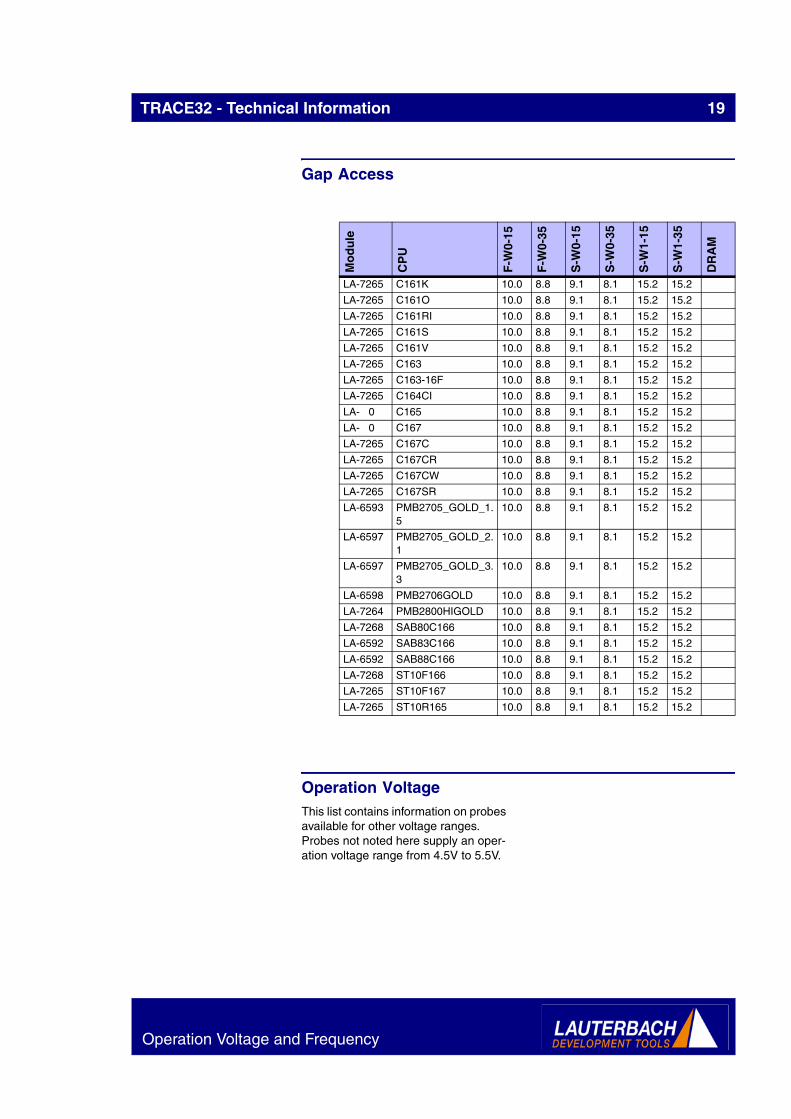
Gap Access
Operation VoltageThis list contains information on probes available for other voltage ranges. Probes not noted here supply an oper-ation voltage range from 4.5V to 5.5V.
Mo
du
le
CP
U
F-W
0-15
F-W
0-35
S-W
0-15
S-W
0-35
S-W
1-15
S-W
1-35
DR
AM
LA-7265 C161K 10.0 8.8 9.1 8.1 15.2 15.2
LA-7265 C161O 10.0 8.8 9.1 8.1 15.2 15.2
LA-7265 C161RI 10.0 8.8 9.1 8.1 15.2 15.2
LA-7265 C161S 10.0 8.8 9.1 8.1 15.2 15.2
LA-7265 C161V 10.0 8.8 9.1 8.1 15.2 15.2
LA-7265 C163 10.0 8.8 9.1 8.1 15.2 15.2
LA-7265 C163-16F 10.0 8.8 9.1 8.1 15.2 15.2
LA-7265 C164CI 10.0 8.8 9.1 8.1 15.2 15.2
LA- 0 C165 10.0 8.8 9.1 8.1 15.2 15.2
LA- 0 C167 10.0 8.8 9.1 8.1 15.2 15.2
LA-7265 C167C 10.0 8.8 9.1 8.1 15.2 15.2
LA-7265 C167CR 10.0 8.8 9.1 8.1 15.2 15.2
LA-7265 C167CW 10.0 8.8 9.1 8.1 15.2 15.2
LA-7265 C167SR 10.0 8.8 9.1 8.1 15.2 15.2
LA-6593 PMB2705_GOLD_1.5
10.0 8.8 9.1 8.1 15.2 15.2
LA-6597 PMB2705_GOLD_2.1
10.0 8.8 9.1 8.1 15.2 15.2
LA-6597 PMB2705_GOLD_3.3
10.0 8.8 9.1 8.1 15.2 15.2
LA-6598 PMB2706GOLD 10.0 8.8 9.1 8.1 15.2 15.2
LA-7264 PMB2800HIGOLD 10.0 8.8 9.1 8.1 15.2 15.2
LA-7268 SAB80C166 10.0 8.8 9.1 8.1 15.2 15.2
LA-6592 SAB83C166 10.0 8.8 9.1 8.1 15.2 15.2
LA-6592 SAB88C166 10.0 8.8 9.1 8.1 15.2 15.2
LA-7268 ST10F166 10.0 8.8 9.1 8.1 15.2 15.2
LA-7265 ST10F167 10.0 8.8 9.1 8.1 15.2 15.2
LA-7265 ST10R165 10.0 8.8 9.1 8.1 15.2 15.2
Operation Voltage and Frequency
TRACE32 - Technical Information 20
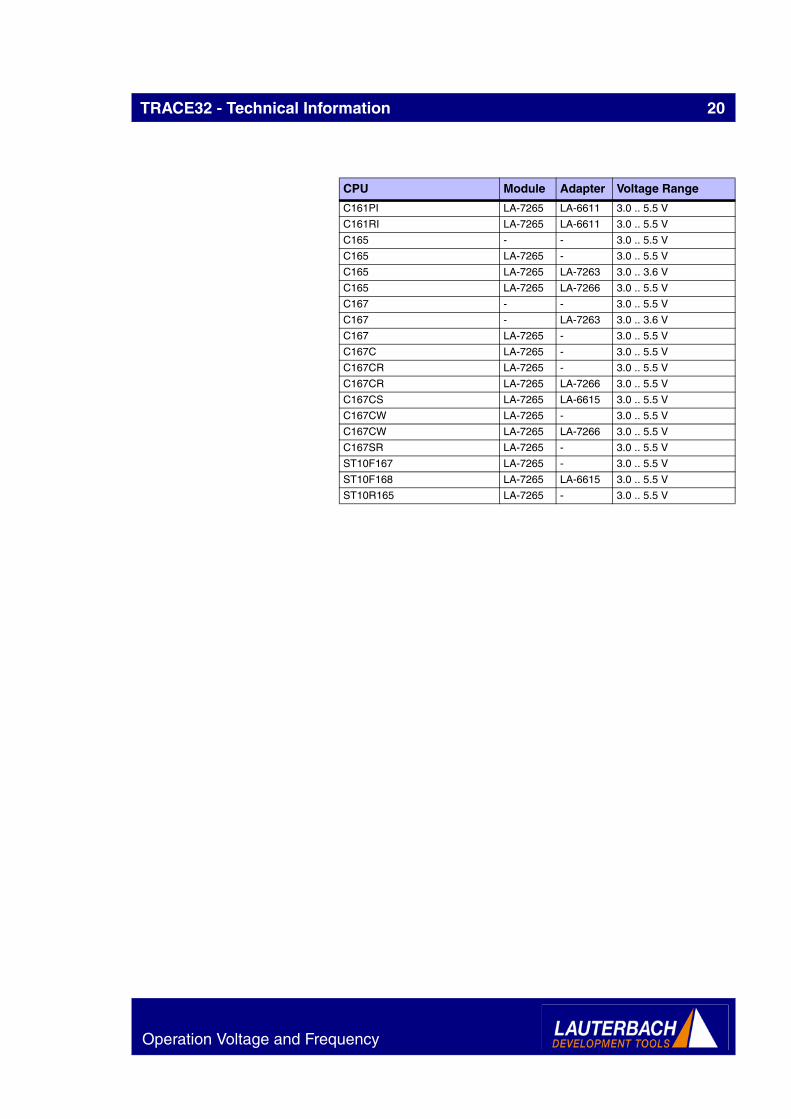
CPU Module Adapter Voltage Range
C161PI LA-7265 LA-6611 3.0 .. 5.5 V
C161RI LA-7265 LA-6611 3.0 .. 5.5 V
C165 - - 3.0 .. 5.5 V
C165 LA-7265 - 3.0 .. 5.5 V
C165 LA-7265 LA-7263 3.0 .. 3.6 V
C165 LA-7265 LA-7266 3.0 .. 5.5 V
C167 - - 3.0 .. 5.5 V
C167 - LA-7263 3.0 .. 3.6 V
C167 LA-7265 - 3.0 .. 5.5 V
C167C LA-7265 - 3.0 .. 5.5 V
C167CR LA-7265 - 3.0 .. 5.5 V
C167CR LA-7265 LA-7266 3.0 .. 5.5 V
C167CS LA-7265 LA-6615 3.0 .. 5.5 V
C167CW LA-7265 - 3.0 .. 5.5 V
C167CW LA-7265 LA-7266 3.0 .. 5.5 V
C167SR LA-7265 - 3.0 .. 5.5 V
ST10F167 LA-7265 - 3.0 .. 5.5 V
ST10F168 LA-7265 LA-6615 3.0 .. 5.5 V
ST10R165 LA-7265 - 3.0 .. 5.5 V
Operation Voltage and Frequency
TRACE32 - Technical Information 21
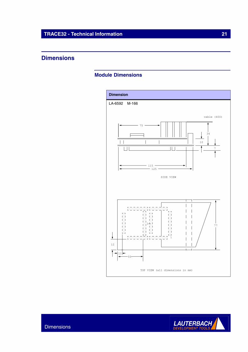
Dimensions
Module Dimensions
Dimension
LA-6592 M-166
cable (400)
75
34
10
115125
SIDE VIEW
7
77
12
1155
TOP VIEW (all dimensions in mm)
1
1
Dimensions
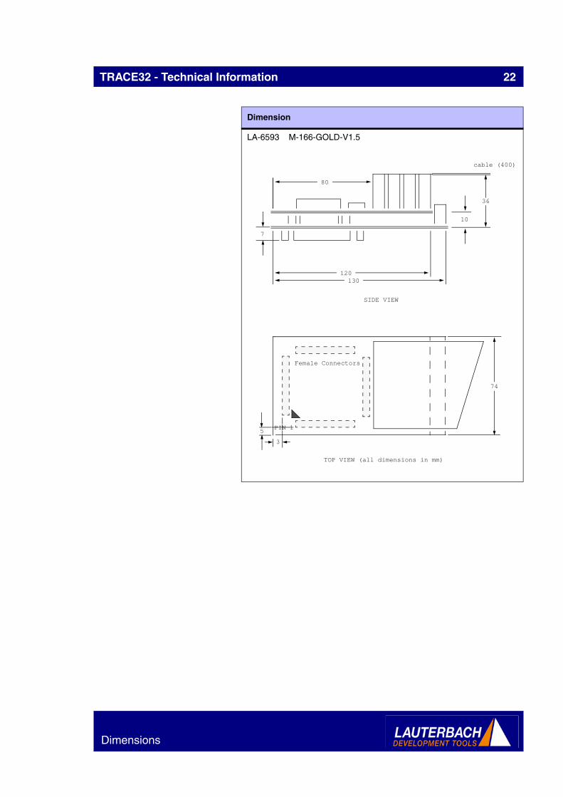
TRACE32 - Technical Information 22
LA-6593 M-166-GOLD-V1.5
Dimension
cable (400)
80
36
10
120130
SIDE VIEW
7
74
5
3
TOP VIEW (all dimensions in mm)
PIN 1
Female Connectors
Dimensions

TRACE32 - Technical Information 23
LA-6597 M-166-GOLD-V2.1
LA-6598 M-166-GOLD-2706
Dimension
cable (400)
80
36
10
120130
SIDE VIEW
7
82
TOP VIEW (all dimensions in mm)
6
6 PIN 1
Dimensions

TRACE32 - Technical Information 24
LA-7264 M-166-GOLD-2800
Dimension
cable (400)
66
37
13
105115
SIDE VIEW
7
77
5
2
TOP VIEW (all dimensions in mm)
PIN 1
Dimensions

TRACE32 - Technical Information 25
LA-7265 M-167E2-B
Dimension
cable (400)
96
34
10
135145
SIDE VIEW
8
15
84
10
10TOP VIEW (all dimensions in mm)
1 1
20
PIN 1
9
31
Dimensions

TRACE32 - Technical Information 26
LA-7266 A-167E2
Dimension
10
145
SIDE VIEW
8
15
84
10
10TOP VIEW (all dimensions in mm)
1 1
20
PIN 1
9
31
Dimensions

TRACE32 - Technical Information 27
LA-7268 M-166-B
LA-7263 A-167-B-3.3-V
Dimension
cable (400)
89
34
10
127137
SIDE VIEW
7
76
11
10
TOP VIEW (all dimensions in mm)
PIN 1
58
1
Dimensions
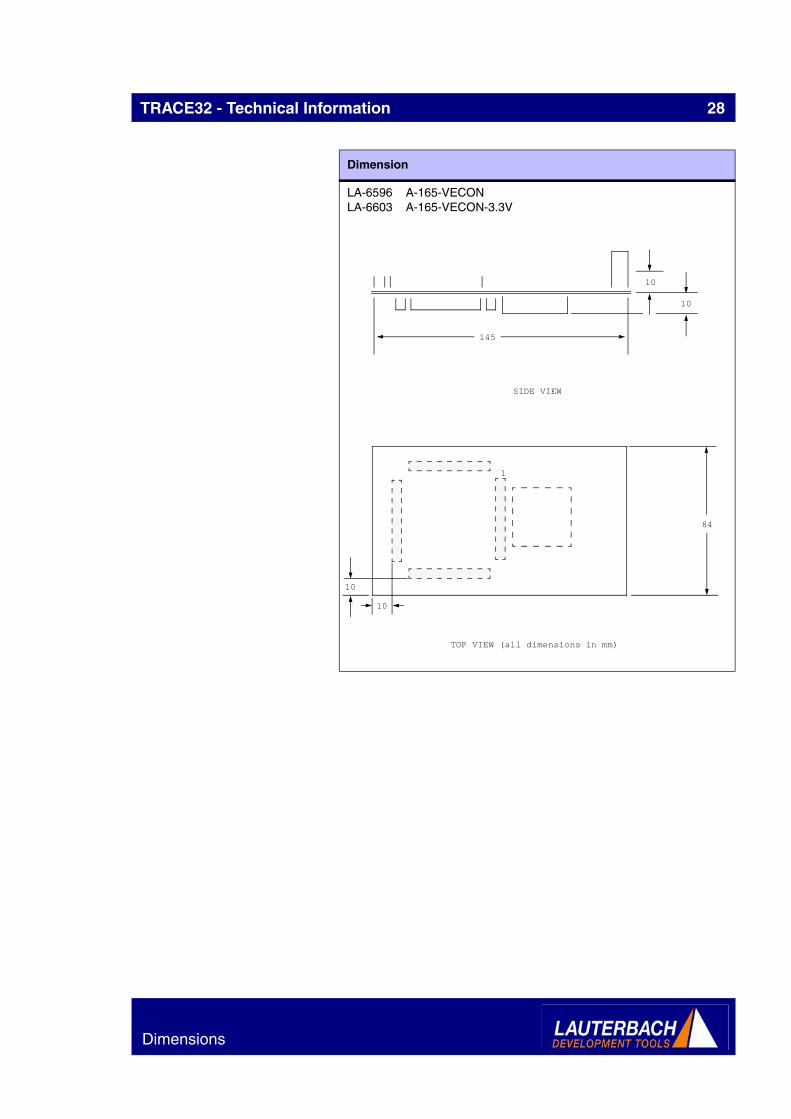
TRACE32 - Technical Information 28
LA-6596 A-165-VECONLA-6603 A-165-VECON-3.3V
Dimension
10
145
SIDE VIEW
10
84
10
TOP VIEW (all dimensions in mm)
1
10
Dimensions

TRACE32 - Technical Information 29
LA-1201 ET160-VECON160
Dimension
10
72
SIDE VIEW
10
72
6
7
TOP VIEW (all dimensions in mm)
TARGET
Dimensions

TRACE32 - Technical Information 30
LA-6602 A-C163LA-6604 A-C163-3.3V
Dimension
10
145
SIDE VIEW
25
15
84
9
9TOP VIEW (all dimensions in mm)
1
PIN 1
18
Dimensions

TRACE32 - Technical Information 31
LA-6610 A-C161V
Dimension
10
145
SIDE VIEW
7
84
10
25
TOP VIEW (all dimensions in mm)
PIN 1 PIN 1
41
14
Dimensions

TRACE32 - Technical Information 32
LA-6611 A-C161RI
Dimension
10
145
SIDE VIEW
7
84
11
18
TOP VIEW (all dimensions in mm)26
16
1 1
Dimensions

TRACE32 - Technical Information 33
LA-6612 A-C164CI
Dimension
10
145
SIDE VIEW
7
84
10
21
TOP VIEW (all dimensions in mm)
1
Dimensions

TRACE32 - Technical Information 34
LA-6613 A-C161CI
Dimension
10
145
SIDE VIEW
7
84
9
11
TOP VIEW (all dimensions in mm)
1
23
23
Dimensions

TRACE32 - Technical Information 35
LA-6615 A-C167E2CS
Dimension
Dimensions
TRACE32 - Technical Information 36
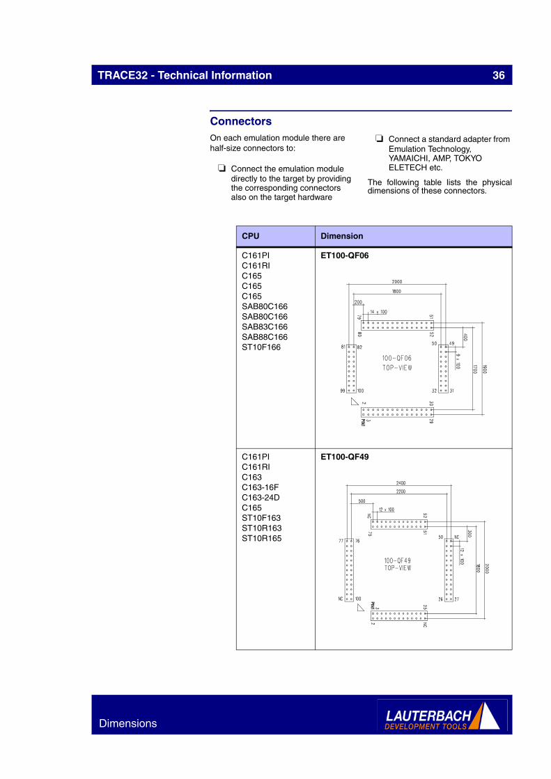
ConnectorsOn each emulation module there are half-size connectors to:
❏ Connect the emulation module directly to the target by providing the corresponding connectors also on the target hardware
❏ Connect a standard adapter from Emulation Technology, YAMAICHI, AMP, TOKYO ELETECH etc.
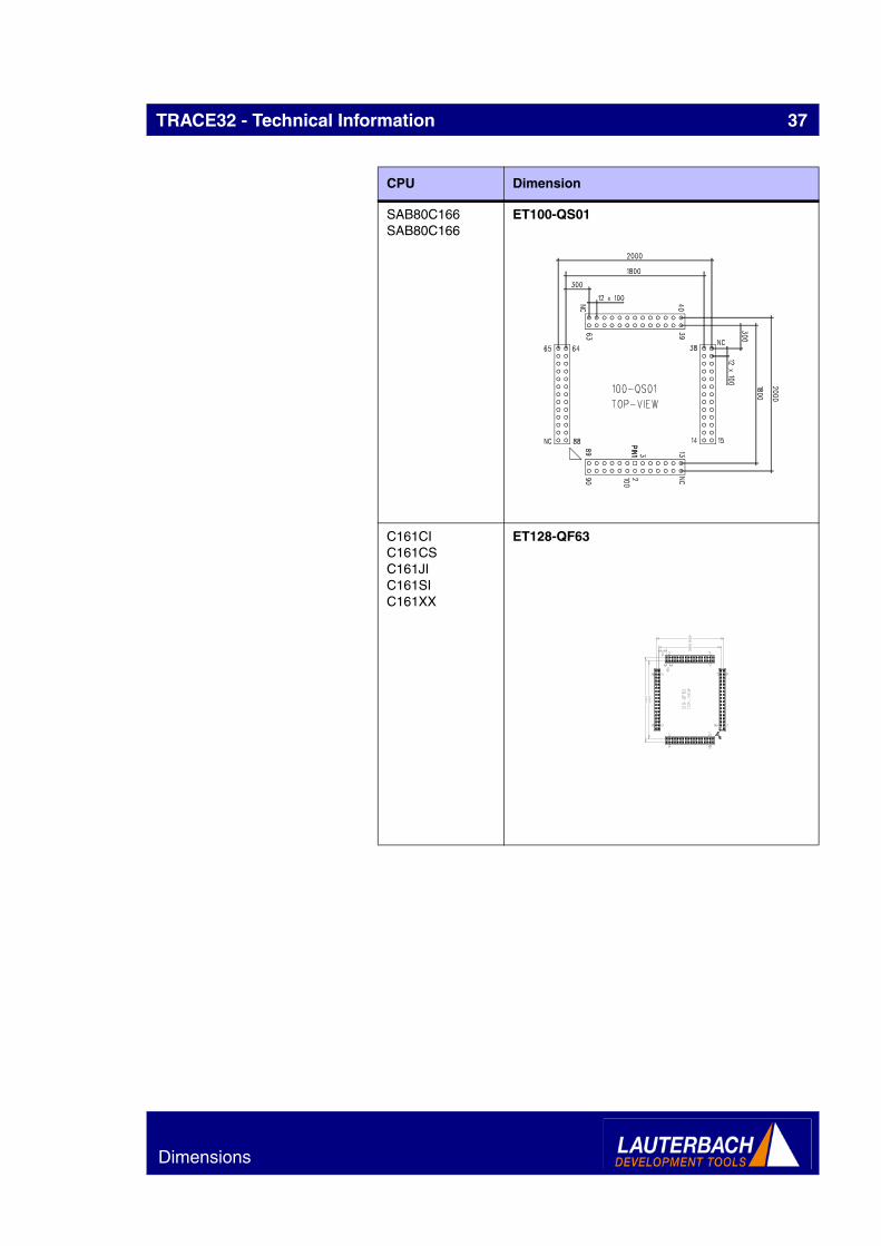
The following table lists the physicaldimensions of these connectors.
CPU Dimension
C161PIC161RIC165C165C165SAB80C166SAB80C166SAB83C166SAB88C166ST10F166
ET100-QF06
C161PIC161RIC163C163-16FC163-24DC165ST10F163ST10R163ST10R165
ET100-QF49
Dimensions
TRACE32 - Technical Information 37
SAB80C166SAB80C166
ET100-QS01
C161CIC161CSC161JIC161SIC161XX
ET128-QF63
CPU Dimension
Dimensions
TRACE32 - Technical Information 38
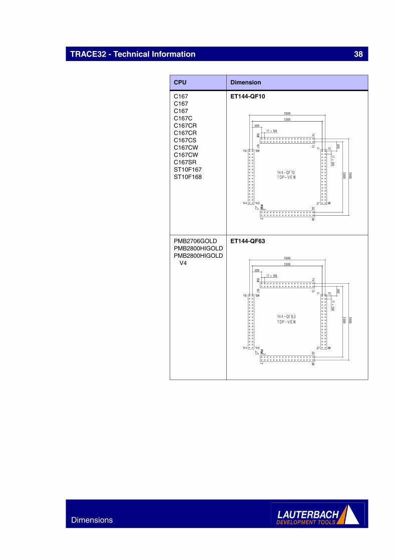
C167C167C167C167CC167CRC167CRC167CSC167CWC167CWC167SRST10F167ST10F168
ET144-QF10
PMB2706GOLDPMB2800HIGOLDPMB2800HIGOLD
V4
ET144-QF63
CPU Dimension
Dimensions

TRACE32 - Technical Information 39
PMB2705_GOLD_1.5
ET160-QF07
PMB2705_GOLD_2.1
PMB2705_GOLD_3.3
ET176-QF19
CPU Dimension
Dimensions
TRACE32 - Technical Information 40
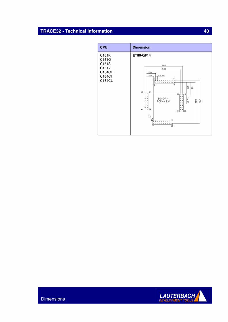
C161KC161OC161SC161VC164CHC164CIC164CL
ET80-QF14
CPU Dimension
Dimensions
TRACE32 - Technical Information 41
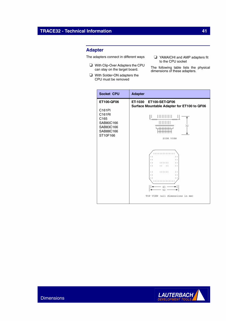
AdapterThe adapters connect in different ways
❏ With Clip-Over Adapters the CPU can stay on the target board.
❏ With Solder-ON adapters the CPU must be removed
❏ YAMAICHI and AMP adapters fit to the CPU socket
The following table lists the physicaldimensions of these adapters.
Socket CPU Adapter
ET100-QF06
C161PIC161RIC165SAB80C166SAB83C166SAB88C166ST10F166
ET-1030 ET100-SET-QF06Surface Mountable Adapter for ET100 to QF06
32
SIDE VIEW
:::::::::::::: :: :::: :::: :::::: :::: :: :: ::
:: :::::: :::: :::: :: ::::::::::::::
4352
TOP VIEW (all dimensions in mm)
Dimensions

TRACE32 - Technical Information 42
ET100-QF06
C161PIC161RIC165SAB80C166SAB83C166SAB88C166ST10F166
YA-1031 ET100-EYA-QF06Emul. Adapter for YAMAICHI socket ET100-QF06
Socket CPU Adapter
6
54
SIDE VIEW
8
56
9
11
TOP VIEW (all dimensions in mm)
1
Dimensions

TRACE32 - Technical Information 43
ET100-QF06
C161PIC161RIC165
ET-1032 ET100-CET-QF06Clip-Over Adapter for ET100-QF06
Socket CPU Adapter
32
SIDE VIEW
:::::::::::::: :: :::: :::: :::::: :::: :: :: ::
:: :::::: :::: :::: :: ::::::::::::::
52
TOP VIEW (all dimensions in mm)
Dimensions

TRACE32 - Technical Information 44
ET100-QF49
C161PIC161RIC163C163-16FC163-24DC165ST10F163ST10R163ST10R165
YA-1091 ET100-EYA-QF49Emul. Adapter for YAMAICHI socket ET100-QF49
Socket CPU Adapter
6
56
SIDE VIEW
8
66
18
14
TOP VIEW (all dimensions in mm)
1
Dimensions

TRACE32 - Technical Information 45
ET128-QF63
C161CIC161CSC161JIC161SIC161XX
YA-1112 ET128-EYA-QF63Emul. Adapter for YAMAICHI socket ET128-QF63
Socket CPU Adapter
6
69
SIDE VIEW
8
69
17
18
TOP VIEW (all dimensions in mm)
Dimensions
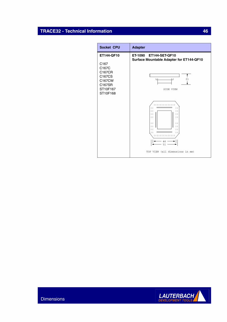
TRACE32 - Technical Information 46
ET144-QF10
C167C167CC167CRC167CSC167CWC167SRST10F167ST10F168
ET-1090 ET144-SET-QF10Surface Mountable Adapter for ET144-QF10
Socket CPU Adapter
21
SIDE VIEW
:::::::::::::: :: :::: :::: :::: ::
:: :::: :::: :::: :: ::::::::::::::
4651
TOP VIEW (all dimensions in mm)
Dimensions

TRACE32 - Technical Information 47
ET144-QF10
C167C167CC167CRC167CSC167CWC167SRST10F167ST10F168
YA-1094 ET144-EYA-QF10Emul. Adapter for YAMAICHI socket ET144-QF10
Socket CPU Adapter
6
69
SIDE VIEW
8
69
13
13
TOP VIEW (all dimensions in mm)
Dimensions

TRACE32 - Technical Information 48
ET144-QF10
C167C167CC167CRC167CSC167CWC167SRST10F167ST10F168
LA-1096 ET144-FP144Adapter ET144 to Footprint AMP Sockets
Socket CPU Adapter
9
69
SIDE VIEW
8
69
15
15
TOP VIEW (all dimensions in mm)
TARGET
Dimensions

TRACE32 - Technical Information 49
ET144-QF10
C167C167CC167CRC167CSC167CWC167SRST10F167ST10F168
TO-1300 ET144-ETO-QF10Emul. Adapter for T0 socket ET144-QF10
Socket CPU Adapter
144
143
110
109
450
71
7225002700
38
37
4 X SAMTEC:TSW-118-D-...
TARGET
TET-ADAPTER
TET-SOCKET
36
0
77
5
80
3536 7473
25
00
27
00
10
0100
107
108
450
TOP VIEW
12
ALL DIM
IN 1/
Dimensions

TRACE32 - Technical Information 50
ET144-QF63
PMB2706GOLDPMB2800HIGOLDPMB2800HIGOLDV4
YA-1111 ET144-EYA-QF63Emul. Adapter for YAMAICHI socket ET144-QF63
ET160-QF07
PMB2705_GOLD_1.5
ET-1060 ET160-SET-QF07Surface Mountable Adapter for ET160-QF07
Socket CPU Adapter
6
69
SIDE VIEW
8
69
17
18
TOP VIEW (all dimensions in mm)
:::::::::::::: :: :::: :::: :::: ::
:: :::: :::: :::: :: ::::::::::::::
TOP VIEW (all dimensions in mm)
Dimensions
TRACE32 - Technical Information 51
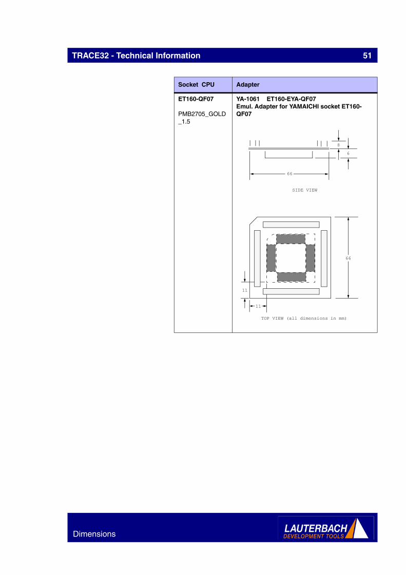
ET160-QF07
PMB2705_GOLD_1.5
YA-1061 ET160-EYA-QF07Emul. Adapter for YAMAICHI socket ET160-QF07
Socket CPU Adapter
6
66
SIDE VIEW
8
66
11
11
TOP VIEW (all dimensions in mm)
Dimensions

TRACE32 - Technical Information 52
ET160-QF07
PMB2705_GOLD_1.5
LA-1063 ET160-FP160-RAdapter for Footprint AMP/3M sockets
Socket CPU Adapter
9
66
SIDE VIEW
8
66
13
13
TOP VIEW (all dimensions in mm)
TARGET
Dimensions

TRACE32 - Technical Information 53
ET160-QF07
PMB2705_GOLD_1.5
LA-1064 ET160-FP160-LAdapter for Footprint AMP/3M sockets
Socket CPU Adapter
9
66
SIDE VIEW
8
66
13
13
TOP VIEW (all dimensions in mm)
TARGET
Dimensions

TRACE32 - Technical Information 54
ET80-QF14
C161KC161OC161SC161VC164CHC164CIC164CL
YA-1131 ET80-EYA-QF14Emul. Adapter for YAMAICHI socket ET080-QF14
Socket CPU Adapter
6
66
SIDE VIEW
8
51
11
18
TOP VIEW (all dimensions in mm)
Dimensions

TRACE32 - Technical Information 55
Available Tool ChainTRACE32 provides a complete set of development tools for this family. This includes:
❏ The In-Circuit Emulator TRACE32-ICE
❏ The high speed RISC Emulator TRACE32-FIRE
❏ The BDM/JTAG/ONCE etc. based In-Circuit Debugger TRACE32-ICD
❏ The ROM Monitor based In-Circuit Debugger TRACE32-ICD
❏ The ICD Trace, a trace externsion to the BDM/JTAG debuggers or ROM monitors
❏ Evaluation boards, which can be used until the target hardware is available.
❏ The Instruction Set Simulator (SIM), a software tool for code test without any hardware
The following list give an overviewwhich development tools are availablefor the specific derivatives of this family.
CP
U
ICE
FIR
E
ICD
DE
BU
G
ICD
MO
NIT
OR
ICD
TR
AC
E
PO
WE
RIN
TE
GR
ATO
R
INS
TR
UC
TIO
NS
IMU
LA
TOR
C161CI YES YES YES YES
C161CS YES YES YESC161JI YES YES YES
C161K YES YES YES YES YES
C161O YES YES YES YES YESC161PI YES YES YES YES
C161RI YES YES YES YES
C161S YES YES YES YES YESC161SI YES YES YES YES
C161V YES YES YES YES YES
C161XX YES YES YES YESC163 YES YES YES YES
C163-16F YES YES YES YES
C163-24D YES YES YES YESC164CH YES YES YES
C164CI YES YES YES YES
C164CL YES YES YES YESC165 YES YES YES YES YES
C167 YES YES YES YES YES
C167C YES YES YES YES YESC167CR YES YES YES YES YES
C167CS YES YES YES YES YES
C167CW YES YES YES YES YESC167SR YES YES YES YES YES
PMB2705_GOLD_1.5 YES YES YES
PMB2705_GOLD_2.1 YES YES YES
Available Tool Chain

TRACE32 - Technical Information 56
PMB2705_GOLD_3.3 YES YES YES
PMB2706GOLD YES YES YESPMB2800HIGOLD YES YES YES
PMB2800HIGOLDV4 YES YES YES
SAB80C166 YES YES YESSAB83C166 YES YES YES
SAB88C166 YES YES YES
ST10F163 YES YES YES YESST10F166 YES YES YES
ST10F167 YES YES YES YES
ST10F168 YES YES YES YESST10R163 YES YES YES YES
ST10R165 YES YES YES YES
CP
U
ICE
FIR
E
ICD
DE
BU
G
ICD
MO
NIT
OR
ICD
TR
AC
E
PO
WE
RIN
TE
GR
ATO
R
INS
TR
UC
TIO
NS
IMU
LA
TOR
Available Tool Chain
TRACE32 - Technical Information 57
Order Information
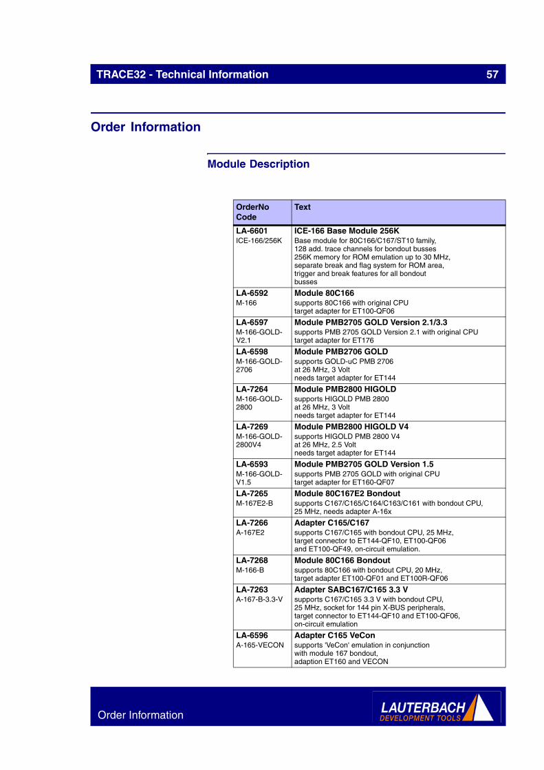
Module Description
OrderNo Code
Text
LA-6601 ICE-166/256K
ICE-166 Base Module 256KBase module for 80C166/C167/ST10 family,128 add. trace channels for bondout busses256K memory for ROM emulation up to 30 MHz,separate break and flag system for ROM area,trigger and break features for all bondoutbusses
LA-6592 M-166
Module 80C166supports 80C166 with original CPUtarget adapter for ET100-QF06
LA-6597 M-166-GOLD-V2.1
Module PMB2705 GOLD Version 2.1/3.3supports PMB 2705 GOLD Version 2.1 with original CPUtarget adapter for ET176
LA-6598 M-166-GOLD-2706
Module PMB2706 GOLDsupports GOLD-uC PMB 2706at 26 MHz, 3 Voltneeds target adapter for ET144
LA-7264 M-166-GOLD-2800
Module PMB2800 HIGOLDsupports HIGOLD PMB 2800at 26 MHz, 3 Voltneeds target adapter for ET144
LA-7269 M-166-GOLD-2800V4
Module PMB2800 HIGOLD V4supports HIGOLD PMB 2800 V4at 26 MHz, 2.5 Voltneeds target adapter for ET144
LA-6593 M-166-GOLD-V1.5
Module PMB2705 GOLD Version 1.5supports PMB 2705 GOLD with original CPUtarget adapter for ET160-QF07
LA-7265 M-167E2-B
Module 80C167E2 Bondoutsupports C167/C165/C164/C163/C161 with bondout CPU,25 MHz, needs adapter A-16x
LA-7266 A-167E2
Adapter C165/C167supports C167/C165 with bondout CPU, 25 MHz,target connector to ET144-QF10, ET100-QF06and ET100-QF49, on-circuit emulation.
LA-7268 M-166-B
Module 80C166 Bondoutsupports 80C166 with bondout CPU, 20 MHz,target adapter ET100-QF01 and ET100R-QF06
LA-7263 A-167-B-3.3-V
Adapter SABC167/C165 3.3 Vsupports C167/C165 3.3 V with bondout CPU,25 MHz, socket for 144 pin X-BUS peripherals,target connector to ET144-QF10 and ET100-QF06,on-circuit emulation
LA-6596 A-165-VECON
Adapter C165 VeConsupports 'VeCon' emulation in conjunctionwith module 167 bondout,adaption ET160 and VECON
Order Information

TRACE32 - Technical Information 58
LA-6615 A-C167E2CS
Adapter C165/C167CS/F168supports C167/C165 with bondout CPU, 25 MHz,target connector to ET144-QF10, ET100-QF06and ET100-QF49, on-circuit emulation.Socket for XPER device, supports C167CS and ST10F168
LA-6603 A-165-VECON-3.3V
Adapter C165 VeCon 3.3Vsupports 'VeCon' emulation in conjunctionwith module 167 bondout 3.3V,adaption ET160 and VECON
LA-1201 ET160-VECON160
ET160 to VECON160 Converteradaption for connector definition in VECON manual
LA-6602 A-C163
Adapter C163supports C163 with module 167 bondout,25 MHz, socket for 100 pin X-BUS peripherals,target connector to ET100-QF49,on-circuit emulation
LA-6604 A-C163-3.3V
Adapter C163 3.3Vsupports C163 emulation in conjunctionwith module 167 bondout 3.3V25 MHz, socket for 100 pin X-BUS peripherals,target connector to ET100F,on-circuit emulation
LA-6612 A-C164CI
Adapter C164CIsupports C164CI with module 167 bondout20 MHz, target connector to ET80-QF14on-circuit emulation
LA-6616 A-C164CR
Adapter C164CRsupports C164CR with module 167 bondout,25 MHz, target connector to ET100-QF49,on-circuit emulation
LA-6610 A-C161V
Adapter C161Vsupports C161S, C161V, C161K and C161O withwith module 167 bondout, 16 MHztarget connector to ET80-QF14on-circuit emulation
LA-6611 A-C161RI
Adapter C161RIsupports C161RI, C161PI with module 167 bondout,16 MHz target connector to ET100-QF49 and ET100-QF06on-circuit emulation
LA-6613 A-C161CI
Adapter C161SI/CI/CSsupports C161SI/CI/CS with module 167E2-B,16/12 MHz Operationtarget connector to ET128(ET144-QF63)on-circuit emulation
LA-6599 ET100R-EYA-QF49
Adapter ET100R-06 to YAMAICHI socket QF49Emulation Adapter for 80C165 in QF49for YAMAICHI socketYAMAICHI part number:IC-149-100-025-S5 without locator pinIC-149-100-125-S5 with locator pin
OrderNo Code
Text
Order Information
TRACE32 - Technical Information 59
Detailed Order Information
Order No.
Code Text
LA-6601 ICE-166/256K ICE-166 Base Module 256KLA-6592 M-166 Module 80C166LA-6597 M-166-GOLD-
V2.1Module PMB2705 GOLD Version 2.1/3.3
LA-6598 M-166-GOLD-2706
Module PMB2706 GOLD
LA-7264 M-166-GOLD-2800
Module PMB2800 HIGOLD
LA-7269 M-166-GOLD-2800V4
Module PMB2800 HIGOLD V4
LA-6593 M-166-GOLD-V1.5
Module PMB2705 GOLD Version 1.5
LA-7265 M-167E2-B Module 80C167E2 BondoutLA-7266 A-167E2 Adapter C165/C167LA-7268 M-166-B Module 80C166 BondoutLA-7263 A-167-B-3.3-V Adapter SABC167/C165 3.3 VLA-6596 A-165-VECON Adapter C165 VeConLA-6615 A-C167E2CS Adapter C165/C167CS/F168LA-6603 A-165-VECON-
3.3VAdapter C165 VeCon 3.3V
LA-1201 ET160-VECON160
ET160 to VECON160 Converter
LA-6602 A-C163 Adapter C163LA-6604 A-C163-3.3V Adapter C163 3.3VLA-6612 A-C164CI Adapter C164CILA-6616 A-C164CR Adapter C164CRLA-6610 A-C161V Adapter C161VLA-6611 A-C161RI Adapter C161RILA-6613 A-C161CI Adapter C161SI/CI/CSLA-6599 ET100R-EYA-
QF49Adapter ET100R-06 to YAMAICHI socket QF49
Additional OptionsAM-1055 ET100-AMP100 Adapter for AMP QFP100 Socket
ET-1032 ET100-CET-QF06 Clip-Over Adapter for ET100-QF06
TO-1260 ET100-ETO-QF06
Emul. Adapter for TO socket ET100-QF06
TO-1250 ET100-ETO-QF49
Emul. Adapter for T0 socket ET100-QF49
TO-1255 ET100-ETO-SE Emul. Adapter for T0 socket ET100-SE 0.4mm
YA-1051 ET100-EYA-QF01 Emul. Adapter for YAMAICHI socket ET100-QF01
YA-1031 ET100-EYA-QF06 Emul. Adapter for YAMAICHI socket ET100-QF06
Order Information

TRACE32 - Technical Information 60
YA-1091 ET100-EYA-QF49 Emul. Adapter for YAMAICHI socket ET100-QF49
LA-1054 ET100-FP100-L Adapter for ET100 to Footprint AMP/3M Sockets
LA-1053 ET100-FP100-R Adapter for ET100 to Footprint AMP/3M Sockets
ET-1050 ET100-SET-QF01 Surface Mountable Adapter for ET100 to QF01
ET-1030 ET100-SET-QF06 Surface Mountable Adapter for ET100 to QF06
ET-1092 ET100-SET-QF49 Surface Mountable Adapter for ET100-QF49
TO-1261 ET100-STO-QF06
Emul. Adapter TO-surface mount. ET100-QF06
TO-1251 ET100-STO-QF49
Emul. Adapter TO-surface mount. ET100-QF49
YA-1112 ET128-EYA-QF63 Emul. Adapter for YAMAICHI socket ET128-QF63
ET-1095 ET144-CET-QF10 Clip Over Adapter for ET144-QF10
TO-1300 ET144-ETO-QF10
Emul. Adapter for T0 socket ET144-QF10
TO-1310 ET144-ETO-QF63
Emul. Adapter for T0 socket ET144-QF63
YA-1094 ET144-EYA-QF10 Emul. Adapter for YAMAICHI socket ET144-QF10
YA-1111 ET144-EYA-QF63 Emul. Adapter for YAMAICHI socket ET144-QF63
LA-1096 ET144-FP144 Adapter ET144 to Footprint AMP Sockets
ET-1090 ET144-SET-QF10 Surface Mountable Adapter for ET144-QF10
ET-1110 ET144-SET-QF63 Surface Mountable Adapter for ET144-QF63
TO-1301 ET144-STO-QF10
Emul. Adapter TO-surface mount. ET144-QF10
TO-1311 ET144-STO-QF63
Emul. Adapter TO-surface mount. ET144-QF63
TO-1320 ET160-ETO-QF07
Emul. Adapter for T0 socket ET160-QF07
YA-1061 ET160-EYA-QF07 Emul. Adapter for YAMAICHI socket ET160-QF07
LA-1064 ET160-FP160-L Adapter for Footprint AMP/3M sockets
LA-1063 ET160-FP160-R Adapter for Footprint AMP/3M sockets
ET-1060 ET160-SET-QF07 Surface Mountable Adapter for ET160-QF07
TO-1321 ET160-STO-QF07
Emul. Adapter TO-surface mount. ET160-QF07
ET-1132 ET80-CET-QF14 Clip Over Adapter for QF14
TO-1275 ET80-ETO-QF14 Emul. Adapter for T0 socket ET080-QF14
YA-1131 ET80-EYA-QF14 Emul. Adapter for YAMAICHI socket ET080-QF14
ET-1130 ET80-SET-QF14 Surface Mountable Adapter for ET80-QF14
TO-1276 ET80-STO-QF14 Emul. Adapter TO-surface mount. ET080-QF14
LA-7512 MON-166 ROM Monitor for C166/ST10 on ESI
LA-7755 OCDS-C166CBC OCDS Debugger for C166CBC (ICD)
LA-6450 PA64 Port Analyzer
LA-8803 SIM-166 TRACE32 Instruction Set Simulator for C166/ST
Order No.
Code Text
Order Information

TRACE32 - Technical Information 61
Contact
International RepresentativeArgentina
Anacom Eletronica Ltda.Mr. Rafael SoriceRua Nazareth, 807, BarcelonaBR-09551-200 São Caetano do Sul, SPPhone: +55 11 3422 4200FAX: +55 11 3422 4242EMAIL: [email protected]
AustraliaEmbedded Logic Solutions P/LMr. Ramzi KattanSuite 2, Level 3144 Marsden StreetParramatta NSW 2150Phone: +61 2 9687 1880FAX: +61 2 9687 1881EMAIL: [email protected]
AustriaLauterbach GmbHAltlaufstr. 40D-85635 Höhenkirchen-SiegertsbrunnPhone: +49 8102 9876 0FAX: +49 8102 9876 999EMAIL: [email protected]
BelgiumTritec Benelux B.V.Mr. Robbert de VoogtStationspark 550NL-3364 DA SliedrechtPhone: +31 184 41 41 31FAX: +31 184 42 36 11EMAIL: [email protected]
BrazilAnacom Eletronica Ltda.Mr. Rafael SoriceRua Nazareth, 807, BarcelonaBR-09551-200 São Caetano do Sul, SPPhone: +55 11 3422 4200FAX: +55 11 3422 4242EMAIL: [email protected]
CanadaLauterbach Inc.Mr. Udo Zoettler4 Mount Royal Ave.USA-Marlborough, MA 01752Phone: +1 508 303 6812FAX: +1 508 303 6813EMAIL: [email protected]
China BeijingLauterbach Technologies Co., LtdMr. Linglin HeBeijing OfficeA3,South Lishi Road, XiCheng DistrictBeijing 100037, P.R. ChinaPhone: +86 10 68023502FAX: +86 10 68023523EMAIL: [email protected]
China ShenzhenLauterbach Technologies Co., Ltd1406/E Xihaimingzhu BuildingNo.1 Taoyuan Road, Nanshan DistrictShenzhen 518052, P.R. ChinaPhone: +86 755 8621 0671FAX: +86 755 8621 0675EMAIL: [email protected]
China SuzhouLauterbach Technologies Co., LtdMr. Tom MeyerHengyu Square, Rm 709No. 188, Xing Hai StreetSuzhou, 215021 P.R. of ChinaPhone: +86 512 6265 8030FAX: +86 512 6265 8032EMAIL: [email protected]
DenmarkNohau Danmark A/SMr. Flemming JensenKlausdalsbrovej 493DK-2730 HerlevPhone: +45 44 52 16 50FAX: +45 44 52 26 55EMAIL: [email protected]
EgyptWantech EgyptMr. Wagih A. Nawara5 Shafik Ghalie St., Suite 2Off Pyramids Road, GizaCairo 12111Phone: +20 100 1251955FAX: +20 100 1250349EMAIL: [email protected]
FinlandNohau Solutions FinlandMr. Leevi LehtinenTeknobulevardi 3-5FI-01531 VantaaPhone: +358 40 546 1469FAX: +358 9 2517 8101EMAIL: [email protected]
FranceLauterbach S.A.R.L.Mr. Jean-Pierre ParadisoEuroparc - Le Hameau B135 Chemin Des BassinsF-94035 Créteil CedexPhone: +33 1 49 56 20 30FAX: +33 1 49 56 20 39EMAIL: [email protected]
GermanyLauterbach GmbHAltlaufstr. 40D-85635 Höhenkirchen-SiegertsbrunnPhone: +49 8102 9876 0FAX: +49 8102 9876 999EMAIL: [email protected]
Germany NorthLauterbach GmbHMr. Klaus HommannLeonhardring 5D-31319 SehndePhone: +49 5138 6185 0FAX: +49 5138 6185 3EMAIL: [email protected]
Germany SouthLauterbach GmbHAltlaufstr. 40D-85635 Höhenkirchen-SiegertsbrunnPhone: +49 8102 9876 129FAX: +49 8102 9876 187EMAIL: [email protected]
GreekLauterbach GmbHAltlaufstr. 40D-85635 Höhenkirchen-SiegertsbrunnPhone: +49 8102 9876 0FAX: +49 8102 9876 999EMAIL: [email protected]
Contact
TRACE32 - Technical Information 62
India-BangaloreElectro Systems Associates Pvt. Ltd.Mr. G. V. GurunathamS-606, World Trade CenterMalleswaram West, No.26/1, Dr. Rajkumar
RoadIndia - Bangalore 560055Phone: +91 80 67648888FAX: +91 80 23475615EMAIL: [email protected]
India-ChennaiElectro Systems Associates Pvt. Ltd.Mr. D. KannanNo.109 /59A , Ground FloorIV Avenue, Ashok NagarIndia - Chennai - 600 083 TamilnaduPhone: +91 044-24715750FAX: ++91 44 24715750EMAIL: [email protected]
India-DelhiElectro Systems Associates Pvt. Ltd.Mr. R.K. BhandariNo. 705, 7th Floor, Laxmi DeepShivajinagarIndia - Delhi - 110 092Phone: +91 11-22549351FAX:EMAIL: [email protected]
India-HyderabadElectro Systems Associates Pvt. Ltd.Mr. C.V.M. Sri Ram MurthyShop No. 14, "Global Enclave"Bhagyanagar Colony, Kukat pallyIndia - Hyderabad 500 072Phone: +91 40-23063346FAX: +91 40-23063346EMAIL: [email protected]
India-PuneElectro Systems Associates Pvt. Ltd.Mr. R K BhandariShriram Complex,1126/1, Model ColonyShivajinagarIndia - Pune - 411 016Phone: +91 20 - 30462035 / 25663FAX: +91 20-25677202EMAIL: [email protected]
IrelandLauterbach Ltd.Mr. Barry Lock11 Basepoint Enterprise CentreStroudley RoadBasingstoke, Hants RG24 8UPPhone: +44-1256-333-690FAX: +44-1256-336-661EMAIL: [email protected]
IsraelItec Ltd.Mr. Mauri GottliebP.O.Box 10002IL-Tel Aviv 61100Phone: +972 3 6491202FAX: +972 3 6497661EMAIL: [email protected]
ItalyLauterbach SrlMr. Maurizio MenegottoVia Enzo Ferrieri 12I-20153 MilanoPhone: +39 02 45490282FAX: +39 02 45490428EMAIL: [email protected]
JapanLauterbach Japan, Ltd.Mr. Kenji Furukawa3-8-8 ShinyokohamaKouhoku-kuYokohama-shi, Japan 222-0033Phone: +81 45 477 4511FAX: +81 45 477 4519EMAIL: [email protected]
LuxemburgTritec Benelux B.V.Mr. Robbert de VoogtStationspark 550NL-3364 DA SliedrechtPhone: +31 184 41 41 31FAX: +31 184 42 36 11EMAIL: [email protected]
MalaysiaFlash TechnologyMr. Teo Kian HockNo 61, # 04-15 Kaki Bukit Av 1Shun Li Industrial ParkSGP-Singapore 417943Phone: +65 6749 6168FAX: +65 6749 6138EMAIL: [email protected]
MexicoLauterbach Inc.Mr. Udo Zoettler4 Mount Royal Ave.USA-Marlborough, MA 01752Phone: +1 508 303 6812FAX: +1 508 303 6813EMAIL: [email protected]
NetherlandsTritec Benelux B.V.Mr. Robbert de VoogtStationspark 550NL-3364 DA SliedrechtPhone: +31 184 41 41 31FAX: +31 184 42 36 11EMAIL: [email protected]
New ZealandEmbedded Logic Solutions P/LMr. Ramzi KattanSuite 2, Level 3144 Marsden StreetParramatta NSW 2150Phone: +61 2 9687 1880FAX: +61 2 9687 1881EMAIL: [email protected]
NorwayNohau Solutions ABMr. Jörgen NilssonDerbyvägen 4SE-21235 MalmoePhone: +46 40 592 206FAX: +46-40 592 229EMAIL: [email protected]
PolandQUANTUM Sp. z o.o.Mr. Czeslaw Bilul. Wystawowa 151-618 WroclawPhone: +48 71 362 6356FAX: +48 71 362 6357EMAIL: [email protected]
PortugalCaptura Electronica,SCCLMr. Juan Martinezc/Duero, 40E-08031 BarcelonaPhone: +34 93 429 5730FAX: +34 93 407 0778EMAIL: [email protected]
RomaniaLauterbach GmbHAltlaufstr. 40D-85635 Höhenkirchen-SiegertsbrunnPhone: +49 8102 9876 0FAX: +49 8102 9876 999EMAIL: [email protected]
RussiaRTSoftMr. Alexey IsaevNikitinskaya 3RUS-105037 MoscowPhone: +7 495 742 6828FAX: +7 495 742 6829EMAIL: [email protected]
Contact

TRACE32 - Technical Information 63
SingaporeFlash TechnologyMr. Teo Kian HockNo 61, # 04-15 Kaki Bukit Av 1Shun Li Industrial ParkSGP-Singapore 417943Phone: +65 6749 6168FAX: +65 6749 6138EMAIL: [email protected]
South Korea, PangyoMDS Technology Co.,Ltd.Mr. Sangheon Lee3FL. Hancom Tower49, Daewangpangyo-ro 644, Bundang-guSeongnam-si, Gyeonggi-do, 463-400, ROKPhone: +82-31-627-3000FAX: +82-31-627-3100EMAIL: [email protected]
SpainCaptura Electronica,SCCLMr. Juan Martinezc/Duero, 40E-08031 BarcelonaPhone: +34 93 429 5730FAX: +34 93 407 0778EMAIL: [email protected]
SwedenNohau Solutions ABMr. Jörgen NilssonDerbyvägen 4SE-21235 MalmoePhone: +46 40 592 206FAX: +46 40 592 229EMAIL: [email protected]
SwitzerlandJDT Jberg DatenTechnikMr. Andreas JbergZimmereistrasse 2CH-5734 Reinach AGPhone: +41 62 7710 886FAX:EMAIL: [email protected]
TaiwanSuperlink Technology Corp.Mr. Sulin Huang3F-8,No.77,Shin-Tai-Wu Rd.Sec1Taipei Hsien 221, Taiwan, R.O.C.Phone: +886 2 26983456FAX: +886 2 26983535EMAIL: [email protected]
TunesiaLauterbach Consulting S.A.R.L.Mr. Khaled Jmal
Phone:FAX:EMAIL: [email protected]
Turkey-1Tektronik Muh. ve Tic. Ltd.Mr. Hakan YavuzMahatma Gandhi Cad 68A/2G.O.Pasa06700 AnkaraPhone: +90 312 437 3000FAX: +90 312 437 1616EMAIL: [email protected]
Turkey-2G3TEK Embedded Technologies Ltd.Mr. Celal AygunIlkyerlesim Mah. 445.Sok. No: 4806370 Batikent/AnkaraPhone: +90 312 3324769FAX: +90 312 3324769EMAIL: [email protected]
UKLauterbach Ltd.Mr. Barry Lock11 Basepoint Enterprise CentreStroudley RdBasingstoke, Hants RG24 8UPPhone: +44 1256 333 690FAX: +44 1256 336 661EMAIL: [email protected]
USA EastLauterbach Inc.Mr. Udo Zoettler4 Mount Royal Ave.USA-Marlborough, MA 01752Phone: +1 508 303 6812FAX: +1 508 303 6813EMAIL: [email protected]
USA WestLauterbach Inc.Mr. Jerry Flake1111 Main Street, Suite 610USA-Vancouver, WA. 98660Phone: +1 503 524 2222FAX: +1 503 524 2223EMAIL: [email protected]
Contact

TRACE32 - Technical Information 64
Additional Information
Lauterbach GmbHAltlaufstr. 40 D-85649 HofoldingTel. ++49 8102 9876-0 FAX [email protected]://www.lauterbach.de
Lauterbach Inc.4 Mount Royal Ave.Marlboro MA 01752Phone (508) 303 6812 FAX (508) 303 [email protected]://www.us.lauterbach.com
Lauterbach Ltd.11 Basepoint Enterprise Ctre Stroudley RoadBasingstoke, Hants RG24 8UP Phone ++44-1256-333-690 FAX -661 [email protected]:/www.lauterbach.co.uk
Lauterbach S.A.R.L.135 Chemin Des BassinsF-94035 Créteil CedexPhone ++33-149-562-030 FAX ++33-149-562-039 [email protected]:/www.lauterbach.fr
Lauterbach Japan, Ltd.3-9-5 Shinyokohama Kouhoku-kuYokohama-shi Japan 222-0033Phone ++81-45-477-4511 FAX [email protected]://www.lauterbach.co.jp
Lauterbach s.r.l.Lauterbach s.r.l. Via Enzo Ferrieri 12I-20153 MilanoPhone ++39 02 45490282FAX ++39 02 [email protected]://www.lauterbach.it
Suzhou Lauterbach Consulting Co.,Ltd.
Room 1605, Xing Hai International SquareNo.200, Xing Hai StreetSuzhou, 215021 PR of ChinaPhone: 0086-512 6265 8030FAX: 0086-512 6265 [email protected]://www.lauterbach.cn
Disclaimer
http://www.lauterbach.com
The information presented is intended to give overview information only. Changes and technical enhancements or modifications can be made with-out notice.
Contact
Related Documents


![Sequencer 1, Sequencer 2 or Drum - medias.arturia.net · —Sequencer 1, Sequencer 2 or Drum SHIFT + [>>] = Extend sequence SHIFT + Knob 1 = Offset value for all active steps ...](https://static.cupdf.com/doc/110x72/5b87086c7f8b9aa0218be152/sequencer-1-sequencer-2-or-drum-sequencer-1-sequencer-2-or-drum-shift.jpg)