VIRGINIA POLYTECHNIC INSTITUTE AND STATE UNIVERSITY Tech V irginia 1 8 7 2 © 2001 T. S. Rappaport, All Rights Reserved In-building Wireless Tutorial The Last 100 Meters of the Wireless Revolution Dr. Ted S. Rappaport James S. Tucker Professor Mobile & Portable Radio Research Group Virginia Tech [email protected] 11 th Annual MPRG Symposium June 6-8, 2001 VIRGINIA POLYTECHNIC INSTITUTE AND STATE UNIVERSITY Tech V irginia 1 8 7 2 2 ©2001 T. S. Rappaport Today’s Topics Motivation Emerging Trends Technical Details Equipment Choices Demo of Tools Design Examples

Welcome message from author
This document is posted to help you gain knowledge. Please leave a comment to let me know what you think about it! Share it to your friends and learn new things together.
Transcript
1
VIRGINIA POLYTECHNIC INSTITUTEAND STATE UNIVERSITY
TechVirginia
1 8 7 2
© 2001 T. S. Rappaport, All Rights Reserved
In-building Wireless TutorialThe Last 100 Meters of the Wireless Revolution
Dr. Ted S. RappaportJames S. Tucker ProfessorMobile & Portable Radio Research GroupVirginia [email protected]
11th Annual MPRG Symposium
June 6-8, 2001
VIRGINIA POLYTECHNIC INSTITUTEAND STATE UNIVERSITY
TechVirginia
1 8 7 2
2
©2001 T. S. Rappaport
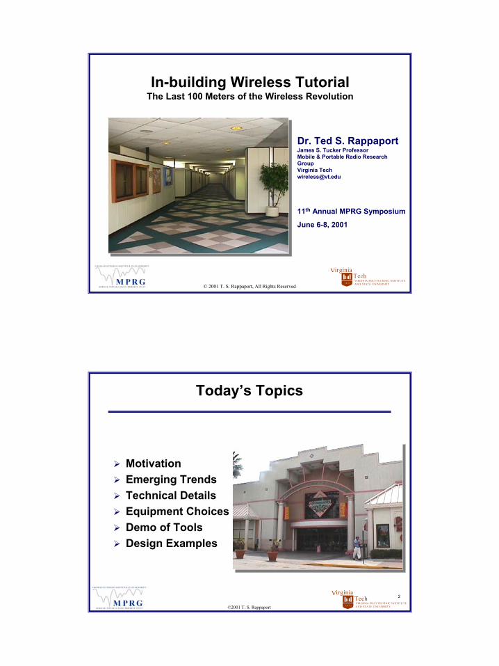
Today’s Topics
MotivationEmerging TrendsTechnical DetailsEquipment ChoicesDemo of ToolsDesign Examples

2
VIRGINIA POLYTECHNIC INSTITUTEAND STATE UNIVERSITY
TechVirginia
1 8 7 2
3
©2001 T. S. Rappaport
Tutorial Overview
Motivation for In- building WirelessService TypesDesign ObjectivesThe Indoor RF EnvironmentIn- building Distribution TechnologiesEquipment Options & Design IssuesLink Budget & Propagation ModelingTraffic EngineeringPractical Deployment IssuesDesign Tools
VIRGINIA POLYTECHNIC INSTITUTEAND STATE UNIVERSITY
TechVirginia
1 8 7 2
© 2001 T. S. Rappaport, All Rights Reserved
Motivation for In-building Wireless
3
VIRGINIA POLYTECHNIC INSTITUTEAND STATE UNIVERSITY
TechVirginia
1 8 7 2
5
©2001 T. S. Rappaport
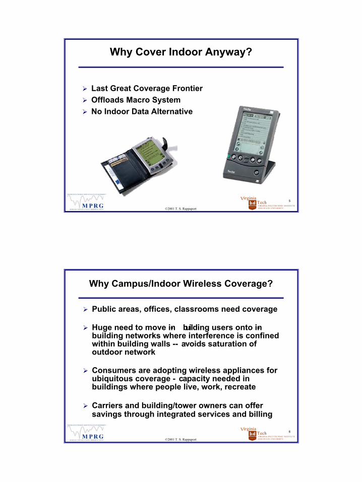
Why Cover Indoor Anyway?
Last Great Coverage FrontierOffloads Macro SystemNo Indoor Data Alternative
VIRGINIA POLYTECHNIC INSTITUTEAND STATE UNIVERSITY
TechVirginia
1 8 7 2
6
©2001 T. S. Rappaport
Why Campus/Indoor Wireless Coverage?
Public areas, offices, classrooms need coverage
Huge need to move in- building users onto in-building networks where interference is confined within building walls -- avoids saturation of outdoor network
Consumers are adopting wireless appliances for ubiquitous coverage - capacity needed in buildings where people live, work, recreate
Carriers and building/tower owners can offer savings through integrated services and billing

4
VIRGINIA POLYTECHNIC INSTITUTEAND STATE UNIVERSITY
TechVirginia
1 8 7 2
7
©2001 T. S. Rappaport
Buildings and Campus enterprises need planned wireless internet and cellular/PCS strategy
Campus environments require design tools that support ongoing facilities management and maintenance for expansion and upgrades
In- building wireless deployment in its infancy but will explode with Wireless Office, Wireless LANs, Wireless Video, VoIP, Bluetooth, and Wireless PDAs.
Wireless Access Issues in Buildings
VIRGINIA POLYTECHNIC INSTITUTEAND STATE UNIVERSITY
TechVirginia
1 8 7 2
© 2001 T. S. Rappaport, All Rights Reserved
Service Types
5
VIRGINIA POLYTECHNIC INSTITUTEAND STATE UNIVERSITY
TechVirginia
1 8 7 2
9
©2001 T. S. Rappaport
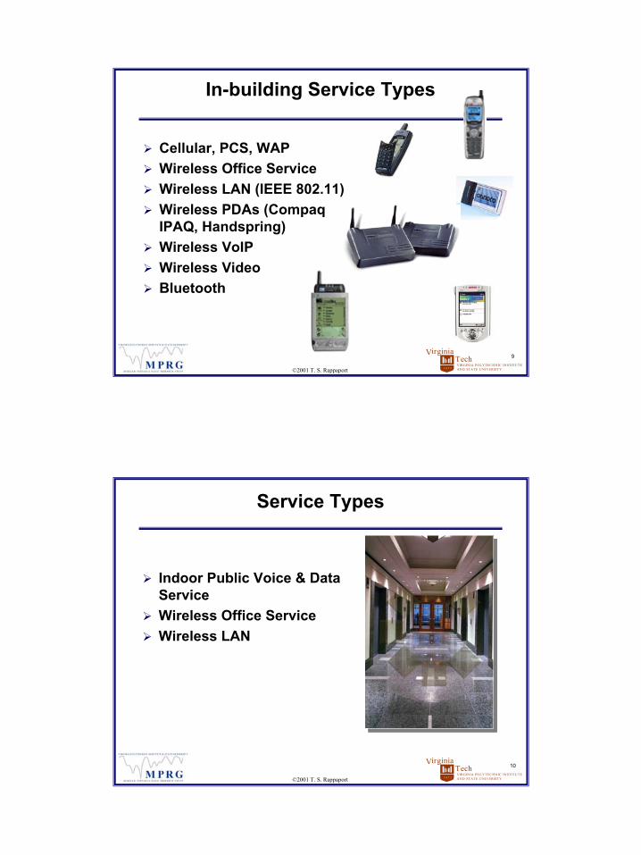
In-building Service Types
Cellular, PCS, WAPWireless Office ServiceWireless LAN (IEEE 802.11)Wireless PDAs (Compaq IPAQ, Handspring)Wireless VoIPWireless VideoBluetooth
VIRGINIA POLYTECHNIC INSTITUTEAND STATE UNIVERSITY
TechVirginia
1 8 7 2
10
©2001 T. S. Rappaport
Service Types
Indoor Public Voice & Data ServiceWireless Office ServiceWireless LAN

6
VIRGINIA POLYTECHNIC INSTITUTEAND STATE UNIVERSITY
TechVirginia
1 8 7 2
11
©2001 T. S. Rappaport
Indoor Public Service
Base Station is Microcell or Picocell Radio EquipmentCarrier Pays
VIRGINIA POLYTECHNIC INSTITUTEAND STATE UNIVERSITY
TechVirginia
1 8 7 2
12
©2001 T. S. Rappaport
Wireless Office Service (Private Service)
Wireless PBX or Cellular Base StationPSID for User Re- RegistrationDialing and Billing FeaturesCustomer Pays
7
VIRGINIA POLYTECHNIC INSTITUTEAND STATE UNIVERSITY
TechVirginia
1 8 7 2
13
©2001 T. S. Rappaport
Public WLAN (PubLAN)
Public Access to 802.11b W- LANInternet Service Provider (ISP) offers accessIn- building service provider (IBSP) installs and owns equipment
VIRGINIA POLYTECHNIC INSTITUTEAND STATE UNIVERSITY
TechVirginia
1 8 7 2
© 2001 T. S. Rappaport, All Rights Reserved
Design Objectives
8
VIRGINIA POLYTECHNIC INSTITUTEAND STATE UNIVERSITY
TechVirginia
1 8 7 2
15
©2001 T. S. Rappaport
Design Objectives
RF Performance
Cost
Specific Customer requests
Ease of Installation
Ease of Maintenance
VIRGINIA POLYTECHNIC INSTITUTEAND STATE UNIVERSITY
TechVirginia
1 8 7 2
16
©2001 T. S. Rappaport
RF Planning Objectives
Satisfaction of Specific Customer NeedsRF and Network Performance (Coverage and Capacity)Minimal Cost (Equipment and Installation)Cooperation with macrocell systems and interference minimizationEase of installation and integration with building environment, all properly documentedOngoing infrastructure maintenance

9
VIRGINIA POLYTECHNIC INSTITUTEAND STATE UNIVERSITY
TechVirginia
1 8 7 2
17
©2001 T. S. Rappaport
Design Objective: RF Performance
Sufficient Downlink Power for:Phones to camp on to your indoor or microcellsystemGood downlink voice quality anywhere customer can make a callInternet access inside buildings
VIRGINIA POLYTECHNIC INSTITUTEAND STATE UNIVERSITY
TechVirginia
1 8 7 2
18
©2001 T. S. Rappaport
Design Objective: RF Performance
Limit downlink power to prevent phone overload at closest access point
10
VIRGINIA POLYTECHNIC INSTITUTEAND STATE UNIVERSITY
TechVirginia
1 8 7 2
19
©2001 T. S. Rappaport
Design Objective: RF Performance
Transmit as little downlink power out of the building as possibleKeep antennas away from exterior glassMinimize macrocell interference
VIRGINIA POLYTECHNIC INSTITUTEAND STATE UNIVERSITY
TechVirginia
1 8 7 2
20
©2001 T. S. Rappaport
Design Objective: RF Performance
Sufficiently Low- Loss Reverse Link Path for:Good reverse link voice qualityGood reverse link with minimum power drainMinimize uplink interference to macrocellHigh speed Internet link

11
VIRGINIA POLYTECHNIC INSTITUTEAND STATE UNIVERSITY
TechVirginia
1 8 7 2
21
©2001 T. S. Rappaport
Design Objective: RF Performance
Reliable handoffs with the macrocell SystemWalking into the buildingIn an elevator on all floorsDriving out of basement parking garageExiting via elevated walkway
VIRGINIA POLYTECHNIC INSTITUTEAND STATE UNIVERSITY
TechVirginia
1 8 7 2
22
©2001 T. S. Rappaport
Best Placement Objectives
Cover sensitive or secure areas without requiring installation of antennas or cable (i.e. hospitals)

12
VIRGINIA POLYTECHNIC INSTITUTEAND STATE UNIVERSITY
TechVirginia
1 8 7 2
23
©2001 T. S. Rappaport
Best Placement Objectives
Hide or disguise the antenna system for minimum visual impact
VIRGINIA POLYTECHNIC INSTITUTEAND STATE UNIVERSITY
TechVirginia
1 8 7 2
24
©2001 T. S. Rappaport
Best Placement Objectives
Achieve design objectives at minimum costEquipment Cost: maximizing efficiency Installation Cost: best technology choice Leasing Cost: distribution system
RBSDark FiberCAT 3 or CAT 5

13
VIRGINIA POLYTECHNIC INSTITUTEAND STATE UNIVERSITY
TechVirginia
1 8 7 2
© 2001 T. S. Rappaport, All Rights Reserved
The Indoor RF Environment
VIRGINIA POLYTECHNIC INSTITUTEAND STATE UNIVERSITY
TechVirginia
1 8 7 2
26
©2001 T. S. Rappaport
The RF Propagation Environment
LossesFadingNoiseRF ExposureRF OverloadMultipath
14
VIRGINIA POLYTECHNIC INSTITUTEAND STATE UNIVERSITY
TechVirginia
1 8 7 2
27
©2001 T. S. Rappaport
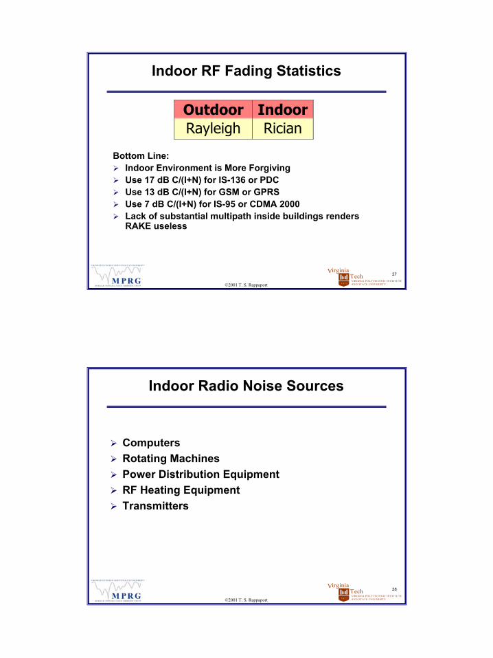
Indoor RF Fading Statistics
Bottom Line: Indoor Environment is More ForgivingUse 17 dB C/(I+N) for IS-136 or PDCUse 13 dB C/(I+N) for GSM or GPRSUse 7 dB C/(I+N) for IS-95 or CDMA 2000Lack of substantial multipath inside buildings renders RAKE useless
Outdoor IndoorRayleigh Rician
VIRGINIA POLYTECHNIC INSTITUTEAND STATE UNIVERSITY
TechVirginia
1 8 7 2
28
©2001 T. S. Rappaport
Indoor Radio Noise Sources
ComputersRotating MachinesPower Distribution EquipmentRF Heating EquipmentTransmitters
15
VIRGINIA POLYTECHNIC INSTITUTEAND STATE UNIVERSITY
TechVirginia
1 8 7 2
29
©2001 T. S. Rappaport
Indoor Maximum Power Exposure (MPE)
Radiax Produces Low Power DensityBe Careful of Directional Antennas Aimed Toward FloorPreventing Phone Overload Will Keep Power Density Well Below MPEFCC Requires Measuring Power Density for Indoor Sites in US (OET65)
VIRGINIA POLYTECHNIC INSTITUTEAND STATE UNIVERSITY
TechVirginia
1 8 7 2
© 2001 T. S. Rappaport, All Rights Reserved
In-building Distribution Technologies
16
VIRGINIA POLYTECHNIC INSTITUTEAND STATE UNIVERSITY
TechVirginia
1 8 7 2
31
©2001 T. S. Rappaport
In-Building Distribution Technologies
Repeaters (coverage,but no capacity)Bi-directional amplifier (BDA)
Passive Distribution (lossy, short distance)Coaxial cable, splitters
RF Amplifier Distribution (expensive)Coaxial cable, splitters, amplifiers
Active Distribution (requires new wiring)Optical, analog or digital; CAT-5
VIRGINIA POLYTECHNIC INSTITUTEAND STATE UNIVERSITY
TechVirginia
1 8 7 2
32
©2001 T. S. Rappaport
Repeater Design Issues
Sufficient capacity in outdoor serving cellNoise floor levels on both sides of BDAAdjusting BDA gains for desired coveragePlacement of BDA and antennasOverall cost vs. performance
17
VIRGINIA POLYTECHNIC INSTITUTEAND STATE UNIVERSITY
TechVirginia
1 8 7 2
33
©2001 T. S. Rappaport
Passive Distribution Design Issues
Noise floor increases due to lossSignal loss through distribution networkAdditional loss due to splitters or tapsUsing radiating cable vs. run- and- dropDesigning multi- antenna “star” topologySingle- or multi- band distributionOverall cost vs. performance
VIRGINIA POLYTECHNIC INSTITUTEAND STATE UNIVERSITY
TechVirginia
1 8 7 2
34
©2001 T. S. Rappaport
RF Amplifier Distribution Design Issues
Correct allocation of gain in systemAvoidance of intermod or spurious signalsLimitation: dynamic range headroomBi- directional gain and noise figure designOverall cost vs. performance
18
VIRGINIA POLYTECHNIC INSTITUTEAND STATE UNIVERSITY
TechVirginia
1 8 7 2
35
©2001 T. S. Rappaport
Active Distribution Design Issues
Accurate provisioning: power per RF userExisting vs. installed distribution wiringSingle- mode fiber vs. multi- mode fiberUpgradeable architectureOverall cost vs. performance
VIRGINIA POLYTECHNIC INSTITUTEAND STATE UNIVERSITY
TechVirginia
1 8 7 2
36
©2001 T. S. Rappaport
Example of Active Distribution
LGCell™ by LGC WirelessSupports multiple standards and bandsMain Hub connects to BTS/repeaterFiber connects Main Hub to Expansion HubsCAT-5 connects Expansion Hubs to Remote RF unitsUses inexpensive fiber and copper wiring

19
VIRGINIA POLYTECHNIC INSTITUTEAND STATE UNIVERSITY
TechVirginia
1 8 7 2
37
©2001 T. S. Rappaport
Example of Active Distribution
Litenna™ & Rfiber™ by Foxcom WirelessSupports multiple standards and bandsRFiber transceiver connects to BTS/repeaterFiber and optical BDA connect RFiber to Litenna base unitsLitenna base units connect via fiber to many remote hub unitsUses inexpensive fiber and simple connectors
VIRGINIA POLYTECHNIC INSTITUTEAND STATE UNIVERSITY
TechVirginia
1 8 7 2
38
©2001 T. S. Rappaport
Example of Active Distribution
Digivance™ by ADCSupports multiple standards and bandsDigital Host Unit connects to BTS/repeaterMulti-mode fiber connects Digital Host Unit to Digital Expansion unitsDigital Expansion Units connect via fiber to many Digital Remote UnitsUses all-digital RF-to-optical transport

20
VIRGINIA POLYTECHNIC INSTITUTEAND STATE UNIVERSITY
TechVirginia
1 8 7 2
© 2001 T. S. Rappaport, All Rights Reserved
Equipment Options & Design Issues
VIRGINIA POLYTECHNIC INSTITUTEAND STATE UNIVERSITY
TechVirginia
1 8 7 2
40
©2001 T. S. Rappaport
Equipment Options
Branching Cable NetworkSignal Conversion for Distribution via:
Fiber Optic CableCheap, Flexible CoaxTwisted PairPre-Installed LAN Wiring

21
VIRGINIA POLYTECHNIC INSTITUTEAND STATE UNIVERSITY
TechVirginia
1 8 7 2
41
©2001 T. S. Rappaport
Branching Cable Network
Microcell Drives Backbone DirectlyLPA and LNA Boost Power Through Backbone Coax CableInstallation Cheap in Many CasesNo Remote Power RequiredCable Runs Limited to 500 Feet
VIRGINIA POLYTECHNIC INSTITUTEAND STATE UNIVERSITY
TechVirginia
1 8 7 2
42
©2001 T. S. Rappaport
Branching Cable Network Architecture
22
VIRGINIA POLYTECHNIC INSTITUTEAND STATE UNIVERSITY
TechVirginia
1 8 7 2
43
©2001 T. S. Rappaport
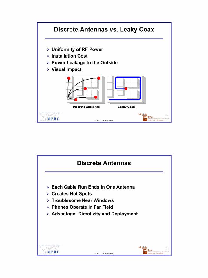
Discrete Antennas vs. Leaky Coax
Uniformity of RF PowerInstallation CostPower Leakage to the OutsideVisual Impact
Discrete Antennas Leaky Coax
VIRGINIA POLYTECHNIC INSTITUTEAND STATE UNIVERSITY
TechVirginia
1 8 7 2
44
©2001 T. S. Rappaport
Discrete Antennas
Each Cable Run Ends in One AntennaCreates Hot SpotsTroublesome Near WindowsPhones Operate in Far FieldAdvantage: Directivity and Deployment
23
VIRGINIA POLYTECHNIC INSTITUTEAND STATE UNIVERSITY
TechVirginia
1 8 7 2
45
©2001 T. S. Rappaport
Leaky Coax
Cable Run Is the AntennaNo Hot SpotsPhones Operate in Near FieldBuilding Structure Spoils Far Field PatternSimpler, Costly InstallationInstalls Out of Sight
VIRGINIA POLYTECHNIC INSTITUTEAND STATE UNIVERSITY
TechVirginia
1 8 7 2
46
©2001 T. S. Rappaport
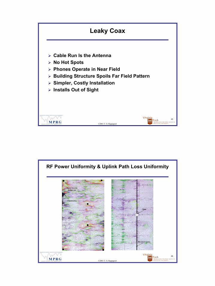
RF Power Uniformity & Uplink Path Loss Uniformity
DiscreteAntennas
LeakyCoax
24
VIRGINIA POLYTECHNIC INSTITUTEAND STATE UNIVERSITY
TechVirginia
1 8 7 2
47
©2001 T. S. Rappaport
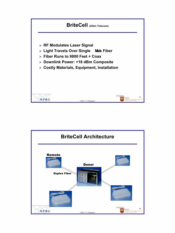
BriteCell (Allen Telecom)
RF Modulates Laser SignalLight Travels Over Single- Mode FiberFiber Runs to 9800 Feet + CoaxDownlink Power: +18 dBm CompositeCostly Materials, Equipment, Installation
VIRGINIA POLYTECHNIC INSTITUTEAND STATE UNIVERSITY
TechVirginia
1 8 7 2
48
©2001 T. S. Rappaport
BriteCell Architecture
Remote
Donor
Duplex Fiber

25
VIRGINIA POLYTECHNIC INSTITUTEAND STATE UNIVERSITY
TechVirginia
1 8 7 2
49
©2001 T. S. Rappaport
Fiber Design Issues
Single vs. Multi- ModeConnector TypesBest Approach: Get Vendor to Approve Fiber
VIRGINIA POLYTECHNIC INSTITUTEAND STATE UNIVERSITY
TechVirginia
1 8 7 2
50
©2001 T. S. Rappaport
Allen Telecom CableStar
RF Downconverted to 400 MHzTravels on RG6 or RG11Runs to 3200 Feet + CoaxDownlink Power: +20 dBm CompositeNo Remote Power RequiredSomewhat Weatherproof

26
VIRGINIA POLYTECHNIC INSTITUTEAND STATE UNIVERSITY
TechVirginia
1 8 7 2
51
©2001 T. S. Rappaport
CableStar Architecture
VIRGINIA POLYTECHNIC INSTITUTEAND STATE UNIVERSITY
TechVirginia
1 8 7 2
52
©2001 T. S. Rappaport
Ericsson Picocell
All RF Stages Placed Near AntennaCoded Voice Signal Distributed Over 4- Wire LAN CableRuns to 3300 Feet + CoaxDownlink Power: +20 dBm per ChannelCheaper Equipment, Cheap Installation
27
VIRGINIA POLYTECHNIC INSTITUTEAND STATE UNIVERSITY
TechVirginia
1 8 7 2
53
©2001 T. S. Rappaport
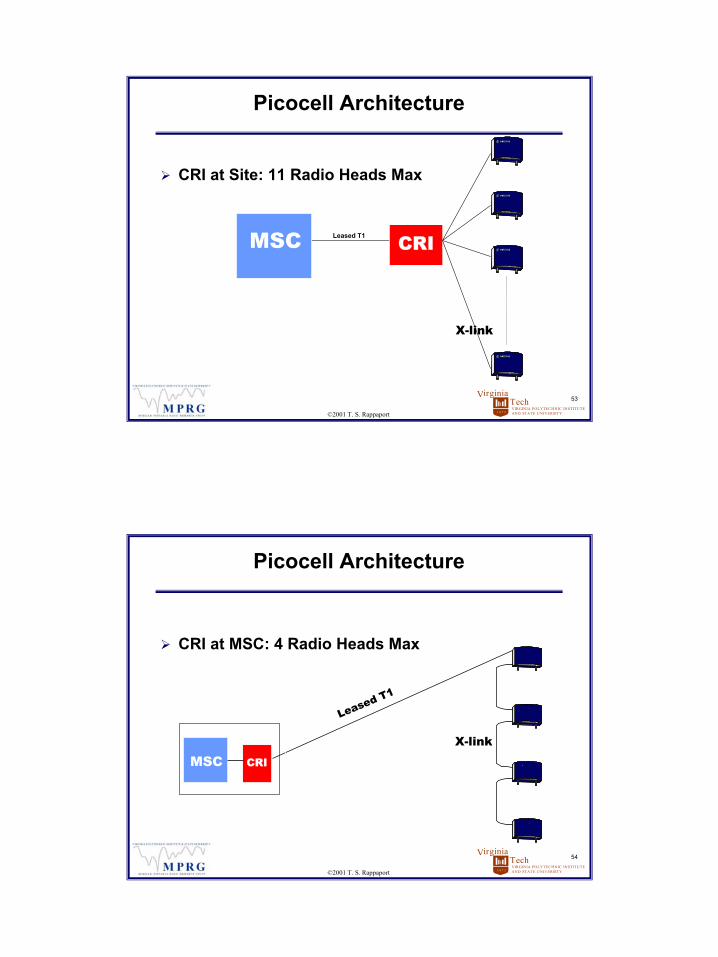
Picocell Architecture
CRILeased T1MSC
CRI at Site: 11 Radio Heads Max
X-link
Leased T1
VIRGINIA POLYTECHNIC INSTITUTEAND STATE UNIVERSITY
TechVirginia
1 8 7 2
54
©2001 T. S. Rappaport
Picocell Architecture
CRI at MSC: 4 Radio Heads Max
MSC CRI
Leased T1
X-link
28
VIRGINIA POLYTECHNIC INSTITUTEAND STATE UNIVERSITY
TechVirginia
1 8 7 2
55
©2001 T. S. Rappaport
Other Remoting Systems
ADC Telecommucation (Duplex Fiber)LGC Wireless (Twisted Pair or Fiber)Foxcom Wireless (Duplex Fiber)CI Wireless (Duplex Fiber)Andrew Illuminator (Duplex Fiber)Many types of deployed equipment complicates:
Field technician trainingSpares inventory
VIRGINIA POLYTECHNIC INSTITUTEAND STATE UNIVERSITY
TechVirginia
1 8 7 2
© 2001 T. S. Rappaport, All Rights Reserved
Link Budget & Propagation Modeling

29
VIRGINIA POLYTECHNIC INSTITUTEAND STATE UNIVERSITY
TechVirginia
1 8 7 2
57
©2001 T. S. Rappaport
Link Budget (Forward Link)
PA Output + LPA Gain- Network Losses + Network Gains+ Antenna Gains- Prop., Environment & Body Losses
Compare to Noise Floor + Receiver NFConsider most likely radio countConsider various RF distribution methods
VIRGINIA POLYTECHNIC INSTITUTEAND STATE UNIVERSITY
TechVirginia
1 8 7 2
58
©2001 T. S. Rappaport
Link Budget (Reverse Link)
Desired Phone Power- Body, Prop. & Environment Losses+ Antenna Gains- Network Losses + Network Gain+ LNA Gain + Multicoupler Gain
Compare to Noise Floor + Receiver NFInclude NF of distribution system

30
VIRGINIA POLYTECHNIC INSTITUTEAND STATE UNIVERSITY
TechVirginia
1 8 7 2
59
©2001 T. S. Rappaport
Propagation Modeling
Keenan- Motley (Seidel- Rappaport)Carter Model for Leaky CoaxMeasurement- Based ModelsRay- tracing
VIRGINIA POLYTECHNIC INSTITUTEAND STATE UNIVERSITY
TechVirginia
1 8 7 2
60
©2001 T. S. Rappaport
Keenan-Motley
Extended by Seidel- RappaportPath Loss Exponent, Wavenumber, Distance, Site-specific informationWall & Floor attenuation factorsUsed in SitePlanner®
( ) FmWnrk ⋅+⋅+⋅⋅ logαSource: Seidel and Rappaport, “914 MHz Path Loss Prediction Models for Indoor Wireless Communications in Multifloored Buildings,” IEEE Trans. Ant. Prop., Vol. 40, No. 2, Feb. 1992, pp. 207-217

31
VIRGINIA POLYTECHNIC INSTITUTEAND STATE UNIVERSITY
TechVirginia
1 8 7 2
61
©2001 T. S. Rappaport
Carter Model for Radiax
Radiax is like a uniform line source antennaPower is spread over a cylindrical surface
S D Pr Lav
T T=⋅
⋅ ⋅ ⋅2 π
L
r
Source: K. Carter, “Predicting Propagation Loss from Leaky Coaxial Cable Terminated with an Indoor Antena,” pp. 71-82, 8th Virginia Tech/MPRG Symposium Wireless Communications Proceedings, June 10-12, 1998.
VIRGINIA POLYTECHNIC INSTITUTEAND STATE UNIVERSITY
TechVirginia
1 8 7 2
62
©2001 T. S. Rappaport
Carter Model for Radiax
Empirical constants match uniform line source with real- world leaky feeder
70.000637
44.353479
CL 1 f( )
vyj
2.4 103.30 f vxj,
0 1000 2000 300040
60
80Frequency Loss
150 52450 57900 631700 69
CE
LintSource: K. Carter, “Predicting Propagation Loss from Leaky Coaxial Cable Terminated with an Indoor Antena,” pp. 71-82, 8th Virginia Tech/MPRG Symposium Wireless Communications Proceedings, June 10-12, 1998.

32
VIRGINIA POLYTECHNIC INSTITUTEAND STATE UNIVERSITY
TechVirginia
1 8 7 2
63
©2001 T. S. Rappaport
Carter Model for Radiax
Near Field Loss for a long horizontal run:
[ ]L L f r H V C L xL f
r C L x
nf h h h E
h
h E
, , ( , ), , ,log( ) log( )
log( ) .
int
int
=
⋅ + ⋅+ ⋅ − + + ⋅10 20
10 43037Source: K. Carter, “Predicting Propagation Loss from Leaky Coaxial Cable Terminated with an Indoor Antena,” pp. 71-82, 8th Virginia Tech/MPRG Symposium Wireless Communications Proceedings, June 10-12, 1998.
VIRGINIA POLYTECHNIC INSTITUTEAND STATE UNIVERSITY
TechVirginia
1 8 7 2
64
©2001 T. S. Rappaport
Indoor RF Losses
WallsFloorsPeopleFurnitureLarge Metal Objects

33
VIRGINIA POLYTECHNIC INSTITUTEAND STATE UNIVERSITY
TechVirginia
1 8 7 2
65
©2001 T. S. Rappaport
Environment Testing
Take measurements of test transmitter signalsCalculate best- fit losses and path loss exponentsBest results obtained with multiple transmittersDesire spatial decorrelation from transmittersTransmitter vendors include BVS, AndrewReceiver vendors include Anritsu, BVS, ZK Celltest, DTI, and EricssonMeasurement software and optimization software for all vendors are produced by Wireless Valley
VIRGINIA POLYTECHNIC INSTITUTEAND STATE UNIVERSITY
TechVirginia
1 8 7 2
© 2001 T. S. Rappaport, All Rights Reserved
Traffic Engineering
34
VIRGINIA POLYTECHNIC INSTITUTEAND STATE UNIVERSITY
TechVirginia
1 8 7 2
67
©2001 T. S. Rappaport
Traffic Engineering
50- 75 mEr/User in officesVaries by business typeUse Erlang B, then over- provisionTrunking efficiency declines with PicocellIndoor handoffs complicate mattersTraffic is very site- specific and event- specificRequires site- specific capacity modeling
VIRGINIA POLYTECHNIC INSTITUTEAND STATE UNIVERSITY
TechVirginia
1 8 7 2
© 2001 T. S. Rappaport, All Rights Reserved
Practical Deployment Issues
35
VIRGINIA POLYTECHNIC INSTITUTEAND STATE UNIVERSITY
TechVirginia
1 8 7 2
69
©2001 T. S. Rappaport
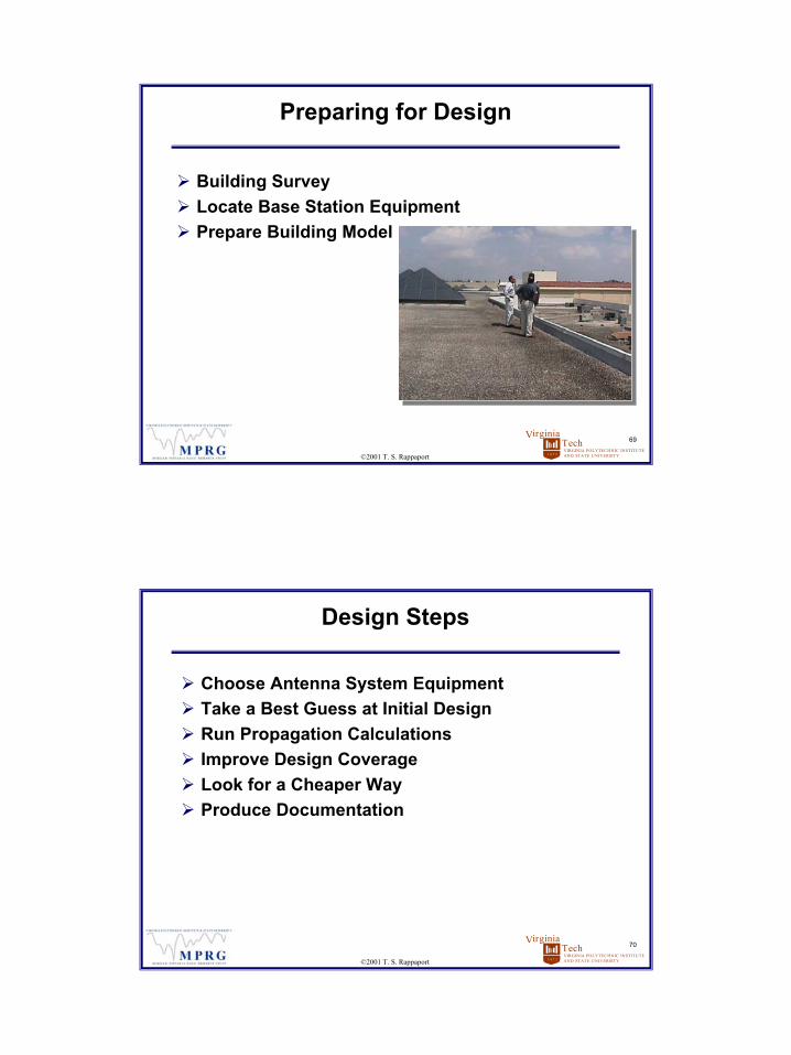
Preparing for Design
Building SurveyLocate Base Station EquipmentPrepare Building Model
VIRGINIA POLYTECHNIC INSTITUTEAND STATE UNIVERSITY
TechVirginia
1 8 7 2
70
©2001 T. S. Rappaport
Design Steps
Choose Antenna System EquipmentTake a Best Guess at Initial DesignRun Propagation CalculationsImprove Design CoverageLook for a Cheaper WayProduce Documentation
36
VIRGINIA POLYTECHNIC INSTITUTEAND STATE UNIVERSITY
TechVirginia
1 8 7 2
71
©2001 T. S. Rappaport
Survey
Obtain Letter- Size Floorplan NTSFire Exit MapBrochure From Info Booth
Obtain E Size Scaled Floorplan or CAD FileScout Equipment LocationTake Digital Photos
VIRGINIA POLYTECHNIC INSTITUTEAND STATE UNIVERSITY
TechVirginia
1 8 7 2
72
©2001 T. S. Rappaport
Survey
Identify Wall ConstructionLocate Sensitive AreasNote Desired or Undesired Coverage AreasLocate Fire WallsLocate Stacked RoomsDetermine Ceiling Heights and Types
37
VIRGINIA POLYTECHNIC INSTITUTEAND STATE UNIVERSITY
TechVirginia
1 8 7 2
73
©2001 T. S. Rappaport
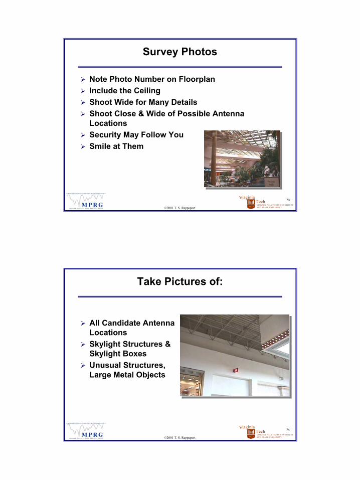
Survey Photos
Note Photo Number on FloorplanInclude the CeilingShoot Wide for Many DetailsShoot Close & Wide of Possible Antenna LocationsSecurity May Follow YouSmile at Them
VIRGINIA POLYTECHNIC INSTITUTEAND STATE UNIVERSITY
TechVirginia
1 8 7 2
74
©2001 T. S. Rappaport
Take Pictures of:
All Candidate Antenna LocationsSkylight Structures & Skylight BoxesUnusual Structures, Large Metal Objects

38
VIRGINIA POLYTECHNIC INSTITUTEAND STATE UNIVERSITY
TechVirginia
1 8 7 2
75
©2001 T. S. Rappaport
Take Pictures of:
Windows, Entrances, Back HallwaysCorridors, Equipment RoomsAreas Where Crowds Gather
VIRGINIA POLYTECHNIC INSTITUTEAND STATE UNIVERSITY
TechVirginia
1 8 7 2
76
©2001 T. S. Rappaport
Building Structure Types
Brick or Poured Concrete Supporting WallsPrisons, Historic Buildings, COs

39
VIRGINIA POLYTECHNIC INSTITUTEAND STATE UNIVERSITY
TechVirginia
1 8 7 2
77
©2001 T. S. Rappaport
Building Structure Types
Concrete Block Walls, Steel SkeletonSchools, MallsSupermarketsDept. StoresHome Depot
VIRGINIA POLYTECHNIC INSTITUTEAND STATE UNIVERSITY
TechVirginia
1 8 7 2
78
©2001 T. S. Rappaport
Building Structure Types
Poured Concrete CellsCondosSmall HotelsApartments
40
VIRGINIA POLYTECHNIC INSTITUTEAND STATE UNIVERSITY
TechVirginia
1 8 7 2
79
©2001 T. S. Rappaport
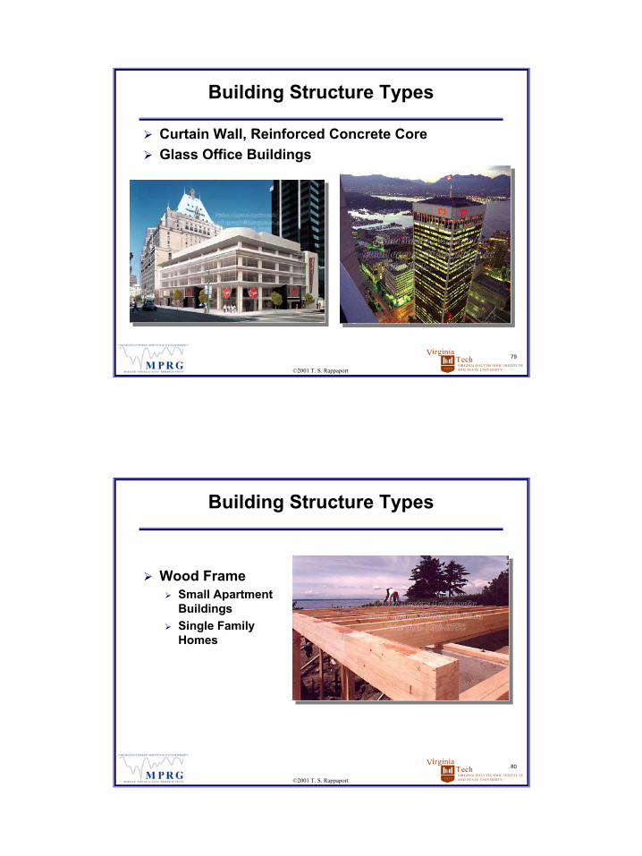
Building Structure Types
Curtain Wall, Reinforced Concrete CoreGlass Office Buildings
VIRGINIA POLYTECHNIC INSTITUTEAND STATE UNIVERSITY
TechVirginia
1 8 7 2
80
©2001 T. S. Rappaport
Building Structure Types
Wood FrameSmall Apartment BuildingsSingle Family Homes
41
VIRGINIA POLYTECHNIC INSTITUTEAND STATE UNIVERSITY
TechVirginia
1 8 7 2
81
©2001 T. S. Rappaport
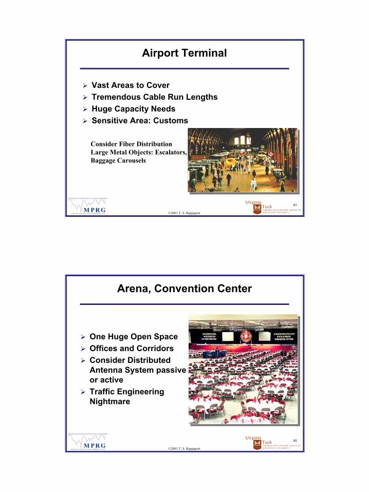
Airport Terminal
Vast Areas to CoverTremendous Cable Run LengthsHuge Capacity NeedsSensitive Area: Customs
Consider Fiber DistributionLarge Metal Objects: Escalators, Baggage Carousels
VIRGINIA POLYTECHNIC INSTITUTEAND STATE UNIVERSITY
TechVirginia
1 8 7 2
82
©2001 T. S. Rappaport
Arena, Convention Center
One Huge Open SpaceOffices and CorridorsConsider Distributed Antenna System passive or activeTraffic Engineering Nightmare
42
VIRGINIA POLYTECHNIC INSTITUTEAND STATE UNIVERSITY
TechVirginia
1 8 7 2
83
©2001 T. S. Rappaport
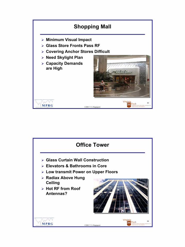
Shopping Mall
Minimum Visual ImpactGlass Store Fronts Pass RFCovering Anchor Stores DifficultNeed Skylight PlanCapacity Demands are High
VIRGINIA POLYTECHNIC INSTITUTEAND STATE UNIVERSITY
TechVirginia
1 8 7 2
84
©2001 T. S. Rappaport
Office Tower
Glass Curtain Wall ConstructionElevators & Bathrooms in CoreLow transmit Power on Upper FloorsRadiax Above Hung CeilingHot RF from Roof Antennas?

43
VIRGINIA POLYTECHNIC INSTITUTEAND STATE UNIVERSITY
TechVirginia
1 8 7 2
85
©2001 T. S. Rappaport
Factory
Open Space Plus OfficesMany Noise SourcesSensitive Areas: Clean Rooms, R&D LabsCover the Break Rooms& Smoking Areas
VIRGINIA POLYTECHNIC INSTITUTEAND STATE UNIVERSITY
TechVirginia
1 8 7 2
86
©2001 T. S. Rappaport
Airplane Hangar, Kmart
Open Space with Large Metal ObjectsRepeater with One AntennaPossibly Picocell with Built- in AntennaMay Require Testing After Installation
44
VIRGINIA POLYTECHNIC INSTITUTEAND STATE UNIVERSITY
TechVirginia
1 8 7 2
87
©2001 T. S. Rappaport
Guidelines
Cable Fire RatingsPuncturing Fire WallsLeaky Coax TypesLeaky Coax InstallationIndoor AntennasMounting AntennasDocumentation
VIRGINIA POLYTECHNIC INSTITUTEAND STATE UNIVERSITY
TechVirginia
1 8 7 2
88
©2001 T. S. Rappaport
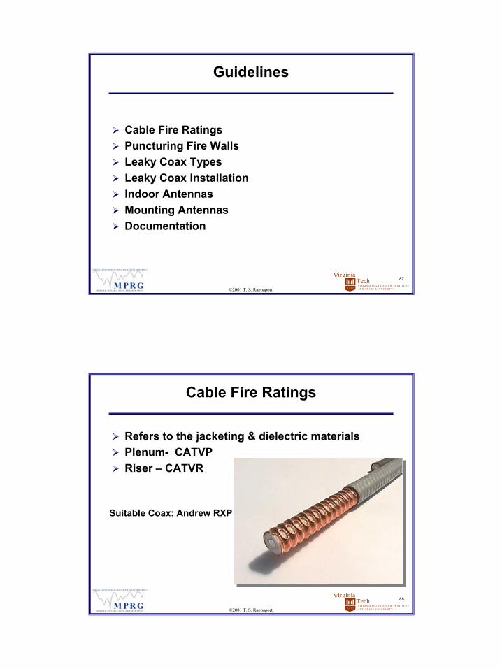
Cable Fire Ratings
Refers to the jacketing & dielectric materialsPlenum - CATVPRiser – CATVR
Suitable Coax: Andrew RXP
45
VIRGINIA POLYTECHNIC INSTITUTEAND STATE UNIVERSITY
TechVirginia
1 8 7 2
89
©2001 T. S. Rappaport
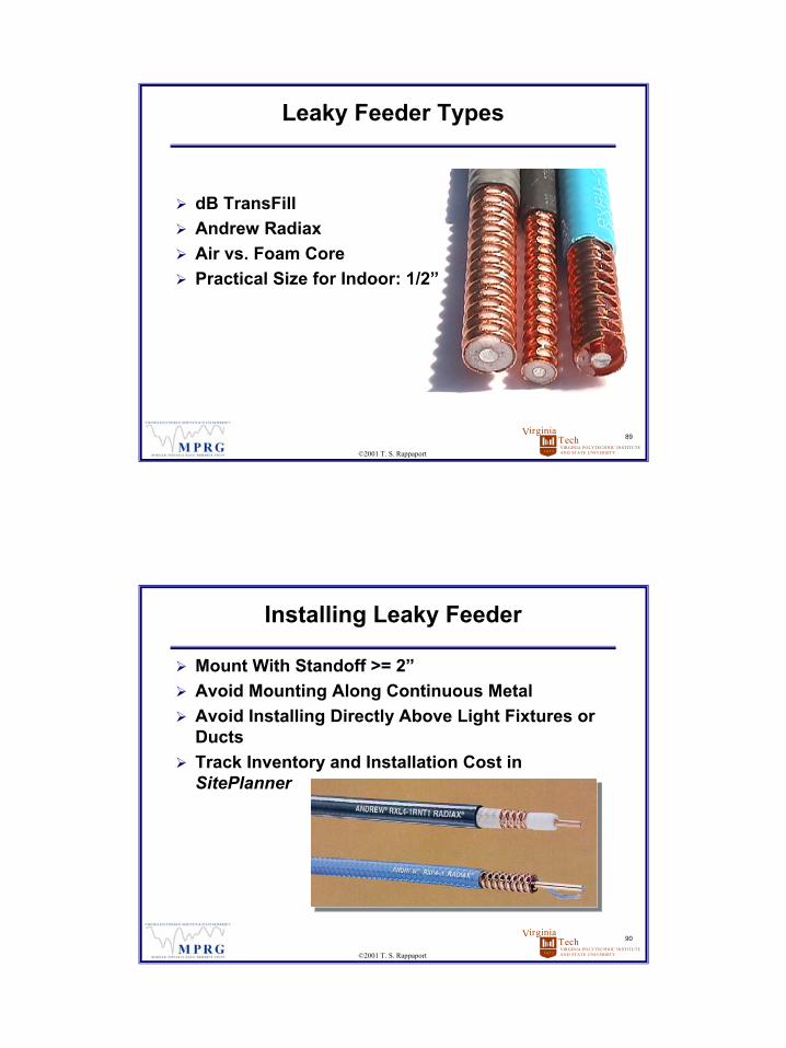
Leaky Feeder Types
dB TransFill Andrew RadiaxAir vs. Foam CorePractical Size for Indoor: 1/2”
VIRGINIA POLYTECHNIC INSTITUTEAND STATE UNIVERSITY
TechVirginia
1 8 7 2
90
©2001 T. S. Rappaport
Installing Leaky Feeder
Mount With Standoff >= 2”Avoid Mounting Along Continuous MetalAvoid Installing Directly Above Light Fixtures or DuctsTrack Inventory and Installation Cost in SitePlanner
46
VIRGINIA POLYTECHNIC INSTITUTEAND STATE UNIVERSITY
TechVirginia
1 8 7 2
91
©2001 T. S. Rappaport
Indoor Antennas
Indoor Antennas vs. Outdoor AntennasEMS OmniAllgonDB DiamondMany Others
VIRGINIA POLYTECHNIC INSTITUTEAND STATE UNIVERSITY
TechVirginia
1 8 7 2
92
©2001 T. S. Rappaport
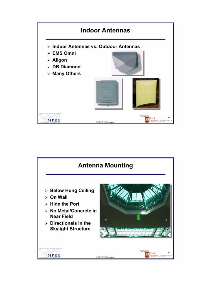
Antenna Mounting
Below Hung CeilingOn WallHide the PortNo Metal/Concrete in Near FieldDirectionals in the Skylight Structure
47
VIRGINIA POLYTECHNIC INSTITUTEAND STATE UNIVERSITY
TechVirginia
1 8 7 2
93
©2001 T. S. Rappaport
Documenting Your Design
PlansLegendDetail DrawingsBackbone DiagramBill of MaterialsPhoto SimsFiles Stored Safely
884M AMP DuplexerTxRx
TxRx
36' 7/8" feeder 330' RXP4-2
34' 7
/8" f
eede
r13
' 1/2
" fee
der
13' 1
/2" f
eede
r
54' 7/8" feeder 323' RXP4-2
80' 7/8" feeder 330' RXP4-2
158' RXP4-2
125' RXP4-2
30' 1
/2"
fee d
er
4th Floor
3rd Floor
2ndFloor
1st Floor
Parking Level
50-ohmtermination
50-ohmtermination
2nd Floor
Antenna End Detail
falseceiling
3 ft.6 to 10 ft.
antenna
floor
10 ft. or 10'9"12 ft.
SitePlanner® does all of this!
VIRGINIA POLYTECHNIC INSTITUTEAND STATE UNIVERSITY
TechVirginia
1 8 7 2
94
©2001 T. S. Rappaport
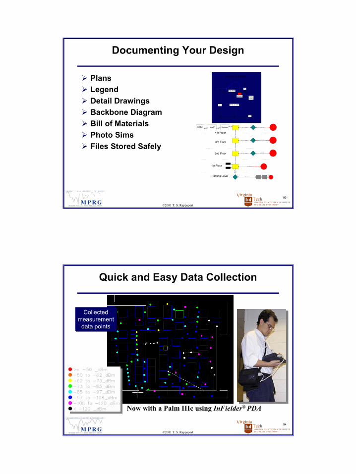
Quick and Easy Data Collection
Collectedmeasurement
data points
Collectedmeasurement
data points
Now with a Palm IIIc using InFielder® PDA
48
VIRGINIA POLYTECHNIC INSTITUTEAND STATE UNIVERSITY
TechVirginia
1 8 7 2
95
©2001 T. S. Rappaport
Design Methods
Cut and Try – old method Educated Guess – old method Keenan- Motley w/spreadsheet – currentBetter Models - SitePlanner®
Better Calculators - SitePlanner®
Graphical Environment – SitePlanner®
Automatic archiving - SitePlanner®
Asset Management – SitePlanner®
VIRGINIA POLYTECHNIC INSTITUTEAND STATE UNIVERSITY
TechVirginia
1 8 7 2
© 2001 T. S. Rappaport, All Rights Reserved
Design Tools

49
VIRGINIA POLYTECHNIC INSTITUTEAND STATE UNIVERSITY
TechVirginia
1 8 7 2
© 2001 T. S. Rappaport, All Rights Reserved
How can we talk the same language?
VIRGINIA POLYTECHNIC INSTITUTEAND STATE UNIVERSITY
TechVirginia
1 8 7 2
98
©2001 T. S. Rappaport
Millions of Buildings … So Little Time
How can we quickly design systems?How can we compare technologies?How can we save and communicate designs?How will integrators become designers?How will vendors verify design guidelines?How will building owners track hardware?How will we manage and maintain the in- building infrastructure?

50
VIRGINIA POLYTECHNIC INSTITUTEAND STATE UNIVERSITY
TechVirginia
1 8 7 2
99
©2001 T. S. Rappaport
Spreadsheet Tools
Difficult to UseNo Design GraphicsFew Antenna PatternsQuestionable SupportNo Design StorageDifficult to Interpret, except for Engineers
VIRGINIA POLYTECHNIC INSTITUTEAND STATE UNIVERSITY
TechVirginia
1 8 7 2
100
©2001 T. S. Rappaport
Design/Planning History: Macrocell Design
Original use of planning tools was for outdoor cellular networks - RF design and planningPlanning decisions and tower placements could be simulated and analyzed prior to deploymentDesign strategies and techniques improvedCell tower placement became more efficientLacked asset management or document supportDifficult to track installed tower infrastructure
51
VIRGINIA POLYTECHNIC INSTITUTEAND STATE UNIVERSITY
TechVirginia
1 8 7 2
101
©2001 T. S. Rappaport
VA Tech MPRG Research
Early in- building propagation workDecade of measurement experienceDecade of modeling and optimization experienceDecade of Industry suggestions and practical adviceSitePlanner is the result of over 30 years of student research
VIRGINIA POLYTECHNIC INSTITUTEAND STATE UNIVERSITY
TechVirginia
1 8 7 2
102
©2001 T. S. Rappaport
VA Tech MPRG Research (cont.)
MPRG students and staff researchers have contributed to the body of knowledge used in theSitePlanner concept:
Scott Seidel, Joe Liberti, Dwayne Hawbaker, Ken Blackard, Alan Fox, Roger Skidmore, Idine Ghoreishain, Greg Durgin, Neal Patwari, Ray Lovestead, Ben Henty, Brian Gold, Charles Lepple, Bob Boyle, Kirk Carter, Juin Siew, Wesley Rios, Manish Panjwani
52
VIRGINIA POLYTECHNIC INSTITUTEAND STATE UNIVERSITY
TechVirginia
1 8 7 2
103
©2001 T. S. Rappaport
SitePlanner® Features and Benefits
Facilitates rapid cost and performance tradeoff analysis of all technologies at low overall costSimultaneously supports site designs, surveys, verification, and documentation with 3D graphical representation and complete database recordAutomatic archiving of installed infrastructureAutomatic bill of materials created during designAsset management facilities built inCellular, PCS, 3G, WLAN, MMDS, and beyondAccurate and practical modeling of any campus wireless system
VIRGINIA POLYTECHNIC INSTITUTEAND STATE UNIVERSITY
TechVirginia
1 8 7 2
104
©2001 T. S. Rappaport
SitePlanner: Planning, Design, and Management for In-Building Telecom
Provides rapid system design of complex technologies while minimizing costs and meeting coverage and capacity needsIndoor wireless coverage is non-intuitive and complex, but SitePlanner provides huge cost/time savings and rapidly trains the userSitePlanner allows flexibility and rapid “what if” designs to meet specific needs of customers Easy visualization of proposed systemsSitePlanner provides simultaneous performance analysis, wireless equipment tracking, project documentation, and asset management!
53
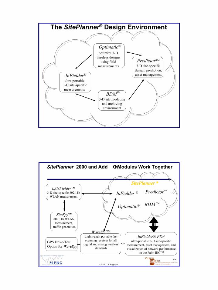
The SitePlanner® Design Environment
InFielder®
ultra-portable3-D site-specific measurements
Predictor™3-D site-specific
design, prediction, asset management
BDM™
3-D site modeling and archiving environment
Optimatic®
optimize 3-D wireless designs
using field measurements
VIRGINIA POLYTECHNIC INSTITUTEAND STATE UNIVERSITY
TechVirginia
1 8 7 2
106
©2001 T. S. Rappaport
SitePlanner 2000 and Add- On Modules Work Together
InFielder® PDAultra-portable 3-D site-specific
measurement, asset management, and visualization of network performance
on the Palm IIICTM
LANFielder™3-D site-specific 802.11b
WLAN measurement
WaveSpyTM
Lightweight portable fast scanning receiver for all
digital and analog wireless standards
InFielder ® Predictor™
BDM ™Optimatic®
SiteSpy™802.11b WLAN measurement,
traffic generation
SitePlanner ®
GPS Drive-Test Option for WaveSpy
54
VIRGINIA POLYTECHNIC INSTITUTEAND STATE UNIVERSITY
TechVirginia
1 8 7 2
107
©2001 T. S. Rappaport
Typical Design Steps
Use SitePlanner to simulate RF performance of several straw- man designs in facility of interest In- situ site survey and measurements with SitePlanner, including interference, throughput or signal strength with transmitter locations from most promising straw- man designsUse SitePlanner field measurements to optimize network performance and select final layout System Installation and Site- survey/performance verification in SitePlannerSitePlanner provides Maintenance and Design Archiving for on- going support of infrastructure
VIRGINIA POLYTECHNIC INSTITUTEAND STATE UNIVERSITY
TechVirginia
1 8 7 2
108
©2001 T. S. Rappaport
Common Uses of SitePlanner
Common software platform provides sharing of designs and “as-builts” throughout an organization or across users on a projectAllows vendors, consultants, integrators, and manufacturers to share and archive designsProvides an objective “level playing field” for all in-building design, deployment, and optimization workAllows new hires or inexperienced personnel to become rapidly proficient in the field of in-building wireless design, specification, or integrationProvides retrievable records of all aspects of an in-building project, for quality audits and maintenanceSitePlanner can be shared by engineers, facilities managers, and accounting staff from cradle-to-grave
55
VIRGINIA POLYTECHNIC INSTITUTEAND STATE UNIVERSITY
TechVirginia
1 8 7 2
109
©2001 T. S. Rappaport
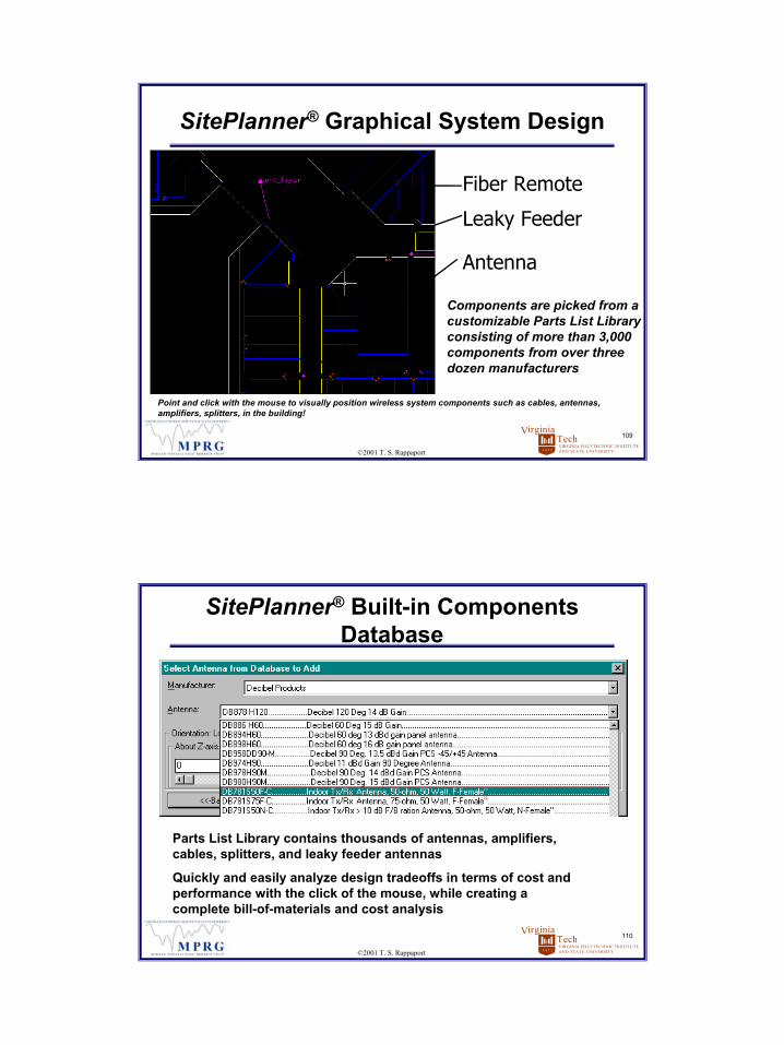
Point and click with the mouse to visually position wireless system components such as cables, antennas, amplifiers, splitters, in the building!
SitePlanner® Graphical System Design
Fiber Remote
Leaky Feeder
Antenna
Components are picked from a customizable Parts List Library consisting of more than 3,000 components from over three dozen manufacturers
VIRGINIA POLYTECHNIC INSTITUTEAND STATE UNIVERSITY
TechVirginia
1 8 7 2
110
©2001 T. S. Rappaport
SitePlanner® Built-in Components Database
Parts List Library contains thousands of antennas, amplifiers, cables, splitters, and leaky feeder antennas
Quickly and easily analyze design tradeoffs in terms of cost andperformance with the click of the mouse, while creating a complete bill-of-materials and cost analysis
56
VIRGINIA POLYTECHNIC INSTITUTEAND STATE UNIVERSITY
TechVirginia
1 8 7 2
111
©2001 T. S. Rappaport
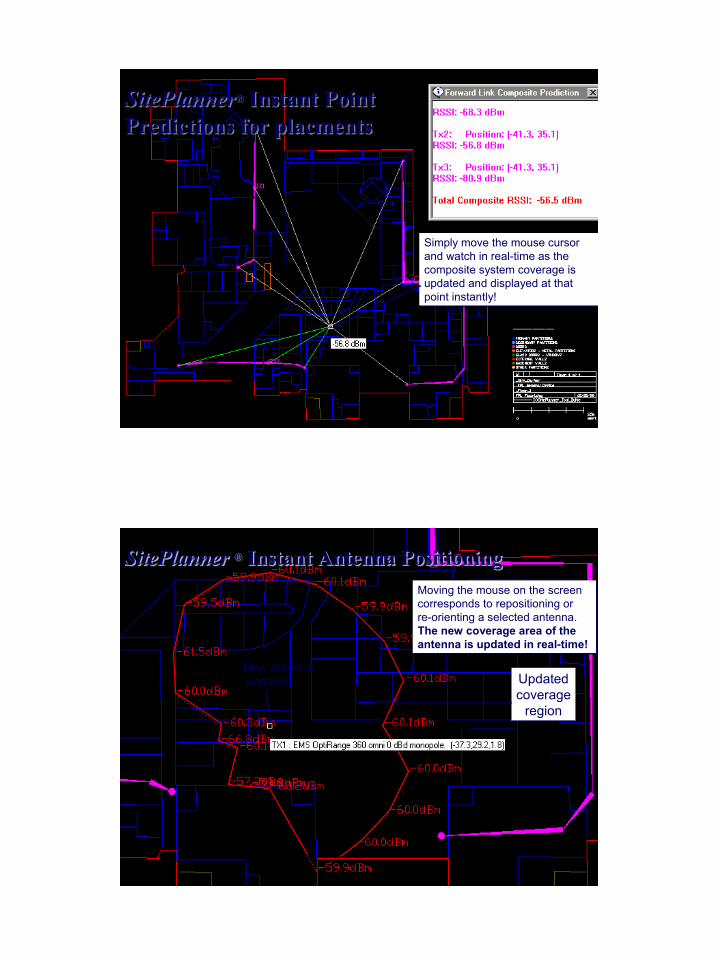
SitePlanner® Instant Point Predictions for placmentsSitePlanner® Instant Point Predictions for placments
Simply move the mouse cursor and watch in real-time as the composite system coverage is updated and displayed at thatpoint instantly!
Simply move the mouse cursor and watch in real-time as the composite system coverage is updated and displayed at thatpoint instantly!
VIRGINIA POLYTECHNIC INSTITUTEAND STATE UNIVERSITY
TechVirginia
1 8 7 2
112
©2001 T. S. Rappaport
SitePlanner ® Instant Antenna PositioningSitePlanner SitePlanner ®® Instant Antenna PositioningInstant Antenna PositioningMoving the mouse on the screencorresponds to repositioning orre-orienting a selected antenna.The new coverage area of theantenna is updated in real-time!
Moving the mouse on the screencorresponds to repositioning orre-orienting a selected antenna.The new coverage area of theantenna is updated in real-time!
New antennaposition Updated
coverageregion

57
VIRGINIA POLYTECHNIC INSTITUTEAND STATE UNIVERSITY
TechVirginia
1 8 7 2
113
©2001 T. S. Rappaport
SitePlanner® Wireless System Layout
In real time, SitePlanner allows the user to analyze performance by creating a graphical wireless system component interconnection diagram, while simultaneously creating bill of materials and complete cost analysis
VIRGINIA POLYTECHNIC INSTITUTEAND STATE UNIVERSITY
TechVirginia
1 8 7 2
114
©2001 T. S. Rappaport
SitePlanner® Graphical Partition InputSitePlanner® Graphical Partition Input
Quickly and easily create 3D building models from CAD drawing files or scanned blueprints.
Quickly and easily create 3D building models from CAD drawing files or scanned blueprints.
58
VIRGINIA POLYTECHNIC INSTITUTEAND STATE UNIVERSITY
TechVirginia
1 8 7 2
115
©2001 T. S. Rappaport
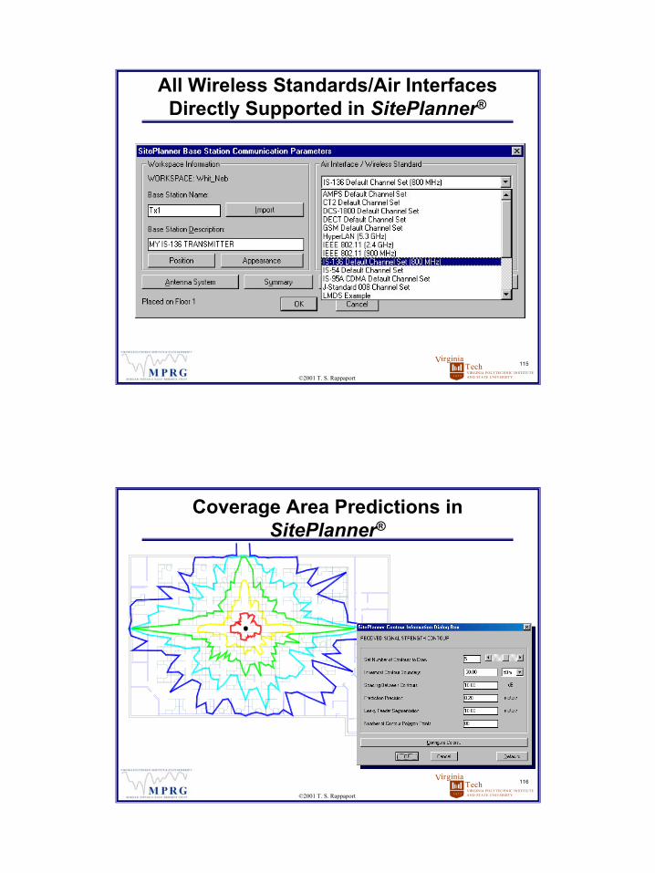
All Wireless Standards/Air Interfaces Directly Supported in SitePlanner®
VIRGINIA POLYTECHNIC INSTITUTEAND STATE UNIVERSITY
TechVirginia
1 8 7 2
116
©2001 T. S. Rappaport
Coverage Area Predictions in SitePlanner®

59
VIRGINIA POLYTECHNIC INSTITUTEAND STATE UNIVERSITY
TechVirginia
1 8 7 2
117
©2001 T. S. Rappaport
Composite Coverage in SitePlanner ®Composite Coverage in SitePlanner ®
Shopping mallstore walls
Leaky FeederAntenna System
VIRGINIA POLYTECHNIC INSTITUTEAND STATE UNIVERSITY
TechVirginia
1 8 7 2
118
©2001 T. S. Rappaport
Composite Coverage in SitePlanner®Composite Coverage in SitePlanner®
Shopping mallstore walls
Leaky FeederAntenna Systems
Signal leakageoutside the building
60
VIRGINIA POLYTECHNIC INSTITUTEAND STATE UNIVERSITY
TechVirginia
1 8 7 2
119
©2001 T. S. Rappaport
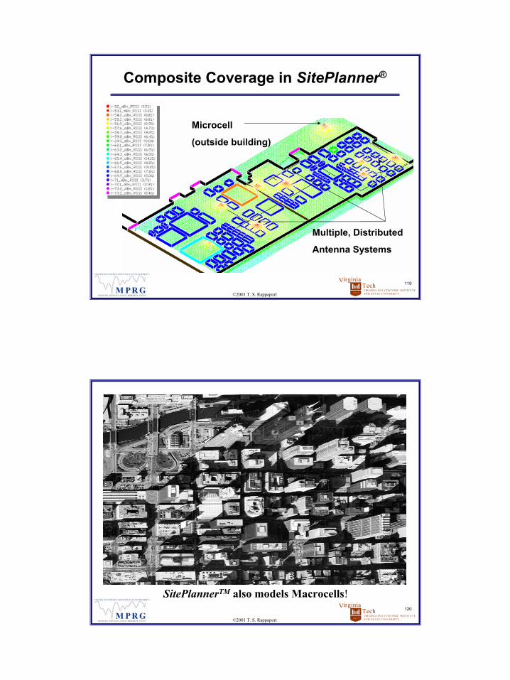
Composite Coverage in SitePlanner®
Multiple, Distributed
Antenna Systems
Microcell
(outside building)
VIRGINIA POLYTECHNIC INSTITUTEAND STATE UNIVERSITY
TechVirginia
1 8 7 2
120
©2001 T. S. Rappaport
SitePlannerTM also models Macrocells!

61
VIRGINIA POLYTECHNIC INSTITUTEAND STATE UNIVERSITY
TechVirginia
1 8 7 2
121
©2001 T. S. Rappaport
0.33 km-50 dBm
-70 dBm
-90 dBm
RSSI
M1
M2
M3
U1
U2
U3
U4
U5
U6
SitePlanner® Macrocell Modeling of Chicago
VIRGINIA POLYTECHNIC INSTITUTEAND STATE UNIVERSITY
TechVirginia
1 8 7 2
122
©2001 T. S. Rappaport
45 dB
30 dB
15 dB
40m
C/I
SitePlanner® models inside the building (point omni-antenna) using Macrocell system parameters
62
VIRGINIA POLYTECHNIC INSTITUTEAND STATE UNIVERSITY
TechVirginia
1 8 7 2
123
©2001 T. S. Rappaport
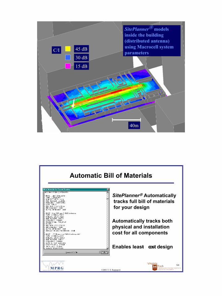
45 dB
30 dB
15 dB
40m
C/I
SitePlanner® models inside the building (distributed antenna) using Macrocell system parameters
VIRGINIA POLYTECHNIC INSTITUTEAND STATE UNIVERSITY
TechVirginia
1 8 7 2
124
©2001 T. S. Rappaport
Automatic Bill of Materials
SitePlanner® Automaticallytracks full bill of materials for your design
Automatically tracks both physical and installation cost for all components
Enables least- cost design
63
VIRGINIA POLYTECHNIC INSTITUTEAND STATE UNIVERSITY
TechVirginia
1 8 7 2
125
©2001 T. S. Rappaport
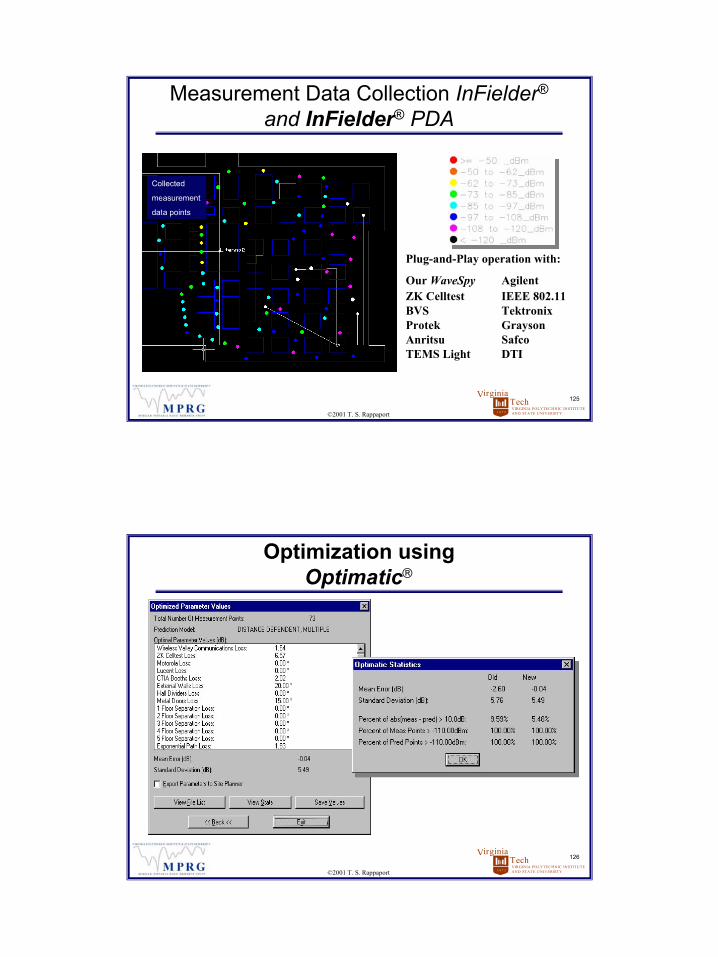
Measurement Data Collection InFielder®
and InFielder® PDA
Collected
measurement
data points
Plug-and-Play operation with:
Our WaveSpy AgilentZK Celltest IEEE 802.11BVS TektronixProtek GraysonAnritsu SafcoTEMS Light DTI
VIRGINIA POLYTECHNIC INSTITUTEAND STATE UNIVERSITY
TechVirginia
1 8 7 2
126
©2001 T. S. Rappaport
Optimization using Optimatic
64
VIRGINIA POLYTECHNIC INSTITUTEAND STATE UNIVERSITY
TechVirginia
1 8 7 2
127
©2001 T. S. Rappaport
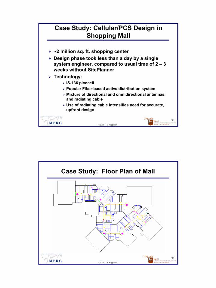
Case Study: Cellular/PCS Design in Shopping Mall
~2 million sq. ft. shopping centerDesign phase took less than a day by a single system engineer, compared to usual time of 2 – 3 weeks without SitePlannerTechnology:
IS-136 picocellPopular Fiber-based active distribution systemMixture of directional and omnidirectional antennas, and radiating cableUse of radiating cable intensifies need for accurate, upfront design
VIRGINIA POLYTECHNIC INSTITUTEAND STATE UNIVERSITY
TechVirginia
1 8 7 2
128
©2001 T. S. Rappaport
Case Study: Floor Plan of Mall
65
VIRGINIA POLYTECHNIC INSTITUTEAND STATE UNIVERSITY
TechVirginia
1 8 7 2
129
©2001 T. S. Rappaport
Cellular/PCS Design
SitePlanner allowed instant selection of pre-approved distribution components, both passive and activeSitePlanner simultaneously computed coverage, capacity, installation cost, equipment cost, and created a complete bill of materials and graphical documents of proposed designThe completed design was stored, transported, displayed, and used throughout the enterprise to provide a complete record of the installed project
VIRGINIA POLYTECHNIC INSTITUTEAND STATE UNIVERSITY
TechVirginia
1 8 7 2
130
©2001 T. S. Rappaport
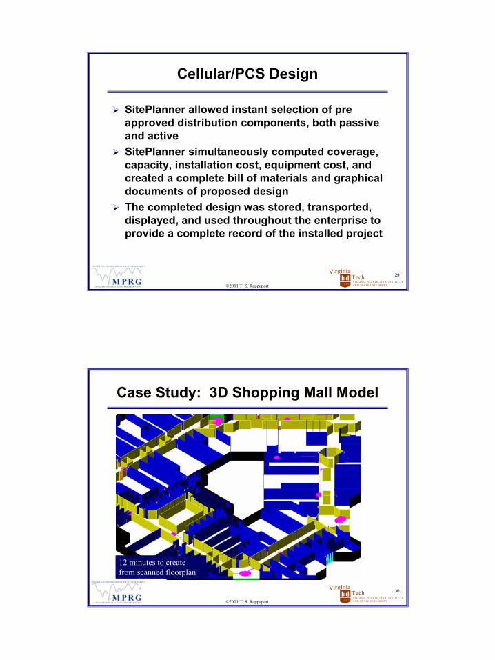
Case Study: 3D Shopping Mall Model
12 minutes to create from scanned floorplan

66
VIRGINIA POLYTECHNIC INSTITUTEAND STATE UNIVERSITY
TechVirginia
1 8 7 2
131
©2001 T. S. Rappaport
Shopping mallstore walls
Leaky FeederAntenna System
Required < 2 minutes on a Pentium II 300 MHz PC
VIRGINIA POLYTECHNIC INSTITUTEAND STATE UNIVERSITY
TechVirginia
1 8 7 2
132
©2001 T. S. Rappaport
Shopping Mall Case Study: Conclusions
Customer saved several weeks of time on overall design and deployment
Verification confirmed an accuracy within 5 dB standard deviation (predicted vs. measured)Rapid predictions enabled numerous design tradeoffs to be analyzed within hours
Greater RF designer satisfactionDesigner can “see” performance
Greater building owner satisfactionBuilding owner can “see” performance
Automatic archival of design critical

67
VIRGINIA POLYTECHNIC INSTITUTEAND STATE UNIVERSITY
TechVirginia
1 8 7 2
133
©2001 T. S. Rappaport
Wireless LAN Planning: LANFielder™and SiteSpy™
Measurement results that youcan understand without being an RF Engineer
Provides wireless data network measurement using client/server technique
VIRGINIA POLYTECHNIC INSTITUTEAND STATE UNIVERSITY
TechVirginia
1 8 7 2
134
©2001 T. S. Rappaport
Case Study: WLAN Design
100,000 sq. ft., multi- story academic building on the University of Virginia Tech campusTechnology:
IEEE 802.11b, 2.4 GHz DS-SS Wireless LAN11 Mbps Cabletron RoamAbout access points and modems (Lucent/ORiNOCO OEM)

68
VIRGINIA POLYTECHNIC INSTITUTEAND STATE UNIVERSITY
TechVirginia
1 8 7 2
135
©2001 T. S. Rappaport
WLAN Design: 3D Model
10 minutes from CAD file to SitePlanner model
VIRGINIA POLYTECHNIC INSTITUTEAND STATE UNIVERSITY
TechVirginia
1 8 7 2
136
©2001 T. S. Rappaport
Predicted signal strength for 3 Wireless LAN Access Points
WLAN Design: Predicted Performance
<60 seconds on PII 300
69
VIRGINIA POLYTECHNIC INSTITUTEAND STATE UNIVERSITY
TechVirginia
1 8 7 2
137
©2001 T. S. Rappaport
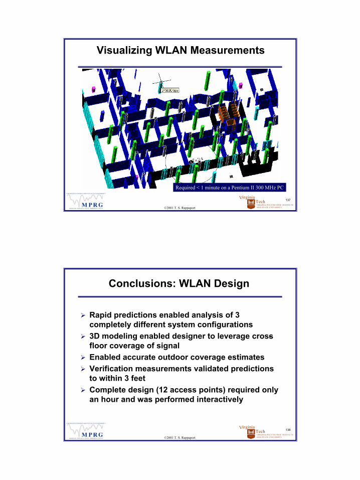
Visualizing WLAN Measurements
Required < 1 minute on a Pentium II 300 MHz PC
VIRGINIA POLYTECHNIC INSTITUTEAND STATE UNIVERSITY
TechVirginia
1 8 7 2
138
©2001 T. S. Rappaport
Conclusions: WLAN Design
Rapid predictions enabled analysis of 3 completely different system configurations 3D modeling enabled designer to leverage cross-floor coverage of signalEnabled accurate outdoor coverage estimatesVerification measurements validated predictions to within 3 feetComplete design (12 access points) required only an hour and was performed interactively
70
VIRGINIA POLYTECHNIC INSTITUTEAND STATE UNIVERSITY
TechVirginia
1 8 7 2
139
©2001 T. S. Rappaport
Conclusions: WLAN Design
Significant time savings on overall design and deployment
Verification confirmed an accuracy within 5 dB standard deviation (predicted vs. measured)Rapid predictions enabled numerous design tradeoffs to be analyzed
Greater RF designer satisfactionDesigner can “see” performance
Greater building owner satisfactionBuilding owner can “see” performance
Automatic design archiving and asset management is a key benefit of SitePlanner!
VIRGINIA POLYTECHNIC INSTITUTEAND STATE UNIVERSITY
TechVirginia
1 8 7 2
140
©2001 T. S. Rappaport
Conclusion
In- building/campus systems proliferating rapidly Engineering work load increasing rapidly Technology cost comparisons vital for deployment efficiencies Visual and textual records required for common procedures and shared strategies, archiving SitePlanner® facilitates cost and time savings for rapid deployment and ongoing maintenance for any in- building or campus system

71
VIRGINIA POLYTECHNIC INSTITUTEAND STATE UNIVERSITY
TechVirginia
1 8 7 2
141
©2001 T. S. Rappaport
Final Remarks
In- building wireless is next growth phaseMany distribution methods to choose fromMany design issues to confrontRF Planning tools ease wireless system design
intelligent design tradeoffscompetitive system analysis and comparisons
SitePlanner is based on over a decade of Virginia Tech research, and offers a revolutionary design environment that supports in- building wirelessSitePlanner provides real cost and time savings for rapid deployment and ongoing maintenance Indoor design demonstrations
Related Documents