National Public Safety Telecommunications Council Best Practices for In-Building Communications Appendices A through E National Public Safety Telecommunications Council (NPSTC) In-Building Working Group Stu Overby, Chair [email protected] November 12, 2007

In-Building Wireless Communications Best Practices - Appendices
Oct 15, 2014
Appendices for In-Building Wireless Communication Best Practices
Welcome message from author
This document is posted to help you gain knowledge. Please leave a comment to let me know what you think about it! Share it to your friends and learn new things together.
Transcript

National Public Safety Telecommunications Council
Best Practices for In-Building Communications
Appendices A through E
National Public Safety Telecommunications Council (NPSTC)
In-Building Working Group
Stu Overby, Chair [email protected]
November 12, 2007
1
Appendix A: Interference Survey
The attached interference survey was developed and has been distributed to the public safety community by the Jack Daniel Company. ------------------------------------------------------------------------------------------------- The following is a survey to gather information and statistics concerning any interference from BDAs (bi-directional Amplifiers) you may have experienced. This survey will be used in support of petitions requesting the FCC update and revise rules for BDAs. One such petition may be viewed at: http://www.rfsolutions.com/bird-fcc.pdf. The intent is to get the FCC to open the rules for public input of changes needed regardless of whether you agree with the Bird petition or not. Please email comments, questions or suggestions about this survey to: [email protected] 1. Has BDA OSCILLATIONS (not noise) caused you any problems ? No Yes
2. If you answered YES to question 1, how many different BDA installations in the last 5 years ? (1 to 10+) 3. Has broadband NOISE (not oscillations) from BDAs caused you any problems (such as receiver desense) ? No Yes 4. If YES to question 3, how many different BDA installations were focused on the same donor site ? (1 to 10+) 5. Do you think internet BDA sales to consumers should be stopped ? No Yes 6. Do you think 'voluntary' registration of BDA installations would work ? No Yes 7. Should the FCC enforce existing BDA (signal booster) rules better ? No Yes 8. Should FCC rules be updated and made more restrictive ? No Yes 9. Should BDA installations be licensed similar to control stations ? No Yes 10. Is there any place else this survey should be posted ? (Feel free to distribute to other groups) 12. May we supply your name to the FCC with this survey ? The FCC pays more attention to specific reports than anonymous sources. No Yes Contact me first
2
Appendix B
Introduction to in-Building Wireless Signal Distribution
for Public Safety
A General Design Overview and Installation Guideline. (See notice on last page)
© 2005, 2007 Jack Daniel Company Tel: 800-NON-TOLL
email: [email protected] Note: NPSTC Received Permission from Jack Daniel to include this copyrighted document.

3
Introduction: Wireless users expect and rely on communications wherever they go, including inside large structures, high rise buildings, underground parking, malls, basements, subways, etc. When wireless radio frequency (RF) signals pass through any material they lose strength and when the RF signal levels fell below a given amount, communications becomes unreliable or completely stops. Whenever the area needing radio coverage is below grade (underground) it is almost certain a RF distribution system will be needed. The following discussion of RF (radio frequency) distribution systems is intended as an introduction to the various solutions being used to improve RF signal levels when necessary.

4
The primary components of an amplified RF Distribution system are identified below: 1. Donor (roof) antenna. This is called the "DONOR" antenna. It is usually mounted on the roof, or a side of the structure, where a clear line-of-sight path exists to the distant radio tower. The distant site is also known as the "Donor". This is a two way interface; - the DOWNLINK" is the RF signal direction going INTO the structure. - the "UPLINK" is the RF signal being sent back OUT of the structure. 2. BDA (Bi-Directional RF Amplifier). A very specialized RF amplifier which selects what frequencies are to be amplified in the downlink and uplink paths (they are different) and increases the RF signal strength in both directions. The FCC calls these amplifiers 'signal boosters' and there are very specific federal rules on their operation that should be followed by the system designer. 3. The RF distribution network. The most common method is to use coaxial cables. The coaxial cables fall into two classes; standard (non-radiating) and radiating. Standard (Non-radiating) coaxial cables route RF signals to multiple indoor antennas placed in areas where radio operation is needed. Special devices that take a portion of the RF signal out of the main coax cable to feed multiple antennas may be used. There are several types of these devices and they may be called "taps", "splitters" or "decouplers", all serving the same purpose.

5
"Radiating" coaxial cables (sometimes called 'leaky coax') intentionally allows low level RF signals to 'leak' in and out along the path of the cable. The ideal location for radiating cables is in passageways, tunnels etc. The RF signal looses strength going through coaxial cable. These losses increase with length and RF frequency. In most cases, the maximum usable length of a coaxial cable is less than 1000 feet. Coaxial cables used for RF distribution must be 50 ohm (not 75 ohm) type. Indoor antennas can be placed at the end of a coaxial cable or 'tapped' into a coaxial cable to allow multiple antennas along the coaxial cable route. This method is called Distributed Antenna System or "DAS". 800 MHz antennas are typically small and unobtrusive, some looking similar to smoke detectors. Ideally, the indoor antennas will be located where they are optically visible from every location you wish to communicate, however RF signals can travel through 2 - 4 wood or drywall walls but the signal will be weakened. In parking garages, low profile (2" thick, 6 " diameter) antennas are sometimes glued to the lower side of overhead structural beams with construction adhesive. Locations of antennas sometimes follow the layout for video surveillance cameras, with both often serving the same area. "RF-Over-Fiber" Fiber Optic cables When a long coaxial cable would be required to connect antennas inside a larger structure, a long tunnels or adjacent buildings, it may be more practical to use 'RF-over-fiber' technology. Instead of using coaxial cables, the signals are converted to light and transported over fiber optic cables. On longer distances, fiber often offers less cost and easier installation. Use of fiber optic cables is explained further later.
Photo of a ceiling mounted low profile antenna.

6
Mixed RF distribution type designs: All three types of cable may be combined as required by each project by the distribution system designer. Basic Single Structure application; In this example, a directional roof top antenna (Donor Antenna) is positioned so it has a line-of-sight path to the appropriate distant radio tower. A non-radiating coaxial cable connects the donor antenna to the BDA RF amplifier.
Figure 1

7
SPECIAL NOTE: The most frequent problem with an in-building installation is inadequate isolation (path loss) between the roof antenna and those within the building. When insufficient the system 'oscillates' and causes interference to yourself and others. It is illegal to operate a signal booster that oscillates. Reduce gain settings to prevent oscillations. The industry standard for minimum antenna to antenna isolation uses this formula; BDA gain + 15 dB. Example, 80 dB BDA gain + 15 dB = 95 dB minimum ant – ant isolation. Excessive gain does not improve performance and may present excessive noise to nearby receivers. Always use the minimum reliable gain setting. It is VERY important that the gain setting of the BDA be adjusted by a qualified radio technician. Factory certified technicians are recommended when available. Contact the signal booster manufacturer for a list of certified technicians in your area. Remember, the Federal Communications Commission (FCC) can impose fines and confiscate equipment that causes interference. ---------------------------------------------------------------------------------------------------------- The other side of the BDA connects to the internal RF distribution system. In the example, a Distributed Antenna System (DAS) approach is used. The black lines are non-radiating coaxial cables. The green boxes are decouplers which take off a portion of the RF signal on each floor. The decoupled signal is routed through coaxial cable to an indoor antenna (yellow discs)

8
In real applications, the system is designed to have sufficient RF coverage from each inside antenna. Other devices, such as power dividers and antenna taps, may be used to place multiple antennas on each floor. Single structure Fiber Optic application. In some structures it may be better to use "RF-over-fiber" technology to overcome long coaxial cables which lose too much RF signal, are harder to install and often more expensive. Unlike coaxial cables, fiber distribution includes low level RF amplification which results in zero distribution loss. Orange cables are 2 fiber single mode cables Blue boxes are Remote Hubs. A fiber installation is similar to coaxial cables EXCEPT each fiber run between the BDA and each inside antenna is a separate 'home run' type path. In practice a 4 to 6 fiber single mode fibers is installed for each path; 2 are in use and the rest are spares. Multimode fibers cannot be used for this application. The fiber device near the inside antennas is called a 'remote hub' and can serve as many as 4 inside antennas per remote hub. The inside antennas are connected to the remote hub with non-radiating coaxial cable. The exact combination of remote hubs, inside antennas and length of coaxial cables is designed by an in-building distribution engineer.
Figure 2

9
Note: A combination splice tray and fiber patch panel is recommended at the BDA to manage the various fiber cable runs. Fiber cable terminations and short fiber jumpers are required at each remote hub as well as a 110 VAC 1 Amp power source. In exposed areas, such as parking garages, all this and a DC power supply is often mounted inside a small NEMA 12 utility box. These are normally fabricated by the integrator to match the system requirements. See 800 MHz example below. (Bands below 800 MHz and multi-band remotes are much larger)
Remote Hub Device
Fiber Connectors
110 VAC - 24 VDC Power Supply
Coax Cable Connectors (To inside antennas)
Fiber Storage Loops
NEMA 12 Case

10
Multiple structure 'Campus' application. This application is very similar to a single structure fiber optic distribution system. The only difference is a multiple fiber single mode finer cable is ran from the BDA to distant buildings. On the distant buildings a patch panel is installed to break out the smaller fiber cables ran to the remote fiber units in that building. Remote fiber units and inside antennas can also be placed in the same structure as the BDA. The result is one pair of fibers from every remote fiber unit being ran (home run) to the BDA. In this illustration, BDA located in the 'main equipment room' is used to feed the RF distribution in that building as well as fiber remote units in 3 others. If there are more than one remote fiber unit in a distant building, a larger fiber optic cake may be used between the buildings and a "patch panel" used to separate the 2 fiber runs in the distant building.
Remote Fiber Units
Donor Ant
BDA
11
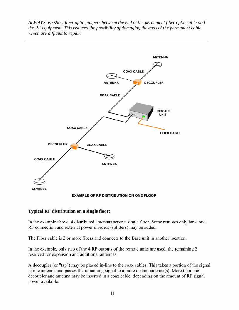
ALWAYS use short fiber optic jumpers between the end of the permanent fiber optic cable and the RF equipment. This reduced the possibility of damaging the ends of the permanent cable which are difficult to repair.
Typical RF distribution on a single floor: In the example above, 4 distributed antennas serve a single floor. Some remotes only have one RF connection and external power dividers (splitters) may be added. The Fiber cable is 2 or more fibers and connects to the Base unit in another location. In the example, only two of the 4 RF outputs of the remote units are used, the remaining 2 reserved for expansion and additional antennas. A decoupler (or "tap") may be placed in-line to the coax cables. This takes a portion of the signal to one antenna and passes the remaining signal to a more distant antenna(s). More than one decoupler and antenna may be inserted in a coax cable, depending on the amount of RF signal power available.

12
The exact locations of antennas and the quantity of antennas is determined by the system engineering. Code Compliance: Local building and safety codes must be met, most being the same as IBC 2003 and NEC2005 - NFPA 70 codes. Specific recommendations: Recommended coaxial cable type (per NEC-2005 article 820) 820.113 "CATVP"; - 1/2 inch dia., 50 Ohm (75 ohm not acceptable). "N" male type RF connectors only. Verticals and long laterals. - 1/4 inch dia., 50 Ohm (75 ohm not acceptable). "N" male / "SMA" male type RF connectors. Remote unit to nearby inside antenna, short runs. Recommended fiber cable type (per NEC-2005 article 770) 770.113 "OFNP". Fiber optic cable connectors are either "SC-APC" or "FC-APC", as specified otherwise by the system designer. Non "APC" connectors are NOT acceptable. A minimum of 4 fibers per remote fiber unit is recommended. (2 in use, 2 spares) Never use orange connectors or orange jacketed fiber cables. Top: "SC-APC" = Use if specified Top: "FC-APC" = Use if specified Bottom: "SC" = DO NOT USE Bottom: "FC" = DO NOT USE Conduits: Fiber Cables: 2 - 4 fibers per fiber remote unit; 1 inch I.D. Min. bending radius = 6 inches. No more than two bends between breakouts. Coaxial cables up to 5/8" diameter; 2 inch conduit. Min bending radius = 12 inches. No more than 3 bends between breakouts. Coaxial cables up to 1 " diameter, 4 inch conduit. Min bending radius = 24 inches, No more than 2 bends between breakouts.

13
Note: Normally risers to roof are 4". Unless the local code specifies otherwise, Coaxial cable risers do not have to be in conduit. 4" core drillings in vertically stacked equipment rooms are common practice. Note: Always use cable manufacturers specifications. Note: Do not run radiating coaxial cables over 10 ft inside metallic conduit. Misc. Fiber items: Head-end Hardware: 2 each, 36 inch ¼" dia. cable jumpers with N-male and SMA-male connectors . Connects BDA to Fiber head end unit. 1 each, 110 VC in 24 VDC output power supply. Typically 1 amp per 8 remote hub connections. RF-to-Fiber Head end units. Each unit serves 4 or 8 remote hubs according to model. Maybe expanded to approximately 64 remotes Fiber patch panels for SC-APC or FC-APC connectors. (connectors match Head end connectors) 2 connectors per remote hub. Typical Head-end (Main Equipment room) Patch Panel Fiber Jumpers: 36" or 1 meter signal mode fiber with SC-APC or FC-APC (connectors match head-end equipment), 2 jumpers per remote unit. Miscellaneous: Standard 19" inch equipment mounting rack. Will house rack mounted BDA, Fiber head-end, patch panel, DC power supply, interconnecting cables, etc. Typical Remote Fiber Unit Hardware; 1 each, Fiber remote unit. 1 each, DC power supply If installed in open area, (see picture on page 9) add; 1 each, NEMA12 type case. Approx 16 x 16 x 10 inch for 800 MHz. NOTE: For lower bands and multiband systems case will be larger.

14
1 each, Small 2 to 6 fiber patch box. 2 are in-service and others are spares. 2 each, 36" single mode fiber jumpers with SC-APC or FC-APC connectors. RF jumpers will be required if the assembly is fabricated in the field. Antennas: 1 each, Donor rooftop antenna: (10 dB typical gain directional antenna for 800 MHz.) 1 each, Roof antenna mast and 1-1/2 inch antenna mount pipe. Iinclude roof penetration considerations! Indoor antennas. Surface mount, unity gain with N-male connector. Up to 4 per remote hub. OPTIONAL: Radiating coax. Antenna 'taps", splitters, etc. as specified by system designer. Antennas and Hardware for frequencies below 800 MHz. Different components are usually required for each radio frequency band. Some combinations of frequency bands, such as public safety and cellular bands, may not be compatible or require special and additional hardware. Consult the system designer for additional information NOTICE: This information is supplied as an educational document only and does not include all possibilities of designs nor does it contain adequate information to complete a proper design. This may serve as a general installation guideline for contractors. In all cases, experienced in-building integrator or system designer is highly recommended. Only detailed analysis can determine exact antenna placements. Factory certified in-building integrators are recommended.

15
Appendix C
Providing Robust In-Building Coverage in Public Safety Wireless Networks
By Gary Grimes, Dekolink Americas
1. INTRODUCTION
It is well known that most mobile wireless communications in urban environments terminate in an indoor environment. Because of this, it is not only desirable but, more and more, legally mandated that upgraded and new public safety networks guarantee a level of in-building coverage for first responders. Until relatively recently, wireless public safety networks have been deployed with the goal that in-building coverage will be provided to whatever extent possible by the outdoor network of high sites.
It is now widely recognized that this approach leaves many crucial highly populated areas in high-rise office buildings, shopping malls, hospitals, government buildings and tunnels with severely limited coverage for emergency services. To fill in this coverage with additional, very expensive high sites is economically impractical.
To meet these requirements, there is a range of in-building coverage solutions available that can solve these coverage problems economically. These solutions extend the coverage of the outdoor network to the indoor environment through the use of a bi-directional RF signal booster. One RF port of the booster is connected to an outdoor directional antenna that pulls the signal in from a nearby high site, which acts the “donor” site. The other RF port of the booster is connected to an indoor antenna or indoor distributed antenna system (DAS) that is designed to provide uniform coverage within the building.
RF Boosters range from low power, low cost, wideband devices to state-of-the-art multichannel digital RF boosters. The available products trade off cost with features and performance. The latest digital boosters are specifically designed for Public Safety networks to provide the simplest and most reliable set up in any network as well as performance and
Floor 2
Floor 1
To/FromDonor Site
Off AirDirectional Antenna(Yagi)
RF Booster
IndoorCoverageAntenna
RF SplitterCoaxial Cable
Figure 1. In-Building Coverage System.

16
features that guarantee robust coverage even in real emergencies.
Most of the products approved by the network OEMs will provide the needed coverage but only if they are deployed as part of a well-engineered site. Hasty installations of low-cost RF boosters usually cause more serious problems than they solve. Because of the nature of public safety networks, designing and deploying in-building coverage systems for these networks requires more engineering care and skill than for commercial wireless networks. Even small sites should be designed and deployed by experienced and licensed engineers.
In choosing RF booster performance, features and technology, Public Safety users have options between simple, low cost Class B only technologies and higher cost technologies that can be configured as Class B, Class A or a mix as necessary. To summarize, Class B technologies retransmit an entire band or large segment of a band. Class A technologies select only the desired channels to retransmit. Small indoor coverage sites may only warrant a low cost solution. On the other hand, if interference with other sites cannot be mitigated by such low cost solutions, then no indoor solution will be effective(except fiber fed or a micro base station). Indoor coverage systems for large buildings can cost well over several hundred thousand dollars in engineering services and installation alone so a high performance multichannel solution that costs $10k to $30k would be the choice to ensure the most robust coverage for the money.
2. FCC 47 CFR 90.219 USE OF SIGNAL BOOSTERS
The Code of Federal Regulations part 47 section 90.7 and 90.219 details the definitions and limits for the use of RF signal boosters in Land Mobile Radio networks.
These rules are included in Section V of this Best Practices paper.
3. AVAILABLE TECHNOLOGIES
3.1 Bi-directional Amplifier (BDA) Although this is the common terminology that has been used in the two-way industry for years, some of the major manufacturers are re-educating the market so as to differentiate the various technologies.
Figure 2. Bi-directional amplifier. All of the filtering is handled by the duplexers.

17
Figure 2 shows the block diagram for a BDA. There is no heterodyning (internal frequency conversion). All of the filtering is handled by the duplexers. Although this is the simplest architecture, the BDA has a number of limitations. The main ones are: 1. Poor out-of-band rejection: when filtering at the higher frequencies, it is difficult to
achieve very sharp roll off in the filter response. These are usually full band devices. The poor roll off characteristics have caused problems for Cellular carriers for years.
2. Fixed filtering: To get a different frequency range, the entire unit must be replaced.
3.2 Analog RF Boosters This architecture starts with the BDA then adds an internal heterodyned section.
This architecture has a number of significant advantages over the basic BDA. 1. Better filtering: At the lower IF, low cost filters with very sharp roll offs are
available. These can be crystal filters or SAW (surface acoustic wave). The sharp roll off filters permit the realization of channel selective filtering or any number of sub bands.
2. Tunable: the down- and upconversion process permits tuning of the pass band anywhere within the full band of the duplexer.
3. Multiple bands: Splitting the IF path allows for multiple sub bands.
The components and processes needed for this architecture are produced in high numbers so add very little cost to the basic BDA design but result in a much higher performing product with better features.
Figure 3. Analog RF Booster includes an internal RF down/upconversion that permits adding additional filtering at a lower Intermediate Frequency (IF).

18
3.3 Digital Filter RF Booster This booster has the same architecture as the analog booster except that the SAW or crystal filter is replaced by a digital filter. Here, the IF signal is sampled by a high speed A/D converter. The filtering is done in the digital domain on this data stream with digital signal processing. The processed data is converted back to analog RF by a high speed D/A converter.
With the filtering handled by digital signal processing, the range of possibilities of this architecture is vast. A wide range of filter types can be stored in the library with differing bandwidth, roll off, delay times and general transfer functions. The unit can be configured with many filters, each of which is independently selected and tuned. The newest versions permit selection of up to 24 filters which can be a mix of single and multiple channel pass bands. Because of this, it is more accurate to refer to this architecture as “spectrum selective” rather than channel selective.
Figure 4. Digitally filtered RF Booster.

19
4. CHARACTERISTICS OF EACH DESIGN
4.1 Time Delay There is much discussion about the time delay through a Class B booster versus that through a Class A booster. The concern is that there can be signal quality degradation in areas where there is overlap between the primary signal directly from the base station and the delayed version of the signal through an RF booster. This is discussed in detail in section 7 below. At this point, note that the delay through a filter is inversely proportional to its bandwidth and directly proportional to the filter “order”, that is, the number of sections that determine the sharpness of the roll off and the flatness across the pass band. This is the same no matter how the filter is implemented, i.e.; no matter whether it is analog or digital. So, a filter that is narrow band with a sharp roll off will have a higher time delay than will a wide band filter with a soft roll off. For filters wider than about 200 kHz, the delay through the booster is determined by the delay through the electrical components, typically around 5 μsec. However, as the filter bandwidth is increased, the adjacent channel signal rejection is reduced. The proper tradeoff of these factors for the spectrum environment encountered is part of the professional system design needed to optimize operation.
4.2 Gain
• Preventing Feedback Oscillations It is important to design and deploy an RF Booster site such that there is sufficient electrical isolation between the donor and coverage antennas. If they are too close to each other, the system will go into feedback oscillation similar to holding a microphone too close to the PA speaker. The rule of thumb is to ensure the total isolation is at least G + 15 dB where G is the gain of the RF booster. The required gain is determined by the coverage area needed and the available signal from the donor site as well as the antenna gains. This is the same for any RF booster, Class A or B. Therefore, either class A or class B systems that are properly designed and installed can provide the necessary isolation to avoid feedback. For outdoor coverage, the donor and coverage antennas are often mounted on a tower with a vertical separation. Antenna manufacturers provide data for the attenuation of the directional antenna gain away from the main beam. This data is used to calculate the needed separation between the antennas. Often, the needed isolation is achieved by placing the antennas on opposite sides of a physical structure such as a building. For in-building applications, the building provides the needed isolation between the outdoor donor antenna and the indoor coverage antennas. The standard practices used by qualified installers ensure sufficient isolation.

20
• Automatic Gain Control (AGC)
Most RF Boosters employ an AGC circuit that automatically limits the RF output power to the “rated” power of the booster. The rated output power is the maximum output power that ensures that all transmitted spurious signals and intermodulation products will be less than the FCC limit. This level is typically approximately 10 dB lower than the output 1 dB compression point of the booster. If a large RF signal is received such that, if the gain remained unchanged the output would exceed the rated power, the AGC automatically reduces the gain to prevent this. When the input level drops, the AGC restores the gain to its original setting.
• Microprocessor-Controlled AGC In some RF boosters, manufacturers have implemented “smart” gain control circuits in addition to the standard AGC. There three primary advantages of these circuits. 1. Automatic Gain Optimization during set up: It is often difficult to know the
correct gain setting during set up. This is due to the fact that, when on site RF measurements are made, all of the available channels in the network are not on. The “smart” circuits monitor the network and make the necessary gain adjustments until the proper gain is discovered.
2. Oscillation Prevention: If the antenna isolation changes temporarily because of, say, nearby construction that causes the system to feedback, these circuits will automatically reduce the gain to stop the oscillation. When the source of the oscillation has been removed, the system will return to the original gain setting. It is not true that these circuits cause a “bursty” oscillation problem. Instead, the gain will simply remain below the oscillation threshold until the isolation problem is removed. The condition is reported by the unit locally and over the remote monitoring connection (if deployed).
3. Long Term Maintenance: these circuits will make small adjustments as necessary to maintain the proper booster gain if the donor link changes over time. Changes might occur from misalignment of the donor or a change in the donor link multipath due to new construction in the area. This eliminates the need for service personnel to revisit the site.
4.3 Uplink Noise All FCC-approved boosters have limits on transmitted out-of-band noise. The limits are defined in 47 CFR 90.210. There are two possible problems with the transmitted uplink noise that must be addressed in any site design. 1. Base Station Desense: if the booster uplink gain is set too high, the noise from
booster can reduce the sensitivity of the base station. This causes a reduction in the base station coverage area for all portables and mobiles. Note that this problem can be caused by improper deployment of any booster whether low power or high power. It is not true that channelized boosters have inherently higher output noise than broadband boosters. If a particular product has a higher out of band noise

21
characteristic, this is due to the manufacturer’s design and not because of any problem inherent with channelized architectures.
2. Other Services Desense: with broadband boosters, one must be careful not to desense other services with base stations located within the donor antenna beam width but closer than the desired base station. A gain setting that is correct for the desired service will be high for the other service and will jam their signal. There have been cases where the initial set up was good but a new service deployed a site nearer the booster that was then jammed by the out of band noise from booster. In this case, either a more directional antenna or a narrowband booster must be used.
5. PRACTICAL CONSIDERATIONS
5.1 Digital RF Booster specifications The newest digitally filtered, spectrum selective RF boosters are designed specifically for Public Safety networks. The primary specifications for the 700/800 MHz versions are: Frequency 700 + 800 MHz or 800 MHz band only Composite Downlink RF Power 2W or 10W Number of Filters up to 24 Filter Bandwidth range 12.5 kHz to 12 MHz Time Delay 5 μsec to 100 μsec depending on filter Per Filter AGC 60 dB range Note that the digital booster can function as a Class B booster or Class A or a mix as necessary. There are enough filters to handle most Public Safety networks even if each filter is for a single channel. The per channel AGC selectively squelches any large, transient signal from, say, a passing high power mobile so that the wideband AGC is not activated which would desense all of the channels. All of these features make the digital booster somewhat more expensive than a Class B booster but the flexibility and guaranteed non-interfering, robust coverage in real environments make this the preferred choice in many applications.
5.2 Need for External Combiners and Multicouplers This only applies to the high power, narrowband UHF and VHF boosters that are employing a common transmit/receive for each of the donor and coverage antennas. Unlike the 700/800 MHz band where the transmit and receive channels are assigned to separate frequency blocks, transmit and receive channels for UHF are interleaved. UHF transmit and receive channel pairs are separated by 5 MHz, but a low level receive channel for one service may be adjacent to a high power transmit channel from another. Although the booster itself may be channelized using either analog or digital filtering, combining all of the transmit and receive channels to and from the base station onto a single antenna requires a separate rack of cavity filters and combiners that is custom for every site. The same applies to the coverage antenna or DAS port.
5.3 Filter Selection and Rebanding A number of analog RF booster designs with internal heterodyning are configured with either switchable bands or replaceable plug-in filter sections. Manufacturers may offer a

22
selection of filter bandwidths that may be configured. This simple approach can be effective in many applications. Often, the optimum filter choice is not available from the standard SAW filters offered. In these cases, the digital filter may be the best or only choice. Digitally filtered boosters will come with a standard library of filter choices. If the optimum filter for a given installation is not included in the standard library, the manufacturer can usually e-mail the needed filters that can then be downloaded into the digital filter. This same flexibility can be a big advantage if there are changes in the network channel plan either because of added capacity or Rebanding. Although Rebanding has been implemented in some areas, there are many areas where it has not and will not be for some time. This is especially true near the borders with Canada and Mexico where the changes involve negotiations with those countries. Finally, it is important to note that Rebanding eliminates most of the adjacent channel interference issues with Sprint/Nextel and SouthernLinc but there are still many different emergency services and SMR services that share the remaining band. Note that any broadband filter solution deployed in a pre-Rebanding area will have to be retuned or replaced after the Rebanding. This is because a broadband booster will often have to cover the entire 800 MHz band to accommodate channels scattered throughout the band. After Rebanding, the booster must be changed to pass only the non-ESMR services. The digital filtered boosters need reprogramming of the filters. And if the booster is deployed with remote monitor and control, this reprogramming can be accomplished without having to visit the site physically.
6. PROVIDING ROBUST COVERAGE IN A REAL EMERGENCY
Many in-building network engineers design and verify in-building coverage systems for two-way radio the same way they do for commercial cellular systems. That is, they design to guarantee a certain downlink signal level, usually -85 dBm, over some percentage of the building, and then verify the actual coverage with a simple walk through with a portable. In fact, Public Safety networks have several major differences that must be taken into account. 1. No power control: commercial mobile handsets have automatic power control so they
always transmit just enough power to maintain the needed signal quality. Two-way radio mobiles and portables have manual power settings only. Because of this, the coverage system for a Public Safety network must be able to accommodate nearby high power portables and mobiles.
2. Two-way radio networks are unbalanced: commercial networks balance the transmit power with the receive sensitivity automatically. Two-way radio networks are almost never balanced since there is no automatic power control. Because of this, the optimum gain settings may be different for the uplink and downlink paths.
3. The loading environment is very different during a real emergency: The primary purpose of a Public Safety network is to function during a real emergency. Designing and verifying an in-building system for operation when there may be one or two security guards present does not reflect how the system will perform during an emergency when

23
there are a high number of portables and mobiles in operation in the area from first responders.
6.1 Accommodating Additional Services Some literature has claimed that broadband boosters are preferable during real emergencies because they can accommodate other first responder services that are not otherwise in use. First, if a broadband system has been designed to provide coverage for certain services, adding channels to this system will require that the booster gain be reduced so as not to overdrive the booster. This would result in a loss in overall coverage area. So, in order to accommodate these additional services, the system would have to be designed from the beginning to anticipate the additional loading. Also, additional donor antennas would have to be included in the initial design that point towards the relevant donor sites for these additional services. These same considerations then apply to any booster design, Class A, Class B or mixed.
6.2 Transient High Power Mobiles One crucial advantage of the new digital boosters for Public Safety is the per filter AGC feature. If the filters selected are single channel, then this feature becomes a per channel AGC. In a real emergency, high power mobiles or even high power portables can pass close to the coverage antennas. This is especially the case for systems that include outdoor coverage or coverage in parking garages where mobiles in emergency vehicles could go. With a broadband uplink power amplifier on the analog or digital booster, this high level signal can cause the broadband amplifier AGC to reduce the gain which then reduces the uplink sensitivity. This can cause a reduction in signal quality or complete loss of signal for the portables at the edge of coverage at the emergency site. The per channel AGC selectively squelches the large signal so that none of the other channels are affected. A broadband booster can be relatively unaffected by high power transients if the unit features a high power uplink amplifier. For in-building coverage where only portables and not mobiles are expected, adding sufficient RF loss by designing the DAS with enough cable and RF splitters to multiple antennas will also minimize this problem.
7. CLASS A OR CLASS B OR MIXED?
The decision to use a Class A, Class B or mixed class, spectrum selective booster at a given site depends on several factors. 1. Economics: is the higher cost of a digital or analog Class A or spectrum selective booster
supported by the available budget? 2. Uplink Interference: Can the donor site be isolated or mostly isolated from other services
by selecting a narrow beam donor antenna? If so, a broadband booster could be used. If not, it may be that services in adjacent channel can be filtered using narrow, but not necessarily channel selective filters. In this case, a digital filtered spectrum selective booster provides the simplest solution.
3. Site Size and Importance: Larger buildings and facilities for government and crucial services may necessitate the most robust coverage during actual emergencies when a high number of first responders are present. In this case, a narrowband or mixed class,

24
programmable, multichannel spectrum selective digital booster with per channel AGC is the safest choice.
4. Futureproof and Accessibility: An easily reprogrammed digital multichannel spectrum selective booster may be the best choice if network changes for Rebanding are expected. Broadband units in urban areas are also vulnerable to interfering with new sites that fall in the donor antenna beamwidth. Also, sites that are located in difficult to reach locations can be much better served by boosters that can be reconfigured via remote connection. On the other hand, a remote, rural installation may not have much adjacent channel interference so a Class B approach with a low power requirement for a dedicated fuel cell or solar power may be the best choice.
7.1 Number of Channels and Composite Power Even if there are other services within the donor antenna beamwidth, a broadband booster can be set up to accommodate this by setting the gain such that the composite output power does not exceed the rated power of the booster. The more channels that must be accommodated, the lower the available power per channel will be. For example, a booster that can provide 27 dBm/channel for 2 channels will provide 24 dBm/channel for 4 (equal) channels, 21 dBm/channel for 8 equal channels, and so on. Especially in urban areas, one must regularly monitor any changes in the other networks or the addition of any new services that could adversely affect the coverage.
7.2 Uplink Interference - The Main Concern Incorrect interpretation of the FCC rules as well as lack of knowledge about the functioning of two-way radio networks, has led many to believe they can always use a broadband booster for indoor coverage. This is especially the case for small buildings where many assume that, since the coverage area requires just a small, low power booster, it cannot possibly harm the network. This simply is not true. A small, low power broadband booster improperly deployed can cause just as much damage to the network as a high power unit. One problem was discussed previously, namely improper uplink gain settings. But a complete knowledge of the location and channel plans for other services is required to assure a non-interfering deployment of any booster as required by the FCC.
Figure 5. A narrowband donor antenna isolates the desired donor site. A broadband booster is OK.

25
Figure 6. The only other services within the donor antenna beam width are far away. A broadband booster will work.
Figure 7. There are other services near the desired service not closer to the booster site. A broadband booster could be used if planned carefully since the channels from the other services will mix with the channels from the desired service. Also, any excess out-of-band noise or spurious could jam the other services. A spectrum selective booster could be easier to set up and more reliable if the additional cost is within the budget.
Figure 8. Other services have donor sites closer to the booster site than the desired site. A broadband booster cannot be used since the uplink noise would jam the other services. A Class A or spectrum selective booster must be used.

26
8. PROPAGATION DELAY
Some industry analysts have depicted the propagation delay through RF boosters as a universally bad thing. In fact, propagation delay is simply a part of the device physics and must be factored into any properly engineered coverage solution.
8.1 Time Delay in RF Boosters The propagation delay through any filter, whether it is implemented digitally or in the analog domain, is inversely proportional to the bandwidth and (roughly) directly proportional to the order (number of sections) of the filter which determines the filters flatness across the pass band and sharpness of the roll off at the filter’s edges. For filters with bandwidths greater than about 200 kHz, the delay is limited by the electrical delay through the components. This is typically approximately 5 μsec.
8.2 TDI (Time Domain Interference) It is well known from simulcast network design that signal quality degradation can result from the overlap of a signal and a delayed version of the same signal. The worst case occurs in areas where the two signals are the same level. The analysis from the TIA TSB-88B Recommended Methodologies shows that, under these conditions, the maximum relative delay that can be tolerated to maintain a DAQ 3.4 is 33 μsec. For P25 Phase 2 systems, this value is expected to be 15 μsec. When one signal is stronger, higher relative delays can be tolerated. This is shown in Figure 9 below.

27
Figure 9. These plots show the maximum allowable relative time delay as a function of relative signal strengths.
8.3 Design to Minimize BOTH Adjacent Channel Interference and TDI If it is determined that a narrowband analog or digital filtered booster is required or preferred, the coverage system must be designed so as to minimize both adjacent channel interference and time domain interference. More severe adjacent channel interference calls for narrower filters, which introduces more time delay. The coverage design must then ensure that delay does not cause signal degradation.
• Step 1: Select the Donor Antenna The first step in proper design to mitigate interference is to select a donor antenna that has a beam width narrow enough to eliminate as many adjacent channel services as possible. In many cases, it is desirable to select an antenna with a beam width narrower than needed to guard against possible future sites. It is important to consider the site where the antenna is to be installed as this could pose physical limitations either in size or aesthetics.
2 Signal Level Difference vs Relative Time Delay for DAQ 3.4 (Phase I P25)
0.0
2.0
4.0
6.0
8.0
10.0
33.0 35.0 40.0 45.0 50.0 55.0
Time Delay Difference (usec)
Sign
al L
evel
Diff
eren
ce
(dB)
2 Signal Level Difference vs Relative Time Delay for DAQ 3.4 (Phase II P25)
0.02.04.06.08.0
10.012.014.016.018.020.0
15.0 16.0 18.0 20.0 23.0 25.0 32.0 43.0 60.0
Time Delay Difference (usec)
Sig
nal L
evel
Diff
eren
ce (d
B)
28
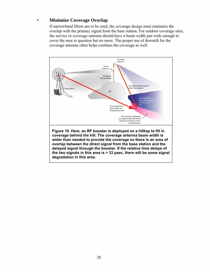
• Minimize Coverage Overlap If narrowband filters are to be used, the coverage design must minimize the overlap with the primary signal from the base station. For outdoor coverage sites, the service or coverage antenna should have a beam width just wide enough to cover the area in question but no more. The proper use of downtilt for the coverage antenna often helps confines the coverage as well.
Figure 10. Here, an RF booster is deployed on a hilltop to fill in coverage behind the hill. The coverage antenna beam width is wider than needed to provide the coverage so there is an area of overlap between the direct signal from the base station and the delayed signal through the booster. If the relative time delays of the two signals in this area is > 33 μsec, there will be some signal degradation in this area.

29
• Minimizing Overlap for Indoor Coverage The signal penetrating a building from the outdoor network can be quite spotty and irregular depending on the building layout and materials as well as the nearby obstructions outside the building. If a building were located in an isolated place with no nearby obstructions, the signal from the nearest high site would still be much higher at the upper floors because of the characteristics of RF propagation over the earth’s surface. The signal level difference between the ground level and 100 feet higher can be over 20 dB. In real environments, there are additional attenuations that affect the lower floors from terrain, nearby buildings and even trees. If the signal levels are good at the higher floors, one could take the approach of providing a full indoor coverage system for the lower floors and just the stairwells and elevators shafts for the upper floors. Another approach is to cover the entire building and shape the coverage so that the indoor coverage signal dominates over any signal from the outside. One way to accomplish this is to design a DAS with directional antennas at the corners of each floor. This way, the indoor coverage signal can immediately be dominate over signals coming through the walls and windows without leakage to the outside (Figure 13).
Figure 11. Same as before but a coverage antenna has been selected with a narrower beam width to cover only the area needed. Also, the antenna alignment has been optimized and downtilt has been employed to better focus the coverage. Now, the coverage overlap area has been minimized. Any signal degradation occurs only in a small strip.

30
•
Figure 12. In-building coverage from the outside network will generally be much worse for the lower floors. The actual coverage may be spotty throughout. The best solution is a DAS design that ensures a dominant indoor signal
Figure 13. A DAS design with directional corner antennas can ensure capture of the indoor signal without leakage to the outside.
31
Select filters with maximum BW that give the needed adjacent channel rejection
A detailed knowledge of the adjacent channel services being picked up by the donor antenna allows the design engineer to select filters in the booster that are as wide as possible but still provide the required adjacent channel rejection. In the worst case, one or more of the filters may have to be selected that pass one or more adjacent channel services. Accommodating a few additional channels is still far easier and more controllable than accommodating 30 additional channels in a broadband booster.
9. RF BOOSTERS IN SIMULCAST NETWORKS
Somewhat more care must be taken deploying narrowband and spectrum selective boosters in a simulcast network. Broadband boosters generally have time delays of around 5 μsec so can be deployed without time delay concerns. If narrowband or spectrum selective boosters are to be deployed in the capture area of one site of a simulcast network, the same methodology described above for a non-simulcast network applies. If the in-building site is located in an area covered by more than one donor, all of the same procedures for minimizing both adjacent channel and time domain interference apply, however the donor site used must be the one nearest and with the most dominant signal and one must take extra care to “shape” the indoor coverage as discussed previously to ensure capture of the portables with that donor site.
10. SUMMARY
RF signal boosters are the cost-effective way to fill in crucial coverage in Public Safety networks. There is a range of available solutions from simple broadband boosters to analog narrowband boosters to digital multichannel spectrum selective boosters that can be configured as Class A, Class B or a mix as necessary. All of these solutions can provide coverage that is as robust as the rest of the network if the coverage solution is engineered properly. Similarly, any in-building system regardless of class, configuration, size and cost that is deployed with little planning or poor engineering can cause network performance problems. Every site is different and requires a thorough knowledge of the services in that area and a carefully planned design by qualified engineers.
32
Appendix D: Optimizing FCC Class B Band Selective (broadband) Signal boosters for Urban use
By Jack Daniel, Jack Daniel Company
The FCC signal booster Class, A and B, are operational designations and should not be confused with the commonly used technical classifications of amplifier designs used within the signal booster. For example, FCC Class B signal boosters usually use technical class A amplifier circuits to provide high linearity. FCC Class A signal boosters may be using any of the technical classes of amplifier circuit. Reference: FCC part 90.219. The Code of Federal Regulations part 47 section 90.7 and 90.219 details the definitions and limits for the use of RF signal boosters in Land Mobile Radio networks. These rules are included in Section V of this Best Practices paper. Within this paper FCC Class B signal boosters are called 'broadband' amplifiers or better clarity. Effects of multiple channels and Composite Power Broadband amplifiers are used in FCC Class B signal boosters to amplify multiple channels within a given bandwidth. To be a FCC Class B signal booster the broadband amplifier's passband is wider than one channel bandwidth and may be many channel bandwidths wide. The FCC rules permit the amplification of both licensees and others within the passband of a Class B signal boosters. These amplifiers used in Class b signal boosters are very linear amplifiers to minimize distortion and intermodulation generation. To assure the amplifier operation remains within the linear region while operating at maximum usable output power, a feedback circuit reduces the amplifier gain so the maximum output is relatively stable. This also assures the out of band emissions are within the FCC limitations, which is currently -13 dBm. Since the bandwidth of a broadband amplifier allows amplification of more than one communications channel, the total power of all the channels together is called the "composite power". A power measurement of the total power out of a broadband amplifier is the sum of all the carriers within that passband, not any one single channel. A more accurate measurement of 'power per channel' can be made using a spectrum analyzer. The end result of the feedback driven gain adjustment is the output power per channel can vary in direct proportion to the input power per channel when operating at maximum composite power output .

33
The impact of multiple channels on the power per channel Example relationships are illustrated in Table 1 on page 2 when comparing the power level per channel when the signal boosters composite output power level is fixed at maximum. Table 1 Effect of composite power when signal booster is operating at maximum design output level In this illustration, the input carriers are all 0.001 mW (-30 dBm) and the maximum composite output power is 1 watt (+30 dB). Number
of Input Power Output Power Input per channel Composite Composite Effective per channel per channel composite
channels mW input (mW) Input (dBm) Gain * dBm mW output (w)
1 0.001 0.001 -30.00 60.00 30.00 1000.000 1 2 0.001 0.002 -26.99 56.99 26.99 500.000 1 3 0.001 0.003 -25.23 55.23 25.23 333.333 1 4 0.001 0.004 -23.98 53.98 23.98 250.000 1 5 0.001 0.005 -23.01 53.01 23.01 200.000 1 6 0.001 0.006 -22.22 52.22 22.22 166.667 1 7 0.001 0.007 -21.55 51.55 21.55 142.857 1 8 0.001 0.008 -20.97 50.97 20.97 125.000 1 9 0.001 0.009 -20.46 50.46 20.46 111.111 1
10 0.001 0.010 -20.00 50.00 20.00 100.000 1 20 0.001 0.020 -16.99 46.99 16.99 50.000 1 30 0.001 0.030 -15.23 45.23 15.23 33.333 1 40 0.001 0.040 -13.98 43.98 13.98 25.000 1
* Effective gain is signal booster gain after feedback control (AGC)
Obviously, the more input channels, the less power out per channel. Good engineering practice is to assume worse case based on the spectrum activity within the signal boosters passband. For example, it is practice to assume 40 equal level carriers could occur in the worse case in downtown Los Angeles, so the coverage is designed around a per carrier power level of 25 mW or +14 dBm. When there is less activity the coverage will improve. Although the input filter's bandpass may be wide enough to pass more than 40 channels, that is seldom the real spectrum seen out of the donor (roof top) directional antenna. Directional antennas reduce the level of undesired channels that are not in the main gain lobe of the antenna. It is true that a very strong signal within the passband can 'dominate' the power per channel and have the same effect as multiple undesired channels. The most extreme cases may require the use of FCC Class A channelized signal boosters, with the engineers awareness of other potential undesirable tradeoffs that may occur when using channelized signal boosters. Exceptionally strong undesired adjacent channels may not be attenuated sufficiently by the channel selective filter to prevent negative impacts on a channelized amplifier. For example, a channelized signal booster's filter may attenuate adjacent channels by 40 dB and if the offending adjacent channel signal is 40 dB higher than the desired channel level this is the same as having

34
two channels within the channelized signal boosters amplifiers. In real applications, a distant donor site may be delivering a -90 dBm signal to the signal booster while a nearby cell site is delivering -50 dBm, a 40 dB overdrive by the undesired signal. High level input signals can exceed the capability of the AGC circuits and/or the 3rd order intercept point of the input amplifiers in any type signal booster, leading to excessive IM products and out of band emissions. The solution is the same as for all designs: anticipate these conditions in the system design and set signal booster gains accordingly. Note that for antenna-to-antenna isolation the value that should be used should be the gain setting of the signal booster plus 15 dB. In the example above, this would be 60 dB + 15 dB for a total isolation requirement of 75 dB or more. The impact of lower level channels on Channel Power When doing a spectrum analysis it is not uncommon to see many low level 'undesired' channels within the signal booster's passband. The best place to insert the spectrum analyzer is after the input filter. The downlink path is usually the most active. The result on the spectrum analyzer will now be a true representation of the input spectrum after the improvement caused by the input filter by reducing out-of-band channels as well as the directivity of the donor (roof top) antenna. It has become common practice to ignore undesired signals that are 20 dB or more below the desired channels. Table 2 demonstrates the insignificant impact of as many as 40 undesired channels upon the output level of the desired channels.

35
Table 2 Impact of undesired channels 20 dB below desired channels In this illustration, the desired channels are -30 dBm, the undesired channels are -50 dBm and signal booster output set at +30 dBm composite Number
of Composite Number
of Undesired Composite Channel
dBm Channel
dBm Net dBm desired desired undesired channel undesired without with reduction
channels channels (dBm) channels levels channels undesired undesired impact
1 -30.00 0 none none 30 30.00 0 1 -30.00 10 -50.00 -40.00 30 29.54 0.46 1 -30.00 20 -50.00 -37.00 30 29.24 0.76 1 -30.00 40 -50.00 -33.00 30 28.24 1.76
10 -20.00 0 none -20.00 20 20.00 0.00 10 -20.00 10 -50.00 -40.00 20 19.96 0.04 10 -20.00 20 -50.00 -37.00 20 19.91 0.09 10 -20.00 40 -50.00 -33.00 20 19.79 0.21 20 -17.00 0 none none 17 17.00 0.00 20 -17.00 10 -50.00 -40.00 17 16.98 0.02 20 -17.00 20 -50.00 -37.00 17 16.91 0.09 20 -17.00 40 -50.00 -33.00 17 16.89 0.11 40 -14.00 0 none none 14 14.00 0.00 40 -14.00 10 -50.00 -40.00 14 13.99 0.01 40 -14.00 20 -50.00 -37.00 14 13.98 0.02 40 -14.00 40 -50.00 -33.00 14 13.95 0.05
Best Practices for Donor Antennas From Table 2 it can be recognized that undesirable channels that are much lower than the desired channels have minimal impact. The 'donor' antenna is typically the outside roof antenna. Careful choices of antennas types and mounting can improve the desired channel levels and reduce undesirable channel power levels. Obviously, an antenna with high directivity and high front-to-back rations should always be used. This includes locations where the benefits of the antenna gain is not important because we are looking for the directivity. The following illustrations demonstrate several important methodologies. Using the structure itself to reduce undesired channels: Many roof tops have elevator and HVAC rooms that may provide additional blockage of undesired channels. Instead of placing the antenna above these rooms, place the antenna on the side of the room, putting the attenuation of the room between you and potential undesired channel locations. This approach can be used on the face of buildings as well. High donor antennas also 'see' more sites in the distance. The antenna elevation should be as low as practical an still maintain a line of sight path. Below are pictures of actual public safety installations using this approach:

36
Donor Antenna on side of structure. Blocking nearby Nextel site
Panel Donor Antenna at street level. (Downtown Los Angeles)

37
The above illustration shows the importance of a directional antenna in reducing the levels of potential undesirable interferers. Note the vehicular source also. This illustration shows the practice of slightly rotating a directional antenna 'off center' so that the offending sources fall with the low gain side lobes of the antenna. This effect is most noticeable in Yagi type antennas.

38
Broadband bandpass filter optimization: It is a common error to think input and output filters are simple duplex filters. While the function of duplexing the downlink and uplink channels does occur, high performance filters are required to prevent interactions due to the high gains within the signal booster itself and the reduced guardbands that are more demanding than common duplexers. The passbands of public safety rated signal boosters can usually be ordered to match the requirements. Consumer grade products usually come with one maximum bandwidth choice. The type of filter includes cavity, combine, saw and digital with each having its advantages and disadvantages. By providing the system designer with the exact operating frequencies, site coordinates and known power levels, they can determine which choices bets fit the application. There may be more than one solution. Summation: Class B broadband signal boosters have a long record of successfully providing reliable in-building coverage for public safety agencies. Although the basic concepts were developed several years ago, these products are under constant improvements in performance and functionality. System engineers and client agencies are cautioned to evaluate the real design dynamics of their environment in making their system design and equipment selections. While Class B signal boosters satisfy many public safety requirements, the use of Class A may be needed in some situations to address undesirable in-band interferers. There are many considerations and trade-offs the system designer must handle when planning and installing a public safety in-building system, whether class A or B.
39
Appendix E: Optimizing FCC Class A Channel Selective (channelized) Signal boosters
By Jack Daniel., Jack Daniel Company
The FCC signal booster Classes, A and B, are operational designations and should not be confused with the commonly used technical classifications of amplifier designs used within the signal booster. For example, FCC Class B signal boosters usually use technical class A amplifier circuits to provide high linearity. FCC Class A signal boosters may be using any of the technical classes of amplifier circuits. Reference: FCC part 90.219. The Code of Federal Regulations part 47 section 90.7 and 90.219 details the definitions and limits for the use of RF signal boosters in Land Mobile Radio networks. These rules are included in Section V of this Best Practices paper. Within this paper FCC Class A signal boosters are called 'channelized' amplifiers for better clarity. Types of Class A signal boosters Class A signal boosters have been available for over 15 years with different, newer technologies and bands appearing over the years. There are four types available today and because of operational differences each type may require different configurations and optimizations. The following is a very minimal description of the different types. These types will be cited throughout this document when the types has different characteristics relative to the subject being discussed. Type 1: Crystal filter type: This is the original type and it is only available currently at VHF frequencies. These are not programmable and generally limited to 4 channels per signal booster. Except for bandwidth these are the same as Class B signal boosters. Since the signal booster only passes one channel the composite power effect in broadband signal boosters does not exist. These types are the most economical of all channelized amplifiers. Type 2: Single Channel heterodyne. These are perhaps the most programmable of all Class A signal boosters. These are always channelized as the passband bandwidth is restricted and cannot be reprogrammed to operate as a Class B broadband signal booster. Selectivity is achieved by down converting the input to a narrow IF filter then up converting the output back to the input frequency. These closely resemble a standard repeater, with good input sensitivity and fixed output power regardless of input level. Repeater activation thresholds are programmable and squelch operation can be none, CTCSS or Digital squelch activated. This type is capable of up to approximately 30 watts output per channel. The number of channels are unlimited as each channel is a stand alone rack mounted module and scaleable as required. Remote status monitoring, alarming and complete programmability capability is standard.

40
Type 3: Multiple channel heterodyne. This design uses a wideband down conversion of the input band (i.e. block conversion) into a bank of multiple parallel "IF" sections, combines the IF outputs into a composite output, then up coverts the composite signal into a common output power amplifier. Each IF is programmable so each may select an individual channel. The number of channels per signal booster is determined by the number of Ifs used, with 4 and 8 channel versions being most common. Due to the common input amplification and common output power amplifier this type does exhibit the composite power effect common to Class B signal boosters. (a discussion of composite power and optimization of composite power effects can be found in Addendum E, Optimizing Class B Signal Boosters) The potential output power per channel varies greatly from model to model due to many output power amplifier choices. Remote alarming and channel programmability is available as an option in some models. Since this type does not use baseband demodulation, CTCSS or Digital squelch control is not currently offered. Type 4: Functionally, this type is similar to Type 3 but uses digital signal processing to perform the channel bandwidth and frequency selection. This is sometimes referred to as 'digital filtering'. Current standard models have 4 to 8 channel capacity per signal booster. This type can allow programmability of gain per channel, which may be beneficial when input signals are from different remote sites. The output power per channel varies from model to model and high power (25 to 60 watt) amplifiers are available. Note the power amplifier is amplifying the composite power of the number of active channels, therefore the power per channels is less than the overall power rating of the output amplifier. Remote status monitoring, alarming and complete programmability capability is standard. Since this type does not have normally include baseband demodulation, CTCSS or Digital squelch control is not currently offered. Note: Type 4 has passband programmability which allows the passband to be more than one channel's bandwidth. When operating in this mode, the signal booster becomes a FCC Class B, broadband signal booster and has more composite power effects. Number of Channels: Type 1 is limited to approximately 4 VHF channels and is typically 1 channel. Type 2 has no limits on the number of channels, however conventional low power transmit combiners are required and that places practical limits on how many channels can be combined while retaining adequate power per channel. In in-building applications where low power distribution is preferred the combining loses are more acceptable. Most current Type 3 and type 4 models have hardware limitations of up to 8 channels per signal booster. (up to 16 channel capacity is under development) When the primary system utilizes more channels than the capacity of one signal booster additional signal booster inputs and outputs may be combined using hybrid combiners or other commonly available devices. Normal combining losses will reduce the power per channel accordingly.

41
Interoperability Considerations: The number of channels in a Class A signal booster is intentionally fixed to those specific channels used by the system it normally communicate with. The main function of a Class A signal booster is to prevent other undesired channels from interacting with the desired channels passing through the signal booster. The system planner should consider the channel requirements when the signal booster should also serve mutual aid and other outside agencies during an emergency event. This is an extension of interoperability. When additional channels should be processed by a channelized signal booster temporarily, one or more approaches may be used to accommodate them. (a) The Class A signal booster is installed with all the expected interoperability channels in addition to the normal channels being used. If the number of channels exceed the capacity of one Class A signal booster, more are added in parallel until a sufficient number of channels is provided. The system designer must also anticipate the composite power effects if the 'emergency' channels are only activated during an event. (b) The channels within the Class A signal booster are reprogrammed to accommodate interoperability channels. In this method the system designer must predetermine what normally processed channels within the signal booster will be made inactive during the event. The channel change is most effectively implemented using remote programming access circuits. (c) If the new channels are close to existing channels, the passband bandwidth of one or more channels may be widened. When this approach is used, the system designer should prepare a plan then, based on the levels of all the channels that will pass through each window, recalculate the output power. This is because the composite power effect comes into play when any passband allows more than input channel to be amplified by the same output amplifier. The passband bandwidth change is most effectively implemented using remote programming access circuits. This choice is currently limited to type 4 signal boosters. In scenarios (b) and (c) preplanning is required to have fast reprogramming response capability during the emergency. It would not be practical to dispatch a trained person to each structure to implement changes at the signal booster's physical location. A centralized remote site is optimal. The requires the system designer to include circuits for remote control to the appropriate structures. There are many circuit options available to the system designer, such internal data networks, dedicated or dial up telephone circuits, etc. Naturally the most dependable method is preferred and the public internet is never recommended. The remote reprogramming effort is similar to the methods used in 'dynamic regrouping' methodology. As many emergency scenarios as possible are matched with the radio channel changes that would be required in each scenario, limited by the channel capacity of the Class A signal booster(s). The results are entered into a program that allows non-technical personnel to activate the reprogramming based on the event type.

42
Propagation Delay When signals pass through a signal booster they are delayed by the signal boosters internal circuits. The amount of delay varies with design but overall is relative to the passband bandwidth. The narrower the passband, the greater the propagation delay. Propagation delay becomes a consideration in public safety applications where the direct signals from the repeater site and the delayed signals from the signal booster overlap. When the signal booster delay is small it has no effect on system operation. Manufacturers experience with overlap (or multipath) in simulcast system designs has established maximum signal booster delays relative to the type or brand of radio system used. Digital modulations have reduced the acceptable signal booster delay and the system designer should anticipate the worse case to facilitate current and future system requirements without replacing or reprogramming signal boosters. Currently, the most severe digital modulation type radio system delay recommendation is 15 microseconds or less. Analog systems may operate with longer delays, dependent upon each radio each system design. Current Class A signal boosters cannot achieve much less than 50 microseconds propagation delay while maintaining a single channel passband bandwidth. If deployed in a tunnel or other situation where no overlap with the outside signal can exist, signal booster propagation delay is not a consideration. (Although not part of this in-building discussion, delay is a major problem when using a signal booster to fill-in for an outdoor area.) It has also been established when a stronger signal 'captures' the receiver there will be no communication degradation caused by the lesser signal(s), regardless of delay. Again, digital modulations generate the most demanding specification. Recent evaluation has established digital receivers are captured by the signal that is 16 dB or greater than any other signal at the receiver input. The system designer can overcome the propagation delay challenge of Class A signal boosters by designing each in-building installation so as there are no overlap areas with less than 16 dB dominance of a signal from either the direct or delayed signal path. Obviously, at some point the signals must approach equal levels and delay becomes detrimental to the operation of the system. The system designer should calculate the various looses to identify where the 16 dB rule is violated and make sure these locations are not in areas where communications is needed. This can be a complex issue because the effect wall and floor attenuations must be considered. As the signals pass through additional walls and floors the levels can change considerably in a few feet. Reducing Class A signal booster delay: Since delay is dominated by the passband bandwidth, the delay can be reduced by simply widening the passband bandwidth. At some point, usually 200 KHz or greater bandwidth, the delay in a Class A is reduced to an acceptable level. As the bandwidth is increased the Class A signal booster delay becomes closer to being a Class B signal booster, which has propagation delays of less than 5 microseconds.

43
When using a channelized signal booster with more than one channel passband in a trunked radio system, all the passbands should be increased equally to prevent unpredictable operation. When operating as a Class B signal booster the composite power effects apply and the system engineer should anticipate the highest possible input levels from undesired signals that appear within the widened passbands. Margins to accommodate the potential output signal variations must be added. The system designer may also have to reprogram the ACG circuits to accommodate the effect of high level undesired signals on an AGC circuit normally handing one channel instead of many channels at the same time. Output power considerations Many Class A signal boosters have the capability of providing 5 watts or more output power per channel. While this may be desired, additional considerations arise at these power levels. First, the FCC 90.219 rules for signal boosters limit the ERP per channel to 5 watts maximum under any conditions. With gain roof top (donor) antennas it is easy to exceed this level on the uplink path. Since directional antennas with inherent high gain are desirable on the roof, the uplink output power should be reduced accordingly. For example, a net 10 dB antenna/coax gain roof antenna system, an input level of 500 milliwatts (+ 27 dBm) is maximum signal booster output under the FCC signal booster rules. The limitation on power delivered to inside antennas is more compliance to OSHA Human RF Exposure limits than the FCC 5 watt ERP limit. It is easy to exceed these limits with high power output signal boosts, and, if allowed to occur, open civil liability issues in the event of a complaint. The system designer should establish the ERP for the highest ERP antenna and, using OSHA guidelines, adjust the signal booster power accordingly. Although not endorsed here, the common compliance practice is to use cellular handsets as an acceptable power level reference, or 600 milliwatts (+27 dBm) maximum ERP at any indoor antenna. Remember, for exposure measurements, this is the maximum composite power measure and the power per channel in a multichannel system will be less. For example, the 600 mW composite power ERP for a 10 channel trunked system results in 60 mW (+17 dBm) maximum ERP per radio channel at any indoor antenna. This reduces the signal boosters output power requirements considerably. Naturally, the system designer must also consider balance between the uplink and downlink coverage within the structure to prevent one sided communication attempts. In at trunked system this effect is usually caused by excessive downlink power levels. Alternately, an ERP of over 5 watts is legal when each signal booster installation is coordinated and licensed as a separate fixed location base station. This may be desirable for outdoor fill-in applications of high power signal boosters but less suitable for in-door applications due to the human exposure limitations.
44
Power Consumption Many in-building system specifications include some form of back-up power. In This is usually addressed using battery based DC power back-up devices and the most common requirement is 12 hours operation. The system designer must anticipate the back-up power requirement, which can be considerable with high powered signal boosters. The system designer may use a lower operating power level but at the risk of someone later increasing power consumption beyond the back-up's capability. Alternately, ask the manufacturer for a lower powered unit to reduce the size and cost of the back-up system. Conclusion Class A signal boosters offer reduction of interactions caused by undesired channels and may provide higher power per channel in the finished system design as compared to Class B signal boosters. However, these benefits may come at additional cost. There are many considerations and trade-offs the system designer must handle when planning and installing a public safety in-building system, whether class A or B.
Related Documents