IMRT Shielding Symposium 2001 AAPM Annual Meeting Salt Palace Convention Center, Salt Lake City, Utah OUTLINE James E. Rodgers, Ph.D. (Approximately 25 minutes): I. Introduction a) IMRT description - Dynamic multileaf collimator (DMLC) - Segmental multileaf collimator (SMLC) - Tomotherapy b) A brief conventional therapy shielding calculation overview (NCRP 49) - Primary Barrier - Scatter Shielding - Leakage Shielding c) Conventional therapy vs. IMRT shielding assumptions - Workload - Use Factor - Field Size - Beam Energy d) IMRT shielding concerns - Primary Barrier - Scatter Shielding - Leakage Shielding II. The AAPM Task Group 57 overview Donald M. Robinson, Ph.D. (Approximately 25 minutes) III. Shielding Considerations and Calculations for Tomotherapy Delivery a) A brief MIMiC and tomotherapy machine description b) Primary barrier calculations - Workload - Use Factor - Field Size - Beam Energy

Welcome message from author
This document is posted to help you gain knowledge. Please leave a comment to let me know what you think about it! Share it to your friends and learn new things together.
Transcript
IMRT Shielding Symposium 2001 AAPM Annual Meeting
Salt Palace Convention Center, Salt Lake City, Utah
OUTLINE
James E. Rodgers, Ph.D. (Approximately 25 minutes): I. Introduction a) IMRT description
- Dynamic multileaf collimator (DMLC) - Segmental multileaf collimator (SMLC) - Tomotherapy
b) A brief conventional therapy shielding calculation overview (NCRP 49) - Primary Barrier
- Scatter Shielding - Leakage Shielding
c) Conventional therapy vs. IMRT shielding assumptions
- Workload - Use Factor - Field Size - Beam Energy
d) IMRT shielding concerns - Primary Barrier
- Scatter Shielding - Leakage Shielding
II. The AAPM Task Group 57 overview Donald M. Robinson, Ph.D. (Approximately 25 minutes) III. Shielding Considerations and Calculations for Tomotherapy Delivery
a) A brief MIMiC and tomotherapy machine description b) Primary barrier calculations
- Workload - Use Factor - Field Size - Beam Energy
c) Secondary barrier calculations - Workload - Beam Energy
IV. Shielding considerations and calculations for tomotherapy delivery
a) Primary barrier calculations - Workload - Use factor - Field size - Beam energy
b) Secondary barrier calculations - Workload - Beam energy
Sasa Mutic, M.S. (Approximately 25 minutes): V. Experimental verification of an IMRT shielding calculation formalism a) A brief formalism summary
- Tomotherapy - DMLC/SMLC
b) Measurement technique
- Tomotherapy - DMLC/SMLC
c) Data analysis
- Tomotherapy - DMLC/SMLC
VI. Conclusions
1
IMRT SHIELDING SYMPOSIUMAAPM 2001
INTRODUCTION
James E. RodgersJames E. RodgersJames E. RodgersJames E. RodgersGeorgetown University HospitalGeorgetown University HospitalGeorgetown University HospitalGeorgetown University Hospital
Dept. of Radiation MedicineDept. of Radiation MedicineDept. of Radiation MedicineDept. of Radiation Medicine
Washington, DCWashington, DCWashington, DCWashington, DC
Variations on the Technique ofVariations on the Technique ofVariations on the Technique ofVariations on the Technique ofIMRTIMRTIMRTIMRT
There are several ways tosequentially deliver dose to sub-volumes of the planning targetvolume in order to achieve abetter dose distribution throughintensity modulation.
J Rodgers AAPM 01
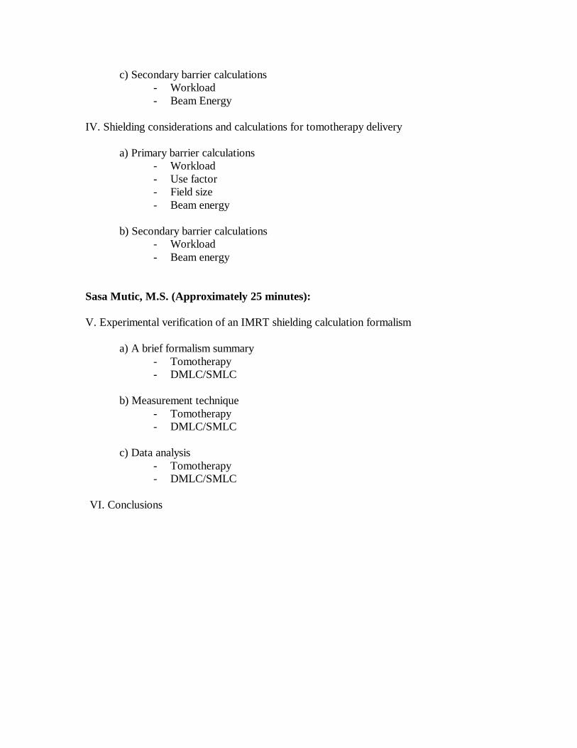
These include :
* DMLC = dynamic multileaf collimation
* SMLC = segmented multileaf collimation
* Combined dynamic gantry and DMLC
* Tomotherapy
J Rodgers AAPM 01
… Variations on the Technique of… Variations on the Technique of… Variations on the Technique of… Variations on the Technique ofIMRTIMRTIMRTIMRT
J Rodgers AAPM 01
PTV
Subdividing the Field
Beam’s Eye View of a Field
Abeamletirradiates asubdivision
J Rodgers AAPM 01
Static Gantry Positions for SMLCStatic Gantry Positions for SMLCStatic Gantry Positions for SMLCStatic Gantry Positions for SMLCand DMLCand DMLCand DMLCand DMLC
J Rodgers AAPM 01
Segmented Field Shaping for SMLC
S2
S3S1
S4
PlanningTargetVolume
2
J Rodgers AAPM 01
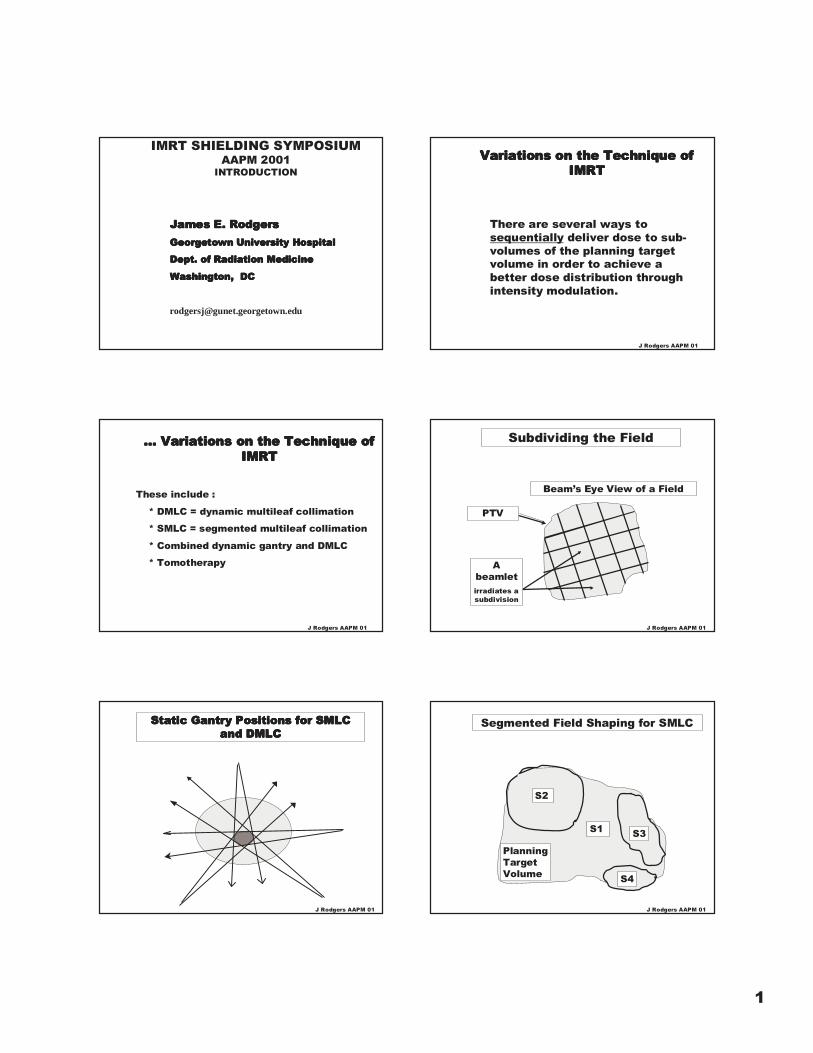
Dynamic Field Shaping for DMLC
J Rodgers AAPM 01
Dynamic Field Shaping for DMLC)
J Rodgers AAPM 01
Dynamic Field Shaping for DMLC
J Rodgers AAPM 01
Dynamic Gantry Rotation andDynamic Gantry Rotation andDynamic Gantry Rotation andDynamic Gantry Rotation andField ShapingField ShapingField ShapingField Shaping
J Rodgers AAPM 01
dynamicallymodulated (mlc)
fan beam
Patienttranslated
axially
Tomotherapy IMRT requires more monitor unitsto deliver the “same” dose
❋❋❋❋ IMRT delivers dose to the targetvolume by sequentially deliveringdose to sub-volumes.
The finer the subdivision, the moreMU needed to treat the totalvolume.
J Rodgers AAPM 01

3
… IMRT requires more monitorunits to deliver the “same” dose
❋❋❋❋ The IMRT ratio of MU to cGyThe IMRT ratio of MU to cGyThe IMRT ratio of MU to cGyThe IMRT ratio of MU to cGyat at at at ““““isocenterisocenterisocenterisocenter””””, , , , CCCC,,,, ranges from ranges from ranges from ranges fromabout 2 to 10 or 20.about 2 to 10 or 20.about 2 to 10 or 20.about 2 to 10 or 20.
For some proposed methods For some proposed methods For some proposed methods For some proposed methods CCCCgoes as high as 50.goes as high as 50.goes as high as 50.goes as high as 50.
J Rodgers AAPM 01
VAULT SHIELDING
Review of Traditional CalculationalMethods
NCRP Report 49 (1976)Primary barriers:Primary barriers:Primary barriers:Primary barriers:
P = BP = BP = BP = Bpripripripri W U T/d W U T/d W U T/d W U T/dpripripripri2 (direct radiation)2 (direct radiation)2 (direct radiation)2 (direct radiation)
Secondary barriersSecondary barriersSecondary barriersSecondary barriers::::
P = BP = BP = BP = BLLLL *10 *10 *10 *10-3-3-3-3 *W [U] T/d *W [U] T/d *W [U] T/d *W [U] T/dLLLL2 (leakage)2 (leakage)2 (leakage)2 (leakage)
P = BP = BP = BP = Bscascascasca *a( *a( *a( *a(θθθθ)))) *W [U] T/d *W [U] T/d *W [U] T/d *W [U] T/dscascascasca2222 *F/400 *F/400 *F/400 *F/400
((((scatter radiationscatter radiationscatter radiationscatter radiation))))
J Rodgers AAPM 01
dpri
Primarybarrier
X-ray target
isocenter
J RodgersAAPM 01
W*U, dpri, T, P
J Rodgers AAPM 01
Primary
barrier
secondary
gantry axisisocenter
gantry or beam plane
Leakage from accelerator head to point S
S
X-ray target
J RodgersAAPM 01
Some contributions influencingmaze barrier and door design
Maze barrier
Consider a dual energy accelerator with 6 MVand 15 or 18 MV x-rays.
If W(HQ) = W(LQ) = 30,000 cGy (MU)/wk
T =1 everywhere, P= 100 mrem/y = 2 rem/wk
Primary barrier (calculated for 18 MV x-rays) :
dpri= 7m U=.25 requires n = 4.88 TVLs
or, 214 cm (84”) of normal density concrete
[ For 6 MV: 171 cm, diff. is 1 TVL ∴ 214 cm ]
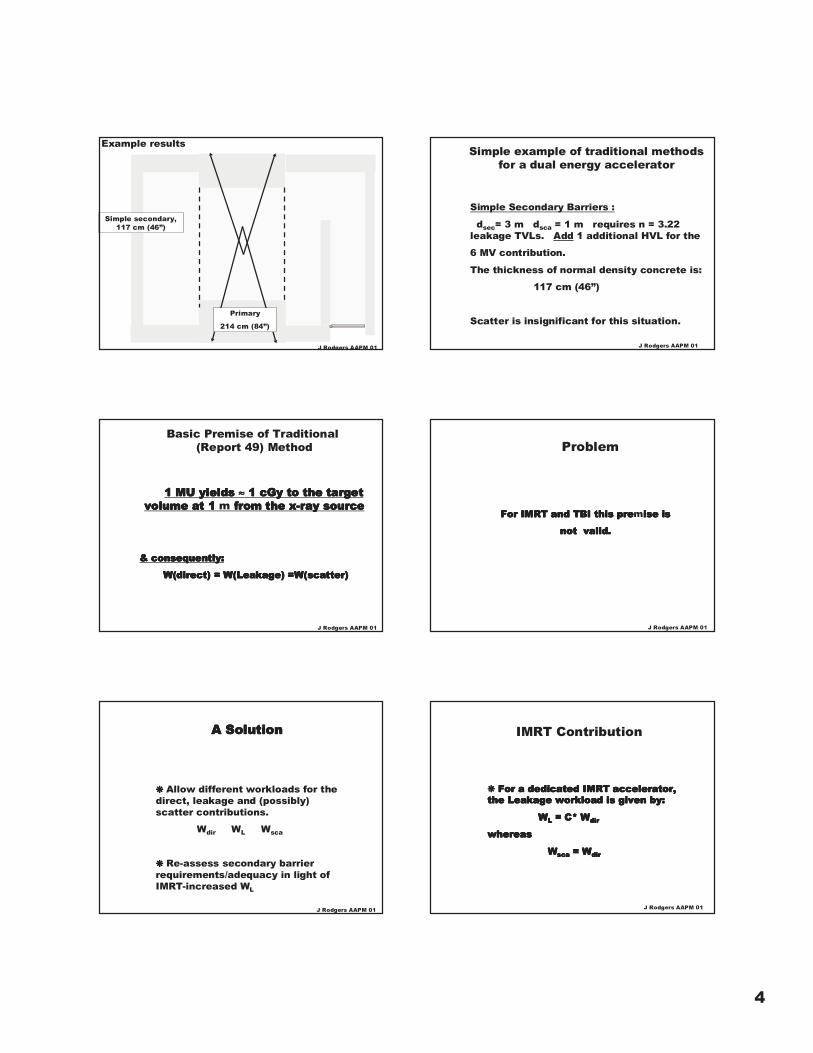
Simple example of traditional designmethods for a dual energy accelerator
J Rodgers AAPM 01
4
J Rodgers AAPM 01
Simple secondary,117 cm (46”)
Primary
214 cm (84”)
Example results
Simple Secondary Barriers :
dsec= 3 m dsca = 1 m requires n = 3.22leakage TVLs. Add 1 additional HVL for the
6 MV contribution.
The thickness of normal density concrete is:
117 cm (46”)
Scatter is insignificant for this situation.
Simple example of traditional methodsfor a dual energy accelerator
J Rodgers AAPM 01
Basic Premise of Traditional (Report 49) Method
1 MU yields 1 MU yields 1 MU yields 1 MU yields ≈≈≈≈ 1 cGy to the target 1 cGy to the target 1 cGy to the target 1 cGy to the targetvolumevolumevolumevolume at 1 at 1 at 1 at 1 m from the x-ray source from the x-ray source from the x-ray source from the x-ray source
& consequently:& consequently:& consequently:& consequently:
W(direct) = W(Leakage) =W(scatter)W(direct) = W(Leakage) =W(scatter)W(direct) = W(Leakage) =W(scatter)W(direct) = W(Leakage) =W(scatter)
J Rodgers AAPM 01
For IMRT and TBI this preFor IMRT and TBI this preFor IMRT and TBI this preFor IMRT and TBI this premise isise isise isise is
not valid.not valid.not valid.not valid.
Problem
J Rodgers AAPM 01
A SolutionA SolutionA SolutionA Solution
❋❋❋❋ Allow different workloads for thedirect, leakage and (possibly)scatter contributions.
Wdir WL Wsca
❋❋❋❋ Re-assess secondary barrierrequirements/adequacy in light ofIMRT-increased WL
J Rodgers AAPM 01
IMRT Contribution
❋❋❋❋ For a dedicated IMRT accelerator, For a dedicated IMRT accelerator, For a dedicated IMRT accelerator, For a dedicated IMRT accelerator,the Leakage workload is given by:the Leakage workload is given by:the Leakage workload is given by:the Leakage workload is given by:
WWWWLLLL = C* = C* = C* = C* WWWWdirdirdirdir
whereaswhereaswhereaswhereas
W W W Wscascascasca = = = = WWWWdirdirdirdir
J Rodgers AAPM 01
5
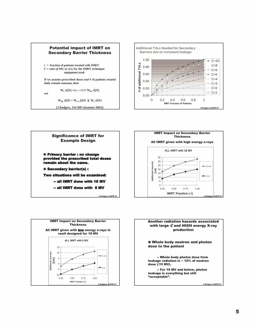
r = fraction of patients treated with IMRTC = ratio of MU to cGy for the IMRT technique/
equipment used.
If we assume prescribed doses and # of patients treateddaily remain constant, then
WL (QX) =(1-r + r*C)* Wdir (QX)and
Wdir (QX) = Wsca (QX) ≤≤≤≤ WL (QX)
[J Rodgers, JACMP (Summer 2001)]
Potential impact of IMRT onSecondary Barrier Thickness
Additional TVLs Needed for SecondaryBarriers due to increased leakage
0.00
0.20
0.40
0.60
0.80
1.00
0 0.2 0.4 0.6 0.8 1IMRT Fraction of Patients
#of
add
itio
nal
TV
Ls
C=10
C=8
C=6
C=5
C=4C=3
C=2
C=1
J Rodgers AAPM 01
Significance of IMRT forExample Design
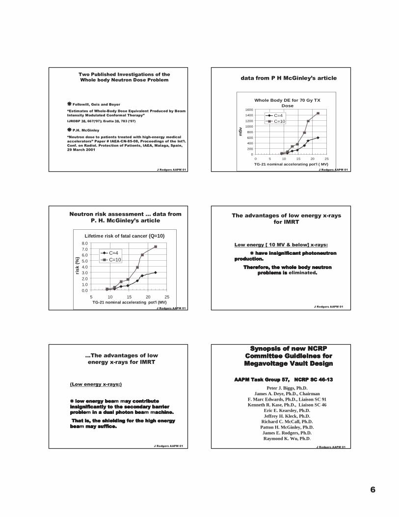
❋❋❋❋ Primary barrierPrimary barrierPrimary barrierPrimary barrier : no change : no change : no change : no changeprovided the prescribed total dosesprovided the prescribed total dosesprovided the prescribed total dosesprovided the prescribed total dosesremain about the same.remain about the same.remain about the same.remain about the same.
❋❋❋❋ Secondary barrier(s)Secondary barrier(s)Secondary barrier(s)Secondary barrier(s) : : : :
Two situations will be examined:Two situations will be examined:Two situations will be examined:Two situations will be examined:
-- all IMRT done with 18 MV -- all IMRT done with 18 MV -- all IMRT done with 18 MV -- all IMRT done with 18 MV
-- all IMRT done with 6 MV -- all IMRT done with 6 MV -- all IMRT done with 6 MV -- all IMRT done with 6 MV
J Rodgers AAPM 01
ALL IMRT with 18 MV
0
5
10
15
20
25
30
35
0.25 0.50 0.75 1.00
IMRT Fraction ( r)
Ad
dit
ion
alco
ncr
ete
(cm
)
C=10
C=4
IMRT Impact on Secondary BarrierThickness
All IMRT given with high energy x-rays
J Rodgers AAPM 01
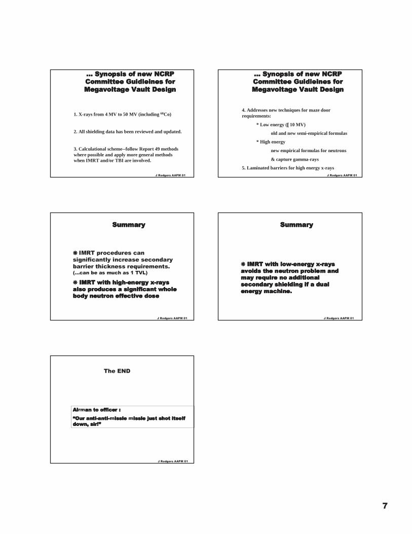
IMRT Impact on Secondary BarrierThickness
All IMRT given with lowlowlowlow energy x-rays invault designed for 18 MV
ALL IMRT with 6 MV
-10
-5
0
5
10
15
0.25 0.50 0.75 1.00
IMRT Fraction ( r)
Ad
diti
onal
conc
rete
(cm
) C=10
C=4
J Rodgers AAPM 01
Another radiation hazards associatedwith large C and HIGH energy X-ray
production
❋❋❋❋ Whole body neutron and photondose to the patient
-- Whole body photon dose fromleakage radiation is ~ 10% of neutrondose (]15 MV).
-- For 10 MV and below, photonleakage is everything but still“acceptable”.
J Rodgers AAPM 01
6
❋❋❋❋ Followill, Geis and Boyer
“Estimates of Whole-Body Dose Equivalent Produced by BeamIntensity Modulated Conformal Therapy”IJROBP 38, 667(‘97); Eratta 38, 783 (‘97)
❋❋❋❋ P.H. McGinley
“Neutron dose to patients treated with high-energy medicalaccelerators” Paper # IAEA-CN-85-08, Proceedings of the Int’l.Conf. on Radiol. Protection of Patients, IAEA, Malaga, Spain,29 March 2001
J Rodgers AAPM 01
Two Published Investigations of theWhole body Neutron Dose Problem
Whole Body DE for 70 Gy TXDose
0
200
400
600
800
1000
1200
1400
1600
0 5 10 15 20 25
TG-21 nominal accelerating pot'l ( MV)
mS
v
C=4
C=10
data from P H McGinley’s article
J Rodgers AAPM 01
Lifetime risk of fatal cancer (Q=10)
0.01.02.03.04.05.06.07.08.0
5 10 15 20 25TG-21 nominal accelerating pot'l (MV)
risk
(%)
C=4C=10
Neutron risk assessment … data fromP. H. McGinley’s article
J Rodgers AAPM 01
The advantages of low energy x-raysfor IMRT
Low energy [ 10 MV & below] x-rays:
❋❋❋❋ have insignificant have insignificant have insignificant have insignificant photoneutronphotoneutronphotoneutronphotoneutronproduction.production.production.production.
Therefore, the whole body neutronTherefore, the whole body neutronTherefore, the whole body neutronTherefore, the whole body neutronproblems is problems is problems is problems is eliminated....
J Rodgers AAPM 01
(Low energy x-rays:)
❋❋❋❋ low energy bea low energy bea low energy bea low energy beam may contributeay contributeay contributeay contributeinsignificantly to the secondary barrierinsignificantly to the secondary barrierinsignificantly to the secondary barrierinsignificantly to the secondary barrierprobleprobleprobleproblem in a dual photon bea in a dual photon bea in a dual photon bea in a dual photon beam machine.achine.achine.achine.
That is, the shielding for the That is, the shielding for the That is, the shielding for the That is, the shielding for the high energyhigh energyhigh energyhigh energybeabeabeabeam may suffice may suffice may suffice may suffice....
...The advantages of lowenergy x-rays for IMRT
J Rodgers AAPM 01
Synopsis of new NCRPSynopsis of new NCRPSynopsis of new NCRPSynopsis of new NCRPCommittee Committee Committee Committee Guidleines Guidleines Guidleines Guidleines forforforforMegavoltage Megavoltage Megavoltage Megavoltage Vault DesignVault DesignVault DesignVault Design
AAPM Task Group 57, NCRP SC 46-13AAPM Task Group 57, NCRP SC 46-13AAPM Task Group 57, NCRP SC 46-13AAPM Task Group 57, NCRP SC 46-13
Peter J. Biggs, Ph.D.James A. Deye, Ph.D., Chairman
F. Marc Edwards, Ph.D., Liaison SC 91Kenneth R. Kase, Ph.D., Liaison SC 46
Eric E. Kearsley, Ph.D.Jeffrey H. Kleck, Ph.D.
Richard C. McCall, Ph.D.Patton H. McGinley, Ph.D.James E. Rodgers, Ph.D.Raymond K. Wu, Ph.D.
J Rodgers AAPM 01
7
… Synopsis of new NCRP… Synopsis of new NCRP… Synopsis of new NCRP… Synopsis of new NCRPCommittee Committee Committee Committee Guidleines Guidleines Guidleines Guidleines forforforforMegavoltage Megavoltage Megavoltage Megavoltage Vault DesignVault DesignVault DesignVault Design
1. X-rays from 4 MV to 50 MV (including 60Co)
2. All shielding data has been reviewed and updated.
3. Calculational scheme--follow Report 49 methodswhere possible and apply more general methodswhen IMRT and/or TBI are involved.
J Rodgers AAPM 01
… Synopsis of new NCRP… Synopsis of new NCRP… Synopsis of new NCRP… Synopsis of new NCRPCommittee Committee Committee Committee Guidleines Guidleines Guidleines Guidleines forforforforMegavoltage Megavoltage Megavoltage Megavoltage Vault DesignVault DesignVault DesignVault Design
4. Addresses new techniques for maze doorrequirements:
* Low energy ([[[[ 10 MV)
old and new semi-empirical formulas
* High energy
new empirical formulas for neutrons
& capture gamma-rays
5. Laminated barriers for high energy x-raysJ Rodgers AAPM 01
SummarySummarySummarySummary
❋❋❋❋ IMRT procedures cansignificantly increase secondarybarrier thickness requirements.(…can be as much as 1 TVL)
❋❋❋❋ IMRT with IMRT with IMRT with IMRT with high-energyhigh-energyhigh-energyhigh-energy x-rays x-rays x-rays x-raysalso produces a significant wholealso produces a significant wholealso produces a significant wholealso produces a significant wholebody neutron effective dosebody neutron effective dosebody neutron effective dosebody neutron effective dose
J Rodgers AAPM 01
SummarySummarySummarySummary
❋❋❋❋ IMRT with IMRT with IMRT with IMRT with low-energylow-energylow-energylow-energy x-rays x-rays x-rays x-raysavoids the neutron problem andavoids the neutron problem andavoids the neutron problem andavoids the neutron problem andmay require no additionalmay require no additionalmay require no additionalmay require no additionalsecondary shielding if a dualsecondary shielding if a dualsecondary shielding if a dualsecondary shielding if a dualenergy machine.energy machine.energy machine.energy machine.
J Rodgers AAPM 01
AiAiAiAirman to officer :an to officer :an to officer :an to officer :
“Our anti-anti-“Our anti-anti-“Our anti-anti-“Our anti-anti-missle issle issle issle missle issle issle issle just shot itselfjust shot itselfjust shot itselfjust shot itselfdown, sir!”down, sir!”down, sir!”down, sir!”
The END
J Rodgers AAPM 01
1
IMRT Shielding IMRT Shielding considerations for considerations for
Tomotherapy Tomotherapy and MLCand MLCbeam deliverybeam delivery
Don Robinson, Don Robinson, PhPh.D..D.Dept. of Medical PhysicsDept. of Medical Physics
Cross Cancer InstituteCross Cancer Institute
Overview
• Serial and Spiral Tomotherapy
• Tomotherapy Shielding Considerations
• Shielding for IMRT with MLC
Overview
• Serial and Spiral Tomotherapy
• Tomotherapy Shielding Considerations
• Shielding for IMRT with MLC
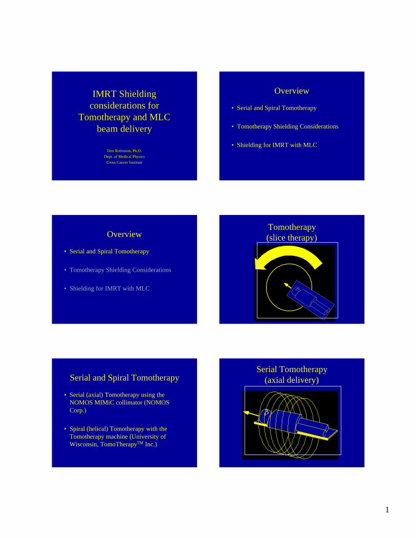
Tomotherapy(slice therapy)
Serial and Spiral Tomotherapy
• Serial (axial) Tomotherapy using the NOMOS MIMiC collimator (NOMOS Corp.)
• Spiral (helical) Tomotherapy with the Tomotherapy machine (University of Wisconsin, TomoTherapyTM Inc.)
Serial Tomotherapy(axial delivery)
2
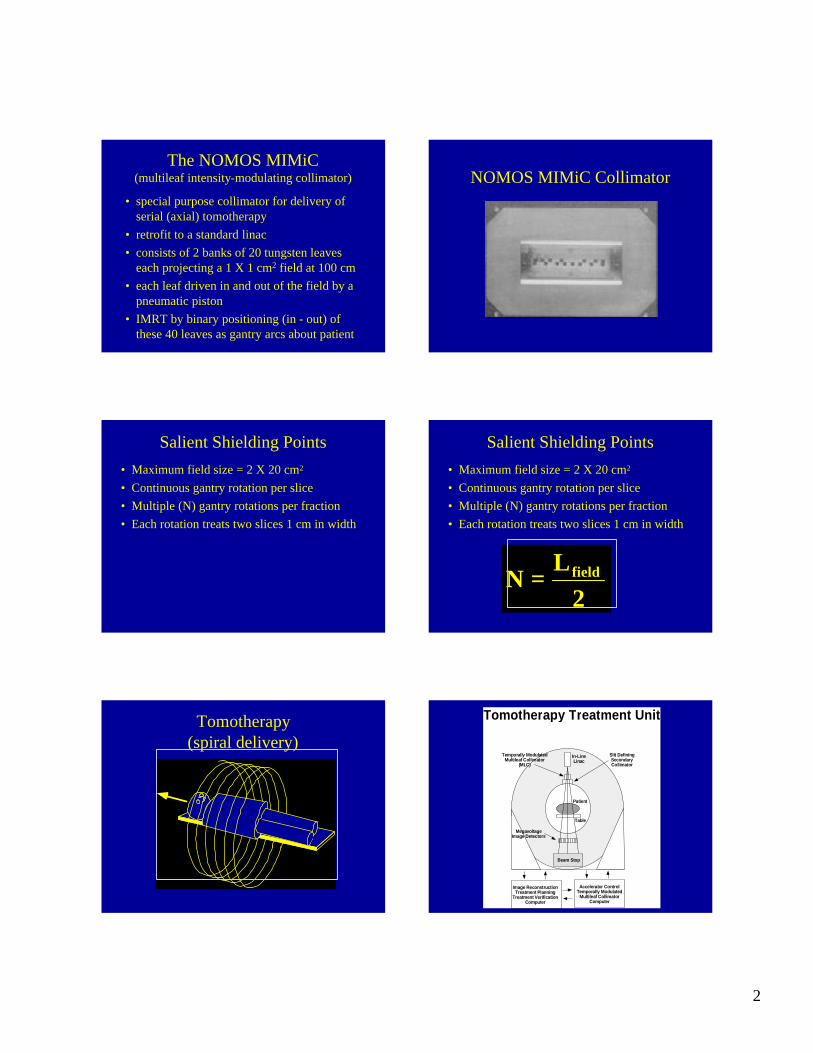
The NOMOS MIMiC(multileaf intensity-modulating collimator)
• special purpose collimator for delivery of serial (axial) tomotherapy
• retrofit to a standard linac• consists of 2 banks of 20 tungsten leaves
each projecting a 1 X 1 cm2 field at 100 cm• each leaf driven in and out of the field by a
pneumatic piston• IMRT by binary positioning (in - out) of
these 40 leaves as gantry arcs about patient
NOMOS MIMiC Collimator
Salient Shielding Points• Maximum field size = 2 X 20 cm2
• Continuous gantry rotation per slice• Multiple (N) gantry rotations per fraction• Each rotation treats two slices 1 cm in width
Salient Shielding Points• Maximum field size = 2 X 20 cm2
• Continuous gantry rotation per slice• Multiple (N) gantry rotations per fraction• Each rotation treats two slices 1 cm in width
2L
N field=
Tomotherapy(spiral delivery)
MegavoltageImage Detectors
Temporally ModulatedMultileaf Collimator
(MLC)
Beam Stop
Slit DefiningSecondaryCollimator
Patient
Table
In-LineLinac
Image ReconstructionTreatment Planning
Treatment VerificationComputer
Accelerator ControlTemporally Modulated
Multileaf CollimatorComputer
Tomotherapy Treatment Unit
3
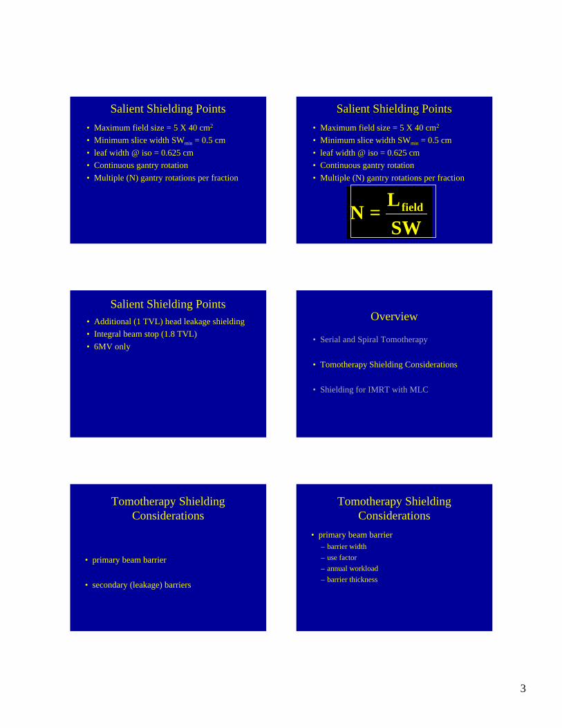
Salient Shielding Points• Maximum field size = 5 X 40 cm2
• Minimum slice width SWmin = 0.5 cm• leaf width @ iso = 0.625 cm• Continuous gantry rotation• Multiple (N) gantry rotations per fraction
Salient Shielding PointsSalient Shielding Points• Maximum field size = 5 X 40 cm2
• Minimum slice width SWmin = 0.5 cm• leaf width @ iso = 0.625 cm• Continuous gantry rotation• Multiple (N) gantry rotations per fraction
SWL
N field=
Salient Shielding Points• Additional (1 TVL) head leakage shielding• Integral beam stop (1.8 TVL)• 6MV only
Overview
• Serial and Spiral Tomotherapy
• Tomotherapy Shielding Considerations
• Shielding for IMRT with MLC
Tomotherapy Shielding Considerations
• primary beam barrier
• secondary (leakage) barriers
Tomotherapy Shielding Considerations
• primary beam barrier– barrier width– use factor– annual workload– barrier thickness
4
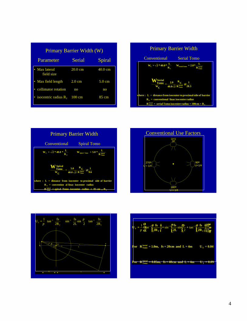
Primary Barrier Width (W)
Parameter Serial Spiral
• Max lateral 20.0 cm 40.0 cmfield size
• Max field length 2.0 cm 5.0 cm
• collimator rotation no no
• isocentric radius RT 100 cm 85 cm
Primary Barrier Width
Conventional Serial Tomo
CSerialTomo
C
SerialTomo
SerialTomo
Tomo SerialC
C
R100cmradiusisocenter Tomo serial R
radiusisocenter linac alconvention R barrier of side proximal toisocenter from distance L :where
28.3
1R
CR
240.02.0
CW
SerialTomo
R
L2.0 W
RL
40.02 W
W
===
==
≅=
∗=∗∗=
Primary Barrier Width
Conventional Spiral Tomo
CSpiralTomo
C
SpiralTomo
SpiralTomo
Tomo SpiralC
C
R cm 85 radiusisocenter Tomo spiralR
radiusisocenter linac alconvention R barrier of side proximal toisocenter from distance L :where
9.61
RCR
240.05.0
CW
SpiralTomo
RL
5.0 W RL
40.02 W
W
≠==
==
≅=
∗=∗∗=
Conventional Use Factors0o
180oU = 1/4
U=1
90o U=1/4U = 1/4
270o
fs/2
fs/2
R
L
P
Ψ
θθ Ψ
R L
φ
++
= −−−
T
11
T
1T 2R
fstan2
sin2Lfssin
2Rfstan1U π
π
0.09U 4m L and 40cm fs 0.85m,RFor
0.04U 4m L and 20cm fs 1.0m,RFor
2Rfs
2Lfs
2Rfs
U
TSpiralTomo
TSerialTomo
TTT
====
====
++
= −−− 111 tan
2sinsintan
1 ππ

5
Primary Beam Barriers
Annual Workload • Annual dose delivered by the primary beam
– dose per fraction (DF) [DF per rotation]– rotations per patient (N)– dose escalation factor ( )– daily through put (P) [patients per day]– days worked per year (D)
e
Annual Workloaddose per fraction
• Conventional therapy- DFC => 180 to 225 cGy per fraction
• IMRT- dose escalation?- DFT => 250 - 300 cGy/fraction, higher?
Annual Workloadfraction dose escalation factor
CFDT
FD
DFeDF
dose fractional alConventiondose fractional yTomotherap
e
∗=
=
Annual Workloadrotations (N) per patient
• Field length and slice width dependent• assume field length L = 20 to 30 cm • serial tomotherapy: N = L/2
– Nserial (L =30 cm) = 15
• spiral tomotherapy: Nspiral =L/SW– assume slice width of 0.5 cm to 1.0 cm– Nspiral (L = 20 cm, SW = 0.5 cm) => Nspiral = 40
Annual Workloaddaily throughput
• assume PT =PC
conventional treatment patient daily through put (PC)
Tomotherapy patient daily through put (PT)
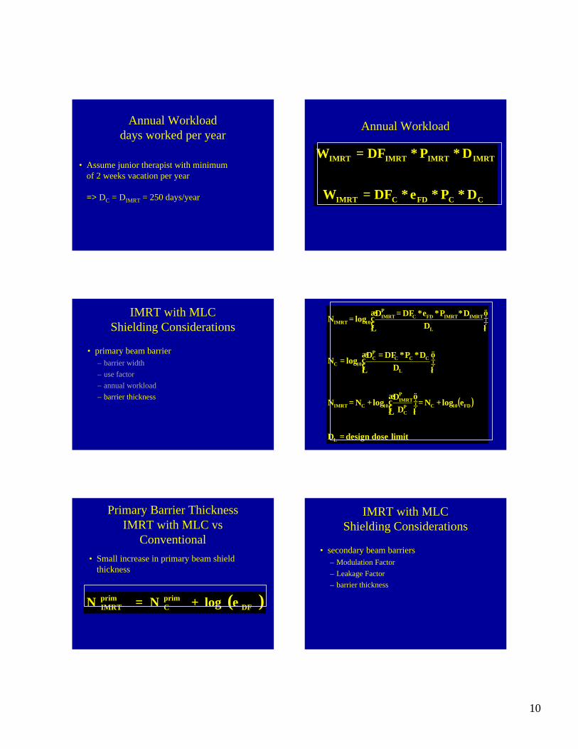
Annual Workloaddays worked per year
• Assume junior therapist with minimum of 2 weeks vacation per year
=> DC = DT = 250 days/year
6
Annual WorkloadAnnual Workload
CCFDCTomo
TTTTomo
DPNeDFW
DPNDF W
∗∗∗∗=
∗∗∗=fs/2
fs/2
R
L
P
Ψ
θθ Ψ
R L
φ
( )∫ ++=
ψ
ψψ
π 0 T22
T
2TCP
T LcosRLRd
2RNW
D2
2
( )
++
=
++
+
−+=
++=
−−−
−
∫
T
11
T
1
T22
T
22T
44T
1
22T
44T
2TCP
T
0T
22T
2TCP
T
2Rfs
tan2
sin2Lfs
sin2Rfs
tan
L2RLR2tanL2R-LR
tanLR2LR2
RNW4D
LcosR2LRd
2RNW2
D
πψ
ψ
π
ψψ
πψ
( )
+
++
+
−++=
=
+=
=
=
−
2C
2CCC
T22
T
22T
44T
1
22T
44T
2TCDF
10CT
LPC
PT
10CT
L
PC
10CL
PT
10T
LR
RUW
L2RLR2
?tanL2R-LRtan
L2RLR2p
RNW4e
logNN
limit dose designD DD
logNN
DD
logN DD
logN
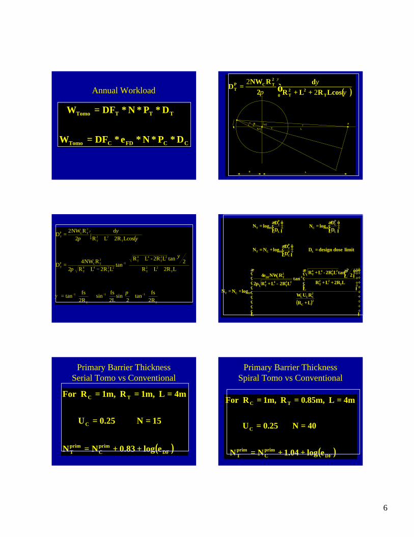
Primary Barrier ThicknessSerial Tomo vs Conventional
( )DFprimC
primT
C
TC
elog0.83NN
15N 0.25U
4mL 1m,R 1m,RFor
++=
==
===
Primary Barrier ThicknessSpiral Tomo vs Conventional
( )DFprimC
primT
C
TC
elog1.04NN
40N 0.25U
4mL 0.85m,R 1m,RFor
++=
==
===
7
Tomotherapy Shielding Considerations
• primary beam barrier
• secondary (leakage) barriers
Tomotherapy Shielding Considerations
• secondary beam barriers– Modulation Factor– Leakage Factor– barrier thickness
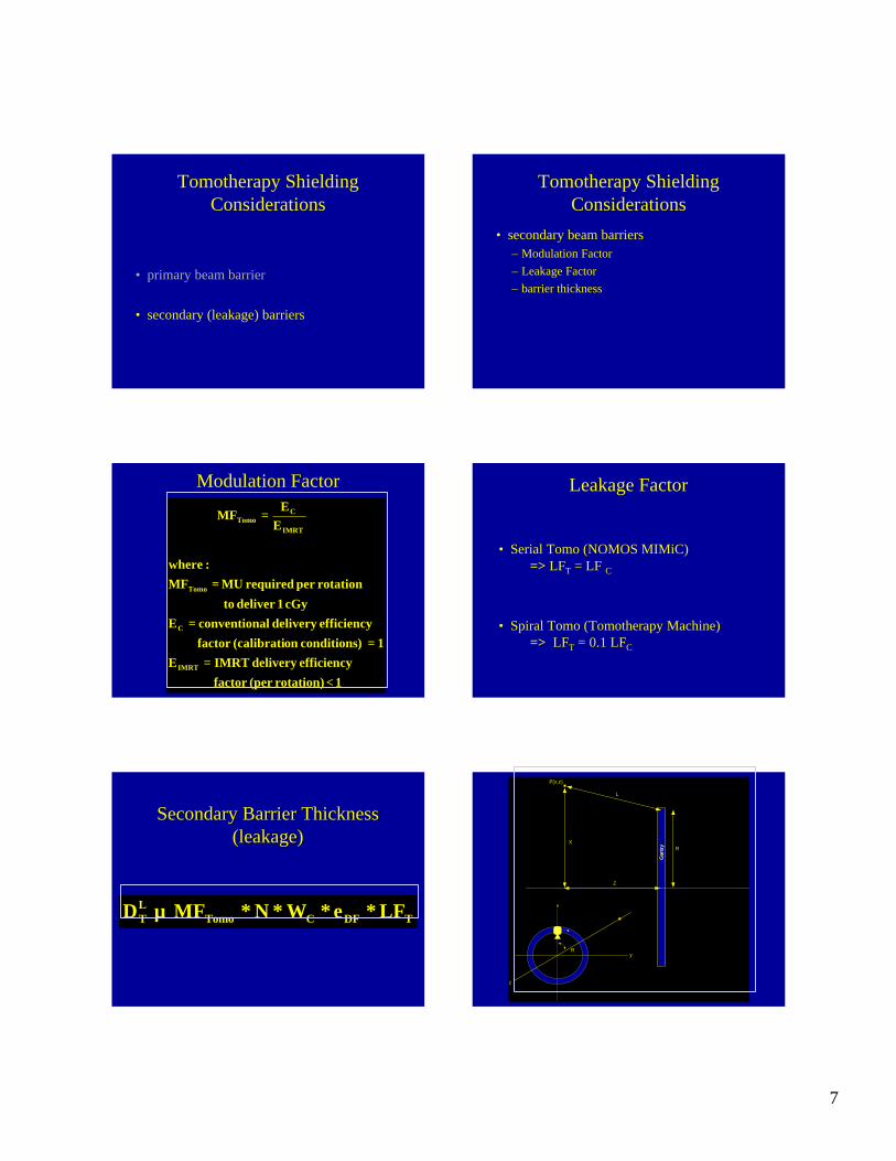
Modulation Factor
1 rotation)(per factor efficiency delivery IMRTE
1 )conditions on(calibratifactor efficiency delivery alconventionE
cGy 1deliver to
rotationper required MU MF:where
EE
MF
IMRT
C
Tomo
IMRT
CTomo
<=
==
=
=
Leakage Factor
• Serial Tomo (NOMOS MIMiC)=> LFT = LF C
• Spiral Tomo (Tomotherapy Machine)=> LFT = 0.1 LFC
TDFCTomoLT LFeWNMFD ∗∗∗∗∝
Secondary Barrier ThicknessSecondary Barrier Thickness(leakage)(leakage)
R
L
X
Z
Gan
try
R
x
y
z
P(x,z)
8
( )
( )
load work primary alconventionW:where
R4xRzx
rLFNMFeWD
?cos2xR-Rzxd?
2prLFNMFeW2
D
LFeWNMFD
PC
2T
22T
22
2TTomoDF
PCL
T
p
0 T2T
22
2TTomoDF
PCL
T
TDFCTomoLT
=
−++
∗∗∗∗∗=
++∗∗∗∗∗∗
=
∗∗∗∗∝
∫
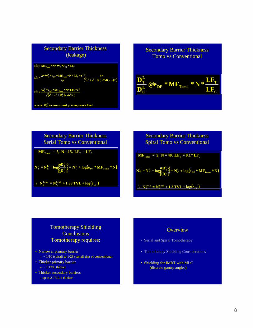
Secondary Barrier ThicknessSecondary Barrier Thickness(leakage)(leakage)
Secondary Barrier ThicknessTomo vs Conventional
C
TTomoDFL
C
LT
LFLF
NMFeDD
∗∗∗≅
Secondary Barrier ThicknessSecondary Barrier ThicknessSerialSerial TomoTomo vs Conventionalvs Conventional
( )
( )DFLeakC
LeakT
TomoDFLCL
C
LTL
CLT
CTTomo
elogTVL 1.88NN
NMFelogNDD
logN N
LFLF 15, N 5, MF
++=∴
∗∗+=
+=
===
Secondary Barrier ThicknessSecondary Barrier ThicknessSpiral Spiral TomoTomo vs Conventionalvs Conventional
( )
( )DFLeakC
LeakT
TomoDFLCL
C
LTL
CLT
CTTomo
elogTVL 1.3NN
NMFelogNDD
logN N
LF*0.1LF 40, N 5, MF
++=∴
∗∗+=
+=
===
Tomotherapy ShieldingConclusions
Tomotherapy requires:
• Narrower primary barrier – ~ 1/10 (spiral) to 1/28 (serial) that of conventional
• Thicker primary barrier– ~ 1 TVL thicker
• Thicker secondary barriers– up to 2 TVL’s thicker
Overview
• Serial and Spiral Tomotherapy
• Tomotherapy Shielding Considerations
• Shielding for IMRT with MLC (discrete gantry angles)
9
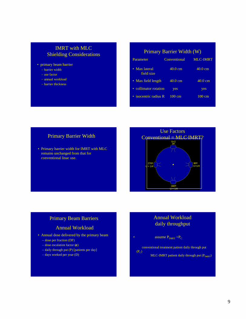
IMRT with MLCShielding Considerations
• primary beam barrier– barrier width– use factor– annual workload– barrier thickness
Primary Barrier Width (W)Parameter Conventional MLC-IMRT
• Max lateral 40.0 cm 40.0 cmfield size
• Max field length 40.0 cm 40.0 cm
• collimator rotation yes yes
• isocentric radius R 100 cm 100 cm
Primary Barrier Width
• Primary barrier width for IMRT with MLC remains unchanged from that for conventional linac use.
Use FactorsConventional = MLC-IMRT?
0o
180oU = 1/4
U=1
90o U=1/4U = 1/4
270o
Primary Beam Barriers
Annual Workload • Annual dose delivered by the primary beam
– dose per fraction (DF)– dose escalation factor ( )– daily through put (P) [patients per day]– days worked per year (D)
e
Annual Workloaddaily throughput
• assume PIMRT =PC
conventional treatment patient daily through put (PC)
MLC-IMRT patient daily through put (PIMRT)
10
Annual Workloaddays worked per year
• Assume junior therapist with minimum of 2 weeks vacation per year
=> DC = DIMRT = 250 days/year
Annual Workload
CCFDCIMRT
IMRTIMRTIMRTIMRT
DPeDF W
DPDFW
∗∗∗=
∗∗=
IMRT with MLCShielding Considerations
• primary beam barrier– barrier width– use factor– annual workload– barrier thickness ( )
limit dose designD
elogND
DlogNN
DDPDFD
logN
DDPeDFD
logN
L
FD10CPC
PIMRT
10CIMRT
L
CCCPC
10C
L
IMRTIMRTFDCPIMRT
10IMRT
=
+=
+=
∗∗==
∗∗∗==
Primary Barrier ThicknessIMRT with MLC vs
Conventional
( )DFprimC
primIMRT elogNN +=
• Small increase in primary beam shield thickness
IMRT with MLCShielding Considerations
• secondary beam barriers– Modulation Factor– Leakage Factor– barrier thickness
11
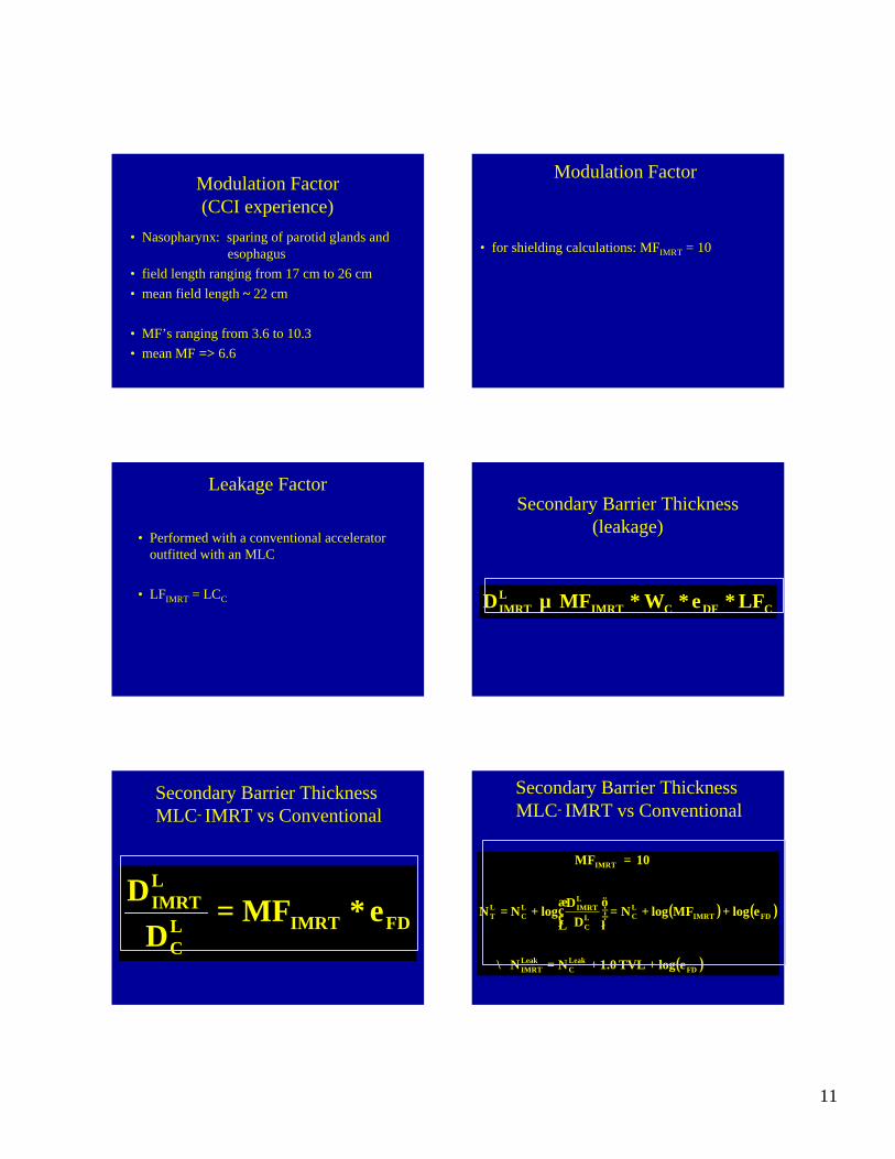
Modulation Factor(CCI experience)
• Nasopharynx: sparing of parotid glands and esophagus
• field length ranging from 17 cm to 26 cm• mean field length ~ 22 cm
• MF’s ranging from 3.6 to 10.3• mean MF => 6.6
Modulation Factor
• for shielding calculations: MFIMRT = 10
Leakage Factor
• Performed with a conventional accelerator outfitted with an MLC
• LFIMRT = LCCCDFCIMRT
LIMRT LFeWMFD ∗∗∗∝
Secondary Barrier Thickness(leakage)
Secondary Barrier ThicknessMLC- IMRT vs Conventional
FDIMRTLC
LIMRT eMFD
D∗=
Secondary Barrier ThicknessMLC- IMRT vs Conventional
( ) ( )
( )FDLeakC
LeakIMRT
FDIMRTLCL
C
LIMRTL
CLT
IMRT
elogTVL 1.0NN
elogMFlogND
DlogN N
10 MF
++=∴
++=
+=
=

12
Secondary Barrier ThicknessMLC- IMRT vs Conventional
( )DFleakC
leakIMRT elogTVL 1.0NN ++=
• increase in secondary shielding thickness~ 1TVL
IMRT with MLC Conclusions
IMRT with MLC requires:
• Same width primary barrier • Small increase in primary barrier thickness• Thicker secondary barriers
– ~ 1 TVL thicker
WashingtonWashingtonWASHINGTONWASHINGTON••UNIVERSITYUNIVERSITY••ININ••STST••LOUISLOUIS
Sasa Mutic , AAPM 2001
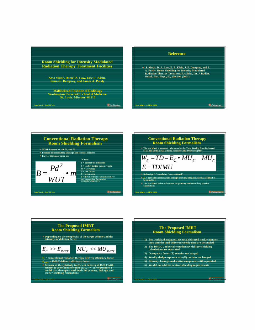
Room Shielding for Intensity Modulated Radiation Therapy Treatment Facilities
Sasa Mutic, Daniel A. Low, Eric E. Sasa Mutic, Daniel A. Low, Eric E. Klein, James F. Dempsey, and James A. Purdyand James A. Purdy
Mallinckrodt Institute of RadiologyMallinckrodt Institute of RadiologyWashington University School of MedicineWashington University School of Medicine
St. Louis, Missouri 63110 St. Louis, Missouri 63110
WashingtonWashingtonWASHINGTONWASHINGTON••UNIVERSITYUNIVERSITY••ININ••STST••LOUISLOUIS
Sasa Mutic , AAPM 2001
ReferenceReference
S. Mutic, D. A. Low, E. E. Klein, J. F. Dempsey, and J. S. Mutic, D. A. Low, E. E. Klein, J. F. Dempsey, and J. A. Purdy, Room Shielding for Intensity Modulated A. Purdy, Room Shielding for Intensity Modulated Radiation Therapy Treatment Facilities, Int. J.Radiation Therapy Treatment Facilities, Int. J. RadiatRadiat..OncolOncol. Biol. Phys., 50, 239. Biol. Phys., 50, 239--246, (2001).246, (2001).
WashingtonWashingtonWASHINGTONWASHINGTON••UNIVERSITYUNIVERSITY••ININ••STST••LOUISLOUIS
Sasa Mutic , AAPM 2001
Conventional Radiation TherapyConventional Radiation TherapyRoom Shielding Formalism Room Shielding Formalism
NCRP Reports No. 49, 51, and 79Primary and secondary (leakage and scatter) barriersBarrier thickness based on:
Where: B = barrier transmissionP = weekly design exposure rateW = workloadU = use factorT = occupancyd = distance from radiation sourcem = correction factors for secondary barriers
mWUTPd
B •=2
WashingtonWashingtonWASHINGTONWASHINGTON••UNIVERSITYUNIVERSITY••ININ••STST••LOUISLOUIS
Sasa Mutic , AAPM 2001
Conventional Radiation TherapyConventional Radiation TherapyRoom Shielding Formalism Room Shielding Formalism
The workload is assumed to be equal to the Total Weekly Dose Delivered (TD) and to the Total Weekly Monitor Units Delivered (MU)
Subscript “c” stands for “conventional”
Ec = conventional radiation therapy delivery efficiency factor, assumed to be equal to 1
The workload value is the same for primary and secondary barriercalculations
MUTDEcMUcMUcETDcW
≡≅•==
WashingtonWashingtonWASHINGTONWASHINGTON••UNIVERSITYUNIVERSITY••ININ••STST••LOUISLOUIS
Sasa Mutic , AAPM 2001
The Proposed IMRT The Proposed IMRT Room Shielding Formalism Room Shielding Formalism
Depending on the complexity of the target volume and the intensity modulation device
EEcc = conventional radiation therapy delivery efficiency factor= conventional radiation therapy delivery efficiency factorEEIMRTIMRT = IMRT delivery efficiency factor= IMRT delivery efficiency factor
Because of the relatively inefficient delivery of IMRT with respect to use of monitor units (EIMRT<< 1), we propose a model that decouples workloads for primary, leakage, and scatter shielding calculations
IMRTEEc >> IMRTMUMUc <<
WashingtonWashingtonWASHINGTONWASHINGTON••UNIVERSITYUNIVERSITY••ININ••STST••LOUISLOUIS
Sasa Mutic , AAPM 2001
The Proposed IMRTThe Proposed IMRTRoom Shielding Formalism Room Shielding Formalism
1) For workload estimates, tthe total delivered weekly monitor units and the total delivered weekly dose are are decoupleddecoupled
2) The DMLC and serial tomotherapy delivery shielding calculations are separated
3) Occupancy factor (T) remains unchanged4) Weekly design exposure rate (P) remains unchanged5) Primary, leakage, and scatter components still separated6) We did not address neutron shielding requirements
WashingtonWashingtonWASHINGTONWASHINGTON••UNIVERSITYUNIVERSITY••ININ••STST••LOUISLOUIS
Sasa Mutic , AAPM 2001
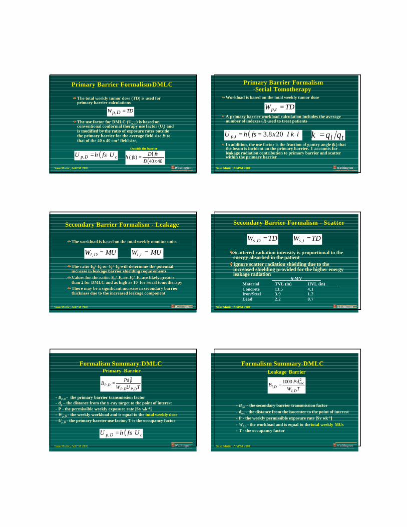
Primary Barrier FormalismPrimary Barrier Formalism--DMLCDMLC
The total weekly tumor dose (TD) is used for primary barrier calculations
The use factor for DMLC (Up, D) is based on conventional conformal therapy use factor (Uc) and is modified by the ratio of exposure rates outside the primary barrier for the average field size fs to that of the 40 x 40 cm2 field size,
TDDpW =,
( ) cDp UfsU η=,( )
( )4040)(
xDfsD
fs =η
Outside the barrier
WashingtonWashingtonWASHINGTONWASHINGTON••UNIVERSITYUNIVERSITY••ININ••STST••LOUISLOUIS
Sasa Mutic , AAPM 2001
Primary Barrier FormalismPrimary Barrier Formalism--Serial TomotherapySerial Tomotherapy
Workload is based on the total weekly tumor dose
A primary barrier workload calculation includes the average number of indexes (I) used to treat patients
In addition, the use factor is the fraction of gantry angle (κ) that the beam is incident on the primary barrier. λ accounts for leakage radiation contribution to primary barrier and scatter within the primary barrier
ti θθκ =
TDW tp =,
( ) λκη IxfsU tp 208.3, ==
WashingtonWashingtonWASHINGTONWASHINGTON••UNIVERSITYUNIVERSITY••ININ••STST••LOUISLOUIS
Sasa Mutic , AAPM 2001
The workload is based on the total weekly monitor unitsThe workload is based on the total weekly monitor units
The ratio EThe ratio EDD/ E/ EC C or Eor Et t / E/ EC C will determine the potential will determine the potential increase in leakage barrier shielding requirements increase in leakage barrier shielding requirements Values for the ratios EValues for the ratios EDD/ E/ EC C or Eor Et t / E/ ECC are likely greater are likely greater than 2 for DMLC and as high as 10 for serial tomotherapythan 2 for DMLC and as high as 10 for serial tomotherapyThere may be a significant increase in secondary barrier There may be a significant increase in secondary barrier thickness due to the increased leakage componentthickness due to the increased leakage component
Secondary Barrier Formalism Secondary Barrier Formalism -- LeakageLeakage
MUW Dl =, MUW tl =,
WashingtonWashingtonWASHINGTONWASHINGTON••UNIVERSITYUNIVERSITY••ININ••STST••LOUISLOUIS
Sasa Mutic , AAPM 2001
Secondary Barrier Formalism Secondary Barrier Formalism -- ScatterScatter
Scattered radiation intensity is proportional to the energy absorbed in the patientIgnore scatter radiation shielding due to the increased shielding provided for the higher energy leakage radiation
6 MVMaterial TVL (in) HVL (in)Concrete 13.5 4.1Iron/Steel 3.9 1.2Lead 2.2 0.7
TDW Ds =, TDW ts =,
WashingtonWashingtonWASHINGTONWASHINGTON••UNIVERSITYUNIVERSITY••ININ••STST••LOUISLOUIS
Sasa Mutic , AAPM 2001
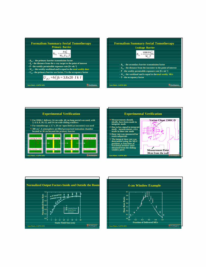
Formalism SummaryFormalism Summary--DMLCDMLC
- BP,D - the primary barrier transmission factor- dp – the distance from the x-ray target to the point of interest- P - the permissible weekly exposure rate [Sv wk -1]- Wp,D - the weekly workload and is equal to the total weekly dose- Up,D - the primary barrier use factor, T is the occupancy factor
TUWPd
BDPDP
PDP
,,
2
, =
Primary Barrier
( ) cDp UfsU η=,
WashingtonWashingtonWASHINGTONWASHINGTON••UNIVERSITYUNIVERSITY••ININ••STST••LOUISLOUIS
Sasa Mutic , AAPM 2001
Formalism SummaryFormalism Summary--DMLCDMLC
- Bl,D - the secondary barrier transmission factor- dsec - the distance from the isocenter to the point of interest- P - the weekly permissible exposure rate [Sv wk -1]- Wl,D - the workload and is equal to the total weekly MUs- T - the occupancy factor
Leakage Barrier
TWPd
BDl
Dl,
2sec
,1000
=
WashingtonWashingtonWASHINGTONWASHINGTON••UNIVERSITYUNIVERSITY••ININ••STST••LOUISLOUIS
Sasa Mutic , AAPM 2001
Formalism SummaryFormalism Summary--Serial TomotherapySerial Tomotherapy
- BP,t - the primary barrier transmission factor- dp – the distance from the x-ray target to the point of interest- P - the weekly permissible exposure rate [Sv wk -1]- Wp,t - the weekly workload and is equal to the total weekly dose- Up,t - the primary barrier use factor, T is the occupancy factor
Primary Barrier
TUWPd
BtPtP
PtP
,,
2
, =
( ) λκη IxfsU tp 208.3, ==
WashingtonWashingtonWASHINGTONWASHINGTON••UNIVERSITYUNIVERSITY••ININ••STST••LOUISLOUIS
Sasa Mutic , AAPM 2001
Formalism SummaryFormalism Summary--Serial TomotherapySerial Tomotherapy
- Bl,t - the secondary barrier transmission factor- dsec - the distance from the isocenter to the point of interest- P - the weekly permissible exposure rate [Sv wk -1]- Wl,t - the workload and is equal to the total weekly MUs- T - the occupancy factor
Leakage Barrier
TWPd
Btl
tl,
2sec
,1000
=
WashingtonWashingtonWASHINGTONWASHINGTON••UNIVERSITYUNIVERSITY••ININ••STST••LOUISLOUIS
Sasa Mutic , AAPM 2001
Experimental VerificationExperimental Verification
For DMLC delivery 14 cm wide, 40 cm long portal was used, with 2, 4, 6, 8, 10, 12, and 14 cm wide sliding windowsFor tomotherapy a 3.7 x 20 cm 2 open field (at isocenter) was used300 cm 3, 6 atmosphere air-filled pressurized ionization chamber located at 30 cm beyond the primary barrier30 cm beyond the primary barrier
Dose Fraction = 0.000
Center of the Field
Dose Fraction = 0.222
Center of the Field
Dose Fraction = 0.778
Center of the Field
Dose Fraction = 1.000
Center of the Field
WashingtonWashingtonWASHINGTONWASHINGTON••UNIVERSITYUNIVERSITY••ININ••STST••LOUISLOUIS
Sasa Mutic , AAPM 2001
Experimental VerificationExperimental Verification
Measurements should, ideally, have been made in integrate modeDue to low signal in integrate mode - measurements were made in dose rate modeDose rate was measured for static subportalsThe integral dose rate was determined using the MLC positions as functions of fractional monitor units obtained from the sliding window ports Measurement Point
30cm from the wall
Varian Clinac 2300C/D
WashingtonWashingtonWASHINGTONWASHINGTON••UNIVERSITYUNIVERSITY••ININ••STST••LOUISLOUIS
Sasa Mutic , AAPM 2001
Normalized Output Factors Inside and Outside the RoomNormalized Output Factors Inside and Outside the Room
0.0
0.2
0.4
0.6
0.8
1.0
1.2
0 5 10 15 20 25 30 35 40
Outside RoomInside RoomIsocenter
Nor
mal
ized
Dos
e R
ate
Static Field Size (cm)WashingtonWashington
WASHINGTONWASHINGTON••UNIVERSITYUNIVERSITY••ININ••STST••LOUISLOUISSasa Mutic , AAPM 2001
4 cm Window Example4 cm Window Example
0.0
0.1
0.2
0.3
0.4
0.5
0.6
0.7
0.0 0.2 0.4 0.6 0.8 1.0
Dos
e R
ate
Rat
io
Fraction of Delivered MUs

WashingtonWashingtonWASHINGTONWASHINGTON••UNIVERSITYUNIVERSITY••ININ••STST••LOUISLOUIS
Sasa Mutic , AAPM 2001
Dose Delivery Efficiency Dose Delivery Efficiency -- DMLCDMLC
WindowWidth14x40 cm
2
EIMRT
BeyondShield
EIMRT
IsocenterRatio±0.04
2 0.194 0.169 1.154 0.264 0.259 1.026 0.343 0.332 1.038 0.394 0.393 1.0010 0.448 0.444 1.0112 0.492 0.486 1.0114 0.521 0.524 0.994, 10x10 cm2 0.326 0.323 1.01
WashingtonWashingtonWASHINGTONWASHINGTON••UNIVERSITYUNIVERSITY••ININ••STST••LOUISLOUIS
Sasa Mutic , AAPM 2001
Results Results -- TomotherapyTomotherapy
0.0
0.2
0.4
0.6
0.8
1.0
1.2
-15 -10 -5 0 5 10 15
Rel
ativ
e D
ose
Rat
e
Incidence Gantry Angle (deg)
WashingtonWashingtonWASHINGTONWASHINGTON••UNIVERSITYUNIVERSITY••ININ••STST••LOUISLOUIS
Sasa Mutic , AAPM 2001
Transmission Correction Transmission Correction -- TomotherapyTomotherapyLambdaLambda
1.0
1.1
1.2
1.3
1.4
1.5
1.6
1.7
0 50 100 150 200 250 300 350 400
λ
Arc Length (degrees)
WashingtonWashingtonWASHINGTONWASHINGTON••UNIVERSITYUNIVERSITY••ININ••STST••LOUISLOUIS
Sasa Mutic , AAPM 2001
Results Results -- TomotherapyTomotherapy
0.0
0.2
0.4
0.6
0.8
1.0
0 50 100 150 200 250 300 350 400Rotation Angle (degrees)
κ
WashingtonWashingtonWASHINGTONWASHINGTON••UNIVERSITYUNIVERSITY••ININ••STST••LOUISLOUIS
Sasa Mutic , AAPM 2001
ConclusionsConclusions
Primary ShieldingPrimary Shielding––Significant Field Size Factor (0.35 Significant Field Size Factor (0.35 -- 0.80 relative to 0.80 relative to
40x40)40x40)––DMLCDMLC
»» 40x40 overestimates IMRT conformal therapy 40x40 overestimates IMRT conformal therapy shielding requirementsshielding requirements
»» Using TD for sliding window W Using TD for sliding window W -- accurate within accurate within 10% to 2 cm window10% to 2 cm window
–– Primary Barriers Primary Barriers -- Comparable to conventional Comparable to conventional shieldingshielding
–– Secondary Barriers Secondary Barriers -- Possible increase due to leakagePossible increase due to leakage
WashingtonWashingtonWASHINGTONWASHINGTON••UNIVERSITYUNIVERSITY••ININ••STST••LOUISLOUIS
Sasa Mutic , AAPM 2001
ConclusionsConclusions
Sequential TomotherapySequential Tomotherapy»» MU component (MU component (λλ) from 15% to 60% compared to geometric estimate ) from 15% to 60% compared to geometric estimate TD * TD * κκ of of
single index workload. single index workload. »» 7 indexes, I 7 indexes, I κκ λλ ranges from 0.61 for 180ranges from 0.61 for 180°° to 0.35 for 360to 0.35 for 360°° arcarc»» ηη ((fsfs=3.8 x 20 cm=3.8 x 20 cm22) = 0.24) = 0.24»» 7 indexes, 7 indexes, ηη ((fsfs=3.8 x 20 cm=3.8 x 20 cm22)I )I κκ λλ ranges from 0.15 for 180ranges from 0.15 for 180°° to 0.08 for 360to 0.08 for 360 °° arcarc
–– Primary BarrierPrimary Barrier»» Comparable to conventional shielding due to reduced number of trComparable to conventional shielding due to reduced number of treated eated
patients and patients and ηη I I κκ λλ productproduct–– Secondary Barriers Secondary Barriers
»» Increased due to leakageIncreased due to leakage»» MIR experience MIR experience ≅≅ 3,000 MU/fraction3,000 MU/fraction»» 300,000 MU/week for 20 patients300,000 MU/week for 20 patients
ηκλITDUW tt =
Related Documents