Revision 3 MAR 12, 2012 Author: John Propst Technical Review: Bill Pancake 1 Impulse Mags and the Continental A65- 8 Engine Author: John Propst Technical Advisor: Bill Pancake Abstract – Installation of an impulse magneto on the right side of a Continental A65-8 engine may result in an interference fit between the end of the magneto and the back of the engine crankcase. When Continental A65-8 engines were originally manufactured, they had a single impulse magneto mounted on the left side of the engine and a non-impulse magneto mounted on the right side of the engine. Impulse magnetos are installed to retard the spark timing of the magneto during starting to aid in starting and to minimize backfiring. During overhauls and upgrades it has been a more common practice to install impulse magnetos on both the left and right sides of both -8 and -12 Continental engines. This is done to enhance the engine starting process by permitting both the left and right magnetos to be “on” during starting. The purpose of this article is to point out that when an impulse magneto is installed on the right side of a Continental A65-8 engine, there may be an interference fit between the end of the magneto and the engine crankcase. The following photo is a side by side comparison of two Bendix magnetos. The one on the left has an impulse coupling between the magneto and the drive gear while the one on the right has the drive gear attached directly to the magneto shaft.

Welcome message from author
This document is posted to help you gain knowledge. Please leave a comment to let me know what you think about it! Share it to your friends and learn new things together.
Transcript
Revision 3 MAR 12, 2012 Author: John Propst Technical Review: Bill Pancake
1
Impulse Mags and the Continental A65- 8 Engine Author: John Propst Technical Advisor: Bill Pancake
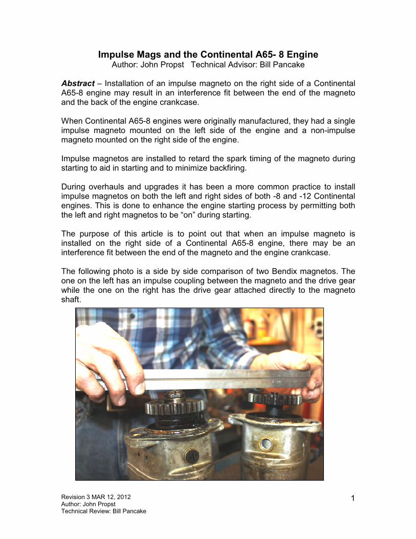
Abstract – Installation of an impulse magneto on the right side of a Continental A65-8 engine may result in an interference fit between the end of the magneto and the back of the engine crankcase. When Continental A65-8 engines were originally manufactured, they had a single impulse magneto mounted on the left side of the engine and a non-impulse magneto mounted on the right side of the engine. Impulse magnetos are installed to retard the spark timing of the magneto during starting to aid in starting and to minimize backfiring. During overhauls and upgrades it has been a more common practice to install impulse magnetos on both the left and right sides of both -8 and -12 Continental engines. This is done to enhance the engine starting process by permitting both the left and right magnetos to be “on” during starting. The purpose of this article is to point out that when an impulse magneto is installed on the right side of a Continental A65-8 engine, there may be an interference fit between the end of the magneto and the engine crankcase. The following photo is a side by side comparison of two Bendix magnetos. The one on the left has an impulse coupling between the magneto and the drive gear while the one on the right has the drive gear attached directly to the magneto shaft.

Revision 3 MAR 12, 2012 Author: John Propst Technical Review: Bill Pancake
2
The photo on the left shows the back of a A-65 crankcase. The large bored hole near the center of the crankcase is for the engine crankshaft and the bottom bored hole is for the engine camshaft. If you look closely at the engine casting you will notice that the area to the left of the crankshaft hole is flat while the area to the right of the crankshaft hole is humped up. When the accessory case is mounted to the back of the engine, the drive gear end of the left magneto will be sticking toward the flat area immediately to the left of the crankshaft and the right magneto will be sticking toward the humped area of the crankcase immediately to the right of the crankshaft. On most A-65 engines the hole above the crankshaft hole is not machined. However, on an A-65-9 engine the hole was machined for the installation of either a Hummer or Eclipse starter mechanism. The A-65-9 engine was not
approved for use on Aeronca Champs or Chiefs.
The photo on the left is a C-85-12. Note the difference between the back end of the A65-8 engine and the C85-12 engine. On the C85-12 engine the area immediately to both the left and the right of the center crankshaft hole is an open hole in the crankcase casting. When the engine accessory case in installed on the back of a C85-12 engine, the magneto shafts will face forward in these open areas of the crankcase. The crankcase castings for all of the C85, 90, and O-200 engines have the cast holes in the back of the crankcase. As a side note to this photo, this engine is being converted (by Don Sword’s STC SE0192AT) from a C85-12 engine to a C85-8 engine. This conversion requires removing two crankcase ears on the top of the crankcase and drilling and tapping
Revision 3 MAR 12, 2012 Author: John Propst Technical Review: Bill Pancake
3
a number of new holes in the back face of the crankcase for mounting the -8 accessory case. Don Sword at Don’s Dream Machines can do this conversion if you have a desire to convert your C-85, 90, or O-200 engine from a -12 to a -8.
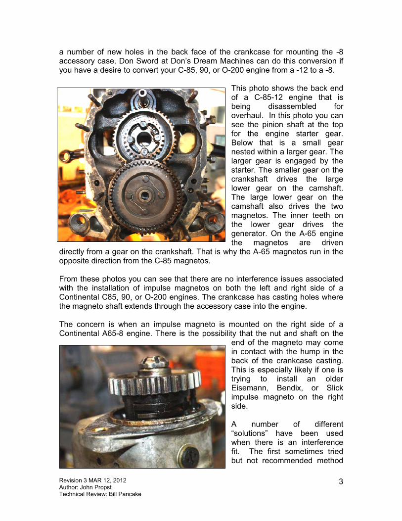
This photo shows the back end of a C-85-12 engine that is being disassembled for overhaul. In this photo you can see the pinion shaft at the top for the engine starter gear. Below that is a small gear nested within a larger gear. The larger gear is engaged by the starter. The smaller gear on the crankshaft drives the large lower gear on the camshaft. The large lower gear on the camshaft also drives the two magnetos. The inner teeth on the lower gear drives the generator. On the A-65 engine the magnetos are driven
directly from a gear on the crankshaft. That is why the A-65 magnetos run in the opposite direction from the C-85 magnetos. From these photos you can see that there are no interference issues associated with the installation of impulse magnetos on both the left and right side of a Continental C85, 90, or O-200 engines. The crankcase has casting holes where the magneto shaft extends through the accessory case into the engine. The concern is when an impulse magneto is mounted on the right side of a Continental A65-8 engine. There is the possibility that the nut and shaft on the
end of the magneto may come in contact with the hump in the back of the crankcase casting. This is especially likely if one is trying to install an older Eisemann, Bendix, or Slick impulse magneto on the right side. A number of different “solutions” have been used when there is an interference fit. The first sometimes tried but not recommended method

Revision 3 MAR 12, 2012 Author: John Propst Technical Review: Bill Pancake
4
is to do nothing. Mount the magneto on the engine. When the engine is put back into service the magneto shaft and nut will most likely grind a divot into the back of the crankcase. This will most likely result in damage to the magneto, possible damage to the gears and crankcase, and an accumulation of aluminum chips in the oil screen and other undesirable areas of the engine lubrication system. Obviously this method is strongly discouraged. Another method sometimes tried is to place multiple gaskets between the magneto mounting flange and the accessory case. Note on the photo that there is a small rabbit fit shoulder on the end of the magneto case to position the magneto on the accessory case. If the use of multiple gaskets still allows the magneto to be properly positioned on the accessory case then multiple gaskets may be a solution. Be aware that over time the gaskets will shrink and that may result in the magneto contacting the crankcase. Another method is to grind sufficient material from the crankcase to prevent the interference fit. This is not recommended. The humped area of the A-65 crankcase is already a weak area of the crankcase and any grinding in this area may result in a crankcase crack or failure. Some of the newer Slick impulse mags for the A-65-8 engine have been redesigned and provide adequate clearance. It is up to the individual installing an impulse mag on the right side of an A-65 engine to assure that there is adequate clearance. At one time Slick had a spacer that permitted installing an older style Slick A-65 impulse mag along with the drive gear from a C-85 Slick mag on an A-65 engine. If you are considering installing an impulse mag on a C-65-8 engine and you find there is an interference fit, the best and recommended solution is to install a non-impulse mag in its place. It is important to remember that all inspection, maintenance, alterations, and documentation should be done in accordance with Part 43 of the Federal Aviation Regulations (FAR).
Related Documents