Improving the Li-Electrochemical Properties of Monodisperse Ni 2 P Nanoparticles by Self-Generated Carbon Coating S. Carenco, †,§ C. Surcin, ‡,§ M. Morcrette, ‡,§ D. Larcher, ‡,§ N. Me ́ zailles, ∥ C. Boissie ̀ re, † and C. Sanchez †, * † Laboratoire de Chimie de la Matie ̀ re Condense ́ e, Collè ge de France, University Pierre et Marie Curie (UPMC), CNRS UMR 7574, Place Berthelot, 75005 Paris, France ‡ Laboratoire de Ré activite ́ et Chimie des Solides, Universite ́ de Picardie Jules Verne, CNRS UMR6007, 33 rue Saint Leu 80039 Amiens, France § ALISTORE−European Research Institute ∥ Laboratoire Hé té roe ́ lé ments et Coordination, Ecole Polytechnique, CNRS UMR7653, Route de Saclay, 91128 Palaiseau, France * S Supporting Information ABSTRACT: Carbon coating of electrode materials is nowadays a major tool to improve the electronic percolation of the electrode. In this study, a self-generated carbon coating is described as a new way to deposit a regular thin layer of carbon on the surface of nanoparticles. It relies on the soft decomposition of the nanoparticles surface native ligands, containing alkyl chains, under inert atmosphere at 400 °C, a route particularly suited for oxidation-sensitive nanoparticles. Using 25 nm monodispersed Ni 2 P nanoparticles as a model phase, we succeeded in forming nonsintered and nonoxidized carbon-coated nanoparticles. The carbon coating is then tuned in thickness by modifying the ligands set. Electrochemical properties of the resulting Ni 2 P/C nanoparticles vs Li are compared with those of bulk Ni 2 P. Both materials are shown to undergo a conversion reaction. The capacity of the bulk material collapses after a few cycles while Ni 2 P/C nanoparticles show much better retention. The self-generated carbon coating is thus found to promote Li uptake by providing a Li-permeable electron-conductive percolating network and by improving the mechanical integrity of the electrode. KEYWORDS: carbon coating, nickel phosphide nanoparticles, electrochemical properties, negative electrode, nanostructured electrode, ligand decomposition, self-generated carbon shell 1. INTRODUCTION The quest for high-capacity lithium batteries is rooted in the growing need for electronic portable devices and their potential use in electric vehicles. Improving the negative electrode materials is a major challenge in this field. 1,2 Since the early 2000s, metal phosphides have raised interest in this purpose, because they can undergo either intercalation 3 or conversion 4 reactions, associated with high gravimetric capacities 5 despite a high reaction voltage (ca 1 V vs Li + /Li 0 ), relative to the Li- graphite system. So far, numerous phases of binary and ternary metal phosphides have been used to build negative electrodes, 6 such as MnP 4 , 3 CoP 3 , 4 ZnP 2 , 7 Zn 3 P 2 , 8 InP, GaP, 9 Cu 3 P, 10 VP, 11 VP 2 , 12 VP 4 , 13 FeP, 14 FeP 2 , and FeP 4 . 15 Meanwhile, nanoscaling of electrode materials has been attempted both for negative and positive electrodes, with sometimes impressive increase in performances. P. Bruce et al. and A. S. Aricò et al. have summarized the major features that have been encountered so far. 16,17 In particular, nanoscaling of the electrode material is expected to enable reactions that would not occur in the bulk, increasing the kinetics of Li incorporation/removal because of shorter transport distance and higher contact area with the electrolyte. Additionally, it may provide a wider range of solid solution for the material investigated. 18 Yet, using nanoparticles as electrodes is not straightforward. Indeed, their cohesion has to be achieved from both mechanical and electronic point of view to ensure long-term cyclability and efficient electron wiring to the current collector (electronic percolation). This has been achieved in the past few years by coating the nanoparticles with a layer of carbon. Several methods were developed for the fabrication of well-percolated conductive carbon/active nanopowder composites or even graphene-wrapped nanoparticles. Most of them rely on the deposition or growth of nanoparticles on nanostructured carbon precursors, such as graphite layers, 19 carbon nano- tubes, 20 graphite oxide, 21 and mesoporous carbon. 22 Fewer routes rely on the use of molecular sources of carbon, such as glucose, 23 sucrose in supercritical CO 2 , 24 pluronic copolymer (P123), 25 Li 2 CO 3 , 26 and polyacene. 27 More importantly for our purpose, a large majority of reported carbon-coated and carbon-supported systems 28 are positive and low-conductivity electrode materials (such as LiFePO 4 /C composites, as exemplified by the references chosen in the last sentence). These electrodes are generally less sensitive to oxidation or Received: October 23, 2011 Revised: January 25, 2012 Article pubs.acs.org/cm © XXXX American Chemical Society A dx.doi.org/10.1021/cm203164a | Chem. Mater. XXXX, XXX, XXX−XXX

Welcome message from author
This document is posted to help you gain knowledge. Please leave a comment to let me know what you think about it! Share it to your friends and learn new things together.
Transcript

Improving the Li-Electrochemical Properties of Monodisperse Ni2PNanoparticles by Self-Generated Carbon CoatingS. Carenco,†,§ C. Surcin,‡,§ M. Morcrette,‡,§ D. Larcher,‡,§ N. Mezailles,∥ C. Boissiere,† and C. Sanchez†,*†Laboratoire de Chimie de la Matiere Condensee, College de France, University Pierre et Marie Curie (UPMC), CNRS UMR 7574,Place Berthelot, 75005 Paris, France‡Laboratoire de Reactivite et Chimie des Solides, Universite de Picardie Jules Verne, CNRS UMR6007, 33 rue Saint Leu 80039Amiens, France§ALISTORE−European Research Institute∥Laboratoire Heteroelements et Coordination, Ecole Polytechnique, CNRS UMR7653, Route de Saclay, 91128 Palaiseau, France
*S Supporting Information
ABSTRACT: Carbon coating of electrode materials is nowadays a major tool to improve theelectronic percolation of the electrode. In this study, a self-generated carbon coating isdescribed as a new way to deposit a regular thin layer of carbon on the surface of nanoparticles.It relies on the soft decomposition of the nanoparticles surface native ligands, containing alkylchains, under inert atmosphere at 400 °C, a route particularly suited for oxidation-sensitivenanoparticles. Using 25 nm monodispersed Ni2P nanoparticles as a model phase, wesucceeded in forming nonsintered and nonoxidized carbon-coated nanoparticles. The carboncoating is then tuned in thickness by modifying the ligands set. Electrochemical properties ofthe resulting Ni2P/C nanoparticles vs Li are compared with those of bulk Ni2P. Both materialsare shown to undergo a conversion reaction. The capacity of the bulk material collapses after afew cycles while Ni2P/C nanoparticles show much better retention. The self-generated carboncoating is thus found to promote Li uptake by providing a Li-permeable electron-conductivepercolating network and by improving the mechanical integrity of the electrode.
KEYWORDS: carbon coating, nickel phosphide nanoparticles, electrochemical properties, negative electrode, nanostructured electrode,ligand decomposition, self-generated carbon shell
1. INTRODUCTIONThe quest for high-capacity lithium batteries is rooted in thegrowing need for electronic portable devices and their potentialuse in electric vehicles. Improving the negative electrodematerials is a major challenge in this field.1,2 Since the early2000s, metal phosphides have raised interest in this purpose,because they can undergo either intercalation3 or conversion4
reactions, associated with high gravimetric capacities5 despite ahigh reaction voltage (ca 1 V vs Li+/Li0), relative to the Li-graphite system. So far, numerous phases of binary and ternarymetal phosphides have been used to build negative electrodes,6
such as MnP4,3 CoP3,
4 ZnP2,7 Zn3P2,
8 InP, GaP,9 Cu3P,10 VP,11
VP2,12 VP4,
13 FeP,14 FeP2, and FeP4.15
Meanwhile, nanoscaling of electrode materials has beenattempted both for negative and positive electrodes, withsometimes impressive increase in performances. P. Bruce et al.and A. S. Arico et al. have summarized the major features thathave been encountered so far.16,17 In particular, nanoscaling ofthe electrode material is expected to enable reactions thatwould not occur in the bulk, increasing the kinetics of Liincorporation/removal because of shorter transport distanceand higher contact area with the electrolyte. Additionally, itmay provide a wider range of solid solution for the materialinvestigated.18
Yet, using nanoparticles as electrodes is not straightforward.Indeed, their cohesion has to be achieved from both mechanicaland electronic point of view to ensure long-term cyclability andefficient electron wiring to the current collector (electronicpercolation). This has been achieved in the past few years bycoating the nanoparticles with a layer of carbon. Severalmethods were developed for the fabrication of well-percolatedconductive carbon/active nanopowder composites or evengraphene-wrapped nanoparticles. Most of them rely on thedeposition or growth of nanoparticles on nanostructuredcarbon precursors, such as graphite layers,19 carbon nano-tubes,20 graphite oxide,21 and mesoporous carbon.22 Fewerroutes rely on the use of molecular sources of carbon, such asglucose,23 sucrose in supercritical CO2,
24 pluronic copolymer(P123),25 Li2CO3,
26 and polyacene.27 More importantly for ourpurpose, a large majority of reported carbon-coated andcarbon-supported systems28 are positive and low-conductivityelectrode materials (such as LiFePO4/C composites, asexemplified by the references chosen in the last sentence).These electrodes are generally less sensitive to oxidation or
Received: October 23, 2011Revised: January 25, 2012
Article
pubs.acs.org/cm
© XXXX American Chemical Society A dx.doi.org/10.1021/cm203164a | Chem. Mater. XXXX, XXX, XXX−XXX
carbide formation than negative electrode materials, for whichonly a few systems have been reported (mainly Si/C,29,30
SnO2/C31,32 and Si/C33), often using glucose or sucrose as the
main carbon source. Yet, there is still a need for new carbon-coating methods that would be compatible with nanoparticleshighly sensitive to oxidation and that would ensure a conformalcoating, percolating through the electrode, without causingnanoparticles sintering.In the present work, we described a straightforward self-
generated carbon coating protocol, using well-defined 25 nmNi2P nanoparticles as a model system. It relied on a relativelysoft thermal treatment (400 °C, 30 min) that decomposed thenanoparticles native ligands to form a thin carbon layer (ca 2−3nm) without sintering of the nanoparticles. Electrochemicalproperties of the Ni2P/C composite negative electrode wereevaluated and compared with those of bulk Ni2P and noncoatednanoparticles, this phase being reported here as electrochemi-cally active vs Li for the first time. The transformations of thenanoparticles (size, shape, and crystal structure) were scruti-nized by systematic post-mortem analyses, in order to propose areaction pathway for Ni2P.
2. RESULTS AND DISCUSSIONOnly a few studies have been conducted using metal phosphidenanoparticles (MoP2,
34 GaP,35 SnP0.9436) by J. Cho and co-
workers, and have illustrated a range of behaviors (intercalationor alloying with Ga). However, the influences of particlesnanometric size and surface state were not discussed at thattime.On the other hand, several bulk nickel phosphide phases
were reported as negative electrodes, such as Ni3P,37 NiP2,
38−40
or NiP3.41 Among them, phosphorus-rich phases (Ni/P < 1),
were the most studied: a large initial capacity of 1475 mAh/gwas obtained for NiP3 but it dropped dramatically after a few
cycles. Cubic NiP2 exhibited interesting performances byundergoing conversion to Li3P and Ni. However, monoclinicNiP2, obtained at high temperature (900 °C) from elementalNi and P, was found to be the most interesting candidate sofar.38 Indeed, it starts to react though an insertion process andswitches to a conversion reaction.46,42,43 The latter charge/discharge cycles work with a conversion reaction and are fairlyreversible for 5 Li per Ni, but drops because of electrodefragmentation. Optimization of the performances was obtainedby supporting the NiP2 monoclinic phase on a nickel foam,giving a very good reversible capacity of ca 900 mAh/g.38
Nanostructuration of the electrode into nanowires was alsoproposed, as a first step toward nanoscaling.44 Tatsumigo andco-workers proposed the use of Ni5P4 and NiP2 submicronicnanoparticle aggregates in all-solid-state batteries with(Li2S)80(P2S5)20 to enhance the performances of the electro-des.45
In contrast with this, NixPy phosphorus-poor phases (Ni/P ≥1) were only scarcely evaluated as negative electrodes. In thephases obtained by solid-state reaction at 900 °C, Ni3P, Ni2P,Ni12P5, Ni5P4, and NiP, only the last two phases were reportedto react with lithium.46 Additionally, Ni3P thin films (400 nm)were electrodeposited and treated at 500 °C, givingagglomerates of nanosized particles (70 nm).47 The filmsunderwent incomplete conversion reaction to Li3P and Ni,providing a capacity of 2 Li per Ni (ca 260 mAh/g) at the firstdischarge. However, only a limited capacity was recovered atthe first charge (75 mAh/g). Interestingly, no plateau could beobserved during the charge and the discharge.Altogether, metal-rich phosphides (Ni3P, Ni5P4, and NiP)
exhibit a stronger metallic character and a higher proportion ofNi−Ni bonds vs Ni−P and P−P bonds than monoclinic NiP2,which makes the reaction potential lower in average, a featureof the negative electrode that is intrinsically interesting for
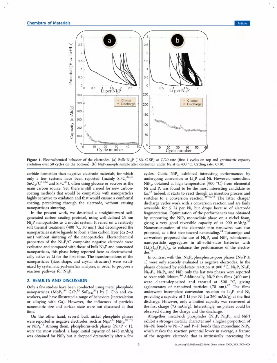
Figure 1. Electrochemical behavior of the electrodes. (a) Bulk Ni2P (15% C-SP) at C/20 rate (first 4 cycles on top and gravimetric capacityevolution over 50 cycles on the bottom). (b) Ni2P-amorph sample after calcination under N2 at ca 400 °C. Cycling rate: C/10.
Chemistry of Materials Article
dx.doi.org/10.1021/cm203164a | Chem. Mater. XXXX, XXX, XXX−XXXB

energy storage. Because the Ni2P phase has been the moststudied as the nanoscale and is now mature (highlyreproducible syntheses, fine control of the nanoparticles sizeand surface),48,49 we choose it as a model material to investigate
the effect of nanoscaling and nanoparticle surface treatment onthe electrochemical properties of metal phosphides.
2.1. Surface-Clean Bulk Ni2P Phase. Prior to the study ofNi2P nanoparticles, we investigated the electrochemical
Figure 2. Electrochemical behavior of the electrodes. (d) PITT cycling mode of the calcined Ni2P-amorph sample, containing carbon-coated Ni2Pnanoparticles (samples 1 and 2 come from the same batch). (e) Ni2P-PBu3 after calcination.
Figure 3. Electrochemical behavior of the electrodes. (c) First cycles of the three as-made nanoparticles samples (cycling rate: C/10). (f) CalcinedNi2P-PBu3 nanoparticles; the carbon SP was added after the calcination. (g) Calcined Ni2P-PBu3 nanoparticles; the carbon SP was added before thecalcination. (h) Calcined Ni2P-OA sample at a C/20 cycling rate.
Chemistry of Materials Article
dx.doi.org/10.1021/cm203164a | Chem. Mater. XXXX, XXX, XXX−XXXC

response of surface-clean bulk Ni2P, as a benchmark compoundto be compared with carbon-coated nanoparticles. Consideringthe reaction modes of the other nickel phosphides, thefollowing conversion reaction was expected for Ni2P:
+ → +Ni P 3Li 2Ni Li P2 3 (1)
Surface-clean bulk Ni2P was prepared, as described inprevious works, by the reaction of white phosphorus (P4), areactive source of P atoms, on M(0) species.49,50 Very briefly,the reaction of Ni(COD)2 (COD: 1,5-cyclooctadiene) and1/8P4 produced an amorphous Ni2P powder, then all the CODwas evacuated under vacuum. The remaining solid, whichcontains no more organic components, was annealed undernitrogen to induce the crystallization of Ni2P. Large micronicaggregates were obtained, though the crystallites size was onlyca 20 nm.51 When introduced as such in a two-electrodeSwagelok-type cell with a counter electrode of lithium, the Ni2Ppowder presented no electrochemical reaction in a potentialwindow of 0 to 2 V vs Li. This was not surprising as Ni2P is notan electron conductor.The fine powder was therefore mixed with 15% mass carbon
SP (a conductive additive) and cycled in the 0−2 V range. Atthe first discharge, a capacity of ca 500 mAh/g was reached(Figure 1a). The corresponding x value in LixNi2P was close to3, as expected for the conversion reaction proposed in eq 1,although part of this lithium consumption is to be expectedfrom reaction with the electrolyte.However, only 50% of the initial capacity was restored at the
first charge. This lack of reversibility carried on over the nextcycles, resulting in a dramatic drop of capacity. After 20 cycles,the remaining capacity corresponded to the contribution ofcarbon SP (30 mAh/g). Moreover, there was no well-definedplateau over the first cycles. This might suggest a solid solutionbehavior. Alternatively, this could be a consequence of thecovalence of the Ni−P bond: the potential of reaction wasreported to continuously decrease with the phase composition(x value in LixNi2P) because of the strong electronic exchangesbetween its components.5
XRD analysis after the last charge step showed a destructionof the initial Ni2P structure (Figure 4). The powder was now
majorly an amorphous Ni-based structure, as attested by thebroad signal from 40 to 50°. It showed one relatively sharp peakat 45° that is likely due to the formation of poorly crystallizedNi−P mixed phases,52 while the broad peak centered at 47°likely corresponded to poorly crystallized Ni−P compounds.Altogether, this experiment showed that, in our conditions,
the Ni2P phase was prone to react with lithium in a significantmanner. Even though the reversibility of the reaction was poor
and the electrode capacity collapsed after a few cycles, theactivity of the Ni2P phase vs lithium could be observed.
2.2. Electrochemical Properties of NanoparticlesCovered with a Ligand Shell. Advantageously, thecomparison between bulk and nanoscaled Ni2P could bemade in the best conditions because the same syntheticmethodology, using P4 as a phosphorus source, can be appliedto produce Ni2P nanoparticles. Monodisperse Ni2P nano-particles (25 nm diameter) were indeed synthesized, asdescribed in a previous work (Figure 5), by adding whitephosphorus on nickel nanoparticles.53 Very briefly, mono-disperse 25 nm nickel nanoparticles were reacted at 220 °C on1/8 equiv. P4. The reaction resulted in the quantitative insertionof phosphorus in the nanoparticles and the recrystallization ofthe Ni2P phase, each nanoparticle being a single crystal.Aggregation and extensive growth of the nanoparticles duringthe synthesis was prevented by the presence of tri-n-octylphosphine ligands on their surface (Ni2P-TOP sample).For the purpose of comparison, an amorphous Ni2P sample wasalso prepared, by heating at 120 °C for 15 min instead of 220°C for 2 h (Ni2P-amorph; see Figure 1 in the SupportingInformation). Lastly, when TOP was not introduced, largerpolycrystallized Ni2P nanoparticles (50−80 nm diameter) wereobtained (Ni2P-OA sample; OA: oleylamine).53
All samples were tested after copious washing of the excesssurface ligands. It must be noted that the closest layers ofligands, coordinated to the surface, resisted this washing, asdescribed in a previous work.54 In the absence of an electronicconducting additive, no reaction was observed. As in the case ofbulk Ni2P, the powders were thus mixed with 15% mass carbonSP by soft manual grinding in the glovebox.Upon cycling, all samples exhibited similar behavior: an
irreversible reaction with modest amounts of Li, followed by avery poor reversible contribution, which came from the carbonSP part (Figure 3c). XRD analyses of the samples after cyclingindicated no modification of the structure (whether crystallineor amorphous), which correlates with the fact that thenanoparticles did not react with Li+ in these conditions. In anattempt to understand this failure, TEM observations wereperformed (Figure 6). They showed the presence of largeaggregates of nanoparticles that were not directly in contactwith carbon SP. Thus, we reasoned that the conductive additivemay not percolate properly in the electrode, leaving most of thenanoparticles without an electronic connection, even in thepresence of carbon SP. Several procedures were attempted topromote a better physical mixing of the two powders: a shortball-milling (30 min), an impregnation of the nanoparticleswith the carbon in cyclohexane under stirring, and the additionof larger amounts of carbon (20% mass). However, they werenot successful, suggesting that a incomplete percolation was notthe sole problem.We therefore reasoned that the layer of aliphatic ligands on
the nanoparticles surface may be responsible for the lack of Lireaction. Indeed, the presence of long alkyl chains from TOPand/or OA may prevent the electrolyte from wetting thenanoparticles surface and the solvated Li+ ions from accessingthe inorganic core of the nanoparticles. This ligand layer couldnot be washed more thoroughly, as mentioned before, becauseit was strongly coordinated to the surface.
2.3. Self-Generated Carbon Coating by Calcination.Because its complete removal is not reachable, we attempted totransform this organic coating without altering the Ni2P phase,the samples were treated by a short calcination under inert
Figure 4. XRD analysis of bulk Ni2P before and after cycling (sampletaken out of the battery at 2 V).
Chemistry of Materials Article
dx.doi.org/10.1021/cm203164a | Chem. Mater. XXXX, XXX, XXX−XXXD

atmosphere. Amorphous nanoparticles (sample Ni2P-amorph)were heated as a powder in a Schlenk tube for 30 min at 400°C, under N2. The powder stayed black under this treatment,which was consistent with the remaining of nonoxidizedspecies.Complete characterization of the sample was then
performed. After calcination, the XRD diagram indicated theformation of the Ni2P phase, as expected at such temperature(Figure 7, bottom).53 At this point, it must be noted that a
similar calcination process applied to crystallized Ni2P nano-
particles (Ni2P-TOP) lead to similar powders and electro-
chemical properties than exposed below.
Interestingly, the appearance of a nice, relatively regular,coating of 2−3 nm thickness was evidenced by TEMobservations (Figure 8). It appeared to be quite porous with
pore size in the subnanometer range. This self-generated shellwas relatively robust under electron beam, as expected from agraphitic-like carbon species. Some small domains of layeredstructures could be found (spacing of ca 0.4−0.5 nm). Thisshell is composed of carbon from the ligands decomposition(with some possible doping by nitrogen or phosphorus fromthe ligands). The formation of active graphitic-like species uponcalcination is likely catalyzed by the Ni2P nanoparticles, assuggested by a report that mentions the catalytic growth ofcarbon nanotubes on NiP amorphous nanoparticles.55
To get information on the nature of this thin carbon coating,a surface-dedicated technique was required. XPS analysis wasthus performed on the Ni2P/C nanoparticles (Figure 9).Surface composition confirmed the presence of graphite-likecarbon (B.E. of 284.6 eV for C1s).56 Only a small proportion ofthe carbon (ca 23%) is in an oxidized state in carbonyl-likemoieties. However, no carbide-like species was detected (Ni3Cwould have appeared at 283.90 eV), confirming that the Ni2Pphase was not affected by the thermal treatment. Moreover, arelatively high proportion of phosphorus was observed on thesurface of the sample (19% atom). It likely comes from thedecomposition of the phosphine ligands. Interestingly, it isfound both as phosphorus oxides (134.0 and 134.7 eV) and asreduced species (P elemental-like type at 130.4 eV and Ni2Pphosphorus at 129.5 eV). Since the carbon-coating step wasconducted in the absence of oxygen, phosphorus oxides wereformed either before it, by oxidation of the surface phosphinethat acted as a scavenger toward oxygen during the washing ofthe nanoparticles,54 or by secondary oxidation of P in thegraphitic network upon air-exposure of the sample. Lastly, theNi2P spectrum showed the presence of the expected Ni2P asthe major component (48%). Altogether, XPS confirmed the
Figure 5. TEM observation of the three Ni2P nanoparticles samples.
Figure 6. TEM observation of the Ni2P-TOP electrode after cycling.Aggregates of Ni2P nanoparticles that do not incorporate carbon SP(such as in the lower-right corner) are numerous. Regions wherenanoparticles are in contact with the carbon SP, as illustrated on thecenter of the figure, are a minority.
Figure 7. XRD diagram of calcined Ni2P-amorph sample, before andafter cycling.
Figure 8. TEM observations of the calcined Ni2P-amorph samplebefore cycling.
Chemistry of Materials Article
dx.doi.org/10.1021/cm203164a | Chem. Mater. XXXX, XXX, XXX−XXXE

formation of graphitic-like carbon that did contain significantamounts of phosphorus.The Ni2P/C nanoparticles were gently crushed by manual
milling and introduced in an electrochemical cell, without anycarbon SP. The electrochemical behavior was profoundlyaffected by this carbon shell, as can be seen in Figure 1b.The self-generated carbon revealed to be permeable to Li+ ionsand ensured good electron conductivity to the current collector,even in the absence of additional carbon SP.Thus, the calcined nanoparticles clearly reacted with Li, in
contrast with noncalcined ones. Altogether, the capacityseemed to stabilize at ca 75 mAh/g, a capacity solely due tothe carbon-coated Ni2P nanoparticles since no conductiveadditive (carbon SP) had been added to these samples.It could not be excluded at this point that this newly formed
carbon shell would be partially responsible for the Li uptake ofthe composite electrode. To evaluate the carbon coatingcontribution on the total capacity of the electrode, 25 nmnickel(0) nanoparticles exhibiting the same ligand set werecalcined and cycled at a C/20 rate to produce carbon-coated Ninanoparticles. In these nanoparticles, Ni2P was not present,which made the carbon the only potentially active compounds.A capacity of 20 mAh/g was obtained at the first discharge.Then, the capacity immediately dropped to 2 mAh/g at the firstcharge. Thus, the contribution of the coating on the overallcapacity was confirmed to be negligible in front of thecontribution of the Ni2P phase. Accordingly, the potentialsobserved on charge and discharge for the calcined Ni2P sample
(Figure 1b) were very similar those observed with bulk Ni2P(Figure 1a).Finally, post-mortem analysis unraveled the transformation of
the 25 nm Ni2P nanoparticles upon Li intake. Indeed, TEMobservations after cycling revealed the presence of smallcontrasted nanoparticles in an amorphous beam-sensitivematrix (Figure 10 and Supporting Information Figure 2)that prevented the use of selected area electron diffraction(SAED). Their dark appearance indicated that they containednickel atoms. Because a potential of 0 V was reached (Figure1b), the conversion also yielded fully reduced nickel nano-particles at the end of the discharge. Additionally, the increasingand broadening of the peak at 47.4° observed on the XRDpatterns after cycling (Figure 7, top spectrum), which indicatedthe formation of back-formed NixPy nanoparticles, which mayalso be observed here. Additionally, the carbon shell was stillobserved by TEM and a gray matrix, surrounding thenanoparticles, showed the presence of crystallized domainssensitive to beam-exposure (Figure 10). They were thusidentified using an autocorrelation treatment of the region ofinterest in a low-magnification picture (Gatan software).Analyses of several regions showed lattice distances of 0.47and 0.38 nm (among others), suggesting the presence of theLiPO3 (d = 0.472 nm, major diffraction peak) and Li3PO4 (d =0.380 nm, major diffraction peak) phases. These phasesappeared from LiP and Li3P phases oxidation upon airexposure of the sample, during their transfer from the gloveboxto the TEM sample-holder.
Figure 9. XPS analyses of Ni2P/C nanoparticles (area values are given in percent). Complementary spectra can be found in the SupportingInformation.
Figure 10. TEM observation of the electrode after cycling (left) and typical autocorrelation analysis. (right) of the gray crystallized matrix in whichthe Ni nanoparticles are entrapped.
Chemistry of Materials Article
dx.doi.org/10.1021/cm203164a | Chem. Mater. XXXX, XXX, XXX−XXXF

To sum up, the carbon-coated Ni2P nanoparticles underwenta conversion reaction in the electrochemical cell. This reactionyielded Ni nanoparticles and LixP phases. The electrode hadenough mechanical coherence to undergo several cycleswithout collapsing. The good electrochemical behaviorachieved here was a direct consequence of the calcinationunder N2 of the monodispersed nanoparticles:
(i) During the thermal treatment, there was no directsintering of the particles, which would have led topolydispersity; instead, a percolating carbon shell, fromligand decomposition, wrapped the nanoparticles. It notonly provided an intimate contact between the carbonand the active phase but also between nanoparticles.
(ii) This carbon coating ensured Li+ diffusion, electronicconduction, and a certain degree of mechanical robust-ness upon cycling, while the initial alkylphosphineligands were not permeable to Li+ and/or preventedthe electron conduction even in the presence of carbonSP.
As a result, the properties of the nanoparticles-basedelectrode were much better than the properties of the referenceNi2P-bulk compound, in terms of reversibility. However, lesslithium could be accommodated in the electrode, which will bediscussed below.To gain understanding on this last point, another electrode
was prepared and cycled using the potentiostatic intermittenttitration technique (PITT). In this technique, the potential isimposed but it describes very small steps (10 mV); a newpotential is applied when the current reaches a very small value,fixed a priori. Thus, the electron injection in the electrode ismuch softer, and the system tends to its equilibrium at eachstep. In these very slow conditions, a reversible capacity of 150mAh/g was reached (Figure 2d).XRD analyses on the electrodes stopped at 0 or 2 V were
performed (Supporting Information Figure 3). For bothsamples, a broad signal (40−50°) was present and testified ofthe formation of additional species (small Ni nanoparticles orother amorphous phases). For sample 1 (only one cycle), onlythe Ni2P phase was observed. For sample 2 (10 cycles), theNi2P phase practically disappeared, which was compatible withits quantitative consumption in the conversion reaction. A newpeak appeared at 47.4°, the same position than noticed before.The theoretical Li uptake (x = 3) was not reached, whichsuggested that, in the absence of carbon SP, some portions ofthe electrode were not surrounded by a good electronconductor.Additionally, the charge−discharge plots did not show any
potential plateau, indicating that the reaction could workthrough a solid-solution mechanism. However, this could alsobe due to the highly covalent character of the Ni2P phase,compared with the NiP2 ones, which may favor a directimplication of the P centers in the redox reaction.5
2.6. Flexibility and Tailoring of the Self-GeneratedCarbon Coating. To better understand the formation of thecarbon coating, the Ni2P-OA sample (50−80 nm nanoparticleswith oleylamine ligands and without phosphine) was alsocalcined under nitrogen and compared with the native sample.A relatively regular carbon coating was observed on thepolydispersed nanoparticles (Supporting Information Figure 4).This indicated that amine ligands, as well as phosphine ligands,were well suited for self-generated carbon coating. Here also,this coating was associated with drastically enhanced properties
of the electrode (Figure 3h). An initial capacity of 200 mAh/gwas obtained at the first discharge and a reversible capacity ofca 50 mAh/g was observed. There was no striking size-effect onthe properties in this case, though the x value after the firstdischarge was slightly smaller here. This was likely due todiffusion limitation in larger nanoparticles, an effect that wouldbe compensated by a slower cycling regime.The carbon coating that appeared on the Ni2P-TOP
nanoparticles was quite thick, meaning longer diffusionpathways for Li and lesser accessibility of the nanoparticles.We reasoned that using lighter phosphine ligands, with shorteralkyl tails, it may be possible to enhance the performances ofthe electrode.New Ni2P nanoparticles were thus prepared using PBu3
instead of TOP (sample Ni2P-PBu3). The nanoparticlesexhibited the same diameter range as before (ca 25 nm).After calcination, the carbon coating was found to be slightlythinner (ca 1.5 nm; see Supporting Information Figure 5). Interms of electrochemical properties, the initial capacity of 450mAh/g (Figure 2e) was found to be higher than before andnear those of surface-clean bulk Ni2P (ca 500 mAh/g),indicating a better accessibility of the nanoparticles to the Li+
ions than for the calcined Ni2P-amorph electrode. The cyclingrate was found to influence mainly the first 10 cycles. Uponfurther cycling, the same slow decrease in capacity wasobserved. This correlates well with a conversion mechanism:the first discharge is critical because the kinetic andthermodynamic barriers for the formation of metal nano-particles must be overcome. However, a slower cycling rate alsopromotes secondary reactions of the electrode with theelectrolyte by increasing the reaction duration. Afterward, thematerials are trapped within a matrix containing LixP phasesand products of decomposition from the electrolyte.The overall properties were found to be interesting, but the
capacity could not be stabilized. The self-generated carboncoating was indeed very efficient to improve interparticularelectric contact, but it seemed that the contact with the currentcollector was not good enough yet. To improve it, carbon SPwas reintroduced in the samples, either before, or after theligand transformation by calcination; the order was found tohave no consequence on the electrochemical properties. Figure3f and Figure 3g show the electrochemical properties ofcalcined Ni2P-PBu3 nanoparticles with 15% carbon SP. With aslow cycling rate of C/20, better Li uptake were observed.XRD after cycling at C/10 (right) was performed (the
cycling was stopped at 0 V). It showed the same feature as thatnoticed before (Supporting Information Figure 6): a strikingconsumption of the Ni2P phase and the appearance of a peaknear 47°. TEM observations showed, as before, the formationof Ni nanoparticles (Supporting Information Figure 6).Altogether, the addition of carbon SP was slightly beneficialto the overall capacity of the electrode by improving long-rangeelectron transfer, while the self-generated carbon coatingprovided local connectivity.
2.7. Mechanistic Considerations. Altogether, interestingelectrodes could be obtained from carbon-coated Ni2Pnanoparticles. Interestingly, two recent studies also mentionedit as an active phase,57,58 highlighting the growing interest incarbon-coated nanophosphides. A soft calcination step wasfound to be the key by (i) modifying the surface properties ofthe nanoparticles, (ii) making them accessible to Li+, and (iii)ensuring a good “electronic wiring”, even in the absence ofcarbon SP. In the presence of this last additive, a practically
Chemistry of Materials Article
dx.doi.org/10.1021/cm203164a | Chem. Mater. XXXX, XXX, XXX−XXXG

complete consumption of the Ni2P was obtained at the firstdischarge, producing Ni(0) nanoparticles and Li3P. At thispoint, it may be argued that the nickel nanoparticles might onlyact as catalysts for the further transformation of Li3P to LiPupon cycling (eq 2).
→ + ″ ″Li P LiP 2 P3 (2)
Such transformation, with no well-defined plateau ofpotential, was described for a black P/carbon SP electrode,and no crystallized intermediate was observed.59 Yet, the charge(ca 1.3 V) and discharge (ca 0.7 V) potentials were muchhigher in this study than the one observed here (ca 1.0 V and ca0.5 V). Moreover, XRD analyses showed the appearance of apeak at ca 47°, attributed to the formation of intermediate Ni−P phases.52 Therefore, it is likely that the Ni element wasinvolved in the phase transformation upon cycling and not justas a catalyst. Accordingly, the broadness of the Ni2P peaks inFigure 6 of Supporting Information pleaded for the presence ofnewly formed smaller Ni2P nanoparticles with smaller crystallitesizes.
3. CONCLUSIONWe here reported that bulk Ni2P can undergo a partiallyreversible reaction with Li. This material was thus chosen as amodel to assess the influence of carbon coating on nano-particles. Indeed, as-made monodisperse nickel phosphidenanoparticles were found to be inactive, in contrast with bulkNi2P, until a suitable method of “self-generated carbon coating”was developed: a soft calcination step was found to providecarbon-coated active Ni2P nanoparticles. Not only did it avoidany growth of the nanoparticles by sintering but also itprovided a very good conductive coating, ensuring electronwiring. Further optimizations lead to interesting properties:Ni2P nanoparticles with a reversible capacity of ca 200 mAh/g,and insertion of ca 3 Li per lattice unit could be obtained in thebest cases. The conversion mechanism could be confirmed bypost-mortem analyses of the electrodes, even though it could stillbe competitive with a solid-solution insertion mechanism, assuggested by the absence of charge/discharge potential plateau.The self-generated carbon coating method is original is the
sense that it uses the ligands that come with the nanoparticlesas a carbon source. Several other methods were developed inprevious or simultaneous works, as mentioned in theIntroduction, for the fabrication of well-percolated conductivecarbon/active nanopowder composites or even graphene-wrapped nanoparticles. Most of them deal with cathodematerials (such as LiFePO4/C composites), which are lesssensitive to oxidation and carbide formation than metal-likestructures. In opposition with this, the protocol developed hererelied on a relatively soft thermal treatment and did not entail adeep preliminary ligand removal that may be associated withoxidation or aggregation of the nanoparticles. It may then beeasily extended to other nanoscaled negative electrodes thatinvolve nanoparticles synthesized from solution routes. In thisdomain, ligands variety offers an attractive tool for furtheroptimization of the carbon coating.Altogether, our study unraveled several relevant features of
the nanoscale for lithium batteries: (i) a self-generated carboncoating method that avoids nanoparticles sintering wasproposed, based on the thermal decomposition of coordinatedligands in inert atmosphere, (ii) the Ni2P phase was chosen as amodel to probe the effect of this coating, (iii) it has proven tobe electrochemically active vs lithium as a bulk phase, even
though the gravimetric capacities are still limited, (iv) thepercolated carbon coating was found not only to restore butalso to improve the electrochemical properties of the Ni2P asthe nanoscale.
4. EXPERIMENTAL SECTIONNanoparticles Synthesis. All reactions were carried out under
nitrogen atmosphere using standard air-free techniques.60 First, nickelnanoparticles were synthesized according to a literature procedure.54
Briefly, Ni(acac)2 (2.00 g, 7.80 mmol) was added to 78.0 mmol ofoleylamine (20.8 g, 10 equivalents) and 6.24 mmol of TOP (2.30 g,0.8 equivalents). The mixture was degassed at 100 °C, and heated at220 °C for 2 h under inert atmosphere, giving quickly a black solution.After 2 h, the heating was stopped and the solution left to cool downto room temperature. The Ni(0) nanoparticles solution was used assuch for the second step. Second, Ni2P nanoparticles were obtainedaccording to a literature procedure.49,53 Very briefly, a P4 in solution intoluene (13.0 mL, concentration in P: 0.3 mol/L, 0.5 equivalent in P)was added to the as-synthesized solution of Ni nanoparticles.61 Thetoluene was evaporated at 60 °C under vacuum and the solution washeated under nitrogen at 220 °C for 2 h for the preparation ofcrystallized Ni2P nanoparticles. To obtain Ni2P amorphous nano-particles, the solution was heated at 120 °C for 15 min. The mixturewas cooled to room temperature and centrifuged after the addition of40 mL of acetone to give a black product. The nanoparticles could beeasily redispersed in hexanes to prepare the TEM grids (deposition ofone drop of the colloidal solution on a copper grid).
The carbon coating was obtained by heating of the nanoparticlesblack powder in a Schlenk tube under N2, at 400 °C for 30 min. Aftercooling down, the resulting black powder aggregates were gentlycrushed manually for 10 s and stored under inert atmosphere.
Characterization. Powder XRD measurements were performedwith a Bruker D8 X-ray diffractometer operating in the reflectionmode at Cu Kα radiation with 40 kV beam voltage and 40 mA beamcurrent.
Transmission electron microscopy (TEM): Samples were preparedby evaporating a drop of hexanes diluted suspension of thenanoparticles on a carbon-coated copper grid. The nanoparticleswere studied using a TECNAI 120 (120 kV) apparatus with a GATANcamera and the Digital Micrograph software.
XPS was performed with a SPECS GmbH PHOIBOS 100-5 MCDhemispherical analyzer and a monochromatic Al Kα X-ray source(energy 1486.6 eV). High resolution spectra were recorded at atransient energy of 10 eV under a pressure of 3.10−10 Torr in thechamber.
Electrochemical Measurements. Electrochemical discharge andcharge runs were carried out at 20 °C in Swagelok-type cells connectedto a VMP automatic cycling and data recording system. The cells wereassembled in a glovebox under argon. They contained a lithium foil(Aldrich) as the negative electrode, a Whatman GF/D borosilicateglass fiber sheet saturated with a LP30 electrolyte (solution of 1 MLiPF6 in ethylene carbonate/dimethyl carbonate (1/1 by weight)).The positive electrode was composed of the powder of metalphosphide nanoparticles and, when indicated, 15 wt % carbon black(SP). Typically, 10 mg of mixed metal phosphide and carbon black(85/15 wt %) were used, and the tests were carried out at C/10 scanrates (1 Li in 10 h per formula unit) in a potential window between 2.0and 0.0 V versus Li+/Li.
■ ASSOCIATED CONTENT
*S Supporting InformationComplementary XRD, TEM, and XPS data. This information isavailable free of charge via the Internet at http://pubs.acs.org/.
■ AUTHOR INFORMATION
Corresponding Author*E-mail: [email protected].
Chemistry of Materials Article
dx.doi.org/10.1021/cm203164a | Chem. Mater. XXXX, XXX, XXX−XXXH

NotesThe authors declare no competing financial interest.
■ ACKNOWLEDGMENTS
Christophe Methivier (LRS, UPMC−CNRS) is gratefullyacknowledged for the XPS measurements. Marie-LiesseDoublet (Institut Charles Gehrardt) is gratefully acknowledgedfor fruitful discussions. The CNRS, the UPMC, the College deFrance, and the Ecole Polytechnique are acknowledged forfinancial support. The ALISTORE network is also acknowl-edged for financial support. S.C. thanks the DGA for financialsupport.
■ REFERENCES(1) Tarascon, J.-M.; Grugeon, S.; Morcrette, M.; Laruelle, S.; Rozier,P.; Poizot, P. C. R. Chim. 2005, 8, 9−15.(2) Tarascon, J.-M.; Recham, N.; Armand, M.; Chotard, J.-N.;Barpanda, P.; Walker, W.; Dupont, L. Chem. Mater. 2010, 22, 724−739.(3) Souza, D. C. S.; Pralong, V.; Jacobson, A. J.; Nazar, L. F. Science2002, 296, 2012−5.(4) Pralong, V.; Souza, D. C. S.; Leung, K. T.; Nazar, L. F.Electrochem. Commun. 2002, 4, 516−520.(5) Cabana, J.; Monconduit, L.; Larcher, D.; Palacín, M. R. Adv.Mater. 2010, 22, 170.(6) Park, C.-M.; Kim, J.-H.; Kim, H.; Sohn, H.-J. Chem. Soc. Rev.2010, 39, 3115−41.(7) Hwang, H.; Kim, M. G.; Kim, Y.; Martin, S. W.; Cho, J. J. Mater.Chem. 2007, 17, 3161.(8) Bichat, M.; Pascal, J.; Gillot, F.; Favier, F. J. Phys. Chem. Solids2006, 67, 1233.(9) Satyakishore, M.; Varadaraju, U. J. Power Sources 2006, 156, 594.(10) (a) Crosnier, O.; Nazar, L. F. Electrochem. Solid-State Lett. 2004,7, A187. (b) Wang, K.; Yang, J.; Xie, J. Y.; Wang, B. F.; Wen, Z. S.Electrochem. Commun. 2003, 5, 480.(11) Park, C.-M.; Kim, Y.-U.; Sohn, H.-J. Chem. Mater. 2009, 21,5566.(12) Gillot, F.; Menetrier, M.; Bekaert, E.; Dupont, L.; Morcrette, M.;Monconduit, L.; Tarascon, J. M. J. Power Sources 2007, 172, 877.(13) Kim, Y.-U.; Cho, B. W.; Sohn, H.-J. J. Electrochem. Soc. 2005,152, A1475.(14) Boyanov, S.; Bernardi, J.; Gillot, F.; Dupont, L.; Womes, M.;Tarascon, J.-M.; Monconduit, L.; Doublet, M.-L. Chem. Mater. 2006,18, 3531.(15) Boyanov, S.; Zitoun, D.; Menetrier, M.; Jumas, J. C.; Womes,M.; Monconduit, L. J. Phys. Chem. C 2009, 113, 21441.(16) Bruce, P. G.; Scrosati, B.; Tarascon, J.-M. Angew. Chem., Int. Ed.2008, 47, 2930.(17) Arico, A. S.; Bruce, P.; Scrosati, B.; Tarascon, J.-M.; vanSchalkwijk, W. Nat. Mater. 2005, 4, 366.(18) Meethong, N.; Huang, H.-Y. S.; Carter, W. C.; Chiang, Y.-M.Electrochem. Solid-State Lett. 2007, 10, A134.(19) Zhou, G.; Wang, D.-W.; Li, F.; Zhang, L.; Li, N.; Wu, Z.-S.;Wen, L.; Lu, G. Q. (M.); Cheng, H.-M. Chem. Mater. 2010, 22, 5306.(20) Kim, S.-W.; Seo, D.-H.; Gwon, H.; Kim, J.; Kang, K. Adv. Mater.2010, 22, 5260.(21) Yang, S.; Feng, X.; Ivanovici, S.; Mullen, K. Angew. Chem., Int.Ed. 2010, 49, 8408.(22) Wang, G.; Liu, H.; Liu, J.; Qiao, S.; Lu, G. M.; Munro, P.; Ahn,H. Adv. Mater. 2010, 22, 4944.(23) Yang, S.; Zhou, X.; Zhang, J.; Liu, Z. J. Mater. Chem. 2010, 20,8086.(24) Zhang, J.; Zhuo, L.; Zhang, L.; Wu, C.; Zhang, X.; Wang, L. J.Mater. Chem. 2011, 21, 6975−6980.(25) Sinha, N. N.; Shivakumara, C.; Munichandraiah, N. ACS Appl.Mater. Interfaces 2010, 2, 2031.
(26) Oh, S. W.; Myung, S.-T.; Oh, S.-M.; Oh, K. H.; Amine, K.;Scrosati, B.; Sun, Y.-K. Adv. Mater. 2010, 22, 4842.(27) Sun, L.-Q.; Li, M.-J.; Cui, R.-H.; Xie, H.-M.; Wang, R.-S. J. Phys.Chem. C 2010, 114, 3297.(28) For a review, see: Liu, R.; Duay, J.; Lee, S. B. Chem. Commun.2011, 47, 1384−404.(29) Yang, J.; Wang, B. F.; Wang, K.; Liu, Y.; Xie, J. Y.; Wen, Z. S.Electrochem. Solid-State Lett. 2003, 6, A154−A156.(30) Hu, Y.-S.; Demir-Cakan, R.; Titirici, M.-M.; Muller, J.-O.;Schlogl, R.; Antonietti, M.; Maier, J. Angew. Chem., Int. Ed. 2008, 47,1645−9.(31) Demir-Cakan, R.; Hu, Y.-S.; Antonietti, M.; Maier, J.; Titirici,M.-M. Chem. Mater. 2008, 20, 1227−1229.(32) (a) Lin, Y.-S.; Duh, J.-G.; Hung, M.-H. J. Phys. Chem. C 2010,114, 13136−13141. (b) Yu, X.; Yang, S.; Zhang, B.; Shao, D.; Dong,X.; Fang, Y.; Li, Z.; Wang, H. J. Mater. Chem. 2011, 21, 12295.(33) (a) Magasinski, A.; Dixon, P.; Hertzberg, B.; Kvit, A.; Ayala, J.;Yushin, G. Nat. Mater. 2010, 9, 353−8. (b) Su, L.; Zhou, Z.; Ren, M.Chem. Commun. 2010, 46, 2590−2.(34) Kim, M. G.; Lee, S.; Cho, J. J. Electrochem. Soc. 2009, 156, A89.(35) Hwang, H.; Kim, M. G.; Cho, J. J. Phys. Chem. C 2007, 111,1186.(36) Kim, Y.; Hwang, H.; Yoon, C. S.; Kim, M. G.; Cho, J. Adv.Mater. 2007, 19, 92.(37) Cruz, M.; Morales, J.; Sanchez, L.; Santos-Pena, J.; Martín, F. J.Power Sources 2007, 171, 870.(38) Gillot, F.; Boyanov, S.; Dupont, L.; Doublet, M.-L.; Morcrette,M.; Monconduit, L.; Tarascon, J.-M. Chem. Mater. 2005, 17, 6327.(39) Boyanov, S.; Annou, K.; Villevieille, C.; Pelosi, M.; Zitoun, D.;Monconduit, L. Ionics 2008, 14, 183.(40) Doublet, M. L.; Lemoigno, F.; Gillot, F.; Monconduit, L. Chem.Mater. 2002, 14, 4126.(41) Xiang, J. Y.; Tu, J. P.; Wang, X. L.; Huang, X. H.; Yuan, Y. F.;Xia, X. H.; Zeng, Z. Y. J. Power Sources 2008, 185, 519.(42) Bernardi, J. Ph.D. Thesis dissertation, University of Montpellier2, Montpellier, France 2008.(43) Boyanov, S.; Bernardi, J.; Bekaert, E.; Menetrier, M.; Doublet,M.-L.; Monconduit, L. Chem. Mater. 2009, 21, 298.(44) Boyanov, S.; Annou, K.; Villevieille, C.; Pelosi, M.; Zitoun, D.;Monconduit, L. Ionics 2008, 14, 183.(45) Aso, K.; Hayashi, A.; Tatsumisago, M. Inorg. Chem. 2011, 50(21), 10820−10824.(46) Boyanov, S. Ph.D. Thesis Dissertation, University of Montpellier2, Montpellier, France, 2008.(47) Cruz, M.; Morales, J.; Sanchez, L.; Santos-Pena, J.; Martín, F. J.Power Sources 2007, 171, 870.(48) (a) Park, J.-G.; Park, J.; Koo, B.; Yoon, K. Y.; Hwang, Y.; Kang,M.; Hyeon, T. J. Am. Chem. Soc. 2005, 127, 8433−8440. (b) Henkes,A. E.; Vasquez, Y.; Schaak, R. E. J. Am. Chem. Soc. 2007, 129, 1896−1897. (c) Senevirathne, K.; Burns, A. W.; Bussell, M. E.; Brock, S. L.Adv. Funct. Mater. 2007, 17, 3933−3939.(49) Carenco, S.; Resa, I.; Le Goff, X.; Le Floch, P.; Mezailles, N.Chem. Commun. 2008, 2568−2570.(50) Carenco, S.; Demange, M.; Shi, J.; Boissiere, C.; Sanchez, C.; LeFloch, P.; Mezailles, N. Chem. Commun. 2010, 46, 5578−5580.(51) This relatively small crystallite size is due to the soft conditionsused (400 °C only), which does not favor a strong crystal growth.(52) Wang, W.-K.; Sun, Z.-B.; Zheng, M.-L.; Dong, X.-Z.; Zhao, Z.-S.; Duan, X.-M. J. Phys Chem. C 2011, 115, 11275−11281.(53) Carenco, S.; Le Goff, X. F.; Shi, J.; Roiban, L.; Ersen, O.;Boissiere, C.; Sanchez, C.; Mezailles, N. Chem. Mater. 2011, 23, 2270−2277.(54) Carenco, S.; Boissiere, C.; Nicole, L.; Sanchez, C.; Le Floch, P.;Mezailles, N. Chem. Mater. 2010, 22, 1340−1349.(55) Mandel, K.; Dillon, F.; Koos, A. A.; Aslam, Z.; Jurkschat, K.;Cullen, F.; Crossley, A.; Bishop, H.; Moh, K.; Cavelius, C.; Arzt, E.;Grobert, N. Chem. Commun. 2011, 47, 4108.(56) NIST XPS Database. Available online: http://srdata.nist.gov/xps/selEnergyType.aspx; accessed Oct 1, 2011.
Chemistry of Materials Article
dx.doi.org/10.1021/cm203164a | Chem. Mater. XXXX, XXX, XXX−XXXI

(57) Lu, Y.; Tu, J.-P.; Gu, C.-D.; Wang, X.-L.; Mao, S. X. J. Mater.Chem. 2011, 21, 17988−17997.(58) Lu, Y.; Tu, J. P.; Xiang, J .Y.; Wang, X. L.; Zhang, J.; Mai, Y. J.;Mao, S. X. J. Phys. Chem. C 2011, 115 (48), 23760−23767.(59) Park, C.-M.; Sohn, H.-J. Adv. Mater. 2007, 19, 2465.(60) Shriver, D.F. The Manipulation of Air-Sensitive Compounds, 2nded.; Wiley Interscience: New York, 1986.(61) Safety Note: White phosphorus is stable in water but highlyflammable and very toxic if swallowed or inhaled. It is incompatiblewith strong oxidizing agents and strong bases. It is light and heatsensitive. It should be handled accordingly.
Chemistry of Materials Article
dx.doi.org/10.1021/cm203164a | Chem. Mater. XXXX, XXX, XXX−XXXJ
Related Documents