IEEE TRANSACTIONS ON INDUSTRIAL ELECTRONICS, VOL. 50, NO. 1, FEBRUARY 2003 161 Improving Passive Filter Compensation Performance With Active Techniques Darwin Rivas, Luis Morán, Senior Member, IEEE, Juan W. Dixon, Senior Member, IEEE, and José R. Espinoza, Member, IEEE Abstract—This paper presents the performance analysis of a hy- brid filter composed of passive and active filters connected in se- ries. The analysis is done by evaluating the influence of passive filter parameters variations and the effects that different active power filter’s gain have in the compensation performance of the hybrid scheme. The compensation performance is quantified by evaluating the attenuation factor in a power distribution system en- ergizing high-power nonlinear loads compensated with passive fil- ters and then improved with the connection of a series active power filter. Finally, compensation characteristics of the hybrid topology are tested on a 10-kVA experimental setup. Index Terms—Active power filter, current harmonics, power factor, power filter, reactive power. I. INTRODUCTION P ASSIVE filters have always been considered a good alternative for current harmonics compensation and displacement power-factor correction. In general, passive tuned filters have been used to minimize low-frequency current harmonics while high-pass units have been connected to attenuate the amplitude of high frequency current components. However, high-pass filters present disadvantages due to the resistance connected in parallel to the inductor, which increases the filter losses and reduces the filtering effectiveness at the tuned frequency. Technical disadvantages of passive filters have been exten- sively discussed in previous literature. The most critical aspects of passive filters are related to the fact that they cannot modify their compensation characteristics following the dynamic changes of the nonlinear load, the performance dependence they present with the power system parameters, and the proba- bility of series resonances with the power system’s equivalent reactance. Another technical disadvantage of passive filters is related to the small design tolerances acceptable in the values of and . Small changes in the value of or modify the filter resonant frequency. For example, a 5% difference in the se- lected value of or in a second-order filter tuned at 250 Manuscript received April 9, 2001; revised June 19, 2002. Abstract published on the Internet November 20, 2002. This work was supported by “FONDECYT” (Chilean Research Council) under the 1990413 Project. D. Rivas was with the Department of Electrical Engineering, Universidad de Concepción, Concepción, Chile. He is now with the Escondida Copper Mine, Concepción, Chile. L. Morán and J. R. Espinoza are with the Department of Electrical Engineering, Universidad de Concepción, Concepción, Chile (e-mail: [email protected]). J. W. Dixon is with the Department of Electrical Engineering, Universidad Católica de Chile, Santiago, Chile (e-mail: [email protected]). Digital Object Identifier 10.1109/TIE.2002.807658 Hz (fifth harmonic) modifies the required resonant frequency in 7% with respect to the selected design value, affecting the filter current harmonic compensation performance. Also, the passive filter generates at fundamental frequency reactive power that changes the system voltage regulation, and if the filter is not designed properly or disconnected during low load operating conditions, overvoltages can be generated at its terminals. Hybrid topologies composed of passive filters connected in series to an active power filter have already been proposed and discussed in technical papers [1]–[6]. Hybrid topology im- proves the compensation characteristics of passive filters, and allows the use of active power filters in high-power applications at a relatively low cost. Moreover, compensation characteristics of already installed passive filters can be significantly improved by connecting a series active power filter at its terminals, giving more flexibility to the compensation scheme. Most of the tech- nical disadvantages of passive filters described before can be eliminated if an active power filter is connected in series to the passive approach as shown in Fig. 1. Papers dealing with hybrid topologies have focussed their analysis on the control scheme, principles of operation, and de- sign criteria used in the active power filter [1]–[6]. In all tech- nical papers, the compensation characteristics have been tested in simple systems consisting of an ideal voltage source and a nonlinear load. In this paper, a complete analysis of the influ- ence of the passive filter parameters, and the active power filter gain in the compensation performance of the hybrid scheme is presented. Also, simulated results illustrate how the compensa- tion characteristics of a passive filter used to eliminate current harmonics in a large industrial power distribution system can be improved by connecting an active power filter. Finally, the compensation performance of the hybrid scheme is tested on a 10-kVA laboratory prototype for nonlinear load compensation, and the operation with distorted line voltages. II. PRINCIPLES OF OPERATION The hybrid active power filter topology presented in this paper is shown in Fig. 1 and is implemented with a three-phase pulsewidth modulation (PWM) voltage-source inverter oper- ating at fixed switching frequency (the active power filter), and connected in series to the passive filter through coupling trans- formers. The principles of operation of the control scheme are presented and analyzed in [6]. Basically, the active power filter acts as a controlled voltage source and forces the utility line currents to become sinusoidal and in phase with the respective phase to neutral voltage by pushing all current harmonics to 0278-0046/03$17.00 © 2003 IEEE

Welcome message from author
This document is posted to help you gain knowledge. Please leave a comment to let me know what you think about it! Share it to your friends and learn new things together.
Transcript
IEEE TRANSACTIONS ON INDUSTRIAL ELECTRONICS, VOL. 50, NO. 1, FEBRUARY 2003 161
Improving Passive Filter Compensation PerformanceWith Active Techniques
Darwin Rivas, Luis Morán, Senior Member, IEEE, Juan W. Dixon, Senior Member, IEEE, andJosé R. Espinoza, Member, IEEE
Abstract—This paper presents the performance analysis of a hy-brid filter composed of passive and active filters connected in se-ries. The analysis is done by evaluating the influence of passivefilter parameters variations and the effects that different activepower filter’s gain have in the compensation performance of thehybrid scheme. The compensation performance is quantified byevaluating the attenuation factor in a power distribution system en-ergizing high-power nonlinear loads compensated with passive fil-ters and then improved with the connection of a series active powerfilter. Finally, compensation characteristics of the hybrid topologyare tested on a 10-kVA experimental setup.
Index Terms—Active power filter, current harmonics, powerfactor, power filter, reactive power.
I. INTRODUCTION
PASSIVE filters have always been considered a goodalternative for current harmonics compensation and
displacement power-factor correction. In general, passive tunedfilters have been used to minimize low-frequency currentharmonics while high-pass units have been connected toattenuate the amplitude of high frequency current components.However, high-pass filters present disadvantages due to theresistance connected in parallel to the inductor, which increasesthe filter losses and reduces the filtering effectiveness at thetuned frequency.
Technical disadvantages of passive filters have been exten-sively discussed in previous literature. The most critical aspectsof passive filters are related to the fact that they cannot modifytheir compensation characteristics following the dynamicchanges of the nonlinear load, the performance dependencethey present with the power system parameters, and the proba-bility of series resonances with the power system’s equivalentreactance. Another technical disadvantage of passive filters isrelated to the small design tolerances acceptable in the values of
and . Small changes in the value ofor modify the filterresonant frequency. For example, a 5% difference in the se-lected value of or in a second-order filter tuned at 250
Manuscript received April 9, 2001; revised June 19, 2002. Abstract publishedon the Internet November 20, 2002. This work was supported by “FONDECYT”(Chilean Research Council) under the 1990413 Project.
D. Rivas was with the Department of Electrical Engineering, Universidad deConcepción, Concepción, Chile. He is now with the Escondida Copper Mine,Concepción, Chile.
L. Morán and J. R. Espinoza are with the Department of ElectricalEngineering, Universidad de Concepción, Concepción, Chile (e-mail:[email protected]).
J. W. Dixon is with the Department of Electrical Engineering, UniversidadCatólica de Chile, Santiago, Chile (e-mail: [email protected]).
Digital Object Identifier 10.1109/TIE.2002.807658
Hz (fifth harmonic) modifies the required resonant frequency in7% with respect to the selected design value, affecting the filtercurrent harmonic compensation performance. Also, the passivefilter generates at fundamental frequency reactive power thatchanges the system voltage regulation, and if the filter is notdesigned properly or disconnected during low load operatingconditions, overvoltages can be generated at its terminals.
Hybrid topologies composed of passive filters connectedin series to an active power filter have already been proposedand discussed in technical papers [1]–[6]. Hybrid topology im-proves the compensation characteristics of passive filters, andallows the use of active power filters in high-power applicationsat a relatively low cost. Moreover, compensation characteristicsof already installed passive filters can be significantly improvedby connecting a series active power filter at its terminals, givingmore flexibility to the compensation scheme. Most of the tech-nical disadvantages of passive filters described before can beeliminated if an active power filter is connected in series to thepassive approach as shown in Fig. 1.
Papers dealing with hybrid topologies have focussed theiranalysis on the control scheme, principles of operation, and de-sign criteria used in the active power filter [1]–[6]. In all tech-nical papers, the compensation characteristics have been testedin simple systems consisting of an ideal voltage source and anonlinear load. In this paper, a complete analysis of the influ-ence of the passive filter parameters, and the active power filtergain in the compensation performance of the hybrid scheme ispresented. Also, simulated results illustrate how the compensa-tion characteristics of a passive filter used to eliminate currentharmonics in a large industrial power distribution system canbe improved by connecting an active power filter. Finally, thecompensation performance of the hybrid scheme is tested on a10-kVA laboratory prototype for nonlinear load compensation,and the operation with distorted line voltages.
II. PRINCIPLES OFOPERATION
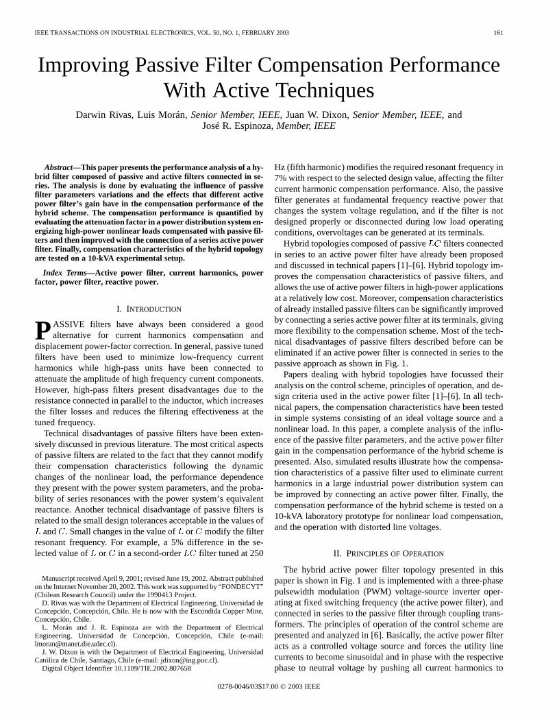
The hybrid active power filter topology presented in thispaper is shown in Fig. 1 and is implemented with a three-phasepulsewidth modulation (PWM) voltage-source inverter oper-ating at fixed switching frequency (the active power filter), andconnected in series to the passive filter through coupling trans-formers. The principles of operation of the control scheme arepresented and analyzed in [6]. Basically, the active power filteracts as a controlled voltage source and forces the utility linecurrents to become sinusoidal and in phase with the respectivephase to neutral voltage by pushing all current harmonics to
0278-0046/03$17.00 © 2003 IEEE
162 IEEE TRANSACTIONS ON INDUSTRIAL ELECTRONICS, VOL. 50, NO. 1, FEBRUARY 2003
Fig. 1. Hybrid active power filter configuration.
circulate through the hybrid scheme. In other words, becausethe active power filter is connected in series to the passivefilter through coupling transformers, it imposes a voltagesignal at the primary terminals that forces the circulation ofcurrent harmonics through the passive filter, improving itscompensation characteristic, independently of the variations inthe selected resonant frequency or filter parameters.
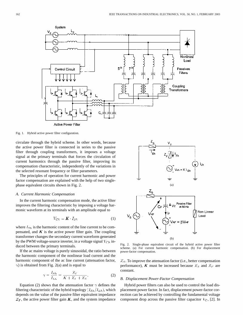
The principles of operation for current harmonic and powerfactor compensation are explained with the help of two single-phase equivalent circuits shown in Fig. 2.
A. Current Harmonic Compensation
In the current harmonic compensation mode, the active filterimproves the filtering characteristic by imposing a voltage har-monic waveform at its terminals with an amplitude equal to
(1)
where is the harmonic content of the line current to be com-pensated, and is the active power filter gain. The couplingtransformer changes the secondary current waveform generatedby the PWM voltage-source inverter, in a voltage signal in-duced between the primary terminals.
If the ac mains voltage is purely sinusoidal, the ratio betweenthe harmonic component of the nonlinear load current and theharmonic component of the ac line current (attenuation factor,
) is obtained from Fig. 2(a) and is equal to
(2)
Equation (2) shows that the attenuation factordefines thefiltering characteristic of the hybrid topology , whichdepends on the value of the passive filter equivalent impedance
, the active power filter gain , and the system impedance
(a)
(b)
Fig. 2. Single-phase equivalent circuit of the hybrid active power filterscheme. (a) For current harmonic compensation. (b) For displacementpower-factor compensation.
. To improve the attenuation factor (i.e., better compensationperformance), must be increased because and areconstant.
B. Displacement Power-Factor Compensation
Hybrid power filters can also be used to control the load dis-placement power factor. In fact, displacement power-factor cor-rection can be achieved by controlling the fundamental voltagecomponent drop across the passive filter capacitor, [2]. In
RIVAS et al.: IMPROVING PASSIVE FILTER COMPENSATION PERFORMANCE WITH ACTIVE TECHNIQUES 163
order to do that, a voltage component at fundamental frequency,, and in phase with the capacitor filter voltage is gener-
ated at the coupling transformer primary terminals featuring anamplitude equal to
(3)
On the other hand, at fundamental frequency the passive filterequivalent impedance is capacitive, as shown in Fig. 2(b), andthe voltage across the hybrid filter is equal to
(4)
which shows that the voltage across the capacitorcan bechanged by adjusting the active power filter output voltage am-plitude in phase with . The hybrid filter fundamentalcurrent is defined by the following expression:
(5)Considering that and are the voltage and current,
respectively, at the hybrid filter terminals, (5) suggests that, bydefining
(6)
the hybrid filter can be considered as an equivalent capacitor. Moreover, (6) shows that if is positive the hybrid filter
reduces the reactive power that flows to the load, and conversely,if is negative the hybrid filter increases the reactive power thatflows to the load. According to (3), modifyingmeans that thevoltage across the active filter is changed and hence the voltageacross the pasive filter is inversely changed as indicated by (4),assuming that is mainly constant.
III. H YBRID FILTER COMPENSATIONPERFORMANCE
Current harmonic compensation is achieved by reducing theimpedance of the hybrid filter and, thus, forcing the current har-monic to follow the low-impedance trajectory instead of cir-culating through the power system [Fig. 2(a)]. To accomplishthis task, the hybrid filter must present a wide bandwidth anda very small impedance at the frequency of the harmonics thatare being compensated. The hybrid filter bandwidth depends onthe passive filter parameters and on the active power filter gain
. The passive filter impedance value at the resonant frequencydepends on the tuned factor.
The tuned factor in per unit with respect to the resonantfrequency is defined by
(7)
where is the passive filter real resonant frequency, andthe designed value. The tuned factordefines the magnitudein which the passive filter resonant frequency changes due tothe variations in the power system frequency and modificationsin the passive filter parametersand . The values of and
can change due to aging conditions, temperature variations,
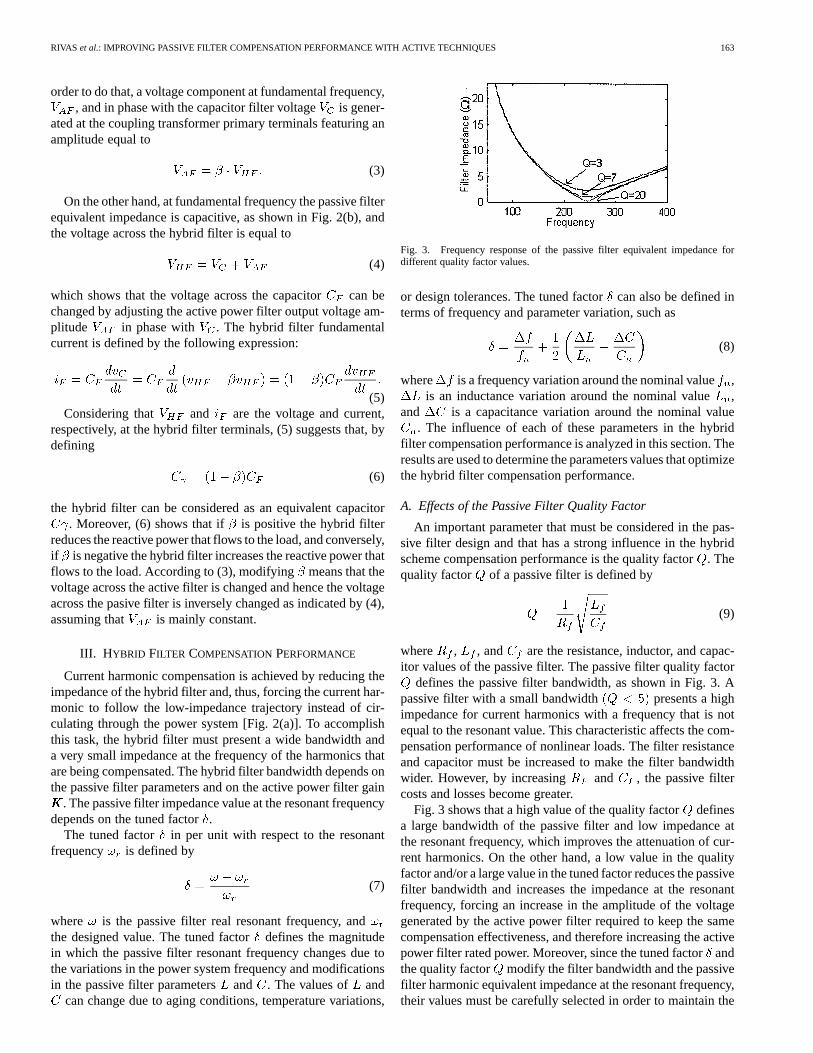
Fig. 3. Frequency response of the passive filter equivalent impedance fordifferent quality factor values.
or design tolerances. The tuned factorcan also be defined interms of frequency and parameter variation, such as
(8)
where is a frequency variation around the nominal value,is an inductance variation around the nominal value,
and is a capacitance variation around the nominal value. The influence of each of these parameters in the hybrid
filter compensation performance is analyzed in this section. Theresults are used to determine the parameters values that optimizethe hybrid filter compensation performance.
A. Effects of the Passive Filter Quality Factor
An important parameter that must be considered in the pas-sive filter design and that has a strong influence in the hybridscheme compensation performance is the quality factor. Thequality factor of a passive filter is defined by
(9)
where , , and are the resistance, inductor, and capac-itor values of the passive filter. The passive filter quality factor
defines the passive filter bandwidth, as shown in Fig. 3. Apassive filter with a small bandwidth presents a highimpedance for current harmonics with a frequency that is notequal to the resonant value. This characteristic affects the com-pensation performance of nonlinear loads. The filter resistanceand capacitor must be increased to make the filter bandwidthwider. However, by increasing and , the passive filtercosts and losses become greater.
Fig. 3 shows that a high value of the quality factordefinesa large bandwidth of the passive filter and low impedance atthe resonant frequency, which improves the attenuation of cur-rent harmonics. On the other hand, a low value in the qualityfactor and/or a large value in the tuned factor reduces the passivefilter bandwidth and increases the impedance at the resonantfrequency, forcing an increase in the amplitude of the voltagegenerated by the active power filter required to keep the samecompensation effectiveness, and therefore increasing the activepower filter rated power. Moreover, since the tuned factorandthe quality factor modify the filter bandwidth and the passivefilter harmonic equivalent impedance at the resonant frequency,their values must be carefully selected in order to maintain the
164 IEEE TRANSACTIONS ON INDUSTRIAL ELECTRONICS, VOL. 50, NO. 1, FEBRUARY 2003
(a)
(b)
(c)
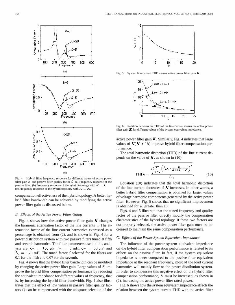
Fig. 4. Hybrid filter frequency response for different values of active powerfilter gainKKK and passive filter quality factorQ. (a) Frequency response of thepassive filter. (b) Frequency response of the hybrid topology withKKK = 5.(c) Frequency response of the hybrid topology withKKK = 20.
compensation effectiveness of the hybrid topology. A better hy-brid filter bandwidth can be achieved by modifying the activepower filter gain as discussed below.
B. Effects of the Active Power Filter Gaing
Fig. 4 shows how the active power filter gain changesthe harmonic attenuation factor of the line currents. The at-tenuation factor of the line current harmonics expressed as apercentage is obtained from (2), and is shown in Fig. 4 for apower distribution system with two passive filters tuned at fifthand seventh harmonics. The filter parameters used in this anal-ysis are: F, mH, F, and
mH. The tuned factor selected for the filters are0.1 for the fifth and 0.07 for the seventh.
Fig. 4 shows that the hybrid filter bandwidth can be modifiedby changing the active power filter gain. Large values ofim-prove the hybrid filter compensation performance by reducingthe equivalent impedance for different values of frequency, thatis, by increasing the hybrid filter bandwidth. Fig. 4 also illus-trates that the effect of low values in passive filter quality fac-tors can be compensated with the adequate selection of the
Fig. 5. System line current THD versus active power filter gainKKK.
Fig. 6. Relation between the THD of the line current versus the active powerfilter gainKKK for different values of the system equivalent impedance.
active power filter gain . Similarly, Fig. 4 indicates that largevalues of improve hybrid filter compensation per-formance.
The total harmonic distortion (THD) of the line current de-pends on the value of , as shown in (10)
(10)
Equation (10) indicates that the total harmonic distortionof the line current decreases if increases. In other words, abetter hybrid filter compensation is obtained for larger valuesof voltage harmonic components generated by the active powerfilter. However, Fig. 5 shows that no significant improvementis obtained for greater than 15.
Figs. 4 and 5 illustrate that the tuned frequency and qualityfactor of the passive filter directly modify the compensationcharacteristics of the hybrid topology. If these two factors arenot properly selected, the active power filter gain must be in-creased to maintain the same compensation performance.
C. Effects of the Power System Equivalent Impedance
The influence of the power system equivalent impedanceon the hybrid filter compensation performance is related to itseffects on the passive filter. In fact, if the system equivalentimpedance is lower compared to the passive filter equivalentimpedance at the resonant frequency, most of the load currentharmonics will mainly flow to the power distribution system.In order to compensate this negative effect on the hybrid filtercompensation performance, must be increased, as shown in(2), increasing the active power filter rated power.
Fig. 6 shows how the system equivalent impedance affects therelation between the system current THD with the active filter
RIVAS et al.: IMPROVING PASSIVE FILTER COMPENSATION PERFORMANCE WITH ACTIVE TECHNIQUES 165
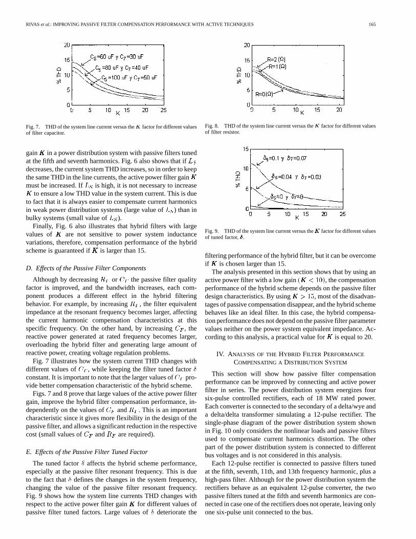
Fig. 7. THD of the system line current versus theKKK factor for different valuesof filter capacitor.
gain in a power distribution system with passive filters tunedat the fifth and seventh harmonics. Fig. 6 also shows that ifdecreases, the current system THD increases, so in order to keepthe same THD in the line currents, the active power filter gainmust be increased. If is high, it is not necessary to increase
to ensure a low THD value in the system current. This is dueto fact that it is always easier to compensate current harmonicsin weak power distribution systems (large value of) than inbulky systems (small value of ).
Finally, Fig. 6 also illustrates that hybrid filters with largevalues of are not sensitive to power system inductancevariations, therefore, compensation performance of the hybridscheme is guaranteed if is larger than 15.
D. Effects of the Passive Filter Components
Although by decreasing or the passive filter qualityfactor is improved, and the bandwidth increases, each com-ponent produces a different effect in the hybrid filteringbehavior. For example, by increasing , the filter equivalentimpedance at the resonant frequency becomes larger, affectingthe current harmonic compensation characteristics at thisspecific frequency. On the other hand, by increasing, thereactive power generated at rated frequency becomes larger,overloading the hybrid filter and generating large amount ofreactive power, creating voltage regulation problems.
Fig. 7 illustrates how the system current THD changes withdifferent values of , while keeping the filter tuned factorconstant. It is important to note that the larger values ofpro-vide better compensation characteristic of the hybrid scheme.
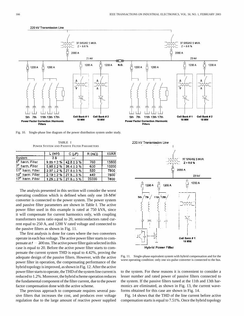
Figs. 7 and 8 prove that large values of the active power filtergain, improve the hybrid filter compensation performance, in-dependently on the values of and . This is an importantcharacteristic since it gives more flexibility in the design of thepassive filter, and allows a significant reduction in the respectivecost (small values of and are required).
E. Effects of the Passive Filter Tuned Factor
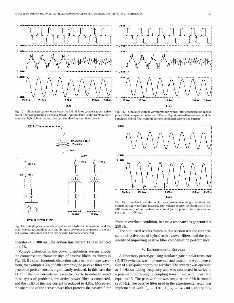
The tuned factor affects the hybrid scheme performance,especially at the passive filter resonant frequency. This is dueto the fact that defines the changes in the system frequency,changing the value of the passive filter resonant frequency.Fig. 9 shows how the system line currents THD changes withrespect to the active power filter gain for different values ofpassive filter tuned factors. Large values ofdeteriorate the
Fig. 8. THD of the system line current versus theKKK factor for different valuesof filter resistor.
Fig. 9. THD of the system line current versus theKKK factor for different valuesof tuned factor,���.
filtering performance of the hybrid filter, but it can be overcomeif is chosen larger than 15.
The analysis presented in this section shows that by using anactive power filter with a low gain , the compensationperformance of the hybrid scheme depends on the passive filterdesign characteristics. By using , most of the disadvan-tages of passive compensation disappear, and the hybrid schemebehaves like an ideal filter. In this case, the hybrid compensa-tion performance does not depend on the passive filter parametervalues neither on the power system equivalent impedance. Ac-cording to this analysis, a practical value foris equal to 20.
IV. A NALYSIS OF THE HYBRID FILTER PERFORMANCE
COMPENSATING A DISTRIBUTION SYSTEM
This section will show how passive filter compensationperformance can be improved by connecting and active powerfilter in series. The power distribution system energizes foursix-pulse controlled rectifiers, each of 18 MW rated power.Each converter is connected to the secondary of a delta/wye anda delta/delta transformer simulating a 12-pulse rectifier. Thesingle-phase diagram of the power distribution system shownin Fig. 10 only considers the nonlinear loads and passive filtersused to compensate current harmonics distortion. The otherpart of the power distribution system is connected to differentbus voltages and is not considered in this analysis.
Each 12-pulse rectifier is connected to passive filters tunedat the fifth, seventh, 11th, and 13th frequency harmonic, plus ahigh-pass filter. Although for the power distribution system therectifiers behave as an equivalent 12-pulse converter, the twopassive filters tuned at the fifth and seventh harmonics are con-nected in case one of the rectifiers does not operate, leaving onlyone six-pulse unit connected to the bus.
166 IEEE TRANSACTIONS ON INDUSTRIAL ELECTRONICS, VOL. 50, NO. 1, FEBRUARY 2003
Fig. 10. Single-phase line diagram of the power distribution system under study.
TABLE IPOWER SYSTEM AND PASSIVE FILTER PARAMETERS
The analysis presented in this section will consider the worstoperating condition which is defined when only one 18-MWconverter is connected to the power system. The power systemand passive filter parameters are shown in Table I. The activepower filter used in this example is rated at 750 kVA, sinceit will compensate for current harmonics only, with couplingtransformers turns ratio equal to 20, semiconductors rated cur-rent equal to 250 A, and 1200 V rated voltage and connected tothe passive filters as shown in Fig. 11.
The first analysis is done for cases where the two convertersoperate in each bus voltage. The active power filter starts to com-pensateat ms.Theactivepower filtergainselected in thiscase is equal to 20. Before the active power filter starts to com-pensate the current system THD is equal to 4.42%, proving theadequate design of the passive filters. However, with the activepower filter in operation, the compensating performance of thehybrid topology is improved, as shown in Fig. 12. After the activepower filter starts tooperate, theTHDof thesystem linecurrent isreduced to 1.2%. Moreover, the hybrid scheme operation reducesthe fundamental component of the filter current, due to the powerfactor compensation done with the active scheme.
The previous approach to compensate requires several pas-sive filters that increases the cost, and produces over voltageregulation due to the large amount of reactive power supplied
Fig. 11. Single-phase equivalent system with hybrid compensation and for theworst operating condition: only one six-pulse converter is connected to the bus.
to the system. For these reasons it is convenient to consider alesser number and rated power of passive filters connected tothe system. If the passive filters tuned at the 11th and 13th har-monics are eliminated, as shown in Fig. 13, the current wave-forms obtained for this case are shown in Fig. 14.
Fig. 14 shows that the THD of the line current before activecompensation starts is equal to 7.51%. Once the hybrid topology
RIVAS et al.: IMPROVING PASSIVE FILTER COMPENSATION PERFORMANCE WITH ACTIVE TECHNIQUES 167
Fig. 12. Simulated current waveforms for hybrid filter compensation (activepower filter compensation starts at 300 ms). Top: simulated load current; middle:simulated hybrid filter current; bottom: simulated system line current.
Fig. 13. Single-phase equivalent system with hybrid compensation and theworst operating condition: only one six-pulse converter is connected to the busand passive filters tuned at fifth and seventh harmonic connected.
operates ms , the system line current THD is reducedto 4.7%.
Voltage distortion in the power distribution system affectsthe compensation characteristics of passive filters, as shown inFig. 15. If a small harmonic distortion exists in the voltage wave-form, for example a 3% of fifth harmonic, the passive filter com-pensation performance is significantly reduced. In this case theTHD of the line currents increases to 15.2%. In order to avoidthese types of problems, the active power filter is connected,and the THD of the line current is reduced to 4.8%. Moreover,the operation of the active power filter protects the passive filter
Fig. 14. Simulated current waveforms for hybrid filter compensation (activepower filter compensation starts at 300 ms). Top: simulated load current; middle:simulated hybrid filter current; bottom: simulated system line current.
Fig. 15. Simulated waveforms for steady-state operating conditions andsystem voltage waveform distorted. Top: voltage source waveform with 3% offifth harmonic; bottom: system line current (active power filter compensationstarts att = 300 ms).
from an overload condition, in case a resonance is generated at250 Hz.
The simulated results shown in this section test the compen-sation effectiveness of hybrid active power filters, and the pos-sibility of improving passive filter compensation performance.
V. EXPERIMENTAL RESULTS
A laboratory prototype using insulated gate bipolar transistor(IGBT) switches was implemented and tested in the compensa-tion of a six-pulse controlled rectifier. The inverter was operatedat 4-kHz switching frequency and was connected in series toa passive filter through a coupling transformer with turns ratioequal to 15. The passive filter was tuned at the fifth harmonic(250 Hz). The passive filter used in the experimental setup wasimplemented with F, mH, and quality
168 IEEE TRANSACTIONS ON INDUSTRIAL ELECTRONICS, VOL. 50, NO. 1, FEBRUARY 2003
(a) (b)
Fig. 16. Experimental ac line current waveform with passive filtering compensation. (a) Line current waveform(THD = 24%). (b) Line current frequencyspectrum.
(a) (b)
Fig. 17. Experimental ac line current waveform with hybrid filter compensation. (a) Line current waveform(THD = 6:3%). (b) Associated frequency spectrum.
(a) (b)
Fig. 18. Experimental ac line current waveform for resonant compensation. (a) Line current waveform(THD = 60%). (b) Associated frequency spectrum.
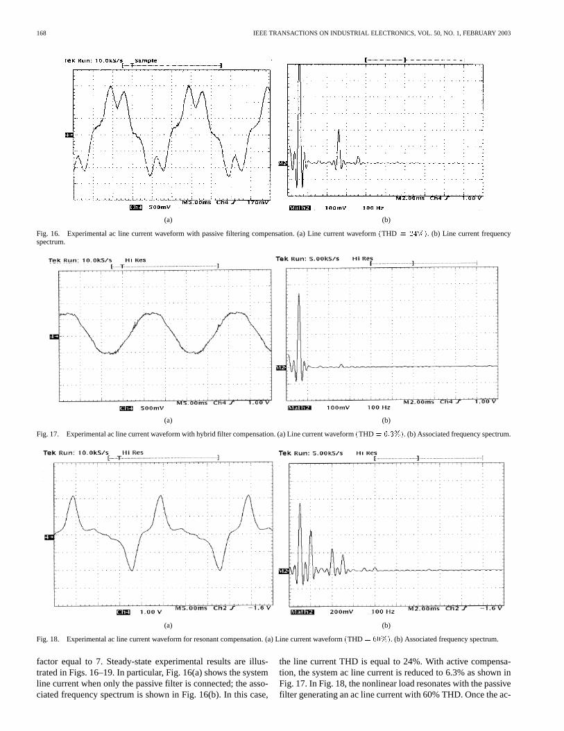
factor equal to 7. Steady-state experimental results are illus-trated in Figs. 16–19. In particular, Fig. 16(a) shows the systemline current when only the passive filter is connected; the asso-ciated frequency spectrum is shown in Fig. 16(b). In this case,
the line current THD is equal to 24%. With active compensa-tion, the system ac line current is reduced to 6.3% as shown inFig. 17. In Fig. 18, the nonlinear load resonates with the passivefilter generating an ac line current with 60% THD. Once the ac-
RIVAS et al.: IMPROVING PASSIVE FILTER COMPENSATION PERFORMANCE WITH ACTIVE TECHNIQUES 169
(a) (b)
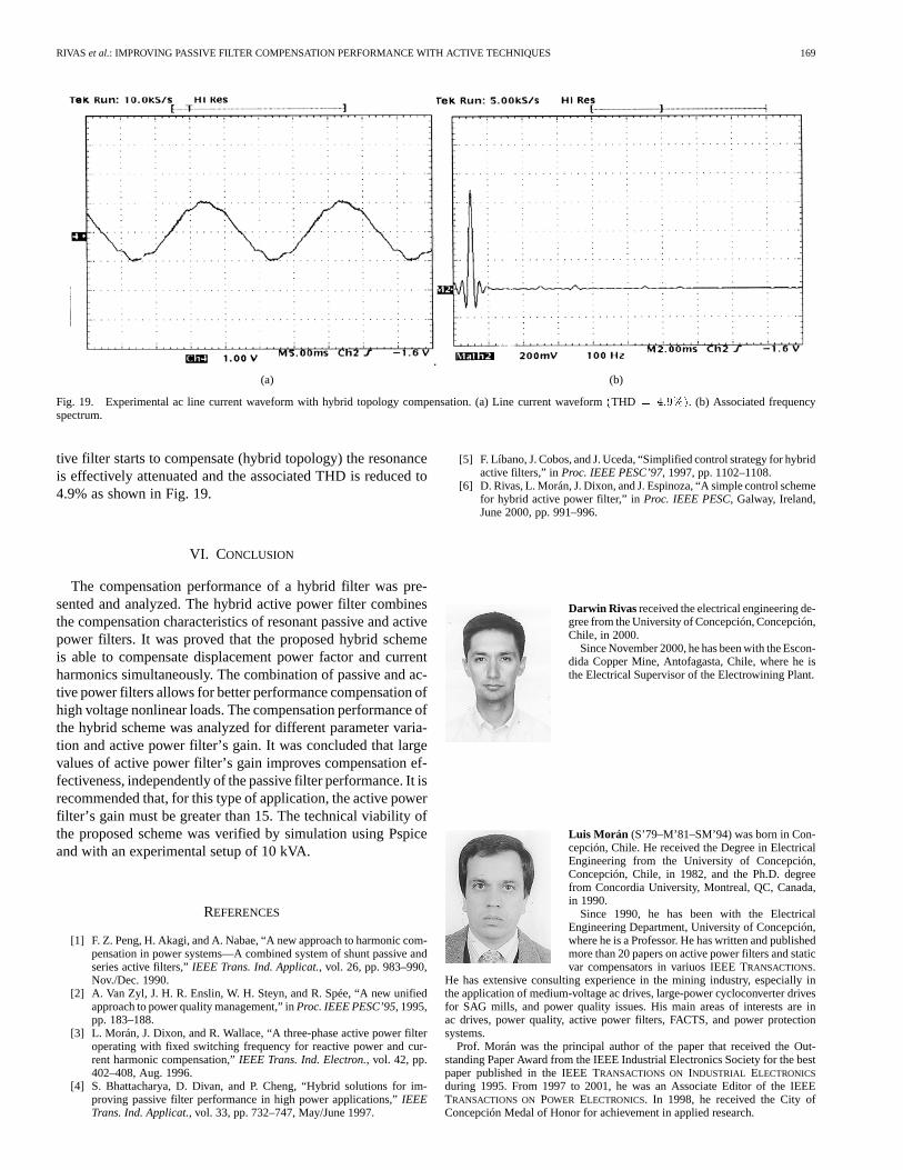
Fig. 19. Experimental ac line current waveform with hybrid topology compensation. (a) Line current waveform(THD = 4:9%). (b) Associated frequencyspectrum.
tive filter starts to compensate (hybrid topology) the resonanceis effectively attenuated and the associated THD is reduced to4.9% as shown in Fig. 19.
VI. CONCLUSION
The compensation performance of a hybrid filter was pre-sented and analyzed. The hybrid active power filter combinesthe compensation characteristics of resonant passive and activepower filters. It was proved that the proposed hybrid schemeis able to compensate displacement power factor and currentharmonics simultaneously. The combination of passive and ac-tive power filters allows for better performance compensation ofhigh voltage nonlinear loads. The compensation performance ofthe hybrid scheme was analyzed for different parameter varia-tion and active power filter’s gain. It was concluded that largevalues of active power filter’s gain improves compensation ef-fectiveness, independently of the passive filter performance. It isrecommended that, for this type of application, the active powerfilter’s gain must be greater than 15. The technical viability ofthe proposed scheme was verified by simulation using Pspiceand with an experimental setup of 10 kVA.
REFERENCES
[1] F. Z. Peng, H. Akagi, and A. Nabae, “A new approach to harmonic com-pensation in power systems—A combined system of shunt passive andseries active filters,”IEEE Trans. Ind. Applicat., vol. 26, pp. 983–990,Nov./Dec. 1990.
[2] A. Van Zyl, J. H. R. Enslin, W. H. Steyn, and R. Spée, “A new unifiedapproach to power quality management,” inProc. IEEE PESC’95, 1995,pp. 183–188.
[3] L. Morán, J. Dixon, and R. Wallace, “A three-phase active power filteroperating with fixed switching frequency for reactive power and cur-rent harmonic compensation,”IEEE Trans. Ind. Electron., vol. 42, pp.402–408, Aug. 1996.
[4] S. Bhattacharya, D. Divan, and P. Cheng, “Hybrid solutions for im-proving passive filter performance in high power applications,”IEEETrans. Ind. Applicat., vol. 33, pp. 732–747, May/June 1997.
[5] F. Líbano, J. Cobos, and J. Uceda, “Simplified control strategy for hybridactive filters,” inProc. IEEE PESC’97, 1997, pp. 1102–1108.
[6] D. Rivas, L. Morán, J. Dixon, and J. Espinoza, “A simple control schemefor hybrid active power filter,” inProc. IEEE PESC, Galway, Ireland,June 2000, pp. 991–996.
Darwin Rivas received the electrical engineering de-gree from the University of Concepción, Concepción,Chile, in 2000.
Since November 2000, he has been with the Escon-dida Copper Mine, Antofagasta, Chile, where he isthe Electrical Supervisor of the Electrowining Plant.
Luis Morán (S’79–M’81–SM’94) was born in Con-cepción, Chile. He received the Degree in ElectricalEngineering from the University of Concepción,Concepción, Chile, in 1982, and the Ph.D. degreefrom Concordia University, Montreal, QC, Canada,in 1990.
Since 1990, he has been with the ElectricalEngineering Department, University of Concepción,where he is a Professor. He has written and publishedmore than 20 papers on active power filters and staticvar compensators in variuos IEEE TRANSACTIONS.
He has extensive consulting experience in the mining industry, especially inthe application of medium-voltage ac drives, large-power cycloconverter drivesfor SAG mills, and power quality issues. His main areas of interests are inac drives, power quality, active power filters, FACTS, and power protectionsystems.
Prof. Morán was the principal author of the paper that received the Out-standing Paper Award from the IEEE Industrial Electronics Society for the bestpaper published in the IEEE TRANSACTIONS ON INDUSTRIAL ELECTRONICS
during 1995. From 1997 to 2001, he was an Associate Editor of the IEEETRANSACTIONS ON POWER ELECTRONICS. In 1998, he received the City ofConcepción Medal of Honor for achievement in applied research.
170 IEEE TRANSACTIONS ON INDUSTRIAL ELECTRONICS, VOL. 50, NO. 1, FEBRUARY 2003
Juan W. Dixon (M’90–SM’95) was born in San-tiago, Chile. He received the B.S. degree from theUniversity of Chile, Santiago, Chile, in 1977, and theM-Eng. and Ph.D. degrees in electrical engineeringfrom McGill University, Montreal, QC, Canada, in1986 and 1988, respectively.
Since 1979, he has been with the UniversidadCatólica de Chile, Santiago, Chile, where heis an Associate Professor in the Department ofElectrical Engineering, teaching in the areas ofpower electronics, electric traction, electric power
generation, and electrical machines. His research interest includes electricvehicles, machine drives, frequency changers, high-power rectifiers, static varcompensators, and active power filters.
José R. Espinoza (S’93–M’98) was born inConcepción, Chile, in 1965. He received the Eng.degree in electronic engineering and the M.Sc.degree in electrical engineering from the Universityof Concepción, Concepción, Chile, in 1989 and1992, respectively, and the Ph.D. degree in electricalengineering from Concordia University, Montreal,QC, Canada, in 1997.
He is currently an Associate Professor in theDepartment of Electrical Engineering, Universityof Concepción, where he is engaged in teaching and
research in the areas of automatic control and power electronics.
Related Documents