www.vti.se/publications Dina K. Kuttah Improving low-volume road construction and performance Validity of using the heavy vehicle simulator in evaluating the reinforcement of low-volume roads VTI notat 9A–2013 Published 2013

Welcome message from author
This document is posted to help you gain knowledge. Please leave a comment to let me know what you think about it! Share it to your friends and learn new things together.
Transcript
www.vti.se/publications
Dina K. Kuttah
Improving low-volume road construction and performance
Validity of using the heavy vehicle simulator in evaluating the reinforcement of low-volume roads
VTI notat 9A–2013Published 2013

VTI notat 9A-2013 Dnr: 2012/0384-29
Preface
The main goal of this report is to highlight the benefits of using the heavy vehicle
simulator (HVS) in verifying the validity of the proposed design of roads before
construction which in turn leads to more efficient and economical road constructions.
Furthermore, this report discusses the main advantages of using the heavy vehicle
simulator in the evaluation of construction issues and the determination of the relative
engineering properties of the materials used in roads constructions. The mechanistic
analysis of all pavement structures can be assessed using the HVS test. In addition, the
monitoring of the long term performance of the geosynthetics reinforced sections under
road traffic can also be performed.
The other purpose of this report is to exemplify the use of geotextiles and/or geogrids as
a cost-effective solution to enhance the performance of low volume traffic roads.
Basically, using of geosynthetics in roads construction reduces the thickness of unbound
layers required over soft soil, which in turn reduce the costs of constructions. Therefore,
this report sheds line on the importance of studying the effects of using geosynthetics to
reinforce low volume roads by using the HVS test.
However, this report is not intended to replace the excellent literature works and papers
used in this subject but it is hoped that the report will give the reader a greater
understanding of the needs of full-scale roads testing to ensure the usage of new road
design approaches and materials.
Finally, it is important to mention here that regardless of whether the road is paved or
unpaved with asphalt, reinforced or unreinforced with geogrids, tested or untested with
HVS, we should not forget that the research road should be paved with high ambitions,
reinforced with patience and tested with respect to work ethics.
Linköping 2012
Dina Kuttah
Projektledare
VTI notat 9A-2013
Kvalitetsgranskning
Intern peer review har genomförts av Håkan Arvidsson 17 januari 2013. Dina Kutta har
genomfört justeringar av slutligt rapportmanus 4 mars 2013. Projektledarens närmaste
chef Björn Kalman har därefter granskat och godkänt publikationen för publicering 16
september 2013.
Quality review
Internal peer review was carried out by Håkan Arvidsson 17 January 2013. Dina Kuttah
has made alterations to the final manuscript of the report 4 March 2013. The research
director of the project manager, Björn Kalman, examined and approved the report for
publication on 16 September 2013.
VTI notat 9A-2013
List of contents
Summary ........................................................................................................... 9
Sammanfattning ............................................................................................... 11
1 Introduction ............................................................................................ 13
2 Purpose of the Study ............................................................................. 14
3 The Accelerated Loading Testing .......................................................... 15
3.1 The uses of the HVS test all over the world ........................................... 15
3.2 Swedish case studies in using the VTIʼs heavy vehicle simulator .......... 17
4 Low Traffic Volume Roads ..................................................................... 29
4.1 General information ............................................................................... 29
4.2 Feature of unpaved low traffic volume roads ......................................... 29
4.3 Feature of paved low traffic volume roads ............................................. 29
4.4 Design principle for low traffic volume roads .......................................... 29
4.5 Problems behind unpaved roads ........................................................... 30
5 Management of Low Traffic Volume Roads ........................................... 31
6 Improving Unpaved Low Traffic-Volume Roads ..................................... 32
6.1 In general ............................................................................................... 32
6.2 Improving unpaved roads by using geosynthetic materials.................... 32
7 Cost Benefit Study from using the Geosynthetics in Road Construction 38
8 Cost- Benefit Study from Using the HVS in Road Testing ..................... 41
9 Future Situations: Needs and Challenges .............................................. 42
10 Conclusions and Recommendations ..................................................... 43
References ....................................................................................................... 44

VTI notat 9A-2013
List of Figures
Figure 1 The VTIs heavy vehicle simulator with track temperature control capabilities .................................................................................................. 19
Figure 2 Instrumentations used during projects carried out by the VTI’s heavy vehicle simulator. ........................................................................................ 19
Figure 3 Transporting of the VTI heavy vehicle simulator ................................ 20 Figure 4 Testing of proposed pavements structures in Poland using the VTI
heavy vehicle simulator .............................................................................. 21 Figure 5 Longitudinal cross section of SE05 instrumentation (after Wiman,
2006). ......................................................................................................... 24 Figure 6 Positions of volumetric water content measurement sensors (after
Wiman, 2006) ............................................................................................. 25 Figure 7 Rut depth propagation in SE05 test, structure 1 (Natural granular
material) and structure 2 (Crushed rock aggregate), after Wiman (2006). . 26 Figure 8 The average cross profile before and after test of Structure 1 (after
Wiman, 2006) ............................................................................................. 26 Figure 9 Water content by weight, at a depth of 15 cm from the base layer
surface, during raising and lowering of the ground water level (after Wiman, 2006) .......................................................................................................... 27
Figure 10 Surface mean rut depth and total base layer deformation at the end of the test (573,000 wheel passes), after Wiman (2006) ................................ 28
Figure 11 Base layer deformation, variation with depth (after Wiman, 2006) ... 28 Figure 12 Roads without geotextile, intermixing decreases road base thickness,
resulting in failure of the road ..................................................................... 34 Figure 13 Roads with geosynthetic material, aggregate will not sink into the soil
nor intermix with the subsoil ....................................................................... 34 Figure 14 Using of geosynthetics stabilize and strengthen the unpaved roads 35 Figure 15 Possible reinforcement functions provided by geosynthetics in
roadways, the lateral restraint of geosynthetic ........................................... 35 Figure 16 Possible reinforcement functions provided by geosynthetics in
roadways, the bearing capacity increase ................................................... 36 Figure 17 Possible reinforcement functions provided by geosynthetics in
roadways, the membrane tension support.................................................. 36

VTI notat 9A-2013
List of Tables
Table 1 the VTI’s heavy vehicle simulator configurations ..............................................18 Table 2 pavement layer mean thicknesses in SE05 center line, after Wiman
(2006) .............................................................................................................................................23

VTI notat 9A-2013
VTI notat 9A-2013 9
Improving low-volume road construction and performance
by Dina Kuttah
VTI, Swedish National Road and Research Institute
SE-581 95 Linköping, Sweden
Summary
Sweden has a wide network of unpaved low-volume roads which suffer from frost-
thaw problems as well as insufficient drainage. As more water is penetrating down into
the subgrade soil under the freeze-thaw seasons, the bearing capacity will decreases and
deterioration of road increases. Approximately, one-fifth of pavement failures occur due
to insufficient structural strength. Inadequate bearing capacity of underlying weak
subgrade and inefficient load transfer from the base course are two of the main reasons
for roads failures. The road will suffer a small deterioration every time a vehicle travel
over it and overloading of a vehicle will accelerate this process.
Since the unpaved roads consist of unbound materials, they are susceptible to erosion.
This erosion (due to traffic loading or change in climate conditions) will negatively
affect the minimum road grade required to drain out the surface water due to rainfall or
melt frozen snow. The cross sectional road slope should promote surface drainage and
prevent ponding on the road surface that can promote softening of subgrade materials.
Correspondingly, geosynthetics are specially fabricated to be used in transportation
engineering applications and to reduce the aforementioned roads problems. It is
convenient to identify the primary function of a geosynthetic as being one of:
separation, filtration, drainage, reinforcement, and erosion control. In many cases the
geosynthetics may serve dual functions. However, the validity of using geosynthetics as
a cost-effective alternative for constructing unpaved roads could be examined by
accelerated load testing (ALT). Water contents and the change of subgrade shape and
road grades can be monitored during the accelerated loading testing.
Therefore, the use of geosynthetics in order to keep the shape and slope of subgrade soil
as well as to stabilize the road structure is highly recommended to be examined in
detailed under different loading and environmental conditions using the heavy vehicle
simulator (HVS). This testing can result in significant cost and construction time saving,
better and durable unpaved roads as well as encourage the use of geosynthetics in
Sweden as a less expensive alternative in producing stable roads. In addition, the HVS
can be used to evaluate the cost differences in conventional and new construction
technique using the geosynthetic materials and to develop guidelines for road design
and construction as well as to provide some input for the development of roads
modeling software.

10 VTI notat 9A-2013
VTI notat 9A-2013 11
Förbättring av konstruktion och prestanda för lågtrafikerade vägar
av Dina Kuttah
VTI
581 95 Linköping
Sammanfattning
Sverige har ett omfattande vägnät av oasfalterade, lågtrafikerade vägar som påverkas av
tjäl- och upptiningsproblem samt otillräcklig dränering. När vatten kan tränga ned i
undergrunden under vintersäsongen kommer bärigheten att minska och försämringen av
vägen att öka. Ungefär en femtedel av beläggningsskadorna uppstår på grund av
otillräcklig hållfasthet i konstruktionen. Otillräcklig bärighet i en svag undergrund och
ineffektiv lastöverföring från bärlagret är två av de viktigaste orsakerna till vägskador.
Vägen kommer att försämras gradvis varje gång ett fordon passerar och överbelastning
av fordon kommer att påskynda denna process.
Eftersom grusvägar består av obundet material är de känsliga för erosion. Erosionen
(orsakad av trafikbelastning eller förändrade klimatförhållanden) kommer att negativt
påverka det minsta tvärfall som krävs för att dränera bort ytvattnet från regn eller smält
snö. Tvärfallet bör underlätta avrinning och förhindra oönskade vattensamlingar på
vägbanan som kan orsaka uppmjukning av undergrunden.
På motsvarande sätt är geosyntetiska material speciellt tillverkade för att användas i
transporttekniska tillämpningar och för att minska de ovannämnda problemen. De
primära funktionerna hos ett geosyntetiskt material är: uppdelning, filtrering, dränering,
förstärkning och erosionsskydd. I många fall kan de geosyntetiska materialen tjäna
dubbla syften. Emellertid bör nyttan av att använda geosyntetiska material som ett
kostnadseffektivt alternativ vid byggnation av grusvägar undersökas genom
accelererade belastningsprov (ALT). Vatteninnehåll, förändringar i undergrundens form
och vägens tvärfall kan övervakas under det accelererade belastningsprovet. Vid
användning av geosyntetiska material för att bevara form och lutning på undergrunden
samt för att stabilisera vägkonstruktionen rekommenderas en detaljerad undersökning
av olika belastnings- och miljöförhållanden med hjälp av tunga fordonssimulatorn
(HVS).
Ett sådant test kan resultera i betydande besparingar vad gäller kostnader, konstruktion
och tid, ge bättre och mer hållbara grusvägar samt uppmuntra till användningen av
geosyntetiska material i Sverige som ett billigare alternativ vid produktion av stabila
vägar. Dessutom kan HVS användas för att utvärdera skillnaderna i kostnad mellan
konventionella och nya konstruktionstekniker vid användande av geosyntetiska
material, att utveckla riktlinjer för vägkonstruktion och utförande samt att ge input i
utvecklingen av vägmodelleringsprogram.

12 VTI notat 9A-2013
Abbreviations
AADT Annual average daily traffic
ABb Asphalt Concrete in Binder Courses
AC Asphalt concrete
APT Accelerated pavement testing
ASG Asphalt strain gauges
ATB General technical description, Swedish road specification
ATPB Asphalt-treated permeable base
FEACONS A Finite Element computer program
FWD Falling weight deflectometer testing
HVS The heavy vehicle simulator test
LCC Life-cycle cost analysis
LVDT Displacement transducers (Linear Variable Differential Transformer)
MLET Multilayer Elastic Theory (MLET)
RLT Repeated load triaxial testing
SLR Spring load restrictions
SPC Soil pressure cells
Standard axle
An imaginary axle with a couple of the wheels of 100 kN axle load distributed between the wheels. Each wheel has a circular contact between the tire and the road with contact pressure of 800 kPa
VTI The Swedish National Road and Transport Research Institute
VTT Technical Research Centre of Finland

VTI notat 9A-2013 13
1 Introduction
It is well known that geosynthetic basal reinforcement has been used in paved and
unpaved roads to limit the occurrence of rutting, fatigue, and environmental-related
cracking, as well as to permit reduction in base course thickness. Nevertheless, the lack
of a representative, cost-efficient test that can be used to evaluate the behavior of large-
scale pavement trial sections has prevented detailed analyses of variables that may
affect the performance of basally-reinforced flexible pavements or unpaved roads. The
most important parameters that should be examined in such cases are the base thickness,
subgrade and base soil properties, geosynthetic materials properties and functions, depth
of geosynthetic placement, stress state, corresponding traffic loading and the
corresponding environmental conditions.
Accordingly, the main objective of this study is to highlight the importance of using the
heavy vehicle simulator to characterize the full-scale, geosynthetic reinforced pavement
response.
This report includes a description of the methodology and historical use of the HVS all
over the world with a focus on the results from Swedish case studies that have been
implemented using the HVS owned by the Swedish National Road and Transport
Research Institute (VTI).
In addition this report highlights the cost- benefit analysis from using the HVS as a
testing approach as well as the use of geosynthetics as an effective and economical
approach to enhance the performance of low traffic volume roads.
Usually, the pavements are designed to support an expected amount of traffic over the
desired design life, but unfortunately most of the pavements suffer from mechanical
failure before they reach the desired design life due to unexpected loadings,
environmental interaction, drainage problems, etc.
Consequently, in order to reach the lifetime of paved and unpaved roads, pavement
engineers have incorporated thicker layers of base material into flexible pavements.
However, this strategy has led to excessive cost in some situations (Cox et. al. 2010).
Accordingly, alternatives such as geosynthetic reinforcement of the base course have
been used in flexible pavements as well as unpaved roads (Steward et al. 1977).
Field studies have indicated that geosynthetic reinforcement of pavement base course
layers can lead to reduced differential settlement, reduced base course thickness, extend
the service life, and improved stress distribution (Hufenus et al. 2006), but most of these
studies based on short term laboratory tests and initial costs assessments. Therefore,
long term roads performance evaluation based on life cycle cost analysis is highly
recommended.

14 VTI notat 9A-2013
2 Purpose of the Study
The objective of this study is to highlight the benefits of using the HVS to verify the
subgrade soil reinforcement under long term traffic conditions. Correspondingly,
provides a better understanding of the importance of using large scale tests (e. g. the
heavy vehicle simulator test) to simulate traffic associated deterioration of a road over
its design life (usually 20 years) in as little as three months.
Furthermore, this study deals with general aspects related to road’s problems associated
with low volume traffic in order to provide a better understanding of the problems that
addresses the needs of testing new roads design approaches using full scale tests. In
addition, this report presents a systematic step-by-step method for design and repair of
roads suffering spring thaw weakening using geosynthetics.
Consequently, the report will discuss whether and under what conditions geosynthetics
(geogrids and geotextiles) increase the structural capacity of pavements and under what
conditions geosynthetics increase the service life of pavements. At the same time this
report will give a historical overview about the use of accelerated pavement testing all
over the world and open the access over new accelerating testing programs using the
heavy vehicle simulator to verify the validity of new road design approaches like the use
of reinforced materials in roads constructions to extend the service life of the road.
In principle, long term roads performance assessment will help in answering the most
important pavement mysteries and questions, like:
The road looks good today, but how will it perform tomorrow?
What should we do in order to guaranty that the road everyday will perform as well as
the first day of service?
What should we do in order to get a better road surface and reduce road maintenance
with simplified construction and lower costs?
What test can give dependable results that reflect the full-scale performance of roads
and could be the bases for pavements design guide?
What materials should we use to construct environmentally acceptable roads that can
service over the whole design life?

VTI notat 9A-2013 15
3 The Accelerated Loading Testing
According to Byron and Choubane (2003), the accelerated loading testing is a
controlled application of a realistic wheel loading to a pavement system simulating
long-term loading conditions. This technique allows the monitoring of a pavement
performance and response to accumulated load damage within a shorter time period
(Byron and Choubane, 2003).
The need for faster and more practical evaluation methods under simulated in-service
conditions prompted several transportation agencies, including the Swedish National
Road and Transport Research Institute (VTI), to consider accelerated pavement testing
(APT).
One of the large scaled accelerated pavement tests is the Heavy Vehicle Simulator,
HVS, which can be simulate traffic associated deterioration of a road over its design life
(usually 20 years) in as little as three months. The HVS is used to study how different
types of road constructions manage heavy traffic while exposing the full-scale roads to
accelerated traffic. Prior to the HVS, researchers had to wait many years to see if new
laboratory test methods or field tests would indeed provide reliable results for
pavements under actual truckloads and traffic.
Regarding the HVS test, the mechanism of working is based on the rolling of a truck
tire over a patch of asphalt or any type of road construction material. It goes back and
forth to simulate years of traffic in just weeks or months while verifying whether a
pavement structure will last or fall apart.
Consequently, the following paragraph is intent to present a description of the HVS
testing program all over the world with a focus on the main usage and findings of the
Swedish HVS testing program.
3.1 The uses of the HVS test all over the world
The following paragraphs address in details many of the experiments that have been
carried out all over the world to evaluate the new road construction materials and design
approaches using the heavy vehicle simulator. The literature review presented in this
subject covers just few research studies carried out using the heavy vehicle simulator.
Nevertheless, there are more studies in this area but unfortunately; it is not possible to
address all of them here.
Correspondingly, a research study has been carried out in Florida to evaluate the long-
term performance of superpave asphalt mix design and modified superpave asphalt mix
design using the HVS. The main objectives of this study were to evaluate the
operational performance of the Heavy Vehicle Simulator, and its possible use in
evaluating the rutting performance of pavement materials and/or designs under typical
Florida traffic and climate conditions. As a result, the rutting performances of a typical
superpave mixture used in Florida were sufficiently evaluated using the HVS as
reported by Tia et al. (2002).
Kohler et al. (2004) described the evolution of precast concrete pavements in various
countries and, in particular, in the United States. The design, construction, and
installation of a particular system of precast slabs called Super-Slab™, was explained,
and an overview of the results of accelerated load testing with a heavy vehicle simulator
(HVS) performed in California were presented by Kohler et al. (2004).

16 VTI notat 9A-2013
According to Kohler et al. (2004), the HVS results indicate that the evaluated system of
precast slabs can be safely opened to traffic in ungrouted condition, so that the panels
can be installed in consecutive nights rather than completing the entire installation at
one time. In addition, Kohler et al. (2004) pointed out that the life of this system of
precast slabs, is estimated to be between 142 and 242 million equivalent single-axle
loads, equivalent to 25 to 37 years of service and the failure mechanism did not differ
from the failure mechanism of cast-in-place jointed concrete pavements.
Moreover, the Heavy Vehicle Simulator (HVS) was used to test pavements on two
roads in South Africa that were recycled in place and treated with foamed bitumen and
emulsified bitumen. The HVS testing was performed on road P243/1 near Vereeniging,
Gauteng Province, and on the N7 road outside Cape Town in the Western Cape in order
to characterize the foamed and emulsified bitumen treated materials. The other purposes
of the test were to identify distress mechanism and to investigate how the distress
progressed with increasing load repetitions. In principle, the APT testing has provided
the tool for early assessment of a relatively new pavement technology such as foamed
bitumen treatment and deep in situ recycling as described by Theyse et al. (2004).
The California Department of Transportation requires that all new flexible pavements
should include a 75-mm layer of asphalt-treated permeable base (ATPB) between the
asphalt concrete and aggregate base layers to block off the entering of water to the
pavement structure, either through cracks in the asphalt concrete or through high-
permeability asphalt concrete. This layer will transport the cracks out of the pavement
before it reaches the unbound materials. The validity of using the ATPB layer was
examined using heavy vehicle simulator (HVS) to evaluate the performance of drained
and undrained flexible pavements under wet conditions. Results of the accelerated
pavement testing indicate that ATPB strips under combined conditions of wet base and
heavy loading and the drained and undrained sections have similar pavement lives;
however, the primary mode of failure for the drained section was surface rutting and for
the undrained sections was fatigue cracking (Bejarano et. al., 2004)
According to Tia and Kumara (2005), in Florida, full slab replacement is a common
method for repair of badly deteriorated concrete pavement slabs. However, there were
certain requirements on the compressive strength as well as uncertainties on the
optimum concrete mixtures to be used; therefore the Florida Department of Transport-
ation requested research in this area using the HVS. For this purpose, five test concrete
slabs were tested by the HVS and the results of this experiment helped the researchers
to decide which slab could perform better than the other. Tia and Kumara (2005) found
that the performance of the test slabs was independent of the cement content of the
concrete used. Therefore, the HVS gave the researchers a complete idea about the
factors that influence the concrete slabs performance. In addition, the tests parameters
resulted from the HVS test were used to develop a Finite Element computer program
(FEACONS) to model the response of the test slabs and to predict the stresses in the
concrete slabs caused by the applied loads and the temperature differentials in the
concrete slabs (Tia and Kumara, 2005).
Plessis (2008) highlighted the benefits achieved from using the heavy vehicle simulator
in roads testing. Plessis (2008) reported that the HVS had been used in verifying the
validation of a new large stone mix design method; use of modified binders in mixes; in
situ recycling of materials; upgrading of gravel roads as well as block paving and
rehabilitation procedures for concrete roads. Moreover, Plessis (2008) added that the
use of HVS had allowed a better (optimal) use of funds and natural resources.
VTI notat 9A-2013 17
3.2 Swedish case studies in using the VTIʼs heavy vehicle simulator
3.2.1 Background
The HVS of the Swedish National Road and Transport Research Institute has been used
since 1998. The acquisition of the machine was planned in co-operation with the VTT.
In many respects, the VTI's heavy vehicle simulator testing programme has contributed
and is still contributing significantly to technological development in a number of areas,
such as materials design, pavement structural design; materials test methods and several
innovative modeling methods. The VTI's heavy vehicle simulator focus research areas
involve the following fields:
Mechanistic design of semi-rigid pavements
Stability tests of modified AC-layer
Evaluation of the Swedish pavement design specification
Evaluation of different strengthening strategies on existing roads in some
European countries
3.2.2 Sweden’s HVS facility
The VTI’s heavy vehicle simulator configurations are reported in details in Table 1. It
can be seen from Table 1 that the VTI’s heavy vehicle simulator can apply wheel loads
between 30 and 110 kN (using dual or single tires) along 8 m test strip within any given
test track.
The effective test segment within this test span is approximately 6 m in length. The
remaining 2 m, at either end of the test strip, allows the load wheel to reach
programmed parameters controlling load and speed levels. These 2 m sections are
referred to as the acceleration/deceleration zones.

18 VTI notat 9A-2013
Table 1 The VTI’s heavy vehicle simulator configurations
Model MK IV
Test wheel Dual or single
Load range 30-110 kN (corresponds to 6-22 tones axle load)
Capacity 150,000 passes/week
Loading direction One or two directions
Max. test speed 12 km/h
Total lateral wander 0 - 0.7 m
Pavement temperature 0 – 30 °C
Power Diesel or electricity
Length 23 m
Width 3.7 m
Height 4.2 m
Weight Approx. 50 tones
Test length 8m (of which 6 m of constant speed and load)
Test width 0.5-1.25m
The VTI’s HVS works 24 hours a day, during the nights and weekends without human
control. Consequently, the VTI’s HVS is electrically powered (using external electric
power source or electricity from an on-board diesel generator), fully automated, and
mobile and its functionality includes laser profiling and test track temperature control
capabilities, as shown in Figure 1.
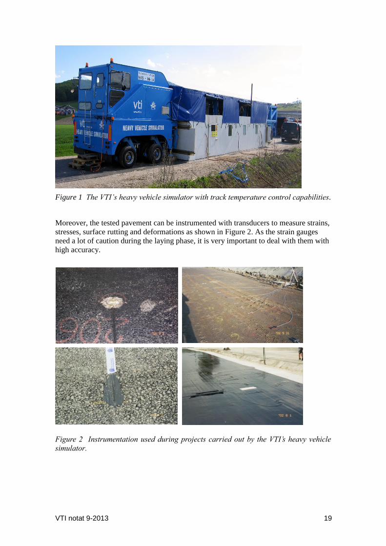
VTI notat 9-2013 19
Figure 1 The VTI’s heavy vehicle simulator with track temperature control capabilities.
Moreover, the tested pavement can be instrumented with transducers to measure strains,
stresses, surface rutting and deformations as shown in Figure 2. As the strain gauges
need a lot of caution during the laying phase, it is very important to deal with them with
high accuracy.
Figure 2 Instrumentation used during projects carried out by the VTI’s heavy vehicle
simulator.

20 VTI notat 9A-2013
This paragraph is devoted to shed light on European usage of the VTI’s HVS during
REFLEX project. In this project, three full-scale accelerated tests have been performed,
two in Sweden during the summer of 2000, and one in Finland in late year 2000. The
main goal of the project was to develop a new road construction and rehabilitation
technology. The idea was to reinforce the asphalt roads by steel fabric reinforcement to
make road structures more cost effective by improving the lifetime of new constructed
roads (Wiman and Gustafson, 2000).
During REFLEX project, response measurements were made at the beginning of the test
and during and after the test at selected intervals. One of the important findings of the
project was that the rut depths were reduced by approximately 24% at the area where
steel net was used (Wiman and Gustafson, 2000).
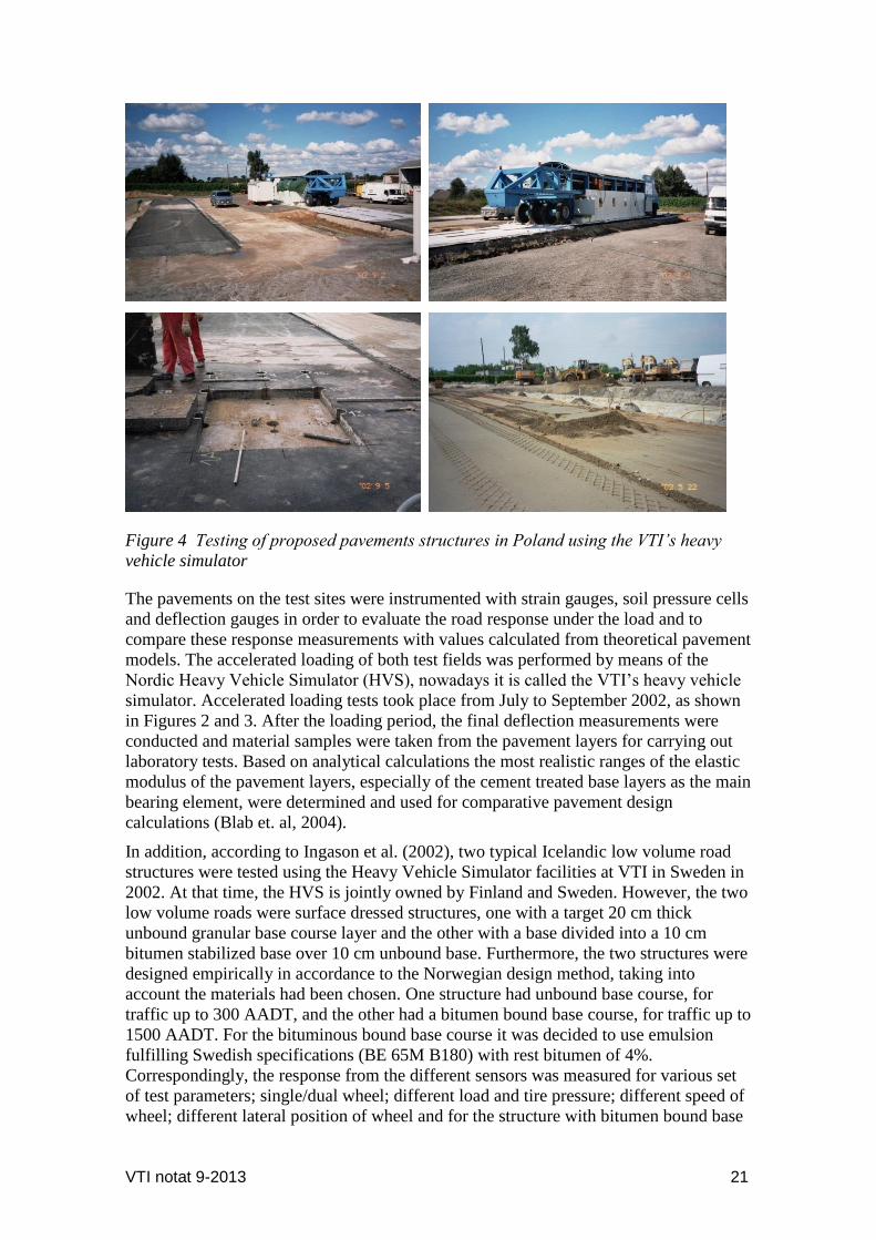
Moreover, the VTI’s HVS test has been performed to evaluate the existing design of A2
motorway semi-rigid pavement in Poznan, Poland, as shown in Figure 3. The tested
pavement consisted of an unbound drainage layer (frost protection layer), a cement-
bound sub-base course (the lower layer), and a cement-bound main base course (the
upper layer). The asphaltic package consisted of an asphaltic base course and an
asphaltic surface layer. A comprehensive test program was carried out; comprising a
HVS experiment on two instrumented test fields, see Figure 4.
Figure 3 Transporting of the VTI’s heavy vehicle simulator.
VTI notat 9-2013 21
Figure 4 Testing of proposed pavements structures in Poland using the VTI’s heavy
vehicle simulator
The pavements on the test sites were instrumented with strain gauges, soil pressure cells
and deflection gauges in order to evaluate the road response under the load and to
compare these response measurements with values calculated from theoretical pavement
models. The accelerated loading of both test fields was performed by means of the
Nordic Heavy Vehicle Simulator (HVS), nowadays it is called the VTI’s heavy vehicle
simulator. Accelerated loading tests took place from July to September 2002, as shown
in Figures 2 and 3. After the loading period, the final deflection measurements were
conducted and material samples were taken from the pavement layers for carrying out
laboratory tests. Based on analytical calculations the most realistic ranges of the elastic
modulus of the pavement layers, especially of the cement treated base layers as the main
bearing element, were determined and used for comparative pavement design
calculations (Blab et. al, 2004).
In addition, according to Ingason et al. (2002), two typical Icelandic low volume road
structures were tested using the Heavy Vehicle Simulator facilities at VTI in Sweden in
2002. At that time, the HVS is jointly owned by Finland and Sweden. However, the two
low volume roads were surface dressed structures, one with a target 20 cm thick
unbound granular base course layer and the other with a base divided into a 10 cm
bitumen stabilized base over 10 cm unbound base. Furthermore, the two structures were
designed empirically in accordance to the Norwegian design method, taking into
account the materials had been chosen. One structure had unbound base course, for
traffic up to 300 AADT, and the other had a bitumen bound base course, for traffic up to
1500 AADT. For the bituminous bound base course it was decided to use emulsion
fulfilling Swedish specifications (BE 65M B180) with rest bitumen of 4%.
Correspondingly, the response from the different sensors was measured for various set
of test parameters; single/dual wheel; different load and tire pressure; different speed of
wheel; different lateral position of wheel and for the structure with bitumen bound base
22 VTI notat 9A-2013
course also for different temperaturs. Consequently, the results showed that using
bitumen to stabilize “unstable” material increases the life time of the pavement
structure. In addition it was concluded that constructing one 20 cm thick layer of
unbound base material with same grain size distribution is not advisable. It should be
divided in two layers using coarser materials.
Moreover, Erlingsson and Ingason (2004) modeled the pavements response using the
Multilayer Elastic Theory (MLET) and the Finite Element (FE) and compared the
modeling results with the results obtained from the aforementioned HVS test. For both
techniques linear and non-linear behavior of the base has been assumed. The material
properties used in the response analyses were based on back calculation from a plate
load (PL) testing and falling weight deflectometer (FWD) testing as well as on results
from repeated load triaxial (RLT) testing. Erlingsson and Ingason (2004) added that for
the thin unbound structure, much better agreement was found between the nonlinear
response and the actual testing results, but both the linear and the non-linear responses
gave similar results for bitumen bounded structure. In addition, good agreement was
found between the numerical simulations and the testing results for the two tested
structures using the HVS. Erlingsson and Ingason, (2004) recommended the use of the
HVS-tests in developing a mechanistically based pavement design method and
increasing the understanding of the thin pavements performance.
Lenngren and Hansson (2004) pointed out that the Western Region of the Swedish Road
Administration decided to do a thorough field test of mica-rich materials and light-fill
materials in 2003. After the laboratory tests of the materials in question, the field test
was carried out using the Swedish heavy vehicle simulator. The test sections were each
instrumented with six accurate deflectometers and two pressure cells at different depths.
Moreover, temperature and soil moisture readings were also achieved. The preliminary
results showed that the influence of moisture affects the deterioration of the road when
mica is present. However, at dry conditions prevailed during the field test, the presence
of mica does not influence the results much. Lenngren and Hansson (2004) added that
even if this outcome was less desirable, the data was nevertheless interesting to analyze
from other aspects. The deflections gathered with the falling weight deflectometer
indicated that the cells were subjected to different degrees of compaction, in turn
affecting the rutting rates. However, the data collected by Lenngren and Hansson (2004)
established a good start for developing a relationship between the initial and long-term
rutting depths.
Furthermore, the HVS was used to examine the differences in permanent deformation
between crushed and uncrushed material when subjected to loading using the Swedish
Heavy Vehicle Simulator (HVS) test (Odermatt, et. al., 2004 and Wiman 2006).
Correspondingly, accelerated loading tests on a test section constructed with two
different base course materials were conducted at the Swedish National Road and
Transport Research Institute (VTI), using the Nordic Heavy Vehicle Simulator (HVS-
Nordic). During the HVS test, stresses and strains in the base course were measured
together with the rut depth at the surface, when the test road was subjected to a 60 kN
dual wheel load by means of bi-directional loading. The main finding obtained from the
HVS tests is that the permanent deformation was larger for the crushed material than for
the uncrushed materials (Odermatt, et. al., 2004 and Wiman 2006).
According to Wiman (2010), another attempt to use the VTI’s HVS in predicting the
pavements response was performed under the period of December 2004 to March 2005.
VTI notat 9-2013 23
Full-scale road structures were constructed in the VTI’s HVS site on a subgrade of fine
graded sand. Totally, about 0.5 million loadings were carried on in three different
pavement temperatures (+10°C, +20°C and +30°C).
The aim of the test was to study the stability characteristics of two pavement structures
with different binder courses in relatively thick bitumen pavements in different
temperatures. Polymer modified bitumen was used in the binder course in one of the
structures, and in the other a conventional bitumen (ABb22, 70/100, according to the
Swedish design manual for pavements (ATB Road). As expected, the structure with the
polymer modified bitumen in the binder course showed less rutting on the surface. After
the first two periods (with temperatures of +10°C and +20°C) the rutting was measured
to be 13 mm, compared to 20 mm (+50%) in the reference structure, Wiman (2010).
3.2.3 Detailed example of data and results obtained from the HVS Test
All the tests results given in this paragraph presents summary of research carried out by
Wiman (2006) using the VTI’s heavy vehicle simulator. The purpose of illustrating this
example here is to give an idea about the instrumentations that could be used in carrying
out the HVS test using the VTI’s heavy vehicle simulator regardless of the road
structure and materials tested. In addition, this paragraph highlights part of the results
obtained by research carried out by Wiman (2006) in order to give the reader of this
report an idea about the findings obtained from using the HVS in testing roads
structures.
According to Wiman (2006), a HVS test was performed at the VTI test facility in
Sweden during 2003 under the name of SE05 test. The objective of this test was to
investigate the deformation behaviour of two different unbound base materials. Half of
the test area was constructed with a base layer of natural granular material (named
“Olivehult”) and the other half with a base layer of crushed rock aggregate (named
“Skärlunda”). Hence, the two structures were tested simultaneously.
The test set-up
Table 2 shows details about layer thicknesses, instrumentation of the test sections and
material properties and characteristics. Correspondingly, the thickness of the subgrade
was 2.5 m on a rigid bottom of cement concrete.
Table 2 Pavement layer mean thicknesses in SE05 center line, after Wiman (2006)
Layer Planned thickness Actual thickness
Natural granular material (Olivehult)
Crushed rock aggregate (Skärlunda)
Asphalt concrete 40 mm 50 mm 55 mm
Unbound base 450 mm 462 mm 451 mm
Total thickness 490 mm 512 mm 506 mm
The total thickness of the unbound bases was 450 mm. In fact, it was believed that this
thickness could give a clearer and more distinct difference between the two materials
used as compared to thinner base layers on a sub-base layer.
24 VTI notat 9A-2013
Instrumentation
Sensors were installed in the structures during construction to be used in the response
measurement programme, as shown in Figure 5.
It is important to note that most of the sensors were located in the center line of the
loaded area (6x1 m). Correspondingly, the following sensors were used in test SE05:
H-shaped asphalt strain gauges (ASG)
Soil pressure cells from the University of Nottingham (SPC)
LVDTs for vertical deflection and deformation
Inductive coils (εMU) for vertical deformation and strain (static and dynamic)
Water content reflectometers (WCR)
Temperature gauges.
Figure 5 Longitudinal cross section of SE05 instrumentation (after Wiman, 2006).
Sensors for measurement of volumetric water content were installed at different depths.
A diagram of this outline appears in Figure 6. On the other hand, the sensors in the
centerline were installed outside the test area but in the area where the loading wheel
changes direction.
Instrumentation SE05
0,0
0,1
0,2
0,3
0,4
0,5
0,6
-6 -5 -4 -3 -2 -1 0
Longitudinal position, m
Ve
rtic
al
po
sit
ion
, m
Pavement surface Base layer surfaceSubgrade surface Lateral asphalt strainLongitudinal asphalt strain Vertical stressDeform/deflection unbound layers Pavement surface deflection (1)Pavement surface deflection(2) subgrade deform./deflection (1)Subgrade deform./deflection (2) Inductive coilsTemperature Cross profiles
Subgrade
Structure 2
Crushed aggregate
Structure 1
Natural gravel
Asphalt concrete

VTI notat 9-2013 25
Figure 6 Positions of volumetric water content measurement sensors (after Wiman,
2006)
The test procedure
According to tests carried out by Wiman (2006), the response measurement programme
consisted of significant measurement of stresses, strains, and deflections at different
positions, at different test loads, speeds, lateral positions as well as temperatures, using
different test-wheels and tire pressures. After the response measurement programme, the
HVS test was performed. Normal running was 24 hr a day, for five days a week with
breaks only for daily service of the machine, which means about 22,000 loadings per
day, in both directions.
The pavement performance has been studied by visual inspections and measurements of
cross profiles at fixed test structures locations for the purpose of rut depth
measurements.
The test was divided into two phases; the first one was carried out in dry condition and
the second in wet condition. At the beginning of the test, the subgrade soil was not
soaked with water, but after about 350,000 passages, the test was stopped and the
subgrade and structure were filled with water. Initially, the water level was raised to the
top of the pavement and then lowered to 30–40 cm below the subgrade surface (Wiman,
2006).
The surface rut depth results
The surface rut depths were calculated from cross profile measurements at three fixed
longitudinal positions on each structure. Wiman (2006) reported that the equipment
used was a beam with a moving laser, taking readings every 2 mm over a total length of
2,500 mm.
As illustrated previously, the test was performed in dry condition at the beginning and
after about 350,000 passes; water was added to the subgrade soil and the structures. The
rest of the test was performed in wet condition with ground water level at 30–40 cm
below the subgrade surface, as shown in Figure 7.
WCR 11
WCR 8
WCR 5
WCR 10
WCR 7
WCR 4
WCR 9
WCR 6
WCR 3
WCR 2WCR 1
0
0,1
0,2
0,3
0,4
0,5
0,6
-7 -6 -5 -4 -3 -2 -1 0 1
Longitudinal Position, m
Vert
ical
Po
sit
ion
, m
Pavement surface Base layer surface Subgrade surface
WCR in centre line WCR 1,4 m to the right
Subgrade
Structure 2 Structure 1
Asphalt concrete

26 VTI notat 9A-2013
Figure 7 Rut depth propagation in SE05 test, structure 1 (Natural granular material)
and structure 2 (Crushed rock aggregate), after Wiman (2006).
The average result from the three cross profile measurements on structure 1 before and
after the test is shown in Figures 8.
For the reason of water content measurements, WCR sensors (water content
reflectometers) were placed at different depths in the test structures.
Figure 8 The average cross profile before and after test of Structure 1 (after Wiman,
2006)
Figure 9 shows the results during the period when ground water level was raised from
the bottom of the subgrade to the top of the pavement and then lowered to 30–40 cm
below the subgrade surface.
Rut depth propagation SE05
0
2
4
6
8
10
12
14
16
18
0 100000 200000 300000 400000 500000 600000 700000
Load repetitions
Ru
t d
ep
th (
mm
)
Profile 1:1
Profile 1:2
Profile 1:3
Profile 2:1
Profile 2:2
Profile 2:3
Mean structure 1
Mean structure 2
SE05 Structure 1
Average Cross profiles
-18
-15
-12
-9
-6
-3
0
3
0 500 1000 1500 2000 2500
mm
mm
Before test
After test
VTI notat 9-2013 27
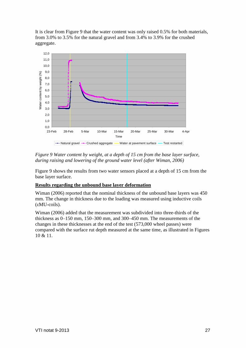
It is clear from Figure 9 that the water content was only raised 0.5% for both materials,
from 3.0% to 3.5% for the natural gravel and from 3.4% to 3.9% for the crushed
aggregate.
Figure 9 Water content by weight, at a depth of 15 cm from the base layer surface,
during raising and lowering of the ground water level (after Wiman, 2006)
Figure 9 shows the results from two water sensors placed at a depth of 15 cm from the
base layer surface.
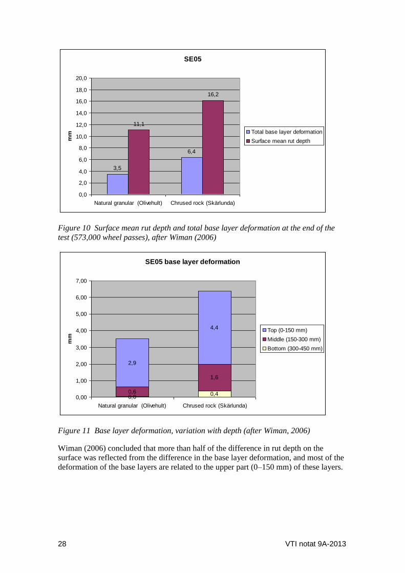
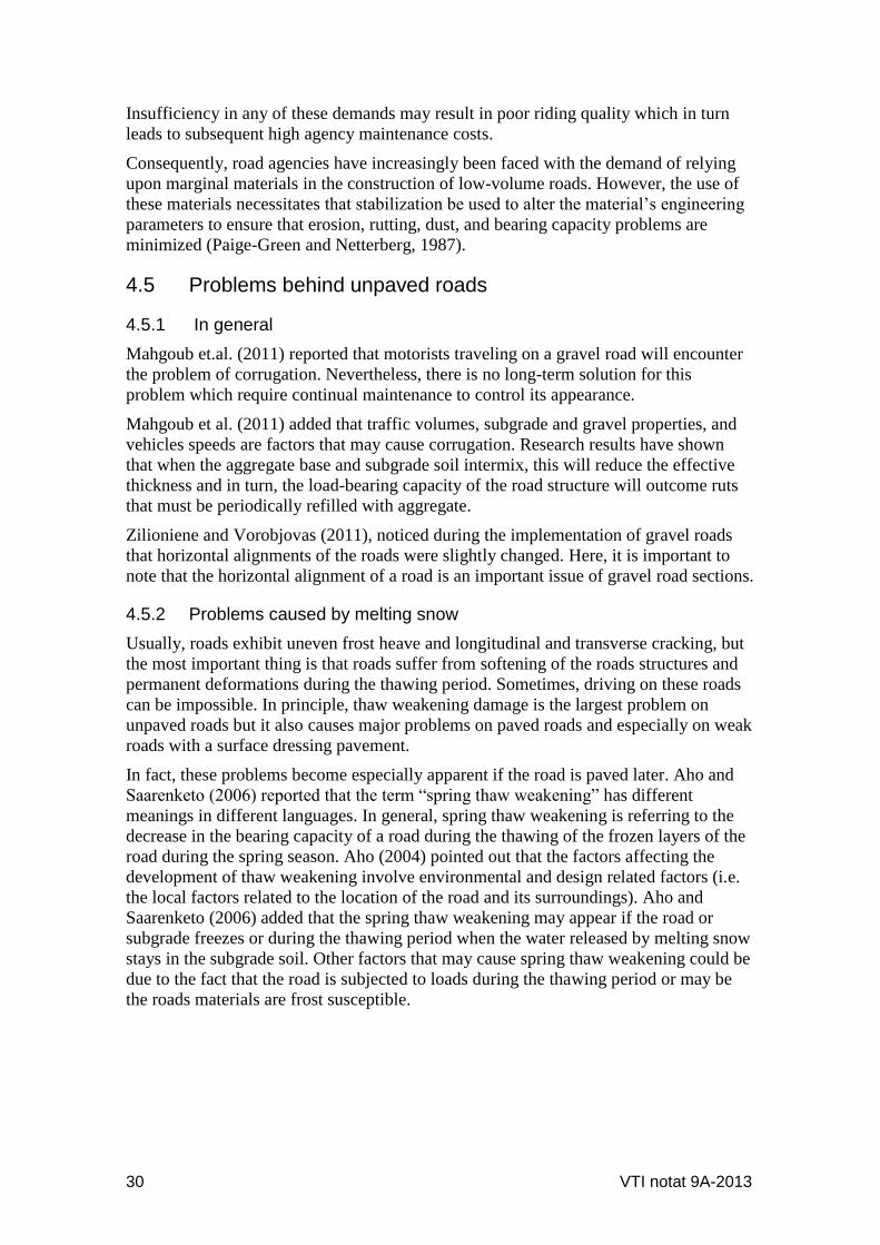
Results regarding the unbound base layer deformation
Wiman (2006) reported that the nominal thickness of the unbound base layers was 450
mm. The change in thickness due to the loading was measured using inductive coils
(εMU-coils).
Wiman (2006) added that the measurement was subdivided into three-thirds of the
thickness as 0–150 mm, 150–300 mm, and 300–450 mm. The measurements of the
changes in these thicknesses at the end of the test (573,000 wheel passes) were
compared with the surface rut depth measured at the same time, as illustrated in Figures
10 & 11.
0,0
1,0
2,0
3,0
4,0
5,0
6,0
7,0
8,0
9,0
10,0
11,0
12,0
23-Feb 28-Feb 5-Mar 10-Mar 15-Mar 20-Mar 25-Mar 30-Mar 4-Apr
Time
Wate
r conte
nt
by w
eig
ht
(%)
Natural gravel Crushed aggregate Water at pavement surface Test restarted
28 VTI notat 9A-2013
Figure 10 Surface mean rut depth and total base layer deformation at the end of the
test (573,000 wheel passes), after Wiman (2006)
Figure 11 Base layer deformation, variation with depth (after Wiman, 2006)
Wiman (2006) concluded that more than half of the difference in rut depth on the
surface was reflected from the difference in the base layer deformation, and most of the
deformation of the base layers are related to the upper part (0–150 mm) of these layers.
SE05
3,5
6,4
11,1
16,2
0,0
2,0
4,0
6,0
8,0
10,0
12,0
14,0
16,0
18,0
20,0
Natural granular (Olivehult) Chrused rock (Skärlunda)
mm Total base layer deformation
Surface mean rut depth
SE05 base layer deformation
0,00,40,6
1,6
2,9
4,4
0,00
1,00
2,00
3,00
4,00
5,00
6,00
7,00
Natural granular (Olivehult) Chrused rock (Skärlunda)
mm
Top (0-150 mm)
Middle (150-300 mm)
Bottom (300-450 mm)

VTI notat 9A-2013 29
4 Low Traffic Volume Roads
4.1 General information
Pratico and Giunta (2011) defined the low-volume roads as facilities outside built-up
areas with a traffic volume of less than 400 annual average daily traffic (AADT). In
spite of the fact that these roads are of lower use because of their location, low-volume
roads play an important social and economic role and sometimes represent a large part
of the regional and national road network (Russell and Kornala, 2003 and Pratico and
Giunta, 2011). In Sweden, the design of low traffic volume roads is governed by
“Dimensionering av lågtrafikerade vägar- DK1, 2009” for roads up to 500 000 standard
axle. Nevertheless, for traffic volume more than 500 000 standard axel, design method
DK2 is used as referred to in TRVK Väg.
4.2 Feature of unpaved low traffic volume roads
It is well known that the unpaved roads are roads built without an asphalt or concrete
wearing surface, so they derive all structural support from their aggregate base layers. In
principle, the unpaved roads are used for many purposes including industrial and private
roads, temporary roads, detours and rural roads.
Because unpaved roads have no asphalt or concrete wearing surface to help support
traffic loads, they require a greater depth of aggregate base than the paved roads. This is
applicable in designing roads for the same traffic.
However, it is important here to mention that because of the increasing cost associated
with asphalt repaving, interest has been rising in turning back damaged asphalt
roadways into maintainable aggregate driving surfaces (Shearer and Scheetz, 2011).
4.3 Feature of paved low traffic volume roads
According to Wayne et al., (2011), the flexible pavement structure for a low traffic
volume road (LVR) consists of a relatively thin asphalt-concrete wearing course and an
aggregate base course constructed on subgrade layer. An asphalt wearing course
provides a good riding surface and moisture protection for the base course. Service life
of a thin asphalt pavement depends on material quality and thickness of granular layers
(Wayne et. al., 2011).
4.4 Design principle for low traffic volume roads
In spite of the fact that there are similar basic principles for pavement design, each
country has adopted individual methods and structures that suits their requirements
according to their experience.
In general, unpaved-road construction using gravel requires that the material meet
certain basic engineering demands. These demands include the following categories:
Adequate cohesion to resist erosion,
A particle size distribution that assists a tight engagement of the individual
material particles, and
Adequate strength to support the applied traffic loads without significant
deformations.
30 VTI notat 9A-2013
Insufficiency in any of these demands may result in poor riding quality which in turn
leads to subsequent high agency maintenance costs.
Consequently, road agencies have increasingly been faced with the demand of relying
upon marginal materials in the construction of low-volume roads. However, the use of
these materials necessitates that stabilization be used to alter the material’s engineering
parameters to ensure that erosion, rutting, dust, and bearing capacity problems are
minimized (Paige-Green and Netterberg, 1987).
4.5 Problems behind unpaved roads
4.5.1 In general
Mahgoub et.al. (2011) reported that motorists traveling on a gravel road will encounter
the problem of corrugation. Nevertheless, there is no long-term solution for this
problem which require continual maintenance to control its appearance.
Mahgoub et al. (2011) added that traffic volumes, subgrade and gravel properties, and
vehicles speeds are factors that may cause corrugation. Research results have shown
that when the aggregate base and subgrade soil intermix, this will reduce the effective
thickness and in turn, the load-bearing capacity of the road structure will outcome ruts
that must be periodically refilled with aggregate.
Zilioniene and Vorobjovas (2011), noticed during the implementation of gravel roads
that horizontal alignments of the roads were slightly changed. Here, it is important to
note that the horizontal alignment of a road is an important issue of gravel road sections.
4.5.2 Problems caused by melting snow
Usually, roads exhibit uneven frost heave and longitudinal and transverse cracking, but
the most important thing is that roads suffer from softening of the roads structures and
permanent deformations during the thawing period. Sometimes, driving on these roads
can be impossible. In principle, thaw weakening damage is the largest problem on
unpaved roads but it also causes major problems on paved roads and especially on weak
roads with a surface dressing pavement.
In fact, these problems become especially apparent if the road is paved later. Aho and
Saarenketo (2006) reported that the term “spring thaw weakening” has different
meanings in different languages. In general, spring thaw weakening is referring to the
decrease in the bearing capacity of a road during the thawing of the frozen layers of the
road during the spring season. Aho (2004) pointed out that the factors affecting the
development of thaw weakening involve environmental and design related factors (i.e.
the local factors related to the location of the road and its surroundings). Aho and
Saarenketo (2006) added that the spring thaw weakening may appear if the road or
subgrade freezes or during the thawing period when the water released by melting snow
stays in the subgrade soil. Other factors that may cause spring thaw weakening could be
due to the fact that the road is subjected to loads during the thawing period or may be
the roads materials are frost susceptible.

VTI notat 9A-2013 31
5 Management of Low Traffic Volume Roads
The management of roads is a complex issue and requires a comprehensive set of
relevant indicators. Yearly, the Swedish paved road network is monitored by road
surface testers in order to supply the Swedish Transport Administration with
documentary condition data. The data is used to measure how well the road condition
standard is achieved (Sjögren and Lundberg, 2011).
In regard to Aho and Saarenketo (2006), there are several policies and techniques for
managing a road during spring thaw weakening depending on the scale and scope of the
spring thaw weakening problem. In general, the management tools can be divided into
different maintenance techniques used to decrease the effect of spring thaw in addition
to load restrictions and different tools to minimize the problems caused by these
restrictions. However, strengthening weak road sections to the extent that load
restrictions can be removed or used only in extreme conditions can also minimize the
problem (Aho and Saarenketo, 2006).
Aho and Saarenketo (2006) added that road administrators traditionally have attempted
to prevent spring thaw damage by implementing load restrictions or even closing the
road. Basically, the use of spring load restrictions increases the pavement service
lifetime but on the other hand, this action causes major extra costs for industries using
heavy transport vehicles.
In Finland the extra costs to the forest industry, due to spring thaw weakening, has been
calculated to be 100 Million €, of which 65 Million € comes from the public roads.
Thus, the most economical and sustainable solution for managing thaw weakening
problems is to strengthen the weak road sections (Aho and Saarenketo, 2006).
Liu et. al. (2011) supports what is given by Aho and Saarenketo (2006) with respect to
the action of highway agencies by applying spring load restrictions (SLR) to limit the
damage caused by heavy loads during the spring weakening period. Liu et. al. (2011)
pointed out that an alternative to minimize truck loads during the spring is the reduction
of truck tire pressure since reducing the tire pressure decreases the tire-pavement
contact pressure and hence, the associated damage during the spring period will be
decreased.
In general, better design and construction methods can prolong pavement service life
and result in lower maintenance and rehabilitation costs (Sirivitmaitrie et. al., 2011).
However, the following paragraph will shed light on several design and construction
materials/methods that may use to lower maintenance and rehabilitation costs.
32 VTI notat 9A-2013
6 Improving Unpaved Low Traffic-Volume Roads
6.1 In general
Low-volume roads are an important part of the world's transportation infrastructure and
a direct cause of the economic development of small city and rural communities.
Therefore, the construction, maintenance, and rehabilitation of these roads are major
tasks and require a major part of the public works budget (Sirivitmaitrie et. al., 2011).
However, road agencies are increasingly faced with the necessity of relying on marginal
materials in construction of low-volume roads. Use of these materials requires that
stabilization be used to improve the engineering parameters to ensure that, for example,
erosion, rutting, dust, and low-bearing capacity structure are avoided. Soil stabilization
is increasingly being used as an unpaved road asset management tool in an attempt to
minimize the impacts of these matters (Campbell and Jones, 2011).
Therefore, this report aims to enhance relatively large investigations of alternative
stabilizing materials that may lead to a durable and longtime pavement performance.
These stabilizing materials can be validated using the accelerated pavement testing to
verify the validity of unpaved road strengthening under long term loading and various
environmental conditions.
6.2 Improving unpaved roads by using geosynthetic materials
6.2.1 Background
Previous evaluations of the structural benefits of base-course reinforcement have been
conducted on road sections that are designed to fail with relatively low volume traffic.
Recently, geosynthetic materials have been used in pavement sections to reinforce the
base course to support vehicular traffic during the life of the pavement structure (base-
course reinforcement). Qian et. al. (2011) reported that when geosynthetics used as
base-course reinforcement, they provide significant structural benefits, resulting in
improved pavement life and/or equivalent performance with a reduced structural
section. Qian et. al. (2011) added that increasingly, geogrids have been successfully
used to improve soft subgrade and reinforce weak base courses for low-volume roads by
providing lateral confinement.
In addition to the above, geosynthetics are widely used as filters, separation layers, and
subgrade restraint to facilitate construction on weak subgrades.
Together with load-induced damages, pavements are subjected to environmentally
induced damages, since seasonal variations in soil temperature and moisture content
may lead to significant change in the construction materials mechanical properties
which in turn will affect the support capacity of the base course and subgrade soils.
Such seasonal variations should be considered in evaluations of the base reinforcement
benefits of geosynthetics.
In principle, the use of geosynthetics to support construction over weak subgrade soils
is well documented. Geogrid and geotextile manufacturers claim that base course
reinforcement will provide increased pavement service life and/or equivalent
performance with a reduced structural section. However, these claims should be
supported by long-term and dependent LCC studies based on different pavement
designs requirements. Shedding light on such studies in Sweden has become necessary.
VTI notat 9A-2013 33
In addition, such studies will provide, in a timely manner, the critical missing data
required for the successful development of the Swedish specification regarding the uses
of geosynthetics to reinforce the gravel roads structures.
6.2.2 Types of geosynthetic materials
Koerner (2005) defined a geosynthetic material as a synthetic material manufactured
from polymers such as polyethylene, polypropylene, or polyester. Although
geosynthetics have many forms and uses, the two forms of geosynthetics that are
specifically used for basal reinforcement are woven geotextiles and geogrids (Koerner
2005).
Geogrids
A geogrid is a geosynthetic material consisting of connected intersecting ribs with
opening sizes into which soil particles can enter, enhancing interlocking between the
soil and geogrids (Koerner 2005).
The interlocking aspect of geogrids makes them ideal for use in granular soils such as
the pavement base course. If the surface of a pavement having geogrid basal
reinforcement is loaded vertically, the dense soil particles at first want to expand
laterally due to the Poisson effect under elastic strain levels, and then dilate and expand
under higher strain levels. Perkins and Ismeik (1997) observed that geogrids may
restrict this lateral movement through interlocking. This mechanism may indicate that
stiffer geogrid polymers may yield improved lateral confinement. In this mechanism,
the geogrid does not likely go into tension unless higher strains are observed in the
system (Giroud and Noiray 1981).
Geotextiles
According to Koerner (2005), the geotextiles usually used for reinforcement
applications are woven filament sheets. Moreover, the main reinforcement mechanism
of woven geotextiles is separation since woven geotextiles are used to separate two
dissimilar materials, and preventing intermixing (Fannin and Sigurdsson 1996, Perkins
and Ismeik 1997, and Al-Qadi et al. 1994). For this reason, most geotextiles are placed
between the subgrade and base layer. Here, it is important to note that separation allows
a stiff material placed on a soft subgrade to maintain its full thickness throughout the
life of the pavement. The principle of work is similar like in the case of geogrids, in
order to mobilize tension, the soil and geotextile must deform a certain amount to
mobilize the tensile strength of the geosynthetic. Consequantly, Cuelho and Perkins
(2009) suggested that the puncture resistance of the geotextile should be taken into
account, as penetration of particles through the geotextile will reduce its strength and
stiffness.
6.2.3 How the geosynthetic materials work as roads stabilizer?
Researches carried out on using geosynthetics in roads constructions have showed that
the progressive downward movement of aggregate into the subgrade and the associated
upward pumping of subgrade soil into the aggregate base layer will result in intermixing
between the dissimilar road layers (Archer, 2008). This intermixing decreases road base
thickness which leads to reducing the design strength and load-bearing capacity, which
can result in the failure of the road as shown in Figure 12.

34 VTI notat 9A-2013
Figure 12 Roads without geotextile, intermixing decreases road base thickness,
resulting in failure of the road
In specific, using of geosynthetic materials stabilize and strengthen unpaved roads by
providing a permeable separation layer between the aggregate base and the subgrade
layer which in turn preserving the original design and life expectancy of the roadway
(see Figure 13).
When the geotextiles are involved in the design, between the aggregate sub-base and
subgrade soil, intermixing is decreased and any allowance of aggregate base for
intermixing can then be reduced.
It is important here to highlight the fact that the geosynthetics durability and tensile
strength also confines the subgrade (see Figure 14), which significantly increases the
road’s load-bearing capacity (Archer, 2008). Over time, the geosynthetics minimizes
intermixing, which prevents deterioration of the base.
Figure 13 Roads with geosynthetic material, aggregate will not sink into the soil nor
intermix with the subsoil
Aggregate
Subgrade soil
Geosynthetic material
Aggregate
Subgrade soil

VTI notat 9A-2013 35
Figure 14 Using of geosynthetics stabilize and strengthen the unpaved roads
6.2.4 Theoretical concept of road stabilization using geosynthetics
It is well to mention that the information given in this paragraph is based mainly on
Berg et al. (2000) article. However, minor reforming has been performed. The figures
given in this paragraph are originally cited from Haliburton, et al., (1981), but
redrawing of the figures has been implemented.
Berg et. al. (2000) reported that geogrids and geotextiles provide reinforcement through
three possible mechanisms, as described below:
Provide lateral restraint of the base material and subgrade soil through friction and
interlock between the aggregate, soil and the geosynthetic, as shown in Figure 15.
Increase the system bearing capacity by forcing the expected bearing capacity failure
surface to develop along alternate, higher shear strength surfaces (see Figure 16).
Membrane support of the wheel loads, as shown in Figure 17.
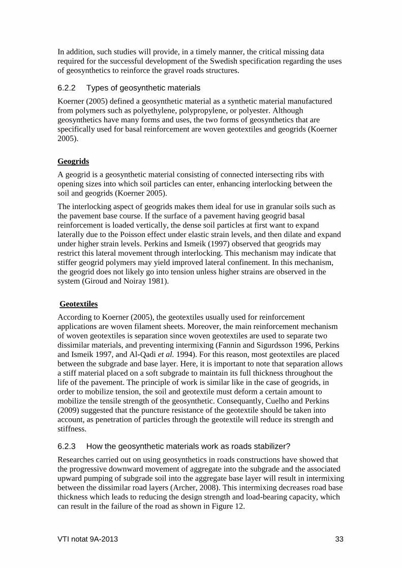
Figure 15 Possible reinforcement functions provided by geosynthetics in roadways, the
lateral restraint of geosynthetic
Aggregate
Subgrade soil
Geosynthetic material
Separation
Stabilization
Tire Load
Geosynthetic
Lateral Restraint of
Geosynthetic
36 VTI notat 9A-2013
When an aggregate layer is loaded by a wheel or track, the aggregate tends to move or
laterally, as shown conceptually in Figure 15, unless it is restricted by the subgrade or
geosynthetic reinforcement.
Weak subgrade soils provide very little lateral restraint, so when the aggregate moves
laterally; ruts develop on the aggregate surface and also in the subgrade. This problem
can be overcome by using a geogrid with good interlocking capabilities or a geotextile
with good frictional capabilities in order to provide tensile resistance to lateral aggregate
movement.
Figure 16 Possible reinforcement functions provided by geosynthetics in roadways, the
bearing capacity increase
Figure 17 Possible reinforcement functions provided by geosynthetics in roadways, the
membrane tension support
Another possible geosynthetic reinforcement mechanism is illustrated in Figure 16.
Using the same analogy of a wheel load to a footing, the geosynthetic material forces
Tire Load
Geosynthetic
Hypothetical Shear Surface with
Geosynthetic
Subbase or
Subgrade
Potential shear Surface
without Geosynthetic
Tire Load
Geosynthetic
Vertical
support
component of
membrane
Subbase or
Subgrade
Membrane tension
in geosynthetic
Wheel path rut

VTI notat 9A-2013 37
the proposed bearing capacity failure surface to follow an alternate higher shear strength
path. This phenomenon tends to increase the bearing capacity of the roadway.
The third function of geosynthetic reinforcement is the membrane effect support of tire
loads. A diagram of this outline appears in Figure 17. In such a case, the tire load
stresses should be high enough to cause plastic deformation and develop ruts in the
subgrade. If the geosynthetic material has an adequate tensile modulus, tensile stresses
will build up in the geosynthetic. As a result, the vertical stress component generated in
the membrane will assist to support the applied tire loads. Since the tensile stress within
the geosynthetic cannot be built up without some elongation, tire path rutting of more
than 100 mm is required to generate membrane support.

38 VTI notat 9A-2013
7 Cost Benefit Study from using the Geosynthetics in Road Construction
According to Berg et al. (2000), there are many advantages from using the
geosynthetics in road constructions. However, it is recommended that an economic
assessment of a proposed reinforced pavement project be provided with life-cycle cost
analysis. Berg et al. (2000) added that only when examining of initial construction costs
demonstrate a cost savings with geosynthetic reinforcement, in this case, a detailed life-
cycle cost analysis (LCC) may not be required. In several cases when the total savings
over the project life should be quantified, a detailed life-cycle cost analysis could be
performed even if the examining of initial construction costs shows a cost savings with
geosynthetic reinforcement. For example, the use of LCC analysis is required to
compare the savings in road thickness reduction as compared to maintaining the
thickness and increasing the design life.
Regarding the construction over low subgrade conditions, the general procedures used
in evaluating the cost-benefit from using the geosynthetic reinforcement typically will
result in demonstration of cost savings. Nevertheless, for some moderate subgrade
conditions, cost savings also may be computed in terms of base thickness reduction
(Berg et. al., 2000).
On the other hand, maintaining the thickness and extending the design life may provide
greater cost savings as reported by Berg et al. (2000). Correspondingly, the design
method and geosynthetic type do not affect the approach to quantifying the cost savings.
Nevertheless, there are many costs and factors to be considered in a life-cycle cost
analysis. Berg et al. (2000) pointed out the major initial and recurring costs that should
be taken into account in the economic assessment concerning the use of geosynthetics in
roads reinforcements. Berg et al. (2000) reported that the major cost that should be
considered in a LCC analysis is the agency costs which involve the initial construction
costs, future construction or rehabilitation costs, maintenance costs, residual value at the
end of the design period, engineering and administration costs as well as traffic control
costs, if any are involved.
The other important cost factor in LCC analysis is the use costs which take into account
the travel time, vehicle operation, accidents, discomfort, time delay and extra vehicle
operating costs during resurfacing or major maintenance (Berg et al., 2000).
Additionally, factors that should be clearly characterized for a life-cycle analysis
include the analysis and performance periods; equivalent single axle loads (ESALs)
over initial performance period; annual maintenance costs; initial construction costs,
initial and terminal serviceability values; discount rate; pavement component
thicknesses; pavement components structural coefficients; subgrade resilient modulus;
as well as rehabilitation construction costs. In principle, pavement management systems
can greatly assist in assessing the cost of alternatives and can be used to estimate the
cost of extending service life through use of geosynthetic reinforcement. However, such
an analysis can be summarized in the following example (Berg et al., 2000).
VTI notat 9-2013 39
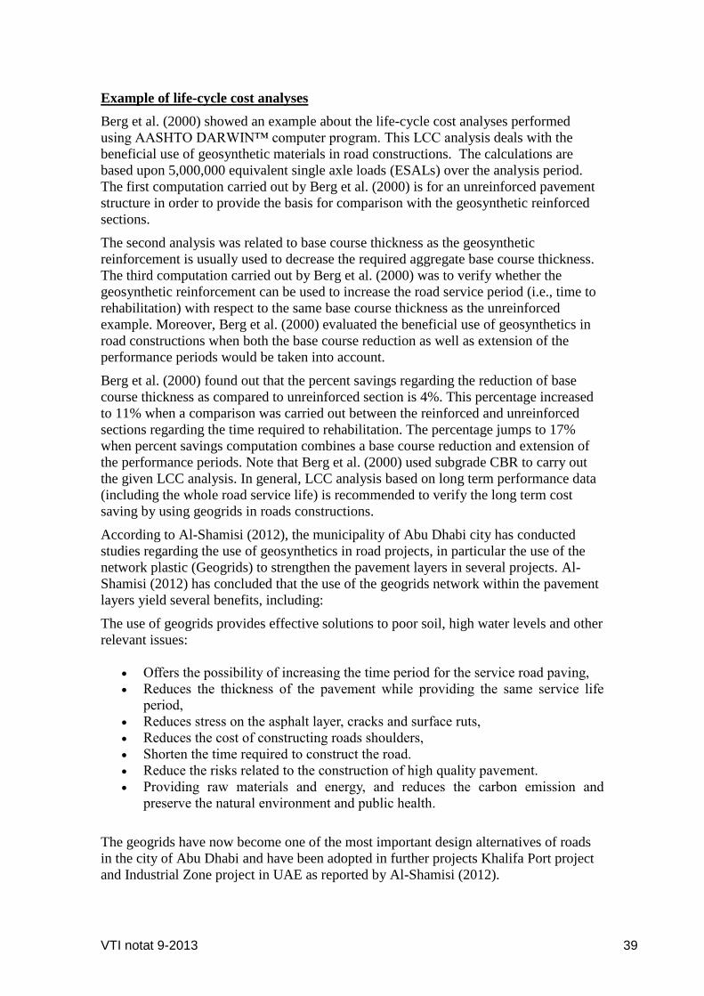
Example of life-cycle cost analyses
Berg et al. (2000) showed an example about the life-cycle cost analyses performed
using AASHTO DARWIN™ computer program. This LCC analysis deals with the
beneficial use of geosynthetic materials in road constructions. The calculations are
based upon 5,000,000 equivalent single axle loads (ESALs) over the analysis period.
The first computation carried out by Berg et al. (2000) is for an unreinforced pavement
structure in order to provide the basis for comparison with the geosynthetic reinforced
sections.
The second analysis was related to base course thickness as the geosynthetic
reinforcement is usually used to decrease the required aggregate base course thickness.
The third computation carried out by Berg et al. (2000) was to verify whether the
geosynthetic reinforcement can be used to increase the road service period (i.e., time to
rehabilitation) with respect to the same base course thickness as the unreinforced
example. Moreover, Berg et al. (2000) evaluated the beneficial use of geosynthetics in
road constructions when both the base course reduction as well as extension of the
performance periods would be taken into account.
Berg et al. (2000) found out that the percent savings regarding the reduction of base
course thickness as compared to unreinforced section is 4%. This percentage increased
to 11% when a comparison was carried out between the reinforced and unreinforced
sections regarding the time required to rehabilitation. The percentage jumps to 17%
when percent savings computation combines a base course reduction and extension of
the performance periods. Note that Berg et al. (2000) used subgrade CBR to carry out
the given LCC analysis. In general, LCC analysis based on long term performance data
(including the whole road service life) is recommended to verify the long term cost
saving by using geogrids in roads constructions.
According to Al-Shamisi (2012), the municipality of Abu Dhabi city has conducted
studies regarding the use of geosynthetics in road projects, in particular the use of the
network plastic (Geogrids) to strengthen the pavement layers in several projects. Al-
Shamisi (2012) has concluded that the use of the geogrids network within the pavement
layers yield several benefits, including:
The use of geogrids provides effective solutions to poor soil, high water levels and other
relevant issues:
Offers the possibility of increasing the time period for the service road paving,
Reduces the thickness of the pavement while providing the same service life
period,
Reduces stress on the asphalt layer, cracks and surface ruts,
Reduces the cost of constructing roads shoulders,
Shorten the time required to construct the road.
Reduce the risks related to the construction of high quality pavement.
Providing raw materials and energy, and reduces the carbon emission and
preserve the natural environment and public health.
The geogrids have now become one of the most important design alternatives of roads
in the city of Abu Dhabi and have been adopted in further projects Khalifa Port project
and Industrial Zone project in UAE as reported by Al-Shamisi (2012).

40 VTI notat 9A-2013
Al-Shamisi (2012), added that the use of geogrids in pavement design for the road
projects in the municipality of Abu Dhabi city has achieved the following benefits:
Reduce the thickness of asphalt pavement in the range of (30-50) %,
Reduce the cost of asphalt manufacturing in the range of (10 - 20) % (a total
value of about 27 million dirhams (e.g. 5,622,032 €),
Shorten implementation time for paving operations by 30%,
Providing raw materials and energy, and reduce the carbon emission by up to
20%.
VTI notat 9-2013 41
8 Cost- Benefit Study from Using the HVS in Road Testing
As with many pavement analysis concepts, when carrying out the rehabilitation process,
it is important to have in mind that the data, once collected on the road network, can be
utilized for many years not only in the design and fix of freeze-thaw damaged road
sections but also in observing how well the repaired road sections are working.
In fact, reliable survey and follow-up data can be extremely important for learning to
identify the weak road sections, but the follow-up process is likely to be time
consuming and costly. Therefore, the ability of the HVS to supply results in a relatively
short time period has not only produced a significant contribution to the development of
pavement engineering but has also saved the road authorities and the tax payer
significant amounts (Rust, 1997).
For example, the HVS has played a significant role in the reduction of pavement
construction costs in South Africa. It has been reported that in South Africa, the HVS
programme yielded a benefit/cost ratio of 12.8 (Rust, 1997). Basically, it is well
recognized that the construction and initial materials costs of South African pavements
are in the order of 40 % less than those in the areas of the United States with
corresponding climatic conditions. This is largely due to the fact that pavement
innovations could be rapidly evaluated using the HVS as reported by Rust (1997).
Moreover, according to a case study implemented by the VTI team before the
construction of a 100 km highway (part of the Berlin - Warsaw highway) in Poland, the
polish authorities wanted to use about 30 cm cement stabilized gravel layer in the
pavement structure. The HVS team found that 15 cm was sufficient. With the help of
the HVS equipment, the VTI team could show that a design depth of 15 cm managed
the specified traffic loads. If the Polish authorities implemented the 15 cm design depth,
money saving of up to 10 million € could be achieved (compared to the cost of about
0.5 million € for the entire test project where the HVS equipment was used).

42 VTI notat 9A-2013
9 Future Situations: Needs and Challenges
This report highlights the importance of using the HVS test in a wide experiment
programme to employ a mechanistic approach to determine any structural benefits
provided by using geosynthetics as base-course reinforcement for low volume
pavements in Sweden. The following parameters could be methodically varied to
examine their influence on road performance, like: base thickness, moisture conditions,
subgrade type, and presence or absence of base reinforcement. Results collected from
carrying out such studies can be used to evaluate the cost-effective benefits from using
geogrids reinforcement in low volume roads construction based on long term road
performance results (e.g., the possible reduction in measured stresses and strains, ruts
depths at the end of the road service life). Therefore, in conjunction with structural
benefits, the cost effectiveness of using geosynthetics in roads construction in Sweden
should be assessed.
A test programme can be conducted at the VTI in order to utilize their world-class
facilities and state-of-the-art heavy vehicle simulator (HVS). With accelerated traffic
loading, controlled environments, and full-scale testing could be carried out, during
which, each test section can be instrumented with temperature, moisture, stress, and
strain sensors. The deformations in the base and subgrade can be measured using coil
gauges or linear variable displacement transformers (LVDTs), and geosynthetic strain
can be measured with strain gauges or LVDTs. Correspondingly, the results will be
obtained in a matter of months, thereby providing worthy information to the
transportation community in a timely matter.
VTI notat 9-2013 43
10 Conclusions and Recommendations
It can be concluded from the collected studies that the accelerated pavement testing can
produce early and beneficial results that lead to improving pavement technology and
provide better understanding of the application and effectiveness of new materials used
to enhance the pavement systems performance.
It is clear that using of geosynthetic materials in roads construction will result in
reducing the thickness of the road pave layer and hence reduces the cost of construction.
In addition, using of geogrids will decrease the intensity of stress on the subgrade and
providing raw materials and energy, and reduce the carbon emission.
When carrying out HVS test to validate the use of geogrids in roads construction, the
impact of the subgrade strength and base course layer thickness will be crucial factors
during the results analysis. Additionally, geosynthetics location and properties should
also be considered during the analysis.
In general, more research regarding the beneficial use of geosynthetics in roads
construction should be conducted taken into account the HVS testing result according to
the aforementioned issues. Such a study will result in recommendations regarding the
performance of different types of geosynthetic materials under different loading
conditions which in turn will result in economic economic analyses of the different
options.

44 VTI notat 9A-2013
References
1. Aho, S. (2004): “Sorateiden Kelirikkokorjausten Toimivuus Ja
Elinkaarikustannukset”, Diplomityö, Tampereen Teknillinen Yliopisto, Tampere.
(English abstract).
2. Aho, S. and Saarenketo, T. (2006): “ Managing Drainage On Low Volume Roads,
Executive Summary, Roadex III Project.
3. Al-Qadi, I. L.; Brandon, T. L.; Smith, T. A., and Lacina, B. A. (1994): “How Do
Geosynthetics Improve Pavements Performance” Proceedings of Material
Engineering Conference, San Diego, CA, USA, pp. 606-616.
4. Al-Shamisi, A. (2012): “The Use of Geosynthetics in Networks Installation and
Strengthening Asphalt Pavement of Roads”, Emaratalyoum Newspaper,
http://www.emaratalyoum.com/local-section/other/2012-02-11-1.460017, or
http://www.adm.gov.ae/Earthhours/energy_savings_ar.html (in Arabic).
5. Archer, Stephen (2008): “Subgrade Improvement for Paved and Unpaved
Surfaces Using Geogrids”, Contech and Tensar International
6. Bejarano, M. O.;Harvey, J. T.; Ali, A.; Russo, M.; Mahama, D.; Hung, D. and
Preedonant, P. (2004): “Performance of Drained and Undrained Flexible
Pavement Structures under Wet Conditions; Test Data from Accelerated Pavement
Test Section 543-Drained”, Draft Report Prepared for California Department of
Transportation, Pavement Research Center Institute of Transportation Studies
University of California at Berkeley.
7. Berg R.; Christopher, B. and Perkins, S. (2000): “Geosynthetic Reinforcement of
the Aggregate Base Course of Flexible Pavement Structures”, GMA White Paper
II, Geosynthetic Materials Association, Roseville, MN, USA, 130p.
8. Blab, R.; Wiman, L. G.; Litzba, J. Ruttmar, I. (2004): “Heavy Vehicle Simulator
Experiment on a Semi-Rigid Pavement Structure of a Motorway”, Proceedings of
the 2nd International Conference on Accelerated Pavement Testing, 2004,
Minneapolis, Minnesota, USA.
9. Byron, T. and Choubane, B. (2003): “Assessing Appropriate Loading
Configuration in Accelerated Pavement Testing”, State Materials Office, Research
Report FL/DOT/SMO/03-463, Florida.
10. Campbell, A., and Jones, D. (2011): “Soil Stabilization in Low-Volume Roads”,
Transportation Research Record 1106, TRB, National Research Council,
Washington, D.C., pp. 172-178.
11. Cox, B. R.; McCartney, T. S. and Trowler, C. N. (2010): “Accelerated
Characterization of Full-Scale Flexible Pavements Using a Vibroseis”, Project
Number: MBTC 3013, Department of Transportation, University Transportation
Centers Program, USA.
12. Cuelho, E. and Perkins, S. (2009). “Field Investigation of Geosynthetic Used for
Subgrade Stabilization”, Performed for the State of Montana, Department of
Transportation, NAUE GmbH & Co. KG, in cooperation with the U.S.
Department of Transportation, Federal Highway Administration.
13. Dimensionering av lågtrafikerade vägar- DK1 (2009): The Swedish Transport
administration, VVMB 302, publication number 2009:7.
14. Erlingsson, S. and Ingason, T. (2004): “Performance of Two Thin Pavement
Structures during Accelerated Pavement Testing Using A Heavy Vehicle
Simulator”, Proceedings of the 2nd International Conference on Accelerated
Pavement Testing, 2004, Minneapolis, Minnesota, USA.
15. Fannin, R. J. and Sigurdsson, O. (1996): “Field Observations on Stabilization of
VTI notat 9-2013 45
Unpaved Roads with Geosynthetics”, Journal of Geotechnical Engineering,
ASCE, 122, No. 7, pp. 544-553. 85.
16. Giroud, J. P. and Noiray, L. (1981):“Geotextile Reinforced Unpaved Road
Design”, Journal of the Geotechnical Engineering Division. ASCE, Vol. 107, No
GT9, pp. 1233-1254.
17. Haliburton, T. A. Lawmaster, J. D. and Mc Guffey, V. C.(1981): “Use of
Engineering Fabrics in Transportation Related Application”, FHWA DTFH 61-80-
C-0094.
18. Hufenus, R.; Ruegger, R.; Banjac, R.; Mayor, P.; Springman, S.M. and
Bronnimann, R., (2006): “Full-Scale Field Tests on Geosynthetics Reinforced
Unpaved Roads on Soft Subgrade”, Geotextiles and Geomembranes 24/1, pp. 21–
37.
19. Ingason, Th.; Wiman, L. G., & Haraldsson, H.(2002): “HVS-Testing of Icelandic
Low Volume Road Structures”, ISAP 9th International Conference on Asphalt
Pavements, Copenhage.
20. Koerner, R. M. (2005): “Designing with Geosynthetics”, 5th edition, Pearson
Prentice Hall, Upper Saddle River, New Jersey, 796 pgs.
21. Kohler, E; Du Plessis, L.; Smith, P.; Harvey, J. and Pyle, T. (2004): “Precast
Concrete Pavements and Results of Accelerated Traffic Load Test”, Proceedings
of the 2nd International Conference on Accelerated Pavement Testing, 2004,
Minneapolis, Minnesota, USA, pp. 263- 281.
22. Lenngren, C. A. and Hansson, J. (2004): “Comparing FWD Initial Tests With
HVS Induced Initial and Long-Term Rutting”, Proceedings of the 2nd
International Conference on Accelerated Pavement Testing, 2004, Minneapolis,
Minnesota, USA.
23. Liu, Q.; Kavangh, L. and Shalaby, A. (2011): “Impacts of Reduced Tire Pressure
on Strain Response of Thaw-Weakened, Low-Volume Roads in Manitoba,
Canada”, Transportation Research Record: Journal of the Transportation Research
Board, Issue number 2203, pp. 186-193.
24. Mahgoub, H.; Bennett, C. and Selim, A. (2011): “Analysis of Factors Causing
Corrugation of Gravel Roads”, Transportation Research Record: Journal of the
Transportation Research Board, Issue number 2204, pp. 3-10.
25. Odermatt, N.; Wiman, L.G.; Arm, M. and Magnusson, R. (2004): “Deformation of
Unbound Pavement Materials: Heavy Vehicle Simulator and Cyclic Load
Triaxial .
26. Paige-Green, P., and Netterberg, F. (1987): “Requirements and Properties of
Wearing Course Materials for Unpaved Roads in Relation to Their Performance”,
Transportation Research Record 1106, TRB, National Research Council,
Washington, D.C., 1987, pp. 208–214.
27. Perkins, S. W. and Ismeik, M. (1997):“A Synthesis and Evaluation of
Geosynthetic Reinforced Base Course Layers in Flexible Pavements: Part I
Experimental Work”, Geosynthetics International, Vol. 4, No. 6, pp. 549-604.
28. Plessis, L. (2008): “The Heavy Vehicle Simulator in Accelerated Pavement
Testing, Historical Overview and New Developments”, Proceedings of the 3nd
International Conference on Accelerated Pavement Testing, 2004, Madrid, Spain.
29. Pratico, F. and Giunta, M. (2011): “Speed Distribution on Low-Volume Roads in
Italy”, Transportation Research Record: Journal of the Transportation Research
Board, Issue number 2203, pp. 79-84.
30. Qian, Y.; Han, J.; Pokhorel, S. and Parsons, R. (2011): “Stress Analysis on
Triangular-Aperture Geogrid-Reinforced Bases over Weak Subgrade under Cyclic
46 VTI notat 9A-2013
Loading”, Transportation Research Record: Journal of the Transportation
Research Board, Issue number 2204, pp. 83-91.
31. Russell, E. R. and Kornala, V. K. (2003): “National Handbook of Traffic Control
Practices for Low Volume Rural Roads and Small Cities”, Volume I: Low-Volume
Roads, Kansas State Universit, USA.
32. Rust, F.C. (1997):” Overview of the Strategy for the HVS Testing of LIC Bases on
Road 2388 near Cullinan”, Contract Report CR-97/074, CSIR Transportek,
Pretoria, South Africa.
33. Shearer, D. and Scheetz, B. (2011): “Improvements to Linn Run Road”,
Transportation Research Record: Journal of the Transportation Research Board,
Issue number 2204, pp. 215-220.
34. Sirivitmaitrie, C.; Puppala, A; Saride, S. and Hoyos, L. (2011): “Combined Lime-
Cement Stabilization for Longer Life of Low-Volume Roads”, Transportation
Research Record: Journal of the Transportation Research Board, Issue number
2204, pp. 140-147.
35. Sjögren, L. and Lundberg, T.( 2011): “Svenska vägtillståndsmått då, nu och i
morgon, Del 2: Nu – år 2005–2009”, The Swedish Road and Transport Research
Institute, VTI report no. 718.
36. Steward, J., Williamson, R., and Mohney, J. (1977): “Guidelines for Use of
Fabrics in Construction and Maintenance of Low-Volume Roads”, Forest Service
Report PB-276 972.
37. Theyse, H. L., Long, F. M.; Sadzik, E. (2004): “Heavy Vehicle Simulator Tests”,
Proceedings of the 2nd International Conference on Accelerated Pavement
Testing, 2004, Minneapolis, Minnesota, USA.
38. Tia, M. and Kumara, W. (2005): “Evaluation of Early Strength Requirement of
Concrete of Slabs”, Final report, U.F. Project No. 49104504972-12, Department
of Civil and Costal Engineering, College of Engineering, University of Florida,
Gainesville, Florida.
39. Tia, M.; Roque, R.; Sirin, O. and Kim, H. (2002): “Evaluation Of Superpave
Mixtures with and without Polymer Modification by Means of Accelerated
Pavement Testing”, Final report, U.F. project No. 49104504801-12, Department
of Civil and Costal Engineering, College of Engineering, University of Florida,
Gainesville, Florida.
40. Wayne, M.; Boudreau, R. L. and Kwon, J. (2011): “Characterization of
Mechanically Stabilized Layer by Resilient Modulus and Permanent Deformation
Testing”, Transportation Research Record: Journal of the Transportation Research
Board, Issue number 2204, pp. 76-82.
41. Wiman, L. G. (2006): “Accelerated Load Testing of Pavements HVS-Nordic Tests
at VTI Sweden 2003–2004”, VTI rapport 544A.
42. Wiman, L. G. (2010): “Accelerated Testing of Road Construction - with and
without Polymer Modified Bitumen in The Binder Layer”, The Swedish Road and
Transport research institution, VTI report 576, In Swedish.
43. Wiman, L. G. and Gustafson, K. (2000): “Full Scale Accelerated Test”, REFLEX
REPORT T4:01, European Project Report.
44. Zilioniene, D. and Vorobjovas, V. (2011): “Correspondence of Horizontal and
Vertical Alignment with Safe Driving Conditions on Low-Volume Roads”,
Transportation Research Record: Journal of the Transportation Research Board,
Issue number 2203, pp. 49-5.

VTI, Statens väg- och transportforskningsinstitut, är ett oberoende och internationellt framstående forskningsinstitut inom transportsektorn. Huvuduppgiften är att bedriva forskning och utveckling kring infrastruktur, trafik och transporter. Kvalitetssystemet och miljöledningssystemet är ISO-certifierat enligt ISO 9001 respektive 14001. Vissa provningsmetoder är dessutom ackrediterade av Swedac. VTI har omkring 200 medarbetare och finns i Linköping (huvudkontor), Stockholm, Göteborg, Borlänge och Lund.
The Swedish National Road and Transport Research Institute (VTI), is an independent and internationally prominent research institute in the transport sector. Its principal task is to conduct research and development related to infrastructure, traffic and transport. The institute holds the quality management systems certificate ISO 9001 and the environmental management systems certificate ISO 14001. Some of its test methods are also certified by Swedac. VTI has about 200 employees and is located in Linköping (head office), Stockholm, Gothenburg, Borlänge and Lund.
www.vti.se [email protected]
HUVUDKONTOR/HEAD OFFICE LINKÖPING POST/MAIL SE-581 95 LINKÖPING TEL +46(0)13 20 40 00 www.vti.se
BORLÄNGE POST/MAIL BOX 92 SE-721 29 BORLÄNGE TEL +46(0)243 446 860 www.vti.se
STOCKHOLM POST/MAIL BOX 55685 SE-102 15 STOCKHOLM TEL +46(0)8 555 770 20 www.vti.se
GÖTEBORG POST/MAIL BOX 8072 SE-402 78 GÖTEBORG TEL +46(0)31 750 26 00 www.vti.se
LUND POST/MAIL Scheelevägen 2 SE-223 81 LUND TEL +46(0)46 540 75 00 www.vti.se
Related Documents