Improving heat pump performance during cold weather using solar-air heat collector By Student names: Ibrahem Aljubea Bahaa Shawer Supervisor: Dr. Momen Sughayyer Submitted to the College of Engineering in partial fulfillment of the requirements for the degree of Bachelor degree in Mechatronics Engineering Palestine Polytechnic University Dec 2014

Welcome message from author
This document is posted to help you gain knowledge. Please leave a comment to let me know what you think about it! Share it to your friends and learn new things together.
Transcript
Improving heat pump performance during cold
weather using solar-air heat collector
By
Student names:
Ibrahem Aljubea
Bahaa Shawer
Supervisor: Dr. Momen Sughayyer
Submitted to the College of Engineering
in partial fulfillment of the requirements for the degree of
Bachelor degree in Mechatronics Engineering
Palestine Polytechnic University
Dec 2014
I
ملخص
كن رنك ف انحبالد انز ر , بو انخبصخ انؼبمخجف ثبنغبز ف انمامكبو رحسه كفبئ وظبو انزك دراسخانمشرع ذف انى
. خانشمس انطبقخ مىخفضخ ف انخبرج رزفر انحرارحفب درجبد
نهطبقخاسط انجبمغ انحراري ثف وظبو انزكف خانخبرج حػهى رسخه اناء انذاخم انى انحذ خاالسبس حرزركس انفكر
مه انزذفئخ, ف وفس انقذ ان اسزخذاو خانخبرجح اوخفبض درجبد انحرار كفبءح اوظم انزكف رقم مغ ن, حث أانشمسخ
. انصغرحكجري ف االغهت غر مىبسج نهمسبكه انمجبو ائخزطهت رمرر قىاد نهطبقخ انشمسخ مجبشرحخالل انجبمغ
رفغ مه انخبرجخ انحذحنهىظبمه , حث ان رفغ درج حراري اناء انذاخم انى اإلجبثخفبنمشرع جمغ ثه انجاوت
مه انجبمغ انزذفئخانحصل ػهى وسزطغانزكف ف حبن ػذو رشغم وظبو انى رنك او ثبإلضبفخ , كفبئ وظبو انزكف
. انز ال رحزبج قىاد ائخ انمىسل ثشكم مجبشراقرة مكبن ف ري رمررب انى انحرا
Abstract
This project aims to study the possibility of enhancing the efficiency of gas air-conditioning
system in private and public buildings, that is during the temperature is cold outside the building
and the solar energy is available. The main idea of the project is to heat the air that enters the
external unit of the air conditioning unit by using solar air heating collector system, this because
the conditioning air system generally lose its COP when the external temperature decreases. In
the same time, using the heating by solar air heat collector directly requires passing a complex
air ducts inside the building which is usually inappropriate for small buildings. So this project
combines the advantages of the both systems, because increasing the temperature of air which
enters the collector unit, increases the COP of the conditioning system. In addition, when the
conditioning system is not operating, the heated air can be passed directly to the near zoon of the
house which does not require ducts.
II
List of contents
List of contents ………………….………………...…………………...……………………… II
List of figures …………….……..…………..…………………………………………….…. . IV
List of table ………………………..………………………………………..…………..…….. V
Chapter 1: Introduction and motivations
1.1 Introduction of heating ...……………………………………………………………….... 2
1.2 The problem ………….………….……………………………………………………….. 2
1.3 Research hypothesis ……………………………………………………………………… 3
1.4 Goal and objectives ………………………………………………………………………. 4
1.5 Project scope …………………………………………………………………………….... 4
1.6 Disadvantages of the project ……………………………………………………………... 5
1.7 Time table ………………………………………………………………………………... 6
1.8 Budget …………………………………………………………………………………… 7
Chapter 2: Gas heat pump
2.1 General principles ………………………………………………………………………… 9
2.2 Components of the heat pump……………………………………………………………. 13
2.3 Advantages and disadvantages of the heat pump ……….................................................. 16
2.4 Heat exchanger of heat pump …………………………………………………………… 17
3.5 Coefficient of performance ……………………………………………………………… 18
Chapter 3: Solar air heat collector
3.1 Solar heating systems in Palestine ……………………………………………………….. 21
3.2 Heat transfer fundamentals ………………………………………………………………. 22
III
3.3 Thermal radiant properties ……………………………………………………………….. 23
3.4 Heat collection rate …………………………………………………………………......... 25
3.5 Solar radiation and heat collection ………...…………………………………………….. 25
3.6 Wind speed and heat collection …………………………………..…………………….... 26
3.7 Incident angle and heat collection …………………………………..……………………. 27
3.8 Inlet temperature and heat collection ……………………………….……………………. 28
Chapter 4: System components
4.1 Centrifugal fan ……………………………………………………………….................... 30
4.2 Thermistor .………………………………………………………………………………. 31
4.3 Flexible air ducts …………………………………………………………………………. 32
4.4 Solar air heat collectors ………………………………………………………….............. 32
4.5 Stepper motor …………………………………………………………………………… 33
4.6 Display screen (20*40 LCD Display) …………………………………………………... 34
Chapter 5: Control system
5.1 Introduction ……………………………………………………………………………... 36
5.2 Control system ………………………………………………………………………….. 37
5.2.1 Introduction to control system ………………………………………………... 37
5.2.2 Microcontroller ………………………………………………………………. 39
5.2.3 Block diagram of the system …………………………………………………. 41
5.2.4 Temperature sensors ………………………………………………………….. 42
5.2.5 Stepper motor ………………………………………………………………… 46
5.2.6 16x4 LCD Display ……………………………………………………………. 48
5.2.7 Centrifugal fan ……………………………………………………………….. 49
5.2.8 Software Design ………………………………………………………………. 50
5.2.9 Pin mapping …………………………………………………………………… 52
IV
5.2.10 Microcontroller program …………………………………………………… 53
5.2.11 Design of Electronic Circuits ………………………………………………... 59
5.3 Connect and disconnect the systems ……………………………………………………. 60
Chapter 6: Calculation and design
6.1 Gas heat pump ………………………………………………………………………….. 63
6.2 Solar air heat collector …………………………………………………………………. 64
6.2.1 Fins specifications …………………………………………………………… 65
6.2.2 Inlet and outlet specifications ………………………………………………... 65
6.3 Heat load calculation of the studied house ……………………………………………. 68
Chapter 6: Results and conclusion
7.1 Experimental results …..……………………………………………………………….. 70
7.2 Conclusion ………………………………………………………………….. 74
References ……………………………………………………………………………… 75
V
List of figures
Figure 1.1 Project description ……………………………………………………………… 5
Figure 2.1 System-surrounding and boundary …………………………………………….. 10
Figure 2.2 Steady-flow process ……………….…………………………………………… 11
Figure 2.3 Enthalpy ………………….…………………………………………………….. 12
Figure 2.4 Heat pump concept ……………………………………………………………... 13
Figure 2.5 Concept of heat exchanger ……………………………………………………... 17
Figure 2.6 Relation between COP and Toutdoor …………………………………………...... 19
Figure 3.1 Relation between incident angle and refection and absorption ………………... 27
Figure 4.1 Centrifugal fan ………………………………………………………………….. 30
Figure 4.2 Thermistor ……………..……………………………………………………….. 31
Figure 4.3 Flexible air duct ………………………………………………………………… 32
Figure 4.4 Solar air heat collector …………………………………………………………. 33
Figure 4.5 Stepper motor …………………………………………………………………... 33
Figure 4.6 Display screen (20*30 LCD Display) …………………………………………. 34
Figure 5.1 Project description …………………………………………………………….. 35
Figure 5.2 Project flowchart ………………………………………………………………. 38
Figure 5.3 PIC18F4550 microcontroller ………………………………………………….. 39
Figure 5.4 PIC18F4550 pin diagram. …………………………………………………….. 39
Figure 5.5 MikroC PRO for PIC ………………………………………………………….. 41
Figure 5.6 Block diagram of the system ………………………………………………….. 41
Figure 5.7 NTC 103 Thermistor ………………………………………………………….. 42
Figure 5.8 Temperature sensor Mfile in MATLAB …………..………………………….. 44
Figure 5.9 Characteristic curve for NTC 103…………..………………………………….. 45
Figure 5.10 Characteristic equation for NTC 103…………..……………………..……….. 46
VI
Figure 5.11 Stepper motor connection ………………..………………………….……….. 47
Figure 5.12 Centrifugal fan specification ………………..……………………….……….. 49
Figure 5.13 Centrifugal fan on the inlet that we used ………………..…………...……….. 49
Figure 5.14 Centrifugal fan connection with microcontroller ……….…………...……….. 50
Figure 5.15 Input and outputs of the system …………………..…….…………...……….. 51
Figure 5.16 Pin mapping of peripherals to the PIC18F4550……………………...……….. 52
Figure 5.17 Flexible connection between the systems ………….………………………... 61
Figure 6.1 Dimensions of outdoor unit …………………………………………………... 63
Figure 6.2 Solar air heat collector by catia …..…………………………………………... 64
Figure 6.3 The shapes of rectangular fin …..……………………………………………... 65
Figure 6.4 The inlet air flow with centrifugal fan …..…………………………………..... 65
Figure 6.5 The outlet air flow …………………..…..…………………………………..... 66
Figure 6.6 Gathering of six solar air heat collectors in parallel ………………………..... 67
Figure 6.7 The house design …………………..…..…………………………………..... 68
Figure 7.1 The solar air heat collector …..………………………………………...……... 71
VII
List of table
Table 1.1 Time table ……………………………………………………………………….. 6
Table 1.2 Budget …………………………………………………………………………… 7
Table 3.1 Air temperature in Palestine …………………………………………………… 21
Table 3.2 Sun duration in Palestine ……………………………………………………….. 22
Table 5.1 Specification of PIC18F4550 …………………………………………….……. 40
Table 5.2 Specification of NTC 103.……………………………………………………… 43
Table 5.3 Pin out Connections for 16x4 LCD Display……………………………………. 48
Table 6.1 The dimensions of outdoor unit…………………………………………….…… . 63
Table 6.2 Components specification and characteristics of the solar air heat collector system
parameters ...……………………………………………………………………………….. ... 64
Table 6.3 Specification of centrifugal fan ………………………………………………… 66
Table 6.4 The dimensions of outdoor unit …………………………………………… …... 69
Table 6.5 The dimensions of outdoor unit ………………………………………………… 69
Table 7.1 Experimental data ……………………………………………………………..... 71

1
Chapter One
Introduction and motivations
1.1 Introduction of heating
1.2 The problem
1.3 Research hypothesis
1.4 Goal and objectives
1.5 Project scope
1.6 Disadvantages of the project
1.7 Time table
1.8 Budget
2
1.1 Introduction of heating
The heating is preparing the environment inside the places to overcome the heat loss which results
from the decrease the outdoor temperature. Heating is essential for human comfort in the places
where the temperature is low during the winter. Human used many methods and sources for heating
such as:
Fire: the first heating system was a fire in the caves and when the human discovered the way
of making a hole in the wall or ceiling, that was the development of the first fireplace.
Coal, fossil fuels, and gases: produce heat and pollutes the air; used in making fires which
produces heat.
Electricity: provides us with an easy and comfort heating. It is relatively safe, clean and low
maintenance costs, but it’s operation costs high.
Solar energy: Used in heating through solar air heat collector, and this is what will be used
in this project
In this research oriented project, it is expecting to improve the performance of heat pump during
cold weather by heating the cold air using sun rays which improves the efficiency of air
conditioning system, the heat pump, during winter .
For the purpose of this project, Solidworks® software program will be used to analyze the system
“heat collectors”.
1.2 The problem
Palestine has an ongoing difficulties regarding the traditional energy supply such as petrol, gas
and electricity, In addition to that high cost, which is comparable to the most expensive countries in
the world.
3
Moreover, the Israeli occupation controls the amounts and prices of energy products, and also
controls it’s availability in the markets. In winter, warming is considered as a basic need for human
comfort in places where temperature is low. Heating is required for resident and for some industries
and agricultural products as well.
Given most of the available energy resources are limited and delivered at high cost, it became
necessary to improve performance of system and to integrate renewable sources such as solar
energy which is available in Palestine.
This project objectives are completely in line with this trend when it comes to performance
improvement and renewable energy inter action in Palestine. People are increasingly relay on air-
conditioning systems for heating their homes. Most of these systems are based on compressible
fluids. Greatly, the gas heat pump system performance decline when the outside temperature
decreases to very low temperature during winters. This problem is very obvious and common which
raises the question of possible improvement of the performance during such bad weather when the
heating is needed. Though, heating the outside component of heat pump using solar energy could
improve the performance, which means also integration of renewable energy.
Such idea needs investigation to determine its effectiveness and possible modifications. The project
main idea is to make this investigation.
1.3 Research hypothesis
Increasing the temperature of heat exchanger “evaporator ” of the heat pump leads to increase
the efficiency of air conditioner system.
Reduce the cost of heating process.
4
1.4 Goal and objectives
1- The main goal of this project is to increase the performance of air conditioning system during
winter.
2- The project will be flexible; the system is easy to expand or shrink according to future
requirements.
3- The project will provide a model for integrating solar energy in heating application.
1.5 Project scope
The solar air heat collector system aims to improve the efficiency of air conditioner and reduce its
electrical consumption in winter through heat collector in many cases:
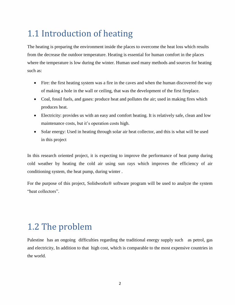
1. The heat collector system is used to increase the efficiency of the heat pump during the cold
weather and the sun is shining “sunny and cold days”. When the conditioner is turned on, the heat
collector works to increase the temperature of the air that enters the conditioner, reducing its
dependence on electricity and increase its efficiency.
2. In case the heat pump is turned off and the weather is cold and sunny, the amount of heat that
produced by heat collector directly enters the house without passing though the heat exchanger of
the heat pump, for example: when there is nobody at home, the heat pump is turned off, and in this
case the hot air directly enters the house. So when people come back to home, they will find that the
house temperature is elevated and they don’t have to heat the house from the beginning. This
method reduces the amount of heat required to heat the house and as a result reduce the monthly
heating costs.
5
1.6 Disadvantages of our project
1- The system is ineffective in many cases, such as: the cloudy weather, the sun is not shining or at
night.
2- The dust that accumulates on the solar panels reduces the system efficiency.
Fig. 1.1:Project description
6
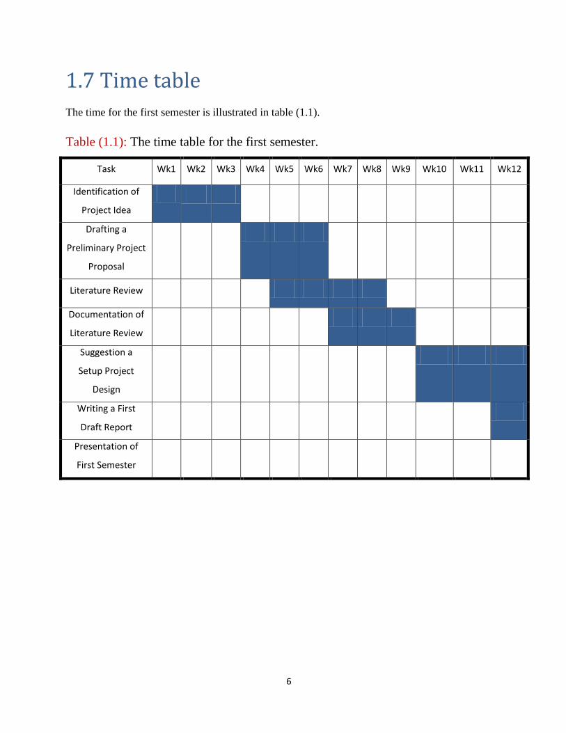
1.7 Time table
The time for the first semester is illustrated in table (1.1).
Table (1.1): The time table for the first semester.
Task Wk1 Wk2 Wk3 Wk4 Wk5 Wk6 Wk7 Wk8 Wk9 Wk10 Wk11 Wk12
Identification of
Project Idea
Drafting a
Preliminary Project
Proposal
Literature Review
Documentation of
Literature Review
Suggestion a
Setup Project
Design
Writing a First
Draft Report
Presentation of
First Semester
7
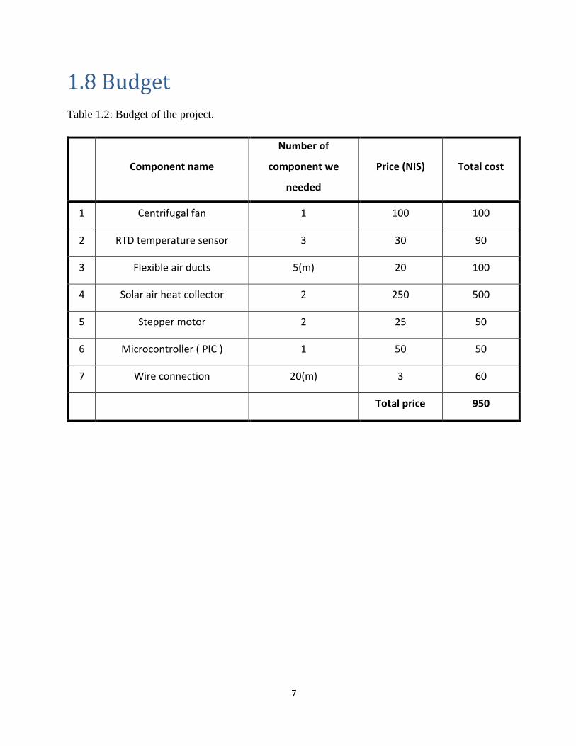
1.8 Budget
Table 1.2: Budget of the project.
Component name
Number of
component we
needed
Price (NIS) Total cost
1 Centrifugal fan 1 100 100
2 RTD temperature sensor 3 30 90
3 Flexible air ducts 5(m) 20 100
4 Solar air heat collector 2 250 500
5 Stepper motor 2 25 50
6 Microcontroller ( PIC ) 1 50 50
7 Wire connection 20(m) 3 60
Total price 950
8
Chapter Two
Gas heat pump
2.1 General principles
2.1.1 System and control volumes
2.1.2 The steady-flow process
2.1.3 Temperature and the zeroth law of thermodynamics
2.1.4 Heat is transferred by three mechanisms
2.1.5 Enthalpy-a combination property
2.2 Components of the heat pump
2.2.1 Compressor
2.2.2 Condenser
2.2.3 Expansion valve
2.2.4 Evaporator
2.3 Advantages and disadvantages of the heat pump
2.4 Heat exchanger of heat pump
2.5 Coefficient of performance
9
2.1 General principles
One of the most fundamental laws of nature is the conservation of energy. It simply states that
during an interaction energy can change from one form to another. But the total amount of energy
remains constant. This mean that energy cannot be created or destroyed.
So the heat pump takes the energy from the outside and concentrates the heat in the room or house
or the volume that we need to increase the temperature in it. So the change in the energy content of
a body or any other system is equal to the difference between the energy input and the energy
output. So the energy balance is expressed as:
Ein- Eout=E
The first law of thermodynamics is simply an expression of the conservation of energy principle,
and it asserts that energy is a thermodynamic property. The second law of thermodynamics asserts
that energy has quality as well as quantity, and actual processes occur in the direction of decreasing
quality of energy.[1]
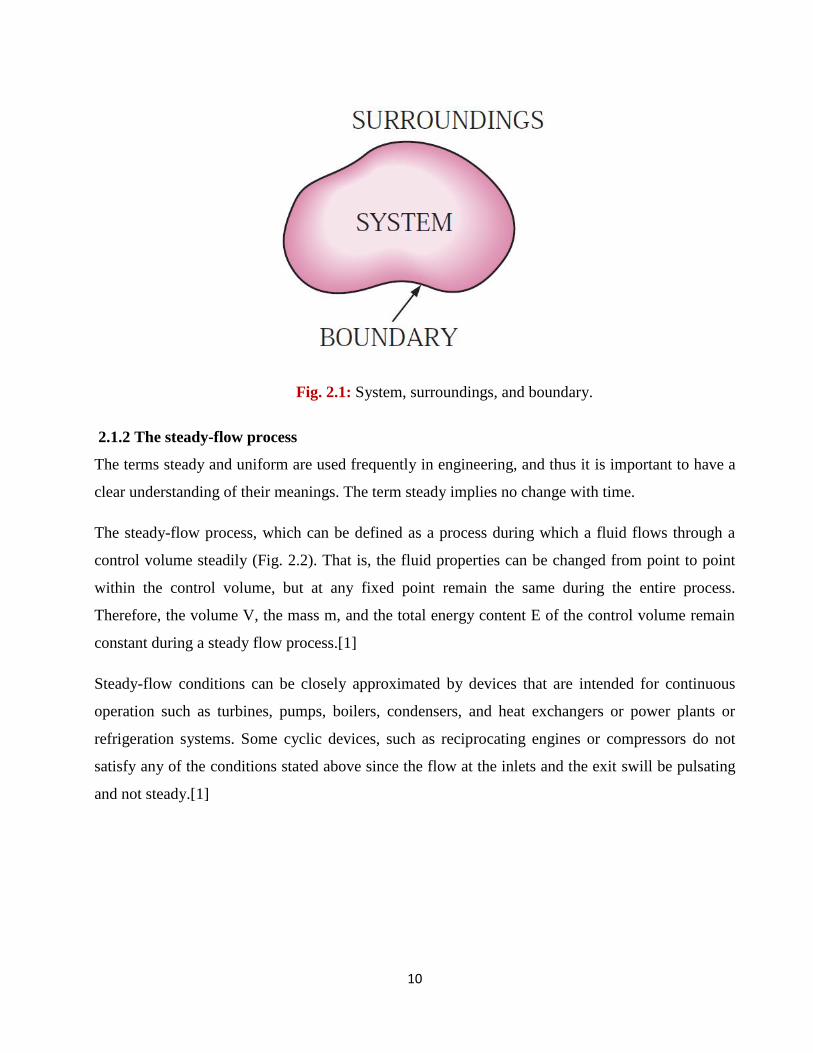
2.1.1 System and control volumes
A system is defined as a quantity of matter or a region in space chosen for study. The mass or
region outside the system is called the surroundings. The real or imaginary surface that separates
the system from its surroundings is called the boundary. These terms are illustrated in Fig. 1.2. The
boundary of a system can be fixed or movable. Note that the boundary is the contact surface shared
by both the system and the surroundings. Mathematically speaking, the boundary has zero
thickness, and thus it can neither contain any mass nor occupy any volume in space.
Systems may be considered to be closed or open depending on whether a fixed mass or a fixed
volume in space is chosen for study. A closed system(also known as a control mass) consists of a
fixed amount of mass and no mass can cross its boundary. That is, no mass can enter or leave a
closed system. But energy, in the form of heat or work, can cross the boundary and the volume of a
closed system does not have to be fixed. If, as a special case, even energy is not allowed to cross the
boundary, that system is called an isolated system.[1]
(2.1)
10
2.1.2 The steady-flow process
The terms steady and uniform are used frequently in engineering, and thus it is important to have a
clear understanding of their meanings. The term steady implies no change with time.
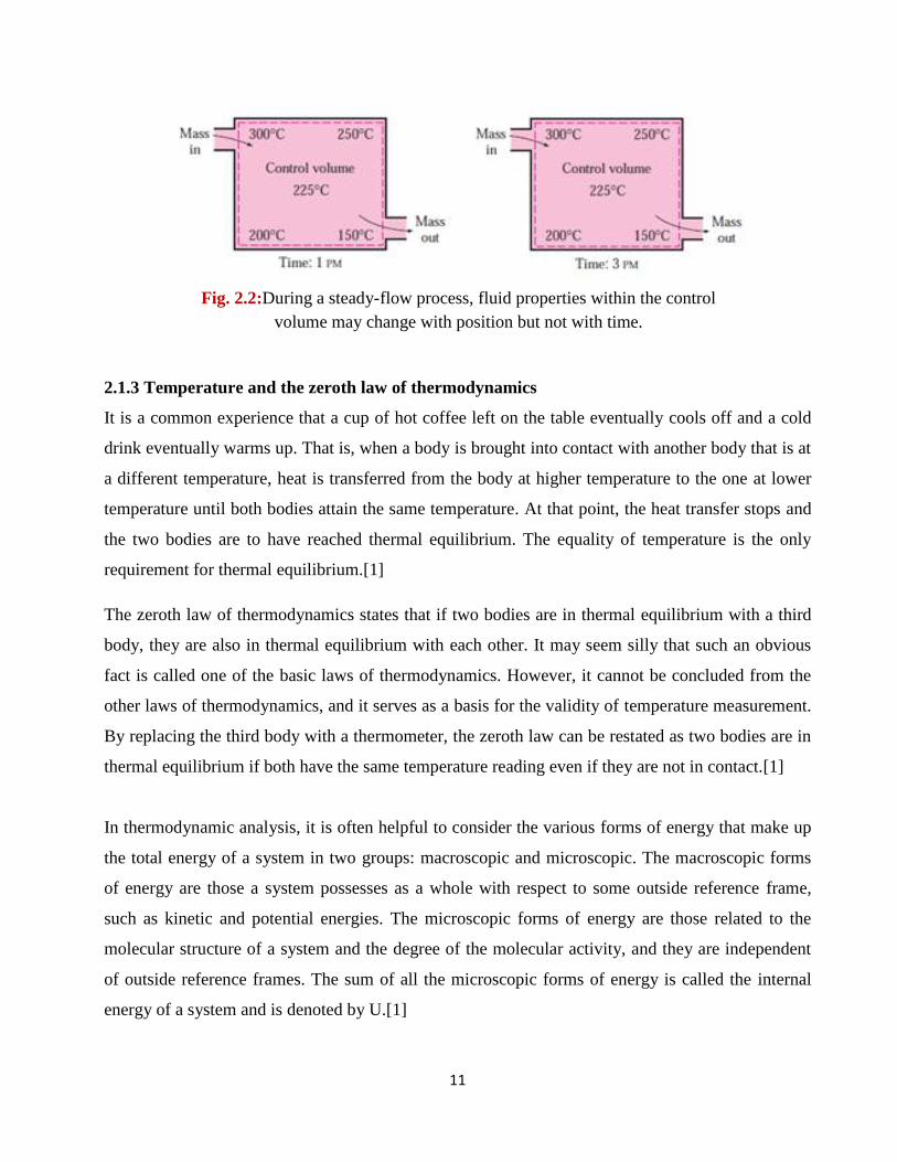
The steady-flow process, which can be defined as a process during which a fluid flows through a
control volume steadily (Fig. 2.2). That is, the fluid properties can be changed from point to point
within the control volume, but at any fixed point remain the same during the entire process.
Therefore, the volume V, the mass m, and the total energy content E of the control volume remain
constant during a steady flow process.[1]
Steady-flow conditions can be closely approximated by devices that are intended for continuous
operation such as turbines, pumps, boilers, condensers, and heat exchangers or power plants or
refrigeration systems. Some cyclic devices, such as reciprocating engines or compressors do not
satisfy any of the conditions stated above since the flow at the inlets and the exit swill be pulsating
and not steady.[1]
Fig. 2.1: System, surroundings, and boundary.
11
2.1.3 Temperature and the zeroth law of thermodynamics
It is a common experience that a cup of hot coffee left on the table eventually cools off and a cold
drink eventually warms up. That is, when a body is brought into contact with another body that is at
a different temperature, heat is transferred from the body at higher temperature to the one at lower
temperature until both bodies attain the same temperature. At that point, the heat transfer stops and
the two bodies are to have reached thermal equilibrium. The equality of temperature is the only
requirement for thermal equilibrium.[1]
The zeroth law of thermodynamics states that if two bodies are in thermal equilibrium with a third
body, they are also in thermal equilibrium with each other. It may seem silly that such an obvious
fact is called one of the basic laws of thermodynamics. However, it cannot be concluded from the
other laws of thermodynamics, and it serves as a basis for the validity of temperature measurement.
By replacing the third body with a thermometer, the zeroth law can be restated as two bodies are in
thermal equilibrium if both have the same temperature reading even if they are not in contact.[1]
In thermodynamic analysis, it is often helpful to consider the various forms of energy that make up
the total energy of a system in two groups: macroscopic and microscopic. The macroscopic forms
of energy are those a system possesses as a whole with respect to some outside reference frame,
such as kinetic and potential energies. The microscopic forms of energy are those related to the
molecular structure of a system and the degree of the molecular activity, and they are independent
of outside reference frames. The sum of all the microscopic forms of energy is called the internal
energy of a system and is denoted by U.[1]
Fig. 2.2:During a steady-flow process, fluid properties within the control
volume may change with position but not with time.
12
2.1.4 Heat is transferred by three mechanisms
Conduction is the transfer of energy from the more energetic particles of a substance to the
adjacent less energetic ones as a result of interaction between particles.
Convection is the transfer of energy between a solid surface and the adjacent fluid that is in
motion, and it involves the combined effects of conduction and fluid motion.
Radiation is the transfer of energy due to the emission of electromagnetic waves (or
photons).[1]
2.1.5 Enthalpy-a combination property
A person looking at the tables of thermodynamics will notice two new properties: enthalpy h and
entropy s. Entropy is a property associated with the second law of thermodynamics, and we will not
use it until it is properly defined. However, it is appropriate to introduce enthalpy at this point.[1]
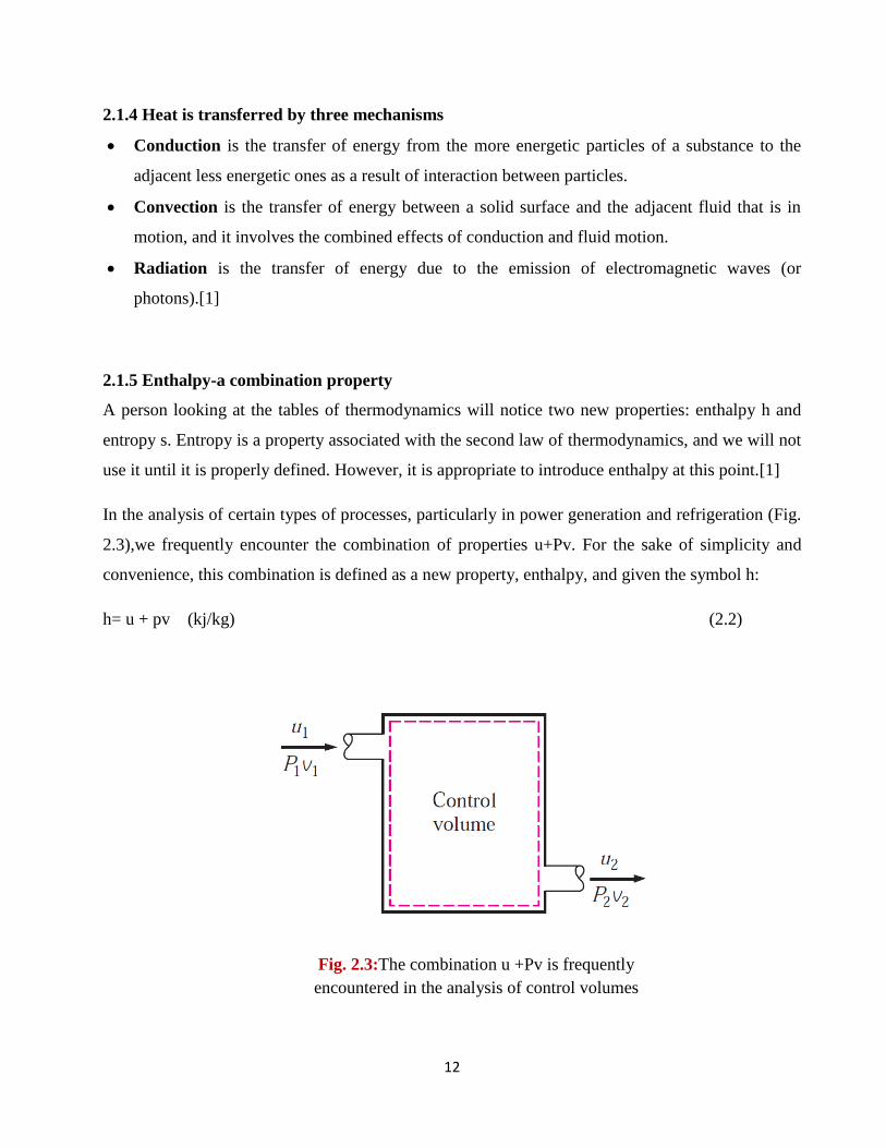
In the analysis of certain types of processes, particularly in power generation and refrigeration (Fig.
2.3),we frequently encounter the combination of properties u+Pv. For the sake of simplicity and
convenience, this combination is defined as a new property, enthalpy, and given the symbol h:
h= u + pv (kj/kg) (2.2)
Fig. 2.3:The combination u +Pv is frequently
encountered in the analysis of control volumes
13
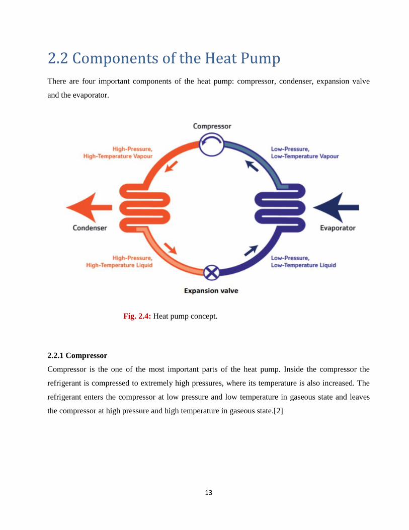
2.2 Components of the Heat Pump
There are four important components of the heat pump: compressor, condenser, expansion valve
and the evaporator.
2.2.1 Compressor
Compressor is the one of the most important parts of the heat pump. Inside the compressor the
refrigerant is compressed to extremely high pressures, where its temperature is also increased. The
refrigerant enters the compressor at low pressure and low temperature in gaseous state and leaves
the compressor at high pressure and high temperature in gaseous state.[2]
Fig. 2.4: Heat pump concept.
14
Types of compressors
There are two types of compressors: reciprocating compressors and rotary compressors. The
reciprocating compressors have piston and cylinder arrangement similar to the reciprocating engine.
While the reciprocating engine produces power by consuming fuel, the reciprocating compressor
produces compression by consuming power. In fact the compressor can also be driven directly by
the engine.
The reciprocating action of the piston inside the cylinder helps in compressing the refrigerant. The
rotary compressors have a rotor which rotates inside the closed chamber and compresses the
incoming refrigerant.[2]
2.2.2 Condenser
The next important part of the heat pump is condenser. The function of the heat pump is to heat the
room and it is the condenser that produces the heating effect inside the room. The main purpose of
the refrigerator is to cool the substance or materials and this effect is produced by the evaporator.
Thus, while the evaporator acts as the main component in refrigerators producing the cooling effect,
the condenser acts as the main component of the heat pump producing the heating effect. In the air
conditioner the condenser is placed outside the room which is to be cooled, but in the heat pump the
condenser is placed inside the room which is to be heated.
The refrigerant leaving the compressor is at very high pressure and high temperature. This
refrigerant then enters the condense which is usually made up of copper coil. Due to high
temperature of the refrigerant, the condenser coil also becomes very hot and it becomes the source
of heat which can be delivered inside the room.
There is a fan or the blower behind the condenser coil that absorbs the room air or atmospheric air
and blows it over the hot condenser coil. As the air is passed over the condenser coil, it gets heated
and the heated air flows to the room making the room hot. The air is absorbed continuously by the
fan and the hot air is thrown into the room keeping it at temperature much higher than the
atmospheric temperature. There are two types of fans that can be used with the condenser coil:
forced fan and induced fan.[2]
15
2.2.3 Expansion valve
The expansion valve is the pressure reducing device. When the high pressure and medium
temperature refrigerant enters the expansion valve, its pressure reduces suddenly and along with it
its temperature also becomes very low suddenly. The expansion valve most commonly used in the
heat pumps is copper capillary tube. The refrigerant leaves the expansion valve at extremely low
pressure and low temperature in partially liquid state and partially gaseous state.
2.2.4 Evaporator
While in the air conditioners the evaporator is located inside the room, in heat pumps the evaporator
is located outside the room and exposed to the atmosphere which is at very low temperature. Just
like condenser the evaporator is also made up of copper coil. The low pressure and low temperature
refrigerant enters the evaporator coil, due to this the temperature of the coil also reduces drastically
and it becomes even lower than the atmospheric temperature.
Since the temperature of the refrigerant inside the evaporator is less than the atmospheric
temperature, it tends to absorb the heat from the atmosphere. The fan or the blower blows
atmospheric air over the evaporator giving up the heat to the refrigerant and heating it. Since the
refrigerant absorbs the heat from atmospheric air, its temperature increases, while its pressure
remains constant and it get converted entirely into the gaseous state.[2]
16
2.3 Advantages and disadvantages of the heat
pump
Advantages of Heat Pumps:
Homeowners with a heat pump system may have more comfortable winters than others. While
many people experience dry skin because of a lack of relative humidity in their heated homes, those
with heat pumps may notice moister skin.
Heat pumps are clean, quiet and odorless. Heat pumps are safer than systems relying on
combustion. Heat pumps are powered by electricity and require no combustible materials.[7]
Disadvantages of Heat Pumps:
It is expensive to install a heat pump. Heat pumps have very high startup costs. While a heat pump
will probably save money in the long run. The installation costs may prevent many homeowners
from choosing one. Secondly, heat pumps have trouble operating in cold areas.
Prolonged exposure to subfreezing temperatures will damage the system and prevent it from
operating at full efficiency. Many homeowners find that the heat generated by a heat pump created
in their home during the winter months feel "cold." However, this problem can usually be fixed by
changing the air direction.[7]
17
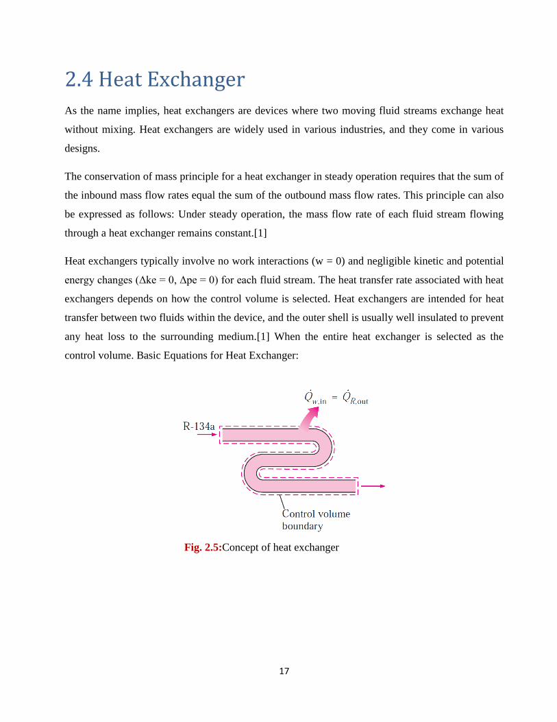
2.4 Heat Exchanger
As the name implies, heat exchangers are devices where two moving fluid streams exchange heat
without mixing. Heat exchangers are widely used in various industries, and they come in various
designs.
The conservation of mass principle for a heat exchanger in steady operation requires that the sum of
the inbound mass flow rates equal the sum of the outbound mass flow rates. This principle can also
be expressed as follows: Under steady operation, the mass flow rate of each fluid stream flowing
through a heat exchanger remains constant.[1]
Heat exchangers typically involve no work interactions (w = 0) and negligible kinetic and potential
energy changes (Δke = 0, Δpe = 0) for each fluid stream. The heat transfer rate associated with heat
exchangers depends on how the control volume is selected. Heat exchangers are intended for heat
transfer between two fluids within the device, and the outer shell is usually well insulated to prevent
any heat loss to the surrounding medium.[1] When the entire heat exchanger is selected as the
control volume. Basic Equations for Heat Exchanger:
Fig. 2.5:Concept of heat exchanger
18
2.5 Coefficient of performance
The coefficient of performance “ COP “ is a measure of the amount of power input to a system
compared to the amount of power output by that system:
(2.3)
The COP is therefore a measurement of efficiency; the higher the number, the more efficient the
system is. The COP is dimensionless because the input power and output power are measured in
Watt. The COP is also an instantaneous measurement in that the units are power which can be
measured at one point in time.
Consider a simple electric heater. All of the electricity that is input to the unit is converted to heat.
There is no waste and the power output (in heat) equals the power input (in electricity), so the COP
is one. The COP can be used to describe any system, not just heating and cooling.[12]
An air conditioning system uses power to move heat from one place to another place. When
cooling, the air conditioning system is moving heat from the space being cooled (usually a room), to
somewhere it is unwanted (usually outside). A heat pump uses the same principles, but it is moving
heat from outside (the cold side) to the space being heated inside (the living space).
The maximum theoretical COP for an air conditioning system is expressed by Carnot’s theorem,
reduced to the following equation:
(2.4)
Where TC is the cold temperature and TH is the hot temperature. For space cooling, the cold
temperature is inside the space; for space heating, the cold temperature is outside. All temperatures
19
are expressed in Kelvin. To convert from °C to Kelvin, add 273.15. To convert from °F to °C,
subtract 32, multiply by 5 and divide by 9.
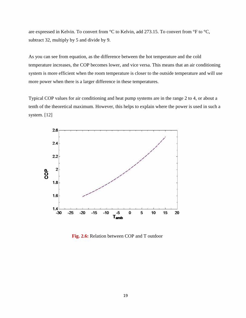
As you can see from equation, as the difference between the hot temperature and the cold
temperature increases, the COP becomes lower, and vice versa. This means that an air conditioning
system is more efficient when the room temperature is closer to the outside temperature and will use
more power when there is a larger difference in these temperatures.
Typical COP values for air conditioning and heat pump systems are in the range 2 to 4, or about a
tenth of the theoretical maximum. However, this helps to explain where the power is used in such a
system. [12]
Fig. 2.6: Relation between COP and T outdoor
20
Chapter Three
Solar air heat collector
3.1 Solar heating systems in Palestine
3.2 Heat transfer fundamentals
3.3 Thermal radiant properties
3.4 Heat collection rate
3.5 Solar radiation and heat collection
3.6 Wind speed and heat collection
3.7 Incident angle and heat collection
3.8 Inlet temperature and heat collection
21
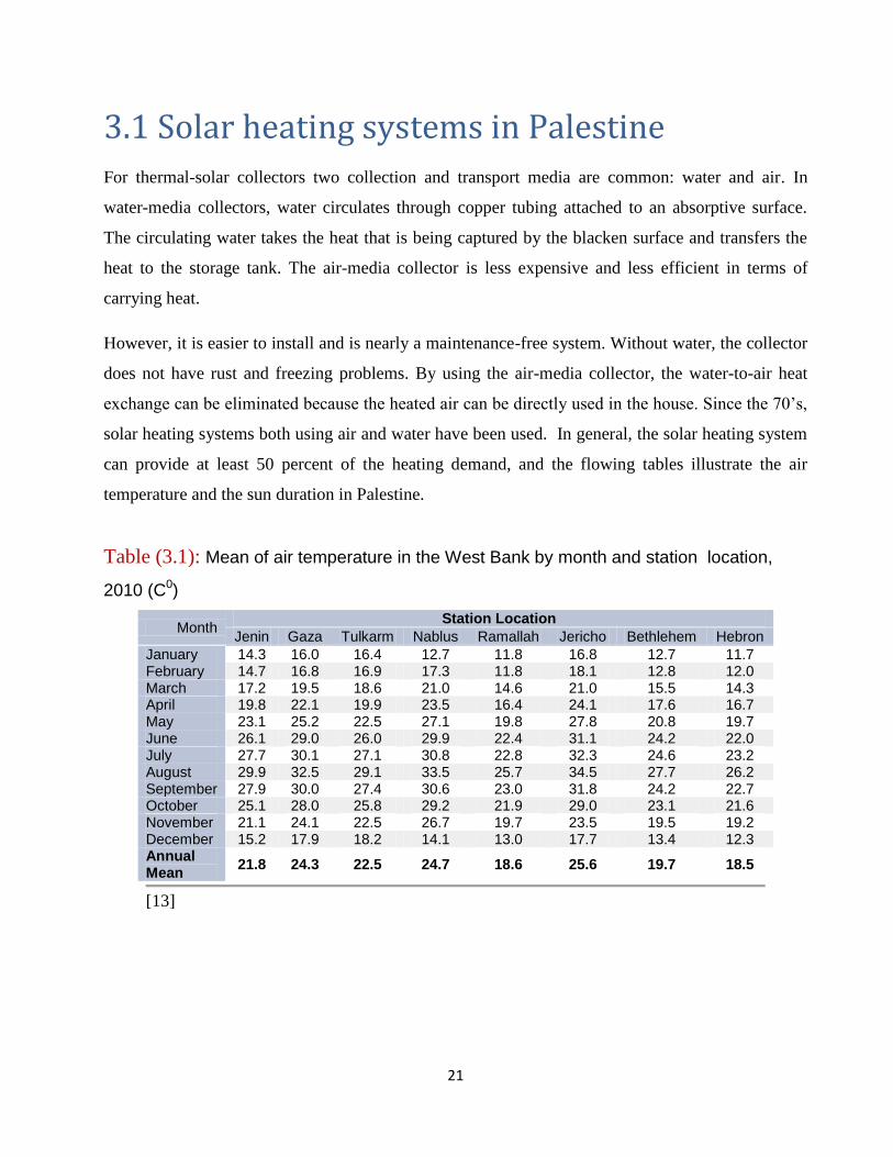
3.1 Solar heating systems in Palestine
For thermal-solar collectors two collection and transport media are common: water and air. In
water-media collectors, water circulates through copper tubing attached to an absorptive surface.
The circulating water takes the heat that is being captured by the blacken surface and transfers the
heat to the storage tank. The air-media collector is less expensive and less efficient in terms of
carrying heat.
However, it is easier to install and is nearly a maintenance-free system. Without water, the collector
does not have rust and freezing problems. By using the air-media collector, the water-to-air heat
exchange can be eliminated because the heated air can be directly used in the house. Since the 70’s,
solar heating systems both using air and water have been used. In general, the solar heating system
can provide at least 50 percent of the heating demand, and the flowing tables illustrate the air
temperature and the sun duration in Palestine.
Table (3.1): Mean of air temperature in the West Bank by month and station location,
2010 (C0)
Month Station Location
Jenin Gaza Tulkarm Nablus Ramallah Jericho Bethlehem Hebron January 14.3 16.0 16.4 12.7 11.8 16.8 12.7 11.7 February 14.7 16.8 16.9 17.3 11.8 18.1 12.8 12.0 March 17.2 19.5 18.6 21.0 14.6 21.0 15.5 14.3 April 19.8 22.1 19.9 23.5 16.4 24.1 17.6 16.7 May 23.1 25.2 22.5 27.1 19.8 27.8 20.8 19.7 June 26.1 29.0 26.0 29.9 22.4 31.1 24.2 22.0 July 27.7 30.1 27.1 30.8 22.8 32.3 24.6 23.2 August 29.9 32.5 29.1 33.5 25.7 34.5 27.7 26.2 September 27.9 30.0 27.4 30.6 23.0 31.8 24.2 22.7 October 25.1 28.0 25.8 29.2 21.9 29.0 23.1 21.6 November 21.1 24.1 22.5 26.7 19.7 23.5 19.5 19.2 December 15.2 17.9 18.2 14.1 13.0 17.7 13.4 12.3 Annual Mean
21.8 24.3 22.5 24.7 18.6 25.6 19.7 18.5
[13]
22
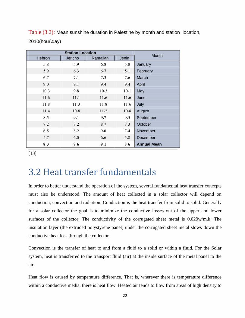
Table (3.2): Mean sunshine duration in Palestine by month and station location,
2010(hour\day)
3.2 Heat transfer fundamentals
In order to better understand the operation of the system, several fundamental heat transfer concepts
must also be understood. The amount of heat collected in a solar collector will depend on
conduction, convection and radiation. Conduction is the heat transfer from solid to solid. Generally
for a solar collector the goal is to minimize the conductive losses out of the upper and lower
surfaces of the collector. The conductivity of the corrugated sheet metal is 0.029w/m.k. The
insulation layer (the extruded polystyrene panel) under the corrugated sheet metal slows down the
conductive heat loss through the collector.
Convection is the transfer of heat to and from a fluid to a solid or within a fluid. For the Solar
system, heat is transferred to the transport fluid (air) at the inside surface of the metal panel to the
air.
Heat flow is caused by temperature difference. That is, wherever there is temperature difference
within a conductive media, there is heat flow. Heated air tends to flow from areas of high density to
Station Location Month
Hebron Jericho Ramallah Jenin
5.8 5.9 6.8 5.8 January
5.9 6.3 6.7 5.1 February
6.7 7.1 7.3 7.6 March
9.0 9.1 9.4 9.4 April
10.3 9.8 10.3 10.1 May
11.6 11.1 11.6 11.6 June
11.8 11.3 11.8 11.6 July
11.4 10.8 11.2 10.8 August
8.5 9.1 9.7 9.5 September
2.7 8.2 8.7 8.3 October
6.5 8.2 9.0 7.4 November
4.7 6.0 6.6 5.8 December
8.3 8.6 9.1 8.6 Annual Mean
[13]
23
areas of low density, high temperature. With a fan installed as a pressure driving force, the outdoor
air at the inlet of the collector .Then the heated air is either sent to the heat exchanger to preheat the
hot water or sent vertically down under the raised floor for occupancy heating. For the purpose of
capturing solar radiation, the corrugated sheet metal is painted with black acrylic latex paint, with
emissivity value ranges from 0.84 to 0.90 and absorption rate ranges from 0.92 to 0.97.
3.3 Thermal radiant properties
Thermal radiation happens whenever there is temperature difference between two regions in view
of each other. The transfer of heat in this way does not depend on any intermediate material. In the
Solar Collector, the heated corrugated sheet metal will radiate its heat to its surroundings, including
the air cavity above it.
Emissivity is a property of the surface characterizing how effectively the surface radiates when
compared to a "blackbody". It is the ratio of the emission of thermal radiant flux from the surface to
the flux that would be emitted by a blackbody at the same temperature. The value is always between
0 and 1.
The blackbody is an ideal surface that emits the maximum possible thermal radiation at a given
temperature. Solar radiation incident on a glazing system is partly transmitted and partly reflected,
and partly absorbed by the system.
Reflectance is the fraction of the reflected part of the incident flux. It means that the less the amount
of solar radiation is reflected, the more the amount of solar radiation is being absorbed or
transmitted by the surface. Absorptance is the ratio between the amount of radiation absorbed by a
surface to the total incident flux on the surface. In the case of Solar Collector, the less reflectance
the corrugated sheet metal has, the better.
After the solar radiation strikes an opaque surface, which in this case is the corrugated sheet metal ,
some radiation is reflected off the surface. The amount of reflection is determined by both the
incident angle and the reflectance of the surface. Assuming little absorption happens in the air, the
rest of the incident solar radiation is absorbed by the surface. How much of the heat being absorbed
by the surface depends on the absorptance of the surface. In this case, high absorptance and low
24
reflectance will make the system reach its optimal performance. The heat being absorbed will be
stored and conducted through surface materials. When the temperature of the surface material is
higher than its surroundings, it will emit heat to the surroundings.
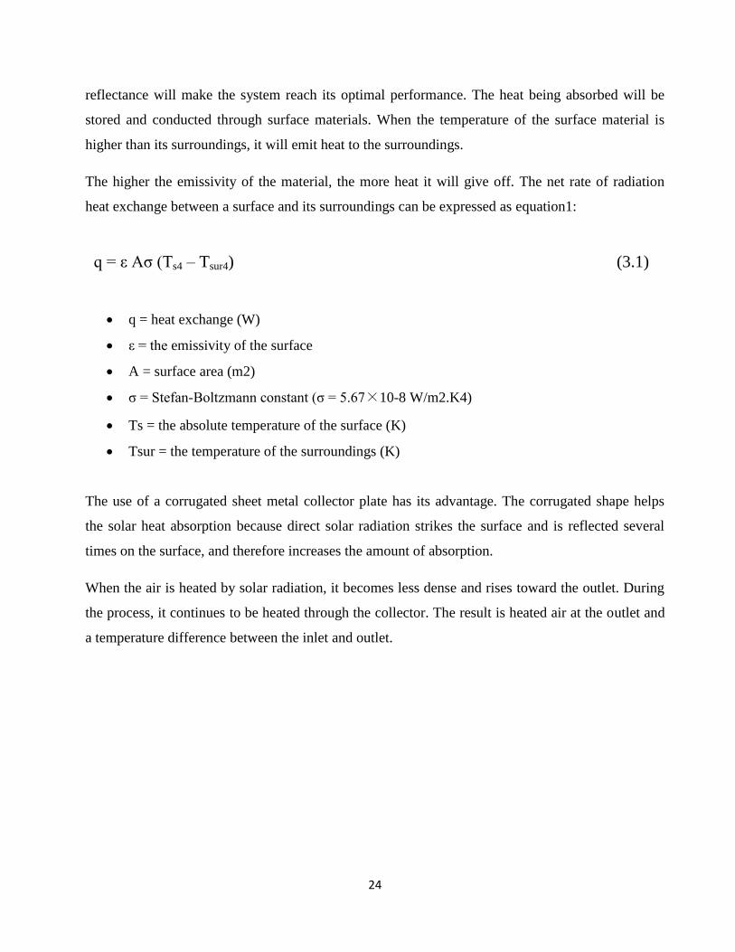
The higher the emissivity of the material, the more heat it will give off. The net rate of radiation
heat exchange between a surface and its surroundings can be expressed as equation1:
q = ε Aσ (Ts4 – Tsur4) (3.1)
q = heat exchange (W)
ε = the emissivity of the surface
A = surface area (m2)
σ = Stefan-Boltzmann constant (σ = 5.67×10⁻⁸ W/m2.K4)
Ts = the absolute temperature of the surface (K)
Tsur = the temperature of the surroundings (K)
The use of a corrugated sheet metal collector plate has its advantage. The corrugated shape helps
the solar heat absorption because direct solar radiation strikes the surface and is reflected several
times on the surface, and therefore increases the amount of absorption.
When the air is heated by solar radiation, it becomes less dense and rises toward the outlet. During
the process, it continues to be heated through the collector. The result is heated air at the outlet and
a temperature difference between the inlet and outlet.
25
3.4 Heat collection rate
To determine the amount of heat collected within the system, two variables must be known:
1) The temperature difference between the inlet and outlet
2) The air flow rate through the collector
When these are known, the energy collected can be calculated according to the sensible heat gain is
calculated as following:
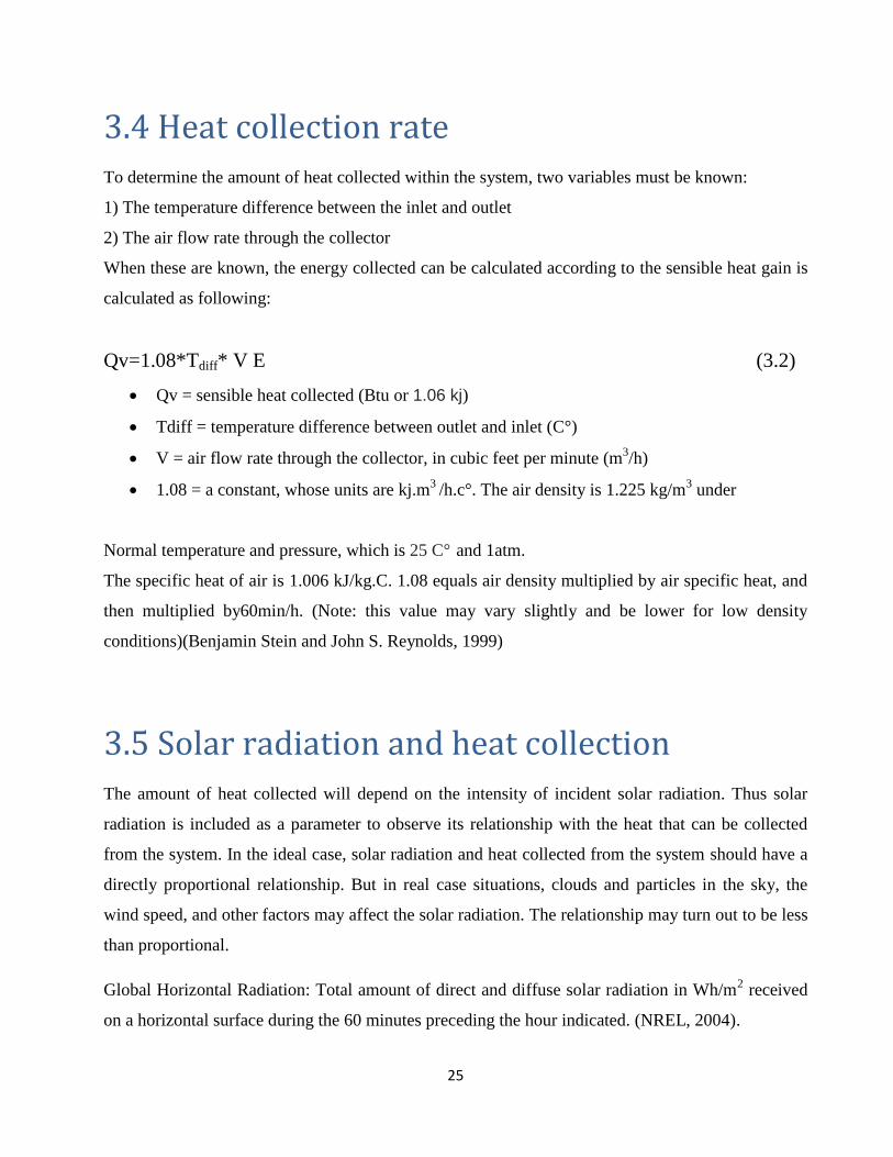
Qv=1.08*Tdiff* V E (3.2)
Qv = sensible heat collected (Btu or 1.06 kj)
Tdiff = temperature difference between outlet and inlet (C°)
V = air flow rate through the collector, in cubic feet per minute (m3/h)
1.08 = a constant, whose units are kj.m3
/h.c°. The air density is 1.225 kg/m3 under
Normal temperature and pressure, which is 25 C° and 1atm.
The specific heat of air is 1.006 kJ/kg.C. 1.08 equals air density multiplied by air specific heat, and
then multiplied by60min/h. (Note: this value may vary slightly and be lower for low density
conditions)(Benjamin Stein and John S. Reynolds, 1999)
3.5 Solar radiation and heat collection
The amount of heat collected will depend on the intensity of incident solar radiation. Thus solar
radiation is included as a parameter to observe its relationship with the heat that can be collected
from the system. In the ideal case, solar radiation and heat collected from the system should have a
directly proportional relationship. But in real case situations, clouds and particles in the sky, the
wind speed, and other factors may affect the solar radiation. The relationship may turn out to be less
than proportional.
Global Horizontal Radiation: Total amount of direct and diffuse solar radiation in Wh/m2 received
on a horizontal surface during the 60 minutes preceding the hour indicated. (NREL, 2004).
26
The solar energy flux is composed of two parts: that due to incident beam radiation (b) and that due
to incident diffuse radiation (d). The diffuse radiation includes both diffuse sky radiation and
radiation reflected from the ground. Their relationship can be expressed by Equation3:
Qs= Qb+Qd (3.3)
Qs= Total amount of solar energy flux, Wh/m2
Qb= Incident beam radiation, Wh/m2
Qd= Incident diffuse radiation, Wh/m2
(ASHREA, 1999)
3.6 Wind speed and heat collection
Wind speed will affect both the airflow rate through the collection cavity and the collector’
exteriors surface heat loss by convection. Under conditions of high solar radiation and low ambient
temperature, high wind speeds will adversely affect the performance of the solar collector. Wind
can increase the airflow rate over the corrugated sheet metal roofing therefore accelerating the
convective heat loss of the collector’s exterior surface. The more convective heat loss on the sheet
metal surface, the more convective heat loss happens from the warmed air to the underside surface
of the sheet metal. At the same time, high wind speeds can change the airflow value in
Equation2,and compromise the assumption of constant heat flow. It contributes to the overall error
of the heat collecting prediction.
27
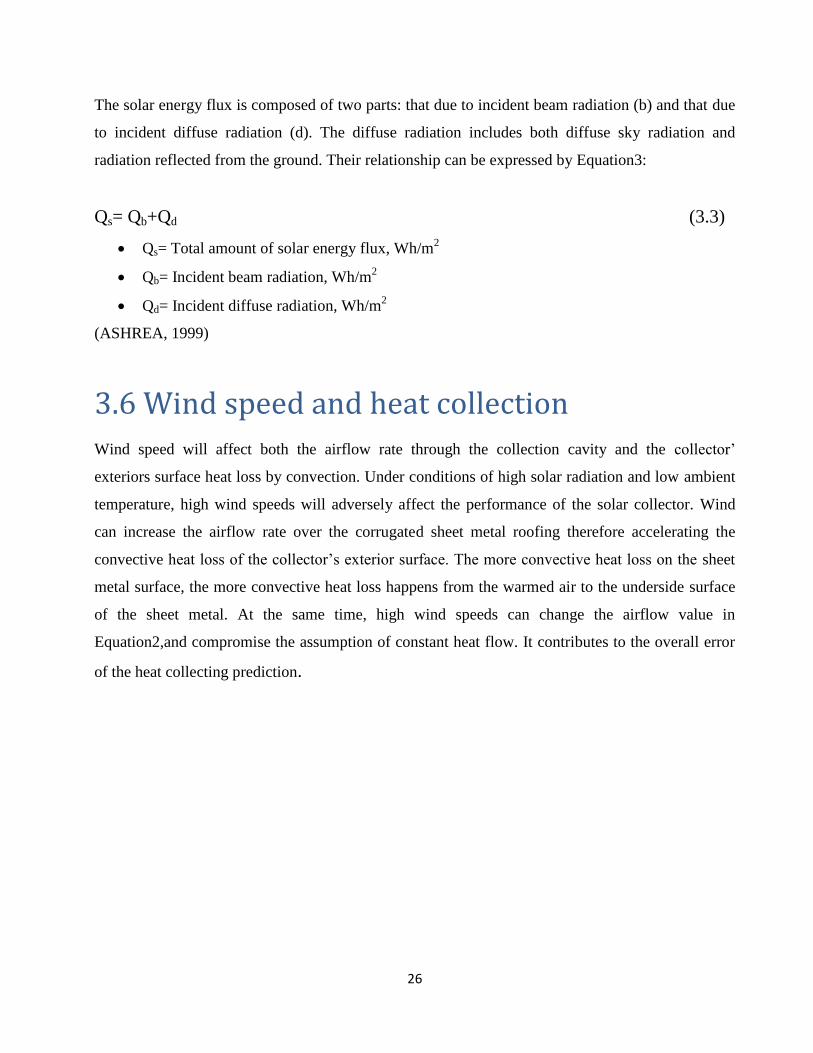
3.7 Incident angle and heat collection
Part of the solar radiation incident on a solar collector surface is absorbed by the surface and part is
reflected. For many materials, glass in particular, the proportion of the amount being reflected and
being absorbed depends on the angle of incidence between the surface and the sun. The incident
angle is defined as the angle between the incoming solar rays and a line normal to that surface.
When the incident angle is 0 degree, the solar radiation absorption is maximal.
When the incident angle value increases, the amount of reflection is greater accordingly and the
absorption is gradually reduced. For typical clear glass, for incident angles over 60 degrees, the
absorption rate drops while the reflectance rises dramatically. Figure shows the relationship
between the incident angle and the reflection and the absorption forc a typical transparent surface.
Fig. 3.1:Relationship between the incident angle and the reflection and the absorption for a
typical transparent surface.
28
3.8 Inlet temperature and heat collection
The inlet temperature is the temperature of the air entering the collector. The relationship between
the inlet temperature and the heat collection is twofold: in a certain range, when the inlet
temperature rises, it is possible that the outlet temperature may not rise at the same rate. The reform,
the temperature difference (Tdiff) between the inlet and the outlet may actually go down. The heat
collected at the outlet can be reduced because of the lower Tdiff value. From observation, this
situation happens normally in the morning when the ambient temperature begins to rise. The solar
angle is still low and thus a large proportion of the solar radiation is reflected off the surface, while
the ambient temperature is heated by the sun faster than the air flowing through the cavity of the
collector.
29
Chapter Four
System components
4.1 Centrifugal fan
4.2 Thermistor
4.3 Flexible air ducts
4.4 Solar air heat collectors
4.5 Stepper motor
4.6 Display screen (20*40 LCD Display)
30
Through the full and accurate study for the project, the best performance for the system
embodying in the selection of the following components:
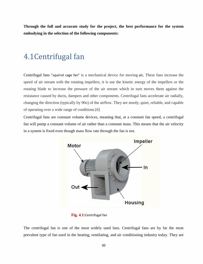
4.1Centrifugal fan
Centrifugal fans ”squirrel cage fan” is a mechanical device for moving air, These fans increase the
speed of air stream with the rotating impellers, it is use the kinetic energy of the impellers or the
rotating blade to increase the pressure of the air stream which in turn moves them against the
resistance caused by ducts, dampers and other components. Centrifugal fans accelerate air radially,
changing the direction (typically by 90o) of the airflow. They are sturdy, quiet, reliable, and capable
of operating over a wide range of conditions.[6]
Centrifugal fans are constant volume devices, meaning that, at a constant fan speed, a centrifugal
fan will pump a constant volume of air rather than a constant mass. This means that the air velocity
in a system is fixed even though mass flow rate through the fan is not.
The centrifugal fan is one of the most widely used fans. Centrifugal fans are by far the most
prevalent type of fan used in the heating, ventilating, and air conditioning industry today. They are
Fig. 4.1:Centrifugal fan
31
usually cheaper than axial fans and simpler in construction. It is used in transporting gas or
materials and in ventilation system for buildings. They are also used commonly in central
heating/cooling systems.
It has a fan wheel composed of a number of fan blades, or ribs, mounted around a hub. As shown in
Figure 1, the hub turns on a driveshaft that passes through the fan housing. The gas enters from the
side of the fan wheel, turns 90 degrees and accelerates due to centrifugal force as it flows over the
fan blades and exits the fan housing
The fan wheel can be linked directly to the shaft of an electric motor. This means that the fan wheel
speed is identical to the motor's rotational speed. With this type of fan drive mechanism, the fan
speed cannot be varied unless the motor speed is adjustable. Air conditioning will then
automatically provide faster speed because colder air is more dense.[6]
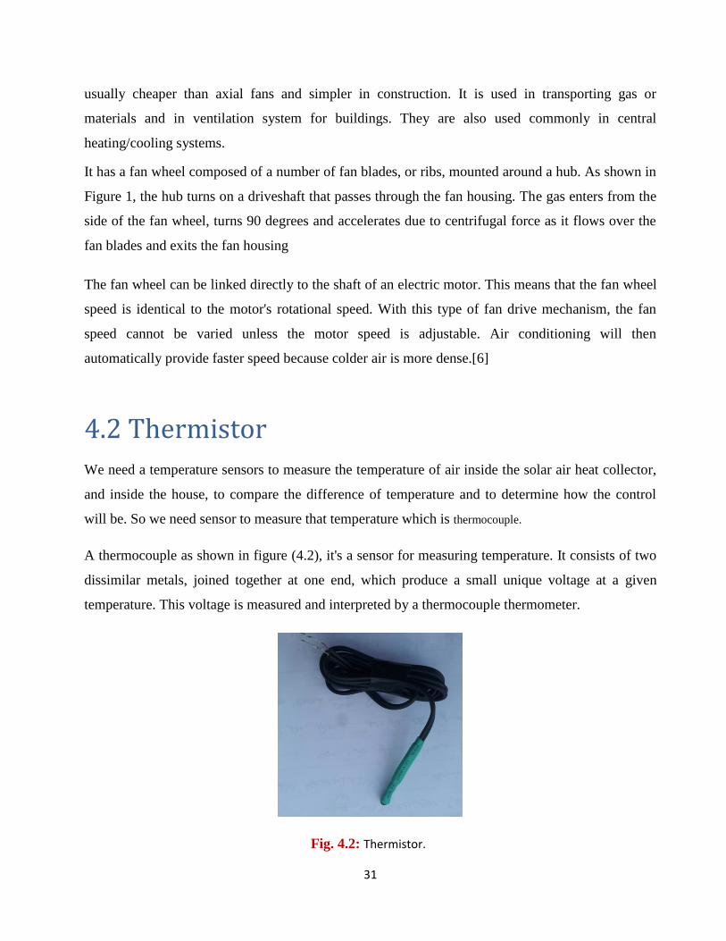
4.2 Thermistor
We need a temperature sensors to measure the temperature of air inside the solar air heat collector,
and inside the house, to compare the difference of temperature and to determine how the control
will be. So we need sensor to measure that temperature which is thermocouple.
A thermocouple as shown in figure (4.2), it's a sensor for measuring temperature. It consists of two
dissimilar metals, joined together at one end, which produce a small unique voltage at a given
temperature. This voltage is measured and interpreted by a thermocouple thermometer.
Fig. 4.2: Thermistor.
32
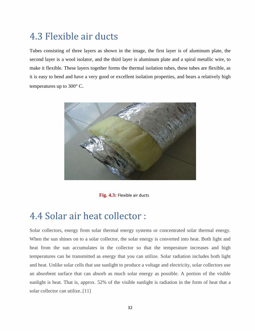
4.3 Flexible air ducts
Tubes consisting of three layers as shown in the image, the first layer is of aluminum plate, the
second layer is a wool isolator, and the third layer is aluminum plate and a spiral metallic wire, to
make it flexible. These layers together forms the thermal isolation tubes, these tubes are flexible, as
it is easy to bend and have a very good or excellent isolation properties, and bears a relatively high
temperatures up to 300° C.
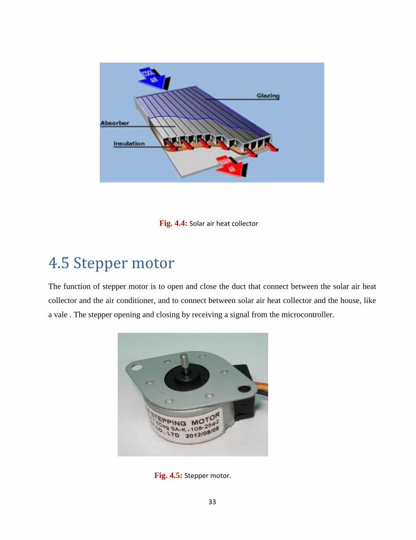
4.4 Solar air heat collector :
Solar collectors, energy from solar thermal energy systems or concentrated solar thermal energy.
When the sun shines on to a solar collector, the solar energy is converted into heat. Both light and
heat from the sun accumulates in the collector so that the temperature increases and high
temperatures can be transmitted as energy that you can utilize. Solar radiation includes both light
and heat. Unlike solar cells that use sunlight to produce a voltage and electricity, solar collectors use
an absorbent surface that can absorb as much solar energy as possible. A portion of the visible
sunlight is heat. That is, approx. 52% of the visible sunlight is radiation in the form of heat that a
solar collector can utilize..[11]
Fig. 4.3: Flexible air ducts
33
4.5 Stepper motor
The function of stepper motor is to open and close the duct that connect between the solar air heat
collector and the air conditioner, and to connect between solar air heat collector and the house, like
a vale . The stepper opening and closing by receiving a signal from the microcontroller.
Fig. 4.4: Solar air heat collector
Fig. 4.5: Stepper motor.
34
4.6 Display screen (02x4 LCD Display)
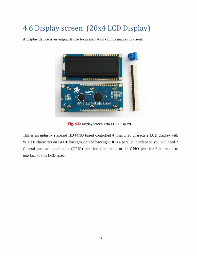
A display device is an output device for presentation of information in visual.
This is an industry standard HD44780 based controlled 4 lines x 02 characters LCD display with
WHITE characters on BLUE background and backlight. It is a parallel interface so you will need 7
General-purpose input/output (GPIO) pins for 4-bit mode or 11 GPIO pins for 8-bit mode to
interface to this LCD screen.
Fig. 4.6: Display screen (02x4 LCD Display).
35
Chapter Five
Control system
5.1 Introduction
5.2 Control system
5.2.1 Introduction to control system
5.2.2 Microcontroller
5.2.3 Block diagram of the system
5.2.4 Temperature sensors
5.2.5 Stepper motor
5.2.6 16x4 LCD Display
5.2.7 Centrifugal fan
5.2.8 Software Design
5.2.9 Pin mapping
5.2.10 Microcontroller program
5.2.11 Design of Electronic Circuits
5.3 Connect and disconnect the systems
36
5.1 Introduction
To get the best performance for the system, we must determine all the possibilities that the system
may pass through. There must be a smart and modern mechatronic control system, to give the best
performance with the least possible energy consumption, and giving the best integration between
the solar system and the heat pump system or the air conditioner. A microcontroller system “ (PIC
18F4550) as shown in fig ” will be used, that is because of its:
Low power consumption
Cheap costs of control
Easy to program
Rapid response.
Making comparison between the outdoor temperature and the air exiting through the solar air heat
collector, when comparing the difference between the two temperatures, and when the difference is
very low, it disconnects the air collector from the evaporator of the air conditioner, and make the
conditioner takes the heat from the outdoor directly without passing through the solar air collector,
because the energy that is required to run the system will be more than the energy that produced by
the solar air heat collector, in night or in cloudy weather.
In summer days, the control system will take a signal from the conditioner, and read it’s operation
mode, so, if the conditioner is running in the heating mode, the solar air heat collector system will
run, whereas if the conditioner is running in the cooling mode, the control system will disconnects
the solar air heat collector system from the conditioner.
In this project, there will be no change to any part of the heat pump parts, or any of its proprieties,
but the solar air heat collector system will accompany the air conditioner system.
The operation mode possibilities of the overall system “heat pump and solar collector systems” are
shown in the flowchart:
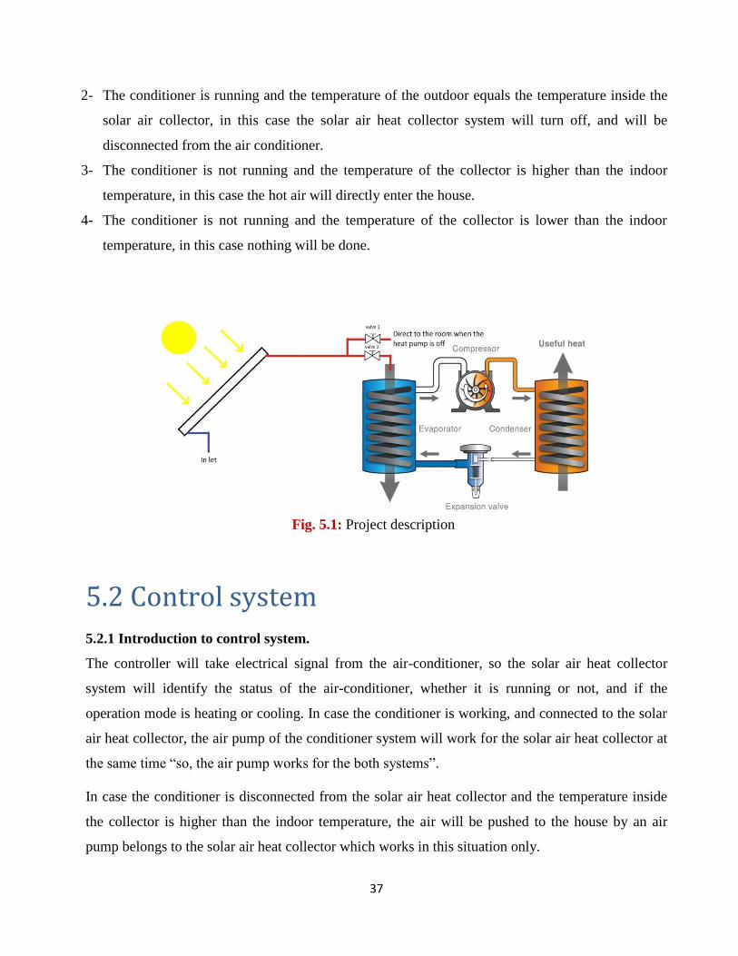
1- The conditioner is running and the temperature of the collector is higher than the outdoor
temperature, in this case the hot air will be pushed to the evaporator of the heat pump.
37
2- The conditioner is running and the temperature of the outdoor equals the temperature inside the
solar air collector, in this case the solar air heat collector system will turn off, and will be
disconnected from the air conditioner.
3- The conditioner is not running and the temperature of the collector is higher than the indoor
temperature, in this case the hot air will directly enter the house.
4- The conditioner is not running and the temperature of the collector is lower than the indoor
temperature, in this case nothing will be done.
5.2 Control system
5.2.1 Introduction to control system.
The controller will take electrical signal from the air-conditioner, so the solar air heat collector
system will identify the status of the air-conditioner, whether it is running or not, and if the
operation mode is heating or cooling. In case the conditioner is working, and connected to the solar
air heat collector, the air pump of the conditioner system will work for the solar air heat collector at
the same time “so, the air pump works for the both systems”.
In case the conditioner is disconnected from the solar air heat collector and the temperature inside
the collector is higher than the indoor temperature, the air will be pushed to the house by an air
pump belongs to the solar air heat collector which works in this situation only.
Fig. 5.1: Project description
38
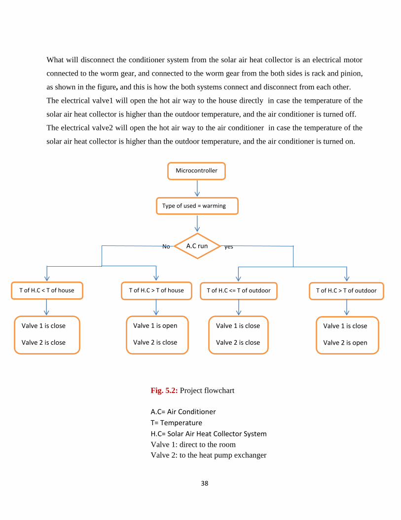
What will disconnect the conditioner system from the solar air heat collector is an electrical motor
connected to the worm gear, and connected to the worm gear from the both sides is rack and pinion,
as shown in the figure, and this is how the both systems connect and disconnect from each other.
The electrical valve1 will open the hot air way to the house directly in case the temperature of the
solar air heat collector is higher than the outdoor temperature, and the air conditioner is turned off.
The electrical valve2 will open the hot air way to the air conditioner in case the temperature of the
solar air heat collector is higher than the outdoor temperature, and the air conditioner is turned on.
No yes
Microcontroller
Type of used = warming
T of H.C < T of house
T of H.C > T of house
T of H.C <= T of outdoor
T of H.C > T of outdoor
Valve 1 is close
Valve 2 is close
Valve 1 is close
Valve 2 is open
Valve 1 is open
Valve 2 is close
Valve 1 is close
Valve 2 is close
A.C run
Fig. 5.2: Project flowchart
A.C= Air Conditioner
T= Temperature
H.C= Solar Air Heat Collector System
Valve 1: direct to the room
Valve 2: to the heat pump exchanger
39
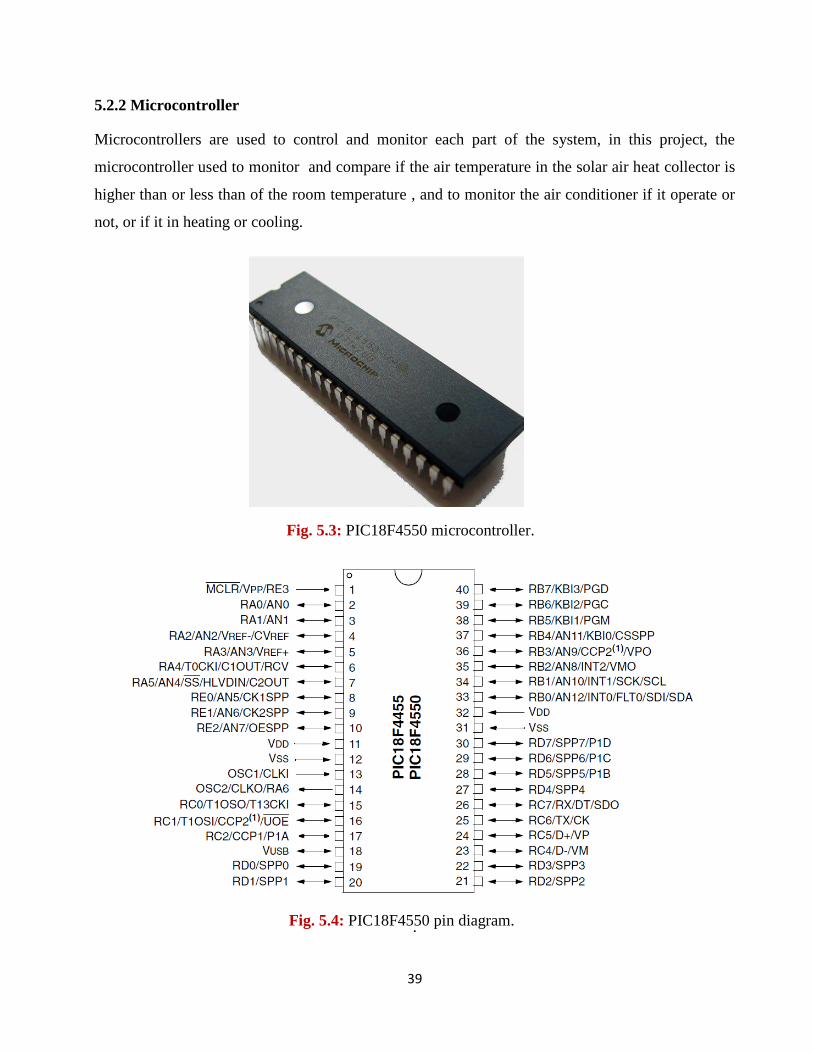
5.2.2 Microcontroller
Microcontrollers are used to control and monitor each part of the system, in this project, the
microcontroller used to monitor and compare if the air temperature in the solar air heat collector is
higher than or less than of the room temperature , and to monitor the air conditioner if it operate or
not, or if it in heating or cooling.
.
Fig. 5.3: PIC18F4550 microcontroller.
Fig. 5.4: PIC18F4550 pin diagram.
40
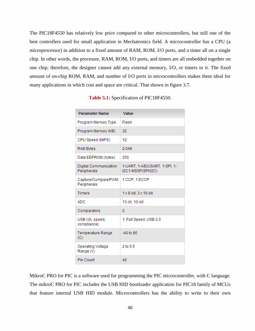
The PIC18F4550 has relatively low price compared to other microcontrollers, but still one of the
best controllers used for small application in Mechatronics field. A microcontroller has a CPU (a
microprocessor) in addition to a fixed amount of RAM, ROM, I/O ports, and a timer all on a single
chip. In other words, the processor, RAM, ROM, I/O ports, and timers are all embedded together on
one chip; therefore, the designer cannot add any external memory, I/O, or timers to it. The fixed
amount of on-chip ROM, RAM, and number of I/O ports in microcontrollers makes them ideal for
many applications in which cost and space are critical. That shown in figure 3.7.
Table 5.1: Specification of PIC18F4550.
MikroC PRO for PIC is a software used for programming the PIC microcontroller, with C language.
The mikroC PRO for PIC includes the USB HID bootloader application for PIC18 family of MCUs
that feature internal USB HID module. Microcontrollers has the ability to write to their own
41
program memory. This feature allows a small bootloader program to receive and write new
firmware into memory. In its most simple form, the bootloader starts the user code running, unless
it finds that new firmware should be downloaded. If there is new firmware to be downloaded, it gets
the data and writes it into program memory.
Fig 5.5: MikroC PRO for PIC.
5.2.3 Block diagram of the system.
As mentioned in the block diagram in figure 5.4, the user will have the ability to monitor the
temperature in the solar air heat collector in outdoor and indoor directly by the display screen, this
system is an embedded system, where the controller control the system without human intervention.
Fig. 5.6: Block diagram of the system.
42
The controller must give signals to activate the stepper motor and centrifugal fan. The controller
will receive signals from the temperature sensors.
5.2.4 Temperature sensors.
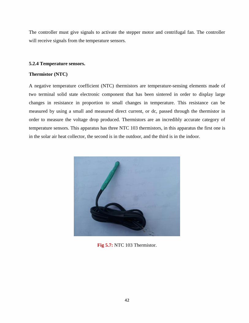
Thermistor (NTC)
A negative temperature coefficient (NTC) thermistors are temperature-sensing elements made of
two terminal solid state electronic component that has been sintered in order to display large
changes in resistance in proportion to small changes in temperature. This resistance can be
measured by using a small and measured direct current, or dc, passed through the thermistor in
order to measure the voltage drop produced. Thermistors are an incredibly accurate category of
temperature sensors. This apparatus has three NTC 103 thermistors, in this apparatus the first one is
in the solar air heat collector, the second is in the outdoor, and the third is in the indoor.
Fig 5.7: NTC 103 Thermistor.
43
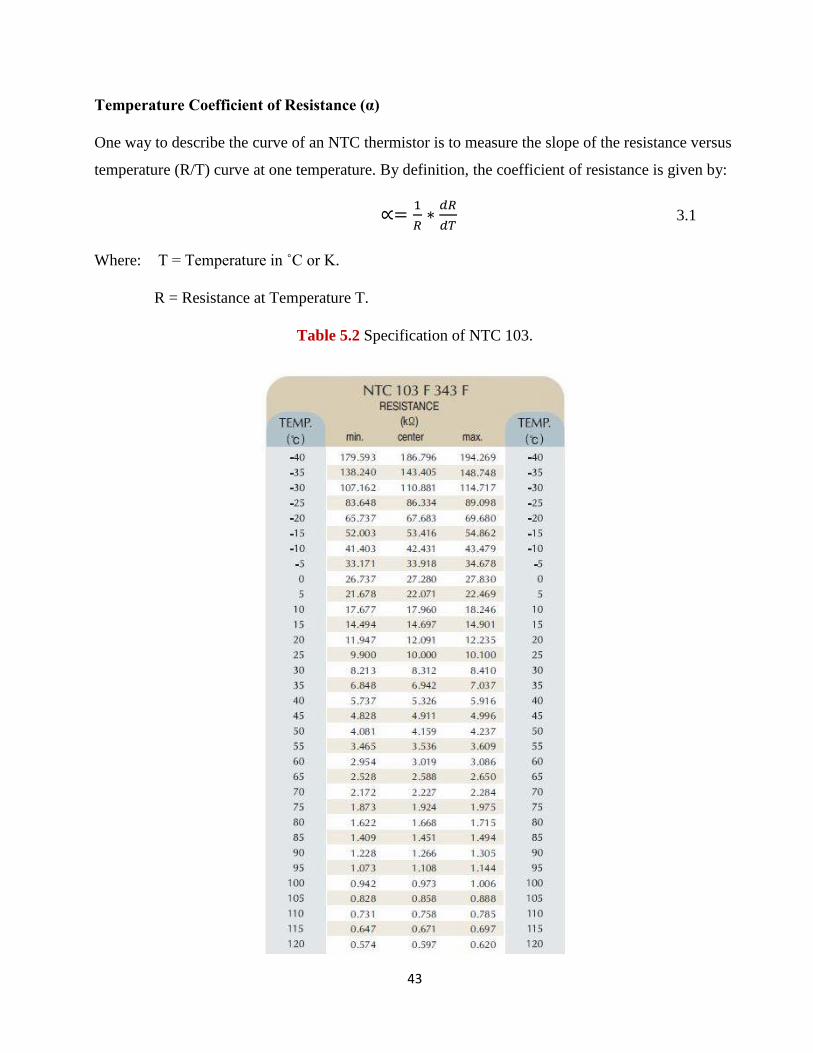
Temperature Coefficient of Resistance (α)
One way to describe the curve of an NTC thermistor is to measure the slope of the resistance versus
temperature (R/T) curve at one temperature. By definition, the coefficient of resistance is given by:
3.1
Where: T = Temperature in ˚C or K.
R = Resistance at Temperature T.
Table 5.2 Specification of NTC 103.
44
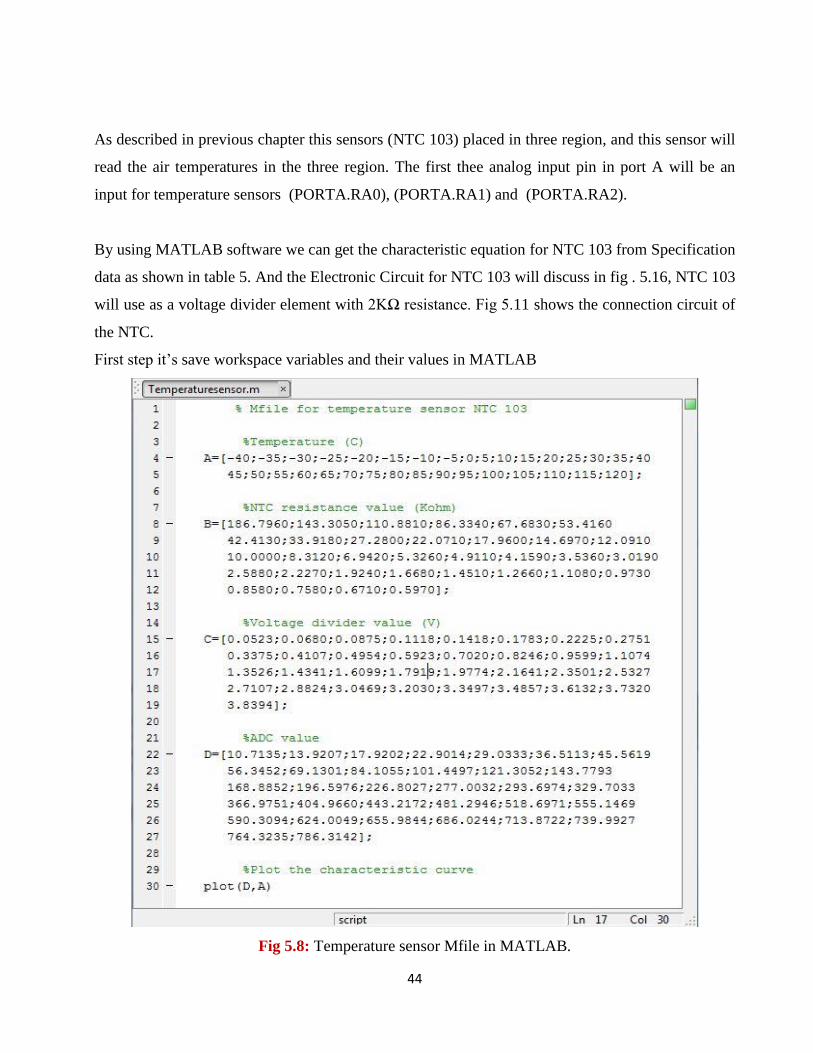
As described in previous chapter this sensors (NTC 103) placed in three region, and this sensor will
read the air temperatures in the three region. The first thee analog input pin in port A will be an
input for temperature sensors (PORTA.RA0), (PORTA.RA1) and (PORTA.RA2).
By using MATLAB software we can get the characteristic equation for NTC 103 from Specification
data as shown in table 5. And the Electronic Circuit for NTC 103 will discuss in fig . 5.16, NTC 103
will use as a voltage divider element with 2KΩ resistance. Fig 5.11 shows the connection circuit of
the NTC.
First step it’s save workspace variables and their values in MATLAB
Fig 5.8: Temperature sensor Mfile in MATLAB.
45
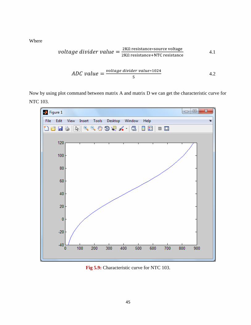
Where
4.1
4.2
Now by using plot command between matrix A and matrix D we can get the characteristic curve for
NTC 103.
Fig 5.9: Characteristic curve for NTC 103.
46
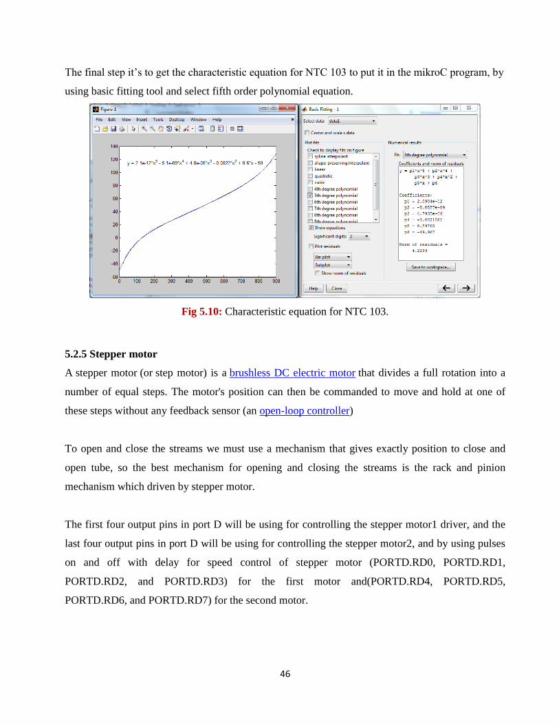
The final step it’s to get the characteristic equation for NTC 103 to put it in the mikroC program, by
using basic fitting tool and select fifth order polynomial equation.
Fig 5.10: Characteristic equation for NTC 103.
5.2.5 Stepper motor
A stepper motor (or step motor) is a brushless DC electric motor that divides a full rotation into a
number of equal steps. The motor's position can then be commanded to move and hold at one of
these steps without any feedback sensor (an open-loop controller)
To open and close the streams we must use a mechanism that gives exactly position to close and
open tube, so the best mechanism for opening and closing the streams is the rack and pinion
mechanism which driven by stepper motor.
The first four output pins in port D will be using for controlling the stepper motor1 driver, and the
last four output pins in port D will be using for controlling the stepper motor2, and by using pulses
on and off with delay for speed control of stepper motor (PORTD.RD0, PORTD.RD1,
PORTD.RD2, and PORTD.RD3) for the first motor and(PORTD.RD4, PORTD.RD5,
PORTD.RD6, and PORTD.RD7) for the second motor.
47
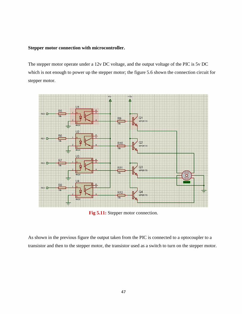
Stepper motor connection with microcontroller.
The stepper motor operate under a 12v DC voltage, and the output voltage of the PIC is 5v DC
which is not enough to power up the stepper motor; the figure 5.6 shown the connection circuit for
stepper motor.
Fig 5.11: Stepper motor connection.
As shown in the previous figure the output taken from the PIC is connected to a optocoupler to a
transistor and then to the stepper motor, the transistor used as a switch to turn on the stepper motor.
48
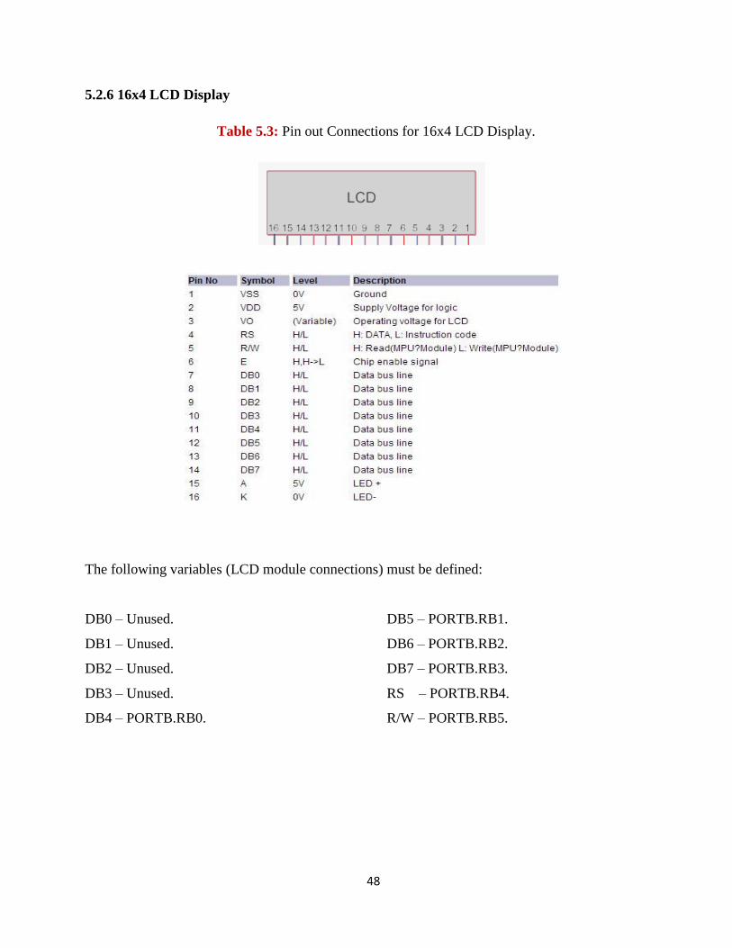
5.2.6 16x4 LCD Display
Table 5.3: Pin out Connections for 16x4 LCD Display.
The following variables (LCD module connections) must be defined:
DB0 – Unused. DB5 – PORTB.RB1.
DB1 – Unused. DB6 – PORTB.RB2.
DB2 – Unused. DB7 – PORTB.RB3.
DB3 – Unused. RS – PORTB.RB4.
DB4 – PORTB.RB0. R/W – PORTB.RB5.
49
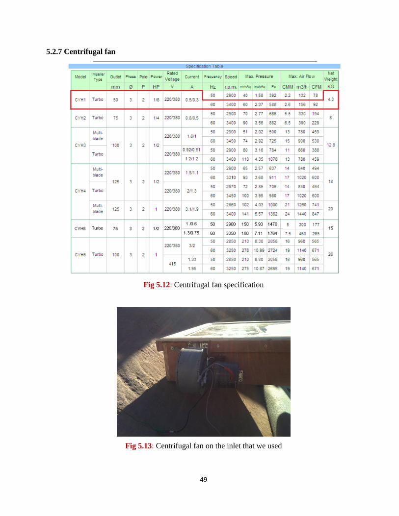
5.2.7 Centrifugal fan
Fig 5.12: Centrifugal fan specification
Fig 5.13: Centrifugal fan on the inlet that we used
50
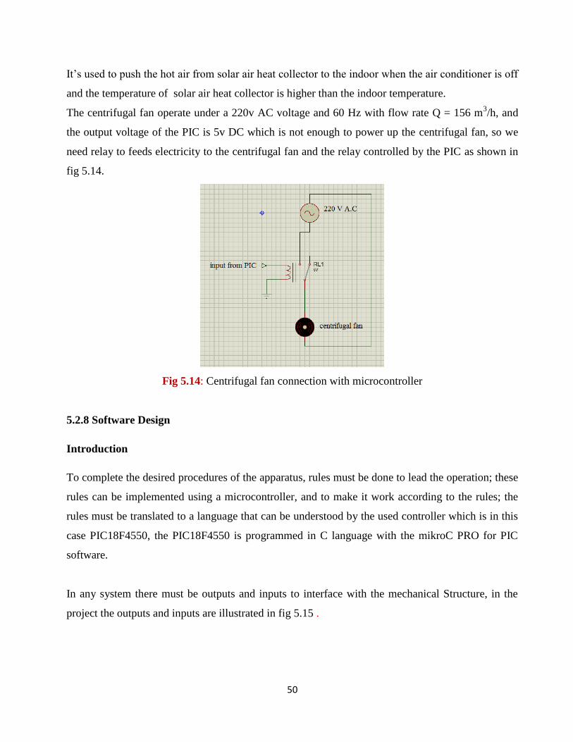
It’s used to push the hot air from solar air heat collector to the indoor when the air conditioner is off
and the temperature of solar air heat collector is higher than the indoor temperature.
The centrifugal fan operate under a 220v AC voltage and 60 Hz with flow rate Q = 156 m3/h, and
the output voltage of the PIC is 5v DC which is not enough to power up the centrifugal fan, so we
need relay to feeds electricity to the centrifugal fan and the relay controlled by the PIC as shown in
fig 5.14.
Fig 5.14: Centrifugal fan connection with microcontroller
5.2.8 Software Design
Introduction
To complete the desired procedures of the apparatus, rules must be done to lead the operation; these
rules can be implemented using a microcontroller, and to make it work according to the rules; the
rules must be translated to a language that can be understood by the used controller which is in this
case PIC18F4550, the PIC18F4550 is programmed in C language with the mikroC PRO for PIC
software.
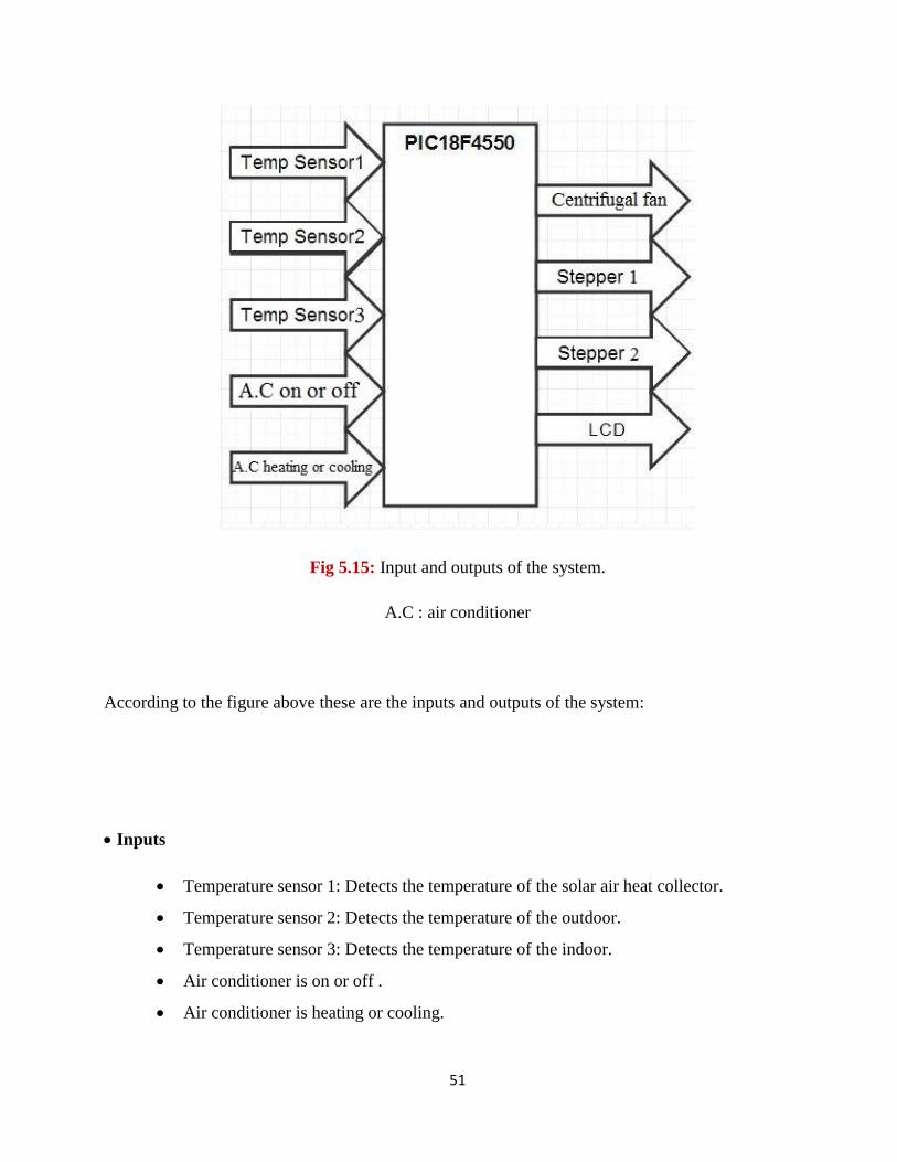
In any system there must be outputs and inputs to interface with the mechanical Structure, in the
project the outputs and inputs are illustrated in fig 5.15 .
51
Fig 5.15: Input and outputs of the system.
A.C : air conditioner
According to the figure above these are the inputs and outputs of the system:
Inputs
Temperature sensor 1: Detects the temperature of the solar air heat collector.
Temperature sensor 2: Detects the temperature of the outdoor.
Temperature sensor 3: Detects the temperature of the indoor.
Air conditioner is on or off .
Air conditioner is heating or cooling.
52
Outputs
Centrifugal fan: Used to push the hot air from the solar air heat collector to the indoor
when the air conditioner is off.
Stepper motor1: Used to open and close the stream between solar air heat collector and
the air conditioner.
Stepper motor2: Use to open and close the stream between solar air heat collector and
indoor.
LCD: Is the display screen.
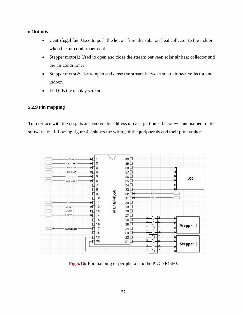
5.2.9 Pin mapping
To interface with the outputs as denoted the address of each part must be known and named in the
software, the following figure 4.2 shows the wiring of the peripherals and their pin number.
Fig 5.16: Pin mapping of peripherals to the PIC18F4550.
53
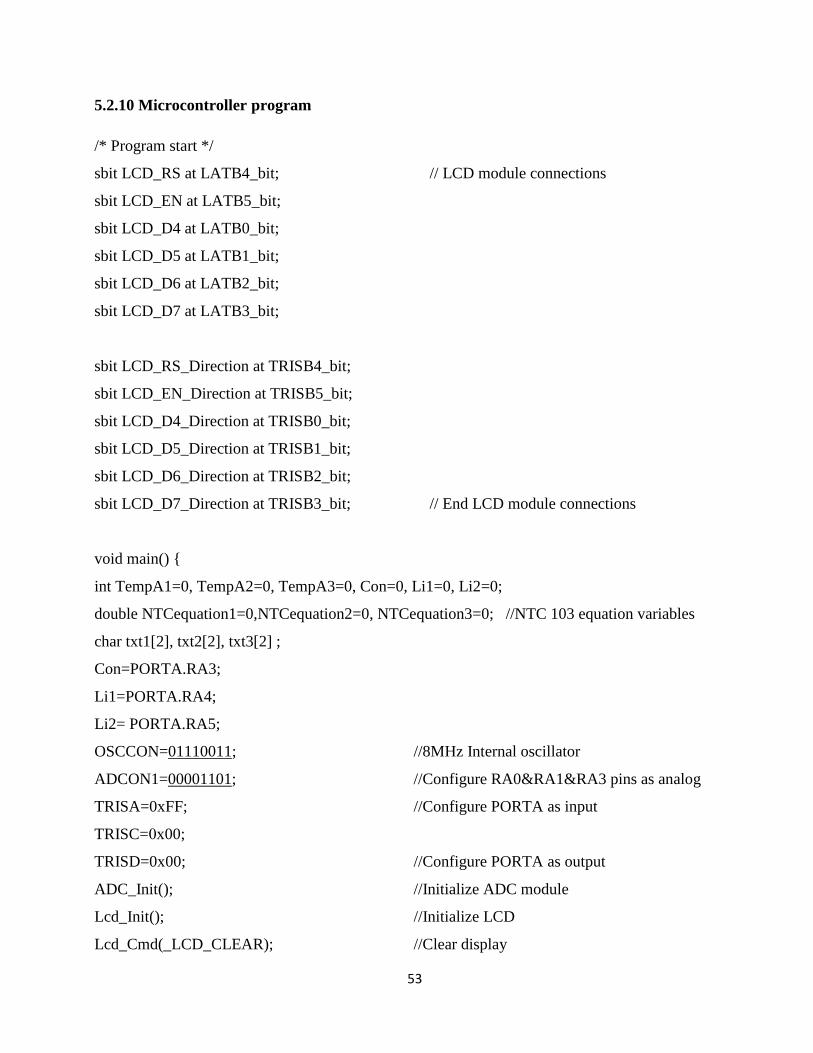
5.2.10 Microcontroller program
/* Program start */
sbit LCD_RS at LATB4_bit; // LCD module connections
sbit LCD_EN at LATB5_bit;
sbit LCD_D4 at LATB0_bit;
sbit LCD_D5 at LATB1_bit;
sbit LCD_D6 at LATB2_bit;
sbit LCD_D7 at LATB3_bit;
sbit LCD_RS_Direction at TRISB4_bit;
sbit LCD_EN_Direction at TRISB5_bit;
sbit LCD_D4_Direction at TRISB0_bit;
sbit LCD_D5_Direction at TRISB1_bit;
sbit LCD_D6_Direction at TRISB2_bit;
sbit LCD_D7_Direction at TRISB3_bit; // End LCD module connections
void main()
int TempA1=0, TempA2=0, TempA3=0, Con=0, Li1=0, Li2=0;
double NTCequation1=0,NTCequation2=0, NTCequation3=0; //NTC 103 equation variables
char txt1[2], txt2[2], txt3[2] ;
Con=PORTA.RA3;
Li1=PORTA.RA4;
Li2= PORTA.RA5;
OSCCON=01110011; //8MHz Internal oscillator
ADCON1=00001101; //Configure RA0&RA1&RA3 pins as analog
TRISA=0xFF; //Configure PORTA as input
TRISC=2x00;
TRISD=0x00; //Configure PORTA as output
ADC_Init(); //Initialize ADC module
Lcd_Init(); //Initialize LCD
Lcd_Cmd(_LCD_CLEAR); //Clear display
54
Lcd_Cmd(_LCD_CURSOR_OFF); //Cursor off
while(1)
PORTA=0x00; //Reset all ports
PORTD=0x00;
PORTC=0x00;
Lcd_Cmd(_LCD_CLEAR); //LCD start display
Lcd_Out(1,1,"Solar air heat");
Lcd_Out(2,4,"collector");
Delay_ms(2000);
Lcd_Cmd(_LCD_CLEAR);
Lcd_Out(2,4,"Project team");
Delay_ms(1000);
Lcd_Cmd(_LCD_CLEAR);
Lcd_Out(1,1,"Eng.Ibrahim");
Lcd_Out(2,1,"Eng. Bahaa");
Delay_ms(3000);
Lcd_Cmd(_LCD_CLEAR);
Lcd_Out(1,1,"Project Supervisors");
Lcd_Out(2,1," Dr.Momen Sughayyer");
Lcd_Cmd(_LCD_CLEAR);
Lcd_Out(1,1,"T1=");
TempA1=ADC_Read(0); // Read analog value from temp sensor 1
NTCequation1=0.0000000000020904*TempA1*TempA1*TempA1*TempA1*TempA1-
0.000000050557*TempA1*TempA1*TempA1*TempA1
+0.0000047935*TempA1*TempA1*TempA1-0.0021861*TempA1*TempA1+0.59765*TempA1-
49.967; //NTC 103 equation
IntToStr(NTCequation1,txt1); // temp indoor
Lcd_Out(1,4,txt1);
55
Lcd_Out(1,8,"T2=");
TempA2=ADC_Read(1); // Read analog value from temp sensor 2
NTCequation2=0.0000000000020904*TempA2*TempA2*TempA2*TempA2*TempA2-
0.000000050557*TempA2*TempA2*TempA2*TempA2
+0.0000047935*TempA2*TempA2*TempA2-0.0021861*TempA2*TempA2+0.59765*TempA2-
49.967; //NTC 103 equation
IntToStr(NTCequation2,txt2); //temp in solar collector
Lcd_Out(1,11,txt2);
Lcd_Out(2,4,"T3=");
TempA3=ADC_Read(2); // Read analog value from temp sensor 3
NTCequation3=0.0000000000020904*TempA3*TempA3*TempA3*TempA3*TempA3-
0.000000050557*TempA3*TempA3*TempA3*TempA3
+0.0000047935*TempA3*TempA3*TempA3-0.0021861*TempA3*TempA3+0.59765*TempA3-
49.967; //NTC 103 equation
IntToStr(NTCequation3,txt3); //temp outdoor
Lcd_Out(2,8,txt3);
If((TempA2 > TempA1) && Con==0)
If(Li1==1)
PORTC.RC2=1;
PORTD.RD0=1; //Open valve to indoor
PORTD.RD1=0;
Delay_ms(200);
PORTD.RD0=0;
PORTD.RD1=1;
Delay_ms(200);
PORTD.RD0=1;
PORTD.RD1=0;
Delay_ms(200);
56
PORTD.RD0=0;
PORTD.RD1=1;
Delay_ms(200);
PORTD.RD0=1;
PORTD.RD1=0;
Delay_ms(200);
PORTD.RD0=0;
PORTD.RD1=0;
PORTC.RC4=1; // close valve to air conditioner
PORTC.RC5=0;
Delay_ms(200);
PORTC.RC4=0;
PORTC.RC5=1;
Delay_ms(200);
PORTC.RC4=1;
PORTC.RC5=0;
Delay_ms(200);
PORTC.RC4=0;
PORTC.RC5=1;
Delay_ms(200);
PORTC.RC4=1;
PORTC.RC5=0;
Delay_ms(200);
PORTC.RC4=0;
PORTC.RC5=0;
If(Con==1&&Li2==1)
PORTD.RD2=1; // Open valve to air conditioner
57
PORTD.RD3=0;
Delay_ms(200);
PORTD.RD2=0;
PORTD.RD3=1;
Delay_ms(200);
PORTD.RD2=1;
PORTD.RD3=0;
Delay_ms(200);
PORTD.RD2=0;
PORTD.RD3=1;
Delay_ms(200);
PORTD.RD2=1;
PORTD.RD3=0;
Delay_ms(200);
PORTD.RD2=0;
PORTD.RD3=0;
PORTC.RC6=1; // close valve to indoor
PORTC.RC7=0;
Delay_ms(200);
PORTC.RC6=0;
PORTC.RC7=1;
Delay_ms(200);
PORTC.RC6=1;
PORTC.RC7=0;
Delay_ms(200);
PORTC.RC6=0;
PORTC.RC7=1;
Delay_ms(200);
PORTC.RC6=1;
58
PORTC.RC7=0;
Delay_ms(200);
PORTC.RC6=0;
PORTC.RC7=0;
If(TempA2<= TempA1)
if(Li1==1&&Li2==0)
PORTC.RC4=1; // close valve to indoor
PORTC.RC5=0;
Delay_ms(200);
PORTC.RC4=0;
PORTC.RC5=1;
Delay_ms(200);
PORTC.RC4=1;
PORTC.RC5=0;
Delay_ms(200);
PORTC.RC4=0;
PORTC.RC5=1;
Delay_ms(200);
PORTC.RC4=1;
PORTC.RC5=0;
Delay_ms(200);
PORTC.RC4=0;
PORTC.RC5=0;
If(Li1==0&&Li2==1)
PORTD.RD2=1; // close valve to air conditioner
PORTD.RD3=0;
Delay_ms(200);
59
PORTD.RD2=0;
PORTD.RD3=1;
Delay_ms(200);
PORTD.RD2=1;
PORTD.RD3=0;
Delay_ms(200);
PORTD.RD2=0;
PORTD.RD3=1;
Delay_ms(200);
PORTD.RD2=1;
PORTD.RD3=0;
Delay_ms(200);
PORTD.RD2=0;
PORTD.RD3=0;
5.2.11 Design of Electronic Circuits
Introduction
An electronic circuit is composed of individual electronic components, such as resistors, transistors,
capacitors, inductors and diodes, connected by conductive wires or traces through which electric
current can flow. The combination of components and wires allows various simple and complex
operations to be performed: signals can be amplified, computations can be performed, and data can
be moved from one place to another. Circuits in the project are constructed of discrete components
connected by individual pieces of wire. In this chapter the electrical parts and circuits are discussed,
to explain the necessary resistance needed for the circuit protection and explaining the circuits of
60
each function such as temperature sensors, stepper driver, and power supply, these functions are
divided into two groups the inputs and outputs as discussed in the previous chapter.
Power Supply
A power supply is a device that supplies electric power to an electrical load, a regulated power
supply is one that controls the output voltage or current to a specific value; the controlled value is
held nearly constant despite variations in either load current or the voltage supplied by the power
supply's energy source. Three types of power sources are needed to power up the apparatus, 220v
AC to power up the centrifugal fan, 12v DC to power up the stepper, and 5v DC to power up the
control circuits such as the microcontroller.
Outputs
The control and activation of the outputs of the system are discussed in this section, which are the
centrifugal fan, and two electrical stepper motors.
5.3 connect and disconnect the two systems
To connect the solar air heat collector system with the air conditioner system, an easy and
appropriate method will be applied to do so, by using flexible connection, and this method will be
done by using four pulleys, two for above the external unit and two for below it, and all these four
pulleys to be fixed on the right and left sides of the external unit of the conditioner, and an electrical
motor to provide motion power for two pulleys, and the motor pulls the flexible connection to the
left by two bands connects the four pulleys when we need to connect the two systems together. And
when we need to disconnect the both systems from each other, the motor rotates in the opposite
direction, so bringing back the flexible connection to the left, so disconnecting both systems, and
the two bands will be fixed or tied to the edge of the flexible connection, so when the motor wraps
the bands, the two bands will pull the flexible connection to the right or left according to the motor
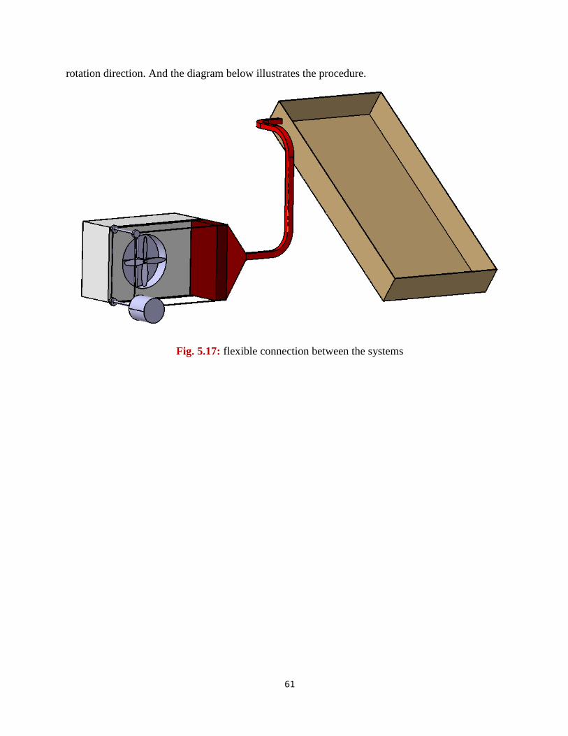
61
rotation direction. And the diagram below illustrates the procedure.
Fig. 5.17: flexible connection between the systems
62
Chapter six
Calculation and design
6.1 Gas heat pump
6.2 Solar air heat collector
6.2.1 Fins specifications
6.2.2 Inlet and outlet specifications
6.3 Heat load calculation of the studied house
63
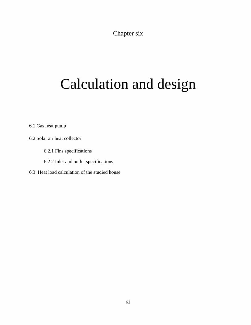
6.1 Gas heat pump
Width (cm)
Height (cm)
Outer diameter (cm)
Inner diameter (cm )
77
53
40
12
(6.1)
( )
⁄
So we need the same flow rate of Air conditioner ( A.C) from solar air heat collector ( S.C) to keep
the system stable.
Fig. 6.1: Dimensions of outdoor unit.
Table 6.1: The dimensions of outdoor unit.
64
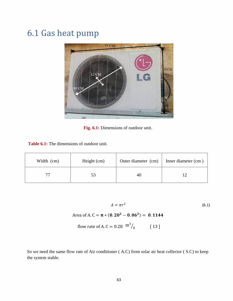
6.2 Solar air heat collector
a. Width 90 (cm) b. Height 180 (cm) c. No . of fins 10 d. Length of fin 65 (cm)
e. Area 16200 ( ) f. Effective area 13496 ( ) g. Absorber plate 1.0 mm aluminum (air collector)
h. Surface treatment Black paint coating
i. Glazing Normal window glass of thickness 4 mm
j. No. of glazing One
k. Back insulation Made of Thermocol sheets of thickness 20 mm
l. Side insulation Made of Thermocol sheets of thickness 20 mm
m. Casing Made of wood of thickness 16 mm
n. Collector tilt 35o
o. Air flow area 0.014 m2
P.S: 1- To increase the effective area, we added Aluminum sheets on sides and fins.
2- The values of the table (6.2) are taken from Annex 1.
Fig. 6.2: Solar air heat collector by catia.
Table 6.2: Components specification and characteristics of the solar air heat collector system parameters.
65
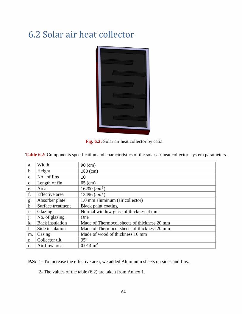
6.2.1 Fins specifications :
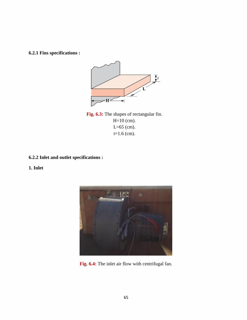
6.2.2 Inlet and outlet specifications :
1. Inlet
Fig. 6.3: The shapes of rectangular fin.
H=10 (cm).
L=65 (cm).
t=1.6 (cm).
Fig. 6.4: The inlet air flow with centrifugal fan.
66
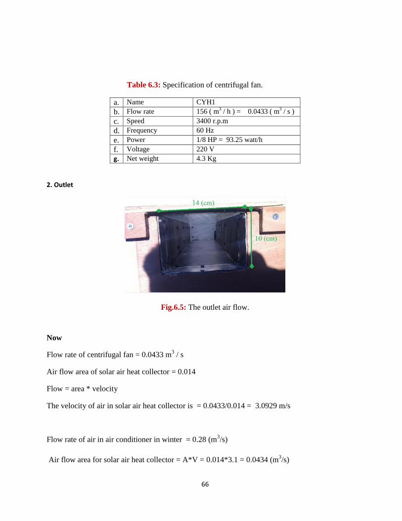
a. Name CYH1
b. Flow rate 156 ( m3 / h ) = 0.0433 ( m
3 / s )
c. Speed 3400 r.p.m
d. Frequency 60 Hz
e. Power 1/8 HP = 93.25 watt/h
f. Voltage 220 V
g. Net weight 4.3 Kg
2. Outlet
Fig.6.5: The outlet air flow.
Now
Flow rate of centrifugal fan = 0.0433 m3 / s
Air flow area of solar air heat collector = 0.014
Flow = area * velocity
The velocity of air in solar air heat collector is = 0.0433/0.014 = 3.0929 m/s
Flow rate of air in air conditioner in winter = 0.28 (m3/s)
Air flow area for solar air heat collector = A*V = 0.014*3.1 = 0.0434 (m3/s)
Table 6.3: Specification of centrifugal fan.
67
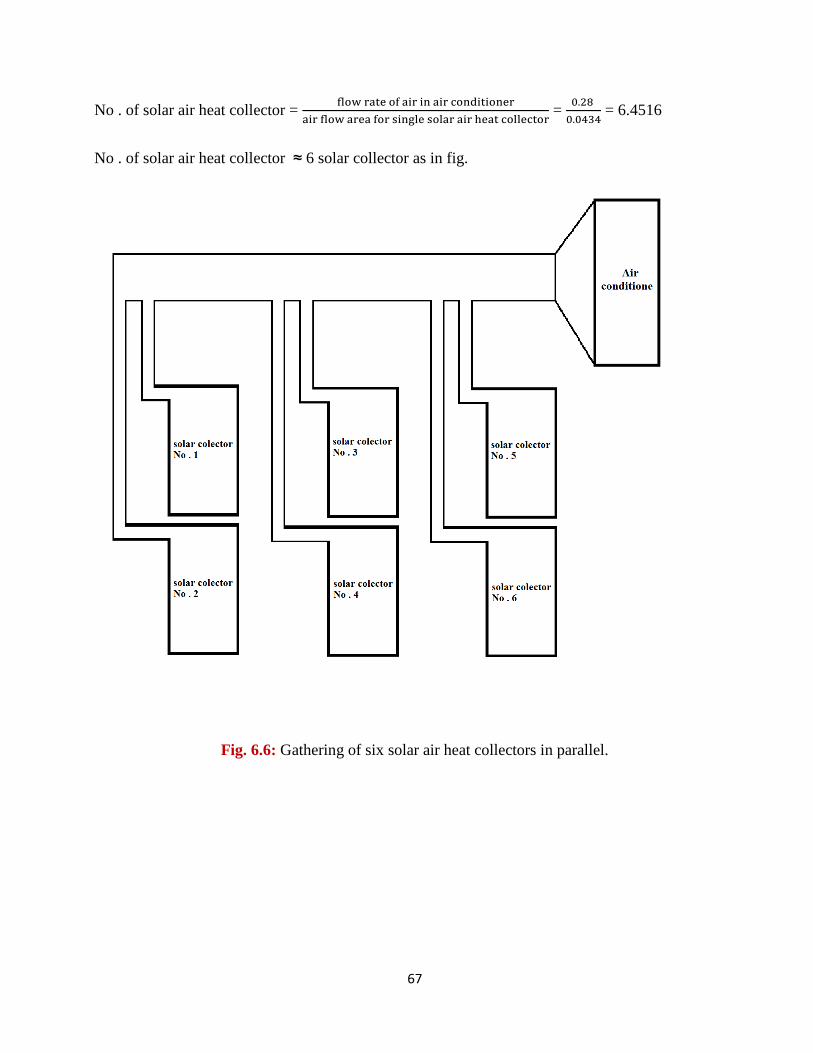
No . of solar air heat collector =
=
= 6.4516
No . of solar air heat collector ≈ 6 solar collector as in fig.
Fig. 6.6: Gathering of six solar air heat collectors in parallel.
68
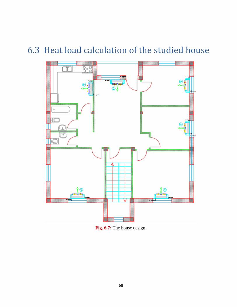
6.3 Heat load calculation of the studied house
Fig. 6.7: The house design.
69
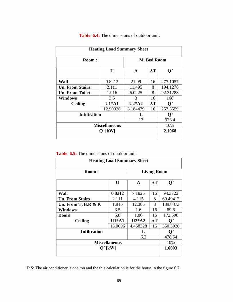
Heating Load Summary Sheet
M. Bed Room Room :
ΔT A U
277.1057 16 21.09 0.8212 Wall
194.1276 8 11.495 2.111 Un. From Stairs
92.31288 8 6.0225 1.916 Un. From Toilet
168 16 3 3.5 Windows
ΔT U2*A2 U1*A1 Ceiling
257.3559 16 3.184479 12.90026
L Infiltration
926.4 12
10% Miscellaneous
2.1068
Heating Load Summary Sheet
Living Room Room :
ΔT A U
94.3723 16 7.1825 0.8212 Wall
69.49412 8 4.115 2.111 Un. From Stairs
189.8373 8 12.385 1.916 Un. From T, B.R & K
89.6 16 1.6 3.5 Windows
172.608 16 1.86 5.8 Doors
ΔT U2*A2 U1*A1 Ceiling
360.3028 16 4.458328 18.0606
L Infiltration
478.64 6.2
10% Miscellaneous
1.6003
P.S: The air conditioner is one ton and the this calculation is for the house in the figure 6.7.
Table 6.4: The dimensions of outdoor unit.
Table 6.5: The dimensions of outdoor unit.
70
Chapter seven
Results and conclusion
7.1 Experimental results
7.2 Conclusion
71
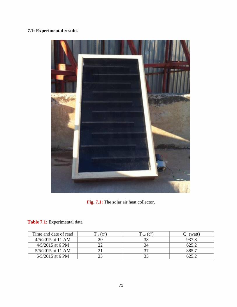
7.1: Experimental results
Fig. 7.1: The solar air heat collector.
Table 7.1: Experimental data
Time and date of read Tin (co) Tout (c
o) Q (watt)
4/5/2015 at 11 AM 20 38 937.8
4/5/2015 at 6 PM 22 34 625.2
5/5/2015 at 11 AM 21 37 885.7
5/5/2015 at 6 PM 23 35 625.2
72
(7.1)
0.014*3.1 = 0.0521 kg/s
( ) (7.2)
* 100% (7.3)
Case 1
(20-38) = 937.8 watt
Ƞ =
ṁ = mass flow rate in solar collector (kg/s)
= density of air = 1.2 (kg/m3)
A = air flow area in solar air collector = 0.014 (m2)
V = speed of air in solar air collector = 3.1 (m/s)
( )
= collector useful energy (watt)
ṁ = mass flow rate in solar collector (kg/s)
Cp = specific heat of air = 1000 (J/kg.K)
( )
Ƞ = efficiency of solar air heat collector
= collector useful energy (watt)
I = solar radiation (w/m2) = 1100 watt/m
2
= effective area = 1.3496 m2
73
Case 2
( -22) = 625.2 watt
Ƞ =
Case 3
( -21) = 885.7 watt
Ƞ =
Case 4
( -23) = 625.2 watt
Ƞ =
Average efficiency =
= 0.5796= 57.96%
74
7.2: Conclusion :
1. The system needs 6 solar air heat collectors to preserve the air flow to the air conditioner
system.
2. The system needs to a surface area of 3*3*3.6 m3 = 32.4 m
3.
3. It is expected that the efficiency of the solar air heat collector system to decrease in the
winter because of the strong winds, low temperature, low intensity of sunlight, and other
factors which causes a decrease in the efficiency of the solar air heat collector system.
75
References:
1- Yunus A. Cengel, Michael A. Boles. “Thermodynamics, An Engineering Approach”, Fifth
Edition, 2006. McGraw-Hill, New York, USA. P: 111-164.
2- Werner Weiss. “Solar Collectors”, AEE - Institute for Sustainable Technologies, 2008, Austria.
P: 3-76.
3- Gang Xiao. “Manual making of a parabolic solar collector”, Université de Nice, , 2010, Nice,
France. P: 2 -27.
4- http://en.wikipedia.org/wiki/Solar_thermal_collector, Accessed during 16th
to 22nd
of November
2014
5- http://www.jms-se.com/rtd.php
6- http://en.wikipedia.org/wiki/Centrifugal_fan
7- http://www.ehow.com/list_6661711_advantages-disadvantages-heat-pump_.html
8-http://www.academia.edu/850238/An_energy_and_exergy_study_of_a_solar_thermal_air_collector
9- http://www.wksolar.com/products/solar-collector/flat-plate-solar-collector-wpb
10-http://www.brighthubengineering.com/hvac/16075-various-components-of-the-heat-pump-part-
two/
11- http://www.catchsolar.net/pages/solar_energy_facts.php
12- http://www.powerknot.com/how-efficient-is-your-air-conditioning-system.html
13- Elsayed, Amr O., Hariri, Abdulrahman S. “Effect of Condenser Air Flow on Performance of
Split Air Conditioner”, World Renewable Energy Congress, 8-13 May 2011; Sweden. P: 2134.
14- Palestinian National Authority-Palestinian Central Bureau of Statistics. “Climatic conditions in
the Palestinian territories”. The annual report 2007, Ramallah; July 2008.
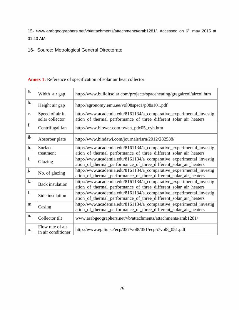
76
15- www.arabgeographers.net/vb/attachments/attachments/arab1281/. Accessed on 6th may 2015 at
01:40 AM.
16- Source: Metrological General Directorate
Annex 1: Reference of specification of solar air heat collector.
a. Width air gap http://www.builditsolar.com/projects/spaceheating/gregaircol/aircol.htm
b. Height air gap http://agronomy.emu.ee/vol08spec1/p08s101.pdf
c. Speed of air in
solar collector
http://www.academia.edu/8161134/a_comparative_experimental_investig
ation_of_thermal_performance_of_three_different_solar_air_heaters
f. Centrifugal fan http://www.blower.com.tw/en_pdc05_cyh.htm
g. Absorber plate http://www.hindawi.com/journals/isrn/2012/282538/
h. Surface
treatment
http://www.academia.edu/8161134/a_comparative_experimental_investig
ation_of_thermal_performance_of_three_different_solar_air_heaters
i. Glazing
http://www.academia.edu/8161134/a_comparative_experimental_investig
ation_of_thermal_performance_of_three_different_solar_air_heaters
j. No. of glazing
http://www.academia.edu/8161134/a_comparative_experimental_investig
ation_of_thermal_performance_of_three_different_solar_air_heaters
k. Back insulation
http://www.academia.edu/8161134/a_comparative_experimental_investig
ation_of_thermal_performance_of_three_different_solar_air_heaters
l. Side insulation
http://www.academia.edu/8161134/a_comparative_experimental_investig
ation_of_thermal_performance_of_three_different_solar_air_heaters
m. Casing
http://www.academia.edu/8161134/a_comparative_experimental_investig
ation_of_thermal_performance_of_three_different_solar_air_heaters
n. Collector tilt www.arabgeographers.net/vb/attachments/attachments/arab1281/
o. Flow rate of air
in air conditioner http://www.ep.liu.se/ecp/057/vol8/051/ecp57vol8_051.pdf
Related Documents