HAL Id: hal-00926579 https://hal.inria.fr/hal-00926579 Submitted on 13 Jan 2014 HAL is a multi-disciplinary open access archive for the deposit and dissemination of sci- entific research documents, whether they are pub- lished or not. The documents may come from teaching and research institutions in France or abroad, or from public or private research centers. L’archive ouverte pluridisciplinaire HAL, est destinée au dépôt et à la diffusion de documents scientifiques de niveau recherche, publiés ou non, émanant des établissements d’enseignement et de recherche français ou étrangers, des laboratoires publics ou privés. Improving Delay-Based Data Dissemination Protocol in VANETs with Network Coding Farhan Mirani, Anthony Busson, Cédric Adjih To cite this version: Farhan Mirani, Anthony Busson, Cédric Adjih. Improving Delay-Based Data Dissemination Protocol in VANETs with Network Coding. REV Journal on Electronics and Communications, IEEE, 2013, 2 (3-4), 10.21553/rev-jec.41. hal-00926579

Welcome message from author
This document is posted to help you gain knowledge. Please leave a comment to let me know what you think about it! Share it to your friends and learn new things together.
Transcript

HAL Id: hal-00926579https://hal.inria.fr/hal-00926579
Submitted on 13 Jan 2014
HAL is a multi-disciplinary open accessarchive for the deposit and dissemination of sci-entific research documents, whether they are pub-lished or not. The documents may come fromteaching and research institutions in France orabroad, or from public or private research centers.
L’archive ouverte pluridisciplinaire HAL, estdestinée au dépôt et à la diffusion de documentsscientifiques de niveau recherche, publiés ou non,émanant des établissements d’enseignement et derecherche français ou étrangers, des laboratoirespublics ou privés.
Improving Delay-Based Data Dissemination Protocol inVANETs with Network Coding
Farhan Mirani, Anthony Busson, Cédric Adjih
To cite this version:Farhan Mirani, Anthony Busson, Cédric Adjih. Improving Delay-Based Data Dissemination Protocolin VANETs with Network Coding. REV Journal on Electronics and Communications, IEEE, 2013, 2(3-4), �10.21553/rev-jec.41�. �hal-00926579�
Improving Delay-Based Data Dissemination
Protocol in VANETs with Network Coding
Farhan H. Mirani
Signals and Systems Laboratory
Supelec, France
Email: [email protected]
Anthony Busson
Laboratory of Parallel Computing
University of Lyon 1 - ENS - Inria
Email: [email protected]
Cedric Adjih
Hipercom Project-Team
Inria, France
Email: [email protected]
Abstract—In vehicular ad hoc networks (VANETs), for a largenumber of applications, the destination of relevant informationsuch as alerts is the whole set of vehicles located inside agiven area. Therefore dissemination with efficient broadcast isan essential communication primitive. One of the families ofbroadcast protocols suitable for such networks is the familyof delay-based broadcast protocols, where farthest receiversretransmit first and where transmissions also act as implicitacknowledgements. For lossless networks, such protocols mayapproach the optimum efficiency. However with realistic lossmodels of VANET wireless communication, their performance isnoticeably degraded. This is because packet losses have a doubleeffect: directly on the amount of successfully received packets andindirectly with implicit acknowledgement misses. In this article,in order to combat the effects of packet losses, we combine delay-based broadcast with network coding through a new protocol:Delay-based Opportunistic Network Coding protocol (DONC). Bydesign, DONC aims at cancelling the twofold effects of packet andimplicit acknowledgement losses. We describe the details of theDONC protocol and we study its behavior, with realistic modelsand simulations. Results illustrate the excellent performance ofthe protocol.
Index Terms—Wireless networks, Broadcast, Network Coding,VANET (Vehicular Ad hoc NETwork)
I. INTRODUCTION
In recent years, we have witnessed the emergence of a pop-
ular solution for future road communications: inter-vehicular
communication (IVC). IVC systems have the potential to
greatly influence the road security as well as to improve traffic
flow by providing the drivers with critical route information
such as upcoming obstacles and weather conditions. In addi-
tion to vital information related to road security, there exists
a wealth of information sources and applications that will
benefit the driver or passengers in mobile vehicles such as:
traffic congestion reports, variable speed limits, ambulance
accommodation, construction zone warnings, local or regional
business locations, gas stations, web surfing, file sharing, etc.
Due to their highly agile nature, VANETs cannot work
in mere client-server type configurations. Fortunately, the
most promising applications in VANETs rely on broadcast
communications: dissemination of messages warning about a
danger, data dissemination from the embedded sensors (speed,
inter-distance, etc.) for autonomous driving systems, advertise-
ments, etc. The basic functioning of information dissemination
by broadcasting is illustrated by the following scenario: on
a route, a random mobile node encounters an event which
needs to be notified to its neighbors. The mobile node that
encountered the event will send information in the form of
broadcast transmissions, which may subsequently be rebroad-
casted by the receiving nodes to propagate the information to
further distance from the source vehicle in multiple hops. This
mechanism is called flooding. In a pure flooding mechanism,
every receiving node will rebroadcast/relay the packet back
to its neighbors. Obviously, such flooding is often inefficient
because in many cases one node will re-broadcast information
that was already received by all its neighbors, causing packet
collisions and straining the already scarce radio bandwidth.
In our work, we follow the philosophy of a family of
improved broadcasting schemes, denoted delay-based broad-
casting schemes (according to the taxonomy of the survey
[1]). The idea of delay-based broadcasting mechanisms is
that among a group of receivers, the farthest node from the
transmitter will retransmit a received packet, thus avoiding re-
dundant simultaneous transmissions. This strategy approaches
the optimum on linear topologies with lossless wireless trans-
missions, however, it does not perform so well in practical
VANETs where wireless losses actually lessen the amount of
self-elimination, and thus cause redundancy [2].
In order to give a precise overview of the context and the
contributions of this paper, we detail in the two next para-
graphs the principles of delay-based broadcasting schemes,
useless transmissions arising with this scheme in lossy envi-
ronment, and our contributions which consists in alleviating
this problem through network coding techniques.
A. Delay-based Broadcast Fundamentals
In delay-based broadcasting, each node that receives a
downstream packet does not rebroadcast it immediately. In-
stead, it starts a calculated timer governed by a ‘delay’
parameter. If by the end of the timer, the node does not
receive the same packet from the opposite direction, only then
it is allowed to rebroadcast. However, if the node receives the
same packet as an upstream packet before its timer expires;
it assumes that a vehicle further aheads received the same
packet and broadcasted before it. Thus, this upstream packet
is considered as an implicit acknowledgement at the receiving
node and consequently the node cancels its currently running
timer.

2
Fig. 1. An example vehicular network
The value of the delay parameter, then, should not be pre-
fixed for all the vehicles. Instead, the value of the delay pa-
rameter should take into account the current distance between
the source and the receiving vehicles, such that the farther
the receiver is from the source, the shorter the delay will be.
Consequently, the farthest vehicle to have received a packet
will have the shortest delay value of all, and therefore must
be chosen as the relaying vehicle. Therefore,
Delay = f(distance),
where f is decreasing.
Figure 1 shows an example of a small vehicular network.
From the example in Figure 1, vehicular node ‘a’ broadcasts
a packet. Let us assume that the average broadcast coverage
zone of node (a) covers the 4 vehicles behind. The broadcasted
packet is received by nodes ‘b’, ‘c’, ‘d’, and ‘e’. All four re-
ceiving nodes will then start a timer, where node ‘b’ will have
a timer with the largest delay value (20 ms) and node ‘e’ will
have a timer with the smallest delay value (7 ms). Out of these
four receiving nodes, the timer for node ‘e’ will expire first and
therefore node ‘e’ will broadcast the packet. Given the nodes
‘b’, ‘c’ and ‘d’ are in coverage range of node ‘e’, they will
receive this packet as well. Upon reception, these nodes will
cancel their running timers, considering the received upstream
packet as an implicit acknowledgement. This mechanism is
repeated at each hop. The number of hops is set up by the
application through a limited number of hops (the IP TTL field
for instance), or information on the geographical coverage of
the messages. This scheme is very efficient from the point
of view of implementation/complexity as well as redundancy.
It does not rely on any underlying protocol, such as routing,
link management (Hellos), or any table. The only required
information is the distance between the transmitter and the
receiver. Geographical locations are easily obtainable through
GPS, or any geographical systems. Therefore, the transmitter
just needs to add its location in a message’s field to allow
a receiver to compute this distance. Moreover, this scheme
systematically selects the best forwarder: the farthest one from
the previous transmitter. It should lead to the minimization of
the number of transmitters and thus redundancy.
In practice, it holds in an ideal radio environment, where
the Frame Error Rate (FER) is 0 if the distance between the
transmitter and the receiver is less than a given distance (the
radio range), and 1 otherwise. This radio model is the so-called
Boolean model. For such a model and the delay-based scheme,
a node receives exactly two times each message: one time from
the transmitter upstream and one time downstream. Unfortu-
nately, it does not hold when the radio model is more complex,
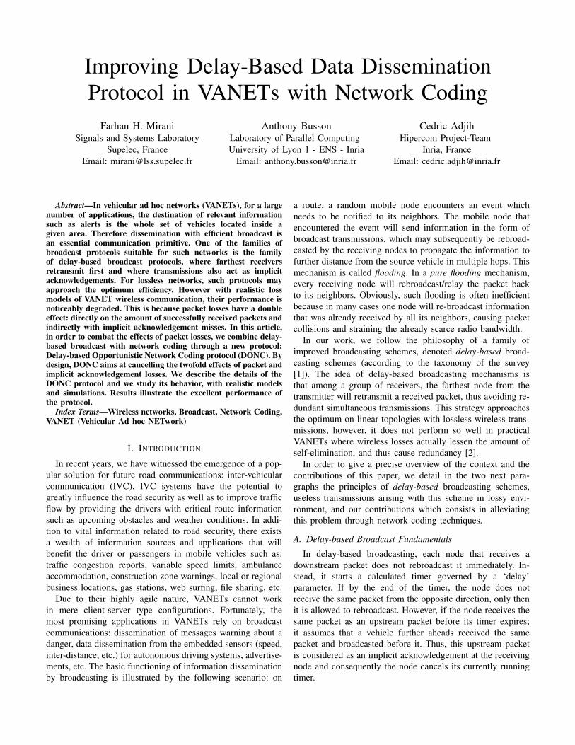
i.e. when the radio range is not a perfect ball. In Figure 2,
we plotted the mean number of receptions for a disseminated
message with regard to the traffic density (number of vehicles
per kilometer). We do not present simulations’ parameters
here, as this curve is just used to highlight effects of the radio
environment on the performances. Simulations parameters and
results will be presented in detail in Section IV-C. We consid-
ered three different radio models, the Boolean, and two more
realistic radio models: 2RM and Rayleigh. We observe that for
the Boolean model, the delay-based scheme works perfectly,
and the mean number of receptions is exactly 2. For the
two lossy models, this number increases significantly with the
traffic density. In the worst case, it reaches approximately 4.7receptions in average. This useless redundancy is mainly due
to the implicit acknowledgement mechanism. Let us consider
the previous example depicted in Figure 1. Vehicles ‘b’, ‘c’,
‘d’ and ‘e’ receives the message. Node ‘e’ retransmits first as it
has the smallest timer. But, if ‘e’ has not the same radio range
as ‘a’, or if the radio range is not a perfect ball, the broadcast
from ‘e’ may not be properly received by ‘b’. In this case, ‘b’
not receiving the implicit acknowledgement from a vehicle
downstream (from ‘e’), forwards the message.
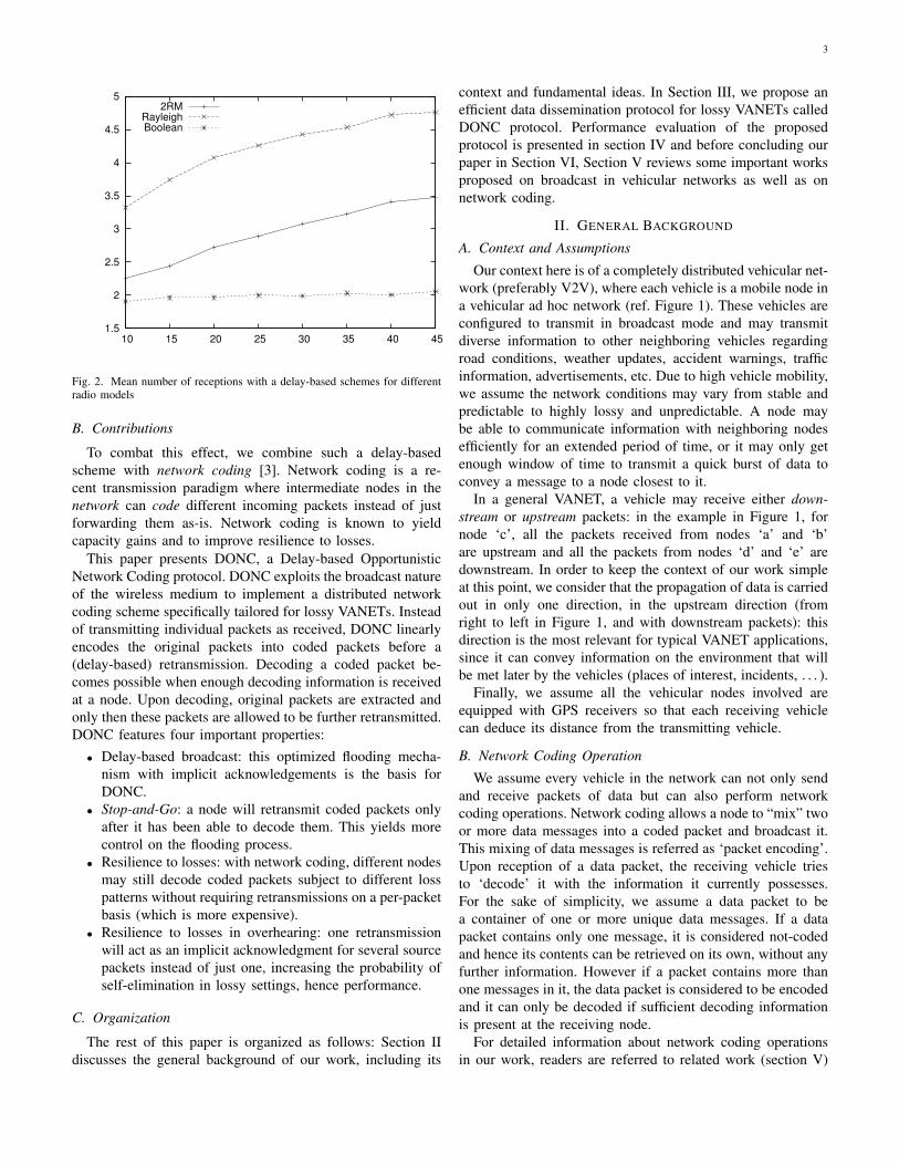
3
1.5
2
2.5
3
3.5
4
4.5
5
10 15 20 25 30 35 40 45
2RMRayleighBoolean
Fig. 2. Mean number of receptions with a delay-based schemes for differentradio models
B. Contributions
To combat this effect, we combine such a delay-based
scheme with network coding [3]. Network coding is a re-
cent transmission paradigm where intermediate nodes in the
network can code different incoming packets instead of just
forwarding them as-is. Network coding is known to yield
capacity gains and to improve resilience to losses.
This paper presents DONC, a Delay-based Opportunistic
Network Coding protocol. DONC exploits the broadcast nature
of the wireless medium to implement a distributed network
coding scheme specifically tailored for lossy VANETs. Instead
of transmitting individual packets as received, DONC linearly
encodes the original packets into coded packets before a
(delay-based) retransmission. Decoding a coded packet be-
comes possible when enough decoding information is received
at a node. Upon decoding, original packets are extracted and
only then these packets are allowed to be further retransmitted.
DONC features four important properties:
• Delay-based broadcast: this optimized flooding mecha-
nism with implicit acknowledgements is the basis for
DONC.
• Stop-and-Go: a node will retransmit coded packets only
after it has been able to decode them. This yields more
control on the flooding process.
• Resilience to losses: with network coding, different nodes
may still decode coded packets subject to different loss
patterns without requiring retransmissions on a per-packet
basis (which is more expensive).
• Resilience to losses in overhearing: one retransmission
will act as an implicit acknowledgment for several source
packets instead of just one, increasing the probability of
self-elimination in lossy settings, hence performance.
C. Organization
The rest of this paper is organized as follows: Section II
discusses the general background of our work, including its
context and fundamental ideas. In Section III, we propose an
efficient data dissemination protocol for lossy VANETs called
DONC protocol. Performance evaluation of the proposed
protocol is presented in section IV and before concluding our
paper in Section VI, Section V reviews some important works
proposed on broadcast in vehicular networks as well as on
network coding.
II. GENERAL BACKGROUND
A. Context and Assumptions
Our context here is of a completely distributed vehicular net-
work (preferably V2V), where each vehicle is a mobile node in
a vehicular ad hoc network (ref. Figure 1). These vehicles are
configured to transmit in broadcast mode and may transmit
diverse information to other neighboring vehicles regarding
road conditions, weather updates, accident warnings, traffic
information, advertisements, etc. Due to high vehicle mobility,
we assume the network conditions may vary from stable and
predictable to highly lossy and unpredictable. A node may
be able to communicate information with neighboring nodes
efficiently for an extended period of time, or it may only get
enough window of time to transmit a quick burst of data to
convey a message to a node closest to it.
In a general VANET, a vehicle may receive either down-
stream or upstream packets: in the example in Figure 1, for
node ‘c’, all the packets received from nodes ‘a’ and ‘b’
are upstream and all the packets from nodes ‘d’ and ‘e’ are
downstream. In order to keep the context of our work simple
at this point, we consider that the propagation of data is carried
out in only one direction, in the upstream direction (from
right to left in Figure 1, and with downstream packets): this
direction is the most relevant for typical VANET applications,
since it can convey information on the environment that will
be met later by the vehicles (places of interest, incidents, . . . ).
Finally, we assume all the vehicular nodes involved are
equipped with GPS receivers so that each receiving vehicle
can deduce its distance from the transmitting vehicle.
B. Network Coding Operation
We assume every vehicle in the network can not only send
and receive packets of data but can also perform network
coding operations. Network coding allows a node to “mix” two
or more data messages into a coded packet and broadcast it.
This mixing of data messages is referred as ‘packet encoding’.
Upon reception of a data packet, the receiving vehicle tries
to ‘decode’ it with the information it currently possesses.
For the sake of simplicity, we assume a data packet to be
a container of one or more unique data messages. If a data
packet contains only one message, it is considered not-coded
and hence its contents can be retrieved on its own, without any
further information. However if a packet contains more than
one messages in it, the data packet is considered to be encoded
and it can only be decoded if sufficient decoding information
is present at the receiving node.
For detailed information about network coding operations
in our work, readers are referred to related work (section V)

4
and cited works: MORE [4] and OMNC [5], which explain in
detail network coding models identical to ours. In summary:
packets are supposed to be of identical size (concatenated
and padded as necessary), coded packets are generated from
source packets with linear combinations through random linear
coding [6], decoding is performed with Gaussian elimination
and encoding vectors are inserted in headers [7] (with a
mapping from packet indices to node and packet identifiers;
finding efficient mappings is not addressed by this article, see
[8] for instance).
III. DONC PROTOCOL
DONC, or Delay-based Opportunistic Network Coding pro-
tocol fuses the idea of the popular delay-based broadcasting
mechanism for VANETs with the principles of network cod-
ing, which allow to improve network throughput and reduce
packet loss in error and collision prone wireless networks.In
order to help readers understand the basic idea of our protocol
without entering immediately in the algorithm and implemen-
tation details, we split this section in two parts. We first present
the basic idea and functioning of DONC protocol. Also, we
present a simple example that highlights the benefit of DONC
with regard to the basic delay-based scheme. Then, we present
the protocol details. In order to implement network coding
with a delay-based broadcasting mechanism, we propose to
introduce an intermediate layer in the protocol stack called the
Network Coding (NC) layer, as shown in the figure 3. In the
NC layer, we introduce two distinct buffers to store incoming
data packets: the Data-Buffer and the Decoding-Buffer.
Layers
3 to 7
Layer 2.5
Data Buffer
Decoding Buffer
Control Module
Lower-layer Interface
Network Coding
Layers 1 & 2
Fig. 3. Network Coding (NC) Layer - Decomposition
A. Protocol Semantics and Architecture
1) Overview: The objective of the protocol is the broad-
cast of data packets. They are stored in two data structures
(described later):
• Data-Buffer: It is a buffer that stores decoded/not-coded
data packets.
• Decoding-Buffer: It is a temporary buffer to store incom-
ing coded data packets which cannot immediately be de-
coded at the receiving vehicle with Gaussian elimination
and require additional coded data packets.
The NC layer also has a Control Module and a Lower Layer
Interface module. The Control Module is responsible for all
the operations of the protocol, which include fetching data to
and from the Data-buffer and Decoding-buffer, running packet
decoding procedures, keeping track of timers, etc. Lower
Layer Interface module provides interface between NC layer
and layer-2.
The functioning of DONC is based on the following principles:
• Coded packets stay in the decoding buffer until decoded,
• Reception from upstream of a given packet acts
as an implicit acknowledgement and any scheduled
(re)transmission of the packet is canceled,
• Decoded/non-coded packets are transmitted after an ini-
tial delay-based timer (unless canceled),
• Decoded/non-coded packets are later retransmitted until
implicit acknowledgement,
• Any transmission of decoded/non-coded packets is per-
formed by first computing a linear combination of such
available packets (network coding).
2) Semantics: DONC semantics rely on three kinds of
events: local application packet handling, packet reception
and coded packet transmission.
Local Application Packet Handling
• Every data packet locally generated by the application(s)
of a node is added to the Data-Buffer with its transmission
timer set to current time; hence a packet transmission is
immediately performed.
Packet Reception
• Upon receiving a coded packet, it is directly added to the
Decoding Buffer. Thereafter, a decoding of the current
set of the coded packets with Gaussian elimination is
attempted. This may result in the decoding of zero, one,
several or all the coded packets in the Decoding Buffer.
• Decoded packets are then removed from the Decoding
Buffer, and for each packet decoded:
– if it is not already present in the data buffer, it is
added
– otherwise, if it is an upstream packet, it is considered
to be an implicit acknowledgment and any associated
retransmission timer is removed.
– otherwise it is ignored and dropped
Coded Packet Transmission
• Whenever the transmission timer of an uncoded packet
expires:
• the first N uncoded packets with the lowest expiry timers
are coded together and transmitted, where ‘N’ be the
maximum number of messages allowed to be encoded
in a data packet
• their timers are updated with the retransmission timeout
3) Data Structures: Every node in the network has a
reference table (Ref-Table), which keeps information regarding
packet transmissions, timers and acknowledgements. It has
three fields: Msg-Ids, Ack-Flgs and Exp-Timers corresponding
to each data message in the Data-buffer (ref. table I). These
entries are updated every time a vehicle has some activity
(transmission or reception). Since Ref-Table is a reflection of
the current contents of Data-Buffer, the size of Ref-Table is
equivalent to that of the Data-Buffer.

5
• Msg-Id: It is a unique ID given to each message before
it is encoded in a data packet. A data packet may
contain many messages and hence many Msg-Ids. Each
vehicle uses a unique tag (originator IP address and
packet sequence number) to differentiate from the packets
originating at neighboring nodes.
• Ack-Flg: It is a flag which indicates if a particular
message has been acknowledged or not.
• Exp-Timer: Every message in the data buffer is
associated an expiry time, after which the message
should be (re)broadcasted. Exp-Timer field indicates
the time when the vehicle wants this message to be
(re)broadcasted.
Msg-Id Ack-Flg Exp-Timer
01 1 1.021554 sec
02 0 1.121245 sec
03 0 1.245644 secTABLE I
EXAMPLE OF A REF-TABLE
Implicit Acknowledgments: Ack-Flg Update
Our protocol operates with implicit acknowledgements
exclusively. When a vehicle receives a second copy of a
particular packet from one of its neighboring vehicles, it
checks if it is a downstream or upstream packet. In case it is
a downstream packet, it is considered to be an unnecessary
retransmission and hence is discarded upon reception.
However if it is an upstream packet, it means the transmitting
vehicle has just forwarded this packet further ahead, so the
node considers this as an implicit acknowledgement. The value
‘0’ in the Ack-Flg field indicates that an acknowledgement
is still awaited for the corresponding message. ‘1’ means the
message is already acknowledged and accounted for.
Timer: Exp-Timer Update
The initial value to be given to Exp-Timer is calculated as:
Exp− Timer = t+Delay (1)
where ‘t’ is the current system time and Delay is a
decreasing function of the distance between the transmitter
and the receiver. Delay is ‘0’ if the message is generated by
the broadcasting vehicle itself, which means this message
needs to be transmitted immediately. After the first expiry of
the timer, the timer becomes a timeout ensuring retransmission
until an implicit acknowledgement is received (or a limit is
reached) as detailed in section III-B3
4) Example: In Figure 4, we illustrate an example of delay-
based scheme with and without network coding. There are 10vehicles, labelled from ‘a’ to ‘j’. We assume that packets must
be disseminated in one direction (it is generally upstream with
regard to the vehicles’ traffic), from node ‘a’ to ‘j’. Nodes ‘a’
and ‘d’ generate a packet, respectively P1 and P2. Arrows
represent radio ranges of the transmissions. Numbers within
the nodes indicate the number of receptions after each step. For
the delay-based scheme without network coding (Figure 4(a)):
Step 1 nodes ‘a’ and ‘d’ transmit the two packets P1 and
P2,
Step 2 node ‘f’ being the farthest receiver from ‘a’, it
retransmits the packet P1. Node ‘h’ does the same
for P2.
Step 3 But, node ‘b’ does not receive properly the retrans-
mission from ‘f’. As it has not received any implicit
acknowledgement, node ‘b’ retransmits P1 at the
expiration of its timer. At the same time, node ‘j’
retransmits P1 as it is the farthest receiver from ‘f’.
We consider exactly the same scenario for the delay-
based scheme using network coding (Figure 4(b)):
Step 1 when node ‘d’ waits for its timer associated to P1,
it receives a packet P2 from a local application.
Then, it combines these two packets using network
coding leading to only one packet P1 +1 P21,
and transmits it immediately. It does not wait for
the timer expiration since it has a local packet to
disseminate.
Step 2 Nodes ‘b’, ‘c’, ‘e’ and ‘f’ have received P1 and
P1+1P2 and are thus able to decode P2. The packet
P1 +1 P2 is used as an implicit acknowledgement
for both packets P1 and P2. All the nodes down-
stream ‘d’ (nodes ‘a’, ‘b’ and ‘c’) cancel timers
and retransmissions for these two packets. Nodes
‘g’ and ‘h’ have received only P1+1P2. This packet
stays in the decoding buffer waiting to be decoded.
Nodes ‘e’ and ‘f’ have two packets in their data
buffer (decoded packets). According to our protocol,
there are two timers associated to these two packets.
The first timer that expires is the timer at node ‘f’,
because it is farther from node ‘a’ and thus a shorter
delay. Therefore, node ‘f’ combines all the packets
in its data buffer (P1 and P2). It generates a new
coded packet P1 +2 P2 and transmits it.
Step 3 Nodes ‘g’ and ‘h’ are now able to decode P1 and
P2. Node ‘h’ being the farthest receiver that have
decoded packets, it is the next forwarder.
We observe that without networking coding, it suffices
that a node does not receive an implicit acknowledgement to
generate a useless transmissions. Such an event, occurring with
a high probability as the vehicles’ density is great, it may
increase significantly the number of useless receptions and
reduce the available bandwidth. The benefit of our approach
lies in the fact that the coded packets acknowledge several
packets. Consequently, it admits a certain number of losses
without degrading the performances. A detailed evaluation of
DONC will be presented in Section IV-C.
B. DONC Protocol Detailed Functioning
In this section, the functioning of the DONC Protocol is
detailed in response to the three events listed in the previous
1We use +1, +2, etc. to indicate that the coding operations/coefficients aredifferent for each new combination.

6
1 2 2 2 2 2 1 1 0 0(a) (b) (c) (d) (e) (f) (g) (h) (i) (j)
P1
P2
2 2 3 4 4 3 3 3 2 2(a) (b) (c) (d) (e) (f) (g) (h) (i) (j)
P1
2 2 4 5 5 5 5 4 3 2(a) (b) (c) (d) (e) (f) (g) (h) (i) (j)
Step 1:
Step 2:
Step 3:
P1
2 2 4 5 5 5 5 4 3 2(a) (b) (c) (d) (e) (f) (g) (h) (i) (j)
Final number of receptions:
P2
P1
(a) Delay-based scheme without network coding
1 2 2 2 2 2 1 1 0 0(a) (b) (c) (d) (e) (f) (g) (h) (i) (j)
P1
P1 +1 P2
2 2 3 4 4 3 3 3 2 2(a) (b) (c) (d) (e) (f) (g) (h) (i) (j)
2 2 3 4 4 4 4 4 3 2(a) (b) (c) (d) (e) (f) (g) (h) (i) (j)
Step 1:
Step 2:
Step 3:
2 2 3 4 4 4 4 4 3 2(a) (b) (c) (d) (e) (f) (g) (h) (i) (j)
Final number of receptions:
P1 +3 P2
P1 +2 P2
P1 +4 P2
(b) Delay-based scheme with network coding
Fig. 4. An example of the dissemination of two messages with and without network coding. Node ‘a’ generates a packet P1 and node ‘d’ a packet P2. Theretransmission from ‘f’ is not received by ‘b’.
section. The functioning is represented by flow-diagrams in
Figure 5, Figure 6 and Figure 7.
1) Detailed Local Application Packet Handling: The
NC layer is responsible for the execution of DONC protocol,
whose behavior depends upon the side the NC layer receives
packets from; either an ‘outgoing’ or an ‘incoming’ data
packet. An outgoing packet is a message generated by a local
application running on the transmitting vehicle, and hence the
Network Coding (NC) layer receives it from the higher layers.
On the other hand, an incoming packet is the one received by
a vehicle from one of its neighbors. It may contain a single
message or a combination of several messages in it. The NC
layer receives it from the lower layers and delivers it to the
higher layers after having processed it.
Start
Outgoing data
message
Data
buffer
Ref-Table
Ack-Flg: 0
Exp-Timer: �t�
End
Fig. 5. NC Layer - Local Application Packet Handling
Every time there is some information to be broadcasted from
a local application, the NC layer receives it from higher layers
in the form of an outgoing packet. The network Coding layer
first sends it to be stored in the Data-buffer. The NC layer then
creates an entry in the reference table corresponding to the
newly received message with its message ID number, flag set
to ‘0’ and expiry timer set to current system time. Finally, the
NC layer starts the packet transmission routine. Flow-diagram
of this process can be seen in figure 5.2) Detailed Processing for Packet Reception: Similarly, a
flow-diagram for incoming packets is shown in figure 6. Every
time a vehicle receives a packet from a neighboring vehicle,
the NC layer receives it from the lower layers. The NC layer
first checks if the packet can be decoded with the information
currently available at the vehicle (Data-buffer and Decoding-
buffer). If it cannot be decoded, the NC layer sends the coded
packet to be stored temporarily in the Decoding-buffer and
wait for more information to be received. On the other hand
if the received packet can be decoded, the NC layer extracts
individual data messages from it.
Start
Incoming coded
data packet
Can be
decoded?
Extract message
Is it
innovative
?
Is it
ACK?
Decoding
buffer
Data
buffer
Received
from
upstream
?
Ref-Table
Ack-Flg: 0
Exp-Timer: �t + delay�
Ref-Table
Ack-Flg: 1
Exp-Timer: �0�
End
No
No
No
No
Yes
Yes Yes
Yes
Yes
No
Last
message?
Fig. 6. NC Layer - Packet Reception
Upon extraction, it is first checked whether each message
is innovative or not. The innovative messages are sent to
be stored in the Data-buffer and their respective reference
table entries are created (Msg-Id, Ack-Flg and Exp-Timer).

7
Every time an innovative message is added to the Data-
buffer, the NC layer checks if there are any coded packets
in the Decoding-buffer that can now be decoded with the
help of this newly received innovative message. If a coded
packet is decoded, its contents are sent to the Data-buffer
and the coded packet itself is deleted from the Decoding-
buffer. On the other hand, the newly decoded non-innovative
messages may either be acknowledgements or unnecessary
retransmissions. To verify which category of the two they
fall in, the NC layer checks if the incoming packet was a
downstream or upstream packet. A downstream packet will
mean the message was a retransmission, and therefore, is
immediately discarded without further inquiry. If however,
the message was received in an upstream packet, it means
this message is an acknowledgement of a previous broadcast.
Therefore, NC layer will update the reference table entry
corresponding to the received acknowledgement by flipping
its flag from ‘0’ to ‘1’.
After every activity on the Data-buffer, the buffer is sorted
in ascending order by the values of its Exp-Timer field, so
that the elements with the smallest values are on the top. The
NC layer then assigns the timer the value of the first element
from the top of the reference table whose Ack-Flg is not ‘1’,
i.e., the corresponding message is not already acknowledged.
From the example given in table I, although the Exp-Timer
value of message ‘01’ is smaller than that of message ‘02’,
but the vehicle timer skips the first value because the message
is already acknowledged and takes the value of Exp-Timer of
message ‘02’ instead.
3) Detailed Coded Packet Transmission: On a vehicle,
NC layer starts the packet transmission routine (ref. flow-
diagram in figure 7) as soon as its timer expires. First, the
NC layer picks the first ‘N’ messages from the reference table
whose Ack-Flgs are ‘0’. It then encodes these ‘N’ messages
in a coded data packet, before sending it to the lower layers
for broadcast. NC layer then updates the Exp-Timer values in
the reference table for the corresponding messages as:
Exp− Timer = t+Ret Timeout (2)
where ‘Ret T imeout’ is the retransmission timeout, a
constant set to a value of the order of magnitude of the time
necessary for a packet to be received and acknowledged by at
least one of the neighboring vehicular nodes.
Start
Data
buffer
Encode top �N� packets
whose Ack-Flg values
are �0�
End
Send coded packet
to lower layers
Ref-Table
Ack-Flg: 0
Exp-Timer: t + delay
Fig. 7. Coded Packet Transmission Routine
IV. PERFORMANCE EVALUATION
In this section, we evaluate the performance of DONC
protocol by simulation. We use Network Simulator 2 (ns2)
[9], which is an open source discrete event network simulator.
We compare the performance of DONC protocol with a stan-
dard delay-based broadcast mechanism. To avoid unnecessary
repetition of words, we call it the SDB (Standard Delay-
based Broadcast) protocol. The presented results illustrate how
combining network coding with a simple delay-based VANET
broadcasting mechanism may help improve its performance,
specially in adverse network conditions.
A. Simulation Scenario
Fig. 8. Simulation Topology
The topology we chose to test DONC protocol is as shown
in figure 8. It consists of a fixed road segment of 4.5 kilometers
approximately. All the vehicular nodes are equipped with radio
equipment on the specifications of IEEE 802.11p standard.
IEEE 802.11p is an enhancement to the IEEE 802.11 standard
destined at adding Wireless Access in Vehicular Environments
(WAVE) [10]. The vehicles in our topology are configured
to transmit in a radius of 800 meters approximately, which
corresponds to the 802.11p standard. Furthermore, in order to
obtain results that are easier to interpret, we assume that the
vehicles are regularly distributed (e.g identical inter-vehicle
distance) and for each test, we vary the node density (from 5
veh/km to 45veh/km). For the sake of simplicity, we simulate
a broadcast of 100 packets (pkt1, pkt2, pkt3,.., pkt10) from
10 first nodes (n0, n1,..,n10), chosen randomly with a time
interval of 1ms between each broadcast.

8
0 20 40 60 80 100 120 140node identifier
40
45
50
55
60
65
70
75
80
tran
smis
sion
inde
x (in
crea
ses
with
tim
e)
receiveduncoded transmit.coded transmit.
Fig. 10. Sample diagram of received transmissions with a Rayleigh model
0
20
40
60
80
100
0 200 400 600 800 1000
Packet R
eception R
ate
Distance (meters)
Loss functions
BooleanR2M
Rayleigh
Fig. 9. Boolean, 2RM and Rayleigh loss functions
In order to test DONC protocol in different wireless sce-
narios, we configured three distinct FER (Frame Error Rate)
models (shown in figure 9), one for each ideal (no-loss),
rural (scarce population) and urban (dense population) envi-
ronments.
• The 2RM FER model was proposed in [11]. It is a
measurement based model of the frame error process in
rural setting. The model takes into account 802.11p wave-
length, heights, distances, antenna gains, frame length,
etc. Figure 9 presents the average packet reception rate
for 2RM loss model.
• The Rayleigh FER model is destined for more complex,
urban settings. In our case, the Rayleigh model serves as
the ‘worst case scenario’ where FER changes frequently
and does not present a definite threshold function. From
the figure 9, it can be noted that packet reception rate for
Rayleigh decreases quickly, even for small distances.
• The Boolean FER model is a custom-built ideal radio
model designed to compare with the performances of
more real-like radio models with little and heavy radio
losses. The packet reception rate in this model is 1 for x
in [0, 700] and 0 for x > 700.
For the delay selection in (1), the delay is a linear function
of the distance with: Delay = β − α × distance (for our
simulations, β = 0.36 and α = 0.0005 with distances
expressed in meters and times in seconds).
B. Illustration of Protocol Behavior with Sample Simulations
The figure 10 illustrates a view of the transmissions and
receptions, occurring in one sample simulation with a node
density of 30 veh/km.
It focuses on some transmissions occurring between time
0.7 sec and time 1.0 sec after the beginning of the simula-
tions. We considered the whole set of transmissions occurring
in the network; and after ordering them according to their
occurrence time, we numbered them and selected the 40th to
the 80th transmissions. This transmission numbering (index)
is represented on the y-axis. On the x-axis, we represent the
node identifier (which is directly proportional to the distance
of the node from some reference point, because nodes are
regularly spaced).
Then the diagram represents the impact of the yth transmis-
sion on the xth node:
• If the node is actually the emitter in the transmission, then
depending whether the node sent an uncoded packet, or a
linear combination of packets, respectively a yellow disk
or a black square is represented.
• If the node is actually a receiver of the transmission, and
if additionally it is further from the source, then a blue
dot is represented.
Thus the diagram is an illustration of three aspects of the
process of the optimized broadcast with DONC:
The first one is related to the Rayleigh model: we observe
that each transmission is associated with a non-continuous
set of blue dots. Whereas, if there was no random loss (for
instance with the boolean model), the set of blue dots would
be continuous. Hence, the diagram gives an insight of the
issues met by delay-based broadcast protocols without network

9
coding: in order to ensure that all nodes receive one packet,
they actually have to cover the x-axis with such disconnected
(random) blue sets, for each transmission, which is difficult
and costly.
The second one is related to the parameters selected for the
simulations: about half of the packets appear not to be coded
(for this whole simulation, statistics indicate that 48% of the
packets are not coded). This is typical of other simulation
scenarios presented in this article, and it shows the fact that
even with “light” coding (coding only a few packets), the
performance is noticeably improved (as shown in next section),
at the expense of a very small CPU cost overhead.
The last aspect in the opportunistic and “ad hoc” behavior
of the protocol: it can be deduced that multiple packets are
transmitted in parallel, but they are coded by some nodes, not
coded by other nodes, with transmissions appearing at irregular
times. The seemingly erratic transmission patterns actually
originate from a strong point of the protocol because it reflects
the fact that it does not require synchronized, predefined, rigid
communication patterns. On the contrary, each node is acting
on its own, with minimal information and feedback from
neighboring nodes, and most importantly adapts to the current
state of the network as it perceives it, including transmission
losses. As a result, an efficient broadcast process emerges from
the adaptive local behavior of each node.
In the figure 11, we represent statistics with DONC. It is
a summary of the statistics of 50 simulations with the same
parameters as for figure 10. For each transmission occurring
in the simulation, we observed its effect on every receiver,
depending also on whether the packet was coded or not,
several cases are possible:
• with a coded packet (linear combination of 2 source
packets or more), for the receiver, either:
– it is a “decoding” transmission, that is a transmission
that allows the receiver to actually decode some
packets
– or it is a “innovative” transmission, here defined
as a transmission that does not allow to decode
immediately, but that provides new information that
would be decoded later
– or else it is a “redundant” transmission
• with a non-coded packet, for the receiver:
– the packet was not yet received
– or the packet was already received, and is redundant
Statistics of every occurring case were collected, depending
on the distance between the receiver and the sender (normal-
ized: 1 unit correspond to the distance between one vehicle
and the one immediately behind it).
The figure 11 shows clearly the expected difference be-
tween upstream and downstream: downstream transmissions
are noticeably more likely to be useful (non-redundant) than
upstream transmissions; but we observe that some upstream
transmissions are non-redundant, and are actually allowing
packet loss recovery. Yet the difference between coding and
not coding, is not dramatic for upstream transmissions. The
largest difference appears with packets in the forward direction
of the broadcast, where coded packets bring approximatively
twice as much non-redundant information as non-coded pack-
ets. It is a perfect depiction of the improvements offered by
the concept of network coding.
C. Simulation Results
In the simulations, almost all nodes (i.e. excluding a few
downstream sources that do not receive other sources up-
stream) ultimately receive and decode the source packets.
Then, the meaningful performance metric is the amount of
redundancy, characterized by the ratio of average number
of received packets per source packet (lower is better). In
an ideal dense linear network without losses, the average
number of receptions would be equal to 2: one reception from
downstream and one reception from upstream (as it is further
propagated by one repeater).
Figure 12(a) compares the performance of the DONC pro-
tocol with the SDB protocol in 2RM loss model. It clearly
appears that for the vehicle densities ranging from 10 to
45 veh/km, the average number of packet receptions per
vehicle with the DONC protocol remains lower than with
SDB. This is because the SDB protocol suffers increased
packet redundancy to counter the effects of packet loss in
VANETs, thereby increasing the network traffic as well as
total channel occupancy of the network. On the other hand, the
DONC protocol uses principles of network coding to reduce
the number of redundant packet transmissions by encoding
multiple messages in a coded packet. Lower unneeded packet
redundancy with the DONC protocol translates into lower
channel occupancy and lower wireless data traffic for the same
amount of information to be communicated.
Figure 12(a) illustrates that DONC protocol performance is
very efficient in slightly lossy VANETs set for rural environ-
ments (2RM model). It keeps the mean number of receptions
close to 2, thus almost reaching the optimal. Also, Figure 12(b)
indicates that the number of receptions remains significantly
inferior in highly congested and lossy environments. The
Rayleigh loss model is adapted to complex urban centres
where wireless medium quality is poor and wireless signals
may be susceptible to heavy multipath fading. It can be seen
in the figure 12(b) that the difference in performance of DONC
over SDB is even greater than it was for 2RM model. This is
because the Rayleigh loss model simulates much higher packet
loss rates, and thus SDB increases its packet redundancy
to cover for the increased packet loss. On the other hand,
DONC encodes multiple messages in individual coded packets
to reduce the packet redundancy and achieve better network
performance.
Results presented in figures 12(a) and 12(b) show perfor-
mance improvements brought by DONC over SDB in light
as well as in heavily loss-riddled environments. While this is
sufficient for real environments where losses occur mainly due
to average/poor radio coverage, we should also make sure that
DONC protocol performs equally, if not better than the SDB
protocol in an ideal environment with perfect radio reception,

10
perc
enta
ge
distance between sender and receiver (normalized)
redundant transmissionsinnovative transmissions
decoding transmissions
0
20
40
60
80
100
120
-30 -20 -10 0 10 20 30
(a) transmissions with coded packets
perc
enta
ge
distance between sender and receiver (normalized)
redundant transmissionstransmissions with unreceived packets
0
20
40
60
80
100
120
-30 -20 -10 0 10 20 30
(b) transmission without coding
Fig. 11. “Decoding”, “innovative”, and redundant transmissions’ percentages, depending on distance between receiver and sender
0
1
2
3
4
5
10 15 20 25 30 35 40 45
Node density (nodes/km)
Network CodingSDB
Confidence intervals
(a) 2RM
0
1
2
3
4
5
10 15 20 25 30 35 40 45
Node density (nodes/km)
Network CodingSDB
Confidence intervals
(b) Rayleigh
0
1
2
3
4
5
10 15 20 25 30 35 40 45
Node density (nodes/km)
Network CodingSDB
Confidence intervals
(c) Boolean
Fig. 12. Average receptions per vehicle
in order to check for any overhead. Figure 12(c) presents a
comparison between DONC and SDB in an ideal environment
(Boolean loss model), where the only losses possible are due
to the collisions among different broadcasts. It can be seen in
the figure that the performance of the DONC protocol in an
ideal environment is as good as for the SDB protocol, both
staying close to the ideal value of 2.
Figure 13 further consolidates the results by showing DONC
protocol’s reduced number of transmissions per vehicle in
comparison to SDB mechanism. It reduces the mean number
of transmissions from 50% to 30% for the 2RM and Rayleigh
models.
V. RELATED WORK
This section is further divided into two subsections. First,
we outline some important works on data dissemination
and broadcast in VANETs and the second subsection briefly
overviews network coding and some related works.
A. VANET Relaying
Packets travel through multi-hop broadcast networks by way
of flooding. Ideally, a vehicular node (source) will transmit an
information packet in broadcast mode and all the neighboring
vehicles (receivers) in its transmission vicinity will receive the
packet. Each of these receiving vehicles will act as relaying
nodes and rebroadcast the received packet to their neighbors

11
0
0.1
0.2
0.3
0.4
0.5
10 15 20 25 30 35 40 45
Node density (nodes/km)
Network CodingWNCB
Confidence intervals
(a) 2RM
0
0.1
0.2
0.3
0.4
0.5
10 15 20 25 30 35 40 45
Node density (nodes/km)
Network CodingWNCB
Confidence intervals
(b) Rayleigh
0
0.1
0.2
0.3
0.4
0.5
10 15 20 25 30 35 40 45
Node density (nodes/km)
Network CodingWNCB
Confidence intervals
(c) Boolean
Fig. 13. Average transmissions per vehicle
and so forth. In this way, the information packet may propagate
through the vehicular network.
However, a vanilla flooding mechanism is most likely to
be inefficient as every single vehicle that receives a packet
will rebroadcast it, causing redundant transmissions wasting
scarce radio resources. The problem is further aggravated as
the network becomes denser, where all the receiving vehicles
may broadcast at the same time, causing packet collisions. This
is referred to as broadcast storm problem. There are several
main techniques used to solve the above mentioned prob-
lems including: optimized flooding (with connected dominated
sets), probabilistic broadcasting and delay-based broadcasting.
In the connected dominating set approach, a (precomputed)
subset of the nodes retransmits the messages. In probabilistic
broadcasting, different rebroadcast probabilities (also called
forwarding probability) are assigned to each vehicle in the
receiving range of a source vehicle, and again only a fraction
of all the receiving vehicles rebroadcast a received packet, but
this time, the set of such nodes is probabilisticly determined.
Both approaches reduce the redundancy of a transmitted
packets as well as packet collisions in a broadcast network.
The biggest challenge for this type of rebroadcasting protocol
to work efficiently is to determine the optimal probability for
each vehicle. The simple techniques fix a probability value
for each vehicle in a network, while the more sophisticated
ones allow each vehicle to dynamically set its own proba-
bility value based on its current position with respect to its
neighbors, network density, etc. An example is provided by
the authors of [12] who propose a distance-based probabilistic
broadcasting mechanism. Upon reception of a packet, the
mechanism determines its forwarding probability based on the
distance between the receiving and source vehicles. Farther the
receiving vehicle, higher the probability of rebroadcast.
Just as probabilistic broadcasting is based on calculating an
optimal value for forwarding probability, delay-based broad-
casting mechanisms are based on determining the optimal
delay on each receiving node before the packet can be re-
broadcasted. Each receiving vehicle will wait for a calculated
time period before it may rebroadcast the packet. The highest
priority rebroadcasting vehicle will be the one with shortest
waiting delay. Once a packet is rebroadcasted, other neigh-
boring vehicles may abort their waiting processes, knowing
this packet has already been rebroadcasted. Ideally, the delay
assigned to each vehicle is a function of distance between
the receiving and transmitting vehicles, such that farther the
receiving vehicle is from the transmitter, shorter the waiting
time.
Urban Multi-hop Broadcast (UMB) [13] proposes to divide
part of the road that is under the transmission coverage of a
transmitting vehicle into multiple segments and prioritize the
vehicles by the position of their road segments in reference to
the transmitting vehicle. When a packet is to be broadcasted,
UMB transmitter first sends a request-to-broadcast (RTB)
control message and waits for a clear-to-broadcast (CTB)

12
message in response from one of the receiving vehicles.
Upon reception of a RTB, each receiving vehicle will start
transmitting a blackburst signal, for a time that will be
determined by its distance from the transmitting vehicle. The
farthest vehicle to have received the RTB will transmit the
longest blackburst, and therefore is chosen implicitly as the
forwarding node. Authors in [14] present Efficient Directional
Broadcast (EDB). Although similar in approach to UMB, EDB
does not use RTB/CTB control messaging. EBD makes use
of the directional antennas to distinguish the two directions
of packet propagation (forward and backward) and has a
unique waiting time calculating function. Multi-hop Vehicular
Broadcast (MHVB) [15] is also a delay-based multi-hop
broadcasting protocol. Every time a packet is received by a
vehicle, a waiting time is computed based on its distance
from the source vehicle. Again, the waiting time is shortest
for the farthest vehicle from the source. This farthest vehicle
will transmit the first and all the other nodes which are still
waiting to rebroadcast the packet will cancel their timers and
abort the packet rebroadcast.
B. Network Coding
Originally proposed by R. Ahlswede in [3], the idea of
network coding breaks the long established assumption that
an intermediate network node has to forward the exact same
data it received. Instead, information at intermediate nodes is
allowed to be processed, mixed together and re-constructed
before it may be relayed forward, as opposed to just store-
and-forward. Application of network coding not only results in
significant improvement in network throughput and robustness
but also helps achieve the network capacity.
Ahlswede’s work was followed by the work of Li et al. [16],
who proved that linear codes are sufficient to achieve maxi-
mum capacity bounds for the multicast traffic (e.g., a butterfly
network). Koetter and Medard [17] presented a solution on
how to find the coefficient of the linear encoding/decoding
functions and Ho et al. [6] extended those results to random
coding approach. In addition to that, Chou et al. [7] proposed
integration of coefficients used in the linear combinations
in the packet header itself to facilitate the decoding of a
combination at the receiver without employing a centralized
mechanism. Chou et al. also gave the notion of grouping
packets into batches for coding together.
Following the aforementioned pioneering works, there has
been extensive research analysing different solutions as well
as its possible applications for network coding. Network
coding has been proven very useful in context of broadcast
wireless networks, which most commonly suffer from multi-
user interference and lack of centralized coordination.
Authors Fragouli et al., in their work [18] presented dis-
tributed network coding algorithms which address issues such
as forwarding factor, managing generations and impact of
transmissions in order to achieve energy savings. Katti et al.
proposed COPE [19]. Although it is a network coding based
unicast routing protocol, COPE uses key properties of wireless
communications, which also encompass communication in
broadcast mode. The three basic techniques in COPE are
based on: (a) snooping or overhearing all the packets being
transmitted in the wireless broadcast medium that the node
can overhear, (b) encoding packets in a combination with
the guarantee that the combination will be decoded at the
destination and (c) keep track of all the packets the neighbors
have received so far. This is achieved with the reception
reports, broadcasted by each node periodically.
The idea of COPE was adapted for VANETs in [20], which
proposed two distinct queues for coding/decoding packets,
each in a different direction of the traffic on a road and looking
for opportunities to broadcast an XOR-ed combination which
may contain packets useful to both directions simultaneously.
Similarly, authors in [21] propose CODEB, a network coding
based broadcast protocol. Also inspired by COPE, CODEB
covers broadcasting scenarios for ad hoc wireless networks, in
which opportunistic coding is performed not just for intended
next-hop neighbor but for all the neighbors surrounding a
node. Another relevant work in the area is presented in [22]
which reduces the number of transmissions required to flood
packets in an ad hoc wireless network. The principle difference
between DifCode and CODEB is that CODEB required all of
its receivers to instantaneously decode the incoming combina-
tions while DifCode contains a buffer that temporarily stores
the coded combinations until enough information has been
collected to decode them.
Chachulsky et al. proposed MORE [4], which is a
distributed multipath opportunistic routing (OR) mechanism
that imbibes the theory of wireless broadcast and network
coding. MORE proposes that multiple intermediate nodes
between a source and a destination combine ‘native packets’
of data into linearly independent coded combinations
(packets). These coded versions are then forwarded towards
their common destination. Since these coded packets are
linearly independent of each other, it suffices to deliver
any ‘N ’ combinations to the destination to successfully
decode ‘N ’ native packets of data. Results prove that MORE
improves communication performance. Zhang et al. [5]
present Optimized Multipath Network Coding (OMNC),
which optimizes MORE to work in a distributed environment
by assigning each node an encoding and broadcast rate
in a decentralized manner. OMNC explores the broadcast
nature of the wireless medium and its possible path diversity,
and takes advantage of network coding to adapt to lossy
environment by controlling the rate at which native packets
may be encoded and/or broadcasted.
For further details on broadcast in VANETs, network coding
and its working principles, readers may refer directly to
[3],[16],[17],[6],[7],[2] and [1].
VI. CONCLUSION
In this article, we have designed a method to improve delay-
based broadcast protocols in environments where they signif-
icantly deviate from the optimum: environments with lossy

13
communications. Such environments are commonly found in
VANETs.
One of our main ideas is to combine the central mechanism
of such protocols with the use of network coding, which offers
desirable properties of reliability and loss recovery without
the need for costly control protocol. This is materialized by
the proposal of the DONC protocol, our Delay-based Oppor-
tunistic Network Coding protocol. The precise functioning of
DONC was detailed, including essential features such as the
coding strategy, and delay-based timeout choices, and some
important practical points.
DONC was implemented for the simulator ns2 (and with
different propagation loss models) and the performance of the
protocol was studied on representative scenarios. Its perfor-
mance was compared with classical delay-based broadcast.
Results illustrate the fact that our protocol outperforms clas-
sical delay-based broadcast by successfully recovering losses
in packets, and providing multi-packet implicit acknowledg-
ments. In addition, we confirm that in the case of networks
without loss or with less losses, the protocol overhead remains
limited, making DONC applicable for all network conditions.
REFERENCES
[1] S. Panichpapiboon and W. Pattara-atikom, “A Review of InformationDissemination Protocols for Vehicular Ad Hoc Networks,” Communi-
cations Surveys Tutorials, IEEE, vol. 14, no. 3, pp. 784 –798, quarter2012.
[2] A. Busson, “Performance evaluation of broadcast protocols inVANET: a point process approach,” in Proceedings of the 6th
ACM symposium on Performance evaluation of wireless ad hoc,
sensor, and ubiquitous networks, ser. PE-WASUN ’09. NewYork, NY, USA: ACM, 2009, pp. 108–115. [Online]. Available:http://doi.acm.org/10.1145/1641876.1641896
[3] R. Ahlswede, N. Cai, S.-Y. Li, and R. Yeung, “Network informationflow,” Information Theory, IEEE Transactions on, vol. 46, no. 4, pp.1204 –1216, jul 2000.
[4] S. Chachulski, M. Jennings, S. Katti, and D. Katabi, “MORE: A NetworkCoding Approach to Opportunistic Routing,” Massachusetts Institute ofTechnology, Computer Science and Artificial Intelligence Laboratory,Massachusetts Institute of Technology, Tech. Rep., June 2006.
[5] X. Zhang and B. Li, “Optimized Multipath Network Coding in LossyWireless Networks,” in Proceedings of the 2008 The 28th International
Conference on Distributed Computing Systems, ser. ICDCS ’08.Washington, DC, USA: IEEE Computer Society, 2008, pp. 243–250.[Online]. Available: http://dx.doi.org/10.1109/ICDCS.2008.45
[6] T. Ho, M. Mdard, R. Koetter, D. R. Karger, M. Effros, J. Shi, andB. Leong, “A random linear network coding approach to multicast,”IEEE TRANS. INFORM. THEORY, vol. 52, no. 10, pp. 4413–4430, 2006.
[7] P. A. Chou, Y. Wu, and K. Jain, “Practical network coding,” 2003.
[8] L. Keller, M. Jafari Siavoshani, C. Fragouli, K. Argyraki, and S. Dig-gavi, “Identity Aware Sensor Networks,” in Proceedings of the IEEE
Conference on Computer Communications (INFOCOM), 2009.
[9] “The Network Simulator 2 (NS-2).” [Online]. Available:http://www.isi.edu/nsnam/ns
[10] “Ieee 802.11p: Wireless access in vehicular environments (wave).”[Online]. Available: http://www.ieee802.org
[11] P. Barsocchi, G. Oligeri, and F. Potorti, “Frame error model in ruralwi-fi networks,” in Modeling and Optimization in Mobile, Ad Hoc and
Wireless Networks and Workshops, 2007. WiOpt 2007. 5th International
Symposium on, april 2007, pp. 1 –6.
[12] N. Wisitpongphan, O. K. Tonguz, J. S. Parikh, P. Mudalige, F. Bai, andV. Sadekar, “Broadcast storm mitigation techniques in vehicular ad hocnetworks,” Wireless Commun., vol. 14, no. 6, pp. 84–94, Dec. 2007.[Online]. Available: http://dx.doi.org/10.1109/MWC.2007.4407231
[13] G. Korkmaz, E. Ekici, F. Ozguner, and U. Ozguner, “Urban multi-hop broadcast protocol for inter-vehicle communication systems,” inProceedings of the 1st ACM international workshop on Vehicular ad hoc
networks, ser. VANET ’04. New York, NY, USA: ACM, 2004, pp. 76–85. [Online]. Available: http://doi.acm.org/10.1145/1023875.1023887
[14] D. Li, H. Huang, X. Li, M. Li, and F. Tang, “A distance-based directionalbroadcast protocol for urban vehicular ad hoc network,” in Wireless
Communications, Networking and Mobile Computing, 2007. WiCom
2007. International Conference on, sept. 2007, pp. 1520 –1523.[15] T. Osafune, L. Lin, and M. Lenardi, “Multi-hop vehicular broadcast
(mhvb),” in ITS Telecommunications Proceedings, 2006 6th Interna-
tional Conference on, june 2006, pp. 757 –760.[16] S. yen Robert Li, S. Member, R. W. Yeung, and N. Cai, “Linear network
coding,” IEEE Transactions on Information Theory, vol. 49, pp. 371–381, 2003.
[17] R. Koetter, M. Mdard, and S. Member, “An algebraic approach tonetwork coding,” IEEE/ACM Transactions on Networking, vol. 11, pp.782–795, 2003.
[18] C. Fragouli, J. Widmer, and J.-Y. Le Boudec, “A Network CodingApproach to Energy Efficient Broadcasting: From Theory to Practice,”in INFOCOM 2006. 25th IEEE International Conference on Computer
Communications. Proceedings, april 2006, pp. 1 –11.[19] S. Katti, H. Rahul, W. Hu, D. Katabi, M. Medard, and J. Crowcroft,
“Xors in the air: Practical wireless network coding,” Networking,
IEEE/ACM Transactions on, vol. 16, no. 3, pp. 497 –510, june 2008.[20] L. Haojie, Z. Dongdong, and Y. Chen, “Local-directed network coding
in vehicular ad-hoc networks,” in Intelligent Signal Processing and
Communication Systems (ISPACS), 2010 International Symposium on,dec. 2010, pp. 1 –4.
[21] L. Li, R. Ramjee, M. Buddhikot, and S. Miller, “Network Coding-BasedBroadcast in Mobile Ad-hoc Networks,” in INFOCOM 2007. 26th IEEE
International Conference on Computer Communications. IEEE, may2007, pp. 1739 –1747.
[22] N. Kadi and K. A. Agha, “Mpr-based flooding with distributed fountainnetwork coding,” in Ad Hoc Networking Workshop (Med-Hoc-Net), 2010
The 9th IFIP Annual Mediterranean, june 2010, pp. 1 –5.
Related Documents