Improvements in mechanical properties of a carbon fiber epoxy composite using nanotube science and technology Daniel C. Davis a, * , Justin W. Wilkerson a , Jiang Zhu b , Daniel O.O. Ayewah a a Texas Institute for Intelligent Bio-Nano Materials and Structures for Aerospace Vehicles, Department of Aerospace Engineering, Texas A&M University, College Station, TX 77843, USA b NanoRidge Materials, Inc., Houston, TX 77023, USA article info Article history: Available online 2 April 2010 Keywords: Cyclic fatigue loading Composites Epoxy Carbon nanotubes Carbon fiber Functionalization abstract Carbon fiber reinforced epoxy composite laminates, with strategically incorporated fluorine functional- ized carbon nanotubes (f-CNTs) at 0.2, 0.3 and 0.5 weight percent (wt.%), are studied for improvements in tensile strength and stiffness and durability under both tension–tension (R = +0.1) and tension–com- pression (R = 0.1) cyclic loadings, and then compared to the neat (0.0 wt.% CNTs) composite laminate material. To develop the nanocomposite laminates, a spraying technology was used to deposit nanotubes on both sides of each four-harness satin weave carbon fiber fabric piece for the 12 ply laminate lay up. For these experimental studies the carbon fiber reinforced epoxy laminates were fabricated using a heated vacuum assisted resin transfer molding (H-VARTM Ò ) method followed by a 2 soak curing cycle. The f-CNTs toughened the epoxy resin-fiber interfaces to mitigate the evolution of fiber/fabric-matrix inter- facial cracking and delamination under both static and cyclic loadings. As a consequence, significant improvements in the mechanical properties of tensile strength, stiffness and resistance to failure due to cyclic loadings resulted for this carbon fiber reinforced epoxy composite laminate. Ó 2010 Elsevier Ltd. All rights reserved. 1. Introduction The newest commercial aircraft designs propose a reduction in weight by having over 50% of the primary structural components fabricated with epoxy based carbon fibers or carbon-glass fiber hy- brid reinforced composites [1,2]. Using advanced light weight and high strength composites is necessary in order to achieve the re- duced fuel consumption and improved passenger comfort goals of these future commercial aircraft design innovations. Fiber rein- forced epoxy composite laminates are known to have high in-plane stiffness, strength and fatigue resistance under tensile loadings. The fibers have the primary role to carry the load imposed on the composite laminate. Carbon fibers have an exceptional tensile strength, but they have essentially no compressive load carrying capability [3]. The role of the matrix is to provide bulk to the com- posite laminate and transfer load between fibers. However, the epoxy matrix can be brittle with poor strength and toughness. There is a third constituent in composite laminates, the fiber/fab- ric-matrix interfaces. A weak fiber/fabric-matrix interfacial strength in composite laminates could be a principal reason for delamination failures and their subsequent failures under fatigue or cycling loadings [4]. A challenge for research on fiber reinforced composite laminates is to achieve improvements in mechanical properties, such as the compressive strength, which may be as low as 50% of the ultimate tensile strength [5,6], the in-plane tension – compression fatigue resistance, and through thickness interlaminar shear strength [7]. In this paper carbon nanotube science and technology is used to directly reinforce the laminate fiber/fabric-matrix interfaces of the composite cross-section. The aim is to hinder the onset of axial or longitudinal direction fiber/fabric-matrix interfacial cracking and delamination, a principal component in the evolution of damage in composites under both monotonic and cyclic loadings [8,9]. As a consequence the matrix rich regions in the laminate cross-sec- tion can also become reinforced with nanotubes, which could hin- der matrix cracking [10]. Recent research shows well dispersed functionalized carbon nanotubes in an epoxy matrix would en- hance the strength [11] and fracture toughness [12] of epoxy nanocomposite materials. This current research illustrates using nanoscale science and technology to further improve mechanical properties of tensile strength and stiffness, and resistance to dam- age and failure due to cyclic loadings in a carbon fiber reinforced epoxy composite. 2. Materials, fabrication and experimental procedures 2.1. Materials The primary materials used in this study are a high strength car- bon fiber, an epoxy resin and fluorine functionalized carbon nanotubes (f-CNTs). The carbon fabric, a four-harness satin weave 0263-8223/$ - see front matter Ó 2010 Elsevier Ltd. All rights reserved. doi:10.1016/j.compstruct.2010.03.019 * Corresponding author. Tel.: +1 832 434 9716. E-mail address: [email protected] (D.C. Davis). Composite Structures 92 (2010) 2653–2662 Contents lists available at ScienceDirect Composite Structures journal homepage: www.elsevier.com/locate/compstruct

Welcome message from author
This document is posted to help you gain knowledge. Please leave a comment to let me know what you think about it! Share it to your friends and learn new things together.
Transcript
Composite Structures 92 (2010) 2653–2662
Contents lists available at ScienceDirect
Composite Structures
journal homepage: www.elsevier .com/locate /compstruct
Improvements in mechanical properties of a carbon fiber epoxy composite usingnanotube science and technology
Daniel C. Davis a,*, Justin W. Wilkerson a, Jiang Zhu b, Daniel O.O. Ayewah a
a Texas Institute for Intelligent Bio-Nano Materials and Structures for Aerospace Vehicles, Department of Aerospace Engineering, Texas A&M University, College Station, TX 77843, USAb NanoRidge Materials, Inc., Houston, TX 77023, USA
a r t i c l e i n f o
Article history:Available online 2 April 2010
Keywords:Cyclic fatigue loadingCompositesEpoxyCarbon nanotubesCarbon fiberFunctionalization
0263-8223/$ - see front matter � 2010 Elsevier Ltd. Adoi:10.1016/j.compstruct.2010.03.019
* Corresponding author. Tel.: +1 832 434 9716.E-mail address: [email protected] (D.C. Davis
a b s t r a c t
Carbon fiber reinforced epoxy composite laminates, with strategically incorporated fluorine functional-ized carbon nanotubes (f-CNTs) at 0.2, 0.3 and 0.5 weight percent (wt.%), are studied for improvementsin tensile strength and stiffness and durability under both tension–tension (R = +0.1) and tension–com-pression (R = �0.1) cyclic loadings, and then compared to the neat (0.0 wt.% CNTs) composite laminatematerial. To develop the nanocomposite laminates, a spraying technology was used to deposit nanotubeson both sides of each four-harness satin weave carbon fiber fabric piece for the 12 ply laminate lay up. Forthese experimental studies the carbon fiber reinforced epoxy laminates were fabricated using a heatedvacuum assisted resin transfer molding (H-VARTM�) method followed by a 2 soak curing cycle. Thef-CNTs toughened the epoxy resin-fiber interfaces to mitigate the evolution of fiber/fabric-matrix inter-facial cracking and delamination under both static and cyclic loadings. As a consequence, significantimprovements in the mechanical properties of tensile strength, stiffness and resistance to failure dueto cyclic loadings resulted for this carbon fiber reinforced epoxy composite laminate.
� 2010 Elsevier Ltd. All rights reserved.
1. Introduction low as 50% of the ultimate tensile strength [5,6], the in-plane
The newest commercial aircraft designs propose a reduction inweight by having over 50% of the primary structural componentsfabricated with epoxy based carbon fibers or carbon-glass fiber hy-brid reinforced composites [1,2]. Using advanced light weight andhigh strength composites is necessary in order to achieve the re-duced fuel consumption and improved passenger comfort goalsof these future commercial aircraft design innovations. Fiber rein-forced epoxy composite laminates are known to have high in-planestiffness, strength and fatigue resistance under tensile loadings.The fibers have the primary role to carry the load imposed onthe composite laminate. Carbon fibers have an exceptional tensilestrength, but they have essentially no compressive load carryingcapability [3]. The role of the matrix is to provide bulk to the com-posite laminate and transfer load between fibers. However, theepoxy matrix can be brittle with poor strength and toughness.There is a third constituent in composite laminates, the fiber/fab-ric-matrix interfaces. A weak fiber/fabric-matrix interfacialstrength in composite laminates could be a principal reason fordelamination failures and their subsequent failures under fatigueor cycling loadings [4]. A challenge for research on fiber reinforcedcomposite laminates is to achieve improvements in mechanicalproperties, such as the compressive strength, which may be as
ll rights reserved.
).
tension – compression fatigue resistance, and through thicknessinterlaminar shear strength [7].
In this paper carbon nanotube science and technology is used todirectly reinforce the laminate fiber/fabric-matrix interfaces of thecomposite cross-section. The aim is to hinder the onset of axial orlongitudinal direction fiber/fabric-matrix interfacial cracking anddelamination, a principal component in the evolution of damagein composites under both monotonic and cyclic loadings [8,9]. Asa consequence the matrix rich regions in the laminate cross-sec-tion can also become reinforced with nanotubes, which could hin-der matrix cracking [10]. Recent research shows well dispersedfunctionalized carbon nanotubes in an epoxy matrix would en-hance the strength [11] and fracture toughness [12] of epoxynanocomposite materials. This current research illustrates usingnanoscale science and technology to further improve mechanicalproperties of tensile strength and stiffness, and resistance to dam-age and failure due to cyclic loadings in a carbon fiber reinforcedepoxy composite.
2. Materials, fabrication and experimental procedures
2.1. Materials
The primary materials used in this study are a high strength car-bon fiber, an epoxy resin and fluorine functionalized carbonnanotubes (f-CNTs). The carbon fabric, a four-harness satin weave
2654 D.C. Davis et al. / Composite Structures 92 (2010) 2653–2662
having identical warp and fill yarns of 6000 filament count, wasmanufactured by Hexcel Corporation using fiber type IM7. TheHexel IM7 is an aerospace grade carbon fiber with a reported ten-sile strength up 5.5 MPa and an elastic modulus near 276 GPa. Thefibers used in this study are typically surface treated and can besized to improve the interlaminar shear properties, handling char-acteristics, and other structural properties. The properties of thisHexcel carbon fiber can be found on product data sheets [13].The resin is commercially available Hexion EPIKOTE™ 862 epoxycross-linked with Hexion EPIKURE™ curing agent – W. EPIKOTE™Resin 862 is a difunctional bisphenol F epoxide (diglycidyl etherofbisphenol F) [14]. The resulting epoxy has a low viscosity, goodmechanical adhesion and is very versatile for fabricating composite
(c)
(a)
(e)
CNT aggregate
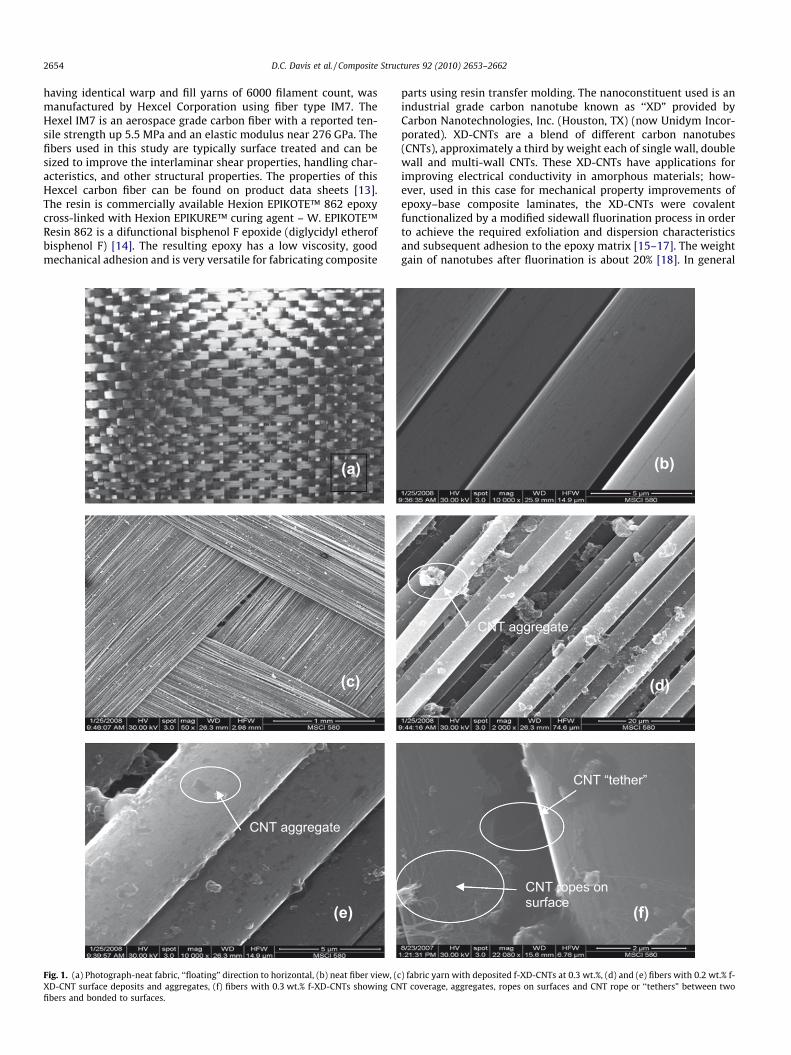
Fig. 1. (a) Photograph-neat fabric, ‘‘floating” direction to horizontal, (b) neat fiber view, (cXD-CNT surface deposits and aggregates, (f) fibers with 0.3 wt.% f-XD-CNTs showing CNfibers and bonded to surfaces.
parts using resin transfer molding. The nanoconstituent used is anindustrial grade carbon nanotube known as ‘‘XD” provided byCarbon Nanotechnologies, Inc. (Houston, TX) (now Unidym Incor-porated). XD-CNTs are a blend of different carbon nanotubes(CNTs), approximately a third by weight each of single wall, doublewall and multi-wall CNTs. These XD-CNTs have applications forimproving electrical conductivity in amorphous materials; how-ever, used in this case for mechanical property improvements ofepoxy–base composite laminates, the XD-CNTs were covalentfunctionalized by a modified sidewall fluorination process in orderto achieve the required exfoliation and dispersion characteristicsand subsequent adhesion to the epoxy matrix [15–17]. The weightgain of nanotubes after fluorination is about 20% [18]. In general
(b)
(d)
CNT aggregate
(f)CNT ropes on surface
CNT “tether”
) fabric yarn with deposited f-XD-CNTs at 0.3 wt.%, (d) and (e) fibers with 0.2 wt.% f-T coverage, aggregates, ropes on surfaces and CNT rope or ‘‘tethers” between two
D.C. Davis et al. / Composite Structures 92 (2010) 2653–2662 2655
carbon nanotube dimensions typically range from 1 to 100 nm indiameter and up to 1–10 microns in length. At the upper limitsCNTs have a theoretical ultimate tensile strength (UTS) of130 GPa and an experimentally measured UTS of up to 50 GPa[19]. The theoretical stiffness or modulus of CNTs could exceed1 TPa [20,21]. These properties would make CNTs excellent nano-scale fillers in fiber reinforced epoxy composites for improvedmechanical properties.
2.2. Composite laminate fabrication
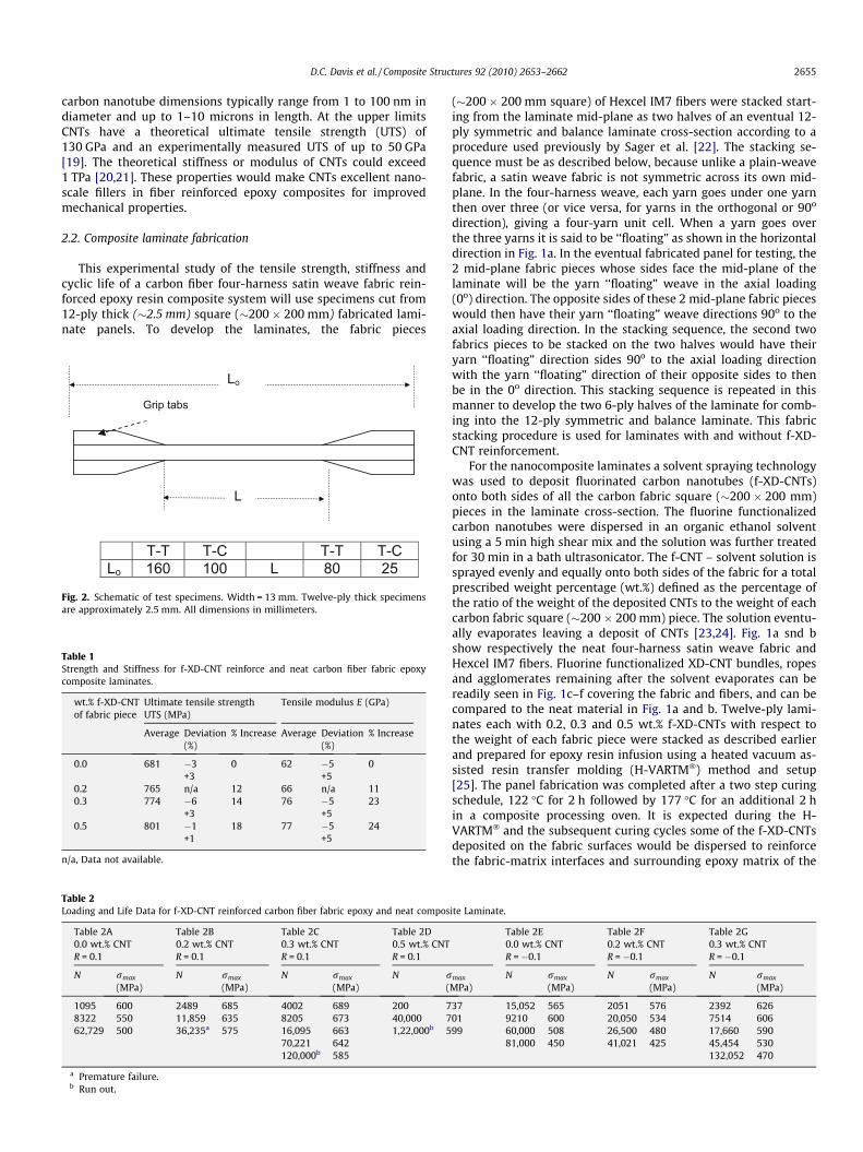
This experimental study of the tensile strength, stiffness andcyclic life of a carbon fiber four-harness satin weave fabric rein-forced epoxy resin composite system will use specimens cut from12-ply thick (�2.5 mm) square (�200 � 200 mm) fabricated lami-nate panels. To develop the laminates, the fabric pieces
L
Grip tabs
Lo
T-T T-C T-T T-C Lo 160 100 L 80 25
Fig. 2. Schematic of test specimens. Width = 13 mm. Twelve-ply thick specimensare approximately 2.5 mm. All dimensions in millimeters.
Table 1Strength and Stiffness for f-XD-CNT reinforce and neat carbon fiber fabric epoxycomposite laminates.
wt.% f-XD-CNTof fabric piece
Ultimate tensile strengthUTS (MPa)
Tensile modulus E (GPa)
Average Deviation(%)
% Increase Average Deviation(%)
% Increase
0.0 681 �3+3
0 62 �5+5
0
0.2 765 n/a 12 66 n/a 110.3 774 �6
+314 76 �5
+523
0.5 801 �1+1
18 77 �5+5
24
n/a, Data not available.
Table 2Loading and Life Data for f-XD-CNT reinforced carbon fiber fabric epoxy and neat compos
Table 2A Table 2B Table 2C Table 2D0.0 wt.% CNTR = 0.1
0.2 wt.% CNTR = 0.1
0.3 wt.% CNTR = 0.1
0.5 wt.% CNTR = 0.1
N rmax
(MPa)N rmax
(MPa)N rmax
(MPa)N r
(
1095 600 2489 685 4002 689 200 78322 550 11,859 635 8205 673 40,000 762,729 500 36,235a 575 16,095 663 1,22,000b 5
70,221 642120,000b 585
a Premature failure.b Run out.
(�200 � 200 mm square) of Hexcel IM7 fibers were stacked start-ing from the laminate mid-plane as two halves of an eventual 12-ply symmetric and balance laminate cross-section according to aprocedure used previously by Sager et al. [22]. The stacking se-quence must be as described below, because unlike a plain-weavefabric, a satin weave fabric is not symmetric across its own mid-plane. In the four-harness weave, each yarn goes under one yarnthen over three (or vice versa, for yarns in the orthogonal or 90o
direction), giving a four-yarn unit cell. When a yarn goes overthe three yarns it is said to be ‘‘floating” as shown in the horizontaldirection in Fig. 1a. In the eventual fabricated panel for testing, the2 mid-plane fabric pieces whose sides face the mid-plane of thelaminate will be the yarn ‘‘floating” weave in the axial loading(0o) direction. The opposite sides of these 2 mid-plane fabric pieceswould then have their yarn ‘‘floating” weave directions 90o to theaxial loading direction. In the stacking sequence, the second twofabrics pieces to be stacked on the two halves would have theiryarn ‘‘floating” direction sides 90o to the axial loading directionwith the yarn ‘‘floating” direction of their opposite sides to thenbe in the 0o direction. This stacking sequence is repeated in thismanner to develop the two 6-ply halves of the laminate for comb-ing into the 12-ply symmetric and balance laminate. This fabricstacking procedure is used for laminates with and without f-XD-CNT reinforcement.
For the nanocomposite laminates a solvent spraying technologywas used to deposit fluorinated carbon nanotubes (f-XD-CNTs)onto both sides of all the carbon fabric square (�200 � 200 mm)pieces in the laminate cross-section. The fluorine functionalizedcarbon nanotubes were dispersed in an organic ethanol solventusing a 5 min high shear mix and the solution was further treatedfor 30 min in a bath ultrasonicator. The f-CNT – solvent solution issprayed evenly and equally onto both sides of the fabric for a totalprescribed weight percentage (wt.%) defined as the percentage ofthe ratio of the weight of the deposited CNTs to the weight of eachcarbon fabric square (�200 � 200 mm) piece. The solution eventu-ally evaporates leaving a deposit of CNTs [23,24]. Fig. 1a snd bshow respectively the neat four-harness satin weave fabric andHexcel IM7 fibers. Fluorine functionalized XD-CNT bundles, ropesand agglomerates remaining after the solvent evaporates can bereadily seen in Fig. 1c–f covering the fabric and fibers, and can becompared to the neat material in Fig. 1a and b. Twelve-ply lami-nates each with 0.2, 0.3 and 0.5 wt.% f-XD-CNTs with respect tothe weight of each fabric piece were stacked as described earlierand prepared for epoxy resin infusion using a heated vacuum as-sisted resin transfer molding (H-VARTM�) method and setup[25]. The panel fabrication was completed after a two step curingschedule, 122 �C for 2 h followed by 177 �C for an additional 2 hin a composite processing oven. It is expected during the H-VARTM� and the subsequent curing cycles some of the f-XD-CNTsdeposited on the fabric surfaces would be dispersed to reinforcethe fabric-matrix interfaces and surrounding epoxy matrix of the
ite Laminate.
Table 2E Table 2F Table 2G0.0 wt.% CNTR = �0.1
0.2 wt.% CNTR = �0.1
0.3 wt.% CNTR = �0.1
max
MPa)N rmax
(MPa)N rmax
(MPa)N rmax
(MPa)
37 15,052 565 2051 576 2392 62601 9210 600 20,050 534 7514 60699 60,000 508 26,500 480 17,660 590
81,000 450 41,021 425 45,454 530132,052 470
2656 D.C. Davis et al. / Composite Structures 92 (2010) 2653–2662
composite laminate for improved mechanical properties [26]. Theidentical H-VARTM� procedures and curing cycles are used to fab-ricate the neat (0.0 wt.% CNTs) laminate for comparison. The panelswere limited to the lateral dimensions (�200 � 200 mm) to ensurefull infusion of the epoxy resin in all 12 stacked fabric layers thathad nanotube deposits. With the CNTs being deposited directlyon the fabric using this spraying technology, resin infusion shouldnot be hindered by increased viscosity that could be the case ifCNTs are dispersed directly in the resin prior to infusion [27]. Fab-ricated panels were evaluated for large porosities using an ultra-sound technique to eliminate any panels with large porositiesuntil expertise was developed in H-VARTM� to fabricate laminateslargely porosity free. Laminates had an average 55% fiber volumecontent.
2.3. Specimen configurations and test procedures
Test specimens were water jet cut from the fabricated panels.This was the case for panels with or without f-CNT reinforced fiberfabric. Shown in Fig. 2 are schematics of the specimens withdimension to be used in tensile strength and tension–tension(T–T) cyclic testing and in the tension–compression (T–C) cyclictesting [28]. The shorter in length specimen for T–C cyclic testingis to avoid Euler geometric buckling upon initial compression load-ing. Due to the limited size (�200 � 200 mm) of each panel gener-ally a maximum of six (6) T–T/tensile type specimens and four (4)
0
100
200
300
400
500
600
700
800
900
0.0 0.2 0.3 0.5
(a) Laminate Stren
MPa
0
10
20
30
40
50
60
70
80
90
0.0 0.2 0.3 0.5
(b) Laminate Stiffnes
GPa
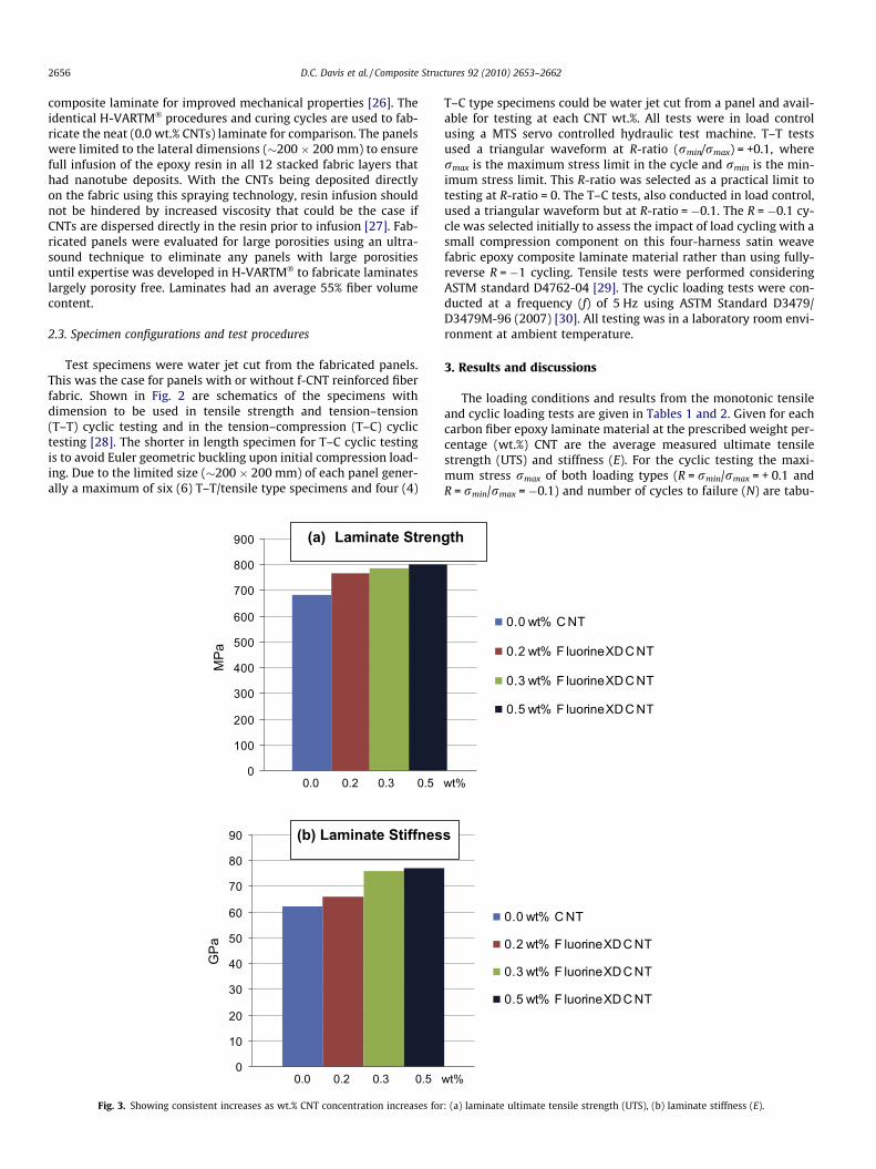
Fig. 3. Showing consistent increases as wt.% CNT concentration increases for
T–C type specimens could be water jet cut from a panel and avail-able for testing at each CNT wt.%. All tests were in load controlusing a MTS servo controlled hydraulic test machine. T–T testsused a triangular waveform at R-ratio (rmin/rmax) = +0.1, wherermax is the maximum stress limit in the cycle and rmin is the min-imum stress limit. This R-ratio was selected as a practical limit totesting at R-ratio = 0. The T–C tests, also conducted in load control,used a triangular waveform but at R-ratio = �0.1. The R = �0.1 cy-cle was selected initially to assess the impact of load cycling with asmall compression component on this four-harness satin weavefabric epoxy composite laminate material rather than using fully-reverse R = �1 cycling. Tensile tests were performed consideringASTM standard D4762-04 [29]. The cyclic loading tests were con-ducted at a frequency (f) of 5 Hz using ASTM Standard D3479/D3479M-96 (2007) [30]. All testing was in a laboratory room envi-ronment at ambient temperature.
3. Results and discussions
The loading conditions and results from the monotonic tensileand cyclic loading tests are given in Tables 1 and 2. Given for eachcarbon fiber epoxy laminate material at the prescribed weight per-centage (wt.%) CNT are the average measured ultimate tensilestrength (UTS) and stiffness (E). For the cyclic testing the maxi-mum stress rmax of both loading types (R = rmin/rmax = + 0.1 andR = rmin/rmax = �0.1) and number of cycles to failure (N) are tabu-
0.0 wt% C NT
0.2 wt% F luorineXDC NT
0.3 wt% F luorineXDC NT
0.5 wt% F luorineXDC NT
wt%
gth
0.0 wt% C NT
0.2 wt% F luorineXDC NT
0.3 wt% F luorineXDC NT
0.5 wt% F luorineXDC NT
wt%
s
: (a) laminate ultimate tensile strength (UTS), (b) laminate stiffness (E).
D.C. Davis et al. / Composite Structures 92 (2010) 2653–2662 2657
lated. Using these test results, the primary objective of this studywas to assess the impact of this proposed nanotube science andtechnology on the micro mechanisms of damage and failure ofthese carbon fiber reinforced epoxy composite laminates undermonotonic and cyclic loads. The objective was not to obtainmechanical property data for component design.
3.1. Tensile strength and stiffness
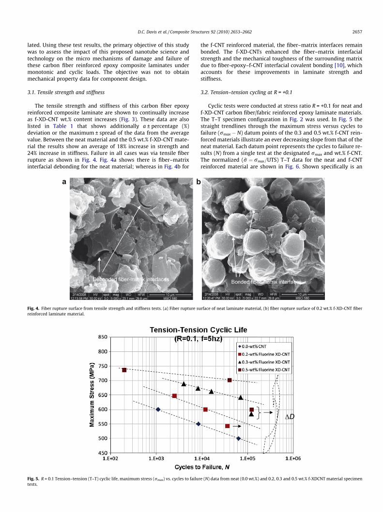
The tensile strength and stiffness of this carbon fiber epoxyreinforced composite laminate are shown to continually increaseas f-XD-CNT wt.% content increases (Fig. 3). These data are alsolisted in Table 1 that shows additionally a ± percentage (%)deviation or the maximum ± spread of the data from the averagevalue. Between the neat material and the 0.5 wt.% f-XD-CNT mate-rial the results show an average of 18% increase in strength and24% increase in stiffness. Failure in all cases was via tensile fiberrupture as shown in Fig. 4. Fig. 4a shows there is fiber–matrixinterfacial debonding for the neat material; whereas in Fig. 4b for
(b)
a b
Fig. 4. Fiber rupture surface from tensile strength and stiffness tests. (a) Fiber rupture sureinforced laminate material.
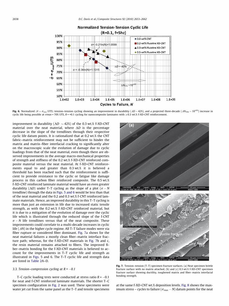
Fig. 5. R = 0.1 Tension–tension (T–T) cyclic life, maximum stress (rmax) vs. cycles to failurtests.
the f-CNT reinforced material, the fiber–matrix interfaces remainbonded. The f-XD-CNTs enhanced the fiber–matrix interfacialstrength and the mechanical toughness of the surrounding matrixdue to fiber-epoxy–f-CNT interfacial covalent bonding [10], whichaccounts for these improvements in laminate strength andstiffness.
3.2. Tension–tension cycling at R = +0.1
Cyclic tests were conducted at stress ratio R = +0.1 for neat andf-XD-CNT carbon fiber/fabric reinforced epoxy laminate materials.The T–T specimen configuration in Fig. 2 was used. In Fig. 5 thestraight trendlines through the maximum stress versus cycles tofailure (rmax � N) datum points of the 0.3 and 0.5 wt.% f-CNT rein-forced materials illustrate an ever decreasing slope from that of theneat material. Each datum point represents the cycles to failure re-sults (N) from a single test at the designated rmax and wt.% f-CNT.The normalized (~r ¼ rmax=UTS) T–T data for the neat and f-CNTreinforced material are shown in Fig. 6. Shown specifically is an
rface of neat laminate material, (b) fiber rupture surface of 0.2 wt.% f-XD-CNT fiber
ΔD
e (N) data from neat (0.0 wt.%) and 0.2, 0.3 and 0.5 wt.% f-XDCNT material specimen
ΔD ~ 42%
ΔN70% ~10+03
σ = -0.36ln(N)+1.1315
σ= -0.21ln(N)+1.0599
Fig. 6. Normalized ð~r ¼ rmas=UTSÞ tension–tension cycling showing an improvement in durability (DD � 42%), and a projected three-decade (DN70% � 10+03) increase incyclic life being possible at rmax = 70% UTS, R = +0.1 cycling for nanocomposite laminates with P0.3 wt.% f-XD-CNT reinforcement.
(a)
(b)
(c)
Ductile fracture.
Fig. 7. Tension–tension (T–T) specimen fracture surfaces. (a) Neat specimen brittlefracture surface with no matrix attached, (b) and (c) 0.3 wt.% f-XD-CNT specimenfracture surface showing ductility, toughened matrix and fiber–matrix interfacialbonding strength.
2658 D.C. Davis et al. / Composite Structures 92 (2010) 2653–2662
improvement in durability (DD � 42%) of the 0.3 wt.% f-XD-CNTmaterial over the neat material, where DD is the percentagedecrease in the slope of the trendlines through their respectivecyclic life datum points. It is rationalized that at 0.2 wt.% the CNTfabric–matrix reinforcement may not be sufficient to hinder thematrix and matrix–fiber interfacial cracking to significantly alteron the macroscopic scale the evolution of damage due to cyclicloadings from that of the neat material, even though there are ob-served improvements in the average macro-mechanical propertiesof strength and stiffness of the 0.2 wt.% f-XD-CNT reinforced com-posite material versus the neat material. At f-XD-CNT reinforce-ments equal to and greater than 0.3 wt.% it is believed athreshold has been reached such that the reinforcement is suffi-cient to provide resistance to the cyclic or fatigue like damageprocess in this carbon fiber reinforced composite. The 0.5 wt.%f-XD-CNT reinforced laminate material would have an even greaterdurability (DD) under T–T cycling as the slope of a plot (r � Ntrendline) through the data in Figs. 5 and 6 would be less than thatof the neat material and the 0.2 and 0.3 wt.% f-CNT reinforced lam-inate materials. Hence, an improved durability in this T–T cycling ismore than just an extension in life due to increased static tensilestrength, as with the 0.2 wt.% f-XD-CNT reinforced material, butit is due to a mitigation of the evolution of damage over the cycliclife which is illustrated through the reduced slope of the f-CNTr � N life trendlines versus that of the neat composite. Theseimprovements could correlate to a multi-decade increases in cycliclife (DN) in the higher cycle regime. All T–T failure modes were viafiber rupture or considered fiber dominant. Fig. 7a shows for theneat material failures a mostly clean fiber–matrix interface frac-ture path; whereas, for the f-XD-CNT materials in Fig. 7b and c,the resin material remains attached to fibers. The improved fi-ber–matrix bonding for the f-XD-CNT materials is believed to ac-count for the improvements in T–T cyclic life and strength asillustrated in Figs. 5 and 6. The T–T cyclic life and strength dataare listed in Table 2A–D.
3.3. Tension–compression cycling at R = �0.1
T–C cyclic loading tests were conducted at stress ratio R = �0.1for neat and f-CNT reinforced laminate materials. The shorter T–Cspecimen configuration in Fig. 2 was used. These specimens werewater jet cut from the same panel as the T–T and tensile specimens
at the same f-XD-CNT wt.% deposition levels. Fig. 8 shows the max-imum stress – cycles to failure (rmax � N) datum points for the neat
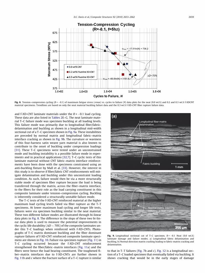
σmax = -17.51ln(N) + 736.2
σmax = -60.5ln(N) + 1151.6 ΔD~70%
Fig. 8. Tension–compression cycling (R = �0.1) of maximum fatigue stress (rmax) vs. cycles to failure (N) data plots for the neat (0.0 wt.%) and 0.2 and 0.3 wt.% f-XDCNTmaterial specimens. Trendlines are based on only the neat material buckling failure data and the 0.3 wt.% f-XD-CNT fiber rupture failure data.
(a) Longitudinal fiber-matrix delamination
Fabric buckling
(b)
Normal matrix cracking initiating at fiber-matrix interface
Fig. 9. Longitudinal sectional cut of T–C specimen. R = �0.1 Neat (0.0 wt.%)laminate damage and failure modes. a) Longitudinal fabric delamination andbuckling, b) Normal direction matrix cracking leading to fabric-matrix cracking anddelamination.
D.C. Davis et al. / Composite Structures 92 (2010) 2653–2662 2659
and f-XD-CNT laminate materials under the R = �0.1 load cycling.These data are also listed in Tables 2E–G. The neat laminate mate-rial T–C failure mode was specimen buckling at all loading levels.This failure mode was primarily due to longitudinal fiber/fabric-delamination and buckling as shown in a longitudinal mid-widthsectional cut of a T–C specimen shown in Fig. 9a. These instabilitiesare preceded by normal matrix and longitudinal fabric–matrixinterface cracking as shown in Fig. 9b. The curvature or wavinessof this four-harness satin weave yarn material is also known tocontribute to the onset of buckling under compression loadings[31]. These T–C specimens were tested under an unconstrainedmode and buckling instability is a possible failure mode in exper-iments and in practical applications [32,7]. T–C cyclic tests of thislaminate material without CNT fabric–matrix interface reinforce-ments have been done with the specimens constrained using ananti-buckling fixture by Mall et al. [33]. However, the interest inthis study is to observe if fiber/fabric CNT reinforcements will mit-igate delamination and buckling under this unconstraint loadingcondition. As such, failure would then be via a more structurallystable mode of specimen fiber rupture because the load is beingtransferred through the matrix, across the fiber–matrix interface,to the fibers for their role as the load carrying constituent in thiscomposite laminate under tension–compression cycling. Bucklingis inherently considered a structurally unstable failure mode.
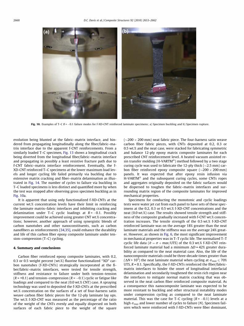
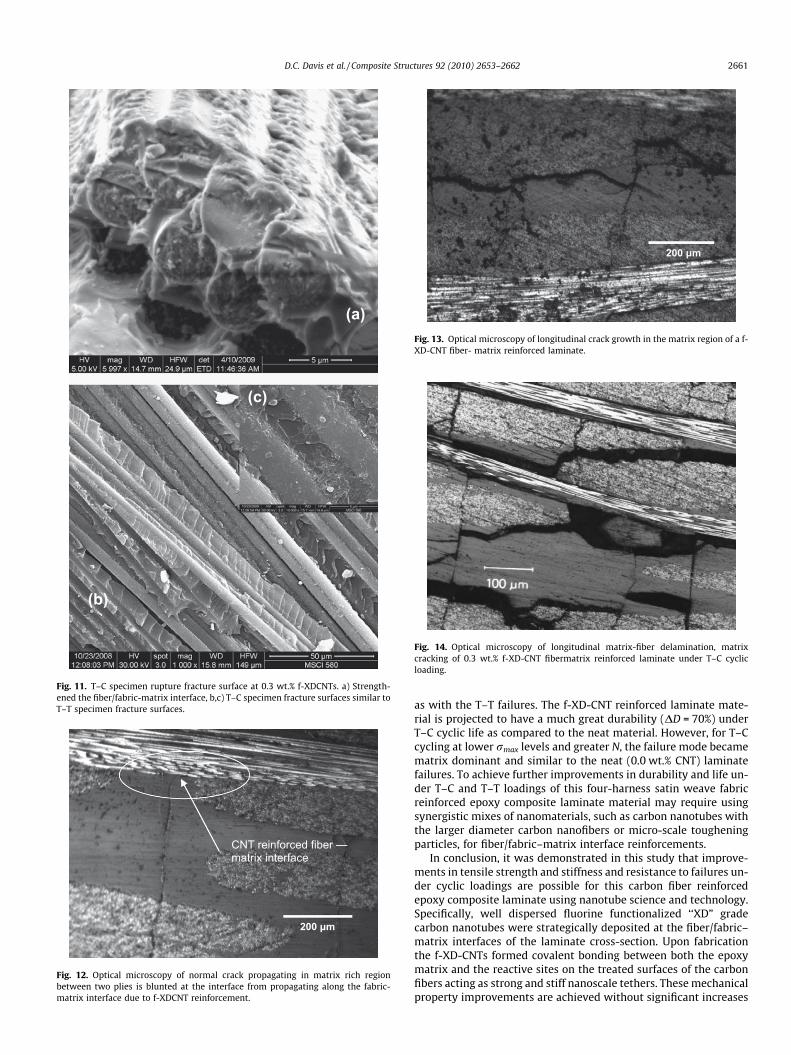
The T–C tests of the f-XD-CNT reinforced material at the highermaximum load cycling levels failed via fiber rupture as the T–Tspecimens. At lower maximum load cycling and longer life tests,failures were via specimen buckling similar to the neat material.These two different failure modes are illustrated through bi-lineardata plots in Fig. 8. The difference in the slops of these two bi-lin-ear data plots is used to measure the potential improvements inthe cyclic life durability (DD � 70%) of the composite laminates un-der this T–C loadings when reinforced with f-XD-CNTs. Photo-graphs of T–C matrix dominant buckling and the fiber dominantrupture failures of f-XD-CNT reinforced composite laminate speci-mens are shown in Fig. 10. Failure via specimen rupture (Fig. 11) inT–C cycling occurred because the f-XD-CNT reinforcementstrengthened the fiber/fabric–matrix interfaces (Fig. 11a) and thefibers were hence the load bearing constituent. The toughened fi-ber–matrix interfaces due to f-XD-CNTs are further shown inFig. 11b and c where the fracture surface of a T–C rupture is similar
to that in T–T failures (Fig. 7b and c). Fig. 12 is a longitudinal sec-tion of a T–C loaded specimen that eventually failed via buckling. Itshows cracking that would be in the early stages of damage
(b)(a)
Fig. 10. Examples of T–C R = �0.1 failure modes for f-XD-CNT reinforced laminate specimens; a) Specimen buckling and b) Specimen rupture.
2660 D.C. Davis et al. / Composite Structures 92 (2010) 2653–2662
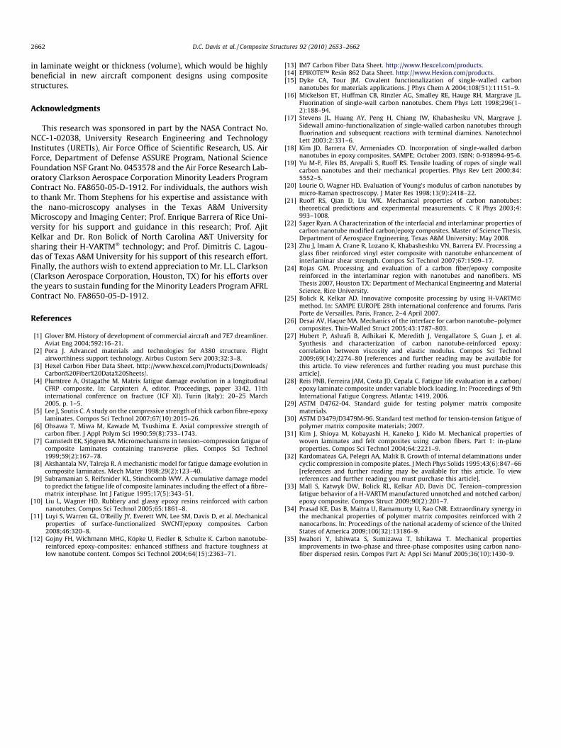
evolution being blunted at the fabric–matrix interface, and hin-dered from propagating longitudinally along the fiber/fabric–ma-trix interface due to the apparent f-CNT reinforcements. From asimilarly loaded T–C specimen, Fig. 13 shows a longitudinal crackbeing diverted from the longitudinal fiber/fabric–matrix interfaceand propagating in possibly a least resistive fracture path due tof-CNT fabric–matrix interface reinforcement. Eventually, the f-XD-CNT reinforced T–C specimens at the lower maximum load lev-els and longer cycling life failed primarily via buckling due toextensive matrix cracking and fiber–matrix delamination as illus-trated in Fig. 14. The number of cycles to failure via buckling inT–C loaded specimens is less distinct and quantified more by whenthe test was stopped after observing gross specimen buckling as inFig. 10a.
It is apparent that using only functionalized f-XD-CNTs at thecurrent wt.% concentration levels have their limit in reinforcingthe laminate matrix–fabric interfaces and inhibiting cracking anddelamination under T–C cyclic loadings at R = �0.1. Possiblyimprovement could be achieved using greater CNT wt.% concentra-tions; however, another approach of using synergistic blends ofcarbon nanotubes and other nanoconstituents, such as carbonnanofibers as reinforcements [34,35], could enhance the durabilityand life of this carbon fiber epoxy composite laminate under ten-sion–compression (T–C) cycling.
4. Summary and conclusions
Carbon fiber reinforced epoxy composite laminates, with 0.2,0.3 or 0.5 weight percent (wt.%) fluorine functionalized ‘‘XD” car-bon nanotubes (f-XD-CNTs) strategically incorporated at the fi-ber/fabric–matrix interfaces, were tested for tensile strength,stiffness and resistance to failure under both tension–tension(R = +0.1) and tension–compression (R = �0.1) cyclic or fatigue likeloadings and compared to the neat (0.0 wt.% CNT) case. A sprayingtechnology was used to deposited the f-XD-CNTs at the prescribedwt.% concentration on the surfaces of a set of four-harness satinweave carbon fiber fabric pieces for the 12-ply laminate lay ups.The wt.% f-XD-CNT was measured as the percentage of the ratioof the weight of the CNTs evenly and equally dispersed on bothsurfaces of each fabric piece to the weight of the square
(�200 � 200 mm) neat fabric piece. The four-harness satin weavecarbon fiber fabric pieces, with CNTs deposited at 0.2, 0.3 or0.5 wt.% and the neat case, were stacked for fabricating symmetricand balance 12-ply epoxy matrix composite laminates for eachprescribed CNT reinforcement level. A heated vacuum assisted re-sin transfer molding (H-VARTM�) method followed by a two stagecuring cycle was used to fabricate the 12-ply thick (�2.5 mm) car-bon fiber reinforced epoxy composite square (�200 � 200 mm)panels. It was expected that after epoxy resin infusion viaH-VARTM� and the subsequent curing cycles, some CNTs ropesand aggregates originally deposited on the fabric surfaces wouldbe dispersed to toughen the fabric–matrix interfaces and sur-rounding matrix region of the composite laminates for improvedmechanical properties.
Specimens for conducting the monotonic and cyclic loadingstests were water jet cut from each panel to have sets of these spec-imens at the 0.2, 0.3 or 0.5 wt.% f-XD-CNT concentrations and theneat (0.0 wt.%) case. The results showed tensile strength and stiff-ness of the composite gradually increased with f-CNT wt.% concen-tration increases. The tensile strength of the 0.5 wt.% f-XD-CNTreinforced laminate was on the average 18% greater than the neatlaminate materials and the stiffness was on the average 24% great-er. However, as shown in Fig. 6, the most significant improvementin mechanical properties was in T–T cyclic life. The normalized T–Tcyclic life data (~r ¼ rþmax=UTS) of the 0.3 wt.% f-XD-CNT rein-forced laminate material had a minimum DD = 42% greater dura-bility as compared to the neat material case. Also, the life of thenanocomposite materials could be three-decade times greater than(DN > 103) the neat laminate material when cycling at rmax 6 70%UTS, R = 0.1. Specifically, the f-XD-CNTs reinforced the fiber/fabric-matrix interfaces to hinder the onset of longitudinal interfacialdelamination and secondarily toughened the resin rich region nearthe interfaces to mitigate normal matrix cracking that was ob-served in the neat carbon fiber reinforced composite material. Asa consequence this nanocomposite laminate was expected to bemore resistant to buckling and other structural instability modesunder compression cycling as compared to the neat laminatematerial. This was the case for T–C cycling (R = �0.1) levels at ahigh rmax and lower number of cycles to failure (N). Specimen fail-ures which were reinforced with f-XD-CNTs were fiber dominant,
200 µm
CNT reinforced fiber – matrix interface
Fig. 12. Optical microscopy of normal crack propagating in matrix rich regionbetween two plies is blunted at the interface from propagating along the fabric-matrix interface due to f-XDCNT reinforcement.
200 µm
Fig. 13. Optical microscopy of longitudinal crack growth in the matrix region of a f-XD-CNT fiber- matrix reinforced laminate.
Fig. 14. Optical microscopy of longitudinal matrix-fiber delamination, matrixcracking of 0.3 wt.% f-XD-CNT fibermatrix reinforced laminate under T–C cyclicloading.
(c)
(b)
(a)
Fig. 11. T–C specimen rupture fracture surface at 0.3 wt.% f-XDCNTs. a) Strength-ened the fiber/fabric-matrix interface, b,c) T–C specimen fracture surfaces similar toT–T specimen fracture surfaces.
D.C. Davis et al. / Composite Structures 92 (2010) 2653–2662 2661
as with the T–T failures. The f-XD-CNT reinforced laminate mate-rial is projected to have a much great durability (DD = 70%) underT–C cyclic life as compared to the neat material. However, for T–Ccycling at lower rmax levels and greater N, the failure mode becamematrix dominant and similar to the neat (0.0 wt.% CNT) laminatefailures. To achieve further improvements in durability and life un-der T–C and T–T loadings of this four-harness satin weave fabricreinforced epoxy composite laminate material may require usingsynergistic mixes of nanomaterials, such as carbon nanotubes withthe larger diameter carbon nanofibers or micro-scale tougheningparticles, for fiber/fabric–matrix interface reinforcements.
In conclusion, it was demonstrated in this study that improve-ments in tensile strength and stiffness and resistance to failures un-der cyclic loadings are possible for this carbon fiber reinforcedepoxy composite laminate using nanotube science and technology.Specifically, well dispersed fluorine functionalized ‘‘XD” gradecarbon nanotubes were strategically deposited at the fiber/fabric–matrix interfaces of the laminate cross-section. Upon fabricationthe f-XD-CNTs formed covalent bonding between both the epoxymatrix and the reactive sites on the treated surfaces of the carbonfibers acting as strong and stiff nanoscale tethers. These mechanicalproperty improvements are achieved without significant increases
2662 D.C. Davis et al. / Composite Structures 92 (2010) 2653–2662
in laminate weight or thickness (volume), which would be highlybeneficial in new aircraft component designs using compositestructures.
Acknowledgments
This research was sponsored in part by the NASA Contract No.NCC-1-02038, University Research Engineering and TechnologyInstitutes (URETIs), Air Force Office of Scientific Research, US. AirForce, Department of Defense ASSURE Program, National ScienceFoundation NSF Grant No. 0453578 and the Air Force Research Lab-oratory Clarkson Aerospace Corporation Minority Leaders ProgramContract No. FA8650-05-D-1912. For individuals, the authors wishto thank Mr. Thom Stephens for his expertise and assistance withthe nano-microscopy analyses in the Texas A&M UniversityMicroscopy and Imaging Center; Prof. Enrique Barrera of Rice Uni-versity for his support and guidance in this research; Prof. AjitKelkar and Dr. Ron Bolick of North Carolina A&T University forsharing their H-VARTM� technology; and Prof. Dimitris C. Lagou-das of Texas A&M University for his support of this research effort.Finally, the authors wish to extend appreciation to Mr. L.L. Clarkson(Clarkson Aerospace Corporation, Houston, TX) for his efforts overthe years to sustain funding for the Minority Leaders Program AFRLContract No. FA8650-05-D-1912.
References
[1] Glover BM. History of development of commercial aircraft and 7E7 dreamliner.Aviat Eng 2004;592:16–21.
[2] Pora J. Advanced materials and technologies for A380 structure. Flightairworthiness support technology. Airbus Custom Serv 2003;32:3–8.
[3] Hexel Carbon Fiber Data Sheet. http://www.hexcel.com/Products/Downloads/Carbon%20Fiber%20Data%20Sheets/.
[4] Plumtree A, Ostagathe M. Matrix fatigue damage evolution in a longitudinalCFRP composite. In: Carpinteri A, editor. Proceedings, paper 3342, 11thinternational conference on fracture (ICF XI). Turin (Italy); 20–25 March2005, p. 1–5.
[5] Lee J, Soutis C. A study on the compressive strength of thick carbon fibre-epoxylaminates. Compos Sci Technol 2007;67(10):2015–26.
[6] Ohsawa T, Miwa M, Kawade M, Tsushima E. Axial compressive strength ofcarbon fiber. J Appl Polym Sci 1990;59(8):733–1743.
[7] Gamstedt EK, Sjögren BA. Micromechanisms in tension–compression fatigue ofcomposite laminates containing transverse plies. Compos Sci Technol1999;59(2):167–78.
[8] Akshantala NV, Talreja R. A mechanistic model for fatigue damage evolution incomposite laminates. Mech Mater 1998;29(2):123–40.
[9] Subramanian S, Reifsnider KL, Stinchcomb WW. A cumulative damage modelto predict the fatigue life of composite laminates including the effect of a fibre–matrix interphase. Int J Fatigue 1995;17(5):343–51.
[10] Liu L, Wagner HD. Rubbery and glassy epoxy resins reinforced with carbonnanotubes. Compos Sci Technol 2005;65:1861–8.
[11] Luyi S, Warren GL, O’Reilly JY, Everett WN, Lee SM, Davis D, et al. Mechanicalproperties of surface-functionalized SWCNT/epoxy composites. Carbon2008;46:320–8.
[12] Gojny FH, Wichmann MHG, Köpke U, Fiedler B, Schulte K. Carbon nanotube-reinforced epoxy-composites: enhanced stiffness and fracture toughness atlow nanotube content. Compos Sci Technol 2004;64(15):2363–71.
[13] IM7 Carbon Fiber Data Sheet. http://www.Hexcel.com/products.[14] EPIKOTE™ Resin 862 Data Sheet. http://www.Hexion.com/products.[15] Dyke CA, Tour JM. Covalent functionalization of single-walled carbon
nanotubes for materials applications. J Phys Chem A 2004;108(51):11151–9.[16] Mickelson ET, Huffman CB, Rinzler AG, Smalley RE, Hauge RH, Margrave JL.
Fluorination of single-wall carbon nanotubes. Chem Phys Lett 1998;296(1–2):188–94.
[17] Stevens JL, Huang AY, Peng H, Chiang IW, Khabashesku VN, Margrave J.Sidewall amino-functionalization of single-walled carbon nanotubes throughfluorination and subsequent reactions with terminal diamines. NanotechnolLett 2003;2:331–6.
[18] Kim JD, Barrera EV, Armeniades CD. Incorporation of single-walled darbonnanotubes in epoxy composites. SAMPE; October 2003. ISBN: 0-938994-95-6.
[19] Yu M-F, Files BS, Arepalli S, Ruoff RS. Tensile loading of ropes of single wallcarbon nanotubes and their mechanical properties. Phys Rev Lett 2000;84:5552–5.
[20] Lourie O, Wagner HD. Evaluation of Young’s modulus of carbon nanotubes bymicro-Raman spectroscopy. J Mater Res 1998;13(9):2418–22.
[21] Ruoff RS, Qian D, Liu WK. Mechanical properties of carbon nanotubes:theoretical predictions and experimental measurements. C R Phys 2003;4:993–1008.
[22] Sager Ryan. A Characterization of the interfacial and interlaminar properties ofcarbon nanotube modified carbon/epoxy composites. Master of Science Thesis,Department of Aerospace Engineering, Texas A&M University; May 2008.
[23] Zhu J, Imam A, Crane R, Lozano K, Khabasheshku VN, Barrera EV. Processing aglass fiber reinforced vinyl ester composite with nanotube enhancement ofinterlaminar shear strength. Compos Sci Technol 2007;67:1509–17.
[24] Rojas GM. Processing and evaluation of a carbon fiber/epoxy compositereinforced in the interlaminar region with nanotubes and nanofibers. MSThesis 2007, Houston TX: Department of Mechanical Engineering and MaterialScience, Rice University.
[25] Bolick R, Kelkar AD. Innovative composite processing by using H-VARTM�method. In: SAMPE EUROPE 28th international conference and forums. ParisPorte de Versailles, Paris, France, 2–4 April 2007.
[26] Desai AV, Haque MA. Mechanics of the interface for carbon nanotube–polymercomposites. Thin-Walled Struct 2005;43:1787–803.
[27] Hubert P, Ashrafi B, Adhikari K, Meredith J, Vengallatore S, Guan J, et al.Synthesis and characterization of carbon nanotube-reinforced epoxy:correlation between viscosity and elastic modulus. Compos Sci Technol2009;69(14):2274–80 [references and further reading may be available forthis article. To view references and further reading you must purchase thisarticle].
[28] Reis PNB, Ferreira JAM, Costa JD, Cepala C. Fatigue life evaluation in a carbon/epoxy laminate composite under variable block loading. In: Proceedings of 9thInternational Fatigue Congress. Atlanta; 1419, 2006.
[29] ASTM D4762-04. Standard guide for testing polymer matrix compositematerials.
[30] ASTM D3479/D3479M-96. Standard test method for tension-tension fatigue ofpolymer matrix composite materials; 2007.
[31] Kim J, Shioya M, Kobayashi H, Kaneko J, Kido M. Mechanical properties ofwoven laminates and felt composites using carbon fibers. Part 1: in-planeproperties. Compos Sci Technol 2004;64:2221–9.
[32] Kardomateas GA, Pelegri AA, Malik B. Growth of internal delaminations undercyclic compression in composite plates. J Mech Phys Solids 1995;43(6):847–66[references and further reading may be available for this article. To viewreferences and further reading you must purchase this article].
[33] Mall S, Katwyk DW, Bolick RL, Kelkar AD, Davis DC. Tension–compressionfatigue behavior of a H-VARTM manufactured unnotched and notched carbon/epoxy composite. Compos Struct 2009;90(2):201–7.
[34] Prasad KE, Das B, Maitra U, Ramamurty U, Rao CNR. Extraordinary synergy inthe mechanical properties of polymer matrix composites reinforced with 2nanocarbons. In: Proceedings of the national academy of science of the UnitedStates of America 2009;106(32):13186–9.
[35] Iwahori Y, Ishiwata S, Sumizawa T, Ishikawa T. Mechanical propertiesimprovements in two-phase and three-phase composites using carbon nano-fiber dispersed resin. Compos Part A: Appl Sci Manuf 2005;36(10):1430–9.
Related Documents


![International Journal of Engineering RESEARCHnanoparticles in the epoxy resin. Navidfar et al. [23] studied the influence of processing condition and carbon nanotube on mechanical](https://static.cupdf.com/doc/110x72/611d28076ebbae26db65518f/international-journal-of-engineering-nanoparticles-in-the-epoxy-resin-navidfar.jpg)