Published in IET Signal Processing Received on 8th April 2013 Revised on 4th July 2013 Accepted on 9th July 2013 doi: 10.1049/iet-spr.2013.0139 ISSN 1751-9675 Improved sub-band adaptive thresholding function for denoising of satellite image based on evolutionary algorithms Vivek Soni 1 , Ashish Kumar Bhandari 1 , Anil Kumar 1 , Girish Kumar Singh 2,3 1 Indian Institute of Information Technology Design and Manufacturing, Jabalpur 482011, MP, India 2 Department of Electrical Engineering, Indian Institute Technology Roorkee, Uttrakhand 247667, India 3 Present Address: Visiting Professor, Department of Electrical Engineering, University of Malaya, Malaysia E-mail: [email protected] Abstract: In this study, an improved method based on evolutionary algorithms for denoising of satellite images is proposed. In this approach, the stochastic global optimisation techniques such as Cuckoo Search (CS) algorithm, artificial bee colony (ABC), and particle swarm optimisation (PSO) technique and their different variants are exploited for learning the parameters of adaptive thresholding function required for optimum performance. It was found that the CS algorithm and ABC algorithm-based denoising approach give better performance in terms of edge preservation index or edge keeping index (EPI or EKI) peak signal-to-noise ratio (PSNR) and signal-to-noise ratio (SNR) as compared to PSO-based denoising approach. The proposed technique has been tested on satellite images. The quantitative (EPI, PSNR and SNR) and visual (denoised images) results show superiority of the proposed technique over conventional and state-of-the-art image denoising techniques. 1 Introduction Satellite images are used in many applications such as geographical information system, astronomy and geoscience studies. Data sets collected by image sensors are generally contaminated by noise. Distinct types of noise like additive noise (Gaussian noise), multiplicative noise (Speckle noise) and artefacts in different imaging modalities degrade the image quality. Wrong instrumentation, problems with data acquisition process, and interfering natural phenomena all degrade the data of interest. Owing to such degradation, human interpretation as well as accuracy of the processing methods, in case of satellite imaging, is severely affected. Computer-aided analysis and quantitative measurements become difficult and unreliable because of poor image quality. Thus, denoising and enhancement of the images become necessary for many practical applications. Image denoising still remains a challenge for researchers because noise removal introduces artefacts and blurring of the image causing a very drastic reduction in information. The image denoising research can be broadly divided into two domains; spatial and transform domain [1, 2]. Among these two domains, in last two decades, lot of works has been done in wavelet transform (WT) domain. Wavelet thresholding denoising technique is very useful and important research field. Owing to inherent properties of wavelet coefficients like sparsity and decomposition [3], effective and simplified implementation of thresholding technique in wavelet domain have become easy. ‘Wavelet shrinkages’ methodology has been proposed by Donoho et al. [4, 5] for classifying the wavelet coefficients of real-world noisy data, which have been further modified to increase signal-to-noise ratio (SNR). Intensive research [6–8] was carried out for improving the performance of thresholding, based on wavelet domain. There has been continuos focus on development and implementation of the thresholding function. The Bayes Shrink and Sure Shrink gives good performance [9], on denoising by wavelet shrinkage like soft, hard, garrote and semi-soft. Statistical approach like Bayesian approach for denoising the images has been proposed by researchers in [10–12]. Various noise models for distribution of noisy wavelet coefficients such as hidden Markov models [13], Gaussian [14], Fisher-Tippet [15] and Maxwell [16] were analysed. These methods are dependent on a specific noise model, and thus reduces their flexibility. Further, some researchers [17–20] have proposed a mixture of statistical models, which is more computationally complex. Rabbani [20] has proposed a mixture of Laplacian and Gaussian model for estimating the noise free wavelet coefficient, and a mixture of Gaussian and Rayleigh model for additive noise, but it is complex in computation. Joint bilateral filter in spatial domain and trivariate shrinkages filter in wavelet domain is proposed by Yu et al. [21]. Computational complexity has increased because of spatial operation. Further, improvement in perceptual quality of an image can also be achieved by proper shrinkages using an optimum threshold value determined by sub-band adaptive method based on WT, discrete cosine transform (DCT), www.ietdl.org 720 & The Institution of Engineering and Technology 2013 IET Signal Process., 2013, Vol. 7, Iss. 8, pp. 720–730 doi: 10.1049/iet-spr.2013.0139

Welcome message from author
This document is posted to help you gain knowledge. Please leave a comment to let me know what you think about it! Share it to your friends and learn new things together.
Transcript
www.ietdl.org
7&
Published in IET Signal ProcessingReceived on 8th April 2013Revised on 4th July 2013Accepted on 9th July 2013doi: 10.1049/iet-spr.2013.0139
20The Institution of Engineering and Technology 2013
ISSN 1751-9675
Improved sub-band adaptive thresholding function fordenoising of satellite image based on evolutionaryalgorithmsVivek Soni1, Ashish Kumar Bhandari1, Anil Kumar1, Girish Kumar Singh2,3
1Indian Institute of Information Technology Design and Manufacturing, Jabalpur 482011, MP, India2Department of Electrical Engineering, Indian Institute Technology Roorkee, Uttrakhand 247667, India3Present Address: Visiting Professor, Department of Electrical Engineering, University of Malaya, Malaysia
E-mail: [email protected]
Abstract: In this study, an improved method based on evolutionary algorithms for denoising of satellite images is proposed. Inthis approach, the stochastic global optimisation techniques such as Cuckoo Search (CS) algorithm, artificial bee colony (ABC),and particle swarm optimisation (PSO) technique and their different variants are exploited for learning the parameters of adaptivethresholding function required for optimum performance. It was found that the CS algorithm and ABC algorithm-based denoisingapproach give better performance in terms of edge preservation index or edge keeping index (EPI or EKI) peak signal-to-noiseratio (PSNR) and signal-to-noise ratio (SNR) as compared to PSO-based denoising approach. The proposed technique has beentested on satellite images. The quantitative (EPI, PSNR and SNR) and visual (denoised images) results show superiority of theproposed technique over conventional and state-of-the-art image denoising techniques.
1 Introduction
Satellite images are used in many applications such asgeographical information system, astronomy and geosciencestudies. Data sets collected by image sensors are generallycontaminated by noise. Distinct types of noise like additivenoise (Gaussian noise), multiplicative noise (Speckle noise)and artefacts in different imaging modalities degrade theimage quality. Wrong instrumentation, problems with dataacquisition process, and interfering natural phenomena alldegrade the data of interest. Owing to such degradation,human interpretation as well as accuracy of the processingmethods, in case of satellite imaging, is severely affected.Computer-aided analysis and quantitative measurementsbecome difficult and unreliable because of poor imagequality. Thus, denoising and enhancement of the imagesbecome necessary for many practical applications. Imagedenoising still remains a challenge for researchers becausenoise removal introduces artefacts and blurring of the imagecausing a very drastic reduction in information. The imagedenoising research can be broadly divided into twodomains; spatial and transform domain [1, 2]. Among thesetwo domains, in last two decades, lot of works has beendone in wavelet transform (WT) domain. Waveletthresholding denoising technique is very useful andimportant research field.Owing to inherent properties of wavelet coefficients like
sparsity and decomposition [3], effective and simplifiedimplementation of thresholding technique in waveletdomain have become easy. ‘Wavelet shrinkages’
methodology has been proposed by Donoho et al. [4, 5] forclassifying the wavelet coefficients of real-world noisy data,which have been further modified to increasesignal-to-noise ratio (SNR). Intensive research [6–8] wascarried out for improving the performance of thresholding,based on wavelet domain. There has been continuos focuson development and implementation of the thresholdingfunction. The Bayes Shrink and Sure Shrink gives goodperformance [9], on denoising by wavelet shrinkage likesoft, hard, garrote and semi-soft. Statistical approach likeBayesian approach for denoising the images has beenproposed by researchers in [10–12]. Various noise modelsfor distribution of noisy wavelet coefficients such as hiddenMarkov models [13], Gaussian [14], Fisher-Tippet [15] andMaxwell [16] were analysed. These methods are dependenton a specific noise model, and thus reduces their flexibility.Further, some researchers [17–20] have proposed a mixtureof statistical models, which is more computationallycomplex. Rabbani [20] has proposed a mixture ofLaplacian and Gaussian model for estimating the noise freewavelet coefficient, and a mixture of Gaussian and Rayleighmodel for additive noise, but it is complex in computation.Joint bilateral filter in spatial domain and trivariateshrinkages filter in wavelet domain is proposed by Yu et al.[21].Computational complexity has increased because of spatial
operation. Further, improvement in perceptual quality of animage can also be achieved by proper shrinkages using anoptimum threshold value determined by sub-band adaptivemethod based on WT, discrete cosine transform (DCT),
IET Signal Process., 2013, Vol. 7, Iss. 8, pp. 720–730doi: 10.1049/iet-spr.2013.0139
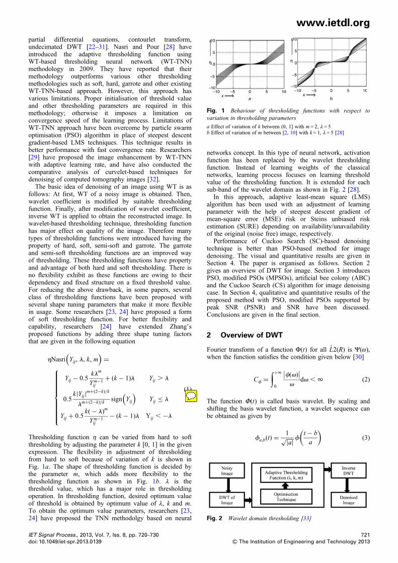
Fig. 2 Wavelet domain thresholding [33]
Fig. 1 Behaviour of thresholding functions with respect tovariation in thresholding parameters
a Effect of variation of k between (0, 1] with m = 2, λ = 5b Effect of variation of m between [2, 10] with k = 1, λ = 5 [28]
www.ietdl.org
partial differential equations, contourlet transform,undecimated DWT [22–31]. Nasri and Pour [28] haveintroduced the adaptive thresholding function usingWT-based thresholding neural network (WT-TNN)methodology in 2009. They have reported that theirmethodology outperforms various other thresholdingmethodologies such as soft, hard, garrote and other existingWT-TNN-based approach. However, this approach hasvarious limitations. Proper initialisation of threshold valueand other thresholding parameters are required in thismethodology; otherwise it imposes a limitation onconvergence speed of the learning process. Limitations ofWT-TNN approach have been overcome by particle swarmoptimisation (PSO) algorithm in place of steepest descentgradient-based LMS techniques. This technique results inbetter performance with fast convergence rate. Researchers[29] have proposed the image enhancement by WT-TNNwith adaptive learning rate, and have also conducted thecomparative analysis of curvelet-based techniques fordenoising of computed tomography images [32].The basic idea of denoising of an image using WT is asfollows: At first, WT of a noisy image is obtained. Then,wavelet coefficient is modified by suitable thresholdingfunction. Finally, after modification of wavelet coefficient,inverse WT is applied to obtain the reconstructed image. Inwavelet-based thresholding technique, thresholding functionhas major effect on quality of the image. Therefore manytypes of thresholding functions were introduced having theproperty of hard, soft, semi-soft and garrote. The garroteand semi-soft thresholding functions are an improved wayof thresholding. These thresholding functions have propertyand advantage of both hard and soft thresholding. There isno flexibility exhibit as these functions are owing to theirdependency and fixed structure on a fixed threshold value.For reducing the above drawback, in some papers, severalclass of thresholding functions have been proposed withseveral shape tuning parameters that make it more flexiblein usage. Some researchers [23, 24] have proposed a formof soft thresholding function. For better flexibility andcapability, researchers [24] have extended Zhang’sproposed functions by adding three shape tuning factorsthat are given in the following equation
hNasri Yij, l, k, m( )
=
Yij − 0.5klm
Ym−1ij
+ (k − 1)l Yij . l
0.5k|Yij|m+(2−k)/k
lm+(2−k)/k sign Yij
( )Yij ≤ l
Yij + 0.5k(− l)m
Ym−1ij
− (k − 1)l Yij , −l
⎧⎪⎪⎪⎪⎪⎪⎪⎪⎨⎪⎪⎪⎪⎪⎪⎪⎪⎩
(1)
Thresholding function η can be varied from hard to softthresholding by adjusting the parameter k [0, 1] in the givenexpression. The flexibility in adjustment of thresholdingfrom hard to soft because of variation of k is shown inFig. 1a. The shape of thresholding function is decided bythe parameter m, which adds more flexibility to thethresholding function as shown in Fig. 1b. λ is thethreshold value, which has a major role in thresholdingoperation. In thresholding function, desired optimum valueof threshold is obtained by optimum value of λ, k and m.To obtain the optimum value parameters, researchers [23,24] have proposed the TNN methodolgy based on neural
IET Signal Process., 2013, Vol. 7, Iss. 8, pp. 720–730doi: 10.1049/iet-spr.2013.0139
networks concept. In this type of neural network, activationfunction has been replaced by the wavelet thresholdingfunction. Instead of learning weights of the classicalnetworks, learning process focuses on learning thresholdvalue of the thresholding function. It is extended for eachsub-band of the wavelet domain as shown in Fig. 2 [28].In this approach, adaptive least-mean square (LMS)
algorithm has been used with an adjustment of learningparameter with the help of steepest descent gradient ofmean-square error (MSE) risk or Steins unbiased riskestimation (SURE) depending on availability/unavailabilityof the original (noise free) image, respectively.Performance of Cuckoo Search (SC)-based denoising
technique is better than PSO-based method for imagedenoising. The visual and quantitative results are given inSection 4. The paper is organised as follows. Section 2gives an overview of DWT for image. Section 3 introducesPSO, modified PSOs (MPSOs), artificial bee colony (ABC)and the Cuckoo Search (CS) algorithm for image denoisingcase. In Section 4, qualitative and quantitative results of theproposed method with PSO, modified PSOs supported bypeak SNR (PSNR) and SNR have been discussed.Conclusions are given in the final section.
2 Overview of DWT
Fourier transform of a function Φ(t) for all L^2(R) is Ψ(ω),
when the function satisfies the condition given below [30]
Cf =∫+1
0
c(v)∣∣ ∣∣v
dv , 1 (2)
The function Φ(t) is called basis wavelet. By scaling andshifting the basis wavelet function, a wavelet sequence canbe obtained as given by
fa,b(t) =1a| |√ f
t − b
a
( )(3)
721& The Institution of Engineering and Technology 2013
Administrator
Sticky Note
Soft Thresholding
www.ietdl.org
where a, b∈ R, a≠ 0, and a is defined as the stretch factor, bis defined as the shift factor.The image signal is a two-dimensional signal. Thecontinuous signal WT is given as
f (x, y) = 1
Cf
∫1
a
∫+1
−1
∫+1
−1Wf a, b1, b2
( ) 1af
× x− b1a
,y− b2
a
( )dxdy
(4)
Decomposition and reconstruction of two-dimensional DWTuses Mallat fast algorithm. Suppose ‘I’ is the locatedtwo-dimensional image, then wavelet decompositionalgorithm is given by
I1 = LRLCI , D1 = LRGCI and D2 = GRLCI ,
D3 = GRGCI(5)
where I is the low frequency operator map obtained after firstlevel decomposition. D1, D2 and D3 are the horizontal,vertical, diagonal direction, respectively, in thehigh-frequency operator map. L and G is a filteringoperator, which is determined by choosing the waveletfunction. R and C stand for row and column operation,respectively.Reconstruction of an image from wavelet coefficients is as
follows
I = �LC�LRI1 + �GC
�LRD1 + �LC �GRD
2 + �GC�GRD
3 (6)
where I and G are the conjugate transpose operator of L andG, respectively.
3 Different evolutionary techniques fordenoising of satellite images
3.1 PSO technique
PSO technique for image denoising was proposed by Bhutadaet al. [33]. In this paper, wavelet coefficient is thresholded byan adaptive thresholding function. PSO is used for tuning thethresholding function parameters λ, k and m. PSO algorithmis inspired by social behaviour patterns of the organismsthat live and interact within large groups. It is simulation ofbehaviour observed in flocks of birds, swarm of bees,human social behaviour and school of fish. Globalexploration and local exploration feature duringoptimisation process is the key feature of PSO. They havealso proposed edge preserved image enhancement usingadaptive fusion of images denoised by wavelet and curvelettransform [34] and fast adaptive learning algorithm forsub-band adaptive thresholding function in image denoising[35].PSO model consists of swarm of particles, which are
initialised with a population of random solutions. Theseparticles move iteratively through n-dimensional problemspace in search of new solution depending upon the bestfitness value of the particles, which is calculated by usingcertain quality measures. Search for solution continues tillcertain stopping criteria is achieved or a fixed number ofiterations is completed. PSO can be formulated in bothsupervised and unsupervised way. Here, fitness function istaken as MSE, which is to be minimised.
722& The Institution of Engineering and Technology 2013
The minimum value of MSE is required to be estimated by(7). Thresholding function parameters are optimised forminimum value of MSE for getting optimum performanceof the thresholding function. Therefore the fitness criteriafor PSO-based learning process is given by
f = MSE y, y( ) = 1
N
∑Nn=1
y(n)− y(n)( )2
(7)
where N is the size of sub-band, y(n) is the WT coefficientsof noise free image, y^(n) is the thresholded WT coefficientsof noisy image.According to (7), a fitness value is dependent upon the
thresholded wavelet coefficients y^(n), which depends uponthe thresholding function η. η is the function of λ, k and m.Therefore parameters λ, k and m are chosen as a searchparticle in PSO-based learning process. For optimising thethresholding function given in (1), various types ofoptimisation techniques can be utilised with the aim ofobtaining minimum value of MSE function, and can beimplemented in supervised and unsupervised way both.
3.2.1 Algorithm steps for denoising of satelliteimage-based on PSO: Each particle tries to modify itsposition using the informations: current positions, currentvelocities, distance between the current position and pbest(personal best or current best), distance between the currentposition and gbest (global best).
Step 1: The search space, that is range of thresholdingprameters (λ, k, m) is initialised first. The range ofthresholding parameter can be taken as λ = (1–150), k =(0.1–2) and m = (1–4). In this three-dimensional searchspace, initial positions of populations of the particles havebeen randomly initialised which is in the range definedabove. The number of particles are taken as twice or morethan twice of the dimensional search space. Here,dimension of the problem is 3, and hence, minimum sixparticles will be taken.Step 2: Fitness F is calculated for each particle. After that theparticles are ready for further iterative process in search ofbest solution. Fpd is the initial fitness.Step 3: Different variables and constant has to initialised asfollows:
1. C1 and C2 are the positive acceleration constants, whichare the coefficient of self-recognition component and socialcomponent, respectively. C1 and C2 are taken as 2.2. R1 and R2 are randomly chosen constants, which maintaindiversity of the population. These are uniformly distributed inthe interval [0, 1].3. i represents the iteration number, having range ofmaximum number of iteration (Imax).4. W is the inertia factor. It starts with 0.9 and decreaseslinearly to 0.4 with iteration i.5. Xpd and Vpd are position and velocity of the particle,respectively. Xpd is initialised randomly, whereas Vpd isinitialised to zero.6. Fpp(i) and Fgp(i) are the personal best position and globalbest position. Fpp(i) is initialised with Fpd, which iscalculated in step 2, and the best of Fpp(i) is taken asFgp(i) at initial step.7. Xppd(i) and Xgpd(i) are the personal best position and theglobal best position, respectively. The position of Fpp(i) isstored in Xppd(i) and position of Fgp(i) is stored in Xgpd(i).
IET Signal Process., 2013, Vol. 7, Iss. 8, pp. 720–730doi: 10.1049/iet-spr.2013.0139
Administrator
Highlight
Administrator
Sticky Note
Min MSE and Max FSIM
www.ietdl.org
Step 4: Update the velocity and position with the help of (8)and (9) shown as followsVpd(i+ 1) = W (i)Vpd(i)+ C1R1 Xppd(i)− Xpd(i)( )
+ C2R2 Xgpd(i)− Xpd(i)( ) (8)
Xpd(i+ 1) = Xpd(i)+ Vpd(i+ 1) (9)
Step 5: Updating of position and velocity is restricted by theboundary value, which is 80% of the maximum and minimumvalue of particle search space.Step 6: Calculate the fitness Fpd(i) at new search position.Update Fpp(i) if current value of Fpd(i) is less than the currentvalue of Fpp(i), otherwise retain old Fpp(i). Update Fgp(i) ifbest of Fpp(i) is less than previous Fgp(i) otherwise retainFgp(i). Similarly, Xppd(i) and Xgpd(i) are updated accordingly.Step 7: Repeat step 3–5 till stopping criteria or maximumnumber of iteration is achieved.
3.2.2 Modified PSO (PSO-TVAC): Performance of PSOcan be improved by employing modified forms of PSO. InPSO-TVAC, two changes are made
(i) A linearly varying inertia weight over the generationwhich is given by the following equation
W = Wmin + Wmax −Wmin
( )Imax − i( )
/Imax
( )(10)
(ii) Coefficient of self-recognition C1, and social componentC2, are linearly varying over the generation, given by thefollowing equations
C1 = Cmin + Cmax − Cmin
( )Imax − i( )
/Imax
( )(11)
C2 = Cmax + Cmax − Cmin
( )Imax − i( )
/Imax
( )(12)
Cmax is set as 2.5 and Cmin is set as 0.5. C1 varies from 2.5 to0.5 as the iteration proceeds whereas C2 varies from 0.5 to 2.5as suggested by Ratnaweera et al. [36]. High diversity isobtained during the early part of search for globalexploration over full range of search space.
3.2.3 Modified PSO (nonlinearly varying C1, C2 andW): In 2011, researchers [37] proposed the MPSOalgorithm with nonlinearly decreasing and time varyinginertia weight and acceleration coefficients based on theirearlier works. Here, a nonlinearly varying inertia weightover the generations is used along with the nonlinearlyvarying coefficient of self-recognition component and socialcomponent C1 and C2.The nonlinearly varying coefficient of self-recognition
component C1 and social component C2 are given by thefollowing equations
C1 = Cmin + Cmax − Cmin
( )sin p 1− i/Imax
( )/2
( )(13)
C2 = Cmin + Cmax − Cmin
( )cos p 1− i/Imax
( )/2
( )(14)
Moreover, nonlinearly varying inertia factor is given byequation
Wk = Wmin + Wmax −Wmin
( )1− i/Imax
( )b(15)
IET Signal Process., 2013, Vol. 7, Iss. 8, pp. 720–730doi: 10.1049/iet-spr.2013.0139
Here, Wmax = 0.9; Wmin = 0.4; Cmax = 2.5; Cmin = 0.5; β = 0.4,Imax = maximum number of iteration.
3.2.4 MPSO (Ai-Qin Mu1 et al.): In standard PSO,particles have the ability to find the best position of thegroup of particles that have been searched. The global bestposition is searched out over the local particles for alliteration, and are updated to make sure that the bestposition is global best position not the local best. Based onthis, Ai-Qin Mu1 et al. has proposed some modification inthe original form of PSO [38]. In this modification,algorithm chooses the particle with maximum fitness whenit is iterating, initialises its position randomly for increasingchaos ability of the particles. By this, the particle cansearch more domains. Select a limited extent of fitness α,then change in fitness is calculated and accept the newposition if the change in fitness is smaller than α.Otherwise, new position is assigned randomly from theneighbourhood with radius.The algorithmic step is as follows:
Step 1: Initialise position and velocity of the particle, andevaluate fitness.Step 2: Particle with biggest fitness value re-initialises itsposition and evaluates the particle with smallest fitnessvalue, whether its new position is acceptable or not. If it isacceptable, updates its position, otherwise new position isassigned to the particle, then update the position andvelocity of the particle.Step 3: Compare the personal best and update the personalbest value and its fitness value if it is better than previous one.Step 4: Find out the best particle of group with best fitnessvalue, and update the global best if current value is betterthan the previous global best.Step 5: Checkout the stopping criterion or maximum numberof iteration otherwise return to step 2.
3.3 ABC algorithm
ABC is one of the most recently defined algorithms byKaraboga in 2005 [39]. The algorithm is specifically basedon the model proposed by Tereshko and Loengarov (2005)for foraging the behaviour of honey bee colonies. It ismotivated by the intelligent behaviour of bees. The ABCalgorithm is as simple as PSO and differential evolutionaryalgorithms, and is also easy to implement. ABC algorithmuses the common control parameters like colony size andmaximum number of cycle. ABC as an optimisation toolprovides a population-based search in which individualsknown as food positions are modified by the artificial beeswith time. The bee’s aim is to search or to discover theplaces of food sources with high nectar amount, and finally,the one with highest nectar. Initially, all the food sourcepositions are searched by scout bees and then the nectar offood sources are exploited by the employed bees andonlooker bees, and this continual exploitation willultimately cause them to become exhausted.In ABC algorithm, the colony of artificial bees contains
three groups of bees: employed bees, onlookers and scouts.The onlooker bee waits on the dance area for makingdecision to choose a food source. A bee going to the foodsource visited by it previously is named an employed bee.A bee carrying out random search is called as scout.The detailed algorithm steps for the optimisation of the
thresholding function are as follows:
723& The Institution of Engineering and Technology 2013
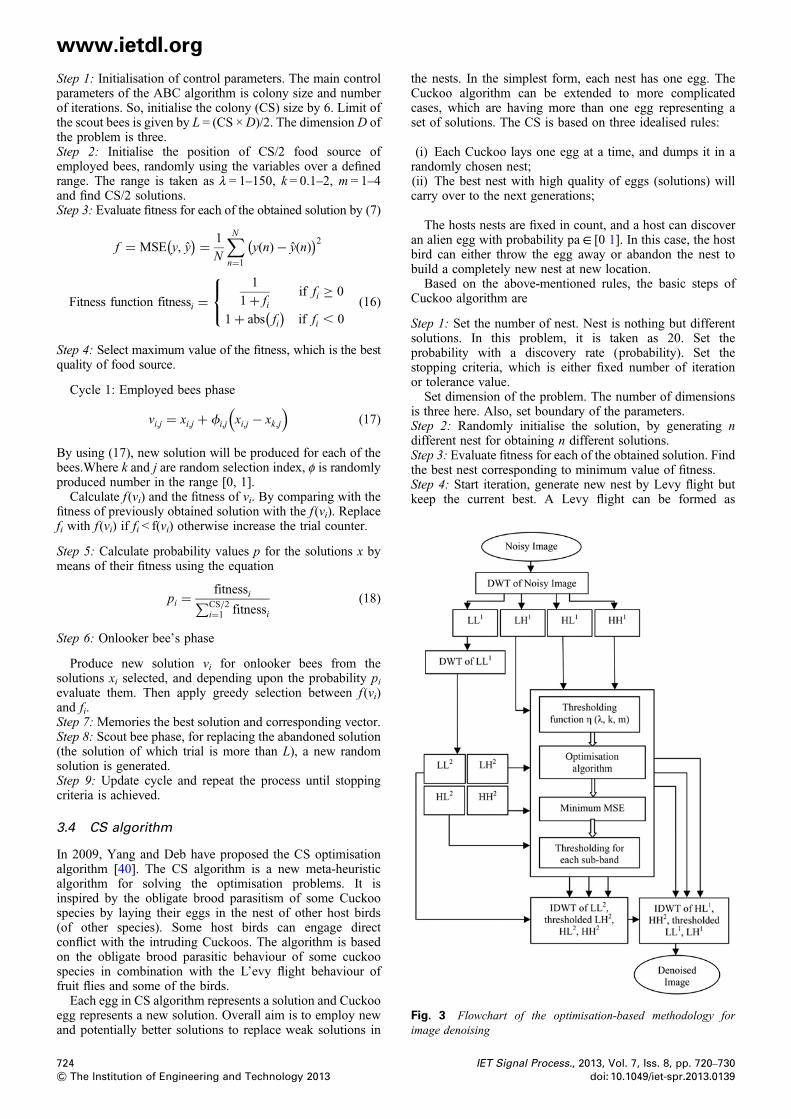
Fig. 3 Flowchart of the optimisation-based methodology forimage denoising
www.ietdl.org
Step 1: Initialisation of control parameters. The main controlparameters of the ABC algorithm is colony size and numberof iterations. So, initialise the colony (CS) size by 6. Limit ofthe scout bees is given by L = (CS ×D)/2. The dimension D ofthe problem is three.Step 2: Initialise the position of CS/2 food source ofemployed bees, randomly using the variables over a definedrange. The range is taken as λ = 1–150, k = 0.1–2, m = 1–4and find CS/2 solutions.Step 3: Evaluate fitness for each of the obtained solution by (7)f = MSE y, y( ) = 1
N
∑Nn=1
y(n)− y(n)( )2
Fitness function fitnessi =1
1+ fiif fi ≥ 0
1+ abs fi( )
if fi , 0
⎧⎨⎩ (16)
Step 4: Select maximum value of the fitness, which is the bestquality of food source.
Cycle 1: Employed bees phase
vi,j = xi,j + fi,j xi,j − xk,j
( )(17)
By using (17), new solution will be produced for each of thebees.Where k and j are random selection index, φ is randomlyproduced number in the range [0, 1].Calculate f (vi) and the fitness of vi. By comparing with the
fitness of previously obtained solution with the f (vi). Replacefi with f (vi) if fi < f(vi) otherwise increase the trial counter.
Step 5: Calculate probability values p for the solutions x bymeans of their fitness using the equation
pi =fitnessi∑CS/2
i=1 fitnessi(18)
Step 6: Onlooker bee’s phase
Produce new solution vi for onlooker bees from thesolutions xi selected, and depending upon the probability pievaluate them. Then apply greedy selection between f (vi)and fi.Step 7: Memories the best solution and corresponding vector.Step 8: Scout bee phase, for replacing the abandoned solution(the solution of which trial is more than L), a new randomsolution is generated.Step 9: Update cycle and repeat the process until stoppingcriteria is achieved.
3.4 CS algorithm
In 2009, Yang and Deb have proposed the CS optimisationalgorithm [40]. The CS algorithm is a new meta-heuristicalgorithm for solving the optimisation problems. It isinspired by the obligate brood parasitism of some Cuckoospecies by laying their eggs in the nest of other host birds(of other species). Some host birds can engage directconflict with the intruding Cuckoos. The algorithm is basedon the obligate brood parasitic behaviour of some cuckoospecies in combination with the L’evy flight behaviour offruit flies and some of the birds.Each egg in CS algorithm represents a solution and Cuckoo
egg represents a new solution. Overall aim is to employ newand potentially better solutions to replace weak solutions in
724& The Institution of Engineering and Technology 2013
the nests. In the simplest form, each nest has one egg. TheCuckoo algorithm can be extended to more complicatedcases, which are having more than one egg representing aset of solutions. The CS is based on three idealised rules:
(i) Each Cuckoo lays one egg at a time, and dumps it in arandomly chosen nest;(ii) The best nest with high quality of eggs (solutions) willcarry over to the next generations;
The hosts nests are fixed in count, and a host can discoveran alien egg with probability pa∈ [0 1]. In this case, the hostbird can either throw the egg away or abandon the nest tobuild a completely new nest at new location.Based on the above-mentioned rules, the basic steps of
Cuckoo algorithm are
Step 1: Set the number of nest. Nest is nothing but differentsolutions. In this problem, it is taken as 20. Set theprobability with a discovery rate (probability). Set thestopping criteria, which is either fixed number of iterationor tolerance value.Set dimension of the problem. The number of dimensions
is three here. Also, set boundary of the parameters.Step 2: Randomly initialise the solution, by generating ndifferent nest for obtaining n different solutions.Step 3: Evaluate fitness for each of the obtained solution. Findthe best nest corresponding to minimum value of fitness.Step 4: Start iteration, generate new nest by Levy flight butkeep the current best. A Levy flight can be formed as
IET Signal Process., 2013, Vol. 7, Iss. 8, pp. 720–730doi: 10.1049/iet-spr.2013.0139
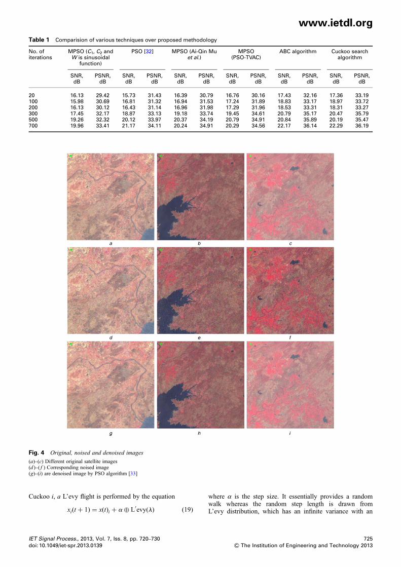
Table 1 Comparision of various techniques over proposed methodology
No. ofiterations
MPSO (C1, C2 andW is sinusoidal
function)
PSO [32] MPSO (Ai-Qin Muet al.)
MPSO(PSO-TVAC)
ABC algorithm Cuckoo searchalgorithm
SNR,dB
PSNR,dB
SNR,dB
PSNR,dB
SNR,dB
PSNR,dB
SNR,dB
PSNR,dB
SNR,dB
PSNR,dB
SNR,dB
PSNR,dB
20 16.13 29.42 15.73 31.43 16.39 30.79 16.76 30.16 17.43 32.16 17.36 33.19100 15.98 30.69 16.81 31.32 16.94 31.53 17.24 31.89 18.83 33.17 18.97 33.72200 16.13 30.12 16.43 31.14 16.96 31.98 17.29 31.96 18.53 33.31 18.31 33.27300 17.45 32.17 18.87 33.13 19.18 33.74 19.45 34.61 20.79 35.17 20.47 35.79500 19.26 32.32 20.12 33.97 20.37 34.19 20.79 34.91 20.84 35.89 20.19 35.47700 19.96 33.41 21.17 34.11 20.24 34.91 20.29 34.56 22.17 36.14 22.29 36.19
Fig. 4 Original, noised and denoised images
(a)–(c) Different original satellite images(d )–( f ) Corresponding noised image(g)–(i) are denoised image by PSO algorithm [33]
www.ietdl.org
Cuckoo i, a L’evy flight is performed by the equation
xi(t + 1) = x(t)i + a⊕ L′evy(l) (19)
IET Signal Process., 2013, Vol. 7, Iss. 8, pp. 720–730doi: 10.1049/iet-spr.2013.0139
where α is the step size. It essentially provides a randomwalk whereas the random step length is drawn fromL’evy distribution, which has an infinite variance with an
725& The Institution of Engineering and Technology 2013

Fig. 5 Visual results of the proposed technique
( j)–(l ) are denoised by MPSO(m)–(o) are denoised by PSO-TVAC(p)–(r) are denoised image by ABC algorithm
www.ietdl.org
infinite mean. L’evy distribution is given by
L′evy � u = t−l, (1 , l ≤ 3) (20)
L’evy function can be changed according to application.Mantegna’s algorithm is one of the L’evy function.
Step 5: Evaluate this set of solutions and obtain new fitness.Compare the old fitness with this new fitness, and replaceold fitness if new fitness is better than the old one. Updatethe best nest corresponding to fitness.Step 6: Repeat the above process until some stopping criteriais achieved giving the best fitness and corresponding bestnest.
A complete flowchart routine of optimisation-basedmethodology for image denoising is shown in Fig. 3,depicting the detailed steps of overall algorithm.There are several methods, which have been used for satellite
image denoising. In this paper, various state-of-the-art
726& The Institution of Engineering and Technology 2013
techniques are used for comparison purposes. In order toshow effectiveness of the proposed method over conventionaland state-of-the-art image denoising techniques, three lowcontrast satellite images with different features available so farare used for comparison. Table 1 compares the PSNR andSNR performance indices of the proposed CS technique withthe MPSO (C1, C2 and W is sinusoidal function), PSO,MPSO (Ai-Qin Mu et al.), MPSO (PSO-TVAC), ABCalgorithm and CS algorithm (Fig. 4).Visual results of the proposed technique are shown in
Figs. 5 m–p supported by the quantitative results given inTable 1. For example in Figs. 6v–x, output denoisedimages are depicted. Results in Table 1 indicatesuperiority of the proposed technique over otherstate-of-the-art and conventional image denoisingtechniques. The PSNR block computes the PSNR, indecibels between two images. This ratio is often used as aquality measurement between the original and improvedimages. The higher PSNR signifies better quality of theenhanced or reconstructed image.
IET Signal Process., 2013, Vol. 7, Iss. 8, pp. 720–730doi: 10.1049/iet-spr.2013.0139
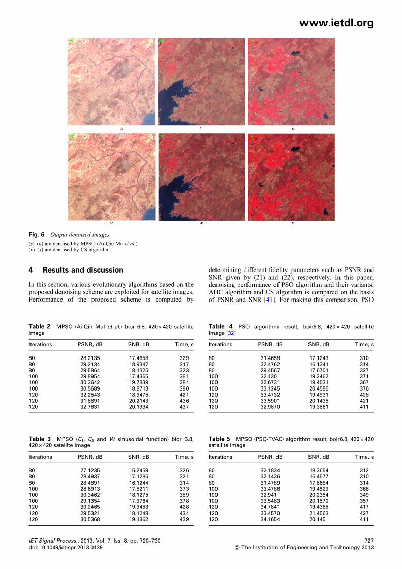
Fig. 6 Output denoised images
(s)–(u) are denoised by MPSO (Ai-Qin Mu et al.)(v)–(x) are denoised by CS algorithm
www.ietdl.org
4 Results and discussion
In this section, various evolutionary algorithms based on theproposed denoising scheme are exploited for satellite images.Performance of the proposed scheme is computed by
Table 2 MPSO (Ai-Qin Mul et al.) bior 6.8, 420 × 420 satelliteimage
Iterations PSNR, dB SNR, dB Time, s
80 28.2135 17.4658 32980 29.2134 18.9347 31780 29.5864 18.1325 323100 29.8954 17.4365 381100 30.3642 19.7839 384100 30.5689 18.8713 390120 32.2543 18.9475 421120 31.8891 20.2143 436120 32.7631 20.1934 437
Table 3 MPSO (C1, C2 and W sinusoidal function) bior 6.8,420 × 420 satellite image
Iterations PSNR, dB SNR, dB Time, s
80 27.1235 15.2459 32680 28.4937 17.1285 32180 28.4891 16.1244 314100 28.6913 17.8211 373100 30.3462 18.1275 389100 29.1354 17.9764 378120 30.2465 19.9453 428120 29.5321 18.1248 434120 30.5368 19.1362 439
IET Signal Process., 2013, Vol. 7, Iss. 8, pp. 720–730doi: 10.1049/iet-spr.2013.0139
determining different fidelity parameters such as PSNR andSNR given by (21) and (22), respectively. In this paper,denoising performance of PSO algorithm and their variants,ABC algorithm and CS algorithm is compared on the basisof PSNR and SNR [41]. For making this comparison, PSO
Table 4 PSO algorithm result, boir6.8, 420 × 420 satelliteimage [32]
Iterations PSNR, dB SNR, dB Time, s
80 31.4658 17.1243 31080 32.4762 16.1341 31480 29.4567 17.6701 327100 32.130 19.2462 371100 32.6731 19.4531 367100 33.1245 20.4586 376120 33.4732 19.4931 428120 33.5901 20.1435 421120 32.9870 19.3861 411
Table 5 MPSO (PSO-TVAC) algorithm result, boir6.8, 420 × 420satellite image
Iterations PSNR, dB SNR, dB Time, s
80 32.1834 18.3654 31280 32.1436 16.4577 31080 31.4789 17.8684 314100 33.4786 19.4529 366100 32.941 20.2354 349100 33.5483 20.1570 357120 34.7841 19.4365 417120 33.4570 21.4563 427120 34.1654 20.145 411
727& The Institution of Engineering and Technology 2013

Table 6 ABC algorithm result bior 6.8, 420 × 420 satelliteimage
Iterations PSNR, dB SNR, dB Time, s
80 33.7421 20.7546 60180 32.1456 21.3564 61780 29.1452 19.4532 629100 33.8965 22.1321 1191100 32.4567 21.1325 1145100 32.1452 20.1467 1102120 34.12365 22.1479 1349120 34.2014 20.1452 1370120 35.1245 22.5135 1422
Table 7 CS algorithm result bior 6.8, 420 × 420 satellite image
Iterations PSNR, dB SNR, dB Time, s
80 33.4315 20.6751 62480 33.4625 21.2678 61280 32.2197 19.8375 619100 33.9175 21.7542 1179100 33.7132 20.9132 1165100 32.8175 20.0214 1159120 33.9576 22.3142 1376120 34.5671 21.4231 1379120 35.3245 22.4125 1409
Table 8 EKI or EPI
Method (600iterations)
(EPI)Sampleimage 1
(EPI)Sampleimage 2
(EPI)Sampleimage 3
MPSO (C1, C2 and Wis sinusoidalfunction)
0.6712 0.5629 0.5843
PSO 0.6791 0.5871 0.5917MPSO (Ai-Qin Muet al.)
0.6738 0.5901 0.6014
MPSO (PSO-TVAC) 0.6854 0.5921 0.6071ABC algorithm 0.7131 0.6064 0.6213Cuckoo searchalgorithm
0.7297 0.6124 0.6295
www.ietdl.org
algorithm, MPSO (PSO-TVAC), MPSO (Ai-Qin Mu1 et al.),MPSO, ABC algorithm and CS algorithm is executed withMATLAB R2012a. The various set of results are obtainedfor bior 6.8 (biorthogonal filter, version 6.8) filter. Table 1shows the results obtained by running the algorithms fordifferent number of iterations. Here, six types of algorithmare considered, and each algorithm is tested for denoisingwith different number of iterations ranging from 20 to 700iterations. It was observed that the ABC algorithm and CSalgorithm gives better value of PSNR and SNR ascompared to PSO, whereas PSNR and SNR values of othervariants of PSO lies around PSO technique.PSNR in dB for an image can be calculated from the
following equation
PSNR = 10 log10MAX2
i
MSE
( )= 20 log10
MAXiMSE
√( )
(21)
SNR in dB can be calculated from the following equation
SNR = 10 log10signal power
noise power
( )(22)
Results show that ABC algorithm and CS algorithm givesbetter performance. Further testing of the performance of allthe algorithms considered is elaborated in Tables 2–6. Eachalgorithm is tested for different number of iterations (80–120), and table includes PSNR, SNR and time taken forcompletion. Table 2 shows SNR, PSNR and time taken forMPSO (Ai-Qin Mu1 et al.). In Table 3, results obtained forMPSO (sinusoidal varying C1, C2 and W) are given.Table 4 depicts the performance of PSO-TVAC, whereasTable 5 shows the performance of PSO algorithm for imagedenoising. Performance indices for ABC algorithm and CSalgorithm are given in Table 6 and Table 7, respectively.The time taken to complete the process of denoising is
728& The Institution of Engineering and Technology 2013
considered for multiband data or input original satelliteimage. Satellite image is a multiband data (3 or 7 bands).So the time required to complete the process of denoising isthrice (in case of 3 band satellite image) as compared to thetime required for single band or grey-scale image. Owing tocomplexity of application of ABC algorithm and CSalgorithm in image denoising, time taken is more ascompared to PSO but SNR and PSNR values are better.Table 1 represents overall comparion of the results between
proposed and state-of-the-art and conventional techniques.Table 2 shows detailed comparison of the results usingMPSO (Ai-Qin Mul et al.) technique, whereas in Table 3,comparison of the results using MPSO (C1, C2 and Wsinusoidal function) technique is given. Table 4 includes thedetailed comparison of the results using PSO algorithmsupported by number of iteration, PSNR, SNR and time.Table 5 shows detailed comparison of the results using
MPSO (PSO-TVAC) algorithm whereas the detailedcomparison of the results using proposed ABC and CSalgorithm, respectively, supported by number ofiteration,PSNR, SNR and time are included in Tables 6 and 7.Calculation of edge keeping index (EKI) or edge
preservation index (EPI)
EKI =∑N
i=1 Dgi − Dmg
( )Dfi − Dmf
( )∑N
i=1 Dgi − Dmg
( )2∑Ni=1 Dfi − Dmf
( )2√ (23)
where gi and fi are the original and reconstructed images,respectively. Δgi and Δfi are found by filtering g and fthrough high pass Laplacian filter with mean value as µgand µf, respectively. The EKI calculates that how much theedges are preserved for the reconstructed image comparedwith the original image. High value of EKI or EPIrepresents that more edge details are conserved. EKI isincluded in Table 8.
5 Conclusion
In this work, an improved denoising scheme for satelliteimages is presented using different evolutionary algorithmssuch as CS algorithm, ABC algorithm and different variantsof PSO for learning of parameters of adaptive thresholdingfunction required for optimum performance. The proposedtechnique has been tested on several satellite images. Thefidelity parameters obtained clearly show superiority of theproposed technique over other conventional andstate-of-the-art image denoising techniques. A comparative
IET Signal Process., 2013, Vol. 7, Iss. 8, pp. 720–730doi: 10.1049/iet-spr.2013.0139
www.ietdl.org
study of different evolutionary algorithms has also beenmade, and it has been found that the proposed technique,based on CS algorithm and ABC algorithm, yields betterperformance as compared to PSO and their differentvariants in terms of EKI or EPI, PSNR and SNR.6 References
1 Gonzalez, R.C., Woods, R.E.: ‘Digital image processing’ (PearsonPrentice-Hall, Singapore, 2002, 2nd edn.)
2 Bhandari, A.K., Kumar, A., Padhy, P.K.: ‘Improved normaliseddifference vegetation index method based on discrete cosine transformand singular value decomposition for satellite image processing’. IETSignal Process., 2012, pp. 1–9
3 Mallat, G.: ‘Theory for multi-resolution signal decomposition: thewavelet representation’, IEEE Trans. Pattern Anal. Mach. Intell.,1989, 2, (7), pp. 674–694
4 Donoho, D.L., Johnstone, I.M.: ‘Ideal spatial adaptation by waveletshrinkage’, Biometrika, 1994, 81, (3), pp. 425–455
5 Donoho, D.L., Johnstone, I.M.: ‘Adapting to unknown smoothness viawavelet shrinkage’, J. Am. Stat. Assoc., 1995, 90, (432), pp. 1200–1224
6 Donoho, D.L.: ‘Denoising by soft thresholding’, IEEE Trans. Inf.Theory, 1995, 41, pp. 613–627
7 Gao, H., Bruce, A.G.: ‘WaveShrink with firm shrinkage’, Stat. Sin.,1997, 7, pp. 855–874
8 Gao, H.: ‘Wavelet shrinkage denoising using the nonnegative garrote’, J.Comput. Graph. Stat., 1998, 7, pp. 469–488
9 Fodder, I.K., Kamath, C.: ‘Denoising through wavelet shrinkage: anempirical study’, J. Electron. Imaging, 2003, 12, (1), pp. 151–160
10 Achim, A., Bezerianos, A., Tsakalides, P.: ‘Novel Bayesian multiscalemethod for speckle removal in medical ultrasound Images’, IEEETrans. Med. Imaging, 2001, 20, (8), pp. 772–783
11 Achim, A., Kuruoghlu, E.: ‘Image denoising using alpha-stabledistributions in the complex wavelet domain’, IEEE Signal Process.Lett., 2005, 12, (1), pp. 17–20
12 Mihcak, M.K., Kozintsev, I., Ramchandran, K., Moulin, P.: ‘Lowcomplexity image denoising based on statistical modeling of waveletcoefficients’, IEEE Signal Process. Lett., 1999, 9, pp. 300–303
13 Crouse, M.S., Nowak, R.D., Baraniuk, R.G.: ‘Wavelet-based statisticalsignal processing using hidden Markov models’, IEEE Trans. SignalProcess., 1998, 46, (4), pp. 886–902
14 Mohamad, M., Hamid, M.: ‘Ultrasound speckle suppression usingheavy tailed distribution in the dual tree complex wavelet domain’.Proc. IEEE Int. Conf. on Wavelet Diversity and Design, 2007, pp. 65–68
15 Michailovich, O.V., Tannenbum, A.: ‘Despeckling of ultrasoundimages’, IEEE Trans. Ultrason., Ferroelectr. Freq. Control, 2006, 53,(1), pp. 64–78
16 Bhuiyan, M.I.H., Ahmad, M.O., Swamy, M.N.S.: ‘New spatial adaptivewavelet based method for the despeckling of medical ultrasound image’.Proc. IEEE Int. Conf. on Symp. on Circuits and System, 2007,pp. 2347–2350
17 Portilla, J., Strela, V., Wainwright, M.J., Simoncelli, E.P.: ‘Imagedenoising using Gaussian scale mixtures in the wavelet domain’, IEEETrans. Image Process., 2003, 12, pp. 1338–1351
18 Pizurica, A., Philips, W.: ‘Estimating the probability of the presence of asignal of interest in multiresolution single- and multiband imagedenoising’, IEEE Trans. Image Process., 2006, 15, (3), pp. 654–665
19 Rabbani, H., Mansur, V., Purang, A., Saeed, G.: ‘Speckle noisereduction of medical ultrasound images in complex wavelet domainusing mixture priors’, IEEE Trans. Biomed. Eng., 2008, 55, (9),pp. 2152–2160
20 Rabbani, H.: ‘Image denoising in steerable pyramid domain based on alocal Laplace prior’, Elsevier J. Pattern Recognit., 2009, 42, (9),pp. 2181–2193
21 Yu, H., Zhao, L., Wang, H.: ‘Image denoising using trivariate shrinkagefilter in the wavelet domain and joint bilateral filter in the spatialdomain’, IEEE Trans. Image Proc., 2009, 18, (10), pp. 2364–2369
22 Zhang, X.P., Desai, M.D.: ‘Adaptive denoising based on SURE risk’,IEEE Signal Process.’, Lett., 1998, 5, (10), pp. 265–267
23 Zhang, X.P.: ‘State-scale adaptive noise reduction in images based onthresholding neural network’. Proc. IEEE Int. Conf. on Acoustic,Speech and Signal Processing, 2001, pp. 1889–1892
24 Zhang, X.P.: ‘Thresholding neural network for adaptive noisereduction’, IEEE Trans. Neural Netw., 2001, 12, (3), pp. 567–584
25 Liu, P., Huang, F., Li, G., Liu, Z.: ‘Remote-sensing image denoisingusing partial differential equations and auxiliary images as priors’,Geosci. Remote Sens. Lett., IEEE, 2012, 9, (3), pp. 358–362
IET Signal Process., 2013, Vol. 7, Iss. 8, pp. 720–730doi: 10.1049/iet-spr.2013.0139
26 Sivakumar, R., Balaji, G., Ravikiran, R.S.J., Karikalan, R., Janaki, S.S.:‘Image denoising using contourlet transform’. Proc. IEEE Second Int.Conf. in Computer and Electrical Engineering, 2009, vol. l, no. 1,pp. 22–25
27 Yu-feng, L.I.: ‘Bayesian Denoising for remote sensing image basedon undecimated discrete wavelet transform’, Proc. IEEE Int. Conf. onInformation Engineering and Computer science (ICIECS), 2009,3, pp. 1–4
28 Nasri, M., Pour, H.N.: ‘Image denoising in the wavelet domain using anew adaptive thresholding function’, Elsevier J. Neurocomput., 2009,72, pp. 1012–1025
29 Bhutada, G.G., Anand, R.S., Saxena, S.C.: ‘Image enhancement bywavelet-based thresholding neural network with adaptive learningrate’, IET Image Process., 2011, 5, (7), pp. 573–582
30 Bhandari, A.K., Gadde, M., Kumar, A., Singh, G.K.: ‘Comparativeanalysis of different wavelet filters for low contrast and brightnessenhancement of multispectral remote sensing images’. Proc. IEEE Int.Conf. on Machine Vision and Image Processing (MVIP), 2012,pp. 81–86
31 Foi, A., Katkovnik, V., Egiazarian, K.: ‘Pointwise shape-adaptive DCTfor high-quality denoising and deblocking of grayscale and colorimages’, IEEE Trans. Image Process., 2007, 16, (5), pp. 1395–1411
32 Bhadauria, H.S., Dewal, M.L., Anand, R.S.: ‘Comparative analysis ofcurvelet based techniques for denoising of computed tomographyimages’. Devices and Communications (ICDeCom), Int. Conf. on.IEEE, 2011, pp. 1–5
33 Bhutada, G.G., Anand, R.S., Saxena, S.C.: ‘PSO-based learning ofsub-band adaptive thresholding function for image denoising’,Springer Signal, Image Video Process. (SIViP), 2012, 6, pp. 1–7
34 Bhutada, G.G., Anand, R.S., Saxena, S.C.: ‘Edge preserved imageenhancement using adaptive fusion of images denoised by waveletand curvelet transform’, Digital Signal Process., 2011, 21, (1),pp. 118–130
35 Bhutada, G.G., Anand, R.S., Saxena, S.C.: ‘Fast adaptive learningalgorithm for sub-band adaptive thresholding function in imagedenoising’, Int. J. Comput. Intell. Stud., 2010, 1, (3), pp. 227–241
36 Ratnaweera, A., Halgamuge, S.K., Watson, H.C.: ‘Self-organizinghierarchical particle swarm optimizer with time-varying accelerationcoefficients’, IEEE Trans. Evol. Comput., 2004, 8, pp. 240–255
37 Gupta, S., Devi, S.: ‘Modified PSO algorithm with high exploration’,Int. J. Softw. Eng. Res. Pract., 2011, 1, (1), pp. 15–19
38 Mu, A.Q., De-Xin, C., Wang, X.H.: ‘A modified particle swarmoptimization algorithm’, Nat. Sci., 2009, 1, (2), pp. 151–155
39 Karaboga, D.: ‘An idea based on honey bee swarm for numericaloptimization’. Technical Report-TR06, Erciyes University,Engineering Faculty, Computer Engineering Department, 2005
40 Yang, X.S., Deb, S.: ‘Cuckoo search via Lévy flights’. World Congresson Nature & Biologically Inspired Computing (NaBIC 2009). IEEEPublications, 2009, pp. 210–214, http://papercore.org/Yang2009
41 Prattt, W.K.: ‘Digital image processing’ (John Wiley and Sons, 2006,3rd edn.)
7 Appendix
The proposed method has been also tested using 4 × 4 blockfor intrascale dependency. Here, input image 400 × 400 × 3(multiband satellite image) taken one band at a time. Detailsteps of suggested algorithm are as follows:
(i) Separate red component from input image having 400 ×400 size.(ii) Apply DWT to input band, after decomposition LL, LH,HL, HH sub-band of size 200 × 200 each (using bior 6.8mother wavelet).(iii) Now thresholding is applied on each sub-bandconsidering 4 × 4 block using CS algorithm.(iv) This process is followed for all sub-bands one by oneusing 4 × 4 blocks using CS algorithm.(v) After completion of 4 × 4 blocking process using CS forRED component. This process is repeated for NIR band andfor green band.(vi) Finally, denoised results are obtained using intrascaledependency
729& The Institution of Engineering and Technology 2013
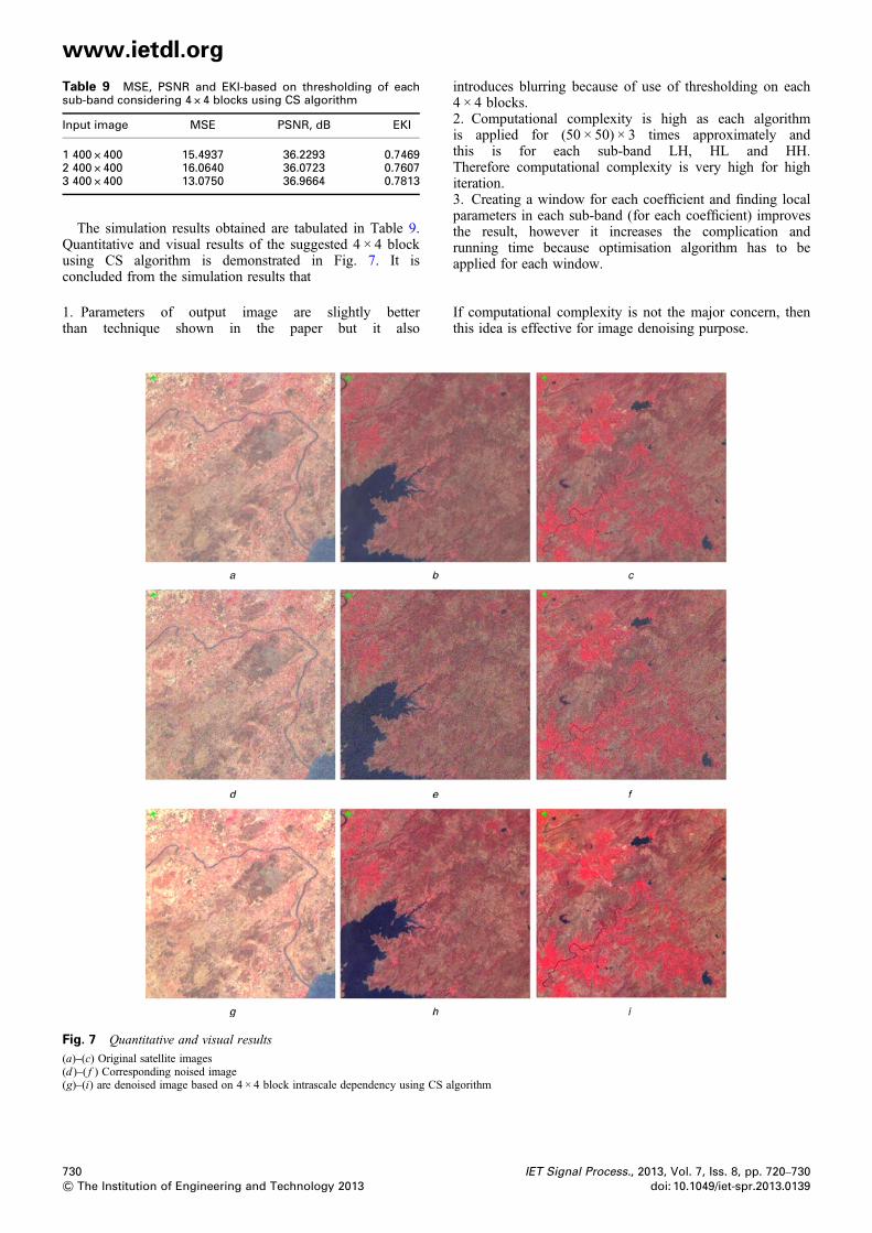
Table 9 MSE, PSNR and EKI-based on thresholding of eachsub-band considering 4 × 4 blocks using CS algorithm
Input image MSE PSNR, dB EKI
1 400 × 400 15.4937 36.2293 0.74692 400 × 400 16.0640 36.0723 0.76073 400 × 400 13.0750 36.9664 0.7813
www.ietdl.org
The simulation results obtained are tabulated in Table 9.Quantitative and visual results of the suggested 4 × 4 blockusing CS algorithm is demonstrated in Fig. 7. It isconcluded from the simulation results that
1. Parameters of output image are slightly betterthan technique shown in the paper but it also
Fig. 7 Quantitative and visual results
(a)–(c) Original satellite images(d )–( f ) Corresponding noised image(g)–(i) are denoised image based on 4 × 4 block intrascale dependency using CS a
730& The Institution of Engineering and Technology 2013
introduces blurring because of use of thresholding on each4 × 4 blocks.2. Computational complexity is high as each algorithmis applied for (50 × 50) × 3 times approximately andthis is for each sub-band LH, HL and HH.Therefore computational complexity is very high for highiteration.3. Creating a window for each coefficient and finding localparameters in each sub-band (for each coefficient) improvesthe result, however it increases the complication andrunning time because optimisation algorithm has to beapplied for each window.
If computational complexity is not the major concern, thenthis idea is effective for image denoising purpose.
lgorithm
IET Signal Process., 2013, Vol. 7, Iss. 8, pp. 720–730doi: 10.1049/iet-spr.2013.0139
Related Documents