International Journal of Computer Applications (0975 – 8887) Volume 161 – No 12, March 2017 8 Improve Roll Dynamic Response of Road Vehicle to Step Steer Input using Semi-active PID Suspension Controller Karim H. Ali, PhD University of Baghdad College of Engineering Mechanical Department Farah Ayad A. Majeed University of Baghdad College of Engineering Mechanical Department ABSTRACT Roll dynamic response is investigated and studied to improve the dynamic behavior of road vehicle during sudden maneuver according to step steer input using semi-active PID suspension. A Mathematical model including the differential governing equations of operation for full road vehicle with (9) degrees of freedom and passive PID suspension is presented. Car body movements and displacements are investigated using Computer-aided simulation with Matlab Program for different vehicle speeds and specified step steer angles. A special technique is used to transform the second order differential equations of operation for the road vehicle into first order equations in order to reduce the computational time. Simulation results shows the dynamic responses of road vehicle at vertical, pitch and roll motions subjected to different vehicle speeds and step steer angles utilizing settling time and maximum peak overshoot, also the results show an improvement in dynamic roll response using semi-active PID suspension with conical shaped spring. Keywords Roll dynamic response, Semi active suspension, PID controller, road vehicle 1. INTRODUCTION Ride passenger comfort and safety are the most important parameters should be considered when transportation equipment and devices are utilized. Road vehicle is widely used these days to transport passengers for long distances subjected to different external road conditions. Undesirable vibrations and oscillations may be introduced according to these external road disturbances by which many mechanical problems will occur that cause unsafely road vehicle handling with ride passenger discomfort. Hence road vehicle should be subjected to some control devices such as braking control, traction control, acceleration control, lateral stability control and suspension control. Such road vehicle control systems refer to enhance ride passenger comfort with safety road vehicle handling. Suspension with PID semi-active controller is used in this study to improve vehicle dynamic response based on roll movement. Suspensions are considered as an important control elements widely used in most vehicle applications and vibrating machinery such as cars and trains used to depress vibrations and oscillations introduced throughout dynamic running. Whereas these suspensions are the most important control element used to satisfy ride passenger comfort and safety. In a classical car suspension which is commonly called passive PID suspension, it aims to achieve isolation from the road disturbances by means of spring-type elements and viscous dampers (shock absorbers). Many studies have been accomplished to improve road vehicle dynamic response using different suspension PID controllers in order to achieve ride passenger comfort and safety. M. Senthil Kumar et al. [2007] describes the development of active suspension system of light passenger vehicle to improve ride comfort of the passengers using PID (Proportional –Integral -Derivative) controller. The system is subjected to bumpy road and its performance is assessed and compared with a passive suspension system. Experimental verification of analytical results is carried out. It is found that ride comfort is improved by 78.03%, suspension travel has been reduced by 71.05% an`d road holding ability is improved by 60% with active suspension system when compared with passive suspension system. The study of Anil Shirahatt et al. [2008] shows a suitable optimizing technique at design stage to obtain the suspension parameters of a passive suspension and active suspension for a passenger car. The constraints arise from the practical kinetic and comfortability considerations, such as limits of the maximum vertical acceleration of the passenger seat, tyre displacement and the suspension working space. Results show passenger bounce, passenger acceleration, and tyre displacement are reduced by 74.2%, 88.72% and 28.5% respectively. In the study of M. Zapateiro et al. [2009] the problem of designing the semiactive controller for a class of vehicle suspension system is investigated. As the first step, an adequate model of the MR damper must be developed. Estimate the control voltage input to the MR damper, which is necessary for producing the optimal force predicted by the controller so as to reduce the vibrations. The performance of the control system is evaluated bymeans of simulations in MATLAB/Simulink. Bushra Rasheed Mohameed [2011] describes a unique solution of bouncing and pitching interactions, in which it play an increasingly significant role in vehicle. This work is theoretical and finite element method via ANSYS software study of dynamic performance of vehicle. Przemyslaw Gorczyca et al. [2011] is concerned with a mathematical model of the semi-active suspension system of a vehicle modeled with a car quarter while a simulation model is written by in the Matlab/Similink program. The research of Soud farhan Choudhury et al. [2012] is carried out to study the performance of two basic suspension systems with a different approach, passive and active suspension system. For the simplicity, mathematical modeling is done by assuming 2 degree of freedom (2 DOF) system. Quarter car model is used to simplify the system. To analyze the model, simulation software MATLAB/SIMULINK is used. M. Khairi et al. [2013] presents the composite nonlinear feedback (CNF) technique for yaw tracking control of active front steering system with the objectives to improve the transient performance of yaw rate response. For lateral and yaw

Welcome message from author
This document is posted to help you gain knowledge. Please leave a comment to let me know what you think about it! Share it to your friends and learn new things together.
Transcript

International Journal of Computer Applications (0975 – 8887)
Volume 161 – No 12, March 2017
8
Improve Roll Dynamic Response of Road Vehicle to Step
Steer Input using Semi-active PID Suspension Controller
Karim H. Ali, PhD University of Baghdad College of Engineering Mechanical Department
Farah Ayad A. Majeed University of Baghdad College of Engineering Mechanical Department
ABSTRACT Roll dynamic response is investigated and studied to improve
the dynamic behavior of road vehicle during sudden maneuver
according to step steer input using semi-active PID
suspension. A Mathematical model including the differential
governing equations of operation for full road vehicle with (9)
degrees of freedom and passive PID suspension is presented.
Car body movements and displacements are investigated
using Computer-aided simulation with Matlab Program for
different vehicle speeds and specified step steer angles. A
special technique is used to transform the second order
differential equations of operation for the road vehicle into
first order equations in order to reduce the computational
time. Simulation results shows the dynamic responses of road
vehicle at vertical, pitch and roll motions subjected to
different vehicle speeds and step steer angles utilizing settling
time and maximum peak overshoot, also the results show an
improvement in dynamic roll response using semi-active PID
suspension with conical shaped spring.
Keywords
Roll dynamic response, Semi active suspension, PID
controller, road vehicle
1. INTRODUCTION Ride passenger comfort and safety are the most important
parameters should be considered when transportation
equipment and devices are utilized. Road vehicle is widely
used these days to transport passengers for long distances
subjected to different external road conditions. Undesirable
vibrations and oscillations may be introduced according to
these external road disturbances by which many mechanical
problems will occur that cause unsafely road vehicle handling
with ride passenger discomfort. Hence road vehicle should be
subjected to some control devices such as braking control,
traction control, acceleration control, lateral stability control
and suspension control. Such road vehicle control systems
refer to enhance ride passenger comfort with safety road
vehicle handling. Suspension with PID semi-active controller
is used in this study to improve vehicle dynamic response
based on roll movement.
Suspensions are considered as an important control elements
widely used in most vehicle applications and vibrating
machinery such as cars and trains used to depress vibrations
and oscillations introduced throughout dynamic running.
Whereas these suspensions are the most important control
element used to satisfy ride passenger comfort and safety. In a
classical car suspension which is commonly called passive
PID suspension, it aims to achieve isolation from the road
disturbances by means of spring-type elements and viscous
dampers (shock absorbers).
Many studies have been accomplished to improve road
vehicle dynamic response using different suspension PID
controllers in order to achieve ride passenger comfort and
safety.
M. Senthil Kumar et al. [2007] describes the development of
active suspension system of light passenger vehicle to
improve ride comfort of the passengers using PID
(Proportional –Integral -Derivative) controller. The system is
subjected to bumpy road and its performance is assessed and
compared with a passive suspension system. Experimental
verification of analytical results is carried out. It is found that
ride comfort is improved by 78.03%, suspension travel has
been reduced by 71.05% an`d road holding ability is improved
by 60% with active suspension system when compared with
passive suspension system. The study of Anil Shirahatt et al.
[2008] shows a suitable optimizing technique at design stage
to obtain the suspension parameters of a passive suspension
and active suspension for a passenger car. The constraints
arise from the practical kinetic and comfortability
considerations, such as limits of the maximum vertical
acceleration of the passenger seat, tyre displacement and the
suspension working space. Results show passenger bounce,
passenger acceleration, and tyre displacement are reduced by
74.2%, 88.72% and 28.5% respectively. In the study of M.
Zapateiro et al. [2009] the problem of designing the
semiactive controller for a class of vehicle suspension system
is investigated. As the first step, an adequate model of the MR
damper must be developed. Estimate the control voltage input
to the MR damper, which is necessary for producing the
optimal force predicted by the controller so as to reduce the
vibrations. The performance of the control system is evaluated
bymeans of simulations in MATLAB/Simulink.
Bushra Rasheed Mohameed [2011] describes a unique
solution of bouncing and pitching interactions, in which it
play an increasingly significant role in vehicle. This work is
theoretical and finite element method via ANSYS software
study of dynamic performance of vehicle. Przemyslaw
Gorczyca et al. [2011] is concerned with a mathematical
model of the semi-active suspension system of a vehicle
modeled with a car quarter while a simulation model is
written by in the Matlab/Similink program. The research of
Soud farhan Choudhury et al. [2012] is carried out to study
the performance of two basic suspension systems with a
different approach, passive and active suspension system. For
the simplicity, mathematical modeling is done by assuming 2
degree of freedom (2 DOF) system. Quarter car model is used
to simplify the system. To analyze the model, simulation
software MATLAB/SIMULINK is used. M. Khairi et al.
[2013] presents the composite nonlinear feedback (CNF)
technique for yaw tracking control of active front steering
system with the objectives to improve the transient
performance of yaw rate response. For lateral and yaw
International Journal of Computer Applications (0975 – 8887)
Volume 161 – No 12, March 2017
9
dynamics analysis, nonlinear and linear vehicle models are
utilized as actual vehicle plant and for controller design
respectively. The simulation results demonstrate that the
application of CNF for yaw rate tracking control improves the
yaw stability and vehicle handling Performances.
Ali M. Abd-El- Tawwab [2013] stated that semi-active
suspension system is a possible way to improve suspension
performance although the passive system can effectively
handle some control of suspension system. The main propose
is to assess performance of semi-active suspension system by
implementing Fuzzy and Proportional-Integral-Derivative
(PID) controls in comparison with passive suspension system.
The performance of pneumatic semi-active suspension system
theoretically and experimentally predicted using two degrees
of freedom of quarter car model. The results showed that there
is a worthwhile improvement for the pneumatic semi-active
suspension system with fuzzy control over the passive. The
study of Devdut et al. [2014] presents different semi-active
control strategies for non-linear quarter car model equipped
with controllable magneto-rheological (MR) shock absorbers.
Simulink responses of four different cases are evaluated for
passenger ride comfort analysis taking uncontrolled, primary
suspension controlled, secondary suspension controlled and
fully controlled quarter car models. The obtained results in
graphical and mathematical form demonstrate that the fully
controlled
quarter car system provides excellent performance in
suppression of passenger seat vibrations compared to other
control strategies while the vehicle travels over the sinusoidal
type of input road profile.
Through the reviewed literature, it was addressed that many
dynamic problems occur in road vehicle system during
operation, such as hunting instability, damage into mechanical
components , excessive vehicle vibrations, and prospective
ride passenger discomfort. Thus the significance of this
research is to introduce the parameters that have an important
influence on the dynamic behavior of the vehicle system. In
which these parameters are controlled to eliminate the
introduced mechanical problems.
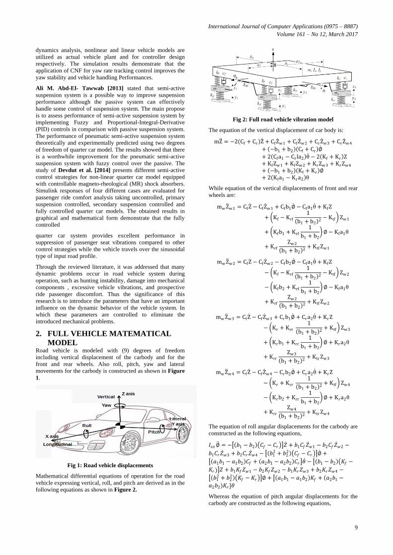
2. FULL VEHICLE MATEMATICAL
MODEL Road vehicle is modeled with (9) degrees of freedom
including vertical displacement of the carbody and for the
front and rear wheels. Also roll, pitch, yaw and lateral
movements for the carbody is constructed as shown in Figure
1.
Fig 1: Road vehicle displacements
Mathematical differential equations of operation for the road
vehicle expressing vertical, roll, and pitch are derived as in the
following equations as shown in Figure 2.
Fig 2: Full road vehicle vibration model
The equation of the vertical displacement of car body is:
mZ = −2 Cf + Cr Z + CfZ w1 + CfZ w2 + CrZ w3 + CrZ w4
+ −b1 + b2 Cf + Cr ∅
+ 2 Cfa1 − Cr la2 θ − 2 Kf + Kr Z+ KfZw1 + KfZw2 + KrZw3 + KrZw4
+ −b1 + b2 Kf + Kr ∅+ 2 Kfa1 − Kra2 θ
While equation of the vertical displacements of front and rear
wheels are:
mw Z w1 = CfZ − CfZ w1 + Cfb1∅ − Cfa1θ + KfZ
+ Kf − Krf
1
b1 + b2 2− Ktf Zw1
+ Kfb1 + Krf
1
b1 + b2 ∅ − Kfa1θ
+ Krf
Zw2
b1 + b2 2
+ Ktf Zw1
mw Z w2 = CfZ − CfZ w2 − Cfb2∅ − Cfa1θ + KfZ
− Kf − Krf
1
b1 + b2 2− Ktf Zw2
− Kfb2 + Krf
1
b1 + b2 ∅ − Kfa1θ
+ Krf
Zw2
b1 + b2 2
+ Ktf Zw2
mw Z w3 = CfZ − CfZ w3 + Crb1∅ + Cra2θ + KrZ
− Kr + Krr
1
b1 + b2 2
+ Ktf Zw3
+ Krb1 + Krr
1
b1 + b2 ∅ + Kra2θ
+ Krr
Zw3
b1 + b2 2
+ Ktr Zw3
mw Z w4 = CfZ − CfZ w4 − Crb2∅ + Cra2θ + KrZ
− Kr + Krr
1
b1 + b2 2
+ Ktf Zw4
− Krb2 + Krr
1
b1 + b2 ∅ + Kra2θ
+ Krr
Zw4
b1 + b2 2
+ Ktr Zw4
The equation of roll angular displacements for the carbody are
constructed as the following equations,
𝐼𝑥𝑥∅ = − 𝑏1 − 𝑏2 𝐶𝑓 − 𝐶𝑟 𝑍 + 𝑏1𝐶𝑓𝑍 𝑤1 − 𝑏2𝐶𝑓𝑍 𝑤2 −
𝑏1𝐶𝑟𝑍 𝑤3 + 𝑏2𝐶𝑟𝑍 𝑤4 − 𝑏12 + 𝑏2
2 𝐶𝑓 − 𝐶𝑟 ∅ +
𝑎1𝑏1 − 𝑎1𝑏2 𝐶𝑓 + 𝑎2𝑏1 − 𝑎2𝑏2 𝐶𝑟 𝜃 − 𝑏1 − 𝑏2 𝐾𝑓 −
𝐾𝑟 𝑍 + 𝑏1𝐾𝑓𝑍𝑤1 − 𝑏2𝐾𝑓𝑍𝑤2 − 𝑏1𝐾𝑟𝑍𝑤3 + 𝑏2𝐾𝑟𝑍𝑤4 −
𝑏12 + 𝑏2
2 𝐾𝑓 − 𝐾𝑟 ∅ + 𝑎1𝑏1 − 𝑎1𝑏2 𝐾𝑓 + 𝑎2𝑏1 −
𝑎2𝑏2 𝐾𝑟 𝜃
Whereas the equation of pitch angular displacements for the
carbody are constructed as the following equations,
International Journal of Computer Applications (0975 – 8887)
Volume 161 – No 12, March 2017
10
𝐼𝑦𝑦𝜃 = 2 𝑎1𝐶𝑓 − 𝑎2𝐶𝑟 𝑍 − 𝑎1𝐶𝑓𝑍 𝑤1 − 𝑎1𝐶𝑓𝑍 𝑤2 + 𝑎2𝐶𝑟𝑍 𝑤3
+ 𝑎2𝐶𝑟𝑍 𝑤4
+ 𝑎1𝑏1 − 𝑎1𝑏2 𝐶𝑓− 𝑎2𝑏1 − 𝑎2𝑏2 𝐶𝑟 ∅
− 2 𝑎12𝐶𝑓 + 𝑎2
2𝐶𝑟 𝜃 + 2 𝑎1𝐾𝑓 − 𝑎2𝐾𝑟 𝑍
− 𝑎1𝐾𝑓𝑍𝑤1 − 𝑎1𝐾𝑓𝑍𝑤2 + 𝑎2𝐾𝑟𝑍𝑤3
+ 𝑎2𝐾𝑟𝑍𝑤4
+ 𝑎1𝑏1 − 𝑎1𝑏2 𝐾𝑓− 𝑎2𝑏1 − 𝑎2𝑏2 𝐾𝑟 ∅
− 2 𝑎12𝐾𝑓 + 𝑎2
2𝐾𝑟 𝜃
Yaw and lateral motion for the carbody are constructed as the
following equations as shown in Figure 3,
Fig 3: Yaw and lateral motion for road vehicle
Yaw motion of the car body can be expressed by the
following:
𝐼𝑧𝑧𝜓 = 2𝑙𝑓𝐶𝑓𝛿𝑐𝑜𝑠𝛿 − 2𝑙𝑓𝐶𝑓
𝑈𝑐𝑜𝑠𝛿 𝑌 − 2𝑙𝑓
2𝐶𝑓
𝑈𝑐𝑜𝑠𝛿 𝜓
+ 2𝑙𝑟𝐶𝑟𝑈𝑌 − 2𝑙𝑟
2𝐶𝑟𝑈
𝜓
+ 2𝜇𝑔𝑙𝑓 𝑚𝑡
4+ 𝑚𝑤 𝑠𝑖𝑛𝛿
The lateral motion of the car body can be written as:
𝑚𝑡𝑌 = 2𝐶𝑓𝛿𝑐𝑜𝑠𝛿 − 2𝐶𝑓
𝑈𝑐𝑜𝑠𝛿 𝑌 − 2
𝐶𝑓
𝑈𝑙𝑓𝑐𝑜𝑠𝛿 𝜓
− 2𝐶𝑟𝑈𝑌 + 2
𝐶𝑟𝑈𝑙𝑟
𝜓
+ 2𝜇𝑔 𝑚𝑡
4+ 𝑚𝑤 𝑠𝑖𝑛𝛿 + 𝑈𝜓
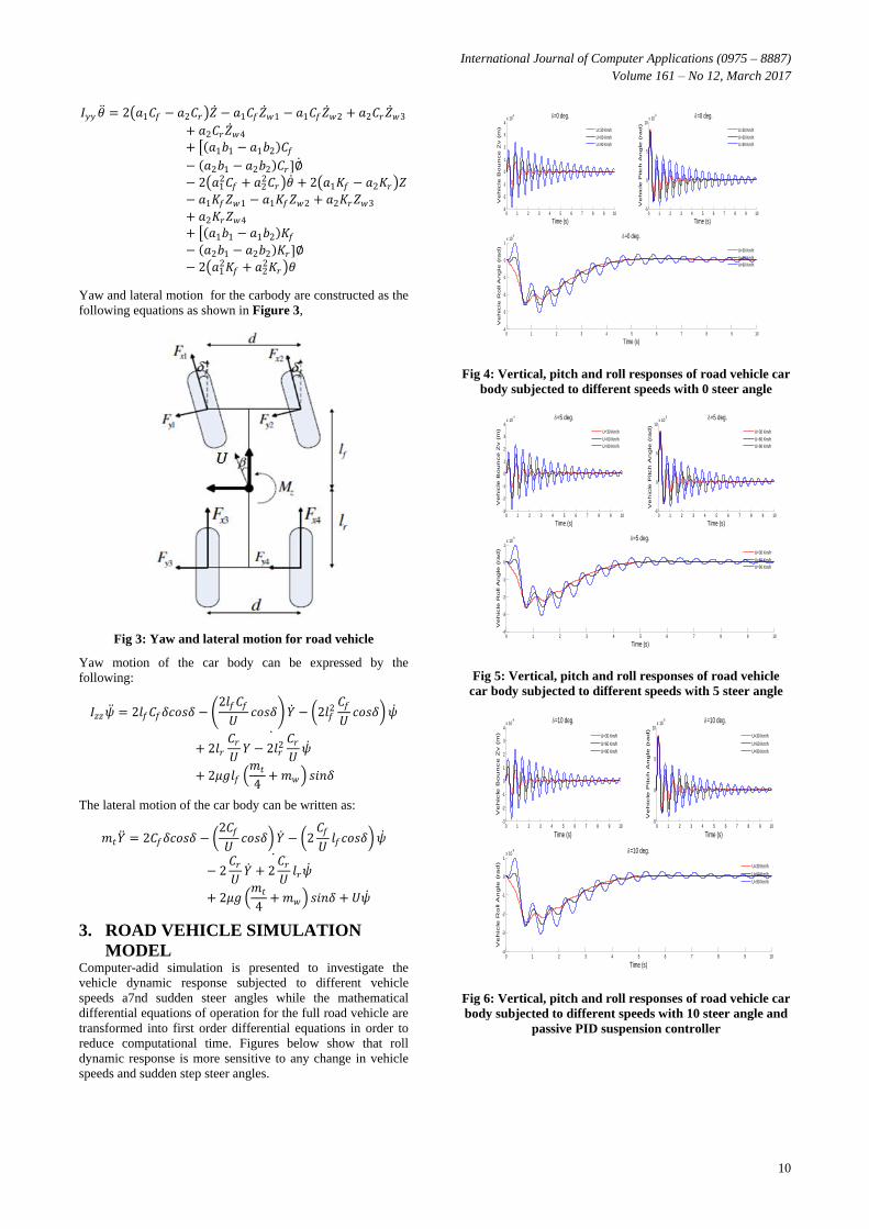
3. ROAD VEHICLE SIMULATION
MODEL Computer-adid simulation is presented to investigate the
vehicle dynamic response subjected to different vehicle
speeds a7nd sudden steer angles while the mathematical
differential equations of operation for the full road vehicle are
transformed into first order differential equations in order to
reduce computational time. Figures below show that roll
dynamic response is more sensitive to any change in vehicle
speeds and sudden step steer angles.
Fig 4: Vertical, pitch and roll responses of road vehicle car
body subjected to different speeds with 0 steer angle
Fig 5: Vertical, pitch and roll responses of road vehicle
car body subjected to different speeds with 5 steer angle
Fig 6: Vertical, pitch and roll responses of road vehicle car
body subjected to different speeds with 10 steer angle and
passive PID suspension controller
0 1 2 3 4 5 6 7 8 9 10-3
-2
-1
0
1
2
3
4x 10
-4
Time (s)
Ve
hic
le B
ou
nce
Zv (
m)
=0 deg.
U=30 Km/h
U=60 Km/h
U=90 Km/h
0 1 2 3 4 5 6 7 8 9 10-4
-3
-2
-1
0
1x 10
-5
Time (s)
Ve
hic
le R
oll A
ng
le (
ra
d)
=0 deg.
U=30 Km/h
U=60 Km/h
U=90 Km/h
0 1 2 3 4 5 6 7 8 9 10-5
0
5
10x 10
-5
Time (s)
Ve
hic
le P
itch
An
gle
(ra
d)
=0 deg.
U=30 Km/h
U=60 Km/h
U=90 Km/h
0 1 2 3 4 5 6 7 8 9 10-3
-2
-1
0
1
2
3
4x 10
-4
Time (s)
Ve
hic
le B
ou
nce
Zv (
m)
=5 deg.
U=30 Km/h
U=60 Km/h
U=90 Km/h
0 1 2 3 4 5 6 7 8 9 10-4
-3
-2
-1
0
1x 10
-5
Time (s)
Ve
hic
le R
oll A
ng
le (
ra
d)
=5 deg.
U=30 Km/h
U=60 Km/h
U=90 Km/h
0 1 2 3 4 5 6 7 8 9 10-5
0
5
10x 10
-5
Time (s)
Ve
hic
le P
itch
An
gle
(ra
d)
=5 deg.
U=30 Km/h
U=60 Km/h
U=90 Km/h
0 1 2 3 4 5 6 7 8 9 10-3
-2
-1
0
1
2
3
4x 10
-4
Time (s)
Ve
hic
le B
ou
nce
Zv (
m)
=10 deg.
U=30 Km/h
U=60 Km/h
U=90 Km/h
0 1 2 3 4 5 6 7 8 9 10-4
-3
-2
-1
0
1x 10
-5
Time (s)
Ve
hic
le R
oll A
ng
le (
ra
d)
=10 deg.
U=30 Km/h
U=60 Km/h
U=90 Km/h
0 1 2 3 4 5 6 7 8 9 10-5
0
5
10x 10
-5
Time (s)
Ve
hic
le P
itch
An
gle
(ra
d)
=10 deg.
U=30 Km/h
U=60 Km/h
U=90 Km/h

International Journal of Computer Applications (0975 – 8887)
Volume 161 – No 12, March 2017
11
Fig 7: Vertical, pitch and roll responses of road vehicle
car body subjected to different speeds with 10 steer angle
and passive PID suspension controller
4. ANALYSIS OF ROAD VEHICLE
SIMULATION RESULTS The vertical, pitch and roll responses of car body that are
included from simulation results are investigated and analyzed
to represent the most sensitive parameter to change in road
vehicle speeds and sudden step steer angles. Specifications for
settling time and maximum peak overshoot are adapted to
investigate and study the behavior of vertical, pitch and roll
motions of the road vehicle car body. A comparison is
performed between the behavior of vertical, pitch and roll
motion of the road vehicle car body. A comparison is
performed between the behaviors of these three motions in
which shows the roll dynamic response of road vehicle is the
parameter that should be used as a threshold to improve the
overall response of the road vehicle to any sudden external
disturbances.
Fig 8: Settling time analysis for road vehicle Vertical response subjected to different vehicle speeds and steer angle
Fig 9: Maximum Peak overshoot analysis for road vehicle Vertical response subjected to different vehicle speeds and steer
angle
0 1 2 3 4 5 6 7 8 9 10-3
-2
-1
0
1
2
3
4x 10
-4
Time (s)
Ve
hic
le B
ou
nce
Zv (
m)
=15 deg.
U=30 Km/h
U=60 Km/h
U=90 Km/h
0 1 2 3 4 5 6 7 8 9 10-4
-3
-2
-1
0
1x 10
-5
Time (s)
Ve
hic
le R
oll A
ng
le (
ra
d)
=15 deg.
U=30 Km/h
U=60 Km/h
U=90 Km/h
0 1 2 3 4 5 6 7 8 9 10-5
0
5
10x 10
-5
Time (s)
Ve
hic
le P
itch
An
gle
(ra
d)
=15 deg.
U=30 Km/h
U=60 Km/h
U=90 Km/h
0
2
4
6
8
10
12
14
16
0 5 10 15 20
Sett
ling
Tim
e (
s)
Steer Angle (deg.)
Zv
30 Km/h
60 Km/h
90 Km/h
0.00E+00
5.00E-03
1.00E-02
1.50E-02
2.00E-02
2.50E-02
3.00E-02
3.50E-02
0 10 20
Max
. Pe
ak O
vers
ho
ot
(m)
Steer Angle (deg.)
Zv
30 Km/h
60 Km/h
90 Km/h

International Journal of Computer Applications (0975 – 8887)
Volume 161 – No 12, March 2017
12
Fig 10: Settling time analysis for road vehicle roll response subjected to different vehicle speeds and steer angle
Fig 11: Maximum Peak overshoot analysis for road vehicle roll response subjected to different vehicle speeds and steer angle
0
2
4
6
8
10
12
14
16
0 5 10 15 20
Sett
ling
Tim
e (
s)
Steer Angle (deg.)
Vehicle Roll
30 Km/h
60 Km/h
90 Km/h
0
0.0005
0.001
0.0015
0.002
0.0025
0.003
0.0035
0 5 10 15 20
Max
. Pe
ak O
vers
ho
ot
(m)
Steer Angle (deg.)
Vehicle Roll
30 Km/h
60 Km/h
90 Km/h

International Journal of Computer Applications (0975 – 8887)
Volume 161 – No 12, March 2017
13
Fig 12: Settling time analysis for road vehicle pitch response subjected to different vehicle speeds and steer angle
Fig 13: Maximum Peak overshoot analysis for road vehicle pitch response subjected to different vehicle speeds and steer angle
5. SIMULATION RESULTS WITH
SEMI-ACTIVE PID CONTROLLER The road vehicle dynamic responses to any external
disturbance such as vehicle speeds and sudden step steer
angles are improved using a semi-active PID suspension with
conical shape spring.
Specifications and variable stiffness of the conical shaped
spring are calculated according to dynamic behavior of the
road vehicle response according to roll motion. A distinct
improvement of dynamic responses for vertical, pitch and roll
motions can be achieved as shown in the following figures
from the simulation model with semi-active PID suspension
controller.
Fig 14: Vertical, pitch and roll responses of road vehicle
car body with passive and semi-active PID suspension
controller subjected to (U=30km/hr & δ=0)
0
2
4
6
8
10
12
14
16
0 10 20
Sett
ling
Tim
e (
s)
Steer Angle (deg.)
Vehicle Pitch
30 Km/h
60 Km/h
90 Km/h
8.30E-038.35E-038.40E-038.45E-038.50E-038.55E-038.60E-038.65E-038.70E-038.75E-03
0 5 10 15 20
Max
. Pe
ak O
vers
ho
ot
(m)
Steer Angle (deg.)
Vehicle Pitch
30 Km/h
60 Km/h
90 Km/h
0 1 2 3 4 5 6 7 8 9 10-1.5
-1
-0.5
0
0.5
1x 10
-3
Time (s)
Ve
hic
le Z
v (
m)
U=30 Km/h & =0 deg.
Helical Spring
Conical Spring
0 1 2 3 4 5 6 7 8 9 10-2
-1.5
-1
-0.5
0
0.5
1x 10
-4
Time (s)
Ve
hic
le R
oll a
ng
le (
rad
)
U=30 Km/h & =0 deg.
Helical Spring
Conical Spring
0 1 2 3 4 5 6 7 8 9 10-5
0
5
10
15x 10
-4
Time (s)
Ve
hic
le P
itch
An
gle
(d
eg
.)
U=30 Km/h & =0 deg.
Helical Spring
Conical Spring
International Journal of Computer Applications (0975 – 8887)
Volume 161 – No 12, March 2017
14
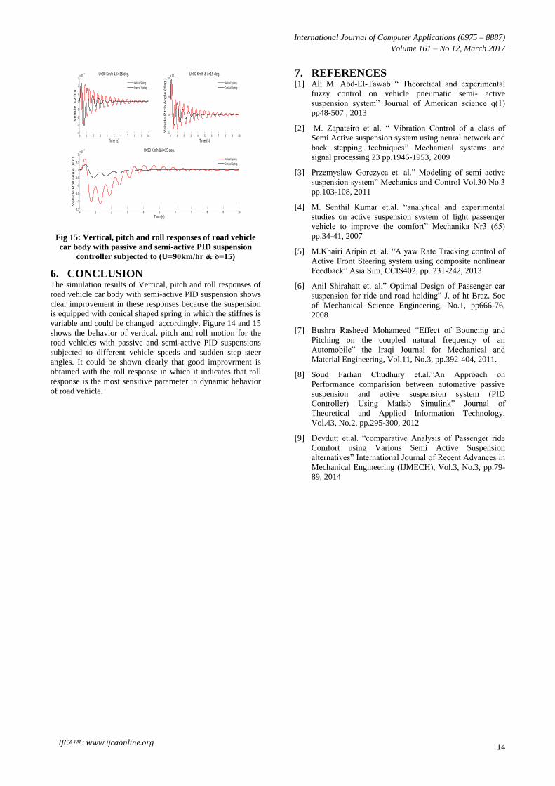
Fig 15: Vertical, pitch and roll responses of road vehicle
car body with passive and semi-active PID suspension
controller subjected to (U=90km/hr & δ=15)
6. CONCLUSION The simulation results of Vertical, pitch and roll responses of
road vehicle car body with semi-active PID suspension shows
clear improvement in these responses because the suspension
is equipped with conical shaped spring in which the stiffnes is
variable and could be changed accordingly. Figure 14 and 15
shows the behavior of vertical, pitch and roll motion for the
road vehicles with passive and semi-active PID suspensions
subjected to different vehicle speeds and sudden step steer
angles. It could be shown clearly that good improvrment is
obtained with the roll response in which it indicates that roll
response is the most sensitive parameter in dynamic behavior
of road vehicle.
7. REFERENCES [1] Ali M. Abd-El-Tawab “ Theoretical and experimental
fuzzy control on vehicle pneumatic semi- active
suspension system” Journal of American science q(1)
pp48-507 , 2013
[2] M. Zapateiro et al. “ Vibration Control of a class of
Semi Active suspension system using neural network and
back stepping techniques” Mechanical systems and
signal processing 23 pp.1946-1953, 2009
[3] Przemyslaw Gorczyca et. al.” Modeling of semi active
suspension system” Mechanics and Control Vol.30 No.3
pp.103-108, 2011
[4] M. Senthil Kumar et.al. “analytical and experimental
studies on active suspension system of light passenger
vehicle to improve the comfort” Mechanika Nr3 (65)
pp.34-41, 2007
[5] M.Khairi Aripin et. al. “A yaw Rate Tracking control of
Active Front Steering system using composite nonlinear
Feedback” Asia Sim, CCIS402, pp. 231-242, 2013
[6] Anil Shirahatt et. al.” Optimal Design of Passenger car
suspension for ride and road holding” J. of ht Braz. Soc
of Mechanical Science Engineering, No.1, pp666-76,
2008
[7] Bushra Rasheed Mohameed “Effect of Bouncing and
Pitching on the coupled natural frequency of an
Automobile” the Iraqi Journal for Mechanical and
Material Engineering, Vol.11, No.3, pp.392-404, 2011.
[8] Soud Farhan Chudhury et.al.”An Approach on
Performance comparision between automative passive
suspension and active suspension system (PID
Controller) Using Matlab Simulink” Journal of
Theoretical and Applied Information Technology,
Vol.43, No.2, pp.295-300, 2012
[9] Devdutt et.al. “comparative Analysis of Passenger ride
Comfort using Various Semi Active Suspension
alternatives” International Journal of Recent Advances in
Mechanical Engineering (IJMECH), Vol.3, No.3, pp.79-
89, 2014
0 1 2 3 4 5 6 7 8 9 10-4
-3
-2
-1
0
1
2
3x 10
-3
Time (s)
Ve
hic
le Z
v (
m)
U=90 Km/h & =15 deg.
Helical Spring
Conical Spring
0 1 2 3 4 5 6 7 8 9 10-2.5
-2
-1.5
-1
-0.5
0
0.5
1x 10
-4
Time (s)
Ve
hic
le R
oll a
ng
le (
ra
d)
U=90 Km/h & =15 deg.
Helical Spring
Conical Spring
0 1 2 3 4 5 6 7 8 9 10-5
0
5
10x 10
-4
Time (s)
Ve
hic
le P
itch
An
gle
(d
eg
.)
U=90 Km/h & =15 deg.
Helical Spring
Conical Spring
IJCATM : www.ijcaonline.org
Related Documents