Accessories EN DE FR PR IT NL RU CZ Adaptive Multi-Unit Charger Mehrfach-Rekonditionierungsladegerät Chargeur Conditionneur Multiple Cargador adaptable múltiple Carregador auto adaptável múltiplo Caricatore adattivo a più unità Adaptieve meervoudige lader Àäàïòèâíîå ìíîãîìåñòíîå çàðÿäíîå óñòðîéñòâî Adaptivní víceèlánkovou nabíjeèku ES IMPRES™ Adaptive Mult-unit Charger

Welcome message from author
This document is posted to help you gain knowledge. Please leave a comment to let me know what you think about it! Share it to your friends and learn new things together.
Transcript

Accessories
EN
DE
FR
PR
IT
NL
RU
CZ
Adaptive Multi-Unit Charger
Mehrfach-Rekonditionierungsladegerät
Chargeur Conditionneur Multiple
Cargador adaptable múltiple
Carregador auto adaptável múltiplo
Caricatore adattivo a più unità
Adaptieve meervoudige lader
Àäàïòèâíîå ìíîãîìåñòíîå çàðÿäíîå óñòðîéñòâî
Adaptivní víceèlánkovou nabíjeèku
ES
IMPRES™Adaptive Mult-unit Charger
37D22-B_Cover_new.fm Page 1 Tuesday, July 11, 2006 3:17 PM

37D22-B_Cover_new.fm Page 2 Tuesday, July 11, 2006 3:17 PM

1
En
glis
h
TABLE OF CONTENTS
Important Safety Instructions . . . . . . . . . . . . . . . . . . . . . . . . . . . . . . . . 2
Operational Safety Guidelines . . . . . . . . . . . . . . . . . . . . . . . . . . . . . . . 3
IMPRES Feature/Benefit Description . . . . . . . . . . . . . . . . . . . . . . . . . 4
Operational Characteristics/Differences . . . . . . . . . . . . . . . . . . . . . . . 5
Battery Lists . . . . . . . . . . . . . . . . . . . . . . . . . . . . . . . . . . . . . . . . . . . . . 7
Power Sources and Motorola Authorized Power Adapters . . . . . . . . 10
Operating Instructions . . . . . . . . . . . . . . . . . . . . . . . . . . . . . . . . . . . . 11Charging the Batteries. . . . . . . . . . . . . . . . . . . . . . . . . . . . . . . . . . 13Manually Reconditioning the Batteries . . . . . . . . . . . . . . . . . . . . . 14Automatically Reconditioning the Batteries . . . . . . . . . . . . . . . . . . 14Manually Terminating the Reconditioning Process . . . . . . . . . . . . 15
Troubleshooting . . . . . . . . . . . . . . . . . . . . . . . . . . . . . . . . . . . . . . . . . 16
Service. . . . . . . . . . . . . . . . . . . . . . . . . . . . . . . . . . . . . . . . . . . . . . . . 17
Chargers with Display Module (CDM) . . . . . . . . . . . . . . . . . . . . . . . . 18
This accessory manual is applicable to the following IMPRES Universal Multi-Unit chargers:WPLN4108, WPLN4109, WPLN4110, WPLN4118, WPLN4119, WPLN4120, WPLN4121, WPLN4123, WPLN4130, WPLN4131, WPLN4132, WPLN4133, WPLN4134, WPLN4135, WPLN4136
Additionally, this manual includes the following IMPRES Universal Multi-Unit chargers that are available for the GP Professional Series radios:WPLN4144, WPLN4145, WPLN4146, WPLN4187, WPLN4188, WPLN4189, WPLN4190, WPLN4191, WPLN4192, WPLN4193, WPLN4194, WPLN4195, WPLN4196, WPLN4204, WPLN4205
‘Universal’ denotes that the charger supports multiple radio models and, through the use of battery adapters, all batteries listed in tables 1 - 6 inclusive.
37D22-B_Impres_MUC_EN.fm Page 1 Wednesday, July 12, 2006 2:02 PM

2
En
glish
IMPORTANT SAFETY INSTRUCTIONSSAVE THESE INSTRUCTIONS
This document contains important safety and operating instructions. Please read these instructions carefully and save them for future reference.
Before using the battery charger, read all the instructions and cautionary markings on (1) the charger and (2) the battery (3) and on the radio using the battery.
1. To reduce risk of injury, charge only the rechargeable Motorola authorized batteries listed in Tables 1 through 5. Other batteries may explode, causing personal injury and damage.
2. Use of accessories not recommended by Motorola may result in risk of fire, electric shock, or injury.
3. To reduce risk of damage to the electric plug and cord, pull by the plug rather than the cord when disconnecting the charger.
4. An extension cord should not be used unless absolutely necessary. Use of an improper extension cord could result in risk of fire and electric shock. If an extension cord must be used, make sure that the cord size is 18AWG for lengths of up to 100 feet (30.48m), and 16AWG for lengths up to 150 feet (45.72m).
5. To reduce risk of fire, electric shock, or injury, do not operate the charger if it has been broken or damaged in any way. Take it to a qualified Motorola service representative.
6. This unit is repairable. Each pocket is powered by a unique printed circuit board & power supply. The PCB / power supply can be purchased from the Aftermarket / Parts organization. The PCB replacement part number is RLN5325. No other component level replacement parts are available. A service manual describing the replacement process can also be ordered from the Aftermarket / Parts organization. The Service Manual Number is 6880309L66.
7. To reduce risk of electric shock, unplug the charger from the ac outlet before attempting any maintenance or cleaning.
!WARNING
37D22-B_Impres_MUC_EN.fm Page 2 Wednesday, July 12, 2006 2:02 PM

3
En
glis
h
OPERATIONAL SAFETY GUIDELINES• Turn the radio off when charging the battery.
• This equipment is not suitable for outdoor use. Use only in dry locations/conditions.
• Connect equipment only to an appropriately fused and wired supply of the correct voltage (as specified on the product).
• Disconnect from line voltage by removing the mains plug from the outlet.
• The socket outlet to which this equipment is connected should be close and easily accessible.
• For equipment using fuses, replacements must comply with the type and rating specified in the equipment instructions.
• Maximum ambient temperature around the charger must not exceed 40°C (104°F).
• Make sure the cord is located where it will not be stepped on, tripped over, or subjected to water, damage, or stress.
• This unit utilizes the same wall mount unit as the NTN4796 Multi Unit Charger. The wall mount part number is NLN7967.
• For fuse replacement, use only fuses of the same type and rating listed on the charger label. The following parts can be ordered from your local Parts / Aftermarket facility:
Fuse 6571489S01Holder 0987626G01Cover 0987739G01
37D22-B_Impres_MUC_EN.fm Page 3 Wednesday, July 12, 2006 2:02 PM

4
En
glish
IMPRES FEATURE / BENEFIT DESCRIPTION
The IMPRES energy solution is an advanced Tri-Chemistry energy system developed by Motorola which encompasses (a) IMPRES batteries, (b) the IMPRES Adaptive Multi-Unit Charger, and (c) radio hardware / software which provides the capability for IMPRES compatible radios to communicate with IMPRES batteries (not applicable for GP Professional Series radios).
The IMPRES Adaptive Multi-Unit Charger, when used in conjunction with Motorola IMPRES batteries will:
• maximize operation time between charge cycles by automatically eliminating memory effect
• maximize battery life by significantly reducing heat during the trickle and post charge cycles
• eliminate the need to purchase reconditioning equipment and train personnel to “manage battery maintenance tasks.”
With this unique patented system approach, there is no need to track and record battery use, conduct manual reconditioning cycles or remove batteries from chargers following charging.
The IMPRES Adaptive Multi-Unit Charger monitors the usage pattern of the IMPRES batteries, stores that information in the IMPRES batteries, and performs a recondition cycle only when needed.
The IMPRES Adaptive Multi-Unit Charger will not overheat the batteries regardless of how long the batteries are left in the charger pockets. The charger monitors the batteries and automatically “tops off” the batteries, as required.
The IMPRES Adaptive Multi-Unit Charger simplifies the charging and battery care process: Just follow these simple steps:
1. Place the radios / batteries into the charger pockets.
2. Remove the radios / batteries when fully charged!
Motorola is the only manufacturer that offers a conditioning or reconditioning charger that provides users with the choice of charging the radios with the batteries attached or the batteries separately.
37D22-B_Impres_MUC_EN.fm Page 4 Wednesday, July 12, 2006 2:02 PM

5
En
glis
h
OPERATIONAL CHARACTERISTICS / DIFFERENCES:1. IMPRES batteries may be charged in conventional chargers.
However, in order for the Smart Energy features to be enabled, IMPRES batteries must be charged in the IMPRES Adaptive Multi-Unit Charger. The first time an IMPRES battery is charged in an IMPRES Adaptive Multi-Unit Charger, the charger initially indicates a STEADY YELLOW on the charger indicator. This first charge must be allowed to complete to a STEADY GREEN indication on the charger indicator. This properly calibrates the IMPRES battery and enables the Smart Energy features. If this process is interrupted, the charger will calibrate the battery upon the next insertion.
2. Since the IMPRES Adaptive Multi-Unit Charger automatically determines the conditions necessary to recondition an IMPRES battery, the charger may go into recondition mode when a radio or battery is inserted. This is indicated by a STEADY YELLOW on the charger indicator. The recondition mode can be over ridden, if required, by removing and reinserting the radio or battery. (Please see instructions later in this guide.)
3. The IMPRES Adaptive Multi-Unit Charger is designed to charge any battery listed in Tables 1 through 6. However, only genuine IMPRES batteries will provide Smart Energy features.
4. The IMPRES Adaptive Multi-Unit Charger must be used to calibrate IMPRES Smart batteries to ensure they accurately record, store and display IMPRES battery usage data.
37D22-B_Impres_MUC_EN.fm Page 5 Wednesday, July 12, 2006 2:02 PM

6
En
glish
5. If an IMPRES battery is used with a display radio (e.g. XTS5000), the radio may display an icon indicating the charge status of the battery. This icon is enabled after an IMPRES battery has beencalibrated in an IMPRES charger. The charger status icon will remain displayed as long as the user continues to use IMPRES chargers to charge the batteries. However, if an IMPRES battery is charged in a non-IMPRES charger for a period of 7 days (or more), the icon will disappear. To re-enable the icon, insert an IMPRES battery into an IMPRES charger and allow it to complete the charging process (resulting in a STEADY GREEN indication). The charge status icon will then be displayed on the radio. If the icon does not appear after a full charge, place a partially discharged battery (at least 70% discharged) into the charger, initiate a reconditioning, and allow it to complete the charging process. The icon will then appear on the radio display (not applicable to GP Professional Series radios).
6. The IMPRES Adaptive Multi-Unit Charger can only be repaired by a qualified service technician authorised by Motorola CGISS. Any violation of this policy can void unit warranty.
37D22-B_Impres_MUC_EN.fm Page 6 Wednesday, July 12, 2006 2:02 PM
7
En
glis
h
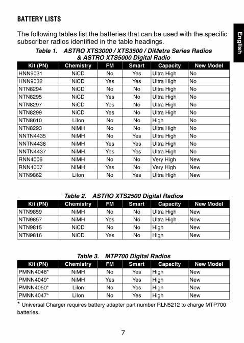
BATTERY LISTS
The following tables list the batteries that can be used with the specific subscriber radios identified in the table headings.
* Universal Charger requires battery adapter part number RLN5212 to charge MTP700 batteries.
Table 1. ASTRO XTS3000 / XTS3500 / DiMetra Series Radios& ASTRO XTS5000 Digital Radio
Kit (PN) Chemistry FM Smart Capacity New ModelHNN9031 NiCD No Yes Ultra High No
HNN9032 NiCD Yes Yes Ultra High NoNTN8294 NiCD No No Ultra High No
NTN8295 NiCD Yes No Ultra High No
NTN8297 NiCD Yes No Ultra High No
NTN8299 NiCD Yes No Ultra High No
NTN8610 LiIon No No High No
NTN8293 NiMH No No Ultra High NoNNTN4435 NiMH No Yes Ultra High No
NNTN4436 NiMH Yes Yes Ultra High No
NNTN4437 NiMH Yes Yes Ultra High No
RNN4006 NiMH No No Very High New
RNN4007 NIMH Yes No Very High New
NTN9862 LiIon No Yes Ultra High New
Table 2. ASTRO XTS2500 Digital RadiosKit (PN) Chemistry FM Smart Capacity New Model
NTN9859 NiMH No No Ultra High NewNTN9857 NiMH Yes No Ultra High New
NTN9815 NiCD No No High New
NTN9816 NiCD Yes No High New
Table 3. MTP700 Digital RadiosKit (PN) Chemistry FM Smart Capacity New Model
PMNN4048* NiMH No Yes High New
PMNN4049* NiMH Yes Yes High New
PMNN4050* Lilon No Yes High New
PMNN4047* LiIon No Yes High New
37D22-B_Impres_MUC_EN.fm Page 7 Wednesday, July 12, 2006 2:02 PM

8
En
glish
**Universal Charger requires battery adapter part number 4385922B01 to charge Astro Saber batteries.
Table 4. HT1000 / MT2000 / MTS2000 / MTX8000& MTX9000 Jedi Series Radios
Kit (PN) Chemistry FM Smart Capacity New ModelHNN9028 NiCD No Yes Ultra High No
HNN9029 NiCD Yes Yes Ultra High No
NTN7143 NiCD No No High No
NTN7144 NiCD No No Ultra High NoNTN7146 NiCD Yes No High No
NTN7147 NiCD Yes No Ultra High No
NTN7148 NiCD CENELEC No High No
NTN7149 NiCD CSA No High No
NTN7150 NiCD MSHA No High No
NTN7341 NiCD Yes No Ultra High NoNTN7372 NiCD Yes No High No
WPPN4013 NiMH No No Ultra High No
WPPN4037 NiMH Yes No Ultra high No
RNN4008 NiCD ATEX No High No
Table 5. Saber / Astro Saber/ SSE5000 / MX1000 RadiosKit (PN) Chemistry FM Smart Capacity New Model
HNN9033 NiCD No Yes Ultra High NoHNN9031 NiCD Yes Yes Ultra High No
NTN4537** NiCD Yes No Low No
NTN4538 NiCD Yes No High No
NTN4592** NiCD No No Low No
NTN4593 NiCD No No High No
NTN4595 NiCD No No Ultra High NoNTN4596 NiCD Yes No Ultra High No
NTN4657 NiCD No No High No
NTN4671 NiCD CENELEC No High No
NTN4992 NiCD Yes No Ultra High No
NTN7014** NiMH No No High No
NTN7058 NiCD Yes No Ultra High NoNTN7426 NiCD Yes No Low No
NTN8251 NiMH Yes No Ultra High No
NTN8818** LiIon No No High No
37D22-B_Impres_MUC_EN.fm Page 8 Wednesday, July 12, 2006 2:02 PM

9
En
glis
h
Universal Charger requires battery adapter part number RLN5648.
Table 6. GP Professional Series RadiosKit (PN) Chemistry FM Smart Capacity New Model
HNN9003 NiMHAA Bluetooth
No No High No
HNN9008 NiMH No No High No
HNN9009 NiMH No No Ultra High No
HNN9010 NiMH Yes No Ultra High NoHNN9011 NiCD Yes No High No
HNN9012 NiCD No No High No
HNN9013 LiIon No No High No
WPNN4045 NiMH No No High No
PMNN4045 NiMH No No High No
HNN4001 Impres NiMH No Yes Ultra High YesHNN4002 Impres NiMH Yes Yes Ultra High Yes
HNN4003 Impres LiIon No Yes Ultra High Yes
NOTE:Adapters can be purchased from a radio sales or Aftermarketsales team representative.
37D22-B_Impres_MUC_EN.fm Page 9 Wednesday, July 12, 2006 2:02 PM

10
En
glish
POWER SOURCES AND MOTOROLA AUTHORIZED POWER ADAPTERS
This charger is designed for use in 100 V ac to 240 V ac, 50/60 Hz applications and uses the following Motorola power cords shown in Table 7. Power cords used with the charger for GP Professional Series radios are listed in Table 8:
Table 7. Motorola Universal Model Power CordsPlug Type Charger Kit Charger Kit
(Display Model)Power Cord
No Power cord / plug WPLN4121 WPLN4127 None
U.S./NA WPLN4108 WPLN4130 3087791G01
Euro WPLN4109 WPLN4131 3087791G04
U.K. WPLN4110 WPLN4132 3087791G07
Australia/New Zealand WPLN4118 WPLN4133 3087791G10
Argentina WPLN4119 WPLN4134 3087791G13U.S./NA WPLN4120 WPLN4135 3087791G01
Korea WPLN4123 WPLN4136 3087791G16
Table 8. Motorola GP Professional Series Model Power CordsPlug Type Charger Kit Charger Kit
(Display Model)Power Cord
No Power cord / plug WPLN4197 WPLN4198 NoneU.S./NA WPLN4187 WPLN4192 3087791G01
Euro WPLN4189 WPLN4194 3087791G04
U.K. WPLN4188 WPLN4193 3087791G07
Australia/New Zealand WPLN4190 WPLN4195 3087791G10
Argentina WPLN4191 WPLN4196 3087791G13
U.S./NA WPLN4205 WPLN4204 3087791G01Korea WPLN4146 WPLN4145 3087791G16
37D22-B_Impres_MUC_EN.fm Page 10 Wednesday, July 12, 2006 2:02 PM

11
En
glis
h
OPERATING INSTRUCTIONS
The charger pockets accommodate either a radio with a battery attached or a battery alone. Prior to charging a radio with a battery, turn the radio off. Batteries charge best if they are at room temperature when charged.
1. Plug the charger end of the power cord into the ac receptacle located at the back of the charger.
2. Plug the wall receptacle end of the power cord into the appropriate ac outlet. A successful power-up sequence is indicated by a SINGLE FLASH GREEN on the charger indicator.
3. Insert a battery, or radio with a battery (radio turned off), into a charger pocket by:
a. aligning the groove on each side of the battery with the corresponding raised rail on each side of the charger pocket
b. pressing the battery toward the rear of the pocket
c. sliding the battery into the charger pocket, ensuring complete contact between the charger and battery contacts.
Once a battery is properly seated into a charger pocket, the charger indicator illuminates, indicating the charger has recognized the presence of a battery. Refer to the charging indicators in Table 9
.
NOTESThe IMPRES Multi-Unit Adaptive Charger charges only theMotorola authorized batteries listed in Tables 1 through 6. Otherbatteries may not charge.The IMPRES Multi-Unit Adaptive Charger has automatic featuresand capabilities that are different from other battery chargers.Pay close attention to the charge indicator to ensure that thecharger is in the desired/expected mode of operation.
37D22-B_Impres_MUC_EN.fm Page 11 Wednesday, July 12, 2006 2:02 PM

12
En
glish
In order for the features of Motorola Smart batteries and the Adaptive Charging System to be fully available, the data contained in Motorola Smart batteries must be initialized by the charger the first time it is charged. This process is indicated by a STEADY YELLOW on the charger indicator (the same as though the battery were reconditioning). The process is automatic, includes an initial reconditioning of the battery, and begins charging upon completion of this process. This process requires time to initialize the battery, so the battery should be left in the charger overnight on the initial insertion.
Table 9. Charging IndicatorsCharge Indicator Description
Single Flash Green Charger has successfully powered up.
Steady Red Battery is in rapid charge mode.Flashing Green Battery has completed rapid charge (>90% available
capacity). Battery is in Top-Off charge (Trickle charge).
Steady Green Battery has completed charging and is fully charged.
Flashing Yellow Battery is recognized by charger but is waiting to charge. (Either the battery voltage is too low or the battery temperature is too low or to high to allow charging. When this condition is corrected, the battery will begin charging.)
Flashing Red Battery is unchargeable or not making proper contact.
Steady Yellow (This feature is for Smart batteries only)
Battery is in recondition mode. The length of time the charger remains in this mode is dependent upon the state of charge remaining in the battery when inserted. (Fully charged batteries require more time to recondition – 8 hours or more - than fully discharged batteries.)
Flashing Red/Green (This feature is for Smart batteries only)
Battery has completed charging and is fully charged. Battery continues to be usable, but may be nearing the end of its rated service life.
NOTEThe IMPRES Adaptive Multi-Unit Charger is unique in that ithas the ability, when used with Motorola IMPRES batteries, toautomatically determine the need of the batteries to bereconditioned.
37D22-B_Impres_MUC_EN.fm Page 12 Wednesday, July 12, 2006 2:02 PM

13
En
glis
h
The IMPRES Adaptive Multi-Unit Charger operates both as:
• a Charger with all Motorola authorized batteries, and
• a Reconditioner with Motorola authorized IMPRES batteries.
Charging the Batteries
To ensure optimum performance, Motorola recommends all new batteries be left in the charger 14 to 16 hours prior to initial use.
1. Once a battery or radio with a battery is properly inserted into a charger pocket, the charger begins to rapid charge the battery and is indicated by a STEADY RED on the charger indicator. The length of time the charger indicates a STEADY RED is dependent upon the charge remaining in the battery.
2. Completion of rapid charge (>90% available capacity) is indicated by a FLASHING GREEN on the charger indicator. This indicates the “top-off” charge (trickle charge) and requires approximately 1 hour.
3. Completion of “top-off” charge is indicated by a STEADY GREEN on the charger indicators. This indicates a battery is fully charged.
4. Other indications that may appear on the charger indicator while charging are:• FLASHING YELLOW – indicates that either the battery
temperature or the battery voltage is out of range for charging. Charging resumes when theses conditions have been corrected.
• FLASHING RED AND GREEN – indicates that the battery may be approaching the end of its rated service life. While this battery
IMPORTANT:The charger pockets are designed to accept several differentbattery shapes and sizes, so it is important to make certainthat a radio with a battery attached or a battery alone isinserted correctly. If a radio with a battery attached or batteryalone is inserted incorrectly, the indicator will not illuminate,indicating that the battery is not being charged.
NOTE:New batteries (never used before) prematurely indicate a fullcharge in some cases (STEADY GREEN indication)
37D22-B_Impres_MUC_EN.fm Page 13 Wednesday, July 12, 2006 2:02 PM

14
En
glish
is fully charged, its charging capacity has been reduced by usage and may not adequately support heavier applications. This feature is available only when used with Motorola IMPRES batteries. This is not a fault indication, merely a notification to the user that a battery may soon no longer be able to yield expected service and may need to be replaced.
• FLASHING RED – indicates that the battery is unchargeable. This could be the result of a loss of contact between the battery and the charger’s contacts. Charging resumes when the condition causing this indication is corrected.
Motorola Smart batteries have an internal memory device that is read by the Motorola IMPRES Adaptive Multi-Unit Charger. If an IMPRES battery is charged for more than 2-1/2 minutes, the IMPRES Adaptive Multi-Unit Charger retains the serial number of the IMPRES battery. The IMPRES battery may be removed from the charger for up to 30 minutes. Once the battery is reinserted back into the charger, it will resume the charging process from that point from when the battery was first removed.
Manually Reconditioning the Batteries
Within 2-1/2 minutes of the initial insertion of an IMPRES battery (STEADY RED indication), remove and reinsert the battery within 5 seconds to manually force reconditioning to occur. The charger indicator changes from a STEADY RED to a STEADY YELLOW. This forces the charger to recondition and automatically recharge the battery.
Automatically Reconditioning the Batteries
The Motorola IMPRES Adaptive Multi-Unit Charger, when used in conjunction with a Motorola IMPRES battery, has the ability to determine when it is appropriate to recondition the battery.
NOTE:Excessive use of this feature may reduce the overall life of the battery.
37D22-B_Impres_MUC_EN.fm Page 14 Wednesday, July 12, 2006 2:02 PM

15
En
glis
h
When an IMPRES battery is properly inserted into the charger, the charger determines if it is appropriate to recondition the battery. If the battery needs reconditioning, the charger automatically indicates a STEADY YELLOW. This process may take up to 8 hours or more to complete, depending upon the state of charge and capacity rating of the battery when it is inserted.
It is important to note, for this process to be effective, the battery must be allowed to complete the recondition/recharge process. Leave the battery in the charger until the charger indicates a STEADY GREEN.
At the completion of the recondition cycle, the charger automatically recharges the battery.
Manually Terminating the Reconditioning Process
At any time during the reconditioning process of a Motorola IMPRES battery (STEADY YELLOW indication), reconditioning may be terminated by removing and reinserting the battery within 5 seconds. This causes the charger to terminate the reconditioning process and begin the charging process. The charger indicator changes to a STEADY RED.
37D22-B_Impres_MUC_EN.fm Page 15 Wednesday, July 12, 2006 2:02 PM

16
En
glish
TROUBLESHOOTING
The IMPRES Adaptive Multi-Unit Charger incorporates the features of:
• a universal input (100 V ac-240 V ac, 50/60 Hz) power supply
• a constant current rapid charger
• an interrupted current (negative pulse) conditioning charger
• a reconditioning unit.
The combination of the features listed above are unique in a desktop charger. Therefore, operation of a radio with a battery attached while in the charger is not recommended.
While in the charger, radio operation can result in minimally reduced radio performance and extended battery charge time.
Towards the end of the rapid charge cycle (STEADY RED indication), the battery voltage exceeds the normal operating voltage of the radio. The voltage returns to a normal level following the rapid charge mode or when the battery is removed from the charger.
If a radio is turned on while the charger is in rapid charge mode, the radio becomes temporarily inoperable. This condition can be cleared by removing the radio from the charger and turning the radio off and on again.
During the reconditioning process, the battery becomes fully discharged. As a result, the radio may not function during reconditioning mode.
When troubleshooting, always observe the charge indicator – Refer to Table 9.
37D22-B_Impres_MUC_EN.fm Page 16 Wednesday, July 12, 2006 2:02 PM

17
En
glis
h
SERVICE
The IMPRES Adaptive Multi-Unit Charger can only be repaired by a qualified service technician authorised by Motorola. Any violation of this policy can void unit warranty.
Table 10. Troubleshooting Problem What it means... What to do...
No chargerindication
• Charger contact is not being made.
• No power to the charger.
• Check that the radio with battery, or the battery alone, is inserted cor-rectly.• Make sure that the power cord is securely plugged into the charger and an appropriate ac outlet, and that there is power to the outlet.• Replace fuse(s).
Flashing Red Indication
• Charger contact is not being made.
• Battery is unchargeable.
• Remove the battery from the charger and replace it back into the charger.• Verify that the battery is a Motorola authorized battery listed in Tables 1 through 6. Other batteries may not charge.• Remove power from the battery charger and, using a clean dry cloth, clean the gold metal charging con-tacts of both the battery and the charger.• Replace battery.
Flashing Yellow Indication
• Battery it waiting to charge. The battery temperature may be below 5°C (41°F) or above 40°C (104°F) or the battery voltage may be lower than the predetermined threshold level for rapid charging.
• When this condition is corrected, the battery will begin charging.
37D22-B_Impres_MUC_EN.fm Page 17 Wednesday, July 12, 2006 2:02 PM

18
En
glish
CHARGERS WITH DISPLAY MODULE (CDM)The IMPRES Adaptive Multi-Unit Charger can be enhanced with the addition of a charger display module (CDM), Motorola part no. RLN5382.
General Display InformationThe IMPRES Adaptive Multi-Unit Charger with CDM provides the user with valuable information while performing battery maintenance and care. The information that the charger displays and the corresponding LED indicators are detailed in the following tables.
Start Up
Non-IMPRES Battery in the Pocket
IMPRES Battery in the Pocket
Upon Charger Power-upLED SINGLE FLASH GREEN
Line 1 IMPRES
Line 2
If There is No Battery in the Pocket LED OFF
Line 1 NO BATTERY
Line 2
Reading Battery Data LED Any Defined Indication
Line 1 READING
Line 2 BATTERY DATA
LED Defined by Charge State
Line 1 NON-IMPRES
Line 2 BATTERY
IMPRES and Software Versions are DisplayedLED Defined by Charge State
Line 1 IMPRES
Line 2 SW xx.yy; aa.bb
NOTE:xx.yy denotes charger SW version, and aa.bb denotes CDMSW version.
37D22-B_Impres_MUC_EN.fm Page 18 Wednesday, July 12, 2006 2:02 PM

19
En
glis
h
IMPRES Battery Kit # and Chemistry are Displayed LED Defined by Charge State
Line 1 KIT# --------
Line 2 -----CHEMISTRY
Forecasted # of Cycles Prior to Automatic Recondition LED Defined by Charge State
Line 1 ----CYCLES
Line 2 TO RECONDITION
* Displayed only when the number of cycles to recondition is less than 6.
Charger Waiting to Charge, Battery is Hot LED Flashing ORANGE
Line 1 WAITING TO CHG
Line 2 HOT BATTERY
Charger Waiting to Charge, Battery is Cold LED Flashing ORANGE
Line 1 WAITING TO CHG
Line 2 COLD BATTERY
Charger Waiting to Charge, Low Voltage LED Flashing ORANGE
Line 1 WAITING TO CHG
Line 2 LOW VOLTAGE
NOTE:Not all screens shown above will be displayed. For example,Waiting to Charge displays (battery hot, cold, low voltage) willonly be shown if the situation warrants.
37D22-B_Impres_MUC_EN.fm Page 19 Wednesday, July 12, 2006 2:02 PM

20
En
glish
Charger is in Trickle Charge ModeLED Flashing GREEN
Line 1 TRICKLE CHARGE
Line 2
Charge is Complete LED Steady GREEN or Flashing RED / GREEN
Line 1 CHARGE COMPLETE
Line 2
Charger is in Discharge/Reconditioning Mode LED Steady ORANGE
Line 1 DISCHARGE
Line 2
Charger is Calibrating an IMPRES Battery LED Steady ORANGE, Steady RED, & Flashing ORANGE or
GREEN
Line 1 Calibrating
Line 2 Battery
LED Steady GREEN
Line 1 Battery
Line 2 Calibrated
* All IMPRES batteries should be calibrated before initial use. An IMPRES charger will automatically initiate calibration for all new batteries
Battery Capacity Data is Displayed as “%” in mAH, and Voltage LED Defined by Charge State
Line 1 ----% RATED CAP.
Line 2 ----mAH --.-V
37D22-B_Impres_MUC_EN.fm Page 20 Wednesday, July 12, 2006 2:02 PM

21
En
glis
h
NOTE:(1) Estimated time to complete charging includes rapid charge
and discharge cycles (if applicable). (2) Battery capacity information may not be displayed for
uncalibrated batteries.(3) Use of IMPRES batteries with non-IMPRES chargers can
affect capacity and charging time accuracy.
Estimated Time to Rapid ChargeComplete Displayed in Hours, Minutes for NiCd & NiMH IMPRES Batteries Only
LED Defined by Charge State
Line 1 RAPID CHG ENDS
Line 2 IN xx HRS, yy MIN
37D22-B_Impres_MUC_EN.fm Page 21 Wednesday, July 12, 2006 2:02 PM

22
En
glish
Sequencing Diagrams for IMPRES Batteries
Note: These diagrams are the sequences shown in the previous ‘General Display Information’ and are in English only.
IMPRES NiCd & NiMH Battery Display Sequence
LED Defined by Charge State
Line 1 KIT# xxxxxxxx
Line 2 SN: yyyyyyyyyyyy
LED Defined by Charge State
Line 1 KIT# xxxxxxxx
Line 2 yyyyy CHEMISTRY
LED Defined by Charge State
Line 1 xxxx CYCLES
Line 2 TO RECONDITION
LED Steady RED
Line 1 RAPID CHARGE
Line 2
LED Defined by Charge State
Line 1 xx% RATED CAP.
Line 2 yyyyy mAH zz.z V
LED Defined by Charge State
Line 1 RAPID CHG ENDS
Line 2 IN xx HRS, yy MIN
Start
(4.0 sec)
(2.0 sec)
(2.0 sec)
(2.0 sec)
(7.0 sec)
(4.0 sec)
Every73.0 sec
Every13.0 sec
5X65.0sec
37D22-B_Impres_MUC_EN.fm Page 22 Wednesday, July 12, 2006 2:02 PM
23
En
glis
h
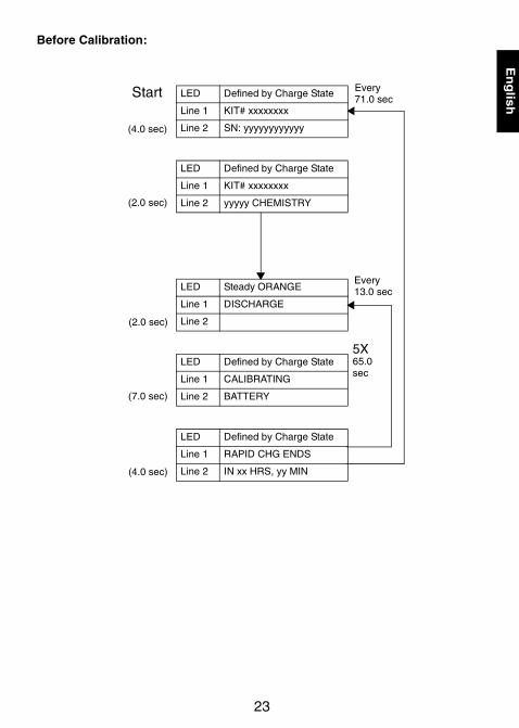
Before Calibration:
LED Defined by Charge State
Line 1 KIT# xxxxxxxx
Line 2 SN: yyyyyyyyyyyy
LED Defined by Charge State
Line 1 KIT# xxxxxxxx
Line 2 yyyyy CHEMISTRY
LED Steady ORANGE
Line 1 DISCHARGE
Line 2
LED Defined by Charge State
Line 1 CALIBRATING
Line 2 BATTERY
LED Defined by Charge State
Line 1 RAPID CHG ENDS
Line 2 IN xx HRS, yy MIN
Every71.0 secStart
(4.0 sec)
(2.0 sec)
(2.0 sec)
(7.0 sec)
(4.0 sec)
Every13.0 sec
5X65.0sec
37D22-B_Impres_MUC_EN.fm Page 23 Wednesday, July 12, 2006 2:02 PM

24
En
glish
After Calibration:
LED Defined by Charge State
Line 1 KIT# xxxxxxxx
Line 2 SN: yyyyyyyyyyyy
LED Defined by Charge State
Line 1 KIT# xxxxxxxx
Line 2 yyyyy CHEMISTRY
LED Steady GREEN
Line 1 CHARGE COMPLETE
Line 2
LED Defined by Charge State
Line 1 BATTERY
Line 2 CALIBRATED
LED Defined by Charge State
Line 1 xx% RATED CAP.
Line 2 yyyy mAH zz.z V
Start
(4.0 sec)
(2.0 sec)
(2.0 sec)
(2.0 sec)
(7.0 sec)
Every61.0sec
Every11 sec
5X55.0sec
37D22-B_Impres_MUC_EN.fm Page 24 Wednesday, July 12, 2006 2:02 PM
25
En
glis
h
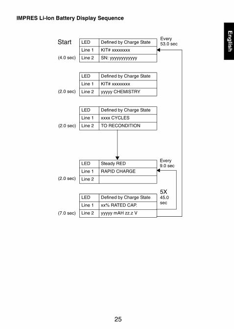
IMPRES Li-Ion Battery Display Sequence
LED Defined by Charge State
Line 1 KIT# xxxxxxxx
Line 2 SN: yyyyyyyyyyyy
LED Defined by Charge State
Line 1 KIT# xxxxxxxx
Line 2 yyyyy CHEMISTRY
LED Defined by Charge State
Line 1 xxxx CYCLES
Line 2 TO RECONDITION
LED Steady RED
Line 1 RAPID CHARGE
Line 2
LED Defined by Charge State
Line 1 xx% RATED CAP.
Line 2 yyyyy mAH zz.z V
Start
(4.0 sec)
(2.0 sec)
(2.0 sec)
(2.0 sec)
(7.0 sec)
Every53.0 sec
Every9.0 sec
5X45.0sec
37D22-B_Impres_MUC_EN.fm Page 25 Wednesday, July 12, 2006 2:02 PM

26
En
glish
Before Calibration:
LED Defined by Charge State
Line 1 KIT# xxxxxxxx
Line 2 SN: yyyyyyyyyyyy
LED Defined by Charge State
Line 1 KIT# xxxxxxxx
Line 2 yyyyy CHEMISTRY
LED Steady ORANGE
Line 1 DISCHARGE
Line 2
LED Defined by Charge State
Line 1 CALIBRATING
Line 2 BATTERY
Start
(4.0 sec)
(2.0 sec)
(2.0 sec)
(7.0 sec)
Every51.0 sec
Every9.0 sec
5X45.0sec
37D22-B_Impres_MUC_EN.fm Page 26 Wednesday, July 12, 2006 2:02 PM
Related Documents