1 VOCATIONAL TRAINING REPORT (Study and modelling of MTI Radar) AT RADAR SYSTEMS GROUP INTEGRATED TEST RANGE, CHANDIPUR DEFENCE RESEARCH& DEVELOPMENTORGANISATION BY ABINASH RATH DEEPAK KUMAR BIBHUTI NATH DHEERAJ SOURAV GARNAIK GANDHI ENGINEERING COLLEGE BHUBANESWAR

Welcome message from author
This document is posted to help you gain knowledge. Please leave a comment to let me know what you think about it! Share it to your friends and learn new things together.
Transcript
1
VOCATIONAL TRAINING REPORT
(Study and modelling of MTI Radar)
AT
RADAR SYSTEMS GROUP INTEGRATED TEST RANGE, CHANDIPUR
DEFENCE RESEARCH& DEVELOPMENTORGANISATION
BY ABINASH RATH DEEPAK KUMAR BIBHUTI NATH DHEERAJ SOURAV GARNAIK
GANDHI ENGINEERING COLLEGE BHUBANESWAR
2

3
ACKNOWLEDGEMENT
We have been part of the project “STUDY AND MODELLING OF MTI RADAR”. The project has required our full involvement, however, it would not have been possible without the kind support and help of many individuals. We would like to extend our sincere thanks to all of them.We wish to express our gratitude to Mr. C.R.OJHA (Scientist ‟F‟), HRD who was abundantly helpful and offered invaluable assistance, support and guidance. Deepest gratitude are also due to Mr. N ROY (Scientist „F‟), GD, Radar Systems Group. Dr. A.K.ROY (Scientist ‟F‟), Radar Systems Group and Mr. Rajarshi Biswas (Scientist-‟B‟), Radar Systems Group without whose knowledge and assistance this study would not have been successfull.We would like to express our gratitudeto staff members of Radar Systems Group for their kind co-operation and encouragement for the valuable information they provided in their respective fields. Lastly we thank Almighty, our parents, friends, for their constant encouragement.
4
Content
TOPICS PAGES
DRDO and ITR---------------------------------------------5-7
Range Radar Division {RRD}-----------------------------8
Types of Radars-----------------------------------------9-12
MTI radars and their utility-------------------------13-15
o Real life Example-------------------------------------14
o Utility---------------------------------------------------15
The MTI Radar Model--------------------------------16-26
o The concept-------------------------------------------16
o The model Specification------------------------17-18
o Description---------------------------------------19-23
Butterfly plot of the system-------------------------24-26
The future of MTI Radars--------------------------------27
Conclusion--------------------------------------------------28
Bibliography-----------------------------------------------29
5
DRDO AND ITR
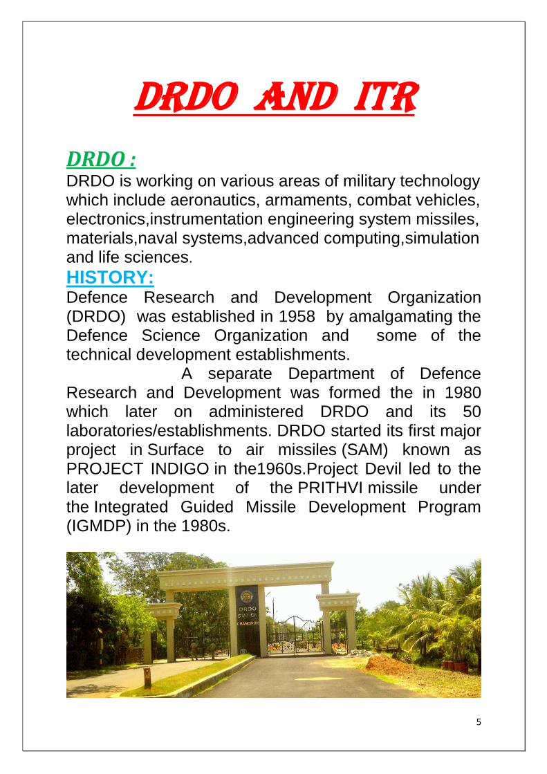
DRDO : DRDO is working on various areas of military technology which include aeronautics, armaments, combat vehicles, electronics,instrumentation engineering system missiles, materials,naval systems,advanced computing,simulation and life sciences.
HISTORY: Defence Research and Development Organization (DRDO) was established in 1958 by amalgamating the Defence Science Organization and some of the technical development establishments. A separate Department of Defence Research and Development was formed the in 1980 which later on administered DRDO and its 50 laboratories/establishments. DRDO started its first major project in Surface to air missiles (SAM) known as PROJECT INDIGO in the1960s.Project Devil led to the later development of the PRITHVI missile under the Integrated Guided Missile Development Program (IGMDP) in the 1980s.
6
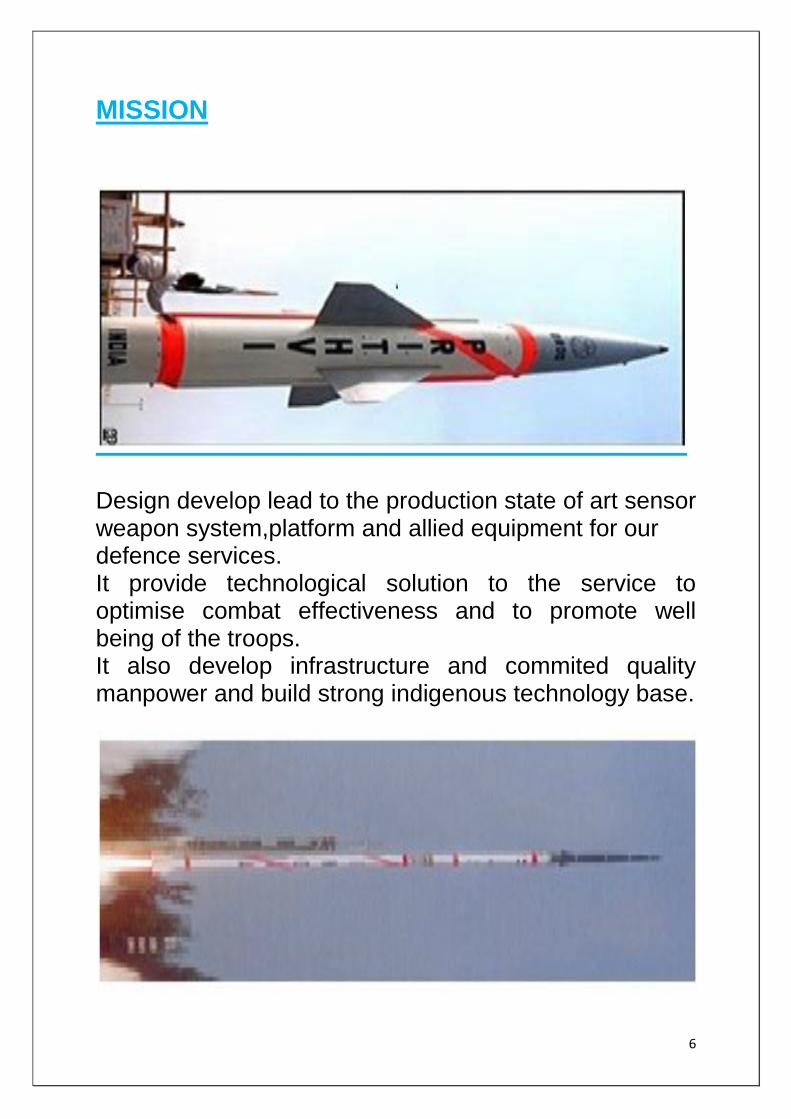
MISSION
Design develop lead to the production state of art sensor weapon system,platform and allied equipment for our defence services. It provide technological solution to the service to optimise combat effectiveness and to promote well being of the troops. It also develop infrastructure and commited quality manpower and build strong indigenous technology base.
7
ITR (integrated test range):
The Integrated Test Range is a dedicated missile test site for ranges up to 5,000 km. PRITHVI and AGNI I-V ballistic missiles, AKASH and TRISHUL surface-to-air missiles, the Nag anti-tank missile, and Advanced Air Defence (AAD) ballistic missile interceptors have all been tested here. For launching missiles, rockets and flight test vehicles, a
dedicated range known as Integrated Test Range (ITR)
was established in 1989. A number of test vehicles of
different class including multirole missile Trishul,
multitarget capability missile Akash, the antitank Nag
missile, the most precise surface-to-surface missile Prithvi
and the large scale technology demonstrator Agni have
been test fired from this range. With its versatile technical
and scientific capability, ITR has also supported a number
of other missions such as Multibarrel Rocket Launcher—
Pinaka and Pilotless Target Aircraft (PTA).The range is spread over a length of 17 km along the sea coast where a number of tracking instruments have been deployed to cover the total flight path of the test vehicles. Some of the significant test facilities at ITR are: Electro-Optical Tracking System (Mobile and Fixed) S-Band Tracking Radar (KAMA-N) (Mobile) C-Band Tracking Radar (PCMC) (Fixed) Telemetry System (Fixed and Mobile) Range Computer
CCTV System Photo Processing System
Meteorological System
Range Safety System
8
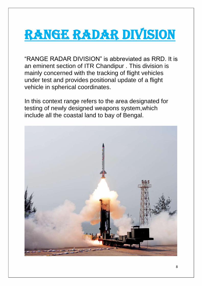
RANGE RADAR DIVISION
“RANGE RADAR DIVISION” is abbreviated as RRD. It is an eminent section of ITR Chandipur . This division is mainly concerned with the tracking of flight vehicles under test and provides positional update of a flight vehicle in spherical coordinates. In this context range refers to the area designated for testing of newly designed weapons system,which include all the coastal land to bay of Bengal.
9
TYPES OF RADAR
SEARCH RADAR: Search radar, as previously mentioned, continuously scans a volume of space and provides initial detection divided into specific types, according to the type of object they are designed to detect. For example, surface-search, air-search, and height-finding radars are all types of search radar.
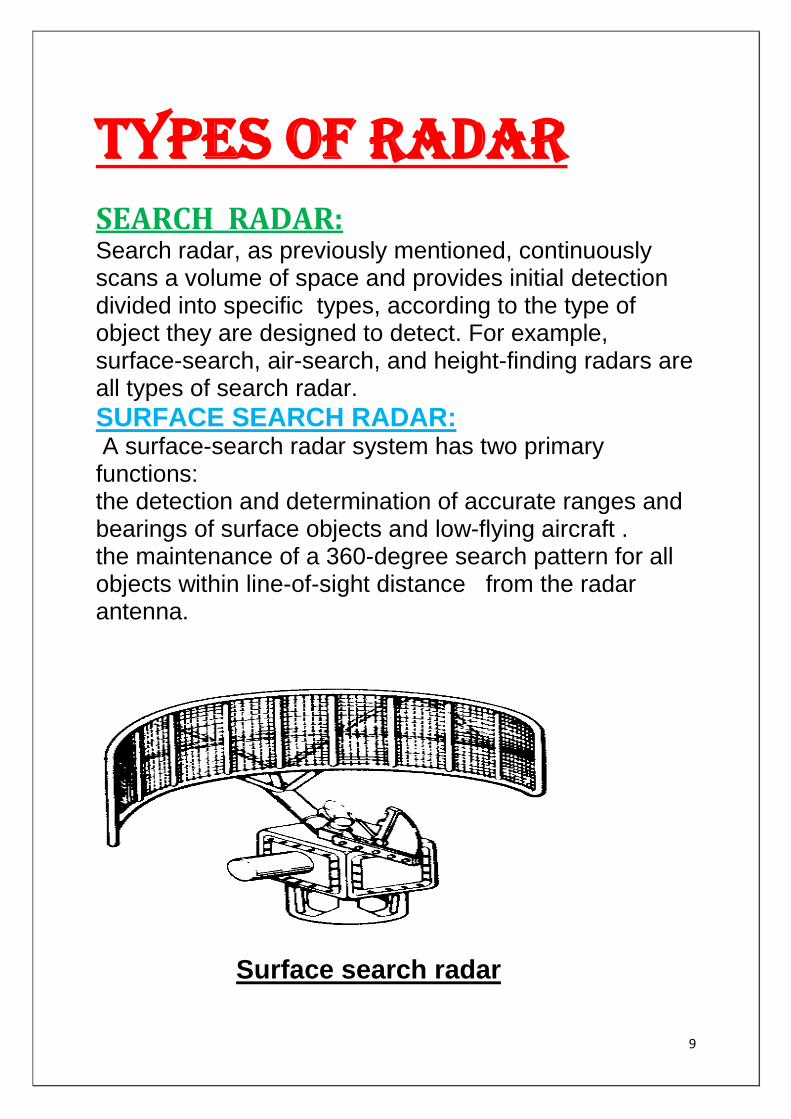
SURFACE SEARCH RADAR: A surface-search radar system has two primary functions: the detection and determination of accurate ranges and bearings of surface objects and low-flying aircraft . the maintenance of a 360-degree search pattern for all objects within line-of-sight distance from the radar antenna.
Surface search radar
10
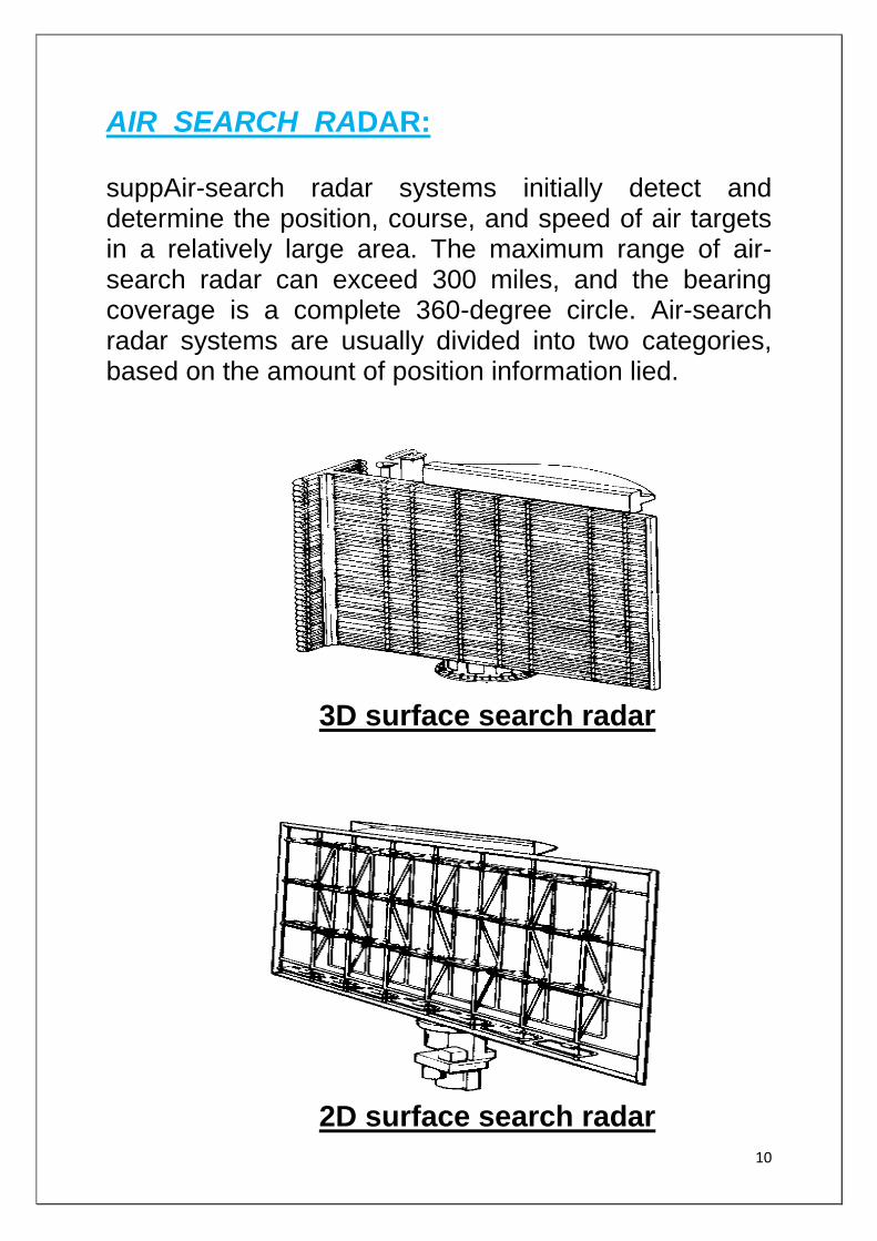
AIR SEARCH RADAR: suppAir-search radar systems initially detect and determine the position, course, and speed of air targets in a relatively large area. The maximum range of air-search radar can exceed 300 miles, and the bearing coverage is a complete 360-degree circle. Air-search radar systems are usually divided into two categories, based on the amount of position information lied.
3D surface search radar
2D surface search radar
11
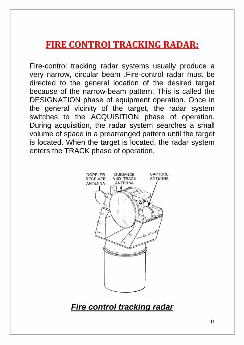
FIRE CONTROl TRACKING RADAR: Fire-control tracking radar systems usually produce a very narrow, circular beam .Fire-control radar must be directed to the general location of the desired target because of the narrow-beam pattern. This is called the DESIGNATION phase of equipment operation. Once in the general vicinity of the target, the radar system switches to the ACQUISITION phase of operation. During acquisition, the radar system searches a small volume of space in a prearranged pattern until the target is located. When the target is located, the radar system enters the TRACK phase of operation.
Fire control tracking radar

12
TRACKING RADAR:
Radar that provides continuous positional data on a target is called tracking radar. Most tracking radar systems used by the military are also fire-control radar; the two names are often used interchangeably . AIR BORNE SURVEILLENCE RADAR: These radar systems are designed for early warning, land and maritime surveillance, whether for fixed-wing aircraft, helicopters, or remotely piloted vehicles (RPV's).
AIR BORNE FIRE CONTROL RADAR: Includes those airborne radar systems for weapons fire-control (missiles or guns) and weapons aiming.
SPACEBORNE RADAR SYSTEM: Considerable effort has been applied to spaceborne radar (SBR) research for intelligence, surveillance, and reconnaissance missions over the last 30 years. The Department of Defense (DOD) seems to be expressing new interest in SBR.
CLOUD PROFILE RADAR: Usually employed abroad an aircraft or satellite.The radar beam is oriented at nadir measuring the radar returns from clouds to determine the cloud reflectively profile over the earths surface.
13
MTI radar and their utility RADAR (Radio Detection and Ranging) is a system used mainly in defence applications which is used to locate the target, that is, to find its exact position in the range which it covers. The drawback of conventional pulse RADAR is that it can determine only the range, that is, the distance of the target from RADAR antenna. In order to determine the motion of the target we use MTI (Moving Target Indication) RADAR. MTI RADAR has become a boon for detecting motion of the targets in the field of RADAR Engineering. Moving target indication is a mode of operation of a radar to discriminate a target against clutter. MTI RADAR is defined as the RADAR in which the Doppler effect can be employed to differentiate between stationary and moving targets, with the former suppressedandonlythelatterdisplayedAlong with the detection of moving target italso eliminates the effect of stationary objects or stationary clutters. This can be achieved by using the Delay line canceller. By sensing Doppler frequencies, an MTI radar can differentiate echoes of a moving target from stationary objects and clutter, and reject the clutter. Its waveform is a train of pulses with a low PRR to avoid range ambiguities. What this means is that range measurement at the low PRR is good while speed measurement is less accurate than at a high PRR's. Almost all ground-based aircraft search and surveillance radar systems use some form of MTI.
The Army, Navy, Air Force, FAA, USCG, NASA, and DOC are large users of MTI radars.
To find the movement of target.
14
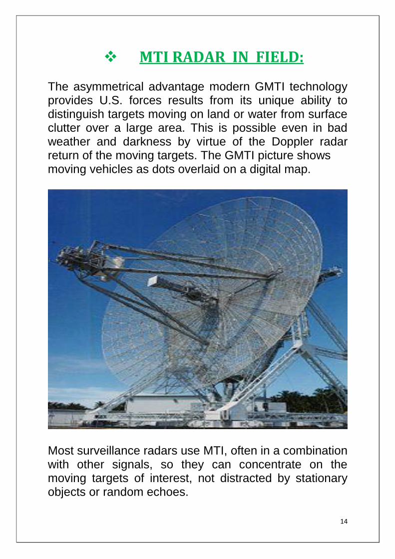
MTI RADAR IN FIELD: The asymmetrical advantage modern GMTI technology provides U.S. forces results from its unique ability to distinguish targets moving on land or water from surface clutter over a large area. This is possible even in bad weather and darkness by virtue of the Doppler radar return of the moving targets. The GMTI picture shows moving vehicles as dots overlaid on a digital map.
Most surveillance radars use MTI, often in a combination with other signals, so they can concentrate on the moving targets of interest, not distracted by stationary objects or random echoes.
15
UTILITY:
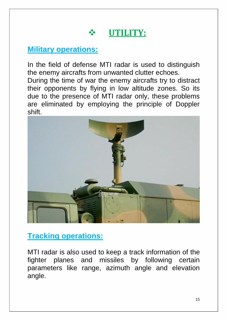
Military operations:
In the field of defense MTI radar is used to distinguish the enemy aircrafts from unwanted clutter echoes. During the time of war the enemy aircrafts try to distract their opponents by flying in low altitude zones. So its due to the presence of MTI radar only, these problems are eliminated by employing the principle of Doppler shift.
Tracking operations: MTI radar is also used to keep a track information of the fighter planes and missiles by following certain parameters like range, azimuth angle and elevation angle.
16
THE CONCEPT:
The concept of modelling deals with each component used in the practical operation . In MTI radar modelling, these components are: dynamic target static target significance of integer delay block delay line canceller scope for display.
Each blocks have their sub blocks for their respective operations. Target detection job is done by a block called delay line canceller. One method commonly employed to extract Doppler information in a form suitable for display on the PPI scope(Here A scope is used ) is with a delay-line canceller. The delay-line canceller acts as a filter to eliminate the dc component of fixed targets and to pass the ac components of moving targets. With the help of simulation blocks (either created or available in Simulink library). Starting from the generation and transmission of electromagnetic wave to the reception of echoes, the characteristic analysis has been done through scope block(available in Simulink library). Basically in modelling part, target response is the matter of concern. Response of target may be affected by different moving and stationary clutters. Rejection of these clutters is mandatory in order to have better output indication.
17
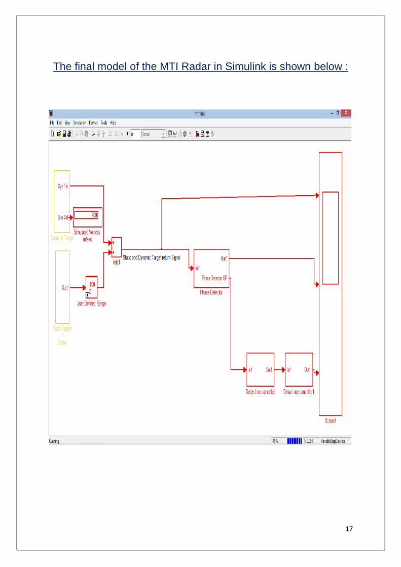
The final model of the MTI Radar in Simulink is shown below :
18
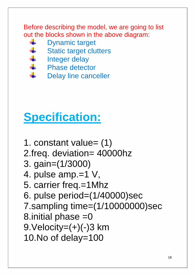
Before describing the model, we are going to list out the blocks shown in the above diagram:
Dynamic target Static target clutters Integer delay Phase detector Delay line canceller
Specification: 1. constant value= (1) 2.freq. deviation= 40000hz 3. gain=(1/3000) 4. pulse amp.=1 V, 5. carrier freq.=1Mhz 6. pulse period=(1/40000)sec 7.sampling time=(1/10000000)sec 8.initial phase =0 9.Velocity=(+)(-)3 km 10.No of delay=100

19
1.DYNAMIC TARGET: The block shown for dynamic target is a combination of some other blocks as a part of its operation. This block represent the target in motion. Dynamic target has 2 port. One is for dynamic target, and another is for simulated velocity. Simulated velocity is totally concern with constant as shown in the next diagram. The dynamic target is the desired response. It contains a pulse generator, i.e., nothing but for the pulse repetition frequency(PRF), a FM modulator block, whose work is to give the Doppler shift in frequency. Basically the job of FM modulator is to give the information about the variation occurred in the received echoes . Input to the FM modulator is a modified constant gain. Further both PRF and the output of FM modulator get multiplied to give the dynamic target, and this is 1
st port. Another port
is generated from the constant via a slider gain, called as simulated velocity.
20
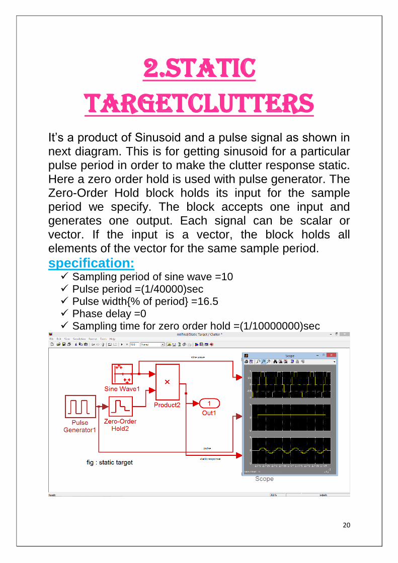
2.STATIC TARGETCLUTTERS
It‟s a product of Sinusoid and a pulse signal as shown in next diagram. This is for getting sinusoid for a particular pulse period in order to make the clutter response static. Here a zero order hold is used with pulse generator. The Zero-Order Hold block holds its input for the sample period we specify. The block accepts one input and generates one output. Each signal can be scalar or vector. If the input is a vector, the block holds all elements of the vector for the same sample period.
specification: Sampling period of sine wave =10 Pulse period =(1/40000)sec Pulse width{% of period} =16.5 Phase delay =0 Sampling time for zero order hold =(1/10000000)sec
21
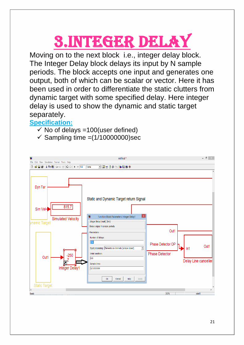
3.INTEGER DELAY Moving on to the next block i.e., integer delay block. The Integer Delay block delays its input by N sample periods. The block accepts one input and generates one output, both of which can be scalar or vector. Here it has been used in order to differentiate the static clutters from dynamic target with some specified delay. Here integer delay is used to show the dynamic and static target separately. Specification: No of delays =100(user defined) Sampling time =(1/10000000)sec
22
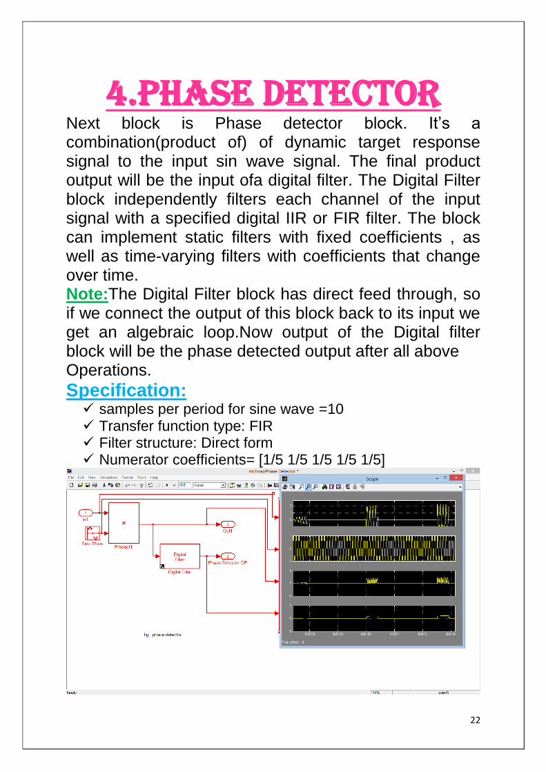
4.PHASE DETECTOR Next block is Phase detector block. It‟s a combination(product of) of dynamic target response signal to the input sin wave signal. The final product output will be the input ofa digital filter. The Digital Filter block independently filters each channel of the input signal with a specified digital IIR or FIR filter. The block can implement static filters with fixed coefficients , as well as time-varying filters with coefficients that change over time. Note:The Digital Filter block has direct feed through, so if we connect the output of this block back to its input we get an algebraic loop.Now output of the Digital filter block will be the phase detected output after all above Operations.
Specification: samples per period for sine wave =10 Transfer function type: FIR Filter structure: Direct form Numerator coefficients= [1/5 1/5 1/5 1/5 1/5]
23
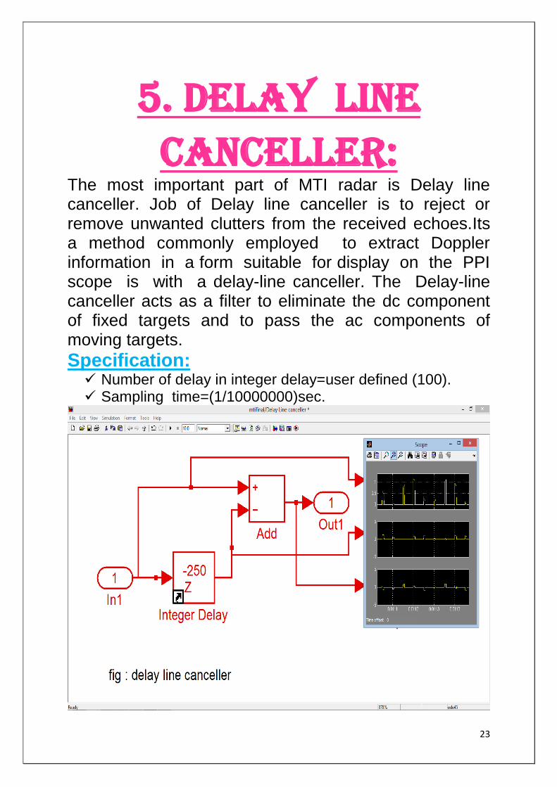
5. Delay line canceller:
The most important part of MTI radar is Delay line canceller. Job of Delay line canceller is to reject or remove unwanted clutters from the received echoes.Its a method commonly employed to extract Doppler information in a form suitable for display on the PPI scope is with a delay-line canceller. The Delay-line canceller acts as a filter to eliminate the dc component of fixed targets and to pass the ac components of moving targets.
Specification: Number of delay in integer delay=user defined (100). Sampling time=(1/10000000)sec.
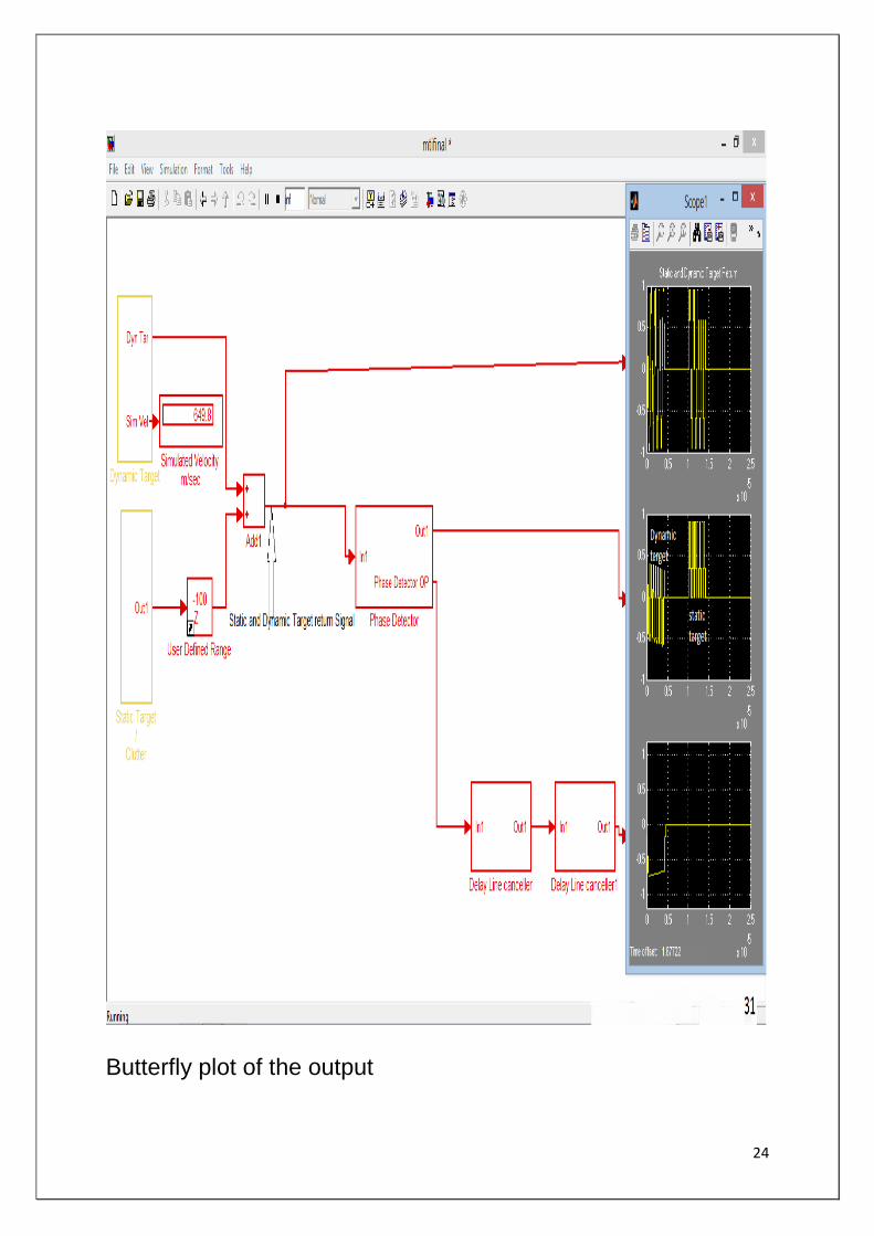
24
Butterfly plot of the output
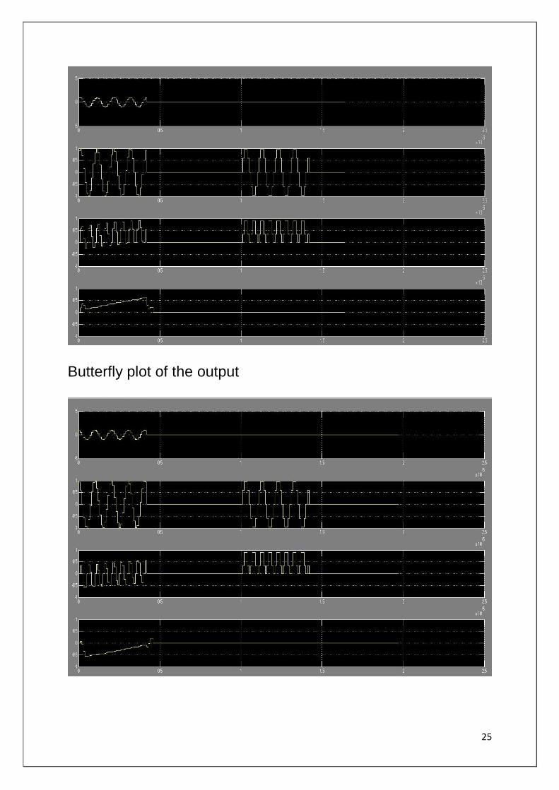
25
Butterfly plot of the output
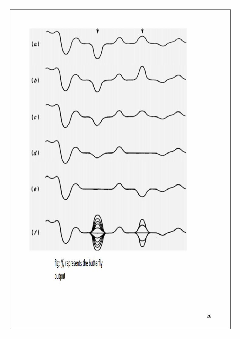
26
27
The future of MTI Radar
An innovative multi static radar concept is proposed to be developed based on the principles of generalized space time adaptive processing(STAP) to coherently detect airborne and ground moving targets in the presence of the severe clutter and interference backgrounds that are encountered by high-altitude standoff ISR platforms. The multi-static system concept to be studied employs the AWACS as a single high-altitude transmitter, with multiple single-element passive receivers moving in arbitrary, but known, trajectories. This multi-static system concept operates without the restrictive assumptions traditionally placed on traditional STAP receive arrays, and is amenable to future net-centric system architectures. Feasibility studies will be performed using analysis and computer simulation methods to demonstrate whether TSC's Generalized STAP MTI algorithms are suitable for enhanced E-3 Sentry operations in future net-centric environments, supporting the U.S. Air Force Electronic Systems Center (ESC) vision of the capabilities needed to meet existing and future Airborne Warning and Control System (AWACS) missions.
28
CONCLUSION
In this project we have understood the
working of MTI radar and its ability to
distinguish a moving target from a
stationary target/clutter using the
MATLAB-SIMULINK model. The output
thus obtained after simulation met the
desired specifications and functionality
was satisfactory.
29
BIBLIOGRAPHY
MERRILL SKOLNIK-RADAR HANDBOOK(3RD
EDITION) considered as “The Bible of Radar”
HTTP://IEEEXPLORE.IEEE.ORG/MTI radar utilities. HTTP://IEEEXPLORE.IEEE.ORG/ future of MTI radar. HTTP://EN.WIKIPEDIA.ORG/WIKI/ DRDO Balasore. HTTPS://WWW.GOOGLE.CO.IN/ ITR ChandipurBalasore. HTTP://WWW.DRDO.GOV.IN/DRDO/PUB/TECHFOCUS/2013/TF_APRIL_2013_WEB.PDF/ types of radar in RRD.
Related Documents