ibm.com/redbooks Front cover Implementing the IBM Storwize V7000 V6.3 Jon Tate Alejandro Berardinelli Mark Chitti Torben Jensen Massimo Rosati Christian Schroeder Discover the exciting latest addition to the IBM virtualization family Become familiar with the leading edge intuitive GUI See how simple IBM virtualization really is

Welcome message from author
This document is posted to help you gain knowledge. Please leave a comment to let me know what you think about it! Share it to your friends and learn new things together.
Transcript

ibm.com/redbooks
Front cover
Implementing the IBM Storwize V7000 V6.3
Jon TateAlejandro Berardinelli
Mark ChittiTorben Jensen
Massimo RosatiChristian Schroeder
Discover the exciting latest addition to the IBM virtualization family
Become familiar with the leading edge intuitive GUI
See how simple IBM virtualization really is

International Technical Support Organization
Implementing the IBM Storwize V7000 V6.3
February 2012
SG24-7938-01

© Copyright International Business Machines Corporation 2011, 2012. All rights reserved.Note to U.S. Government Users Restricted Rights -- Use, duplication or disclosure restricted by GSA ADP ScheduleContract with IBM Corp.
Second Edition (February 2012)
This edition applies to the IBM Storwize V7000 Version 6.3.0.
Note: Before using this information and the product it supports, read the information in “Notices” on page ix.
Note: This book is based on a pre-GA version of a product and may not apply when the product becomes generally available. Consult the product documentation or follow-on versions of this book for more current information.

Contents
Notices . . . . . . . . . . . . . . . . . . . . . . . . . . . . . . . . . . . . . . . . . . . . . . . . . . . . . . . . . . . . . . . . . ixTrademarks . . . . . . . . . . . . . . . . . . . . . . . . . . . . . . . . . . . . . . . . . . . . . . . . . . . . . . . . . . . . . . .x
Preface . . . . . . . . . . . . . . . . . . . . . . . . . . . . . . . . . . . . . . . . . . . . . . . . . . . . . . . . . . . . . . . . . xiThe team who wrote this book . . . . . . . . . . . . . . . . . . . . . . . . . . . . . . . . . . . . . . . . . . . . . . . . xiNow you can become a published author, too! . . . . . . . . . . . . . . . . . . . . . . . . . . . . . . . . . . xiiiComments welcome. . . . . . . . . . . . . . . . . . . . . . . . . . . . . . . . . . . . . . . . . . . . . . . . . . . . . . . xiiiStay connected to IBM Redbooks . . . . . . . . . . . . . . . . . . . . . . . . . . . . . . . . . . . . . . . . . . . . xiv
Summary of changes . . . . . . . . . . . . . . . . . . . . . . . . . . . . . . . . . . . . . . . . . . . . . . . . . . . . . .xvFebruary 2012, Second Edition . . . . . . . . . . . . . . . . . . . . . . . . . . . . . . . . . . . . . . . . . . . . . . .xv
Chapter 1. Overview of the IBM Storwize V7000 system. . . . . . . . . . . . . . . . . . . . . . . . . 11.1 Storage virtualization. . . . . . . . . . . . . . . . . . . . . . . . . . . . . . . . . . . . . . . . . . . . . . . . . . . . 21.2 IBM Storwize V7000 overview . . . . . . . . . . . . . . . . . . . . . . . . . . . . . . . . . . . . . . . . . . . . 31.3 IBM Storwize V7000 terminology . . . . . . . . . . . . . . . . . . . . . . . . . . . . . . . . . . . . . . . . . . 4
1.3.1 IBM Storwize V7000 models . . . . . . . . . . . . . . . . . . . . . . . . . . . . . . . . . . . . . . . . . . 51.3.2 IBM Storwize V7000 attributes . . . . . . . . . . . . . . . . . . . . . . . . . . . . . . . . . . . . . . . . 61.3.3 IBM Storwize V7000 functions . . . . . . . . . . . . . . . . . . . . . . . . . . . . . . . . . . . . . . . . 71.3.4 IBM Storwize V7000 licensing. . . . . . . . . . . . . . . . . . . . . . . . . . . . . . . . . . . . . . . . . 9
1.4 IBM Storwize V7000 hardware . . . . . . . . . . . . . . . . . . . . . . . . . . . . . . . . . . . . . . . . . . . 101.4.1 Control enclosure . . . . . . . . . . . . . . . . . . . . . . . . . . . . . . . . . . . . . . . . . . . . . . . . . 111.4.2 Expansion enclosure. . . . . . . . . . . . . . . . . . . . . . . . . . . . . . . . . . . . . . . . . . . . . . . 131.4.3 Disk drive types. . . . . . . . . . . . . . . . . . . . . . . . . . . . . . . . . . . . . . . . . . . . . . . . . . . 14
1.5 IBM Storwize V7000 components . . . . . . . . . . . . . . . . . . . . . . . . . . . . . . . . . . . . . . . . . 141.5.1 Hosts . . . . . . . . . . . . . . . . . . . . . . . . . . . . . . . . . . . . . . . . . . . . . . . . . . . . . . . . . . . 141.5.2 Nodes . . . . . . . . . . . . . . . . . . . . . . . . . . . . . . . . . . . . . . . . . . . . . . . . . . . . . . . . . . 151.5.3 I/O groups . . . . . . . . . . . . . . . . . . . . . . . . . . . . . . . . . . . . . . . . . . . . . . . . . . . . . . . 151.5.4 Clustered system . . . . . . . . . . . . . . . . . . . . . . . . . . . . . . . . . . . . . . . . . . . . . . . . . 151.5.5 RAID . . . . . . . . . . . . . . . . . . . . . . . . . . . . . . . . . . . . . . . . . . . . . . . . . . . . . . . . . . . 161.5.6 Managed disks . . . . . . . . . . . . . . . . . . . . . . . . . . . . . . . . . . . . . . . . . . . . . . . . . . . 171.5.7 Quorum disks . . . . . . . . . . . . . . . . . . . . . . . . . . . . . . . . . . . . . . . . . . . . . . . . . . . . 181.5.8 Storage pools . . . . . . . . . . . . . . . . . . . . . . . . . . . . . . . . . . . . . . . . . . . . . . . . . . . . 181.5.9 Volumes . . . . . . . . . . . . . . . . . . . . . . . . . . . . . . . . . . . . . . . . . . . . . . . . . . . . . . . . 211.5.10 Thin-provisioned volumes . . . . . . . . . . . . . . . . . . . . . . . . . . . . . . . . . . . . . . . . . . 231.5.11 Mirrored volumes . . . . . . . . . . . . . . . . . . . . . . . . . . . . . . . . . . . . . . . . . . . . . . . . 241.5.12 Easy Tier . . . . . . . . . . . . . . . . . . . . . . . . . . . . . . . . . . . . . . . . . . . . . . . . . . . . . . . 251.5.13 iSCSI. . . . . . . . . . . . . . . . . . . . . . . . . . . . . . . . . . . . . . . . . . . . . . . . . . . . . . . . . . 25
1.6 Advanced copy services . . . . . . . . . . . . . . . . . . . . . . . . . . . . . . . . . . . . . . . . . . . . . . . . 271.6.1 Synchronous / Asynchronous Remote Copy . . . . . . . . . . . . . . . . . . . . . . . . . . . . 281.6.2 FlashCopy. . . . . . . . . . . . . . . . . . . . . . . . . . . . . . . . . . . . . . . . . . . . . . . . . . . . . . . 291.6.3 Copy Services configuration limits . . . . . . . . . . . . . . . . . . . . . . . . . . . . . . . . . . . . 29
1.7 Management and support tools. . . . . . . . . . . . . . . . . . . . . . . . . . . . . . . . . . . . . . . . . . . 301.7.1 IBM Assist On-site and remote service . . . . . . . . . . . . . . . . . . . . . . . . . . . . . . . . . 301.7.2 Event notifications. . . . . . . . . . . . . . . . . . . . . . . . . . . . . . . . . . . . . . . . . . . . . . . . . 311.7.3 SNMP traps. . . . . . . . . . . . . . . . . . . . . . . . . . . . . . . . . . . . . . . . . . . . . . . . . . . . . . 311.7.4 Syslog messages . . . . . . . . . . . . . . . . . . . . . . . . . . . . . . . . . . . . . . . . . . . . . . . . . 311.7.5 Call Home email . . . . . . . . . . . . . . . . . . . . . . . . . . . . . . . . . . . . . . . . . . . . . . . . . . 32
1.8 Useful Storwize V7000 websites. . . . . . . . . . . . . . . . . . . . . . . . . . . . . . . . . . . . . . . . . . 32
© Copyright IBM Corp. 2011, 2012. All rights reserved. iii
1.8.1 IBM Storwize V7000 learning videos on YouTube . . . . . . . . . . . . . . . . . . . . . . . . 33
Chapter 2. Initial configuration . . . . . . . . . . . . . . . . . . . . . . . . . . . . . . . . . . . . . . . . . . . . 352.1 Hardware installation planning . . . . . . . . . . . . . . . . . . . . . . . . . . . . . . . . . . . . . . . . . . . 362.2 SAN configuration planning. . . . . . . . . . . . . . . . . . . . . . . . . . . . . . . . . . . . . . . . . . . . . . 382.3 LAN configuration planning . . . . . . . . . . . . . . . . . . . . . . . . . . . . . . . . . . . . . . . . . . . . . . 40
2.3.1 Management IP address considerations. . . . . . . . . . . . . . . . . . . . . . . . . . . . . . . . 402.3.2 Service IP address considerations . . . . . . . . . . . . . . . . . . . . . . . . . . . . . . . . . . . . 41
2.4 Host configuration planning. . . . . . . . . . . . . . . . . . . . . . . . . . . . . . . . . . . . . . . . . . . . . . 422.5 Miscellaneous configuration planning . . . . . . . . . . . . . . . . . . . . . . . . . . . . . . . . . . . . . . 422.6 System management . . . . . . . . . . . . . . . . . . . . . . . . . . . . . . . . . . . . . . . . . . . . . . . . . . 44
2.6.1 Graphical user interface (GUI) . . . . . . . . . . . . . . . . . . . . . . . . . . . . . . . . . . . . . . . 442.6.2 Command-line interface . . . . . . . . . . . . . . . . . . . . . . . . . . . . . . . . . . . . . . . . . . . . 45
2.7 First-time setup . . . . . . . . . . . . . . . . . . . . . . . . . . . . . . . . . . . . . . . . . . . . . . . . . . . . . . . 462.8 Initial configuration . . . . . . . . . . . . . . . . . . . . . . . . . . . . . . . . . . . . . . . . . . . . . . . . . . . . 54
2.8.1 Configure Call Home, email alert, and inventory. . . . . . . . . . . . . . . . . . . . . . . . . . 56
Chapter 3. Graphical user interface overview . . . . . . . . . . . . . . . . . . . . . . . . . . . . . . . . 653.1 Overview of IBM Storwize V7000 management software . . . . . . . . . . . . . . . . . . . . . . . 66
3.1.1 Access to the storage management software . . . . . . . . . . . . . . . . . . . . . . . . . . . . 663.1.2 Getting Started window layout . . . . . . . . . . . . . . . . . . . . . . . . . . . . . . . . . . . . . . . 673.1.3 Navigation . . . . . . . . . . . . . . . . . . . . . . . . . . . . . . . . . . . . . . . . . . . . . . . . . . . . . . . 693.1.4 Multiple selections. . . . . . . . . . . . . . . . . . . . . . . . . . . . . . . . . . . . . . . . . . . . . . . . . 733.1.5 Status Indicators menus . . . . . . . . . . . . . . . . . . . . . . . . . . . . . . . . . . . . . . . . . . . . 75
3.2 Home menu. . . . . . . . . . . . . . . . . . . . . . . . . . . . . . . . . . . . . . . . . . . . . . . . . . . . . . . . . . 773.2.1 Monitoring System menu . . . . . . . . . . . . . . . . . . . . . . . . . . . . . . . . . . . . . . . . . . . 78
3.3 Monitoring and Troubleshooting menu . . . . . . . . . . . . . . . . . . . . . . . . . . . . . . . . . . . . . 823.3.1 Recommended Actions menu. . . . . . . . . . . . . . . . . . . . . . . . . . . . . . . . . . . . . . . . 833.3.2 Event Log menu . . . . . . . . . . . . . . . . . . . . . . . . . . . . . . . . . . . . . . . . . . . . . . . . . . 863.3.3 Support menu . . . . . . . . . . . . . . . . . . . . . . . . . . . . . . . . . . . . . . . . . . . . . . . . . . . . 88
3.4 Pools menu . . . . . . . . . . . . . . . . . . . . . . . . . . . . . . . . . . . . . . . . . . . . . . . . . . . . . . . . . . 933.4.1 Internal menu . . . . . . . . . . . . . . . . . . . . . . . . . . . . . . . . . . . . . . . . . . . . . . . . . . . . 943.4.2 External menu. . . . . . . . . . . . . . . . . . . . . . . . . . . . . . . . . . . . . . . . . . . . . . . . . . . . 953.4.3 Storage Pools menu . . . . . . . . . . . . . . . . . . . . . . . . . . . . . . . . . . . . . . . . . . . . . . . 963.4.4 MDisks menu . . . . . . . . . . . . . . . . . . . . . . . . . . . . . . . . . . . . . . . . . . . . . . . . . . . . 97
3.5 Volumes menu . . . . . . . . . . . . . . . . . . . . . . . . . . . . . . . . . . . . . . . . . . . . . . . . . . . . . . 1003.5.1 All Volumes menu . . . . . . . . . . . . . . . . . . . . . . . . . . . . . . . . . . . . . . . . . . . . . . . . 1013.5.2 Volumes by Pool menu . . . . . . . . . . . . . . . . . . . . . . . . . . . . . . . . . . . . . . . . . . . . 1033.5.3 Volumes by Host menu. . . . . . . . . . . . . . . . . . . . . . . . . . . . . . . . . . . . . . . . . . . . 105
3.6 Hosts menu . . . . . . . . . . . . . . . . . . . . . . . . . . . . . . . . . . . . . . . . . . . . . . . . . . . . . . . . . 1073.6.1 All Hosts menu . . . . . . . . . . . . . . . . . . . . . . . . . . . . . . . . . . . . . . . . . . . . . . . . . . 1083.6.2 Ports by Host menu . . . . . . . . . . . . . . . . . . . . . . . . . . . . . . . . . . . . . . . . . . . . . . 1103.6.3 Host Mappings menu . . . . . . . . . . . . . . . . . . . . . . . . . . . . . . . . . . . . . . . . . . . . . 112
3.7 Copy Services menu . . . . . . . . . . . . . . . . . . . . . . . . . . . . . . . . . . . . . . . . . . . . . . . . . . 1143.7.1 FlashCopy menu. . . . . . . . . . . . . . . . . . . . . . . . . . . . . . . . . . . . . . . . . . . . . . . . . 1153.7.2 FlashCopy Consistency Group menu . . . . . . . . . . . . . . . . . . . . . . . . . . . . . . . . . 1173.7.3 FlashCopy Mapping menu . . . . . . . . . . . . . . . . . . . . . . . . . . . . . . . . . . . . . . . . . 1183.7.4 Remote Copy menu . . . . . . . . . . . . . . . . . . . . . . . . . . . . . . . . . . . . . . . . . . . . . . 1193.7.5 Partnerships menu . . . . . . . . . . . . . . . . . . . . . . . . . . . . . . . . . . . . . . . . . . . . . . . 120
3.8 Access menu. . . . . . . . . . . . . . . . . . . . . . . . . . . . . . . . . . . . . . . . . . . . . . . . . . . . . . . . 1213.8.1 Users menu. . . . . . . . . . . . . . . . . . . . . . . . . . . . . . . . . . . . . . . . . . . . . . . . . . . . . 1223.8.2 Audit Log menu. . . . . . . . . . . . . . . . . . . . . . . . . . . . . . . . . . . . . . . . . . . . . . . . . . 124
3.9 Settings menu . . . . . . . . . . . . . . . . . . . . . . . . . . . . . . . . . . . . . . . . . . . . . . . . . . . . . . . 125
iv Implementing the IBM Storwize V7000 V6.3
3.9.1 Network menu. . . . . . . . . . . . . . . . . . . . . . . . . . . . . . . . . . . . . . . . . . . . . . . . . . . 1263.9.2 Event Notification menu . . . . . . . . . . . . . . . . . . . . . . . . . . . . . . . . . . . . . . . . . . . 1283.9.3 General menu . . . . . . . . . . . . . . . . . . . . . . . . . . . . . . . . . . . . . . . . . . . . . . . . . . . 129
Chapter 4. Host configuration . . . . . . . . . . . . . . . . . . . . . . . . . . . . . . . . . . . . . . . . . . . . 1314.1 Host attachment overview. . . . . . . . . . . . . . . . . . . . . . . . . . . . . . . . . . . . . . . . . . . . . . 1324.2 Preparing the host operating system . . . . . . . . . . . . . . . . . . . . . . . . . . . . . . . . . . . . . 133
4.2.1 Windows 2008 (R2): Preparing for Fibre Channel attachment . . . . . . . . . . . . . . 1334.2.2 Windows 2008 R2: Preparing for iSCSI attachment . . . . . . . . . . . . . . . . . . . . . . 1364.2.3 VMware ESX: Preparing for Fibre Channel attachment . . . . . . . . . . . . . . . . . . . 1384.2.4 VMware ESX: Preparing for iSCSI attachment . . . . . . . . . . . . . . . . . . . . . . . . . . 141
4.3 Creating hosts using the GUI . . . . . . . . . . . . . . . . . . . . . . . . . . . . . . . . . . . . . . . . . . . 1484.3.1 Creating Fibre Channel hosts . . . . . . . . . . . . . . . . . . . . . . . . . . . . . . . . . . . . . . . 1504.3.2 Creating iSCSI hosts. . . . . . . . . . . . . . . . . . . . . . . . . . . . . . . . . . . . . . . . . . . . . . 154
Chapter 5. Basic volume configuration. . . . . . . . . . . . . . . . . . . . . . . . . . . . . . . . . . . . . 1595.1 Provisioning storage from IBM Storwize V7000 and making it available to the host. . 160
5.1.1 Creating a generic volume . . . . . . . . . . . . . . . . . . . . . . . . . . . . . . . . . . . . . . . . . 1625.1.2 Creating a thin-provisioned volume. . . . . . . . . . . . . . . . . . . . . . . . . . . . . . . . . . . 1635.1.3 Creating a mirrored volume. . . . . . . . . . . . . . . . . . . . . . . . . . . . . . . . . . . . . . . . . 1665.1.4 Creating a thin-mirror volume . . . . . . . . . . . . . . . . . . . . . . . . . . . . . . . . . . . . . . . 169
5.2 Mapping a volume to the host . . . . . . . . . . . . . . . . . . . . . . . . . . . . . . . . . . . . . . . . . . . 1725.2.1 Mapping newly created volumes to the host using the wizard . . . . . . . . . . . . . . 172
5.3 Discovering the volumes from the host and specifying multipath settings . . . . . . . . . 1745.3.1 Windows 2008 Fibre Channel volume attachment . . . . . . . . . . . . . . . . . . . . . . . 1755.3.2 Windows 2008 iSCSI volume attachment . . . . . . . . . . . . . . . . . . . . . . . . . . . . . . 1795.3.3 VMware ESX Fibre Channel attachment . . . . . . . . . . . . . . . . . . . . . . . . . . . . . . 1875.3.4 VMware ESX iSCSI attachment . . . . . . . . . . . . . . . . . . . . . . . . . . . . . . . . . . . . . 194
Chapter 6. Migration wizard . . . . . . . . . . . . . . . . . . . . . . . . . . . . . . . . . . . . . . . . . . . . . . 2056.1 Preparing for data migration . . . . . . . . . . . . . . . . . . . . . . . . . . . . . . . . . . . . . . . . . . . . 2066.2 Migrating the data using the migration wizard. . . . . . . . . . . . . . . . . . . . . . . . . . . . . . . 206
Chapter 7. Storage pools . . . . . . . . . . . . . . . . . . . . . . . . . . . . . . . . . . . . . . . . . . . . . . . . 2237.1 Working with internal drives . . . . . . . . . . . . . . . . . . . . . . . . . . . . . . . . . . . . . . . . . . . . 224
7.1.1 Actions on internal drives . . . . . . . . . . . . . . . . . . . . . . . . . . . . . . . . . . . . . . . . . . 2287.1.2 Configuring internal storage . . . . . . . . . . . . . . . . . . . . . . . . . . . . . . . . . . . . . . . . 231
7.2 Working with MDisks. . . . . . . . . . . . . . . . . . . . . . . . . . . . . . . . . . . . . . . . . . . . . . . . . . 2437.2.1 Adding MDisks to storage pools . . . . . . . . . . . . . . . . . . . . . . . . . . . . . . . . . . . . . 2457.2.2 Importing MDisks . . . . . . . . . . . . . . . . . . . . . . . . . . . . . . . . . . . . . . . . . . . . . . . . 2497.2.3 RAID action for MDisks. . . . . . . . . . . . . . . . . . . . . . . . . . . . . . . . . . . . . . . . . . . . 2567.2.4 Selecting the tier for MDisks . . . . . . . . . . . . . . . . . . . . . . . . . . . . . . . . . . . . . . . . 2587.2.5 Additional actions on MDisks . . . . . . . . . . . . . . . . . . . . . . . . . . . . . . . . . . . . . . . 260
7.3 Working with storage pools . . . . . . . . . . . . . . . . . . . . . . . . . . . . . . . . . . . . . . . . . . . . . 264
Chapter 8. Advanced host and volume administration . . . . . . . . . . . . . . . . . . . . . . . . 2698.1 Advanced host administration . . . . . . . . . . . . . . . . . . . . . . . . . . . . . . . . . . . . . . . . . . . 270
8.1.1 Modifying Mappings menu . . . . . . . . . . . . . . . . . . . . . . . . . . . . . . . . . . . . . . . . . 2728.1.2 Unmapping all volumes from a host . . . . . . . . . . . . . . . . . . . . . . . . . . . . . . . . . . 2778.1.3 Renaming . . . . . . . . . . . . . . . . . . . . . . . . . . . . . . . . . . . . . . . . . . . . . . . . . . . . . . 2798.1.4 Deleting a host . . . . . . . . . . . . . . . . . . . . . . . . . . . . . . . . . . . . . . . . . . . . . . . . . . 2808.1.5 Host properties . . . . . . . . . . . . . . . . . . . . . . . . . . . . . . . . . . . . . . . . . . . . . . . . . . 281
8.2 Adding and deleting host ports . . . . . . . . . . . . . . . . . . . . . . . . . . . . . . . . . . . . . . . . . . 2848.2.1 Adding a host port . . . . . . . . . . . . . . . . . . . . . . . . . . . . . . . . . . . . . . . . . . . . . . . . 285
Contents v

8.2.2 Adding a Fibre Channel port . . . . . . . . . . . . . . . . . . . . . . . . . . . . . . . . . . . . . . . . 2868.2.3 Adding an iSCSI host port. . . . . . . . . . . . . . . . . . . . . . . . . . . . . . . . . . . . . . . . . . 2888.2.4 Deleting a host port . . . . . . . . . . . . . . . . . . . . . . . . . . . . . . . . . . . . . . . . . . . . . . . 290
8.3 Host mappings overview . . . . . . . . . . . . . . . . . . . . . . . . . . . . . . . . . . . . . . . . . . . . . . . 2918.3.1 Unmapping a volume . . . . . . . . . . . . . . . . . . . . . . . . . . . . . . . . . . . . . . . . . . . . . 2928.3.2 Properties (Host) . . . . . . . . . . . . . . . . . . . . . . . . . . . . . . . . . . . . . . . . . . . . . . . . . 2938.3.3 Properties (Volume) . . . . . . . . . . . . . . . . . . . . . . . . . . . . . . . . . . . . . . . . . . . . . . 293
8.4 Advanced volume administration . . . . . . . . . . . . . . . . . . . . . . . . . . . . . . . . . . . . . . . . 2938.4.1 Advanced volume functions . . . . . . . . . . . . . . . . . . . . . . . . . . . . . . . . . . . . . . . . 2948.4.2 Mapping a volume to a host . . . . . . . . . . . . . . . . . . . . . . . . . . . . . . . . . . . . . . . . 2968.4.3 Unmapping volumes from all hosts . . . . . . . . . . . . . . . . . . . . . . . . . . . . . . . . . . . 2978.4.4 Viewing a host mapped to a volume . . . . . . . . . . . . . . . . . . . . . . . . . . . . . . . . . . 2988.4.5 Renaming a volume . . . . . . . . . . . . . . . . . . . . . . . . . . . . . . . . . . . . . . . . . . . . . . 2998.4.6 Shrinking a volume . . . . . . . . . . . . . . . . . . . . . . . . . . . . . . . . . . . . . . . . . . . . . . . 3008.4.7 Expanding a volume . . . . . . . . . . . . . . . . . . . . . . . . . . . . . . . . . . . . . . . . . . . . . . 3018.4.8 Migrating a volume to another storage pool . . . . . . . . . . . . . . . . . . . . . . . . . . . . 3018.4.9 Exporting to an image mode volume. . . . . . . . . . . . . . . . . . . . . . . . . . . . . . . . . . 3048.4.10 Deleting a volume . . . . . . . . . . . . . . . . . . . . . . . . . . . . . . . . . . . . . . . . . . . . . . . 306
8.5 Volume properties . . . . . . . . . . . . . . . . . . . . . . . . . . . . . . . . . . . . . . . . . . . . . . . . . . . . 3078.5.1 Overview tab . . . . . . . . . . . . . . . . . . . . . . . . . . . . . . . . . . . . . . . . . . . . . . . . . . . . 3088.5.2 Host Maps tab. . . . . . . . . . . . . . . . . . . . . . . . . . . . . . . . . . . . . . . . . . . . . . . . . . . 3118.5.3 Member MDisk tab . . . . . . . . . . . . . . . . . . . . . . . . . . . . . . . . . . . . . . . . . . . . . . . 3128.5.4 Adding a mirrored volume copy . . . . . . . . . . . . . . . . . . . . . . . . . . . . . . . . . . . . . 3138.5.5 Editing thin-provisioned volume properties . . . . . . . . . . . . . . . . . . . . . . . . . . . . . 315
8.6 Advanced volume copy functions . . . . . . . . . . . . . . . . . . . . . . . . . . . . . . . . . . . . . . . . 3188.6.1 Thin-provisioned . . . . . . . . . . . . . . . . . . . . . . . . . . . . . . . . . . . . . . . . . . . . . . . . . 3208.6.2 Splitting into a new volume . . . . . . . . . . . . . . . . . . . . . . . . . . . . . . . . . . . . . . . . . 3208.6.3 Validate Volume Copies option. . . . . . . . . . . . . . . . . . . . . . . . . . . . . . . . . . . . . . 3218.6.4 Delete Copy option . . . . . . . . . . . . . . . . . . . . . . . . . . . . . . . . . . . . . . . . . . . . . . . 3238.6.5 Migrating volumes using the volume copy features . . . . . . . . . . . . . . . . . . . . . . 323
8.7 Volumes by storage pool. . . . . . . . . . . . . . . . . . . . . . . . . . . . . . . . . . . . . . . . . . . . . . . 3248.7.1 Changing the Storage Pool function icon . . . . . . . . . . . . . . . . . . . . . . . . . . . . . . 3268.7.2 Changing the storage pool name . . . . . . . . . . . . . . . . . . . . . . . . . . . . . . . . . . . . 327
8.8 Volumes by host . . . . . . . . . . . . . . . . . . . . . . . . . . . . . . . . . . . . . . . . . . . . . . . . . . . . . 3298.8.1 Renaming a host . . . . . . . . . . . . . . . . . . . . . . . . . . . . . . . . . . . . . . . . . . . . . . . . . 331
Chapter 9. External storage virtualization . . . . . . . . . . . . . . . . . . . . . . . . . . . . . . . . . . 3339.1 Planning for external storage virtualization . . . . . . . . . . . . . . . . . . . . . . . . . . . . . . . . . 334
9.1.1 License for external storage virtualization. . . . . . . . . . . . . . . . . . . . . . . . . . . . . . 3349.1.2 SAN configuration planning . . . . . . . . . . . . . . . . . . . . . . . . . . . . . . . . . . . . . . . . 3369.1.3 External storage configuration planning . . . . . . . . . . . . . . . . . . . . . . . . . . . . . . . 3379.1.4 Guidelines for virtualizing external storage . . . . . . . . . . . . . . . . . . . . . . . . . . . . . 338
9.2 Working with external storage. . . . . . . . . . . . . . . . . . . . . . . . . . . . . . . . . . . . . . . . . . . 3389.2.1 Adding external storage . . . . . . . . . . . . . . . . . . . . . . . . . . . . . . . . . . . . . . . . . . . 3399.2.2 Managing external storage . . . . . . . . . . . . . . . . . . . . . . . . . . . . . . . . . . . . . . . . . 3399.2.3 Removing external storage . . . . . . . . . . . . . . . . . . . . . . . . . . . . . . . . . . . . . . . . . 343
Chapter 10. Easy Tier . . . . . . . . . . . . . . . . . . . . . . . . . . . . . . . . . . . . . . . . . . . . . . . . . . . 34510.1 Easy Tier overview . . . . . . . . . . . . . . . . . . . . . . . . . . . . . . . . . . . . . . . . . . . . . . . . . . 34610.2 Easy Tier for IBM Storwize V7000 . . . . . . . . . . . . . . . . . . . . . . . . . . . . . . . . . . . . . . 348
10.2.1 Disk tiers . . . . . . . . . . . . . . . . . . . . . . . . . . . . . . . . . . . . . . . . . . . . . . . . . . . . . . 34810.2.2 Tiered storage pools . . . . . . . . . . . . . . . . . . . . . . . . . . . . . . . . . . . . . . . . . . . . . 348
10.3 Easy Tier process . . . . . . . . . . . . . . . . . . . . . . . . . . . . . . . . . . . . . . . . . . . . . . . . . . . 349
vi Implementing the IBM Storwize V7000 V6.3
10.3.1 I/O Monitoring . . . . . . . . . . . . . . . . . . . . . . . . . . . . . . . . . . . . . . . . . . . . . . . . . . 35010.3.2 Data Placement Advisor . . . . . . . . . . . . . . . . . . . . . . . . . . . . . . . . . . . . . . . . . . 35010.3.3 Data Migration Planner . . . . . . . . . . . . . . . . . . . . . . . . . . . . . . . . . . . . . . . . . . . 35010.3.4 Data Migrator . . . . . . . . . . . . . . . . . . . . . . . . . . . . . . . . . . . . . . . . . . . . . . . . . . 35110.3.5 Easy Tier operating modes . . . . . . . . . . . . . . . . . . . . . . . . . . . . . . . . . . . . . . . . 35110.3.6 Easy Tier rules . . . . . . . . . . . . . . . . . . . . . . . . . . . . . . . . . . . . . . . . . . . . . . . . . 352
10.4 Easy Tier configuration using the GUI . . . . . . . . . . . . . . . . . . . . . . . . . . . . . . . . . . . 35410.4.1 Creating multitiered pools: Enable Easy Tier . . . . . . . . . . . . . . . . . . . . . . . . . . 35410.4.2 Downloading Easy Tier I/O measurements. . . . . . . . . . . . . . . . . . . . . . . . . . . . 362
10.5 Easy Tier configuration using the CLI . . . . . . . . . . . . . . . . . . . . . . . . . . . . . . . . . . . . 36310.5.1 Enabling Easy Tier evaluation mode. . . . . . . . . . . . . . . . . . . . . . . . . . . . . . . . . 36410.5.2 Enabling or disabling Easy Tier on single volumes. . . . . . . . . . . . . . . . . . . . . . 367
10.6 IBM Storage Tier Advisor Tool . . . . . . . . . . . . . . . . . . . . . . . . . . . . . . . . . . . . . . . . . 36810.6.1 Creating graphical reports. . . . . . . . . . . . . . . . . . . . . . . . . . . . . . . . . . . . . . . . . 36810.6.2 STAT reports. . . . . . . . . . . . . . . . . . . . . . . . . . . . . . . . . . . . . . . . . . . . . . . . . . . 369
Chapter 11. Copy services . . . . . . . . . . . . . . . . . . . . . . . . . . . . . . . . . . . . . . . . . . . . . . . 37111.1 FlashCopy . . . . . . . . . . . . . . . . . . . . . . . . . . . . . . . . . . . . . . . . . . . . . . . . . . . . . . . . . 372
11.1.1 Business requirements for FlashCopy . . . . . . . . . . . . . . . . . . . . . . . . . . . . . . . 37211.1.2 FlashCopy functional overview . . . . . . . . . . . . . . . . . . . . . . . . . . . . . . . . . . . . . 37311.1.3 Planning for FlashCopy. . . . . . . . . . . . . . . . . . . . . . . . . . . . . . . . . . . . . . . . . . . 38211.1.4 Managing FlashCopy using the GUI . . . . . . . . . . . . . . . . . . . . . . . . . . . . . . . . . 38311.1.5 Managing FlashCopy mapping . . . . . . . . . . . . . . . . . . . . . . . . . . . . . . . . . . . . . 393
11.2 Volume mirroring and migration options . . . . . . . . . . . . . . . . . . . . . . . . . . . . . . . . . . 42211.2.1 Managing Volume Mirror and migration with the GUI . . . . . . . . . . . . . . . . . . . . 424
11.3 Remote Copy . . . . . . . . . . . . . . . . . . . . . . . . . . . . . . . . . . . . . . . . . . . . . . . . . . . . . . 43311.3.1 Remote Copy concepts. . . . . . . . . . . . . . . . . . . . . . . . . . . . . . . . . . . . . . . . . . . 43311.3.2 Global Mirror with Change Volumes . . . . . . . . . . . . . . . . . . . . . . . . . . . . . . . . . 44011.3.3 Remote Copy planning . . . . . . . . . . . . . . . . . . . . . . . . . . . . . . . . . . . . . . . . . . . 445
11.4 Troubleshooting Remote Copy . . . . . . . . . . . . . . . . . . . . . . . . . . . . . . . . . . . . . . . . . 44811.4.1 1920 error . . . . . . . . . . . . . . . . . . . . . . . . . . . . . . . . . . . . . . . . . . . . . . . . . . . . . 44811.4.2 1720 error . . . . . . . . . . . . . . . . . . . . . . . . . . . . . . . . . . . . . . . . . . . . . . . . . . . . . 450
11.5 Managing Remote Copy using the GUI . . . . . . . . . . . . . . . . . . . . . . . . . . . . . . . . . . 45111.5.1 Managing cluster partnerships . . . . . . . . . . . . . . . . . . . . . . . . . . . . . . . . . . . . . 45111.5.2 Deleting a partnership . . . . . . . . . . . . . . . . . . . . . . . . . . . . . . . . . . . . . . . . . . . . 45911.5.3 Managing a Remote Copy consistency group . . . . . . . . . . . . . . . . . . . . . . . . . 472
Chapter 12. IBM Tivoli Storage Productivity Center . . . . . . . . . . . . . . . . . . . . . . . . . . 48112.1 Tivoli Storage Productivity Center overview . . . . . . . . . . . . . . . . . . . . . . . . . . . . . . . 482
12.1.1 IBM Tivoli Storage Productivity Center for Disk Midrange Edition . . . . . . . . . . 48212.2 Tivoli Storage Productivity Center architecture . . . . . . . . . . . . . . . . . . . . . . . . . . . . . 483
12.2.1 Data Server . . . . . . . . . . . . . . . . . . . . . . . . . . . . . . . . . . . . . . . . . . . . . . . . . . . . 48312.2.2 Device Server . . . . . . . . . . . . . . . . . . . . . . . . . . . . . . . . . . . . . . . . . . . . . . . . . . 48312.2.3 IBM Tivoli Integrated Portal. . . . . . . . . . . . . . . . . . . . . . . . . . . . . . . . . . . . . . . . 48412.2.4 Tivoli Storage Productivity Center for Replication. . . . . . . . . . . . . . . . . . . . . . . 48412.2.5 IBM DB2 Database . . . . . . . . . . . . . . . . . . . . . . . . . . . . . . . . . . . . . . . . . . . . . . 48412.2.6 Agents. . . . . . . . . . . . . . . . . . . . . . . . . . . . . . . . . . . . . . . . . . . . . . . . . . . . . . . . 48412.2.7 Interfaces . . . . . . . . . . . . . . . . . . . . . . . . . . . . . . . . . . . . . . . . . . . . . . . . . . . . . 484
12.3 Preparing Windows to install Tivoli Storage Productivity Center. . . . . . . . . . . . . . . . 48512.3.1 Installation overview . . . . . . . . . . . . . . . . . . . . . . . . . . . . . . . . . . . . . . . . . . . . . 48612.3.2 Product code layout . . . . . . . . . . . . . . . . . . . . . . . . . . . . . . . . . . . . . . . . . . . . . 48612.3.3 Pre-installation steps for Windows . . . . . . . . . . . . . . . . . . . . . . . . . . . . . . . . . . 487
12.4 Installing Tivoli Storage Productivity Center components . . . . . . . . . . . . . . . . . . . . . 499
Contents vii

12.5 Connecting Tivoli Storage Productivity Center to an IBM Storwize V7000 system. . 50812.6 Administering and reporting an IBM Storwize V7000 system through Tivoli Storage
Productivity Center . . . . . . . . . . . . . . . . . . . . . . . . . . . . . . . . . . . . . . . . . . . . . . . . . . . 51512.6.1 Basic configuration and administration . . . . . . . . . . . . . . . . . . . . . . . . . . . . . . . 51512.6.2 Report generation . . . . . . . . . . . . . . . . . . . . . . . . . . . . . . . . . . . . . . . . . . . . . . . 517
Chapter 13. RAS, monitoring, and troubleshooting for an IBM Storwize V7000 system521
13.1 Reliability, availability, and serviceability on the IBM Storwize V7000 system . . . . . 52213.1.1 Node canisters . . . . . . . . . . . . . . . . . . . . . . . . . . . . . . . . . . . . . . . . . . . . . . . . . 52213.1.2 Disk subsystem. . . . . . . . . . . . . . . . . . . . . . . . . . . . . . . . . . . . . . . . . . . . . . . . . 52513.1.3 Power . . . . . . . . . . . . . . . . . . . . . . . . . . . . . . . . . . . . . . . . . . . . . . . . . . . . . . . . 528
13.2 Configuration backup procedure . . . . . . . . . . . . . . . . . . . . . . . . . . . . . . . . . . . . . . . . 53013.2.1 Generating a configuration backup using the CLI . . . . . . . . . . . . . . . . . . . . . . . 53013.2.2 Downloading a configuration backup using the GUI . . . . . . . . . . . . . . . . . . . . . 532
13.3 Software upgrade . . . . . . . . . . . . . . . . . . . . . . . . . . . . . . . . . . . . . . . . . . . . . . . . . . . 53313.4 Critical Fix Notification feature . . . . . . . . . . . . . . . . . . . . . . . . . . . . . . . . . . . . . . . . . 54113.5 Monitoring host paths to the IBM Storwize V7000 system . . . . . . . . . . . . . . . . . . . . 54113.6 Monitoring overview . . . . . . . . . . . . . . . . . . . . . . . . . . . . . . . . . . . . . . . . . . . . . . . . . 54313.7 Manipulating the event log and recommended actions grid . . . . . . . . . . . . . . . . . . . 54713.8 Recommended Actions menu: Details . . . . . . . . . . . . . . . . . . . . . . . . . . . . . . . . . . . 54813.9 Audit Log tab . . . . . . . . . . . . . . . . . . . . . . . . . . . . . . . . . . . . . . . . . . . . . . . . . . . . . . . 56013.10 Collecting support information. . . . . . . . . . . . . . . . . . . . . . . . . . . . . . . . . . . . . . . . . 56213.11 Shutting down an IBM Storwize V7000 system . . . . . . . . . . . . . . . . . . . . . . . . . . . 564
13.11.1 Shutting down using the GUI . . . . . . . . . . . . . . . . . . . . . . . . . . . . . . . . . . . . . 56413.11.2 Shutting down using the command-line interface . . . . . . . . . . . . . . . . . . . . . . 56613.11.3 Shutting down and powering on an IBM Storwize V7000 infrastructure . . . . . 56613.11.4 Shutting down . . . . . . . . . . . . . . . . . . . . . . . . . . . . . . . . . . . . . . . . . . . . . . . . . 56713.11.5 Powering on . . . . . . . . . . . . . . . . . . . . . . . . . . . . . . . . . . . . . . . . . . . . . . . . . . 567
Appendix A. CLI setup and SAN Boot. . . . . . . . . . . . . . . . . . . . . . . . . . . . . . . . . . . . . . 569Command-line interface . . . . . . . . . . . . . . . . . . . . . . . . . . . . . . . . . . . . . . . . . . . . . . . . . . . 570
Basic setup . . . . . . . . . . . . . . . . . . . . . . . . . . . . . . . . . . . . . . . . . . . . . . . . . . . . . . . . . . 570Example commands . . . . . . . . . . . . . . . . . . . . . . . . . . . . . . . . . . . . . . . . . . . . . . . . . . . 581
SAN Boot . . . . . . . . . . . . . . . . . . . . . . . . . . . . . . . . . . . . . . . . . . . . . . . . . . . . . . . . . . . . . . 585Enabling SAN Boot for Windows. . . . . . . . . . . . . . . . . . . . . . . . . . . . . . . . . . . . . . . . . . 586Enabling SAN Boot for VMware . . . . . . . . . . . . . . . . . . . . . . . . . . . . . . . . . . . . . . . . . . 586Windows SAN Boot migration. . . . . . . . . . . . . . . . . . . . . . . . . . . . . . . . . . . . . . . . . . . . 586
Related publications . . . . . . . . . . . . . . . . . . . . . . . . . . . . . . . . . . . . . . . . . . . . . . . . . . . . 589IBM Redbooks . . . . . . . . . . . . . . . . . . . . . . . . . . . . . . . . . . . . . . . . . . . . . . . . . . . . . . . . . . 589Other publications . . . . . . . . . . . . . . . . . . . . . . . . . . . . . . . . . . . . . . . . . . . . . . . . . . . . . . . 589Online resources . . . . . . . . . . . . . . . . . . . . . . . . . . . . . . . . . . . . . . . . . . . . . . . . . . . . . . . . 590Help from IBM . . . . . . . . . . . . . . . . . . . . . . . . . . . . . . . . . . . . . . . . . . . . . . . . . . . . . . . . . . 591
Index . . . . . . . . . . . . . . . . . . . . . . . . . . . . . . . . . . . . . . . . . . . . . . . . . . . . . . . . . . . . . . . . . 593
viii Implementing the IBM Storwize V7000 V6.3
Notices
This information was developed for products and services offered in the U.S.A.
IBM may not offer the products, services, or features discussed in this document in other countries. Consult your local IBM representative for information on the products and services currently available in your area. Any reference to an IBM product, program, or service is not intended to state or imply that only that IBM product, program, or service may be used. Any functionally equivalent product, program, or service that does not infringe any IBM intellectual property right may be used instead. However, it is the user's responsibility to evaluate and verify the operation of any non-IBM product, program, or service.
IBM may have patents or pending patent applications covering subject matter described in this document. The furnishing of this document does not give you any license to these patents. You can send license inquiries, in writing, to: IBM Director of Licensing, IBM Corporation, North Castle Drive, Armonk, NY 10504-1785 U.S.A.
The following paragraph does not apply to the United Kingdom or any other country where such provisions are inconsistent with local law: INTERNATIONAL BUSINESS MACHINES CORPORATION PROVIDES THIS PUBLICATION "AS IS" WITHOUT WARRANTY OF ANY KIND, EITHER EXPRESS OR IMPLIED, INCLUDING, BUT NOT LIMITED TO, THE IMPLIED WARRANTIES OF NON-INFRINGEMENT, MERCHANTABILITY OR FITNESS FOR A PARTICULAR PURPOSE. Some states do not allow disclaimer of express or implied warranties in certain transactions, therefore, this statement may not apply to you.
This information could include technical inaccuracies or typographical errors. Changes are periodically made to the information herein; these changes will be incorporated in new editions of the publication. IBM may make improvements and/or changes in the product(s) and/or the program(s) described in this publication at any time without notice.
Any references in this information to non-IBM websites are provided for convenience only and do not in any manner serve as an endorsement of those websites. The materials at those websites are not part of the materials for this IBM product and use of those websites is at your own risk.
IBM may use or distribute any of the information you supply in any way it believes appropriate without incurring any obligation to you.
Information concerning non-IBM products was obtained from the suppliers of those products, their published announcements or other publicly available sources. IBM has not tested those products and cannot confirm the accuracy of performance, compatibility or any other claims related to non-IBM products. Questions on the capabilities of non-IBM products should be addressed to the suppliers of those products.
This information contains examples of data and reports used in daily business operations. To illustrate them as completely as possible, the examples include the names of individuals, companies, brands, and products. All of these names are fictitious and any similarity to the names and addresses used by an actual business enterprise is entirely coincidental.
COPYRIGHT LICENSE:
This information contains sample application programs in source language, which illustrate programming techniques on various operating platforms. You may copy, modify, and distribute these sample programs in any form without payment to IBM, for the purposes of developing, using, marketing or distributing application programs conforming to the application programming interface for the operating platform for which the sample programs are written. These examples have not been thoroughly tested under all conditions. IBM, therefore, cannot guarantee or imply reliability, serviceability, or function of these programs.
© Copyright IBM Corp. 2011, 2012. All rights reserved. ix

Trademarks
IBM, the IBM logo, and ibm.com are trademarks or registered trademarks of International Business Machines Corporation in the United States, other countries, or both. These and other IBM trademarked terms are marked on their first occurrence in this information with the appropriate symbol (® or ™), indicating US registered or common law trademarks owned by IBM at the time this information was published. Such trademarks may also be registered or common law trademarks in other countries. A current list of IBM trademarks is available on the Web at http://www.ibm.com/legal/copytrade.shtml
The following terms are trademarks of the International Business Machines Corporation in the United States, other countries, or both:
AIX®BladeCenter®DB2®DS8000®Easy Tier®FlashCopy®
Global Technology Services®IBM®Passport Advantage®Redbooks®Redbooks (logo) ®Storwize®
System Storage®System x®Tivoli®XIV®
The following terms are trademarks of other companies:
Intel, Intel logo, Intel Inside logo, and Intel Centrino logo are trademarks or registered trademarks of Intel Corporation or its subsidiaries in the United States and other countries.
Microsoft, Windows, and the Windows logo are trademarks of Microsoft Corporation in the United States, other countries, or both.
Snapshot, and the NetApp logo are trademarks or registered trademarks of NetApp, Inc. in the U.S. and other countries.
Java, and all Java-based trademarks and logos are trademarks or registered trademarks of Oracle and/or its affiliates.
UNIX is a registered trademark of The Open Group in the United States and other countries.
Intel, Intel logo, Intel Inside, Intel Inside logo, Intel Centrino, Intel Centrino logo, Celeron, Intel Xeon, Intel SpeedStep, Itanium, and Pentium are trademarks or registered trademarks of Intel Corporation or its subsidiaries in the United States and other countries.
Linux is a trademark of Linus Torvalds in the United States, other countries, or both.
Other company, product, or service names may be trademarks or service marks of others.
x Implementing the IBM Storwize V7000 V6.3

Preface
Continuing its commitment to developing and delivering industry-leading storage technologies, IBM® introduces the IBM Storwize® V7000 solution, an innovative new storage offering that delivers essential storage efficiency technologies and exceptional ease of use and performance, all integrated into a compact, modular design that is offered at a competitive, midrange price.
The IBM Storwize V7000 solution incorporates some of the top IBM technologies typically found only in enterprise-class storage systems, raising the standard for storage efficiency in midrange disk systems. This cutting-edge storage system extends the comprehensive storage portfolio from IBM and can help change the way organizations address the ongoing information explosion.
This IBM Redbooks® publication introduces the features and functions of the IBM Storwize V7000 system through several examples. This book is aimed at pre- and post-sales technical support and marketing, storage administrators, and will help you understand the architecture of the Storwize V7000, how to implement it, and take advantage of the industry leading functions and features.
The team who wrote this book
This book was produced by a team of specialists from around the world working at the International Technical Support Organization, San Jose, CA.
Jon Tate is a Project Manager for IBM System Storage® SAN Solutions at the International Technical Support Organization, San Jose, CA. Before joining the ITSO in 1999, he worked in the IBM Technical Support Center, providing Level 2 support for IBM storage products. Jon has 26 years of experience in storage software and management, services, and support, and is both an IBM Certified IT Specialist and an IBM SAN Certified Specialist. He is also the UK Chairman of the Storage Networking Industry Association.
Alejandro Berardinelli is an IT Storage Specialist with IBM Uruguay since 2005. His primary focus is IBM storage implementations involving IBM System Storage DS8000®, IBM System Storage DS5000, and Storwize V7000, tape subsystems, and Brocade and CISCO switches. He also works with IBM Tivoli® Storage Manager and IBM Tivoli Storage Productivity Center deployment and support. He has provided storage support for several customers in South America. Alejandro holds a degree in Computer Engineer from UdelaR and has coauthored other IBM Redbooks publications.
Mark Chitti is an IBM Expert Certified IT Specialist and an Open Group Master Certified IT Specialist. He currently holds a position as team lead for approximately one quarter of the account storage architects within Integrated Technology Delivery. Mark joined IBM in 2001, having been a subcontractor to IBM for just under a year before. Since joining IBM, Mark has remained with the Integrated Technology Delivery Storage Service Line, but has held several positions within it. In 2004, Mark moved from prior delivery roles to the architecture area. He is currently working toward his Senior Technical Staff Member appointment within IBM and performs an “Acting STSM” function in addition to his daily duties while he gains the experience needed to formally obtain his STSM appointment.
© Copyright IBM Corp. 2011, 2012. All rights reserved. xi

Torben Jensen is an IT Specialist at IBM Global Technology Services®, Copenhagen, Denmark. He joined IBM in 1999 for an apprenticeship as an IT-System Supporter. From 2001 to 2005, he was the client representative for IBM Internal Client platforms in Denmark. Torben started work with the SAN/DISK for open systems department in March 2005. Torben provides daily and ongoing support, and works with SAN designs and solutions for customers.
Massimo Rosati is a Certified ITS Senior Storage and SAN Software Specialist at IBM Italy. He has 26 years of experience in the delivery of Professional Services and SW Support. His areas of expertise include storage hardware, storage area networks, storage virtualization, disaster recovery, and business continuity solutions. He has written other IBM Redbooks publication on storage virtualization products.
Christian Schroeder is a Storage and SAN support specialist at the Technical Support and Competence Center (TSCC) in IBM Germany, and he has been with IBM since 1999. Before he joined the TSCC for IBM Systems Storage, he worked as a support specialist for IBM System x® servers and provided EMEA Level 2 support for IBM BladeCenter® solutions.
Figure 1 Authors, L-R, Jon, Alejandro, Massimo, Torben, and Christian
This book was produced by a team of specialists from around the world working at Brocade Communications Systems, San Jose, and the International Technical Support Organization, San Jose, CA.
We extend our thanks to the following people for their contributions to this project, including the development and PFE teams in Hursley.
In particular, we thank the authors of the previous edition of this book:
Brian Cartwright, Ronda Hruby, Daniel Koeck, Xin Liu, Massimo Rosati, Thomas Vogel, Bill Wiegand
Thanks also to the following people for their contributions to previous editions, and to those people who contributed to this edition:
Tayfun Arli, Chris Canto, Peter Eccles, Huw Francis, Carlos Fuente, Alex Howell, Colin Jewell, Neil Kirkland, Geoff Lane, Andrew Martin, Paul Merrison, Evelyn Perez, Steve Randle, Lucy Harris (nee Raw), Bill Scales, Greg Shepherd, Matt Smith, Barry Whyte, Muhammad ZubairIBM Hursley
xii Implementing the IBM Storwize V7000 V6.3

Bill WiegandIBM Advanced Technical Support
Sharon WangIBM Chicago
Chris SaulIBM San Jose
Tina SampsonIBM Tucson
Sangam RacherlaIBM ITSO
Special thanks to the Brocade staff for their unparalleled support of this residency in terms of equipment and support in many areas:
Jim Baldyga, Mansi Botadra, Yong Choi, Silviano Gaona, Brian Steffler, Marcus Thordal, Steven TongBrocade Communications Systems
Now you can become a published author, too!
Here’s an opportunity to spotlight your skills, grow your career, and become a published author—all at the same time! Join an ITSO residency project and help write a book in your area of expertise, while honing your experience using leading-edge technologies. Your efforts will help to increase product acceptance and customer satisfaction, as you expand your network of technical contacts and relationships. Residencies run from two to six weeks in length, and you can participate either in person or as a remote resident working from your home base.
Find out more about the residency program, browse the residency index, and apply online at:
ibm.com/redbooks/residencies.html
Comments welcome
Your comments are important to us!
We want our books to be as helpful as possible. Send us your comments about this book or other IBM Redbooks publications in one of the following ways:
� Use the online Contact us review Redbooks form found at:
ibm.com/redbooks
� Send your comments in an email to:
� Mail your comments to:
IBM Corporation, International Technical Support OrganizationDept. HYTD Mail Station P0992455 South RoadPoughkeepsie, NY 12601-5400
Preface xiii
Stay connected to IBM Redbooks
� Find us on Facebook:
http://www.facebook.com/IBMRedbooks
� Follow us on Twitter:
http://twitter.com/ibmredbooks
� Look for us on LinkedIn:
http://www.linkedin.com/groups?home=&gid=2130806
� Explore new Redbooks publications, residencies, and workshops with the IBM Redbooks weekly newsletter:
https://www.redbooks.ibm.com/Redbooks.nsf/subscribe?OpenForm
� Stay current on recent Redbooks publications with RSS Feeds:
http://www.redbooks.ibm.com/rss.html
xiv Implementing the IBM Storwize V7000 V6.3

Summary of changes
This section describes the technical changes made in this edition of the book and in previous editions. This edition might also include minor corrections and editorial changes that are not identified.
Summary of Changesfor SG24-7938-01for Implementing the IBM Storwize V7000 V6.3as created or updated on February 7, 2012.
February 2012, Second Edition
This revision reflects the addition, deletion, or modification of new and changed information described below.
Changed information� All screen captures replaced with versions form Version 6.3.0� Command examples changed
© Copyright IBM Corp. 2011, 2012. All rights reserved. xv

xvi Implementing the IBM Storwize V7000 V6.3
Chapter 1. Overview of the IBM Storwize V7000 system
This chapter provides an overview of the IBM Storwize V7000 architecture and includes a brief explanation of storage virtualization.
1
© Copyright IBM Corp. 2011, 2012. All rights reserved. 1

1.1 Storage virtualization
Storage virtualization, like server virtualization, is one of the foundations of building a flexible and reliable infrastructure solution that allows companies to better align their business and IT needs.
Storage virtualization allows an organization to implement pools of storage across physically separate disk systems (which might be from different vendors). Storage can then be deployed from these pools and can be migrated between pools without any outage of the attached host systems. Storage virtualization provides a single set of tools for advanced functions, such as instant copy and remote mirroring solutions, which means that deploying storage can be performed by using a single tool regardless of the underlying storage hardware.
Figure 1-1 shows a storage virtualization scenario.
Figure 1-1 Storage virtualization
For a more detailed explanation of storage virtualization, see Implementing the IBM System Storage SAN Volume Controller V6.1, SG24-7933.
2 Implementing the IBM Storwize V7000 V6.3
1.2 IBM Storwize V7000 overview
The IBM Storwize V7000 solution provides a modular storage system that includes the capability to virtualize external SAN-attached storage and its own internal storage. The IBM Storwize V7000 solution is built upon the IBM SAN Volume Controller technology base and uses technology from the IBM System Storage DS8000 family.
An IBM Storwize V7000 system provides a number of configuration options that are aimed at simplifying the implementation process. It also provides automated wizards, called Directed Maintenance Procedures (DMP), to assist in resolving any events that might occur. An IBM Storwize V7000 system is a clustered, scalable, and midrange storage system, and an external virtualization device.
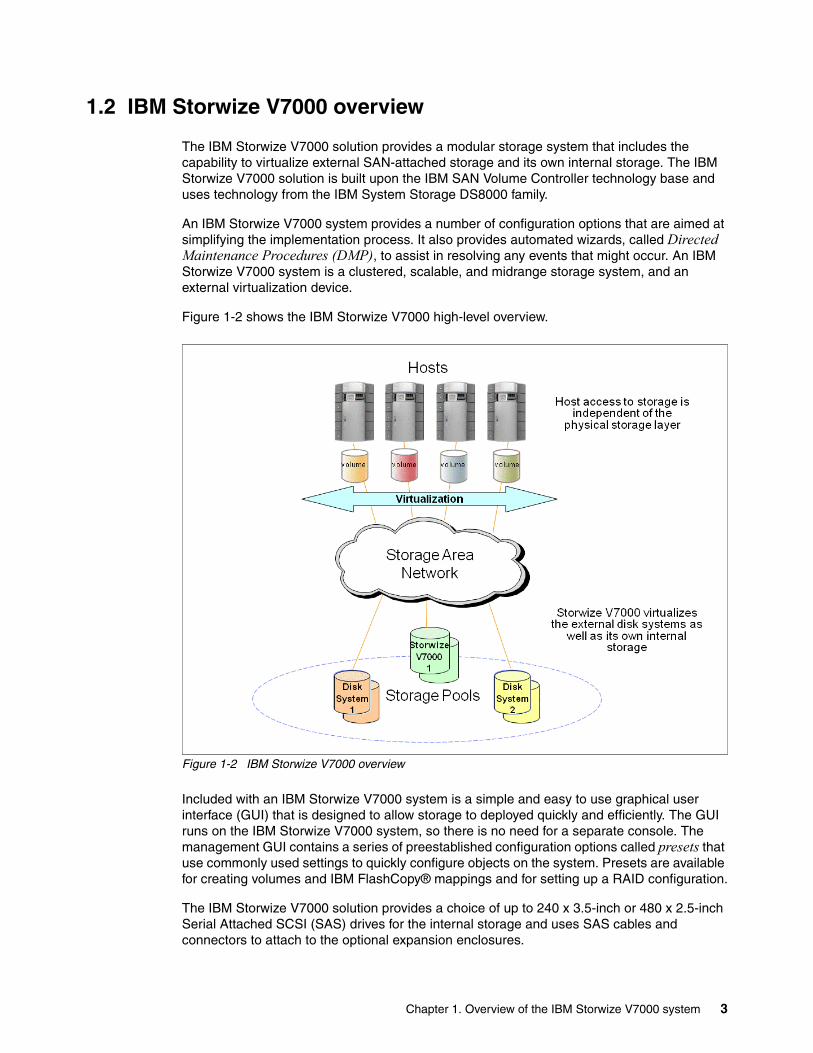
Figure 1-2 shows the IBM Storwize V7000 high-level overview.
Figure 1-2 IBM Storwize V7000 overview
Included with an IBM Storwize V7000 system is a simple and easy to use graphical user interface (GUI) that is designed to allow storage to deployed quickly and efficiently. The GUI runs on the IBM Storwize V7000 system, so there is no need for a separate console. The management GUI contains a series of preestablished configuration options called presets that use commonly used settings to quickly configure objects on the system. Presets are available for creating volumes and IBM FlashCopy® mappings and for setting up a RAID configuration.
The IBM Storwize V7000 solution provides a choice of up to 240 x 3.5-inch or 480 x 2.5-inch Serial Attached SCSI (SAS) drives for the internal storage and uses SAS cables and connectors to attach to the optional expansion enclosures.
Chapter 1. Overview of the IBM Storwize V7000 system 3
When virtualizing external storage arrays, an IBM Storwize V7000 system can provide up to 32 PB of usable capacity. An IBM Storwize V7000 system supports a range of external disk systems similar to what the SAN Volume Controller supports today.
The IBM Storwize V7000 solution consists of a one or two control enclosures and, optionally, up to 18 expansion enclosures (and supports the intermixing of the different expansion enclosures). Within each enclosure are two canisters. Control enclosures contain two node canisters, and expansion enclosures contain two expansion canisters.
1.3 IBM Storwize V7000 terminology
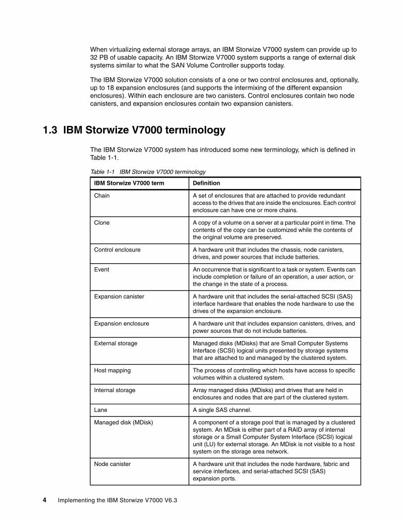
The IBM Storwize V7000 system has introduced some new terminology, which is defined in Table 1-1.
Table 1-1 IBM Storwize V7000 terminology
IBM Storwize V7000 term Definition
Chain A set of enclosures that are attached to provide redundant access to the drives that are inside the enclosures. Each control enclosure can have one or more chains.
Clone A copy of a volume on a server at a particular point in time. The contents of the copy can be customized while the contents of the original volume are preserved.
Control enclosure A hardware unit that includes the chassis, node canisters, drives, and power sources that include batteries.
Event An occurrence that is significant to a task or system. Events can include completion or failure of an operation, a user action, or the change in the state of a process.
Expansion canister A hardware unit that includes the serial-attached SCSI (SAS) interface hardware that enables the node hardware to use the drives of the expansion enclosure.
Expansion enclosure A hardware unit that includes expansion canisters, drives, and power sources that do not include batteries.
External storage Managed disks (MDisks) that are Small Computer Systems Interface (SCSI) logical units presented by storage systems that are attached to and managed by the clustered system.
Host mapping The process of controlling which hosts have access to specific volumes within a clustered system.
Internal storage Array managed disks (MDisks) and drives that are held in enclosures and nodes that are part of the clustered system.
Lane A single SAS channel.
Managed disk (MDisk) A component of a storage pool that is managed by a clustered system. An MDisk is either part of a RAID array of internal storage or a Small Computer System Interface (SCSI) logical unit (LU) for external storage. An MDisk is not visible to a host system on the storage area network.
Node canister A hardware unit that includes the node hardware, fabric and service interfaces, and serial-attached SCSI (SAS) expansion ports.
4 Implementing the IBM Storwize V7000 V6.3
1.3.1 IBM Storwize V7000 models
The IBM Storwize V7000 platform consists of enclosures and drives. Each enclosure contains two canisters that, although they can be replaced independently, are seen as part of the enclosure.
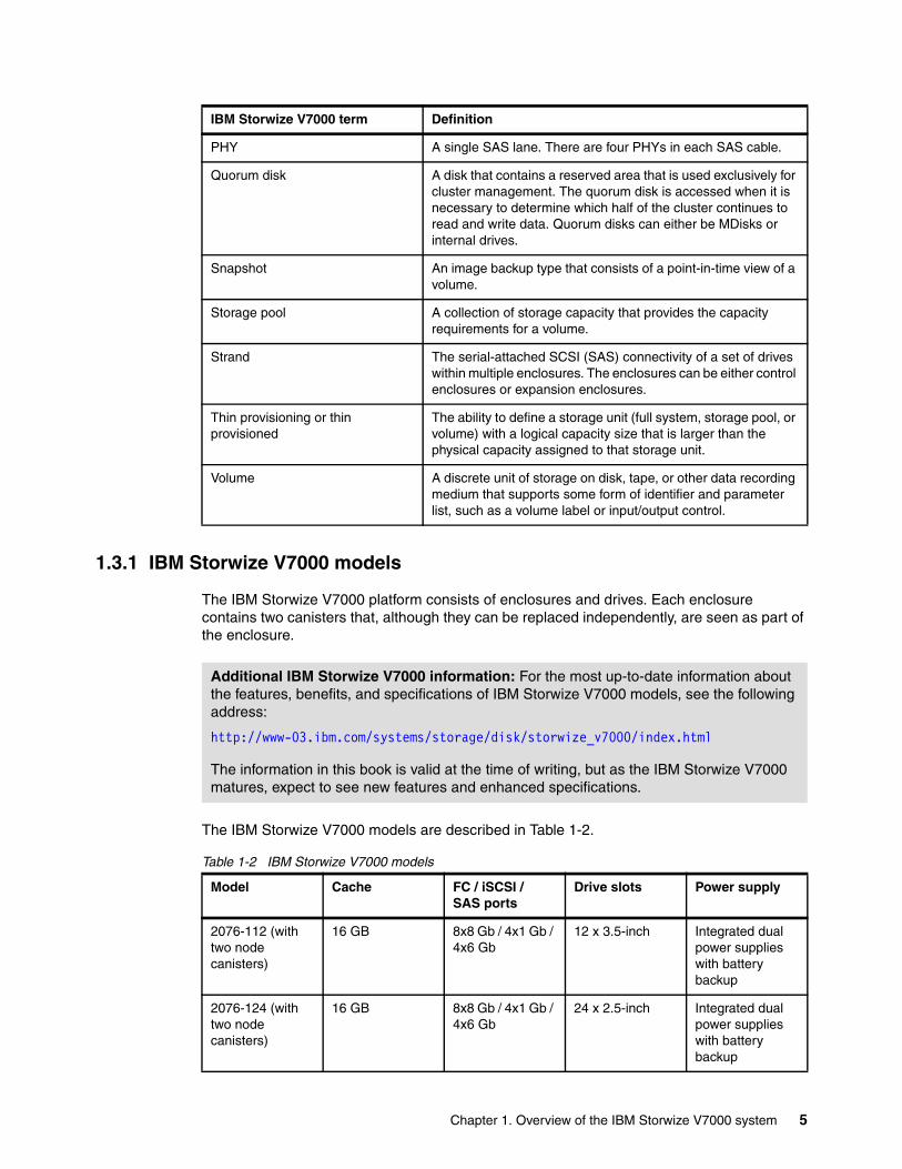
The IBM Storwize V7000 models are described in Table 1-2.
Table 1-2 IBM Storwize V7000 models
PHY A single SAS lane. There are four PHYs in each SAS cable.
Quorum disk A disk that contains a reserved area that is used exclusively for cluster management. The quorum disk is accessed when it is necessary to determine which half of the cluster continues to read and write data. Quorum disks can either be MDisks or internal drives.
Snapshot An image backup type that consists of a point-in-time view of a volume.
Storage pool A collection of storage capacity that provides the capacity requirements for a volume.
Strand The serial-attached SCSI (SAS) connectivity of a set of drives within multiple enclosures. The enclosures can be either control enclosures or expansion enclosures.
Thin provisioning or thin provisioned
The ability to define a storage unit (full system, storage pool, or volume) with a logical capacity size that is larger than the physical capacity assigned to that storage unit.
Volume A discrete unit of storage on disk, tape, or other data recording medium that supports some form of identifier and parameter list, such as a volume label or input/output control.
IBM Storwize V7000 term Definition
Additional IBM Storwize V7000 information: For the most up-to-date information about the features, benefits, and specifications of IBM Storwize V7000 models, see the following address:
http://www-03.ibm.com/systems/storage/disk/storwize_v7000/index.html
The information in this book is valid at the time of writing, but as the IBM Storwize V7000 matures, expect to see new features and enhanced specifications.
Model Cache FC / iSCSI / SAS ports
Drive slots Power supply
2076-112 (with two node canisters)
16 GB 8x8 Gb / 4x1 Gb / 4x6 Gb
12 x 3.5-inch Integrated dual power supplies with battery backup
2076-124 (with two node canisters)
16 GB 8x8 Gb / 4x1 Gb / 4x6 Gb
24 x 2.5-inch Integrated dual power supplies with battery backup
Chapter 1. Overview of the IBM Storwize V7000 system 5
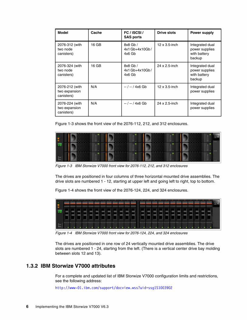
Figure 1-3 shows the front view of the 2076-112, 212, and 312 enclosures.
Figure 1-3 IBM Storwize V7000 front view for 2076-112, 212, and 312 enclosures
The drives are positioned in four columns of three horizontal mounted drive assemblies. The drive slots are numbered 1 - 12, starting at upper left and going left to right, top to bottom.
Figure 1-4 shows the front view of the 2076-124, 224, and 324 enclosures.
Figure 1-4 IBM Storwize V7000 front view for 2076-124, 224, and 324 enclosures
The drives are positioned in one row of 24 vertically mounted drive assemblies. The drive slots are numbered 1 - 24, starting from the left. (There is a vertical center drive bay molding between slots 12 and 13).
1.3.2 IBM Storwize V7000 attributes
For a complete and updated list of IBM Storwize V7000 configuration limits and restrictions, see the following address:
http://www-01.ibm.com/support/docview.wss?uid=ssg1S1003902
2076-312 (with two node canisters)
16 GB 8x8 Gb / 4x1 Gb+4x10Gb / 4x6 Gb
12 x 3.5-inch Integrated dual power supplies with battery backup
2076-324 (with two node canisters)
16 GB 8x8 Gb / 4x1 Gb+4x10Gb / 4x6 Gb
24 x 2.5-inch Integrated dual power supplies with battery backup
2076-212 (with two expansion canisters)
N/A -- / -- / 4x6 Gb 12 x 3.5-inch Integrated dual power supplies
2076-224 (with two expansion canisters)
N/A -- / -- / 4x6 Gb 24 x 2.5-inch Integrated dual power supplies
Model Cache FC / iSCSI / SAS ports
Drive slots Power supply
6 Implementing the IBM Storwize V7000 V6.3

1.3.3 IBM Storwize V7000 functions
The following functions are available with IBM Storwize V7000:
� Thin provisioning (No license required)
Traditional fully allocated volumes allocate real physical disk capacity for an entire volume even if that capacity is never used. Thin-provisioned volumes allocate real physical disk capacity only when data is written to the logical volume.
� Volume mirroring (No license required)
Provides a single volume image to the attached host systems while maintaining pointers to two copies of data in separate storage pools. Copies can be on separate disk storage systems that are being virtualized. If one copy failing, IBM Storwize V7000 provides continuous data access by redirecting I/O to the remaining copy. When the copy becomes available, automatic resynchronization occurs.
� FlashCopy (included with the base IBM Storwize V7000 license)
Provides a volume level point-in-time copy function for any storage being virtualized by IBM Storwize V7000. This function is designed to create copies for backup, parallel processing, testing, and development, and have the copies available almost immediately.
IBM Storwize V7000 includes the following FlashCopy functions:
– Full / Incremental copy
This function copies only the changes from either the source or target data since the last FlashCopy operation and is designed to enable completion of point-in-time online backups much more quickly than using traditional FlashCopy.
– Multitarget FlashCopy
IBM Storwize V7000 supports copying of up to 256 target volumes from a single source volume. Each copy is managed by a unique mapping and, in general, each mapping acts independently and is not affected by other mappings sharing the source volume.
– Cascaded FlashCopy
This function is used to create copies of copies and supports full, incremental, or nocopy operations.
– Reverse FlashCopy
This function allows data from an earlier point-in-time copy to be restored with minimal disruption to the host.
– FlashCopy nocopy with thin provisioning
This function provides a combination of using thin-provisioned volumes and FlashCopy together to help reduce disk space requirements when making copies. There are two variations of this option:
• Space-efficient source and target with background copy
Copies only the allocated space.
• Space-efficient target with no background copy
Copies only the space used for changes between the source and target and is generally referred to as “snapshots”.
This function may be used with multi-target, cascaded, and incremental FlashCopy.
Chapter 1. Overview of the IBM Storwize V7000 system 7

– Consistency groups
Consistency groups address the issue where application data is on multiple volumes. By placing the FlashCopy relationships into a consistency group, commands can be issued against all of the volumes in the group. This action enables a consistent point-in-time copy of all of the data, even though it might be on a physically separate volume.
FlashCopy mappings can be members of a consistency group, or they can be operated in a stand-alone manner, that is, not as part of a consistency group. FlashCopy commands can be issued to a FlashCopy consistency group, which affects all FlashCopy mappings in the consistency group, or to a single FlashCopy mapping if it is not part of a defined FlashCopy consistency group.
� Metro Mirror (licensed based on the number of enclosures and includes both Metro and Global Mirror)
Provides a synchronous remote mirroring function up to approximately 300 km between sites. As the host I/O only completes after the data is cached at both locations, performance requirements might limit the practical distance. Metro Mirror is designed to provide fully synchronized copies at both sites with zero data loss after the initial copy is completed.
Metro Mirror can operate between multiple IBM Storwize V7000 systems.
� Global Mirror (licensed based on capacity being mirrored and includes both Metro and Global Mirror)
Provides long distance asynchronous remote mirroring function up to approximately 8,000 km between sites. With Global Mirror, the host I/O completes locally and the changed data is sent to the remote site later. This function is designed to maintain a consistent recoverable copy of data at the remote site, which lags behind the local site.
Global Mirror can operate between multiple IBM Storwize V7000 systems.
� Data Migration (no charge for temporary usage)
IBM Storwize V7000 provides a data migration function that can be used to import external storage systems into the IBM Storwize V7000 system.
It allows you to:
– Move volumes nondisruptively onto a newly installed storage system
– Move volumes to rebalance a changed workload
– Migrate data from other back-end storage to IBM Storwize V7000 managed storage
� IBM System Storage Easy Tier® (no charge)
Provides a mechanism to seamlessly migrate hot spots to the most appropriate tier within the IBM Storwize V7000 solution. This migration could be to internal drives within IBM Storwize V7000 or to external storage systems that are virtualized by IBM Storwize V7000.
8 Implementing the IBM Storwize V7000 V6.3

This function is shown in Figure 1-5.
Figure 1-5 Easy Tier overview
1.3.4 IBM Storwize V7000 licensing
IBM Storwize V7000 might require the following licenses:
� Enclosure� External Virtualization� Remote Copy (Advanced Copy Services: Metro Mirror / Global Mirror)
Table 1-3 gives a summary of all the licenses that might be required.
Table 1-3 Licenses that might be required
License type Unit License number License required?
Enclosure Base+expansion Physical Enclosure Number
5639-VM1 Yes
External Virtualization Physical Enclosure Number Of External Storage
5639-EV1 Optional
Remote Copy Physical Enclosure Number
5639-RM1 Optional
FlashCopy N/A N/A No
Volume Mirroring N/A N/A No
Chapter 1. Overview of the IBM Storwize V7000 system 9

1.4 IBM Storwize V7000 hardware
The IBM Storwize V7000 solution is a modular storage system that is built on a common enclosure (control enclosure and expansion enclosure) that is Storage Bridge Bay (SBB) compliant.
SBB is a specification created by a non-profit working group that defines a mechanical and electrical interface between a passive backplane drive array and the electronics packages that give the array its “personality”.
Figure 1-6 shows an overview of the hardware components of the IBM Storwize V7000 solution.
Figure 1-6 IBM Storwize V7000 hardware components
Thin Provisioning N/A N/A No
Volume Migration N/A N/A No
Easy Tier N/A N/A No
Migration: If the Storwize V7000 is used as a general migration tool, then the appropriate External Virtualization licenses must be ordered. The only exception is if you want to migrate existing data from external storage to IBM Storwize V7000 internal storage; you can temporarily configure your External Storage license for use within 45 days. For a more-than-45-day migration requirement from external storage to IBM Storwize V7000 internal storage, the appropriate External Virtualization license must be ordered.
License type Unit License number License required?
10 Implementing the IBM Storwize V7000 V6.3
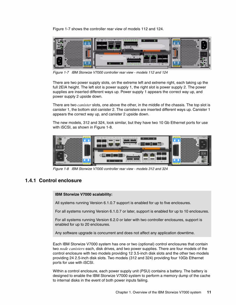
Figure 1-7 shows the controller rear view of models 112 and 124.
Figure 1-7 IBM Storwize V7000 controller rear view - models 112 and 124
There are two power supply slots, on the extreme left and extreme right, each taking up the full 2EIA height. The left slot is power supply 1, the right slot is power supply 2. The power supplies are inserted different ways up. Power supply 1 appears the correct way up, and power supply 2 upside down.
There are two canister slots, one above the other, in the middle of the chassis. The top slot is canister 1, the bottom slot canister 2. The canisters are inserted different ways up. Canister 1 appears the correct way up, and canister 2 upside down.
The new models, 312 and 324, look similar, but they have two 10 Gb Ethernet ports for use with iSCSI, as shown in Figure 1-8.
Figure 1-8 IBM Storwize V7000 controller rear view - models 312 and 324
1.4.1 Control enclosure
Each IBM Storwize V7000 system has one or two (optional) control enclosures that contain two node canisters each, disk drives, and two power supplies. There are four models of the control enclosure with two models providing 12 3.5-inch disk slots and the other two models providing 24 2.5-inch disk slots. Two models (312 and 324) providing four 10Gb Ethernet ports for use with iSCSI.
Within a control enclosure, each power supply unit (PSU) contains a battery. The battery is designed to enable the IBM Storwize V7000 system to perform a memory dump of the cache to internal disks in the event of both power inputs failing.
IBM Storwize V7000 scalability:
All systems running Version 6.1.0.7 support is enabled for up to five enclosures.
For all systems running Version 6.1.0.7 or later, support is enabled for up to 10 enclosures.
For all systems running Version 6.2.0 or later with two controller enclosures, support is enabled for up to 20 enclosures.
Any software upgrade is concurrent and does not affect any application downtime.
Chapter 1. Overview of the IBM Storwize V7000 system 11

The two nodes act as a single processing unit and form an I/O group that is attached to the SAN fabric. The pair of nodes is responsible for serving I/O to a given volume.
The two nodes provide a highly available fault-tolerant controller so that if one node fails the surviving node automatically takes over. Nodes are deployed in pairs called I/O groups.
With the optional second controller, you have two I/O groups.
One node is designated as the configuration node, but each node in the control enclosures and in the I/O groups holds a copy of the control enclosure state information.
The terms node canister and node are used interchangeably throughout this book.
Figure 1-9 shows a single node canister.
Figure 1-9 A single canister for controller models 112 or 124
There are four Fibre Channel ports on the left side of the canister. They are in a block of four in two rows of two connectors. The ports are numbered 1 - 4, from left to right, top to bottom. The ports operate at 2, 4, or 8 Gbps. Use of the ports is optional. There are two green LEDs associated with each port: the speed LED and link activity LED.
There are two 10 / 100 / 1000 Mbps Ethernet ports side by side on the canister. They are numbered 1 on the left and 2 on the right. Using port 1 is required; port 2 is optional. There are two LEDs associated with each Ethernet port. The 2076 models 312 or 324 have four additional 10 Gb Ethernet ports (two per canister) for use with iSCSI.
There are two USB 2.0 ports side by side on the canister. They are numbered 1 on the left and 2 on the right. Use of the connectors is optional. The only defined usage is with USB flash drives, which is described in Chapter 2, “Initial configuration” on page 35.
There are two 6 Gbps SAS ports side by side on the canister. They are numbered 1 on the left and 2 on the right. These ports are used to connect to the optional expansion enclosures.
PSUs: The power supply units for the control enclosure and expansion enclosure are not interchangeable
12 Implementing the IBM Storwize V7000 V6.3

1.4.2 Expansion enclosure
The optional expansion enclosure contains two expansion canisters, disk drives, and two power supplies. There are two models of the control enclosure with one model providing 12 disk slots and the other providing 24 disk slots.
Figure 1-10 shows the expansion enclosure.
Figure 1-10 Expansion enclosure
The expansion enclosure power supplies are similar to the control enclosure but do not contain the battery. There is a single power lead connector on the power supply unit. The PSU has an IEC C14 socket and the mains connection cable has a C13 plug.
Each expansion canister provides two SAS interfaces that are used to connect to the control enclosure and any optional expansion enclosures. The ports are numbered 1 on the left and 2 on the right. SAS port 1 is the IN port and SAS port 2 is the OUT port. There is also a symbol printed above the SAS ports to identify whether it is an IN or an OUT port.
Use of the SAS connector 1 is mandatory, as the expansion enclosure must be attached to either a control enclosure or another expansion enclosure. SAS connector 2 is optional, as it is used to attach to additional expansion enclosures.
Each port connects four PHYs (ports of SAS drive). There is an LED associated with each PHY in each port (eight LEDs in total). The LEDs are green and are next to the ports, and for each port they are numbered 1 through 4. The LED indicates activity on the PHY.
Figure 1-11 shows an expansion canister.
Figure 1-11 A single expansion canister
Chapter 1. Overview of the IBM Storwize V7000 system 13
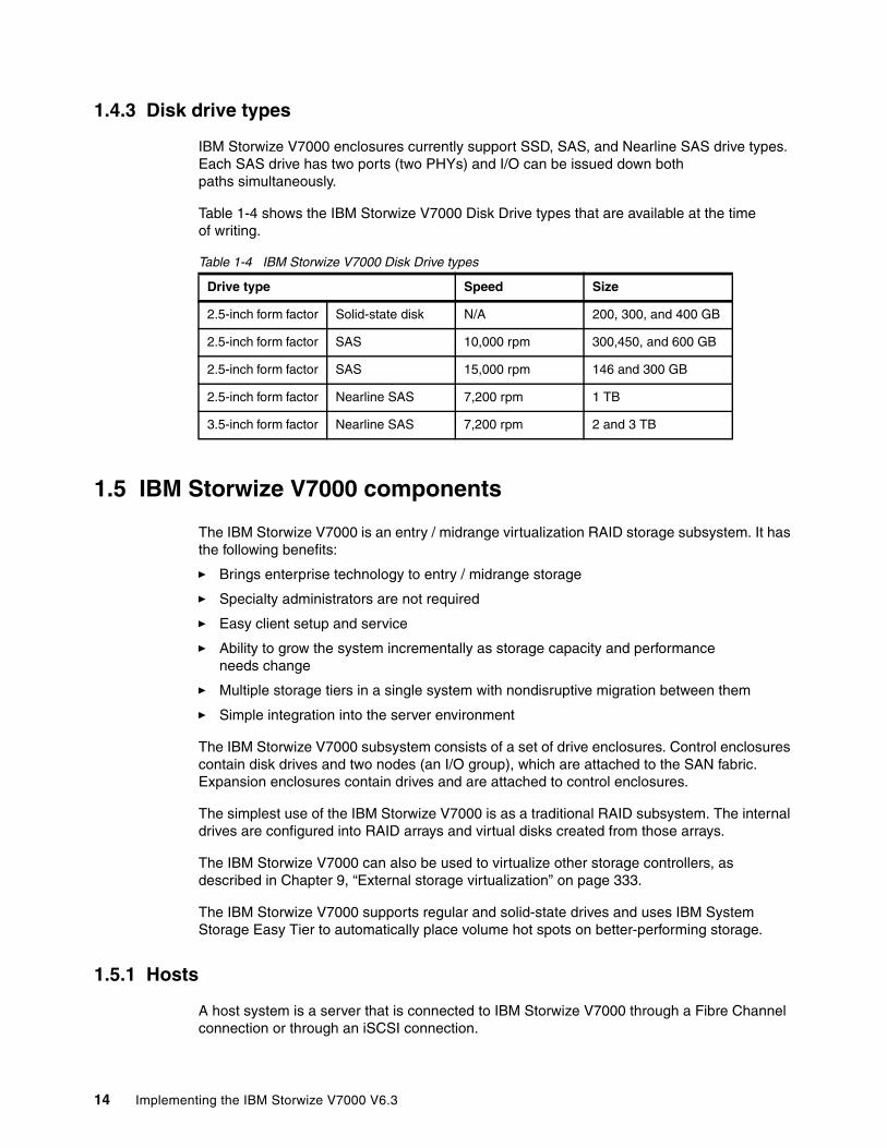
1.4.3 Disk drive types
IBM Storwize V7000 enclosures currently support SSD, SAS, and Nearline SAS drive types. Each SAS drive has two ports (two PHYs) and I/O can be issued down both paths simultaneously.
Table 1-4 shows the IBM Storwize V7000 Disk Drive types that are available at the time of writing.
Table 1-4 IBM Storwize V7000 Disk Drive types
1.5 IBM Storwize V7000 components
The IBM Storwize V7000 is an entry / midrange virtualization RAID storage subsystem. It has the following benefits:
� Brings enterprise technology to entry / midrange storage
� Specialty administrators are not required
� Easy client setup and service
� Ability to grow the system incrementally as storage capacity and performance needs change
� Multiple storage tiers in a single system with nondisruptive migration between them
� Simple integration into the server environment
The IBM Storwize V7000 subsystem consists of a set of drive enclosures. Control enclosures contain disk drives and two nodes (an I/O group), which are attached to the SAN fabric. Expansion enclosures contain drives and are attached to control enclosures.
The simplest use of the IBM Storwize V7000 is as a traditional RAID subsystem. The internal drives are configured into RAID arrays and virtual disks created from those arrays.
The IBM Storwize V7000 can also be used to virtualize other storage controllers, as described in Chapter 9, “External storage virtualization” on page 333.
The IBM Storwize V7000 supports regular and solid-state drives and uses IBM System Storage Easy Tier to automatically place volume hot spots on better-performing storage.
1.5.1 Hosts
A host system is a server that is connected to IBM Storwize V7000 through a Fibre Channel connection or through an iSCSI connection.
Drive type Speed Size
2.5-inch form factor Solid-state disk N/A 200, 300, and 400 GB
2.5-inch form factor SAS 10,000 rpm 300,450, and 600 GB
2.5-inch form factor SAS 15,000 rpm 146 and 300 GB
2.5-inch form factor Nearline SAS 7,200 rpm 1 TB
3.5-inch form factor Nearline SAS 7,200 rpm 2 and 3 TB
14 Implementing the IBM Storwize V7000 V6.3
Hosts are defined to IBM Storwize V7000 by identifying their worldwide port names (WWPNs) for Fibre Channel hosts. For iSCSI hosts, they are identified by using their iSCSI names. The iSCSI names can either be iSCSI qualified names (IQNs) or extended unique identifiers (EUIs).
1.5.2 Nodes
IBM Storwize V7000 can have two or four hardware components called nodes or node canisters that provide the virtualization of internal and external volumes, and cache and copy services (Remote Copy) functions. A clustered system consists of a one or two node pairs.
One of the nodes within the system is known as the configuration node and it is the node that manages configuration activity for the clustered system. If this node fails, the system nominates another node to become the configuration node.
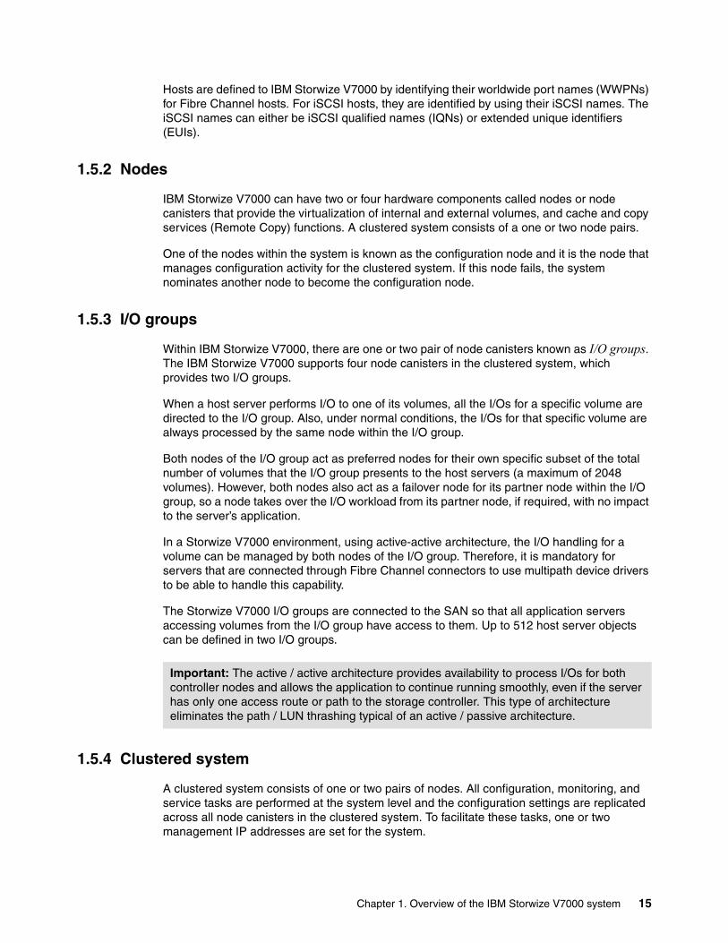
1.5.3 I/O groups
Within IBM Storwize V7000, there are one or two pair of node canisters known as I/O groups. The IBM Storwize V7000 supports four node canisters in the clustered system, which provides two I/O groups.
When a host server performs I/O to one of its volumes, all the I/Os for a specific volume are directed to the I/O group. Also, under normal conditions, the I/Os for that specific volume are always processed by the same node within the I/O group.
Both nodes of the I/O group act as preferred nodes for their own specific subset of the total number of volumes that the I/O group presents to the host servers (a maximum of 2048 volumes). However, both nodes also act as a failover node for its partner node within the I/O group, so a node takes over the I/O workload from its partner node, if required, with no impact to the server’s application.
In a Storwize V7000 environment, using active-active architecture, the I/O handling for a volume can be managed by both nodes of the I/O group. Therefore, it is mandatory for servers that are connected through Fibre Channel connectors to use multipath device drivers to be able to handle this capability.
The Storwize V7000 I/O groups are connected to the SAN so that all application servers accessing volumes from the I/O group have access to them. Up to 512 host server objects can be defined in two I/O groups.
1.5.4 Clustered system
A clustered system consists of one or two pairs of nodes. All configuration, monitoring, and service tasks are performed at the system level and the configuration settings are replicated across all node canisters in the clustered system. To facilitate these tasks, one or two management IP addresses are set for the system.
Important: The active / active architecture provides availability to process I/Os for both controller nodes and allows the application to continue running smoothly, even if the server has only one access route or path to the storage controller. This type of architecture eliminates the path / LUN thrashing typical of an active / passive architecture.
Chapter 1. Overview of the IBM Storwize V7000 system 15
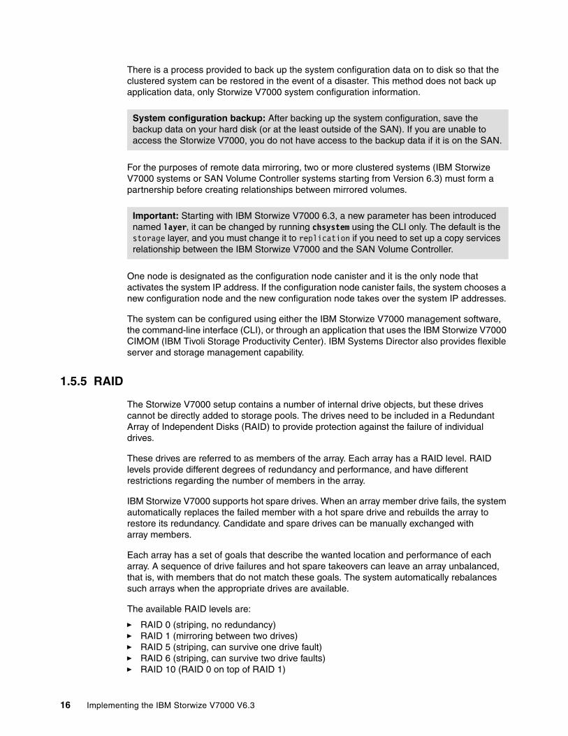
There is a process provided to back up the system configuration data on to disk so that the clustered system can be restored in the event of a disaster. This method does not back up application data, only Storwize V7000 system configuration information.
For the purposes of remote data mirroring, two or more clustered systems (IBM Storwize V7000 systems or SAN Volume Controller systems starting from Version 6.3) must form a partnership before creating relationships between mirrored volumes.
One node is designated as the configuration node canister and it is the only node that activates the system IP address. If the configuration node canister fails, the system chooses a new configuration node and the new configuration node takes over the system IP addresses.
The system can be configured using either the IBM Storwize V7000 management software, the command-line interface (CLI), or through an application that uses the IBM Storwize V7000 CIMOM (IBM Tivoli Storage Productivity Center). IBM Systems Director also provides flexible server and storage management capability.
1.5.5 RAID
The Storwize V7000 setup contains a number of internal drive objects, but these drives cannot be directly added to storage pools. The drives need to be included in a Redundant Array of Independent Disks (RAID) to provide protection against the failure of individual drives.
These drives are referred to as members of the array. Each array has a RAID level. RAID levels provide different degrees of redundancy and performance, and have different restrictions regarding the number of members in the array.
IBM Storwize V7000 supports hot spare drives. When an array member drive fails, the system automatically replaces the failed member with a hot spare drive and rebuilds the array to restore its redundancy. Candidate and spare drives can be manually exchanged with array members.
Each array has a set of goals that describe the wanted location and performance of each array. A sequence of drive failures and hot spare takeovers can leave an array unbalanced, that is, with members that do not match these goals. The system automatically rebalances such arrays when the appropriate drives are available.
The available RAID levels are:
� RAID 0 (striping, no redundancy)� RAID 1 (mirroring between two drives)� RAID 5 (striping, can survive one drive fault)� RAID 6 (striping, can survive two drive faults)� RAID 10 (RAID 0 on top of RAID 1)
System configuration backup: After backing up the system configuration, save the backup data on your hard disk (or at the least outside of the SAN). If you are unable to access the Storwize V7000, you do not have access to the backup data if it is on the SAN.
Important: Starting with IBM Storwize V7000 6.3, a new parameter has been introduced named layer, it can be changed by running chsystem using the CLI only. The default is the storage layer, and you must change it to replication if you need to set up a copy services relationship between the IBM Storwize V7000 and the SAN Volume Controller.
16 Implementing the IBM Storwize V7000 V6.3

RAID 0 arrays stripe data across the drives. The system supports RAID 0 arrays with just one member, which is similar to traditional JBOD attach. RAID 0 arrays have no redundancy, so they do not support hot spare takeover or immediate exchange. A RAID 0 array can be formed by one to eight drives.
RAID 1 arrays stripe data over mirrored pairs of drives. A RAID 1 array mirrored pair is rebuilt independently. A RAID 1 array can be formed by two drives only.
RAID 5 arrays stripe data over the member drives with one parity strip on every stripe. RAID 5 arrays have single redundancy. The parity algorithm means that an array can tolerate no more than one member drive failure. A RAID 5 array can be formed by 3 to 16 drives.
RAID 6 arrays stripe data over the member drives with two parity stripes (known as the P-parity and the Q-parity) on every stripe. The two parity strips are calculated using different algorithms, which give the array double redundancy. A RAID 6 array can be formed by 5 to 16 drives.
RAID 10 arrays have single redundancy. Although they can tolerate one failure from every mirrored pair, they cannot tolerate two-disk failures. One member out of every pair can be rebuilding or missing at the same time. A RAID 10 array can be formed by 2 to 16 drives.
1.5.6 Managed disks
A managed disk (MDisk) refers to the unit of storage that IBM Storwize V7000 virtualizes. This unit could be a logical volume on an external storage array presented to the IBM Storwize V7000 or a RAID array consisting of internal drives. The IBM Storwize V7000 can then allocate these MDisks into various storage pools.
An MDisk is not visible to a host system on the storage area network, as it is internal or only zoned to the IBM Storwize V7000 system.
An MDisk has four modes:
� Array
Array mode MDisks are constructed from drives using the RAID function. Array MDisks are always associated with storage pools.
� Unmanaged
Unmanaged MDisks are not being used by the system. This situation might occur when an MDisk is first imported into the system, for example.
� Managed
Managed MDisks are assigned to a storage pool and provide extents so that volumes can use it.
� Image
Image MDisks are assigned directly to a volume with a one-to-one mapping of extents between the MDisk and the volume. This situation is normally used when importing logical volumes into the clustered system that already have data on them, which ensures that the data is preserved as it is imported into the clustered system.
Chapter 1. Overview of the IBM Storwize V7000 system 17

1.5.7 Quorum disks
A quorum disk is a managed disk (MDisk) that contains a reserved area for use exclusively by the system. In the Storwize V7000, internal drives can be considered as quorum candidates. The clustered system uses quorum disks to break a tie when exactly half the nodes in the system remain after a SAN failure.
The clustered system automatically forms the quorum disk by taking a small amount of space from a managed disk (MDisk). It allocates space from up to three different MDisks for redundancy, although only one quorum disk is active.
If the environment has multiple storage systems, then to avoid the possibility of losing all of the quorum disks because of a failure of a single storage system, you should allocate the quorum disk on different storage systems. It is possible to manage the quorum disks by using the CLI.
1.5.8 Storage pools
A storage pool is a collection of MDisks (up to 128) that are grouped together to provide capacity for volumes. All MDisks in the pool are split into extents with the same size. Volumes are then allocated out of the storage pool and are mapped to a host system.
MDisks can be added to a storage pool at any time to increase the capacity of the storage pool. MDisks can belong in only one storage pool and only MDisks in unmanaged mode can be added to the storage pool. When an MDisk is added to the storage pool, the mode changes from unmanaged to managed and vice versa when you remove it.
Each MDisk in the storage pool is divided into a number of extents. The size of the extent is selected by the administrator at creation time of the storage pool and cannot be changed later. The size of the extent ranges from 16 MB up to 8 GB.
The extent size has a direct impact on the maximum volume size and storage capacity of the clustered system. A system can manage 4 million (4 x 1024 x 1024) extents. For example, a system with a 16 MB extent size can manage up to 16 MB x 4 MB = 64 TB of storage.
The effect of extent size on the maximum volume size is shown inTable 1-5, and lists the extent size and the corresponding maximum clustered system size.
Table 1-5 Maximum volume capacity by extent size
Storwize V7000 object names: The names must begin with a letter, which cannot be numeric. The name can be a maximum of 63 characters. Valid characters are uppercase (A-Z), lowercase letters (a-z), digits (0 - 9), underscore (_), period (.), hyphen (-), and space. The names must not begin or end with a space.
Extent size Maximum volume capacity for normal volumes (GB)
16 2048 (2 TB)
32 4096 (4 TB)
64 8192 (8 TB)
128 16384 (16 TB)
256 32768 (32 TB)
18 Implementing the IBM Storwize V7000 V6.3
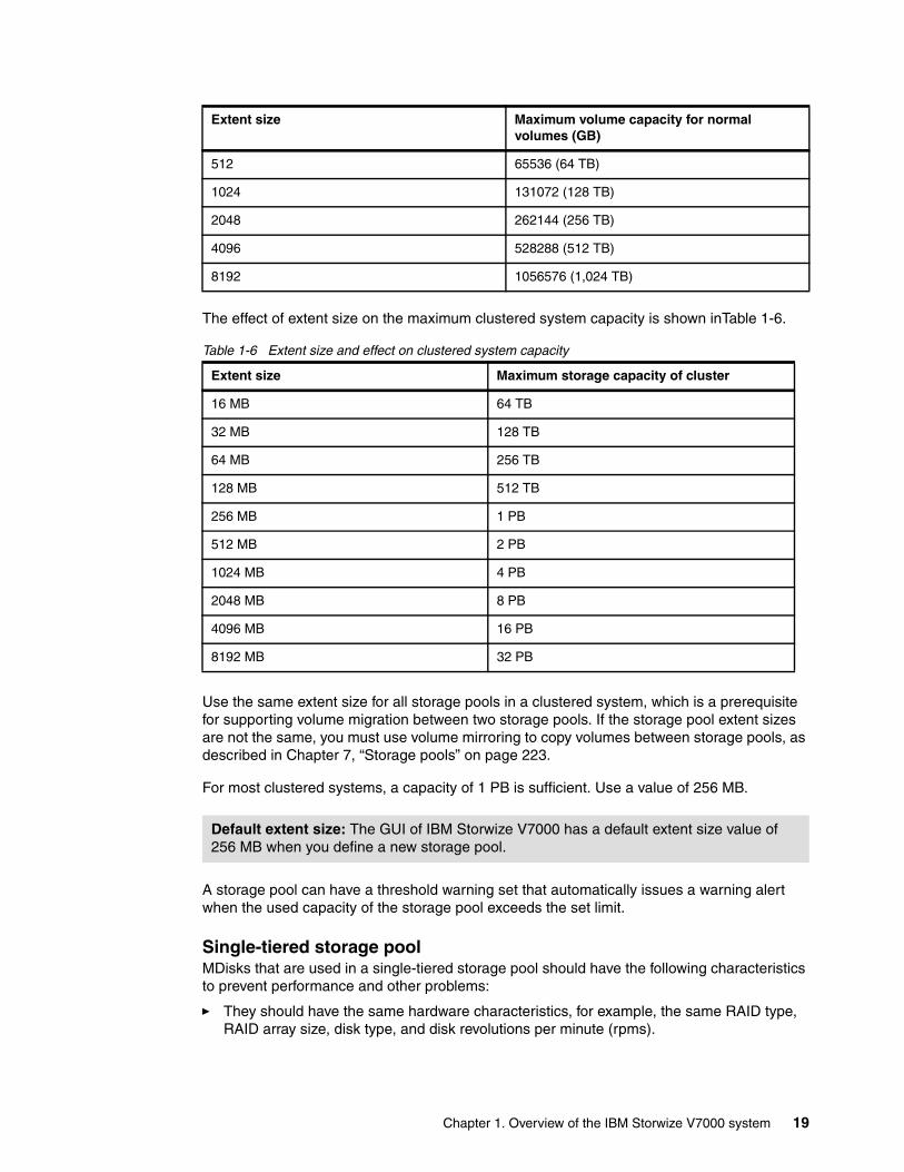
The effect of extent size on the maximum clustered system capacity is shown inTable 1-6.
Table 1-6 Extent size and effect on clustered system capacity
Use the same extent size for all storage pools in a clustered system, which is a prerequisite for supporting volume migration between two storage pools. If the storage pool extent sizes are not the same, you must use volume mirroring to copy volumes between storage pools, as described in Chapter 7, “Storage pools” on page 223.
For most clustered systems, a capacity of 1 PB is sufficient. Use a value of 256 MB.
A storage pool can have a threshold warning set that automatically issues a warning alert when the used capacity of the storage pool exceeds the set limit.
Single-tiered storage poolMDisks that are used in a single-tiered storage pool should have the following characteristics to prevent performance and other problems:
� They should have the same hardware characteristics, for example, the same RAID type, RAID array size, disk type, and disk revolutions per minute (rpms).
512 65536 (64 TB)
1024 131072 (128 TB)
2048 262144 (256 TB)
4096 528288 (512 TB)
8192 1056576 (1,024 TB)
Extent size Maximum storage capacity of cluster
16 MB 64 TB
32 MB 128 TB
64 MB 256 TB
128 MB 512 TB
256 MB 1 PB
512 MB 2 PB
1024 MB 4 PB
2048 MB 8 PB
4096 MB 16 PB
8192 MB 32 PB
Default extent size: The GUI of IBM Storwize V7000 has a default extent size value of 256 MB when you define a new storage pool.
Extent size Maximum volume capacity for normal volumes (GB)
Chapter 1. Overview of the IBM Storwize V7000 system 19
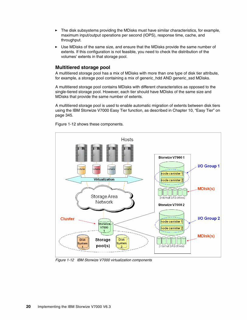
� The disk subsystems providing the MDisks must have similar characteristics, for example, maximum input/output operations per second (IOPS), response time, cache, and throughput.
� Use MDisks of the same size, and ensure that the MDisks provide the same number of extents. If this configuration is not feasible, you need to check the distribution of the volumes’ extents in that storage pool.
Multitiered storage poolA multitiered storage pool has a mix of MDisks with more than one type of disk tier attribute, for example, a storage pool containing a mix of generic_hdd AND generic_ssd MDisks.
A multitiered storage pool contains MDisks with different characteristics as opposed to the single-tiered storage pool. However, each tier should have MDisks of the same size and MDisks that provide the same number of extents.
A multitiered storage pool is used to enable automatic migration of extents between disk tiers using the IBM Storwize V7000 Easy Tier function, as described in Chapter 10, “Easy Tier” on page 345.
Figure 1-12 shows these components.
Figure 1-12 IBM Storwize V7000 virtualization components
20 Implementing the IBM Storwize V7000 V6.3
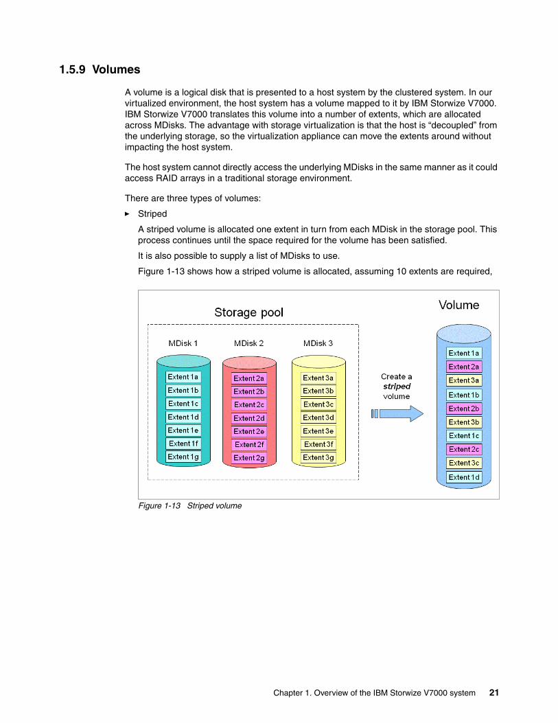
1.5.9 Volumes
A volume is a logical disk that is presented to a host system by the clustered system. In our virtualized environment, the host system has a volume mapped to it by IBM Storwize V7000. IBM Storwize V7000 translates this volume into a number of extents, which are allocated across MDisks. The advantage with storage virtualization is that the host is “decoupled” from the underlying storage, so the virtualization appliance can move the extents around without impacting the host system.
The host system cannot directly access the underlying MDisks in the same manner as it could access RAID arrays in a traditional storage environment.
There are three types of volumes:
� Striped
A striped volume is allocated one extent in turn from each MDisk in the storage pool. This process continues until the space required for the volume has been satisfied.
It is also possible to supply a list of MDisks to use.
Figure 1-13 shows how a striped volume is allocated, assuming 10 extents are required,
Figure 1-13 Striped volume
Chapter 1. Overview of the IBM Storwize V7000 system 21

� Sequential
A sequential volume is where the extents are allocated one after the other from one MDisk to the next MDisk (Figure 1-14).
Figure 1-14 Sequential volume
� Image mode
Image mode volumes are special volumes that have a direct relationship with one MDisk. They are used to migrate existing data into and out of the clustered system.
22 Implementing the IBM Storwize V7000 V6.3
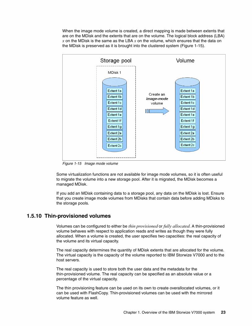
When the image mode volume is created, a direct mapping is made between extents that are on the MDisk and the extents that are on the volume. The logical block address (LBA) x on the MDisk is the same as the LBA x on the volume, which ensures that the data on the MDisk is preserved as it is brought into the clustered system (Figure 1-15).
Figure 1-15 Image mode volume
Some virtualization functions are not available for image mode volumes, so it is often useful to migrate the volume into a new storage pool. After it is migrated, the MDisk becomes a managed MDisk.
If you add an MDisk containing data to a storage pool, any data on the MDisk is lost. Ensure that you create image mode volumes from MDisks that contain data before adding MDisks to the storage pools.
1.5.10 Thin-provisioned volumes
Volumes can be configured to either be thin provisioned or fully allocated. A thin-provisioned volume behaves with respect to application reads and writes as though they were fully allocated. When a volume is created, the user specifies two capacities: the real capacity of the volume and its virtual capacity.
The real capacity determines the quantity of MDisk extents that are allocated for the volume. The virtual capacity is the capacity of the volume reported to IBM Storwize V7000 and to the host servers.
The real capacity is used to store both the user data and the metadata for the thin-provisioned volume. The real capacity can be specified as an absolute value or a percentage of the virtual capacity.
The thin provisioning feature can be used on its own to create overallocated volumes, or it can be used with FlashCopy. Thin-provisioned volumes can be used with the mirrored volume feature as well.
Chapter 1. Overview of the IBM Storwize V7000 system 23
A thin-provisioned volume can be configured to autoexpand, which causes IBM Storwize V7000 to automatically expand the real capacity of a thin-provisioned volume as its real capacity is used. Autoexpand attempts to maintain a fixed amount of unused real capacity on the volume. This amount is known as the contingency capacity.
The contingency capacity is initially set to the real capacity that is assigned when the volume is created. If the user modifies the real capacity, the contingency capacity is reset to be the difference between the used capacity and real capacity.
A volume that is created with a zero contingency capacity goes offline as soon as it needs to expand. A volume with a non-zero contingency capacity stays online until it has been used up.
Autoexpand does not cause the real capacity to grow much beyond the virtual capacity. The real capacity can be manually expanded to more than the maximum that is required by the current virtual capacity, and the contingency capacity is recalculated.
To support the autoexpansion of thin-provisioned volumes, the storage pools from which they are allocated have a configurable warning capacity. When the used free capacity of the group exceeds the warning capacity, a warning is logged. For example, if a warning of 80% has been specified, the warning is logged when 20% of the free capacity remains.
A thin-provisioned volume can be converted to a fully allocated volume using volume mirroring (and vice versa).
1.5.11 Mirrored volumes
IBM Storwize V7000 provides a function called volume mirroring, which enables a volume to have two physical copies. Each volume copy can belong to a different storage pool and can be on different physical storage systems, which provides a high-availability solution.
When a host system issues a write to a mirrored volume, IBM Storwize V7000 writes the data to both copies. When a host system issues a read to a mirrored volume, IBM Storwize V7000 places it into the primary copy. If one of the mirrored volume copies is temporarily unavailable, the IBM Storwize V7000 automatically uses the alternative copy without any outage for the host system. When the mirrored volume copy is repaired, IBM Storwize V7000 resynchronizes the data.
A mirrored volume can be converted into a non-mirrored volume by deleting one copy or by splitting one copy to create a new non-mirrored volume.
The mirrored volume copy can be any type: image, striped, sequential, and thin provisioned or not. The two copies can be different volume types.
Using mirrored volumes can also assist with migrating volumes between storage pools that have different extent sizes and can provide a mechanism to migrate fully allocated volumes to thin-provisioned volumes without any host outages.
Using Storwize V7000 V6.3, you can change the time-out value, latency, which prioritizes low host latency (default) or redundancy, which prioritizes redundancy (longer timeout)
Unmirrored volumes: An unmirrored volume can be migrated from one location to another by adding a second copy to the wanted destination, waiting for the two copies to synchronize, and then removing the original copy. This operation can be stopped at any time.
24 Implementing the IBM Storwize V7000 V6.3
1.5.12 Easy Tier
Easy Tier is a performance function that automatically migrates or moves extents off a volume to, or from, SSD storage to HDD storage. Easy Tier monitors the host I/O activity and latency on the extent of all volumes with the Easy Tier function turned on in a multitiered storage pool over a 24-hour period. It then creates an extent migration plan based on this activity and then dynamically moves high activity or hot extents to a higher disk tier within the storage pool. It also moves extents’ activity that has dropped off or cooled from the high tiered MDisk back to lower tiered MDisk.
The Easy Tier function may be turned on or off at the storage pool and volume level.
It is possible to demonstrate the potential benefit of Easy Tier in your environment before installing a solid-state disk. By turning on the Easy Tier function for a single level storage pool and the Easy Tier Function for the volumes within that pool, Easy Tier creates a migration report every 24 hours on the number of extents it would move if the pool was a multitiered pool. Easy Tier statistics measurement is enabled.
Using Easy Tier might make it more appropriate to use smaller storage pool extent sizes.
The usage statistics file can be offloaded from IBM Storwize V7000 nodes and then an IBM Storage Advisor Tool can be used to create a summary report.
Contact your IBM representative or IBM Business Partner for more information about the Storage Advisor Tool. We describe Easy Tier in more detail in Chapter 10, “Easy Tier” on page 345.
1.5.13 iSCSI
iSCSI is an alternative means of attaching hosts to the IBM Storwize V7000. All communications with back-end storage subsystems, and with other IBM Storwize V7000s, only occur through a Fibre Channel connection.
The iSCSI function is a software function that is provided by the IBM Storwize V7000 code, not hardware.
In the simplest terms, iSCSI allows the transport of SCSI commands and data over a TCP/IP network, based on IP routers and Ethernet switches. iSCSI is a block-level protocol that encapsulates SCSI commands into TCP/IP packets and uses an existing IP network, instead of requiring expensive FC HBAs and a SAN fabric infrastructure.
A pure SCSI architecture is based on the client/server model. A client (for example, server or workstation) initiates read or write requests for data from a target server (for example, a data storage system).
Commands, which are sent by the client and processed by the server, are put into the Command Descriptor Block (CDB). The server runs a command, and completion is indicated by a special signal alert.
The major functions of iSCSI include encapsulation and the reliable delivery of CDB transactions between initiators and targets through the Internet Protocol network, especially over a potentially unreliable IP network.
Chapter 1. Overview of the IBM Storwize V7000 system 25
The concepts of names and addresses have been carefully separated in iSCSI:
� An iSCSI name is a location-independent, permanent identifier for an iSCSI node. An iSCSI node has one iSCSI name, which stays constant for the life of the node. The terms initiator name and target name also refer to an iSCSI name.
� An iSCSI address specifies not only the iSCSI name of an iSCSI node, but also a location of that node. The address consists of a host name or IP address, a TCP port number (for the target), and the iSCSI name of the node. An iSCSI node can have any number of addresses, which can change at any time, particularly if they are assigned by way of Dynamic Host Configuration Protocol (DHCP). An IBM Storwize V7000 node represents an iSCSI node and provides statically allocated IP addresses.
Each iSCSI node, that is, an initiator or target, has a unique iSCSI Qualified Name (IQN), which can have a size of up to 255 bytes. The IQN is formed according to the rules adopted for Internet nodes.
The iSCSI qualified name format is defined in RFC3720 and contains (in order) these elements:
� The string “iqn”.
� A date code specifying the year and month in which the organization registered the domain or subdomain name used as the naming authority string.
� The organizational naming authority string, which consists of a valid, reversed domain or a subdomain name.
� Optionally, a colon (:), followed by a string of the assigning organization’s choosing, which must make each assigned iSCSI name unique.
For IBM Storwize V7000, the IQN for its iSCSI target is specified as:
iqn.1986-03.com.ibm:2145.<clustername>.<nodename>
On a Windows server, the IQN, that is, the name for the iSCSI initiator, can be defined as:
iqn.1991-05.com.microsoft:<computer name>
The IQNs can be abbreviated by using a descriptive name, known as an alias. An alias can be assigned to an initiator or a target. The alias is independent of the name and does not need to be unique. Because it is not unique, the alias must be used in a purely informational way. It cannot be used to specify a target at login or used during authentication. Both targets and initiators can have aliases.
An iSCSI name provides the correct identification of an iSCSI device irrespective of its physical location. Remember, the IQN is an identifier, not an address.
The iSCSI session, which consists of a login phase and a full feature phase, is completed with a special command.
Changing names: Before changing system or node names for an IBM Storwize V7000 clustered system that has servers connected to it using SCSI, be aware that because the system and node name are part of the IQN for the IBM Storwize V7000, you can lose access to your data by changing these names. The IBM Storwize V7000 GUI shows a specific warning, but the CLI does not.
26 Implementing the IBM Storwize V7000 V6.3

The login phase of the iSCSI is identical to the FC port login process (PLOGI). It is used to adjust various parameters between two network entities and to confirm the access rights of an initiator.
If the iSCSI login phase is completed successfully, the target confirms the login for the initiator; otherwise, the login is not confirmed and the TCP connection breaks.
As soon as the login is confirmed, the iSCSI session enters the full feature phase. If more than one TCP connection was established, iSCSI requires that each command / response pair goes through one TCP connection. Thus, each separate read or write command is carried out without the necessity to trace each request for passing separate flows. However, separate transactions can be delivered through separate TCP connections within one session.
For further details about configuring iSCSI, see Chapter 4, “Host configuration” on page 131.
1.6 Advanced copy services
IBM Storwize V7000 supports the following copy services:
� Synchronous Remote Copy� Asynchronous Remote Copy � FlashCopy
Starting with SAN Volume Controller V6.3, copy services functions are implemented within a single IBM Storwize V7000 or between multiple IBM Storwize V7000s and SAN Volume Controllers. The Copy Services layer sits above and operates independently of the function or characteristics of the underlying disk subsystems used to provide storage resources to an IBM Storwize V7000. Figure 1-16 shows an example of copy services with SAN Volume Controllers and IBM Storwize V7000 (they must be at Version 6.3 or later). A new parameter of the clustered system properties named layer has been introduced, which can be changed from storage (default) to replication if you need to make a new relationship between the IBM Storwize V7000 and SAN Volume Controller systems. You can change it only using the CLI command chsystem. In SAN Volume Controller systems, this parameter is fixed to replication and cannot be changed.
Figure 1-16 Example of SAN Volume Controller and Storwize V7000 copy services relationship
Chapter 1. Overview of the IBM Storwize V7000 system 27

1.6.1 Synchronous / Asynchronous Remote CopyThe general application of Remote Copy seeks to maintain two copies of data. Often, the two copies are separated by distance, but not always.
The Remote Copy can be maintained in one of two modes: synchronous or asynchronous.
With the IBM Storwize V7000, Metro Mirror and Global Mirror are the IBM branded terms for the functions that are synchronous Remote Copy and asynchronous Remote Copy.
Synchronous Remote Copy ensures that updates are committed at both the primary and the secondary before the application considers the updates complete; therefore, the secondary is fully up to date if it is needed in a failover. However, the application is fully exposed to the latency and bandwidth limitations of the communication link to the secondary. In a truly remote situation, this extra latency can have a significant adverse effect on application performance.
Special configuration guidelines exist for SAN fabrics that are used for data replication. It is necessary to consider the distance and available bandwidth of the intersite links (see Chapter 11, “Copy services” on page 371).
A new function of Global Mirror designed for low bandwidth has been introduced in IBM Storwize V7000 6.3. It uses change volumes associated with the primary and secondary volumes. These volumes are used to record changes to the remote copy volume, the FlashCopy relationship that exists between the secondary volume and the change volume, and between the primary volume and the change volume. This function is called Global Mirror cycling mode. Figure 1-17 shows an example of this function where you can see the relationship between volumes and change volumes.
Figure 1-17 Global Mirror with change volumes
In asynchronous Remote Copy, the application acknowledges that the write is complete before the write is committed at the secondary. Hence, on a failover, certain updates (data) might be missing at the secondary. The application must have an external mechanism for recovering the missing updates, if possible. This mechanism can involve user intervention. Recovery on the secondary site involves starting the application on this recent “backup” and then rolling forward or backward to the most recent commit point.
IBM Support for automation is provided by IBM Tivoli Storage Productivity Center for Replication. The Tivoli documentation can also be accessed online at the IBM Tivoli Storage Productivity Center Information Center at the following website:
http://publib.boulder.ibm.com/infocenter/tivihelp/v4r1/index.jsp
28 Implementing the IBM Storwize V7000 V6.3

1.6.2 FlashCopy
FlashCopy makes a copy of a source volume on a target volume. The original content of the target volume is lost. After the copy operation has started, the target volume has the contents of the source volume as they existed at a single point in time. Although the copy operation takes time, the resulting data at the target appears as though the copy was made instantaneously.
FlashCopy is sometimes described as an instance of a time-zero (T0) copy or a point in time (PiT) copy technology.
FlashCopy can be performed on multiple source and target volumes. FlashCopy permits the management operations to be coordinated so that a common single point in time is chosen for copying target volumes from their respective source volumes.
IBM Storwize V7000 also permits multiple target volumes to be FlashCopied from the same source volume. This capability can be used to create images from separate points in time for the source volume, and to create multiple images from a source volume at a common point in time. Source and target volumes can be thin-provisioned volumes.
Reverse FlashCopy enables target volumes to become restore points for the source volume without breaking the FlashCopy relationship and without waiting for the original copy operation to complete. IBM Storwize V7000 supports multiple targets and thus multiple rollback points.
Most clients aim to integrate the FlashCopy feature for point in time copies and quick recovery of their applications and databases. IBM Support is provided by Tivoli Storage FlashCopy Manager, which is described at the following website:
http://www-01.ibm.com/software/tivoli/products/storage-flashcopy-mgr/
You can read a detailed description about the FlashCopy copy services in Chapter 11, “Copy services” on page 371.
1.6.3 Copy Services configuration limits
In Table 1-7, we describe the Copy Services configuration limits. For the most up-to-date list of these limits, see the following website:
http://www-01.ibm.com/support/docview.wss?uid=ssg1S1003702&myns=s028&mynp=familyind5402112&mync=E
Table 1-7 Copy Services configuration limits
Properties Maximum number Note
Remote Copy (Metro Mirror and Global Mirror) relationships per clustered system
4096 This configuration can be any mix of Metro Mirror and Global Mirror relationships.
Remote Copy relationships per consistency group
- No limit is imposed beyond the Remote Copy relationships per clustered system limit
Remote Copy consistency groups per clustered system
256 -
Chapter 1. Overview of the IBM Storwize V7000 system 29
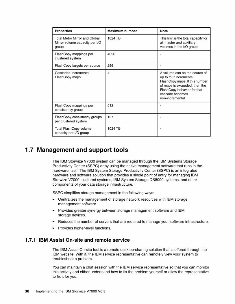
1.7 Management and support tools
The IBM Storwize V7000 system can be managed through the IBM Systems Storage Productivity Center (SSPC) or by using the native management software that runs in the hardware itself. The IBM System Storage Productivity Center (SSPC) is an integrated hardware and software solution that provides a single point of entry for managing IBM Storwize V7000 clustered systems, IBM System Storage DS8000 systems, and other components of your data storage infrastructure.
SSPC simplifies storage management in the following ways:
� Centralizes the management of storage network resources with IBM storage management software.
� Provides greater synergy between storage management software and IBM storage devices.
� Reduces the number of servers that are required to manage your software infrastructure.
� Provides higher-level functions.
1.7.1 IBM Assist On-site and remote service
The IBM Assist On-site tool is a remote desktop-sharing solution that is offered through the IBM website. With it, the IBM service representative can remotely view your system to troubleshoot a problem.
You can maintain a chat session with the IBM service representative so that you can monitor this activity and either understand how to fix the problem yourself or allow the representative to fix it for you.
Total Metro Mirror and Global Mirror volume capacity per I/O group
1024 TB This limit is the total capacity for all master and auxiliary volumes in the I/O group.
FlashCopy mappings per clustered system
4096 -
FlashCopy targets per source 256 -
Cascaded Incremental FlashCopy maps
4 A volume can be the source of up to four incremental FlashCopy maps. If this number of maps is exceeded, then the FlashCopy behavior for that cascade becomes non-incremental.
FlashCopy mappings per consistency group
512 -
FlashCopy consistency groups per clustered system
127 -
Total FlashCopy volume capacity per I/O group
1024 TB -
Properties Maximum number Note
30 Implementing the IBM Storwize V7000 V6.3
To use the IBM Assist On-site tool, the SSPC or master console must be able to access the Internet. The following website provides further information about this tool:
http://www.ibm.com/support/assistonsite/
When you access the website, you sign in and enter a code that the IBM service representative provides to you. This code is unique to each IBM Assist On-site session. A plug-in is downloaded on to your SSPC or master console to connect you and your IBM service representative to the remote service session. The IBM Assist On-site contains several layers of security to protect your applications and your computers.
You can also use security features to restrict access by the IBM service representative.
Your IBM service representative can provide you with more detailed instructions for using the tool.
1.7.2 Event notifications
IBM Storwize V7000 can use Simple Network Management Protocol (SNMP) traps, syslog messages, and a Call Home email to notify you and the IBM Support Center when significant events are detected. Any combination of these notification methods can be used simultaneously.
Each event that IBM Storwize V7000 detects is assigned a notification type of Error, Warning, or Information. You can configure IBM Storwize V7000 to send each type of notification to specific recipients.
1.7.3 SNMP traps
SNMP is a standard protocol for managing networks and exchanging messages. IBM Storwize V7000 can send SNMP messages that notify personnel about an event. You can use an SNMP manager to view the SNMP messages that IBM Storwize V7000 sends. You can use the management GUI or the IBM Storwize V7000 command-line interface to configure and modify your SNMP settings.
You can use the Management Information Base (MIB) file for SNMP to configure a network management program to receive SNMP messages that are sent by the IBM Storwize V7000. This file can be used with SNMP messages from all versions of IBM Storwize V7000 Software.
1.7.4 Syslog messages
The syslog protocol is a standard protocol for forwarding log messages from a sender to a receiver on an IP network. The IP network can be either IPv4 or IPv6. IBM Storwize V7000 can send syslog messages that notify personnel about an event. IBM Storwize V7000 can transmit syslog messages in either expanded or concise format. You can use a syslog manager to view the syslog messages that IBM Storwize V7000 sends. IBM Storwize V7000 uses the User Datagram Protocol (UDP) to transmit the syslog message. You can use the management GUI or the IBM Storwize V7000 command-line interface to configure and modify your syslog settings.
Chapter 1. Overview of the IBM Storwize V7000 system 31

1.7.5 Call Home email
The Call Home feature transmits operational and error-related data to you and IBM through a Simple Mail Transfer Protocol (SMTP) server connection in the form of an event notification email. When configured, this function alerts IBM service personnel about hardware failures and potentially serious configuration or environmental issues. You can use the call home function if you have a maintenance contract with IBM or if the Storwize V7000 is within the warranty period.
To send email, you must configure at least one SMTP server. You can specify as many as five additional SMTP servers for backup purposes. The SMTP server must accept the relaying of email from the IBM Storwize V7000 clustered system IP address. You can then use the management GUI or the IBM Storwize V7000 command-line interface to configure the email settings, including contact information and email recipients. Set the reply address to a valid email address. Send a test email to check that all connections and infrastructure are set up correctly. You can disable the Call Home function at any time using the management GUI or the IBM Storwize V7000 command-line interface.
1.8 Useful Storwize V7000 websites
The IBM Storwize V7000 Support page is at the following website
http://www.ibm.com/storage/support/storwize/v7000
The IBM Storwize V7000 home page is at the following website
http://www-03.ibm.com/systems/storage/news/center/storwize_v7000/index.html
The IBM Storwize V7000 Supported hardware list is at the following website:
http://www-01.ibm.com/support/docview.wss?uid=ssg1S1003908
The IBM Storwize V7000 Configuration Limit and Restrictions are at the following website:
http://www-01.ibm.com/support/docview.wss?uid=ssg1S1003902
The IBM Storwize V7000 Online documentation is at the following website:
http://www-947.ibm.com/support/entry/portal/Documentation/Hardware/System_Storage/Disk_systems/Mid-range_disk_systems/IBM_Storwize_V7000_%282076%29
The IBM Storwize V7000 Online Information Center is at the following website:
http://publib.boulder.ibm.com/infocenter/storwize/ic/index.jsp
You can see lBM Redbooks publications about IBM Storwize V7000 at the following website:
http://www.redbooks.ibm.com/cgi-bin/searchsite.cgi?query=v7000
32 Implementing the IBM Storwize V7000 V6.3

1.8.1 IBM Storwize V7000 learning videos on YouTube
Some interesting videos are available on YouTube that describe the IBM Storwize V7000 GUI and are available at the URLs shown in Table 1-8.
Table 1-8 Videos available on YouTube
Description of the video Link WEB
IBM Storwize V7000 Storage Virtualization Terminology Overview
http://www.youtube.com/watch?v=I2rzt3m2gP0
IBM Storwize V7000 Interface tour http://www.youtube.com/watch?v=FPbNRs9HacQ
IBM Storwize V7000 Volume management http://www.youtube.com/watch?v=YXeKqH8Sd9o
IBM Storwize V7000 Migration http://www.youtube.com/watch?v=dXxnUN6dk74
IBM Storwize V7000 Introduction to FlashCopy http://www.youtube.com/watch?v=MXWgGWjBzG4
IBM Storwize V7000 Introduction to Remote Copy 1
http://www.youtube.com/watch?v=koFYm--gnEc
IBM Storwize V7000 Introduction to Remote Copy 2
http://www.youtube.com/watch?v=kMOFFS3NYas
IBM Storwize V7000 Rapid Application Storage Solution - Tivoli Storage FlashCopy Manager
http://www.youtube.com/watch?v=1zgEljRVDSc
VMware data protection with Storwize V7000 http://www.youtube.com/watch?v=vecOap-qwbA
IBM SAN Volume Controller and Storwize V7000 Performance Panel Sped-up! (HD)
http://www.youtube.com/watch?v=7noC71tLkWs
Chapter 1. Overview of the IBM Storwize V7000 system 33

34 Implementing the IBM Storwize V7000 V6.3
Chapter 2. Initial configuration
This chapter provides a description of the IBM Storwize V7000 initial configuration steps.
In this chapter, we describe the following topics:
� Planning for IBM Storwize V7000 installation� First time setup� Initial configuration steps� Call Home, email event alert, and inventory settings
2
© Copyright IBM Corp. 2011, 2012. All rights reserved. 35
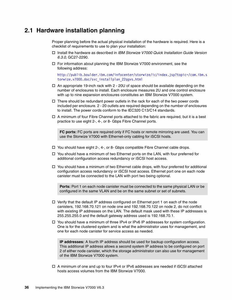
2.1 Hardware installation planning
Proper planning before the actual physical installation of the hardware is required. Here is a checklist of requirements to use to plan your installation:
Install the hardware as described in IBM Storwize V7000 Quick Installation Guide Version 6.3.0, GC27-2290.
For information about planning the IBM Storwize V7000 environment, see the following address:
http://publib.boulder.ibm.com/infocenter/storwize/ic/index.jsp?topic=/com.ibm.storwize.v7000.doc/svc_installplan_22qgvs.html
An appropriate 19-inch rack with 2 - 20U of space should be available depending on the number of enclosures to install. Each enclosure measures 2U and one control enclosure with up to nine expansion enclosures constitutes an IBM Storwize V7000 system.
There should be redundant power outlets in the rack for each of the two power cords included per enclosure. 2 - 20 outlets are required depending on the number of enclosures to install. The power cords conform to the IEC320 C13/C14 standards.
A minimum of four Fibre Channel ports attached to the fabric are required, but it is a best practice to use eight 2-, 4-, or 8- Gbps Fibre Channel ports.
You should have eight 2-, 4-, or 8- Gbps compatible Fibre Channel cable drops.
You should have a minimum of two Ethernet ports on the LAN, with four preferred for additional configuration access redundancy or iSCSI host access.
You should have a minimum of two Ethernet cable drops, with four preferred for additional configuration access redundancy or iSCSI host access. Ethernet port one on each node canister must be connected to the LAN with port two being optional.
Verify that the default IP address configured on Ethernet port 1 on each of the node canisters, 192.168.70.121 on node one and 192.168.70.122 on node 2, do not conflict with existing IP addresses on the LAN. The default mask used with these IP addresses is 255.255.255.0 and the default gateway address used is 192.168.70.1.
You should have a minimum of three IPv4 or IPv6 IP addresses for system configuration. One is for the clustered system and is what the administrator uses for management, and one for each node canister for service access as needed.
A minimum of one and up to four IPv4 or IPv6 addresses are needed if iSCSI attached hosts access volumes from the IBM Storwize V7000.
FC ports: FC ports are required only if FC hosts or remote mirroring are used. You can use the Storwize V7000 with Ethernet-only cabling for iSCSI hosts.
Ports: Port 1 on each node canister must be connected to the same physical LAN or be configured in the same VLAN and be on the same subnet or set of subnets.
IP addresses: A fourth IP address should be used for backup configuration access. This additional IP address allows a second system IP address to be configured on port 2 of either node canister, which the storage administrator can also use for management of the IBM Storwize V7000 system.
36 Implementing the IBM Storwize V7000 V6.3
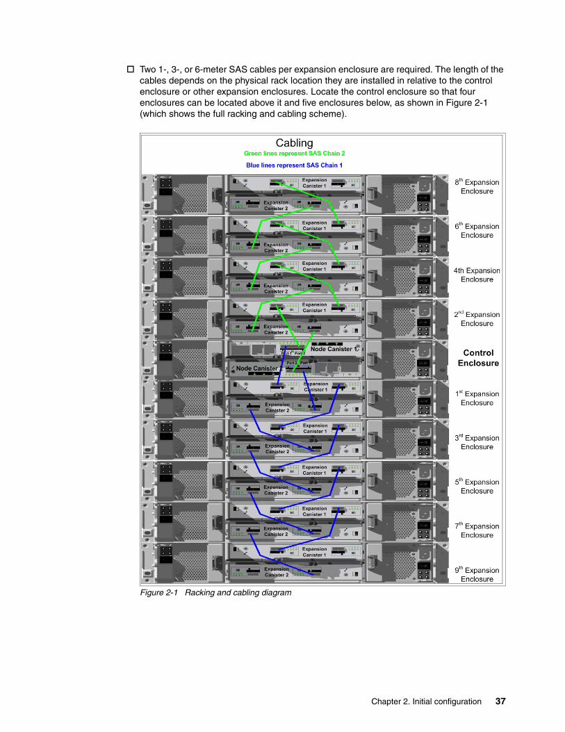
Two 1-, 3-, or 6-meter SAS cables per expansion enclosure are required. The length of the cables depends on the physical rack location they are installed in relative to the control enclosure or other expansion enclosures. Locate the control enclosure so that four enclosures can be located above it and five enclosures below, as shown in Figure 2-1 (which shows the full racking and cabling scheme).
Figure 2-1 Racking and cabling diagram
Chapter 2. Initial configuration 37

2.2 SAN configuration planning
The recommended SAN configuration is composed of a minimum of two fabrics with all host ports, and any ports on external storage systems to be virtualized by IBM Storwize V7000. The IBM Storwize V7000 ports themselves are evenly split between the two fabrics to provide redundancy in the event one of the fabrics goes offline (either planned or unplanned).
After the IBM Storwize V7000, hosts, and optional external storage systems are connected to the SAN fabrics, zoning needs to be implemented.
In each fabric, create a zone with just the four IBM Storwize V7000 WWPNs, two from each node canister. If there is an external storage system to be virtualized, then in each fabric, create a zone with the four IBM Storwize V7000 WWPNs, two from each node canister, along with up to a maximum of eight WWPNs from the external storage system. Assuming every host has a Fibre Channel connection to each fabric, then in each fabric, create a zone with the host WWPN and one WWPN from each node canister in the IBM Storwize V7000 system.
Disk drives: The disk drives included with the control enclosure, model 2076-224 or 2076-212, are part of SAS chain number two. Therefore, only four additional expansion enclosures can be connected to this chain. SAS chain number one supports the addition of up to five expansion enclosures. The first expansion enclosure should be connected to SAS chain number one so both chains are used and the full bandwidth of the system is used.
Maximum ports or WWPNs: IBM Storwize V7000 supports a maximum of 16 ports or WWPNs from a given external storage system that is virtualized.
38 Implementing the IBM Storwize V7000 V6.3
Figure 2-2 shows how to cable devices to the SAN. See this example as we describe the zoning.
Figure 2-2 SAN cabling and zoning diagram
Create a host / IBM Storwize V7000 zone for each server to which volumes are mapped to from the clustered system. For example:
� Zone Server 1 port A (RED) with all node port 1s� Zone Server 1 port B (BLUE) with all node port 2s� Zone Server 2 port A (RED) with all node port 3s� Zone Server 2 port B (BLUE) with all node port 4s
Verify that the SAN switches or directors that the IBM Storwize V7000 connects to meet the following requirements (see http://www.ibm.com/storage/support/Storwize/V7000 for more information):
� Switches or directors are at the firmware levels supported by the IBM Storwize V7000.
� IBM Storwize V7000 port login maximums listed in restriction document must not be exceeded.
Connectivity issues: If you have any connectivity issues between IBM Storwize V7000 ports and Brocade SAN Switches or Directors at 8 Gbps, see http://www-01.ibm.com/support/docview.wss?rs=591&uid=ssg1S1003699 for the correct setting of the fillword port config parameter in the Brocade operating system.
Chapter 2. Initial configuration 39
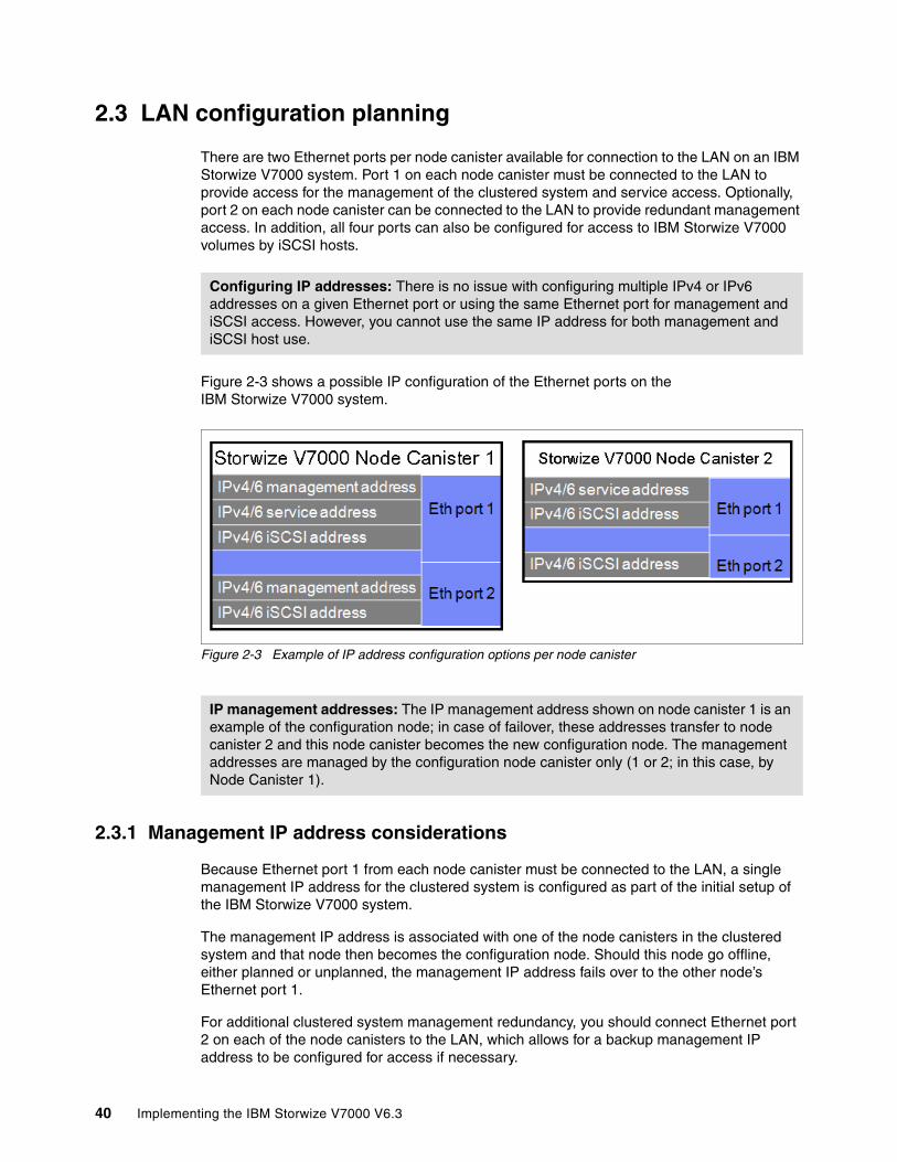
2.3 LAN configuration planning
There are two Ethernet ports per node canister available for connection to the LAN on an IBM Storwize V7000 system. Port 1 on each node canister must be connected to the LAN to provide access for the management of the clustered system and service access. Optionally, port 2 on each node canister can be connected to the LAN to provide redundant management access. In addition, all four ports can also be configured for access to IBM Storwize V7000 volumes by iSCSI hosts.
Figure 2-3 shows a possible IP configuration of the Ethernet ports on the IBM Storwize V7000 system.
Figure 2-3 Example of IP address configuration options per node canister
2.3.1 Management IP address considerations
Because Ethernet port 1 from each node canister must be connected to the LAN, a single management IP address for the clustered system is configured as part of the initial setup of the IBM Storwize V7000 system.
The management IP address is associated with one of the node canisters in the clustered system and that node then becomes the configuration node. Should this node go offline, either planned or unplanned, the management IP address fails over to the other node’s Ethernet port 1.
For additional clustered system management redundancy, you should connect Ethernet port 2 on each of the node canisters to the LAN, which allows for a backup management IP address to be configured for access if necessary.
Configuring IP addresses: There is no issue with configuring multiple IPv4 or IPv6 addresses on a given Ethernet port or using the same Ethernet port for management and iSCSI access. However, you cannot use the same IP address for both management and iSCSI host use.
IP management addresses: The IP management address shown on node canister 1 is an example of the configuration node; in case of failover, these addresses transfer to node canister 2 and this node canister becomes the new configuration node. The management addresses are managed by the configuration node canister only (1 or 2; in this case, by Node Canister 1).
40 Implementing the IBM Storwize V7000 V6.3
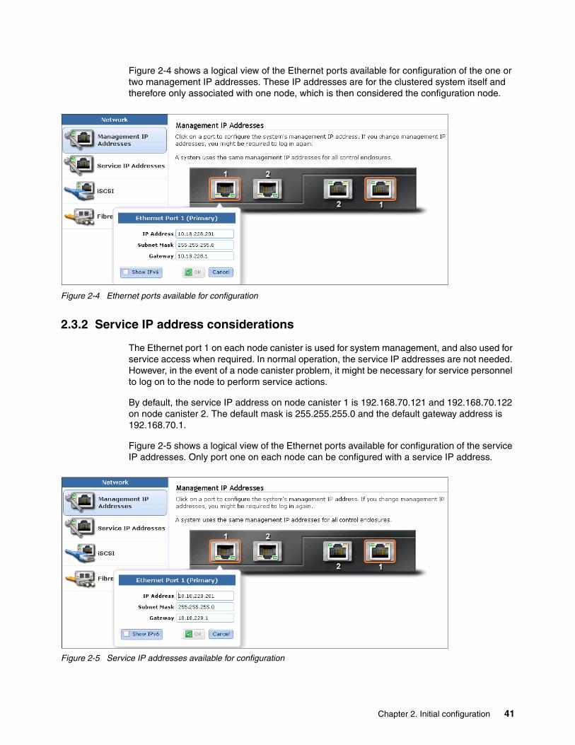
Figure 2-4 shows a logical view of the Ethernet ports available for configuration of the one or two management IP addresses. These IP addresses are for the clustered system itself and therefore only associated with one node, which is then considered the configuration node.
Figure 2-4 Ethernet ports available for configuration
2.3.2 Service IP address considerations
The Ethernet port 1 on each node canister is used for system management, and also used for service access when required. In normal operation, the service IP addresses are not needed. However, in the event of a node canister problem, it might be necessary for service personnel to log on to the node to perform service actions.
By default, the service IP address on node canister 1 is 192.168.70.121 and 192.168.70.122 on node canister 2. The default mask is 255.255.255.0 and the default gateway address is 192.168.70.1.
Figure 2-5 shows a logical view of the Ethernet ports available for configuration of the service IP addresses. Only port one on each node can be configured with a service IP address.
Figure 2-5 Service IP addresses available for configuration
Chapter 2. Initial configuration 41
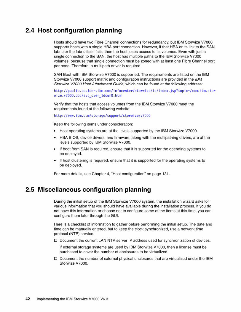
2.4 Host configuration planning
Hosts should have two Fibre Channel connections for redundancy, but IBM Storwize V7000 supports hosts with a single HBA port connection. However, if that HBA or its link to the SAN fabric or the fabric itself fails, then the host loses access to its volumes. Even with just a single connection to the SAN, the host has multiple paths to the IBM Storwize V7000 volumes, because that single connection must be zoned with at least one Fibre Channel port per node. Therefore, a multipath driver is required.
SAN Boot with IBM Storwize V7000 is supported. The requirements are listed on the IBM Storwize V7000 support matrix and configuration instructions are provided in the IBM Storwize V7000 Host Attachment Guide, which can be found at the following address:
http://publib.boulder.ibm.com/infocenter/storwize/ic/index.jsp?topic=/com.ibm.storwize.v7000.doc/svc_over_1dcur0.html
Verify that the hosts that access volumes from the IBM Storwize V7000 meet the requirements found at the following website:
http://www.ibm.com/storage/support/storwize/v7000
Keep the following items under consideration:
� Host operating systems are at the levels supported by the IBM Storwize V7000.
� HBA BIOS, device drivers, and firmware, along with the multipathing drivers, are at the levels supported by IBM Storwize V7000.
� If boot from SAN is required, ensure that it is supported for the operating systems to be deployed.
� If host clustering is required, ensure that it is supported for the operating systems to be deployed.
For more details, see Chapter 4, “Host configuration” on page 131.
2.5 Miscellaneous configuration planning
During the initial setup of the IBM Storwize V7000 system, the installation wizard asks for various information that you should have available during the installation process. If you do not have this information or choose not to configure some of the items at this time, you can configure them later through the GUI.
Here is a checklist of information to gather before performing the initial setup. The date and time can be manually entered, but to keep the clock synchronized, use a network time protocol (NTP) service.
Document the current LAN NTP server IP address used for synchronization of devices.
If external storage systems are used by IBM Storwize V7000, then a license must be purchased to cover the number of enclosures to be virtualized.
Document the number of external physical enclosures that are virtualized under the IBM Storwize V7000.
42 Implementing the IBM Storwize V7000 V6.3
Document the total number of physical enclosures, including both the internal and external virtualized enclosures for the Global Mirror and Metro Mirror features. You must have enough Global Mirror and Metro Mirror licenses for all the enclosures attached to the system, regardless of the amount of Global Mirror and Metro Mirror capacity you intend to use.
The Easy Tier function is included with the IBM Storwize V7000 system and is not a purchased feature. If the system has solid-state drives, and this capability is used to optimize the usage of the SSD drives, then this function is enabled.
For alerts to be sent to storage administrators and to set up Call Home to IBM for service and support, you need the following information:
Name of primary storage administrator for IBM to contact if necessary.
Email address of the storage administrator for IBM to contact if necessary.
Phone number of the storage administrator for IBM to contact if necessary.
Physical location of the IBM Storwize V7000 system for IBM service (for example, Building 22, first floor).
SMTP or email server address to direct alerts to and from the IBM Storwize V7000.
For the Call Home service to work, the IBM Storwize V7000 system must have access to an SMTP server on the LAN that can forward emails to the default IBM service address [email protected].
Email address of local administrators needing to be notified of alerts.
IP address of SNMP server to direct alerts to if wanted (for example, operations or help desk).
After the IBM Storwize V7000 initial configuration, you might want to add additional users who can manage the system. You can create as many users as you need, but currently there are only four roles generally configured for users:
� Security Admin� Administrator� Copyoperator� Monitor
The Security Admin role allows the user to perform any function on the IBM Storwize V7000.
The administrator role allows the user to perform any function on the IBM Storwize V7000 system except create users.
The copyoperator role allows the user to view anything in the system, but the user can only configure and manage copy functions that include the replication functions of Metro and Global Mirror and the FlashCopy capabilities.
The monitor role can view object and system configuration, but cannot configure, manage, or modify any system resource.
User creation: The create users function is allowed by the Security Admin role only and should be limited to as few users as possible.
Chapter 2. Initial configuration 43

The only other role available is the service role, which is used if you create a user ID for the IBM service representative. This role allows IBM service personnel to view anything on the system, as with the monitor role, plus perform service-related commands, such as adding a node back to the system after being serviced or include disks that have been excluded.
2.6 System management
The graphical user interface (GUI) is used to configure, manage, and troubleshoot the IBM Storwize V7000 system. It is used primarily to configure RAID arrays and logical drives, assign logical drives to hosts, replace and rebuild failed disk drives, and expand the logical drives.
It allows for troubleshooting and management tasks, such as checking the status of the storage server components, updating the firmware, and managing the storage server.
Finally, it offers advanced functions, such as FlashCopy, Volume Mirroring, and Remote Mirroring. A command-line interface (CLI) for the IBM Storwize V7000 system is available as well.
This section briefly describes the system management using GUI and CLI.
2.6.1 Graphical user interface (GUI)
A web browser is used for GUI access. You must use a supported web browser to access the management GUI. For a list of supported web browsers, see the Recommended Software Level document at the following website:
http://www.ibm.com/storage/support/storwize/v7000
Open your web browser on a workstation and point it to the IBM Storwize V7000 system management address (this address is defined in 2.7, “First-time setup” on page 46).
44 Implementing the IBM Storwize V7000 V6.3
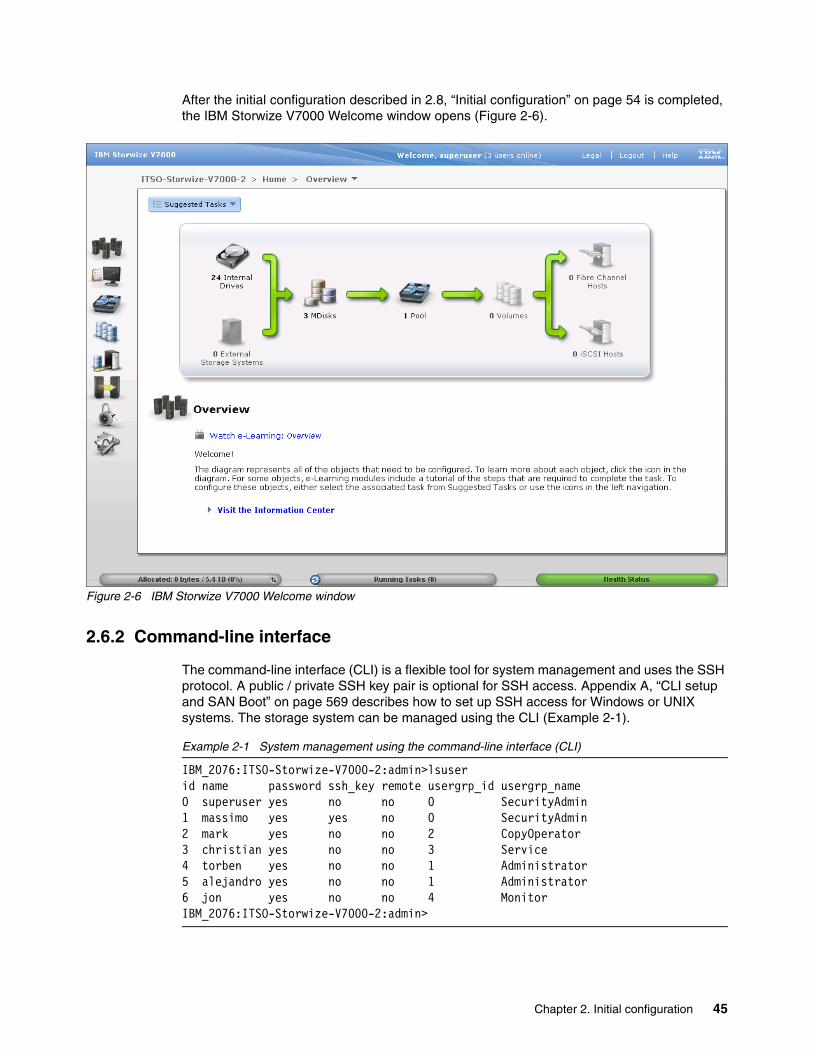
After the initial configuration described in 2.8, “Initial configuration” on page 54 is completed, the IBM Storwize V7000 Welcome window opens (Figure 2-6).
Figure 2-6 IBM Storwize V7000 Welcome window
2.6.2 Command-line interface
The command-line interface (CLI) is a flexible tool for system management and uses the SSH protocol. A public / private SSH key pair is optional for SSH access. Appendix A, “CLI setup and SAN Boot” on page 569 describes how to set up SSH access for Windows or UNIX systems. The storage system can be managed using the CLI (Example 2-1).
Example 2-1 System management using the command-line interface (CLI)
IBM_2076:ITSO-Storwize-V7000-2:admin>lsuserid name password ssh_key remote usergrp_id usergrp_name 0 superuser yes no no 0 SecurityAdmin 1 massimo yes yes no 0 SecurityAdmin 2 mark yes no no 2 CopyOperator 3 christian yes no no 3 Service 4 torben yes no no 1 Administrator 5 alejandro yes no no 1 Administrator 6 jon yes no no 4 Monitor IBM_2076:ITSO-Storwize-V7000-2:admin>
Chapter 2. Initial configuration 45

The initial IBM Storwize V7000 system setup should be done using the graphical tools we describe in 2.7, “First-time setup” on page 46.
2.7 First-time setup
This section describes how to perform a first-time IBM Storwize V7000 system setup.
IBM Storwize V7000 uses an easy to use initial setup that is contained within a USB key. The USB key is delivered with each storage system and contains the initialization application called InitTool.exe. A system management IP address, the subnet mask, and the network gateway address are required. The initialization application creates a configuration file on the USB key.
The IBM Storwize V7000 starts the initial setup as soon as you plug in the USB key with the newly created file in to the storage system.
The USB key contains the initTool.exe file (Figure 2-7).
Figure 2-7 InitTool program in the USB key
Commands: Starting with IBM Storwize V7000 6.3, the svctask and svcinfo command prefixes are no longer necessary when issuing a command. If you have existing scripts that use those prefixes, they continue to function. You do not need to change the scripts.
Another important change is that you can use lssystem command instead of svcinfo lscluster or chsytem instead of svctask chcluster. The old commands are maintained for compatibility purposes with any previously written scripts.
USB key: If you are unable to find the official USB key supplied with the IBM Storwize V7000, you can use any USB key you have and download and copy the initTool.exe application from the IBM Storwize V7000 Support website at the following address:
http://www.ibm.com/storage/support/Storwize/V7000
46 Implementing the IBM Storwize V7000 V6.3
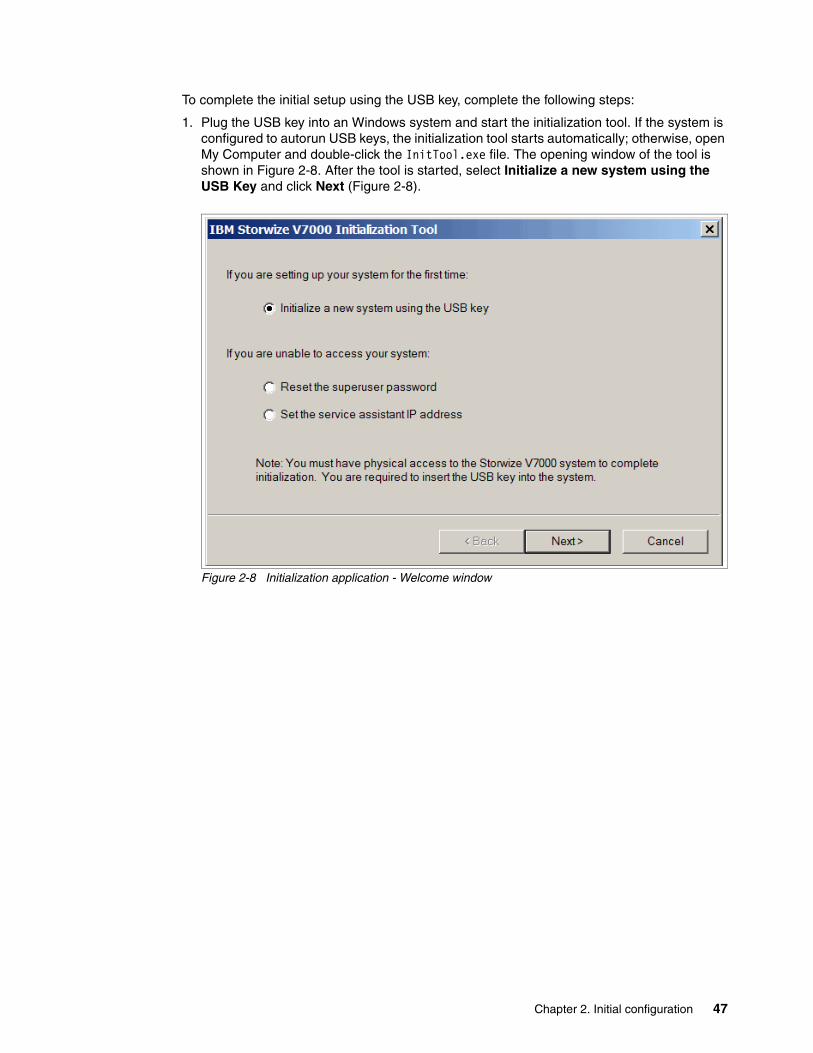
To complete the initial setup using the USB key, complete the following steps:
1. Plug the USB key into an Windows system and start the initialization tool. If the system is configured to autorun USB keys, the initialization tool starts automatically; otherwise, open My Computer and double-click the InitTool.exe file. The opening window of the tool is shown in Figure 2-8. After the tool is started, select Initialize a new system using the USB Key and click Next (Figure 2-8).
Figure 2-8 Initialization application - Welcome window
Chapter 2. Initial configuration 47
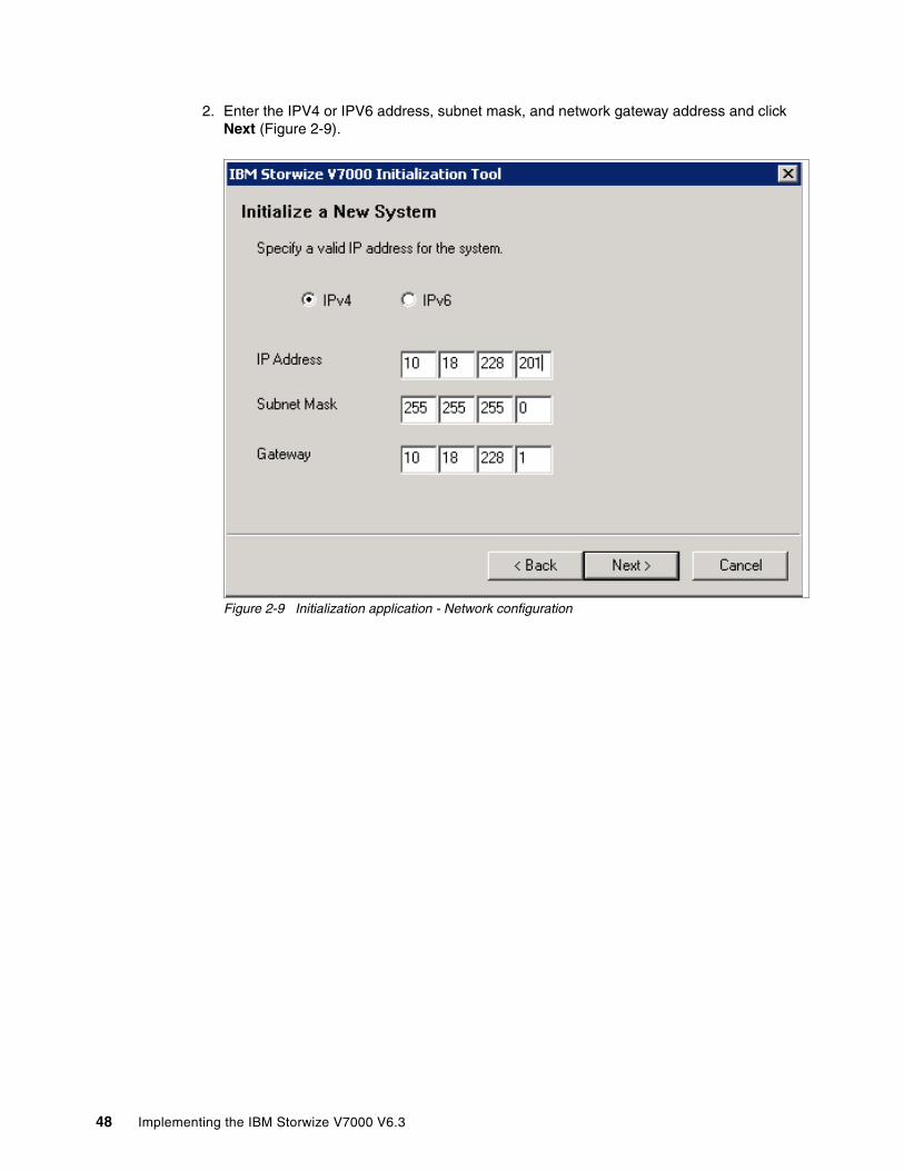
2. Enter the IPV4 or IPV6 address, subnet mask, and network gateway address and click Next (Figure 2-9).
Figure 2-9 Initialization application - Network configuration
48 Implementing the IBM Storwize V7000 V6.3

3. Click Finish (Figure 2-10).
Figure 2-10 Initialization application - Finalizing the initial setup
The application creates a file called satask.txt on the USB key (Figure 2-11).
Figure 2-11 The satask.txt file created during the InitTool procedure
The contents of this file is similar to the following command:
satask mkcluster -clusterip 10.18.228.201 -gw 10.18.228.1 -mask 255.255.255.0
4. Unplug the USB key from your Windows system and plug it into the IBM Storwize V7000 USB connector slot and the storage system will automatically:
a. Detect the key.b. Read the satask.txt file and run its contents.c. Delete the satask.txt file.d. Write the response to a new file called satask_result.html (Figure 2-12).
Figure 2-12 satask_result.html file created during the InitTool procedure
Chapter 2. Initial configuration 49

After this task has completed successfully, the initial setup is done. The IBM Storwize V7000 is available for further configuration changes using the newly defined configuration address.
Each node has two Ethernet ports that can be used for system management. Ethernet port 1 is used for system management and must be configured and connected on both nodes. The use of Ethernet port 2 is optional.
Each IBM Storwize V7000 clustered system has one or two system IP addresses. If the configuration node fails, the system IP addresses are transferred to another node in the same clustered system.
A sample of the contents of the satask_result.html file is shown in Example 2-2.
Example 2-2 satask_result.html file contents
Service Command Resultssatask mkcluster -clusterip 10.18.228.201 -gw 10.18.228.1 -mask 255.255.255.0
Tue Sep 20 10:51:57 PDT 2011
System Statussainfo lsservicenodes
panel_name cluster_id cluster_name node_id node_name relation node_status error_data78G00RJ-1 00000200A0A006B2 Cluster_10.18.228.201 1 node1 local Active
sainfo lsservicestatus
panel_name 78G00RJ-1cluster_id 00000200a0a006b2cluster_name Cluster_10.18.228.201cluster_status Activecluster_ip_count 2cluster_port 1cluster_ip 10.18.228.201cluster_gw 10.18.228.1cluster_mask 255.255.255.0cluster_ip_6 cluster_gw_6 cluster_prefix_6 cluster_port 2cluster_ip
Clustered system creation: While the clustered system is being created, the amber fault LED on the node canister flashes. When the amber fault LED stops flashing, remove the USB key from IBM Storwize V7000 and insert it in your system to check the results.
Important: The first system management IP address always uses port 1. Always connect port 1 for all node canisters to the management network.
50 Implementing the IBM Storwize V7000 V6.3

cluster_gw cluster_mask cluster_ip_6 cluster_gw_6 cluster_prefix_6 node_id 1node_name node1node_status Activeconfig_node Yeshardware 100service_IP_address service_gateway service_subnet_mask service_IP_address_6 service_gateway_6 service_prefix_6 node_sw_version 6.3.0.0node_sw_build 54.0.1109090000cluster_sw_build 54.0.1109090000node_error_count 1error_code 835error_data error_code error_data error_code error_data error_code error_data error_code error_data fc_ports 4port_id 1port_status Activeport_speed 2Gbport_WWPN 50050768021005a8SFP_type Short-waveport_id 2port_status Activeport_speed 4Gbport_WWPN 50050768022005a8SFP_type Short-waveport_id 3port_status Inactiveport_speed N/Aport_WWPN 50050768023005a8SFP_type Short-waveport_id 4port_status Inactiveport_speed N/Aport_WWPN 50050768024005a8SFP_type Short-waveethernet_ports 2ethernet_port_id 1port_status Link Onlineport_speed 1Gb/s - Full
Chapter 2. Initial configuration 51
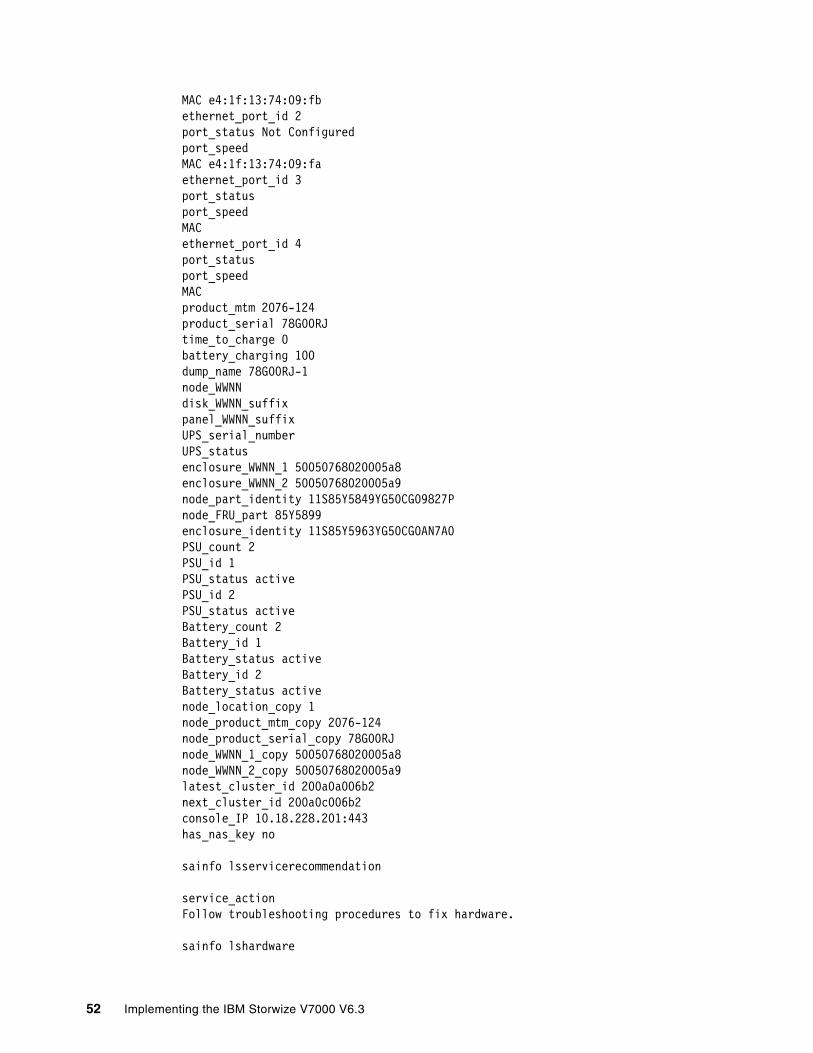
MAC e4:1f:13:74:09:fbethernet_port_id 2port_status Not Configuredport_speed MAC e4:1f:13:74:09:faethernet_port_id 3port_status port_speed MAC ethernet_port_id 4port_status port_speed MAC product_mtm 2076-124product_serial 78G00RJtime_to_charge 0battery_charging 100dump_name 78G00RJ-1node_WWNN disk_WWNN_suffix panel_WWNN_suffix UPS_serial_number UPS_status enclosure_WWNN_1 50050768020005a8enclosure_WWNN_2 50050768020005a9node_part_identity 11S85Y5849YG50CG09827Pnode_FRU_part 85Y5899enclosure_identity 11S85Y5963YG50CG0AN7A0PSU_count 2PSU_id 1PSU_status activePSU_id 2PSU_status activeBattery_count 2Battery_id 1Battery_status activeBattery_id 2Battery_status activenode_location_copy 1node_product_mtm_copy 2076-124node_product_serial_copy 78G00RJnode_WWNN_1_copy 50050768020005a8node_WWNN_2_copy 50050768020005a9latest_cluster_id 200a0a006b2next_cluster_id 200a0c006b2console_IP 10.18.228.201:443has_nas_key no
sainfo lsservicerecommendation
service_actionFollow troubleshooting procedures to fix hardware.
sainfo lshardware
52 Implementing the IBM Storwize V7000 V6.3

panel_name 78G00RJ-1node_id 1node_name node1node_status Activehardware 100actual_different noactual_valid yesmemory_configured 8memory_actual 8memory_valid yescpu_count 1cpu_socket 1cpu_configured 4 core Intel(R) Xeon(R) CPU C3539 @ 2.13GHzcpu_actual 4 core Intel(R) Xeon(R) CPU C3539 @ 2.13GHzcpu_valid yescpu_socket cpu_configured cpu_actual cpu_valid adapter_count 5adapter_location 0adapter_configured Four port 8Gb/s FC adapteradapter_actual Four port 8Gb/s FC adapteradapter_valid yesadapter_location 0adapter_configured 1Gb/s Ethernet adapteradapter_actual 1Gb/s Ethernet adapteradapter_valid yesadapter_location 0adapter_configured 1Gb/s Ethernet adapteradapter_actual 1Gb/s Ethernet adapteradapter_valid yesadapter_location 0adapter_configured High Speed SAS adapteradapter_actual High Speed SAS adapteradapter_valid yesadapter_location 0adapter_configured Midplane bus adapteradapter_actual Midplane bus adapteradapter_valid yesadapter_location adapter_configured adapter_actual adapter_valid
Chapter 2. Initial configuration 53
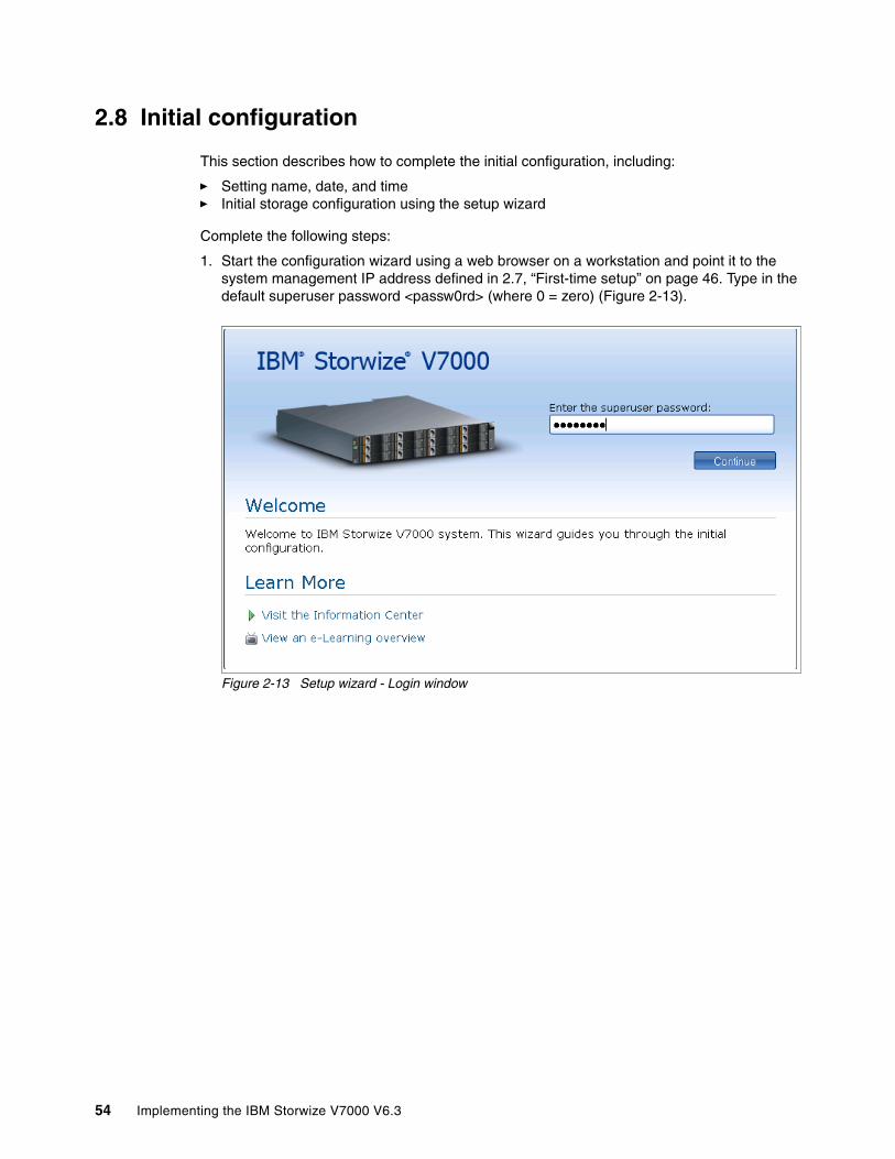
2.8 Initial configuration
This section describes how to complete the initial configuration, including:
� Setting name, date, and time� Initial storage configuration using the setup wizard
Complete the following steps:
1. Start the configuration wizard using a web browser on a workstation and point it to the system management IP address defined in 2.7, “First-time setup” on page 46. Type in the default superuser password <passw0rd> (where 0 = zero) (Figure 2-13).
Figure 2-13 Setup wizard - Login window
54 Implementing the IBM Storwize V7000 V6.3

2. Read and accept the license agreement (Figure 2-14).
Figure 2-14 Setup wizard - License Agreement
3. Set up the system name, current date, and time (Figure 2-15).
Figure 2-15 Setup wizard - Set name, date, and time
4. Optionally, you can type in advanced licenses for virtualization of external storage devices and a Remote Copy limit, as applicable. The virtualization license for all local devices is already included in the system and must not be added here.
Chapter 2. Initial configuration 55

Figure 2-16 shows an example of how to add a license for external storage, Remote Copy, and Real Time Compression.
Figure 2-16 Setup wizard - License setting
2.8.1 Configure Call Home, email alert, and inventory
If your system is within warranty, or you have a hardware maintenance agreement, configure your system to send email reports to IBM if an issue that requires hardware replacement is detected. This function is called Call Home. When this email is received, IBM automatically opens a problem report and contacts you to verify if replacements parts are required.
To configure the Call Home and email alert event notification in IBM Storwize V7000, complete the following steps.
1. Click Configure Email Event Notification (Figure 2-17) to start the email configuration wizard.
Figure 2-17 Setup wizard option email and event configuration
Call Home: When configuring Call Home, use one of the following email addresses, depending on country or region of installation:
� [email protected]: USA, Canada, Latin America, and Caribbean Islands
� [email protected]: All other countries/regions
56 Implementing the IBM Storwize V7000 V6.3

2. Define the sending email account (Figure 2-18).
Figure 2-18 Email and event configuration - Setting contact information
3. Configure the email server (Figure 2-19).
Figure 2-19 Email and event configuration - Email server definition
Chapter 2. Initial configuration 57

4. Type in the receiving email address for local users and for support and select the appropriate message type for each user (Figure 2-20).
Figure 2-20 Email and event configuration - Setting email address and event level for Call Home
5. Click Next to verify the email configuration and click Finish (Figure 2-21).
Figure 2-21 Email and event configuration - Verify email addresses and finish the configuration
58 Implementing the IBM Storwize V7000 V6.3

6. The Email Event Notification setup is successfully done. The setup wizard shows the new email configuration. You can modify the settings, discard them, or continue with the configuration by clicking Next (Figure 2-22).
Figure 2-22 Setup wizard - Finalize email settings
Chapter 2. Initial configuration 59
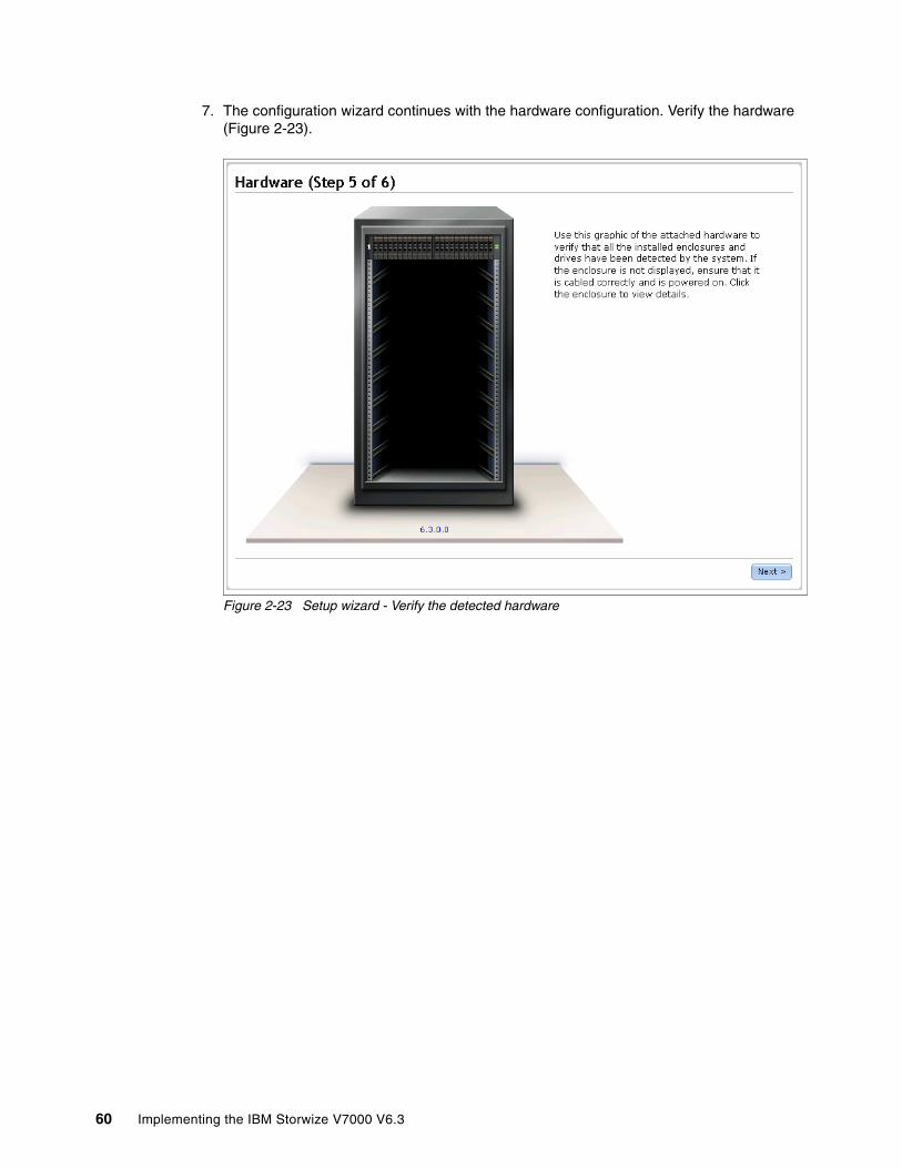
7. The configuration wizard continues with the hardware configuration. Verify the hardware (Figure 2-23).
Figure 2-23 Setup wizard - Verify the detected hardware
60 Implementing the IBM Storwize V7000 V6.3

8. After you click Next, an Add Enclosure window opens. Wait until The task completed windows opens (Figure 2-24).
Figure 2-24 Setup wizard - Task completed
Chapter 2. Initial configuration 61
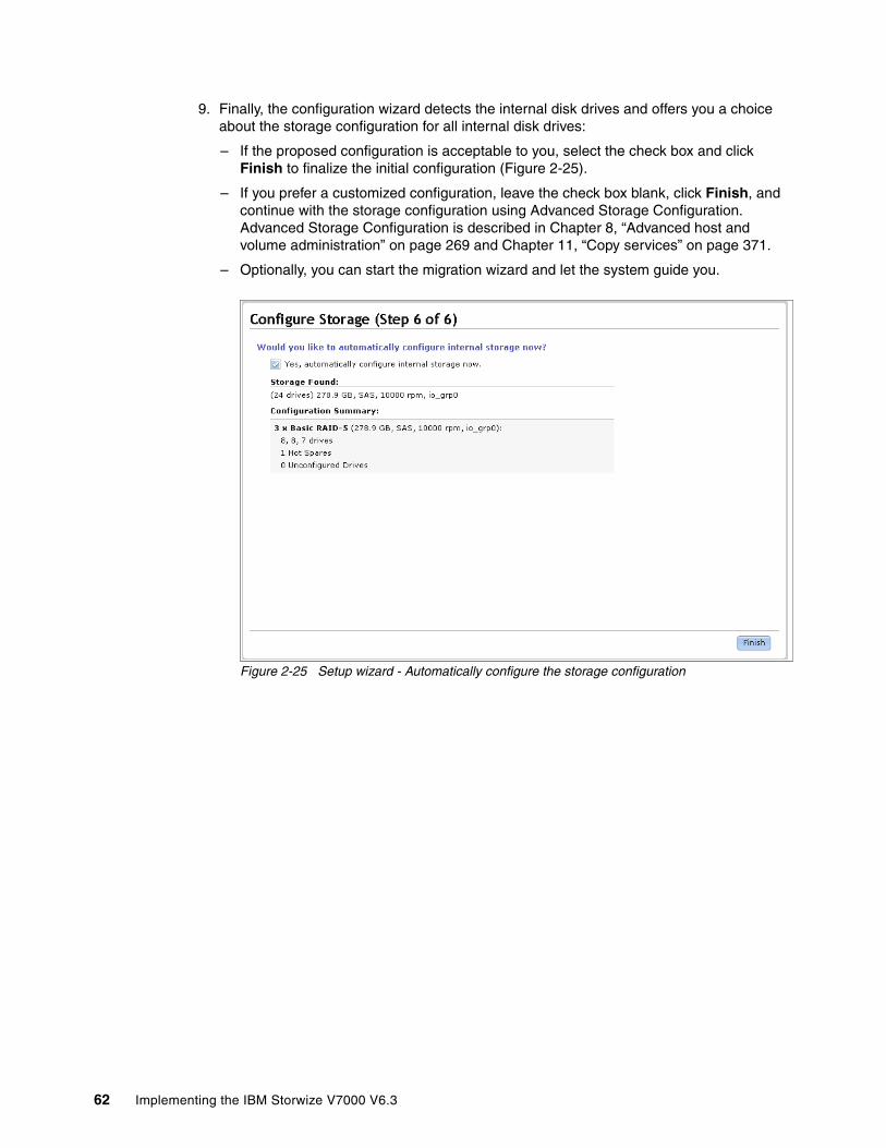
9. Finally, the configuration wizard detects the internal disk drives and offers you a choice about the storage configuration for all internal disk drives:
– If the proposed configuration is acceptable to you, select the check box and click Finish to finalize the initial configuration (Figure 2-25).
– If you prefer a customized configuration, leave the check box blank, click Finish, and continue with the storage configuration using Advanced Storage Configuration. Advanced Storage Configuration is described in Chapter 8, “Advanced host and volume administration” on page 269 and Chapter 11, “Copy services” on page 371.
– Optionally, you can start the migration wizard and let the system guide you.
Figure 2-25 Setup wizard - Automatically configure the storage configuration
62 Implementing the IBM Storwize V7000 V6.3

After you click Finish, a Synchronizing memory cache window opens. Wait until the task completed window opens (Figure 2-26).
Figure 2-26 Setup wizard - Task completed
Chapter 2. Initial configuration 63

You have now successfully finalized the initial configuration wizard for the IBM Storwize V7000 system. Figure 2-27 shows the Getting Started window.
Figure 2-27 IBM Storwize V7000 - Getting Started window
64 Implementing the IBM Storwize V7000 V6.3
Chapter 3. Graphical user interface overview
This chapter provides an overview of the graphical user interface for IBM Storwize V7000 and shows how to use the navigation tools.
3
© Copyright IBM Corp. 2011, 2012. All rights reserved. 65
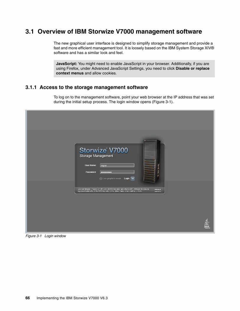
3.1 Overview of IBM Storwize V7000 management software
The new graphical user interface is designed to simplify storage management and provide a fast and more efficient management tool. It is loosely based on the IBM System Storage XIV® software and has a similar look and feel.
3.1.1 Access to the storage management software
To log on to the management software, point your web browser at the IP address that was set during the initial setup process. The login window opens (Figure 3-1).
Figure 3-1 Login window
JavaScript: You might need to enable JavaScript in your browser. Additionally, if you are using Firefox, under Advanced JavaScript Settings, you need to click Disable or replace context menus and allow cookies.
66 Implementing the IBM Storwize V7000 V6.3
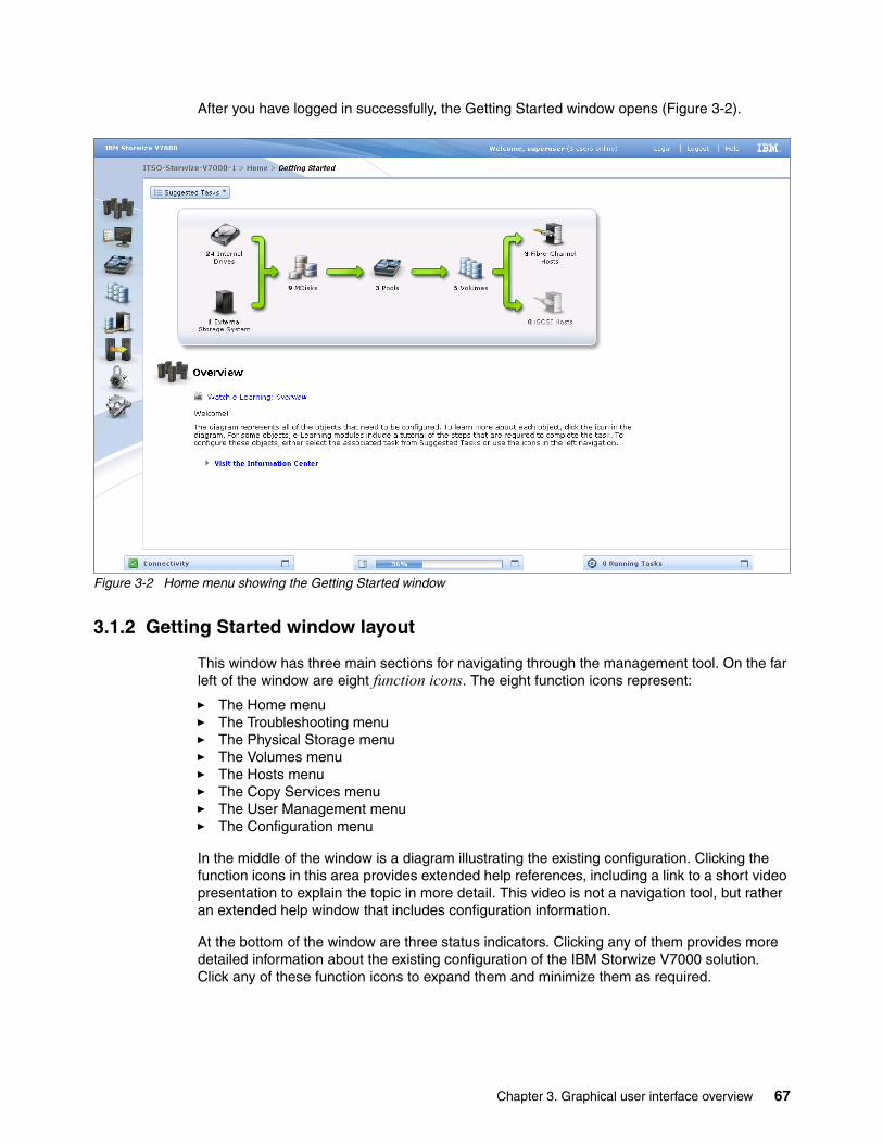
After you have logged in successfully, the Getting Started window opens (Figure 3-2).
Figure 3-2 Home menu showing the Getting Started window
3.1.2 Getting Started window layout
This window has three main sections for navigating through the management tool. On the far left of the window are eight function icons. The eight function icons represent:
� The Home menu� The Troubleshooting menu� The Physical Storage menu� The Volumes menu� The Hosts menu� The Copy Services menu� The User Management menu� The Configuration menu
In the middle of the window is a diagram illustrating the existing configuration. Clicking the function icons in this area provides extended help references, including a link to a short video presentation to explain the topic in more detail. This video is not a navigation tool, but rather an extended help window that includes configuration information.
At the bottom of the window are three status indicators. Clicking any of them provides more detailed information about the existing configuration of the IBM Storwize V7000 solution. Click any of these function icons to expand them and minimize them as required.
Chapter 3. Graphical user interface overview 67
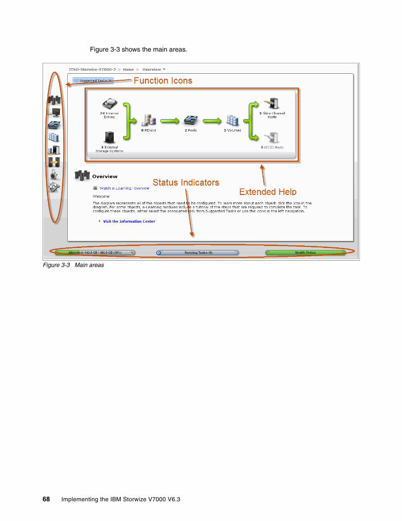
Figure 3-3 shows the main areas.
Figure 3-3 Main areas
68 Implementing the IBM Storwize V7000 V6.3
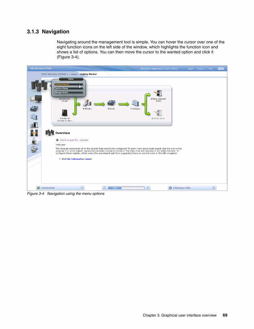
3.1.3 Navigation
Navigating around the management tool is simple. You can hover the cursor over one of the eight function icons on the left side of the window, which highlights the function icon and shows a list of options. You can then move the cursor to the wanted option and click it (Figure 3-4).
Figure 3-4 Navigation using the menu options
Chapter 3. Graphical user interface overview 69

An alternative method is to click the wanted function icon, which opens the corresponding window (Figure 3-5).
Figure 3-5 Navigation using the menu tabs
70 Implementing the IBM Storwize V7000 V6.3
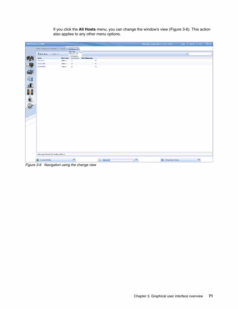
If you click the All Hosts menu, you can change the window’s view (Figure 3-6). This action also applies to any other menu options.
Figure 3-6 Navigation using the change view
Chapter 3. Graphical user interface overview 71
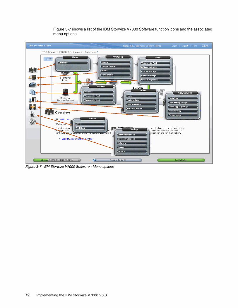
Figure 3-7 shows a list of the IBM Storwize V7000 Software function icons and the associated menu options.
Figure 3-7 BM Storwize V7000 Software - Menu options
72 Implementing the IBM Storwize V7000 V6.3

3.1.4 Multiple selections
The new management tool also lets you select multiple items by using a combination of the Shift or Ctrl keys. To select multiple items in a display, click the first item, press and hold the Shift key, and click the last item in the list you require. All the items in between those two items are selected (Figure 3-8).
Figure 3-8 Multiple selections using the Shift key
Chapter 3. Graphical user interface overview 73
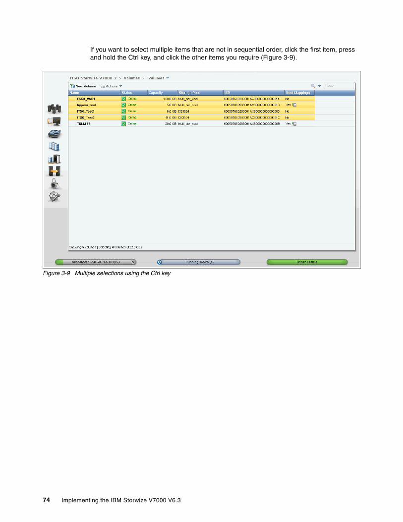
If you want to select multiple items that are not in sequential order, click the first item, press and hold the Ctrl key, and click the other items you require (Figure 3-9).
Figure 3-9 Multiple selections using the Ctrl key
74 Implementing the IBM Storwize V7000 V6.3

3.1.5 Status Indicators menus
Other useful tools are the Status Indicator menus that appear at the bottom of the window (Figure 3-10). These menus can be maximized and minimized and provide links to connectivity options, a storage allocation window, and a window of long running tasks.
Figure 3-10 Status Indicators menus
Chapter 3. Graphical user interface overview 75

You can view the details of the running task by clicking the status indicator bars at the bottom of the window (Figure 3-11).
Figure 3-11 Show running task details window
76 Implementing the IBM Storwize V7000 V6.3

3.2 Home menu
The IBM Storwize V7000 management software provides an efficient and quick mechanism for navigating between the various different functions. Clicking one of the eight function icons on the left side of the window causes a menu option to open that allows you to navigate directly to the selected option (Figure 3-12).
Figure 3-12 Navigate to the Home menu
Chapter 3. Graphical user interface overview 77

3.2.1 Monitoring System menu
The System menu is useful for identifying configuration information about the IBM Storwize V7000 solution. This window shows a bar on the left that lists the physical and usable capacity of the system when you hover the cursor over it (Figure 3-13). Figure 3-13 also shows the control enclosure and any expansion enclosures of the IBM Storwize V7000 solution.
Figure 3-13 System Status window showing allocated capacity
78 Implementing the IBM Storwize V7000 V6.3
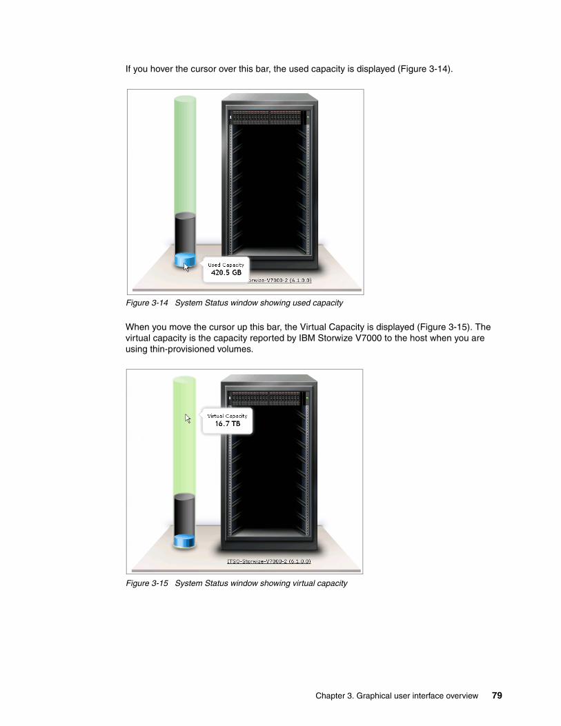
If you hover the cursor over this bar, the used capacity is displayed (Figure 3-14).
Figure 3-14 System Status window showing used capacity
When you move the cursor up this bar, the Virtual Capacity is displayed (Figure 3-15). The virtual capacity is the capacity reported by IBM Storwize V7000 to the host when you are using thin-provisioned volumes.
Figure 3-15 System Status window showing virtual capacity
Chapter 3. Graphical user interface overview 79

The System Status menu can also display the status of the various IBM Storwize V7000 components. By clicking the enclosure and then hovering the cursor over the affected drive, a status report is displayed for the drive in question (Figure 3-16).
Figure 3-16 System Status window showing an enclosure
80 Implementing the IBM Storwize V7000 V6.3

When you click the cluster name at the bottom of the IBM Storwize V7000 picture, more detailed configuration information is displayed (Figure 3-17).
Figure 3-17 System Status window showing cluster information
Chapter 3. Graphical user interface overview 81
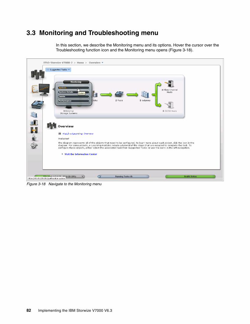
3.3 Monitoring and Troubleshooting menu
In this section, we describe the Monitoring menu and its options. Hover the cursor over the Troubleshooting function icon and the Monitoring menu opens (Figure 3-18).
Figure 3-18 Navigate to the Monitoring menu
82 Implementing the IBM Storwize V7000 V6.3

3.3.1 Recommended Actions menu
Clicking Recommended Actions opens the window shown in Figure 3-19. This window lists any events that have occurred that might impact the IBM Storwize V7000 solution. To fix an event, click Run Fix Procedure, and a Directed Maintenance Procedure (DMP) starts that walks you through the process to fix that particular event.
Figure 3-19 Recommended Actions menu
Chapter 3. Graphical user interface overview 83
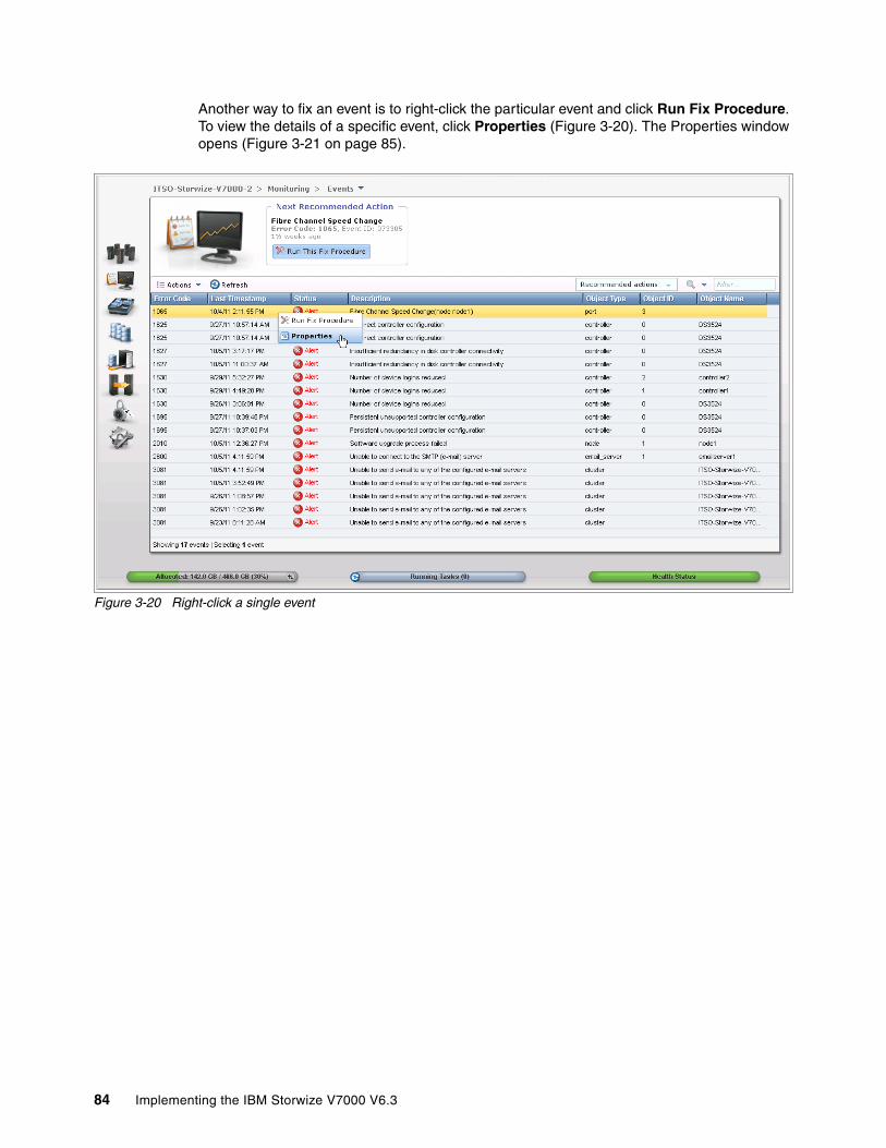
Another way to fix an event is to right-click the particular event and click Run Fix Procedure. To view the details of a specific event, click Properties (Figure 3-20). The Properties window opens (Figure 3-21 on page 85).
Figure 3-20 Right-click a single event
84 Implementing the IBM Storwize V7000 V6.3

Figure 3-21 Properties of the event
Chapter 3. Graphical user interface overview 85
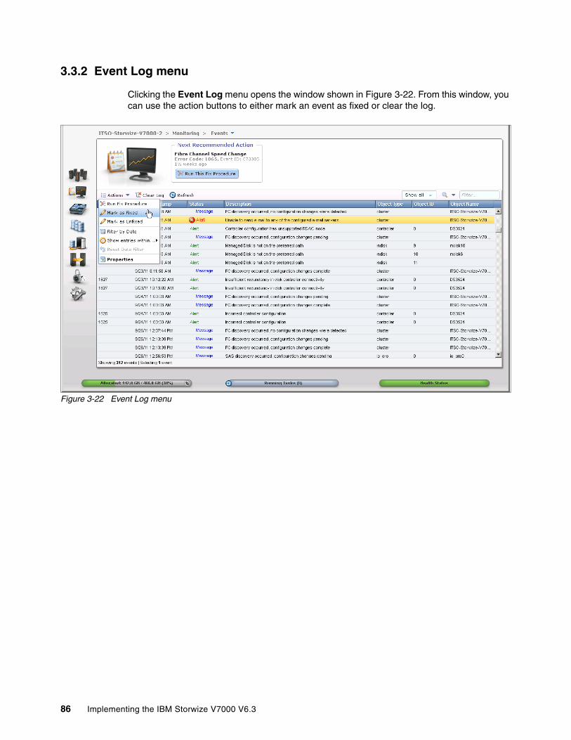
3.3.2 Event Log menu
Clicking the Event Log menu opens the window shown in Figure 3-22. From this window, you can use the action buttons to either mark an event as fixed or clear the log.
Figure 3-22 Event Log menu
86 Implementing the IBM Storwize V7000 V6.3
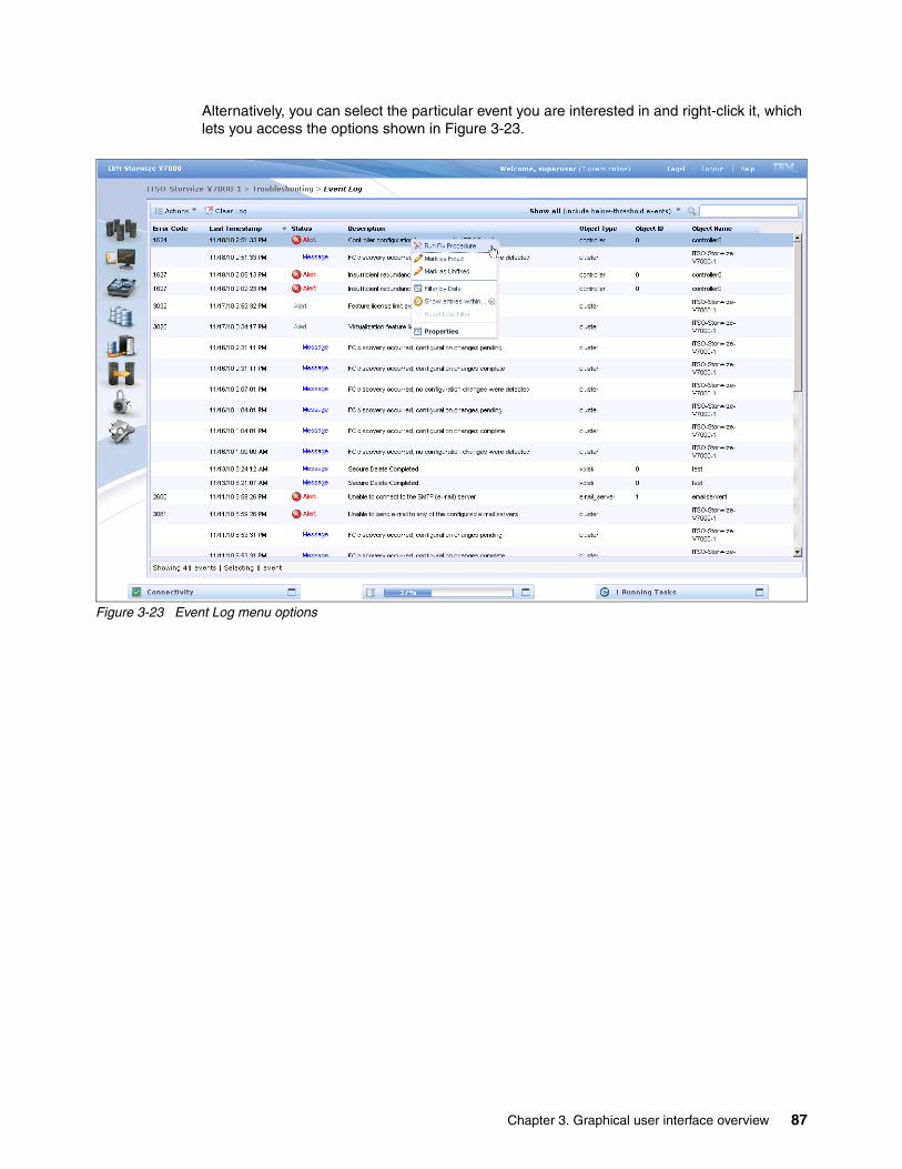
Alternatively, you can select the particular event you are interested in and right-click it, which lets you access the options shown in Figure 3-23.
Figure 3-23 Event Log menu options
Chapter 3. Graphical user interface overview 87

3.3.3 Support menu
Clicking Support opens the window shown in Figure 3-24. From this window, click Show full log listing to show all the log files.
Figure 3-24 Support menu
88 Implementing the IBM Storwize V7000 V6.3

You can download any of the various log files or delete them by selecting a single item (Figure 3-25) and click either the Download or Delete options under the Actions button.
Figure 3-25 Download / Delete options of the Actions button
Delete option: When the Delete option is not available, the file cannot be deleted because it is a file being used by the system.
Chapter 3. Graphical user interface overview 89

At the upper right of the window, there is a Node option that can be used to show node canister 1 or 2 log files (Figure 3-26).
Figure 3-26 Change the log listing of the Nodes canister
90 Implementing the IBM Storwize V7000 V6.3

Clicking Download Support Package opens the window shown in Figure 3-27. This window provides a number of different options that can be used to collect logs and save state information from the cluster.
Figure 3-27 Download a support package
Chapter 3. Graphical user interface overview 91
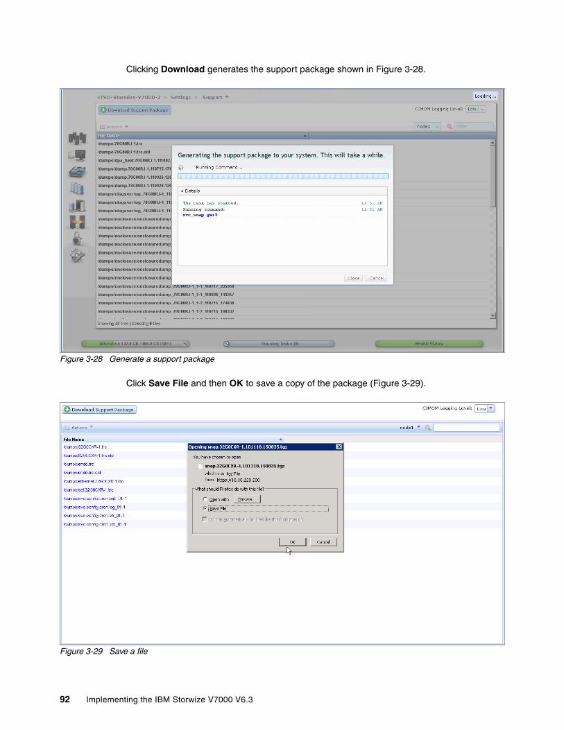
Clicking Download generates the support package shown in Figure 3-28.
Figure 3-28 Generate a support package
Click Save File and then OK to save a copy of the package (Figure 3-29).
Figure 3-29 Save a file
92 Implementing the IBM Storwize V7000 V6.3
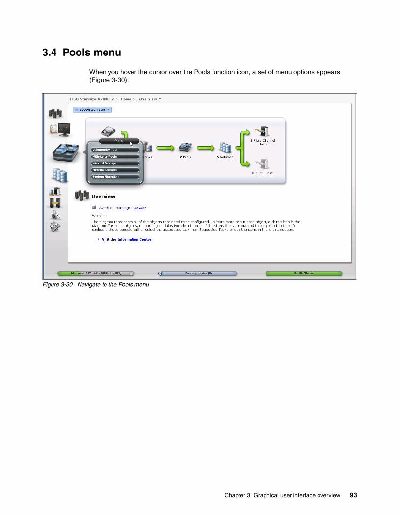
3.4 Pools menu
When you hover the cursor over the Pools function icon, a set of menu options appears (Figure 3-30).
Figure 3-30 Navigate to the Pools menu
Chapter 3. Graphical user interface overview 93

3.4.1 Internal menu
Clicking the Internal option opens the window shown in Figure 3-31. From this window, you can place internal disk drives into storage pools. This window also provides the option to display the internal drives based on their capacity and speed.
Figure 3-31 Internal storage window
94 Implementing the IBM Storwize V7000 V6.3
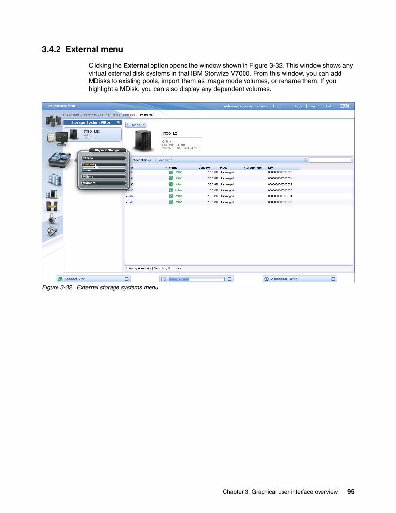
3.4.2 External menu
Clicking the External option opens the window shown in Figure 3-32. This window shows any virtual external disk systems in that IBM Storwize V7000. From this window, you can add MDisks to existing pools, import them as image mode volumes, or rename them. If you highlight a MDisk, you can also display any dependent volumes.
Figure 3-32 External storage systems menu
Chapter 3. Graphical user interface overview 95
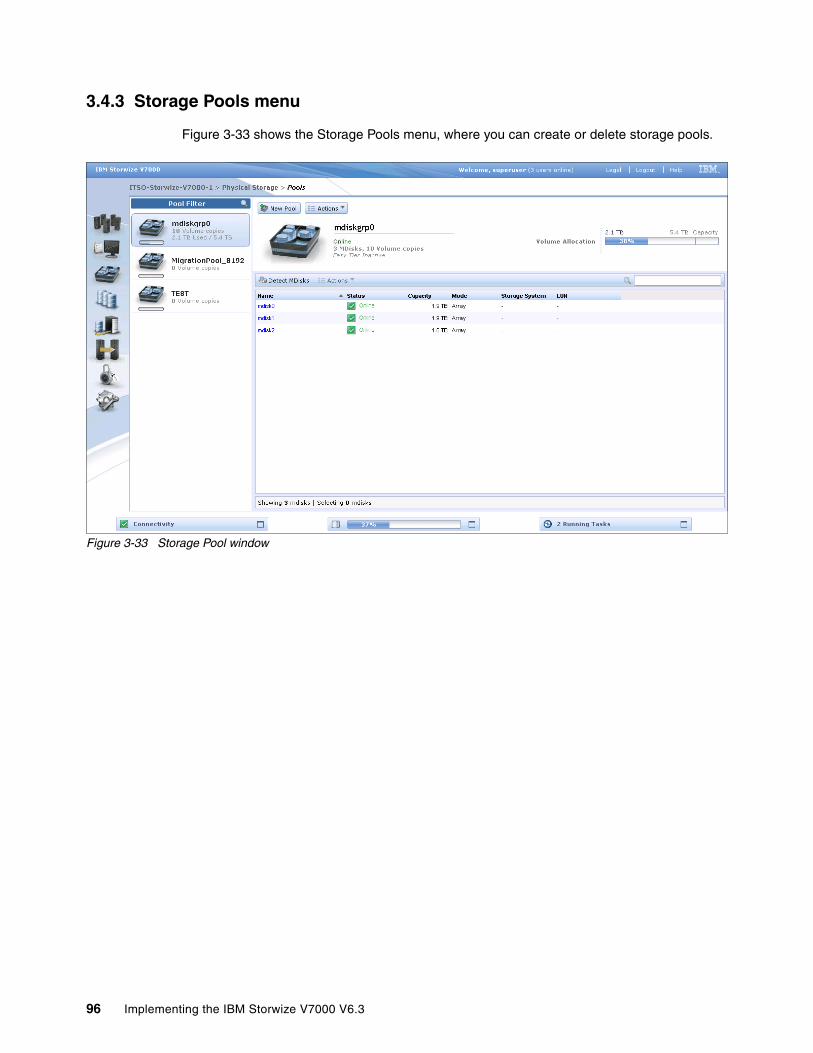
3.4.3 Storage Pools menu
Figure 3-33 shows the Storage Pools menu, where you can create or delete storage pools.
Figure 3-33 Storage Pool window
96 Implementing the IBM Storwize V7000 V6.3

3.4.4 MDisks menu
Figure 3-34 shows the MDisks that are available to the IBM Storwize V7000 system. The MDisks show whether they are managed, in which case the storage pool is displayed, or whether they are unmanaged, in which case the storage pools can be added to a new pool.
Figure 3-34 MDisk window
Chapter 3. Graphical user interface overview 97
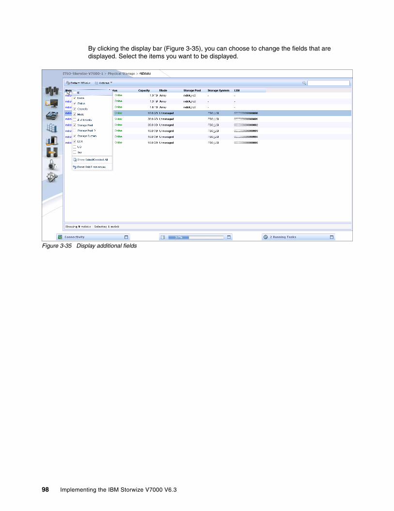
By clicking the display bar (Figure 3-35), you can choose to change the fields that are displayed. Select the items you want to be displayed.
Figure 3-35 Display additional fields
98 Implementing the IBM Storwize V7000 V6.3
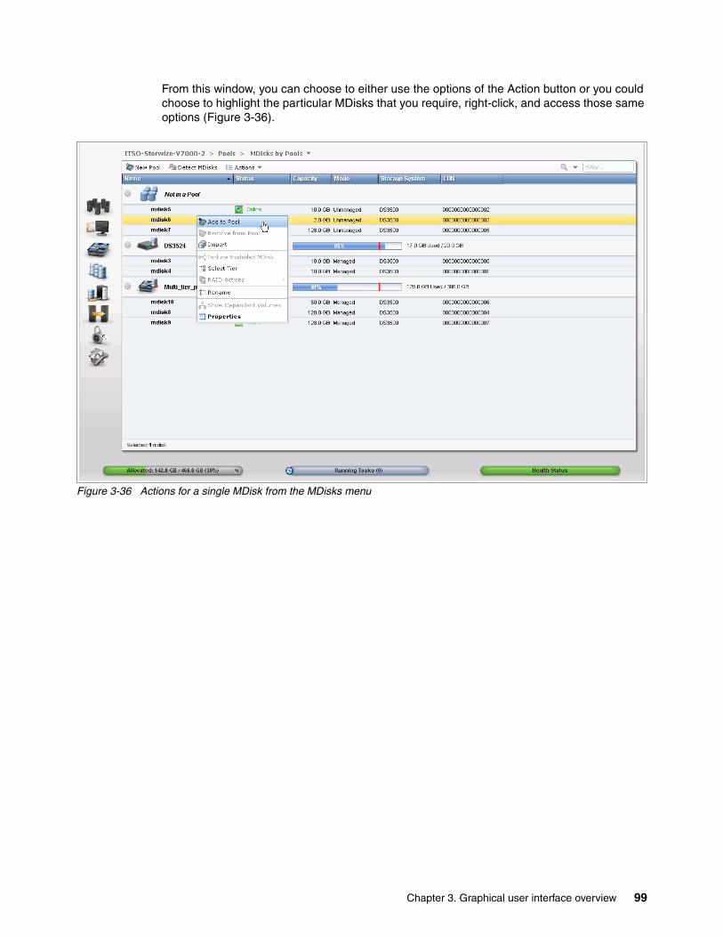
From this window, you can choose to either use the options of the Action button or you could choose to highlight the particular MDisks that you require, right-click, and access those same options (Figure 3-36).
Figure 3-36 Actions for a single MDisk from the MDisks menu
Chapter 3. Graphical user interface overview 99

3.5 Volumes menu
In this section, we describe the Volumes menu and its options. When you hover the cursor over the Volumes function icon, the menu shown in Figure 3-37 opens.
Figure 3-37 Navigate to the Volumes menu
100 Implementing the IBM Storwize V7000 V6.3

3.5.1 All Volumes menu
Clicking the All Volumes menu opens the window shown in Figure 3-38. From here you can perform tasks on the volumes, such as shrink or enlarge them, map them to a host, or migrate a volume.
Figure 3-38 All Volumes window
Chapter 3. Graphical user interface overview 101
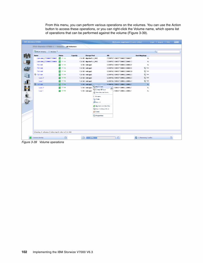
From this menu, you can perform various operations on the volumes. You can use the Action button to access these operations, or you can right-click the Volume name, which opens list of operations that can be performed against the volume (Figure 3-39).
Figure 3-39 Volume operations
102 Implementing the IBM Storwize V7000 V6.3

3.5.2 Volumes by Pool menu
Clicking the Volumes by Pool menu opens the window shown in Figure 3-40.
Figure 3-40 Volumes by Pool window
Chapter 3. Graphical user interface overview 103

Similar to the previous window, you can either use the Action button to access the menu operations or you can right-click the pool to display a list of valid commands (Figure 3-41).
Figure 3-41 Commands for a single volume from the Volume by Pool menu
104 Implementing the IBM Storwize V7000 V6.3

3.5.3 Volumes by Host menu
Clicking the Volumes by Host option opens the window shown in Figure 3-42. This window shows the volumes that have been mapped to a given host.
Figure 3-42 Volumes by Host window
Chapter 3. Graphical user interface overview 105

You can use the Action button or you can right-click the pool to show a list of valid commands (Figure 3-43).
Figure 3-43 Commands for a single volume from the Volume by Host menu
106 Implementing the IBM Storwize V7000 V6.3

3.6 Hosts menu
In this section, we describe the Hosts menu and its options. When you hover the cursor over the Host function icon, a menu opens (Figure 3-44).
Figure 3-44 Navigate to the Hosts menu
Chapter 3. Graphical user interface overview 107
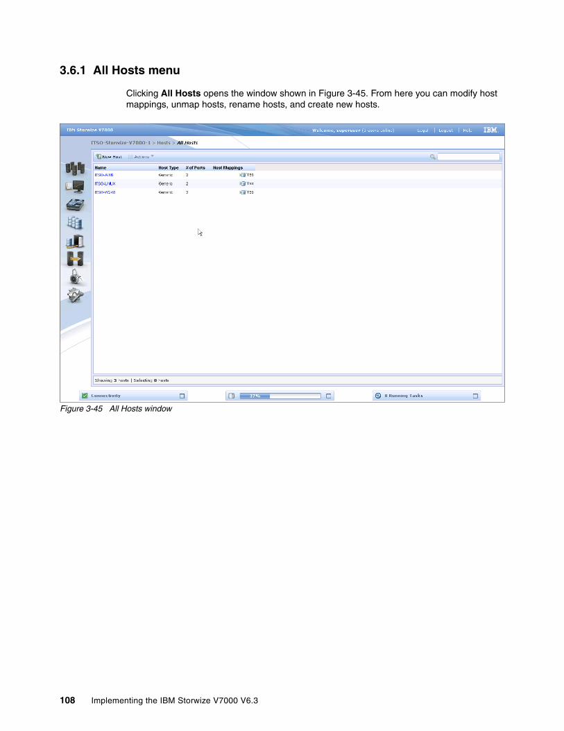
3.6.1 All Hosts menu
Clicking All Hosts opens the window shown in Figure 3-45. From here you can modify host mappings, unmap hosts, rename hosts, and create new hosts.
Figure 3-45 All Hosts window
108 Implementing the IBM Storwize V7000 V6.3
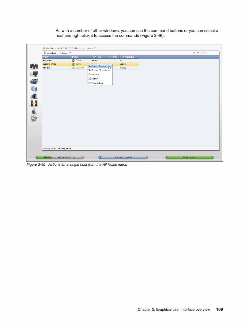
As with a number of other windows, you can use the command buttons or you can select a host and right-click it to access the commands (Figure 3-46).
Figure 3-46 Actions for a single host from the All Hosts menu
Chapter 3. Graphical user interface overview 109
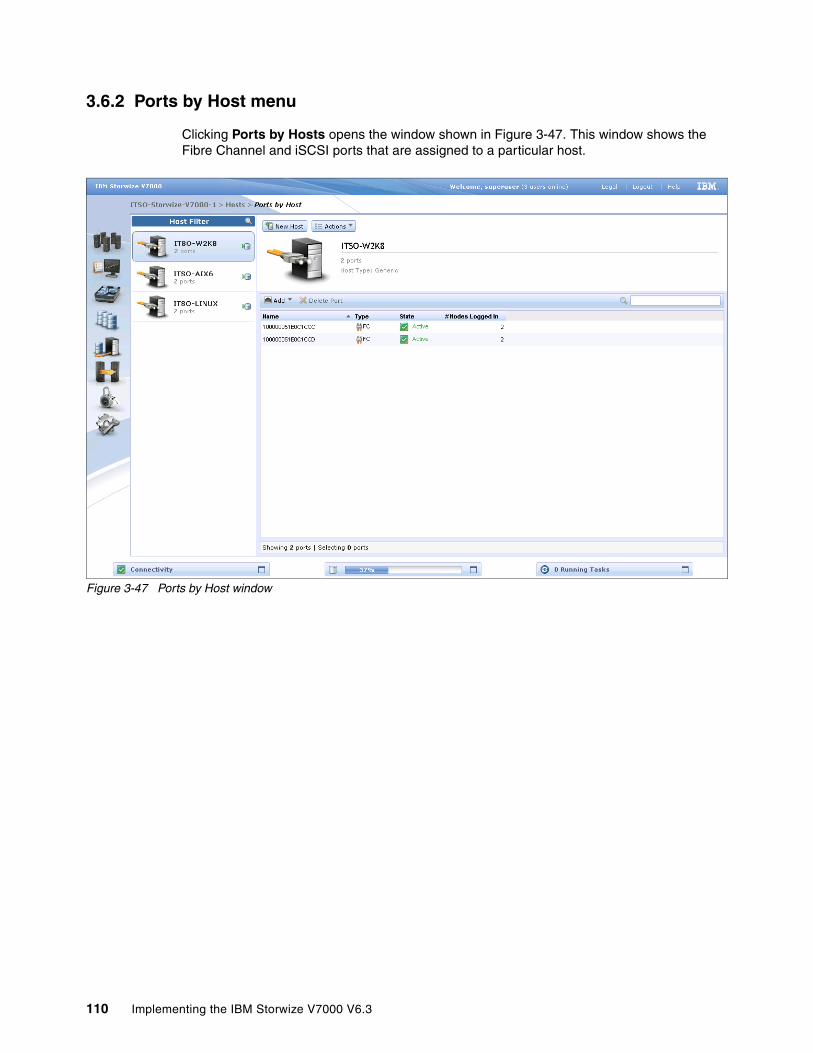
3.6.2 Ports by Host menu
Clicking Ports by Hosts opens the window shown in Figure 3-47. This window shows the Fibre Channel and iSCSI ports that are assigned to a particular host.
Figure 3-47 Ports by Host window
110 Implementing the IBM Storwize V7000 V6.3

Clicking the Actions button allows you to modify the mappings, unmap volumes, rename hosts, and delete ports (Figure 3-48).
Figure 3-48 Actions for a single host from the Ports by Host window
Chapter 3. Graphical user interface overview 111
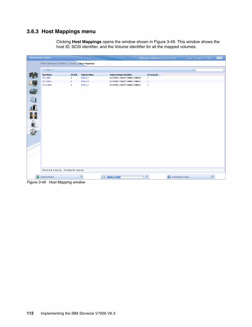
3.6.3 Host Mappings menu
Clicking Host Mappings opens the window shown in Figure 3-49. This window shows the host ID, SCSI identifier, and the Volume identifier for all the mapped volumes.
Figure 3-49 Host Mapping window
112 Implementing the IBM Storwize V7000 V6.3
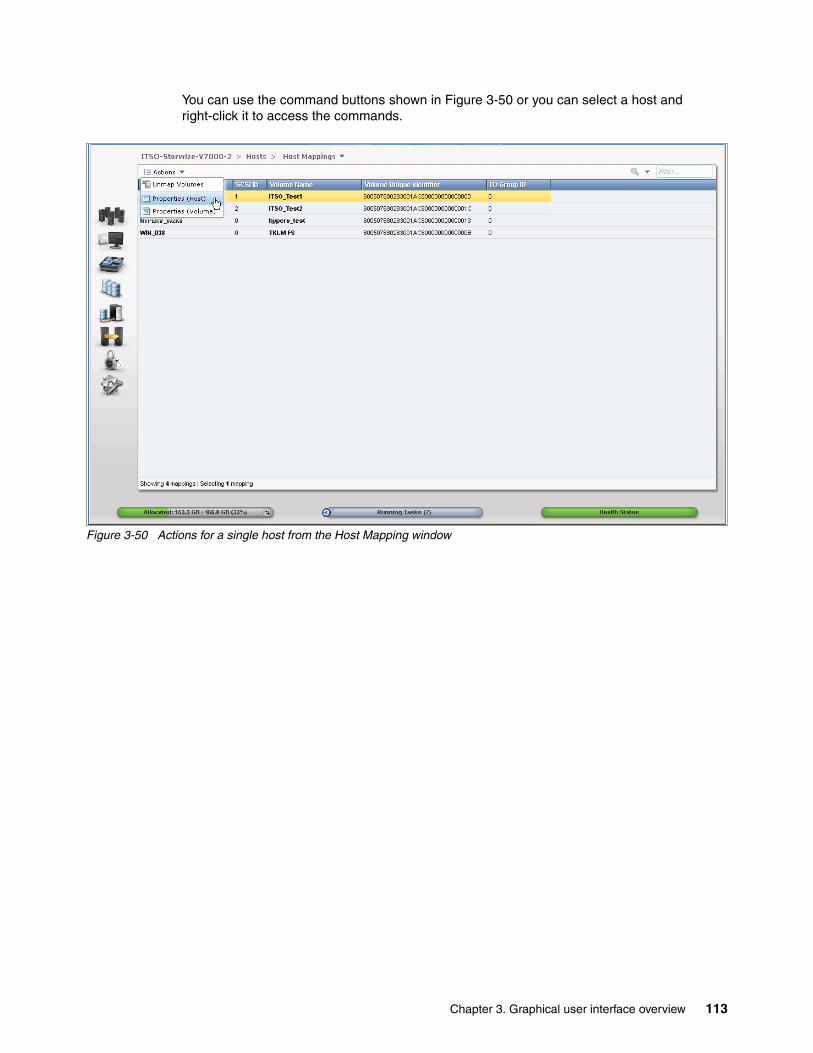
You can use the command buttons shown in Figure 3-50 or you can select a host and right-click it to access the commands.
Figure 3-50 Actions for a single host from the Host Mapping window
Chapter 3. Graphical user interface overview 113
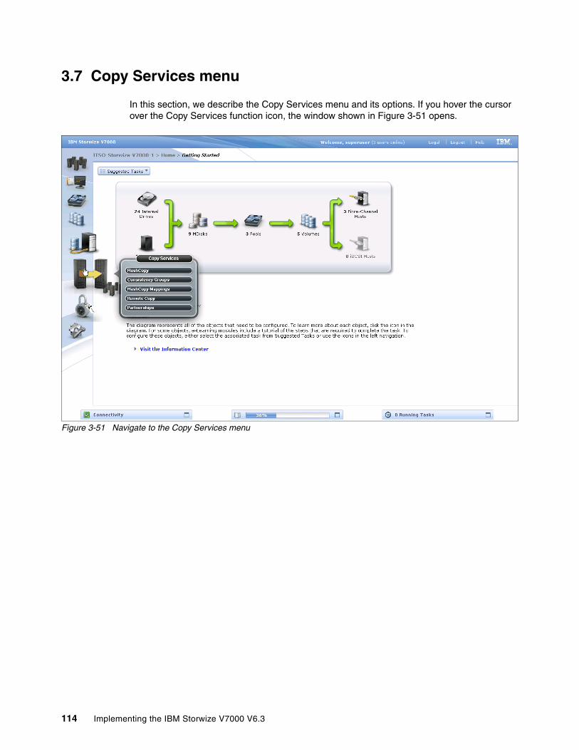
3.7 Copy Services menu
In this section, we describe the Copy Services menu and its options. If you hover the cursor over the Copy Services function icon, the window shown in Figure 3-51 opens.
Figure 3-51 Navigate to the Copy Services menu
114 Implementing the IBM Storwize V7000 V6.3
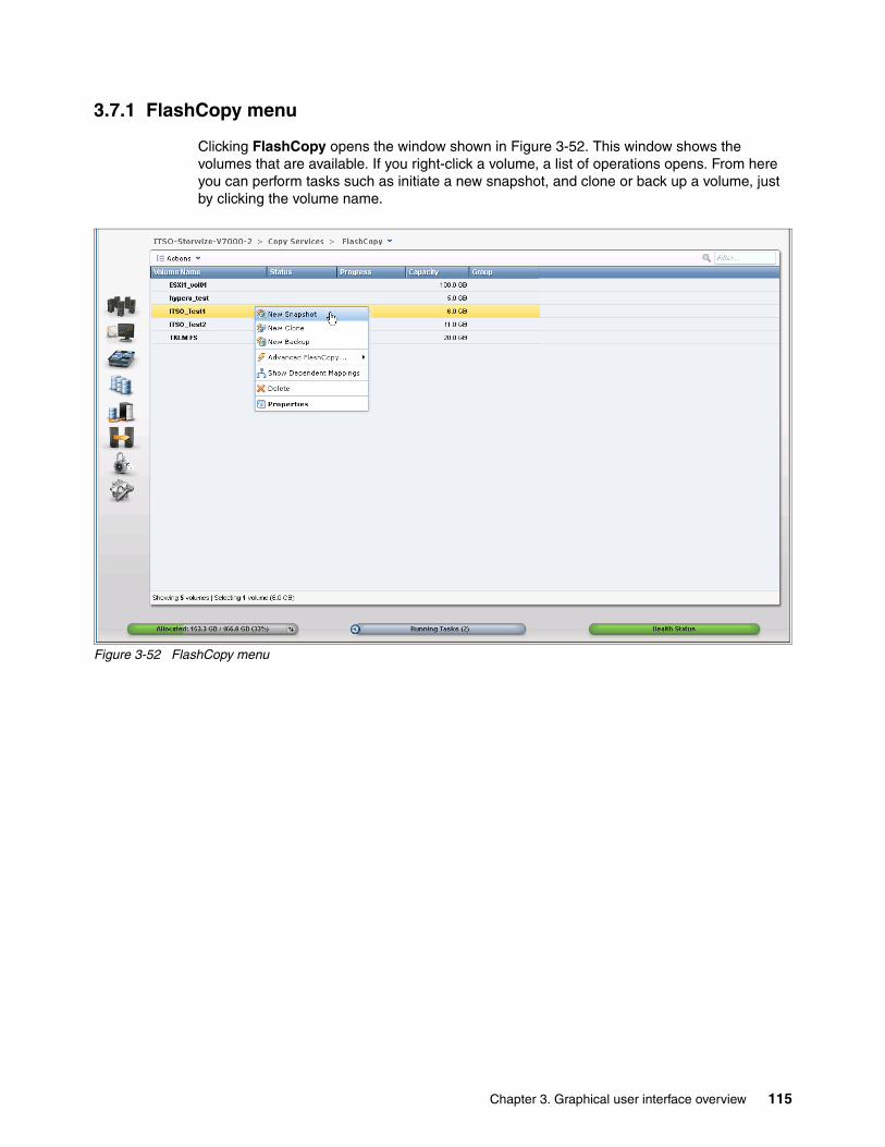
3.7.1 FlashCopy menu
Clicking FlashCopy opens the window shown in Figure 3-52. This window shows the volumes that are available. If you right-click a volume, a list of operations opens. From here you can perform tasks such as initiate a new snapshot, and clone or back up a volume, just by clicking the volume name.
Figure 3-52 FlashCopy menu
Chapter 3. Graphical user interface overview 115

Clicking the volume name opens the window shown in Figure 3-53. From here, you can click the tabs at the top of the window to display additional information, such as the hosts that the volume or FlashCopy volume is mapped to and its dependant MDisks.
Figure 3-53 FlashCopy volume details
Clicking the Action button initiates a mirrored copy of the volume or migrates it to a different storage pool.
116 Implementing the IBM Storwize V7000 V6.3
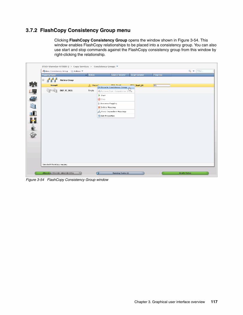
3.7.2 FlashCopy Consistency Group menu
Clicking FlashCopy Consistency Group opens the window shown in Figure 3-54. This window enables FlashCopy relationships to be placed into a consistency group. You can also use start and stop commands against the FlashCopy consistency group from this window by right-clicking the relationship.
Figure 3-54 FlashCopy Consistency Group window
Chapter 3. Graphical user interface overview 117
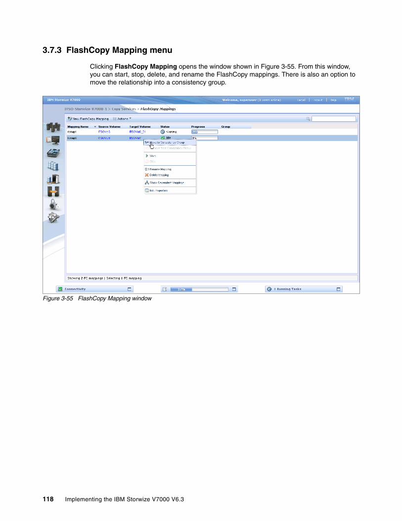
3.7.3 FlashCopy Mapping menu
Clicking FlashCopy Mapping opens the window shown in Figure 3-55. From this window, you can start, stop, delete, and rename the FlashCopy mappings. There is also an option to move the relationship into a consistency group.
Figure 3-55 FlashCopy Mapping window
118 Implementing the IBM Storwize V7000 V6.3

3.7.4 Remote Copy menu
Clicking Remote Copy opens the window shown in Figure 3-56. This window shows the existing Remote Copy relationships and allows you to set up and modify consistency groups. From this window, you can also start and stop relationships, add relationships to a consistency group, and switch the direction of the mirror.
Figure 3-56 Remote Copy window
Chapter 3. Graphical user interface overview 119

3.7.5 Partnerships menu
Clicking Partnerships opens the window shown in Figure 3-57. This window allows you to set up a new partnership or delete an existing partnership with another IBM Storwize V7000 system for the purposes of remote mirroring.
Figure 3-57 Partnerships window
From this window, we can also set the background copy rate. This rate specifies the bandwidth, in megabytes per second (MBps), that is used by the background copy process between the clusters.
120 Implementing the IBM Storwize V7000 V6.3

3.8 Access menu
In this section, we describe the Access menu and its options. If you hover the cursor over the Access function icon, a menu opens (Figure 3-58).
Figure 3-58 Access window
Chapter 3. Graphical user interface overview 121

3.8.1 Users menu
Figure 3-59 shows the Users window. This window enables you to create and delete new users, change and remove passwords, and add and remove SSH keys.
Figure 3-59 Users window
122 Implementing the IBM Storwize V7000 V6.3

Clicking New User opens the window shown in Figure 3-60. From here you can enter the name of the user and the password, and load the SSH key (if the SSH key has been generated). Starting with SAN Volume Controller V6.3m the SSH key is not required for CLI access, and you can choose either to use SSH or password for CLI authentication.
Figure 3-60 New User window
Chapter 3. Graphical user interface overview 123

3.8.2 Audit Log menu
Clicking Audit Log opens the window shown in Figure 3-61. The cluster maintains an audit log of successfully executed commands, indicating which users performed particular actions at certain times.
Figure 3-61 Audit Log menu
124 Implementing the IBM Storwize V7000 V6.3
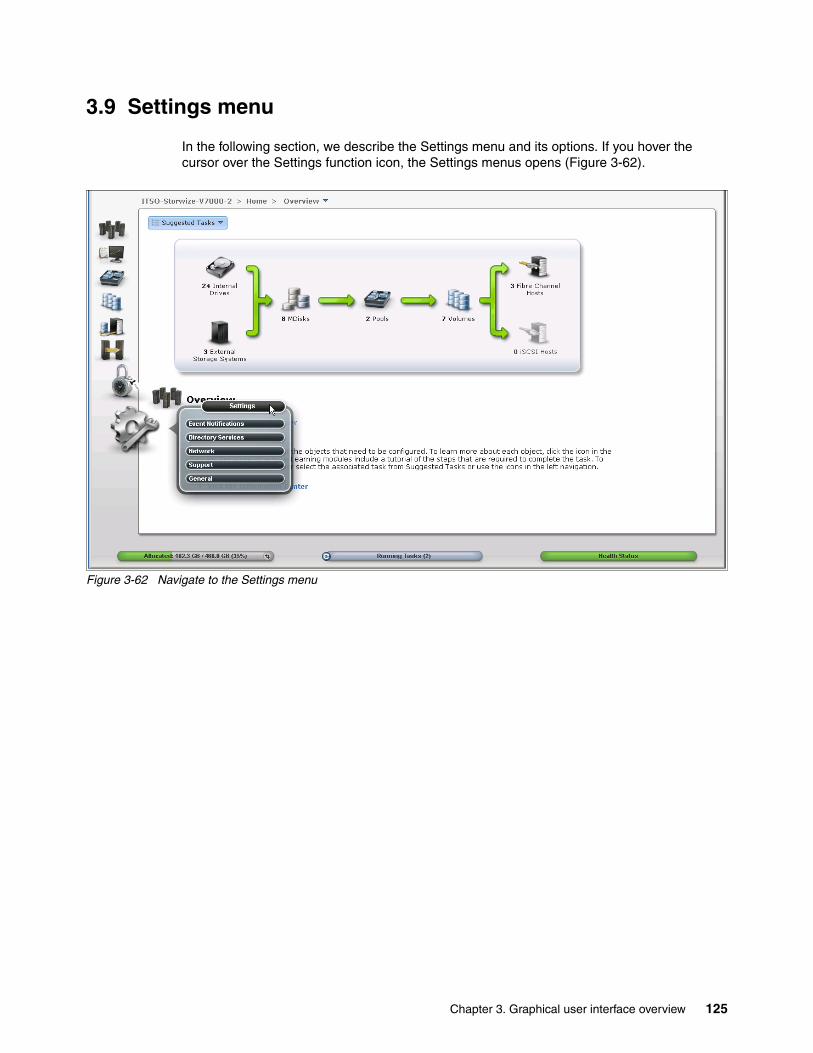
3.9 Settings menu
In the following section, we describe the Settings menu and its options. If you hover the cursor over the Settings function icon, the Settings menus opens (Figure 3-62).
Figure 3-62 Navigate to the Settings menu
Chapter 3. Graphical user interface overview 125

3.9.1 Network menu
Clicking Network opens the window shown in Figure 3-63. From here you can update the network configuration, set up iSCSI definitions, and view information about the Fibre Channel connections.
Figure 3-63 Network window
126 Implementing the IBM Storwize V7000 V6.3
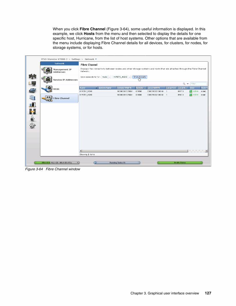
When you click Fibre Channel (Figure 3-64), some useful information is displayed. In this example, we click Hosts from the menu and then selected to display the details for one specific host, Hurricane, from the list of host systems. Other options that are available from the menu include displaying Fibre Channel details for all devices, for clusters, for nodes, for storage systems, or for hosts.
Figure 3-64 Fibre Channel window
Chapter 3. Graphical user interface overview 127
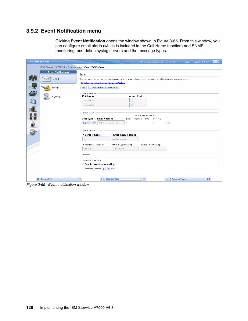
3.9.2 Event Notification menu
Clicking Event Notification opens the window shown in Figure 3-65. From this window, you can configure email alerts (which is included in the Call Home function) and SNMP monitoring, and define syslog servers and the message types.
Figure 3-65 Event notification window
128 Implementing the IBM Storwize V7000 V6.3

3.9.3 General menu
Clicking the General option opens the window shown in Figure 3-66. This window provides options to set the date and time, update the software licensing levels, upgrade the firmware, and set GUI preferences.
Figure 3-66 General window
Chapter 3. Graphical user interface overview 129

130 Implementing the IBM Storwize V7000 V6.3
Chapter 4. Host configuration
This chapter describes how to use the IBM Storwize V7000 GUI to create hosts, and how to prepare a host to access the volumes that are created. (Volume creation is described in Chapter 5, “Basic volume configuration” on page 159.)
4
© Copyright IBM Corp. 2011, 2012. All rights reserved. 131

4.1 Host attachment overview
A host system is an open-systems computer that is connected to the switch through a Fibre Channel or an iSCSI interface.
This chapter describes the following topics:
� Preparing the host operating system– Windows
• Fibre Channel (FC)• iSCSI
– VMware• Fibre Channel• iSCSI
� Creating hosts using the Storwize V7000 GUI– Creating FC hosts– Creating iSCSI hosts
In this chapter, we assume that your hosts are connected to your FC or IP network and you have completed the steps described in Chapter 2, “Initial configuration” on page 35. Follow basic zoning recommendations to ensure that each host has at least two network adapters, that each adapter is on a separate network (or at minimum in a separate zone), and is connected to both canisters. This setup assures four paths for failover and failback purposes.
Before mapping the newly created volumes on the host of your choice, a little preparation goes a long way towards ease of use and reliability. There are several steps required on a host in preparation for mapping new IBM Storwize V7000 volumes to the host. Use the System Storage Interoperation Center (SSIC) to check which code levels are supported to attach your host to your storage. SSIC is a web tool that checks the interoperation of host, storage, switches, and multipathing drivers. It can be found at the following address:
http://ibm.com/systems/support/storage/ssic/interoperability.wss
The complete support matrix is listed in the IBM Storwize V7000 Supported Hardware List, Device Driver, Firmware, and Recommended Software Levels V6.3 document, which is available at the following address:
http://ibm.com/support/docview.wss?uid=ssg1S1003907
This chapter focuses on Windows and VMware. If you must attach any other hosts, for example, IBM AIX®, Linux, or even an Apple system, then you can find the required information in the IBM Storwize V7000 Information Center at the following address:
http://publib.boulder.ibm.com/infocenter/storwize/ic/index.jsp
132 Implementing the IBM Storwize V7000 V6.3
4.2 Preparing the host operating system
In this section, we describe how to prepare Windows and VMware hosts for attachment to an IBM Storwize V7000, using either Fibre Channel or iSCSI to connect.
4.2.1 Windows 2008 (R2): Preparing for Fibre Channel attachment
Complete the following steps to prepare a Windows 2008 (R2) host to connect to an IBM Storwize V7000 using Fibre Channel:
1. Make sure that the latest OS service pack and test fixes are applied to your Microsoft server.
2. Use the latest firmware and driver levels on your host system.
3. Install HBA or HBAs on the Windows server using the latest BIOS and drivers.
4. Connect the FC Host Adapter ports to the switches.
5. Configure the switches (zoning).
6. Configure the HBA for hosts running Windows.
7. Set the Windows timeout value.
8. Install the multipath module.
Downloading and installing the supported drivers and firmwareInstall a supported HBA driver for your configuration. Use the Windows Device Manager or vendor tools such as Sansurfer (QLogic), HBAnyware (Emulex), or HBA Software Installer (Brocade) to install the driver. Also check and update the BIOS (firmware) level of the HBA using the manufacturer’s provided tools. Check the readme file to see if there are Windows registry parameters that should be set for the HBA driver.
The latest supported levels are available at the following address:
http://ibm.com/support/docview.wss?uid=ssg1S1003703#_Win2008
Configuring Brocade HBAs for WindowsThis section applies to Windows hosts that have Brocade HBAs installed. After installing the device driver and firmware, you must configure the HBAs. To perform this task, either use the Brocade HCM software or reboot into the HBA BIOS, load the adapter defaults, and set the following values:
� Host Adapter BIOS: Disabled (unless the host is configured for SAN Boot)� Queue depth: 4
Configuring QLogic HBAs for WindowsThis section applies to Windows hosts that have QLogic HBAs installed.
After installing the device driver and firmware, you must configure the HBAs. To perform this task, either use the QLogic Sansurfer software or reboot into the HBA BIOS, load the adapter defaults, and set the following values:
� Host Adapter BIOS: Disabled (unless the host is configured for SAN Boot)� Adapter Hard Loop ID: Disabled� Connection Options: 1 - point to point only� LUNs Per Target: 0� Port Down Retry Count: 15
Chapter 4. Host configuration 133

Configuring Emulex HBAs for WindowsThis section applies to Windows hosts that have Emulex HBAs installed.
After installing the device driver and firmware, you must configure the HBAs. To perform this task, either use the Emulex HBAnyware software or reboot into the HBA BIOS, load the defaults, and set topology to 1 (10F_Port Fabric).
Setting the Windows timeout valueFor Windows hosts, the disk I/O timeout value should be set to 60 seconds. To verify this setting, complete the following steps:
1. Click Start Run.
2. In the dialog box, type regedit and press Enter.
3. In the registry editor, locate the HKEY_LOCAL_MACHINE\System\CurrentControlSet\Services\Disk\TimeOutValue key.
4. Confirm that the value for the key is 60 (decimal value), and, if necessary, change the value to 60 (Figure 4-1).
Figure 4-1 Windows timeout value
Installing the multipathing softwareMicrosoft Multipath Input/Output (MPIO) solutions are designed to work with device-specific modules (DSMs) written by vendors, but the MPIO driver package does not, by itself, form a complete solution. This joint solution allows the storage vendors to design device-specific solutions that are tightly integrated with the Windows operating system. MPIO is not shipped with the Windows operating system; storage vendors must pack the MPIO drivers with their own DSM.
IBM Subsystem Device Driver DSM (SDDDSM) is the IBM multipath I/O solution that is based on Microsoft MPIO technology. It is a device-specific module designed to support IBM storage devices on Windows hosts. The intent of MPIO is to provide better integration of a multipath storage solution with the operating system, and it allows the use of multipath in the SAN infrastructure during the boot process for SAN Boot hosts.
To ensure correct multipathing with IBM Storwize V7000, SDDDSM must be installed on Windows hosts. To install SDDDSM, complete the following steps:
1. Check the SDDDSM download matrix to determine the correct level of SDDDSM to install for Windows 2008 (R2) and download the package from the following address:
http://ibm.com/support/docview.wss?uid=ssg1S7001350#WindowsSDDDSM
134 Implementing the IBM Storwize V7000 V6.3

2. Extract the package to your hard disk drive and run setup.exe to install SDDDSM. A command prompt window opens (Figure 4-2). Confirm the installation by entering Y.
Figure 4-2 SDDDSM setup
3. After the setup completes, you are prompted to restart the system. Confirm this restart by typing yes and pressing Enter (Figure 4-3).
Figure 4-3 Answer yes to restart the host
You have now successfully installed IBM SDDDSM. You can check the installed driver version if you select Start All Programs Subsystem Device Driver DSM Subsystem Device Driver DSM. A command prompt opens; run datapath query version to determine the version currently installed (Example 4-1) for this Windows 2008 R2 host.
Example 4-1 datapath query version
C:\Program Files\IBM\SDDDSM>datapath.exe query versionIBM SDDDSM Version 2.4.3.1-2Microsoft MPIO Version 6.1.7601.17514
This command can also be used to determine the WWPNs of the host. Run datapath query wwpn (Example 4-2) and note the WWPNs of your host, as you need them later.
Example 4-2 datapath query wwpn
C:\Program Files\IBM\SDDDSM>datapath.exe query wwpn Adapter Name PortWWN Scsi Port 7 100000051EC76B89 Scsi Port 7 100000051EC76B8A
Chapter 4. Host configuration 135

If you need more detailed information about SDDDSM, see Multipath Subsystem Device Driver User’s Guide, GC52-1309.
The Windows host has been prepared to connect to the IBM Storwize V7000 and you know the WWPNs of the host. The next step is to configure a host object for the WWPNs by using the IBM Storwize V7000 GUI. This task is explained in 4.3.1, “Creating Fibre Channel hosts” on page 150.
SAN Boot hosts are beyond the intended scope of this book. For more information about that topic, follow the steps in the Information Center available from the IBM Support Portal.
4.2.2 Windows 2008 R2: Preparing for iSCSI attachment
In Windows 2008 R2, the Microsoft iSCSI software initiator is preinstalled. Enter iscsi in the search field of the Windows start menu (Figure 4-4) and click iSCSI Initiator.
Figure 4-4 Windows iSCSI Initiator
Windows 2003: The examples focus on Windows 2008 R2, but the procedure for Windows 2003 is similar. If you use Windows 2003, do not forget to install Microsoft Hotfix 908980. If you do not install it before performing this procedure, preferred pathing is not available. You can download this hotfix at the following address:
http://support.microsoft.com/kb/908980
136 Implementing the IBM Storwize V7000 V6.3
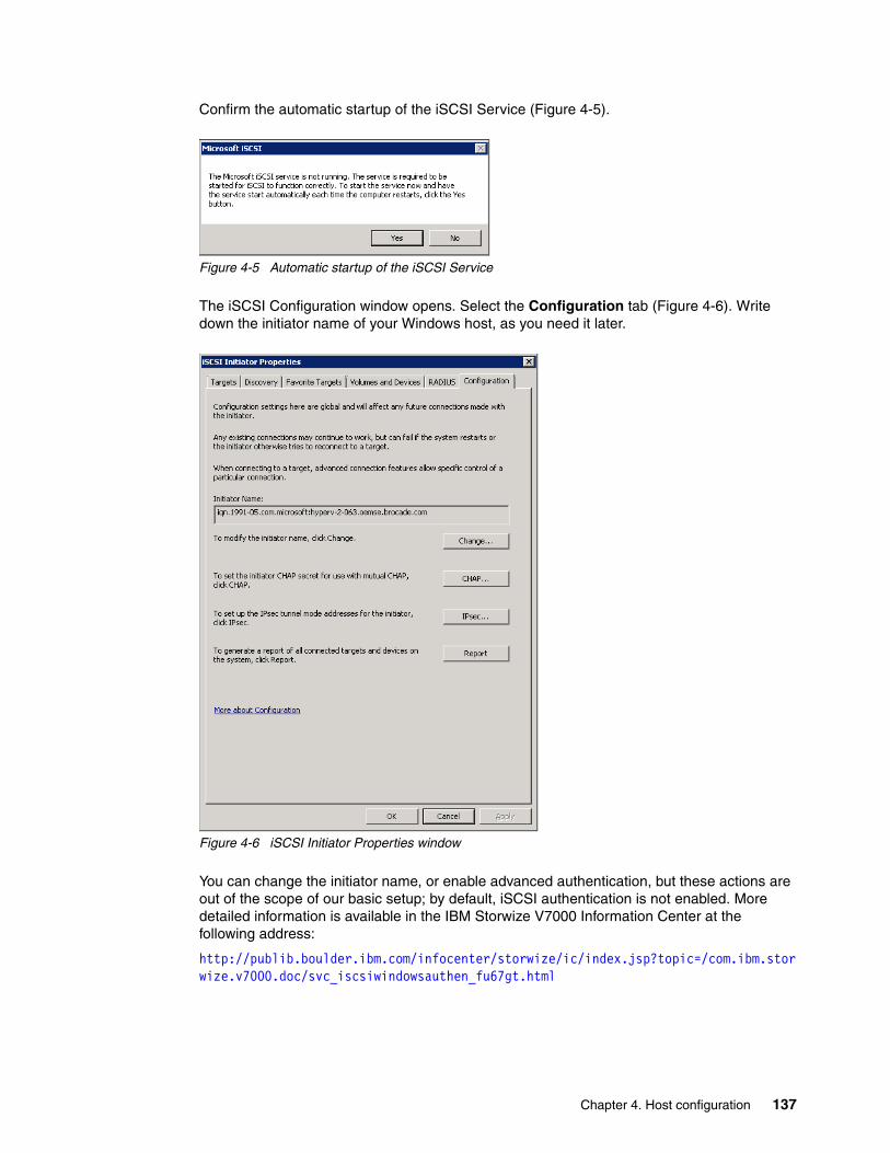
Confirm the automatic startup of the iSCSI Service (Figure 4-5).
Figure 4-5 Automatic startup of the iSCSI Service
The iSCSI Configuration window opens. Select the Configuration tab (Figure 4-6). Write down the initiator name of your Windows host, as you need it later.
Figure 4-6 iSCSI Initiator Properties window
You can change the initiator name, or enable advanced authentication, but these actions are out of the scope of our basic setup; by default, iSCSI authentication is not enabled. More detailed information is available in the IBM Storwize V7000 Information Center at the following address:
http://publib.boulder.ibm.com/infocenter/storwize/ic/index.jsp?topic=/com.ibm.storwize.v7000.doc/svc_iscsiwindowsauthen_fu67gt.html
Chapter 4. Host configuration 137
Setting the Windows registry keysYou should make the following changes to the system registry to make your iSCSI operations more reliable:
1. In the search field of the Windows Start menu, type regedit and click regedit.exe.
2. In the registry editor, locate the key HKEY_LOCAL_MACHINE\SYSTEM\CurrentControlSet\Control\Class\{4D36E97B-E325-11CE-BFC1-08002BE10318}\<bus ID>\Parameters\LinkDownTime.
Confirm that the value for the LinkDownTime key is 120 (decimal value), and, if necessary, change the value to 120.
3. In the registry editor, locate the HKEY_LOCAL_MACHINE\SYSTEM\CurrentControlSet\Control\Class\{4D36E97B-E325-11CE-BFC1-08002BE10318}\<bus ID>\Parameters\MaxRequestHoldTime key.
Confirm that the value for the MaxRequestHoldTime key is 120 (decimal value), and, if necessary, change the value to 120.
4. In the registry editor, locate the HKEY_LOCAL_MACHINE\SYSTEM\CurrentControlSet\Control\Class\{4D36E97B-E325-11CE-BFC1-08002BE10318}\<bus ID>\Parameters\ MaxPendingRequests key.
Confirm that the value for the MaxPendingRequests key is 2048 (decimal value), and, if necessary, change the value to 2048.
5. In the registry editor, locate the HKEY_LOCAL_MACHINE\SYSTEM\CurrentControlSet\Services\Disk\TimeOutValue key.
Confirm that the value for the TimeOutValue key is 60 (decimal value), and, if necessary, change the value to 60.
6. Reboot your host for these changes to take effect.
These steps are the basic steps to prepare a Windows 2008 R2 host for iSCSI attachment. To configure the IBM Storwize V7000 for iSCSI connections, see 4.3.2, “Creating iSCSI hosts” on page 154.
4.2.3 VMware ESX: Preparing for Fibre Channel attachment
Complete the following steps to prepare a VMware ESX host to connect to an IBM Storwize V7000 using Fibre Channel:
1. Install HBA or HBAs on the ESX server.2. Make sure that the latest firmware levels are applied on your host system.3. Update and configure the HBA for hosts running ESX.4. Connect the FC Host Adapter ports to the switches.5. Configure the switches (zoning).6. Install VMware ESX and load additional drivers if required.
Downloading and installing the supported firmwareInstall the latest firmware levels to your host server. For the HBAs, check the “IBM Storwize V7000 Supported Hardware List, Device Driver, Firmware, and Recommended Software Levels V6.3” list for VMware at the following address:
http://ibm.com/support/docview.wss?uid=ssg1S1003907#_VMware
138 Implementing the IBM Storwize V7000 V6.3
Download the latest supported HBA firmware for your configuration and apply it to your system. Some HBAs and especially the new CNA Adapters require an additional driver to be loaded into ESX. Check the VMware Compatibility Guide to see if there are any requirements for your configuration by going to the following address:
http://www.vmware.com/resources/compatibility/search.php
Configuring Brocade HBAs for VMware ESXThis section applies to ESX hosts that have Brocade HBAs installed. After installing the firmware, load the default settings of all your adapters installed on the host system and make sure that the Adapter BIOS is disabled, unless you are using SAN Boot.
Configuring QLogic HBAs for VMware ESXThis section applies to ESX hosts that have QLogic HBAs installed. After installing the firmware, you must configure the HBAs. To perform this task, either use the QLogic Sansurfer software or the HBA BIOS, load the adapter defaults, and set the following values:
� Host Adapter Settings:– Host Adapter BIOS: Disabled (unless the host is configured for SAN Boot)– Frame size: 2048– Loop Reset Delay: 5 (minimum)– Adapter Hard Loop ID: Disabled– Hard Loop ID: 0– Spinup Delay: Disabled– Connection Options 1: Point to point only– Fibre Channel Tape Support: Disabled– Data Rate: 2
� Advanced Adapter Settings– Execution throttle: 100– LUNs per Target: 0– Enable LIP Reset: No– Enable LIP Full Login: Yes– Enable Target Reset: Yes– Login Retry Count: 8– Link Down Timeout: 10– Command Timeout: 20– Extended event logging: Disabled (only enable it for debugging)– RIO Operation Mode: 0– Interrupt Delay Timer: 0
Configuring Emulex HBAs for VMware ESXThis section applies to ESX hosts that have Emulex HBAs installed. After installing the firmware, load the default settings of all your adapters installed on the host system and make sure that the Adapter BIOS is disabled, unless you are using SAN Boot.
VMware ESX installationInstall your VMware ESX server and load any additional drivers and patches if required. If you are not familiar with the procedure, you can find a detailed installation guide at the following address:
http://www.vmware.com/pdf/vsphere4/r40/vsp_40_esx_vc_installation_guide.pdf
Chapter 4. Host configuration 139
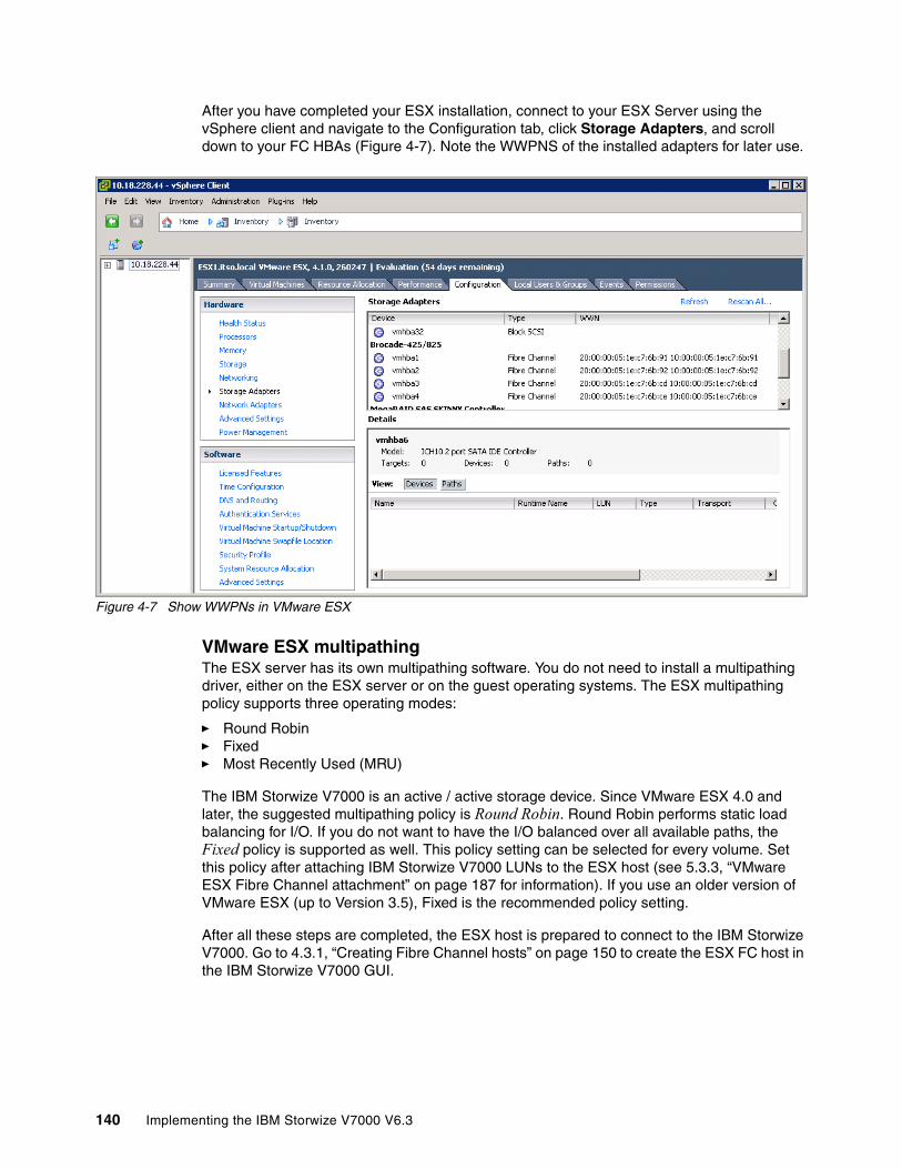
After you have completed your ESX installation, connect to your ESX Server using the vSphere client and navigate to the Configuration tab, click Storage Adapters, and scroll down to your FC HBAs (Figure 4-7). Note the WWPNS of the installed adapters for later use.
Figure 4-7 Show WWPNs in VMware ESX
VMware ESX multipathingThe ESX server has its own multipathing software. You do not need to install a multipathing driver, either on the ESX server or on the guest operating systems. The ESX multipathing policy supports three operating modes:
� Round Robin� Fixed� Most Recently Used (MRU)
The IBM Storwize V7000 is an active / active storage device. Since VMware ESX 4.0 and later, the suggested multipathing policy is Round Robin. Round Robin performs static load balancing for I/O. If you do not want to have the I/O balanced over all available paths, the Fixed policy is supported as well. This policy setting can be selected for every volume. Set this policy after attaching IBM Storwize V7000 LUNs to the ESX host (see 5.3.3, “VMware ESX Fibre Channel attachment” on page 187 for information). If you use an older version of VMware ESX (up to Version 3.5), Fixed is the recommended policy setting.
After all these steps are completed, the ESX host is prepared to connect to the IBM Storwize V7000. Go to 4.3.1, “Creating Fibre Channel hosts” on page 150 to create the ESX FC host in the IBM Storwize V7000 GUI.
140 Implementing the IBM Storwize V7000 V6.3

4.2.4 VMware ESX: Preparing for iSCSI attachment
This section describes how to enable iSCSI on VMware ESX hosts. In this book, we focus on vSphere (ESX 4.0 and later) because the complete iSCSI stack has been rewritten in this level, offers improved performance, and supports useful features, such as jumbo frames and TCP Segmentation Offload. In this book, we focus on the basic ESX iSCSI setup; more detailed information is provided in the VMware iSCSI SAN Configuration Guide, which is available at the following address:
http://www.vmware.com/pdf/vsphere4/r40/vsp_40_iscsi_san_cfg.pdf
Complete the following steps to prepare a VMware ESX host to connect to an IBM Storwize V7000 using iSCSI:
1. Make sure that the latest firmware levels are applied on your host system.
2. Install VMware ESX and load additional drivers if required.
3. Connect the ESX server to your network. You should use separate network interfaces for iSCSI traffic.
4. Configure your network to fulfill your security and performance requirements.
The iSCSI initiator is installed by default on your ESX server, and you only have to enable it. To enable it, complete the following steps:
1. Connect to your ESX server using the vSphere Client, navigate to Configuration, and select Networking (Figure 4-8).
Figure 4-8 Select VMware networking
Chapter 4. Host configuration 141

2. Click Add Networking to start the Add Network Wizard (Figure 4-9). Select VMkernel and click Next.
Figure 4-9 VMware - Add Network Wizard
142 Implementing the IBM Storwize V7000 V6.3

3. Select one or more network interfaces that you want to use for iSCSI traffic and click Next (Figure 4-10).
Figure 4-10 VMware - Select an iSCSI interface
Chapter 4. Host configuration 143
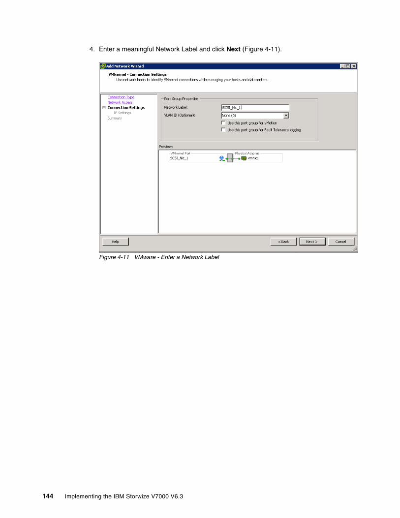
4. Enter a meaningful Network Label and click Next (Figure 4-11).
Figure 4-11 VMware - Enter a Network Label
144 Implementing the IBM Storwize V7000 V6.3
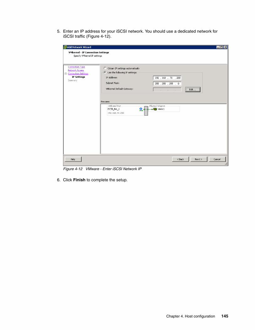
5. Enter an IP address for your iSCSI network. You should use a dedicated network for iSCSI traffic (Figure 4-12).
Figure 4-12 VMware - Enter iSCSI Network IP
6. Click Finish to complete the setup.
Chapter 4. Host configuration 145
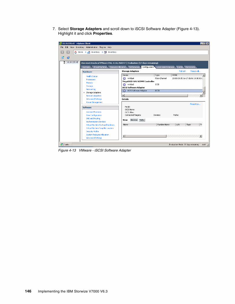
7. Select Storage Adapters and scroll down to iSCSI Software Adapter (Figure 4-13). Highlight it and click Properties.
Figure 4-13 VMware - iSCSI Software Adapter
146 Implementing the IBM Storwize V7000 V6.3
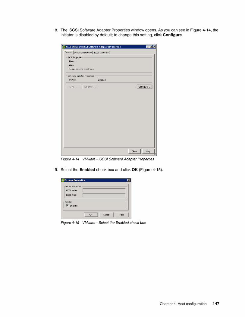
8. The iSCSI Software Adapter Properties window opens. As you can see in Figure 4-14, the initiator is disabled by default; to change this setting, click Configure.
Figure 4-14 VMware - iSCSI Software Adapter Properties
9. Select the Enabled check box and click OK (Figure 4-15).
Figure 4-15 VMware - Select the Enabled check box
Chapter 4. Host configuration 147

10.The VMware ESX iSCSI initiator is now successfully enabled (Figure 4-16). Note the initiator name for later use.
Figure 4-16 VMware iSCSI Initiator enabled
Your VMware ESX host is now prepared to connect to the IBM Storwize V7000. Go to 4.3.2, “Creating iSCSI hosts” on page 154 to create the ESX iSCSI host using the IBM Storwize V7000 GUI.
4.3 Creating hosts using the GUI
This section describes how to create Fibre Channel and iSCSI hosts using the IBM Storwize V7000 GUI. We assume that the hosts are prepared for attachment, as described in 4.2, “Preparing the host operating system” on page 133, and that you know the host WWPNs and their iSCSI initiator names.
148 Implementing the IBM Storwize V7000 V6.3

To create a host, complete the following steps:
1. Open the host configuration window by clicking Hosts (Figure 4-17).
Figure 4-17 Open the host window
2. To create a host, click New Host to start the wizard (Figure 4-18).
Figure 4-18 Create a host
If you want to create a Fibre Channel host, continue with 4.3.1, “Creating Fibre Channel hosts” on page 150; to create iSCSI hosts, go to 4.3.2, “Creating iSCSI hosts” on page 154.
Chapter 4. Host configuration 149

4.3.1 Creating Fibre Channel hosts
To create Fibre Channel hosts, complete the following steps:
1. Click Fibre Channel Host (Figure 4-18 on page 149). The Fibre Channel configuration wizard opens (Figure 4-19).
Figure 4-19 Create a Fibre Channel host
2. Enter a host name and click the Fibre Channel Ports drop-down menu to get a list of all known WWPNs (Figure 4-20).
Figure 4-20 Available WWPNs
The IBM Storwize V7000 has the host port WWPNs available if you prepared the hosts, as described in 4.2, “Preparing the host operating system” on page 133. If they do not appear in the list, scan for new disks in your operating system and click Rescan in the configuration wizard. If they still do not appear, check your SAN zoning and repeat the scanning.
150 Implementing the IBM Storwize V7000 V6.3
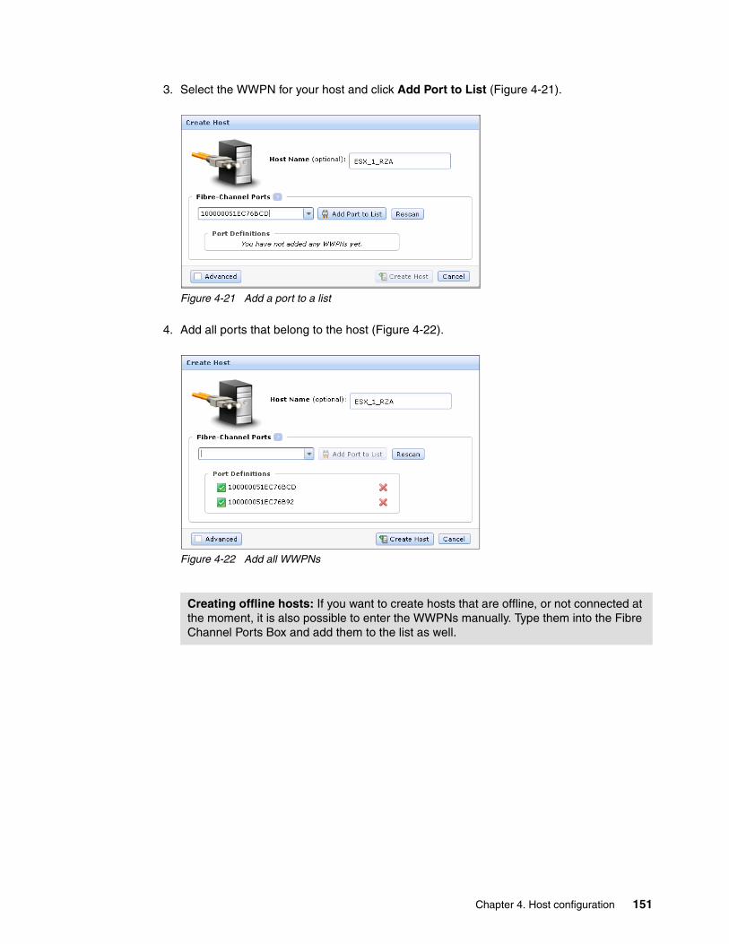
3. Select the WWPN for your host and click Add Port to List (Figure 4-21).
Figure 4-21 Add a port to a list
4. Add all ports that belong to the host (Figure 4-22).
Figure 4-22 Add all WWPNs
Creating offline hosts: If you want to create hosts that are offline, or not connected at the moment, it is also possible to enter the WWPNs manually. Type them into the Fibre Channel Ports Box and add them to the list as well.
Chapter 4. Host configuration 151

5. If you are creating an HP/UX or TPGS host, select the Advanced check box and more options appear (Figure 4-23). Select your host type.
Figure 4-23 Create Host - Advanced Settings
6. Click Create Host and the wizard creates the host (Figure 4-24).
Figure 4-24 Create Host completes
152 Implementing the IBM Storwize V7000 V6.3

7. Click Close to return to the host window (Figure 4-25).
Figure 4-25 All Hosts
8. Repeat these steps for all of your Fibre Channel hosts. Figure 4-26 shows the All Hosts window after creating a second host.
Figure 4-26 All Hosts - After creating a second host
After you complete the creation of Fibre Channel hosts, go to Chapter 5, “Basic volume configuration” on page 159 to create volumes and map them to the created hosts.
Chapter 4. Host configuration 153
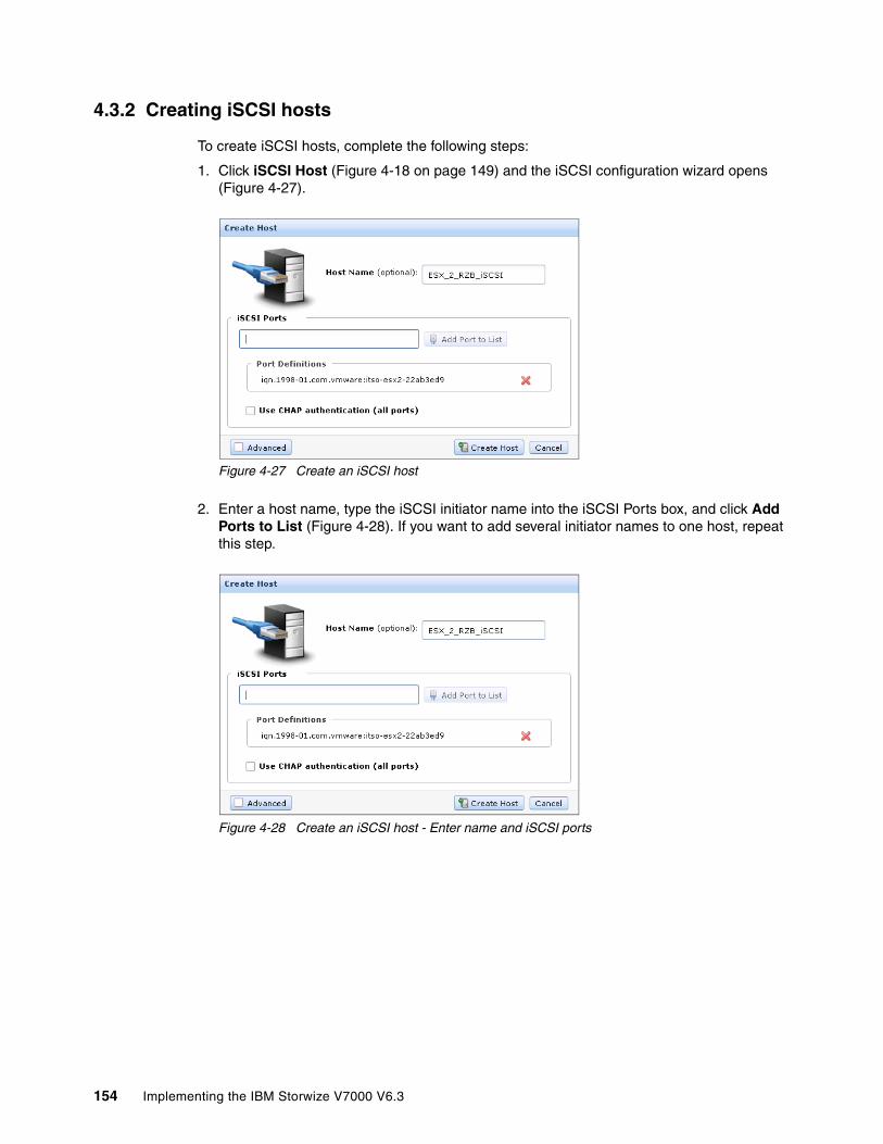
4.3.2 Creating iSCSI hosts
To create iSCSI hosts, complete the following steps:
1. Click iSCSI Host (Figure 4-18 on page 149) and the iSCSI configuration wizard opens (Figure 4-27).
Figure 4-27 Create an iSCSI host
2. Enter a host name, type the iSCSI initiator name into the iSCSI Ports box, and click Add Ports to List (Figure 4-28). If you want to add several initiator names to one host, repeat this step.
Figure 4-28 Create an iSCSI host - Enter name and iSCSI ports
154 Implementing the IBM Storwize V7000 V6.3
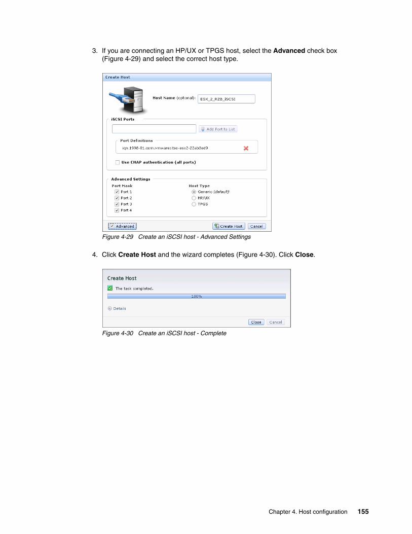
3. If you are connecting an HP/UX or TPGS host, select the Advanced check box (Figure 4-29) and select the correct host type.
Figure 4-29 Create an iSCSI host - Advanced Settings
4. Click Create Host and the wizard completes (Figure 4-30). Click Close.
Figure 4-30 Create an iSCSI host - Complete
Chapter 4. Host configuration 155
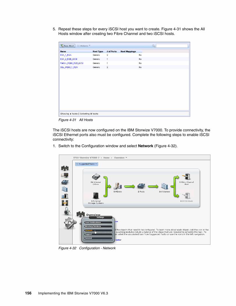
5. Repeat these steps for every iSCSI host you want to create. Figure 4-31 shows the All Hosts window after creating two Fibre Channel and two iSCSI hosts.
Figure 4-31 All Hosts
The iSCSI hosts are now configured on the IBM Storwize V7000. To provide connectivity, the iSCSI Ethernet ports also must be configured. Complete the following steps to enable iSCSI connectivity:
1. Switch to the Configuration window and select Network (Figure 4-32).
Figure 4-32 Configuration - Network
156 Implementing the IBM Storwize V7000 V6.3

2. Select iSCSI and the iSCSI Configuration window opens (Figure 4-33).
Figure 4-33 iSCSI Configuration window
In the configuration, you have an overview of all the iSCSI settings for the IBM Storwize V7000. You can configure iSCSI Alias, iSNS Addresses, and Chap Authentication Configuration on this window, and the iSCSI IP address, which we also edit in the basic setup.
3. Click Ethernet Ports to enter the iSCSI IP address (Figure 4-34). Repeat this step for each port you want to use for iSCSI traffic.
Figure 4-34 Enter an iSCSI IP address
Chapter 4. Host configuration 157
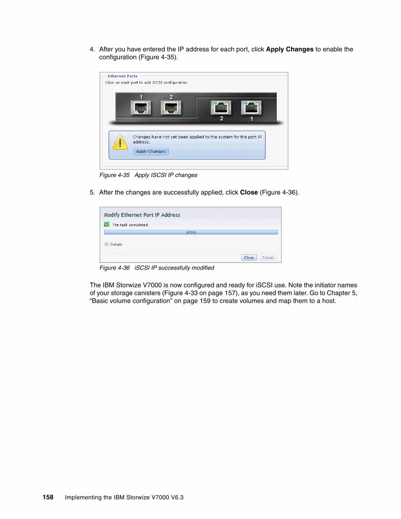
4. After you have entered the IP address for each port, click Apply Changes to enable the configuration (Figure 4-35).
Figure 4-35 Apply ISCSI IP changes
5. After the changes are successfully applied, click Close (Figure 4-36).
Figure 4-36 iSCSI IP successfully modified
The IBM Storwize V7000 is now configured and ready for iSCSI use. Note the initiator names of your storage canisters (Figure 4-33 on page 157), as you need them later. Go to Chapter 5, “Basic volume configuration” on page 159 to create volumes and map them to a host.
158 Implementing the IBM Storwize V7000 V6.3
Chapter 5. Basic volume configuration
This chapter describes how to use the IBM Storwize V7000 to create a volume and map a volume to a host. A volume is a logical disk on the IBM Storwize V7000 that is provisioned out of a storage pool and is recognized by a host with an identifier UID field and a parameter list.
The first part of the chapter describes how to create volumes and map them to the defined hosts.
The second part of this chapter covers how to discover those volumes (5.1, “Provisioning storage from IBM Storwize V7000 and making it available to the host” on page 160). After you finish this chapter, your basic configuration is done and you are able to store data on the IBM Storwize V7000.
Advanced host and volume administration, such as volume migration, creating volume copies, and so on, is described in Chapter 8, “Advanced host and volume administration” on page 269.
5
© Copyright IBM Corp. 2011, 2012. All rights reserved. 159
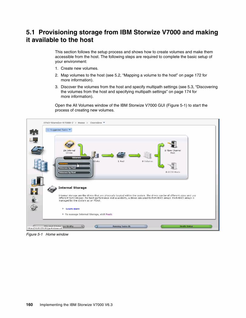
5.1 Provisioning storage from IBM Storwize V7000 and making it available to the host
This section follows the setup process and shows how to create volumes and make them accessible from the host. The following steps are required to complete the basic setup of your environment:
1. Create new volumes.
2. Map volumes to the host (see 5.2, “Mapping a volume to the host” on page 172 for more information).
3. Discover the volumes from the host and specify multipath settings (see 5.3, “Discovering the volumes from the host and specifying multipath settings” on page 174 for more information).
Open the All Volumes window of the IBM Storwize V7000 GUI (Figure 5-1) to start the process of creating new volumes.
Figure 5-1 Home window
160 Implementing the IBM Storwize V7000 V6.3
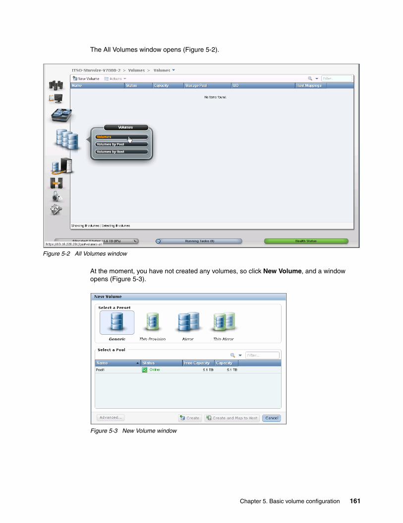
The All Volumes window opens (Figure 5-2).
Figure 5-2 All Volumes window
At the moment, you have not created any volumes, so click New Volume, and a window opens (Figure 5-3).
Figure 5-3 New Volume window
Chapter 5. Basic volume configuration 161

By default, all volumes that you create are striped across all available MDisks in one storage pool. The GUI for the IBM Storwize V7000 provides the following preset selections for the user:
� Generic: A striped volume that is fully provisioned, as described in 5.1.1, “Creating a generic volume” on page 162.
� Thin-provisioned: A striped volume that is space efficient. There are choices under the Advanced button to help determine how much space is fully allocated initially and how large the volume is able to grow, as described in 5.1.2, “Creating a thin-provisioned volume” on page 163.
� Mirror: The striped volume consists of two striped copies and is synchronized to protect against loss of data if the underlying storage pool of one copy is lost, as described in 5.1.3, “Creating a mirrored volume” on page 166.
� Thin-mirror: Two synchronized copies. Both are thin provisioned, as described in 5.1.4, “Creating a thin-mirror volume” on page 169.
Select which volume you want to create and go to the relevant section.
5.1.1 Creating a generic volume
The most commonly used type of volume is the generic volume type. This type of volume is fully provisioned, with the entire size of the volume dedicated to the volume. The host and the IBM Storwize V7000 see the fully allocated space without a mirror.
We choose a generic volume (Figure 5-3 on page 161) and then we select the pool in which the volume should be created. Select the pool by clicking it. In our example, we click Pool1. The result is shown in Figure 5-4.
Figure 5-4 Create a generic volume
162 Implementing the IBM Storwize V7000 V6.3

Enter a volume name and a size, and click Create and Map to Host. The new Generic Volume is created (Figure 5-5). Click Continue and go to 5.2.1, “Mapping newly created volumes to the host using the wizard” on page 172.
Figure 5-5 Volume created
If you do not want to map the volumes now, click Create to complete the task. Volumes can also be mapped later, as described in 5.2, “Mapping a volume to the host” on page 172.
5.1.2 Creating a thin-provisioned volume
Volumes can be configured to be thin provisioned. A thin-provisioned volume behaves with respect to application reads and writes as though they were fully allocated. When creating a thin-provisioned volume, it is possible to specify two capacities: the real physical capacity allocated to the volume from the storage pool and its virtual capacity available to the host. So the real capacity determines the quantity of extents that are initially allocated to the volume. The virtual capacity is the capacity of the volume reported to all other components (for example, FlashCopy, cache, and Remote Copy) and to the host servers.
Chapter 5. Basic volume configuration 163

To create a thin-provisioned volume, complete the following steps:
1. Select Thin Provision (Figure 5-6).
Figure 5-6 Create a thin-provisioned volume
2. Select the pool in which the thin-provisioned volume should be created by clicking it and entering the volume name and size (Figure 5-7).
Figure 5-7 Enter the volume name and size
164 Implementing the IBM Storwize V7000 V6.3
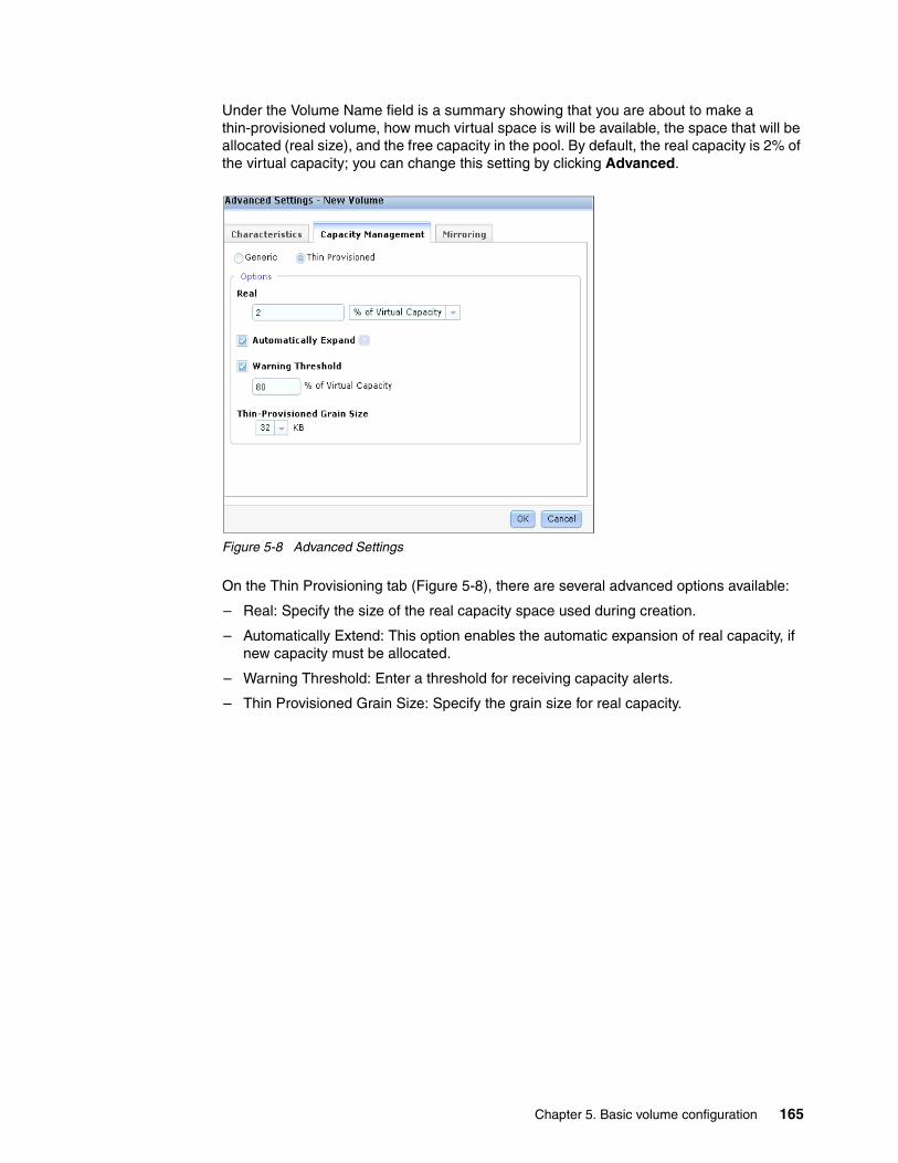
Under the Volume Name field is a summary showing that you are about to make a thin-provisioned volume, how much virtual space is will be available, the space that will be allocated (real size), and the free capacity in the pool. By default, the real capacity is 2% of the virtual capacity; you can change this setting by clicking Advanced.
Figure 5-8 Advanced Settings
On the Thin Provisioning tab (Figure 5-8), there are several advanced options available:
– Real: Specify the size of the real capacity space used during creation.
– Automatically Extend: This option enables the automatic expansion of real capacity, if new capacity must be allocated.
– Warning Threshold: Enter a threshold for receiving capacity alerts.
– Thin Provisioned Grain Size: Specify the grain size for real capacity.
Chapter 5. Basic volume configuration 165
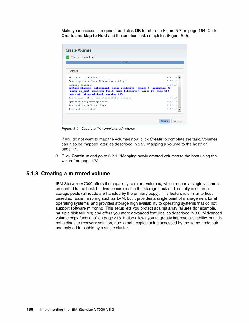
Make your choices, if required, and click OK to return to Figure 5-7 on page 164. Click Create and Map to Host and the creation task completes (Figure 5-9).
Figure 5-9 Create a thin-provisioned volume
If you do not want to map the volumes now, click Create to complete the task. Volumes can also be mapped later, as described in 5.2, “Mapping a volume to the host” on page 172
3. Click Continue and go to 5.2.1, “Mapping newly created volumes to the host using the wizard” on page 172.
5.1.3 Creating a mirrored volume
IBM Storwize V7000 offers the capability to mirror volumes, which means a single volume is presented to the host, but two copies exist in the storage back end, usually in different storage pools (all reads are handled by the primary copy). This feature is similar to host based software mirroring such as LVM, but it provides a single point of management for all operating systems, and provides storage high availability to operating systems that do not support software mirroring. This setup lets you protect against array failures (for example, multiple disk failures) and offers you more advanced features, as described in 8.6, “Advanced volume copy functions” on page 318. It also allows you to greatly improve availability, but it is not a disaster recovery solution, due to both copies being accessed by the same node pair and only addressable by a single cluster.
166 Implementing the IBM Storwize V7000 V6.3
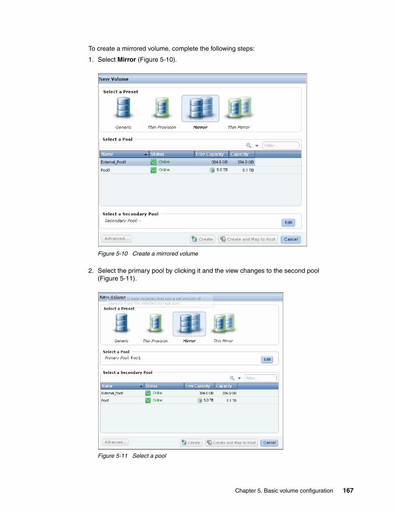
To create a mirrored volume, complete the following steps:
1. Select Mirror (Figure 5-10).
Figure 5-10 Create a mirrored volume
2. Select the primary pool by clicking it and the view changes to the second pool (Figure 5-11).
Figure 5-11 Select a pool
Chapter 5. Basic volume configuration 167
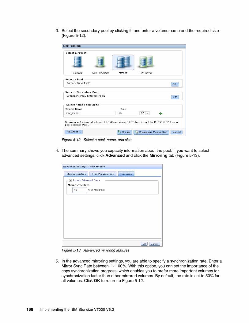
3. Select the secondary pool by clicking it, and enter a volume name and the required size (Figure 5-12).
Figure 5-12 Select a pool, name, and size
4. The summary shows you capacity information about the pool. If you want to select advanced settings, click Advanced and click the Mirroring tab (Figure 5-13).
Figure 5-13 Advanced mirroring features
5. In the advanced mirroring settings, you are able to specify a synchronization rate. Enter a Mirror Sync Rate between 1 - 100%. With this option, you can set the importance of the copy synchronization progress, which enables you to prefer more important volumes for synchronization faster than other mirrored volumes. By default, the rate is set to 50% for all volumes. Click OK to return to Figure 5-12.
168 Implementing the IBM Storwize V7000 V6.3

6. Click Create and Map to Host and the mirrored volume is created (Figure 5-14).
Figure 5-14 Create a mirrored volume
7. Click Continue and go to 5.2.1, “Mapping newly created volumes to the host using the wizard” on page 172.
5.1.4 Creating a thin-mirror volume
A thin-mirror volume allows you to allocate the required space on demand (described in 5.1.2, “Creating a thin-provisioned volume” on page 163) and have several copies of a volume (described in 5.1.3, “Creating a mirrored volume” on page 166) available.
Chapter 5. Basic volume configuration 169
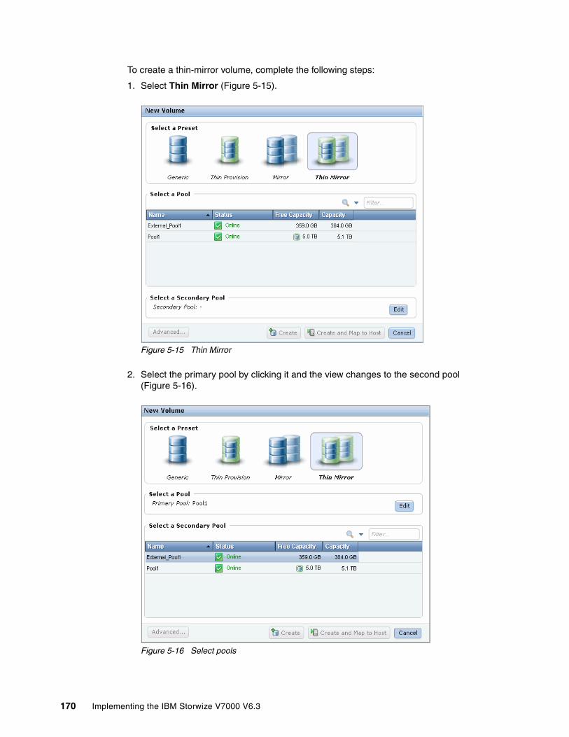
To create a thin-mirror volume, complete the following steps:
1. Select Thin Mirror (Figure 5-15).
Figure 5-15 Thin Mirror
2. Select the primary pool by clicking it and the view changes to the second pool (Figure 5-16).
Figure 5-16 Select pools
170 Implementing the IBM Storwize V7000 V6.3
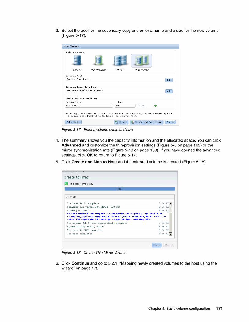
3. Select the pool for the secondary copy and enter a name and a size for the new volume (Figure 5-17).
Figure 5-17 Enter a volume name and size
4. The summary shows you the capacity information and the allocated space. You can click Advanced and customize the thin-provision settings (Figure 5-8 on page 165) or the mirror synchronization rate (Figure 5-13 on page 168). If you have opened the advanced settings, click OK to return to Figure 5-17.
5. Click Create and Map to Host and the mirrored volume is created (Figure 5-18).
Figure 5-18 Create Thin Mirror Volume
6. Click Continue and go to 5.2.1, “Mapping newly created volumes to the host using the wizard” on page 172.
Chapter 5. Basic volume configuration 171
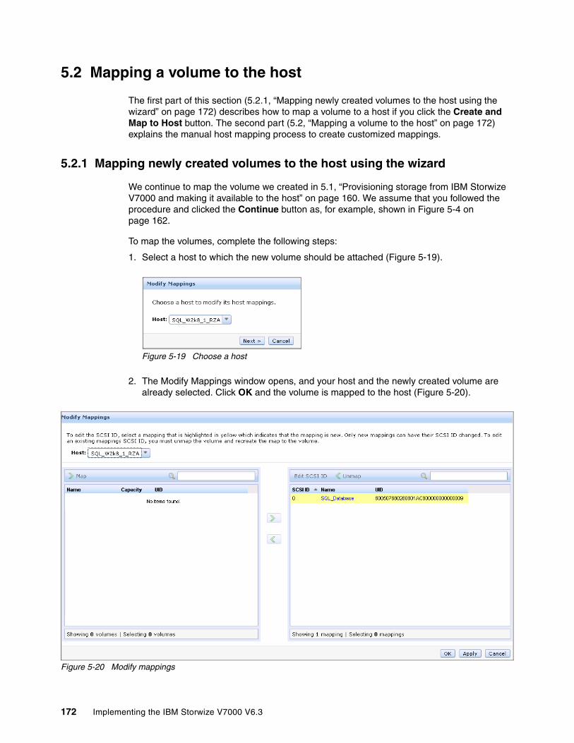
5.2 Mapping a volume to the host
The first part of this section (5.2.1, “Mapping newly created volumes to the host using the wizard” on page 172) describes how to map a volume to a host if you click the Create and Map to Host button. The second part (5.2, “Mapping a volume to the host” on page 172) explains the manual host mapping process to create customized mappings.
5.2.1 Mapping newly created volumes to the host using the wizard
We continue to map the volume we created in 5.1, “Provisioning storage from IBM Storwize V7000 and making it available to the host” on page 160. We assume that you followed the procedure and clicked the Continue button as, for example, shown in Figure 5-4 on page 162.
To map the volumes, complete the following steps:
1. Select a host to which the new volume should be attached (Figure 5-19).
Figure 5-19 Choose a host
2. The Modify Mappings window opens, and your host and the newly created volume are already selected. Click OK and the volume is mapped to the host (Figure 5-20).
Figure 5-20 Modify mappings
172 Implementing the IBM Storwize V7000 V6.3

3. After the task completes, click Close (Figure 5-21), and the wizard returns to the All Volumes window.
Figure 5-21 Modify Mappings complete
The newly created volume is displayed. We see that it is already mapped to a host (Figure 5-22).
Figure 5-22 New Volume mapped to host
The host is now able to access the volumes and store data on it. Go to 5.3, “Discovering the volumes from the host and specifying multipath settings” on page 174 to discover the volumes on the host and make some additional host settings if required.
You can also create multiple volumes in preparation for discovering them later. Mappings can be customized as well. Advanced host configuration is described in 8.1.1, “Modifying Mappings menu” on page 272.
Chapter 5. Basic volume configuration 173

5.3 Discovering the volumes from the host and specifying multipath settings
This section shows how to discover the volumes created and mapped in 5.1, “Provisioning storage from IBM Storwize V7000 and making it available to the host” on page 160 and 5.2, “Mapping a volume to the host” on page 172, and set additional multipath settings, if required.
We assume that you have completed all steps described previously in the book so that the hosts and the IBM Storwize V7000 are prepared:
� Prepare your operating systems for attachment (Chapter 4, “Host configuration” on page 131).
� Create hosts using the GUI (4.3, “Creating hosts using the GUI” on page 148).
� Perform basic volume configuration and host mapping (5.1, “Provisioning storage from IBM Storwize V7000 and making it available to the host” on page 160).
This section shows how to discover Fibre Channel and iSCSI volumes from Windows 2008 and VMware ESX 4.x hosts.
In the IBM Storwize V7000 GUI, click Hosts and All Hosts (Figure 5-23).
Figure 5-23 Open all hosts
174 Implementing the IBM Storwize V7000 V6.3

The view that opens gives you an overview of the currently configured and mapped hosts (Figure 5-24).
Figure 5-24 All Hosts view
5.3.1 Windows 2008 Fibre Channel volume attachment
To perform Fibre Channel volume attachment in Windows 2008, complete the following steps:
1. Right-click your Windows 2008 Fibre Channel host in the All Hosts view (Figure 5-25) and select Properties.
Figure 5-25 Host properties
Chapter 5. Basic volume configuration 175

Navigate to the Mapped Volumes tab (Figure 5-26).
Figure 5-26 Mapped volumes to a host
The host details show you which volumes are currently mapped to the host, and you also see the volume UID and the SCSI ID. In our example, one volume with SCSI ID 0 is mapped to the host.
2. Log on to your Microsoft host and click Start All Programs Subsystem Device Driver DSM Subsystem Device Driver DSM. A command-line interface opens. Enter datapath query device and press Enter to see if there are IBM Storwize V7000 disks connected to this host (Example 5-1).
Example 5-1 datapath query device
C:\Program Files\IBM\SDDDSM>datapath query device
Total Devices : 1DEV#: 0 DEVICE NAME: Disk14 Part0 TYPE: 2145 POLICY: OPTIMIZEDSERIAL: 600507680280801AC800000000000009=============================================================================Path# Adapter/Hard Disk State Mode Select Errors 0 Scsi Port5 Bus0/Disk14 Part0 OPEN NORMAL 0 0 1 Scsi Port5 Bus0/Disk14 Part0 OPEN NORMAL 22 0 2 Scsi Port6 Bus0/Disk14 Part0 OPEN NORMAL 19 0 3 Scsi Port6 Bus0/Disk14 Part0 OPEN NORMAL 0 0
C:\Program Files\IBM\SDDDSM>
176 Implementing the IBM Storwize V7000 V6.3
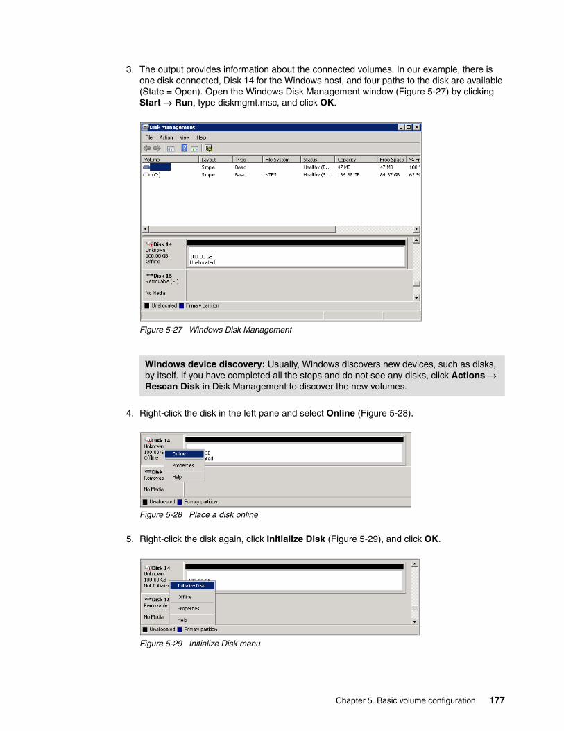
3. The output provides information about the connected volumes. In our example, there is one disk connected, Disk 14 for the Windows host, and four paths to the disk are available (State = Open). Open the Windows Disk Management window (Figure 5-27) by clicking Start Run, type diskmgmt.msc, and click OK.
Figure 5-27 Windows Disk Management
4. Right-click the disk in the left pane and select Online (Figure 5-28).
Figure 5-28 Place a disk online
5. Right-click the disk again, click Initialize Disk (Figure 5-29), and click OK.
Figure 5-29 Initialize Disk menu
Windows device discovery: Usually, Windows discovers new devices, such as disks, by itself. If you have completed all the steps and do not see any disks, click Actions Rescan Disk in Disk Management to discover the new volumes.
Chapter 5. Basic volume configuration 177
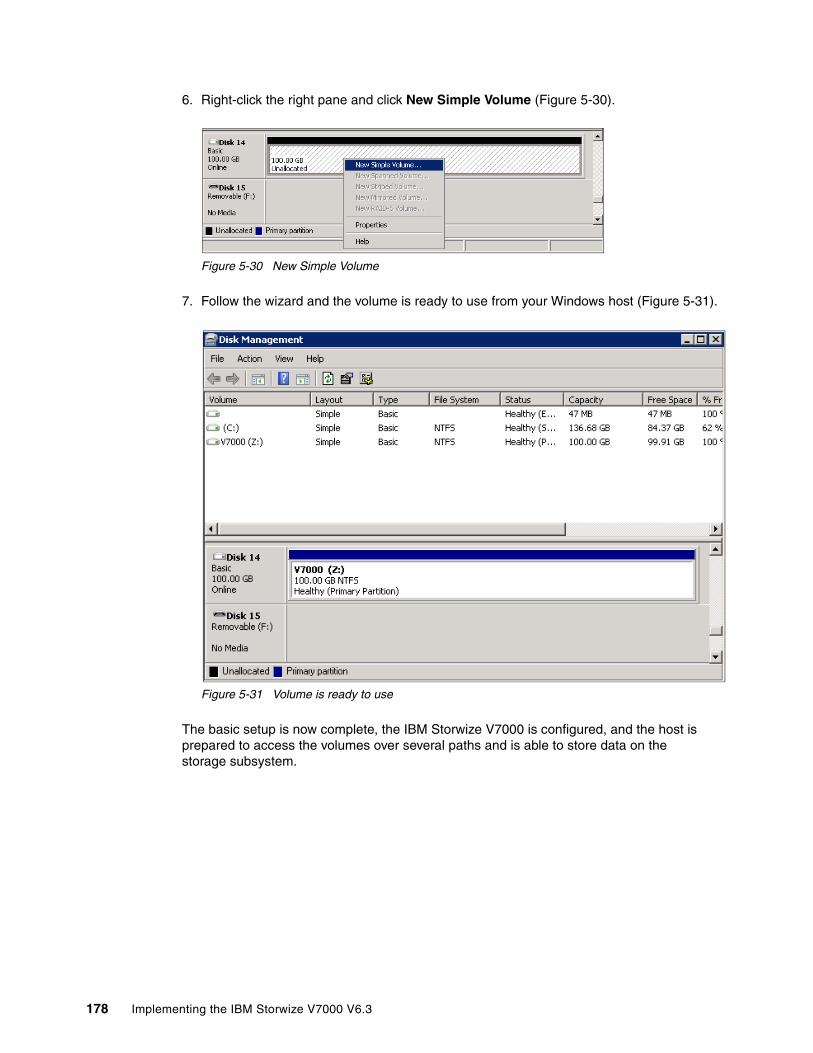
6. Right-click the right pane and click New Simple Volume (Figure 5-30).
Figure 5-30 New Simple Volume
7. Follow the wizard and the volume is ready to use from your Windows host (Figure 5-31).
Figure 5-31 Volume is ready to use
The basic setup is now complete, the IBM Storwize V7000 is configured, and the host is prepared to access the volumes over several paths and is able to store data on the storage subsystem.
178 Implementing the IBM Storwize V7000 V6.3
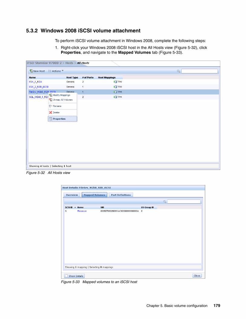
5.3.2 Windows 2008 iSCSI volume attachment
To perform iSCSI volume attachment in Windows 2008, complete the following steps:
1. Right-click your Windows 2008 iSCSI host in the All Hosts view (Figure 5-32), click Properties, and navigate to the Mapped Volumes tab (Figure 5-33).
Figure 5-32 All Hosts view
Figure 5-33 Mapped volumes to an iSCSI host
Chapter 5. Basic volume configuration 179
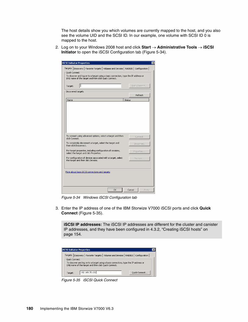
The host details show you which volumes are currently mapped to the host, and you also see the volume UID and the SCSI ID. In our example, one volume with SCSI ID 0 is mapped to the host.
2. Log on to your Windows 2008 host and click Start Administrative Tools iSCSI Initiator to open the iSCSI Configuration tab (Figure 5-34).
Figure 5-34 Windows iSCSI Configuration tab
3. Enter the IP address of one of the IBM Storwize V7000 iSCSI ports and click Quick Connect (Figure 5-35).
Figure 5-35 iSCSI Quick Connect
iSCSI IP addresses: The iSCSI IP addresses are different for the cluster and canister IP addresses, and they have been configured in 4.3.2, “Creating iSCSI hosts” on page 154.
180 Implementing the IBM Storwize V7000 V6.3

The IBM Storwize V7000 initiator is discovered and connected (Figure 5-36).
Figure 5-36 iSCSI Initiator target is connected
Now you have completed the steps to connect the storage disk to your iSCSI host, but you are only using a single path at the moment. To enable multipathing for iSCSI targets, more actions are required. Complete the following steps:
1. Click Start Run and type cmd to open a command prompt. Enter ServerManagerCMD.exe -install Multipath-IO and press Enter (Example 5-2).
Example 5-2 Installing MPIO
C:\Users\Administrator>ServerManagerCmd.exe -Install Multipath-IO
Start Installation...[Installation] Succeeded: [Multipath I/O] Multipath I/O.<100/100>
Success: Installation succeeded.
Chapter 5. Basic volume configuration 181
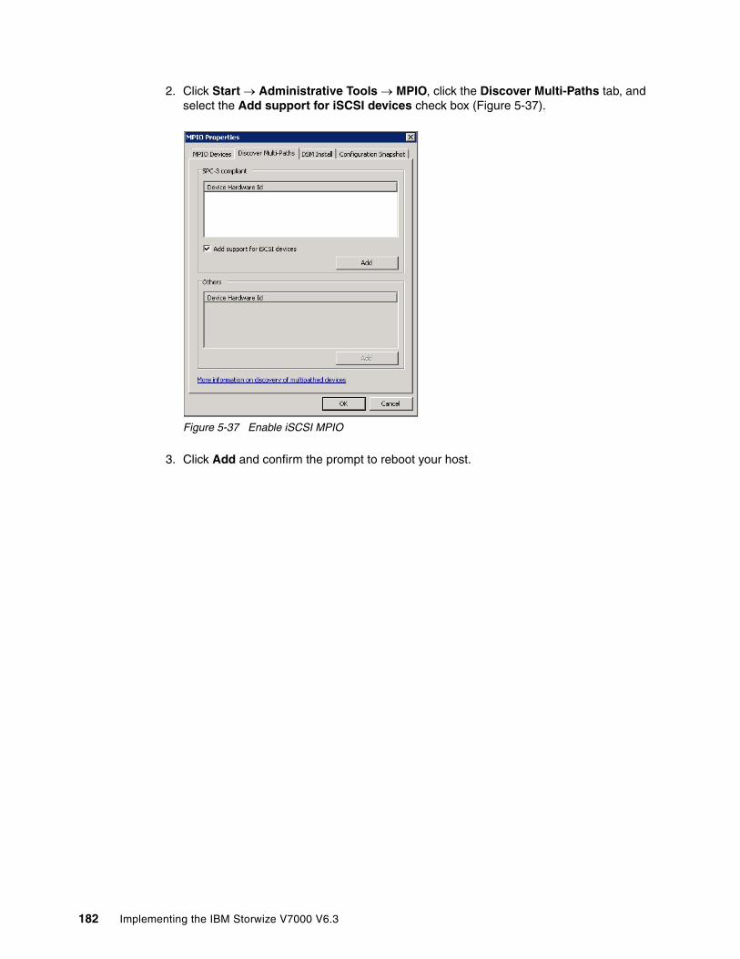
2. Click Start Administrative Tools MPIO, click the Discover Multi-Paths tab, and select the Add support for iSCSI devices check box (Figure 5-37).
Figure 5-37 Enable iSCSI MPIO
3. Click Add and confirm the prompt to reboot your host.
182 Implementing the IBM Storwize V7000 V6.3

4. After the reboot, log on again, click Start Administrative Tools iSCSI Initiator to open the iSCSI Configuration tab, and navigate to the Discovery tab (Figure 5-38).
Figure 5-38 iSCSI Properties Discovery tab
5. Click Discover Portal..., enter the IP address of another IBM Storwize V7000 iSCSI port (Figure 5-39), and click OK.
Figure 5-39 Discover Target Portal window
Chapter 5. Basic volume configuration 183

6. Return to the Targets tab (Figure 5-40) and you find the new connection there is listed as Inactive.
Figure 5-40 Inactive target ports
7. Highlight the inactive port and click Connect. The Connect to Target window opens (Figure 5-41).
Figure 5-41 Connect to a target
184 Implementing the IBM Storwize V7000 V6.3

8. Select the Enable Multipath check box and click OK. The second port now appears as Connected (Figure 5-42).
Figure 5-42 Second target port connected
Repeat this step for each IBM Storwize V7000 port you want to use for iSCSI traffic. It is possible to have up to four port paths to the system.
Chapter 5. Basic volume configuration 185

9. Click Devices MPIO to make sure that the multipath policy for Windows 2008 is set to the default, which is Round Robin with Subset (Figure 9), and click OK to close this view.
Figure 5-43 Round Robin with Subset
10.Open the Windows Disk Management window (Figure 5-44) by clicking Start Run, typing diskmgmt.msc, and clicking OK.
Figure 5-44 Windows Disk Management
11.Set the disk online, initialize it, create a file system on it, and then it is ready to use. The detailed steps of this process are the same as described in 5.3.1, “Windows 2008 Fibre Channel volume attachment” on page 175.
186 Implementing the IBM Storwize V7000 V6.3

Now the storage disk is ready for use (Figure 5-45). In our example, we have mapped a 10 TB disk, which is thin-provisioned on the IBM Storwize V7000, to a Windows 2008 host using iSCSI.
Figure 5-45 Windows Disk Management: Disk is ready to use
5.3.3 VMware ESX Fibre Channel attachment
To perform VMware ESX Fibre Channel attachment, complete the following steps:
1. Right-click your VMware ESX Fibre Channel host in the All Hosts view (Figure 5-46) and select Properties
Figure 5-46 Example ESX FC host
Chapter 5. Basic volume configuration 187
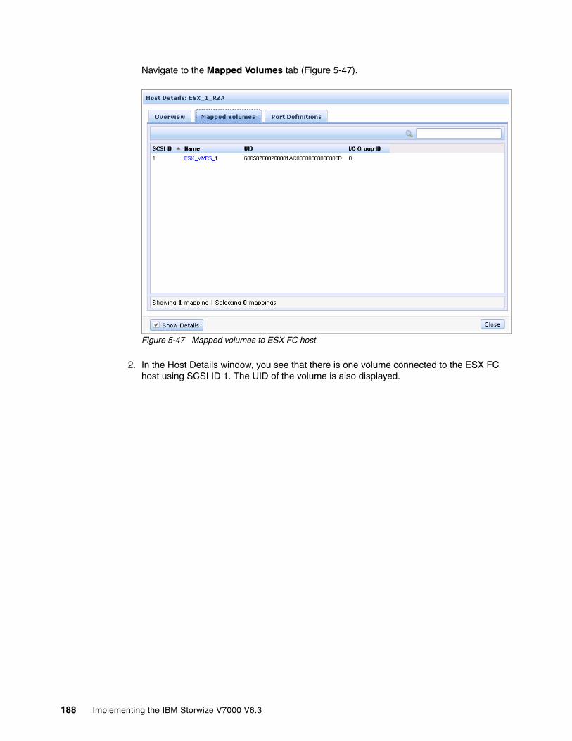
Navigate to the Mapped Volumes tab (Figure 5-47).
Figure 5-47 Mapped volumes to ESX FC host
2. In the Host Details window, you see that there is one volume connected to the ESX FC host using SCSI ID 1. The UID of the volume is also displayed.
188 Implementing the IBM Storwize V7000 V6.3
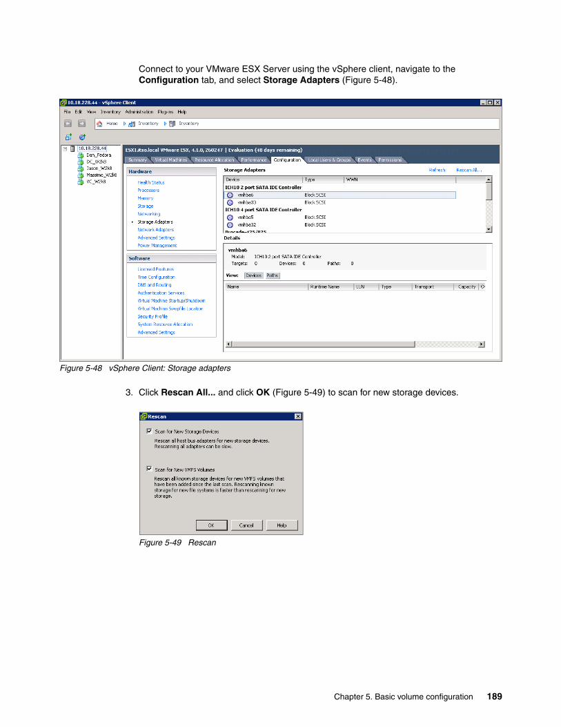
Connect to your VMware ESX Server using the vSphere client, navigate to the Configuration tab, and select Storage Adapters (Figure 5-48).
Figure 5-48 vSphere Client: Storage adapters
3. Click Rescan All... and click OK (Figure 5-49) to scan for new storage devices.
Figure 5-49 Rescan
Chapter 5. Basic volume configuration 189

4. Select Storage and click Add Storage (Figure 5-50).
Figure 5-50 vSphere Client: Storage
190 Implementing the IBM Storwize V7000 V6.3
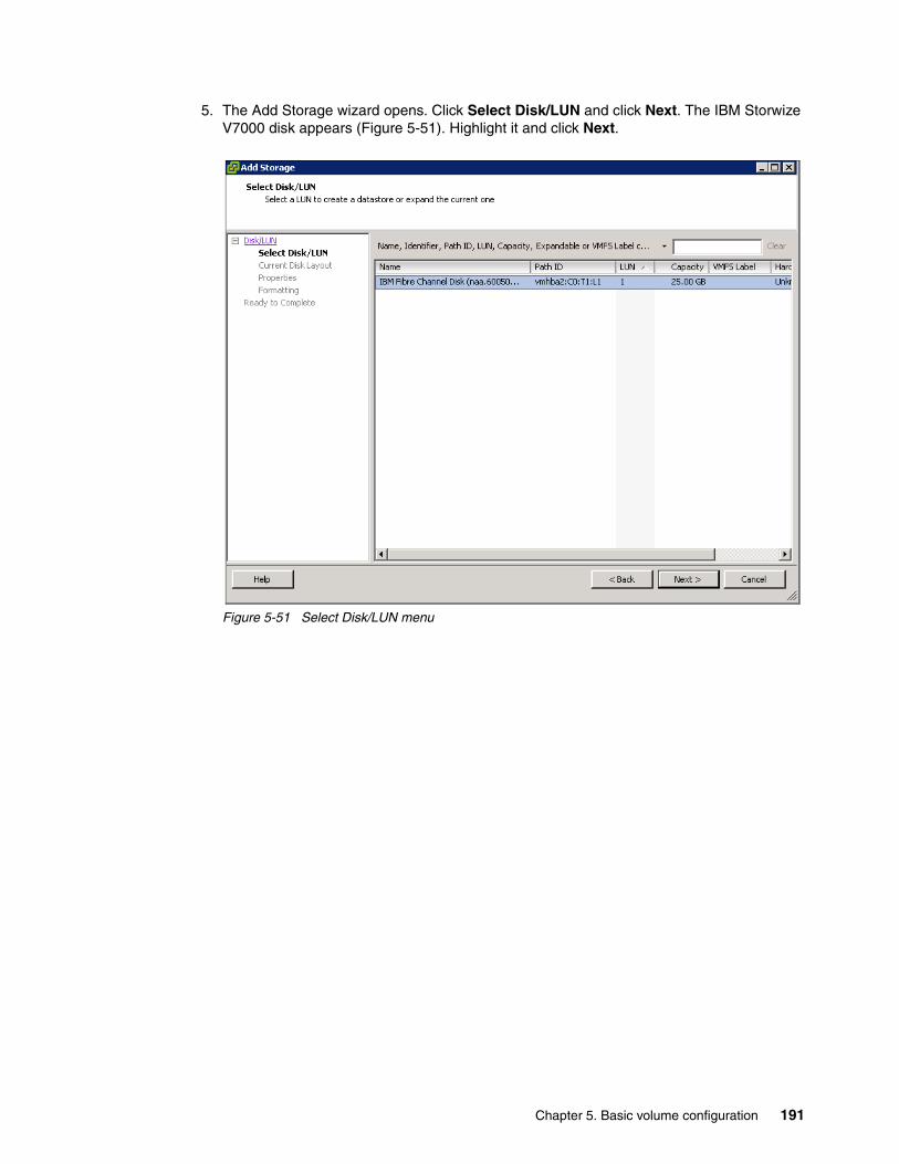
5. The Add Storage wizard opens. Click Select Disk/LUN and click Next. The IBM Storwize V7000 disk appears (Figure 5-51). Highlight it and click Next.
Figure 5-51 Select Disk/LUN menu
Chapter 5. Basic volume configuration 191
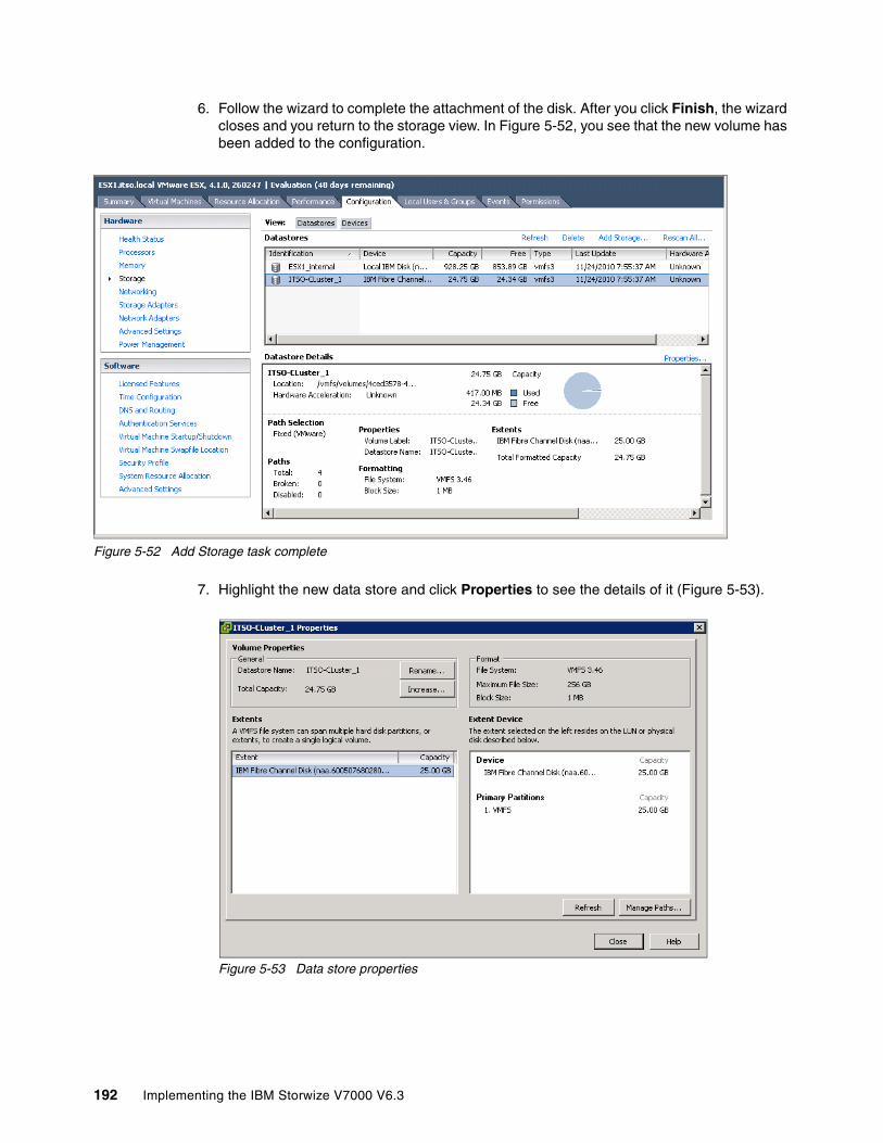
6. Follow the wizard to complete the attachment of the disk. After you click Finish, the wizard closes and you return to the storage view. In Figure 5-52, you see that the new volume has been added to the configuration.
Figure 5-52 Add Storage task complete
7. Highlight the new data store and click Properties to see the details of it (Figure 5-53).
Figure 5-53 Data store properties
192 Implementing the IBM Storwize V7000 V6.3
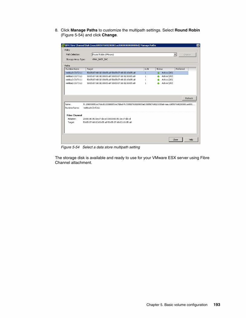
8. Click Manage Paths to customize the multipath settings. Select Round Robin (Figure 5-54) and click Change.
Figure 5-54 Select a data store multipath setting
The storage disk is available and ready to use for your VMware ESX server using Fibre Channel attachment.
Chapter 5. Basic volume configuration 193
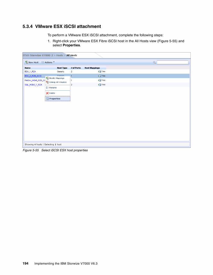
5.3.4 VMware ESX iSCSI attachment
To perform a VMware ESX iSCSI attachment, complete the following steps:
1. Right-click your VMware ESX Fibre iSCSI host in the All Hosts view (Figure 5-55) and select Properties.
Figure 5-55 Select iSCSI ESX host properties
194 Implementing the IBM Storwize V7000 V6.3

Navigate to the Mapped Volumes tab (Figure 5-56).
Figure 5-56 iSCSI ESX host properties
2. In the Host Details window, you see that there is one volume connected to the ESX iSCSI host using SCSI ID 0. The UID of the volume is also displayed.
Chapter 5. Basic volume configuration 195

Connect to your VMware ESX Server using the vSphere Client, navigate to the Configuration tab, and select Storage Adapters (Figure 5-57).
Figure 5-57 vSphere Client: Storage
196 Implementing the IBM Storwize V7000 V6.3
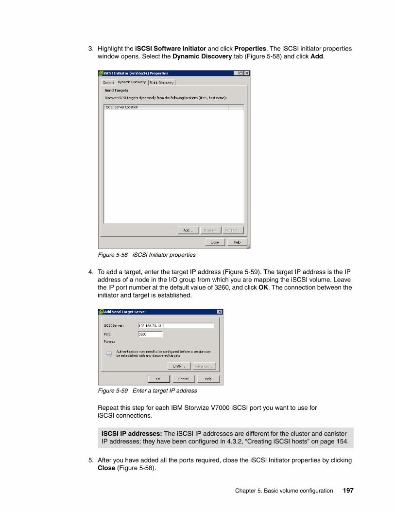
3. Highlight the iSCSI Software Initiator and click Properties. The iSCSI initiator properties window opens. Select the Dynamic Discovery tab (Figure 5-58) and click Add.
Figure 5-58 iSCSI Initiator properties
4. To add a target, enter the target IP address (Figure 5-59). The target IP address is the IP address of a node in the I/O group from which you are mapping the iSCSI volume. Leave the IP port number at the default value of 3260, and click OK. The connection between the initiator and target is established.
Figure 5-59 Enter a target IP address
Repeat this step for each IBM Storwize V7000 iSCSI port you want to use for iSCSI connections.
5. After you have added all the ports required, close the iSCSI Initiator properties by clicking Close (Figure 5-58).
iSCSI IP addresses: The iSCSI IP addresses are different for the cluster and canister IP addresses; they have been configured in 4.3.2, “Creating iSCSI hosts” on page 154.
Chapter 5. Basic volume configuration 197
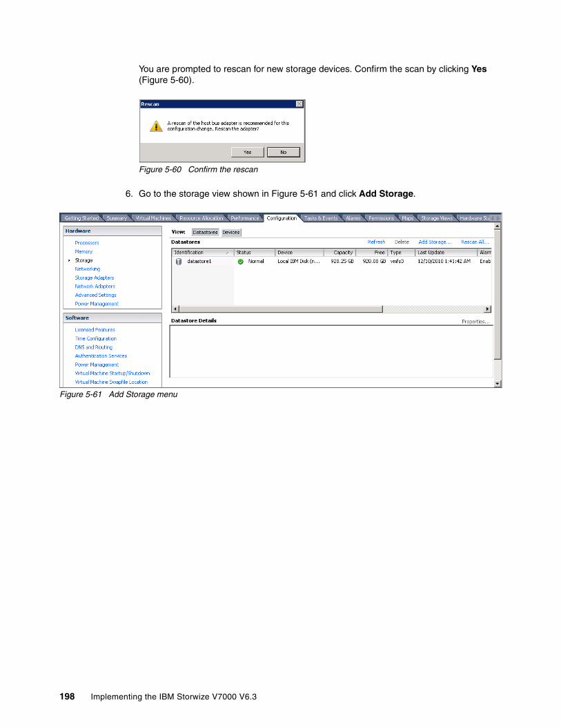
You are prompted to rescan for new storage devices. Confirm the scan by clicking Yes (Figure 5-60).
Figure 5-60 Confirm the rescan
6. Go to the storage view shown in Figure 5-61 and click Add Storage.
Figure 5-61 Add Storage menu
198 Implementing the IBM Storwize V7000 V6.3
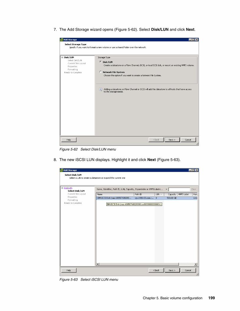
7. The Add Storage wizard opens (Figure 5-62). Select Disk/LUN and click Next.
Figure 5-62 Select Disk/LUN menu
8. The new iSCSI LUN displays. Highlight it and click Next (Figure 5-63).
Figure 5-63 Select iSCSI LUN menu
Chapter 5. Basic volume configuration 199

9. Review the disk layout and click Next (Figure 5-64).
Figure 5-64 Current Disk Layout
10.Enter a name for the data store and click Next (Figure 5-65).
Figure 5-65 Enter a data store name
200 Implementing the IBM Storwize V7000 V6.3

11.Select the maximum file size and click Next (Figure 5-66).
Figure 5-66 Maximum file size
12.Review your selections and click Finish (Figure 5-67).
Figure 5-67 Finish the wizard
Chapter 5. Basic volume configuration 201
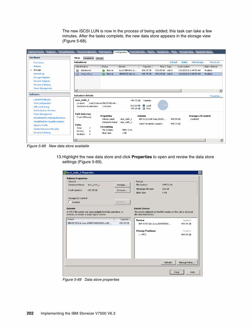
The new iSCSI LUN is now in the process of being added; this task can take a few minutes. After the tasks complete, the new data store appears in the storage view (Figure 5-68).
Figure 5-68 New data store available
13.Highlight the new data store and click Properties to open and review the data store settings (Figure 5-69).
Figure 5-69 Data store properties
202 Implementing the IBM Storwize V7000 V6.3
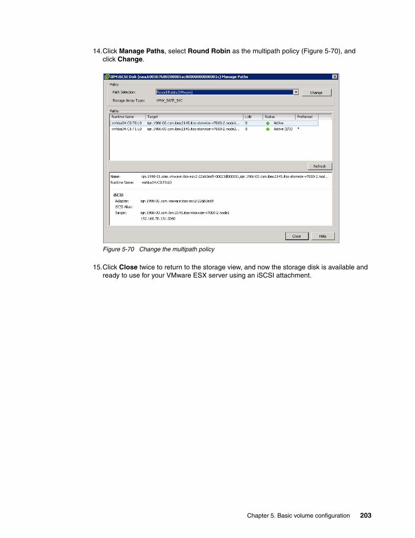
14.Click Manage Paths, select Round Robin as the multipath policy (Figure 5-70), and click Change.
Figure 5-70 Change the multipath policy
15.Click Close twice to return to the storage view, and now the storage disk is available and ready to use for your VMware ESX server using an iSCSI attachment.
Chapter 5. Basic volume configuration 203

204 Implementing the IBM Storwize V7000 V6.3

Chapter 6. Migration wizard
In this chapter, we describe how to migrate existing data on older storage systems to the IBM Storwize V7000 storage system. Migrating data from older storage systems to the IBM Storwize V7000 storage system allows applications to benefit from the new features, such as Easy Tier, an intuitive management GUI, and advanced storage replication functions that better support applications.
To migrate existing data, the IBM Storwize V7000 provides a storage migration wizard to guide you through the entire procedure.
6
© Copyright IBM Corp. 2011, 2012. All rights reserved. 205

6.1 Preparing for data migration
In this section, we show you how to prepare external storage systems and IBM Storwize V7000 for data migration. Data migration is always an important step when setting up new storage systems in an existing storage infrastructure.
Before attaching any external storage systems to IBM Storwize V7000, see the IBM Storwize V7000 support matrix at the following address:
http://www-01.ibm.com/support/docview.wss?uid=ssg1S1003703
When migrating data from an external storage system to IBM Storwize V7000, where the external storage system is removed from IBM Storwize V7000 control when complete, you can temporarily configure the external virtualization license setting. Configuring the external license setting prevents messages from being sent that indicate that you are in violation of the license agreement. When the migration is complete, the external virtualization license must be reset to its original limit.
To prepare the data migration, external storage systems need to be configured to be under IBM Storwize V7000 control. Complete the following steps:
1. Stop host I/O to the external storage LUNs that need to be migrated.
2. Remove zones between the hosts and the storage system from which you are migrating.
3. Update your host device drivers, including your multipath driver, and configure them for attachment to the IBM Storwize V7000 system.
4. Create a storage system zone between the storage system being migrated and IBM Storwize V7000 system, and the host zones for the host attachment.
5. Unmap the LUNs in the external storage system to the host and map them to the IBM Storwize V7000 system.
6. Verify that the IBM Storwize V7000 has discovered the LUNs as unmanaged MDisks.
6.2 Migrating the data using the migration wizard
In this section, we describe how to migrate existing data on external storage systems using the IBM Storwize V7000 storage migration wizard.
We use the IBM Storwize V7000 wizard that has been designed specifically for this scenario to guide you through the process and describe the steps along the way.
External storage: When external storage is virtualized by IBM Storwize V7000, a per-enclosure external virtualization license is required. Contact your IBM account team or IBM Business Partner for further assistance, if required.
206 Implementing the IBM Storwize V7000 V6.3
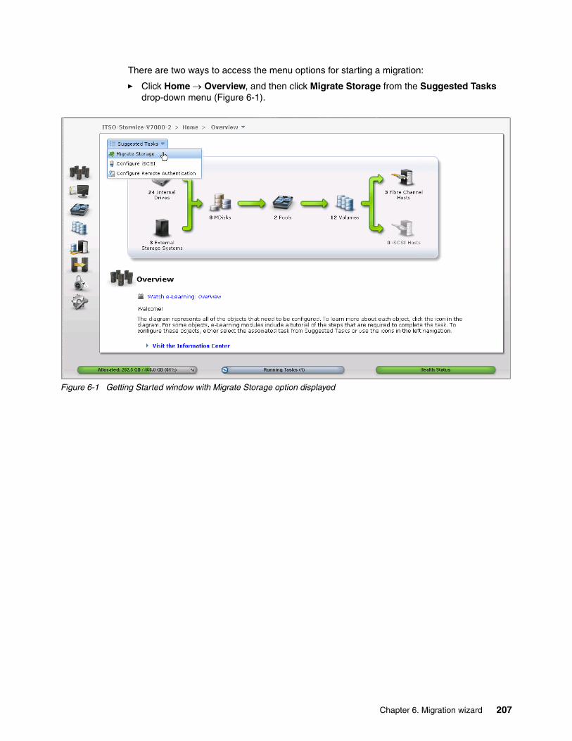
There are two ways to access the menu options for starting a migration:
� Click Home Overview, and then click Migrate Storage from the Suggested Tasks drop-down menu (Figure 6-1).
Figure 6-1 Getting Started window with Migrate Storage option displayed
Chapter 6. Migration wizard 207
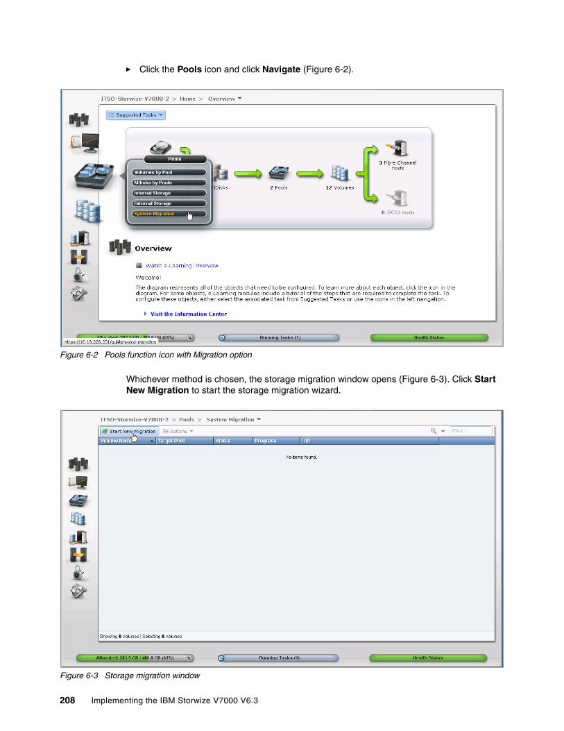
� Click the Pools icon and click Navigate (Figure 6-2).
Figure 6-2 Pools function icon with Migration option
Whichever method is chosen, the storage migration window opens (Figure 6-3). Click Start New Migration to start the storage migration wizard.
Figure 6-3 Storage migration window
208 Implementing the IBM Storwize V7000 V6.3

Using the IBM Storwize V7000 storage migration wizard, you can easily migrate your existing data. Complete the following steps:
1. Perform step 1 of the storage migration wizard, check the restrictions and prerequisites, and click Next (Figure 6-4).
Figure 6-4 Before You Begin window
Step 1 shows there are some restrictions and prerequisites to using the storage migration wizard:
– Restrictions:
• Do not use the storage migration wizard to migrate cluster hosts, including clusters of VMware hosts and VIOS.
• Do not use the storage migration wizard to migrate SAN Boot images.
Avoiding data loss: To avoid any potential data loss, back up all the data stored on your external storage before using the wizard.
Chapter 6. Migration wizard 209

If you have either of these two environments, you need to migrate them outside of this wizard. You can find more information about this topic at the IBM Storwize V7000 Information Center at the following address:
http://publib.boulder.ibm.com/infocenter/storwize/ic/index.jsp
The VMware ESX Storage vMotion feature might be an alternative to migrating VMware clusters. For more information about this topic, see the following address:
http://www.vmware.com/products/vmotion/overview.html
– Prerequisites:
• Make sure that the IBM Storwize V7000 Fibre Channel ports have been connected to the SAN fabrics to which the external disk controller and hosts you want to migrate from are connected.
• If you have VMware ESX hosts in the migration, make sure the VMware ESX hosts are set to allow volume copies to be recognized.
Click Next to go to the next step.
2. Perform step 2 of the storage migration wizard, prepare the environment for migration, and click Next (Figure 6-5).
Figure 6-5 Prepare the environment for migration
210 Implementing the IBM Storwize V7000 V6.3
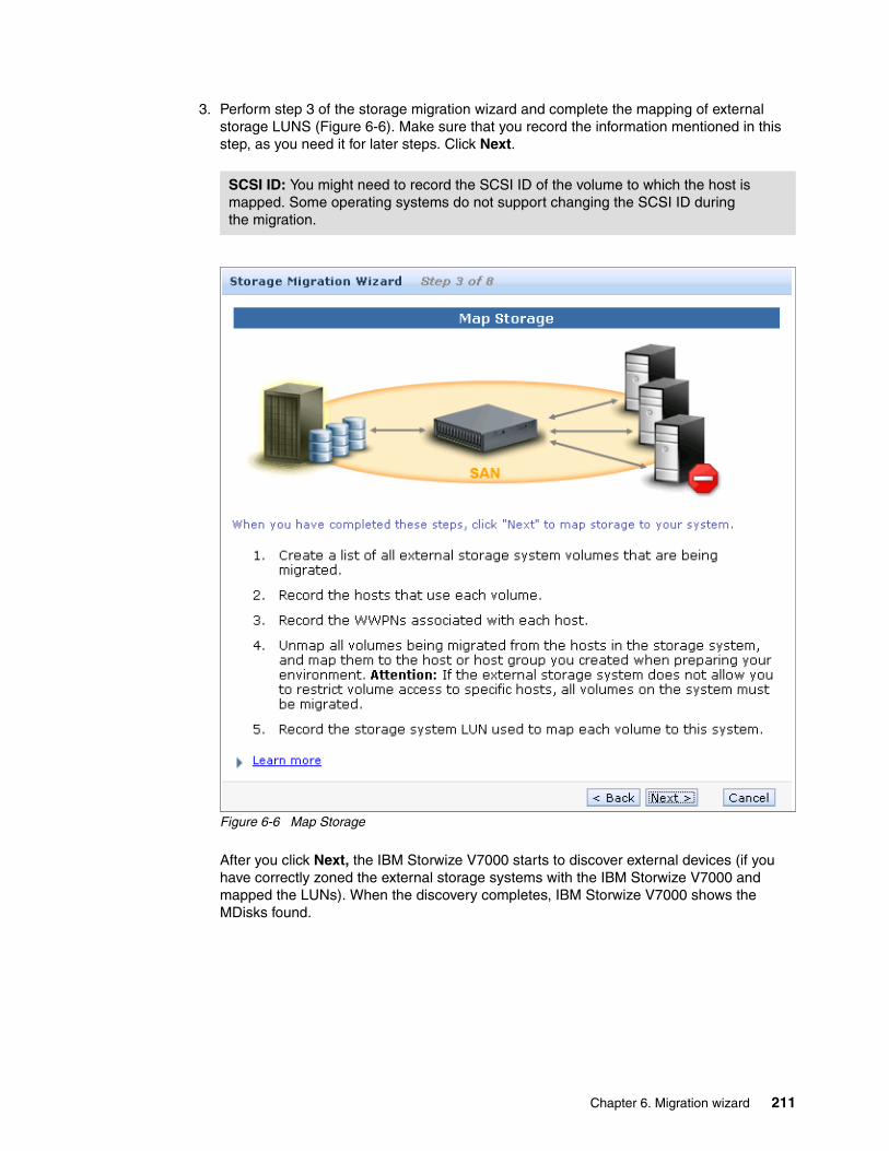
3. Perform step 3 of the storage migration wizard and complete the mapping of external storage LUNS (Figure 6-6). Make sure that you record the information mentioned in this step, as you need it for later steps. Click Next.
Figure 6-6 Map Storage
After you click Next, the IBM Storwize V7000 starts to discover external devices (if you have correctly zoned the external storage systems with the IBM Storwize V7000 and mapped the LUNs). When the discovery completes, IBM Storwize V7000 shows the MDisks found.
SCSI ID: You might need to record the SCSI ID of the volume to which the host is mapped. Some operating systems do not support changing the SCSI ID during the migration.
Chapter 6. Migration wizard 211

4. Choose the MDisks you want to migrate and click Next (Figure 6-7).
Figure 6-7 Migrate MDisks
If the MDisks that need migrating are in the list, select them and click Next. The IBM Storwize V7000 starts to import the MDisks that you have chosen. If the MDisks that need migrating are not in the list, you might need to check your zone configuration and LUN mapping, and click Detect MDisks to run the IBM Storwize V7000 discovery procedure again.
You can select one or more MDisks as required, and detailed information about the MDisk can be shown by double-clicking it.
In Figure 6-7, three LUNs are discovered as MDisks that are candidates for migration. In your particular situation, you might need to reference the information you recorded earlier to identify these MDisks. In our example, the MDisks have been selected to go forward to the next step.
When you click Next in this step, IBM Storwize V7000 completes the importation of the MDisks with the host’s data and a storage pool has been created. The MDisks are added to the pool and image mode volumes (with the same size as the MDisks) are created, which are ready for mapping back to the original hosts.
212 Implementing the IBM Storwize V7000 V6.3
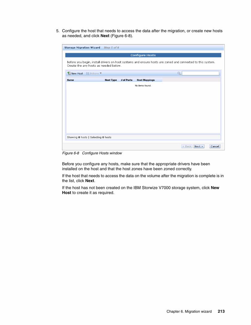
5. Configure the host that needs to access the data after the migration, or create new hosts as needed, and click Next (Figure 6-8).
Figure 6-8 Configure Hosts window
Before you configure any hosts, make sure that the appropriate drivers have been installed on the host and that the host zones have been zoned correctly.
If the host that needs to access the data on the volume after the migration is complete is in the list, click Next.
If the host has not been created on the IBM Storwize V7000 storage system, click New Host to create it as required.
Chapter 6. Migration wizard 213
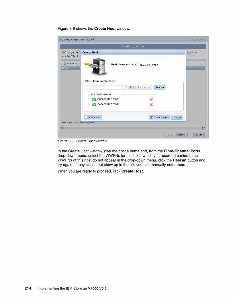
Figure 6-9 shows the Create Host window.
Figure 6-9 Create Host window
In the Create Host window, give the host a name and, from the Fibre-Channel Ports drop-down menu, select the WWPNs for this host, which you recorded earlier. If the WWPNs of this host do not appear in the drop-down menu, click the Rescan button and try again. If they still do not show up in the list, you can manually enter them.
When you are ready to proceed, click Create Host.
214 Implementing the IBM Storwize V7000 V6.3
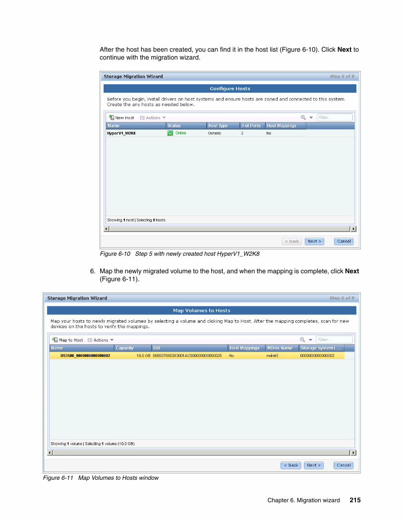
After the host has been created, you can find it in the host list (Figure 6-10). Click Next to continue with the migration wizard.
Figure 6-10 Step 5 with newly created host HyperV1_W2K8
6. Map the newly migrated volume to the host, and when the mapping is complete, click Next (Figure 6-11).
Figure 6-11 Map Volumes to Hosts window
Chapter 6. Migration wizard 215

In step 6 of the migration wizard, the volumes from the imported MDisks that need to be migrated have been listed. The names of the volumes have been assigned automatically by the IBM Storwize V7000 storage system. You can change the names to any words that would be meaningful to you by selecting the volume and clicking Rename in the Actions drop-down menu.
To map the volumes to the hosts, select the volumes and click Map to Host. A window opens with a drop-down list of the hosts. At this time, the IBM Storwize V7000 lets you choose which host to which you need to map the volumes. Choose the correct host and click Next.
Figure 6-12 shows the menu for choosing the host to which you map the volumes.
Figure 6-12 Choose the host to which you map the volumes
After choosing the host, the Modify Mappings window opens. On the right, you can find your newly mapped volumes highlighted in yellow. You can change the SCSI ID of the new mappings. Click OK to complete the mapping.
Names: The names must begin with a letter. The name can be a maximum of 63 characters. Valid characters are uppercase letters (A-Z), lowercase letters (a-z), digits (0 - 9), underscore (_), period (.), hyphen (-), and space. The names must not begin or end with a space.
Volume mapping: As a best practice, map the volume to the host with the same SCSI ID before the migration, which you should have recorded in step 3.
216 Implementing the IBM Storwize V7000 V6.3

Figure 6-13 shows the Modify Mappings window in the migration wizard.
Figure 6-13 Modify Mappings window in the migration wizard
When the mapping completes, you discover that the Host Mappings column of the volumes changed from No to Yes. A scan could be performed to discover the new devices on the host for verification. Click Next to go to the next step of the storage migration wizard.
Figure 6-14 shows step 6 of the storage migration wizard with host mappings modified.
Figure 6-14 Completion of the host mappings
Chapter 6. Migration wizard 217
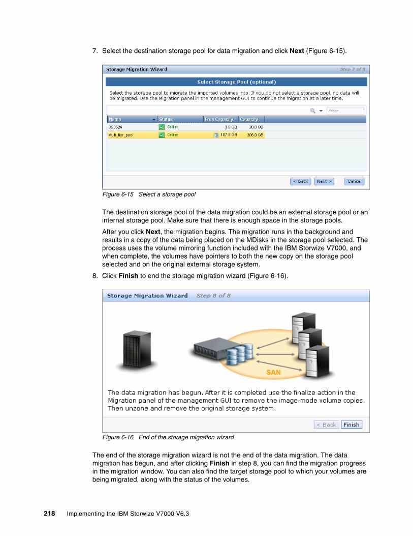
7. Select the destination storage pool for data migration and click Next (Figure 6-15).
Figure 6-15 Select a storage pool
The destination storage pool of the data migration could be an external storage pool or an internal storage pool. Make sure that there is enough space in the storage pools.
After you click Next, the migration begins. The migration runs in the background and results in a copy of the data being placed on the MDisks in the storage pool selected. The process uses the volume mirroring function included with the IBM Storwize V7000, and when complete, the volumes have pointers to both the new copy on the storage pool selected and on the original external storage system.
8. Click Finish to end the storage migration wizard (Figure 6-16).
Figure 6-16 End of the storage migration wizard
The end of the storage migration wizard is not the end of the data migration. The data migration has begun, and after clicking Finish in step 8, you can find the migration progress in the migration window. You can also find the target storage pool to which your volumes are being migrated, along with the status of the volumes.
218 Implementing the IBM Storwize V7000 V6.3
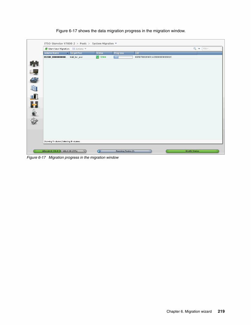
Figure 6-17 shows the data migration progress in the migration window.
Figure 6-17 Migration progress in the migration window
Chapter 6. Migration wizard 219
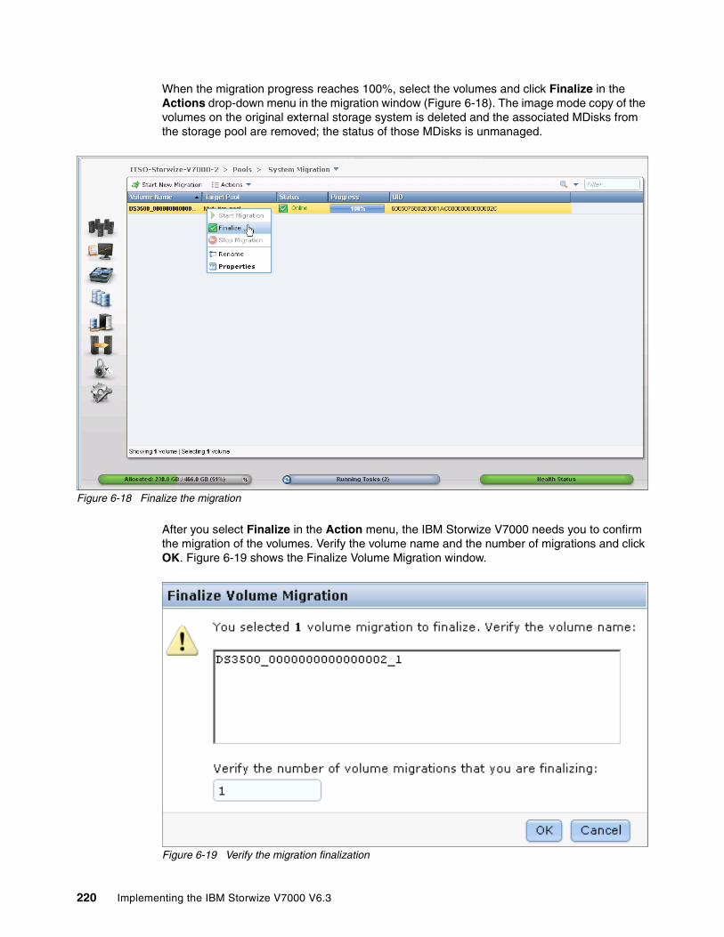
When the migration progress reaches 100%, select the volumes and click Finalize in the Actions drop-down menu in the migration window (Figure 6-18). The image mode copy of the volumes on the original external storage system is deleted and the associated MDisks from the storage pool are removed; the status of those MDisks is unmanaged.
Figure 6-18 Finalize the migration
After you select Finalize in the Action menu, the IBM Storwize V7000 needs you to confirm the migration of the volumes. Verify the volume name and the number of migrations and click OK. Figure 6-19 shows the Finalize Volume Migration window.
Figure 6-19 Verify the migration finalization
220 Implementing the IBM Storwize V7000 V6.3

When the finalization completes, the data migration to the IBM Storwize V7000 is done. You can un-zone and remove the older storage system from the IBM Storwize V7000.
For more information about the advanced migration function, see Chapter 7, “Storage pools” on page 223 and Chapter 9, “External storage virtualization” on page 333.
Chapter 6. Migration wizard 221

222 Implementing the IBM Storwize V7000 V6.3
Chapter 7. Storage pools
This chapter explains how IBM Storwize V7000 manages physical storage resources. All storage resources under IBM Storwize V7000 control are managed using storage pools. Storage pools make it easy to dynamically allocate resources, maximize productivity, and reduce costs. Advanced internal storage, MDisks, and storage pool management are covered in this chapter, while external storage is covered in Chapter 9, “External storage virtualization” on page 333.
7
© Copyright IBM Corp. 2011, 2012. All rights reserved. 223
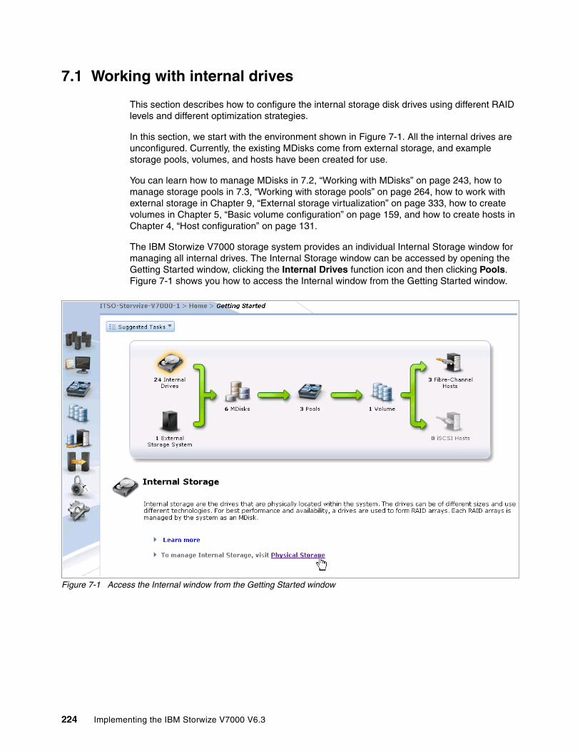
7.1 Working with internal drives
This section describes how to configure the internal storage disk drives using different RAID levels and different optimization strategies.
In this section, we start with the environment shown in Figure 7-1. All the internal drives are unconfigured. Currently, the existing MDisks come from external storage, and example storage pools, volumes, and hosts have been created for use.
You can learn how to manage MDisks in 7.2, “Working with MDisks” on page 243, how to manage storage pools in 7.3, “Working with storage pools” on page 264, how to work with external storage in Chapter 9, “External storage virtualization” on page 333, how to create volumes in Chapter 5, “Basic volume configuration” on page 159, and how to create hosts in Chapter 4, “Host configuration” on page 131.
The IBM Storwize V7000 storage system provides an individual Internal Storage window for managing all internal drives. The Internal Storage window can be accessed by opening the Getting Started window, clicking the Internal Drives function icon and then clicking Pools. Figure 7-1 shows you how to access the Internal window from the Getting Started window.
Figure 7-1 Access the Internal window from the Getting Started window
224 Implementing the IBM Storwize V7000 V6.3

An alternative way to access the Internal Storage window is by clicking the Pools icon on the left side of the window (Figure 7-2).
Figure 7-2 Access the Internal Storage window using the Pools icon
Chapter 7. Storage pools 225

The Internal Storage window (Figure 7-3) gives an overview of the internal drives installed in the IBM Storwize V7000 storage system. Selecting All Internal in the Drive Class Filter shows all the drives installed in the managed system, including attached expansion enclosures. Alternatively, you can filter the drives by their type or class, for example, you can choose to show only SAS, SATA or SSD drives.
Figure 7-3 Internal Storage window
On the right side of the Internal Storage window, the internal disk drives of the selected type are listed. By default, this additional information is listed along with it:
� Logical drive ID� Drive’s capacity� Current type of use (unused, candidate, member, spare, or failed)� Status (online, offline, and degraded)� MDisk’s name that the drive is a member of� Enclosure ID that it is installed in� Physical Drive Slot ID of the enclosure that it is installed in
226 Implementing the IBM Storwize V7000 V6.3
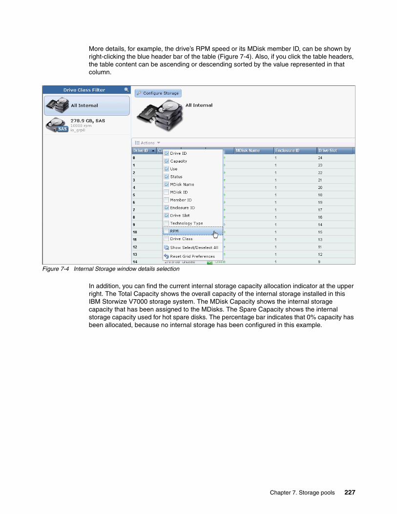
More details, for example, the drive’s RPM speed or its MDisk member ID, can be shown by right-clicking the blue header bar of the table (Figure 7-4). Also, if you click the table headers, the table content can be ascending or descending sorted by the value represented in that column.
Figure 7-4 Internal Storage window details selection
In addition, you can find the current internal storage capacity allocation indicator at the upper right. The Total Capacity shows the overall capacity of the internal storage installed in this IBM Storwize V7000 storage system. The MDisk Capacity shows the internal storage capacity that has been assigned to the MDisks. The Spare Capacity shows the internal storage capacity used for hot spare disks. The percentage bar indicates that 0% capacity has been allocated, because no internal storage has been configured in this example.
Chapter 7. Storage pools 227

7.1.1 Actions on internal drives
There are a few actions can be taken on internal drives when you select the drive and right-click it, or click the Actions drop-down menu (Figure 7-5).
Figure 7-5 Take actions on internal drives
� The Fix Error action starts the Directed Maintenance Procedure (DMP) for a defective drive. For more information about this topic, see Chapter 13, “RAS, monitoring, and troubleshooting for an IBM Storwize V7000 system” on page 521.
� The internal drives can be taken offline when there are problems on the drives by clicking Take Offline in the Actions drop-down menu. A confirmation window opens (Figure 7-6). The IBM Storwize V7000 storage system prevents the drive from being taken offline if there might be data loss as a result. A drive should be taken offline only if a spare drive is available.
Figure 7-6 Take Drive Offline warning window
228 Implementing the IBM Storwize V7000 V6.3
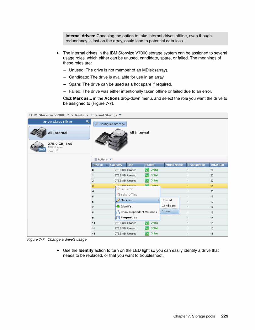
� The internal drives in the IBM Storwize V7000 storage system can be assigned to several usage roles, which either can be unused, candidate, spare, or failed. The meanings of these roles are:
– Unused: The drive is not member of an MDisk (array).
– Candidate: The drive is available for use in an array.
– Spare: The drive can be used as a hot spare if required.
– Failed: The drive was either intentionally taken offline or failed due to an error.
Click Mark as... in the Actions drop-down menu, and select the role you want the drive to be assigned to (Figure 7-7).
Figure 7-7 Change a drive’s usage
� Use the Identify action to turn on the LED light so you can easily identify a drive that needs to be replaced, or that you want to troubleshoot.
Internal drives: Choosing the option to take internal drives offline, even though redundancy is lost on the array, could lead to potential data loss.
Chapter 7. Storage pools 229
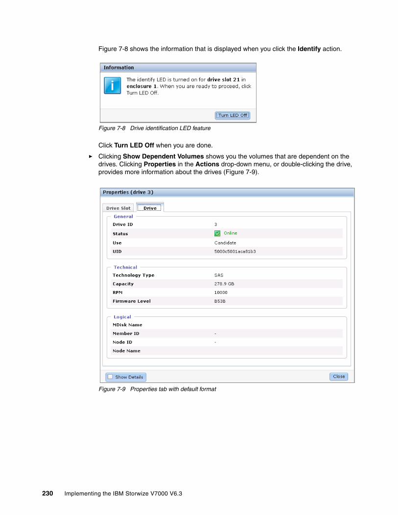
Figure 7-8 shows the information that is displayed when you click the Identify action.
Figure 7-8 Drive identification LED feature
Click Turn LED Off when you are done.
� Clicking Show Dependent Volumes shows you the volumes that are dependent on the drives. Clicking Properties in the Actions drop-down menu, or double-clicking the drive, provides more information about the drives (Figure 7-9).
Figure 7-9 Properties tab with default format
230 Implementing the IBM Storwize V7000 V6.3

� If you select the Show Details check box, you can discover more detailed information, including vendor ID, FRU Part Number, and ID (Figure 7-10).
Figure 7-10 Properties tab with details
7.1.2 Configuring internal storage
To configure internal storage for use with hosts, click Pools Internal Storage and click the Configure Storage button (Figure 7-4 on page 227). A configuration wizard opens and guides you through the process of configuring internal storage (Figure 7-11).
Figure 7-11 Wizard to Configure Internal Storage
Chapter 7. Storage pools 231

The wizard shows all internal drives with a status of candidate available for configuration. If there are internal drives with a status of unused, a window opens, offering to include them in the RAID configuration.
Using the storage configuration wizard simplifies the initial disk drive setup and offers two options:
� Use the recommended configuration� Select a different configuration
Selecting Use the recommended configuration guides you through the wizard described in “Using the recommended configuration” on page 234. Selecting Select a different configuration uses the wizard described in “Selecting a different configuration” on page 237.
Before going through the storage configuration wizard, we first describe IBM Storwize V7000 RAID configuration presets.
RAID configuration presetsRAID configuration presets are used to configure internal drives based on recommended values for the RAID level and drive class. Each preset has a specific goal for the number of drives per array, the number of spare drives to maintain redundancy, and whether the drives in the array are balanced across enclosure chains, thus protecting the array from enclosure failures. For details about enclosure chains, see 1.3, “IBM Storwize V7000 terminology” on page 4.
Table 7-1 describes the presets that are used for solid-state drives (SSDs) for the IBM Storwize V7000 storage system.
Table 7-1 SSD RAID presets
Preset Purpose RAID level
Drives per array goal
Spare drive goal
SSD RAID 5 Protects against a single drive failure. Data and one stripe of parity are striped across all array members.
5 8 1
SSD RAID 6 Protects against two drive failures. Data and two stripes of parity are striped across all array members.
6 12 1
SSD RAID 10 Protects against at least one drive failure. All data is mirrored on two array members.
10 8 1
SSD RAID 0 Provides no protection against drive failures.
0 8 0
SSD Easy Tier Mirrors data to protect against drive failure. The mirrored pairs are spread between storage pools to be used for the Easy Tier function.
10 2 1
SSD RAID instances: In all SSD RAID instances, drives in the array are balanced across enclosure chains if possible.
232 Implementing the IBM Storwize V7000 V6.3

Table 7-2 describes the RAID presets that are used for hard disk drives for the IBM Storwize V7000 storage system.
Table 7-2 HDD RAID presets
Preset Purpose RAID level
Drives per array goal
Spare goal
Chain balance
Basic RAID 5
Protects against a single drive failure. Data and one stripe of parity are striped across all array members.
5 8 1 All drives in the array are from the same chain wherever possible.
Basic RAID 6
Protects against two drive failures. Data and two stripes of parity are striped across all array members.
6 12 1 All drives in the array are from the same chain wherever possible.
Basic RAID 10
Protects against at least one drive failure. All data is mirrored on two array members.
10 8 1 All drives in the array are from the same chain wherever possible.
Balanced RAID 10
Protects against at least one drive or enclosure failure. All data is mirrored on two array members. The mirrors are balanced across the two enclosure chains.
10 8 1 Exactly half of the drives are from each chain.
RAID 0 Provides no protection against drive failures.
0 8 0 All drives in the array are from the same chain wherever possible.
Chapter 7. Storage pools 233
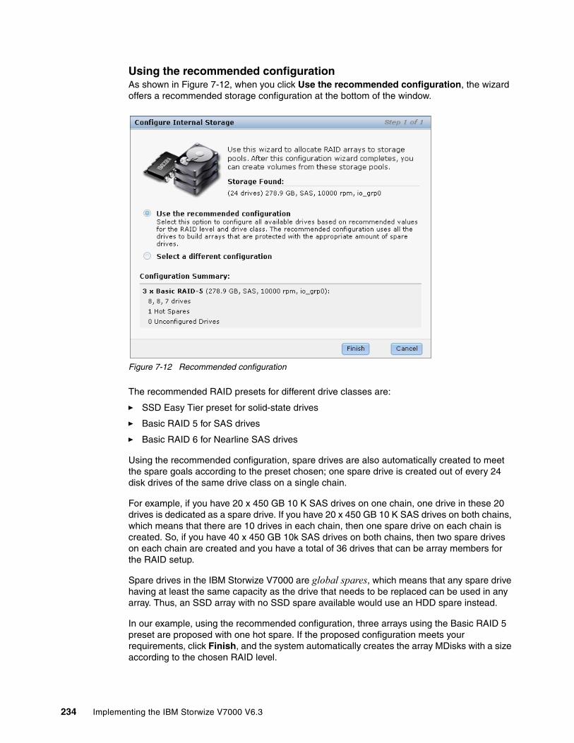
Using the recommended configurationAs shown in Figure 7-12, when you click Use the recommended configuration, the wizard offers a recommended storage configuration at the bottom of the window.
Figure 7-12 Recommended configuration
The recommended RAID presets for different drive classes are:
� SSD Easy Tier preset for solid-state drives
� Basic RAID 5 for SAS drives
� Basic RAID 6 for Nearline SAS drives
Using the recommended configuration, spare drives are also automatically created to meet the spare goals according to the preset chosen; one spare drive is created out of every 24 disk drives of the same drive class on a single chain.
For example, if you have 20 x 450 GB 10 K SAS drives on one chain, one drive in these 20 drives is dedicated as a spare drive. If you have 20 x 450 GB 10 K SAS drives on both chains, which means that there are 10 drives in each chain, then one spare drive on each chain is created. So, if you have 40 x 450 GB 10k SAS drives on both chains, then two spare drives on each chain are created and you have a total of 36 drives that can be array members for the RAID setup.
Spare drives in the IBM Storwize V7000 are global spares, which means that any spare drive having at least the same capacity as the drive that needs to be replaced can be used in any array. Thus, an SSD array with no SSD spare available would use an HDD spare instead.
In our example, using the recommended configuration, three arrays using the Basic RAID 5 preset are proposed with one hot spare. If the proposed configuration meets your requirements, click Finish, and the system automatically creates the array MDisks with a size according to the chosen RAID level.
234 Implementing the IBM Storwize V7000 V6.3

Storage pools are also automatically created to contain the MDisks with similar performance characteristics, including the consideration of RAID level, number of member drives, drive class, and so on.
After creating an array, the Array MDisk members are being synchronized with each other through a background initialization process. The progress of the initialization process can be monitored by clicking the icon at the left of the Running Tasks status bar and then clicking the task displayed (Figure 7-13).
Figure 7-13 Running Tasks status bar
The progress window opens (Figure 7-14). The array is available for I/O during this process. The initialization does not affect the availability due to possible member drive failures.
Figure 7-14 Array initialization
Chapter 7. Storage pools 235
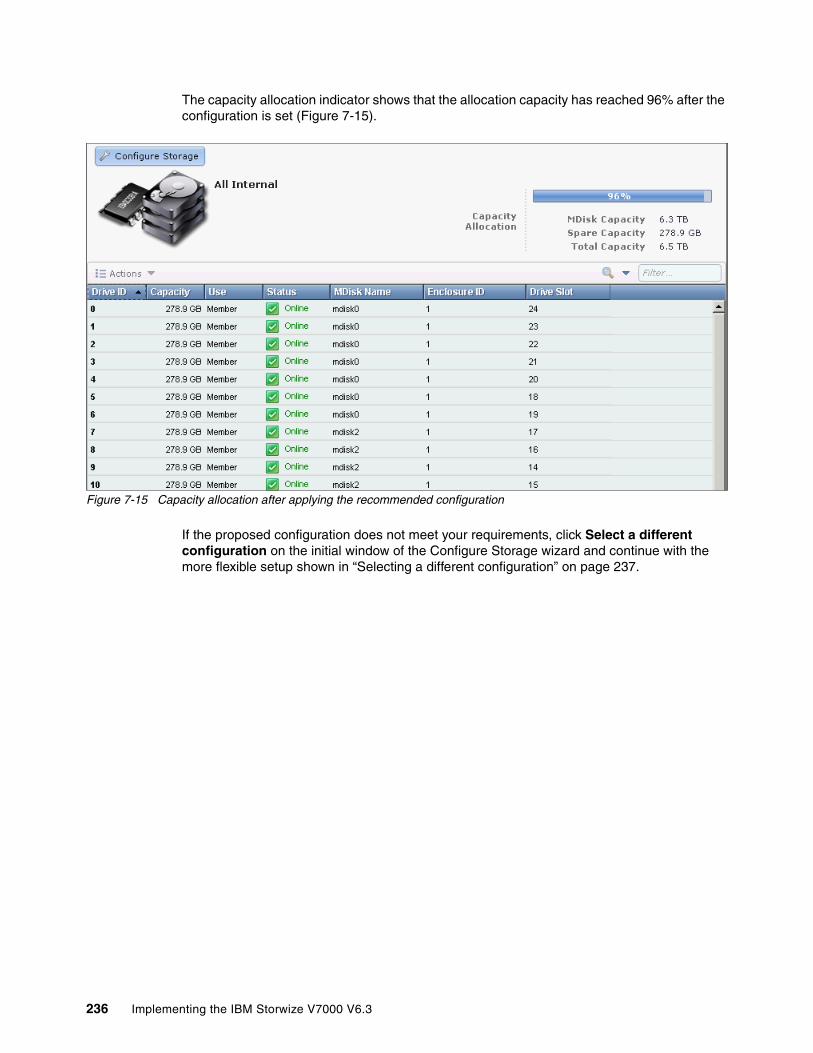
The capacity allocation indicator shows that the allocation capacity has reached 96% after the configuration is set (Figure 7-15).
Figure 7-15 Capacity allocation after applying the recommended configuration
If the proposed configuration does not meet your requirements, click Select a different configuration on the initial window of the Configure Storage wizard and continue with the more flexible setup shown in “Selecting a different configuration” on page 237.
236 Implementing the IBM Storwize V7000 V6.3

Selecting a different configurationThe option Select a different configuration offers a more flexible way for the configuration of the internal storage as compared to the Use the recommended configuration preset in terms of drive selection, RAID level, and storage pool to be used.
Complete the following steps:
1. Click Select a different configuration and choose the Drive Class you want to configure (Figure 7-16).
Figure 7-16 Select a drive class
Chapter 7. Storage pools 237
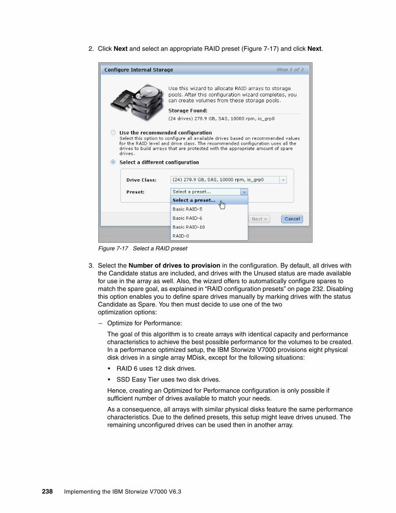
2. Click Next and select an appropriate RAID preset (Figure 7-17) and click Next.
Figure 7-17 Select a RAID preset
3. Select the Number of drives to provision in the configuration. By default, all drives with the Candidate status are included, and drives with the Unused status are made available for use in the array as well. Also, the wizard offers to automatically configure spares to match the spare goal, as explained in “RAID configuration presets” on page 232. Disabling this option enables you to define spare drives manually by marking drives with the status Candidate as Spare. You then must decide to use one of the two optimization options:
– Optimize for Performance:
The goal of this algorithm is to create arrays with identical capacity and performance characteristics to achieve the best possible performance for the volumes to be created. In a performance optimized setup, the IBM Storwize V7000 provisions eight physical disk drives in a single array MDisk, except for the following situations:
• RAID 6 uses 12 disk drives.
• SSD Easy Tier uses two disk drives.
Hence, creating an Optimized for Performance configuration is only possible if sufficient number of drives available to match your needs.
As a consequence, all arrays with similar physical disks feature the same performance characteristics. Due to the defined presets, this setup might leave drives unused. The remaining unconfigured drives can be used then in another array.
238 Implementing the IBM Storwize V7000 V6.3
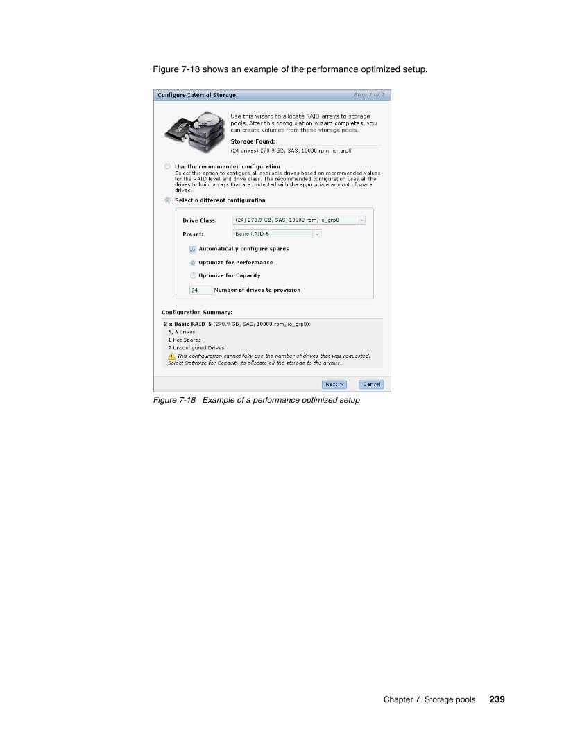
Figure 7-18 shows an example of the performance optimized setup.
Figure 7-18 Example of a performance optimized setup
Chapter 7. Storage pools 239
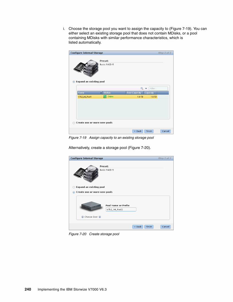
i. Choose the storage pool you want to assign the capacity to (Figure 7-19). You can either select an existing storage pool that does not contain MDisks, or a pool containing MDisks with similar performance characteristics, which is listed automatically.
Figure 7-19 Assign capacity to an existing storage pool
Alternatively, create a storage pool (Figure 7-20).
Figure 7-20 Create storage pool
240 Implementing the IBM Storwize V7000 V6.3

ii. Click Finish to finalize the wizard. After the wizard completes, the configuration changes are reflected at the upper right of the Internal Storage window (Figure 7-21).
Figure 7-21 Configuration complete with performance optimized setup
With the performance optimized setup, two array MDisks have been created, each containing eight drives. Seven drives remained unconfigured, as they did not meet the goal of eight drives for a Basic RAID 5 array to create another performance optimized MDisk. The progress of the array initialization process is displayed in the Running Tasks status indicator, and the capacity allocation indicator has been updated to 67% as well.
– Optimize for Capacity:
The goal of this algorithm is to create a setup with the maximum usable capacity, depending on the selected RAID level.
While creating arrays, the IBM Storwize V7000 system attempts to fulfill the width goal for each array before creating another one. This setup is an example with 24 unused drives, Select a different configuration was chosen with the following options:
• Preset: Basic RAID-5.
• Automatically configure spares was checked.
• Optimize for capacity.
The results are as follows:
• One hot spare drive is defined.
• Three basic RAID 5 arrays are created. Two of the arrays contain eight drives that are width goal matched. One array contains the remaining seven drives that are width goal not fully matched.
• No unused drives are left.
Chapter 7. Storage pools 241
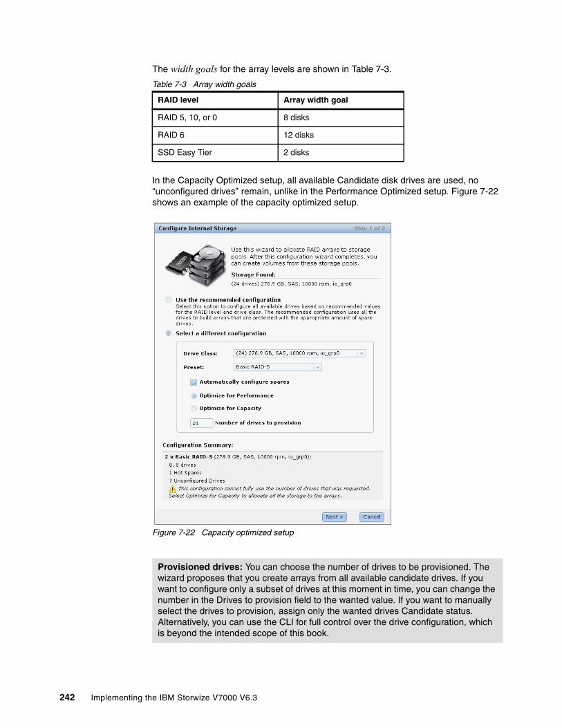
The width goals for the array levels are shown in Table 7-3.
Table 7-3 Array width goals
In the Capacity Optimized setup, all available Candidate disk drives are used, no “unconfigured drives” remain, unlike in the Performance Optimized setup. Figure 7-22 shows an example of the capacity optimized setup.
Figure 7-22 Capacity optimized setup
RAID level Array width goal
RAID 5, 10, or 0 8 disks
RAID 6 12 disks
SSD Easy Tier 2 disks
Provisioned drives: You can choose the number of drives to be provisioned. The wizard proposes that you create arrays from all available candidate drives. If you want to configure only a subset of drives at this moment in time, you can change the number in the Drives to provision field to the wanted value. If you want to manually select the drives to provision, assign only the wanted drives Candidate status. Alternatively, you can use the CLI for full control over the drive configuration, which is beyond the intended scope of this book.
242 Implementing the IBM Storwize V7000 V6.3

7.2 Working with MDisks
After the configuration is completed for the internal storage, you can find the MDisks created on the internal arrays in the MDisks by Pools window.
You can access the MDisks window by clicking Home Overview and clicking the MDisks function icon. In the extended help information window, click Pools.
Figure 7-23 shows how to access the Pools window from the Getting Started window.
Figure 7-23 Access the Pools management window from the Overview window
Chapter 7. Storage pools 243

Another way to access the MDisks window is by using the Physical Storage function icon on the left (Figure 7-24).
Figure 7-24 Access the MDisks by Pools window using the Physical Storage function icon
The MDisks by Pools window (Figure 7-25) lets you manage all MDisks made of both internal and external storage.
Figure 7-25 MDisks by Pools window
244 Implementing the IBM Storwize V7000 V6.3
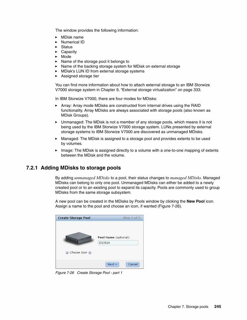
The window provides the following information:
� MDisk name� Numerical ID� Status� Capacity� Mode� Name of the storage pool it belongs to� Name of the backing storage system for MDisk on external storage� MDisk’s LUN ID from external storage systems� Assigned storage tier
You can find more information about how to attach external storage to an IBM Storwize V7000 storage system in Chapter 9, “External storage virtualization” on page 333.
In IBM Storwize V7000, there are four modes for MDisks:
� Array: Array mode MDisks are constructed from internal drives using the RAID functionality. Array MDisks are always associated with storage pools (also known as MDisk Groups).
� Unmanaged: The MDisk is not a member of any storage pools, which means it is not being used by the IBM Storwize V7000 storage system. LUNs presented by external storage systems to IBM Storwize V7000 are discovered as unmanaged MDisks.
� Managed: The MDisk is assigned to a storage pool and provides extents to be used by volumes.
� Image: The MDisk is assigned directly to a volume with a one-to-one mapping of extents between the MDisk and the volume.
7.2.1 Adding MDisks to storage pools
By adding unmanaged MDisks to a pool, their status changes to managed MDisks. Managed MDisks can belong to only one pool. Unmanaged MDisks can either be added to a newly created pool or to an existing pool to expand its capacity. Pools are commonly used to group MDisks from the same storage subsystem.
A new pool can be created in the MDisks by Pools window by clicking the New Pool icon. Assign a name to the pool and choose an icon, if wanted (Figure 7-26).
Figure 7-26 Create Storage Pool - part 1
Chapter 7. Storage pools 245

The Create Storage Pool window (Figure 7-27) lets you include unmanaged MDisks in the new pool. Several filter options at the top of the window allow you to limit the selection, for example, by storage subsystem, capacity, and so on. Several MDisks can be selected by pressing the Ctrl key while clicking the MDisks listed with the mouse. Also, the Detect MDisks icon initiates a SAN discovery for finding recently attached external storage systems.
Figure 7-27 Create Storage Pools - part 2
To add an unmanaged MDisks to an existing pool select the MDisk, click Actions Add to Pool (Figure 7-28).
Figure 7-28 Add an unmanaged MDisk to a storage pool
246 Implementing the IBM Storwize V7000 V6.3
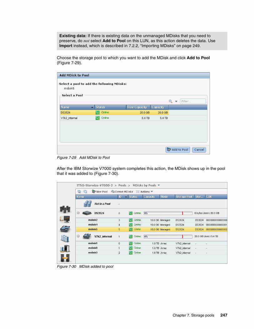
Choose the storage pool to which you want to add the MDisk and click Add to Pool (Figure 7-29).
Figure 7-29 Add MDisk to Pool
After the IBM Storwize V7000 system completes this action, the MDisk shows up in the pool that it was added to (Figure 7-30).
Figure 7-30 MDisk added to pool
Existing data: If there is existing data on the unmanaged MDisks that you need to preserve, do not select Add to Pool on this LUN, as this action deletes the data. Use Import instead, which is described in 7.2.2, “Importing MDisks” on page 249.
Chapter 7. Storage pools 247
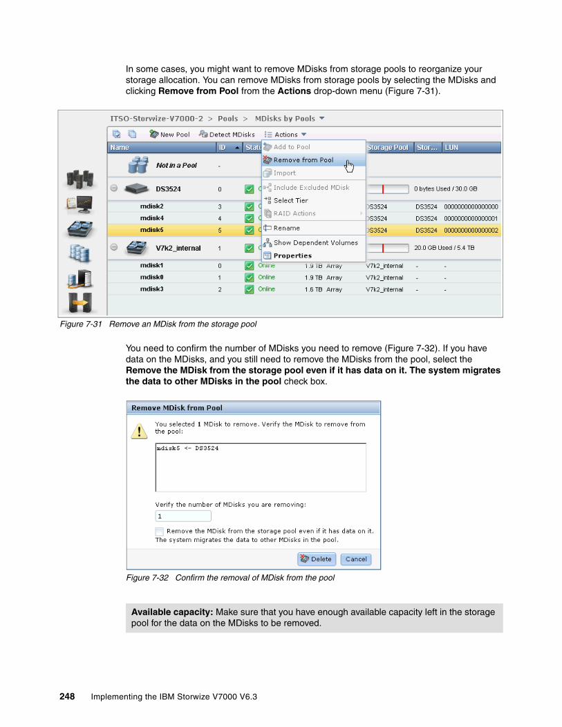
In some cases, you might want to remove MDisks from storage pools to reorganize your storage allocation. You can remove MDisks from storage pools by selecting the MDisks and clicking Remove from Pool from the Actions drop-down menu (Figure 7-31).
Figure 7-31 Remove an MDisk from the storage pool
You need to confirm the number of MDisks you need to remove (Figure 7-32). If you have data on the MDisks, and you still need to remove the MDisks from the pool, select the Remove the MDisk from the storage pool even if it has data on it. The system migrates the data to other MDisks in the pool check box.
Figure 7-32 Confirm the removal of MDisk from the pool
Available capacity: Make sure that you have enough available capacity left in the storage pool for the data on the MDisks to be removed.
248 Implementing the IBM Storwize V7000 V6.3

After you click Delete, data migration from the MDisks to be removed starts. You can find the migration progress in the Running Tasks status indicator (Figure 7-33).
Figure 7-33 Data migration progress when removing MDisks from the pool
7.2.2 Importing MDisks
LUNs hosted on external storage systems can be migrated into IBM Storwize V7000 storage. Hosts, which used to be directly attached to those external storage systems, can continue to use their storage that is now presented by the IBM Storwize V7000 instead.
To achieve this configuration, the existing external LUNs must be imported as an image-mode volume using the Import option. This action is possible for unmanaged MDisks only. Those disks must not have been added to a pool, as described in 7.2.1, “Adding MDisks to storage pools” on page 245.
If the Import option is used and no existing storage pool is chosen, a temporary migration pool is created to hold the new image-mode volume. This image-mode volume has a direct block-for-block translation from the imported MDisk to the volume presented from now on by the IBM Storwize V7000 and existing data is being preserved.
Chapter 7. Storage pools 249

In Figure 7-34, we show an example of how to import an unmanaged MDisk. Select the unmanaged MDisk and click Import from the Actions drop-down menu.
Figure 7-34 Import MDisk
As shown in Figure 7-35, the import wizard is activated and guides you through the import process.
Figure 7-35 Import Wizard step 1 of 2
In step 1 of the Import Wizard, you must decide whether the volume is imported as a generic volume (the default) or as thin-provisioned. Caching for the volume can be disabled; it is enabled by default.
� Select Use thin-provisioning only if the volume to be imported originally was a thin-provisioned volume that was exported to an image-mode volume. More information about export volumes is available in Chapter 8, “Advanced host and volume administration” on page 269.
� Clear Enable Caching if you use copy services on the external storage system hosting the LUN. It is a best practice to use the copy services of IBM Storwize V7000 for volumes virtualized. You can find more information about virtualizing external storage in Chapter 9, “External storage virtualization” on page 333.
250 Implementing the IBM Storwize V7000 V6.3

If you want to migrate the data from the external volume (that is being imported) to existing V7000 MDisks, choose an existing destination storage pool; only pools with sufficient free capacity are listed (Figure 7-36). The actual data migration begins after the MDisk was imported successfully.
Figure 7-36 Import Wizard - step 2 of 2
You can check the migration progress in the Running Tasks status indicator (Figure 7-37) or by clicking Pools System Migration.
Figure 7-37 Migration progress in the status indicator of Running Tasks
Chapter 7. Storage pools 251
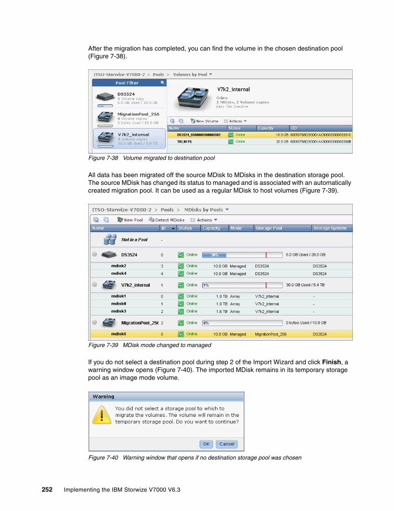
After the migration has completed, you can find the volume in the chosen destination pool (Figure 7-38).
Figure 7-38 Volume migrated to destination pool
All data has been migrated off the source MDisk to MDisks in the destination storage pool. The source MDisk has changed its status to managed and is associated with an automatically created migration pool. It can be used as a regular MDisk to host volumes (Figure 7-39).
Figure 7-39 MDisk mode changed to managed
If you do not select a destination pool during step 2 of the Import Wizard and click Finish, a warning window opens (Figure 7-40). The imported MDisk remains in its temporary storage pool as an image mode volume.
Figure 7-40 Warning window that opens if no destination storage pool was chosen
252 Implementing the IBM Storwize V7000 V6.3
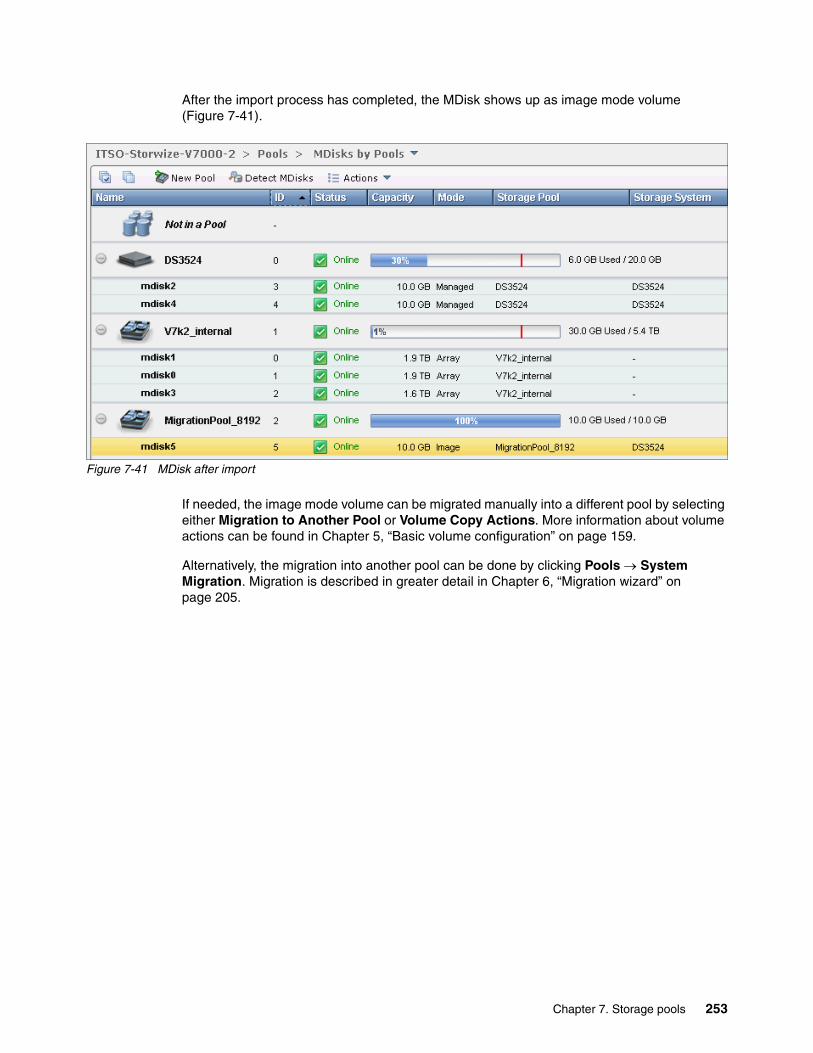
After the import process has completed, the MDisk shows up as image mode volume (Figure 7-41).
Figure 7-41 MDisk after import
If needed, the image mode volume can be migrated manually into a different pool by selecting either Migration to Another Pool or Volume Copy Actions. More information about volume actions can be found in Chapter 5, “Basic volume configuration” on page 159.
Alternatively, the migration into another pool can be done by clicking Pools System Migration. Migration is described in greater detail in Chapter 6, “Migration wizard” on page 205.
Chapter 7. Storage pools 253
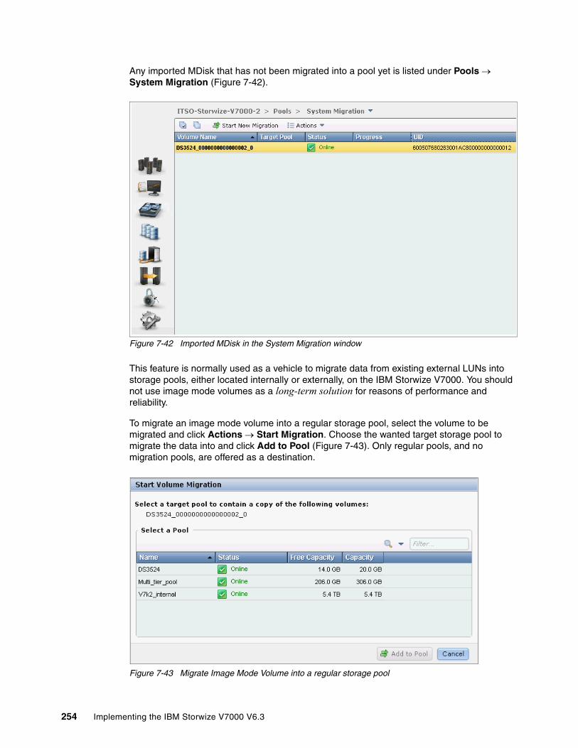
Any imported MDisk that has not been migrated into a pool yet is listed under Pools System Migration (Figure 7-42).
Figure 7-42 Imported MDisk in the System Migration window
This feature is normally used as a vehicle to migrate data from existing external LUNs into storage pools, either located internally or externally, on the IBM Storwize V7000. You should not use image mode volumes as a long-term solution for reasons of performance and reliability.
To migrate an image mode volume into a regular storage pool, select the volume to be migrated and click Actions Start Migration. Choose the wanted target storage pool to migrate the data into and click Add to Pool (Figure 7-43). Only regular pools, and no migration pools, are offered as a destination.
Figure 7-43 Migrate Image Mode Volume into a regular storage pool
254 Implementing the IBM Storwize V7000 V6.3

The migration itself internally uses the volume copy function, which creates a second copy of the existing volume in the chosen target pool. For more information about the volume copy function, see 8.6, “Advanced volume copy functions” on page 318. If the migration process is interrupted for any reason, select the volume being migrated and click Actions Stop Migration (Figure 7-44). The process of adding a secondary volume copy is interrupted.
Figure 7-44 Stop Migration
When the migration progress reaches 100%, click Finalize to complete the migration process (Figure 7-45).
Figure 7-45 Finalize volume migration
The original volume copy on the image mode MDisk is deleted and the newly created copy is kept. The source image mode MDisk is removed from the Migration Pool and changes its mode back to unmanaged.
Chapter 7. Storage pools 255

7.2.3 RAID action for MDisks
Internal drives in the IBM Storwize V7000 are managed as Array mode MDisks, on which several RAID actions can be performed. Select the appropriate Array MDisk by clicking Pools MDisks by Pools, and then click Actions RAID Actions (Figure 7-46).
Figure 7-46 RAID actions on Array MDisks
You can choose the following RAID actions:
� Set Spare Goal: You can set the wanted number of spare drives that is required to protect the array from drive failures. If the number of drives assigned as Spare does not meet the configured spare goal, an error is logged in the event log that reads “Array MDisk is not protected by sufficient spares”. This error can be fixed by either replacing defunct drives, which occupy a spare drive, or by adding additional drives as spare. Remember that during the internal drive configuration that automatically spare drives are assigned according to the chosen RAID preset’s spare goals, as described in 7.1.2, “Configuring internal storage” on page 231.
256 Implementing the IBM Storwize V7000 V6.3
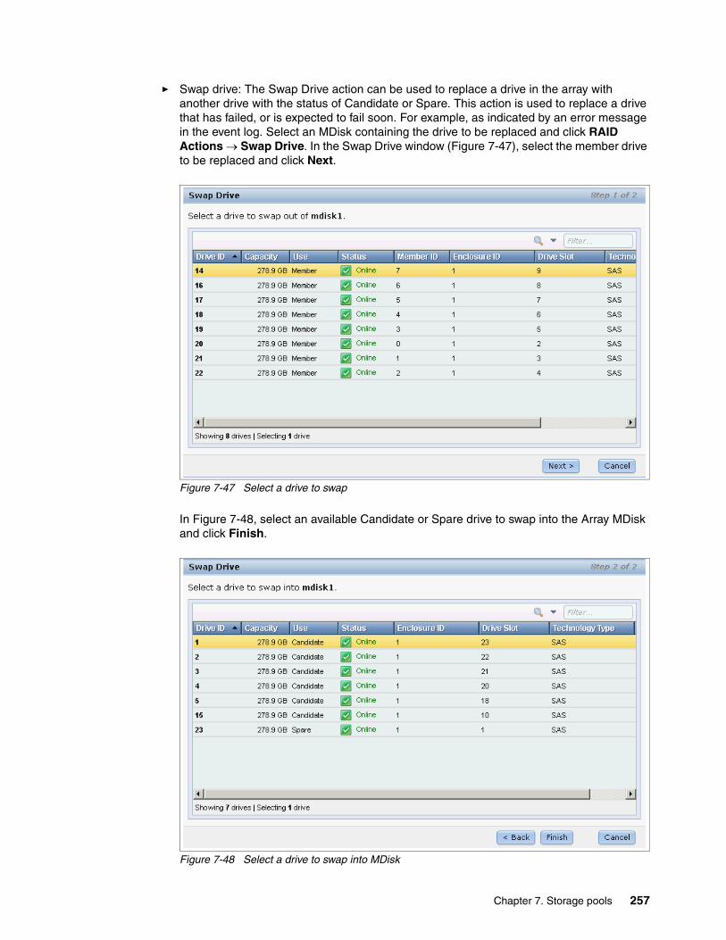
� Swap drive: The Swap Drive action can be used to replace a drive in the array with another drive with the status of Candidate or Spare. This action is used to replace a drive that has failed, or is expected to fail soon. For example, as indicated by an error message in the event log. Select an MDisk containing the drive to be replaced and click RAID Actions Swap Drive. In the Swap Drive window (Figure 7-47), select the member drive to be replaced and click Next.
Figure 7-47 Select a drive to swap
In Figure 7-48, select an available Candidate or Spare drive to swap into the Array MDisk and click Finish.
Figure 7-48 Select a drive to swap into MDisk
Chapter 7. Storage pools 257
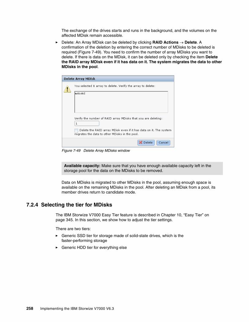
The exchange of the drives starts and runs in the background, and the volumes on the affected MDisk remain accessible.
� Delete: An Array MDisk can be deleted by clicking RAID Actions Delete. A confirmation of the deletion by entering the correct number of MDisks to be deleted is required (Figure 7-49). You need to confirm the number of array MDisks you want to delete. If there is data on the MDisk, it can be deleted only by checking the item Delete the RAID array MDisk even if it has data on it. The system migrates the data to other MDisks in the pool.
Figure 7-49 Delete Array MDisks window
Data on MDisks is migrated to other MDisks in the pool, assuming enough space is available on the remaining MDisks in the pool. After deleting an MDisk from a pool, its member drives return to candidate mode.
7.2.4 Selecting the tier for MDisks
The IBM Storwize V7000 Easy Tier feature is described in Chapter 10, “Easy Tier” on page 345. In this section, we show how to adjust the tier settings.
There are two tiers:
� Generic SSD tier for storage made of solid-state drives, which is the faster-performing storage
� Generic HDD tier for everything else
Available capacity: Make sure that you have enough available capacity left in the storage pool for the data on the MDisks to be removed.
258 Implementing the IBM Storwize V7000 V6.3
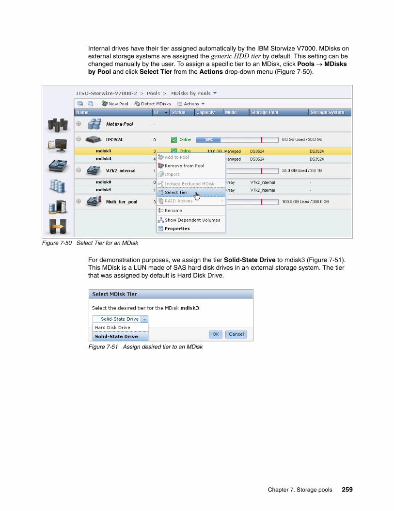
Internal drives have their tier assigned automatically by the IBM Storwize V7000. MDisks on external storage systems are assigned the generic HDD tier by default. This setting can be changed manually by the user. To assign a specific tier to an MDisk, click Pools MDisks by Pool and click Select Tier from the Actions drop-down menu (Figure 7-50).
Figure 7-50 Select Tier for an MDisk
For demonstration purposes, we assign the tier Solid-State Drive to mdisk3 (Figure 7-51). This MDisk is a LUN made of SAS hard disk drives in an external storage system. The tier that was assigned by default is Hard Disk Drive.
Figure 7-51 Assign desired tier to an MDisk
Chapter 7. Storage pools 259

After the action has been completed successfully, the MDisk can be found in the SSD tier (Figure 7-52).
Figure 7-52 The desired tier has been assigned to the MDisk
7.2.5 Additional actions on MDisks
Here are some of the additional actions that can be performed on MDisks.
� Detect MDisks: The Detect MDisks button at the upper left of the MDisks by Pools window is useful if you have external storage controllers in your environment (for more information about this topic, see Chapter 9, “External storage virtualization” on page 333). The Detect MDisk action initiates a rescan of the Fibre Channel network. It discovers any new MDisks that have been mapped to the IBM Storwize V7000 storage system, and rebalances MDisk access across the available controller device ports. This action also detects any loss of controller port availability, and updates the IBM Storwize V7000 configuration to reflect any changes.
When external storage controllers are added to the IBM Storwize V7000 environment, the IBM Storwize V7000 automatically discovers the controllers and the LUNs that are presented by those controllers are listed as unmanaged MDisks. However, if you have attached new storage and the IBM Storwize V7000 has not detected it, you might need to use the Detect MDisk button before the system detects the new LUNs. If the configuration of the external controllers is modified afterward, the IBM Storwize V7000 might be unaware of these configuration changes. Use the Detect MDisk button to rescan the Fibre Channel network and update the list of unmanaged MDisks.
� Include Excluded MDisks: An MDisk could be excluded from the IBM Storwize V7000 because of multiple I/O failures. These failures might be caused, for example, by link errors. After a fabric-related problem has been fixed, the excluded disk can be added back into the IBM Storwize V7000 by selecting the MDisks and clicking Include Excluded MDisk from the Actions drop-down menu.
MDisks detection: The Detect MDisks action is asynchronous. Although the task appears to be finished, it still might be running in the background.
260 Implementing the IBM Storwize V7000 V6.3

� Rename: MDisks can be renamed by selecting the MDisk and clicking Rename from the Actions drop-down menu. Input the new name of your MDisk and click Rename (Figure 7-53).
Figure 7-53 Rename MDisk
� Show Dependent Volumes: The volumes dependent on a particular MDisk can be displayed by selecting the MDisk and clicking Show Dependent Volumes from the Actions drop-down list. The volumes are listed with general information (Figure 7-54).
Figure 7-54 Show dependent volumes
Chapter 7. Storage pools 261

Several actions can be taken on volumes by selecting the volume and choosing the action needed from the Actions drop-down menu (Figure 7-55). For more information about volume actions, see Chapter 5, “Basic volume configuration” on page 159.
Figure 7-55 Available actions on volumes
The Properties action for an MDisk shows the information that you need to identify it. In the MDisks by Pools window, select the MDisk and click Properties from the Actions drop-down menu. A window opens (Figure 7-56).
Figure 7-56 MDisk overview with general information
262 Implementing the IBM Storwize V7000 V6.3

There are three tabs in this information window.
– The Overview tab contains information about the MDisk itself. To show more details, click Show Details (Figure 7-57).
Figure 7-57 MDisk overview with detailed information
– The Dependent Volumes tab lists all volumes using extents on this MDisk.
Chapter 7. Storage pools 263
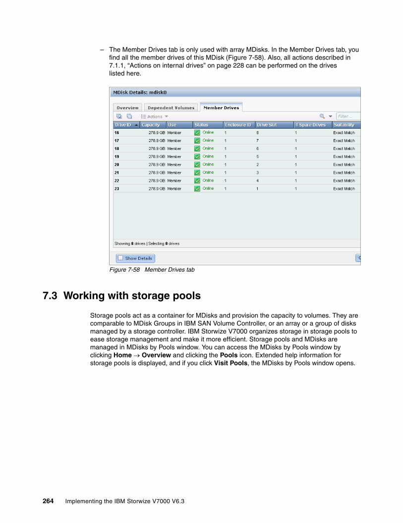
– The Member Drives tab is only used with array MDisks. In the Member Drives tab, you find all the member drives of this MDisk (Figure 7-58). Also, all actions described in 7.1.1, “Actions on internal drives” on page 228 can be performed on the drives listed here.
Figure 7-58 Member Drives tab
7.3 Working with storage pools
Storage pools act as a container for MDisks and provision the capacity to volumes. They are comparable to MDisk Groups in IBM SAN Volume Controller, or an array or a group of disks managed by a storage controller. IBM Storwize V7000 organizes storage in storage pools to ease storage management and make it more efficient. Storage pools and MDisks are managed in MDisks by Pools window. You can access the MDisks by Pools window by clicking Home Overview and clicking the Pools icon. Extended help information for storage pools is displayed, and if you click Visit Pools, the MDisks by Pools window opens.
264 Implementing the IBM Storwize V7000 V6.3

Figure 7-59 shows how to access the Pools window from the Overview window.
Figure 7-59 Access Pool management window from the Overview window
The other way to access the Pools window is to click Pools MDisks by Pools (Figure 7-60).
Figure 7-60 Access Pools window from Physical Storage function icon
Chapter 7. Storage pools 265
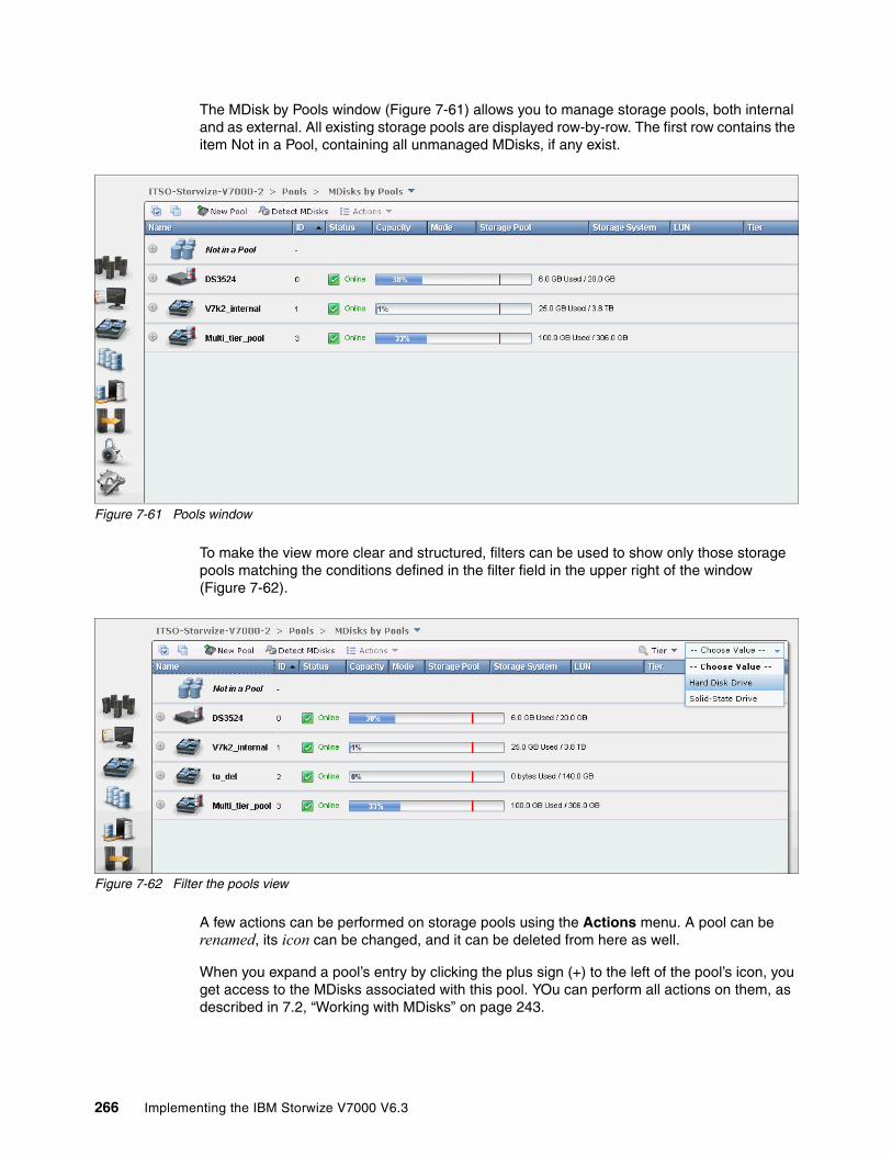
The MDisk by Pools window (Figure 7-61) allows you to manage storage pools, both internal and as external. All existing storage pools are displayed row-by-row. The first row contains the item Not in a Pool, containing all unmanaged MDisks, if any exist.
Figure 7-61 Pools window
To make the view more clear and structured, filters can be used to show only those storage pools matching the conditions defined in the filter field in the upper right of the window (Figure 7-62).
Figure 7-62 Filter the pools view
A few actions can be performed on storage pools using the Actions menu. A pool can be renamed, its icon can be changed, and it can be deleted from here as well.
When you expand a pool’s entry by clicking the plus sign (+) to the left of the pool’s icon, you get access to the MDisks associated with this pool. YOu can perform all actions on them, as described in 7.2, “Working with MDisks” on page 243.
266 Implementing the IBM Storwize V7000 V6.3
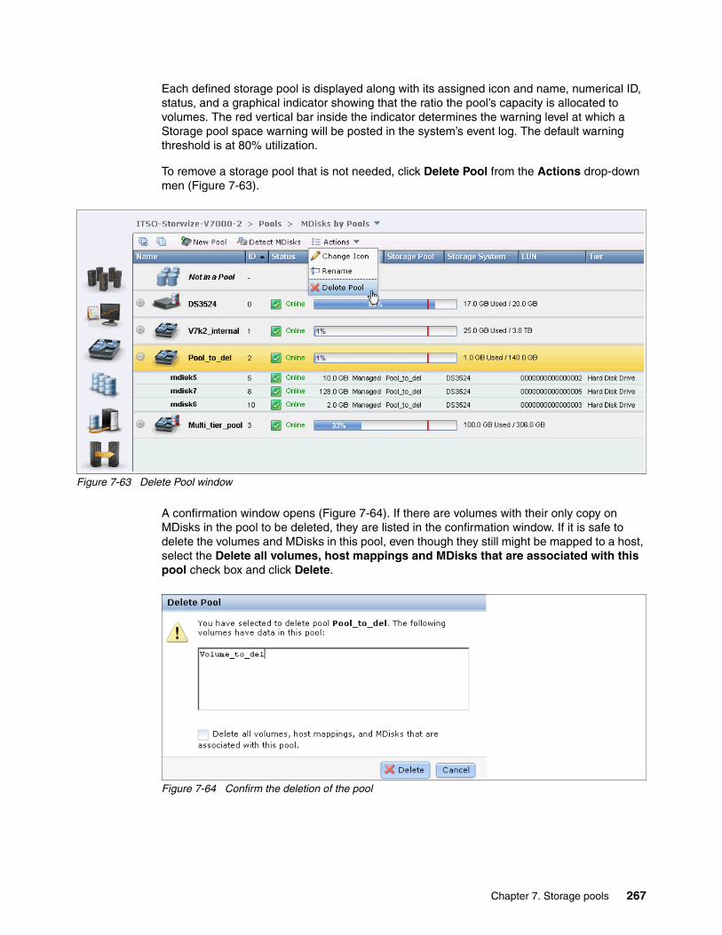
Each defined storage pool is displayed along with its assigned icon and name, numerical ID, status, and a graphical indicator showing that the ratio the pool’s capacity is allocated to volumes. The red vertical bar inside the indicator determines the warning level at which a Storage pool space warning will be posted in the system’s event log. The default warning threshold is at 80% utilization.
To remove a storage pool that is not needed, click Delete Pool from the Actions drop-down men (Figure 7-63).
Figure 7-63 Delete Pool window
A confirmation window opens (Figure 7-64). If there are volumes with their only copy on MDisks in the pool to be deleted, they are listed in the confirmation window. If it is safe to delete the volumes and MDisks in this pool, even though they still might be mapped to a host, select the Delete all volumes, host mappings and MDisks that are associated with this pool check box and click Delete.
Figure 7-64 Confirm the deletion of the pool
Chapter 7. Storage pools 267

After you delete the pool, all the associated volumes and their host mappings are removed. All the managed or image mode MDisks in the pool return to a status of unmanaged after the pool is deleted. If the pool is deleted, all the array mode MDisks in the pool are removed and all the member drives return to candidate status.
Important: After you delete the pool, all the data in the pool is lost except for the image mode MDisks; their volume definition is deleted, yet the data on the imported MDisk remains untouched.
268 Implementing the IBM Storwize V7000 V6.3

Chapter 8. Advanced host and volume administration
The IBM Storwize V7000 offers many functions for volume and hosts creation and configuration. In Chapter 4, “Host configuration” on page 131 and in Chapter 5, “Basic volume configuration” on page 159, the basic host and volumes features of IBM Storwize V7000 are covered. Those chapters show how to create hosts and volumes, and how to map them to a host. This chapter describes host and volume administration tasks apart from Easy Tier, which is described in Chapter 10, “Easy Tier” on page 345.
This chapter contains the following topics:
� Advanced host administration� Advanced volume administration
8
© Copyright IBM Corp. 2011, 2012. All rights reserved. 269
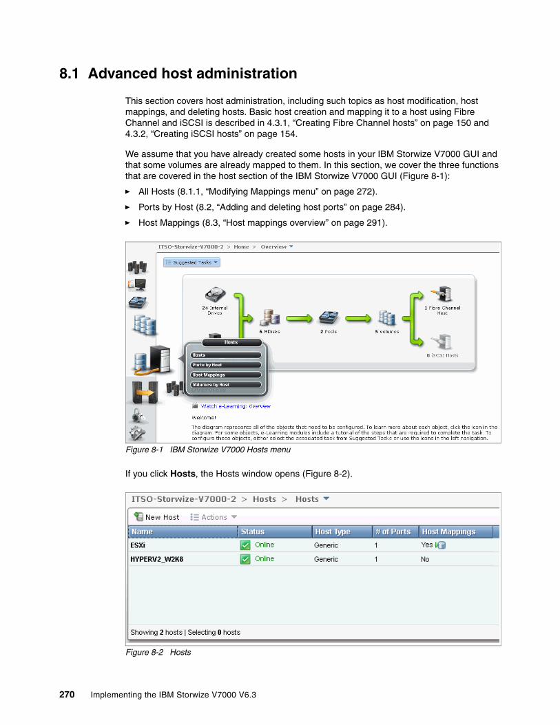
8.1 Advanced host administration
This section covers host administration, including such topics as host modification, host mappings, and deleting hosts. Basic host creation and mapping it to a host using Fibre Channel and iSCSI is described in 4.3.1, “Creating Fibre Channel hosts” on page 150 and 4.3.2, “Creating iSCSI hosts” on page 154.
We assume that you have already created some hosts in your IBM Storwize V7000 GUI and that some volumes are already mapped to them. In this section, we cover the three functions that are covered in the host section of the IBM Storwize V7000 GUI (Figure 8-1):
� All Hosts (8.1.1, “Modifying Mappings menu” on page 272).
� Ports by Host (8.2, “Adding and deleting host ports” on page 284).
� Host Mappings (8.3, “Host mappings overview” on page 291).
Figure 8-1 IBM Storwize V7000 Hosts menu
If you click Hosts, the Hosts window opens (Figure 8-2).
Figure 8-2 Hosts
270 Implementing the IBM Storwize V7000 V6.3

As you can see in our example, two hosts are created and volumes are already mapped to one of them; we use these hosts to show the modification possibilities.
If you highlight a host, you can either click Action (Figure 8-3) or right-click the host (Figure 8-4) to see all the available tasks.
Figure 8-3 Hosts Action window
Figure 8-4 Host menu
Chapter 8. Advanced host and volume administration 271
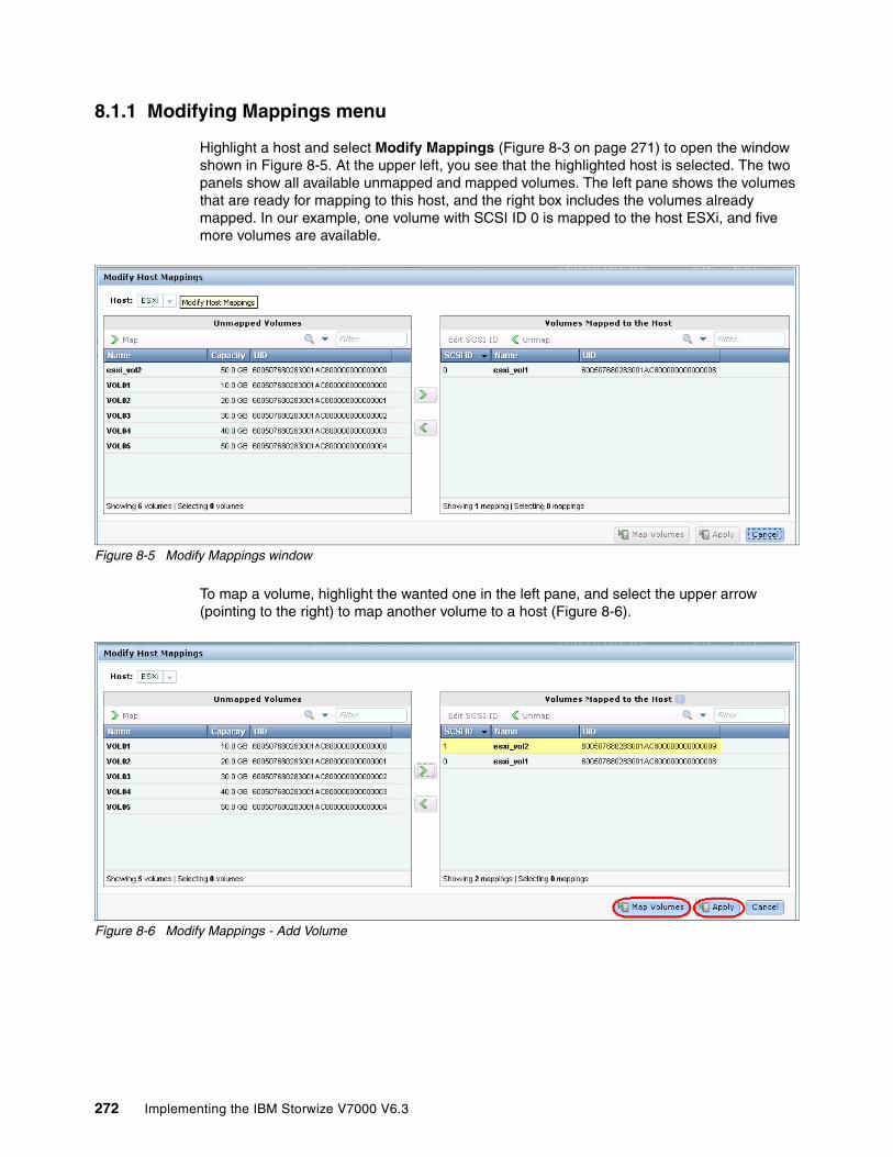
8.1.1 Modifying Mappings menu
Highlight a host and select Modify Mappings (Figure 8-3 on page 271) to open the window shown in Figure 8-5. At the upper left, you see that the highlighted host is selected. The two panels show all available unmapped and mapped volumes. The left pane shows the volumes that are ready for mapping to this host, and the right box includes the volumes already mapped. In our example, one volume with SCSI ID 0 is mapped to the host ESXi, and five more volumes are available.
Figure 8-5 Modify Mappings window
To map a volume, highlight the wanted one in the left pane, and select the upper arrow (pointing to the right) to map another volume to a host (Figure 8-6).
Figure 8-6 Modify Mappings - Add Volume
272 Implementing the IBM Storwize V7000 V6.3
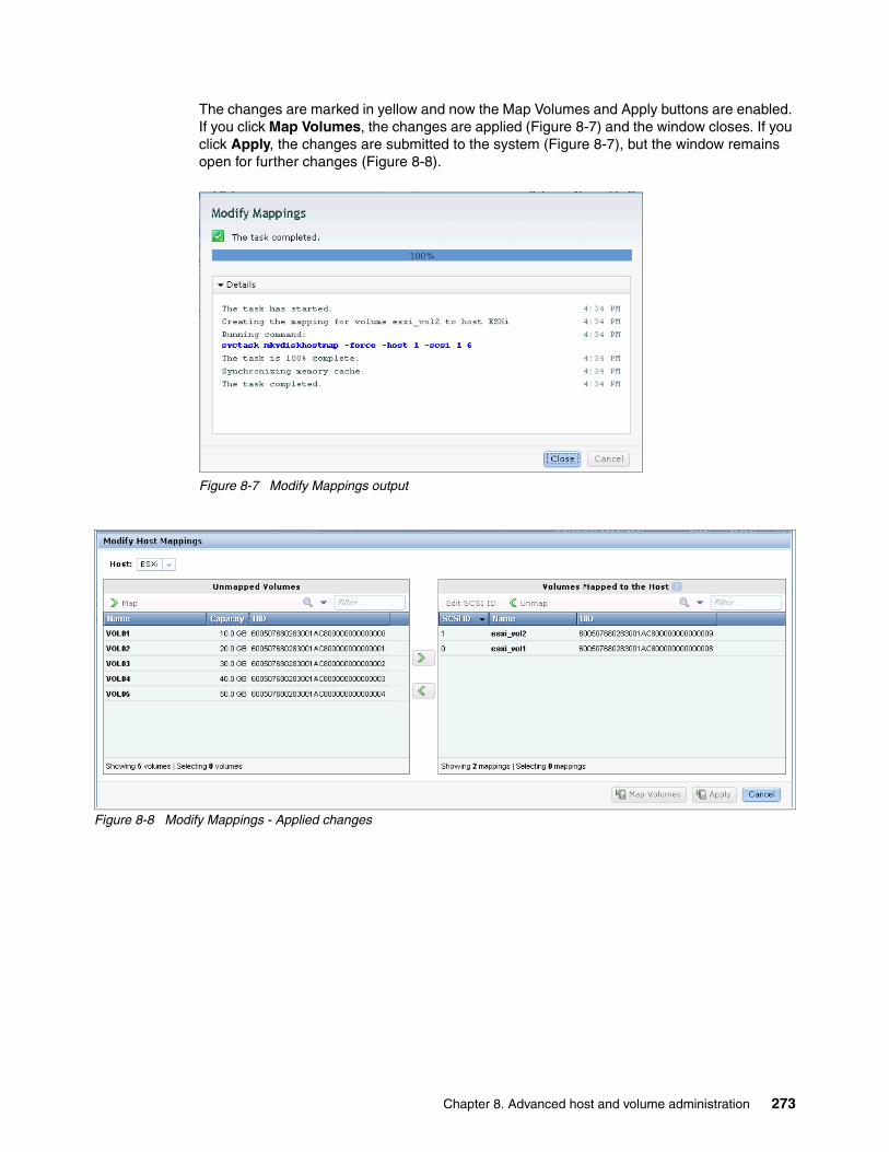
The changes are marked in yellow and now the Map Volumes and Apply buttons are enabled. If you click Map Volumes, the changes are applied (Figure 8-7) and the window closes. If you click Apply, the changes are submitted to the system (Figure 8-7), but the window remains open for further changes (Figure 8-8).
Figure 8-7 Modify Mappings output
Figure 8-8 Modify Mappings - Applied changes
Chapter 8. Advanced host and volume administration 273

You can now select another host in the Hosts drop-down menu (Figure 8-9) to modify the host settings for it or continue working with the one already selected (Figure 8-8 on page 273).
Figure 8-9 Modify another hosts
Highlight the volume to be modified again and click the right arrow button to move it to the right pane. The changes are shown in yellow there. If you right-click the yellow volume, you are able to change the SCSI ID, which is used for the host mapping (Figure 8-10).
Figure 8-10 Edit the SCSI ID
Click Edit SCSI ID and click OK to change the ID (Figure 8-11).
Figure 8-11 Enter a new SCSI ID
274 Implementing the IBM Storwize V7000 V6.3

The changes are shown in the Modify Mappings window (Figure 8-12).
Figure 8-12 Modify host mappings
Click Apply to submit the changes. The resulting output is shown in Figure 8-13.
Figure 8-13 Modified Mappings
If you would like to remove a host mapping, the required steps are much the same, except that you select a volume in the right pane and click the left arrow button to remove the mapping (Figure 8-14).
Figure 8-14 Modify Mappings - Remove
Chapter 8. Advanced host and volume administration 275

Figure 8-15 shows that the selected volume has been moved to the left pane for unmapping.
Figure 8-15 Modify Mappings - Remove
Click Apply to submit the changes to the system (Figure 8-16).
Figure 8-16 Modify Mappings - Removal Complete
After you are done with all host mapping modifications, click Close to return to the Modify Mappings window (Figure 8-5 on page 272).
276 Implementing the IBM Storwize V7000 V6.3
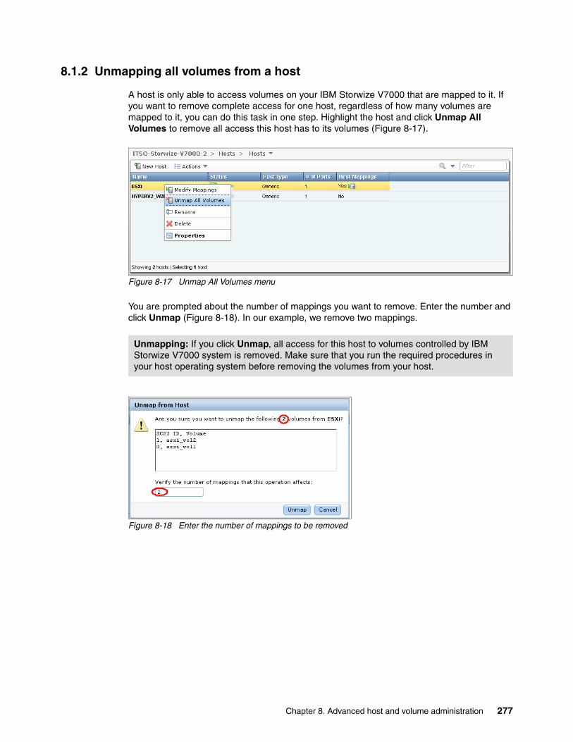
8.1.2 Unmapping all volumes from a host
A host is only able to access volumes on your IBM Storwize V7000 that are mapped to it. If you want to remove complete access for one host, regardless of how many volumes are mapped to it, you can do this task in one step. Highlight the host and click Unmap All Volumes to remove all access this host has to its volumes (Figure 8-17).
Figure 8-17 Unmap All Volumes menu
You are prompted about the number of mappings you want to remove. Enter the number and click Unmap (Figure 8-18). In our example, we remove two mappings.
Figure 8-18 Enter the number of mappings to be removed
Unmapping: If you click Unmap, all access for this host to volumes controlled by IBM Storwize V7000 system is removed. Make sure that you run the required procedures in your host operating system before removing the volumes from your host.
Chapter 8. Advanced host and volume administration 277
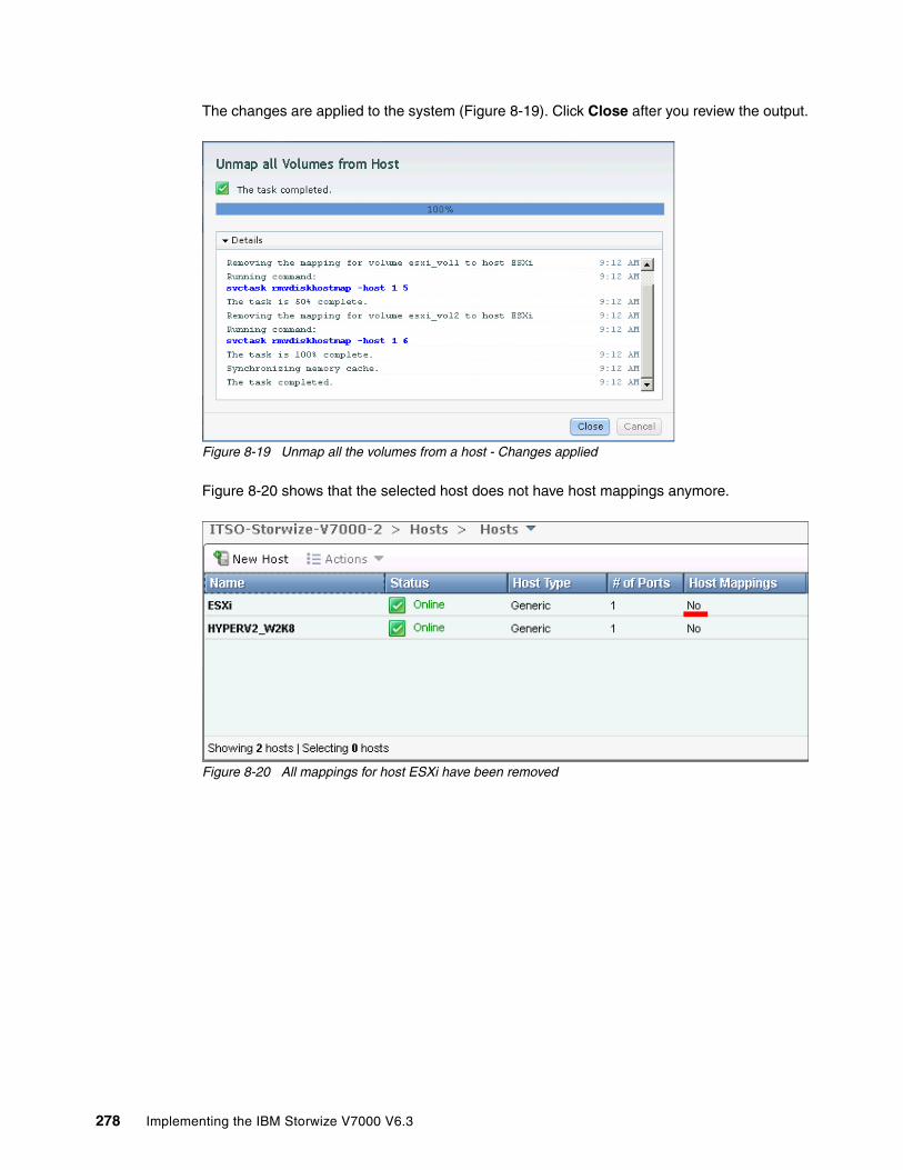
The changes are applied to the system (Figure 8-19). Click Close after you review the output.
Figure 8-19 Unmap all the volumes from a host - Changes applied
Figure 8-20 shows that the selected host does not have host mappings anymore.
Figure 8-20 All mappings for host ESXi have been removed
278 Implementing the IBM Storwize V7000 V6.3
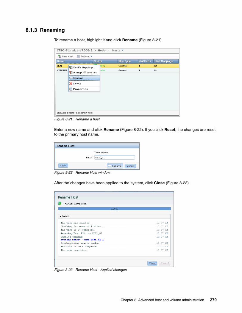
8.1.3 Renaming
To rename a host, highlight it and click Rename (Figure 8-21).
Figure 8-21 Rename a host
Enter a new name and click Rename (Figure 8-22). If you click Reset, the changes are reset to the primary host name.
Figure 8-22 Rename Host window
After the changes have been applied to the system, click Close (Figure 8-23).
Figure 8-23 Rename Host - Applied changes
Chapter 8. Advanced host and volume administration 279
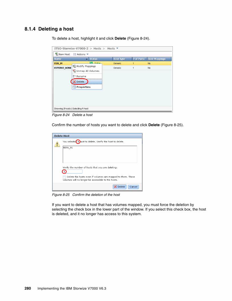
8.1.4 Deleting a host
To delete a host, highlight it and click Delete (Figure 8-24).
Figure 8-24 Delete a host
Confirm the number of hosts you want to delete and click Delete (Figure 8-25).
Figure 8-25 Confirm the deletion of the host
If you want to delete a host that has volumes mapped, you must force the deletion by selecting the check box in the lower part of the window. If you select this check box, the host is deleted, and it no longer has access to this system.
280 Implementing the IBM Storwize V7000 V6.3
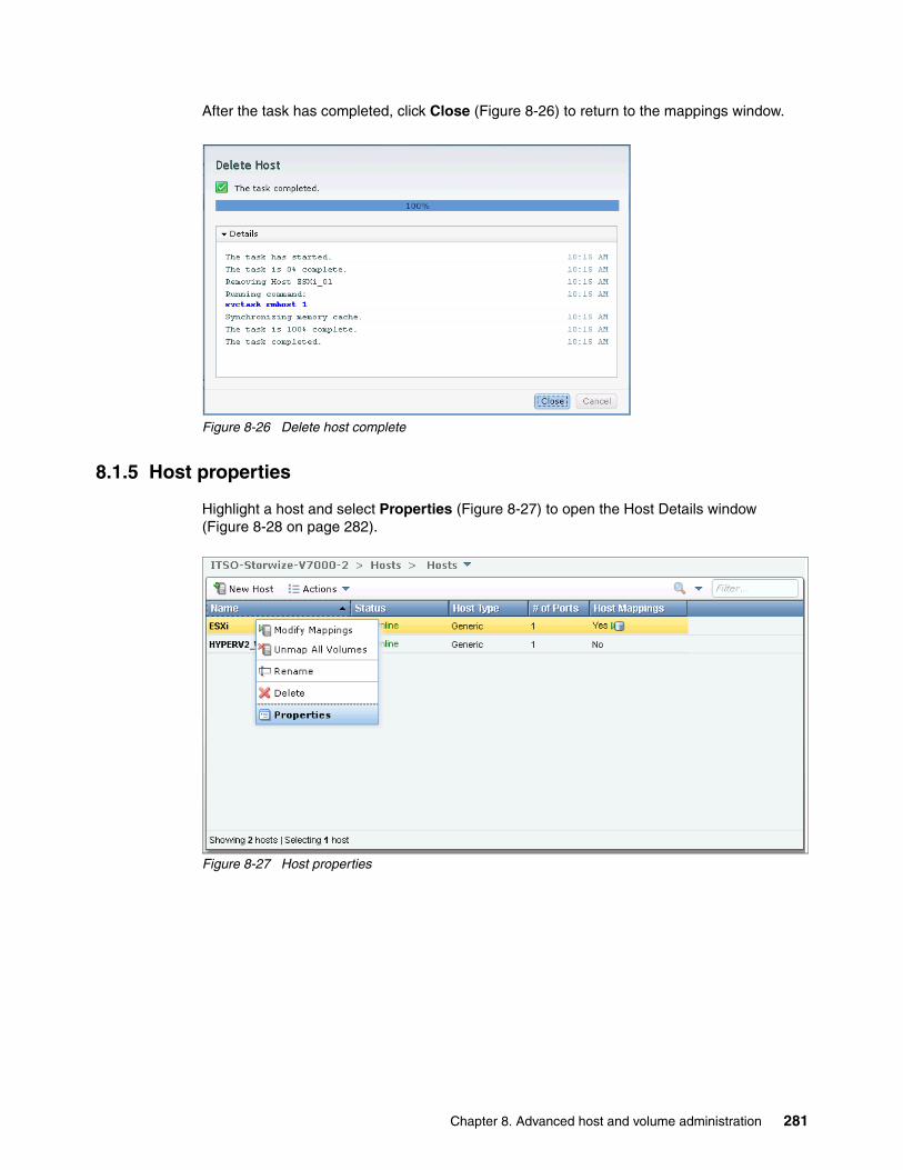
After the task has completed, click Close (Figure 8-26) to return to the mappings window.
Figure 8-26 Delete host complete
8.1.5 Host properties
Highlight a host and select Properties (Figure 8-27) to open the Host Details window (Figure 8-28 on page 282).
Figure 8-27 Host properties
Chapter 8. Advanced host and volume administration 281

Figure 8-28 Host properties overview
The Host Details window gives you an overview of your host properties. There are three tabs available: Overview, Mapped Volumes, and Port Definitions.
The Overview tab is shown in Figure 8-28. Select the Show Details check box to get more information about the host (Figure 8-29).
Figure 8-29 Host Properties - Show details
Click the Edit button and you are able to change the host properties (Figure 8-30).
Figure 8-30 Edit host properties
282 Implementing the IBM Storwize V7000 V6.3
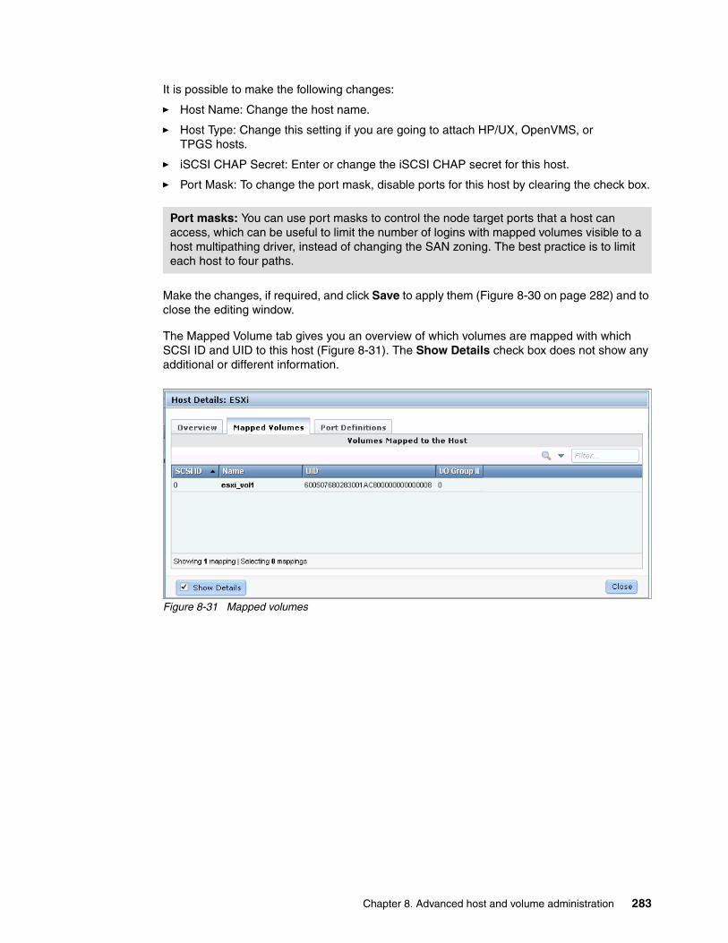
It is possible to make the following changes:
� Host Name: Change the host name.
� Host Type: Change this setting if you are going to attach HP/UX, OpenVMS, or TPGS hosts.
� iSCSI CHAP Secret: Enter or change the iSCSI CHAP secret for this host.
� Port Mask: To change the port mask, disable ports for this host by clearing the check box.
Make the changes, if required, and click Save to apply them (Figure 8-30 on page 282) and to close the editing window.
The Mapped Volume tab gives you an overview of which volumes are mapped with which SCSI ID and UID to this host (Figure 8-31). The Show Details check box does not show any additional or different information.
Figure 8-31 Mapped volumes
Port masks: You can use port masks to control the node target ports that a host can access, which can be useful to limit the number of logins with mapped volumes visible to a host multipathing driver, instead of changing the SAN zoning. The best practice is to limit each host to four paths.
Chapter 8. Advanced host and volume administration 283

The Port Definitions tab shows you the configured host ports of a host and gives you status information about them (Figure 8-32).
Figure 8-32 Port definitions
This window offers you the option to start Add and Delete Port actions, as described in 8.2, “Adding and deleting host ports” on page 284.
Click Close to close the Host Details section.
8.2 Adding and deleting host ports
To configure host ports, click Ports by Host (Figure 8-1 on page 270) to open the associated window (Figure 8-33).
Figure 8-33 Ports by Host
284 Implementing the IBM Storwize V7000 V6.3

In the left pane of the window, you find all the hosts listed, and the function icons tell you whether it is a Fibre Channel (orange cable) or iSCSI (blue cable) host. The properties of the highlighted host are shown in the right pane. If you click the New Host button, the wizard described in 4.3, “Creating hosts using the GUI” on page 148 starts. If you click the Action drop-down menu (Figure 8-34) the tasks described in 8.1.1, “Modifying Mappings menu” on page 272 may be started from this location.
Figure 8-34 Ports by Host actions
8.2.1 Adding a host port
To add a host port, highlight the host and click Add (Figure 8-33 on page 284), and select if you want to add a Fibre Channel or an iSCSI port (Figure 8-35).
Figure 8-35 Add host ports
Chapter 8. Advanced host and volume administration 285

8.2.2 Adding a Fibre Channel port
In Figure 8-35 on page 285, click Fibre Channel Port and the Add Fibre-Channel Ports window opens (Figure 8-36).
Figure 8-36 Add Fibre Channel Ports window
If you click the drop-down menu, you get a list of all known Fibre Channel host ports (Figure 8-37). If the WWPN of your host is not available in the drop-down menu, check your SAN zoning and rescan the SAN from the host. Afterward, click Rescan and the new port should now be available in the drop-down menu.
Figure 8-37 Add Fibre Channel Ports - Known WWPNs
Select the WWPN you want to add and click Add Port to List (Figure 8-38).
Figure 8-38 Add a port to list
286 Implementing the IBM Storwize V7000 V6.3

It is possible to repeat this step to add more ports to a host.
If you want to add an offline port, enter manually the WWPN of the port into the Fibre Channel Ports box (Figure 8-39) and click Add Port to List.
Figure 8-39 Add an offline port
The port appears as unverified (Figure 8-40) because it is not logged on to the IBM Storwize V7000. The first time it logs on, it changes its state to online automatically and the mapping is applied to this port.
Figure 8-40 Unverified port
To remove one of the ports from the list, click the red X next to it (Figure 8-41). In this example, we delete the manually added FC port so only the detected port remains.
Figure 8-41 Remove a port from a list
Chapter 8. Advanced host and volume administration 287
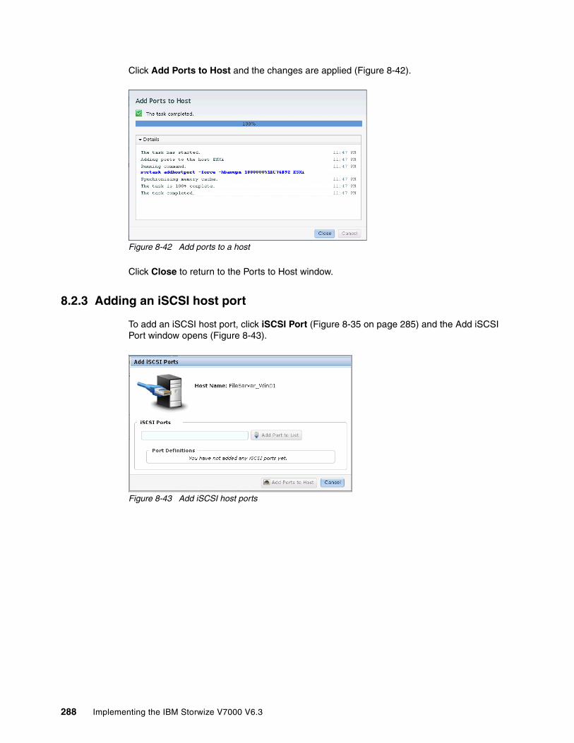
Click Add Ports to Host and the changes are applied (Figure 8-42).
Figure 8-42 Add ports to a host
Click Close to return to the Ports to Host window.
8.2.3 Adding an iSCSI host port
To add an iSCSI host port, click iSCSI Port (Figure 8-35 on page 285) and the Add iSCSI Port window opens (Figure 8-43).
Figure 8-43 Add iSCSI host ports
288 Implementing the IBM Storwize V7000 V6.3

Enter the initiator name of your host (Figure 8-44) and click Add Port to List (Figure 8-45).
Figure 8-44 Enter the initiator name
Figure 8-45 Add ports to the ports definitions
Click Add Ports to Host to complete the tasks and apply the changes to the system (Figure 8-46).
Figure 8-46 Add Host Ports: Apply changes
Click Close to return to the Ports by Host window.
Chapter 8. Advanced host and volume administration 289

8.2.4 Deleting a host port
To delete a host port, highlight it and click Delete Port (Figure 8-47).
Figure 8-47 Delete host port
If you press and hold the Ctrl key on your keyboard, you can also select several host ports to delete (Figure 8-48).
Figure 8-48 Delete several host ports
Click Delete and enter the number of host ports you want to remove (Figure 8-49).
Figure 8-49 Enter the number of host ports to delete
290 Implementing the IBM Storwize V7000 V6.3
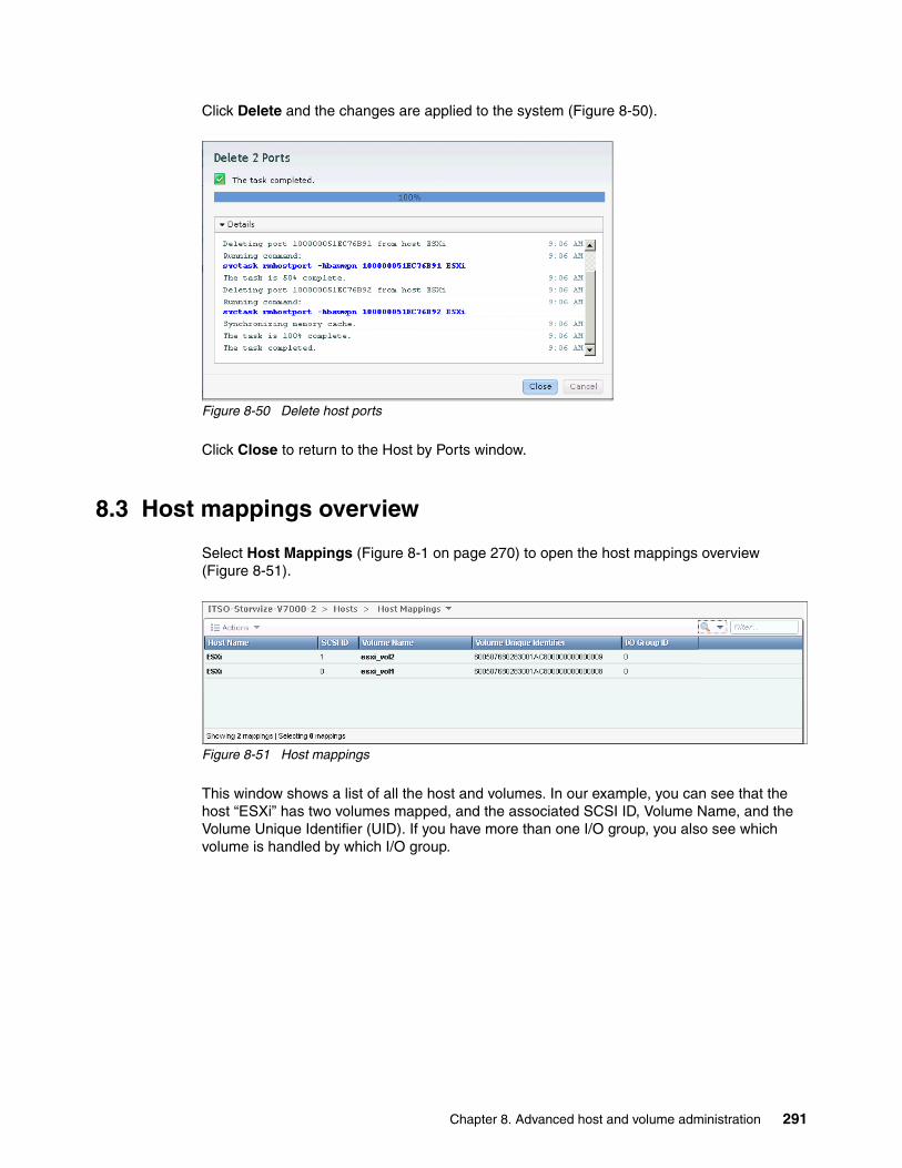
Click Delete and the changes are applied to the system (Figure 8-50).
Figure 8-50 Delete host ports
Click Close to return to the Host by Ports window.
8.3 Host mappings overview
Select Host Mappings (Figure 8-1 on page 270) to open the host mappings overview (Figure 8-51).
Figure 8-51 Host mappings
This window shows a list of all the host and volumes. In our example, you can see that the host “ESXi” has two volumes mapped, and the associated SCSI ID, Volume Name, and the Volume Unique Identifier (UID). If you have more than one I/O group, you also see which volume is handled by which I/O group.
Chapter 8. Advanced host and volume administration 291
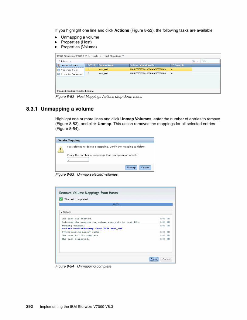
If you highlight one line and click Actions (Figure 8-52), the following tasks are available:
� Unmapping a volume� Properties (Host)� Properties (Volume)
Figure 8-52 Host Mappings Actions drop-down menu
8.3.1 Unmapping a volume
Highlight one or more lines and click Unmap Volumes, enter the number of entries to remove (Figure 8-53), and click Unmap. This action removes the mappings for all selected entries (Figure 8-54).
Figure 8-53 Unmap selected volumes
Figure 8-54 Unmapping complete
292 Implementing the IBM Storwize V7000 V6.3
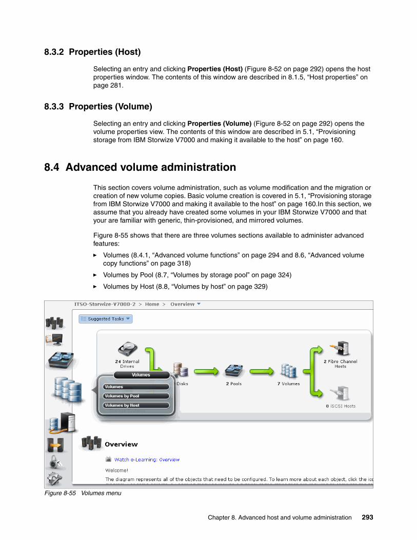
8.3.2 Properties (Host)
Selecting an entry and clicking Properties (Host) (Figure 8-52 on page 292) opens the host properties window. The contents of this window are described in 8.1.5, “Host properties” on page 281.
8.3.3 Properties (Volume)
Selecting an entry and clicking Properties (Volume) (Figure 8-52 on page 292) opens the volume properties view. The contents of this window are described in 5.1, “Provisioning storage from IBM Storwize V7000 and making it available to the host” on page 160.
8.4 Advanced volume administration
This section covers volume administration, such as volume modification and the migration or creation of new volume copies. Basic volume creation is covered in 5.1, “Provisioning storage from IBM Storwize V7000 and making it available to the host” on page 160.In this section, we assume that you already have created some volumes in your IBM Storwize V7000 and that your are familiar with generic, thin-provisioned, and mirrored volumes.
Figure 8-55 shows that there are three volumes sections available to administer advanced features:
� Volumes (8.4.1, “Advanced volume functions” on page 294 and 8.6, “Advanced volume copy functions” on page 318)
� Volumes by Pool (8.7, “Volumes by storage pool” on page 324)
� Volumes by Host (8.8, “Volumes by host” on page 329)
Figure 8-55 Volumes menu
Chapter 8. Advanced host and volume administration 293

8.4.1 Advanced volume functions
Click Volumes (Figure 8-55 on page 293) and the Volumes window opens (Figure 8-56).
Figure 8-56 Volumes window
This window lists all configured volumes on the system and provides the following information:
� Name: Shows the name of the volume. If there is a sign next to the name, this sign means that there are several copies of this volume. Click it to expand the view and list the copies (Figure 8-57).
� Status: Gives you status information about the volume. It can be online, offline, or degraded.
� Capacity: The capacity that is presented to the host is listed here. If there is a blue volume listed next to the capacity, this notation means that this volume is a thin-provisioned volume, and that the listed capacity is the virtual capacity, which might be less than the real capacity on the system.
� Storage Pool: Shows in which Storage Pool the volume is stored. If you have several volume copies, it shows you the pool of the primary copy.
� UID: The volume unique identifier.
� Host Mappings: Provides information if the volume is mapped to at least one host or not.
Figure 8-57 Volume copies
294 Implementing the IBM Storwize V7000 V6.3
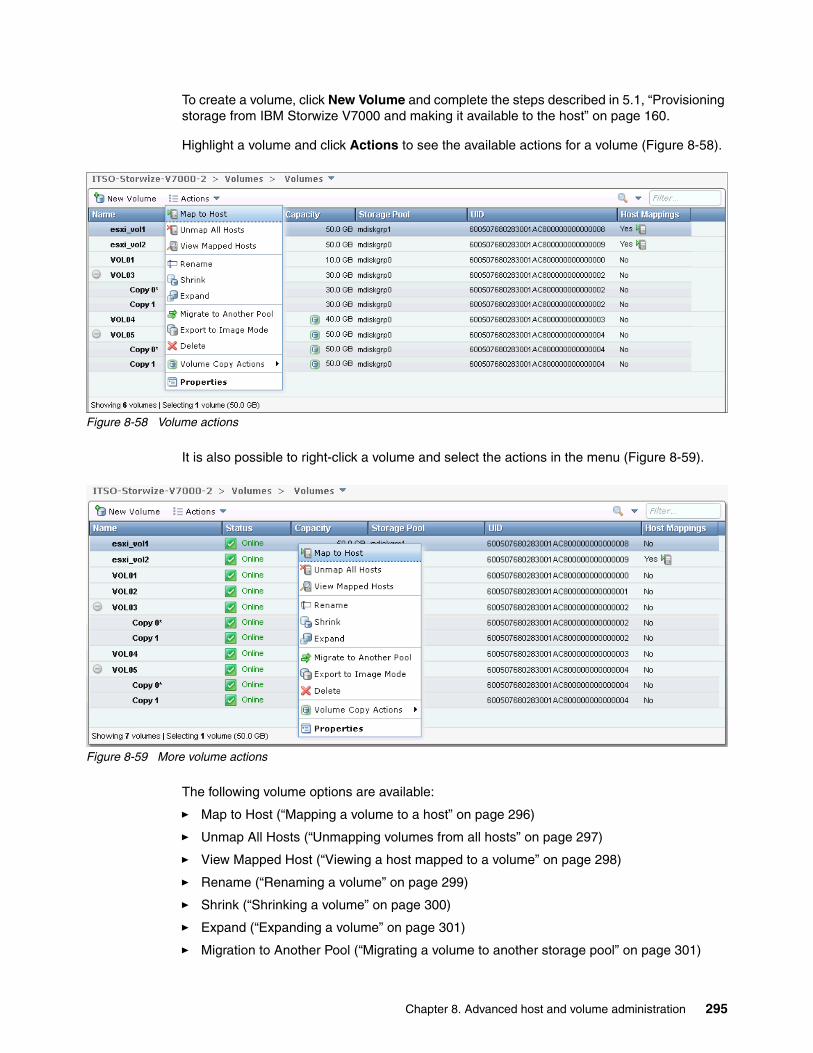
To create a volume, click New Volume and complete the steps described in 5.1, “Provisioning storage from IBM Storwize V7000 and making it available to the host” on page 160.
Highlight a volume and click Actions to see the available actions for a volume (Figure 8-58).
Figure 8-58 Volume actions
It is also possible to right-click a volume and select the actions in the menu (Figure 8-59).
Figure 8-59 More volume actions
The following volume options are available:
� Map to Host (“Mapping a volume to a host” on page 296)
� Unmap All Hosts (“Unmapping volumes from all hosts” on page 297)
� View Mapped Host (“Viewing a host mapped to a volume” on page 298)
� Rename (“Renaming a volume” on page 299)
� Shrink (“Shrinking a volume” on page 300)
� Expand (“Expanding a volume” on page 301)
� Migration to Another Pool (“Migrating a volume to another storage pool” on page 301)
Chapter 8. Advanced host and volume administration 295

� Export to image Mode (“Exporting to an image mode volume” on page 304)
� Delete (“Deleting a volume” on page 306)
� Properties (“Volume properties” on page 307)
Depending on which volume you view, there might be two more available actions for Volume Copy Actions:
� Add Mirror Copy: Only available for generic volumes (“Adding a mirrored volume copy” on page 313)
� Thin Provisioned: Only available for thin-provisioned volumes (“Editing thin-provisioned volume properties” on page 315)
8.4.2 Mapping a volume to a host
If you want to map a volume to a host, select Map to Host from the menu shown in Figure 8-58 on page 295. Select the host to which you want to map the volume and click Next (Figure 8-60).
Figure 8-60 Select Host
The Modify Mappings window opens. In the upper left, you see your selected host, and the yellow volume is the selected volume that will be mapped (Figure 8-61). Click Map Volumes to apply the changes to the system.
Figure 8-61 Modify Mappings window
296 Implementing the IBM Storwize V7000 V6.3

After the changes have completed, click Close to return to the All Volumes window (Figure 8-62).
Figure 8-62 Modify Mappings window
8.4.3 Unmapping volumes from all hosts
If you want to remove all host mappings from a volume, click Unmap All Host (Figure 8-58 on page 295). This action removes all host mappings from this volume, which means that no hosts are able to access this volume anymore. Enter the number of mappings that are affected and click Unmap to perform this action (Figure 8-63).
Figure 8-63 Unmap Volumes - Enter number of mappings to be removed
Modify Mappings window: The Modify Mappings window is described in 8.1.1, “Modifying Mappings menu” on page 272.
Chapter 8. Advanced host and volume administration 297

After the task completes, click Close (Figure 8-64) to return to the All Volumes window.
Figure 8-64 Unmap Volume from all Hosts complete
8.4.4 Viewing a host mapped to a volume
If you want to know which host mappings are currently configured, highlight a volume and click View Mapped Host (Figure 8-58 on page 295). This action opens the Host Maps tab of the Volume Details window (Figure 8-65). In this example, you see that there is one existing host mapping for the esxi_vol1 volume.
Figure 8-65 Volume details
If you want to remove a mapping, highlight the host and click Unmap from Host, which removes the access for the selected host (after you confirm it). If there are several hosts mapped to this volume (for example, in a cluster), only the highlighted host is removed.
298 Implementing the IBM Storwize V7000 V6.3
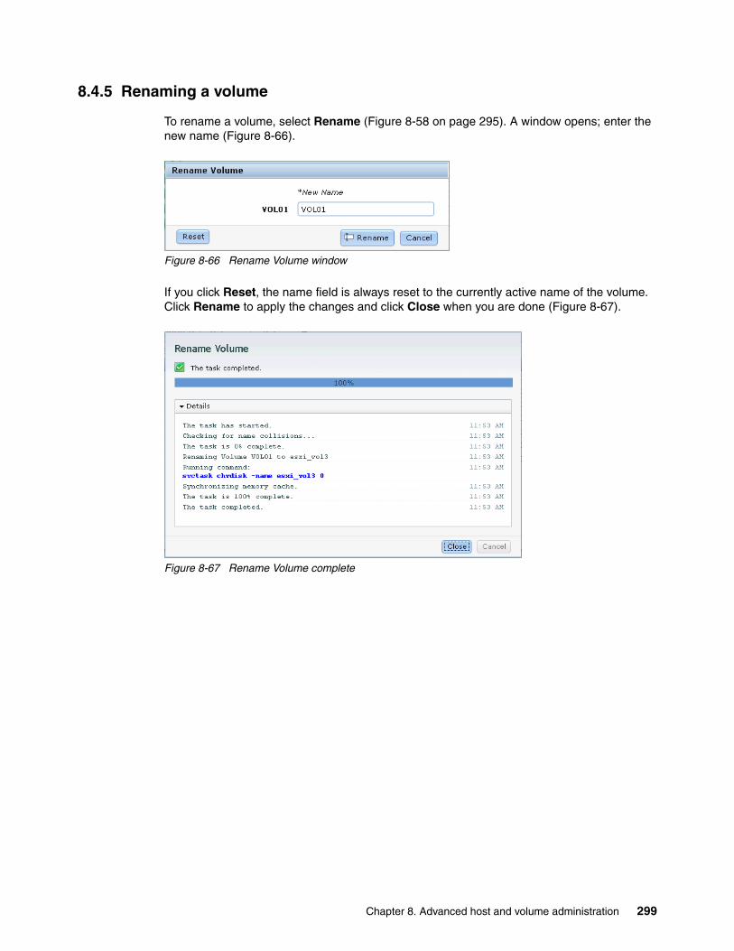
8.4.5 Renaming a volume
To rename a volume, select Rename (Figure 8-58 on page 295). A window opens; enter the new name (Figure 8-66).
Figure 8-66 Rename Volume window
If you click Reset, the name field is always reset to the currently active name of the volume. Click Rename to apply the changes and click Close when you are done (Figure 8-67).
Figure 8-67 Rename Volume complete
Chapter 8. Advanced host and volume administration 299

8.4.6 Shrinking a volume
IBM Storwize V7000 offers you the ability to shrink volumes. However, you should only use this feature if your host operating system supports this feature. Before shrinking a volume, complete the preparation required in your host operating system to shrink a volume on the storage. After you have prepared your OS, click Shrink (Figure 8-58 on page 295). You can either enter the new size, or enter how much the volume should shrink. If you enter a value, the other line updates itself (Figure 8-68).
Figure 8-68 Shrink Volume window
Click Shrink to start the process and click Close (Figure 8-69) to return to the All Volumes window.
Figure 8-69 Shrink Volume complete
Run the required procedures on your host to complete the shrinking process.
300 Implementing the IBM Storwize V7000 V6.3

8.4.7 Expanding a volume
If you want to expand a volume, click Expand (Figure 8-58 on page 295) and the Expand Volume window opens. Before you continue, check if your operating system supports online volume expansion. Enter the new volume size and click Expand (Figure 8-70).
Figure 8-70 Expand Volume window
After the tasks have completed, click Close (Figure 8-71) to return to the All Volumes window.
Figure 8-71 Expand Volume complete
Run the required procedures in your operating system to use the newly available space.
8.4.8 Migrating a volume to another storage pool
IBM Storwize V7000 provides online volume migration while applications are running. Storage pools are managed disk groups, as described in Chapter 7, “Storage pools” on page 223. Volume migration allows you to move the data between these storage pools, regardless if it is an internal pool, or a pool on another external storage system. This migration is done without the server’s and application’s knowledge that it even occurred. The migration process itself is a low priority process that does not affect the performance of the IBM Storwize V7000. However, it moves one extent after another to the new storage pool, so the performance of the volume becomes more like the performance of the new storage pool during the migration process.
Chapter 8. Advanced host and volume administration 301
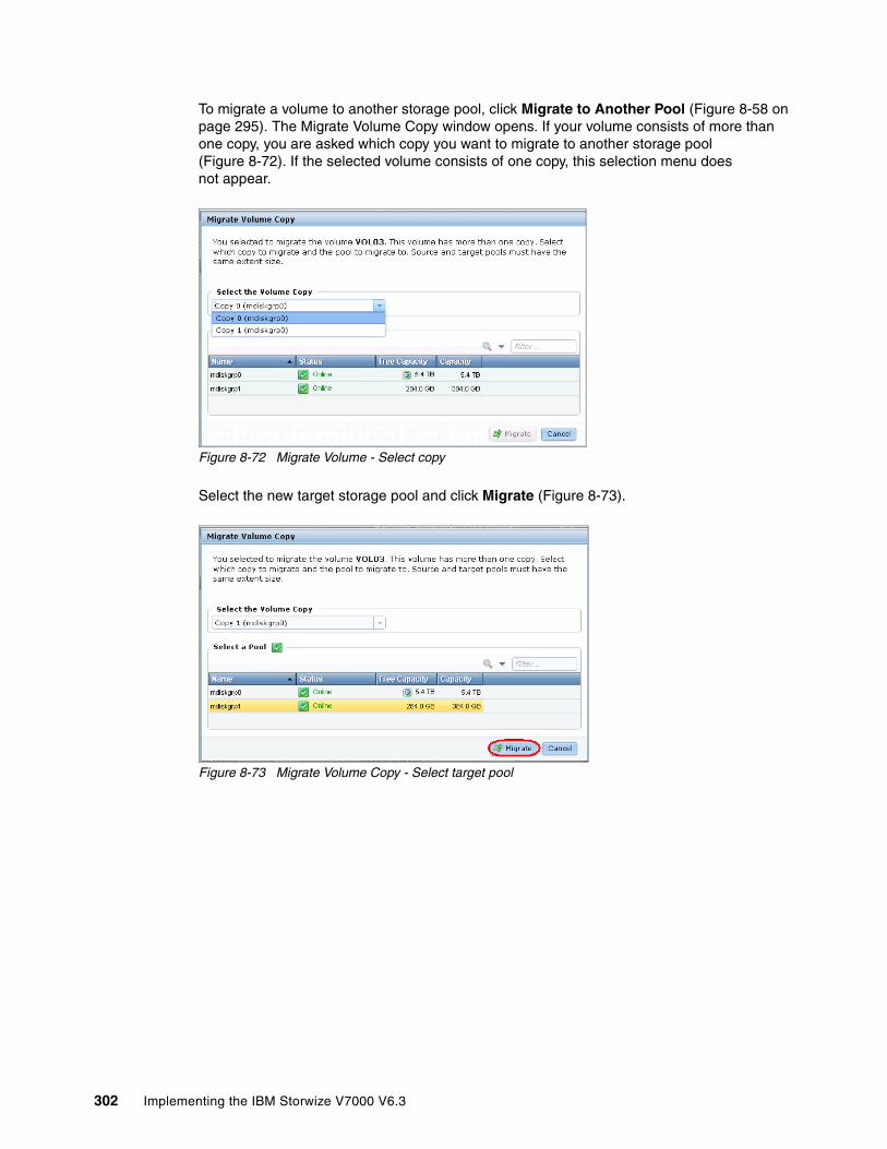
To migrate a volume to another storage pool, click Migrate to Another Pool (Figure 8-58 on page 295). The Migrate Volume Copy window opens. If your volume consists of more than one copy, you are asked which copy you want to migrate to another storage pool (Figure 8-72). If the selected volume consists of one copy, this selection menu does not appear.
Figure 8-72 Migrate Volume - Select copy
Select the new target storage pool and click Migrate (Figure 8-73).
Figure 8-73 Migrate Volume Copy - Select target pool
302 Implementing the IBM Storwize V7000 V6.3

The volume copy migration starts (Figure 8-74). Click Close to return to the All Volumes window.
Figure 8-74 Migrate Volume Copy started
Depending on the size of the volume, the migration process takes some time, but you can monitor the status of the migration in the running tasks bar at the bottom of the window (Figure 8-75).
Figure 8-75 Migration process
Chapter 8. Advanced host and volume administration 303
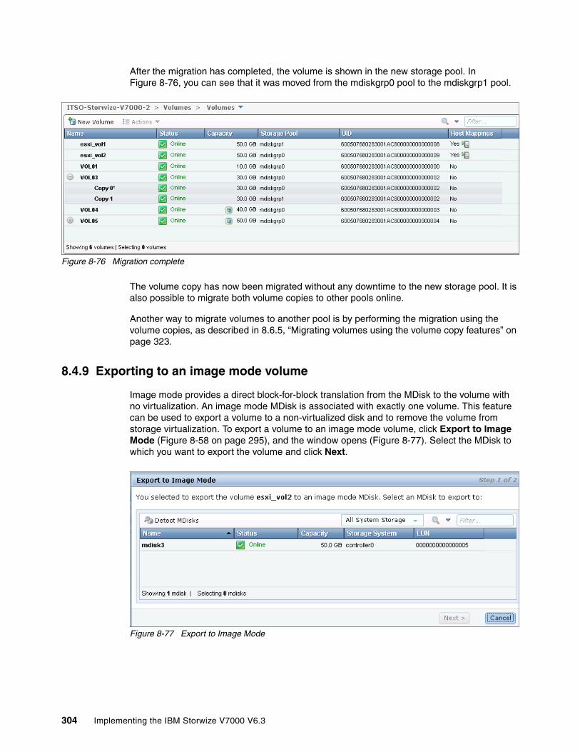
After the migration has completed, the volume is shown in the new storage pool. In Figure 8-76, you can see that it was moved from the mdiskgrp0 pool to the mdiskgrp1 pool.
Figure 8-76 Migration complete
The volume copy has now been migrated without any downtime to the new storage pool. It is also possible to migrate both volume copies to other pools online.
Another way to migrate volumes to another pool is by performing the migration using the volume copies, as described in 8.6.5, “Migrating volumes using the volume copy features” on page 323.
8.4.9 Exporting to an image mode volume
Image mode provides a direct block-for-block translation from the MDisk to the volume with no virtualization. An image mode MDisk is associated with exactly one volume. This feature can be used to export a volume to a non-virtualized disk and to remove the volume from storage virtualization. To export a volume to an image mode volume, click Export to Image Mode (Figure 8-58 on page 295), and the window opens (Figure 8-77). Select the MDisk to which you want to export the volume and click Next.
Figure 8-77 Export to Image Mode
304 Implementing the IBM Storwize V7000 V6.3
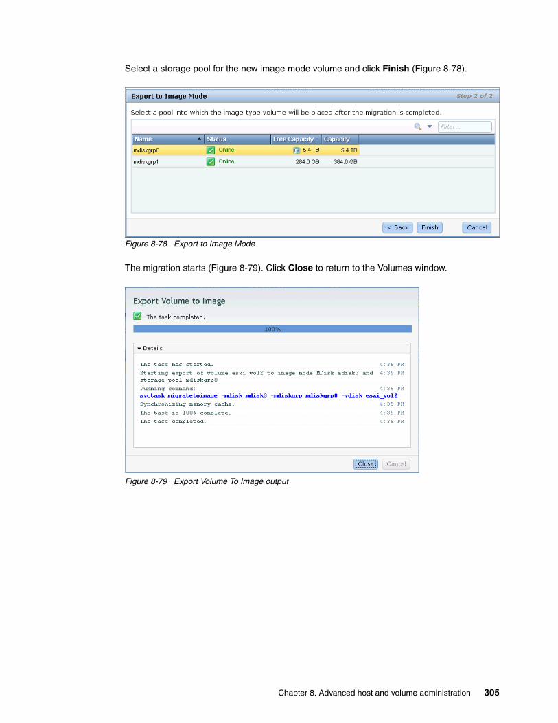
Select a storage pool for the new image mode volume and click Finish (Figure 8-78).
Figure 8-78 Export to Image Mode
The migration starts (Figure 8-79). Click Close to return to the Volumes window.
Figure 8-79 Export Volume To Image output
Chapter 8. Advanced host and volume administration 305

8.4.10 Deleting a volume
To delete a volume, select Delete (Figure 8-58 on page 295). Enter the number of volumes you want to delete and select the check box if you want to force the deletion (Figure 8-80). You must force the deletion if the volume has host mappings or is used in FlashCopy mappings or Remote Copy relationships.
Figure 8-80 Delete Volume
Click Delete and the volume is removed from the system (Figure 8-81).
Figure 8-81 Delete Volume complete
Click Close to return to the Volumes window.
Deleting volumes: This action removes all copies from your storage system and the data on the volume is lost. Before you perform this step, make sure that you do not need the volume anymore.
306 Implementing the IBM Storwize V7000 V6.3

8.5 Volume properties
To open the advanced view of a volume, select Properties (Figure 8-58 on page 295), and the Volume Details window opens (Figure 8-82). In this window, three tabs are available:
� Overview tab� Host Maps tab� Member MDisk tab
Figure 8-82 Volume properties
Chapter 8. Advanced host and volume administration 307

8.5.1 Overview tab
The Overview tab shown in Figure 8-82 on page 307 gives you a basic overview of the volume properties. In the left part of the window, you find common volume properties, and in the right part, you see information about the volume copies. To get a more detailed view, select the Show Details check box at the lower left (Figure 8-83).
Figure 8-83 Show details
The following details are available:
� Volume Properties:
– Volume Name: Shows the name of the volume.
– Volume ID: Shows the ID of the volume. Every volume has a system-wide unique ID.
– Status: Gives status information about the volume which can be online, offline, or degraded.
– Capacity: Shows the capacity of the volume. If the volume is thin-provisioned, this number is the virtual capacity; the real capacity is displayed for each copy.
– # of FlashCopy Mappings: Number of existing FlashCopy relationships. A detailed description about FlashCopy is covered in Chapter 11, “Copy services” on page 371.
– Volume UID: The volume unique identifier.
– I/O Group: Specifies the I/O group that the volume belongs to.
– Preferred Node: Specifies the ID of the preferred node for the volume.
– I/O Throttling: It is possible to set a maximum rate at which the volume processes I/O requests. The limit can be set in I/Os to MBps. This feature is an advanced feature and it is only possible to enable it through the CLI, as described in Appendix A, “CLI setup and SAN Boot” on page 569.
308 Implementing the IBM Storwize V7000 V6.3

– Mirror Sync Rate: After creation, or if a volume copy is offline, the mirror sync rate weights the synchronization process. Volumes with a high sync rate (100%) complete the synchronization faster than volumes with a lower priority. By default, the rate is set to 50% for all volumes.
– Cache Mode: Shows whether the cache is enabled or disabled for this volume.
– Cache State: Gives you feedback if open I/O requests are inside the cache that have not been destaged to the disks.
– UDID (OpenVMS): The unit device identifiers are used by OpenVMS host to access the volume.
� Copy Properties:
– Storage Pool: Gives you information about in which pool the copy rests, what copy it is (generic or thin-provisioned), and gives you status information.
– Capacity: Shows the allocated (used) and the virtual (Real) capacity, and the warning threshold and the set grain size.
If you want to edit any of these settings, click the Edit button and the window changes to the modify mode (Figure 8-84).
Figure 8-84 Edit volume details
Inside the Volume Details window, it is possible to change the following properties:
� Volume Name� I/O Group� I/O Throttling� Mirror Sync Rate� Cache Mode� UDID
Chapter 8. Advanced host and volume administration 309

Make any required changes and click Save (Figure 8-85). For this example, we change the preferred node.
Figure 8-85 Change properties
The changes are applied to the system (Figure 8-86).
Figure 8-86 Apply changes
Mirror Sync Rate: Setting the Mirror Sync Rate to 0% disables synchronization.
310 Implementing the IBM Storwize V7000 V6.3

8.5.2 Host Maps tab
The second tab of the volume properties is Host Maps (Figure 8-87). All hosts that are currently mapped to this volume are listed in this view.
Figure 8-87 Host Maps tab
If you want to unmap a host from this volume, highlight it and click Unmap from Host. Confirm the number of mappings to remove and click Unmap (Figure 8-88).
Figure 8-88 Unmap from host
The changes are applied to the system (Figure 8-89). The selected host no longer has access to this volume. Click Close to return to the Host Maps window.
Figure 8-89 Unmapping host complete
Chapter 8. Advanced host and volume administration 311

8.5.3 Member MDisk tab
The third tab is Member MDisk, which lists all MDisks on which the volume is located. Select a copy and the associated MDisks appear in the window (Figure 8-90).
Figure 8-90 Member MDisk
Highlight an MDisk and click Actions to get a view of the available tasks (Figure 8-91). The tasks are described in Chapter 7, “Storage pools” on page 223.
Figure 8-91 Member MDisk actions
Click Close to return to the All Volumes window.
312 Implementing the IBM Storwize V7000 V6.3
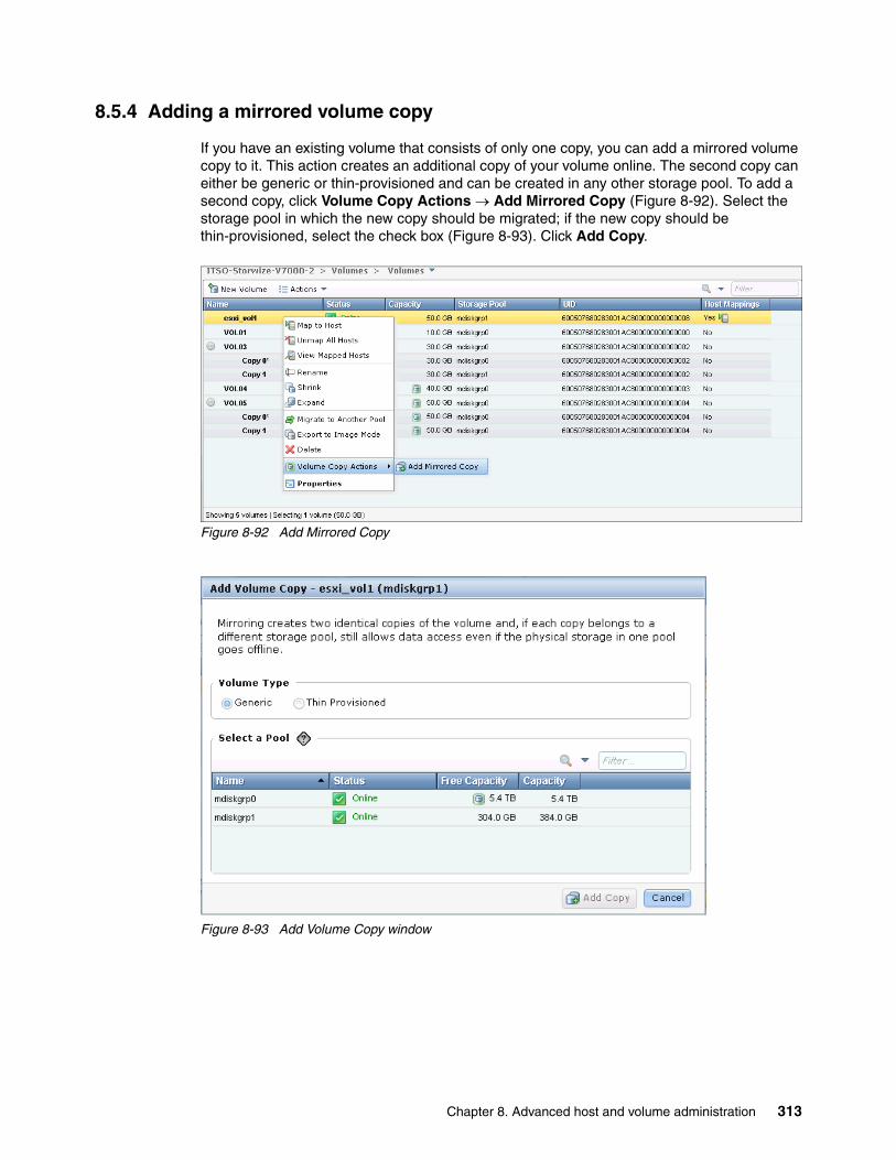
8.5.4 Adding a mirrored volume copy
If you have an existing volume that consists of only one copy, you can add a mirrored volume copy to it. This action creates an additional copy of your volume online. The second copy can either be generic or thin-provisioned and can be created in any other storage pool. To add a second copy, click Volume Copy Actions Add Mirrored Copy (Figure 8-92). Select the storage pool in which the new copy should be migrated; if the new copy should be thin-provisioned, select the check box (Figure 8-93). Click Add Copy.
Figure 8-92 Add Mirrored Copy
Figure 8-93 Add Volume Copy window
Chapter 8. Advanced host and volume administration 313
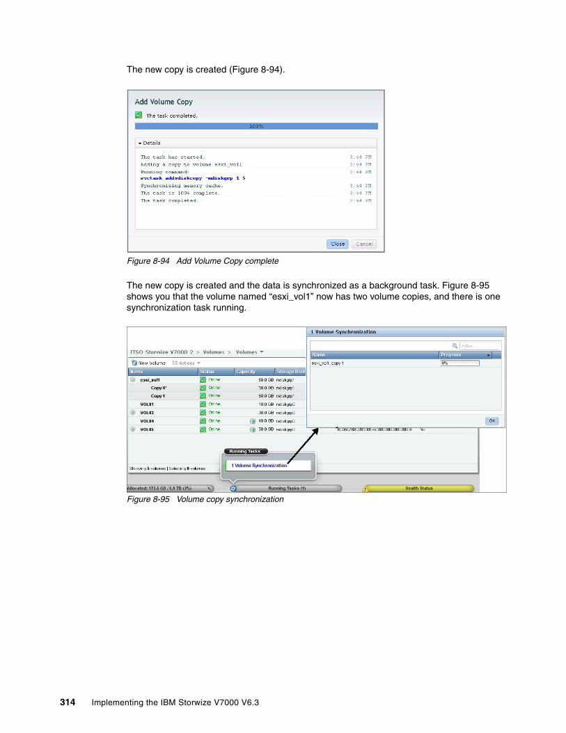
The new copy is created (Figure 8-94).
Figure 8-94 Add Volume Copy complete
The new copy is created and the data is synchronized as a background task. Figure 8-95 shows you that the volume named “esxi_vol1” now has two volume copies, and there is one synchronization task running.
Figure 8-95 Volume copy synchronization
314 Implementing the IBM Storwize V7000 V6.3
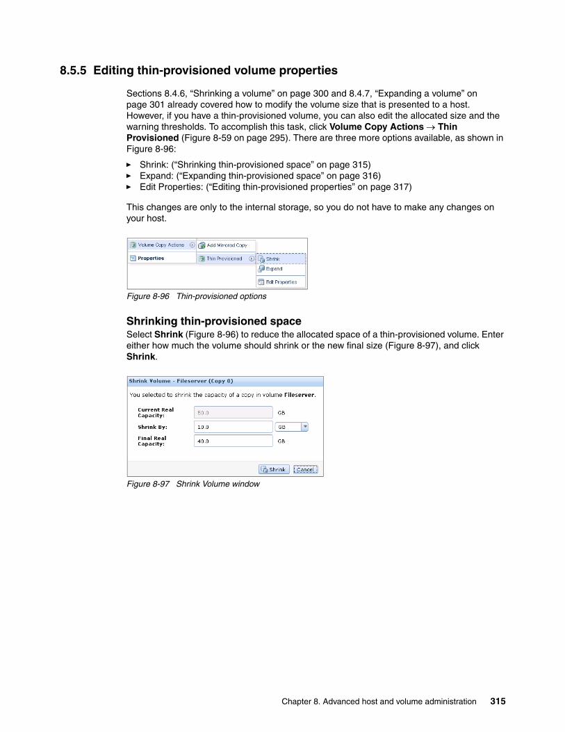
8.5.5 Editing thin-provisioned volume properties
Sections 8.4.6, “Shrinking a volume” on page 300 and 8.4.7, “Expanding a volume” on page 301 already covered how to modify the volume size that is presented to a host. However, if you have a thin-provisioned volume, you can also edit the allocated size and the warning thresholds. To accomplish this task, click Volume Copy Actions Thin Provisioned (Figure 8-59 on page 295). There are three more options available, as shown in Figure 8-96:
� Shrink: (“Shrinking thin-provisioned space” on page 315)� Expand: (“Expanding thin-provisioned space” on page 316)� Edit Properties: (“Editing thin-provisioned properties” on page 317)
This changes are only to the internal storage, so you do not have to make any changes on your host.
Figure 8-96 Thin-provisioned options
Shrinking thin-provisioned spaceSelect Shrink (Figure 8-96) to reduce the allocated space of a thin-provisioned volume. Enter either how much the volume should shrink or the new final size (Figure 8-97), and click Shrink.
Figure 8-97 Shrink Volume window
Chapter 8. Advanced host and volume administration 315
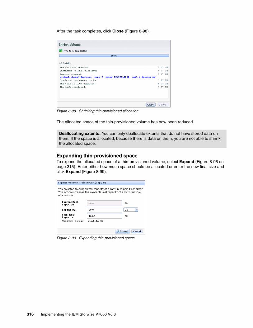
After the task completes, click Close (Figure 8-98).
Figure 8-98 Shrinking thin-provisioned allocation
The allocated space of the thin-provisioned volume has now been reduced.
Expanding thin-provisioned spaceTo expand the allocated space of a thin-provisioned volume, select Expand (Figure 8-96 on page 315). Enter either how much space should be allocated or enter the new final size and click Expand (Figure 8-99).
Figure 8-99 Expanding thin-provisioned space
Deallocating extents: You can only deallocate extents that do not have stored data on them. If the space is allocated, because there is data on them, you are not able to shrink the allocated space.
316 Implementing the IBM Storwize V7000 V6.3

The new space is now allocated. Click Close (Figure 8-100).
Figure 8-100 Expanding thin-provisioned space complete
Editing thin-provisioned propertiesTo edit thin-provisioned properties, select Edit Properties (Figure 8-96 on page 315). Edit the settings if required (Figure 8-101) and click OK to apply the changes.
Figure 8-101 Editing thin-provisioned properties
After the task completes, click Close (Figure 8-102) to return to the All Volumes window.
Figure 8-102 Editing thin-provisioned properties complete
Chapter 8. Advanced host and volume administration 317
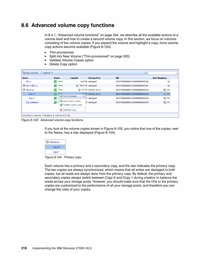
8.6 Advanced volume copy functions
In 8.4.1, “Advanced volume functions” on page 294, we describe all the available actions at a volume level and how to create a second volume copy. In this section, we focus on volumes consisting of two volume copies. If you expand the volume and highlight a copy, more volume copy actions become available (Figure 8-103):
� Thin-provisioned� Split into New Volume (“Thin-provisioned” on page 320)� Validate Volume Copies option� Delete Copy option
Figure 8-103 Advanced volume copy functions
If you look at the volume copies shown in Figure 8-103, you notice that one of the copies, next to the Name, has a star displayed (Figure 8-104).
Figure 8-104 Primary copy
Each volume has a primary and a secondary copy, and the star indicates the primary copy. The two copies are always synchronized, which means that all writes are destaged to both copies, but all reads are always done from the primary copy. By default, the primary and secondary copies always switch between Copy 0 and Copy 1 during creation to balance the reads across your storage pools. However, you should make sure that the I/Os to the primary copies are customized to the performance of all your storage pools, and therefore you can change the roles of your copies.
318 Implementing the IBM Storwize V7000 V6.3
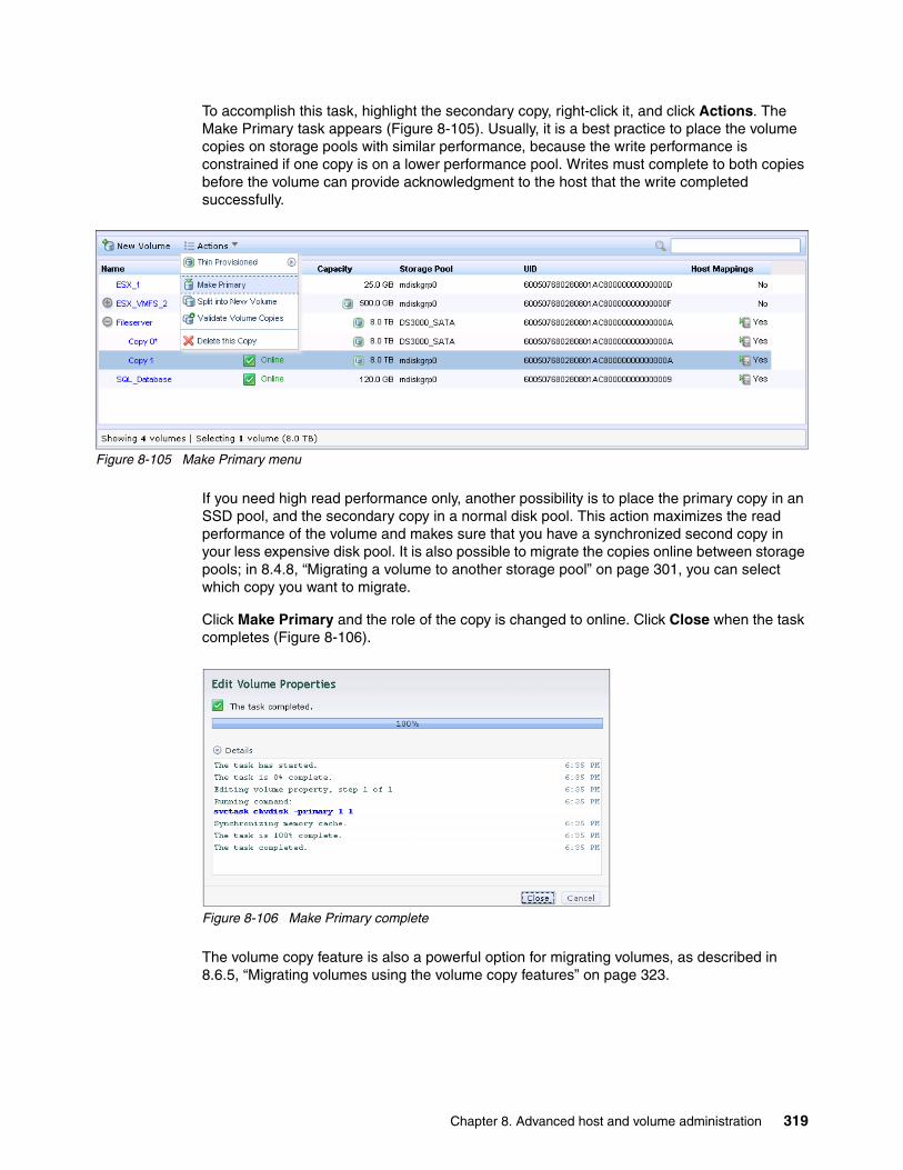
To accomplish this task, highlight the secondary copy, right-click it, and click Actions. The Make Primary task appears (Figure 8-105). Usually, it is a best practice to place the volume copies on storage pools with similar performance, because the write performance is constrained if one copy is on a lower performance pool. Writes must complete to both copies before the volume can provide acknowledgment to the host that the write completed successfully.
Figure 8-105 Make Primary menu
If you need high read performance only, another possibility is to place the primary copy in an SSD pool, and the secondary copy in a normal disk pool. This action maximizes the read performance of the volume and makes sure that you have a synchronized second copy in your less expensive disk pool. It is also possible to migrate the copies online between storage pools; in 8.4.8, “Migrating a volume to another storage pool” on page 301, you can select which copy you want to migrate.
Click Make Primary and the role of the copy is changed to online. Click Close when the task completes (Figure 8-106).
Figure 8-106 Make Primary complete
The volume copy feature is also a powerful option for migrating volumes, as described in 8.6.5, “Migrating volumes using the volume copy features” on page 323.
Chapter 8. Advanced host and volume administration 319

8.6.1 Thin-provisioned
This section includes the same functions described in “Shrinking thin-provisioned space” on page 315 to “Editing thin-provisioned properties” on page 317 (Figure 8-107). You can specify the same settings for each volume copy.
Figure 8-107 Thin-provisioned volume copy tasks
8.6.2 Splitting into a new volume
If your two volume copies are synchronized, you can split one of the copies to a new volume and map this new volume to another host. From a storage point of view, this procedure can be performed online, which means you could split one copy from the volume, and create a copy from the remaining one without any host impact. However, if you want to use the split copy for testing or backup purposes, you must make sure that the data inside the volume is consistent. Therefore, you must flush the data to storage to make the copies consistent. Refer to your operating system documentation for details about flushing the data. The easiest way is to shut down the hosts before splitting a copy.
To split a copy, click Split into New Volume (Figure 8-103 on page 318). If you perform this action on the primary copy, the remaining secondary copy automatically becomes the primary for the source volume. Enter a name for the new volume and click Split Volume Copy (Figure 8-108).
Figure 8-108 Split Volume Copy window
320 Implementing the IBM Storwize V7000 V6.3

After the task completes, click Close to return to the All Volumes window, where the copy appears as a new volume that can be mapped to a host (Figure 8-109).
Figure 8-109 All Volumes - New volume from split copy
8.6.3 Validate Volume Copies option
To validate the copies of a mirrored volume, complete the following steps:
1. Select Validate Volume Copies (Figure 8-103 on page 318). The Validate Volume Copies window opens (Figure 8-110).
Figure 8-110 Validate Volume Copies window
The following options are available:
– Generate Event of Differences: Use this option if you only want to verify that the mirrored volume copies are identical. If any difference is found, the command stops and logs an error that includes the logical block address (LBA) and the length of the first difference. You can use this option, starting at a different LBA each time, to count the number of differences on a volume.
Chapter 8. Advanced host and volume administration 321

– Overwrite Differences: Use this option to overwrite contents from the primary volume copy to the other volume copy. The command corrects any differing sectors by copying the sectors from the primary copy to the copies being compared. Upon completion, the command process logs an event, which indicates the number of differences that were corrected. Use this option if you are sure that either the primary volume copy data is correct or that your host applications can handle incorrect data.
– Return Media Error to Host: Use this option to convert sectors on all volumes copies that contain different contents into virtual medium errors. Upon completion, the command logs an event, which indicates the number of differences that were found, the number that were converted into medium errors, and the number that were not converted. Use this option if you are unsure what the correct data is, and you do not want an incorrect version of the data to be used.
2. Select which action to perform and click Validate to start the task. The volume is now checked. Click Close (Figure 8-111).
Figure 8-111 Validate Volume Copies - Started
The validation process takes some time depending on the volume size, and you can check the status in the Running Tasks window (Figure 8-112).
Figure 8-112 Validate Volume Copies - Running tasks
322 Implementing the IBM Storwize V7000 V6.3

8.6.4 Delete Copy option
Select Delete (Figure 8-103 on page 318) to delete a volume copy. The copy is deleted, but the volume remains online using the remaining copy. Confirm the deletion process by clicking OK (Figure 8-113).
Figure 8-113 Deleting a copy
The copy is deleted. Click Close (Figure 8-114) to return to the All Volumes window.
Figure 8-114 Delete copy complete
8.6.5 Migrating volumes using the volume copy features
In the previous sections, we showed that it is possible to create, synchronize, split, and delete volume copies. A combination of these tasks can be used to migrate volumes to other storage pools. The easiest way to migrate volume copies is to use the migration feature described in 8.4.8, “Migrating a volume to another storage pool” on page 301. If you use this feature, one extent after another would be migrated to the new storage pool. However, using volume copies provides another possibility to migrate volumes. To migrate a volume, complete the following steps:
1. Create a second copy of your volume in the target storage pool (see 8.5.4, “Adding a mirrored volume copy” on page 313).
2. Wait until the copies are synchronized.
3. Change the role of the copies and make the new copy of the primary copy (see 8.6, “Advanced volume copy functions” on page 318).
4. Split or delete the old copy from the volume (see 8.6.2, “Splitting into a new volume” on page 320 or 8.6.4, “Delete Copy option” on page 323).
Chapter 8. Advanced host and volume administration 323
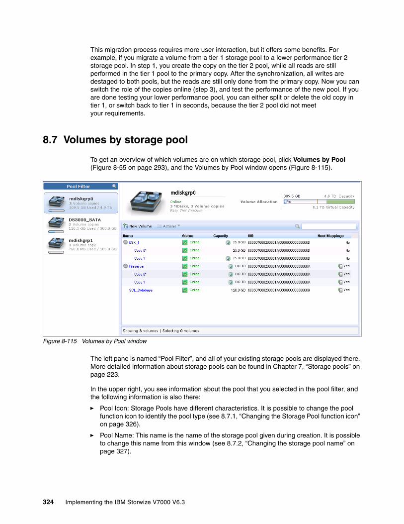
This migration process requires more user interaction, but it offers some benefits. For example, if you migrate a volume from a tier 1 storage pool to a lower performance tier 2 storage pool. In step 1, you create the copy on the tier 2 pool, while all reads are still performed in the tier 1 pool to the primary copy. After the synchronization, all writes are destaged to both pools, but the reads are still only done from the primary copy. Now you can switch the role of the copies online (step 3), and test the performance of the new pool. If you are done testing your lower performance pool, you can either split or delete the old copy in tier 1, or switch back to tier 1 in seconds, because the tier 2 pool did not meet your requirements.
8.7 Volumes by storage pool
To get an overview of which volumes are on which storage pool, click Volumes by Pool (Figure 8-55 on page 293), and the Volumes by Pool window opens (Figure 8-115).
Figure 8-115 Volumes by Pool window
The left pane is named “Pool Filter”, and all of your existing storage pools are displayed there. More detailed information about storage pools can be found in Chapter 7, “Storage pools” on page 223.
In the upper right, you see information about the pool that you selected in the pool filter, and the following information is also there:
� Pool Icon: Storage Pools have different characteristics. It is possible to change the pool function icon to identify the pool type (see 8.7.1, “Changing the Storage Pool function icon” on page 326).
� Pool Name: This name is the name of the storage pool given during creation. It is possible to change this name from this window (see 8.7.2, “Changing the storage pool name” on page 327).
324 Implementing the IBM Storwize V7000 V6.3
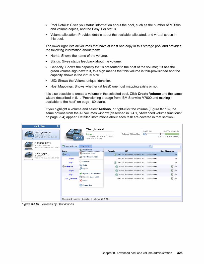
� Pool Details: Gives you status information about the pool, such as the number of MDisks and volume copies, and the Easy Tier status.
� Volume allocation: Provides details about the available, allocated, and virtual space in this pool.
The lower right lists all volumes that have at least one copy in this storage pool and provides the following information about them:
� Name: Shows the name of the volume.
� Status: Gives status feedback about the volume.
� Capacity: Shows the capacity that is presented to the host of the volume; if it has the green volume sign next to it, this sign means that this volume is thin-provisioned and the capacity shown is the virtual size.
� UID: Shows the Volume unique identifier.
� Host Mappings: Shows whether (at least) one host mapping exists or not.
It is also possible to create a volume in the selected pool. Click Create Volume and the same wizard described in 5.1, “Provisioning storage from IBM Storwize V7000 and making it available to the host” on page 160 starts.
If you highlight a volume and select Actions, or right-click the volume (Figure 8-116), the same options from the All Volumes window (described in 8.4.1, “Advanced volume functions” on page 294) appear. Detailed instructions about each task are covered in that section.
Figure 8-116 Volumes by Pool actions
Chapter 8. Advanced host and volume administration 325
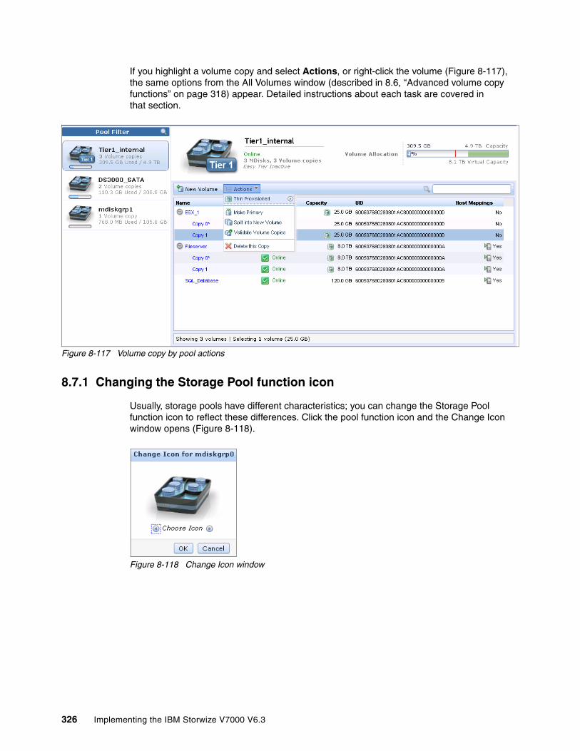
If you highlight a volume copy and select Actions, or right-click the volume (Figure 8-117), the same options from the All Volumes window (described in 8.6, “Advanced volume copy functions” on page 318) appear. Detailed instructions about each task are covered in that section.
Figure 8-117 Volume copy by pool actions
8.7.1 Changing the Storage Pool function icon
Usually, storage pools have different characteristics; you can change the Storage Pool function icon to reflect these differences. Click the pool function icon and the Change Icon window opens (Figure 8-118).
Figure 8-118 Change Icon window
326 Implementing the IBM Storwize V7000 V6.3

Use the left and right arrows to select a new function icon (Figure 8-119). There are several options available.
Figure 8-119 Select a new function icon
Click OK and the changes are applied to the system (Figure 8-120). Click Close.
Figure 8-120 Change function icon - Complete
The function icon has been changed to make it easier to identify the pool (Figure 8-121).
Figure 8-121 Changed function icon
8.7.2 Changing the storage pool name
To change the given name of a storage pool, click the name and you are able to edit it (Figure 8-122).
Figure 8-122 Change name
Chapter 8. Advanced host and volume administration 327
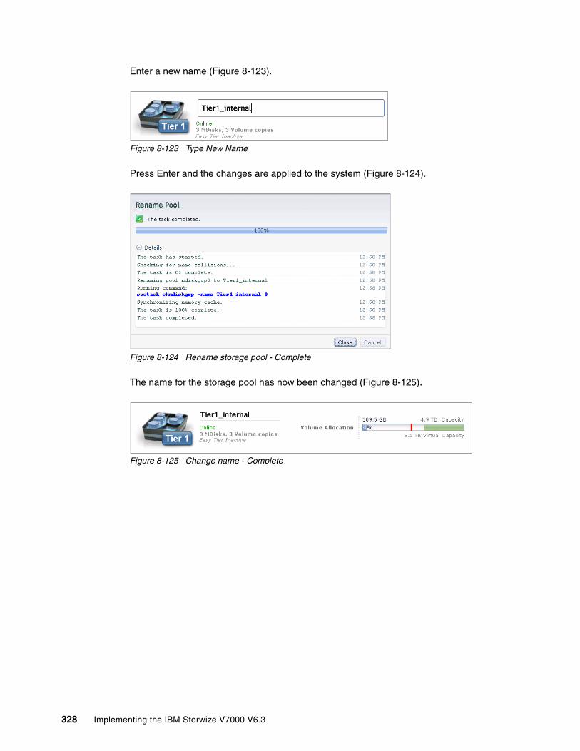
Enter a new name (Figure 8-123).
Figure 8-123 Type New Name
Press Enter and the changes are applied to the system (Figure 8-124).
Figure 8-124 Rename storage pool - Complete
The name for the storage pool has now been changed (Figure 8-125).
Figure 8-125 Change name - Complete
328 Implementing the IBM Storwize V7000 V6.3

8.8 Volumes by host
To get an overview about which volumes a host is able to access, click Volumes by Host (Figure 8-55 on page 293), and the Volumes by Host window opens (Figure 8-126).
Figure 8-126 Volumes by Host window
In the left pane of the view is the “Host Filter”, and if you select a host, its properties appear in the right pane of the view. The hosts with the orange cable represent Fibre Channel hosts, and the blue cable represents iSCSI hosts. In the upper right side, you see the Host function icon, the host name, the number of host ports, and the host type. The volumes that are mapped to this host are listed in the pane below.
If you want to create a volume for this host, click New Volume, and the same wizard described in 5.1, “Provisioning storage from IBM Storwize V7000 and making it available to the host” on page 160 starts.
Chapter 8. Advanced host and volume administration 329

Highlight a volume and select Actions or right-click the volume (Figure 8-127), and the same options from the All Volumes window (described in 8.4.1, “Advanced volume functions” on page 294) appear. Detailed instructions about each task are covered in that section.
Figure 8-127 Volume actions
If the volume owns more than one copy, you can highlight a volume copy and select Actions or right-click the copy (Figure 8-128), and the same options from the All Volumes window (described in 8.6, “Advanced volume copy functions” on page 318) appear. Detailed instructions about each task are covered in that section.
Figure 8-128 Volume copy actions
330 Implementing the IBM Storwize V7000 V6.3

8.8.1 Renaming a host
To rename a host in the Volumes by Host window, click it and you are able to edit the name (Figure 8-129).
Figure 8-129 Rename a host
Enter a new name (Figure 8-130).
Figure 8-130 Enter a new name
Press Enter to apply the changes to the system (Figure 8-131).
Figure 8-131 Rename host complete
Chapter 8. Advanced host and volume administration 331
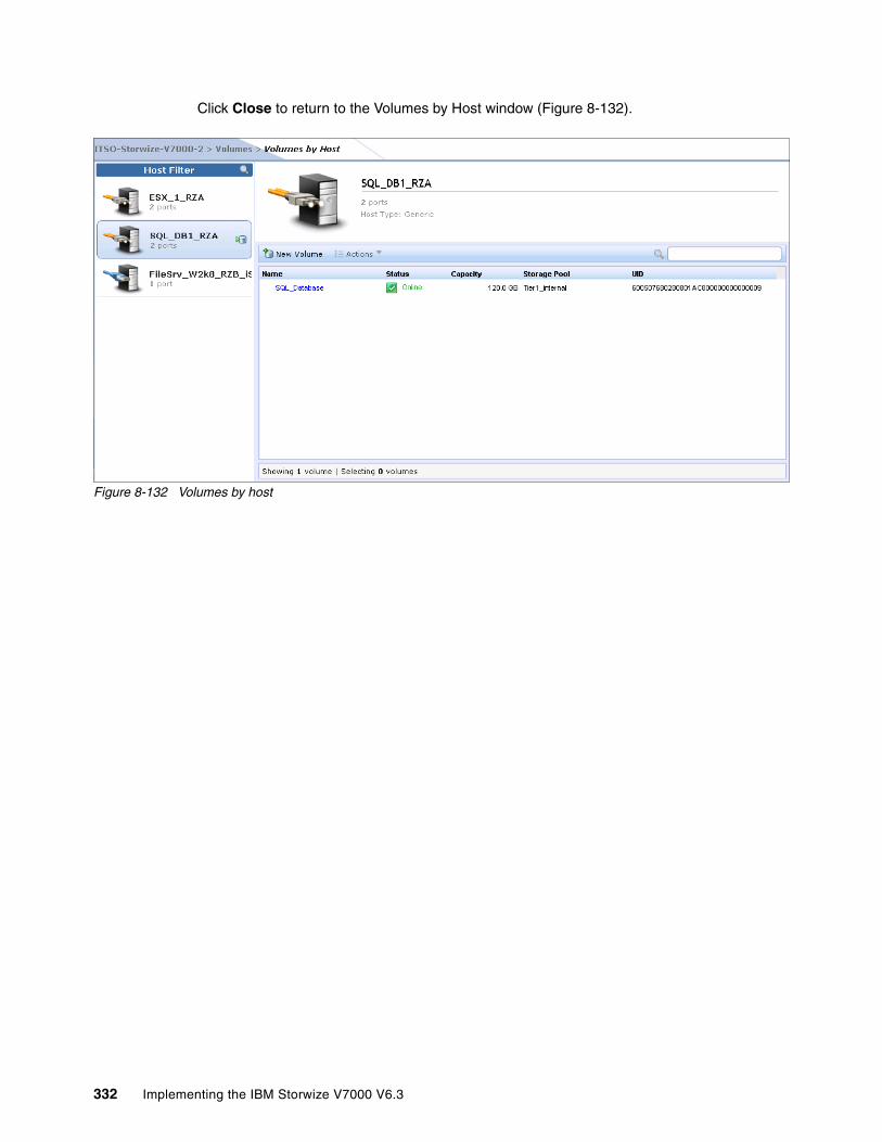
Click Close to return to the Volumes by Host window (Figure 8-132).
Figure 8-132 Volumes by host
332 Implementing the IBM Storwize V7000 V6.3

Chapter 9. External storage virtualization
In this chapter, we describe how to incorporate external storage systems into the virtualized world of the IBM Storwize V7000. A key feature of IBM Storwize V7000 is its ability to consolidate disk controllers from various vendors into pools of storage. In this way, the storage administrator can, from a single user interface, manage and provision storage to applications, and use a common set of advanced functions across all the storage systems under the control of the IBM Storwize V7000.
9
© Copyright IBM Corp. 2011, 2012. All rights reserved. 333

9.1 Planning for external storage virtualization
In this section, we describe how to plan for virtualizing external storage with IBM Storwize V7000. Virtualizing the storage infrastructure with IBM Storwize V7000 makes your storage environment more flexible, cost-effective, and easy to manage. The combination of IBM Storwize V7000 and an external storage system allows more storage capacity benefits from the powerful software function within the IBM Storwize V7000.
The external storage systems that are incorporated into the IBM Storwize V7000 environment could be brand new systems or existing systems. The data on the existing storage systems could be easily migrated to the IBM Storwize V7000 managed environment, as described in Chapter 6, “Migration wizard” on page 205 and Chapter 7, “Storage pools” on page 223.
9.1.1 License for external storage virtualization
From a licensing standpoint, when external storage systems are virtualized by IBM Storwize V7000, a per-enclosure External Virtualization license is required. You can find more licensing information in 1.3.4, “IBM Storwize V7000 licensing” on page 9, and contact your IBM account team or IBM Business Partner for further assistance, if required.
Migration: If the IBM Storwize V7000 is used as a general migration tool, then the appropriate External Virtualization licenses must be ordered. The only exception is if you want to migrate existing data from external storage systems to IBM Storwize V7000 internal storage, as you can temporarily configure your External Storage license within 45 days. For a more than 45 day migration requirement from external storage to IBM Storwize V7000 internal storage, an appropriate External Virtualization license must be ordered.
334 Implementing the IBM Storwize V7000 V6.3

You can configure the IBM Storwize V7000 licenses by clicking the Settings icon and then clicking General Licensing (Figure 9-1).
Figure 9-1 General option
In the Advanced window, click Licensing, and the Update License view opens in the right pane (Figure 9-2).
In the Update License pane, there are two license options you can set: External Virtualization Limit and Remote-Copy Limit. Set these two license options to the limit you obtained from IBM.
Figure 9-2 Update License window
Chapter 9. External storage virtualization 335
For assistance with licensing questions or to purchase an External Virtualization or Remote Copy license, contact your IBM account team or IBM Business Partner.
9.1.2 SAN configuration planning
External storage controllers virtualized by IBM Storwize V7000 must be connected through SAN switches. A direct connection between the IBM Storwize V7000 and storage controllers or hosts ports is not supported.
Make sure that the switches or directors are at the firmware levels supported by the IBM Storwize V7000 and that the IBM Storwize V7000 port login maximums listed in the restriction document will not be exceeded. The configuration restrictions can be found by navigating to the Support home page at the following address:
http://www-947.ibm.com/support/entry/portal/Overview
The recommended SAN configuration is composed of a minimum of two fabrics. The ports on external storage systems are be virtualized by the IBM Storwize V7000 and the IBM Storwize V7000 ports themselves, and are evenly split between the two fabrics to provide redundancy if one of the fabrics goes offline.
After the IBM Storwize V7000 and external storage systems are connected to the SAN fabrics, zoning must be implemented. In each fabric, create a zone with the four IBM Storwize V7000 WWPNs, two from each node canister, along with up to a maximum of eight WWPNs from each external storage system.
Ports: IBM Storwize V7000 supports a maximum of 16 ports or WWPNs from a given external storage system that will be virtualized.
336 Implementing the IBM Storwize V7000 V6.3
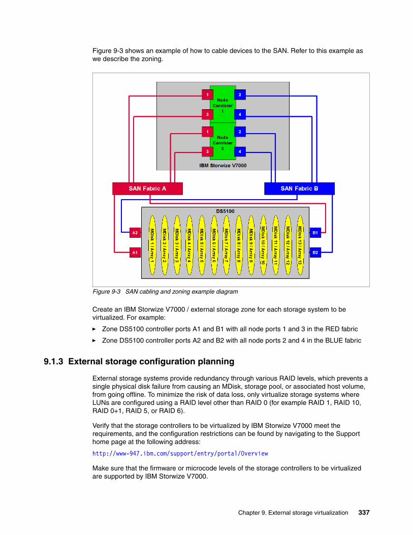
Figure 9-3 shows an example of how to cable devices to the SAN. Refer to this example as we describe the zoning.
Figure 9-3 SAN cabling and zoning example diagram
Create an IBM Storwize V7000 / external storage zone for each storage system to be virtualized. For example:
� Zone DS5100 controller ports A1 and B1 with all node ports 1 and 3 in the RED fabric
� Zone DS5100 controller ports A2 and B2 with all node ports 2 and 4 in the BLUE fabric
9.1.3 External storage configuration planning
External storage systems provide redundancy through various RAID levels, which prevents a single physical disk failure from causing an MDisk, storage pool, or associated host volume, from going offline. To minimize the risk of data loss, only virtualize storage systems where LUNs are configured using a RAID level other than RAID 0 (for example RAID 1, RAID 10, RAID 0+1, RAID 5, or RAID 6).
Verify that the storage controllers to be virtualized by IBM Storwize V7000 meet the requirements, and the configuration restrictions can be found by navigating to the Support home page at the following address:
http://www-947.ibm.com/support/entry/portal/Overview
Make sure that the firmware or microcode levels of the storage controllers to be virtualized are supported by IBM Storwize V7000.
Chapter 9. External storage virtualization 337

IBM Storwize V7000 must have exclusive access to the LUNs from the external storage system mapped to it. LUNs cannot be shared between IBM Storwize V7000s or between an IBM Storwize V7000 and other storage virtualization platforms or between an IBM Storwize V7000 and hosts. However, different LUNs could be mapped from one external storage system to an IBM Storwize V7000 and other hosts in the SAN through different storage ports.
Make sure to configure the storage subsystem LUN masking settings to map all LUNs to all the WWPNs in the IBM Storwize V7000 storage system.
Ensure that you go to the IBM Storwize V7000 Information Center and review the “Configuring and servicing external storage system” topic before preparing the external storage systems for discovery by the IBM Storwize V7000 system. This Information Center can be found at:
http://publib.boulder.ibm.com/infocenter/storwize/ic/index.jsp
9.1.4 Guidelines for virtualizing external storage
When virtualizing external storage using the IBM Storwize V7000, there are a few guidelines to follow:
� Avoid splitting arrays into multiple LUNs at the external storage system level. When possible, create a single LUN per array for mapping to the IBM Storwize V7000.
� Except for Easy Tier, do not mix MDisks that vary in performance or reliability in the same storage pool. Always put similarly sized MDisks into one storage pool. For more information about Easy Tier, see Chapter 10, “Easy Tier” on page 345.
� Do not leave volumes in image mode. Only use image mode to import or export existing data into or out of the IBM Storwize V7000. Migrate such data from image mode MDisks to other storage pools to benefit from storage virtualization.
� Using the copy services in Storwize V7000 gives you a unified method to manage data integrity across heterogeneous storage systems.
� The Easy Tier function is included with the IBM Storwize V7000 system, and the external storage system could benefit from this powerful storage tiering function to remove hot spots and improve overall performance.
9.2 Working with external storage
In this section, we describe how to manage external storage using an IBM Storwize V7000.
The basic concepts of managing external storage system are the same as internal storage. IBM Storwize V7000 discovers LUNs from the external storage system as one or more MDisks. These MDisks are ultimately added to a storage pool in which volumes are created and mapped to hosts as needed.
338 Implementing the IBM Storwize V7000 V6.3

9.2.1 Adding external storage
To add new external storage systems to the IBM Storwize V7000 virtualized environment, complete the following steps:
1. Zone a minimum of two and a maximum of 16 Fibre Channel ports from the external storage system with all eight Fibre Channel ports on the IBM Storwize V7000 system. As a best practice, have two fabrics for redundancy in the SAN. Then in each fabric, zone two ports from each node canister in the IBM Storwize V7000 system with half the ports from the external system. As the IBM Storwize V7000 is virtualizing your storage, hosts should be zoned with the V7000 controllers WWPNs.
2. Using the storage partitioning or LUN masking feature of the external storage system, create a group that includes all eight IBM Storwize V7000 WWPNs.
3. Create equal size arrays on the external system using any RAID level but zero.
4. Create a single LUN per RAID array.
5. Map the LUNs to all eight Fibre Channel ports on the IBM Storwize V7000 system by assigning them to the group created in step 2.
6. Verify that IBM Storwize V7000 discovered the LUNs as unmanaged MDisks. If they do not show up automatically, click the Detect MDisk option from the MDisk window of the GUI, as described in 7.2.5, “Additional actions on MDisks” on page 260. You should see the MDisks mapped to the IBM Storwize V7000 under the respective Storage system.
7. Select the storage tier for the MDisks, as described in 7.2.4, “Selecting the tier for MDisks” on page 258.
8. Create a storage pool, as described in 7.3, “Working with storage pools” on page 264.
9. Add the MDisks to the pool, as described in 7.2.1, “Adding MDisks to storage pools” on page 245.
10.Create volumes and map them to hosts as needed, as described in Chapter 4, “Host configuration” on page 131 and Chapter 5, “Basic volume configuration” on page 159.
If the external storage systems are not new ones, that is, there is existing data on the LUNs that must be kept after virtualization, complete the steps in Chapter 6, “Migration wizard” on page 205 to prepare the environment. Then you can migrate the existing data with or without using wizard to IBM Storwize V7000 internal storage or some other external storage system.
Section 7.2.2, “Importing MDisks” on page 249 shows how to manually import MDisks and migrate the data to other storage pools. Whether you migrate the data with the wizard or not, you can select your destination storage pools to be internal storage pools or external storage pools.
9.2.2 Managing external storage
The IBM Storwize V7000 provides an individual External window for managing external storage systems.
You can access the External window by opening the Getting Started window and clicking the External Storage System function icon. Extended help information for external storage appears; click Physical Storage and the External window opens.
Chapter 9. External storage virtualization 339

Figure 9-4 shows how to access the External Storage window from the Getting Started window.
Figure 9-4 Access the External Storage window from the Getting Started window
The other method to access the External window is to use the Physical Storage function icons that are shown in the left pane (Figure 9-5).
Figure 9-5 Access the External window from the Getting Started window
340 Implementing the IBM Storwize V7000 V6.3

The External window (Figure 9-6) gives you an overview of all your external storage systems. On the left side of the window, there is a list of the external storage systems. With the help of the filter, you can show only the external storage systems on which you need to act. If you click and highlight the external storage system, detailed information is shown in the right pane, including all the MDisks provided by it.
Figure 9-6 External Storage window
On the right side the window, you can change the name of external storage system by clicking the name beside the picture of the external storage box. The status of the external storage system and its WWPN can also be found under the name.
From the Actions drop-down list, found at the top of the name of external storage on the right part of the External window, you can find the Show Dependent Volumes option (Figure 9-7).
Figure 9-7 Show Dependent Volumes option in the Actions drop-down menu
Clicking the Show Dependent Volumes option shows you the volumes in this external storage system (Figure 9-8).
Figure 9-8 Volumes dependent on external storage
Chapter 9. External storage virtualization 341
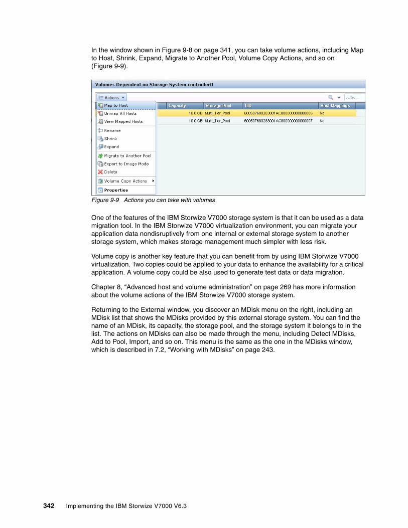
In the window shown in Figure 9-8 on page 341, you can take volume actions, including Map to Host, Shrink, Expand, Migrate to Another Pool, Volume Copy Actions, and so on (Figure 9-9).
Figure 9-9 Actions you can take with volumes
One of the features of the IBM Storwize V7000 storage system is that it can be used as a data migration tool. In the IBM Storwize V7000 virtualization environment, you can migrate your application data nondisruptively from one internal or external storage system to another storage system, which makes storage management much simpler with less risk.
Volume copy is another key feature that you can benefit from by using IBM Storwize V7000 virtualization. Two copies could be applied to your data to enhance the availability for a critical application. A volume copy could be also used to generate test data or data migration.
Chapter 8, “Advanced host and volume administration” on page 269 has more information about the volume actions of the IBM Storwize V7000 storage system.
Returning to the External window, you discover an MDisk menu on the right, including an MDisk list that shows the MDisks provided by this external storage system. You can find the name of an MDisk, its capacity, the storage pool, and the storage system it belongs to in the list. The actions on MDisks can also be made through the menu, including Detect MDisks, Add to Pool, Import, and so on. This menu is the same as the one in the MDisks window, which is described in 7.2, “Working with MDisks” on page 243.
342 Implementing the IBM Storwize V7000 V6.3
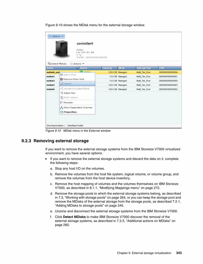
Figure 9-10 shows the MDisk menu for the external storage window.
Figure 9-10 MDisk menu in the External window
9.2.3 Removing external storage
If you want to remove the external storage systems from the IBM Storwize V7000 virtualized environment, you have several options:
� If you want to remove the external storage systems and discard the data on it, complete the following steps:
a. Stop any host I/O on the volumes.
b. Remove the volumes from the host file system, logical volume, or volume group, and remove the volumes from the host device inventory.
c. Remove the host mapping of volumes and the volumes themselves on IBM Storwize V7000, as described in 8.1.1, “Modifying Mappings menu” on page 272.
d. Remove the storage pools to which the external storage systems belong, as described in 7.3, “Working with storage pools” on page 264, or you can keep the storage pool and remove the MDisks of the external storage from the storage pools, as described 7.2.1, “Adding MDisks to storage pools” on page 245.
e. Unzone and disconnect the external storage systems from the IBM Storwize V7000.
f. Click Detect MDisks to make IBM Storwize V7000 discover the removal of the external storage systems, as described in 7.2.5, “Additional actions on MDisks” on page 260.
Chapter 9. External storage virtualization 343
� If you want to remove the external storage systems and keep the volumes and their data on the IBM Storwize V7000, complete the following steps:
a. Migrate volumes and their data to the other storage pools that are on IBM Storwize V7000 internal storage or other external storage systems, as described in 5.3, “Discovering the volumes from the host and specifying multipath settings” on page 174.
b. Remove the storage pools to which the external storage systems belong, or you can keep the storage pools and remove the MDisks of the external storage from the storage pools, as described in Chapter 7, “Storage pools” on page 223.
c. Unzone and disconnect the external storage systems from the IBM Storwize V7000.
d. Click Detect MDisks to make IBM Storwize V7000 discover the removal of the external storage systems, as described in 7.2.5, “Additional actions on MDisks” on page 260.
� If you want to remove the external storage systems from IBM Storwize V7000 control and keep the volumes and their data on external storage systems, complete the following steps:
a. Migrate volumes and their data to the other storage pools that are on IBM Storwize V7000 internal storage or other external storage systems, as described in Chapter 5, “Basic volume configuration” on page 159.
b. Remove the storage pools to which the external storage systems belong, or you can keep the storage pools and remove the MDisks of the external storage from the storage pools, as described in Chapter 7, “Storage pools” on page 223.
c. Export volumes to image mode with the MDisks on the external storage systems. The restrictions and prerequisites for migration can be found in Chapter 6, “Migration wizard” on page 205. You also need to record pre-migration information, for example, the original SCSI IDs the volumes used to be mapped to hosts. Some operating systems do not support changing the SCSI ID during the migration. More information about migration can be found in the IBM Storwize V7000 Information Center at the following address:
http://publib.boulder.ibm.com/infocenter/storwize/ic/index.jsp
d. Unzone and disconnect the external storage systems from the IBM Storwize V7000.
a. Click Detect MDisks to make IBM Storwize V7000 discover the removal of the external storage systems, as described Chapter 7, “Storage pools” on page 223.
344 Implementing the IBM Storwize V7000 V6.3
Chapter 10. Easy Tier
In today’s storage market, solid-state drives (SSDs) are emerging as an attractive alternative to hard disk drives (HDDs). Because of their low response times, high throughput, and IOPS-energy-efficient characteristics, SSDs have the potential to allow your storage infrastructure to achieve significant savings in operational costs. However, the current acquisition cost per GB for SSDs is currently much higher than for HDDs. SSD performance depends a lot on workload characteristics, so SSDs need to be used with HDDs. It is critical to choose the right mix of drives and the right data placement to achieve optimal performance at low cost. Maximum value can be derived by placing “hot” data with high IO density and low response time requirements on SSDs, while targeting HDDs for “cooler” data that is accessed more sequentially and at lower rates.
Easy Tier automates the placement of data among different storage tiers, and can be enabled for internal and external storage as well. This IBM Storwize V7000 no charge feature boosts your storage infrastructure performance to achieve optimal performance through a software, server, and storage solution.
This chapter describes the function provided by the Easy Tier disk performance optimization feature of the IBM Storwize V7000, and it also covers how to activate the Easy Tier process for both evaluation purposes and for automatic extent migration.
10
© Copyright IBM Corp. 2011, 2012. All rights reserved. 345
10.1 Easy Tier overview
Easy Tier is a no charge feature of IBM Storwize V7000 that brings enterprise storage functions to the midrange segment. It enables automated subvolume data placement throughout different storage tiers to intelligently align the system with current workload requirements and to optimize the usage of SSDs. This functionality includes the ability to automatically and nondisruptively relocate data (at the extent level) from one tier to another tier in either direction to achieve the best available storage performance for your workload in your environment. Easy Tier reduces the I/O latency for hot spots, but it does not replace storage cache. Both Easy Tier and storage cache solve a similar access latency workload problem, but these two methods weigh differently in the algorithmic construction based on “locality of reference”, recency, and frequency. Because Easy Tier monitors I/O performance from the device end (after cache), it can pick up the performance issues that cache cannot solve and complement the overall storage system performance.
In general, the storage environments I/O is monitored on volumes and the entire volume is always placed inside one appropriate storage tier. Determining the amount of I/O is too complex for monitoring I/O statistics on single extents and moving them manually to an appropriate storage tier and reacting to workload changes.
346 Implementing the IBM Storwize V7000 V6.3

Easy Tier is a performance optimization function that overcomes this issue, as it automatically migrates, or moves, extents belonging to a volume between different storage tiers (Figure 10-1). As this migration works at the extent level, it is often referred to as sub-LUN migration.
Figure 10-1 Easy Tier
You can enable Easy Tier for storage on a volume basis. It monitors the I/O activity and latency of the extents on all Easy Tier enabled volumes over a 24 hour period. Based on the performance log, it creates an extent migration plan and dynamically moves high activity or hot extents to a higher disk tier within the same storage pool, as well as moving extents whose activity has dropped off, or cooled, from higher disk tier MDisks back to a lower tier MDisk.
Chapter 10. Easy Tier 347
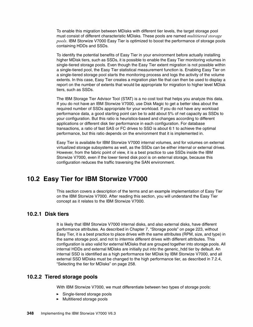
To enable this migration between MDisks with different tier levels, the target storage pool must consist of different characteristic MDisks. These pools are named multitiered storage pools. IBM Storwize V7000 Easy Tier is optimized to boost the performance of storage pools containing HDDs and SSDs.
To identify the potential benefits of Easy Tier in your environment before actually installing higher MDisk tiers, such as SSDs, it is possible to enable the Easy Tier monitoring volumes in single-tiered storage pools. Even though the Easy Tier extent migration is not possible within a single-tiered pool, the Easy Tier statistical measurement function is. Enabling Easy Tier on a single-tiered storage pool starts the monitoring process and logs the activity of the volume extents. In this case, Easy Tier creates a migration plan file that can then be used to display a report on the number of extents that would be appropriate for migration to higher level MDisk tiers, such as SSDs.
The IBM Storage Tier Advisor Tool (STAT) is a no cost tool that helps you analyze this data. If you do not have an IBM Storwize V7000, use Disk Magic to get a better idea about the required number of SSDs appropriate for your workload. If you do not have any workload performance data, a good starting point can be to add about 5% of net capacity as SSDs to your configuration. But this ratio is heuristics-based and changes according to different applications or different disk tier performance in each configuration. For database transactions, a ratio of fast SAS or FC drives to SSD is about 6:1 to achieve the optimal performance, but this ratio depends on the environment that it is implemented in.
Easy Tier is available for IBM Storwize V7000 internal volumes, and for volumes on external virtualized storage subsystems as well, as the SSDs can be either internal or external drives. However, from the fabric point of view, it is a best practice to use SSDs inside the IBM Storwize V7000, even if the lower tiered disk pool is on external storage, because this configuration reduces the traffic traversing the SAN environment.
10.2 Easy Tier for IBM Storwize V7000
This section covers a description of the terms and an example implementation of Easy Tier on the IBM Storwize V7000. After reading this section, you will understand the Easy Tier concept as it relates to the IBM Storwize V7000.
10.2.1 Disk tiers
It is likely that IBM Storwize V7000 internal disks, and also external disks, have different performance attributes. As described in Chapter 7, “Storage pools” on page 223, without Easy Tier, it is a best practice to place drives with the same attributes (RPM, size, and type) in the same storage pool, and not to intermix different drives with different attributes. This configuration is also valid for external MDisks that are grouped together into storage pools. All internal HDDs and external MDisks are initially put into the generic_hdd tier by default. An internal SSD is identified as a high performance tier MDisk by IBM Storwize V7000, and all external SSD MDisks must be changed to the high performance tier, as described in 7.2.4, “Selecting the tier for MDisks” on page 258.
10.2.2 Tiered storage pools
With IBM Storwize V7000, we must differentiate between two types of storage pools:
� Single-tiered storage pools� Multitiered storage pools
348 Implementing the IBM Storwize V7000 V6.3
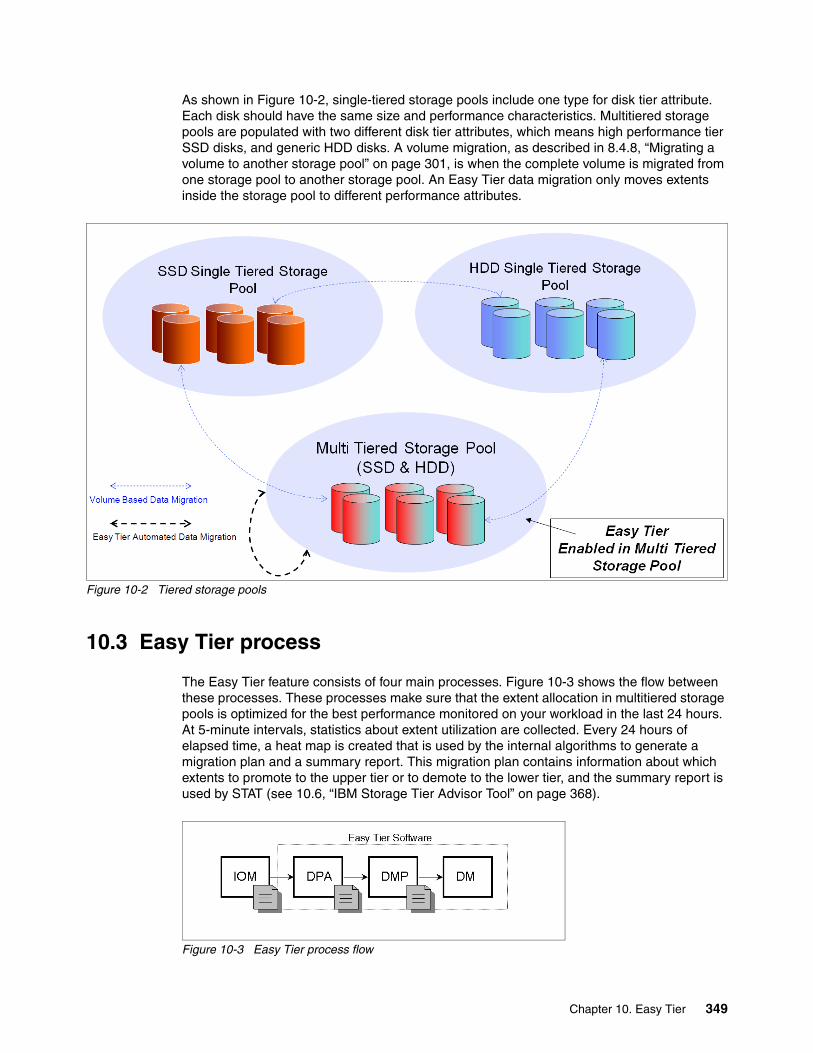
As shown in Figure 10-2, single-tiered storage pools include one type for disk tier attribute. Each disk should have the same size and performance characteristics. Multitiered storage pools are populated with two different disk tier attributes, which means high performance tier SSD disks, and generic HDD disks. A volume migration, as described in 8.4.8, “Migrating a volume to another storage pool” on page 301, is when the complete volume is migrated from one storage pool to another storage pool. An Easy Tier data migration only moves extents inside the storage pool to different performance attributes.
Figure 10-2 Tiered storage pools
10.3 Easy Tier process
The Easy Tier feature consists of four main processes. Figure 10-3 shows the flow between these processes. These processes make sure that the extent allocation in multitiered storage pools is optimized for the best performance monitored on your workload in the last 24 hours. At 5-minute intervals, statistics about extent utilization are collected. Every 24 hours of elapsed time, a heat map is created that is used by the internal algorithms to generate a migration plan and a summary report. This migration plan contains information about which extents to promote to the upper tier or to demote to the lower tier, and the summary report is used by STAT (see 10.6, “IBM Storage Tier Advisor Tool” on page 368).
Figure 10-3 Easy Tier process flow
Chapter 10. Easy Tier 349
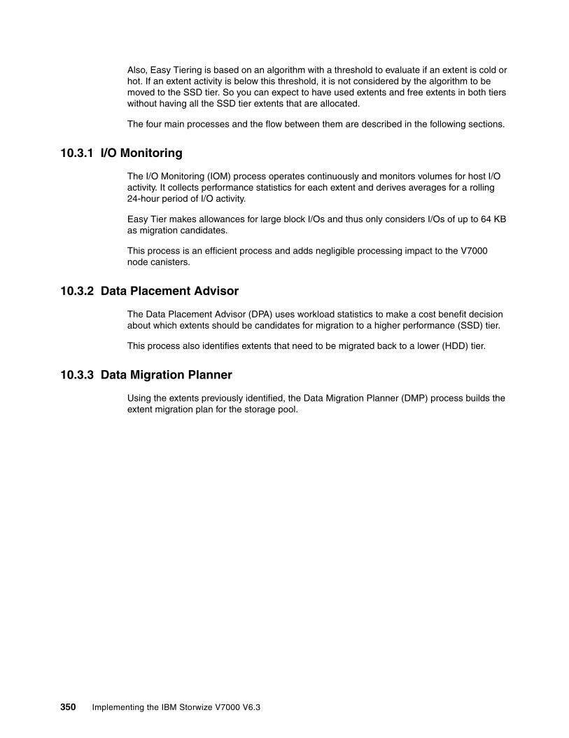
Also, Easy Tiering is based on an algorithm with a threshold to evaluate if an extent is cold or hot. If an extent activity is below this threshold, it is not considered by the algorithm to be moved to the SSD tier. So you can expect to have used extents and free extents in both tiers without having all the SSD tier extents that are allocated.
The four main processes and the flow between them are described in the following sections.
10.3.1 I/O Monitoring
The I/O Monitoring (IOM) process operates continuously and monitors volumes for host I/O activity. It collects performance statistics for each extent and derives averages for a rolling 24-hour period of I/O activity.
Easy Tier makes allowances for large block I/Os and thus only considers I/Os of up to 64 KB as migration candidates.
This process is an efficient process and adds negligible processing impact to the V7000 node canisters.
10.3.2 Data Placement Advisor
The Data Placement Advisor (DPA) uses workload statistics to make a cost benefit decision about which extents should be candidates for migration to a higher performance (SSD) tier.
This process also identifies extents that need to be migrated back to a lower (HDD) tier.
10.3.3 Data Migration Planner
Using the extents previously identified, the Data Migration Planner (DMP) process builds the extent migration plan for the storage pool.
350 Implementing the IBM Storwize V7000 V6.3

10.3.4 Data Migrator
The Data Migrator (DM) process involves scheduling and the actual movement or migration of the volume’s extents up to, or down from, the high disk tier. The extent migration rate is capped so that a maximum of up to 15 MBps is migrated. This rate equates to around 2 TB a day that will be migrated between disk tiers (Figure 10-4).
Figure 10-4 Easy Tier Data Migrator
10.3.5 Easy Tier operating modes
IBM Storwize V7000 offers three operating modes for Easy Tier:
� Easy Tier - OFF (See “Easy Tier - OFF” on page 351.)
� Evaluation Mode (See “Evaluation Mode” on page 351.)
� Auto Data Placement Mode (See “Automatic Data Placement Mode” on page 352.)
Easy Tier - OFFEasy Tier can be turned off. No statistics are recorded and no extents are moved.
Evaluation ModeIf you turn on Easy Tier in a single-tiered storage pool, it runs in Evaluation Mode, which means it measures the I/O activity for all extents. A statistic summary file is created and can be offloaded from the IBM Storwize V700. This file can be analyzed with the IBM Storage Tier Advisory Tool, as described in 10.6, “IBM Storage Tier Advisor Tool” on page 368. This analysis shows the benefits for your workload if you were to add SSDs to your pool, before any hardware acquisition.
Chapter 10. Easy Tier 351
Automatic Data Placement ModeThis operating mode is enabled by default if you create a multitiered storage pool. On all volumes inside the multitiered storage pool, Easy Tier is also set to On. The extents are migrated dynamically by the Easy Tier processes to achieve the best performance. The movement is not apparent to the host server and applications, and it only provides increased performance.
If you do want to disable Auto Data Placement Mode for single volumes inside a multitiered storage pool, it is possible to turn off the mode at the volume level. This action excludes the volume from Auto Data Placement Mode and measures the I/O statistics only.
The statistic summary file can be offloaded for input to the advisor tool. The tool produces a report on the extents moved to SSD and a prediction of performance improvement that could be gained if more SSD was available.
10.3.6 Easy Tier rules
Some operating rules exist when using IBM System Storage Easy Tier on the IBM Storwize V7000:
� Automatic data placement and extent I/O activity monitors are supported on each copy of a mirrored volume. Easy Tier works with each copy independently of the other copy.
� Easy Tier works with all striped volumes, which includes:
– Generic volumes– Thin-provisioned volumes– Mirrored volumes– Thin-mirrored volumes– Global and Metro Mirror sources and targets
� Easy Tier automatic data placement is not supported for image mode or sequential volumes. I/O monitoring for such volumes is supported, but you cannot migrate extents on such volumes unless you convert image or sequential volume copies to striped volumes.
� If possible, IBM Storwize V7000 creates new volumes or volume expansions using extents from MDisks from the HDD tier, but uses extents from MDisks from the SSD tier if no HDD space is available.
� When a volume is migrated out of a storage pool that is managed with Easy Tier, Automatic Data Placement Mode is no longer active on that volume. Automatic Data Placement is also turned off while a volume is being migrated, even if it is between pools that both have Easy Tier Automatic Data Placement enabled. Automatic Data Placement for the volume is re-enabled when the migration is complete.
� SSD performance is dependent on block sizes, and small blocks perform much better than larger ones. As Easy Tier is optimized to work with SSD, it decides if an extent is hot by measuring I/O smaller than 64 KB, but it migrates the entire extent to the appropriate disk tier.
� As extents are migrated, the use of smaller extents makes Easy Tier more efficient.
� The first migration of hot data to SSD starts about 1 hour after enabling Automatic Data Placement Mode, but it takes up to 24 hours to achieve optimal performance.
Volume mirroring: Volume mirroring can have different workload characteristics on each copy of the data, as reads are normally directed to the primary copy and writes occur to both. Thus, the amount of extents that Easy Tier migrates to SSD tier will probably be different for each copy.
352 Implementing the IBM Storwize V7000 V6.3
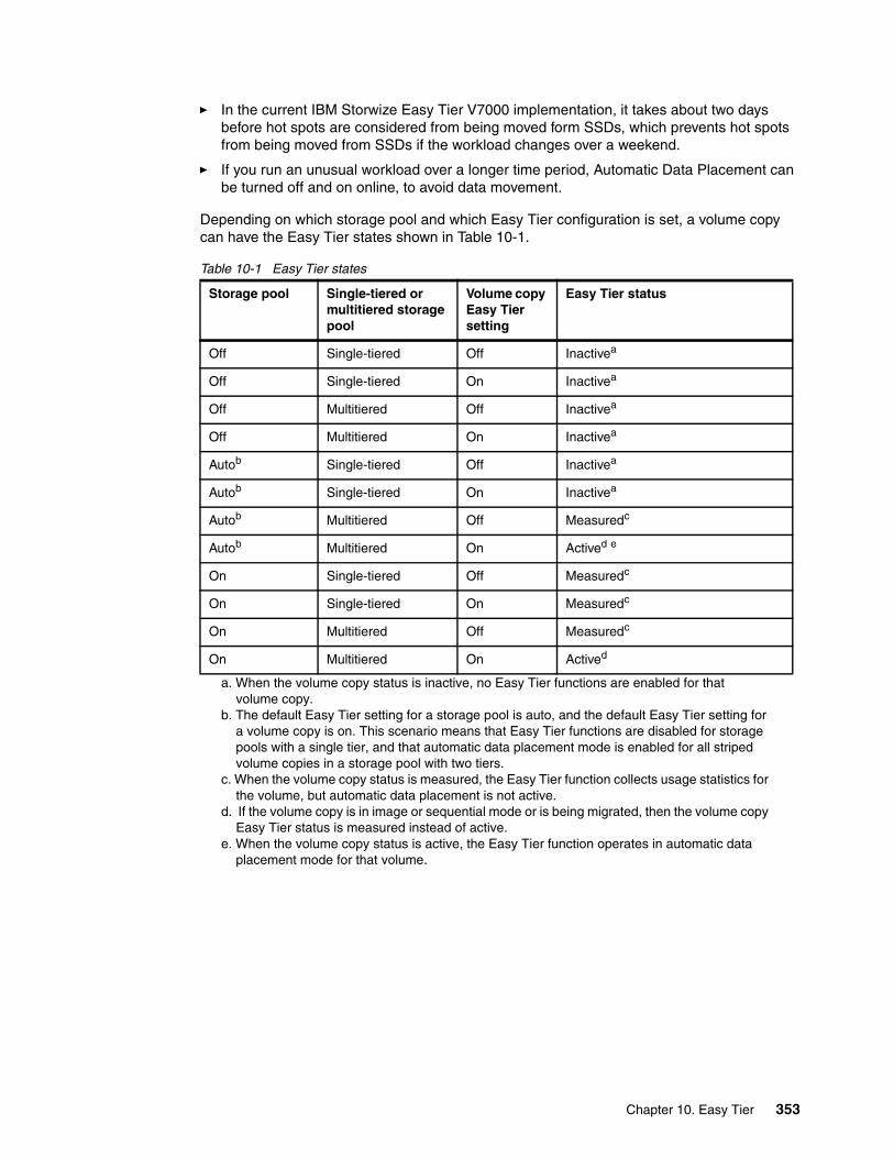
� In the current IBM Storwize Easy Tier V7000 implementation, it takes about two days before hot spots are considered from being moved form SSDs, which prevents hot spots from being moved from SSDs if the workload changes over a weekend.
� If you run an unusual workload over a longer time period, Automatic Data Placement can be turned off and on online, to avoid data movement.
Depending on which storage pool and which Easy Tier configuration is set, a volume copy can have the Easy Tier states shown in Table 10-1.
Table 10-1 Easy Tier states
Storage pool Single-tiered or multitiered storage pool
Volume copy Easy Tier setting
Easy Tier status
Off Single-tiered Off Inactivea
a. When the volume copy status is inactive, no Easy Tier functions are enabled for that volume copy.
Off Single-tiered On Inactivea
Off Multitiered Off Inactivea
Off Multitiered On Inactivea
Autob
b. The default Easy Tier setting for a storage pool is auto, and the default Easy Tier setting for a volume copy is on. This scenario means that Easy Tier functions are disabled for storage pools with a single tier, and that automatic data placement mode is enabled for all striped volume copies in a storage pool with two tiers.
Single-tiered Off Inactivea
Autob Single-tiered On Inactivea
Autob Multitiered Off Measuredc
c. When the volume copy status is measured, the Easy Tier function collects usage statistics for the volume, but automatic data placement is not active.
Autob Multitiered On Actived e
d. If the volume copy is in image or sequential mode or is being migrated, then the volume copy Easy Tier status is measured instead of active.
e. When the volume copy status is active, the Easy Tier function operates in automatic data placement mode for that volume.
On Single-tiered Off Measuredc
On Single-tiered On Measuredc
On Multitiered Off Measuredc
On Multitiered On Actived
Chapter 10. Easy Tier 353

10.4 Easy Tier configuration using the GUI
This section describes how to activate Easy Tier using the IBM Storwize V7000 GUI.
10.4.1 Creating multitiered pools: Enable Easy Tier
In this section, we describe how to create multitiered storage pools using the GUI. As soon as a storage pool changes from single-tiered to multitiered, Easy Tier is enabled by default for the pool and on all volume copies inside this pool.
To create multitiered pools, completed the following steps:
1. Click Volumes Volumes by Pool. Figure 10-5 shows that, in our example, the mdiskgrp1 storage pool exists and Easy Tier is inactive. Now SSD drives must be added to the mdiskgrp1 storage pool to enable Easy Tier.
Figure 10-5 Single-tiered pool
2. Click Pools Internal Storage. Figure 10-6 shows that four internal SSD drives are available and they are in Unused status. Internal SSD are assigned the generic_ssd high performance tier automatically by the IBM Storwize V7000.
Figure 10-6 Internal SSDs
354 Implementing the IBM Storwize V7000 V6.3
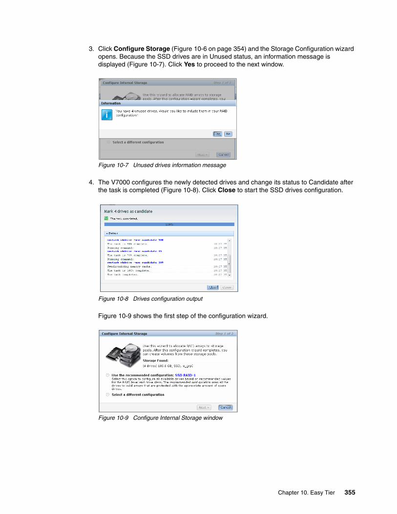
3. Click Configure Storage (Figure 10-6 on page 354) and the Storage Configuration wizard opens. Because the SSD drives are in Unused status, an information message is displayed (Figure 10-7). Click Yes to proceed to the next window.
Figure 10-7 Unused drives information message
4. The V7000 configures the newly detected drives and change its status to Candidate after the task is completed (Figure 10-8). Click Close to start the SSD drives configuration.
Figure 10-8 Drives configuration output
Figure 10-9 shows the first step of the configuration wizard.
Figure 10-9 Configure Internal Storage window
Chapter 10. Easy Tier 355

The wizard recommends using the SSDs to enable Easy Tier. If you select Use recommended configuration, it selects the recommended RAID level and hot spare coverage for your system automatically (Figure 10-10). For our configuration, the wizard configures one RAID1 array with two SSD and two spares, because we have an even number of drives.
Figure 10-10 Recommended configuration
If you select Select a different configuration (Figure 10-11), you can select the preset.
Figure 10-11 Select a preset menu
5. Choose a custom RAID level, or you can also select the “SSD Easy Tier” preset to review and modify the recommended configuration. Because we do not have enough drives in our configuration, the “SSD Easy Tier” preset is not available from the preset selection. This preset, when available, configures a RAID 10 array with a spare goal of one drive.
356 Implementing the IBM Storwize V7000 V6.3

In this example, we create a RAID 5 array. Because there are not enough drives, an error message is displayed (Figure 10-12).
Figure 10-12 Select RAID 5 preset
This error message can be avoided if the Automatically configure spares check box is cleared (Figure 10-13). A RAID 5 array with four drives and zero spares is created.
Figure 10-13 Array creation configuration summary
Chapter 10. Easy Tier 357

6. To create a multitiered storage pool, the SSDs must be added to an existing generic HDD pool. Select Expand an existing pool (Figure 10-14) and select the pool you want to change to a multitiered storage pool. In our example, mdiskgrp01 is selected; click Finish.
Figure 10-14 Expand an existing pool
7. Now the array is configured on the SSDs and added to the selected storage pool. Click Close after the task completes (Figure 10-15).
Figure 10-15 Completed task
358 Implementing the IBM Storwize V7000 V6.3

Figure 10-16 shows that the internal SSD drives usage has now changed to Member and that the wizard created an MDisk that is named mdisk2085.
Figure 10-16 SSD usage has changed
In Figure 10-17, you see that the new MDisk is now part of the mdiskgrp01 storage pool and that the status of the Easy Tier has changed to Active. In this pool, Automatic Data Placement Mode is started and the Easy Tier processes start to work.
Figure 10-17 Easy Tier active
Chapter 10. Easy Tier 359

The storage pool has been successfully changed to a multitiered storage pool (look at the icon: ) and Easy Tier has been activated by default. To reflect this change, we rename the storage pool (described in 8.7.2, “Changing the storage pool name” on page 327) and change the function icon (described in 8.7.1, “Changing the Storage Pool function icon” on page 326) (Figure 10-18).
Figure 10-18 Multitiered storage pool
By default, Easy Tier is now active in this pool and in all volumes in this storage pool. Figure 10-19 shows two volumes on the multitiered storage pool.
Figure 10-19 Volumes by pool
360 Implementing the IBM Storwize V7000 V6.3

If you open the properties of a volume (by clicking Actions Properties), you can also see that Easy Tier is enabled on the volume by default (Figure 10-20).
Figure 10-20 Easy Tier enabled volume
If a volume owns more than one copy, Easy Tier can be enabled and disabled on each copy separately (Figure 10-21). This action depends on the storage pool where the volume copy is defined.
Figure 10-21 Easy Tier by copy
If you want to enable Easy Tier on the second copy, change the storage pool of the second copy to a multitiered storage pool by repeating these steps.
Chapter 10. Easy Tier 361
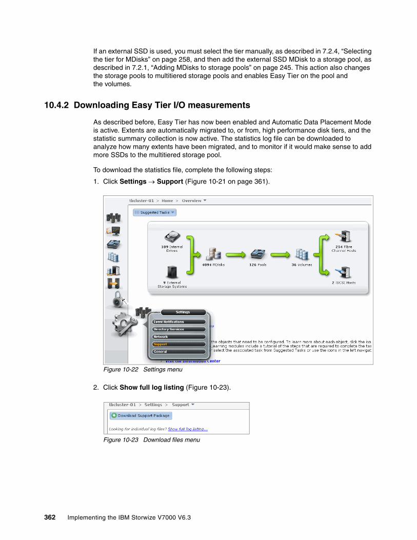
If an external SSD is used, you must select the tier manually, as described in 7.2.4, “Selecting the tier for MDisks” on page 258, and then add the external SSD MDisk to a storage pool, as described in 7.2.1, “Adding MDisks to storage pools” on page 245. This action also changes the storage pools to multitiered storage pools and enables Easy Tier on the pool and the volumes.
10.4.2 Downloading Easy Tier I/O measurements
As described before, Easy Tier has now been enabled and Automatic Data Placement Mode is active. Extents are automatically migrated to, or from, high performance disk tiers, and the statistic summary collection is now active. The statistics log file can be downloaded to analyze how many extents have been migrated, and to monitor if it would make sense to add more SSDs to the multitiered storage pool.
To download the statistics file, complete the following steps:
1. Click Settings Support (Figure 10-21 on page 361).
Figure 10-22 Settings menu
2. Click Show full log listing (Figure 10-23).
Figure 10-23 Download files menu
362 Implementing the IBM Storwize V7000 V6.3

This action lists all the log files available to download (Figure 10-24). The Easy Tier log files are always named dpa_heat.canister_name_date.time.data.
Figure 10-24 Download dpa_heat file
If you run Easy Tier for a longer period, it generates a heat file at least every 24 hours.
The time and date of the file creation is included in the file name. The heat log file always includes the measured I/O activity of the last 24 hours.
3. Right-click the dpa_heat.canister_name_date.time.data file and click Download. Select the file for Easy Tier measurement for the most representative time period.
You can also use the search box on the right to filter your search (Figure 10-25).
Figure 10-25 Filter your search
Depending on your browser settings, the file is downloaded to your default location, or you are prompted to save it to your computer. This file can be analyzed as described in 10.6, “IBM Storage Tier Advisor Tool” on page 368.
10.5 Easy Tier configuration using the CLI
Section 10.4, “Easy Tier configuration using the GUI” on page 354 describes how to enable IBM Storwize V7000 Easy Tier using the GUI. Easy Tier can also be configured using the CLI, and for the advanced user, this method offers several more options for Easy Tier configuration.
Before using the CLI, you must configure CLI access, as described in Appendix A, “CLI setup and SAN Boot” on page 569.
Log file creation: Depending on your workload and configuration, it can take up to 24 hours until a new Easy Tier log file is created.
Readability: In most examples shown in this section, many lines have been deleted in the command output or responses so that we can concentrate on the Easy Tier related information only.
Chapter 10. Easy Tier 363

10.5.1 Enabling Easy Tier evaluation mode
If you want to enable Easy Tier in evaluation mode, you must enable Easy Tier on a single-tiered storage pool. Connect to your IBM Storwize V7000 using the CLI and run lsmdiskgrp (Example 10-1). This command shows an overview about all configured storage pools and the Easy Tier status of the pool. In our example, there are two storage pools listed: mdiskgrp0 with Easy Tier inactive, and Multi_Tier_Pool with Easy Tier enabled.
Example 10-1 List storage pools
IBM_2076:admin>lsmdiskgrpid name status mdisk_count ... easy_tier easy_tier_status0 mdiskgrp0 online 3 ... auto inactive1 Multi_Tier_Pool online 3 ... auto active
To get a more detailed view of the single-tiered storage pool, run lsmdiskgrp storage pool name (Example 10-2).
Example 10-2 Storage Pools details - Easy Tier inactive
IBM_2076:admin>lsmdiskgrp mdiskgrp0id 0name mdiskgrp0status onlinemdisk_count 3...easy_tier autoeasy_tier_status inactivetier generic_ssdtier_mdisk_count 0...tier generic_hddtier_mdisk_count 3...
To enable Easy Tier on a single-tiered storage pool, run chmdiskgrp -easytier on storage pool name (Example 10-3). As this storage pool does not have any SSD MDisks, it is not a multitiered storage pool; only measuring is available.
Example 10-3 Enable Easy Tier on a single-tiered storage pool
IBM_2076:admin>chmdiskgrp -easytier on mdiskgrp0IBM_2076:admin>
Check the status of the storage pool again by running lsmdiskgrp storage pool name again (Example 10-4).
Example 10-4 Storage pool details - Easy Tier ON
IBM_2076:admin>lsmdiskgrp mdiskgrp0id 0name mdiskgrp0status onlinemdisk_count 3vdisk_count 7...easy_tier on
364 Implementing the IBM Storwize V7000 V6.3
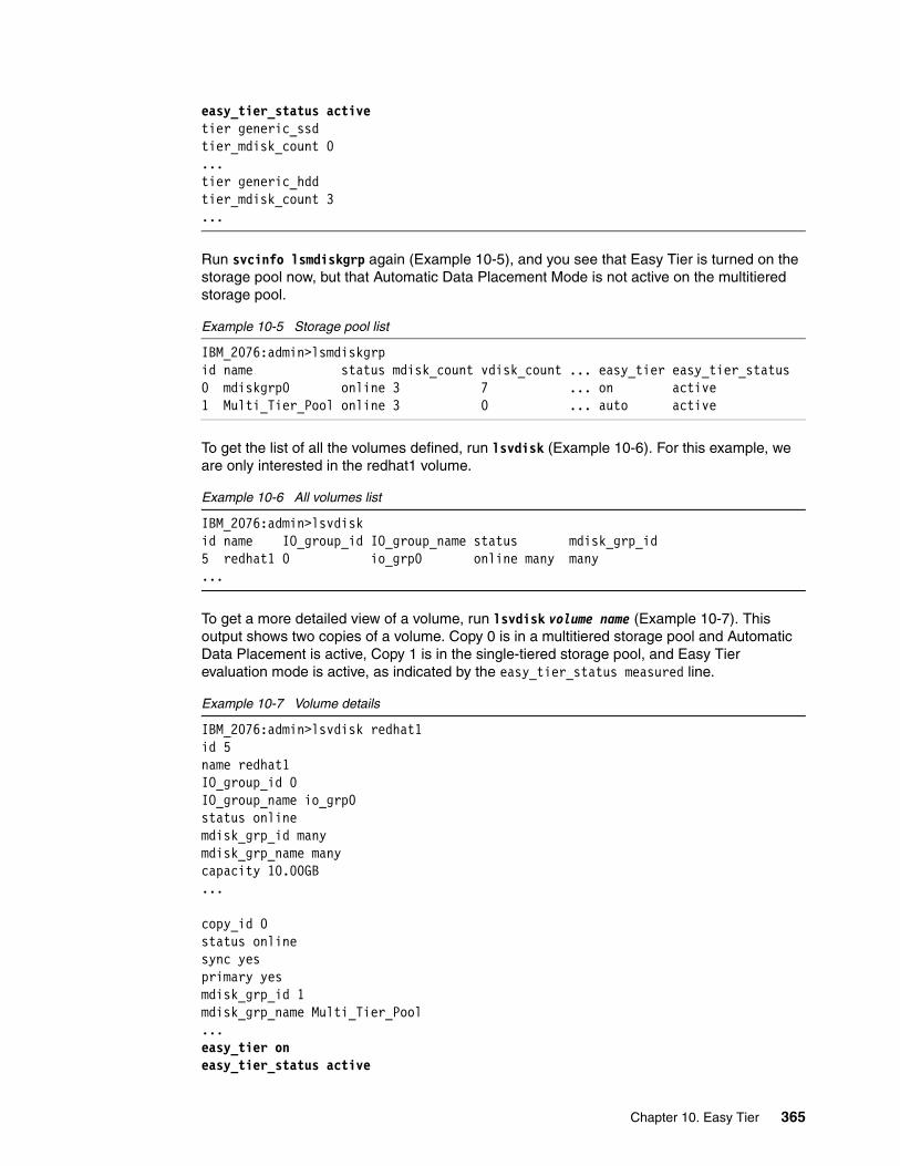
easy_tier_status activetier generic_ssdtier_mdisk_count 0...tier generic_hddtier_mdisk_count 3...
Run svcinfo lsmdiskgrp again (Example 10-5), and you see that Easy Tier is turned on the storage pool now, but that Automatic Data Placement Mode is not active on the multitiered storage pool.
Example 10-5 Storage pool list
IBM_2076:admin>lsmdiskgrpid name status mdisk_count vdisk_count ... easy_tier easy_tier_status0 mdiskgrp0 online 3 7 ... on active1 Multi_Tier_Pool online 3 0 ... auto active
To get the list of all the volumes defined, run lsvdisk (Example 10-6). For this example, we are only interested in the redhat1 volume.
Example 10-6 All volumes list
IBM_2076:admin>lsvdiskid name IO_group_id IO_group_name status mdisk_grp_id 5 redhat1 0 io_grp0 online many many ...
To get a more detailed view of a volume, run lsvdisk volume name (Example 10-7). This output shows two copies of a volume. Copy 0 is in a multitiered storage pool and Automatic Data Placement is active, Copy 1 is in the single-tiered storage pool, and Easy Tier evaluation mode is active, as indicated by the easy_tier_status measured line.
Example 10-7 Volume details
IBM_2076:admin>lsvdisk redhat1id 5name redhat1IO_group_id 0IO_group_name io_grp0status onlinemdisk_grp_id manymdisk_grp_name manycapacity 10.00GB...
copy_id 0status onlinesync yesprimary yesmdisk_grp_id 1mdisk_grp_name Multi_Tier_Pool...easy_tier oneasy_tier_status active
Chapter 10. Easy Tier 365
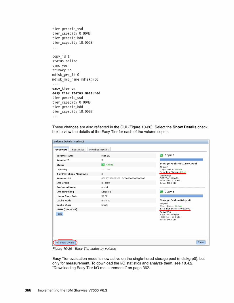
tier generic_ssdtier_capacity 0.00MBtier generic_hddtier_capacity 10.00GB...
copy_id 1status onlinesync yesprimary nomdisk_grp_id 0mdisk_grp_name mdiskgrp0....easy_tier oneasy_tier_status measuredtier generic_ssdtier_capacity 0.00MBtier generic_hddtier_capacity 10.00GB...
These changes are also reflected in the GUI (Figure 10-26). Select the Show Details check box to view the details of the Easy Tier for each of the volume copies.
Figure 10-26 Easy Tier status by volume
Easy Tier evaluation mode is now active on the single-tiered storage pool (mdiskgrp0), but only for measurement. To download the I/O statistics and analyze them, see 10.4.2, “Downloading Easy Tier I/O measurements” on page 362.
366 Implementing the IBM Storwize V7000 V6.3

10.5.2 Enabling or disabling Easy Tier on single volumes
If you enable Easy Tier on a storage pool, by default, all volume copies inside the Easy Tier pools also have it enabled. This setting applies both to multitiered and single-tiered storage pools. It is also possible to turn Easy Tier on and off for single volume copies.
To disable Easy Tier on single volumes, run chvdisk -easytier off volume name (Example 10-8).
Example 10-8 Disable Easy Tier on a single volume
IBM_2076:admin>chvdisk -easytier off redhat1IBM_2076:admin>
This command disables Easy Tier on all copies of this volume. Example 10-9 shows that the Easy Tier status of the copies has changed, even if Easy Tier is still enabled on the storage pool.
Example 10-9 Easy Tier disabled
IBM_2076:admin>lsvdisk redhat1id 5name redhat1IO_group_id 0IO_group_name io_grp0status onlinemdisk_grp_id manymdisk_grp_name manycapacity 10.00GB...
copy_id 0status onlinesync yesprimary yesmdisk_grp_id 1mdisk_grp_name Multi_Tier_Pool...easy_tier offeasy_tier_status meassuredtier generic_ssdtier_capacity 0.00MBtier generic_hddtier_capacity 10.00GB...
copy_id 1status onlinesync yesprimary nomdisk_grp_id 0mdisk_grp_name mdiskgrp0....easy_tier offeasy_tier_status measuredtier generic_ssd
Chapter 10. Easy Tier 367

tier_capacity 0.00MBtier generic_hddtier_capacity 10.00GB...
To enable Easy Tier on a volume, run chvdisk -easytier on volume name (Example 10-10), and the Easy Tier Status changes back to enabled (Example 10-7 on page 365).
Example 10-10 Easy Tier enabled
IBM_2076:admin>chvdisk -easytier on redhat1IBM_2076:admin>
10.6 IBM Storage Tier Advisor Tool
The IBM Storage Tier Advisor Tool (STAT) is a command-line tool that runs on Windows-based systems. If you run Easy Tier in evaluation mode, it analyzes your extents and estimates how much benefit you derive if you implement Easy Tier Automatic Data Placement with SSD MDisks. If Automatic Data Placement Mode is already active, the analysis also includes an overview of migrated hot data and recommendations about whether you could derive any benefit by adding more SSD drives. The output provides a graphical representation of the performance data collected by Easy Tier over a 24-hour operational cycle.
10.6.1 Creating graphical reports
STAT takes input from the dpa_heat log file and produces an HTML file that contains the report. Download the heat_log file, as described in 10.4.2, “Downloading Easy Tier I/O measurements” on page 362, and save it to the hard disk drive of a Windows system.
You can read more about the tool, and download it, at the following address:
http://www-01.ibm.com/support/docview.wss?uid=ssg1S4000935
Click Start Run, enter cmd, and click OK to open a command prompt.
Typically, the tool is installed under the C:\Program Files\IBM\STAT directory. Enter the following command to generate the report (Example 10-11):
C:\Program Files\IBM\STAT>STAT.exe -o c:\directory_where_you_want_the output_to_go c:\location_of_dpa_heat_data_file
If you do not specify -o c:\directory_where_you_want_the output_to_go, the output goes to the directory where the STAT.exe file is located.
Example 10-11 Generate HTML file
C:\EasyTier>STAT.exe -o C:\EasyTier C:\StorwizeV7000_Logs\dpa_heat.31G00KV-1.101209.131801.data
CMUA00019I The STAT.exe command has completed.
C:\EasyTier>
368 Implementing the IBM Storwize V7000 V6.3
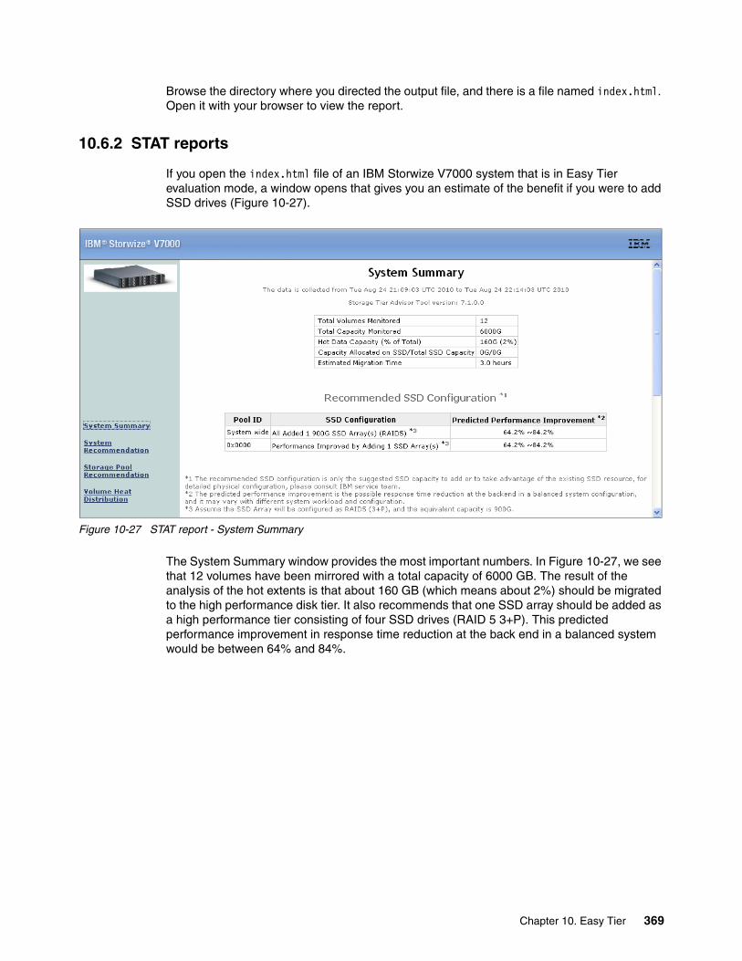
Browse the directory where you directed the output file, and there is a file named index.html. Open it with your browser to view the report.
10.6.2 STAT reports
If you open the index.html file of an IBM Storwize V7000 system that is in Easy Tier evaluation mode, a window opens that gives you an estimate of the benefit if you were to add SSD drives (Figure 10-27).
Figure 10-27 STAT report - System Summary
The System Summary window provides the most important numbers. In Figure 10-27, we see that 12 volumes have been mirrored with a total capacity of 6000 GB. The result of the analysis of the hot extents is that about 160 GB (which means about 2%) should be migrated to the high performance disk tier. It also recommends that one SSD array should be added as a high performance tier consisting of four SSD drives (RAID 5 3+P). This predicted performance improvement in response time reduction at the back end in a balanced system would be between 64% and 84%.
Chapter 10. Easy Tier 369

Click Volume Heat Distribution to change to a more detailed view (Figure 10-28).
Figure 10-28 Volume Heat Distribution window
The table in this view gives you a more detailed view as to how the hot extents are distributed across your system. It contains the following information:
� Volume ID: The unique ID of each volume on the IBM Storwize V7000.
� Copy ID: If a volume owns more than one copy, the data is measured for each copy.
� Pool ID: The unique ID of each pool configured on the IBM Storwize V7000.
� Configured Size: The configured size of each volume that is represented to the host.
� Capacity on SSD: Capacity of the volumes on high performance disk tier (even in evaluation mode, volumes can be on high performance disk tiers if they have been moved there before).
� Heat Distribution: Shows the heat distribution of the data in this volume. The blue portion of the bar represents the capacity of the cold data, and the red portion represents the capacity of the hot data. The red hot data are candidates to be moved to high performance disk tier.
370 Implementing the IBM Storwize V7000 V6.3
Chapter 11. Copy services
In this chapter, we describe the copy services functions provided by the IBM Storwize V7000 storage system, including FlashCopy and Remote Copy. Copy services functions are useful for making data copies for backup, application test, recovery, and so on. The IBM Storwize V7000 system makes it easy to apply these functions to your environment through its intuitive GUI.
11
© Copyright IBM Corp. 2011, 2012. All rights reserved. 371
11.1 FlashCopy
The FlashCopy function of the IBM Storwize V7000 storage system lets you create a point-in-time copy of one or more volumes. In this section, we describe the structure of FlashCopy and provide details about its configuration and use.
You can use FlashCopy to solve critical and challenging business needs that require duplication of data of on your source volume. Volumes may remain online and active while you create consistent copies of the data sets. Because the copy is performed at the block level, it operates below the host operating system and cache and is therefore not apparent to the host.
While the FlashCopy operation is performed, the source volume is frozen briefly to initialize the FlashCopy bitmap and then I/O is allowed to resume. Although several FlashCopy options require the data to be copied from the source to the target in the background, which can take time to complete, the resulting data on the target volume copy appears to have completed immediately. This task is accomplished through the use of a bitmap (or bit array) that tracks changes to the data after the FlashCopy is initiated, and an indirection layer, which allows data to be read from the source volume transparently.
11.1.1 Business requirements for FlashCopy
When deciding if FlashCopy addresses your needs, you need to adopt a combined business and technical view of the problems you need to solve. Determine what your needs are from a business perspective, and then determine if FlashCopy fulfills the technical needs of those business requirements.
With an immediately available copy of the data, FlashCopy could be used in various business scenarios, which include:
� Rapidly creating consistent backups of dynamically changing data
FlashCopy can be used to create backups through periodic execution of FlashCopy; the FlashCopy target volumes can be used to complete a rapid restore of individual files or the entire volume through Reverse FlashCopy (using the -restore option).
The target volumes created by FlashCopy may be also used for backup to tape, by attaching them to another server, which to a great extent offloads the production server. After the copy to tape completes, the target volumes can be discarded if required or kept as a rapid restore copy of the data.
� Rapidly creating consistent copies of production data to facilitate data movement or migration between hosts
FlashCopy can be used to facilitate the movement or migration of data between hosts while minimizing downtime for applications. FlashCopy allows application data to be copied from source volumes to new target volumes while applications remain online. After the volumes are fully copied and synchronized, the application can be stopped and then immediately started on the new server accessing the new FlashCopy target volumes. This mode of migration is swifter than other migration methods available through the IBM Storwize V7000, because the size or the speed of the migration is not as limited.
Flushing: Because FlashCopy operates at the block level, below the host operating system and cache, those levels do need to be flushed for consistent FlashCopy copies.
372 Implementing the IBM Storwize V7000 V6.3

� Rapidly creating copies of production data sets for application development and testing
Under normal circumstances, to perform application development and testing, data must be restored from traditional backup media, such as tape. Depending the amount of data and the technology in use, this process could easily take a day or more. With FlashCopy, a copy can be created and online for use in just a few minutes. The time varies based on the application and the data set size.
� Rapidly creating copies of production data sets for auditing purposes and data mining
Auditing or data mining normally require the usage of the production applications. This situation can cause high loads for databases track inventories or similar data. With FlashCopy, you can create copies for your reporting and data mining activities. This situation reduces the load on your production systems, increasing their performance.
� Rapidly creating copies of production data sets for quality assurance
Quality assurance is an interesting case for FlashCopy. Because traditional methods involve so much time and labor, the refresh cycle is typically extended. This reduction in time required allows much more frequent refreshes of the quality assurance database.
11.1.2 FlashCopy functional overview
FlashCopy occurs between a source volume and a target volume. The source and target volumes must be the same size. Multiple FlashCopy mappings (source-to-target relationships) can be defined, and point-in-time consistency can be maintained across multiple point-in-time mappings using consistency groups. FlashCopy consistency groups are further described in “FlashCopy consistency groups” on page 378.
The minimum granularity that IBM Storwize V7000 storage system supports for FlashCopy is an entire volume; it is not possible to use FlashCopy to copy only part of a volume. Additionally, the source and target volumes must belong to the same IBM Storwize V7000 storage system, but they do not have to be in the same storage pool.
Before you start a FlashCopy (regardless of the type and options specified) you must run either prestartfcmap or prestartfcconsistgrp, which puts the SAN Volume Controller Cache into write-through mode, flushing the I/O currently bound for your volume. After FlashCopy is started, an effective copy of a source volume to a target volume has been created. The content of the source volume is immediately presented on the target volume and the original content of the target volume is lost. This FlashCopy operation is also referred to as a time-zero copy (T0).
Immediately following the FlashCopy operation, both the source and target volumes are available for use. The FlashCopy operation creates a bitmap that is referenced and maintained to direct I/O requests within the source and target relationship. This bitmap is updated to reflect the active block locations as data is copied in the background from the source to target and updates are made to the source.
Chapter 11. Copy services 373

Figure 11-1 shows the redirection of the host I/O toward the source volume and the target volume.
Figure 11-1 Redirection of host I/O
When data is copied between volumes, it is copied in units of address space known as grains. Grains are units of data grouped together to optimize the use of the bitmap that track changes to the data between the source and target volume. You have the option of using 64 KB or 256 KB grain sizes; 256 KB is the default. The FlashCopy bitmap contains 1 bit for each grain and is used to track whether the source grain has been copied to the target. The 64 KB grain size consumes bitmap space at a rate of four times the default 256 KB size.
The FlashCopy bitmap dictates read and write behavior for both the source and target volumes as follows:
� Read I/O request to source: Reads are performed from the source volume, which is the same as for non-FlashCopy volumes.
� Write I/O request to source: Writes to the source cause the grains to be copied to the target if it has not already been copied, and then the write is performed to the source.
� Read I/O request to target: Reads are performed from the target if the grains have already been copied; otherwise, the read is performed from the source.
� Write I/O request to target: Writes to the target cause the grain to be copied from the source to the target unless the entire grain is being written, and then the write completes to the target.
FlashCopy mappingsA FlashCopy mapping defines the relationship between a source volume and a target volume. FlashCopy mappings can be either stand-alone mappings or a member of a consistency group, as described in “FlashCopy consistency groups” on page 378.
374 Implementing the IBM Storwize V7000 V6.3

Incremental FlashCopy mappingsIn an incremental FlashCopy, the initial mapping copies all of the data from the source volume to the target volume. Subsequent FlashCopy mappings only copy data that has been modified since the initial FlashCopy mapping. This action reduces the amount of time that it takes to re-create an independent FlashCopy image. You can define a FlashCopy mapping as incremental only when you create the FlashCopy mapping.
Multiple target FlashCopy mappingsYou can copy up to 256 target volumes from a single source volume. Each relationship between a source and target volume is managed by a unique mapping such that a single volume can be the source volume for up to 256 mappings.
Each of the mappings from a single source can be started and stopped independently. If multiple mappings from the same source are active (in the copying or stopping states), a dependency exists between these mappings.
If a single source volume has multiple target FlashCopy volumes, the write to the source volume does not cause its data to be copied to all of the targets. Instead, it is copied to the newest target volume only. The older targets refer to new targets first before referring to the source. A dependency relationship exists between a particular target and all newer targets that share a source until all data has been copied to this target and all older targets.
Cascaded FlashCopy mappingsThe cascaded FlashCopy function allows a FlashCopy target volume to be the source volume of another FlashCopy mapping. Up to 256 mappings can exist in a cascade. If cascaded mappings and multiple target mappings are used, a tree of up to 256 mappings can be created.
Cascaded mappings differ from multiple target FlashCopy mappings in depth. Cascaded mappings have an association in the manner of A > B > C, while multiple target FlashCopy has an association in the manner A > B1 and A > B2.
Background copy The background copy rate is a property of a FlashCopy mapping defined as a value of 0 - 100. The background copy rate can be defined and dynamically changed for individual FlashCopy mappings. A value of 0 disables background copy. This option is also called the no-copy option, which provides pointer-based images for limited lifetime uses.
With FlashCopy background copy, the source volume data is copied to the corresponding target volume in the FlashCopy mapping. If the background copy rate is set to 0, which means disable the FlashCopy background copy, only data that changed on the source volume is copied to the target volume. The benefit of using a FlashCopy mapping with background copy enabled is that the target volume becomes a real independent clone of the FlashCopy mapping source volume after the copy is complete. When the background copy is disabled, the target volume only remains a valid copy of the source data while the FlashCopy mapping remains in place. Copying only the changed data saves your storage capacity (assuming it is thin provisioned and -rsize has been correctly setup.)
Chapter 11. Copy services 375

The relationship of the background copy rate value to the amount of data copied per second is shown in Table 11-1.
Table 11-1 Background copy rate
Cleaning rateThe cleaning rate provides a method for FlashCopy copies with dependant mappings (either multiple target or cascaded) to be able to complete their background copies before their source goes offline or is deleted after a stop has been issued.
When you create or modify a FlashCopy mapping, you can specify a cleaning rate for the FlashCopy mapping that is independent of the background copy rate. The cleaning rate is also defined as a value of 0 - 100, which has the same relationship to data copied per second with the backup copy rate (Table 11-1).
The cleaning rates controls the rate at which the cleaning process operates. The cleaning process’ purpose is to copy (or flush) data from FlashCopy source volumes upon which there are dependent mappings. For cascaded and multiple target FlashCopy, the source maybe a target for another FlashCopy or a source for a chain (cascade) of FlashCopy mappings. The cleaning process must complete before the FlashCopy mapping can go to the stopped state. This feature and the distinction between stopping and stopped states was added to prevent data access interruption for dependent mappings, when their source is issued a stop.
Value Data copied per second
Grains per second (256 KB grain)
Grains per second (64 KB grain)
1 - 10 128 KB 0.5 2
11 - 20 256 KB 1 4
21 - 30 512 KB 2 8
31 - 40 1 MB 4 16
41 - 50 2 MB 8 32
51 - 60 4 MB 16 64
61 - 70 8 MB 32 128
71 - 80 16 MB 64 256
81 - 90 32 MB 128 512
91 - 100 64 MB 256 1024
Data copy rate: The data copy rate remains the same regardless of the FlashCopy grain size. The difference is the number of grains copied per second. The gain size can be either 64 or 256 KB. The smaller size consumes more bitmap space and thus limits the total amount of FlashCopy space possible, but may be more efficient regarding the amount of data moved, depending on your environment.
376 Implementing the IBM Storwize V7000 V6.3
FlashCopy mapping statesAt any point in time, a mapping is in one of the following states:
� Idle or Copied
The source and target volumes act as independent volumes even if a mapping exists between the two. Read and write caching is enabled for both the source and the target volumes.
If the mapping is incremental and the background copy is complete, the mapping only records the differences between the source and target volumes. If the connection to both nodes in the IBM Storwize V7000 storage system that the mapping is assigned to is lost, the source and target volumes go offline.
� Copying
The copy is in progress. Read and write caching is enabled on the source and the target volumes.
� Prepared
The mapping is ready to start. The target volume is online, but is not accessible. The target volume cannot perform read or write caching. Read and write caching is failed by the SCSI front end as a hardware error. If the mapping is incremental and a previous mapping has completed, the mapping only records the differences between the source and target volumes. If the connection to both nodes in the IBM Storwize V7000 storage system that the mapping is assigned to is lost, the source and target volumes go offline.
� Preparing
The target volume is online, but not accessible. The target volume cannot perform read or write caching. Read and write caching is failed by the SCSI front end as a hardware error. Any changed write data for the source volume is flushed from the cache. Any read or write data for the target volume is discarded from the cache. If the mapping is incremental and a previous mapping has completed, the mapping records only the differences between the source and target volumes. If the connection to both nodes in the IBM Storwize V7000 storage system that the mapping is assigned to is lost, the source and target volumes go offline.
� Stopped
The mapping is stopped because either you issued a stop command or an I/O error occurred. The target volume is offline and its data is lost. To access the target volume, you must restart or delete the mapping. The source volume is accessible and the read and write cache is enabled. If the mapping is incremental, the mapping is recording write operations to the source volume. If the connection to both nodes in the IBM Storwize V7000 storage system that the mapping is assigned to is lost, the source and target volumes go offline.
� Stopping
The mapping is in the process of copying data to another mapping. If the background copy process is complete, the target volume is online while the stopping copy process completes. If the background copy process is not complete, data is discarded from the target volume cache. The target volume is offline while the stopping copy process runs. The source volume is accessible for I/O operations.
� Suspended
The mapping started, but it did not complete. Access to the metadata is lost, which causes both the source and target volume to go offline. When access to the metadata is restored, the mapping returns to the copying or stopping state and the source and target volumes return online. The background copy process resumes.
Chapter 11. Copy services 377

Any data that has not been flushed and has been written to the source or target volume before the suspension is in cache until the mapping leaves the suspended state.
FlashCopy consistency groupsConsistency groups address the requirement to preserve point-in-time data consistency across multiple volumes for applications having related data that spans them. For these volumes, consistency groups maintain the integrity of the FlashCopy by ensuring that dependent writes, which are described in more detail in “Dependent writes” on page 378, are executed in the application’s intended sequence.
When consistency groups are used, the FlashCopy commands are issued to the FlashCopy consistency group, which performs the operation on all FlashCopy mappings contained within the consistency group.
Figure 11-2 shows a consistency group consisting of two FlashCopy mappings.
Figure 11-2 FlashCopy consistency group
Dependent writesTo illustrate why it is crucial to use consistency groups when a data set spans multiple volumes, consider the following typical sequence of writes for a database update transaction:
1. A write is executed to update the database log, indicating that a database update is about to be performed.
2. A second write is executed to complete the actual update to the database.
3. A third write is executed to update the database log, indicating that the database update has completed successfully.
FlashCopy mapping management: After an individual FlashCopy mapping has been added to a consistency group, it can only be managed as part of the group; operations such as start and stop are no longer allowed on the individual mapping.
378 Implementing the IBM Storwize V7000 V6.3

The database ensures the correct ordering of these writes by waiting for each step to complete before starting the next step. However, if the database log (updates 1 and 3) and the database itself (update 2) are on separate volumes, it is possible for the FlashCopy of the database volume to occur before the FlashCopy of the database log. This situation can result in the target volumes seeing writes (1) and (3) but not (2), because the FlashCopy of the database volume occurred before the write was completed.
In this case, if the database was restarted using the backup that was made from the FlashCopy target volumes, the database log indicates that the transaction had completed successfully when in fact it had not. This situation occurs because the FlashCopy of the volume with the database file was started (bitmap was created) before the write had completed to the volume. Therefore, the transaction is lost and the integrity of the database is in question.
To overcome the issue of dependent writes across volumes and to create a consistent image of the client data, it is necessary to perform a FlashCopy operation on multiple volumes as an atomic operation using consistency groups.
A FlashCopy consistency group can contain up to 512 FlashCopy mappings. The more mappings you have, the more time it takes to prepare the consistency group. FlashCopy commands can then be issued to the FlashCopy consistency group and simultaneously for all of the FlashCopy mappings that are defined in the consistency group. For example, when starting the FlashCopy for the consistency group, all FlashCopy mappings in the consistency group are started at the same time, resulting in a point-in-time copy that is consistent across all FlashCopy mappings that are contained in the consistency group.
A consistency group aggregates FlashCopy mappings, not volumes. Thus, where a source volume has multiple FlashCopy mappings, they can be in the same or separate consistency groups. If a particular volume is the source volume for multiple FlashCopy mappings, you might want to create separate consistency groups to separate each mapping of the same source volume. Regardless of whether the source volume with multiple target volumes is in the same consistency group or in separate consistency groups, the resulting FlashCopy produces multiple identical copies of the source data.
The consistency group can be specified when the mapping is created. You can also add the FlashCopy mapping to a consistency group or change the consistency group of a FlashCopy mapping later. Do not place stand-alone mappings into a consistency group, because they become controlled as part of that consistency group.
FlashCopy consistency group statesAt any point in time, a FlashCopy consistency group is in one of the following states:
� Idle or Copied
All FlashCopy Mappings in this consistency group are in the Idle or Copied state.
� Preparing
At least one FlashCopy mapping in this consistency group is in the Preparing state.
� Prepared
The consistency group is ready to start. While in this state, the target volumes of all FlashCopy mappings in this consistency group are not accessible.
� Copying
At least one FlashCopy mapping in the consistency group is in the Copying state and no FlashCopy mappings are in the Suspended state.
Chapter 11. Copy services 379

� Stopping
At least one FlashCopy mapping in the consistency group is in the Stopping state and no FlashCopy mappings are in the Copying or Suspended state.
� Stopped
The consistency group is stopped because either you issued a command or an I/Oerror occurred.
� Suspended
At least one FlashCopy mapping in the consistency group is in the Suspended state.
� Empty
The consistency group does not have any FlashCopy mappings.
Reverse FlashCopyReverse FlashCopy enables FlashCopy targets to become restore points for the source without breaking the FlashCopy relationship and without waiting for the original copy operation to complete. It supports multiple targets and multiple rollback points.
A key advantage of Reverse FlashCopy is that it does not delete the original target, thus allowing processes using the target, such as a tape backup, to continue uninterrupted.
You can also create an optional copy of the source volume that is made before starting the reverse copy operation. This copy restores the original source data, which can be useful for diagnostic purposes.
380 Implementing the IBM Storwize V7000 V6.3

Figure 11-3 shows an example of the reverse FlashCopy scenario.
Figure 11-3 Reverse FlashCopy scenario
To restore from an FlashCopy backup, complete the following steps:
1. (Optional) Create a target volume (volume Z) and run FlashCopy on the production volume (volume X) to copy data on to the new target for later problem analysis.
2. Create a FlashCopy map with the backup to be restored (volume Y) or (volume W) as the source volume and volume X as the target volume, if this map does not exist.
3. Start the FlashCopy map (volume Y -> volume X) with the -restore option to copy the backup data onto the production disk.
The production disk is instantly available with the backup data.
Regardless of whether the initial FlashCopy map (volume X to volume Y) is incremental, the Reverse FlashCopy operation only copies the modified data.
The -restore option: In the GUI, the -restore option is applied automatically when you start the FlashCopy mapping from volume Y to volume X; in the CLI, you need to add the -restore option to the command manually. More information about using the CLI is in Appendix A, “CLI setup and SAN Boot” on page 569.
Chapter 11. Copy services 381

Consistency groups are reversed by creating a set of new “reverse” FlashCopy maps and adding them to a new “reverse” consistency group. Consistency groups cannot contain more than one FlashCopy map with the same target volume.
11.1.3 Planning for FlashCopy
There are several items that must be considered before performing a FlashCopy, which we describe in this section.
Guidelines for FlashCopy implementationConsider the following guidelines for FlashCopy implementation:
� The source and target volumes must be on the same IBM Storwize V7000 storage system.
� The source and target volumes do not need to be in the same storage pool.
� The FlashCopy source and target volumes can be thin-provisioned.
� The source and target volumes must be the same size. The size of the source and target volumes cannot be altered (increased or decreased) while a FlashCopy mapping is defined.
� FlashCopy operations perform in direct proportion to the performance of the source and target disks. If you have a fast source disk and slow target disk, the performance of the source disk is reduced because it must wait for the write operation to occur at the target before it can write to the source.
Maximum configurations for FlashCopyTable 11-2 shows some of the FlashCopy maximum configurations.
Table 11-2 FlashCopy maximum configurations
FlashCopy property Maximum
FlashCopy targets per source 256
FlashCopy mappings per cluster 4,096
FlashCopy consistency groups per cluster
127
FlashCopy mappings per consistency group
512
382 Implementing the IBM Storwize V7000 V6.3

FlashCopy presetsThe IBM Storwize V7000 storage system provides three FlashCopy presets, named Snapshot, Clone, and Backup, to simplify the more common FlashCopy operations (Table 11-3).
Table 11-3 FlashCopy presets
11.1.4 Managing FlashCopy using the GUI
The IBM Storwize V7000 storage system provides a separate function icon to access copy service management. There are three windows for managing FlashCopy under the Copy Services function icon, including:
� FlashCopy� Consistency Groups� FlashCopy Mappings
Preset Purpose
Snapshot Creates a point-in-time view of the production data. The snapshot is not intended to be an independent copy, but is used to maintain a view of the production data at the time the snapshot is created.This preset automatically creates a thin-provisioned target volume with 0% of the capacity allocated at the time of creation. The preset uses a FlashCopy mapping with 0% background copy so that only data written to the source or target is copied to the target volume.
Clone Creates an exact replica of the volume, which can be changed without affecting the original volume. After the copy operation completes, the mapping that was created by the preset is automatically deleted.This preset automatically creates a volume with the same properties as the source volume and creates a FlashCopy mapping with a background copy rate of 50. The FlashCopy mapping is configured to automatically delete itself when the FlashCopy mapping reaches 100% completion.
Backup Creates a point-in-time replica of the production data. After the copy completes, the backup view can be refreshed from the production data, with minimal copying of data from the production volume to the backup volume.This preset automatically creates a volume with the same properties as the source volume. The preset creates an incremental FlashCopy mapping with a background copy rate of 50.
Presets: All of the presets can be adjusted by using the Advanced Settings expandable section in the GUI.
Chapter 11. Copy services 383
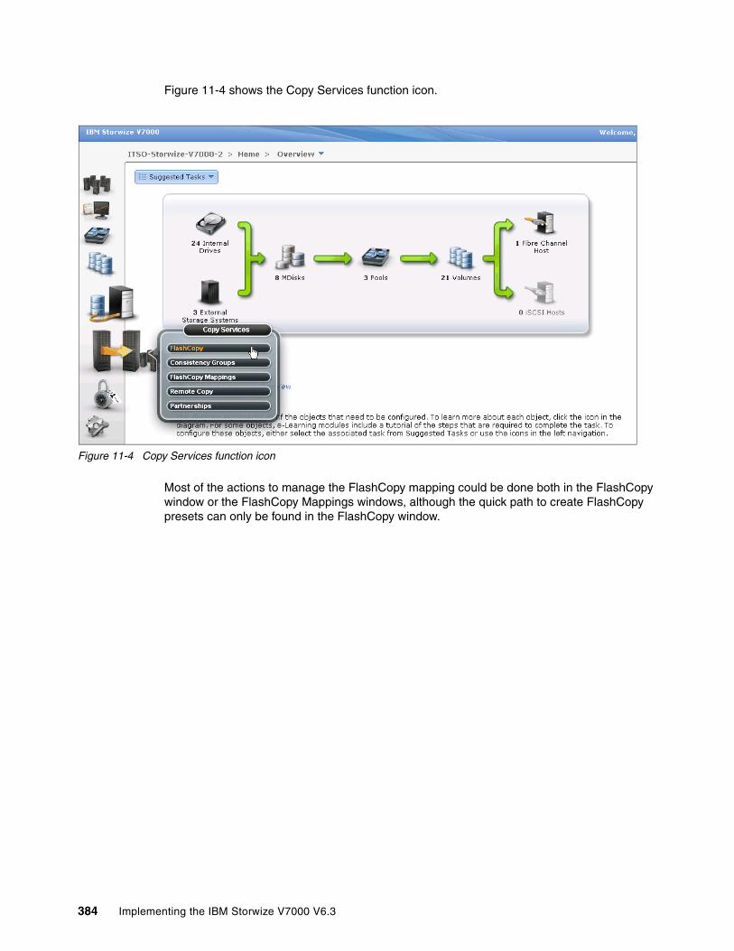
Figure 11-4 shows the Copy Services function icon.
Figure 11-4 Copy Services function icon
Most of the actions to manage the FlashCopy mapping could be done both in the FlashCopy window or the FlashCopy Mappings windows, although the quick path to create FlashCopy presets can only be found in the FlashCopy window.
384 Implementing the IBM Storwize V7000 V6.3
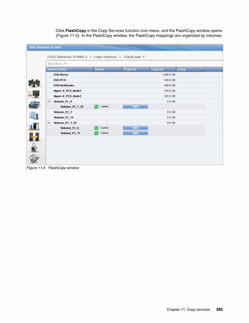
Click FlashCopy in the Copy Services function icon menu, and the FlashCopy window opens (Figure 11-5). In the FlashCopy window, the FlashCopy mappings are organized by volumes.
Figure 11-5 FlashCopy window
Chapter 11. Copy services 385

Click FlashCopy Mappings in the Copy Services function icon menu, and the FlashCopy Mappings window opens (Figure 11-6). In the FlashCopy Mappings window, the FlashCopy mappings are listed one by one.
Figure 11-6 FlashCopy Mappings window
386 Implementing the IBM Storwize V7000 V6.3

The Consistency Groups window could be used to manage the consistency groups for FlashCopy mappings. Click Consistency Groups in the Copy Services function icon menu, and the Consistency Groups window opens (Figure 11-8 on page 388).
Figure 11-7 Consistency Groups window
Chapter 11. Copy services 387

Quick path to create FlashCopy presetsIt is easy to create FlashCopy using the presets in the FlashCopy window.
Creating a snapshotIn the FlashCopy window, choose a volume and click New Snapshot from the Actions drop-down menu (Figure 11-8).
Figure 11-8 Create a snapshot from the preset
You now have a snapshot volume for the volume you choose.
388 Implementing the IBM Storwize V7000 V6.3

Creating a cloneIn the FlashCopy window, choose a volume and click New Clone from the Actions drop-down menu (Figure 11-9).
Figure 11-9 Create a clone from the preset
You now have a clone volume for the volume you choose.
Chapter 11. Copy services 389
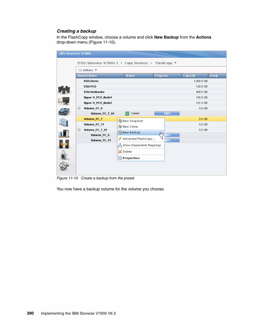
Creating a backupIn the FlashCopy window, choose a volume and click New Backup from the Actions drop-down menu (Figure 11-10).
Figure 11-10 Create a backup from the preset
You now have a backup volume for the volume you choose.
390 Implementing the IBM Storwize V7000 V6.3

Now, in the FlashCopy window, you find three FlashCopy target volumes under the source volume (Figure 11-11). The progress bars behind the target volumes indicate the copy progress in percentage. The copy progress remains 0% for snapshot; there is no change happening at the moment because only the changed data is being copied. At the same time, the copy progresses for clone and backup keep increasing.
Figure 11-11 FlashCopy in progress viewed for the FlashCopy window
Chapter 11. Copy services 391

The copy progress can be also found under the Running Tasks status indicator (Figure 11-12). This view is slightly different than the Remote Copy Running Tasks status indicator.
Figure 11-12 The FlashCopy progress viewed from the Running Tasks status indicator
392 Implementing the IBM Storwize V7000 V6.3
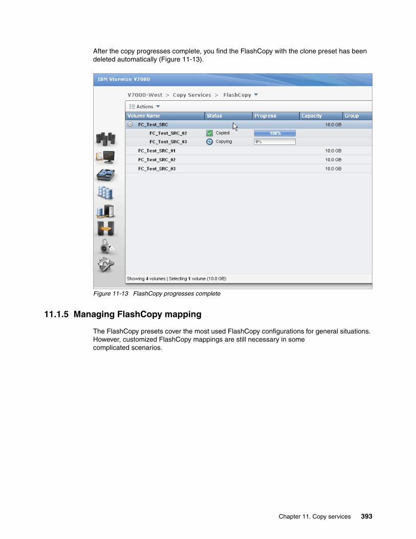
After the copy progresses complete, you find the FlashCopy with the clone preset has been deleted automatically (Figure 11-13).
Figure 11-13 FlashCopy progresses complete
11.1.5 Managing FlashCopy mapping
The FlashCopy presets cover the most used FlashCopy configurations for general situations. However, customized FlashCopy mappings are still necessary in some complicated scenarios.
Chapter 11. Copy services 393
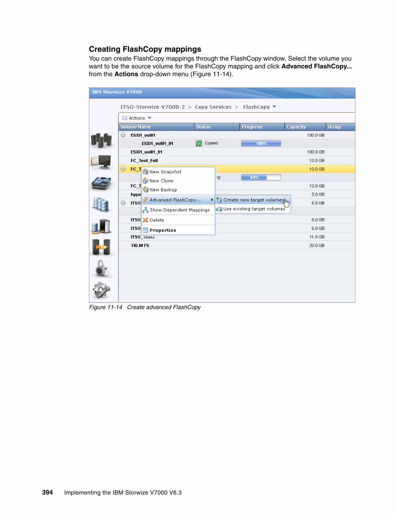
Creating FlashCopy mappingsYou can create FlashCopy mappings through the FlashCopy window. Select the volume you want to be the source volume for the FlashCopy mapping and click Advanced FlashCopy... from the Actions drop-down menu (Figure 11-14).
Figure 11-14 Create advanced FlashCopy
394 Implementing the IBM Storwize V7000 V6.3
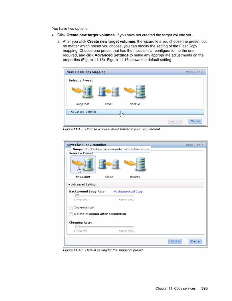
You have two options:
� Click Create new target volumes, if you have not created the target volume yet.
a. After you click Create new target volumes, the wizard lets you choose the preset, but no matter which preset you choose, you can modify the setting of the FlashCopy mapping. Choose one preset that has the most similar configuration to the one required, and click Advanced Settings to make any appropriate adjustments on the properties (Figure 11-15). Figure 11-16 shows the default setting.
Figure 11-15 Choose a preset most similar to your requirement
Figure 11-16 Default setting for the snapshot preset
Chapter 11. Copy services 395
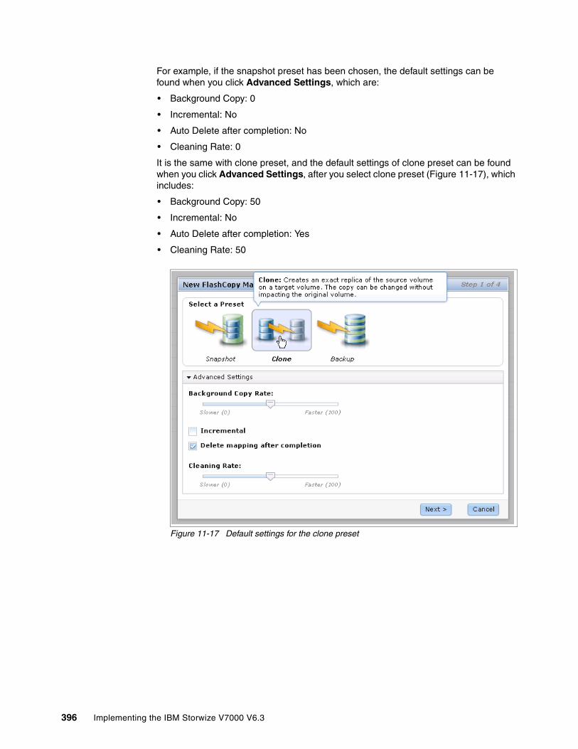
For example, if the snapshot preset has been chosen, the default settings can be found when you click Advanced Settings, which are:
• Background Copy: 0
• Incremental: No
• Auto Delete after completion: No
• Cleaning Rate: 0
It is the same with clone preset, and the default settings of clone preset can be found when you click Advanced Settings, after you select clone preset (Figure 11-17), which includes:
• Background Copy: 50
• Incremental: No
• Auto Delete after completion: Yes
• Cleaning Rate: 50
Figure 11-17 Default settings for the clone preset
396 Implementing the IBM Storwize V7000 V6.3

It is the same with backup preset, and the default settings of backup preset are found when you click Advanced Settings, after you select the backup preset (Figure 11-18), which includes:
• Background Copy: 50
• Incremental: Yes
• Auto Delete after completion: No
• Cleaning Rate: 50
Figure 11-18 Default settings for the backup preset
Change the settings of the FlashCopy mapping according to your requirements and click Next.
Chapter 11. Copy services 397
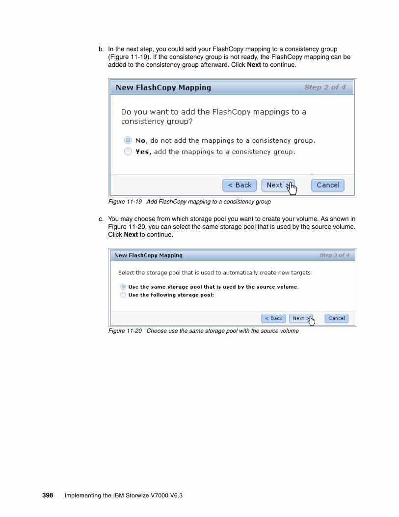
b. In the next step, you could add your FlashCopy mapping to a consistency group (Figure 11-19). If the consistency group is not ready, the FlashCopy mapping can be added to the consistency group afterward. Click Next to continue.
Figure 11-19 Add FlashCopy mapping to a consistency group
c. You may choose from which storage pool you want to create your volume. As shown in Figure 11-20, you can select the same storage pool that is used by the source volume. Click Next to continue.
Figure 11-20 Choose use the same storage pool with the source volume
398 Implementing the IBM Storwize V7000 V6.3

d. You can also specify some other storage pool for your new volume (Figure 11-21). Click Next to continue.
Figure 11-21 Choose another storage pool to create the volume
Chapter 11. Copy services 399
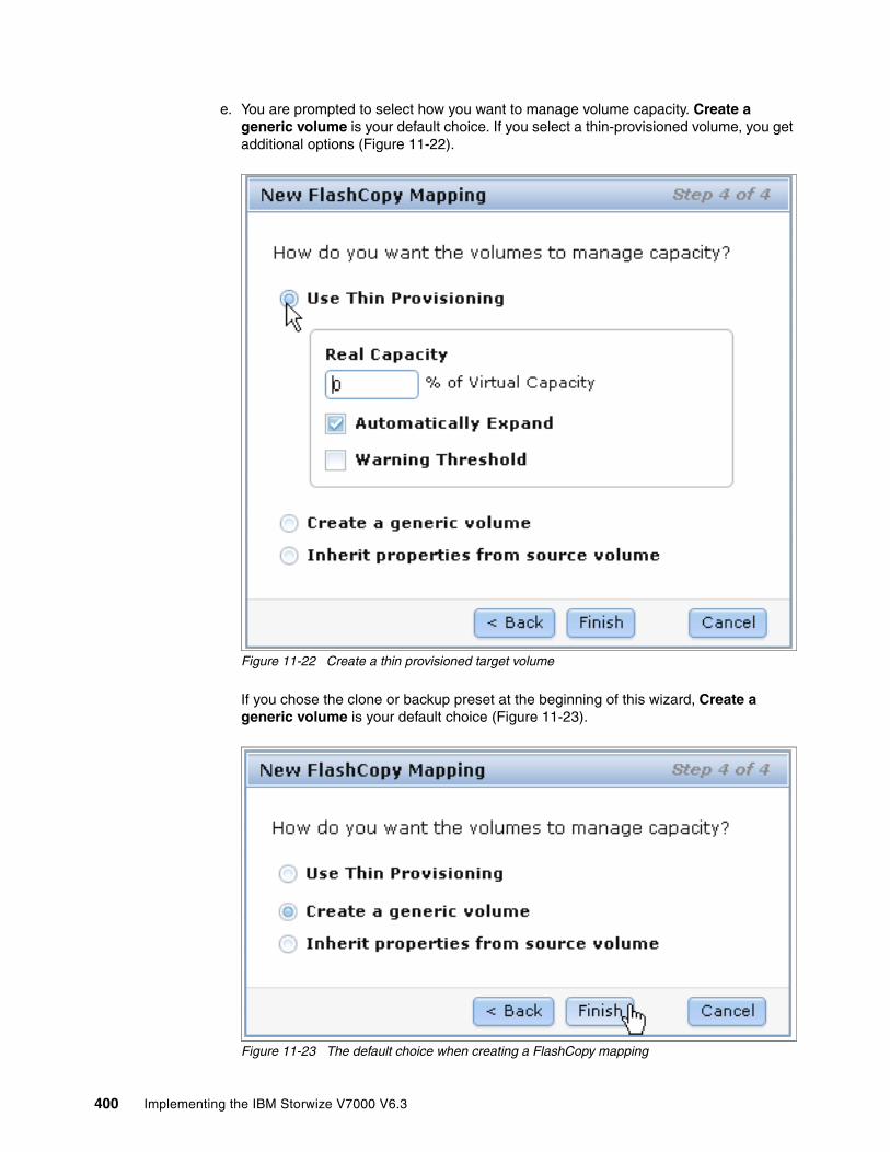
e. You are prompted to select how you want to manage volume capacity. Create a generic volume is your default choice. If you select a thin-provisioned volume, you get additional options (Figure 11-22).
Figure 11-22 Create a thin provisioned target volume
If you chose the clone or backup preset at the beginning of this wizard, Create a generic volume is your default choice (Figure 11-23).
Figure 11-23 The default choice when creating a FlashCopy mapping
400 Implementing the IBM Storwize V7000 V6.3

f. Click Finish when you make your decision, and the FlashCopy mapping is created on your volume with a new target (Figure 11-24). The status of the newly created FlashCopy mapping is Idle; it could be started, as described in “Starting a FlashCopy mapping” on page 405.
Figure 11-24 New FlashCopy mapping has been created with a new target
Chapter 11. Copy services 401

� In the Advanced FlashCopy menu, if you already have candidate target volumes, select Use existing target volumes (Figure 11-25).
Figure 11-25 Create FlashCopy mapping using existing target volume
a. You need to choose the target volume for the source volume you selected. Select the target volume in the drop-down menu in the right pane of the window and click Add (Figure 11-26).
Figure 11-26 Select the target volume
402 Implementing the IBM Storwize V7000 V6.3
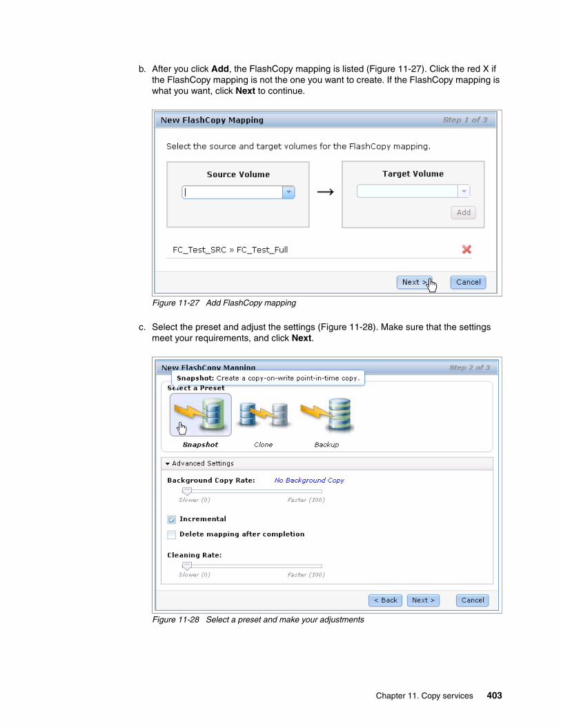
b. After you click Add, the FlashCopy mapping is listed (Figure 11-27). Click the red X if the FlashCopy mapping is not the one you want to create. If the FlashCopy mapping is what you want, click Next to continue.
Figure 11-27 Add FlashCopy mapping
c. Select the preset and adjust the settings (Figure 11-28). Make sure that the settings meet your requirements, and click Next.
Figure 11-28 Select a preset and make your adjustments
Chapter 11. Copy services 403
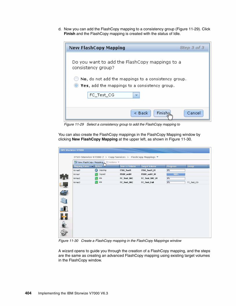
d. Now you can add the FlashCopy mapping to a consistency group (Figure 11-29). Click Finish and the FlashCopy mapping is created with the status of Idle.
Figure 11-29 Select a consistency group to add the FlashCopy mapping to
You can also create the FlashCopy mappings in the FlashCopy Mapping window by clicking New FlashCopy Mapping at the upper left, as shown in Figure 11-30.
Figure 11-30 Create a FlashCopy mapping in the FlashCopy Mappings window
A wizard opens to guide you through the creation of a FlashCopy mapping, and the steps are the same as creating an advanced FlashCopy mapping using existing target volumes in the FlashCopy window.
404 Implementing the IBM Storwize V7000 V6.3
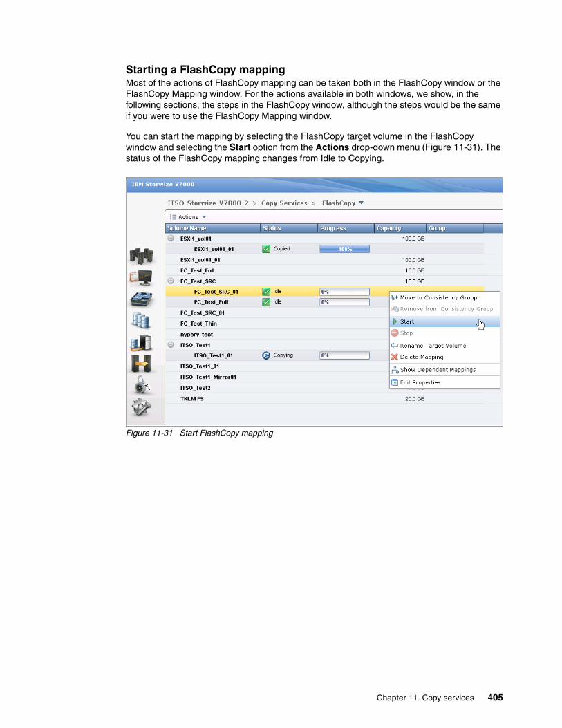
Starting a FlashCopy mappingMost of the actions of FlashCopy mapping can be taken both in the FlashCopy window or the FlashCopy Mapping window. For the actions available in both windows, we show, in the following sections, the steps in the FlashCopy window, although the steps would be the same if you were to use the FlashCopy Mapping window.
You can start the mapping by selecting the FlashCopy target volume in the FlashCopy window and selecting the Start option from the Actions drop-down menu (Figure 11-31). The status of the FlashCopy mapping changes from Idle to Copying.
Figure 11-31 Start FlashCopy mapping
Chapter 11. Copy services 405

Stopping a FlashCopy mappingThe FlashCopy mapping can be stopped by selecting the FlashCopy target volume in the FlashCopy window and clicking the Stop option from the Actions drop-down menu (Figure 11-32). After the stopping process completes, the status of the FlashCopy mapping is changed to Stopped.
Figure 11-32 Stopping a FlashCopy mapping
Renaming the target volumeIf the FlashCopy target volumes were created automatically by IBM Storwize V7000 storage system, the name of the target volumes is the source volume name plus a suffix containing numbers. The name of the target volumes could be changed to be more meaningful in your environment.
406 Implementing the IBM Storwize V7000 V6.3

To change the name of the target volume, select the FlashCopy target volume in the FlashCopy window and click the Rename Target Volume option from the Actions drop-down menu (Figure 11-33).
Figure 11-33 Rename a target volume
Input your new name for the target volume (Figure 11-34). Click Rename to finish.
Figure 11-34 Rename a target volume
Renaming a FlashCopy mappingThe FlashCopy mappings are created with names that begin with fcmap. The name of FlashCopy mappings can be changed to be more meaningful to you.
Chapter 11. Copy services 407

To change the name of a FlashCopy mapping, select the FlashCopy mapping in the FlashCopy Mappings window and click the Rename Mapping option from the Actions drop-down menu (Figure 11-35).
Figure 11-35 Rename a FlashCopy mapping
You need to enter your new name for the FlashCopy mapping (Figure 11-36). Click Rename to finish.
Figure 11-36 Enter a new name for the FlashCopy mapping
408 Implementing the IBM Storwize V7000 V6.3
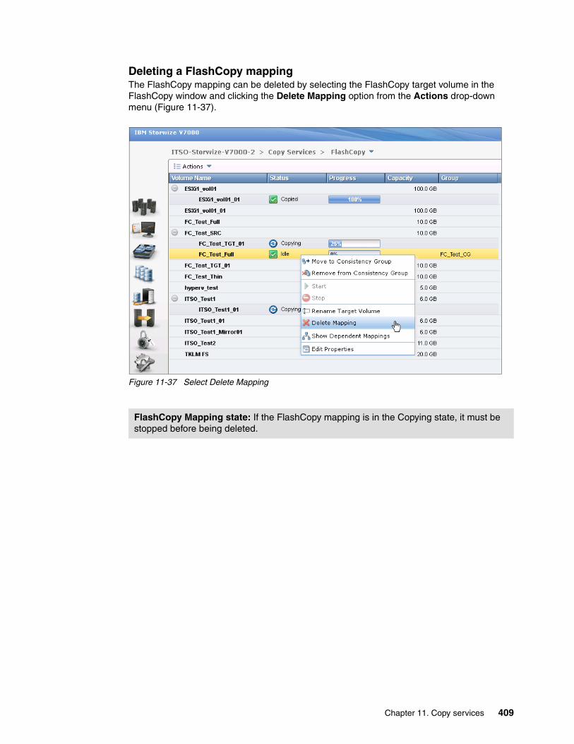
Deleting a FlashCopy mappingThe FlashCopy mapping can be deleted by selecting the FlashCopy target volume in the FlashCopy window and clicking the Delete Mapping option from the Actions drop-down menu (Figure 11-37).
Figure 11-37 Select Delete Mapping
FlashCopy Mapping state: If the FlashCopy mapping is in the Copying state, it must be stopped before being deleted.
Chapter 11. Copy services 409

You need to confirm your action to delete FlashCopy mappings in the window that opens (Figure 11-38). Verify the number of FlashCopy mappings that you need to delete, and if you want to delete the FlashCopy mappings while the data on the target volume is inconsistent with the source volume, select the check box. Click Delete and your FlashCopy mapping is removed.
Figure 11-38 Confirm the deletion of FlashCopy mappings
Deleting FlashCopy mapping: Deleting the FlashCopy mapping does not delete the target volume. If you need to reclaim the storage space occupied by the target volume, you need to delete the target volume manually.
410 Implementing the IBM Storwize V7000 V6.3
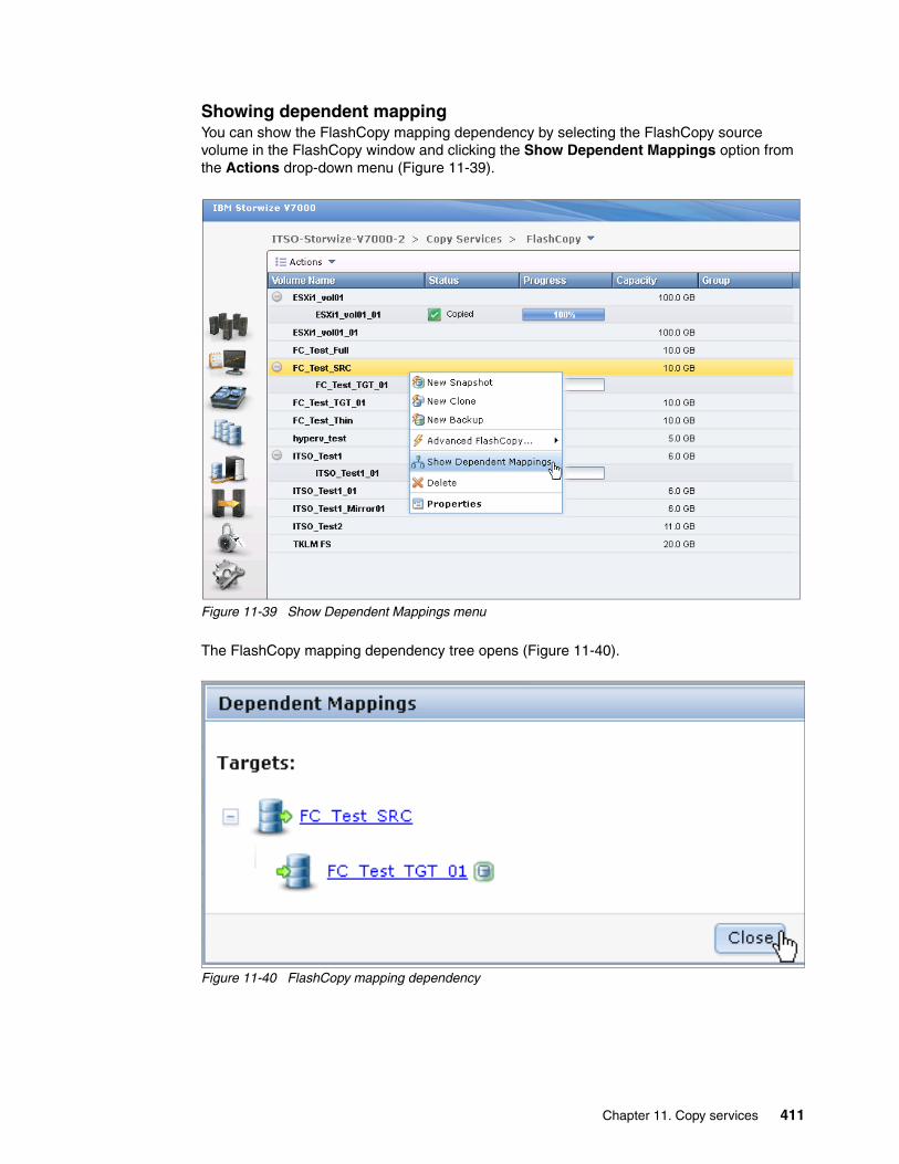
Showing dependent mappingYou can show the FlashCopy mapping dependency by selecting the FlashCopy source volume in the FlashCopy window and clicking the Show Dependent Mappings option from the Actions drop-down menu (Figure 11-39).
Figure 11-39 Show Dependent Mappings menu
The FlashCopy mapping dependency tree opens (Figure 11-40).
Figure 11-40 FlashCopy mapping dependency
Chapter 11. Copy services 411
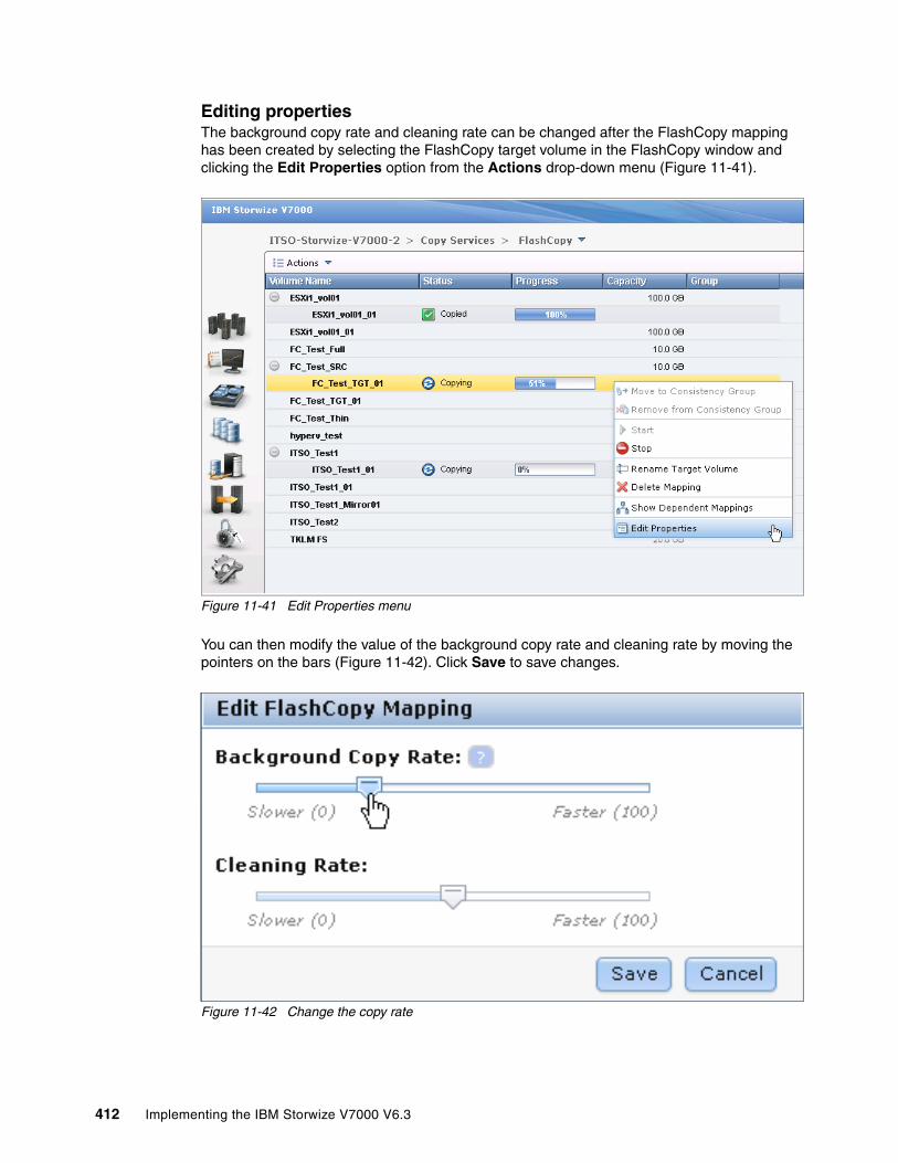
Editing propertiesThe background copy rate and cleaning rate can be changed after the FlashCopy mapping has been created by selecting the FlashCopy target volume in the FlashCopy window and clicking the Edit Properties option from the Actions drop-down menu (Figure 11-41).
Figure 11-41 Edit Properties menu
You can then modify the value of the background copy rate and cleaning rate by moving the pointers on the bars (Figure 11-42). Click Save to save changes.
Figure 11-42 Change the copy rate
412 Implementing the IBM Storwize V7000 V6.3

Managing a FlashCopy consistency groupFlashCopy consistency groups can be managed by clicking the Consistency Groups menu under the Copy Services function icon (Figure 11-43).
Figure 11-43 Access to the Consistency Groups window
Chapter 11. Copy services 413

The Consistency Groups window (Figure 11-44) is where you can manage both consistency groups and FlashCopy mappings.
Figure 11-44 Consistency Groups window
In the left pane of the Consistency Groups window, you can list the consistency groups you need. Click Not in a Group, and then expand your selection by clicking the plus icon next to Not in a Group. All the FlashCopy mappings that are not in any consistency groups are displayed in the lower pane.
In the lower pane of the Consistency Groups window, you can discover the properties of a consistency group and the FlashCopy mappings in it. You can also take actions on any consistency groups and FlashCopy mappings within the Consistency Groups window, as allowed by their state. All the actions allowed for the FlashCopy mapping are described in 11.1.5, “Managing FlashCopy mapping” on page 393.
Creating a FlashCopy consistency groupTo create a FlashCopy consistency group, click New Consistency Group at the top of the Consistency Groups window (Figure 11-44).
414 Implementing the IBM Storwize V7000 V6.3

You are prompted to enter the name of the new consistency group (Figure 11-45). Following your naming conventions, enter the name of the new consistency group in the box and click Create.
Figure 11-45 Enter the name for the consistency group
After the creation process completes, you find a new consistency group in the left pane of the Consistency Groups window. Select the new consistency group, and you see more detailed information about this consistency group in the right pane (Figure 11-46).
Figure 11-46 New consistency group
You can rename the consistency group by clicking the name of the consistency group in the main pane and enter a name for it (following your naming convention). Next to the name of the consistency group, the state shows that it is now an empty consistency group with no FlashCopy mapping in it.
Chapter 11. Copy services 415

Adding FlashCopy mappings to a consistency groupClick Not in a Group to list all the FlashCopy mappings with no consistency group. You can add FlashCopy mappings to a consistency group by selecting them and clicking the Move to Consistency Group option form the Actions drop-down menu (Figure 11-47). Selections of a range are performed by highlighting a mapping, pressing and holding the Shift key, and clicking the last item in the range. Multiple selections can be made by pressing and holding the Ctrl key and clicking each mapping individually.
Figure 11-47 Select the FlashCopy mappings to add to a consistency group
You are prompted to specify which consistency group you want to move the FlashCopy mapping into (Figure 11-48). Click Move to Consistency Group to continue.
Figure 11-48 Select consistency group
After the action completes, you find that the FlashCopy mappings you selected have been removed from the Not In a Group list of the consistency group you chose.
416 Implementing the IBM Storwize V7000 V6.3
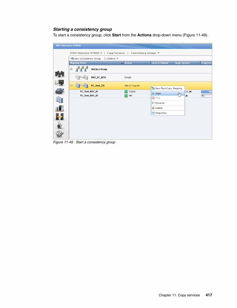
Starting a consistency groupTo start a consistency group, click Start from the Actions drop-down menu (Figure 11-49).
Figure 11-49 Start a consistency group
Chapter 11. Copy services 417
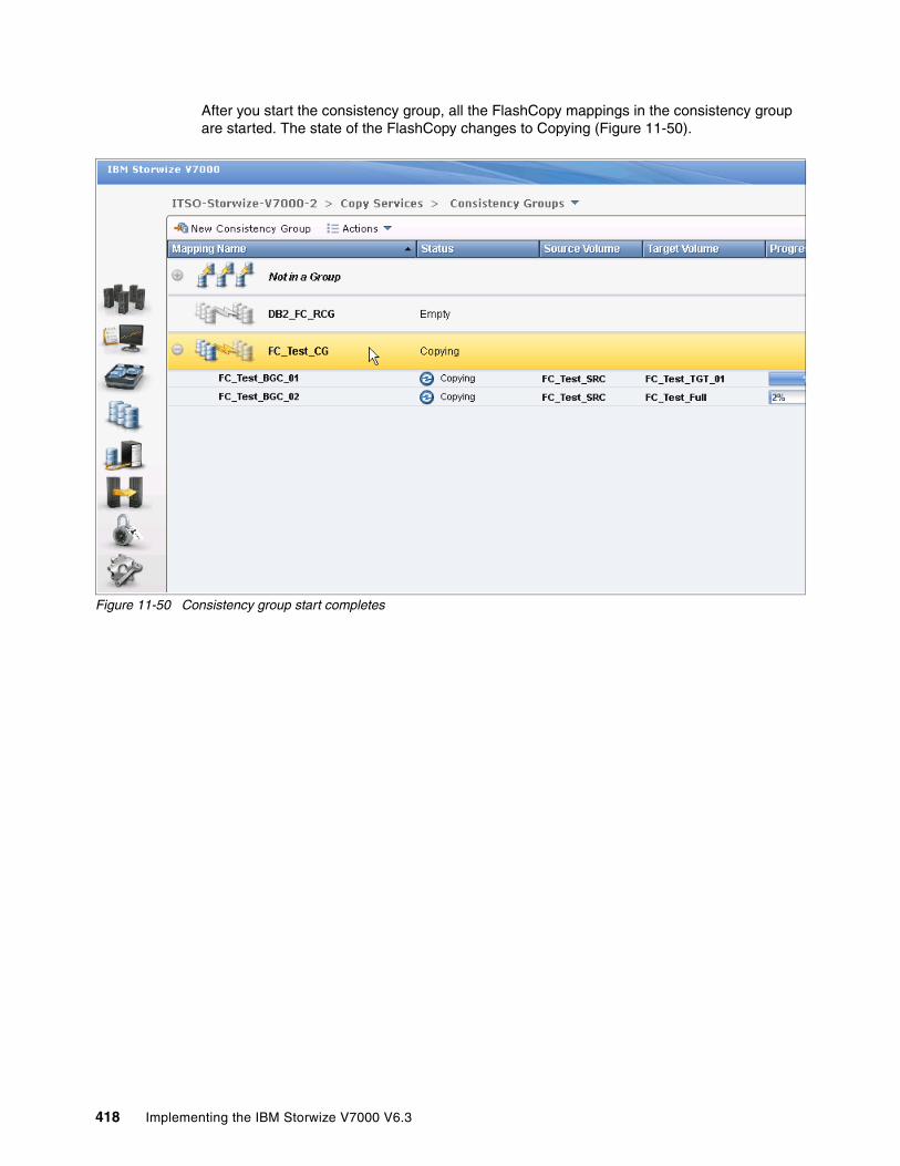
After you start the consistency group, all the FlashCopy mappings in the consistency group are started. The state of the FlashCopy changes to Copying (Figure 11-50).
Figure 11-50 Consistency group start completes
418 Implementing the IBM Storwize V7000 V6.3

Stopping a consistency groupThe consistency group can be stopped by selecting Stop from the Actions drop-down window (Figure 11-51).
Figure 11-51 Stop a consistency group
Chapter 11. Copy services 419
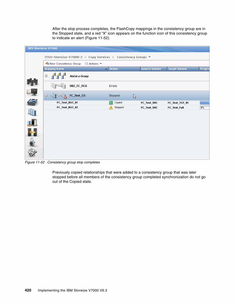
After the stop process completes, the FlashCopy mappings in the consistency group are in the Stopped state, and a red “X” icon appears on the function icon of this consistency group to indicate an alert (Figure 11-52).
Figure 11-52 Consistency group stop completes
Previously copied relationships that were added to a consistency group that was later stopped before all members of the consistency group completed synchronization do not go out of the Copied state.
420 Implementing the IBM Storwize V7000 V6.3

Removing FlashCopy mappings from a consistency groupThe FlashCopy mappings can be removed from a consistency group by selecting the FlashCopy mappings and clicking Remove from Consistency Group from the Actions drop-down menu of the FlashCopy mapping (Figure 11-53).
Figure 11-53 Remove from consistency group
The FlashCopy mappings are returned to the Not in a Group list after being removed from the consistency group.
Chapter 11. Copy services 421
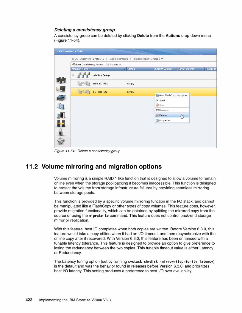
Deleting a consistency groupA consistency group can be deleted by clicking Delete from the Actions drop-down menu (Figure 11-54).
Figure 11-54 Delete a consistency group
11.2 Volume mirroring and migration options
Volume mirroring is a simple RAID 1 like function that is designed to allow a volume to remain online even when the storage pool backing it becomes inaccessible. This function is designed to protect the volume from storage infrastructure failures by providing seamless mirroring between storage pools.
This function is provided by a specific volume mirroring function in the I/O stack, and cannot be manipulated like a FlashCopy or other types of copy volumes. This feature does, however, provide migration functionality, which can be obtained by splitting the mirrored copy from the source or using the migrate to command. This feature does not control back-end storage mirror or replication.
With this feature, host IO completes when both copies are written. Before Version 6.3.0, this feature would take a copy offline when it had an I/O timeout, and then resynchronize with the online copy after it recovered. With Version 6.3.0, this feature has been enhanced with a tunable latency tolerance. This feature is designed to provide an option to give preference to losing the redundancy between the two copies. This tunable timeout value is either Latency or Redundancy.
The Latency tuning option (set by running svctask chvdisk -mirrowritepriority latency) is the default and was the behavior found in releases before Version 6.3.0, and prioritizes host I/O latency. This setting produces a preference to host I/O over availability.
422 Implementing the IBM Storwize V7000 V6.3

However, you might need to give preference to Redundancy when availability is more important than I/O response time. To accomplish this task, run svctask chvdisk -mirrowritepriority redundancy.
Regardless of which option you choose, volume mirroring can provide extra protection for your environment.
Regarding migration, there are several options available:
� Export to Image mode: This option allows you to move storage from managed mode to image mode, which is useful if you are using the SAN Volume Controller as a migration device. For example, vendor A’s product cannot communicate with vendor B’s product, but you need to migrate existing data from vendor A to vendor B. Using Export to image mode allows you to migrate data using Copy Services functions and then return control to the native array, while maintaining access to the hosts.
� Import to Image mode: This option allows you to import an existing storage MDisk or LUN with existing data, from an external storage system without putting metadata on it, so the existing data remains intact. After they are imported, all copy services functions maybe used to migrate the storage to other locations, while the data remains accessible to your hosts.
� Volume migration using Volume Mirroring then Split into New Volume: This option allows you to use the RAID 1 functionality to create two copies of data that initially have a set relationship (one primary and one secondary) but then break the relationship (both primary and no relationship) and make them independent copies of data. You can use this mode to migrate data between storage pools and devices. You might use this option if you want to move volumes to multiple different storage pools. You can only mirror one volume at a time.
� Volume migration using Move to Another Pool: This option allows any volume to be moved between storage pools without interruption to host access. This option is effectively a quicker version of clicking Volume Mirroring Split into New Volume. You might use this option if you want to move volumes in a single step or do not already have a volume mirror copy.
Migration methods: While the migration methods listed do not distribute access, you need to take a brief outage to install the host drivers for your SAN Volume Controller. See IBM System Storage SAN Volume Controller Host Attachment User’s Guide, SC26-7905 for more details. Make sure to consult the revision of the document that applies for your SAN Volume Controller.
Chapter 11. Copy services 423
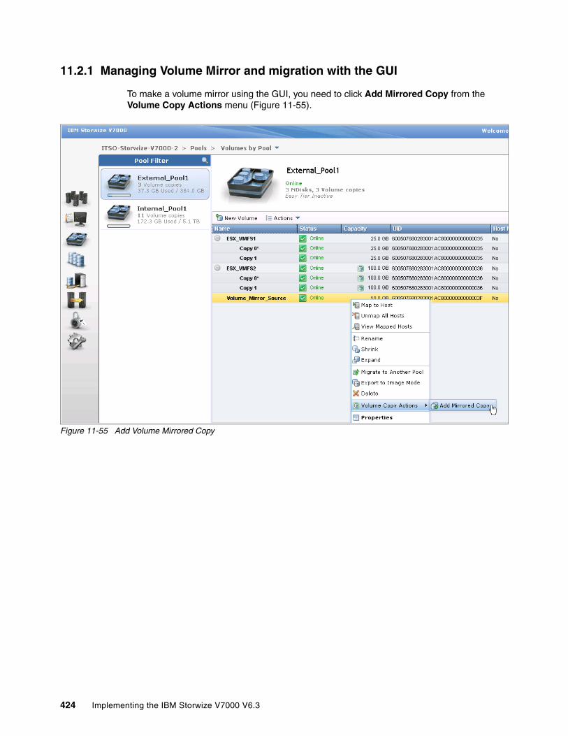
11.2.1 Managing Volume Mirror and migration with the GUI
To make a volume mirror using the GUI, you need to click Add Mirrored Copy from the Volume Copy Actions menu (Figure 11-55).
Figure 11-55 Add Volume Mirrored Copy
424 Implementing the IBM Storwize V7000 V6.3
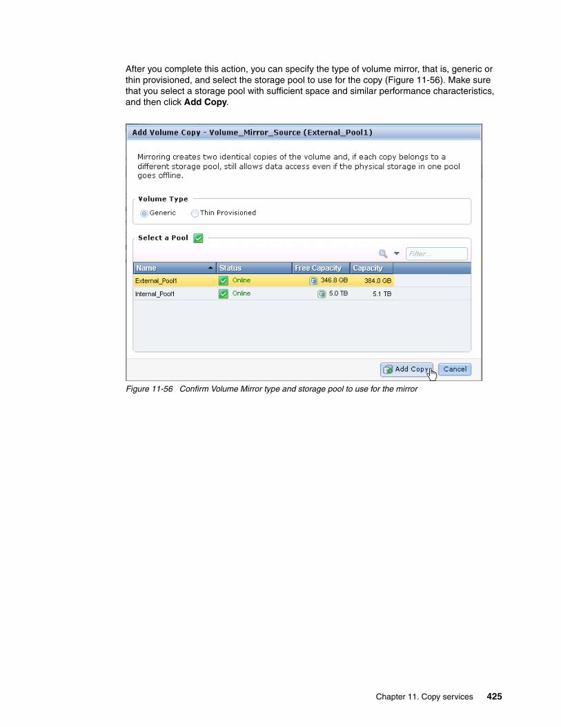
After you complete this action, you can specify the type of volume mirror, that is, generic or thin provisioned, and select the storage pool to use for the copy (Figure 11-56). Make sure that you select a storage pool with sufficient space and similar performance characteristics, and then click Add Copy.
Figure 11-56 Confirm Volume Mirror type and storage pool to use for the mirror
Chapter 11. Copy services 425

After you create your mirror, you can view the distribution of extents (Figure 11-57) or you can view the mirroring progress percentage by using Running Tasks (Figure 11-58).
Figure 11-57 The distribution of extents for primary and mirror copy of a volume
Figure 11-58 Progress of a mirror copy creation as viewed by using Running Tasks
426 Implementing the IBM Storwize V7000 V6.3

After the copy completes, you have the option of splitting either copy of the mirror into a new stand-alone volume (Figure 11-59).
Figure 11-59 Selection of Split into New Volume
After you click Split into New Volume on either Copy0 or Copy1, you can specify a new volume name and confirm the split (Figure 11-60).
Figure 11-60 Confirmation of volume mirror split
Extent distribution: Extent distribution for the mirror copy is automatically balanced as well as possible within the storage pool selected.
Chapter 11. Copy services 427

After providing a new volume name (optional) and confirming the split, you can see the results in Figure 11-61.
Figure 11-61 Results of volume mirror split
Splitting volume copies: When you split a volume copy, the view returns to the pool in which it was created, not where the primary copy existed.
428 Implementing the IBM Storwize V7000 V6.3

If you want to migrate your volumes to another storage pool in one step instead of two, you can use the Migrate to Another Pool option (Figure 11-62).
Figure 11-62 Using the Migrate to Another Pool option
Migration limitation: You cannot migrate more than one volume at a time. For this reason, Copy Services functions are more expedient, if available.
Chapter 11. Copy services 429
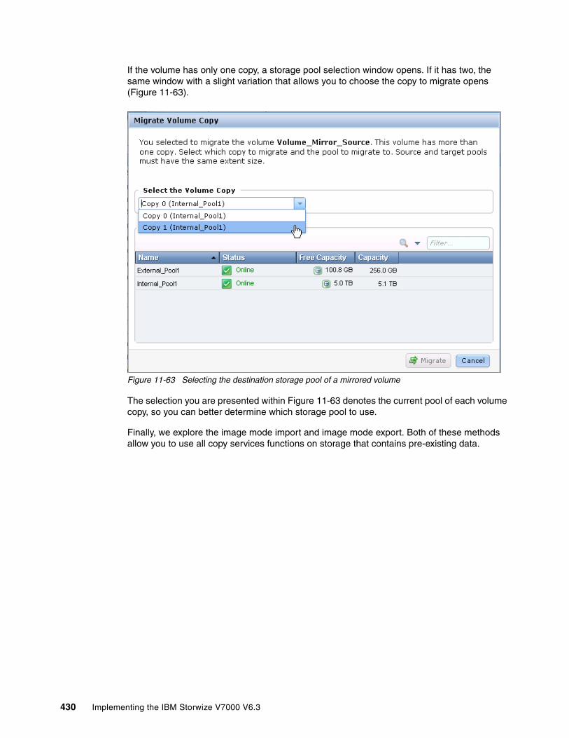
If the volume has only one copy, a storage pool selection window opens. If it has two, the same window with a slight variation that allows you to choose the copy to migrate opens (Figure 11-63).
Figure 11-63 Selecting the destination storage pool of a mirrored volume
The selection you are presented within Figure 11-63 denotes the current pool of each volume copy, so you can better determine which storage pool to use.
Finally, we explore the image mode import and image mode export. Both of these methods allow you to use all copy services functions on storage that contains pre-existing data.
430 Implementing the IBM Storwize V7000 V6.3

To import pre-existing storage, click Pools MDisks by Pool Not in a Pool. Select the storage you want to import and right-click it. The menu shown in Figure 11-64 opens.
Figure 11-64 Import in image mode option
When you select Import, a window opens that allows you to import as a generic volume or use thin-provisioning, and disable the cache if you so choose (Figure 11-65).
Figure 11-65 Import wizard
Chapter 11. Copy services 431
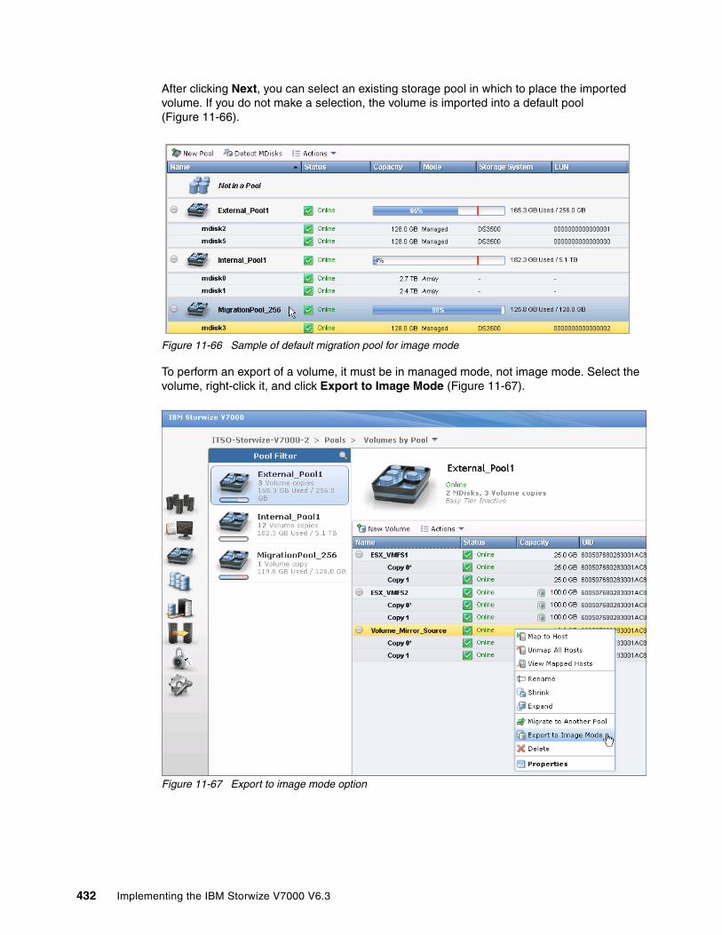
After clicking Next, you can select an existing storage pool in which to place the imported volume. If you do not make a selection, the volume is imported into a default pool (Figure 11-66).
Figure 11-66 Sample of default migration pool for image mode
To perform an export of a volume, it must be in managed mode, not image mode. Select the volume, right-click it, and click Export to Image Mode (Figure 11-67).
Figure 11-67 Export to image mode option
432 Implementing the IBM Storwize V7000 V6.3

You can export only one volume or copy at a time, and you need to select a storage pool for the volume when you export it (Figure 11-68).
Figure 11-68 Select pool to export managed mode to image mode
When you click Finish, you have exported the volume or copy to image mode.
11.3 Remote Copy
In this section, we describe how the Remote Copy function works in IBM Storwize V7000. We also provide the implementation steps, using the GUI, for Remote Copy configuration and management.
Remote Copy consists of three methods for copying: Metro Mirror, Global Mirror, and Global Mirror with Change Volumes. Metro Mirror is designed for metropolitan distances with a synchronous copy requirement. Global Mirror is designed for longer distances without requiring the hosts to wait for the full round-trip delay of the long-distance link through asynchronous methodology. Starting with Version 6.3.0, Global Mirror with Change Volumes is an added piece of functionality for Global Mirror designed to attain consistency on lower-quality network links.
Metro Mirror and Global Mirror are IBM branded terms for the functions Synchronous Remote Copy and Asynchronous Remote Copy. Throughout this book, the term “Remote Copy” is used to refer to both functions where the text applies to each term equally.
11.3.1 Remote Copy concepts
In this section, we describe Remote Copy concepts.
PartnershipWhen creating a partnership, we connect two separate IBM Storwize V7000 systems or an IBM SAN Volume Controller and an IBM Storwize V7000, which are separated by distance, but this distance is not required. After the partnership creation has been configured on both systems, further communication between the node canisters in each of the storage systems is established and maintained by the SAN network. All inter-cluster communication goes through the Fibre Channel network. Partnership must be defined on both IBM Storwize V7000 or on the IBM Storwize V7000 and then IBM SAN Volume Controller systems to make the partnership fully functional.
Chapter 11. Copy services 433

Introduction to layersVersion 6.3.0 introduces a new concept called layers for the IBM Storwize V7000. Layers determine how the V7000 interacts with the IBM SAN Volume Controller. Currently there are two layers: replication and storage.
The replication layer is used when you want to use the IBM Storwize V7000 with one or more SAN Volume Controllers as a Remote Copy partner. The storage layer is the default mode of operation for the IBM Storwize V7000, and is used when you want to use the IBM Storwize V7000 to present storage to an SAN Volume Controller.
The layer for the IBM Storwize V7000 can be switched by running svctask chsystem -layer replication. Generally, switch the layer while your IBM Storwize V7000 system is not in production. This situation prevents potential disruptions, as layer changes are not I/O tolerant.
Figure 11-69 shows the effect of layers on SAN Volume Controller and V7000 partnerships.
Figure 11-69 The relationship of layers and SAN Volume Controller and Storwize V7000 partnerships
The replication layer allows an IBM Storwize V7000 system to be a Remote Copy partner with an SAN Volume Controller, while the storage layer allows an IBM Storwize V7000 system to function as back-end storage for an SAN Volume Controller. An IBM Storwize V7000 system cannot be in both layers at once.
Limitations on the SAN Volume Controller and Storwize V7000 partnershipWith Version 6.3.0, SAN Volume Controller and IBM Storwize V7000 systems can be partners in a Remote Copy partnership. There are however, a few limitations:
� The layer for the V7000 must be set to replication. The default is storage.
� If any other SAN Volume Controller or IBM Storwize V7000 ports are visible on the SAN, aside from the ones on the cluster where you are making changes, you cannot change the layer.
Interconnection: Interconnects between IBM Storwize V7000 and IBM SAN Volume Controller is new for Version 6.3.0. Both devices must be at that level, and the IBM Storwize V7000 must set the replication layer using the svctask chsystem -layer replication limitations described in “Introduction to layers”.
434 Implementing the IBM Storwize V7000 V6.3

� If any host object is defined to an SAN Volume Controller or IBM Storwize V7000 system, you cannot change the layer.
� If any MDisks from an IBM Storwize V7000 other than the one you are making the layer change on are visible, you cannot change the layer.
� If any cluster partnership is defined, you cannot change the layer.
Partnership topologiesA partnership between up to four IBM Storwize V7000 systems are allowed.
Typical partnership topologies between multiple IBM Storwize V7000s are:
� Daisy-chain topology (Figure 11-70)
Figure 11-70 Daisy-chain topology for IBM Storwize V7000 Triangle topology
� Triangle topology (Figure 11-71)
Figure 11-71 Triangle topology for IBM Storwize V7000
Chapter 11. Copy services 435

� Star topology (Figure 11-72)
Figure 11-72 Star topology for IBM Storwize V7000
� Full-meshed topology (Figure 11-73)
Figure 11-73 Full-meshed IBM Storwize V7000
Partnerships: These partnerships are valid for configurations with SAN Volume Controllers and IBM Storwize V7000 systems, as long as the IBM Storwize V7000 systems are using the replication layer.
436 Implementing the IBM Storwize V7000 V6.3
Partnership statesA partnership has the following states:
� Partially Configured
Indicates that only one cluster partner is defined from a local or remote cluster to the displayed cluster and is started. For the displayed cluster to be configured fully and to complete the partnership, you must define the cluster partnership from the cluster that is displayed to the corresponding local or remote cluster.
� Fully Configured
Indicates that the partnership is defined on the local and remote clusters and is started.
� Remote Not Present
Indicates that the remote cluster is not present for the partnership.
� Partially Configured (Local Stopped)
Indicates that the local cluster is only defined to the remote cluster and the local cluster is stopped.
� Fully Configured (Local Stopped)
Indicates that a partnership is defined on both the local and remote clusters and the remote cluster is present, but the local cluster is stopped.
� Fully Configured (Remote Stopped)
Indicates that a partnership is defined on both the local and remote clusters and the remote cluster is present, but the remote cluster is stopped.
� Fully Configured (Local Excluded)
Indicates that a partnership is defined between a local and remote cluster; however, the local cluster has been excluded. Usually this state occurs when the fabric link between the two clusters has been compromised by too many fabric errors or slow response times of the cluster partnership.
� Fully Configured (Remote Excluded)
Indicates that a partnership is defined between a local and remote cluster; however, the remote cluster has been excluded. Usually this state occurs when the fabric link between the two clusters has been compromised by too many fabric errors or slow response times of the cluster partnership.
� Fully Configured (Remote Exceeded)
Indicates that a partnership is defined between a local and remote cluster and the remote is available; however, the remote cluster exceeds the number of allowed clusters within a cluster network. The maximum of four clusters can be defined in a network. If the number of clusters exceeds that limit, the IBM Storwize V7000 system determines the inactive cluster or clusters by sorting all the clusters by their unique identifier in numerical order. The inactive cluster partner that is not in the top four of the cluster unique identifiers shows Fully Configured (Remote Exceeded).
Remote Copy relationshipsA Remote Copy relationship is a relationship between two individual volumes of the same size. These volumes are called a master (source) volume and an auxiliary (target) volume.
Typically, the master volume contains the production copy of the data and is the volume that the application normally accesses. The auxiliary volume typically contains a backup copy of the data and is used for disaster recovery.
Chapter 11. Copy services 437

The master and auxiliary volumes are defined when the relationship is created, and these attributes never change. However, either volume can operate in the primary or secondary role as necessary. The primary volume contains a valid copy of the application data and receives updates from the host application, which is analogous to a source volume. The secondary volume receives a copy of any updates to the primary volume, because these updates are all transmitted across the mirror link. Therefore, the secondary volume is analogous to a continuously updated target volume. When a relationship is created, the master volume is assigned the role of primary volume and the auxiliary volume is assigned the role of secondary volume. The initial copying direction is from master to auxiliary. When the relationship is in a consistent state, you can reverse the copy direction.
The two volumes in a relationship must be the same size. The Remote Copy relationship can be established on the volumes within one IBM Storwize V7000 storage system, which is called an intra-cluster relationship. The relationship can also be established in different IBM Storwize V7000 storage systems or between an IBM Storwize V7000 storage system and an IBM SAN Volume Controller, which are called inter-cluster relationships.
Usage of Remote Copy target volumes as Remote Copy source volumes is not allowed. A FlashCopy target volume can be used as Remote Copy source volume and also as a Remote Copy target volume.
Metro MirrorMetro Mirror is a type of Remote Copy that creates a synchronous copy of data from a master volume to an auxiliary volume. With synchronous copies, host applications write to the master volume, but do not receive confirmation that the write operation has completed until the data is written to the auxiliary volume. This action ensures that both volumes have identical data when the copy completes. After the initial copy completes, the Metro Mirror function maintains a fully synchronized copy of the source data at the target site at all times.
Figure 11-74 shows how a write to the master volume is mirrored to the cache of the auxiliary volume before an acknowledgement of the write is sent back to the host that issued the write. This process ensures that the auxiliary is synchronized in real time, if it is needed in a failover situation.
Figure 11-74 Write on volume in a Metro Mirror relationship
FlashCopy: Using target volumes as remote copy sources and target volumes for FlashCopy requires Version 6.2.x or higher.
438 Implementing the IBM Storwize V7000 V6.3
The Metro Mirror function supports copy operations between volumes that are separated by distances up to 300 km. For disaster recovery purposes, Metro Mirror provides the simplest way to maintain an identical copy on both the primary and secondary volumes. However, as with all synchronous copies over remote distances, there can be a performance impact to host applications. This performance impact is related to the distance between primary and secondary volumes and, depending on application requirements, its use might be limited based on the distance between sites.
Global MirrorGlobal Mirror provides an asynchronous copy, which means that the secondary volume is not an exact match of the primary volume at every point in time. The Global Mirror function provides the same function as Metro Mirror Remote Copy without requiring the hosts to wait for the full round-trip delay of the long-distance link; however, some delay can be seen on the hosts in congested or overloaded environments. Make sure that you closely monitor and understand your workload.
In asynchronous Remote Copy, which Global Mirror provides, write operations are completed on the primary site and the write acknowledgement is sent to the host before it is received at the secondary site. An update of this write operation is sent to the secondary site at a later stage, which provides the capability to perform Remote Copy over distances exceeding the limitations of synchronous Remote Copy.
The distance of Global Mirror replication is limited primarily by the latency of the WAN Link provided. Global Mirror has a requirement of 80 ms round-trip-time for data sent to the remote location. The propagation delay is roughly 8.2 µs per mile or 5 µs per kilometer for Fibre Channel connections. Each device in the path adds addition delay of about 25 µs. Devices that use software (such as some compression devices) add much more time. The time added by software-assisted devices is highly variable and should be measured directly. Be sure to include these times when planning your Global Mirror design.
You should also measure application performance based on the expected delays before Global Mirror is fully implemented. The IBM Storwize V7000 storage system provides you with an advanced feature of Global Mirror that permits you to test performance implications before deploying Global Mirror and obtaining a long-distance link. This advanced feature is enabled by modifying the IBM Storwize V7000 storage system parameters gmintradelaysimulation and gminterdelaysimulation. These two parameters could be used to simulate the write delay to the secondary volume. The delay simulation can be enabled separately for each intra-cluster or inter-cluster Global Mirror. You can use this feature to test an application before the full deployment of the Global Mirror feature. You can find more information about how to enable the CLI feature in Appendix A, “CLI setup and SAN Boot” on page 569.
Chapter 11. Copy services 439
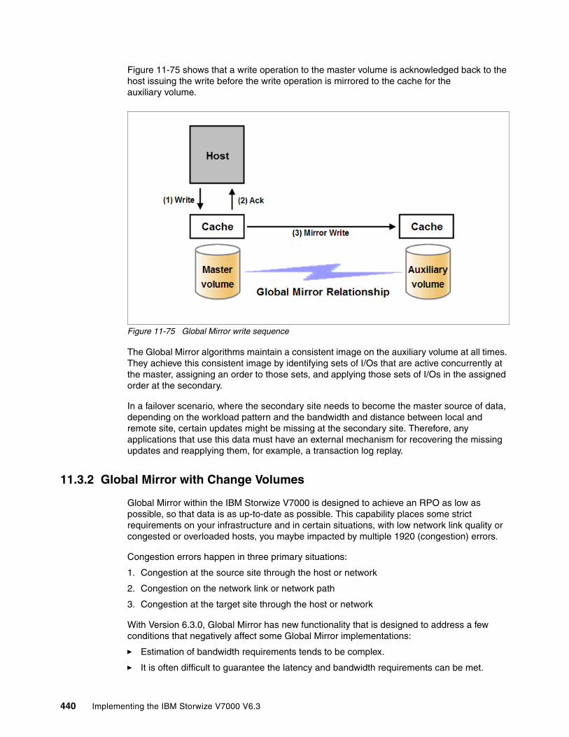
Figure 11-75 shows that a write operation to the master volume is acknowledged back to the host issuing the write before the write operation is mirrored to the cache for the auxiliary volume.
Figure 11-75 Global Mirror write sequence
The Global Mirror algorithms maintain a consistent image on the auxiliary volume at all times. They achieve this consistent image by identifying sets of I/Os that are active concurrently at the master, assigning an order to those sets, and applying those sets of I/Os in the assigned order at the secondary.
In a failover scenario, where the secondary site needs to become the master source of data, depending on the workload pattern and the bandwidth and distance between local and remote site, certain updates might be missing at the secondary site. Therefore, any applications that use this data must have an external mechanism for recovering the missing updates and reapplying them, for example, a transaction log replay.
11.3.2 Global Mirror with Change Volumes
Global Mirror within the IBM Storwize V7000 is designed to achieve an RPO as low as possible, so that data is as up-to-date as possible. This capability places some strict requirements on your infrastructure and in certain situations, with low network link quality or congested or overloaded hosts, you maybe impacted by multiple 1920 (congestion) errors.
Congestion errors happen in three primary situations:
1. Congestion at the source site through the host or network
2. Congestion on the network link or network path
3. Congestion at the target site through the host or network
With Version 6.3.0, Global Mirror has new functionality that is designed to address a few conditions that negatively affect some Global Mirror implementations:
� Estimation of bandwidth requirements tends to be complex.
� It is often difficult to guarantee the latency and bandwidth requirements can be met.
440 Implementing the IBM Storwize V7000 V6.3

� Congested hosts on either the source or target site can cause disruption.
� Congested network links can cause disruption with only intermittent peaks.
To address these issues, Change Volumes have been added as an option for Global Mirror relationships. Change Volumes use the FlashCopy functionality, but cannot be manipulated as FlashCopy volumes, as they are special purpose only. Change Volumes replicate point-in-time images on a cycling period (the default is 300 seconds.) This situation means that your change rate only needs to include the condition of the data at the point-in-time the image was taken, instead of all the updates during the period. This situation can provide significant reductions in replication volume.
Figure 11-76 shows a diagram of a basic Global Mirror relationship without Change Volumes.
Figure 11-76 Global Mirror without Change Volumes
Figure 11-77 shows a diagram with the Change Volumes.
Figure 11-77 Global Mirror with Change Volumes
With Change Volumes, a FlashCopy mapping exists between the primary volume and the primary Change Volume. The mapping is updated during a cycling period (every 60 seconds to one day.) The primary Change Volume is then replicated to the secondary Global Mirror volume at the target site, which is then captured in another change volume on the target site. This situation provides an always consistent image at the target site and protects your data from being inconsistent during resynchronization.
Chapter 11. Copy services 441

Take a closer look at how Change Volumes might reduce replication traffic.
Figure 11-78 shows a number of I/Os on the source volume and the same number on the target volume, and in the same order. Assuming that this set is the same set of data being updated over and over, then these updates are wasted network traffic and the I/O can be completed much more efficiently (Figure 11-79).
Figure 11-78 Global Mirror I/O replication without Change Volumes
In Figure 11-79, the same data is being updated repeatedly, so Change Volumes demonstrate significant IO transmission savings, because you only need to send I/O number 16, which was the last I/O before the cycling period.
Figure 11-79 Global Mirror I/O replication with Change Volumes
The cycling period can be adjusted by running chrcrelationship -cycleperiodseconds <60-86400>. If a copy does not complete in the cycle period, the next cycle does not start until the prior one has completed. It is for this reason that using Change Volumes gives you two possibilities for RPO:
� If your replication completes in the cycling period, then your RPO is twice the cycling period.
� If your replication does not complete within the cycling period, then your RPO is twice the completion time. The next cycling period starts immediately after the prior one is finished.
Careful consideration should be put into balancing your business requirements with the performance of Global Mirror with Change Volumes. Global Mirror with Change Volumes increases the inter-cluster traffic for more frequent cycling periods, so going as short as possible is not always the answer. In most cases, the default should meet your requirements and perform reasonably well.
442 Implementing the IBM Storwize V7000 V6.3

Remote Copy consistency groupsA consistency group is a logical entity that groups copy relationships. By grouping the relationships, you can ensure that these relationships are managed in unison and the data within the group is in a consistent state. More information about the necessity of consistency groups can be found in “FlashCopy consistency groups” on page 378.
Remote Copy commands can be issued to a Remote Copy consistency group, and therefore simultaneously for all Metro Mirror relationships defined within that consistency group, or to a single Metro Mirror relationship that is not part of a Metro Mirror consistency group.
Figure 11-80 shows the concept of Remote Copy consistency groups. Because the RC_Relationships 1 and 2 are part of the consistency group, they can be handled as one entity, while the stand-alone RC_Relationship 3 is handled separately.
Figure 11-80 Remote Copy consistency group
Important: When using Global Mirror volumes with Change Volumes, make sure that you remember to select the Change Volume on the auxiliary (target) site. Failure to do so leaves you exposed during a resynchronization operation.
Important: The GUI for Version 6.3.0 automatically creates Change Volumes for you. However, it is a limitation of this initial release that they are fully provisioned volumes. To save space, you should create thin-provisioned volumes before and use the existing volume option to select your change volumes.
Chapter 11. Copy services 443

Remote Copy relationships can only belong to one consistency group, but they do not have to belong to a consistency group. Relationships that are not part of a consistency group are called stand-alone relationships. A consistency group can contain zero or more relationships. All relationships in a consistency group must have matching primary and secondary clusters, which are sometimes referred to as master and auxiliary clusters. All relationships in a consistency group must also have the same copy direction and state.
Metro Mirror and Global Mirror relationships cannot belong to the same consistency group. A copy type is automatically assigned to a consistency group when the first relationship is added to the consistency group. After the consistency group is assigned a copy type, only relationships of that copy type can be added to the consistency group.
Remote Copy and consistency group statesStand-alone Remote Copy relationships and consistency groups share a common configuration and state model. All of the relationships in a non-empty consistency group have the same state as the consistency group.
These states apply to both the relationships and the consistency groups, except for the Empty state, which is only for consistency groups:
� InconsistentStopped
The primary volumes are accessible for read and write I/O operations, but the secondary volumes are not accessible for either one. A copy process must be started to make the secondary volumes consistent.
� InconsistentCopying
The primary volumes are accessible for read and write I/O operations, but the secondary volumes are not accessible for either one. This state indicates that a copy process is ongoing from the primary to the secondary volume.
� ConsistentStopped
The secondary volumes contain a consistent image, but it might be out-of-date with respect to the primary volumes. This state can occur when a relationship was in the ConsistentSynchronized state and experiences an error that forces a freeze of the consistency group or the Remote Copy relationship.
� ConsistentSynchronized
The primary volumes are accessible for read and write I/O operations. The secondary volumes are accessible for read-only I/O operations.
� Idling
Both the primary volumes and the secondary volumes are operating in the primary role. Consequently, the volumes are accessible for write I/O operations.
� IdlingDisconnected
The volumes in this half of the consistency group are all operating in the primary role and can accept read or write I/O operations.
� InconsistentDisconnected
The volumes in this half of the consistency group are all operating in the secondary role and cannot accept read or write I/O operations.
444 Implementing the IBM Storwize V7000 V6.3

� ConsistentDisconnected
The volumes in this half of the consistency group are all operating in the secondary role and can accept read I/O operations but not write I/O operations.
� Empty
The consistency group does not contain any relationships.
11.3.3 Remote Copy planning
Before you use Remote Copy, you need to plan for its usage.
General guidelines for Remote CopyGeneral guidelines for Remote Copy include the following items:
� Partnerships between up to four IBM Storwize V7000 storage systems or IBM SAN Volume Controller systems is allowed. The partnership must be defined on any partnered IBM Storwize V7000 storage systems or IBM SAN Volume Controller systems to make it fully functional.
� The two volumes in a relationship must be the same size.
� The Remote Copy relationship can be established on the volumes within one IBM Storwize V7000 storage system or in different IBM Storwize V7000 storage systems. When the two volumes are in the same cluster, they must be in the same I/O group.
� You can use Remote Copy target volumes as Remote Copy source volumes. A FlashCopy target volume can be used as Remote Copy source volume, as of Version 6.2.0. There are additional restrictions outlined in Table 11-5 on page 447.
� The Metro Mirror function supports copy operations between volumes that are separated by distances up to 300 km.
� One Remote Copy relationship can only belong to one consistency group.
� All relationships in a consistency group must have matching primary and secondary clusters, which are sometimes referred to as master and auxiliary clusters. All relationships in a consistency group must also have the same copy direction and state.
� Metro Mirror and Global Mirror relationships cannot belong to the same consistency group.
� To manage multiple Remote Copy relationships as one entity, relationships can be made part of a Remote Copy consistency group, which ensures data consistency across multiple Remote Copy relationships and provides ease of management.
� An IBM Storwize V7000 storage system implements flexible resynchronization support, enabling it to resynchronize volume pairs that have experienced write I/Os to both disks and to resynchronize only those regions that are known to have changed.
� Global Mirror with Change Volumes should have Change Volumes defined for the master and auxiliary volumes.
Chapter 11. Copy services 445
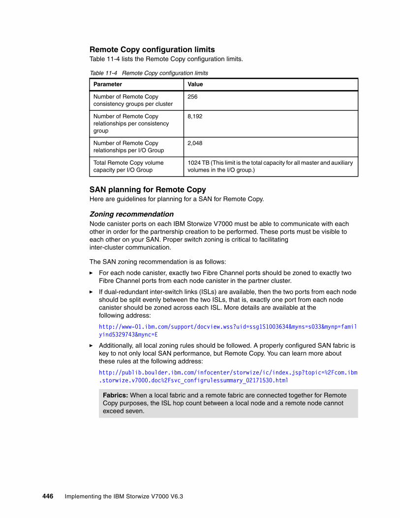
Remote Copy configuration limitsTable 11-4 lists the Remote Copy configuration limits.
Table 11-4 Remote Copy configuration limits
SAN planning for Remote CopyHere are guidelines for planning for a SAN for Remote Copy.
Zoning recommendationNode canister ports on each IBM Storwize V7000 must be able to communicate with each other in order for the partnership creation to be performed. These ports must be visible to each other on your SAN. Proper switch zoning is critical to facilitating inter-cluster communication.
The SAN zoning recommendation is as follows:
� For each node canister, exactly two Fibre Channel ports should be zoned to exactly two Fibre Channel ports from each node canister in the partner cluster.
� If dual-redundant inter-switch links (ISLs) are available, then the two ports from each node should be split evenly between the two ISLs, that is, exactly one port from each node canister should be zoned across each ISL. More details are available at the following address:
http://www-01.ibm.com/support/docview.wss?uid=ssg1S1003634&myns=s033&mynp=familyind5329743&mync=E
� Additionally, all local zoning rules should be followed. A properly configured SAN fabric is key to not only local SAN performance, but Remote Copy. You can learn more about these rules at the following address:
http://publib.boulder.ibm.com/infocenter/storwize/ic/index.jsp?topic=%2Fcom.ibm.storwize.v7000.doc%2Fsvc_configrulessummary_02171530.html
Parameter Value
Number of Remote Copy consistency groups per cluster
256
Number of Remote Copy relationships per consistency group
8,192
Number of Remote Copy relationships per I/O Group
2,048
Total Remote Copy volume capacity per I/O Group
1024 TB (This limit is the total capacity for all master and auxiliary volumes in the I/O group.)
Fabrics: When a local fabric and a remote fabric are connected together for Remote Copy purposes, the ISL hop count between a local node and a remote node cannot exceed seven.
446 Implementing the IBM Storwize V7000 V6.3

Remote Copy link requirementsThe link requirements are valid for Metro Mirror and Global Mirror. Basically, there are two link requirements:
� Round-trip latency
The total round-trip latency must be less than 80 ms, and less than 40 ms in each direction. Latency simulations should be performed with your applications before putting any network links in place to see if the applications perform at an acceptable level while meeting the round-trip latency requirement.
� Bandwidth
The bandwidth must satisfy the following requirements:
– If you are not using Change Volumes: Be able to sustain peak write load for all mirrored volumes and background copy traffic.
– If you are using Change Volumes with Global Mirror: Be able to sustain change rate of Source Change Volumes and background copy traffic.
– Additional background copy rate (the best practice is 10% to 20% of maximum peak load) for initial synchronization and resynchronization.
– Remote Copy internal communication at idle with or without Change Volumes is approximately 2.6 Mbps. This amount is the minimum amount.
Interaction between Remote Copy and FlashCopyTable 11-5 lists which combinations of FlashCopy and Remote Copy are supported.
Table 11-5 FlashCopy and Remote Copy interaction
Redundancy: If the link between two sites is configured with redundancy so that it can tolerate single failures, the link must be sized so that the bandwidth and latency requirement can be met during single failure conditions.
Component Remote Copy primary site Remote Copy secondary site
FlashCopy source Supported Supported.When the FlashCopy relationship is in the Preparing and Prepared states, the cache at the Remote Copy secondary site operates in write-through mode. This process adds additional latency to the already latent Remote Copy relationship.
FlashCopy destination This combination is supported. It has several restrictions:� Issuing stop -force might
cause the Remote Copy relationship to fully resynchronize.
� The code level must be Version 6.2.x or higher.
� The I/O group must be the same.
This combination is supported with the restriction that the FlashCopy mapping cannot be copying, stopping, or suspended. Otherwise, the restrictions are the same as at the Remote Copy primary site.
Chapter 11. Copy services 447

If you are not using Global Mirror with Change Volumes, you can, for disaster recovery purposes, use the FlashCopy feature to create a consistent copy of an image before you restart a Global Mirror relationship.
When a consistent relationship is stopped, the relationship enters the consistent_stopped state. While in this state, I/O operations at the primary site continue to run. However, updates are not copied to the secondary site. When the relationship is restarted, the synchronization process for new data is started. During this process, the relationship is in the inconsistent_copying state. The secondary volume for the relationship cannot be used until the copy process completes and the relationship returns to the consistent state. When this situation occurs, start a FlashCopy operation for the secondary volume before you restart the relationship. While the relationship is in the Copying state, the FlashCopy feature can provide a consistent copy of the data. If the relationship does not reach the synchronized state, you can use the FlashCopy target volume at the secondary site.
11.4 Troubleshooting Remote Copy
Remote Copy (Global Mirror and Metro Mirror) has two primary error codes: 1920 or 1720. A 1920 error is a congestion error. This error means that either the source, the link between source and target, or the target were not able to keep up with the rate of demand. A 1720 error is a heartbeat or cluster partnership communication error. This error tends to be more serious, as failing communication between your cluster partners involves some extended diagnostic time.
11.4.1 1920 error
Let us focus first on the 1920 error. A 1920 error (event ID 050010) can have several triggers. Official probable cause projections are:
� Primary 2145 cluster or SAN fabric problem (10%)� Primary 2145 cluster or SAN fabric configuration (10%)� Secondary 2145 cluster or SAN fabric problem (15%)� Secondary 2145 cluster or SAN fabric configuration (25%)� Inter-cluster link problem (15%)� Inter-cluster link configuration (25%)
In practice, the error that is most often overlooked is latency. Global Mirror has a round-trip-time tolerance limit of 80 ms. A message sent from your source SAN Volume Controller cluster to your target SAN Volume Controller Cluster and the accompanying acknowledgement must have a total time of 80 ms or 40 ms each way (for Version 4.1.1.x and later.)
The primary component of your round-trip time is the physical distance between sites. For every 1000 km (621.36 miles), there is a 5 ms delay. This delay does not include the time added by equipment in the path. Every device adds a varying amount of time, depending on the device, but expect about 25 µs for pure hardware devices. For software-based functions (such as compression implemented in software), the delay added tends to be much higher (usually in the millisecond plus range.)
Round-trip time: For Version 4.1.0.x and earlier, this limit was 68 ms or 34 ms one way for Fibre Channel extenders, and for SAN routers it was 10 ms one way or 20 ms round trip. Make sure to use the correct values for the correct versions!
448 Implementing the IBM Storwize V7000 V6.3
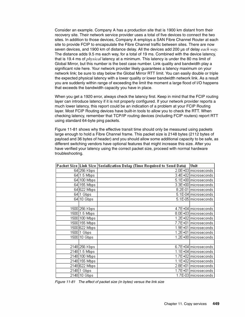
Consider an example. Company A has a production site that is 1900 km distant from their recovery site. Their network service provider uses a total of five devices to connect the two sites. In addition to those devices, Company A employs a SAN Fibre Channel Router at each site to provide FCIP to encapsulate the Fibre Channel traffic between sites. There are now seven devices, and 1900 km of distance delay. All the devices add 200 µs of delay each way. The distance adds 9.5 ms each way, for a total of 19 ms. Combined with the device latency, that is 19.4 ms of physical latency at a minimum. This latency is under the 80 ms limit of Global Mirror, but this number is the best case number. Link quality and bandwidth play a significant role here. Your network provider likely guarantees a latency maximum on your network link; be sure to stay below the Global Mirror RTT limit. You can easily double or triple the expected physical latency with a lower quality or lower bandwidth network link. As a result you are suddenly within range of exceeding the limit the moment a large flood of I/O happens that exceeds the bandwidth capacity you have in place.
When you get a 1920 error, always check the latency first. Keep in mind that the FCIP routing layer can introduce latency if it is not properly configured. If your network provider reports a much lower latency, this report could be an indication of a problem at your FCIP Routing layer. Most FCIP Routing devices have built-in tools to allow you to check the RTT. When checking latency, remember that TCP/IP routing devices (including FCIP routers) report RTT using standard 64-byte ping packets.
Figure 11-81 shows why the effective transit time should only be measured using packets large enough to hold a Fibre Channel frame. This packet size is 2148 bytes (2112 bytes of payload and 36 bytes of header) and you should allow some additional capacity to be safe, as different switching vendors have optional features that might increase this size. After you have verified your latency using the correct packet size, proceed with normal hardware troubleshooting.
Figure 11-81 The effect of packet size (in bytes) versus the link size
Chapter 11. Copy services 449

Before you proceed, take a quick look at the second largest component of your round-trip-time, that is, serialization delay. Serialization delay is the amount of time required to move a packet of data of a specific size across a network link of a given bandwidth. This delay is based on a simple concept: the time required to move a specific amount of data decreases as the data transmission rate increases.
In Figure 11-81 on page 449, there are orders of magnitude of difference between the different link bandwidths. It is easy to see how 1920 errors can arise when your bandwidth is insufficient and why you should never use a TCP/IP ping to measure RTT for FCIP traffic.
Figure 11-81 on page 449 compares the amount of time in microseconds required to transmit a packet across network links of varying bandwidth capacity. Three packet sizes are used:
� 64 bytes: The size of the common ping packet� 1500 bytes: The size of the standard TCP/IP packet� 2148 bytes: The size of a Fibre Channel frame
Remember that your path MTU affects the delay incurred in getting a packet from one location to another, when it causes fragmentation or is too large and causes too many retransmits when a packet is lost.
11.4.2 1720 error
The 1720 error (event ID 050020) is the other primary error code of Remote Copy. Because the term “System Partnership” implies that all involved virtualization systems are partners, they must be able to communicate with each other. When a partner on either side stops communicating, you see a 1720 error appear in your error log. According to official documentation, there are no likely field replaceable unit breakages or other causes.
In practice, the source of this error is most often a fabric problem or a problem the network path between your partners. When you receive this error, if your fabric has more than 64 HBA ports zoned, you should check your fabric configuration for zoning of more than one HBA port for each node per I/O group. One port for each node per I/O group associated with the host is the recommended zoning configuration for fabrics. For those fabrics with 64 or more host ports, this recommendation becomes a rule. You must follow this zoning rule or the configuration is technically unsupported.
Improper zoning leads to SAN congestion, which can inhibit remote link communication intermittently. Checking the zero buffer credit timer through IBM Tivoli Storage Productivity Center and comparing its value against your sample interval might reveal potential SAN congestion. Anytime a zero buffer credit timer is above 2% of the total time of the sample interval, it is likely to cause problems.
Next, always ask your network provider to check the status of the link. If the link is okay, watch for repetition of this error. It is possible in a normal and functional network setup to have occasional 1720 errors, but multiple occurrences point to a larger problem.
If you receive multiple 1720 errors, recheck your network connection and then check the IBM Storwize V7000 partnership information to verify their status and settings. Perform diagnostic tests for every piece of equipment in the path between the two systems. It often helps to have a diagram showing the path of your replication from both logical and physical configuration viewpoints.
If your investigation fails to resolve your Remote Copy problems, you should contact your IBM support representative for a complete analysis.
450 Implementing the IBM Storwize V7000 V6.3

11.5 Managing Remote Copy using the GUI
The IBM Storwize V7000 storage system provides a separate function icon for copy service management. There are two windows for managing Remote Copy, which are accessed through the Copy Services function icon:
� Remote Copy� Partnerships
As the name implies, these two windows are used to manage Remote Copy and the partnership.
11.5.1 Managing cluster partnerships
The Partnership window is used to manage a partnership between clusters. To access the Partnership window, click the Copy Services function icon and click Partnerships (Figure 11-82).
Figure 11-82 Partnership window
Chapter 11. Copy services 451

Creating a partnershipNo partnership is defined in our example (Figure 11-83), so you must create a partnership between the IBM Storwize V7000 systems. Click New Partnership in the Partnership window.
Figure 11-83 Create a cluster partnership
If there is no partnership candidate, an error window opens (Figure 11-84).
Figure 11-84 No candidates are available to create a partnership
452 Implementing the IBM Storwize V7000 V6.3
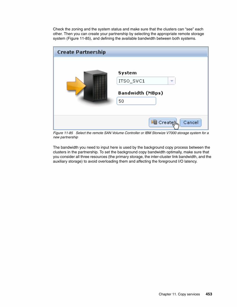
Check the zoning and the system status and make sure that the clusters can “see” each other. Then you can create your partnership by selecting the appropriate remote storage system (Figure 11-85), and defining the available bandwidth between both systems.
Figure 11-85 Select the remote SAN Volume Controller or IBM Storwize V7000 storage system for a new partnership
The bandwidth you need to input here is used by the background copy process between the clusters in the partnership. To set the background copy bandwidth optimally, make sure that you consider all three resources (the primary storage, the inter-cluster link bandwidth, and the auxiliary storage) to avoid overloading them and affecting the foreground I/O latency.
Chapter 11. Copy services 453

Click Create and the partnership definition is complete on the first IBM Storwize V7000 system. You can find the partnership listed in the left pane of the Partnership window, and if you select the partnership, more information for this partnership is displayed on the right (Figure 11-86).
Figure 11-86 Partially configured partnership
Complete the same steps on the second storage system that becomes a fully configured partner.
454 Implementing the IBM Storwize V7000 V6.3

The Remote Copy partnership is now implemented between two IBM Storwize V7000 systems and both systems are ready for further configuration of Remote Copy relationships (Figure 11-87).
Figure 11-87 Fully configured partnership
You can also change the bandwidth setting for the partnership in the Partnerships window (Figure 11-88). Click Apply Changes to confirm your modification.
Figure 11-88 Apply changes to the partnership bandwidth
Chapter 11. Copy services 455
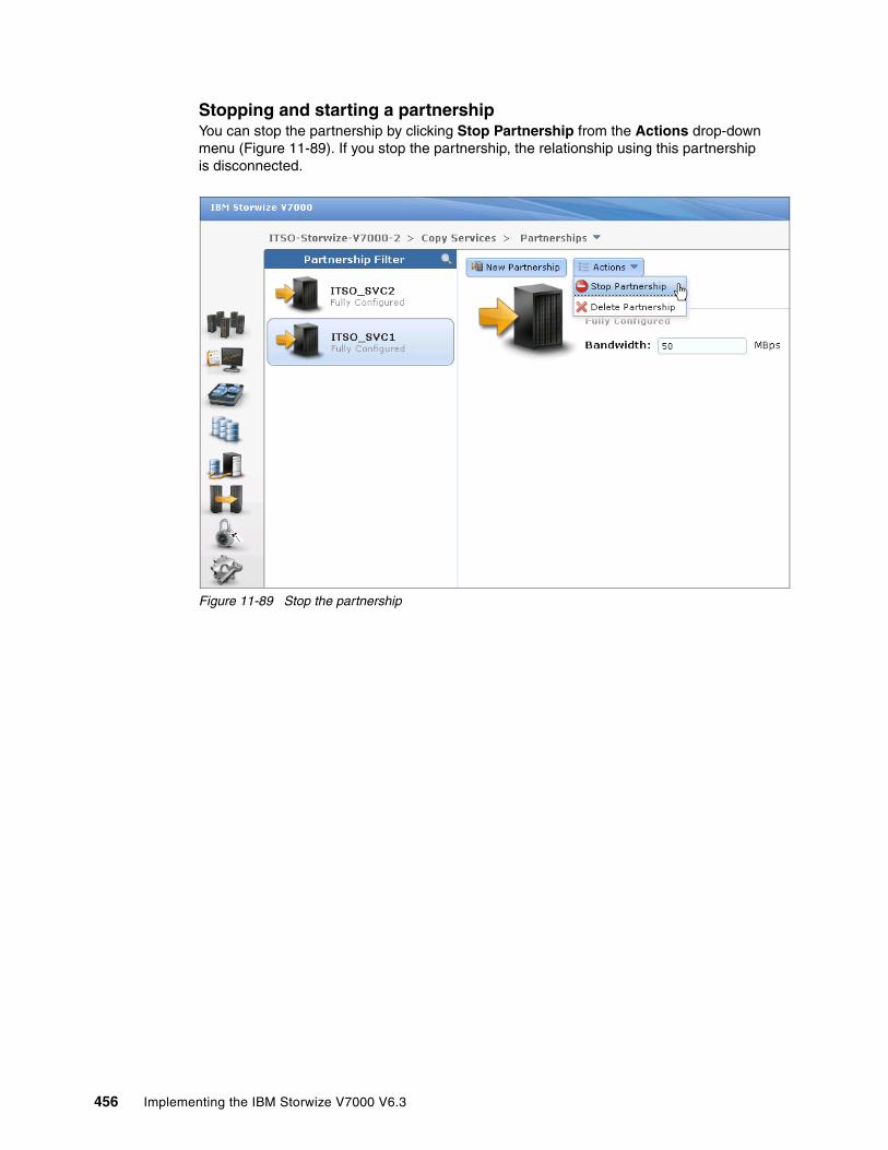
Stopping and starting a partnershipYou can stop the partnership by clicking Stop Partnership from the Actions drop-down menu (Figure 11-89). If you stop the partnership, the relationship using this partnership is disconnected.
Figure 11-89 Stop the partnership
456 Implementing the IBM Storwize V7000 V6.3

After you have stopped the partnership, your partnership is listed as Fully Configured: Stopped (Figure 11-90).
Figure 11-90 Fully configured partnership in stopped state
Chapter 11. Copy services 457
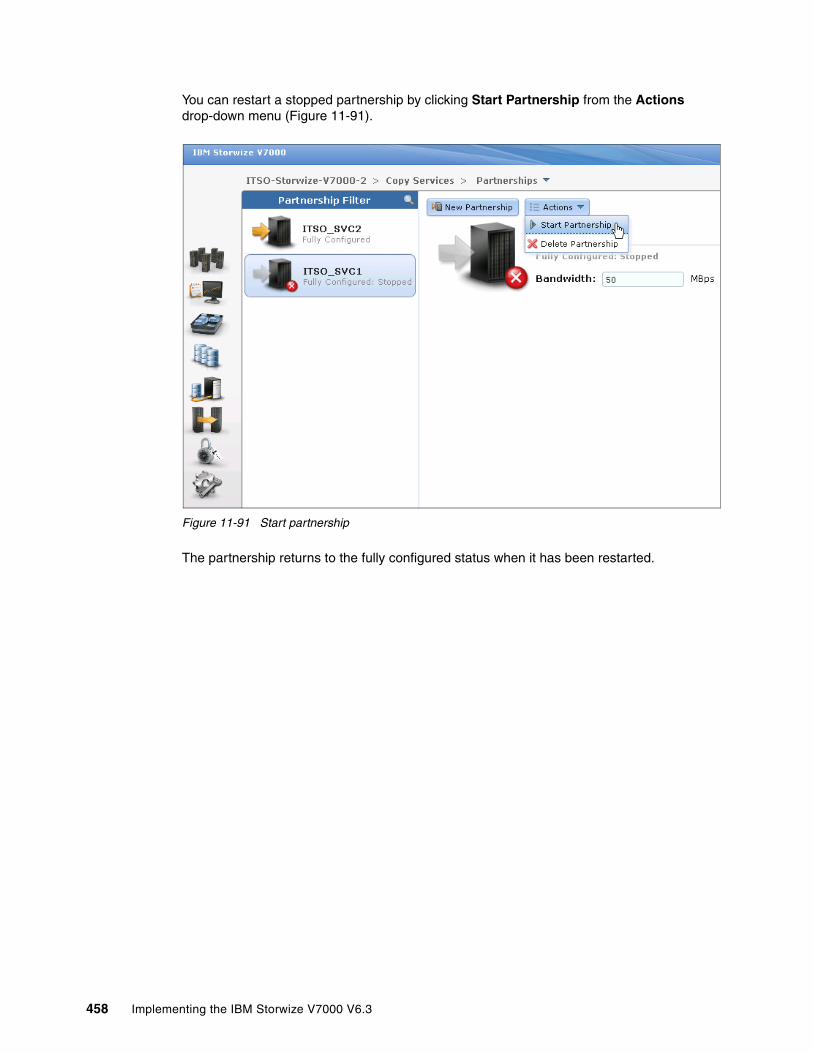
You can restart a stopped partnership by clicking Start Partnership from the Actions drop-down menu (Figure 11-91).
Figure 11-91 Start partnership
The partnership returns to the fully configured status when it has been restarted.
458 Implementing the IBM Storwize V7000 V6.3

11.5.2 Deleting a partnership
You can delete a partnership by selecting Delete Partnership from the Actions drop-down menu (Figure 11-92).
Figure 11-92 Delete a partnership
Managing stand-alone Remote Copy relationshipsA Remote Copy relationship can be defined between two volumes, where one is the master (source) and the other one is the auxiliary (target) volume. Usage of Remote Copy auxiliary volumes as Remote Copy master volumes is not allowed.
Chapter 11. Copy services 459

Open the Remote Copy window to manage Remote Copy by clicking the Copy Services icon and clicking Remote Copy (Figure 11-93).
Figure 11-93 Open Remote Copy window
The Remote Copy window (Figure 11-94) is where you can manage Remote Copy relationships and Remote Copy consistency groups.
Figure 11-94 Remote Copy window
460 Implementing the IBM Storwize V7000 V6.3
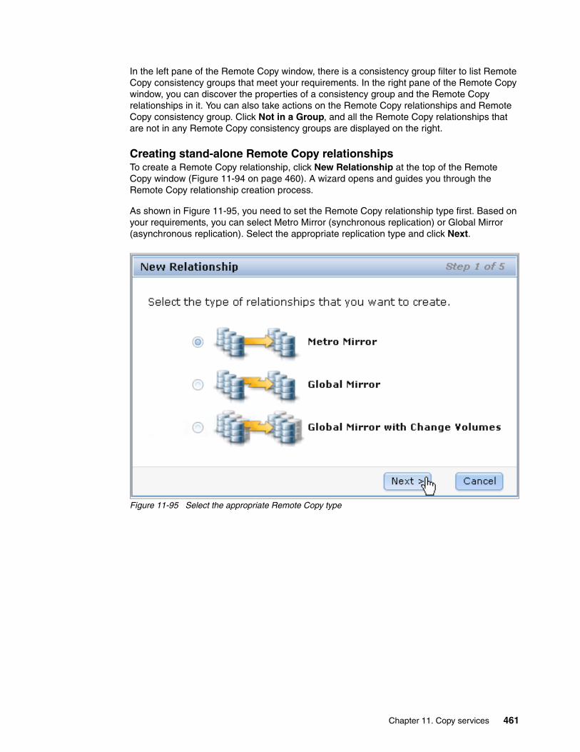
In the left pane of the Remote Copy window, there is a consistency group filter to list Remote Copy consistency groups that meet your requirements. In the right pane of the Remote Copy window, you can discover the properties of a consistency group and the Remote Copy relationships in it. You can also take actions on the Remote Copy relationships and Remote Copy consistency group. Click Not in a Group, and all the Remote Copy relationships that are not in any Remote Copy consistency groups are displayed on the right.
Creating stand-alone Remote Copy relationshipsTo create a Remote Copy relationship, click New Relationship at the top of the Remote Copy window (Figure 11-94 on page 460). A wizard opens and guides you through the Remote Copy relationship creation process.
As shown in Figure 11-95, you need to set the Remote Copy relationship type first. Based on your requirements, you can select Metro Mirror (synchronous replication) or Global Mirror (asynchronous replication). Select the appropriate replication type and click Next.
Figure 11-95 Select the appropriate Remote Copy type
Chapter 11. Copy services 461

You need to select your Remote Copy auxiliary (target) storage system, the local system, or the already defined second storage system as the Remote Copy partner. In our example (Figure 11-96), choose another system to build an inter-cluster relationship. Click Next to continue.
Figure 11-96 Select Remote Copy partner
The Remote Copy master and auxiliary volume need to be specified. Both volumes must have the same size. As shown in Figure 11-97, the system offers only appropriate auxiliary candidates with the same volume size as the selected master volume. After you select the volumes based on your requirement, click Add.
Figure 11-97 Select the master and auxiliary volume
462 Implementing the IBM Storwize V7000 V6.3

You can define multiple and independent relationships by clicking Add. You can remove a relationship by clicking the red cross. In our example, create two independent Remote Copy relationships (Figure 11-98).
Figure 11-98 Define multiple independent relationships
A window opens and asks if the volumes in the relationship are already synchronized. In most situations, the data on the master volume and on the auxiliary volume are not identical, so click No and click Next to enable an initial copy (Figure 11-99).
Figure 11-99 Activate initial data copy
Chapter 11. Copy services 463
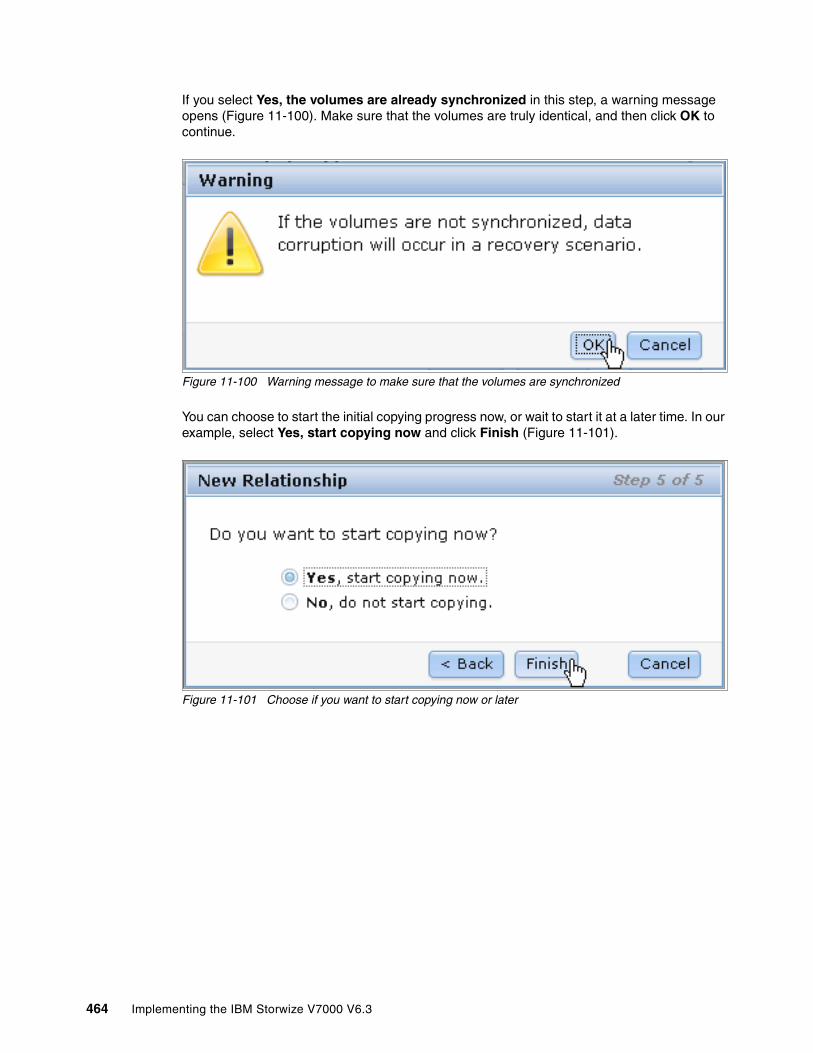
If you select Yes, the volumes are already synchronized in this step, a warning message opens (Figure 11-100). Make sure that the volumes are truly identical, and then click OK to continue.
Figure 11-100 Warning message to make sure that the volumes are synchronized
You can choose to start the initial copying progress now, or wait to start it at a later time. In our example, select Yes, start copying now and click Finish (Figure 11-101).
Figure 11-101 Choose if you want to start copying now or later
464 Implementing the IBM Storwize V7000 V6.3
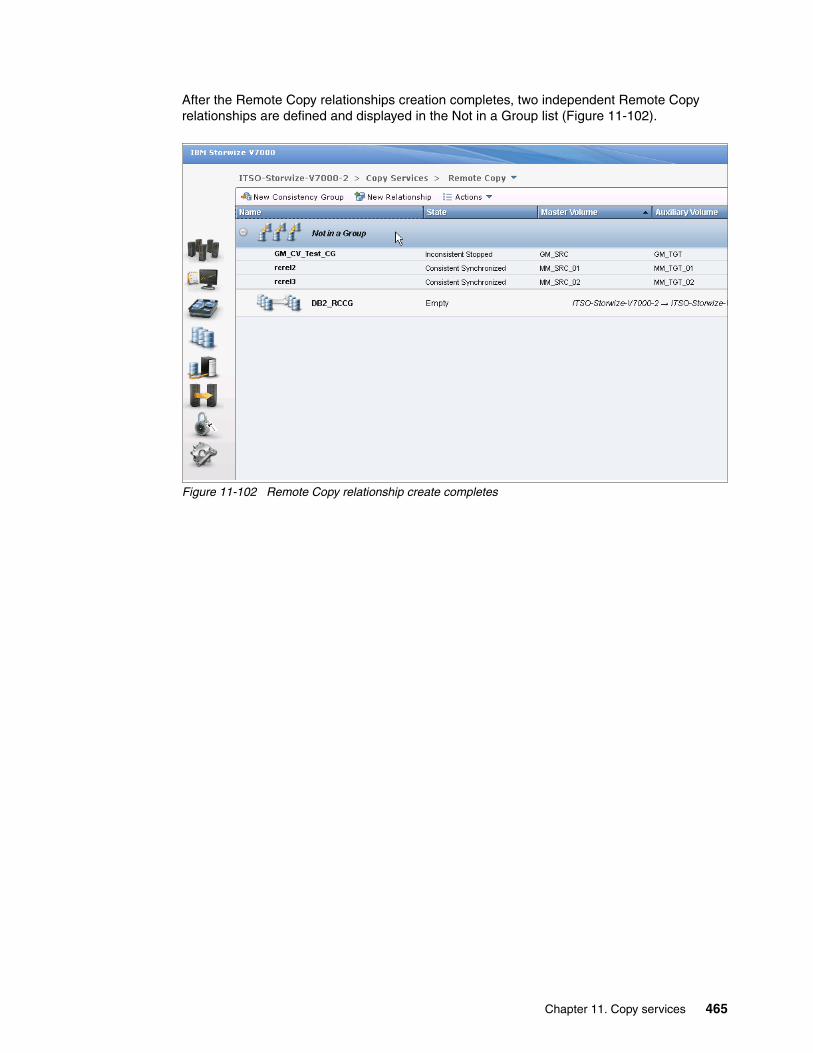
After the Remote Copy relationships creation completes, two independent Remote Copy relationships are defined and displayed in the Not in a Group list (Figure 11-102).
Figure 11-102 Remote Copy relationship create completes
Chapter 11. Copy services 465
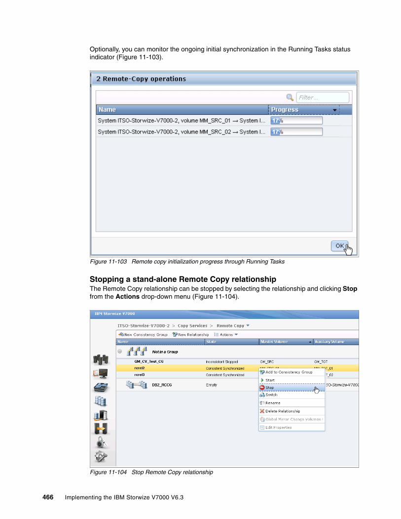
Optionally, you can monitor the ongoing initial synchronization in the Running Tasks status indicator (Figure 11-103).
Figure 11-103 Remote copy initialization progress through Running Tasks
Stopping a stand-alone Remote Copy relationshipThe Remote Copy relationship can be stopped by selecting the relationship and clicking Stop from the Actions drop-down menu (Figure 11-104).
Figure 11-104 Stop Remote Copy relationship
466 Implementing the IBM Storwize V7000 V6.3

Allow secondary read/write access, if required, and click Stop Relationship (Figure 11-105).
Figure 11-105 Option to allow secondary read/write access
After the stop completes, the state of the Remote Copy relationship is changed from Consistent Synchronized to Idling (Figure 11-106). Read / write access to both volumes is now allowed.
Figure 11-106 Remote Copy relationship stop completes
Chapter 11. Copy services 467

Starting a stand-alone Remote Copy relationshipThe Remote Copy relationship can be started by selecting the relationship and clicking Stop from the Actions drop-down menu (Figure 11-107).
Figure 11-107 Start a Remote Copy relationship
When starting a Remote Copy relationship, the most important item is selecting the copy direction. Both master and auxiliary volumes could be the primary. Make your decision based on your requirements and click Start Relationship. In our example, choose the master volume to be the primary (Figure 11-108).
Figure 11-108 Choose the copy direction
468 Implementing the IBM Storwize V7000 V6.3
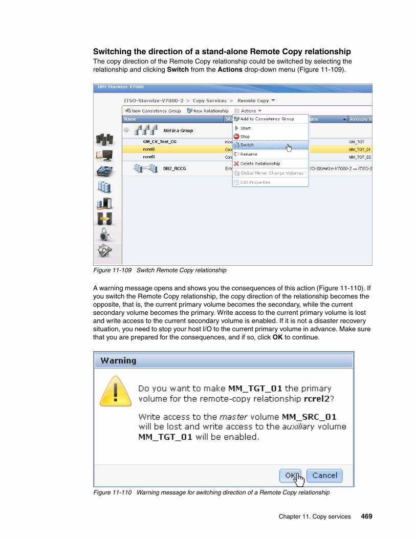
Switching the direction of a stand-alone Remote Copy relationshipThe copy direction of the Remote Copy relationship could be switched by selecting the relationship and clicking Switch from the Actions drop-down menu (Figure 11-109).
Figure 11-109 Switch Remote Copy relationship
A warning message opens and shows you the consequences of this action (Figure 11-110). If you switch the Remote Copy relationship, the copy direction of the relationship becomes the opposite, that is, the current primary volume becomes the secondary, while the current secondary volume becomes the primary. Write access to the current primary volume is lost and write access to the current secondary volume is enabled. If it is not a disaster recovery situation, you need to stop your host I/O to the current primary volume in advance. Make sure that you are prepared for the consequences, and if so, click OK to continue.
Figure 11-110 Warning message for switching direction of a Remote Copy relationship
Chapter 11. Copy services 469

After the switch completes, your Remote Copy relationship is tagged (Figure 11-111), and shows you that the primary volume in this relationship has been changed.
Figure 11-111 Note the switch icon on the state of the relationship
Renaming a stand-alone Remote Copy relationshipThe Remote Copy relationship can be renamed by selecting the relationship and clicking Rename from the Actions drop-down menu (Figure 11-112).
Figure 11-112 Rename the Remote Copy relationship
470 Implementing the IBM Storwize V7000 V6.3
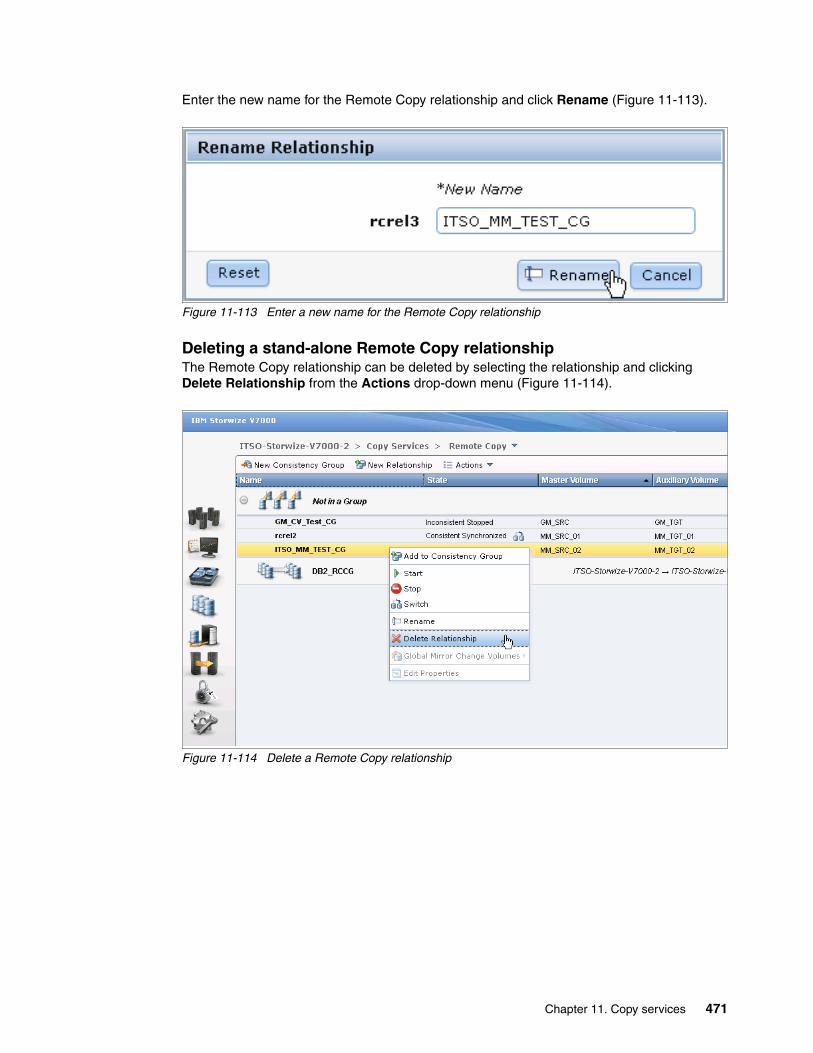
Enter the new name for the Remote Copy relationship and click Rename (Figure 11-113).
Figure 11-113 Enter a new name for the Remote Copy relationship
Deleting a stand-alone Remote Copy relationshipThe Remote Copy relationship can be deleted by selecting the relationship and clicking Delete Relationship from the Actions drop-down menu (Figure 11-114).
Figure 11-114 Delete a Remote Copy relationship
Chapter 11. Copy services 471
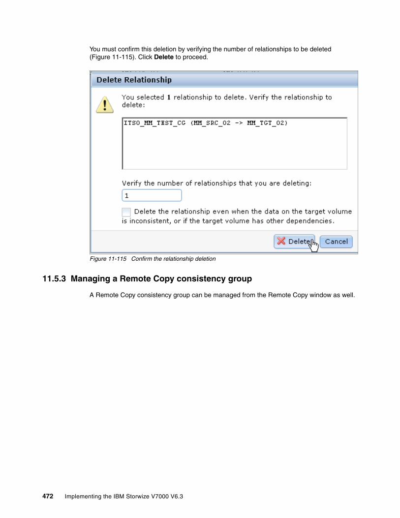
You must confirm this deletion by verifying the number of relationships to be deleted (Figure 11-115). Click Delete to proceed.
Figure 11-115 Confirm the relationship deletion
11.5.3 Managing a Remote Copy consistency group
A Remote Copy consistency group can be managed from the Remote Copy window as well.
472 Implementing the IBM Storwize V7000 V6.3
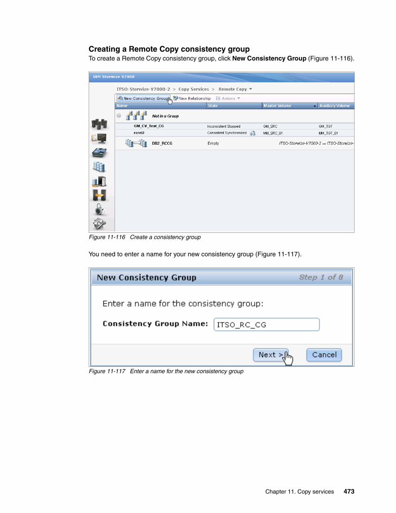
Creating a Remote Copy consistency groupTo create a Remote Copy consistency group, click New Consistency Group (Figure 11-116).
Figure 11-116 Create a consistency group
You need to enter a name for your new consistency group (Figure 11-117).
Figure 11-117 Enter a name for the new consistency group
Chapter 11. Copy services 473
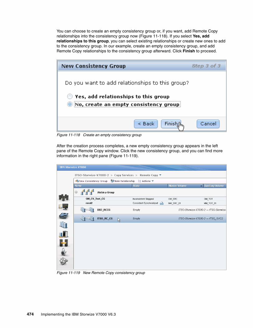
You can choose to create an empty consistency group or, if you want, add Remote Copy relationships into the consistency group now (Figure 11-118). If you select Yes, add relationships to this group, you can select existing relationships or create new ones to add to the consistency group. In our example, create an empty consistency group, and add Remote Copy relationships to the consistency group afterward. Click Finish to proceed.
Figure 11-118 Create an empty consistency group
After the creation process completes, a new empty consistency group appears in the left pane of the Remote Copy window. Click the new consistency group, and you can find more information in the right pane (Figure 11-119).
Figure 11-119 New Remote Copy consistency group
474 Implementing the IBM Storwize V7000 V6.3

You can find the name and the status of the consistency group beside the Relationship function icon. It is easy to change the name of consistency group by clicking the name and entering a new one. At the upper right of the Remote Copy window, you can take actions on the Remote Copy consistency group. Below the Relationship function icon, you find all the Remote Copy relationships in this consistency group. The actions on the Remote Copy relationships can be applied here by using the Actions drop-down menu.
Adding Remote Copy to a consistency groupThe Remote Copy relationships in the Not in a Group list could be added to a consistency group by selecting the volumes and clicking Add to Consistency Group from the Actions drop-down menu (Figure 11-120).
Figure 11-120 Add Remote Copy relationships to a consistency group
You must choose the consistency group to which to add the Remote Copy relationships. Based on your requirements, select the appropriate consistency group and click Add to Consistency Group (Figure 11-121).
Figure 11-121 Choose the consistency group to add the remote copies to
Your Remote Copy relationships are now in the consistency group you selected.
Chapter 11. Copy services 475
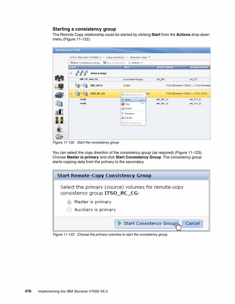
Starting a consistency groupThe Remote Copy relationship could be started by clicking Start from the Actions drop-down menu (Figure 11-122).
Figure 11-122 Start the consistency group
You can select the copy direction of the consistency group (as required) (Figure 11-123). Choose Master is primary and click Start Consistency Group. The consistency group starts copying data from the primary to the secondary.
Figure 11-123 Choose the primary volumes to start the consistency group
476 Implementing the IBM Storwize V7000 V6.3

Stopping a consistency groupThe Remote Copy relationship can be stopped by clicking Stop in the Actions drop-down menu (Figure 11-124).
Figure 11-124 Stop the consistency group
You can allow read / write access to secondary volumes by selecting the check box (Figure 11-125) and clicking Stop Consistency Group.
Figure 11-125 Confirm consistency group stop and decide to allow secondary read / write access
Chapter 11. Copy services 477

Switching a consistency groupAs with the switch action on the Remote Copy relationship, you can switch the copy direction of the consistency group as well. To switch the copy direction of the consistency group, click Switch from the Actions drop-down menu (Figure 11-126).
Figure 11-126 Switch the copy direction of a consistency group
A warning message opens (Figure 11-127). After the switch, the primary cluster in the consistency group is changed. Write access to current master volumes is lost, while write access to the current auxiliary volumes is enabled. Make sure that these settings are what you need, and if so, click OK to continue.
Figure 11-127 Warning message to confirm the switch
478 Implementing the IBM Storwize V7000 V6.3
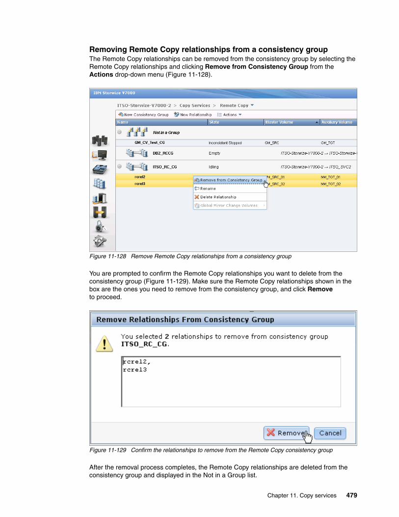
Removing Remote Copy relationships from a consistency groupThe Remote Copy relationships can be removed from the consistency group by selecting the Remote Copy relationships and clicking Remove from Consistency Group from the Actions drop-down menu (Figure 11-128).
Figure 11-128 Remove Remote Copy relationships from a consistency group
You are prompted to confirm the Remote Copy relationships you want to delete from the consistency group (Figure 11-129). Make sure the Remote Copy relationships shown in the box are the ones you need to remove from the consistency group, and click Remove to proceed.
Figure 11-129 Confirm the relationships to remove from the Remote Copy consistency group
After the removal process completes, the Remote Copy relationships are deleted from the consistency group and displayed in the Not in a Group list.
Chapter 11. Copy services 479
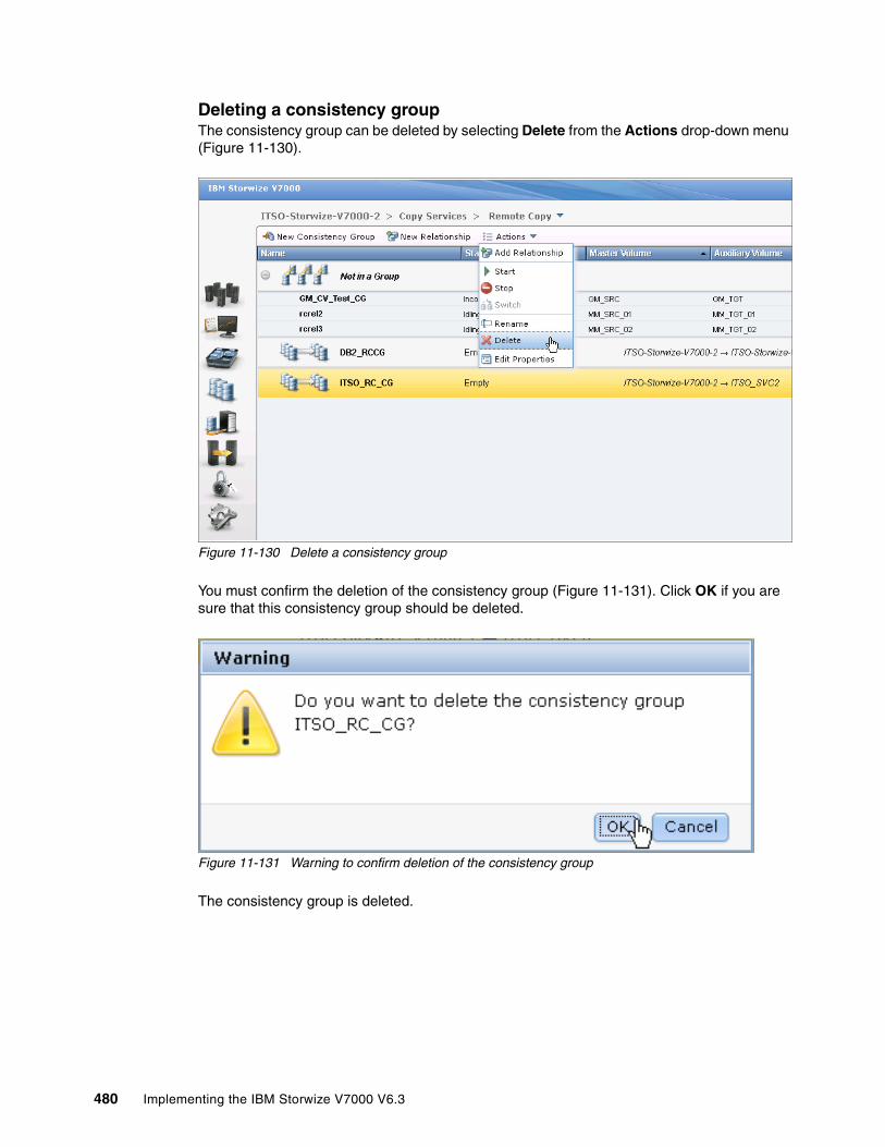
Deleting a consistency groupThe consistency group can be deleted by selecting Delete from the Actions drop-down menu (Figure 11-130).
Figure 11-130 Delete a consistency group
You must confirm the deletion of the consistency group (Figure 11-131). Click OK if you are sure that this consistency group should be deleted.
Figure 11-131 Warning to confirm deletion of the consistency group
The consistency group is deleted.
480 Implementing the IBM Storwize V7000 V6.3
Chapter 12. IBM Tivoli Storage Productivity Center
The IBM Tivoli Storage Productivity Center suite of storage infrastructure management tools helps customers improve time to value and reduces the complexity of managing their storage environments. It accomplished these tasks by centralizing, simplifying, and optimizing storage tasks associated with storage systems, storage networks, replication services, and capacity management.
Tivoli Storage Productivity Center is designed to:
� Help centralize the management of your storage infrastructure from a single interface using role-based administration and single sign-on.
� Provide a single management application with modular integrated components that are easy to install and provide common services for simple and consistent configuration and consistent operations across host, fabric, and storage systems.
� Manage performance and connectivity from the host file system to the physical disk, including in-depth performance monitoring and analysis on SAN fabric performance.
� Manage the capacity utilization and availability of storage systems, file systems, and databases.
� Monitor, manage, and control (zone) SAN fabric components.
� Automate capacity provisioning of file systems.
� Monitor and track the performance of SAN-attached SMI-S compliant storage devices.
� Manage advanced replication services (Global Mirror, Metro Mirror, and FlashCopy).
Tivoli Storage Productivity Center can help you manage the capacity utilization of storage systems, file systems, and databases. It can help automate file system capacity provisioning, and perform device configuration and management of multiple devices from a single user interface. It can tune and proactively manage the performance of storage devices on a storage area network (SAN) and manage, monitor, and control your SAN fabric.
12
© Copyright IBM Corp. 2011, 2012. All rights reserved. 481
There is a plug-in for IBM System Director named IBM System Director Storage Productivity Center that is now available. It is designed to be used as an embedded version of Tivoli Storage Productivity Center V4.2.1 for IBM System Director V6.2.1.
12.1 Tivoli Storage Productivity Center overview
In this book, we give a basic overview of Tivoli Storage Productivity Center, and show how to perform a typical setup (in 12.4, “Installing Tivoli Storage Productivity Center components” on page 499) and connect it to the IBM Storwize V7000 (in 12.5, “Connecting Tivoli Storage Productivity Center to an IBM Storwize V7000 system” on page 508). Remember that the functions are dependent on the type of Tivoli Storage Productivity Center license you have and are not included with IBM Storwize V7000.
Contact your IBM Business Partner or IBM Representative to obtain the correct license for your requirements.
12.1.1 IBM Tivoli Storage Productivity Center for Disk Midrange Edition
Tivoli Storage Productivity Center now enables enterprise-wide management of IBM Storwize V7000 systems. In addition to device-level management software that comes packaged with IBM Storwize V7000 systems, Tivoli Storage Productivity Center offers incremental benefits that are included its latest version, Version 4.2.1. Tivoli Storage Productivity Center for Disk Midrange Edition is ideally suited for use with IBM Storwize V7000 systems.
The benefits of Tivoli Storage Productivity Center for Disk Midrange Edition are:
� Simplified deployment and visibility: Tivoli Storage Productivity Center for Disk Midrange Edition supports IBM Storwize V7000 systems during discovery as a new device type with different types of managed disks. The quick discovery and configuration capabilities of Tivoli Storage Productivity Center enable you to attach the storage device with ease and helps you configure efficiently, that is, plan for replication while provisioning the device. Tivoli Storage Productivity Center for Disk Midrange Edition also enables launch-in-context and single sign-on, significantly reducing the burden on storage administrators.
� The Tivoli Storage Productivity Center topology viewer offers a collective view that includes IBM Storwize V7000 systems, helps differentiate between external array-based disks and local disks, and shows tiering information. Tivoli Storage Productivity Center for Disk Midrange Edition also extends thin provisioning support for IBM Storwize V7000 systems, enabling increased utilization and lowered costs.
� Performance management: An IBM Storwize V7000 system offers unmatched performance and availability among midrange disk systems. Adding Tivoli Storage Productivity Center for Disk Midrange Edition enhances performance monitoring by capturing metrics such as input and output (I/O) and data rates, and cache utilization from a single console. Tivoli Storage Productivity Center helps establish threshold levels based on business priorities and alerts when these levels are breached, while proactively managing performance and service levels by tracking historical information.
� Replication management: Tivoli Storage Productivity Center for Replication gives IBM Storwize V7000 systems superior disaster recovery (DR) management, provides central control of the replication environment, and helps establish FlashCopy and Metro Mirror and Global Mirror relationships.
482 Implementing the IBM Storwize V7000 V6.3
� Comprehensive reporting: Tivoli Storage Productivity Center for Disk Midrange Edition offers detailed metrics that include performance data for storage subsystems, controllers, cache, I/O, arrays, disk groups, and ports. These performance statistics can be stored in database tables for later use, so that storage administrators can track and measure service levels.
� Easy Tier: Tivoli Storage Productivity Center for Disk Midrange Edition also provides information about Easy Tier to monitor automatic migration of data assets to high-performance disk tiers (such as solid-state drives (SSDs)).
� Advanced management: Tivoli Storage Productivity Center Standard Edition offers performance metrics-based recommendations for provisioning, including SAN planning (and DR planning with Tivoli Storage Productivity Center for Replication). The new Disk Magic model of Tivoli Storage Productivity Center helps identify “hot spots”, improving storage optimization for IBM Storwize V7000.
12.2 Tivoli Storage Productivity Center architecture
The IBM Tivoli Storage Productivity Center consists of the following key components:
� Data Server� Device Server� IBM Tivoli Integrated Portal� Tivoli Storage Productivity Center for Replication� IBM DB2 Database� Agents� Interfaces
12.2.1 Data Server
This component is the control point for product scheduling functions, configuration, event information, reporting, and graphical user interface (GUI) support. It coordinates communication with and data collection from agents that scan file systems and databases to gather storage demographics and populate the database with results. Automated actions can be defined to perform file system extension, data deletion, backup or archiving, or event reporting when defined thresholds are encountered. The Data Server is the primary contact point for GUI user interface functions. It also includes functions that schedule data collection and discovery for the Device Server.
12.2.2 Device Server
This component discovers, gathers information from, analyzes performance of, and controls storage subsystems and SAN fabrics. It coordinates communication with and data collection from agents that scan SAN fabrics and storage devices.
Chapter 12. IBM Tivoli Storage Productivity Center 483
12.2.3 IBM Tivoli Integrated Portal
Tivoli Storage Productivity Center V4 is integrated with Tivoli Integrated Portal. This integration provides functions such as single sign-on and the use of IBM Tivoli Common Reporting:
� Single sign-on: Enables you to access Tivoli Storage Productivity Center and then Tivoli Storage Productivity Center for Replication using a single user ID and password.
� Tivoli Common Reporting: Tivoli Common Reporting is a component provided by Tivoli Integrated Portal. It is one possible option to implement customized reporting solutions using SQL database access, providing output in HTML, PDF, or Microsoft Excel.
12.2.4 Tivoli Storage Productivity Center for Replication
Starting with Tivoli Storage Productivity Center V4.1, the Tivoli Storage Productivity Center for Replication product is integrated into Tivoli Storage Productivity Center. Currently, the integration is limited to basic functions, such as providing launch-in-context links in the Tivoli Storage Productivity Center GUI, and cross-checks when a volume is deleted with Tivoli Storage Productivity Center and mapping of user roles.
12.2.5 IBM DB2 Database
A single database instance serves as the repository for all Tivoli Storage Productivity Center components. This repository is where all of your storage information and usage statistics are stored. All agent and user interface access to the central repository is done through a series of calls and requests made to the server. All database access is done using the server component to maximize performance and to eliminate the need to install database connectivity software on your agent and UI systems.
12.2.6 Agents
Outside of the server, there are several interfaces that are used to gather information about the environment. The most important sources of information are the Tivoli Storage Productivity Center agents (Storage Resource Agent, Data Agent, and Fabric Agent), and SMI-S enabled storage devices that use a CIMOM agent (either embedded or as a proxy agent). Storage Resource Agent, CIM agents, and Out of Band Fabric Agents gather host, application, storage system, and SAN fabric information and send that information to the Data Server or Device Server.
12.2.7 Interfaces
As Tivoli Storage Productivity Center gathers information from your storage (servers, subsystems, and switches) across your enterprise, it accumulates a repository of knowledge about your storage assets and how they are used. You can use the reports provided in the user interface view and analyze that repository of information from various perspectives to gain insight into the use of storage across your enterprise. The user interfaces (UI) enable users to request information and then generate and display reports based on that information. Certain user interfaces can also be used for configuration of Tivoli Storage Productivity Center or storage provisioning for supported devices.
484 Implementing the IBM Storwize V7000 V6.3

The following interfaces are available for Tivoli Storage Productivity Center:
� Tivoli Storage Productivity Center GUI: This GUI is the central point of Tivoli Storage Productivity Center administration. Here you have the choice of configuring Tivoli Storage Productivity Center after installation, defining jobs to gather information, initiating provisioning functions, viewing reports, and working with the advanced analytics functions.
� Java Web Start GUI: When you use Java Web Start, the regular Tivoli Storage Productivity Center GUI is downloaded to your workstation and started automatically, so you do not have to install the GUI separately. The main reason for using Java Web Start is that it can be integrated into other products (for example, Tivoli Integrated Portal). By using launch-in-context from those products, you are guided directly to the Select window. The launch-in-context URLs can also be assembled manually and be used as bookmarks.
� TPCTOOL: This interface is a command-line interface (CLI) based program that interacts with the Tivoli Storage Productivity Center Device Server. It is used to extract performance data from the Tivoli Storage Productivity Center repository database to create graphs and charts with multiple metrics, with various unit types and for multiple entities (for example, subsystems, volumes, controller, and arrays) using charting software. Commands are entered as lines of text (that is, sequences of types of characters) and output can be received as text. Furthermore, the tool provides queries, management, and reporting capabilities, but you cannot initiate discoveries, probes, and performance collection from the tool.
� Database access: Starting with Tivoli Storage Productivity Center V4, the Tivoli Storage Productivity Center database provides views that provide access to the data stored in the repository, which allows you to create customized reports. The views and the required functions are grouped together into a database schema called TPCREPORT. For this function, you need to have sufficient knowledge about SQL. To access the views, IBM DB2® supports various interfaces, for example, JDBC and ODBC.
12.3 Preparing Windows to install Tivoli Storage Productivity Center
Tivoli Storage Productivity Center can be installed on one of your host servers, or you can also purchase the IBM System Storage Productivity Center (SSPC). It is a hardware appliance that consolidates IBM storage administration and configuration utilities into a single console. The System Storage Productivity Center is composed of:
� Physical hardware (an IBM System x3550 M2 Type 7946 server running the Microsoft Windows Server 2008 32-bit Enterprise Edition operating system)
� Management software (including the Tivoli Storage Productivity Center and other IBM software)
If you have SSPC, the software is preinstalled.
In this section, we cover the Tivoli Storage Productivity Center installation wizard for Windows. The installation wizard covers two installation paths, Typical and Custom. We guide you through the installation of the Typical path. The installation in this chapter is not related to any of the different licenses that are available. All editions use the same code base and as such each window are the same for each license.
Chapter 12. IBM Tivoli Storage Productivity Center 485
12.3.1 Installation overview
To get Tivoli Storage Productivity Center V4.2 to work, the prerequisite components must be installed before starting the installation wizard. You need to complete the following steps:
1. Check that the system meets the prerequisites (see “Verifying the system requirements for Windows” on page 487).
2. Install the prerequisite components (see 12.3.3, “Pre-installation steps for Windows” on page 487).
3. Install the Tivoli Storage Productivity Center components (see 12.4, “Installing Tivoli Storage Productivity Center components” on page 499).
4. Connect Tivoli Storage Productivity Center to the IBM Storwize V7000 system (see 12.5, “Connecting Tivoli Storage Productivity Center to an IBM Storwize V7000 system” on page 508).
The Typical installation allows you to install all the components of the Tivoli Storage Productivity Center on the local server in one step, but you still can decide which components to install:
� Server:Data Server, Device Server Replication Manager, and Tivoli Integrated Portal� Clients: Tivoli Storage Productivity Center GUI� Storage Resource Agent
The drawback of using the Typical installation is that everything besides the selections in the earlier list are set to the defaults. At about 75% of the way into the installation, the installer starts the Tivoli Storage Productivity Center for Replication installation wizard to give you the options to change some installation parameters. You basically must step through it, and click Finish to start its installation procedure. After this procedure is done, you must click Finish to return to the Tivoli Storage Productivity Center installer to complete the last few steps of the installation.
12.3.2 Product code layout
In this section, we describe the contents of the product media at the time of the writing of this book. The IBM Passport Advantage® and web media content consists of a disk image and a SRA compressed file. The disk image is broken up into four parts:
� Disk1 part 1 contains these Tivoli Productivity Center components:
– Database Schema – Data Server– Device Server– GUI– CLI– Storage Resource Agent (SRA)
� Disk1 part 2 contains these Tivoli Productivity Center components:
– Tivoli Integrated Portal– Tivoli Storage Productivity Center for Replication
� Disk1 part 3 contains IBM Tivoli Integrated Portal Fix Pack.
Disk notes: Part 1, part 2, and part 3 are required for every Tivoli Storage Productivity Center installation and need to be downloaded and extracted to a single directory.
486 Implementing the IBM Storwize V7000 V6.3

� Disk1 part 4 contains an optional component named IBM Tivoli Storage Productivity Center Monitoring Agent for IBM Tivoli Monitoring.
The SRA compressed file contains Tivoli Storage Productivity Center Storage Resource Agents (SRAs). A Tivoli Storage Productivity Center Storage Resource Agent contains the local agent installation components:
� Storage Resource Agent� Installation scripts for the Virtual I/O Server
The content of this disk is:
� The readme directory� The sra directory� The version.txt file
In addition to the images mentioned above, the following images are available:
� Tivoli Storage Productivity Center Storage globalization
� IBM Tivoli Storage Productivity Center for Replication Two Site Business Continuity License, which is available for Windows, Linux, and AIX
� IBM Tivoli Storage Productivity Center for Replication Three Site Business Continuity License, which is available for Windows, Linux, and AIX
12.3.3 Pre-installation steps for Windows
Certain prerequisite components need to be installed before proceeding with the Tivoli Storage Productivity Center storage installation. They are IBM DB2 UDB Enterprise Server Edition 9.1 Fix Pack 2 or later, 9.5 Fix Pack 3a or later, or 9.7 without any Fix Pack.
Verifying the system requirements for WindowsTo install Tivoli Storage Productivity Center, the following system requirements must be met:
� One Intel Quad Core Xeon or greater
� 8 GB of memory
� 6 GB of free disk space and 500 MB in the temp directory.
The latest operating system support level matrix is available at the following address:
http://publib.boulder.ibm.com/infocenter/tivihelp/v4r1/index.jsp?topic=%2Fcom.ibm.tpc_V42.doc%2Ffqz0_t_upgrading_all.html
Verifying the primary domain name systems Before you start the installation, verify whether a primary domain name system (DNS) suffix is set. This action might require a computer restart.
Directory name: On Windows, ensure that the directory name where the installation images are on has no spaces or special characters, or the Tivoli Storage Productivity Center installation fails. For example, a failure occurs if you happened to have a directory name such as the following example:
C:\tpc 42 standard edition\disk1
Fix Pack and Version 9.7: Do not use Version 9.7 with any fix pack, even if it is a later version, as the Tivoli Storage Productivity Center installation will fail.
Chapter 12. IBM Tivoli Storage Productivity Center 487
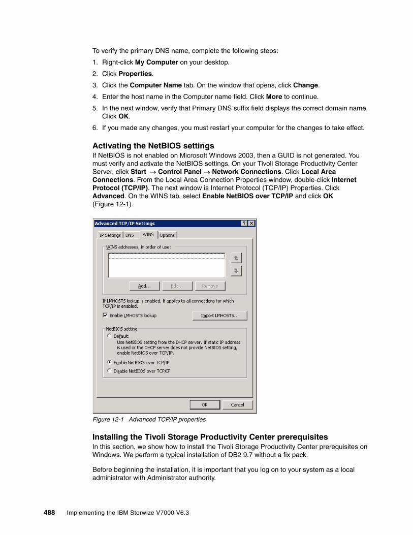
To verify the primary DNS name, complete the following steps:
1. Right-click My Computer on your desktop.
2. Click Properties.
3. Click the Computer Name tab. On the window that opens, click Change.
4. Enter the host name in the Computer name field. Click More to continue.
5. In the next window, verify that Primary DNS suffix field displays the correct domain name. Click OK.
6. If you made any changes, you must restart your computer for the changes to take effect.
Activating the NetBIOS settingsIf NetBIOS is not enabled on Microsoft Windows 2003, then a GUID is not generated. You must verify and activate the NetBIOS settings. On your Tivoli Storage Productivity Center Server, click Start Control Panel Network Connections. Click Local Area Connections. From the Local Area Connection Properties window, double-click Internet Protocol (TCP/IP). The next window is Internet Protocol (TCP/IP) Properties. Click Advanced. On the WINS tab, select Enable NetBIOS over TCP/IP and click OK (Figure 12-1).
Figure 12-1 Advanced TCP/IP properties
Installing the Tivoli Storage Productivity Center prerequisitesIn this section, we show how to install the Tivoli Storage Productivity Center prerequisites on Windows. We perform a typical installation of DB2 9.7 without a fix pack.
Before beginning the installation, it is important that you log on to your system as a local administrator with Administrator authority.
488 Implementing the IBM Storwize V7000 V6.3

DB2 installationTo begin the installation of DB2, complete the following steps:
1. Insert the IBM DB2 Installer CD into the CD drive.
If Windows autorun is enabled, the installation program starts automatically. If it does not start automatically, open Windows Explorer and go to the DB2 Installation image path and double-click setup.exe.
You see the Welcome window (Figure 12-2). Click Install a Product to proceed with the installation.
Figure 12-2 DB2 Setup Welcome window
User ID: Only the user ID that has installed the DB2 product has the privilege to issue the db2start and db2stop commands.
Chapter 12. IBM Tivoli Storage Productivity Center 489
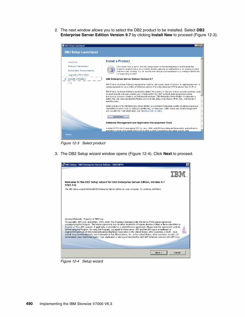
2. The next window allows you to select the DB2 product to be installed. Select DB2 Enterprise Server Edition Version 9.7 by clicking Install New to proceed (Figure 12-3).
Figure 12-3 Select product
3. The DB2 Setup wizard window opens (Figure 12-4). Click Next to proceed.
Figure 12-4 Setup wizard
490 Implementing the IBM Storwize V7000 V6.3

4. The next window shows the license agreement; click I accept the terms in the license agreement (Figure 12-5).
Figure 12-5 License agreement
5. To select the installation type, accept the default of Typical and click Next to continue (Figure 12-6).
Figure 12-6 Typical installation
Chapter 12. IBM Tivoli Storage Productivity Center 491
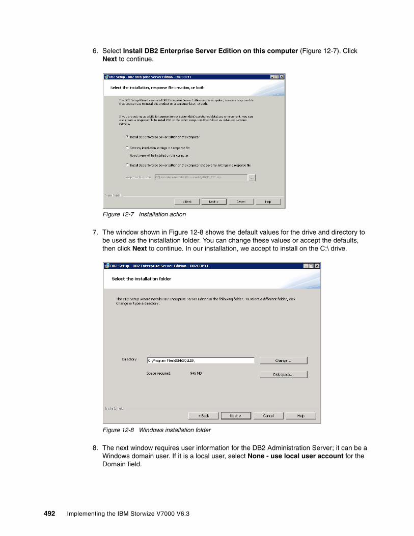
6. Select Install DB2 Enterprise Server Edition on this computer (Figure 12-7). Click Next to continue.
Figure 12-7 Installation action
7. The window shown in Figure 12-8 shows the default values for the drive and directory to be used as the installation folder. You can change these values or accept the defaults, then click Next to continue. In our installation, we accept to install on the C:\ drive.
Figure 12-8 Windows installation folder
8. The next window requires user information for the DB2 Administration Server; it can be a Windows domain user. If it is a local user, select None - use local user account for the Domain field.
492 Implementing the IBM Storwize V7000 V6.3
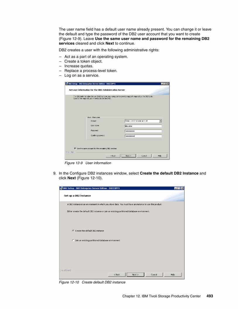
The user name field has a default user name already present. You can change it or leave the default and type the password of the DB2 user account that you want to create (Figure 12-9). Leave Use the same user name and password for the remaining DB2 services cleared and click Next to continue.
DB2 creates a user with the following administrative rights:
– Act as a part of an operating system.– Create a token object.– Increase quotas.– Replace a process-level token.– Log on as a service.
Figure 12-9 User information
9. In the Configure DB2 instances window, select Create the default DB2 Instance and click Next (Figure 12-10).
Figure 12-10 Create default DB2 instance
Chapter 12. IBM Tivoli Storage Productivity Center 493
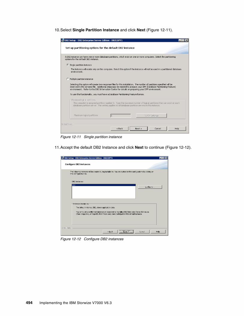
10.Select Single Partition Instance and click Next (Figure 12-11).
Figure 12-11 Single partition instance
11.Accept the default DB2 Instance and click Next to continue (Figure 12-12).
Figure 12-12 Configure DB2 instances
494 Implementing the IBM Storwize V7000 V6.3

12.The next window allows you to specify options to prepare the DB2 tools catalog (Figure 12-13). Verify that Prepare the DB2 tools catalog on this computer is clear. Click Next to continue.
Figure 12-13 Prepare the DB2 tools catalog
13.The next window (Figure 12-14) allows you to set the DB2 server to send notifications when the database needs attention. Ensure that Set up your DB2 server to send notification is clear and click Next to continue.
Figure 12-14 Health Monitor
Chapter 12. IBM Tivoli Storage Productivity Center 495

14.Accept the defaults for the DB2 administrators group and DB2 users group in the Enable operating system security for DB2 objects window (Figure 12-15) and click Next to proceed.
Figure 12-15 Enable operating system security for DB2 objects
15.Figure 12-16 shows the summary window of what is going to be installed, based on your input. Review the settings and click Finish to continue.
Figure 12-16 Summary window
496 Implementing the IBM Storwize V7000 V6.3

The DB2 installation proceeds and you see a progress window similar to the one shown in Figure 12-17.
Figure 12-17 DB2 Enterprise Server Edition installation progress
16.When the setup completes, click Finish (Figure 12-18).
Figure 12-18 Setup is complete
Chapter 12. IBM Tivoli Storage Productivity Center 497

17.Close the DB2 Setup Launchpad (Figure 12-19) to complete the installation.
Figure 12-19 DB2 first steps
Verifying the DB2 installation Complete the following steps to verify the DB2 installation:
1. Open a DB2 Command window by clicking Start IBM DB2 DB2COPY1 (Default) Command Line Tools Command Window.
2. Create the SAMPLE database by running db2sampl (Figure 12-20).
Figure 12-20 Create the SAMPLE database
498 Implementing the IBM Storwize V7000 V6.3

3. Enter the following DB2 commands. Connect to the SAMPLE database, issue a simple SQL query, and reset the database connection.
db2 connect to sampledb2 “select * from staff where dept = 20”db2 connect reset
The result of these commands is shown in Figure 12-21.
Figure 12-21 DB2 commands results
4. If you installed DB2 Enterprise Server 9.7, restart the system now.
12.4 Installing Tivoli Storage Productivity Center components Make sure that all the prerequisites described in 12.3.3, “Pre-installation steps for Windows” on page 487 have been installed. If they have, you can continue to install the Tivoli Storage Productivity Center components, keeping in mind that with Tivoli Storage Productivity Center V4.2, both Tivoli Storage Productivity Center and Tivoli Storage Productivity Center for Replication are installed.
Before starting the installation, verify that a supported version of DB2 Enterprise Server Edition has been installed and it has been started.
Rebooting: If you do not reboot your server or at least the DB2 service after installing DB2 level 9.7, the Tivoli Storage Productivity Center installation fails. For more details, see the following address:
http://www-01.ibm.com/support/docview.wss?uid=swg21452614
Important: Log on to your system as a local administrator with database authority.
Chapter 12. IBM Tivoli Storage Productivity Center 499

Complete the following steps:
1. If Windows autorun is enabled, the installation program starts automatically. If it does not, open Windows Explorer and go to the Tivoli Storage Productivity Center CD–ROM drive or directory. Double-click setup.exe.
2. Choose your language and click OK (Figure 12-22).
Figure 12-22 Language selection window
3. The License Agreement window opens. Read the terms and select I accept the terms of the license agreement. Click Next to continue (Figure 12-23).
Figure 12-23 Accept the license agreement
500 Implementing the IBM Storwize V7000 V6.3
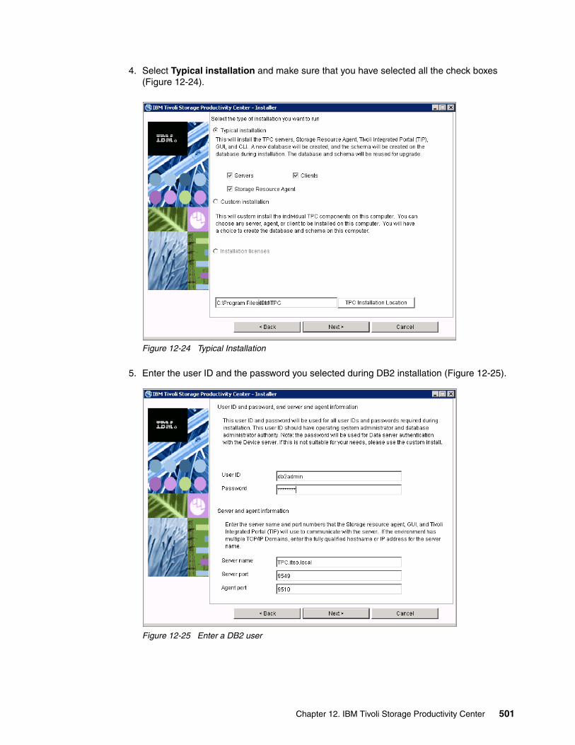
4. Select Typical installation and make sure that you have selected all the check boxes (Figure 12-24).
Figure 12-24 Typical Installation
5. Enter the user ID and the password you selected during DB2 installation (Figure 12-25).
Figure 12-25 Enter a DB2 user
Chapter 12. IBM Tivoli Storage Productivity Center 501

6. Specify the location to install Tivoli Integrated Portal (Figure 12-26). If you install Tivoli Storage Productivity Center on 64-bit Windows, the default path includes “Program Files (x86)”. Remove x86 or you will get an error message and you will not be able to proceed.
Figure 12-26 Select IBM Tivoli Integrated Portal location
7. Select your preferred authentication method and click Next (Figure 12-27).
Figure 12-27 Select authentication method
502 Implementing the IBM Storwize V7000 V6.3
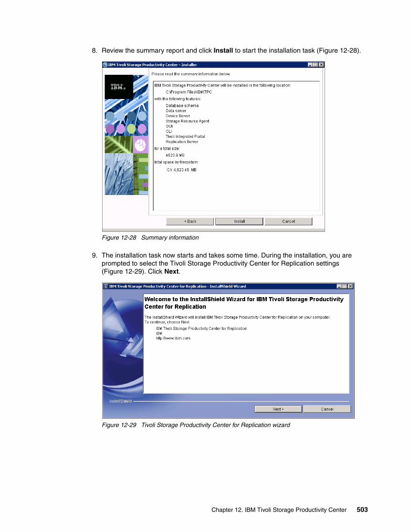
8. Review the summary report and click Install to start the installation task (Figure 12-28).
Figure 12-28 Summary information
9. The installation task now starts and takes some time. During the installation, you are prompted to select the Tivoli Storage Productivity Center for Replication settings (Figure 12-29). Click Next.
Figure 12-29 Tivoli Storage Productivity Center for Replication wizard
Chapter 12. IBM Tivoli Storage Productivity Center 503

10.To perform a prerequisites check, click Next (Figure 12-30).
Figure 12-30 System prerequisites check
11.Select I accept the terms of the license agreement and click Next (Figure 12-31).
Figure 12-31 Accept the license agreement
504 Implementing the IBM Storwize V7000 V6.3

12.Select an installation path and click Next (Figure 12-32).
Figure 12-32 Select the installation path
13.Keep the default ports and click Next (Figure 12-33).
Figure 12-33 Select ports
Chapter 12. IBM Tivoli Storage Productivity Center 505

14.Review the installation summary and click Install (Figure 12-34).
Figure 12-34 Tivoli Storage Productivity Center for Replication installation summary
The installation progress for Tivoli Storage Productivity Center for Replication is shown in Figure 12-35.
Figure 12-35 Installation progress
506 Implementing the IBM Storwize V7000 V6.3
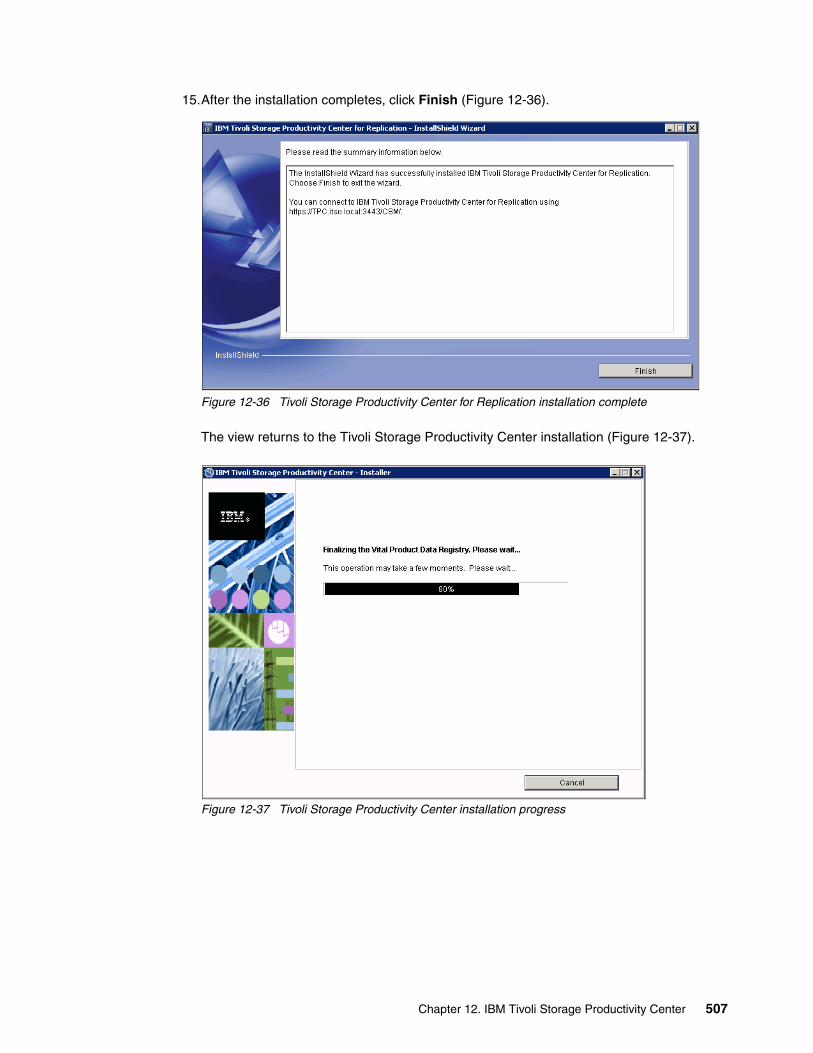
15.After the installation completes, click Finish (Figure 12-36).
Figure 12-36 Tivoli Storage Productivity Center for Replication installation complete
The view returns to the Tivoli Storage Productivity Center installation (Figure 12-37).
Figure 12-37 Tivoli Storage Productivity Center installation progress
Chapter 12. IBM Tivoli Storage Productivity Center 507
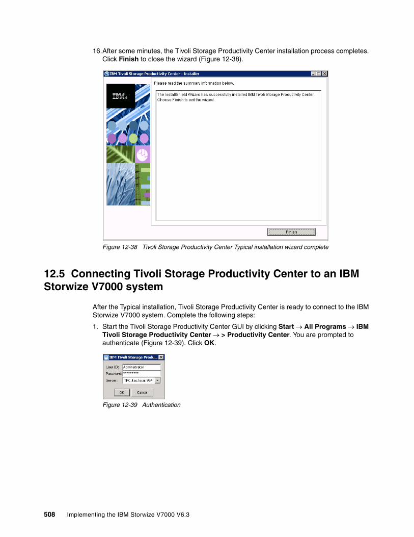
16.After some minutes, the Tivoli Storage Productivity Center installation process completes. Click Finish to close the wizard (Figure 12-38).
Figure 12-38 Tivoli Storage Productivity Center Typical installation wizard complete
12.5 Connecting Tivoli Storage Productivity Center to an IBM Storwize V7000 system
After the Typical installation, Tivoli Storage Productivity Center is ready to connect to the IBM Storwize V7000 system. Complete the following steps:
1. Start the Tivoli Storage Productivity Center GUI by clicking Start All Programs IBM Tivoli Storage Productivity Center > Productivity Center. You are prompted to authenticate (Figure 12-39). Click OK.
Figure 12-39 Authentication
508 Implementing the IBM Storwize V7000 V6.3
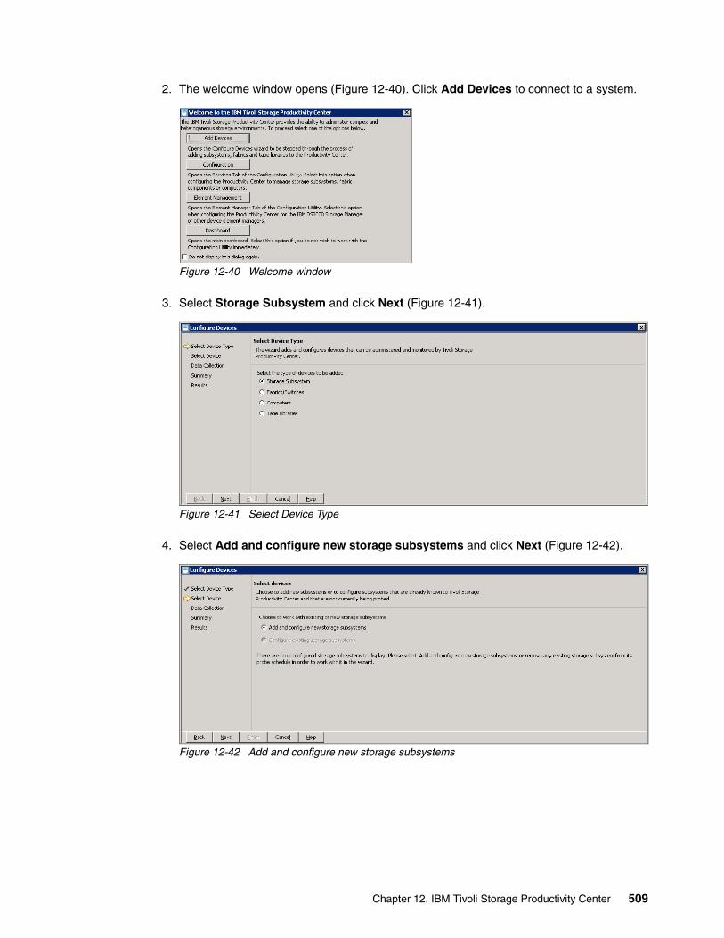
2. The welcome window opens (Figure 12-40). Click Add Devices to connect to a system.
Figure 12-40 Welcome window
3. Select Storage Subsystem and click Next (Figure 12-41).
Figure 12-41 Select Device Type
4. Select Add and configure new storage subsystems and click Next (Figure 12-42).
Figure 12-42 Add and configure new storage subsystems
Chapter 12. IBM Tivoli Storage Productivity Center 509

5. Select or enter the following settings to connect to the IBM Storwize V7000 system (Figure 12-43):
a. Device Type: IBM SAN Volume Controller / IBM Storwize V7000.
b. Software Version: 5+.
c. IP Address: Enter the IBM Storwize V7000 cluster IP address.
d. Select Key:Upload a new key
e. Admin Username: superuser.
f. Admin Password: Enter the superuser password.
g. Username: Select a user to connect
h. Private SSH Key: Specify the location of a private key. Because you are authenticated with the user name and password, this key does not really have to be associated with the selected user.
Figure 12-43 Configure storage subsystem connections
510 Implementing the IBM Storwize V7000 V6.3
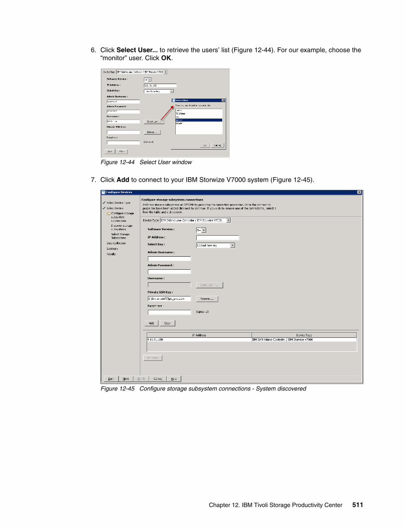
6. Click Select User... to retrieve the users’ list (Figure 12-44). For our example, choose the “monitor” user. Click OK.
Figure 12-44 Select User window
7. Click Add to connect to your IBM Storwize V7000 system (Figure 12-45).
Figure 12-45 Configure storage subsystem connections - System discovered
Chapter 12. IBM Tivoli Storage Productivity Center 511

8. Repeat these steps to add another system or click Next to complete the discovery of the new storage subsystems (Figure 12-46).
Figure 12-46 Discover subsystems
9. After the discovery, select the new storage subsystem that you want to add to the configuration (Figure 12-47).
Figure 12-47 Select storage subsystem to connect
512 Implementing the IBM Storwize V7000 V6.3

10.Specify the data collection settings. To add the new system to the default group, select Monitoring Group and Subsystem Standard Group (Figure 12-48).
Figure 12-48 Specify data collection settings
11.Review your selections and click Next (Figure 12-49) to add the new device.
Figure 12-49 Review user selections
Chapter 12. IBM Tivoli Storage Productivity Center 513
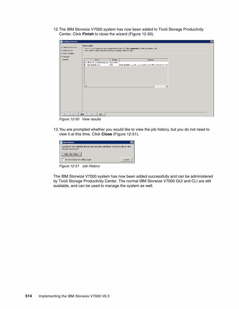
12.The IBM Storwize V7000 system has now been added to Tivoli Storage Productivity Center. Click Finish to close the wizard (Figure 12-50).
Figure 12-50 View results
13.You are prompted whether you would like to view the job history, but you do not need to view it at this time. Click Close (Figure 12-51).
Figure 12-51 Job History
The IBM Storwize V7000 system has now been added successfully and can be administered by Tivoli Storage Productivity Center. The normal IBM Storwize V7000 GUI and CLI are still available, and can be used to manage the system as well.
514 Implementing the IBM Storwize V7000 V6.3
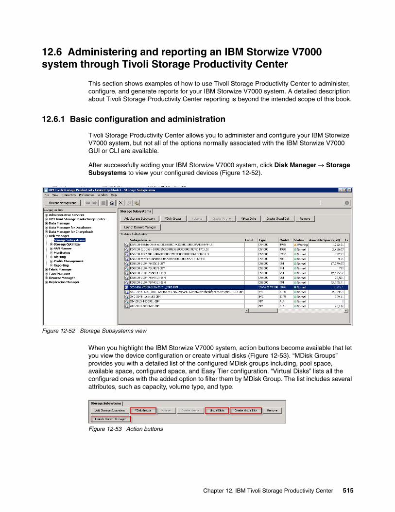
12.6 Administering and reporting an IBM Storwize V7000 system through Tivoli Storage Productivity Center
This section shows examples of how to use Tivoli Storage Productivity Center to administer, configure, and generate reports for your IBM Storwize V7000 system. A detailed description about Tivoli Storage Productivity Center reporting is beyond the intended scope of this book.
12.6.1 Basic configuration and administration
Tivoli Storage Productivity Center allows you to administer and configure your IBM Storwize V7000 system, but not all of the options normally associated with the IBM Storwize V7000 GUI or CLI are available.
After successfully adding your IBM Storwize V7000 system, click Disk Manager Storage Subsystems to view your configured devices (Figure 12-52).
Figure 12-52 Storage Subsystems view
When you highlight the IBM Storwize V7000 system, action buttons become available that let you view the device configuration or create virtual disks (Figure 12-53). “MDisk Groups” provides you with a detailed list of the configured MDisk groups including, pool space, available space, configured space, and Easy Tier configuration. “Virtual Disks” lists all the configured ones with the added option to filter them by MDisk Group. The list includes several attributes, such as capacity, volume type, and type.
Figure 12-53 Action buttons
Chapter 12. IBM Tivoli Storage Productivity Center 515

If you click Create Virtual Disk, the Create Virtual Disk wizard window opens (Figure 12-54). Use this window to create volumes, specifying several options, such as size, name, thin provisioning, and even add MDisks to an MDisk Group.
Figure 12-54 Virtual Disk creation wizard
In Figure 12-53 on page 515, if you click Launch Element Manager, your default browser opens the IBM Storwize V7000 GUI.
516 Implementing the IBM Storwize V7000 V6.3

12.6.2 Report generation
In this section, we show some basic report generation. Click Disk Manager Reporting Storage Subsystems to view the available options to select different reports (Figure 12-55).
Figure 12-55 V7000 volumes report generation
If you highlight a report in the left pane, the associated view appears in the right pane. In Figure 12-55, we selected to report on Volumes filtered by Storage Subsystem. To report only on IBM Storwize V7000 volumes, click Selection... and select the check box next to the IBM Storwize V7000 system.
Chapter 12. IBM Tivoli Storage Productivity Center 517

Figure 12-56 shows the generated report and Figure 12-57 shows the configured Storage pools report.
Figure 12-56 Volumes by storage subsystem
Figure 12-57 Storage pools by storage subsystem
518 Implementing the IBM Storwize V7000 V6.3

In addition to being able to monitor configuration data, there are many more options, such as performance statistics, health monitoring, path usage, and so on.
To monitor performance, create a subsystem performance monitor by clicking Disk Manager Monitoring, right-clicking Subsystem Performance Monitors, and click Create Subsystem Performance Monitor.
Figure 12-58 shows you the statistics for a single disk pool.
Figure 12-58 Storage subsystem performance by managed disk group (storage pool) - Total I/O rate
Chapter 12. IBM Tivoli Storage Productivity Center 519

520 Implementing the IBM Storwize V7000 V6.3

Chapter 13. RAS, monitoring, and troubleshooting for an IBM Storwize V7000 system
There are many ways to monitor and troubleshoot the IBM Storwize V7000 system. This chapter describes the following topics:
� Reliability, availability, and serviceability (RAS)� Hardware and LEDs descriptions� Monitoring from a host� Monitoring from the IBM Storwize V7000 system� Backup procedure� Software upgrade procedure� Troubleshooting� Recommended actions� Event log navigation� Audit log navigation� Support� Shutting down the IBM Storwize V7000 system� Shutting down the infrastructure using the IBM Storwize V7000 system
13
© Copyright IBM Corp. 2011, 2012. All rights reserved. 521

13.1 Reliability, availability, and serviceability on the IBM Storwize V7000 system
Reliability, availability, and serviceability (RAS) are important concepts in the design of the IBM Storwize V7000 system. Hardware features, software features, design considerations, and operational guidelines all contribute to make the IBM Storwize V7000 system reliable.
Fault tolerance and high levels of availability are achieved by:
� The RAID capabilities of the underlying disk subsystems� IBM Storwize V7000 nodes clustering using a Compass architecture� Auto-restart of hung nodes� UPS units to provide memory protection in the event of a site power failure� Host system failover capabilities
High levels of serviceability are achieved by providing:
� Cluster error logging� Asynchronous error notification� Dump capabilities to capture software detected failures� Concurrent diagnostic procedures� Directed maintenance procedures� Concurrent log analysis and memory dump data recovery tools� Concurrent maintenance of all IBM Storwize V7000 components� Concurrent upgrade of IBM Storwize V7000 Software and microcode� Concurrent addition or deletion of the IBM Storwize V7000 nodes canister in a cluster� Software recovery through a service panel push button� Automatic software version correction when replacing a node� Detailed status and error conditions displayed on the service panel� Error and event notification through SNMP, syslog, and email
At the heart of the IBM Storwize V7000 system is a pair of node canisters. These two canisters share the data transmitting and receiving load between the attached hosts and the disk arrays. This section looks at the RAS features of the IBM Storwize V7000 system, monitoring, and troubleshooting.
13.1.1 Node canisters
The two node canisters are located in the control enclosure and they work as a cluster.
522 Implementing the IBM Storwize V7000 V6.3

Figure 13-1 shows the ports and indicator lights of a node canister.
Figure 13-1 Ports and indicators of a node canister (112 or 124 controller models)
Fibre ChannelThere are four Fibre Channel (FC) ports on the left side of the canister. They are in two rows of two connectors. The ports are numbered 1 - 4 from left to right, top to bottom. The ports operate at 2, 4, or 8 Gbps. Each port has two green LEDs associated with it. These LEDs are not shown in the figure, but are located between the two rows of ports and are triangular, pointing towards the port to which they refer. On the left is the Speed LED and on the right the Link LED. In Table 13-1, we explain the status of the indicators:
Table 13-1 Fibre Channel link LEDs statuses
USBThere are two USB connectors side by side, and they are numbered as 1 on the left and as 2 on the right. There are no indicators associated with the USB ports.
Ethernet and LED statusThere are two 10/100/1000 Mbps Ethernet ports side by side on the canister and they are numbered 1 on the left and 2 on the right. Each port has two LEDs and their statuses are shown in Table 13-2.
Table 13-2 Ethernet LEDs statuses
Speed LED Link LED Link Status
Off Off Inactive
Off On or Flashing Idle or busy at 2 Gbps
Flashing On or Flashing Idle or busy at 4 Gbps
On On or Flashing Idle or busy at 8 Gbps
LED Color Meaning
Link state Green It is on when there is an Ethernet link.
Activity Yellow It is flashing when there is activity on the link.
Chapter 13. RAS, monitoring, and troubleshooting for an IBM Storwize V7000 system 523

Serial Attached SCSI drives and LED statusThere are two 6 Gbps Serial Attached SCSI (SAS) ports side by side on the canister. They are numbered 1 on the left and 2 on the right. Each port connects four PHYs; each PHY is associated with an LED. These LEDs are green and are directly above the ports. For each port, they are numbered 1 through 4. The LED indicates activity on the link and the statuses are shown in Table 13-3.
Table 13-3 SAS LED statuses
Canister and LED statusThere are three LEDs in a row at the upper right of the canister that indicate the status and identification for the node (Table 13-4).
Table 13-4 Node canister LEDs statuses
State Meaning
On Link is connected.
Flashing Link is connected and being used for I/O.
Off Link is not connected.
Position Color Name State Meaning
Left Green Cluster status
On The node is in the active or starting state. It might not be safe to remove the canister. If the fault LED is off, then the node is an active member of a cluster. If the fault LED is also on, then there is a problem establishing a cluster for example due to a lack of quorum.
Flashing The node is in candidate or service state. It is safe to remove the canister.
Off There is no power to the canister or it is in a state where IBM Storwize V7000 code is not running, for example, standby mode or Power On Self Test (POST).
Middle Amber Fault On The node is supposed to be in a cluster but is unable to reach an active state.
Flashing The canister is being identified. There might be a fault.
Off The node is in a candidate or active state. This status does not mean that there is not a hardware error on the node.
Right Green Power On The canister is powered on and the processors are running.
Fast flashing
The canister is running a POST.
Slow flashing
AC is available, but the canister is in the standby mode that follows a request by the software to power off.
Off AC is not available.
524 Implementing the IBM Storwize V7000 V6.3
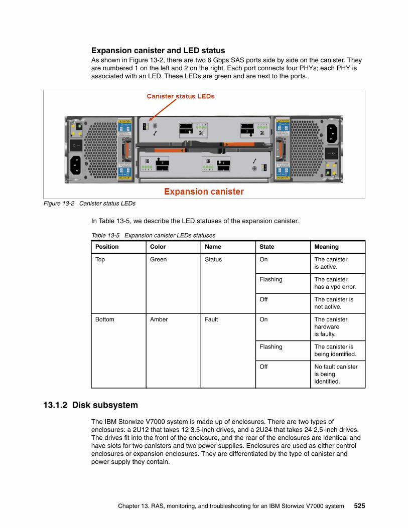
Expansion canister and LED statusAs shown in Figure 13-2, there are two 6 Gbps SAS ports side by side on the canister. They are numbered 1 on the left and 2 on the right. Each port connects four PHYs; each PHY is associated with an LED. These LEDs are green and are next to the ports.
Figure 13-2 Canister status LEDs
In Table 13-5, we describe the LED statuses of the expansion canister.
Table 13-5 Expansion canister LEDs statuses
13.1.2 Disk subsystem
The IBM Storwize V7000 system is made up of enclosures. There are two types of enclosures: a 2U12 that takes 12 3.5-inch drives, and a 2U24 that takes 24 2.5-inch drives. The drives fit into the front of the enclosure, and the rear of the enclosures are identical and have slots for two canisters and two power supplies. Enclosures are used as either control enclosures or expansion enclosures. They are differentiated by the type of canister and power supply they contain.
Position Color Name State Meaning
Top Green Status On The canister is active.
Flashing The canister has a vpd error.
Off The canister is not active.
Bottom Amber Fault On The canister hardware is faulty.
Flashing The canister is being identified.
Off No fault canister is being identified.
Chapter 13. RAS, monitoring, and troubleshooting for an IBM Storwize V7000 system 525

An array is a type of MDisk made up of disk drives that are in the enclosures. These drives are referred to as members of the array. Each array has a RAID level. RAID levels provide different degrees of redundancy and performance, and have different restrictions on the number of members in the array. An IBM Storwize V7000 system supports hot spare drives. When an array member drive fails, the system automatically replaces the failed member with a hot spare drive and rebuilds the array to restore its redundancy. Candidate and spare drives can be manually exchanged with array members.
Each array has a set of goals that describe the wanted location and performance of each array member. A sequence of drive failures and hot spare takeovers can leave an array unbalanced, that is, with members that do not match these goals. The system automatically rebalances such arrays when appropriate drives are available.
An IBM Storwize V7000 system supports the RAID levels shown in Table 13-6.
Table 13-6 RAID levels supported by an IBM Storwize V7000 system
Disk scrubbingThe scrub process runs when arrays do not have any other background processes. The process checks that the drive LBAs are readable and array parity is in synchronization. Arrays are scrubbed independently and each array is entirely scrubbed every seven days.
Solid-state drivesSolid-date drives (SSD) are treated no differently by an IBM Storwize V7000 system than HDDs with respect to RAID arrays or MDisks. The individual SSD drives in the storage managed by the IBM Storwize V7000 system are combined into an array, usually in RAID 10 or RAID 5 format. It is unlikely that RAID 6 SSD arrays are used due to the double parity impact, with two SSD logical drives used for parity only.
A LUN is created on the array, which is then presented to the IBM Storwize V7000 system as a normal managed disk (MDisk). As is the case for HDDs, the SSD RAID array format helps protect against individual SSD failures. Depending on your requirements, additional high availability protection, above the RAID level, can be achieved by using volume mirroring.
RAID level Where data is striped Minimum to maximum members
0 Data is striped on one or more drives.
1 - 8
1 Data is mirrored between two drives.
2
5 Data is striped across several drives with one parity.
3 - 16
6 Data is striped across several drives with two parities.
5 - 16
10 Data is striped across pairs of mirrored drives.
2 - 16
526 Implementing the IBM Storwize V7000 V6.3
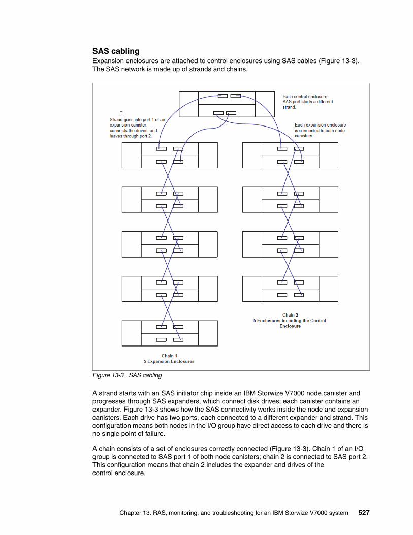
SAS cablingExpansion enclosures are attached to control enclosures using SAS cables (Figure 13-3). The SAS network is made up of strands and chains.
Figure 13-3 SAS cabling
A strand starts with an SAS initiator chip inside an IBM Storwize V7000 node canister and progresses through SAS expanders, which connect disk drives; each canister contains an expander. Figure 13-3 shows how the SAS connectivity works inside the node and expansion canisters. Each drive has two ports, each connected to a different expander and strand. This configuration means both nodes in the I/O group have direct access to each drive and there is no single point of failure.
A chain consists of a set of enclosures correctly connected (Figure 13-3). Chain 1 of an I/O group is connected to SAS port 1 of both node canisters; chain 2 is connected to SAS port 2. This configuration means that chain 2 includes the expander and drives of the control enclosure.
Chapter 13. RAS, monitoring, and troubleshooting for an IBM Storwize V7000 system 527
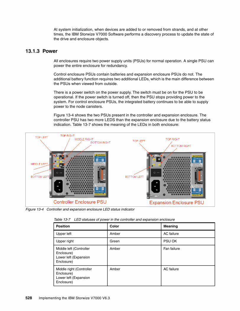
At system initialization, when devices are added to or removed from strands, and at other times, the IBM Storwize V7000 Software performs a discovery process to update the state of the drive and enclosure objects.
13.1.3 Power
All enclosures require two power supply units (PSUs) for normal operation. A single PSU can power the entire enclosure for redundancy.
Control enclosure PSUs contain batteries and expansion enclosure PSUs do not. The additional battery function requires two additional LEDs, which is the main difference between the PSUs when viewed from outside.
There is a power switch on the power supply. The switch must be on for the PSU to be operational. If the power switch is turned off, then the PSU stops providing power to the system. For control enclosure PSUs, the integrated battery continues to be able to supply power to the node canisters.
Figure 13-4 shows the two PSUs present in the controller and expansion enclosure. The controller PSU has two more LEDS than the expansion enclosure due to the battery status indication. Table 13-7 shows the meaning of the LEDs in both enclosure:
Figure 13-4 Controller and expansion enclosure LED status indicator
Table 13-7 LED statuses of power in the controller and expansion enclosure
Position Color Meaning
Upper left Amber AC failure
Upper right Green PSU OK
Middle left (Controller Enclosure)Lower left (Expansion Enclosure)
Amber Fan failure
Middle right (Controller Enclosure)Lower left (Expansion Enclosure)
Amber AC failure
528 Implementing the IBM Storwize V7000 V6.3
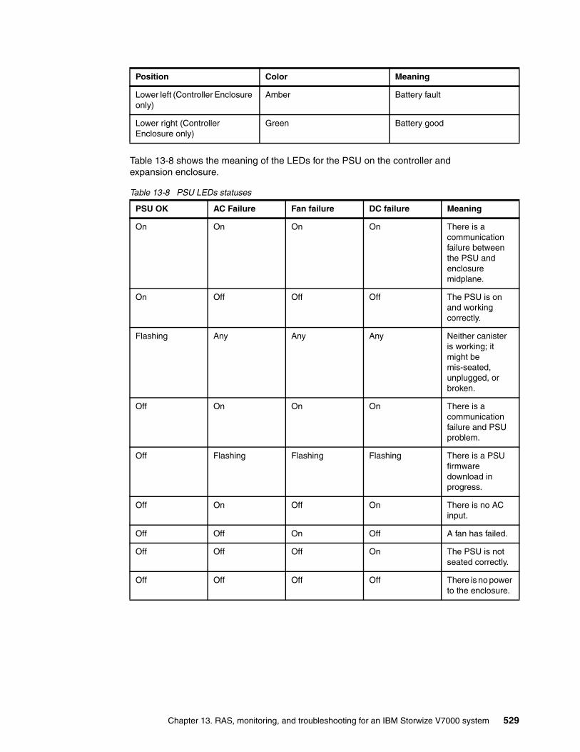
Table 13-8 shows the meaning of the LEDs for the PSU on the controller and expansion enclosure.
Table 13-8 PSU LEDs statuses
Lower left (Controller Enclosure only)
Amber Battery fault
Lower right (Controller Enclosure only)
Green Battery good
PSU OK AC Failure Fan failure DC failure Meaning
On On On On There is a communication failure between the PSU and enclosure midplane.
On Off Off Off The PSU is on and working correctly.
Flashing Any Any Any Neither canister is working; it might be mis-seated, unplugged, or broken.
Off On On On There is a communication failure and PSU problem.
Off Flashing Flashing Flashing There is a PSU firmware download in progress.
Off On Off On There is no AC input.
Off Off On Off A fan has failed.
Off Off Off On The PSU is not seated correctly.
Off Off Off Off There is no power to the enclosure.
Position Color Meaning
Chapter 13. RAS, monitoring, and troubleshooting for an IBM Storwize V7000 system 529

Table 13-9 shows the meaning of the LEDs for the battery on the controller enclosure
Table 13-9 Battery LEDs’ statuses
13.2 Configuration backup procedure
You can download a configuration backup file using the IBM Storwize V7000 GUI. This procedure must be done manually.
Regularly saving a configuration backup file of the IBM Storwize V7000 system is important. Download this file regularly to your management workstation to protect the data (a best practice is to automate this download using a script and save it every day).
This file must be used if there is a serious failure that requires you to restore your system configuration.
The backup file is updated by the cluster every day. It is important to save it after any changes to your system configuration. It contains configuration data such as arrays, pools, volumes, and so on (but no customer applications data).
You can use the GUI or the CLI to generate it. You must run svcconfig backup to produce a new backup file; it is not possible at this time generate a new backup file using the GUI, but you can only save it using the GUI.
13.2.1 Generating a configuration backup using the CLI
Further information about the CLI for the IBM Storwize V7000 system is in Appendix A, “CLI setup and SAN Boot” on page 569.
You must have the following prerequisites in place:
� All nodes must be online.
� No object name can begin with an underscore.
� All objects must have non-default names, that is, names that are not assigned by the IBM Storwize V7000 system.
Although objects should have non-default names at the time that the backup is taken, this prerequisite is not mandatory. Objects with default names are renamed when they are restored.
Battery is good Battery is at fault Meaning
On Off The battery is OK and fully charged.
Flashing Off The battery is OK but not fully charged. It is either charging or doing a maintenance discharge.
Off On The battery is broken.
Off Flashing The battery is broken but can be serviced.
530 Implementing the IBM Storwize V7000 V6.3

To generate a configuration backup using the CLI, run the following command:
svcconfig backup
Example 13-1 shows an example of the svcconfig backup command’s output.
Example 13-1 svcconfig backup command
IBM_2076:ITSO-Storwize-V7000-1:admin>svcconfig backup.............CMMVC6130W Cluster ITSO-Storwize-V7000-2 with inter-cluster partnership fully_configured will not be restored.........................................................................................................................................CMMVC6155I SVCCONFIG processing completed successfullyIBM_2076:ITSO-Storwize-V7000-1:admin>
The svcconfig backup command creates three files that provide information about the backup process and cluster configuration. These files are created in the /tmp directory of the configuration node.
Table 13-10 describes the three files that are created by the backup process.
Table 13-10 File names created by the backup process
File name Description
svc.config.backup.xml This file contains your cluster configuration data.
svc.config.backup.sh This file contains the names of the commands that were issued to create the backup of the cluster.
svc.config.backup.log This file contains details about the backup, including any error information that might have been reported.
Chapter 13. RAS, monitoring, and troubleshooting for an IBM Storwize V7000 system 531
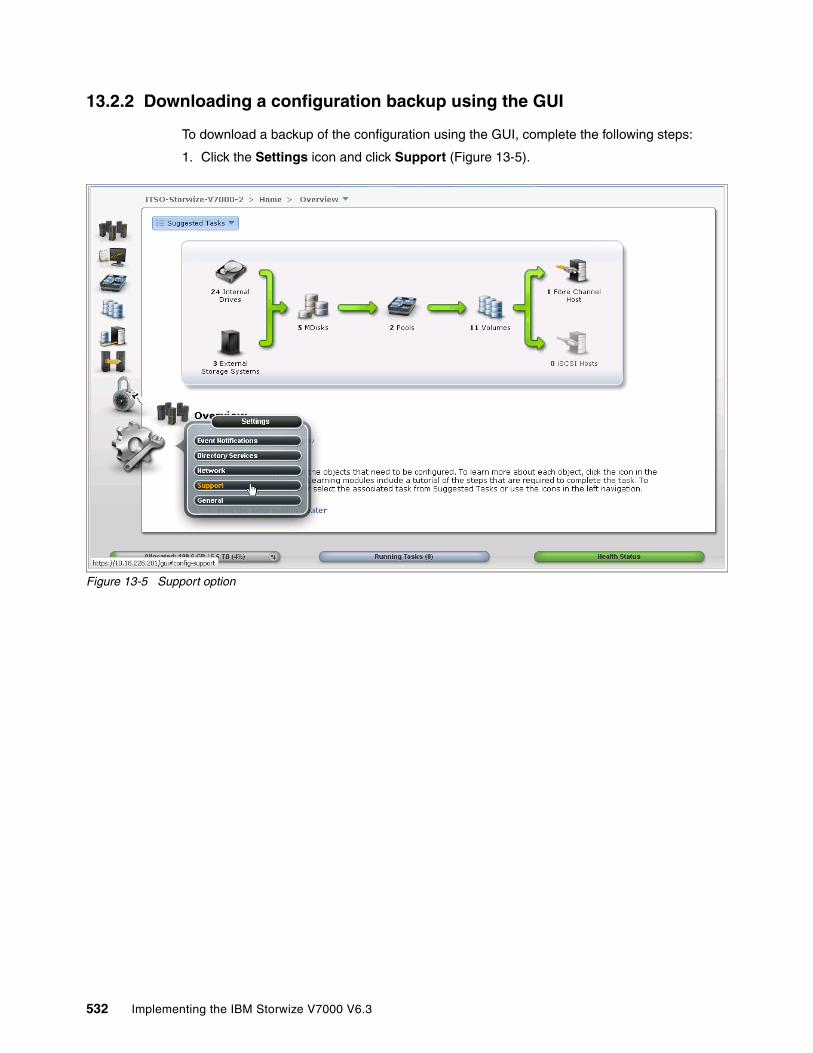
13.2.2 Downloading a configuration backup using the GUI
To download a backup of the configuration using the GUI, complete the following steps:
1. Click the Settings icon and click Support (Figure 13-5).
Figure 13-5 Support option
532 Implementing the IBM Storwize V7000 V6.3
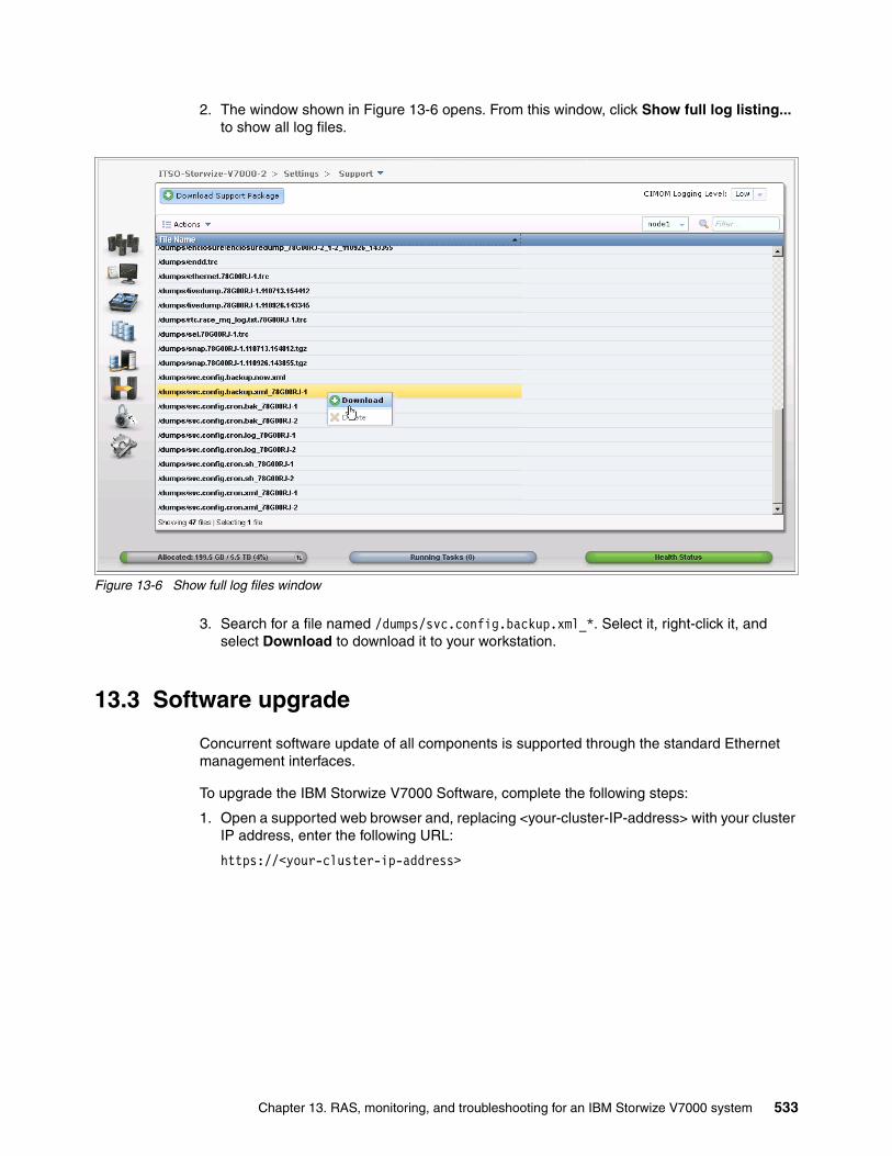
2. The window shown in Figure 13-6 opens. From this window, click Show full log listing... to show all log files.
Figure 13-6 Show full log files window
3. Search for a file named /dumps/svc.config.backup.xml_*. Select it, right-click it, and select Download to download it to your workstation.
13.3 Software upgrade
Concurrent software update of all components is supported through the standard Ethernet management interfaces.
To upgrade the IBM Storwize V7000 Software, complete the following steps:
1. Open a supported web browser and, replacing <your-cluster-IP-address> with your cluster IP address, enter the following URL:
https://<your-cluster-ip-address>
Chapter 13. RAS, monitoring, and troubleshooting for an IBM Storwize V7000 system 533
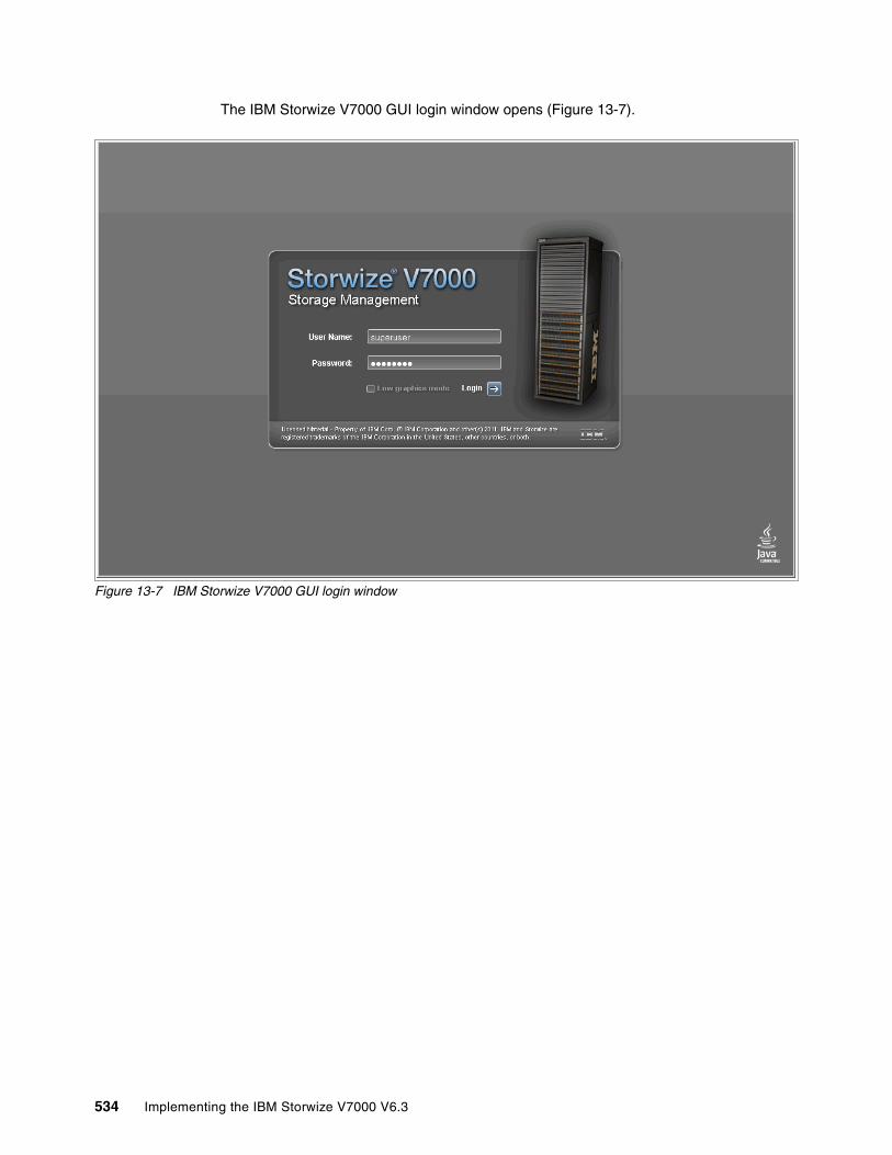
The IBM Storwize V7000 GUI login window opens (Figure 13-7).
Figure 13-7 IBM Storwize V7000 GUI login window
534 Implementing the IBM Storwize V7000 V6.3
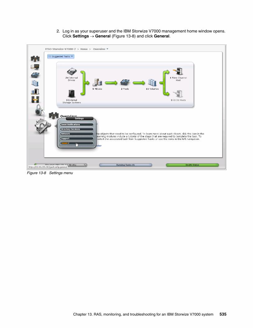
2. Log in as your superuser and the IBM Storwize V7000 management home window opens. Click Settings General (Figure 13-8) and click General.
Figure 13-8 Settings menu
Chapter 13. RAS, monitoring, and troubleshooting for an IBM Storwize V7000 system 535
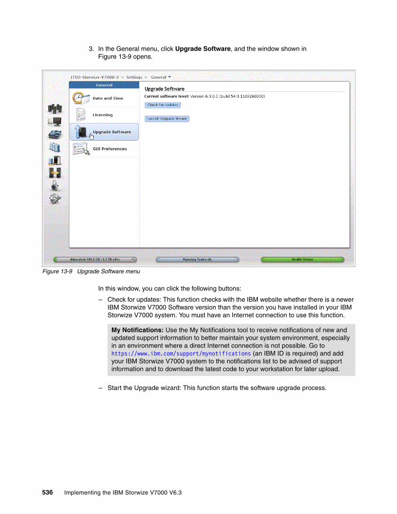
3. In the General menu, click Upgrade Software, and the window shown in Figure 13-9 opens.
Figure 13-9 Upgrade Software menu
In this window, you can click the following buttons:
– Check for updates: This function checks with the IBM website whether there is a newer IBM Storwize V7000 Software version than the version you have installed in your IBM Storwize V7000 system. You must have an Internet connection to use this function.
– Start the Upgrade wizard: This function starts the software upgrade process.
My Notifications: Use the My Notifications tool to receive notifications of new and updated support information to better maintain your system environment, especially in an environment where a direct Internet connection is not possible. Go to https://www.ibm.com/support/mynotifications (an IBM ID is required) and add your IBM Storwize V7000 system to the notifications list to be advised of support information and to download the latest code to your workstation for later upload.
536 Implementing the IBM Storwize V7000 V6.3

4. Click Launch Upgrade Wizard to start the upgrade process and you are redirected to the window shown in Figure 13-10.
Figure 13-10 Upgrade Package window
In the window shown in Figure 13-10, you can download the Upgrade Test Utility, or if you downloaded it previously, you can browse to the location where you saved it (Figure 13-11).
Figure 13-11 Upload Test Utility
Chapter 13. RAS, monitoring, and troubleshooting for an IBM Storwize V7000 system 537

5. When the Upgrade Test Utility has been uploaded, the window shown in Figure 13-12 opens.
Figure 13-12 Upload completed
6. Click Next and the Upgrade Test Utility is applied and you are redirected to the window shown in Figure 13-13.
Figure 13-13 Upgrade Test Utility applied
7. Click Close and the window shown in Figure 13-14 opens, where you can run the Upgrade Test Utility.
Figure 13-14 Run Upgrade Test Utility
538 Implementing the IBM Storwize V7000 V6.3

8. Click Next and you are redirected to the window shown in Figure 13-14 on page 538. At this time, the Upgrade Test Utility runs and you are able to see the suggested actions, if any, in the window shown in Figure 13-15.
Figure 13-15 Results of the Test Utility
9. Click Next to start the software upload procedure, and you are redirected to the window shown in Figure 13-16.
Figure 13-16 Downloading software code
10.In the window shown in Figure 13-16, you can download the SAN Volume Controller software upgrade package, or you can browse and upload the software upgrade package from the location where you saved it (Figure 13-17).
Figure 13-17 Downloaded code
Chapter 13. RAS, monitoring, and troubleshooting for an IBM Storwize V7000 system 539

11.Click Open in Figure 13-17 on page 539 and you are redirected to the windows shown in Figure 13-18.
Figure 13-18 Upload software code
12.Click Next and you are redirected to the window shown in Figure 13-19.
Figure 13-19 System ready to upgrade
13.Click Finish and the software upgrade starts. You are redirected to the window shown in Figure 13-20. Click Close in the window shown in Figure 13-20; the warning message shown in Figure 13-21 opens.
Figure 13-20 Upgrade the software code
Figure 13-21 Warning message
540 Implementing the IBM Storwize V7000 V6.3
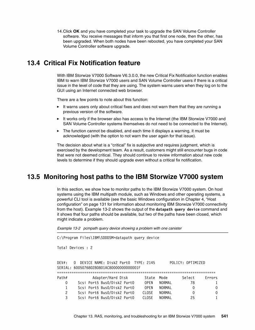
14.Click OK and you have completed your task to upgrade the SAN Volume Controller software. You receive messages that inform you that first one node, then the other, has been upgraded. When both nodes have been rebooted, you have completed your SAN Volume Controller software upgrade.
13.4 Critical Fix Notification feature
With IBM Storwize V7000 Software V6.3.0.0, the new Critical Fix Notification function enables IBM to warn IBM Storwize V7000 users and SAN Volume Controller users if there is a critical issue in the level of code that they are using. The system warns users when they log on to the GUI using an Internet connected web browser.
There are a few points to note about this function:
� It warns users only about critical fixes and does not warn them that they are running a previous version of the software.
� It works only if the browser also has access to the Internet (the IBM Storwize V7000 and SAN Volume Controller systems themselves do not need to be connected to the Internet).
� The function cannot be disabled, and each time it displays a warning, it must be acknowledged (with the option to not warn the user again for that issue).
The decision about what is a “critical” fix is subjective and requires judgment, which is exercised by the development team. As a result, customers might still encounter bugs in code that were not deemed critical. They should continue to review information about new code levels to determine if they should upgrade even without a critical fix notification.
13.5 Monitoring host paths to the IBM Storwize V7000 system
In this section, we show how to monitor paths to the IBM Storwize V7000 system. On host systems using the IBM multipath module, such as Windows and other operating systems, a powerful CLI tool is available (see the basic Windows configuration in Chapter 4, “Host configuration” on page 131 for information about monitoring IBM Storwize V7000 connectivity from the host). Example 13-2 shows the output of the datapath query device command and it shows that four paths should be available, but two of the paths have been closed, which might indicate a problem.
Example 13-2 pcmpath query device showing a problem with one canister
C:\Program Files\IBM\SDDDSM>datapath query device
Total Devices : 2
DEV#: 0 DEVICE NAME: Disk2 Part0 TYPE: 2145 POLICY: OPTIMIZEDSERIAL: 600507680280801AC80000000000001F============================================================================Path# Adapter/Hard Disk State Mode Select Errors 0 Scsi Port5 Bus0/Disk2 Part0 OPEN NORMAL 78 1 1 Scsi Port5 Bus0/Disk2 Part0 OPEN NORMAL 0 0 2 Scsi Port6 Bus0/Disk2 Part0 CLOSE NORMAL 0 0 3 Scsi Port6 Bus0/Disk2 Part0 CLOSE NORMAL 25 1
Chapter 13. RAS, monitoring, and troubleshooting for an IBM Storwize V7000 system 541

DEV#: 1 DEVICE NAME: Disk3 Part0 TYPE: 2145 POLICY: OPTIMIZEDSERIAL: 600507680280801AC800000000000020============================================================================Path# Adapter/Hard Disk State Mode Select Errors 0 Scsi Port5 Bus0/Disk3 Part0 OPEN NORMAL 1 1 1 Scsi Port5 Bus0/Disk3 Part0 OPEN NORMAL 78 1 2 Scsi Port6 Bus0/Disk3 Part0 CLOSE NORMAL 28 1 3 Scsi Port6 Bus0/Disk3 Part0 CLOSE NORMAL 1 1
C:\Program Files\IBM\SDDDSM>
The datapath query adapter command (Example 13-3) shows all IBM Storwize V7000 paths that are available to the host. We can see that only Adapter 0 is available, and that Adapter 1’s state is FAILED.
Example 13-3 datapath query adapter command
C:\Program Files\IBM\SDDDSM>datapath query adapter
Active Adapters :2
Adpt# Name State Mode Select Errors Paths Active 0 Scsi Port5 Bus0 NORMAL ACTIVE 36 0 2 2 1 Scsi Port6 Bus0 FAILED ACTIVE 17 1 2 0
C:\Program Files\IBM\SDDDSM>
After the problem is fixed, scan for new disks on your host, and check if all paths are available again (Example 13-4).
Example 13-4 datapath query device command
C:\Program Files\IBM\SDDDSM>datapath query device
Total Devices : 2
DEV#: 0 DEVICE NAME: Disk2 Part0 TYPE: 2145 POLICY: OPTIMIZEDSERIAL: 600507680280801AC80000000000001F============================================================================Path# Adapter/Hard Disk State Mode Select Errors 0 Scsi Port5 Bus0/Disk2 Part0 OPEN NORMAL 95 1 1 Scsi Port5 Bus0/Disk2 Part0 OPEN NORMAL 0 0 2 Scsi Port6 Bus0/Disk2 Part0 OPEN NORMAL 0 0 3 Scsi Port6 Bus0/Disk2 Part0 OPEN NORMAL 28 1
DEV#: 1 DEVICE NAME: Disk3 Part0 TYPE: 2145 POLICY: OPTIMIZEDSERIAL: 600507680280801AC800000000000020============================================================================Path# Adapter/Hard Disk State Mode Select Errors 0 Scsi Port5 Bus0/Disk3 Part0 OPEN NORMAL 1 1 1 Scsi Port5 Bus0/Disk3 Part0 OPEN NORMAL 95 1 2 Scsi Port6 Bus0/Disk3 Part0 OPEN NORMAL 31 1 3 Scsi Port6 Bus0/Disk3 Part0 OPEN NORMAL 1 1
542 Implementing the IBM Storwize V7000 V6.3

C:\Program Files\IBM\SDDDSM>
You can also use the datapath query adapter command and check that the FAILED path is back ONLINE (State=NORMAL) (Example 13-5).
Example 13-5 datapath query adapter to check if a failed path is online
C:\Program Files\IBM\SDDDSM>datapath query adapter
Active Adapters :2
Adpt# Name State Mode Select Errors Paths Active 0 Scsi Port5 Bus0 NORMAL ACTIVE 52 0 2 2 1 Scsi Port6 Bus0 NORMAL ACTIVE 21 1 2 2
C:\Program Files\IBM\SDDDSM>
13.6 Monitoring overview
Figure 13-22 shows the navigation window that is used to start the Monitoring wizard for the Viewing System, Viewing System Details, Viewing Events, and See Real Time Performance Graphs.
Figure 13-22 Monitoring
Chapter 13. RAS, monitoring, and troubleshooting for an IBM Storwize V7000 system 543

The Recommended Actions tab shows the highest priority maintenance procedure that needs to be run. Use the troubleshooting wizard to allow the IBM Storwize V7000 system to determine the proper order of maintenance procedures. Click Recommended Actions and the highest priority event that needs to be fixed appears (Figure 13-23).
Figure 13-23 Recommended Actions
In this example, Number of device logins reduced appears. The next step in this example is to review the physical FC cabling to determine the issue and then click Run Fix Procedure.
A best practice is to review the event logs and recommended actions periodically to ensure that there are no unexpected events, and to configure Call Home so that notification of serious events is done immediately.
544 Implementing the IBM Storwize V7000 V6.3
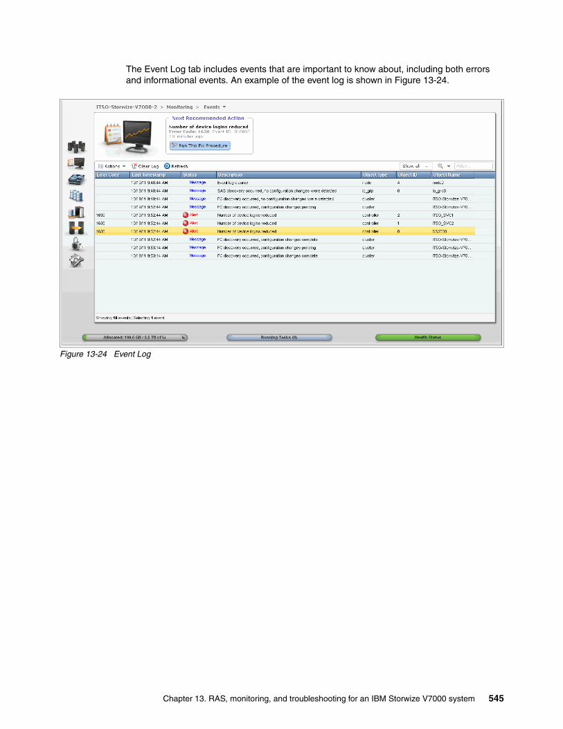
The Event Log tab includes events that are important to know about, including both errors and informational events. An example of the event log is shown in Figure 13-24.
Figure 13-24 Event Log
Chapter 13. RAS, monitoring, and troubleshooting for an IBM Storwize V7000 system 545
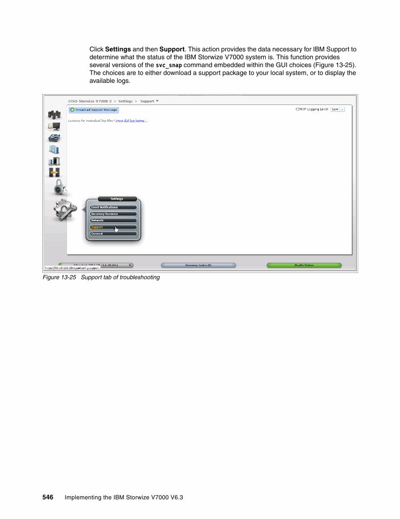
Click Settings and then Support. This action provides the data necessary for IBM Support to determine what the status of the IBM Storwize V7000 system is. This function provides several versions of the svc_snap command embedded within the GUI choices (Figure 13-25). The choices are to either download a support package to your local system, or to display the available logs.
Figure 13-25 Support tab of troubleshooting
546 Implementing the IBM Storwize V7000 V6.3
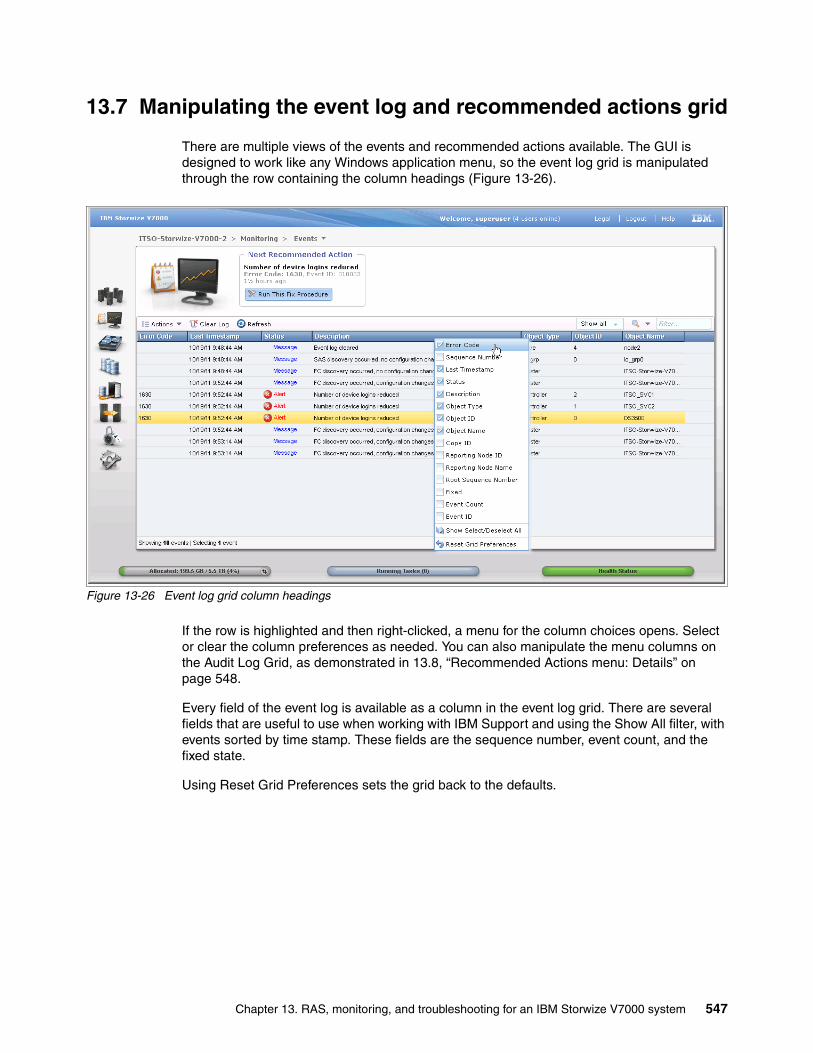
13.7 Manipulating the event log and recommended actions grid
There are multiple views of the events and recommended actions available. The GUI is designed to work like any Windows application menu, so the event log grid is manipulated through the row containing the column headings (Figure 13-26).
Figure 13-26 Event log grid column headings
If the row is highlighted and then right-clicked, a menu for the column choices opens. Select or clear the column preferences as needed. You can also manipulate the menu columns on the Audit Log Grid, as demonstrated in 13.8, “Recommended Actions menu: Details” on page 548.
Every field of the event log is available as a column in the event log grid. There are several fields that are useful to use when working with IBM Support and using the Show All filter, with events sorted by time stamp. These fields are the sequence number, event count, and the fixed state.
Using Reset Grid Preferences sets the grid back to the defaults.
Chapter 13. RAS, monitoring, and troubleshooting for an IBM Storwize V7000 system 547

It is possible to adjust the width of the columns to match your preferences (Figure 13-27) by hovering the mouse over the column marker, clicking the marker and holding the button, and then moving the column width. This width can also be reset by using the Reset Grid Preferences.
Figure 13-27 Adjusting the column width of Recommended Actions and Event Log panes
13.8 Recommended Actions menu: Details
The IBM Storwize V7000 system determines the most important action that is currently presenting itself in the event log, and highlights this action at the top of the Recommended Actions window. Check this window periodically to monitor for any unexpected informational events or errors.
548 Implementing the IBM Storwize V7000 V6.3

As an example, Figure 13-28 shows how a Fibre Channel cable that is loose presents itself and how the IBM Storwize V7000 reports this problem as the highest priority event at the time.
Figure 13-28 Recommended Action - Number of device logins reduced
Chapter 13. RAS, monitoring, and troubleshooting for an IBM Storwize V7000 system 549

We click the Run Fix Procedure button, and the window shown in Figure 13-29 opens.
Figure 13-29 Error code 1630 (Fix Procedure)
550 Implementing the IBM Storwize V7000 V6.3

In this case, the Storage System named DS3500 has not deliberately been removed, so select No in Figure 13-30 and then click Next.
Figure 13-30 Back-end storage question for Fix Procedure
Chapter 13. RAS, monitoring, and troubleshooting for an IBM Storwize V7000 system 551
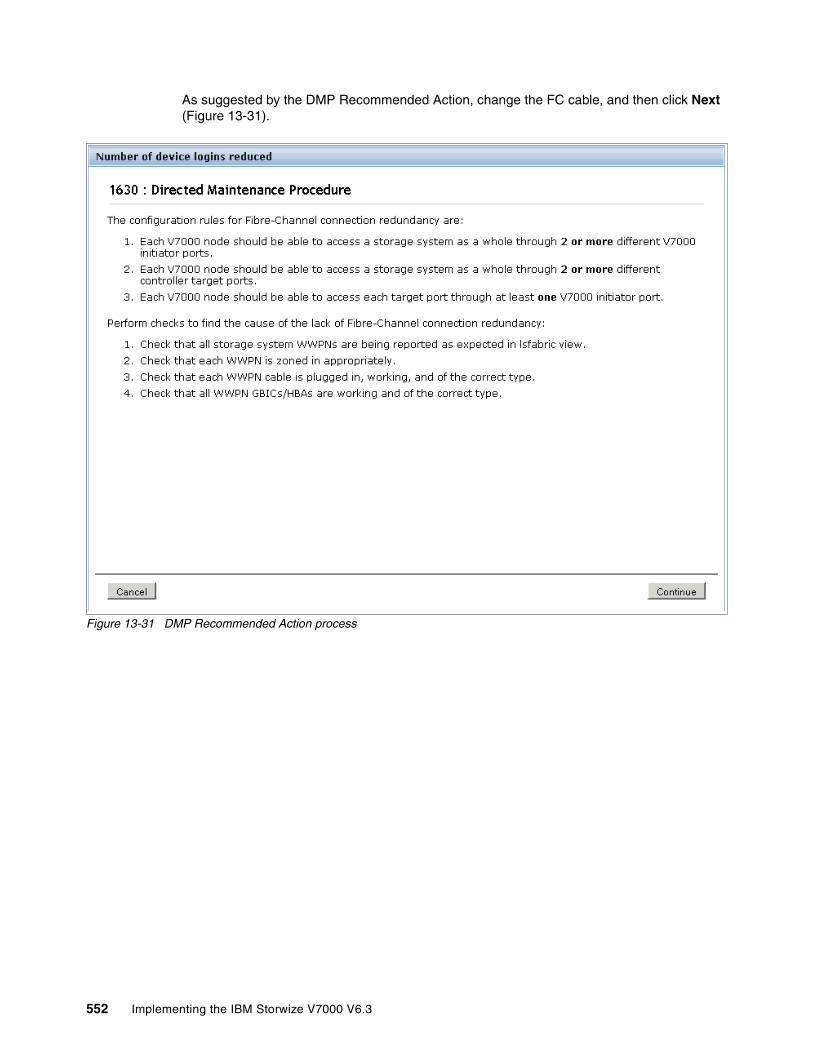
As suggested by the DMP Recommended Action, change the FC cable, and then click Next (Figure 13-31).
Figure 13-31 DMP Recommended Action process
552 Implementing the IBM Storwize V7000 V6.3

Click Continue to verify the status change (Figure 13-32).
Figure 13-32 DMP Recommended Action process
Chapter 13. RAS, monitoring, and troubleshooting for an IBM Storwize V7000 system 553

After you click Continue, the MDisk discovery process starts (Figure 13-33).
Figure 13-33 DMP Recommended Action process
554 Implementing the IBM Storwize V7000 V6.3

After you click the Continue button, the error is marked as fixed (Figure 13-34).
Figure 13-34 DMP Recommended Action process completed
Chapter 13. RAS, monitoring, and troubleshooting for an IBM Storwize V7000 system 555

If you return to the main Actions grid, it is also possible to mark this error as fixed or view the event details (Figure 13-35).
Figure 13-35 Actions event properties
556 Implementing the IBM Storwize V7000 V6.3
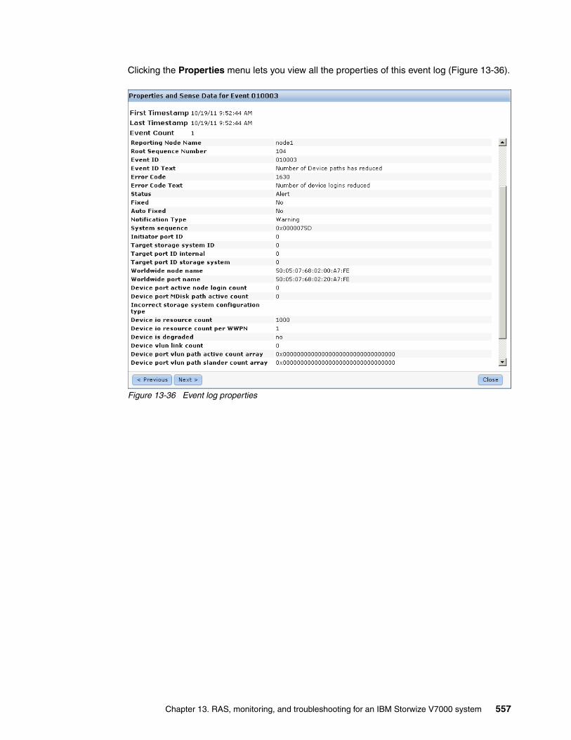
Clicking the Properties menu lets you view all the properties of this event log (Figure 13-36).
Figure 13-36 Event log properties
Chapter 13. RAS, monitoring, and troubleshooting for an IBM Storwize V7000 system 557
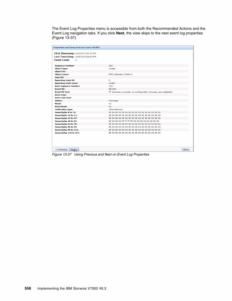
The Event Log Properties menu is accessible from both the Recommended Actions and the Event Log navigation tabs. If you click Next, the view skips to the next event log properties (Figure 13-37).
Figure 13-37 Using Previous and Next on Event Log Properties
558 Implementing the IBM Storwize V7000 V6.3
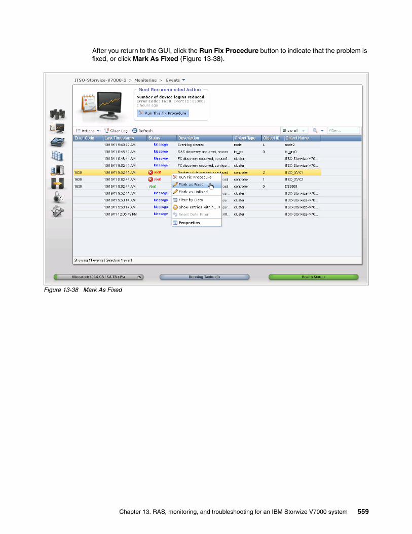
After you return to the GUI, click the Run Fix Procedure button to indicate that the problem is fixed, or click Mark As Fixed (Figure 13-38).
Figure 13-38 Mark As Fixed
Chapter 13. RAS, monitoring, and troubleshooting for an IBM Storwize V7000 system 559

13.9 Audit Log tab
Figure 13-39 shows the Audit Log tab menu item. Click Audit Log to view which configuration CLI commands have been run so far on the IBM Storwize V7000 system (information and service commands are not included).
Figure 13-39 Audit Log from Access Management window
560 Implementing the IBM Storwize V7000 V6.3

An example of the audit log after creating volumes and mapping them to hosts is shown in Figure 13-40, with a command highlighted. The Running Tasks button is available at the bottom of the window in the status pod; if you click that button, the progress of the currently running tasks is displayed.
Figure 13-40 Audit log
The audit log is especially useful in determining past configuration events when trying to determine, for example, how a volume ended up being shared by two hosts, or why the volume was overwritten. The audit log is also included in the svc_snap support data to aid in problem determination.
It is also possible to change the view of the Audit Log grid by right-clicking the column headings (Figure 13-41). The grid layout and sorting is completely under the user’s control, so you can view everything in the audit log, sort different columns, or reset the default grid preferences.
Figure 13-41 Right-click audit log column headings
Chapter 13. RAS, monitoring, and troubleshooting for an IBM Storwize V7000 system 561

13.10 Collecting support information
Occasionally, if you have a problem and call the IBM Support Center, they might ask you to provide support data. You can find this data under the Support tab of the Troubleshooting navigation window.
Click Settings and then the Support tab to begin the procedure of collecting support data (Figure 13-42). Assuming that the node restarts, use the menu shown in Figure 13-44 on page 563 to collect the default logs plus all the existing statesaves to capture the maximum data for support.
Figure 13-42 Support option Data Collection
Click Download Support Package (Figure 13-43).
Figure 13-43 Download Support Package window
562 Implementing the IBM Storwize V7000 V6.3

The window for collecting different versions of svc_snap opens (Figure 13-44); the version you download depends on the event that are investigated. For example, if you notice that a node was restarted in the event log, capture the snap with the latest existing statesaves.
Figure 13-44 Download support package choices
The procedure to create the snap on the IBM Storwize V7000 system, including the latest statesave from each node canister, starts. This process might take a few minutes (Figure 13-45).
Figure 13-45 Task detail window
A window opens that gives you the choice to save the file on your local Windows system (Figure 13-46).
Figure 13-46 Save file to the local Windows system
Chapter 13. RAS, monitoring, and troubleshooting for an IBM Storwize V7000 system 563
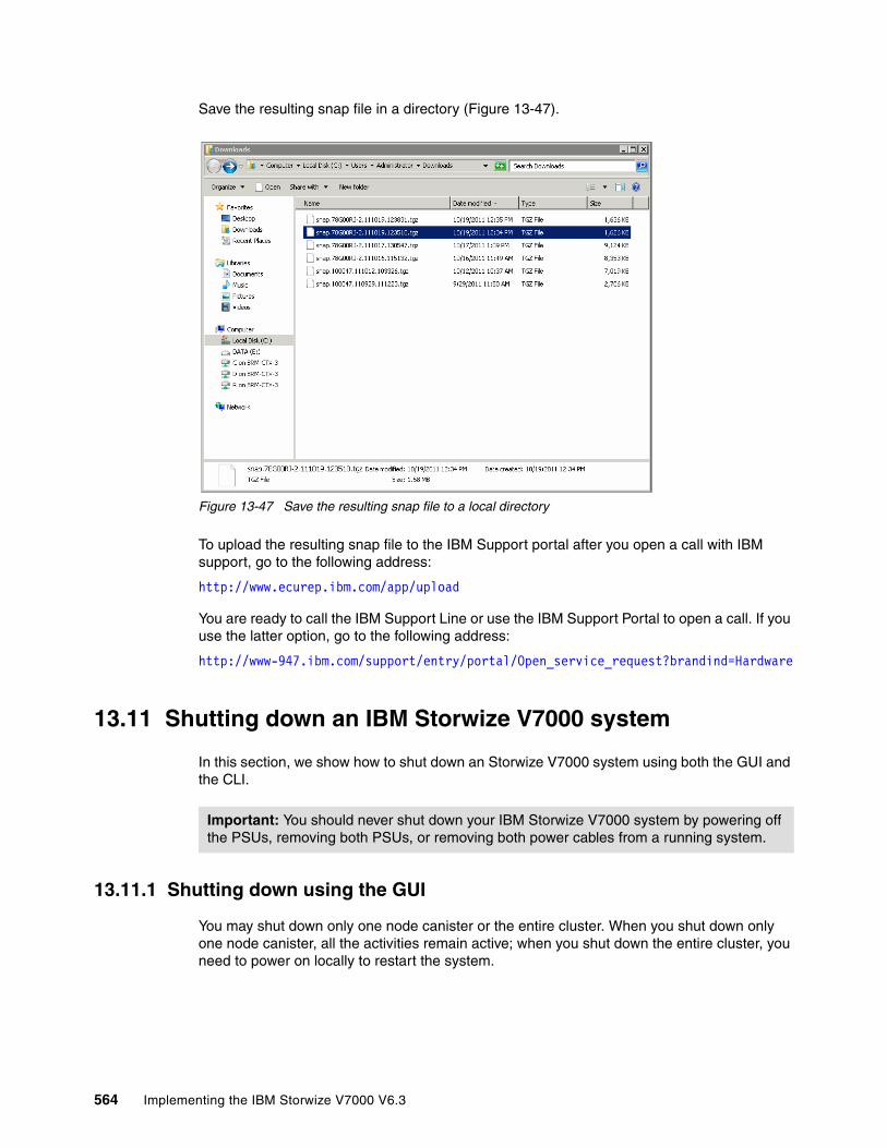
Save the resulting snap file in a directory (Figure 13-47).
Figure 13-47 Save the resulting snap file to a local directory
To upload the resulting snap file to the IBM Support portal after you open a call with IBM support, go to the following address:
http://www.ecurep.ibm.com/app/upload
You are ready to call the IBM Support Line or use the IBM Support Portal to open a call. If you use the latter option, go to the following address:
http://www-947.ibm.com/support/entry/portal/Open_service_request?brandind=Hardware
13.11 Shutting down an IBM Storwize V7000 system
In this section, we show how to shut down an Storwize V7000 system using both the GUI and the CLI.
13.11.1 Shutting down using the GUI
You may shut down only one node canister or the entire cluster. When you shut down only one node canister, all the activities remain active; when you shut down the entire cluster, you need to power on locally to restart the system.
Important: You should never shut down your IBM Storwize V7000 system by powering off the PSUs, removing both PSUs, or removing both power cables from a running system.
564 Implementing the IBM Storwize V7000 V6.3
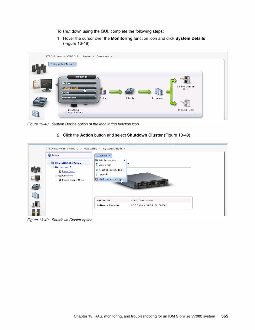
To shut down using the GUI, complete the following steps:
1. Hover the cursor over the Monitoring function icon and click System Details (Figure 13-48).
Figure 13-48 System Device option of the Monitoring function icon
2. Click the Action button and select Shutdown Cluster (Figure 13-49).
Figure 13-49 Shutdown Cluster option
Chapter 13. RAS, monitoring, and troubleshooting for an IBM Storwize V7000 system 565
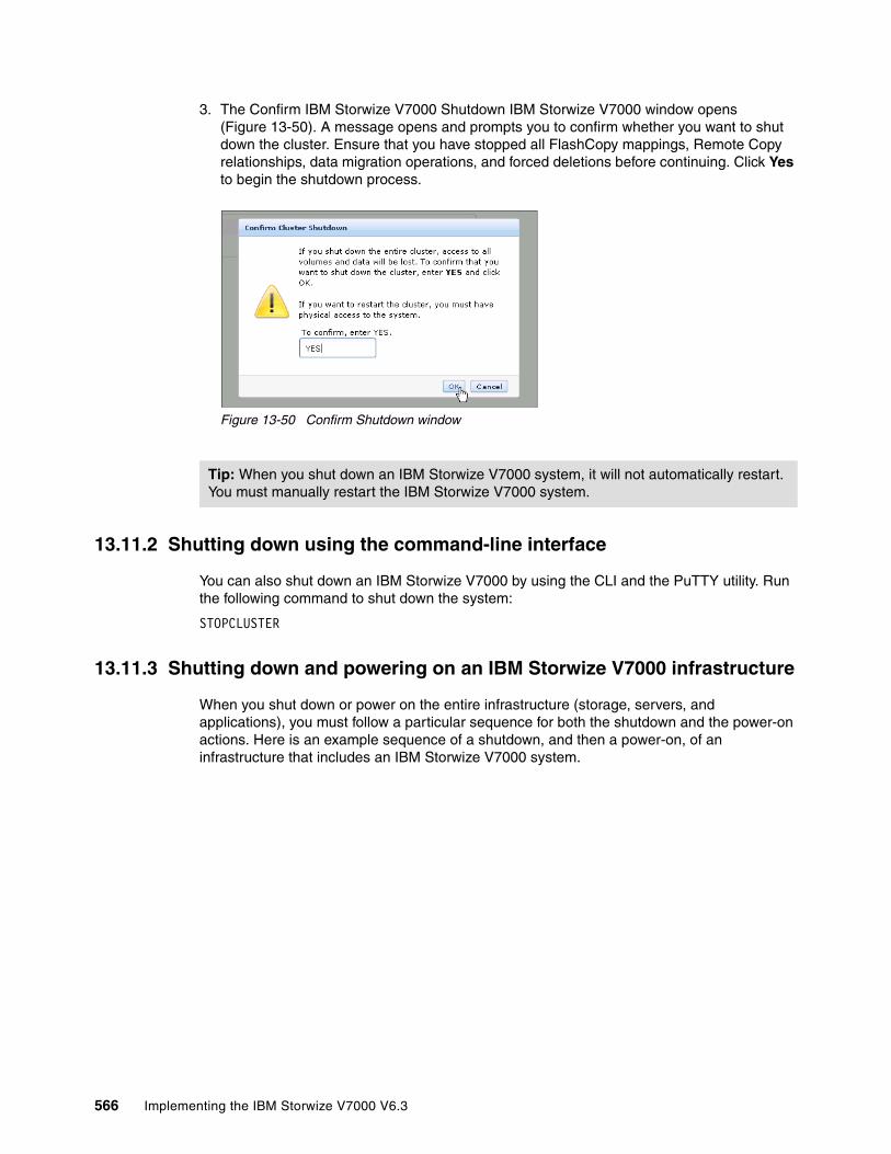
3. The Confirm IBM Storwize V7000 Shutdown IBM Storwize V7000 window opens (Figure 13-50). A message opens and prompts you to confirm whether you want to shut down the cluster. Ensure that you have stopped all FlashCopy mappings, Remote Copy relationships, data migration operations, and forced deletions before continuing. Click Yes to begin the shutdown process.
Figure 13-50 Confirm Shutdown window
13.11.2 Shutting down using the command-line interface
You can also shut down an IBM Storwize V7000 by using the CLI and the PuTTY utility. Run the following command to shut down the system:
STOPCLUSTER
13.11.3 Shutting down and powering on an IBM Storwize V7000 infrastructure
When you shut down or power on the entire infrastructure (storage, servers, and applications), you must follow a particular sequence for both the shutdown and the power-on actions. Here is an example sequence of a shutdown, and then a power-on, of an infrastructure that includes an IBM Storwize V7000 system.
Tip: When you shut down an IBM Storwize V7000 system, it will not automatically restart. You must manually restart the IBM Storwize V7000 system.
566 Implementing the IBM Storwize V7000 V6.3

Figure 13-51 shows the location of power switches on the controller and expansion enclosures.
Figure 13-51 Location of power switches
13.11.4 Shutting down
To shut down the infrastructure, complete the following steps:
1. Shut down your servers and all applications.
2. Shut down your IBM Storwize V7000 system:
a. Shut down the cluster using either the GUI or CLI.b. Power off both switches of the controller enclosure.c. Power off both switches of all the expansion enclosures.
3. Shut down your SAN switches.
13.11.5 Powering on
To power on your infrastructure, complete the following steps:
1. Power on your SAN switches and wait until the boot completes.
2. Power on your storage systems and wait until the systems are up, and then:
a. Power on both switches of all the expansion enclosures.b. Power on both switches of the controller enclosure.
3. Power on your servers and start your applications.
Chapter 13. RAS, monitoring, and troubleshooting for an IBM Storwize V7000 system 567

568 Implementing the IBM Storwize V7000 V6.3
Appendix A. CLI setup and SAN Boot
This appendix describes the setup of the CLI and provides additional information about the SAN Boot function.
A
© Copyright IBM Corp. 2011, 2012. All rights reserved. 569
Command-line interface
The IBM Storwize V7000 system has a powerful CLI, which offers even more functions than the GUI. This section is not intended to be a detailed guide to the CLI, as that topic is beyond the scope of this book. The basic configuration of the IBM Storwize V7000 CLI and some example commands are covered. However, the CLI commands are the same as in the SAN Volume Controller, and in addition, there are more commands that are available to manage internal storage. If a task completes in the GUI, the CLI command is always displayed in the details, as shown throughout this book.
Detailed CLI information is available in the IBM Storwize V7000 Information Center under the Command Line section, which can be found at the following address:
http://publib.boulder.ibm.com/infocenter/storwize/ic/index.jsp?topic=/com.ibm.storwize.v7000.doc/svc_clicommandscontainer_229g0r.html
Implementing the IBM System Storage SAN Volume Controller V6.1, SG24-7933 has a great deal of information about using the CLI, and the commands in that book also apply to the IBM Storwize V7000 system.
Basic setup
In the IBM Storwize V7000 GUI, authentication is done by using a user name and a password. The CLI uses a Secure Shell to connect from the host to the IBM Storwize V7000 system. As of IBM Storwize V7000 V6.3, either a private and a public key pair or user name and password is necessary. The following steps are required to enable CLI access with SSH keys:
� A public key and a private key are generated together as a pair.
� A public key is uploaded to the IBM Storwize V7000 system through the GUI.
� A client Secure Shell (SSH) tool must be configured to authenticate with the private key.
� A secure connection can be established between the client and IBM Storwize V7000 system.
Secure Shell is the communication vehicle between the management workstation and the IBM Storwize V7000 system. The SSH client provides a secure environment from which to connect to a remote machine. It uses the principles of public and private keys for authentication.
SSH keys are generated by the SSH client software. The SSH keys include a public key, which is uploaded and maintained by the clustered system, and a private key, which is kept private on the workstation that is running the SSH client. These keys authorize specific users to access the administration and service functions on the system. Each key pair is associated with a user-defined ID string that can consist of up to 40 characters. Up to 100 keys can be stored on the system. New IDs and keys can be added, and unwanted IDs and keys can be deleted. To use the CLI, an SSH client must be installed on that system, the SSH key pair must be generated on the client system, and the client’s SSH public key must be stored on the IBM Storwize V7000 systems.
The SSH client used in this book is PuTTY. There is also a PuTTY key generator that can be used to generate the private and public key pair. The PuTTY client can be downloaded at no cost at the following address:
http://www.chiark.greenend.org.uk
570 Implementing the IBM Storwize V7000 V6.3

Download the following tools:
� PuTTY SSH client: putty.exe
� PuTTY key generator: puttygen.exe
Generating a public and private key pairTo generate a public and private key pair, complete the following steps:
1. Start the PuTTY key generator to generate the public and private key pair (Figure A-1).
Figure A-1 PuTTY key generator
Make sure that the following options are selected:
– SSH2 RSA
– Number of bits in a generated key: 1024
Appendix A. CLI setup and SAN Boot 571
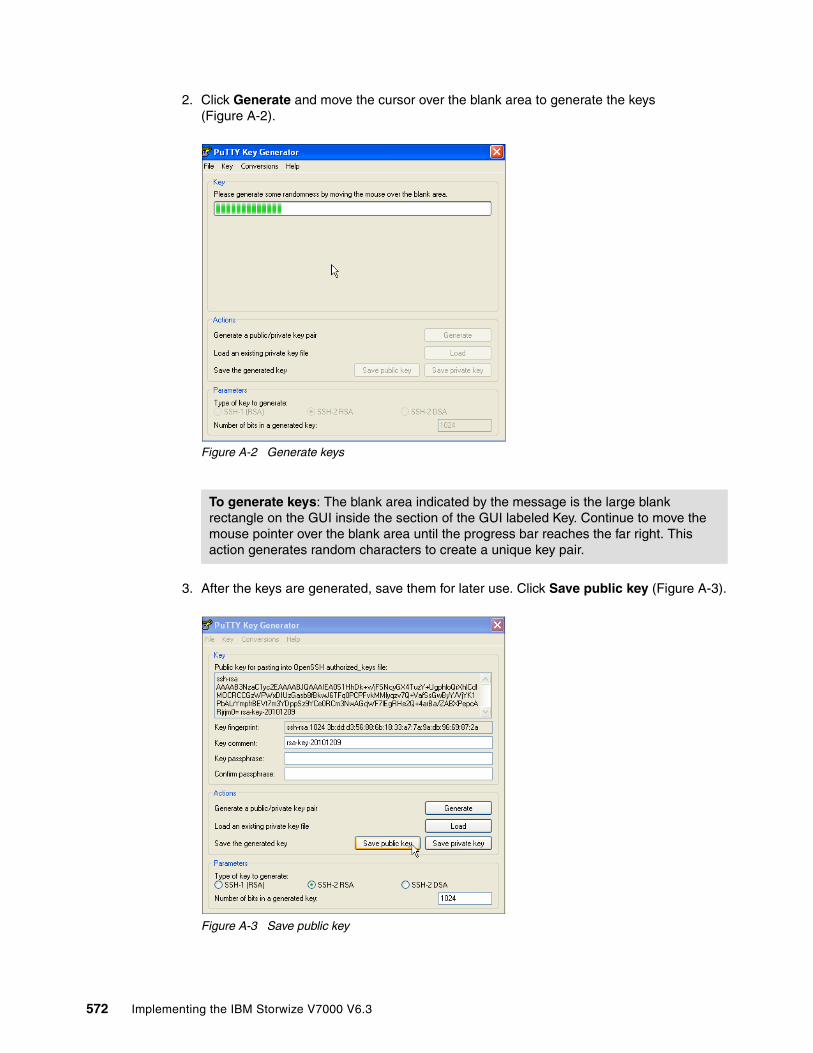
2. Click Generate and move the cursor over the blank area to generate the keys (Figure A-2).
Figure A-2 Generate keys
3. After the keys are generated, save them for later use. Click Save public key (Figure A-3).
Figure A-3 Save public key
To generate keys: The blank area indicated by the message is the large blank rectangle on the GUI inside the section of the GUI labeled Key. Continue to move the mouse pointer over the blank area until the progress bar reaches the far right. This action generates random characters to create a unique key pair.
572 Implementing the IBM Storwize V7000 V6.3

4. You are prompted for a name (for example, pubkey) and a location for the public key (for example, C:\Support Utils\PuTTY). Click Save.
Ensure that you record the name and location, because the name and location of this SSH public key must be specified later.
5. Click Save private key (Figure A-4).
Figure A-4 Save private key
6. You are prompted with a warning message (Figure A-5). Click Yes to save the private key without a passphrase.
Figure A-5 Confirm the security warning
7. When prompted, enter a name (for example, “icat”), select a secure place as the location, and click Save.
8. Close the PuTTY key generator.
Public key extension: By default, the PuTTY key generator saves the public key with no extension. Use the string “pub” for naming the public key, for example, “pubkey”, to easily differentiate the SSH public key from the SSH private key.
Key generator: The PuTTY key generator saves the private key with the PPK extension.
Appendix A. CLI setup and SAN Boot 573

Uploading the SSH public key to the IBM Storwize V7000After you have created your SSH key pair, you need to upload your SSH public key onto the SAN Volume Controller system. Complete the following steps:
1. Open the user section (Figure A-6).
Figure A-6 Open user section
2. Right-click the user for which you want to upload the key and click Properties (Figure A-7).
Figure A-7 Superuser properties
574 Implementing the IBM Storwize V7000 V6.3

3. To upload the public key, click Browse, select your public key, and click OK (Figure A-8).
Figure A-8 Select public key
4. Click OK and the key is uploaded (Figure A-9).
Figure A-9 Public key upload complete
5. Click Close to return to the GUI.
Appendix A. CLI setup and SAN Boot 575
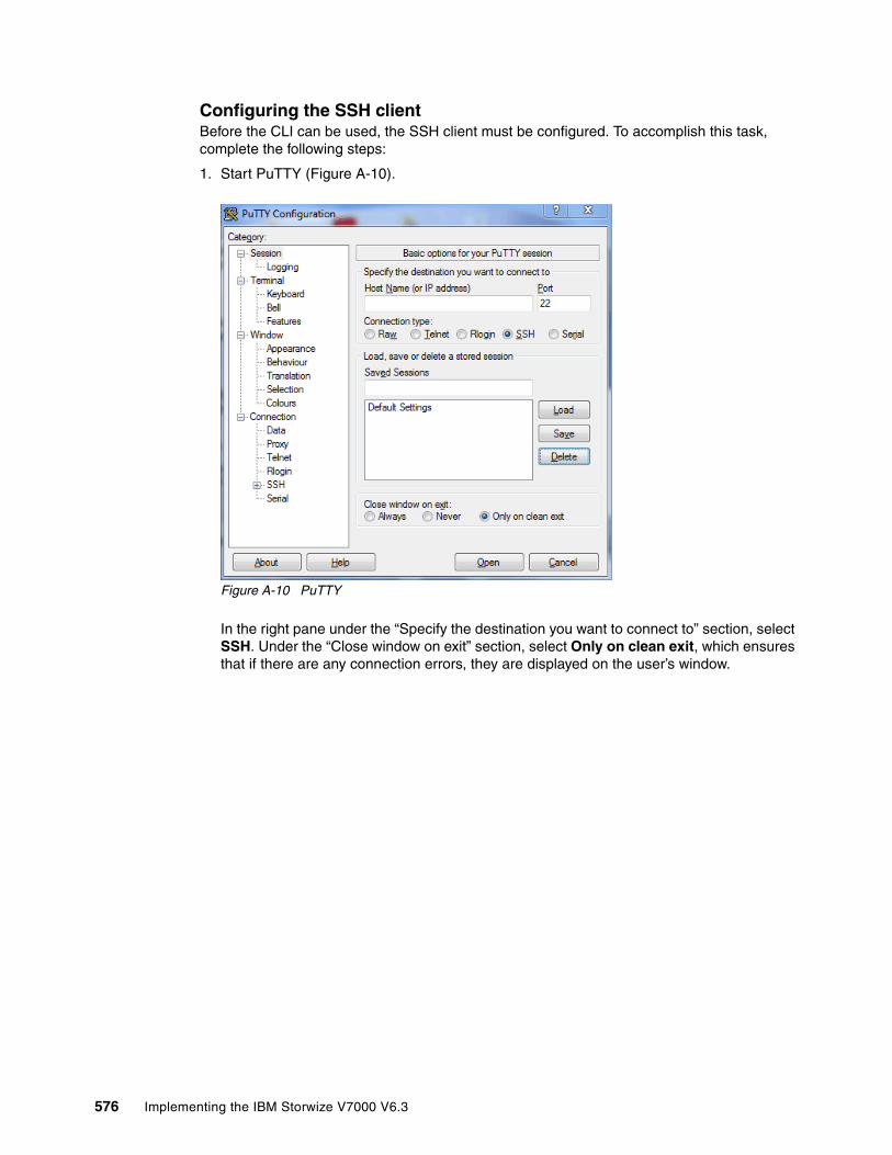
Configuring the SSH clientBefore the CLI can be used, the SSH client must be configured. To accomplish this task, complete the following steps:
1. Start PuTTY (Figure A-10).
Figure A-10 PuTTY
In the right pane under the “Specify the destination you want to connect to” section, select SSH. Under the “Close window on exit” section, select Only on clean exit, which ensures that if there are any connection errors, they are displayed on the user’s window.
576 Implementing the IBM Storwize V7000 V6.3
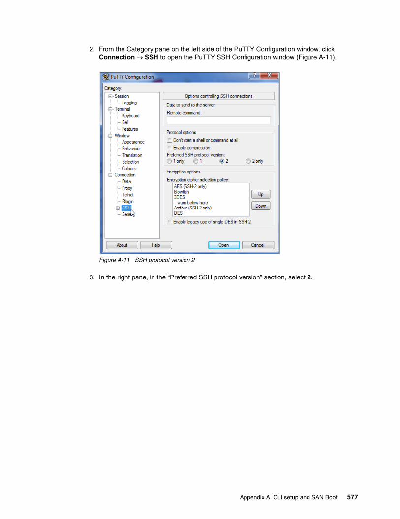
2. From the Category pane on the left side of the PuTTY Configuration window, click Connection SSH to open the PuTTY SSH Configuration window (Figure A-11).
Figure A-11 SSH protocol version 2
3. In the right pane, in the “Preferred SSH protocol version” section, select 2.
Appendix A. CLI setup and SAN Boot 577
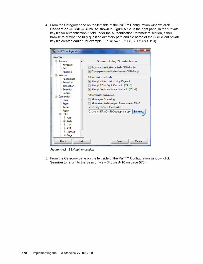
4. From the Category pane on the left side of the PuTTY Configuration window, click Connection SSH Auth. As shown in Figure A-12, in the right pane, in the “Private key file for authentication:” field under the Authentication Parameters section, either browse to or type the fully qualified directory path and file name of the SSH client private key file created earlier (for example, C:\Support Utils\PuTTY\icat.PPK).
Figure A-12 SSH authentication
5. From the Category pane on the left side of the PuTTY Configuration window, click Session to return to the Session view (Figure A-10 on page 576).
578 Implementing the IBM Storwize V7000 V6.3
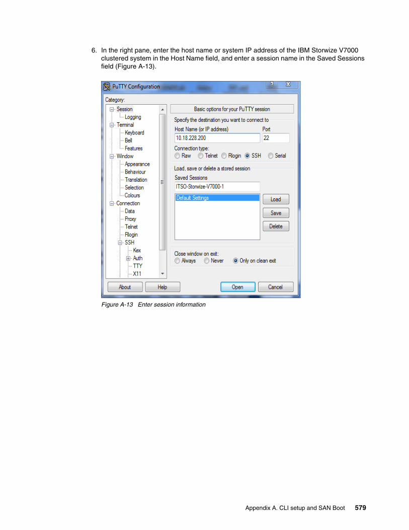
6. In the right pane, enter the host name or system IP address of the IBM Storwize V7000 clustered system in the Host Name field, and enter a session name in the Saved Sessions field (Figure A-13).
Figure A-13 Enter session information
Appendix A. CLI setup and SAN Boot 579

7. Click Save to save the new session (Figure A-14).
Figure A-14 Save Session
8. Highlight the new session and click Open to connect to the IBM Storwize V7000 system. A PuTTY Security Alert opens; confirm it by clicking Yes (Figure A-15).
Figure A-15 Confirm Security Alert
9. PuTTY now connects to the system and prompts you for a user name. Enter admin as the user name and press Enter (Example A-1).
Example: A-1 Enter user name
login as: adminAuthenticating with public key "rsa-key-20101006"IBM_2076:ITSO-Storwize-V7000-1:admin>
You have now completed the tasks that are required to configure the CLI for IBM Storwize V7000 administration.
580 Implementing the IBM Storwize V7000 V6.3

Example commands
A detailed description about all the available commands is beyond the intended scope of this book. In this section are sample commands that we have referenced in this book.
The svcinfo and svctask prefixes are no longer needed in IBM Storwize V7000 V6.3. If you have scripts using this prefix, they run without problems. If you type svcinfo or svctask and press the Tab key twice, all the available subcommands are listed. Pressing the Tab key twice also auto-completes commands if the input is valid and unique to the system.
Enter lsvdisk, as shown in Example A-2, to list all configured volumes on the system. The example shows that three volumes are configured.
Example: A-2 List all volumes
IBM_2076:ITSO-Storwize-V7000-1:admin>lsvdiskid name IO_group_id IO_group_name status mdisk_grp_id mdisk_grp_name capacity type FC_id FC_name RC_id RC_name vdisk_UID fc_map_count copy_count fast_write_state se_copy_count RC_change0 Hyper-V_PCO_Node1 0 io_grp0 online many many 100.00GB many 600507680185853FF00000000000000F 0 2 empty 0 no1 ESXi-PCO 0 io_grp0 online many many 100.00GB many 600507680185853FF000000000000010 0 2 empty 0 no2 ESXi-Redbooks 0 io_grp0 online many many 400.00GB many 600507680185853FF000000000000011 0 2 not_empty 0 no3 Hyper-V_PCO_Node2 0 io_grp0 online many many 101.00GB many 600507680185853FF000000000000012 0 2 empty 0 no4 ESXi-Demo 0 io_grp0 online many many 1000.00GB many 600507680185853FF000000000000013 0 2 not_empty 0 no
Enter lshost to get a list of all configured hosts on the system (Example A-3).
Example: A-3 List hosts
IBM_2076:ITSO-Storwize-V7000-1:admin>lshostid name port_count iogrp_count status2 HyperV-1_FCoE 2 4 online3 HyperV-2_FCoE 2 4 online4 ESXi-1 2 4 online5 ESXi-2 2 4 online
To map the volume to the hosts, enter mkvdiskhostmap (Example A-4).
Example: A-4 Map volumes to host
IBM_2076:ITSO-Storwize-V7000-1:admin>mkvdiskhostmap -host ESXi-1 -scsi 0 -force ESXi-RedbooksVirtual Disk to Host map, id [0], successfully created
To verify the host mapping, enter lsvdiskhostmap (Example A-5).
Example: A-5 List all hosts mapped to a volume
IBM_2076:ITSO-Storwize-V7000-1:admin>lshostvdiskmap ESXi-1id name SCSI_id vdisk_id vdisk_name vdisk_UID4 ESXi-1 0 2 ESXi-Redbooks 600507680185853FF000000000000011
Appendix A. CLI setup and SAN Boot 581

In the CLI, there are more options available than in the GUI. All advanced settings can be set, for example, I/O throttling. To enable I/O throttling, change the properties of a volume using the changevdisk command (Example A-6). To verify the changes, run lsvdisk.
Example: A-6 Enable advanced properties: I/O throttling
IBM_2076:ITSO-Storwize-V7000-1:admin>chvdisk -rate 1200 -unit mb ESXi-RedbooksIBM_2076:ITSO-Storwize-V7000-1:admin>IBM_2076:ITSO-Storwize-V7000-1:admin>lsvdisk ESXi-Redbooks
id 2name ESXi-Redbooks..vdisk_UID 600507680185853FF000000000000011virtual_disk_throttling (MB) 1200preferred_node_id 2..IBM_2076:ITSO-Storwize-V7000-1:admin>
If you do not specify the unit parameter, the throttling is based on I/Os instead of throughput (Example A-7).
Example: A-7 Throttling based on I/O
IBM_2076:ITSO-Storwize-V7000-1:admin>chvdisk -rate 4000 ESXi-RedbooksIBM_2076:ITSO-Storwize-V7000-1:admin>lsvdisk ESXi-Redbooksid 2name ESXi-Redbooks..vdisk_UID 600507680185853FF000000000000011throttling 4000preferred_node_id 2..IBM_2076:ITSO-Storwize-V7000-1:admin>
To disable I/O throttling, set the I/O rate to 0 (Example A-8).
Example: A-8 Disable I/O Throttling
IBM_2076:ITSO-Storwize-V7000-1:admin>chvdisk -rate 0 ESXi-RedbooksIBM_2076:ITSO-Storwize-V7000-1:admin>lsvdisk ESXi-Redbooksid 2..vdisk_UID 600507680185853FF000000000000011throttling 0preferred_node_id 2.
Command output: The lsvdisk command lists all available properties of a volume and its copies, but to make it easier to read, lines in the example output have been deleted.
582 Implementing the IBM Storwize V7000 V6.3
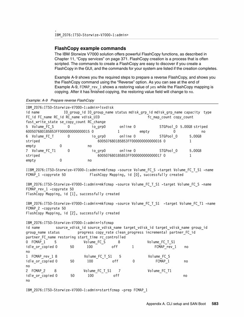
.IBM_2076:ITSO-Storwize-V7000-1:admin>
FlashCopy example commandsThe IBM Storwize V7000 solution offers powerful FlashCopy functions, as described in Chapter 11, “Copy services” on page 371. FlashCopy creation is a process that is often scripted. The commands to create a FlashCopy are easy to discover if you create a FlashCopy in the GUI, and the commands for your system are listed if the creation completes.
Example A-9 shows you the required steps to prepare a reverse FlashCopy, and shows you the FlashCopy command using the “Reverse” option. As you can see at the end of Example A-9, FCMAP_rev_1 shows a restoring value of yes while the FlashCopy mapping is copying. After it has finished copying, the restoring value field will change to no.
Example: A-9 Prepare reverse FlashCopy
IBM_2076:ITSO-Storwize-V7000-1:admin>lsvdiskid name IO_group_id IO_group_name status mdisk_grp_id mdisk_grp_name capacity type FC_id FC_name RC_id RC_name vdisk_UID fc_map_count copy_count fast_write_state se_copy_count RC_change5 Volume_FC_S 0 io_grp0 online 0 STGPool_0 5.00GB striped 600507680185853FF000000000000015 0 1 empty 0 no6 Volume_FC_T 0 io_grp0 online 0 STGPool_0 5.00GB striped 600507680185853FF000000000000016 0 1 empty 0 no7 Volume_FC_T1 0 io_grp0 online 0 STGPool_0 5.00GB striped 600507680185853FF000000000000017 0 1 empty 0 no
IIBM_2076:ITSO-Storwize-V7000-1:admin>mkfcmap -source Volume_FC_S -target Volume_FC_T_S1 -name FCMAP_1 -copyrate 50 FlashCopy Mapping, id [0], successfully created
IBM_2076:ITSO-Storwize-V7000-1:admin>mkfcmap -source Volume_FC_T_S1 -target Volume_FC_S -name FCMAP_rev_1 -copyrate 50FlashCopy Mapping, id [1], successfully created
IBM_2076:ITSO-Storwize-V7000-1:admin>mkfcmap -source Volume_FC_T_S1 -target Volume_FC_T1 -name FCMAP_2 -copyrate 50FlashCopy Mapping, id [2], successfully created
IBM_2076:ITSO-Storwize-V7000-1:admin>lsfcmapid name source_vdisk_id source_vdisk_name target_vdisk_id target_vdisk_name group_id group_name status progress copy_rate clean_progress incremental partner_FC_id partner_FC_name restoring start_time rc_controlled0 FCMAP_1 5 Volume_FC_S 8 Volume_FC_T_S1 idle_or_copied 0 50 100 off 1 FCMAP_rev_1 no no1 FCMAP_rev_1 8 Volume_FC_T_S1 5 Volume_FC_S idle_or_copied 0 50 100 off 0 FCMAP_1 no no2 FCMAP_2 8 Volume_FC_T_S1 7 Volume_FC_T1 idle_or_copied 0 50 100 off no no
IBM_2076:ITSO-Storwize-V7000-1:admin>startfcmap -prep FCMAP_1
Appendix A. CLI setup and SAN Boot 583

IBM_2076:ITSO-Storwize-V7000-1:admin>lsfcmapid name source_vdisk_id source_vdisk_name target_vdisk_id target_vdisk_name group_id group_name status progress copy_rate clean_progress incremental partner_FC_id partner_FC_name restoring start_time rc_controlled0 FCMAP_1 5 Volume_FC_S 8 Volume_FC_T_S1 copying 0 50 100 off 1 FCMAP_rev_1 no 111006160239 no1 FCMAP_rev_1 8 Volume_FC_T_S1 5 Volume_FC_S idle_or_copied 0 50 100 off 0 FCMAP_1 no no2 FCMAP_2 8 Volume_FC_T_S1 7 Volume_FC_T1 idle_or_copied 0 50 100 off no no
IBM_2076:ITSO-Storwize-V7000-1:admin>startfcmap -prep FCMAP_2IBM_2076:ITSO-Storwize-V7000-1:admin>lsfcmapid name source_vdisk_id source_vdisk_name target_vdisk_id target_vdisk_name group_id group_name status progress copy_rate clean_progress incremental partner_FC_id partner_FC_name restoring start_time rc_controlled0 FCMAP_1 5 Volume_FC_S 8 Volume_FC_T_S1 copying 3 50 96 off 1 FCMAP_rev_1 no 111006160239 no1 FCMAP_rev_1 8 Volume_FC_T_S1 5 Volume_FC_S idle_or_copied 0 50 100 off 0 FCMAP_1 no no2 FCMAP_2 8 Volume_FC_T_S1 7 Volume_FC_T1 copying 0 50 100 off no 111006160359 no
IBM_2076:ITSO-Storwize-V7000-1:admin>startfcmap -prep FCMAP_rev_1CMMVC6298E The command failed because a target VDisk has dependent FlashCopy mappings.IBM_2076:ITSO-Storwize-V7000-1:admin>startfcmap -prep -restore FCMAP_rev_1IBM_2076:ITSO-Storwize-V7000-1:admin>lsfcmapid name source_vdisk_id source_vdisk_name target_vdisk_id target_vdisk_name group_id group_name status progress copy_rate clean_progress incremental partner_FC_id partner_FC_name restoring start_time rc_controlled0 FCMAP_1 5 Volume_FC_S 8 Volume_FC_T_S1 copying 18 50 81 off 1 FCMAP_rev_1 no 111006160239 no1 FCMAP_rev_1 8 Volume_FC_T_S1 5 Volume_FC_S copying 81 50 18 off 0 FCMAP_1 yes 111006161024 no2 FCMAP_2 8 Volume_FC_T_S1 7 Volume_FC_T1 copying 14 50 100 off no 111006160359 no
Modifying Global Mirror Delay for testingAs described in 11.3, “Remote Copy” on page 433, a delay can be simulated on Global Mirror links. This feature is an advanced feature only available in the CLI. Example A-10 shows you how to add a delay to the Global Mirror connection.
Example: A-10 Add Global Mirror Delay
IBM_2076:ITSO-Storwize-V7000-1:admin>lssystemid 0000020061614FFC
584 Implementing the IBM Storwize V7000 V6.3
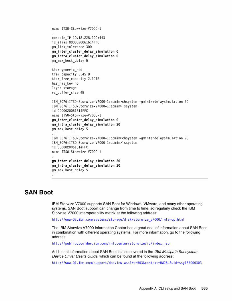
name ITSO-Storwize-V7000-1.console_IP 10.18.228.200:443id_alias 0000020061614FFCgm_link_tolerance 300gm_inter_cluster_delay_simulation 0gm_intra_cluster_delay_simulation 0gm_max_host_delay 5.tier generic_hddtier_capacity 5.45TBtier_free_capacity 2.10TBhas_nas_key nolayer storagerc_buffer_size 48
IBM_2076:ITSO-Storwize-V7000-1:admin>chsystem -gmintradelaysimulation 20IBM_2076:ITSO-Storwize-V7000-1:admin>lssystemid 0000020061614FFCname ITSO-Storwize-V7000-1gm_inter_cluster_delay_simulation 0gm_intra_cluster_delay_simulation 20gm_max_host_delay 5.IBM_2076:ITSO-Storwize-V7000-1:admin>chsystem -gminterdelaysimulation 20IBM_2076:ITSO-Storwize-V7000-1:admin>lssystemid 0000020061614FFCname ITSO-Storwize-V7000-1.gm_inter_cluster_delay_simulation 20gm_intra_cluster_delay_simulation 20gm_max_host_delay 5.
SAN Boot
IBM Storwize V7000 supports SAN Boot for Windows, VMware, and many other operating systems. SAN Boot support can change from time to time, so regularly check the IBM Storwize V7000 interoperability matrix at the following address:
http://www-03.ibm.com/systems/storage/disk/storwize_v7000/interop.html
The IBM Storwize V7000 Information Center has a great deal of information about SAN Boot in combination with different operating systems. For more information, go to the following address:
http://publib.boulder.ibm.com/infocenter/storwize/ic/index.jsp
Additional information about SAN Boot is also covered in the IBM Multipath Subsystem Device Driver User’s Guide, which can be found at the following address:
http://www-01.ibm.com/support/docview.wss?rs=503&context=HW26L&uid=ssg1S7000303
Appendix A. CLI setup and SAN Boot 585
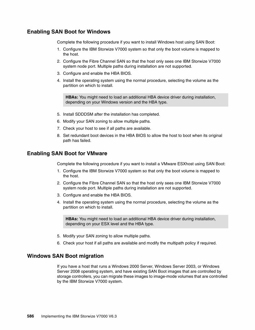
Enabling SAN Boot for Windows
Complete the following procedure if you want to install Windows host using SAN Boot:
1. Configure the IBM Storwize V7000 system so that only the boot volume is mapped to the host.
2. Configure the Fibre Channel SAN so that the host only sees one IBM Storwize V7000 system node port. Multiple paths during installation are not supported.
3. Configure and enable the HBA BIOS.
4. Install the operating system using the normal procedure, selecting the volume as the partition on which to install.
5. Install SDDDSM after the installation has completed.
6. Modify your SAN zoning to allow multiple paths.
7. Check your host to see if all paths are available.
8. Set redundant boot devices in the HBA BIOS to allow the host to boot when its original path has failed.
Enabling SAN Boot for VMware
Complete the following procedure if you want to install a VMware ESXhost using SAN Boot:
1. Configure the IBM Storwize V7000 system so that only the boot volume is mapped to the host.
2. Configure the Fibre Channel SAN so that the host only sees one IBM Storwize V7000 system node port. Multiple paths during installation are not supported.
3. Configure and enable the HBA BIOS.
4. Install the operating system using the normal procedure, selecting the volume as the partition on which to install.
5. Modify your SAN zoning to allow multiple paths.
6. Check your host if all paths are available and modify the multipath policy if required.
Windows SAN Boot migration
If you have a host that runs a Windows 2000 Server, Windows Server 2003, or Windows Server 2008 operating system, and have existing SAN Boot images that are controlled by storage controllers, you can migrate these images to image-mode volumes that are controlled by the IBM Storwize V7000 system.
HBAs: You might need to load an additional HBA device driver during installation, depending on your Windows version and the HBA type.
HBAs: You might need to load an additional HBA device driver during installation, depending on your ESX level and the HBA type.
586 Implementing the IBM Storwize V7000 V6.3
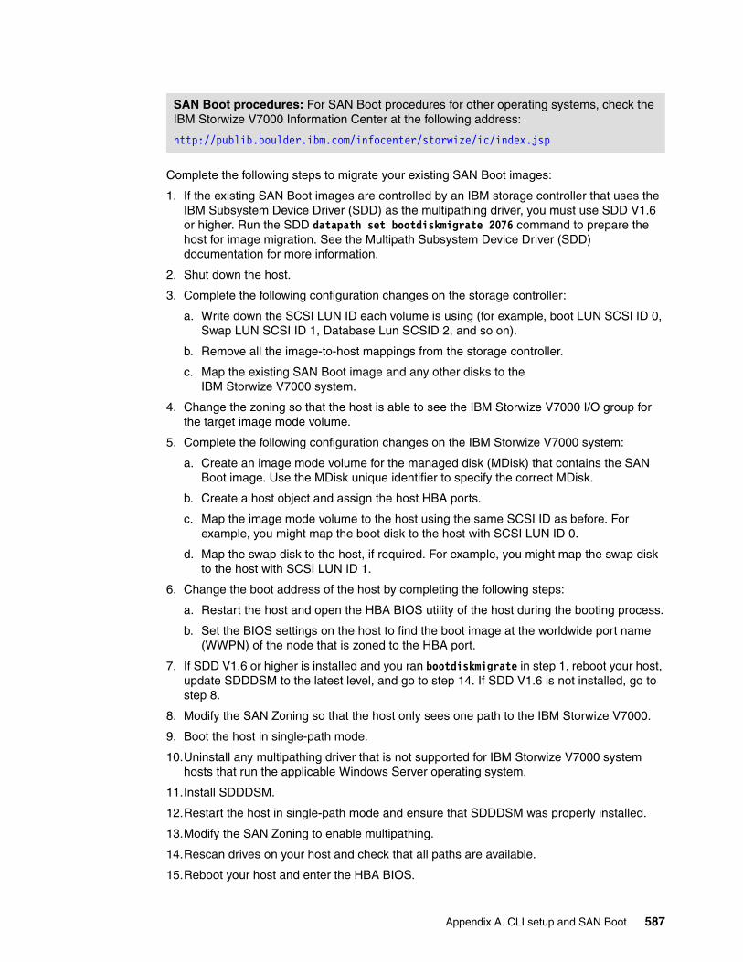
Complete the following steps to migrate your existing SAN Boot images:
1. If the existing SAN Boot images are controlled by an IBM storage controller that uses the IBM Subsystem Device Driver (SDD) as the multipathing driver, you must use SDD V1.6 or higher. Run the SDD datapath set bootdiskmigrate 2076 command to prepare the host for image migration. See the Multipath Subsystem Device Driver (SDD) documentation for more information.
2. Shut down the host.
3. Complete the following configuration changes on the storage controller:
a. Write down the SCSI LUN ID each volume is using (for example, boot LUN SCSI ID 0, Swap LUN SCSI ID 1, Database Lun SCSID 2, and so on).
b. Remove all the image-to-host mappings from the storage controller.
c. Map the existing SAN Boot image and any other disks to the IBM Storwize V7000 system.
4. Change the zoning so that the host is able to see the IBM Storwize V7000 I/O group for the target image mode volume.
5. Complete the following configuration changes on the IBM Storwize V7000 system:
a. Create an image mode volume for the managed disk (MDisk) that contains the SAN Boot image. Use the MDisk unique identifier to specify the correct MDisk.
b. Create a host object and assign the host HBA ports.
c. Map the image mode volume to the host using the same SCSI ID as before. For example, you might map the boot disk to the host with SCSI LUN ID 0.
d. Map the swap disk to the host, if required. For example, you might map the swap disk to the host with SCSI LUN ID 1.
6. Change the boot address of the host by completing the following steps:
a. Restart the host and open the HBA BIOS utility of the host during the booting process.
b. Set the BIOS settings on the host to find the boot image at the worldwide port name (WWPN) of the node that is zoned to the HBA port.
7. If SDD V1.6 or higher is installed and you ran bootdiskmigrate in step 1, reboot your host, update SDDDSM to the latest level, and go to step 14. If SDD V1.6 is not installed, go to step 8.
8. Modify the SAN Zoning so that the host only sees one path to the IBM Storwize V7000.
9. Boot the host in single-path mode.
10.Uninstall any multipathing driver that is not supported for IBM Storwize V7000 system hosts that run the applicable Windows Server operating system.
11.Install SDDDSM.
12.Restart the host in single-path mode and ensure that SDDDSM was properly installed.
13.Modify the SAN Zoning to enable multipathing.
14.Rescan drives on your host and check that all paths are available.
15.Reboot your host and enter the HBA BIOS.
SAN Boot procedures: For SAN Boot procedures for other operating systems, check the IBM Storwize V7000 Information Center at the following address:
http://publib.boulder.ibm.com/infocenter/storwize/ic/index.jsp
Appendix A. CLI setup and SAN Boot 587

16.Configure the HBA settings on the host. Ensure that all HBA ports are boot-enabled and can see both nodes in the I/O group that contains the SAN Boot image. Configure the HBA ports for redundant paths.
17.Exit the BIOS utility and finish starting the host.
18.Map any additional volumes to the host as required.
588 Implementing the IBM Storwize V7000 V6.3
Related publications
The publications listed in this section are considered suitable for a more detailed discussion of the topics covered in this book.
IBM Redbooks
The following IBM Redbooks publications provide additional information about the topic in this document. Some publications referenced in this list might be available in softcopy only.
� Get More Out of Your SAN with IBM Tivoli Storage Manager, SG24-6687
� IBM System Storage Business Continuity: Part 1 Planning Guide, SG24-6547
� IBM System Storage Business Continuity: Part 2 Solutions Guide, SG24-6548
� IBM Tivoli Storage Area Network Manager: A Practical Introduction, SG24-6848
� Implementing an IBM b-type SAN with 8 Gbps Directors and Switches, SG24-6116
� Implementing the IBM System Storage SAN Volume Controller V6.1, SG24-7933
� Introduction to Storage Area Networks, SG24-5470
� SAN Volume Controller V4.3.0 Advanced Copy Services, SG24-7574
� SAN Volume Controller Best Practices and Performance Guidelines, SG24-7521
� Using the SVC for Business Continuity, SG24-7371
Other publications
These publications are also relevant as further information sources:
� Command Line Interface User’s Guide, SG26-7903
� IBM System Storage Master Console: Installation and User’s Guide, GC30-4090
� IBM System Storage Open Software Family SAN Volume Controller: CIM Agent Developers Reference, SC26-7545
� IBM System Storage Open Software Family SAN Volume Controller: Command-Line Interface User’s Guide, SC26-7544
� IBM System Storage Open Software Family SAN Volume Controller: Configuration Guide, SC26-7543
� IBM System Storage Open Software Family SAN Volume Controller: Host Attachment Guide, SC26-7563
� IBM System Storage Open Software Family SAN Volume Controller: Installation Guide, SC26-7541
� IBM System Storage Open Software Family SAN Volume Controller: Planning Guide, GA22-1052
� IBM System Storage Open Software Family SAN Volume Controller: Service Guide, SC26-7542
© Copyright IBM Corp. 2011, 2012. All rights reserved. 589
� IBM System Storage SAN Volume Controller Model 2145-8A4 Hardware Installation Guide, GC27-2219
� IBM System Storage SAN Volume Controller Model 2145-8G4 Hardware Installation Guide, GC27-2220
� IBM System Storage SAN Volume Controller Model 2145-CF8 Hardware Installation Guide, GC52-1356
� IBM System Storage SAN Volume Controller Models 2145-8F2 and 2145-8F4 Hardware Installation Guide, GC27-2221
� IBM System Storage SAN Volume Controller V5.1.0 - Host Attachment Guide, SG26-7905-05
� IBM TotalStorage Multipath Subsystem Device Driver User’s Guide, SC30-4096
� Subsystem Device Driver User’s Guide for the IBM TotalStorage Enterprise Storage Server and the IBM System Storage SAN Volume Controller, SC26-7540
Online resources
These websites are also relevant as further information sources:
� Cygwin Linux-like environment for Windows:
http://www.cygwin.com
� Download site for Windows Secure Shell (SSH) freeware:
http://www.chiark.greenend.org.uk/~sgtatham/putty
� lBM Redbooks publications about SAN Volume Controller:
http://www.redbooks.ibm.com/cgi-bin/searchsite.cgi?query=SVC
� IBM site to download SSH for AIX:
http://oss.software.ibm.com/developerworks/projects/openssh
� IBM Storwize V7000 environment planning:
http://publib.boulder.ibm.com/infocenter/storwize/ic/index.jsp?topic=/com.ibm.storwize.v7000.doc/svc_installplan_22qgvs.html
� IBM Storwize V7000 Host Attachment Guide:
http://publib.boulder.ibm.com/infocenter/storwize/ic/index.jsp?topic=/com.ibm.storwize.v7000.doc/svc_over_1dcur0.html
� IBM Tivoli Storage Area Network Manager site:
http://www-306.ibm.com/software/sysmgmt/products/support/IBMTivoliStorageAreaNetworkManager.html
� IBM TotalStorage home page:
http://www.storage.ibm.com
� IBM TotalStorage Virtualization home page:
http://www-1.ibm.com/servers/storage/software/virtualization/index.html
� Microsoft Knowledge Base Article 131658:
http://support.microsoft.com/support/kb/articles/Q131/6/58.asp
� Microsoft Knowledge Base Article 149927:
http://support.microsoft.com/support/kb/articles/Q149/9/27.asp
590 Implementing the IBM Storwize V7000 V6.3
� Open source site for SSH for Windows and Mac:
http://www.openssh.com/windows.html
� SAN Volume Controller supported platform:
http://www-1.ibm.com/servers/storage/support/software/sanvc/index.html
� Subsystem Device Driver download site:
http://www-1.ibm.com/servers/storage/support/software/sdd/index.html
� SAN Volume Controller online documentation:
http://publib.boulder.ibm.com/infocenter/svcic/v3r1m0/index.jsp
� SAN Volume Controller support page:
http://www-947.ibm.com/systems/support/supportsite.wss/selectproduct?taskind=4&brandind=5000033&familyind=5329743&typeind=0&modelind=0&osind=0&psid=sr&continue.x=1
� Sysinternals home page:
http://www.sysinternals.com
� VMware information:
http://www.vmware.com/products/vmotion/overview.html
Help from IBM
IBM Support and downloads
ibm.com/support
IBM Global Services
ibm.com/services
Related publications 591

592 Implementing the IBM Storwize V7000 V6.3
Index
Aactive-active architecture 15Add Enclosure window 61administrative rights
DB2 user 493Advance FlashCopy menu 402Advanced Copy Services 9advanced copy services 27Advanced Settings 152, 155, 395–397alerts 19, 25, 35, 56, 420algorithms 17, 238, 241aliases 26analyses 368–369, 381, 481, 522architecture 1, 15, 25, 522arrays 16–17, 242, 245, 258, 369
splitting 338asynchronous replication 461audit logs 124, 561authentication 26, 137, 157, 502, 570, 578Authentication Parameters 578auto-complete
commands 581autoexpand 24autoexpansion 24automatic data placement 352automatically discover 260automation 28autorun enabled 489
Bbackground copies 7, 120, 375–377, 383, 412, 447, 453
bandwidth 453background copy rate 375–376, 383backup copy rate 376backups 7, 32, 36, 320, 371, 379, 383, 391, 437, 483
application data 16, 28batteries 5FlashCopy 372, 381image 5management IP address 40preset 397, 400system configuration data 16tape 372, 380volumes 115, 383, 390
bandwidth 28, 38, 120, 440, 447, 453, 455batteries 5, 11, 13, 528, 530bitmaps 373, 379boot 134, 567
Ccache 11, 15, 20, 63, 309, 346, 377, 438, 440, 482–483Call Home 32, 128
email 31–32
© Copyright IBM Corp. 2011, 2012. All rights reserved.
candidate 229, 232canisters 4–5, 11, 13, 15, 36, 40, 50, 132, 158, 433, 522, 525, 527
expansion 4, 6, 13, 525slots 11, 525
capacity 163allocation 236allocation indicator 236, 241cluster maximum 19cluster storage maximum 19cold data 370configurable warning 24current internal storage 227free 165Global Mirror and Metro Mirror 43hosts 294, 325hot data 370management 481maximum usable 241MDisks 245, 342mirrored 8optimized setup 242physical and usable 78pools 168real 23, 163, 165, 294, 308real physicial disks 7solid-state disks 348storage 14, 18–19, 227, 334, 375thin provisioned volumes 383used 19, 24used free 24utilization 481virtual 23, 79, 163, 165, 294, 308–309virtual external storage arrays 4volumes 18, 30, 171, 264, 294, 308, 369, 446warning 24
Cascaded FlashCopy 7mappings 375
CD layout 486chains 4, 38, 233–234, 435, 527CHAP 283chat sessions 30CIMOM 16, 484clones 4, 115, 375, 389, 393, 396, 400clusters 15, 21, 39, 166, 298
allowed 437audit logs 124auxiliary 444–445background copy rate 120backups 530–531configuration 36, 531
data 531configuration nodes 15consistency groups per cluster 29creating 50
593

error logging 522extent sizes 19external storage 4Fibre Channel details 127FlashCopy consistency groups per cluster 382FlashCopy mappings per cluster 30, 382host mappings 4hosts 209I/O groups 15image MDisks 17Image Mode volumes 22inactive 437internal storage 4IP addresses 32, 36, 40, 50, 180, 197, 510, 533, 579local 437management 5, 40–41, 43master 444–445master and auxiliary 444–445maximum capacity 19MDisks 4
data 23names 81network 437node canisters 522node pairs 15number of Remote Copy consistency groups per clus-ter 446number of Remote Copy relationships per cluster 446partnerships 16, 437, 446, 451, 453primary 444–445, 478primary and secondary 445public keys 570relationships per cluster 29remote 437secondary 444–445shutdown 564, 566–567states 91statuses 524unmanaged MDisks 17VMware 210
colliding writes 446Command Descriptor Block (CDB) 25command-line interface (CLI) 16, 18, 26, 31, 44–45, 308, 363, 381, 439, 485–486, 514, 530, 560, 564, 566, 569–570, 576, 580, 582, 584
authentication 123commands 8, 25, 44, 104, 106, 109, 113, 117, 124, 378–379, 443, 489, 499, 531, 560, 570, 581, 583communication failures 529concepts 26, 522configuration 67, 78, 81, 159, 192
access redundancy 36advanced host 173backups 530, 532basic 269, 570basic volumes 174basic Windows hosts 541changes 50, 587CLI commands 560cluster activity 15
clusters 16consistent 481Copy Services limits 29data 519, 530device 481Easy Tier 353email 58–59enabling 158events 56, 58, 561files 46FlashCopy 393guidelines 28HBA firmware 139help 67hosts 149initial 54IP address options 40IP addresses 50IP addresses for Ethernet ports 40–41issues 32limits 29limits and restrictions 6Metro Mirror
limits 446network 48, 126nodes 12, 15–16, 40–41, 50, 531options 3recommended storage 234restrictions 336–337steps 35storage 62storage controller changes 587supported HBA driver 133system changes 530system restore 530tasks 15wizards 56, 62, 64, 150, 154, 231zone 212
Configuration tab 137Configuration window 156connectivity 541
database 484host file systems to physical disks 481IBM Storwize V7000 and Brocade SAN Switches and Directors 39iSCSI 156iSCSI Ethernet ports 156options 75
consistencypoint in time 378
consistency groups 8, 29–30, 118–119, 374, 378, 382, 398, 404, 413–417, 419, 421–422, 443, 445, 460–461, 472–480
empty 415, 444, 474Consistency Groups menu 413Consistency Groups window 383, 414consistent
configuration 481copies 448data set 372
594 Implementing the IBM Storwize V7000 V6.3
image 379, 440, 444relationship 448
ConsistentDisconnected 445ConsistentStopped 444ConsistentSynchronized 444containers 264contingency 24
capacity 24control enclosures 4, 11–13, 36, 38, 522, 527–528
state information 12Copied state 377, 379copies
fully synchronized 8primary 24, 28, 166, 294, 318, 320, 322–324, 352splitting 24, 320–321, 323
copybandwidth 453operations 29, 380, 383processes 120, 377, 444, 448, 453rate 120, 375–376, 383, 412, 447
copy processesstopping 377
Copy Services 9, 29, 67, 114, 383–387, 413, 451layer 27
copy services 27functions 27, 371
Copying state 377, 379, 405, 409, 448creating
advanced FlashCopy mappings 404Fibre Channel and iSCSI hosts 156Fibre Channel hosts 153FlashCopy 583hosts 270HP/UX or TPGS hosts 152new volume copies 293partnerships 433, 446relationships between mirrored volumes 16Remote Copy relationships 461, 465Reverse FlashCopy mappings 382second host 153second hosts 153thin-provisioned volumes 163volume copies 159volumes 293, 561volumes and FlashCopy mappings 3
Critical Fix Notification 541cycling mode 28
Ddata
analyses 348application 16, 342, 440, 530backup 16, 209, 381client 379cluster configuration 16collection 483collection settings 513configuration 519, 530consistency 445consistent copy 448
deletion 483error-related 32flushing 320hosts 212hot 345, 352, 368importing or exporting 338loss 162, 209, 228–229, 337master volume 463MDisks 23, 248, 258memory dumps 522migration 8, 10, 22, 205–206, 209, 218–219, 221, 249, 252, 334, 338–339, 342, 349, 566mirrored 232mirrored volumes 24movement 353multiple volumes 8performance 368, 483, 485placement 345–346primary volume copy 322production 383, 437protection 530rates 482read and write 5, 377recording medium 5relocation 346replication 28repositories 485sets 378sources 379–380storage infrastructure 30striped 17, 526support 562svc_snap support 561targets 7transmitting and receiving load 522workload performance 348
Data Migration feature 8Data Migration Planner 350Data Migrator 351Data Placement Advisor (DPA) 350database
attention required 495integrity 379
date and time 42, 54–55, 129, 363date code 26DB2 Administration Server 492DB2 installation 488
verify installation 498DB2 Installer 489DB2 tools catalog 495DB2 user account 493db2sampl command 498decoupled 21default location 363delete
consistency groups 480FlashCopy mappings 118, 383, 410host ports 284, 290hosts 280log files 89
Index 595
mappings 377old volume copies 323partnerships 120, 459users 122volume copies 323volumes 306
Delete option 89deleting 24, 270dependent writes 378–379destaged 309, 318, 324Detect MDisk action 260detected
hardware issues 56new storage 260software failures 522
device-specific modules (DSM) 134Directed Maintenance Procedure (DMP) 83, 228, 350disk controllers 210disk drive types 14disks
failure 337slots 13
DNS suffix 487domain name system 487domain name systems
primary 487drives 5–6, 587
3.5-inch 525dependent 230disk 11, 13–14, 38enclosures 4–5failure 16–17, 232fast SAS or FC 348faults 16hard disk 345hot spare 234, 238, 242internal 5, 8, 14, 16–18, 62, 94, 224, 228–229, 232
capacity 94objects 16overview 226
logical 44expanding 44
MDisks 258, 264, 268mirrored 17
pairs 17, 232RAID arrays 232–233, 526slots 6solid-state 43, 346, 348, 354, 356, 358–359, 368–369spare 228unconfigured 241
EEasy Tier 25, 43, 205, 345
Automatic Data Placement Mode 352definition 8enabling 364enabling and disabling 361enabling or disabling 367evaluation mode 365, 368
extent migration 20, 352hot spots 353internal volumes 348log files 363measurements 363mixing MDisks 338operating modes 351overview 9, 346performance data 368process 349SSD 232, 234, 238, 242, 356states 353statuses 359Tivoli Storage Productivity Center 483volume hot spots 14
enclosures 5–6, 8, 14, 36, 525, 528chains 4expansion 3–5, 12–13, 36–38, 78, 525, 527–528, 567virtualized 42
errors 555asynchronous notification 522cluster logging 522ConsistentStopped state 444hardware 377, 524I/O 380link 260mirrored volume copies 321partnership candidates 452Recommended Actions grid 556service panel 522svc.config.backup.log 531vpd 525
Ethernetcabling 36LED statuses 523management interfaces 533ports 12, 36, 40–41, 50, 523switches 25
Ethernet Ports menu 157EUIs 15Event Log Properties menu 558Event Log tabs 558events 3, 83, 87
alerts 35configuration 56–57, 561count 547definition 4details 556detected 31disaster 16extended logging 139failure 4highest priority 544, 549informational 483, 548level 58logs 322, 543–545, 547–548, 557–558, 563marked as fixed 86node canisters 41notifications 31, 56, 522
596 Implementing the IBM Storwize V7000 V6.3

offline fabrics 38power input failure 11reporting 483resolving 84serious 544site power failure 522SNMP traps 31sorted by time stamp 547svc_snap files 563syslog messages 31unexpected 544
Expand Volume window 301expansion enclosures 226extended unique identifiers 15extents 20, 25, 346
allocation 349cold 350Easy Tier 25, 347, 368hot 350, 352, 369–370I/O activity 352level 347managed MDisks 17, 245mappings 23MDisks 18, 23migration 301, 323, 345, 348–349, 352, 362migration plans 25, 347monitoring I/O statistics 346real capacity 163sizes 18–19, 24–25striped volumes 21
external storage 338adding 339arrays 4, 17backups 209definition 4destination 218Easy Tier 345External window 341image mode copies 220importing 8licenses 42lower tiered pools 348mapping 211MDisks 224, 244, 260, 342migration 10, 206ports 38, 336
maximum 336removing 343Show Dependent Volumes option 341virtualization 333–334volume migration 301zoning 211
external storage systemextended help 339
External Virtualization 9–10, 334–335
Ffabric 4, 348, 481
BLUE 337errors 437
Fibre Channel ports 36links 437Out of Band Agents 484problems 260RED 337remote 446WWPN zones 38
failed 229failover situation 438failovers 15, 28, 40, 132, 440fault-tolerant controller 12Fibre Channel
ports 12, 27, 36, 210, 286, 339, 446, 523Fibre Channel connections 126Fibre Channel Port Login 27file system 343, 481, 483FlashCopy 7, 29, 44, 115, 163, 372–373
capabilities 43commands 378–379consistency group
statesPrepared 379Preparing 379Stopped 380
consistency groups 8, 379, 413–414states 379
Suspended 379copy services 27, 371database volumes 379example commands 583functions 7integrity 378mapping
states 377Idling/Copied 378Prepared 377Preparing 377Stopped 377Suspended 377
mapping statesStopped 406, 420
mappings 3, 8, 30, 118, 306, 308, 374, 376, 378–379, 381–383, 395, 397, 401, 405, 407, 409, 414–416, 420–421, 566, 583
creating 394deleting 409–410dependency tree 411renaming 407
operations 382–383properties 382relationships 308Remote Copy 447source volumes 411thin provisioning 23volumes 116
multiple target 375target 379, 391, 405–406, 409, 412, 438, 445
FlashCopy Consistency Group window 117FlashCopy Mapping window 118, 404FlashCopy Mappings menu 386
Index 597

FlashCopy nocopy with thin provisioning 7flexibility 237foreground I/O latency 453Full Feature Phase 26Full/Incremental Copy 7
GGetting Started window
help references 67Global Mirror 8–9, 28–29, 43, 433, 439–440, 444–445, 461, 481–482, 584
definition 8relationships 448
gminterdelaysimulation 439gmintradelaysimulation 439grains 165, 309, 374granularity 373GUID 488
Hhardware failures 32HBAs
BIOS 42, 133, 586installing 133, 138port connection 42ports 587–588
heat maps 349high availability 166, 526Host function icon 329Host Type setting 283hosts 159
adding ports 287administration 270agents 484capacity 294clusters 42configuration 149configured and mapped
overview 175creating 149data 212deleting 280details 127, 176, 180, 188, 195device drivers 206devices 217domain name systems 488drivers 213ESX 140–141, 148
Fibre Channel 187–188, 194iSCSI 148, 195
Fibre Channel 149connections 38Windows 2008 175
Fibre Channel and iSCSI ports 110I/O 8, 206, 374IDs 112initiator names 154, 289iSCSI 156, 181, 285iSCSI access 36, 40
iSCSI CHAP Secret 283manual mapping process 172mapping volumes 296mappings 4, 101, 105, 108, 158–159, 172–174, 176, 180, 215–217, 269, 274–276, 291, 294, 297, 325
overview 291verifying 581viewing 298
mirrored volumes 166modification 270names 26, 154naming 214OpenVMS 309paths 541ports 38, 151, 284–285, 288
deleting 290WWPNs 150
primary 279properties 281–282, 293
overview 282rebooting 182renaming 283, 331servers 15, 23, 138, 163settings 274spare 234systems 2, 4, 7, 14, 17–18, 21, 24, 127, 132–133, 138–139, 141TPGS 152unmapping 277, 297virtual capacity 79, 163volumes 329volumes access 42, 131, 178Windows 586Windows 2008 133, 135–137, 177–178
iSCSI 138, 179, 187WWPNs 38, 136, 286zones 213
hot spare 16, 227, 229, 241, 356, 526
II/O groups 12, 14–15, 30, 197, 291, 445–446, 527, 587–588I/O Monitoring (IOM) 350I/O statistics 346, 352, 366IBM Assist On-site
restricting access 31IBM Assist On-site tool 30–31IBM SAN Volume Contoller (SVC) 3–4, 539, 541, 570, 574
upgrades 539IBM Storage Tier Advisor Tool (STAT) 349, 368IBM Storwize V7000 150
adding external storage 339adding Fibre Channel ports 287advanced host administration 270advanced host and volume administration 269Advanced menu 129advanced volume administration 293amber fault LED 50architecture 1
598 Implementing the IBM Storwize V7000 V6.3

Audit Log tab 560basic volume configuration 159Call Home configuration 56capacity 4clusters 16command-line interface 46, 570components 14configuration backup procedure 530configuration instructions 42configuration limits and restrictions 6control enclosures 11copy services 371creating generic volumes 162creating mirrored volumes 166creating new partnerships 452data migration 342disk drive types 14disk subsystems 525downloading and installing supported firmware 138Easy Tier 345, 348
configuration using the CLI 363overview 346rules 352
educational videos 33enclosures 14External Physical Storage menu 95external storage configuration planning 337external storage virtualization 333Fibre Channel ports 210FlashCopy
concepts 373guidelines for implementation 382mapping states 377
front view 6full-meshed topology 436function icons 72generating configuration backups using the CLI 530Getting Started window 67GUI 3, 19, 26, 31, 33, 42, 44, 136, 140, 148, 205, 514, 530, 534
creating hosts 131–132, 148, 174Easy Tier configuration 354managing and configuring Remote Copy 451managing and implementing Remote Copy 433managing FlashCopy 383overview 65
hardware components 10hardware installation planning 36hardware overview 10Home menu 77host configuration 131
planning 42Information Center 137initial configuration 35, 43, 54initiator 181internal storage 3, 10, 334, 339, 344iSCSI 25
connections 138overview 157
LAN configuration planning 40
licensing 9managed 334managed storage 8management 16
GUI 3management and support tools 30management software overview 66maximum ports or WWPNs 336MDisks 17
menu 97Metro Mirror 8migrating a volume to another storage pool 301migration 10migration wizard 205, 209mirrored volumes 24models 5monitoring host paths 541multipathing 134multitiered storage pools 20nodes 15overview 1, 3Partnerships menu 120performance optimized setup 238planning for external virtualization storage 334ports
login maximums 39preparing for data migration 206provisioning storage 160quorum disks 18RAID 14
supported levels 526RAS 522RAS, monitoring, and troubleshooting 521Recommended Actions menu 83, 548Remote Copy
general guidelines 445partnerships 433synchronous and asynchronous 28
removing external storage 343renaming target volumes 406SAN
configuration planning 38requirements 39
SAN Boot 42, 585SAS cabling 528shrinking volumes 300shutdown 564, 566–567
using the GUI 564SNMP traps 31software upgrades 522, 533STAT reports 369Supported Hardware List 132system configuration backup 16System Status menu 78terminology 4thin-provisioned volumes 23triangle topology 435troubleshooting overview 544unmapping volumes from a host 277uploading the SSH public key 574
Index 599
USB connector slot 49VMware ESX
iSCSI attachment 141multipathing 140
Volume ID 370volume mirroring function 218volume types 162warnings 26websites 32Windows
SAN Boot migration 587IBM Subsystem Device Driver (SDD) 587IBM Subsystem Device Driver DSM (SDDDSM) 134–135, 176, 586
updates 587IBM Support Center 31, 562IBM Systems Storage Productivity Center (SSPC) 30, 485IBM Tivoli Integrated Portal 484, 486IBM Tivoli Storage FlashCopy Manager 29IBM Tivoli Storage Productivity Center 16, 481
architecture 483component install 499configuration 482connecting to IBM Storwize V7000 508GUI 485–486, 508Information Center 28installation 485
components 499errors 502overview 486prerequisites 488
licenses 482overview 482
IBM Tivoli Storage Productivity Center for ReplicationTwo Site Business Continuity License 487
identical data 438IdlingDisconnected 444image mode 17, 22, 95, 212, 220, 245, 304, 338, 352, 587Include Excluded MDisk menu 260InconsistentCopying 444InconsistentDisconnected 444InconsistentStopped 444Incremental FlashCopy
mappings 375initialization process 235inter-cluster 439, 462
communication 433link bandwidth 453
internal storage 218, 223–224, 227, 338, 570configuring 231definition 4
intra-cluster 439IP addresses 16, 26, 32, 36, 40–43, 50, 54, 145, 180, 197, 533, 579IP network 25, 31IP port numbers 197iSCISI Configuration tab 180iSCSI 25
access 40adding host ports 285addresses 26advanced host administration 270attachment 141
Windows 2008 136CHAP Secret 283connections 14definitions 126ESX
attachment 194initiator 148
Ethernet ports 156hosts 36, 40
creating 149, 154initiator names 26–27, 136, 141, 147, 154, 158, 197, 289interface 132Microsoft software initiator 136name 26nodes 26ports 180, 183ports by host 110ports on IBM Storwize models 5settings 157stacks 141volumes 174
mappings 197Windows 2008 179
iSCSI Alias 157iSCSI Configuration tab 180, 183iSCSI Host menu 154iSCSI qualified names (IQN) 15, 26iSCSI Service 137iSCSI Software Adapter Properties window 147ISL hop count 446iSNS 157
JJava Web Start
GUI 485JBOD 17
Kkey generators 570–571, 573key pairs 45, 570, 572keys 510
HKEY_LOCAL_MACHINESYSTEMCurrentControlSetControl-Class‘4D36E97B-E325-11CE-BFC1-08002BE10318}<bus ID>Parameters axRequestHoldTime 138HKEY_LOCAL_MACHINESYSTEMCurrentControlSetControl-Class‘4D36E97B-E325-11CE-BFC1-08002BE10318}<bus ID>ParametersLinkDownTime 138HKEY_LOCAL_MACHINESystemCurrentControlSetServices‡iskimeOutValue 134private 570–571, 573, 578public 570, 572, 574–575
600 Implementing the IBM Storwize V7000 V6.3
SSH 123, 570, 574USB 46, 49–50
Llanes
PHY 5latency 25, 28, 346–347, 447, 453learning videos 33LEDs 12–13, 50, 229, 521, 523–525, 528, 530licenses
Enclosure 9, 42external 206External Storage 10, 55, 334External Virtualization 334External Virtualization Limit and Remote-Copy Limit 335External Virtulization 10Global Mirror and Metro Mirror 43IBM Storwize V7000 9summary 9thin provisioning 7virtualization 55, 206Volume Mirroring 7
Linux 132, 487logged 24, 67, 287logical block addresses (LBA) 23, 321logical disks 21, 159logical units (LU) 4login phase 27logins 283logs
listing 88, 90, 533messages 31
low bandwidth 28lower tiers 349LUNs 133, 140, 206, 211–212, 260, 337–339
Mmaintenance contract 32management
capacity 481copy services 451device-level 482enterprise-wide 482FlashCopy 383IP addresses 15, 41redundant access 40storage 30storage infrastructure 481system 44–46, 50, 54
Management Information Base (MIB) 31mappings 270
extents 245external storage LUNs 211FlashCopy 8, 374
cleaning rate 376host
definition 4LUNs 212
Multi-target FlashCopy 7removing 292, 343source volumes 379user roles 484volumes 132
master console 31MDisks 23, 243
adding to storage pools 95, 245additional actions 260arrays 234, 264
definition 526capacity 227definition 4extended help 243external 348external storage 4
definition 4FlashCopy 116HDD tier 352higher tier 25, 348image mode 255, 304internal storage
definition 4lower tier 25, 347managed 23, 97, 245, 252, 301, 482
definition 17menu 97, 342migration 212mixing 338mode 253overview 17, 262–263performance 338, 348Pool Details 325Properties action 262quorum disks 18
overview 18RAID 256single-tiered storage pools 19source 252, 255storage pools 162, 223swapping drives 257tiers 259unmanaged 18, 97, 206, 220, 245–247, 250, 255, 260, 339
definition 17window 262
Member MDisk tab 312memory dumps 11, 522message types 128metadata 23, 377Metro Mirror 8, 28–29, 352, 433, 438–439, 443–445, 447, 461, 481
consistency groups 443relationships 443
microcode 337, 522Microsoft Multipath Input Output (MPIO) 134, 181–182, 186migration 24, 206, 212, 216
advanced migration function 221automatic 20, 483
Index 601
Automatic Data Placement 352cluster hosts 209copies between storage pools 319data migration tool 8, 342Easy Tier 25, 347, 352extent migration plans 25extents 345, 347, 352feature 323FlashCopy 372hot spots 8image mode volumes 22images 586licenses 10nondisruptive 14plan 349pools 249process 255, 301, 303, 324progress 218, 249, 251, 255reports 25SAN Boot images 209, 587status 303storage migration wizard 208–209VMware clusters 210VMware ESX hosts 210volume copies 303–304volumes 19volumes to storage pools 302wizard 62, 205–206, 215
mirroringadvance mirroring settings 168host based software 166remote 2, 8, 16, 36, 120
modes 17, 28, 140, 245, 351monitoring 15, 128, 348, 352, 481–482, 519, 522Move to Consistency Group option 416multipath I/O 134multipath storage solution 134multiple paths 42, 586Multi-target FlashCopy 7multitiered storage pools 20
Nnaming authority string 26Nearline SAS 14, 234NETBIOS 488network management program 31network time protocol (NTP) 42Node option 90nodes 127, 522
adding back to a cluster 44canisters 4, 11, 38, 40, 50, 90, 336, 339, 433, 446, 522
definitions 4Ethernet ports 36LED status 524overview 522
configuration node canisters 16Ethernet ports 50expansion canisters
definition 4
FlashCopy mapping states 377hung 522I/O groups 14internal storage
definition 4Internet 26IP addresses 36, 41names
changing 26overview 15pairs 166partner 15port 1 36ports 586quorum disks 18replacing 522surviving 12target ports 283usage statistics file 25
non-zero contingency 24
Oobject names 18operations
copy 439, 445data migration 566I/O 377, 444, 448IOPS 20iSCSI 138nocopy 7start and stop 378stop 378write 377, 439
ordering 379Overview tab 282, 308overwritten 373
Pparity strips 17partnerships 16
clusters 437managing 451
creating 433, 446, 452deleting 120disconnected 456new 120states
Fully Configure (Remote Stopped) 437Fully Configured (Remote Exceeded) 437Fully Configured (Remote Excluded) 437Fully Configured Stopped 457, 459Local Excluded 437Partially Configured 437Remote Not Present 437Stopped 437, 457
stopped 457passphrases 573peak loads 447performance
602 Implementing the IBM Storwize V7000 V6.3
analyses 483high performance disk tiers 362, 369–370I/O 346impacts 439logs 347monitoring and analysis 481needs 14optimized setups 238, 241–242pools 324requirements 8, 141statistics 483, 519storage 346testing 439
performance optimized setups 239PHY 5, 13, 524–525physical location 26PLOGI 27point in time (PiT) 4, 29, 377, 379, 439
copies 7–8, 29, 379consistent 8
data 378pools
primary 167, 170secondary 168, 171
Pools function iconextended help 264
Port Mask field 283port masks 283ports
controller devices 260deleting 111FC Host Adapter 133, 138iSCSI 183iSCSi 180node canister 446offline 287states 287
power supply 11, 13, 525, 528slots 11
power supply units (PSU) 11, 13, 528removing 564
P-parity 17presets 3, 232–234, 237–238, 383–384, 388, 393private keys 570–571, 573, 578provisioning
capacity 481storage 484
public keys 570, 572, 574–575PuTTY 570–571, 573, 576–578, 580
key generators 573
QQ-parity 17quorum
candidates 18disks 5, 18
RRAID
definition 16MDisks 4mirrored 16, 232, 526overview 16performance 16, 526presets 3, 232, 234, 238types 19
RAID 0 16, 232–233, 337redundancy 16
RAID 1 16–17, 337RAID 10 16–17, 232, 337
failure 17RAID 5 16–17, 233, 242, 337, 369
redundancy 17RAID 6 16–17, 232, 238, 242, 337RAID arrays 14, 17, 21, 44, 245, 526
goals 16, 526spare 234width 242
RAID levels 16, 224, 232, 235, 237, 241–242, 337, 339, 356, 526
redundancy 16rebalancing 16, 260, 526receivers 31Redbooks website
Contact us xiiiredundancy
access 4arrays 16–17, 229boot devices 586clustered system management 40external storage systems 337fabrics 38, 336, 339hosts 42inter-switch links 446management access 40MDisks 18paths 588PSUs 528spare drives 232
relationshipconsistent 448
Relationship function icon 475relationships
background copies 376cleaning rate 376copy direction 469FlashCopy 29, 374–375, 380Global Mirror 448image mode volumes 22inter-cluster 462Metro Mirror 438, 443partnerships 456Remote Copy 444removing 463stopping 466
reliability 132, 338reliability, availability, and serviceability (RAS) 521–522remote
clusters 437
Index 603
data mirroring 16fabric 446mirroring 2, 8, 36nodes 446service 31storage system 453
Remote Copyasynchronous 8, 27–28, 433, 439configuration 433consistency groups 443–444
creating 473managing 472
copy services 371description 433general guidelines 445Global Mirror 439licenses 9, 56, 336limits 55, 446link requirements 447management 433Metro Mirror 438nodes 15partnerships 455planning 445synchronous 27–28, 433, 439
Remote Copy menu 119Remote Copy relationships 29, 119, 306, 437, 444–445, 463, 566
deleting 471, 479multiple 445renaming 470stand-alone 459, 461starting 468stopping 466switching direction 469
Remote Mirroring 44, 120Remote-Copy Limit option 335response times 20restore points 29, 380Reverse FlashCopy 7, 29, 380–381, 583RFC3720 26roles
primary 438
SSAN Boot 42, 136, 139, 209, 569, 586–587
hosts 133SAN fabrics 12, 14, 25, 42, 210, 481, 484SAN Volume Controller 3, 510
clusters 570, 574SCSI
clustered systems 26commands 25front ends 377LUN IDs 587MDisks 4
SCSI IDs 112, 176, 180, 188, 195, 211, 216, 272, 274, 283, 291, 344secondary
read/write access 467
securityfeatures 31requirements 141
Serial Attached SCSI (SAS) 3–5, 13–14, 37–38, 234, 348, 358, 524–525, 527
connectivity 5, 527connectors 13drives 3initiators 527interfaces 13lanes 4ports 4–5, 12–13, 524–525, 527
service tasks 15Shutdown Cluster menu 565Simple Network Management Protocol (SNMP) 31, 43, 128, 522
manager 31messages 31settings 31
single points of failure 527single sign-on 481, 484single-tiered 19, 348sites
primary 439, 447remote 8, 440secondary 28, 439–440, 447–448target 438
SMTP server 32, 43snapshots 5, 115, 383, 388, 391, 396solid-state drives (SSD) 14, 345
arrays 234, 369capacity 370Easy Tier 238, 242, 356Easy Tier presets 234extents 352external 362hot data 352internal 348MDisks 368, 526multiered storage pools 358optimization 43performance 345pools 319RAID instances 232response times 345storage 25tiers 258, 350
sorting 437, 561sources 7, 30, 374, 380, 383, 440
data 7Global and Metro Mirror 352multiple 29
space warning 267spare role 229SSH 45, 122, 570, 573–574, 576
client 570, 576, 578keys 123, 570, 574
state information 91states
consistent 438, 443
604 Implementing the IBM Storwize V7000 V6.3

fixed 547link 523model 444processes 4service 524starting 524stopped 376, 420stopping 375, 377suspended 378
statistics 351, 519Easy Tier 25file 362I/O 352, 366log file 362performance 483, 519usage 484
stop 118, 467, 469command 117, 377partnerships 456process 420
storageprimary 43, 453secondary 453
storage area networks (SAN)configuration 38, 336fabric 484failure 18planning 483zoning 150, 283, 286, 446, 586
Storage Bridge Bay (SBB) 10storage pools
adding capacity 240adding drives 16adding internal disks 94adding MDisks 23balancing reads 318capacity 5, 18, 218, 248, 258changing names 327clustered systems 19configured
overview 364creating 18, 324, 339data 7definition 5, 18deleting 96Easy Tier 367management 223, 342MDisks Groups 245migrating data 301migrating volumes 323multitiered 358, 362naming 324, 328overview 223performance 348placing attributes 348removing MDisks 248single-tiered 364striped volumes 21target 302, 323, 348thin provisioning
definition 5storage systems
auxiliary 462external
overview 341strand 527
definition 5striping 16summary reports 25, 349, 503superuser 43, 54, 510, 535svctask 581–582syslog
manager 31messages 31protocol 31
syslog messages sender 31syslog servers 128
TT0 29targets 7, 25–26, 184, 197, 352, 374, 380, 383, 401
IP address 197names 26
TCPports 26
temporary storage pool 252thin provisioned 162, 187, 375
definition 5thin provisioning 5, 7, 23, 482thrashing 15threshold warning 19tie 18time-zero copy 29traffic 141, 143, 145, 157, 185, 348troubleshooting 30, 44, 229, 521
overview 543Typical install 491
UUDP 31unbalanced 16, 526unconfigured drives 238unused 229, 232updates 28, 260, 373, 379, 438, 440, 448, 536
database transaction 378drives and enclosures 528HBA BIOS 133IBM Storiwze V7000
software 533network configuration 126software licenses 129unmanaged MDisks 260write operations 439
upgradesfirmware 129software 521, 533, 536, 540
upper tier 349usage statistics 25USB 12, 46, 49–50, 523
Index 605

User Datagram Protocol 31
VVDisks
auxiliary 440viewing 543virtual disks 14Virtual I/O Server (VIOS)
scripts 487virtualization 1–3, 14–15, 20–21, 23, 55, 206, 304, 336, 338–339, 342volume copies
primary 322volume copy feature 319Volume Details window 307Volume Mirroring 44Volume Mirroring function 7volume properties view 293volumes 4–5, 7–8, 12, 15, 17, 21, 23, 30, 102, 104, 106, 115–116, 140, 159, 162, 164, 166, 168–169, 171–173, 175–178, 180, 188, 192, 195, 210–211, 213, 216, 245, 250, 252, 262, 272, 274–276, 291, 294–298, 304, 309, 311–312, 314, 318, 322–323, 329–330, 346–347, 361, 370, 372, 381, 388, 398–399, 401, 561, 586
actions 342adding a mirrored copy 313administration 293auxiliary 30, 437, 440, 446, 459, 462–463, 468, 478boot 586–587by host
overview 329by storage pool
overview 324capacity
per I/O group 30, 446change 28clones 389copies 304, 314, 318–320, 326, 330, 353–354, 367–368, 370
deleting 323mirrored 321
data placement 346database 379definition 5deleting 306, 323, 484details 365discovering 173Easy Tier 361entire 373expanding 24, 301, 318extents 348fully allocated 7, 23–24, 162–163group 343host 337hot spots 14I/O handling
management 15image mode 23, 253, 305, 587iSCSI 197level 318, 352
logical 17, 343mappings 172, 581
overview 283master 30, 437, 440, 446, 459, 462–463, 468, 478maximum size 18migrating 19, 23–24, 101, 159, 215, 301, 303–304, 349
volume copy feature 319mirrored 16, 19, 23–24, 116, 169, 171, 218, 321, 352, 526
adding 313automatic data placement 352copies 313creating 167peak write load 447validating 321
mirroring 19, 218, 526modification 293names 115–116, 220, 325non-mirrored 24overview 21overwritten 561pairs 445primary 438–439, 444, 468–469properties 307–308, 311, 361, 582
overview 308Remote Copy
master 462removing 277renaming 299secondary 28, 318, 320, 438–439, 444, 448, 469, 476–477sequential 22, 24, 352shrinking 300, 315size 322, 462snapshots 388source 7, 29–30, 320, 372–375, 377, 379–383, 391, 394, 398, 402, 406, 410–411, 437–438, 445, 459, 463, 468splitting 318, 320SQL_Database 298status 325striped 21, 162
definition 21target 29, 372–374, 377, 379, 381–383, 391, 395, 402, 404–407, 409–410, 412, 437–438, 445, 448, 459, 462–463
image mode 587multiple 29
thin-mirror 169thin-provisioned 7, 23–24, 29, 79, 163–166, 250, 315, 382–383, 400
expanding 316UID 176, 180, 188, 195
Wwarning level 267warning threshold 267, 309warranty period 32width 242
606 Implementing the IBM Storwize V7000 V6.3
Windows 26, 45, 47, 49, 132–138, 174–175, 177–180, 186–187, 368, 485, 487–489, 492, 500, 541, 547, 563, 585–587
timeout value 133–134wizard 232, 356working with 547WWPNs 15, 38, 214, 286, 336, 338–339
Zzero contingency 24zone 38, 132, 206, 212, 221, 336–337, 339, 481zoning recommendation 446
Index 607

608 Implementing the IBM Storwize V7000 V6.3

(1.0” spine)0.875”<
->1.498”
460 <->
788 pages
Implem
enting the IBM Storw
ize V7000 V6.3
Implem
enting the IBM Storw
ize V7000 V6.3
Implem
enting the IBM Storw
ize V7000 V6.3
Implem
enting the IBM Storw
ize V7000 V6.3

Implem
enting the IBM Storw
ize V7000 V6.3
Implem
enting the IBM Storw
ize V7000 V6.3


®
SG24-7938-01 ISBN 0738436488
INTERNATIONAL TECHNICALSUPPORTORGANIZATION
BUILDING TECHNICAL INFORMATION BASED ON PRACTICAL EXPERIENCE
IBM Redbooks are developed by the IBM International Technical Support Organization. Experts from IBM, Customers and Partners from around the world create timely technical information based on realistic scenarios. Specific recommendations are provided to help you implement IT solutions more effectively in your environment.
For more information:ibm.com/redbooks
®
Implementing the IBM Storwize V7000 V6.3
Discover the exciting latest addition to the IBM virtualization family
Get familiar with the leading edge intuitive GUI
See how simple IBM virtualization really is
Continuing its commitment to developing and delivering industry-leading storage technologies, IBM introduces the IBM Storwize V7000 solution, an innovative new storage offering that delivers essential storage efficiency technologies and exceptional ease of use and performance, all integrated into a compact, modular design that is offered at a competitive, midrange price.
The IBM Storwize V7000 solution incorporates some of the top IBM technologies typically found only in enterprise-class storage systems, raising the standard for storage efficiency in midrange disk systems. This cutting-edge storage system extends the comprehensive storage portfolio from IBM and can help change the way organizations address the ongoing information explosion.
This IBM Redbooks publication introduces the features and functions of the IBM Storwize V7000 system through several examples. This book is aimed at pre- and post-sales technical support and marketing, storage administrators, and will help you understand the architecture of the Storwize V7000, how to implement it, and take advantage of the industry leading functions and features.
Back cover
Related Documents


![IBM Storwize V3500img.zhilankeji.com/ibm/storwize_v3500_01.pdf · 2013-12-18 · IBM Storwize V7000 2010 年 10 ... V7000 Storwize V7000 [ Unified ] DS4000, DS5000, Storwize V7000](https://static.cupdf.com/doc/110x72/5f8da2e2ad21c4137b6552e2/ibm-storwize-2013-12-18-ibm-storwize-v7000-2010-10-v7000-storwize-v7000.jpg)
